1 Copyright © Intusoft, All Rights Reserved Personal Computer Circuit & System Design Tools Issue #70 May 2003 Tel. (310) 329-3295 Fax (310) 329-9864 Intusoft Newsletter General Feedback Theorem (GFT) r. R. David Middlebrook with the California Institute of Technology developed the theorem, which describes a control system in terms of its response to signal injection inside the control loop. Application of the GFT provides simulation techniques for measuring control system characteristics when the loop is closed. Of particular interest is the loop gain and its contribution to system stability using Bode Plots. With the loop closed, the simulator automatically accounts for the DC operating point and circuit loading is properly handled at the signal injection point. The generalization of this technique removes the previous restriction of the single injection method described in Newsletter 57. D GFT, a brief summary Back in the days before computer simulation, network equations were commonly solved using determinants. Interestingly, determinants provide insight for understanding the effect of one network element on the overall network behavior. For example, the following equation taken from Bode in 1945 [1] shows how impedance, z, somewhere in a network affects the transfer impedance, Z T , between the network input current at node 1 and output voltage at node 2 with an impedance z belonging to Zij in the original determinant. In This Issue 1 GFT Brief Summary 5 In ICAP/4 9 Summer 2003 Update EDIF for Mentor Connect Current Test Point to Subckt Pins 10 Test Points Support B-Element Scope Reads in CSDF Print Reduced Schematic Save Schematic to EMF 11 Schematic “Save As” XML Database for PCB Footprint 12 Support XP Style UI 13Design Autotransformer

Welcome message from author
This document is posted to help you gain knowledge. Please leave a comment to let me know what you think about it! Share it to your friends and learn new things together.
Transcript

1
Copyright © Intusoft, All Rights Reserved
Personal Computer Circuit & System Design Tools
Issue #70 May 2003Tel. (310) 329-3295Fax (310) 329-9864
Intusoft Newsletter
General Feedback Theorem (GFT)r. R. David Middlebrook with theCalifornia Institute of Technologydeveloped the theorem, whichdescribes a control system in termsof its response to signal injectioninside the control loop. Applicationof the GFT provides simulationtechniques for measuring controlsystem characteristics when theloop is closed. Of particular interestis the loop gain and its contributionto system stability using Bode Plots.With the loop closed, the simulatorautomatically accounts for the DCoperating point and circuit loadingis properly handled at the signalinjection point. The generalizationof this technique removes theprevious restriction of the singleinjection method described inNewsletter 57.
D
GFT, a brief summary
Back in the days before computer simulation, networkequations were commonly solved using determinants.Interestingly, determinants provide insight for understandingthe effect of one network element on the overall networkbehavior. For example, the following equation taken from Bodein 1945 [1] shows how impedance, z, somewhere in a networkaffects the transfer impedance, ZT, between the network inputcurrent at node 1 and output voltage at node 2 with animpedance z belonging to Zij in the original determinant.
In This Issue1 GFT
Brief Summary
5 In ICAP/49 Summer 2003 Update
EDIF for Mentor
Connect CurrentTest Point to Subckt Pins
10 Test Points SupportB-Element
Scope Reads in CSDF
Print Reduced Schematic
Save Schematic to EMF
11 Schematic “Save As”
XML Database forPCB Footprint
12 Support XP Style UI13Design Autotransformer

2
This comes about by expanding the determinants and their
minor elements into the parts shown in (1a). The terms Dij and
D12ij are also not dependent on z. Bode went on to show that
for any given frequency, when z and Z are complex numbers
(1a) can be recast as follows where A, B, C and D are network
parameters that are independent of z:
ZA Bz
C Dz= +
+ (1b)
This representation is a bilinear transform that maps variationsin z at each frequency into circles in Z.
Re-arranging Bodes equation results in the followinginterpretation.
ZE
IZ
zZnz
Zd
T T= =+
+
Ê
Ë
ÁÁÁ
ˆ
¯
˜˜˜
1
2
11
11
0 (2)
Where ZT is the impedance with z present
ZT 0
0
120= D
D is the impedance with z shorted. (3)
Znij
10
= DD (4)
Zdij
1 120
12
= DD (5)
Zz
zTij
ij
=D + D
D + D
0
120
12(1a)
where the superscript, ∆0 and ∆120 are properties of the network
when z = 0.
3
Now we can further generalize the concept to measure thetransfer response of any pair of voltages or currents, using thenotation ui for input voltage or current and uo for output voltageor current. With this interpretation, this becomes the ExtraElement Theorem [2]. Middlebrook goes on to show that:
(6)
(7)
Where v and i are the voltage and current in z. Both Zn1 andZd1 can be measured using a simulator by injecting a voltagein place of z and measuring the ratio of v/i. For Zd1, the input,ui, is set to zero. However, to calculate Zn1 you must null uoand not set it to zero. The null is achieved by connecting ahigh gain amplifier between uo and ui. The rational for thisnull injection technique was discussed in the last newsletter, NL69.
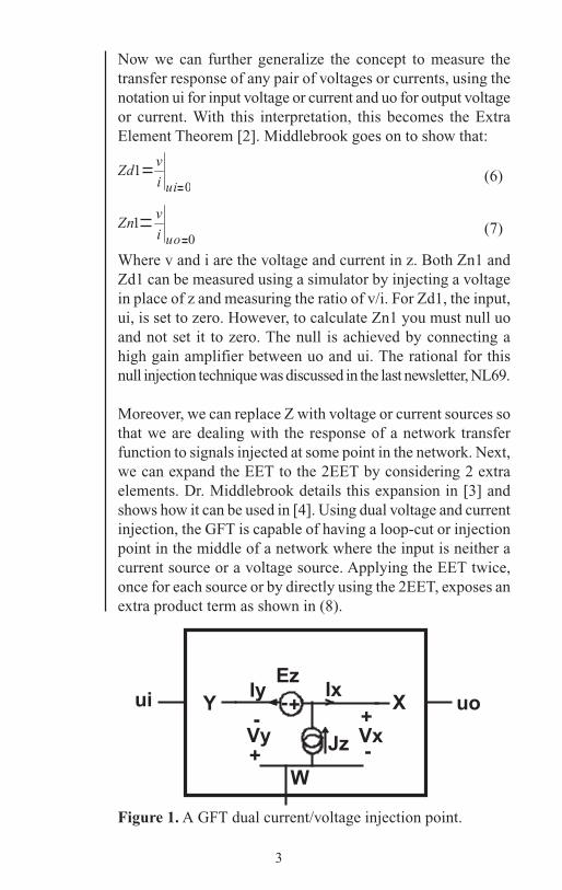
Moreover, we can replace Z with voltage or current sources sothat we are dealing with the response of a network transferfunction to signals injected at some point in the network. Next,we can expand the EET to the 2EET by considering 2 extraelements. Dr. Middlebrook details this expansion in [3] andshows how it can be used in [4]. Using dual voltage and currentinjection, the GFT is capable of having a loop-cut or injectionpoint in the middle of a network where the input is neither acurrent source or a voltage source. Applying the EET twice,once for each source or by directly using the 2EET, exposes anextra product term as shown in (8).
Figure 1. A GFT dual current/voltage injection point.
4
Using the voltage and current definitions in Figure 1, the loopgain T is given by equation 8.
(8)
Finding T, then requires 3 simulations.
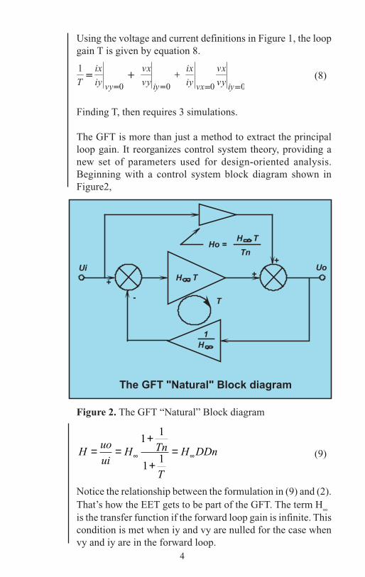
The GFT is more than just a method to extract the principalloop gain. It reorganizes control system theory, providing anew set of parameters used for design-oriented analysis.Beginning with a control system block diagram shown inFigure2,
Huo
uiH Tn
T
H DDn= =+
+=∞ ∞
11
11 (9)
Notice the relationship between the formulation in (9) and (2).That’s how the EET gets to be part of the GFT. The term H•is the transfer function if the forward loop gain is infinite. Thiscondition is met when iy and vy are nulled for the case whenvy and iy are in the forward loop.
Figure 2. The GFT “Natural” Block diagram
5
ix
iy
vx
vy
sv si E
Analog
Out
Mux
10
1
X1mux4
sv si
Set param LowFreq wellbelow the lowest frequency of interest
V3{ GFT_AC }
iy
ywBvx
B6
v(x,w)
v(y,w)
Laplace
A1denorm_freq = { LowFreq * 8 * atan(1) }
AC Coupleds (s 1)
vn
3
B1Current
{ gain * GFT_AC} * v(vn)
VyAC = { GFT_AC } Vxy
BiyVoltage
BixVoltage
ix iy
x
i(Vx)i(Vy)
Set GFT_AC =1 to enablethe GFT Simulation Template
VSV
sv
VSI
si
VSN
sn
Use alter in GFT.scp, template scriptto control the state for each simulationThis subcircuit name XGFT is magic becausewe identify VSN, etc as XGFT:VSN
truth tablesi sv out 0 0 vx ... 20 1 vy ... 11 0 ix ... 41 1 iy ... 3
ix
V13xx
V14yy
w
xw
V16
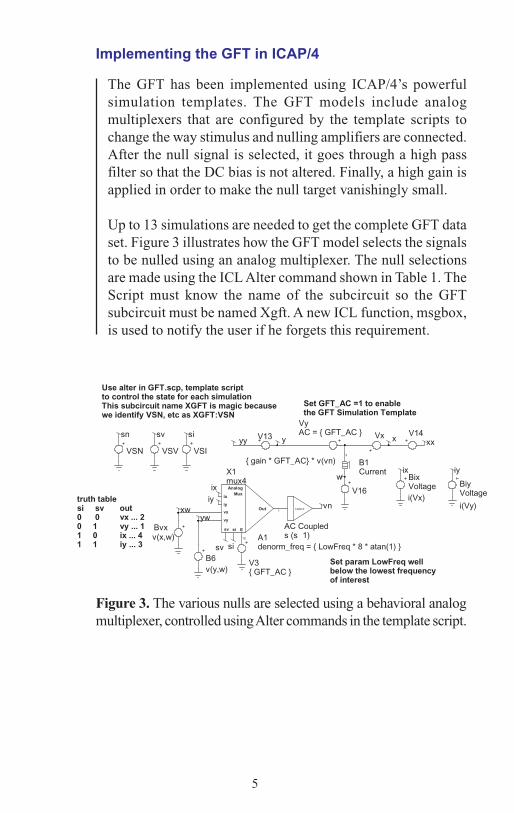
Implementing the GFT in ICAP/4
Figure 3. The various nulls are selected using a behavioral analogmultiplexer, controlled using Alter commands in the template script.
The GFT has been implemented using ICAP/4’s powerfulsimulation templates. The GFT models include analogmultiplexers that are configured by the template scripts tochange the way stimulus and nulling amplifiers are connected.After the null signal is selected, it goes through a high passfilter so that the DC bias is not altered. Finally, a high gain isapplied in order to make the null target vanishingly small.
Up to 13 simulations are needed to get the complete GFT dataset. Figure 3 illustrates how the GFT model selects the signalsto be nulled using an analog multiplexer. The null selectionsare made using the ICL Alter command shown in Table 1. TheScript must know the name of the subcircuit so the GFTsubcircuit must be named Xgft. A new ICL function, msgbox,is used to notify the user if he forgets this requirement.

6
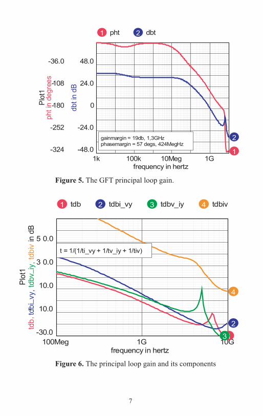
More information is available when the input and output areincluded. Figure 4 illustrates the technique used for the GFTgmodel and a portion of the template script. Several built-inscope scripts can be invoked to plot some common functions.For example, running “gft/T” will make a Bode Plot of theprincipal loop gain, T as seen in Figure 5. While the mathbehind the GFT can be daunting, its use is simple.
The transistor amplifier shown in Figure 4 illustrates the useof the GFT in exploring this design. This is a portion ofSample.dwg, a drawing delivered with ICAP/4 that is used fortraining. Q1 and Q2 have been upgraded to use widerbandwidth transistors, which requires the addition of R6 toeliminate ringing. Breaking the loop at Q2’s base lets us lookat the Bode plot, shown in figure 5. The 3 components of theloop gain T are shown in Figure 6.
Figure 4. Transistor Amplifier with feedback
if isdef(v(yw:xgft))…alter @vsv:xgft[dc] = 1alter @vsi:xgft[dc] = 0alter @vsn:xgft[dc] = 0* null vy#simulation#mprintresult.Ti_vy = v(iy:xgft) / v(ix:xgft)…setplot resultt_iv = ti_vx * tv_iyt = 1/(1/ti_vy + 1/tv_iy + 1/t_iv)elsemsgbox “You need to name the GFTs subcircuit Xgft “end
Table 1. A portion of the Simulation Template Script, GFTs
7
Figure 5. The GFT principal loop gain.
Figure 6. The principal loop gain and its components

8
[1] H.W.Bode, “Network Analyais and Feedback AmplifierDesign”Princeton, NJ: Van’Nostrand, p. 10, 1945.[2] R.D.Middlebrook, “Null Double Injection and the ExtraElement Theorem,” IEEE Trans. on Education, vol. 32, no. 3,Aug. 1989; pp. 167-180.[3] R.D.Middlebrook, “The GFT: A General Yet PracticalFeedback Theorem,” to be published.[4] R.D.Middlebrook, “GFT Template User’s Manual v.1.0"published at http://www.intusoft.com/gft.htm.
Figure 8. Increasing R6 damps the ringing as confirmed bythe GFT analysis.
Figure 7. Bode plot with small R6.
9
EDIF Capability ComingSpiceNet will create a Mentor compatible EDIF descriptionthat works with their DxAnalog and PADSAnalog products.That lets you use ICAP/4 for the design phase and transferproduction to the Mentor products.
Coming soon is a Layout and Auto Routing package. We’ll letyou know as we fill in the details.
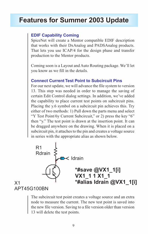
Connect Current Test Point to Subcircuit PinsFor our next update, we will advance the file system to version13. This step was needed in order to manage the saving ofcertain Edit Control dialog settings. In addition, we’ve addedthe capability to place current test points on subcircuit pins.Placing the y.6 symbol on a subcircuit pin achieves this. Tryeither of two methods: 1) Pull down the parts menu and select“Y Test Point/6y Current Subcircuit,” or 2) press the key “6”then “y.” The test point is drawn at the insertion point. It canbe dragged anywhere on the drawing. When it is placed on asubcircuit pin, it attaches to the pin and creates a voltage sourcein series with the appropriate alias as shown below.
The subcircuit test point creates a voltage source and an extranode to measure the current. The new test point is saved intothe new file version. Saving to a file version older than version13 will delete the test points.
Features for Summer 2003 Update

10
Test Point Support Added to B-ElementsYou will now be able to assign current and power test points toB-elements.
IntuScope Now Reads in CSDF File FormatScope5 can now read CSDF( Common Simulation Data File)file output. This is particularly useful for importing rawwaveform data from IsSpice4 or other external simulationofferings like HSPICEtm and PSpicetm.
Successfully Reduce Schematic Image for PublicationCertain features are now available for transferring schematicsfor publishing purposes. For example, when you shrink aschematic to fit in a small space (as done in our newsletter) theline widths may become too small. Other flaws can also occur.Techniques to successfully reduce schematics for publication are:
1. Increase font size to 16 point.2. Increase line width to 50/100 millimeter.3. Print, Copy to clipboard and paste into you target
publication.4. Shrink the schematic in the target publication by 50% to
get 8-point fonts and 1-point lines.
Save Schematic Image Directly to EMF FileCopy to clipboard in SpiceNet now has extra shift key options.When you press the shift key and left click on Copy toClipboard in the print dialog, you get the dialog shown below,Figure 9.
Figure 9. Save directly to EMF file instead of to the clipboard.

11
You can also save Enhanced Metafiles to disk. The EMF formatis the preferred Windows clipboard format. It saves drawingsand graphs as vectors so that you can render to the precision ofyour output device.
“Save as” added to SpiceNet File Menu
“Save as…” has been added to the SpiceNet file menu, addingto the existing “Save Copy as…” The difference between thetwo is that “Save as…” abandons the current drawing and saveschanges in the new “Save as…” file. It then switches the projectto this new file. “Save Copy as…” works as before to producea back up copy, but retains the current drawing as active. Thisadds to recent capability that enables projects to automaticallyswitch to the drawing that the user desires as active, ultimatelyto invoke simulation control and running simulation.
XML Database for PCB FootprintsAn xml database has been added for selecting part numbersand mechanical footprints, i.e., as required for PCB layout.When you right click on a part and select the Footprint…option, a dialog as shown in Figure 11 will appear.
Figure 11. New Footprint Picker builds part numbers and selectspackage footprints
Figure 10. New Save as... command

12
The xml files are named ??.type, where ? is the spice key forthe part. For a resistor, the database is RR.type. We haveinitiated databases for resistors, capacitors and inductors usingthe NASA Parts Selection List, NPSL:
http://nepp.nasa.gov/npsl/npsl_toc.htm.The list is comprehensive, and generally parts are also availableto commercial specification. We’ve added built in parsers tohelp build the part number as shown in Figure 11. User DLL’scan be added to augment or replace the built-in parsers.
The benefit of this feature is that it makes it even easier to beable to export PCB netlist with the correct syntax. Intusoftcurrently supports PCB netlist export to any package that canread in the following formats.
Tango PWB - Netlist for AccelPads 2000 - Netlist for PadsPads ASCII 1 - Netlist for PadsPads ASCII 2 - Netlist for PadsPads PCB- Netlist for PadsMentor V6 - Netlist for Mentor GraphicsOrCAD/PCB II - Netlist for OrCAD Capture PCBProtel PWB - Netlist for Advanced PCBWinboard - Netlist for Ivex
New XP Style UIIf you like the new XP-style dialog user interface, it will beavailable on XP machines simply by selecting DisplayProperties/Appearance/Windows and Buttons/Windows XPstyle.
Figure 12. SpiceNet andIntuScope now support theWindows XP look and feel

13
An auto transformer, shown in Figure 13, is a 2-windingtransformer connected so that its windings are in series.Magnetics Designer needs as its input the voltage and currentfor each of these windings. If the design requirement calls fora prescribed output current, with a transformer ratio vo/vi, then,
Winding 1 2Average Voltage K(vi-vo) K(vo)RMS Current io(vo/vi) io(1-vo/vi)
K is a waveform shape factor, so for sine waves,K = 2*sqrt(2)/pi = 0.900317where v and vi are RMS quantities. The only unusual aspect tothe design is the need for winding 1 to have sufficient insulationto handle the voltage at the input.
Figure 13. As v1 approaches 0, the power handled by thetransformer action approaches 0.
Autotransformers sacrifice isolation for extremely highefficiency when the turns ratio is near unity. Figure 14 showsthe results of a Magnetic Designer design of an isolationtransformer going from 120 VRMS to 110VRMS at 1KW.Figure 15 meets the same requirements but uses theautotransformer configuration.
Designing an Autotransformer

14
Magnetics Designer picked the “best” geometry from a set ofrectangular laminations with variable stack size. The stackheight to width ratio was .789 for the autotransformer and .444for the isolation transformer. The automatic design algorithmsearches cores from the smallest power handling capability to
Figure 15: A 1KW autotransformer
Figure 14: A 1KW isolation transformer
Efficiency Weight
IsolationTransformer
Autotransformer
95.07%
98.6%
21.9 lbs
1.86 lbs
Table 2. Summary of 1KW 120 to 110 Vrms Designs

15
There is a sharp increase in Rac in the 1KHz to 10Khz regiondue to the skin effect. The result is to cause the “best” designto under-fill the window. Interestingly, the onset of these highfrequency effects occurs at lower frequencies as the power levelincreases.
[5] Bennett and Larson, Effective Resistance to AlternatingCurrents of Multilayer Windings, AIEE Transactions 1940, vol.59, pages 1010-1017.
Figure 16. High frequency losses increase sharply for windingsin the center of the stack where the field is highest.
the largest, beginning with the theoretically smallest core. Trialdesigns are made and discarded if the temperature rise is abovethe specification. Several “larger” power capacity designs aretested to see if they produce a lower weight. The lowest weightdesign is then presented to the user. The user is free to lock inany core, thereby disabling the automatic core selection. Foreach core, Magnetics Designer makes trial windings to pickthe wire size under the constraint of minimum temperaturerise. For low frequency designs like this example, the windingarea will be nearly 100% full. On the other hand, high frequencydesigns will have significant losses because of the skin effect,proximity loss, and in some cases gap induced eddy currents.Magnetics Designer builds on the work of Bennet and Larson[5] to predict these losses. Figure 16 shows what happens tothe isolation transformer if the frequency is increased to 1KHzusing 4mil laminations.

16
Intusoft’s World-Wide Support StaffListed below are dealers where Intusoft products, updates, information, and support may be obtained.
Dahan Tech Inc. - Sang Y. ChoSouth KoreaTele: 82-2-515-2845/FAX: 82-2-515-2844email - [email protected]: http://www.dahan.co.kr
Technology Sources Ltd. - Dr. Graham PlowsDenmark, Spain, Portugal, Norway, Sweden, UKTele: 44-01223-516469/FAX: 44-01223-729-916email - [email protected]: http://www.softsim.com
DS-Design Systems OY-Hannu TikkanenFinlandTele: 358-14-652588/FAX: 358 -14-610725email - [email protected]: http://www.designsystems.fi
Thomatronik GmbH - Herbert M. MüellerGermany,Austria,Croatia,Slovenia,CzechRep.Tele:49 -8031-2175-0/FAX: 49- 8031-2175-30email - [email protected]: http://www.thomatronik.de
Cho Chieh Enterprise Ltd. - Tennyson LinTaiwan, Hong Kong, China, Southeast AsiaTele: 886-2-2981-2187FAX: 886-2-8983-5229email - [email protected]: www.chochieh.com.tw
TECH 5 - Geert MosterdijkNetherlands, Belgium, LuxenburgTele: 31-184-6155-51/FAX: 31-184-6154-51Tele:32-2-657-31-64/Fax:32-2-657-49-25 Belgiumemail: [email protected]/[email protected]: www.tech5.nl/[email protected]
Intusoft Inside Sales :879 West 190th StreetSuite 100Gardena, CA 90248-4223Tele: (310) 329-3295Fax: (310) 329-9864e-mail: [email protected]
CAREL - Cezary RudnickiPolandTele/FAX: (0-22) 624-06-19e-mail: [email protected]: www.carel.waw.pl
Siscad s.r.l.- Valerio ScibiliaItalyTele: 39-02-48022546/FAX: 39-02-48015146email - [email protected]: http://www.siscad.it
CMR Design Automation - Mahesh ChandraIndiaTele: 91 11 6477085/Fax:91 11 6213498email - [email protected]
ChipCAD - Tibor BerkyHungaryTele: 36-1 231-7000/FAX: 36-1 231-7001email - [email protected]: http://www.chipcad.hu
IVIS Co., Ltd. - Hiro NaganoJapanTele: 81-45-332-5381/FAX: 81-45-332-5391email - [email protected]: http://www.i-vis.co.jp
EDA Software - John MeltezosGreeceTele: 30-210-825-6258 or 6259/FAX: 30-210-884-1016email - [email protected]
INTSYS Europe SA - Claude MasseboeufFrance, Tunisia, Algeria, MoroccoTele:(33)01-60-81-00-69/FAX:(33)01-60-81-00-70email - [email protected]: http://www.intsys-europe.fr
DFM - Tuvia LiranIsraelTele: 972-4-9533059/FAX: 972-4-9533057email - [email protected]: http://www.dfm4vlsi.com
Related Documents