Artifact motion and repeating pattern …recognition by the delta bit-block indexing companion algorithm Copyright 2008-2010 F. Scott Deaver - all rights reserved. Proprietary and confidential information, may not be disclosed. July 12, 2010 1 | Page

Welcome message from author
This document is posted to help you gain knowledge. Please leave a comment to let me know what you think about it! Share it to your friends and learn new things together.
Transcript

Artifact motion and repeating pattern…recognition by the delta bit-block indexing companion algorithm
Copyright 2008-2010 F. Scott Deaver - all rights reserved. Proprietary and confidential information, may not be disclosed.
July 12, 2010 1 | P a g e

Introduction.................................................................................................................................................3
Identifying “different” pixel groups that have moved or are repeated...................................................3
Terms and conventions.......................................................................................................................3
Moving and repeating artifacts............................................................................................................3
Scalability....................................................................................................................................................4
Colors, color matching, and color averaging...............................................................................................4
Identifying pixel groups and locations.........................................................................................................6
Bit shapes....................................................................................................................................................6
Bit shape classes......................................................................................................................................6
Basic bit shapes...................................................................................................................................7
Complex bit shapes..............................................................................................................................7
Relative complex bit shapes............................................................................................................8
Explicit complex bit shapes..............................................................................................................9
Bit shape evolution/devolution during compilation..............................................................................10
Identifying bit shapes when processing a video frame......................................................................10
Implementation.........................................................................................................................................14
Finding a candidate artifact for matching in the current image............................................................15
Marching the artifact found to other recorded artifacts.......................................................................18
Proximate artifact in previous image method (first choice of two)...................................................19
Artifact discovery by color match in previous image method (second choice of two)......................21
Identifying a repeating pattern in the current frame.........................................................................21
Final frame processing.......................................................................................................................22
Final video processing...........................................................................................................................23
Copyright 2008-2010 F. Scott Deaver - all rights reserved. Proprietary and confidential information, may not be disclosed.
July 12, 2010 2 | P a g e

IntroductionThe delta bit-block indexing algorithm is incredibly efficient at specifying the locations of individual pixels or groups of pixels that are “different” (that is, vary outside tolerance limits) from pixel groups at the same locations in preceding image (see the various previous patent applications and the improvements described in the document entitled “Delta bit-block design and implementation improvements …and third delta bit-block indexing (provisional) patent application support”).
This approach is more than adequate for any application that simply needs the locations of the “differences” and does not need the values at those locations returned in the results set. However, when the delta bit-block indexing algorithm is used for compression (that is, the values found at locations identified as different must be included in the returned results set), the algorithm’s advantages over other forms of compression becomes less as the sizes of the blocks of “different” pixels increases.
Identifying “different” pixel groups that have moved or are repeated
Terms and conventionsBecause “groups of ‘different’ pixels” is at best clumsy and doesn’t always communicate what I am trying to say, I’ve take to using the word “artifact” to indicate a group of “different” pixels in an image that forms a pattern and includes the colors that fill in the “different” pixels of the pattern. I am using the term “bit shape” to describe the pattern of the pixels that are “different” within an artifact (because I am using “pattern” in the context of a repeating pattern of artifacts that occur within the current frame image).
Therefore, an artifact is an assemblage of a bit shape, a location for the bit shape within a frame image (specifically the location of the upper left corner of the rectangle enclosing the bit shape), and the array of colors (or indexes to colors) that fill in the “1” bits of the bit shape.
Moving and repeating artifacts Fortunately, the means and tools by which the delta bit-block indexing algorithm identifies pixel “differences” are easily adapted to (and work well for) identifying artifacts in the comparison image which may be either similar to artifacts in the reference image but at a changed location within the reference image, or which represent patterns that are repeated through the comparison image. And, it turns out that the pattern/moving artifact identification algorithm described below and the original delta bit-block indexing algorithm are in perfect harmony with one another – the pattern/moving artifact identification algorithm can pick out and efficiently store patterns and moving artifacts, and the original delta bit-block indexing algorithm can then inventory the orphan pixels and small pixel groups left over very cleanly.
The tremendous benefits derived from the ability to detect artifacts that have changed positions from a previous frames and/or patterns that have repeated within the current frame come from the fact that for moved or repeated artifacts/patterns you do not need to repeat the storage of values of the pixels that fall at locations within those artifacts or patterns (you need merely point back to either the old Copyright 2008-2010 F. Scott Deaver - all rights reserved. Proprietary and confidential information, may not be disclosed.
July 12, 2010 3 | P a g e

location of the artifact in the previous image, or to the first occurrence of a repeating pattern in the current image).
The following design documentation illustrates how moving artifacts and repeated patterns can be detected and stored, and is intended to improve upon the patent applications already submitted, and to extend the improvements discussed in “Delta bit-block design and implementation improvements …and third delta bit-block indexing (provisional) patent application support”.
[My apologies to James Cardle for saddling him with yet another document that uses implementation as the descriptive vehicle – I know doing so makes the translation to patent documents very difficult, and I do appreciate the extra effort he puts forth!]
ScalabilityMy experiments (which are based as of this writing on extremely limited samples and very little available time – I will continue to test and publish results sets as I work on the demo) suggest that the methods as described in this and preceding documents could reduce the contents of a dual layer BluRay disk (about 50 gigabytes capacity) containing a typical retail video release to fit easily on a dual-layer DVD (about 9.4 gigabytes capacity) at the original resolution (1920 by 1080 PPI) and at (or indistinguishably near) the original BluRay quality. While the implications for download and storage (the motivating force behind all of this work) should be obvious, I am not suggesting anyone would throw away their standalone BluRay disk players for dual-layer DVD players (although for computers, the target audience, the requirement to lug around a BluRay player does go away). However, it does mean that an existing BluRay player (used as a data device instead of a video device) could adequately store the next generation of ultra-high definition video (already available for computers, promoted commercially as IMAX, and produced by digital cameras such as Red One (http://www.filmschooldirect.com/sample_lessons/sample_lesson_HD_video.htm).
Colors, color matching, and color averagingUnlike previous patent applications and improvement documents in this series which dealt with delta bit-block indexing considerations that were applicable across many data types, this document deals specifically with video, and for demonstration purposes specifically challenges the BluRay standard, which encapsulates MPEG-2 Part 2, H.264/MPEG-4 AVC, and SMPTE VC-1 compression techniques.
In practice, versions of a program based on the intellectual property described here could take input in a wide variety of formats, color spaces, and data arrangements. For the purposes of demonstration in this document, the data sources for compression are presumed to be ordered arrays of frames containing two-dimensional arrays (of identical fixed sizes) of three-byte data elements, where the elements contain bytes representing in order the red, green, and blue (RGB) components of a pixel color. This data could be formatted from raw data output by a video capture device or camera, or could be extracted from data sources previously compressed using other means.
Copyright 2008-2010 F. Scott Deaver - all rights reserved. Proprietary and confidential information, may not be disclosed.
July 12, 2010 4 | P a g e

Therefore, tolerance values used here will be expressed as double-precision equivalents of RGB “distances” , where a distance is computed as the square root of the added squares of the deltas of each color component for two compared values, weighted by NTSC standards for human eye sensitivity per color component, like so:
const double dblNTSCRedWeighting = 0.299; // NTSC weighting for perceptual significanceconst double dblNTSCGreenWeighting = 0.587; // NTSC weighting for perceptual significanceconst double dblNTSCBlueWeighting = 0.114; // NTSC weighting for perceptual significance
double dblRedDelta = ((double)byteRedLeftSample - (double)byteRedRightSample);double dblGreenDelta = ((double)byteGreenLeftSample - (double)byteGreenRightSample);double dblBlueDelta = ((double)byteBlueLeftSample - (double)byteBlueRightSample);
double dblDistance = sqrt((((dblRedDelta * dblRedDelta) * dblNTSCRedWeighting ) + ((dblGreenDelta * dblGreenDelta) * dblNTSCGreenWeighting) + ((dblBlueDelta * dblBlueDelta) * dblNTSCBlueWeighting)));
There are other ways to calculate color difference that could just as easily be used.
In the context of video for this demonstration, all RGB colors after initial input are normalized to CIE L*a*b color space – that is, RGB colors are converted to their CIE L*a*b equivalents, and then back again. In addition to saving pixel color storage by using only the subset of colors distinguishable by the human eye, the number of bits required to represent each color as an index is also reduced. At the beginning of video compression, the code will create a table of all unique CIE L*a*b-normalized RGB colors in memory, and sort those colors by the nearest-neighbor distance method described previously. This will expedite color lookups during processing, and provide index-ranged nearest neighbor substitutions for color quantizing post-frame and post-video.
As to the last item, there are video-wide settings, as well as per-frame overrides, which the user can set during the video compilation process as to whether the creation of new colors is allowed during the color quantizing process (see the description of quantizing tolerances in the document entitled “Delta bit-block design and implementation improvements …and third delta bit-block indexing (provisional) patent application support”) – in other words, is the quantizing algorithm forced to use only colors already in use, or can it create new compromise colors that are “between” two similar colors? We will calculate color averages using RGB color space with the formula, where “a” and “b” each represent an unsigned long RGB color ordered byte-wise as 0x00RRGGBB:
((((a ^ b) & 0xFFFEFEFE) >> 1) + (a & b))
We will take the result of the average and normalize it by converting to CIE L*a*b color space and then back again to RGB color space.
While none of the component techniques described above is unique or unusual in and of itself, the way in which they are employed together may represent intellectual property of some sort (trade secret?) – I will leave that up to James Cardle to determine.
Copyright 2008-2010 F. Scott Deaver - all rights reserved. Proprietary and confidential information, may not be disclosed.
July 12, 2010 5 | P a g e

Identifying pixel groups and locationsFor this demonstration, artifacts and patterns are identified within the fixed-size frame (here, 1920 by 1080) by the 0-based X/Y coordinates of their top left corners and bottom right corners plus a starting-point offset for the equally-sized matching moving artifact in the previous frame or the starting-point offset for the equally-sized matching repeating pattern in the current frame. In a 0-based two-dimensional coordinate system having at most 1920 positions in either direction, the largest number that must be represented is 1919, which in binary is 11101111111 (eleven bits). This means the most basic bit shape (filled rectangles) will require 44 bits to describe (11 bits each for the left, top, right, and bottom coordinates) and offsets to the parental moving artifact or repeating pattern will require 22 bits (11 for the X offset, 11 for the Y offset). To describe each copy of a moving artifact or repeating pattern will require 66 bits (plus, for repeating patterns, one-time color pixel storage of the original artifact in the current frame).
It is important to consider this storage size requirement, because very small moving artifact or repeating pattern copies may be better left to be picked up by the follow-up delta bit-block indexing processing instead. Otherwise, very large moving artifact copies (especially, because no new storage of the original artifact is required) and repeating pattern copies can be stored extremely efficiently (at the cost of processing time during the compilation).
Bit shapesBit shapes are the portion of artifacts which describe the pattern of “different” pixels which give the artifact its shape (but not its color or location). Earlier versions of this document described the shapes of artifacts found in previous or current frames in terms of rectangles. Unfortunately, rectangles are not an efficient means to describe collections of “different” pixels for several reasons, including that even when shapes are rectangular (rarely), the pixels within shapes are not usually all “different” (usually, some will be “like”).
I’ve introduce the ability to store and reference by index (to save pixels) bit shapes that represent all of the shapes present throughout the video. Those that are used most often will be stored in the master video header, and shapes that are unique to specific frames will be stored in the data for that frame. The amount of data need to reference a bit shape is reduced to the size of the index in bits, and the colors needed to fill in the shape need only be those which are actually required for the “different” bits.
The resulting bit shape “library” will be unique to each video, and will consist of bit shape primitives (including rectangles) as well as complex bit shapes made from combinations of primitive bit shapes.
Bit shape classesA bit shape is defined as a group of “different” pixels where all the “different” pixels touch, on an edge or by a corner, at least one other “different” member of the group. To create a standalone rectangle primitive or core bit shape there is an additional requirement that the shape must contain at least three “different” pixels – the latter rule does not apply if during analysis of a bit shape it is being split up
Copyright 2008-2010 F. Scott Deaver - all rights reserved. Proprietary and confidential information, may not be disclosed.
July 12, 2010 6 | P a g e

among existing bit-shapes, and leaves a leftover object of less than three pixels (the leftover object will be accepted – se the discussion below regarding object evolution and devolution).
Basic bit shapesThe class hierarchy for bit shapes is at bottom based on the simple rectangle. However, when the rectangle primitives are used to describe artifacts, the rectangle primitive will be assumed to be filled with “different” pixels. A rectangular bit shape primitive requires just two values, each requiring 11 bits in a 1920 by 1080 image, one for the width of the rectangle primitive and another for the height.
The core bit shape class for non-rectangular images is derived from the rectangle primitive class. However, the rectangle inherited from the base class is used differently – in the derived class the rectangle represents the smallest rectangle that can enclose all of the “different” bits of the bit shape, but instead of assuming the rectangle is completely full of “different” pixels, the pattern for the “different” pixels is set by a separate bit-field and bit count in the derived class. A core bit shape might look like this:
In this example the width of the bit shape is 4, the height of the bit shape is 4. The bit-field shows “like” bits (bits representing pixels that are the same in the comparison image as they are in the reference image) as “0” and “different” bits as 1. The bits in the bit-field are aligned in order beginning from the top left corner and running in rows from left to right, with the rows running top to bottom. The bit-field for this bit shape looks like this:
0 1 0 0 0 1 1 0 0 1 1 1 1 0 1
Note that the bit-field only contains 15 bits – it is not necessary to store the bits at beyond the last “1” bit of the last row.
Complex bit shapesIn addition to the rectangle primitive and core non-rectangular bit shape classes, there are two complex bit shape classes build on a common complex bit shape virtual base class. The two upper complex bit shape classes both define how two bit shapes (which can be rectangle primitives, core bit shapes, or other complex bit shapes) are joined together to make another complex bit shape. The two classes are different in the way they define the relationships between the two bit shapes they join. The first class uses predefined relative positions to describe how the two bit shapes are tied together to make a new bit shape, and the second class uses an explicit number to represent the position in a prescribed path where the second bit shape joins the first bit shape.
In the examples below, the larger black-framed rectangles represent the smallest rectangle that can encapsulate a bit shape. The encapsulating rectangle with the blue pixels represents the first bit shape
Copyright 2008-2010 F. Scott Deaver - all rights reserved. Proprietary and confidential information, may not be disclosed.
July 12, 2010 7 | P a g e

of the two that are being joined, and the encapsulating rectangle with the green pixels represents the second of the two being joined.
Relative complex bit shapesThe relative complex bit shapes class uses predefined relative positions to describe how the two bit shapes are tied together to make a new bit shape – these are the predefine relative positions:
Copyright 2008-2010 F. Scott Deaver - all rights reserved. Proprietary and confidential information, may not be disclosed.
July 12, 2010 8 | P a g e

Though this technique can be applied to bit shapes of any size, these relative positions work especially well where the first bit shape is relatively small. The nice benefit for using this method is that the description of the relationship between the two bit shapes only requires four bits on disk. The down side is that as the first bit shape grows larger, a gap begins to grow between some of the defined positions, and it’s not possible to align the two bit shapes in any position that falls in the gaps.
These gaps will begin to appear between the BIT_SHAPE_ALIGN_B_TO_T_MINUS_1 and the BIT_SHAPE_ALIGN_B_TO_M_FAVOR_UPPER positions, between the BIT_SHAPE_ALIGN_T_TO_M_FAVOR_LOWER and BIT_SHAPE_ALIGN_T_TO_B_MINUS_1 positions, between the BIT_SHAPE_ALIGN_T_TO_B_PLUS_1 and BIT_SHAPE_ALIGN_L_TO_M_FAVOR_RIGHT positions, and between the BIT_SHAPE_ALIGN_R_TO_M_FAVOR_LEFT and BIT_SHAPE_ALIGN_R_TO_L_MINUS_1 positions.
In many cases, this is not a problem because the desired alignment will still fall into one of the pre-defined settings. However, if aligning the two bit shapes requires a position that falls in the gaps, you can use the explicit complex bit shape class below.
Explicit complex bit shapesThe explicit complex bit shapes class uses numbered positions based on the height and width of the two bit shape rectangles to describe how the two bit shapes are tied together to make a new bit shape – these are the numbered positions in order for bit shape rectangles of the sizes shown (the second bit shape rectangle is shown in the starting and final positions only):
This method can define any alignment position for any two first and second bit shapes, at the cost that the numbering uses up to thirteen bits (for a 1920 by 1080 image). The number of available positions is equal to the height of the first bit shape plus the height of the second bit shape plus one plus the width of the first shape minus one.
Copyright 2008-2010 F. Scott Deaver - all rights reserved. Proprietary and confidential information, may not be disclosed.
July 12, 2010 9 | P a g e

Note that it is unnecessary to have a position “23” (or any positions showing the second image on the left or top left of the first image) because position 23 can instead be represented by using bit shape 2 as bit shape 1 and vice versa, at position 0.
Bit shape evolution/devolution during compilationOne goal of the compilation process to build up a library of molecular bit shape patterns during compilation that can be re-used from any frame and is stored within the master video header or individual frame header (whichever is most efficient) at the cost of just an index into an array of bit shapes. The idea is to foster re-use of component bit shapes, and to store only those bit shapes that are appropriate to the video being processed.
Identifying bit shapes when processing a video frameOur algorithm pre-defines an enumeration and a structure we will use when identifying bit shapes:
typedef enum enmCONNECTED_STATE{
CONNECTED_STATE_UNKNOWN = -1,CONNECTED_STATE_FALSE = 0,CONNECTED_STATE_TRUE = 1
};
typedef struct tagCONNECTED_DIRECTIONS{
enmCONNECTED_STATE enmcsNW; // NorthwestenmCONNECTED_STATE enmcsN; // NorthenmCONNECTED_STATE enmcsNE; // NortheastenmCONNECTED_STATE enmcsW; // WestenmCONNECTED_STATE enmcsE; // EastenmCONNECTED_STATE enmcsSW; // SouthwestenmCONNECTED_STATE enmcsS; // SouthenmCONNECTED_STATE enmcsSE; // Southeastunsigned short usXpos;unsigned short usYpos;
} CONNECTED_DIRECTIONS,*PCONNECTED_DIRECTIONS;
It also defines structures that combine each bit shape type with a use count:
typedef struct tagCDDIFilledRectBitShape_W_USE_COUNT{ CDDIFilledRectBitShape frbsBitShape; unsigned __int32 ui32UseCount;} CDDIFilledRectBitShape_W_USE_COUNT,*CDDIFilledRectBitShape_W_USE_COUNT;
typedef struct tagCDDICoreBitShape_W_USE_COUNT{ CDDICoreBitShape cbsBitShape;
Copyright 2008-2010 F. Scott Deaver - all rights reserved. Proprietary and confidential information, may not be disclosed.
July 12, 2010 10 | P a g e

unsigned __int32 ui32UseCount;} CDDICoreBitShape_W_USE_COUNT,*CDDICoreBitShape_W_USE_COUNT;
typedef struct tagCDDIRelativeComplexBitShape_W_USE_COUNT{ CDDIRelativeComplexBitShape rcbsBitShape; unsigned __int32 ui32UseCount;} CDDIRelativeComplexBitShape_W_USE_COUNT,*CDDIRelativeComplexBitShape_W_USE_COUNT;
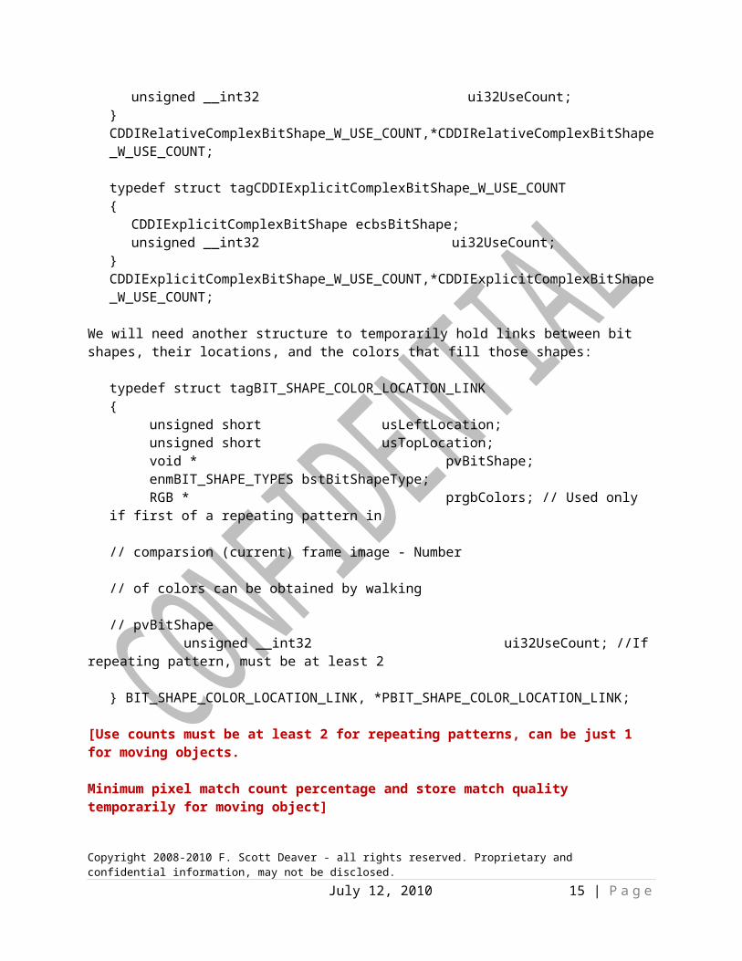
typedef struct tagCDDIExplicitComplexBitShape_W_USE_COUNT{ CDDIExplicitComplexBitShape ecbsBitShape; unsigned __int32 ui32UseCount;} CDDIExplicitComplexBitShape_W_USE_COUNT,*CDDIExplicitComplexBitShape_W_USE_COUNT;
We will need another structure to temporarily hold links between bit shapes, their locations, and the colors that fill those shapes:
typedef struct tagBIT_SHAPE_COLOR_LOCATION_LINK{ unsigned short usLeftLocation; unsigned short usTopLocation; void * pvBitShape; enmBIT_SHAPE_TYPES bstBitShapeType; RGB * prgbColors; // Used only if first of a repeating pattern in // comparsion (current) frame image - Number // of colors can be obtained by walking // pvBitShape
unsigned __int32 ui32UseCount; //If repeating pattern, must be at least 2
} BIT_SHAPE_COLOR_LOCATION_LINK, *PBIT_SHAPE_COLOR_LOCATION_LINK;
[Use counts must be at least 2 for repeating patterns, can be just 1 for moving objects.
Minimum pixel match count percentage and store match quality temporarily for moving object]
If no repeating match found, revert to moving match, if any!
Shrinking rectangle match pattern.]
During compilation, the algorithm stores separate std::vector<> arrays for each of the bit shape types/use count structures that we will generate, sorting them by size (number of “1” bits) in descending order as new items are added so that the largest shapes are always listed first.
These are the steps we will use to extract bit shapes from the “different” pixels (those in the comparison image that are “different” after considering tolerances) in a given frame we are processing:
Copyright 2008-2010 F. Scott Deaver - all rights reserved. Proprietary and confidential information, may not be disclosed.
July 12, 2010 11 | P a g e

1. Create a Boolean array in memory that corresponds one-to-one with every pixel location in the frame image, pre-setting every member of the Boolean array to “false”;
2. Compare every pixel of the comparison image (current frame) with its corresponding pixel in the reference image (previous frame), using the activity history, and controlling zone tolerances, and/or frame preferences descriptor tolerances to determine if the comparison pixel is “different” – if “different”, set the corresponding Boolean table entry to “true”, otherwise set it to “false”. Setting the Boolean table with the results prevents having to calculate pixel location tolerances more than once, since the same Boolean values can be used for later delta bit-block indexing as required;
3. Create an empty std::vector<> of BIT_SHAPE_COLOR_LOCATION_LINK structures to temporarily hold complete artifacts found in the comparison (current) image;
4.
The depiction above represents our simple and contrived example where the comparison image contains a single artifact (the yellow boxes with the X’s through them represent the “different” pixels identified in step 7).
Using the Boolean array in memory as a guide, do the following steps for every pixel on the screen in left to right, top to bottom order, to extract every identifiable artifact from the comparison (current) image:
A. Determine if the Boolean value at the current location is “true” (“true” means that after considering tolerances, there is a “difference” between the reference and comparison pixels in the image locations corresponding to the current Boolean array position)
i. If not “true”, do not follow the steps below – instead, move to the next screen pixel in order and go to step A;
ii. If “true” (in our demo image, this will first occur at row 5, column F, which will be flagged in step 7 as the starting point):a. Create a new CONNECTED_DIRECTIONS structure and seed the usXPos and
usYPos members with the current screen pixel X/Y location, and set the enmcsNW, enmcsN, enmcsNE, enmcsW, enmcsE, enmcsSW, enmcsS, and enmcsSE memebers to CONNECTED_STATE_UNKNOWN;
Copyright 2008-2010 F. Scott Deaver - all rights reserved. Proprietary and confidential information, may not be disclosed.
July 12, 2010 12 | P a g e

b. Using the new current location as a starting point, find the limits of the smallest bounding rectangle of all pixels where any individual pixel meets all of the following conditions:
1. Is within the frame dimensions;2. Is different from the reference pixel at the same location (in other
words, has “true” in the corresponding Boolean array location);3. Is not already recorded as one of the “different” pixels included in
one of the std::vector<> BIT_SHAPE_COLOR_LOCATION_LINK structures already recorded representing another artifact; and
4. Touches one side or corner to a pixel which touches another pixel all the way through to contiguous contact with the pixel at the new index.
We will accomplish this by iteratively crawling though all “different” pixels one-by-one as long as they touch at least one other pixel in the group, recording the connected ones in this manner:
1. Make sure this location passes the first three of the four conditions listed above – if not, return “false” (indicating not a connection) for this iteration of the connection test method. Otherwise, continue to the next step;
2. Check to see that the current pixel location does not already appear in any iterators of the std::vector<> of CONNECTED_DIRECTIONS for the frame – if it does not, create a new empty CONNECTED_DIRECTIONS structure for the current pixel location and push it to the std::vector<> (otherwise, use the CONNECTED_DIRECTIONS structure pointed to by the iterator you found) ;
3. If this loop iteration is being called by a previous iteration, mark this iteration’s CONNECTED_DIRECTIONS structure enmcsNW, enmcsN, enmcsNE, enmcsW, enmcsE, enmcsSW, enmcsS, or enmcsSE member as CONNECTED_STATE_TRUE in accordance with this pixel location’s orientation with the calling pixel location (not applicable to the very first iteration);
4. Check every CONNECTED_DIRECTIONS structure in the std::vector<> to find every structure whose location abuts this pixel’s location – for each one that you find, mark that structure’s appropriate enmcsNW, enmcsN, enmcsNE, enmcsW, enmcsE, enmcsSW, enmcsS, or enmcsSE member (in accordance with its orientation to this location) as CONNECTED_STATE_TRUE (if not already so marked) and then set this location’s CONNECTED_DIRECTIONS structure enmcsNW, enmcsN, enmcsNE, enmcsW, enmcsE, enmcsSW, enmcsS, or enmcsSE member CONNECTED_STATE_TRUE
Copyright 2008-2010 F. Scott Deaver - all rights reserved. Proprietary and confidential information, may not be disclosed.
July 12, 2010 13 | P a g e

as appropriate for this locations relationship to the found CONNECTED_DIRECTIONS structure;
5. For every CONNECTED_DIRECTIONS structure enmcsNW, enmcsN, enmcsNE, enmcsW, enmcsE, enmcsSW, enmcsS, or enmcsSE member that remains set to CONNECTED_STATE_UNKNOWN after the last step, call the iterative connection test function to set that member to either CONNECTED_STATE_FALSE or CONNECTED_STATE_TRUE;
6. Once all enmcsNW, enmcsN, enmcsNE, enmcsW, enmcsE, enmcsSW, enmcsS, and enmcsSE members have been properly set for all linked pixel locations, the iterations will naturally end and the artifact’s pixel contents known. At this point, inventory all of the positions of all CONNECTED_DIRECTIONS structures in the std::vector<> to get a count of the number of connected pixels as well as the outer bounds of the smallest rectangle that can encompass all of the artifacts. Note that this process will normally produce a rectangle that contains more pixels than the number of pixels in the artifact itself, and that some of the included pixels will likely not be “different” from the source. This is intentional and by design. When using the proximate colors in the previous image method, only “different” pixels are used to find the initial color match starting locations in the previous image, and the actual matching of artifacts is the same as the proximate artifact in the previous image method; and
7. If the count determined in the last step times the smaller of the size of a color link or value is not greater than the size of a most basic bit shape (filled rectangle) and X/Y offset (66 bits for a 1920 by 1080 image), the linked pixels do not qualify as an artifact for our purposes (it would take more bits to link the artifact than to describe the individual pixels using delta bit-block indexing), and the artifact will not be recorded and further processing of this artifact ends – otherwise go to the next step;
8. Copy all of the “different” pixels shown as connected in the CONNECTED_DIRECTIONS structures BIT_SHAPE_COLOR_LOCATION_LINK A and seek out the connected pixels of the next artifact in the image.
5.6.
Copyright 2008-2010 F. Scott Deaver - all rights reserved. Proprietary and confidential information, may not be disclosed.
July 12, 2010 14 | P a g e
ImplementationThe goal here is to always use, where possible, the previous image as an artifact and/or color source palette for the pixels in the current image, rather than to directly use individual pixel colors to describe a current artifact. The idea is that colors in the previous image are already rendered and therefore do not cost us any additional storage, except for the 66 bits needed to store the most basic bit shape (filled rectangle) for our current object and an offset into the previous image describing where to find that same object.
I’ve provided two mutually-exclusive means for finding the positions of moving artifacts in the previous frame, each having specific advantages and disadvantages with respect to the other. The first method uses proximity to the position of the same artifact in the current image as a criterion for finding the artifact in the previous image. This method is ordinarily faster and can be less accurate (the locations it must search for matches is a finite subset of all possible locations, making it faster, but it will not find the artifact if it has moved beyond a specific radius of the current artifact position).
The second method identifies pixel group color similarities to the colors of “different” pixels found in the current image artifact we are trying to match to the previous image. In this method, the locations of all colors in the previous image were inventoried along with their locations. The colors of the “different” pixels in the current artifact are compared to the locations of matching colors in the to see if similar patterns of contiguous colors are found in the previous image – if so, those locations are using as starting points for the artifact match algorithm, and the best candidate selected. This method is ordinarily slower to process during compilation than the first, but is always as accurate as allowed by the tolerances then in play.
I expect that each of the two methods will have value to the end user, depending upon his/her goals and resources. The choice of which of the two methods to deploy will be offered as an option in the master video settings or even in the frame preferences descriptors.
For any given artifact we’ve identified in our current image, if we fail finding an artifact in the previous image that we can re-use efficiently, then we will try to find duplicate orphaned artifacts in our current image that are similar enough we can repeat them (rather than store separate sets of data for them).
Finding a candidate artifact for matching in the current imageFirst, we must look for artifacts in the current image suitable to matching to artifacts found either in the previous image (preferable) or already discovered in the current image. For our purposes here, we will define “suitable artifact” as one where a group of contiguous (including corner-to-corner contact) pixels are found, and that group’s members are sufficient in number that the number of bits required to
Copyright 2008-2010 F. Scott Deaver - all rights reserved. Proprietary and confidential information, may not be disclosed.
July 12, 2010 15 | P a g e

record the group is greater than the number of bits required to store a bit shape and X/Y offset (for the most basic bit shape, a filled rectangle, 66 bits).
These are the steps we will use to identify suitable artifacts:
7. Create a Boolean array in memory that corresponds one-to-one with every pixel location in the image, pre-setting every member to false;
8. We will need an enumeration:
typedef enum enmCONNECTED_STATE{
CONNECTED_STATE_UNKNOWN = -1,CONNECTED_STATE_FALSE = 0,CONNECTED_STATE_TRUE = 1
};
9. We will also need a structure:
typedef struct tagCONNECTED_DIRECTIONS{
enmCONNECTED_STATE enmcsNW; // NorthwestenmCONNECTED_STATE enmcsN; // NorthenmCONNECTED_STATE enmcsNE; // NortheastenmCONNECTED_STATE enmcsW; // WestenmCONNECTED_STATE enmcsE; // EastenmCONNECTED_STATE enmcsSW; // SouthwestenmCONNECTED_STATE enmcsS; // SouthenmCONNECTED_STATE enmcsSE; // Southeastunsigned short usXpos;unsigned short usYpos;
} CONNECTED_DIRECTIONS,*PCONNECTED_DIRECTIONS;
10. Create an empty std::vector<> of CONNECTED_DIRECTIONS structures for found artifacts just to record motion comparisons for the frame;
11. Create an empty std::vector<> of force exclusionary controlling zones which will hold the bit shapes encapsulating moving artifacts found in the reference image for the frame;
12. Create an empty std::vector<> of bit shapes (and their use counts) encapsulating artifact-like pixel groups found in the comparison image but not matched to anything in the reference image for the frame (these are the candidates for repeated patterns within the current image);
13. Using the non-artifact-motion (important!) tolerances appropriate to the frame (using default tolerances as well as any specified in the inclusionary controlling zones), for every pixel in the image record into the Boolean array whether that pixel, after considering tolerances, is “different” than the reference image pixel at the same location. Record the first “different” pixel location found as the starting point for step 8.
14.
Copyright 2008-2010 F. Scott Deaver - all rights reserved. Proprietary and confidential information, may not be disclosed.
July 12, 2010 16 | P a g e

The depiction above represents our simple and contrived example for the comparison image containing a single artifact that has moved from a previous location in the reference image (the yellow boxes with the X’s through them represent the “different” pixels identified in step 7).
Using the Boolean array in memory as a guide, do the following steps for every pixel on the screen in left to right, top to bottom order:B. Is the Boolean value at this location “true” (“true” means that after considering tolerances,
there is a “difference” between the reference and comparison pixels in the image locations corresponding to the current Boolean array position)?
iii. If not “true”, do not follow the steps below – instead, move to the next screen pixel in order and go to step 4;
iv. If “true” (in our demo image, this will first occur at row 5, column F, which will be flagged in step 7 as the starting point):a. Create a new X/Y index and seed it with the current screen pixel location;b. Using the new index as a starting point, find the limits of the smallest
bounding rectangle of all pixels where any individual pixel meets all of the following conditions:
1. Is within the frame dimensions;2. Is different from the reference pixel at the same location (in other
words, has “true” in the corresponding Boolean array location);3. Is not already included in a force exclusionary controlling zone
rectangle binding another artifact; and4. Touches one side or corner to a pixel which touches another pixel
all the way through to contiguous contact with the pixel at the new index.
We will accomplish this by iteratively crawling though all connected pixels one-by-one, recording the connected ones, in this manner:
9. Make sure this location passes the first three of the four conditions listed above – if not, return “false” (indicating not a connection) for
Copyright 2008-2010 F. Scott Deaver - all rights reserved. Proprietary and confidential information, may not be disclosed.
July 12, 2010 17 | P a g e

this iteration of the connection test method. Otherwise, continue to the next step;
10. Check to see that the current pixel location does not already appear in any iterators of the std::vector<> of CONNECTED_DIRECTIONS for the frame – if it does not, create a new empty CONNECTED_DIRECTIONS structure for the current pixel location and push it to the std::vector<> (otherwise, use the CONNECTED_DIRECTIONS structure pointed to by the iterator you found) ;
11. If this loop iteration is being called by a previous iteration, mark this iteration’s CONNECTED_DIRECTIONS structure enmcsNW, enmcsN, enmcsNE, enmcsW, enmcsE, enmcsSW, enmcsS, or enmcsSE member as CONNECTED_STATE_TRUE in accordance with this pixel location’s orientation with the calling pixel location (not applicable to the very first iteration);
12. Check every CONNECTED_DIRECTIONS structure in the std::vector<> to find every structure whose location abuts this pixel’s location – for each one that you find, mark that structure’s appropriate enmcsNW, enmcsN, enmcsNE, enmcsW, enmcsE, enmcsSW, enmcsS, or enmcsSE member (in accordance with its orientation to this location) as CONNECTED_STATE_TRUE (if not already so marked) and then set this location’s CONNECTED_DIRECTIONS structure enmcsNW, enmcsN, enmcsNE, enmcsW, enmcsE, enmcsSW, enmcsS, or enmcsSE member CONNECTED_STATE_TRUE as appropriate for this locations relationship to the found CONNECTED_DIRECTIONS structure;
13. For every CONNECTED_DIRECTIONS structure enmcsNW, enmcsN, enmcsNE, enmcsW, enmcsE, enmcsSW, enmcsS, or enmcsSE member that remains set to CONNECTED_STATE_UNKNOWN after the last step, call the iterative connection test function to set that member to either CONNECTED_STATE_FALSE or CONNECTED_STATE_TRUE;
14. Once all enmcsNW, enmcsN, enmcsNE, enmcsW, enmcsE, enmcsSW, enmcsS, and enmcsSE members have been properly set for all linked pixel locations, the iterations will naturally end and the artifact’s pixel contents known. At this point, inventory all of the positions of all CONNECTED_DIRECTIONS structures in the std::vector<> to get a count of the number of connected pixels as well as the outer bounds of the smallest rectangle that can encompass all of the artifacts. Note that this process will normally produce a rectangle that contains more pixels than the number of
Copyright 2008-2010 F. Scott Deaver - all rights reserved. Proprietary and confidential information, may not be disclosed.
July 12, 2010 18 | P a g e

pixels in the artifact itself, and that some of the included pixels will likely not be “different” from the source. This is intentional and by design. When using the proximate artifact in the previous image method, during the station match process, the extra pixels are resolved and “like” pixels cause no harm (in certain circumstances, they can actually help increase the useable artifact’s final size if the station match’s surrounding pixels happen to match the “like” pixels from the comparison artifact bit shape). When using the proximate colors in the previous image method, only “different” pixels are used to find the initial color match starting locations in the previous image, and the actual matching of artifacts is the same as the proximate artifact in the previous image method; and
15. If the count determined in the last step times the smaller of the size of a color link or value is not greater than the size of a most basic bit shape (filled rectangle) and X/Y offset (66 bits for a 1920 by 1080 image), the linked pixels do not qualify as an artifact or pattern for our purposes (it would take more bits to link the artifact than to describe the individual pixels using delta bit-block indexing), and the artifact will not be recorded and further processing of this artifact ends – otherwise go to the first step of either one of the two artifact match methods following.
Marching the artifact found to other recorded artifactsOnce a suitable artifact is discovered in the current image, the challenge than becomes to find a match preferably in the previous image, or otherwise to a recurring pattern in the current image. I’ve provide two means to do that – there is no value in using both mehods on the same data, so the user will want to choose one or the other, either form the entire video or as needed frame-by-frame.
At this point, there are three possibilities for the ultimate disposition of our artifact:
1. A similar artifact will be found in the reference (previous) image of sufficient size to justify storing a (probably trimmed) bit shape and X/Y offset in our rendering image in place of delta bit-block indexing – this represents artifact movement;
2. A similar artifact was found in our comparison (current) image of sufficient size to justify storing a (probably trimmed) bit shape and X/Y offset in our rendering image in place of delta bit-block indexing – this represents pattern repetition; or
3. No suitable match of either kind was found – in that case, this artifact will be stored as the unmatched potentially original artifact of a series of copies, for use later as processing continues.
Note that the sequence described favors movement over repetition (there are cases where an artifact could pass both tests). This is also by design and intent – movement requires no storage of color values
Copyright 2008-2010 F. Scott Deaver - all rights reserved. Proprietary and confidential information, may not be disclosed.
July 12, 2010 19 | P a g e

(since all colors come from the previous image). However, for repeating patterns in the current image, one copy - the original artifact’s – of the artifact color values will have to be stored (though of course color values for copies do not).
[Note: The examples assume you would look only to the immediately previous image for a matching artifact. It occurs to me you could keep the past several recent images around (perhaps equal to the history depth used for tracking and weighting pixel activity in the delta bit-block indexing algorithm), and thereby catch artifacts that were swinging regularly like a pendulum through the frame, or happened to have some other behavior that caused them to appear and disappear (illumination by a flashing light?). However, this would add to the bits necessary to describe the bit shape for all moving artifacts (bits needed to enumerate which frame it came from), and I suspect the cost would outweigh the occasional benefit (if any). I did, however, want to mention the possibility for later experimentation.]
We first need to see if we can find the same artifact in the reference image (assuming it existed in the previous frame) using one of the two methods.
Proximate artifact in previous image method (first choice of two)For this method, we will compare the pixels in the rectangle we just identified in the previous steps to pixels in the reference image in a winding pattern, starting from our current comparison image position, similar to that shown here (the red, yellow and gray rectangle represents the pattern we are trying to match from the comparison image and the green, blue, and black rectangle represents station sample locations in the reference image – blue represents intersections between the original comparison pixel locations and the reference image station sample locations):
Copyright 2008-2010 F. Scott Deaver - all rights reserved. Proprietary and confidential information, may not be disclosed.
July 12, 2010 20 | P a g e

Copyright 2008-2010 F. Scott Deaver - all rights reserved. Proprietary and confidential information, may not be disclosed.
July 12, 2010 21 | P a g e

1. At each match station in the pattern, a pixel-to-pixel comparison will be made at the new location in the reference image, using the comparison tolerance as modified by the (optional) movement tolerance supplied by the frame preferences descriptor. At each station, the best bit shape that can encapsulate contiguous “like” pixels between the sample set and the reference image pixels at the station is recorded, along with the accuracy of each pixel match as a averaged percentage of the movement tolerance value.
Note that how far afield the match stations are allowed to range from the original comparison image location can be limited by variables set for maximum north, south, east, and west distances in the frame preferences descriptor (lesser ranges speed the match search for each artifact, at the cost of possibly missing a match just one pixel further out. The speed savings is exponential as the range limits are decreased, since as you go outward the number of stations you must process increases significantly.
2. The match bit shapes’ size and match quality percentage are compared for each match station, and the best match is chosen. If that best match has a bit shape size times the link or pixel size larger than the overhead for the most basic bit shape (filled rectangle) and offset storage in the storage file (66 bits), the bit shape is then added to the bit shapes std::vector, and added (if not already present) to the std::vector<> of exclusionary bit shapes which will hold the bit shapes encapsulating moving artifacts found in the reference image for the frame.
Artifact discovery by color match in previous image method (second choice of two)This method requires preparation of the previous (reference) image – when the previous reference image is itself processed initially for pixel “differences” between itself and its predecessor, it will look ahead to see if it’s following image requires artifact discovery by color match in the reference image. If so, as it scans for “different” pixels, it will also inventory the pixel colors of all pixels in its frame (whether “different” or not) – this inventory will consist of a listing of all colors used in the frame, and for each unique color will include an array of all pixel locations on the screen are bound to that color.
When it comes time to process the current frame, and a suitable artifact is found in the current image for matching to artifacts in the previous image, the colors of “different” pixels in the current image found artifact is compared to similar colors (within the comparison tolerance range) in the previous images color inventory. The goal is to seek out colors in that previous image similar to those in the found artifact and having the same relationships position-wise.
The match rectangles’ size and match quality percentage are compared for each set of color-based matches, and the best match is chosen. If that best match has a rectangle size times the link or pixel size larger than the overhead for rectangle and offset storage in the storage file (66 bits), the bounding rectangle is then converted to an exclusionary controlling zone, and added (if not already present) to the std::vector<> of force exclusionary controlling zones which will hold the rectangles encapsulating moving artifacts found in the reference image for the frame.
Identifying a repeating pattern in the current frame[// Stored size on disk requires 52 bits for 1920 x 1080 imagetypedef struct tagREPEAT_OBJ_SOURCE
{Copyright 2008-2010 F. Scott Deaver - all rights reserved. Proprietary and confidential information, may not be disclosed.
July 12, 2010 22 | P a g e

CDDIVideoDataRect vdrRect;BYTE byUseCount; // for now, assume maximum 255 copies of any artifact
} REPEAT_OBJ_SOURCE,*PREPEAT_OBJ_SOURCE;
// Stored size on disk requires 30 bits for 1920 x 1080 imagetypedef struct tagREPEAT_OBJ_REFERENCE{
BYTE byRepeatObjSrcIndex; // for now, assume maximum 255 copies of any artifactunsigned short usXOffset; // actually only need 11 bits in the final stored version of this unsigned short usYOffset; // actually only need 11 bits in the final stored version of this
} REPEAT_OBJ_REFERENCE,*PREPEAT_OBJ_REFERENCE;
Change the section below: Do the repeating pattern search as a first and second pass instead. In the first pass, merely collect all the orphaned artifacts into an array of REPEAT_OBJ_SOURCEs with use counts set to 0. Then, in a second pass among those orphaned artifacts, convert as many of the orphaned artifacts to REPEAT_OBJ_REFERENCEs as we can, increment use counts as we go, to fix up duplicates and best matches among the orphaned artifacts. For any that ultimately can’t be matched efficiently to an orphaned sibling (that is, wind up with a use count of 0), discard them and let the individual pixels for the artifact get picked up by follow-up delta bit-block indexing ].
1. If, in the previous step, the best-match rectangle is too small to justify saving, then the original artifact rectangle (pre-station match) is compared to items in the repeating pattern match std::vector<> of rectangles and use counts. For each repeating pattern candidate, a pixel-to-pixel comparison will be made at the stored pattern’s location in the comparison image, using the comparison tolerance as modified by the (optional) movement tolerance supplied by the frame preferences descriptor. For each stored pattern, the smallest possible rectangle that can encapsulate contiguous (no gaps allowed) “like” pixels between the sample set and the stored pattern’s image pixels is recorded, along with the accuracy of each pixel match as a averaged percentage of the movement tolerance value.
[Note: I may modify this to allow seeking a better repeating- pattern match even if a suitable station-match candidate was found in the reference image – we have to consider the additional cost of storing the color pixels for that first repeating-pattern artifact].
2. If a match to a stored pattern is found with a rectangle size times the link or pixel size larger than the overhead for rectangle storage in the storage file (66 bits), then the use count for the matched repeating pattern is incremented – if 0 at the time, the pixel colors for the original pattern are also stored. The new match to that pattern is recorded as 66 bits of rectangle and offset information to be stored in the final results set for the frame;
3. If no match to either a moving artifact or to a repeating pattern was found in the previous steps, then the entire pre-moving-artifact-match-station artifact rectangle is stored in the repeating pattern match std::vector<> of rectangles and use counts, with the use count set to 0.
Final frame processing1. At the conclusion of the search for artifacts in motion and/or repeating patterns for the frame,
all remaining unmatched artifacts (those which have a use count of 0) in the std::vector<> of comparison rectangles and use counts will be discarded. The “different” pixels originally
Copyright 2008-2010 F. Scott Deaver - all rights reserved. Proprietary and confidential information, may not be disclosed.
July 12, 2010 23 | P a g e

recorded in those rectangles will instead be recorded in the delta bit-block indexing algorithm pass that follows the artifacts in motion/repeating pattern matching step above.
2. Now the delta bit-block indexing algorithm is run for the frame (as described in previous documents), with the additional test added to the “different” determination which states that the “different” pixel candidate must not be located in an area encompassed by an existing moving artifact or repeating pattern rectangle.
3. After the frame is complete, an additional pass is run to quantize and optimize color storage for the frame.
Final video processing1. After all frames are processed, quantizing and per-frame index fix-ups of the video-wide color
table and per-frame indexes are performed in an additional pass. 2. After compilation of the entire video is complete, the final results file is output, with these
components (the order and nature of the components will change as the demo is refined):a. Video header - describes frame size (resolution), frame display rate, color format,
number of frames, bit-size and number of elements in the master video color table, and size of the video header itself;
b. Master bit-field indicating frames with changes (frames unchanged from the previous frame get a 0 bit and are otherwise not represented in the data, changed frames get a 1 bit);
c. Largest single-frame data size (we use this to control the number of bits we allocate to storing the number representing data sizes at the individual frames);
d. Boolean value indicating whether any frames use proxy data;e. Proxy data size (optional, default is 0);f. Proxy data (optional);g. The master video color table;h. The start of the frame arrays representing all frames that had a 1 (“on”) bit in the
master frame-change bit-field, in sequential order. Each frame that has changes and is therefore represented in the data will have a frame header. The frame header will include:
i. The size in bytes of all the data in this frame (including the header);ii. Two bits to indicate if any artifacts in motion or repeated patterns are recorded
– the first bit indicates whether artifacts in motion are present, the second whether repeating patterns are present.
iii. Two bits to indicate 1) whether proxy data is used (not provided if the master video header indicates no proxy data was used in any frames) and 2) whether the proxy indexes reference local proxy data or master video proxy data;
iv. If in the preceding item moving artifacts are indicated as present, the following are provided:
1. A count of artifacts-in-motion; and2. An array of 66-bit rectangles and previous frame offsets equal in
number to the previous item.v. If in the item two steps before repeating patterns are indicated as present, the
following are provided:1. A count of repeating patterns; 2. An array of 66-bit rectangles and previous frame offsets equal in
number to the previous item; and
Copyright 2008-2010 F. Scott Deaver - all rights reserved. Proprietary and confidential information, may not be disclosed.
July 12, 2010 24 | P a g e

3. Data space to store the color values/indices for the original (only) of each pattern listed in the previous item.
vi. Delta bit-block indexing data for all pixels which are “different” from the previous frame and not included in a moving artifact or repeating pattern rectangle.
vii. The number of unique color values/master video color table indexes used by this frame’s “different” pixels;
viii. The array of unique color values/master video color table indexes used by this frames “different” pixels;
ix. If the proxy data bit for the frame was turned on:1. Proxy data size (optional, can be 0 if all proxy data references are to
master video proxy data); and2. Proxy data.
Note: If proxy data is used, it may be used in place of color data or alongside color data. In the case where both color data and proxy data are provided, each color index in the bit-block pixel data (or first-instance repeating pattern rectangle data) will carry an extra bit indicating if proxy data was in fact supplied for that pixel – if one, then the appropriate index into the proxy data store will follow the bit-block pixel’s color value/index. Where proxy data replaces color, the bit-block data will carry only the index into the proxy data.
In case you missed the presentation in earlier documentation, proxy data is extra data that can be attached to individual pixels or frames and can do just about anything a computer can do when the video is played back on a computer – interpret menu commands, run scripts, launch other programs, modify the playback of the movie, add content, adjust the environment, etc. – in response to changes in a pixel or frame. For a more complete discussion, see the document entitled “Delta bit-block design and implementation improvements …and third delta bit-block indexing (provisional) patent application support”).
Copyright 2008-2010 F. Scott Deaver - all rights reserved. Proprietary and confidential information, may not be disclosed.
July 12, 2010 25 | P a g e
Related Documents