Advances in Thermal Energy Storage Systems. http://dx.doi.org/10.1533/9781782420965.1 Copyright © 2015 Elsevier Ltd. All rights reserved. 1 Introduction to thermal energy storage (TES) systems L. F. Cabeza 1 , I. Martorell 1 , L. Miró 1 , A. I. Fernández 2 , C. Barreneche 2 1 Universitat de Lleida, Spain; 2 Universitat de Barcelona, Spain 1.1 Introduction Thermal energy storage (TES) systems can store heat or cold to be used later under varying conditions such as temperature, place or power. The main use of TES is to overcome the mismatch between energy generation and energy use [1–3]. In TES systems energy is supplied to a storage system to be used at a later time, involving three steps: charge, storage and discharge, giving a complete storage cycle (Figure 1.1). Storage concepts are active or passive systems (Figure 1.2) [4]. An active storage system is characterized by forced convection heat transfer into the storage material. The storage material circulates through a heat exchanger, a solar receiver or a steam generator. Active storage systems can be direct, the heat transfer fluid (HTF) serving Charging Storing Discharging Figure 1.1 TES complete storage cycle [3]. Passive storage Active storage Indirect system Direct system Storage concept Figure 1.2 Scheme of classification of different storage systems according to the storage concept [3].

Welcome message from author
This document is posted to help you gain knowledge. Please leave a comment to let me know what you think about it! Share it to your friends and learn new things together.
Transcript
Advances in Thermal Energy Storage Systems. http://dx.doi.org/10.1533/9781782420965.1Copyright © 2015 Elsevier Ltd. All rights reserved.
1Introduction to thermal energy storage (TES) systems L. F. Cabeza1, I. Martorell 1, L. Miró1, A. I. Fernández2, C. Barreneche2
1Universitat de Lleida, Spain; 2Universitat de Barcelona, Spain
1.1 Introduction
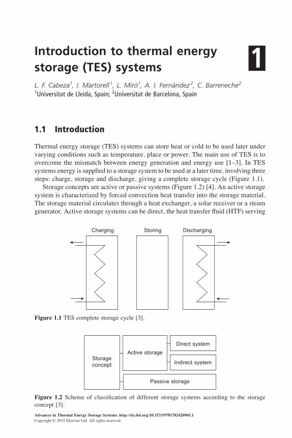
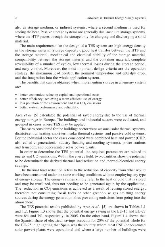
Thermal energy storage (TES) systems can store heat or cold to be used later under varying conditions such as temperature, place or power. The main use of TES is to overcome the mismatch between energy generation and energy use [1–3]. In TES systems energy is supplied to a storage system to be used at a later time, involving three steps: charge, storage and discharge, giving a complete storage cycle (Figure 1.1). Storage concepts are active or passive systems (Figure 1.2) [4]. An active storage system is characterized by forced convection heat transfer into the storage material. The storage material circulates through a heat exchanger, a solar receiver or a steam generator. Active storage systems can be direct, the heat transfer fluid (HTF) serving
Charging Storing Discharging
Figure 1.1 TES complete storage cycle [3].
Passive storage
Active storage
Indirect system
Direct system
Storageconcept
Figure 1.2 Scheme of classification of different storage systems according to the storage concept [3].
Advances in Thermal Energy Storage Systems2
also as storage medium, or indirect systems, where a second medium is used for storing the heat. Passive storage systems are generally dual-medium storage systems, where the HTF passes through the storage only for charging and discharging a solid material. The main requirements for the design of a TES system are high energy density in the storage material (storage capacity), good heat transfer between the HTF and the storage material, mechanical and chemical stability of the storage material, compatibility between the storage material and the container material, complete reversibility of a number of cycles, low thermal losses during the storage period, and easy control. Moreover, the most important design criteria are the operation strategy, the maximum load needed, the nominal temperature and enthalpy drop, and the integration into the whole application system. The benefits that can be obtained when implementing storage in an energy system are:
∑ better economics: reducing capital and operational costs∑ better efficiency: achieving a more efficient use of energy∑ less pollution of the environment and less CO2 emissions∑ better system performance and reliability.
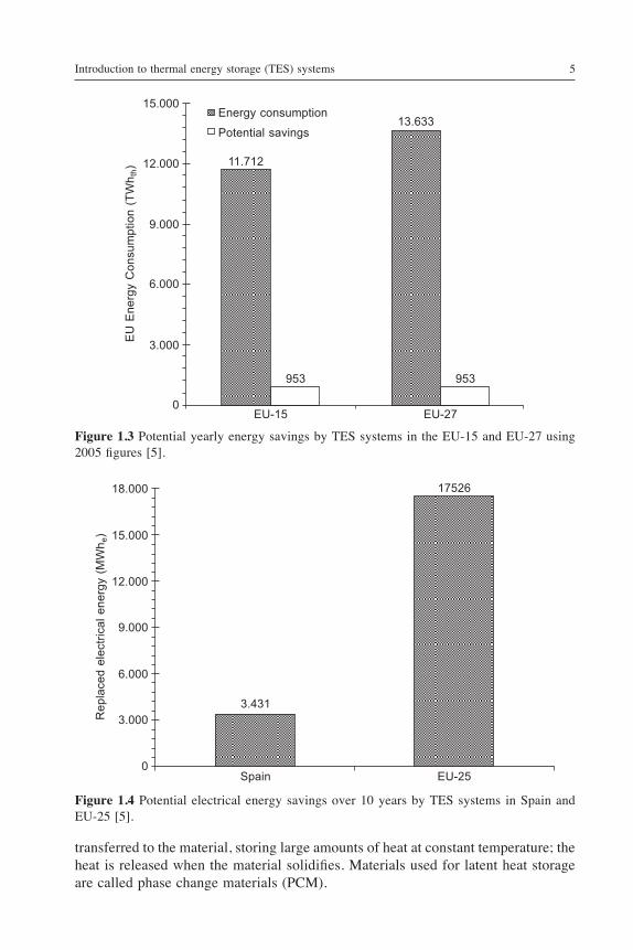
Arce et al. [5] calculated the potential of saved energy due to the use of thermal energy storage in Europe. The buildings and industrial sectors were evaluated, and grouped in cases where TES may be applied. The cases considered for the buildings sector were seasonal solar thermal systems, district/central heating, short-term solar thermal systems, and passive cold systems. For the industrial sector the cases considered were combined heat and power (CHP, also called cogeneration), industry (heating and cooling systems), power stations and transport, and concentrated solar power plants. In order to determine the TES potential, the required parameters are related to energy and CO2 emissions. Within the energy field, two quantities show the potential to be determined: the derived thermal load reduction and thermal/electrical energy savings. The thermal load reduction refers to the reduction of capacity from what would have been consumed under the same working conditions without employing any type of energy storage. The energy savings simply refer to the heat or cold that is stored and may be reutilized, thus not needing to be generated again by the application. The reduction in CO2 emissions is achieved as a result of reusing stored energy, therefore not consuming fossil fuels or other greenhouse gas emitting energy sources during the energy generation, thus preventing emissions from going into the atmosphere. The TES potential results published by Arce et al. [5] are shown in Tables 1.1 and 1.2. Figure 1.3 shows that the potential energy saving in the EU-15 and EU-27 were 8% and 7%, respectively, in 2005. On the other hand, Figure 1.4 shows that the Spanish share of electrical savings accounts for 20% of the potential whole for the EU-25, highlighting that Spain was the country where most CSP (concentrated solar power) plants were operational and where a large number of buildings were
Introduction to thermal energy storage (TES) systems 3
built, including regasification terminals (with savings in electricity influencing the TES potential), thus making it the country with the highest potential for saving electrical energy.
1.2 Basic thermodynamics of energy storage
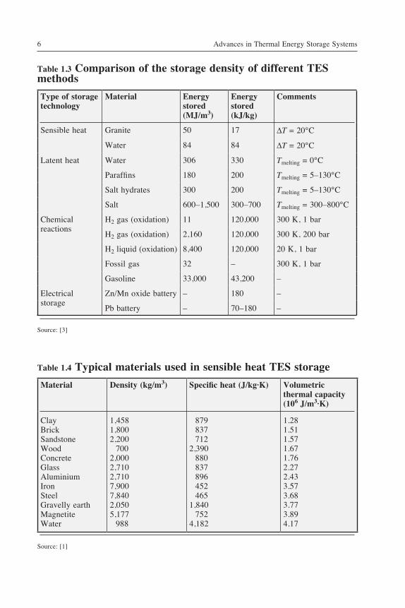
There are three types of thermal energy storage systems: sensible heat storage, latent heat storage, and thermochemical storage. Table 1.3 shows characteristics of the three types of thermal energy storage plus the electrical storage, for comparison purposes.
1.2.1 Sensible heat storage
When the energy is stored, increasing or decreasing the temperature of a storage material, sensible heat storage is occurring. The storage material can be water, air, oil, bedrock, brick, concrete, etc. Each material has its own advantages and disadvantages, but usually the material is selected according to its heat capacity and the available space for storage [1]. The amount of energy stored is calculated following Eq. [1.1]:
Q = m · cp · DT [1.1]
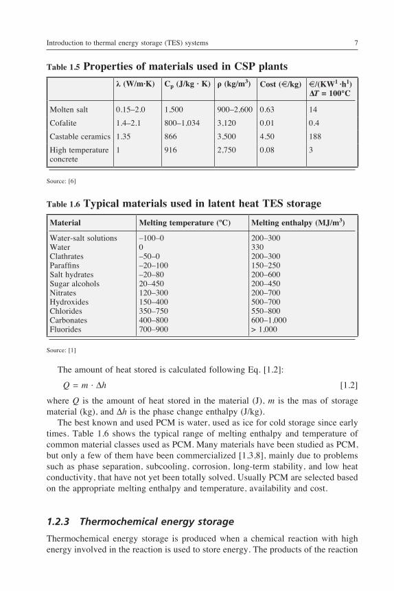
where Q is the amount of heat stored in the material (J), m is the mas of storage material (kg), cp is the specific heat of the storage material (J/kg·K), and DT is the temperature change (K). Some common materials used in sensible heat TES systems are presented in Table 1.4. Table 1.5 presents as an example of materials used for sensible heat TES in a given application: storage in CSP plants [6]. The materials need to have high thermal capacity and be abundant and cheap. The properties looked at when selecting
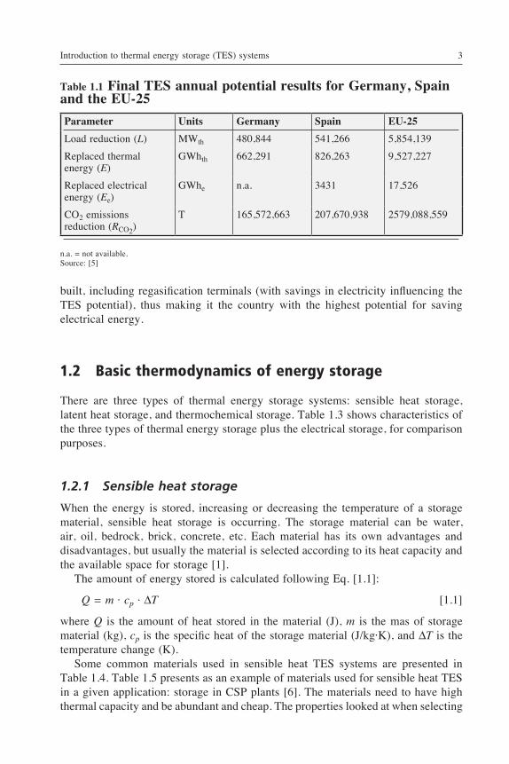
Table 1.1 Final TES annual potential results for Germany, Spain and the EU-25
Parameter Units Germany Spain EU-25
Load reduction (L) MWth 480,844 541,266 5,854,139
Replaced thermal energy (E)
GWhth 662,291 826,263 9,527,227
Replaced electrical energy (Ee)
GWhe n.a. 3431 17,526
CO2 emissions reduction (RCO2)
T 165,572,663 207,670,938 2579,088,559
n.a. = not available.Source: [5]
Advances in Thermal Energy Storage Systems4
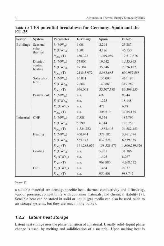
Table 1.2 TES potential breakdown for Germany, Spain and the EU-25
Sector System Parameter Germany Spain EU-25
Buildings Seasonal solar thermal
L (MWth) 1,001 2,294 25,287
E (GWhth) 1,801 4,186 46,150
RCO2 (T) 450,322 1,049,089 12,517,676
District/central heating
L (MWth) 57,000 19,642 1,453,863
E (GWhth) 87,384 35,846 2,326,182
RCO2 (T) 21,845,972 8,983,685 630,957,558
Solar short term
L (MWth) 16,011 135,093 416,180
E (GWhth) 2,664 140,883 319,269
RCO2 (T) 666,008 35,307,388 86,599,153
Passive cold L (MWth) n.a. 699 9,944
E (GWhth) n.a. 1,275 18,148
Ee (GWhe) n.a. 472 6,481
RCO2 (T) n.a. 306,519 3,085,135
Industrial CHP L (MWth) 5,888 9,354 187,790
E (GWhth) 5,299 6,314 126,758
RCO2 (T) 1,324,732 1,582,403 34,382,153
Heating L (MWth) 400,944 374,185 3,761,074
E (GWhth) 565,143 632,528 6,659,335
RCO2 (T) 141,285,629 158,521,473 1,806,289,626
Cooling E (GWhth) n.a. 5,231 31,386
Ee (GWhe) n.a. 1,495 8,967
RCO2 (T) n.a. 969,980 4,268,512
CSP Ee (GWhe) n.a. 1,464 2,077
RCO2 (T) n.a. 950,401 988,747
Source: [5]
a suitable material are density, specific heat, thermal conductivity and diffusivity, vapour pressure, compatibility with container materials, and chemical stability [7]. Sensible heat can be stored in solid or liquid (gas media can also be used, such as air storage systems, but they are much more bulky).
1.2.2 Latent heat storage
Latent heat storage uses the phase transition of a material. Usually solid–liquid phase change is used, by melting and solidification of a material. Upon melting heat is
Introduction to thermal energy storage (TES) systems 5
Energy consumption
Potential savings
11.712
13.633
953 953
EU-15 EU-27
EU
Ene
rgy
Con
sum
ptio
n (T
Wh t
h)
15.000
12.000
9.000
6.000
3.000
0
Figure 1.3 Potential yearly energy savings by TES systems in the EU-15 and EU-27 using 2005 figures [5].
Spain
3.431
EU-25
17526
Rep
lace
d el
ectri
cal e
nerg
y (M
Wh e
)
18.000
15.000
12.000
9.000
6.000
3.000
0
Figure 1.4 Potential electrical energy savings over 10 years by TES systems in Spain and EU-25 [5].
transferred to the material, storing large amounts of heat at constant temperature; the heat is released when the material solidifies. Materials used for latent heat storage are called phase change materials (PCM).
Advances in Thermal Energy Storage Systems6
Table 1.3 Comparison of the storage density of different TES methods
Type of storage technology
Material Energy stored (MJ/m3)
Energy stored (kJ/kg)
Comments
Sensible heat Granite 50 17 DT = 20°C
Water 84 84 DT = 20°C
Latent heat Water 306 330 Tmelting = 0°C
Paraffins 180 200 Tmelting = 5–130°C
Salt hydrates 300 200 Tmelting = 5–130°C
Salt 600–1,500 300–700 Tmelting = 300–800°C
Chemical reactions
H2 gas (oxidation) 11 120,000 300 K, 1 bar
H2 gas (oxidation) 2,160 120,000 300 K, 200 bar
H2 liquid (oxidation) 8,400 120,000 20 K, 1 bar
Fossil gas 32 – 300 K, 1 bar
Gasoline 33,000 43,200 –
Electrical storage
Zn/Mn oxide battery – 180 –
Pb battery – 70–180 –
Source: [3]
Table 1.4 Typical materials used in sensible heat TES storage
Material Density (kg/m3) Specific heat (J/kg·K) Volumetric thermal capacity (106 J/m3·K)
ClayBrickSandstoneWoodConcreteGlassAluminiumIronSteelGravelly earthMagnetiteWater
1,4581,8002,200
7002,0002,7102,7107,9007,8402,0505,177
988
879837712
2,390880837896452465
1,840752
4,182
1.281.511.571.671.762.272.433.573.683.773.894.17
Source: [1]
Introduction to thermal energy storage (TES) systems 7
The amount of heat stored is calculated following Eq. [1.2]:
Q = m · Dℎ [1.2]
where Q is the amount of heat stored in the material (J), m is the mas of storage material (kg), and Dℎ is the phase change enthalpy (J/kg). The best known and used PCM is water, used as ice for cold storage since early times. Table 1.6 shows the typical range of melting enthalpy and temperature of common material classes used as PCM. Many materials have been studied as PCM, but only a few of them have been commercialized [1,3,8], mainly due to problems such as phase separation, subcooling, corrosion, long-term stability, and low heat conductivity, that have not yet been totally solved. Usually PCM are selected based on the appropriate melting enthalpy and temperature, availability and cost.
1.2.3 Thermochemical energy storage
Thermochemical energy storage is produced when a chemical reaction with high energy involved in the reaction is used to store energy. The products of the reaction
Table 1.5 Properties of materials used in CSP plants
l (W/m·K) Cp (J/kg · K) r (kg/m3) Cost (7/kg) 7/(KW1 ·h1) ∆T = 100°C
Molten salt 0.15–2.0 1,500 900–2,600 0.63 14
Cofalite 1.4–2.1 800–1,034 3,120 0.01 0.4
Castable ceramics 1.35 866 3,500 4.50 188
High temperature concrete
1 916 2,750 0.08 3
Source: [6]
Table 1.6 Typical materials used in latent heat TES storage
Material Melting temperature (ºC) Melting enthalpy (MJ/m3)
Water-salt solutionsWaterClathratesParaffinsSalt hydratesSugar alcoholsNitratesHydroxidesChloridesCarbonatesFluorides
–100–00–50–0–20–100–20–8020–450120–300150–400350–750400–800700–900
200–300330200–300150–250200–600200–450200–700500–700550–800600–1,000> 1,000
Source: [1]
Advances in Thermal Energy Storage Systems8
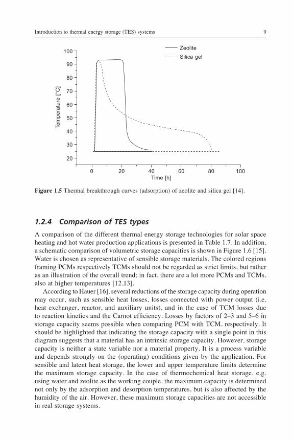
should be able to be stored and the heat stored separately during the reaction should be able to be retrieved when the reverse reaction takes place [1]. Therefore, only reversible reactions can be used for this storage process. Thermochemical energy storage is divided between chemical reactions and sorption systems. In chemical reactions, high energy storage density and reversibility is required of the materials [9]. Usually chemical energy conversion has better energy storage performance efficiency than physical methods (sensible and latent heat storage). The most important challenge is to find the appropriate reversible chemical reaction for the energy source used. Thermochemical reactions are used as TCM at high temperatures (more than 400°C) and the enthalpy of the reaction is located in a high range (80–180 kJ/mol). In addition, since the products of the reaction must be store separately, the systems that use TCM to store energy can be applied as seasonal storage systems [10]. The main drawbacks in solid–gas chemical reactions are the poor heat and mass transfer performance in the reactive bed and the low thermodynamic efficiency of the basic cycle [11]. On the other hand, Cot-Gores et al. [11] summarized the substances used as TCM taking into account cooling or evaporating temperature (Tc), the heat sink or condensing temperature (Tm), and heat source temperature (Tℎ). The main reactions studied for use in storage media hydration reactions are the carbonation reaction, ammonia decomposition, metal oxidation reactions and sulfur cycles [12,13]. Moreover, adsorption on solid materials or absorption on liquids is used in sorption systems [14]. Adsorption means binding a gas or liquid on the inner surface of a porous material. Heat is put into the material during the desorption step, removing the adsorbed components from the surface. As soon as the adsorption starts, heat is released, this being the discharging process of the storage cycle. There are two types of sorption systems: closed and open storage systems. In a closed sorption system, the heat is transferred to and from the adsorbent by a heat exchanger, usually called the condenser/evaporator. The heat has to be transported to the absorber at the same time as it is extracted from the condenser to keep the HTF, usually water, flowing from the adsorber to the condenser. The energy density is lower than in open sorption systems because the adsorptive fluid is part of the storage system and also has to be stored. In the case of using zeolite or silica gel as adsorbent, this can be up to 30–40% of the weight of the storage material. On the other hand, the advantages of closed systems include being able to reach higher output temperature for heating operations compared to open systems, being able to supply lower temperatures for cooling, and being able to produce ice in the evaporator. In an open sorption storage system, air transports water vapour and heat in and out of the adsorbents. In the desorption process, hot air desorbs the water from the adsorbent, leaving the system cooler and saturated. In the adsorption process, humidified cool air enters the adsorbent, which adsorbs the water vapour and releases heat; the air leaves the storage warm and dry. The most common adsorbents are zeolites and silica gels. For the characterization of these storage materials the most important criteria are the possible temperature lift, the breakthrough curves, the thermal coefficient of performance, and the energy density referring to the volume of the absorbent (Figure 1.5).
Introduction to thermal energy storage (TES) systems 9
1.2.4 Comparison of TES types
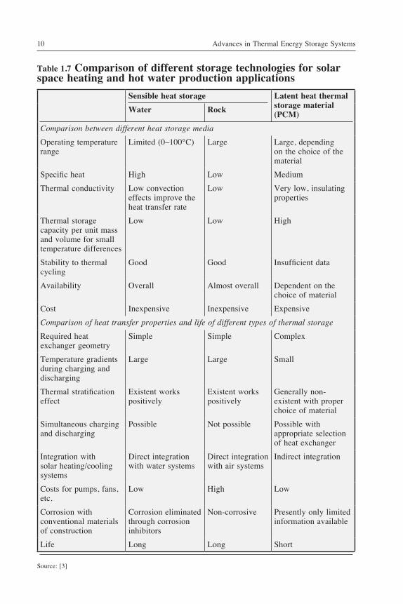
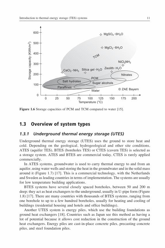
A comparison of the different thermal energy storage technologies for solar space heating and hot water production applications is presented in Table 1.7. In addition, a schematic comparison of volumetric storage capacities is shown in Figure 1.6 [15]. Water is chosen as representative of sensible storage materials. The colored regions framing PCMs respectively TCMs should not be regarded as strict limits, but rather as an illustration of the overall trend; in fact, there are a lot more PCMs and TCMs, also at higher temperatures [12,13]. According to Hauer [16], several reductions of the storage capacity during operation may occur, such as sensible heat losses, losses connected with power output (i.e. heat exchanger, reactor, and auxiliary units), and in the case of TCM losses due to reaction kinetics and the Carnot efficiency. Losses by factors of 2–3 and 5–6 in storage capacity seems possible when comparing PCM with TCM, respectively. It should be highlighted that indicating the storage capacity with a single point in this diagram suggests that a material has an intrinsic storage capacity. However, storage capacity is neither a state variable nor a material property. It is a process variable and depends strongly on the (operating) conditions given by the application. For sensible and latent heat storage, the lower and upper temperature limits determine the maximum storage capacity. In the case of thermochemical heat storage, e.g. using water and zeolite as the working couple, the maximum capacity is determined not only by the adsorption and desorption temperatures, but is also affected by the humidity of the air. However, these maximum storage capacities are not accessible in real storage systems.
ZeoliteSilica gel
0 20 40 60 80 100Time [h]
Tem
pera
ture
[°C
]100
90
80
70
60
50
40
30
20
Figure 1.5 Thermal breakthrough curves (adsorption) of zeolite and silica gel [14].
Advances in Thermal Energy Storage Systems10
Table 1.7 Comparison of different storage technologies for solar space heating and hot water production applications
Sensible heat storage Latent heat thermal storage material (PCM)Water Rock
Comparison between different ℎeat storage media
Operating temperature range
Limited (0–100°C) Large Large, depending on the choice of the material
Specific heat High Low Medium
Thermal conductivity Low convection effects improve the heat transfer rate
Low Very low, insulating properties
Thermal storage capacity per unit mass and volume for small temperature differences
Low Low High
Stability to thermal cycling
Good Good Insufficient data
Availability Overall Almost overall Dependent on the choice of material
Cost Inexpensive Inexpensive Expensive
Comparison of ℎeat transfer properties and life of different types of tℎermal storage
Required heat exchanger geometry
Simple Simple Complex
Temperature gradients during charging and discharging
Large Large Small
Thermal stratification effect
Existent works positively
Existent works positively
Generally non-existent with proper choice of material
Simultaneous charging and discharging
Possible Not possible Possible with appropriate selection of heat exchanger
Integration with solar heating/cooling systems
Direct integration with water systems
Direct integration with air systems
Indirect integration
Costs for pumps, fans, etc.
Low High Low
Corrosion with conventional materials of construction
Corrosion eliminated through corrosion inhibitors
Non-corrosive Presently only limited information available
Life Long Long Short
Source: [3]
Introduction to thermal energy storage (TES) systems 11
1.3 Overview of system types
1.3.1 Underground thermal energy storage (UTES)
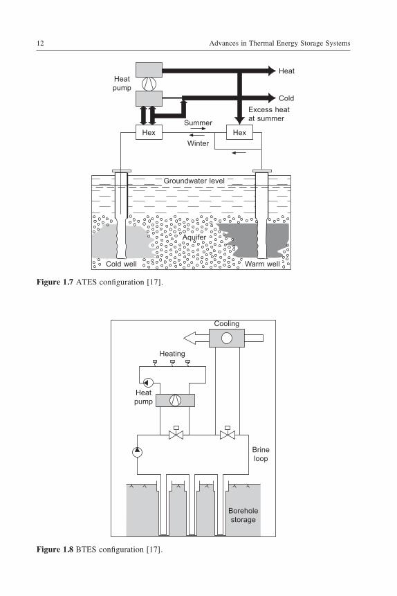
Underground thermal energy storage (UTES) uses the ground to store heat and cold. Depending on the geological, hydrogeological and other site conditions, ATES (aquifer TES), BTES (boreholes TES) or CTES (cavern TES) is selected as a storage system. ATES and BTES are commercial today, CTES is rarely applied commercially. In ATES systems, groundwater is used to carry thermal energy to and from an aquifer, using water wells and storing the heat in the groundwater and in the solid mass around it (Figure 1.7) [17]. This is a commercial technology, with the Netherlands and Sweden as leading countries in terms of implementation. The systems are usually for low temperature building applications. BTES systems have several closely spaced boreholes, between 50 and 200 m deep; they act as heat exchangers to the underground, usually in U-pipe form (Figure 1.8) [17]. There are many countries with thousands of BTES systems, ranging from one borehole to up to a few hundred boreholes, usually for heating and cooling of buildings (residential housing and hotels and office buildings). Another UTES system is energy piles, which use the building foundations as ground heat exchangers [18]. Countries such as Japan see this method as having a lot of potential because it allows cost reduction in the construction of the ground heat exchangers. Energy piles are cast-in-place concrete piles, precasting concrete piles, and steel foundation piles.
Sto
rage
cap
acity
(K
Wh/
m3 )
600
500
400
300
200
100
0 0 25 50 75 100 125 150 175 200
Temperature (°C)
MgSO4 · 6H2O
MgCl2 · 6H2O
TCM
NiCl2NH2
CaCl2 · NH3Zeolith · H2OSilica gel · H2O
PCMNitrates
Salt hydrates Sugar alcoholsParaffines
Water © ZAE Bayern
Figure 1.6 Storage capacities of PCM and TCM compared to water [15].
Advances in Thermal Energy Storage Systems12
Heat
Cold
Heatpump
Hex HexSummer
Winter
Excess heatat summer
Aquifer
Warm wellCold well
Groundwater level
Figure 1.7 ATES configuration [17].
Cooling
Heating
Heat pump
Brineloop
Boreholestorage
Figure 1.8 BTES configuration [17].
Introduction to thermal energy storage (TES) systems 13
1.3.2 Water storage
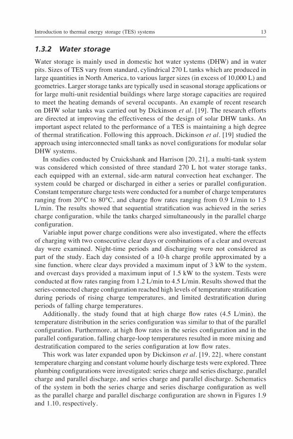
Water storage is mainly used in domestic hot water systems (DHW) and in water pits. Sizes of TES vary from standard, cylindrical 270 L tanks which are produced in large quantities in North America, to various larger sizes (in excess of 10,000 L) and geometries. Larger storage tanks are typically used in seasonal storage applications or for large multi-unit residential buildings where large storage capacities are required to meet the heating demands of several occupants. An example of recent research on DHW solar tanks was carried out by Dickinson et al. [19]. The research efforts are directed at improving the effectiveness of the design of solar DHW tanks. An important aspect related to the performance of a TES is maintaining a high degree of thermal stratification. Following this approach, Dickinson et al. [19] studied the approach using interconnected small tanks as novel configurations for modular solar DHW systems. In studies conducted by Cruickshank and Harrison [20, 21], a multi-tank system was considered which consisted of three standard 270 L hot water storage tanks, each equipped with an external, side-arm natural convection heat exchanger. The system could be charged or discharged in either a series or parallel configuration. Constant temperature charge tests were conducted for a number of charge temperatures ranging from 20°C to 80°C, and charge flow rates ranging from 0.9 L/min to 1.5 L/min. The results showed that sequential stratification was achieved in the series charge configuration, while the tanks charged simultaneously in the parallel charge configuration. Variable input power charge conditions were also investigated, where the effects of charging with two consecutive clear days or combinations of a clear and overcast day were examined. Night-time periods and discharging were not considered as part of the study. Each day consisted of a 10-h charge profile approximated by a sine function, where clear days provided a maximum input of 3 kW to the system, and overcast days provided a maximum input of 1.5 kW to the system. Tests were conducted at flow rates ranging from 1.2 L/min to 4.5 L/min. Results showed that the series-connected charge configuration reached high levels of temperature stratification during periods of rising charge temperatures, and limited destratification during periods of falling charge temperatures. Additionally, the study found that at high charge flow rates (4.5 L/min), the temperature distribution in the series configuration was similar to that of the parallel configuration. Furthermore, at high flow rates in the series configuration and in the parallel configuration, falling charge-loop temperatures resulted in more mixing and destratification compared to the series configuration at low flow rates. This work was later expanded upon by Dickinson et al. [19, 22], where constant temperature charging and constant volume hourly discharge tests were explored. Three plumbing configurations were investigated: series charge and series discharge, parallel charge and parallel discharge, and series charge and parallel discharge. Schematics of the system in both the series charge and series discharge configuration as well as the parallel charge and parallel discharge configuration are shown in Figures 1.9 and 1.10, respectively.
Advances in Thermal Energy Storage Systems14
Tests from the first part of this study [19] were conducted by charging the system with a constant inlet charge temperature (hot feed) of 55°C for 8 h, while performing five equal volume draws commencing at the start of every hour after 4 h of charging, i.e., draws occurred at the start of hours 4–8. Draws were chosen to commence after 4 h in order to provide a partial charge to the system, and different draw volumes were also considered such that the effects on tank stratification could be observed. In an effort to build upon the work of the previous studies, Dickinson et al. [22] investigated the effects of variable input power charging and variable hourly draw volumes. Three experimental tests were performed over two-day test periods to include variable charge and discharge conditions. The plumbing configurations which were considered included: series charge and series discharge, parallel charge and parallel discharge, and series charge and parallel discharge. Comparisons between system configurations were based on stratification levels, hot water delivery temperatures, and solar fractions. Results of the study showed that charging and discharging the system in parallel produced the highest solar fraction when compared to the other multi-tank configurations, with solar fractions of 0.62 and 0.67 from experimental testing and TRNSYS simulation, respectively. When compared to a single tank configuration, the parallel charge and parallel discharge configuration achieved 97.7% of the delivered solar energy of a stratified single tank system with the same storage volume and heat exchanger performance.
MainsCold feed
Chargeloop
Coldreturn
To load
Hotfeed
Tank 1
Tank 2
Tank 3
Heatexchanger
Naturalconvection
loop
Figure 1.9 Schematic of the multi-tank storage plumbed in the series charge and series discharge configuration [19].
Introduction to thermal energy storage (TES) systems 15
1.3.3 Phase change materials
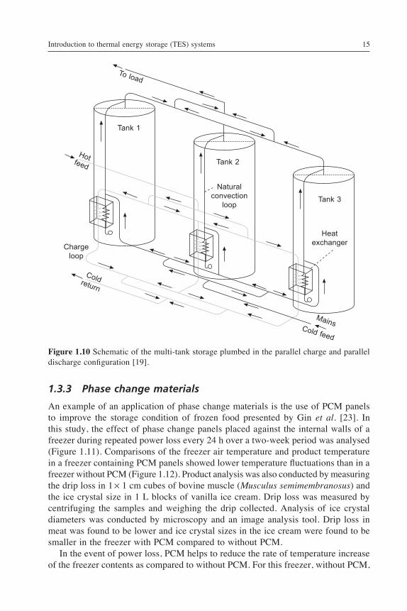
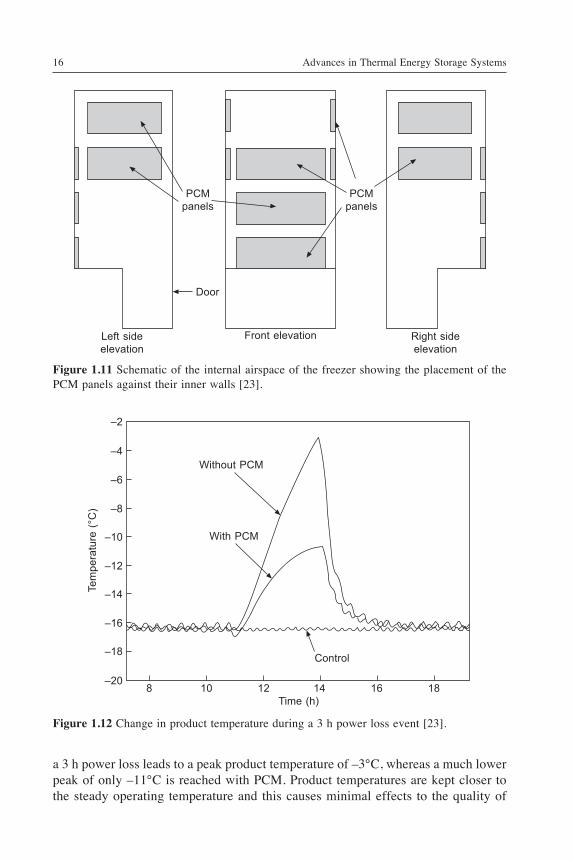
An example of an application of phase change materials is the use of PCM panels to improve the storage condition of frozen food presented by Gin et al. [23]. In this study, the effect of phase change panels placed against the internal walls of a freezer during repeated power loss every 24 h over a two-week period was analysed (Figure 1.11). Comparisons of the freezer air temperature and product temperature in a freezer containing PCM panels showed lower temperature fluctuations than in a freezer without PCM (Figure 1.12). Product analysis was also conducted by measuring the drip loss in 1 ¥ 1 cm cubes of bovine muscle (Musculus semimembranosus) and the ice crystal size in 1 L blocks of vanilla ice cream. Drip loss was measured by centrifuging the samples and weighing the drip collected. Analysis of ice crystal diameters was conducted by microscopy and an image analysis tool. Drip loss in meat was found to be lower and ice crystal sizes in the ice cream were found to be smaller in the freezer with PCM compared to without PCM. In the event of power loss, PCM helps to reduce the rate of temperature increase of the freezer contents as compared to without PCM. For this freezer, without PCM,
To load
MainsCold feed
Chargeloop
Coldreturn
Hotfeed
Tank 1
Tank 2
Tank 3
Heatexchanger
Naturalconvection
loop
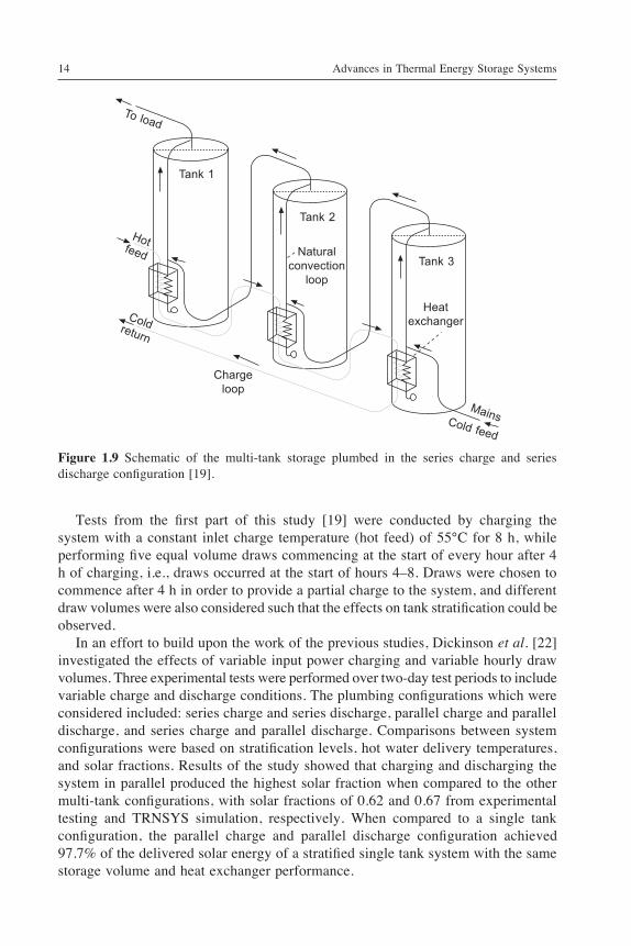
Figure 1.10 Schematic of the multi-tank storage plumbed in the parallel charge and parallel discharge configuration [19].
Advances in Thermal Energy Storage Systems16
PCMpanels
PCMpanels
Door
Front elevation Right sideelevation
Left sideelevation
a 3 h power loss leads to a peak product temperature of –3°C, whereas a much lower peak of only –11°C is reached with PCM. Product temperatures are kept closer to the steady operating temperature and this causes minimal effects to the quality of
Figure 1.11 Schematic of the internal airspace of the freezer showing the placement of the PCM panels against their inner walls [23].
Figure 1.12 Change in product temperature during a 3 h power loss event [23].
8 10 12 14 16 18Time (h)
Tem
pera
ture
(°C
)
–20
–18
–16
–14
–12
–10
–8
–6
–4
–2
Control
Without PCM
With PCM
Introduction to thermal energy storage (TES) systems 17
food products. This is observed in the ice crystal size in ice cream. The average ice crystal size of 40–50 mm is maintained over the power loss period with PCM in the freezer, whereas without PCM, the average size rose to 70–80 mm by the end of the two-week power loss period. Drip loss in frozen meat also demonstrated that the lower temperature fluctuations achieved due to PCM led to better food quality. After two-weeks, the drip loss with PCM panels was 10%, compared to 17% without PCM.
1.3.4 Thermochemical storage
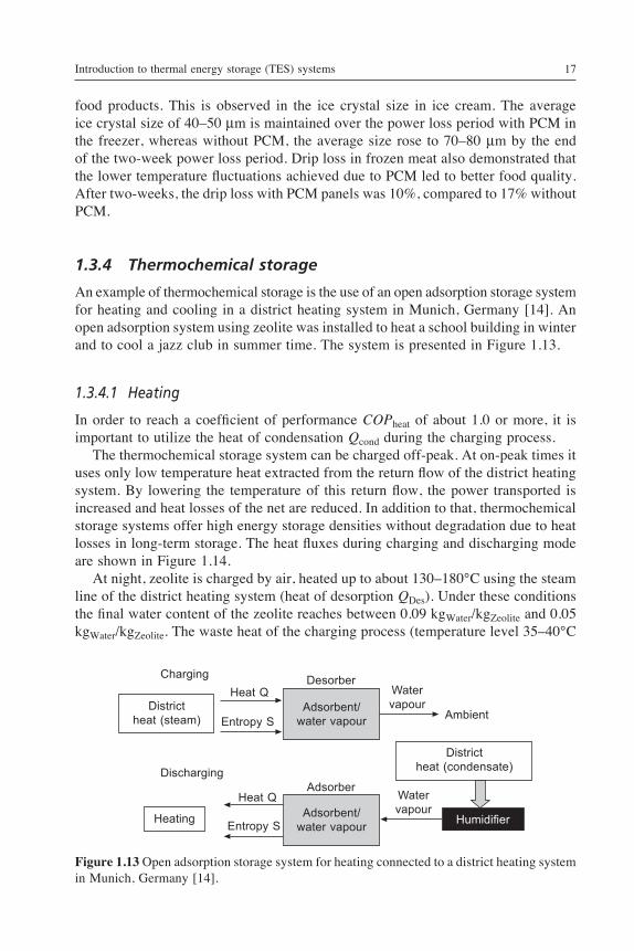
An example of thermochemical storage is the use of an open adsorption storage system for heating and cooling in a district heating system in Munich, Germany [14]. An open adsorption system using zeolite was installed to heat a school building in winter and to cool a jazz club in summer time. The system is presented in Figure 1.13.
1.3.4.1 Heating
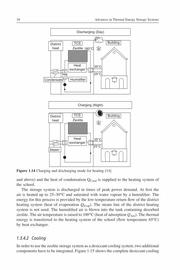
In order to reach a coefficient of performance COPheat of about 1.0 or more, it is important to utilize the heat of condensation Qcond during the charging process. The thermochemical storage system can be charged off-peak. At on-peak times it uses only low temperature heat extracted from the return flow of the district heating system. By lowering the temperature of this return flow, the power transported is increased and heat losses of the net are reduced. In addition to that, thermochemical storage systems offer high energy storage densities without degradation due to heat losses in long-term storage. The heat fluxes during charging and discharging mode are shown in Figure 1.14. At night, zeolite is charged by air, heated up to about 130–180°C using the steam line of the district heating system (heat of desorption QDes). Under these conditions the final water content of the zeolite reaches between 0.09 kgWater/kgZeolite and 0.05 kgWater/kgZeolite. The waste heat of the charging process (temperature level 35–40°C
Ambient
Humidifier
Districtheat (condensate)
Water vapour
Water vapour
Desorber
Adsorber
Adsorbent/water vapour
Adsorbent/water vapour
Districtheat (steam)
Heating
Discharging
ChargingHeat Q
Heat Q
Entropy S
Entropy S
Figure 1.13 Open adsorption storage system for heating connected to a district heating system in Munich, Germany [14].
Advances in Thermal Energy Storage Systems18
and above) and the heat of condensation QCond is supplied to the heating system of the school. The storage system is discharged in times of peak power demand. At first the air is heated up to 25–30°C and saturated with water vapour by a humidifier. The energy for this process is provided by the low temperature return flow of the district heating system (heat of evaporation QEvap). The steam line of the district heating system is not used. The humidified air is blown into the tank containing desorbed zeolite. The air temperature is raised to 100°C (heat of adsorption QAds). The thermal energy is transferred to the heating system of the school (flow temperature 65°C) by heat exchanger.
1.3.4.2 Cooling
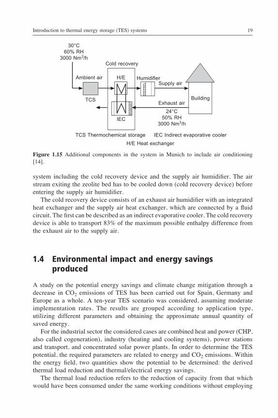
In order to use the zeolite storage system as a desiccant cooling system, two additional components have to be integrated. Figure 1.15 shows the complete desiccant cooling
Figure 1.14 Charging and discharging mode for heating [14].
Discharging (Day)
Charging (Night)
Building
Building
TCS
TCS
Districtheat
Districtheat
25°C
25°C
35°C
35°C
Zeolite
Zeolite
180°C
Condensate Humidifier
Heatexchanger
Heatexchanger
Steam
Introduction to thermal energy storage (TES) systems 19
system including the cold recovery device and the supply air humidifier. The air stream exiting the zeolite bed has to be cooled down (cold recovery device) before entering the supply air humidifier. The cold recovery device consists of an exhaust air humidifier with an integrated heat exchanger and the supply air heat exchanger, which are connected by a fluid circuit. The first can be described as an indirect evaporative cooler. The cold recovery device is able to transport 83% of the maximum possible enthalpy difference from the exhaust air to the supply air.
1.4 Environmental impact and energy savings produced
A study on the potential energy savings and climate change mitigation through a decrease in CO2 emissions of TES has been carried out for Spain, Germany and Europe as a whole. A ten-year TES scenario was considered, assuming moderate implementation rates. The results are grouped according to application type, utilizing different parameters and obtaining the approximate annual quantity of saved energy. For the industrial sector the considered cases are combined heat and power (CHP, also called cogeneration), industry (heating and cooling systems), power stations and transport, and concentrated solar power plants. In order to determine the TES potential, the required parameters are related to energy and CO2 emissions. Within the energy field, two quantities show the potential to be determined: the derived thermal load reduction and thermal/electrical energy savings. The thermal load reduction refers to the reduction of capacity from that which would have been consumed under the same working conditions without employing
H/E Heat exchangerTCS Thermochemical storage IEC Indirect evaporative cooler
Cold recovery
Building
Supply air
Exhaust air24°C
50% RH3000 Nm3/h
30°C60% RH
3000 Nm3/h
HumidifierH/E
IEC
TCS
Ambient air
Figure 1.15 Additional components in the system in Munich to include air conditioning [14].
Advances in Thermal Energy Storage Systems20
any type of energy storage. The energy savings simply refer to the ‘heat’ or ‘cold’ that is stored and may be reutilized, thus not needing to be generated ‘again’ by the application. The CO2 emissions reduction is that achieved as a result of reusing stored energy, therefore not consuming fossil fuels or other greenhouse gas emitting energy sources during energy generation and thus preventing emissions from going into the atmosphere. Global TES potential results are shown in Table 1.1; these include industrial and building applications. The obtained values broken down by sector and system are shown in Table 1.2. Within Annex 25 ‘Surplus Heat Management using Advanced TES for CO2 Mitigation’ of the Energy Conservation through Energy Storage Implementing Agreement (ECES IA) of the International Energy Agency, a new attempt to ascertain the CO2 mitigation potential of thermal energy storage was carried out between 2011 and 2013 [15,24]. Different applications were evaluated from literature or our own data. The applications studied are described in the following subsections.
1.4.1 Refrigeration applications
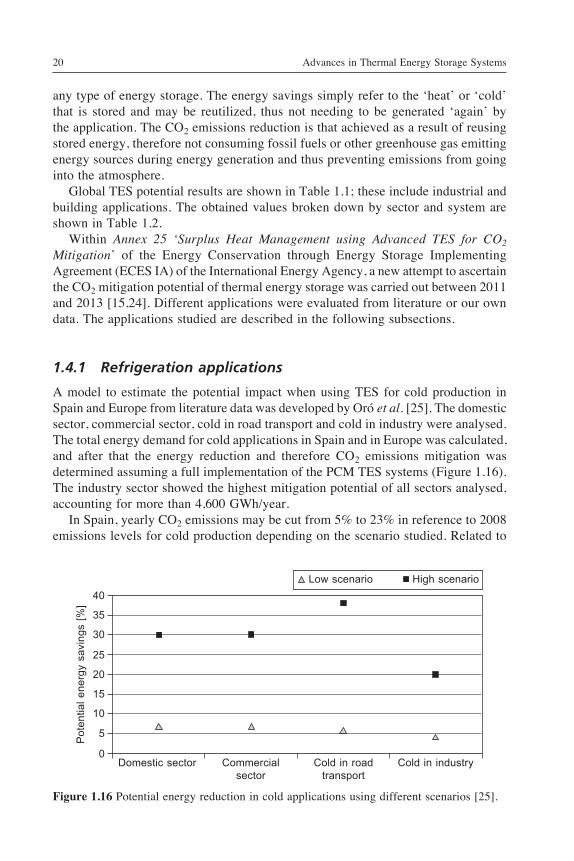
A model to estimate the potential impact when using TES for cold production in Spain and Europe from literature data was developed by Oró et al. [25]. The domestic sector, commercial sector, cold in road transport and cold in industry were analysed. The total energy demand for cold applications in Spain and in Europe was calculated, and after that the energy reduction and therefore CO2 emissions mitigation was determined assuming a full implementation of the PCM TES systems (Figure 1.16). The industry sector showed the highest mitigation potential of all sectors analysed, accounting for more than 4,600 GWh/year. In Spain, yearly CO2 emissions may be cut from 5% to 23% in reference to 2008 emissions levels for cold production depending on the scenario studied. Related to
Low scenario High scenario
Domestic sector Commercial sector
Cold in road transport
Cold in industry
Pot
entia
l ene
rgy
savi
ngs
[%]
40
35
30
25
20
15
10
5
0
Figure 1.16 Potential energy reduction in cold applications using different scenarios [25].
Introduction to thermal energy storage (TES) systems 21
Europe CO2 emissions mitigation, those values become 5% and 22%, respectively. However, it is not just about minimizing CO2 emissions or potential savings; PCM integration also improves the quality of the refrigeration. Even though on an overall level the impact of the implementation of PCM TES systems is barely 1% compared to the total CO2 emissions in 2008 in Europe, it could be much more important than it seems [26].
1.4.2 Solar power plants
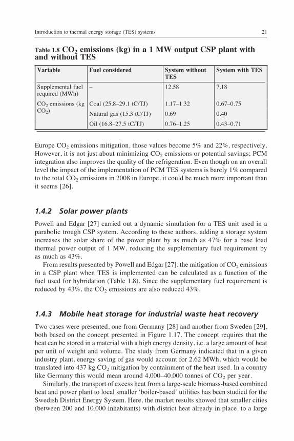
Powell and Edgar [27] carried out a dynamic simulation for a TES unit used in a parabolic trough CSP system. According to these authors, adding a storage system increases the solar share of the power plant by as much as 47% for a base load thermal power output of 1 MW, reducing the supplementary fuel requirement by as much as 43%. From results presented by Powell and Edgar [27], the mitigation of CO2 emissions in a CSP plant when TES is implemented can be calculated as a function of the fuel used for hybridation (Table 1.8). Since the supplementary fuel requirement is reduced by 43%, the CO2 emissions are also reduced 43%.
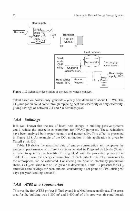
1.4.3 Mobile heat storage for industrial waste heat recovery
Two cases were presented, one from Germany [28] and another from Sweden [29], both based on the concept presented in Figure 1.17. The concept requires that the heat can be stored in a material with a high energy density, i.e. a large amount of heat per unit of weight and volume. The study from Germany indicated that in a given industry plant, energy saving of gas would account for 2.62 MWh, which would be translated into 437 kg CO2 mitigation by containment of the heat used. In a country like Germany this would mean around 4,000–40,000 tonnes of CO2 per year. Similarly, the transport of excess heat from a large-scale biomass-based combined heat and power plant to local smaller ‘boiler-based’ utilities has been studied for the Swedish District Energy System. Here, the market results showed that smaller cities (between 200 and 10,000 inhabitants) with district heat already in place, to a large
Table 1.8 CO2 emissions (kg) in a 1 MW output CSP plant with and without TES
Variable Fuel considered System without TES
System with TES
Supplemental fuel required (MWh)
– 12.58 7.18
CO2 emissions (kg CO2)
Coal (25.8–29.1 tC/TJ) 1.17–1.32 0.67–0.75
Natural gas (15.3 tC/TJ) 0.69 0.40
Oil (16.8–27.5 tC/TJ) 0.76–1.25 0.43–0.71
Advances in Thermal Energy Storage Systems22
extent based on boilers only, generate a yearly heat demand of about 11 TWh. The CO2 mitigation could come through replacing heat and electricity or only electricity, giving savings of between 2.4 and 5.8 Mtonnes/year.
1.4.4 Buildings
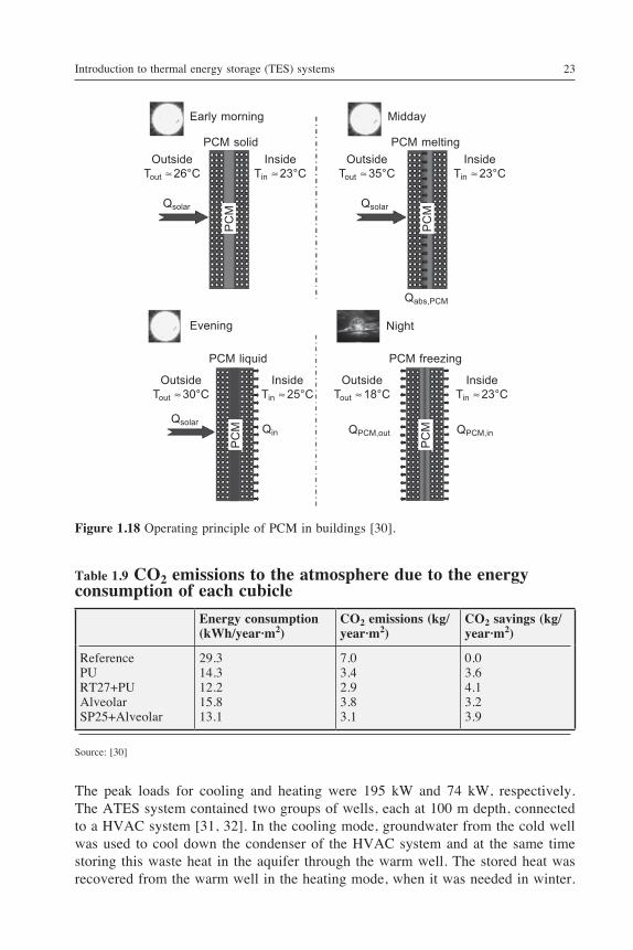
It is well known that the use of latent heat storage in building passive systems could reduce the energetic consumption for HVAC purposes. These reductions have been analysed both experimentally and numerically. This effect is presented in Figure 1.18. An example of the CO2 mitigation in this application is given by Castell et al. [30]. Table 1.9 shows the measured data of energy consumption and compares the energetic performance of different cubicles located in Puigverd de Lleida (Spain) in order to quantify the benefits of using PCM with the properties presented in Table 1.10. From the energy consumption of each cubicle, the CO2 emissions to the atmosphere can be estimated. Considering the Spanish electricity production share, a CO2 emission rate of 238 g/kWh is determined. Table 1.9 presents the CO2 emissions and savings for each cubicle, considering a set point of 24°C during 90 days per year (cooling demand).
1.4.5 ATES in a supermarket
This was the first ATES project in Turkey and in a Mediterranean climate. The gross area for the building was 1,800 m² and 1,400 m² of this area was air-conditioned.
Heat supply
TransportHeat on wheels
BiomassHeat
Large scale CHP utility
Small scale CHP utility
Heat demand
Accumulator Discharging accumulator
Charging accumulator
Heat onwheels
Heat carriersupply, 90°CBoiler
(Supple-mental heat)
Heat carrierreturn, 45°C
Figure 1.17 Schematic description of the heat on wheels concept.
Introduction to thermal energy storage (TES) systems 23
The peak loads for cooling and heating were 195 kW and 74 kW, respectively. The ATES system contained two groups of wells, each at 100 m depth, connected to a HVAC system [31, 32]. In the cooling mode, groundwater from the cold well was used to cool down the condenser of the HVAC system and at the same time storing this waste heat in the aquifer through the warm well. The stored heat was recovered from the warm well in the heating mode, when it was needed in winter.
Early morning
Evening
Midday
Night
PCM meltingPCM solid
PCM freezingPCM liquid
QsolarQsolar
Qsolar
OutsideTout ª 26°C
OutsideTout ª 30°C
OutsideTout ª 35°C
OutsideTout ª 18°C
InsideTin ª 23°C
InsideTin ª 25°C
InsideTin ª 23°C
InsideTin ª 23°C
Qin QPCM,out QPCM,in
PC
MP
CM
PC
MP
CM
Qabs,PCM
Figure 1.18 Operating principle of PCM in buildings [30].
Table 1.9 CO2 emissions to the atmosphere due to the energy consumption of each cubicle
Energy consumption (kWh/year·m2)
CO2 emissions (kg/year·m2)
CO2 savings (kg/year·m2)
ReferencePURT27+PUAlveolarSP25+Alveolar
29.314.312.215.813.1
7.03.42.93.83.1
0.03.64.13.23.9
Source: [30]
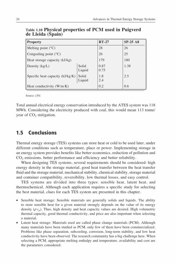
Advances in Thermal Energy Storage Systems24
Table 1.10 Physical properties of PCM used in Puigverd de Lleida (Spain)
Property RT-27 SP-25 A8
Melting point (°C) 28 26
Congealing point (°C) 26 25
Heat storage capacity (kJ/kg) 179 180
Density (kg/L) SolidLiquid
0.870.75
1.38
Specific heat capacity (kJ/kg·K) SolidLiquid
1.82.4
2.5
Heat conductivity (W/m·K) 0.2 0.6
Source: [30]
Total annual electrical energy conservation introduced by the ATES system was 118 MWh. Considering the electricity produced with coal, this would mean 113 tonne/year of CO2 mitigation.
1.5 Conclusions
Thermal energy storage (TES) systems can store heat or cold to be used later, under different conditions such as temperature, place or power. Implementing storage in an energy system provides benefits like better economics, reduction of pollution and CO2 emissions, better performance and efficiency and better reliability. When designing TES systems, several requirements should be considered: high energy density in the storage material, good heat transfer between the heat transfer fluid and the storage material, mechanical stability, chemical stability, storage material and container compatibility, reversibility, low thermal losses, and easy control. TES systems are divided into three types: sensible heat, latent heat, and thermochemical. Although each application requires a specific study for selecting the best material, clues for each TES system are presented in this chapter.
∑ Sensible heat storage: Sensible materials are generally solids and liquids. The ability to store sensible heat for a given material strongly depends on the value of its energy density (r·cp). Thus, high density and heat capacity values are desired. High volumetric thermal capacity, good thermal conductivity, and price are also important when selecting a material.
∑ Latent heat storage: Materials used are called phase change materials (PCM). Although many materials have been studied as PCM, only few of them have been commercialized. Problems like phase separation, subcooling, corrosion, long-term stability, and low heat conductivity have been observed. The research community has a big challenge here. When selecting a PCM, appropriate melting enthalpy and temperature, availability and cost are the parameters considered.
Introduction to thermal energy storage (TES) systems 25
∑ Thermochemical storage: Thermochemical storage is divided between chemical reactions and sorption systems. Sorption systems are also divided between closed and open systems. The most common adsorbents are zeolites and silica gels. For the characterization of theses storage materials the most important criteria are the possible temperature lift, the breakthrough curves, the thermal coefficient of performance, and the energy density referring to the volume of the absorbent.
∑ Chemical energy conversion usually has better energy storage performance efficiency than sensible and latent heat storage.
∑ Extensive and detailed information of different storage technologies for solar space heating and hot water is provided in comparison of TES types. A general conclusion can be drawn; for sensible and latent heat storage, the lower and upper temperature limits determine the maximum storage capacity; for thermochemical heat storage the maximum capacity depends not only on the adsorption and desorption temperatures, but also the humidity of the air.
In the overview of system types section, description of particular and novel applications are reported for underground TES, water storage, PCM, and thermochemical storage. The potential energy savings and climate change mitigation of using TES with a 10-year scenario is presented for Spain, Germany and Europe as a whole, and for industrial and building applications. The main conclusions are that the EU-25 load reduction is 5,854,139 MWth (9.24% coming from Spain and 8.21% from Germany). EU-25 thermal energy savings are 9,527,227 GWhth (8.67% coming from Spain and 6.95% coming from Germany). EU-25 electrical energy savings when using TES are 17,526 GWhe. Finally, EU-25 CO2 emission reduction is 2,579,088,559 T (8.05 coming from Spain and 6.42% coming from Germany). The International Energy Agency determined the CO2 mitigation potential of TES in different applications between 2011 and 2013. The most important conclusions in each application are as follows.
∑ Refrigeration applications: Four sectors were studied (domestic, commercial, cold in road transport and cold in industry). The industry sector showed the highest potential, accounting for mitigation of more than 4,600 GWh/year. PCM integration not only minimizes CO2 emissions but improves the quality of the refrigeration.
∑ Solar power plants: According to Powell and Edgar [27], adding a storage system increases the solar share of the power plant by as much as 47%, reducing the supplementary fuel requirement by as much as 43% and the CO2 emissions also by 43%.
∑ Mobile heat storage for industrial waste heat recovery: Two studies are presented in this chapter. Both studies conclude that using TES implies CO2 mitigation. In the first study in Germany the CO2 mitigation amounts to 437 kg CO2 per container of heat used. In the second study in small cities in Sweden, savings reported are between 2.4 and 5.8 Mtonnes/year.
∑ Buildings: In order to show the CO2 mitigation when using PCM in buildings the study by Castell et al. [30] is presented. CO2 savings between 3.2 and 4.1 kg/year·m2 were obtained.
∑ ATES in supermarket: Paksoy et al. [31,32] presented results in Turkey with an ATES system with two groups of wells connected to a HVAC system. Results show that considering electricity produced with coal, the CO2 mitigation was 113 tonnes/year.
Advances in Thermal Energy Storage Systems26
Acknowledgements
The work is partially funded by the Spanish government (ENE2011-28269-C03-02 and ENE2011-22722). The authors would like to thank the Catalan Government for the quality accreditation given to their research groups GREA (2009 SGR 534) and research group DIOPMA (2009 SGR 645). The work leading to this invention has received funding from the European Union’s Seventh Framework Programme (FP7/2007-2013) under grant agreement no. PIRSES-GA-2013-610692 (INNOSTORAGE). Laia Miró would like to thank the Spanish Government for her research fellowship (BES-2012-051861).
References
1. Mehling, H. and Cabeza, L.F. (2008) Heat and Cold Storage witℎ PCM: An Up to Date Introduction into Basics and Applications. Heidelberg, Berlin: Springer.
2. Dincer, I. and Rosen, M.A. (2002) Thermal energy storage (TES) methods. In: Dincer, I. and Rosen, M.A. (eds) Tℎermal Energy Storage: Systems and Applications, pp. 93–212. New York: John Wiley & Sons.
3. Cabeza, L.F. (2012) Thermal energy storage. In: Sayigh, A. (ed.) Compreℎensive Renewable Energy, Vol. 3, pp. 211–253. Oxford: Elsevier.
4. Gil, A., Medrano, M., Martorell, I., Lazaro, A., Dolado, P., Zalba, B. and Cabeza, L.F. (2010) ‘State of the art on high temperature thermal energy storage for power generation. Part 1 – concepts, materials and modellization’, Renewable and Sustainable Energy Reviews, 14, 31–55.
5. Arce, P., Medrano, M., Gil, A., Oró, E. and Cabeza, L.F. (2011) ‘Overview of thermal energy storage (TES) potential energy savings and climate change mitigation in Spain and Europe’, Applied Energy, 88, 2764-2774.
6. Navarro, M.E., Martinez, M., Gil, A., Fernandez, A.I., Cabeza, L.F., Olives, R. and Py X. (2012) ‘Selection and characterization of recycled materials for sensible thermal energy storage’, Solar Energy Materials and Solar Cells, 107, 131–135.
7. Fernandez, A.I., Martinez, M., Segarra, M., Martorell, I. and Cabeza, L.F. (2010) ‘Selection of materials with potential in sensible thermal energy storage’, Solar Energy Materials and Solar Cells, 94, 1723–1729.
8. Zalba, B., Marín, J.M., Cabeza, L.F. and Mehling H. (2003) ‘Review on thermal energy storage with phase change: materials, heat transfer analysis and applications’, Applied Tℎermal Engineering, 23, 251–283.
9. Kato, Y. (2007) Chemical energy conversion technologies for efficient energy use. In: Paksoy, H.O. (ed.) NATO Sciences Series, II. Matℎematics, Pℎysics and Cℎemistry, Vol. 234: Tℎermal Energy Storage for Sustainable Energy Consumption: Fundamentals, Case Studies and Design, pp. 377–391. Dordrecht: Springer.
10. Michel, B., Mazet, N., Mauran, S., Stitou, D. and Xu, J. (2012) ‘Thermochemical process for seasonal storage of solar energy: characterization and modeling of a high density reactive bed’, Energy, 47, pp. 553–563.
11. Cot-Gores, J., Castell, A. and Cabeza, L.F. (2012) ‘Thermochemical energy storage and conversion: A-state-of-the-art review of the experimental research under practical conditions’, Renewable and Sustainable Energy Reviews, 16, 5207–5224.
Introduction to thermal energy storage (TES) systems 27
12. Tatsidjodoung, P., Le Pierrès, N. and Luo, L. (2013) ‘A review of potential materials for thermal energy storage in building applications’, Renewable and Sustainable Energy Reviews, 18, 327–349.
13. N’Tsoukpoe, K.E., Liu, H., Le Pierrès, N. and Luo, L. (2009) ‘A review on long-term sorption solar energy storage’, Renewable and Sustainable Energy Reviews, 13, pp. 2385–2396.
14. Hauer, A. (2007) Sorption theory for thermal energy storage. In: Paksoy. H.O. (ed.) NATO Sciences Series, II. Matℎematics, Pℎysics and Cℎemistry, Vol. 234: Tℎermal Energy Storage for Sustainable Energy Consumption: Fundamentals, Case Studies and Design, pp. 393–408. Dordrecht: Springer.
15. Cabeza, L.F. et al. (2013) Final report Annex 25: Surplus Heat Management using Advanced TES for CO2 Mitigation. ECES IA – IEA.
16. Hauer, A. (2013) Thermal energy storage, storage capacity and economics – some basic considerations. In 8tℎ International Renewable Energy Storage Conference and Exℎibition (IRES 2013), Berlin.
17. Andersson, O. (2007) Aquifer thermal energy storage (ATES). In: Paksoy, H.O. (ed.) NATO Sciences Series, II. Matℎematics, Pℎysics and Cℎemistry, Vol. 234: Tℎermal Energy Storage for Sustainable Energy Consumption: Fundamentals, Case Studies and Design, pp. 155–176. Dordrecht: Springer.
18. Nagano, K. (2007) Energy pile system in new building of Sapporo City University. In: Paksoy, H.O. (ed.) NATO Sciences Series, II. Matℎematics, Pℎysics and Cℎemistry, Vol. 234: Tℎermal Energy Storage for Sustainable Energy Consumption: Fundamentals, Case Studies and Design, pp. 245–253. Dordrecht: Springer.
19. Dickinson, R.M., Cruickshank, C.A. and Harrison, S.J. (2013) ‘Charge and discharge strategies for a multi-tank thermal energy storage’, Applied Energy, 109, 366–373.
20. Cruickshank, C.A. and Harrison, S.J. (2009) ‘Characterization of a thermosyphon heat exchanger for solar domestic hot water systems’, Journal of Solar Energy Engineering, Transactions of tℎe ASME, 131, 0245021–0245024.
21. Cruickshank, C.A. and Harrison, S.J. (2011) ‘Thermal response of a series- and parallel-connected solar energy storage to multi-day charge sequences’, Solar Energy, 85, 180–187.
22. Dickinson, R.M., Cruickshank, C.A. & Harrison, S.J. (2014) ‘Thermal behaviour of a modular storage system when subjected to variable charge and discharge sequences’, Solar Energy. 104, 29–41.
23. Gin, B., Farid, M.M. and Bansal, P.K. (2010) ‘Effect of door opening and defrost cycle on a freezer with phase change panels’, Energy Conversion and Management, 51, 2698–2706.
24. Cabeza, L.F. et al. CO2 mitigation accounting for thermal energy storage (TES) case studies. Applied Energy, Submitted.
25. Oró, E., Miró, L., Farid, M.M., Martin, V. and Cabeza, L.F. (2014) ‘Energy management and CO2 mitigation using phase change materials (PCM) for thermal energy storage (TES) in cold storage and transport’, International Journal of Refrigeration, 42, 26–35.
26. Cabeza, L.F., Castell, A., Barreneche, C., De Gracia, A. and Fernandez, A.I. (2011) ‘Materials used as PCM in thermal energy storage in buildings: a review’, Renewable and Sustainable Energy Reviews, 15, 1675–1695.
27. Powell, K.M. and Edgar, T.F. (2012) ‘Modeling and control of a solar thermal power plant with thermal energy storage’, Cℎemical Engineering Science, 71, 138–145.
28. Cabeza L.F. et al. (2013) Final report Annex 25: Surplus Heat Management using Advanced TES for CO2 mitigation. ECES IA – IEA, Section 9.3.3.
Advances in Thermal Energy Storage Systems28
29. Martin, V. and Vadiee, A. (2013) ‘Technoeconomical feasibility study of the integration of PCM-base thermal energy transportation in district energy systems’.
30. Castell, A., Martorell, I., Medrano, M., Pérez, G. and Cabeza, L.F. (2010) ‘Experimental study of using PCM in brick constructive solutions for passive cooling’, Energy and Buildings, 42, 534–540.
31. Paksoy, H.Ö., Gürbüz, Z., Turgut, B., Dikici, D. and Evliya, H. (2004) ‘Aquifer thermal storage (ATES) for air-conditioning of a supermarket in Turkey’, Renewable Energy, 29, 1991–1996.
32. Paksoy, H.Ö., Evliya, H., Abaci, Ş., Mazman, M., Konuklu, Y., Turgut, B., Gök, O., Yilmaz, M., Yilmaz, S. and Beyhan, B. (2008) ‘CO2 mitigation with thermal energy storage’, International Journal on Global Warming, 1, 253–269.
Related Documents