Introduction to the HPLC ChemStation and Acquisition

Welcome message from author
This document is posted to help you gain knowledge. Please leave a comment to let me know what you think about it! Share it to your friends and learn new things together.
Transcript
Introduction to the HPLC ChemStation and Acquisition
2
In This Section, We Will Discuss:
• How to work in the Microsoft Windows Environment
• The structure of the ChemStation Software.
• How to set up an acquisition method.
• How to run a single sample.
3
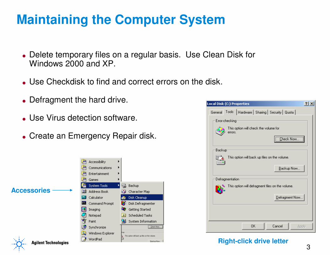
� Delete temporary files on a regular basis. Use Clean Disk for Windows 2000 and XP.
� Use Checkdisk to find and correct errors on the disk.
� Defragment the hard drive.
� Use Virus detection software.
� Create an Emergency Repair disk.
Maintaining the Computer System
Accessories
Right-click drive letter
4
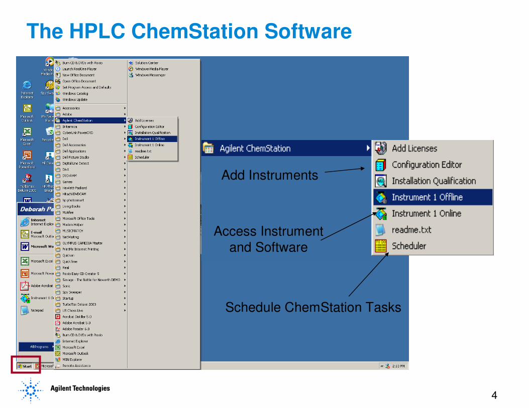
The HPLC ChemStation Software
Add Instruments
Schedule ChemStation Tasks
Access Instrument
and Software
5
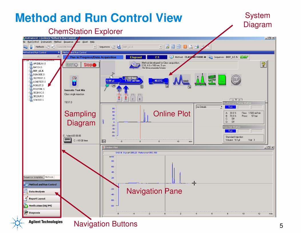
Method and Run Control View
Sampling
Diagram
System
Diagram
Online Plot
Navigation Pane
ChemStation Explorer
Navigation Buttons
6
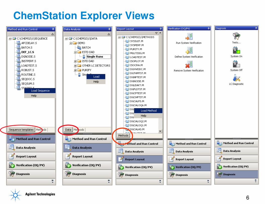
ChemStation Explorer Views
7
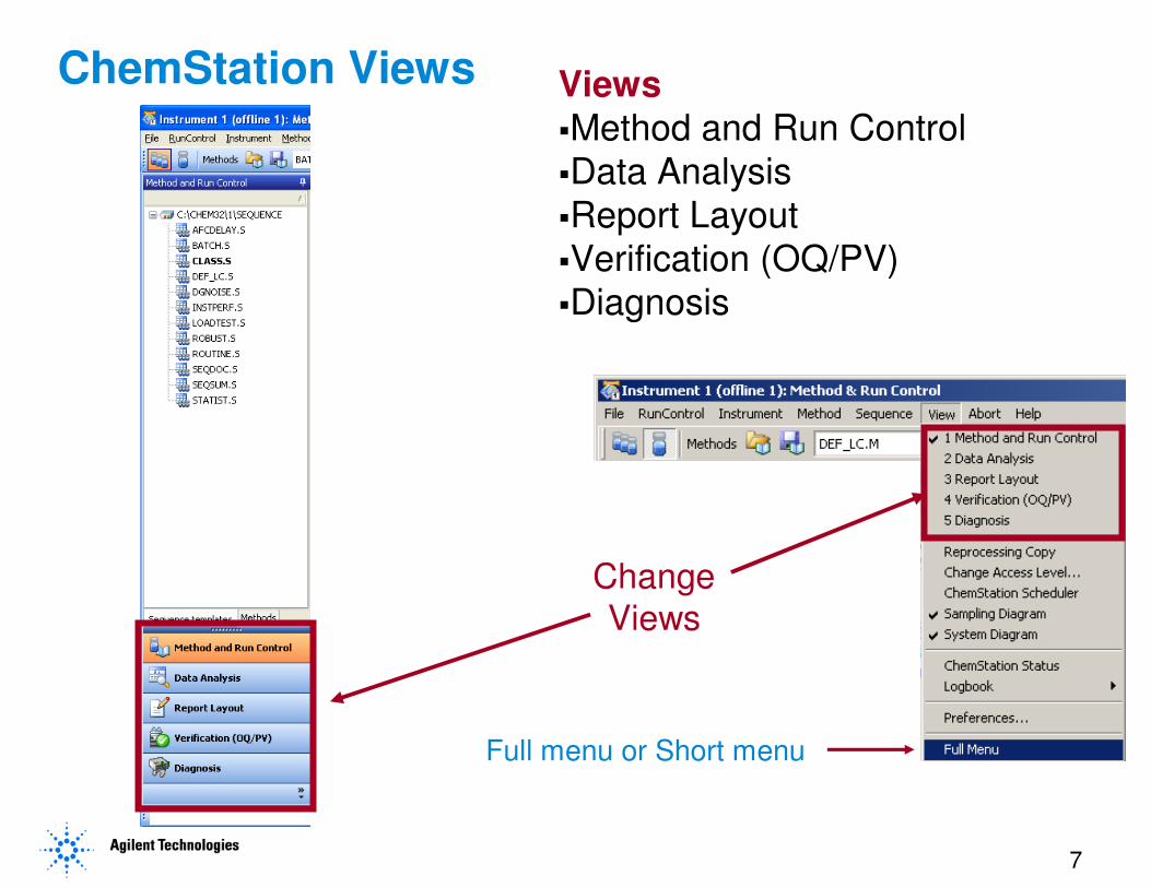
ChemStation Views Views�Method and Run Control
�Data Analysis
�Report Layout
�Verification (OQ/PV)
�Diagnosis
Full menu or Short menu
Change
Views
8
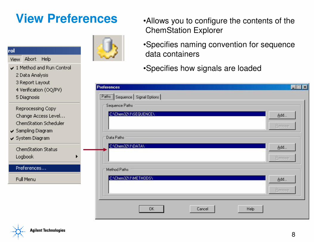
View Preferences •Allows you to configure the contents of the
ChemStation Explorer
•Specifies naming convention for sequence
data containers
•Specifies how signals are loaded
9
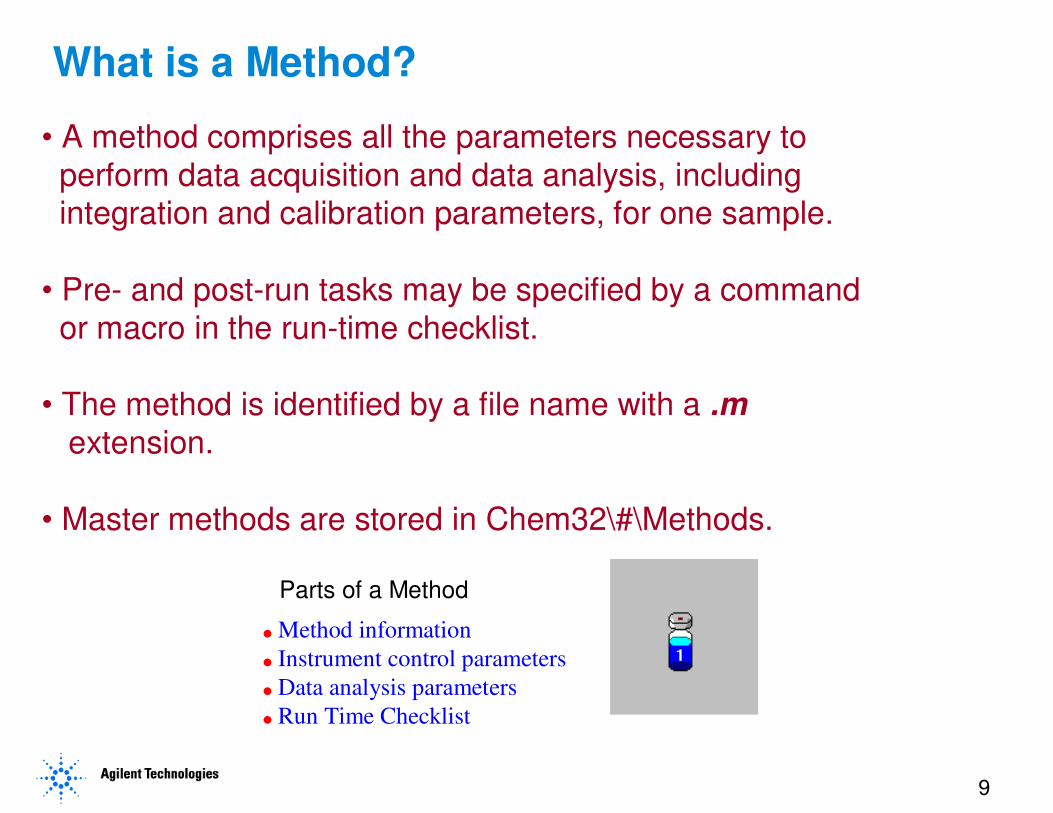
Parts of a Method
� Method information
� Instrument control parameters
� Data analysis parameters
� Run Time Checklist
What is a Method?
• A method comprises all the parameters necessary to
perform data acquisition and data analysis, includingintegration and calibration parameters, for one sample.
• Pre- and post-run tasks may be specified by a command
or macro in the run-time checklist.
• The method is identified by a file name with a .m
extension.
• Master methods are stored in Chem32\#\Methods.
10
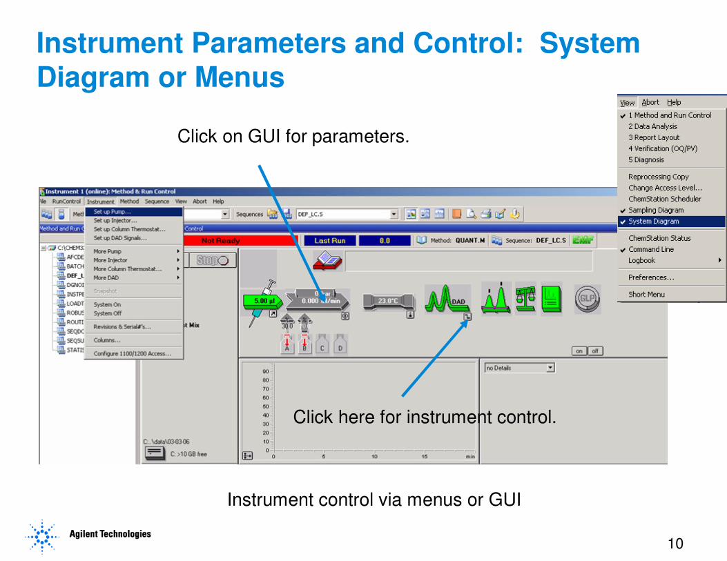
Instrument Parameters and Control: System Diagram or Menus
Click on GUI for parameters.
Instrument control via menus or GUI
Click here for instrument control.
11
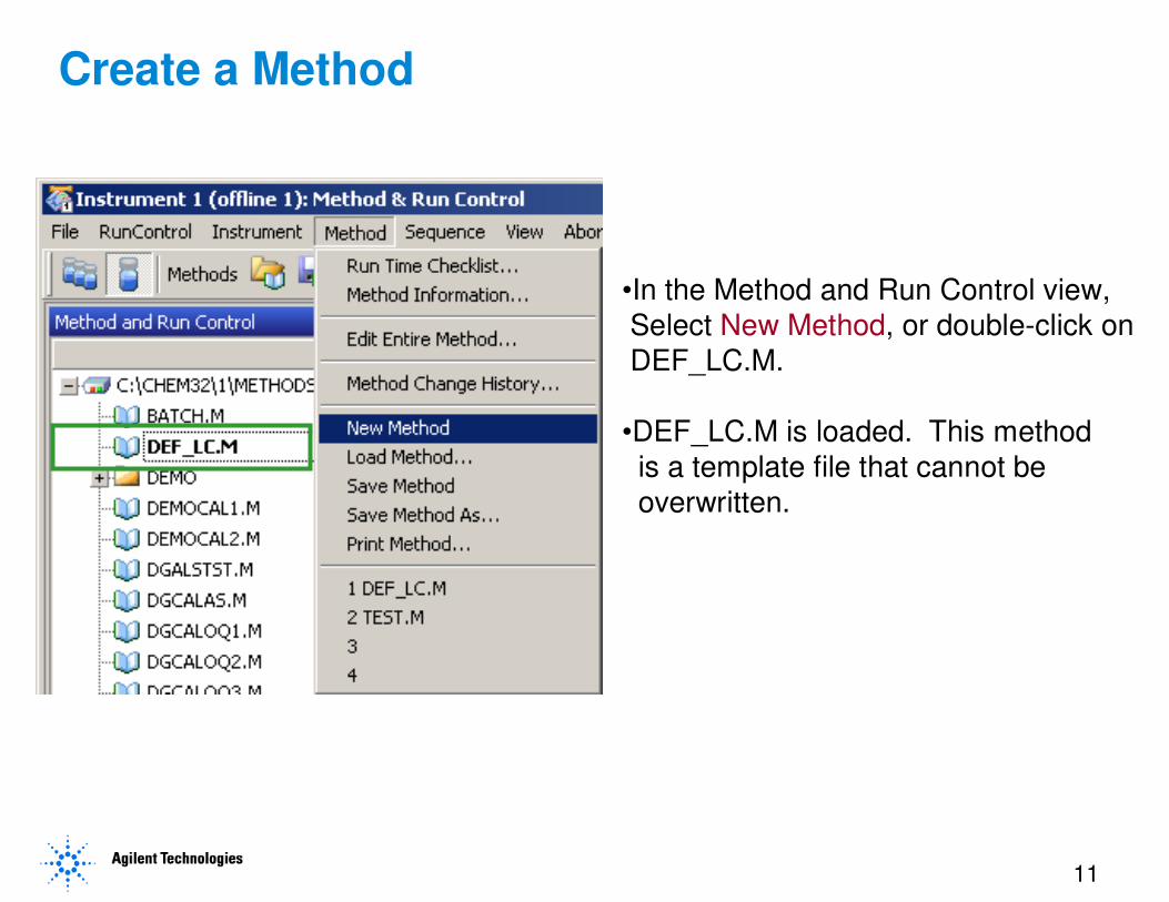
Create a Method
•In the Method and Run Control view,
Select New Method, or double-click on
DEF_LC.M.
•DEF_LC.M is loaded. This method
is a template file that cannot be
overwritten.
12
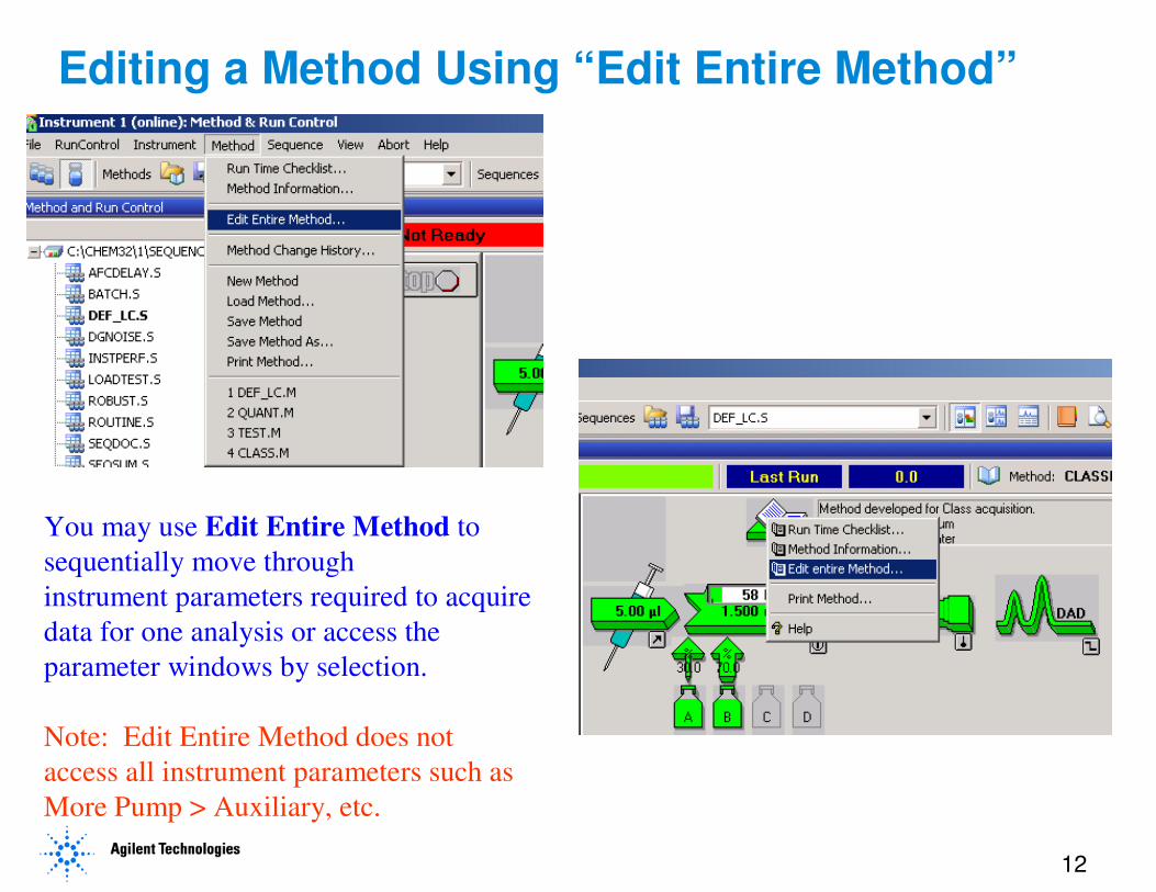
You may use Edit Entire Method to
sequentially move through
instrument parameters required to acquire
data for one analysis or access the
parameter windows by selection.
Note: Edit Entire Method does not
access all instrument parameters such as
More Pump > Auxiliary, etc.
Editing a Method Using “Edit Entire Method”
13
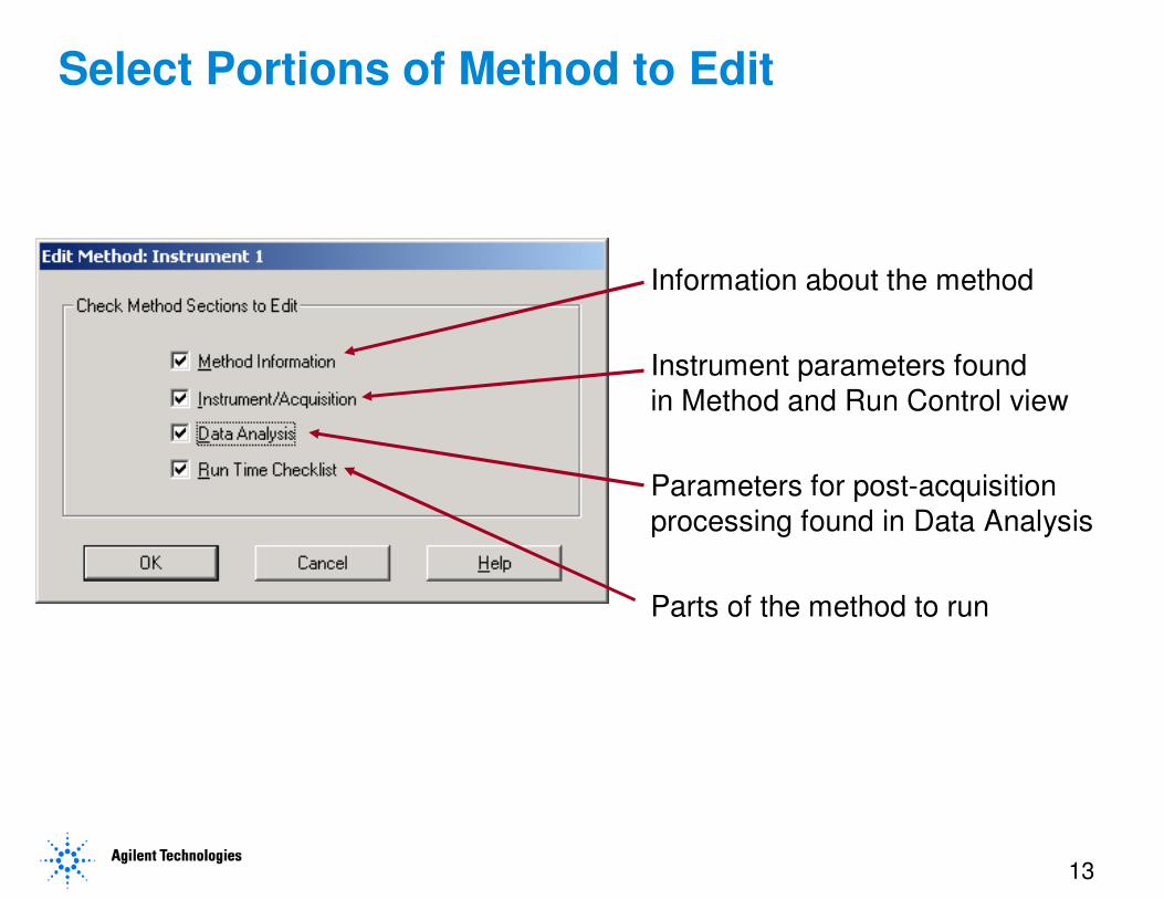
Select Portions of Method to Edit
Information about the method
Instrument parameters found
in Method and Run Control view
Parameters for post-acquisition
processing found in Data Analysis
Parts of the method to run
14
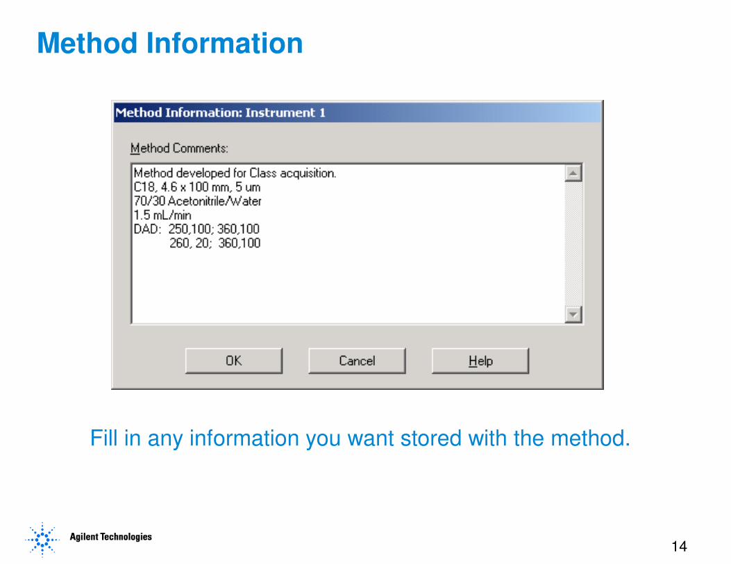
Method Information
Fill in any information you want stored with the method.
15
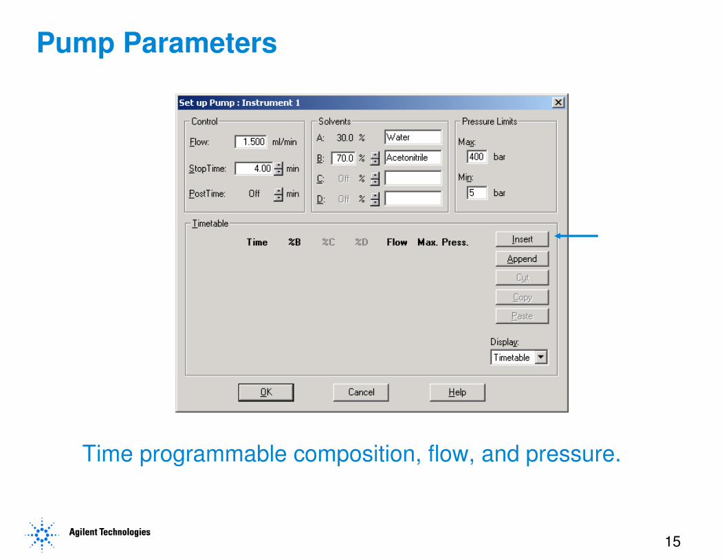
Time programmable composition, flow, and pressure.
Pump Parameters
16
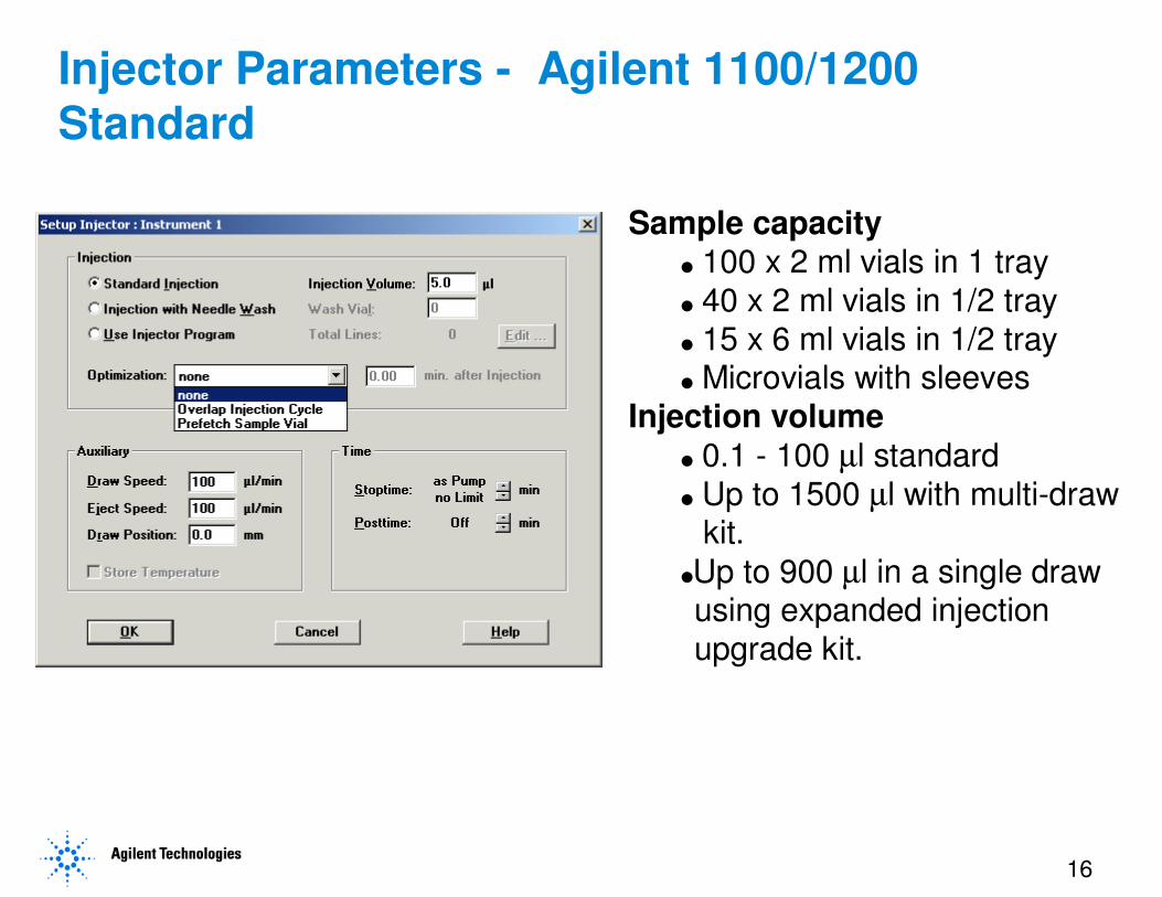
Injector Parameters - Agilent 1100/1200 Standard
Sample capacity� 100 x 2 ml vials in 1 tray� 40 x 2 ml vials in 1/2 tray� 15 x 6 ml vials in 1/2 tray� Microvials with sleeves
Injection volume
� 0.1 - 100 µl standard� Up to 1500 µl with multi-draw
kit.
�Up to 900 µl in a single drawusing expanded injectionupgrade kit.
17
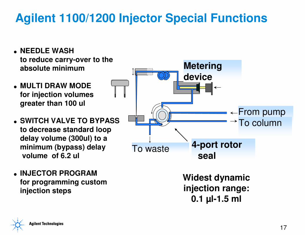
� NEEDLE WASHto reduce carry-over to the absolute minimum
� MULTI DRAW MODEfor injection volumesgreater than 100 ul
� SWITCH VALVE TO BYPASS to decrease standard loop delay volume (300ul) to a minimum (bypass) delayvolume of 6.2 ul
� INJECTOR PROGRAMfor programming custom injection steps
Widest dynamic injection range:
0.1 µl-1.5 ml
From pump
To column
Metering device
To waste 4-port rotor seal
Agilent 1100/1200 Injector Special Functions
18
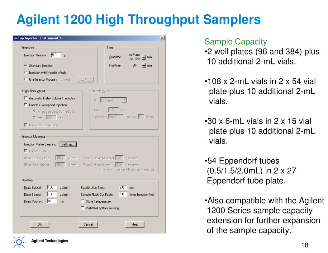
Agilent 1200 High Throughput Samplers
Sample Capacity
•2 well plates (96 and 384) plus
10 additional 2-mL vials.
•108 x 2-mL vials in 2 x 54 vial
plate plus 10 additional 2-mL
vials.
•30 x 6-mL vials in 2 x 15 vial
plate plus 10 additional 2-mL
vials.
•54 Eppendorf tubes
(0.5/1.5/2.0mL) in 2 x 27
Eppendorf tube plate.
•Also compatible with the Agilent
1200 Series sample capacity
extension for further expansion
of the sample capacity.
19
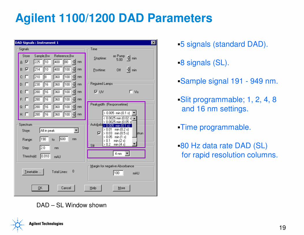
Agilent 1100/1200 DAD Parameters
�5 signals (standard DAD).
�8 signals (SL).
�Sample signal 191 - 949 nm.
�Slit programmable; 1, 2, 4, 8
and 16 nm settings.
�Time programmable.
�80 Hz data rate DAD (SL)
for rapid resolution columns.
DAD – SL Window shown
20
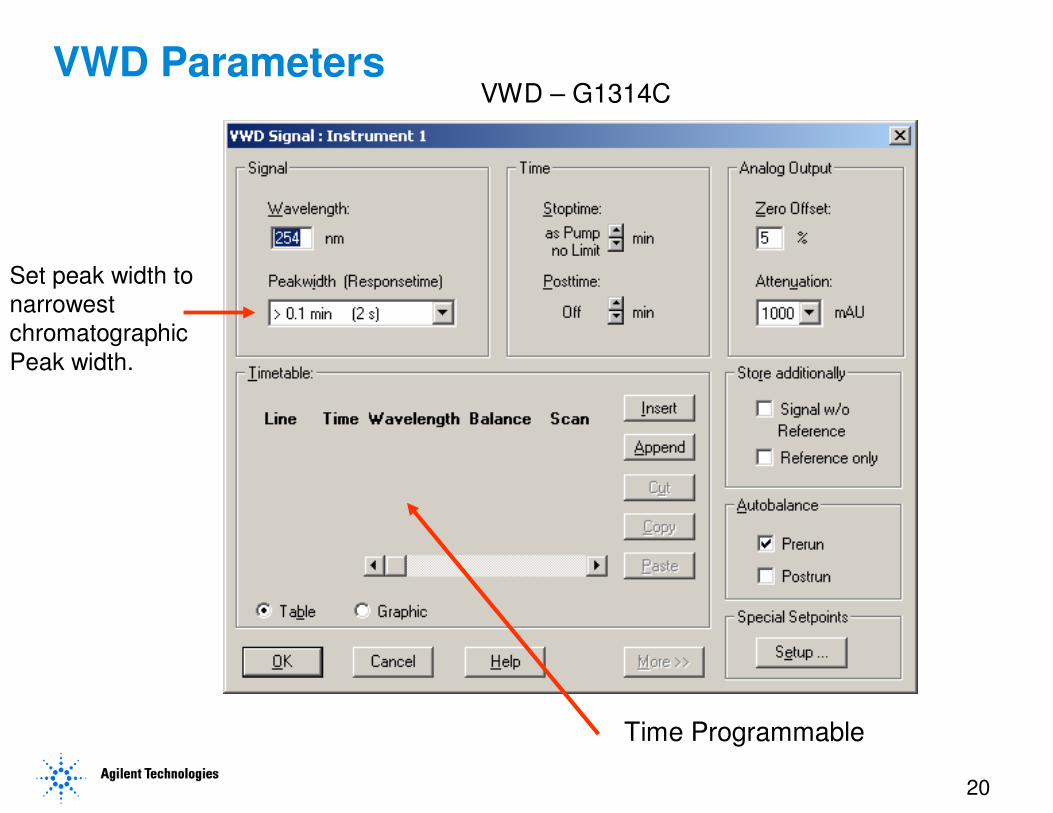
VWD Parameters
Time Programmable
Set peak width to
narrowest
chromatographic
Peak width.
VWD – G1314C

21
Column Thermostat Parameters
�10 degrees below ambient to
80 degrees C (Standard).
�10 degrees below ambient to
100 degrees C (SL).
�Two separate heated zones for
two columns.
�Optional valve for column
switching applications.
�Compartment holds up to 30 cm
column.
�Column identification module
with injection record for GLP.
(TCC –SL shown)
22
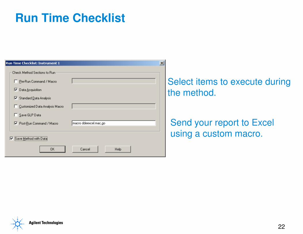
Run Time Checklist
Select items to execute during
the method.
Send your report to Excel
using a custom macro.
23
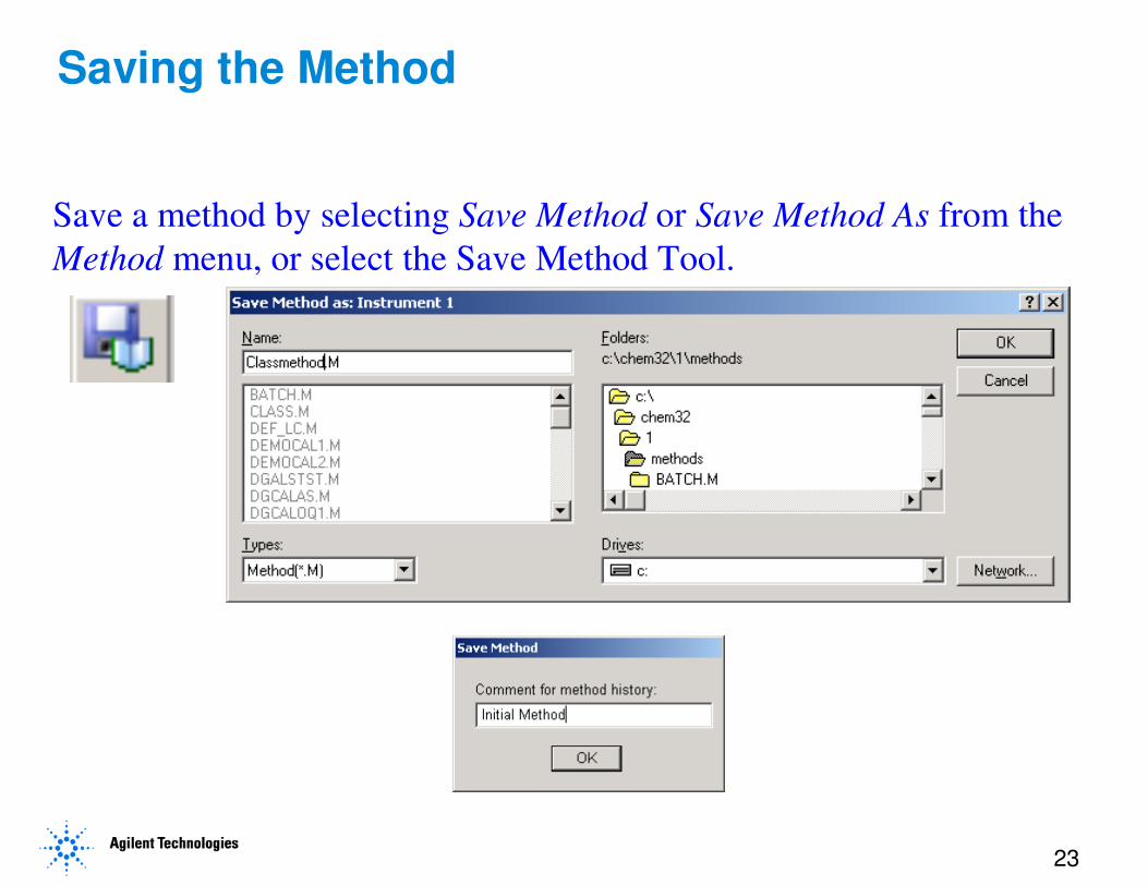
Saving the Method
Save a method by selecting Save Method or Save Method As from the
Method menu, or select the Save Method Tool.
24
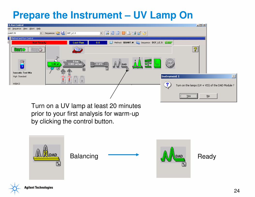
Prepare the Instrument – UV Lamp On
Turn on a UV lamp at least 20 minutes
prior to your first analysis for warm-up
by clicking the control button.
Balancing Ready
25
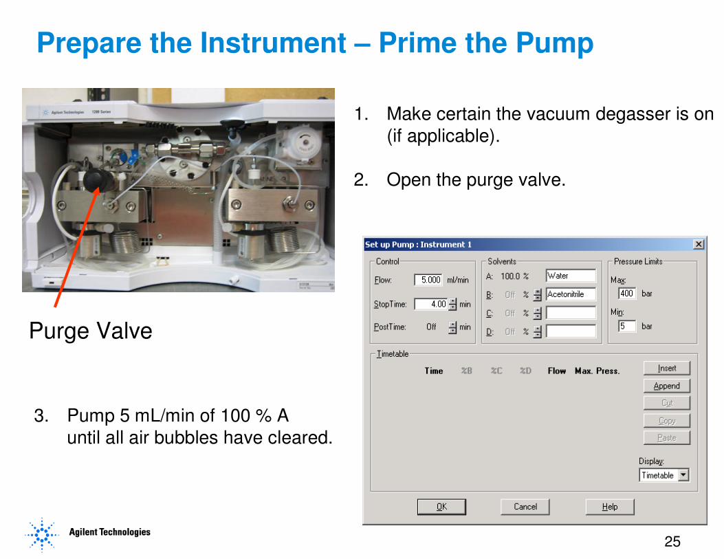
Prepare the Instrument – Prime the Pump
Purge Valve
1. Make certain the vacuum degasser is on
(if applicable).
2. Open the purge valve.
3. Pump 5 mL/min of 100 % A
until all air bubbles have cleared.
26
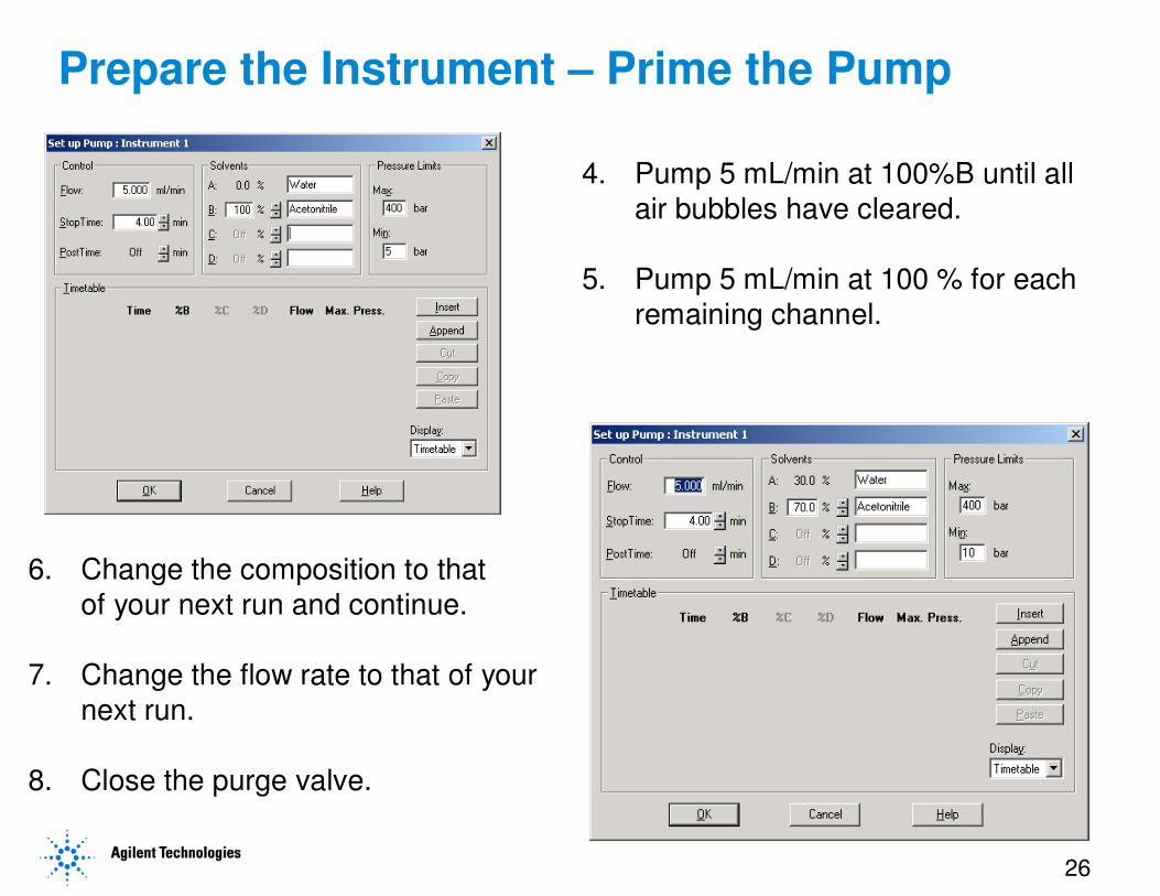
Prepare the Instrument – Prime the Pump
4. Pump 5 mL/min at 100%B until all
air bubbles have cleared.
5. Pump 5 mL/min at 100 % for each
remaining channel.
6. Change the composition to that
of your next run and continue.
7. Change the flow rate to that of your
next run.
8. Close the purge valve.
27
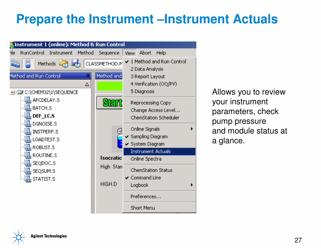
Prepare the Instrument –Instrument Actuals
Allows you to review
your instrument
parameters, check
pump pressure
and module status at
a glance.
28
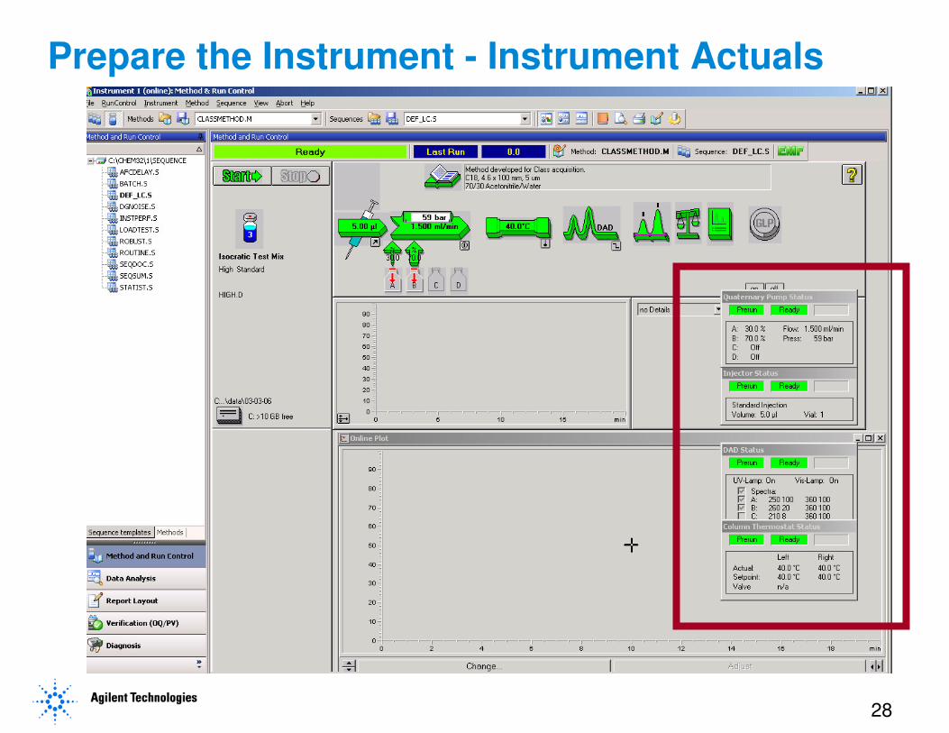
Prepare the Instrument - Instrument Actuals
29
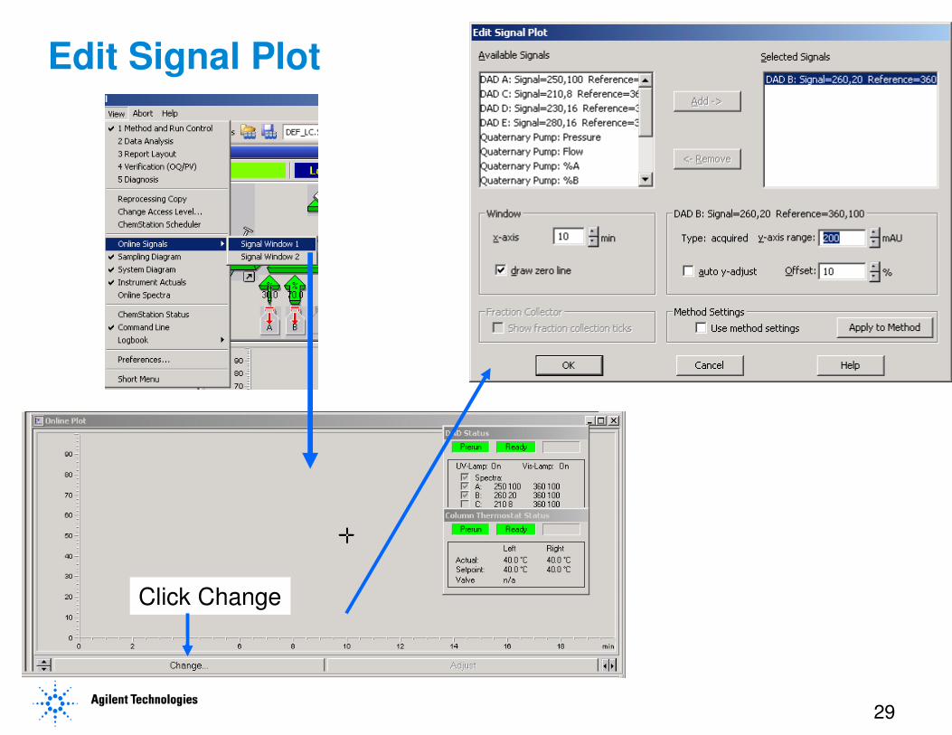
Edit Signal Plot
Click Change
30
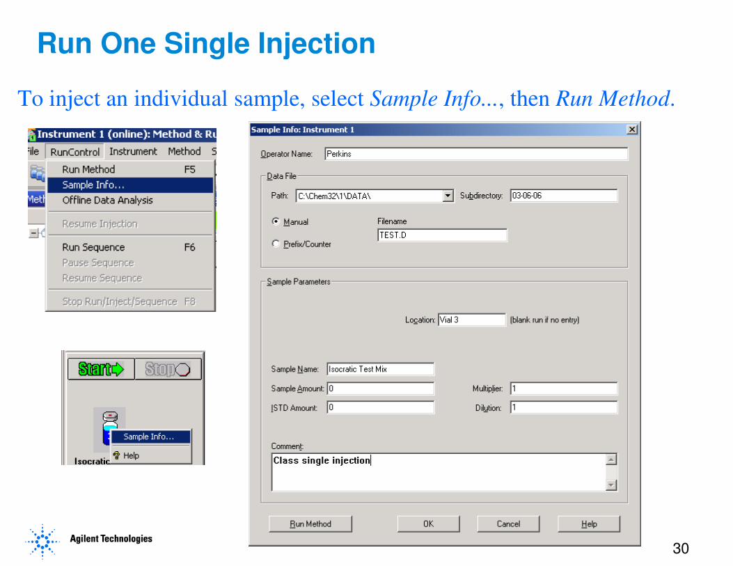
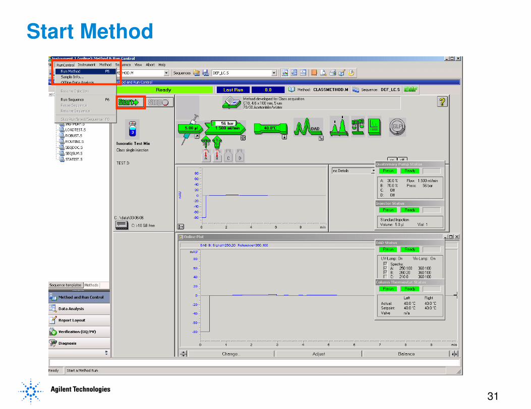
Run One Single Injection
To inject an individual sample, select Sample Info..., then Run Method.
31
Start Method
32
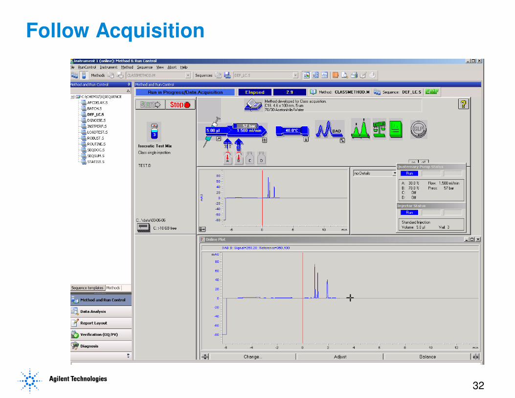
Follow Acquisition
33
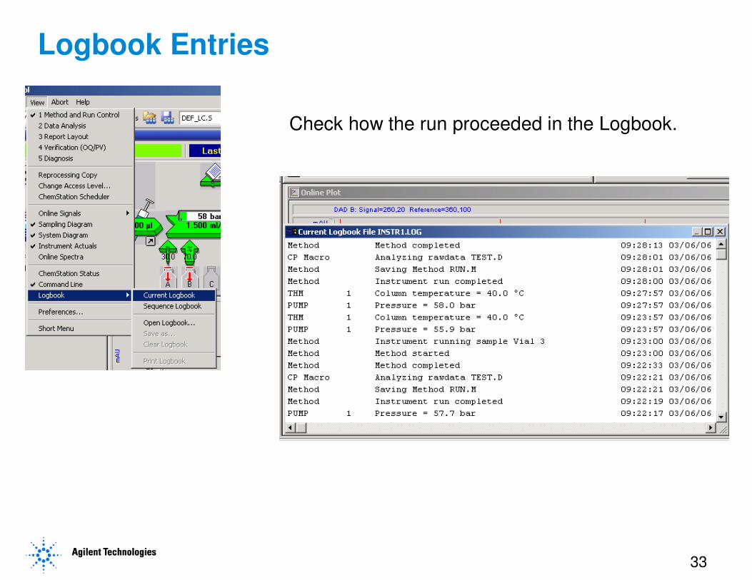
Logbook Entries
Check how the run proceeded in the Logbook.
34
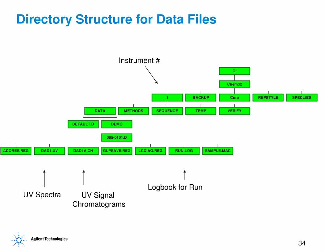
Directory Structure for Data Files
DEFAULT.D
ACQRES.REG DAD1.UV DAD1A.CH GLPSAVE.REG LCDIAG.REG RUN.LOG SAMPLE.MAC
005-0101.D
DEMO
DATA METHODS SEQUENCE TEMP VERIFY
1 BACKUP Core REPSTYLE SPECLIBS
Chem32
C:
Instrument #
UV Spectra UV Signal
Chromatograms
Logbook for Run
35
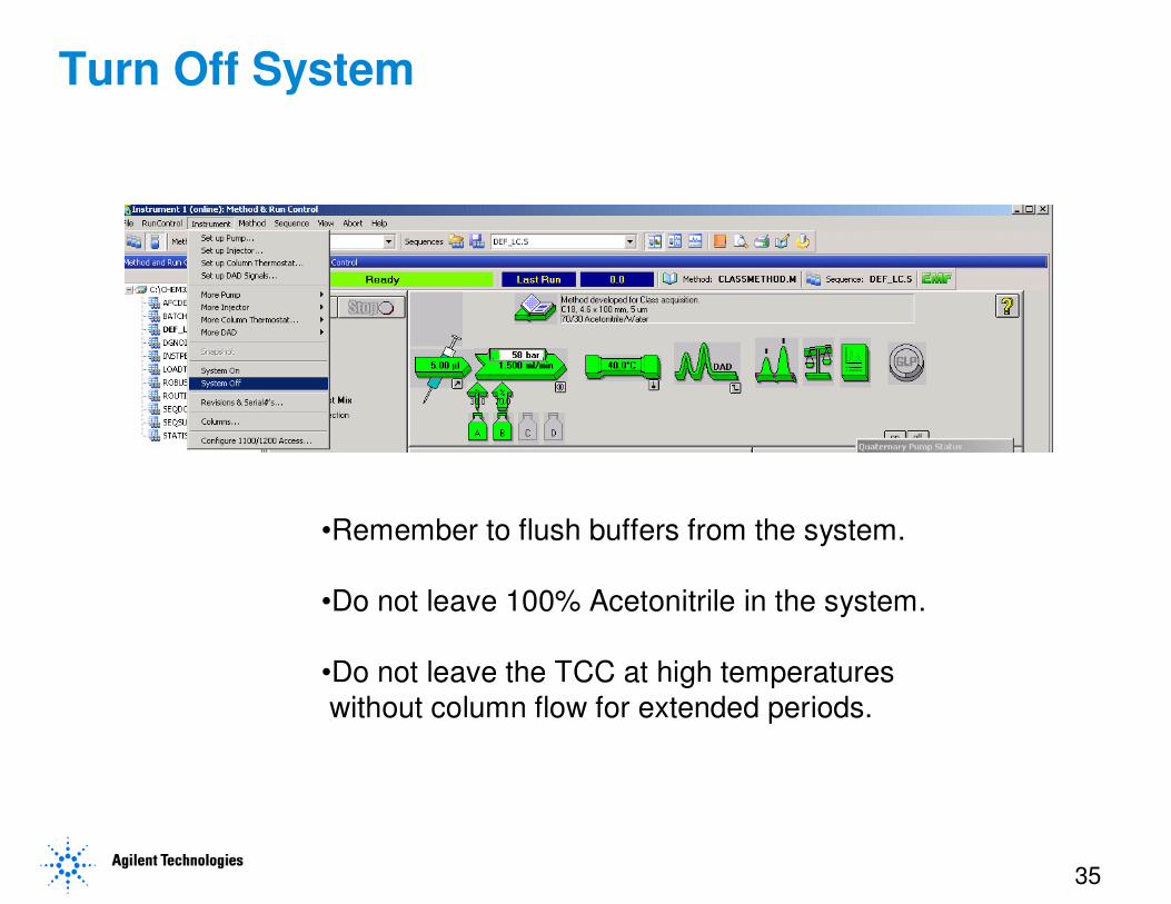
Turn Off System
•Remember to flush buffers from the system.
•Do not leave 100% Acetonitrile in the system.
•Do not leave the TCC at high temperatures
without column flow for extended periods.
Related Documents