© 2015 The MathWorks, Inc. Introduction to System Modeling Simulink ® for System and Algorithm Modeling

Welcome message from author
This document is posted to help you gain knowledge. Please leave a comment to let me know what you think about it! Share it to your friends and learn new things together.
Transcript

© 2015 The MathWorks, Inc.
Introduction to System Modeling
Simulink® for System and Algorithm Modeling
2 - 2Introduction to System Modeling
© 2006 The MathWorks, Inc.
Outline
• Model-Based Design
• Types of modeling
• System modeling with Simulink
• Modeling steps

2 - 3Introduction to System Modeling
© 2006 The MathWorks, Inc.
Model-Based Design with Simulink

2 - 4Introduction to System Modeling
© 2006 The MathWorks, Inc.
System Design Process
Subsystem
Design
Define Requirements
& Specification
Integration
and Test
System Integration,
Test & Calibration
Simulink
Stateflow
Blocksets
Subsystem
Implementation

2 - 5Introduction to System Modeling
© 2006 The MathWorks, Inc.
Types of Modeling
• First-principles modeling
• Simulink
• Finite-state machine
• Stateflow
• Physical modeling
• SimMechanics, SimPowerSystems, SimDriveline
• System identification
• Neural networks, system identification

2 - 6Introduction to System Modeling
© 2006 The MathWorks, Inc.
System Modeling with Simulink
• A graphical environment for hierarchical block diagram
development
• Supplied with libraries of basic and compound blocks for
general system buildup
• Supplied with functions that automate model constructions
and simulations
• Extensible for custom feature development and
distribution
• Supports modeling of continuous-time, discrete-time
(including single-rate, multirate, and asynchronous) and
hybrid systems
• Supports integration of custom and legacy code

2 - 7Introduction to System Modeling
© 2006 The MathWorks, Inc.
Simulink Environment
• Simulink Library Browser contains basic and
add-on blocks.
• Simulink block diagram editor facilitates the buildup of a
model or subsystem block diagram.
• The Simulink solver engine steps the model in time.
• The solver engine propagates signals block by block after
each update.
• Simulink manages the interaction between the model and
the solver engine during a simulation.

2 - 8Introduction to System Modeling
© 2006 The MathWorks, Inc.
Simulink Dependency on MATLAB
• Simulink depends on the MATLAB workspace to define
and evaluate model and block parameters.
• Simulink depends on the MATLAB workspace to define
model inputs.
• Simulink can use the MATLAB workspace to store model
outputs for analysis.
• Simulink can integrate calls to MATLAB operators and
functions in models.

2 - 9Introduction to System Modeling
© 2006 The MathWorks, Inc.
Simulink Add-Ons
• Application-specific features via add-on blocksets
• Complex flow charts and state machine design
environment via Stateflow
• Automatic code generation from models/subsystems via
Real-Time Workshop and its add-on targets to support
• Rapid simulation
• Rapid prototyping
• Embedded design testing
• Automatic generation of model documentation or
specifications via Simulink Report Generator

2 - 10Introduction to System Modeling
© 2006 The MathWorks, Inc.
Modeling Steps
• Defining the system.
• Identifying the system components.
• Modeling the system with equations.
• Building a block diagram for the model using Simulink.
• Simulating the model.
• Validating the simulation results.

2 - 11Introduction to System Modeling
© 2006 The MathWorks, Inc.
Defining the System
• Electronic throttle control
Throttle Body
Pedal
Pedal Position
SensorEngine
Control
Module
Se
rvo
mo
tor Position
Sensor
Electronic throttle control (ETC) –
Throttle by wire
Traditional mechanical linkage
throttle control
Throttle Body
Cable
Pedal
Throttle Body
Pedal
Throttle Body
Pedal
2 - 12Introduction to System Modeling
© 2006 The MathWorks, Inc.
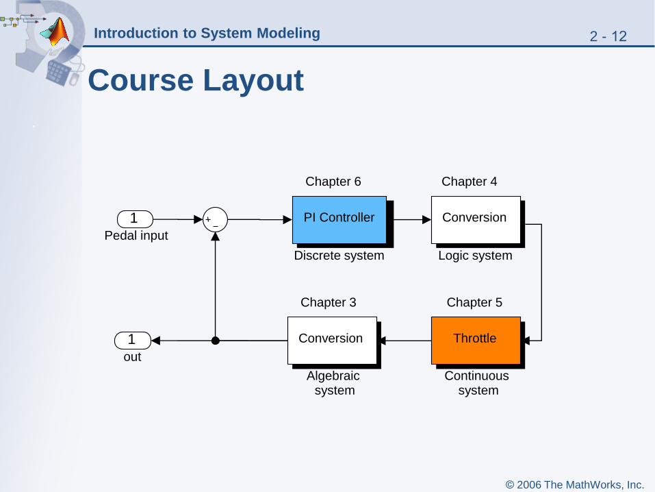
Course Layout
1out
Chapter 4
Conversion
Logic systemDiscrete system
Chapter 6
PI Controller
Chapter 5
Throttle
Continuoussystem
1Pedal input
Chapter 3
Conversion
Algebraic system

2 - 13Introduction to System Modeling
© 2006 The MathWorks, Inc.
Identifying the System Components
• What are the input signals?
• What are the output signals?
• What are the intermediate signals?
• What are the parameters?
• What are the discrete states?
• What are the continuous states?
• For the electronic throttle controller you have
• One input — the pedal position
• One output — the throttle angle
• Two continuous states — throttle angular position and
velocity
• One discrete state coming from the discrete integrator
in the PI controller
• A number of intermediate signals and parameters

2 - 14Introduction to System Modeling
© 2006 The MathWorks, Inc.
DYNAMIC
SYSTEMInputs u(t) Outputs y(t)
Internal state variables x(t)
Continuous Dynamics
Discrete Dynamics
Output Equation
Overview of a General Dynamic System
),,()(
),,()(
),,()(
1
tuxqty
tuxftx
tuxftx
dk
cc

2 - 15Introduction to System Modeling
© 2006 The MathWorks, Inc.
Summary
• Model-Based Design
• Types of modeling
• System modeling with Simulink
• Modeling steps
Related Documents


