Software Design

Welcome message from author
This document is posted to help you gain knowledge. Please leave a comment to let me know what you think about it! Share it to your friends and learn new things together.
Transcript

Software Design
Software Design
• Software design is a blueprint or a plan for a computer-
based solution for system
• Software design deals with transforming the customer
requirements , as described by the SRS into a form that is
implementable using a programming language
• According to the IEEE definition [IEEE 610.12-90], design is
both "the process of defining the architecture, components,
interfaces, and other characteristics of a system or
component" and "the result of that process”.

Software Design (Contd..)
• The design process for software systems often
has two levels :
– Top-level Design
– Detailed Design

Four Components of a Design
Procedural
Design
Interface Design
Architectural Design
Data Design
The Design Model

Design Objectives/Properties
• Correctness
• Verifiability
• Completeness
• Traceability
• Efficiency
• Simplicity
Design Principles
• Partitioning
• Abstraction
• Modularity
• Top-down and Bottom-up approach

Partitioning
• Basic principle "divide and conquer"
• Divide the problem into manageably small pieces
– Ideally ,each piece can be solved separately
– Ideally, each piece can be modified separately
• Pieces cannot be independent; they must
communicate
• Communication adds complexity
• As number of components increases, this cost
increases
• Stop partitioning when cost is more than benefit
• Results in hierarchies in the design

Abstraction
• Abstraction is a view of an object that
focuses on the information relevant to a
particular purpose and ignores the
remainder of the information
• An abstraction of a component describes
the external behaviour of the system
without bothering with the internal details
that produce the behaviour
• To allow the designer to concentrate on one
component at a time , abstraction of other
component is used
Abstraction (Contd..)
• Functional Abstraction
• Data abstraction

Top- Down and Bottom –up strategies
• A top-down approach starts by identifying
the major component of the system,
decompose them into lower level
components and iterating until the desired
level of detail is achieved.
• Stepwise refinement

Top- Down and Bottom –up strategies (contd…)
• A bottom-up approach starts with designing
most basic or primitive components and
proceeds to higher level components that
uses these lower-level components
• Work with layers of abstraction

Modularity
• Modularity refers to the degree to which
software can be understood by examining
its components independent of one another
• A system is considered modular if it consist
of discrete components so that each
component can be implemented separately
and a change to one component has
minimal impact on other components

Functional Independence
• A module having high cohesion and
low coupling is said to be functionally
independent of other module
– Error Isolation
– Scope of reuse
– Understandability

Cohesion
• The measure of strength of the
association of elements within a
module is known as cohesion –
Degree of interaction within a module

Types of Cohesion
• Functional Cohesion
• Sequential Cohesion
• Communicational Cohesion
• Procedural Cohesion
• Temporal Cohesion
• Logical Cohesion
• Coincidental Cohesion

Functional Cohesion
• A module exhibits ``functional cohesion'' if
it supports activities needed for the
execution for one and only one problem-
related task.
• Example
• Compute cosine of angle
• Calculate net employee salary
• Sort the array

Sequential Cohesion
A sequentially cohesive module is one
whose elements are involved in activities
such that output data from one activity
serves as input data to the next.
Example

Communicational Cohesion
• Communicational cohesion occurs when
the elements of a module are grouped
together because they operate on same
input or output data
• Example
Procedural Cohesion
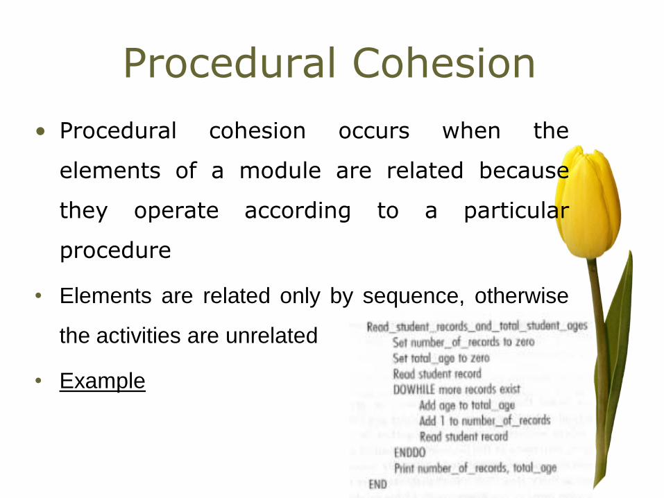
• Procedural cohesion occurs when the
elements of a module are related because
they operate according to a particular
procedure
• Elements are related only by sequence, otherwise
the activities are unrelated
• Example

Temporal Cohesion
• A temporarily cohesive module is one
whose elements are functions that are
related in time.
• Example
module initialise
set counter to 0
open student file
clear error message variable
initialise array
end module

Logical Cohesion
• A logically cohesive module is one whose
elements performs activities of the same
general category.
• For example, a report module, display
module or I/O module

Coincidental Cohesion
• Coincidental cohesion occurs when elements
contribute to activities that have no meaningful
relationship to one another.
• Module performs multiple, completely unrelated
actions.
• Example
– print next line, reverse string of characters comprising second
parameter, add 7 to fifth parameter, convert fourth parameter
to floating point

Classification of Cohesion

Determining Module Cohesion
Doing one
function
only?
Activities
same category?
Sequence
important?
Module
related
by?
Sequence
important?
Functional
Sequential
Communicational
Procedural Temporal
Logical
Coincidental
Yes
No
Data None
Control Flow
Yes
Yes
Yes
No
No
No
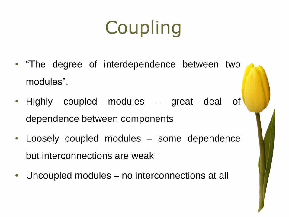
Coupling
• “The degree of interdependence between two
modules”.
• Highly coupled modules – great deal of
dependence between components
• Loosely coupled modules – some dependence
but interconnections are weak
• Uncoupled modules – no interconnections at all

Goal is to
• Minimize Coupling
– Enable us to change the portion of the system while
disrupting the rest of the system as little as possible
Types of Coupling
• Data Coupling
• Stamp Coupling
• Control Coupling
• Common Coupling
• Content Coupling

Data Coupling
• Modules communicate by passing
simple data parameters
• Each parameter is an elementary
piece of data
Process
Results
Calculate
Grade
mark grade

Stamp Coupling
• A composite data is passed
between modules
• Not all of the individual
components of the data may
not be used
Process
Results
Update
Grade
record updated
record

Control Coupling
• One module passes an element
of control to another.
• One module directs the order of
instruction execution of another
module by passing necessary
control information
Check
record
Display
error
Error
code

Common Coupling
• When two modules refer to
the same global data area
Process
Results
Update
Grade
updated
record
Global data

Content Coupling
• Two modules are content coupled if one directly
references the contents of another.
– One module branches into another module.
– One module references or alters data contained inside
another module
– Module A modifies the statement of module B.

Range of Coupling
High Coupling
Loose
Low
Content
Common
Control
Stamp
Data
Uncoupled

General Design Approaches
• Function Oriented Design
– Structured Design by Constantine and Yourdon
– Jackon’s structured design
– Warnier-Orr Methodology
– Step-wise refinement by Writh
• Object Oriented Design
Structured Design
• Structured Design is a process-oriented technique
to divide a system into a hierarchy of modules
leading to programs that are easy to develop and
maintain
• The basic approach in system design is
systematic conversation o data flow diagrams into
structure chart

Structure Chart Notation

Structure Chart Notation (contd…)

Example
Modules on level 2 can be decomposed further

Repetition

Structure Chart - Module•Rectangle represents a module (program or
subroutine)
•Control Modules (mainline) branch to sub-modules
•Library modules are reusable and can be invoked from
more than one Control Module elsewhere in the
system

Selection

2.1
Billchecksform
2.1
Validatesalesorder
AZ104 formchecked AZ104 form
sales order
valid sales order
Master File
Sales orders
Physical to Logical DFDs
2.1
Billchecksform
2.1
Validatesalesorder
AZ104 formchecked AZ104 form
sales order
valid sales order
Master File
Sales orders
Physical to Logical DFDs

Physical DFD
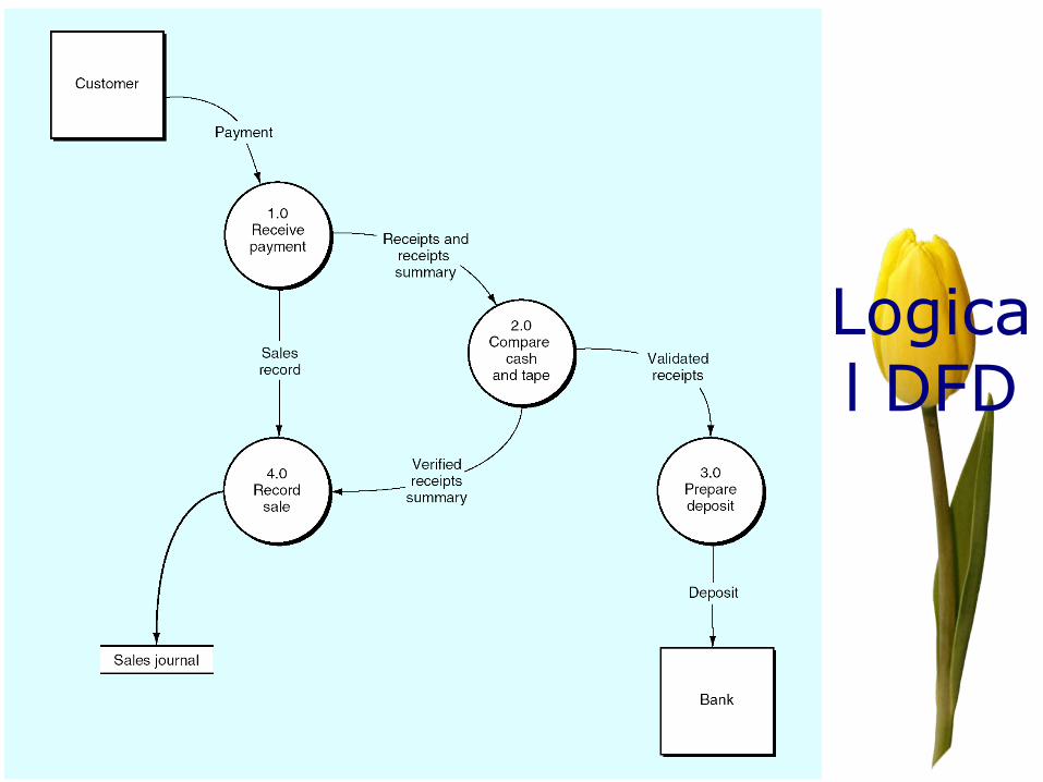
Logical DFD
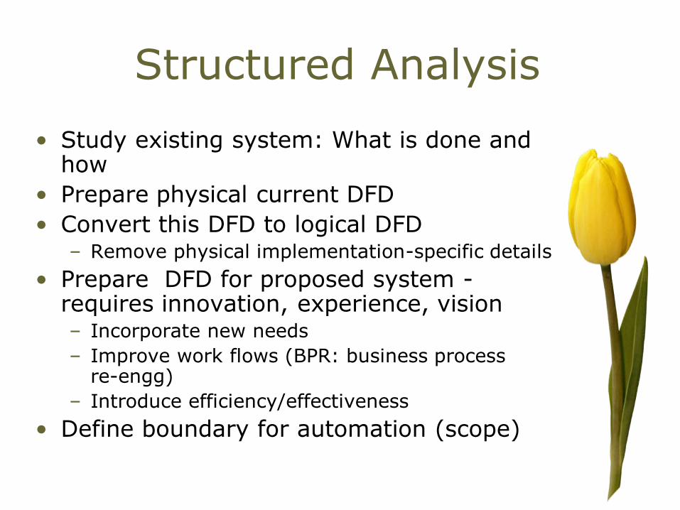
Structured Analysis
• Study existing system: What is done and how
• Prepare physical current DFD
• Convert this DFD to logical DFD– Remove physical implementation-specific details
• Prepare DFD for proposed system -requires innovation, experience, vision– Incorporate new needs
– Improve work flows (BPR: business process re-engg)
– Introduce efficiency/effectiveness
• Define boundary for automation (scope)

Automation Boundary on a System-Level DFD

SSA/SD process
1. Construct an initial DFD for each major component
to provide a top level description of the problem.
context diagram)
2. Review and refine DFDs for the major components
until a sufficient degree of cohesion is achieved for
processes; one elaborates the context diagram
into a layered hierarchy of DFDs, supported by a
data dictionary.
3. Determine whether each DFD has a
transformational or transactional flow
characteristics.
The remaining steps depend on the outcome of step 3

Transformational Flow
• Data continuously moves through a
collection of incoming flow processes
transform center processes and finally
outgoing flow processes

Transform Analysis (contd..)
• Input portion in the DFD:
– processes which convert input data from physical to logical
form.
– Each input portion is called an afferent branch.
– Possible to have more than one afferent branch in a DFD.
• Output portion of a DFD:
– transforms output data from logical form to physical form.
– Each output portion is called an efferent branch.
• The remaining portions of a DFD
– called central transform

Transform Analysis
4.Isolate the transform center by specifying
incoming and outgoing flow boundaries.
– Determine most abstract data input and most
abstract data output
– (Identify the transform center by specifying
Most Abstract Input and Output Data
Elements)

Transform Analysis (contd..)
• Divide the DFD into 3 types of parts:
• Afferent stream,
• Central transform,
• Efferent stream

Transform Analysis
5. Perform first level factoring

First- Cut Structure Chart for word count Problem

Transform Analysis (contd..)
6. Perform second level factoring
Transform Analysis (contd..)
7.Refine the first iteration program structure using
design heuristics for improved software quality

Design heuristics for effective modularity
• Reduce coupling and increase cohesion
– Explode complicated modules into multiple modules
– Implode related modules
• Minimize structures with high fan-out
– Strive for fan-in as depth increased
• Keep scope of effect within in the scope of control
• Tune module interfaces to reduce complexity

Transform Mapping

Level 3 DFD for Monitor Sensors with flow boundaries

First level factoring for monitor sensors

Second Level Factoring

First-Iteration program structure for monitor sensors
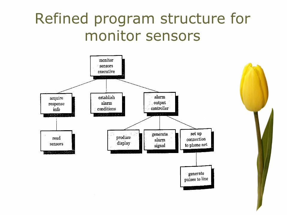
Refined program structure for monitor sensors
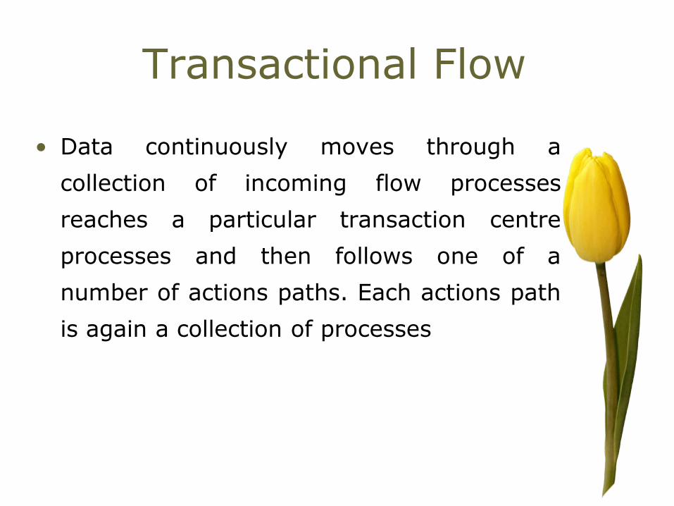
Transactional Flow
• Data continuously moves through a
collection of incoming flow processes
reaches a particular transaction centre
processes and then follows one of a
number of actions paths. Each actions path
is again a collection of processes
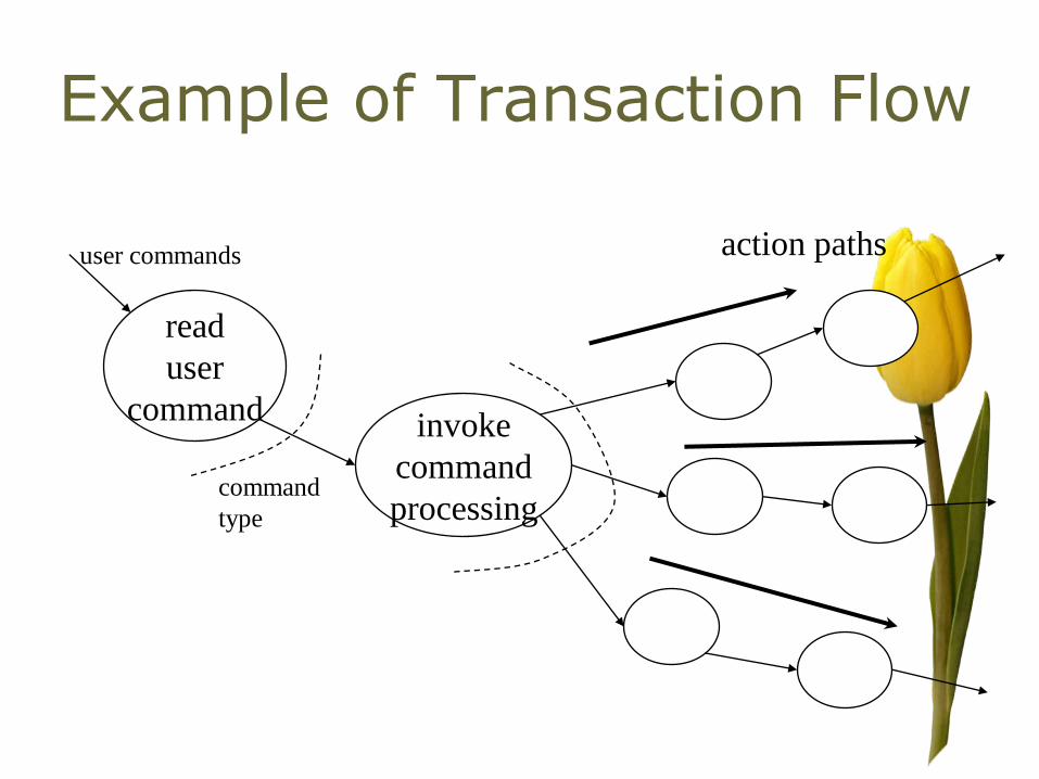
Example of Transaction Flow
read
user
commandinvoke
command
processing
user commands
command
type
action paths
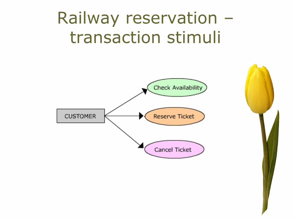
Railway reservation –transaction stimuli

Transaction Flow
T
Transaction
center
Transact
ion Action
paths
Transaction: Information flow is often characterized by a single
data item, that triggers other data flow along one of many paths
Action Paths :The transaction is evaluated and based on its value
flow along one of many action paths ; implements different types of
functionalities
Transaction center :The hub of info flow from which many action
paths originate, evaluates transaction and initialize the correct
action path

Transaction Analysis
4.Identify the transaction center and the flow characteristics
along each of the action paths.
• isolate incoming path and all action paths
• each action path evaluated for its flow
characteristic.

5. Perform first level factoring for a transactional
flow; map the DFD to a program structure
amenable to transaction processing
5.Factor and refine the transaction structure and the
structure of each action path.
6. Refine the first iteration program structure using
design heuristics for improved software quality.
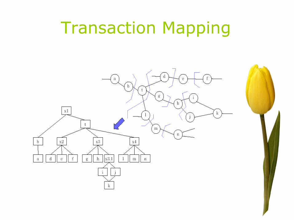
Transaction Mapping

Level 2 DFD for user transaction subsystem with
flow boundaries

First level factoring for user interaction subsystem

Transaction mapping (contd..)
• Factor and refine the transaction
structure and the structure of each
action path
• Refine the first iteration program
structure using design heuristics for
improved software quality
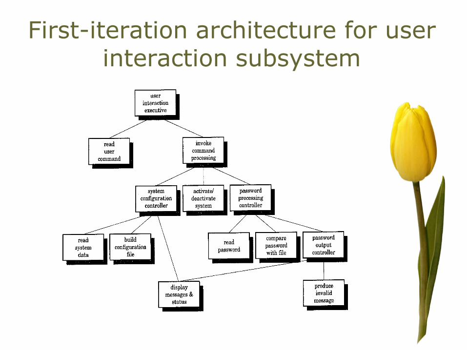
First-iteration architecture for user interaction subsystem

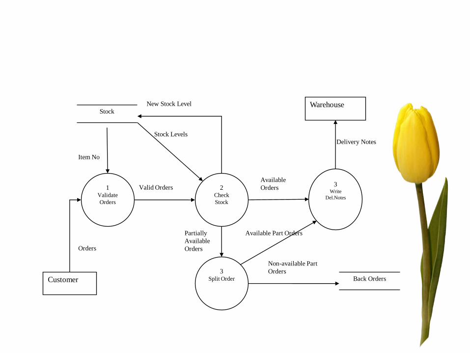
1Validate
Orders
2Check
Stock
3Write
Del.Notes
3Split Order
Stock
Back OrdersCustomer
Warehouse
Item No
Stock Levels
New Stock Level
Valid Orders
Orders
Available
Orders
Partially
Available
Orders
Available Part Orders
Non-available Part
Orders
Delivery Notes

1Validate
Orders
2Check
Stock
3Write
Del.Notes
3Split Order
Item No
Stock Levels
New Stock Level
Valid Orders
Orders
Available Orders
Partially
Available Orders
Available Part Orders
Non-available Part
Orders
Delivery Notes

1Validate
Orders
2Check
Stock
3Write
Del.Notes
3Split
Order
Item No
Stock
Levels
New Stock
Level
Valid Orders
Orders
Available
Orders
Partially
Available
Orders
Available Part Orders
Non-available
Part Orders
Delivery
Notes

1Validate
Orders
2Check
Stock
3Write
Del.Notes
3Split
Order
Item No
Stock
Levels
New Stock
Level
Valid Orders
Orders
Available
Orders
Partially
Available
Orders
Available Part Orders
Non-available
Part Orders
Delivery
Notes
5Process
Orders
Partially
Available
Orders
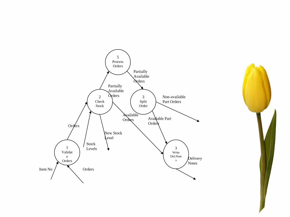
1Validat
e
Orders
2Check
Stock
3Write
Del.Note
s
3Split
Order
Item No
Stock
Levels
New Stock
Level
Orders
Orders
Available
Orders
Partially
Available
Orders
Available Part
Orders
Non-available
Part Orders
Delivery
Notes
5Process
Orders
Partially
Available
Orders

Item No
Stock
Levels
New Stock
Level
Valid Orders
Orders
Available
Orders
Partially
Available
Orders
Available Part
Orders
Non-available
Part Orders
Delivery
Notes
Check Stock
Validate Orders
Split Order
Write Delivery
Notes
Orders
End of
Orders

Item No
Stock
Levels
New Stock
Level
Valid Orders
Orders
Available
Orders
Partially
Available
Orders
Available
Part
Orders
Non-available
Part Orders
Check Stock
Validate OrdersSplit Order
Write Delivery
Notes
Orders
End of
Orders
Read Orders Read Stock Write Stock Write Back
Stock

Verification
• Review
– Review process involves a group of
people get together to discuss the design
with the aim of revealing design errors
or undesirable properties
– Errors include omissions,
misinterpretation of requirements, weak
modularity etc.
Detailed Design
• A processing narrative must be developedfor each module. Using process designlanguage
• An interface description is provided for eachmodule.
• Local and global data structures are refinedor designed.
• A design review is conducted.
• “Optimization” is considered (if requiredand justified).

Process Design Language
Mimax(file)
Array a
Do Until end of input
Read an item into a
Enddo
max,min:=first item of a
DO FOR each item in a
IF max<item THEN set max to item
IF min >item THEN set min to item
ENDDO
END
Related Documents