1 © 2015 The MathWorks, Inc. Introduction to Simulink & Stateflow GianCarlo Pacitti, MathWorks

Welcome message from author
This document is posted to help you gain knowledge. Please leave a comment to let me know what you think about it! Share it to your friends and learn new things together.
Transcript
1© 2015 The MathWorks, Inc.
Introduction to Simulink & Stateflow
GianCarlo Pacitti, MathWorks
2
4
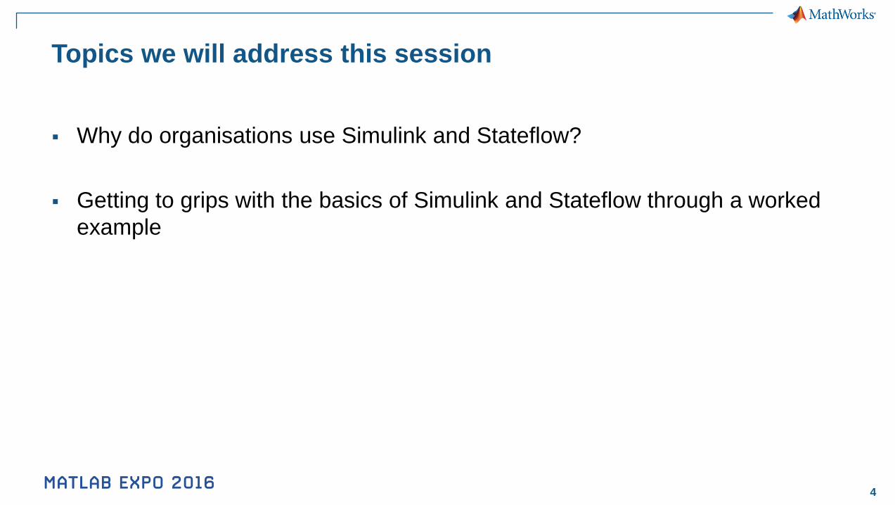
Topics we will address this session
Why do organisations use Simulink and Stateflow?
Getting to grips with the basics of Simulink and Stateflow through a worked
example
6
Why model a system?

7
8
Modelling & Simulation
gives you insight
9
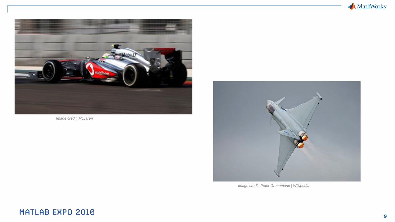
Image credit: McLaren
Image credit: Peter Gronemann | Wikipedia
10
Mechanical
Components
MCAD/
MCAE
Electrical
Components
EDA
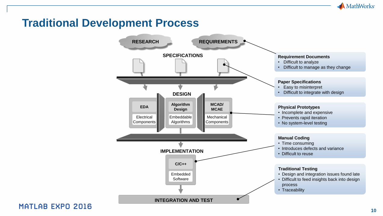
INTEGRATION AND TEST
SPECIFICATIONS
DESIGN
RESEARCH REQUIREMENTS
Embedded
Software
C/C++
IMPLEMENTATION
Requirement Documents
• Difficult to analyze
• Difficult to manage as they change
Paper Specifications
• Easy to misinterpret
• Difficult to integrate with design
Manual Coding
• Time consuming
• Introduces defects and variance
• Difficult to reuse
Traditional Testing
• Design and integration issues found late
• Difficult to feed insights back into design
process
• Traceability
Embeddable
Algorithms
Algorithm
DesignPhysical Prototypes
• Incomplete and expensive
• Prevents rapid iteration
• No system-level testing
Traditional Development Process
11
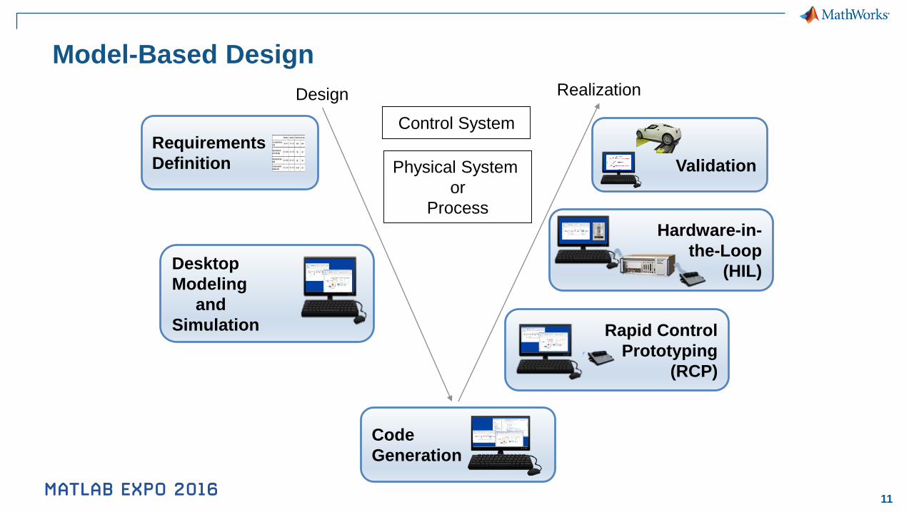
Hardware-in-
the-Loop
(HIL)
Model-Based Design
Requirements
Definition
Code
Generation
Desktop
Modeling
and
Simulation
Design Realization
Validation
Rapid Control
Prototyping
(RCP)
Control System
Physical System
or
Process
12
Why use
Simulink?
13
1. Common environment for all disciplines
2. Integrated workflow from requirements to code
3. Integration with MATLAB
14
Using Simulink &
Stateflow
15
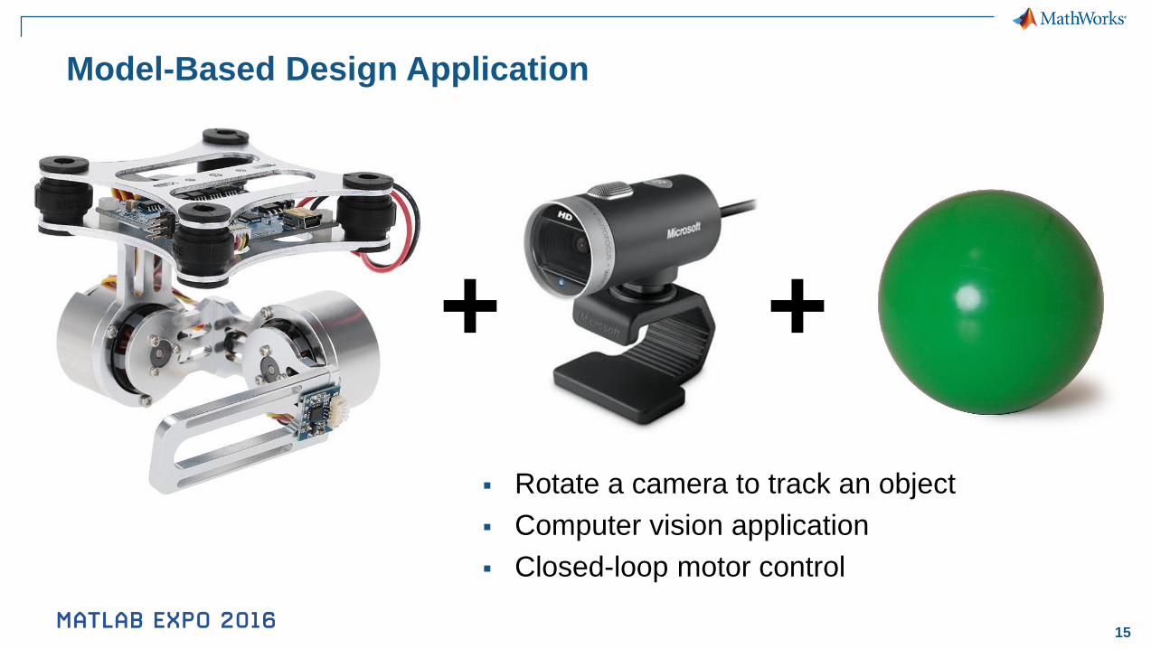
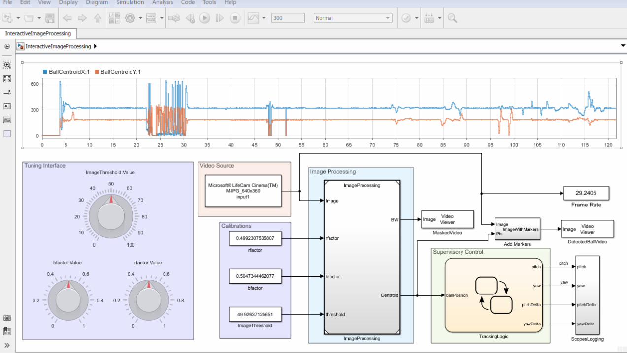
Model-Based Design Application
+ +
Rotate a camera to track an object
Computer vision application
Closed-loop motor control
17
18
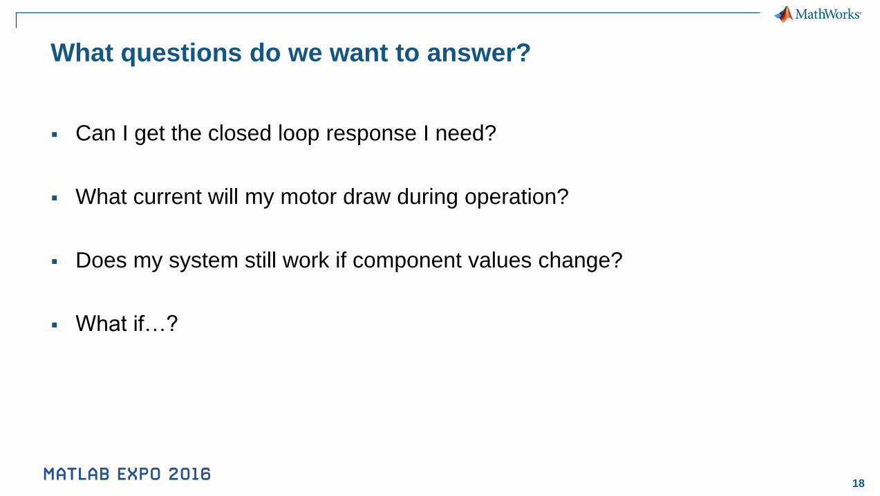
What questions do we want to answer?
Can I get the closed loop response I need?
What current will my motor draw during operation?
Does my system still work if component values change?
What if…?
19
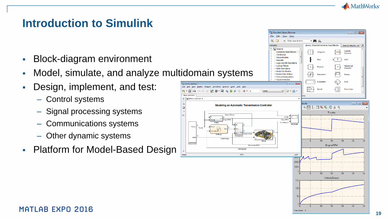
Introduction to Simulink
Block-diagram environment
Model, simulate, and analyze multidomain systems
Design, implement, and test:
– Control systems
– Signal processing systems
– Communications systems
– Other dynamic systems
Platform for Model-Based Design
20
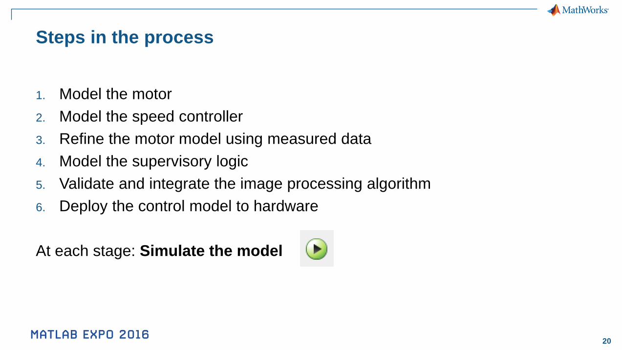
Steps in the process
1. Model the motor
2. Model the speed controller
3. Refine the motor model using measured data
4. Model the supervisory logic
5. Validate and integrate the image processing algorithm
6. Deploy the control model to hardware
At each stage: Simulate the model

23
Steps in the process
Model the motor
Model the speed controller
3. Refine the motor model using measured data
4. Model the supervisory logic
5. Validate and integrate the image processing algorithm
6. Deploy the control model to hardware
At each stage: Simulate the model
24
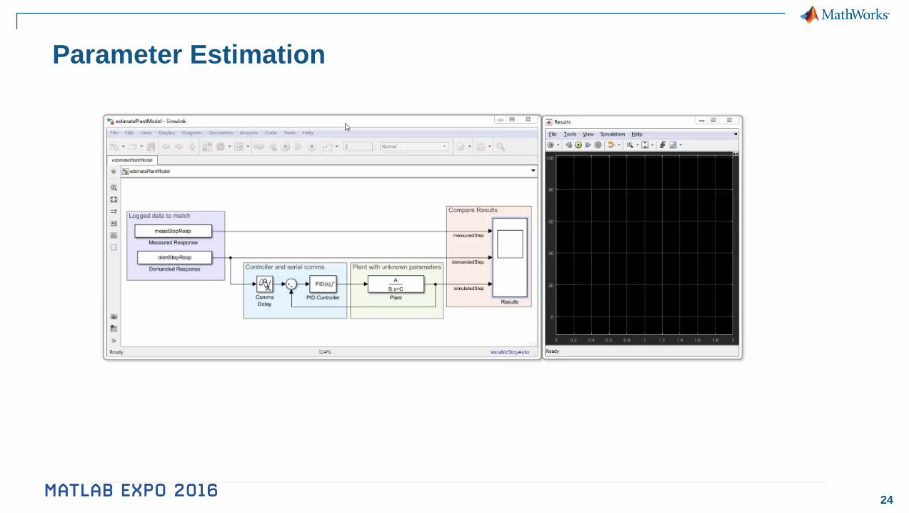
Parameter Estimation
25
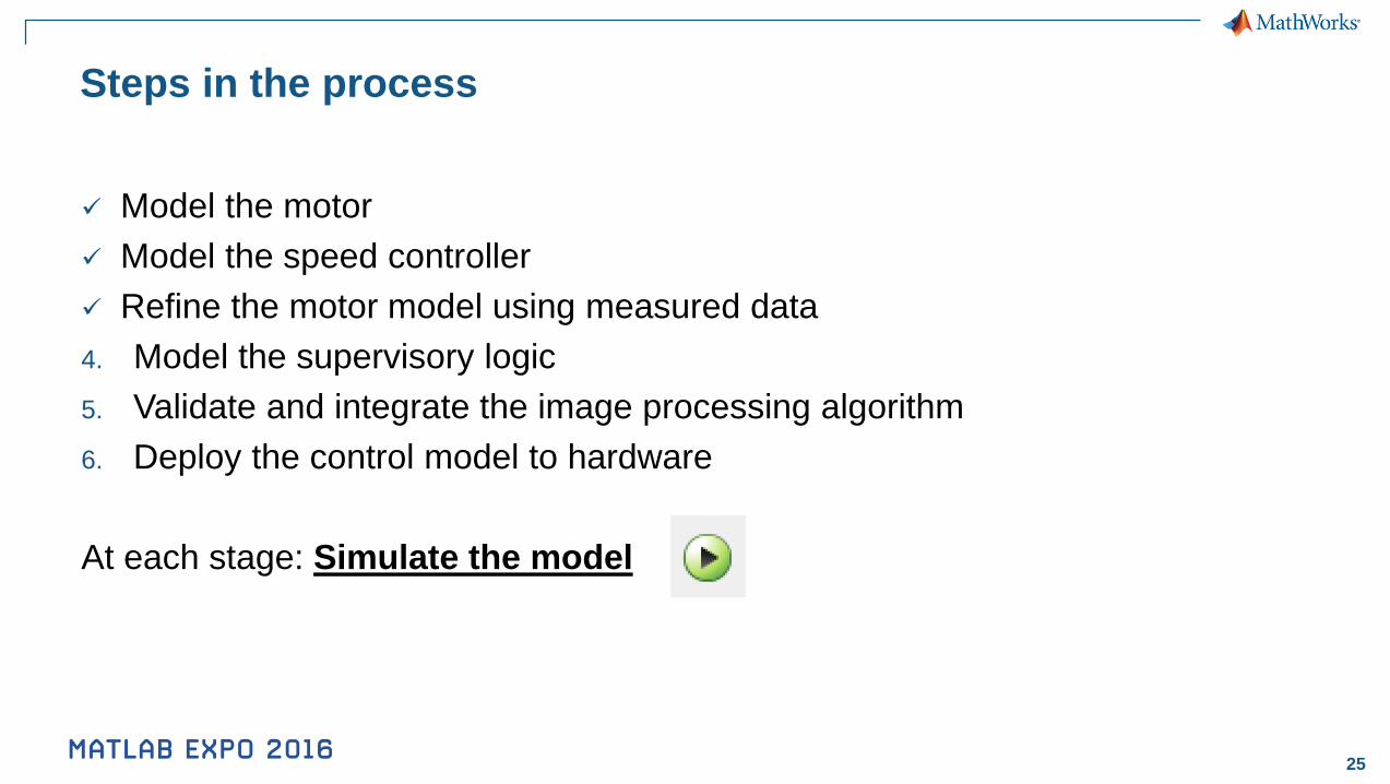
Steps in the process
Model the motor
Model the speed controller
Refine the motor model using measured data
4. Model the supervisory logic
5. Validate and integrate the image processing algorithm
6. Deploy the control model to hardware
At each stage: Simulate the model
26
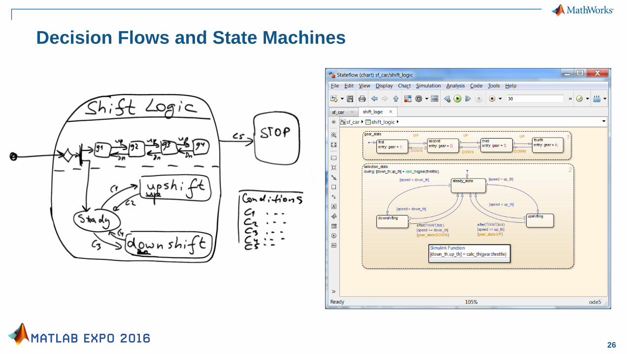
Decision Flows and State Machines
27
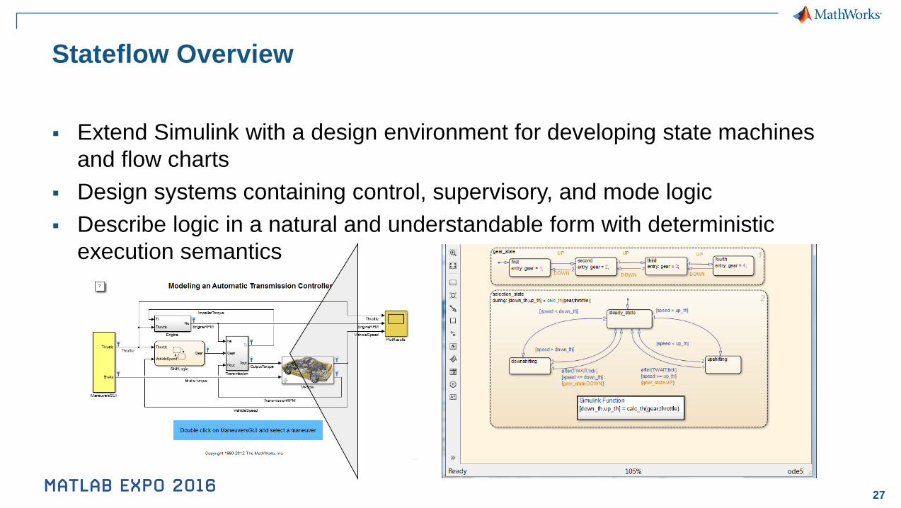
Stateflow Overview
Extend Simulink with a design environment for developing state machines
and flow charts
Design systems containing control, supervisory, and mode logic
Describe logic in a natural and understandable form with deterministic
execution semantics
28
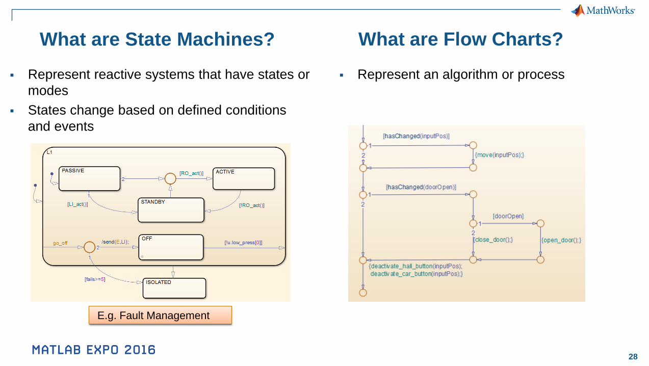
What are State Machines?
Represent an algorithm or process Represent reactive systems that have states or
modes
States change based on defined conditions
and events
What are Flow Charts?
E.g. Fault Management
30
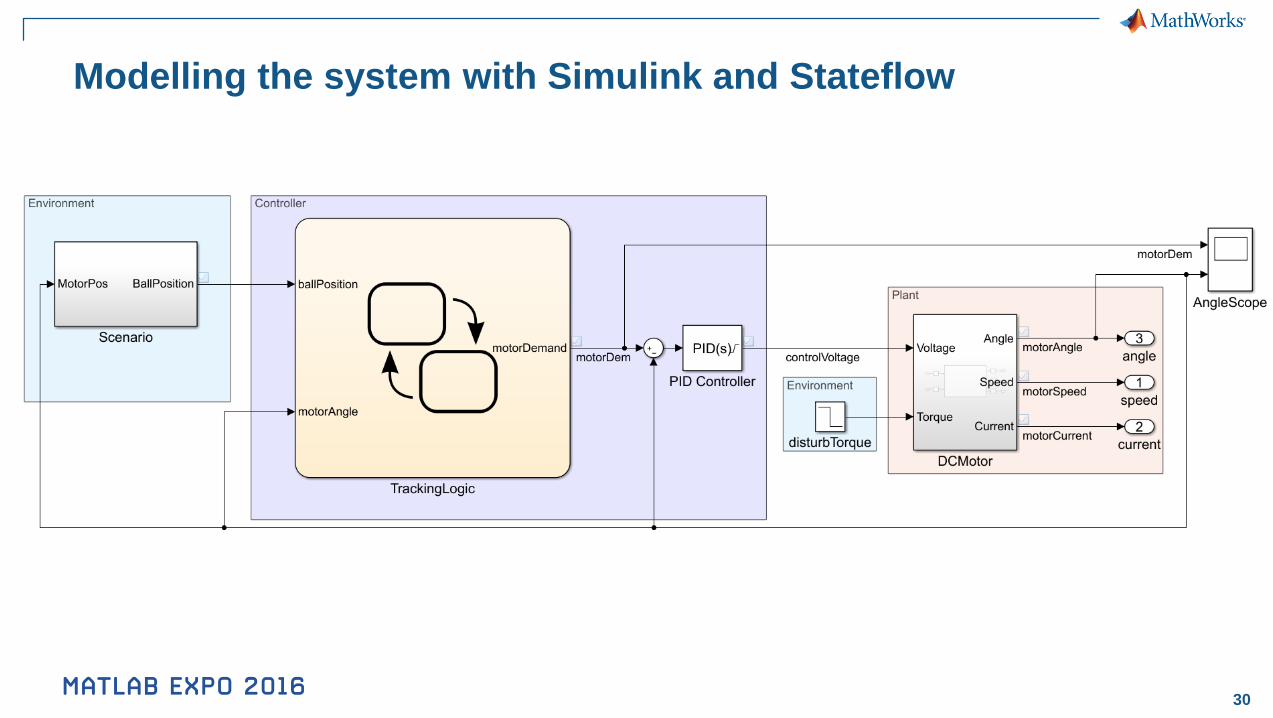
Modelling the system with Simulink and Stateflow
31
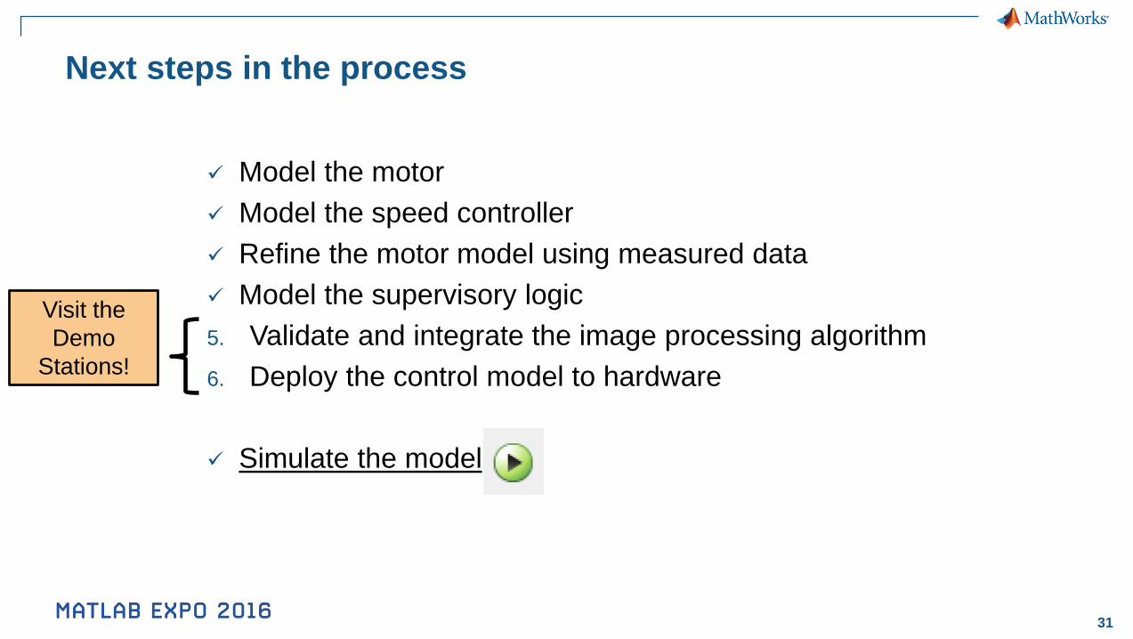
Next steps in the process
Model the motor
Model the speed controller
Refine the motor model using measured data
Model the supervisory logic
5. Validate and integrate the image processing algorithm
6. Deploy the control model to hardware
Simulate the model
Visit the
Demo
Stations!
32
Conclusions
Modelling and simulation gives you insight to make smarter decisions,
earlier
Simulink allows you to model the complete system in a single environment
Accelerate your simulation work with the power of MATLAB
Related Documents


