INTRODUCTION TO SERIAL ARM A robot manipulator consists of links connected by joints. The links of the manipulator can be considered to form a kinematic chain. The business end of the kinematic chain of the manipulator is called the end effector and it is analogous to the human hand. The end effector can be a gripper or can be designed to perform any desired task such as welding, painting, assembly, etc. MECHANICAL DESIGN In constructing the arm, we made use of five servo motors (including gripper) since our structure allows movement in all three dimensions. There is a servo motor at the base, which allows for angular movement of the whole structure; other two at the shoulder and elbow to allow the upward and downward movement of the arm; one for the movement of the wrist while the last servo motor at the end effector allows for the gripping of objects. The serial arm is a four degree of freedom system. Three DOF control the position of the arm in the Cartesian space, one for wrist orientation and one additional servo for actuating gripper. The robot features in the control GUI or teach pendant are base rotation, shoulder, elbow, wrist rotate, and a functional gripper. The base of the robotic arm is made up of Perspex while the links are made up of Aluminium. The serial manipulator uses 1 x HS-485 in the base, 1 x HS-485 in the shoulder, 1 x HS-485 HB in the elbow, 1 x HS-225 in the wrist, and 1 x HS-81 in the gripper.

Welcome message from author
This document is posted to help you gain knowledge. Please leave a comment to let me know what you think about it! Share it to your friends and learn new things together.
Transcript

INTRODUCTION TO SERIAL ARM
A robot manipulator consists of links connected by joints. The links of the manipulator can be considered to form a kinematic chain. The business end of the kinematic chain of the manipulator is called the end effector and it is analogous to the human hand. The end effector can be a gripper or can be designed to perform any desired task such as welding, painting, assembly, etc.
MECHANICAL DESIGN
In constructing the arm, we made use of five servo motors (including gripper) since our structure allows movement in all three dimensions. There is a servo motor at the base, which allows for angular movement of the whole structure; other two at the shoulder and elbow to allow the upward and downward movement of the arm; one for the movement of the wrist while the last servo motor at the end effector allows for the gripping of objects.
The serial arm is a four degree of freedom system. Three DOF control the position of the arm in the Cartesian space, one for wrist orientation and one additional servo for actuating gripper. The robot features in the control GUI or teach pendant are base rotation, shoulder, elbow, wrist rotate, and a functional gripper. The base of the robotic arm is made up of Perspex while the links are made up of Aluminium. The serial manipulator uses 1 x HS-485 in the base, 1 x HS-485 in the shoulder, 1 x HS-485 HB in the elbow, 1 x HS-225 in the wrist, and 1 x HS-81 in the gripper.

Servo motors serve as the actuators at various joint. These motors feature 180 degree rotation in clockwise direction. The motors are controlled by Arduino mega microcontroller board upon receiving commands from a host computer via USB cable.
ASSEMBLY DETAILS OF ARM
Base Servo Motor (HS485-HB)

Disc Motor Holder
Servo Motor (HS485-HB
Link 1 Servo Motor (HS485-HB)
NOTE: Before fixing the links to servo motor’s shaft, the motor shaft be brought to center position (90 degree) and then the links are to be fixed in upright position.

Link-2 Servo Motor HS225-BB
Gripper
Fully Assembled Serial Arm
NOTE: Before fixing the gripper to wrist servo, the motor shaft be brought to center position and then the gripper is to be fixed in a manner shown in the figure above.

ROBOT WORKSPACE
Degrees of Freedom (DOF)
A degree of freedom is a joint on the arm, a place where it can bend or rotate or translate. We can typically identify the number of degrees of freedom by the number of actuators on the robot arm (in case of serial arms). The gripper is often complex with multiple DOF or can be a toll for welding etc., so for simplicity it is treated as separate subsystem in basic robot arm design.
Robot Workspace (Work Volume)
The robot workspace (sometimes known as reachable space) is a collection of points that the end effector (gripper) can reach. The workspace is dependent on the DOF angle/translation limitations, the arm link lengths, the angle at which something must be picked up at, etc. The workspace is highly dependent on the robot configuration. The figure given below describes the workspace for our serial arm. It should be noted that it does not include the DOF which controls the wrist orientation as the workspace is independent of orientation variable.
The shoulder and elbow joints rotate a maximum of 180 degrees. To determine the workspace, trace all locations that the end effector (gripper) can reach as in the image below.

Now rotating that by the base joints another 180 degrees to get 3D work volume. This creates a workspace of a shelled quarter sphere as shown below.

If you change the link lengths you can get very different sizes of workspaces, but this would be the general shape. Any location outside of this space is a location the arm can’t reach. If there are objects in the way of the arm, the workspace can get even more complicated.
Here are a few more robot workspace examples:
Cartesian Gantry Robot Arm
Cylindrical Robot Arm
Spherical Robot Arm

The workspace for our serial arm can be mathematically described in polar coordinates as:
, where L1 and L2 represent the lengths of link 1 and link 2 respectively and r denotes the polar distance Similarly,
L1 = 9.2cm L2 = 11.5cm
INVERSE KINEMATICS
Forward kinematics is the method for determining the orientation and position of the end effector, given the joint angles and link lengths of the robot arm. Inverse kinematics is the opposite of forward kinematics. It is required when we have a desired end effector position, but need to know the joint angles in order to achieve it.
Suppose we have a planar 2 DOF robotic arm. We are required to find the joint angles in order to place the end effector at a particular position in Cartesian space. Coordinates of end effectors are taken as input variables x and y while the base is taken as origin.

, Where d is the polar distance of the end effectors in Cartesian coordinates.
Given length of link 1 and link 2 as L1 and L2 we can find & using cosine formula.
Similarly, can also be calculated using the cosine formula.
Total angular displacement of motor shaft at joint 1 is
Total angular displacement of motor shaft at joint 2 is
ELECTRONICS AND CONTROL
Servo motor
Servos are a special type of DC motors with built in gearing and feedback control loop circuitry and they don’t require motor controllers. These motors are mainly developed for making robots, toys, etc. that are mainly used for education and not for industrial applications.
Servos are becoming extremely popular with robot, RC plane, and RC boat builders. Most servo motors can rotate about 90 to 180 degrees. Some rotate through a full 360 degrees or more. However, servos are unable to continually rotate, meaning they can't be used for driving wheels (unless modified), but their precision positioning makes them ideal for robot arms and legs, rack and pinion steering, and sensor scanners to name a few. Since servos are fully self contained, the velocity and angle control loops are very easy to implement. To use a servo, we connect the black wire to ground, the red to a 4.8-6V source, and the yellow/white wire to a signal source (such as from your microcontroller). Vary the square wave pulse width from 1-2ms and the servo is now position/velocity controlled.
Servo Wiring: All servos have three wires: Black or Brown is for ground. Red is for power (~4.8-6V). Yellow, Orange, or White is the signal wire (3-5V). Servo Voltage (Red and Black/Brown wires):

Servos can operate under a range of voltages. Typical operation is from 4.8V to 6V. There are a few micro sized servos that can operate at less, and now a few Hitec servos that operate at much more.
Signal Wire (Yellow/Orange/White wire):
While the black and red wires provide power to the motor, the signal wire is what we use to command the servo. The general concept is to simply send an ordinary logic square wave to your servo at a specific wave length (50Hz), and the servo goes to a particular angle. The wavelength directly maps to servo angle. In our case Arduino Mega takes input from the PC and generates the corresponding square wave, which in turn controls the angular position of the servo motor.
The standard time vs. angle is represented in this chart:
BASIC CONCEPT OF ARDUINO
Overview
An Arduino is a single-board microcontroller and a software suite for programming. It is designed for an Atmel AVR processor and features on-board I/O support. The software consists of a standard programming language and the boot loader that runs on the board.
We are using Arduino Mega microcontroller board based on the ATmega1280.
It has 54 digital input/output pins (of which 14 can be used as PWM outputs), 16 analog inputs, 4 UARTs (hardware serial ports), a 16 MHz crystal oscillator, a USB connection, a power jack, an ICSP header, and a reset button.
It contains everything needed to support the microcontroller; simply connect it to a computer with a USB cable or power it with an AC-to-DC adapter or battery to get started.
POWER: The Arduino Mega can be powered via the USB connection or with an external power supply. The power source is selected automatically.
The power pins are as follows:
VIN: The input voltage to the Arduino board when it's using an external power source.
5V: The regulated power supply used to power the microcontroller and other components on the board.
3V3: 3.3 volt supply generated by the on-board FTDI chip. Maximum current draw is 50 mA.
GND: Ground pins.
MEMORY: The ATMEGA 1280 has 128 KB of flash memory for storing code.
COMMUNICATION: The Arduino software includes a serial monitor which allows simple textual data to be sent to and from the Arduino board. The RX and TX LEDs on the board will flash when data is being transmitted via the FTDI chip and USB connection to the computer (but not for serial communication on pins 0 and 1. It has a number of facilities for communicating with a computer, another Arduino, or other microcontrollers.
How To Get Arduino Running on Windows
These are the steps that we'll go through:
1. Get an Arduino board and cable

2. Download the Arduino environment 3. Install the USB drivers 4. Connect the board 5. Run the Arduino environment 6. Upload a program 7. Look for the blinking LED 8. Learn to use Arduino
1 | Get an Arduino board and cable
In this tutorial, we assume you're using an Arduino Mega.
The Arduino is a simple board that contains everything you need to start working with electronics and microcontroller programming. This diagram illustrates the major components of an Arduino Mega.
You also need a standard USB cable (A plug to B plug): the kind you would connect to a USB printer, for example.
2 | Download the Arduino environment

To program the Arduino board you need the Arduino environment.
When the download finishes, unzip the downloaded file. Make sure to preserve the folder structure. Double-click the folder to open it. There should be a few files and sub-folders inside.
3 | Locate the USB drivers
If you are using a USB Arduino, you will need to install the drivers for the FTDI chip on the board. These can be found in the drivers/FTDI USB Drivers directory of the Arduino distribution. In the next step ("Connect the board"), you will point Window's Add New Hardware wizard to these drivers.
4 | Connect the board
On Arduino, the power source is selected by the jumper between the USB and power plugs. To power the board from the USB port (good for controlling low power devices like LEDs), place the jumper on the two pins closest to the USB plug. To power the board from an external power supply (6-12V), place the jumper on the two pins closest to the power plug. On the Arduino Mega, the power source is selected automatically (there is no power selection jumper). In any case, connect the board to a USB port on your computer.
The green power LED (labeled PWR) should go on.
The Add New Hardware wizard will open. Tell it not to connect to Windows update and click next.

Then select "Install from a list or specified location (Advanced)" and click next.

Make sure that "Search for the best driver in these locations is checked"; uncheck "Search removable media"; check "Include this location in the search" and browse to the location you unzipped the USB drivers to in the previous step. Click next.
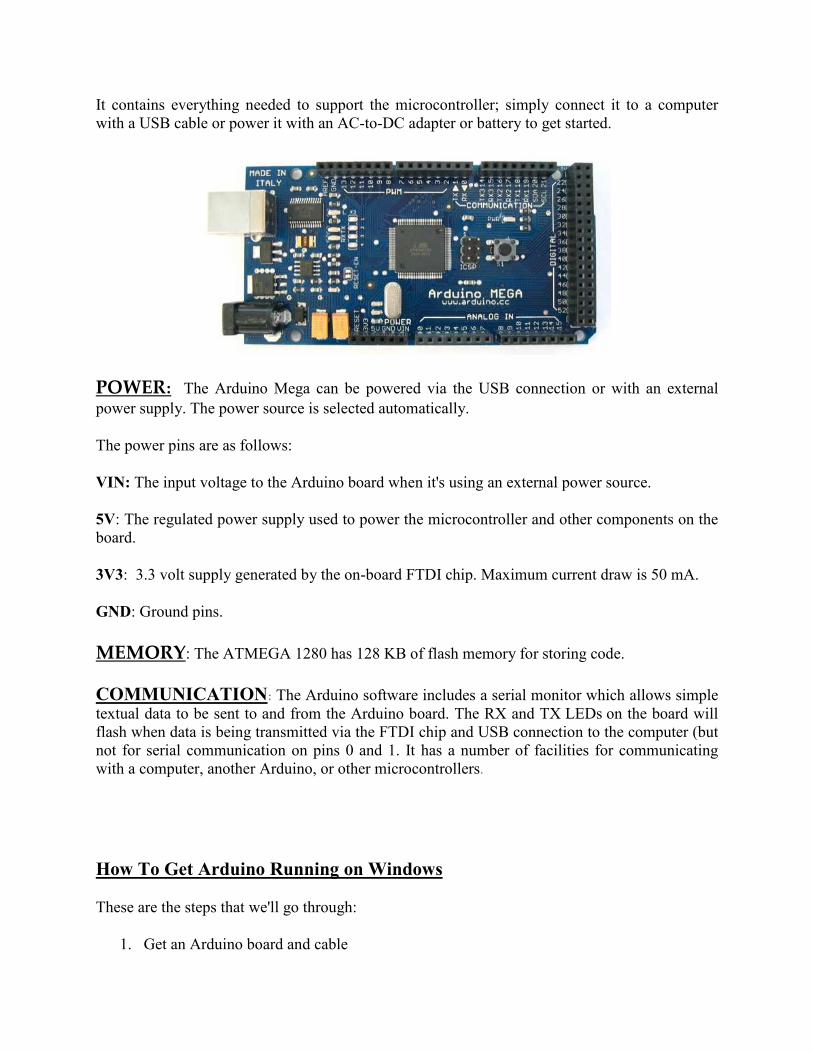
The wizard will search for the driver and then tell you that a "USB Serial Converter" was found. Click finish.
The new hardware wizard will appear again. Go through the same steps. This time, a "USB Serial Port" will be found.
5 | Run the Arduino environment
Open the Arduino folder and double-click the Arduino application.
6 | Initialize
You'll need to select the entry in the Tools > Board menu that corresponds to your Arduino Mega.

Select the serial device of the Arduino board from the Tools > Serial Port menu. On Windows, this should be COM3, COM4, COM5 or a higher COM address for a USB board.

To find out which COM port it is, open the Windows Device Manager (in the Hardware tab of System control panel). Look for a "USB Serial Port" in the Ports section; that's the Arduino board.

GETTING STARTED
A) Install Software for ARDUINO MEGA: Download the Arduino IDE from the following link, http://arduino.cc/en/Main/Software Complete installation as per the instructions given in the previous section. B) Install DEV C++ : Download and install DEV C++ from the following link http://www.brothersoft.com/dev-c++-65296.html. C) Make the Electrical Connections from SERIAL ARM to the ARDUINO MEGA.
Ø Connect the red and black wires of all the servo motors to 5V power supply and
ground respectively. Ø Connect the yellow wires (control signal) of the base, shoulder, elbow, wrist and
gripper servo motors to PWM pin 3, 7, 8, 10 and 12 respectively on the Arduino Mega.
Ø Connect a common ground wire from the 5V power supply to the “gnd” pin on Arduino Mega.
D) Connect the ARDUINO MEGA to the System using USB CABLE.
E) Copy the CONTROL SOFTWARE to the PC.
Ø code.c Ø serial.h Ø code.exe
Related Documents