Introduction to Scalable Multi-Port Converters Modeling and control of an arbitrary number of power ports This work has been conducted within the project EPT300, co-funded by grants from Austria, Germany, The Netherlands, France, Italy, Portugal and the ENIAC Joint Undertaking. Bas Vermulst June 14, 2016

Welcome message from author
This document is posted to help you gain knowledge. Please leave a comment to let me know what you think about it! Share it to your friends and learn new things together.
Transcript

Introduction to Scalable Multi-Port
Converters Modeling and control of an arbitrary number of power ports
This work has been conducted within the project EPT300, co-funded by grants from Austria,
Germany, The Netherlands, France, Italy, Portugal and the ENIAC Joint Undertaking.
Bas Vermulst
June 14, 2016

Trends in power electronics: multi-port converters
• Traditional power converters
− One input, one output
− Unidirectional power flow
− Stages for ac-dc and dc-dc
• Recent developments
− Multi-port
− Bidirectional power flow
− Combined dc-dc and ac-dc conversion
1

bi-directional multi-port converter
Example application
Household equipment
Photovoltaics Mains grid Stationary battery
Electric vehicle

Topology concept
• Active bridge (AB) as building block
• Number of active bridges is variable
…
…
AB 1
AB 2
AB 3
AB i

Topology concept
• Properties:
− Modular and scalable structure
− Bi-directional power flow
− Galvanically isolated ports
− Little passive components
…

Modeling
• Fourier-based modeling approach
− Steady-state solutions
− Low computational effort
• Allows analysis of
− Power transfer
− Voltage and current waveforms
− Switching transients
− Conduction losses
5
Modeling
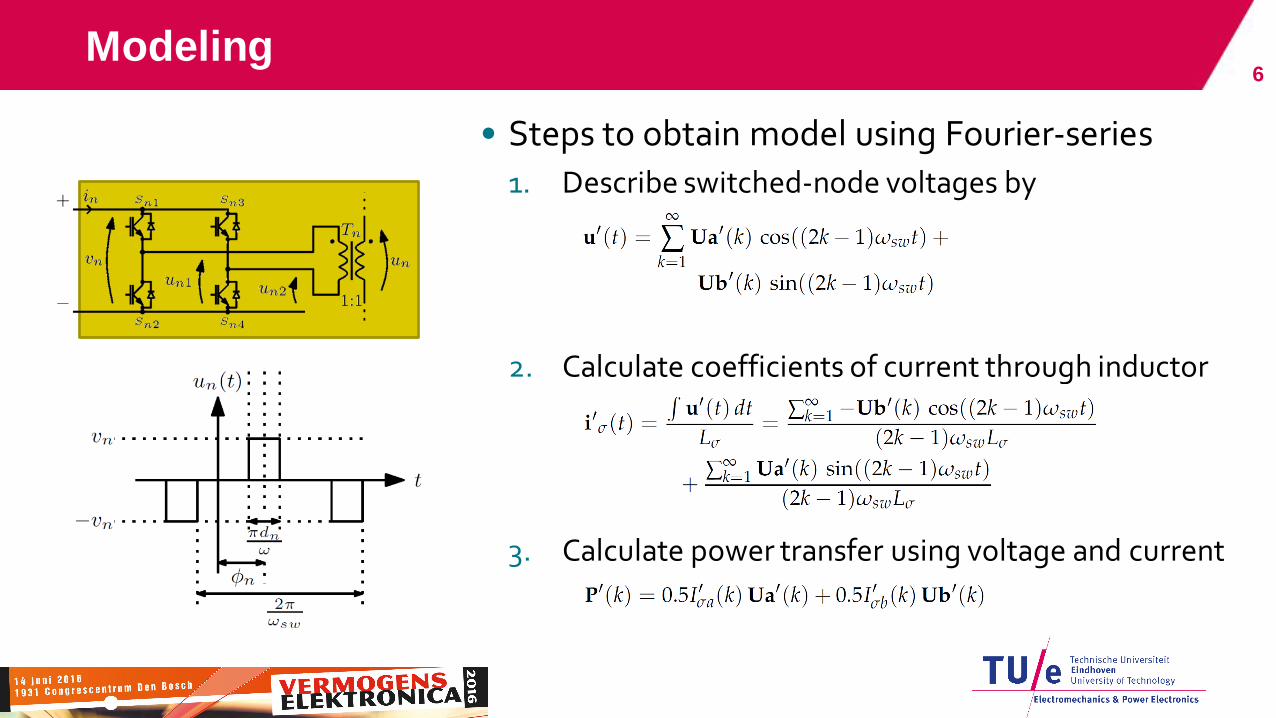
• Steps to obtain model using Fourier-series
1. Describe switched-node voltages by
2. Calculate coefficients of current through inductor
3. Calculate power transfer using voltage and current
6

Modeling accuracy 7
(a) Fourier-based model,
truncated at 25 harmonics
(b) Plexim PLECS simulation

Evaluating soft-switching properties
• Steps to analyze soft-switching
1. Determine transient instants
2. Calculate current at these instants (truncation!)
3. Check if sufficient current to charge parasitics within dead-time
8
etc…

Modeling accuracy 9
(a) Truncation of harmonics vs
duty cycle and accuracy (fixed phase shift)
(b) Accuracy of first-harmonic approximation
for all operating points
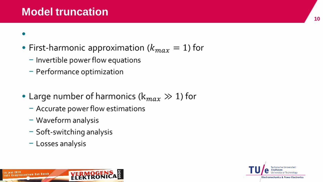
Model truncation
•
10

Modulation scheme
• Use first-harmonic approximation in Newton optimization
− Cost function contains circulating current (i.e. conduction losses)
− Lagrange operator to include power constraints (i.e. reference tracking)
• Results in duty-cycle at given phase shift with minimum circulating current
11
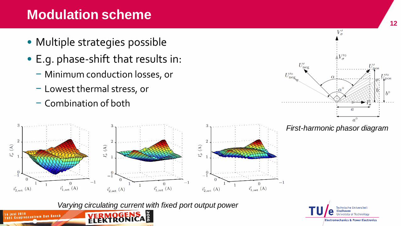
• Multiple strategies possible
• E.g. phase-shift that results in:
− Minimum conduction losses, or
− Lowest thermal stress, or
− Combination of both
12 Modulation scheme
Varying circulating current with fixed port output power
First-harmonic phasor diagram

Modulation scheme 13
(a) Optimized modulation,
minimum circulating current
(b) Phase-shift modulation,
no optimization
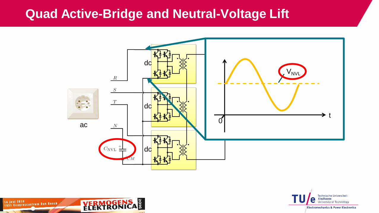
dc
Quad Active-Bridge and Neutral-Voltage Lift
VNVL
t 0
ac
dc
dc
dc

Prototype
Parameter Value
Maximum output power 20 kW
Power ports 4 (“QAB”)
Neutral-voltage lift
Semiconductor material SiC
Switching frequency 45 kHz
Cooling Forced air
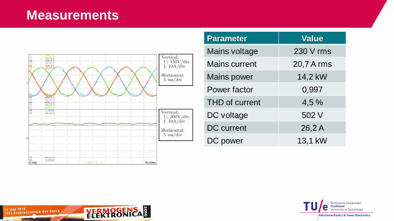
Measurements
Parameter Value
Mains voltage 230 V rms
Mains current 20,7 A rms
Mains power 14,2 kW
Power factor 0,997
THD of current 4,5 %
DC voltage 502 V
DC current 26,2 A
DC power 13,1 kW

Measurements
Parameter Value
Mains power 5 kW -5 kW

Measurements 18
• Converter start-up behavior

Measurements
Parameter Value
Mains voltage 230 V rms
DC voltage 500 V
Operating mode Inverter

Conclusion
• Framework for multi-port converters
− Topology concept
− Modeling
− Modulation scheme
− Neutral-voltage lift for ac-connections
• Experimental verification on 20 kW prototype in ac-dc application
• Multi-port converters are a competitive solution in a wide range of applications
20
Related Documents