Introduction to Multicopter Design and Control Quan Quan , Associate Professor [email protected] BUAA Reliable Flight Control Group, http://rfly.buaa.edu.cn/ Beihang University, China Lesson 14 Health Evaluation and Failsafe

Welcome message from author
This document is posted to help you gain knowledge. Please leave a comment to let me know what you think about it! Share it to your friends and learn new things together.
Transcript

Introduction to MulticopterDesign and Control
Quan Quan , Associate [email protected]
BUAA Reliable Flight Control Group, http://rfly.buaa.edu.cn/Beihang University, China
Lesson 14 Health Evaluation and Failsafe

2016/12/25 2
Whatkindofeventsareinvolvedinsafetyissue?
Howaretheseeventsdealtwith?
Preface
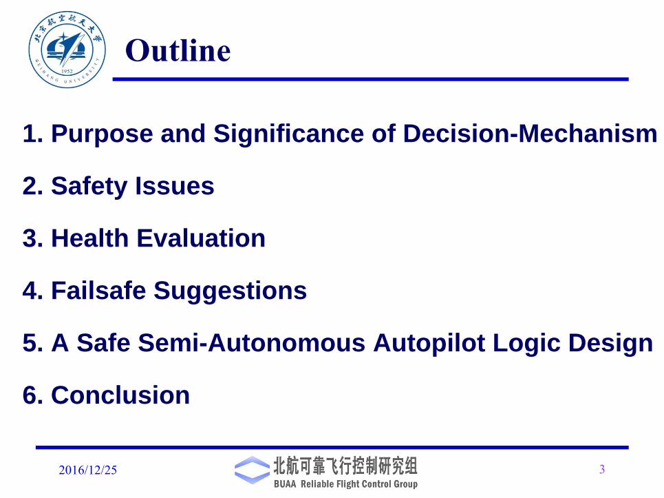
Outline
1. Purpose and Significance of Decision-Mechanism
2. Safety Issues
3. Health Evaluation
4. Failsafe Suggestions
5. A Safe Semi-Autonomous Autopilot Logic Design
6. Conclusion
2016/12/25 3

1. Purpose and Significance of Decision-Mechanism
2016/12/25 4
The main reasons for multicopters to have decision-making
modules in the form of flight modes are as follows:
1. Bringing flight process under remote pilot's control
2. Adapting to different flight missions.
3. Adapting to different anomalies.
4. Better interpretation of the user demands.
2016/12/25 5
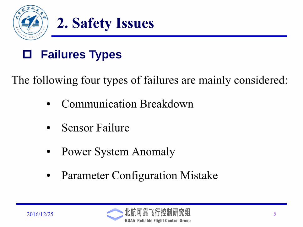
The following four types of failures are mainly considered:
• Communication Breakdown
• Sensor Failure
• Power System Anomaly
• Parameter Configuration Mistake
2. Safety Issues
Failures Types
Communication Breakdown
2016/12/25 6
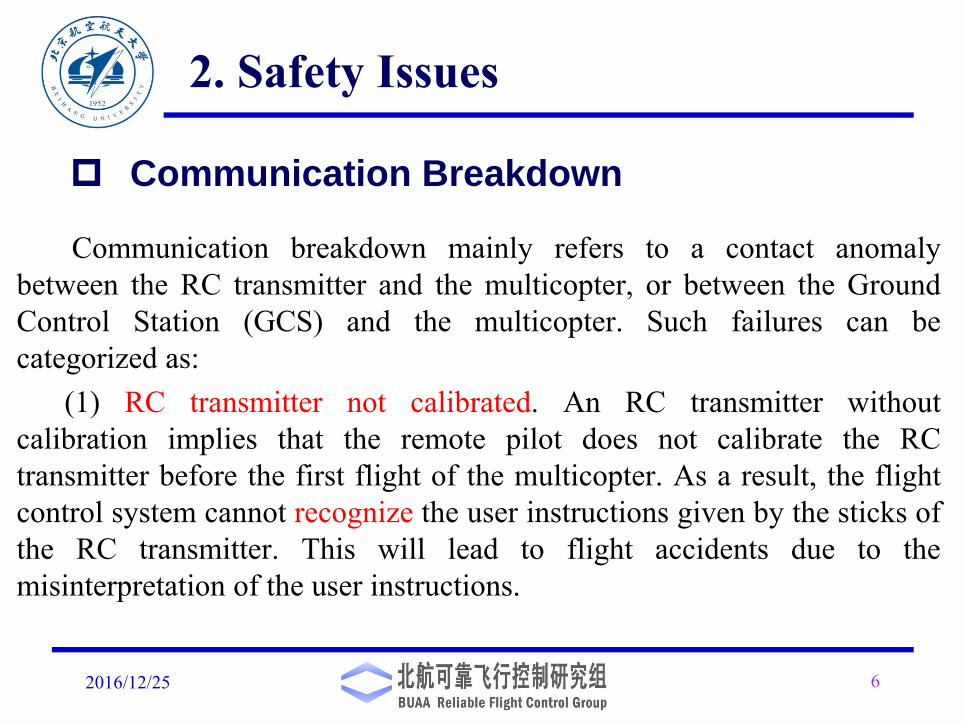
Communication breakdown mainly refers to a contact anomalybetween the RC transmitter and the multicopter, or between the GroundControl Station (GCS) and the multicopter. Such failures can becategorized as:
(1) RC transmitter not calibrated. An RC transmitter withoutcalibration implies that the remote pilot does not calibrate the RCtransmitter before the first flight of the multicopter. As a result, the flightcontrol system cannot recognize the user instructions given by the sticks ofthe RC transmitter. This will lead to flight accidents due to themisinterpretation of the user instructions.
2. Safety Issues

Communication Breakdown
2016/12/25 7
(2) Loss of RC. Loss of RC implies that the RC transmitter isunable to communicate with the corresponding RC receiver onboardbefore the multicopter takes off or during flight. The loss of RC willresult in the multicopter going out of control and leading to an accident
(3) Loss of GCS. Loss of GCS implies that the GCS is unable tocommunicate with the corresponding multicopter before themulticopter takes off or during flight. The loss of GCS will cause themulticopter to fail to reach the desired position, and then the task fails
2. Safety Issues

2016/12/25 8
Sensor failure mainly implies that a sensor on the multicoptercannot measure accurately, or cannot work properly. Such failures canbe categorized as follows.
(1) Barometer failure.
Barometer failure will cause a multicopter to fail to measure the flightaltitude accurately. The reasons include:
1) Barometer hardware failure. 2) Height measurement results frombarometers and other height measurement sensors (ultrasonic rangefinder, etc.) are inconsistent.
2. Safety Issues
Sensor Failure
2016/12/25 9
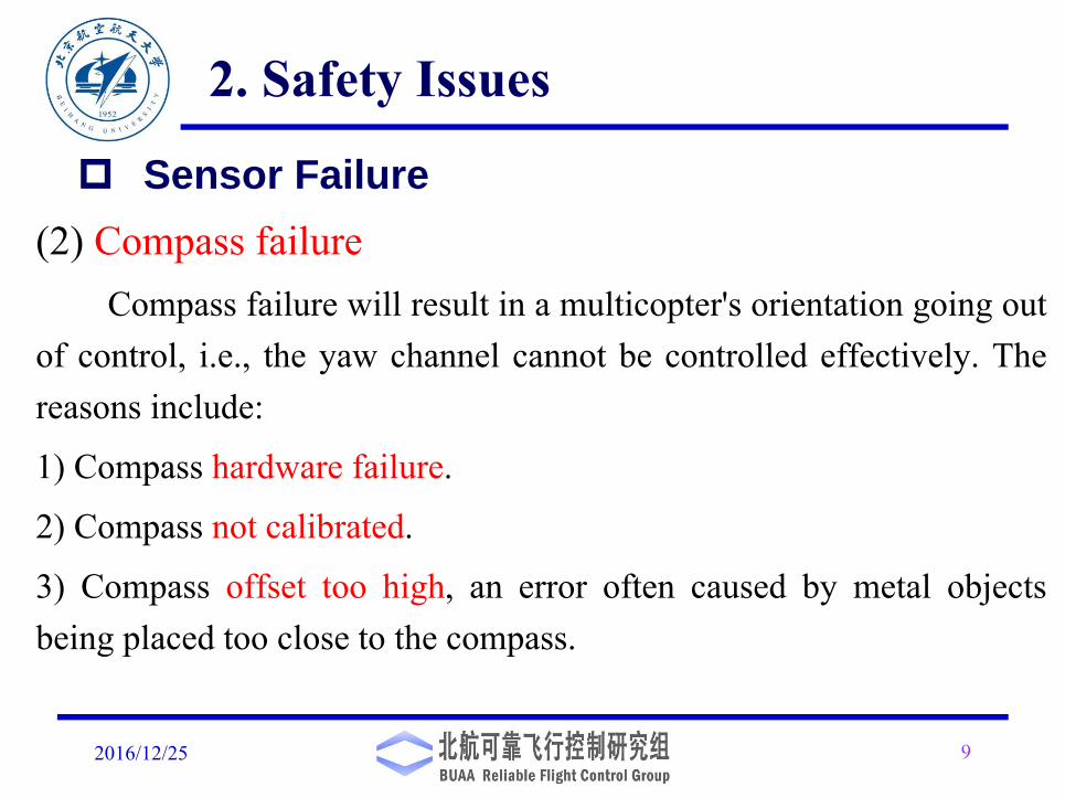
(2) Compass failureCompass failure will result in a multicopter's orientation going out
of control, i.e., the yaw channel cannot be controlled effectively. Thereasons include:
1) Compass hardware failure.
2) Compass not calibrated.
3) Compass offset too high, an error often caused by metal objectsbeing placed too close to the compass.
2. Safety Issues
Sensor Failure
2016/12/25 10
(2) Compass failure
4) Regional magnetic field too high or too low (For example, it is35% above or below expected value).
5) The internal and external are pointing to different directions(For example, the difference is greater than 45 degrees. This isnormally caused by the external compass orientation being setincorrectly).
2. Safety Issues
Sensor Failure
2016/12/25 11
(3) GPS failure
GPS failure implies that a GPS module cannot measure thelocation information accurately. In this case, the multicoptercannot hover or complete the pre-programmed route. After losingthe location information from the GPS, the position estimationwithin several seconds is only acceptable with dead reckoning
2. Safety Issues
Sensor Failure

2016/12/25 12
(4) Inertial Navigation System (INS) failureINS failure mainly indicates anomalies in accelerometers andgyroscopes, which implies that the system cannot correctlymeasure attitude angle and attitude angular rate. The reasonsinclude:1) INS is not calibrated2) Accelerometer or gyroscope hardware failures.3) Measurements of different gyroscopes and accelerometers areinconsistent.
2. Safety Issues
Sensor Failure
2016/12/25 13
(4) Inertial Navigation System (INS) failureINS failure mainly indicates anomalies in accelerometers andgyroscopes, which implies that the system cannot correctlymeasure attitude angle and attitude angular rate. The reasonsinclude:1) INS is not calibrated2) Accelerometer or gyroscope hardware failures.3) Measurements of different gyroscopes and accelerometers areinconsistent.
2. Safety Issues
Sensor Failure
Propulsion System Anomaly
2016/12/25 14
Propulsion system anomaly mainly refers to either battery failure, or hardwarefailure of propulsors of the flight control system caused by batteries, ElectronicSpeed Controllers (ESCs), motors or propellers.(1) Battery failure. This usually refers to a lack of power caused by low battery
capacity or a degradation in the battery life, and is mainly reflected in the followingthree aspects.(2) ESC failure. This is mainly reflected in the following two aspects. 1) An ESCcannot correctly recognize the PWM instructions given by the autopilot. 2) An ESCis unable to provide a correct output voltage to the motor.(3) Motor failure. This mainly means that the output speed is incorrect under acertain input voltage.(4) Propeller failure. This is mainly caused by worn and broken blades, or a looseblade from the propeller shaft, etc.
2. Safety Issues
Propulsion System Anomaly
2016/12/25 15
For small drones, the possibility of actuator failure is rather small. Such afailure often occurs in the case that the motor and propeller are damaged due toa strong collision caused by the improper operation of remote pilot.
1) These crashes will further cause the poor contact in the wires connecting themotor to ESC.
2) due to an aggressive maneuver or a motor rotation jam, the working currentmay be too high so that it damages these electronic components and relatedsolder joints.
3) These components have reached their life span.
4) For motors, the phenomenon of demagnetization may occur under workingcondition with high temperature
2. Safety Issues
2016/12/25 16
This kind of mistake mainly indicates the inappropriate parameterconfiguration of autopilot by users, such as parameters of PIDcontrollers, parameters of filters, failure threshold, etc.
2. Safety Issues
Parameter Configuration Mistake
ACRO_BAL_ROLL/PITCH: the ACRO_BAL_ROLL parameter is higher than the
Stabilize Roll P and/or ACRO_BAL_PITCH parameter is higher than the Stabilize
Pitch P value. This could lead to the pilot being unable to control the lean angle in
ACRO mode because the Acro Trainer stabilization would overpower the pilot’s input.
From: http://ardupilot.org/copter/docs/prearm_safety_check.html
3. Health Evaluation
2016/12/25 17
Health evaluation refers to the process of judging whether the
system is working properly and whether there is an anomaly or a
potential failure in the system during a certain period of time in the
future. Such a process is important in order to guarantee the safety
of a multicopter. This section contains two parts, i.e., the pre-flight
health check (offline) and in-flight health evaluation (online).
Difference between health evaluation and fault diagnosis ?
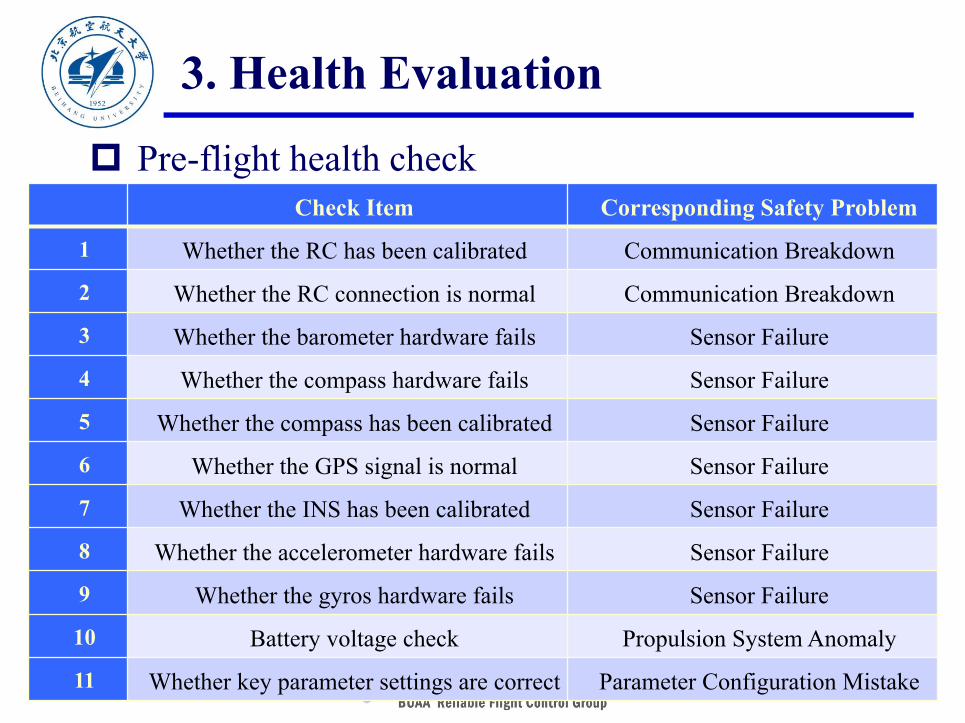
Pre-flight health check
2016/12/25 18
Check Item Corresponding Safety Problem
1 Whether the RC has been calibrated Communication Breakdown
2 Whether the RC connection is normal Communication Breakdown
3 Whether the barometer hardware fails Sensor Failure
4 Whether the compass hardware fails Sensor Failure
5 Whether the compass has been calibrated Sensor Failure
6 Whether the GPS signal is normal Sensor Failure
7 Whether the INS has been calibrated Sensor Failure
8 Whether the accelerometer hardware fails Sensor Failure
9 Whether the gyros hardware fails Sensor Failure
10 Battery voltage check Propulsion System Anomaly
11 Whether key parameter settings are correct Parameter Configuration Mistake
3. Health Evaluation
Pre-flight health check
2016/12/25 19
3. Health Evaluation
Before a user tries to arm a multicopter, it is suggested that the
autopilot automatically check the eleven items. If any of these
items does not pass the health check, then the autopilot should
give the corresponding warning using LED lights onboard. If the
GCS and the multicopter are connected, then the occurrence and
reasons of corresponding safety problems will be indicated by
the GCS.
2016/12/25 20
(1) Real-time health evaluation for communication channels
If the multicopter has not received a signal from the RC transmitterfor a certain period of time (e.g. 5 seconds), then it is inferred that theRC transmitter has lost contact with the multicopter.
If the multicopter has not receive the waypoint from the GCS for acertain period of time (e.g. 5 seconds), then it is inferred that the GCShas lost contact with the multicopter.
In-flight health evaluation
3. Health Evaluation

2016/12/25 21
(2) Real-time health evaluation for sensorsExcept for GPS, health evaluation of sensors often requires that themulticopter be preferably in a steady state, because the output of each sensoris then stable.
• If the height of the multicopter cannot be stabilized, then the possibility ofan anomaly in the barometer is high.
• If the rotation phenomenon occurs in the multicopter, then the possibilityof an unhealthy compass is high.
• If severe oscillations occur in the multicopter, then the possibility of anunhealthy INS is high.
In-flight health evaluation
3. Health Evaluation
2016/12/25 22
(2) Real-time health evaluation for sensorsMethods for the health evaluation of the compass and GPS are
given in APM:
1) Compass health evaluation
i) The magnetic interference from the propulsion system can bereflected by the "mag_field" value returned by the multicopter.
ii) The compensation dosage for each direction of the compass shouldbe between -400 to 400 milligauss. If it is not in this range, then it isconsidered that there is a problem in the compass.
In-flight health evaluation
3. Health Evaluation

2016/12/25 23
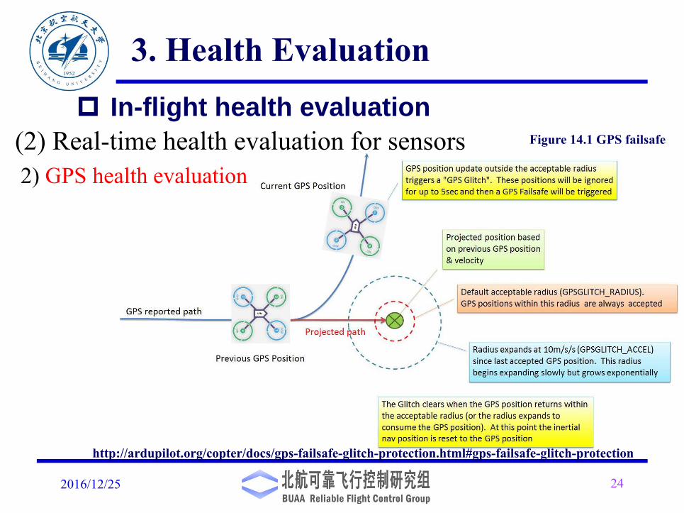
(2) Real-time health evaluation for sensors
2) GPS health evaluation
The GPS health evaluation is based on the position estimation and
position measurement from the GPS, where the estimation of the position
is updated by using Extended Kalman Filter (EKF) combined with the
data obtained by the Inertial Measurement Unit (IMU). If the difference
between the two values is less than the parameter "EKF_POS_GATE",
then the GPS is considered healthy. Otherwise, it is considered unhealthy.
In-flight health evaluation
3. Health Evaluation
2016/12/25 24
(2) Real-time health evaluation for sensors2) GPS health evaluation
http://ardupilot.org/copter/docs/gps-failsafe-glitch-protection.html#gps-failsafe-glitch-protection
In-flight health evaluation
3. Health Evaluation
Figure 14.1 GPS failsafe

2016/12/25 25
(3)Real-time health evaluation for the propulsion system1)Model-based health evaluation for the motor and propeller
Multicopter model:
Control effectiveness matrix:1 : healthy, 0.5 : sub-healthy, 0 : unhealthy
Health evaluation is translated into the evaluation of the controleffectiveness matrix.
1 2diag , , , n Λ
1
T
k k k k k
k k k
x f x BΛ u Γw
y C x v
In-flight health evaluation
3. Health Evaluation

2016/12/25 26
Here, Augmented-EKF is used to estimate .
Assuming that satisfies
ηη
1 1,
1 2,
k k k k
k k k
η η ξ εξ ξ ε
where and are Gaussian white noise . Then, the extended systemis
1,kε 2,kε 1
1 1,
1 2,
1T
1
1
k k k kk
k k k k
k k k
k
k k k
k
f x BΛ u Γwxη η ξ εξ ξ ε
xy C 0 η v
ξ
In-flight health evaluation
3. Health Evaluation
2016/12/25 27
( 3)Real-time health evaluation for the propulsion
system
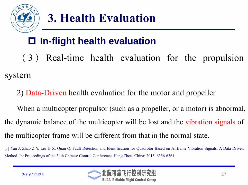
2) Data-Driven health evaluation for the motor and propeller
When a multicopter propulsor (such as a propeller, or a motor) is abnormal,
the dynamic balance of the multicopter will be lost and the vibration signals of
the multicopter frame will be different from that in the normal state.[1] Yan J, Zhao Z Y, Liu H X, Quan Q. Fault Detection and Identification for Quadrotor Based on Airframe Vibration Signals: A Data-Driven
Method. In: Proceedings of the 34th Chinese Control Conference. Hang Zhou, China: 2015. 6356-6361.
In-flight health evaluation
3. Health Evaluation
3.2 In-flight health evaluation
2016/12/25 28
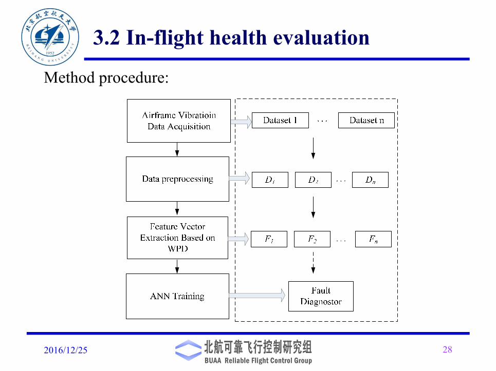
Method procedure:

3.2 In-flight health evaluation
2016/12/25 29
Feature extraction:

3.2 In-flight health evaluation
2016/12/25 30
Health status:
ANN training:
Figure 14.2 Propeller faultless
3.2 In-flight health evaluation
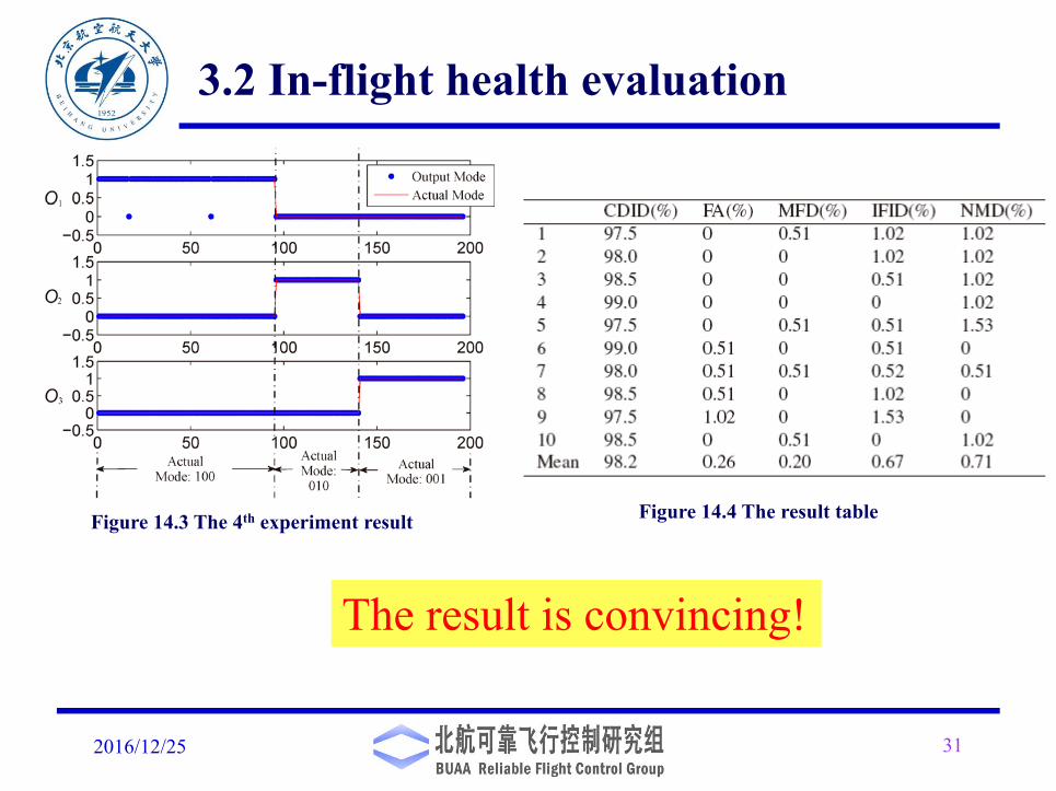
2016/12/25 31
The result is convincing!
Figure 14.3 The 4th experiment result Figure 14.4 The result table
2016/12/25 32
(3)Real-time health evaluation for the propulsion system
3)Battery health evaluation
In practice, the terminal voltage of the battery can be used as an
indicator of battery capacity, and the resistance can be used as an
indicator of battery life. In references, State of Charge (SoC) is used to
reflect the battery capacity. The value covers the range [0,1], where
SoC=1 represents fully charged, SoC=0 represents fully discharged.
In-flight health evaluation
3. Health Evaluation
3)Battery health evaluation
2016/12/25 33
There exists a filter-based SoC and battery resistance estimation method.
Based on above equations. Filter-based method can be used to estimate SoC and R.
3. Health Evaluation
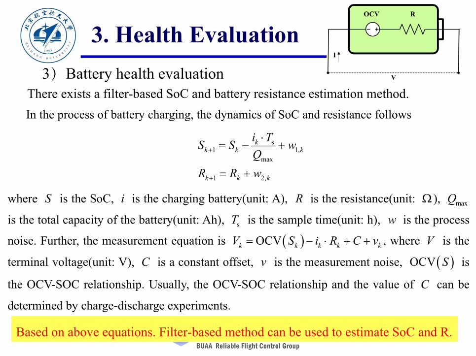
In the process of battery charging, the dynamics of SoC and resistance follows
s1 1,
max
1 2,
kk k k
k k k
i TS S wQ
R R w
where S is the SoC, i is the charging battery(unit: A), R is the resistance(unit: ), maxQ
is the total capacity of the battery(unit: Ah), sT is the sample time(unit: h), w is the process
noise. Further, the measurement equation is OCVk k k k kV S i R C v , where V is the
terminal voltage(unit: V), C is a constant offset, v is the measurement noise, OCV S is
the OCV-SOC relationship. Usually, the OCV-SOC relationship and the value of C can be
determined by charge-discharge experiments.
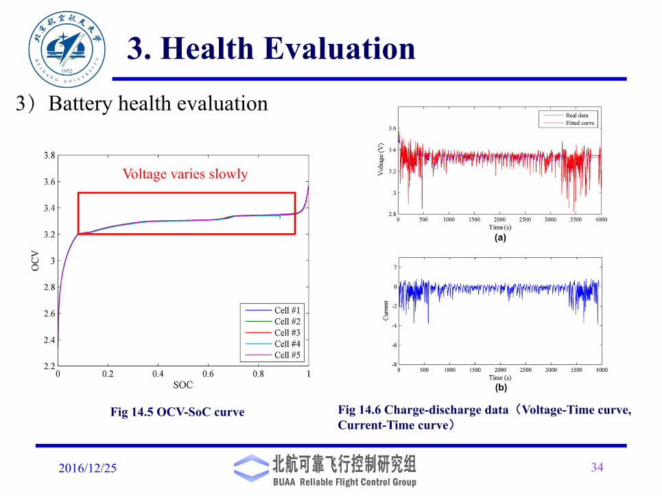
2016/12/25 34
Fig 14.6 Charge-discharge data(Voltage-Time curve, Current-Time curve)
Fig 14.5 OCV-SoC curve
Voltage varies slowly
3. Health Evaluation3)Battery health evaluation
2016/12/25 35
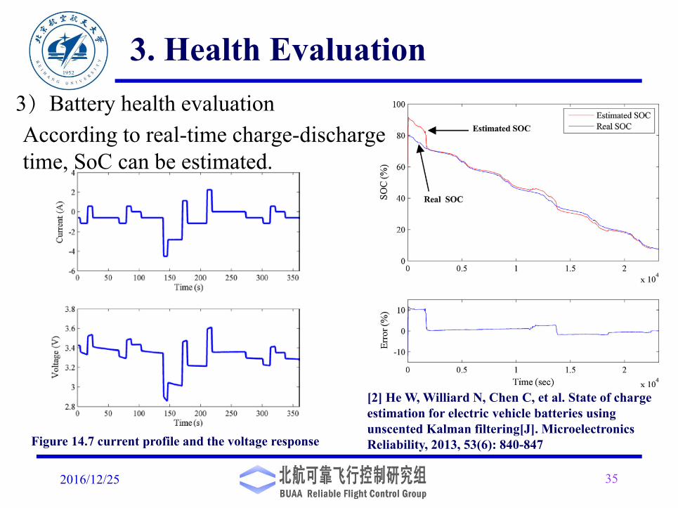
[2] He W, Williard N, Chen C, et al. State of charge estimation for electric vehicle batteries using unscented Kalman filtering[J]. Microelectronics Reliability, 2013, 53(6): 840-847
3. Health Evaluation
According to real-time charge-discharge time, SoC can be estimated.
3)Battery health evaluation
Figure 14.7 current profile and the voltage response
4. Failsafe Suggestions
2016/12/25 36
Failsafe of key components of a multicopter will be carried out
in the pre-flight process. Here, introduce a few falisafe suggestions
for key components:
1. RC transmitter failsafe
2. Sensor failsafe
3. Propulsion system failsafe
A failsafe is that, in the event of a specific type of failure, responds in a way that will cause no harm, or at least a minimum of harm, to other devices or to personnel.
RC transmitter failsafe
2016/12/25 37
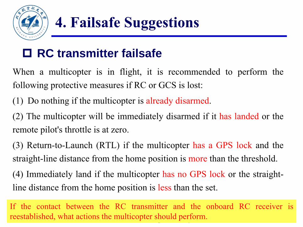
When a multicopter is in flight, it is recommended to perform thefollowing protective measures if RC or GCS is lost:
(1) Do nothing if the multicopter is already disarmed.
(2) The multicopter will be immediately disarmed if it has landed or theremote pilot's throttle is at zero.
(3) Return-to-Launch (RTL) if the multicopter has a GPS lock and thestraight-line distance from the home position is more than the threshold.
(4) Immediately land if the multicopter has no GPS lock or the straight-line distance from the home position is less than the set.
If the contact between the RC transmitter and the onboard RC receiver isreestablished, what actions the multicopter should perform.
4. Failsafe Suggestions
2016/12/25 38
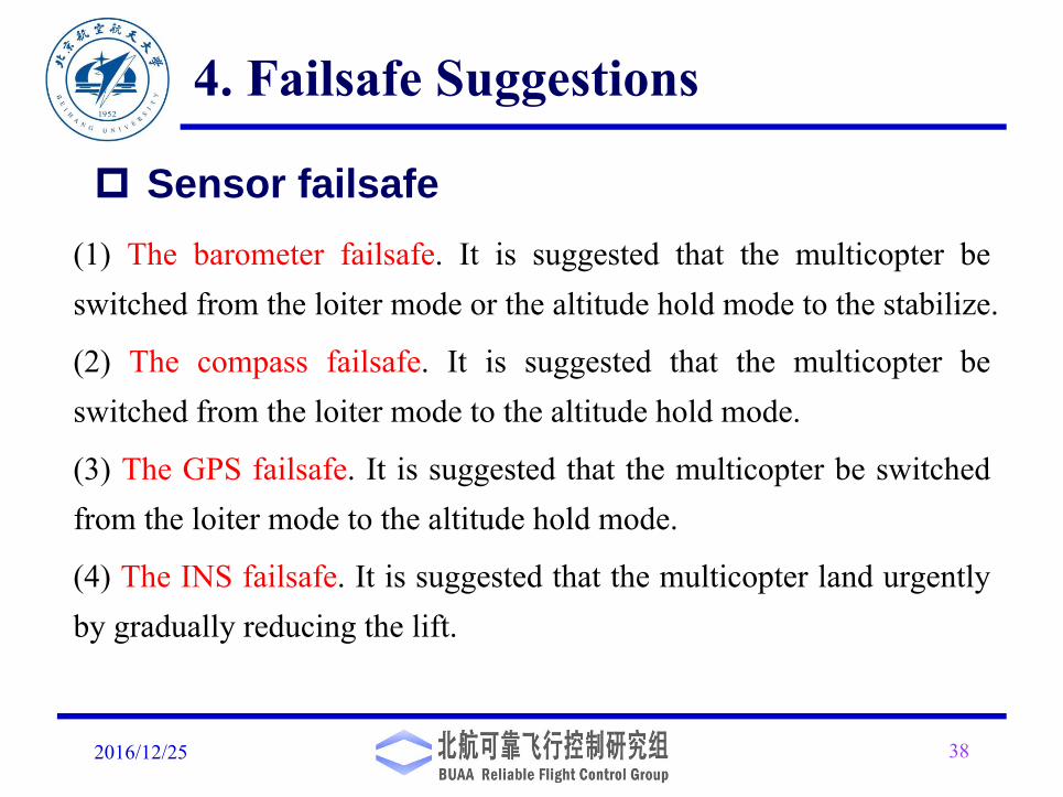
(1) The barometer failsafe. It is suggested that the multicopter beswitched from the loiter mode or the altitude hold mode to the stabilize.
(2) The compass failsafe. It is suggested that the multicopter beswitched from the loiter mode to the altitude hold mode.
(3) The GPS failsafe. It is suggested that the multicopter be switchedfrom the loiter mode to the altitude hold mode.
(4) The INS failsafe. It is suggested that the multicopter land urgentlyby gradually reducing the lift.
Sensor failsafe
4. Failsafe Suggestions
2016/12/25 39
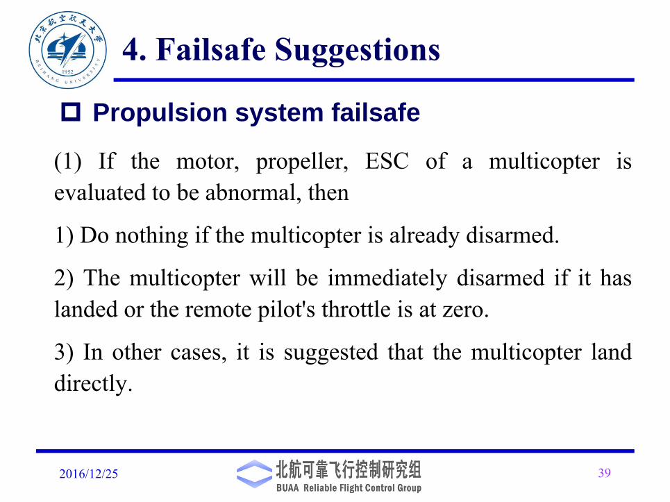
(1) If the motor, propeller, ESC of a multicopter isevaluated to be abnormal, then
1) Do nothing if the multicopter is already disarmed.
2) The multicopter will be immediately disarmed if it haslanded or the remote pilot's throttle is at zero.
3) In other cases, it is suggested that the multicopter landdirectly.
Propulsion system failsafe
4. Failsafe Suggestions

2016/12/25 40
If a multicopter has one propulsor (including a propeller, amotor, and ESC) failed, it may lose the controllability at thehover state. Readers could recall the controllability of themulticopter in Lesson10. In this case, it is suggested that themulticopter adopt a degraded control scheme immediately toland urgently by giving up the yaw. If the multicopter is stillcontrollable at the hover state, then the control reallocation isoften adopted or robust stabilizing control is used by regardingthe damage as a disturbance.
Propulsion system failsafe
4. Failsafe Suggestions
2016/12/25 41
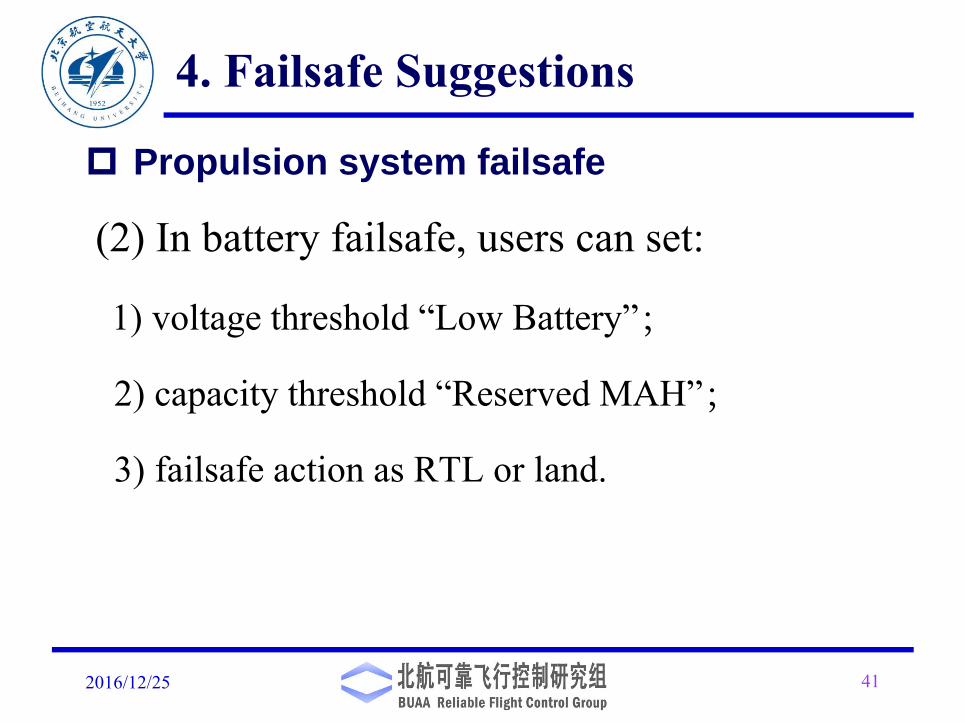
(2) In battery failsafe, users can set:
1) voltage threshold “Low Battery”;
2) capacity threshold “Reserved MAH”;
3) failsafe action as RTL or land.
4. Failsafe Suggestions
Propulsion system failsafe
5. A Safe Semi-Autonomous Autopilot Logic Design
2016/12/25 42
An SAA logic is realized by using a state machine. The state automatonis a mathematical model to describe a hybrid system. Generally, thefollowing conditions are assumed to be true:
(1) the system has a finite number of modes;
(2) system behavior in a specific mode should remain the same;
(3) the system always stays in a certain mode for certain period of time;
(4) the number of conditions for mode switch are finite;
(5) a switch of the system mode is the response to an event;
(6) the time of mode switch is negligible.
2016/12/25 43
First, three multicopter states are defined as follows.
(1) POWER OFF STATE. This state implies that a multicopter is out ofpower. In this state, the user can disassemble, modify and replace thehardware of a multicopter.
(2) STANDBY STATE. When a multicopter is connected to the powermodule, it enters the pre-flight state immediately. In this state, themulticopter is not armed, and users can arm the multicopter manually.
(3) GROUND_ERROR STATE. This state indicates that the multicopterhas a safety problem. In this state, the buzzer will turn on an alarm to alertthe user that there are errors in the system.
Multicopter State and Flight Mode Definition
5. A Safe Semi-Autonomous Autopilot Logic Design

2016/12/25 44
Furthermore, three kinds of flight modes are defined.
(4) MANUAL FLIGHT MODE. This mode allows a remote pilot tomanually control a multicopter. It further contains three submodes,namely LOITER MODE, ALTITUDE HOLD MODE andSTABILIZE MODE.
(5) RTL MODE. Under this mode, the multicopter will return to thehome location from the current position, and hover there
(6) AUTO-LANDING MODE. In this mode, the multicopterrealizes the automatic landing by adjusting the throttle according tothe estimated height.
Multicopter State and Flight Mode Definition
5. A Safe Semi-Autonomous Autopilot Logic Design
Event Definition
2016/12/25 45
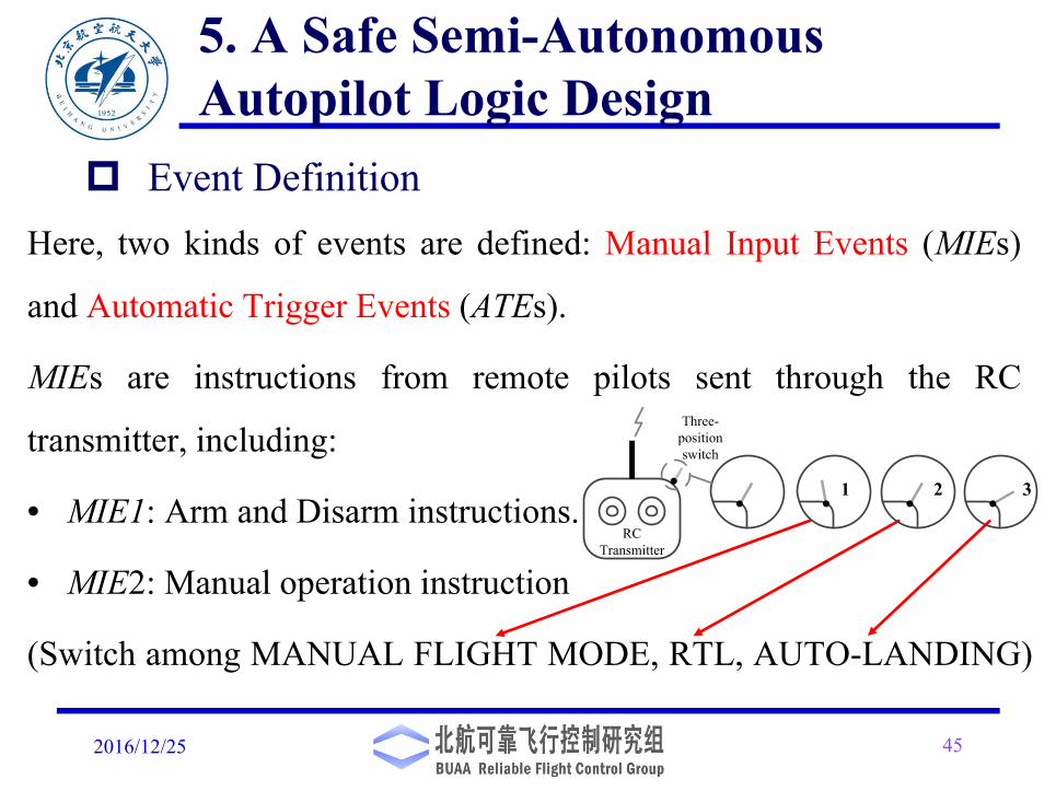
Here, two kinds of events are defined: Manual Input Events (MIEs)
and Automatic Trigger Events (ATEs).
MIEs are instructions from remote pilots sent through the RC
transmitter, including:
• MIE1: Arm and Disarm instructions.
• MIE2: Manual operation instruction
(Switch among MANUAL FLIGHT MODE, RTL, AUTO-LANDING)
5. A Safe Semi-Autonomous Autopilot Logic Design
Three-position switch
1 2 3
RC Transmitter

2016/12/25 46
ATEs are independent of the remote pilot's operations, but mainly generated bythe status of on board components.
5. A Safe Semi-Autonomous Autopilot Logic Design
Event Definition
ATE1: Health status of INS and status of multicopter (1: healthy; 0: unhealthy)ATE2: Health status of GPS (1: healthy; 0: unhealthy) ATE3: Health status of barometer (1: healthy; 0: unhealthy) ATE4: Health status of compass (1: healthy; 0: unhealthy)ATE5: Health status of propulsion system (1: healthy; 0: unhealthy)ATE6: Status of connections of RC (1: normal; 0: abnormal)ATE7: The status of battery’s capacity (1: adequate; 0: inadequate, able to RTL; −1: inadequate,
unable to RTL)ATE8: Comparison of the multicopter’s altitude and a specified threshold, (1: the multi- copter’s
altitude is lower than the specified threshold, as −pze < −pzT ; 0: the multicopter’s altitude is not lowerthan the specified threshold, as −pze ≥−pzT .)
ATE9: Comparison of the multicopter’s throttle command and a specified threshold overa time horizon, (1: the multicopter’s throttle command is less than the specified threshold, as σdrc <σdrcT for t > tT; 0: otherwise)
ATE10: Comparison of the multicopter’s distance from HOME point and a specified threshold, (1:the multicopter’s distance from HOME point is greater than the specified threshold, as d > dT; 0:the multicopter’s distance from HOME point is not greater than the specified threshold, as d ≤dT.)

2016/12/25 47
Autopilot Logic Design
5. A Safe Semi-Autonomous Autopilot Logic Design
POWEROFF STANDBY GROUND_E
RROR
RETURN-TO-
LAUNCH
AUTO-LANDING
C1 C5
C3 C4
C7 C8C11
C10
C9
C13C14
MANUAL FLIGHT
MODEC15
C12
C2
C6(a) State machine
STABILIZE ALTITUDE HOLD LOITERC18
C17 C16
C21(b)Inner state machine of the manual
flight mode
C19
C20
2016/12/25
5.3 Autopilot Logic Design
48
Here, a few transitions are introduced.
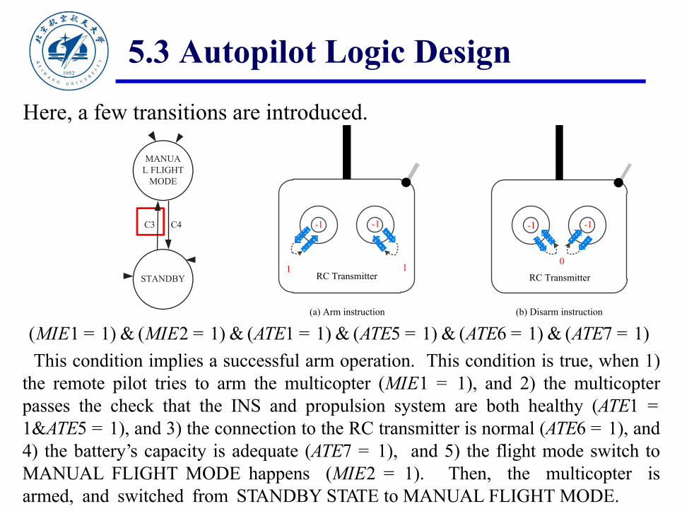
(MIE1 = 1) & (MIE2 = 1) & (ATE1 = 1) & (ATE5 = 1) & (ATE6 = 1) & (ATE7 = 1)This condition implies a successful arm operation. This condition is true, when 1)
the remote pilot tries to arm the multicopter (MIE1 = 1), and 2) the multicopterpasses the check that the INS and propulsion system are both healthy (ATE1 =1&ATE5 = 1), and 3) the connection to the RC transmitter is normal (ATE6 = 1), and4) the battery’s capacity is adequate (ATE7 = 1), and 5) the flight mode switch toMANUAL FLIGHT MODE happens (MIE2 = 1). Then, the multicopter isarmed, and switched from STANDBY STATE to MANUAL FLIGHT MODE.
STANDBY
C3 C4
MANUAL FLIGHT
MODE
RC Transmitter
(a) Arm instruction (b) Disarm instruction
1
-1
1
-1
0
-1 -1
RC Transmitter
2016/12/25
5.3 Autopilot Logic Design
49
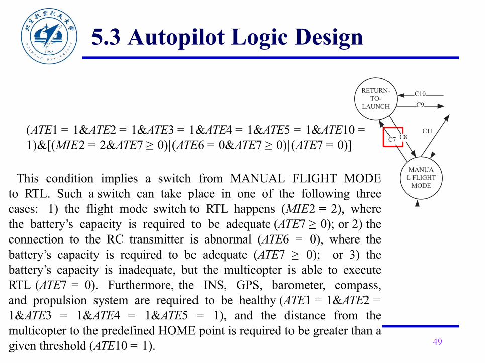
(ATE1 = 1&ATE2 = 1&ATE3 = 1&ATE4 = 1&ATE5 = 1&ATE10 =1)&[(MIE2 = 2&ATE7 ≥ 0)|(ATE6 = 0&ATE7 ≥ 0)|(ATE7 = 0)]
This condition implies a switch from MANUAL FLIGHT MODEto RTL. Such a switch can take place in one of the following threecases: 1) the flight mode switch to RTL happens (MIE2 = 2), wherethe battery’s capacity is required to be adequate (ATE7 ≥ 0); or 2) theconnection to the RC transmitter is abnormal (ATE6 = 0), where thebattery’s capacity is required to be adequate (ATE7 ≥ 0); or 3) thebattery’s capacity is inadequate, but the multicopter is able to executeRTL (ATE7 = 0). Furthermore, the INS, GPS, barometer, compass,and propulsion system are required to be healthy (ATE1 = 1&ATE2 =1&ATE3 = 1&ATE4 = 1&ATE5 = 1), and the distance from themulticopter to the predefined HOME point is required to be greater than agiven threshold (ATE10 = 1).
RETURN-TO-
LAUNCH
C7 C8C11
C10
C9
MANUAL FLIGHT
MODE

5.3 Autopilot Logic Design
2016/12/25 50
C16: ATE2 = 0|ATE4 = 0This condition indicates that if the GPS or compass is unhealthy (ATE2 = 0|ATE4 = 0), then the flight mode is
switched from LOITER MODE to ALTITUDE HOLD MODE.C17: ATE3 = 0This condition indicates that if the barometer is unhealthy (ATE3 = 0), then the flight mode is switched from
ALTITUDE HOLD MODE to STABILIZE MODE.C18: (ATE3 = 1)&(ATE2 = 0|ATE4 = 0)This condition indicates that if the barometer is healthy (ATE3 = 1), and the GPS or compass is unhealthy
(ATE2 = 0|ATE4 = 0), then the flight mode is switched from STA- BILIZE MODE to ALTITUDE HOLDMODE.
C19: ATE2 = 1&ATE4 = 1This condition indicates that if the GPS and compass are healthy (ATE2 = 1&ATE4 = 1), then the flight modeis switched from ALTITUDE HOLD MODE to LOITER MODE.C20: ATE2 = 1&ATE3 = 1&ATE4 = 1This condition indicates that if the GPS, compass and barometer are all healthy (ATE2 = 1&ATE3 = 1&ATE4= 1), then the flight mode is switched from STABILIZE MODE to LOITER MODE.C21: ATE3 = 0This condition indicates that if the barometer is unhealthy (ATE3 = 0), then the flight mode is switched from
LOITER MODE to STABILIZE MODE.

6. Conclusion
2016/12/25 51
1. The research on safety issues has a long way to go. For themulticopter control accuracy, an increase of the accuracy from 90%to 99% maybe trivial, but a rise in the probability of safety from90% to 99% is rather significant.
2. There are many methods of health evaluation before the flight orduring the flight process, based on either measurement data, orcomprehensive analysis of model and data.
3. Failsafe should be performed after anomaly detected.4. Events affected multicopter safety should be further complemented.5. The safety logic of autopilot is commonly designed by practical
experiences. How to design it more scientifically?

Deep thanks go to
for material preparation
2016/12/25 52
Acknowledgement
Zhiyao Zhao Yao Luo Xunhua Dai

2016/12/25 53
Thank you!All course PPTs and resources can be downloaded at
http://rfly.buaa.edu.cn/course
For more detailed content, please refer to the textbook: Quan, Quan. Introduction to Multicopter Design and Control. Springer,
2017. ISBN: 978-981-10-3382-7.It is available now, please visit http://
www.springer.com/us/book/9789811033810
Related Documents


