Introduction to Machining and Machining Fluids Dr. Mamilla Ravi Sankar Department of Mechanical Engineering Indian Institute of Technology, Guwahati Lecture - 09 Tool Wear and Tool life Part-1 Welcome to the course. So, this is about the tool wear and tool life. (Refer Slide Time: 00:34) So, the tool wear, normally if you see the tool wear it describes the gradual failure of the cutting tool due to regular machining because it is a progressive wear basically. So, it describes gradually how atom by atom or molecule by molecule are the amount gradually it will goes off that is what the progressive tool wear is.

Welcome message from author
This document is posted to help you gain knowledge. Please leave a comment to let me know what you think about it! Share it to your friends and learn new things together.
Transcript

Introduction to Machining and Machining FluidsDr. Mamilla Ravi Sankar
Department of Mechanical EngineeringIndian Institute of Technology, Guwahati
Lecture - 09Tool Wear and Tool life Part-1
Welcome to the course. So, this is about the tool wear and tool life.
(Refer Slide Time: 00:34)
So, the tool wear, normally if you see the tool wear it describes the gradual failure of the
cutting tool due to regular machining because it is a progressive wear basically. So, it
describes gradually how atom by atom or molecule by molecule are the amount
gradually it will goes off that is what the progressive tool wear is.
(Refer Slide Time: 00:55)
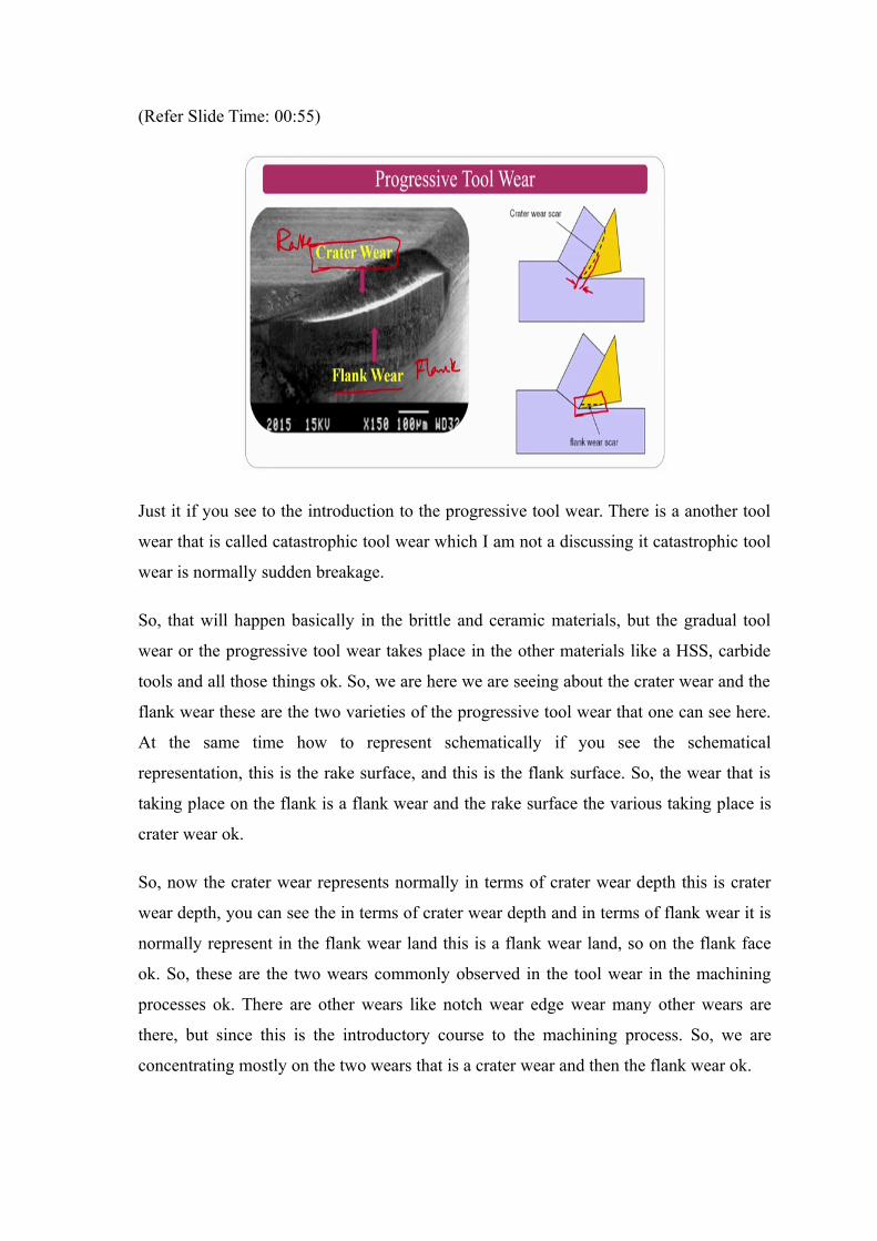
Just it if you see to the introduction to the progressive tool wear. There is a another tool
wear that is called catastrophic tool wear which I am not a discussing it catastrophic tool
wear is normally sudden breakage.
So, that will happen basically in the brittle and ceramic materials, but the gradual tool
wear or the progressive tool wear takes place in the other materials like a HSS, carbide
tools and all those things ok. So, we are here we are seeing about the crater wear and the
flank wear these are the two varieties of the progressive tool wear that one can see here.
At the same time how to represent schematically if you see the schematical
representation, this is the rake surface, and this is the flank surface. So, the wear that is
taking place on the flank is a flank wear and the rake surface the various taking place is
crater wear ok.
So, now the crater wear represents normally in terms of crater wear depth this is crater
wear depth, you can see the in terms of crater wear depth and in terms of flank wear it is
normally represent in the flank wear land this is a flank wear land, so on the flank face
ok. So, these are the two wears commonly observed in the tool wear in the machining
processes ok. There are other wears like notch wear edge wear many other wears are
there, but since this is the introductory course to the machining process. So, we are
concentrating mostly on the two wears that is a crater wear and then the flank wear ok.
(Refer Slide Time: 02:32)
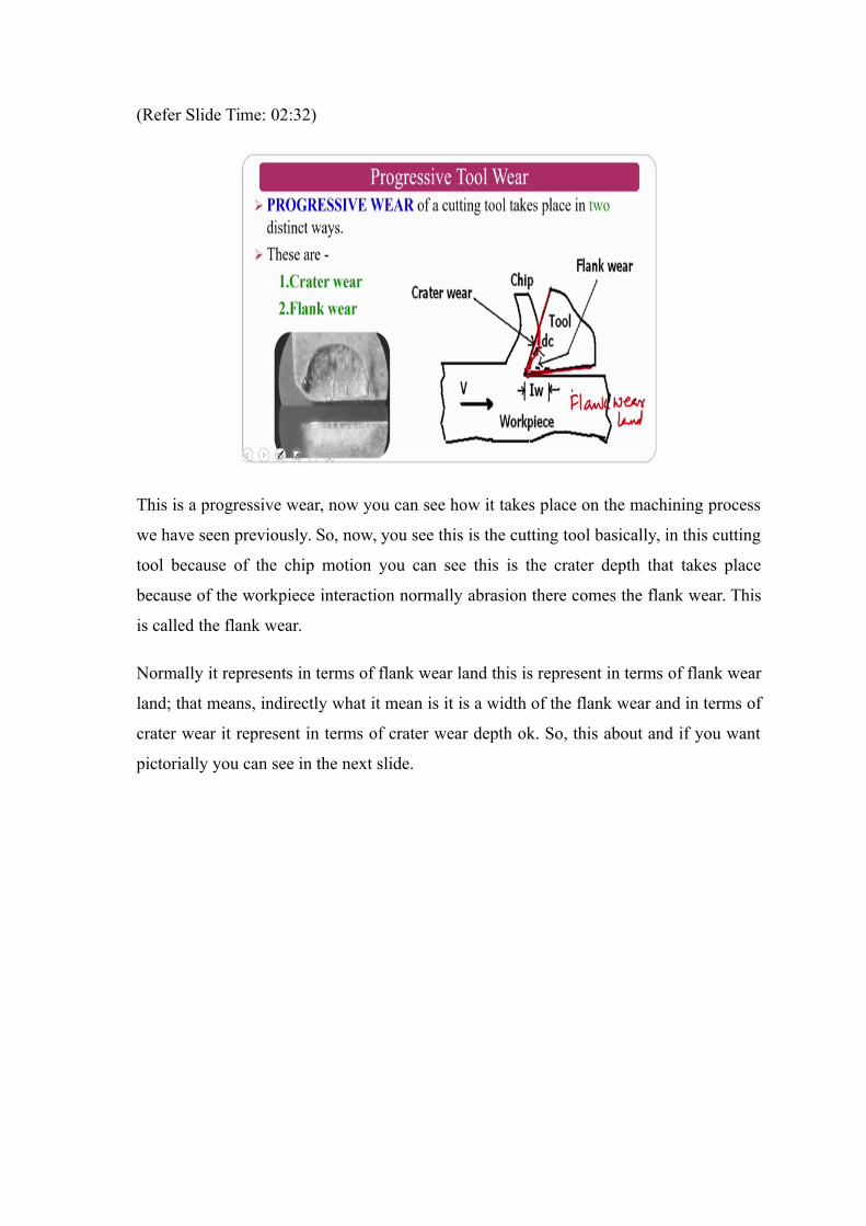
This is a progressive wear, now you can see how it takes place on the machining process
we have seen previously. So, now, you see this is the cutting tool basically, in this cutting
tool because of the chip motion you can see this is the crater depth that takes place
because of the workpiece interaction normally abrasion there comes the flank wear. This
is called the flank wear.
Normally it represents in terms of flank wear land this is represent in terms of flank wear
land; that means, indirectly what it mean is it is a width of the flank wear and in terms of
crater wear it represent in terms of crater wear depth ok. So, this about and if you want
pictorially you can see in the next slide.
(Refer Slide Time: 03:28)
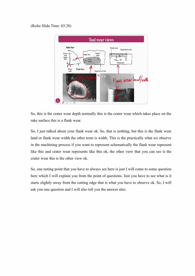
So, this is the crater wear depth normally this is the crater wear which takes place on the
rake surface this is a flank wear.
So, I just talked about your flank wear ok. So, that is nothing, but this is the flank wear
land or flank wear width the other term is width. This is the practically what we observe
in the machining process if you want to represent schematically the flank wear represent
like this and crater wear represents like this ok, the other view that you can see is the
crater wear this is the other view ok.
So, one noting point that you have to always see here is just I will come to some question
here which I will explain you from the point of questions. Just you have to see what is it
starts slightly away from the cutting edge that is what you have to observe ok. So, I will
ask you one question and I will also tell you the answer also.
(Refer Slide Time: 04:53)
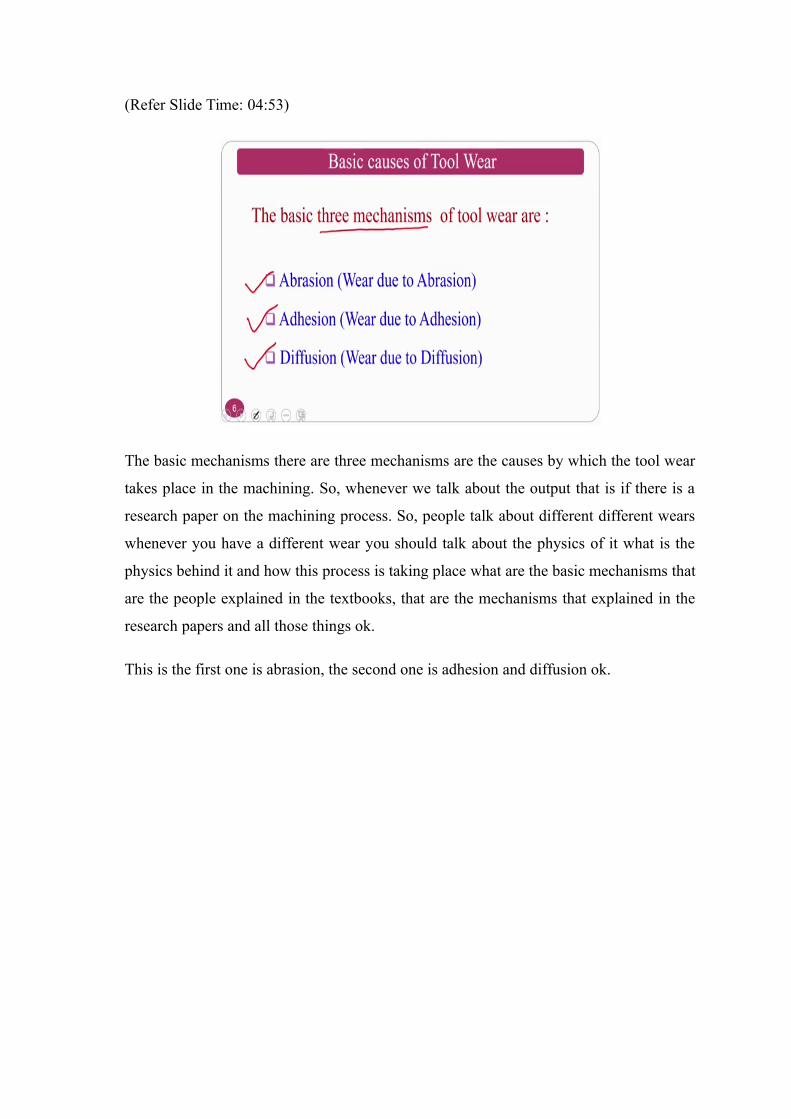
The basic mechanisms there are three mechanisms are the causes by which the tool wear
takes place in the machining. So, whenever we talk about the output that is if there is a
research paper on the machining process. So, people talk about different different wears
whenever you have a different wear you should talk about the physics of it what is the
physics behind it and how this process is taking place what are the basic mechanisms that
are the people explained in the textbooks, that are the mechanisms that explained in the
research papers and all those things ok.
This is the first one is abrasion, the second one is adhesion and diffusion ok.
(Refer Slide Time: 05:36)
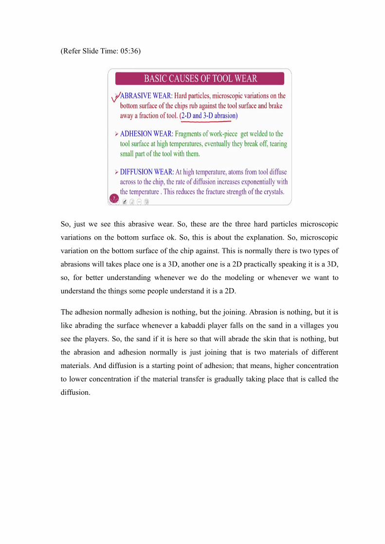
So, just we see this abrasive wear. So, these are the three hard particles microscopic
variations on the bottom surface ok. So, this is about the explanation. So, microscopic
variation on the bottom surface of the chip against. This is normally there is two types of
abrasions will takes place one is a 3D, another one is a 2D practically speaking it is a 3D,
so, for better understanding whenever we do the modeling or whenever we want to
understand the things some people understand it is a 2D.
The adhesion normally adhesion is nothing, but the joining. Abrasion is nothing, but it is
like abrading the surface whenever a kabaddi player falls on the sand in a villages you
see the players. So, the sand if it is here so that will abrade the skin that is nothing, but
the abrasion and adhesion normally is just joining that is two materials of different
materials. And diffusion is a starting point of adhesion; that means, higher concentration
to lower concentration if the material transfer is gradually taking place that is called the
diffusion.
(Refer Slide Time: 06:43)
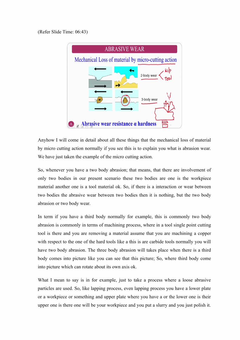
Anyhow I will come in detail about all these things that the mechanical loss of material
by micro cutting action normally if you see this is to explain you what is abrasion wear.
We have just taken the example of the micro cutting action.
So, whenever you have a two body abrasion; that means, that there are involvement of
only two bodies in our present scenario these two bodies are one is the workpiece
material another one is a tool material ok. So, if there is a interaction or wear between
two bodies the abrasive wear between two bodies then it is nothing, but the two body
abrasion or two body wear.
In term if you have a third body normally for example, this is commonly two body
abrasion is commonly in terms of machining process, where in a tool single point cutting
tool is there and you are removing a material assume that you are machining a copper
with respect to the one of the hard tools like a this is are carbide tools normally you will
have two body abrasion. The three body abrasion will takes place when there is a third
body comes into picture like you can see that this picture; So, where third body come
into picture which can rotate about its own axis ok.
What I mean to say is in for example, just to take a process where a loose abrasive
particles are used. So, like lapping process, even lapping process you have a lower plate
or a workpiece or something and upper plate where you have a or the lower one is their
upper one is there one will be your workpiece and you put a slurry and you just polish it.
What will happen? You have the component, you have the lap on, and you have abrasive
particles whenever you try to polish it what will happen the abrasive particles will also
take part along with the lap ok. So, this is what three body abrasion.
Now, the same thing whenever we want to explain from the point of metal cutting. See
whenever you have a single point cutting tool wear chip is taking case if you are putting
a cooling fluid. What will happen? Because the chip is high temperature it will be in the
form of semisolid or something and the tool is also chip is continuously flowing because
of which the tool gets hot and hard ok.
So, in that circumstances it may create some particles this is in the semisolid state
whenever the liquid with a high convict to heat transfer coefficient falls, it will may
generate particles there is a chance I am not saying it is a compulsory. So, there is a
chance whenever you are machining low melting point materials like aluminum and all
those things. So, there may be the chance of particle formation because of the cutting
fluid maybe ok.
So, not only the chip and the tool interaction here because of the foreign body particles
that with particles generated, because of the interaction of the cutting fluid with the chip
bottom side on the top side of the cutting where the particles comes because of these you
have a chip you have a tool material in bit you have particles. So, because of which the
three body abrasion also comes into the picture ok.
So, normally if at all I want to check this three body abrasion or something in terms of
tribological aspects people uses for the two body abrasion normally people uses
workpiece material and tool material and they, they will do the tribology pin on disc and
all those things. If they want to go for the three body abrasion basically on the disc pin
on disc that is pod they will instead of disc they will take the abrasive sheet and they will
just perform the experiments and they try to correlate various tribological issues. So, in
that way this can be studied ok.
(Refer Slide Time: 11:08)
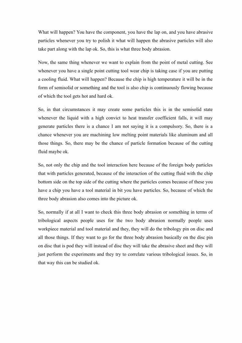
So, the next one is adhesion wear the, mechanical wear process wear particle generate
from the softer and to contacting surface characterized metal surface and mechanism is
welding and rupture ok. So, basically whatever here welding and rupture is the tool wear
mechanism ok.
So, pertaining to the adhesion only welding takes place. So, whenever you are machining
certain material when the temperature goes high what will happen? There is a welding
that is nothing, but the adhesion takes place between chip and tool for a instant for a
microsecond or a nanosecond. So, what will happen? If I have a soft workpiece material
whose chip is continuously flowing on the surface in that circumstances chip is carrying
already told that 80 to 85 percent of the generated heat ok.
So, it tries to build its internal layers nanometer by nano meter by nano meter on the tool
surface and after some time because of this because of the friction and high temperature
of the chip this temperature goes inside inside inside of the tool and thermal softening of
the tool takes place and at the certain point of time. The tool top layers will goes off; that
means, that crater wear whatever I am just shown the crater wear takes place; that means,
that layer by layer by layer of the binning surface of the chip will accumulate that is
welding takes place and because of this the temperature of the tool goes high.
Even temp tool also gets 10 to 15 percent of the temperature 80 percent of the chip is
giving which is flowing also giving the temperature. Chip is a continuous body and the
tool is a static body in that circumstances the thermal softening of the tool takes place
after some time and these top layers of the tool whenever after some time it goes off. So,
that is nothing, but the rupture.
So, this is about the adhesion and the rupture ok. Softer body normally work piece will
be there softer body, and the harder body will be tool I mean cutting tool. This is about
the adhesion wear.
Now, the diffusion wear. Normally the diffusions basic definition if you speak it is called
higher concentration to the lower concentration ok.
(Refer Slide Time: 13:42)
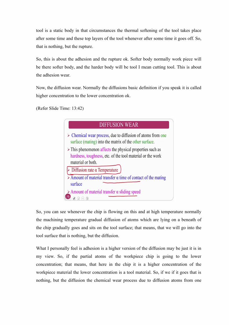
So, you can see whenever the chip is flowing on this and at high temperature normally
the machining temperature gradual diffusion of atoms which are lying on a beneath of
the chip gradually goes and sits on the tool surface; that means, that we will go into the
tool surface that is nothing, but the diffusion.
What I personally feel is adhesion is a higher version of the diffusion may be just it is in
my view. So, if the partial atoms of the workpiece chip is going to the lower
concentration; that means, that here in the chip it is a higher concentration of the
workpiece material the lower concentration is a tool material. So, if we if it goes that is
nothing, but the diffusion the chemical wear process due to diffusion atoms from one
surface to the matrix of the other surface goes the phenomena affect the physical
properties such as hardness toughness of the tool material and others.
Normally diffusion is proportional to the temperature. At high temperature that diffusion
will be very high ok. So, the initial step of the adhesion may also can call as the diffusion
process ok. The amount of material transfer is proportional to the time of the contact ok.
So, amount of material transfer is proportional to the sliding speed if the sliding speed is
very high the temperature also will high, if the temperature is very high so the diffusion
will also takes place if the contact area is very high or the contact surface between this
area high.
What will happen? This is the lower concentration and this is the higher concentration if
the contact area is this it is different, if it is this it is different. So, if the contact area is
very high normally it is proportional to the diffusion where is proportional; that means,
that it we increase ok. These are the 3 mechanisms, one is abrasion where rubbing action
will takes place it is a mechanical action, the second one is adhesion which is the thermal
one and the diffusion is also a thermal one ok. So, these are the three mechanisms on
which the tool wear depends ok.
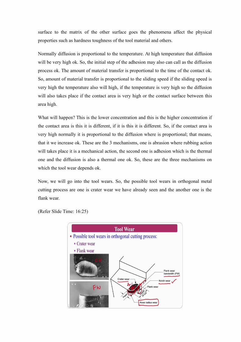
Now, we will go into the tool wears. So, the possible tool wears in orthogonal metal
cutting process are one is crater wear we have already seen and the another one is the
flank wear.
(Refer Slide Time: 16:25)
So, this is also I have shown in the previous slides which is a crater wear and the flank
wear. To show you the isometric view just we have given you a glimpse here on a single
point cutting tool this is the crater wear and this is the flank wear ok. So, this is about the
flank wear ok.
So, normally flank wear I already told you flank wear width is the one flank wear land is
the one another wear is nothing but the notch wear, you can see the notch wear which I
am not going to talk much about this one. Just I am talking about the introduction to the
tool wear. So, I talked about only tool wears, but however, you can see at the end of the
flank wear there is a wear called the notch wear. So, that is another type of wear.
So, there is another one wear is nothing, but the nose radius wear, you can see here on
the nose radius ok, this is the nose radius and this is the sharpness radius which is ok. So,
these are the glimpse that schematically I can show you ok.
(Refer Slide Time: 17:55)
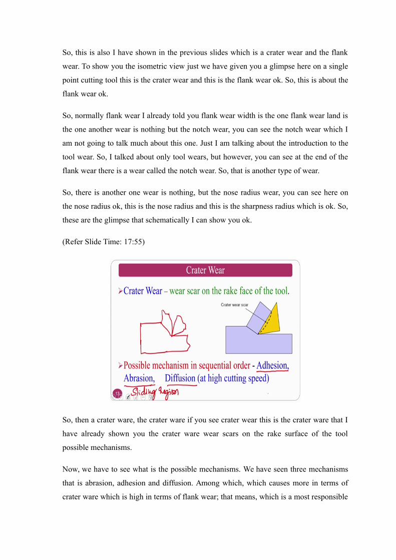
So, then a crater ware, the crater ware if you see crater wear this is the crater ware that I
have already shown you the crater ware wear scars on the rake surface of the tool
possible mechanisms.
Now, we have to see what is the possible mechanisms. We have seen three mechanisms
that is abrasion, adhesion and diffusion. Among which, which causes more in terms of
crater ware which is high in terms of flank wear; that means, which is a most responsible
mechanism in the crater ware which is the most responsible mechanism in the flank wear
that we have to see, ok.
See the possible mechanisms sequential order I am just saying about the crater ware. The
crater wear means if my workpiece is there and the tool is there if my chip is moving on
top of it ok. So, the chip is carrying lot of temperature and it is imparting into the tool
that what I have said and the basic mechanism here is welding and rupture. Why I am
saying is welding and rupture.
If you see this picture where my chip is moving, so the bottom line surface of the chip
gradually welds on the surface the surface of the workpiece and when the thermal
softening takes place this will takes away. This particular portion is goes off; that means,
that the basic mechanism dominating mechanism here is adhesion and followed by
abrasion because it has a sticking zone as well as a sliding zone ok.
So, the crater wear takes place in the in terms of sticking as well as sliding, but the
sticking it is dominating and sliding slightly less. So, sliding region sliding region is
mainly because of the abrasion and the diffusion also plays at very high speeds ok. The
basic mechanism that one can tell is adhesion is the dominant mechanism of tool wear in
terms of crater wear, ok.
(Refer Slide Time: 20:23)
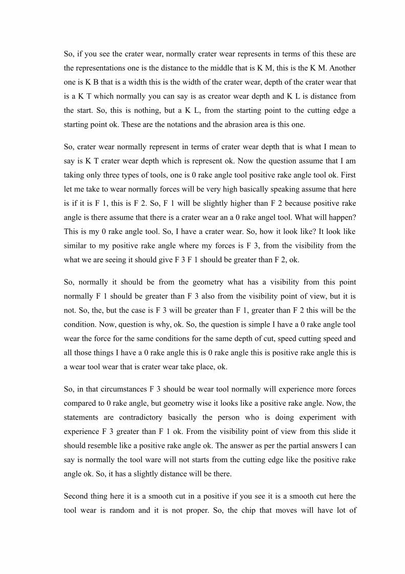
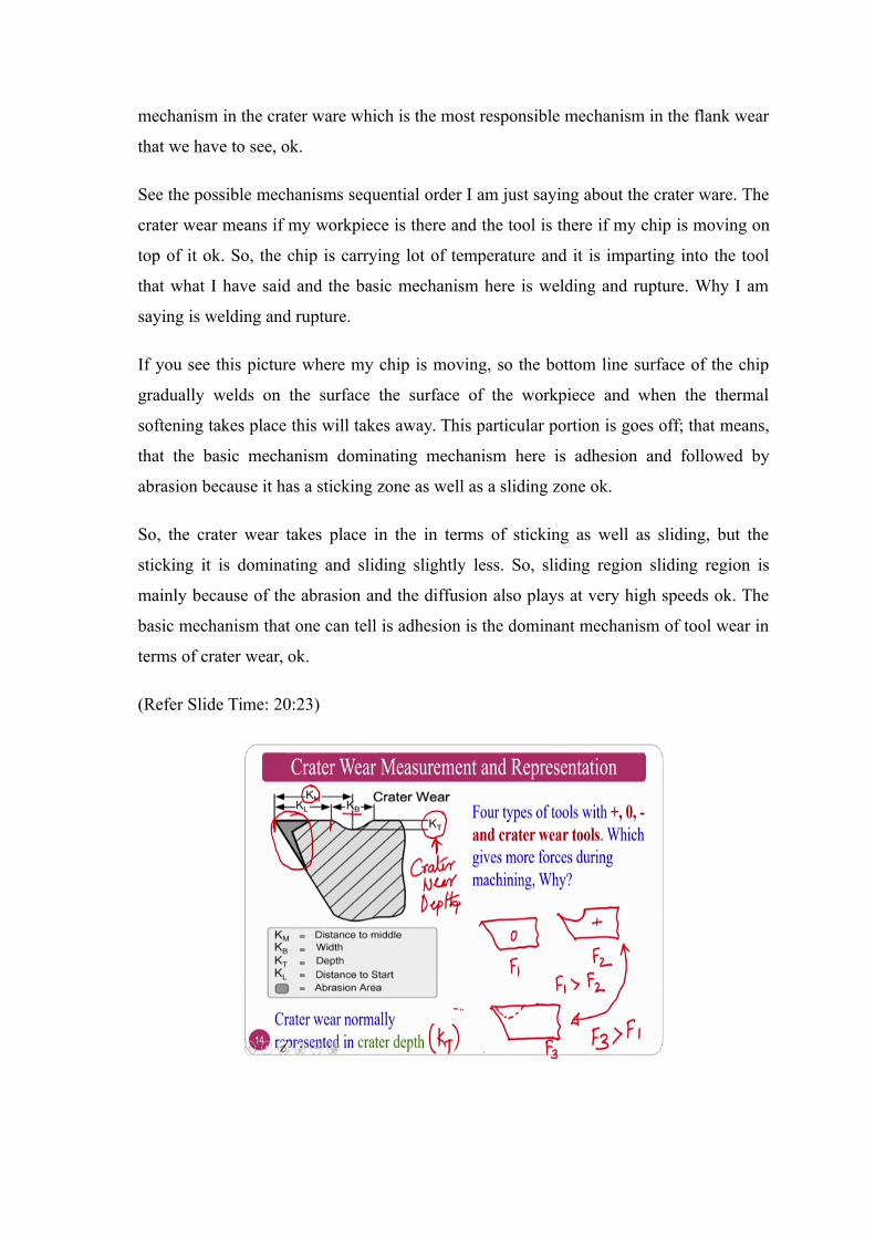
So, if you see the crater wear, normally crater wear represents in terms of this these are
the representations one is the distance to the middle that is K M, this is the K M. Another
one is K B that is a width this is the width of the crater wear, depth of the crater wear that
is a K T which normally you can say is as creator wear depth and K L is distance from
the start. So, this is nothing, but a K L, from the starting point to the cutting edge a
starting point ok. These are the notations and the abrasion area is this one.
So, crater wear normally represent in terms of crater wear depth that is what I mean to
say is K T crater wear depth which is represent ok. Now the question assume that I am
taking only three types of tools, one is 0 rake angle tool positive rake angle tool ok. First
let me take to wear normally forces will be very high basically speaking assume that here
is if it is F 1, this is F 2. So, F 1 will be slightly higher than F 2 because positive rake
angle is there assume that there is a crater wear an a 0 rake angel tool. What will happen?
This is my 0 rake angle tool. So, I have a crater wear. So, how it look like? It look like
similar to my positive rake angle where my forces is F 3, from the visibility from the
what we are seeing it should give F 3 F 1 should be greater than F 2, ok.
So, normally it should be from the geometry what has a visibility from this point
normally F 1 should be greater than F 3 also from the visibility point of view, but it is
not. So, the, but the case is F 3 will be greater than F 1, greater than F 2 this will be the
condition. Now, question is why, ok. So, the question is simple I have a 0 rake angle tool
wear the force for the same conditions for the same depth of cut, speed cutting speed and
all those things I have a 0 rake angle this is 0 rake angle this is positive rake angle this is
a wear tool wear that is crater wear take place, ok.
So, in that circumstances F 3 should be wear tool normally will experience more forces
compared to 0 rake angle, but geometry wise it looks like a positive rake angle. Now, the
statements are contradictory basically the person who is doing experiment with
experience F 3 greater than F 1 ok. From the visibility point of view from this slide it
should resemble like a positive rake angle ok. The answer as per the partial answers I can
say is normally the tool ware will not starts from the cutting edge like the positive rake
angle ok. So, it has a slightly distance will be there.
Second thing here it is a smooth cut in a positive if you see it is a smooth cut here the
tool wear is random and it is not proper. So, the chip that moves will have lot of
disturbances and all those things ok. These are the partial reasons why normally F 3
whatever we are seeing here F 3 is greater than F 1, greater than F 2 ok.
(Refer Slide Time: 25:04)
So, that is the some of the reasons there are many other reasons also for the same cutting
tool normally this starts slightly ahead this is a distance and it is a rough, ok.
(Refer Slide Time: 25:27)
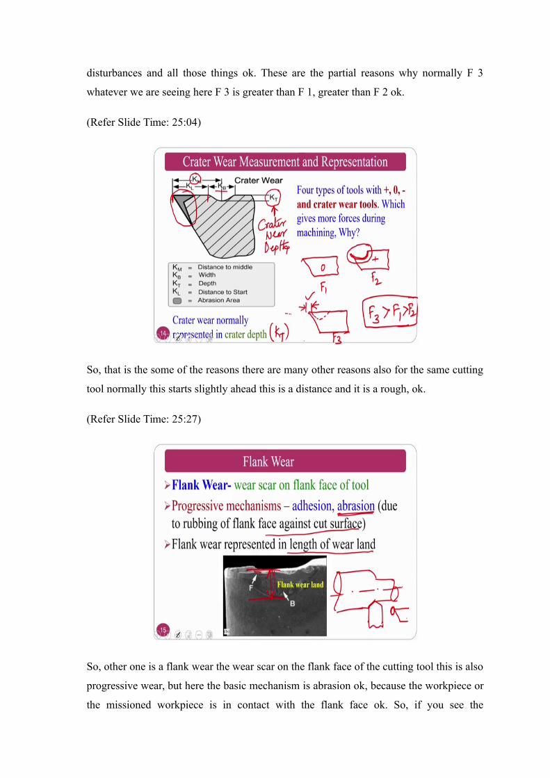
So, other one is a flank wear the wear scar on the flank face of the cutting tool this is also
progressive wear, but here the basic mechanism is abrasion ok, because the workpiece or
the missioned workpiece is in contact with the flank face ok. So, if you see the
workpiece normally the rubbing action takes place on the flank face of the tool rubbing
action takes place here because of which there is a flank wear land the dominant
mechanism is abrasion. So, that it is a mechanical rubbing action against the cut surface
that is a machined surface. Flank wear represents the length of the flank wear land ok.
So, this is nothing, but the flank wear land
So, the summary is in a crater wear adhesion is the dominating mechanism here abrasion
is a dominating mechanism that is the bottom line of the wear mechanisms versus the
wears ok. So, now, we will see the flank wear versus time how the flank wear
progressively increases with respect to time and all those things ok.
(Refer Slide Time: 27:02)
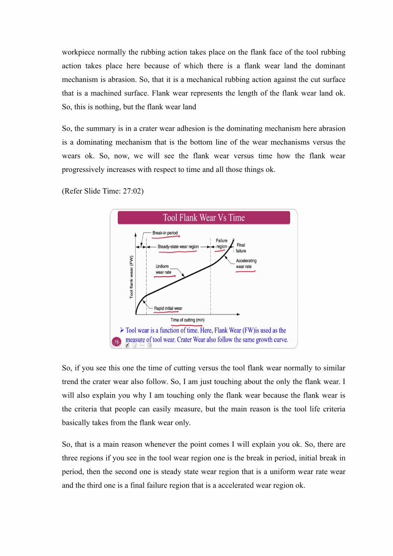
So, if you see this one the time of cutting versus the tool flank wear normally to similar
trend the crater wear also follow. So, I am just touching about the only the flank wear. I
will also explain you why I am touching only the flank wear because the flank wear is
the criteria that people can easily measure, but the main reason is the tool life criteria
basically takes from the flank wear only.
So, that is a main reason whenever the point comes I will explain you ok. So, there are
three regions if you see in the tool wear region one is the break in period, initial break in
period, then the second one is steady state wear region that is a uniform wear rate wear
and the third one is a final failure region that is a accelerated wear region ok.
So, the first phase follows rapid wear uniform wear followed by exaggerated wear. So,
these are the three wears in the three regions of breaking period and steady state wear
region and the failure region. So, we will go by one by one.
(Refer Slide Time: 28:08)
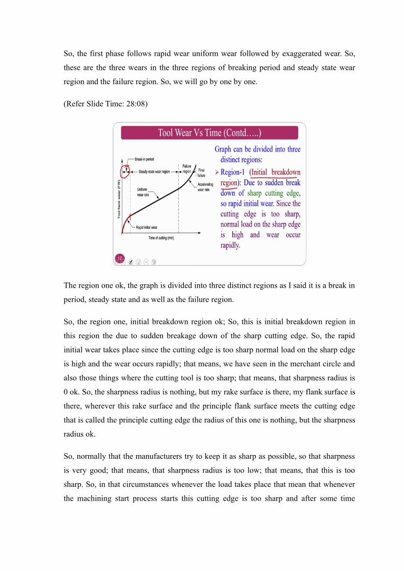
The region one ok, the graph is divided into three distinct regions as I said it is a break in
period, steady state and as well as the failure region.
So, the region one, initial breakdown region ok; So, this is initial breakdown region in
this region the due to sudden breakage down of the sharp cutting edge. So, the rapid
initial wear takes place since the cutting edge is too sharp normal load on the sharp edge
is high and the wear occurs rapidly; that means, we have seen in the merchant circle and
also those things where the cutting tool is too sharp; that means, that sharpness radius is
0 ok. So, the sharpness radius is nothing, but my rake surface is there, my flank surface is
there, wherever this rake surface and the principle flank surface meets the cutting edge
that is called the principle cutting edge the radius of this one is nothing, but the sharpness
radius ok.
So, normally that the manufacturers try to keep it as sharp as possible, so that sharpness
is very good; that means, that sharpness radius is too low; that means, that this is too
sharp. So, in that circumstances whenever the load takes place that mean that whenever
the machining start process starts this cutting edge is too sharp and after some time
suddenly it goes off that mean sharpness radius suddenly increases; that means, that that
sharp edge will goes off that is nothing, but initial breakdown region ok.
So, that is why initially this portion will come ok. So, I said you know initially because
you are area interacting with respect to the cutting region because of the sharp cutting
edge is very less. So, that will goes off automatically after sometime that is called initial
wear by breakdown or something. The second one is steady state wear region where
uniformed wear rate takes place.
(Refer Slide Time: 30:16)
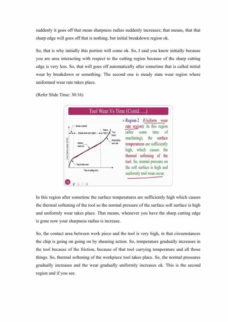
In this region after sometime the surface temperatures are sufficiently high which causes
the thermal softening of the tool so the normal pressure of the surface soft surface is high
and uniformly wear takes place. That means, whenever you have the sharp cutting edge
is gone now your sharpness radius is increase.
So, the contact area between work piece and the tool is very high, in that circumstances
the chip is going on going on by shearing action. So, temperature gradually increases in
the tool because of the friction, because of that tool carrying temperature and all those
things. So, thermal softening of the workpiece tool takes place. So, the normal pressures
gradually increases and the wear gradually uniformly increases ok. This is the second
region and if you see.
(Refer Slide Time: 31:12)
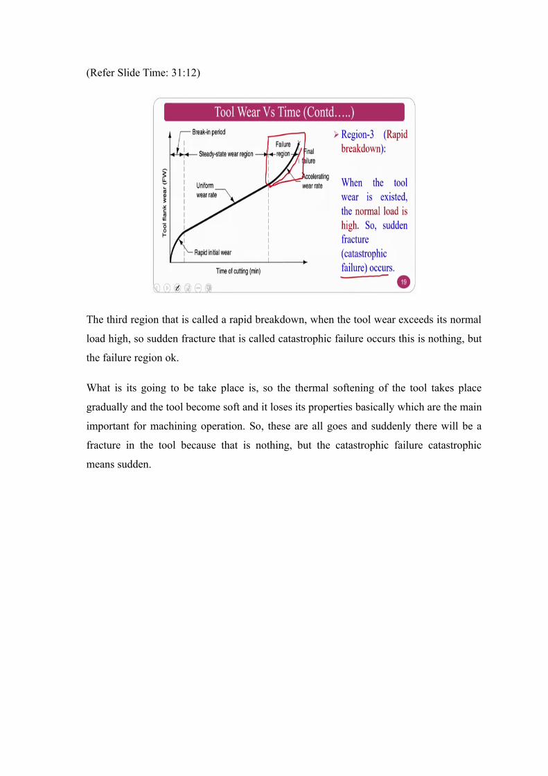
The third region that is called a rapid breakdown, when the tool wear exceeds its normal
load high, so sudden fracture that is called catastrophic failure occurs this is nothing, but
the failure region ok.
What is its going to be take place is, so the thermal softening of the tool takes place
gradually and the tool become soft and it loses its properties basically which are the main
important for machining operation. So, these are all goes and suddenly there will be a
fracture in the tool because that is nothing, but the catastrophic failure catastrophic
means sudden.

(Refer Slide Time: 32:02)
If you see these three regions normally so initial breakdown this is the summary where
the initial region that is a region one initial breakdown uniform wear the sharp edge will
goes off immediately, and the uniform temperature goes in goes in goes into the tool
because of thermal softening takes place. So, uniform progressive tool wear takes place
and the third one is breakdown takes place because it is completely thermals offend
because the machining time is too high and the tool is a stationary body that is why the
catastrophic failure takes place. This is about the time versus the tool wear.
So, now we will go to the tool life as I said when I am explaining you that I am
explaining you to the flank wear. Why I am explaining the flank wear? Since the similar
mechanism is there in crater wear also just. So, you can go through that some basic
textbook. So, you can get it. And the tool life if I will say which wear is can be treated as
a tool life criteria whether it is a flank wear or crater wear and why.
(Refer Slide Time: 33:07)
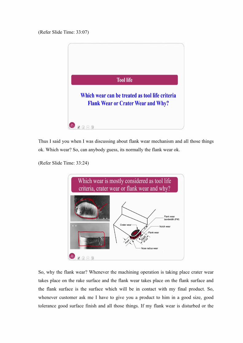
Thus I said you when I was discussing about flank wear mechanism and all those things
ok. Which wear? So, can anybody guess, its normally the flank wear ok.
(Refer Slide Time: 33:24)
So, why the flank wear? Whenever the machining operation is taking place crater wear
takes place on the rake surface and the flank wear takes place on the flank surface and
the flank surface is the surface which will be in contact with my final product. So,
whenever customer ask me I have to give you a product to him in a good size, good
tolerance good surface finish and all those things. If my flank wear is disturbed or the
flank wear is high in that circumstances I cannot give him the good product because the
product comes out will be in a not good shape or in an acceptable form for a customer.
So obviously, my chip will be in contact with rake surface which causes the this wear
crater wear the chip I do not bother because the chip is the one which is not useful for
me. I cannot say useful, but you can recycle into workpiece material and all those things,
but I am worried about the final product, if at all I want to give a good product my flank
wear land should be within the limits. If my flank and flank wear is the criteria if my
flank wear I can keep the criteria as my criteria I can give you good product that is why
always or the most of the time flank wear will be the criteria. Some of the times crater
wear will also a criteria that is whenever you are speaking about high speed machining
and all those things where the temperatures are goes high.
In that processes crater wear is also a criteria, but however, for the normal conditions of
the machining process the flank wear is the criteria that one can follow.
(Refer Slide Time: 35:21)
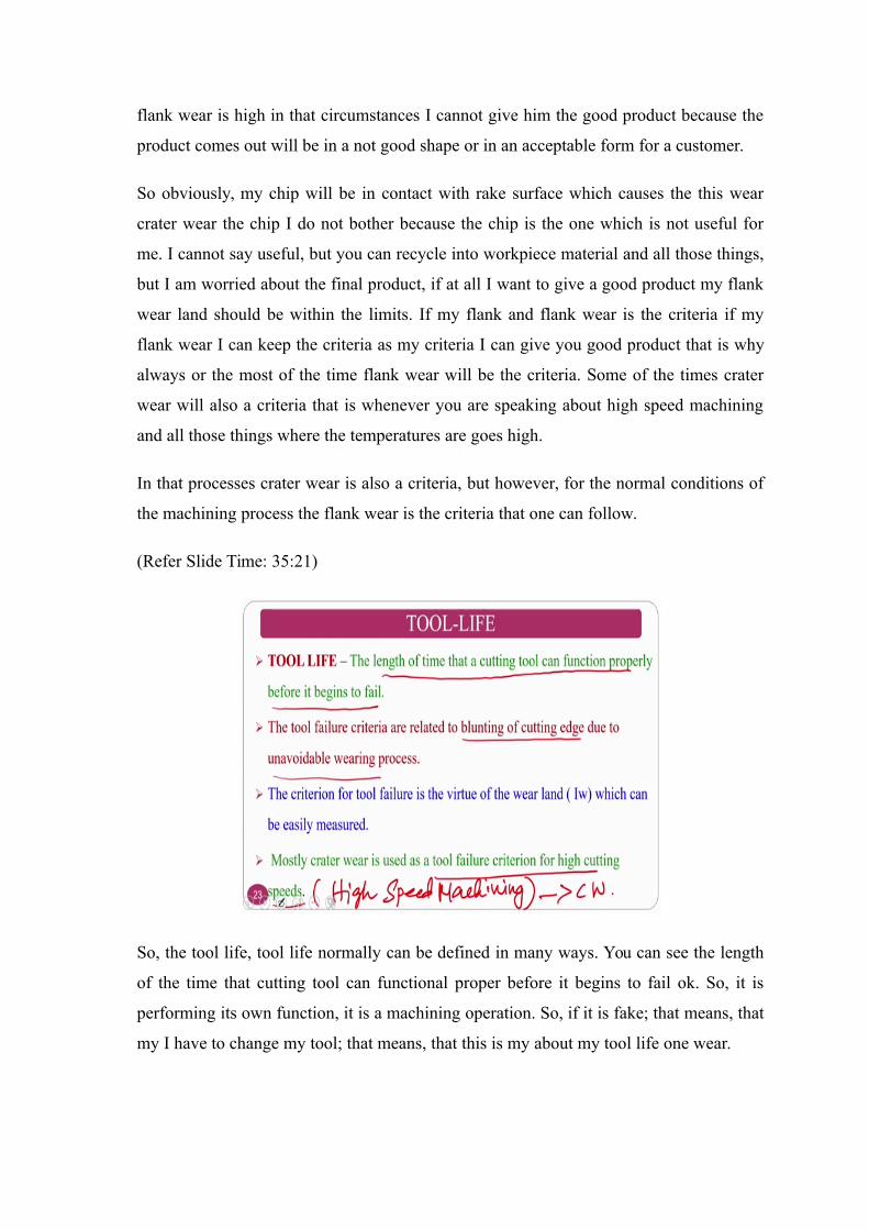
So, the tool life, tool life normally can be defined in many ways. You can see the length
of the time that cutting tool can functional proper before it begins to fail ok. So, it is
performing its own function, it is a machining operation. So, if it is fake; that means, that
my I have to change my tool; that means, that this is my about my tool life one wear.
The tool life criteria can be related to the blunting of the cutting edge due to unavoidable
wearing process ok. Blunting of the cutting tool if the my cutting edge is gone what I
mean to say is that I have to replace because otherwise lot of vibrations will takes place
which hampers the accuracy of the product and all those things.
The third one is the criteria of the tool failure in the virtue of wear land which can easily
measure under then most crater wear is using tool failure criteria I said that in the high
cutting speed that is high speed machining basically ok. Normally here crater wear will
be criteria ok. So, that is what I want to convey. Now, what are the variables that affects a
tool life? If at all I want to see what are the variables that affect the tool life of my any
tool that I have taken whether; it is a HSS or carbide diamond or something.
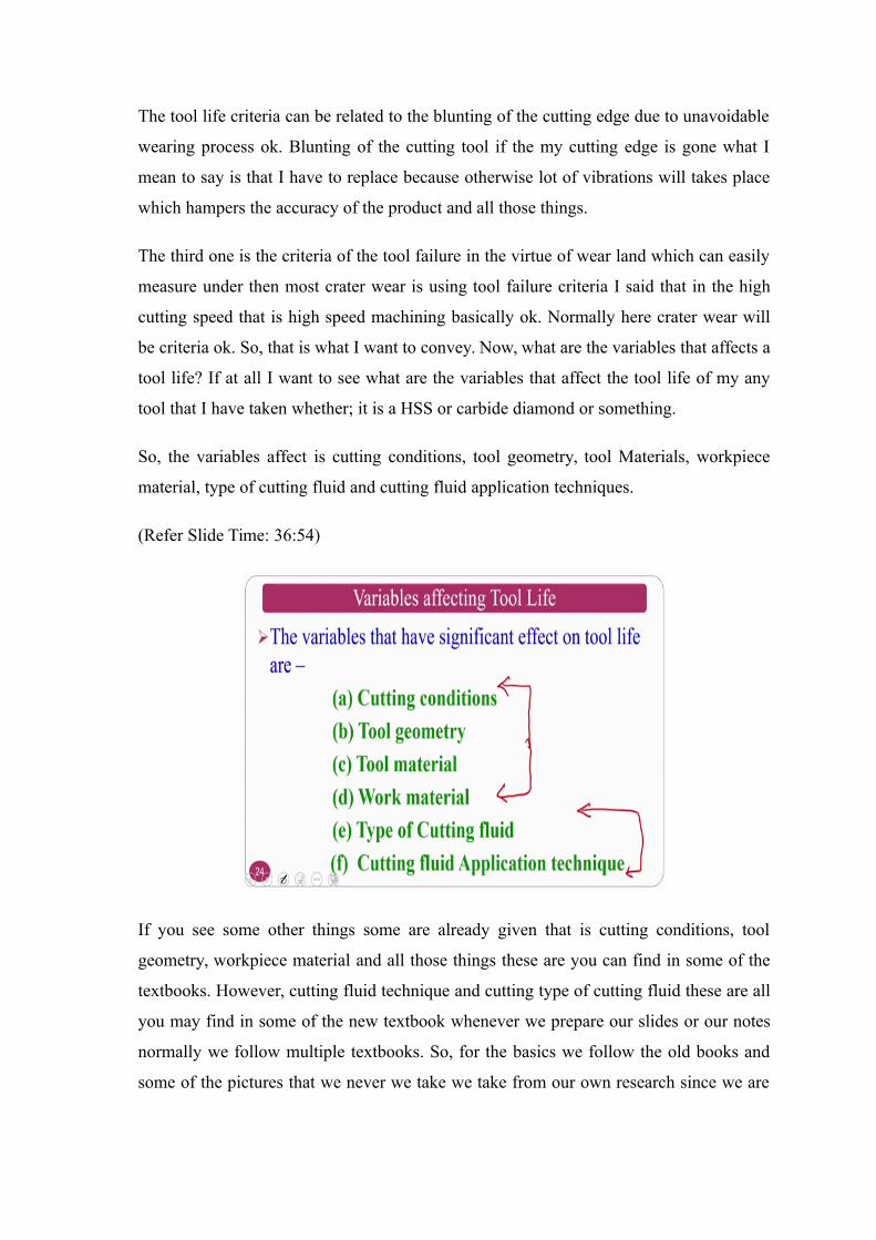
So, the variables affect is cutting conditions, tool geometry, tool Materials, workpiece
material, type of cutting fluid and cutting fluid application techniques.
(Refer Slide Time: 36:54)
If you see some other things some are already given that is cutting conditions, tool
geometry, workpiece material and all those things these are you can find in some of the
textbooks. However, cutting fluid technique and cutting type of cutting fluid these are all
you may find in some of the new textbook whenever we prepare our slides or our notes
normally we follow multiple textbooks. So, for the basics we follow the old books and
some of the pictures that we never we take we take from our own research since we are

doing some of the research in these areas we also take with that is why a research and
teaching goes hand in hand ok.
So, whenever we teach we also teach some of the advances that are found during the
research ok. So, the first one which we can see is the cutting conditions.
(Refer Slide Time: 38:00)
So, the cutting condition the rate wear and the cut is proportional to the cutting speed that
is V T power n equal to constant this is called Taylor tool life equation. So, whenever you
see this Taylor tool life equation V T power n equal to constant where the V is cutting
speed, T is the tool life and n and C are the constants ok.
So, V is the cutting speed, as I said T is a tool life and the n and C are parameter that
depend on workpiece and tool material that is nothing but workpiece material and tool
material combination n and the C depends ok. It is not depend on as a workpiece material
or the tool material it will always depend on the combination whether you are using HSS
versus steel HSS versus cast iron or carbide versus cast iron or mild steel or something
ok.
(Refer Slide Time: 38:55)
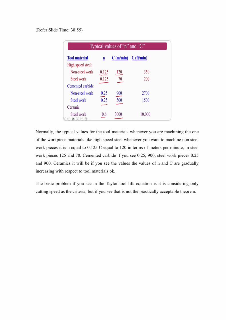
Normally, the typical values for the tool materials whenever you are machining the one
of the workpiece materials like high speed steel whenever you want to machine non steel
work pieces it is n equal to 0.125 C equal to 120 in terms of meters per minute; in steel
work pieces 125 and 70. Cemented carbide if you see 0.25, 900; steel work pieces 0.25
and 900. Ceramics it will be if you see the values the values of n and C are gradually
increasing with respect to tool materials ok.
The basic problem if you see in the Taylor tool life equation is it is considering only
cutting speed as the criteria, but if you see that is not the practically acceptable theorem.
(Refer Slide Time: 39:50)
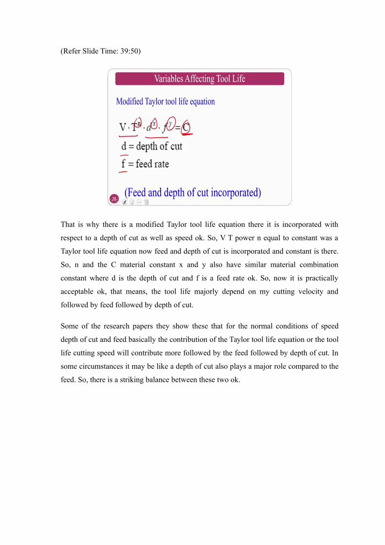
That is why there is a modified Taylor tool life equation there it is incorporated with
respect to a depth of cut as well as speed ok. So, V T power n equal to constant was a
Taylor tool life equation now feed and depth of cut is incorporated and constant is there.
So, n and the C material constant x and y also have similar material combination
constant where d is the depth of cut and f is a feed rate ok. So, now it is practically
acceptable ok, that means, the tool life majorly depend on my cutting velocity and
followed by feed followed by depth of cut.
Some of the research papers they show these that for the normal conditions of speed
depth of cut and feed basically the contribution of the Taylor tool life equation or the tool
life cutting speed will contribute more followed by the feed followed by depth of cut. In
some circumstances it may be like a depth of cut also plays a major role compared to the
feed. So, there is a striking balance between these two ok.
(Refer Slide Time: 41:02)
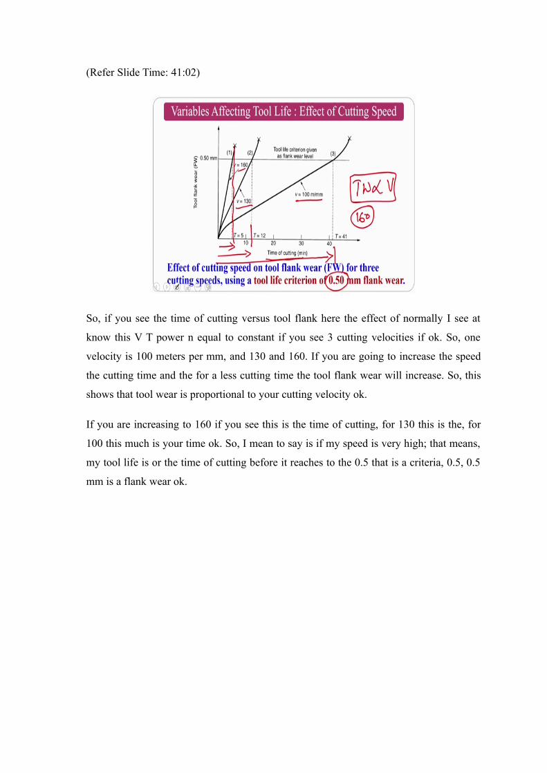
So, if you see the time of cutting versus tool flank here the effect of normally I see at
know this V T power n equal to constant if you see 3 cutting velocities if ok. So, one
velocity is 100 meters per mm, and 130 and 160. If you are going to increase the speed
the cutting time and the for a less cutting time the tool flank wear will increase. So, this
shows that tool wear is proportional to your cutting velocity ok.
If you are increasing to 160 if you see this is the time of cutting, for 130 this is the, for
100 this much is your time ok. So, I mean to say is if my speed is very high; that means,
my tool life is or the time of cutting before it reaches to the 0.5 that is a criteria, 0.5, 0.5
mm is a flank wear ok.

(Refer Slide Time: 42:11)
So, let me explain a problem for some of the people who are beginners to the
manufacturing and all those thing just I will give you some a tool run at 160 meters per
minute last for 5 minutes. If the tool runs at 100 meters per minute it lasts for 41 minutes
what is a C and n values.
If you see these one two conditions are given that is in one case v 1 is given as well as T
1 is given, the second case v 2 is given and T 2 is also given. Normally for as this we are
giving for a constant work piece material and tool material; that means, if I am using a
same material combination my n value my C value are same ok.
So, considering that you can solve like this v T v 1 T 1 power n equal to constant which
is equal to v 2 T 2 power n. So, if you take log on both sides you can easily get and you
can get the value of the n. If you get the n value; obviously, if you can put into any one of
the equations I can calculate the C value. This is how you can calculate the material
combination constant n as well as C it is about the problem.
So, whenever I am giving you these are problems. So, in the examination also you may
get some of the simple problems where the question paper goes like multiple choice
questions, where you may have to solve the question and you choose the answer in the a
b c d. So, you should be prepared for the problems as well as the theory ok. But in my
case mostly it will be theory based. So, problems will be slightly less, since I am not
touching much about the mechanics as I said some of the professor will take this course
in this season or the next season where he explains mostly important mathematics ok.
(Refer Slide Time: 44:20)
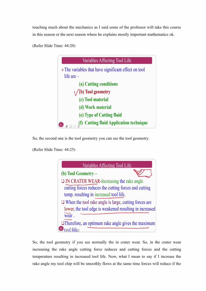
So, the second one is the tool geometry you can see the tool geometry.
(Refer Slide Time: 44:25)
So, the tool geometry if you see normally the in crater wear. So, in the crater wear
increasing the rake angle cutting force reduces and cutting forces and the cutting
temperature resulting in increased tool life. Now, what I mean to say if I increase the
rake angle my tool chip will be smoothly flows at the same time forces will reduce if the
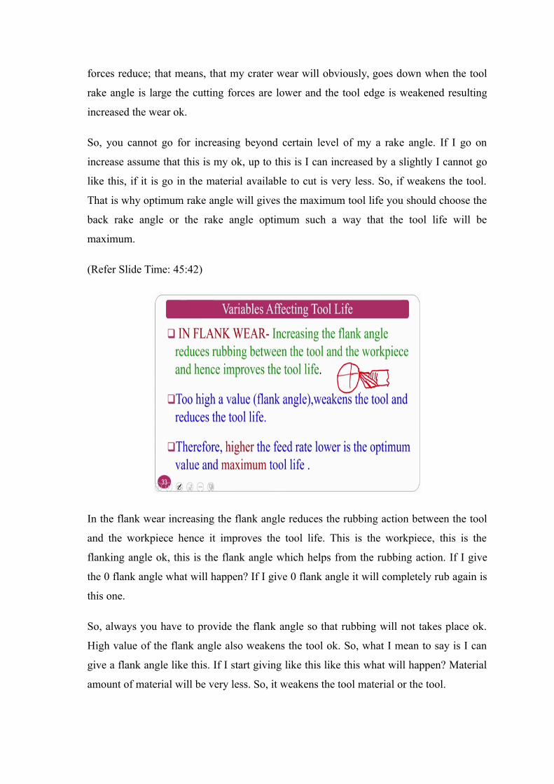
forces reduce; that means, that my crater wear will obviously, goes down when the tool
rake angle is large the cutting forces are lower and the tool edge is weakened resulting
increased the wear ok.
So, you cannot go for increasing beyond certain level of my a rake angle. If I go on
increase assume that this is my ok, up to this is I can increased by a slightly I cannot go
like this, if it is go in the material available to cut is very less. So, if weakens the tool.
That is why optimum rake angle will gives the maximum tool life you should choose the
back rake angle or the rake angle optimum such a way that the tool life will be
maximum.
(Refer Slide Time: 45:42)
In the flank wear increasing the flank angle reduces the rubbing action between the tool
and the workpiece hence it improves the tool life. This is the workpiece, this is the
flanking angle ok, this is the flank angle which helps from the rubbing action. If I give
the 0 flank angle what will happen? If I give 0 flank angle it will completely rub again is
this one.
So, always you have to provide the flank angle so that rubbing will not takes place ok.
High value of the flank angle also weakens the tool ok. So, what I mean to say is I can
give a flank angle like this. If I start giving like this like this what will happen? Material
amount of material will be very less. So, it weakens the tool material or the tool.
So, therefore, high feed rate lower optimum value is maximum for the tool life normally
you have to choose optimum flank angle. Higher feed rate lower is the optimum value of
the maximum tool life ok. So, you should go I mean to say you should go for optimum
flank angle also this is about the flank angle as well as the rake angle how this will
affect.
Third one is tool materials ok; So, the tool materials, if you see the tool materials
selection of tool material, ok.
(Refer Slide Time: 47:17)
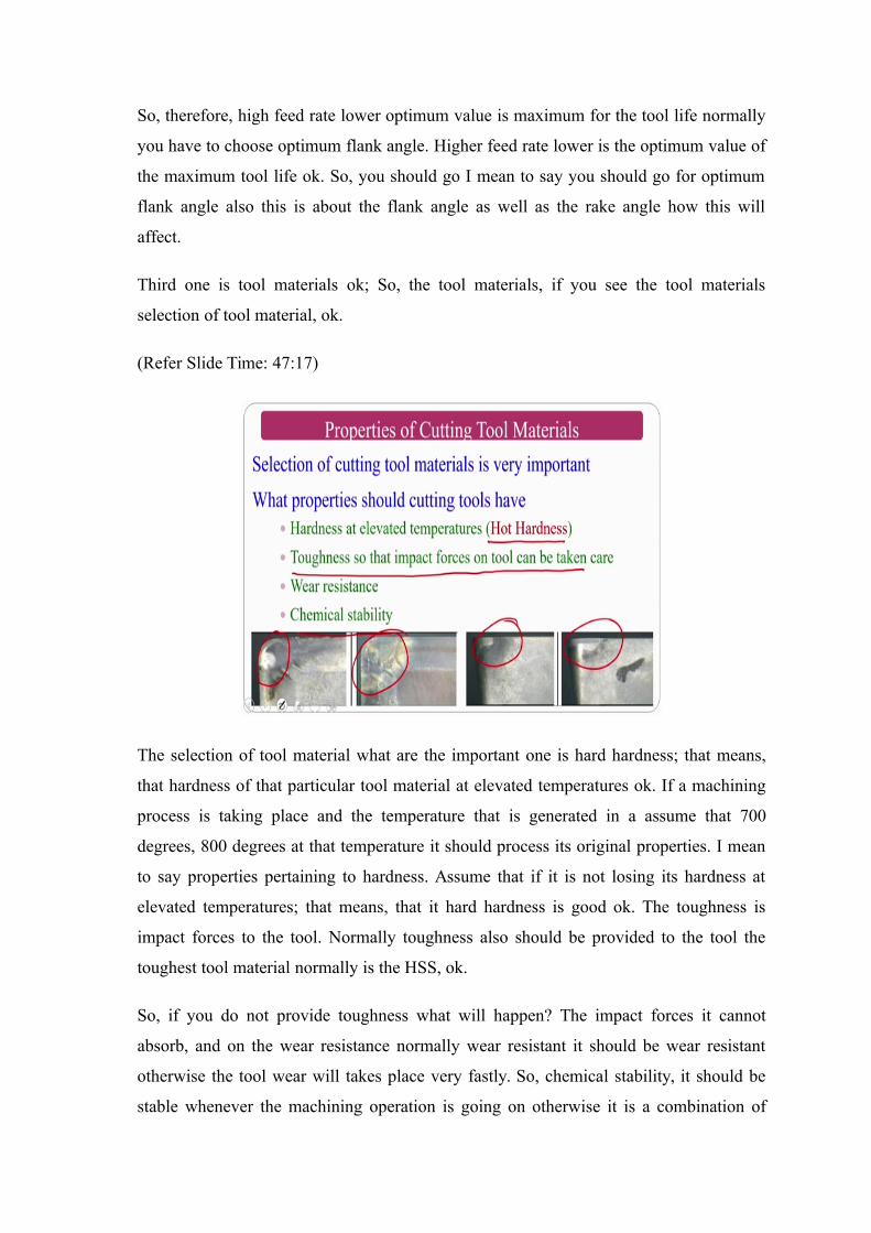
The selection of tool material what are the important one is hard hardness; that means,
that hardness of that particular tool material at elevated temperatures ok. If a machining
process is taking place and the temperature that is generated in a assume that 700
degrees, 800 degrees at that temperature it should process its original properties. I mean
to say properties pertaining to hardness. Assume that if it is not losing its hardness at
elevated temperatures; that means, that it hard hardness is good ok. The toughness is
impact forces to the tool. Normally toughness also should be provided to the tool the
toughest tool material normally is the HSS, ok.
So, if you do not provide toughness what will happen? The impact forces it cannot
absorb, and on the wear resistance normally wear resistant it should be wear resistant
otherwise the tool wear will takes place very fastly. So, chemical stability, it should be
stable whenever the machining operation is going on otherwise it is a combination of
tool material, workpiece material, some chemical I mean to say the cutting fluids is
falling and atmospheric environment is there, where nitrogen is there, where the oxygen
is there and some of the other gases also there depend on the location of the industry and
all those things. So, it should be chemically stable also you can see glimpse of the tool
wears some of the just practically what people have observed.
(Refer Slide Time: 49:01)
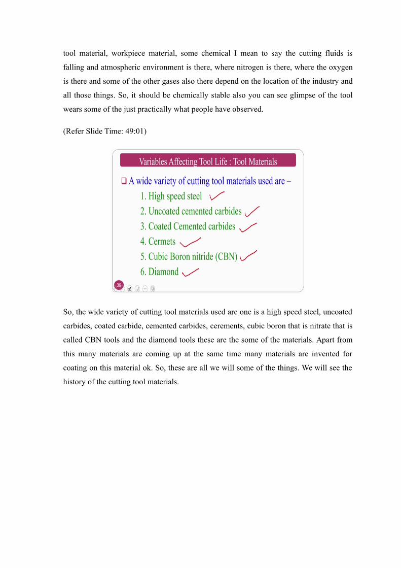
So, the wide variety of cutting tool materials used are one is a high speed steel, uncoated
carbides, coated carbide, cemented carbides, cerements, cubic boron that is nitrate that is
called CBN tools and the diamond tools these are the some of the materials. Apart from
this many materials are coming up at the same time many materials are invented for
coating on this material ok. So, these are all we will some of the things. We will see the
history of the cutting tool materials.
(Refer Slide Time: 49:34)
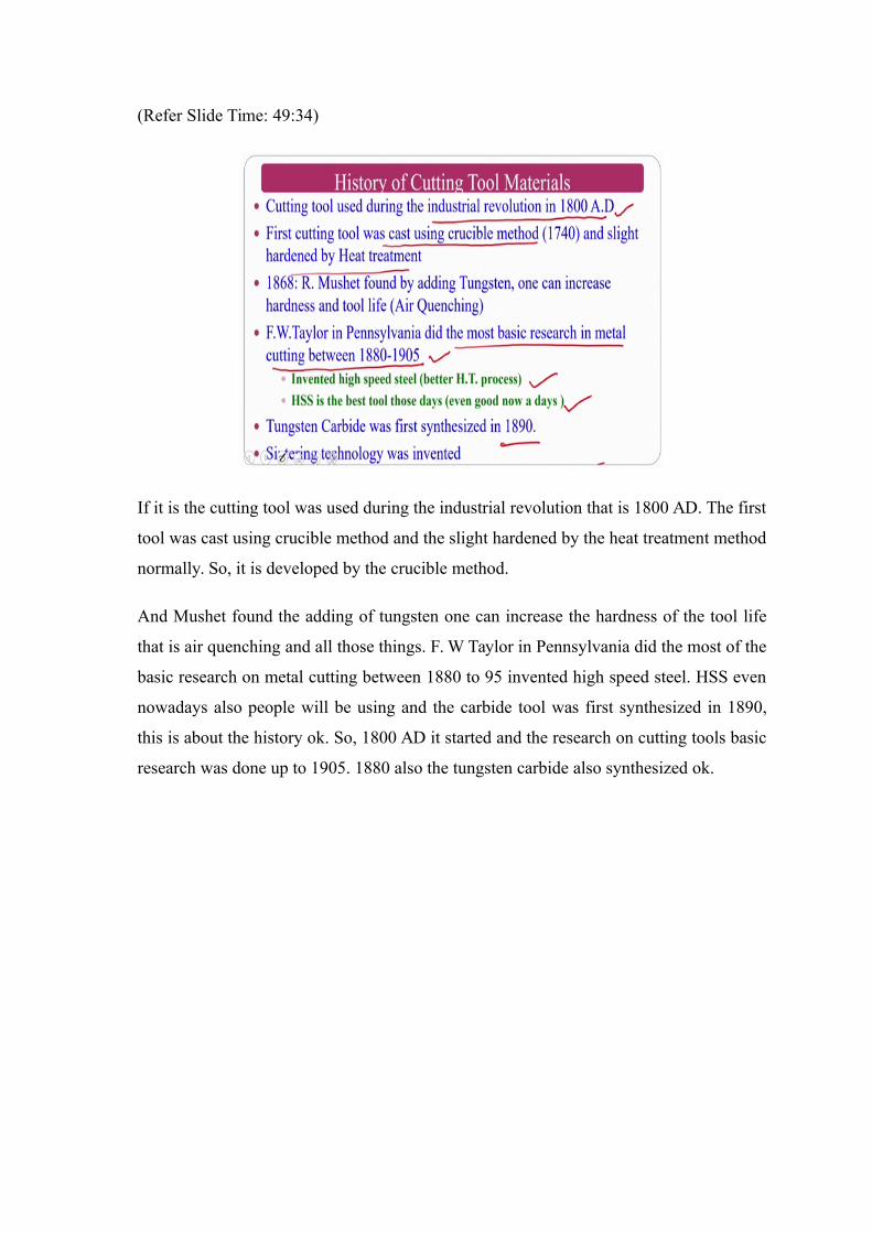
If it is the cutting tool was used during the industrial revolution that is 1800 AD. The first
tool was cast using crucible method and the slight hardened by the heat treatment method
normally. So, it is developed by the crucible method.
And Mushet found the adding of tungsten one can increase the hardness of the tool life
that is air quenching and all those things. F. W Taylor in Pennsylvania did the most of the
basic research on metal cutting between 1880 to 95 invented high speed steel. HSS even
nowadays also people will be using and the carbide tool was first synthesized in 1890,
this is about the history ok. So, 1800 AD it started and the research on cutting tools basic
research was done up to 1905. 1880 also the tungsten carbide also synthesized ok.
(Refer Slide Time: 50:32)
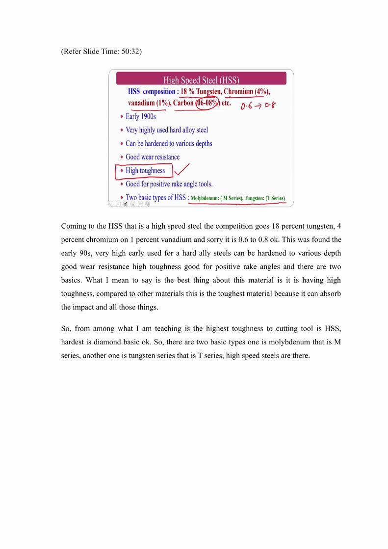
Coming to the HSS that is a high speed steel the competition goes 18 percent tungsten, 4
percent chromium on 1 percent vanadium and sorry it is 0.6 to 0.8 ok. This was found the
early 90s, very high early used for a hard ally steels can be hardened to various depth
good wear resistance high toughness good for positive rake angles and there are two
basics. What I mean to say is the best thing about this material is it is having high
toughness, compared to other materials this is the toughest material because it can absorb
the impact and all those things.
So, from among what I am teaching is the highest toughness to cutting tool is HSS,
hardest is diamond basic ok. So, there are two basic types one is molybdenum that is M
series, another one is tungsten series that is T series, high speed steels are there.
(Refer Slide Time: 51:29)
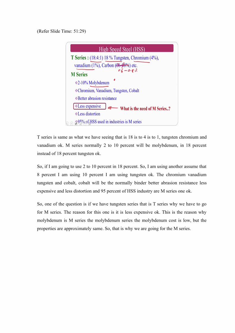
T series is same as what we have seeing that is 18 is to 4 is to 1, tungsten chromium and
vanadium ok. M series normally 2 to 10 percent will be molybdenum, in 18 percent
instead of 18 percent tungsten ok.
So, if I am going to use 2 to 10 percent in 18 percent. So, I am using another assume that
8 percent I am using 10 percent I am using tungsten ok. The chromium vanadium
tungsten and cobalt, cobalt will be the normally binder better abrasion resistance less
expensive and less distortion and 95 percent of HSS industry are M series one ok.
So, one of the question is if we have tungsten series that is T series why we have to go
for M series. The reason for this one is it is less expensive ok. This is the reason why
molybdenum is M series the molybdenum series the molybdenum cost is low, but the
properties are approximately same. So, that is why we are going for the M series.
(Refer Slide Time: 52:55)
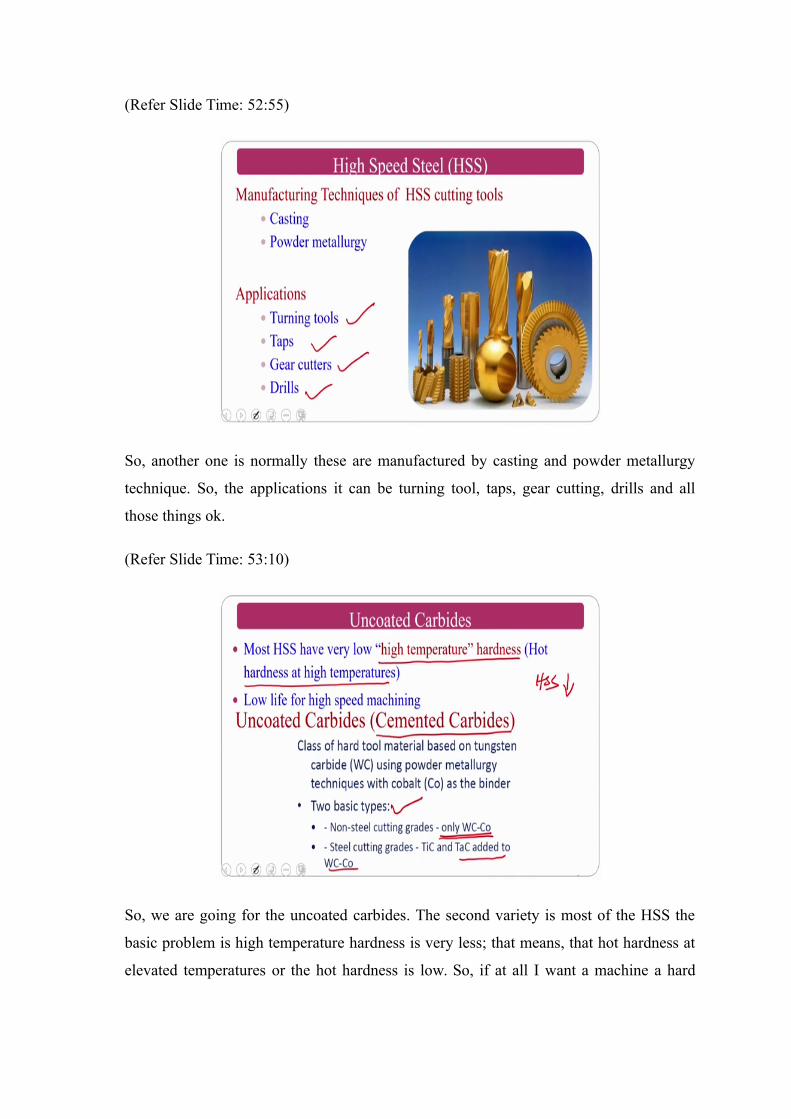
So, another one is normally these are manufactured by casting and powder metallurgy
technique. So, the applications it can be turning tool, taps, gear cutting, drills and all
those things ok.
(Refer Slide Time: 53:10)
So, we are going for the uncoated carbides. The second variety is most of the HSS the
basic problem is high temperature hardness is very less; that means, that hot hardness at
elevated temperatures or the hot hardness is low. So, if at all I want a machine a hard
material where machining temperature goes high in their circumstances the HSS will fail
ok.
So, the low life for high speed machining, normally if at all I want to go for high speed
machining in that circumstances it is very less. That is why we go for the next version
slightly higher version that is called uncoated carbides. Uncoated carbides are uncoated
cemented carbides class of hard tool material based on tungsten using powder
metallurgy. There are two basic types in this one, one is tungsten carbide based that is
called a non steel cutting rates and the titanium carbide and tantalum carbide based
tungsten carbide tools. These are the two varieties of cutting tools are there.
(Refer Slide Time: 54:12)
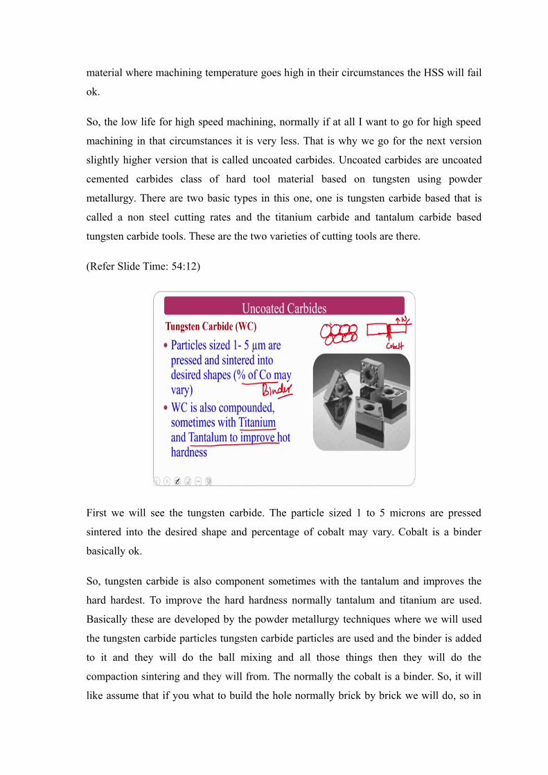
First we will see the tungsten carbide. The particle sized 1 to 5 microns are pressed
sintered into the desired shape and percentage of cobalt may vary. Cobalt is a binder
basically ok.
So, tungsten carbide is also component sometimes with the tantalum and improves the
hard hardest. To improve the hard hardness normally tantalum and titanium are used.
Basically these are developed by the powder metallurgy techniques where we will used
the tungsten carbide particles tungsten carbide particles are used and the binder is added
to it and they will do the ball mixing and all those things then they will do the
compaction sintering and they will from. The normally the cobalt is a binder. So, it will
like assume that if you what to build the hole normally brick by brick we will do, so in
between we will put the cement. So, this is nothing, but the cobalt this is nothing, but
cobalt and this is nothing, but your tungsten carbide ok. This is how this will work ok.
(Refer Slide Time: 55:19)
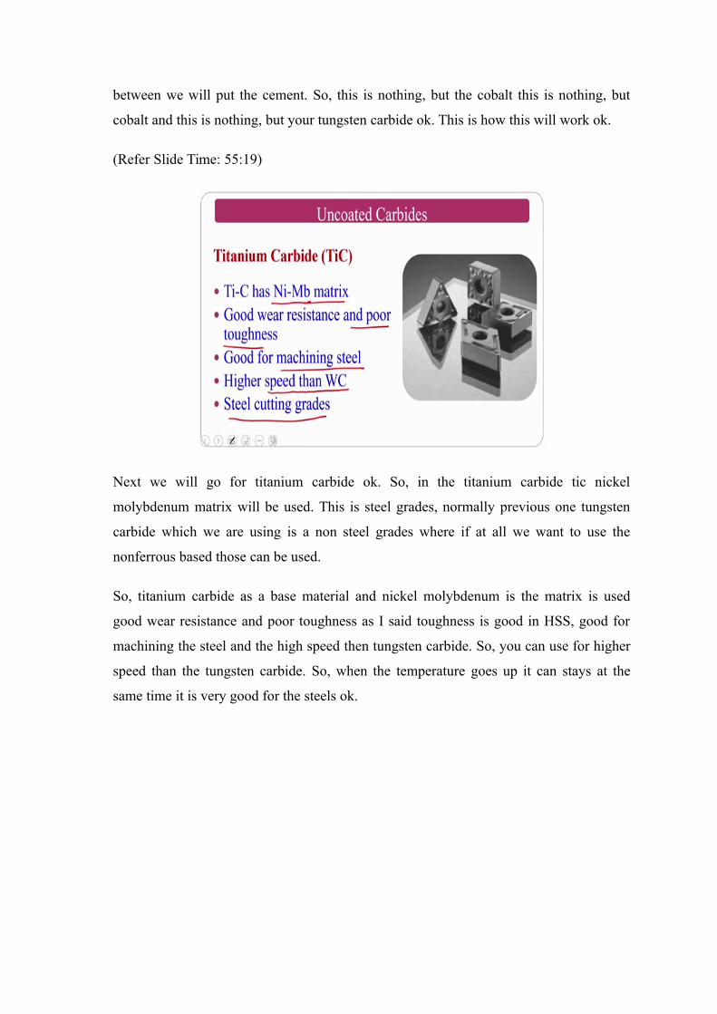
Next we will go for titanium carbide ok. So, in the titanium carbide tic nickel
molybdenum matrix will be used. This is steel grades, normally previous one tungsten
carbide which we are using is a non steel grades where if at all we want to use the
nonferrous based those can be used.
So, titanium carbide as a base material and nickel molybdenum is the matrix is used
good wear resistance and poor toughness as I said toughness is good in HSS, good for
machining the steel and the high speed then tungsten carbide. So, you can use for higher
speed than the tungsten carbide. So, when the temperature goes up it can stays at the
same time it is very good for the steels ok.
(Refer Slide Time: 56:05)
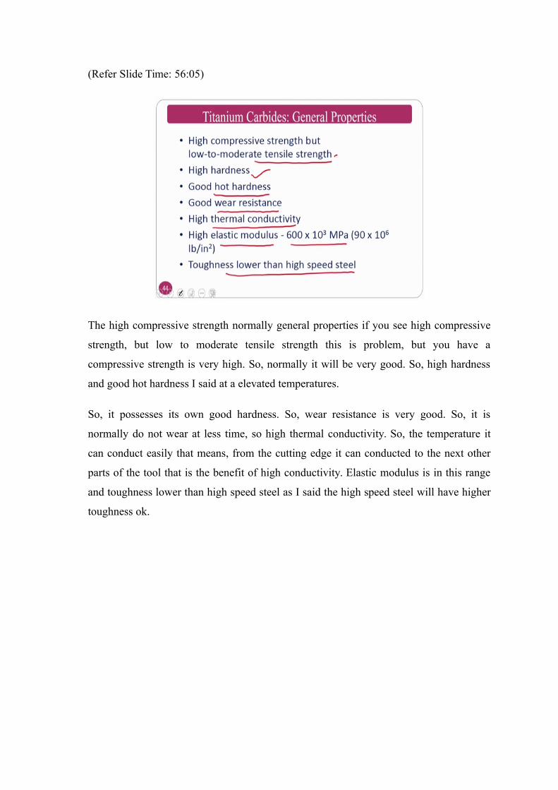
The high compressive strength normally general properties if you see high compressive
strength, but low to moderate tensile strength this is problem, but you have a
compressive strength is very high. So, normally it will be very good. So, high hardness
and good hot hardness I said at a elevated temperatures.
So, it possesses its own good hardness. So, wear resistance is very good. So, it is
normally do not wear at less time, so high thermal conductivity. So, the temperature it
can conduct easily that means, from the cutting edge it can conducted to the next other
parts of the tool that is the benefit of high conductivity. Elastic modulus is in this range
and toughness lower than high speed steel as I said the high speed steel will have higher
toughness ok.
(Refer Slide Time: 54:56)
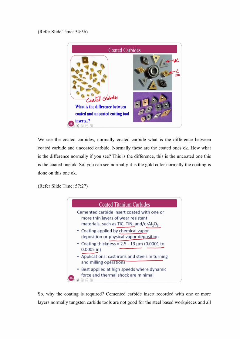
We see the coated carbides, normally coated carbide what is the difference between
coated carbide and uncoated carbide. Normally these are the coated ones ok. How what
is the difference normally if you see? This is the difference, this is the uncoated one this
is the coated one ok. So, you can see normally it is the gold color normally the coating is
done on this one ok.
(Refer Slide Time: 57:27)
So, why the coating is required? Cemented carbide insert recorded with one or more
layers normally tungsten carbide tools are not good for the steel based workpieces and all
those? If at all I want to use it what people will do is TiC, TiN this is titanium carbide
and titanium nitride or ceramic Al 2 O 3. Coatings will be done there are various
techniques that is chemical vapor deposition. physical vapor deposition radiofrequency
sputtering there is a laser coatings are there may many techniques are there. So, normally
these thicknesses ranges from 2.5 to 13 microns.
Nowadays very good nano coatings also coming into the market; Applications normally
you can use for the steels and other simplest applied for high speeds and dynamic shock
and the thermal shock and whenever the minimum if you want you can go for this coated
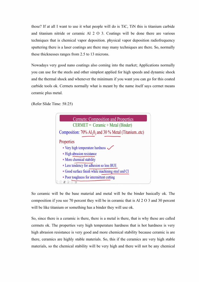
carbide tools ok. Cermets normally what is meant by the name itself says cermet means
ceramic plus metal.
(Refer Slide Time: 58:25)
So ceramic will be the base material and metal will be the binder basically ok. The
composition if you see 70 percent they will be in ceramic that is Al 2 O 3 and 30 percent
will be like titanium or something has a binder they will use ok.
So, since there is a ceramic is there, there is a metal is there, that is why these are called
cermets ok. The properties very high temperature hardness that is hot hardness is very
high abrasion resistance is very good and more chemical stability because ceramic is are
there, ceramics are highly stable materials. So, this if the ceramics are very high stable
materials, so the chemical stability will be very high and there will not be any chemical
reaction and all those things. Less tendency for adhesion, so there is a less chance of
buildup edge. Good surface finish while machining the steel and cast iron.
So, put only the problem here with this one is it is having poor toughness. So, if at all I
want to use for intermittent cutting it cannot be used. For intermittent cutting you need
good toughness in the tool material ok. So, this is very good from the chemical point of
view because this is having a dominating ceramic ok, so ceramic is highly stable
material.
(Refer Slide Time: 59:43)
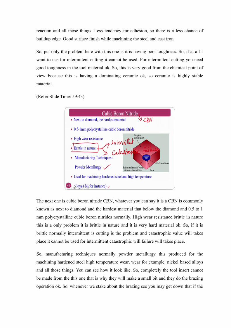
The next one is cubic boron nitride CBN, whatever you can say it is a CBN is commonly
known as next to diamond and the hardest material that below the diamond and 0.5 to 1
mm polycrystalline cubic boron nitrides normally. High wear resistance brittle in nature
this is a only problem it is brittle in nature and it is very hard material ok. So, if it is
brittle normally intermittent is cutting is the problem and catastrophic value will takes
place it cannot be used for intermittent catastrophic will failure will takes place.
So, manufacturing techniques normally powder metallurgy this produced for the
machining hardened steel high temperature wear, wear for example, nickel based alloys
and all those things. You can see how it look like. So, completely the tool insert cannot
be made from the this one that is why they will make a small bit and they do the brazing
operation ok. So, whenever we stake about the brazing see you may get down that if the
it is braced the normally brazing is done at very low temperature welding process or the
joining process, brazing comes out.
So, some of the local tools which we got unfortunately these are the brazing is going. But
if you purchase from the standard companies like sand (Refer Time: 61:17) and other
companies you will get the proper tools. So, what I mean to say is that the brazing
normally it can sustain up to 300 degrees and all if it is go for 600-700 degrees the
cutting tool temperature it may not sustain, but why brazing is done still is if you see the
thermal aspects of machining the only 15 percent tool takes care ok, out of each the CBN
have low thermal conductivity so that means, that the top edge of the cutting tool will
only experience most of the heat and it cannot conduct towards the bottom side.
So, there is a very less chance of one if it is not maintained properly. So, it means goes
off ok. So, diamond tool also look like this only instead of CBN they will put the
diamond.
(Refer Slide Time: 62:11)
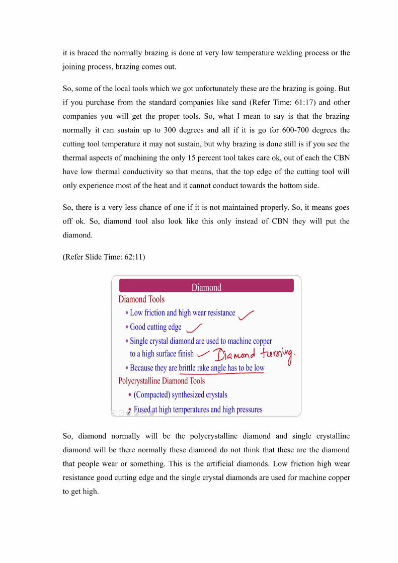
So, diamond normally will be the polycrystalline diamond and single crystalline
diamond will be there normally these diamond do not think that these are the diamond
that people wear or something. This is the artificial diamonds. Low friction high wear
resistance good cutting edge and the single crystal diamonds are used for machine copper
to get high.
Normally this is called a diamond turning, turning operation. Nowadays it is one of the
good process and I will teach whenever I am teaching about the advances in
advancement in metal cutting process or machining process they have brittle rake angle
should be low. So, polycrystalline diamond compacts synthesized crystals and fused high
temperature and all those things ok. So, this is about diamond.
One thing please note that diamond is a hardest material HSS is the toughest tool
material ok. So, do not confused between the toughest tool material is not the diamond
ok. So, it is a brittle material and it will fail in the brittle fracture ok.
(Refer Slide Time: 63:14)
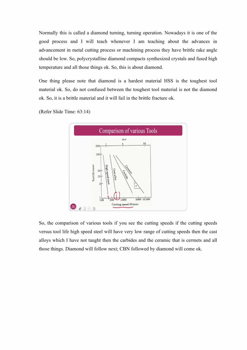
So, the comparison of various tools if you see the cutting speeds if the cutting speeds
versus tool life high speed steel will have very low range of cutting speeds then the cast
alloys which I have not taught then the carbides and the ceramic that is cermets and all
those things. Diamond will follow next; CBN followed by diamond will come ok.
Related Documents


![Introduction to Body Fluids-1[1]](https://static.cupdf.com/doc/110x72/55cf8cb35503462b138f0406/introduction-to-body-fluids-11.jpg)