Introduction to Machine Maintenance and Installation

Welcome message from author
This document is posted to help you gain knowledge. Please leave a comment to let me know what you think about it! Share it to your friends and learn new things together.
Transcript
Introduction to Machine Maintenance
and Installation
• What is the place of Maintenance
Professionals in Industry?
Maintenance Planner
Sales Engineer
Maintenance Engineer
Technique Manager

• Which industries require the service of
maintenance professionals? • All manufacturing industries:
Metal industries
Plastic factories
Automotive industries
Cement factories
Lather and Lather Products
Textile and Garment Factories
Breweries
Soft drink factories
Alcohol and liquor factories
Food processing industries
Construction industries, etc.
• Service industries
Hotels and Resorts
1. INTRODUCTION
• What is Maintenance?
• Maintenance can be considered as a
combination of activities directed towards
preservation and restoration of the performance
of a facility, machine or equipment.
• Which comprises:
• service
• repair,
• replace, and
• modify components of a machine/equipment.
1. INTRO. Cont.
• The main purposes of maintenance:
to eliminate system failures and hazards.
to ensure that equipment continues to work
within the design tolerances and
specifications.
to ensure the defined functions and standards
of operations of the plant are maintained, and
to ensure equipment are capable of being
performed for the required period.
1. INTRO. Cont.
Effect of Poor Maintenance
Inadequate or lack of effective and efficient
maintenance system especially in a manufacturing
enterprise gives rise to several undesirable
consequences. These consequences include:
(i) Excessive machine breakdown
(ii) Frequent emergency maintenance work
(iii) Shortened life-span of the facility
(iv) Poor use of maintenance staff
(v) Loss in production output
(vi) Inability to meet delivery dates
(vii) Excessive overtime
1. INTRO. Cont.
• The level of maintenance required at the
equipment operation stage is affected by
factors at other stages through which the
equipment passes. Theses are:
1. Design stage:
2. Installation stage:
3. Commissioning stage:
4. Operational stage:
1. INTRO. Cont. 1. Design stage:
Reliability and maintainability are the important factors which should be considered properly in relation to performance of equipment, capital and running costs.
2. Installation stage:
Maintainability is an important factor to be considered during the installation, for it is here that maintenance problems become clear.
3. Commissioning stage:
This is a stage of technical performance testing and also a stage of where primary design faults are located and designed out.
4. Operational stage:
The operational stage is a stage of learning where maintenance plays an important role.
2. Basics of Machine Installation
General Procedure of Machine Installation
Installation procedure of a
machine involves a series of
activities like:
a) Location and layout;
b) Positioning of machines;
c) Foundation;
d) Leveling and alignment;
e) Grouting;
f) Fitting of other parts, accessories, piping etc.;
g) Final leveling and test runs
a) Location and Layout
• The location of a machine depends on its purpose of
installation, definite types and sizes and other special
requirements, if any.
• For example, a centrifugal pump location should be as
close to the source of water as possible when suction lift is
present, or for a compressor location may be selected near
the particular shop where maximum air will be consumed
and at the same time a clear intake air will be available.
• Moreover the location plan should permit to have required
wide space all-around for continuing the erection work and
should facilitate regular inspection, repairing, etc.
• The location should also be finalized in such a fashion that
it will not disturb or obstruct the operation and
maintenance work of other nearby machines.
a) Location and Layout Cont.
• Once the location is finalized, the work of laying
out the foundation plan is to be undertaken.
• Laying out means marking of the foundation plan.
It may be done with the help of chalk on a
concrete floor and by a string with a number of
pegs.
• The general procedure is to indicate the outlines as
per specification of the machine.
• The axis lines are to be drawn both longitudinally
and crosswise to locate the center of foundation.
• Excavation of soil may be started only when the
layout is completed as per the requirement.
b) Positioning of Machines
• Positioning of the machine at the location is an important
job, which deserves care, skill an efficient teamwork.
• An equipment may have the weight of a few tons. But it is
to be loaded or unloaded, to be moved vertically or
horizontally to bring it at the site and to place it on the
foundation as well.
• Different types of lifting devices like pulley blocks, chain-
hoists, overhead cranes etc. may be used as per the
availability and requirement.
• When the load is light, rope pulley blocks are widely used
and chain pulley blocks may be useful, but for a very
heavy load, electric cranes are generally employed.
• However, the slinging should be done with much care to
avoid any impact shock, to avoid formation of any
scratches and breakages, etc.
b) Positioning of Machines Cont.
• For a machine of about 2 tones, hemp rope or
Manila rope of diameter about 4 to 5 cm may be
used instead of chains, wooden blocks and felts
should be interposed between rope and the
machine, to avoid damage to the finishing.
• Care must be taken to sling the machine upright
with weight distributed evenly. Thus, the efficient
fixing and passing of ropes or ‘chains’ through the
machine structure deserves skill and experience.
• Two typical slinging diagram (Fig. 1: a & b) are
given for a lathe and a vertical milling machine
respectively to explain the complicacies of
slinging.
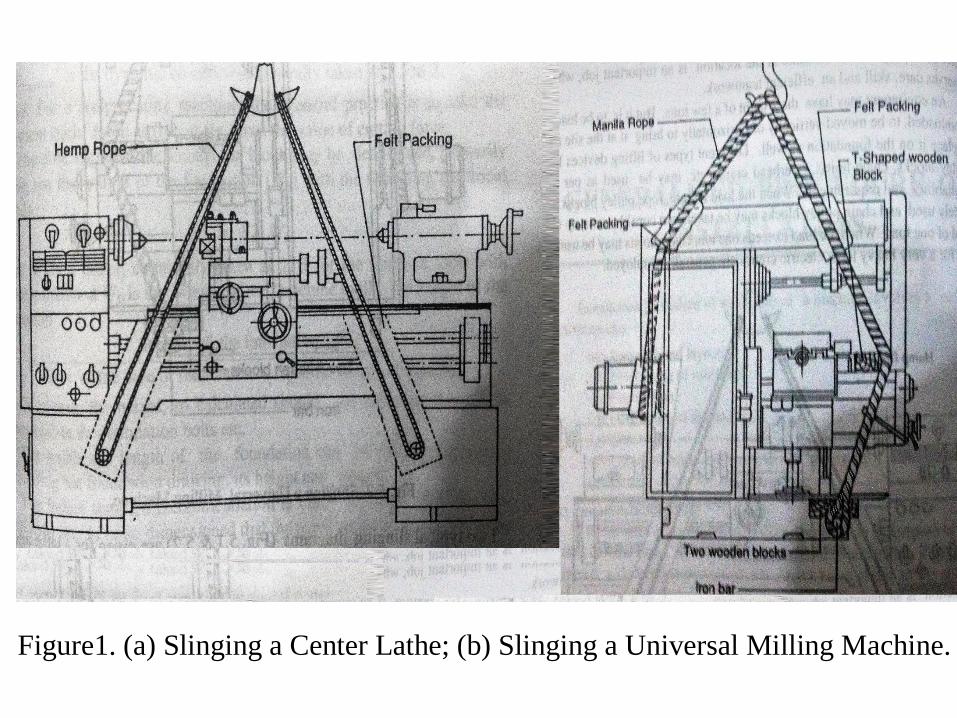
Figure1. (a) Slinging a Center Lathe; (b) Slinging a Universal Milling Machine.
c) Foundation
• The shapes and sizes of the foundation differ according
to the type and size of the machines.
• They are also dependent on the property of the subsoil
and the dynamic loads of the machine during operation.
• If the weight of the installed machine is not too much
or if the dynamic loads are insignificant, the size of the
foundation may be finalized on the basis of design
considerations.
• But when the dynamic loads predominant, the
foundation should also serve the purpose to protect the
machine from external vibration and to lower down the
frequency of natural vibration by increasing its total
mass.
c) Foundation Cont.
Other Design Criteria for Foundation
• Besides the dimensions, as stated above, some other
criteria are also considered for suitable foundation
work.
i. Ground Condition
• The nature of soil is obviously a vital criterion. For a
hard soil or for a normal soil, the construction of a
concrete bed does not entangle too many complicacies.
It is rather most straightforward to consider the
foundation plan supplied by the manufacturer.
• But, for soft and loose soil, a large surface area with
proper depth is needed for the foundation of a
machine.
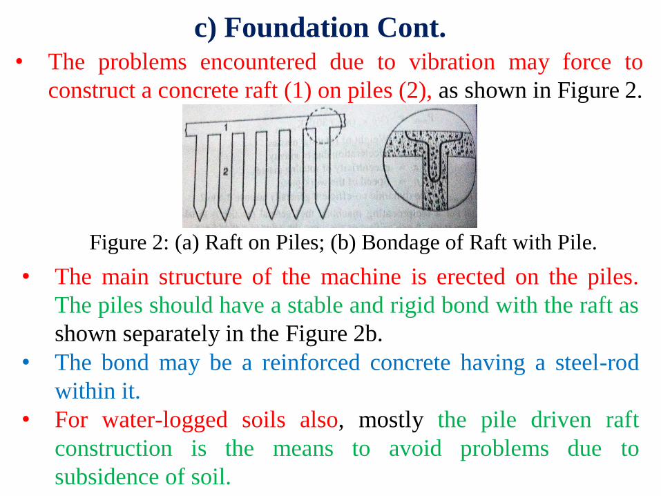
c) Foundation Cont.
• The problems encountered due to vibration may force to
construct a concrete raft (1) on piles (2), as shown in Figure 2.
Figure 2: (a) Raft on Piles; (b) Bondage of Raft with Pile.
• The main structure of the machine is erected on the piles.
The piles should have a stable and rigid bond with the raft as
shown separately in the Figure 2b.
• The bond may be a reinforced concrete having a steel-rod
within it.
• For water-logged soils also, mostly the pile driven raft
construction is the means to avoid problems due to
subsidence of soil.
c) Foundation Cont.
Vibration Consideration • To avoid transmission of vibration to adjoining parts of buildings
or other foundations, it is necessary to provide a suitable isolation
between the equipment foundation and the joining structure.
• Usually a gap is maintained all around the foundation (like a
trench), and is filled by sand to avoid such transmission of
vibration.
• Any vibration isolating material, other than sand, such as rubber,
lead sheet, felt etc. may also be used.
• As a rule, the equipment foundation shall not be allowed to serve
as support for other structures or for machineries not related to
the particular equipment.
• The impact type machines, like stamping press, drop and forging
hammer, need special care during foundation. The depth of the
foundation becomes very large to make the foundation heavy.
c) Foundation Cont.
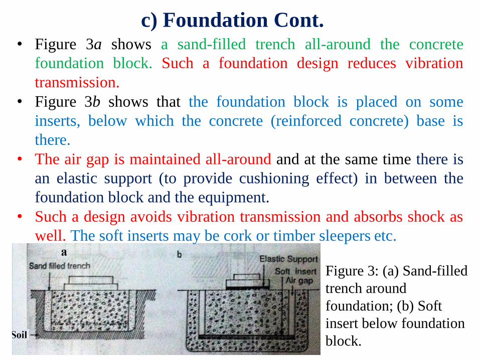
• Figure 3a shows a sand-filled trench all-around the concrete
foundation block. Such a foundation design reduces vibration
transmission.
• Figure 3b shows that the foundation block is placed on some
inserts, below which the concrete (reinforced concrete) base is
there.
• The air gap is maintained all-around and at the same time there is
an elastic support (to provide cushioning effect) in between the
foundation block and the equipment.
• Such a design avoids vibration transmission and absorbs shock as
well. The soft inserts may be cork or timber sleepers etc.
Figure 3: (a) Sand-filled
trench around
foundation; (b) Soft
insert below foundation
block.
c) Foundation Cont.
Foundation bolts • To install the machineries, foundation bolts will be specified and
supplied by the manufacturers. Some of the foundation bolts
become rigid on pouring concrete and some may be removable
and adjustable bolts.
• A few type of foundation bolts, very commonly used, are
discussed below.
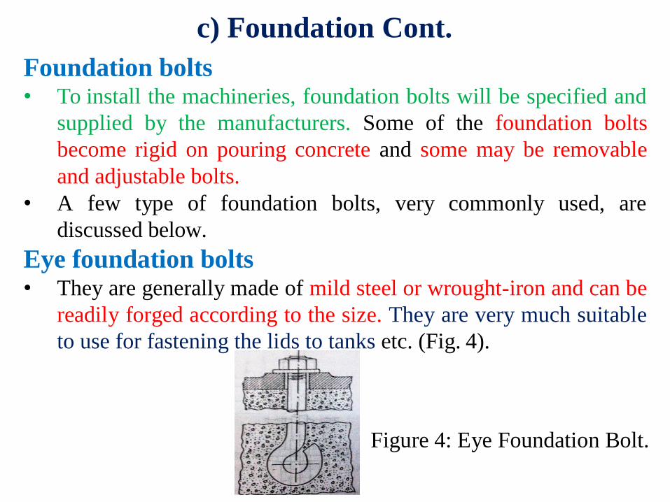
Eye foundation bolts • They are generally made of mild steel or wrought-iron and can be
readily forged according to the size. They are very much suitable
to use for fastening the lids to tanks etc. (Fig. 4).
Figure 4: Eye Foundation Bolt.
c) Foundation Cont.
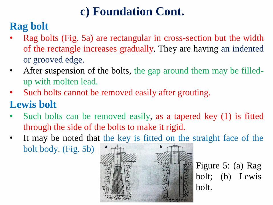
Rag bolt • Rag bolts (Fig. 5a) are rectangular in cross-section but the width
of the rectangle increases gradually. They are having an indented
or grooved edge.
• After suspension of the bolts, the gap around them may be filled-
up with molten lead.
• Such bolts cannot be removed easily after grouting.
Lewis bolt • Such bolts can be removed easily, as a tapered key (1) is fitted
through the side of the bolts to make it rigid.
• It may be noted that the key is fitted on the straight face of the
bolt body. (Fig. 5b)
Figure 5: (a) Rag
bolt; (b) Lewis
bolt.
c) Foundation Cont.
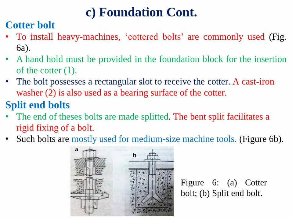
Cotter bolt • To install heavy-machines, ‘cottered bolts’ are commonly used (Fig.
6a).
• A hand hold must be provided in the foundation block for the insertion
of the cotter (1).
• The bolt possesses a rectangular slot to receive the cotter. A cast-iron
washer (2) is also used as a bearing surface of the cotter.
Split end bolts • The end of theses bolts are made splitted. The bent split facilitates a
rigid fixing of a bolt.
• Such bolts are mostly used for medium-size machine tools. (Figure 6b).
Figure 6: (a) Cotter
bolt; (b) Split end bolt.
c) Foundation Cont.
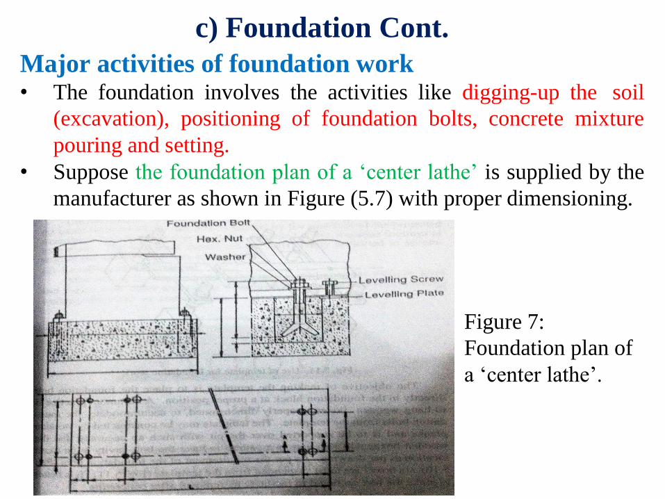
Major activities of foundation work • The foundation involves the activities like digging-up the soil
(excavation), positioning of foundation bolts, concrete mixture
pouring and setting.
• Suppose the foundation plan of a ‘center lathe’ is supplied by the
manufacturer as shown in Figure (5.7) with proper dimensioning.
Figure 7:
Foundation plan of
a ‘center lathe’.
c) Foundation Cont.
• The erection work is undertaken mostly when the foundation
block has been set in and hardened.
• The machine tool is placed on the foundation with the help of
spacers or pads, leveling wedges, etc.
• Foundation plates are also supported similarly, for different
machines etc. At this time, a gap (minimum 50 to 70mm)
depending on the type of the machine is maintained between
the top of the foundation block and the bottom of the machine
or base plate.
• The foundation bolts are positioned before positioning the
machine and the exact location of the machine is guided by
the insertion of the projected foundation-bolt ends through
the holes, provided at the machine footings or base plate.
• The bolt-ends should remain sufficiently projected to
accommodate the washers and nuts as well.
c) Leveling and Alignment
• After having the machine on the foundation, the
important job is to level and align it with other
accessories.
• The leveling is performed with leveling wedges,
shoes etc. as stated before.
• The horizontal and slight vertical movements of the
heavy mass of machine is performed by pipes,
rollers as shown in Fig. 9a or using pinch bars (Fig.
9b).
• Straight edge, spiral level, dial indicator etc., are
generally useful instruments to level the machine.
• The leveling is to be checked in the both,
longitudinal and transverse direction.
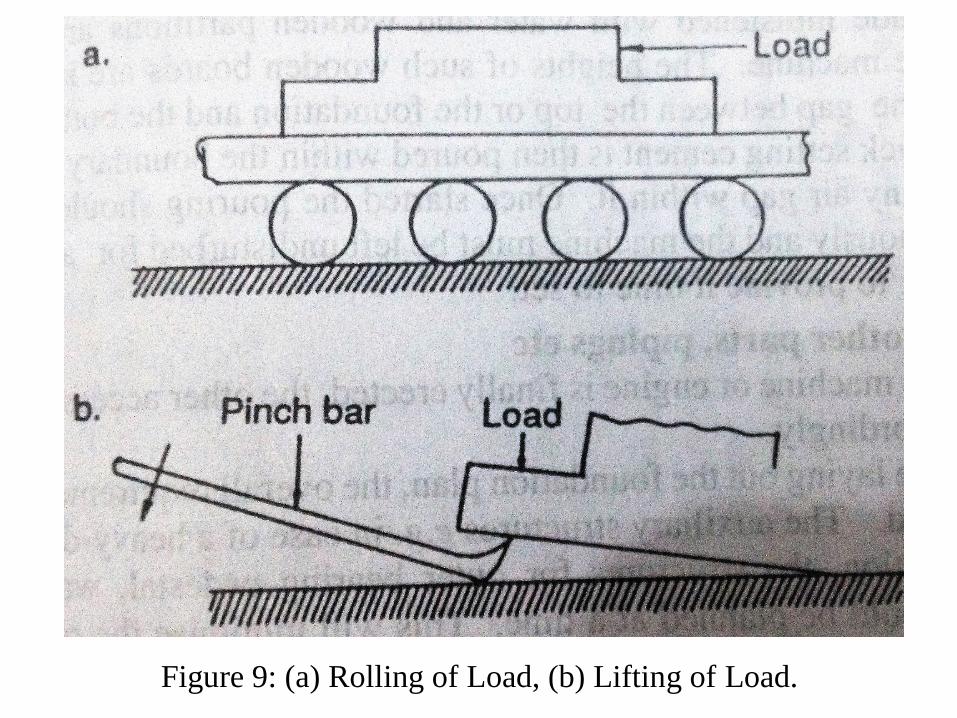
Figure 9: (a) Rolling of Load, (b) Lifting of Load.
d) Leveling Cont.
• The parallelity, perpendicularity of different faces, axes
should be leveled and aligned, as are required.
• When leveling is completed, the foundation bolt cavity
along with the bolt may be made concreted. Pouring of
cement concrete is generally made through the gap
provided at the top of the foundation, as shown in Fig.
10.
• This concreting will provide a bondage of the
foundation bolts with the foundation block while
performing grouting, discussed later.
• Whenever, the foundation block is continuously made
for a connected accessory, (say, the alternator with the
turbine) the relative alignment should be established
before concreting the foundation bolts.
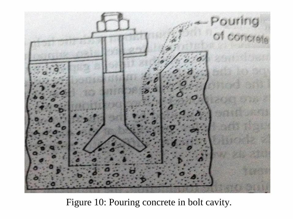
Figure 10: Pouring concrete in bolt cavity.
d) Grouting • Grouting is a procedure of connecting the machine with the
foundation by a concrete mixture of plastic consistency or
cement mortar. It is extensively used in installing most of the
machines.
• Generally, a quick setting cement is used to perform grouting.
The top of the foundation block is made roughned, made
moistened with water and wooden partitions are placed all-
around the machine.
• The heights of such wooden boards are kept much higher than
the gap between the top or the foundation and the bottom of the
machine.
• Quick setting cement is then poured within the boundary with
care to eliminate any air gap within it.
• Once started, the pouring should be completed continuously and
the machine must be felt undisturbed for a few days after
grouting to provide it time to set.
e) Fitting of other parts
• When the machine is erected, the other
accessories may be joined accordingly.
• But, while laying out the foundation plan, the
overall requirement should be kept in mind.
• The auxiliary structures e.g. in case of a heavy-
duty diesel engine foundation, the structures for
outer bearing pedestal, water pump blocks etc.
should be planned at a time.
• This will minimize the problem of internal
fittings.
f) Final leveling and test runs
• Accurate leveling can be carried out only when
the grouting has set in after a few days.
• The machine is to be made cleaned and leveled
then. Such leveling involves minor adjustments.
• Whenever provided, the leveling screws as shown
in Fig. 7. may be operated to achieve the final
level.
• Everything should now be made ready to carry the
test run. The style of testing will differ from
machine to machine.
• For instance, for metal-cutting machine tools, they
are always sent out with a test chart.
f) Final leveling Cont.
• ‘Test chart’ may be defined as the specification
of accuracies of major typical points like
‘straightness of guide ways’ ‘Trueness of
spindles’ etc. which should exist for the desired
functioning of the respective machines.
• The accuracy shown in the chart will be re-
obtained only if the machine is correctly erected

and leveled
Related Documents