INTRODUCTION TO INSTABILITIES IN NATURAL CIRCULATION SYSTEMS P.K. Vijayan Reactor Engineering Division, Bhabha Atomic Research Centre, Mumbai, India IAEA Course on Natural Circulation in Water- Cooled Nuclear Power Plants, ICTP, Trieste, Italy, 25-29 June, 2007 (Lecture : T-6)

INTRODUCTION TO INSTABILITIES IN NATURAL CIRCULATION SYSTEMS
Jan 01, 2016
INTRODUCTION TO INSTABILITIES IN NATURAL CIRCULATION SYSTEMS. P.K. Vijayan Reactor Engineering Division, Bhabha Atomic Research Centre, Mumbai, India. IAEA Course on Natural Circulation in Water-Cooled Nuclear Power Plants, ICTP, Trieste, Italy, 25-29 June, 2007 (Lecture : T-6). - PowerPoint PPT Presentation
Welcome message from author
This document is posted to help you gain knowledge. Please leave a comment to let me know what you think about it! Share it to your friends and learn new things together.
Transcript

INTRODUCTION TO INSTABILITIES IN NATURAL CIRCULATION SYSTEMS
P.K. VijayanReactor Engineering Division,
Bhabha Atomic Research Centre, Mumbai, India
IAEA Course on Natural Circulation in Water-Cooled Nuclear Power Plants, ICTP, Trieste, Italy, 25-29 June, 2007 (Lecture : T-6)
- INTRODUCTION
- STABILITY OF SINGLE-PHASE NC
- CLASSIFICATION OF INSTABILITIES
- INSTABILITY DUE TO BOILING INCEPTION
- TWO-PHASE NC INSTABILITY
- CONCLUDING REMARKS
OUTLINE OF THE LECTURE T#6
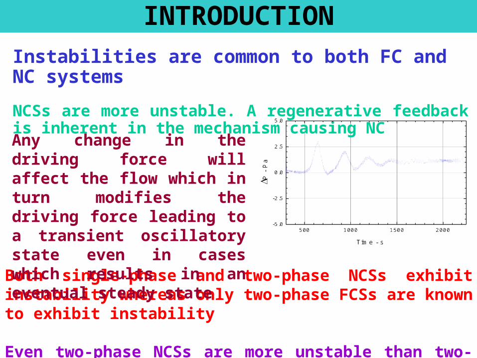
INTRODUCTION
Instabilities are common to both FC and NC systems
NCSs are more unstable. A regenerative feedback is inherent in the mechanism causing NC
Both single-phase and two-phase NCSs exhibit instability whereas only two-phase FCSs are known to exhibit instability
Even two-phase NCSs are more unstable than two-phase FCSs
Any change in the driving force will affect the flow which in turn modifies the driving force leading to a transient oscillatory state even in cases which results in an eventual steady state

stable
Neutrally stable
unstable
Time - s
Flo
w –
kg/
s
- Following a perturbation if a thermal-hydraulic system returns to its original steady state, then the system is considered to be stable
What is instability?
- If the system continues to oscillate with the same amplitude, then it is considered as neutrally stable
-If the system oscillates with increasing amplitude or shift to a new steady state, then it is considered as unstable

0 3000 6000 9000 12000 15000 18000-3
-2
-1
0
1
2
3
(d)
0 5000 10000 15000 20000 25000-3
-2
-1
0
1
2
3
Orientation :HHHC
480 W240 W120 W60 W
P across the bottom horizontal section
P - mm of w
ater colum
n
Time - s(c)
0 4000 8000 1200016000200002400028000-3
-2
-1
0
1
2
3
350 W60 W
Orientation : HHHC P across the bottom horizontal section
P - mm of w
ater colum
n
Time - s
(b)
0 3000 6000 9000 12000 15000 18000 21000-3
-2
-1
0
1
2
3
Orientation : HHHC
300 W180 W60 W
P across the bottom horizontal section
P - mm of water colum
n
Time - s
(a)
Orientation : HHHC
280 W180 W
80 W
P across the bottom horizontal section
P - mm of water colum
n
Time - s
-3 -2 -1 0 1 2 3-0.2
-0.1
0.0
0.1
0.2
Limit Cycle OscillationsIn all practical systems oscillation growth cannot continue indefinitely. Instead, oscillation growth is terminated by system nonlinearities leading to limit cycle oscillations
Time seriesLimit Cycle,Phase space (plot ortrajectory), orbit
System nonlinearities
- System temperature cannot be lower than the sink temperature
- Void fraction can only vary between zero and unity
- Neutron flux cannot be negative

DISADVANTAGES OF INSTABILITY
- Premature CHF occurrence can be induced by flow oscillations
- Instability can disturb control systems and pause operational problems in nuclear reactors.
- Sustained flow oscillations may cause forced mechanical vibration of components
- Induce undesirable secondary effects like power oscillations in a BWR

Classification of instabilities
Several kinds of instabilities are observed in NCSs excited by different mechanisms
A fundamental cause of all instabilities is due to the existence of competing multiple solutions so that the system is unable to settle down to any of them permanently
However, differences exist in the transport mechanism, oscillatory mode, phase shift, the nature of the unstable threshold, and its prediction methods
Loop geometry and induced secondary phenomena also affect the instability
Instabilities are classified according to various bases
- analysis method
- propagation method
- nature of the oscillations
- loop geometry,
- disturbances or perturbations
Classification of instabilities – Contd.

Analysis method (or Governing equations used)
Pure static instabilityThe occurrence of multiple solutions and the instability threshold itself can be predicted from the steady state equations governing the process
Examples are Ledinegg instability and the instability induced by the occurrence of CHF
(a) Pure (or fundamental) static instability(b) Compound static instability(c) Pure dynamic instability(d) Compound dynamic instability
Classification of instabilities – Contd.

Compound static instability
In some cases of multiple steady state solutions, the instability threshold cannot be predicted from the steady state laws alone or the predicted threshold is modified by other effects.
In this case, the cause of the instability lies in the steady state laws, but feedback effects are important in predicting the threshold
Typical examples are the instability due to flow pattern transition, flashing and geysering
Classification of instabilities – Contd.

Pure Dynamic instability
For many NCSs neither the cause nor the threshold of instability can be predicted from the steady state laws as inertia and feedback effects are important
In this case, there are no multiple steady states, but the multiple solutions appear during the transient
The full transient governing equations are required for explaining the cause and predicting the threshold of instability
Typical example is the density wave oscillations commonly observed in NCSs
Classification of instabilities – Contd.

Compound dynamic instability
In many oscillatory conditions, secondary phenomena gets excited and it modifies significantly the characteristics and the threshold of pure dynamic instability
In such cases even the prediction of the instability threshold requires consideration of the secondary effect
Typical examples are
- neutronics responding to the void fluctuations
- primary fluid dynamics affecting the SG instability
Classification of instabilities – Contd.

Propagation method
This classification is restricted to only dynamic instabilities. Dynamic instabilities involve propagation or transport of disturbances. The disturbances can be transported by two kinds of waves
- Pressure or acoustic waves
- Density waves (Stenning and Veziroglu)
In two-phase flow, both waves are present, however, their velocities differ by one or two orders of magnitude allowing us to distinguish between the two
DWI is the most commonly observed instability. The frequency of DWI is of the order of 1 Hz in 2- flow
Classification of instabilities – Contd.

Based on the nature of oscillations - Flow excursions, - Pressure drop oscillations, - Power oscillations, - Temperature excursions
Based on the periodicity - Periodic oscillations- chaotic oscillations
Based on the oscillatory mode – Fundamental mode
- Higher harmonics
Based on the phase lag - in-phase oscillations, - out-of-phase oscillations- dual oscillations
Based on flow direction - Unidirectional oscillations- Bi-directional oscillations- Chaotic switching
Classification of instabilities – Contd.

Based on the loop geometry
- Open U-tube oscillations
- Pressure drop oscillations
- Parallel channel oscillations
Based on the disturbances
Certain two-phase flow phenomena cause a major disturbance and induce or modify the instability in NCSs
- Boiling inception- Flashing and geysering- Flow pattern transition- Occurrence of CHF
H
CC
F 0
Time
Classification of instabilities – Contd.
Closure
The classification based on the analysis method is the most widely accepted one and covers all observed instabilities
All other classifications addresses only a subset of the instabilities
It does not differentiate between NC and FC systems
Most instabilities observed in FC systems are observed in NCSs
However, certain instabilities associated with NCSs are not observed in FCSs – Single-phase instability and the instability associated with flow direction
Hence a specific discussion of instabilities for single-phase and two-phase NCSs is considered useful
Classification of instabilities – Contd.
STABILITY OF SINGLE-PHASE NCSs
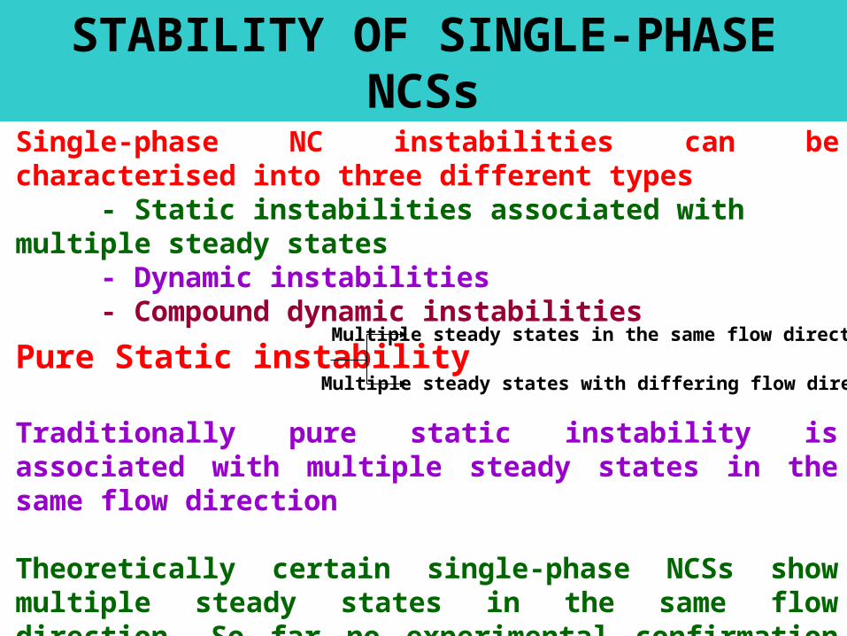
Single-phase NC instabilities can be characterised into three different types
- Static instabilities associated with multiple steady states- Dynamic instabilities- Compound dynamic instabilities
Pure Static instability
Traditionally pure static instability is associated with multiple steady states in the same flow direction
Theoretically certain single-phase NCSs show multiple steady states in the same flow direction. So far no experimental confirmation exists
Multiple steady states in the same flow direction
Multiple steady states with differing flow directions
coolant
Q1
Q2=0
Q1
Q2>Qc
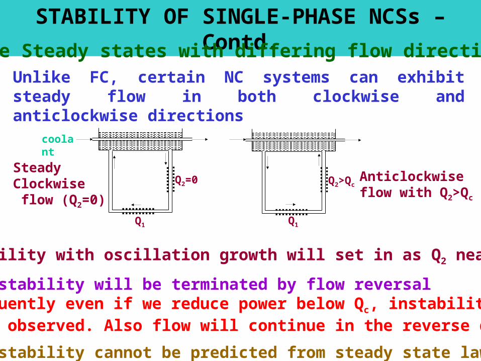
Steady Clockwise flow (Q2=0)
Anticlockwise flow with Q2>Qc
STABILITY OF SINGLE-PHASE NCSs – Contd.
Multiple Steady states with differing flow direction
- Instability with oscillation growth will set in as Q2 nears Qc
- The instability will be terminated by flow reversal- Subsequently even if we reduce power below Qc, instability will not be observed. Also flow will continue in the reverse direction
- The instability cannot be predicted from steady state laws alone
Unlike FC, certain NC systems can exhibit steady flow in both clockwise and anticlockwise directions
9750 10000 10250 10500 10750 11000-1.0
-0.5
0.0
0.5
Orientation : HHVC
p -
mm
of w
ate
r co
lum
n
Time - s
Grm
Stm
stableunstable
Clockwise flow Anticlockwise flow
0 5 10103
1013
1x10²³
Lt=7.19m, L
t/D=267.29, p=0.316, b=0.25
HHVC (ANTICLOCKWISE) HHVC (CLOCKWISE)
Gr m
Stm
410
620
800
2100
410 620 385H
1415
1180
C
26.9
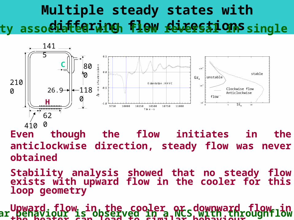
Multiple steady states with differing flow directionsInstability associated with flow reversal in single phase NCS
Similar behaviour is observed in a NCS with throughflow
Even though the flow initiates in the anticlockwise direction, steady flow was never obtained
Stability analysis showed that no steady flow exists with upward flow in the cooler for this loop geometry
Upward flow in the cooler or downward flow in the heater can lead to similar behaviour
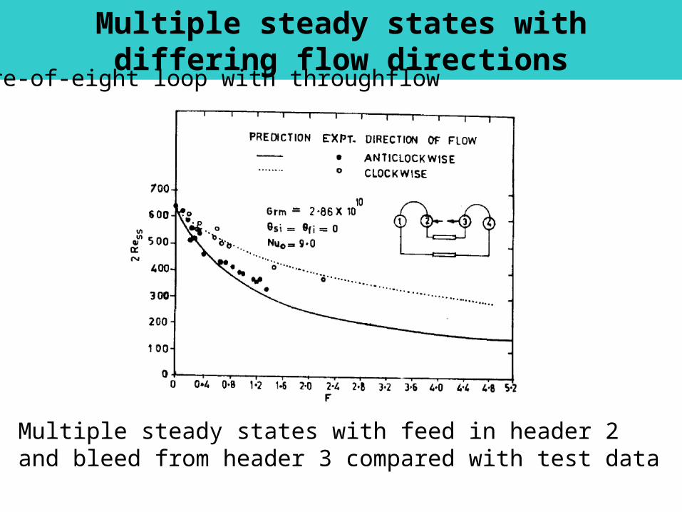
Multiple steady states with differing flow directions
Figure-of-eight loop with throughflow
Multiple steady states with feed in header 2 and bleed from header 3 compared with test data
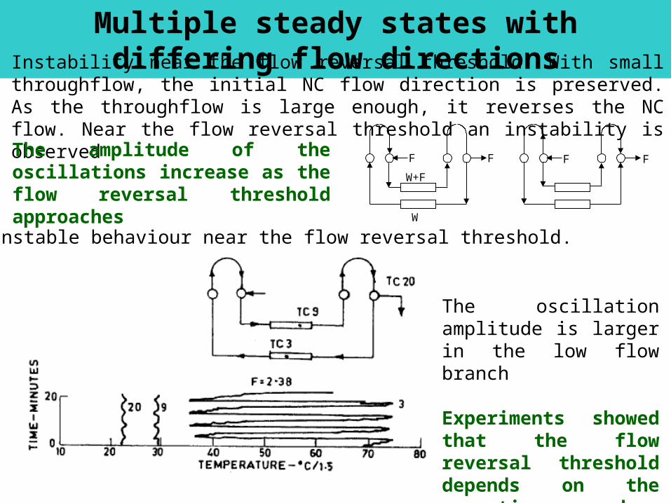
Multiple steady states with differing flow directionsInstability near the flow reversal threshold: With small throughflow, the initial NC flow direction is preserved. As the throughflow is large enough, it reverses the NC flow. Near the flow reversal threshold an instability is observed
F F F F
W+F
W
Typical unstable behaviour near the flow reversal threshold.
The oscillation amplitude is larger in the low flow branch
Experiments showed that the flow reversal threshold depends on the operating procedure (hysteresis)
The amplitude of the oscillations increase as the flow reversal threshold approaches

Parallel channel NC systems
Qb
Qm
Qt
cooler
ht
hm
hb
Unequally heated parallel horizontal channels having unequal elevations relevant to PHWRs
Existence of multiple steady states was first explored by Chato (1963)
heat
er
hs
hm
hl
Parallel vertical inverted U-tubes relevant to
SGs
dow
ncom
er
Qd=0Wd
Qn
Wn
Q3
W3
Q2
W2
Q1
W1
Vertical parallel channel system relevant to the RPV of BWRs, PWRs, etc.
Inlet header
Outlet header
Q
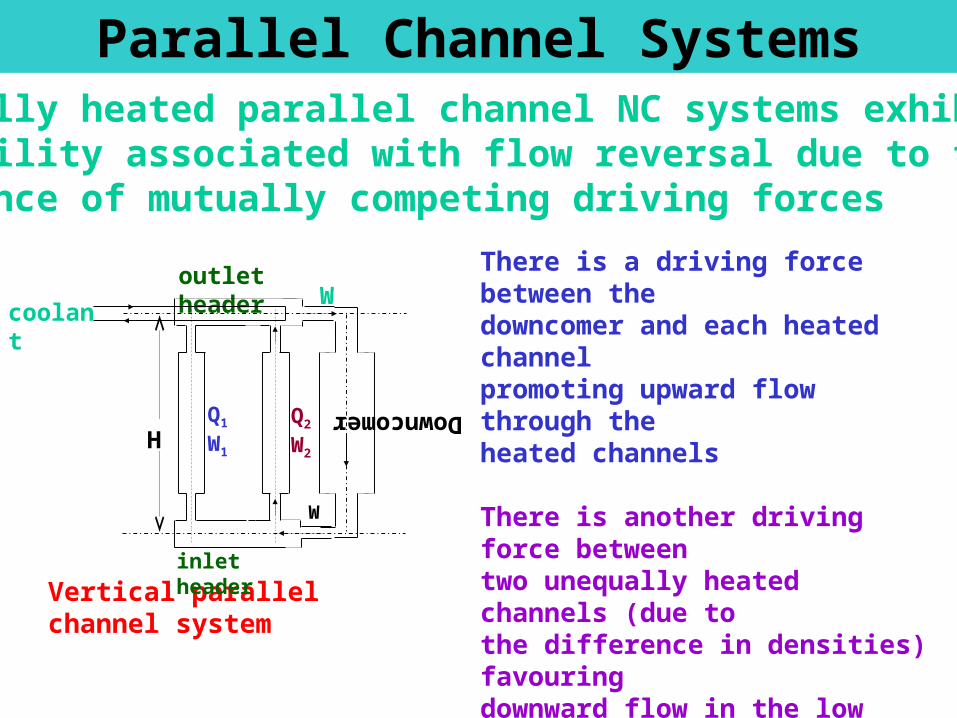
Unequally heated parallel channel NC systems exhibit an instability associated with flow reversal due to the existence of mutually competing driving forces
coolant
Vertical parallel channel systeminlet header
outlet header
Q2
W2
Q1
W1 H
W
DowncomerW
Parallel Channel Systems
There is a driving force between thedowncomer and each heated channel promoting upward flow through the heated channels
There is another driving force betweentwo unequally heated channels (due to the difference in densities) favouring downward flow in the low power channel
The actual flow direction is decided by the greater of the two driving forces

Parallel Channel Systems
coolant
(a) Vertical parallel channel system
inlet header
outlet header
Q2
W2
Q1=0W1
H
W
Dow
nco
mer
W
For an unheated channel, upward flow is unstable and stable downward flow can prevail.Keeping Q2 constant, if we increase Q1 then flow reversal in channel 1 occurs if Q1 > Qc (Chato (1963))
Keeping Q2 constant, if we reduce Q1, then the upward flowing channel 1 flow will reverse if Q1<Qc
(Linzer and Walter (2003))
The flow reversal threshold is a function of the power of channel 2.
Channel flow reversal is undesirable as it can lead to instabilities in two-phase systems
Parallel Channel Systems
It appears that channel flow reversal can be avoided in a system of vertical parallel channels if all the channels are equally powered
However, with vertical inverted U-tubes (as in SGs) and horizontal channels as in PHWRs, mutually competing driving forces exist even if all the channels are equally powered due to the differences in elevation.
Single-phase NC with reverse flow in some of the longest U-tubes are observed in several integral test loops
Steady state with one of the channels flowing in the reverse direction was observed during thermosyphon tests in NAPS

BOTTOM HEADER
TOP HEADER
COOLANT INLET COOLANT OUTLET
DO
WN
CO
ME
R
Ch-1 Ch-2 Ch-3
BOTTOM HEADER
TOP HEADER
COOLANT INLET COOLANT OUTLET
DO
WN
CO
ME
R
Ch-1 Ch-2 Ch-3
Initial steady state was achieved with equal power to Ch-1,2 & 3 and Ch-4 unheated. Ch- 1, 2 & 3 are with upflow and Ch-4 with downflow. Power in Ch-1 was decreased keeping other channels’ power constant. The BLACK curve starts at A. After reaching a power ratio corresponds to B, the flow in Ch-1 reverses from upflow (+ve) to downflow (-ve) and the curve jumps from state B to state C. For the second case, initial steady state was achieved with equal power to Ch-2 & 3 and Ch-1 & 4 unheated. i.e. Ch-2 & 3 with upflow and Ch-1 & 4 with downflow. The BLUE curve starts at D. Power in Ch-1 was increased. After reaching a power ratio corresponds to E, the flow in Ch-1 reverses from downflow (-ve) to upflow (+ve) and the curve jumps from state E to state F.
A
B
C
D
EF
Dynamic Instability in single-phase NCSs
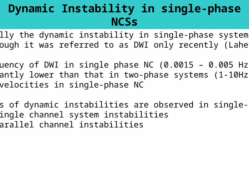
Essentially the dynamic instability in single-phase systems is also DWI although it was referred to as DWI only recently (Lahey, Jr)
The frequency of DWI in single phase NC (0.0015 – 0.005 Hz) is significantly lower than that in two-phase systems (1-10Hz) due to the low velocities in single-phase NC
Two types of dynamic instabilities are observed in single-phase NCSs- Single channel system instabilities- Parallel channel instabilities
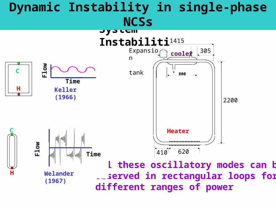
System Instabilities
Dynamic Instability in single-phase NCSs
Flo
w
TimeH
C
Keller (1966)
All these oscillatory modes can be observed in rectangular loops for different ranges of power
Expansion tank
1415
305
410
cooler
620
2200
410620
385
800
Heater
25 50 75 100-3
-2
-1
0
1
2
3St
m=7.0, Gr
m=1x10¹³
Flo
w
C
H Welander (1967)
Time
Dynamic Instability in single-phase NCSs
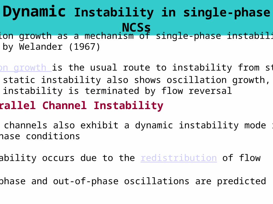
Oscillation growth as a mechanism of single-phase instability proposed by Welander (1967)
- Oscillation growth is the usual route to instability from steady state - Compound static instability also shows oscillation growth, but the instability is terminated by flow reversal
Parallel Channel Instability
Parallel channels also exhibit a dynamic instability mode in single-phase conditions
The instability occurs due to the redistribution of flow
Both in-phase and out-of-phase oscillations are predicted

Two-phase NC instabilityPure static instabilityCompound static instabilityDynamic instabilityCompound Dynamic instability
Pure static instability
Flow excursion or excursive (Ledinegg) instabilityBoiling Crisis
Ledinegg instability
Involves sudden change of flow rate to a lower valueThe new flow rate may induce CHFOccurrence of multiple steady states is the fundamental cause of the instability

Ledinegg instability – Contd.
Driving pressure differential
Two-phase system characteristic
a b c
Flow rate
Head
dow
ncom
er
Feed
Steam
heat
er
riser
It occurs during the negative sloping region of the p – W characteristic; d(p)/dW < 0 is the criterion for the Ledinegg instability
Point ‘b’ satisfies this criterion and is therefore unstableThe instability can be avoided by inlet throttling in FCSsInlet throttling may not work as effectively as in FCSs due to the reduction in flow caused by it

Boiling Crisis
Following the occurrence of critical heat flux, a regime of transition boiling may be observed as in pool boiling
Transitionboiling
Filmboiling
Hea
t fl
ux
Ts - Tsat
Nucleate boiling
Natural convection
During transition boiling a film of vapour prevents the liquid from coming in direct contact with the heating surface resulting in a steep rise in temperature
The film itself is not stable causing repetitive wetting and dewetting of the heating surface resulting in an oscillatory surface temperatureThe instability is characterized by sudden rise in wall temperature followed by an almost simultaneous occurrence of flow oscillations
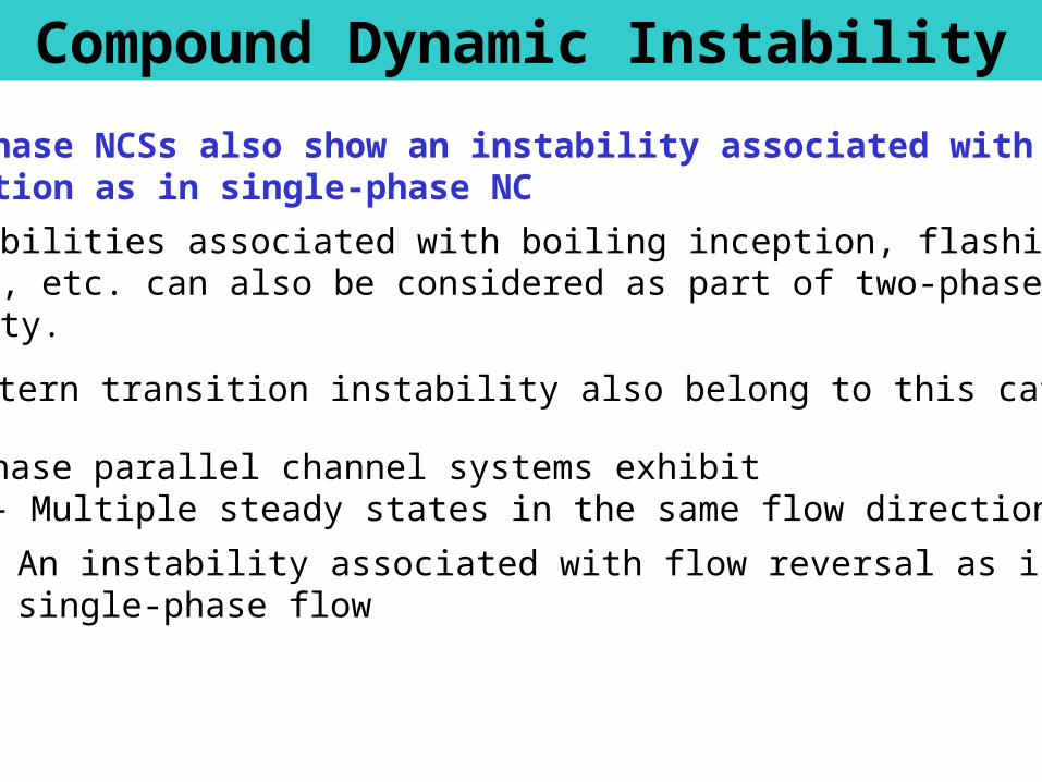
Compound Dynamic Instability
Two-phase NCSs also show an instability associated with flow direction as in single-phase NC
All instabilities associated with boiling inception, flashing and geysering, etc. can also be considered as part of two-phase NC instability.
Flow pattern transition instability also belong to this category
Two-phase parallel channel systems exhibit - Multiple steady states in the same flow direction
- An instability associated with flow reversal as in single-phase flow
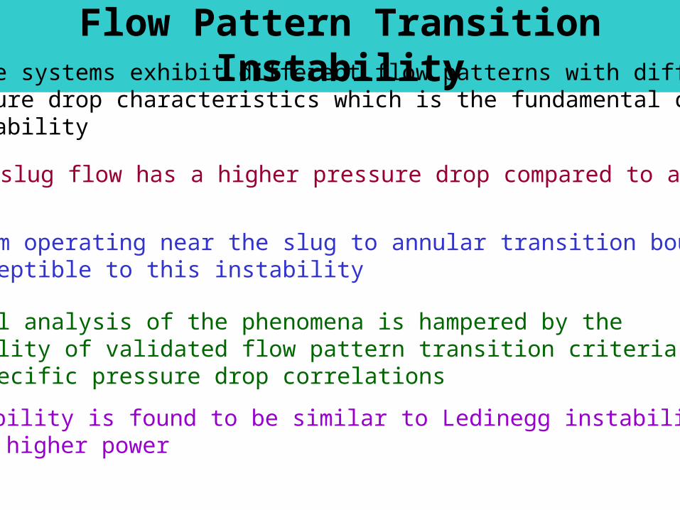
Flow Pattern Transition InstabilityTwo-phase systems exhibit different flow patterns with differences in pressure drop characteristics which is the fundamental cause of the instability
Bubbly-slug flow has a higher pressure drop compared to annular flow
A system operating near the slug to annular transition boundary is susceptible to this instability
Theoretical analysis of the phenomena is hampered by the unavailability of validated flow pattern transition criteria and flow pattern specific pressure drop correlations
The instability is found to be similar to Ledinegg instability, but occurs at higher power
Fukuda-Kobori
Type-I instability
Type-II instability
Stable two-phase NC
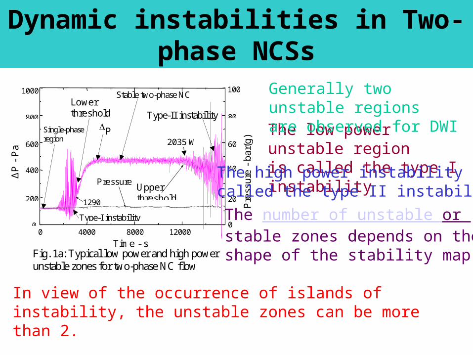
Fig. 1a: Typical low power and high power unstable zones for two-phase NC flow
Single-phase region
0 4000 8000 12000 0
200
400
600
800
1000
0
20
40
60
80
100
Pressure
P
Pre
ssur
e -
bar(
g)
2035 W
1290 W
Upper threshold
Lower threshold
ΔP
- P
a
Time - s
The low power unstable regionis called the type I instability
In view of the occurrence of islands of instability, the unstable zones can be more than 2.
Generally two unstable regionsare observed for DWI
The number of unstable or stable zones depends on the shape of the stability map
The high power instability iscalled the type II instability
Dynamic instabilities in Two-phase NCSs
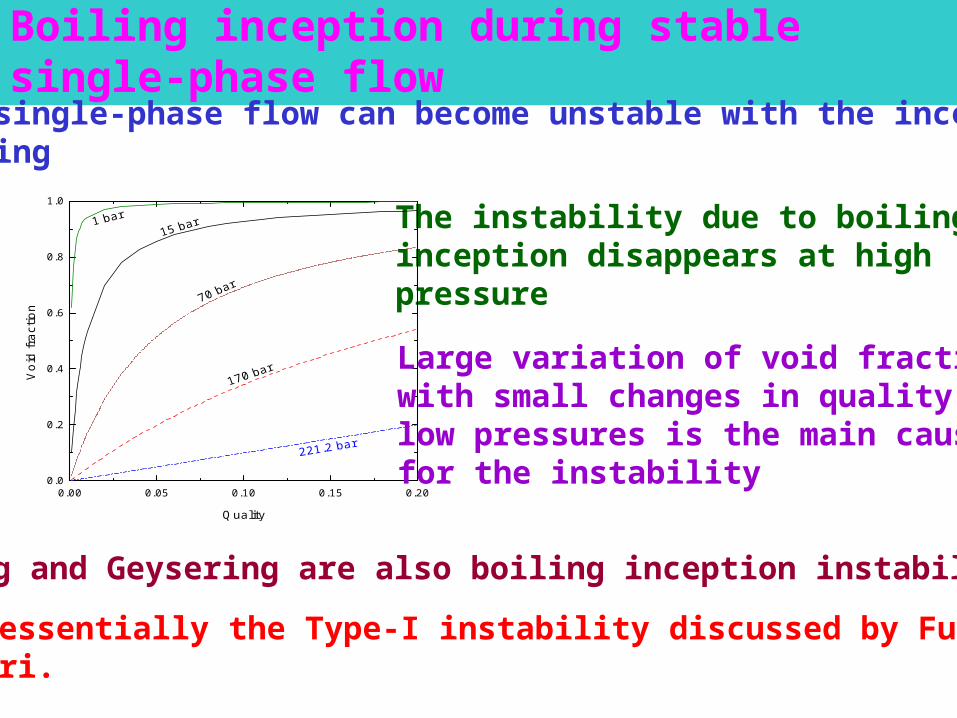
Boiling inception during stable single-phase flow
Stable single-phase flow can become unstable with the inception of boiling
The instability due to boiling inception disappears at high pressure
0.00 0.05 0.10 0.15 0.200.0
0.2
0.4
0.6
0.8
1.0
Void
fra
ctio
n
Quality
Large variation of void fraction with small changes in quality at low pressures is the main cause for the instability
Flashing and Geysering are also boiling inception instability
This is essentially the Type-I instability discussed by Fukuda and Kobori.

Flashing Induced InstabilityOccurs in NCSs with tall risers. The rising hot liquid experiences static pressure decrease and may reach its saturation value leading to flashing in low pressure systems
The increased buoyancy force increases the flow which in turn reduces exit enthalpy and may even suppress flashing causing reduction in buoyancy force and flow. Reduced flow leads to larger exit enthalpy leading to the repetition of the process.
The necessary condition for flashing is that the fluid temperature at the riser inlet is greater than the saturation temperature at the exit
The instability is observed only in low pressure systems
Thermodynamic equilibrium conditions prevail during flashing

Geysering Instability
Generally observed in systems with tall risers. Geysering is expected during subcooled boiling taking place at the exit of the heater
As the bubbles move up the riser, bubble growth (due to static pressure decrease) as well as condensation can take place.
Sudden condensation results in depressurisation causing the liquid water to rush to the space vacated by the slug bubble leading to a large increase in the flow rate reducing the driving force
Geysering is a nonequilibrium phenomenon unlike flashing
Both Geysering and flashing instabilities are observed in low pressure systems only

Dynamic Instability in Two-phase NCSsRegenerative feedback and time delay are important for dynamic instability
DWI is the most commonly observed dynamic instability in NCSs and the mechanism causing the instability has already been discussed earlier
A number of geometric and operating parameters affect the instability in addition to certain boundary conditions
Riser height, orificing, length and diameter of source, sink and connecting pipes are the important geometric parameters
Pressure, inlet subcooling, power and its distribution are the important operating parameters
Boundary conditions of interest are wall heat transfer coefficient,heat storage in walls, wall heat losses, constant pressure drop, etc.
Compound Dynamic Instability in two-phase NCSs
If only one instability mechanism is at work, it is said to be fundamental or pure instability. Instability is compound if more than one mechanisms interact in the process and cannot be studied separately
-Thermal oscillations-Parallel channel instability-Pressure drop oscillations-BWR instability-SG instability

The steep variation in heat transfer coefficient gets coupled with DWO
The dryout or CHF point shift upstream of or downstream during thermal oscillations
The large variation in heat transfer coefficient results in significant variation in heat transfer rate even if the wall heat generation is constant
Thermal oscillations are a regular feature of post dry out heat transferheat transfer in steam-water mixtures at high pressures
The variable heat transfer coefficient leads to a variable thermal response of the heated wall that gets coupled with the DWO
Thermal Oscillations
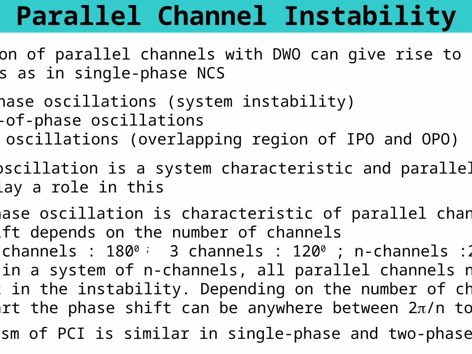
Parallel Channel InstabilityInteraction of parallel channels with DWO can give rise to interesting behaviours as in single-phase NCS
-In-phase oscillations (system instability)- Out-of-phase oscillations-Dual oscillations (overlapping region of IPO and OPO)
In-phase oscillation is a system characteristic and parallel channels may not play a role in this
Out-of-phase oscillation is characteristic of parallel channels. Thephase shift depends on the number of channels
- 2 channels : 1800 ; 3 channels : 1200 ; n-channels :2/nHowever, in a system of n-channels, all parallel channels need not take part in the instability. Depending on the number of channels taking part the phase shift can be anywhere between 2/n to
Mechanism of PCI is similar in single-phase and two-phase systems

Pressure drop oscillationsThis is associated with operation in the negative sloping region of p-w curve.
Caused by the interaction of a compressible volume at the inlet of the heated section with the pump characteristics
Usually observed in FCSs. DWO oscillation occurs at flow rates lower than the flow rate at which PDO is observed
The frequency of PDO is much smaller than DWO.
Very long test sections may have sufficient internal compressibility to cause PDO
Like Ledinegg instability there is a danger of CHF occurrence during PDO
Inlet throttling can stabilize PDO as in the case of Ledinegg instability
Instability in NBWRs
The flow velocity in NBWRs is usually much smaller than FC BWRs
The presence of tall risers causes the oscillation frequency to be much smaller
The only NCR whose stability has been extensively studied is the Dodewaard reactor.
The negative void reactivity stabilizes type I instability. But it may stabilize or destabilize type II instability
Pump trip transients in FC BWRs lead to type II instability

Various bases used for classification of instabilities have been reviewed. The most widely accepted classification is based on the method of analysis used in identifying the stability threshold.
While classifying NC instabilities, it was convenient to consider the instabilities associated with single-phase and two-phase NC separately Natural circulation systems are more unstable due to the regenerative feedback inherent in the mechanism causing the flow.
Besides the instability in single-phase systems, natural circulation loops also exhibit an instability associated with flow reversal in contrast to forced circulation systems.
CONCLUDING REMARKS

Thank you

Density wave instability
Due to the importance of void fraction and its effect on flow, the instability is often referred to as ‘flow-void feedback instability’ in two-phase NCSs
Since transportation time delays are crucial to the instability, it is also known as ‘time delay oscillations’
In single-phase, near critical and supercritical fluids, the instability is also known as ‘thermally induced oscillations’
Classification of instabilities – Contd.
DWI is most commonly observed in NCSs. The frequency of DWI is of the order of 1 Hz in 2- flow

Instabilities Associated with Boiling Inception
Boiling inception modifies single-phase instability
Boiling inception can induce instabilities in a stable single-phase NCS
Occurrence of single-phase conditions during part of the oscillation cycle is a characteristic feature of this instability
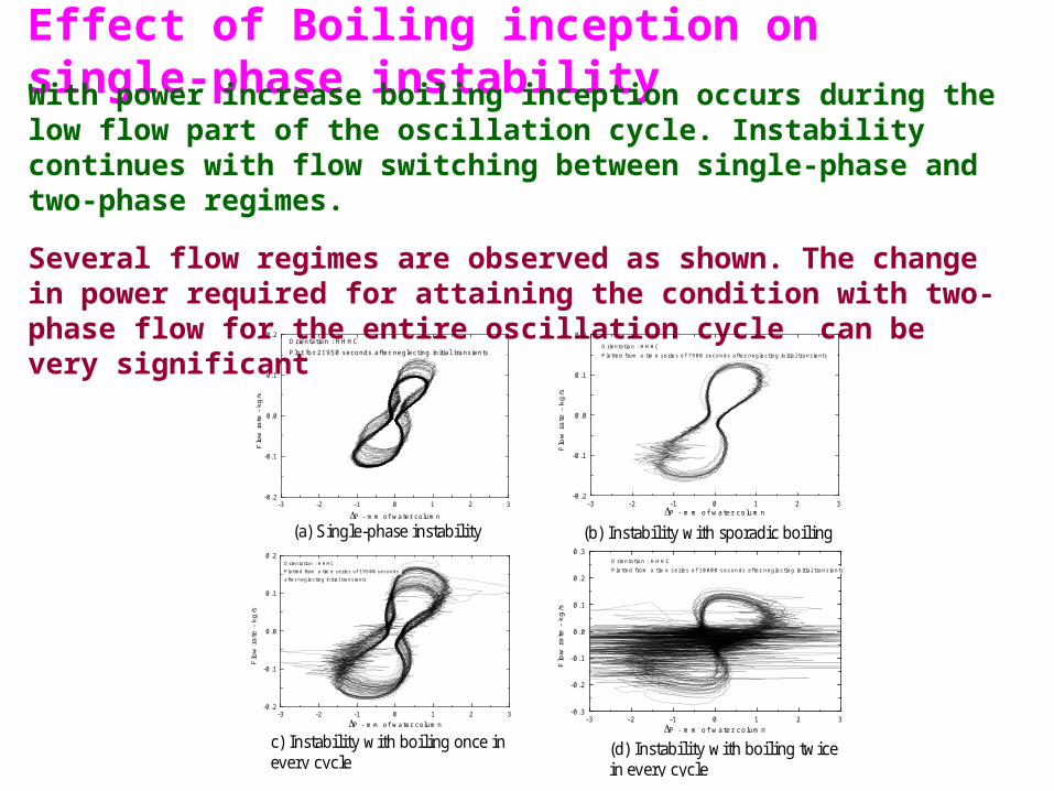
Effect of Boiling inception on single-phase instability
With power increase boiling inception occurs during the low flow part of the oscillation cycle. Instability continues with flow switching between single-phase and two-phase regimes.
Several flow regimes are observed as shown. The change in power required for attaining the condition with two-phase flow for the entire oscillation cycle can be very significant
c) Instability with boiling once in every cycle
(d) Instability with boiling twice in every cycle
(b) Instability with sporadic boiling (a) Single-phase instability
-3 -2 -1 0 1 2 3-0.2
-0.1
0.0
0.1
0.2Orientation : HHHCPlot for 21950 seconds after neglecting initial transients
Flo
w r
ate
- kg
/s
P - mm of water column
-3 -2 -1 0 1 2 3
-0.2
-0.1
0.0
0.1
0.2Orientation : HHHCPlotted from a time series of 7900 seconds after neglecting initial transients
Flo
w r
ate
- k
g/s
P - mm of water column
-3 -2 -1 0 1 2 3-0.2
-0.1
0.0
0.1
0.2Orientation : HHHCPlotted from a time series of 19500 seconds after neglecting initial transients
Flo
w r
ate
- k
g/s
P - mm of water column
-3 -2 -1 0 1 2 3
-0.3
-0.2
-0.1
0.0
0.1
0.2
0.3O rientation : HHHCPlotted from a tim e series of 10000 seconds after neglecting initial transients
Flo
w r
ate
- k
g/s
P - m m of water colum n
Related Documents