1 Introduction to Embedded Systems Chapter 10: Input and Output, Interrupts Sanjit A. Seshia UC Berkeley EECS 149/249A Fall 2015 © 2008-2015: E. A. Lee, A. L. Sangiovanni-Vincentelli, S. A. Seshia. All rights reserved. EECS 149/249A, UC Berkeley: 2 Connecting the Analog and Digital Worlds Semantic mismatch: Cyber: • Digital • Discrete in time • Sequential Physical: • Continuum • Continuous in time • Concurrent

Welcome message from author
This document is posted to help you gain knowledge. Please leave a comment to let me know what you think about it! Share it to your friends and learn new things together.
Transcript

1
Introduction toEmbedded Systems
Chapter 10: Input and Output, Interrupts
Sanjit A. SeshiaUC Berkeley
EECS 149/249A
Fall 2015
© 2008-2015: E. A. Lee, A. L. Sangiovanni-Vincentelli, S. A. Seshia. All rights reserved.
EECS 149/249A, UC Berkeley: 2
Connecting the Analog and Digital Worlds
Semantic mismatch:
Cyber:
• Digital
• Discrete in time
• Sequential
Physical:
• Continuum
• Continuous in time
• Concurrent

2
EECS 149/249A, UC Berkeley: 3
Practical Issues
• Analog vs. digital
• Wired vs. wireless
• Serial vs. parallel
• Sampled or event triggered
• Bit rates
• Access control, security, authentication
• Physical connectors
• Electrical requirements (voltages and currents)
EECS 149/249A, UC Berkeley: 4
A Typical Microcomputer BoardBeaglebone Black from Texas Instruments
This board has analog and digital inputs and outputs. What are they? How do they work?

3
EECS 149/249A, UC Berkeley: 5
Wired ConnectionsParallel vs. Serial Digital Interfaces
Parallel (one wire per bit) ATA: Advanced Technology Attachment
PCI: Peripheral Component Interface
SCSI: Small Computer System Interface
…
Serial (one wire per direction) RS-232
SPI: Serial Peripheral Interface bus
I2C: Inter-Integrated Circuit
USB: Universal Serial Bus
SATA: Serial ATA
…
Mixed (one or more “lanes”) PCIe: PCI Express
PCI
SCSI
USB
RS-232
EECS 149/249A, UC Berkeley: 6
Wired ConnectionsParallel vs. Serial Digital Interfaces
Parallel connectors have been steadily replaced by serial ones.
Why?
4
EECS 149/249A, UC Berkeley: 7
Input/Output Mechanisms in Software
Polling Main loop uses each I/O device periodically.
If output is to be produced, produce it.
If input is ready, read it.
Interrupts External hardware alerts the processor that input is ready.
Processor suspends what it is doing.
Processor invokes an interrupt service routine (ISR).
ISR interacts with the application concurrently.
EECS 149/249A, UC Berkeley: 8
Polling
Processor Setup Code
Processor checks I/O control register for status of peripheral 1
Processor services I/O 1
Processor checks I/O control register for status of peripheral 2
Processor checks I/O control register for status of peripheral 3
Processor services I/O 2
Processor services I/O 3
Ready
Ready
Ready
Not Ready
Not Ready
Not Ready

5
EECS 149/249A, UC Berkeley: 9
Example Using a Serial Interface
In an Atmel AVR 8-bit microcontroller, to send a byte over a serial port, the following C code will do:
while(!(UCSR0A & 0x20));
UDR0 = x;
• x is a variable of type uint8.
• UCSR0A and UDR0 are variables defined in a header.
• They refer to memory-mapped registers in the UART (Universal Asynchronous Receiver-Transmitter)
EECS 149/249A, UC Berkeley: 10
Send a Sequence of Bytes
for(i = 0; i < 8; i++) {
while(!(UCSR0A & 0x20));
UDR0 = x[i];
}
How long will this take to execute? Assume:
• 57600 baud serial speed.
• 8/57600 =139 microseconds.
• Processor operates at 18 MHz.
Each for loop iteration will consume about 2502 cycles.
6
EECS 149/249A, UC Berkeley: 11
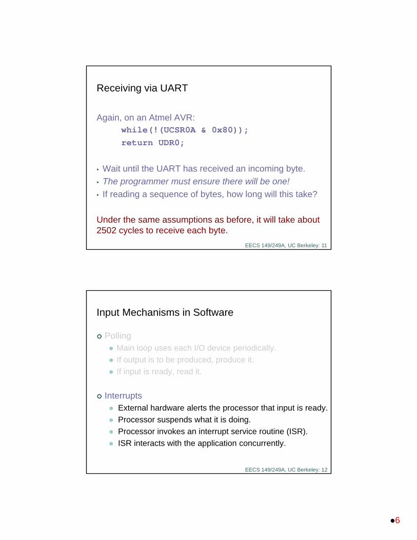
Receiving via UART
Again, on an Atmel AVR:while(!(UCSR0A & 0x80));
return UDR0;
• Wait until the UART has received an incoming byte.
• The programmer must ensure there will be one!
• If reading a sequence of bytes, how long will this take?
Under the same assumptions as before, it will take about 2502 cycles to receive each byte.
EECS 149/249A, UC Berkeley: 12
Input Mechanisms in Software
Polling Main loop uses each I/O device periodically.
If output is to be produced, produce it.
If input is ready, read it.
Interrupts External hardware alerts the processor that input is ready.
Processor suspends what it is doing.
Processor invokes an interrupt service routine (ISR).
ISR interacts with the application concurrently.

7
EECS 149/249A, UC Berkeley: 13
Interrupts
Interrupt Service RoutineShort subroutine that handles the interrupt
Processor Setup Code
Register the Interrupt Service Routine
Processor executes task code Run Interrupt Service Routine
Interrupt!
Context switch
Resume
EECS 149/249A, UC Berkeley: 14
Interrupts
Triggers: A level change on an interrupt request pin Writing to an interrupt pin configured as an output (“software
interrupt”)
Responses: Disable interrupts. Push the current program counter onto the stack. Execute the instruction at a designated address in the flash memory.
Design of interrupt service routine: Save and restore any registers it uses. Re-enable interrupts before returning from interrupt.
Source: ATmega168 Reference Manual
Program memory addresses, not data memory addresses.
8
EECS 149/249A, UC Berkeley: 15
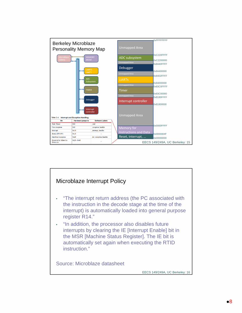
Berkeley MicroblazePersonality Memory Map
0xFFFFFFFF
0x0000004F
0x0000FFFF
Unmapped Area
ADC subsystem
Memory for Instructions and Data
Interrupt controller0x81800000
MicroBlaze50MHz
MEMORYBRAM
UART0UART1
ADCSubsystem
TIMER
Debugger
Interrupt controller
0x8180FFFF
Unmapped Area
Timer0x83C00000
0x83C0FFFF
Unmapped Area
UARTs
Unmapped Area0x84000000
0x8402FFFF
Debugger
Unmapped Area
Unmapped Area
0x84400000
0x8440FFFF
0xC2200000
0xC220FFFF
Reset, interrupt, … 0x00000000
EECS 149/249A, UC Berkeley: 16
Microblaze Interrupt Policy
• “The interrupt return address (the PC associated with the instruction in the decode stage at the time of the interrupt) is automatically loaded into general purpose register R14.”
• “In addition, the processor also disables future interrupts by clearing the IE [Interrupt Enable] bit in the MSR [Machine Status Register]. The IE bit is automatically set again when executing the RTID instruction.”
Source: Microblaze datasheet
9
EECS 149/249A, UC Berkeley: 17
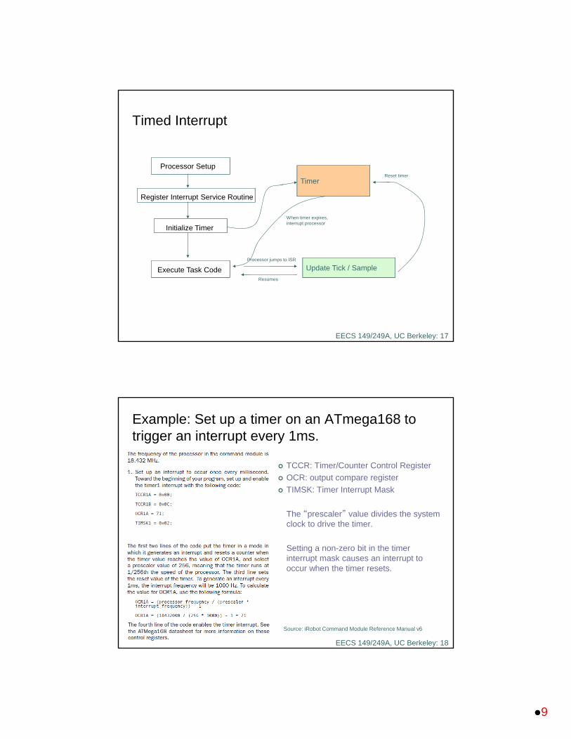
Timed Interrupt
Timer
Update Tick / Sample
When timer expires, interrupt processor
Reset timer
Processor jumps to ISR
Resumes
Processor Setup
Register Interrupt Service Routine
Initialize Timer
Execute Task Code
EECS 149/249A, UC Berkeley: 18
Example: Set up a timer on an ATmega168 to trigger an interrupt every 1ms.
TCCR: Timer/Counter Control Register
OCR: output compare register
TIMSK: Timer Interrupt Mask
The “prescaler” value divides the system clock to drive the timer.
Setting a non-zero bit in the timer interrupt mask causes an interrupt to occur when the timer resets.
Source: iRobot Command Module Reference Manual v6
10
EECS 149/249A, UC Berkeley: 19
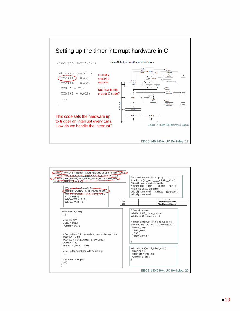
Setting up the timer interrupt hardware in C
#include <avr/io.h>
int main (void) {
TCCR1A = 0x00;
TCCR1B = 0x0C;
OCR1A = 71;
TIMSK1 = 0x02;
...
}
This code sets the hardware up to trigger an interrupt every 1ms. How do we handle the interrupt? Source: ATmega168 Reference Manual
memory-mapped register.
But how is this proper C code?
EECS 149/249A, UC Berkeley: 20
void initialize(void) {cli();
// Set I/O pinsDDRB = 0x10;PORTB = 0xCF;…….
// Set up timer 1 to generate an interrupt every 1 msTCCR1A = 0x00;TCCR1B = (_BV(WGM12) | _BV(CS12));OCR1A = 71;TIMSK1 = _BV(OCIE1A);
// Set up the serial port with rx interrupt…….
// Turn on interruptssei();
}
// Global variablesvolatile uint16_t timer_cnt = 0;volatile uint8_t timer_on = 0;
// Timer 1 interrupt to time delays in msSIGNAL(SIG_OUTPUT_COMPARE1A) {
if(timer_cnt) {timer_cnt--;
} else {timer_on = 0;
}}
void delayMs(uint16_t time_ms) {timer_on = 1;timer_cnt = time_ms;while(timer_on) ;
}
//Enable interrupts (interrupt.h)# define sei() __asm__ __volatile__ ("sei" ::)//Disable interrupts (interrupt.h)# define cli() __asm__ __volatile__ ("cli" ::)#define SIGNAL(signame) \void signame (void) __attribute__ ((signal)); \void signame (void)
#define _MMIO_BYTE(mem_addr) (*(volatile uint8_t *)(mem_addr))#define _SFR_IO8(io_addr) _MMIO_BYTE((io_addr) + 0x20)#define _SFR_MEM8(mem_addr) _MMIO_BYTE(mem_addr)#define _BV(bit) (1 << (bit))
//Timer defines (iomx8.h)#define TCCR1A _SFR_MEM8 (0x80)#define TCCR1B _SFR_MEM8 (0x81)/* TCCR1B */#define WGM12 3#define CS12 2

11
EECS 149/249A, UC Berkeley: 21
Setting up the timer interrupt hardware in C
#include <avr/io.h>
int main (void) {
TCCR1A = 0x00;
TCCR1B = 0x0C;
OCR1A = 71;
TIMSK1 = 0x02;
...
}
Source: ATmega168 Reference Manual
(*(volatile uint8_t *) (0x80)) = 0x00;
EECS 149/249A, UC Berkeley: 22
Example 2: Set up a timer on a Luminary Micro board to trigger an interrupt every 1ms.
// Setup and enable SysTick with interrupt every 1ms
void initTimer(void) {
SysTickPeriodSet(SysCtlClockGet() / 1000);
SysTickEnable();
SysTickIntEnable();
}
// Disable SysTick
void disableTimer(void) {
SysTickIntDisable();
SysTickDisable();
}
Source: Stellaris Peripheral Driver Library User’s Guide
Number of cycles per sec.
Start SysTick counter
Enable SysTick timer interrupt
12
EECS 149/249A, UC Berkeley: 23
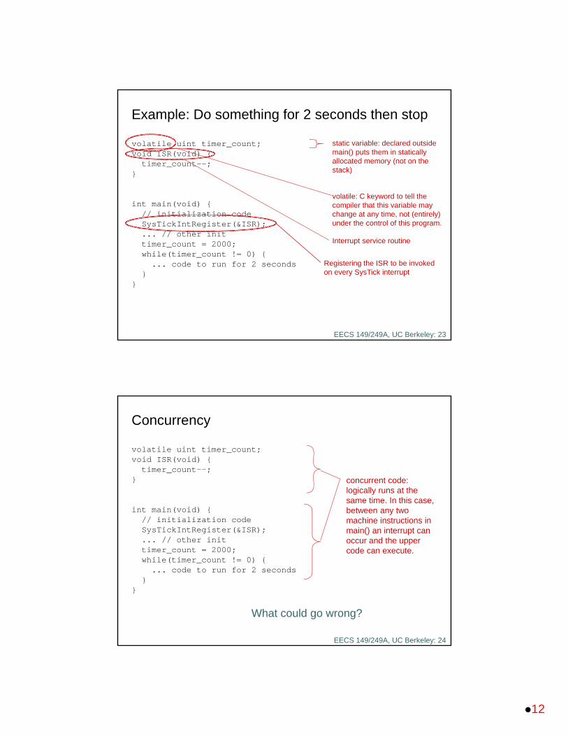
volatile uint timer_count;void ISR(void) {
timer_count--;}
int main(void) {// initialization codeSysTickIntRegister(&ISR); ... // other inittimer_count = 2000;while(timer_count != 0) {... code to run for 2 seconds
}}
Example: Do something for 2 seconds then stop
volatile: C keyword to tell the compiler that this variable may change at any time, not (entirely) under the control of this program.
static variable: declared outside main() puts them in statically allocated memory (not on the stack)
Interrupt service routine
Registering the ISR to be invoked on every SysTick interrupt
EECS 149/249A, UC Berkeley: 24
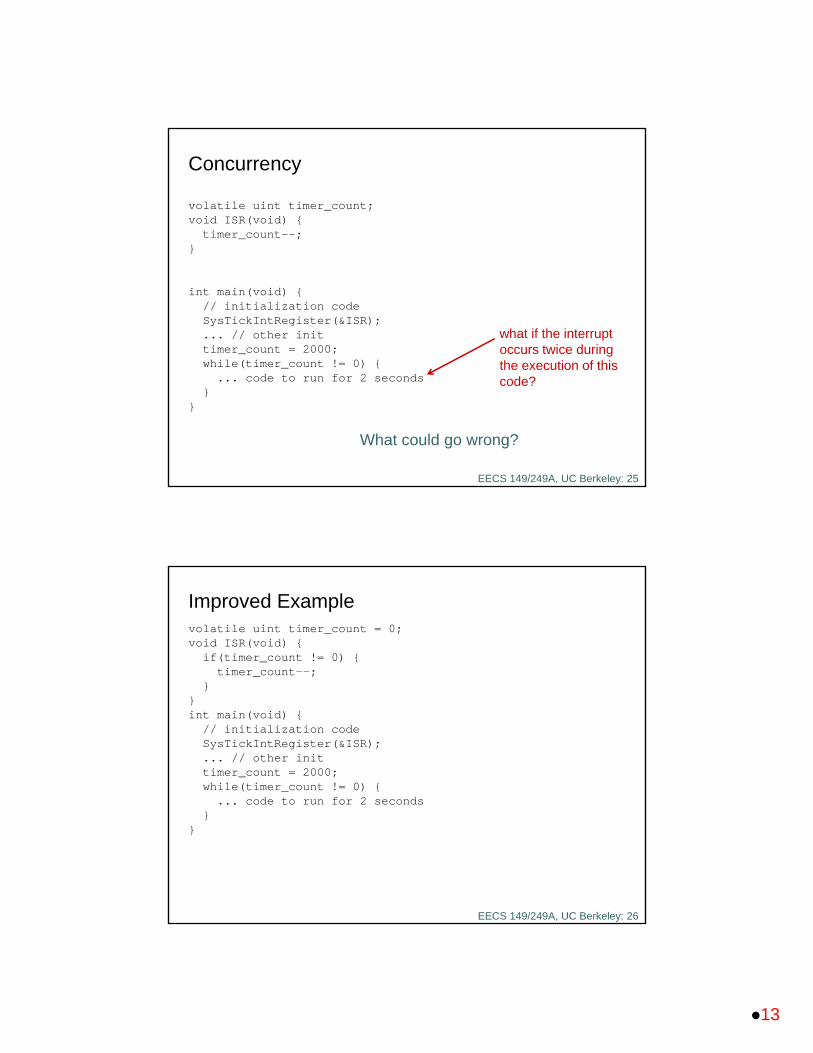
volatile uint timer_count;void ISR(void) {
timer_count--;}
int main(void) {// initialization codeSysTickIntRegister(&ISR); ... // other inittimer_count = 2000;while(timer_count != 0) {... code to run for 2 seconds
}}
Concurrency
concurrent code: logically runs at the same time. In this case, between any two machine instructions in main() an interrupt can occur and the upper code can execute.
What could go wrong?
13
EECS 149/249A, UC Berkeley: 25
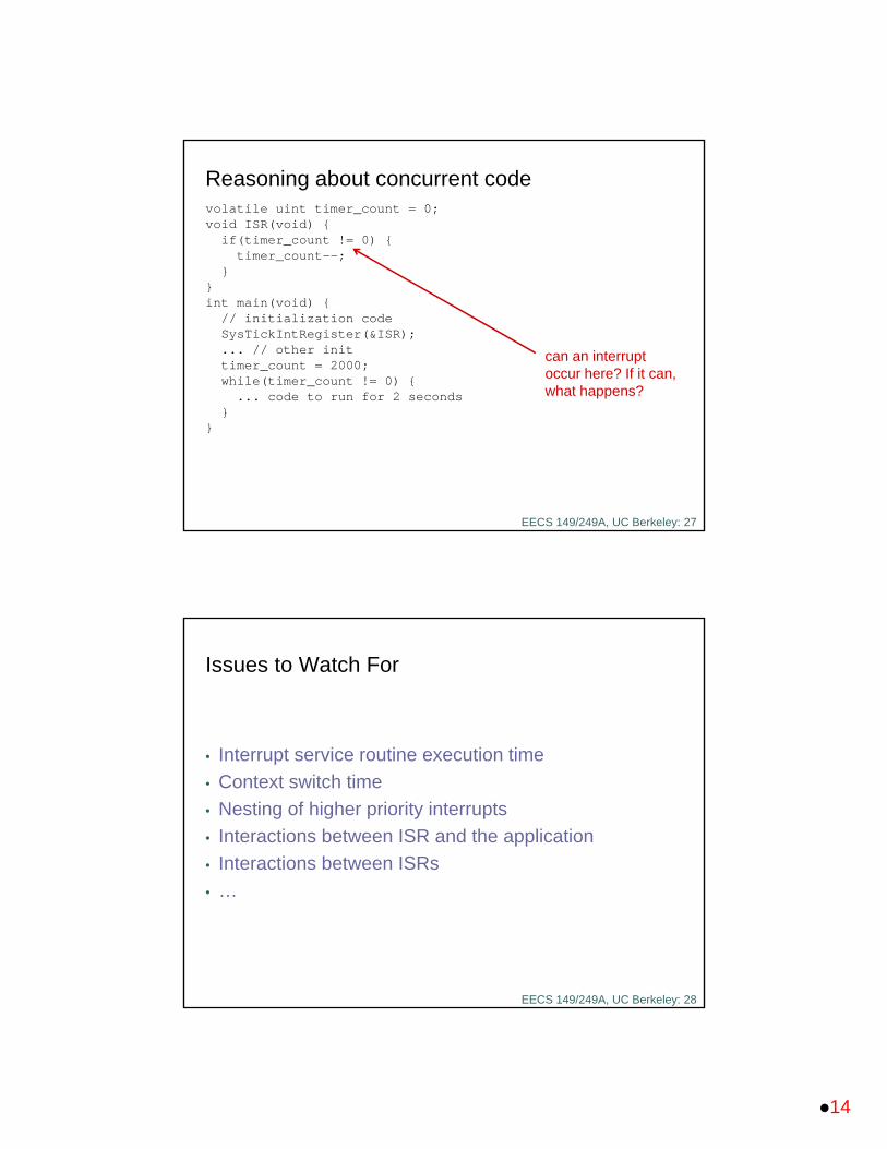
volatile uint timer_count;void ISR(void) {
timer_count--;}
int main(void) {// initialization codeSysTickIntRegister(&ISR); ... // other inittimer_count = 2000;while(timer_count != 0) {... code to run for 2 seconds
}}
Concurrency
What could go wrong?
what if the interrupt occurs twice during the execution of this code?
EECS 149/249A, UC Berkeley: 26
volatile uint timer_count = 0;void ISR(void) {
if(timer_count != 0) { timer_count--;
}}int main(void) {
// initialization codeSysTickIntRegister(&ISR); ... // other inittimer_count = 2000;while(timer_count != 0) {... code to run for 2 seconds
}}
Improved Example
14
EECS 149/249A, UC Berkeley: 27
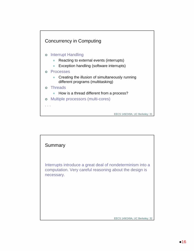
volatile uint timer_count = 0;void ISR(void) {
if(timer_count != 0) { timer_count--;
}}int main(void) {
// initialization codeSysTickIntRegister(&ISR); ... // other inittimer_count = 2000;while(timer_count != 0) {... code to run for 2 seconds
}}
Reasoning about concurrent code
can an interrupt occur here? If it can, what happens?
EECS 149/249A, UC Berkeley: 28
Issues to Watch For
• Interrupt service routine execution time
• Context switch time
• Nesting of higher priority interrupts
• Interactions between ISR and the application
• Interactions between ISRs
• …

15
EECS 149/249A, UC Berkeley: 29
A question:
What’s the difference between
Concurrency
and
Parallelism
EECS 149/249A, UC Berkeley: 30
Concurrency and Parallelism
A program is said to be concurrent if different parts of the program conceptually execute simultaneously.
A program is said to be parallel if different parts of the program physically execute simultaneously on distinct hardware.
A parallel program is concurrent, but a concurrent program need not be parallel.
16
EECS 149/249A, UC Berkeley: 31
Concurrency in Computing
Interrupt Handling Reacting to external events (interrupts)
Exception handling (software interrupts)
Processes Creating the illusion of simultaneously running
different programs (multitasking)
Threads How is a thread different from a process?
Multiple processors (multi-cores)
. . .
EECS 149/249A, UC Berkeley: 32
Summary
Interrupts introduce a great deal of nondeterminism into a computation. Very careful reasoning about the design is necessary.
Related Documents