Spencer/Ghausi, Introduction to Electronic Circuit Design, 1e, ©2003, Pearson Education, Inc. Chapter 9, slide 1 Introduction to Electronic Circuit Design Richard R. Spencer Mohammed S. Ghausi

Introduction to electronic circuit design..model
Aug 09, 2015
Welcome message from author
This document is posted to help you gain knowledge. Please leave a comment to let me know what you think about it! Share it to your friends and learn new things together.
Transcript

Spencer/Ghausi, Introduction to Electronic Circuit Design, 1e, ©2003, Pearson Education, Inc. Chapter 9, slide 1
Introductionto
Electronic Circuit DesignRichard R. Spencer
Mohammed S. Ghausi

Spencer/Ghausi, Introduction to Electronic Circuit Design, 1e, ©2003, Pearson Education, Inc. Chapter 9, slide 2
Figure 9-1 One possible model for (a) a real resistor, (b) a real inductor, and (c) a real capacitor. The elements used in the models are ideal resistance, capacitance, and inductance. Rs is the series parasitic resistance (caused by the leads), Rp is the parallel parasitic resistance, and Ls and Cp are the parasitic series inductance and parallel capacitance, respectively.
Spencer/Ghausi, Introduction to Electronic Circuit Design, 1e, ©2003, Pearson Education, Inc. Chapter 9, slide 3
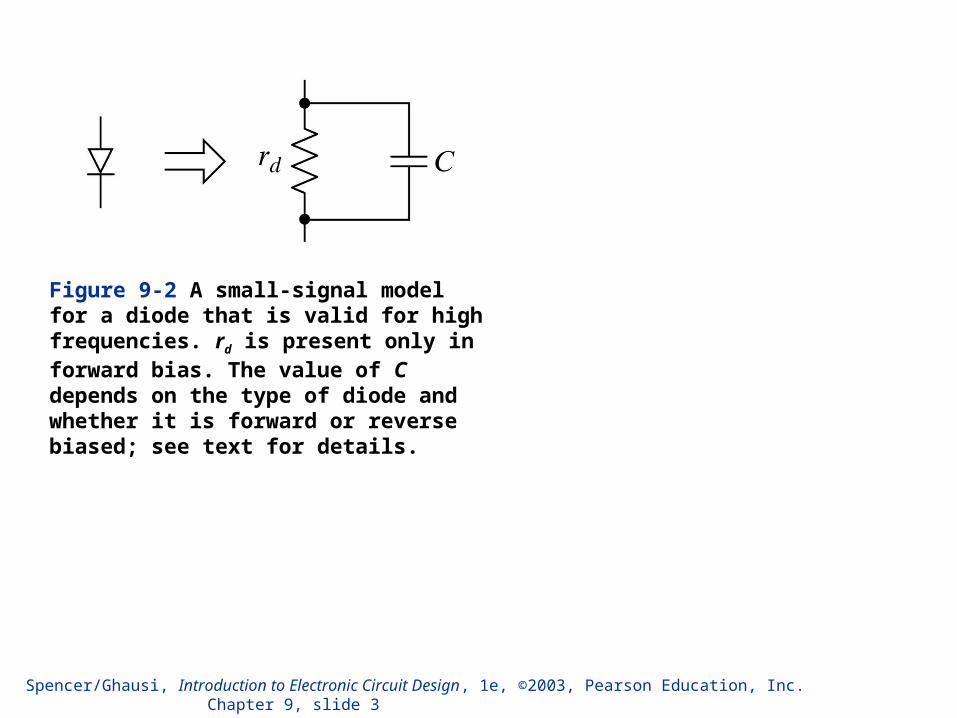
Figure 9-2 A small-signal model for a diode that is valid for high frequencies. rd is present only in forward bias. The value of C depends on the type of diode and whether it is forward or reverse biased; see text for details.

Spencer/Ghausi, Introduction to Electronic Circuit Design, 1e, ©2003, Pearson Education, Inc. Chapter 9, slide 4
Figure 9-3 (a) The high-frequency hybrid- model and (b) the high-frequency T model for the generic transistor.

Spencer/Ghausi, Introduction to Electronic Circuit Design, 1e, ©2003, Pearson Education, Inc. Chapter 9, slide 5
Figure 9-4 The high-frequency hybrid- model for a BJT.
Figure 9-5 The high-frequency T model of a BJT with rb omitted.
Figure 9-6 The current-controlled version of the high-frequency hybrid- BJT model.
Spencer/Ghausi, Introduction to Electronic Circuit Design, 1e, ©2003, Pearson Education, Inc. Chapter 9, slide 6
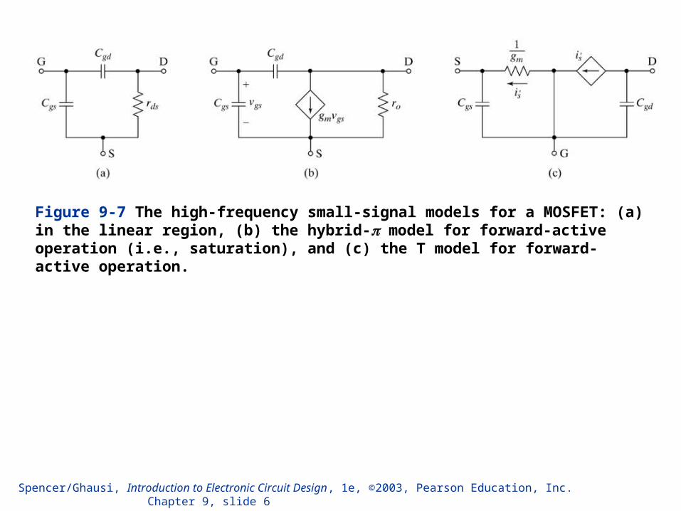
Figure 9-7 The high-frequency small-signal models for a MOSFET: (a) in the linear region, (b) the hybrid- model for forward-active operation (i.e., saturation), and (c) the T model for forward-active operation.
Spencer/Ghausi, Introduction to Electronic Circuit Design, 1e, ©2003, Pearson Education, Inc. Chapter 9, slide 7
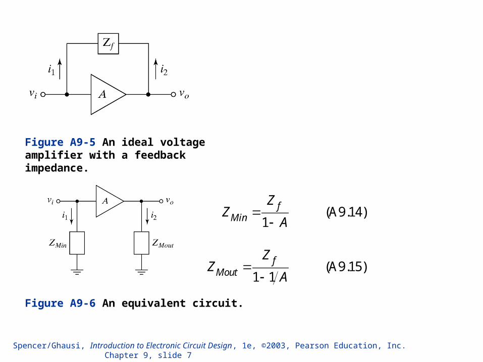
Figure A9-5 An ideal voltage amplifier with a feedback impedance.
Figure A9-6 An equivalent circuit.
(A9.14)1
fMin
ZZ
A
(A9.15)1 1
fMout
ZZ
A
Spencer/Ghausi, Introduction to Electronic Circuit Design, 1e, ©2003, Pearson Education, Inc. Chapter 9, slide 8
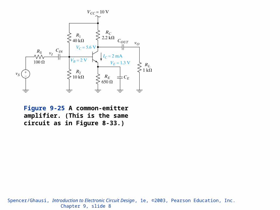
Figure 9-25 A common-emitter amplifier. (This is the same circuit as in Figure 8-33.)

Spencer/Ghausi, Introduction to Electronic Circuit Design, 1e, ©2003, Pearson Education, Inc. Chapter 9, slide 9
Figure 9-26 The small-signal low-frequency AC equivalent circuit for the common-emitter amplifier of Figure 9-25.
Figure 9-27 The circuit of Figure 9-26 with the emitter impedance reflected into the base.

Spencer/Ghausi, Introduction to Electronic Circuit Design, 1e, ©2003, Pearson Education, Inc. Chapter 9, slide 10
Figure 9-29 The small-signal high-frequency AC equivalent circuit for the amplifier of Figure 9-25.

Spencer/Ghausi, Introduction to Electronic Circuit Design, 1e, ©2003, Pearson Education, Inc. Chapter 9, slide 11
Figure 9-30 The equivalent circuit from Figure 9-29 after application of Miller’s theorem.

Spencer/Ghausi, Introduction to Electronic Circuit Design, 1e, ©2003, Pearson Education, Inc. Chapter 9, slide 12
Figure 9-32 (a) The small-signal low-frequency AC equivalent for the common-emitter amplifier of Figure 9-25 and (b) the circuit for finding the short-circuit driving-point resistance seen by CE.

Spencer/Ghausi, Introduction to Electronic Circuit Design, 1e, ©2003, Pearson Education, Inc. Chapter 9, slide 13
Figure 9-34 The circuit for finding the open-circuit driving-point resistance seen by C.

Spencer/Ghausi, Introduction to Electronic Circuit Design, 1e, ©2003, Pearson Education, Inc. Chapter 9, slide 14
Figure 9-35 A common-source amplifier.

Spencer/Ghausi, Introduction to Electronic Circuit Design, 1e, ©2003, Pearson Education, Inc. Chapter 9, slide 15
Figure 9-36 The small-signal low-frequency AC equivalent circuit for the common-source amplifier of Figure 9-35.
Spencer/Ghausi, Introduction to Electronic Circuit Design, 1e, ©2003, Pearson Education, Inc. Chapter 9, slide 16
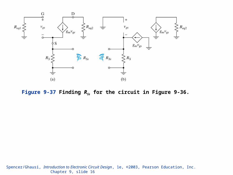
Figure 9-37 Finding RSs for the circuit in Figure 9-36.

Spencer/Ghausi, Introduction to Electronic Circuit Design, 1e, ©2003, Pearson Education, Inc. Chapter 9, slide 17
Figure 9-40 The equivalent circuit from Figure 9-39 after application of Miller’s theorem.

Spencer/Ghausi, Introduction to Electronic Circuit Design, 1e, ©2003, Pearson Education, Inc. Chapter 9, slide 18
Figure 9-43 The circuit for finding the open-circuit driving-point resistance seen by Cgd.

Spencer/Ghausi, Introduction to Electronic Circuit Design, 1e, ©2003, Pearson Education, Inc. Chapter 9, slide 19
Figure 9-46 (a) The small-signal high-frequency AC equivalent for the buffer in Figure 9-44. (b) After applying Miller’s approximation.

Spencer/Ghausi, Introduction to Electronic Circuit Design, 1e, ©2003, Pearson Education, Inc. Chapter 9, slide 20
Figure 9-47 Finding the open-circuit driving-point resistance seen by Ccm.
cmo x cmR R r

Spencer/Ghausi, Introduction to Electronic Circuit Design, 1e, ©2003, Pearson Education, Inc. Chapter 9, slide 21
Figure 9-59 The small-signal high-frequency AC equivalent circuit for a common-control amplifier stage.

Spencer/Ghausi, Introduction to Electronic Circuit Design, 1e, ©2003, Pearson Education, Inc. Chapter 9, slide 22
Figure 9-61 The small-signal high-frequency AC equivalent circuit for the amplifier in Figure 9-60.
Figure 9-60 A common-base amplifier.

Spencer/Ghausi, Introduction to Electronic Circuit Design, 1e, ©2003, Pearson Education, Inc. Chapter 9, slide 23
Figure 9-63 The small-signal high-frequency AC equivalent circuit for the amplifier in Figure 9-62.
Figure 9-62 A common-gate amplifier.
Spencer/Ghausi, Introduction to Electronic Circuit Design, 1e, ©2003, Pearson Education, Inc. Chapter 9, slide 24
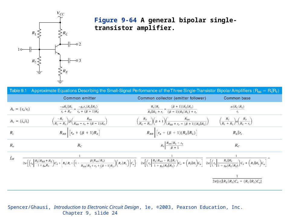
Figure 9-64 A general bipolar single-transistor amplifier.

Spencer/Ghausi, Introduction to Electronic Circuit Design, 1e, ©2003, Pearson Education, Inc. Chapter 9, slide 25

Spencer/Ghausi, Introduction to Electronic Circuit Design, 1e, ©2003, Pearson Education, Inc. Chapter 9, slide 26
Figure 9-65 A general FET single-transistor amplifier.

Spencer/Ghausi, Introduction to Electronic Circuit Design, 1e, ©2003, Pearson Education, Inc. Chapter 9, slide 27

Spencer/Ghausi, Introduction to Electronic Circuit Design, 1e, ©2003, Pearson Education, Inc. Chapter 9, slide 28

Spencer/Ghausi, Introduction to Electronic Circuit Design, 1e, ©2003, Pearson Education, Inc. Chapter 9, slide 29
Figure 9-83 A bipolar cascode amplifier.

Spencer/Ghausi, Introduction to Electronic Circuit Design, 1e, ©2003, Pearson Education, Inc. Chapter 9, slide 30
Figure 9-84 The high-frequency small-signal AC equivalent circuit of the cascode amplifier in Figure 9-83.

Spencer/Ghausi, Introduction to Electronic Circuit Design, 1e, ©2003, Pearson Education, Inc. Chapter 9, slide 31
Figure 9-86 A MOSFET cascode amplifier.

Spencer/Ghausi, Introduction to Electronic Circuit Design, 1e, ©2003, Pearson Education, Inc. Chapter 9, slide 32
Figure 9-87 The high-frequency small-signal AC equivalent circuit for the amplifier in Figure 9-86.
Related Documents