Introduction to Data Communications by Eugene Blanchard Copyleft Sept 1999- Jan 2005

Introduction to Data Communications ver
Jan 20, 2016
Data
Welcome message from author
This document is posted to help you gain knowledge. Please leave a comment to let me know what you think about it! Share it to your friends and learn new things together.
Transcript

Introduction to Data Communications
by Eugene Blanchard
Copyleft Sept 1999- Jan 2005
Table of Contents
1. Introduction 1
2. Acknowledgements 2
3. Revision List 3
4. Data Communications 5
5. Why Telecommunications? 5
a. Voice Channels 15
b. Data Channels 16
6. Introduction to Networking 17
a. The Big Picture 17
b. Telecommunications Components of The Big Picture 20
c. ISO OSI 20
7. Breaking The Big Picture up! 22
a. The Local Loop 22
b. LANs 23
c. MANs 24
d. WANs. 26
8. Trade Magazines 27
9. The Role of Telecommunications in Networking 29
a. LANs 29
b. MANs 29
c. WANs 30
10. Brief History of Networking 31
11. Data Communication Network 34
a. Performance 34
b. Consistency 34
c. Reliability, 35
d. Recovery 36
e. Security 36
f. Applications 36
g. Basic Components 38
12. Data Flow 40
13. Modems 43
a. Basic Definition 43
b. Digital Connection 43
c. Analog Connection 45
d. External/Internal Modems 45
e. Modem Types 47
f. Features of Modems 49
g. Modem Speeds / Standards 50
h. Transfer Rate versus PC Bus Speed 51
h. V.90 56 kbps Modems 51
14. Physical Connection 52
15. Transmission Media - Guided 53
a. Open Wire 53
b. Twisted Pair 55
c. Coaxial Cable 57
d. Optical Fibre 57
i. Optical Transmission Modes 59
ii. Step Index Mode 61
iii. Grade Index Mode 61
iv. Single Mode 61
v. Comparison of Optical Fibres 63
vi. Advantages of Optical Fibre 64
vii. Disadvantages of Optical Fibre 65
e. Media versus Bandwidth 65
16. Transmission Media - Unguided 65
a. RF Propagation 66
i. Ground Wave Propagation 66
ii. Ionospheric Propagation 67

iii. Line of Sight Propagation 67
b. Radio Frequencies 68
c. Microwave 69
d. Satellite 70
e. Iridium Telecom System 72
17. RS-232D Serial Interface Standard 74
a. Mechanical Characteristics of the RS-232D 74
b. Electrical Characteristics of the RS-232D 74
c. Function of Each Signal 76
d. Subsets of Signals for Certain Applications 78
18. RS-232D Flow Control 80
a. Hardware Handshaking 81
b. Hardware Null Modems 88
c. Software Handshaking (Xon/Xoff) 89
d. Software Null Modem 89
e. Terminals & PCs 91
19. Timing 92
a. Asynchronous vs. Synchronous Transmission 93
20. Asynchronous Communications 95
a. Start/Stop bits 95
b. 7/8 Bit Codes 99
c. Parity Bits 101
21. Line Encoding 104
a. Unipolar Encoding 104
b. Polar Encoding 106
c. Bipolar Line Encoding 108
d. Manchester Line Encoding 108
22. Standard Digital Codes 110
a. EBCDIC - Extended Binary Coded Decimal Interchange Code 110
b. ASCII - American Standard Code for Information Interchange 116
23. Voice Channel Communications 121
a. Voice Channel Specification 121
b. Voice Channel Constraints 122
c. Nyquist Theorem 123
24. Telephone Networks 125
a. POTS - Plain Old Telephone Set 125
b. Local Loops 129
c. Central Office 131
d. Hierarchical Phone Networks 131
25. Telephone Line Characteristics 135
a. Attenuation Distortion 135
b. Propagation Delay 137
c. Envelope Delay Distortion 139
26. Line Impairments 140
a. Crosstalk 140
b. Echo or Signal Return 140
c. Frequency Shift 142
d. Non-Linear Distortion 142
e. Jitter: Amplitude and Phase 143
f. Transients: Impulse Noise, Gain Hits, Dropouts & Phase Hits 144
27. Modulation Techniques 147
a. AM - Amplitude Modulation 147
b. FM - Frequency Modulation 149
c. PM - Phase Modulation 149
28. Modem Modulation 151
a. FSK - Frequency Shift Keying 151
b. QPSK - Quadrature Phase Shift Keying 155
c. QAM - Quadrature Amplitude Modulation 157
29. AT Command Set 159
a. Basic AT commands 160
30. Multiplexing 161
a. FDM - Frequency Division Multiplexing 164
b. TDM - Time Division Multiplexing 166
c. STDM - Statistical Time Division Multiplexing 168
31. Telecommunication Multiplexing 168
a. FDM - Channel Groups 169
b. TDM - T1 Carrier System 169
32. Introduction to the ISO - OSI Model 172
a. OSI Model Explained 172
b. Layer 7 - Application Layer 172
c. Layer 6 - Presentation Layer 176
d. Layer 5 - Session Layer 177
e. Layer 4 - Transport Layer 177
f. Layer 3 - Network Layer 179
g. Layer 2 - Data Link Layer 179
h. Layer 1 - Physical Layer 180
i. Layer Specific Communication 181
j. OSI Model Functional Drawing 183
33. Synchronous Transmission 185
a. Clocking: Self & Manchester Encoding 186
34. Basic Frame Structure 188
a. Preamble: Starting Delimiter/Alert Burst/Start of Header 188
b. Address Field(s): Source and/or Destination 188
c. Control Field 190
d. Data/Message and optional Pad 190
e. CRC/ Frame Check Sequence 190
f. End Frame Delimiter 190
35. Physical Layer 192
a. Asynchronous & Synchronous Communication 192
36. IEEE-802.3 Protocol 194
a. CSMA/CD (Carrier Sense Multiple Access/ Collision Detect) 194
b. IEEE 802.3 Ethernet Media Types 195
c. IEEE 802.3 10Base5 196
d. IEEE 802.3a 10Base2 200

e. IEEE 802.3i 10BaseT 203
f. MAC - Medium Access Control 206
g. Total Length of a MAC Frame 209
h. MAC Frame 211
i. Packet Sniffing 212
j. Packet Sniffing Block Diagram 216
37. IEEE 802.2 LLC - Logical Link Control Layer 217
a. Service Access Ports (SAPs) 219
b. Types of LLC Operation 220
c. Classes of LLC 224
d. LLC PDU Control Field Formats 224
38. Network Interface Cards 229
a. IRQs, DMAs and Base Addresses 230
b. Legacy 234
c. NIC Diagnostic Tools 236
d. Network Interface Card Drivers 238
i. NDIS Drivers 241
ii. ODI Drivers 243
iii. Packet Drivers 245
iv. Software Interrupts 245
39. Repeaters 247
a. Purpose of a Repeater 247
b. Repeater's OSI Operating Layer 249
c. Repeater's Segment to Segment Characteristics 249
d. Repeater Addressing: MAC Layer and Network Segment 251
40. Hubs 253
a. Purpose of Hubs 253
b. Hub's OSI Operating Layer 255
c. Hub's Segment to Segment Characteristics 255
d. Hub's Addressing 257
e. Half-Duplex & Full-Duplex Ethernet Hubs 257
f. Switching Hubs 258
41. Bridges 260
a. Bridge OSI Operating Layer 260
b. Purpose of a Bridge 260
c. Bridge Segment to Segment Characteristics 263
d. Bridge Methodologies 265
e. Reasons to use a Bridge 270
f. Bridge Addressing 270
g. Collapsed Backbones 270
42. Routers 272
a. Purpose of Routers 272
b. Router OSI Operating Layer 272
c. Router Segment to Segment Characteristics 274
d. Router Addressing 276
e. Routing Protocols 276
f. RIP - Routing Information Protocol 276
g. EGRP - Exterior Gateway Routing Protocol 279
h. OSPF - Open Shortest Path First 279
43. Brouters (Bridge/Routers) 281
44. Gateway 282
a. Gateway's OSI Operating Layer 282
b. Gateway Segment to Segment Characteristics 283
c. Gateway Addressing 283
45. Token Ring 284
a. IBM Token Ring 285
b. IEEE 802.4 Token Bus 286
c. IEEE 802.5 Token Ring 286
d. IEEE 802.5 Bus Arbitration 286
e. 4 / 16 Mbps Transfer Rate 292
f. IEEE 802.5 Topology 292
g. MSAUs 292
i. Token Ring connectors 294
ii. MSAU Relay 296
iii. Ring In/ Ring Out 296
iv. Wrapping 298
v. Physical Star/ Logical Ring 299
h. IEEE 802.5 and the OSI Model 299
i. Token Ring Cabling 302
i. Shielded Twisted Pair 302
ii. Unshielded Twisted Pair - Type 3 302
iii. IBM Cabling System 303
j. Ring Insertion 304
k. CAUs & LAMs 305
l. Ring Calculations 306
i. Maximum Ring Length 306
ii. Ring Length Calculations 306
iii. Mixing Cables and Ring Length 307
iii. Active Concentrators and Ring Length 309
m. Token Ring Monitors and Servers 311
i. Active Monitor (AM) 311
ii. Standby Monitor (SM) 316
iii. Ring Parameter Server (RPS) 318
iv. Configuration Report Server (CRS) 318
v. Ring Error Monitor (REM) 320
vi. Where are these Monitors? 324
n. Token Ring Hierarchy 324
o. IEEE 802.5 Frames 326
46. Linux and Token Ring 336
47. Source Routing 342
48. ISDN - Integrated Services Digital Network 344
49. ADSL - Asymmetrical Digital Subscriber Line 347
50. Cable Modems 350
51. Quick Introduction to Unix 352
a. Basic Unix Commands 359
b. Access and Permissions 362
c. Links, Instances & Processes 365
d. Background Processing 369
e. Shell Programs 371

f. Communicating with Other Users 373
g. Creating Users and Groups 375
52. SAMBA, Win95, NT and HP Jetdirect 377
53. The Suite of TCP/IP Protocols 387
54. Internet Protocol 389
a. IP Addresses 389
b. IP Address Classifications 390
i. Class A addresses 390
ii. Class B addresses 390
iii. Class C addresses 391
iv. Class D addresses 391
v. Class E addresses 391
c. Reserved IP Addresses 392
d. Network Masking 393
e. Domain Names 398
f. IP Header 401
55. Address Resolution Protocol (ARP) 404
56. Reverse Address Resolution Protocol (RARP) 406
57. Internet Control Messaging Protocol (ICMP) 407
58. Transmission Control Protocol (TCP) 416
59. User Datagram Protocol (UDP) 420
60. Simple Network Management Protocol 422
a. SNMPv2 to the Rescue 423
b. MIB - Management Information Base 423
c. RMON - Remote Network Monitoring 423
61. Handy Unix Network Troubleshooting Commands 425
62. X.25 429
a. X.25 OSI Layers 431
b. X.25 High overhead 433
c. X.25 Packet Formats 435
63. Frame Relay 439
a. Decreased Protocol Overhead 439
b. LAPD - Link Access Protocol D channel 441
c. LAN to Frame Relay Connection 441
Appendix a. PC Block Diagram 442
b. PC Quick ID Guide 445
c. Ethernet Type Field 463
d. Ethernet Address Assignments 466
e. IP Protocol Address Space 470
f. IP Multicast Addresses 472
g. IP Header Protocols 476
h. IP Hardware Types 478
i. TCP/IP Well Known Ports 479
j. AT Command Set (Partial listing) 493
k. ISO 3166 Country Codes 497
l. Token Ring - Major Vector IDs 499
m. The GNU General Public License 502
n. Copyleft Rules & Regulations 508
Introduction to Data Communications Copyleft Sept. 1999
1. Introduction
This book was written over a period of five years in my spare time while consulting at the Southern
Alberta Institute of Technology (SAIT) for various academic departments. Some of the material is
reprints of articles that I have written for the Linux Gazette.
When I started consulting in 1994, there were very few books that explored data communications for
network computing. The books that I read on data communications only gave a partial view of the
"big picture" and tended to assume that the reader had previous knowledge of networking and data
communications.
I've tried to sort out the confusing issues in this book and to focus on only the topics of the
"moment". I've been successful in the classroom with this approach and hope that you find it
meaningful too. I find that most books on the Linux operating system do not cover the data
communications aspects of networking. The purpose of this book is to fill this void and introduce the
concepts of data communication with a slight leaning towards the Linux operating system.
2. Acknowledgements
I would like to thank my wife, Susan, for putting up with my obsessive behaviour while I was
writing the original course material. Without her in my life, this book would never had been started.
I would especially like to thank Harold Sylven for the support and faith that he has had in me.
I would also like to thank Michael Wilson for his hard work and dedication to the first Area
Network Technical Analyst program and who never received the credit that he deserved. I would
like to thank Doug Spurgeon who has been my "partner in crime" at SAIT and who I have relied on
extensively for his support in Windows NT and Novell Netware.
Lastly but not least, I would like to thank my parents for supporting and guiding me throughout my
life.

3. Revision List
Thursday, May 18, 2000
- Made Rev 1.2 pdf file. Web book and pdf file now match.
Sunday, April 23, 2000
- Realized that telnet, http, ftp, tftp and nntp have much better resources available than what I could
write. So I nixed them from the book. Now I can work on revising the existing chapters.
Saturday, April 22, 2000
- Added a short chapter on UDP.
Friday, April 21, 2000
- Added chapter on TCP. ICMP is more interesting...
Monday, April 17, 2000
- Added a chapter on ICMP. Quite an interesting protocol. You sure learn alot by writing about
stuff...
Sunday, April 16, 2000
- Special thanks to Ahmet from Swinburne University for providing an anonymous ftp site :-)
Mar 16, 2000
- Received a rude awakening from my ISP. Downloads from my website were costing me an arm
and a leg! Took down the website until I could think of some other method of transfer (nonpaying).
The big culprit is the pdf file. So for now if anyone wants it, they can email me.
Tuesday, Feb 8, 2000
- Fixed page238.html's wrong gif for Class D, added comments courtesy of Jacques Sincennes to
Page 58.html, added more info on stop bits page60.html, changed ASDL to ASDL on page 211.html
(I'm sure I've done this one before?), corrected ADSL does NOT require modifications to C.O.,
Saturday, Feb 5, 2000
- Fixed TOC with tables and page numbers - aaaaaagh! Viewed pdf file there are numerous changes
to make to get rid of the wasted pages. At least the pdf is usable now.
Saturday, Jan 29, 2000
- Have updated all the webpages with section numbers. Now have to add page numbers to TOC.
Thursday, Jan 27, 2000
- Caught a major faux pas in the pdf file. Forgot to add the section numbers to the webpages and
page numbers in TOC. Removed pdf file until its corrected. Sigh...
Friday, Jan 21, 1980
- Decided to remove the compressed html and pdf files, just left the pdf file. I have limited webspace
and my 10 MB quota was being used up real quick on the different compression types (tgz and zip).
Thursday, 01/20/100
- Finally generated some tarballed pdf and html files for downloading.
Wednesday, January 19, 19100
- Checking all webpages for unique internal links in preparation for generating the pdf file. What a
pain in the butt......
Tuesday, January 11, 1900
- Changed directory structure of website. Still working on finishing the final stuff and a pdf file.
Saturday, December 32, 1999
- No Y2K bugs to report.
Wednesday, December 22, 1999
- Added lilo boot info and minor corrections to Linux Token Ring section
Saturday, December 04, 1999
- added Frame Relay and SNMP section
Monday, November 29, 1999
- Added X.25 section
Introduction to Data Communications 4. Data Communications

4. Data Communications
Data Communications is the transfer of data or information between a source and a receiver. The
source transmits the data and the receiver receives it. The actual generation of the information is not
part of Data Communications nor is the resulting action of the information at the receiver. Data
Communication is interested in the transfer of data, the method of transfer and the preservation of
the data during the transfer process.
In Local Area Networks, we are interested in "connectivity", connecting computers together to share
resources. Even though the computers can have different disk operating systems, languages, cabling
and locations, they still can communicate to one another and share resources.
The purpose of Data Communications is to provide the rules and regulations that allow computers
with different disk operating systems, languages, cabling and locations to share resources. The rules
and regulations are called protocols and standards in Data Communications.
5. Why Telecommunications?
What does networking have to do with telephones?
Telephones and networking work hand in hand. The telecommunications industry has been
gradually integrating with the computer industry and the computer industry has been gradually
integrating with the telecommunications industry. The common goal is to join distantly located
Local Area Networks into Metropolitan and Wide Area Networks (MANs and WANs).
5a. Voice Channels
First thing that comes to mind is telephone systems and the phone at home. Talking to someone on
the phone uses Voice Channels. This doesn't seem to have much to do with Networks!
We do use voice channels for modem communications to connect to BBSs (Bulletin Board Services)
or to connect to the Internet. We also use voice channels to connect LANs using remote access. Due
to the bandwidth limits on the Voice Channel, the data transfer rate is relatively slow.
Voice Channel: Dial-up connection through a modem using standard telephone lines. Typical Voice
Channel communication rates are: 300, 1200, 2400, 9600, 14.4k, 19.2k, 28.8k, 33.6k and 56 kbps
(bits per second).
5b. Data Channels
Data channels are dedicated lines for communicating digitized voice and data. At the end of 1996,
there was a major milestone where more data was communicated in North America's
telecommunications system than voice.
Data Channels are special communications channels provided by the "common carriers" such as
Telus, Sprint, Bell Canada, AT&T, etc.. for transferring digital data. Data Channels are also called
"Leased Lines". They are "directly" connected and you don't have to dial a connection number. The

connections are up and running 24 hours per day. They appear as if there were a wire running
directly between the source and destination. Typical transfer rates for data communication are: 56 k,
128k, 1.544 M, 2.08 M, 45M and 155 Mbps.
Common carriers charge for data connections by
1. the amount of data transferred (megabytes per month)
2. the transfer rate (bits per second)
3. the amount of use (time per month)
6. Introduction to Networking
What is a Network? This is a difficult question to answer. A network can consist of two computers
connected together on a desk or it can consist of many Local Area Networks (LANs) connected
together to form a Wide Area Network (WAN) across a continent.
The key is that 2 or more computers are connected together by a medium and they are sharing
resources. The resources can be files, printers, hard drives or cpu number crunching power.
6a. The Big Picture
Many individuals have asked to see The Big Picture of networking: "where does everything fit in?".
Where does Microsoft NT fit in with routers and the OSI layers? What about UNIX, Linux and
Novell? The following page has a graphic showing The Big Picture. It attempts to show all areas of
networking and how they tie into each other. The following key describes the graphical symbols
used:
Circles Network Operating Systems
Squares Communication & cabling protocols (OSI Transport to Physical Layer)
Storm Clouds Telecommunications media or Information providers that connect to the
Internet
Machine symbol Network "linker" can be a Bridge, Router, Brouter or Gateway
The Internet jagged haphazard dotted line
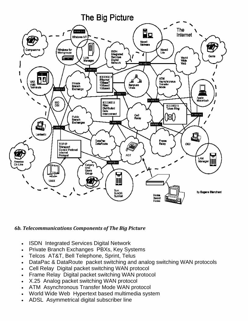
6b. Telecommunications Components of The Big Picture
ISDN Integrated Services Digital Network Private Branch Exchanges PBXs, Key Systems Telcos AT&T, Bell Telephone, Sprint, Telus DataPac & DataRoute packet switching and analog switching WAN protocols Cell Relay Digital packet switching WAN protocol Frame Relay Digital packet switching WAN protocol X.25 Analog packet switching WAN protocol ATM Asynchronous Transfer Mode WAN protocol World Wide Web Hypertext based multimedia system ADSL Asymmetrical digital subscriber line
6c. ISO OSI
The International Standards Organization (ISO) Open Systems Interconnect (OSI) is
a standard set of rules describing the transfer of data between each layer. Each layer
has a specific function. For example the Physical layer deals with the electrical and
cable specifications.
The OSI Model clearly defines the interfaces between each layer. This allows different network
operating systems and protocols to work together by having each manufacturere adhere to the
standard interfaces. The application of the ISO OSI model has allowed the modern multi protocol
networks that exist today. There are 7 Layers of the OSI model:
7. Application Layer (Top Layer) 6. Presentation Layer 5. Session Layer 4. Transport Layer 3. Network Layer 2. Data Link Layer 1. Physical Layer (Bottom Layer)
The OSI model provides the basic rules that allow multiprotocol networks to operate. Understanding
the OSI model is instrument in understanding how the many different protocols fit into the
networking jigsaw puzzle. The OSI model is discussed in detail in Introduction to the ISO - OSI
Model.
7. Breaking The Big Picture up!
The Big Picture still doesn't give us a good idea of the placement of the many protocols involved in
networking and telecommunications. The Big Picture can be broken up according to their protocols
into the following 4 areas:
7a. Local Loop , 7b. LANs , 7c. MANs and 7d. WANs.
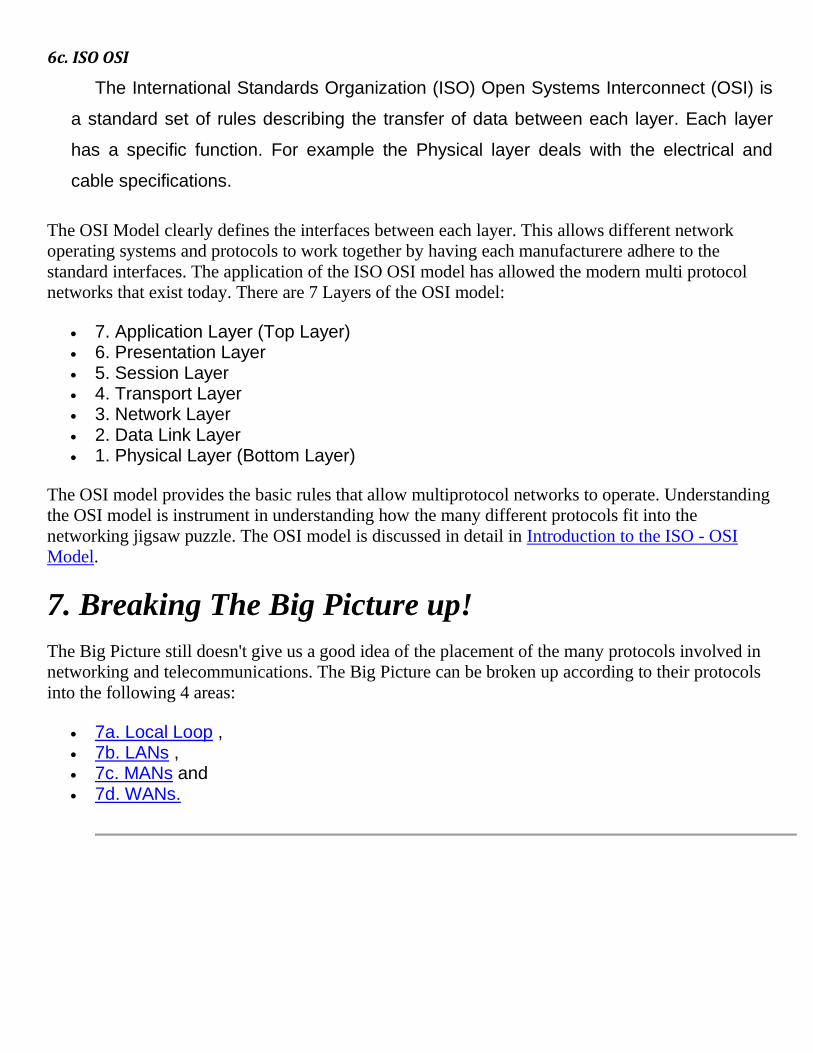
7a. The Local Loop
The Local Loop is often called "the last mile" and it refers to the last mile of analog phone line that
goes from the central office (CO) to your house. Typical local loop protocols are:
Voice lines Modem connections 56 kbps ISDN (Integrated Services Digital Network) 2 x 64 kbps digital lines ADSL (Asymmetrical Digital Subscriber Line) up to 8 Mbps Cable Modems up to 30 Mbps
Note: Cable modems are not part of the Local Loop but do fall in the category of "the last mile" or
how to get high speed digital communication to the premise (home). It would incredibly expensive
to replace the existing cabling structure. All of these protocols are used to overcome the existing
cabling limitations in the local loop and provide high speed digital data tranmission. The existing
cabling was designed for voice communications and not digital.
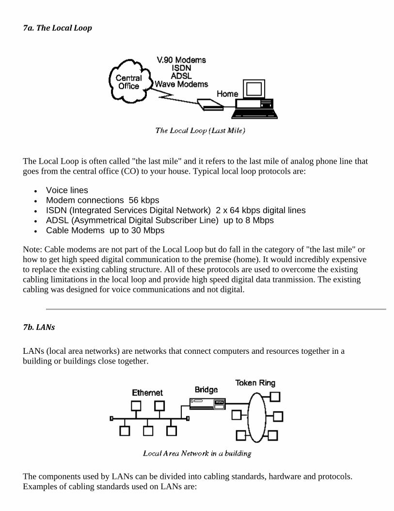
7b. LANs
LANs (local area networks) are networks that connect computers and resources together in a
building or buildings close together.
The components used by LANs can be divided into cabling standards, hardware and protocols.
Examples of cabling standards used on LANs are:
Cat 3, 4 and 5 cables IBM Type 1 9 cabling standards EIA568A and 568B Ethernet cabling standards: IEEE 802.3 (10Base5), IEEE 802.3a (10Base2), IEEE
802.3i (10BaseT) Unshielded Twisted Pair (UTP) Shielded Twisted Pair (STP) Connectors: RJ45, RJ11, Hermaphroditic connectors, RS 232, DB 25, BNC, TEE
Examples of hardware devices are:
Network Interface Cards NICs
Repeaters Ethernet Hubs or multiport repeaters Token Ring MultiStation Access Units (MSAUs), Control Access Units (CAUs) and
Lobe Access Modules (LAMs) Bridges Brouters Routers Gateways Print servers File servers Switches
Examples of LAN protocols are:
Ethernet frame types: Ethernet_II, Ethernet_SNAP, Ethernet_802.2, Ethernet_802.3 Media Access Control layer (MAC layer) Token Ring: IBM and IEEE 802.5 Logical Link Control Layer (LLC) IEEE 802.2 TCP/IP SMB, NetBIOS and NetBeui IPX/SPX Fiber Distributed Data Interchange (FDDI) Asynchronous Transfer Mode (ATM)
7c. MANs
Metropolitan Area Networks (MANs) are networks that connect LANs together within
a city.

The main criteria for a MAN is that the connection between LANs is through a local exchange
carrier (the local phone company). The protocols that are used for MANs are quite different from
LANs except for ATM which can be used for both under certain conditions.
Examples of MAN protocols are:
RS 232, V 35 X.25 (56kbps), PADs Frame Relay (up to 45 Mbps), FRADs Asynchronous Transfer Mode (ATM) ISDN (Integrated Services Digital Network) PRI and BRI Dedicated T 1 lines (1.544 Mbps) and Fractional T 1 T 3 (45 Mbps) and OC 3 lines (155 Mbps) ADSL (Asymmetrical Digital Subscriber Line) up to 8 Mbps xDSL (many different types of Digital Subscriber Lines)
7d. WAN
Wide Area Networks (WANs) connect LANs together between cities.
The main difference between a MAN and a WAN is that the WAN uses Long Distance Carriers.
Otherwise the same protocols and equipment are used as a MAN.
8. Trade Magazines
In 1994, TCP/IP was considered dead by many Unix was considered obsolete. World Wide Web
didn't exist as we know it today! Today TCP/IP is the king of network transport protocols! In a
matter of months, the computing world completed reversed its direction. The only way to keep
current in the computing industry is to read trade publications.
Educational institutes are not able to keep up with the pace of the computing industry. The fast track
education cycle takes 6 months to a year to propose, develope and finally run a new course! In that
time, there could be major changes or revisions of the product. An excellent example of change is
the Linux kernel revisions over the past year.
Anything you read that is over 2 years old is pretty much obsolete! For example: anything you read
about fibre optics that is 3 months old is obsolete. To succeed you must read regularly every trade
and computer magazine possible. You just have to skim the magazines and read only the articles that
are of interest.
There are many free trade publications available to the computing industry if you qualify. Some
examples are:
Free Publications:
Internetwork
Computing Canada
Comnputer Service News
Communication News
LAN Computing
The Computer Paper
Other publications that are worthwhile reading are:
Byte Magazine
MacWorld
PC Computing
Linux Journal
LAN magazine
Most trade magazines now offer webpage versions of their magazines on the Internet. In addition,
they provide a searchable database of previous articles and programs. Access to the Internet is a
necessity if you are going to succeed in the field of network computing. Examples of online
resources are:
Linux Gazette
Slashdot (news for nerds)
ZDnet
Linux Documentation Project
Linux.org
9. The Role of Telecommunications in Networking
From The Big Picture, we see that telecommunications provides a connection service
(storm clouds) between networks (circles). Telecommunications provides the external
connection service for joining networks across cities, provinces and countries.
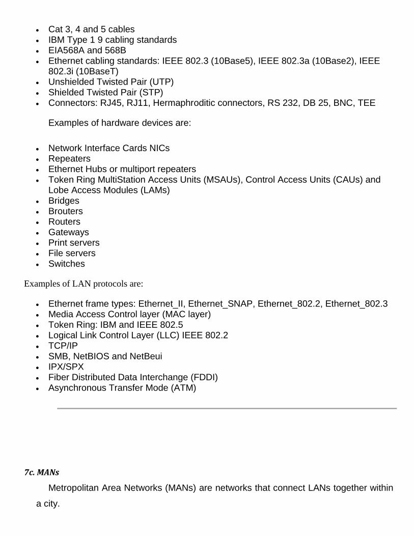
9a. LANs
Local Area Networks - a system of computers that share resources such as hard-
drives, printers, data, CPU power, fax/modem, applications, etc... They usually have
distributed processing - means that there is many desktop computers distributed around
the network and that there is no central processor machine (mainframe). Can be
campus wide like a college or university.
Location: In a building or individual rooms or floors of buildings or nearby
buildings.
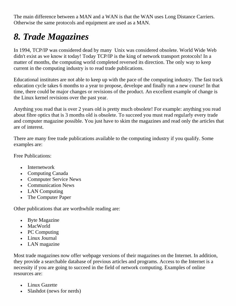
9b. MANs
Metropolitan Area Networks: a system of LANs connected through out a city or
metropolitan. MANs are used to connect to other LANs. A MAN has to have the
requirement of using a telecommunication media such as Voice Channels or Data
Channels. Branch offices are connected to head offices through MANs. Examples of
companies that use MANs are universities and colleges, grocery chains and banks.
Location: Separate buildings distributed throughout a city.
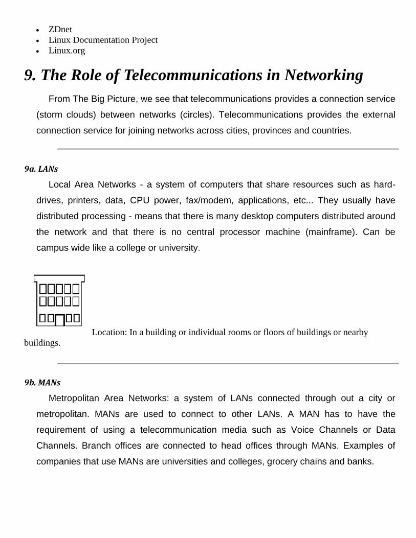
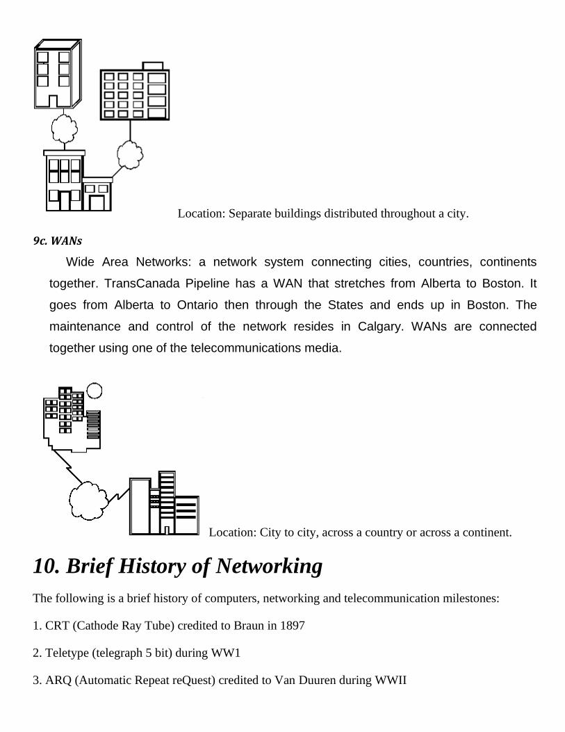
9c. WANs
Wide Area Networks: a network system connecting cities, countries, continents
together. TransCanada Pipeline has a WAN that stretches from Alberta to Boston. It
goes from Alberta to Ontario then through the States and ends up in Boston. The
maintenance and control of the network resides in Calgary. WANs are connected
together using one of the telecommunications media.
Location: City to city, across a country or across a continent.
10. Brief History of Networking
The following is a brief history of computers, networking and telecommunication milestones:
1. CRT (Cathode Ray Tube) credited to Braun in 1897
2. Teletype (telegraph 5 bit) during WW1
3. ARQ (Automatic Repeat reQuest) credited to Van Duuren during WWII

error checking and auto request for retransmission
4. ENIAC credited to DOD / MIT during WWII
Electronic Numerical Integrator And Calculator
Used for decoding enemy messages
1st generation computer: used vacuum tubes
Programmed with jumpers and switches
MTBF (Mean Time Between Failure): 7 minutes
337 multiplications per second
5. SAGE (Semi-Automatic Ground Environment) MIT 1950s
23 centres for ground/air enemy detection systems
error checking, keyboard & CRT terminals
duplexed computers, voice grade (300-4KHz)
300 baud, light pens, multiuser system
magnetic core memory
Ground to air data Tx
1st commercial use was Sabre Reservation System
6. Jacquard's Loom
First programmable machine
7. Transistorized Computers - 2nd Generation 1960s
One of the 1st inventors: Cray
Batch programming: 1 pgm @ a time
Punch cards
Stored programs: held in memory
50K instructions/second
ex. IBM 7905
8. CTSS (Compatible Time Sharing System) credited to Cobato/MIT in 1961
time slices multiusers
9. Synchronous Orbit Communication Satellites. Idea by Arthur C. Clarke in 1945
Geostationary orbit around equator by Rose/Hughes Aerospace in1963
36,000 miles altitude
10. LASER credited to Maiman in 1960
A narrow band source of optical radiation suitable for use as a carrier of info.
Light Amplification by Stimulated Emission of Radiation

11. T-1 Carrier System credited to Bell Labs in 1961
TDM (Time Domain Multiplexing)
24 channels = 64 Kbps ea.
1.544 Mbps (mega bits per sec)
12. RS232 developed in 1960 and revised since.
Standard plug and "protocol" convention between modems and machines: 25 pin
Europe uses V.24 compatible standard
13. Auto Equalization Techniques of Phone lines credited to Lucky et al. in 1965
adapt to characteristics of telephone line to increase speed
14. Fibre Glass credited to Kao & Hockman in 1966
proposed "fibre glass " optics developed at Standard Telecom Labs
15. Integrated Circuits Computers - 3rd Generation - 1967
SSI/MSI (Small Scale Integration/Medium Scale Integration)
10 transistors/chip and 100 transistors/chip
Multi-user systems
Multitasking
16. Carterfone - FCC Decision in 1968 -
FCC decision allows other manufacturer's to use phone lines
opens up competition among phone systems
17. Low-loss Fibre credited to Kapron in 1970
speeds: 45-90 Mbps developed at Corning Glass Works
1984: attained 405-565 Mbps in single mode
Early 1990s: attained 1.7 Gbps
18. ARPA Network (ARPANET) developed by the DOD in the 1970s
Advanced Research Projects Agency of the Department of Defence - US
1st use of Packet Switching, layered protocols
Beginning of the Internet
19. VLSI Integration - 4th Generation Computers developed by Intel in 1971
Very large scale integration: 20,000+ transistors/chip
Intel 4004 microprocessor - 4 bit
Grandparent of processors today

20. Layered Network Architecture
SNA: System Network Architecture IBM Mainframe
DNA: Digital Network Architecture DEC for DECNET
21. Ethernet developed by Xerox in 1974 -
Ether is the mysterious invisible fluid that transfers heat
Originally based on the ALOHA radio protocol
22. Videotex developed by Teletel (France) in the 1980s
Interactive video Minitel
23. Reference Model for Open Systems Interconnect developed by the ISO in 1983
Continuously evolving model for layering network protocols
24. AT&T Divestiture in 1984 -
Break-up of AT&T monopoly into Baby Bells
25. ISDN developed in 1984 -
Integrated Services Digital Network
Strong in Europe
A network evolving from a telephony integrated digital network supporting: voice, teletex,
videotex, fax, slowscan video, etc..
26. Linux Version 0.01 released Sept 17, 1991
11. Data Communication Network
The major criteria that a Data Communication Network must meet are:
i. 11a. Performance
ii. 11b. Consistency iii. 11c. Reliability, iv. 11d. Recovery and
v. 11e. Security
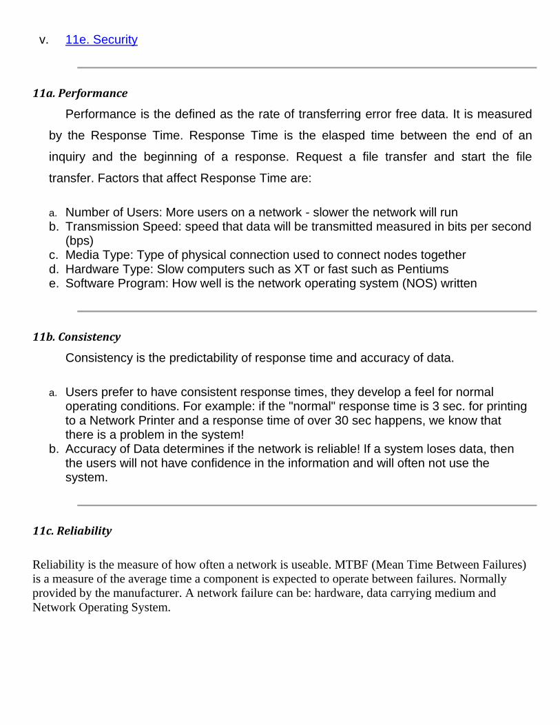
11a. Performance
Performance is the defined as the rate of transferring error free data. It is measured
by the Response Time. Response Time is the elasped time between the end of an
inquiry and the beginning of a response. Request a file transfer and start the file
transfer. Factors that affect Response Time are:
a. Number of Users: More users on a network - slower the network will run
b. Transmission Speed: speed that data will be transmitted measured in bits per second (bps)
c. Media Type: Type of physical connection used to connect nodes together d. Hardware Type: Slow computers such as XT or fast such as Pentiums e. Software Program: How well is the network operating system (NOS) written
11b. Consistency
Consistency is the predictability of response time and accuracy of data.
a. Users prefer to have consistent response times, they develop a feel for normal operating conditions. For example: if the "normal" response time is 3 sec. for printing to a Network Printer and a response time of over 30 sec happens, we know that there is a problem in the system!
b. Accuracy of Data determines if the network is reliable! If a system loses data, then the users will not have confidence in the information and will often not use the system.
11c. Reliability
Reliability is the measure of how often a network is useable. MTBF (Mean Time Between Failures)
is a measure of the average time a component is expected to operate between failures. Normally
provided by the manufacturer. A network failure can be: hardware, data carrying medium and
Network Operating System.

11d. Recovery
Recovery is the Network's ability to return to a prescribed level of operation after a
network failure. This level is where the amount of lost data is nonexistent or at a
minimum. Recovery is based on having Back-up Files.
11e. Security
Security is the protection of Hardware, Software and Data from unauthorized access.
Restricted physical access to computers, password protection, limiting user privileges
and data encryption are common security methods. Anti-Virus monitoring programs to
defend against computer viruses are a security measure.
11f. Applications
The following lists general applications of a data communication network:
i. Electronic Mail (e-mail or Email) replaces snail mail. E-mail is the forwarding of electronic files to an electronic post office for the recipient to pick up.
ii. Scheduling Programs allow people across the network to schedule appointments directly by calling up their fellow worker's schedule and selecting a time!
iii. Videotext is the capability of having a 2 way transmission of picture and sound. Games like Doom, Hearts, distance education lectures, etc..
iv. Groupware is the latest network application, it allows user groups to share documents, schedules databases, etc.. ex. Lotus Notes.
v. Teleconferencing allows people in different regions to "attend" meetings using telephone lines.
vi. Telecommuting allows employees to perform office work at home by "Remote Access" to the network.
vii. Automated Banking Machines allow banking transactions to be performed everywhere: at grocery stores, Drive-in machines etc..
viii. Information Service Providers: provide connections to the Internet and other information services. Examples are Compuserve, Genie, Prodigy, America On-Line (AOL), etc...
ix. Electronic Bulletin Boards (BBS - Bulletin Board Services) are dialup connections (use a modem and phone lines) that offer a range of services for a fee.
x. Value Added Networks are common carriers such as AGT, Bell Canada, etc.. (can be private or public companies) who provide additional leased line connections to their customers. These can be Frame Relay, ATM (Asynchronous Transfer Mode), X.25, etc.. The leased line is the Value Added Network.
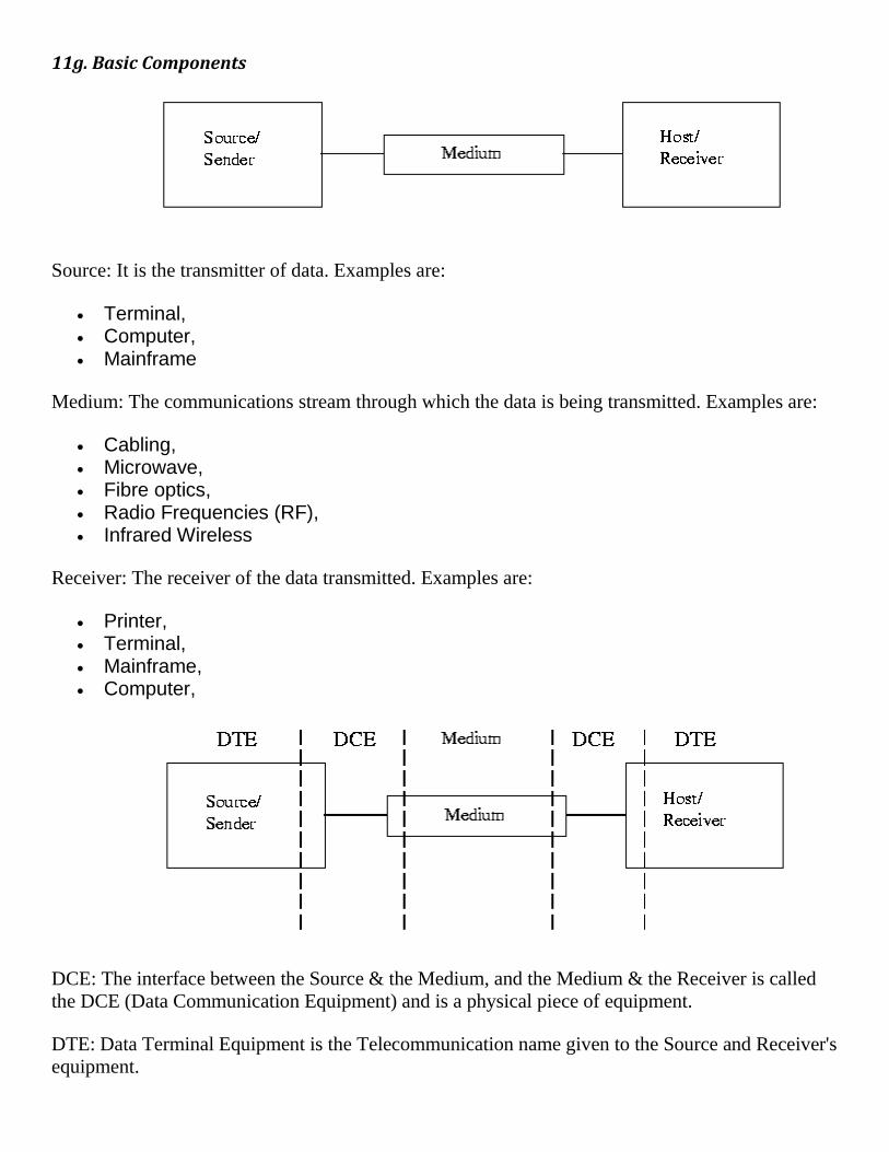
11g. Basic Components
Source: It is the transmitter of data. Examples are:
Terminal, Computer, Mainframe
Medium: The communications stream through which the data is being transmitted. Examples are:
Cabling, Microwave, Fibre optics, Radio Frequencies (RF), Infrared Wireless
Receiver: The receiver of the data transmitted. Examples are:
Printer, Terminal, Mainframe, Computer,
DCE: The interface between the Source & the Medium, and the Medium & the Receiver is called
the DCE (Data Communication Equipment) and is a physical piece of equipment.
DTE: Data Terminal Equipment is the Telecommunication name given to the Source and Receiver's
equipment.
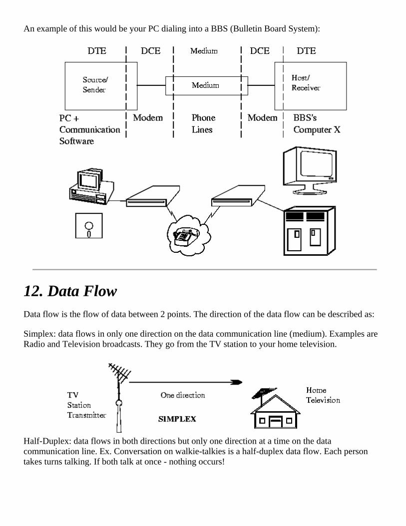
An example of this would be your PC dialing into a BBS (Bulletin Board System):
12. Data Flow
Data flow is the flow of data between 2 points. The direction of the data flow can be described as:
Simplex: data flows in only one direction on the data communication line (medium). Examples are
Radio and Television broadcasts. They go from the TV station to your home television.
Half-Duplex: data flows in both directions but only one direction at a time on the data
communication line. Ex. Conversation on walkie-talkies is a half-duplex data flow. Each person
takes turns talking. If both talk at once - nothing occurs!

Bi-directional but only 1 direction @ a time!
HALF-DUPLEX
Full-Duplex: data flows in both directions simultaneously. Modems are configured to flow data in
both directions.
Bi-directional both directions simultaneously!
FULL-DUPLEX
13. Modems
A modem is a Modulator/Demodulator, it connects a terminal/computer (DTE) to the
Voice Channel (dial-up line).
13a. Basic Definition
The modem (DCE - Data Communication Equipment) is connected between the
terminal/computer (DTE - Data Terminal Equipment) and the phone line (Voice
Channel). A modem converts the DTE (Data Terminal Equipment) digital signal to an
analog signal that the Voice Channel can use.
A modem is connected to the terminal/computer's RS232 serial port (25 pin male D connector) and
the outgoing phone line with an RJ11 cable connector (same as on a phone extension cord). Male
connectors have pins, female connectors have sockets.
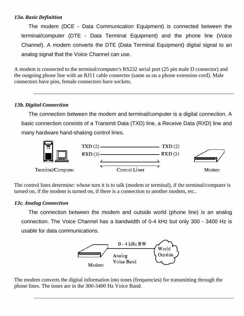
13b. Digital Connection
The connection between the modem and terminal/computer is a digital connection. A
basic connection consists of a Transmit Data (TXD) line, a Receive Data (RXD) line and
many hardware hand-shaking control lines.
The control lines determine: whose turn it is to talk (modem or terminal), if the terminal/computer is
turned on, if the modem is turned on, if there is a connection to another modem, etc..
13c. Analog Connection
The connection between the modem and outside world (phone line) is an analog
connection. The Voice Channel has a bandwidth of 0-4 kHz but only 300 - 3400 Hz is
usable for data communications.
The modem converts the digital information into tones (frequencies) for transmitting through the
phone lines. The tones are in the 300-3400 Hz Voice Band.
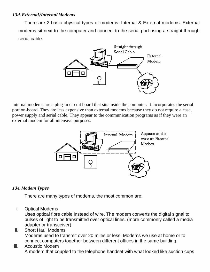
13d. External/Internal Modems
There are 2 basic physical types of modems: Internal & External modems. External
modems sit next to the computer and connect to the serial port using a straight through
serial cable.
Internal modems are a plug-in circuit board that sits inside the computer. It incorporates the serial
port on-board. They are less expensive than external modems because they do not require a case,
power supply and serial cable. They appear to the communication programs as if they were an
external modem for all intensive purposes.
13e. Modem Types
There are many types of modems, the most common are:
i. Optical Modems Uses optical fibre cable instead of wire. The modem converts the digital signal to pulses of light to be transmitted over optical lines. (more commonly called a media adapter or transceiver)
ii. Short Haul Modems Modems used to transmit over 20 miles or less. Modems we use at home or to connect computers together between different offices in the same building.
iii. Acoustic Modem A modem that coupled to the telephone handset with what looked like suction cups
that contained a speaker and microphone. Used for connecting to hotel phones for travelling salespeople.
iv. Smart Modem Modem with a CPU (microprocessor) on board that uses the Hayes AT command set. This allows auto-answer & dial capability rather than manually dialing & answering.
v. Digital Modems Converts the RS-232 digital signals to digital signals more suitable for transmission. (also called a media adapter or transceiver)
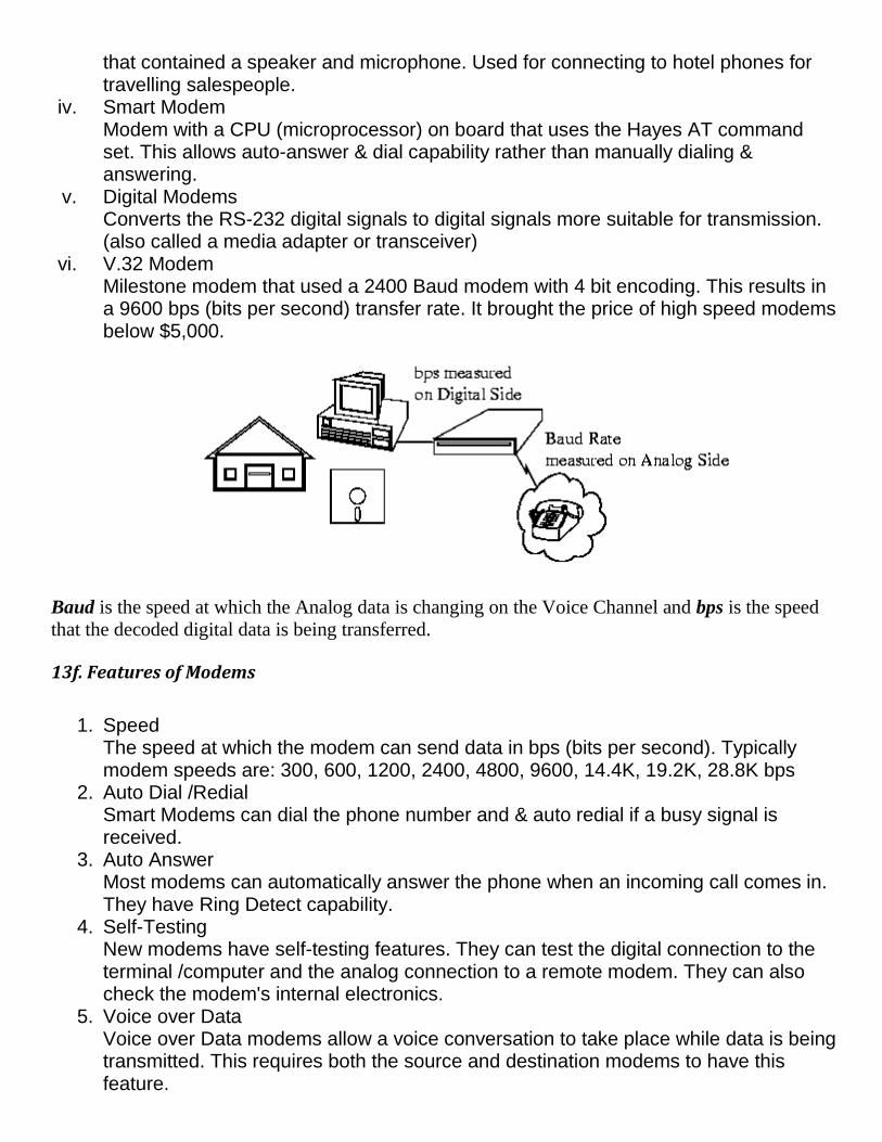
vi. V.32 Modem Milestone modem that used a 2400 Baud modem with 4 bit encoding. This results in a 9600 bps (bits per second) transfer rate. It brought the price of high speed modems below $5,000.
Baud is the speed at which the Analog data is changing on the Voice Channel and bps is the speed
that the decoded digital data is being transferred.
13f. Features of Modems
1. Speed The speed at which the modem can send data in bps (bits per second). Typically modem speeds are: 300, 600, 1200, 2400, 4800, 9600, 14.4K, 19.2K, 28.8K bps
2. Auto Dial /Redial Smart Modems can dial the phone number and & auto redial if a busy signal is received.
3. Auto Answer Most modems can automatically answer the phone when an incoming call comes in. They have Ring Detect capability.
4. Self-Testing New modems have self-testing features. They can test the digital connection to the terminal /computer and the analog connection to a remote modem. They can also check the modem's internal electronics.
5. Voice over Data Voice over Data modems allow a voice conversation to take place while data is being transmitted. This requires both the source and destination modems to have this feature.
6. Synchronous or Asynchronous Transmission Newer modems allow a choice of synchronous or asynchronous transmission of data. Normally, modem transmission is asynchronous. We send individual characters with just start and stop bits. Synchronous transmission or packet transmission is used in specific applications.
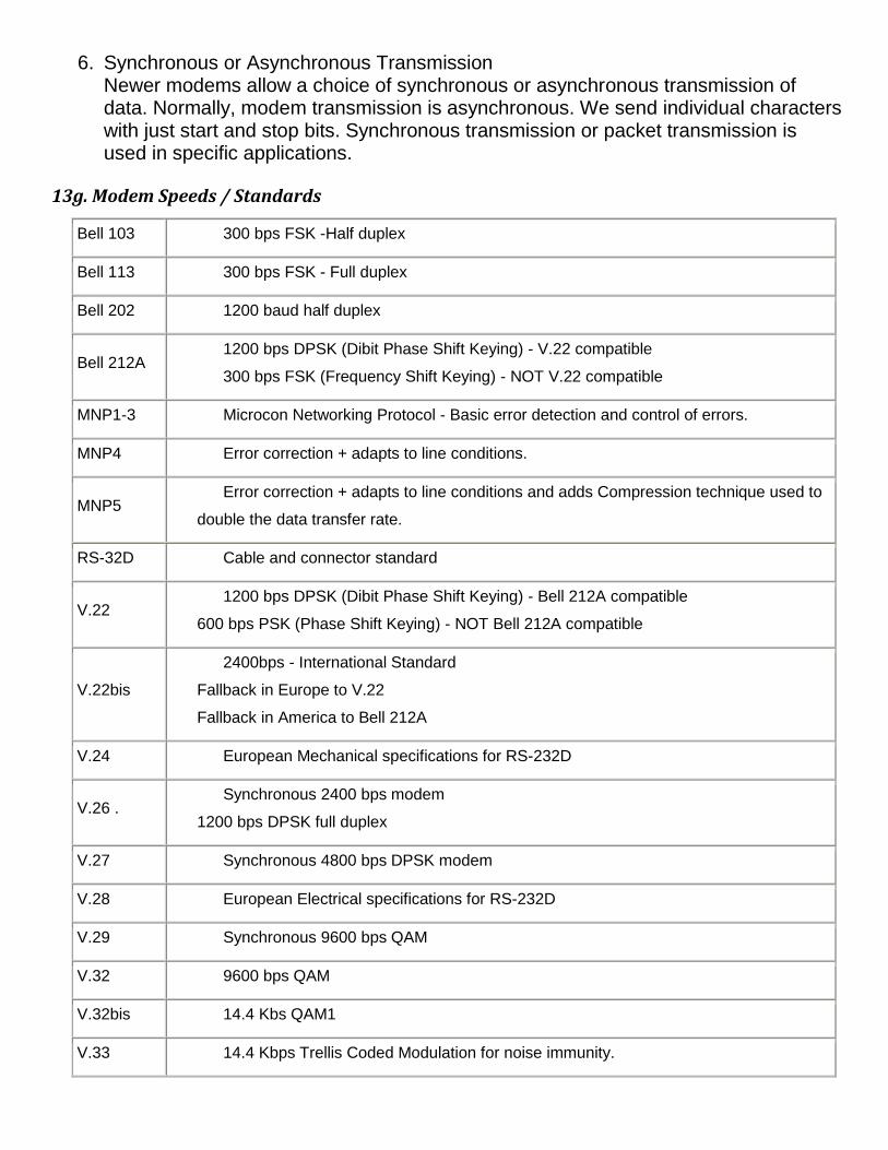
13g. Modem Speeds / Standards
Bell 103 300 bps FSK -Half duplex
Bell 113 300 bps FSK - Full duplex
Bell 202 1200 baud half duplex
Bell 212A 1200 bps DPSK (Dibit Phase Shift Keying) - V.22 compatible
300 bps FSK (Frequency Shift Keying) - NOT V.22 compatible
MNP1-3 Microcon Networking Protocol - Basic error detection and control of errors.
MNP4 Error correction + adapts to line conditions.
MNP5 Error correction + adapts to line conditions and adds Compression technique used to
double the data transfer rate.
RS-32D Cable and connector standard
V.22 1200 bps DPSK (Dibit Phase Shift Keying) - Bell 212A compatible
600 bps PSK (Phase Shift Keying) - NOT Bell 212A compatible
V.22bis
2400bps - International Standard
Fallback in Europe to V.22
Fallback in America to Bell 212A
V.24 European Mechanical specifications for RS-232D
V.26 . Synchronous 2400 bps modem
1200 bps DPSK full duplex
V.27 Synchronous 4800 bps DPSK modem
V.28 European Electrical specifications for RS-232D
V.29 Synchronous 9600 bps QAM
V.32 9600 bps QAM
V.32bis 14.4 Kbs QAM1
V.33 14.4 Kbps Trellis Coded Modulation for noise immunity.
V.34 28.8 Kbps modem standard
V.34bis 33.6 Kbps modem standard
V.42bis Compression technique to roughly double the data transfer rate. Uses Automatic
Repeat Request ARQ and CRC (Cyclic Redundancy Checking)
WE201 Synchronous Western Electric 2400 bps DPSK
WE208 Synchronous 4800 bps DPSK
WE209 Synchronous 9600 bps
13h. Transfer Rate versus PC Bus Speed
The lowliest XT PC can out-perform the fastest modem transfer rate. For example: an XT has an 8
bit parallel expansion bus operating at 4.77 MHz. This equates to a data transfer rate of:
8 bits x 4.77 MHz = 38.16 Mbps
Compare this to the fastest modem transfer rates of 57.6 kbps!
V.90 Standard 56 kbps Modems
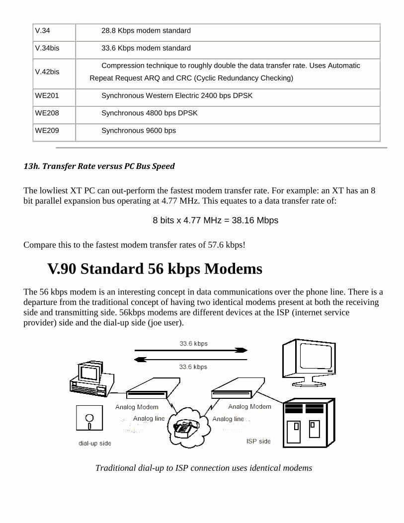
The 56 kbps modem is an interesting concept in data communications over the phone line. There is a
departure from the traditional concept of having two identical modems present at both the receiving
side and transmitting side. 56kbps modems are different devices at the ISP (internet service
provider) side and the dial-up side (joe user).
Traditional dial-up to ISP connection uses identical modems

Traditionally, a dial-up connection uses two identical modems with the same communication
standard at both ends. This method of communication reached a transfer limit of 33.6 kbps with the
V.34bis standard.
In order to increase the transfer rate, the "modem" connection at the ISP side was "modified" to
eliminate the analog to digital conversion. The modem at the ISP end uses only digital
communication while the dial-up user's modem retains the analog to digital characteristics required
to use the local loop. By eliminating one of the analog to digital conversions required in a traditional
modem connection, the transfer rate is increased in the download direction - from ISP to dial-up
user. This requires that the ISP has a special V.90 compliant digital modem and also digital lines to
the telephone company switch.
V.90 standard dial-up to ISP connection showing digital modem
Maximum upload transfer rate is 33.6 kbps from the dial-up connection to the ISP and the maximum
download transfer rate is 53 kbps (not 56 kbps as advertised) from the ISP to the dial-up connection.
These transfer rates are available under ideal situations and not every local loop connection will
support these speeds. Most phone lines can support the maximum upload transfer rate of 33.6 kbps
but the majority of phone lines seem to be able to support download transfer rates of about 43 kbps.
Again this will vary depending on the quality and age of the dial-up connection.
Initially, there were two competing standards for the 56 kbps modems: Rockwell's K56 and US
Robotics' X2. Eventually, the ISU (International Standards Union) came out with the
current V.90 standard which both Rockwell and USR now follow. If you have a Rockwell K56 or
USR X2 standard modem, you should be able to go to their respective websites and download an
upgrade.
14. Physical Connection

The physical connection determines how many bits (1's or 0's) can be transmitted at a single instance
of time. If only 1 bit of information can be transmitted over the data transmission medium at a time
then it is considered a Serial Communication.
If more than 1 bit of information is transmitted over the data transmission medium at a time then it is
considered a Parallel Communication.
Communications Advantages Disadvantages
Parallel Fast Transfer Rates Short distances only
Serial Long Distances Slow transfer rates
15. Transmission Media - Guided
There are 2 basic categories of Transmission Media:
Guided and
Unguided.
Guided Transmission Media uses a "cabling" system that guides the data signals
along a specific path. The data signals are bound by the "cabling" system.
Guided Media is also known as Bound Media. Cabling is meant in a generic
sense in the previous sentences and is not meant to be interpreted as copper wire
cabling only.
Unguided Transmission Media consists of a means for the data signals to travel
but nothing to guide them along a specific path. The data signals are not bound to
a cabling media and as such are often called Unbound Media.
There 4 basic types of Guided Media:
Open Wire
Twisted Pair
Coaxial Cable
Optical Fibre
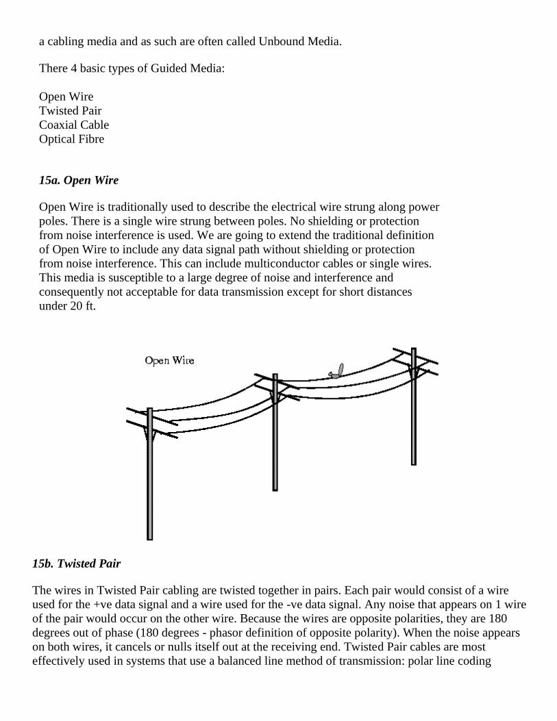
15a. Open Wire
Open Wire is traditionally used to describe the electrical wire strung along power
poles. There is a single wire strung between poles. No shielding or protection
from noise interference is used. We are going to extend the traditional definition
of Open Wire to include any data signal path without shielding or protection
from noise interference. This can include multiconductor cables or single wires.
This media is susceptible to a large degree of noise and interference and
consequently not acceptable for data transmission except for short distances
under 20 ft.
15b. Twisted Pair
The wires in Twisted Pair cabling are twisted together in pairs. Each pair would consist of a wire
used for the +ve data signal and a wire used for the -ve data signal. Any noise that appears on 1 wire
of the pair would occur on the other wire. Because the wires are opposite polarities, they are 180
degrees out of phase (180 degrees - phasor definition of opposite polarity). When the noise appears
on both wires, it cancels or nulls itself out at the receiving end. Twisted Pair cables are most
effectively used in systems that use a balanced line method of transmission: polar line coding
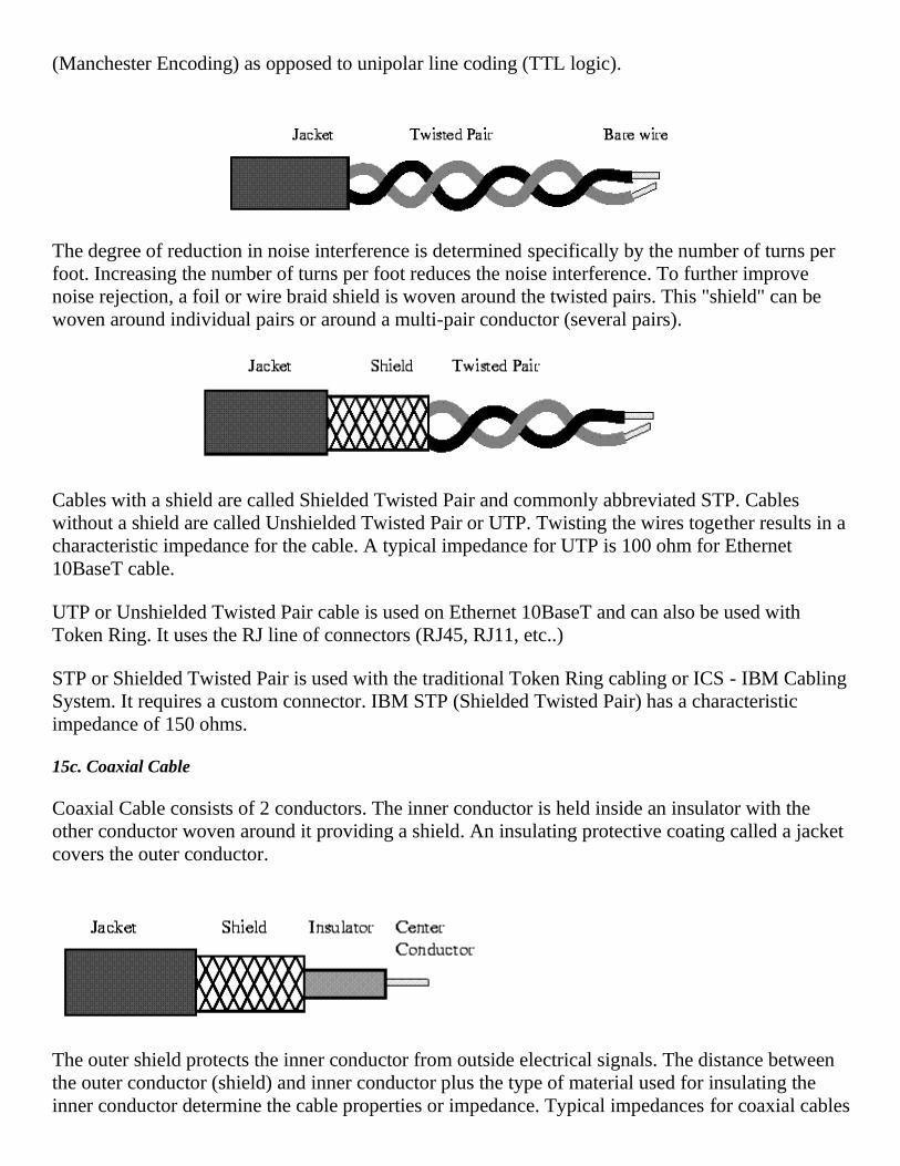
(Manchester Encoding) as opposed to unipolar line coding (TTL logic).
The degree of reduction in noise interference is determined specifically by the number of turns per
foot. Increasing the number of turns per foot reduces the noise interference. To further improve
noise rejection, a foil or wire braid shield is woven around the twisted pairs. This "shield" can be
woven around individual pairs or around a multi-pair conductor (several pairs).
Cables with a shield are called Shielded Twisted Pair and commonly abbreviated STP. Cables
without a shield are called Unshielded Twisted Pair or UTP. Twisting the wires together results in a
characteristic impedance for the cable. A typical impedance for UTP is 100 ohm for Ethernet
10BaseT cable.
UTP or Unshielded Twisted Pair cable is used on Ethernet 10BaseT and can also be used with
Token Ring. It uses the RJ line of connectors (RJ45, RJ11, etc..)
STP or Shielded Twisted Pair is used with the traditional Token Ring cabling or ICS - IBM Cabling
System. It requires a custom connector. IBM STP (Shielded Twisted Pair) has a characteristic
impedance of 150 ohms.
15c. Coaxial Cable
Coaxial Cable consists of 2 conductors. The inner conductor is held inside an insulator with the
other conductor woven around it providing a shield. An insulating protective coating called a jacket
covers the outer conductor.
The outer shield protects the inner conductor from outside electrical signals. The distance between
the outer conductor (shield) and inner conductor plus the type of material used for insulating the
inner conductor determine the cable properties or impedance. Typical impedances for coaxial cables
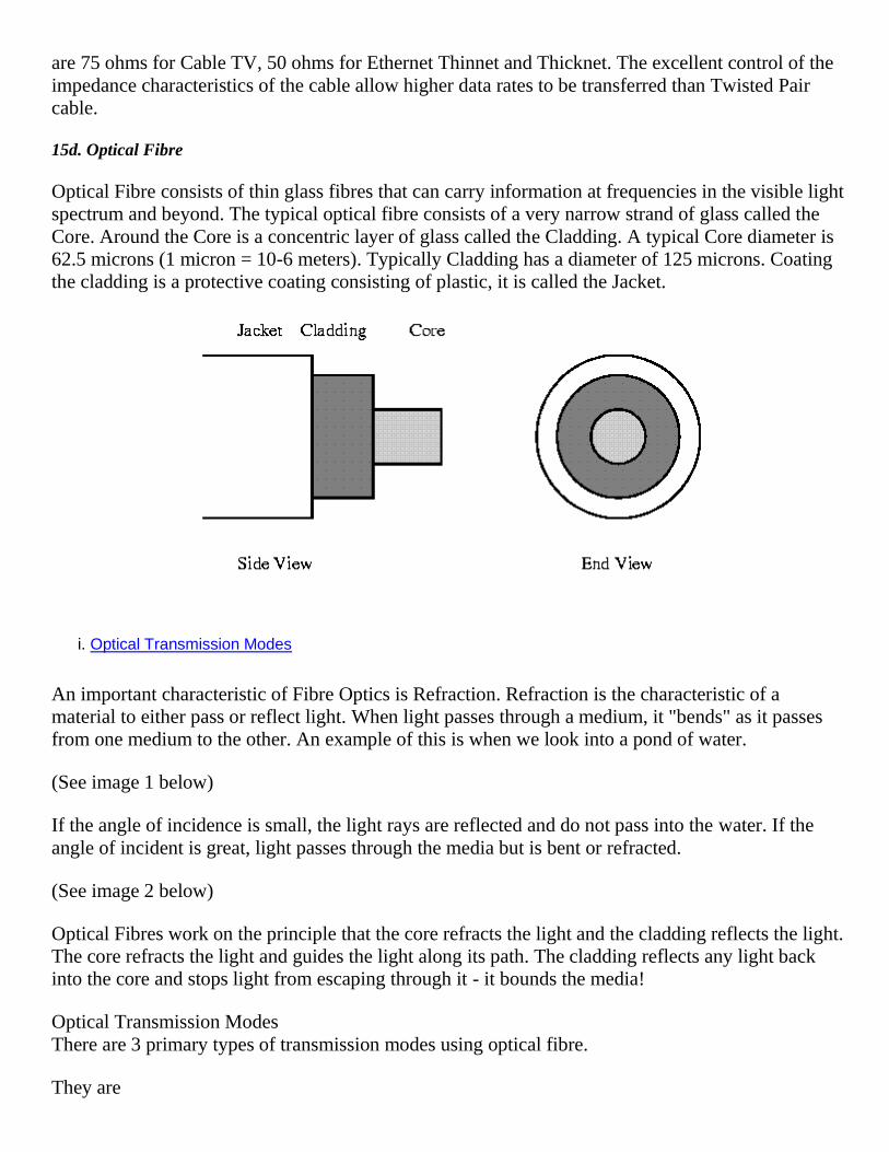
are 75 ohms for Cable TV, 50 ohms for Ethernet Thinnet and Thicknet. The excellent control of the
impedance characteristics of the cable allow higher data rates to be transferred than Twisted Pair
cable.
15d. Optical Fibre
Optical Fibre consists of thin glass fibres that can carry information at frequencies in the visible light
spectrum and beyond. The typical optical fibre consists of a very narrow strand of glass called the
Core. Around the Core is a concentric layer of glass called the Cladding. A typical Core diameter is
62.5 microns (1 micron = 10-6 meters). Typically Cladding has a diameter of 125 microns. Coating
the cladding is a protective coating consisting of plastic, it is called the Jacket.
i. Optical Transmission Modes
An important characteristic of Fibre Optics is Refraction. Refraction is the characteristic of a
material to either pass or reflect light. When light passes through a medium, it "bends" as it passes
from one medium to the other. An example of this is when we look into a pond of water.
(See image 1 below)
If the angle of incidence is small, the light rays are reflected and do not pass into the water. If the
angle of incident is great, light passes through the media but is bent or refracted.
(See image 2 below)
Optical Fibres work on the principle that the core refracts the light and the cladding reflects the light.
The core refracts the light and guides the light along its path. The cladding reflects any light back
into the core and stops light from escaping through it - it bounds the media!
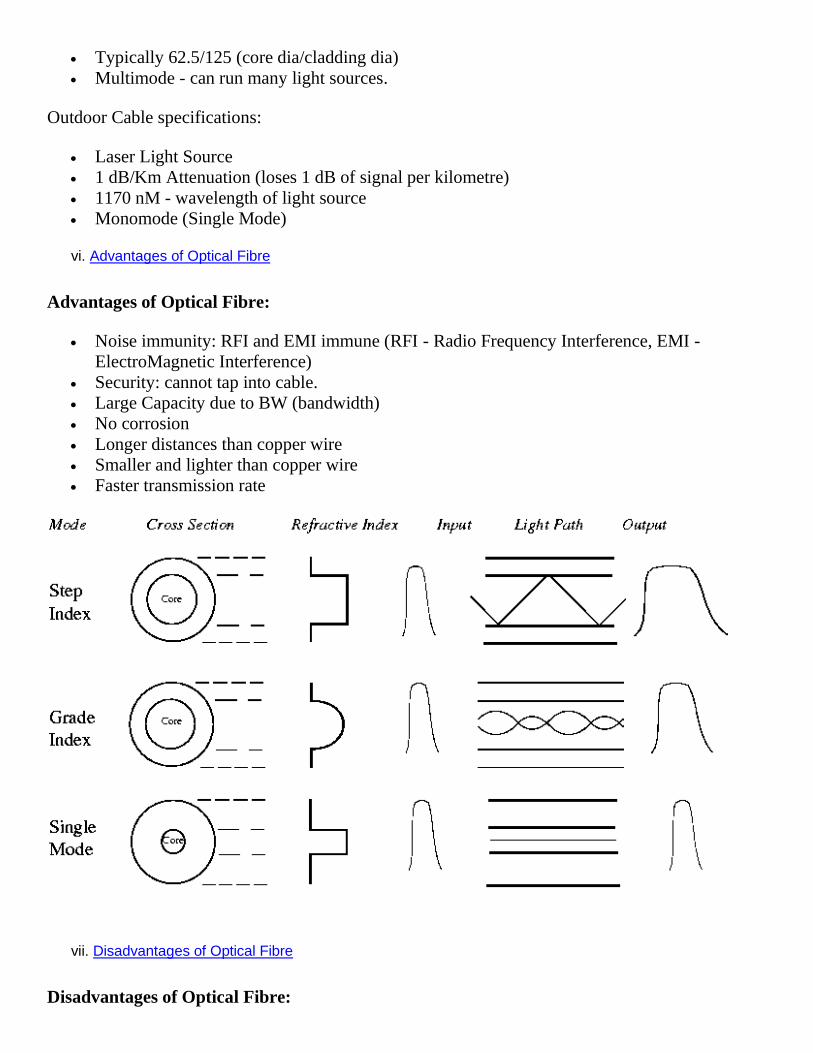
Optical Transmission Modes
There are 3 primary types of transmission modes using optical fibre.
They are

a) Step Index
b) Grade Index
c) Single Mode
ii. Step Index Mode
Step Index has a large core the light rays tend to bounce around, reflecting off the cladding, inside
the core. This causes some rays to take a longer or shorted path through the core. Some take the
direct path with hardly any reflections while others bounce back and forth taking a longer path. The
result is that the light rays arrive at the receiver at different times. The signal becomes longer than
the original signal. LED light sources are used. Typical Core: 62.5 microns.
Step Index Mode
iii. Grade Index Mode

Grade Index has a gradual change in the Core's Refractive Index. This causes the light rays to be
gradually bent back into the core path. This is represented by a curved reflective path in the attached
drawing. The result is a better receive signal than Step Index. LED light sources are used. Typical
Core: 62.5 microns.
Grade Index Mode
Note: Both Step Index and Graded Index allow more than one light source to be used (different
colours simultaneously!). Multiple channels of data can be run simultaneously!
iv. Single Mode
Single Mode has separate distinct Refractive Indexes for the cladding and core. The light ray passes
through the core with relatively few reflections off the cladding. Single Mode is used for a single
source of light (one colour) operation. It requires a laser and the core is very small: 9 microns.
Single Mode
v. Comparison of Optical Fibres
Comparison of Optical Fibres
(See image below)
The Wavelength of the light sources is measured in nanometers or 1 billionth of a meter. We don't
use frequency to talk about speed any more, we use wavelengths instead.
Indoor cable specifications:
LED (Light Emitting Diode) Light Source
3.5 dB/Km Attenuation (loses 3.5 dB of signal per kilometre)
850 nM - wavelength of light source
Typically 62.5/125 (core dia/cladding dia)
Multimode - can run many light sources.
Outdoor Cable specifications:
Laser Light Source
1 dB/Km Attenuation (loses 1 dB of signal per kilometre)
1170 nM - wavelength of light source
Monomode (Single Mode)
vi. Advantages of Optical Fibre
Advantages of Optical Fibre:
Noise immunity: RFI and EMI immune (RFI - Radio Frequency Interference, EMI -
ElectroMagnetic Interference)
Security: cannot tap into cable.
Large Capacity due to BW (bandwidth)
No corrosion
Longer distances than copper wire
Smaller and lighter than copper wire
Faster transmission rate
vii. Disadvantages of Optical Fibre
Disadvantages of Optical Fibre:
Physical vibration will show up as signal noise!
Limited physical arc of cable. Bend it too much & it will break!
Difficult to splice
The cost of optical fibre is a trade-off between capacity and cost. At higher transmission capacity, it
is cheaper than copper. At lower transmission capacity, it is more expensive.
15e. Media versus Bandwidth
The following table compares the usable bandwidth between the different Guided Transmission
Media
Cable Type Bandwidth
Open Cable 0 - 5 MHz
Twisted Pair 0 - 100 MHz
Coaxial Cable 0 - 600 MHz
Optical Fibre 0 - 1 GHz
16. Transmission Media - Unguided
Unguided Transmission Media is data signals that flow through the air. They are not guided or
bound to a channel to follow. They are classified by the type of wave propagation.
16a. RF Propagation
There are 3 types of RF (Radio Frequency) Propagation:
Ground Wave,
Ionospheric and
Line of Sight (LOS) Propagation.
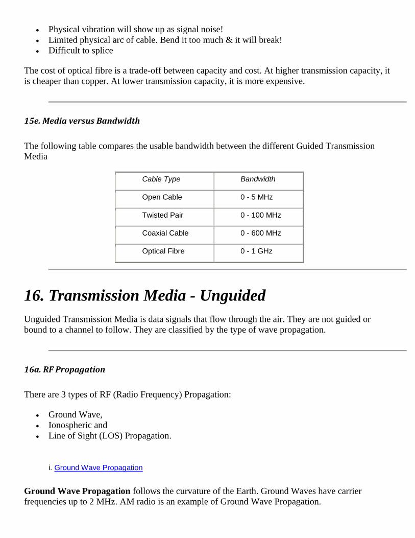
i. Ground Wave Propagation
Ground Wave Propagation follows the curvature of the Earth. Ground Waves have carrier
frequencies up to 2 MHz. AM radio is an example of Ground Wave Propagation.
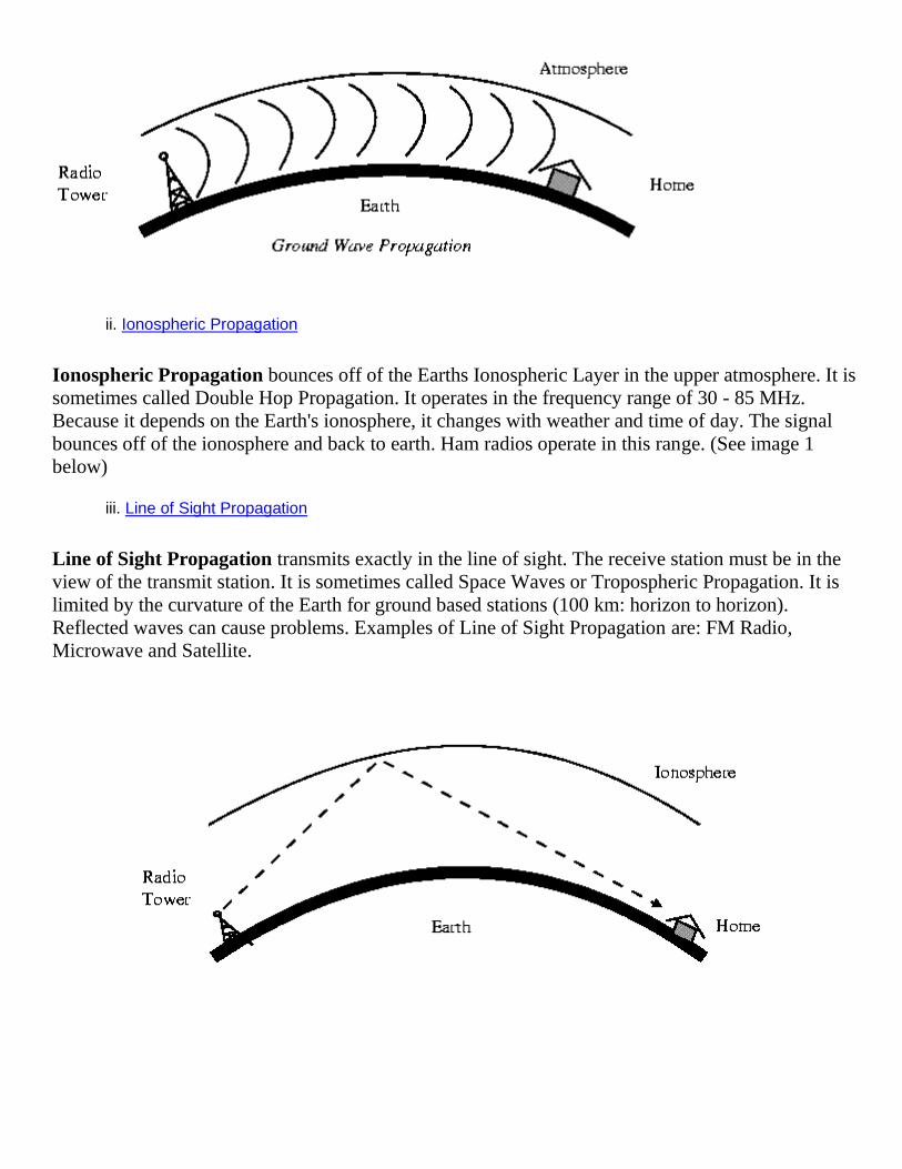
ii. Ionospheric Propagation
Ionospheric Propagation bounces off of the Earths Ionospheric Layer in the upper atmosphere. It is
sometimes called Double Hop Propagation. It operates in the frequency range of 30 - 85 MHz.
Because it depends on the Earth's ionosphere, it changes with weather and time of day. The signal
bounces off of the ionosphere and back to earth. Ham radios operate in this range. (See image 1
below)
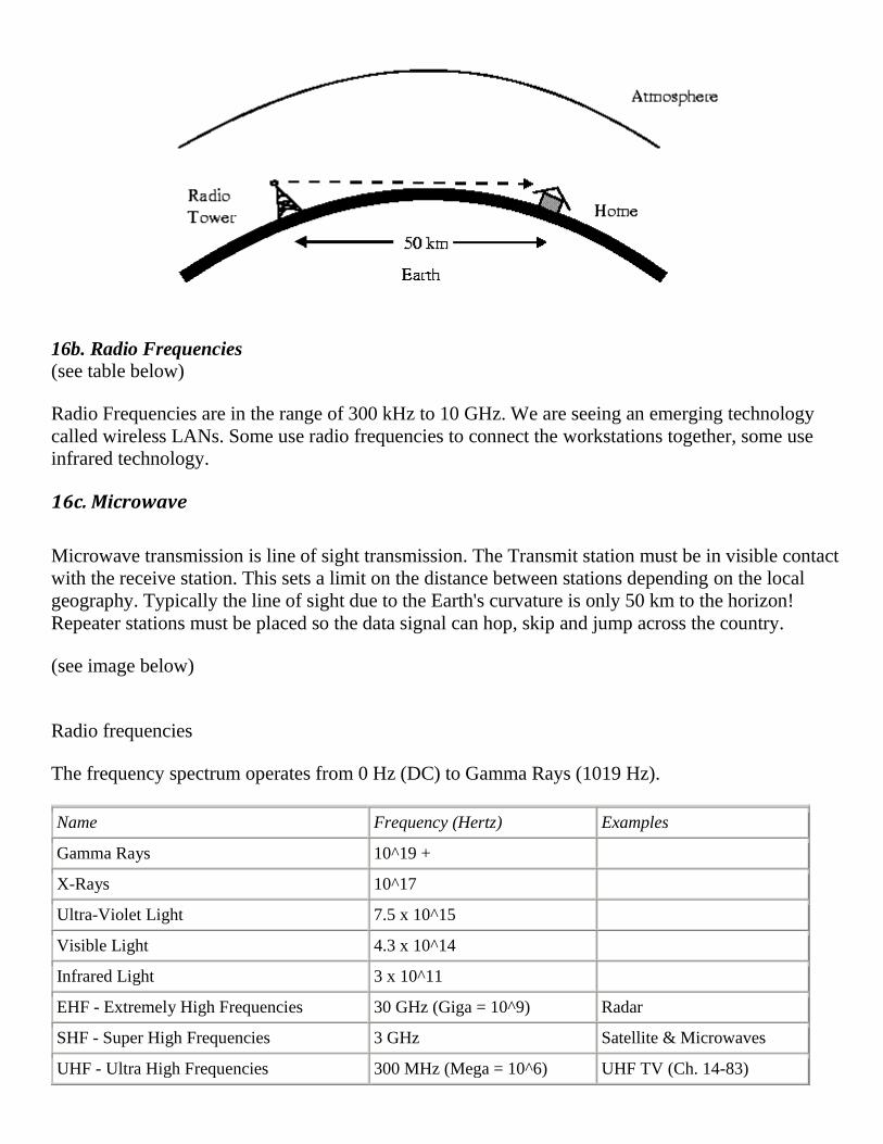
iii. Line of Sight Propagation
Line of Sight Propagation transmits exactly in the line of sight. The receive station must be in the
view of the transmit station. It is sometimes called Space Waves or Tropospheric Propagation. It is
limited by the curvature of the Earth for ground based stations (100 km: horizon to horizon).
Reflected waves can cause problems. Examples of Line of Sight Propagation are: FM Radio,
Microwave and Satellite.
16b. Radio Frequencies
(see table below)
Radio Frequencies are in the range of 300 kHz to 10 GHz. We are seeing an emerging technology
called wireless LANs. Some use radio frequencies to connect the workstations together, some use
infrared technology.
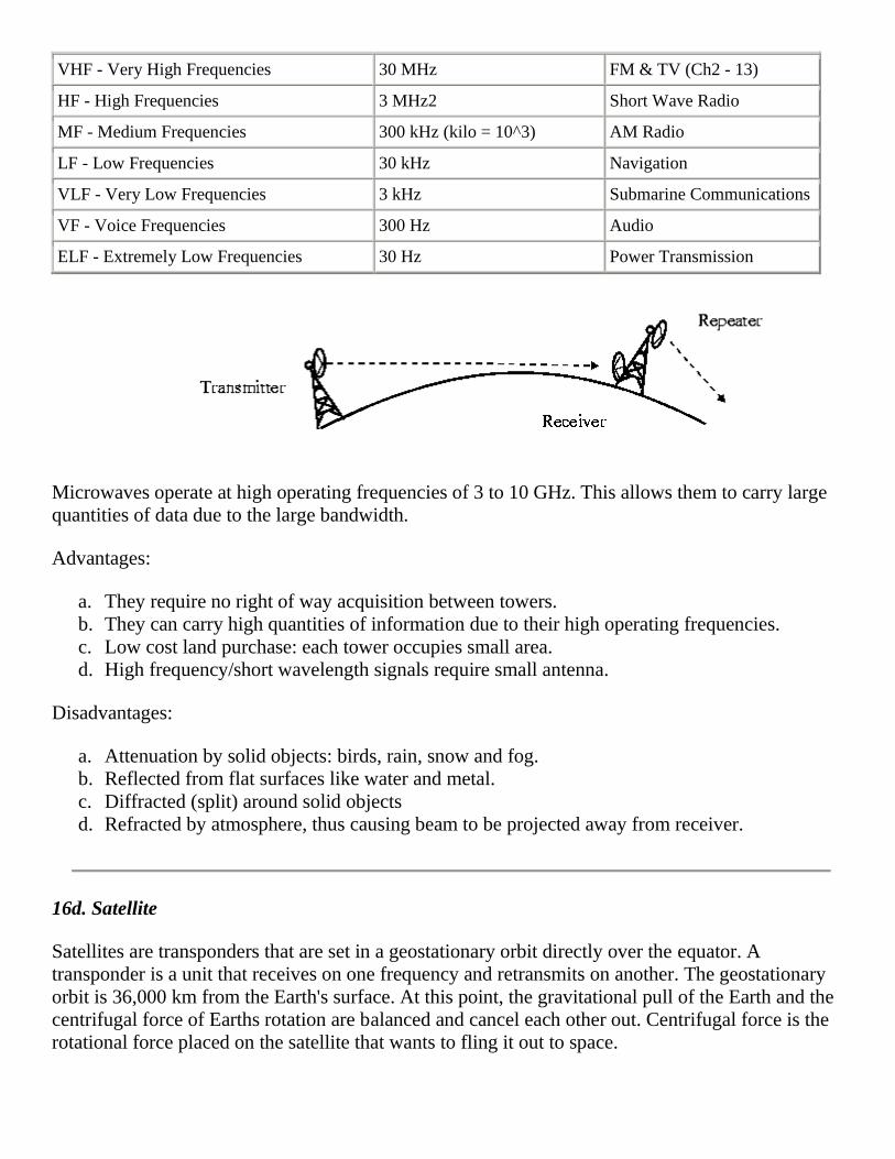
16c. Microwave
Microwave transmission is line of sight transmission. The Transmit station must be in visible contact
with the receive station. This sets a limit on the distance between stations depending on the local
geography. Typically the line of sight due to the Earth's curvature is only 50 km to the horizon!
Repeater stations must be placed so the data signal can hop, skip and jump across the country.
(see image below)
Radio frequencies
The frequency spectrum operates from 0 Hz (DC) to Gamma Rays (1019 Hz).
Name Frequency (Hertz) Examples
Gamma Rays 10^19 +
X-Rays 10^17
Ultra-Violet Light 7.5 x 10^15
Visible Light 4.3 x 10^14
Infrared Light 3 x 10^11
EHF - Extremely High Frequencies 30 GHz (Giga = 10^9) Radar
SHF - Super High Frequencies 3 GHz Satellite & Microwaves
UHF - Ultra High Frequencies 300 MHz (Mega = 10^6) UHF TV (Ch. 14-83)
VHF - Very High Frequencies 30 MHz FM & TV (Ch2 - 13)
HF - High Frequencies 3 MHz2 Short Wave Radio
MF - Medium Frequencies 300 kHz (kilo = 10^3) AM Radio
LF - Low Frequencies 30 kHz Navigation
VLF - Very Low Frequencies 3 kHz Submarine Communications
VF - Voice Frequencies 300 Hz Audio
ELF - Extremely Low Frequencies 30 Hz Power Transmission
Microwaves operate at high operating frequencies of 3 to 10 GHz. This allows them to carry large
quantities of data due to the large bandwidth.
Advantages:
a. They require no right of way acquisition between towers.
b. They can carry high quantities of information due to their high operating frequencies.
c. Low cost land purchase: each tower occupies small area.
d. High frequency/short wavelength signals require small antenna.
Disadvantages:
a. Attenuation by solid objects: birds, rain, snow and fog.
b. Reflected from flat surfaces like water and metal.
c. Diffracted (split) around solid objects
d. Refracted by atmosphere, thus causing beam to be projected away from receiver.
16d. Satellite
Satellites are transponders that are set in a geostationary orbit directly over the equator. A
transponder is a unit that receives on one frequency and retransmits on another. The geostationary
orbit is 36,000 km from the Earth's surface. At this point, the gravitational pull of the Earth and the
centrifugal force of Earths rotation are balanced and cancel each other out. Centrifugal force is the
rotational force placed on the satellite that wants to fling it out to space.
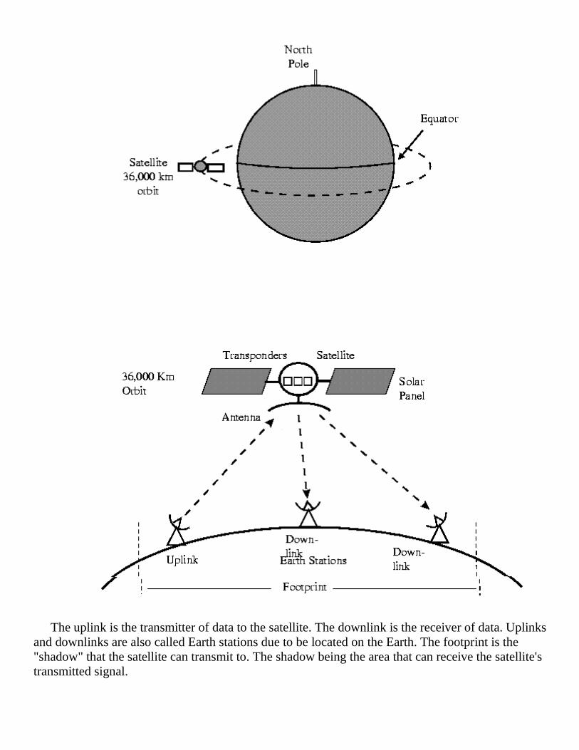
The uplink is the transmitter of data to the satellite. The downlink is the receiver of data. Uplinks
and downlinks are also called Earth stations due to be located on the Earth. The footprint is the
"shadow" that the satellite can transmit to. The shadow being the area that can receive the satellite's
transmitted signal.

16e. Iridium Telecom System
The Iridium telecom system is a new satellite sytem that will be the largest private aerospace project. It is a mobile telecom system to compete with cellular phones. It relies on satellites in Lower Earth Orbit (LEO). The satellites will orbit at an altitude of 900 - 10,000 km and are a polar non-stationary orbit. They are planning on using 66 satellites. The user's handset will require less power and will be cheaper than cellular phones. There will be 100% coverage of the Earth.
They were planning to launch starting 1996-1998 and having 1.5 million subscribers by end of the
decade. Unfortunately at the time of this writing, the Iridium project looked very financially
unstable.
17. RS-232D Serial Interface Standard
The RS-232D Serial Interface Standard added the mechanical characteristics to the
RS-232C Standard. The RS-232D standard defines:
The Mechanical Characteristics of the Interface
The Electrical Characteristics of the Interface The Function of Each Signal Subsets of the Signals for Certain Applications
The European version of RS-232D is defined in:
V.24 - Mechanical Standard V.28 - Electrical Standard
17a. Mechanical Characteristics of the RS-232D
Mechanical Characteristics of the RS-232D Interface defines:
i. The connector is a DB25 connector. DB9 is not universally accepted. ii. The connector gender is Male at the DTE and Female at the DCE. iii. The assignments of signals to pins iv. The maximum cable length is 50 ft. v. The maximum cable capacitance = 2500 pF. Typical cable has 50 pF/foot
capacitance.
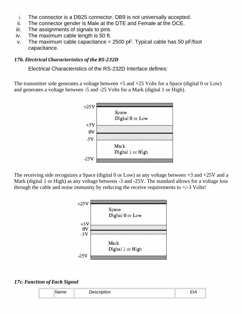
17b. Electrical Characteristics of the RS-232D
Electrical Characteristics of the RS-232D Interface defines:
The transmitter side generates a voltage between +5 and +25 Volts for a Space (digital 0 or Low)
and generates a voltage between -5 and -25 Volts for a Mark (digital 1 or High).
The receiving side recognizes a Space (digital 0 or Low) as any voltage between +3 and +25V and a
Mark (digital 1 or High) as any voltage between -3 and -25V. The standard allows for a voltage loss
through the cable and noise immunity by reducing the receive requirements to +/-3 Volts!
17c. Function of Each Signal
PName Description EIA
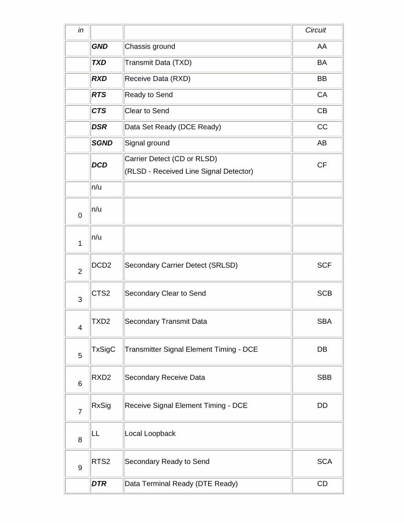
in Circuit
1 GND Chassis ground AA
2 TXD Transmit Data (TXD) BA
3 RXD Receive Data (RXD) BB
4 RTS Ready to Send CA
5 CTS Clear to Send CB
6 DSR Data Set Ready (DCE Ready) CC
7 SGND Signal ground AB
8 DCD Carrier Detect (CD or RLSD)
(RLSD - Received Line Signal Detector) CF
9 n/u
1
0 n/u
1
1 n/u
1
2 DCD2 Secondary Carrier Detect (SRLSD) SCF
1
3 CTS2 Secondary Clear to Send SCB
1
4 TXD2 Secondary Transmit Data SBA
1
5 TxSigC Transmitter Signal Element Timing - DCE DB
1
6 RXD2 Secondary Receive Data SBB
1
7 RxSig Receive Signal Element Timing - DCE DD
1
8 LL Local Loopback
1
9 RTS2 Secondary Ready to Send SCA
2DTR Data Terminal Ready (DTE Ready) CD

0
2
1 SQ/RL Signal Quality/Remote Loopback CG
2
2 RI Ring Indicator CE
2
3 DSRS Data Signal Rate Selector CH/CI
2
4 TxSigT Transmitter Signal Element Timing - DTE DA
5
5 TM Test Mode
The signals in Bold/Italic are required for a basic asynchronous modem connection.
17d. Subsets of Signals for Certain Applications
Data Signals
2 TXD Transmit Data Data generated by DTE BA
3 RXD Receive Data Data generated by DCE BB
Control Signals
4
4 RTS Ready to Send DTE wishes to transmit
5
5 CTS Clear to Send DCE ready to receive
6
6 DSR Data Set Ready (DCE Ready) DCE powered on & ready to go
2
20 DTR Data Terminal Ready (DTE ready) DTE powereded on & ready to go
2
22 RI Ring Indicator Phones ringing
Test Modes
1LL Local Loopback Initiate Local Loopback Self-Test
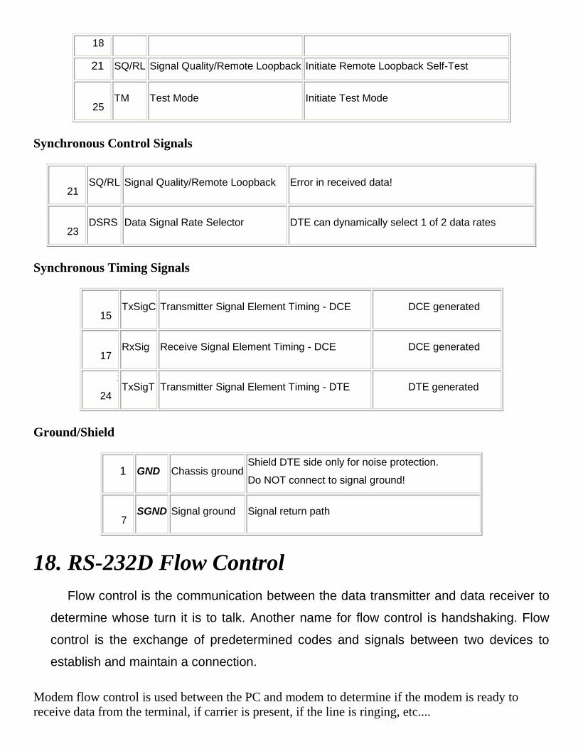
18
21 SQ/RL Signal Quality/Remote Loopback Initiate Remote Loopback Self-Test
2
25 TM Test Mode Initiate Test Mode
Synchronous Control Signals
2
21 SQ/RL Signal Quality/Remote Loopback Error in received data!
2
23 DSRS Data Signal Rate Selector DTE can dynamically select 1 of 2 data rates
Synchronous Timing Signals
1
15 TxSigC Transmitter Signal Element Timing - DCE DCE generated
1
17 RxSig Receive Signal Element Timing - DCE DCE generated
2
24 TxSigT Transmitter Signal Element Timing - DTE DTE generated
Ground/Shield
1 GND Chassis ground Shield DTE side only for noise protection.
Do NOT connect to signal ground!
7
7 SGND Signal ground Signal return path
18. RS-232D Flow Control
Flow control is the communication between the data transmitter and data receiver to
determine whose turn it is to talk. Another name for flow control is handshaking. Flow
control is the exchange of predetermined codes and signals between two devices to
establish and maintain a connection.
Modem flow control is used between the PC and modem to determine if the modem is ready to
receive data from the terminal, if carrier is present, if the line is ringing, etc....
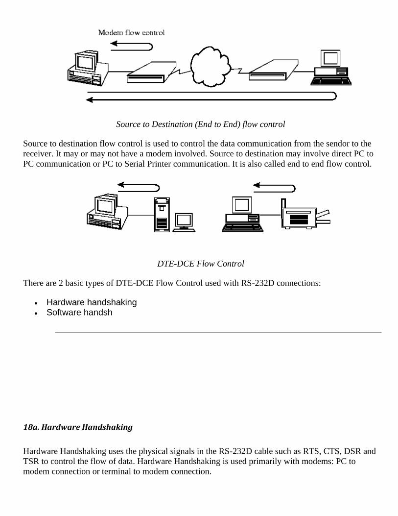
Source to Destination (End to End) flow control
Source to destination flow control is used to control the data communication from the sendor to the
receiver. It may or may not have a modem involved. Source to destination may involve direct PC to
PC communication or PC to Serial Printer communication. It is also called end to end flow control.
DTE-DCE Flow Control
There are 2 basic types of DTE-DCE Flow Control used with RS-232D connections:
Hardware handshaking Software handsh
18a. Hardware Handshaking
Hardware Handshaking uses the physical signals in the RS-232D cable such as RTS, CTS, DSR and
TSR to control the flow of data. Hardware Handshaking is used primarily with modems: PC to
modem connection or terminal to modem connection.
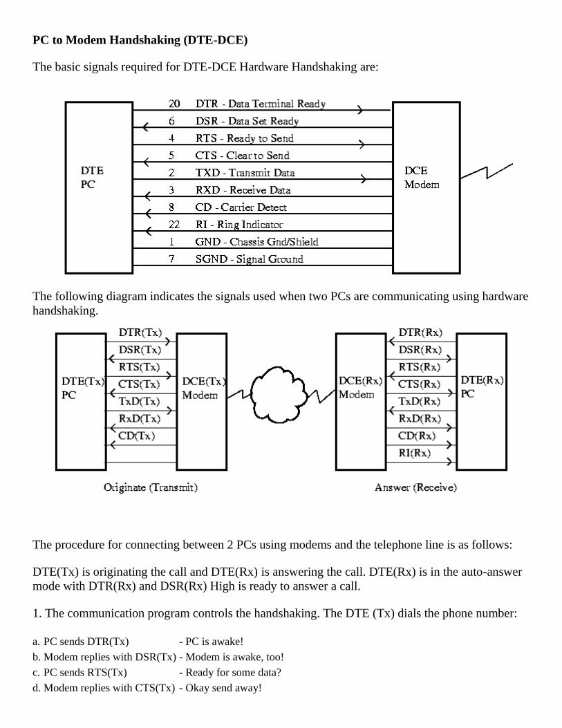
PC to Modem Handshaking (DTE-DCE)
The basic signals required for DTE-DCE Hardware Handshaking are:
The following diagram indicates the signals used when two PCs are communicating using hardware
handshaking.
The procedure for connecting between 2 PCs using modems and the telephone line is as follows:
DTE(Tx) is originating the call and DTE(Rx) is answering the call. DTE(Rx) is in the auto-answer
mode with DTR(Rx) and DSR(Rx) High is ready to answer a call.
1. The communication program controls the handshaking. The DTE (Tx) dials the phone number:
a. PC sends DTR(Tx) - PC is awake!
b. Modem replies with DSR(Tx) - Modem is awake, too!
c. PC sends RTS(Tx) - Ready for some data?
d. Modem replies with CTS(Tx) - Okay send away!
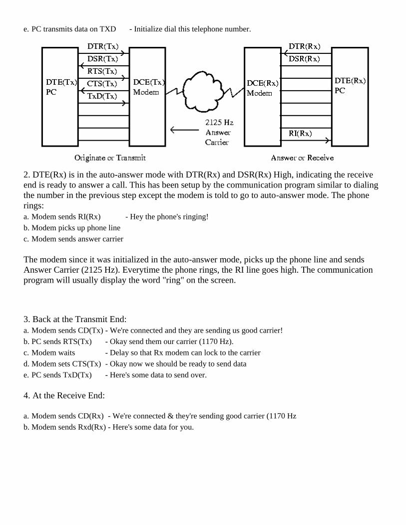
e. PC transmits data on TXD - Initialize dial this telephone number.
2. DTE(Rx) is in the auto-answer mode with DTR(Rx) and DSR(Rx) High, indicating the receive
end is ready to answer a call. This has been setup by the communication program similar to dialing
the number in the previous step except the modem is told to go to auto-answer mode. The phone
rings:
a. Modem sends RI(Rx) - Hey the phone's ringing!
b. Modem picks up phone line
c. Modem sends answer carrier
The modem since it was initialized in the auto-answer mode, picks up the phone line and sends
Answer Carrier (2125 Hz). Everytime the phone rings, the RI line goes high. The communication
program will usually display the word "ring" on the screen.
3. Back at the Transmit End:
a. Modem sends CD(Tx) - We're connected and they are sending us good carrier!
b. PC sends RTS(Tx) - Okay send them our carrier (1170 Hz).
c. Modem waits - Delay so that Rx modem can lock to the carrier
d. Modem sets CTS(Tx) - Okay now we should be ready to send data
e. PC sends TxD(Tx) - Here's some data to send over.
4. At the Receive End:
a. Modem sends CD(Rx) - We're connected & they're sending good carrier (1170 Hz
b. Modem sends Rxd(Rx) - Here's some data for you.

The communication program then interprets the data and decides if a reply is required or if more
data is coming. The communication programs handle the transfer of the data and the direction.
5. Both Originate or Answer can end the communication:
a. DTE(Tx) drops RTS(Tx) or DTR(Tx) - I'm done, hang-up the phone.
b. DCE(Tx) modem drops DSR(Tx) and the Carrier (1170 Hz) - I've disconnected.
c. DCE(Rx) modem drops CD(Rx) - No carrier, they're hanging up
d. DTE(Rx) drops RTS(Rx) - Hang up on them
e. DCE(Rx) modem drops DSR(Rx) and the Carrier (2125 Hz) - I've disconnected.
18b. Hardware Null Modems
Null modems are a way of connecting 2 DTEs together without using a modem - we are
nulling out the modems. This gives way to the term Null Modem. When 2 DTEs are

connected together, the TXD Pin2 of one DTE is crossed to Pin 3 RXD of the other DTE.
We also have to fool the DTEs into believing that they are connected to DCE devices. This
is done by crossing the control lines as follows:
Notice that RI (Ring Indicator) and CD (Carrier Detect) are not used when connecting directly from
DTE to DTE. They are a function of a telephone system and by nulling out the modems, we've
eliminated the telephone system. This can cause problems when transferring files directly because
most communication programs detect loss of carrier (CD) as a disconnect command. The
communication program will abort the data transfer if CD is not present. This can usually be over-
ridden by de-selecting "Transfer Aborted if CD Lost" (or something similar) in one of the
communication software configuration menus.
18c. Software Handshaking (Xon/Xoff)
Software Handshaking does not use the RS-232D control signals, it uses the
software commands Xon/Xoff to control the data flow. Do not use software handshaking
with a modem, because you will lose several important function of the modem such as:
RI, and CD.
Xon Transmit On - ASCII Character DC1
Xoff Transmit Off - ASCII Character DC2
Software handshaking is a simple flow control method that is used mainly with DTE to DTE and
DTE to Serial Printer connections. The receiving device controls the flow of data by issuing Xon
(okay to transmit data) commands and Xoff (stop - let me catch up) commands. A good example is
the DTE to Serial Printer connection.
For example, a dot-matrix printer cannot physically print faster than a transfer rate of
300 bps. Printers are usually equipped with a memory buffer to store the data before it is
printed. The printer buffer allows large chunks of data to be downloaded to the printer from
the DTE, thereby freeing up the DTE to do other tasks rather than wait for a page to be
printed.
When the data is first being downloaded to the printer, the printer issues a Xon command to the
DTE. As the print buffer becomes full (90%), the printer issues an Xoff command to stop
transmitting data until the printer catches up. When the print buffer becomes almost empty (20%)
than the printer issues a Xon command. This goes on until the complete document is printed.
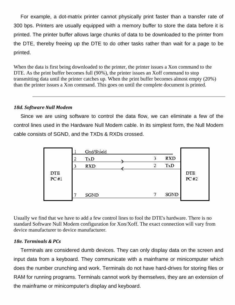
18d. Software Null Modem
Since we are using software to control the data flow, we can eliminate a few of the
control lines used in the Hardware Null Modem cable. In its simplest form, the Null Modem
cable consists of SGND, and the TXDs & RXDs crossed.
Usually we find that we have to add a few control lines to fool the DTE's hardware. There is no
standard Software Null Modem configuration for Xon/Xoff. The exact connection will vary from
device manufacturer to device manufacturer.
18e. Terminals & PCs
Terminals are considered dumb devices. They can only display data on the screen and
input data from a keyboard. They communicate with a mainframe or minicomputer which
does the number crunching and work. Terminals do not have hard-drives for storing files or
RAM for running programs. Terminals cannot work by themselves, they are an extension of
the mainframe or minicomputer's display and keyboard.
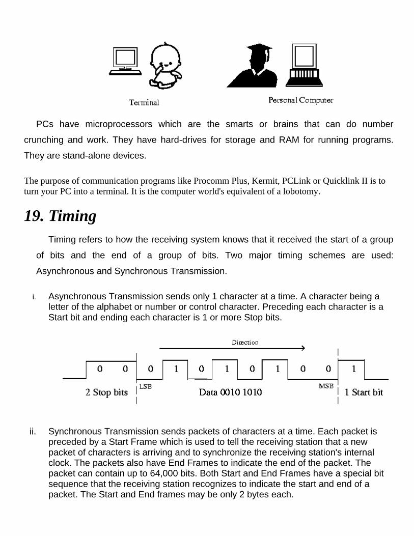
PCs have microprocessors which are the smarts or brains that can do number
crunching and work. They have hard-drives for storage and RAM for running programs.
They are stand-alone devices.
The purpose of communication programs like Procomm Plus, Kermit, PCLink or Quicklink II is to
turn your PC into a terminal. It is the computer world's equivalent of a lobotomy.
19. Timing
Timing refers to how the receiving system knows that it received the start of a group
of bits and the end of a group of bits. Two major timing schemes are used:
Asynchronous and Synchronous Transmission.
i. Asynchronous Transmission sends only 1 character at a time. A character being a letter of the alphabet or number or control character. Preceding each character is a Start bit and ending each character is 1 or more Stop bits.
ii. Synchronous Transmission sends packets of characters at a time. Each packet is preceded by a Start Frame which is used to tell the receiving station that a new packet of characters is arriving and to synchronize the receiving station's internal clock. The packets also have End Frames to indicate the end of the packet. The packet can contain up to 64,000 bits. Both Start and End Frames have a special bit sequence that the receiving station recognizes to indicate the start and end of a packet. The Start and End frames may be only 2 bytes each.
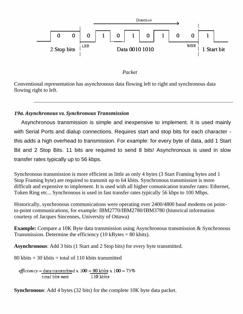
Packet
Conventional representation has asynchronous data flowing left to right and synchronous data
flowing right to left.
19a. Asynchronous vs. Synchronous Transmission
Asynchronous transmission is simple and inexpensive to implement. It is used mainly
with Serial Ports and dialup connections. Requires start and stop bits for each character -
this adds a high overhead to transmission. For example: for every byte of data, add 1 Start
Bit and 2 Stop Bits. 11 bits are required to send 8 bits! Asynchronous is used in slow
transfer rates typically up to 56 kbps.
Synchronous transmission is more efficient as little as only 4 bytes (3 Start Framing bytes and 1
Stop Framing byte) are required to transmit up to 64 kbits. Synchronous transmission is more
difficult and expensive to implement. It is used with all higher comunication transfer rates: Ethernet,
Token Ring etc... Synchronous is used in fast transfer rates typically 56 kbps to 100 Mbps.
Historically, synchronous communications were operating over 2400/4800 baud modems on point-
to-point communications, for example: IBM2770/IBM2780/IBM3780 (historical information
courtesy of Jacques Sincennes, University of Ottawa)
Example: Compare a 10K Byte data transmission using Asynchronous transmission & Synchronous
Transmission. Determine the efficiency (10 kBytes = 80 kbits).
Asynchronous: Add 3 bits (1 Start and 2 Stop bits) for every byte transmitted.
80 kbits + 30 kbits = total of 110 kbits transmitted
Synchronous: Add 4 bytes (32 bits) for the complete 10K byte data packet.

80 kbits + 32 bits = total of 80.032 kbits transmitted
efficiency = data transmitted x 100 = 80 kbits x 100 = 99.9%
Transmission Advantages Disadvantages
Asynchronous Simple & Inexpensive High Overhead
Synchronous Efficient Complex and Expensive
20. Asynchronous Communications
Asynchronous communications or transmission sends individual characters one at a
time framed by a start bit and 1 or 2 stop bits.
20a. Start/Stop bits
The purpose of the Start bit is to notify the receiving station of a new character arriving.
Typically data is shown moving left to right. This is how it would appear on a Storage
Oscilloscope or Network Analyser. The MSB ( Most Significant Bit) is sent first and the LSB
(Least Significant Bit) is sent last.
The purpose of the Stop bits is to indicate the end of data. There could be 1 or 2 stop bits with 1
being the typical number of stop bits used today. In Asynchronous transmission, the characters are
sent individually with a quiet period in between (quiet meaning 0 bit level). Asynchronous
communications requires the transmitting station and the receiving station to have individual internal
free-running clocks operating at the same frequency. Free-running means that the clocks are not
locked together.
Both clocks operating at same frequency:
The receive station starts checking for data after the Start bit is received (Start bit is a wake up call!).

The receive station samples the transmitted data in the middle of each data bit. The samples are
evenly spaced and match the transmitted data because both transmit and receive clocks are operating
at the same frequency.
Receive clock frequency higher than transmitted frequency:
If the receive station's clock is higher in frequency, the samples will be spaced closer together
(higher frequency - shorter period). In the above example, we transmitted the following data: 0100
1010 but we received the data: 0100 0101. The samples are out of synchronization with the
transmitting data. We would have an error in receiving data.
Clocks are controlled by crystals (abbreviated: Xtal). Crystals are metal cans that hold a piezo-
electric element that resonates at a certain frequency when a voltage is applied to it. If you drop a
crystal or a printed circuit board (PCB) that has a crystal on it, the crystal can fracture inside the
metal can. Either it will stop working or change its frequency, both result in a malfunctioning
circuit! Crystals are also temperature sensitive and change frequency with temperature!
Receive clock frequency lower than transmitted frequency:
If the receiving station's clock is lower in frequency than the transmitted frequency, then the samples
become farther apart (lower frequency - wider period). Again the samples become out of sync with
the transmitted data!
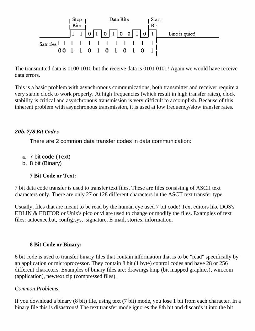
The transmitted data is 0100 1010 but the receive data is 0101 0101! Again we would have receive
data errors.
This is a basic problem with asynchronous communications, both transmitter and receiver require a
very stable clock to work properly. At high frequencies (which result in high transfer rates), clock
stability is critical and asynchronous transmission is very difficult to accomplish. Because of this
inherent problem with asynchronous transmission, it is used at low frequency/slow transfer rates.
20b. 7/8 Bit Codes
There are 2 common data transfer codes in data communication:
a. 7 bit code (Text) b. 8 bit (Binary)
7 Bit Code or Text:
7 bit data code transfer is used to transfer text files. These are files consisting of ASCII text
characters only. There are only 27 or 128 different characters in the ASCII text transfer type.
Usually, files that are meant to be read by the human eye used 7 bit code! Text editors like DOS's
EDLIN & EDITOR or Unix's pico or vi are used to change or modify the files. Examples of text
files: autoexec.bat, config.sys, .signature, E-mail, stories, information.
8 Bit Code or Binary:
8 bit code is used to transfer binary files that contain information that is to be "read" specifically by
an application or microprocessor. They contain 8 bit (1 byte) control codes and have 28 or 256
different characters. Examples of binary files are: drawings.bmp (bit mapped graphics), win.com
(application), newtext.zip (compressed files).
Common Problems:
If you download a binary (8 bit) file, using text (7 bit) mode, you lose 1 bit from each character. In a
binary file this is disastrous! The text transfer mode ignores the 8th bit and discards it into the bit
bucket. In the following example the number 202 is transmitted but the number 74 is received. You
end up with a corrupted file!
Decimal Binary
Transmitted 202 1100 1010 - 8 bit data
Received 74 100 1010 - 7 bit data (MSB is ignored)
If you download a text file (7 bit) using binary (8 bit) mode, an extra bit is inserted into the data. The
bit is set to 0 and placed as the MSB or 8th bit.
Decimal Binary
Transmitted 74 100 1010 - 7 bit data
Received 74 0100 1010 - 8 bit data
The received file works beautifully! If there is a choice or you are not sure what the number of data
bits are, always pick Binary or 8 bit transfer mode! Originally, when transfer rates were very slow
(300 to 1200 bps), sending 7 or 8 bits would make a big difference in transfer times.
20c. Parity Bits
In asynchronous communications, a simple error checking method is used: Parity
Checking. There are 3 types of Parity Bits: Even, Odd and None. None means that there
is no Parity Checking and the Parity Checking is disabled!
Even Parity Generation
Even Parity counts the number of 1s in the data to see if the total is an even number. If the number
of 1s is an even number then the Parity bit is set to 0. If the number of 1s is an odd number, then the
Parity bit is set to 1 to make the total number of 1s an even number. The Even Parity Bit is used to
make the total number of 1s equal to an even number.
Data Even Parity Bit
0100 1010 1 3 x 1s in Data: 3 is an odd number, Parity Bit = 1
0111 1110 0 6x 1s in Data: 6 is an even number, Parity Bit = 0
1010 1010 ? What should the parity bit be?
Even Parity Checking
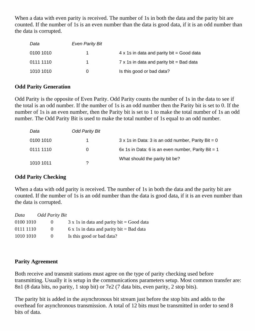
When a data with even parity is received. The number of 1s in both the data and the parity bit are
counted. If the number of 1s is an even number than the data is good data, if it is an odd number than
the data is corrupted.
Data Even Parity Bit
0100 1010 1 4 x 1s in data and parity bit = Good data
0111 1110 1 7 x 1s in data and parity bit = Bad data
1010 1010 0 Is this good or bad data?
Odd Parity Generation
Odd Parity is the opposite of Even Parity. Odd Parity counts the number of 1s in the data to see if
the total is an odd number. If the number of 1s is an odd number then the Parity bit is set to 0. If the
number of 1s is an even number, then the Parity bit is set to 1 to make the total number of 1s an odd
number. The Odd Parity Bit is used to make the total number of 1s equal to an odd number.
Data Odd Parity Bit
0100 1010 1 3 x 1s in Data: 3 is an odd number, Parity Bit = 0
0111 1110 0 6x 1s in Data: 6 is an even number, Parity Bit = 1
1010 1011 ? What should the parity bit be?
Odd Parity Checking
When a data with odd parity is received. The number of 1s in both the data and the parity bit are
counted. If the number of 1s is an odd number than the data is good data, if it is an even number than
the data is corrupted.
Data Odd Parity Bit
0100 1010 0 3 x 1s in data and parity bit = Good data
0111 1110 0 6 x 1s in data and parity bit = Bad data
1010 1010 0 Is this good or bad data?
Parity Agreement
Both receive and transmit stations must agree on the type of parity checking used before
transmitting. Usually it is setup in the communications parameters setup. Most common transfer are:
8n1 (8 data bits, no parity, 1 stop bit) or 7e2 (7 data bits, even parity, 2 stop bits).
The parity bit is added in the asynchronous bit stream just before the stop bits and adds to the
overhead for asynchronous transmission. A total of 12 bits must be transmitted in order to send 8
bits of data.
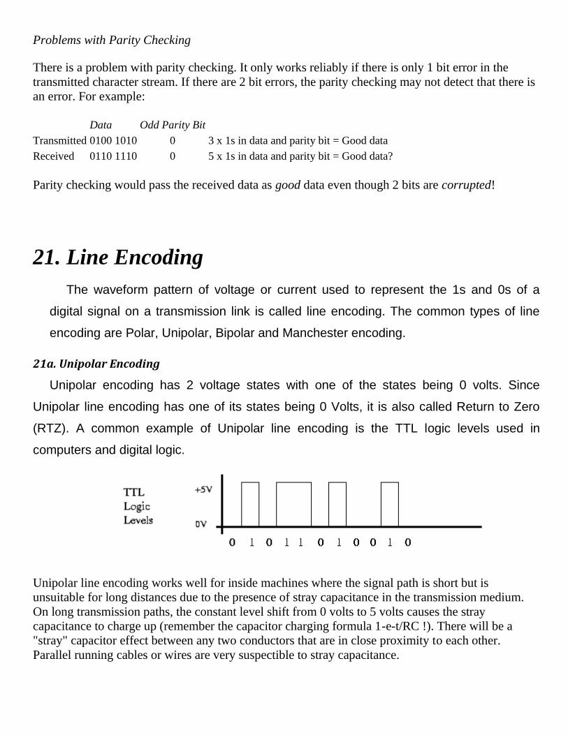
Problems with Parity Checking
There is a problem with parity checking. It only works reliably if there is only 1 bit error in the
transmitted character stream. If there are 2 bit errors, the parity checking may not detect that there is
an error. For example:
Data Odd Parity Bit
Transmitted 0100 1010 0 3 x 1s in data and parity bit = Good data
Received 0110 1110 0 5 x 1s in data and parity bit = Good data?
Parity checking would pass the received data as good data even though 2 bits are corrupted!
21. Line Encoding
The waveform pattern of voltage or current used to represent the 1s and 0s of a
digital signal on a transmission link is called line encoding. The common types of line
encoding are Polar, Unipolar, Bipolar and Manchester encoding.
21a. Unipolar Encoding
Unipolar encoding has 2 voltage states with one of the states being 0 volts. Since
Unipolar line encoding has one of its states being 0 Volts, it is also called Return to Zero
(RTZ). A common example of Unipolar line encoding is the TTL logic levels used in
computers and digital logic.
Unipolar line encoding works well for inside machines where the signal path is short but is
unsuitable for long distances due to the presence of stray capacitance in the transmission medium.
On long transmission paths, the constant level shift from 0 volts to 5 volts causes the stray
capacitance to charge up (remember the capacitor charging formula 1-e-t/RC !). There will be a
"stray" capacitor effect between any two conductors that are in close proximity to each other.
Parallel running cables or wires are very suspectible to stray capacitance.
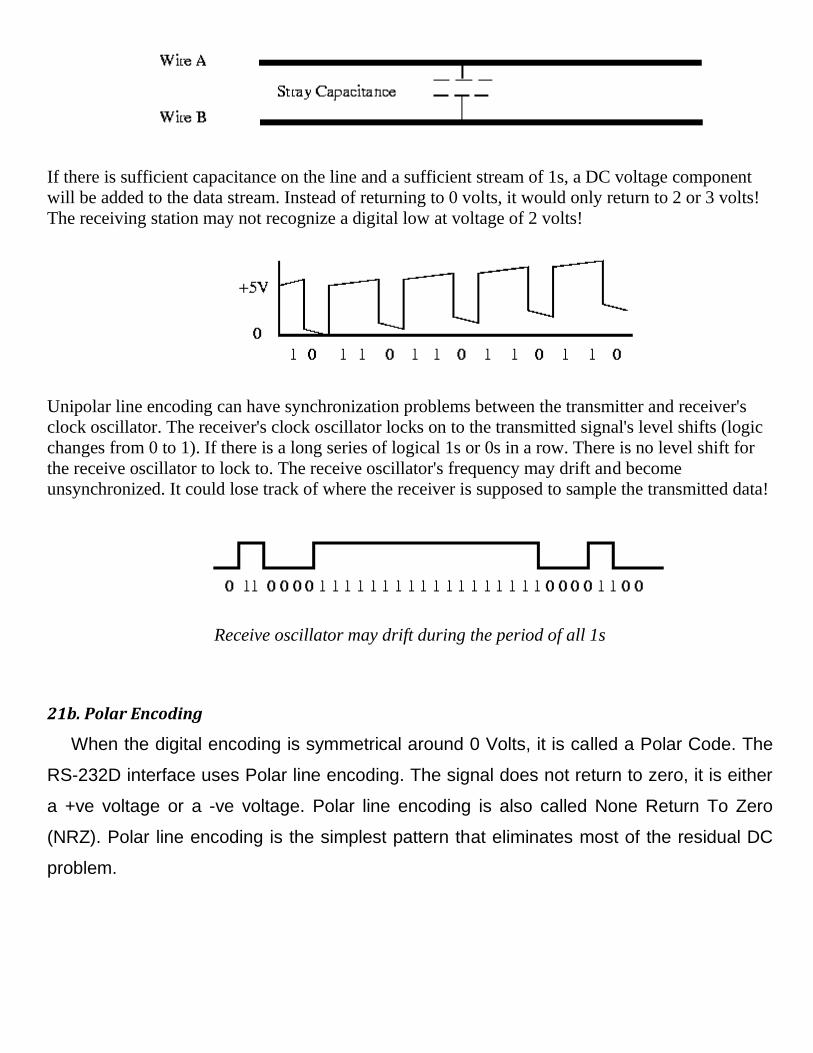
If there is sufficient capacitance on the line and a sufficient stream of 1s, a DC voltage component
will be added to the data stream. Instead of returning to 0 volts, it would only return to 2 or 3 volts!
The receiving station may not recognize a digital low at voltage of 2 volts!
Unipolar line encoding can have synchronization problems between the transmitter and receiver's
clock oscillator. The receiver's clock oscillator locks on to the transmitted signal's level shifts (logic
changes from 0 to 1). If there is a long series of logical 1s or 0s in a row. There is no level shift for
the receive oscillator to lock to. The receive oscillator's frequency may drift and become
unsynchronized. It could lose track of where the receiver is supposed to sample the transmitted data!
Receive oscillator may drift during the period of all 1s
21b. Polar Encoding
When the digital encoding is symmetrical around 0 Volts, it is called a Polar Code. The
RS-232D interface uses Polar line encoding. The signal does not return to zero, it is either
a +ve voltage or a -ve voltage. Polar line encoding is also called None Return To Zero
(NRZ). Polar line encoding is the simplest pattern that eliminates most of the residual DC
problem.

There is still a small residual DC problem but Polar line encoding is a great improvement over
Unipolar line encoding. Polar encoding has an added benefit in that it reduces the power required to
transmit the signal by one-half compared with unipolar.
RS-232D TXD
Polar line encoding has the same synchronization problem as Unipolar line encoding. If there is a
long string of logical 1s or 0s, the receive oscillator may drift and become unsynchronized.
21c. Bipolar Line Encoding
Bipolar line encoding has 3 voltage levels, a low or 0 is represented by a 0 Volt level
and a 1 is represented by alternating polarity pulses. By alternating the polarity of the
pulses for 1s, the residual DC component cancels.
Bipolar Line Encoding
Synchronization of receive and transmit clocks is greatly improved except if there is a long string of
0s transmitted. Bipolar line encoding is also called Alternate Mark Inversion (AMI).
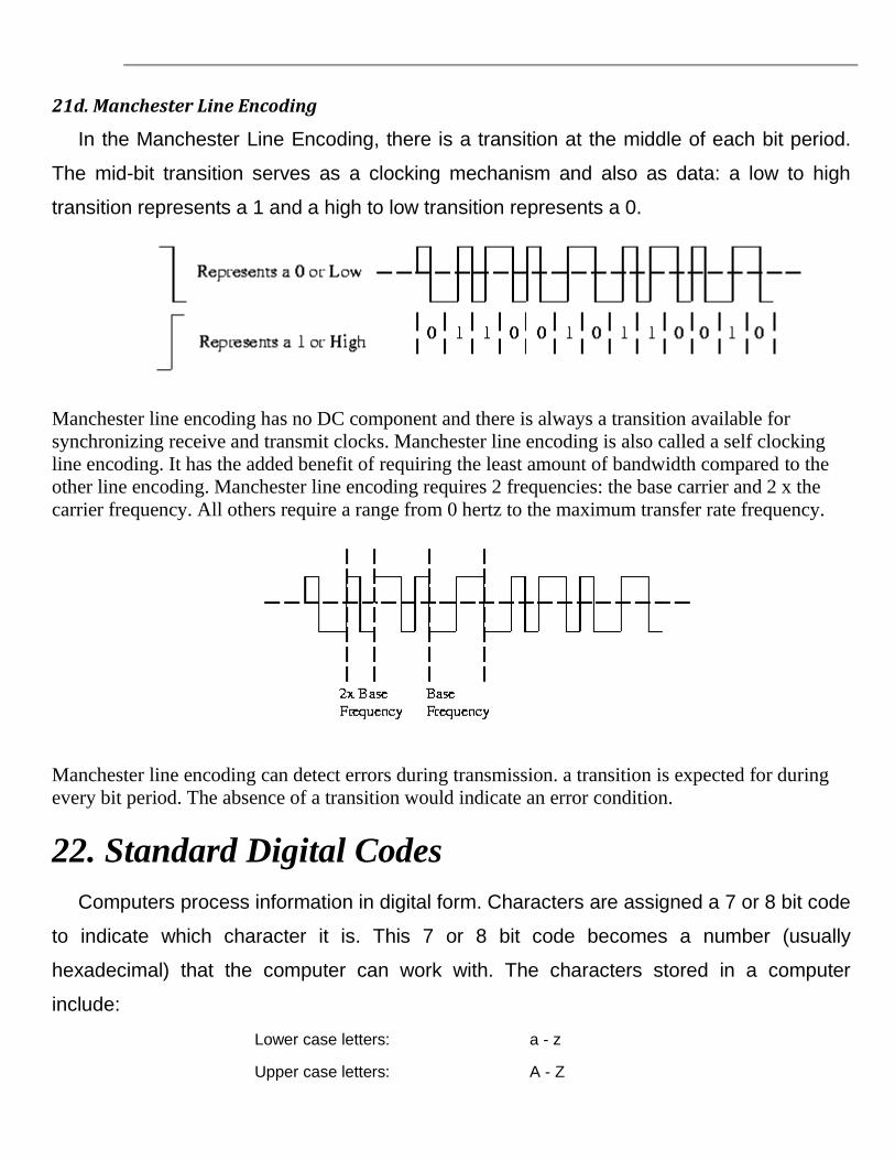
21d. Manchester Line Encoding
In the Manchester Line Encoding, there is a transition at the middle of each bit period.
The mid-bit transition serves as a clocking mechanism and also as data: a low to high
transition represents a 1 and a high to low transition represents a 0.
Manchester line encoding has no DC component and there is always a transition available for
synchronizing receive and transmit clocks. Manchester line encoding is also called a self clocking
line encoding. It has the added benefit of requiring the least amount of bandwidth compared to the
other line encoding. Manchester line encoding requires 2 frequencies: the base carrier and 2 x the
carrier frequency. All others require a range from 0 hertz to the maximum transfer rate frequency.
Manchester line encoding can detect errors during transmission. a transition is expected for during
every bit period. The absence of a transition would indicate an error condition.
22. Standard Digital Codes
Computers process information in digital form. Characters are assigned a 7 or 8 bit code
to indicate which character it is. This 7 or 8 bit code becomes a number (usually
hexadecimal) that the computer can work with. The characters stored in a computer
include:
Lower case letters: a - z
Upper case letters: A - Z
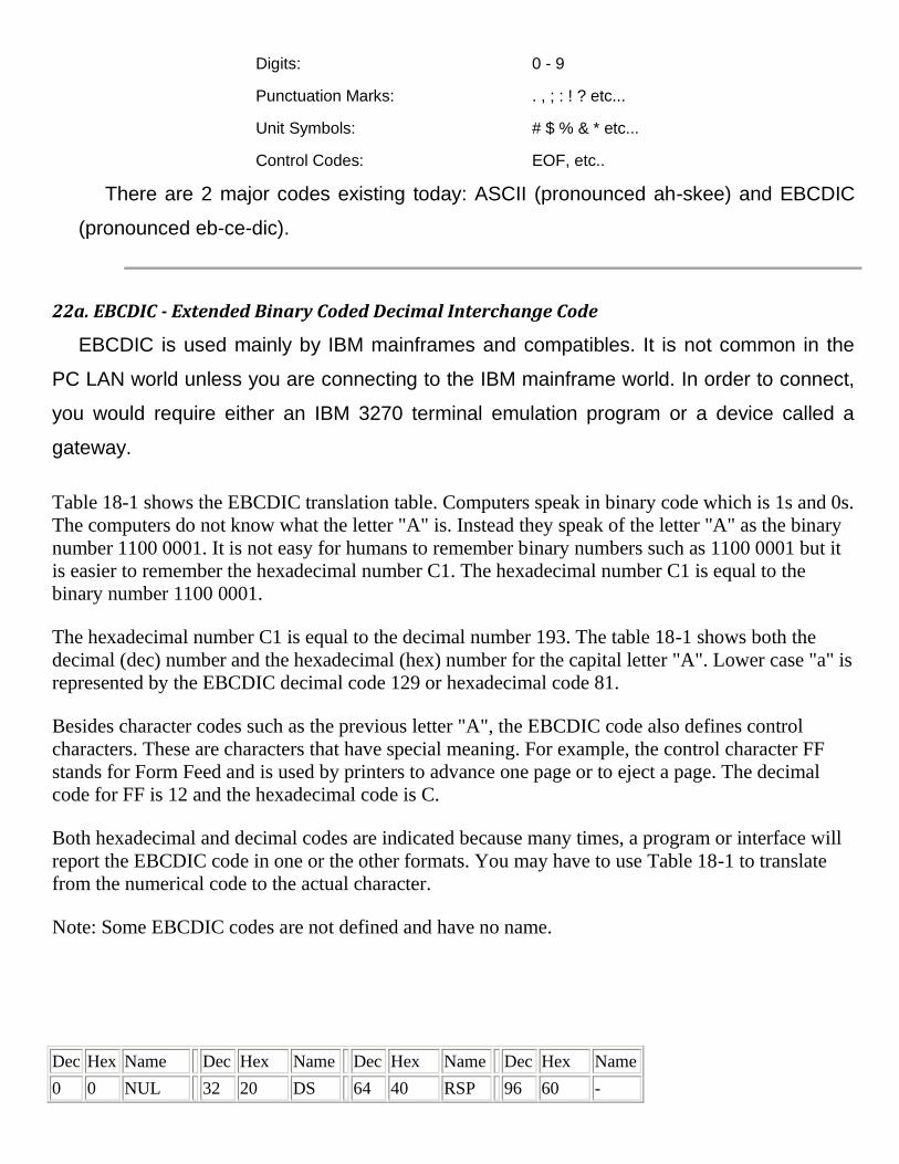
Digits: 0 - 9
Punctuation Marks: . , ; : ! ? etc...
Unit Symbols: # $ % & * etc...
Control Codes: EOF, etc..
There are 2 major codes existing today: ASCII (pronounced ah-skee) and EBCDIC
(pronounced eb-ce-dic).
22a. EBCDIC - Extended Binary Coded Decimal Interchange Code
EBCDIC is used mainly by IBM mainframes and compatibles. It is not common in the
PC LAN world unless you are connecting to the IBM mainframe world. In order to connect,
you would require either an IBM 3270 terminal emulation program or a device called a
gateway.
Table 18-1 shows the EBCDIC translation table. Computers speak in binary code which is 1s and 0s.
The computers do not know what the letter "A" is. Instead they speak of the letter "A" as the binary
number 1100 0001. It is not easy for humans to remember binary numbers such as 1100 0001 but it
is easier to remember the hexadecimal number C1. The hexadecimal number C1 is equal to the
binary number 1100 0001.
The hexadecimal number C1 is equal to the decimal number 193. The table 18-1 shows both the
decimal (dec) number and the hexadecimal (hex) number for the capital letter "A". Lower case "a" is
represented by the EBCDIC decimal code 129 or hexadecimal code 81.
Besides character codes such as the previous letter "A", the EBCDIC code also defines control
characters. These are characters that have special meaning. For example, the control character FF
stands for Form Feed and is used by printers to advance one page or to eject a page. The decimal
code for FF is 12 and the hexadecimal code is C.
Both hexadecimal and decimal codes are indicated because many times, a program or interface will
report the EBCDIC code in one or the other formats. You may have to use Table 18-1 to translate
from the numerical code to the actual character.
Note: Some EBCDIC codes are not defined and have no name.
Dec Hex Name Dec Hex Name
Dec Hex Name
Dec Hex Name
0 0 NUL 32 20 DS
64 40 RSP
96 60 -
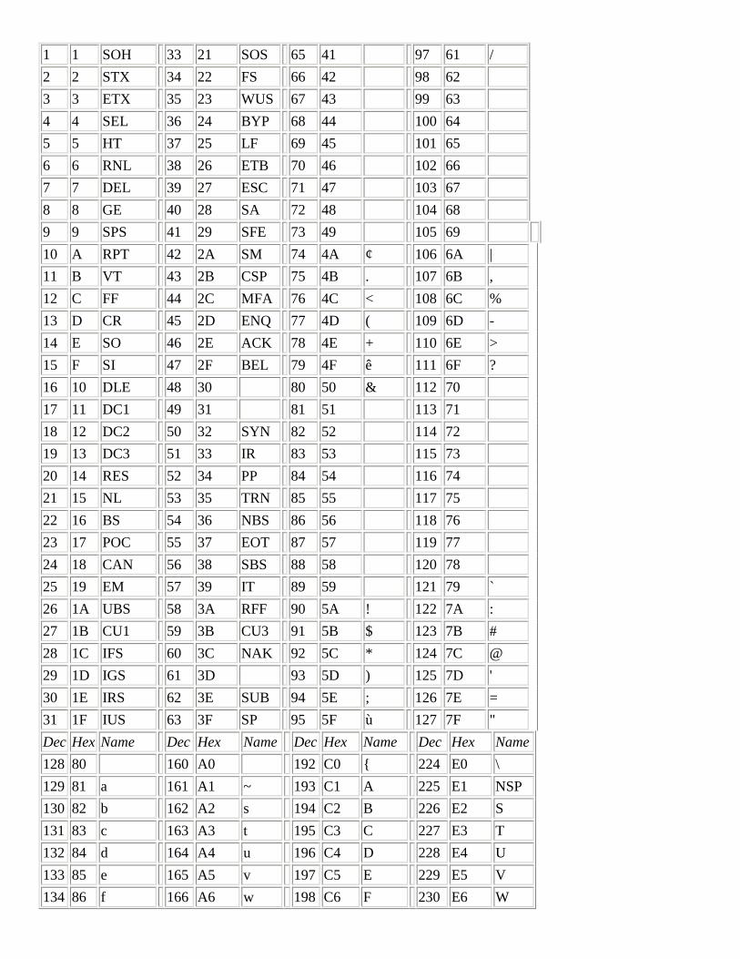
1 1 SOH 33 21 SOS
65 41
97 61 /
2 2 STX 34 22 FS
66 42
98 62
3 3 ETX
35 23 WUS
67 43
99 63
4 4 SEL
36 24 BYP
68 44
100 64
5 5 HT
37 25 LF
69 45
101 65
6 6 RNL
38 26 ETB
70 46
102 66
7 7 DEL
39 27 ESC
71 47
103 67
8 8 GE
40 28 SA
72 48
104 68
9 9 SPS
41 29 SFE
73 49
105 69
10 A RPT
42 2A SM
74 4A ¢
106 6A |
11 B VT 43 2B CSP
75 4B .
107 6B ,
12 C FF 44 2C MFA
76 4C <
108 6C %
13 D CR 45 2D ENQ
77 4D (
109 6D -
14 E SO 46 2E ACK
78 4E +
110 6E >
15 F SI 47 2F BEL
79 4F ê
111 6F ?
16 10 DLE 48 30
80 50 &
112 70
17 11 DC1 49 31
81 51
113 71
18 12 DC2 50 32 SYN
82 52
114 72
19 13 DC3 51 33 IR
83 53
115 73
20 14 RES 52 34 PP
84 54
116 74
21 15 NL 53 35 TRN
85 55
117 75
22 16 BS 54 36 NBS
86 56
118 76
23 17 POC 55 37 EOT
87 57
119 77
24 18 CAN 56 38 SBS
88 58
120 78
25 19 EM 57 39 IT
89 59
121 79 `
26 1A UBS 58 3A RFF
90 5A !
122 7A :
27 1B CU1 59 3B CU3
91 5B $
123 7B #
28 1C IFS 60 3C NAK
92 5C *
124 7C @
29 1D IGS 61 3D
93 5D )
125 7D '
30 1E IRS 62 3E SUB
94 5E ;
126 7E =
31 1F IUS 63 3F SP
95 5F ù
127 7F "
Dec Hex Name Dec Hex Name
Dec Hex Name
Dec Hex Name
128 80
160 A0
192 C0 { 224 E0 \
129 81 a 161 A1 ~
193 C1 A
225 E1 NSP
130 82 b 162 A2 s
194 C2 B
226 E2 S
131 83 c 163 A3 t
195 C3 C
227 E3 T
132 84 d 164 A4 u
196 C4 D
228 E4 U
133 85 e 165 A5 v
197 C5 E
229 E5 V
134 86 f 166 A6 w
198 C6 F
230 E6 W
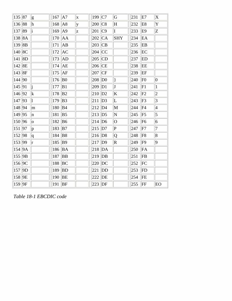
135 87 g 167 A7 x
199 C7 G
231 E7 X
136 88 h 168 A8 y
200 C8 H
232 E8 Y
137 89 i 169 A9 z
201 C9 I
233 E9 Z
138 8A
170 AA
202 CA SHY 234 EA
139 8B
171 AB
203 CB
235 EB
140 8C
172 AC
204 CC
236 EC
141 8D
173 AD
205 CD
237 ED
142 8E
174 AE
206 CE
238 EE
143 8F
175 AF
207 CF
239 EF
144 90
176 B0
208 D0 }
240 F0 0
145 91 j 177 B1
209 D1 J
241 F1 1
146 92 k 178 B2
210 D2 K
242 F2 2
147 93 l 179 B3
211 D3 L
243 F3 3
148 94 m 180 B4
212 D4 M
244 F4 4
149 95 n 181 B5
213 D5 N
245 F5 5
150 96 o 182 B6
214 D6 O
246 F6 6
151 97 p 183 B7
215 D7 P
247 F7 7
152 98 q 184 B8
216 D8 Q
248 F8 8
153 99 r 185 B9
217 D9 R
249 F9 9
154 9A
186 BA
218 DA
250 FA
155 9B
187 BB
219 DB
251 FB
156 9C
188 BC
220 DC
252 FC
157 9D
189 BD
221 DD
253 FD
158 9E
190 BE
222 DE
254 FE
159 9F
191 BF
223 DF
255 FF EO
Table 18-1 EBCDIC code
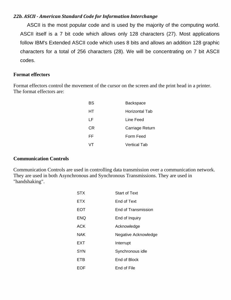
22b. ASCII - American Standard Code for Information Interchange
ASCII is the most popular code and is used by the majority of the computing world.
ASCII itself is a 7 bit code which allows only 128 characters (27). Most applications
follow IBM's Extended ASCII code which uses 8 bits and allows an addition 128 graphic
characters for a total of 256 characters (28). We will be concentrating on 7 bit ASCII
codes.
Format effectors
Format effectors control the movement of the cursor on the screen and the print head in a printer.
The format effectors are:
BS Backspace
HT Horizontal Tab
LF Line Feed
CR Carriage Return
FF Form Feed
VT Vertical Tab
Communication Controls
Communication Controls are used in controlling data transmission over a communication network.
They are used in both Asynchronous and Synchronous Transmissions. They are used in
"handshaking".
STX Start of Text
ETX End of Text
EOT End of Transmission
ENQ End of Inquiry
ACK Acknowledge
NAK Negative Acknowledge
EXT Interrupt
SYN Synchronous idle
ETB End of Block
EOF End of File
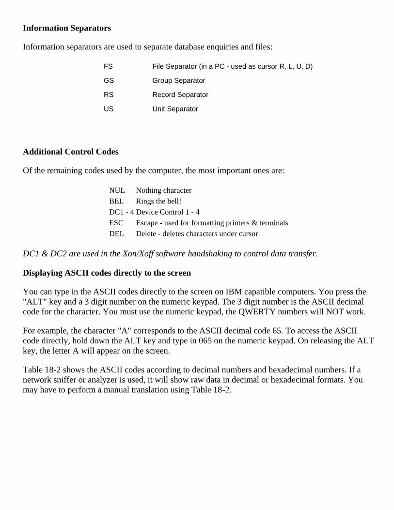
Information Separators
Information separators are used to separate database enquiries and files:
FS File Separator (in a PC - used as cursor R, L, U, D)
GS Group Separator
RS Record Separator
US Unit Separator
Additional Control Codes
Of the remaining codes used by the computer, the most important ones are:
NUL Nothing character
BEL Rings the bell!
DC1 - 4 Device Control 1 - 4
ESC Escape - used for formatting printers & terminals
DEL Delete - deletes characters under cursor
DC1 & DC2 are used in the Xon/Xoff software handshaking to control data transfer.
Displaying ASCII codes directly to the screen
You can type in the ASCII codes directly to the screen on IBM capatible computers. You press the
"ALT" key and a 3 digit number on the numeric keypad. The 3 digit number is the ASCII decimal
code for the character. You must use the numeric keypad, the QWERTY numbers will NOT work.
For example, the character "A" corresponds to the ASCII decimal code 65. To access the ASCII
code directly, hold down the ALT key and type in 065 on the numeric keypad. On releasing the ALT
key, the letter A will appear on the screen.
Table 18-2 shows the ASCII codes according to decimal numbers and hexadecimal numbers. If a
network sniffer or analyzer is used, it will show raw data in decimal or hexadecimal formats. You
may have to perform a manual translation using Table 18-2.
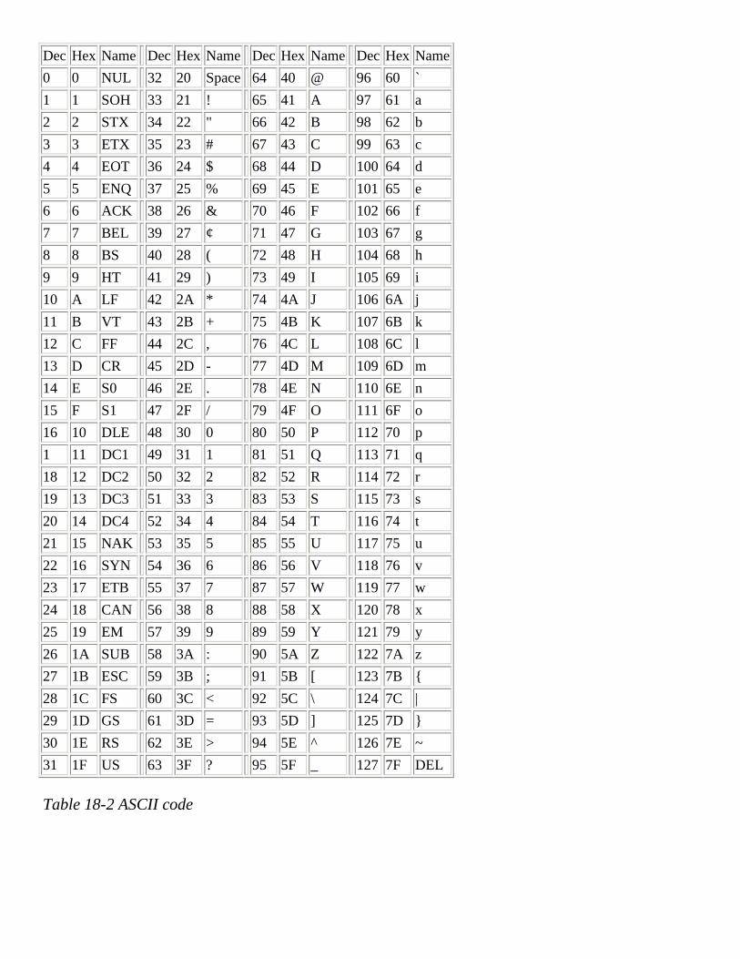
Dec Hex Name Dec Hex Name
Dec Hex Name
Dec Hex Name
0 0 NUL 32 20 Space
64 40 @
96 60 `
1 1 SOH 33 21 !
65 41 A
97 61 a
2 2 STX 34 22 "
66 42 B
98 62 b
3 3 ETX 35 23 #
67 43 C
99 63 c
4 4 EOT 36 24 $
68 44 D
100 64 d
5 5 ENQ 37 25 %
69 45 E
101 65 e
6 6 ACK 38 26 &
70 46 F
102 66 f
7 7 BEL 39 27 ¢
71 47 G
103 67 g
8 8 BS 40 28 (
72 48 H
104 68 h
9 9 HT 41 29 )
73 49 I
105 69 i
10 A LF 42 2A *
74 4A J
106 6A j
11 B VT 43 2B +
75 4B K
107 6B k
12 C FF 44 2C ,
76 4C L
108 6C l
13 D CR 45 2D -
77 4D M
109 6D m
14 E S0 46 2E .
78 4E N
110 6E n
15 F S1 47 2F /
79 4F O
111 6F o
16 10 DLE 48 30 0
80 50 P
112 70 p
1 11 DC1 49 31 1
81 51 Q
113 71 q
18 12 DC2 50 32 2
82 52 R
114 72 r
19 13 DC3 51 33 3
83 53 S
115 73 s
20 14 DC4 52 34 4
84 54 T
116 74 t
21 15 NAK 53 35 5
85 55 U
117 75 u
22 16 SYN 54 36 6
86 56 V
118 76 v
23 17 ETB 55 37 7
87 57 W
119 77 w
24 18 CAN 56 38 8
88 58 X
120 78 x
25 19 EM 57 39 9
89 59 Y
121 79 y
26 1A SUB 58 3A :
90 5A Z
122 7A z
27 1B ESC 59 3B ;
91 5B [
123 7B {
28 1C FS 60 3C <
92 5C \
124 7C |
29 1D GS 61 3D =
93 5D ]
125 7D }
30 1E RS 62 3E >
94 5E ^
126 7E ~
31 1F US 63 3F ?
95 5F _
127 7F DEL
Table 18-2 ASCII code
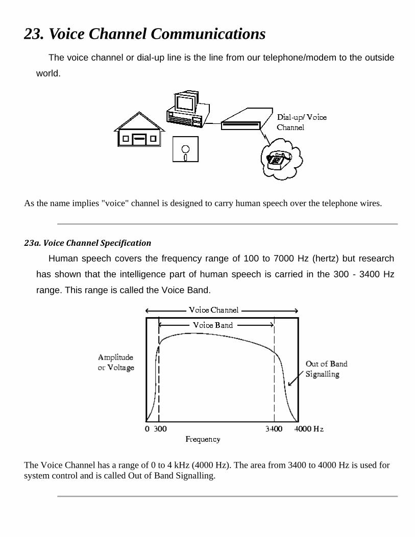
23. Voice Channel Communications
The voice channel or dial-up line is the line from our telephone/modem to the outside
world.
As the name implies "voice" channel is designed to carry human speech over the telephone wires.
23a. Voice Channel Specification
Human speech covers the frequency range of 100 to 7000 Hz (hertz) but research
has shown that the intelligence part of human speech is carried in the 300 - 3400 Hz
range. This range is called the Voice Band.
The Voice Channel has a range of 0 to 4 kHz (4000 Hz). The area from 3400 to 4000 Hz is used for
system control and is called Out of Band Signalling.

23b. Voice Channel Constraints
Due to the limited Bandwidth (BW) of the Voice Channel (0-4 kHz), we are limited to the amount of
data that we can pass through the Voice Channel. The Nyquist Theorem addresses this limitation.
23c. Nyquist Theorem
In a digital Public phone system, the signal leaving our telephone at our house is an
analog signal. It goes to the Central Office through the Local Loop. The Local Loop is
the name for the wires that run from our house to the Central Office. The Central Office
(also called a local exchange) is the building that all the neighbourhood phones with the
same local connect. A local is the 1st 3 digits of your 7 digit phone number or LDN
(Listed Directory Number).
At the Central Office, the analog signal is converted into a digital signal consisting of 1s and 0s.
The Nyquist Theorem states that to accurately reproduce an analog signal with a digital signal, the
analog signal must be sampled a minimum of 2x the highest frequency of the analog signal.
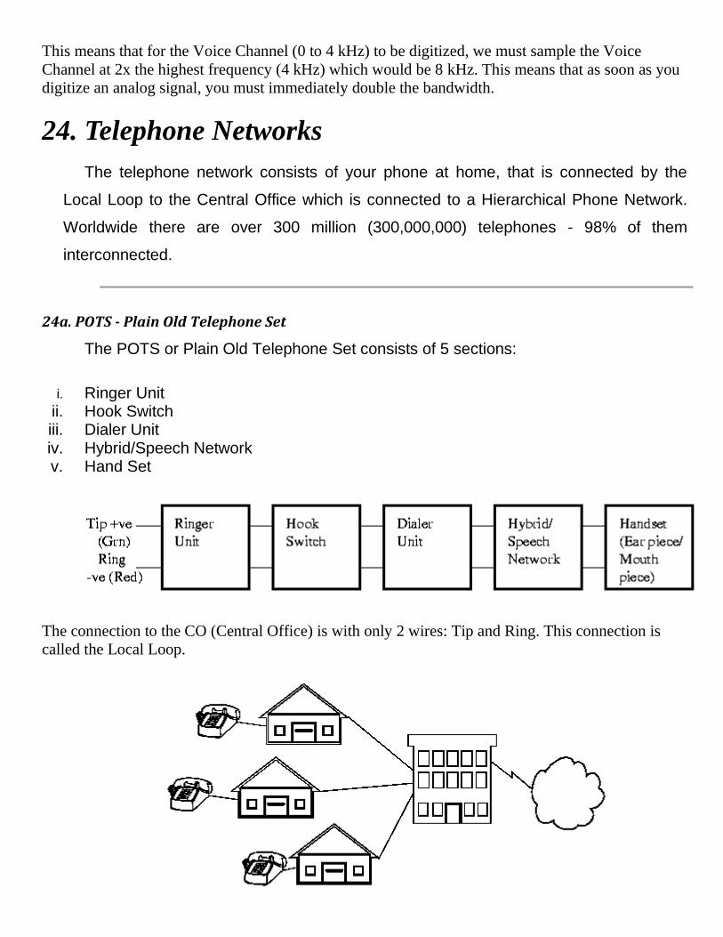
This means that for the Voice Channel (0 to 4 kHz) to be digitized, we must sample the Voice
Channel at 2x the highest frequency (4 kHz) which would be 8 kHz. This means that as soon as you
digitize an analog signal, you must immediately double the bandwidth.
24. Telephone Networks
The telephone network consists of your phone at home, that is connected by the
Local Loop to the Central Office which is connected to a Hierarchical Phone Network.
Worldwide there are over 300 million (300,000,000) telephones - 98% of them
interconnected.
24a. POTS - Plain Old Telephone Set
The POTS or Plain Old Telephone Set consists of 5 sections:
i. Ringer Unit ii. Hook Switch iii. Dialer Unit iv. Hybrid/Speech Network v. Hand Set
The connection to the CO (Central Office) is with only 2 wires: Tip and Ring. This connection is
called the Local Loop.

The Tip is +ve and coloured green.. The Ring is -ve and coloured Red. If you look at a phone jack in
your house, you will see that it is wired for 4 wires: Red, Green, Black and Yellow. Black and
Yellow are not normally used.
The black and yellow wires can be used for a second telephone line or they can be used for running
a Network Physical layer protocol called Phonenet by Farralon. Phonenet uses the Black and Yellow
for Network communications. It is for use with Appletalk and is a replacement for Localtalk. It runs
at the Localtalk speed of 230 Kbps which is reasonable for small networks.
i. Ringer Unit
The ringer is a device to alert you to an incoming call. It interprets the ringing voltage from the
Central Office. Originally, the ringer was a electromagnetic bell but today, most ringers are
electronic devices.
The Central Office sends:
a 90 to 120 VAC ringing voltage
Frequency of 20 Hz
Cadence for North America is 2 sec On/ 4 sec Off
ii. Hook Switch
The hook switch is a switch that is activated by lifting the handset off the cradle. The position of the
hook switch determines whether the telephone is waiting for a call or actively using the line. The
Off-hook position informs the network of a request for use. The On-hook position releases the use of
the network.
iii. Dialer Unit
There are two types of Dialer Units: Rotary Dial and Touch Tone. Rotary Dial are the old put your
finger in the hole and spin type. The rotary dial operates by toggling the Hook Switch on and off.
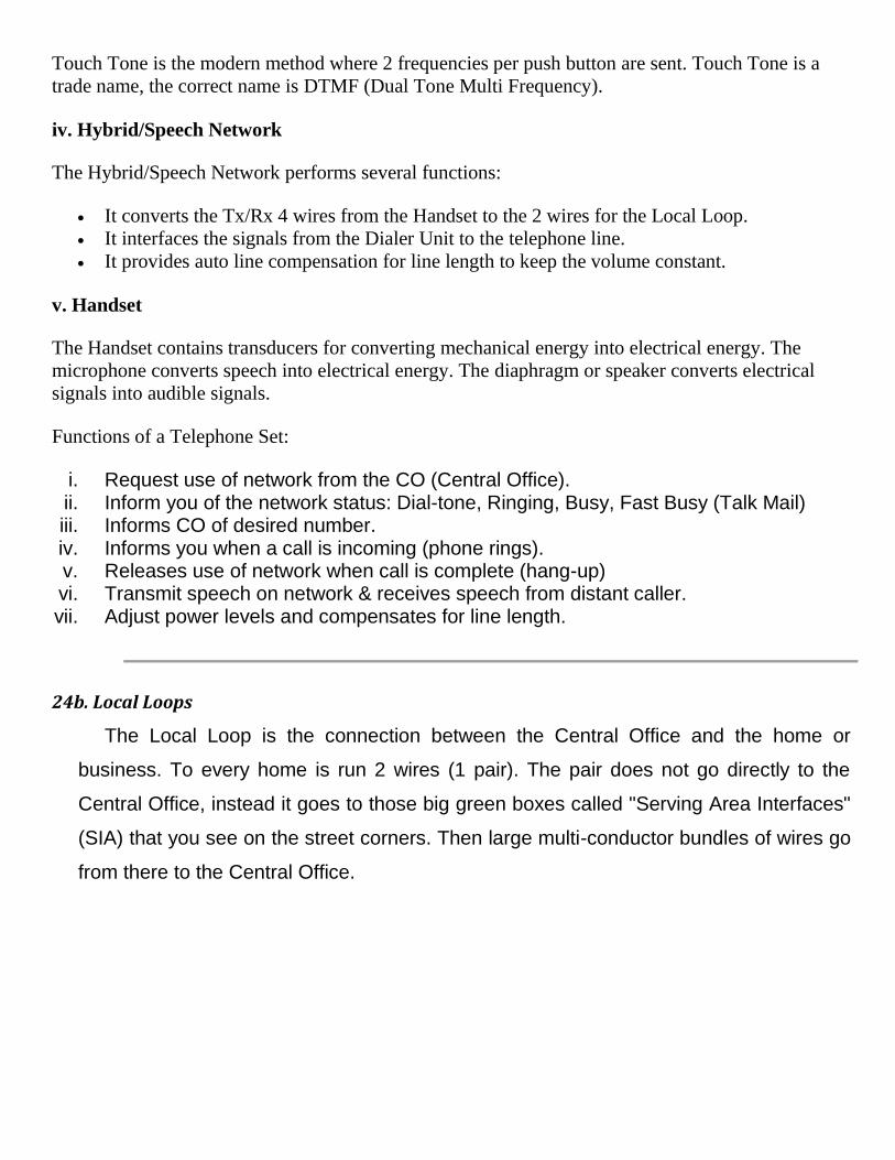
Touch Tone is the modern method where 2 frequencies per push button are sent. Touch Tone is a
trade name, the correct name is DTMF (Dual Tone Multi Frequency).
iv. Hybrid/Speech Network
The Hybrid/Speech Network performs several functions:
It converts the Tx/Rx 4 wires from the Handset to the 2 wires for the Local Loop.
It interfaces the signals from the Dialer Unit to the telephone line.
It provides auto line compensation for line length to keep the volume constant.
v. Handset
The Handset contains transducers for converting mechanical energy into electrical energy. The
microphone converts speech into electrical energy. The diaphragm or speaker converts electrical
signals into audible signals.
Functions of a Telephone Set:
i. Request use of network from the CO (Central Office). ii. Inform you of the network status: Dial-tone, Ringing, Busy, Fast Busy (Talk Mail) iii. Informs CO of desired number. iv. Informs you when a call is incoming (phone rings). v. Releases use of network when call is complete (hang-up) vi. Transmit speech on network & receives speech from distant caller. vii. Adjust power levels and compensates for line length.
24b. Local Loops
The Local Loop is the connection between the Central Office and the home or
business. To every home is run 2 wires (1 pair). The pair does not go directly to the
Central Office, instead it goes to those big green boxes called "Serving Area Interfaces"
(SIA) that you see on the street corners. Then large multi-conductor bundles of wires go
from there to the Central Office.

24c. Central Office
The Central Office provides the following functions:
i. It supplies the battery voltage for the telephone system. The On-hook voltage is 48 Vdc +/- 2V. Off-hook voltage is -6.5 Vdc.
ii. It supplies the Ringing Generator - 90 to 120 VAC, 20 Hz, 2 sec on/ 4 sec off iii. It supplies the Busy signal (480 + 620 Hz, 0.5 sec On/ 0.5 sec Off), Dial Tone (350 +
440 Hz) and Fast Busy (480 + 620 Hz, 0.2 sec On/ 0.3 sec Off). iv. It has the digital switching gear that determines if the number is an Interoffice call
(local) or an Intraoffice call (Toll - long distance).
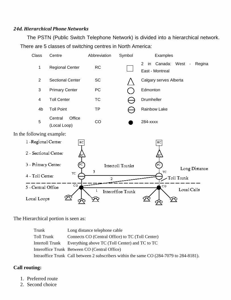
24d. Hierarchical Phone Networks
The PSTN (Public Switch Telephone Network) is divided into a hierarchical network.
There are 5 classes of switching centres in North America:
Class Centre Abbreviation Symbol Examples
1 Regional Center RC
2 in Canada: West - Regina
East - Montreal
2 Sectional Center SC
Calgary serves Alberta
3 Primary Center PC
Edmonton
4 Toll Center TC
Drumheller
4b Toll Point TP
Rainbow Lake
5 Central Office
(Local Loop) CO
284-xxxx
In the following example:
The Hierarchical portion is seen as:
Trunk Long distance telephone cable
Toll Trunk Connects CO (Central Office) to TC (Toll Center)
Intertoll Trunk Everything above TC (Toll Center) and TC to TC
Interoffice Trunk Between CO (Central Office)
Intraoffice Trunk Call between 2 subscribers within the same CO (284-7079 to 284-8181).
Call routing:
1. Preferred route
2. Second choice

3. Third Choice
Call routing is determined by network engineering and physical location. When all lines are idle, the
call routing selects the preferred route. If the preferred route is busy, then the call is routed to the
second choice. Because the second choice is routed through one toll center, the charge for the call is
greater than the preferred route. The third choice is used when the second choice is busy. The third
choice goes through 2 toll centers and is the most expensive route.
A Central Office can have up to 10,000 subscribers: for example 284-0000 to 284-9999. Most have
4,000 to 5,000 subscribers. The Central Office bases the loading requirements on roughly 10% of
the phones will be in use at any one time. The use of Internet dialup access has drastically changed
this!
25. Telephone Line Characteristics
Telephone lines are not perfect devices due to their analog nature. The quality of the
telephone line determines the rate that modulated data can be transferred. Good noise
free lines allow faster transfer rates such as 14.4 kbps, poor quality lines require the
data transfer rate to be stepped down to 9600 bps or less. Phone lines have several
measurable characteristics that determine the quality of the line:
Attenuation Distortion
Propagation Delay Envelope Delay Distortion
25a. Attenuation Distortion
Attenuation Distortion is the change in amplitude of the transmitted signal over the
Voice Band. It is the frequency response curve of the Voice Band.
Attenuation versus Frequency
To measure Attenuation Distortion, the phone line has a test frequency transmitted from 0 - 4 kHz
into the line at a standard amplitude of 0 db. The loss of signal or attenuation is measured at the
receiving end and compared to a standard reference frequency: 1004 Hz.
db is short for decibel which is a relative unit of measure (similar to a unit like a dozen). It is a log
unit and a +3 db gain will indicate an amplitude of 2x the reference. It is a logarithmic ratio between
input voltage and output voltage. It is calculated by the following formula:
db =10 x log (Vout/Vin)
The resulting information is graphed on an Attenuation vs. Frequency chart. Attenuation is a loss of
signal amplitude - the receive signal is a smaller amplitude than the transmitted signal. It is indicated
by a positive db. It is also possible to have a signal appear at the receiving end with a larger
amplitude than when it started - this is indicated by negative db.
The attenuation is due to the many pieces of electronic equipment and transmission media that the
signal has to pass through, some can amplify the signal (make it a larger amplitude) and some may
attenuate the signal (make it smaller).
There are maximum and minimum acceptable limits for Attenuation Distortion for phone lines. The
Basic channel conditioning is:
Frequency Range
Loss (db)
500 - 2500
-2 to +8
300 - 3000
-3 to +12
The above Loss is a range of acceptable values for the frequency range. In the Basic Channelling
Conditioning, it is acceptable to have a loss in signal in the frequency range of 500-2500 Hz of "8 db
loss to -2 db loss" referenced to the amplitude at 1 kHz. Note that on the graph on the previous page
that this is shown as -8db and +2 db.
+3 db attenuation is equal to -3 db in signal amplitude and +8 db attenuation equates to -8 db in
signal amplitude.
25b. Propagation Delay
Signals transmitted down a phone line will take a finite time to reach the end of the
line. The delay from the time the signal was transmitted to the time it was received is
called Propagation Delay. If the propagation delay was the exact same across the
frequency range, there would be no problem. This would imply that all frequencies from
300 to 3000 Hz have the same amount of delay in reaching their destination over the
phone line. They would arrive at the destination at the same time but delayed by a small
amount called the propagation delay.
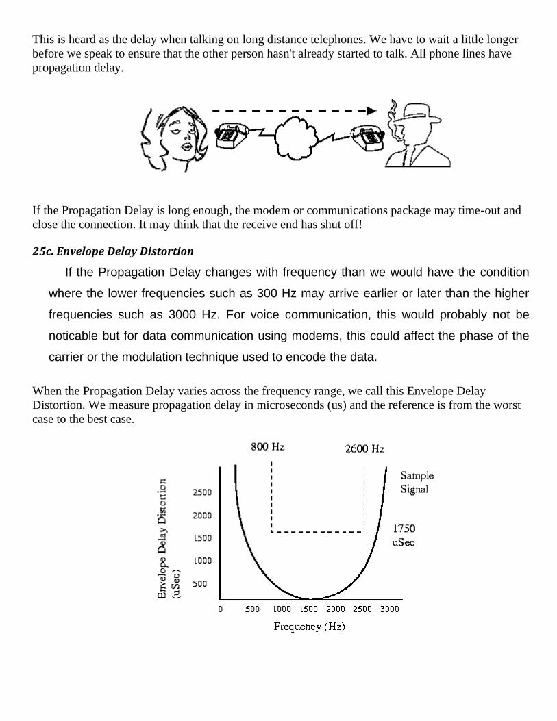
This is heard as the delay when talking on long distance telephones. We have to wait a little longer
before we speak to ensure that the other person hasn't already started to talk. All phone lines have
propagation delay.
If the Propagation Delay is long enough, the modem or communications package may time-out and
close the connection. It may think that the receive end has shut off!
25c. Envelope Delay Distortion
If the Propagation Delay changes with frequency than we would have the condition
where the lower frequencies such as 300 Hz may arrive earlier or later than the higher
frequencies such as 3000 Hz. For voice communication, this would probably not be
noticable but for data communication using modems, this could affect the phase of the
carrier or the modulation technique used to encode the data.
When the Propagation Delay varies across the frequency range, we call this Envelope Delay
Distortion. We measure propagation delay in microseconds (us) and the reference is from the worst
case to the best case.
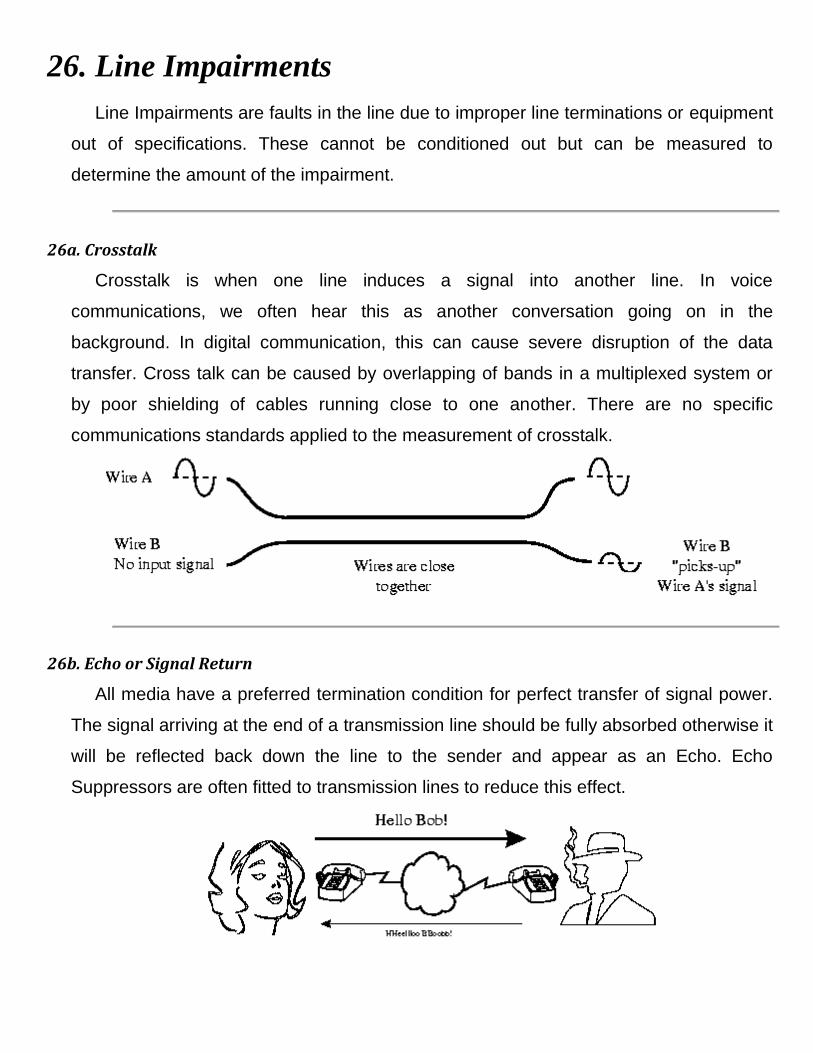
26. Line Impairments
Line Impairments are faults in the line due to improper line terminations or equipment
out of specifications. These cannot be conditioned out but can be measured to
determine the amount of the impairment.
26a. Crosstalk
Crosstalk is when one line induces a signal into another line. In voice
communications, we often hear this as another conversation going on in the
background. In digital communication, this can cause severe disruption of the data
transfer. Cross talk can be caused by overlapping of bands in a multiplexed system or
by poor shielding of cables running close to one another. There are no specific
communications standards applied to the measurement of crosstalk.
26b. Echo or Signal Return
All media have a preferred termination condition for perfect transfer of signal power.
The signal arriving at the end of a transmission line should be fully absorbed otherwise it
will be reflected back down the line to the sender and appear as an Echo. Echo
Suppressors are often fitted to transmission lines to reduce this effect.
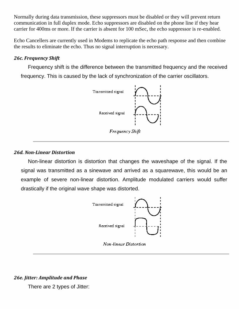
Normally during data transmission, these suppressors must be disabled or they will prevent return
communication in full duplex mode. Echo suppressors are disabled on the phone line if they hear
carrier for 400ms or more. If the carrier is absent for 100 mSec, the echo suppressor is re-enabled.
Echo Cancellers are currently used in Modems to replicate the echo path response and then combine
the results to eliminate the echo. Thus no signal interruption is necessary.
26c. Frequency Shift
Frequency shift is the difference between the transmitted frequency and the received
frequency. This is caused by the lack of synchronization of the carrier oscillators.
26d. Non-Linear Distortion
Non-linear distortion is distortion that changes the waveshape of the signal. If the
signal was transmitted as a sinewave and arrived as a squarewave, this would be an
example of severe non-linear distortion. Amplitude modulated carriers would suffer
drastically if the original wave shape was distorted.
26e. Jitter: Amplitude and Phase
There are 2 types of Jitter:

a. Amplitude Jitter b. Phase Jitter
Amplitude Jitter is the small constantly changing swings in the amplitude of a signal. It is
principally caused by power supply noise (60 Hz) and ringing tone (20 Hz) on the signal.
Phase Jitter is the small constantly changing swings in the phase of a signal. It may result in the
pulses moving into time slots allocated other data pulses when used with Time Domain
Multiplexing.
Telephone company standards call for no more than 10 degrees between 20 and 300 Hz and no more
than 15 degrees between 4 and 20 Hz.
26f. Transients: Impulse Noise, Gain Hits, Dropouts & Phase Hits
Transients are irregular timed impairments. They appear randomly and are very
difficult to troubleshoot. There are 4 basic types of Transients:
i. Impulse Noise
ii. Gain Hits iii. Dropouts iv. Phase Hits
i. Impulse Noise
Impulse noise is sharp quick spikes on the signal caused from electromagnetic interference,
lightning, sudden power switching, electromechanical switching, etc.. These appear on the telephone
line as clicks and pops which are not a problem for voice communication but can appear as a loss of
data or even as wrong data bits during data transfers. Impulse noise has a duration of less than 1
mSec and their effect is dissipated within 4 mSec.
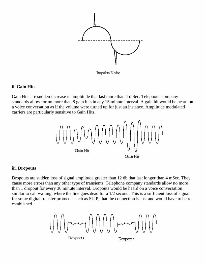
ii. Gain Hits
Gain Hits are sudden increase in amplitude that last more than 4 mSec. Telephone company
standards allow for no more than 8 gain hits in any 15 minute interval. A gain hit would be heard on
a voice conversation as if the volume were turned up for just an instance. Amplitude modulated
carriers are particularly sensitive to Gain Hits.
iii. Dropouts
Dropouts are sudden loss of signal amplitude greater than 12 db that last longer than 4 mSec. They
cause more errors than any other type of transients. Telephone company standards allow no more
than 1 dropout for every 30 minute interval. Dropouts would be heard on a voice conversation
similar to call waiting, where the line goes dead for a 1/2 second. This is a sufficient loss of signal
for some digital transfer protocols such as SLIP, that the connection is lost and would have to be re-
established.
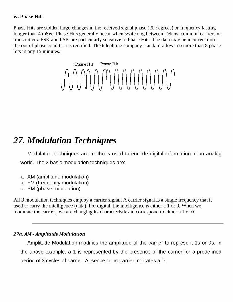
iv. Phase Hits
Phase Hits are sudden large changes in the received signal phase (20 degrees) or frequency lasting
longer than 4 mSec. Phase Hits generally occur when switching between Telcos, common carriers or
transmitters. FSK and PSK are particularly sensitive to Phase Hits. The data may be incorrect until
the out of phase condition is rectified. The telephone company standard allows no more than 8 phase
hits in any 15 minutes.
27. Modulation Techniques
Modulation techniques are methods used to encode digital information in an analog
world. The 3 basic modulation techniques are:
a. AM (amplitude modulation) b. FM (frequency modulation) c. PM (phase modulation)
All 3 modulation techniques employ a carrier signal. A carrier signal is a single frequency that is
used to carry the intelligence (data). For digital, the intelligence is either a 1 or 0. When we
modulate the carrier , we are changing its characteristics to correspond to either a 1 or 0.
27a. AM - Amplitude Modulation
Amplitude Modulation modifies the amplitude of the carrier to represent 1s or 0s. In
the above example, a 1 is represented by the presence of the carrier for a predefined
period of 3 cycles of carrier. Absence or no carrier indicates a 0.
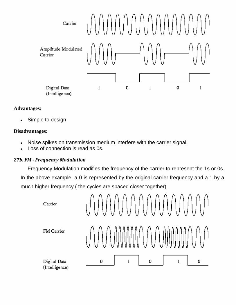
Advantages:
Simple to design.
Disadvantages:
Noise spikes on transmission medium interfere with the carrier signal. Loss of connection is read as 0s.
27b. FM - Frequency Modulation
Frequency Modulation modifies the frequency of the carrier to represent the 1s or 0s.
In the above example, a 0 is represented by the original carrier frequency and a 1 by a
much higher frequency ( the cycles are spaced closer together).
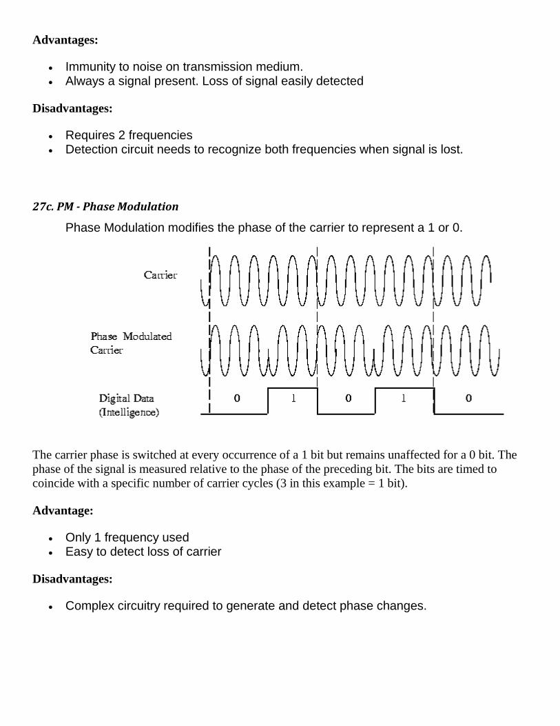
Advantages:
Immunity to noise on transmission medium. Always a signal present. Loss of signal easily detected
Disadvantages:
Requires 2 frequencies Detection circuit needs to recognize both frequencies when signal is lost.
27c. PM - Phase Modulation
Phase Modulation modifies the phase of the carrier to represent a 1 or 0.
The carrier phase is switched at every occurrence of a 1 bit but remains unaffected for a 0 bit. The
phase of the signal is measured relative to the phase of the preceding bit. The bits are timed to
coincide with a specific number of carrier cycles (3 in this example = 1 bit).
Advantage:
Only 1 frequency used Easy to detect loss of carrier
Disadvantages:
Complex circuitry required to generate and detect phase changes.

28. Modem Modulation
There are 3 basic types of modulation used in modems:
a. FSK - Frequency Shifted Keying
b. QPSK - Quadrature Phase Shifted Keying c. QAM - Quadrature Amplitude Modulation
Modern modems use a combination of the above basic modulation techniques and compression to
achieve the high data transfer rates (14.4 Kbps and up).
28a. FSK - Frequency Shift Keying
Frequency Shift Keying or FSK is the frequency modulation of a carrier to represent
digital intelligence. For Simplex or Half Duplex operation, a single carrier (1170 Hz) is
used - communication can only be transmitted in one direction at a time. A Mark or 1 is
represented by 1270 Hz, and a Space or 0 is represented by 1070 Hz. The following
diagram shows the Voice Channel with Simplex/Half Duplex FSK.
Simplex/Half Duplex FSK
Full Duplex FSK
For Full Duplex, (data communication in both directions simultaneously) the upper bandwidth of the
Voice Channel is utilized. Another carrier is added at 2125 Hz. A Mark or 1 is represented by 2225
Hz, and a Space or 0 is represented by 2025 Hz. The originating modem (the one which dials the
phone number and starts the connection) uses the lower carrier (1170 Hz) and the answer modem
(the one which answers the ringing phone line) uses the upper carrier (2125 Hz). This allocation of
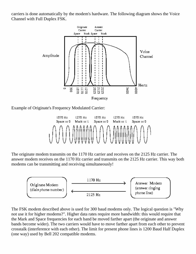
carriers is done automatically by the modem's hardware. The following diagram shows the Voice
Channel with Full Duplex FSK.
Example of Originate's Frequency Modulated Carrier:
The originate modem transmits on the 1170 Hz carrier and receives on the 2125 Hz carrier. The
answer modem receives on the 1170 Hz carrier and transmits on the 2125 Hz carrier. This way both
modems can be transmitting and receiving simultaneously!
The FSK modem described above is used for 300 baud modems only. The logical question is "Why
not use it for higher modems?". Higher data rates require more bandwidth: this would require that
the Mark and Space frequencies for each band be moved farther apart (the originate and answer
bands become wider). The two carriers would have to move farther apart from each other to prevent
crosstalk (interference with each other). The limit for present phone lines is 1200 Baud Half Duplex
(one way) used by Bell 202 compatible modems.
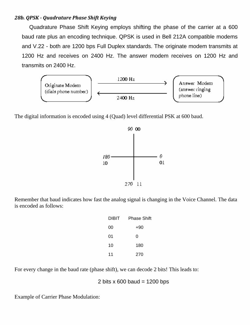
28b. QPSK - Quadrature Phase Shift Keying
Quadrature Phase Shift Keying employs shifting the phase of the carrier at a 600
baud rate plus an encoding technique. QPSK is used in Bell 212A compatible modems
and V.22 - both are 1200 bps Full Duplex standards. The originate modem transmits at
1200 Hz and receives on 2400 Hz. The answer modem receives on 1200 Hz and
transmits on 2400 Hz.
The digital information is encoded using 4 (Quad) level differential PSK at 600 baud.
Remember that baud indicates how fast the analog signal is changing in the Voice Channel. The data
is encoded as follows:
DIBIT Phase Shift
00 +90
01 0
10 180
11 270
For every change in the baud rate (phase shift), we can decode 2 bits! This leads to:
2 bits x 600 baud = 1200 bps
Example of Carrier Phase Modulation:
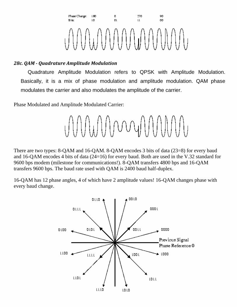
28c. QAM - Quadrature Amplitude Modulation
Quadrature Amplitude Modulation refers to QPSK with Amplitude Modulation.
Basically, it is a mix of phase modulation and amplitude modulation. QAM phase
modulates the carrier and also modulates the amplitude of the carrier.
Phase Modulated and Amplitude Modulated Carrier:
There are two types: 8-QAM and 16-QAM. 8-QAM encodes 3 bits of data (23=8) for every baud
and 16-QAM encodes 4 bits of data (24=16) for every baud. Both are used in the V.32 standard for
9600 bps modem (milestone for communications!). 8-QAM transfers 4800 bps and 16-QAM
transfers 9600 bps. The baud rate used with QAM is 2400 baud half-duplex.
16-QAM has 12 phase angles, 4 of which have 2 amplitude values! 16-QAM changes phase with
every baud change.
16-QAM Phasor Diagram
Higher transfer rates use much more complex QAM methods. For example, V.32bis (14.4 kbps)
uses a 64 point constellation to transfer 6 bits per baud. Compare that to the above 16 point
constellation!
29. AT Command Set
Hayes modems were the first smart modems. They had built-in CPUs that could interpret a special
series of commands. These commands are called the AT command set. The basic command for
getting a modem's attention was the characters "AT" (older modems may only recognize lower case
"at"). Once the modem's attention was available, character's are added immediately after that specify
instructions.
Smart modems operate in two modes: command and communication mode. In command mode, the
modem is waiting for AT command instructions. In communication mode, the modem is transferring
data from sender to receiver.
To talk to a modem, you must use either a terminal or a terminal emulation software on a PC such as
Procomm or Hyperterminal. A basic test to see if the modem is communicating properly with the
terminal, is to type "AT". If the modem responds with "OK", then the software's configuration
matches the modems configuration.
The following configuration issues must match before proper modem to terminal communication
will work:
Configuration Point Typical value
Com port of modem: Com2 for external, Com4 for internal
IRQ of modem: IRQ3
Number of data bits: 8
Type of parity: n (none)
Number of stop bits: 1
Transfer speed: 56 kbps (depends on modem)
Terminal emulation: vt100
If the modem is on-line (communicaton mode), to enter command mode, type "+++" (3 pluses in a
row) and wait. The modem should respond with "OK". This indicates that you have entered
command mode. You then may enter AT command strings to the modem.
29a. Basic AT commands
Modern modems require an initialization string for configuring themselves. The most
common configuration string is "ATZ", which is the reset command. Usually and this will
depend on the modem, there are factory stored configurations that can be accessed by

using the "ATF1" command. If there are more than one available configuration, the
others can be accessed by "ATF2" and so on.
Older modems, typically 14.4kbps and earlier, had elaborate initialization strings that differed for
each modem and each manufacturer. It was quite a headache to support so many different types of
modems and make them work with each other.
To dial out, the "ATD" command is used. "ATDT" uses tone dialing versus rotary dialing.
Immediately after the "ATDT" command, the destination telephone number is entered, for example:
"ATDT555-1234". Would command the modem to use tone dialing to dial the number 555-1234. To
hang up a modem, the AT command string "ATH" can be used.
A partial listing of the AT command set is available in Appendix J. The AT command set is
incredibly large and is constantly growing due to the improvements and innovations by the modem
manufacturers. There are two main manufacturer's of modem chipsets: Rockwell and US Robotics.
Both have excellent documentation on identifying and configuring the modem chipsets that they
manufacture.
30. Multiplexing
Multiplexing is the transmission of multiple data communication sessions over a common wire or
medium. Multiplexing reduces the number of wires or cable required to connect multiple sessions. A
session is considered to be data communication between two devices: computer to computer,
terminal to computer, etc..
Individual lines running from 3 terminals to one mainframe is not a problem but when the number of
terminals increases to 10 and up, it becomes a problem. Imagine a mainframe computer with 1200
terminals connected and each terminal running its own wire to the mainframe. If each wire was 1/4"
in diameter (typical Cat 5 cable), you would have a wiring bundle going into the computer, roughly
2 feet in diameter.
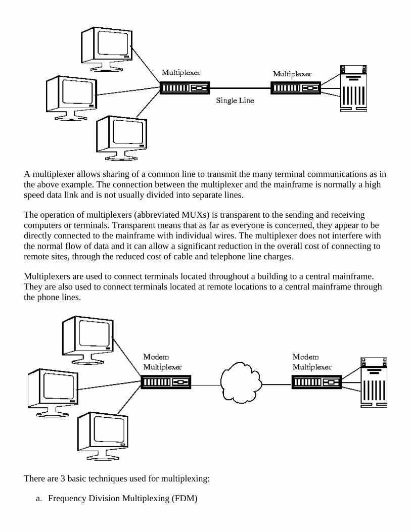
A multiplexer allows sharing of a common line to transmit the many terminal communications as in
the above example. The connection between the multiplexer and the mainframe is normally a high
speed data link and is not usually divided into separate lines.
The operation of multiplexers (abbreviated MUXs) is transparent to the sending and receiving
computers or terminals. Transparent means that as far as everyone is concerned, they appear to be
directly connected to the mainframe with individual wires. The multiplexer does not interfere with
the normal flow of data and it can allow a significant reduction in the overall cost of connecting to
remote sites, through the reduced cost of cable and telephone line charges.
Multiplexers are used to connect terminals located throughout a building to a central mainframe.
They are also used to connect terminals located at remote locations to a central mainframe through
the phone lines.
There are 3 basic techniques used for multiplexing:
a. Frequency Division Multiplexing (FDM)
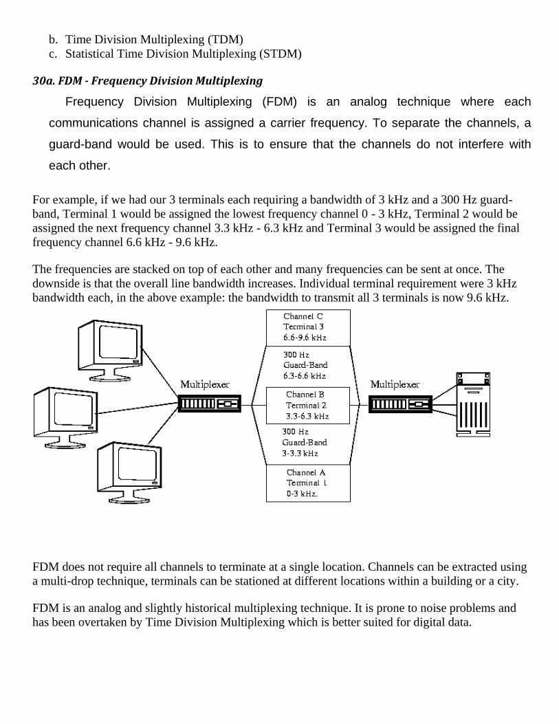
b. Time Division Multiplexing (TDM)
c. Statistical Time Division Multiplexing (STDM)
30a. FDM - Frequency Division Multiplexing
Frequency Division Multiplexing (FDM) is an analog technique where each
communications channel is assigned a carrier frequency. To separate the channels, a
guard-band would be used. This is to ensure that the channels do not interfere with
each other.
For example, if we had our 3 terminals each requiring a bandwidth of 3 kHz and a 300 Hz guard-
band, Terminal 1 would be assigned the lowest frequency channel 0 - 3 kHz, Terminal 2 would be
assigned the next frequency channel 3.3 kHz - 6.3 kHz and Terminal 3 would be assigned the final
frequency channel 6.6 kHz - 9.6 kHz.
The frequencies are stacked on top of each other and many frequencies can be sent at once. The
downside is that the overall line bandwidth increases. Individual terminal requirement were 3 kHz
bandwidth each, in the above example: the bandwidth to transmit all 3 terminals is now 9.6 kHz.
FDM does not require all channels to terminate at a single location. Channels can be extracted using
a multi-drop technique, terminals can be stationed at different locations within a building or a city.
FDM is an analog and slightly historical multiplexing technique. It is prone to noise problems and
has been overtaken by Time Division Multiplexing which is better suited for digital data.
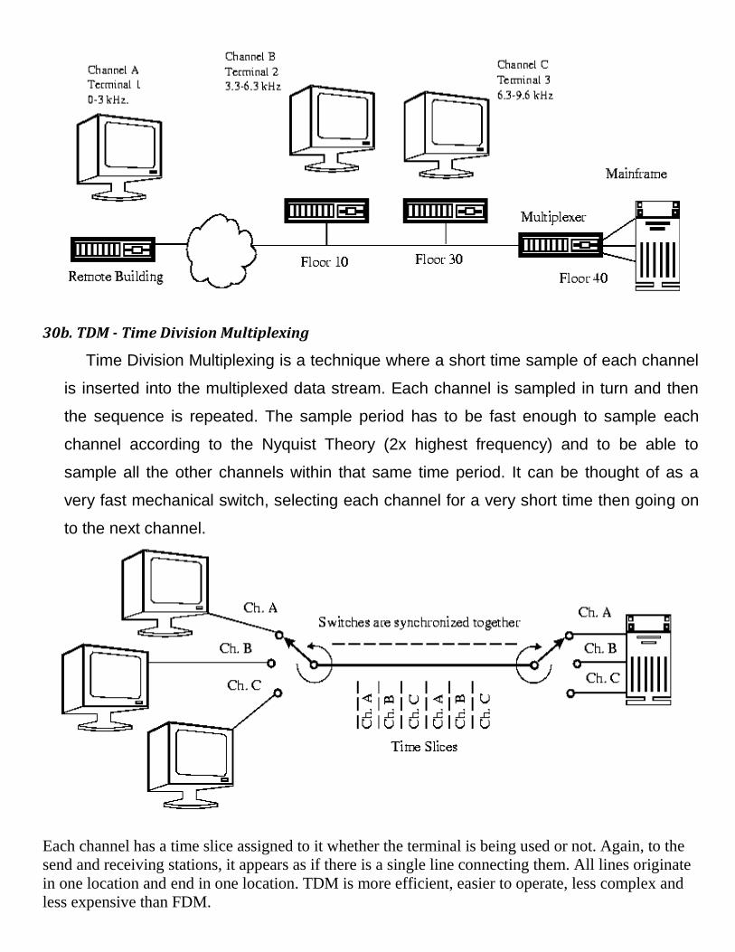
30b. TDM - Time Division Multiplexing
Time Division Multiplexing is a technique where a short time sample of each channel
is inserted into the multiplexed data stream. Each channel is sampled in turn and then
the sequence is repeated. The sample period has to be fast enough to sample each
channel according to the Nyquist Theory (2x highest frequency) and to be able to
sample all the other channels within that same time period. It can be thought of as a
very fast mechanical switch, selecting each channel for a very short time then going on
to the next channel.
Each channel has a time slice assigned to it whether the terminal is being used or not. Again, to the
send and receiving stations, it appears as if there is a single line connecting them. All lines originate
in one location and end in one location. TDM is more efficient, easier to operate, less complex and
less expensive than FDM.
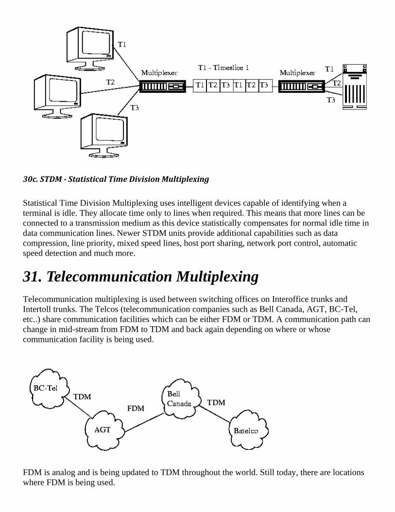
30c. STDM - Statistical Time Division Multiplexing
Statistical Time Division Multiplexing uses intelligent devices capable of identifying when a
terminal is idle. They allocate time only to lines when required. This means that more lines can be
connected to a transmission medium as this device statistically compensates for normal idle time in
data communication lines. Newer STDM units provide additional capabilities such as data
compression, line priority, mixed speed lines, host port sharing, network port control, automatic
speed detection and much more.
31. Telecommunication Multiplexing
Telecommunication multiplexing is used between switching offices on Interoffice trunks and
Intertoll trunks. The Telcos (telecommunication companies such as Bell Canada, AGT, BC-Tel,
etc..) share communication facilities which can be either FDM or TDM. A communication path can
change in mid-stream from FDM to TDM and back again depending on where or whose
communication facility is being used.
FDM is analog and is being updated to TDM throughout the world. Still today, there are locations
where FDM is being used.
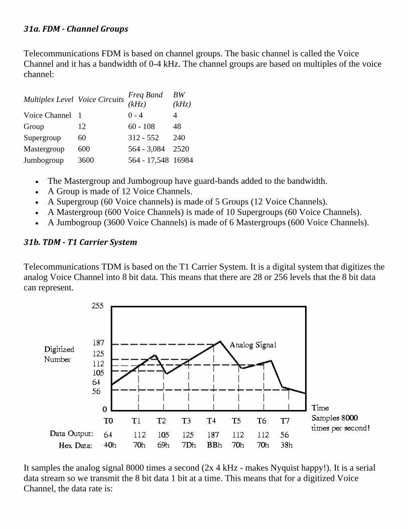
31a. FDM - Channel Groups
Telecommunications FDM is based on channel groups. The basic channel is called the Voice
Channel and it has a bandwidth of 0-4 kHz. The channel groups are based on multiples of the voice
channel:
Multiplex Level
Voice Circuits
Freq Band
(kHz)
BW
(kHz)
Voice Channel
1
0 - 4
4
Group
12
60 - 108
48
Supergroup
60
312 - 552
240
Mastergroup
600
564 - 3,084
2520
Jumbogroup
3600
564 - 17,548
16984
The Mastergroup and Jumbogroup have guard-bands added to the bandwidth.
A Group is made of 12 Voice Channels.
A Supergroup (60 Voice channels) is made of 5 Groups (12 Voice Channels).
A Mastergroup (600 Voice Channels) is made of 10 Supergroups (60 Voice Channels).
A Jumbogroup (3600 Voice Channels) is made of 6 Mastergroups (600 Voice Channels).
31b. TDM - T1 Carrier System
Telecommunications TDM is based on the T1 Carrier System. It is a digital system that digitizes the
analog Voice Channel into 8 bit data. This means that there are 28 or 256 levels that the 8 bit data
can represent.
It samples the analog signal 8000 times a second (2x 4 kHz - makes Nyquist happy!). It is a serial
data stream so we transmit the 8 bit data 1 bit at a time. This means that for a digitized Voice
Channel, the data rate is:
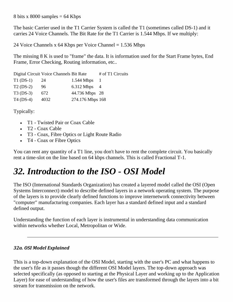
8 bits x 8000 samples = 64 Kbps
The basic Carrier used in the T1 Carrier System is called the T1 (sometimes called DS-1) and it
carries 24 Voice Channels. The Bit Rate for the T1 Carrier is 1.544 Mbps. If we multiply:
24 Voice Channels x 64 Kbps per Voice Channel = 1.536 Mbps
The missing 8 K is used to "frame" the data. It is information used for the Start Frame bytes, End
Frame, Error Checking, Routing information, etc..
Digital Circuit Voice Channels Bit Rate # of T1 Circuits
T1 (DS-1) 24 1.544 Mbps 1
T2 (DS-2) 96 6.312 Mbps 4
T3 (DS-3) 672 44.736 Mbps 28
T4 (DS-4) 4032 274.176 Mbps 168
Typically:
T1 - Twisted Pair or Coax Cable
T2 - Coax Cable
T3 - Coax, Fibre Optics or Light Route Radio
T4 - Coax or Fibre Optics
You can rent any quantity of a T1 line, you don't have to rent the complete circuit. You basically
rent a time-slot on the line based on 64 kbps channels. This is called Fractional T-1.
32. Introduction to the ISO - OSI Model
The ISO (International Standards Organization) has created a layered model called the OSI (Open
Systems Interconnect) model to describe defined layers in a network operating system. The purpose
of the layers is to provide clearly defined functions to improve internetwork connectivity between
"computer" manufacturing companies. Each layer has a standard defined input and a standard
defined output.
Understanding the function of each layer is instrumental in understanding data communication
within networks whether Local, Metropolitan or Wide.
32a. OSI Model Explained
This is a top-down explanation of the OSI Model, starting with the user's PC and what happens to
the user's file as it passes though the different OSI Model layers. The top-down approach was
selected specifically (as opposed to starting at the Physical Layer and working up to the Application
Layer) for ease of understanding of how the user's files are transformed through the layers into a bit
stream for transmission on the network.
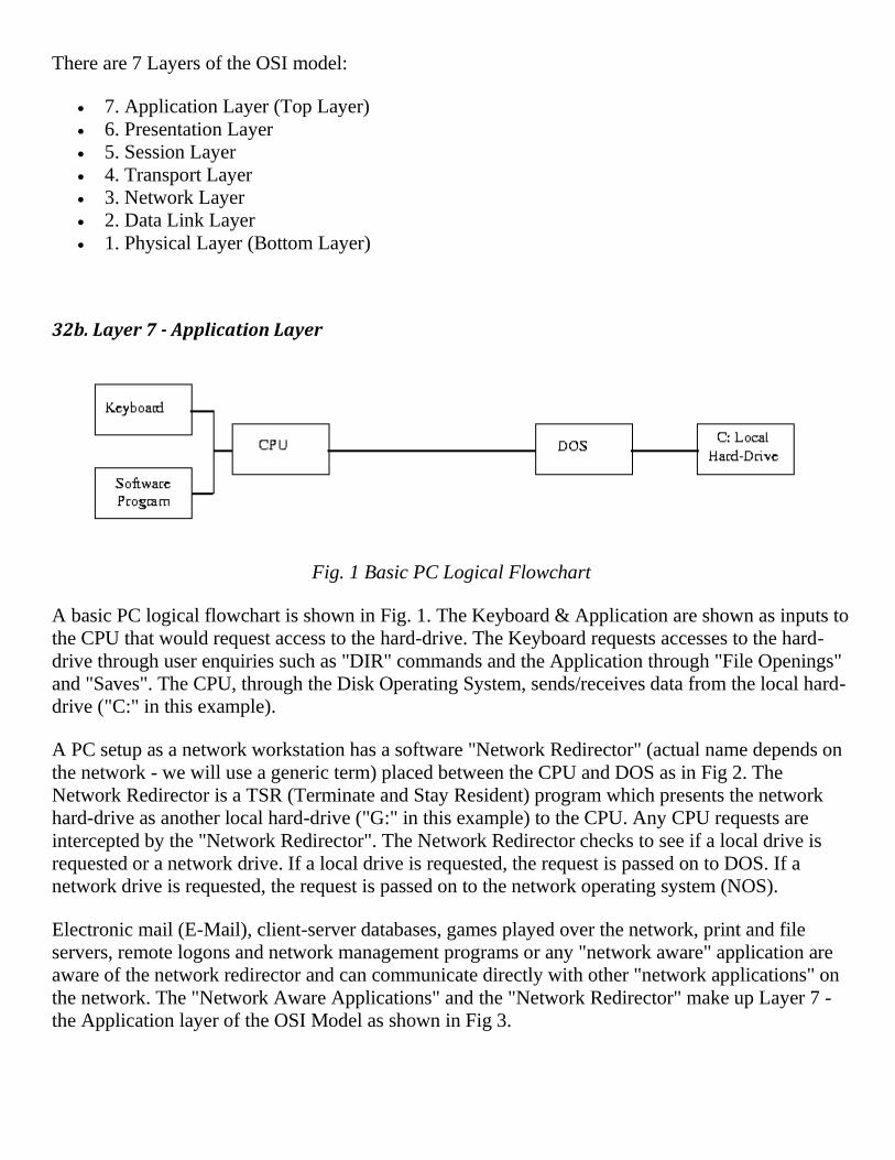
There are 7 Layers of the OSI model:
7. Application Layer (Top Layer)
6. Presentation Layer
5. Session Layer
4. Transport Layer
3. Network Layer
2. Data Link Layer
1. Physical Layer (Bottom Layer)
32b. Layer 7 - Application Layer
Fig. 1 Basic PC Logical Flowchart
A basic PC logical flowchart is shown in Fig. 1. The Keyboard & Application are shown as inputs to
the CPU that would request access to the hard-drive. The Keyboard requests accesses to the hard-
drive through user enquiries such as "DIR" commands and the Application through "File Openings"
and "Saves". The CPU, through the Disk Operating System, sends/receives data from the local hard-
drive ("C:" in this example).
A PC setup as a network workstation has a software "Network Redirector" (actual name depends on
the network - we will use a generic term) placed between the CPU and DOS as in Fig 2. The
Network Redirector is a TSR (Terminate and Stay Resident) program which presents the network
hard-drive as another local hard-drive ("G:" in this example) to the CPU. Any CPU requests are
intercepted by the "Network Redirector". The Network Redirector checks to see if a local drive is
requested or a network drive. If a local drive is requested, the request is passed on to DOS. If a
network drive is requested, the request is passed on to the network operating system (NOS).
Electronic mail (E-Mail), client-server databases, games played over the network, print and file
servers, remote logons and network management programs or any "network aware" application are
aware of the network redirector and can communicate directly with other "network applications" on
the network. The "Network Aware Applications" and the "Network Redirector" make up Layer 7 -
the Application layer of the OSI Model as shown in Fig 3.

Fig. 2 Simple Network Redirection
Fig. 3 PC Workstation with Network Aware Software
32c. Layer 6 - Presentation Layer
The Network Redirector directs CPU operating system native code to the network operating system.
The coding and format of the data is not recognizable by the network operating system. The data
consists of file transfers and network calls by network aware programs.
As an example: when a dumb terminal is used as a workstation in a mainframe or minicomputer
network, the network data is translated into and from the format that the terminal can use. The
Presentation layer presents data to and from the terminal using special control characters to control
the screen display (LF-linefeed, CR-carriage return, cursor movement, etc..). The presentation of
data on the screen would depend on the type of terminal VT100, VT52, VT420, etc.
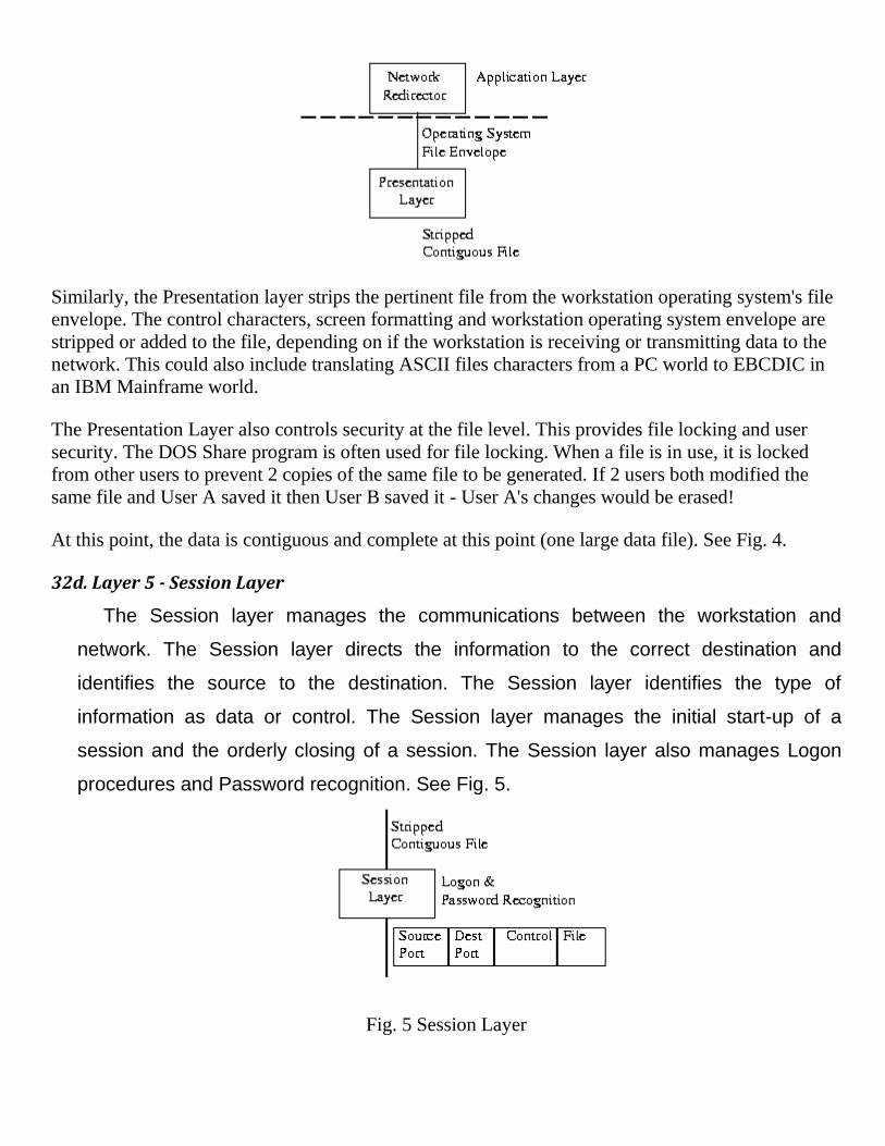
Similarly, the Presentation layer strips the pertinent file from the workstation operating system's file
envelope. The control characters, screen formatting and workstation operating system envelope are
stripped or added to the file, depending on if the workstation is receiving or transmitting data to the
network. This could also include translating ASCII files characters from a PC world to EBCDIC in
an IBM Mainframe world.
The Presentation Layer also controls security at the file level. This provides file locking and user
security. The DOS Share program is often used for file locking. When a file is in use, it is locked
from other users to prevent 2 copies of the same file to be generated. If 2 users both modified the
same file and User A saved it then User B saved it - User A's changes would be erased!
At this point, the data is contiguous and complete at this point (one large data file). See Fig. 4.
32d. Layer 5 - Session Layer
The Session layer manages the communications between the workstation and
network. The Session layer directs the information to the correct destination and
identifies the source to the destination. The Session layer identifies the type of
information as data or control. The Session layer manages the initial start-up of a
session and the orderly closing of a session. The Session layer also manages Logon
procedures and Password recognition. See Fig. 5.
Fig. 5 Session Layer

32e. Layer 4 - Transport Layer
In order for the data to be sent across the network, the file must be broken up into
usable small data segments (typically 512 - 18K bytes). The Transport layer breaks up
the file into segments for transport to the network and combines incoming segments into
a contiguous file. The Transport layer does this logically not physically, it is done in
software as opposed to hardware.
The Transport layer provides error checking at the segment level (frame control sequence). This
checks that the datagrams are in the correct order and the Transport layer will correct out of order
datagrams. The Transport layer guarantees an error-free host to host connection, it is not concerned
with the path between machines.
32f. Layer 3 - Network Layer
The Network layer is concerned about the path through the network. It is responsible
for routing, switching and controlling the flow of information between hosts. The Network
layer converts the segments into smaller datagrams that the network can handle. The
Network layer does not guarantee that the datagram will reach its destination. The
network hardware source and destination addresses are added.
Fig. 7 Network Layer
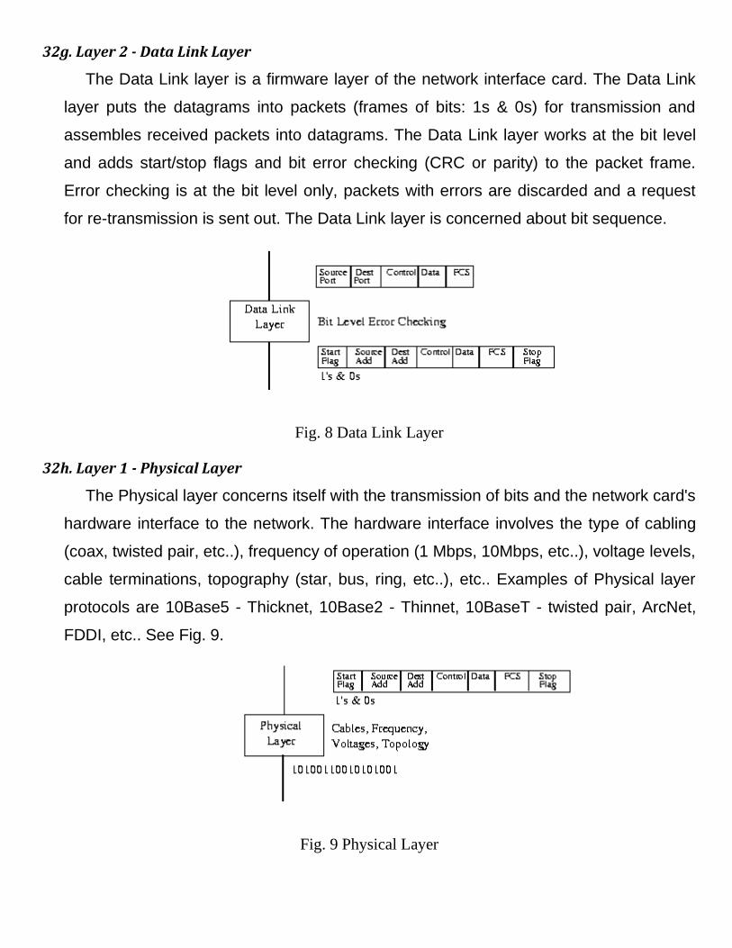
32g. Layer 2 - Data Link Layer
The Data Link layer is a firmware layer of the network interface card. The Data Link
layer puts the datagrams into packets (frames of bits: 1s & 0s) for transmission and
assembles received packets into datagrams. The Data Link layer works at the bit level
and adds start/stop flags and bit error checking (CRC or parity) to the packet frame.
Error checking is at the bit level only, packets with errors are discarded and a request
for re-transmission is sent out. The Data Link layer is concerned about bit sequence.
Fig. 8 Data Link Layer
32h. Layer 1 - Physical Layer
The Physical layer concerns itself with the transmission of bits and the network card's
hardware interface to the network. The hardware interface involves the type of cabling
(coax, twisted pair, etc..), frequency of operation (1 Mbps, 10Mbps, etc..), voltage levels,
cable terminations, topography (star, bus, ring, etc..), etc.. Examples of Physical layer
protocols are 10Base5 - Thicknet, 10Base2 - Thinnet, 10BaseT - twisted pair, ArcNet,
FDDI, etc.. See Fig. 9.
Fig. 9 Physical Layer

32i. Layer Specific Communication
Each layer may add a Header and a Trailer to its Data which consists of the next
higher layer's Header, Trailer and Data as it moves through the layers. The Headers
contain information that addresses layer to layer communication specifically. For
example: The Transport Header (TH) contains information that only the Transport layer
sees and all other layers below the Transport layer pass the Transport Header as part of
their Data.
PDU - Protocol Data Unit (fancy name for Layer Frame)
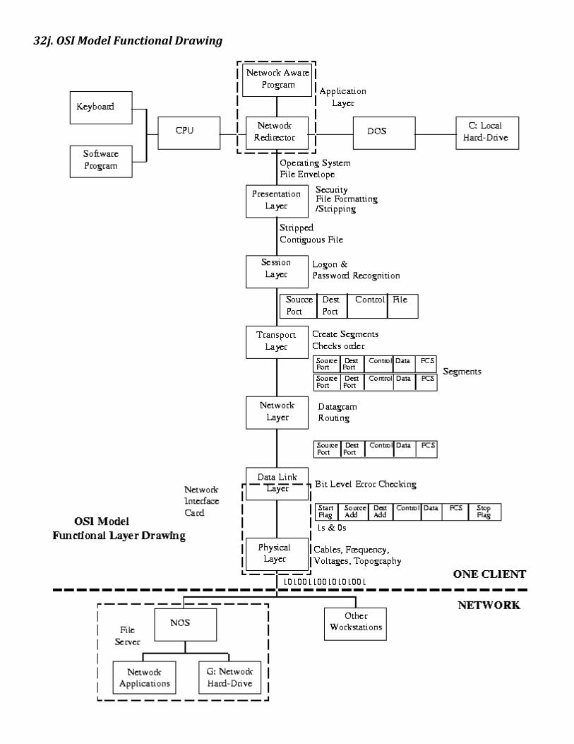
32j. OSI Model Functional Drawing
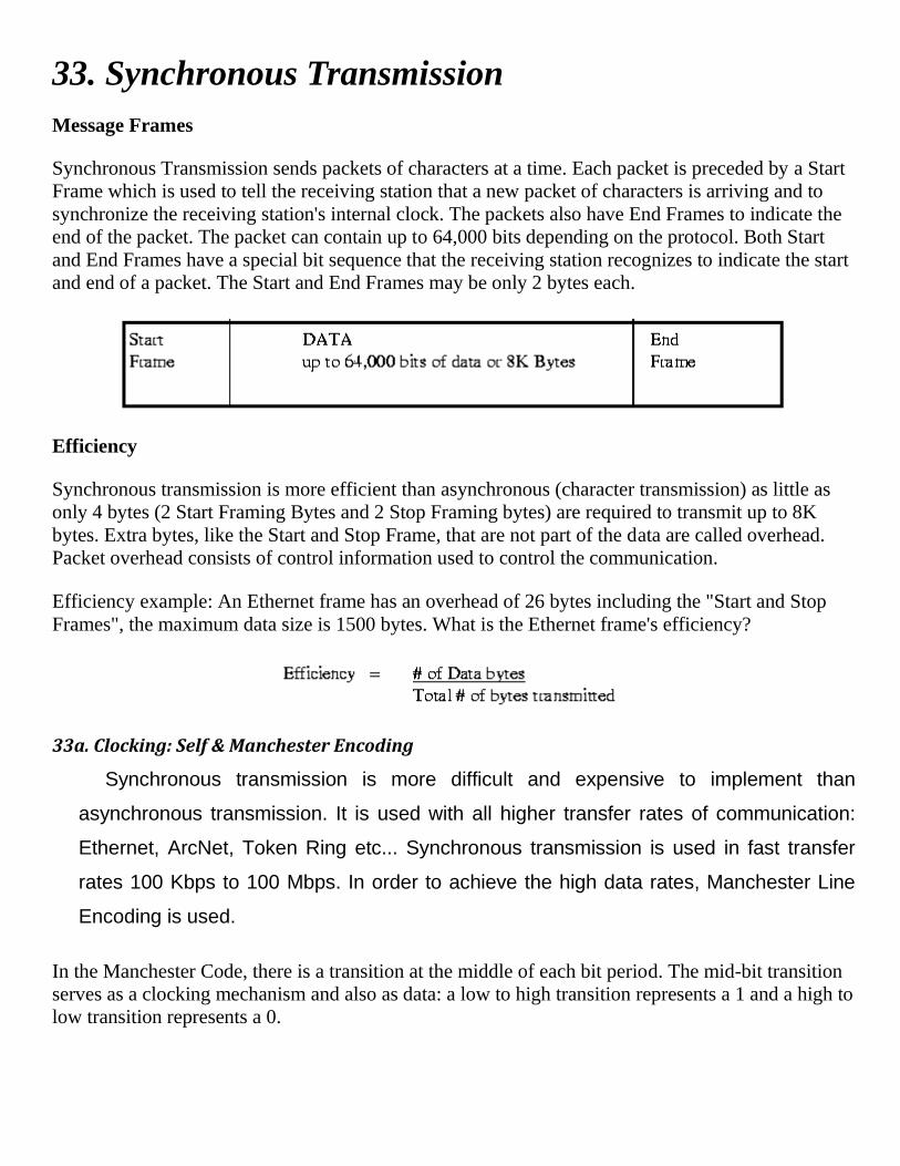
33. Synchronous Transmission
Message Frames
Synchronous Transmission sends packets of characters at a time. Each packet is preceded by a Start
Frame which is used to tell the receiving station that a new packet of characters is arriving and to
synchronize the receiving station's internal clock. The packets also have End Frames to indicate the
end of the packet. The packet can contain up to 64,000 bits depending on the protocol. Both Start
and End Frames have a special bit sequence that the receiving station recognizes to indicate the start
and end of a packet. The Start and End Frames may be only 2 bytes each.
Efficiency
Synchronous transmission is more efficient than asynchronous (character transmission) as little as
only 4 bytes (2 Start Framing Bytes and 2 Stop Framing bytes) are required to transmit up to 8K
bytes. Extra bytes, like the Start and Stop Frame, that are not part of the data are called overhead.
Packet overhead consists of control information used to control the communication.
Efficiency example: An Ethernet frame has an overhead of 26 bytes including the "Start and Stop
Frames", the maximum data size is 1500 bytes. What is the Ethernet frame's efficiency?
33a. Clocking: Self & Manchester Encoding
Synchronous transmission is more difficult and expensive to implement than
asynchronous transmission. It is used with all higher transfer rates of communication:
Ethernet, ArcNet, Token Ring etc... Synchronous transmission is used in fast transfer
rates 100 Kbps to 100 Mbps. In order to achieve the high data rates, Manchester Line
Encoding is used.
In the Manchester Code, there is a transition at the middle of each bit period. The mid-bit transition
serves as a clocking mechanism and also as data: a low to high transition represents a 1 and a high to
low transition represents a 0.

Manchester Encoding has no DC component and there is always a transition available for
synchronizing receive and transmit clocks. Because of the continuous presence of these transitions,
Manchester Encoding is also called a self clocking code.
It has the added benefit of requiring the least amount of bandwidth compared to the other Line
Codes (Unipolar, Polar, etc..). Manchester coding requires 2 frequencies: the base carrier and 2 x the
carrier frequency. All other types of Line Coding require a range from 0 hertz to the maximum
transfer rate frequency. In other words, Manchester Encoding requires a Narrow Bandwidth
34. Basic Frame Structure
The Generic Packet X is used as an introduction to Synchronous Data Transmission.
As we explore more standards and protocols, we find that we can expand the frame
structure (packet) into better defined sections that will allow easier understanding of
different frame types (Ethernet, Token Ring, SDLC, HDLC, Frame Relay, ATM, Cell
Relay, etc...). It also will provide a point of reference.
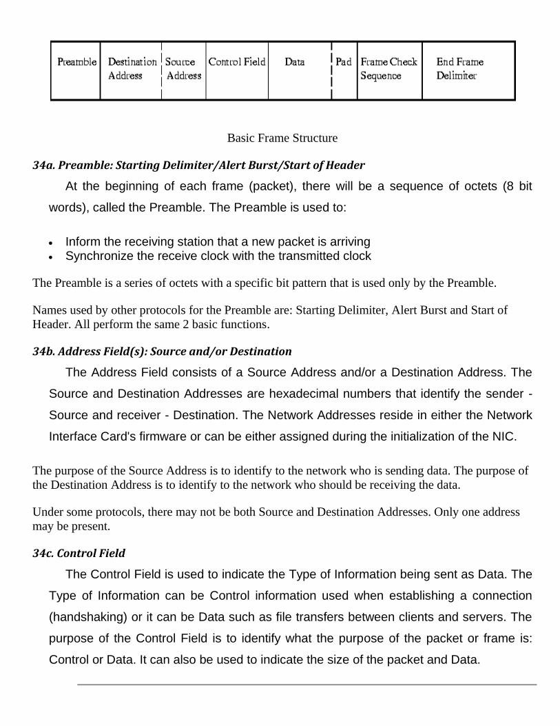
Basic Frame Structure
34a. Preamble: Starting Delimiter/Alert Burst/Start of Header
At the beginning of each frame (packet), there will be a sequence of octets (8 bit
words), called the Preamble. The Preamble is used to:
Inform the receiving station that a new packet is arriving
Synchronize the receive clock with the transmitted clock
The Preamble is a series of octets with a specific bit pattern that is used only by the Preamble.
Names used by other protocols for the Preamble are: Starting Delimiter, Alert Burst and Start of
Header. All perform the same 2 basic functions.
34b. Address Field(s): Source and/or Destination
The Address Field consists of a Source Address and/or a Destination Address. The
Source and Destination Addresses are hexadecimal numbers that identify the sender -
Source and receiver - Destination. The Network Addresses reside in either the Network
Interface Card's firmware or can be either assigned during the initialization of the NIC.
The purpose of the Source Address is to identify to the network who is sending data. The purpose of
the Destination Address is to identify to the network who should be receiving the data.
Under some protocols, there may not be both Source and Destination Addresses. Only one address
may be present.
34c. Control Field
The Control Field is used to indicate the Type of Information being sent as Data. The
Type of Information can be Control information used when establishing a connection
(handshaking) or it can be Data such as file transfers between clients and servers. The
purpose of the Control Field is to identify what the purpose of the packet or frame is:
Control or Data. It can also be used to indicate the size of the packet and Data.
34d. Data/Message and optional Pad
The Data Field or Message is the actual information that is being transmitted. It can
contain Control Information for handshaking or actual Data used by applications. The
Control Field would indicate the Data Field size. The Data field is also called the Info
field by some protocols.
The optional Pad is used to pad the data field when the protocol has a fixed Data Field size. If the
Data Field size is fixed at 1200 octets and only 300 octets of information is available then the Pad
will fill in the remaining 900 octets with characters (e.g. 900 octets of 00h). The protocol may also
use the Pad to ensure a minimum Data field size.
34e. CRC/ Frame Check Sequence
The CRC / Frame Check Sequence (FCS) contains an error checking number that
the Destination can use to verify that the packet is okay and error-free. CRC is an
abbreviation for Cyclic Redundancy Checking. The Frame Check Sequence typically
incorporates a 32 Bit CRC check. Checksums work similarly but use a different
algorithm.
As each packet is sent, the Source calculates a check number from the data using a predetermined
algorithm (formula). The result of this calculation is appended to the packet in the Frame Check
Sequence (FCS) field. At the Destination, the same calculation is performed and the result is
compared to the transmitted Frame Check Sequence. If the result generated at the Destination is
identical to the FCS, then it is assumed that the packet is error free at the bit level.
34f. End Frame Delimiter
The End Frame Delimiter is a series of octets that have a specific bit pattern that
identifies the end of the packet to the Destination. Not all protocols have End Frame
Delimiters fields, protocols with fixed packet size may not need the End Frame Delimiter
field as the Destination may simply count the number of octets it has received.
35. Physical Layer
The OSI Model Physical Layer concerns itself with the transmission of bits through
the communication medium. The order of the bits and importance is determined by the
Protocol's packet.
35a. Asynchronous & Synchronous Communication
In Asynchronous Communications, the OSI Physical layer concerned itself with the
RS-232D standard and the Voice Channel. The RS-232D standard stated the electrical
and mechanical characteristics of the cable for the transmission of the digital signal
between the DTE (PC) and DCE (modem). The Voice Channel stated the electrical and
mechanical characteristics of the connection between DCE to DCE (modem to modem)
through the phone lines.
The order of the bits was determined by the ASCII characters, the parity (Odd/Even/None), number
of Stop Bits and the Transfer Protocol used. Examples of Transfer Protocols are:
Kermit Xmodem Ymodem Zmodem
Similarly, in Synchronous Communications, the electrical and mechanical characteristics of
the cable for the transmission of the signal are defined by the protocol used between
Network Interface Cards.
The electrical characteristics associated with the OSI Model's Physical layer are:
Transmission rate (bits/sec) Voltage levels Line Encoding Propagation delay Termination impedance
The mechanical characteristics associated with the OSI Model's Physical layer are:
Connector type Cable type & size Cable Length Topology Shielding
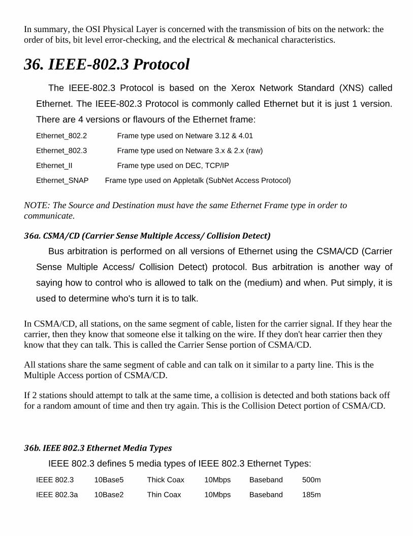
In summary, the OSI Physical Layer is concerned with the transmission of bits on the network: the
order of bits, bit level error-checking, and the electrical & mechanical characteristics.
36. IEEE-802.3 Protocol
The IEEE-802.3 Protocol is based on the Xerox Network Standard (XNS) called
Ethernet. The IEEE-802.3 Protocol is commonly called Ethernet but it is just 1 version.
There are 4 versions or flavours of the Ethernet frame:
Ethernet_802.2 Frame type used on Netware 3.12 & 4.01
Ethernet_802.3 Frame type used on Netware 3.x & 2.x (raw)
Ethernet_II Frame type used on DEC, TCP/IP
Ethernet_SNAP
Frame type used on Appletalk (SubNet Access Protocol)
NOTE: The Source and Destination must have the same Ethernet Frame type in order to
communicate.
36a. CSMA/CD (Carrier Sense Multiple Access/ Collision Detect)
Bus arbitration is performed on all versions of Ethernet using the CSMA/CD (Carrier
Sense Multiple Access/ Collision Detect) protocol. Bus arbitration is another way of
saying how to control who is allowed to talk on the (medium) and when. Put simply, it is
used to determine who's turn it is to talk.
In CSMA/CD, all stations, on the same segment of cable, listen for the carrier signal. If they hear the
carrier, then they know that someone else it talking on the wire. If they don't hear carrier then they
know that they can talk. This is called the Carrier Sense portion of CSMA/CD.
All stations share the same segment of cable and can talk on it similar to a party line. This is the
Multiple Access portion of CSMA/CD.
If 2 stations should attempt to talk at the same time, a collision is detected and both stations back off
for a random amount of time and then try again. This is the Collision Detect portion of CSMA/CD.
36b. IEEE 802.3 Ethernet Media Types
IEEE 802.3 defines 5 media types of IEEE 802.3 Ethernet Types:
IEEE 802.3
10Base5
Thick Coax
10Mbps
Baseband
500m
IEEE 802.3a
10Base2
Thin Coax
10Mbps
Baseband
185m
IEEE803b
10Broad36
Broadband
10 Mbps
Broadband
3600m
IEEE802.3e
1Base5
StarLAN
1 Mbps
Baseband
500m
IEEE 802.3i
10BaseT
Twisted Pair
10Mps
Baseband
100m
IEEE 802.3 - 10Base5 (Thick Coax) is used only as backbones to networks. Backbones are lines that
connect buildings & network equipment together such as Bridges, Routers, Brouter, Hubs,
Concentrators, Gateways, etc.. 10Base5 is being replaced by either Thin Coax or fibre optics.
IEEE 802.3a - 10Base2 is commonly used in new installations as a backbone to connect buildings
and network equipment together. 10Base2 (Thin Coax) is also used to connect work-stations
together but the preferred choice is to use 10BaseT.
IEEE 802.3b - 10Broad36 is rarely used, it combined analog and digital signals together. Broadband
means that a mixture of signals can be sent on the same medium.
IEEE 802.3e - StarLAN is a slow 1 Mbps standard that has been replaced by Thin Coax or Twisted
Pair.
IEEE 802.3i - 10BaseT is commonly used to connect workstations to network hubs. The network
hubs can use 10BaseT (Twisted Pair) to connect to other Hubs.
36c. IEEE 802.3 10Base5
10Base5 Specifications :
Coaxial Cable
Uses double shielded 0.4 inch diameter RG8 coaxial cable about the size of a garden hose. The cable
is not flexible and difficult to work with. The cable has a characteristic impedance of 50 ohms.
Connection to the workstation is made with a MAU - Medium Attachment Unit or Transceiver. The
MAU physically and electrically attaches to the coaxial cable by a cable tap. The cable is pierced
and a connection is made by a screw to the center conductor.
The MAU is connected to the NIC (Network Interface Card) by the AUI (Attachment Unit Interface)
cable. The AUI port on a NIC and a MAU is a DB15 connector. Maximum AUI cable length is 50
m.
Cable Termination and Connector

The standard termination is 50 +/-2 ohms. The end connector on the RG-8 cable is an "N" type
connector. The cable is externally terminated with a resistor inside an N connector.
Grounding
To minimize noise on the segment, the cable is grounded at the termination at only one end.
Maximum Nodes on a cable segment
On any 1 cable segment, the maximum allowed number of nodes or MAUs is 100.
Minimum Distance between nodes
Minimum distance between nodes or MAUs is 2.5 m or 8 feet.
Velocity of propagation
The speed of the signal through the cable is 0.77c. ("c" is equal to the speed of light - 300,000,000
m/sec). The velocity of propagation for 10Base5 specification cable is equal to 0.77 x 300,000,000
m/sec. This is determined by cable capacitance. Maximum coaxial cable segment length 500 m
The maximum segment length is 500 m or a maximum 2.165 uSec propagation delay. Propagation
delay is what actually determines the maximum length of the segment.
Propagation delay for a specific cable length in meters is calculated by:
What is the propagation delay for a 500 m length of 10Base5 cable?
Maximum Number of Segments
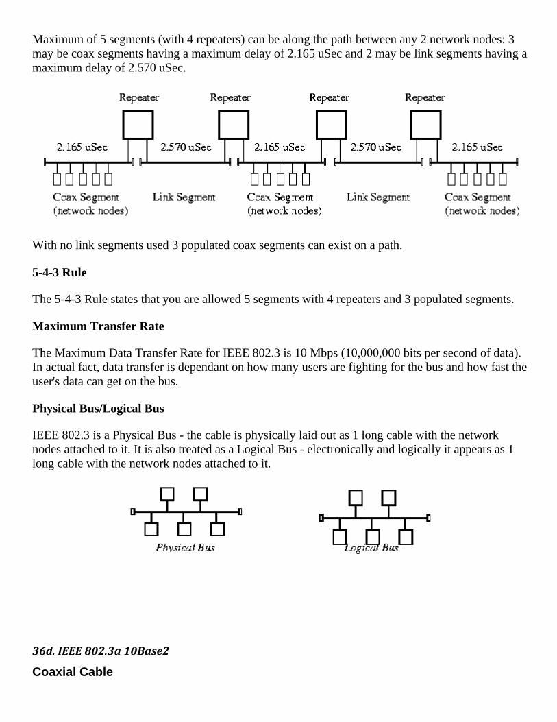
Maximum of 5 segments (with 4 repeaters) can be along the path between any 2 network nodes: 3
may be coax segments having a maximum delay of 2.165 uSec and 2 may be link segments having a
maximum delay of 2.570 uSec.
With no link segments used 3 populated coax segments can exist on a path.
5-4-3 Rule
The 5-4-3 Rule states that you are allowed 5 segments with 4 repeaters and 3 populated segments.
Maximum Transfer Rate
The Maximum Data Transfer Rate for IEEE 802.3 is 10 Mbps (10,000,000 bits per second of data).
In actual fact, data transfer is dependant on how many users are fighting for the bus and how fast the
user's data can get on the bus.
Physical Bus/Logical Bus
IEEE 802.3 is a Physical Bus - the cable is physically laid out as 1 long cable with the network
nodes attached to it. It is also treated as a Logical Bus - electronically and logically it appears as 1
long cable with the network nodes attached to it.
36d. IEEE 802.3a 10Base2
Coaxial Cable
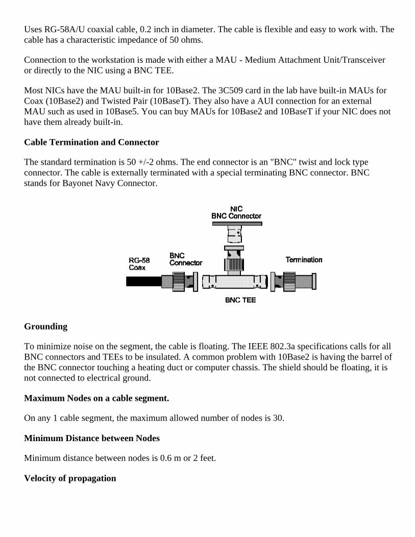
Uses RG-58A/U coaxial cable, 0.2 inch in diameter. The cable is flexible and easy to work with. The
cable has a characteristic impedance of 50 ohms.
Connection to the workstation is made with either a MAU - Medium Attachment Unit/Transceiver
or directly to the NIC using a BNC TEE.
Most NICs have the MAU built-in for 10Base2. The 3C509 card in the lab have built-in MAUs for
Coax (10Base2) and Twisted Pair (10BaseT). They also have a AUI connection for an external
MAU such as used in 10Base5. You can buy MAUs for 10Base2 and 10BaseT if your NIC does not
have them already built-in.
Cable Termination and Connector
The standard termination is 50 +/-2 ohms. The end connector is an "BNC" twist and lock type
connector. The cable is externally terminated with a special terminating BNC connector. BNC
stands for Bayonet Navy Connector.
Grounding
To minimize noise on the segment, the cable is floating. The IEEE 802.3a specifications calls for all
BNC connectors and TEEs to be insulated. A common problem with 10Base2 is having the barrel of
the BNC connector touching a heating duct or computer chassis. The shield should be floating, it is
not connected to electrical ground.
Maximum Nodes on a cable segment.
On any 1 cable segment, the maximum allowed number of nodes is 30.
Minimum Distance between Nodes
Minimum distance between nodes is 0.6 m or 2 feet.
Velocity of propagation
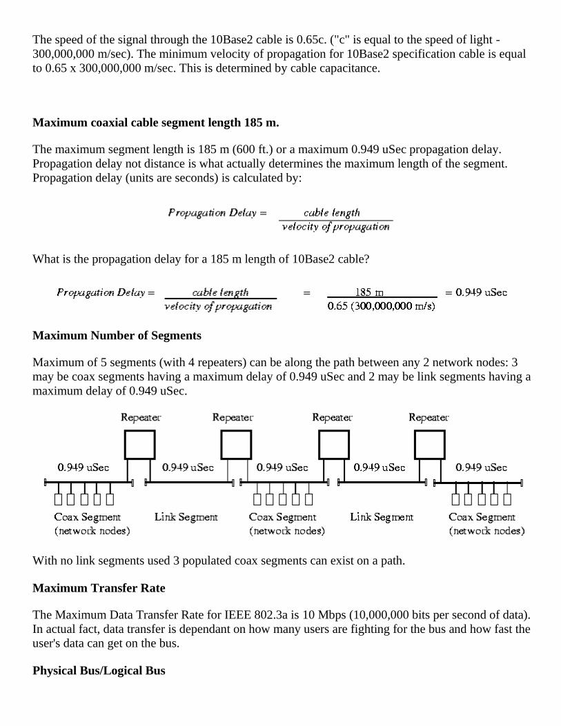
The speed of the signal through the 10Base2 cable is 0.65c. ("c" is equal to the speed of light -
300,000,000 m/sec). The minimum velocity of propagation for 10Base2 specification cable is equal
to 0.65 x 300,000,000 m/sec. This is determined by cable capacitance.
Maximum coaxial cable segment length 185 m.
The maximum segment length is 185 m (600 ft.) or a maximum 0.949 uSec propagation delay.
Propagation delay not distance is what actually determines the maximum length of the segment.
Propagation delay (units are seconds) is calculated by:
What is the propagation delay for a 185 m length of 10Base2 cable?
Maximum Number of Segments
Maximum of 5 segments (with 4 repeaters) can be along the path between any 2 network nodes: 3
may be coax segments having a maximum delay of 0.949 uSec and 2 may be link segments having a
maximum delay of 0.949 uSec.
With no link segments used 3 populated coax segments can exist on a path.
Maximum Transfer Rate
The Maximum Data Transfer Rate for IEEE 802.3a is 10 Mbps (10,000,000 bits per second of data).
In actual fact, data transfer is dependant on how many users are fighting for the bus and how fast the
user's data can get on the bus.
Physical Bus/Logical Bus
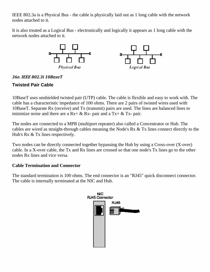
IEEE 802.3a is a Physical Bus - the cable is physically laid out as 1 long cable with the network
nodes attached to it.
It is also treated as a Logical Bus - electronically and logically it appears as 1 long cable with the
network nodes attached to it.
36e. IEEE 802.3i 10BaseT
Twisted Pair Cable
10BaseT uses unshielded twisted pair (UTP) cable. The cable is flexible and easy to work with. The
cable has a characteristic impedance of 100 ohms. There are 2 pairs of twisted wires used with
10BaseT. Separate Rx (receive) and Tx (transmit) pairs are used. The lines are balanced lines to
minimize noise and there are a Rx+ & Rx- pair and a Tx+ & Tx- pair.
The nodes are connected to a MPR (multiport repeater) also called a Concentrator or Hub. The
cables are wired as straight-through cables meaning the Node's Rx & Tx lines connect directly to the
Hub's Rx & Tx lines respectively.
Two nodes can be directly connected together bypassing the Hub by using a Cross-over (X-over)
cable. In a X-over cable, the Tx and Rx lines are crossed so that one node's Tx lines go to the other
nodes Rx lines and vice versa.
Cable Termination and Connector
The standard termination is 100 ohms. The end connector is an "RJ45" quick disconnect connector.
The cable is internally terminated at the NIC and Hub.
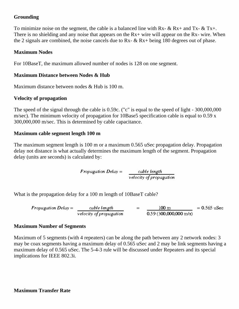
Grounding
To minimize noise on the segment, the cable is a balanced line with Rx- & Rx+ and Tx- & Tx+.
There is no shielding and any noise that appears on the Rx+ wire will appear on the Rx- wire. When
the 2 signals are combined, the noise cancels due to Rx- & Rx+ being 180 degrees out of phase.
Maximum Nodes
For 10BaseT, the maximum allowed number of nodes is 128 on one segment.
Maximum Distance between Nodes & Hub
Maximum distance between nodes & Hub is 100 m.
Velocity of propagation
The speed of the signal through the cable is 0.59c. ("c" is equal to the speed of light - 300,000,000
m/sec). The minimum velocity of propagation for 10Base5 specification cable is equal to 0.59 x
300,000,000 m/sec. This is determined by cable capacitance.
Maximum cable segment length 100 m
The maximum segment length is 100 m or a maximum 0.565 uSec propagation delay. Propagation
delay not distance is what actually determines the maximum length of the segment. Propagation
delay (units are seconds) is calculated by:
What is the propagation delay for a 100 m length of 10BaseT cable?
Maximum Number of Segments
Maximum of 5 segments (with 4 repeaters) can be along the path between any 2 network nodes: 3
may be coax segments having a maximum delay of 0.565 uSec and 2 may be link segments having a
maximum delay of 0.565 uSec. The 5-4-3 rule will be discussed under Repeaters and its special
implications for IEEE 802.3i.
Maximum Transfer Rate
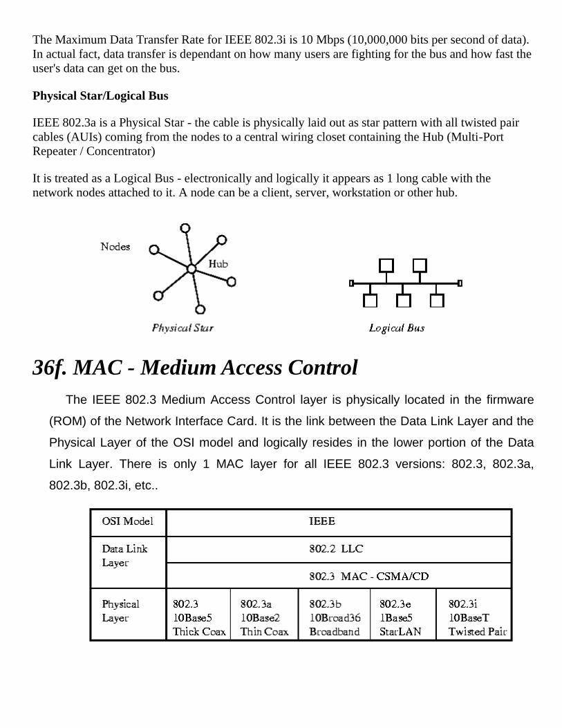
The Maximum Data Transfer Rate for IEEE 802.3i is 10 Mbps (10,000,000 bits per second of data).
In actual fact, data transfer is dependant on how many users are fighting for the bus and how fast the
user's data can get on the bus.
Physical Star/Logical Bus
IEEE 802.3a is a Physical Star - the cable is physically laid out as star pattern with all twisted pair
cables (AUIs) coming from the nodes to a central wiring closet containing the Hub (Multi-Port
Repeater / Concentrator)
It is treated as a Logical Bus - electronically and logically it appears as 1 long cable with the
network nodes attached to it. A node can be a client, server, workstation or other hub.
36f. MAC - Medium Access Control
The IEEE 802.3 Medium Access Control layer is physically located in the firmware
(ROM) of the Network Interface Card. It is the link between the Data Link Layer and the
Physical Layer of the OSI model and logically resides in the lower portion of the Data
Link Layer. There is only 1 MAC layer for all IEEE 802.3 versions: 802.3, 802.3a,
802.3b, 802.3i, etc..
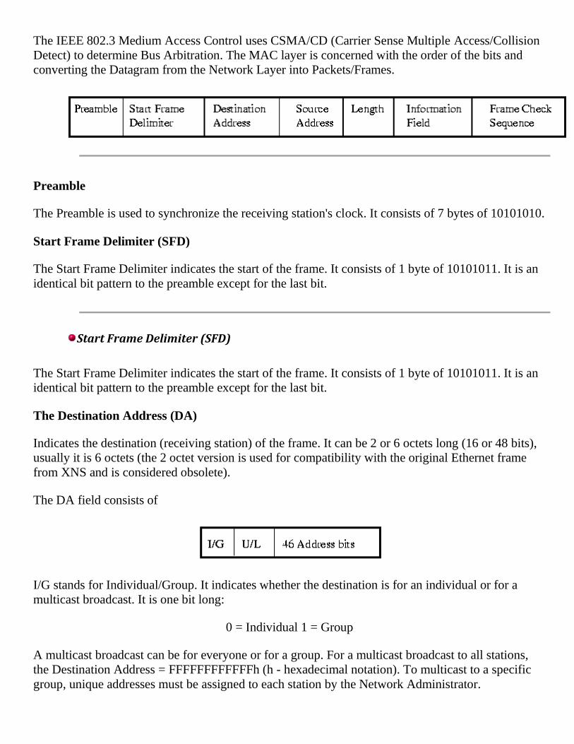
The IEEE 802.3 Medium Access Control uses CSMA/CD (Carrier Sense Multiple Access/Collision
Detect) to determine Bus Arbitration. The MAC layer is concerned with the order of the bits and
converting the Datagram from the Network Layer into Packets/Frames.
Preamble
The Preamble is used to synchronize the receiving station's clock. It consists of 7 bytes of 10101010.
Start Frame Delimiter (SFD)
The Start Frame Delimiter indicates the start of the frame. It consists of 1 byte of 10101011. It is an
identical bit pattern to the preamble except for the last bit.
Start Frame Delimiter (SFD)
The Start Frame Delimiter indicates the start of the frame. It consists of 1 byte of 10101011. It is an
identical bit pattern to the preamble except for the last bit.
The Destination Address (DA)
Indicates the destination (receiving station) of the frame. It can be 2 or 6 octets long (16 or 48 bits),
usually it is 6 octets (the 2 octet version is used for compatibility with the original Ethernet frame
from XNS and is considered obsolete).
The DA field consists of
I/G stands for Individual/Group. It indicates whether the destination is for an individual or for a
multicast broadcast. It is one bit long:
0 = Individual 1 = Group
A multicast broadcast can be for everyone or for a group. For a multicast broadcast to all stations,
the Destination Address = FFFFFFFFFFFFh (h - hexadecimal notation). To multicast to a specific
group, unique addresses must be assigned to each station by the Network Administrator.
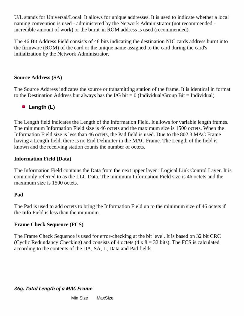
U/L stands for Universal/Local. It allows for unique addresses. It is used to indicate whether a local
naming convention is used - administered by the Network Administrator (not recommended -
incredible amount of work) or the burnt-in ROM address is used (recommended).
The 46 Bit Address Field consists of 46 bits indicating the destination NIC cards address burnt into
the firmware (ROM) of the card or the unique name assigned to the card during the card's
initialization by the Network Administrator.
Source Address (SA)
The Source Address indicates the source or transmitting station of the frame. It is identical in format
to the Destination Address but always has the I/G bit = 0 (Individual/Group Bit = Individual)
Length (L)
The Length field indicates the Length of the Information Field. It allows for variable length frames.
The minimum Information Field size is 46 octets and the maximum size is 1500 octets. When the
Information Field size is less than 46 octets, the Pad field is used. Due to the 802.3 MAC Frame
having a Length field, there is no End Delimiter in the MAC Frame. The Length of the field is
known and the receiving station counts the number of octets.
Information Field (Data)
The Information Field contains the Data from the next upper layer : Logical Link Control Layer. It is
commonly referred to as the LLC Data. The minimum Information Field size is 46 octets and the
maximum size is 1500 octets.
Pad
The Pad is used to add octets to bring the Information Field up to the minimum size of 46 octets if
the Info Field is less than the minimum.
Frame Check Sequence (FCS)
The Frame Check Sequence is used for error-checking at the bit level. It is based on 32 bit CRC
(Cyclic Redundancy Checking) and consists of 4 octets (4 x 8 = 32 bits). The FCS is calculated
according to the contents of the DA, SA, L, Data and Pad fields.
36g. Total Length of a MAC Frame
Min Size
MaxSize
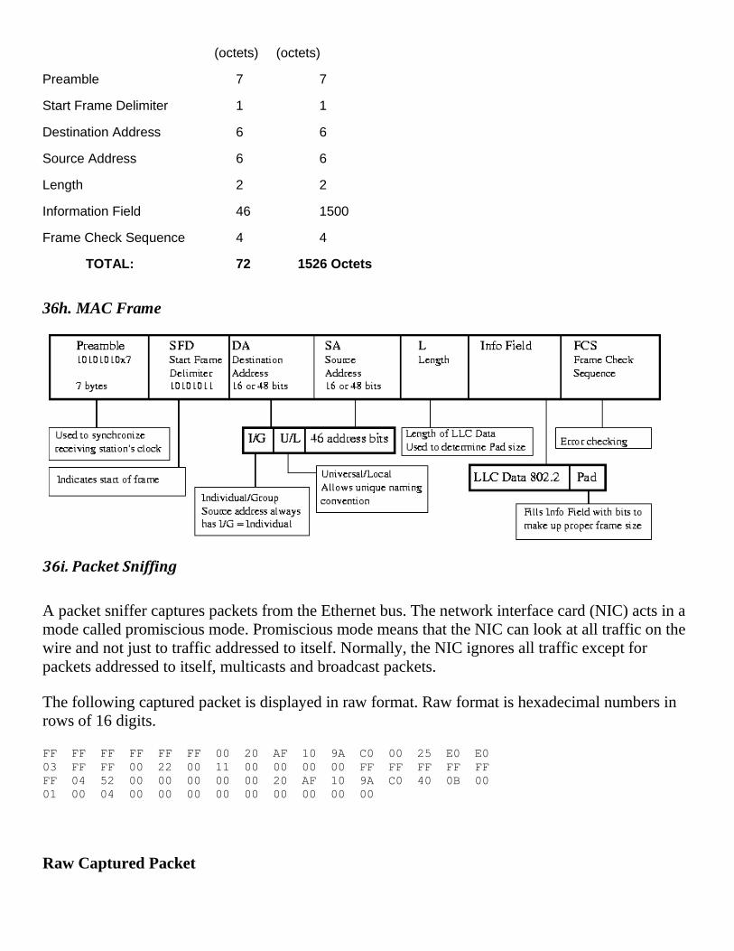
(octets) (octets)
Preamble 7
7
Start Frame Delimiter 1
1
Destination Address 6
6
Source Address 6
6
Length 2
2
Information Field 46
1500
Frame Check Sequence 4
4
TOTAL: 72
1526 Octets
36h. MAC Frame
36i. Packet Sniffing
A packet sniffer captures packets from the Ethernet bus. The network interface card (NIC) acts in a
mode called promiscious mode. Promiscious mode means that the NIC can look at all traffic on the
wire and not just to traffic addressed to itself. Normally, the NIC ignores all traffic except for
packets addressed to itself, multicasts and broadcast packets.
The following captured packet is displayed in raw format. Raw format is hexadecimal numbers in
rows of 16 digits.
FF FF FF FF FF FF 00 20 AF 10 9A C0 00 25 E0 E0
03 FF FF 00 22 00 11 00 00 00 00 FF FF FF FF FF
FF 04 52 00 00 00 00 00 20 AF 10 9A C0 40 0B 00
01 00 04 00 00 00 00 00 00 00 00 00
Raw Captured Packet
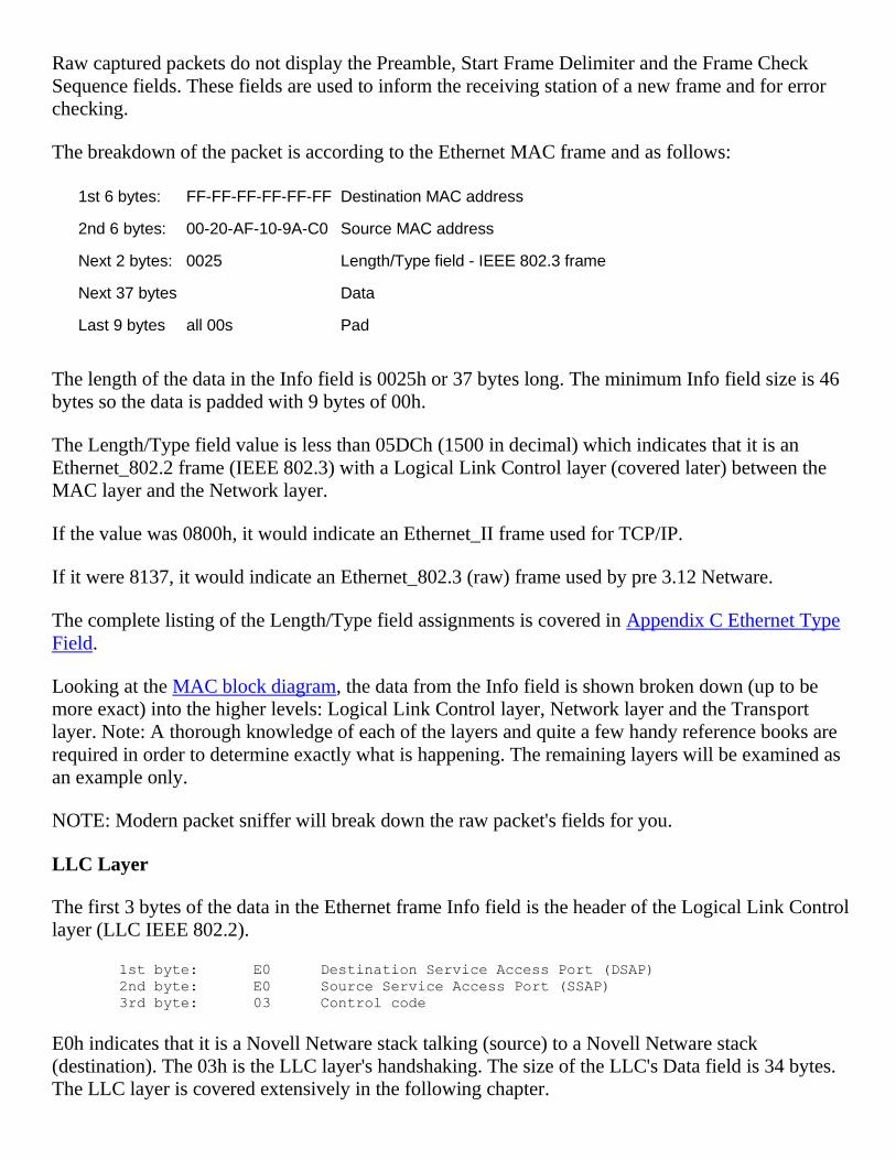
Raw captured packets do not display the Preamble, Start Frame Delimiter and the Frame Check
Sequence fields. These fields are used to inform the receiving station of a new frame and for error
checking.
The breakdown of the packet is according to the Ethernet MAC frame and as follows:
1st 6 bytes:
FF-FF-FF-FF-FF-FF
Destination MAC address
2nd 6 bytes:
00-20-AF-10-9A-C0
Source MAC address
Next 2 bytes:
0025
Length/Type field - IEEE 802.3 frame
Next 37 bytes
Data
Last 9 bytes
all 00s
Pad
The length of the data in the Info field is 0025h or 37 bytes long. The minimum Info field size is 46
bytes so the data is padded with 9 bytes of 00h.
The Length/Type field value is less than 05DCh (1500 in decimal) which indicates that it is an
Ethernet_802.2 frame (IEEE 802.3) with a Logical Link Control layer (covered later) between the
MAC layer and the Network layer.
If the value was 0800h, it would indicate an Ethernet_II frame used for TCP/IP.
If it were 8137, it would indicate an Ethernet_802.3 (raw) frame used by pre 3.12 Netware.
The complete listing of the Length/Type field assignments is covered in Appendix C Ethernet Type
Field.
Looking at the MAC block diagram, the data from the Info field is shown broken down (up to be
more exact) into the higher levels: Logical Link Control layer, Network layer and the Transport
layer. Note: A thorough knowledge of each of the layers and quite a few handy reference books are
required in order to determine exactly what is happening. The remaining layers will be examined as
an example only.
NOTE: Modern packet sniffer will break down the raw packet's fields for you.
LLC Layer
The first 3 bytes of the data in the Ethernet frame Info field is the header of the Logical Link Control
layer (LLC IEEE 802.2).
1st byte: E0 Destination Service Access Port (DSAP)
2nd byte: E0 Source Service Access Port (SSAP)
3rd byte: 03 Control code
E0h indicates that it is a Novell Netware stack talking (source) to a Novell Netware stack
(destination). The 03h is the LLC layer's handshaking. The size of the LLC's Data field is 34 bytes.
The LLC layer is covered extensively in the following chapter.
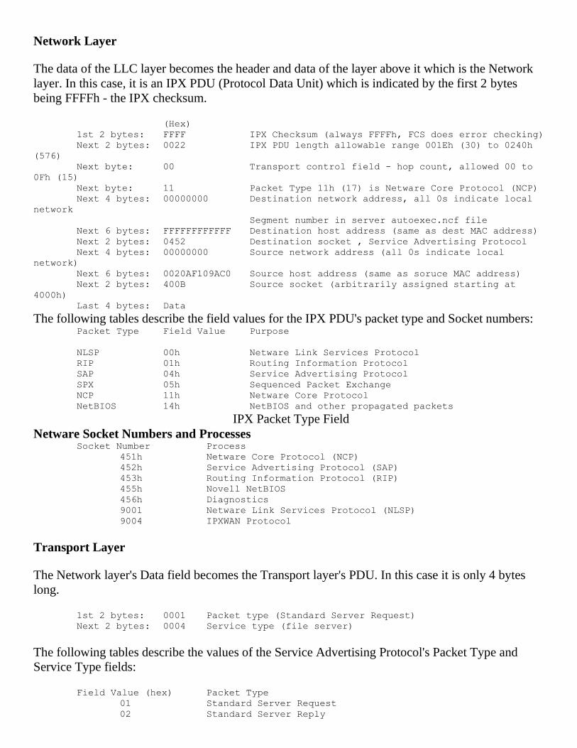
Network Layer
The data of the LLC layer becomes the header and data of the layer above it which is the Network
layer. In this case, it is an IPX PDU (Protocol Data Unit) which is indicated by the first 2 bytes
being FFFFh - the IPX checksum.
(Hex)
1st 2 bytes: FFFF IPX Checksum (always FFFFh, FCS does error checking)
Next 2 bytes: 0022 IPX PDU length allowable range 001Eh (30) to 0240h
(576)
Next byte: 00 Transport control field - hop count, allowed 00 to
0Fh (15)
Next byte: 11 Packet Type 11h (17) is Netware Core Protocol (NCP)
Next 4 bytes: 00000000 Destination network address, all 0s indicate local
network
Segment number in server autoexec.ncf file
Next 6 bytes: FFFFFFFFFFFF Destination host address (same as dest MAC address)
Next 2 bytes: 0452 Destination socket , Service Advertising Protocol
Next 4 bytes: 00000000 Source network address (all 0s indicate local
network)
Next 6 bytes: 0020AF109AC0 Source host address (same as soruce MAC address)
Next 2 bytes: 400B Source socket (arbitrarily assigned starting at
4000h)
Last 4 bytes: Data
The following tables describe the field values for the IPX PDU's packet type and Socket numbers: Packet Type Field Value Purpose
NLSP 00h Netware Link Services Protocol
RIP 01h Routing Information Protocol
SAP 04h Service Advertising Protocol
SPX 05h Sequenced Packet Exchange
NCP 11h Netware Core Protocol
NetBIOS 14h NetBIOS and other propagated packets
IPX Packet Type Field
Netware Socket Numbers and Processes Socket Number Process
451h Netware Core Protocol (NCP)
452h Service Advertising Protocol (SAP)
453h Routing Information Protocol (RIP)
455h Novell NetBIOS
456h Diagnostics
9001 Netware Link Services Protocol (NLSP)
9004 IPXWAN Protocol
Transport Layer
The Network layer's Data field becomes the Transport layer's PDU. In this case it is only 4 bytes
long.
1st 2 bytes: 0001 Packet type (Standard Server Request)
Next 2 bytes: 0004 Service type (file server)
The following tables describe the values of the Service Advertising Protocol's Packet Type and
Service Type fields:
Field Value (hex) Packet Type
01 Standard Server Request
02 Standard Server Reply
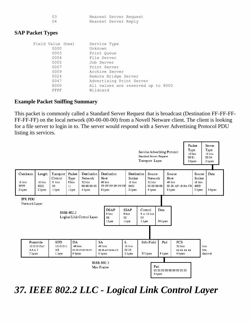
03 Nearest Server Request
04 Nearest Server Reply
SAP Packet Types
Field Value (hex) Service Type
0000 Unknown
0003 Print Queue
0004 File Server
0005 Job Server
0007 Print Server
0009 Archive Server
0024 Remote Bridge Server
0047 Advertising Print Server
8000 All values are reserved up to 8000
FFFF Wildcard
Example Packet Sniffing Summary
This packet is commonly called a Standard Server Request that is broadcast (Destination FF-FF-FF-
FF-FF-FF) on the local network (00-00-00-00) from a Novell Netware client. The client is looking
for a file server to login in to. The server would respond with a Server Advertising Protocol PDU
listing its services.
37. IEEE 802.2 LLC - Logical Link Control Layer

The Logical Link Control Layer resides in the upper portion of the Data Link Layer. The LLC layer
performs these functions:
a. Managing the data-link communication
b. Link Addressing
c. Defining Service Access Points (SAPs)
d. Sequencing
The LLC provides a way for the upper layers to deal with any type of MAC layer (ex. Ethernet -
IEEE 802.3 CSMA/CD or Token Ring IEEE 802.5 Token Passing).
The Data field of the MAC layer Frame transmits the LLC Protocol Data Unit.
LLC PDU Format
37a. Service Access Ports (SAPs)
SAPs are Service Access Ports. A SAP is a port (logical link) to the Network layer
protocol. If we were operating a multiprotocol LAN, each Network Layer protocol would
have its own SAP. This is the method that the LLC uses to identify which protocol is
talking to which. For example, Unix's TCP/IP, Novell's SPX/IPX and IBM's Netbios
would all have different SAPs to identify which was which.
Address Assignment
00 Null LSAP
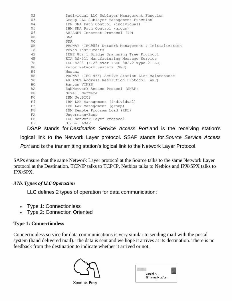
02 Individual LLC Sublayer Management Function
03 Group LLC Sublayer Management Function
04 IBM SNA Path Control (individual)
05 IBM SNA Path Control (group)
06 ARPANET Internet Protocol (IP)
08 SNA
0C SNA
0E PROWAY (IEC955) Network Management & Initialization
18 Texas Instruments
42 IEEE 802.1 Bridge Spannning Tree Protocol
4E EIA RS-511 Manufacturing Message Service
7E ISO 8208 (X.25 over IEEE 802.2 Type 2 LLC)
80 Xerox Network Systems (XNS)
86 Nestar
8E PROWAY (IEC 955) Active Station List Maintenance
98 ARPANET Address Resolution Protocol (ARP)
BC Banyan VINES
AA SubNetwork Access Protocl (SNAP)
E0 Novell NetWare
F0 IBM NetBIOS
F4 IBM LAN Management (individual)
F5 IBM LAN Management (group)
F8 IBM Remote Program Load (RPL)
FA Ungermann-Bass
FE ISO Network Layer Protocol
FF Global LSAP
DSAP stands for Destination Service Access Port and is the receiving station's
logical link to the Network Layer protocol. SSAP stands for Source Service Access
Port and is the transmitting station's logical link to the Network Layer Protocol.
SAPs ensure that the same Network Layer protocol at the Source talks to the same Network Layer
protocol at the Destination. TCP/IP talks to TCP/IP, Netbios talks to Netbios and IPX/SPX talks to
IPX/SPX.
37b. Types of LLC Operation
LLC defines 2 types of operation for data communication:
Type 1: Connectionless
Type 2: Connection Oriented
Type 1: Connectionless
Connectionless service for data communications is very similar to sending mail with the postal
system (hand delivered mail). The data is sent and we hope it arrives at its destination. There is no
feedback from the destination to indicate whether it arrived or not.

Type 1: Connectionless Service
Type 2: Connection Oriented
Connection Oriented service for data communications is very similar to having a phone
conversation. First a connection is made and established by dialing the number, waiting for it to ring,
someone picking up the line and saying hello. This establishes the connection. During the
conversation, confirmation that the other person is still there (hasn't fallen asleep or died) and
listening is given by hearing things like: yeah, oh really, uh huh, etc.. This is the acknowledgement
of receipt of data. If the destination party did not hear something correctly, they ask to have it
repeated which is called automatic repeat request (ARQ).
Connection Oriented service
NOTE: These models for connectionless and connection-oriented can be used for any protocol.
1. Connection establishment
2. Confirmation and acknowledgement that data has been received.
3. Error recovery by requesting received bad data to be resent.
4. Sliding Windows (Modulus: 128)
Sliding Windows are a method of increasing the rate of data transfer. Type 2 Connection Oriented
operation calls for every Protocol Data Unit (LLC frame) sent to be acknowledged. If we waited for
every PDU to be acknowledged before we sent the next PDU, we would have a very slow data
transfer rate.
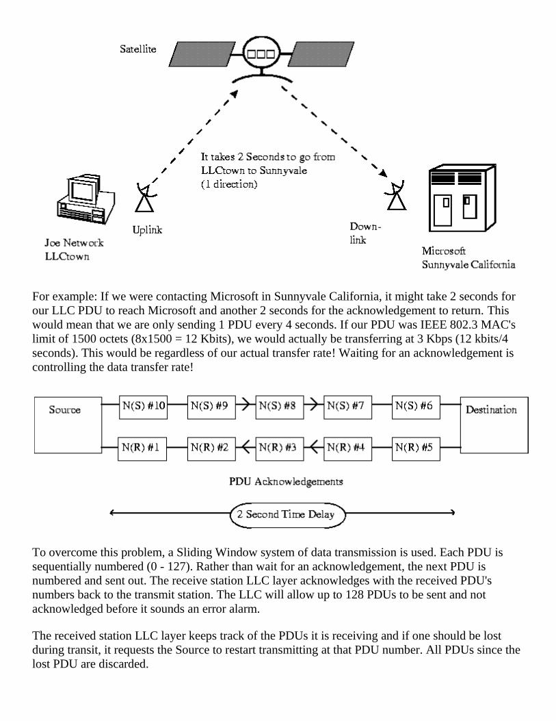
For example: If we were contacting Microsoft in Sunnyvale California, it might take 2 seconds for
our LLC PDU to reach Microsoft and another 2 seconds for the acknowledgement to return. This
would mean that we are only sending 1 PDU every 4 seconds. If our PDU was IEEE 802.3 MAC's
limit of 1500 octets (8x1500 = 12 Kbits), we would actually be transferring at 3 Kbps (12 kbits/4
seconds). This would be regardless of our actual transfer rate! Waiting for an acknowledgement is
controlling the data transfer rate!
To overcome this problem, a Sliding Window system of data transmission is used. Each PDU is
sequentially numbered (0 - 127). Rather than wait for an acknowledgement, the next PDU is
numbered and sent out. The receive station LLC layer acknowledges with the received PDU's
numbers back to the transmit station. The LLC will allow up to 128 PDUs to be sent and not
acknowledged before it sounds an error alarm.
The received station LLC layer keeps track of the PDUs it is receiving and if one should be lost
during transit, it requests the Source to restart transmitting at that PDU number. All PDUs since the
lost PDU are discarded.
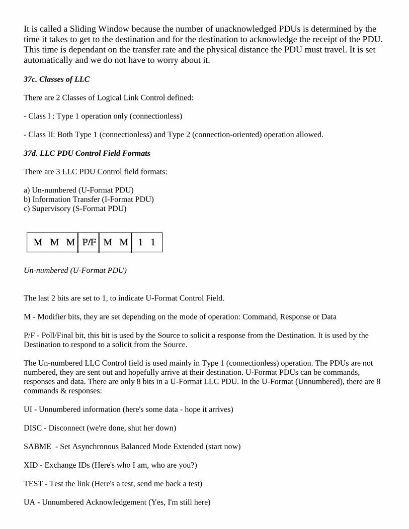
It is called a Sliding Window because the number of unacknowledged PDUs is determined by the
time it takes to get to the destination and for the destination to acknowledge the receipt of the PDU.
This time is dependant on the transfer rate and the physical distance the PDU must travel. It is set
automatically and we do not have to worry about it.
37c. Classes of LLC
There are 2 Classes of Logical Link Control defined:
- Class I : Type 1 operation only (connectionless)
- Class II: Both Type 1 (connectionless) and Type 2 (connection-oriented) operation allowed.
37d. LLC PDU Control Field Formats
There are 3 LLC PDU Control field formats:
a) Un-numbered (U-Format PDU)
b) Information Transfer (I-Format PDU)
c) Supervisory (S-Format PDU)
Un-numbered (U-Format PDU)
The last 2 bits are set to 1, to indicate U-Format Control Field.
M - Modifier bits, they are set depending on the mode of operation: Command, Response or Data
P/F - Poll/Final bit, this bit is used by the Source to solicit a response from the Destination. It is used by the
Destination to respond to a solicit from the Source.
The Un-numbered LLC Control field is used mainly in Type 1 (connectionless) operation. The PDUs are not
numbered, they are sent out and hopefully arrive at their destination. U-Format PDUs can be commands,
responses and data. There are only 8 bits in a U-Format LLC PDU. In the U-Format (Unnumbered), there are 8
commands & responses:
UI - Unnumbered information (here's some data - hope it arrives)
DISC - Disconnect (we're done, shut her down)
SABME - Set Asynchronous Balanced Mode Extended (start now)
XID - Exchange IDs (Here's who I am, who are you?)
TEST - Test the link (Here's a test, send me back a test)
UA - Unnumbered Acknowledgement (Yes, I'm still here)
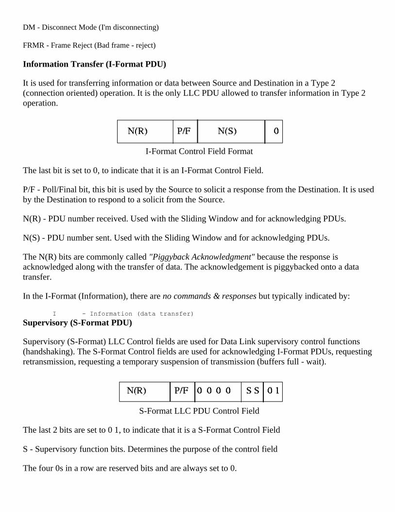
DM - Disconnect Mode (I'm disconnecting)
FRMR - Frame Reject (Bad frame - reject)
Information Transfer (I-Format PDU)
It is used for transferring information or data between Source and Destination in a Type 2
(connection oriented) operation. It is the only LLC PDU allowed to transfer information in Type 2
operation.
I-Format Control Field Format
The last bit is set to 0, to indicate that it is an I-Format Control Field.
P/F - Poll/Final bit, this bit is used by the Source to solicit a response from the Destination. It is used
by the Destination to respond to a solicit from the Source.
N(R) - PDU number received. Used with the Sliding Window and for acknowledging PDUs.
N(S) - PDU number sent. Used with the Sliding Window and for acknowledging PDUs.
The N(R) bits are commonly called "Piggyback Acknowledgment" because the response is
acknowledged along with the transfer of data. The acknowledgement is piggybacked onto a data
transfer.
In the I-Format (Information), there are no commands & responses but typically indicated by:
I - Information (data transfer)
Supervisory (S-Format PDU)
Supervisory (S-Format) LLC Control fields are used for Data Link supervisory control functions
(handshaking). The S-Format Control fields are used for acknowledging I-Format PDUs, requesting
retransmission, requesting a temporary suspension of transmission (buffers full - wait).
S-Format LLC PDU Control Field
The last 2 bits are set to 0 1, to indicate that it is a S-Format Control Field
S - Supervisory function bits. Determines the purpose of the control field
The four 0s in a row are reserved bits and are always set to 0.
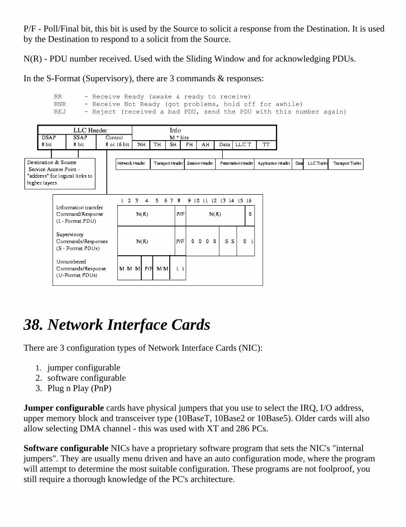
P/F - Poll/Final bit, this bit is used by the Source to solicit a response from the Destination. It is used
by the Destination to respond to a solicit from the Source.
N(R) - PDU number received. Used with the Sliding Window and for acknowledging PDUs.
In the S-Format (Supervisory), there are 3 commands & responses:
RR - Receive Ready (awake & ready to receive)
RNR - Receive Not Ready (got problems, hold off for awhile)
REJ - Reject (received a bad PDU, send the PDU with this number again)
38. Network Interface Cards
There are 3 configuration types of Network Interface Cards (NIC):
1. jumper configurable
2. software configurable
3. Plug n Play (PnP)
Jumper configurable cards have physical jumpers that you use to select the IRQ, I/O address,
upper memory block and transceiver type (10BaseT, 10Base2 or 10Base5). Older cards will also
allow selecting DMA channel - this was used with XT and 286 PCs.
Software configurable NICs have a proprietary software program that sets the NIC's "internal
jumpers". They are usually menu driven and have an auto configuration mode, where the program
will attempt to determine the most suitable configuration. These programs are not foolproof, you
still require a thorough knowledge of the PC's architecture.
Plug n Play NICs will attempt to auto-configure themselves during the bootup sequence
immediately after installation. They also come with a proprietary software program in case that
anything goes wrong and you have to manually configure them.
A combination (combo) NIC has the option of connecting to the network using either Twisted Pair
(10BaseT), Coax (10Base2) or AUI (Attachment Unit Interface for 10Base5). The NIC can only
connect to one medium type at a time and the configuration software allows you to select which
medium interface to connect to. Newer NICs will autodetect the cabling type used.
38a. IRQs, DMAs and Base Addresses
When a NIC is configured, you are setting the parameters which tell the computer
network software where to find the adapter (base address) and who is "tapping the CPU
on the shoulder" (IRQ). The base address is the pointer to the rest of the world that says
"Here I am at base address xxx!". The IRQ is the "tap on the shoulder" to the CPU that
says "Hey, it's IRQx, I've got something important to say!". The Upper Memory Block is
the NIC's BIOS or actual program in the NIC's ROM. It is set to a free area of memory in
the PC's upper memory - to avoid conflicts with other devices (video cards, internal
modems, SCSI drivers, etc..).
IRQ - Interrupt Requests
IRQ stands for Interrupt ReQuest. It is a "tap on the shoulder" to the CPU by a peripheral card
plugged in an ISA slot to tell the CPU that the peripheral has something to say (also used by EISA
and MCA slots). Common peripherals are modems, NICs (network interface cards), sound cards,
SCSI adapters, hard-drive controllers, floppy drive controllers, COM ports and printer ports.
An IRQ is a hardware interrupt, this means that there is a physical line run to each of the ISA slots
on the motherboard. There are 2 types of ISA slots: 8 bit and 16 bit. The 16 bit consists of the 8 bit
slot plus a 16 bit extension slot. There are 8 IRQ (IRQ0-7) lines that run to the 8 bit ISA slot. There
are 8 more (IRQ8-15) that run to the 16 bit ISA extension slot. For a total of 16 IRQs in a typical
ISA bus PC.
IRQ0 has the highest priority and IRQ7 the lowest priority. IRQ8-15 have "special" priority as will
be explained. When IBM introduced the AT computer, they added IRQ8-15. In order to make AT
(286) PCs backward compatible with 8 bit XT (8088) PCs and to "up" the priority of the new IRQ
lines, they cascaded two interrupt controllers. This results in IRQ8-15 having the same priority as
IRQ2. Priority means if two IRQs are active at the same time, the one with the higher priority is
serviced first.
IMPORTANT: An IRQ can be assigned to only ONE active device at a time. If 2 devices share the
same IRQ, this is called a CONFLICT. This means that when the IRQ line becomes active, the CPU
does not know which device needs to "talk".
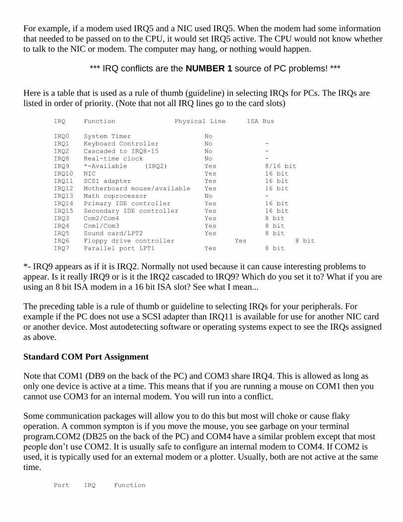
For example, if a modem used IRQ5 and a NIC used IRQ5. When the modem had some information
that needed to be passed on to the CPU, it would set IRQ5 active. The CPU would not know whether
to talk to the NIC or modem. The computer may hang, or nothing would happen.
*** IRQ conflicts are the NUMBER 1 source of PC problems! ***
Here is a table that is used as a rule of thumb (guideline) in selecting IRQs for PCs. The IRQs are
listed in order of priority. (Note that not all IRQ lines go to the card slots)
IRQ Function Physical Line ISA Bus
IRQ0 System Timer No
IRQ1 Keyboard Controller No -
IRQ2 Cascaded to IRQ8-15 No -
IRQ8 Real-time clock No -
IRQ9 *-Available (IRQ2) Yes 8/16 bit
IRQ10 NIC Yes 16 bit
IRQ11 SCSI adapter Yes 16 bit
IRQ12 Motherboard mouse/available Yes 16 bit
IRQ13 Math coprocessor No -
IRQ14 Primary IDE controller Yes 16 bit
IRQ15 Secondary IDE controller Yes 16 bit
IRQ3 Com2/Com4 Yes 8 bit
IRQ4 Com1/Com3 Yes 8 bit
IRQ5 Sound card/LPT2 Yes 8 bit
IRQ6 Floppy drive controller Yes 8 bit
IRQ7 Parallel port LPT1 Yes 8 bit
*- IRQ9 appears as if it is IRQ2. Normally not used because it can cause interesting problems to
appear. Is it really IRQ9 or is it the IRQ2 cascaded to IRQ9? Which do you set it to? What if you are
using an 8 bit ISA modem in a 16 bit ISA slot? See what I mean...
The preceding table is a rule of thumb or guideline to selecting IRQs for your peripherals. For
example if the PC does not use a SCSI adapter than IRQ11 is available for use for another NIC card
or another device. Most autodetecting software or operating systems expect to see the IRQs assigned
as above.
Standard COM Port Assignment
Note that COM1 (DB9 on the back of the PC) and COM3 share IRQ4. This is allowed as long as
only one device is active at a time. This means that if you are running a mouse on COM1 then you
cannot use COM3 for an internal modem. You will run into a conflict.
Some communication packages will allow you to do this but most will choke or cause flaky
operation. A common sympton is if you move the mouse, you see garbage on your terminal
program.COM2 (DB25 on the back of the PC) and COM4 have a similar problem except that most
people don’t use COM2. It is usually safe to configure an internal modem to COM4. If COM2 is
used, it is typically used for an external modem or a plotter. Usually, both are not active at the same
time.
Port IRQ Function
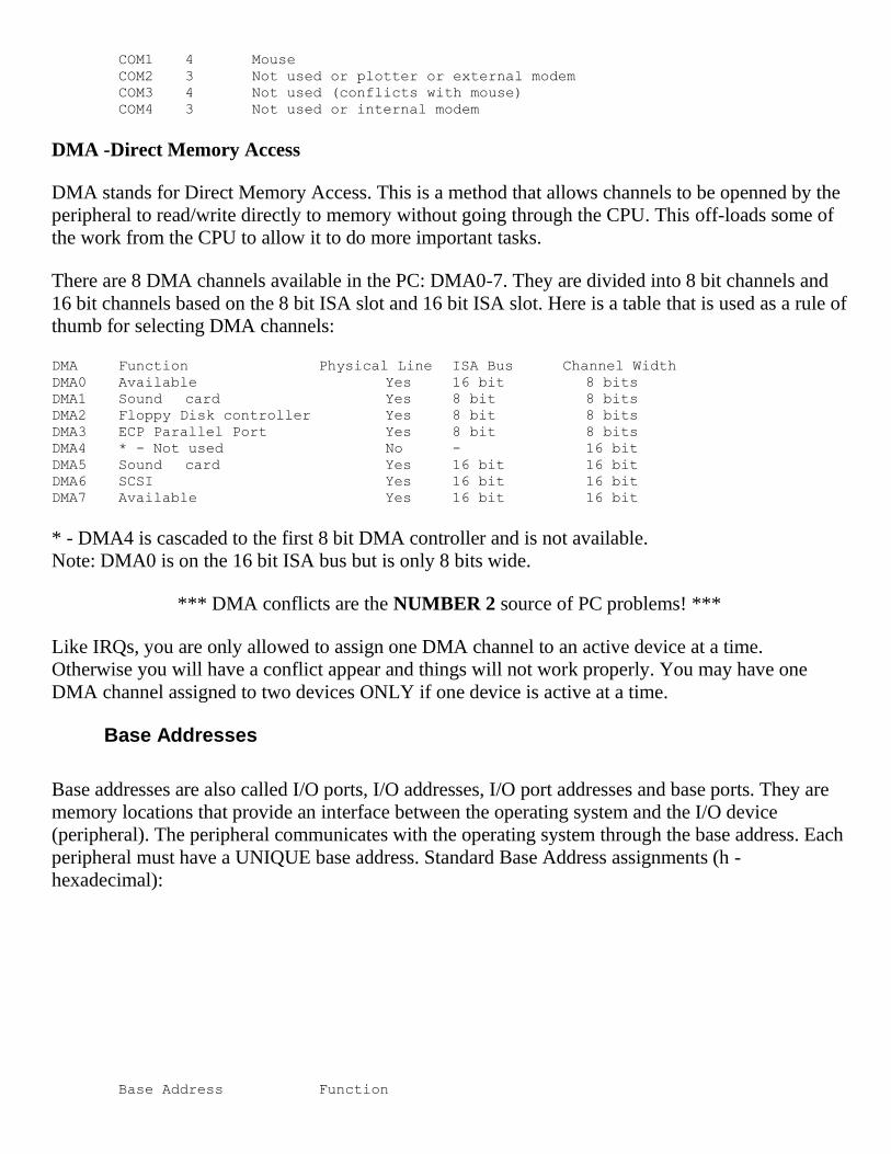
COM1 4 Mouse
COM2 3 Not used or plotter or external modem
COM3 4 Not used (conflicts with mouse)
COM4 3 Not used or internal modem
DMA -Direct Memory Access
DMA stands for Direct Memory Access. This is a method that allows channels to be openned by the
peripheral to read/write directly to memory without going through the CPU. This off-loads some of
the work from the CPU to allow it to do more important tasks.
There are 8 DMA channels available in the PC: DMA0-7. They are divided into 8 bit channels and
16 bit channels based on the 8 bit ISA slot and 16 bit ISA slot. Here is a table that is used as a rule of
thumb for selecting DMA channels:
DMA Function Physical Line ISA Bus Channel Width
DMA0 Available Yes 16 bit 8 bits
DMA1 Sound card Yes 8 bit 8 bits
DMA2 Floppy Disk controller Yes 8 bit 8 bits
DMA3 ECP Parallel Port Yes 8 bit 8 bits
DMA4 * - Not used No - 16 bit
DMA5 Sound card Yes 16 bit 16 bit
DMA6 SCSI Yes 16 bit 16 bit
DMA7 Available Yes 16 bit 16 bit
* - DMA4 is cascaded to the first 8 bit DMA controller and is not available.
Note: DMA0 is on the 16 bit ISA bus but is only 8 bits wide.
*** DMA conflicts are the NUMBER 2 source of PC problems! ***
Like IRQs, you are only allowed to assign one DMA channel to an active device at a time.
Otherwise you will have a conflict appear and things will not work properly. You may have one
DMA channel assigned to two devices ONLY if one device is active at a time.
Base Addresses
Base addresses are also called I/O ports, I/O addresses, I/O port addresses and base ports. They are
memory locations that provide an interface between the operating system and the I/O device
(peripheral). The peripheral communicates with the operating system through the base address. Each
peripheral must have a UNIQUE base address. Standard Base Address assignments (h -
hexadecimal):
Base Address Function
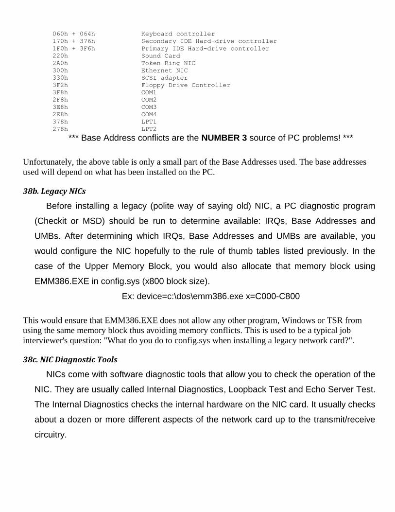
060h + 064h Keyboard controller
170h + 376h Secondary IDE Hard-drive controller
1F0h + 3F6h Primary IDE Hard-drive controller
220h Sound Card
2A0h Token Ring NIC
300h Ethernet NIC
330h SCSI adapter
3F2h Floppy Drive Controller
3F8h COM1
2F8h COM2
3E8h COM3
2E8h COM4
378h LPT1
278h LPT2
*** Base Address conflicts are the NUMBER 3 source of PC problems! ***
Unfortunately, the above table is only a small part of the Base Addresses used. The base addresses
used will depend on what has been installed on the PC.
38b. Legacy NICs
Before installing a legacy (polite way of saying old) NIC, a PC diagnostic program
(Checkit or MSD) should be run to determine available: IRQs, Base Addresses and
UMBs. After determining which IRQs, Base Addresses and UMBs are available, you
would configure the NIC hopefully to the rule of thumb tables listed previously. In the
case of the Upper Memory Block, you would also allocate that memory block using
EMM386.EXE in config.sys (x800 block size).
Ex: device=c:\dos\emm386.exe x=C000-C800
This would ensure that EMM386.EXE does not allow any other program, Windows or TSR from
using the same memory block thus avoiding memory conflicts. This is used to be a typical job
interviewer's question: "What do you do to config.sys when installing a legacy network card?".
38c. NIC Diagnostic Tools
NICs come with software diagnostic tools that allow you to check the operation of the
NIC. They are usually called Internal Diagnostics, Loopback Test and Echo Server Test.
The Internal Diagnostics checks the internal hardware on the NIC card. It usually checks
about a dozen or more different aspects of the network card up to the transmit/receive
circuitry.
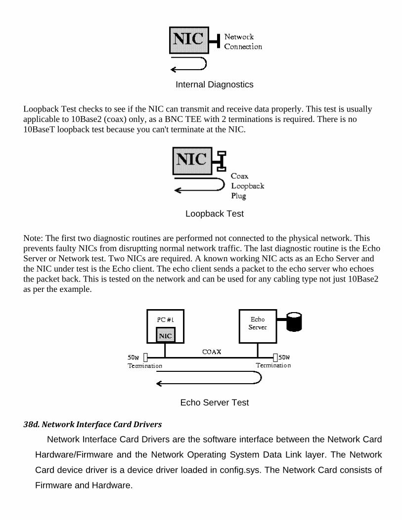
Internal Diagnostics
Loopback Test checks to see if the NIC can transmit and receive data properly. This test is usually
applicable to 10Base2 (coax) only, as a BNC TEE with 2 terminations is required. There is no
10BaseT loopback test because you can't terminate at the NIC.
Loopback Test
Note: The first two diagnostic routines are performed not connected to the physical network. This
prevents faulty NICs from disruptting normal network traffic. The last diagnostic routine is the Echo
Server or Network test. Two NICs are required. A known working NIC acts as an Echo Server and
the NIC under test is the Echo client. The echo client sends a packet to the echo server who echoes
the packet back. This is tested on the network and can be used for any cabling type not just 10Base2
as per the example.
Echo Server Test
38d. Network Interface Card Drivers
Network Interface Card Drivers are the software interface between the Network Card
Hardware/Firmware and the Network Operating System Data Link layer. The Network
Card device driver is a device driver loaded in config.sys. The Network Card consists of
Firmware and Hardware.
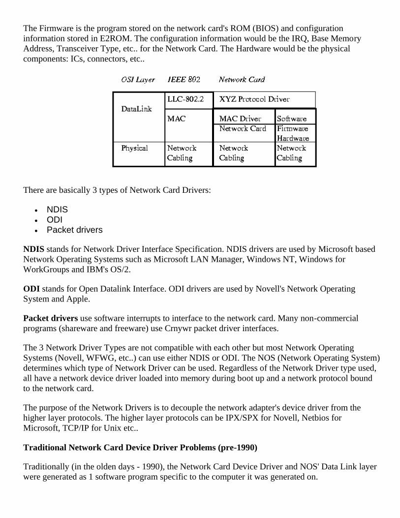
The Firmware is the program stored on the network card's ROM (BIOS) and configuration
information stored in E2ROM. The configuration information would be the IRQ, Base Memory
Address, Transceiver Type, etc.. for the Network Card. The Hardware would be the physical
components: ICs, connectors, etc..
There are basically 3 types of Network Card Drivers:
NDIS ODI Packet drivers
NDIS stands for Network Driver Interface Specification. NDIS drivers are used by Microsoft based
Network Operating Systems such as Microsoft LAN Manager, Windows NT, Windows for
WorkGroups and IBM's OS/2.
ODI stands for Open Datalink Interface. ODI drivers are used by Novell's Network Operating
System and Apple.
Packet drivers use software interrupts to interface to the network card. Many non-commercial
programs (shareware and freeware) use Crnywr packet driver interfaces.
The 3 Network Driver Types are not compatible with each other but most Network Operating
Systems (Novell, WFWG, etc..) can use either NDIS or ODI. The NOS (Network Operating System)
determines which type of Network Driver can be used. Regardless of the Network Driver type used,
all have a network device driver loaded into memory during boot up and a network protocol bound
to the network card.
The purpose of the Network Drivers is to decouple the network adapter's device driver from the
higher layer protocols. The higher layer protocols can be IPX/SPX for Novell, Netbios for
Microsoft, TCP/IP for Unix etc..
Traditional Network Card Device Driver Problems (pre-1990)
Traditionally (in the olden days - 1990), the Network Card Device Driver and NOS' Data Link layer
were generated as 1 software program specific to the computer it was generated on.

As an example, with Novell 3.11 and earlier, a special program was run, called WSGen (workstation
generator), which would generate a Workstation Shell. The Workstation Shell would be a software
program running as a TSR which would be a combination of the Network Card Device Driver and
Novell's IPX protocol. The Workstation Shell was specific to the computer that it was generated on
and could not be used on another computer. This meant that every PC in a network would have its
Workstation Shell recompiled with every new version of Novell! In a small network this would not
be a problem, but in large networks (100+ PCs), this becomes a logistic nightmare!
Another problem emerged, the Workstation Shells directly controlled the network card and were
specific to only one NOS. This meant that only one NOS protocol could be run, in Novell's case
IPX. Interconnecting Networks became a major problem.
Still another problem arose in trying to run more than 1 network card in a computer (This is done
typically in bridges, routers and servers). The Workstation Shells did not have the provision to allow
the NOS Protocol to "bind" to more than one Network Card easily.
The NIDS and ODI Network Card Driver specifications were implemented to address the following
specific areas:
Provide a standard separate interface between the Network Card Device Driver and Data Link
Layer.
Allow more than one NOS Protocol to access the Network Card Device Driver.
Allow the NOS to "bind" to more than one Network Card Device Driver.
NDIS Drivers The NDIS (Network Driver Interface Specification) standard was developed jointly by
Microsoft and 3Com for implementation in Microsoft's NOS and IBM OS/2.
The Microsoft implementation of NDIS modifies the config.sys file, autoexec.bat file and
makes two important initialization files: SYSTEM.INI and PROTOCOL.INI.
Microsoft loads the IFSHLP.SYS file as a device driver in the CONFIG.SYS file. The
IFSHLP.SYS is the installable file system helper file and contains the network redirector for
the NDIS interface. The LASTDRIVE command in the config.sys file tells the network
operating system the last available drive that can be used for mapping network drives.
The SYSTEM.INI file contains information similar to the following: [network]
sizworkbuf=1498
filesharing=no
printsharing=no
autologon=yes
computername=E237-12
lanroot=C:\NET
username=EBLANCHARD
workgroup=WORKGROUP
reconnect=yes
dospophotkey=N
lmlogon=1
logondomain=T217PROJECT
preferredredir=full
autostart=full
maxconnections=8
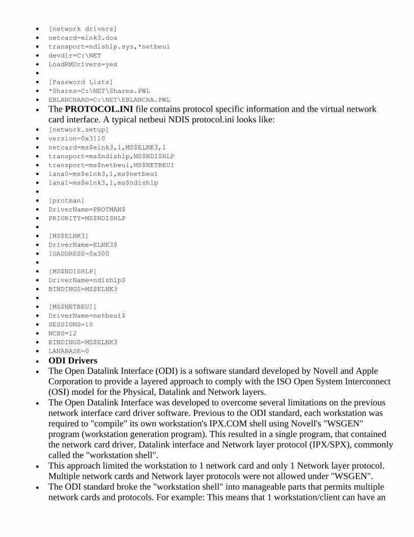
[network drivers]
netcard=elnk3.dos
transport=ndishlp.sys,*netbeui
devdir=C:\NET
LoadRMDrivers=yes
[Password Lists]
*Shares=C:\NET\Shares.PWL
EBLANCHARD=C:\NET\EBLANCHA.PWL
The PROTOCOL.INI file contains protocol specific information and the virtual network
card interface. A typical netbeui NDIS protocol.ini looks like: [network.setup]
version=0x3110
netcard=ms$elnk3,1,MS$ELNK3,1
transport=ms$ndishlp,MS$NDISHLP
transport=ms$netbeui,MS$NETBEUI
lana0=ms$elnk3,1,ms$netbeui
lana1=ms$elnk3,1,ms$ndishlp
[protman]
DriverName=PROTMAN$
PRIORITY=MS$NDISHLP
[MS$ELNK3]
DriverName=ELNK3$
IOADDRESS=0x300
[MS$NDISHLP]
DriverName=ndishlp$
BINDINGS=MS$ELNK3
[MS$NETBEUI]
DriverName=netbeui$
SESSIONS=10
NCBS=12
BINDINGS=MS$ELNK3
LANABASE=0
ODI Drivers The Open Datalink Interface (ODI) is a software standard developed by Novell and Apple
Corporation to provide a layered approach to comply with the ISO Open System Interconnect
(OSI) model for the Physical, Datalink and Network layers.
The Open Datalink Interface was developed to overcome several limitations on the previous
network interface card driver software. Previous to the ODI standard, each workstation was
required to "compile" its own workstation's IPX.COM shell using Novell's "WSGEN"
program (workstation generation program). This resulted in a single program, that contained
the network card driver, Datalink interface and Network layer protocol (IPX/SPX), commonly
called the "workstation shell".
This approach limited the workstation to 1 network card and only 1 Network layer protocol.
Multiple network cards and Network layer protocols were not allowed under "WSGEN".
The ODI standard broke the "workstation shell" into manageable parts that permits multiple
network cards and protocols. For example: This means that 1 workstation/client can have an
Ethernet 10BaseT card running IPX/SPX protocols (Novell) and a Farallon Localtalk card in
it for running Appletalk (Macintosh).
The ODI standard compared to the OSI Model:
OSI = Open System Interconnect ODI = Open Datalink Interface
SPX = Sequenced Packet Exchange IPX = Internetwork Packet Exhange
LSL = Link Suppport Layer VLM = Virtual Loadable Modules
MLID = Multiple Link Interface Driver MSM = Media Support Module
HSM = Hardware Support Module
Novell Lite (very old - defunct) is Novell's Peer to Peer Network Operating system. Peer to
Peer Networks use DOS's File Allocation Table (FAT) and Novell Lite is no exception
(Novell Netware has its own high performance disk operating system). Novell Lite follows
Novell's Netware structure for the Network, Datalink and Physical layers and it is an excellent
example of an ODI compliant NOS (Network Operating System). At the Transport layer it
uses Peer to Peer Client and Server software instead of Novell's Netware Transport layer
software - SPX (VLM).
A typical Novell client is loaded from the DOS prompt or from a STARTNET.BAT file: SET NWLANGUAGE= ENGLISH
LSL.COM Link Support Layer Software
3C509.COM 3C509 Network Interface Card Driver (MLID) ODI
Compliant
IPXODI IPX Network layer protocol driver
VLM Loads client software
NET.CFG is the network configuration file used by the above files. It is a text file and
contains the following basic section: Link Driver 3C5X9 (NIC drivername)
INT 10 (IRQ #)
PORT 300 (Base memory address in hexadecimal)
FRAME Ethernet_802.2 (Frame type on Netware 3.12 & newer)
FRAME Ethernet_802.3 (Frame type on Netware 3.11 and older)
FRAME Ethernet_II (Frame type used by UNIX)
FRAME Ethernet_SNAP (Frame type used by Appletalk)
NetWare DOS Requester
FIRST NETWORK DRIVE = F
USE DEFAULTS = OFF
VLM = CONN.VLM
VLM = IPXNCP.VLM
VLM = TRAN.VLM
VLM = SECURITY.VLM
; VLM = NDS.VLM (used for Netware 4.11 NDS services)
VLM = BIND.VLM
VLM = NWP.VLM
VLM = FIO.VLM
VLM = GENERAL.VLM
VLM = REDIR.VLM
VLM = PRINT.VLM
VLM = NETX.VLM
Packet Drivers
Packet drivers use software interrupts to identify the network cards to the data link layer. Packet
drivers are free software drivers that were developed to address the problems of running multiple
protocols over one network card. NDIS and ODI are proprietary schemes that have been developed
by 3COM/Microsoft and Novell/Apple respectively to address this problem.
The Crynwr Software collection of packet drivers are available throughout the Internet and they are
free to use unlike shareware and commercial products.
Advantages:
Run multiple applications across the same board: TCP/IP, NetBIOS, Netware
One board fits all, no buying different boards for different applications.
No more reconfiguring and rebooting to change applications.
Connect to a Novell File Server (or servers) and still run TCP/IP or PC-NFS or with the
Novell systems remaining active and available for file serving and printing.
The Packet Driver acts as a fast smart secretary, bothering clients only when packets arrive
specifically for them.
Software Interrupts
Software interrupts are interrupts generated by software unlike hardware interrupts that are physical
lines that run to each device. Software interrupts that are available are 0x60 to 0x66. Table xx-1 lists
the software interrupts and their assignments.
The packet drivers are assigned software interrupts to the network interface card during the bootup
process usually in the autoexec.bat file. For a 3c503 card the autoexec.bat file would have this line:
3c503 0x60 5 0x300
where:
3c509 calls up the packet driver 3c509.com
0x60 is the software interrupt assigned to the NIC
5 is the hardware interrupt of the NIC
0x300 is the I/O address of the NIC
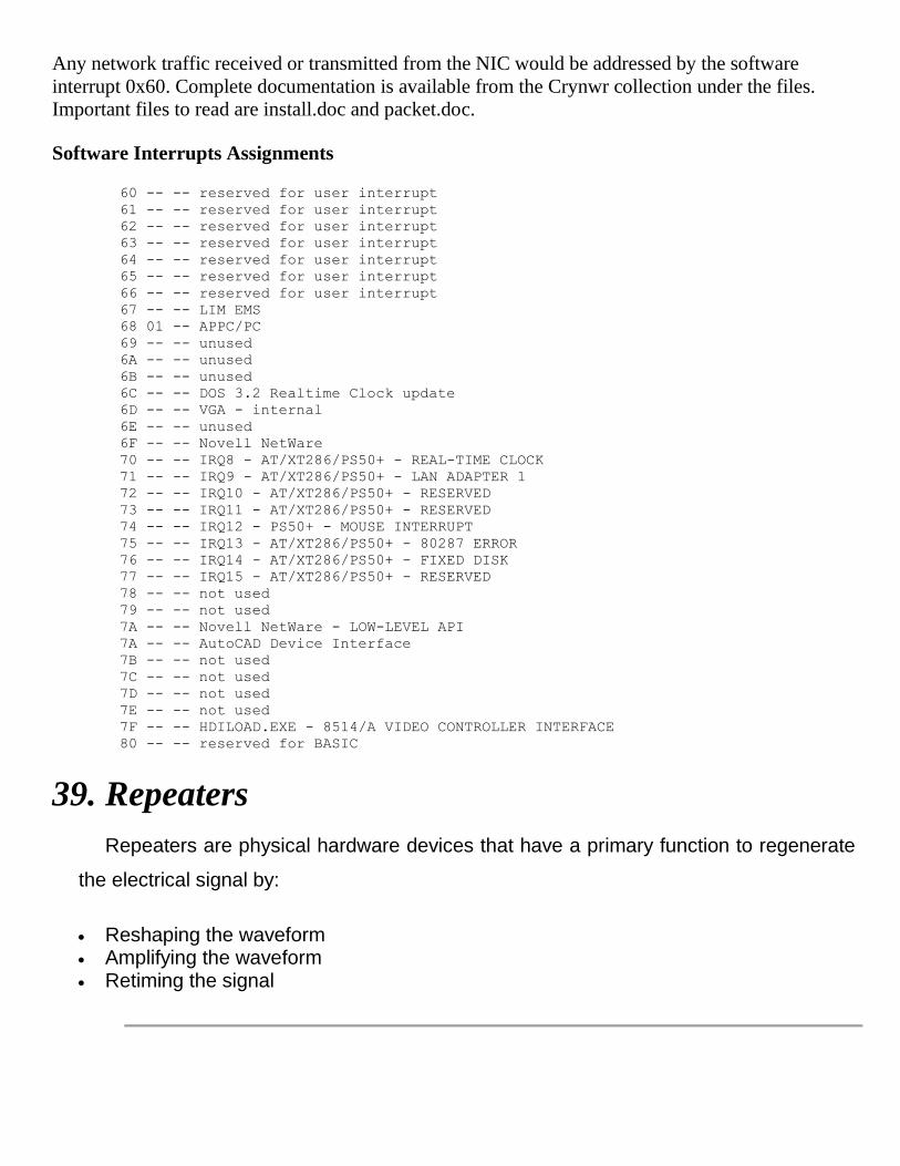
Any network traffic received or transmitted from the NIC would be addressed by the software
interrupt 0x60. Complete documentation is available from the Crynwr collection under the files.
Important files to read are install.doc and packet.doc.
Software Interrupts Assignments
60 -- -- reserved for user interrupt
61 -- -- reserved for user interrupt
62 -- -- reserved for user interrupt
63 -- -- reserved for user interrupt
64 -- -- reserved for user interrupt
65 -- -- reserved for user interrupt
66 -- -- reserved for user interrupt
67 -- -- LIM EMS
68 01 -- APPC/PC
69 -- -- unused
6A -- -- unused
6B -- -- unused
6C -- -- DOS 3.2 Realtime Clock update
6D -- -- VGA - internal
6E -- -- unused
6F -- -- Novell NetWare
70 -- -- IRQ8 - AT/XT286/PS50+ - REAL-TIME CLOCK
71 -- -- IRQ9 - AT/XT286/PS50+ - LAN ADAPTER 1
72 -- -- IRQ10 - AT/XT286/PS50+ - RESERVED
73 -- -- IRQ11 - AT/XT286/PS50+ - RESERVED
74 -- -- IRQ12 - PS50+ - MOUSE INTERRUPT
75 -- -- IRQ13 - AT/XT286/PS50+ - 80287 ERROR
76 -- -- IRQ14 - AT/XT286/PS50+ - FIXED DISK
77 -- -- IRQ15 - AT/XT286/PS50+ - RESERVED
78 -- -- not used
79 -- -- not used
7A -- -- Novell NetWare - LOW-LEVEL API
7A -- -- AutoCAD Device Interface
7B -- -- not used
7C -- -- not used
7D -- -- not used
7E -- -- not used
7F -- -- HDILOAD.EXE - 8514/A VIDEO CONTROLLER INTERFACE
80 -- -- reserved for BASIC
39. Repeaters
Repeaters are physical hardware devices that have a primary function to regenerate
the electrical signal by:
Reshaping the waveform
Amplifying the waveform Retiming the signal
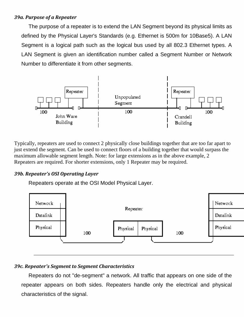
39a. Purpose of a Repeater
The purpose of a repeater is to extend the LAN Segment beyond its physical limits as
defined by the Physical Layer's Standards (e.g. Ethernet is 500m for 10Base5). A LAN
Segment is a logical path such as the logical bus used by all 802.3 Ethernet types. A
LAN Segment is given an identification number called a Segment Number or Network
Number to differentiate it from other segments.
Typically, repeaters are used to connect 2 physically close buildings together that are too far apart to
just extend the segment. Can be used to connect floors of a building together that would surpass the
maximum allowable segment length. Note: for large extensions as in the above example, 2
Repeaters are required. For shorter extensions, only 1 Repeater may be required.
39b. Repeater's OSI Operating Layer
Repeaters operate at the OSI Model Physical Layer.
39c. Repeater's Segment to Segment Characteristics
Repeaters do not "de-segment" a network. All traffic that appears on one side of the
repeater appears on both sides. Repeaters handle only the electrical and physical
characteristics of the signal.
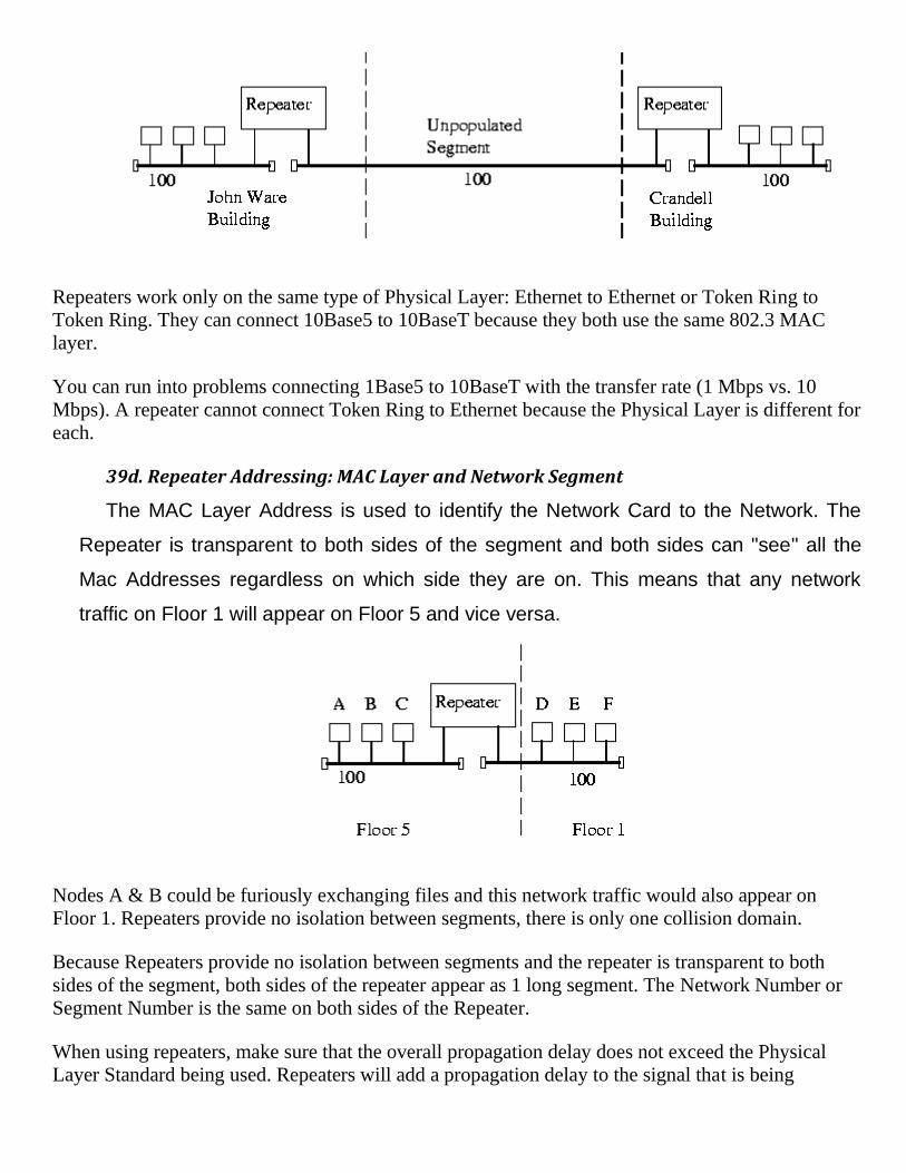
Repeaters work only on the same type of Physical Layer: Ethernet to Ethernet or Token Ring to
Token Ring. They can connect 10Base5 to 10BaseT because they both use the same 802.3 MAC
layer.
You can run into problems connecting 1Base5 to 10BaseT with the transfer rate (1 Mbps vs. 10
Mbps). A repeater cannot connect Token Ring to Ethernet because the Physical Layer is different for
each.
39d. Repeater Addressing: MAC Layer and Network Segment
The MAC Layer Address is used to identify the Network Card to the Network. The
Repeater is transparent to both sides of the segment and both sides can "see" all the
Mac Addresses regardless on which side they are on. This means that any network
traffic on Floor 1 will appear on Floor 5 and vice versa.
Nodes A & B could be furiously exchanging files and this network traffic would also appear on
Floor 1. Repeaters provide no isolation between segments, there is only one collision domain.
Because Repeaters provide no isolation between segments and the repeater is transparent to both
sides of the segment, both sides of the repeater appear as 1 long segment. The Network Number or
Segment Number is the same on both sides of the Repeater.
When using repeaters, make sure that the overall propagation delay does not exceed the Physical
Layer Standard being used. Repeaters will add a propagation delay to the signal that is being
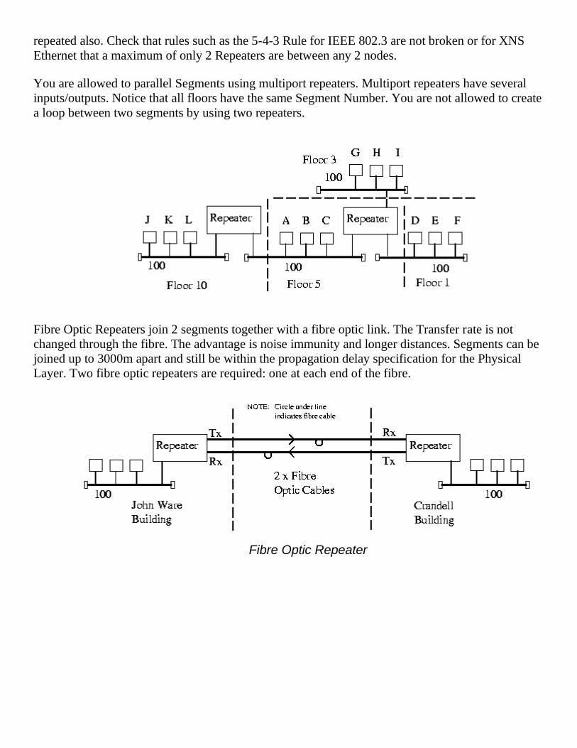
repeated also. Check that rules such as the 5-4-3 Rule for IEEE 802.3 are not broken or for XNS
Ethernet that a maximum of only 2 Repeaters are between any 2 nodes.
You are allowed to parallel Segments using multiport repeaters. Multiport repeaters have several
inputs/outputs. Notice that all floors have the same Segment Number. You are not allowed to create
a loop between two segments by using two repeaters.
Fibre Optic Repeaters join 2 segments together with a fibre optic link. The Transfer rate is not
changed through the fibre. The advantage is noise immunity and longer distances. Segments can be
joined up to 3000m apart and still be within the propagation delay specification for the Physical
Layer. Two fibre optic repeaters are required: one at each end of the fibre.
Fibre Optic Repeater
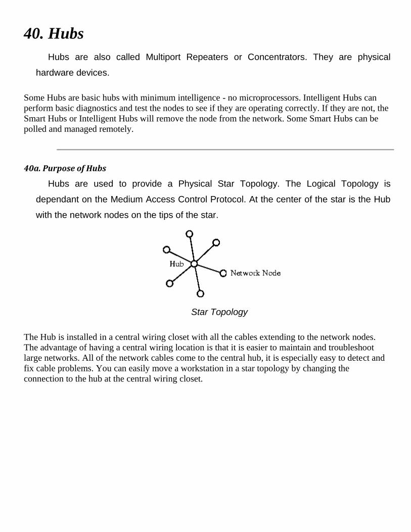
40. Hubs
Hubs are also called Multiport Repeaters or Concentrators. They are physical
hardware devices.
Some Hubs are basic hubs with minimum intelligence - no microprocessors. Intelligent Hubs can
perform basic diagnostics and test the nodes to see if they are operating correctly. If they are not, the
Smart Hubs or Intelligent Hubs will remove the node from the network. Some Smart Hubs can be
polled and managed remotely.
40a. Purpose of Hubs
Hubs are used to provide a Physical Star Topology. The Logical Topology is
dependant on the Medium Access Control Protocol. At the center of the star is the Hub
with the network nodes on the tips of the star.
Star Topology
The Hub is installed in a central wiring closet with all the cables extending to the network nodes.
The advantage of having a central wiring location is that it is easier to maintain and troubleshoot
large networks. All of the network cables come to the central hub, it is especially easy to detect and
fix cable problems. You can easily move a workstation in a star topology by changing the
connection to the hub at the central wiring closet.
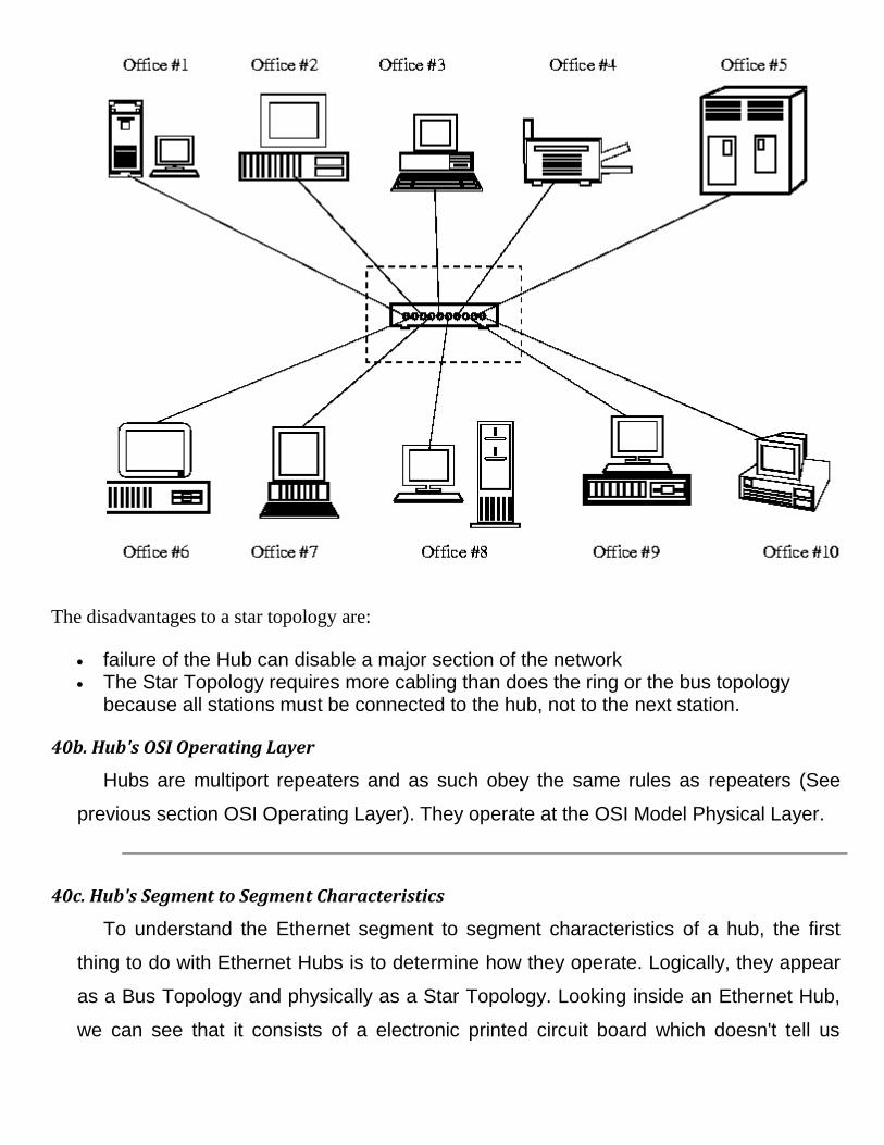
The disadvantages to a star topology are:
failure of the Hub can disable a major section of the network The Star Topology requires more cabling than does the ring or the bus topology
because all stations must be connected to the hub, not to the next station.
40b. Hub's OSI Operating Layer
Hubs are multiport repeaters and as such obey the same rules as repeaters (See
previous section OSI Operating Layer). They operate at the OSI Model Physical Layer.
40c. Hub's Segment to Segment Characteristics
To understand the Ethernet segment to segment characteristics of a hub, the first
thing to do with Ethernet Hubs is to determine how they operate. Logically, they appear
as a Bus Topology and physically as a Star Topology. Looking inside an Ethernet Hub,
we can see that it consists of a electronic printed circuit board which doesn't tell us
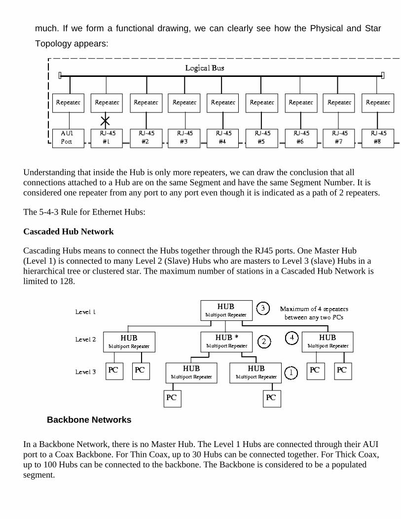
much. If we form a functional drawing, we can clearly see how the Physical and Star
Topology appears:
Understanding that inside the Hub is only more repeaters, we can draw the conclusion that all
connections attached to a Hub are on the same Segment and have the same Segment Number. It is
considered one repeater from any port to any port even though it is indicated as a path of 2 repeaters.
The 5-4-3 Rule for Ethernet Hubs:
Cascaded Hub Network
Cascading Hubs means to connect the Hubs together through the RJ45 ports. One Master Hub
(Level 1) is connected to many Level 2 (Slave) Hubs who are masters to Level 3 (slave) Hubs in a
hierarchical tree or clustered star. The maximum number of stations in a Cascaded Hub Network is
limited to 128.
Backbone Networks
In a Backbone Network, there is no Master Hub. The Level 1 Hubs are connected through their AUI
port to a Coax Backbone. For Thin Coax, up to 30 Hubs can be connected together. For Thick Coax,
up to 100 Hubs can be connected to the backbone. The Backbone is considered to be a populated
segment.
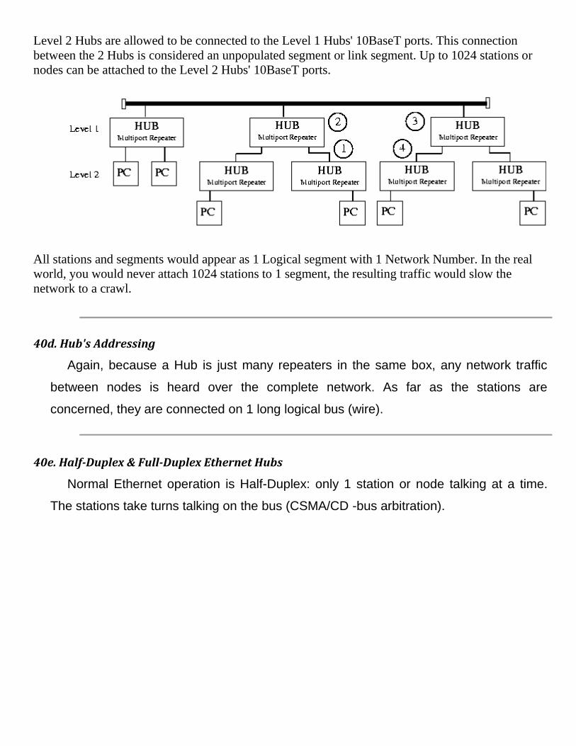
Level 2 Hubs are allowed to be connected to the Level 1 Hubs' 10BaseT ports. This connection
between the 2 Hubs is considered an unpopulated segment or link segment. Up to 1024 stations or
nodes can be attached to the Level 2 Hubs' 10BaseT ports.
All stations and segments would appear as 1 Logical segment with 1 Network Number. In the real
world, you would never attach 1024 stations to 1 segment, the resulting traffic would slow the
network to a crawl.
40d. Hub's Addressing
Again, because a Hub is just many repeaters in the same box, any network traffic
between nodes is heard over the complete network. As far as the stations are
concerned, they are connected on 1 long logical bus (wire).
40e. Half-Duplex & Full-Duplex Ethernet Hubs
Normal Ethernet operation is Half-Duplex: only 1 station or node talking at a time.
The stations take turns talking on the bus (CSMA/CD -bus arbitration).
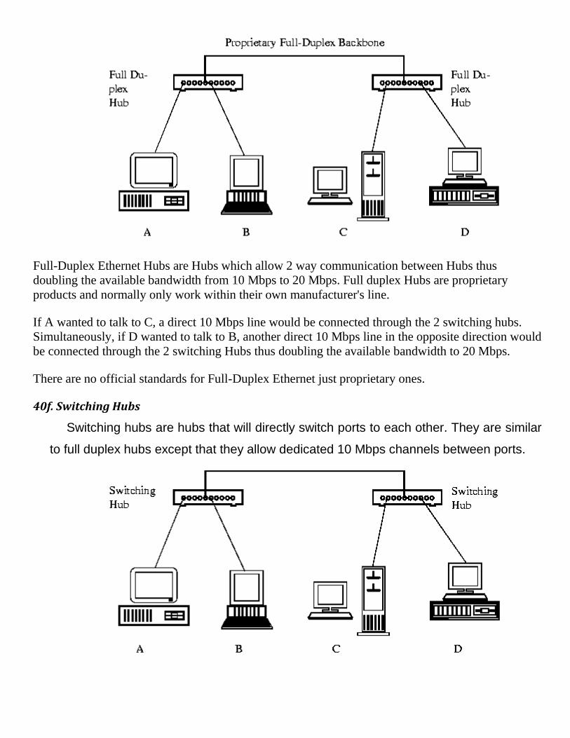
Full-Duplex Ethernet Hubs are Hubs which allow 2 way communication between Hubs thus
doubling the available bandwidth from 10 Mbps to 20 Mbps. Full duplex Hubs are proprietary
products and normally only work within their own manufacturer's line.
If A wanted to talk to C, a direct 10 Mbps line would be connected through the 2 switching hubs.
Simultaneously, if D wanted to talk to B, another direct 10 Mbps line in the opposite direction would
be connected through the 2 switching Hubs thus doubling the available bandwidth to 20 Mbps.
There are no official standards for Full-Duplex Ethernet just proprietary ones.
40f. Switching Hubs
Switching hubs are hubs that will directly switch ports to each other. They are similar
to full duplex hubs except that they allow dedicated 10 Mbps channels between ports.
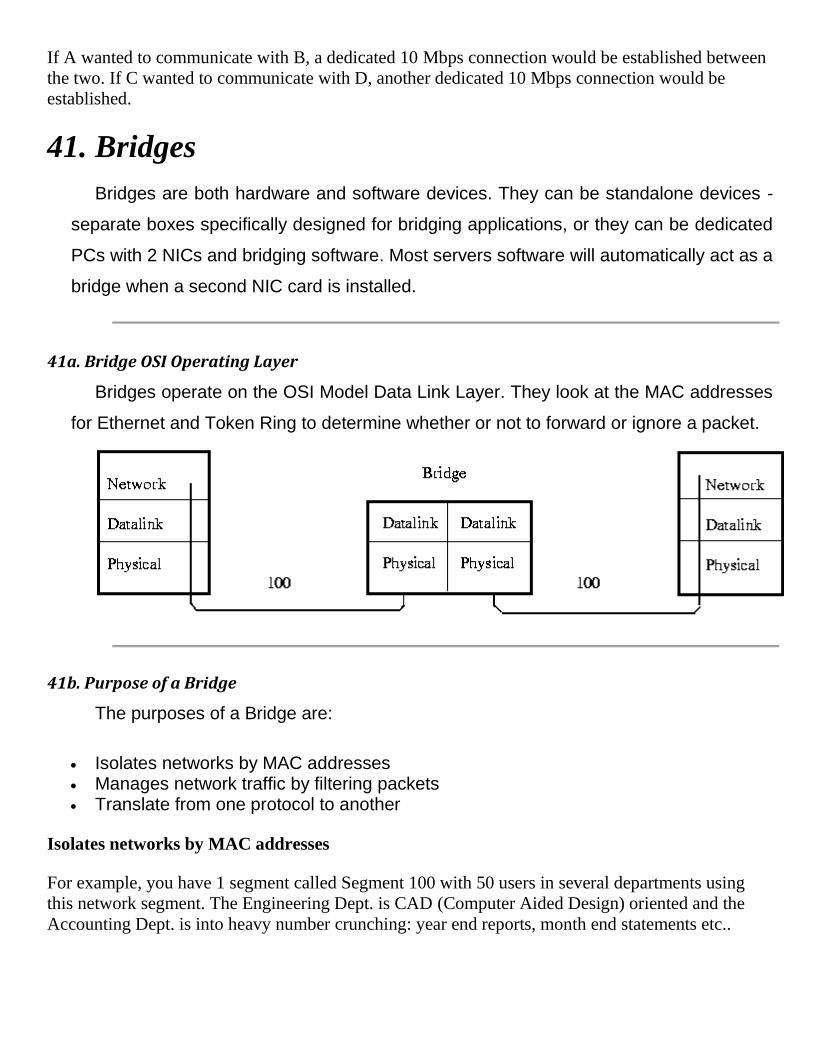
If A wanted to communicate with B, a dedicated 10 Mbps connection would be established between
the two. If C wanted to communicate with D, another dedicated 10 Mbps connection would be
established.
41. Bridges
Bridges are both hardware and software devices. They can be standalone devices -
separate boxes specifically designed for bridging applications, or they can be dedicated
PCs with 2 NICs and bridging software. Most servers software will automatically act as a
bridge when a second NIC card is installed.
41a. Bridge OSI Operating Layer
Bridges operate on the OSI Model Data Link Layer. They look at the MAC addresses
for Ethernet and Token Ring to determine whether or not to forward or ignore a packet.
41b. Purpose of a Bridge
The purposes of a Bridge are:
Isolates networks by MAC addresses
Manages network traffic by filtering packets Translate from one protocol to another
Isolates networks by MAC addresses
For example, you have 1 segment called Segment 100 with 50 users in several departments using
this network segment. The Engineering Dept. is CAD (Computer Aided Design) oriented and the
Accounting Dept. is into heavy number crunching: year end reports, month end statements etc..
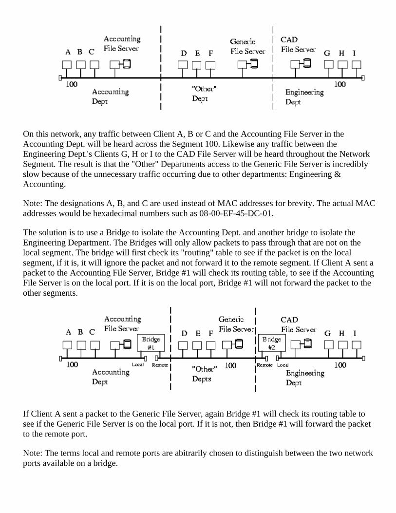
On this network, any traffic between Client A, B or C and the Accounting File Server in the
Accounting Dept. will be heard across the Segment 100. Likewise any traffic between the
Engineering Dept.'s Clients G, H or I to the CAD File Server will be heard throughout the Network
Segment. The result is that the "Other" Departments access to the Generic File Server is incredibly
slow because of the unnecessary traffic occurring due to other departments: Engineering &
Accounting.
Note: The designations A, B, and C are used instead of MAC addresses for brevity. The actual MAC
addresses would be hexadecimal numbers such as 08-00-EF-45-DC-01.
The solution is to use a Bridge to isolate the Accounting Dept. and another bridge to isolate the
Engineering Department. The Bridges will only allow packets to pass through that are not on the
local segment. The bridge will first check its "routing" table to see if the packet is on the local
segment, if it is, it will ignore the packet and not forward it to the remote segment. If Client A sent a
packet to the Accounting File Server, Bridge #1 will check its routing table, to see if the Accounting
File Server is on the local port. If it is on the local port, Bridge #1 will not forward the packet to the
other segments.
If Client A sent a packet to the Generic File Server, again Bridge #1 will check its routing table to
see if the Generic File Server is on the local port. If it is not, then Bridge #1 will forward the packet
to the remote port.
Note: The terms local and remote ports are abitrarily chosen to distinguish between the two network
ports available on a bridge.
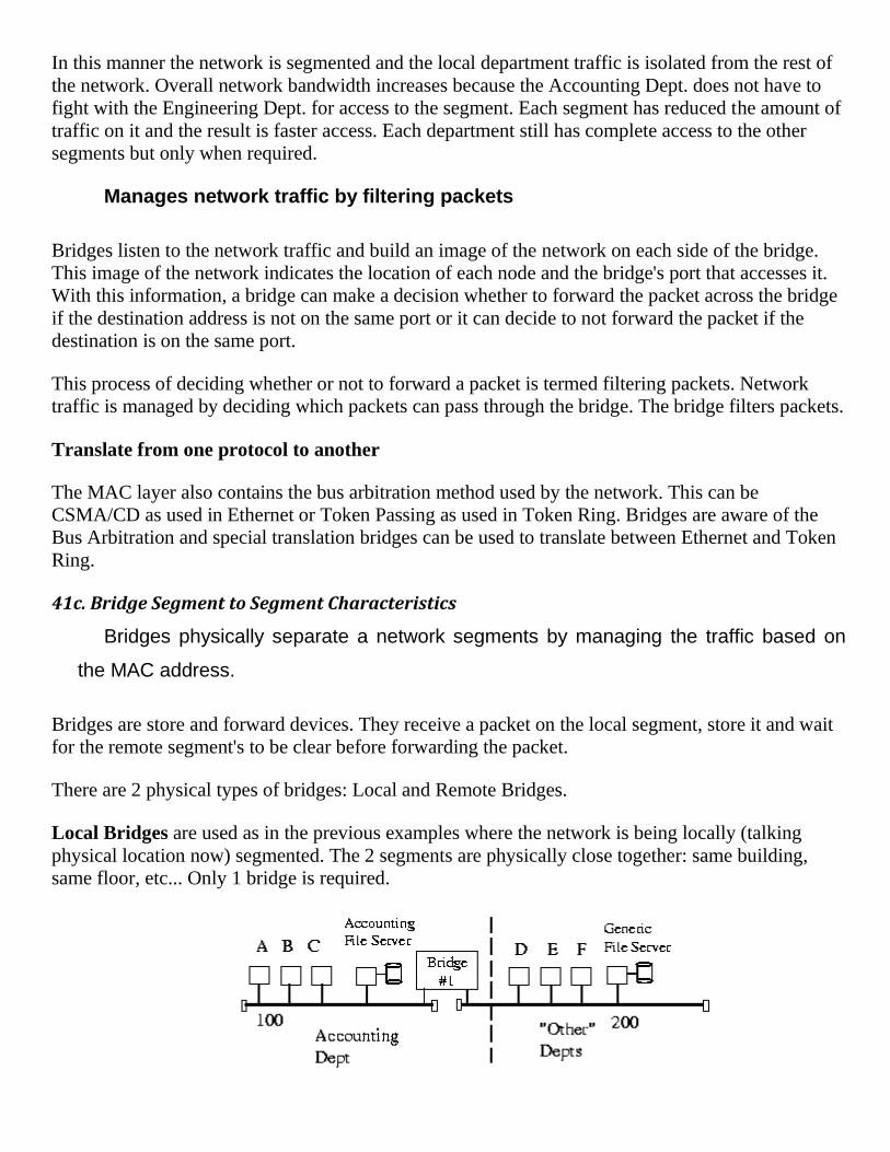
In this manner the network is segmented and the local department traffic is isolated from the rest of
the network. Overall network bandwidth increases because the Accounting Dept. does not have to
fight with the Engineering Dept. for access to the segment. Each segment has reduced the amount of
traffic on it and the result is faster access. Each department still has complete access to the other
segments but only when required.
Manages network traffic by filtering packets
Bridges listen to the network traffic and build an image of the network on each side of the bridge.
This image of the network indicates the location of each node and the bridge's port that accesses it.
With this information, a bridge can make a decision whether to forward the packet across the bridge
if the destination address is not on the same port or it can decide to not forward the packet if the
destination is on the same port.
This process of deciding whether or not to forward a packet is termed filtering packets. Network
traffic is managed by deciding which packets can pass through the bridge. The bridge filters packets.
Translate from one protocol to another
The MAC layer also contains the bus arbitration method used by the network. This can be
CSMA/CD as used in Ethernet or Token Passing as used in Token Ring. Bridges are aware of the
Bus Arbitration and special translation bridges can be used to translate between Ethernet and Token
Ring.
41c. Bridge Segment to Segment Characteristics
Bridges physically separate a network segments by managing the traffic based on
the MAC address.
Bridges are store and forward devices. They receive a packet on the local segment, store it and wait
for the remote segment's to be clear before forwarding the packet.
There are 2 physical types of bridges: Local and Remote Bridges.
Local Bridges are used as in the previous examples where the network is being locally (talking
physical location now) segmented. The 2 segments are physically close together: same building,
same floor, etc... Only 1 bridge is required.
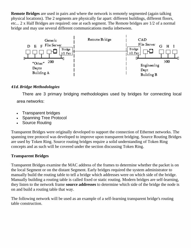
Remote Bridges are used in pairs and where the network is remotely segmented (again talking
physical locations). The 2 segments are physically far apart: different buildings, different floors,
etc... 2 x Half Bridges are required: one at each segment. The Remote bridges are 1/2 of a normal
bridge and may use several different communications media inbetween.
41d. Bridge Methodologies
There are 3 primary bridging methodologies used by bridges for connecting local
area networks:
Transparent bridges
Spanning Tree Protocol Source Routing
Transparent Bridges were originally developed to support the connection of Ethernet networks. The
spanning tree protocol was developed to improve upon transparent bridging. Source Routing Bridges
are used by Token Ring. Source routing bridges require a solid understanding of Token Ring
concepts and as such will be covered under the section discussing Token Ring.
Transparent Bridges
Transparent Bridges examine the MAC address of the frames to determine whether the packet is on
the local Segment or on the distant Segment. Early bridges required the system administrator to
manually build the routing table to tell a bridge which addresses were on which side of the bridge.
Manually building a routing table is called fixed or static routing. Modern bridges are self-learning,
they listen to the network frame source addresses to determine which side of the bridge the node is
on and build a routing table that way.
The following network will be used as an example of a self-learning transparent bridge's routing
table construction.
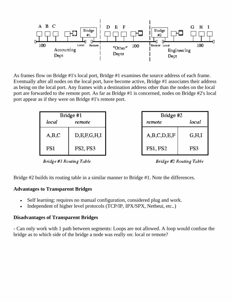
As frames flow on Bridge #1's local port, Bridge #1 examines the source address of each frame.
Eventually after all nodes on the local port, have become active, Bridge #1 associates their address
as being on the local port. Any frames with a destination address other than the nodes on the local
port are forwarded to the remote port. As far as Bridge #1 is concerned, nodes on Bridge #2's local
port appear as if they were on Bridge #1's remote port.
Bridge #2 builds its routing table in a similar manner to Bridge #1. Note the differences.
Advantages to Transparent Bridges
Self learning: requires no manual configuration, considered plug and work.
Independent of higher level protocols (TCP/IP, IPX/SPX, Netbeui, etc..)
Disadvantages of Transparent Bridges
- Can only work with 1 path between segments: Loops are not allowed. A loop would confuse the
bridge as to which side of the bridge a node was really on: local or remote?
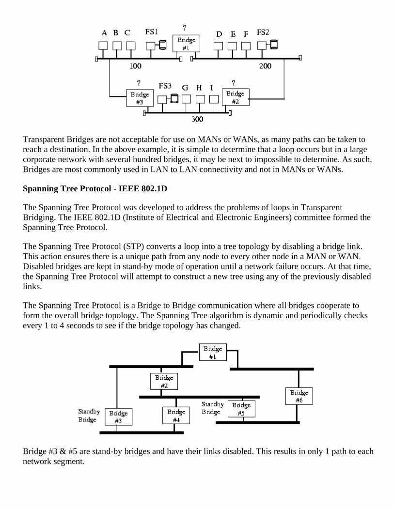
Transparent Bridges are not acceptable for use on MANs or WANs, as many paths can be taken to
reach a destination. In the above example, it is simple to determine that a loop occurs but in a large
corporate network with several hundred bridges, it may be next to impossible to determine. As such,
Bridges are most commonly used in LAN to LAN connectivity and not in MANs or WANs.
Spanning Tree Protocol - IEEE 802.1D
The Spanning Tree Protocol was developed to address the problems of loops in Transparent
Bridging. The IEEE 802.1D (Institute of Electrical and Electronic Engineers) committee formed the
Spanning Tree Protocol.
The Spanning Tree Protocol (STP) converts a loop into a tree topology by disabling a bridge link.
This action ensures there is a unique path from any node to every other node in a MAN or WAN.
Disabled bridges are kept in stand-by mode of operation until a network failure occurs. At that time,
the Spanning Tree Protocol will attempt to construct a new tree using any of the previously disabled
links.
The Spanning Tree Protocol is a Bridge to Bridge communication where all bridges cooperate to
form the overall bridge topology. The Spanning Tree algorithm is dynamic and periodically checks
every 1 to 4 seconds to see if the bridge topology has changed.
Bridge #3 & #5 are stand-by bridges and have their links disabled. This results in only 1 path to each
network segment.

Each bridge is assigned an arbitrary number to assign priority to the bridge in the internetwork. The
number is concatenated with the bridge MAC address. The MAC address is used as a tie breaker
mechanism if 2 bridges have the same priority. The lower the assigned number the higher the bridge
priority.
During initial power-up, a Bridge Protocol Data Unit (BPDU) is flooded out each network port of
the bridge. The BPDU contains the current spanning tree root, the distance to the root (measured in
hops through other bridges), the bridge address information and the age of the information in the
BPDU. Bridge priorities are usually manually controlled so as to configure the traffic flow over the
internetwork over a preferred path.
Problems can arise where the Spanning Tree Algorithm may select a path from Los Angeles to New
York City and back to San Francisco rather than the preferred route of Los Angeles to San
Francisco.
41e. Reasons to use a Bridge
There are four basic reasons to use a bridge:
1. Security: Stops networks from forwarding sensitive data
2. Bandwidth: Reduce traffic by segmentation 3. Reliability: If 1 segment goes down, it does not take down the complete LAN 4. Translation: Translate different Data Link protocols such as Token Ring to Ethernet
41f. Bridge Addressing
Bridges work at the Data Link Layer and recognize the MAC addresses. Spanning
Tree Protocol adds a Bridge Protocol Data Unit (BPDU) for Bridge to Bridge
communications. Source Route Bridges and Token Ring provide special Data Link layer
communication and will be discussed later.
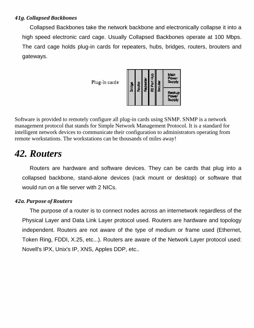
41g. Collapsed Backbones
Collapsed Backbones take the network backbone and electronically collapse it into a
high speed electronic card cage. Usually Collapsed Backbones operate at 100 Mbps.
The card cage holds plug-in cards for repeaters, hubs, bridges, routers, brouters and
gateways.
Software is provided to remotely configure all plug-in cards using SNMP. SNMP is a network
management protocol that stands for Simple Network Management Protocol. It is a standard for
intelligent network devices to communicate their configuration to administrators operating from
remote workstations. The workstations can be thousands of miles away!
42. Routers
Routers are hardware and software devices. They can be cards that plug into a
collapsed backbone, stand-alone devices (rack mount or desktop) or software that
would run on a file server with 2 NICs.
42a. Purpose of Routers
The purpose of a router is to connect nodes across an internetwork regardless of the
Physical Layer and Data Link Layer protocol used. Routers are hardware and topology
independent. Routers are not aware of the type of medium or frame used (Ethernet,
Token Ring, FDDI, X.25, etc...). Routers are aware of the Network Layer protocol used:
Novell's IPX, Unix's IP, XNS, Apples DDP, etc..

42b. Router OSI Operating Layer
Routers operate on the OSI Model's Network Layer. The internetwork must use the
same Network Layer protocol. Routers allow the transportation of the Network Layer
PDU through the internetwork even though the Physical and Data Link Frame size and
addressing scheme may change.
42c. Router Segment to Segment Characteristics
Routers that only know Novell IPX (Internetwork Packet Exchange) will not forward
Unix's IP (Internetwork Packet) PDUs and vice versa. Routers only see the Network
Layer protocol that they have been configured for. This means that a network can have
multiple protocols running on it: SPX/IPX, TCP/IP, Appletalk, XNS, etc..
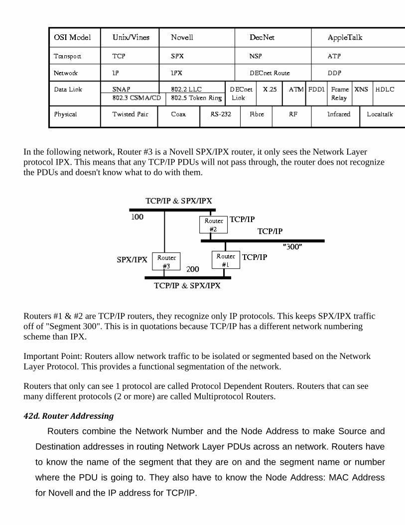
In the following network, Router #3 is a Novell SPX/IPX router, it only sees the Network Layer
protocol IPX. This means that any TCP/IP PDUs will not pass through, the router does not recognize
the PDUs and doesn't know what to do with them.
Routers #1 & #2 are TCP/IP routers, they recognize only IP protocols. This keeps SPX/IPX traffic
off of "Segment 300". This is in quotations because TCP/IP has a different network numbering
scheme than IPX.
Important Point: Routers allow network traffic to be isolated or segmented based on the Network
Layer Protocol. This provides a functional segmentation of the network.
Routers that only can see 1 protocol are called Protocol Dependent Routers. Routers that can see
many different protocols (2 or more) are called Multiprotocol Routers.
42d. Router Addressing
Routers combine the Network Number and the Node Address to make Source and
Destination addresses in routing Network Layer PDUs across an network. Routers have
to know the name of the segment that they are on and the segment name or number
where the PDU is going to. They also have to know the Node Address: MAC Address
for Novell and the IP address for TCP/IP.
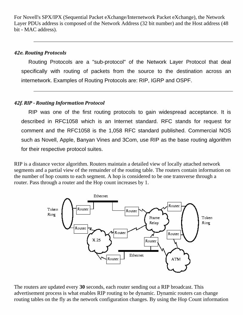
For Novell's SPX/IPX (Sequential Packet eXchange/Internetwork Packet eXchange), the Network
Layer PDUs address is composed of the Network Address (32 bit number) and the Host address (48
bit - MAC address).
42e. Routing Protocols
Routing Protocols are a "sub-protocol" of the Network Layer Protocol that deal
specifically with routing of packets from the source to the destination across an
internetwork. Examples of Routing Protocols are: RIP, IGRP and OSPF.
42f. RIP - Routing Information Protocol
RIP was one of the first routing protocols to gain widespread acceptance. It is
described in RFC1058 which is an Internet standard. RFC stands for request for
comment and the RFC1058 is the 1,058 RFC standard published. Commercial NOS
such as Novell, Apple, Banyan Vines and 3Com, use RIP as the base routing algorithm
for their respective protocol suites.
RIP is a distance vector algorithm. Routers maintain a detailed view of locally attached network
segments and a partial view of the remainder of the routing table. The routers contain information on
the number of hop counts to each segment. A hop is considered to be one transverse through a
router. Pass through a router and the Hop count increases by 1.
The routers are updated every 30 seconds, each router sending out a RIP broadcast. This
advertisement process is what enables RIP routing to be dynamic. Dynamic routers can change
routing tables on the fly as the network configuration changes. By using the Hop Count information
from their routing tables, routers can select the shortest path - the least number of hops to the
destination.
Apple uses RTMP (routing table maintenance protocol) which adds a route status indicator: good,
bad or suspect depending on the age of the route information.
Novell adds ticks to the RIP algorithm, Ticks are dynamically assigned values that represent the
delay associated with a given route. Each tick is considered 1/18 of a second.
LAN segments are typically assigned a value of 1 tick, a T1 link may have a value of 5 to 6 ticks and
a 56 Kbps line may have a value of 20 ticks. Larger number of ticks indicate a slower routing path.
Three commonest problems that can occur with RIP are:
1. Routing loops: the router indicates that the shortest path is back the way the packet came from.
2. Slow Route Convergence: routers have delay timers that start counting after the RIP advertising packet is broadcasted. This gives the routers time to receive and formulate a proper routing table from the other routers. If the delay timer is too short, the routing table can be implemented with incomplete data causing routing loops
3. Hop Count Exceeded: the maximum number of hop counts is 15 for RIP. A hop count of 15 is classified as unreachable which makes RIP unsuitable for large networks where hop counts of 15 and above are normal.
42g. EGRP - Exterior Gateway Routing Protocol
EGRP was created to solve many of the problems with RIP and has become the
default routing protocol across the Internet. EGRP is an enhanced distance vectoring
protocol, it uses up to 5 metrics (conditions) to determine the best route:
Bandwidth
Hop Count (Delay) - maximum of 255 Maximum Packet size Reliability Traffic (Load)
These routing metrics are much more realistic indicators of the best routes compared to simple hop
counts.
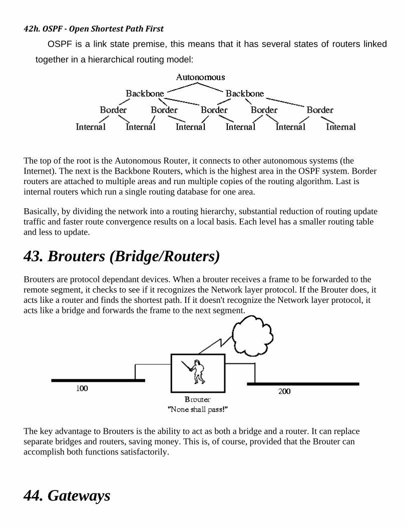
42h. OSPF - Open Shortest Path First
OSPF is a link state premise, this means that it has several states of routers linked
together in a hierarchical routing model:
The top of the root is the Autonomous Router, it connects to other autonomous systems (the
Internet). The next is the Backbone Routers, which is the highest area in the OSPF system. Border
routers are attached to multiple areas and run multiple copies of the routing algorithm. Last is
internal routers which run a single routing database for one area.
Basically, by dividing the network into a routing hierarchy, substantial reduction of routing update
traffic and faster route convergence results on a local basis. Each level has a smaller routing table
and less to update.
43. Brouters (Bridge/Routers)
Brouters are protocol dependant devices. When a brouter receives a frame to be forwarded to the
remote segment, it checks to see if it recognizes the Network layer protocol. If the Brouter does, it
acts like a router and finds the shortest path. If it doesn't recognize the Network layer protocol, it
acts like a bridge and forwards the frame to the next segment.
The key advantage to Brouters is the ability to act as both a bridge and a router. It can replace
separate bridges and routers, saving money. This is, of course, provided that the Brouter can
accomplish both functions satisfactorily.
44. Gateways
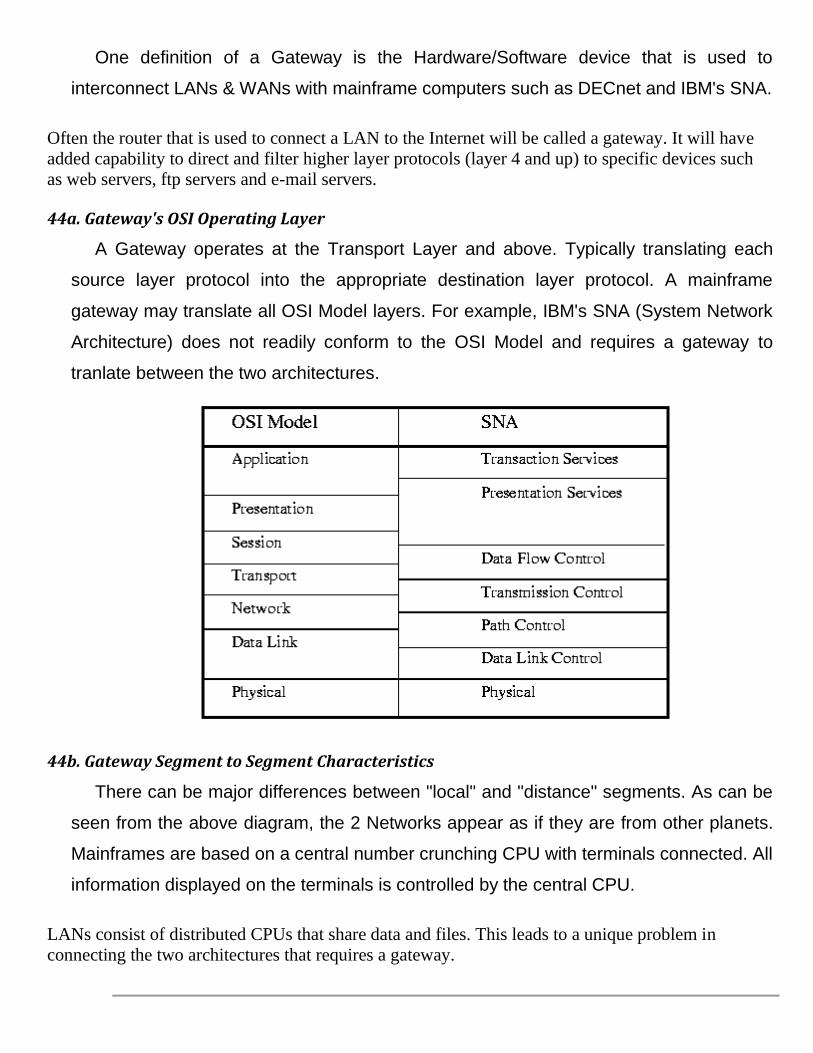
One definition of a Gateway is the Hardware/Software device that is used to
interconnect LANs & WANs with mainframe computers such as DECnet and IBM's SNA.
Often the router that is used to connect a LAN to the Internet will be called a gateway. It will have
added capability to direct and filter higher layer protocols (layer 4 and up) to specific devices such
as web servers, ftp servers and e-mail servers.
44a. Gateway's OSI Operating Layer
A Gateway operates at the Transport Layer and above. Typically translating each
source layer protocol into the appropriate destination layer protocol. A mainframe
gateway may translate all OSI Model layers. For example, IBM's SNA (System Network
Architecture) does not readily conform to the OSI Model and requires a gateway to
tranlate between the two architectures.
44b. Gateway Segment to Segment Characteristics
There can be major differences between "local" and "distance" segments. As can be
seen from the above diagram, the 2 Networks appear as if they are from other planets.
Mainframes are based on a central number crunching CPU with terminals connected. All
information displayed on the terminals is controlled by the central CPU.
LANs consist of distributed CPUs that share data and files. This leads to a unique problem in
connecting the two architectures that requires a gateway.

44c. Gateway Addressing
The gateway addressing depends on which OSI layers are translated. It could be all
layers!
45. Token Ring
STOP - You are now leaving Ethernet IEEE 802.3
Please fasten your seatbelts and place your trays in the fully upright position
Token Ring is a token passing bus arbitration topology for the Physical and Data Link Layers. It is a
logical ring and a physical star topology.
Token Ring uses a token passing scheme for bus arbitration. A special packet is passed around the
ring called a token. When a node requires access to the ring, the node claims the token and then
passes its information packet around the ring. All nodes read the destination address and if it is not
addressed for them, the information packet is then passed on to the next node. When the destination
node reads the packet, it marks it as read and passes it on to the next node. When the information
packet completely circulates the ring and arrives back at the source node, the source node releases
the token back on to the ring.
Token Rings are not usually drawn as the above drawing indicates: a separate line between each
node. They are usually represented as understood that separate paths exist between nodes and are
drawn as in the figure to the right.
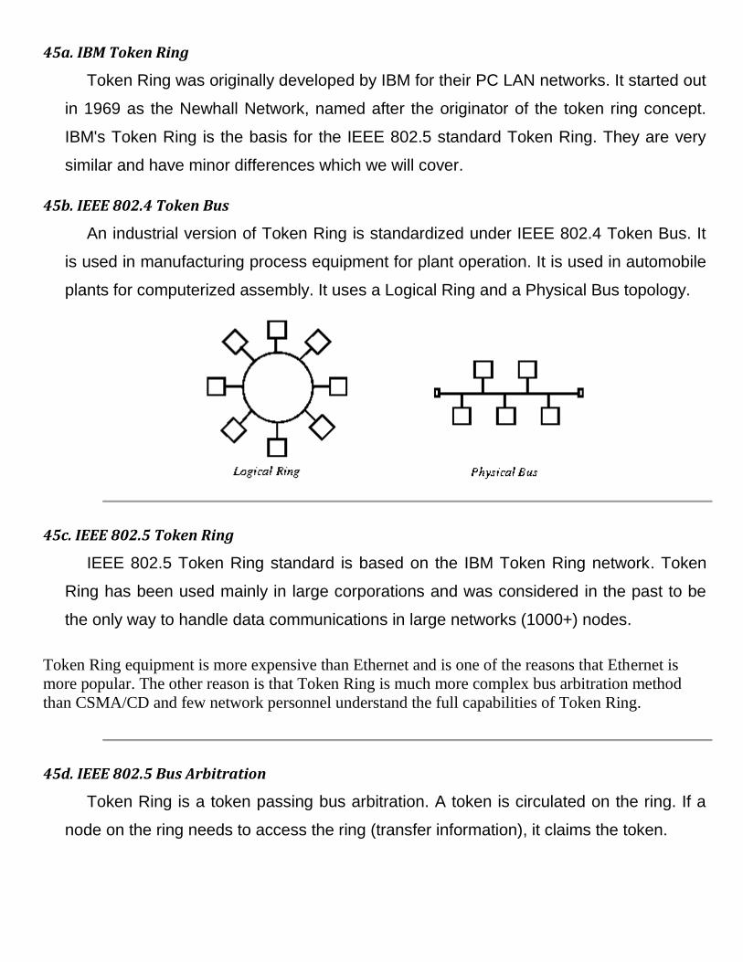
45a. IBM Token Ring
Token Ring was originally developed by IBM for their PC LAN networks. It started out
in 1969 as the Newhall Network, named after the originator of the token ring concept.
IBM's Token Ring is the basis for the IEEE 802.5 standard Token Ring. They are very
similar and have minor differences which we will cover.
45b. IEEE 802.4 Token Bus
An industrial version of Token Ring is standardized under IEEE 802.4 Token Bus. It
is used in manufacturing process equipment for plant operation. It is used in automobile
plants for computerized assembly. It uses a Logical Ring and a Physical Bus topology.
45c. IEEE 802.5 Token Ring
IEEE 802.5 Token Ring standard is based on the IBM Token Ring network. Token
Ring has been used mainly in large corporations and was considered in the past to be
the only way to handle data communications in large networks (1000+) nodes.
Token Ring equipment is more expensive than Ethernet and is one of the reasons that Ethernet is
more popular. The other reason is that Token Ring is much more complex bus arbitration method
than CSMA/CD and few network personnel understand the full capabilities of Token Ring.
45d. IEEE 802.5 Bus Arbitration
Token Ring is a token passing bus arbitration. A token is circulated on the ring. If a
node on the ring needs to access the ring (transfer information), it claims the token.

The token is a special packet, that is circulated around the ring. It is read from one node than passed
to the next node until it arrives at a node that needs to access the ring (transfer information/data).
When a node receives the token, the node is allowed to send out its information packet.
Example: The token is circulating the ring, Node B needs to send some data to Node G. Node B
waits for the token to come by. There is only one token allowed on the ring. When it receives the
token, it can then send out its information packet. Node G is the destination address.
Node C receives the packet, reads the destination address and passes it on to the next node. Node D,
E & F do likewise.
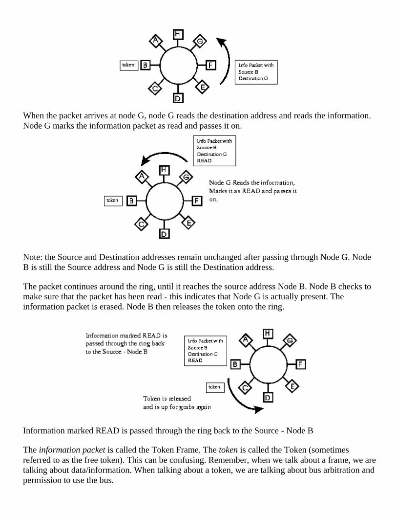
When the packet arrives at node G, node G reads the destination address and reads the information.
Node G marks the information packet as read and passes it on.
Note: the Source and Destination addresses remain unchanged after passing through Node G. Node
B is still the Source address and Node G is still the Destination address.
The packet continues around the ring, until it reaches the source address Node B. Node B checks to
make sure that the packet has been read - this indicates that Node G is actually present. The
information packet is erased. Node B then releases the token onto the ring.
Information marked READ is passed through the ring back to the Source - Node B
The information packet is called the Token Frame. The token is called the Token (sometimes
referred to as the free token). This can be confusing. Remember, when we talk about a frame, we are
talking about data/information. When talking about a token, we are talking about bus arbitration and
permission to use the bus.
45e. 4 / 16 Mbps Transfer Rate
The transfer rate for Token Ring is 4 Mbps for older systems or 16 Mbps for newer
systems (1990 and newer). There are several products in development and available
that will increase Token Ring's transfer rate using Switching Hubs and even faster
transfer rates over existing cabling.
NOTE: 16 Mbps NIC cards will operate at both 16 and 4 Mbps speeds.
4 Mbps NIC cards will only operate at 4 Mbps.
To identify the speed of an unknown card, exam the integrated circuits on the card.
There is only 1 chipset that implements IEEE 802.5's 4 Mbps standard for Token Ring. It
was developed jointly by Texas Instruments and IBM. It is a 5 chip set and consists of:
TMS38051 Ring Interface Transceiver TMS38052 Ring Interface Controller TMS38010 Communications Protocol Processor TMS38021 Protocol Handler for 802.5 Functions TMS38030 DMA Controller between NIC and PC Bus
4 Mbps Token Ring NICs are usually full length expansion cards.
16 Mbps NICs have typically 1 large IC with 132 pins and several small ones. They are typically 1/2
length cards. The IC number is TMS380C16 for the Texas Instrument version or TROPIC for the
IBM version or DP8025 for the National version.
45f. IEEE 802.5 Topology
Token Ring is a Logical Ring / Physical Star topology. So far we've been only
discussing the logical portion. Nodes on the network are physically connected via their
NICs to a central concentrator or hub. The concentrator is called a MAU or MSAU both
stand for MultiStation Access Unit. To avoid confusion with Ethernet MAUs, we will refer
to a Token Ring hub as a MSAU (pronounced "M sow") or as a concentrator.
45g. MSAUs
A Token Ring MSAU has connections to connect to the nodes and it also has special
connections called Ring In and Ring Out to connect to other MSAUs.
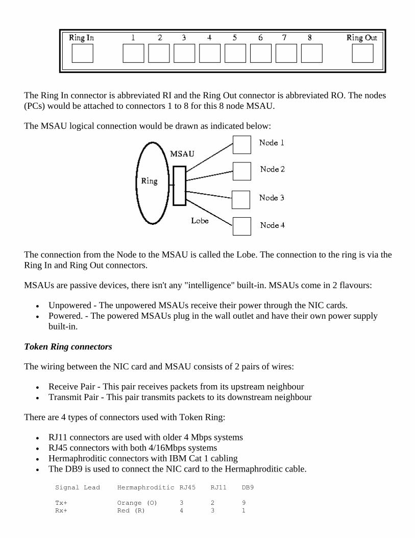
The Ring In connector is abbreviated RI and the Ring Out connector is abbreviated RO. The nodes
(PCs) would be attached to connectors 1 to 8 for this 8 node MSAU.
The MSAU logical connection would be drawn as indicated below:
The connection from the Node to the MSAU is called the Lobe. The connection to the ring is via the
Ring In and Ring Out connectors.
MSAUs are passive devices, there isn't any "intelligence" built-in. MSAUs come in 2 flavours:
Unpowered - The unpowered MSAUs receive their power through the NIC cards.
Powered. - The powered MSAUs plug in the wall outlet and have their own power supply
built-in.
Token Ring connectors
The wiring between the NIC card and MSAU consists of 2 pairs of wires:
Receive Pair - This pair receives packets from its upstream neighbour
Transmit Pair - This pair transmits packets to its downstream neighbour
There are 4 types of connectors used with Token Ring:
RJ11 connectors are used with older 4 Mbps systems
RJ45 connectors with both 4/16Mbps systems
Hermaphroditic connectors with IBM Cat 1 cabling
The DB9 is used to connect the NIC card to the Hermaphroditic cable.
Signal Lead Hermaphroditic RJ45 RJ11 DB9
Tx+ Orange (O) 3 2 9
Rx+ Red (R) 4 3 1
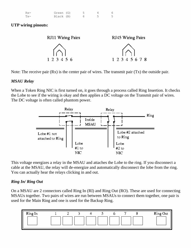
Rx- Green (G) 5 4 6
Tx- Black (B) 6 5 5
UTP wiring pinouts:
Note: The receive pair (Rx) is the center pair of wires. The transmit pair (Tx) the outside pair.
MSAU Relay
When a Token Ring NIC is first turned on, it goes through a process called Ring Insertion. It checks
the Lobe to see if the wiring is okay and then applies a DC voltage on the Transmit pair of wires.
The DC voltage is often called phantom power.
This voltage energizes a relay in the MSAU and attaches the Lobe to the ring. If you disconnect a
cable at the MSAU, the relay will de-energize and automatically disconnect the lobe from the ring.
You can actually hear the relays clicking in and out.
Ring In/ Ring Out
On a MSAU are 2 connectors called Ring In (RI) and Ring Out (RO). These are used for connecting
MSAUs together. Two pairs of wires are run between MSAUs to connect them together, one pair is
used for the Main Ring and one is used for the Backup Ring.
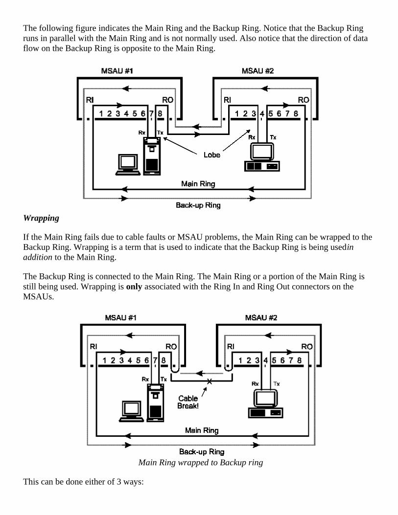
The following figure indicates the Main Ring and the Backup Ring. Notice that the Backup Ring
runs in parallel with the Main Ring and is not normally used. Also notice that the direction of data
flow on the Backup Ring is opposite to the Main Ring.
Wrapping
If the Main Ring fails due to cable faults or MSAU problems, the Main Ring can be wrapped to the
Backup Ring. Wrapping is a term that is used to indicate that the Backup Ring is being usedin
addition to the Main Ring.
The Backup Ring is connected to the Main Ring. The Main Ring or a portion of the Main Ring is
still being used. Wrapping is only associated with the Ring In and Ring Out connectors on the
MSAUs.
Main Ring wrapped to Backup ring
This can be done either of 3 ways:
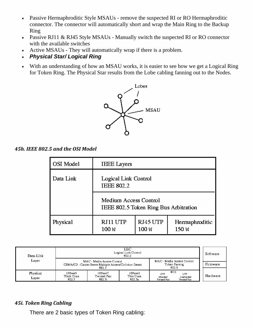
Passive Hermaphroditic Style MSAUs - remove the suspected RI or RO Hermaphroditic
connector. The connector will automatically short and wrap the Main Ring to the Backup
Ring
Passive RJ11 & RJ45 Style MSAUs - Manually switch the suspected RI or RO connector
with the available switches
Active MSAUs - They will automatically wrap if there is a problem.
Physical Star/ Logical Ring
With an understanding of how an MSAU works, it is easier to see how we get a Logical Ring
for Token Ring. The Physical Star results from the Lobe cabling fanning out to the Nodes.
45h. IEEE 802.5 and the OSI Model
45i. Token Ring Cabling
There are 2 basic types of Token Ring cabling:
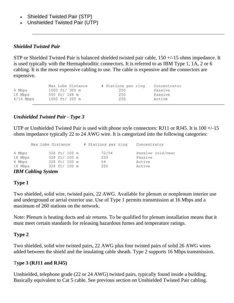
Shielded Twisted Pair (STP) Unshielded Twisted Pair (UTP)
Shielded Twisted Pair
STP or Shielded Twisted Pair is balanced shielded twisted pair cable, 150 +/-15 ohms impedance. It
is used typically with the Hermaphroditic connectors. It is referred to as IBM Type 1, 1A, 2 or 6
cabling. It is the most expensive cabling to use. The cable is expensive and the connectors are
expensive.
Max Lobe Distance # Stations per ring Concentrator
4 Mbps 1000 ft/ 305 m 250 Passive
16 Mbps 550 ft/ 168 m 250 Passive
4/16 Mbps 1000 ft/ 305 m 250 Active
Unshielded Twisted Pair - Type 3
UTP or Unshielded Twisted Pair is used with phone style connectors: RJ11 or RJ45. It is 100 +/-15
ohms impedance typically 22 to 24 AWG wire. It is categorized into the following categories:
Max Lobe Distance # Stations per ring Concentrator
4 Mbps 328 ft/ 100 m 72/54 Passive (old/new)
16 Mbps 328 ft/ 100 m 250 Passive
4 Mbps 328 ft/ 100 m 54 Active
16 Mbps 328 ft/ 100 m 250 Active
IBM Cabling System
Type 1
Two shielded, solid wire, twisted pairs, 22 AWG. Available for plenum or nonplenum interior use
and underground or aerial exterior use. Use of Type 1 permits transmission at 16 Mbps and a
maximum of 260 stations on the network.
Note: Plenum is heating ducts and air returns. To be qualified for plenum installation means that it
must meet certain standards for releasing hazardous fumes and temperature ratings.
Type 2
Two shielded, solid wire twisted pairs, 22 AWG plus four twisted pairs of solid 26 AWG wires
added between the shield and the insulating cable sheath. Type 2 supports 16 Mbps transmission.
Type 3 (RJ11 and RJ45)
Unshielded, telephone grade (22 or 24 AWG) twisted pairs, typically found inside a building.
Basically equivalent to Cat 5 cable. See previous section on Unshielded Twisted Pair cabling.

Type 5
100/50 micron fibre-optic cable, used to connect distant MSAUs with fibre optic repeaters.
Type 6
Patch cables consisting of data-grade, stranded, shielded twisted pairs, 26 AWG. the distant limits
are 66% of Type 1 cable.
Type 8
Under carpet cable, data-grade twisted pair cable, 26 AWG. The distance limits are 50 percent of
Type 1.
Type 9
Shielded twisted pair, 26 AWG approved for plenum installations. The distance limits are 66% of
Type 1 cable.
45j. Ring Insertion
When any node or host wishes to attach to the ring, it initiates the Ring Insertion
process. The Ring Insertion process has 5 phases:
Phase 0 Lobe Media Check
The Lobe Media Check is performed by the NIC and it verifies the Lobe cable by looping the station
transmit signal to the station receiver at the MSAU. A Lobe Media test MAC frame is issued. The
relay in the MSAU is not energized at this time. A special packet is sent from the NIC to the de-
energized MSAU lobe relay. The packet loops back from the MSAU and returns to the NIC. The
integrity of the wiring that makes up the lobe is be checked.
The NIC applies Phantom Power (DC voltage) on the Transmit pair to activate the relay at the
MSAU port. The NIC is now physically connected to the Ring.
Phase 1: Monitor Check
The ring station waits for an Active Monitor Present frame, Standby Monitor Present frame or Ring
Purge MAC frame. If the ring station does not receive one of these frames before the T(attach) timer
runs out, the ring station initiates Token Claiming to re-elect an Active Monitor.
Phase 2: Address Verification
The station verifies that its MAC address is unique with the Ring. It sends a Duplicate Address Test
MAC frame onto the ring. The Duplicate Address Test frame has the source and destination address
set to its own MAC address. If the frame returns marked read, then the station knows that there is
another node with an identical address.
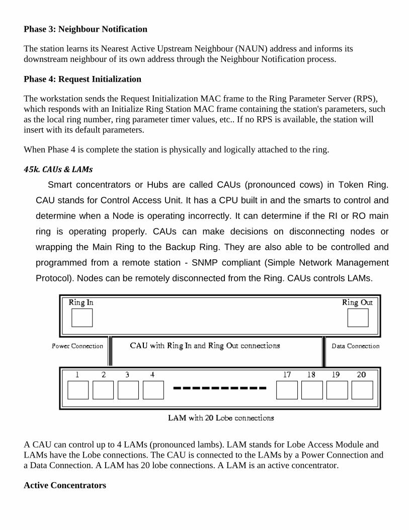
Phase 3: Neighbour Notification
The station learns its Nearest Active Upstream Neighbour (NAUN) address and informs its
downstream neighbour of its own address through the Neighbour Notification process.
Phase 4: Request Initialization
The workstation sends the Request Initialization MAC frame to the Ring Parameter Server (RPS),
which responds with an Initialize Ring Station MAC frame containing the station's parameters, such
as the local ring number, ring parameter timer values, etc.. If no RPS is available, the station will
insert with its default parameters.
When Phase 4 is complete the station is physically and logically attached to the ring.
45k. CAUs & LAMs
Smart concentrators or Hubs are called CAUs (pronounced cows) in Token Ring.
CAU stands for Control Access Unit. It has a CPU built in and the smarts to control and
determine when a Node is operating incorrectly. It can determine if the RI or RO main
ring is operating properly. CAUs can make decisions on disconnecting nodes or
wrapping the Main Ring to the Backup Ring. They are also able to be controlled and
programmed from a remote station - SNMP compliant (Simple Network Management
Protocol). Nodes can be remotely disconnected from the Ring. CAUs controls LAMs.
A CAU can control up to 4 LAMs (pronounced lambs). LAM stands for Lobe Access Module and
LAMs have the Lobe connections. The CAU is connected to the LAMs by a Power Connection and
a Data Connection. A LAM has 20 lobe connections. A LAM is an active concentrator.
Active Concentrators
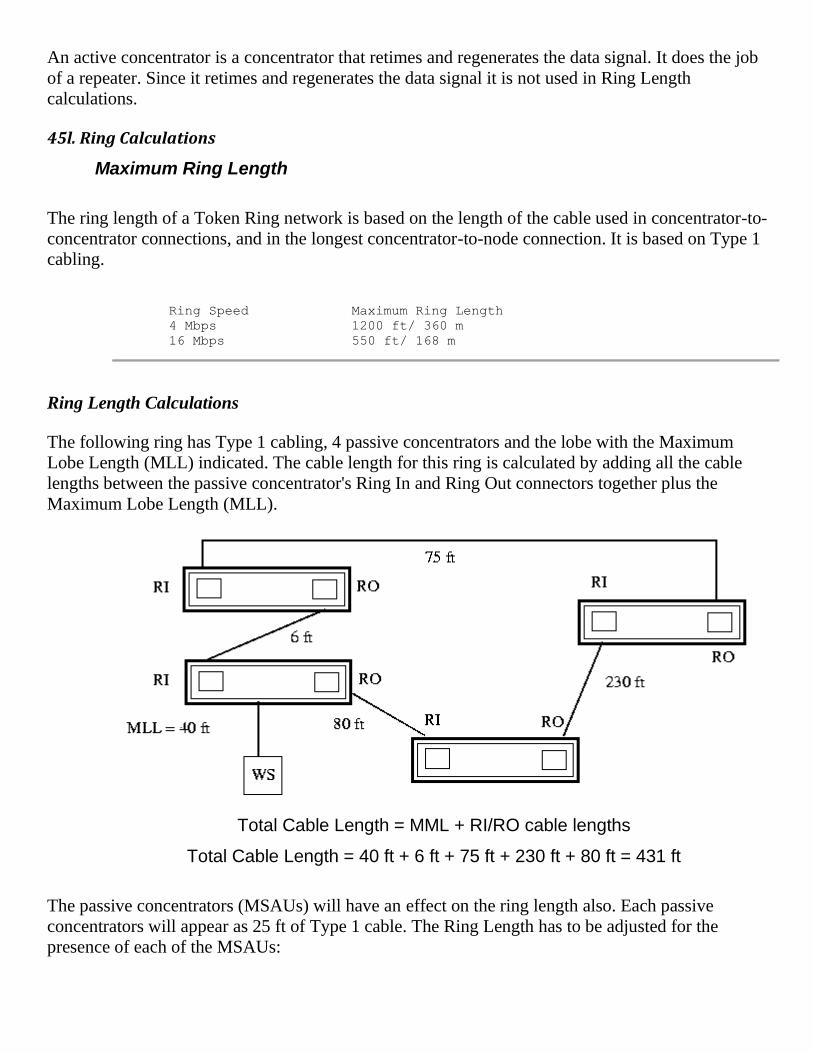
An active concentrator is a concentrator that retimes and regenerates the data signal. It does the job
of a repeater. Since it retimes and regenerates the data signal it is not used in Ring Length
calculations.
45l. Ring Calculations
Maximum Ring Length
The ring length of a Token Ring network is based on the length of the cable used in concentrator-to-
concentrator connections, and in the longest concentrator-to-node connection. It is based on Type 1
cabling.
Ring Speed Maximum Ring Length
4 Mbps 1200 ft/ 360 m
16 Mbps 550 ft/ 168 m
Ring Length Calculations
The following ring has Type 1 cabling, 4 passive concentrators and the lobe with the Maximum
Lobe Length (MLL) indicated. The cable length for this ring is calculated by adding all the cable
lengths between the passive concentrator's Ring In and Ring Out connectors together plus the
Maximum Lobe Length (MLL).
Total Cable Length = MML + RI/RO cable lengths
Total Cable Length = 40 ft + 6 ft + 75 ft + 230 ft + 80 ft = 431 ft
The passive concentrators (MSAUs) will have an effect on the ring length also. Each passive
concentrators will appear as 25 ft of Type 1 cable. The Ring Length has to be adjusted for the
presence of each of the MSAUs:
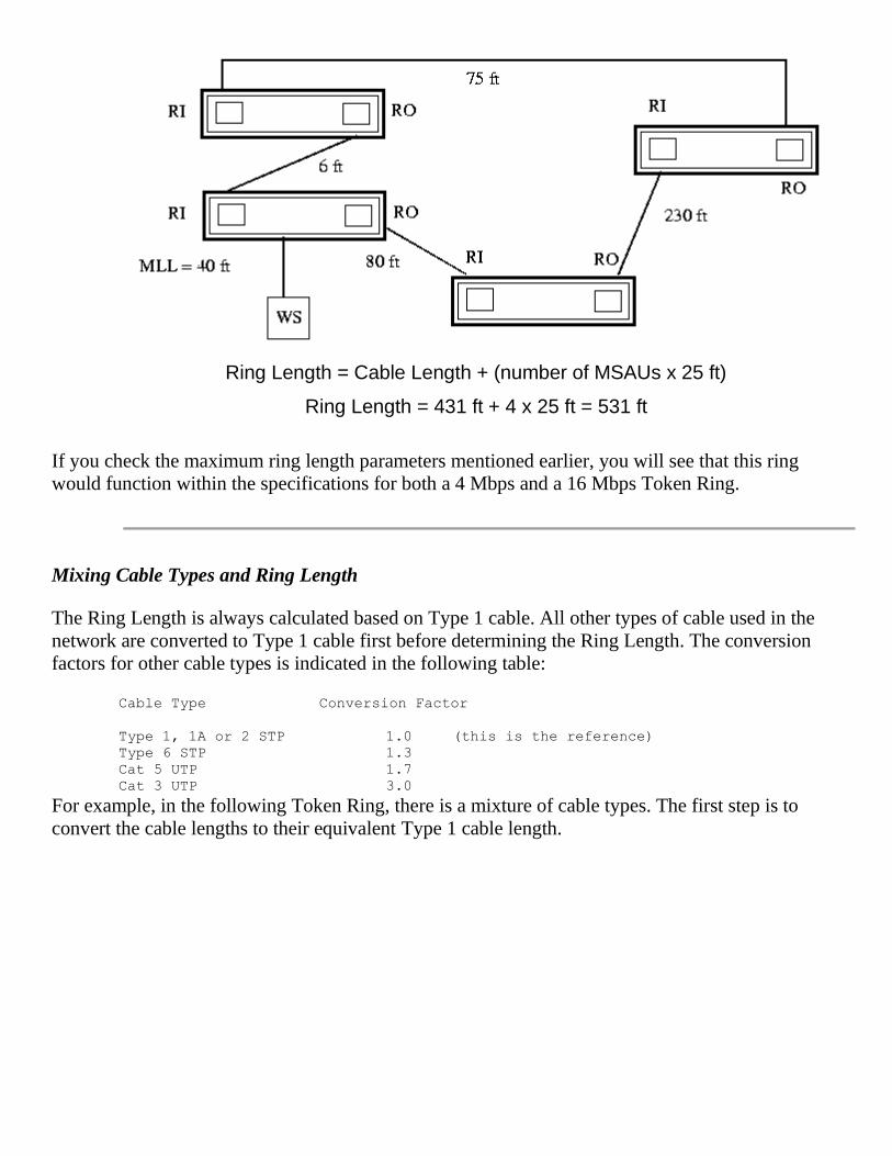
Ring Length = Cable Length + (number of MSAUs x 25 ft)
Ring Length = 431 ft + 4 x 25 ft = 531 ft
If you check the maximum ring length parameters mentioned earlier, you will see that this ring
would function within the specifications for both a 4 Mbps and a 16 Mbps Token Ring.
Mixing Cable Types and Ring Length
The Ring Length is always calculated based on Type 1 cable. All other types of cable used in the
network are converted to Type 1 cable first before determining the Ring Length. The conversion
factors for other cable types is indicated in the following table:
Cable Type Conversion Factor
Type 1, 1A or 2 STP 1.0 (this is the reference)
Type 6 STP 1.3
Cat 5 UTP 1.7
Cat 3 UTP 3.0
For example, in the following Token Ring, there is a mixture of cable types. The first step is to
convert the cable lengths to their equivalent Type 1 cable length.
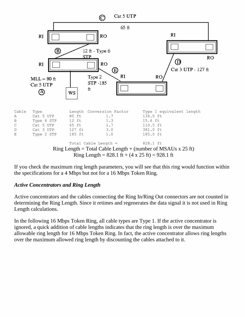
Cable Type Length Conversion Factor Type 1 equivalent length
A Cat 5 UTP 80 ft 1.7 136.0 ft
B Type 6 STP 12 ft 1.3 15.6 ft
C Cat 5 UTP 65 ft 1.7 110.5 ft
D Cat 3 UTP 127 ft 3.0 381.0 ft
E Type 2 STP 185 ft 1.0 185.0 ft
Total Cable Length = 828.1 ft
Ring Length = Total Cable Length + (number of MSAUs x 25 ft)
Ring Length = 828.1 ft + (4 x 25 ft) = 928.1 ft
If you check the maximum ring length parameters, you will see that this ring would function within
the specifications for a 4 Mbps but not for a 16 Mbps Token Ring.
Active Concentrators and Ring Length
Active concentrators and the cables connecting the Ring In/Ring Out connectors are not counted in
determining the Ring Length. Since it retimes and regenerates the data signal it is not used in Ring
Length calculations.
In the following 16 Mbps Token Ring, all cable types are Type 1. If the active concentrator is
ignored, a quick addition of cable lengths indicates that the ring length is over the maximum
allowable ring length for 16 Mbps Token Ring. In fact, the active concentrator allows ring lengths
over the maximum allowed ring length by discounting the cables attached to it.

Total Cable Length = MML + RI/RO cable lengths
Total Cable Length = 75 ft + 12 ft + 210 ft = 297 ft
The 165 ft and 95 ft cables are not counted because they are attached to the active concentrator's
Ring In/Ring Out connectors.
Ring Length = Cable Length + (number of MSAUs x 25 ft)
Ring Length = 297 ft + 3 x 25 ft = 372 ft
The active concentrator is not counted in the calculation of Ring Length so only 3 MSAUs are used.
The ring length appears to be 372 ft which is within the limits of 16 Mbps Token Ring (550 ft). In
fact, the use of an active concentrator allows this 16 Mbps to operate with a total cable length that is
actually greater than the allowed ring length for 16 Mbps Type 1 cabling.
45m. Token Ring Monitors and Servers
Active Monitor (AM)
The Active Monitor (AM) is the active node with the highest address: it wins active monitor status
by a token claiming process that takes place between all active nodes. Any node can become the
AM, all other nodes become Standby Monitors in case the Active Monitor fails or turns off.
The duties of the Active Monitor are:
Maintaining the Master Clock Ensuring Proper Ring Delay Initiating Neighbour Notification Monitoring Neighbour Notification Monitoring Token and Frame Transmission Detecting Lost Tokens and Frames Purging the Ring
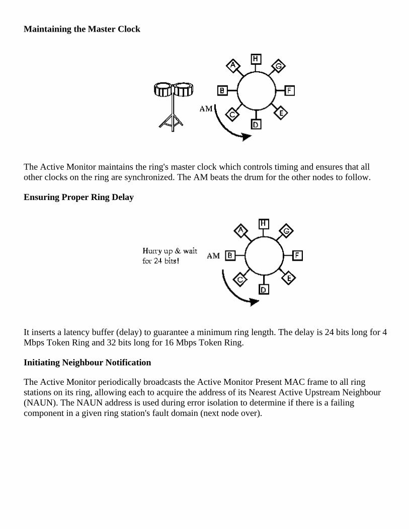
Maintaining the Master Clock
The Active Monitor maintains the ring's master clock which controls timing and ensures that all
other clocks on the ring are synchronized. The AM beats the drum for the other nodes to follow.
Ensuring Proper Ring Delay
It inserts a latency buffer (delay) to guarantee a minimum ring length. The delay is 24 bits long for 4
Mbps Token Ring and 32 bits long for 16 Mbps Token Ring.
Initiating Neighbour Notification
The Active Monitor periodically broadcasts the Active Monitor Present MAC frame to all ring
stations on its ring, allowing each to acquire the address of its Nearest Active Upstream Neighbour
(NAUN). The NAUN address is used during error isolation to determine if there is a failing
component in a given ring station's fault domain (next node over).
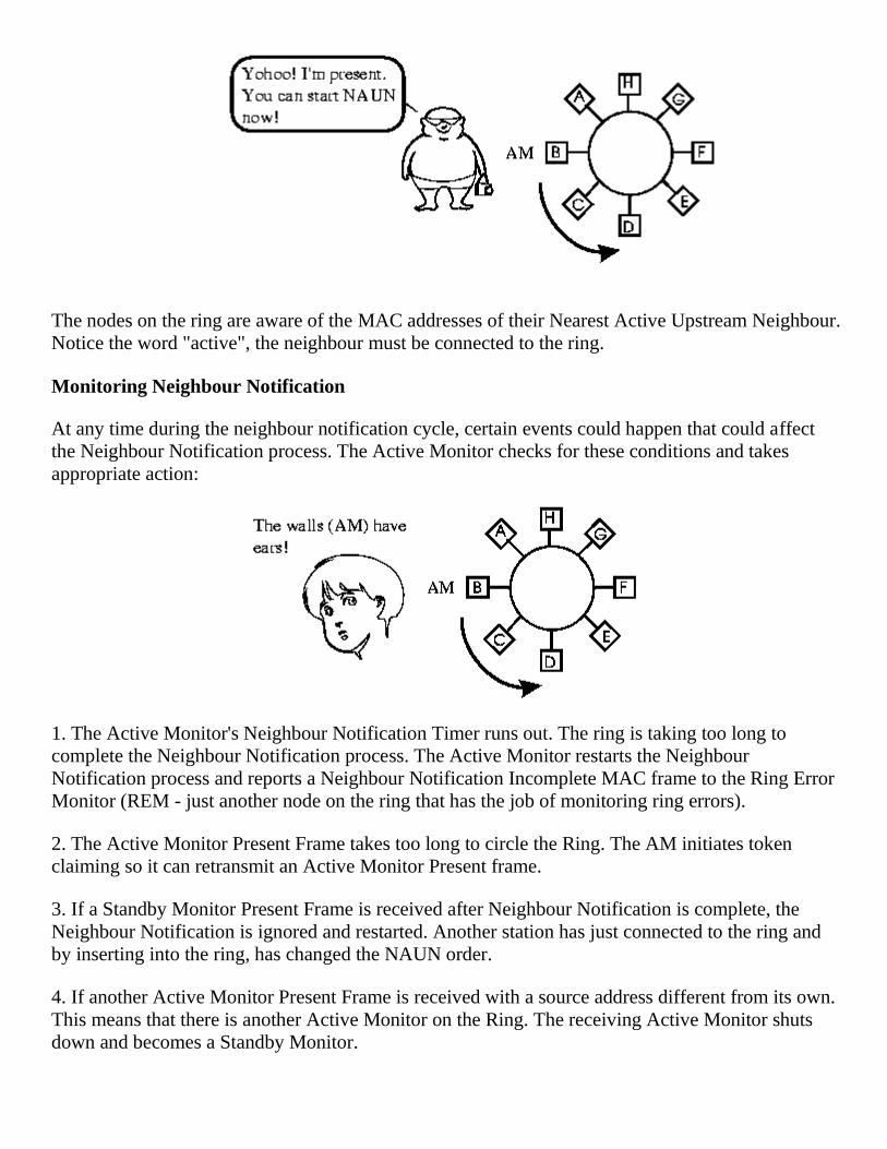
The nodes on the ring are aware of the MAC addresses of their Nearest Active Upstream Neighbour.
Notice the word "active", the neighbour must be connected to the ring.
Monitoring Neighbour Notification
At any time during the neighbour notification cycle, certain events could happen that could affect
the Neighbour Notification process. The Active Monitor checks for these conditions and takes
appropriate action:
1. The Active Monitor's Neighbour Notification Timer runs out. The ring is taking too long to
complete the Neighbour Notification process. The Active Monitor restarts the Neighbour
Notification process and reports a Neighbour Notification Incomplete MAC frame to the Ring Error
Monitor (REM - just another node on the ring that has the job of monitoring ring errors).
2. The Active Monitor Present Frame takes too long to circle the Ring. The AM initiates token
claiming so it can retransmit an Active Monitor Present frame.
3. If a Standby Monitor Present Frame is received after Neighbour Notification is complete, the
Neighbour Notification is ignored and restarted. Another station has just connected to the ring and
by inserting into the ring, has changed the NAUN order.
4. If another Active Monitor Present Frame is received with a source address different from its own.
This means that there is another Active Monitor on the Ring. The receiving Active Monitor shuts
down and becomes a Standby Monitor.
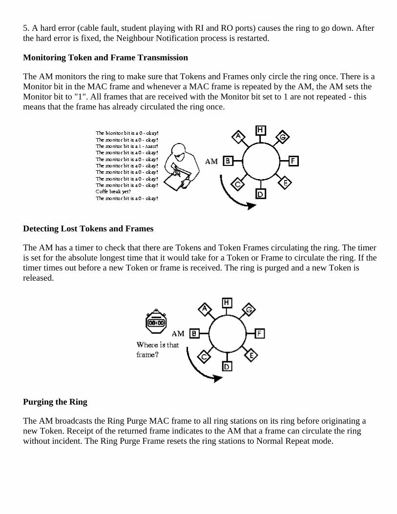
5. A hard error (cable fault, student playing with RI and RO ports) causes the ring to go down. After
the hard error is fixed, the Neighbour Notification process is restarted.
Monitoring Token and Frame Transmission
The AM monitors the ring to make sure that Tokens and Frames only circle the ring once. There is a
Monitor bit in the MAC frame and whenever a MAC frame is repeated by the AM, the AM sets the
Monitor bit to "1". All frames that are received with the Monitor bit set to 1 are not repeated - this
means that the frame has already circulated the ring once.
Detecting Lost Tokens and Frames
The AM has a timer to check that there are Tokens and Token Frames circulating the ring. The timer
is set for the absolute longest time that it would take for a Token or Frame to circulate the ring. If the
timer times out before a new Token or frame is received. The ring is purged and a new Token is
released.
Purging the Ring
The AM broadcasts the Ring Purge MAC frame to all ring stations on its ring before originating a
new Token. Receipt of the returned frame indicates to the AM that a frame can circulate the ring
without incident. The Ring Purge Frame resets the ring stations to Normal Repeat mode.

Standby Monitor (SM)
There is only 1 Active Monitor allowed on the ring at a time, all other stations become Standby
Monitors. Standby Monitors determine whether the Active Monitor is functioning properly. If a
Standby Monitor determines that the Active Monitor is not operating properly, the Standby Monitor
initiates the Token Claiming process.
Duties of the Standby Monitor
a. The Standby Monitor checks to see if a Token is circulating the ring. It has a Timer called the
"Good_token" timer and knows that a Token has to circulate within that time. If the Token does not
go by within this designated period, the Standby Monitor knows that Active Monitor is not doing its
job. The Standby Monitor then initiates the Token Claiming process to re-elect an Active Monitor.
b. The Standby Monitor restarts another Timer called "receive notification" whenever an Active
Monitor Present frame comes by. If the Timer runs out before another Active Monitor Present frame
arrives, the SM assumes that the Active Monitor is not present or has malfunctioned. The SM
initiates the Token Claiming process to re-elect an Active Monitor.
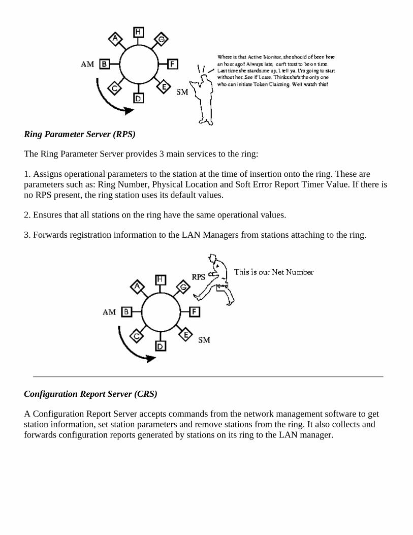
Ring Parameter Server (RPS)
The Ring Parameter Server provides 3 main services to the ring:
1. Assigns operational parameters to the station at the time of insertion onto the ring. These are
parameters such as: Ring Number, Physical Location and Soft Error Report Timer Value. If there is
no RPS present, the ring station uses its default values.
2. Ensures that all stations on the ring have the same operational values.
3. Forwards registration information to the LAN Managers from stations attaching to the ring.
Configuration Report Server (CRS)
A Configuration Report Server accepts commands from the network management software to get
station information, set station parameters and remove stations from the ring. It also collects and
forwards configuration reports generated by stations on its ring to the LAN manager.
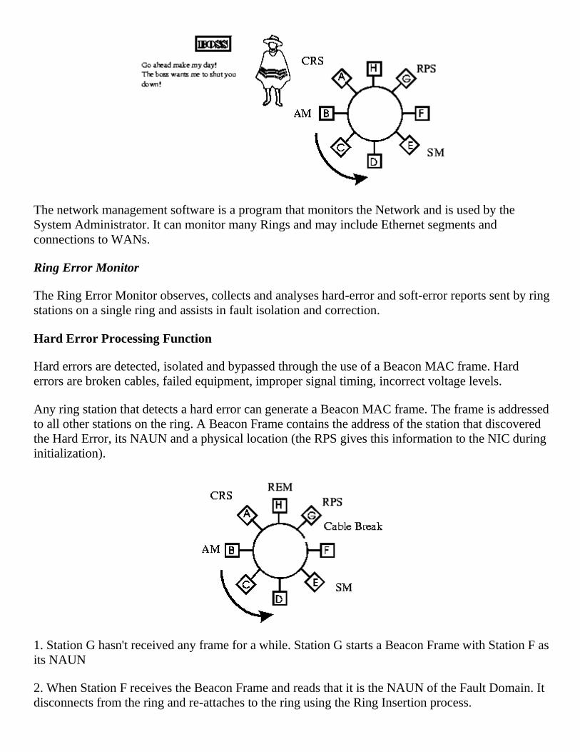
The network management software is a program that monitors the Network and is used by the
System Administrator. It can monitor many Rings and may include Ethernet segments and
connections to WANs.
Ring Error Monitor
The Ring Error Monitor observes, collects and analyses hard-error and soft-error reports sent by ring
stations on a single ring and assists in fault isolation and correction.
Hard Error Processing Function
Hard errors are detected, isolated and bypassed through the use of a Beacon MAC frame. Hard
errors are broken cables, failed equipment, improper signal timing, incorrect voltage levels.
Any ring station that detects a hard error can generate a Beacon MAC frame. The frame is addressed
to all other stations on the ring. A Beacon Frame contains the address of the station that discovered
the Hard Error, its NAUN and a physical location (the RPS gives this information to the NIC during
initialization).
1. Station G hasn't received any frame for a while. Station G starts a Beacon Frame with Station F as
its NAUN
2. When Station F receives the Beacon Frame and reads that it is the NAUN of the Fault Domain. It
disconnects from the ring and re-attaches to the ring using the Ring Insertion process.
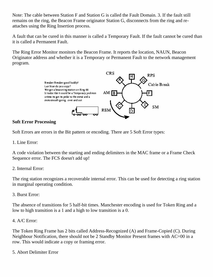
Note: The cable between Station F and Station G is called the Fault Domain. 3. If the fault still
remains on the ring, the Beacon Frame originator Station G, disconnects from the ring and re-
attaches using the Ring Insertion process.
A fault that can be cured in this manner is called a Temporary Fault. If the fault cannot be cured than
it is called a Permanent Fault.
The Ring Error Monitor monitors the Beacon Frame. It reports the location, NAUN, Beacon
Originator address and whether it is a Temporary or Permanent Fault to the network management
program.
Soft Error Processing
Soft Errors are errors in the Bit pattern or encoding. There are 5 Soft Error types:
1. Line Error:
A code violation between the starting and ending delimiters in the MAC frame or a Frame Check
Sequence error. The FCS doesn't add up!
2. Internal Error:
The ring station recognizes a recoverable internal error. This can be used for detecting a ring station
in marginal operating condition.
3. Burst Error:
The absence of transitions for 5 half-bit times. Manchester encoding is used for Token Ring and a
low to high transition is a 1 and a high to low transition is a 0.
4. A/C Error:
The Token Ring Frame has 2 bits called Address-Recognized (A) and Frame-Copied (C). During
Neighbour Notification, there should not be 2 Standby Monitor Present frames with AC=00 in a
row. This would indicate a copy or framing error.
5. Abort Delimiter Error
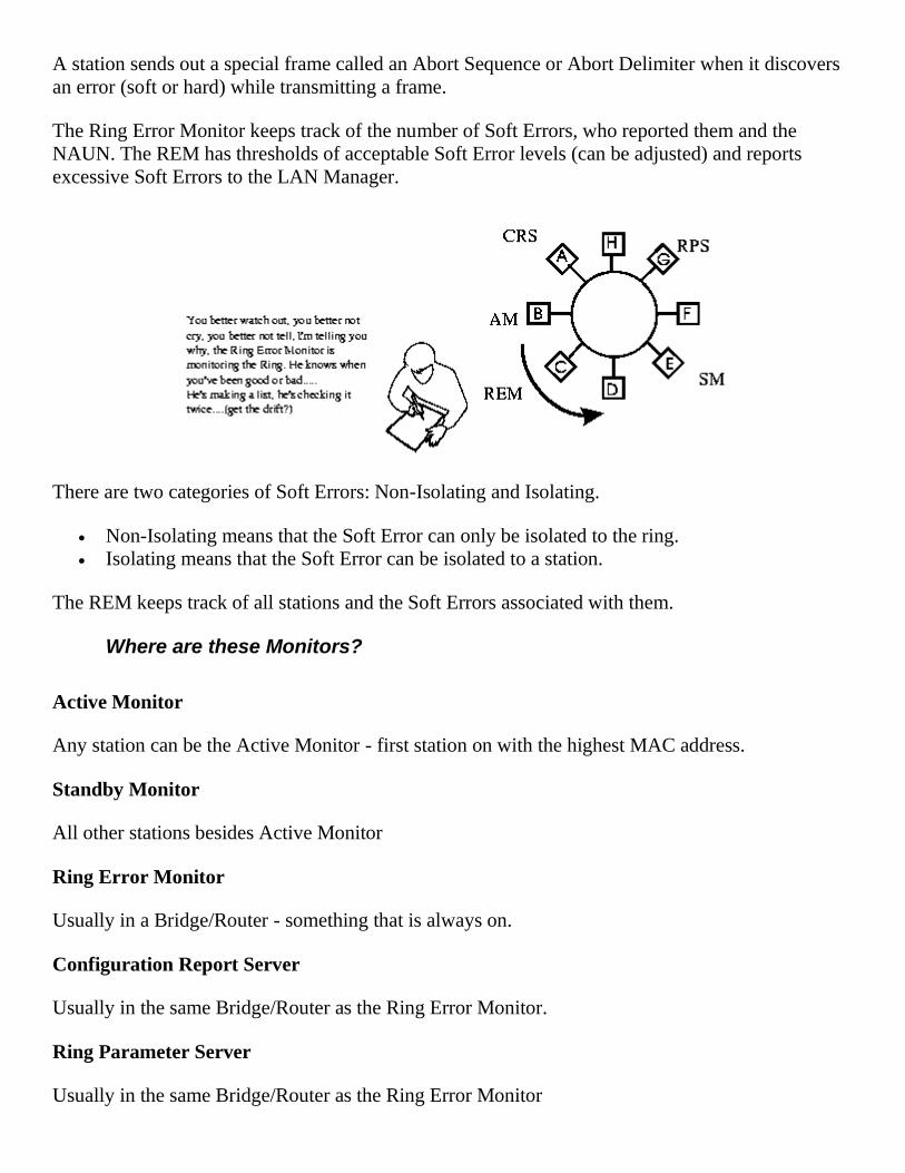
A station sends out a special frame called an Abort Sequence or Abort Delimiter when it discovers
an error (soft or hard) while transmitting a frame.
The Ring Error Monitor keeps track of the number of Soft Errors, who reported them and the
NAUN. The REM has thresholds of acceptable Soft Error levels (can be adjusted) and reports
excessive Soft Errors to the LAN Manager.
There are two categories of Soft Errors: Non-Isolating and Isolating.
Non-Isolating means that the Soft Error can only be isolated to the ring.
Isolating means that the Soft Error can be isolated to a station.
The REM keeps track of all stations and the Soft Errors associated with them.
Where are these Monitors?
Active Monitor
Any station can be the Active Monitor - first station on with the highest MAC address.
Standby Monitor
All other stations besides Active Monitor
Ring Error Monitor
Usually in a Bridge/Router - something that is always on.
Configuration Report Server
Usually in the same Bridge/Router as the Ring Error Monitor.
Ring Parameter Server
Usually in the same Bridge/Router as the Ring Error Monitor
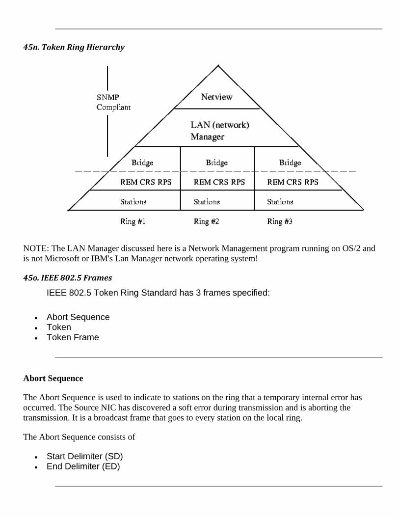
45n. Token Ring Hierarchy
NOTE: The LAN Manager discussed here is a Network Management program running on OS/2 and
is not Microsoft or IBM's Lan Manager network operating system!
45o. IEEE 802.5 Frames
IEEE 802.5 Token Ring Standard has 3 frames specified:
Abort Sequence
Token Token Frame
Abort Sequence
The Abort Sequence is used to indicate to stations on the ring that a temporary internal error has
occurred. The Source NIC has discovered a soft error during transmission and is aborting the
transmission. It is a broadcast frame that goes to every station on the local ring.
The Abort Sequence consists of
Start Delimiter (SD) End Delimiter (ED)
Token
The Token, sometimes called the free token, is used for Bus Arbitration in Token Ring. Whichever
station claims the Token has the right to transmit its information/data (Token Frame) on the ring.
The Token consists of 24 bits:
Start Delimiter (SD) Access Control Field (AC) End Delimiter (ED)
It is a broadcast frame that goes to every station on the local ring.
Token Frame
The Token Frame is used for transmitting information/data on the ring. It is the only frame with
Source and Destination addresses. The Token Frame consists of the following fields:
Start Delimiter (SD) Access Control (AC) Frame Control (FC) Destination Address (DA) Source Address (SA) Information Field (INFO) Frame Check Sequence (FCS) End Delimiter (ED) Frame Status (FS)
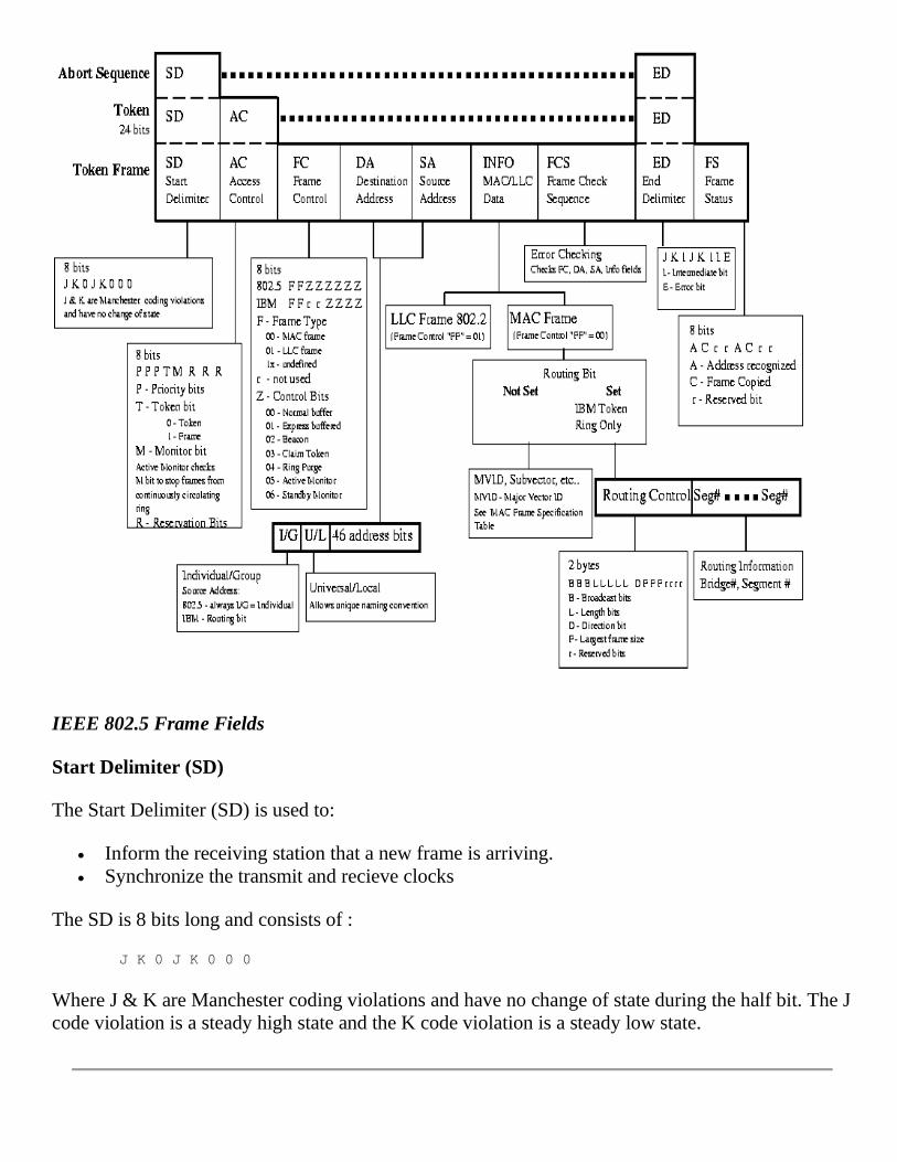
IEEE 802.5 Frame Fields
Start Delimiter (SD)
The Start Delimiter (SD) is used to:
Inform the receiving station that a new frame is arriving.
Synchronize the transmit and recieve clocks
The SD is 8 bits long and consists of :
J K 0 J K 0 0 0
Where J & K are Manchester coding violations and have no change of state during the half bit. The J
code violation is a steady high state and the K code violation is a steady low state.
Access Control (AC)
The Access Control (AC) field is used to:
Set priority of Token
Indicate if it is a Token or Information Frame
To stop frames from continuously circulating the ring
The AC field consists of 8 bits:
P P P T M r r r
Where:
P = Priority Bits
T = Token Bit (0 - Token , 1 - Information)
M = Monitor Bit
R = Reservation Bits
The Priority Bits are used to indicate the priority of the Token. Each workstation is assigned a
priority for their transmissions: 000 is the lowest and 111 is the highest (7 levels of priorities). The
Lan administrator sets the priority levels. For a workstation to claim a Token, it must have a priority
equal to or greater than the priority of the Token.
It is the responsibility of the node when finished transmitting data, to release the Token and to return
the priority bits to the Reservation Bits.
The Reservation Bits are used to negotiate the priority of the next token as a transmission passes
by. When a Token or Token Frame goes by, a node is allowed to reserve the priority of the next
Token to be released by placing its priority in the Reservation Bits. In order to change the
Reservation Bits, the node's priority must be greater than the existing Reservation bits.
The Token Bit is used to indicate whether the frame is a Token or Token Frame (information
frame). T = 0 indicates a Token, T=1 indicates a Token Frame.
The Monitor Bit is used by the Active Monitor (AM) to stop frames from continuously circulating
the ring. The Monitor bit is set to M=0 by the Source and when a frame passes by the AM, the
monitor bit is set to M=1. If the AM receives a frame with the monitor bit set to M=1. The frame is
removed from the ring, purges the ring and issues a new token.
Frame Control (FC)
The Frame Control (FC) field is used to:
Indicate frame type (MAC or LLC)
Provides communication at the MAC level between stations

The FC field consists of 8 bits:
F F Z Z Z Z Z Z
Where:
F = Frame Type (00 = MAC, 01 = LLC, 1x = not defined)
Z = Control Bits
The Frame Type indicates whether it is a MAC layer addressed communication or an LLC layer
addressed communication.
The Control bits indicate the type of MAC level communication:
00 - Normal Buffer
01 - Express Buffered
02 - Beacon
03 - Claim Token
04 - Ring Purge
05 - Active Monitor
06 - Standby Monitor
Destination Address (DA)
The Destination Address (DA) is use to indicate the destination address of the Token Frame
(information frame). It consists of 48 address bits.
The first bit is the Individual/Group (I/G) bit - this is used to indicate an individual or broadcast
(to everyone). The 2nd bit is used to indicate whether a Universal or Local naming convention. A
Universal naming convention would use the MAC address burnt into the NIC's ROM. The Local
naming convention would be set by the Lan Administrator. The remaining 46 bits are the stations
unique address.
Source Address (SA)
The Source Address is identical to the Destination Address field except that the Individual/Group bit
is always set to Individual (0) for IEEE 802.5. For IBM Token Ring, the first bit is the Routing Bit
which instructs bridges to pass the Token Frame (1) or to ignore it (0).
IEEE 802.5
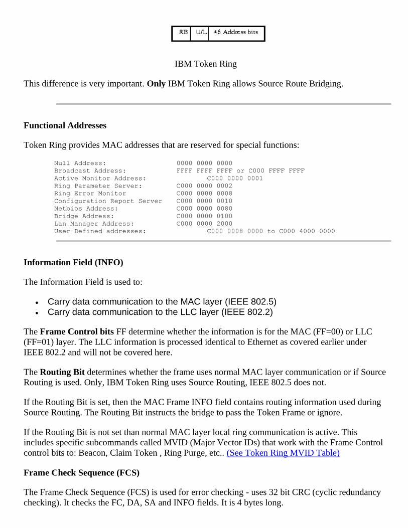
IBM Token Ring
This difference is very important. Only IBM Token Ring allows Source Route Bridging.
Functional Addresses
Token Ring provides MAC addresses that are reserved for special functions:
Null Address: 0000 0000 0000
Broadcast Address: FFFF FFFF FFFF or C000 FFFF FFFF
Active Monitor Address: C000 0000 0001
Ring Parameter Server: C000 0000 0002
Ring Error Monitor C000 0000 0008
Configuration Report Server C000 0000 0010
Netbios Address: C000 0000 0080
Bridge Address: C000 0000 0100
Lan Manager Address: C000 0000 2000
User Defined addresses: C000 0008 0000 to C000 4000 0000
Information Field (INFO)
The Information Field is used to:
Carry data communication to the MAC layer (IEEE 802.5) Carry data communication to the LLC layer (IEEE 802.2)
The Frame Control bits FF determine whether the information is for the MAC (FF=00) or LLC
(FF=01) layer. The LLC information is processed identical to Ethernet as covered earlier under
IEEE 802.2 and will not be covered here.
The Routing Bit determines whether the frame uses normal MAC layer communication or if Source
Routing is used. Only, IBM Token Ring uses Source Routing, IEEE 802.5 does not.
If the Routing Bit is set, then the MAC Frame INFO field contains routing information used during
Source Routing. The Routing Bit instructs the bridge to pass the Token Frame or ignore.
If the Routing Bit is not set than normal MAC layer local ring communication is active. This
includes specific subcommands called MVID (Major Vector IDs) that work with the Frame Control
control bits to: Beacon, Claim Token , Ring Purge, etc.. (See Token Ring MVID Table)
Frame Check Sequence (FCS)
The Frame Check Sequence (FCS) is used for error checking - uses 32 bit CRC (cyclic redundancy
checking). It checks the FC, DA, SA and INFO fields. It is 4 bytes long.
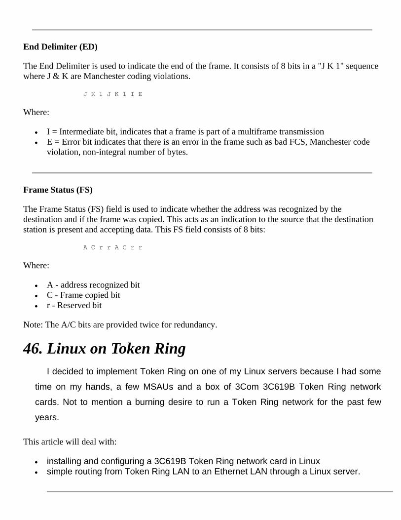
End Delimiter (ED)
The End Delimiter is used to indicate the end of the frame. It consists of 8 bits in a "J K 1" sequence
where J & K are Manchester coding violations.
J K 1 J K 1 I E
Where:
I = Intermediate bit, indicates that a frame is part of a multiframe transmission
E = Error bit indicates that there is an error in the frame such as bad FCS, Manchester code
violation, non-integral number of bytes.
Frame Status (FS)
The Frame Status (FS) field is used to indicate whether the address was recognized by the
destination and if the frame was copied. This acts as an indication to the source that the destination
station is present and accepting data. This FS field consists of 8 bits:
A C r r A C r r
Where:
A - address recognized bit
C - Frame copied bit
r - Reserved bit
Note: The A/C bits are provided twice for redundancy.
46. Linux on Token Ring
I decided to implement Token Ring on one of my Linux servers because I had some
time on my hands, a few MSAUs and a box of 3Com 3C619B Token Ring network
cards. Not to mention a burning desire to run a Token Ring network for the past few
years.
This article will deal with:
installing and configuring a 3C619B Token Ring network card in Linux simple routing from Token Ring LAN to an Ethernet LAN through a Linux server.
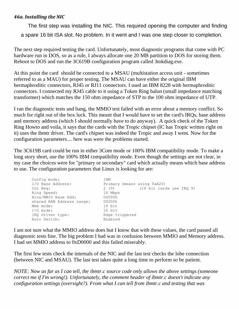
46a. Installing the NIC
The first step was installing the NIC. This required opening the computer and finding
a spare 16 bit ISA slot. No problem. In it went and I was one step closer to completion.
The next step required testing the card. Unfortunately, most diagnostic programs that come with PC
hardware run in DOS, so as a rule, I always allocate one 20 MB partition to DOS for storing them.
Reboot to DOS and run the 3C619B configuration program called 3tokdiag.exe.
At this point the card should be connected to a MSAU (multistation access unit - sometimes
referred to as a MAU) for proper testing. The MSAU can have either the original IBM
hermaphroditic connectors, RJ45 or RJ11 connectors. I used an IBM 8228 with hermaphroditic
connectors. I connected my RJ45 cable to it using a Token Ring balun (small impedance matching
transformer) which matches the 150 ohm impedance of STP to the 100 ohm impedance of UTP.
I ran the diagnostic tests and bang, the MMIO test failed with an error about a memory conflict. So
much for right out of the box luck. This meant that I would have to set the card's IRQs, base address
and memory address (which I should normally have to do anyway). A quick check of the Token
Ring Howto and voila, it says that the cards with the Tropic chipset (IC has Tropic written right on
it) uses the ibmtr driver. The card's chipset was indeed the Tropic and away I went. Now for the
configuration parameters.... here was were the problems started.
The 3C619B card could be run in either 3Com mode or 100% IBM compatibility mode. To make a
long story short, use the 100% IBM compatibility mode. Even though the settings are not clear, in
my case the choices were for "primary or secondary" card which actually means which base address
to use. The configuration parameters that Linux is looking for are:
Config mode: IBM
I/O Base Address: Primary (means using 0xA20)
Int Req: 2 (9) (16 bit cards use IRQ 9)
Ring Speed: 16 Mbps
Bios/MMIO Base Add: D4000h
shared RAM Address range: D0000h
Mem mode: 16 bit
I/O mode: 16 bit
IRQ Driver type: Edge triggered
Auto Switch: Enabled
I am not sure what the MMIO address does but I know that with these values, the card passed all
diagnostic tests fine. The big problem I had was in confusion between MMIO and Memory address.
I had set MMIO address to 0xD0000 and this failed miserably.
The first few tests check the internals of the NIC and the last test checks the lobe connection
(between NIC and MSAU). The last test takes quite a long time to perform so be patient.
NOTE: Now as far as I can tell, the ibmtr.c source code only allows the above settings (someone
correct me if I'm wrong!). Unfortunately, the comment header of ibmtr.c doesn't indicate any
configuration settings (oversight?). From what I can tell from ibmtr.c and testing that was

performed over a period of 3 weeks (yes that is right - I was on the verge of giving up), these are
the only values that will work.
46b. The Kernel and Token Ring
The Linux kernel must be recompiled for Token Ring support. You can compile it in directly or as a
module both methods work admirably. To compile the kernel, you change directories to
/usr/src/linux and run either:
"make config" - for command line text based line by line prompt "make menuconfig" - for a command line configuration menu "make xconfig" - for an X windows configuration menu
I suggest that you use either menuconfig or xconfig. The "make config" method can be
extremely unforgiving if you should make a mistake - you have to start all over again.
The assumption at this point is that you have a working recompiled kernel and are only adding
support for a Token Ring card. This means that the only change should be to add Token Ring
support to the kernel. Go to Network Device Support section and select Token Ring Driver Support
as either as compiled as part of the kernel (Y) or as a module (M). I selected compiled as part of the
kernel. Next select "IBM Tropic chipset based adapter support" (again Y or M - your choice). Save
and exit and you're now ready to recompile the kernel.
make clean ; make dep ; make zImage
make modules
make modules_install
I copied the zImage file to the root directory (I'm using slackware - you may need to copy it to /boot
directory for other distributions):
cp /usr/src/linux/arch/i386/boot/zImage /token-ring
Now the new kernel was in place, it's time to add a new lilo entry.
46c. LILO and T.R. Kernel
Since I wasn't sure how Linux would work with the new Token Ring card, I wanted to be able to
boot to the old working kernel (non Token Ring). I added another entry into /etc/lilo.conf that would
address the new kernel. At the lilo boot prompt I would have a new choice of which kernel to boot
to. I modified /etc/lilo.conf with a simple text editor for the new kernel:
# LILO configuration file
#
# Start LILO global section
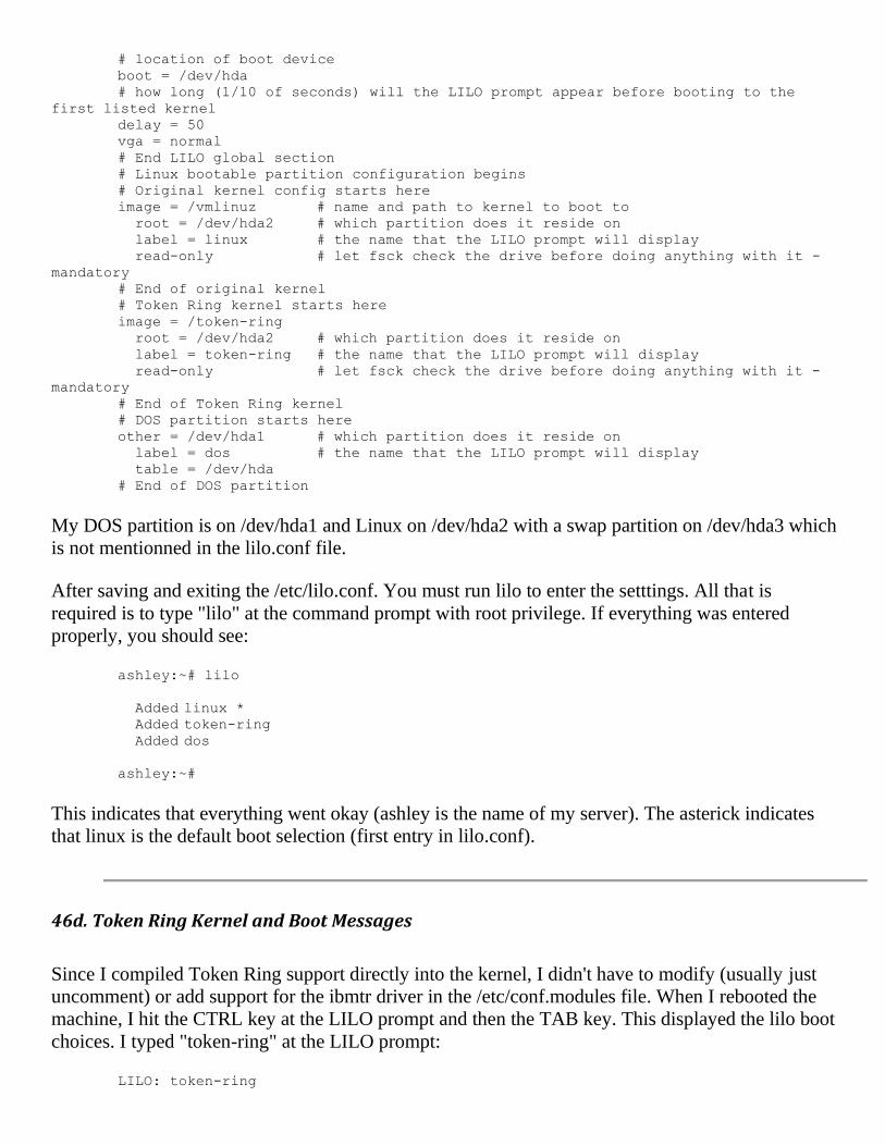
# location of boot device
boot = /dev/hda
# how long (1/10 of seconds) will the LILO prompt appear before booting to the
first listed kernel
delay = 50
vga = normal
# End LILO global section
# Linux bootable partition configuration begins
# Original kernel config starts here
image = /vmlinuz # name and path to kernel to boot to
root = /dev/hda2 # which partition does it reside on
label = linux # the name that the LILO prompt will display
read-only # let fsck check the drive before doing anything with it -
mandatory
# End of original kernel
# Token Ring kernel starts here
image = /token-ring
root = /dev/hda2 # which partition does it reside on
label = token-ring # the name that the LILO prompt will display
read-only # let fsck check the drive before doing anything with it -
mandatory
# End of Token Ring kernel
# DOS partition starts here
other = /dev/hda1 # which partition does it reside on
label = dos # the name that the LILO prompt will display
table = /dev/hda
# End of DOS partition
My DOS partition is on /dev/hda1 and Linux on /dev/hda2 with a swap partition on /dev/hda3 which
is not mentionned in the lilo.conf file.
After saving and exiting the /etc/lilo.conf. You must run lilo to enter the setttings. All that is
required is to type "lilo" at the command prompt with root privilege. If everything was entered
properly, you should see:
ashley:~# lilo
Added linux *
Added token-ring
Added dos
ashley:~#
This indicates that everything went okay (ashley is the name of my server). The asterick indicates
that linux is the default boot selection (first entry in lilo.conf).
46d. Token Ring Kernel and Boot Messages
Since I compiled Token Ring support directly into the kernel, I didn't have to modify (usually just
uncomment) or add support for the ibmtr driver in the /etc/conf.modules file. When I rebooted the
machine, I hit the CTRL key at the LILO prompt and then the TAB key. This displayed the lilo boot
choices. I typed "token-ring" at the LILO prompt:
LILO: token-ring
I then closely watched for the following messages to scroll across the screen:
<snip>
tr0: ISA 16/4 Adapter| 16/4 Adapter /A (long) found
tr0: using IRQ 9, PIO Addr a20, 16 k Shared RAM
tr0: Hardware address: 00:20:AF:0E:C7:2E
tr0: Maximum MTU 16 Mbps: 4056, 4 Mbps: 4568
<snip>
tr0: Initial interrupt: 16 Mbps, Shared Ram base 000d0000
<snip>
tr0: New Ring Status: 20
tr0: New Ring Status: 20
tr0: New Ring Status: 20
tr0: New Ring Status: 20
<snip>
And its up.. It's quite stable and if you have a passive msau, you shoud bew able to hear the relay
click in for the ring insertion phase .
If you see either of these error messages:
arrgh! Transmitter busy
Unknown command 08h in arb
Then you have the wrong Shared Ram Address range configured on your card. Set it to 0xD0000h.
46e. Configuring the Interface
Now that there was support for the Token Ring card in the kernel, the interface had to be configured.
This means that the IP address, mask, broadcast address and default route must be set. In Slackware,
the /etc/rc.d/rc.inet1 file is modified to add the following parameters. If you are just testing, you can
type in the following parameters at the command prompt:
/sbin/ifconfig tr0 192.168.2.1 broadcast 192.168.2.255 netmask 255.255.255.0
where:
tr0 is the first Token Ring adapter found
192.168.2.1 is the IP address of the interface
192.168.2.255 is the broadcast address of the interface
255.255.255.0 is the subnet mask
At this point, you should type "ifconfig" by itself on the command line interface and you should see
something like this:
eth0 Link encap:Ethernet HWaddr 00:A0:24:CC:12:6F
inet addr:192.168.1.3 Bcast:192.168.1.255 Mask:255.255.255
UP BROADCAST RUNNING MULTICAST MTU:1500 Metric:
RX packets:53775 errors:0 dropped:0 overruns:0 frame:
TX packets:7489 errors:0 dropped:0 overruns:0 carrier:
collisions:0 txqueuelen:100
Interrupt:10 Base address:0xe800

tr0 Link encap:Token Ring HWaddr 00:20:AF:0E:C7:2E
inet addr:192.168.2.1 Bcast:192.168.2.255 Mask:255.255.255.0
UP BROADCAST RUNNING MULTICAST MTU:4500 Metric:1
RX packets:0 errors:0 dropped:0 overruns:0 frame:0
TX packets:0 errors:0 dropped:0 overruns:0 carrier:0
collisions:0 txqueuelen:100
Interrupt:9 Base address:0xa20
lo Link encap:Local Loopback
inet addr:127.0.0.1 Mask:255.0.0.0
UP LOOPBACK RUNNING MTU:3924 Metric:1
RX packets:235 errors:0 dropped:0 overruns:0 frame:0
TX packets:235 errors:0 dropped:0 overruns:0 carrier:0
collisions:0 txqueuelen:0
Notice that both the ethernet, loopback and token ring interfaces are listed. It is very important to
make sure that the Ethernet and Token Ring adapters are on separate IP networks. In this example,
eth0 is on subnet 192.168.1.0 and tr0 is on subnet 192.168.2.0.
At this point you should be able to ping your linux box from the token ring network. Symptoms of a
wrong NIC configuration is if you can ping localhost and the linux network card address (like
192.168.2.1) from within the Linux server fine but when you ping anything outside of the linux
server (such as other LAN hosts) you get the error messages listed above.
46f. Routing from Token Ring to Ethernet
There are two methods that can be used to connect Ethernet networks to Token Ring
networks. The first method uses the Data Link layer of the OSI model and is called a
translation bridge. There are several major differences between the two MAC frames,
one of the most significant is the tranmission of most significant bits (MSB) of a byte.
Token Ring transmits the least significant bit (LSB) first while ethernet transmits it in
reverse order with the MSB first (or vice versa depending on if you are a Token Ring
guy or Ethernet guy). Unfortunately, Linux doesn't support translation bridging for a very
good reason (see next paragraph).
The second method uses the Network layer (IP layer) and is called routing. Both Ethernet and Token
Ring protocol stacks already deliver their data to the Network layer in the proper order and in a
common format - IP datagram. This means that all that needs to be done to connect the two LAN
arbitration methods is to add a route to our routing table (too easy!).
Since our ethernet routing is already working including default gateway. I only had to add the
following line to /etc/rc.d/rc.inet1. To test type at the command line:
/sbin/route add - net 192.168.2.0 netmask 255.255.255.0
Any packet not addressed to the Token Ring network 192.168.2.0 is forwarded to the Ethernet
network. I used a similar route on the Ethernet side and everything not addressed to the Ethernet
network 192.168.1.0 was sent to the Token Ring network.
To verify that everything still works from the Linux box:
ping an Ethernet host ping a Token Ring host
To verify that routing is working, try to ping across the Linux server from an Ethernet host to a
Token Ring host and vice versa.
NOTE: This is a very simple routing example. Only two LANs are being used: 192.168.1.0 and
192.168.2.0. Your situation will most likely be more complicated. Please see the man pages on
routed for further information.
46g. Token Ring Problems
While Linux ran beautifully with Token Ring, I can't say the same about Win95. The
biggest problem that I ran into was the fact that Win95 performs a software reboot
whenever its configuration is changed or when most new software is installed. While this
isn't a problem with Ethernet, it is a problem with Token Ring. Token Ring has many
maintenance and administration duties implemented in the network card itself. The
network card requires a hard boot to reset not a soft boot.
The results were that the Win95 clients would lose their network connections (specifically the
network stack to the NIC) and hang during soft boots - very frustrating. Add any new software
especially if it is a network install and bam, down goes Win95 - hung again. I would have to shut off
the PC and reboot. I never realized how often you have to reboot Win95 until I implemented Token
Ring on it. I would not want to administrate a Token Ring network on Win95 for a living.
This is not a Token Ring fault but a Win95 fault as far as I can tell. I was using Win95a so perhaps
later versions have addressed this problem and corrected it. Linux did not have any problems of this
nature.
47. Source Routing
IEEE 802.5 does NOT provide Source Routing as part of the IEEE standard. Only IBM Token
Ring uses Source Routing.
In Source Routing, the Source is responsible for determining the best path to the Destination. The
Source sends out a XID (Exchange ID) or TEST frame which picks up routing information along the
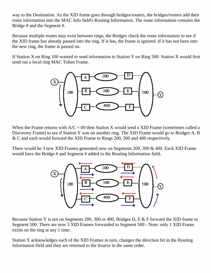
way to the Destination. As the XID frame goes through bridges/routers, the bridges/routers add their
route information into the MAC Info field's Routing Information. The route information contains the
Bridge # and the Segment #.
Because multiple routes may exist between rings, the Bridges check the route information to see if
the XID frame has already passed into the ring. If it has, the frame is ignored. If it has not been into
the new ring, the frame is passed on.
If Station X on Ring 100 wanted to send information to Station Y on Ring 500. Station X would first
send out a local ring MAC Token Frame.
When the Frame returns with A/C = 00 then Station X would send a XID Frame (sometimes called a
Discovery Frame) to see if Station Y was on another ring. The XID Frame would go to Bridges A, B
& C and each would forward the XID Frame to Rings 200, 300 and 400 respectively.
There would be 3 new XID Frames generated now on Segments 200, 300 & 400. Each XID Frame
would have the Bridge # and Segment # added to the Routing Information field.
Because Station Y is not on Segments 200, 300 or 400, Bridges D, E & F forward the XID frame to
Segment 500. There are now 3 XID Frames forwarded to Segment 500 - Note: only 1 XID Frame
exists on the ring at any 1 time.
Station Y acknowledges each of the XID Frames in turn, changes the direction bit in the Routing
Information field and they are returned to the Source in the same order.
Station X receives the first XID frame and uses its routing information for all subsequent frame
transmission to Station Y. Station X ignores all other XID frames. The assumption is made that the
first XID frame received back is the quickest and best route. This method of Source Routing is
called All Routes Broadcast (ARB).
If a Spanning Tree Algorithm is used then only 1 path would exist between Station X and Station
Y. When Source Routing is used with a Spanning Tree Algorithm, it is called a Single Route
Broadcast (SRB).
Note: In IEEE 802.5 and IBM Token Ring, it is the responsibility of the MAC layer to find the best
route. Ethernet relies on the Network layer to find the best route.
48. ISDN - Integrated Services Digital Network
The Integrated Services Digital Network (ISDN) is a method used to bridge "the last mile" between
the Central Office and the premise connection (home). ISDN uses the existing wiring so no new
cabling is required.
There are two basic services offered:
Basic Rate Interface (BRI) consists of 2B + D channels. Which stands for 2 Bearer channels
of 64 kbps each for data and one D channel of 16 kbps for handshaking and control. Having a
separate channel for handshaking and control is called "out of band" signalling. The 2B
channels can be bonded together for a single data channel with a 128 kbps transfer rate.
Primary Rate Interface (PRI) consists of 23B + D channels. Which stands for 23 Bearer
channels of 64 kbps each for data and one D channel of 64 kbps for handshaking and control.
The Bearer channels can be bonded in any combination as required.
ISDN lines can be dedicated lines that are always up and connected or they can be dial on demand
(DOD) lines. When the line is required the connection is dialed up and made. The connection time
for an ISDN line is very quick, in the order of 0.5 second or so. This can result in a substantial cost
saving if used over long distance or paying by the minute. The line charges are only for when data is
being transferred and not when it is sitting idle.
ISDN - OSI Layers
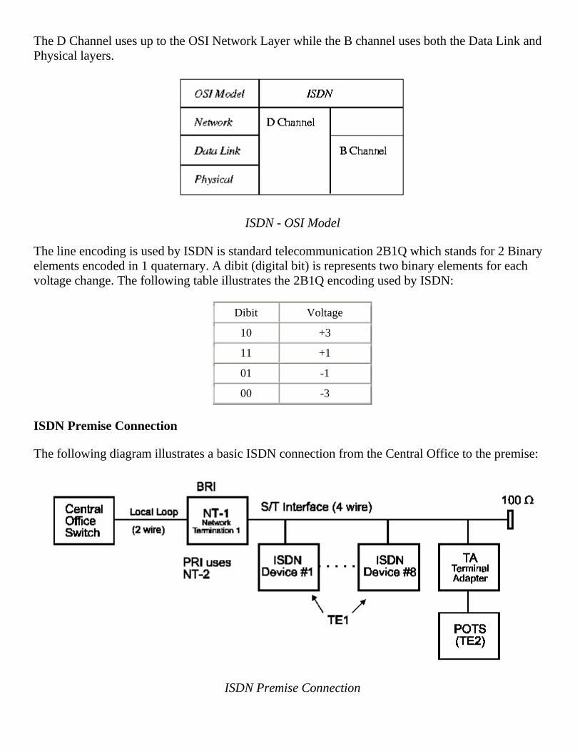
The D Channel uses up to the OSI Network Layer while the B channel uses both the Data Link and
Physical layers.
ISDN - OSI Model
The line encoding is used by ISDN is standard telecommunication 2B1Q which stands for 2 Binary
elements encoded in 1 quaternary. A dibit (digital bit) is represents two binary elements for each
voltage change. The following table illustrates the 2B1Q encoding used by ISDN:
Dibit Voltage
10 +3
11 +1
01 -1
00 -3
ISDN Premise Connection
The following diagram illustrates a basic ISDN connection from the Central Office to the premise:
ISDN Premise Connection
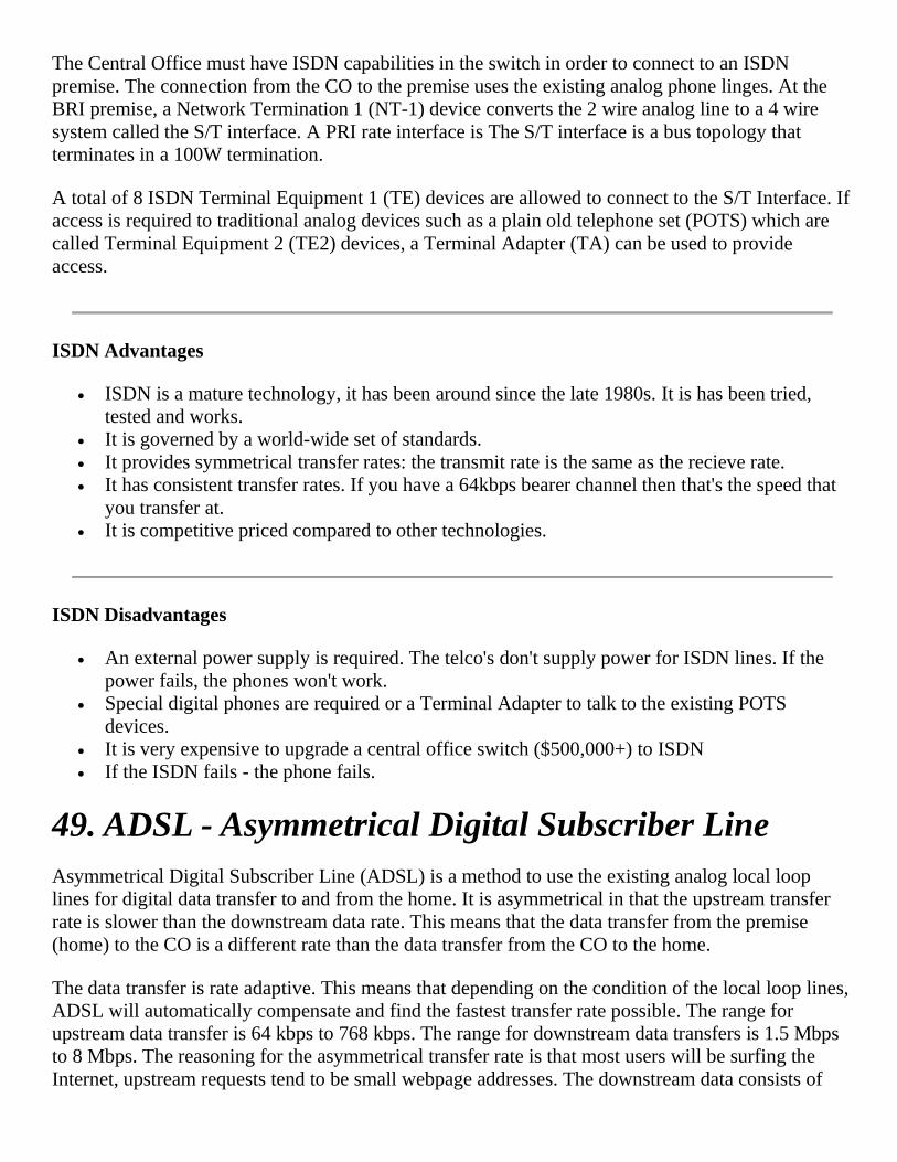
The Central Office must have ISDN capabilities in the switch in order to connect to an ISDN
premise. The connection from the CO to the premise uses the existing analog phone linges. At the
BRI premise, a Network Termination 1 (NT-1) device converts the 2 wire analog line to a 4 wire
system called the S/T interface. A PRI rate interface is The S/T interface is a bus topology that
terminates in a 100W termination.
A total of 8 ISDN Terminal Equipment 1 (TE) devices are allowed to connect to the S/T Interface. If
access is required to traditional analog devices such as a plain old telephone set (POTS) which are
called Terminal Equipment 2 (TE2) devices, a Terminal Adapter (TA) can be used to provide
access.
ISDN Advantages
ISDN is a mature technology, it has been around since the late 1980s. It is has been tried,
tested and works.
It is governed by a world-wide set of standards.
It provides symmetrical transfer rates: the transmit rate is the same as the recieve rate.
It has consistent transfer rates. If you have a 64kbps bearer channel then that's the speed that
you transfer at.
It is competitive priced compared to other technologies.
ISDN Disadvantages
An external power supply is required. The telco's don't supply power for ISDN lines. If the
power fails, the phones won't work.
Special digital phones are required or a Terminal Adapter to talk to the existing POTS
devices.
It is very expensive to upgrade a central office switch ($500,000+) to ISDN
If the ISDN fails - the phone fails.
49. ADSL - Asymmetrical Digital Subscriber Line
Asymmetrical Digital Subscriber Line (ADSL) is a method to use the existing analog local loop
lines for digital data transfer to and from the home. It is asymmetrical in that the upstream transfer
rate is slower than the downstream data rate. This means that the data transfer from the premise
(home) to the CO is a different rate than the data transfer from the CO to the home.
The data transfer is rate adaptive. This means that depending on the condition of the local loop lines,
ADSL will automatically compensate and find the fastest transfer rate possible. The range for
upstream data transfer is 64 kbps to 768 kbps. The range for downstream data transfers is 1.5 Mbps
to 8 Mbps. The reasoning for the asymmetrical transfer rate is that most users will be surfing the
Internet, upstream requests tend to be small webpage addresses. The downstream data consists of
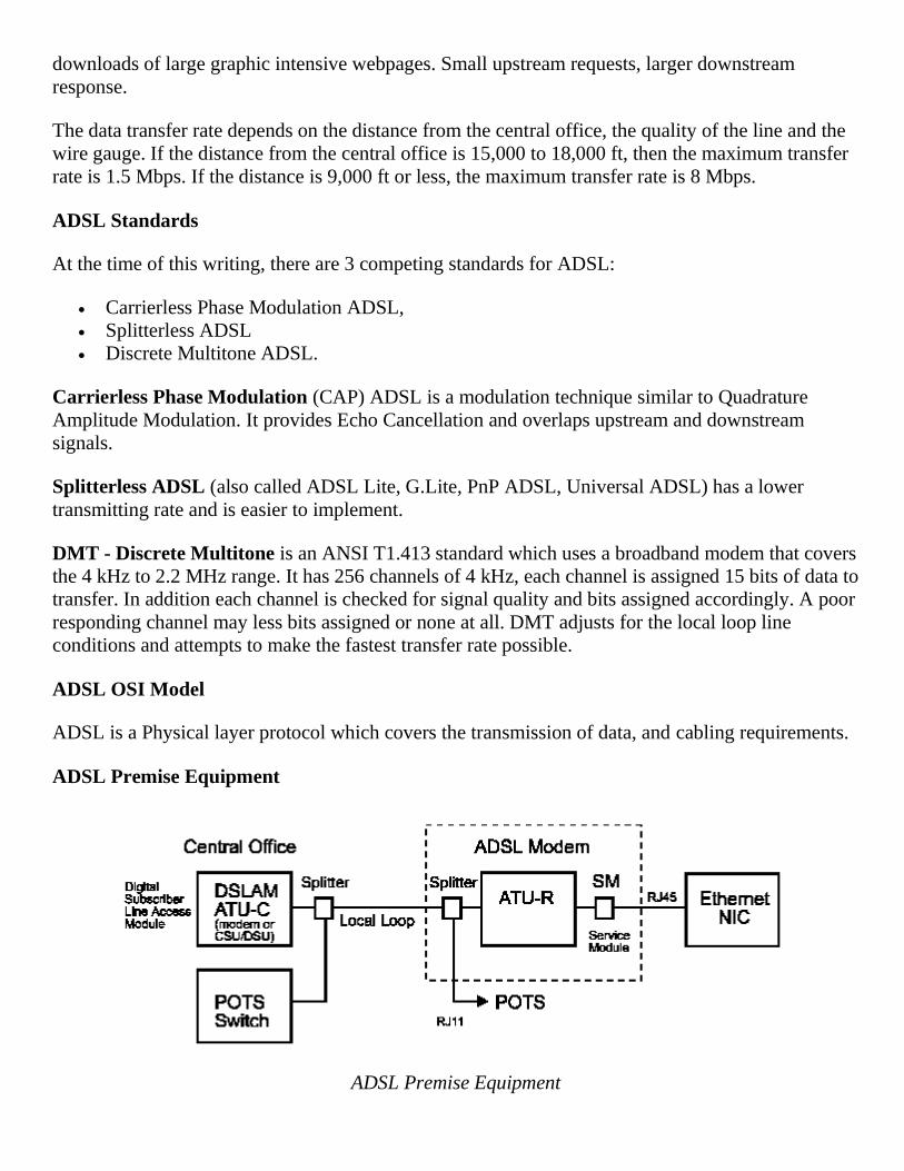
downloads of large graphic intensive webpages. Small upstream requests, larger downstream
response.
The data transfer rate depends on the distance from the central office, the quality of the line and the
wire gauge. If the distance from the central office is 15,000 to 18,000 ft, then the maximum transfer
rate is 1.5 Mbps. If the distance is 9,000 ft or less, the maximum transfer rate is 8 Mbps.
ADSL Standards
At the time of this writing, there are 3 competing standards for ADSL:
Carrierless Phase Modulation ADSL,
Splitterless ADSL
Discrete Multitone ADSL.
Carrierless Phase Modulation (CAP) ADSL is a modulation technique similar to Quadrature
Amplitude Modulation. It provides Echo Cancellation and overlaps upstream and downstream
signals.
Splitterless ADSL (also called ADSL Lite, G.Lite, PnP ADSL, Universal ADSL) has a lower
transmitting rate and is easier to implement.
DMT - Discrete Multitone is an ANSI T1.413 standard which uses a broadband modem that covers
the 4 kHz to 2.2 MHz range. It has 256 channels of 4 kHz, each channel is assigned 15 bits of data to
transfer. In addition each channel is checked for signal quality and bits assigned accordingly. A poor
responding channel may less bits assigned or none at all. DMT adjusts for the local loop line
conditions and attempts to make the fastest transfer rate possible.
ADSL OSI Model
ADSL is a Physical layer protocol which covers the transmission of data, and cabling requirements.
ADSL Premise Equipment
ADSL Premise Equipment
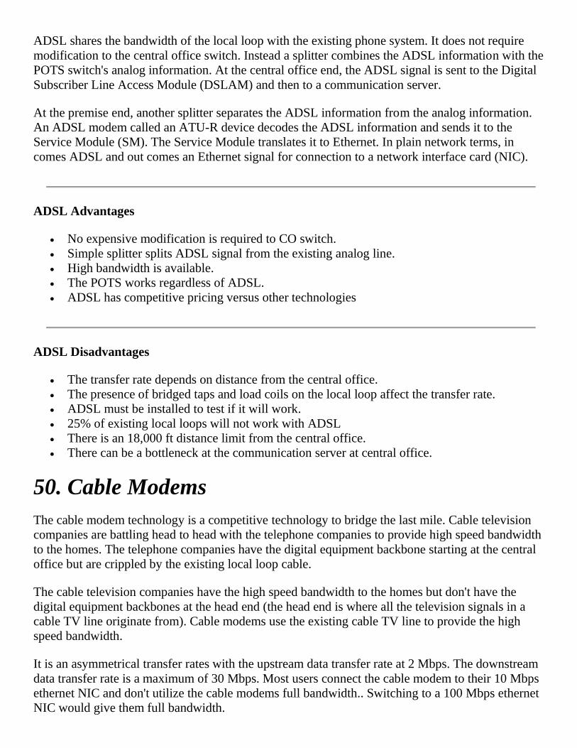
ADSL shares the bandwidth of the local loop with the existing phone system. It does not require
modification to the central office switch. Instead a splitter combines the ADSL information with the
POTS switch's analog information. At the central office end, the ADSL signal is sent to the Digital
Subscriber Line Access Module (DSLAM) and then to a communication server.
At the premise end, another splitter separates the ADSL information from the analog information.
An ADSL modem called an ATU-R device decodes the ADSL information and sends it to the
Service Module (SM). The Service Module translates it to Ethernet. In plain network terms, in
comes ADSL and out comes an Ethernet signal for connection to a network interface card (NIC).
ADSL Advantages
No expensive modification is required to CO switch.
Simple splitter splits ADSL signal from the existing analog line.
High bandwidth is available.
The POTS works regardless of ADSL.
ADSL has competitive pricing versus other technologies
ADSL Disadvantages
The transfer rate depends on distance from the central office.
The presence of bridged taps and load coils on the local loop affect the transfer rate.
ADSL must be installed to test if it will work.
25% of existing local loops will not work with ADSL
There is an 18,000 ft distance limit from the central office.
There can be a bottleneck at the communication server at central office.
50. Cable Modems
The cable modem technology is a competitive technology to bridge the last mile. Cable television
companies are battling head to head with the telephone companies to provide high speed bandwidth
to the homes. The telephone companies have the digital equipment backbone starting at the central
office but are crippled by the existing local loop cable.
The cable television companies have the high speed bandwidth to the homes but don't have the
digital equipment backbones at the head end (the head end is where all the television signals in a
cable TV line originate from). Cable modems use the existing cable TV line to provide the high
speed bandwidth.
It is an asymmetrical transfer rates with the upstream data transfer rate at 2 Mbps. The downstream
data transfer rate is a maximum of 30 Mbps. Most users connect the cable modem to their 10 Mbps
ethernet NIC and don't utilize the cable modems full bandwidth.. Switching to a 100 Mbps ethernet
NIC would give them full bandwidth.

The actual transfer speed depends on number of users that are on-line. The cable line is shared with
the other subscribers in the local neighborhood. Most cable companies use dynamic IP addressing,
each time the user connects, the user is assigned a new IP address. For a fee, permanent static IP
addresses can be assigned.
Most cable TV companies are placing high performance web proxy servers at the head end. These
servers store the most commonly accessed webpages and files locally at the head end. The user's
web browser first checks the proxy server to see if the file has been downloaded there. If it hasn't
then it goes out on the Internet to download it. The storing of the webpages and files on the local
proxy server reduces the load on the communication servers to the Internet and gives the impression
of extremely fast Internet access.
Cable Modems Standards
There are three competing standards for cable modems at the time of this writing:
the European standard DVB/DAVIC
the American standard MCNS
the Geneva standard IEEE 802.14.
Only the Geneva standard guarantees the transfer rate.
Cable Modems Premise Equipment
Cable Modems Premise Equipment
The cable modem is connected to the existing cable TV RG59 coax line using a standard RF
connector. The output of the cable modem is a 10BaseT or 100BaseT ethernet connection to your
NIC.
Cable Modems Security Issues
Cable modems have some security issues. Users can see others on network neighborhood in
Windows. Some systems have each cable modem connection is encrypted.
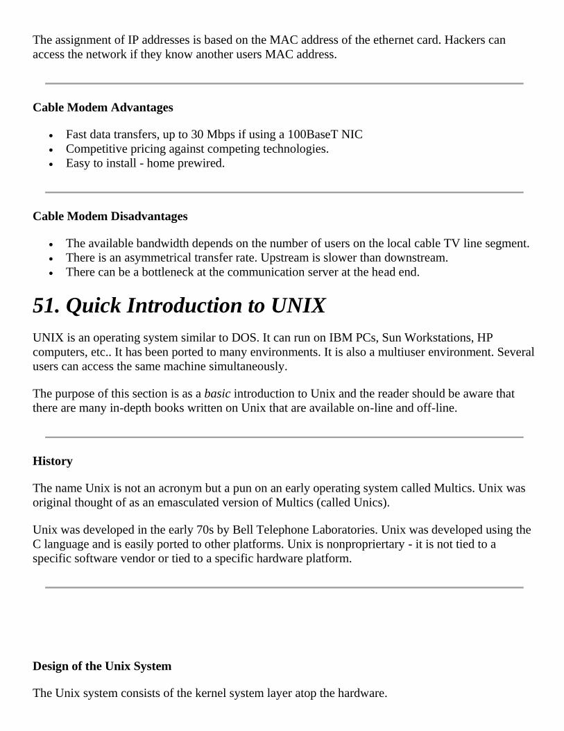
The assignment of IP addresses is based on the MAC address of the ethernet card. Hackers can
access the network if they know another users MAC address.
Cable Modem Advantages
Fast data transfers, up to 30 Mbps if using a 100BaseT NIC
Competitive pricing against competing technologies.
Easy to install - home prewired.
Cable Modem Disadvantages
The available bandwidth depends on the number of users on the local cable TV line segment.
There is an asymmetrical transfer rate. Upstream is slower than downstream.
There can be a bottleneck at the communication server at the head end.
51. Quick Introduction to UNIX
UNIX is an operating system similar to DOS. It can run on IBM PCs, Sun Workstations, HP
computers, etc.. It has been ported to many environments. It is also a multiuser environment. Several
users can access the same machine simultaneously.
The purpose of this section is as a basic introduction to Unix and the reader should be aware that
there are many in-depth books written on Unix that are available on-line and off-line.
History
The name Unix is not an acronym but a pun on an early operating system called Multics. Unix was
original thought of as an emasculated version of Multics (called Unics).
Unix was developed in the early 70s by Bell Telephone Laboratories. Unix was developed using the
C language and is easily ported to other platforms. Unix is nonpropriertary - it is not tied to a
specific software vendor or tied to a specific hardware platform.
Design of the Unix System
The Unix system consists of the kernel system layer atop the hardware.
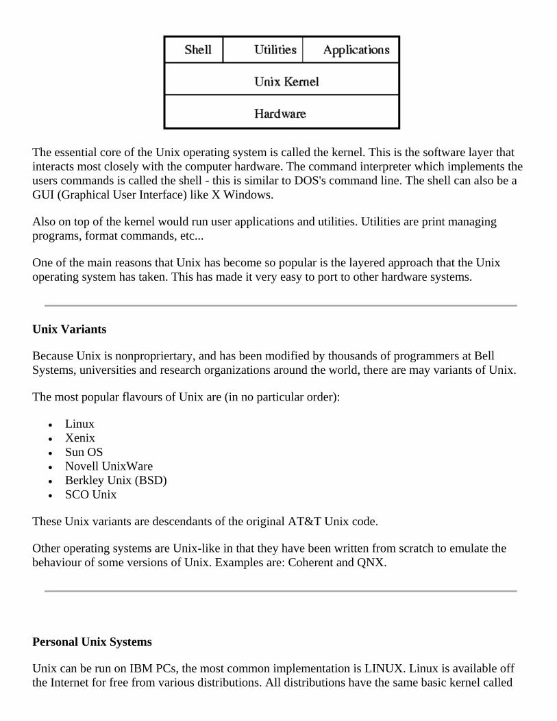
The essential core of the Unix operating system is called the kernel. This is the software layer that
interacts most closely with the computer hardware. The command interpreter which implements the
users commands is called the shell - this is similar to DOS's command line. The shell can also be a
GUI (Graphical User Interface) like X Windows.
Also on top of the kernel would run user applications and utilities. Utilities are print managing
programs, format commands, etc...
One of the main reasons that Unix has become so popular is the layered approach that the Unix
operating system has taken. This has made it very easy to port to other hardware systems.
Unix Variants
Because Unix is nonpropriertary, and has been modified by thousands of programmers at Bell
Systems, universities and research organizations around the world, there are may variants of Unix.
The most popular flavours of Unix are (in no particular order):
Linux
Xenix
Sun OS
Novell UnixWare
Berkley Unix (BSD)
SCO Unix
These Unix variants are descendants of the original AT&T Unix code.
Other operating systems are Unix-like in that they have been written from scratch to emulate the
behaviour of some versions of Unix. Examples are: Coherent and QNX.
Personal Unix Systems
Unix can be run on IBM PCs, the most common implementation is LINUX. Linux is available off
the Internet for free from various distributions. All distributions have the same basic kernel called
Linux. The distributions package the Linux kernel with the programs that they feel will provide the
best overall package. The programs that they add are custom installation programs, office packages,
programming suites, server software, networking software, games, etc..
The most common distributions are (in no particular order):
Slackware
Red Hat
Debian
SuSe
TurboLinux
Caldera
Command Line Operation
The Command Line tells Unix what you want to do. Unix's command line tends to be cryptic and
most users use some sort of GUI.
GUIs
GUIs are graphical user interfaces, they all have a look and feel similar to the Windows environment
which is based on the MAC Desktop and X Windows.
A graphical user interface for Unix consists of 2 major parts: the X Windows System (often called
X) and a Window Manager. An X server on a computer system manages the screen, keyboard and
mouse and their interactions with client applications that reside either on the same system or on
another computer on a network.
The window manager, a client application, controls the window decorations and behaviours such as
resizing, stacking order of multiple windows.
XFree86 is the free X Windows system that is available with Linux. There is a wide choice of free
Window Managers available:
KDE
Gnome
WindowMaker
KVWM
TVWM
Lesstif
OSF/Motif is the most popular commerical window manager for Unix vendors other than Sun. Motif
is based on the work done by members of the Open Software Foundation (OSF). Motif is also the
interface for Open Desktop (ODT) from the Santa Cruz Operations (SCO).
Case Sensitive
Unix's command line is case sensitive. Most commands and responses are presented in lower case
letters. Unlike DOS and many other systems, you cannot use upper case letters when lower case
letters are expected. Thus typing "LS" to list a directory instead of "ls" will result in an error (the
command won't be found). This is especially true of passwords - make sure that when you enter a
new password that you remember whether it is upper case or lower case!
Multi-User Operating System
Unix systems run comfortably in a variety of situations: single-user, host systems with users on local
or remote terminals and networked arrangements of workstations and multiuser systems.
Multiple Operating Systems
One of the most attractive features of the personal Unix systems is their ability to run programs
designed for other operating systems. Versions of Unix designed for IBM PCs lets you load DOS
and Windows applications using progrmas (such as dosemu and wine respectively) and run them in
windows along side Unix specific programs.
Unix is a Pre-emptive Multi-tasking environment. You can have several programs or processes
running simultaneously. This also allows Unix to be a multiuser environment.
Command Line Operation
The Command Line tells Unix what you want to do. Unix's command line tends to be cryptic and
most users use some sort of GUI.
GUIs
GUIs are graphical user interfaces, they all have a look and feel similar to the Windows environment
which is based on the MAC Desktop and X Windows.
A graphical user interface for Unix consists of 2 major parts: the X Windows System (often called
X) and a Window Manager. An X server on a computer system manages the screen, keyboard and
mouse and their interactions with client applications that reside either on the same system or on
another computer on a network.
The window manager, a client application, controls the window decorations and behaviours such as
resizing, stacking order of multiple windows.
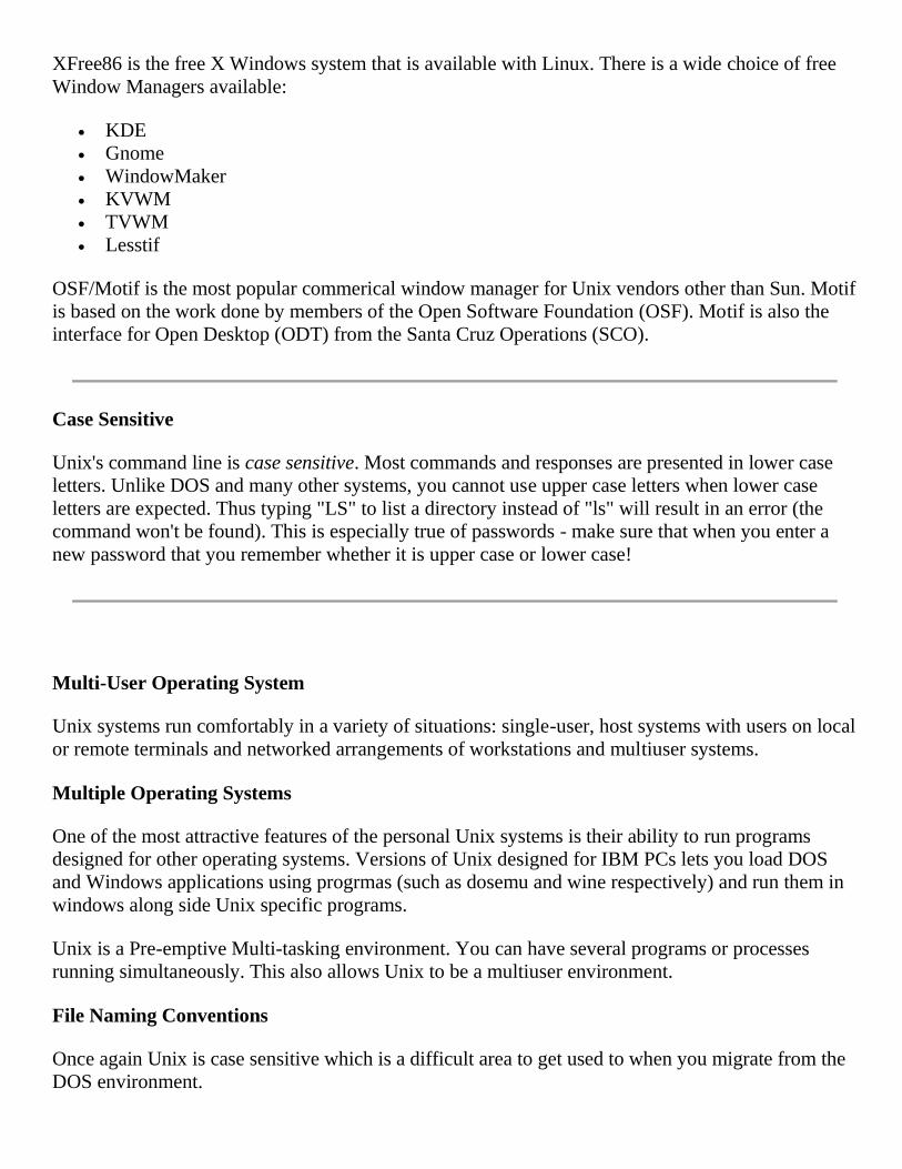
XFree86 is the free X Windows system that is available with Linux. There is a wide choice of free
Window Managers available:
KDE
Gnome
WindowMaker
KVWM
TVWM
Lesstif
OSF/Motif is the most popular commerical window manager for Unix vendors other than Sun. Motif
is based on the work done by members of the Open Software Foundation (OSF). Motif is also the
interface for Open Desktop (ODT) from the Santa Cruz Operations (SCO).
Case Sensitive
Unix's command line is case sensitive. Most commands and responses are presented in lower case
letters. Unlike DOS and many other systems, you cannot use upper case letters when lower case
letters are expected. Thus typing "LS" to list a directory instead of "ls" will result in an error (the
command won't be found). This is especially true of passwords - make sure that when you enter a
new password that you remember whether it is upper case or lower case!
Multi-User Operating System
Unix systems run comfortably in a variety of situations: single-user, host systems with users on local
or remote terminals and networked arrangements of workstations and multiuser systems.
Multiple Operating Systems
One of the most attractive features of the personal Unix systems is their ability to run programs
designed for other operating systems. Versions of Unix designed for IBM PCs lets you load DOS
and Windows applications using progrmas (such as dosemu and wine respectively) and run them in
windows along side Unix specific programs.
Unix is a Pre-emptive Multi-tasking environment. You can have several programs or processes
running simultaneously. This also allows Unix to be a multiuser environment.
File Naming Conventions
Once again Unix is case sensitive which is a difficult area to get used to when you migrate from the
DOS environment.
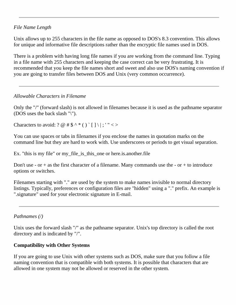
File Name Length
Unix allows up to 255 characters in the file name as opposed to DOS's 8.3 convention. This allows
for unique and informative file descriptions rather than the encryptic file names used in DOS.
There is a problem with having long file names if you are working from the command line. Typing
in a file name with 255 characters and keeping the case correct can be very frustrating. It is
recommended that you keep the file names short and sweet and also use DOS's naming convention if
you are going to transfer files between DOS and Unix (very common occurrence).
Allowable Characters in Filename
Only the "/" (forward slash) is not allowed in filenames because it is used as the pathname separator
(DOS uses the back slash "\").
Characters to avoid: ? @ # $ ^ * ( ) ` [ ] \ | ; ' " < >
You can use spaces or tabs in filenames if you enclose the names in quotation marks on the
command line but they are hard to work with. Use underscores or periods to get visual separation.
Ex. "this is my file" or my_file_is_this_one or here.is.another.file
Don't use - or + as the first character of a filename. Many commands use the - or + to introduce
options or switches.
Filenames starting with "." are used by the system to make names invisible to normal directory
listings. Typically, preferences or configuration files are "hidden" using a "." prefix. An example is
".signature" used for your electronic signature in E-mail.
Pathnames (/)
Unix uses the forward slash "/" as the pathname separator. Unix's top directory is called the root
directory and is indicated by "/".
Compatibility with Other Systems
If you are going to use Unix with other systems such as DOS, make sure that you follow a file
naming convention that is compatible with both systems. It is possible that characters that are
allowed in one system may not be allowed or reserved in the other system.
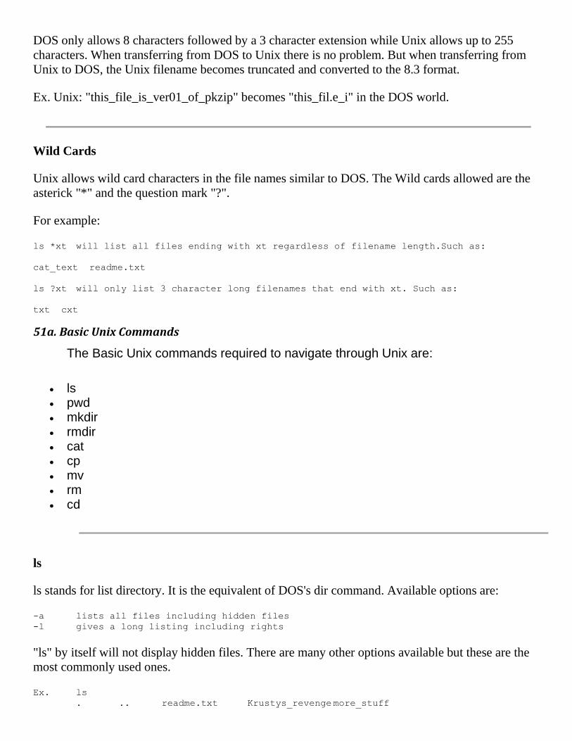
DOS only allows 8 characters followed by a 3 character extension while Unix allows up to 255
characters. When transferring from DOS to Unix there is no problem. But when transferring from
Unix to DOS, the Unix filename becomes truncated and converted to the 8.3 format.
Ex. Unix: "this_file_is_ver01_of_pkzip" becomes "this_fil.e_i" in the DOS world.
Wild Cards
Unix allows wild card characters in the file names similar to DOS. The Wild cards allowed are the
asterick "*" and the question mark "?".
For example:
ls *xt will list all files ending with xt regardless of filename length.Such as:
cat_text readme.txt
ls ?xt will only list 3 character long filenames that end with xt. Such as:
txt cxt
51a. Basic Unix Commands
The Basic Unix commands required to navigate through Unix are:
ls
pwd mkdir rmdir cat cp mv rm cd
ls
ls stands for list directory. It is the equivalent of DOS's dir command. Available options are:
-a lists all files including hidden files
-l gives a long listing including rights
"ls" by itself will not display hidden files. There are many other options available but these are the
most commonly used ones.
Ex. ls
. .. readme.txt Krustys_revenge more_stuff

Ex. ls -a
. .. readme.txt Krustys_revenge more_stuff
.signature .profile
Ex. ls -l
total 956
drwxr-xr-x 6 arh other 1024 Dec 16 09:44 .
drwxrwxr--x 5 root sys 96 Dec 12 09:05 ..
-rw-r--r-- 1 arh other 681 Jan 28 04:56 .profile
etc...
pwd
pwd stands for Print Working Directory. pwd displays on the screen the current directory that you
are in. Before CRTs, all communication with mainframes was printed out on "teletype" style
terminals thus the origins of the name pwd.
ex pwd
/home/bart
mkdir
mkdir stands for make directory. It is similar to DOS's "md" command. In actual fact, originally
DOS's make directory command was mkdir for pre-DOS 3.x.
ex. mkdir homer makes the directory "homer"
in the current working directory.
rmdir
rmdir stands for remove directory. It is similar to DOS's "rd" command. In actual fact, originally
DOS's remove directory command was rmdir for pre-DOS 3.x.
ex. rmdir homer removes or erases the directory "homer"
from the current directory.
cat
cat stands for catalog and is used for displaying files to the screen similar to DOS's "type" command.
"cat" allows single screen paging, it waits for a response before displaying the next screen of
information.
Ex. cat readme.txt this will display the file readme.txt onto the
screen one page at a time.

cp
cp stands for copy. It is used to copy files similar to DOS's "copy" command.
Ex. cp readme.txt springfield.txt copies the file readme.txt and
names the new file springfield.txt
mv
mv stands for move. It is used to move files from one directory to another and it is also used to
rename files.
Ex. mv readme.txt /home/x-files moves readme.txt from current
directory to directory called /home/x-files
Ex. mv agent.sculley agent.muldar renames file agent.sculley to new
name agent.muldar
rm
rm stands for remove. It is used to delete files similar to the DOS "del" command. It will verify that
you want to delete the file. Wildcards can be used with rm.
Ex. rm dana.sculley deletes file named dana.sculley
cd
cd stands for change directory. It is used to change the current directory similar to DOS's "cd"
command. Note: to use the double dots requires a space - cd ..
Ex. cd /x-files/fox.muldar Makes /x-files/fox.muldar the
current directory
51b. Access and Permissions
The owner of the file or directory determines who can access the file and for what
purposes. The type of access can be read, write or execute the file privileges.
User/Group/Other
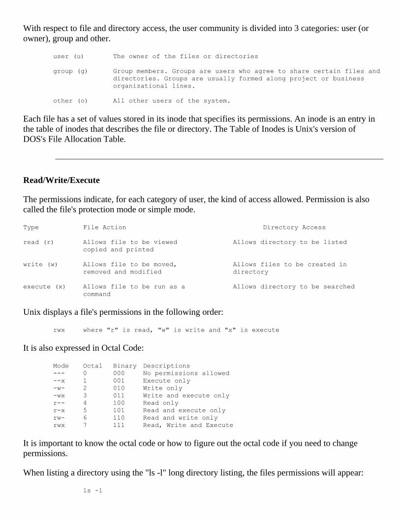
With respect to file and directory access, the user community is divided into 3 categories: user (or
owner), group and other.
user (u) The owner of the files or directories
group (g) Group members. Groups are users who agree to share certain files and
directories. Groups are usually formed along project or business
organizational lines.
other (o) All other users of the system.
Each file has a set of values stored in its inode that specifies its permissions. An inode is an entry in
the table of inodes that describes the file or directory. The Table of Inodes is Unix's version of
DOS's File Allocation Table.
Read/Write/Execute
The permissions indicate, for each category of user, the kind of access allowed. Permission is also
called the file's protection mode or simple mode.
Type File Action Directory Access
read (r) Allows file to be viewed Allows directory to be listed
copied and printed
write (w) Allows file to be moved, Allows files to be created in
removed and modified directory
execute (x) Allows file to be run as a Allows directory to be searched
command
Unix displays a file's permissions in the following order:
rwx where "r" is read, "w" is write and "x" is execute
It is also expressed in Octal Code:
Mode Octal Binary Descriptions
--- 0 000 No permissions allowed
--x 1 001 Execute only
-w- 2 010 Write only
-wx 3 011 Write and execute only
r-- 4 100 Read only
r-x 5 101 Read and execute only
rw- 6 110 Read and write only
rwx 7 111 Read, Write and Execute
It is important to know the octal code or how to figure out the octal code if you need to change
permissions.
When listing a directory using the "ls -l" long directory listing, the files permissions will appear:
ls -l

total 8
drwxr-xr-x 2 rocky other 96 Dec 26 23:16 .
drwxrwxr-x 7 root sys 96 Dec 24 07:40 ..
-rw-r--r-- 1 rocky other 613 Nov 2 12:30 readme.txt
drwxr-xr-x 2 rocky other 234 Feb 28 03:40 x-files
The long directory lists all of the rights associated with the file or directory. The mode bits are
organized as follows:
The default permissions when you create a file are 777 which is 111 111 111 in binary or
(rwxrwxrwx). When a directory is created, the default permissions are 666 which is 110 110 110 or
(rw-rw-rw-).
Changing Permissions
When a file is first created, it is created with the default permissions 777 (rwxrwxrwx). This means
that anyone can read, write or execute the new file. Unix provides a command to modify the default
permissions: umask. "umask" works by deselecting the permissions that you do not want from the
default permissions. "umask" by itself reports what the current mask is.
Ex umask will report current mask
000 000 indicates no mask and default permissions exist
Ex umask 027 will set the mask to 0278 or 000 010 1112
000 010 111
777 (default permission) rwx rwx rwx
027 corresponds to --- -w- rwx permissions deselected
Resulting permissions: rwx r-x ---
user has rwx (all permissions) 000
group has r-x (read and execute only) 010
other has --- (no permissions) 111
The umask command is used during your shell startup script or login script. You set it once during
logging into the system and normally won't have to use it again.
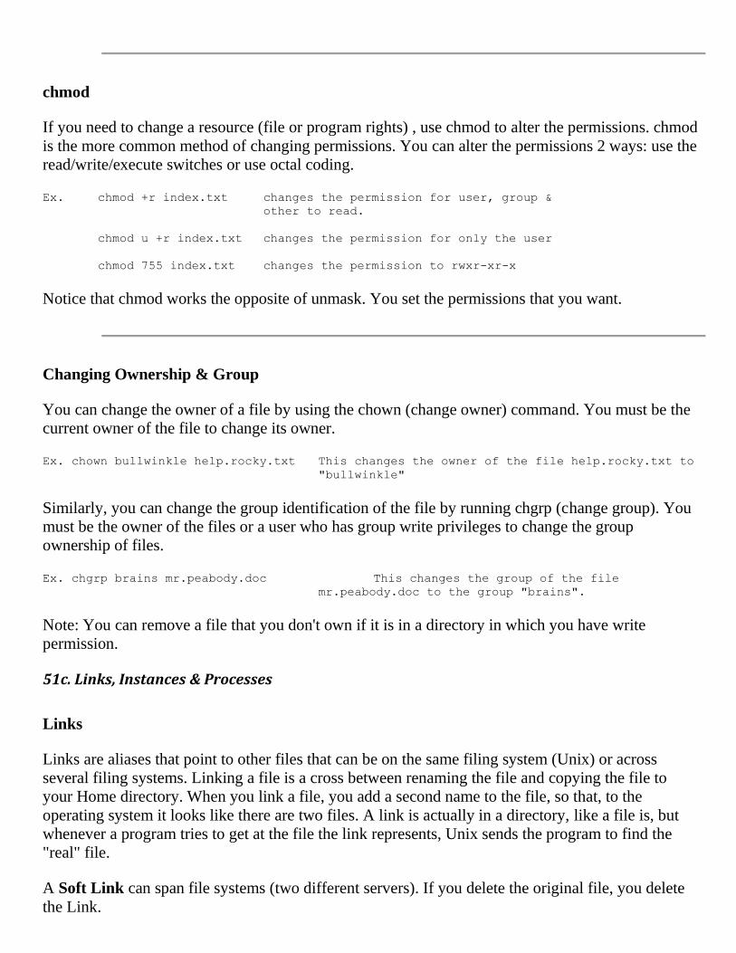
chmod
If you need to change a resource (file or program rights) , use chmod to alter the permissions. chmod
is the more common method of changing permissions. You can alter the permissions 2 ways: use the
read/write/execute switches or use octal coding.
Ex. chmod +r index.txt changes the permission for user, group &
other to read.
chmod u +r index.txt changes the permission for only the user
chmod 755 index.txt changes the permission to rwxr-xr-x
Notice that chmod works the opposite of unmask. You set the permissions that you want.
Changing Ownership & Group
You can change the owner of a file by using the chown (change owner) command. You must be the
current owner of the file to change its owner.
Ex. chown bullwinkle help.rocky.txt This changes the owner of the file help.rocky.txt to
"bullwinkle"
Similarly, you can change the group identification of the file by running chgrp (change group). You
must be the owner of the files or a user who has group write privileges to change the group
ownership of files.
Ex. chgrp brains mr.peabody.doc This changes the group of the file
mr.peabody.doc to the group "brains".
Note: You can remove a file that you don't own if it is in a directory in which you have write
permission.
51c. Links, Instances & Processes
Links
Links are aliases that point to other files that can be on the same filing system (Unix) or across
several filing systems. Linking a file is a cross between renaming the file and copying the file to
your Home directory. When you link a file, you add a second name to the file, so that, to the
operating system it looks like there are two files. A link is actually in a directory, like a file is, but
whenever a program tries to get at the file the link represents, Unix sends the program to find the
"real" file.
A Soft Link can span file systems (two different servers). If you delete the original file, you delete
the Link.
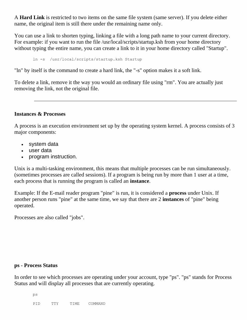
A Hard Link is restricted to two items on the same file system (same server). If you delete either
name, the original item is still there under the remaining name only.
You can use a link to shorten typing, linking a file with a long path name to your current directory.
For example: if you want to run the file /usr/local/scripts/startup.ksh from your home directory
without typing the entire name, you can create a link to it in your home directory called "Startup".
ln -s /usr/local/scripts/startup.ksh Startup
"ln" by itself is the command to create a hard link, the "-s" option makes it a soft link.
To delete a link, remove it the way you would an ordinary file using "rm". You are actually just
removing the link, not the original file.
Instances & Processes
A process is an execution environment set up by the operating system kernel. A process consists of 3
major components:
system data user data program instruction.
Unix is a multi-tasking environment, this means that multiple processes can be run simultaneously.
(sometimes processes are called sessions). If a program is being run by more than 1 user at a time,
each process that is running the program is called an instance.
Example: If the E-mail reader program "pine" is run, it is considered a process under Unix. If
another person runs "pine" at the same time, we say that there are 2 instances of "pine" being
operated.
Processes are also called "jobs".
ps - Process Status
In order to see which processes are operating under your account, type "ps". "ps" stands for Process
Status and will display all processes that are currently operating.
ps
PID TTY TIME COMMAND
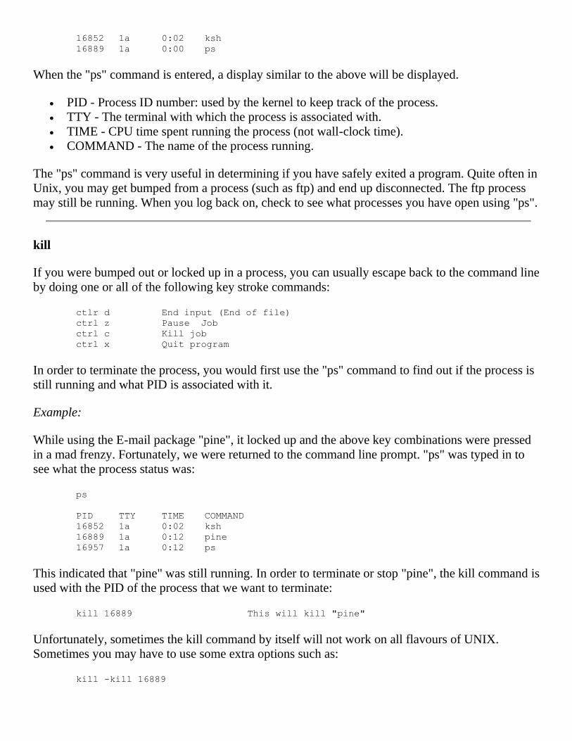
16852 1a 0:02 ksh
16889 1a 0:00 ps
When the "ps" command is entered, a display similar to the above will be displayed.
PID - Process ID number: used by the kernel to keep track of the process.
TTY - The terminal with which the process is associated with.
TIME - CPU time spent running the process (not wall-clock time).
COMMAND - The name of the process running.
The "ps" command is very useful in determining if you have safely exited a program. Quite often in
Unix, you may get bumped from a process (such as ftp) and end up disconnected. The ftp process
may still be running. When you log back on, check to see what processes you have open using "ps".
kill
If you were bumped out or locked up in a process, you can usually escape back to the command line
by doing one or all of the following key stroke commands:
ctlr d End input (End of file)
ctrl z Pause Job
ctrl c Kill job
ctrl x Quit program
In order to terminate the process, you would first use the "ps" command to find out if the process is
still running and what PID is associated with it.
Example:
While using the E-mail package "pine", it locked up and the above key combinations were pressed
in a mad frenzy. Fortunately, we were returned to the command line prompt. "ps" was typed in to
see what the process status was:
ps
PID TTY TIME COMMAND
16852 1a 0:02 ksh
16889 1a 0:12 pine
16957 1a 0:12 ps
This indicated that "pine" was still running. In order to terminate or stop "pine", the kill command is
used with the PID of the process that we want to terminate:
kill 16889 This will kill "pine"
Unfortunately, sometimes the kill command by itself will not work on all flavours of UNIX.
Sometimes you may have to use some extra options such as:
kill -kill 16889
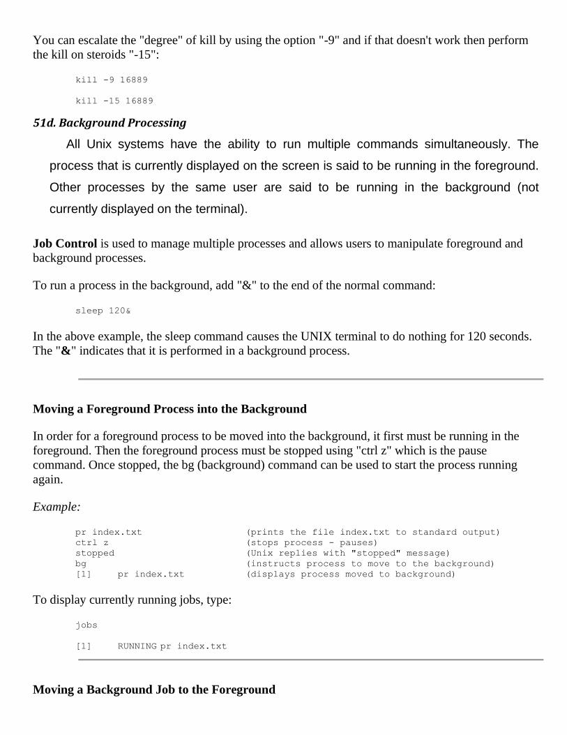
You can escalate the "degree" of kill by using the option "-9" and if that doesn't work then perform
the kill on steroids "-15":
kill -9 16889
kill -15 16889
51d. Background Processing
All Unix systems have the ability to run multiple commands simultaneously. The
process that is currently displayed on the screen is said to be running in the foreground.
Other processes by the same user are said to be running in the background (not
currently displayed on the terminal).
Job Control is used to manage multiple processes and allows users to manipulate foreground and
background processes.
To run a process in the background, add "&" to the end of the normal command:
sleep 120&
In the above example, the sleep command causes the UNIX terminal to do nothing for 120 seconds.
The "&" indicates that it is performed in a background process.
Moving a Foreground Process into the Background
In order for a foreground process to be moved into the background, it first must be running in the
foreground. Then the foreground process must be stopped using "ctrl z" which is the pause
command. Once stopped, the bg (background) command can be used to start the process running
again.
Example:
pr index.txt (prints the file index.txt to standard output)
ctrl z (stops process - pauses)
stopped (Unix replies with "stopped" message)
bg (instructs process to move to the background)
[1] pr index.txt (displays process moved to background)
To display currently running jobs, type:
jobs
[1] RUNNING pr index.txt
Moving a Background Job to the Foreground
To move a background job or process to the foreground, you must know the job number. The
number in square brackets [ ] indicates the job number.
jobs
[1] RUNNING pr index.txt
To move the background job to the foreground, use the fg (foreground) command:
fg OR
fg1 OR
fg %1 (1 indicates job number)
This will move job #1 to the foreground. The fg command will be implemented just a little bit
different depending on the shell or flavour of Unix run.
51e. Shell Programs
Unix allows each individual user to select a customizable command line interpretor.
The standard Unix shell, called the Bourne shell after its author, is called sh and it
resides in the /usr/bin directory.
The shell is a program that, like any other program, can be replaced. The shell is a command
interpreter and a command programming language. It prompts for, reads and executes commands.
The commands can come directly from a terminal or from a file.
csh /ksh
All Unix operating systems have the standard Unix shell sh. Two alternative shells csh and ksh are
available and widely used. "csh" was developed by the University of California at Berkley. "ksh"
was developed by AT&T and the "k" stands for Korn for the developer David Korn. Linux uses a
shell called bash for Bourne again shell. It has added refinements from both csh/ksh shells.
Features of the "csh"
Uses .cshrc and .login files for initialization at startup. These files are used for configuring your environment.
Has a configuration file called .logout that is read when you end your session. Has a command history list. Allows job control as discussed earlier. Provides directory management. Additional directory commands: cd, dirs, pushd,
popd. (Some csh versions don't provide this feature) Offers a more C-like syntax than "sh". When enabled by "filec", csh can complete partially typed unambiguous names for
you.
A list of aliases is kept for you (in .cshrc) that contain frequently used or complicated commands.
The Korn shell ksh uses the best features of the csh with the following enhancements:
ksh enhancements:
Command-line editing using editors from hell worse than DOS's edlin. (Don't know where this came from - it's been many years since I wrote this ;-)
Improved cd (change directory) command. Improved shell programming. Allows pathname to appear in the prompt similar to DOS.
The ksh uses the .profile file for startup configuration.
Aliases
Depending on the shell that you are using, you will have a startup file called either .cshrc (csh) or
.profile (ksh). These files contain startup information for the user. Each user has a startup file in their
home directory which can be modified to suit their individual needs.
Aliases are a means of individualizing a user's account. The user can use aliases as a macro to
shorten command-line entries. In the startup file, there is an area with the heading "# handy alias".
The "#" indicates that this is a comment and is ignored by the operating system. Following this
heading is a list of aliases:
alias vt100="set term = vt100"
This line substitutes "set term = vt100" for when you type "vt100" at the command-line. "set term =
vt100" is how you tell the Unix system what type of terminal you are emulating. Depending on the
flavour of Unix that you are running, you may or may not need the "=" sign after "vt100".
Notice: There is an alias for "help", it is the Unix command "man" (manual).
51f. Communicating with Other Users
You can communicate with other users within Unix by two methods: write and talk.
The write command communicates on the command-line. To finish communicating use "ctrl d".
The talk command splits the screen in two. Top of the screen is the destination's half of the
conversation. The bottom is the source's half. To finish communicating use "ctrl d" or break.
To initiate either method, type the command followed by the person's username that you want to
communicate with. For example:
talk blanchas
To stop users from communicating with you, type:
mesg -n
To allow access:
mesg -y
To see current status:
mesg
51g. Creating Users and Groups
password file
User information is contained in a text file called password that is normally located in the /etc
directory. The file is often modified by a program called adduser or something similar. The text file
password consists of the following information for each user:
eblanchard:1v2B3uWaA.8iA:501:237:Eugene Blanchard:/home/eblanchard:/bin/bash
"eblanchard" is the username.
"1v2B3uWaA.8iA" is the user's encrypted password.
"501" is the user's numerical ID (must be unique)
"237" is the group numerical ID that the user belongs to.
"Eugene Blanchard" is the full name of the user.
"/home/eblanchard" is the home directory of the user.
"/bin/bash" is the shell program that the user uses.
The password file is available to all users to view. This is because some programs require access to
the password file.
Note: usernames longer than 8 characters can cause problems in some programs. For example, the
username "eblanchard" cannot telnet into a Linux server from a Win95 telnet client. The username
is truncated to "eblancha" and the Linux server doesn't recognize it as a valid username.
Changing your password
To change your password, you type the password command. Depending on the flavour of Unix that
you are using, it may be one of the following:
password passwd
passwrd ypasswd (used with NIS)
The password command will prompt you for your existing password (old) then ask you to type in
your new password once and then once again to confirm the password. Choose a password that is at
least 8 characters long, use alphanumeric characters and a combination of upper and lower case
letters. Write down you password in a safe place that you will remember where it is!
group file
The group file is a text file that contains information about the groups that are allowed to use the
system. It is located in the directory /etc. Groups are added using a program called addgrpor
something similar. Each line in a group file contains four fields:
instructors:NONE:237:eblanchard,dspurgeon,hsylvan
"instructors" is the group name
"NONE" indicates that there is no password with this group.
It is limited to the listed users.
"237" is the numerical group ID
"eblanchard,.. is the list of group members which can be users or other
groups
shadow file
Unix passwords are a maximum of 13 characters long and can be encrypted in 4,096 different ways.
There are hacking programs that are able to decode the passwords in the password file. In order to
fix this security leak, Unix operating systems that are System V compatible have another file called
the shadow file that works with the password file.
The password file does not contain the encrypted passwords, instead it points to the shadow file,
which contains the encrypted login passwords. The password file will have a blank space where the
encrypted password usually resides.
The password file is still available for all users to view but the shadow file is restricted and only the
system administrator can view it. In this manner the security loop-hole has been fixed.
SAMBA, Win95, NT and HP Jetdirect
I am running a computer routing lab that is used to teach routing fundamentals on
proprietary equipment. It consists of an 18 seat lab with 9 PCs, 1 server and 1 HP
LaserJet 4050N with a HP Jetdirect print server card installed. The server is running
Slackware 4.0 with Linux 2.2.6 on it. Eight of the PCs are running WinNT 4.0 SP5 and
one PC is running Win95a.
My requirements for the Linux server are as follows:
run as a workgroup server not as a primary domain controller run as master browser share each user's home directory share a common directory among users called public share the server's CD ROM drive share the HP LaserJet printer
There was a choice of using NFS and configure each client to connect to the Linux server
or to use SAMBA and only configure the server. During the normal operation of the lab, the
clients are regularly rebuilt, rebooted and reconfigured. It was felt that by running SAMBA
services, the Linux server would be transparent to the clients and allow the simplest client
install.
This article will describe how I used SAMBA to:
setup SAMBA to run on a Slackware Linux server share drives connect and logon from Win95 connect and logon from WinNT using encrypted passwords how to connect Linux to HP Jetdirect print server how to share a Linux printer using SAMBA
NOTE: This is not a "howto" type of article but an example of a working configuration and the
process used to configure SAMBA
Installing SAMBA
The installation process will vary depending on which distribution of Linux you are
running. Under Slackware, select SAMBA during the installation process or if you are
adding SAMBA to an existing system, use the pkgtool program.
Change to the Slackware CD, cd to /slakware/N11. Type pkgtool and "Install packages from current
directory". For all other distributions, this article will assume that you have SAMBA properly
installed on your system.
SAMBA is started under Slackware by the rc script "/etc/rc.d/rc.samba":
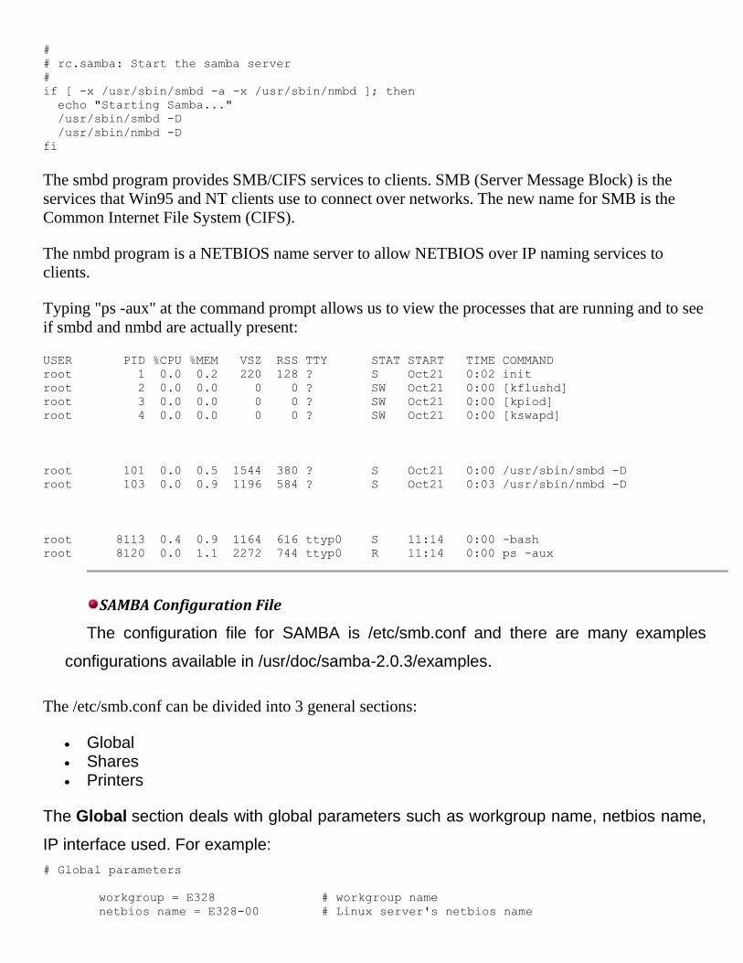
#
# rc.samba: Start the samba server
#
if [ -x /usr/sbin/smbd -a -x /usr/sbin/nmbd ]; then
echo "Starting Samba..."
/usr/sbin/smbd -D
/usr/sbin/nmbd -D
fi
The smbd program provides SMB/CIFS services to clients. SMB (Server Message Block) is the
services that Win95 and NT clients use to connect over networks. The new name for SMB is the
Common Internet File System (CIFS).
The nmbd program is a NETBIOS name server to allow NETBIOS over IP naming services to
clients.
Typing "ps -aux" at the command prompt allows us to view the processes that are running and to see
if smbd and nmbd are actually present:
USER PID %CPU %MEM VSZ RSS TTY STAT START TIME COMMAND
root 1 0.0 0.2 220 128 ? S Oct21 0:02 init
root 2 0.0 0.0 0 0 ? SW Oct21 0:00 [kflushd]
root 3 0.0 0.0 0 0 ? SW Oct21 0:00 [kpiod]
root 4 0.0 0.0 0 0 ? SW Oct21 0:00 [kswapd]
root 101 0.0 0.5 1544 380 ? S Oct21 0:00 /usr/sbin/smbd -D
root 103 0.0 0.9 1196 584 ? S Oct21 0:03 /usr/sbin/nmbd -D
root 8113 0.4 0.9 1164 616 ttyp0 S 11:14 0:00 -bash
root 8120 0.0 1.1 2272 744 ttyp0 R 11:14 0:00 ps -aux
SAMBA Configuration File
The configuration file for SAMBA is /etc/smb.conf and there are many examples
configurations available in /usr/doc/samba-2.0.3/examples.
The /etc/smb.conf can be divided into 3 general sections:
Global Shares Printers
The Global section deals with global parameters such as workgroup name, netbios name,
IP interface used. For example:
# Global parameters
workgroup = E328 # workgroup name
netbios name = E328-00 # Linux server's netbios name

server string = %h - Linux Samba server # comment shown in Win's Network
Neighborhood detail view
interfaces = 192.168.1.3/24 # NICs + subnet mask (24 = 255.255.255.0)
encrypt passwords = Yes # Required for NT (Win95 will work with
encrypted or not)
null passwords = No # Must have a password
log file = /var/log/samba. # location of samba log files (many!)
max log size = 50 # maximum size of each log file
socket options = TCP_NODELAY # Speeds up convergence of netbios
os level = 33 # Gives a higher browse master "priority"
preferred master = Yes # This server is the browsemaster
guest account = pcguest # guest account name
hosts allow = 192.168.1. 127. # networks allowed to access this server using SMB
The Shares section deals with sharing file directories. For example:
[homes]
comment = Home Directories # comment shown in Win's Network Neighborhood detail
view
path = %H # automatically display user's home directory as SMB
share
valid users = %S # Only user is allowed to access this directory
read only = No # can read/write
create mask = 0750 # permissions given when creating new files
browseable = No # only show user's home directory not "homes" folder
[public]
comment = Public Files # comment shown in Win's Network Neighborhood detail
view
path = /home/ftp/pub # path to public directory
guest ok = Yes # anyone can access this directory
[cdrom]
comment = Cdrom on E328-00 # comment shown in Win's Network Neighborhood detail
view
path = /cdrom # path to cdrom drive
guest ok = Yes # anyone can access cdrom drive, public share
The Printers section deals with sharing printers. For example:
[lp]
comment = E328-Laser # comment shown in Win's Network Neighborhood detail
view
path = /var/spool/samba # path to spool directory
print ok = Yes # allowed to open, write to and submit to spool
directory
You can manually create the /etc/smb.conf file if you know what each of the entries mean or you can
use the web GUI called SWAT (SAMBA Web Administration Tool). An added bonus of using
SWAT was the online help files that described each of the choices available. I understand that
SWAT is installed automatically with all versions of SAMBA from 2.0 and up.
Running SWAT
The following instructions are taken directly from the /usr/doc/samba-
2.0.3/swat/README file:

Running via inetd
-----------------
You then need to edit your /etc/inetd.conf and /etc/services to enable
SWAT to be launched via inetd.
In /etc/services you need to add a line like this:
swat 901/tcp
the choice of port number isn't really important except that it should
be less than 1024 and not currently used (using a number above 1024
presents an obscure security hole depending on the implementation
details of your inetd daemon).
In /etc/inetd.conf you should add a line like this:
swat stream tcp nowait.400 root /usr/local/samba/bin/swat swat
One you have edited /etc/services and /etc/inetd.conf you need to send
a HUP signal to inetd. On many systems "killall -1 inetd" will do this
on others you will need to use "kill -1 PID" where PID is the process
ID of the inetd daemon.
Launching
---------
To launch SWAT just run your favourite web browser and point it at
http://localhost:901
Note that you can attach to SWAT from any IP connected machine but
connecting from a remote machine leaves your connection open to
password sniffing as passwords will be sent in the clear over the
wire.
You should be prompted for a username/password when you connect. You
will need to provide the username "root" and the correct root
password.
Once SWAT is up and running, you should see the following:
The menu buttons are pretty self-explanatory and there are excellent help screens available. A quick
break down of the menus:
Home: Takes you to the main page
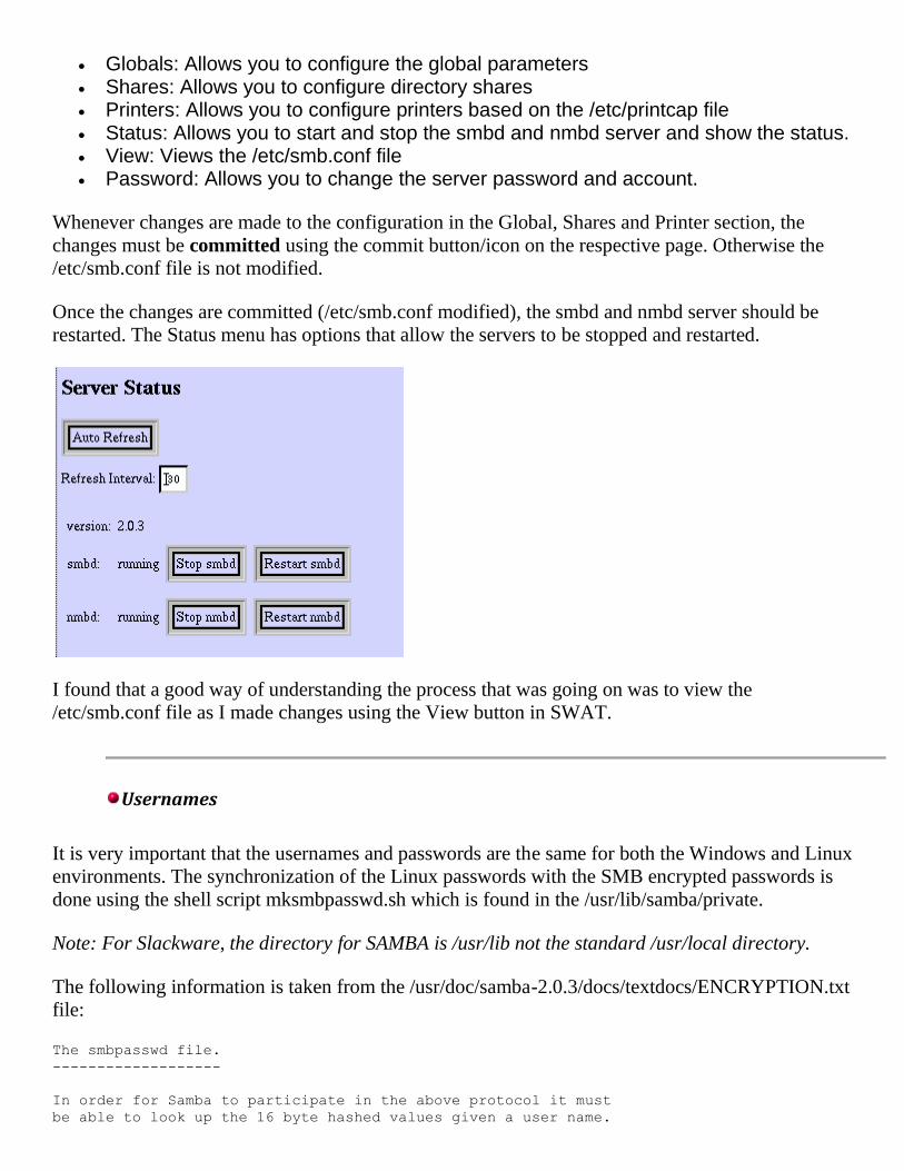
Globals: Allows you to configure the global parameters Shares: Allows you to configure directory shares Printers: Allows you to configure printers based on the /etc/printcap file Status: Allows you to start and stop the smbd and nmbd server and show the status. View: Views the /etc/smb.conf file Password: Allows you to change the server password and account.
Whenever changes are made to the configuration in the Global, Shares and Printer section, the
changes must be committed using the commit button/icon on the respective page. Otherwise the
/etc/smb.conf file is not modified.
Once the changes are committed (/etc/smb.conf modified), the smbd and nmbd server should be
restarted. The Status menu has options that allow the servers to be stopped and restarted.
I found that a good way of understanding the process that was going on was to view the
/etc/smb.conf file as I made changes using the View button in SWAT.
Usernames
It is very important that the usernames and passwords are the same for both the Windows and Linux
environments. The synchronization of the Linux passwords with the SMB encrypted passwords is
done using the shell script mksmbpasswd.sh which is found in the /usr/lib/samba/private.
Note: For Slackware, the directory for SAMBA is /usr/lib not the standard /usr/local directory.
The following information is taken from the /usr/doc/samba-2.0.3/docs/textdocs/ENCRYPTION.txt
file:
The smbpasswd file.
-------------------
In order for Samba to participate in the above protocol it must
be able to look up the 16 byte hashed values given a user name.
Unfortunately, as the UNIX password value is also a one way hash
function (ie. it is impossible to retrieve the cleartext of the users
password given the UNIX hash of it) then a separate password file
containing this 16 byte value must be kept. To minimise problems with
these two password files, getting out of sync, the UNIX /etc/passwd and
the smbpasswd file, a utility, mksmbpasswd.sh, is provided to generate
a smbpasswd file from a UNIX /etc/passwd file.
To generate the smbpasswd file from your /etc/passwd file use the
following command :-
cat /etc/passwd | mksmbpasswd.sh >/usr/local/samba/private/smbpasswd
The problem that I found with this step was that I expected that it would automatically recognize
shadowed passwords and place them in the smbpasswd file. Unfortunately, it didn't and I had to
manually enter in the passwords using the smbpasswd command. Luckly, I had only only about 10
passwords to enter in. There is probably a method of doing this automatically and I am just not
aware of it.
Once completed, I was able to use Network Neighborhood and point and click on the Linux
directory shares without being prompted for a username and password.
Configuring the HP JetDirect Card using Linux
Getting Linux and the HP JetDirect card to work was surprisingly easy. The JetDirect card is a print
server card that fits into the HP 4050N printer. The first step is to configure the HP JetDirect card
and printer. The standard install disk does not contain support for Linux but there is a WebAdmin
tool that you can download from HP's website:http://www.hp.com/support/net_printing. I chose to
do it manually by using telnet and the built-in webserver of the JetDirect card.
Telneting to the JetDirect Card
In order to telnet to the JetDirect card, you need to configure the printer's IP address. The default IP
address is 192.0.0.192 which most likely will not be a valid address on your network. The HP
4050N printer allows you to to configure the IP address through the printer's status window. Select
"JetDirect Menu" from the Menu button and then follow the directions for configuring the network.
After the IP address is set, configure the subnet mask in a similar manner.
Telnet to your printer's IP address. You have two choices when telnetting in, you can view the
current settings of the printer by typing "/" or viewing the help menu using "?" as shown by the
following:
Please type "?" for HELP, or "/" for current settings
>/
===JetDirect Telnet Configuration===
Firmware Rev. : G.07.20
MAC Address : 00:10:83:1b:41:c7
Config By : USER SPECIFIED
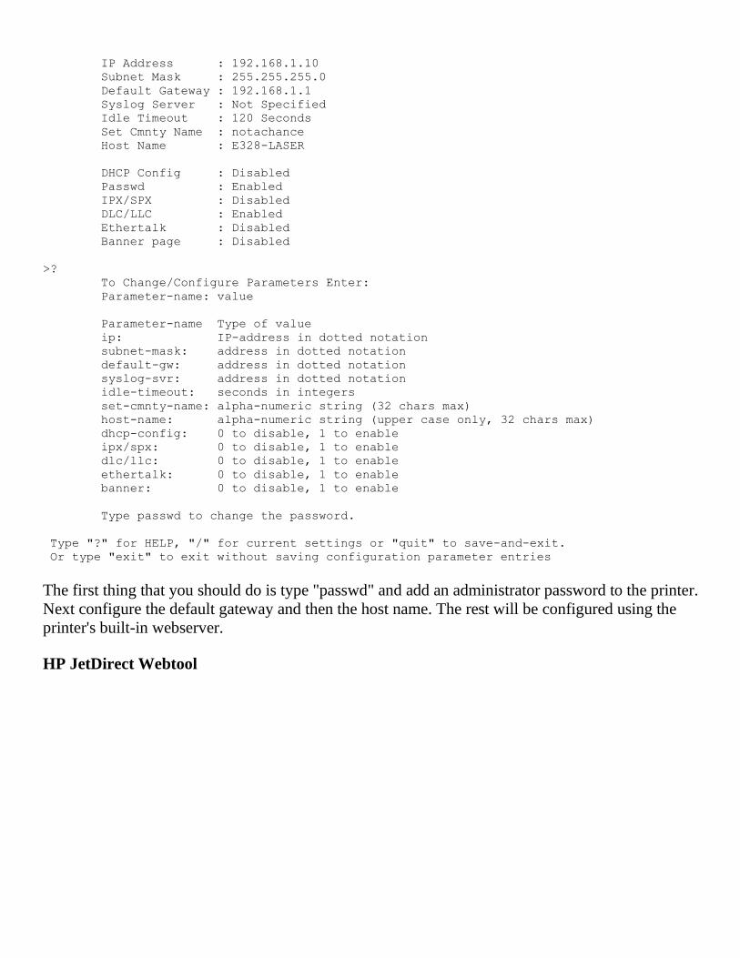
IP Address : 192.168.1.10
Subnet Mask : 255.255.255.0
Default Gateway : 192.168.1.1
Syslog Server : Not Specified
Idle Timeout : 120 Seconds
Set Cmnty Name : notachance
Host Name : E328-LASER
DHCP Config : Disabled
Passwd : Enabled
IPX/SPX : Disabled
DLC/LLC : Enabled
Ethertalk : Disabled
Banner page : Disabled
>?
To Change/Configure Parameters Enter:
Parameter-name: value
Parameter-name Type of value
ip: IP-address in dotted notation
subnet-mask: address in dotted notation
default-gw: address in dotted notation
syslog-svr: address in dotted notation
idle-timeout: seconds in integers
set-cmnty-name: alpha-numeric string (32 chars max)
host-name: alpha-numeric string (upper case only, 32 chars max)
dhcp-config: 0 to disable, 1 to enable
ipx/spx: 0 to disable, 1 to enable
dlc/llc: 0 to disable, 1 to enable
ethertalk: 0 to disable, 1 to enable
banner: 0 to disable, 1 to enable
Type passwd to change the password.
Type "?" for HELP, "/" for current settings or "quit" to save-and-exit.
Or type "exit" to exit without saving configuration parameter entries
The first thing that you should do is type "passwd" and add an administrator password to the printer.
Next configure the default gateway and then the host name. The rest will be configured using the
printer's built-in webserver.
HP JetDirect Webtool
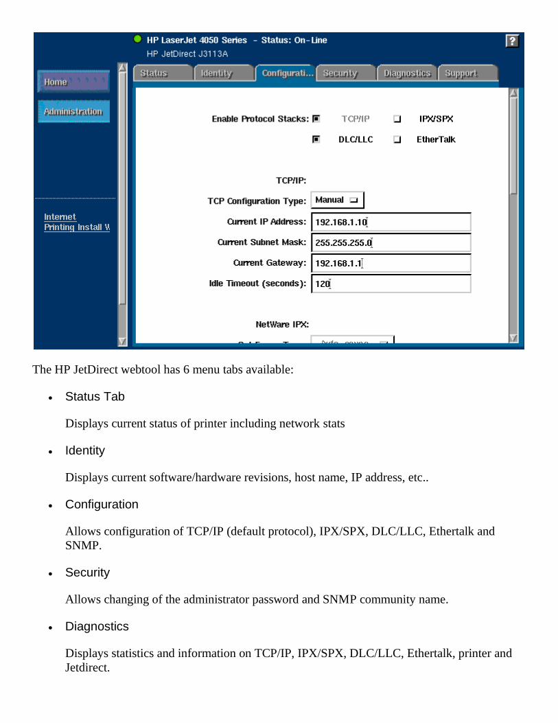
The HP JetDirect webtool has 6 menu tabs available:
Status Tab
Displays current status of printer including network stats
Identity
Displays current software/hardware revisions, host name, IP address, etc..
Configuration
Allows configuration of TCP/IP (default protocol), IPX/SPX, DLC/LLC, Ethertalk and
SNMP.
Security
Allows changing of the administrator password and SNMP community name.
Diagnostics
Displays statistics and information on TCP/IP, IPX/SPX, DLC/LLC, Ethertalk, printer and
Jetdirect.
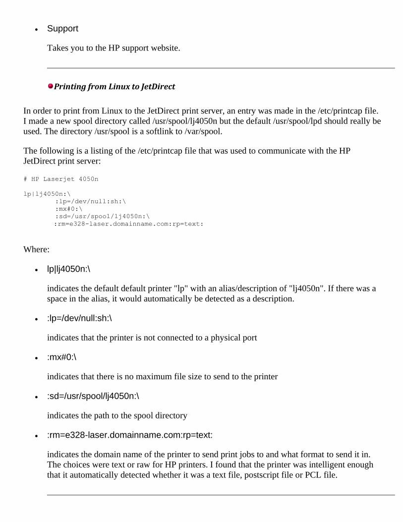
Support
Takes you to the HP support website.
Printing from Linux to JetDirect
In order to print from Linux to the JetDirect print server, an entry was made in the /etc/printcap file.
I made a new spool directory called /usr/spool/lj4050n but the default /usr/spool/lpd should really be
used. The directory /usr/spool is a softlink to /var/spool.
The following is a listing of the /etc/printcap file that was used to communicate with the HP
JetDirect print server:
# HP Laserjet 4050n
lp|lj4050n:\
:lp=/dev/null:sh:\
:mx#0:\
:sd=/usr/spool/lj4050n:\
:rm=e328-laser.domainname.com:rp=text:
Where:
lp|lj4050n:\
indicates the default default printer "lp" with an alias/description of "lj4050n". If there was a
space in the alias, it would automatically be detected as a description.
:lp=/dev/null:sh:\
indicates that the printer is not connected to a physical port
:mx#0:\
indicates that there is no maximum file size to send to the printer
:sd=/usr/spool/lj4050n:\
indicates the path to the spool directory
:rm=e328-laser.domainname.com:rp=text:
indicates the domain name of the printer to send print jobs to and what format to send it in.
The choices were text or raw for HP printers. I found that the printer was intelligent enough
that it automatically detected whether it was a text file, postscript file or PCL file.

Configuring Windows for Linux Shared Printer
From Network Neighborhood, double-click on the Linux server's shared printer icon. Windows will
ask you to configure the printer. I shared the printer's configuration CD on the Linux box and went
to the disk1 folder to find the INF file. The printer configuration/installation will stop and display a
message something to the tune that it "can't find disk2" just go up a directory to find the disk2
folder. It will finish the installation and you are done. I usually run a Print Testpage to ensure that it
works properly.
The normal installation procedure is to run the setup utility from the CD. This installs megabytes of
data on to the client which was not what I wanted. I only wanted the print driver and found that the
above method gave me a quick, clean and simple printer configuration.
Summary
It was surprisingly easy to configure SAMBA and have it meet the lab's objectives.
When I first ran SAMBA, it took less than 10 minutes to communicate with Win95. This
was amazing as I had no prior experience with it.
In configuring the lab environment, I ran into a few problems, some annoying and some took a bit of
work to sort but all were solved.
An example of one of the annoying problems was having the [homes] folder show up as a share on a
client. It was identical to the client's home directory. Selecting "Browseable = No" in the Global
section of /etc/smb.conf solved that.
The most frustrating problem was finding out the the smbpasswd file did not automatically convert
passwords from shadow files. I kept getting asked for a username and password whenever I tried to
connect to a network share. All the documentation indicated that I was doing everything correct.
Manually entering each username's password using the smbpasswd program solved this. I am sure
that there is an automatic process for this, as this would not be acceptable if there more than my 10
generic user accounts.
All in all, I was able to configure the network quicker and easier than if I used an NT server and the
Linux server is totally transparent to the user. Here's an interesting point: this article has taken longer
to write than it did to configure the network.
53. The Suite of TCP/IP Protocols
Unix and the suite of TCP/IP protocols go hand in hand. It is not possible to separate
the two. TCP/IP refers to a suite of protocols not just the TCP and IP protocols. TCP/IP
is the network portion of Unix. The following figure relates the Dept. of Defense (DoD)
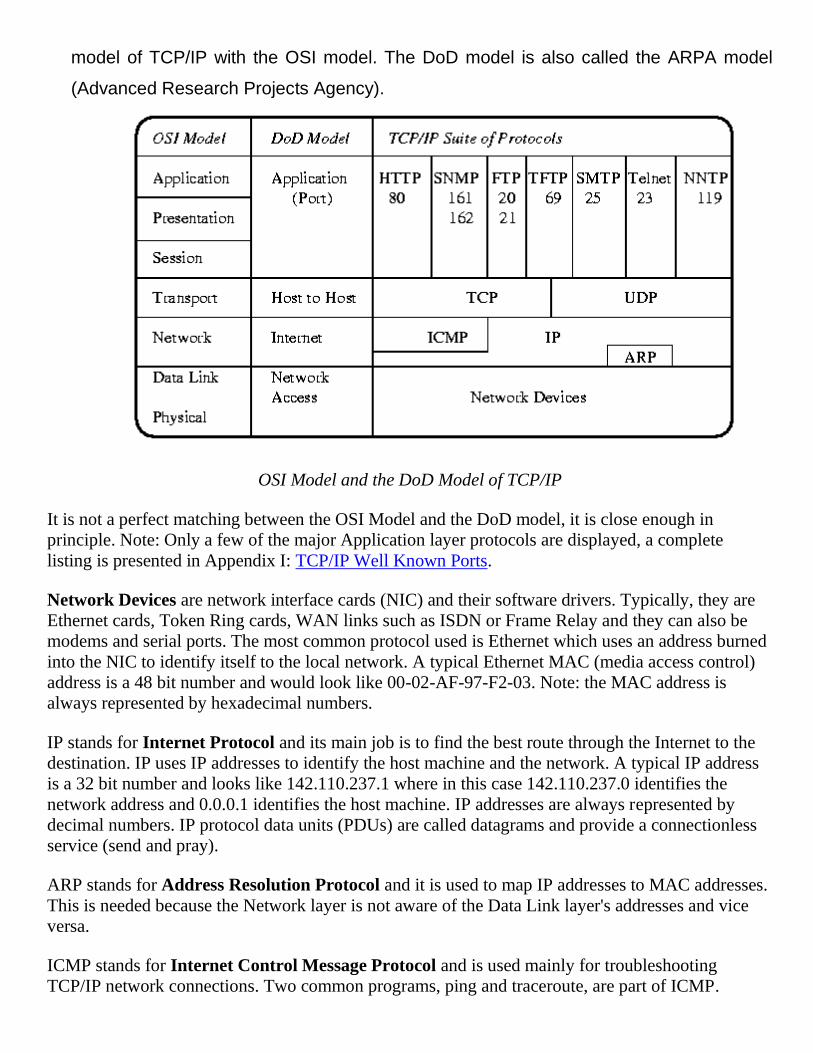
model of TCP/IP with the OSI model. The DoD model is also called the ARPA model
(Advanced Research Projects Agency).
OSI Model and the DoD Model of TCP/IP
It is not a perfect matching between the OSI Model and the DoD model, it is close enough in
principle. Note: Only a few of the major Application layer protocols are displayed, a complete
listing is presented in Appendix I: TCP/IP Well Known Ports.
Network Devices are network interface cards (NIC) and their software drivers. Typically, they are
Ethernet cards, Token Ring cards, WAN links such as ISDN or Frame Relay and they can also be
modems and serial ports. The most common protocol used is Ethernet which uses an address burned
into the NIC to identify itself to the local network. A typical Ethernet MAC (media access control)
address is a 48 bit number and would look like 00-02-AF-97-F2-03. Note: the MAC address is
always represented by hexadecimal numbers.
IP stands for Internet Protocol and its main job is to find the best route through the Internet to the
destination. IP uses IP addresses to identify the host machine and the network. A typical IP address
is a 32 bit number and looks like 142.110.237.1 where in this case 142.110.237.0 identifies the
network address and 0.0.0.1 identifies the host machine. IP addresses are always represented by
decimal numbers. IP protocol data units (PDUs) are called datagrams and provide a connectionless
service (send and pray).
ARP stands for Address Resolution Protocol and it is used to map IP addresses to MAC addresses.
This is needed because the Network layer is not aware of the Data Link layer's addresses and vice
versa.
ICMP stands for Internet Control Message Protocol and is used mainly for troubleshooting
TCP/IP network connections. Two common programs, ping and traceroute, are part of ICMP.
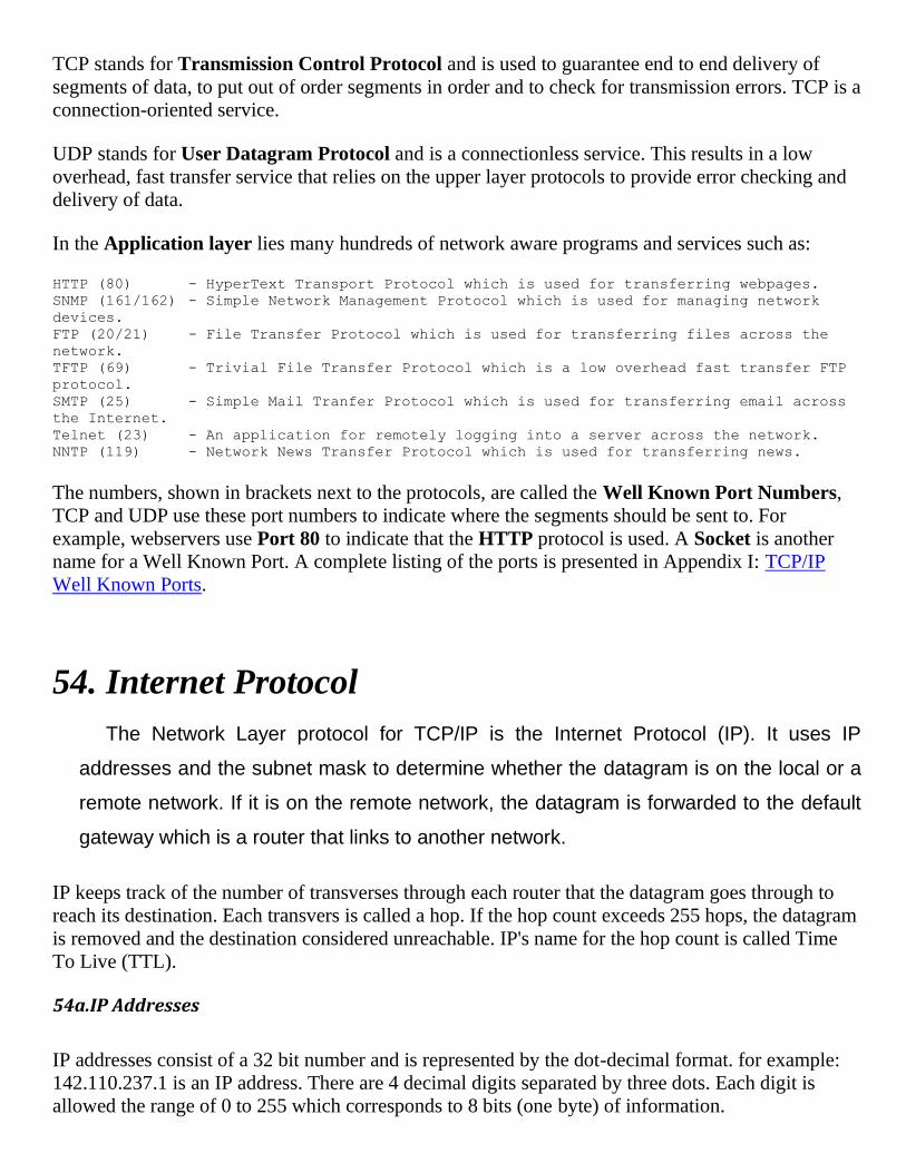
TCP stands for Transmission Control Protocol and is used to guarantee end to end delivery of
segments of data, to put out of order segments in order and to check for transmission errors. TCP is a
connection-oriented service.
UDP stands for User Datagram Protocol and is a connectionless service. This results in a low
overhead, fast transfer service that relies on the upper layer protocols to provide error checking and
delivery of data.
In the Application layer lies many hundreds of network aware programs and services such as:
HTTP (80) - HyperText Transport Protocol which is used for transferring webpages.
SNMP (161/162) - Simple Network Management Protocol which is used for managing network
devices.
FTP (20/21) - File Transfer Protocol which is used for transferring files across the
network.
TFTP (69) - Trivial File Transfer Protocol which is a low overhead fast transfer FTP
protocol.
SMTP (25) - Simple Mail Tranfer Protocol which is used for transferring email across
the Internet.
Telnet (23) - An application for remotely logging into a server across the network.
NNTP (119) - Network News Transfer Protocol which is used for transferring news.
The numbers, shown in brackets next to the protocols, are called the Well Known Port Numbers,
TCP and UDP use these port numbers to indicate where the segments should be sent to. For
example, webservers use Port 80 to indicate that the HTTP protocol is used. A Socket is another
name for a Well Known Port. A complete listing of the ports is presented in Appendix I: TCP/IP
Well Known Ports.
54. Internet Protocol
The Network Layer protocol for TCP/IP is the Internet Protocol (IP). It uses IP
addresses and the subnet mask to determine whether the datagram is on the local or a
remote network. If it is on the remote network, the datagram is forwarded to the default
gateway which is a router that links to another network.
IP keeps track of the number of transverses through each router that the datagram goes through to
reach its destination. Each transvers is called a hop. If the hop count exceeds 255 hops, the datagram
is removed and the destination considered unreachable. IP's name for the hop count is called Time
To Live (TTL).
54a.IP Addresses
IP addresses consist of a 32 bit number and is represented by the dot-decimal format. for example:
142.110.237.1 is an IP address. There are 4 decimal digits separated by three dots. Each digit is
allowed the range of 0 to 255 which corresponds to 8 bits (one byte) of information.
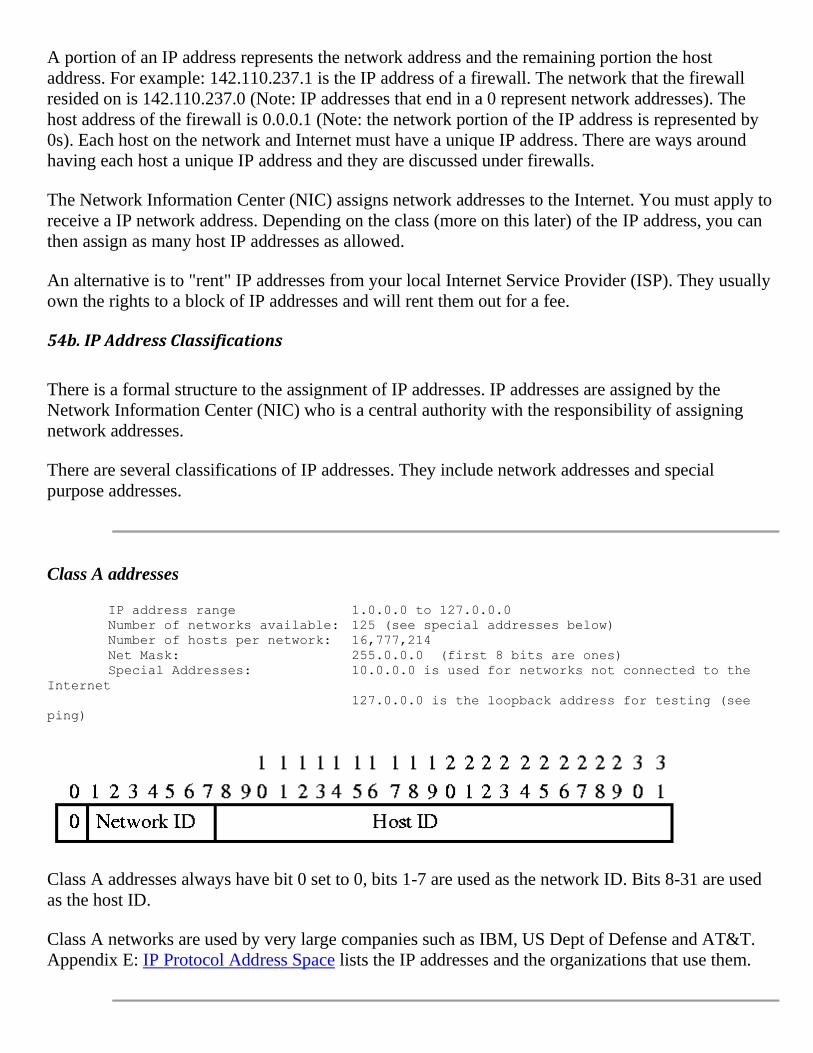
A portion of an IP address represents the network address and the remaining portion the host
address. For example: 142.110.237.1 is the IP address of a firewall. The network that the firewall
resided on is 142.110.237.0 (Note: IP addresses that end in a 0 represent network addresses). The
host address of the firewall is 0.0.0.1 (Note: the network portion of the IP address is represented by
0s). Each host on the network and Internet must have a unique IP address. There are ways around
having each host a unique IP address and they are discussed under firewalls.
The Network Information Center (NIC) assigns network addresses to the Internet. You must apply to
receive a IP network address. Depending on the class (more on this later) of the IP address, you can
then assign as many host IP addresses as allowed.
An alternative is to "rent" IP addresses from your local Internet Service Provider (ISP). They usually
own the rights to a block of IP addresses and will rent them out for a fee.
54b. IP Address Classifications
There is a formal structure to the assignment of IP addresses. IP addresses are assigned by the
Network Information Center (NIC) who is a central authority with the responsibility of assigning
network addresses.
There are several classifications of IP addresses. They include network addresses and special
purpose addresses.
Class A addresses
IP address range 1.0.0.0 to 127.0.0.0
Number of networks available: 125 (see special addresses below)
Number of hosts per network: 16,777,214
Net Mask: 255.0.0.0 (first 8 bits are ones)
Special Addresses: 10.0.0.0 is used for networks not connected to the
Internet
127.0.0.0 is the loopback address for testing (see
ping)
Class A addresses always have bit 0 set to 0, bits 1-7 are used as the network ID. Bits 8-31 are used
as the host ID.
Class A networks are used by very large companies such as IBM, US Dept of Defense and AT&T.
Appendix E: IP Protocol Address Space lists the IP addresses and the organizations that use them.
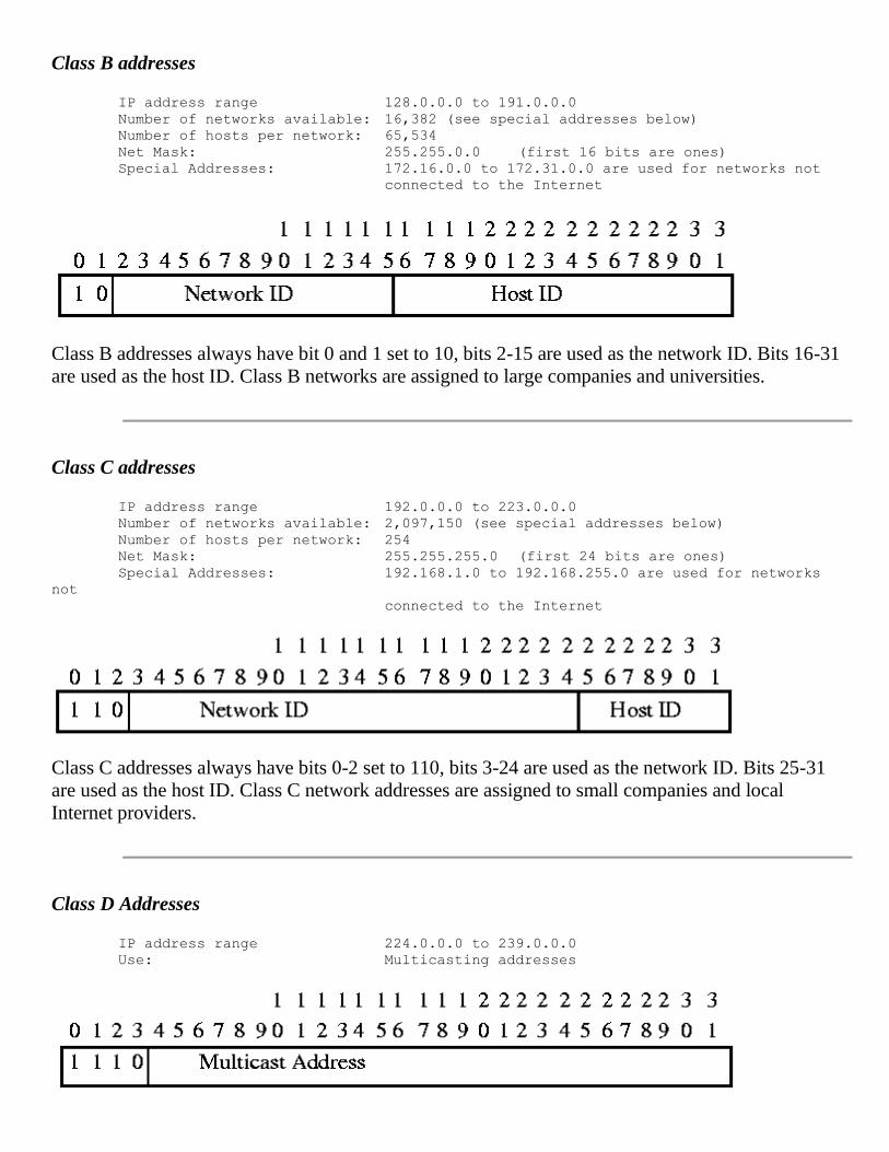
Class B addresses
IP address range 128.0.0.0 to 191.0.0.0
Number of networks available: 16,382 (see special addresses below)
Number of hosts per network: 65,534
Net Mask: 255.255.0.0 (first 16 bits are ones)
Special Addresses: 172.16.0.0 to 172.31.0.0 are used for networks not
connected to the Internet
Class B addresses always have bit 0 and 1 set to 10, bits 2-15 are used as the network ID. Bits 16-31
are used as the host ID. Class B networks are assigned to large companies and universities.
Class C addresses
IP address range 192.0.0.0 to 223.0.0.0
Number of networks available: 2,097,150 (see special addresses below)
Number of hosts per network: 254
Net Mask: 255.255.255.0 (first 24 bits are ones)
Special Addresses: 192.168.1.0 to 192.168.255.0 are used for networks
not
connected to the Internet
Class C addresses always have bits 0-2 set to 110, bits 3-24 are used as the network ID. Bits 25-31
are used as the host ID. Class C network addresses are assigned to small companies and local
Internet providers.
Class D Addresses
IP address range 224.0.0.0 to 239.0.0.0
Use: Multicasting addresses
Class D addresses always have bits 0-3 set to 1110, bits 4-31 are used as the Multicast address.
Class D network addresses are used by multicasting. Multicasting is a method of reducing network
traffic. Rather than send a separate datagram to each host if multiple host require the same
information. A special multicast address can be used where one datagram is read by many hosts.
Appendix F: IP Multicast Addresses lists the assigned IP multicast address space.
Class E Addresses
IP address range 240.0.0.0 to 255.0.0.0
Use: Reserved by the Internet for its own use.
If you try to ping a Class E address, you should get the error message that says that it is an invalid IP
address.
Reserved IP Addresses
The following IP addresses are reserved:
127.0.0.0 Network addresses used for localhost mode (testing IP stack)
255.255.255.255 An IP address consisting of all 1s in binary (255).
Broadcast address
x.x.x.0 An IP address with the host portion consisting of 0s. Used
to indicate
the network address. Newer routers have the option of
allowing these
addresses.
224.0.0.0 - 255.0.0.0 Class D addresses.
54c. Network Masking
The subnet mask is used to determine which portion of the IP address is the network
address and which is the host address. This means that the portions of network to host
in an IP address can change. The most common subnet mask is 255.255.255.0. The
simple explanation is that wherever there is a 255, this indicates that it is the network
portion. Wherever there is a 0, this indicates the host portion. Later on, subnet masking
will be explained more thoroughly, for now this explanation will suffice.
If we examine our IP address of 142.110.237.1, and use a subnet mask of 255.255.255.0. It can be
seen that the network portion of the IP address is 142.110.237 and the host portion is 1. The network
address is typically written 142.110.237.0 and the host is sometimes written 0.0.0.1.
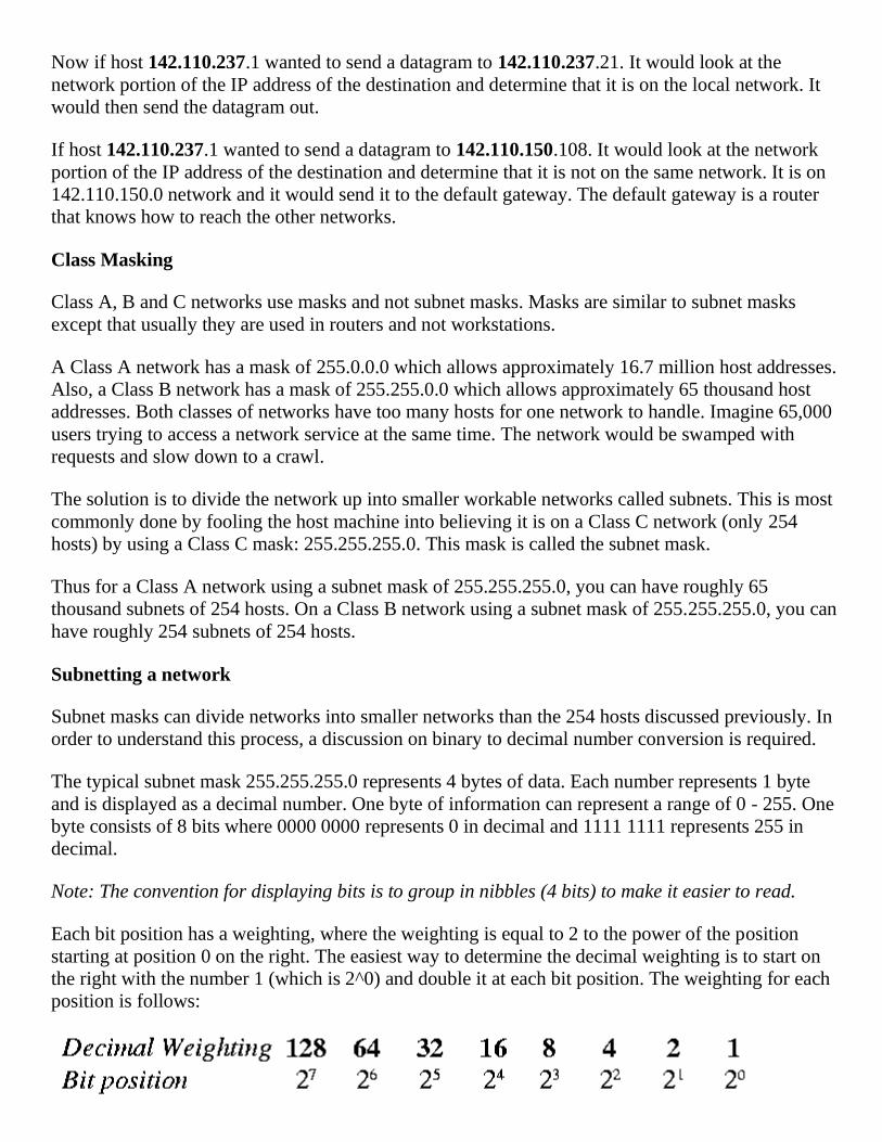
Now if host 142.110.237.1 wanted to send a datagram to 142.110.237.21. It would look at the
network portion of the IP address of the destination and determine that it is on the local network. It
would then send the datagram out.
If host 142.110.237.1 wanted to send a datagram to 142.110.150.108. It would look at the network
portion of the IP address of the destination and determine that it is not on the same network. It is on
142.110.150.0 network and it would send it to the default gateway. The default gateway is a router
that knows how to reach the other networks.
Class Masking
Class A, B and C networks use masks and not subnet masks. Masks are similar to subnet masks
except that usually they are used in routers and not workstations.
A Class A network has a mask of 255.0.0.0 which allows approximately 16.7 million host addresses.
Also, a Class B network has a mask of 255.255.0.0 which allows approximately 65 thousand host
addresses. Both classes of networks have too many hosts for one network to handle. Imagine 65,000
users trying to access a network service at the same time. The network would be swamped with
requests and slow down to a crawl.
The solution is to divide the network up into smaller workable networks called subnets. This is most
commonly done by fooling the host machine into believing it is on a Class C network (only 254
hosts) by using a Class C mask: 255.255.255.0. This mask is called the subnet mask.
Thus for a Class A network using a subnet mask of 255.255.255.0, you can have roughly 65
thousand subnets of 254 hosts. On a Class B network using a subnet mask of 255.255.255.0, you can
have roughly 254 subnets of 254 hosts.
Subnetting a network
Subnet masks can divide networks into smaller networks than the 254 hosts discussed previously. In
order to understand this process, a discussion on binary to decimal number conversion is required.
The typical subnet mask 255.255.255.0 represents 4 bytes of data. Each number represents 1 byte
and is displayed as a decimal number. One byte of information can represent a range of 0 - 255. One
byte consists of 8 bits where 0000 0000 represents 0 in decimal and 1111 1111 represents 255 in
decimal.
Note: The convention for displaying bits is to group in nibbles (4 bits) to make it easier to read.
Each bit position has a weighting, where the weighting is equal to 2 to the power of the position
starting at position 0 on the right. The easiest way to determine the decimal weighting is to start on
the right with the number 1 (which is 2^0) and double it at each bit position. The weighting for each
position is follows:
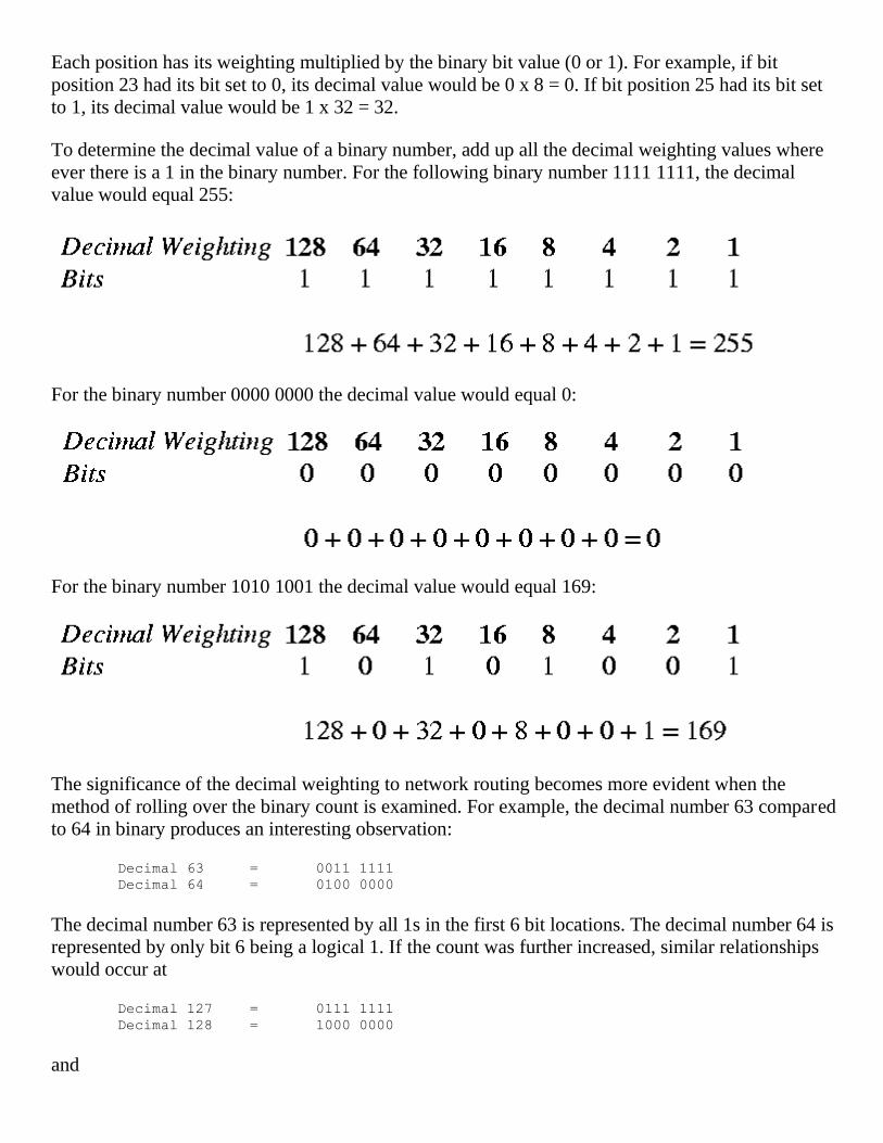
Each position has its weighting multiplied by the binary bit value (0 or 1). For example, if bit
position 23 had its bit set to 0, its decimal value would be 0 x 8 = 0. If bit position 25 had its bit set
to 1, its decimal value would be 1 x 32 = 32.
To determine the decimal value of a binary number, add up all the decimal weighting values where
ever there is a 1 in the binary number. For the following binary number 1111 1111, the decimal
value would equal 255:
For the binary number 0000 0000 the decimal value would equal 0:
For the binary number 1010 1001 the decimal value would equal 169:
The significance of the decimal weighting to network routing becomes more evident when the
method of rolling over the binary count is examined. For example, the decimal number 63 compared
to 64 in binary produces an interesting observation:
Decimal 63 = 0011 1111
Decimal 64 = 0100 0000
The decimal number 63 is represented by all 1s in the first 6 bit locations. The decimal number 64 is
represented by only bit 6 being a logical 1. If the count was further increased, similar relationships
would occur at
Decimal 127 = 0111 1111
Decimal 128 = 1000 0000
and
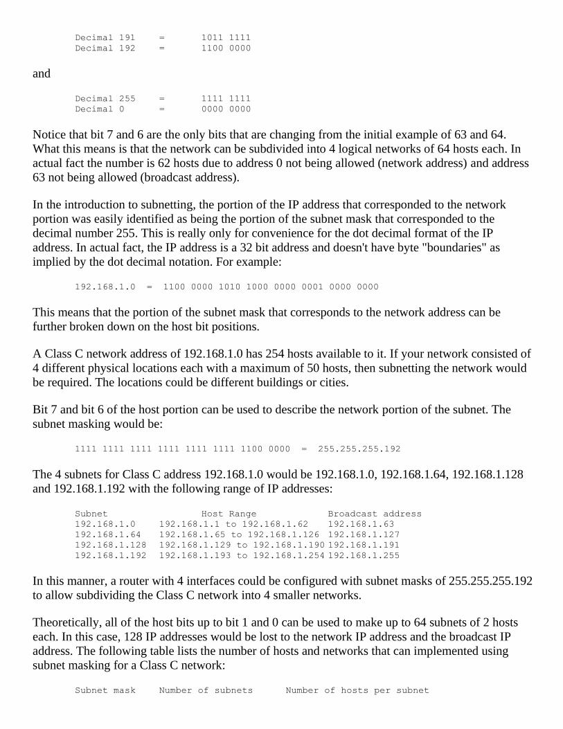
Decimal 191 = 1011 1111
Decimal 192 = 1100 0000
and
Decimal 255 = 1111 1111
Decimal 0 = 0000 0000
Notice that bit 7 and 6 are the only bits that are changing from the initial example of 63 and 64.
What this means is that the network can be subdivided into 4 logical networks of 64 hosts each. In
actual fact the number is 62 hosts due to address 0 not being allowed (network address) and address
63 not being allowed (broadcast address).
In the introduction to subnetting, the portion of the IP address that corresponded to the network
portion was easily identified as being the portion of the subnet mask that corresponded to the
decimal number 255. This is really only for convenience for the dot decimal format of the IP
address. In actual fact, the IP address is a 32 bit address and doesn't have byte "boundaries" as
implied by the dot decimal notation. For example:
192.168.1.0 = 1100 0000 1010 1000 0000 0001 0000 0000
This means that the portion of the subnet mask that corresponds to the network address can be
further broken down on the host bit positions.
A Class C network address of 192.168.1.0 has 254 hosts available to it. If your network consisted of
4 different physical locations each with a maximum of 50 hosts, then subnetting the network would
be required. The locations could be different buildings or cities.
Bit 7 and bit 6 of the host portion can be used to describe the network portion of the subnet. The
subnet masking would be:
1111 1111 1111 1111 1111 1111 1100 0000 = 255.255.255.192
The 4 subnets for Class C address 192.168.1.0 would be 192.168.1.0, 192.168.1.64, 192.168.1.128
and 192.168.1.192 with the following range of IP addresses:
Subnet Host Range Broadcast address
192.168.1.0 192.168.1.1 to 192.168.1.62 192.168.1.63
192.168.1.64 192.168.1.65 to 192.168.1.126 192.168.1.127
192.168.1.128 192.168.1.129 to 192.168.1.190 192.168.1.191
192.168.1.192 192.168.1.193 to 192.168.1.254 192.168.1.255
In this manner, a router with 4 interfaces could be configured with subnet masks of 255.255.255.192
to allow subdividing the Class C network into 4 smaller networks.
Theoretically, all of the host bits up to bit 1 and 0 can be used to make up to 64 subnets of 2 hosts
each. In this case, 128 IP addresses would be lost to the network IP address and the broadcast IP
address. The following table lists the number of hosts and networks that can implemented using
subnet masking for a Class C network:
Subnet mask Number of subnets Number of hosts per subnet

255.255.255.128 2 126
255.255.255.192 4 62
255.255.255.224 8 30
255.255.255.240 16 14
255.255.255.248 32 6
255.255.255.252 64 2
The above example is based on subnetting a Class C network. Subnetting can get extremely
complicated if you are subnetting assigned IP addresses that are in the middle of a Class C network
such as when rented from an ISP. Fortunately, there are many Subnet Mask Calculators available for
download off the Internet that are designed to determine the correct subnet mask for your network.
54e. Domain Names
IP addresses are difficult for humans to remember, they're great for PCs! Domain
names were invented to make it easier to navigate the Internet. A domain name is a
vaguely descriptive name separated by dots. For example: www.linuxhq.org
Every machine that runs TCP/IP has a text file called hosts. It is a simple lookup table that the
network stack (IP) checks to see if it has a match between a domain name and an IP address. It is
easily modified with a text editor and the contents look like the following:
127.0.0.1 localhost
142.110.237.1 e237-firewall.tech.el.sait.ab.ca
142.110.237.2 e237-bridge.tech.el.sait.ab.ca
142.110.237.3 ashley.tech.el.sait.ab.ca
142.110.237.4 mariah mariah.tech.el.sait.ab.ca
The IP address is listed on the left and the domain name is listed on the right. The actual registered
domain name is sait.ab.ca (Southern Alberta Institute of Technology). The domain name el.sait.ab.ca
(electronics dept.) is a subnet of sait.ab.ca. The domain name tech.el.sait.ab.ca (technical) is a subnet
of el.sait.ab.ca.
The machine names are e237-firewall, e237-bridge, ashley and mariah. Mariah's entry is unique in
that both the domain name mariah and mariah.tech.el.sait.ab.ca would be recognized by the IP stack
as 142.110.237.4.
The problem with the hosts file is that each machine must have a current up to date copy of the
network. For a small network (25 or less) not connected to the Internet this is not a problem to
manage. If the network is larger, than problems can occur trying to keep everyone updated.
Another solution is Unix's Network Information Service (NIS) (formerly called Yellow Pages until
there was a copyright conflict with the Telcos). A central NIS server shares a master hosts file to all
the clients. In this way, only one file exists and is updated. This works well for a network not
connected to the Internet.
If you are connected to the Internet then a Domain Name Server (DNS) is used. A DNS is a special
server that communicates with other servers and keeps an up-to-date look-up table that matches IP
addresses to domain names for the complete Internet. It is a hierarchical system where each DNS is
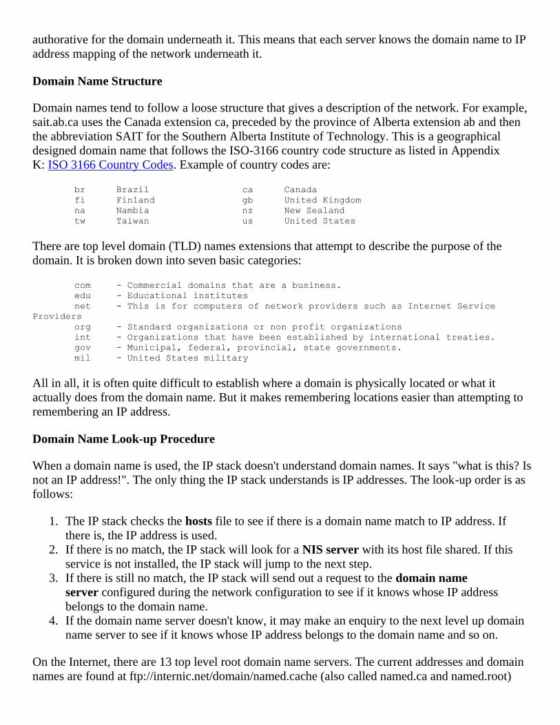
authorative for the domain underneath it. This means that each server knows the domain name to IP
address mapping of the network underneath it.
Domain Name Structure
Domain names tend to follow a loose structure that gives a description of the network. For example,
sait.ab.ca uses the Canada extension ca, preceded by the province of Alberta extension ab and then
the abbreviation SAIT for the Southern Alberta Institute of Technology. This is a geographical
designed domain name that follows the ISO-3166 country code structure as listed in Appendix
K: ISO 3166 Country Codes. Example of country codes are:
br Brazil ca Canada
fi Finland gb United Kingdom
na Nambia nz New Zealand
tw Taiwan us United States
There are top level domain (TLD) names extensions that attempt to describe the purpose of the
domain. It is broken down into seven basic categories:
com - Commercial domains that are a business.
edu - Educational institutes
net - This is for computers of network providers such as Internet Service
Providers
org - Standard organizations or non profit organizations
int - Organizations that have been established by international treaties.
gov - Municipal, federal, provincial, state governments.
mil - United States military
All in all, it is often quite difficult to establish where a domain is physically located or what it
actually does from the domain name. But it makes remembering locations easier than attempting to
remembering an IP address.
Domain Name Look-up Procedure
When a domain name is used, the IP stack doesn't understand domain names. It says "what is this? Is
not an IP address!". The only thing the IP stack understands is IP addresses. The look-up order is as
follows:
1. The IP stack checks the hosts file to see if there is a domain name match to IP address. If
there is, the IP address is used.
2. If there is no match, the IP stack will look for a NIS server with its host file shared. If this
service is not installed, the IP stack will jump to the next step.
3. If there is still no match, the IP stack will send out a request to the domain name
server configured during the network configuration to see if it knows whose IP address
belongs to the domain name.
4. If the domain name server doesn't know, it may make an enquiry to the next level up domain
name server to see if it knows whose IP address belongs to the domain name and so on.
On the Internet, there are 13 top level root domain name servers. The current addresses and domain
names are found at ftp://internic.net/domain/named.cache (also called named.ca and named.root)
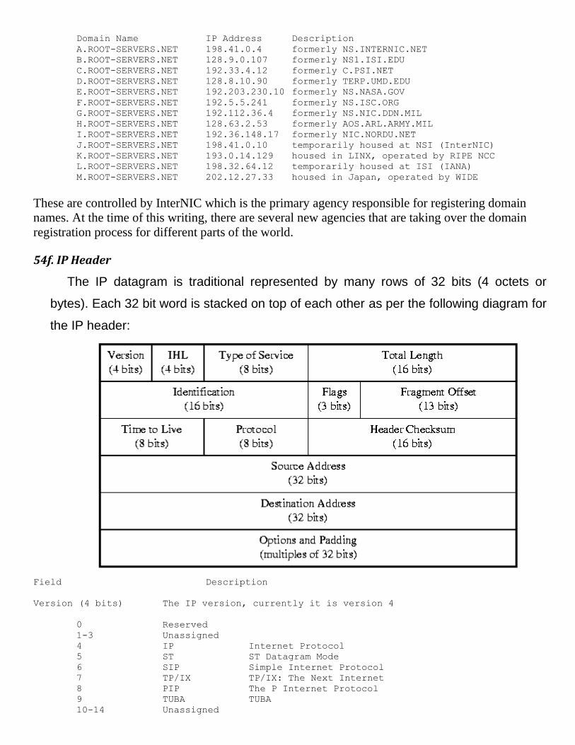
Domain Name IP Address Description
A.ROOT-SERVERS.NET 198.41.0.4 formerly NS.INTERNIC.NET
B.ROOT-SERVERS.NET 128.9.0.107 formerly NS1.ISI.EDU
C.ROOT-SERVERS.NET 192.33.4.12 formerly C.PSI.NET
D.ROOT-SERVERS.NET 128.8.10.90 formerly TERP.UMD.EDU
E.ROOT-SERVERS.NET 192.203.230.10 formerly NS.NASA.GOV
F.ROOT-SERVERS.NET 192.5.5.241 formerly NS.ISC.ORG
G.ROOT-SERVERS.NET 192.112.36.4 formerly NS.NIC.DDN.MIL
H.ROOT-SERVERS.NET 128.63.2.53 formerly AOS.ARL.ARMY.MIL
I.ROOT-SERVERS.NET 192.36.148.17 formerly NIC.NORDU.NET
J.ROOT-SERVERS.NET 198.41.0.10 temporarily housed at NSI (InterNIC)
K.ROOT-SERVERS.NET 193.0.14.129 housed in LINX, operated by RIPE NCC
L.ROOT-SERVERS.NET 198.32.64.12 temporarily housed at ISI (IANA)
M.ROOT-SERVERS.NET 202.12.27.33 housed in Japan, operated by WIDE
These are controlled by InterNIC which is the primary agency responsible for registering domain
names. At the time of this writing, there are several new agencies that are taking over the domain
registration process for different parts of the world.
54f. IP Header
The IP datagram is traditional represented by many rows of 32 bits (4 octets or
bytes). Each 32 bit word is stacked on top of each other as per the following diagram for
the IP header:
Field Description
Version (4 bits) The IP version, currently it is version 4
0 Reserved
1-3 Unassigned
4 IP Internet Protocol
5 ST ST Datagram Mode
6 SIP Simple Internet Protocol
7 TP/IX TP/IX: The Next Internet
8 PIP The P Internet Protocol
9 TUBA TUBA
10-14 Unassigned

15 Reserved
IHL (4 bits) Internet Header Length, the length of the IP header in 32 bit words.
Type of Service Flags to indicate precedence, delay, throughput and
(8 bits) reliability parameters.
Bit 0-2: Precedence
000 - Routine
001 - Priority
010 - Immediate
011 - Flash
100 - Flash override
101 - CRITIC / ECP
110 - Internet control
111 - Network control
Bit 3: 0 = Normal delay, 1 = Low delay
Bit 4: 0 = Normal throughput, 1 = High throughput
Bit 5: 0 = Normal reliability, 1 = High reliability
Bit 6-7: Reserved for future use.
Total Length Total length in bytes of the IP datagram (IP header and data)
(16 bits) Minimum length = 576, Maximum length = 65,535
Identification Unique identifying number for this datagram
(16 bits)
Flags (3 bits) Options that indicate if fragmentation s permitted and/or used
Bit 0: Reserved, allways set to 0
Bit 1: 0 = May fragment, 1 = Don't fragment
Bit 2: 0 = Last fragment, 1 = More fragments
Fragment Offset Indicates where in the entire datagram, this particular fragment
(13 bits) belongs. Measured in 64 bit units from the beginning of the
initial datagram.
Time to live (TTL) Measured in hop counts or seconds. Every transverse through
(8 bits) a router or gateway will decrement the hop count. When the
TTL equals 0, the datagram is discarded. This stops datagrams
from circulating the network forever. Starts at TTL = 255.
Protocol Identifies the next protocol that follows the IP header.
(8 bits) The full listing of protocols is in
Appendix G: IP Header Protocols.
Examples are:
Decimal Protocol Description
0 Reserved
1 ICMP Internet Control Message
2 IGMP Internet Group Management
6 TCP Transmission Control
37 DDP Datagram Delivery Protocol
46 RSVP Reservation Protocol
93 AX.25 AX.25 Frames
Header Checksum A 32 bit Cyclic Redundacy Check that may be checked at each
(32 bit) gateway.
Source Address An IP address indicating the sender. Ex. 142.110.237.1
(32 bit)
Destination Address An IP address indicating the receiptient. Ex. 142.110.237.2
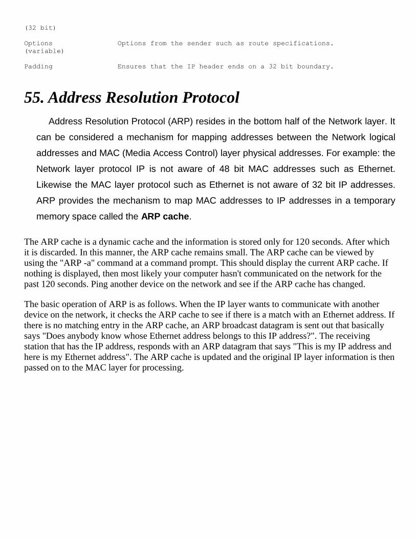
(32 bit)
Options Options from the sender such as route specifications.
(variable)
Padding Ensures that the IP header ends on a 32 bit boundary.
55. Address Resolution Protocol
Address Resolution Protocol (ARP) resides in the bottom half of the Network layer. It
can be considered a mechanism for mapping addresses between the Network logical
addresses and MAC (Media Access Control) layer physical addresses. For example: the
Network layer protocol IP is not aware of 48 bit MAC addresses such as Ethernet.
Likewise the MAC layer protocol such as Ethernet is not aware of 32 bit IP addresses.
ARP provides the mechanism to map MAC addresses to IP addresses in a temporary
memory space called the ARP cache.
The ARP cache is a dynamic cache and the information is stored only for 120 seconds. After which
it is discarded. In this manner, the ARP cache remains small. The ARP cache can be viewed by
using the "ARP -a" command at a command prompt. This should display the current ARP cache. If
nothing is displayed, then most likely your computer hasn't communicated on the network for the
past 120 seconds. Ping another device on the network and see if the ARP cache has changed.
The basic operation of ARP is as follows. When the IP layer wants to communicate with another
device on the network, it checks the ARP cache to see if there is a match with an Ethernet address. If
there is no matching entry in the ARP cache, an ARP broadcast datagram is sent out that basically
says "Does anybody know whose Ethernet address belongs to this IP address?". The receiving
station that has the IP address, responds with an ARP datagram that says "This is my IP address and
here is my Ethernet address". The ARP cache is updated and the original IP layer information is then
passed on to the MAC layer for processing.
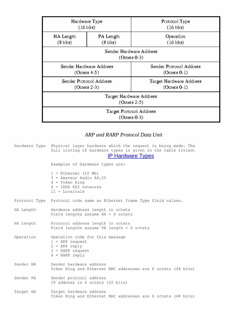
ARP and RARP Protocol Data Unit
Hardware Type Physical layer hardware which the request is being made. The
full listing of hardware types is given in the table titled:
IP Hardware Types
Examples of hardware types are:
1 = Ethernet (10 Mb)
3 = Amateur Radio AX.25
4 = Token Ring
6 = IEEE 802 networks
11 = Localtalk
Protocol Type Protocol code same as Ethernet frame Type field values.
HA Length Hardware address length in octets
Field lengths assume HA = 6 octets
PA Length Protocol address length in octets
Field lengths assume PA length = 4 octets
Operation Operation code for this message
1 = ARP request
2 = ARP reply
3 = RARP request
4 = RARP reply
Sender HA Sender hardware address
Token Ring and Ethernet MAC addresses are 6 octets (48 bits)
Sender PA Sender protocol address
IP address is 4 octets (32 bits)
Target HA Target hardware address
Token Ring and Ethernet MAC addresses are 6 octets (48 bits)
Target PA Target protocol address
IP address is 4 octets (32 bits)
56. Reverse Address Resolution Protocol
Reverse Address Resolution Protocol (RARP) is the reverse of ARP. It is a
mechanism to map MAC addresses to IP addresses. It is used mainly by diskless
workstations upon boot-up to find out their IP addresses from a BOOTP server. The
BOOTP server contains all of the boot-up configuration files that the workstation needs
to boot-up.
On NICs (network interface cards) there is an empty DIP socket that is used for holding a Boot
PROM. The Boot PROM holds a special software program that tells the workstation that upon
powering up, to go and find a BOOTP server. One of the first tasks of the workstation is to find out
its IP address. The MAC layer address is burnt into the NIC and is already known.
A RARP broadcast datagram is sent out that asks "Does any BOOTP server know what my IP
address is?". The BOOTP server will reply with "Here's the IP address that belongs to your MAC
address".
Once the IP address is known, then the rest of the configuration files can be downloaded and the
diskless workstation booted up.
Note: RARP uses the same PDU header as ARP. See ARP PDU.
57. ICMP - Internet Control Message Protocol
The Internet Control Message Protocol's (ICMP) job is to report errors that may have occurred in processing IP
datagrams. ICMP is an integral part of IP and and its messages are encapsulated within an IP datagram. Note:
there are 6 messaging formats used by ICMP which will be discussed later.
The ICMP messages are indicated by the Type Field and are:
0 - Echo Reply
3 - Destination unreachable
4 - Source Quench
5 - Redirect
8 - Echo
11 - Time exceeded
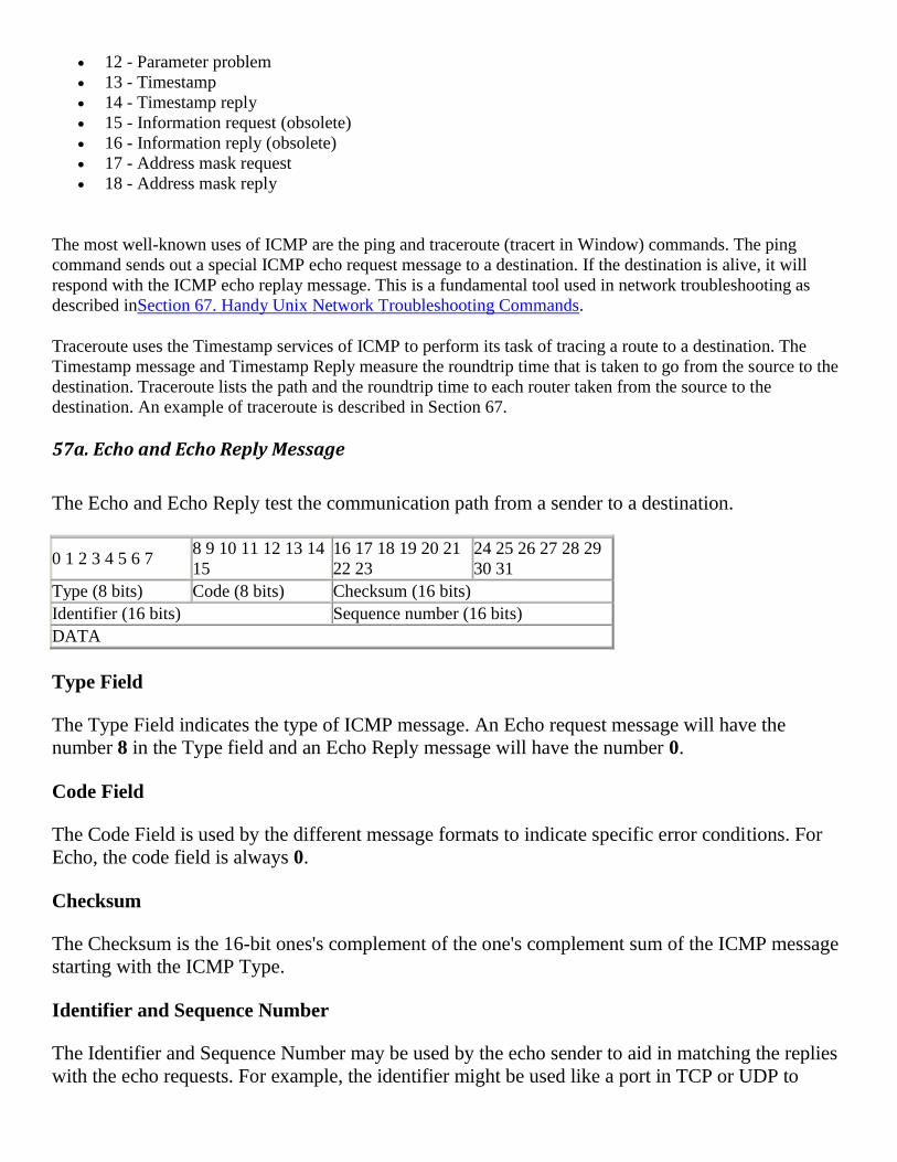
12 - Parameter problem
13 - Timestamp
14 - Timestamp reply
15 - Information request (obsolete)
16 - Information reply (obsolete)
17 - Address mask request
18 - Address mask reply
The most well-known uses of ICMP are the ping and traceroute (tracert in Window) commands. The ping
command sends out a special ICMP echo request message to a destination. If the destination is alive, it will
respond with the ICMP echo replay message. This is a fundamental tool used in network troubleshooting as
described inSection 67. Handy Unix Network Troubleshooting Commands.
Traceroute uses the Timestamp services of ICMP to perform its task of tracing a route to a destination. The
Timestamp message and Timestamp Reply measure the roundtrip time that is taken to go from the source to the
destination. Traceroute lists the path and the roundtrip time to each router taken from the source to the
destination. An example of traceroute is described in Section 67.
57a. Echo and Echo Reply Message
The Echo and Echo Reply test the communication path from a sender to a destination.
0 1 2 3 4 5 6 7 8 9 10 11 12 13 14
15
16 17 18 19 20 21
22 23
24 25 26 27 28 29
30 31
Type (8 bits) Code (8 bits) Checksum (16 bits)
Identifier (16 bits) Sequence number (16 bits)
DATA
Type Field
The Type Field indicates the type of ICMP message. An Echo request message will have the
number 8 in the Type field and an Echo Reply message will have the number 0.
Code Field
The Code Field is used by the different message formats to indicate specific error conditions. For
Echo, the code field is always 0.
Checksum
The Checksum is the 16-bit ones's complement of the one's complement sum of the ICMP message
starting with the ICMP Type.
Identifier and Sequence Number
The Identifier and Sequence Number may be used by the echo sender to aid in matching the replies
with the echo requests. For example, the identifier might be used like a port in TCP or UDP to
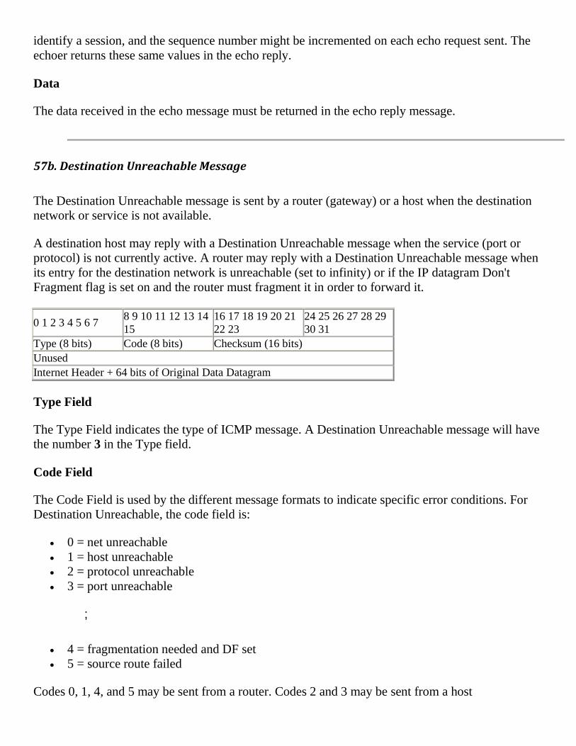
identify a session, and the sequence number might be incremented on each echo request sent. The
echoer returns these same values in the echo reply.
Data
The data received in the echo message must be returned in the echo reply message.
57b. Destination Unreachable Message
The Destination Unreachable message is sent by a router (gateway) or a host when the destination
network or service is not available.
A destination host may reply with a Destination Unreachable message when the service (port or
protocol) is not currently active. A router may reply with a Destination Unreachable message when
its entry for the destination network is unreachable (set to infinity) or if the IP datagram Don't
Fragment flag is set on and the router must fragment it in order to forward it.
0 1 2 3 4 5 6 7 8 9 10 11 12 13 14
15
16 17 18 19 20 21
22 23
24 25 26 27 28 29
30 31
Type (8 bits) Code (8 bits) Checksum (16 bits)
Unused
Internet Header + 64 bits of Original Data Datagram
Type Field
The Type Field indicates the type of ICMP message. A Destination Unreachable message will have
the number 3 in the Type field.
Code Field
The Code Field is used by the different message formats to indicate specific error conditions. For
Destination Unreachable, the code field is:
0 = net unreachable
1 = host unreachable
2 = protocol unreachable
3 = port unreachable
;
4 = fragmentation needed and DF set
5 = source route failed
Codes 0, 1, 4, and 5 may be sent from a router. Codes 2 and 3 may be sent from a host

Checksum
The checksum is the 16-bit ones's complement of the one's complement sum of the ICMP message
starting with the ICMP Type.
Unused
The 32 bits are not used and ignored.
Internet Header + 64 bits of Data Datagram
The IP header plus the first 64 bits of the original datagram's data. This data is used by the host to
match the message to the appropriate process. If a higher level protocol uses port numbers, they are
assumed to be in the first 64 data bits of the original datagram's data.
57c. Source Quench Message
If a router does not have enough buffer space and becomes congested or is approaching its capacity,
it may send a Source Quench message to the datagram source host. The source quench message is a
request to the host to cut back the rate at which it is sending traffic to the internet destination.
0 1 2 3 4 5 6 7 8 9 10 11 12 13 14
15
16 17 18 19 20 21
22 23
24 25 26 27 28 29
30 31
Type (8 bits) Code (8 bits) Checksum (16 bits)
Unused
Internet Header + 64 bits of Original Data Datagram
Type Field
The Type Field indicates the type of ICMP message. An Source Quench message will have the
number 4 in the Type field .
Code Field
The Code Field is used by the different message formats to indicate specific error conditions. For
Source Quench, the code field is always 0.
Checksum
The checksum is the 16-bit ones's complement of the one's complement sum of the ICMP message
starting with the ICMP Type.
Unused
The 32 bits are not used and ignored.
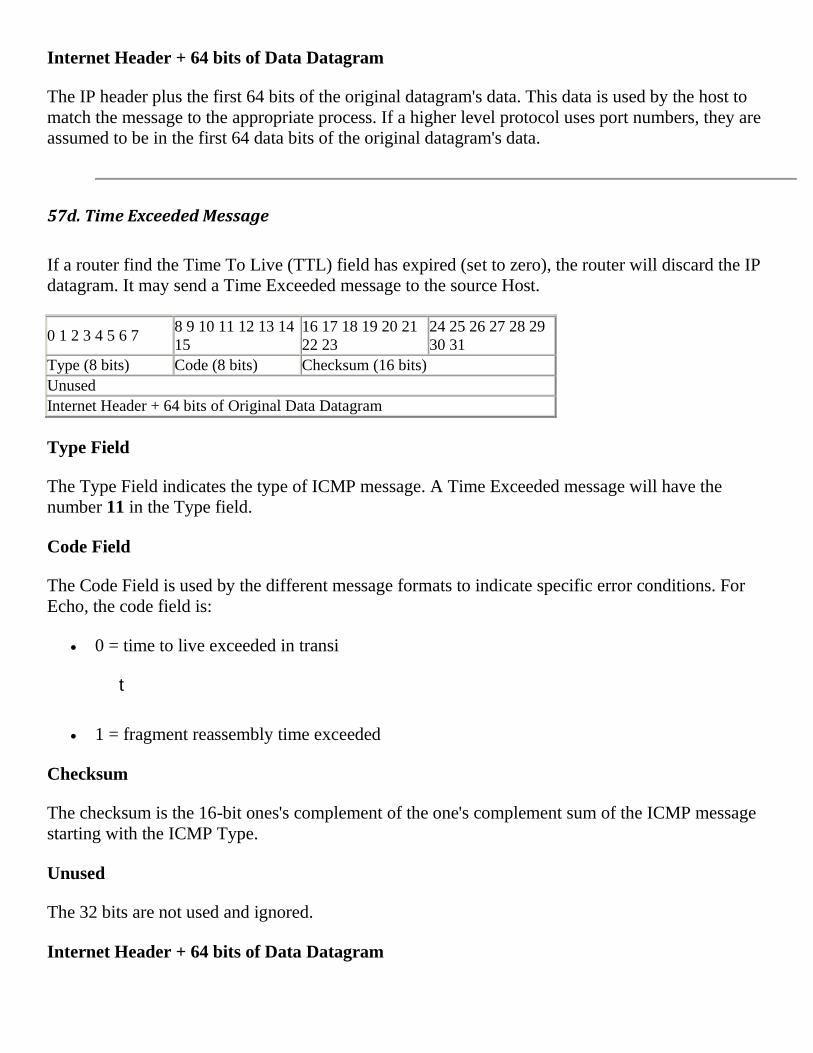
Internet Header + 64 bits of Data Datagram
The IP header plus the first 64 bits of the original datagram's data. This data is used by the host to
match the message to the appropriate process. If a higher level protocol uses port numbers, they are
assumed to be in the first 64 data bits of the original datagram's data.
57d. Time Exceeded Message
If a router find the Time To Live (TTL) field has expired (set to zero), the router will discard the IP
datagram. It may send a Time Exceeded message to the source Host.
0 1 2 3 4 5 6 7 8 9 10 11 12 13 14
15
16 17 18 19 20 21
22 23
24 25 26 27 28 29
30 31
Type (8 bits) Code (8 bits) Checksum (16 bits)
Unused
Internet Header + 64 bits of Original Data Datagram
Type Field
The Type Field indicates the type of ICMP message. A Time Exceeded message will have the
number 11 in the Type field.
Code Field
The Code Field is used by the different message formats to indicate specific error conditions. For
Echo, the code field is:
0 = time to live exceeded in transi
t
1 = fragment reassembly time exceeded
Checksum
The checksum is the 16-bit ones's complement of the one's complement sum of the ICMP message
starting with the ICMP Type.
Unused
The 32 bits are not used and ignored.
Internet Header + 64 bits of Data Datagram
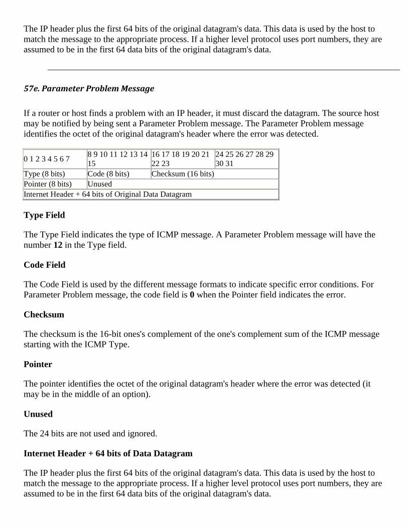
The IP header plus the first 64 bits of the original datagram's data. This data is used by the host to
match the message to the appropriate process. If a higher level protocol uses port numbers, they are
assumed to be in the first 64 data bits of the original datagram's data.
57e. Parameter Problem Message
If a router or host finds a problem with an IP header, it must discard the datagram. The source host
may be notified by being sent a Parameter Problem message. The Parameter Problem message
identifies the octet of the original datagram's header where the error was detected.
0 1 2 3 4 5 6 7 8 9 10 11 12 13 14
15
16 17 18 19 20 21
22 23
24 25 26 27 28 29
30 31
Type (8 bits) Code (8 bits) Checksum (16 bits)
Pointer (8 bits) Unused
Internet Header + 64 bits of Original Data Datagram
Type Field
The Type Field indicates the type of ICMP message. A Parameter Problem message will have the
number 12 in the Type field.
Code Field
The Code Field is used by the different message formats to indicate specific error conditions. For
Parameter Problem message, the code field is 0 when the Pointer field indicates the error.
Checksum
The checksum is the 16-bit ones's complement of the one's complement sum of the ICMP message
starting with the ICMP Type.
Pointer
The pointer identifies the octet of the original datagram's header where the error was detected (it
may be in the middle of an option).
Unused
The 24 bits are not used and ignored.
Internet Header + 64 bits of Data Datagram
The IP header plus the first 64 bits of the original datagram's data. This data is used by the host to
match the message to the appropriate process. If a higher level protocol uses port numbers, they are
assumed to be in the first 64 data bits of the original datagram's data.
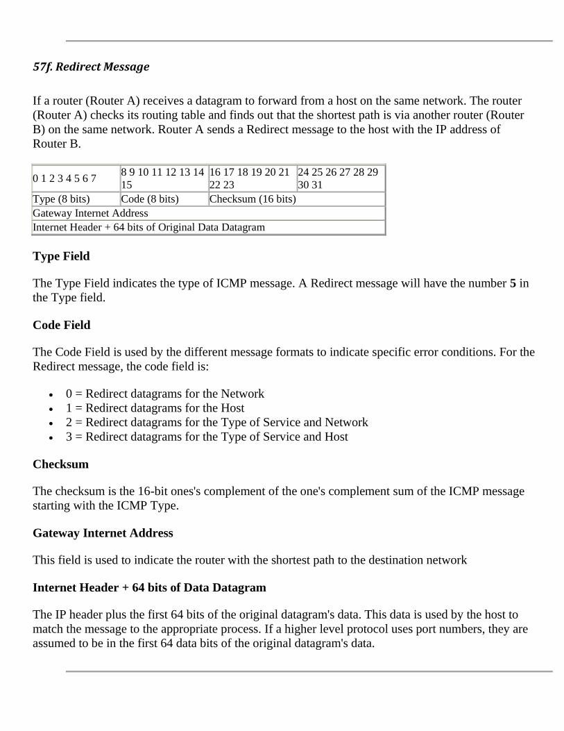
57f. Redirect Message
If a router (Router A) receives a datagram to forward from a host on the same network. The router
(Router A) checks its routing table and finds out that the shortest path is via another router (Router
B) on the same network. Router A sends a Redirect message to the host with the IP address of
Router B.
0 1 2 3 4 5 6 7 8 9 10 11 12 13 14
15
16 17 18 19 20 21
22 23
24 25 26 27 28 29
30 31
Type (8 bits) Code (8 bits) Checksum (16 bits)
Gateway Internet Address
Internet Header + 64 bits of Original Data Datagram
Type Field
The Type Field indicates the type of ICMP message. A Redirect message will have the number 5 in
the Type field.
Code Field
The Code Field is used by the different message formats to indicate specific error conditions. For the
Redirect message, the code field is:
0 = Redirect datagrams for the Network
1 = Redirect datagrams for the Host
2 = Redirect datagrams for the Type of Service and Network
3 = Redirect datagrams for the Type of Service and Host
Checksum
The checksum is the 16-bit ones's complement of the one's complement sum of the ICMP message
starting with the ICMP Type.
Gateway Internet Address
This field is used to indicate the router with the shortest path to the destination network
Internet Header + 64 bits of Data Datagram
The IP header plus the first 64 bits of the original datagram's data. This data is used by the host to
match the message to the appropriate process. If a higher level protocol uses port numbers, they are
assumed to be in the first 64 data bits of the original datagram's data.
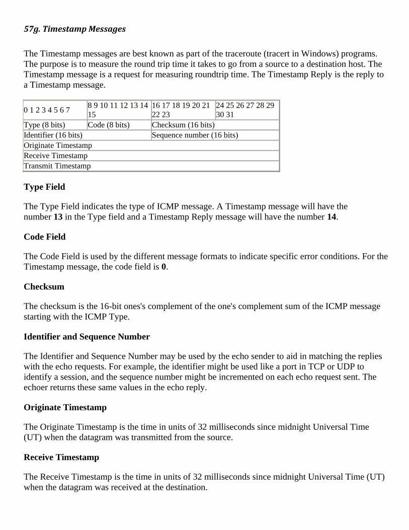
57g. Timestamp Messages
The Timestamp messages are best known as part of the traceroute (tracert in Windows) programs.
The purpose is to measure the round trip time it takes to go from a source to a destination host. The
Timestamp message is a request for measuring roundtrip time. The Timestamp Reply is the reply to
a Timestamp message.
0 1 2 3 4 5 6 7 8 9 10 11 12 13 14
15
16 17 18 19 20 21
22 23
24 25 26 27 28 29
30 31
Type (8 bits) Code (8 bits) Checksum (16 bits)
Identifier (16 bits) Sequence number (16 bits)
Originate Timestamp
Receive Timestamp
Transmit Timestamp
Type Field
The Type Field indicates the type of ICMP message. A Timestamp message will have the
number 13 in the Type field and a Timestamp Reply message will have the number 14.
Code Field
The Code Field is used by the different message formats to indicate specific error conditions. For the
Timestamp message, the code field is 0.
Checksum
The checksum is the 16-bit ones's complement of the one's complement sum of the ICMP message
starting with the ICMP Type.
Identifier and Sequence Number
The Identifier and Sequence Number may be used by the echo sender to aid in matching the replies
with the echo requests. For example, the identifier might be used like a port in TCP or UDP to
identify a session, and the sequence number might be incremented on each echo request sent. The
echoer returns these same values in the echo reply.
Originate Timestamp
The Originate Timestamp is the time in units of 32 milliseconds since midnight Universal Time
(UT) when the datagram was transmitted from the source.
Receive Timestamp
The Receive Timestamp is the time in units of 32 milliseconds since midnight Universal Time (UT)
when the datagram was received at the destination.
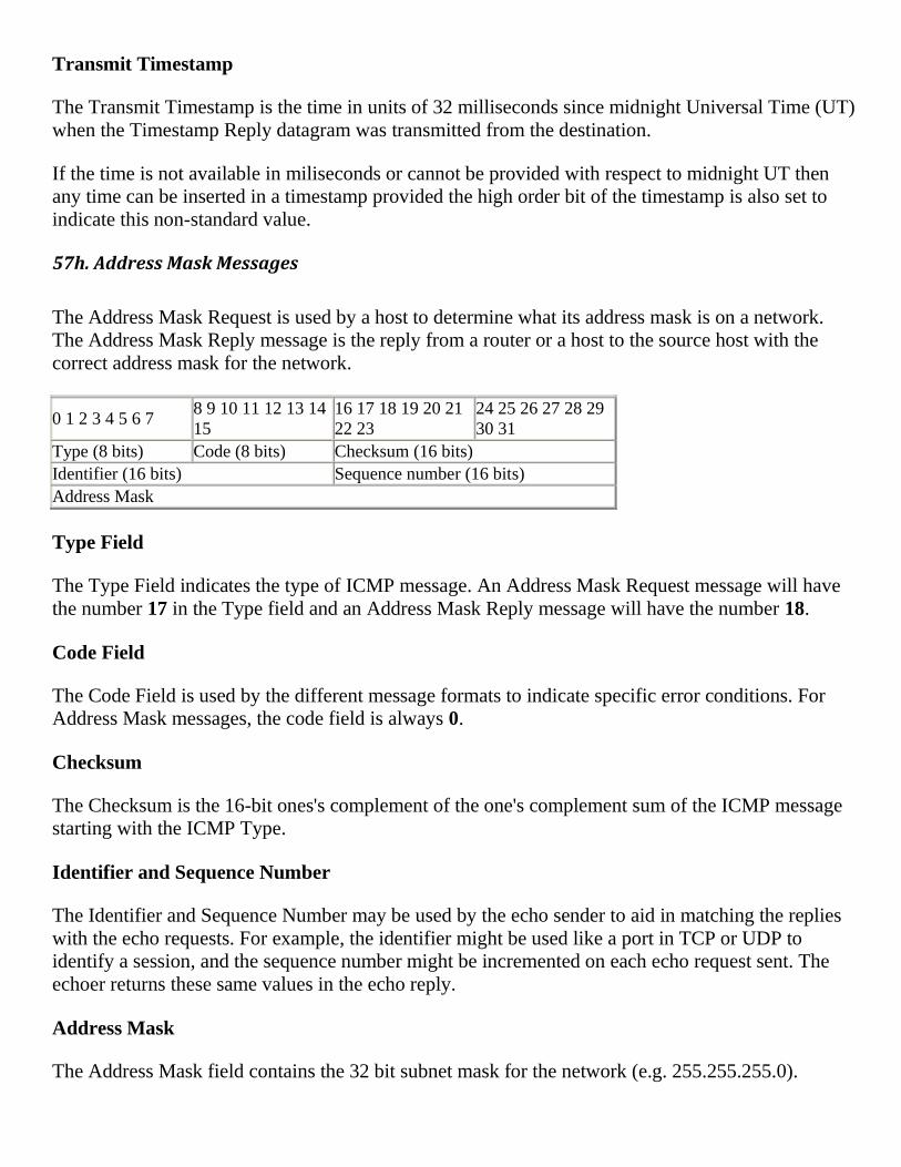
Transmit Timestamp
The Transmit Timestamp is the time in units of 32 milliseconds since midnight Universal Time (UT)
when the Timestamp Reply datagram was transmitted from the destination.
If the time is not available in miliseconds or cannot be provided with respect to midnight UT then
any time can be inserted in a timestamp provided the high order bit of the timestamp is also set to
indicate this non-standard value.
57h. Address Mask Messages
The Address Mask Request is used by a host to determine what its address mask is on a network.
The Address Mask Reply message is the reply from a router or a host to the source host with the
correct address mask for the network.
0 1 2 3 4 5 6 7 8 9 10 11 12 13 14
15
16 17 18 19 20 21
22 23
24 25 26 27 28 29
30 31
Type (8 bits) Code (8 bits) Checksum (16 bits)
Identifier (16 bits) Sequence number (16 bits)
Address Mask
Type Field
The Type Field indicates the type of ICMP message. An Address Mask Request message will have
the number 17 in the Type field and an Address Mask Reply message will have the number 18.
Code Field
The Code Field is used by the different message formats to indicate specific error conditions. For
Address Mask messages, the code field is always 0.
Checksum
The Checksum is the 16-bit ones's complement of the one's complement sum of the ICMP message
starting with the ICMP Type.
Identifier and Sequence Number
The Identifier and Sequence Number may be used by the echo sender to aid in matching the replies
with the echo requests. For example, the identifier might be used like a port in TCP or UDP to
identify a session, and the sequence number might be incremented on each echo request sent. The
echoer returns these same values in the echo reply.
Address Mask
The Address Mask field contains the 32 bit subnet mask for the network (e.g. 255.255.255.0).
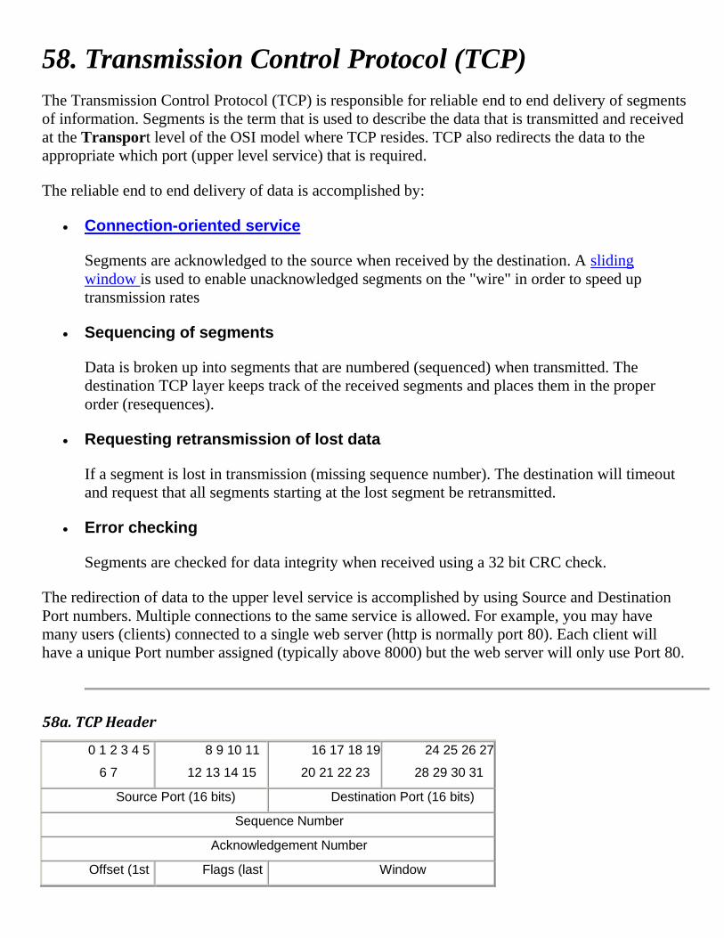
58. Transmission Control Protocol (TCP)
The Transmission Control Protocol (TCP) is responsible for reliable end to end delivery of segments
of information. Segments is the term that is used to describe the data that is transmitted and received
at the Transport level of the OSI model where TCP resides. TCP also redirects the data to the
appropriate which port (upper level service) that is required.
The reliable end to end delivery of data is accomplished by:
Connection-oriented service
Segments are acknowledged to the source when received by the destination. A sliding
window is used to enable unacknowledged segments on the "wire" in order to speed up
transmission rates
Sequencing of segments
Data is broken up into segments that are numbered (sequenced) when transmitted. The
destination TCP layer keeps track of the received segments and places them in the proper
order (resequences).
Requesting retransmission of lost data
If a segment is lost in transmission (missing sequence number). The destination will timeout
and request that all segments starting at the lost segment be retransmitted.
Error checking
Segments are checked for data integrity when received using a 32 bit CRC check.
The redirection of data to the upper level service is accomplished by using Source and Destination
Port numbers. Multiple connections to the same service is allowed. For example, you may have
many users (clients) connected to a single web server (http is normally port 80). Each client will
have a unique Port number assigned (typically above 8000) but the web server will only use Port 80.
58a. TCP Header
0 1 2 3 4 5
6 7
8 9 10 11
12 13 14 15
16 17 18 19
20 21 22 23
24 25 26 27
28 29 30 31
Source Port (16 bits) Destination Port (16 bits)
Sequence Number
Acknowledgement Number
Offset (1st Flags (last Window
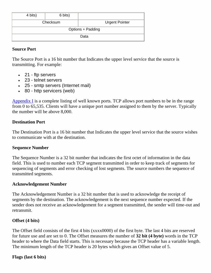
4 bits) 6 bits)
Checksum Urgent Pointer
Options + Padding
Data
Source Port
The Source Port is a 16 bit number that Indicates the upper level service that the source is
transmitting. For example:
21 - ftp servers 23 - telnet servers 25 - smtp servers (Internet mail) 80 - http servicers (web)
Appendix I is a complete listing of well known ports. TCP allows port numbers to be in the range
from 0 to 65,535. Clients will have a unique port number assigned to them by the server. Typically
the number will be above 8,000.
Destination Port
The Destination Port is a 16 bit number that Indicates the upper level service that the source wishes
to communicate with at the destination.
Sequence Number
The Sequence Number is a 32 bit number that indicates the first octet of information in the data
field. This is used to number each TCP segment transmitted in order to keep track of segments for
sequencing of segments and error checking of lost segments. The source numbers the sequence of
transmitted segments.
Acknowledgement Number
The Acknowledgement Number is a 32 bit number that is used to acknowledge the receipt of
segments by the destination. The acknowledgement is the next sequence number expected. If the
sender does not receive an acknowledgement for a segment transmitted, the sender will time-out and
retransmit.
Offset (4 bits)
The Offset field consists of the first 4 bits (xxxx0000) of the first byte. The last 4 bits are reserved
for future use and are set to 0. The Offset measures the number of 32 bit (4 byte) words in the TCP
header to where the Data field starts. This is necessary because the TCP header has a variable length.
The minimum length of the TCP header is 20 bytes which gives an Offset value of 5.
Flags (last 6 bits)
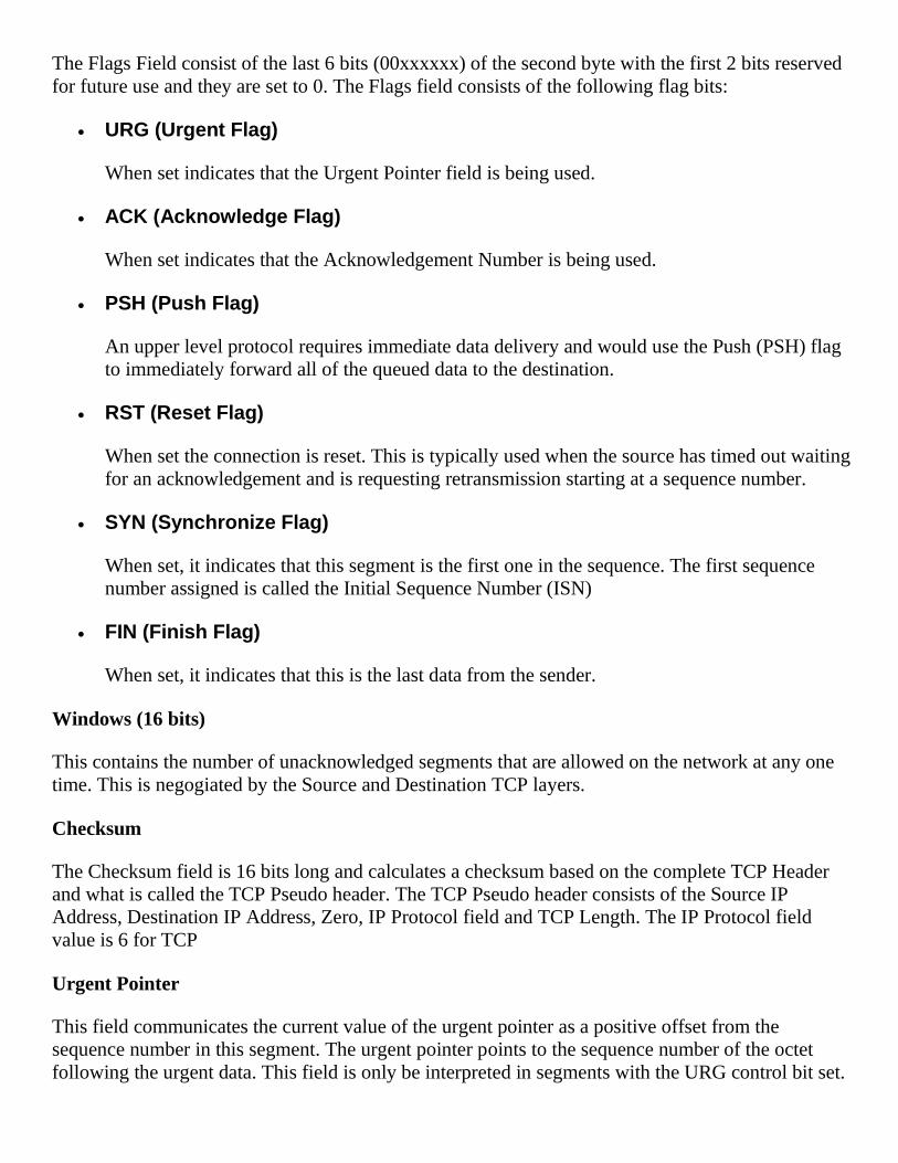
The Flags Field consist of the last 6 bits (00xxxxxx) of the second byte with the first 2 bits reserved
for future use and they are set to 0. The Flags field consists of the following flag bits:
URG (Urgent Flag)
When set indicates that the Urgent Pointer field is being used.
ACK (Acknowledge Flag)
When set indicates that the Acknowledgement Number is being used.
PSH (Push Flag)
An upper level protocol requires immediate data delivery and would use the Push (PSH) flag
to immediately forward all of the queued data to the destination.
RST (Reset Flag)
When set the connection is reset. This is typically used when the source has timed out waiting
for an acknowledgement and is requesting retransmission starting at a sequence number.
SYN (Synchronize Flag)
When set, it indicates that this segment is the first one in the sequence. The first sequence
number assigned is called the Initial Sequence Number (ISN)
FIN (Finish Flag)
When set, it indicates that this is the last data from the sender.
Windows (16 bits)
This contains the number of unacknowledged segments that are allowed on the network at any one
time. This is negogiated by the Source and Destination TCP layers.
Checksum
The Checksum field is 16 bits long and calculates a checksum based on the complete TCP Header
and what is called the TCP Pseudo header. The TCP Pseudo header consists of the Source IP
Address, Destination IP Address, Zero, IP Protocol field and TCP Length. The IP Protocol field
value is 6 for TCP
Urgent Pointer
This field communicates the current value of the urgent pointer as a positive offset from the
sequence number in this segment. The urgent pointer points to the sequence number of the octet
following the urgent data. This field is only be interpreted in segments with the URG control bit set.
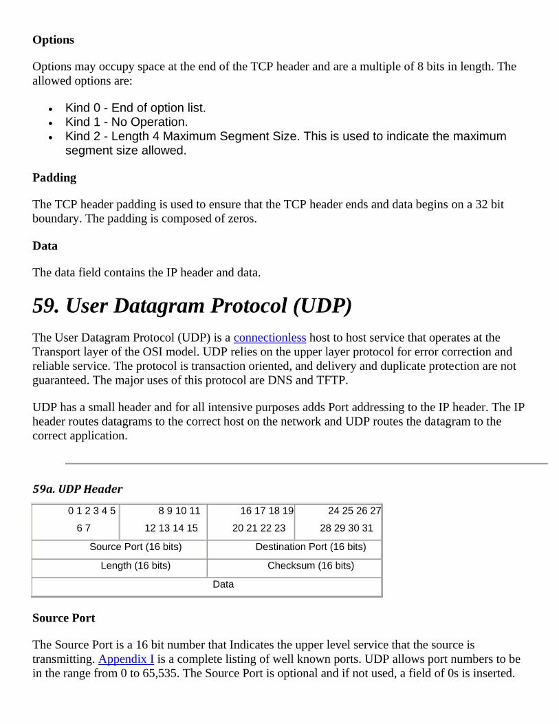
Options
Options may occupy space at the end of the TCP header and are a multiple of 8 bits in length. The
allowed options are:
Kind 0 - End of option list. Kind 1 - No Operation. Kind 2 - Length 4 Maximum Segment Size. This is used to indicate the maximum
segment size allowed.
Padding
The TCP header padding is used to ensure that the TCP header ends and data begins on a 32 bit
boundary. The padding is composed of zeros.
Data
The data field contains the IP header and data.
59. User Datagram Protocol (UDP)
The User Datagram Protocol (UDP) is a connectionless host to host service that operates at the
Transport layer of the OSI model. UDP relies on the upper layer protocol for error correction and
reliable service. The protocol is transaction oriented, and delivery and duplicate protection are not
guaranteed. The major uses of this protocol are DNS and TFTP.
UDP has a small header and for all intensive purposes adds Port addressing to the IP header. The IP
header routes datagrams to the correct host on the network and UDP routes the datagram to the
correct application.
59a. UDP Header
0 1 2 3 4 5
6 7
8 9 10 11
12 13 14 15
16 17 18 19
20 21 22 23
24 25 26 27
28 29 30 31
Source Port (16 bits) Destination Port (16 bits)
Length (16 bits) Checksum (16 bits)
Data
Source Port
The Source Port is a 16 bit number that Indicates the upper level service that the source is
transmitting. Appendix I is a complete listing of well known ports. UDP allows port numbers to be
in the range from 0 to 65,535. The Source Port is optional and if not used, a field of 0s is inserted.
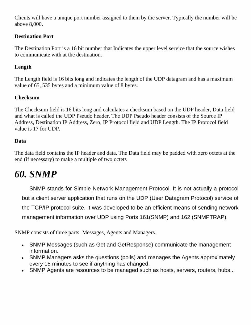
Clients will have a unique port number assigned to them by the server. Typically the number will be
above 8,000.
Destination Port
The Destination Port is a 16 bit number that Indicates the upper level service that the source wishes
to communicate with at the destination.
Length
The Length field is 16 bits long and indicates the length of the UDP datagram and has a maximum
value of 65, 535 bytes and a minimum value of 8 bytes.
Checksum
The Checksum field is 16 bits long and calculates a checksum based on the UDP header, Data field
and what is called the UDP Pseudo header. The UDP Pseudo header consists of the Source IP
Address, Destination IP Address, Zero, IP Protocol field and UDP Length. The IP Protocol field
value is 17 for UDP.
Data
The data field contains the IP header and data. The Data field may be padded with zero octets at the
end (if necessary) to make a multiple of two octets
60. SNMP
SNMP stands for Simple Network Management Protocol. It is not actually a protocol
but a client server application that runs on the UDP (User Datagram Protocol) service of
the TCP/IP protocol suite. It was developed to be an efficient means of sending network
management information over UDP using Ports 161(SNMP) and 162 (SNMPTRAP).
SNMP consists of three parts: Messages, Agents and Managers.
SNMP Messages (such as Get and GetResponse) communicate the management information.
SNMP Managers asks the questions (polls) and manages the Agents approximately every 15 minutes to see if anything has changed.
SNMP Agents are resources to be managed such as hosts, servers, routers, hubs...
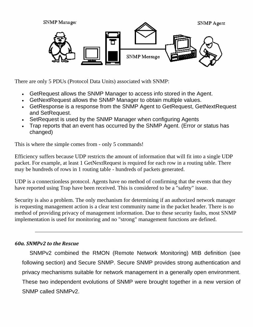
There are only 5 PDUs (Protocol Data Units) associated with SNMP:
GetRequest allows the SNMP Manager to access info stored in the Agent. GetNextRequest allows the SNMP Manager to obtain multiple values. GetResponse is a response from the SNMP Agent to GetRequest, GetNextRequest
and SetRequest. SetRequest is used by the SNMP Manager when configuring Agents Trap reports that an event has occurred by the SNMP Agent. (Error or status has
changed)
This is where the simple comes from - only 5 commands!
Efficiency suffers because UDP restricts the amount of information that will fit into a single UDP
packet. For example, at least 1 GetNextRequest is required for each row in a routing table. There
may be hundreds of rows in 1 routing table - hundreds of packets generated.
UDP is a connectionless protocol. Agents have no method of confirming that the events that they
have reported using Trap have been received. This is considered to be a "safety" issue.
Security is also a problem. The only mechanism for determining if an authorized network manager
is requesting management action is a clear text community name in the packet header. There is no
method of providing privacy of management information. Due to these security faults, most SNMP
implementation is used for monitoring and no "strong" management functions are defined.
60a. SNMPv2 to the Rescue
SNMPv2 combined the RMON (Remote Network Monitoring) MIB definition (see
following section) and Secure SNMP. Secure SNMP provides strong authentication and
privacy mechanisms suitable for network management in a generally open environment.
These two independent evolutions of SNMP were brought together in a new version of
SNMP called SNMPv2.
In addition, SNMPv2 was extended to address the concerns over protocol efficiency and safety
(acknowledgements of Trap). Two new protocol functions (PDUs) were added (GetBulk and Inform
Request) to allow efficient reading of tables and provide reliable communications.
NOTE: SNMPv1 and SNMPv2 do not interoperate. The two versions must be translated to
communicate with each other.
60b. MIB - Management Information Base
SNMP also consists of an extensible Management Information Base (MIB) that runs
on each agent's workstation. Each MIB contains the configuration data for that device.
The MIB structure is defined by the Structure of Management Information (SMI)
language.
Basically the MIB details what information is stored for any specific type of agent, how it is stored
and how storage is to be structured.
60c. RMON - Remote Network Monitoring
RMON is a MIB definition that provides for remote network monitoring and manager
to manager communications. This standard defines the information that a device must
collect to provide an accurate picture of a network's health. The information that the
RMON MIB provides is divided into the following 9 groups:
1. Segment Statistics: Statistics on the attached segment: packets, octets, collisions...
2. History: Data collected by the statistics group for future retrieval and analysis 3. Alarms: Thresholds can be set for certain alarm condition. (Collisions/sec) 4. Events: Thresholds can be set for certain event conditions to trigger certain
activities. 5. Host: Statistics can be gathered on individual nodes or hosts on the LAN. 6. Host Top N: Statistics can be gathered on individual nodes over a user-specified
time. 7. Traffic Matrix: Shows the amount of traffic and number of errors between any host
pair. 8. Packet Capture: Allows capturing of entire packets or individual slices indicating
protocols used. 9. Filters: The filter group specifies the criteria that the packet is going to be captured
by.
SNMP allows you to monitor and control a TCP/IP Network using SNMP Managers. All nodes
(Agents) on a network, regardless of whether they are SNMP compliant, should show up on the
Network map. The SNMP non-compliant nodes typically show up as being present but not
accessible.
SNMP Compliant nodes allow information to be displayed that indicates how the node is
configured. Machine Type, Ethernet Address, DOS Ver, IP Address, Name, etc...
61. Handy Unix Network Troubleshooting Commands
The following network troubleshooting commands will vary slightly in syntax depending on which
operating system is used. Some operating systems will provide more options and some less. Please
use the following information as a guide and the syntax presented with "a grain of salt".
arp
Use this command to see the IP to MAC address translation table if you are having problems
connecting to other network hosts. It is a dynamic cache which updates every 120 seconds. ARP
stands forAddress Resolution Protocol (ARP).
arp - a
address resolution protocol
host name (IP address) at (ethernet address)
ping
The ping command is the most versatile network troubleshooting command in Unix. Use it to verify
that your TCP/IP network services are operating correctly. The ping command allows you to
determine that the:
TCP/IP stack is configured properly
Network interface card is configured properly
Default gateway and subnet mask is configured properly
Domain name services is configured properly.
The following is a step by step guide in determining if your network stack is configured properly:
i. ping 127.0.0.1
Checks that your TCP/IP stack is working properly up to the network interface card (NIC). If
this fails, check to see if you have TCP/IP services loaded.
ii. ping "IP address of default gateway"
Checks that the network interface card is working on the local subnet by pinging the local
side of the default gateway which is a router. If this fails, check that TCP/IP is bound to the
NIC. Then check that the NIC's IRQ, and base address are set properlyboth on the card itself
and in the operating system's interface configuration.
iii. ping "IP address across the gateway"
Checks that the default gateway is correctly identified in the TCP/IP configuration and that
the proper subnet mask is configured. The IP address selected must not be on the local
subnet.
iv. ping "domain name"
Checks that the domain name services (DNS) is correctly configured in the TCP/IP stack. A
domain name is a name like www.yahoo.com. If it fails, check that the DNS server's IP
address is entered in properly in the TCP/IP configuration.
netstat
The network status command netstat displays status information about the network interfaces on the
host machine and it can display routing table information.
i. Local interface status ii. netstat -ain
iii.
iv. a - all interfaces are displayed
v. i - displays configuration
vi. n - IP addresses (!n - host names)
vii.
viii. example output:
ix.
x. Name MTU Net/dest address Ierrs Opkts Collis Queue
xi. le0 1500 (net IP addr) (local IP) . .. ... ....
xii. Routing table information xiii. netstat -r (-nr or rn gives ip addresses)
xiv.
xv. Routing Table
xvi. Destination Gateway Flags Interface
xvii. (net or host) (IP address) UHGD (name)
xviii.
xix. U - up H - host G - gateway D- discovered using ICMP Req
xx.
ifconfig
The ifconfig command is used to display the local interface configuration (winipcfg for Windows)
and to modify the configuration. Local interfaces can be Ethernet network cards, modems, etc..
ifconfig (interface name) (down/up/nothing) nothing gives status
(interface name): flags - 63 (up, broadcast, notra, Running)
inet (ip address) netmask FFFFFF00 broadcast 128.6.7.255
route
The route command allows you to add static routes to the routing tabling.
route (-n) (add/delete/nothing) (dest IP address/subnet/DEFAULT) (local IP address) (hop)
traceroute (tracert in Windows)
Traceroute displays the routers that are passed through to reach the destination.
traceroute "IP address or domain name"
Tracing route to www.apllejcok.com [192.168.1.64]
over a maximum of 30 hops:
1 116 ms 134 ms 112 ms ts10.dshark.com [192.168.128.20]
2 124 ms 112 ms 114 ms bl1.poufe.com [192.168.130.1]
3 122 ms 118 ms 117 ms fifo.amalag.com [192.168.64.2]
4 130 ms 156 ms 132 ms dfg.apllejcok.com [192.168.1.1]
62. X.25
X.25 is an analog packet switching network. It can be considered Slow Packet Switching. The
transfer speeds are typically 56 kbps to 2.08 Mbps. There is a world-wide set of Public X.25
Networks and it is possible for an organization to have its own private X.25 network.
X.25 is over 20 years old and an established technology. There are many multi-vendor solutions and
dissimilar technologies in an organization are allowed to access the X.25 network. In Canada, the
main X.25 network is called Datapac which is a public offering of X.25. You pay either a flat rate or
by the packet.
X.25 is used to connect LANs together. Due to its slow transfer speed, it is used for:
Host terminal emulations: low data
Client/Server applications such as E-mail: small files, bandwidth
File Server: large amount of data & real-time traffic (doesn't work well)
Databases: usually large databases but queries are small inbound and medium size outbound.
X.25 has a high protocol overhead compared to other networks. This reduces the transfer speed and
bandwidth utilization - means its not as efficient.
Overhead Example:
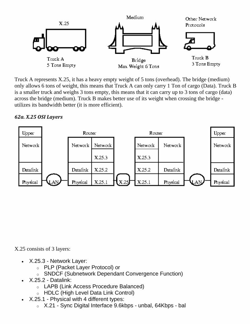
Truck A represents X.25, it has a heavy empty weight of 5 tons (overhead). The bridge (medium)
only allows 6 tons of weight, this means that Truck A can only carry 1 Ton of cargo (Data). Truck B
is a smaller truck and weighs 3 tons empty, this means that it can carry up to 3 tons of cargo (data)
across the bridge (medium). Truck B makes better use of its weight when crossing the bridge -
utilizes its bandwidth better (it is more efficient).
62a. X.25 OSI Layers
X.25 consists of 3 layers:
X.25.3 - Network Layer: o PLP (Packet Layer Protocol) or o SNDCF (Subnetwork Dependant Convergence Function)
X.25.2 - Datalink: o LAPB (Link Access Procedure Balanced) o HDLC (High Level Data Link Control)
X.25.1 - Physical with 4 different types: o X.21 - Sync Digital Interface 9.6kbps - unbal, 64Kbps - bal
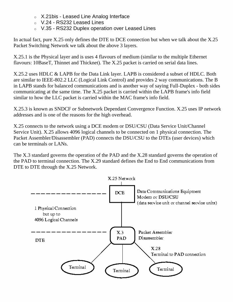
o X.21bis - Leased Line Analog Interface o V.24 - RS232 Leased Lines o V.35 - RS232 Duplex operation over Leased Lines
In actual fact, pure X.25 only defines the DTE to DCE connection but when we talk about the X.25
Packet Switching Network we talk about the above 3 layers.
X.25.1 is the Physical layer and is uses 4 flavours of medium (similar to the multiple Ethernet
flavours: 10BaseT, Thinnet and Thicknet). The X.25 packet is carried on serial data lines.
X.25.2 uses HDLC & LAPB for the Data Link layer. LAPB is considered a subset of HDLC. Both
are similar to IEEE-802.2 LLC (Logical Link Control) and provides 2 way communications. The B
in LAPB stands for balanced communications and is another way of saying Full-Duplex - both sides
communicating at the same time. The X.25 packet is carried within the LAPB frame's info field
similar to how the LLC packet is carried within the MAC frame's info field.
X.25.3 is known as SNDCF or Subnetwork Dependant Convergence Function. X.25 uses IP network
addresses and is one of the reasons for the high overhead.
X.25 connects to the network using a DCE modem or DSU/CSU (Data Service Unit/Channel
Service Unit). X.25 allows 4096 logical channels to be connected on 1 physical connection. The
Packet Assembler/Disassembler (PAD) connects the DSU/CSU to the DTEs (user devices) which
can be terminals or LANs.
The X.3 standard governs the operation of the PAD and the X.28 standard governs the operation of
the PAD to terminal connection. The X.29 standard defines the End to End communications from
DTE to DTE through the X.25 Network.

62b. X.25 High overhead
X.25 has a high overhead because it provides extensive error checking. Each device
in the X.25 network acknowledges every packet sent. This slows down the transfer of
information and uses up available bandwidth. When X.25 was first introduced, the
quality of the analog phone lines required this extensive error checking but now with
digital lines available it is not necessary.
There are 2 types of connections used with X.25:
PVC - Permanent Virtual Circuits: These are leased lines and require no call connect/disconnect
VC - Virtual Circuits: These are like dial-up lines (switched circuits). They require a call connect/disconnect procedure and end to end communication through the network.
VC (virtual circuits) have handshaking very similar to how modems connect as covered earlier. X.25
is often used because an X.25 network is considered 1 Hop.
Normal Routing (Non X.25)
Between San Francisco to Boston
Dashed Route takes 5 hops (Salt Lake City, Denver, Chicago, Detroit, Boston)
Dotted Route takes 8 hops (Los Angeles, El Paso, Houston, New Orleans, Alanta, Washington, New
York, Boston)
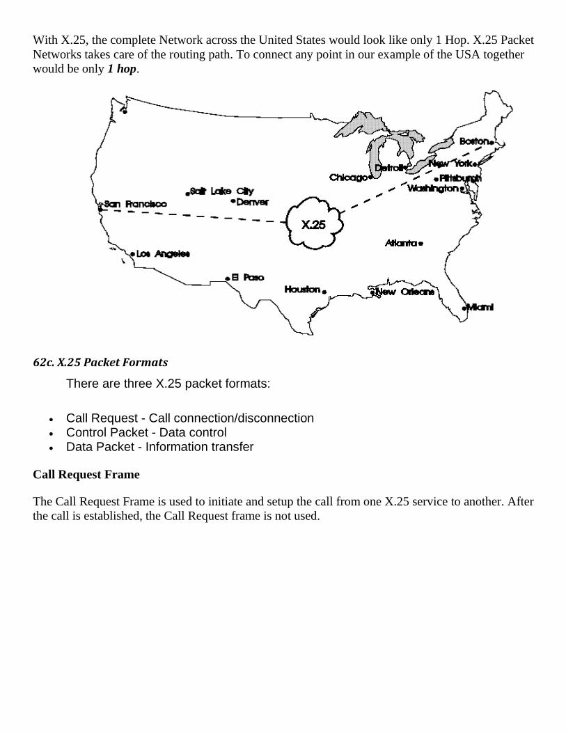
With X.25, the complete Network across the United States would look like only 1 Hop. X.25 Packet
Networks takes care of the routing path. To connect any point in our example of the USA together
would be only 1 hop.
62c. X.25 Packet Formats
There are three X.25 packet formats:
Call Request - Call connection/disconnection
Control Packet - Data control Data Packet - Information transfer
Call Request Frame
The Call Request Frame is used to initiate and setup the call from one X.25 service to another. After
the call is established, the Call Request frame is not used.
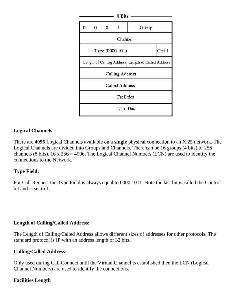
Logical Channels
There are 4096 Logical Channels available on a single physical connection to an X.25 network. The
Logical Channels are divided into Groups and Channels. There can be 16 groups (4 bits) of 256
channels (8 bits). 16 x 256 = 4096. The Logical Channel Numbers (LCN) are used to identify the
connections to the Network.
Type Field:
For Call Request the Type Field is always equal to 0000 1011. Note the last bit is called the Control
bit and is set to 1.
Length of Calling/Called Address:
The Length of Calling/Called Address allows different sizes of addresses for other protocols. The
standard protocol is IP with an address length of 32 bits.
Calling/Called Address:
Only used during Call Connect until the Virtual Channel is established then the LCN (Logical
Channel Numbers) are used to identify the connections.
Facilities Length

Indicates the length of the Facilities Field
Facilities Field
Indicates the types of facilities available. Facilities depend on the Network provider and can include
information such as Charges or Call Forwarding.
Once a Call is established, The Calling/Called Addresses and Facilities Fields are not required and
the Control Packet Format and Data Packet are used.
Control Frame
The Control Frame is used to control the communications during the call.
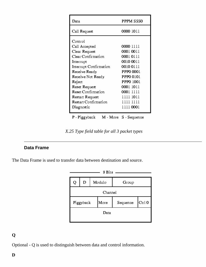
X.25 Type field table for all 3 packet types
Data Frame
The Data Frame is used to transfer data between destination and source.
Q
Optional - Q is used to distinguish between data and control information.
D
D controls the type of Acknowledgment:
0 - Network Control: DTE to DCE 1 - End to End Acknowledgement: DTE to DTE
Modulo
It is used by the sliding window. The modulo allows multiple unacknowledged packets on the
network for faster response. The modulo can be Modulo 8 or Modulo 128 (127 packets out on the
network)
Piggyback
The Piggyback field is used for Acknowledgement with the Modulus (sliding window)
Sequence
The Sequence field holds a unique packet number which identifies the packet.
More
The More field indicates that more data is coming.
63. Frame Relay
Packet Switching was developed as a method of multiplexing packets across the phone systems.
The term Bandwidth on Demand arises when using X.25 and Frame Relay. Both use packet
switching which is a fancy way of saying that the packets are multiplexed on a common line. LAN
traffic tends to be very bursty - periods of inactivity then large fast bursts of data. This is a very
inefficient use of bandwidth if a large proportion of the time the line is idle. By using statistical
multiplexing, bandwidth is used only when required hence the term Bandwidth on Demand.
Frame Relay is very similar to X.25. In fact Frame Relay was developed to improve on X.25's
shortcomings: (slow speed and large overhead). Frame Relay was improved over X.25 by the
following:
Decreased Protocol Overhead Digital Switching Increased bandwidth to 2 Mbps+ Voice over data
63a. Decreased Protocol Overhead
Frame Relay works on the Data Link and Physical layers:
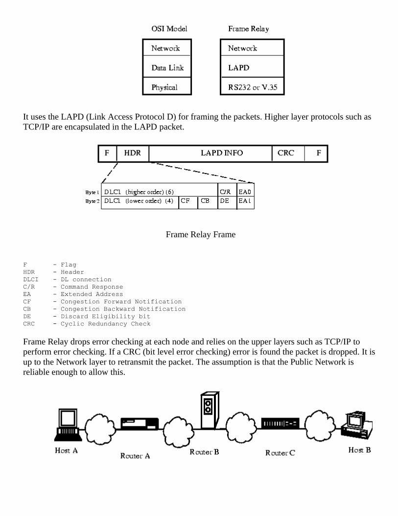
It uses the LAPD (Link Access Protocol D) for framing the packets. Higher layer protocols such as
TCP/IP are encapsulated in the LAPD packet.
Frame Relay Frame
F - Flag
HDR - Header
DLCI - DL connection
C/R - Command Response
EA - Extended Address
CF - Congestion Forward Notification
CB - Congestion Backward Notification
DE - Discard Eligibility bit
CRC - Cyclic Redundancy Check
Frame Relay drops error checking at each node and relies on the upper layers such as TCP/IP to
perform error checking. If a CRC (bit level error checking) error is found the packet is dropped. It is
up to the Network layer to retransmit the packet. The assumption is that the Public Network is
reliable enough to allow this.
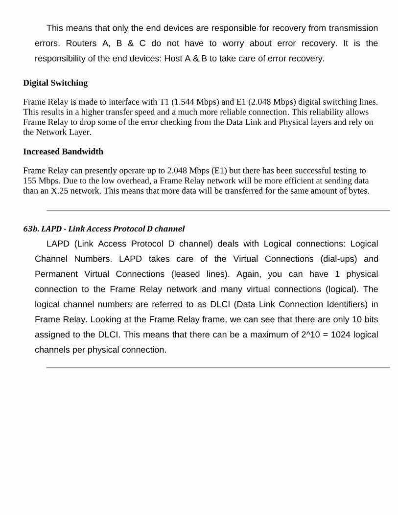
This means that only the end devices are responsible for recovery from transmission
errors. Routers A, B & C do not have to worry about error recovery. It is the
responsibility of the end devices: Host A & B to take care of error recovery.
Digital Switching
Frame Relay is made to interface with T1 (1.544 Mbps) and E1 (2.048 Mbps) digital switching lines.
This results in a higher transfer speed and a much more reliable connection. This reliability allows
Frame Relay to drop some of the error checking from the Data Link and Physical layers and rely on
the Network Layer.
Increased Bandwidth
Frame Relay can presently operate up to 2.048 Mbps (E1) but there has been successful testing to
155 Mbps. Due to the low overhead, a Frame Relay network will be more efficient at sending data
than an X.25 network. This means that more data will be transferred for the same amount of bytes.
63b. LAPD - Link Access Protocol D channel
LAPD (Link Access Protocol D channel) deals with Logical connections: Logical
Channel Numbers. LAPD takes care of the Virtual Connections (dial-ups) and
Permanent Virtual Connections (leased lines). Again, you can have 1 physical
connection to the Frame Relay network and many virtual connections (logical). The
logical channel numbers are referred to as DLCI (Data Link Connection Identifiers) in
Frame Relay. Looking at the Frame Relay frame, we can see that there are only 10 bits
assigned to the DLCI. This means that there can be a maximum of 2^10 = 1024 logical
channels per physical connection.
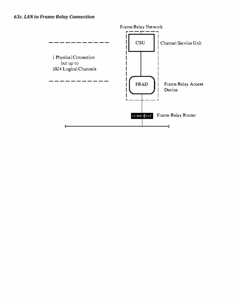
63c. LAN to Frame Relay Connection
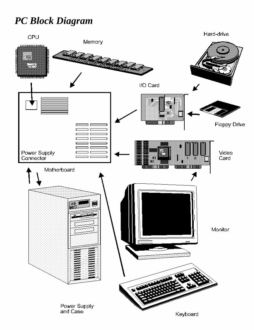
PC Block Diagram
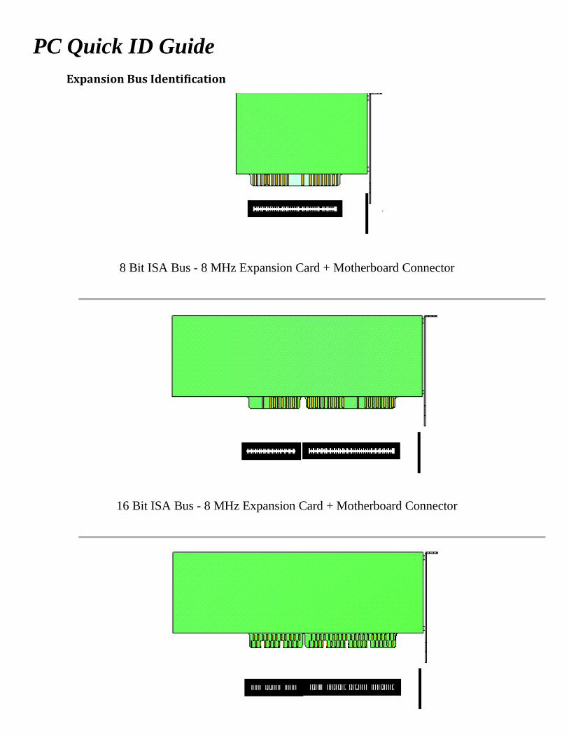
PC Quick ID Guide
Expansion Bus Identification
8 Bit ISA Bus - 8 MHz Expansion Card + Motherboard Connector
16 Bit ISA Bus - 8 MHz Expansion Card + Motherboard Connector

32 Bit EISA Bus - 8 MHz Expansion Card + Motherboard Connector
(has two rows of connectors)
VESA Local Bus 32 Bit 33 MHz Expansion Card + Motherboard Connector
PCI Bus 32 Bit 66 MHz Expansion Card + Motherboard Connector
(has opposite offset from all other cards in relation to card slot openning)
CPU Identification
On the CPU will be a part number such as 80386SX-20
80386 indicates a 386 processor
SX indicates subcategory of the processor
20 indicates the processors speed in MHz
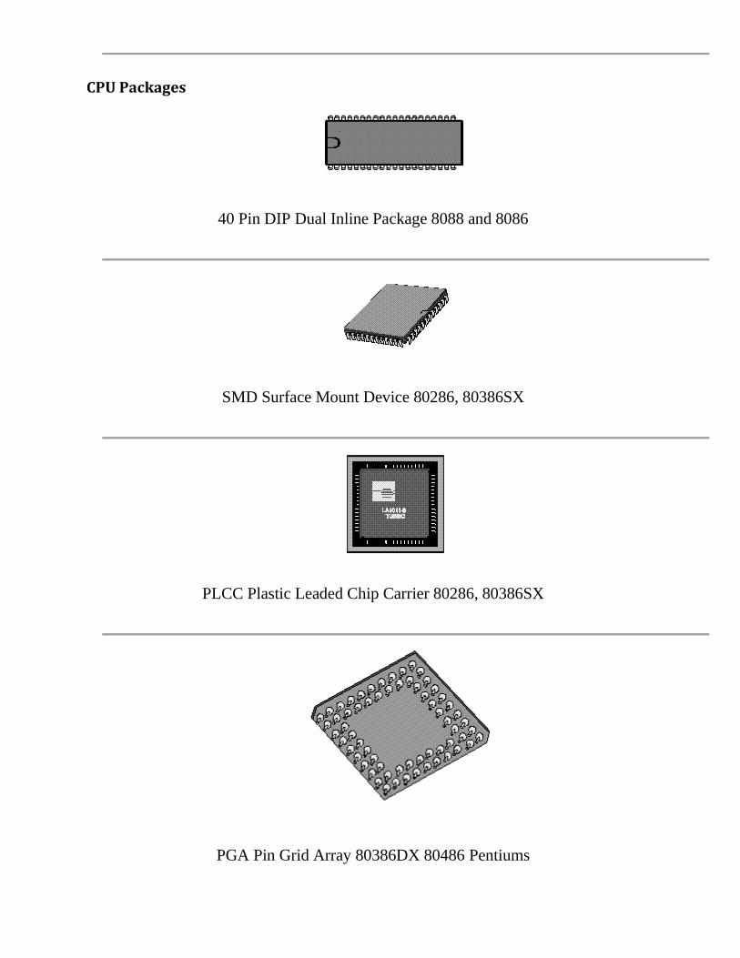
CPU Packages
40 Pin DIP Dual Inline Package 8088 and 8086
SMD Surface Mount Device 80286, 80386SX
PLCC Plastic Leaded Chip Carrier 80286, 80386SX
PGA Pin Grid Array 80386DX 80486 Pentiums
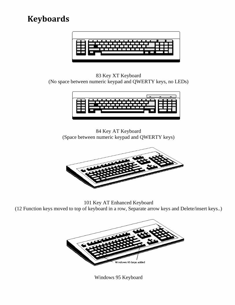
Keyboards
83 Key XT Keyboard
(No space between numeric keypad and QWERTY keys, no LEDs)
84 Key AT Keyboard
(Space between numeric keypad and QWERTY keys)
101 Key AT Enhanced Keyboard
(12 Function keys moved to top of keyboard in a row, Separate arrow keys and Delete/insert keys..)
Windows 95 Keyboard
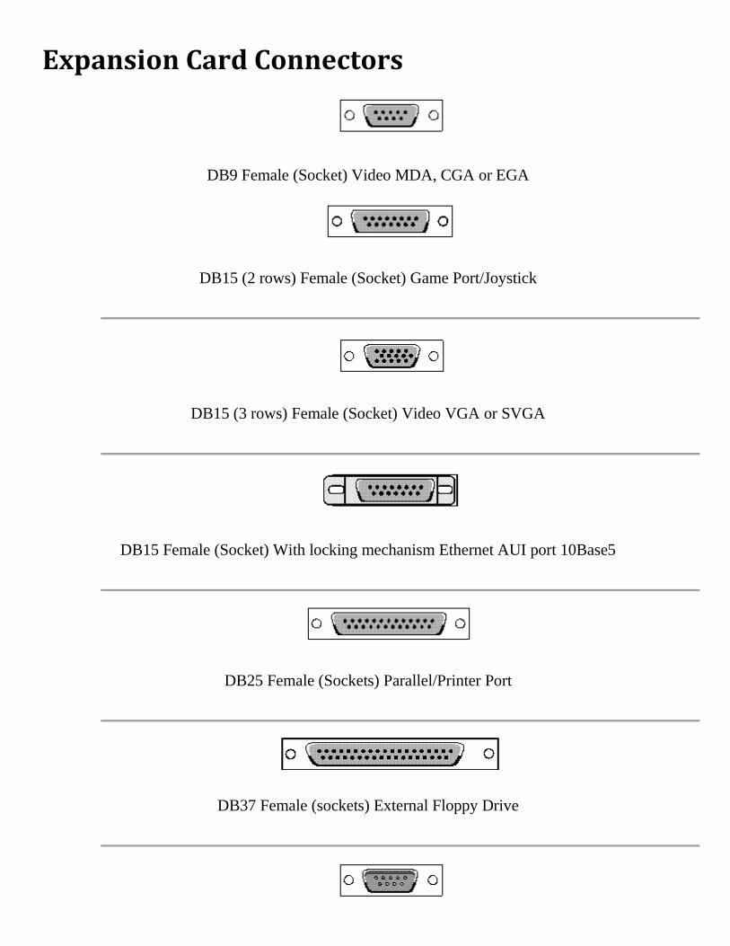
Expansion Card Connectors
DB9 Female (Socket) Video MDA, CGA or EGA
DB15 (2 rows) Female (Socket) Game Port/Joystick
DB15 (3 rows) Female (Socket) Video VGA or SVGA
DB15 Female (Socket) With locking mechanism Ethernet AUI port 10Base5
DB25 Female (Sockets) Parallel/Printer Port
DB37 Female (sockets) External Floppy Drive
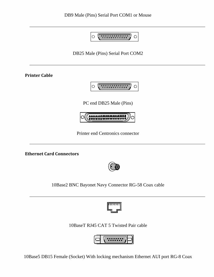
DB9 Male (Pins) Serial Port COM1 or Mouse
DB25 Male (Pins) Serial Port COM2
Printer Cable
PC end DB25 Male (Pins)
Printer end Centronics connector
Ethernet Card Connectors
10Base2 BNC Bayonet Navy Connector RG-58 Coax cable
10BaseT RJ45 CAT 5 Twisted Pair cable
10Base5 DB15 Female (Socket) With locking mechanism Ethernet AUI port RG-8 Coax

Video Monitors
MDA - Monochrome Display Adapter (TTL), DB9 Male Connector or RCA Jack 9", Green or
Yellow phosphour
CGA - Color Graphics Adapter, DB9 Male Connector, Monitor should say "Color" or "RGB"
EGA - Enhanced Graphics Adapter, DB9 Male Connector, Monitor should say "EGA"
VGA or SVGA - Video Graphics Array or Super Video Graphics Array, DB15 Male Connector
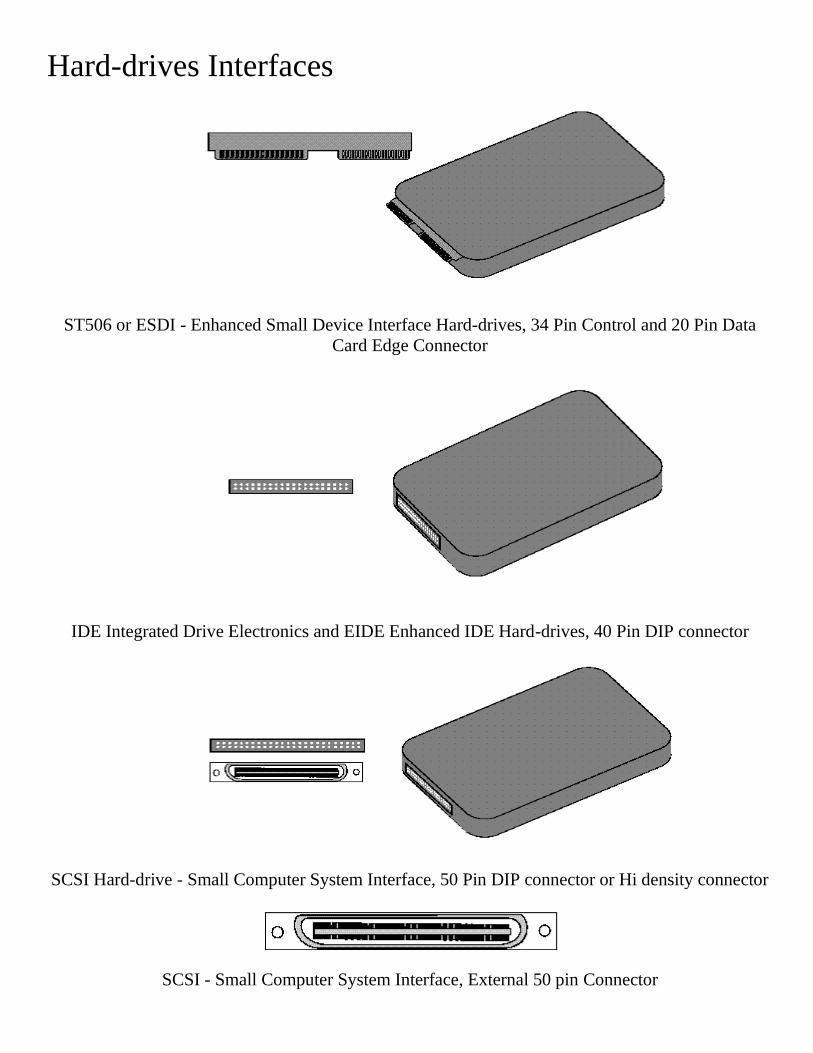
Hard-drives Interfaces
ST506 or ESDI - Enhanced Small Device Interface Hard-drives, 34 Pin Control and 20 Pin Data
Card Edge Connector
IDE Integrated Drive Electronics and EIDE Enhanced IDE Hard-drives, 40 Pin DIP connector
SCSI Hard-drive - Small Computer System Interface, 50 Pin DIP connector or Hi density connector
SCSI - Small Computer System Interface, External 50 pin Connector
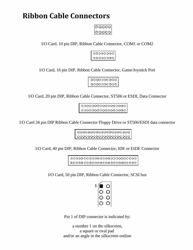
Ribbon Cable Connectors
I/O Card, 10 pin DIP, Ribbon Cable Connector, COM1 or COM2
I/O Card, 16 pin DIP, Ribbon Cable Connector, Game/Joystick Port
I/O Card, 20 pin DIP, Ribbon Cable Connector, ST506 or ESDI, Data Connector
I/O Card 34 pin DIP Ribbon Cable Connector Floppy Drive or ST506/ESDI data connector
I/O Card, 40 pin DIP, Ribbon Cable Connector, IDE or EIDE Connector
I/O Card, 50 pin DIP, Ribbon Cable Connector, SCSI bus
Pin 1 of DIP connector is indicated by:
a number 1 on the silkscreen,
a square or oval pad
and/or an angle in the silkscreen outline
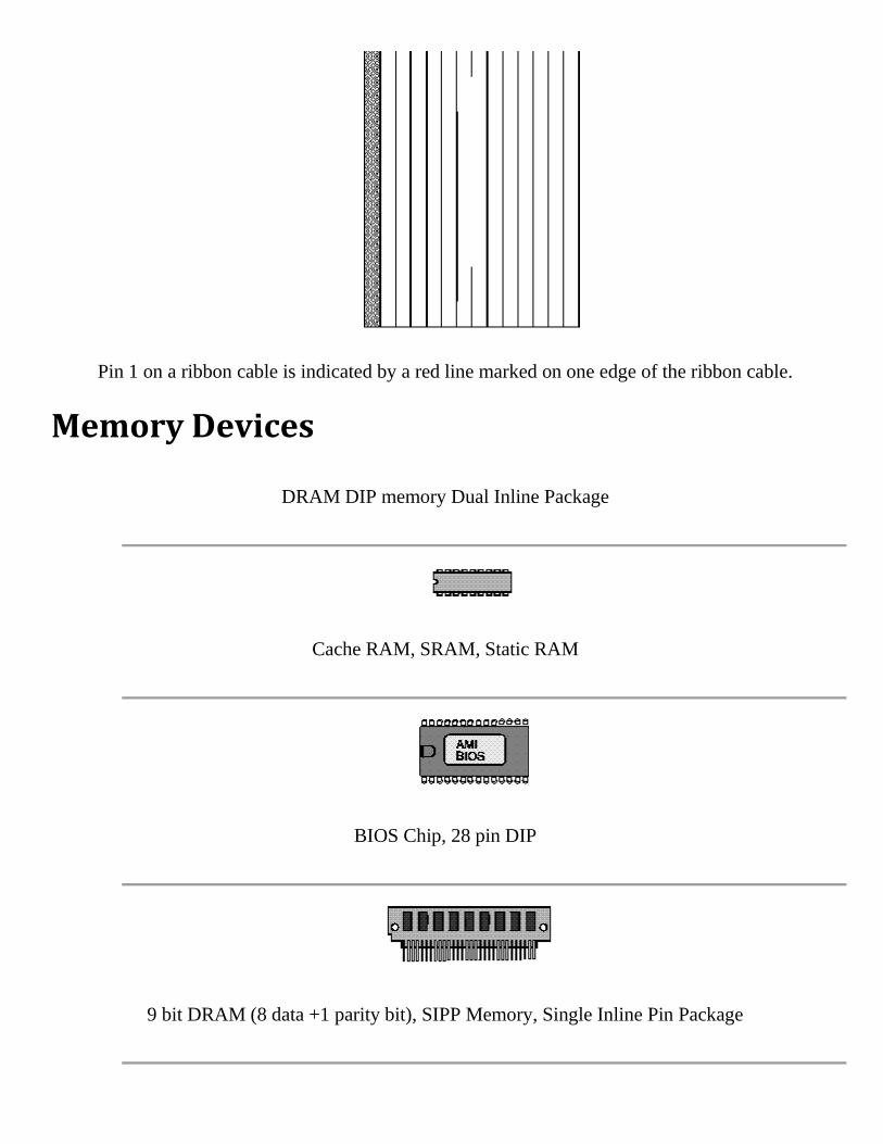
Pin 1 on a ribbon cable is indicated by a red line marked on one edge of the ribbon cable.
Memory Devices
DRAM DIP memory Dual Inline Package
Cache RAM, SRAM, Static RAM
BIOS Chip, 28 pin DIP
9 bit DRAM (8 data +1 parity bit), SIPP Memory, Single Inline Pin Package

9 bit DRAM (8 data +1 parity bit), 30 pin SIMM Memory, Single Inline Memory Module, 9th chip
is parity bit
8 bit DRAM (8 data bits), 30 pin SIMM Memory, Single Inline Memory Module, 9th chip (parity
bit) is missing
32 bit DRAM, 72 pin SIMM Memory, Single Inline Memory Module
Floppy Drive Cable
Controller 34 pin connector, drive B: then a twist in cable and drive A:
Floppies can use edge connector or 34 pin dual row connector
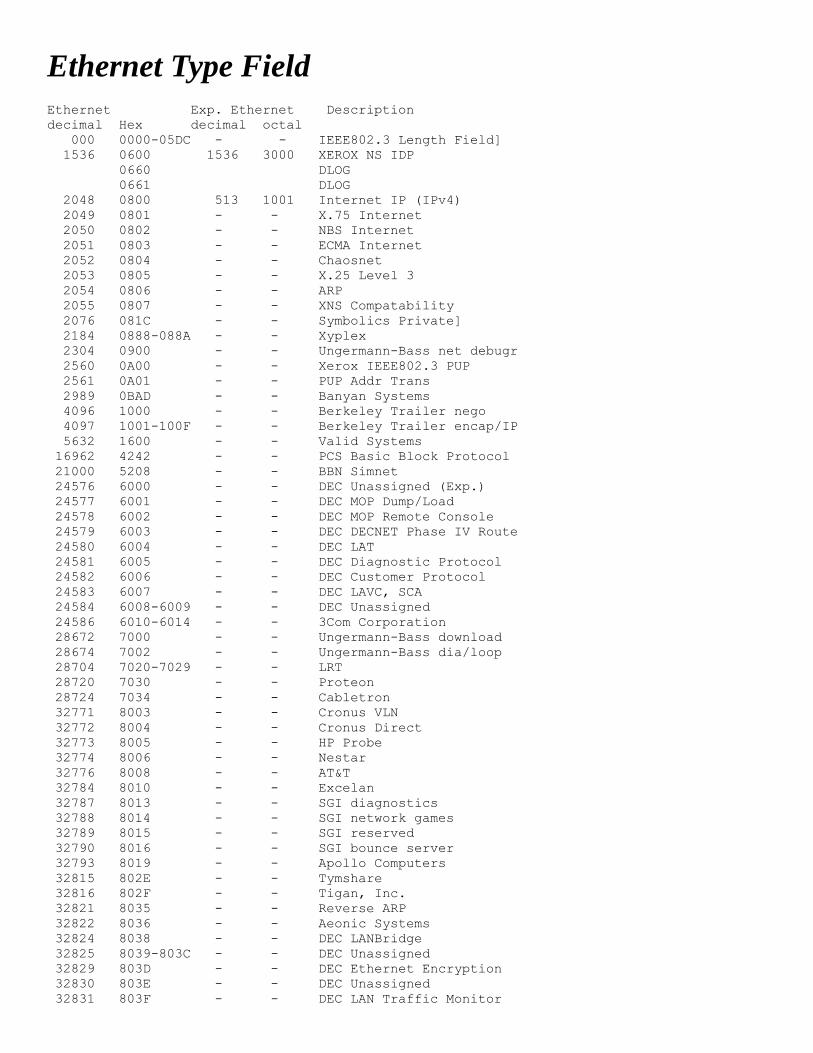
Ethernet Type Field
Ethernet Exp. Ethernet Description
decimal Hex decimal octal
000 0000-05DC - - IEEE802.3 Length Field]
1536 0600 1536 3000 XEROX NS IDP
0660 DLOG
0661 DLOG
2048 0800 513 1001 Internet IP (IPv4)
2049 0801 - - X.75 Internet
2050 0802 - - NBS Internet
2051 0803 - - ECMA Internet
2052 0804 - - Chaosnet
2053 0805 - - X.25 Level 3
2054 0806 - - ARP
2055 0807 - - XNS Compatability
2076 081C - - Symbolics Private]
2184 0888-088A - - Xyplex
2304 0900 - - Ungermann-Bass net debugr
2560 0A00 - - Xerox IEEE802.3 PUP
2561 0A01 - - PUP Addr Trans
2989 0BAD - - Banyan Systems
4096 1000 - - Berkeley Trailer nego
4097 1001-100F - - Berkeley Trailer encap/IP
5632 1600 - - Valid Systems
16962 4242 - - PCS Basic Block Protocol
21000 5208 - - BBN Simnet
24576 6000 - - DEC Unassigned (Exp.)
24577 6001 - - DEC MOP Dump/Load
24578 6002 - - DEC MOP Remote Console
24579 6003 - - DEC DECNET Phase IV Route
24580 6004 - - DEC LAT
24581 6005 - - DEC Diagnostic Protocol
24582 6006 - - DEC Customer Protocol
24583 6007 - - DEC LAVC, SCA
24584 6008-6009 - - DEC Unassigned
24586 6010-6014 - - 3Com Corporation
28672 7000 - - Ungermann-Bass download
28674 7002 - - Ungermann-Bass dia/loop
28704 7020-7029 - - LRT
28720 7030 - - Proteon
28724 7034 - - Cabletron
32771 8003 - - Cronus VLN
32772 8004 - - Cronus Direct
32773 8005 - - HP Probe
32774 8006 - - Nestar
32776 8008 - - AT&T
32784 8010 - - Excelan
32787 8013 - - SGI diagnostics
32788 8014 - - SGI network games
32789 8015 - - SGI reserved
32790 8016 - - SGI bounce server
32793 8019 - - Apollo Computers
32815 802E - - Tymshare
32816 802F - - Tigan, Inc.
32821 8035 - - Reverse ARP
32822 8036 - - Aeonic Systems
32824 8038 - - DEC LANBridge
32825 8039-803C - - DEC Unassigned
32829 803D - - DEC Ethernet Encryption
32830 803E - - DEC Unassigned
32831 803F - - DEC LAN Traffic Monitor
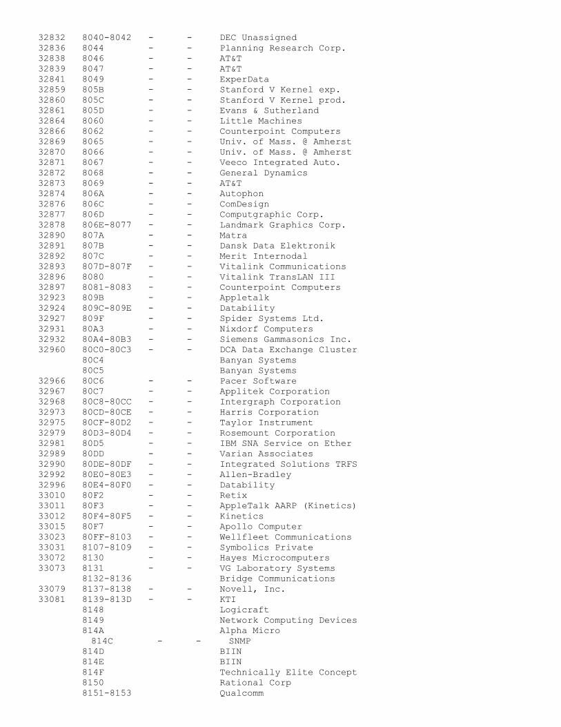
32832 8040-8042 - - DEC Unassigned
32836 8044 - - Planning Research Corp.
32838 8046 - - AT&T
32839 8047 - - AT&T
32841 8049 - - ExperData
32859 805B - - Stanford V Kernel exp.
32860 805C - - Stanford V Kernel prod.
32861 805D - - Evans & Sutherland
32864 8060 - - Little Machines
32866 8062 - - Counterpoint Computers
32869 8065 - - Univ. of Mass. @ Amherst
32870 8066 - - Univ. of Mass. @ Amherst
32871 8067 - - Veeco Integrated Auto.
32872 8068 - - General Dynamics
32873 8069 - - AT&T
32874 806A - - Autophon
32876 806C - - ComDesign
32877 806D - - Computgraphic Corp.
32878 806E-8077 - - Landmark Graphics Corp.
32890 807A - - Matra
32891 807B - - Dansk Data Elektronik
32892 807C - - Merit Internodal
32893 807D-807F - - Vitalink Communications
32896 8080 - - Vitalink TransLAN III
32897 8081-8083 - - Counterpoint Computers
32923 809B - - Appletalk
32924 809C-809E - - Datability
32927 809F - - Spider Systems Ltd.
32931 80A3 - - Nixdorf Computers
32932 80A4-80B3 - - Siemens Gammasonics Inc.
32960 80C0-80C3 - - DCA Data Exchange Cluster
80C4 Banyan Systems
80C5 Banyan Systems
32966 80C6 - - Pacer Software
32967 80C7 - - Applitek Corporation
32968 80C8-80CC - - Intergraph Corporation
32973 80CD-80CE - - Harris Corporation
32975 80CF-80D2 - - Taylor Instrument
32979 80D3-80D4 - - Rosemount Corporation
32981 80D5 - - IBM SNA Service on Ether
32989 80DD - - Varian Associates
32990 80DE-80DF - - Integrated Solutions TRFS
32992 80E0-80E3 - - Allen-Bradley
32996 80E4-80F0 - - Datability
33010 80F2 - - Retix
33011 80F3 - - AppleTalk AARP (Kinetics)
33012 80F4-80F5 - - Kinetics
33015 80F7 - - Apollo Computer
33023 80FF-8103 - - Wellfleet Communications
33031 8107-8109 - - Symbolics Private
33072 8130 - - Hayes Microcomputers
33073 8131 - - VG Laboratory Systems
8132-8136 Bridge Communications
33079 8137-8138 - - Novell, Inc.
33081 8139-813D - - KTI
8148 Logicraft
8149 Network Computing Devices
814A Alpha Micro
814C - - SNMP
814D BIIN
814E BIIN
814F Technically Elite Concept
8150 Rational Corp
8151-8153 Qualcomm
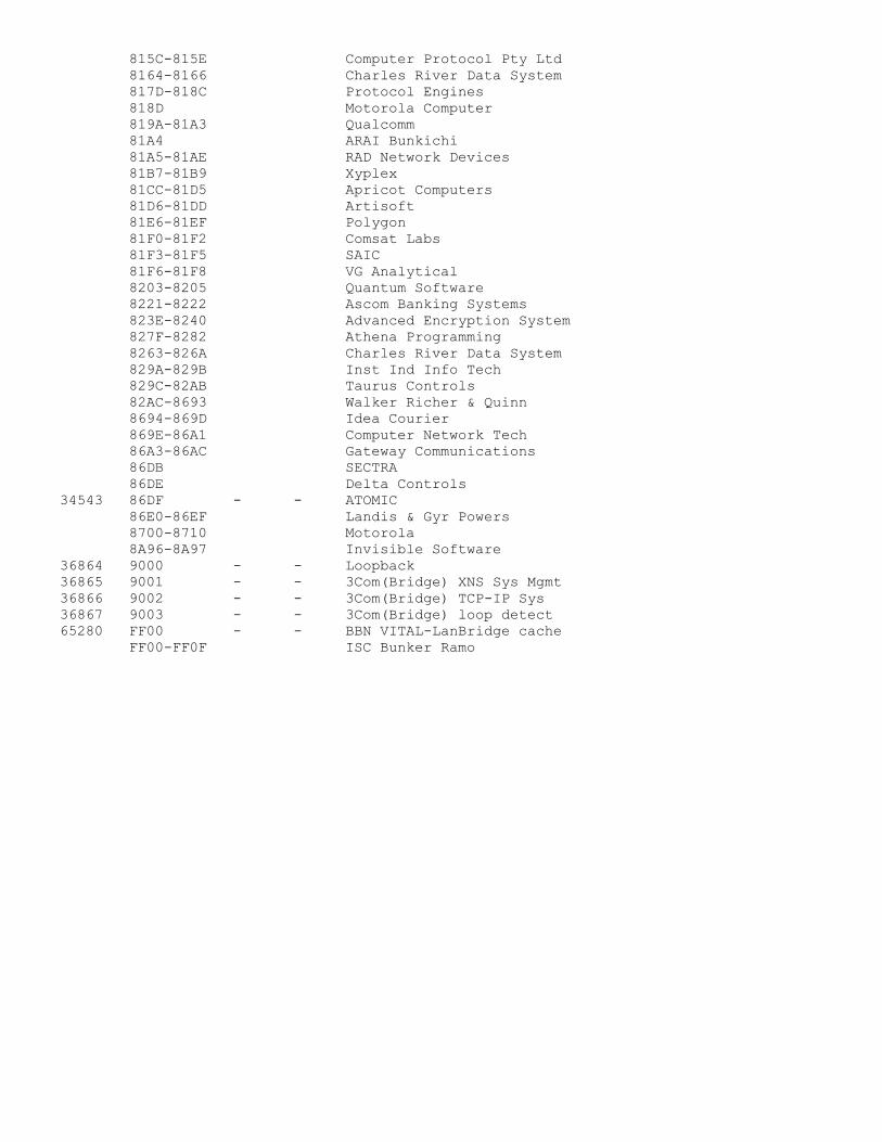
815C-815E Computer Protocol Pty Ltd
8164-8166 Charles River Data System
817D-818C Protocol Engines
818D Motorola Computer
819A-81A3 Qualcomm
81A4 ARAI Bunkichi
81A5-81AE RAD Network Devices
81B7-81B9 Xyplex
81CC-81D5 Apricot Computers
81D6-81DD Artisoft
81E6-81EF Polygon
81F0-81F2 Comsat Labs
81F3-81F5 SAIC
81F6-81F8 VG Analytical
8203-8205 Quantum Software
8221-8222 Ascom Banking Systems
823E-8240 Advanced Encryption System
827F-8282 Athena Programming
8263-826A Charles River Data System
829A-829B Inst Ind Info Tech
829C-82AB Taurus Controls
82AC-8693 Walker Richer & Quinn
8694-869D Idea Courier
869E-86A1 Computer Network Tech
86A3-86AC Gateway Communications
86DB SECTRA
86DE Delta Controls
34543 86DF - - ATOMIC
86E0-86EF Landis & Gyr Powers
8700-8710 Motorola
8A96-8A97 Invisible Software
36864 9000 - - Loopback
36865 9001 - - 3Com(Bridge) XNS Sys Mgmt
36866 9002 - - 3Com(Bridge) TCP-IP Sys
36867 9003 - - 3Com(Bridge) loop detect
65280 FF00 - - BBN VITAL-LanBridge cache
FF00-FF0F ISC Bunker Ramo
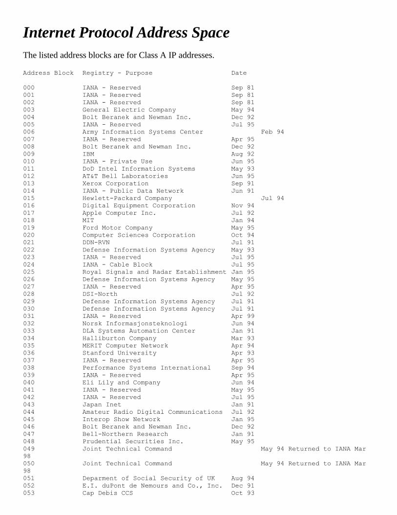
Internet Protocol Address Space
The listed address blocks are for Class A IP addresses.
Address Block Registry - Purpose Date
000 IANA - Reserved Sep 81
001 IANA - Reserved Sep 81
002 IANA - Reserved Sep 81
003 General Electric Company May 94
004 Bolt Beranek and Newman Inc. Dec 92
005 IANA - Reserved Jul 95
006 Army Information Systems Center Feb 94
007 IANA - Reserved Apr 95
008 Bolt Beranek and Newman Inc. Dec 92
009 IBM Aug 92
010 IANA - Private Use Jun 95
011 DoD Intel Information Systems May 93
012 AT&T Bell Laboratories Jun 95
013 Xerox Corporation Sep 91
014 IANA - Public Data Network Jun 91
015 Hewlett-Packard Company Jul 94
016 Digital Equipment Corporation Nov 94
017 Apple Computer Inc. Jul 92
018 MIT Jan 94
019 Ford Motor Company May 95
020 Computer Sciences Corporation Oct 94
021 DDN-RVN Jul 91
022 Defense Information Systems Agency May 93
023 IANA - Reserved Jul 95
024 IANA - Cable Block Jul 95
025 Royal Signals and Radar Establishment Jan 95
026 Defense Information Systems Agency May 95
027 IANA - Reserved Apr 95
028 DSI-North Jul 92
029 Defense Information Systems Agency Jul 91
030 Defense Information Systems Agency Jul 91
031 IANA - Reserved Apr 99
032 Norsk Informasjonsteknologi Jun 94
033 DLA Systems Automation Center Jan 91
034 Halliburton Company Mar 93
035 MERIT Computer Network Apr 94
036 Stanford University Apr 93
037 IANA - Reserved Apr 95
038 Performance Systems International Sep 94
039 IANA - Reserved Apr 95
040 Eli Lily and Company Jun 94
041 IANA - Reserved May 95
042 IANA - Reserved Jul 95
043 Japan Inet Jan 91
044 Amateur Radio Digital Communications Jul 92
045 Interop Show Network Jan 95
046 Bolt Beranek and Newman Inc. Dec 92
047 Bell-Northern Research Jan 91
048 Prudential Securities Inc. May 95
049 Joint Technical Command May 94 Returned to IANA Mar
98
050 Joint Technical Command May 94 Returned to IANA Mar
98
051 Deparment of Social Security of UK Aug 94
052 E.I. duPont de Nemours and Co., Inc. Dec 91
053 Cap Debis CCS Oct 93

054 Merck and Co., Inc. Mar 92
055 Boeing Computer Services Apr 95
056 U.S. Postal Service Jun 94
057 SITA May 95
058 IANA - Reserved Sep 81
059 IANA - Reserved Sep 81
060 IANA - Reserved Sep 81
061 APNIC - Pacific Rim Apr 97
062 RIPE NCC - Europe Apr 97
063 ARIN Apr 97
064 ARIN Jul 99
065-095 IANA - Reserved Sep 81
096-126 IANA - Reserved Sep 81
127 IANA - Reserved Sep 81
128-191 Various Registries May 93
192 Various Registries - MultiRegional May 93
193 RIPE NCC - Europe May 93
194 RIPE NCC - Europe May 93
195 RIPE NCC - Europe May 93
196 Various Registries May 93
197 IANA - Reserved May 93
198 Various Registries May 93
199 ARIN - North America May 93
200 ARIN - Central and South America May 93
201 Reserved - Central and South America May 93
202 APNIC - Pacific Rim May 93
203 APNIC - Pacific Rim May 93
204 ARIN - North America Mar 94
205 ARIN - North America Mar 94
206 ARIN - North America Apr 95
207 ARIN - North America Nov 95
208 ARIN - North America Apr 96
209 ARIN - North America Jun 96
210 APNIC - Pacific Rim Jun 96
211 APNIC - Pacific Rim Jun 96
212 RIPE NCC - Europe Oct 97
213 RIPE NCC - Europe Mar 99
214 US-DOD Mar 98
215 US-DOD Mar 98
216 ARIN - North America Apr 98
217 IANA - Reserved Sep 81
218-223 IANA - Reserved Sep 81
224-239 IANA - Multicast Sep 81
240-255 IANA - Reserved Sep 81
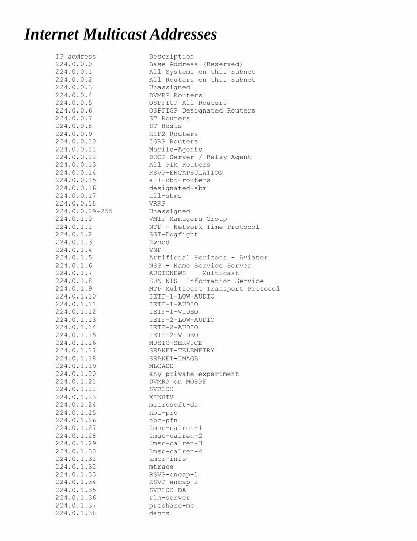
Internet Multicast Addresses
IP address Description
224.0.0.0 Base Address (Reserved)
224.0.0.1 All Systems on this Subnet
224.0.0.2 All Routers on this Subnet
224.0.0.3 Unassigned
224.0.0.4 DVMRP Routers
224.0.0.5 OSPFIGP All Routers
224.0.0.6 OSPFIGP Designated Routers
224.0.0.7 ST Routers
224.0.0.8 ST Hosts
224.0.0.9 RIP2 Routers
224.0.0.10 IGRP Routers
224.0.0.11 Mobile-Agents
224.0.0.12 DHCP Server / Relay Agent
224.0.0.13 All PIM Routers
224.0.0.14 RSVP-ENCAPSULATION
224.0.0.15 all-cbt-routers
224.0.0.16 designated-sbm
224.0.0.17 all-sbms
224.0.0.18 VRRP
224.0.0.19-255 Unassigned
224.0.1.0 VMTP Managers Group
224.0.1.1 NTP - Network Time Protocol
224.0.1.2 SGI-Dogfight
224.0.1.3 Rwhod
224.0.1.4 VNP
224.0.1.5 Artificial Horizons - Aviator
224.0.1.6 NSS - Name Service Server
224.0.1.7 AUDIONEWS - Multicast
224.0.1.8 SUN NIS+ Information Service
224.0.1.9 MTP Multicast Transport Protocol
224.0.1.10 IETF-1-LOW-AUDIO
224.0.1.11 IETF-1-AUDIO
224.0.1.12 IETF-1-VIDEO
224.0.1.13 IETF-2-LOW-AUDIO
224.0.1.14 IETF-2-AUDIO
224.0.1.15 IETF-2-VIDEO
224.0.1.16 MUSIC-SERVICE
224.0.1.17 SEANET-TELEMETRY
224.0.1.18 SEANET-IMAGE
224.0.1.19 MLOADD
224.0.1.20 any private experiment
224.0.1.21 DVMRP on MOSPF
224.0.1.22 SVRLOC
224.0.1.23 XINGTV
224.0.1.24 microsoft-ds
224.0.1.25 nbc-pro
224.0.1.26 nbc-pfn
224.0.1.27 lmsc-calren-1
224.0.1.28 lmsc-calren-2
224.0.1.29 lmsc-calren-3
224.0.1.30 lmsc-calren-4
224.0.1.31 ampr-info
224.0.1.32 mtrace
224.0.1.33 RSVP-encap-1
224.0.1.34 RSVP-encap-2
224.0.1.35 SVRLOC-DA
224.0.1.36 rln-server
224.0.1.37 proshare-mc
224.0.1.38 dantz
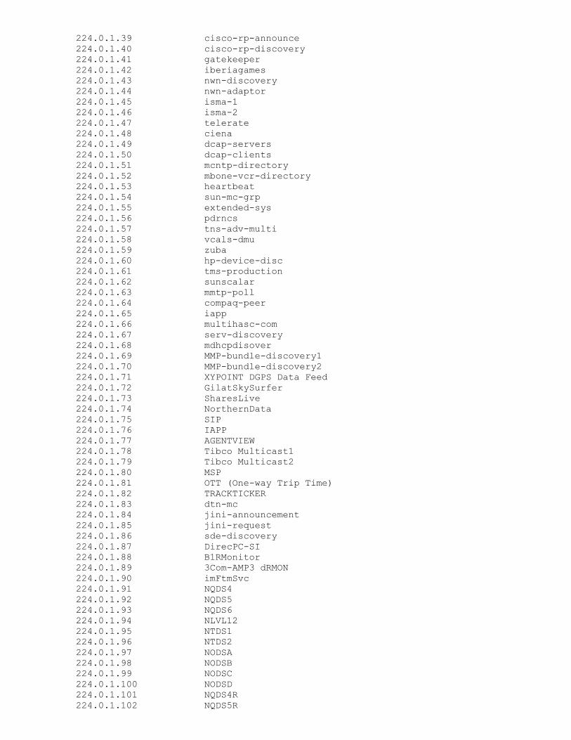
224.0.1.39 cisco-rp-announce
224.0.1.40 cisco-rp-discovery
224.0.1.41 gatekeeper
224.0.1.42 iberiagames
224.0.1.43 nwn-discovery
224.0.1.44 nwn-adaptor
224.0.1.45 isma-1
224.0.1.46 isma-2
224.0.1.47 telerate
224.0.1.48 ciena
224.0.1.49 dcap-servers
224.0.1.50 dcap-clients
224.0.1.51 mcntp-directory
224.0.1.52 mbone-vcr-directory
224.0.1.53 heartbeat
224.0.1.54 sun-mc-grp
224.0.1.55 extended-sys
224.0.1.56 pdrncs
224.0.1.57 tns-adv-multi
224.0.1.58 vcals-dmu
224.0.1.59 zuba
224.0.1.60 hp-device-disc
224.0.1.61 tms-production
224.0.1.62 sunscalar
224.0.1.63 mmtp-poll
224.0.1.64 compaq-peer
224.0.1.65 iapp
224.0.1.66 multihasc-com
224.0.1.67 serv-discovery
224.0.1.68 mdhcpdisover
224.0.1.69 MMP-bundle-discovery1
224.0.1.70 MMP-bundle-discovery2
224.0.1.71 XYPOINT DGPS Data Feed
224.0.1.72 GilatSkySurfer
224.0.1.73 SharesLive
224.0.1.74 NorthernData
224.0.1.75 SIP
224.0.1.76 IAPP
224.0.1.77 AGENTVIEW
224.0.1.78 Tibco Multicast1
224.0.1.79 Tibco Multicast2
224.0.1.80 MSP
224.0.1.81 OTT (One-way Trip Time)
224.0.1.82 TRACKTICKER
224.0.1.83 dtn-mc
224.0.1.84 jini-announcement
224.0.1.85 jini-request
224.0.1.86 sde-discovery
224.0.1.87 DirecPC-SI
224.0.1.88 B1RMonitor
224.0.1.89 3Com-AMP3 dRMON
224.0.1.90 imFtmSvc
224.0.1.91 NQDS4
224.0.1.92 NQDS5
224.0.1.93 NQDS6
224.0.1.94 NLVL12
224.0.1.95 NTDS1
224.0.1.96 NTDS2
224.0.1.97 NODSA
224.0.1.98 NODSB
224.0.1.99 NODSC
224.0.1.100 NODSD
224.0.1.101 NQDS4R
224.0.1.102 NQDS5R

224.0.1.103 NQDS6R
224.0.1.104 NLVL12R
224.0.1.105 NTDS1R
224.0.1.106 NTDS2R
224.0.1.107 NODSAR
224.0.1.108 NODSBR
224.0.1.109 NODSCR
224.0.1.110 NODSDR
224.0.1.111 MRM
224.0.1.112 TVE-FILE
224.0.1.113 TVE-ANNOUNCE
224.0.1.114 Mac Srv Loc
224.0.1.115 Simple Multicast
224.0.1.116 SpectraLinkGW
224.0.1.117 dieboldmcast
224.0.1.118 Tivoli Systems
224.0.1.119 pq-lic-mcast
224.0.1.120 HYPERFEED
224.0.1.121 Pipesplatform
224.0.1.122 LiebDevMgmg-DM
224.0.1.123 TRIBALVOICE
224.0.1.124 UDLR-DTCP
224.0.1.125 PolyCom Relay1
224.0.1.126 Infront Multi1
224.0.1.127 XRX DEVICE DISC
224.0.1.128 CNN
224.0.1.129 PTP-primary
224.0.1.130 PTP-alternate1
224.0.1.131 PTP-alternate2
224.0.1.132 PTP-alternate3
224.0.1.133 ProCast
224.0.1.134 3Com Discp
224.0.1.135 CS-Multicasting
224.0.1.136 TS-MC-1
224.0.1.137 Make Source
224.0.1.138 Teleborsa
224.0.1.139-255 Unassigned
224.0.2.1 "rwho" Group (BSD)
224.0.2.2 SUN RPC
224.0.2.064-095 SIAC MDD Service
224.0.2.096-27 CoolCast
224.0.2.128-191 WOZ-Garage
224.0.2.192-255 SIAC MDD Market Service
224.0.3.000-255 RFE Generic Service
224.0.4.000-255 RFE Individual Conferences
224.0.5.000-127 CDPD Groups
224.0.5.128-191 SIAC Market Service
224.0.5.192-255 Unassigned
224.0.6.000-127 Cornell ISIS Project
224.0.6.128-255 Unassigned
224.0.7.000-255 Where-Are-You
224.0.8.000-255 INTV
224.0.9.000-255 Invisible Worlds
224.0.10.000-255 DLSw Groups
224.0.11.000-255 NCC.NEA Audio
224.0.12.000-063 Microsoft and MSNBC
224.0.13.000-255 UUNET PIPEX Net News
224.0.14.000-255 NLANR
224.0.15.000-255 Hewlett Packard
224.0.16.000-255 XingNet
224.0.17.000-031 Merc & Commodity Exchange
224.0.17.032-063 NDQMD1
224.0.17.064-127 ODN-DTV
224.0.18.000-255 Dow Jones
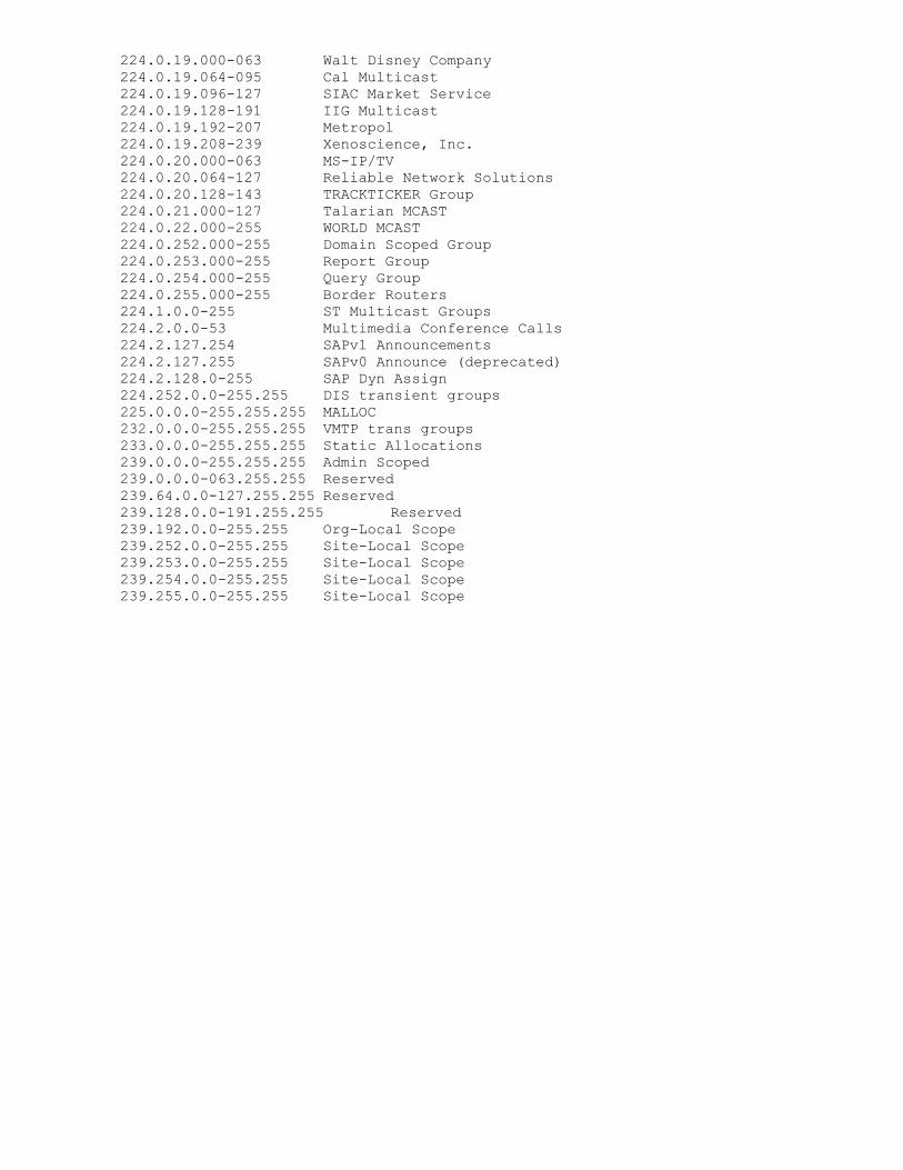
224.0.19.000-063 Walt Disney Company
224.0.19.064-095 Cal Multicast
224.0.19.096-127 SIAC Market Service
224.0.19.128-191 IIG Multicast
224.0.19.192-207 Metropol
224.0.19.208-239 Xenoscience, Inc.
224.0.20.000-063 MS-IP/TV
224.0.20.064-127 Reliable Network Solutions
224.0.20.128-143 TRACKTICKER Group
224.0.21.000-127 Talarian MCAST
224.0.22.000-255 WORLD MCAST
224.0.252.000-255 Domain Scoped Group
224.0.253.000-255 Report Group
224.0.254.000-255 Query Group
224.0.255.000-255 Border Routers
224.1.0.0-255 ST Multicast Groups
224.2.0.0-53 Multimedia Conference Calls
224.2.127.254 SAPv1 Announcements
224.2.127.255 SAPv0 Announce (deprecated)
224.2.128.0-255 SAP Dyn Assign
224.252.0.0-255.255 DIS transient groups
225.0.0.0-255.255.255 MALLOC
232.0.0.0-255.255.255 VMTP trans groups
233.0.0.0-255.255.255 Static Allocations
239.0.0.0-255.255.255 Admin Scoped
239.0.0.0-063.255.255 Reserved
239.64.0.0-127.255.255 Reserved
239.128.0.0-191.255.255 Reserved
239.192.0.0-255.255 Org-Local Scope
239.252.0.0-255.255 Site-Local Scope
239.253.0.0-255.255 Site-Local Scope
239.254.0.0-255.255 Site-Local Scope
239.255.0.0-255.255 Site-Local Scope
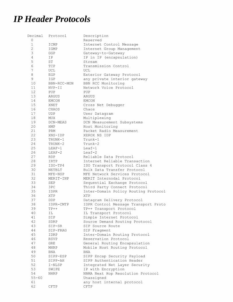
IP Header Protocols
Decimal Protocol Description
0 Reserved
1 ICMP Internet Control Message
2 IGMP Internet Group Management
3 GGP Gateway-to-Gateway
4 IP IP in IP (encapsulation)
5 ST Stream
6 TCP Transmission Control
7 UCL UCL
8 EGP Exterior Gateway Protocol
9 IGP any private interior gateway
10 BBN-RCC-MON BBN RCC Monitoring
11 NVP-II Network Voice Protocol
12 PUP PUP
13 ARGUS ARGUS
14 EMCON EMCON
15 XNET Cross Net Debugger
16 CHAOS Chaos
17 UDP User Datagram
18 MUX Multiplexing
19 DCN-MEAS DCN Measurement Subsystems
20 HMP Host Monitoring
21 PRM Packet Radio Measurement
22 XNS-IDP XEROX NS IDP
23 TRUNK-1 Trunk-1
24 TRUNK-2 Trunk-2
25 LEAF-1 Leaf-1
26 LEAF-2 Leaf-2
27 RDP Reliable Data Protocol
28 IRTP Internet Reliable Transaction
29 ISO-TP4 ISO Transport Protocol Class 4
30 NETBLT Bulk Data Transfer Protocol
31 MFE-NSP MFE Network Services Protocol
32 MERIT-INP MERIT Internodal Protocol
33 SEP Sequential Exchange Protocol
34 3PC Third Party Connect Protocol
35 IDPR Inter-Domain Policy Routing Protocol
36 XTP XTP
37 DDP Datagram Delivery Protocol
38 IDPR-CMTP IDPR Control Message Transport Proto
39 TP++ TP++ Transport Protocol
40 IL IL Transport Protocol
41 SIP Simple Internet Protocol
42 SDRP Source Demand Routing Protocol
43 SIP-SR SIP Source Route
44 SIP-FRAG SIP Fragment
45 IDRP Inter-Domain Routing Protocol
46 RSVP Reservation Protocol
47 GRE General Routing Encapsulation
48 MHRP Mobile Host Routing Protocol
49 BNA BNA
50 SIPP-ESP SIPP Encap Security Payload
51 SIPP-AH SIPP Authentication Header
52 I-NLSP Integrated Net Layer Security
53 SWIPE IP with Encryption
54 NHRP NBMA Next Hop Resolution Protocol
55-60 Unassigned
61 any host internal protocol
62 CFTP CFTP
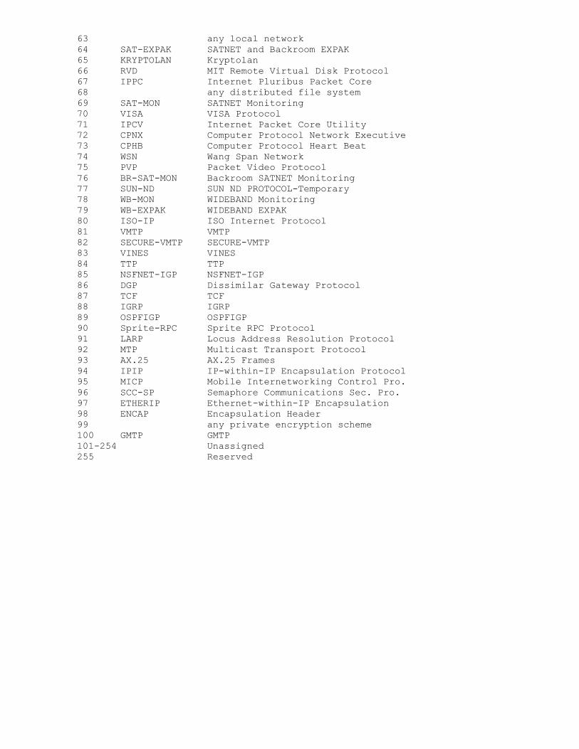
63 any local network
64 SAT-EXPAK SATNET and Backroom EXPAK
65 KRYPTOLAN Kryptolan
66 RVD MIT Remote Virtual Disk Protocol
67 IPPC Internet Pluribus Packet Core
68 any distributed file system
69 SAT-MON SATNET Monitoring
70 VISA VISA Protocol
71 IPCV Internet Packet Core Utility
72 CPNX Computer Protocol Network Executive
73 CPHB Computer Protocol Heart Beat
74 WSN Wang Span Network
75 PVP Packet Video Protocol
76 BR-SAT-MON Backroom SATNET Monitoring
77 SUN-ND SUN ND PROTOCOL-Temporary
78 WB-MON WIDEBAND Monitoring
79 WB-EXPAK WIDEBAND EXPAK
80 ISO-IP ISO Internet Protocol
81 VMTP VMTP
82 SECURE-VMTP SECURE-VMTP
83 VINES VINES
84 TTP TTP
85 NSFNET-IGP NSFNET-IGP
86 DGP Dissimilar Gateway Protocol
87 TCF TCF
88 IGRP IGRP
89 OSPFIGP OSPFIGP
90 Sprite-RPC Sprite RPC Protocol
91 LARP Locus Address Resolution Protocol
92 MTP Multicast Transport Protocol
93 AX.25 AX.25 Frames
94 IPIP IP-within-IP Encapsulation Protocol
95 MICP Mobile Internetworking Control Pro.
96 SCC-SP Semaphore Communications Sec. Pro.
97 ETHERIP Ethernet-within-IP Encapsulation
98 ENCAP Encapsulation Header
99 any private encryption scheme
100 GMTP GMTP
101-254 Unassigned
255 Reserved
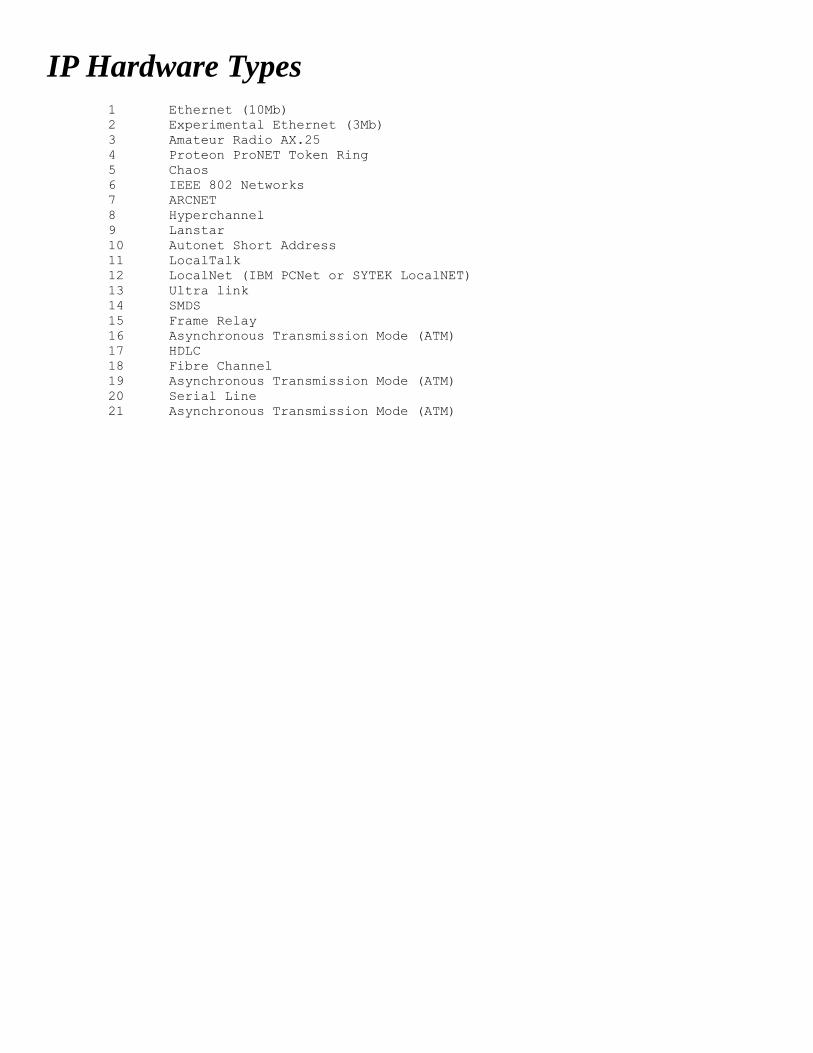
IP Hardware Types
1 Ethernet (10Mb)
2 Experimental Ethernet (3Mb)
3 Amateur Radio AX.25
4 Proteon ProNET Token Ring
5 Chaos
6 IEEE 802 Networks
7 ARCNET
8 Hyperchannel
9 Lanstar
10 Autonet Short Address
11 LocalTalk
12 LocalNet (IBM PCNet or SYTEK LocalNET)
13 Ultra link
14 SMDS
15 Frame Relay
16 Asynchronous Transmission Mode (ATM)
17 HDLC
18 Fibre Channel
19 Asynchronous Transmission Mode (ATM)
20 Serial Line
21 Asynchronous Transmission Mode (ATM)
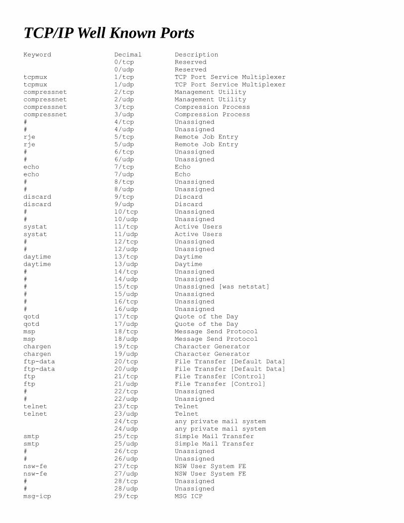
TCP/IP Well Known Ports
Keyword Decimal Description
0/tcp Reserved
0/udp Reserved
tcpmux 1/tcp TCP Port Service Multiplexer
tcpmux 1/udp TCP Port Service Multiplexer
compressnet 2/tcp Management Utility
compressnet 2/udp Management Utility
compressnet 3/tcp Compression Process
compressnet 3/udp Compression Process
# 4/tcp Unassigned
# 4/udp Unassigned
rje 5/tcp Remote Job Entry
rje 5/udp Remote Job Entry
# 6/tcp Unassigned
# 6/udp Unassigned
echo 7/tcp Echo
echo 7/udp Echo
# 8/tcp Unassigned
# 8/udp Unassigned
discard 9/tcp Discard
discard 9/udp Discard
# 10/tcp Unassigned
# 10/udp Unassigned
systat 11/tcp Active Users
systat 11/udp Active Users
# 12/tcp Unassigned
# 12/udp Unassigned
daytime 13/tcp Daytime
daytime 13/udp Daytime
# 14/tcp Unassigned
# 14/udp Unassigned
# 15/tcp Unassigned [was netstat]
# 15/udp Unassigned
# 16/tcp Unassigned
# 16/udp Unassigned
qotd 17/tcp Quote of the Day
qotd 17/udp Quote of the Day
msp 18/tcp Message Send Protocol
msp 18/udp Message Send Protocol
chargen 19/tcp Character Generator
chargen 19/udp Character Generator
ftp-data 20/tcp File Transfer [Default Data]
ftp-data 20/udp File Transfer [Default Data]
ftp 21/tcp File Transfer [Control]
ftp 21/udp File Transfer [Control]
# 22/tcp Unassigned
# 22/udp Unassigned
telnet 23/tcp Telnet
telnet 23/udp Telnet
24/tcp any private mail system
24/udp any private mail system
smtp 25/tcp Simple Mail Transfer
smtp 25/udp Simple Mail Transfer
# 26/tcp Unassigned
# 26/udp Unassigned
nsw-fe 27/tcp NSW User System FE
nsw-fe 27/udp NSW User System FE
# 28/tcp Unassigned
# 28/udp Unassigned
msg-icp 29/tcp MSG ICP
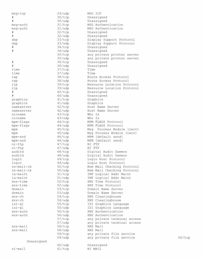
msg-icp 29/udp MSG ICP
# 30/tcp Unassigned
# 30/udp Unassigned
msg-auth 31/tcp MSG Authentication
msg-auth 31/udp MSG Authentication
# 32/tcp Unassigned
# 32/udp Unassigned
dsp 33/tcp Display Support Protocol
dsp 33/udp Display Support Protocol
# 34/tcp Unassigned
# 34/udp Unassigned
35/tcp any private printer server
35/udp any private printer server
# 36/tcp Unassigned
# 36/udp Unassigned
time 37/tcp Time
time 37/udp Time
rap 38/tcp Route Access Protocol
rap 38/udp Route Access Protocol
rlp 39/tcp Resource Location Protocol
rlp 39/udp Resource Location Protocol
# 40/tcp Unassigned
# 40/udp Unassigned
graphics 41/tcp Graphics
graphics 41/udp Graphics
nameserver 42/tcp Host Name Server
nameserver 42/udp Host Name Server
nicname 43/tcp Who Is
nicname 43/udp Who Is
mpm-flags 44/tcp MPM FLAGS Protocol
mpm-flags 44/udp MPM FLAGS Protocol
mpm 45/tcp Msg Process Module [recv]
mpm 45/udp Msg Process Module [recv]
mpm-snd 46/tcp MPM [default send]
mpm-snd 46/udp MPM [default send]
ni-ftp 47/tcp NI FTP
ni-ftp 47/udp NI FTP
auditd 48/tcp Digital Audit Daemon
auditd 48/udp Digital Audit Daemon
login 49/tcp Login Host Protocol
login 49/udp Login Host Protocol
re-mail-ck 50/tcp Rem Mail Checking Protocol
re-mail-ck 50/udp Rem Mail Checking Protocol
la-maint 51/tcp IMP Logical Addr Maint
la-maint 51/udp IMP Logical Addr Maint
xns-time 52/tcp XNS Time Protocol
xns-time 52/udp XNS Time Protocol
domain 53/tcp Domain Name Server
domain 53/udp Domain Name Server
xns-ch 54/tcp XNS Clearinghouse
xns-ch 54/udp XNS Clearinghouse
isi-gl 55/tcp ISI Graphics Language
isi-gl 55/udp ISI Graphics Language
xns-auth 56/tcp XNS Authentication
xns-auth 56/udp XNS Authentication
57/tcp any private terminal access
57/udp any private terminal access
xns-mail 58/tcp XNS Mail
xns-mail 58/udp XNS Mail
59/tcp any private file service
59/udp any private file service 60/tcp
Unassigned
60/udp Unassigned
ni-mail 61/tcp NI MAIL

ni-mail 61/udp NI MAIL
acas 62/tcp ACA Services
acas 62/udp ACA Services
# 63/tcp Unassigned
# 63/udp Unassigned
covia 64/tcp Comm Integrator (CI)
covia 64/udp Comm Integrator (CI)
tacacs-ds 65/tcp TACACS-Database Service
tacacs-ds 65/udp TACACS-Database Service
sql*net 66/tcp Oracle SQL*NET
sql*net 66/udp Oracle SQL*NET
bootps 67/tcp Bootstrap Protocol Server
bootps 67/udp Bootstrap Protocol Server
bootpc 68/tcp Bootstrap Protocol Client
bootpc 68/udp Bootstrap Protocol Client
tftp 69/tcp Trivial File Transfer
tftp 69/udp Trivial File Transfer
gopher 70/tcp Gopher
gopher 70/udp Gopher
netrjs-1 71/tcp Remote Job Service
netrjs-1 71/udp Remote Job Service
netrjs-2 72/tcp Remote Job Service
netrjs-2 72/udp Remote Job Service
netrjs-3 73/tcp Remote Job Service
netrjs-3 73/udp Remote Job Service
netrjs-4 74/tcp Remote Job Service
netrjs-4 74/udp Remote Job Service
75/tcp any private dial out service
75/udp any private dial out service
deos 76/tcp Distributed Ext Object Store
deos 76/udp Distributed Ext Object Store
77/tcp any private RJE service
77/udp any private RJE service
vettcp 78/tcp vettcp
vettcp 78/udp vettcp
finger 79/tcp Finger
finger 79/udp Finger
www-http 80/tcp World Wide Web HTTP
www-http 80/udp World Wide Web HTTP
hosts2-ns 81/tcp HOSTS2 Name Server
hosts2-ns 81/udp HOSTS2 Name Server
xfer 82/tcp XFER Utility
xfer 82/udp XFER Utility
mit-ml-dev 83/tcp MIT ML Device
mit-ml-dev 83/udp MIT ML Device
ctf 84/tcp Common Trace Facility
ctf 84/udp Common Trace Facility
mit-ml-dev 85/tcp MIT ML Device
mit-ml-dev 85/udp MIT ML Device
mfcobol 86/tcp Micro Focus Cobol
mfcobol 86/udp Micro Focus Cobol
87/tcp any private terminal link
87/udp any private terminal link
kerberos 88/tcp Kerberos
kerberos 88/udp Kerberos
su-mit-tg 89/tcp SU/MIT Telnet Gateway
su-mit-tg 89/udp SU/MIT Telnet Gateway
dnsix 90/tcp DNSIX Securit Attrib Tok Map
dnsix 90/udp DNSIX Securit Attrib Tok Map
mit-dov 91/tcp MIT Dover Spooler
mit-dov 91/udp MIT Dover Spooler
npp 92/tcp Network Printing Protocol
npp 92/udp Network Printing Protocol
dcp 93/tcp Device Control Protocol
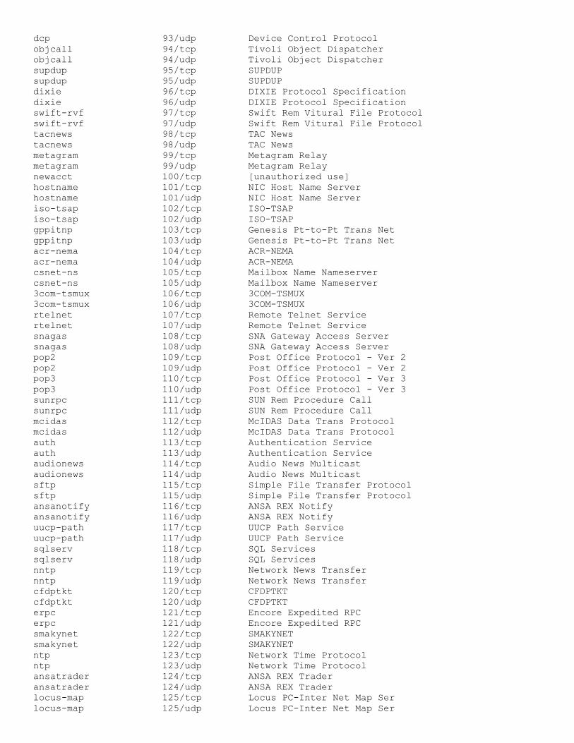
dcp 93/udp Device Control Protocol
objcall 94/tcp Tivoli Object Dispatcher
objcall 94/udp Tivoli Object Dispatcher
supdup 95/tcp SUPDUP
supdup 95/udp SUPDUP
dixie 96/tcp DIXIE Protocol Specification
dixie 96/udp DIXIE Protocol Specification
swift-rvf 97/tcp Swift Rem Vitural File Protocol
swift-rvf 97/udp Swift Rem Vitural File Protocol
tacnews 98/tcp TAC News
tacnews 98/udp TAC News
metagram 99/tcp Metagram Relay
metagram 99/udp Metagram Relay
newacct 100/tcp [unauthorized use]
hostname 101/tcp NIC Host Name Server
hostname 101/udp NIC Host Name Server
iso-tsap 102/tcp ISO-TSAP
iso-tsap 102/udp ISO-TSAP
gppitnp 103/tcp Genesis Pt-to-Pt Trans Net
gppitnp 103/udp Genesis Pt-to-Pt Trans Net
acr-nema 104/tcp ACR-NEMA
acr-nema 104/udp ACR-NEMA
csnet-ns 105/tcp Mailbox Name Nameserver
csnet-ns 105/udp Mailbox Name Nameserver
3com-tsmux 106/tcp 3COM-TSMUX
3com-tsmux 106/udp 3COM-TSMUX
rtelnet 107/tcp Remote Telnet Service
rtelnet 107/udp Remote Telnet Service
snagas 108/tcp SNA Gateway Access Server
snagas 108/udp SNA Gateway Access Server
pop2 109/tcp Post Office Protocol - Ver 2
pop2 109/udp Post Office Protocol - Ver 2
pop3 110/tcp Post Office Protocol - Ver 3
pop3 110/udp Post Office Protocol - Ver 3
sunrpc 111/tcp SUN Rem Procedure Call
sunrpc 111/udp SUN Rem Procedure Call
mcidas 112/tcp McIDAS Data Trans Protocol
mcidas 112/udp McIDAS Data Trans Protocol
auth 113/tcp Authentication Service
auth 113/udp Authentication Service
audionews 114/tcp Audio News Multicast
audionews 114/udp Audio News Multicast
sftp 115/tcp Simple File Transfer Protocol
sftp 115/udp Simple File Transfer Protocol
ansanotify 116/tcp ANSA REX Notify
ansanotify 116/udp ANSA REX Notify
uucp-path 117/tcp UUCP Path Service
uucp-path 117/udp UUCP Path Service
sqlserv 118/tcp SQL Services
sqlserv 118/udp SQL Services
nntp 119/tcp Network News Transfer
nntp 119/udp Network News Transfer
cfdptkt 120/tcp CFDPTKT
cfdptkt 120/udp CFDPTKT
erpc 121/tcp Encore Expedited RPC
erpc 121/udp Encore Expedited RPC
smakynet 122/tcp SMAKYNET
smakynet 122/udp SMAKYNET
ntp 123/tcp Network Time Protocol
ntp 123/udp Network Time Protocol
ansatrader 124/tcp ANSA REX Trader
ansatrader 124/udp ANSA REX Trader
locus-map 125/tcp Locus PC-Inter Net Map Ser
locus-map 125/udp Locus PC-Inter Net Map Ser
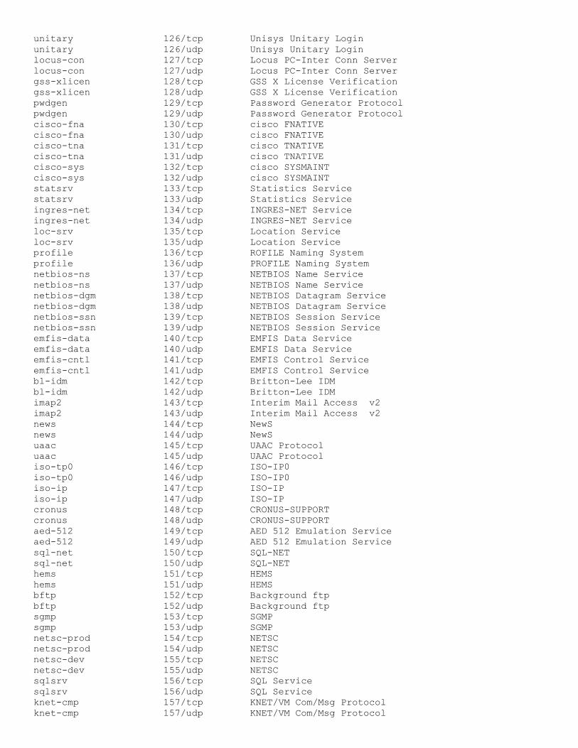
unitary 126/tcp Unisys Unitary Login
unitary 126/udp Unisys Unitary Login
locus-con 127/tcp Locus PC-Inter Conn Server
locus-con 127/udp Locus PC-Inter Conn Server
gss-xlicen 128/tcp GSS X License Verification
gss-xlicen 128/udp GSS X License Verification
pwdgen 129/tcp Password Generator Protocol
pwdgen 129/udp Password Generator Protocol
cisco-fna 130/tcp cisco FNATIVE
cisco-fna 130/udp cisco FNATIVE
cisco-tna 131/tcp cisco TNATIVE
cisco-tna 131/udp cisco TNATIVE
cisco-sys 132/tcp cisco SYSMAINT
cisco-sys 132/udp cisco SYSMAINT
statsrv 133/tcp Statistics Service
statsrv 133/udp Statistics Service
ingres-net 134/tcp INGRES-NET Service
ingres-net 134/udp INGRES-NET Service
loc-srv 135/tcp Location Service
loc-srv 135/udp Location Service
profile 136/tcp ROFILE Naming System
profile 136/udp PROFILE Naming System
netbios-ns 137/tcp NETBIOS Name Service
netbios-ns 137/udp NETBIOS Name Service
netbios-dgm 138/tcp NETBIOS Datagram Service
netbios-dgm 138/udp NETBIOS Datagram Service
netbios-ssn 139/tcp NETBIOS Session Service
netbios-ssn 139/udp NETBIOS Session Service
emfis-data 140/tcp EMFIS Data Service
emfis-data 140/udp EMFIS Data Service
emfis-cntl 141/tcp EMFIS Control Service
emfis-cntl 141/udp EMFIS Control Service
bl-idm 142/tcp Britton-Lee IDM
bl-idm 142/udp Britton-Lee IDM
imap2 143/tcp Interim Mail Access v2
imap2 143/udp Interim Mail Access v2
news 144/tcp NewS
news 144/udp NewS
uaac 145/tcp UAAC Protocol
uaac 145/udp UAAC Protocol
iso-tp0 146/tcp ISO-IP0
iso-tp0 146/udp ISO-IP0
iso-ip 147/tcp ISO-IP
iso-ip 147/udp ISO-IP
cronus 148/tcp CRONUS-SUPPORT
cronus 148/udp CRONUS-SUPPORT
aed-512 149/tcp AED 512 Emulation Service
aed-512 149/udp AED 512 Emulation Service
sql-net 150/tcp SQL-NET
sql-net 150/udp SQL-NET
hems 151/tcp HEMS
hems 151/udp HEMS
bftp 152/tcp Background ftp
bftp 152/udp Background ftp
sgmp 153/tcp SGMP
sgmp 153/udp SGMP
netsc-prod 154/tcp NETSC
netsc-prod 154/udp NETSC
netsc-dev 155/tcp NETSC
netsc-dev 155/udp NETSC
sqlsrv 156/tcp SQL Service
sqlsrv 156/udp SQL Service
knet-cmp 157/tcp KNET/VM Com/Msg Protocol
knet-cmp 157/udp KNET/VM Com/Msg Protocol

pcmail-srv 158/tcp PCMail Server
pcmail-srv 158/udp PCMail Server
nss-routing 159/tcp NSS-Routing
nss-routing 159/udp NSS-Routing
sgmp-traps 160/tcp SGMP-TRAPS
sgmp-traps 160/udp SGMP-TRAPS
snmp 161/tcp SNMP
snmp 161/udp SNMP
snmptrap 162/tcp SNMPTRAP
snmptrap 162/udp SNMPTRAP
cmip-man 163/tcp CMIP/TCP Manager
cmip-man 163/udp CMIP/TCP Manager
cmip-agent 164/tcp CMIP/TCP Agent
smip-agent 164/udp CMIP/TCP Agent
xns-courier 165/tcp Xerox
xns-courier 165/udp Xerox
s-net 166/tcp Sirius Systems
s-net 166/udp Sirius Systems
namp 167/tcp NAMP
namp 167/udp NAMP
rsvd 168/tcp RSVD
rsvd 168/udp RSVD
send 169/tcp SEND
send 169/udp SEND
print-srv 170/tcp Network PostScript
print-srv 170/udp Network PostScript
multiplex 171/tcp Network Innovations Multiplex
multiplex 171/udp Network Innovations Multiplex
cl/1 172/tcp Network Innovations CL/1
cl/1 172/udp Network Innovations CL/1
xyplex-mux 173/tcp Xyplex
xyplex-mux 173/udp Xyplex
mailq 174/tcp MAILQ
mailq 174/udp MAILQ
vmnet 175/tcp VMNET
vmnet 175/udp VMNET
genrad-mux 176/tcp GENRAD-MUX
genrad-mux 176/udp GENRAD-MUX
xdmcp 177/tcp X Display Manager Control
xdmcp 177/udp X Display Manager Control
nextstep 178/tcp NextStep Window Server
NextStep 178/udp NextStep Window Server
bgp 179/tcp Border Gateway Protocol
bgp 179/udp Border Gateway Protocol
ris 180/tcp Intergraph
ris 180/udp Intergraph
unify 181/tcp Unify
unify 181/udp Unify
audit 182/tcp Unisys Audit SITP
audit 182/udp Unisys Audit SITP
ocbinder 183/tcp OCBinder
ocbinder 183/udp OCBinder
ocserver 184/tcp OCServer
ocserver 184/udp OCServer
remote-kis 185/tcp Remote-KIS
remote-kis 185/udp Remote-KIS
kis 186/tcp KIS Protocol
kis 186/udp KIS Protocol
aci 187/tcp Application Comm Interface
aci 187/udp Application Com Interface
mumps 188/tcp Plus Five's MUMPS
mumps 188/udp Plus Five's MUMPS
qft 189/tcp Queued File Transport
qft 189/udp Queued File Transport
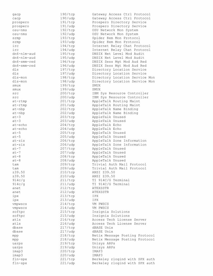
gacp 190/tcp Gateway Access Ctrl Protocol
cacp 190/udp Gateway Access Ctrl Protocol
prospero 191/tcp Prospero Directory Service
prospero 191/udp Prospero Directory Service
osu-nms 192/tcp OSU Network Mon System
osu-nms 192/udp OSU Network Mon System
srmp 193/tcp Spider Rem Mon Protocol
srmp 193/udp Spider Rem Mon Protocol
irc 194/tcp Internet Relay Chat Protocol
irc 194/udp Internet Relay Chat Protocol
dn6-nlm-aud 195/tcp DNSIX Net Level Mod Audit
dn6-nlm-aud 195/udp DNSIX Net Level Mod Audit
dn6-smm-red 196/tcp DNSIX Sess Mgt Mod Aud Red
dn6-smm-red 196/udp DNSIX Sess Mgt Mod Aud Red
dls 197/tcp Directory Location Service
dls 197/udp Directory Location Service
dls-mon 198/tcp Directory Location Service Mon
dls-mon 198/udp Directory Location Service Mon
smux 199/tcp SMUX
smux 199/udp SMUX
src 200/tcp IBM Sys Resource Controller
src 200/udp IBM Sys Resource Controller
at-rtmp 201/tcp AppleTalk Routing Maint
at-rtmp 201/udp AppleTalk Routing Maint
at-nbp 202/tcp AppleTalk Name Binding
at-nbp 202/udp AppleTalk Name Binding
at-3 203/tcp AppleTalk Unused
at-3 203/udp AppleTalk Unused
at-echo 204/tcp AppleTalk Echo
at-echo 204/udp AppleTalk Echo
at-5 205/tcp AppleTalk Unused
at-5 205/udp AppleTalk Unused
at-zis 206/tcp AppleTalk Zone Information
at-zis 206/udp AppleTalk Zone Information
at-7 207/tcp AppleTalk Unused
at-7 207/udp AppleTalk Unused
at-8 208/tcp AppleTalk Unused
at-8 208/udp AppleTalk Unused
tam 209/tcp Trivial Auth Mail Protocol
tam 209/udp Trivial Auth Mail Protocol
z39.50 210/tcp ANSI Z39.50
z39.50 210/udp ANSI Z39.50
914c/g 211/tcp TI 914C/G Terminal
914c/g 211/udp TI 914C/G Terminal
anet 212/tcp ATEXSSTR
anet 212/udp ATEXSSTR
ipx 213/tcp IPX
ipx 213/udp IPX
vmpwscs 214/tcp VM PWSCS
vmpwscs 214/udp VM PWSCS
softpc 215/tcp Insignia Solutions
softpc 215/udp Insignia Solutions
atls 216/tcp Access Tech License Server
atls 216/udp Access Tech License Server
dbase 217/tcp dBASE Unix
dbase 217/udp dBASE Unix
mpp 218/tcp Netix Message Posting Protocol
mpp 218/udp Netix Message Posting Protocol
uarps 219/tcp Unisys ARPs
uarps 219/udp Unisys ARPs
imap3 220/tcp IMAP3
imap3 220/udp IMAP3
fln-spx 221/tcp Berkeley rlogind with SPX auth
fln-spx 221/udp Berkeley rlogind with SPX auth
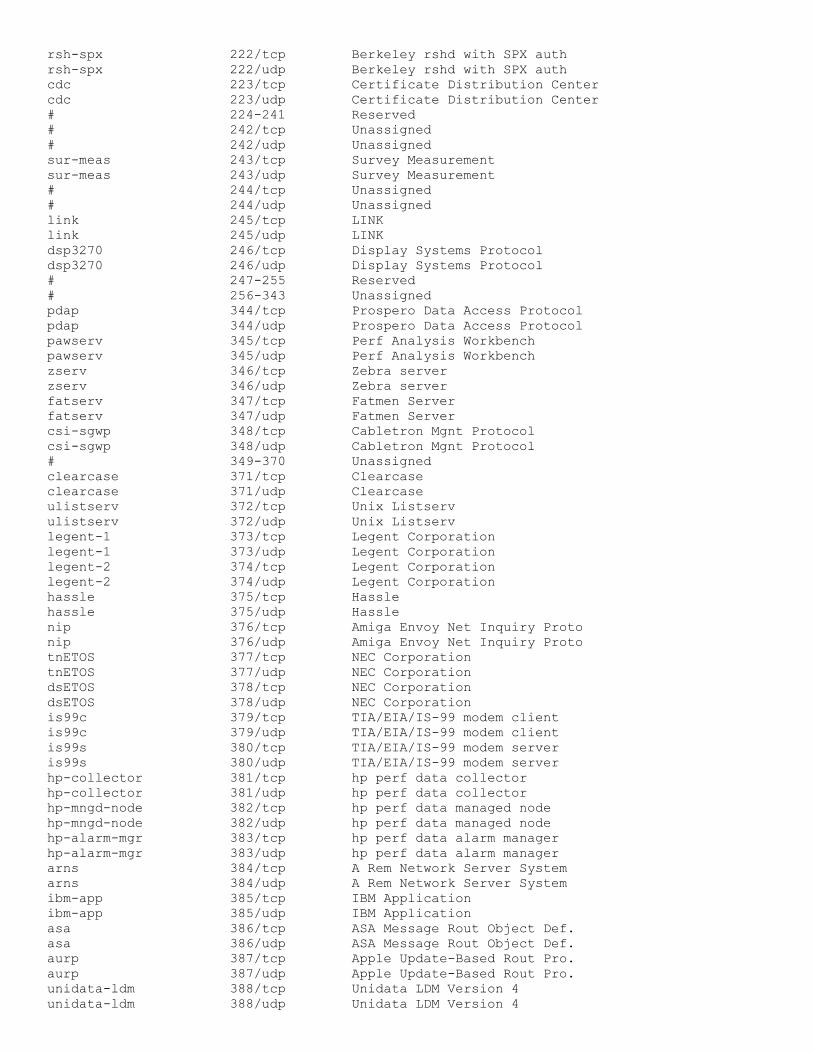
rsh-spx 222/tcp Berkeley rshd with SPX auth
rsh-spx 222/udp Berkeley rshd with SPX auth
cdc 223/tcp Certificate Distribution Center
cdc 223/udp Certificate Distribution Center
# 224-241 Reserved
# 242/tcp Unassigned
# 242/udp Unassigned
sur-meas 243/tcp Survey Measurement
sur-meas 243/udp Survey Measurement
# 244/tcp Unassigned
# 244/udp Unassigned
link 245/tcp LINK
link 245/udp LINK
dsp3270 246/tcp Display Systems Protocol
dsp3270 246/udp Display Systems Protocol
# 247-255 Reserved
# 256-343 Unassigned
pdap 344/tcp Prospero Data Access Protocol
pdap 344/udp Prospero Data Access Protocol
pawserv 345/tcp Perf Analysis Workbench
pawserv 345/udp Perf Analysis Workbench
zserv 346/tcp Zebra server
zserv 346/udp Zebra server
fatserv 347/tcp Fatmen Server
fatserv 347/udp Fatmen Server
csi-sgwp 348/tcp Cabletron Mgnt Protocol
csi-sgwp 348/udp Cabletron Mgnt Protocol
# 349-370 Unassigned
clearcase 371/tcp Clearcase
clearcase 371/udp Clearcase
ulistserv 372/tcp Unix Listserv
ulistserv 372/udp Unix Listserv
legent-1 373/tcp Legent Corporation
legent-1 373/udp Legent Corporation
legent-2 374/tcp Legent Corporation
legent-2 374/udp Legent Corporation
hassle 375/tcp Hassle
hassle 375/udp Hassle
nip 376/tcp Amiga Envoy Net Inquiry Proto
nip 376/udp Amiga Envoy Net Inquiry Proto
tnETOS 377/tcp NEC Corporation
tnETOS 377/udp NEC Corporation
dsETOS 378/tcp NEC Corporation
dsETOS 378/udp NEC Corporation
is99c 379/tcp TIA/EIA/IS-99 modem client
is99c 379/udp TIA/EIA/IS-99 modem client
is99s 380/tcp TIA/EIA/IS-99 modem server
is99s 380/udp TIA/EIA/IS-99 modem server
hp-collector 381/tcp hp perf data collector
hp-collector 381/udp hp perf data collector
hp-mngd-node 382/tcp hp perf data managed node
hp-mngd-node 382/udp hp perf data managed node
hp-alarm-mgr 383/tcp hp perf data alarm manager
hp-alarm-mgr 383/udp hp perf data alarm manager
arns 384/tcp A Rem Network Server System
arns 384/udp A Rem Network Server System
ibm-app 385/tcp IBM Application
ibm-app 385/udp IBM Application
asa 386/tcp ASA Message Rout Object Def.
asa 386/udp ASA Message Rout Object Def.
aurp 387/tcp Apple Update-Based Rout Pro.
aurp 387/udp Apple Update-Based Rout Pro.
unidata-ldm 388/tcp Unidata LDM Version 4
unidata-ldm 388/udp Unidata LDM Version 4

ldap 389/tcp Lightweight Dir Access Prot
ldap 389/udp Lightweight Diry Access Prot
uis 390/tcp UIS
uis 390/udp UIS
synotics-relay 391/tcp SynOptics SNMP Relay Port
synotics-relay 391/udp SynOptics SNMP Relay Port
synotics-broker 392/tcp SynOptics Port Broker Port
synotics-broker 392/udp SynOptics Port Broker Port
dis 393/tcp Data Interpretation System
dis 393/udp Data Interpretation System
embl-ndt 394/tcp EMBL Nucleic Data Transfer
embl-ndt 394/udp EMBL Nucleic Data Transfer
netcp 395/tcp NETscout Control Protocol
netcp 395/udp NETscout Control Protocol
netware-ip 396/tcp Novell Netware over IP
netware-ip 396/udp Novell Netware over IP
mptn 397/tcp Multi Protocol Trans. Net.
mptn 397/udp Multi Protocol Trans. Net.
kryptolan 398/tcp Kryptolan
kryptolan 398/udp Kryptolan
# 399/tcp Unassigned
# 399/udp Unassigned
work-sol 400/tcp Workstation Solutions
work-sol 400/udp Workstation Solutions
ups 401/tcp Uninterruptible Power Supply
ups 401/udp Uninterruptible Power Supply
genie 402/tcp Genie Protocol
genie 402/udp Genie Protocol
decap 403/tcp decap
decap 403/udp decap
nced 404/tcp nced
nced 404/udp nced
ncld 405/tcp ncld
ncld 405/udp ncld
imsp 406/tcp Interactive Mail Support Prot
imsp 406/udp Interactive Mail Support Prot
timbuktu 407/tcp Timbuktu
timbuktu 407/udp Timbuktu
prm-sm 408/tcp Prospero Res Mgr Sys. Man.
prm-sm 408/udp Prospero Res Mgr Sys. Man.
prm-nm 409/tcp Prospero Res Mgr Node Man.
prm-nm 409/udp Prospero Res Mgr Node Man.
decladebug 410/tcp DECLadebug Rem Debug Prot
decladebug 410/udp DECLadebug Rem Debug Prot
rmt 411/tcp Remote MT Protocol
rmt 411/udp Remote MT Protocol
synoptics-trap 412/tcp Trap Convention Port
synoptics-trap 412/udp Trap Convention Port
smsp 413/tcp SMSP
smsp 413/udp SMSP
infoseek 414/tcp InfoSeek
infoseek 414/udp InfoSeek
bnet 415/tcp BNet
bnet 415/udp BNet
silverplatter 416/tcp Silverplatter
silverplatter 416/udp Silverplatter
onmux 417/tcp Onmux
onmux 417/udp Onmux
hyper-g 418/tcp Hyper-G
hyper-g 418/udp Hyper-G
ariel1 419/tcp Ariel
ariel1 419/udp Ariel
smpte 420/tcp SMPTE
smpte 420/udp SMPTE

ariel2 421/tcp Ariel
ariel2 421/udp Ariel
ariel3 422/tcp Ariel
ariel3 422/udp Ariel
opc-job-start 423/tcp IBM Op Plan & Control Start
opc-job-start 423/udp IBM Op Plan & Control Start
opc-job-track 424/tcp IBM Op Plan & Control Track
opc-job-track 424/udp IBM Op Plan & Control Track
icad-el 425/tcp ICAD
icad-el 425/udp ICAD
smartsdp 426/tcp smartsdp
smartsdp 426/udp smartsdp
svrloc 427/tcp Server Location
svrloc 427/udp Server Location
ocs_cmu 428/tcp OCS_CMU
ocs_cmu 428/udp OCS_CMU
ocs_amu 429/tcp OCS_AMU
ocs_amu 429/udp OCS_AMU
utmpsd 430/tcp UTMPSD
utmpsd 430/udp UTMPSD
utmpcd 431/tcp UTMPCD
utmpcd 431/udp UTMPCD
iasd 432/tcp IASD
iasd 432/udp IASD
nnsp 433/tcp NNSP
nnsp 433/udp NNSP
mobileip-agent 434/tcp MobileIP-Agent
mobileip-agent 434/udp MobileIP-Agent
mobilip-mn 435/tcp MobilIP-MN
mobilip-mn 435/udp MobilIP-MN
dna-cml 436/tcp DNA-CML
dna-cml 436/udp DNA-CML
comscm 437/tcp comscm
comscm 437/udp comscm
dsfgw 438/tcp dsfgw
dsfgw 438/udp dsfgw
dasp 439/tcp dasp
dasp 439/udp dasp
sgcp 440/tcp sgcp
sgcp 440/udp sgcp
vms-sysmgt 441/tcp decvms-sysmgt
vms-sysmgt 441/udp decvms-sysmgt
cvc_hostd 442/tcp cvc_hostd
cvc_hostd 442/udp cvc_hostd
https 443/tcp https MCom
https 443/udp https MCom
snpp 444/tcp Simple Net Paging Protocol
snpp 444/udp Simple Net Paging Protocol
microsoft-ds 445/tcp Microsoft-DS
microsoft-ds 445/udp Microsoft-DS
ddm-rdb 446/tcp DDM-RDB
ddm-rdb 446/udp DDM-RDB
ddm-dfm 447/tcp DDM-RFM
ddm-dfm 447/udp DDM-RFM
ddm-byte 448/tcp DDM-BYTE
ddm-byte 448/udp DDM-BYTE
as-servermap 449/tcp AS Server Mapper
as-servermap 449/udp AS Server Mapper
tserver 450/tcp TServer
tserver 450/udp TServer
# 451-511 Unassigned
exec 512/tcp remote process execution;
biff 512/udp mail system notification
login 513/tcp remote login a la telnet;

who 513/udp shows who's logged in
cmd 514/tcp like exec, but auto auth
syslog 514/udp
printer 515/tcp spooler
printer 515/udp spooler
# 516/tcp Unassigned
# 516/udp Unassigned
talk 517/tcp talk
talk 517/udp talk
ntalk 518/tcp
ntalk 518/udp
utime 519/tcp unixtime
utime 519/udp unixtime
efs 520/tcp extended file name server
router 520/udp local routing process (on site);
# 521-524 Unassigned
timed 525/tcp timeserver
timed 525/udp timeserver
tempo 526/tcp newdate
tempo 526/udp newdate
# 527-529 Unassigned
courier 530/tcp rpc
courier 530/udp rpc
conference 531/tcp chat
conference 531/udp chat
netnews 532/tcp readnews
netnews 532/udp readnews
netwall 533/tcp for emergency broadcasts
netwall 533/udp for emergency broadcasts
# 534-538 Unassigned
apertus-ldp 539/tcp Apertus Tech Load Determ
apertus-ldp 539/udp Apertus Tech Load Determ
uucp 540/tcp uucpd
uucp 540/udp uucpd
uucp-rlogin 541/tcp uucp-rlogin
uucp-rlogin 541/udp uucp-rlogin
# 542/tcp Unassigned
# 542/udp Unassigned
klogin 543/tcp
klogin 543/udp
kshell 544/tcp krcmd
kshell 544/udp krcmd
# 545-549 Unassigned
new-rwho 550/tcp new-who
new-rwho 550/udp new-who
# 551-555 Unassigned
dsf 555/tcp
dsf 555/udp
remotefs 556/tcp rfs server
remotefs 556/udp rfs server
# 557-559 Unassigned
rmonitor 560/tcp rmonitord
rmonitor 560/udp rmonitord
monitor 561/tcp
monitor 561/udp
chshell 562/tcp chcmd
chshell 562/udp chcmd
# 563/tcp Unassigned
# 563/udp Unassigned
9pfs 564/tcp plan 9 file service
9pfs 564/udp plan 9 file service
whoami 565/tcp whoami
whoami 565/udp whoami
# 566-569 Unassigned
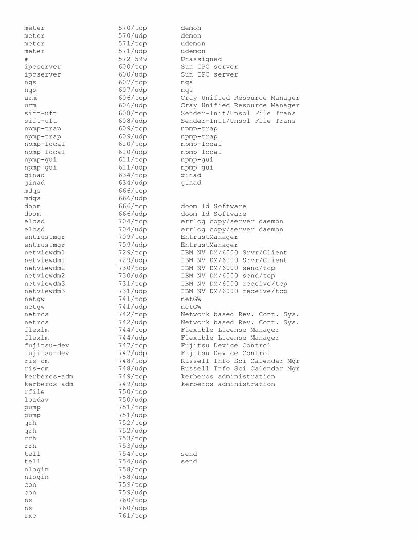
meter 570/tcp demon
meter 570/udp demon
meter 571/tcp udemon
meter 571/udp udemon
# 572-599 Unassigned
ipcserver 600/tcp Sun IPC server
ipcserver 600/udp Sun IPC server
nqs 607/tcp nqs
nqs 607/udp nqs
urm 606/tcp Cray Unified Resource Manager
urm 606/udp Cray Unified Resource Manager
sift-uft 608/tcp Sender-Init/Unsol File Trans
sift-uft 608/udp Sender-Init/Unsol File Trans
npmp-trap 609/tcp npmp-trap
npmp-trap 609/udp npmp-trap
npmp-local 610/tcp npmp-local
npmp-local 610/udp npmp-local
npmp-gui 611/tcp npmp-gui
npmp-gui 611/udp npmp-gui
ginad 634/tcp ginad
ginad 634/udp ginad
mdqs 666/tcp
mdqs 666/udp
doom 666/tcp doom Id Software
doom 666/udp doom Id Software
elcsd 704/tcp errlog copy/server daemon
elcsd 704/udp errlog copy/server daemon
entrustmgr 709/tcp EntrustManager
entrustmgr 709/udp EntrustManager
netviewdm1 729/tcp IBM NV DM/6000 Srvr/Client
netviewdm1 729/udp IBM NV DM/6000 Srvr/Client
netviewdm2 730/tcp IBM NV DM/6000 send/tcp
netviewdm2 730/udp IBM NV DM/6000 send/tcp
netviewdm3 731/tcp IBM NV DM/6000 receive/tcp
netviewdm3 731/udp IBM NV DM/6000 receive/tcp
netgw 741/tcp netGW
netgw 741/udp netGW
netrcs 742/tcp Network based Rev. Cont. Sys.
netrcs 742/udp Network based Rev. Cont. Sys.
flexlm 744/tcp Flexible License Manager
flexlm 744/udp Flexible License Manager
fujitsu-dev 747/tcp Fujitsu Device Control
fujitsu-dev 747/udp Fujitsu Device Control
ris-cm 748/tcp Russell Info Sci Calendar Mgr
ris-cm 748/udp Russell Info Sci Calendar Mgr
kerberos-adm 749/tcp kerberos administration
kerberos-adm 749/udp kerberos administration
rfile 750/tcp
loadav 750/udp
pump 751/tcp
pump 751/udp
qrh 752/tcp
qrh 752/udp
rrh 753/tcp
rrh 753/udp
tell 754/tcp send
tell 754/udp send
nlogin 758/tcp
nlogin 758/udp
con 759/tcp
con 759/udp
ns 760/tcp
ns 760/udp
rxe 761/tcp

rxe 761/udp
quotad 762/tcp
quotad 762/udp
cycleserv 763/tcp
cycleserv 763/udp
omserv 764/tcp
omserv 764/udp
webster 765/tcp
webster 765/udp
phonebook 767/tcp phone
phonebook 767/udp phone
vid 769/tcp
vid 769/udp
cadlock 770/tcp
cadlock 770/udp
rtip 771/tcp
rtip 771/udp
cycleserv2 772/tcp
cycleserv2 772/udp
submit 773/tcp
notify 773/udp
rpasswd 774/tcp
acmaint_dbd 774/udp
entomb 775/tcp
acmaint_transd 775/udp
wpages 776/tcp
wpages 776/udp
wpgs 780/tcp
wpgs 780/udp
concert 786/tcp Concert
concert 786/udp Concert
mdbs_daemon 800/tcp
mdbs_daemon 800/udp
device 801/tcp
device 801/udp
xtreelic 996/tcp Central Point Software
xtreelic 996/udp Central Point Software
maitrd 997/tcp
maitrd 997/udp
busboy 998/tcp
puparp 998/udp
garcon 999/tcp
applix 999/udp Applix ac
puprouter 999/tcp
puprouter 999/udp
cadlock 1000/tcp
ock 1000/udp
1023/tcp Reserved
1024/udp Reserved
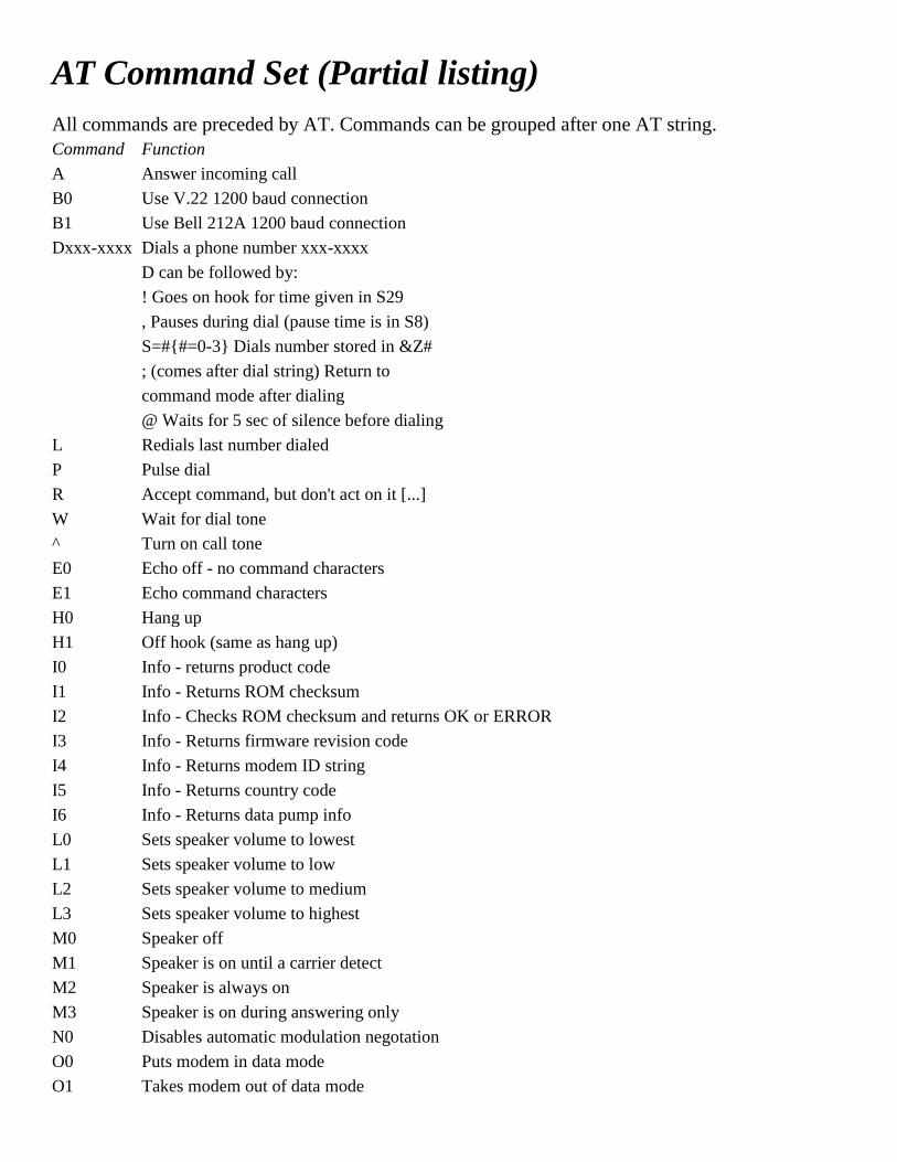
AT Command Set (Partial listing)
All commands are preceded by AT. Commands can be grouped after one AT string.
Command Function
A Answer incoming call
B0 Use V.22 1200 baud connection
B1 Use Bell 212A 1200 baud connection
Dxxx-xxxx Dials a phone number xxx-xxxx
D can be followed by:
! Goes on hook for time given in S29
, Pauses during dial (pause time is in S8)
S=#{#=0-3} Dials number stored in &Z#
; (comes after dial string) Return to
command mode after dialing
@ Waits for 5 sec of silence before dialing
L Redials last number dialed
P Pulse dial
R Accept command, but don't act on it [...]
W Wait for dial tone
^ Turn on call tone
E0 Echo off - no command characters
E1 Echo command characters
H0 Hang up
H1 Off hook (same as hang up)
I0 Info - returns product code
I1 Info - Returns ROM checksum
I2 Info - Checks ROM checksum and returns OK or ERROR
I3 Info - Returns firmware revision code
I4 Info - Returns modem ID string
I5 Info - Returns country code
I6 Info - Returns data pump info
L0 Sets speaker volume to lowest
L1 Sets speaker volume to low
L2 Sets speaker volume to medium
L3 Sets speaker volume to highest
M0 Speaker off
M1 Speaker is on until a carrier detect
M2 Speaker is always on
M3 Speaker is on during answering only
N0 Disables automatic modulation negotation
O0 Puts modem in data mode
O1 Takes modem out of data mode
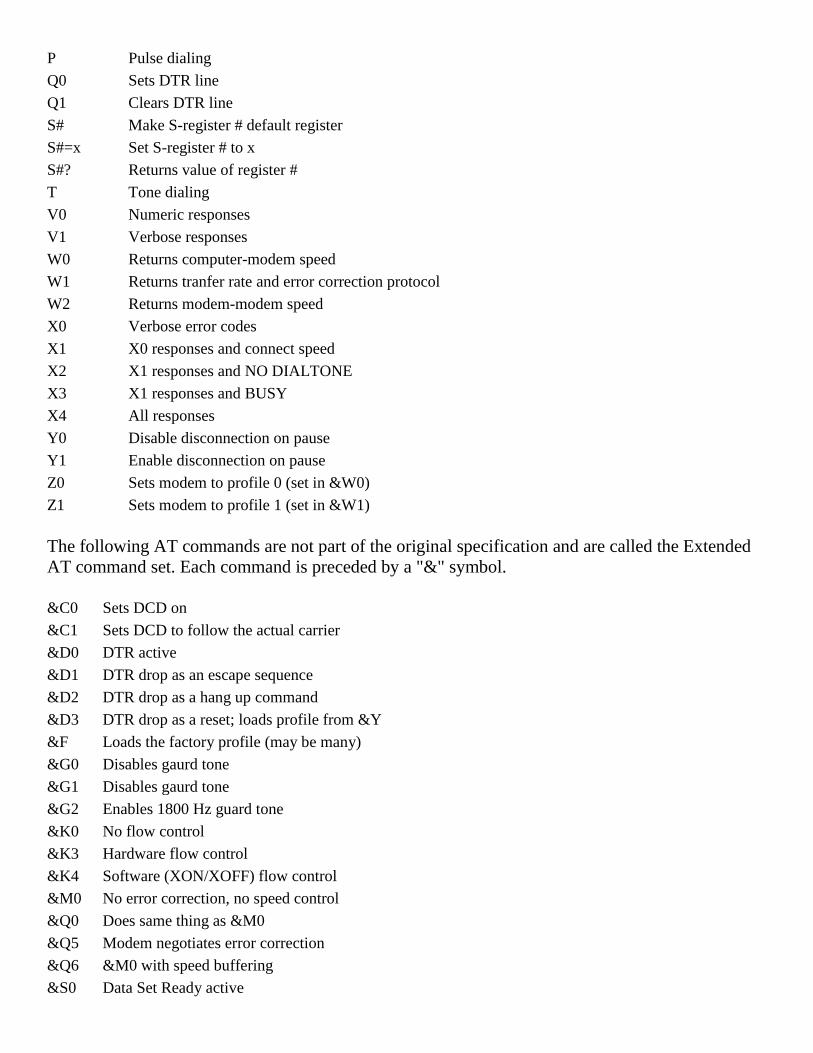
P Pulse dialing
Q0 Sets DTR line
Q1 Clears DTR line
S# Make S-register # default register
S#=x Set S-register # to x
S#? Returns value of register #
T Tone dialing
V0 Numeric responses
V1 Verbose responses
W0 Returns computer-modem speed
W1 Returns tranfer rate and error correction protocol
W2 Returns modem-modem speed
X0 Verbose error codes
X1 X0 responses and connect speed
X2 X1 responses and NO DIALTONE
X3 X1 responses and BUSY
X4 All responses
Y0 Disable disconnection on pause
Y1 Enable disconnection on pause
Z0 Sets modem to profile 0 (set in &W0)
Z1 Sets modem to profile 1 (set in &W1)
The following AT commands are not part of the original specification and are called the Extended
AT command set. Each command is preceded by a "&" symbol.
&C0 Sets DCD on
&C1 Sets DCD to follow the actual carrier
&D0 DTR active
&D1 DTR drop as an escape sequence
&D2 DTR drop as a hang up command
&D3 DTR drop as a reset; loads profile from &Y
&F Loads the factory profile (may be many)
&G0 Disables gaurd tone
&G1 Disables gaurd tone
&G2 Enables 1800 Hz guard tone
&K0 No flow control
&K3 Hardware flow control
&K4 Software (XON/XOFF) flow control
&M0 No error correction, no speed control
&Q0 Does same thing as &M0
&Q5 Modem negotiates error correction
&Q6 &M0 with speed buffering
&S0 Data Set Ready active

&S1 DSR active after answer detected until carrier is lost
&T0-8 {Engineering tests}
&V Returns profiles [&Y] and stored numbers [&Z]
&W0 Save current config as profile 0
&W1 Save current config as profile 1
&Y0 Modem uses profile 0 on startup
&Y1 Modem uses profile 1 on startup
&Z#=x Set stored number (0-3) to #

ISO 3166 Country Codes
ad Andorra fi Finland lb Lebanon
ae United Arab fj Fiji lc Saint Lucia sc Seychelles
Emirates fk Falkland li Liechtenstein sd Sudan
af Afghanistan Islands lk Sri Lanka se Sweden
ag Antigua and (Malvinas) lr Liberia sg Singapore
Barbuda fm Micronesia, ls Lesotho sh St. Helena
ai Anguilla Federated lt Lithuania si Slovenia
al Albania States of lu Luxembourg sj Svalbard and
am Armenia fo Faroe Islands lv Latvia Jan Mayen
an Netherlands fr France ly Libyan Arab Islands
Antilles fx Metropolitan Jamahiriya sk Slovakia
ao Angola France ma Morocco (Slovak
aq Antarctica ga Gabon mc Monaco Republic)
ar Argentina gb United Kingdom md Moldova, sl Sierra Leone
as American Samoa gd Grenada Republic of sm San Marino
at Austria ge Georgia mg Madagascar sn Senegal
au Australia gf French Guiana mh Marshall so Somalia
aw Aruba gh Ghana Islands sr Suriname
az Azerbaijan gi Gibraltar mk Macedonia, The st Sao Tome and
ba Bosnia and gl Greenland Former Principe
Herzegowina gm Gambia Yugoslav sv El Salvador
bb Barbados gn Guinea Republic of sy Syrian Arab
bd Bangladesh gp Guadeloupe ml Mali Republic
be Belgium gq Equatorial mm Myanmar sz Swaziland
bf Burkina Faso Guinea mn Mongolia tc Turks and
bg Bulgaria gr Greece mo Macau Caicos Islands
bh Bahrain gs South Georgia mp Northern td Chad
bi Burundi and The South Mariana tf French
bj Benin Sandwich Islands Southern
bm Bermuda Islands mq Martinique Territories
bn Brunei gt Guatemala mr Mauritania tg Togo
Darussalam gu Guam ms Montserrat th Thailand
bo Bolivia gw Guinea-Bissau mt Malta tj Tajikistan
br Brazil gy Guyana mu Mauritius tk Tokelau
bs Bahamas hk Hong Kong mv Maldives tm Turkmenistan
bt Bhutan hm Heard and Mc mw Malawi tn Tunisia
bv Bouvet Island Donald Islands mx Mexico to Tonga
bw Botswana hn Honduras my Malaysia tp East Timor
by Belarus hr Croatia mz Mozambique tr Turkey
bz Belize (Hrvatska) na Namibia tt Trinidad and
ca Canada ht Haiti nc New Caledonia Tobago
cc Cocos hu Hungary ne Niger tv Tuvalu
(Keeling) id Indonesia nf Norfolk Island tw Taiwan,
Islands ie Ireland ng Nigeria Province of
cf Central il Israel ni Nicaragua China
African in India nl Netherlands tz Tanzania,
Republic io British Indian no Norway United
cg Congo Ocean np Nepal Republic of
ch Switzerland Territory nr Nauru ua Ukraine
ci Cote D'ivoire iq Iraq nu Niue ug Uganda
ck Cook Islands ir Iran (Islamic nz New Zealand um United States
cl Chile Republic of) om Oman Minor Outlying
cm Cameroon is Iceland pa Panama Islands
cn China it Italy pe Peru us United States
co Colombia jm Jamaica pf French uy Uruguay
cr Costa Rica jo Jordan Polynesia uz Uzbekistan
cu Cuba jp Japan pg Papua New va Vatican City
cv Cape Verde ke Kenya Guinea State (Holy
cx Christmas kg Kyrgyzstan ph Philippines See)
Island kh Cambodia pk Pakistan vc Saint Vincent
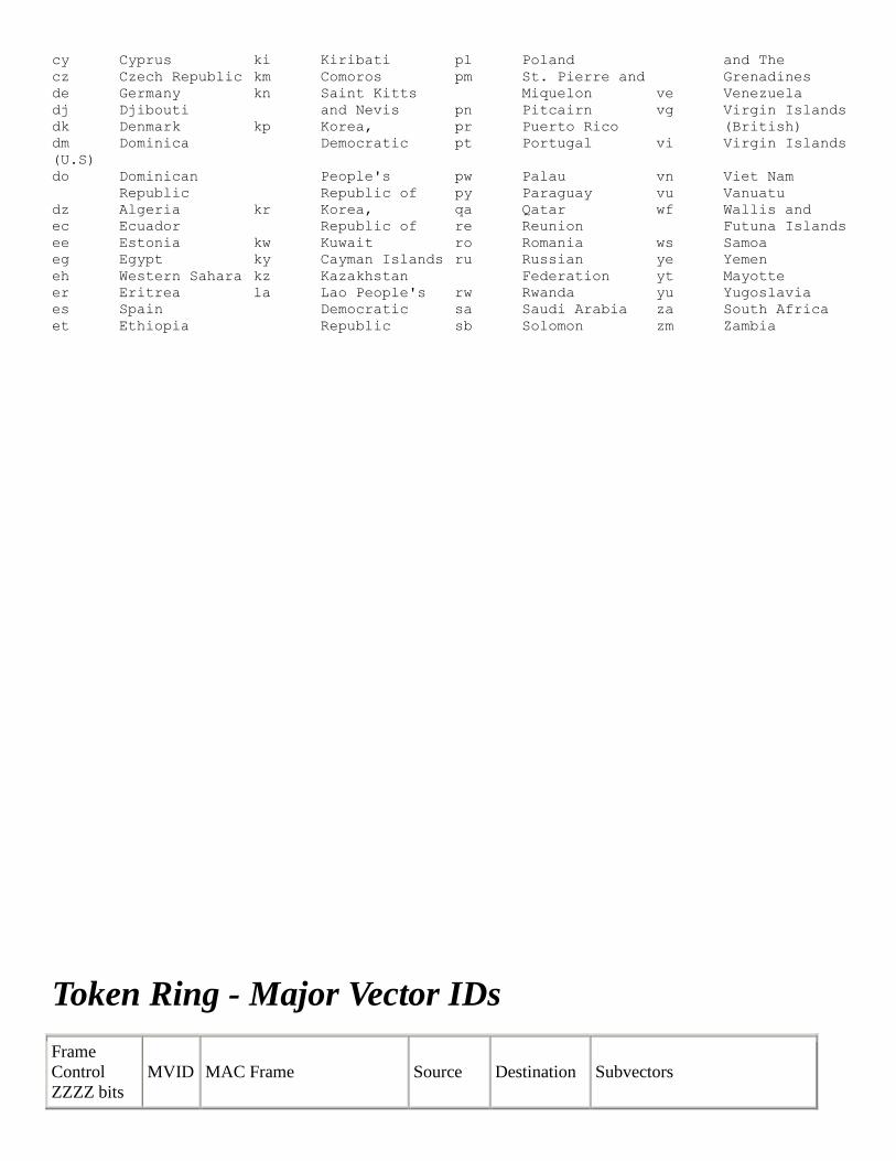
cy Cyprus ki Kiribati pl Poland and The
cz Czech Republic km Comoros pm St. Pierre and Grenadines
de Germany kn Saint Kitts Miquelon ve Venezuela
dj Djibouti and Nevis pn Pitcairn vg Virgin Islands
dk Denmark kp Korea, pr Puerto Rico (British)
dm Dominica Democratic pt Portugal vi Virgin Islands
(U.S)
do Dominican People's pw Palau vn Viet Nam
Republic Republic of py Paraguay vu Vanuatu
dz Algeria kr Korea, qa Qatar wf Wallis and
ec Ecuador Republic of re Reunion Futuna Islands
ee Estonia kw Kuwait ro Romania ws Samoa
eg Egypt ky Cayman Islands ru Russian ye Yemen
eh Western Sahara kz Kazakhstan Federation yt Mayotte
er Eritrea la Lao People's rw Rwanda yu Yugoslavia
es Spain Democratic sa Saudi Arabia za South Africa
et Ethiopia Republic sb Solomon zm Zambia
Token Ring - Major Vector IDs
Frame
Control
ZZZZ bits
MVID MAC Frame Source Destination Subvectors
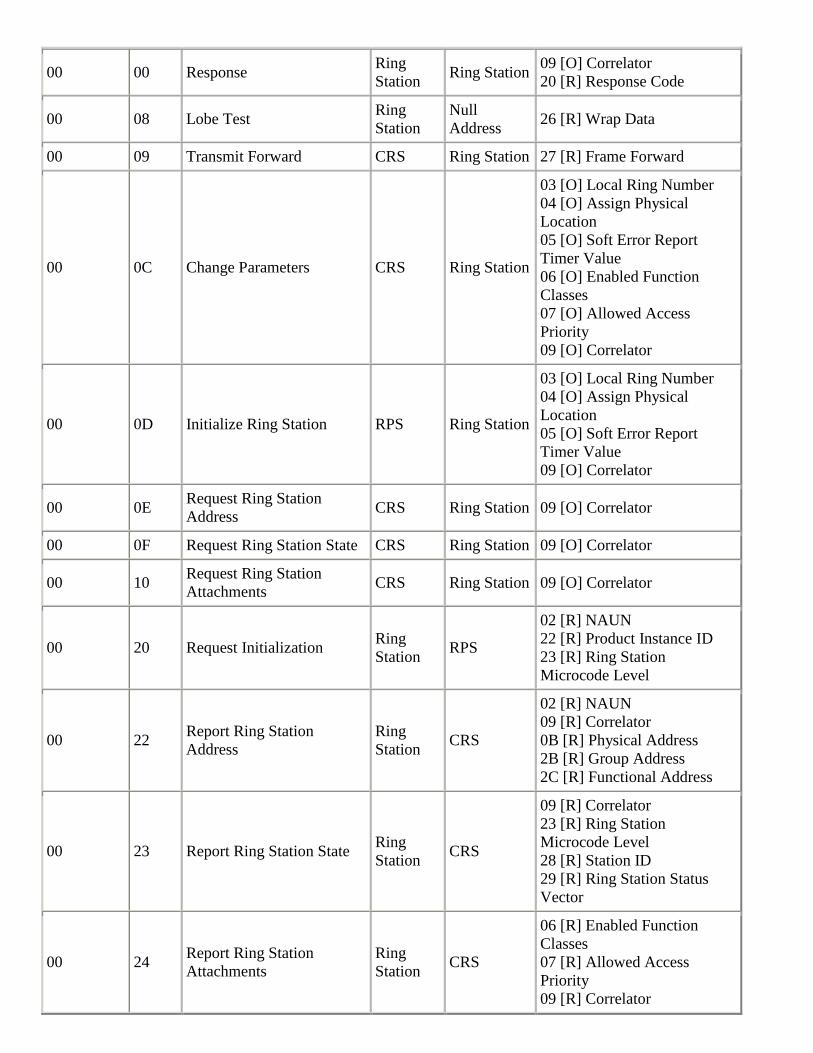
00 00 Response Ring
Station Ring Station
09 [O] Correlator
20 [R] Response Code
00 08 Lobe Test Ring
Station
Null
Address 26 [R] Wrap Data
00 09 Transmit Forward CRS Ring Station 27 [R] Frame Forward
00 0C Change Parameters CRS Ring Station
03 [O] Local Ring Number
04 [O] Assign Physical
Location
05 [O] Soft Error Report
Timer Value
06 [O] Enabled Function
Classes
07 [O] Allowed Access
Priority
09 [O] Correlator
00 0D Initialize Ring Station RPS Ring Station
03 [O] Local Ring Number
04 [O] Assign Physical
Location
05 [O] Soft Error Report
Timer Value
09 [O] Correlator
00 0E Request Ring Station
Address CRS Ring Station 09 [O] Correlator
00 0F Request Ring Station State CRS Ring Station 09 [O] Correlator
00 10 Request Ring Station
Attachments CRS Ring Station 09 [O] Correlator
00 20 Request Initialization Ring
Station RPS
02 [R] NAUN
22 [R] Product Instance ID
23 [R] Ring Station
Microcode Level
00 22 Report Ring Station
Address
Ring
Station CRS
02 [R] NAUN
09 [R] Correlator
0B [R] Physical Address
2B [R] Group Address
2C [R] Functional Address
00 23 Report Ring Station State Ring
Station CRS
09 [R] Correlator
23 [R] Ring Station
Microcode Level
28 [R] Station ID
29 [R] Ring Station Status
Vector
00 24 Report Ring Station
Attachments
Ring
Station CRS
06 [R] Enabled Function
Classes
07 [R] Allowed Access
Priority
09 [R] Correlator
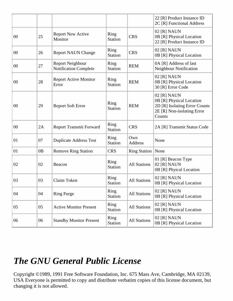
22 [R] Product Instance ID
2C [R] Functional Address
00 25 Report New Active
Monitor
Ring
Station CRS
02 [R] NAUN
0B [R] Physical Location
22 [R] Product Instance ID
00 26 Report NAUN Change Ring
Station CRS
02 [R] NAUN
0B [R] Physical Location
00 27 Report Neighbour
Notification Complete
Ring
Station REM
0A [R] Address of last
Neighbour Notification
00 28 Report Active Monitor
Error
Ring
Station REM
02 [R] NAUN
0B [R] Physical Location
30 [R] Error Code
00 29 Report Soft Error Ring
Station REM
02 [R] NAUN
0B [R] Physical Location
2D [R] Isolating Error Counts
2E [R] Non-isolating Error
Counts
00 2A Report Transmit Forward Ring
Station CRS 2A [R] Transmit Status Code
01 07 Duplicate Address Test Ring
Station
Own
Address None
01 0B Remove Ring Station CRS Ring Station None
02 02 Beacon Ring
Station All Stations
01 [R] Beacon Type
02 [R] NAUN
0B [R] Phyical Location
03 03 Claim Token Ring
Station All Stations
02 [R] NAUN
0B [R] Physical Location
04 04 Ring Purge Ring
Station All Stations
02 [R] NAUN
0B [R] Physical Location
05 05 Active Monitor Present Ring
Station All Stations
02 [R] NAUN
0B [R] Physical Location
06 06 Standby Monitor Present Ring
Station All Stations
02 [R] NAUN
0B [R] Physical Location
The GNU General Public License
Copyright ©1989, 1991 Free Software Foundation, Inc. 675 Mass Ave, Cambridge, MA 02139,
USA Everyone is permitted to copy and distribute verbatim copies of this license document, but
changing it is not allowed.
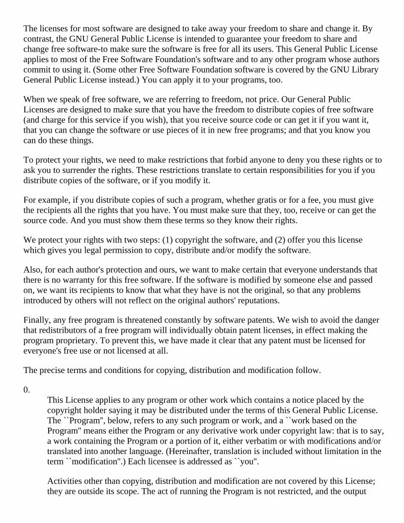
The licenses for most software are designed to take away your freedom to share and change it. By
contrast, the GNU General Public License is intended to guarantee your freedom to share and
change free software-to make sure the software is free for all its users. This General Public License
applies to most of the Free Software Foundation's software and to any other program whose authors
commit to using it. (Some other Free Software Foundation software is covered by the GNU Library
General Public License instead.) You can apply it to your programs, too.
When we speak of free software, we are referring to freedom, not price. Our General Public
Licenses are designed to make sure that you have the freedom to distribute copies of free software
(and charge for this service if you wish), that you receive source code or can get it if you want it,
that you can change the software or use pieces of it in new free programs; and that you know you
can do these things.
To protect your rights, we need to make restrictions that forbid anyone to deny you these rights or to
ask you to surrender the rights. These restrictions translate to certain responsibilities for you if you
distribute copies of the software, or if you modify it.
For example, if you distribute copies of such a program, whether gratis or for a fee, you must give
the recipients all the rights that you have. You must make sure that they, too, receive or can get the
source code. And you must show them these terms so they know their rights.
We protect your rights with two steps: (1) copyright the software, and (2) offer you this license
which gives you legal permission to copy, distribute and/or modify the software.
Also, for each author's protection and ours, we want to make certain that everyone understands that
there is no warranty for this free software. If the software is modified by someone else and passed
on, we want its recipients to know that what they have is not the original, so that any problems
introduced by others will not reflect on the original authors' reputations.
Finally, any free program is threatened constantly by software patents. We wish to avoid the danger
that redistributors of a free program will individually obtain patent licenses, in effect making the
program proprietary. To prevent this, we have made it clear that any patent must be licensed for
everyone's free use or not licensed at all.
The precise terms and conditions for copying, distribution and modification follow.
0.
This License applies to any program or other work which contains a notice placed by the
copyright holder saying it may be distributed under the terms of this General Public License.
The ``Program'', below, refers to any such program or work, and a ``work based on the
Program'' means either the Program or any derivative work under copyright law: that is to say,
a work containing the Program or a portion of it, either verbatim or with modifications and/or
translated into another language. (Hereinafter, translation is included without limitation in the
term ``modification''.) Each licensee is addressed as ``you''.
Activities other than copying, distribution and modification are not covered by this License;
they are outside its scope. The act of running the Program is not restricted, and the output

from the Program is covered only if its contents constitute a work based on the Program
(independent of having been made by running the Program). Whether that is true depends on
what the Program does.
1.
You may copy and distribute verbatim copies of the Program's source code as you receive it,
in any medium, provided that you conspicuously and appropriately publish on each copy an
appropriate copyright notice and disclaimer of warranty; keep intact all the notices that refer
to this License and to the absence of any warranty; and give any other recipients of the
Program a copy of this License along with the Program.
You may charge a fee for the physical act of transferring a copy, and you may at your option
offer warranty protection in exchange for a fee.
2.
You may modify your copy or copies of the Program or any portion of it, thus forming a work
based on the Program, and copy and distribute such modifications or work under the terms of
Section 1 above, provided that you also meet all of these conditions:
a.
You must cause the modified files to carry prominent notices stating that you changed the
files and the date of any change.
b.
You must cause any work that you distribute or publish, that in whole or in part contains or is
derived from the Program or any part thereof, to be licensed as a whole at no charge to all
third parties under the terms of this License.
c.
If the modified program normally reads commands interactively when run, you must cause it,
when started running for such interactive use in the most ordinary way, to print or display an
announcement including an appropriate copyright notice and a notice that there is no warranty
(or else, saying that you provide a warranty) and that users may redistribute the program
under these conditions, and telling the user how to view a copy of this License. (Exception: if
the Program itself is interactive but does not normally print such an announcement, your work
based on the Program is not required to print an announcement.)
These requirements apply to the modified work as a whole. If identifiable sections of that
work are not derived from the Program, and can be reasonably considered independent and
separate works in themselves, then this License, and its terms, do not apply to those sections
when you distribute them as separate works. But when you distribute the same sections as
part of a whole which is a work based on the Program, the distribution of the whole must be
on the terms of this License, whose permissions for other licensees extend to the entire whole,
and thus to each and every part regardless of who wrote it.
Thus, it is not the intent of this section to claim rights or contest your rights to work written
entirely by you; rather, the intent is to exercise the right to control the distribution of
derivative or collective works based on the Program.
In addition, mere aggregation of another work not based on the Program with the Program (or
with a work based on the Program) on a volume of a storage or distribution medium does not
bring the other work under the scope of this License.
3.
You may copy and distribute the Program (or a work based on it, under Section 2) in object
code or executable form under the terms of Sections 1 and 2 above provided that you also do
one of the following:
a.
Accompany it with the complete corresponding machine-readable source code, which must be
distributed under the terms of Sections 1 and 2 above on a medium customarily used for
software interchange; or,
b.
Accompany it with a written offer, valid for at least three years, to give any third party, for a
charge no more than your cost of physically performing source distribution, a complete
machine-readable copy of the corresponding source code, to be distributed under the terms of
Sections 1 and 2 above on a medium customarily used for software interchange; or,
c.
Accompany it with the information you received as to the offer to distribute corresponding
source code. (This alternative is allowed only for noncommercial distribution and only if you
received the program in object code or executable form with such an offer, in accord with
Subsection b above.)
The source code for a work means the preferred form of the work for making modifications to
it. For an executable work, complete source code means all the source code for all modules it
contains, plus any associated interface definition files, plus the scripts used to control
compilation and installation of the executable. However, as a special exception, the source
code distributed need not include anything that is normally distributed (in either source or
binary form) with the major components (compiler, kernel, and so on) of the operating system
on which the executable runs, unless that component itself accompanies the executable.
If distribution of executable or object code is made by offering access to copy from a
designated place, then offering equivalent access to copy the source code from the same place
counts as distribution of the source code, even though third parties are not compelled to copy
the source along with the object code.
4.
You may not copy, modify, sublicense, or distribute the Program except as expressly
provided under this License. Any attempt otherwise to copy, modify, sublicense or distribute
the Program is void, and will automatically terminate your rights under this License.
However, parties who have received copies, or rights, from you under this License will not
have their licenses terminated so long as such parties remain in full compliance.
5.
You are not required to accept this License, since you have not signed it. However, nothing
else grants you permission to modify or distribute the Program or its derivative works. These
actions are prohibited by law if you do not accept this License. Therefore, by modifying or
distributing the Program (or any work based on the Program), you indicate your acceptance of
this License to do so, and all its terms and conditions for copying, distributing or modifying
the Program or works based on it.
6.
Each time you redistribute the Program (or any work based on the Program), the recipient
automatically receives a license from the original licensor to copy, distribute or modify the
Program subject to these terms and conditions. You may not impose any further restrictions
on the recipients' exercise of the rights granted herein. You are not responsible for enforcing
compliance by third parties to this License.
7.
If, as a consequence of a court judgment or allegation of patent infringement or for any other
reason (not limited to patent issues), conditions are imposed on you (whether by court order,
agreement or otherwise) that contradict the conditions of this License, they do not excuse you
from the conditions of this License. If you cannot distribute so as to satisfy simultaneously
your obligations under this License and any other pertinent obligations, then as a consequence
you may not distribute the Program at all. For example, if a patent license would not permit
royalty-free redistribution of the Program by all those who receive copies directly or
indirectly through you, then the only way you could satisfy both it and this License would be
to refrain entirely from distribution of the Program.
If any portion of this section is held invalid or unenforceable under any particular
circumstance, the balance of the section is intended to apply and the section as a whole is
intended to apply in other circumstances.
It is not the purpose of this section to induce you to infringe any patents or other property
right claims or to contest validity of any such claims; this section has the sole purpose of
protecting the integrity of the free software distribution system, which is implemented by
public license practices. Many people have made generous contributions to the wide range of
software distributed through that system in reliance on consistent application of that system; it
is up to the author/donor to decide if he or she is willing to distribute software through any
other system and a licensee cannot impose that choice.
This section is intended to make thoroughly clear what is believed to be a consequence of the
rest of this License.
8.
If the distribution and/or use of the Program is restricted in certain countries either by patents
or by copyrighted interfaces, the original copyright holder who places the Program under this
License may add an explicit geographical distribution limitation excluding those countries, so
that distribution is permitted only in or among countries not thus excluded. In such case, this
License incorporates the limitation as if written in the body of this License.
9.
The Free Software Foundation may publish revised and/or new versions of the General Public
License from time to time. Such new versions will be similar in spirit to the present version,
but may differ in detail to address new problems or concerns.
Each version is given a distinguishing version number. If the Program specifies a version
number of this License which applies to it and ``any later version'', you have the option of
following the terms and conditions either of that version or of any later version published by
the Free Software Foundation. If the Program does not specify a version number of this
License, you may choose any version ever published by the Free Software Foundation.
10.
If you wish to incorporate parts of the Program into other free programs whose distribution
conditions are different, write to the author to ask for permission. For software which is
copyrighted by the Free Software Foundation, write to the Free Software Foundation; we
sometimes make exceptions for this. Our decision will be guided by the two goals of
preserving the free status of all derivatives of our free software and of promoting the sharing
and reuse of software generally.
11.
BECAUSE THE PROGRAM IS LICENSED FREE OF CHARGE, THERE IS NO
WARRANTY FOR THE PROGRAM, TO THE EXTENT PERMITTED BY APPLICABLE
LAW. EXCEPT WHEN OTHERWISE STATED IN WRITING THE COPYRIGHT
HOLDERS AND/OR OTHER PARTIES PROVIDE THE PROGRAM ``AS IS'' WITHOUT
WARRANTY OF ANY KIND, EITHER EXPRESSED OR IMPLIED, INCLUDING, BUT
NOT LIMITED TO, THE IMPLIED WARRANTIES OF MERCHANTABILITY AND
FITNESS FOR A PARTICULAR PURPOSE. THE ENTIRE RISK AS TO THE QUALITY
AND PERFORMANCE OF THE PROGRAM IS WITH YOU. SHOULD THE PROGRAM
PROVE DEFECTIVE, YOU ASSUME THE COST OF ALL NECESSARY SERVICING,
REPAIR OR CORRECTION.
12.
IN NO EVENT UNLESS REQUIRED BY APPLICABLE LAW OR AGREED TO IN
WRITING WILL ANY COPYRIGHT HOLDER, OR ANY OTHER PARTY WHO MAY
MODIFY AND/OR REDISTRIBUTE THE PROGRAM AS PERMITTED ABOVE, BE
LIABLE TO YOU FOR DAMAGES, INCLUDING ANY GENERAL, SPECIAL,
INCIDENTAL OR CONSEQUENTIAL DAMAGES ARISING OUT OF THE USE OR
INABILITY TO USE THE PROGRAM (INCLUDING BUT NOT LIMITED TO LOSS OF
DATA OR DATA BEING RENDERED INACCURATE OR LOSSES SUSTAINED BY
YOU OR THIRD PARTIES OR A FAILURE OF THE PROGRAM TO OPERATE WITH
ANY OTHER PROGRAMS), EVEN IF SUCH HOLDER OR OTHER PARTY HAS BEEN
ADVISED OF THE POSSIBILITY OF SUCH DAMAGES.
If you develop a new program, and you want it to be of the greatest possible use to the public, the
best way to achieve this is to make it free software which everyone can redistribute and change
under these terms.
To do so, attach the following notices to the program. It is safest to attach them to the start of each
source file to most effectively convey the exclusion of warranty; and each file should have at least
the ``copyright'' line and a pointer to where the full notice is found.
one line to give the program's name and a brief idea of what it does. Copyright ©19yy name
of author

This program is free software; you can redistribute it and/or modify it under the terms of the
GNU General Public License as published by the Free Software Foundation; either version 2
of the License, or (at your option) any later version.
This program is distributed in the hope that it will be useful, but WITHOUT ANY
WARRANTY; without even the implied warranty of MERCHANTABILITY or FITNESS
FOR A PARTICULAR PURPOSE. See the GNU General Public License for more details.
You should have received a copy of the GNU General Public License along with this
program; if not, write to the Free Software Foundation, Inc., 675 Mass Ave, Cambridge, MA
02139, USA.
Also add information on how to contact you by electronic and paper mail.
If the program is interactive, make it output a short notice like this when it starts in an interactive
mode:
The hypothetical commands `show w' and `show c' should show the appropriate parts of the General
Public License. Of course, the commands you use may be called something other than `show w' and
`show c'; they could even be mouse-clicks or menu items-whatever suits your program.
You should also get your employer (if you work as a programmer) or your school, if any, to sign a
``copyright disclaimer'' for the program, if necessary. Here is a sample; alter the names:
Yoyodyne, Inc., hereby disclaims all copyright interest in the program `Gnomovision' (which
makes passes at compilers) written by James Hacker.
signature of Ty Coon, 1 April 1989
Ty Coon, President of Vice
This General Public License does not permit incorporating your program into proprietary programs.
If your program is a subroutine library, you may consider it more useful to permit linking
proprietary applications with the library. If this is what you want to do, use the GNU Library
General Public License instead of this License.
Related Documents