Introduction to Capacitors, Inductors & Magnetic Circuits Related Book Basic Circuit Analysis 6thEd by David Erwin 1

Welcome message from author
This document is posted to help you gain knowledge. Please leave a comment to let me know what you think about it! Share it to your friends and learn new things together.
Transcript
Introduction to Capacitors, Inductors& Magnetic Circuits
Related BookBasic Circuit Analysis
6thEdby David Erwin
1
Chap. 6: Capacitors and Inductors
IntroductionCapacitorsSeries and Parallel CapacitorsInductorsSeries and Parallel Inductors
2
6.1 Introduction
Resistor: a passive element which dissipates energy only
Two important passive linear circuit elements:1) Capacitor2) Inductor
Capacitor and inductor can store energy only and they can neither generate nor dissipate energy.
3
Michael Faraday (1971-1867)
4
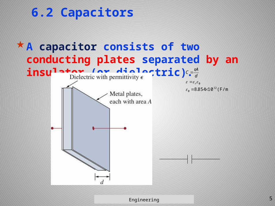
6.2 Capacitors
A capacitor consists of two conducting plates separated by an insulator (or dielectric).
(F/m)10854.8
ε
120
0
r
dAC
5Engineering
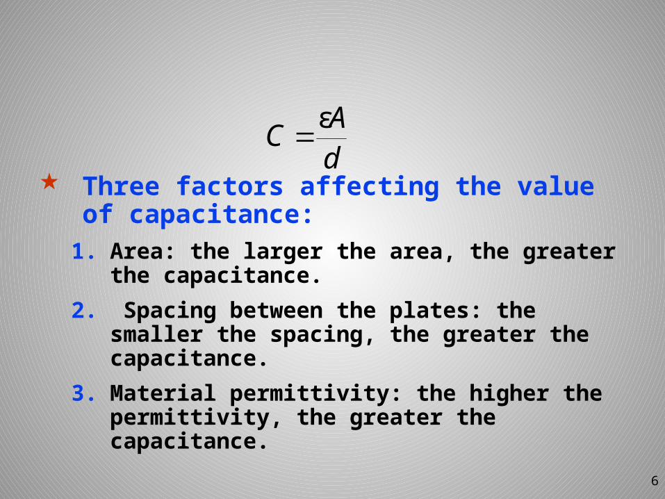
Three factors affecting the value of capacitance:1. Area: the larger the area, the greater
the capacitance.2. Spacing between the plates: the
smaller the spacing, the greater the capacitance.
3. Material permittivity: the higher the permittivity, the greater the capacitance.
6
dAC ε
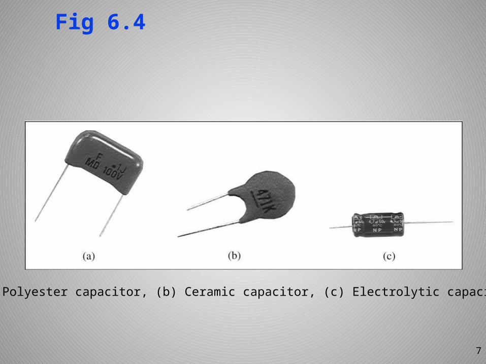
Fig 6.4
7
(a) Polyester capacitor, (b) Ceramic capacitor, (c) Electrolytic capacitor
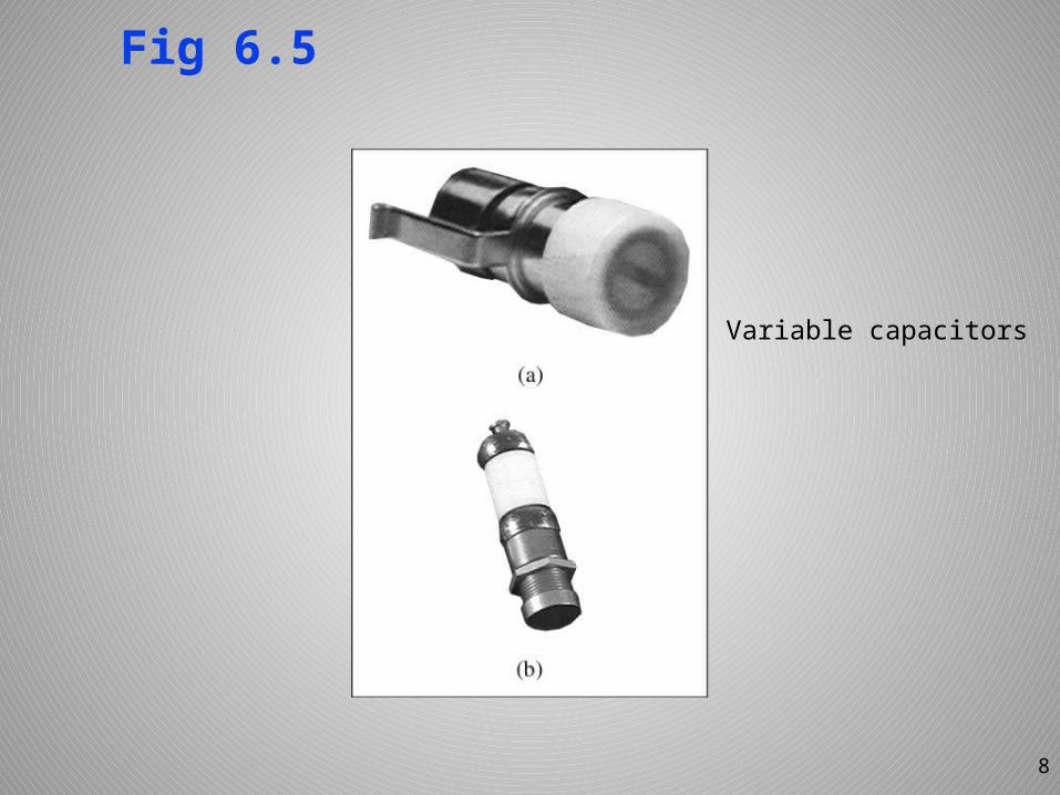
Fig 6.5
8
Variable capacitors
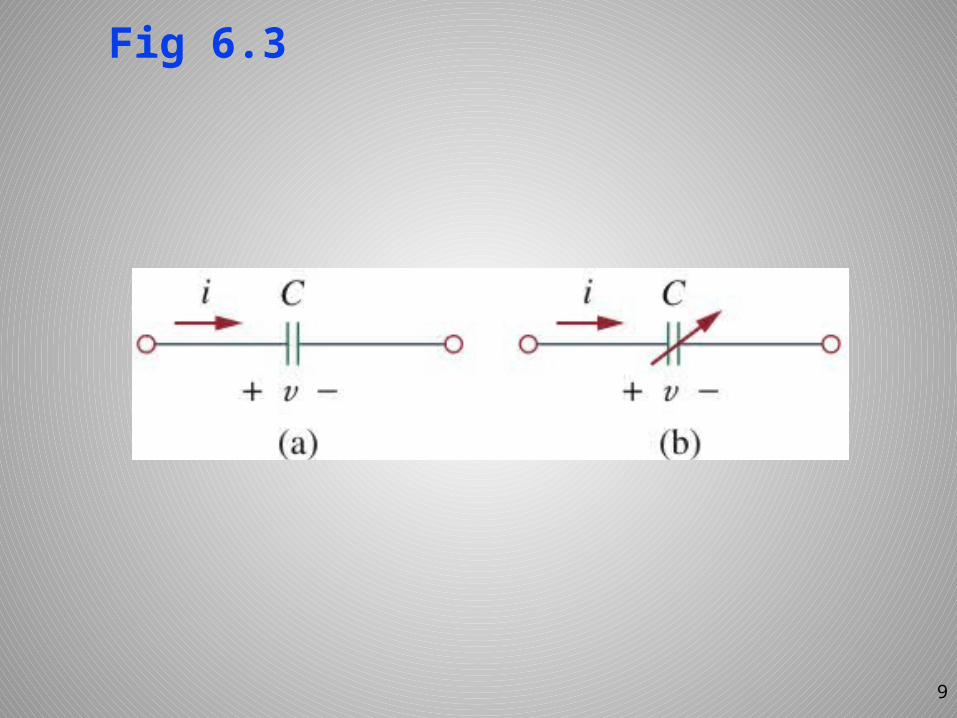
Fig 6.3
9
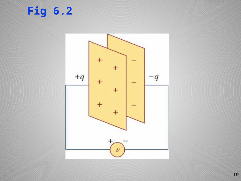
Fig 6.2
10
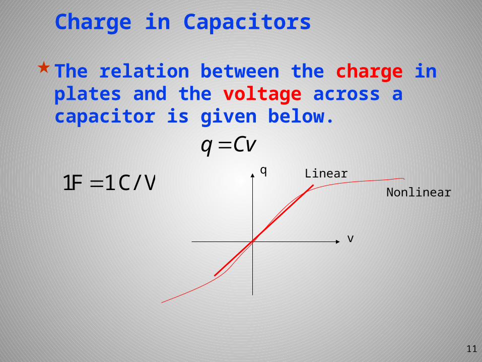
Charge in Capacitors
The relation between the charge in plates and the voltage across a capacitor is given below.
11
CvqC/V1F1
v
q LinearNonlinear
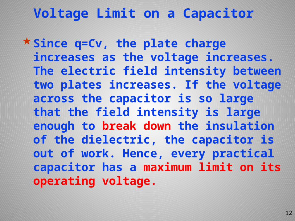
Voltage Limit on a Capacitor
Since q=Cv, the plate charge increases as the voltage increases. The electric field intensity between two plates increases. If the voltage across the capacitor is so large that the field intensity is large enough to break down the insulation of the dielectric, the capacitor is out of work. Hence, every practical capacitor has a maximum limit on its operating voltage.
12
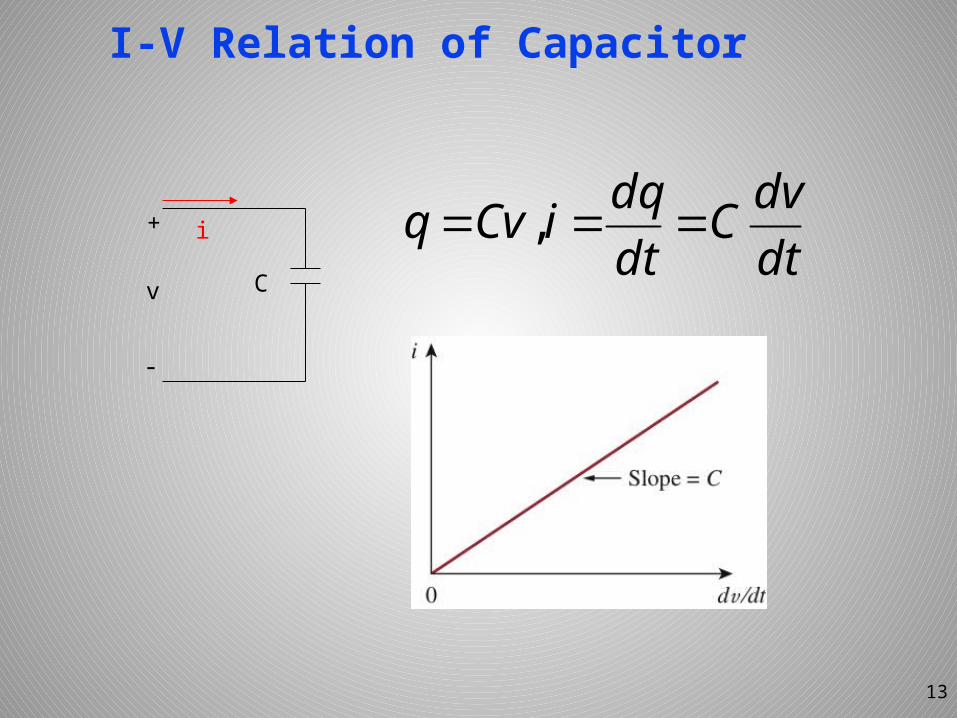
I-V Relation of Capacitor
dtdvC
dtdqiCvq ,
13
+
-
v
i
C
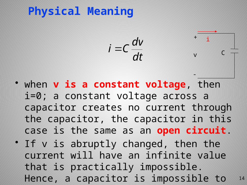
Physical Meaning
dtdvCi
14
• when v is a constant voltage, then i=0; a constant voltage across a capacitor creates no current through the capacitor, the capacitor in this case is the same as an open circuit.
• If v is abruptly changed, then the current will have an infinite value that is practically impossible. Hence, a capacitor is impossible to have an abrupt change in its voltage except an infinite current is applied.
+
-
v
i
C
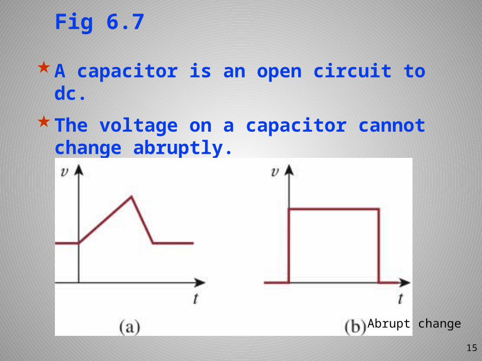
Fig 6.7
A capacitor is an open circuit to dc.
The voltage on a capacitor cannot change abruptly.
15
Abrupt change
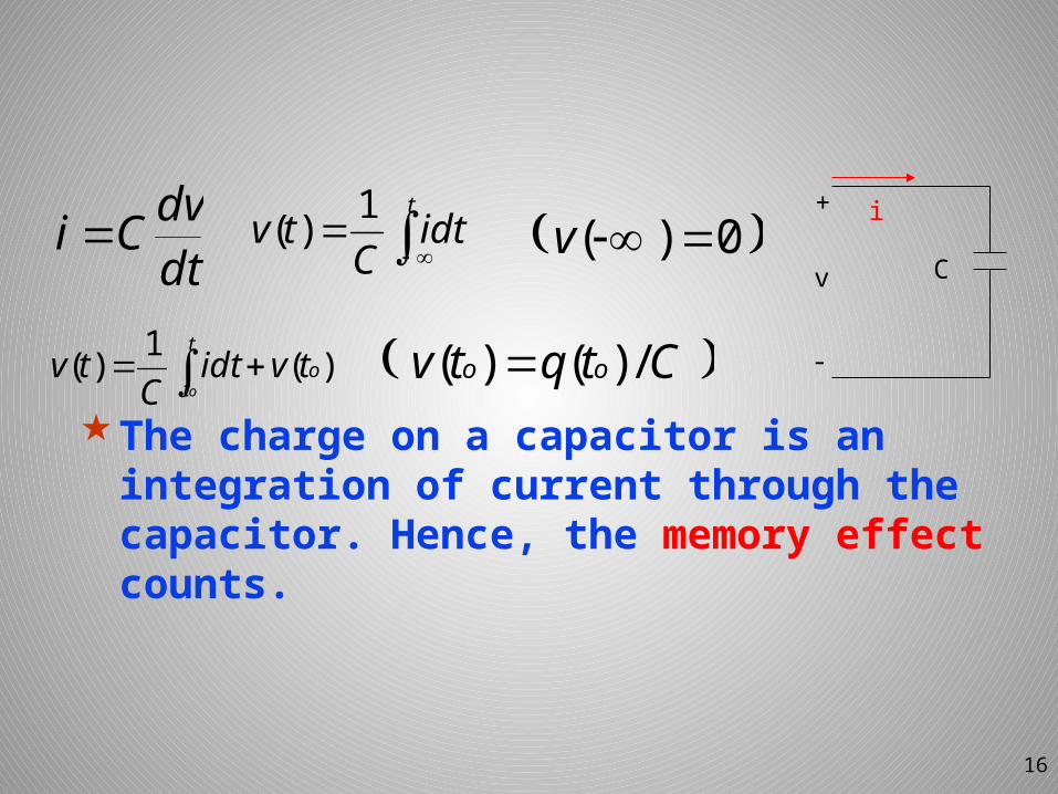
The charge on a capacitor is an integration of current through the capacitor. Hence, the memory effect counts.
16
dtdvCi
tidt
Ctv 1)(
t
to
otvidt
Ctv )(1)(
0)( v
Ctqtv oo /)()(
+
-
v
i
C
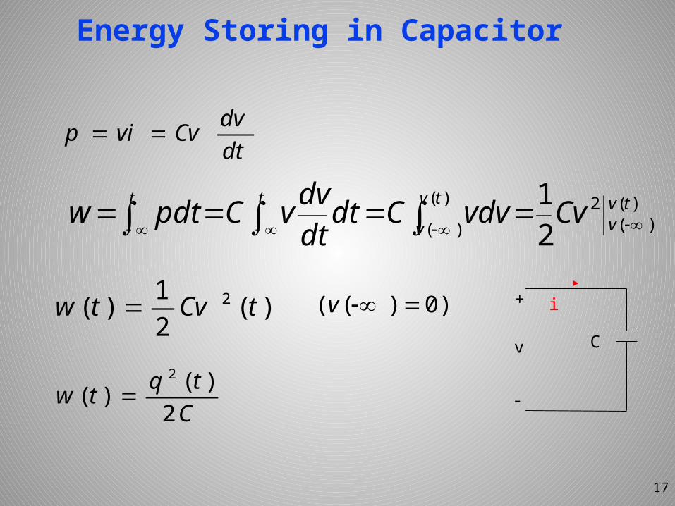
Energy Storing in Capacitor
17
dtdvCvvip
t tvv
tv
v
t CvvdvCdtdtdvvCpdtw )(
)(2)(
)( 21
)(21)( 2 tCvtw
Ctqtw 2)()(
2
)0)(( v +
-
v
i
C
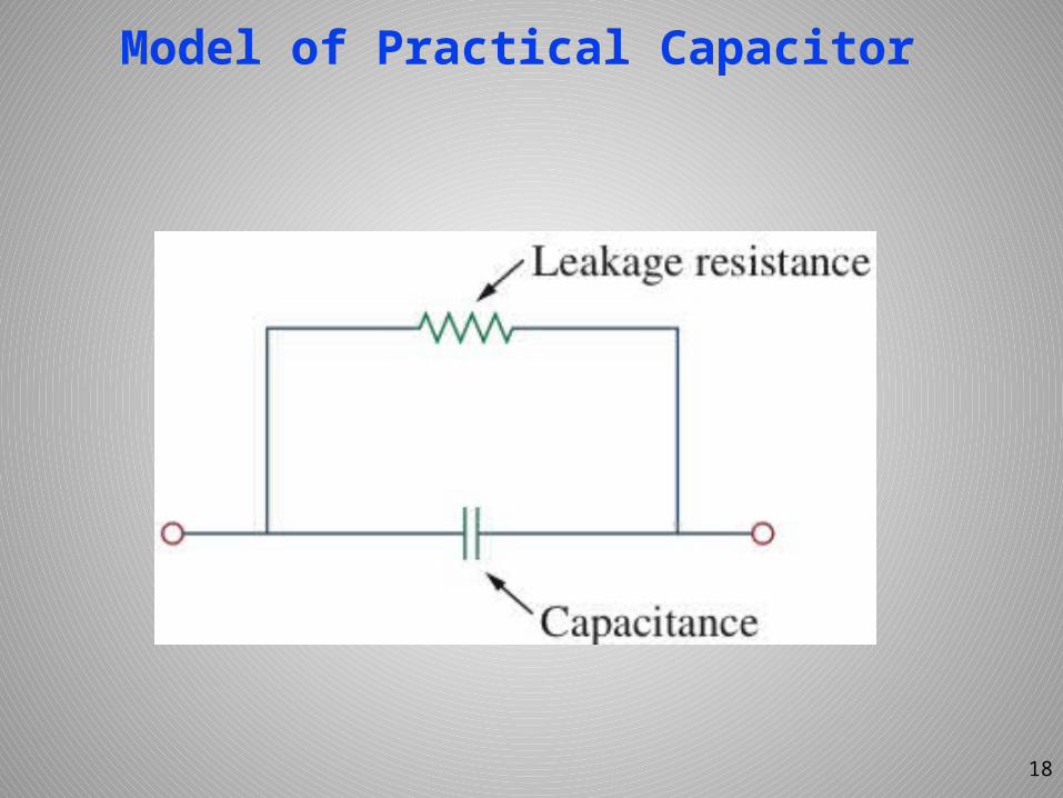
Model of Practical Capacitor
18
Example 6.1
(a)Calculate the charge stored on a 3-pF capacitor with 20V across it.
(b)Find the energy stored in the capacitor.
19
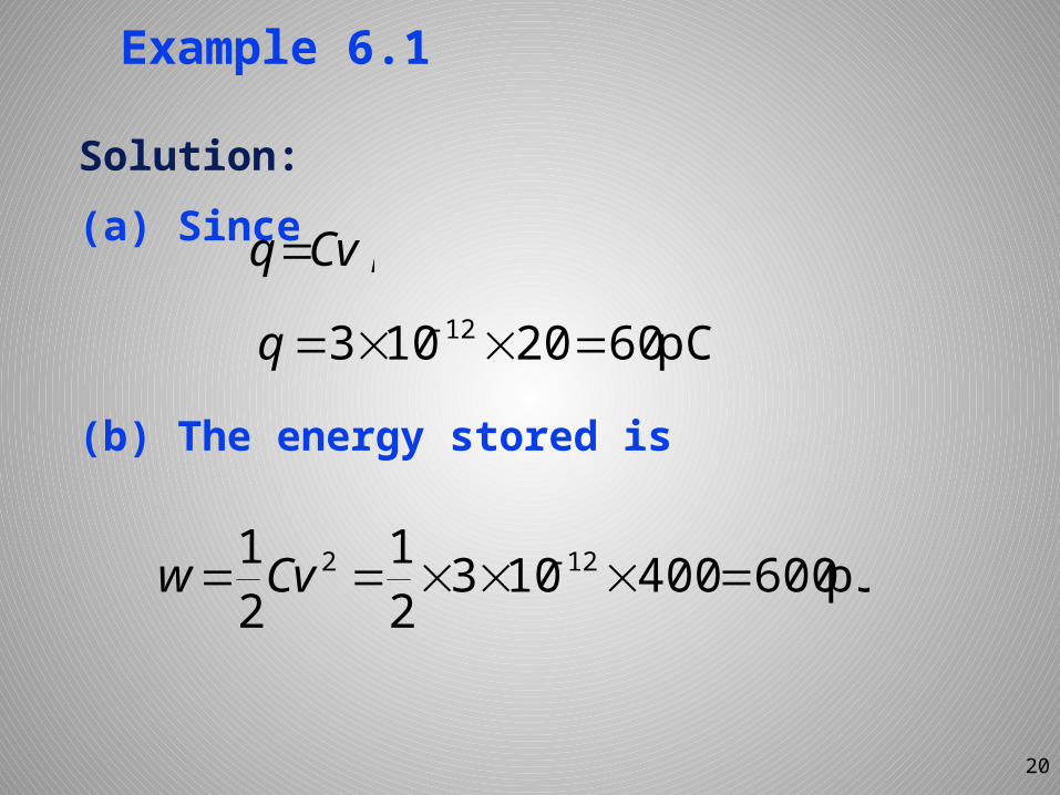
Example 6.1
Solution: (a) Since
(b) The energy stored is
20
pC6020103 12 q
pJ60040010321
21 122 Cvw
,Cvq
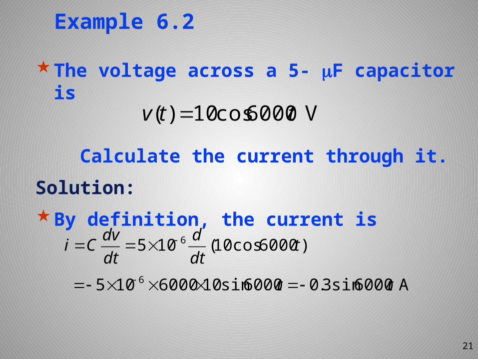
Example 6.2
The voltage across a 5- F capacitor is
Calculate the current through it. Solution: By definition, the current is
21
V 6000cos10)( ttv
6105 dtdvCi
6000105 6
)6000cos10( tdtd
A6000sin3.06000sin10 tt
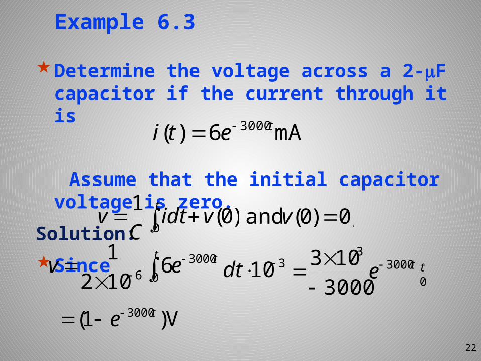
Example 6.3
Determine the voltage across a 2-F capacitor if the current through it is
Assume that the initial capacitor voltage is zero.
Solution: Since
22
mA6)( 3000teti
t tev 0
30006 6102
10
30003
3000103 tte
t vidt
Cv 0 )0(1 ,0)0(and v
310dt
V)1( 3000te
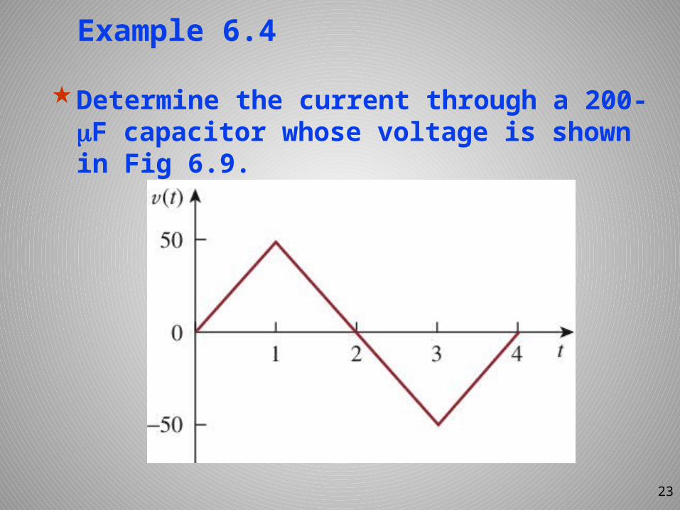
Example 6.4
Determine the current through a 200- F capacitor whose voltage is shown in Fig 6.9.
23
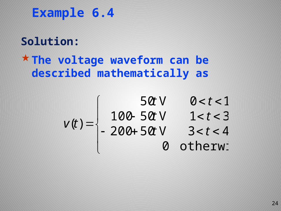
Example 6.4
Solution:The voltage waveform can be described mathematically as
24
otherwise043V 5020031V 5010010V 50
)( tttttt
tv
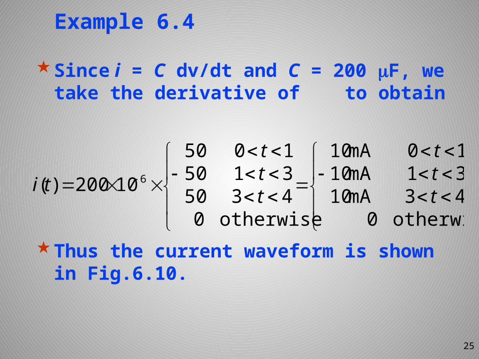
Example 6.4
Since i = C dv/dt and C = 200 F, we take the derivative of to obtain
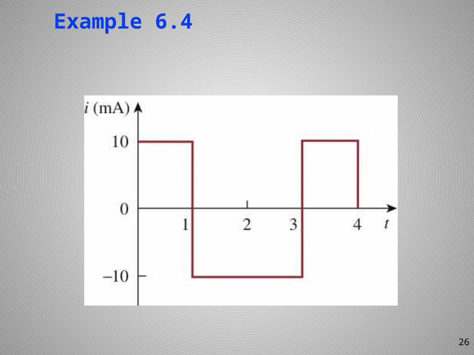
Thus the current waveform is shown in Fig.6.10.
25
otherwise043mA1031mA1010mA10
otherwise0435031501050
10200)( 6ttt
ttt
ti
Example 6.4
26
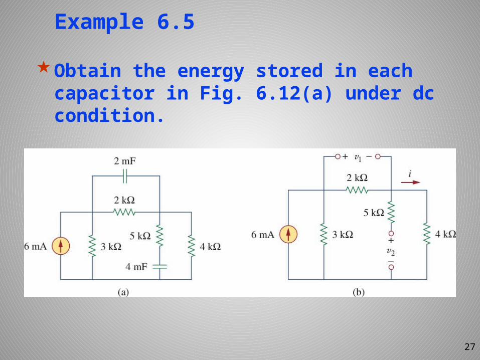
Example 6.5
Obtain the energy stored in each capacitor in Fig. 6.12(a) under dc condition.
27
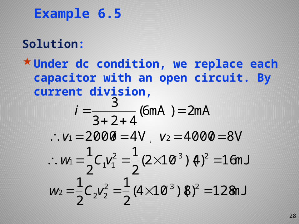
Example 6.5
Solution:Under dc condition, we replace each capacitor with an open circuit. By current division,
28
mA2)mA6(4233
i
,V420001 ivmJ16)4)(102(2
121 232
111 vCw
mJ128)8)(104(21
21 232
222 vCw
V840002 iv
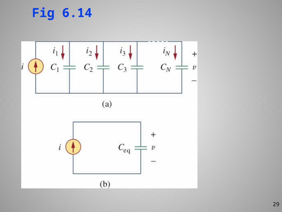
Fig 6.14
Neq CCCCC ....321
29
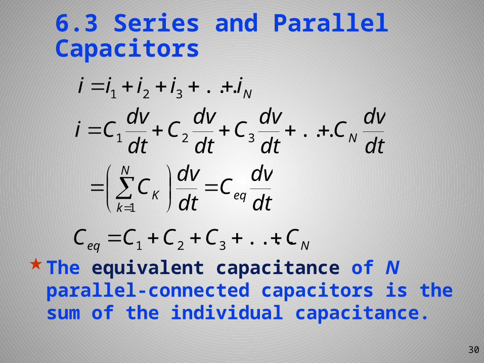
6.3 Series and Parallel Capacitors
The equivalent capacitance of N parallel-connected capacitors is the sum of the individual capacitance.
30
Niiiii ...321
dtdvC
dtdvC
dtdvC
dtdvCi N ...321
dtdvC
dtdvC eq
N
kK
1
Neq CCCCC ....321
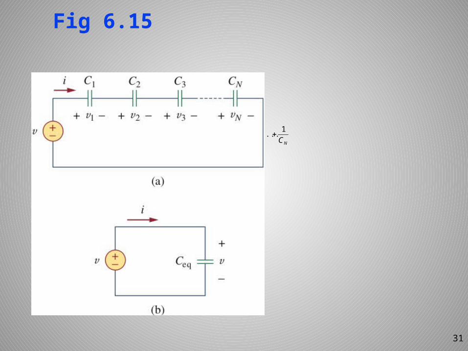
Fig 6.15
Neq CCCCC1...1111
321
31
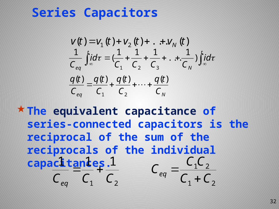
Series Capacitors
The equivalent capacitance of series-connected capacitors is the reciprocal of the sum of the reciprocals of the individual capacitances.
32
Neq
t
N
t
eq
Ctq
Ctq
Ctq
Ctq
idCCCC
idC
)()()()(
)1...111(1
21
321
)(...)()()( 21 tvtvtvtv N
21
111CCCeq
21
21CCCCC eq
Summary
These results enable us to look the capacitor in this way: 1/C has the equivalent effect as the resistance. The equivalent capacitor of capacitors connected in parallel or series can be obtained via this point of view, so is the Y-△ connection and its transformation
33
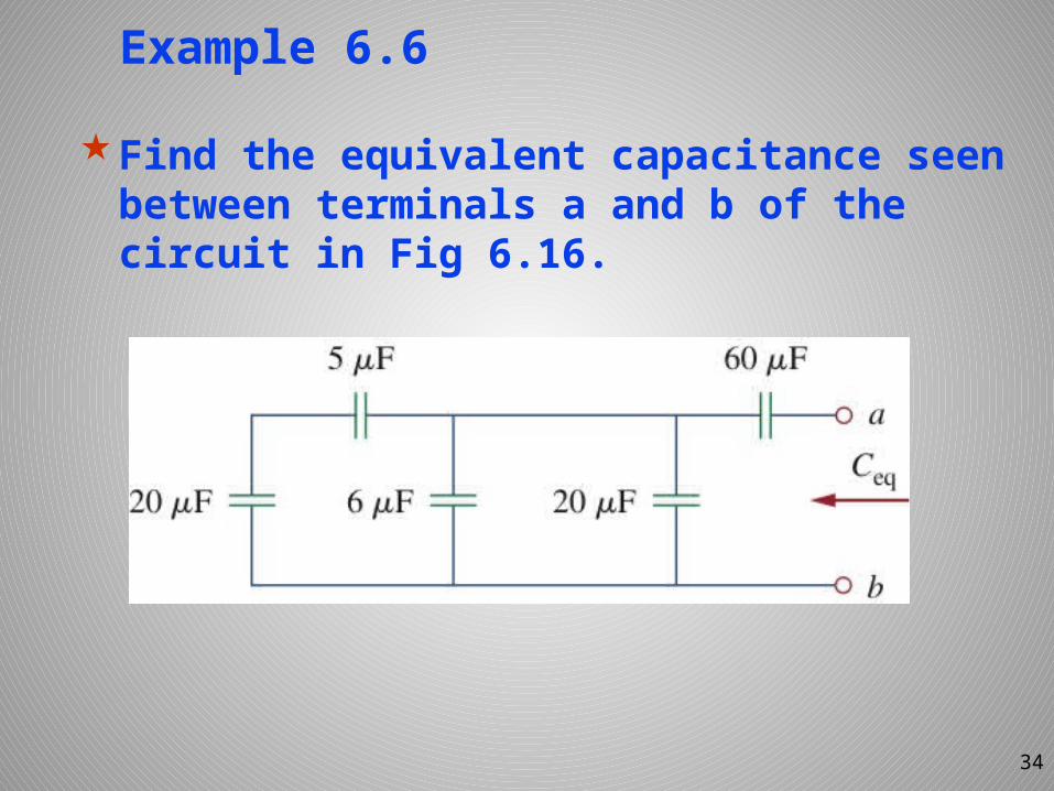
Example 6.6
Find the equivalent capacitance seen between terminals a and b of the circuit in Fig 6.16.
34
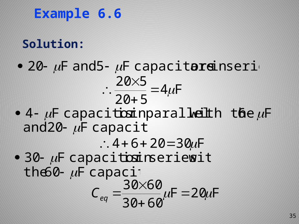
Example 6.6
Solution:
35
F4520520
F302064
F20F60306030
eqC
:seriesin are capacitors F5 and F20
F6 with the parallel in iscapacitor F4 :capacitors F20 and
withseriesin iscapacitor F30 capacitor. F60 the
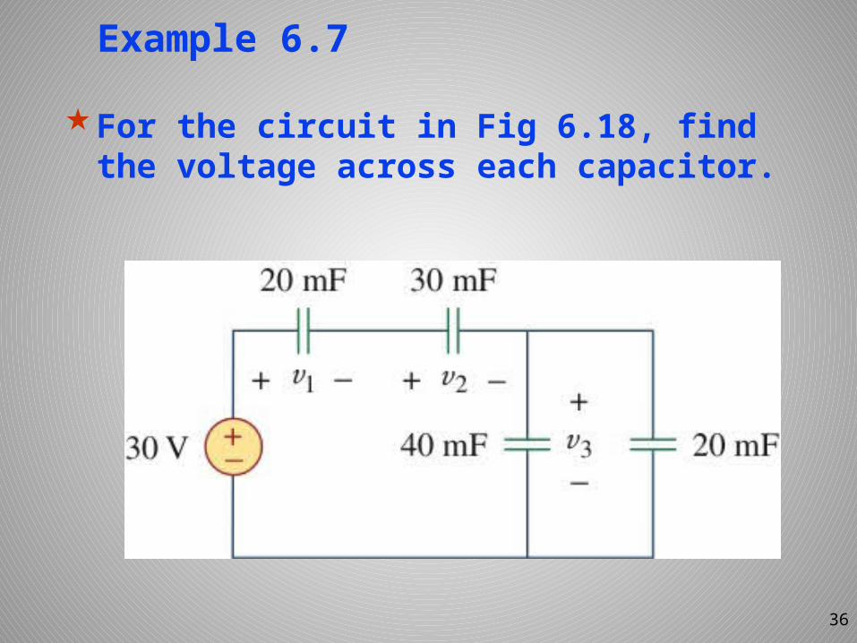
Example 6.7
For the circuit in Fig 6.18, find the voltage across each capacitor.
36
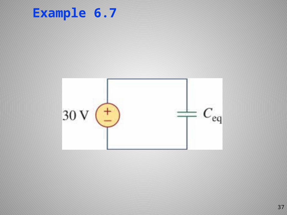
Example 6.7
37
Example 6.7
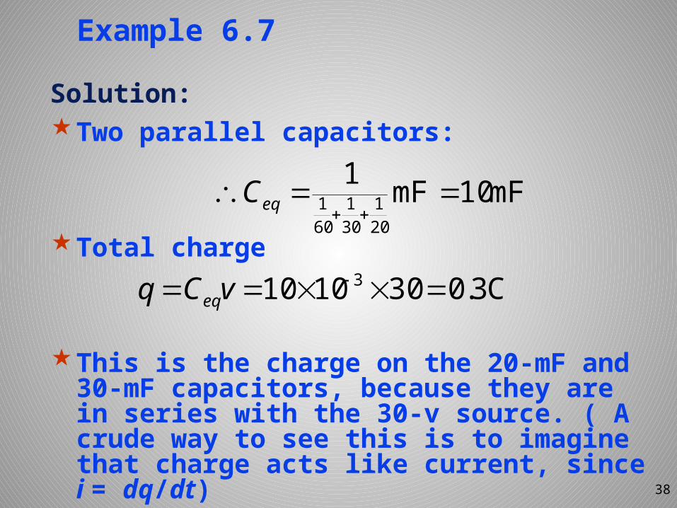
Solution: Two parallel capacitors:
Total charge
This is the charge on the 20-mF and 30-mF capacitors, because they are in series with the 30-v source. ( A crude way to see this is to imagine that charge acts like current, since i = dq/dt) 38
mF10mF1201
301
601
eqC
C3.0301010 3 vCq eq
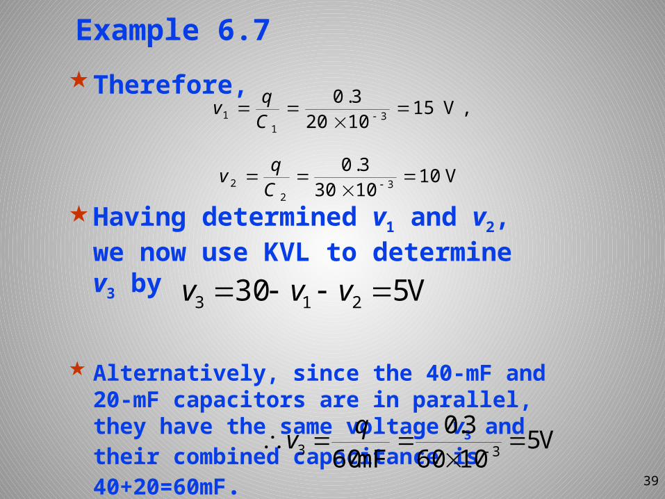
Example 6.7Therefore,
Having determined v1 and v2, we now use KVL to determine v3 by
Alternatively, since the 40-mF and 20-mF capacitors are in parallel, they have the same voltage v3 and their combined capacitance is 40+20=60mF. 39
,V1510203.0
31
1
Cqv
V1010303.0
32
2
Cqv
V530 213 vvv
V510603.0
mF60 33
qv
Joseph Henry (1979-1878)
40
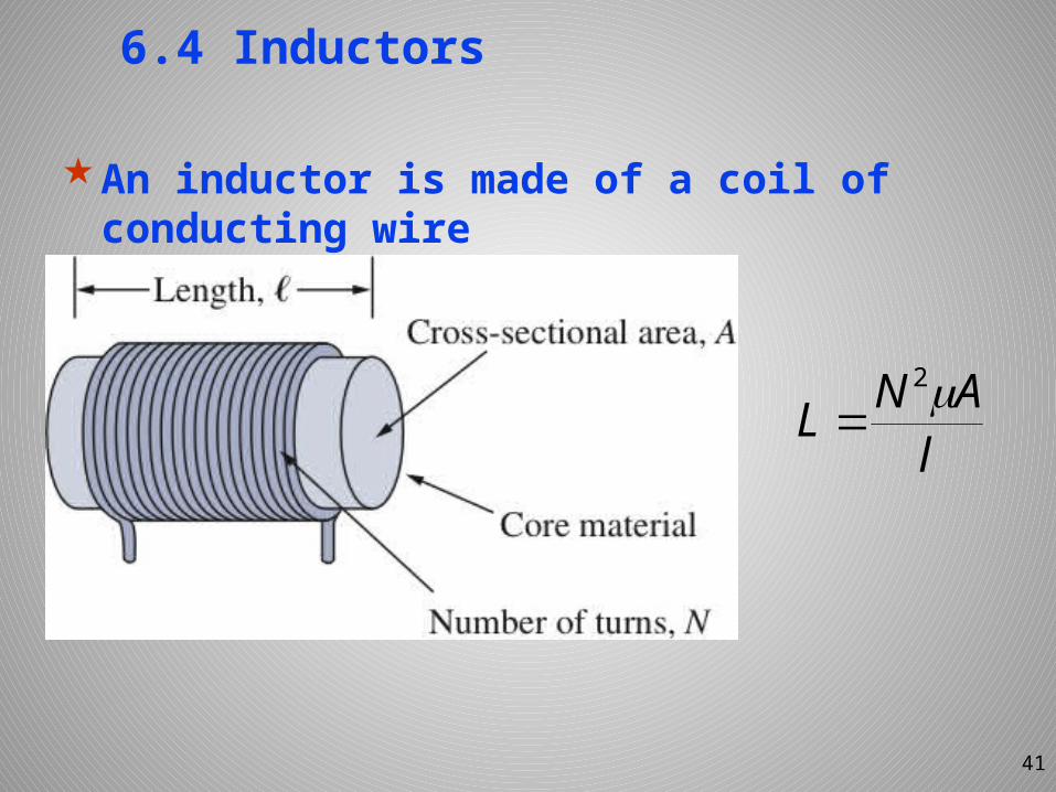
6.4 Inductors
An inductor is made of a coil of conducting wire
lANL 2
41
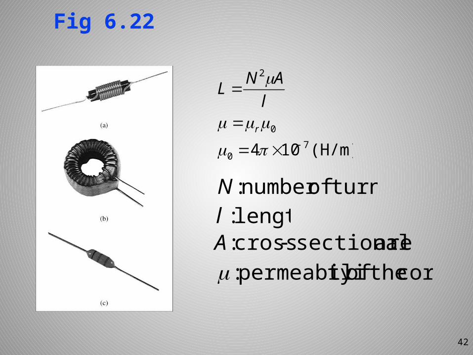
Fig 6.22
42
(H/m)104 70
0
2
r
lANL
turns.ofnumber:Nlength.:l
area. sectionalcross: Acoretheoftypermeabili:
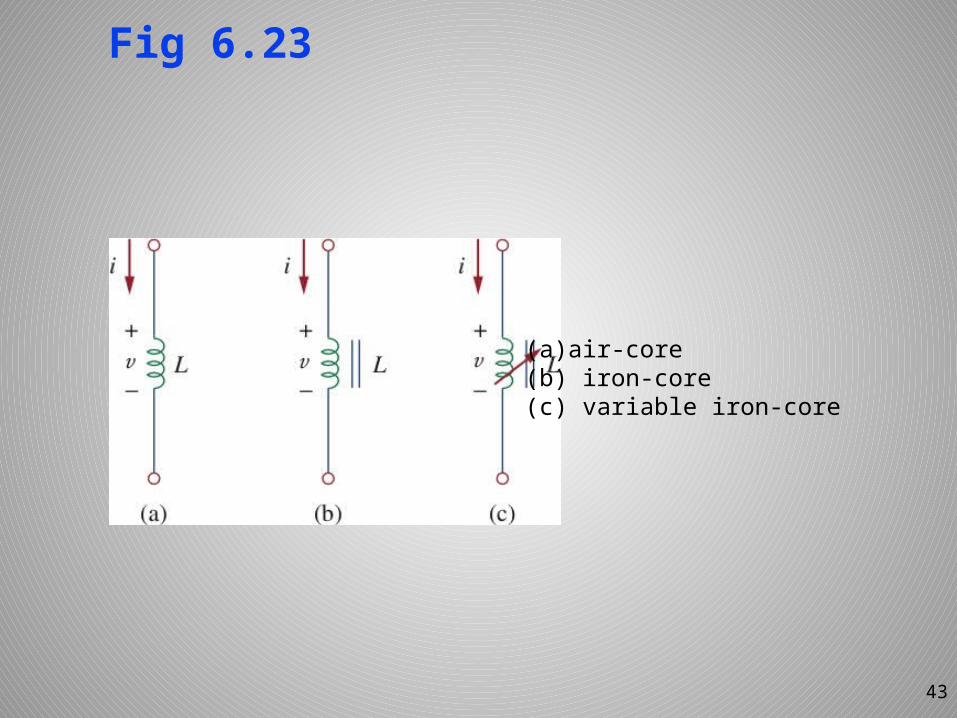
Fig 6.23
43
(a)air-core(b) iron-core(c) variable iron-core
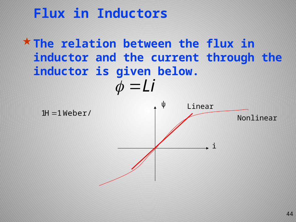
Flux in Inductors
The relation between the flux in inductor and the current through the inductor is given below.
44
LiWeber/A1H1
i
ψ LinearNonlinear
Energy Storage Form
An inductor is a passive element designed to store energy in the magnetic field while a capacitor stores energy in the electric field.
45
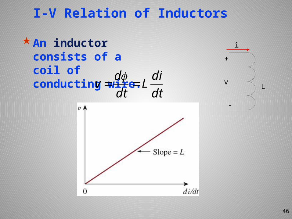
I-V Relation of Inductors
An inductor consists of a coil of conducting wire.
46
dtdiL
dtdv
+
-
v
i
L
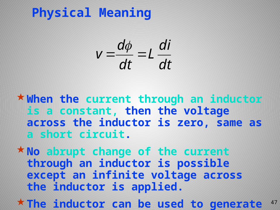
Physical Meaning
When the current through an inductor is a constant, then the voltage across the inductor is zero, same as a short circuit.
No abrupt change of the current through an inductor is possible except an infinite voltage across the inductor is applied.
The inductor can be used to generate a high voltage, for example, used as an igniting element.
dtdiL
dtdv
47
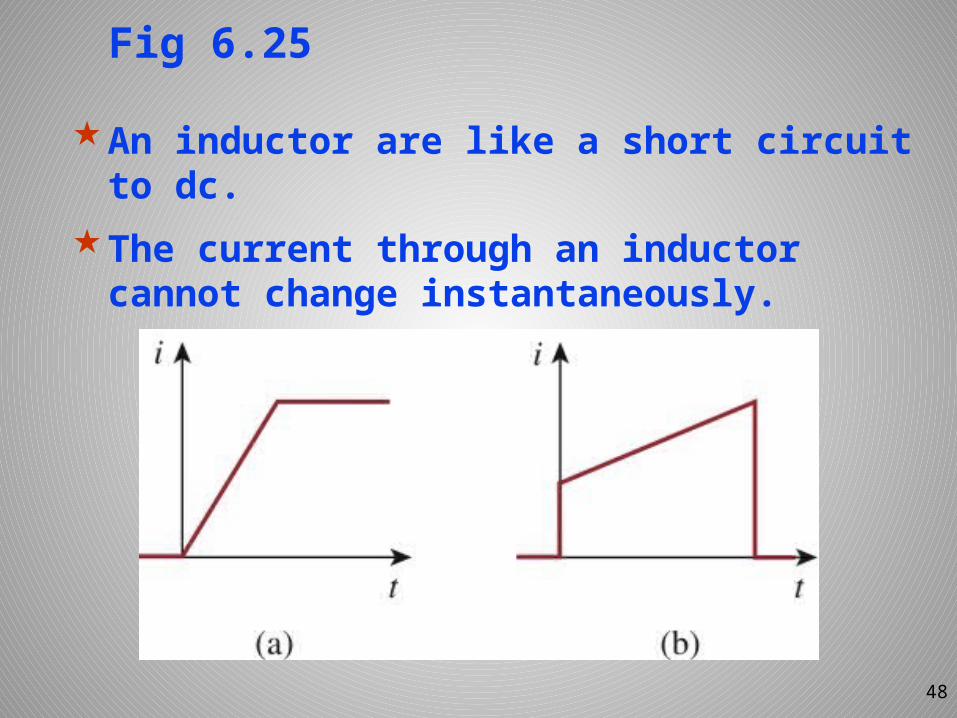
Fig 6.25
An inductor are like a short circuit to dc.
The current through an inductor cannot change instantaneously.
48
49
t
to
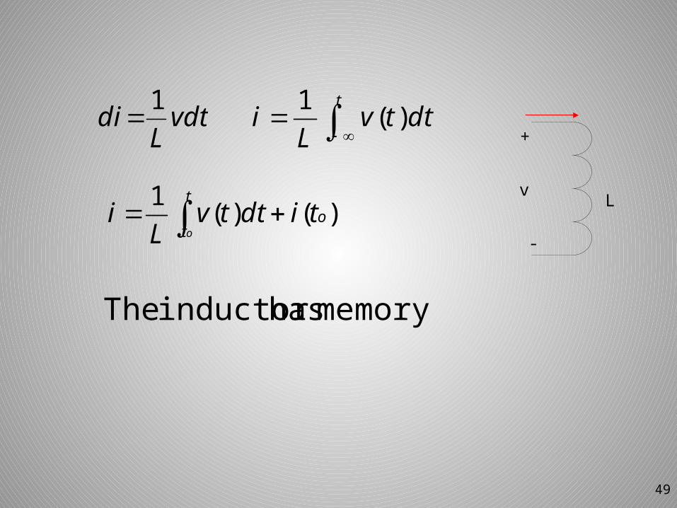
otidttv
Li )()(1
tdttv
Li )(1
memory. hasinductor The
vdtL
di 1
+
-
v L
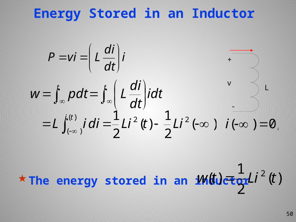
Energy Stored in an Inductor
The energy stored in an inductor
idtdiLviP
50
t t idtdtdiLpdtw
)()(
22 )(21)(2
1ti
iLitLidiiL ,0)( i
)(21)( 2 tLitw
+
-
v L
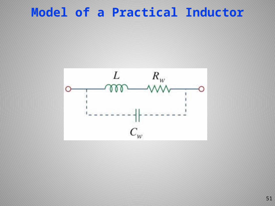
Model of a Practical Inductor
51
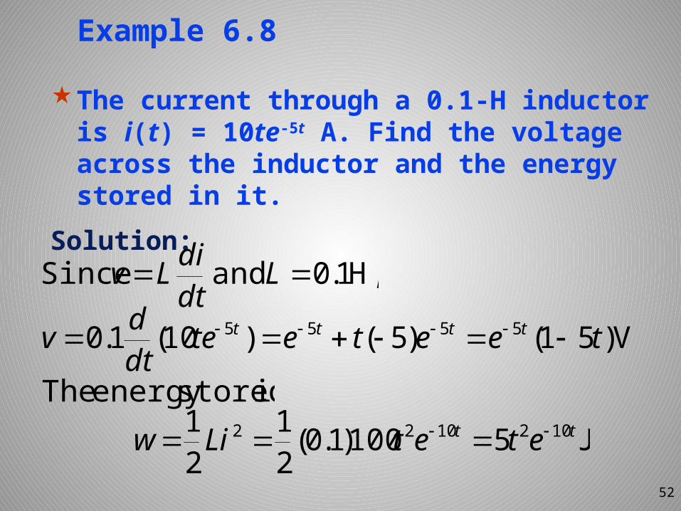
Example 6.8
The current through a 0.1-H inductor is i(t) = 10te-5t A. Find the voltage across the inductor and the energy stored in it.
Solution:
52
V)51()5()10(1.0 5555 teetetedtdv tttt
J5100)1.0(21
21 1021022 tt etetLiw
,H1.0andSince LdtdiLv
isstoredenergyThe
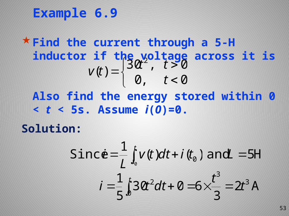
Example 6.9
Find the current through a 5-H inductor if the voltage across it is
Also find the energy stored within 0 < t < 5s. Assume i(0)=0.
Solution:
53
0,00,30)(
2
ttttv
.H5and L)()(1 Since0
0 t
ttidttv
Li
A236 33
tt t dtti 0
2 03051
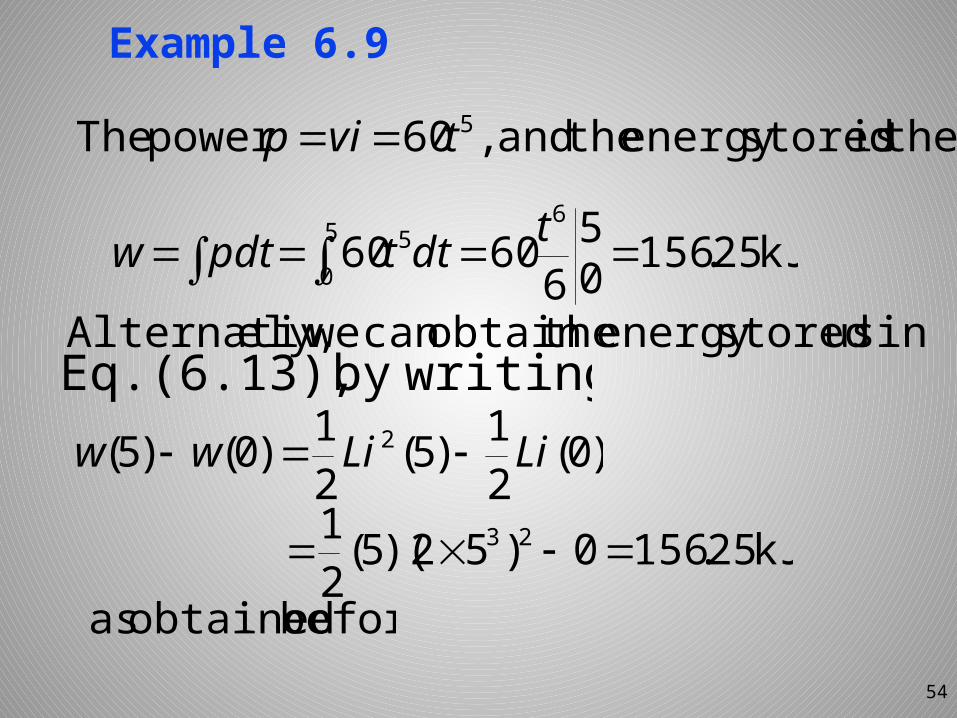
Example 6.9
54
50
65 kJ25.1560
566060 tdttpdtw
thenisstoredenergytheand,60powerThe 5tvip
before.obtainedas
usingstoredenergytheobtaincanweely,AlternativwritingbyEq.(6.13),
)0(21)5(2
1)0()5( 2 LiLiww
kJ25.1560)52)(5(21 23
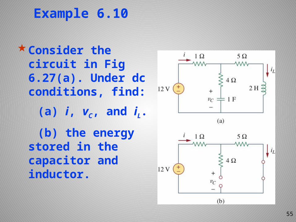
Example 6.10
Consider the circuit in Fig 6.27(a). Under dc conditions, find:
(a) i, vC, and iL. (b) the energy stored in the capacitor and inductor.
55
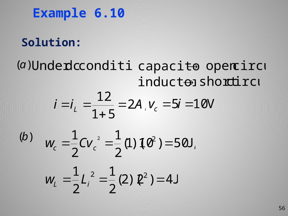
Example 6.10
Solution:
56
,25112 Aii L
,J50)10)(1(21
21 22 cc Cvw
J4)2)(2(21
21 22 iL Lw
)(a :conditiondcUnder capacitorinductor
circuitopencircuitshort
)(b
V105 ivc
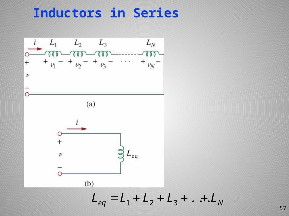
Inductors in Series
Neq LLLLL ...32157
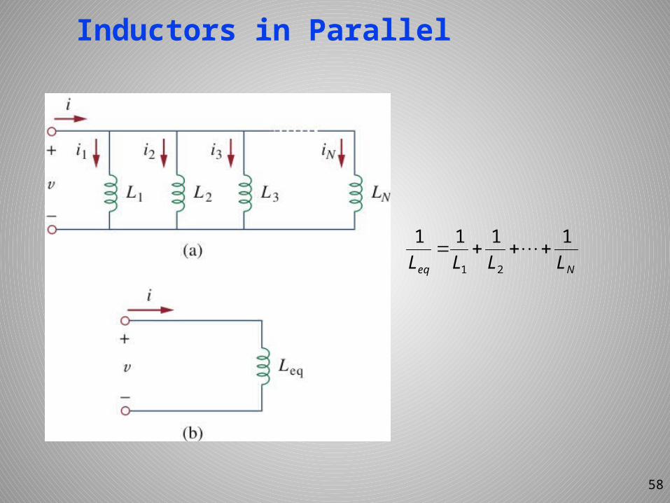
Inductors in Parallel
Neq LLLL1111
21
58
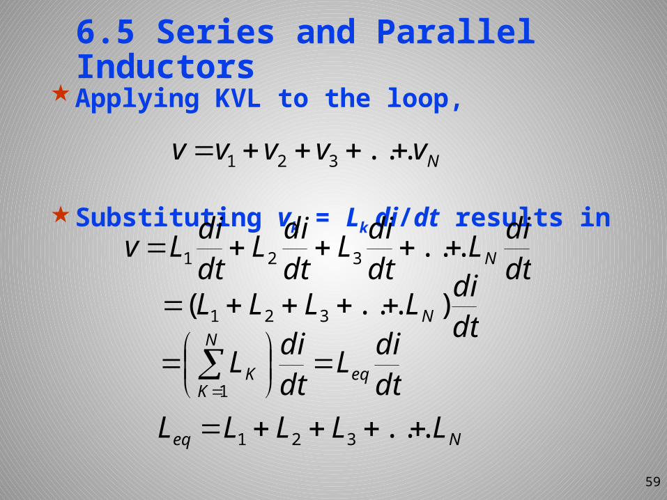
6.5 Series and Parallel Inductors
Applying KVL to the loop,
Substituting vk = Lk di/dt results in
59
Nvvvvv ...321
dtdiL
dtdiL
dtdiL
dtdiLv N ...321
dtdiLLLL N)...( 321
dtdiL
dtdiL eq
N
KK
1
Neq LLLLL ...321
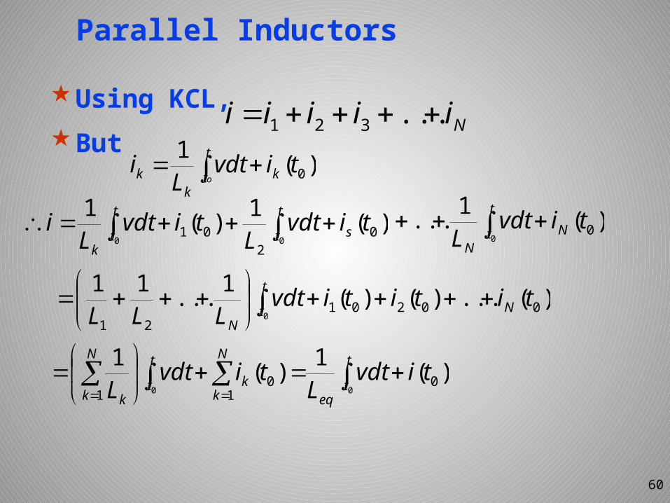
Parallel Inductors
Using KCL,But
60
Niiiii ...321
t
t kk
k otivdt
Li )(1
0
t
t
t
t sk
tivdtL
tivdtL
i0 0
)(1)(10
201
t
t NN
tivdtL 0
)(1... 0
)(...)()(1...1100201
21 0tititivdt
LLL Nt
tN
t
teq
N
kk
t
t
N
k ktivdt
Ltivdt
L 00)(1)(1
01
01
The inductor in various connection has the same effect as the resistor. Hence, the Y-Δ transformation of inductors can be similarly derived.
61
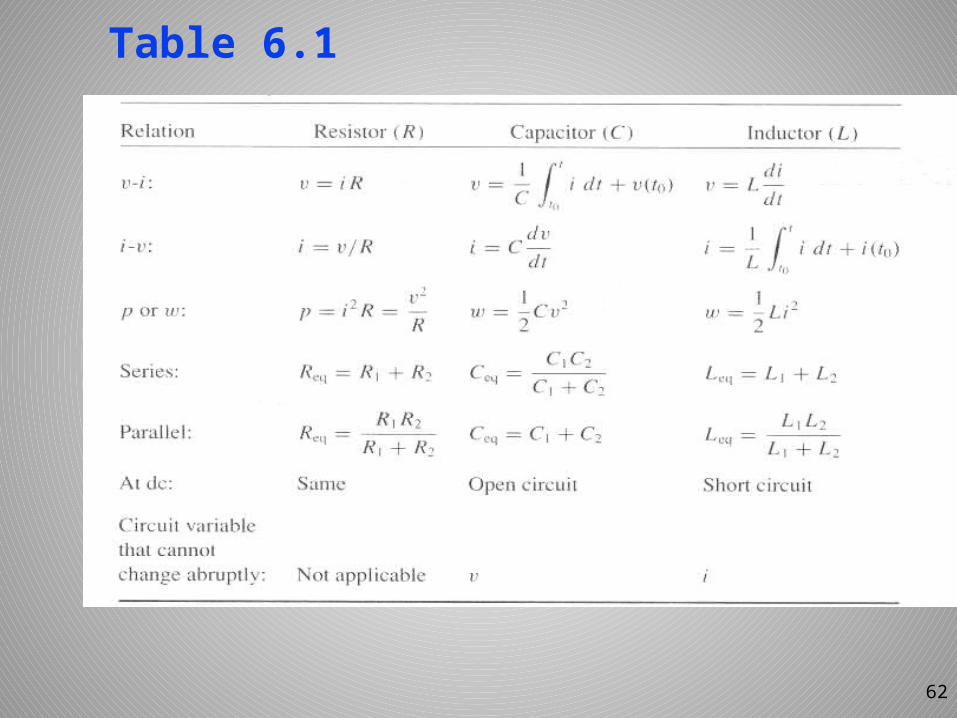
Table 6.1
62
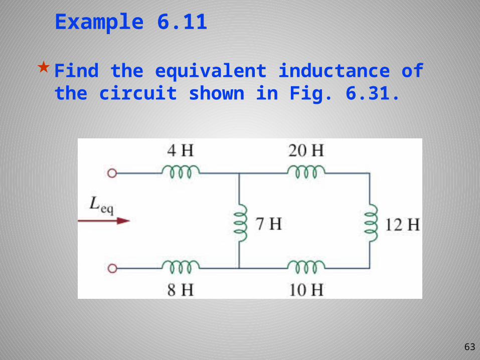
Example 6.11
Find the equivalent inductance of the circuit shown in Fig. 6.31.
63
Example 6.11
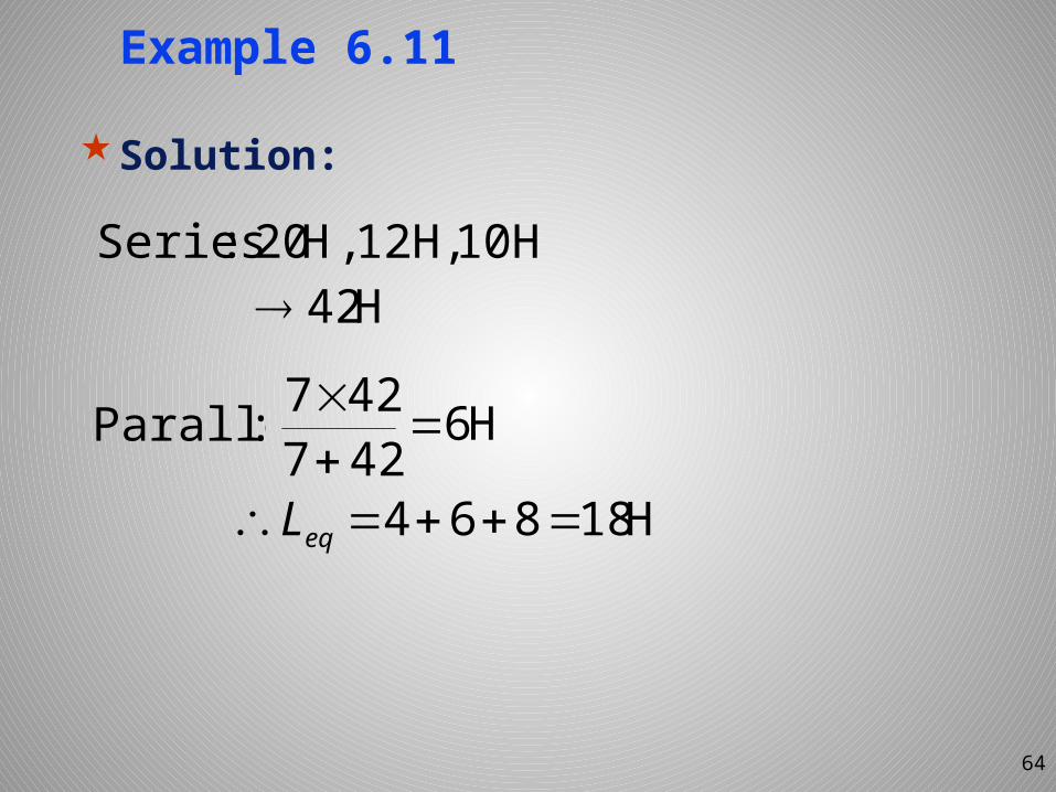
Solution:
64
10H12H,,H20:Series
H6427427
: Parallel
H18864 eqL
H42
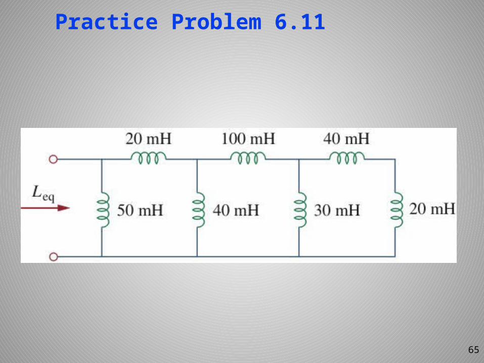
Practice Problem 6.11
65
Example 6.12
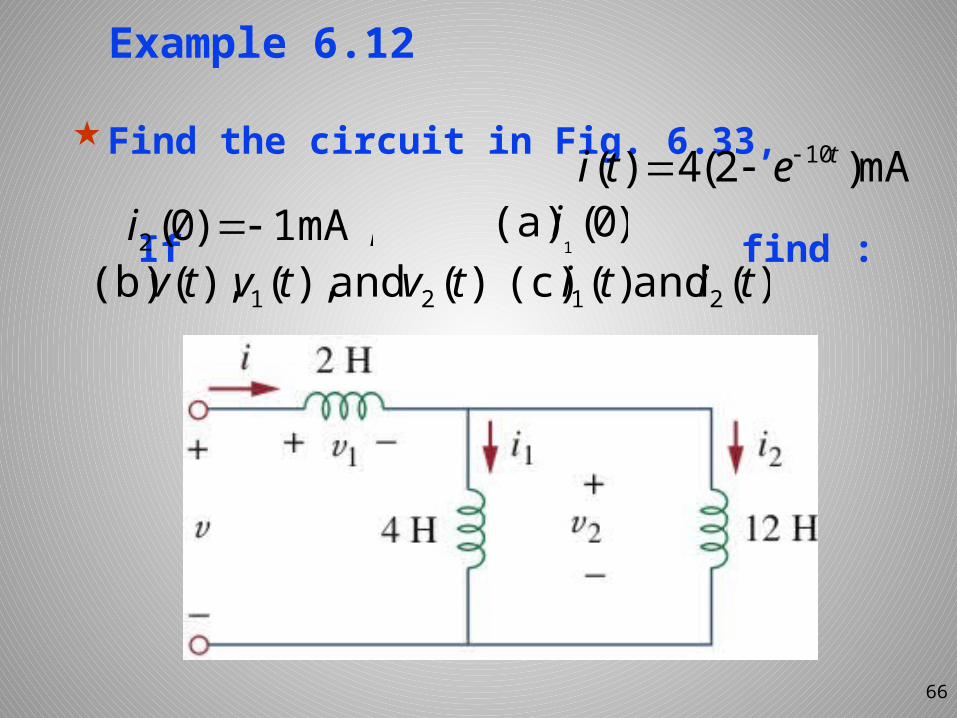
Find the circuit in Fig. 6.33,
If find :
66
.mA)2(4)( 10teti ,mA 1)0(2 i )0( (a)
1i
);(and),(),((b) 21 tvtvtv )(and)((c) 21 titi
Example 6.12
Solution:
67
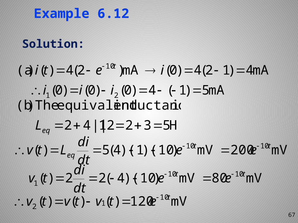
.mA4)12(4)0(mA)2(4)()(a 10 ieti t
mA5)1(4)0()0()0( 21 iii
H53212||42 eqL
mV200mV)10)(1)(4(5)( 1010 tteq eedtdiLtv
mV120)()()( 1012tetvtvtv
mV80mV)10)(4(22)( 10101
tt eedtditv
isinductanceequivalentThe)(b
Example 6.12
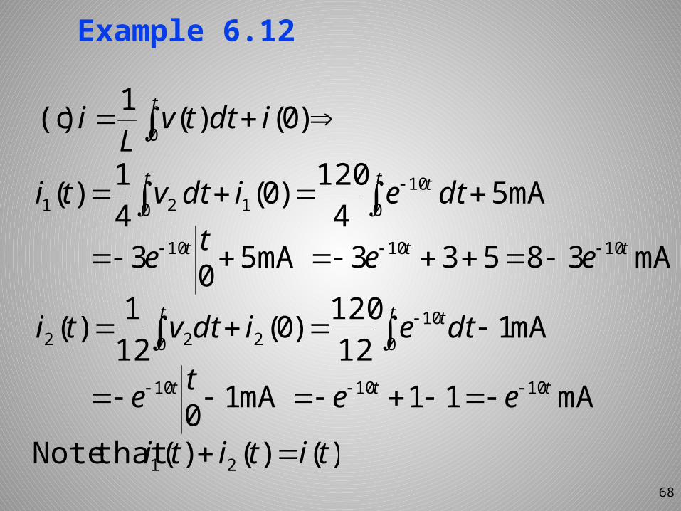
68
t t t dteidtvti 0 010
121 mA54120)0(4
1)(
mA38533mA503 101010 ttt eete
t tt dteidtvti 010
20 22 mA112120)0(12
1)(
mA11mA10101010 ttt eete
)()()(thatNote 21 tititi
t idttv
Li 0 )0()(1)(c
Related Documents

![Capacitors and Inductors [Compatibility Mode]](https://static.cupdf.com/doc/110x72/546a9ac3b4af9fe5268b47da/capacitors-and-inductors-compatibility-mode.jpg)