T A Dwarakanath Division of Remote Handling & Robotics BARC Introduction to applications in Robotics

Welcome message from author
This document is posted to help you gain knowledge. Please leave a comment to let me know what you think about it! Share it to your friends and learn new things together.
Transcript
T A DwarakanathDivision of Remote Handling & RoboticsBARC
Introduction to applications in Robotics
Probably Highest User of Robots in the Country
• The reason of course is the hazardous environment that exist in different stages of Nuclear Fuel Cycle.
• Inspection & Monitoring is very critical. • BARC has a mandate for developing technologies for societal application
• Research for finding robotics substitute for manual applications.
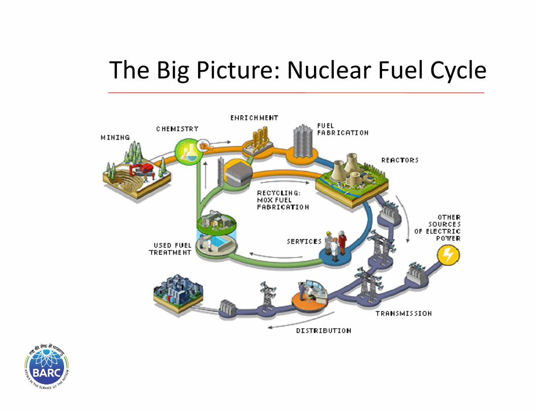
The Big Picture: Nuclear Fuel Cycle
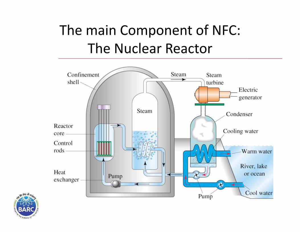
The main Component of NFC: The Nuclear Reactor
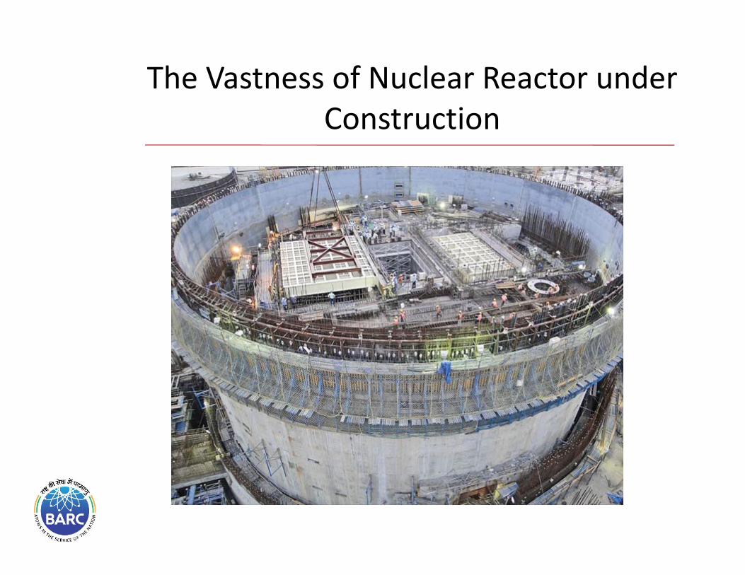
The Vastness of Nuclear Reactor under Construction
Robotics in DAE
is what is known as theMaster‐Slave Manipulators
(over 90% of present day robotics in BARC is of this type)Why? : 3 points.
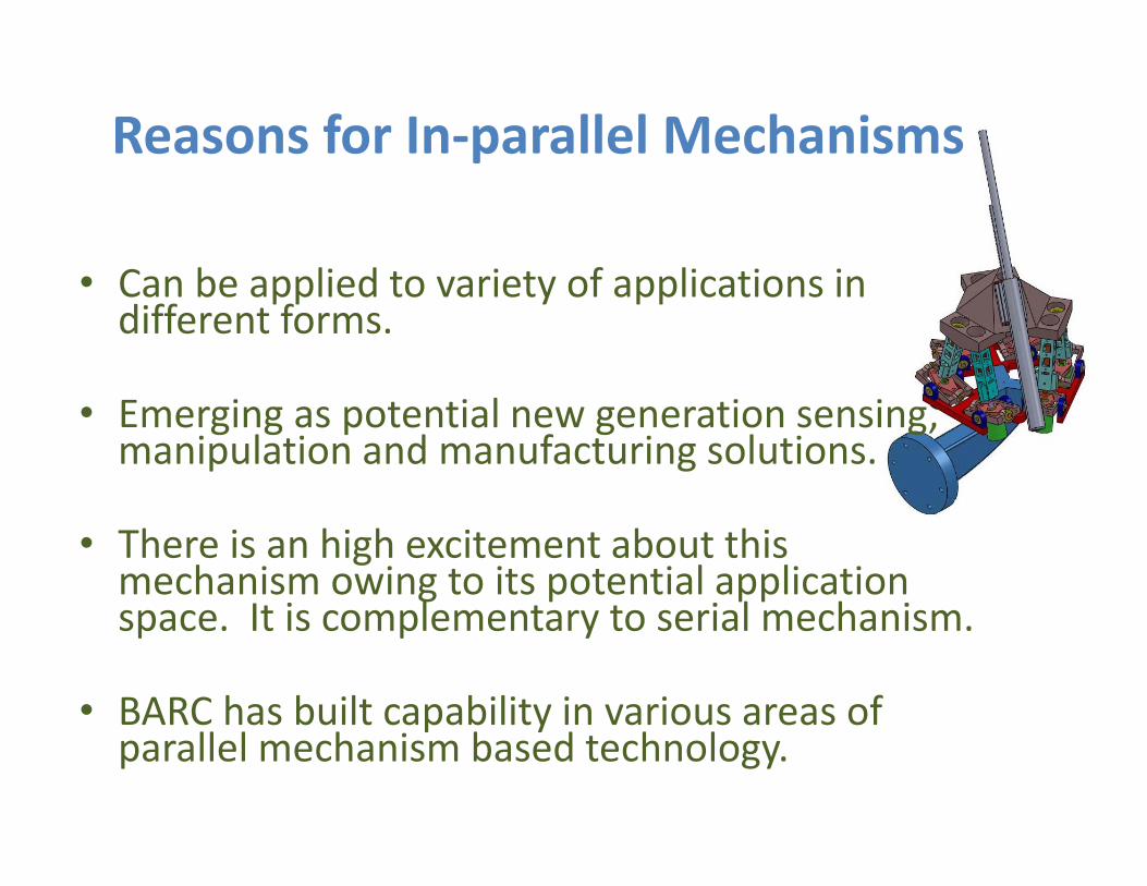
• Can be applied to variety of applications in different forms.
• Emerging as potential new generation sensing, manipulation and manufacturing solutions.
• There is an high excitement about this mechanism owing to its potential application space. It is complementary to serial mechanism.
• BARC has built capability in various areas of parallel mechanism based technology.
Reasons for In‐parallel Mechanisms
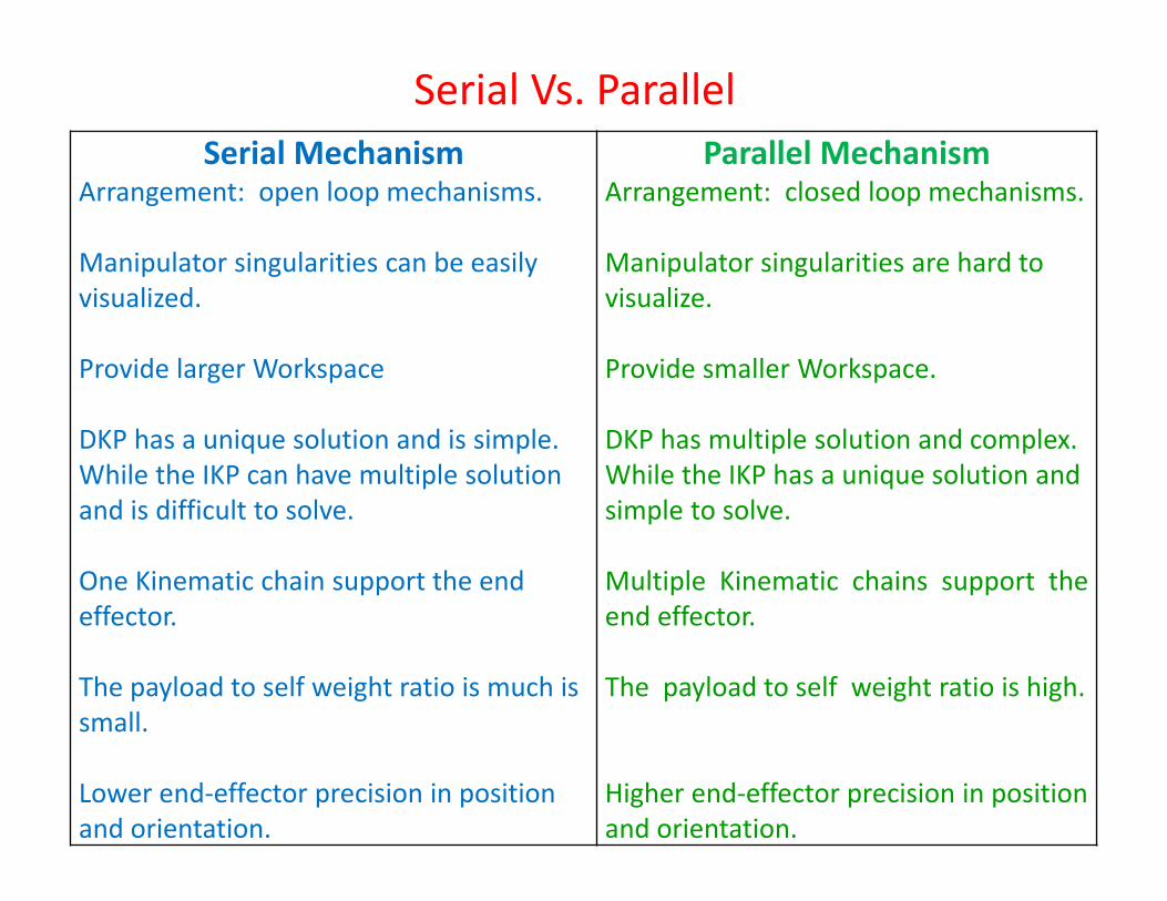
Serial Vs. ParallelSerial Mechanism
Arrangement: open loop mechanisms.
Manipulator singularities can be easily visualized.
Provide larger Workspace
DKP has a unique solution and is simple. While the IKP can have multiple solution and is difficult to solve.
One Kinematic chain support the end effector.
The payload to self weight ratio is much is small.
Lower end‐effector precision in position and orientation.
Parallel Mechanism Arrangement: closed loop mechanisms.
Manipulator singularities are hard to visualize.
Provide smaller Workspace.
DKP has multiple solution and complex.While the IKP has a unique solution and simple to solve.
Multiple Kinematic chains support theend effector.
The payload to self weight ratio is high.
Higher end‐effector precision in position and orientation.
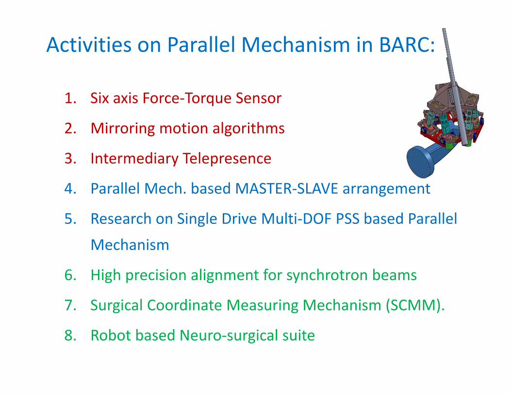
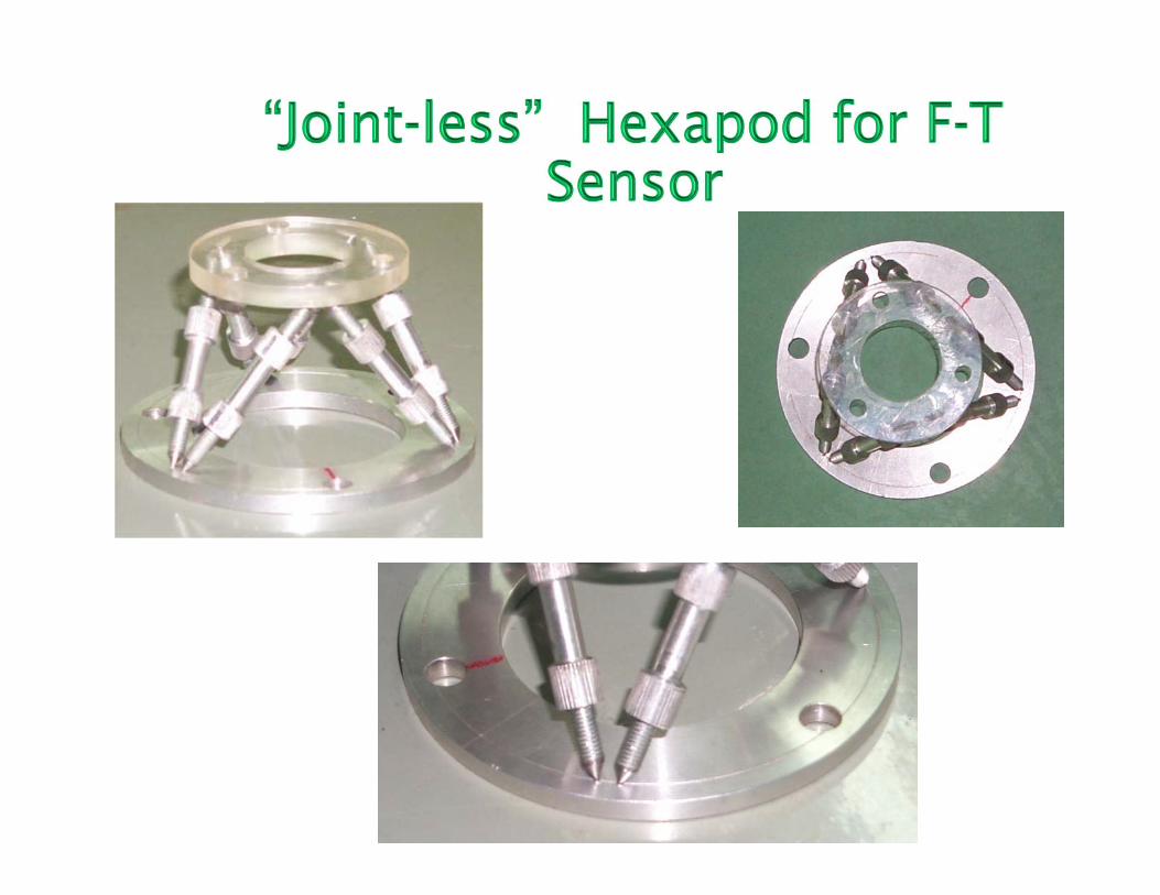
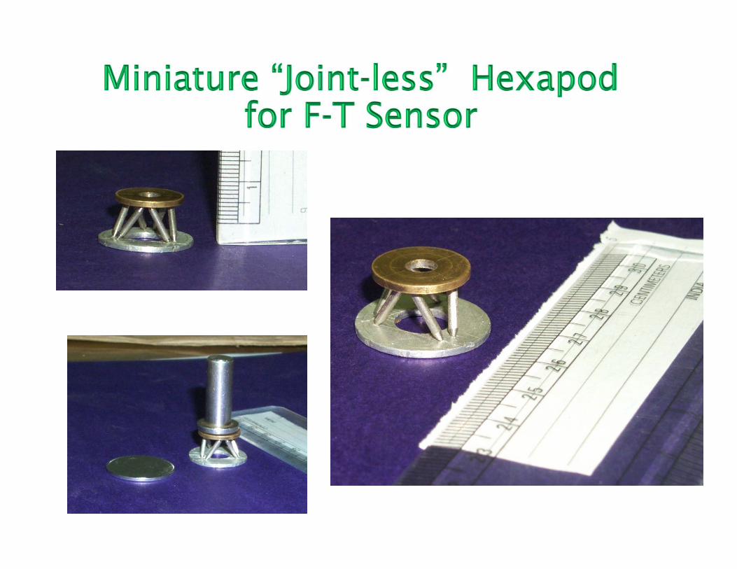
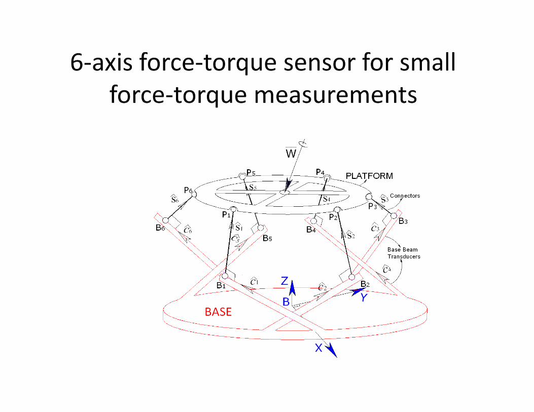
1. Six axis Force‐Torque Sensor
2. Mirroring motion algorithms
3. Intermediary Telepresence
4. Parallel Mech. based MASTER‐SLAVE arrangement
5. Research on Single Drive Multi‐DOF PSS based Parallel Mechanism
6. High precision alignment for synchrotron beams
7. Surgical Coordinate Measuring Mechanism (SCMM).
8. Robot based Neuro‐surgical suite
Activities on Parallel Mechanism in BARC:
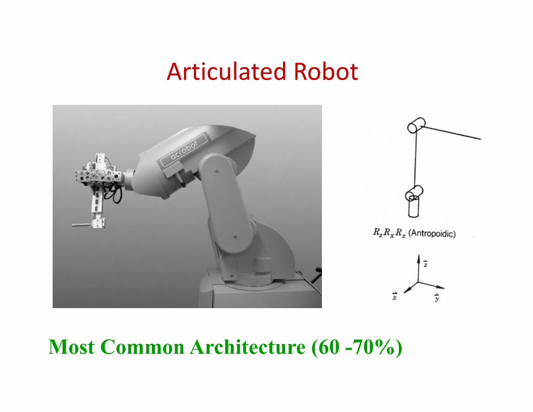
Articulated Robot
Most Common Architecture (60 -70%)
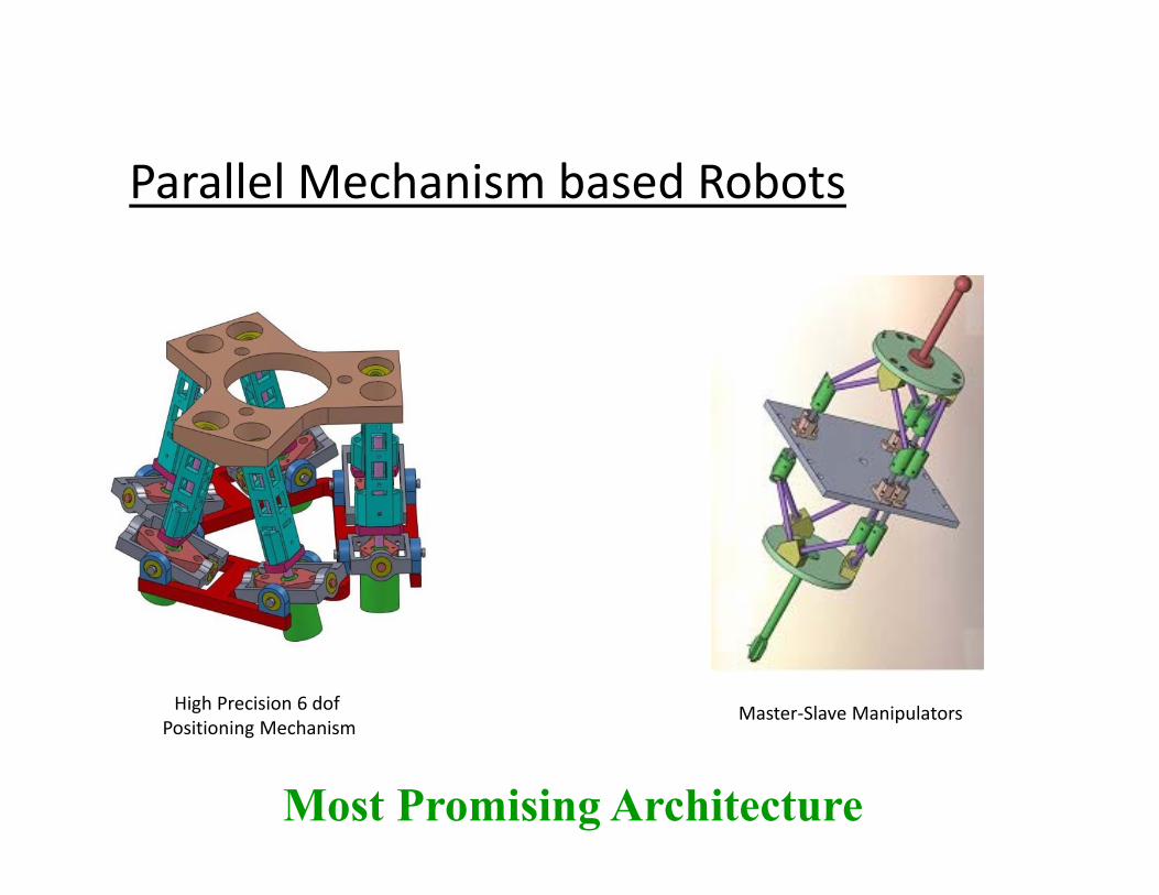
Parallel Mechanism based Robots
High Precision 6 dofPositioning Mechanism
Master‐Slave Manipulators
Most Promising Architecture

Serial Vs. ParallelSerial Mechanism
Arrangement: open loop mechanisms.
Manipulator singularities can be easily visualized.
Provide larger Workspace
DKP has a unique solution and is simple. While the IKP can have multiple solution and is difficult to solve.
One Kinematic chain support the end effector.
The payload to self weight ratio is much is small.
Lower end‐effector precision in position and orientation.
Parallel Mechanism Arrangement: closed loop mechanisms.
Manipulator singularities are hard to visualize.
Provide smaller Workspace.
DKP has multiple solution and complex.While the IKP has a unique solution and simple to solve.
Multiple Kinematic chains support theend effector.
The payload to self weight ratio is high.
Higher end‐effector precision in position and orientation.
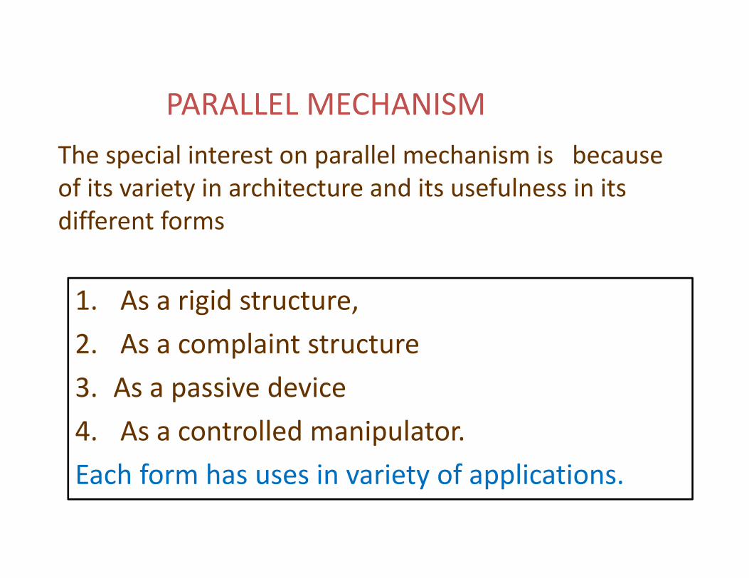
The special interest on parallel mechanism is because of its variety in architecture and its usefulness in its different forms
1. As a rigid structure,2. As a complaint structure 3. As a passive device 4. As a controlled manipulator.Each form has uses in variety of applications.
PARALLEL MECHANISM
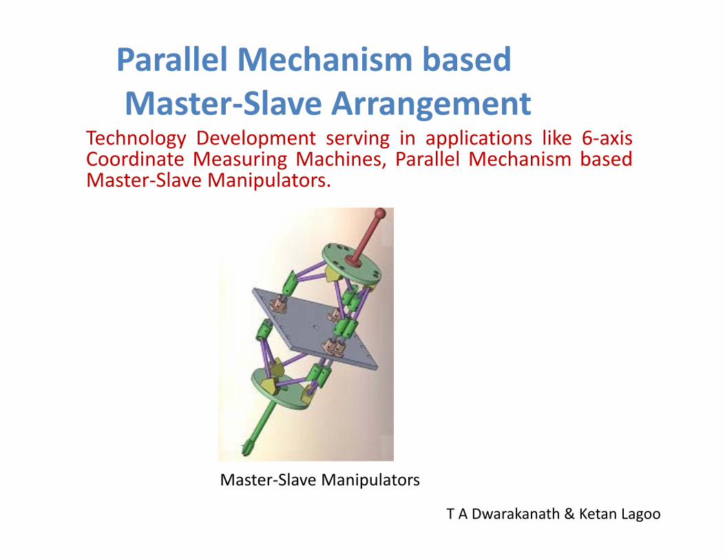
Technology Development serving in applications like 6‐axisCoordinate Measuring Machines, Parallel Mechanism basedMaster‐Slave Manipulators.
Master‐Slave Manipulators
Parallel Mechanism basedMaster‐Slave Arrangement
T A Dwarakanath & Ketan Lagoo
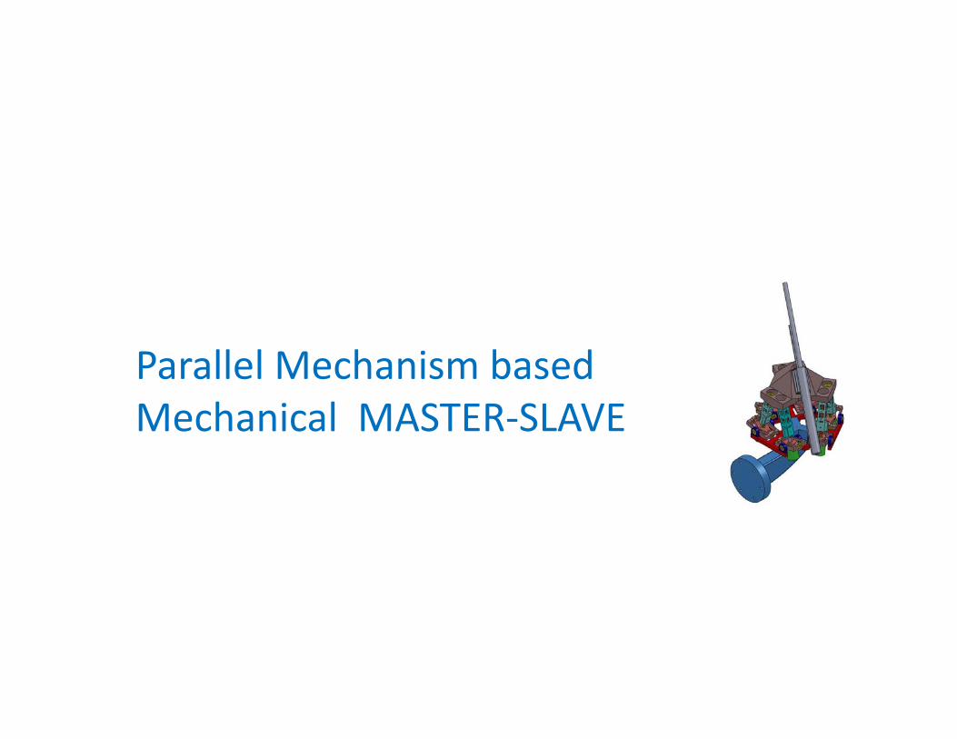
Parallel Mechanism based Mechanical MASTER‐SLAVE
Parallel Mechanism Devices (ZERO DOF)
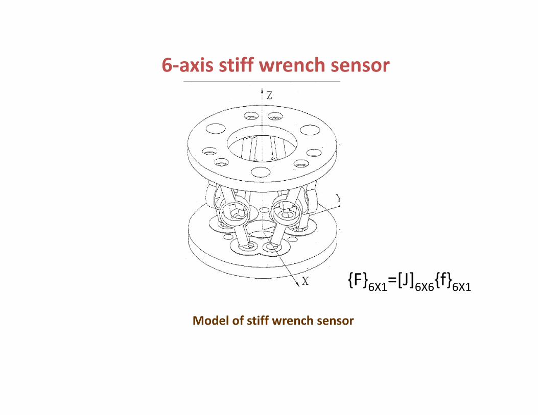
Model of stiff wrench sensor
6‐axis stiff wrench sensor
{F}6X1=[J]6X6{f}6X1
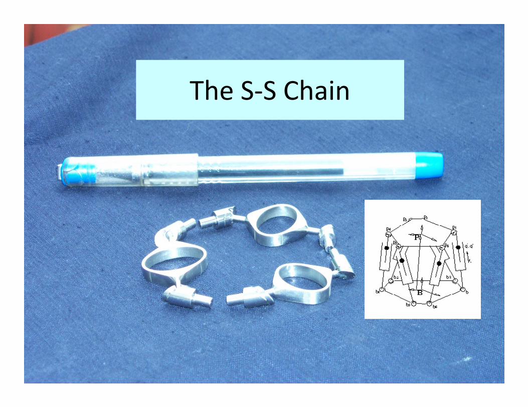
The S‐S Chain
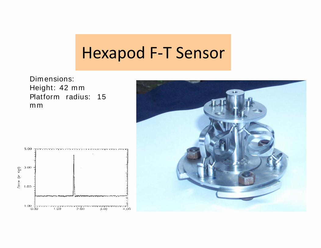
Hexapod F‐T SensorDimensions:Height: 42 mmPlatform radius: 15mm
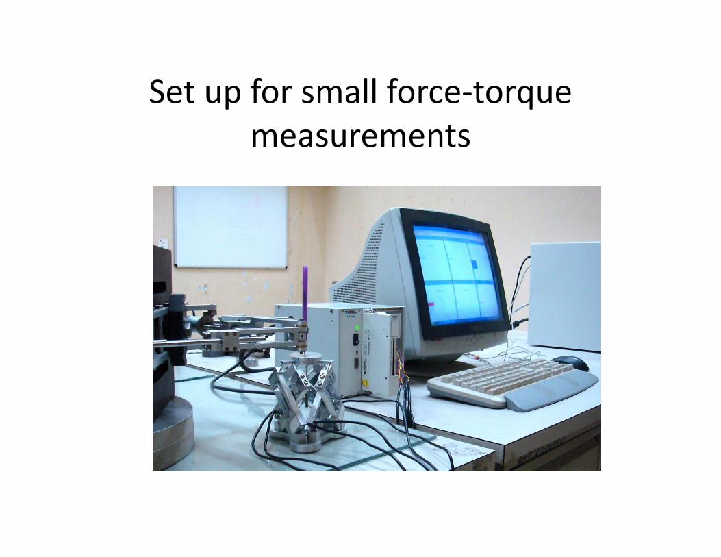
Set up for small force‐torque measurements
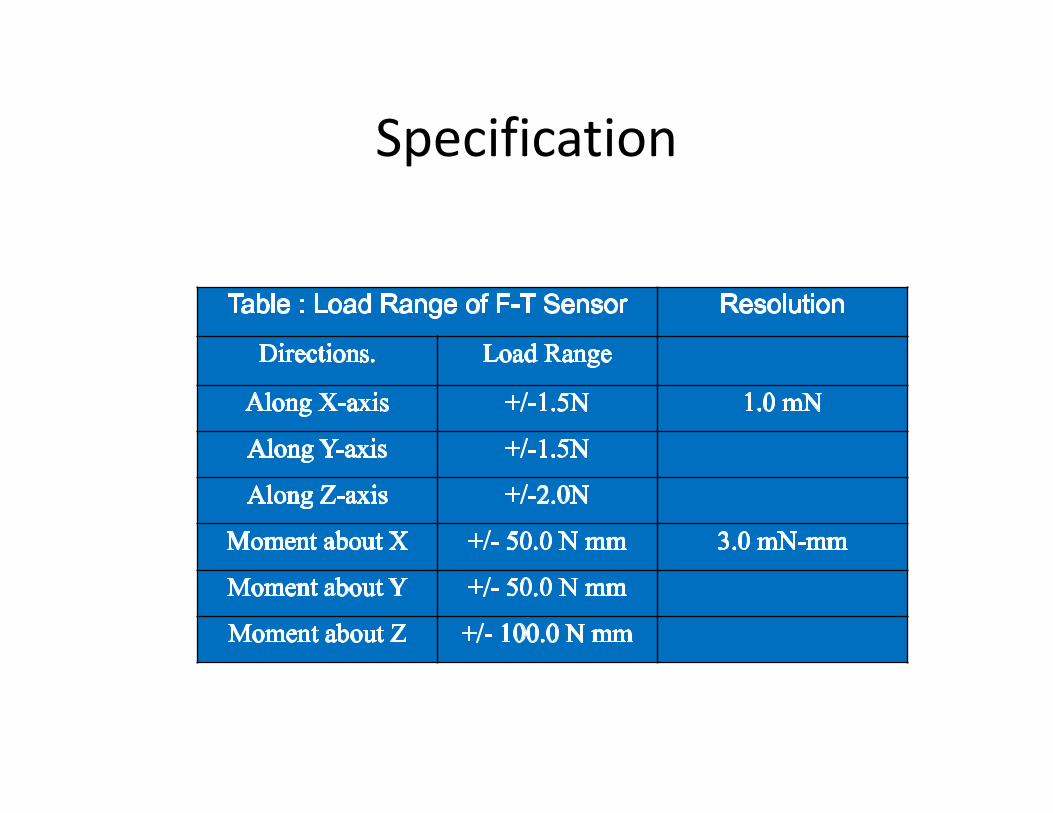
Specification
Force Diagrams : Graphical Force Perception
Graphical representation of wrench information is devised
Force Diagrams, which are proposed here, offer meaningful Graphical representation of Forces and
Moments.
Constructing Force Diagrams
• Consider work space model and wrench information
• Compose force diagrams from Forces and Torques so as to highlight the key features
• Compare intended and actual force diagrams
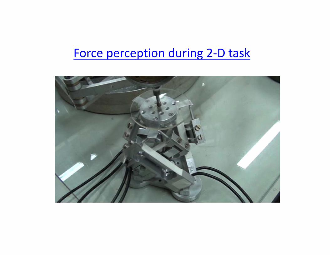
Force perception during 2‐D task
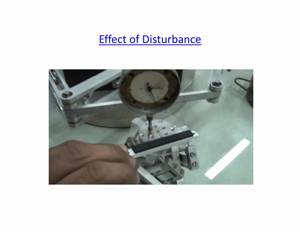
Effect of Disturbance
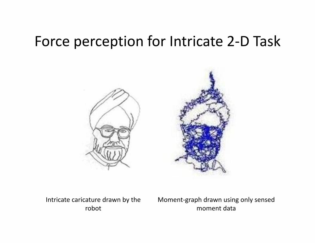
Force perception for Intricate 2‐D Task
Intricate caricature drawn by the robot
Moment‐graph drawn using only sensed moment data
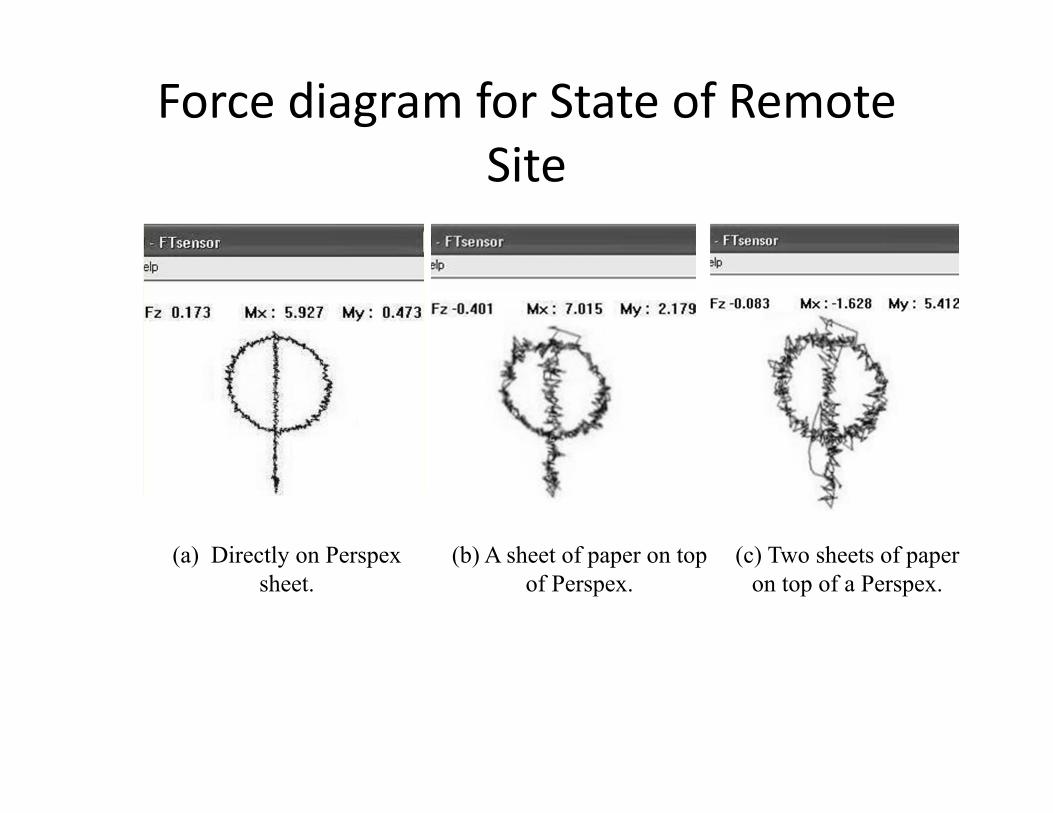
Force diagram for State of Remote Site
(a) Directly on Perspex sheet.
(b) A sheet of paper on top of Perspex.
(c) Two sheets of paper on top of a Perspex.
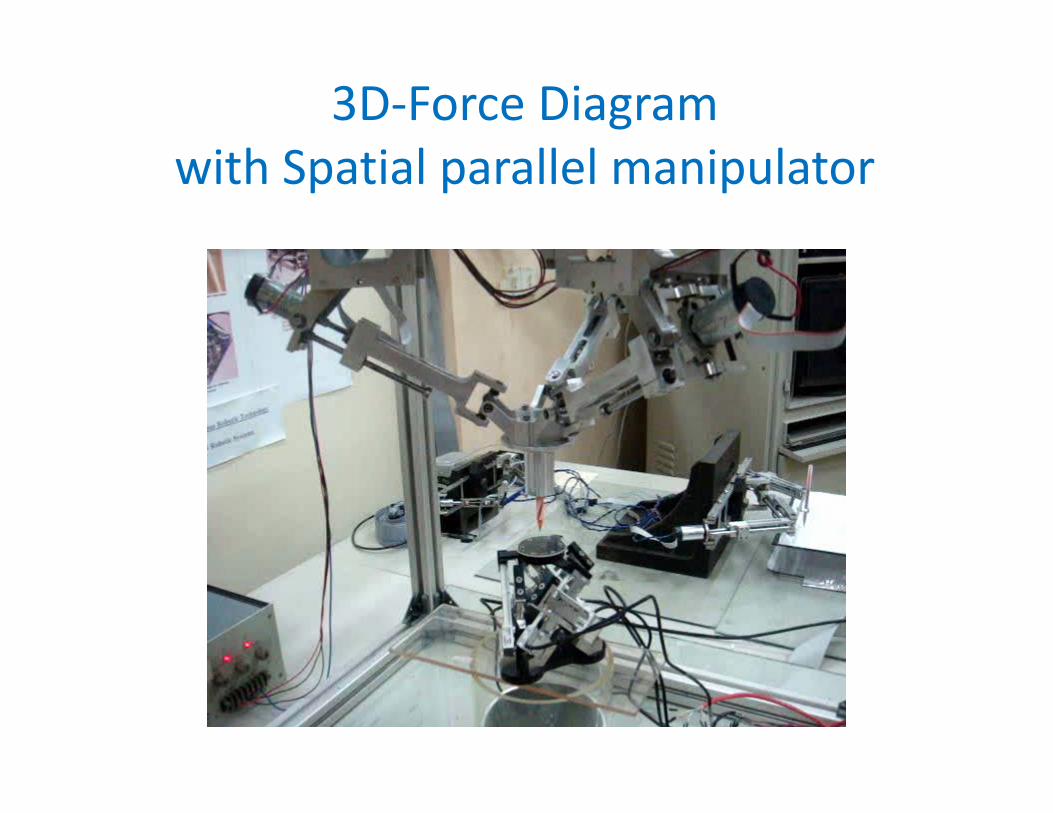
3D‐Force Diagram with Spatial parallel manipulator
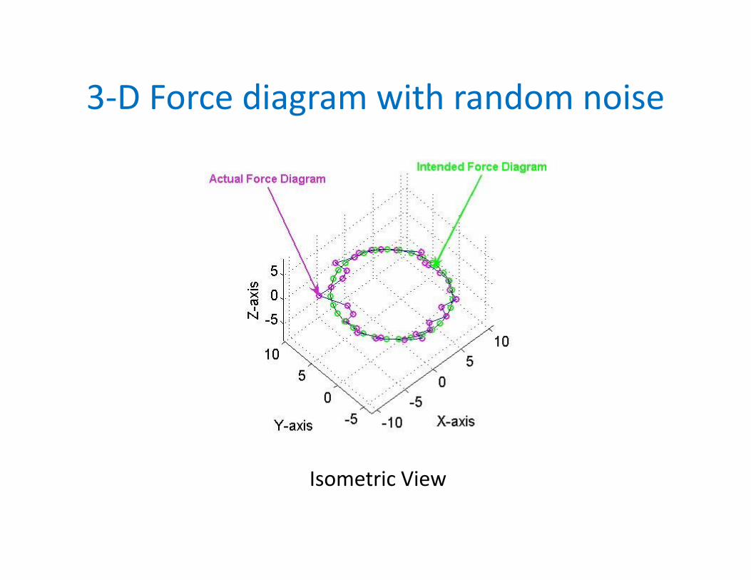
3‐D Force diagram with random noise
Isometric View
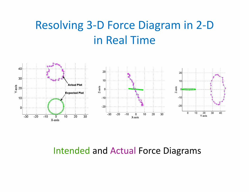
Resolving 3‐D Force Diagram in 2‐Din Real Time
Intended and Actual Force Diagrams
Usefulness of Force Diagrams
Force diagram can enhance the operator’s knowledge about
‐contact wrenches‐real time force trajectory‐accuracy of the motion and force trajectory‐state of the remote site in terms of wrench state
Jacobix: An Analog Computer for a 6‐axes Force‐Torque Sensor
What is an analog computer?
‐OPAMPs can be used to create a circuit that can perform a specific complex computation instantly.
‐The circuit can process analog signals from transducers without A/D convertors.
‐We use it to multiply a matrix (a Jacobian) with a vector. We call it ‘Jacobix’!
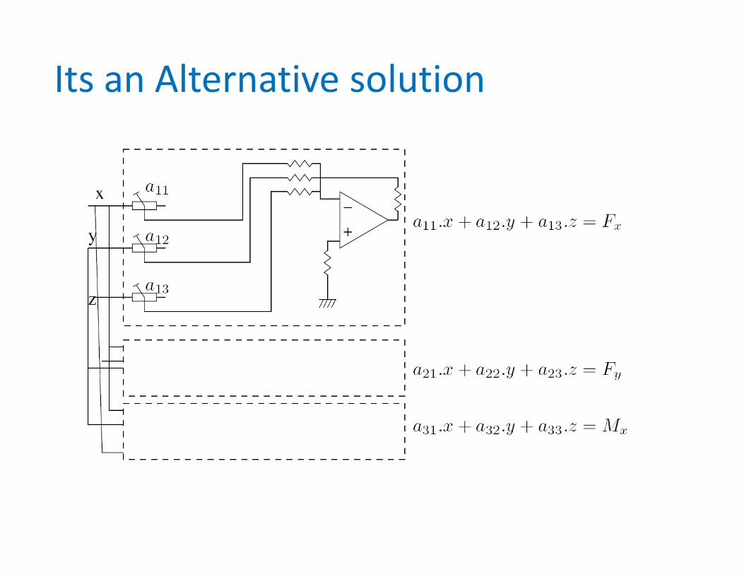
Its an Alternative solution
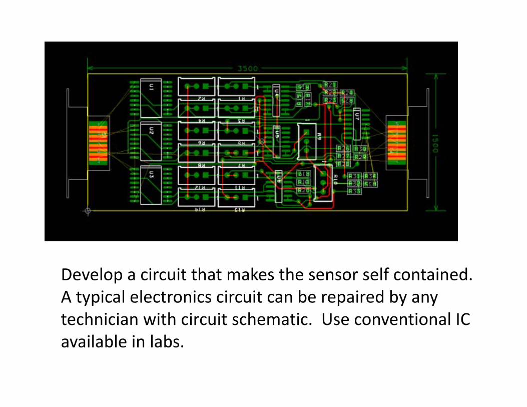
Develop a circuit that makes the sensor self contained. A typical electronics circuit can be repaired by any technician with circuit schematic. Use conventional IC available in labs.
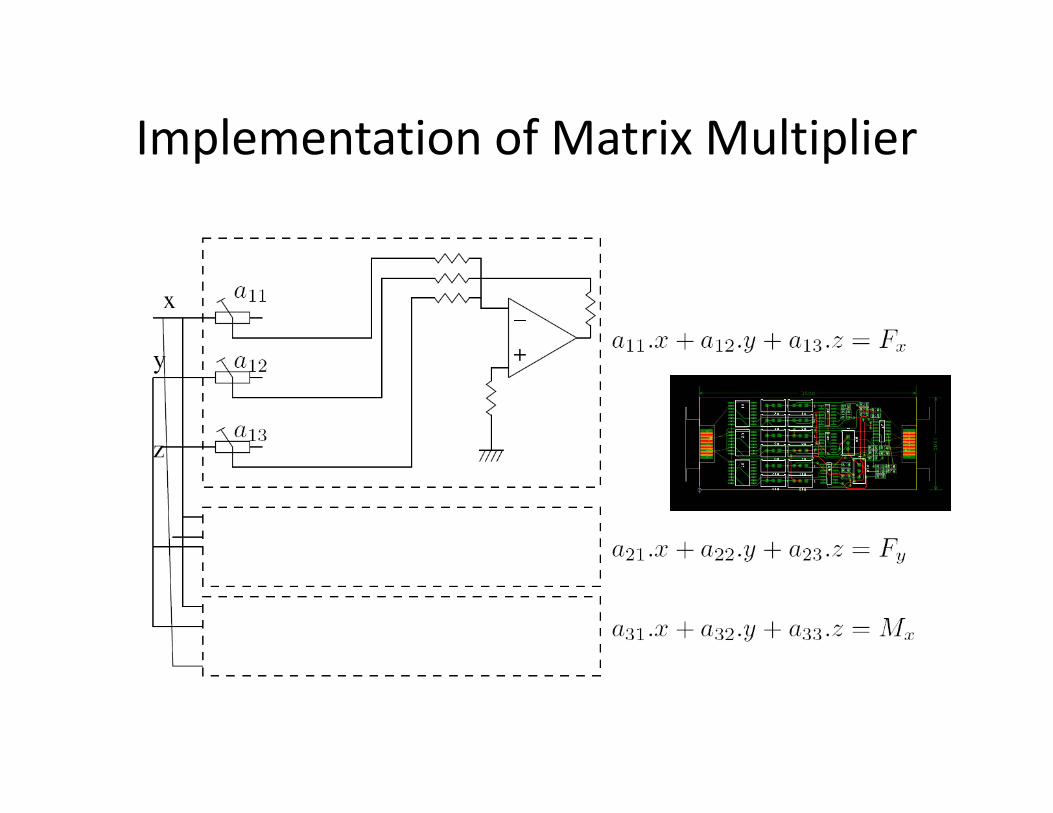
Implementation of Matrix Multiplier
Compliant Parallel Mechanism Devices
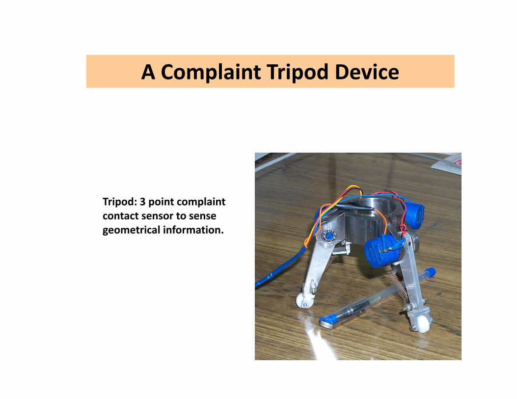
A Complaint Tripod Device
Tripod: 3 point complaint contact sensor to sense geometrical information.

Elastic elements of the connector
Compact arrangement of elastic elements
The SPS Chain
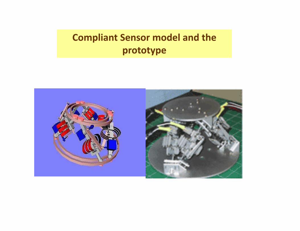
Compliant Sensor model and the prototype
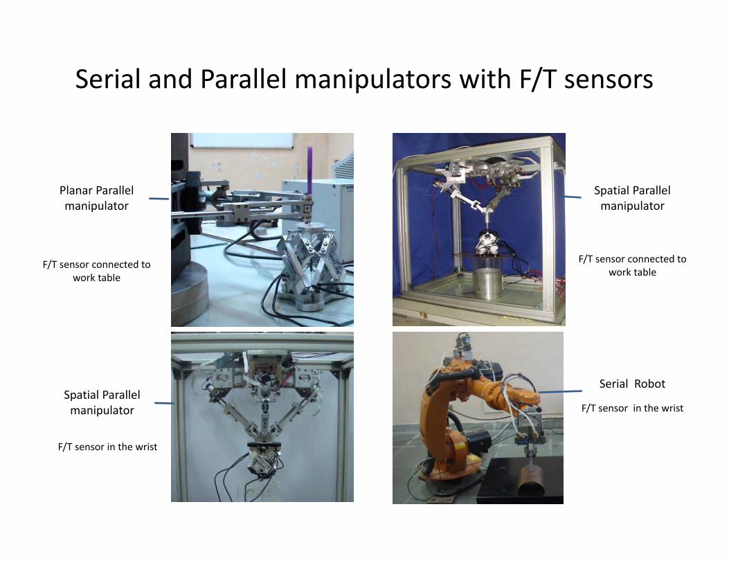
Serial and Parallel manipulators with F/T sensors
Planar Parallel manipulator
Spatial Parallel manipulator
Spatial Parallel manipulator
Serial Robot
F/T sensor connected to work table
F/T sensor connected to work table
F/T sensor in the wrist
F/T sensor in the wrist
INTERMEDIARY TELEPRESENCE FORREMOTE MANIPULATION
Industrial Telepresence Systems
• Immersive – Real time video and audio – Feeling of touch and force– Low‐latency
Problems with Haptic Telepresence
• Depends on Contact perception • Delayed perception • Serves only one user at a time• History of the wrench signal is lost• Expensive• Complex
The objective of the work is to develop a practical intermediary telepresence framework for remote Master – Slave manipulation
The focus of the work is to conduct a reliable remote manipulation with good “presence” at the remote site
Intermediary telepresence
INTERMEDIARY TELEPRESENCE• A full‐fledged telepresence system is not warrantedfor many tasks.
• The requirement is often such that the manipulationhas to be conducted remotely with a operator in thecontrol loop.
• The operator in the loop should play a master orsupervisory role and be able to manipulate thetelemanipulator and also take safety or correctiveaction.
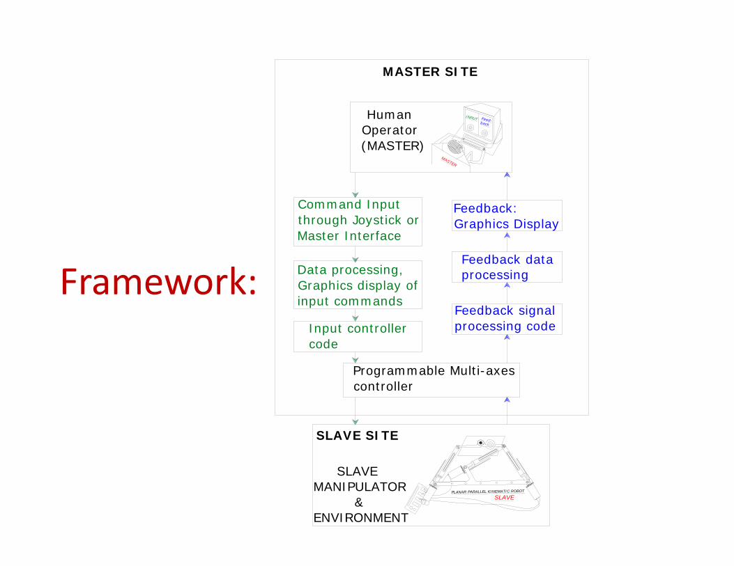
Framework:
Feed-back
INPUT
MASTER
Human Operator(MASTER)
Command Input through Joystick or Master Interface
Feedback: Graphics Display
Data processing, Graphics display of input commands
Feedback data processing
Input controller code
Feedback signal processing code
Programmable Multi-axes controller
PLANAR PARALLEL KINEMATIC ROBOT
SLAVE
SLAVEMANIPULATOR &ENVIRONMENT
MASTER SITE
SLAVE SITE
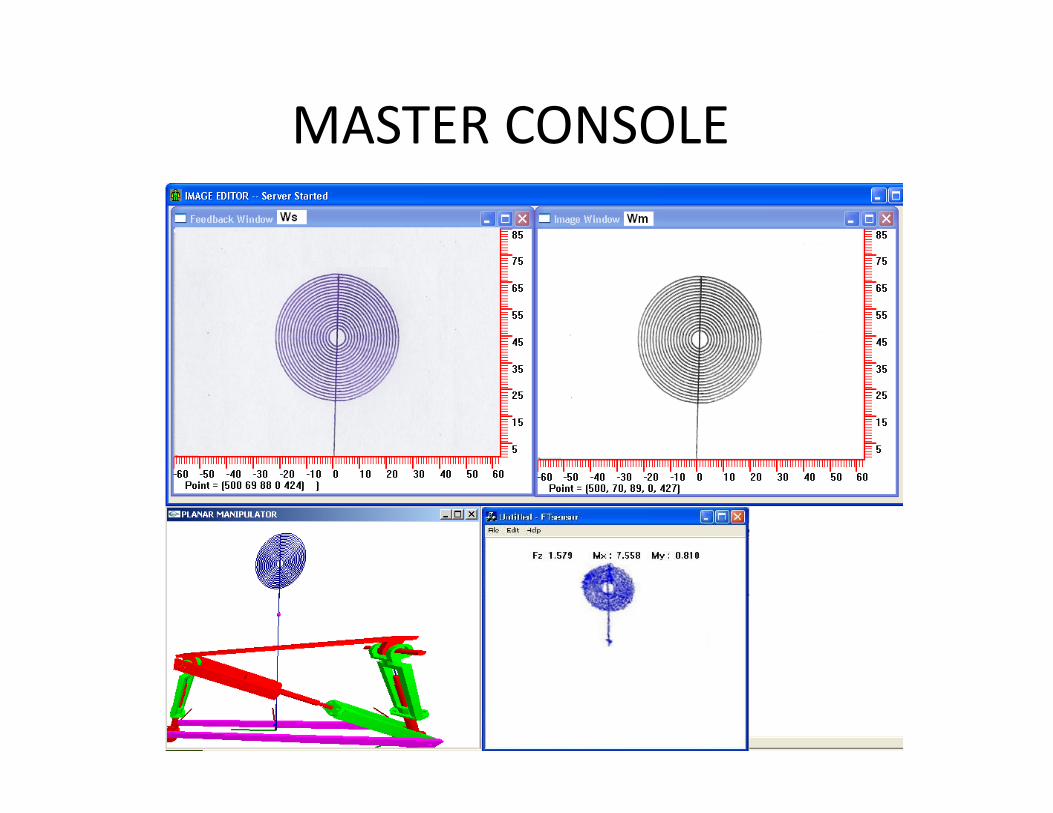
MASTER CONSOLE
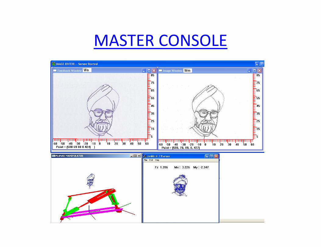
MASTER CONSOLE
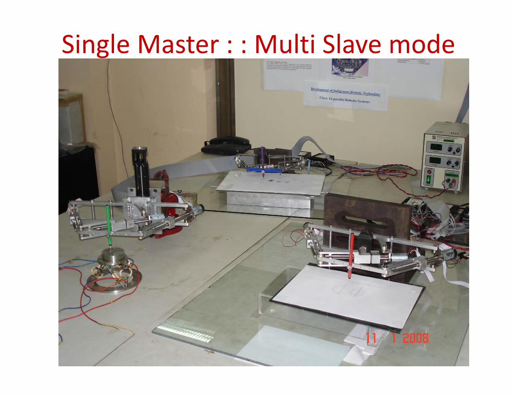
Single Master : : Multi Slave mode
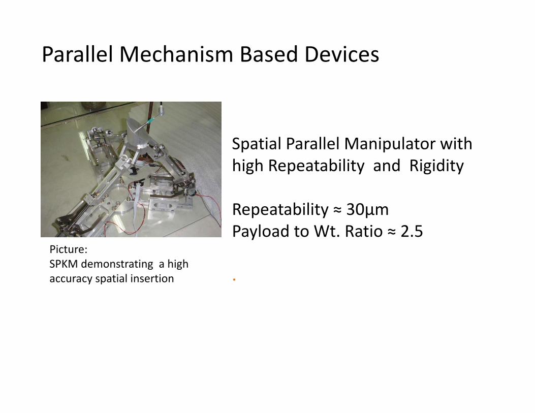
Spatial Parallel Manipulator with high Repeatability and Rigidity
Repeatability ≈ 30µmPayload to Wt. Ratio ≈ 2.5
.
Parallel Mechanism Based Devices
Picture:SPKM demonstrating a high accuracy spatial insertion
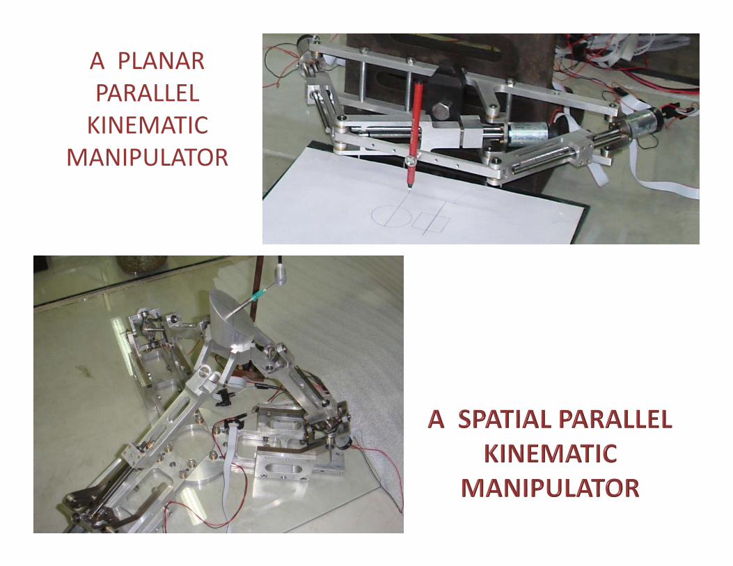
A PLANAR PARALLEL KINEMATIC
MANIPULATOR
Task space trajectory planning among cooperating robots through mirror motions
• Many tasks cannot be accomplished with a singlerobot but can be accomplished easily with two or morerobots.
• If the task demands high dexterity simultaneouslyfrom multiple directions or action at regions which areseparated apart, two or more robots are needed.
• To share the work (load sharing) in accomplishing thecommon goal.
Need of Co-operation among Robots(Mirroring motion algorithms)
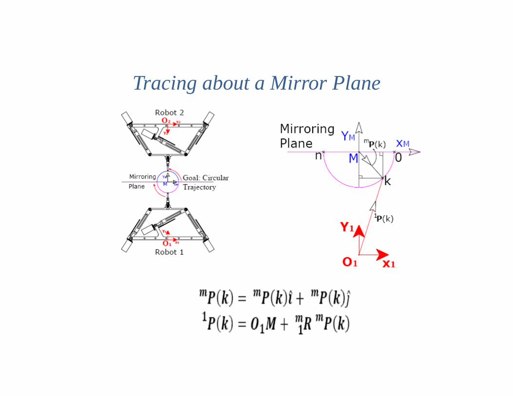
Tracing about a Mirror Plane
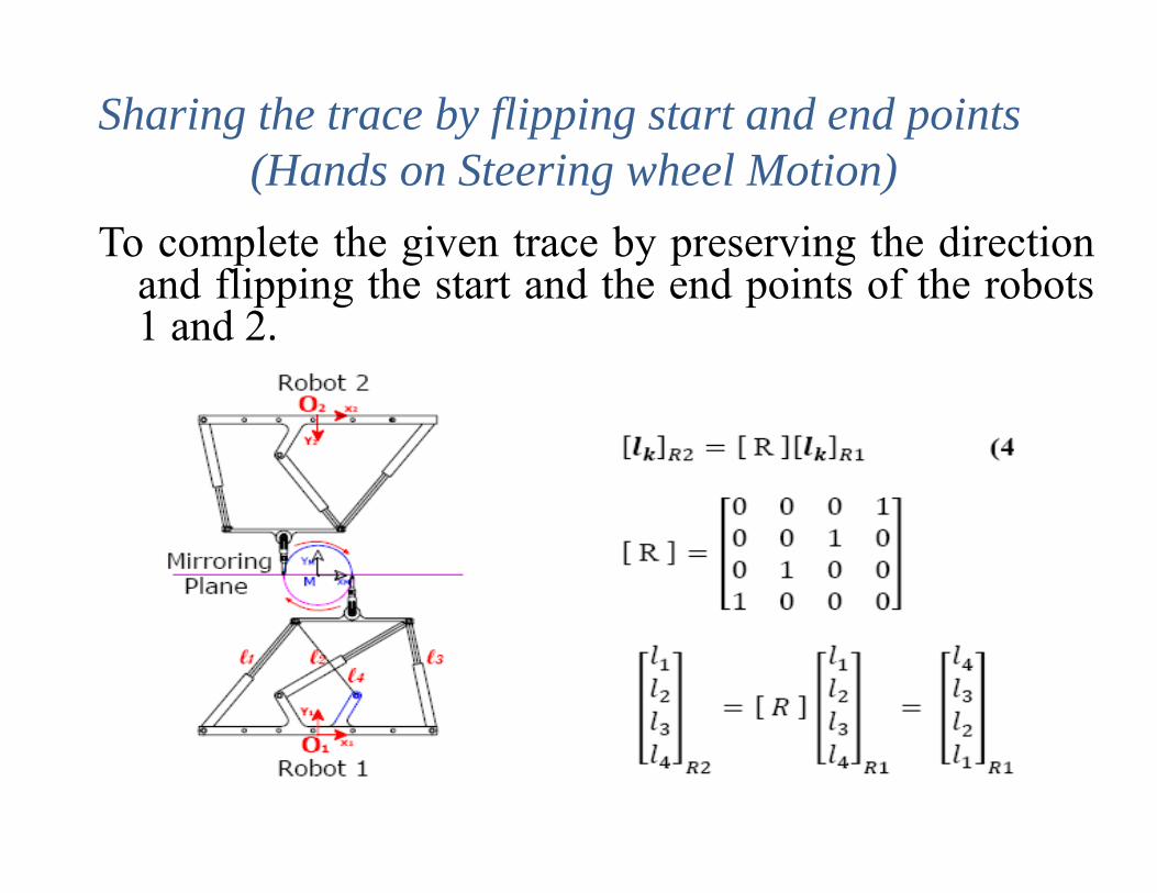
To complete the given trace by preserving the directionand flipping the start and the end points of the robots1 and 2.
Sharing the trace by flipping start and end points(Hands on Steering wheel Motion)
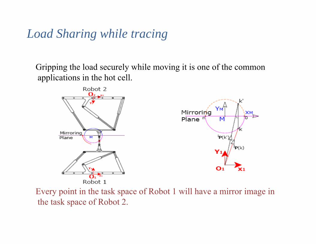
Gripping the load securely while moving it is one of the common applications in the hot cell.
Every point in the task space of Robot 1 will have a mirror image in the task space of Robot 2.
Load Sharing while tracing
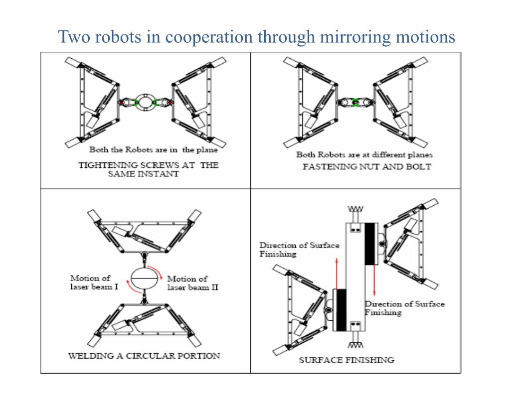
Two robots in cooperation through mirroring motions
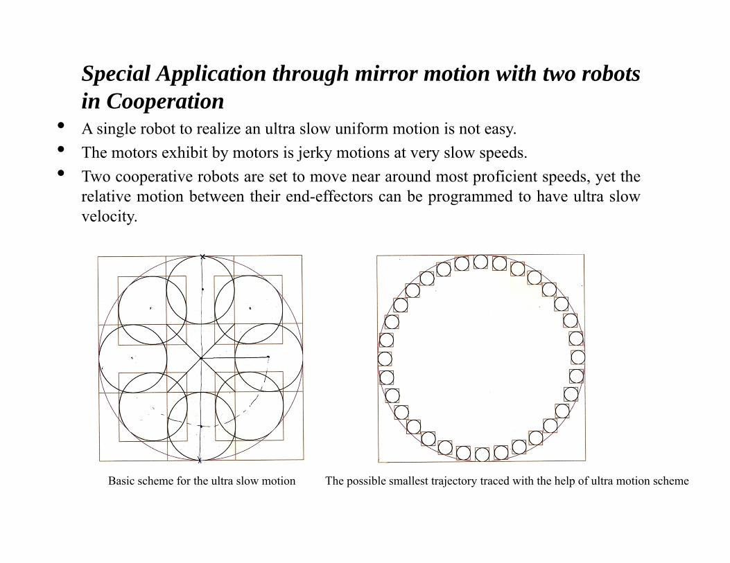
Special Application through mirror motion with two robotsin Cooperation
• A single robot to realize an ultra slow uniform motion is not easy.• The motors exhibit by motors is jerky motions at very slow speeds.• Two cooperative robots are set to move near around most proficient speeds, yet the
relative motion between their end-effectors can be programmed to have ultra slowvelocity.
Basic scheme for the ultra slow motion The possible smallest trajectory traced with the help of ultra motion scheme
The concept of mirror motions simplifies the planning ofcooperation among robots.
Many tasks can be broken into subtasks wherein thecomplete task can be completed under mirror motionscheme
The robot operators who are skilled workers with littleexposure to robot programming can comprehend andhandle the various tasks.
Simplicity in comprehension would reduce the humanerror and thus enhance the safety.
Mirror Motion Algorithm
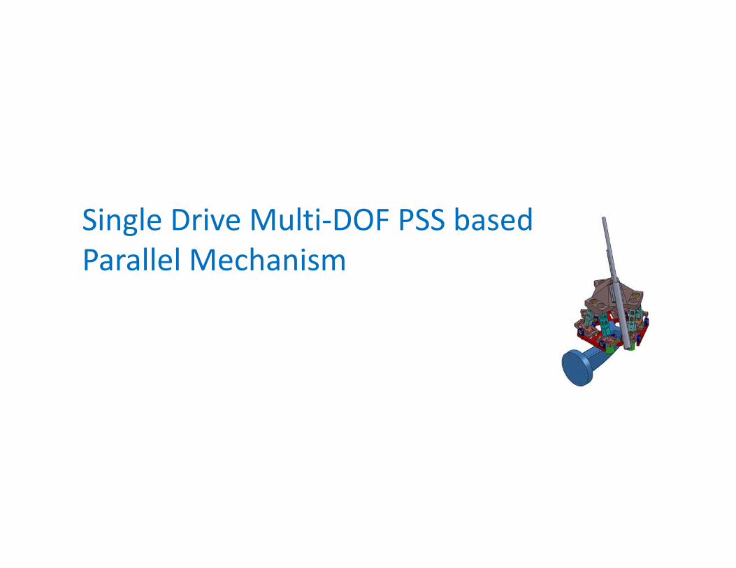
Single Drive Multi‐DOF PSS based Parallel Mechanism
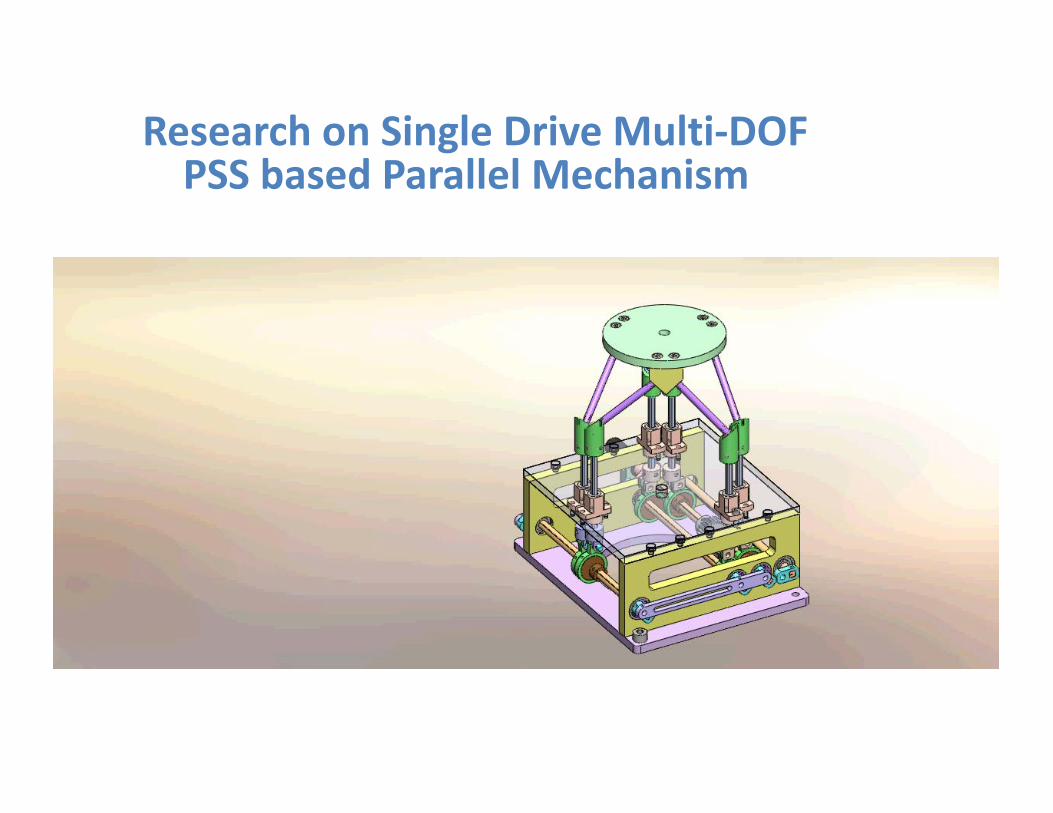
Research on Single Drive Multi‐DOFPSS based Parallel Mechanism
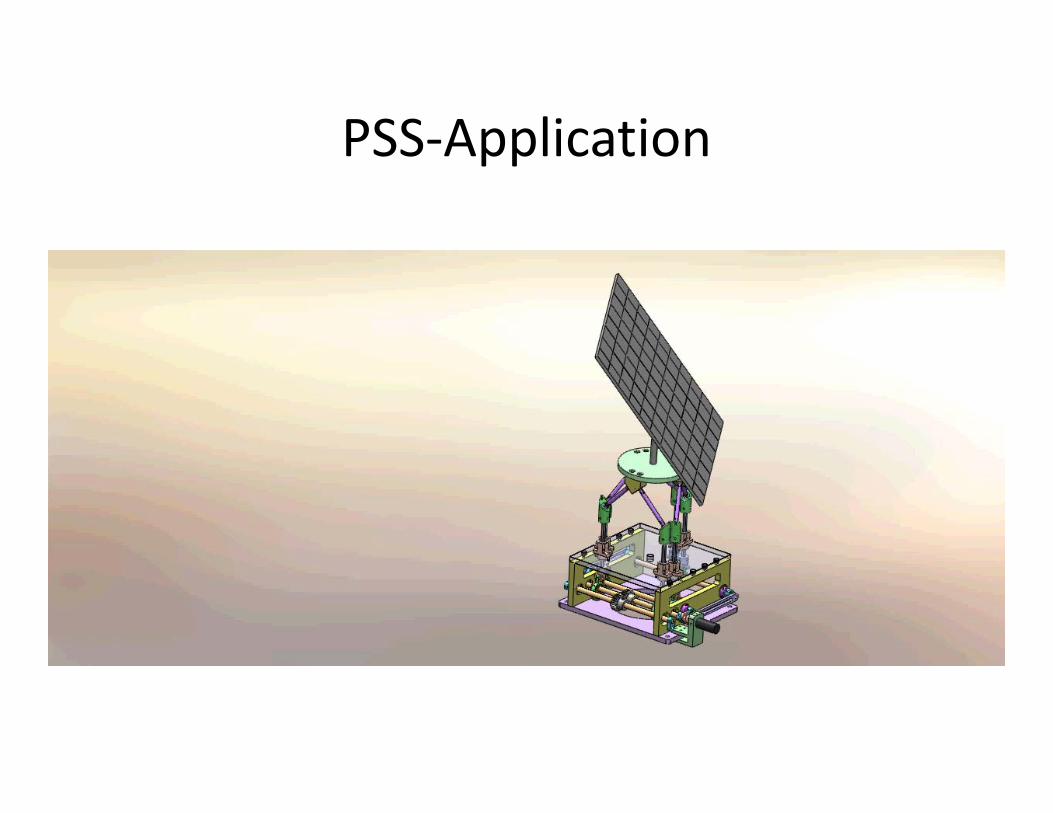
PSS‐Application
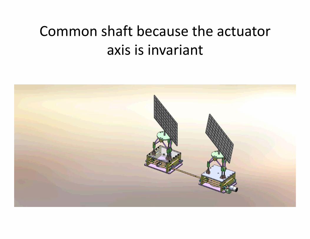
Common shaft because the actuator axis is invariant
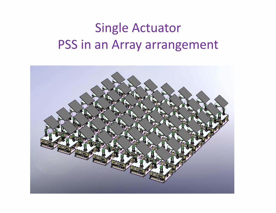
Single Actuator PSS in an Array arrangement

Robot based Neuro‐surgical suite
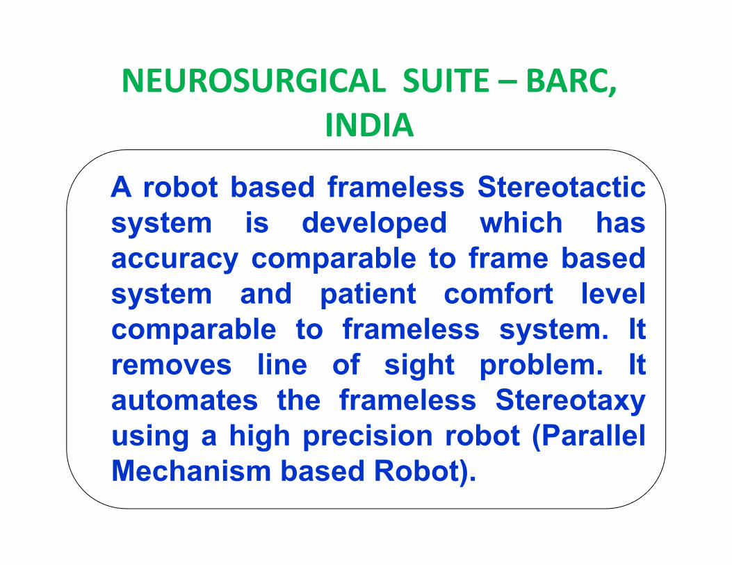
NEUROSURGICAL SUITE – BARC, INDIA
A robot based frameless Stereotacticsystem is developed which hasaccuracy comparable to frame basedsystem and patient comfort levelcomparable to frameless system. Itremoves line of sight problem. Itautomates the frameless Stereotaxyusing a high precision robot (ParallelMechanism based Robot).
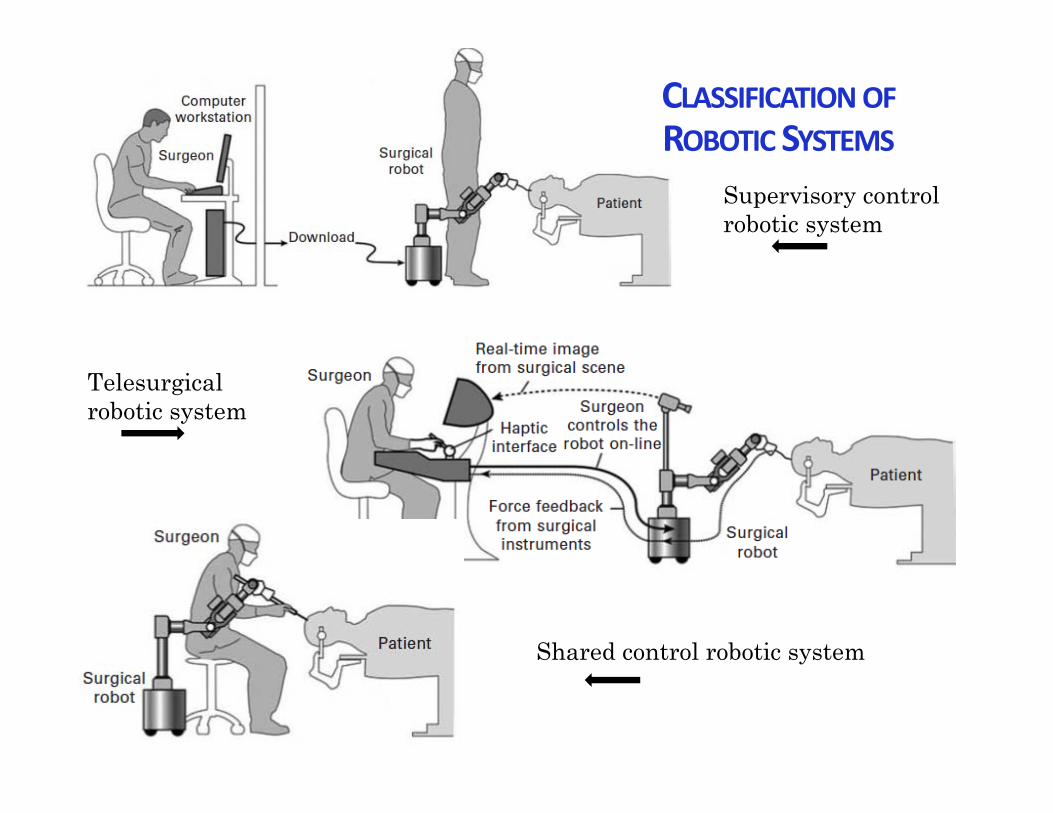
Supervisory control robotic system
Telesurgical robotic system
Shared control robotic system
CLASSIFICATIONOFROBOTIC SYSTEMS
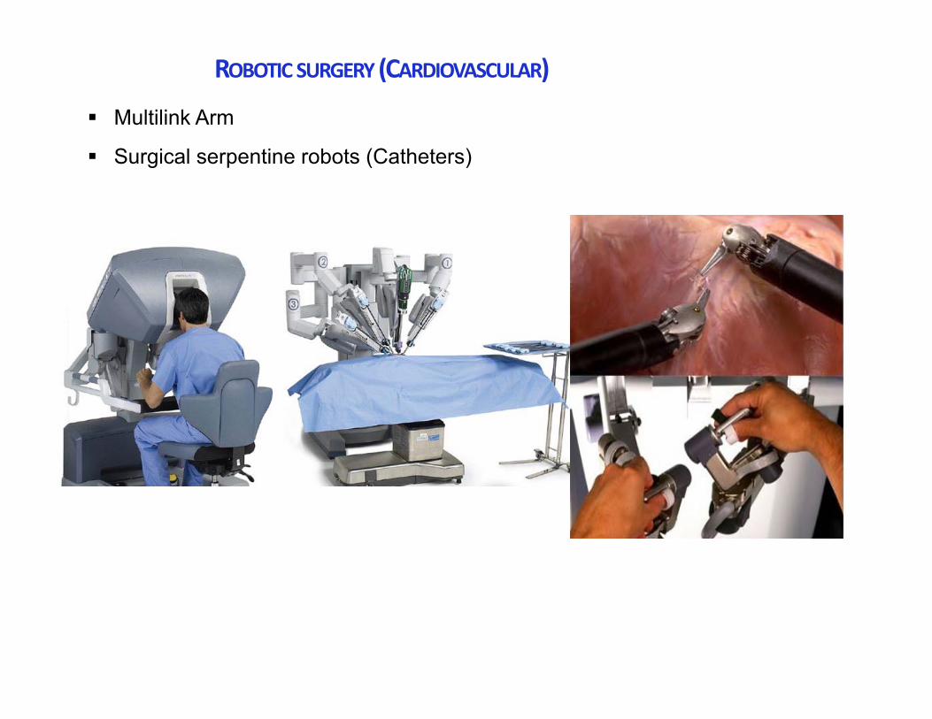
ROBOTIC SURGERY(CARDIOVASCULAR)
Multilink Arm
Surgical serpentine robots (Catheters)
.
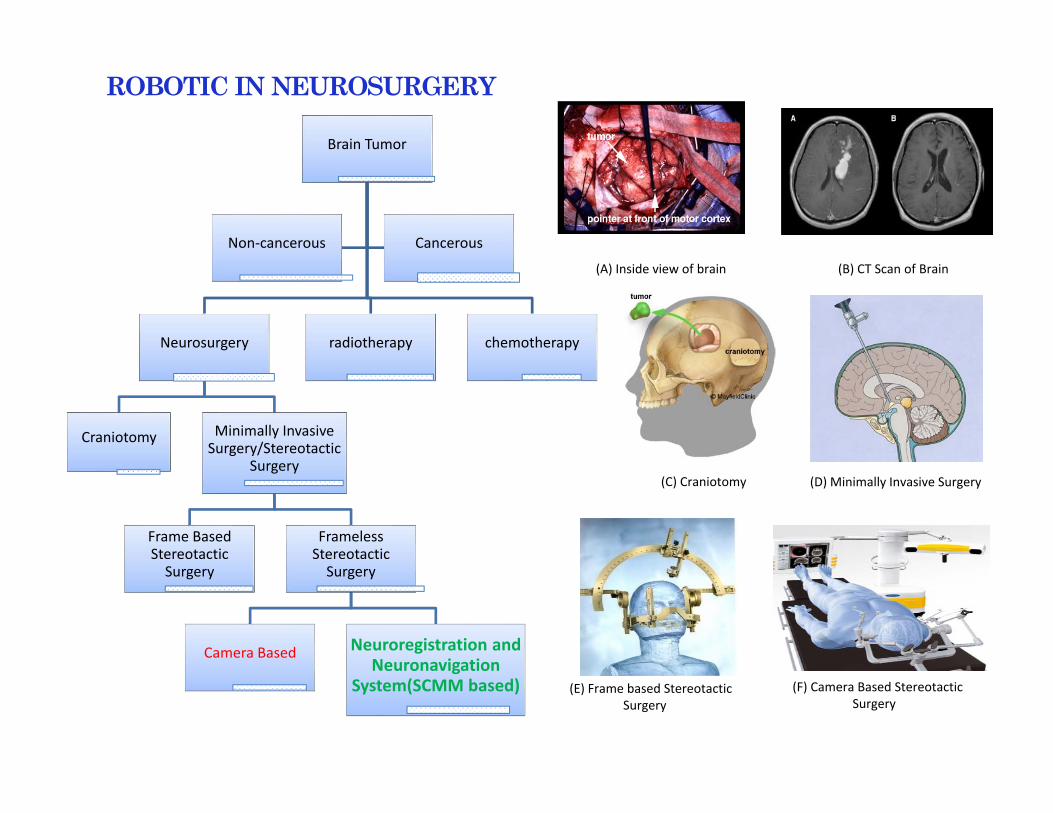
Brain Tumor
Neurosurgery
Craniotomy Minimally Invasive Surgery/Stereotactic
Surgery
Frame Based Stereotactic Surgery
Frameless Stereotactic Surgery
Camera Based Neuroregistration and Neuronavigation
System(SCMM based)
radiotherapy chemotherapy
Non‐cancerous Cancerous
(A) Inside view of brain (B) CT Scan of Brain
(C) Craniotomy (D) Minimally Invasive Surgery
(E) Frame based StereotacticSurgery
(F) Camera Based StereotacticSurgery
ROBOTIC INNEUROSURGERY
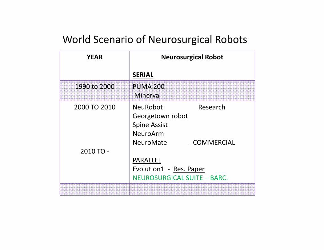
YEAR Neurosurgical Robot
SERIAL
1990 to 2000 PUMA 200Minerva
2000 TO 2010
2010 TO ‐
NeuRobot ResearchGeorgetown robotSpine AssistNeuroArmNeuroMate ‐ COMMERCIAL
PARALLELEvolution1 ‐ Res. PaperNEUROSURGICAL SUITE – BARC.
World Scenario of Neurosurgical Robots
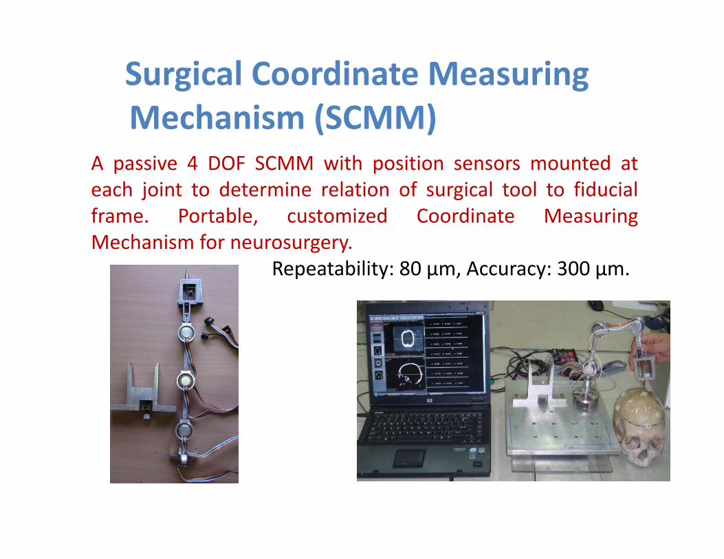
Surgical Coordinate Measuring Mechanism (SCMM)
A passive 4 DOF SCMM with position sensors mounted ateach joint to determine relation of surgical tool to fiducialframe. Portable, customized Coordinate MeasuringMechanism for neurosurgery.
Repeatability: 80 µm, Accuracy: 300 µm.
Neurosurgical Suite for RobotAssisted Neurosurgery • Patient data preparation from imaging. • Development of SCMM• Neuro‐registration using SCMM• Neuro‐navigation using SCMM• Visualization for surgical aid. • Development of a high precision robot. • Integrating Visualization & Robot for conductinghigh precision surgery • Perform frameless Stereotactic Neurosurgery
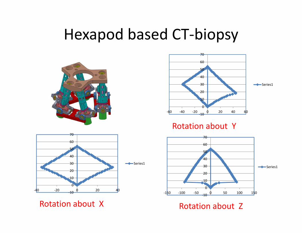
Hexapod based CT‐biopsy
‐10
0
10
20
30
40
50
60
70
‐150 ‐100 ‐50 0 50 100 150
Series1
‐10
0
10
20
30
40
50
60
70
‐60 ‐40 ‐20 0 20 40 60
Series1
Rotation about Z
Rotation about Y
‐10
0
10
20
30
40
50
60
70
‐40 ‐20 0 20 40
Series1
Rotation about X
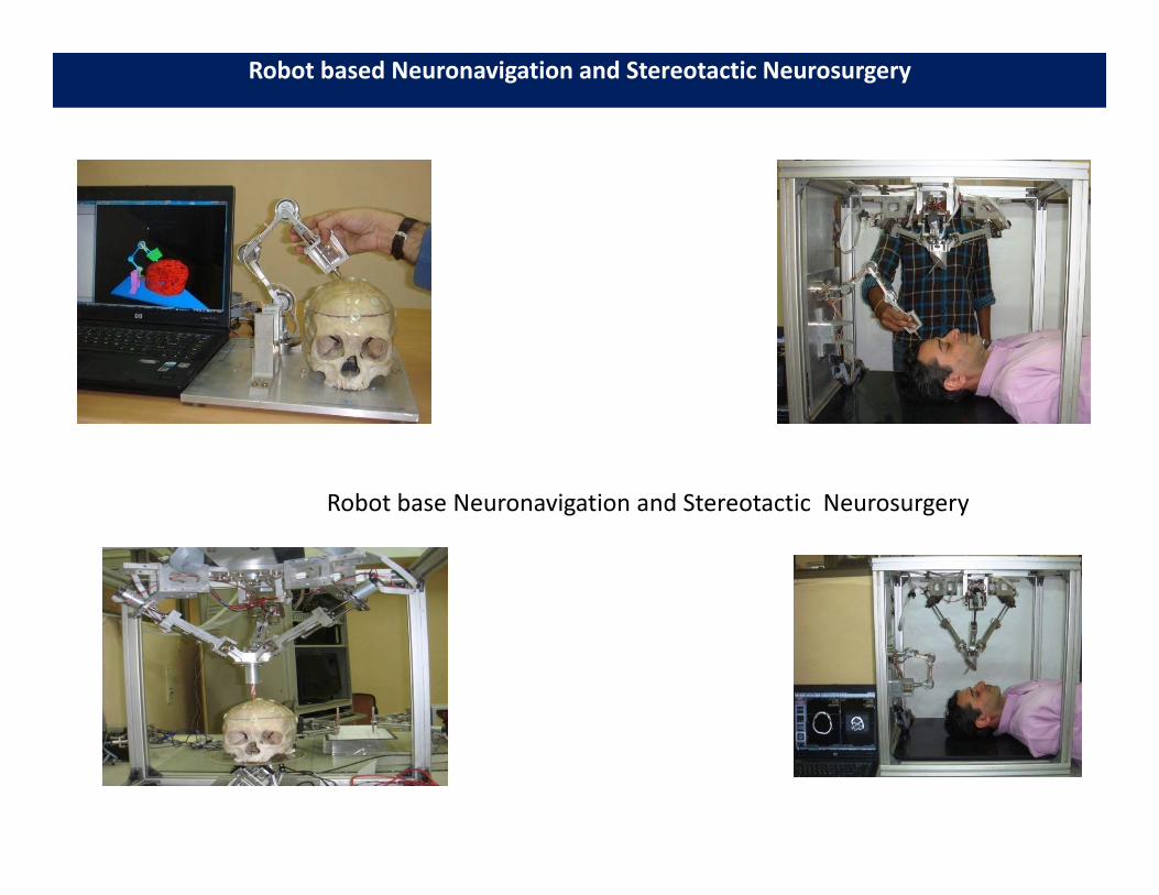
Robot based Neuronavigation and Stereotactic Neurosurgery
Robot base Neuronavigation and Stereotactic Neurosurgery

Thank You
ACKNOWLEDGEMENTS
Dr. D N Badodkar, BARCMr. K Lagoo,Mr. M N Rao,Dr. Gaurav BhutaniMr. S K Sinha
Related Documents