XA9846700. IAEA-TECDOC-999 Introduction of small and medium reactors in developing countries Proceedings of two Advisory Group meetings held in Rabat, Morocco, 23-27 October 1995 and Tunis, Tunisia, 3-6 September 1996 INTERNATIONAL ATOMIC ENERGY AGENCY /A February 1998 9-20

Welcome message from author
This document is posted to help you gain knowledge. Please leave a comment to let me know what you think about it! Share it to your friends and learn new things together.
Transcript

XA9846700.
IAEA-TECDOC-999
Introduction ofsmall and medium reactors
in developing countries
Proceedings of two Advisory Group meetingsheld in Rabat, Morocco, 23-27 October 1995 and
Tunis, Tunisia, 3-6 September 1996
INTERNATIONAL ATOMIC ENERGY AGENCY /A
February 1998
9 - 2 0

The IAEA does not normally maintain stocks of reports in this series.However, microfiche copies of these reports can be obtained from
IN IS ClearinghouseInternational Atomic Energy AgencyWagramerstrasse 5P.O. Box 100A-1400 Vienna, Austria
Orders should be accompanied by prepayment of Austrian Schillings 100,-in the form of a cheque or in the form of IAEA microfiche service couponswhich may be ordered separately from the IN IS Clearinghouse.

IAEA-TECDOC-999
Introduction ofsmall and medium reactors
in developing countries
Proceedings of two Advisory Group meetingsheld in Rabat, Morocco, 23-27 October 1995 and
Tunis, Tunisia, 3-6 September 1996
INTERNATIONAL ATOMIC ENERGY AGENCY

The originating Section of this publication in the IAEA was:
Nuclear Power Technology Development SectionInternational Atomic Energy Agency
Wagramer Strasse 5P.O. Box 100
A-1400 Vienna, Austria
INTRODUCTION OF SMALL AND MEDIUM POWER REACTORSIN DEVELOPING COUNTRIES
IAEA, VIENNA, 1998IAEA-TECDOC-999
ISSN 1011-4289
© IAEA, 1998
Printed by the IAEA in AustriaFebruary 1998

FOREWORD
In the light of renewed interest in the utilization of small and medium reactors (SMRs) indeveloping countries for both power generation and heat applications, the IAEA has surveyedthe reactor designs in the small and medium size range that are currently deployed or underdevelopment. The following TECDOCs on the design and development aspects (includingpassive safety and integral design concepts) have been recently published:
-Review of Design Approaches of Advanced Pressurized LWRs (IAEA-TECDOC-861);
-Design and Development Status of Small and Medium Reactor Systems 1995 (IAEA-TECDOC-881);and
-Status of Advanced Light Water Cooled Reactor Designs 1996 (IAEA-TECDOC-968).
Since deployment aspects such as lessons learned and technology transfer were notcovered in these publications, developing Member States have shown interest in furtherinformation on these subjects.
This publication presents material submitted both by vendor and interested buyerorganizations and conclusions drawn from the discussions of these contributions at twoAdvisory Group meetings on the SMR introduction in developing countries. A few paperswere prepared as follow-up contributions to the proceedings. The summary presents a reviewof the main areas related to SMR introduction and of relevant situations and activities in bothindustrialized and developing countries. It includes an assessment of the expected potentialmarket and of relevant experience that may help developing countries in their efforts tointroduce SMRs. Owing to the inclusion of several new designs, this TECDOC provides anupdate of the SMR status report (IAEA-TECDOC-881) published in 1996. It also reviewsreal time compact nuclear power plant simulators.
The IAEA is grateful to the experts who have contributed to the publication. The IAEAofficers responsible for the compilation of the report were M. Al-Mugrabi and G. Woite ofthe Division of Nuclear Power and the Fuel Cycle

EDITORIAL NOTE
In preparing this publication for press, staff of the IAEA have made up the pages from theoriginal manuscripts as submitted by the authors. The views expressed do not necessarily reflectthose of the IAEA, the governments of the nominating Member States or the nominatingorganizations.
Throughout the text names of Member States are retained as they were when the text wascompiled.
The use of particular designations of countries or territories does not imply any judgement bythe publisher, the IAEA, as to the legal status of such countries or territories, of their authoritiesand institutions or of the delimitation of their boundaries.
The mention of names of specific companies or products (whether or not indicated asregistered) does not imply any intention to infringe proprietary rights, nor should it be construedas an endorsement or recommendation on the part of the IAEA.
The authors are responsible for having obtained the necessary permission for the IAEA toreproduce, translate or use material from sources already protected by copyrights.

CONTENTS
SUMMARY 7
PART I: STATUS AND INTRODUCTION OF SMALL ANDMEDIUM RECTORS
Energy development and nuclear program in China 29Xue Dazhi
Proposal for the CEA/DRN activity on small and medium size reactorsresearch on threshold effects 37G.L. Fiorini
Status of development work on small and medium sized reactors at Siemens/KWU 53D. Bittermann
Some Japanese activities on small and medium nuclear power reactors 67H. Sekimoto
Status of development — An integral type small reactor MRX in JAERI 73T. Hoshi, M. Ochiai, J. Shimazaki
Realization of safety culture into a reactor plant-4S (super safe, small andsimple) LMR 85S. Hattori, I. Ikemoto, A. Minato
General overview of nuclear activities in Morocco 95K. Karouani
Status and potential of small & medium power reactors in Pakistan 99P. Butt, M. Ahmad
PART II: LESSONS LEARNED AND TECHNOLOGY TRANSFER
The CAREM reactor: Bridging the gap to nuclear power generation 113J.P. Ordonez
Technology transfer: The CANDU approach 117R.S. Hart
Setting-up of SMR in a developing country — Indian experience 127C.N. Bapat, P.D. Sharma
Karachi nuclear power plant — A review of performance, problems and upgrades 141S.B. Hussain
The Romanian experience on introduction of C ANDU-600 reactor at theCernavoda NPP 159S.N. Rapeanu, A. Bujor, O. Comsa
Potential role of the Romanian research and industry on the small and mediumreactors market 171S.N. Rapeanu, A. Bujor, O. Comsa
The main steps of the Romanian nuclear power program development —Accumulated experience 193T. Chirica, D. Popescu, M. Condu, M. Vatamanu

PART III: SMALL AND MEDIUM REACTORS POTENTIAL MARKET ANDAPPLICATIONS
Assessment of the world market for small and medium reactors 205B.J. Csik
Potential role of nuclear power in the Moroccan energy programme 221A.A. Haddou, M. Tabet
Market potential of small and medium power reactors in Syria 225/. Khamis, A. Hainoun
Summary of survey on SMR market potential in Japan 229T. Hoshi, M. Ochiai
Experience and prospects of desalination in Morocco 243O. Boucif
PART IV: DESIGN DESCRIPTIONS
CAREM Project: 1995 status of engineering and development 253H.J. Boado, J.P. Ordonez
The CANDU 80 263R.S. Hart
ISIS, safety and economic aspects in view of co-generation of heat and electricity 277L. Cinotti
Design and safety aspect of small lead-/lead-bismuth-cooled fast reactors 289H. Sekimoto
Preliminary design concept of an advanced integral reactor 303K.S. Moon, D.J. Lee, K.K. Kim, M.H. Chang, S.H. Kim
Application of nuclear steam supply system of NIKA series forseawater desalination 317
L.A. Adamovich, A.N. Achkasov, G.I. Grechko, V.L. Pavlov, V.A. Shishkin
PART V: SIMULATION OF NUCLEAR REACTORS
CAE advanced reactor demonstrators for CANDU, PWR and BWR nuclearpower plants 329R.S. Hart
Utilization of El Dabaa basic simulator for manpower development 337W.A. Wahab, S.B. Abdel Hamid
Development of simulators for SMRs 345M.N. Jafri, P. Butt
LIST OF PARTICIPANTS 357

SUMMARY
1. INTRODUCTION
Energy represents an important factor of everyday life, and techno-economic studies haveshown that there is a distinct correlation between the energy consumption and national economicoutput in a wide range of countries. Electricity is the most convenient and versatile form ofenergy. Electricity consumption is playing an important role in modernization efforts to bring thedeveloping world into a new era. This era will mainly be characterized by the electrification ofrural areas where two billion people still do not have access to electricity in their homes and tomodern information technology. Both would require a reliable source of electricity. The shareof electricity in the global energy consumption has grown from 17% to 30% and the averageannual consumption of electricity per capita has almost tripled in the period from 1960 to 1990.hi spite of this increase, developing countries still consume much less electricity per capita thandeveloped countries. The witnessed aspirations for economic growth and improved standard ofliving of developing countries is only possible if a large expansion of electricity production canbe realized.
The world population is expected to increase from the present 5.8 billion to 8 billion bythe year 2030, a rate of 70-80 million per year. Developing countries will account for over 95%of this increase. This will drastically increase the demand for electricity, requiring substantialadditional power production capacities. Hence, the future electricity growth will likely bedominated by developing countries.
Power generation using fossil fuels or hydropower is the dominant means of electricityproduction in the world today, contributing approximately 82% of the total of 12913 TWhelectricity generated in 1995. Nuclear is currently providing about 17% of the power generationin the world, making it one of the three major important energy sources in many countries.Having been introduced only four decades ago, the nuclear option has grown very fast. Nuclearelectricity generation expanded at an average of 24% per year in the period 1970-1980, and16.5% per year in the period 1980-1985. Later on, this rapid expansion was affected by twosevere nuclear accidents and the improved economics of alternate electricity sources, particularlycombined cycle gas turbines, and the growth was only 5.6% in the period 1985-1990 and 3% inthe period 1990-1995. In 1995 there were 437 NPPs operating in 32 countries. Several factscould be concluded from such status and contribution of nuclear power to the world powergeneration:
A significant part of power generation in the world is produced by nuclear power;Nuclear power is well developed and proven;It is economical and competitive to other forms of power generation in a range ofsituations;Nuclear power generation is environmentally benign. There is an incentive for nuclearpower growth if the environmental burdens are to be more effectively controlled in thefuture.
On the other hand, there are unfavourable factors and possible constraints which currentlylimit the further growth of nuclear power, including:
Public opposition;Difficulty of new nuclear power plants (NPPs) to compete economically;Saturation of the electricity market in many industrialized countries;

Lack of nuclear infrastructure, technical and financial resources in many developingcountries;Financing difficulties.
Although the importance of the issues varies among individual countries, they havecontributed to limiting nuclear power growth to a few countries.
Most of the nuclear power is generated in developed countries, but a number ofdeveloping countries have also deployed nuclear power plants. There were 113 nuclear powerplants operating in developing countries in 1995, with a net generating capacity of 68 GW(e).The accumulated operating experience of these plants is over 800 reactor years. There are 20developing countries that have experience with nuclear power generation.
2. THE CASE FOR SMRs IN DEVELOPING COUNTRIES
It can be noted that in most of the developing countries the unit size has been mainly thesmall and medium reactor (SMR) size range. With the exception of China, the Republic ofKorea, and some of the Republics that were part of the former Soviet Union which operate bothmedium sized and large nuclear plants, the remaining units are of 700 MW(e) or below. This ismainly due to the size of their grid, total power demand, electricity demand growth rate, andinfrastructure and financing capabilities. Concerning new nuclear power plants, it is expected thatSMRs will be the preferred choice for developing countries in the next decades, includingdeveloping countries that have not yet deployed nuclear power.
Apart from nuclear power generation, some developing countries could utilize nuclearenergy for heat applications. Seawater desalination, district heating and process heat applicationare important areas for many developing countries where nuclear power can play an importantrole. These applications could be served using small or medium reactors. In addition, some ofthe developing countries have remote areas and/or isolated islands where nuclear power couldhave an advantage over conventional power generation to supply electrical power and/or heat forvarious applications. The total energy demand for this application for a given site is usuallyrelatively small (s 100 MW(e)).
Although nuclear energy is not the only means of providing power and process heat, itis a relevant option, especially if the environmental issues are to be properly accommodated. Inaddition, countries that are not blessed with fossil natural resources could find the nuclear optionattractive on the long run. Future nuclear power utilization will likely deploy advanced nuclearpower plants that are currently under design.
Building on four decades of operating experience, which amounts to about 7000 reactor-years, and applying lessons learned from over 500 plants, a new generation of nuclear powerplants has been or is being designed and developed. These new generation reactors haveincorporated improved safety concepts that will provide better protection against possiblereleases of radioactivity to the environment. During their design, the requirements forconstruction, operation, maintenance and repair were taken into consideration. Although this willensure technical and safety advantages, their economics could only be proven once they havebeen deployed. A nuclear power plant is a capital intensive project; financing has to be secured.
The deployment of nuclear power in developing countries, especially in those withoutnuclear power experience, requires special attention to several areas by both vendor and

purchasing organizations. These areas were presented and discussed during the Advisory GroupMeetings and can be classified in the following three areas:
design and development status of SMRslessons learned from the introduction of SMRs in developing countriesassessment of market potential for SMRs.
3. DESIGN AND DEVELOPMENT STATUS OF SMRs
Over the last three decades, about 7000 reactor years of operating experience have beenaccumulated with the current nuclear energy systems. Building upon this background of success,new small and medium reactor systems are being built or developed. These SMRs generallyincorporate improvements of the safety concepts, including features that will allow operatorsmore time to perform safety actions and that will provide increased protection against anypossible releases of radioactivity to the environment. The new SMR systems have alsoincorporated features to make them simpler to build, operate, inspect, maintain and repair.Descriptions of these systems and their development status have been documented in the IAEA-TECDOC-881 [I]1. The design and development efforts of SMRs have been very active andsome new designs have emerged over the last year. These new designs have been presentedduring the Advisory Group Meetings on the "Status and introduction of small and medium powerreactors into developing countries", in Rabat, Morocco, 23-27 October 1995 and in Tunis,Tunisia, 3-6 September 1996. Overviews of these new designs are included in this technicaldocument for completeness (Table 1).
4. SMR MARKET
The IAEA has performed a questionnaire survey on the SMR market potential in 1996.The questionnaire consisted of a supplier's part and a buyer's part. By the end of 1996, the IAEAhad received responses to the buyers' questionnaire from the following countries: Bulgaria,Chile, Finland, France, Hungary, Indonesia, Pakistan, Thailand, Tunisia, Turkey and Viet Nam.Several countries showed interest in nuclear power for electricity generation and seawaterdesalination; they project their next NPPs to be in operation before the year 2020.
The largest plant sizes will be 300-1500 MW(e) in 2000 and 360-1500 MW(e) in 2015.Six countries foresee that their largest power plant sizes will be under 700 MW(e) in 2000; threecountries foresee that their largest plant sizes will be under 700 MWe in 2015. The othercountries are interested in larger plants.
Some Member States listed factors which they consider important for the NPPintroduction in their country: (a) energy generation cost, (b) investment costs, (c) safety andlicensability, (d) proveness of the technology used, (e) guarantees concerning costs, constructionschedule and performance of the NPP, and (f) local participation capability in the NPPconstruction.
The following countries provided responses to the suppliers'questionnaire: BelgiumFrance, India, Italy, Japan, Republic of Korea, Romania and the Russian Federation. The
1 The technical document has included 29 design descriptions and Table 1 summarizes the main data anddevelopment status of SMRs.

TABLE 1. SMR DESIGNS [1]
1. Reactors being deployed or in the detailed design stage
DesignName
Designer /Supplier
ReactorType
GrossThermalPowerMW(th)
NetElectricalPowerMW(e)
BWR-90
ABB
BWR
2350
720 - 820
AP-600
W
PWR
1940
600
SBWR
OE
BWR
2000
600
QP300
SNERDI
PWR
999
300
AST-500
OKBM
PWR
500
not relevant
KLT-40
OKBM
PWR
Up to 160
Up to 35
CANDU-6
AECL
PHWR
2158
666
CANDU-3
AECL
PHWR
1441
450
PHWR-500
NPC
PHWR
1673
500 (gross)
PHWR-220
NPC
PHWR
743
194
2. Reactors in the basic design stage
DesignName
Dcslnger /Supplier
ReactorType
GrossThermalPowerMW(th)
NetElectricalPowerMW(e)
PIUS
ABB
PWR
2000
610-640
HR-200
INET
-
200
CAREM25
CNEA/INVAP
PWR
100
27
MRX
JAERI
PWR
100
30
ABV
OKBM
PWR
38
6
OT-MHR
OA
HTR
600
286
MHTR
ABB/Siemens
HTR
200
85.5

TABLE 1 (Cont.)
3. Reactors in the conceptual design stage
DesignName
Designer /Supplier
ReactorType
GrossThermalPowerMW(th)
NetElectricalPowerMW(c)
BWR-600
Siemens-AO
BWR
2200
750
VPBER-600
OKBM
PWR
1800
630
HSBWR
HITACHI
BWR
1800
600
SPWR
JAERI
PWR
1800
600
SIR™
Consortium
IntegratedPWR
1000
320
ISIS
ANSALDO
PWR
650
205
ATS-150
EMBDB
PWR
536
Up to 180
MARS
Univ. ofRome,ENEA
PWR
600
Up to 170
RUTA-20
RDIPE
Pool type
20
not relevant
SAKHA-92
OKBM
PWR
7
Uptol
MDPR
CRIEPI
LMR
840
325
4S
CRIEPI
LMR
125
50
Note to designer/supplier: ABB ABB Atom AB, SwedenAECL Atomic Energy of Canada Ltd.CNEA Comision Nacional de Energia Atomica, ArgentiniaCRIEPI Central Research Institute of Electric Industry, JapanEMBDB Experimental Machine Building Design Bureau, Russian FederationGA General Atomic, USAGE General Electric, USAHTR High Temperature ReactorINET Institute of Nuclear Energy and Technology, Tsinghua University, ChinaINVAP INVAP Company, ArgentniaJAERI Japan Atomic Energy InstituteNPC National Power Corporation, IndiaOKBM Special Design Bereau for Mechanical Engineering, Nejninovgarad, Russian FederationRDIPE Reserch and Development Institute of Power Engineering, Russian FederationSNERDI Shanghai Nuclear Engineering Research & Design Institute, ChinaW Westinghouse, USA

responses show a similar trend in conditions for supplying NPPs. Suppliers are willing to offertechnical assistance to buyer countries. Domestic infrastructure requirements in the buyer'scountry are not critical, but a sound technical base in staff and industry is preferred dependingon contractual agreements. A regulatory body must be established in the buyer country.
The suppliers need a firm commitment from the buyer country to the Non-ProliferationTreaty (NPT) and to international/national regulations before transporting any nuclear materials.Nuclear waste management and disposal have to be arranged by the buyer. Some suppliers areprepared to offer a build-operate-transfer (BOT) contract type.
The responses also update information on SMR design status. Most nuclear suppliers areinterested in advanced SMR development for a wide range of applications; some of the advancedSMRs are already in the detailed design stage.
The market potential of SMRs was discussed at the meeting in Tunis, where thequestionnaire responses were taken into account. The initial estimate was revised by the IAEASecretariat after the meeting and is included in Part m.
The market for SMRs until 2015 was assessed by individual countries, taking intoaccount energy demand and supply patterns, growth rates, energy resources, economic andfinancial resources, electric grids, industrial and technical development, infrastructureavailability, environmental and nuclear safety concerns and other policy issues. The marketassessment includes all applications of these reactors, that is electricity generation as well as thesupply of process heat and district heating.
It is expected that SMRs will be deployed primarily in countries which have alreadystarted nuclear projects, in particular in countries which have developed SMR designsthemselves. Thus, projects would be supplied predominantly by domestic sources in the yearsahead; later, the export market is expected to attain more importance. It is further expected thatover two thirds of the SMR units would be in the medium size range, i.e. from 300 to 700MW(e), the rest would be smaller.
About one third of the SMRs to be implemented are expected to supply heat or electricityor both to integrated seawater desalination plants. More than half of these reactors would bebelow 300 MW(e) or 1000 MW(th).
The overall market is estimated at about 60 to 100 SMR units to be implemented up tothe year 2015. It is recognized that forecasts, just like national development plans, tend to err onthe optimistic side. Therefore, an overall market estimate of 70 to 80 units seems reasonable.
5. LESSONS LEARNED FROM NUCLEAR POWER INTRODUCTION
The utilization of experience from the construction and operation of nuclear power plantsis important to developing countries in planning and utilizing nuclear energy for powergeneration or heat applications. Taking advantage of the huge investment already put into nuclearpower development and avoiding excessive local expenditure in trying to develop nucleartechnologies independently is important to save time and money and to have a sound programme.The general approach as well as the specific steps taken with regard to specific areas such asinfrastructure requirements, technology transfer, cooperation and financing by countries that have
12

introduced SMRs provide useful information for other interested countries. Learning fromexperiences will help to avoid costly mistakes. Worldwide, over 20 countries have been involvedin the purchase, construction and operation of SMRs. Fourteen of these are developing countries.This makes the feedback of these experiences quite relevant to other developing countries.Experiences concerning infrastructure requirements, technology transfer and local participationwere discussed at the meetings and are summarized below. It was recognized that also theexperiences concerning financing and project management are quite relevant. They were notdiscussed extensively at the meeting but are basically addressed in the conclusions. More detailedinformation on these areas is contained in other IAEA publications [2, 3].
5.1. Infrastructure requirements
The term nuclear infrastructure refers to the organizations, systems and resources requiredto implement a nuclear power programme. This includes:
(i) Technical infrastructureselectric gridtransportationtelecommunication
(ii) Organizations forregulation and legislationprogramme planningproject implementationplant operation and maintenance
(iii) Qualified manpower(iv) Industrial support(v) Financial resources.
A sufficiently strong infrastructure is one of the most important requirements for nuclearpower introduction. The infrastructure in the buyer country should be sufficiently well developedto support the introduction of nuclear power with appropriate technology transfer. The effortrequired to establish the minimum infrastructure should not be underestimated. While theinfrastructure requirements for the introduction of a very small reactor are less demanding thanfor a large NPP and may be developed partly during the plant construction period, theinfrastructure requirement for a nuclear programme is quite extensive and requires substantialeffort and planning. Institutional and regulatory infrastructure require bilateral as well asmultilateral agreements between relevant organizations. These agreements require governmentalsupport, must be long term in nature and should be at all levels in the relevant organizations.Organizations concerned with engineering, development, manufacturing, project managementand plant operation must have similar agreements for technology transfer. A broad basedrelationship between counterparts in vendor and buyer countries must be established. Theprogramme must have manpower development as an important component and should providemutual benefit to both buyer and vendor countries, hi addition to internal training and bilateralcooperation, multilateral cooperation is important to build up the infrastructure.
5.2. Technology transfer and local participation
In order to introduce SMRs successfully into a developing country, a certain level oftechnology must be present or has to be introduced. These technological capabilities (existing or
13

acquired) should be used for appropriate local participation aiming at a technically sound andeconomical nuclear programme. This will imply an upgrading of the local capabilities and maylead to a spin off effect to other industries. Identification of fields of interest, the relevantindustries and priorities for the selected technologies must be established in the context of thesize of the programme (e.g. number of units to be constructed). There are many areas which maybe considered for technology transfer in the nuclear field. The topics and the scope indicatedbelow, while not exhaustive, are to be seen as important for staffing a nuclear programmeintended to form a major component-in the national energy supply:
1. Design and developmentBasic and on the job training in the design and development areas of interestJoint engineeringTransferring and/or sharing of design toolsJoint R&D programmes
2. ManufacturingIdentification of local capabilities relevant to the nuclear power programmeEvaluation of areas of industries which would participate in the nuclearprogrammeIdentification of potential constraints in achieving the manufacturing objectivesRelevance of technology transfer areas to the overall national plan ofindustrialization
3. Proj ect managementManagement structureTools
4. Quality assurance and quality controlTools and techniquesCodes and standardsImplementation and commitment of QA/QC programmeApplication of QA/QC (across the board)Cost and manpower implications
5. Safety and licensingSafety approachGeneral approach to licensing proceduresStructure of licensing organizationLicensing criteria and regulationsSafety culture
It is important to emphasize technologies that are applicable in the short term. The scopeof these possibilities should be jointly defined by the vendor and the buyer. This selection processshould be built on strengths within local industries and should look for diverse applications ofthe technology gained. The management of technology transfer should be delegated to dedicatedorganizations, which are elements in the total management of the programme. Important areasinclude non-destructive testing (NDT) and in-service inspection (ISI). Another area which is notonly important for a particular sector of the programme but rather to the whole of the programmeis quality assurance(QA). Quality assurance requires training, early introduction into theprogramme and the involvement of the user in the vendor's QA programme. The desire fortechnology transfer at a level for which local industries are not ready, may cause some delay inthe construction project and should be avoided.
14

6. COUNTRY-SPECIFIC SITUATIONS
Argentina
Large gas reserves have been discovered since the start of the nuclear programme. Thereare large hydroplants coming into operation. ATUCHA-2 (the third NPP in the country) has beenunder construction for 15 years. The electricity industry has been privatized with the newgeneration companies seeking a 13% rate of return. All these factors contribute to a situationwhere nuclear may not be able to compete and orders for new plant are unlikely for many years.
The current increase in demand for power in developing countries will lead to morecountries introducing nuclear power but this may not be immediately ahead. The traditional pathinto nuclear energy is to start with a research reactor and then to buy a larger reactor. Thedifference in resources needed for these two projects is very large. This applies to humanresources, licensing capability, industrial infrastructure, finance and time. An intermediate steputilizing a reactor in the 100-500 MW(th) range which produces something to sell may be anappropriate way to bridge the gap. The CAREM reactor is designed to provide this bridge.
The CAREM project justifications are to maintain national nuclear capabilities and as apossible export to countries proposing to initiate a nuclear power programme. It would form animportant step between a low power research reactor and a commercial power plant. CAREMis a 25 MW(e) self-pressurized integral PWR. The Preliminary Safety Analysis Report (PSAR)for CAREM has been presented to the licensing authority in 1996. Basic design and much of theexperimental programme is complete. A siting decision for the prototype is expected in 1997.Funds for construction have been requested in the budget for 1997.
Canada
In Canada, the design and development programme is focused on the CANDU family ofreactors consisting of:
CANDU 3 450 MW(e) Market readyCANDU 6 700 MW(e) In operationCANDU 9 900-1300 MW(e) In detailed design
The next generation plant is CANDUX which will have an alternative coolant at highertemperature and which may incorporate a direct cycle. The CANDU 80 is the latest design in theCANDU line. Among its design requirements were:
power < 100 MW(e).Specific costs to be <CAD 3000/kW(e).Use of proven systems.New features to be applicable to larger plant.
In the design, some basic re-thinking has led to simplifications.
Key features of the CANDU 80 include the use of fully proven systems and technologiesfrom operating CANDU plants, low power density (peak fuel bundle power is 60% of that ofcurrent larger CANDU plants), and the incorporation of a number of passive heat removalsystems.
15

There is a double containment with an inner steel containment, serving as a support formajor components. It has very little internal concrete. There is no need for a zone control systemdue to the reduced size and rating of the core. Power control is by absorbing chains which areinserted into the core to a greater or lesser extent. There is no dump tank as was used in previoussmall CANDU plants. The shutdown systems utilize liquid absorber rods. The basic design hasbeen established, but further design work was stopped in January 1996 pending interest by apotential buyer. There is also the Slowpoke based SES 10 heating plant.
Canada has experience of successful technology transfer to five countries where therehave been increasing levels of local participation. A long term commitment on both sides isneeded for the process to be successful. It involves all levels of the project from design andanalysis down to manufacturing and operation. Both "know-how" and "know-why" are importantand occur in different mixes at construction workers and program managers.
For purchasing countries, technology transfer is necessary to take advantage of the hugeinvestment already put into nuclear power development, and to avoid excessive localexpenditure in trying to catch up independently. A single co-ordinating organization in thereceiving country is recommended. The framework for success requires:
Comprehensive national planing.Organization to develop infrastructure.Committed resources.Firm management.Development of relationships.
China
China is a large consumer of energy. Its total energy consumption ranking is third in theworld and the first in coal consumption. Nevertheless, the country has an energy shortage and hasa vigorous nuclear programme. The coal deposits are in the north-west and the hydro resourcesin the south-west of the country. A strong incentive for nuclear is the coal transport problem;42% of railway and 30% of ship capacity is currently taken up by coal transportation. There isalso a serious air quality problem in many cities due to coal burning.
There are 3 power reactors operating, 9 under construction and 20 more are expected by2010. A large fraction of energy consumption is for heating purposes and China has two reactordevelopment lines to meet these needs:
1. A 10 MW(th) high temperature gas reactor for process heat2. Nuclear heating reactors NHR 5 (5MW(th)) and NHR 200 (200 MW(th)).
For the NHR 200, the PSAR was submitted in October 1995 and a construction permithas been issued in September 1996. The first reactor will be built in Da Qin City in the NorthEast and is scheduled for completion by the year 2000. Pre-construction work on site has beenstarted. More than 10 other places in China are interested in also installing a NHR 200. Chinaalso has isolated areas which could be supplied by SMRs.
16

The NHR 200 design has been supported by operation of the NHR5 reactor, which hasbeen running for some years, and by an extensive test programme including simulation of somechallenging accident sequences. NHR200 is similar in design to NHR5 being an integral lowpressure design with natural circulation of the primary coolant, internal control rod mechanismsand passive residual heat removal systems.
The NHR200 can be coupled to a desalination plant to produce 120 000 m3 per day at acost of $1.3/m3. The reactor capital cost is estimated at $110 million at 1991 prices. It is expectedthat the safety features of the reactor would allow its construction within 2 km of a residentialarea.
France
A newly organized activity on SMRs in France has been started by the Commissariat al'Energie Atomique (CEA). A study is proposed to look at SMRs with new approaches,fundamentally evolutionary, but possibly with some innovative components. There is arecognition that there are technology thresholds which allow some technical solutions withinlimits of size and which contribute to low cost and increased safety but which cannot be used atlarger sizes. The objective is to study the interactions and relationships between size, modularity,availability, maintainability, threshold effects, safety, risks and economics.
Germany
The objectives of SMR development in Germany are low capital cost and a high safetylevel. Factors which could help to offset the economies of scale are: use of existing power reactormaterials, technology transfer from other projects and prefabrication. A large coolant volume andpassive safety systems contribute to the high level of safety.
One design considered a 200 MW(e) integral reactor with hydraulic rod drives and a closefitting containment to ensure core cover at all times. The reactor was designed for 40 years, forwhich two core loads are needed. Within the vessel is storage capacity for the spent fuel. Thedesign has U-tube heat exchanger and an intermediate circuit.
3
Utilization of this system for desalination can yield 40000 to 150000 m /day but thehigher levels need net input of electricity from the grid. Construction in Germany is unlikely andfeasibility studies carried out in the Czech Republic and China did not result in orders.
There is also work on SWR600, a 750 MW(e) BWR for which basic design has startedwith possible extension to 1000 MW(e). The plant is designed for 60 years with spent fuelstorage for 40 years. There are passive safety systems with auto-initiation. The basic design andthe preliminary safety analysis report are scheduled for completion in 1999.
India
The Indian programme started in 1948 and has three major components.
1. use of natural uranium in PHWRs2. use ofU/Pu/Th in fast reactors3. use of U-23 3/Th in fast reactors
17

For the first stage, there are currently 8 units, mostly of 220 MW(e), in operation. Therehas been a policy to carry out design, construction, operation and maintenance with Indianpersonnel only after the first two 220 MW(e )plants. A 14 MW(e) breeder demonstration reactoris under construction as part of the second phase of the programme.
There have been problems with indigenous production but these have been overcome anda degree of standardization has been established. Construction of a 220 MW(e) plant should nowrequire 7 years from first concrete pouring. For Tarapur 3 and 4, a new 500 MW(e) design hasbeen established but this now awaits financial support.
Italy
Italy is looking for innovation to re-establish a reactor programme. There are twoconcepts under consideration, the European passive reactor, a 1000 MW(e) variant of AP 600,and the ISIS reactor. ISIS has followed the concepts of simplicity to reduce costs and passivityto ensure safety.
Nuclear power costs have been challenged by low fossil fuel costs and an increase inefficiency of fossil fuel plant from 33% in 1963 to 54% today and possibly 60% (by the year2000) by the use of high temperatures and dual cycle turbines. Co-generation in a nuclear plantcould overcome the cost reduction of the dual cycle and ISIS is suited to this application.
Japan
The Ministry of Science and Technology is giving strong support to advanced reactordesign, and the proposed national programme has some scope for development work. MRX andthe smaller DRX are integral reactors designed for marine use. They have control rod driveswithin the reactor and have a close fitting water filled containment. The thermal power of theMRX is 300 MW(th), and 500 kW(th) of the DRX. The passive cooling systems make use of thecontainment water. Results of safety analysis demonstrate satisfactory behavior in the case ofdesign basis accidents and beyond. The design is supported by an extensive R&D programmeincluding a thermal hydraulics rig and a control rod drive development rig.
A one piece removal system is proposed for refuelling and maintenance. The entirereactor, including its water filled containment would be lifted out of the ship and replaced withanother one which had already been refueled and maintained.
On economics, a ship carrying 6000 containers as part of a 20 ship fleet operating acrossthe pacific at 30 knots would be economic in comparison with diesel. High speed favors thenuclear option.
A proposal of the utilization of small lead and lead-bismuth reactors in developingcountries was presented by Japan. Reactors of 150 MW(th) with a 12 year period betweenrefuelling and with a B4C shield have been studied. They have 0.1% k/k reactivity swing over12 years, negative temperature coefficient for the core as a whole and a peak burnup of 9%. Thereare differences in void coefficient with the lead/bismuth coolant and metal/nitrite fuel giving ahigh negative coefficient. Accident analyses with all four combinations (Pb, Pb-Bi, metal fuel,nitride fuel), show very satisfactory responses.
18

Japan has 13 SMR designs developed by 6 organizations, 3 of which are researchorganizations and 3 are manufacturers. The electrical outputs range from 4 kW(e) to 100 MW(e).
Republic of Korea
The Republic of Korea has started development work on a medium size integral reactorfor co-generation, to be used for power generation and seawater desalination. The goal of thisproject is to complete the design work by 2005. The stages are:
complete conceptual design 1997complete basic design 2000complete detailed design 2005
The size is to be in the range of 100-600 MW(e) with initial work concentrating on 300 MW(t)size. The reactor is an integral design with no dissolved boron, except for emergency shut down,and a low power density. It is self-pressurized with a mixture of nitrogen and steam and nopressurizer heater. The steam generators are of helical coil type. There is a guard vessel half filledwith water and an additional containment. It has passive safety systems and the valves whichmust open to initiate the decay heat removal system are opened by passive means.
Morocco
Morocco is a country of 27 million inhabitants of which 51% are urban dwellers. 80%of the rural regions are without electricity. The present sources of electrical energy are: oil 74%,coal 24%, both imported, hydro 2% and gas 0.25%. Estimates based on 7% growth to the year2005 and 5% thereafter lead to the following figures for the installed capacity:
1994 3500 MW(e)2000 5300 MW(e)2005 7000 MW(e)
There are grid links with Spain and Algeria and there is continued prospecting for oil. Aserious water deficit is expected in several places unless action is taken. There are several moreplans for desalination facilities to come on stream at various dates after the year 2000. Afeasibility study for nuclear desalination has commenced as a joint exercise between Morocco,China and the IAEA based on a 10MW heating reactor. A move to a bigger plant could be around2010.
There is some existing and planned desalination capacity in Morocco. The first plant atBoujdour was commissioned in 1977 and yields 250 mVday by Mechanical Vapour Compressionat a cost of 50 DH/m3 ($6/m3). The next two plants came into operation in November 1995 andyield 800 m3/day and 7000 m^/day using Reverse Osmosis and costing 43 and 21 DH/m3
respectively. Water prices to consumers in Morocco, where available, are 2-6 DH/m3 dependingon location and quantity consumed.
The first priority is the development of trained manpower. Nuclear Science is taught in12 universities and research centers. Post graduate studies, on related subjects, started at theuniversity of Rabat in 1978. There are now activities in other universities as well. Training isgiven in all nuclear application sciences including industrial, medical, agriculture and foodscience applications.
19

Regulation in Morocco is currently a joint responsibility of several ministries. CNESTENis linked to the ministry of education and is currently planning a nuclear research center (CENproject) with assistance by France on a 25 ha site. It will have a 2 MW TRIGA reactor and 250staff.
A proposed nuclear programme over the next 40 years is to install 8-12 units. The firstshould be commissioned in 2008. The sizes would be either 4 x 300 MW(e) to 2020 followedby 4 x 600 MW(e) or 8 x 450 MW(e). The reactor type is not yet chosen.
Pakistan
Pakistan started its nuclear power programme in the sixties. KANUPP is the first nuclearpower reactor; it is a 137 MW(e) CANDU type and has been in operation since 1972.CHASNUPP is a 300 MW(e) Chinese reactor planned to operate from 1998.
The first plant had many operational problems due to lack of vendor support. It hasresulted, on the other hand, in the development of self-reliance in fuel, spare parts, D2Oproduction, fuel management and technical support. KANUPP is now loaded entirely with locallyfabricated fuel. Much work has also been done to counter the effects of ageing and obsolescence.Some of the tasks undertaken are:
A new control and instrumentation systemTechniques developed for dealing with steam generator leaks including a pluggingcapability.Dealing with valve failures.
As a result of this development of local infrastructure, reactor life is expected to beextended ten years beyond the original design life.
In Pakistan, population is concentrated in the central region around the Indus river andits tributaries. The western part of the country is arid and has potential for desalination along thecoastal area. There are also gas and oil fields. The population is 128 million and the per capitaGNP is US $427. Electricity consumption per capita is 420 kWh and it is available to only 57%of the population. At present 20% of export earnings are spent on imported oil. Coal has recentlybeen discovered but the proven reserves of all fossil fuels are small. About 15% of the hydropotential has been exploited. The electricity production capacities in 1995 were:
Hydro 4825 MW(e)Fossil 7572 MW(e)Nuclear 137MW(e)
Total 12 535 MW(e)
By 2020 the gap between production from indigenous supplies and demand is estimatedat 43,500 MW(e). It is proposed to construct 4050 MW(e) by 2010 and 11125 MW(e) by 2020.In the short term, Pakistan will buy plants from abroad but in the long term, it is hoped to developa complete design and supply organization.
To help reduce the shortfall in electricity production, foreign companies have beeninvited, under favorable trading terms to construct their own electricity generating plant. So far3000 MW(e) has been agreed for operation during the next two years.
20

Romania
hi 1979, Romania signed a contract to build 4 CANDU 6 reactors on one site and in 1982a fifth unit was added. Criticality of the first unit was reached in April 1996. It was synchronizedin June and reached full power in September 1996. It will save at least US $100 million p.a. infossil fuel costs and this money can be put towards completing unit 2 by the year 2000. Romaniahas its own natural uranium resources. During the period since 1979, a heavy water productionplant and a CANDU fuel fabrication facility were built and are operating well. The D2O plant hasproduced 600 tons of D2O reactor grade quality. The fuel plant has produced many fuel elementsof which 200 will be used in the first reactor. Commissioning of the first two reactors will resultin savings of at least US $ 200 million p.a. on fossil fuel purchases.
Technology transfer has been emphasized and personnel training both in Canada andRomania has been extremely important. Deficiencies in management were recognized in 1990,and a joint company with AECL and Ansaldo was formed. This company will initially operatethe first reactor and is contributing further to technology transfer.
As a result of the process of technology transfer there is a proper understanding of theneed for national competence, firm management, independent regulation and of the importanceof quality control as well as of the basic technology.
This programme was presented as an example to other developing countries of what isnecessary if they wish to enter the nuclear field. Lessons learned include the need for a goodorganizational structure with an independent licensing body, the need to develop competence andthe merits of selecting a good partner vendor.
Russian Federation
Russia has experience in the design, construction and operation of several SMRsparticularly at the lower end of power. At the Institute of Physics and Power Engineering (IPPE)current development is concentrated on KLT40c and ABV67. The former is based on thesuccessful icebreaker reactor design. Both are integral designs, used in a co-generation mode. Thefollowing outputs are possible in a barge mounted plant:
Reactor
KLT40cABV67
Reactor powerMW(th)2 x 1502 x 3 8
Electric outputMW(e)2 x 3 52 x 6
Heat outputMW(th)2 x 2 92x 14
An ABV is constructed for military use VOLNOLOM project. There is also a KLT 40cbased project. There are many potential sites on the north coast of Russia but construction canalso take place further south where climatic and industrial conditions are more favorable.
A desalination version in which all the plant is barge mounted has been conceived withan expected water cost of US $ 2/m3. In this case, a facility can be relocated from one site toanother prepared site and be operational again in two months. There is lengthy experience ofnuclear desalination at a plant in Aktau, Kazakstan using the MED process.
Also an OKBM integral design operating at 500 MW(th) for district heating wasconstructed but later dismantled. A second plant has been under construction for 10 years.
21

In the small reactor range, the Russian Nuclear Society organized a contest to select thebest of the many Russian designs in different energy and application ranges. Those that werechosen ranked in 3 levels of merit.
The results were:
Power range
Application
123
<10MW(th)
Heat
Elena-- •
Co-Gen
-Shakha 92TES-M
10-15 MW(th)
Heat
Ruta
Co-Gen
Land
AngstremABV6JTEV-M
Floating
ABV6NICA 120
>50 MW(th)Co-Gen
Land
ATS-80
VK-50
Floating
KLT-40NICA 500
Elena is a 3-4 MW(th) plant with thermo-electric generation, using technology from thespace reactor programme, giving 100 kW of electricity. It is designed for unattended operationfor 30 years without refuelling.
Angstrem is a modular mobile Pb/Bi cooled reactor and ATS-80 is a modification ofATS-150 (the design description is included in TECDOC-881).
Russia has experience in the design, construction and operation of several reactors in themedium range. The medium size reactors are
WWER 440 (V213) developed by GIDOPRESS:There are 16 units operating in 7 countries.
WWER 640 (V407) also developed by GIDOPRESS:
This design was initiated after Chernobyl. It is essentially an evolutionary developmentof previous WWERs. It has a core catcher, double containment and high level water tanks, andis in the final stage of design. It has been licensed for construction at two sites, but constructionis delayed due to financial problems.
VPBER 600
Integral design developed by OKBM. It is in the basic design stage but work on it hasbeen suspended.
Syrian Arab Republic
The Syrian Arab Republic has a population of 14.3 million increasing at 3.3% per year.The increase in energy production is 13% per year. Electricity production capacity is 5000MW(e) available to 96% of the population. The projected increase in demand will require aninstallation programme of 500 MW(e) per year up to the early part of the next century.
There are hydro, gas and oil resources but the gas and oil are expected to run out around2015. By 2010, the estimated energy deficit based on indigenous supplies will be about 4 milliontons per year. No decisions have been made on going nuclear, importing electricity or otherenergy options.
22

Tunisia
The country has rising energy needs and falling supplies of indigenous fossil fuels. Thereis a new off-shore gas field which is expected to last until 2015. The main pipeline from Algeriato Europe passes through Tunisia and some supplies are taken from it. The nuclear option isconsidered both for electrical energy and for desalination.
As far as siting is concerned, the demand is centered in the North but this is an area ofseismic activity. It is essential to site any dual purpose facility by the sea. By 2015, a 600 MW(e)plant will be acceptable on the electric grid.
The water supply and demand in the next 20 years is another important area. Averagewater consumption is 100 liter per person per day, but it is 550 liter/person-day in the touristareas.
The total annual water consumption is 2.2 x 10⁹ m3. By 2010, the deficit is estimated tobe about 15 x 106 mVyear, i.e. about 40,000 m3 per day. A combined desalination (2000m3/day)and electricity (120 MW(e)) pilot plant is under construction and a solar powered desalinationproject is planned.
7. REAL-TIME COMPACT SIMULATORS OF LWRs
Simulators are tools to represent the dynamic behavior of physical and technical systems.Simulators are widely used for various real systems (e.g. airplanes, cars, power plants). Nuclearpower plant simulation is used for operator training, design, development and safety aspects.Depending on the objectives, the characteristics of the simulator may differ. In the course of theIAEA activity on the introduction of small and medium power reactors in developing countries,it was found that nuclear power plant simulators would be of great benefit to countries who areinterested in the introduction of nuclear power for electrical power generation. A simulatorpackage could give them a tool to become acquainted with operational and safety systems of anuclear plant. It would be convenient to have the major reactor types simulated in one packagebefore deciding on the most suitable reactor type. It is understood that the package could be ofinterest to other Member States who are upgrading or expanding their existing nuclear capacity.Some background work by the IAEA has already been conducted to initially identify the mainobjectives, scope of simulation, training function and material and the intended target group. Theresult of this work by the IAEA was presented to the Advisory Group. Highlights of presentationson the subject at the Advisory Group meeting are:
In Japan, several activities were carried out in various organizations and researchinstitutes. There are three levels of simulators:
1. Compact simulators for basic studies2. Engineering simulators for plant behavior including abnormal events3. Replica simulators for plant operator training.
Three compact simulators were described:
1. The Plevis simulator from TOSHIBA2. The MPS simulator from EUROSIM/CRC3. The ANPP simulator from the Ship Research Institute.
23

The first two are available at a price of US $ 0.5-0.6 million including hardware. TheANPP simulator is still under development.
In Egypt a simulator is being used at the Nuclear Power Plant Authority. The simulatoris set up for PWRs in normal operation and for abnormal conditions including large breakLOCA. It can also simulate PHWRs of the CANDU type. It has been used for a wide range oftraining activities. Xenon effects are modelled and many accidents can be simulated. Thesimulator uses work station computers and was bought from France for about FRF 5 million in1991.
Major work of the Canadian Company CAE which is an important company in the fieldof simulation, covering aeroplanes, power plants and chemical process plants, involves thesimulation of all major lines of water-cooled reactors. They supply full scale simulators as wellas compact desk top type simulators. The desk top simulators currently operate on work stationsbut are now being adapted for 486/pentium processors. This process will be completed by March1997. The simulator software will be made available to the IAEA.
In France, there are four organizations that are active in simulation. CEA producesOASES for LMRs and CORIANDRE 2 for LWRs under normal and abnormal operation. Thereare other lower order codes.
EDF SIPA simulator includes post-accident simulation. SIPA compact is planning toreproduce the simulator capability in a desk top environment. SCAR is being developed toincorporate more capabilities into SIPA. It is planned to be ready by the year 2000. It will givegreater flexibility in modelling. CORIS and THOMSON are French companies who are alsoactive in simulation with activities in nuclear power plants simulation, software workshops, toolsfor training, maintenance of industrial process simulators and control room simulators.
For CHASNUPP in Pakistan, a full scope simulator is being developed including a replicacontrol room. The simulator will be available in late 1997. The KANUPP reactor is beingupgraded with extensive re-instrumentation of the control room. The simulator, which is not afull scope one, is being upgraded in parallel.
Based on the input of these presentations, the working session discussion and the proposalprovided by the IAEA to develop a reactor simulator to be distributed to interested MemberStates for training purposes, the main technical specifications of such a simulator were identified.Adoption of the IAEA proposal for a PC based simulator with PWR, BWR and PHWRsimulation capability was agreed as a first step. It was expected that further simulators to coverall reactor types would become available later. A general consensus on the purpose of thepackage is to familiarize the user with the characteristics of nuclear plant and to appreciate thedifference between various reactor types. The target audience would be:
R&D personnel;
University students at the post-graduate level.
A training programme will include the following areas:
Basic training on the reactor characteristic of the types simulated;Operational aspects, initiation of transients and scenarios to identify transient conditionsas they occur.
24

8. CONCLUSIONS
(1) There is a large experience with SMRs and many lessons learned on SMR introductionwere discussed. There is a clear need by developing countries for information in severalareas connected to SMR deployment.
(2) A sufficiently strong infrastructure is one of the most important requirements for theintroduction of nuclear power. This comprises qualified manpower, technical andorganizational infrastructure, industrial support and financial resources. Localparticipation and technology transfer were emphasized as important elements inintroduction of nuclear power.
(3) Infrastructure requirements for the introduction of a very small reactor are less demandingthan for a large NPP. The infrastructure for a very small reactor may be partly developedduring the plant construction period.
(4) There are many SMRs under development or design by vendors, governmentalorganizations and research centers, which indicate a large international interest. Anumber of SMR designs is suitable for both power generation and co-generation. Aconsolidation of SMR development efforts may be useful.
(5) Cost reduction should be a major objective of reactor development to improve theeconomical feasibility of SMRs.
(6) A governmental commitment to utilize nuclear energy for power production is essentialfor nuclear power to be introduced in a developing country.
(7) The introduction of nuclear power can make a substantial contribution to technologicaland manpower development in a developing country.
(8) The availability of financing at reasonable terms is a key factor for the feasibility of anuclear power project. As much as possible of the local cost component of the projectshould be financed in local currency from sources within the host country. Lack offinancing in many developing countries is the most important constraint for moreextensive SMR deployment.
(9) Efficient control of quality, costs and schedule are vital for a successful project.(10) It is recommended that an activity on the user requirements for the SMR range be carried
out on regional and global level. This activity should include also requirements on theinfrastructure and financing.
(11) The market potential is estimated at about 70 to 80 SMR units to be implemented up tothe year 2015.
25

REFERENCES
[ 1 ] INTERNATIONAL ATOMIC ENERGY AGENCY, Design and Development Statusof Small and Medium Reactor Systems 1995, IAEA-TECDOC-881, Vienna (1996).
[2] INTERNATIONAL ATOMIC ENERGY AGENCY, Financing Arrangements forNuclear Power Projects in Developing Countries: A Reference Book,Technical Reports Series No. 353 (1993).
[3] INTERNATIONAL ATOMIC ENERGY AGENCY, Nuclear Power ProjectManagement: A Guidebook, Technical Reports Series No. 279 (1988).
BIBLIOGRAPHY
INTERNATIONAL ATOMIC ENERGY AGENCY, Guidebook on the Introduction ofNuclear Power, Technical Reports Series No. 217, IAEA, Vienna (1982).
INTERNATIONAL ATOMIC ENERGY AGENCY, Options Identification Programme forDemonstration of Nuclear Desalination, IAEA-TECDOC-898, Vienna (1996).
INTERNATIONAL ATOMIC ENERGY AGENCY, Non-Electric Applications of NuclearEnergy, IAEA-TECDOC-923, Vienna (1997).
26

PARTI
STATUS AND INTRODUCTION OFSMALL AND MEDIUM REACTORS
NEXTPAGE(S)left BLANK

ENERGY DEVELOPMENT AND NUCLEAR PROGRAM IN CHINA
XUE DAZHIInstitute of Nuclear Technology,Tsinghua University,Beijing, China
Abstract
In this paper the current situation of energy consumption in China is provided. Coal-burn as adominant sector of energy consumption causes heavy burden on transportation and serious environmentalpollution. The roles of nuclear energy in the future energy supply are discussed. The situation of nucleardevelopment, especially heating reactor is introduced.
1. DEVELOPMENT OF ENERGY INDUSTRY IN CHINA
The energy industry in China was developed very fast in the past 20 years. The annualaverage growth rate of primary energy output and consumption was 10.4% and 11%respectively (refer to Fig. 1 l l )). Especially, remarkable results have been achieved since reformand opening to the outside world. The total output and consumption of primary energy hadreached 1,188 million and 1,227 Mtce respectively in 1994, ranking among the first three inthe world. Among them, the output of coal was 1,240 million tons, ranking the first in theworld; the output of crude oil was 146.08 million tons, ranking the sixth in the world; that ofnatural gas was 17 billion m3; electricity production was 927.8 billion kwh, ranking the fourthin the world, (refer to Fig.21"). Besides the above commercial energy additional 230-250Mtce of non-commercial energy were consumed in the rural areas in 1994.
2. THE FEATURES AND MAIN PROBLEMS
In spite of the great achievements of world interest, Chinese energy industry falls far short ofthe needs of socio-economic developments and is one of the main factors restraining asustained developments of the economy. Also, coal-burn as a dominant sector of energyconsumption causes heavy burden on transportation and serious environmental pollution.
2.1 Shortage of primary energy
In the past years the total supply of energy can basically meets the needs of the economicdevelopment. But in light of the economic development target proposed by Chinesegovernment the shortage of primary energy will become gradually outstanding. In order toforecast the prospect of energy supply and demand in next century a estimation of primaryenergy consumption and composition has been carried out in INET and other institutions.Two results respected high and low estimation are shown in Table I12' . To meet this demanda great efforts should be paid to energy conservation and production.
2.2 The structure of energy consumption
With a speedy development of petroleum and natural gas industry, hydropower and otherenergy resources, China's energy structure improved gradually and a structure of energyproduction and consumption taking coal as the dominant and mutually supplemented byvarious energies was initially formed. By 1994, the proportion of coal in the production andconsumption of energy had gradually dropped to around 75%, while that of oil, natural gas
29

and hydropower (nuclear power) increased to 17.5%, 2% and 5.5%, respectively, (refer toFig.3'1')
Coal-burn as the dominant energy consumption causes great pressure on energy transportationand environmental pollution. The coal resources in China is quite geographically unevendistribution (refer to Fig.4'IJ). Coal resources mainly locate in middle and west areas, coastal
12000
11000
10000
9000
8000
7000c~ 6000
— 5000
4000
3000
2000
1000
100
-
1952 195? 1962 1965 1970 1975
_ .
1980
EJeciriciry generation /
/
/
/
/
/
/
Primary energy consumption
—- **"
____.- " ^ "
1963 1991 1995
Figure 1. Energy Consumption and Economic Growth, 1952-1993
Raw CoaJ (Mt> io87.4
61S
1239.9'
I i
66
|i
131 i
i I
1952 1957 1978 1991 1994
1952
1957
1978
1991
1994
0.44
1.46
Crude Oil (MO
104.05
140.99
146 08
Electricity (TWh) 928 A
677.6 "
256.6
19.37.3 —
C3 D
i!i
J
11 iI
1 i
j1952 1957 1978 1991 1994
Figure 2. Energy Output, 1949~1994
30

1200
1100
1000
900
800
700
6O0
500
400
300
:oo
100
N<:;-[ Coal
WffiffA. Petroleum
I 1 Natural Gas
j|^2223 Hydropower
1952 !957 1965 1970 1978
ZZ
•I
1985 1991 1994
Figure 3. Primary Energy Consumption Mix. 1952-1994
E3productionarea
—11-^ i '—-^i— * / - - j r i V r^^jZ^'*^ •
Figure 4. Distribution of China 's coal resources
31

to TABLE 1. ESTIMATION OF PRIMARY ENERGY CONSUMPTION AND COMPOSITION
Version
H_A_P
L_A_P
GDP(xlO'RMB)
Total
Coal
Oil
Gas
Hydro
Nuclear
New Energy
GDP(xlO'RMB)
Total
Coal
Oil
Gas
Hydro
Nuclear
New Energy
1990
17681
Consumption Fraction(Mtce) (%)
987.0
734.0
168.2
20.3
50.3
0.0
0.7
100.0
74.37
17.04
2.06
5.10
0.00
0.07
17681
Consumption Fraction(Mice) (%)
987.0
734.0
168.2
20.3
50.3
0.0
0.7
100.0
74.37
17.04
2.06
5.10
0.00
0.07
2000
45861
Consumption Fraction(Mtce) (%)
1433.7
1056.2
225.4
38.4
105.6
6.7
1.5
100.00
73.67
15.72
2.68
7.36
0.46
0.10
41858
Consumption Fraction(Mtcc) (%)
1367.6
998.7
217.0
38.6
105.1
6.7
1.5
100.00
73.02
15.87
2.82
7.69
0.49
0.11
2010
99010
Consumption(Mtce)
1937.4
1321.7
288.9
80.4
179.0
64.1
3.3
Fraction
(%)
100.00
68.22
14.91
4.15
9.24
3.31
. 0.17
82341
Consumption(Mtcc)
1776.3
1206.8
270.0
74.2
162.6
59.3
3.3
Fraction(%)
100.00
67.94
15.20
4.18
9.16
3.34
0.18
Consumption(Mtce)
2912.8
1574.5
401.0
177.6
287.4
392.4
80.0
Consumption(Mtce)
2495.9
1373.4
353.1
164.0
275.1
278.7
51.5
2030
317468
Fraction
(%)
100.00
54.05
13.77
6.10
9.87
13.47
2.75
218426
Fraction(%)
100.00
55.03
14.15
6.57
11.02
11.16
2.06

area, east and south China are economic developed, densely populated and high energyconsumption but short of energy resources. So, a big amount of coal transportation and longtransport distance for coal (refer to Table 2) is necessary and leads the already serioustransportation situation even worse.
TABLE 2. TRANSPORTATION OF COAL IN 1994
By Train By Ship
Freight Transport of coal (Mt)
Fraction of Freight Volume (%)
Average Transport mileage (Km)
659.4
42.0
544
94.7
29.7
2622
Coal-burn has caused serious air pollution in many cities. Some example are shown in Table3.Moreover the long-term CO2 problem also have to be dealt with.
TABLE 3. AIR QUALITY (ug/M3)
Recommendation value by WHO
National Standard(I)(II)
Average daiiy concentrationnorthern citiessouthern cities
Shen Yang CitySummerWinter
Chong Qing CitySummerWinter
Particle
60-90
150300
429225
560744
600870
so.40-60
2060
9288
45295
260660
NOX
50100
4792
50110
For a long time past the liquefied fuel is not sufficient in China and shortage of liquefied fuelwill become more serious in the future.
In light of above, the Chinese government pays attention to the development and applicationof the clean coal technology in one hand, and in the other hand, various energy sources areexplored as a supplement.
3. NUCLEAR ENERGY IN CHINA
During the 1980s the first two nuclear power plants were started for construction. The firstphase of Qingshan plant (300 MWe PWR) is the first nuclear power plant designed and builtby China. In was completed and interconnected with power grid in 1991 and went intocommercial operation on 1994. Daya Bay plant (2x900MWe PWR) was imported fromFrance and put into operation on 1994. In 1990s there are additional 4 plants (8 units) areplanned or started for construction (refer to Table 4). It is expected that a large development
33

of nuclear program will be appeared in the beginning of next century. Besides that, someresearch programs on new type of reactors are being conducted, including a 65 MWthexperimental fast breed reactor; 10 MWth high temperature gas cooling reactor etc.
TABLE 4. NUCLEAR POWER PLANT IN CHINA*
Nuclear Power Plant
NPP Type Capacity
(MWc)
Remark
Qingshen Iff
Guangdong 1#
Qingshan 2#
Guangdong 2#
Liaoning
Qingshan 3#
PWR
PWR
PWR
PWR
WER-1'
CAND
1x300 Commercial Operation in 1994.4
2x900 Commercial Operation in 1994.2 & 1994.5
2x600 Under Construction
2x900 Under Construction
WER-1000 2x1000 Under Negotiation
2x700 Site Preparation
• Another 20GW. NPP are planed by the year 2010. Some early stage work are under way for some of them.
In order to achieve the fixed goal of China's economy development, an ambitions developmentof nuclear energy is an indispensable way. The important roles of nuclear energy in futureenergy supply is as follows:
• Nuclear energy is a sole energy resource that could substitute coal at large scale withcompetitiveness economically to make up the huge gap of future energy supply.
• Nuclear energy-coal conversion to produce liquefied fuel is a feasible way to overcome theliquefied fuel shortage.
• Nuclear energy is the important basis of the future clean energy system to solve the longterm energy-environment issue.
4. DEVELOPMENT OF NHR
Among the end user of coal consumption, around 10% is for domestic use. In order toenlarge the utilization of nuclear energy, the research work on the application of nuclear heatwas initiated in early eighties in Institute of Nuclear Energy Technology (INET), TsinghuaUniversity. As a result, a 5MWth nuclear heating test reactor (NHR-5) with an integratedvessel type was designed and built during 1986-1989. Since 1989 the NHR-5 hascontinuously operated for three winters successfully. After that a series of experiments andoperation tests were carried out.l?l It has been shown that the NHR-5 possesses excellent
34

safety characteristics and a high operation availability. In order to extend the application ofheating reactor, some experimental equipment have been installed and tested. The resultsshow that the -NHR can be used for district heating, air conditioning and sea-waterdesalination and other industrial processes.
For speeding up the process of the NHR commercialization, it is decided to build ademonstration plant with output 200 MWt in northeast of China. It is expected that severalNHRs will follow up after the first one successes.
REFERENCES
[1] "95 Energy Report of China", Department of Communications & Energy, State PlanningCommission of P.R. China.
[2] He Jiankun, "The Estimation of Long-Term CO2 Emission in China." (in Chinese) InternalReport, Dec. 95.
[3] Wang Dazhong, et a!., "Experimental Study and Operation Experiences of the 5 MWNuclear Heating Reactor", Nuclear Engineering and Design, 143 (1993)
NEXT PAQE(S)left BLANK
35

PROPOSAL FOR THE CEA/DRN ACTIVITY ON SMALL AND XA9846702MEDIUM SIZE REACTORS RESEARCH ON THRESHOLD EFFECTS
G.L. FIORINICentre d'etudes de Cardache,Saint-paul-lez Durance Cedex,France
Abstract
The discussion on Small and Medium Size Reactors - SMR is difficult considering thepresumptions, justified or not, that affect the debate. Nevertheless, within this context, theCEA/DRN/DER generic objective is the achievement of an exhaustive identification andassessment of the problems that are specific for the SMR.
The paper shows the proposals for the activities that are actually under discussion at theCEA/DRN.
Among these activities, the research on threshold effects is an essential stage in theassessment of the choices in innovative concepts. This research, as well as the assessmentitself, must cover, in an exploratory way, the aspects of operation, safety, economy, fuel cycle,etc.
Before starting or, in some cases, continuing this research work, it seems interesting to define ageneral outline which, by systematising the approach, provides a helpful tool to the designer.
The document is a potential starting point (among others) for the discussions.
1 - INTRODUCTION AND OBJECTIVES
As a preamble it must be pointed out that the discussion on Small and Medium Size Reactors -SMR is difficult. This established fact can be understood considering the presumptions,justified or not, that affect the debate. They concern cost, safety, availability etc.. Within thiscontext, the CEA/DRN/DER generic objective is the achievement of an exhaustiveidentification and assessment of the problems that are specific for the SMR. This assessmentmust covers the safety aspects as well as the economic ones taking into account the differentitems: design, construction, utilisation (electricity production, cogeneration, district heating,desalination, etc.), operation, availability, maintenance and dismantling.
The corresponding technical objective is formulated as follow: Achievement of a technical-economical study which leads to the setting up of a motivated set of plant specifications("cahier de charges") for an SMR. The details of the activities are actually under discussionat the CEA/DRN (see section 2 and 3).
Among these activities, the research on threshold effects is an essential stage in theassessment of the choices in innovative concepts This research, as well as the assessmentitself, must cover, in an exploratory way, the aspects of operation, safety, economy, fuel cycle,etc. CEA/DRN will include such a work within the frame of the activities of the InnovativeR&D Program
37

Before starting or, in some cases, continuing this research work, it seems interesting to define ageneral outline which, by systematising the approach, provides a helpful tool to the designer(see section 4).
2 - MOTIVATION FOR THE ACTIVITIES
For future reactors, the safety and economic improvements are the objectives that lead todefine and justify the guidelines of the CEA/DRN Innovative Programme.
The safety improvement can be achieved (the list is not necessarily exhaustive):
n Searching for design simplification in order to improve the plant transparency
° Incorporating more intrinsic safety characteristics for the accident prevention and managementas well as for the consequences mitigation.
° Increasing the role of the passive safety systems especially for the accident management andconsequences mitigation. Nota Bern: this implementation must be envisaged only after theverification of adequate criteria that concern the system performances, its reliability andthe economy aspects.
° Improving the man-machine interface in order to reduce human factor.
° Improving the plant inspectability, maintenability and repairability.D Increasing the components/systems standardisation as well as the concept - as a whole -
standardisation. Nota Bene: concerning the components/systems, the standardisation mustverify diversification criteria which are essential for an acceptable management ofCommon Mode risks.
a Reducing the frequency of plant abnormal conditions (Increase the plant availability).
The plant economy improvement can be achieved pursuing the following technical objectives(the list is not necessarily exhaustive):D Increasing the plant life.a Optimising the fuel cycle both for fuel manufacturing, fuel flexibility versus its use and for
the fuel cycle end.D Ensuring the design stability to simplify the licensing procedures.
° Minimising the components manufacturing costs.a Shorting the construction delays.
° Minimising the operation and maintenance costs.
° Improving the plant availability.a Minimising the dismantling costs.
° Reducing the risks for the loss of the investment.
The achievement of the suggested technical-economical studies, must try to take into accountall the guidelines-objectives listed before. Within the frame of a SMR assessment, theseobjectives became criteria that lead to judge the interest for a given solution. This can concerna design choice (component/system), an operation mode (base, follow-on) or a given plant use(electricity, cogeneration, etc.).
Some recent DRN studies (boron free PWR, relationship among Modularity andSafety/Availability/Economy) show that SMR have advantages - and certainly drawbacks - thatmust be analysed as a whole to achieve a motivated and exhaustive assessment.
38

3 - TASKS
The basis for the discussion is organised through the following tasks:
3.1 ° Establishment of the economical objectives (requirements) that must be achieved by theSMRs versus their planned use. The comparison terms can be founded using the datacoming from the other competing technologies (e.g. Gas-turbines or Coal plants).
3.2 ° Review of the safety objectives and of the possible safety options.
3.3 ° Detailed analysis about the global plants cost sharing either for the design, theconstruction, the operation/maintenance and the dismantling.
3.4 <=> In conjunction with the previous item: analysis of the relationships among the size, themodularity and the availability taking into account the possibilities for the resourcessharing.
3.5 a In conjunction with the item 3.3: analysis of the relationships among the size andthe threshold effects1.
3.6° Still in conjunction with the item 3.3 and taking into account the safety objectivesidentified under the item 3.2: analysis of the relationships among the size/modularity andthe safety options as well as the global plant risks.
3.7 a Conclusions and propositions for a detailed ad-hoc R&D programme.
4 - RESEARCH ON THRESHOLD EFFECTS
4.1 - In general
The relationship between the specific cost and the plant size is currently considered as adecreasing function (the specific cost decreases with the increase of plant size). This is a majorhandicap for the development of Small and Medium Reactor (SMR).
Among the tasks listed above (see section 3), the detailed analysis of the relationships betweenthe size and the threshold effects covers, at least partially, this issue.
Threshold effects are defined as the ways to introduce discontinuity in such a relationship inorder to maintain the specific cost below acceptable values. Such threshold effects cancorrespond to the "end point of a given technology" [1]. Generally speaking, they practicallyintroduce the possibility to change the way to achieve the plant needed functions (foroperation, safety, fuel cycle, etc.). The Fig.l [1] summarise the principle.
Economies of scalewithin a given technology
Specific •Cost \ / / End Points of a
Given Technology
Plant Size
Fig. 1 - Specific Cost as a function of Size for a given point in time [1]
The threshold effects correspond to the "end point of a given technology" [1] and they practically introduce thepossibility to change the way to achieve the plant needed functions (operation, safety, fuel cycle, etc.; see section 4).
39

As a generic activity on Innovative Reactors (and on SMR in particular), research onthreshold effects is an essential stage in the assessment of the choices in innovativeconcepts. This research, as well as the assessment itself, must cover, in an exploratory way,the aspects of operation, safety, economy, fuel cycle, etc. CEA/DRN will include such a workwithin the frame of the activities of the Innovative R&D Program.
Before starting or, in some cases, continuing this research work, it seems interesting to define ageneral outline which, by systematising the approach, provides a helpful tool to the designer,a tool which is vital for the motivation of the R and D planned or performed on a given designchoice.
The following sections are the potential starting point for discussions. They present a set ofproposals which are all to be discussed. These proposals are :
- the terminology to be used- the work objectives- a research approach on threshold effects- an outline for a Plant Functional Breakdown necessary to the application of the
approach in question- a simplified example
Once the approach is adopted, practical research work on threshold effects would continuewithin adequate framework of ad-hoc work groups by large themes (operation, safety,economy, cycle, etc.) or by large areas (ALWR, LMFBR, HTGR, etc.)
4.2. Definitions, terminology
ProductThe "product" is defined as an Innovative design option (component, system, inherentcharacteristic) implemented in a project (innovative design concept), or proposed individually(ex. Steam injector). It is in charge of a given mission or a given task within the frame of amission ("mission" hereafter). The mission itself is achieved using a given "Principle" (e.g.:passively). For the purposes of this document, the notion of "product" must be generalised tothe "principle" that is concretised by the product itself (e.g. "Steam injector" for the "passivesafety injection").
ProjectThe "project" is the technical environment or architecture within which the product underexamination must achieve the requested mission. Once more the "main options" for the designare fixed. The assessment of several products will lead to the identification of the differentalternative detailed options to achieve, for example, an objective of cost competitivenessoptimisation.
ContextSet of design, technical-environmental, economic and sociological restrictions (or constraints)which condition the project specifications.* Design restrictions: e.g.: implementation of passive systems* Technical-environmental restrictions: e.g.: energy utilisation (electricity production, co-
generation, desalination, etc.), network problems.* Economic restrictions: e.g.: economic competitivity, financing problems, indigenous supply
potential.* Sociological restrictions: e.g.: reduction/elimination of evacuation plan, adoption of passive
systems for safety "transparency".* Others
40

Plant Functional BreakdownThe Plant Functional Breakdown (functional groups, functions and sub-functions) allow toidentify, in an exhaustive way, all the objectives which must be met by the project in a definedcontext as well as the associated constraints.Note: the Plant Functional Breakdown is used to establish the design specifications.
Functional Groups (F.G.)The Functional Groups are the first level of the Plant functional breakdown. They represent aset of complementary study areas for which general objectives can be identified:
- operability/reliability- safety- economy- fuel cycle- market requirements
These functional groups must be identified taking into account the IAEA objectives forAdvanced Nuclear Plants ([2]; see tab. 1). This guarantees the coherence with currentrequirements for future plants.
FunctionsThe Functional Groups identified above are in turn broken up into functions which correspondto complementary and non-redundant study themes of which the objectives have a technicalcharacter which is easier to define. Going through the functional breakdown two types offunctions can be identified: those that can be considered as requested performances (e.g.cooling rate) and others that identify constraints imposed by the context (e.g. seismicresistance)
Sub-function (from 1 to n)The breaking up of functions into sub-functions is motivated by the need to define in a moredetailed way an objective or a technical criterion until the identification of technicalrequirements useful for the designer. The order 1 to n represents the degree of detail.
CriterionConsidering the product characteristics and performances, the criterion is a variable (physical,economical, etc.) that identify, versus a given function/subfunction, the term of comparison ofwhich the respect is the necessary condition for the allowable achievement of the missionwhich the product must achieve. The criterion (A) can be a correlation between severalvariables: A = f (a,b,c,..), where a,b,c are single physical variables.The criterion is defined through its qualitative nature (e.g. the integrity of a structure) one ormore allowable limits (e.g. temperature and pressure) and through its flexibility.
Allowable limitThis notion quantifies the criterion identifying the simple or double ended range which borderthe operability and the acceptability of a product, in a defined context, and for a given project.Such thresholds can correspond to an inherent product characteristic (e.g. mechanical loopresistance: maximum operability range) or be induced by the environment (e.g. maximum sizefor factory construction or transport: maximum acceptability range).
FlexibilityThe notion of flexibility is needed to take into account the possibility for different degrees ofacceptability. For example, within the frame of safety analysis, the acceptable value or range,for a given criterion, depends on the category in which the sequence (or the event), that asksfor the missions, is classified. The allowable range is larger for accidental operating conditions.
Thresholds effectsThreshold effects (end point of a given technology [1]) are discontinuities, induced by thelimits described above, on the relationships that describe, for example, the specific cost versus
41

Tab. 1 - IAEA OBJECTIVES FOR ADVANCED NUCLEAR PLANTS ANDGUIDELINES TO ACHIEVE THEM
Objectives related to improving ReliabilityImproving inspectability and maintenabilityImproving provision for repair and replacementGaining greater simplicityAttaining standardisationUsing new technologies only after adequate testingImproving availability/capacity factors
Objectives related to enhancing SafetyAssuring stability of the reactor coreAssuring the removal of residual heatTaking advantage of inherent safety characteristics, utilising passive safety systemsImproving man machine interfaceReducing on-site impactsReducing off-site impacts of normal operationsReducing off site impacts of accidentsReducing impacts of external events and internal intervention
Objectives related to gaining better EconomicsAttaining long plant lifetimeAssuring design stabilityAssuring regulatory licensing stabilityAssuring construction schedulesMinimising operation and maintenance costsMinimising decommissioning costsProviding enhanced investment protection
Objectives related to assuring Fuel CycleAssuring fuel qualificationProviding fuel cycle flexibilityProviding adequate spent fuel storage
Objectives related to expanding the Market for Nuclear PowerExpanding the range of plant outputInvestigating indigenous supplyAssuring infrastructure readinessExpanding technology transfer
the plant size (see figl). Analogous "thresholds" could be identified on the relationships thatrepresent the specific cost versus the safety margins as well as for those that show the safetymargins versus the plant size. So these threshold effects can be of different natures: physical,economic, others.Generally speaking, these "thresholds" correspond to the boundaries of the acceptabledomain for the product implementation. This domain is identified through the comparisonof several criteria (intersection of several acceptable areas which are defined separately).Within this acceptable domain the requested function can be achieved by the product under
42

examination. At the same time, seeing the meaning of these "end point of a giventechnology" differently, they represent, for a given project the possibility for changing theway to achieve the function under examination using an innovative - and perhaps lessexpensive - product.
4.3. - Objectives of the Threshold Effects activities
In a defined context and for a given project, the general objective is the assessment of thepotential interest and the possibilities for incorporating a given design option (products).
The first step of the activities is to set up an approach which will guide the research and theidentification of possible design option threshold effects.
Nota: Research on the inherent limits of the product is not a part of the objectives. Theselimits are identified by the designer (acceptable area of use).
4.4 - The approach - Generics
For a given product (design option) it can be considered that the domain for its allowableimplementation results from the comparison between the requested mission (performances)and the constraints linked to its construction, and or its implementation, and/or its operation-maintenance-repair and/or its dismantling. Generally speaking, it can be considered that theperformances are the specifications requested for the good behaviour of the plant, and theconstraints are imposed, by the context, to ensure that the good behaviour is achievable.
Considering the mission, it can be considered that the requested performances - in a firstapproach considered as directly linked to the "product size" (PS) - depend on the Reactor Size(RS) and are described with a generic function like PS > PSmin(RS). On the other hand theconstraints induce a relationship like PS < PSmax(RS).
As pointed out before, several parameters, identified with the generic term of "context" (see §2), can affect these correlations inducing discontinuities. Such discontinuities can result fromthreshold effects between the parameters that characterise the product (for example thetransport costs and the product size). So, real figures will show complex relationships.
The figure 2 summarises the principle.
Product'Size
Requested FunctionPSmin=f(RS)
ALLOWABLEDOMAIN
MAXIMUMPERFORMANCES : REACTOR SIZEOPTIMIZED VALUE
Reactor Size
Fig. 2 - Comparison between the product performances and the product constraintsversus the reactor size
On this figure the maximum reactor size coherent with the implementation of a given designoption is showed.
43
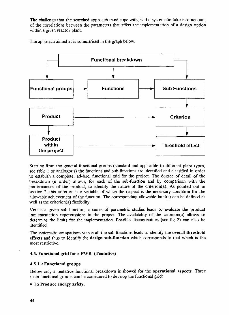
The challenge that the searched approach must cope with, is the systematic take into accountof the correlations between the parameters that affect the implementation of a design optionwithin a given reactor plant.
The approach aimed at is summarised in the graph below.
1
Functional breakdown
IFunctional groups
Product
Prw
the
oductithinproject
— Functions
•
Sub Funct
r
ions
r
Criterion
y
Threshold effect
Starting from the general functional groups (standard and applicable to different plant types,see table 1 or analogous) the functions and sub-functions are identified and classified in orderto establish a complete, ad-hoc, functional grid for the project. The degree of detail of thebreakdown (n order) allows, for each of the sub-function and by comparison with theperformances of the product, to identify the nature of the criterion(a). As pointed out insection 2, this criterion is a variable of which the respect is the necessary condition for theallowable achievement of the function. The corresponding allowable limit(s) can be defined aswell as the criterion(a) flexibility.
Versus a given sub-fiinction, a series of parametric studies leads to evaluate the productimplementation repercussions in the project. The availability of the criterion(a) allows todetermine the limits for the implementation. Possible discontinuities (see fig 2) can also beidentified.
The systematic comparison versus all the sub-functions leads to identify the overall thresholdeffects and thus to identify the design sub-function which corresponds to that which is themost restrictive.
4.5. Functional grid for a PWR (Tentative)
4.5.1 ° Functional groups
Below only a tentative functional breakdown is showed for the operational aspects. Threemain functional groups can be considered to develop the functional grid:a To Produce energy safely,
44

° To Realise the maintenance functions,Q To Integrate the plant within its environment.
Other aspects, like the economy, fuel cycle, or the coherency with the nuclear market, must beanalysed to obtain the corresponding functional lists (see table 2 for tentative guidelines).
The functional grid for the operational aspects can be detailed as follow:
° To Produce energy safely• Assuring Stability of the Reactor Core
•=> Knowing the core reactivity<=> Implementing the means to change the core reactivity•=> Managing the interactions between the reactivity and the other core physical
characteristics (e.g. temperature)• Removing the Produced Energy during normal operation
*=> Removing the core power (behind the first barrier)•=> Transferring the energy to the secondary circuit (behind the second barrier)•=> Distributing the energy to the different users (e.g. turbines, turbopumps, etc.)
• Assuring the Decay Heat Removal•=> Removing the heat from the core<=> Removing the heat from the primary circuit (second barrier)•=> Removing the heat from the confinement (third barrier)
• Assuring the radiological protection and the Radioactive Products Confinement<=> Maintaining the fuel element integrity (first barrier integrity)•=> Maintaining the primary circuit integrity (second barrier integrity)<=> Maintaining the confinement integrity (third barrier integrity)
• Assuring the Reactor Operability<=> Following the load specifications>̂ Monitoring the plant status
•=> Supervising the monitoring system status•=> Reacting to the abnormal situations•=> Storing the data concerning the plant operation and maintenance•=> Storing the data concerning the plant ageing
° To Realise the maintenance functions• Following the ageing and the fatigue of the reactor materials• Assuring the fuel load and unload• Assuring inspections and tests• Assuring diagnostics and repairs• Allowing the replacement of the consumable materials• Allowing the controlled waste release• Allowing the decommissioning
<=> To Integrate the plant within its environment• Taking into account the normal boundary conditions on the design• Taking into account the potential abnormal boundary conditions on the design (internal
and external hazards)• Using the support functions
4.6 - Practical approach (use of functional grid)
The study of a new product must systematically start by its analysis related to the overall sub-functions defined in the functional grid.
45

TAB. 2 - DRAFT TENTATIVE FOR THE FUNCTIONAL DEVELOPMENTCONCERNING THE ECONOMY, THE FUEL CYCLE AND THENUCLEAR MARKET.
•*• IMPROVE ECONOMY
* Minimise plant investment•=> Control design•=> Control certification•=> Control construction
• Simplify the material construction• Simplify the material qualification• Simplify the material transport• Simplify the material implementation
<=> Improve investment protection (Improve the three first Defence in Depth Levels)• Improve safety at prevention level• Improve safety at control level• Improve safety at protection level• Integrate the principles of the defence in depth : balanced, gradual and extended defence
<=> Minimise decommissioning costsImprove the quality of the informationMinimise the materials activation (Minimise the contact dose)Simplify and automates the procedures for the plant decommissioning conditionsMinimise the maintenance times for dismantlingMinimise radioactive waste due to the dismantling operationsMinimise the quantity of radioactive waste for permanent storage
•=> Optimise resource sharing (modularity)
Improve plant availability•=> Simplify every day operationso Simplify maintenance•=> Optimise modularity (partial plant availability)=> Improve man-machine interface
Improve plant reliability•=> Improve the In Service Inspection and Repair (ISIR)•=> Simplify architecture«=> Standardise components<=> Facilitate retrieval
IMPROVE FUEL CYCLE (subjects to be developed)QualificationFlexibilityReprocessingStorageProliferation
ADAPT TO NUCLEAR MARKET (subjects to be developed)Level of powerUnit powerModularityOperator participationInfrastructuresTransfer of technology
A first step allows to identify in a qualitative way (engineer meaning) the functions and thesub-functions which interact with the product.
46

Using adequate R and D, the second step quantifies the correlations between the productcharacteristics/potential and the requested functions. The global analysis of these correlationsleads to identify those which are essential for the design and that show threshold effects.
Nota - The example below is intentionally limited to the examination of two single functions.Exhaustivity can be reached by the systematic analysis of all the functions of the gridthat interact with the design of the product under examination.
4.7. Simplified example
4.7.1 Generics
Product: Passive Containment Cooling System with a metallic containment (AP600type: metal vessel cooled on the outside by a flow of gravity water withexternal concrete building)
Project - PWR
Functional group ° To Produce energy safely
Functions : •=> Removing heat from the confinement (third barrier)
=> Maintaining confinement integrity (third barrier integrity)
Sub-functions :
o To Remove heat from the confinement (third barrier)
SF 1 - Transferring heat to outside
SF 2 - Maintaining cold source on the outside for 72 h(water in pool located on the external concrete building: PassiveContainment Cooling System - PCCS- in AP600).
•=> To Maintain confinement integrity (third barrier integrity)
SF 3 - Resisting to internal loadsSF 4 - Maintaining a non-deformed geometry (resistance to buckling to ensure
good and uniform heat exchange with PCCS water)
4.7.2 Analysis by sub-functions : Identification of correlations between design variables
SF1 - To Transfer heat to outside
This sub-function leads to a correlation which links the metallic Containment Surface (CS)(and thus its volume - CV - to be optimised by the choice of adequate forms) to the reactorresidual power (Decay Heat - DH) and thus to its nominal Reactor Power (RP):
C S > C S m i n = f(RP) (1
CS '•
ALLOWABLEDOMAIN
CSmin
RP
47

SF2 - To Maintain cold source on the outside for 72 h
The sub function must be broken up into three functions of second order :
SF2.1 - Ensuring the availability of necessary water (volume of PCCS pools installed onthe external concrete building)
SF2.2 - Ensuring the resistance of PCCS pools to external aggressions.
SF2.3 - Ensuring the air flow rate between the metal vessel (internal) and the externalconcrete building.
SF2.1 (Ensuring the availability of necessary water) induces a correlation between the PCCSpools Volume (PV) and the Containment Surface (CS) (m3 water/m2 surface) (so indirectlywith the reactor nominal power (RP)).
PV>PV m i n = f(CS) (2.1
PV 'ALLOWABLEDOMAIN "•pVmin=f(CS)
CS
SF2.2 (Ensuring the resistance of PCCS pools to external aggressions) induces correlationsbetween the PCCS pools Volume (PV) and the External concrete Building Height (theelevation - EBH) as well as its Thickness (EBT). These two last variable can be considered asrepresentative of the External Building Size (EBS).
PV
P V < P V m a x = f(EBH;EBT)
PVmax^f(EBT)
(2.2
ALLOWABLEDOMAIN
PVmax=f(EBH)
EBH; EBT
SF2.3 (Ensuring the air flow rate) induces a correlation between the External concreteBuilding Diameter (EBD) and the metallic Containment Diameter (CD).
48

EBD>EBDmin = f(CD) (2.3
ALLOWABLEDOMAIN
EBDmin
CD
SF3- To Resist to internal loads (ex. Loads of Design Basis LOCA)
SF3 gives a correlation which links the Containment Volume (CV), the metallic ContainmentWall Thickness (CWT) and the characteristics of the primary (water volume, size of pipes,etc.: LOCA consequences) and thus generically, for a given specific power, to the ReactorPower (RP).
CV>CVm i n = f(CWT;RP) (3
CVALLOWABLEDOMAIN CVmin=f(RP)
CVmin=f(CWT)
RP;CWT
SF 4 - To Maintain a non-deformed geometry (resistance to buckling)SF4 Induces, for a given form, a correlation between volume of containment (CV) andthickness of the containment wall (CWT).
CV<CV m a x = f(CWT) (4
CV '
ALLOWABLEDOMAIN
CWT
Nota - The possible implementation of strengthening structures could easily allows tomodify this correlation.
49

Determination of threshold effect
In the case of a metal vessel, a threshold effect is induced by, on the one hand, the missionswhich it must face and on the other hand the stresses it must withstand. This comes down toidentify an acceptable area which is, in reality, limited.
In order to do this, one must be able to compare two correlations which use the same variables
Thus, the correlations (2.1 can, by integrating (1 *, be put in the form
PV>PV m i n = f(RP) (5
As well (2.2, by integrating (2.3 and (1*, is reduced to the form
PV<PV m a x = f(RP) (6
The direct comparison between (5 and (6 identifies the researched threshold effect.
PV
ALLOWABLEDOMAIN
OPTIMIZEDPV VALUE
THRESHOLDRP VALUE
RP
* The compatibility with correlations (3 and (4 must be verified simultaneously and leadsto restrictions on thickness
Analogous correlations must be identified considering other key variables like the containmentvolume versus the reactor power, or the external building dimensions, still versus the reactorpower.
4.8. - CONCLUSIONS
Thought is needed to motivate the R&D effort on Small and Medium Reactor (SMR).
The CEA/DRN/DER generic goal is the achievement of an exhaustive identification andassessment of the problems that are specific for the SMR
The technical objective is the achievement of a technical-economical study which leads to thesetting up of a motivated set of plant specifications for an SMR. The details of the activities areactually under discussion at the CEA/DRN.
Among the generic activities on Innovative Reactors, the research on threshold effects is anessential stage in the assessment of the choices in innovative concepts This research, as wellas the assessment itself, must cover, in an exploratory way, the aspects of operation, safety,economy, fuel cycle, nuclear market. This will leads to have a systematic complement to thesystem behaviour assessments, that today monopolise the effort.
CEA/DRN will include such a work within the frame of the activities of the Innovative R&DProgram.
50

The first objective is the definition of a general outline which, by systematising the approach,will provides a helpful tool to the designer.
The document is a very preliminary proposal which objective is to be the starting point for thediscussion. The basis for the approach must be discussed to clearly identify its potential andthe difficulties for its practical application.
The development of agreed functional grids either for operational, safety aspects as well as foreconomic and fuel cycle items, must be the first task.
Examples must be developed and quantified to show the potential and to evaluate the realdifficulties.
REFERENCES
[1] BITTERMANN,Status of Development Work on Small and Medium Sized Reactors at Siemens KWUpresented at the IAEA-AGM meeting in Rabat (Morocco), on October 23-27 1995
[2] INTERNATIONAL ATOMIC ENERGY AGENCY,Objectives for the development of Advanced Nuclear Plants, IAEA TECDOC - 682,Vienna January 93
NEXT PAQE(S)left BLANK
51

STATUS OF DEVELOPMENT WORK ON SMALL AND MEDIUMSIZED REACTORS AT SIEMENS/KWU
D. BITTERMANN XA9846703Siemens AG/KWU,Erlangen, Germany
Abstract
Basic principles of SMR development are discussed and relevant design features of a 200MW(th) heating reactor and of a 600 MW(e) BWR are presented.
1. Introduction
There are two major development tasks to be achieved which are the prerequisites ofthe success of any development of Small and Medium sized Reactors (SMR). They arelow capital cost, and a high safety level. Both tasks are to be seen as equivalent inimportance yet both are different In the difficulty to be achieved. Since the safety levelof the plants is already high and a higher safety level is easier to achieve the smallerthe plant, the goal to achieve acceptable capital cost for a small plant is a much biggerchallenge. It is the aim of this paper to discuss some principles, how one can meetthese challenges. In addition the current status of the design studies is shortlydescribed.
2. Approach to low heat and/or electricity generating costs for small units
In order to reach competitive heat and/or electricity generating costs the most importanttask is to concentrate as much as possible on the question how to reach low capitalcosts. Fuel costs are of second importance only. In addition an approach how toreduce the plant erection time and how to guarantee high reliability and availability ofthe plant should be considered.
As we know from the scaling laws and as it is illustrated in Fig. 1 qualitatively, onewould move along the the upper branch of the capital cost curve without changing ofthe concept of a plant [1]. With this strategy it is impossible to reach the cost target ifone considers smaller units. One only can break through this laws if one would look foradvantages which result from the fact that the individual design features of mostcomponents and systems have technological discontinuities even though the basicconcept remains unchanged regardless of size and duty. For this phenomenon theturbine is a simple example. At a certain size one switches from full speed to half speeddesigns. The half speed design is physically larger and thus more cost expensive. Atthe point of cross over, the specific cost of the half -speed design is higher than that ofist full-speed counterpart. Only on account of the increase in output now possible thespecific cost can be lowered to a new minimum.
Another example is the use of passive systems or components which are much betterto achieve at low power and small sizes. Such behavior is displayed by many technicalcomponents and systems. When designing a small nuclear plant, it is for precisely suchdiscontinuities that one must look to achieve a jump to a lower specific cost level. This
53

c3
a
3a
ua
Economies of scale. within a giventechnology
End points of agiven technology
Plant size (arbitrary units)
FIG. 1. Specific cost as a Junction of size for a given point in time.
new lower level represents a technological solution that is only possible with the smallersize or duty of the unit in question.A second consideration would require the following: in attempting to cut costs, it isbetter to eliminate certain components and systems altogether, even if those remainingbecome larger, than to attempt to make everything a little less expensive. The marginalcost increase associated with the remaining equipment is smaller than the savingsrepresented by what is eliminated.
As a third design rule we propose to use the experience gained with components,materials and equipment as much as possible also if one designs new components.This does not mean that one only should use existing designs, but one should carefullydecide whether one leaves proven designs and equipment especially such wherespecific nuclear technology experience has be accumulated like fuel, fuel elements,materials or design and safety principles. If one considers this, high availability of newplant designs can be expected with the benefit to be able to contribute to the goal toreach competitiveness in cost. In case that developing countries want to introduceSMFTs which have not already gained this experience, they can participate of thisexperience by cooperation and technology transfer with the corresponding companiesand institutions which have this experience.
For SMR plants, the components and equipment are expected to be physically smallercompared to larger plants. Therefore the possibility of prefabrication of systems andprearrangement can be considered in a larger extend compared to the big plants. Thiscould considerably reduce the erection cost of the entire plant.
In case that from a country like Germany SMFTs will be exported an appropriate portionof national supply and services should be considered in order to be able to reduce thecost. In such a case one should optimize the import and national portion together withthe cost for technology transfer.
54

Another and very fundamental general design consideration becomes evident whenlooking at the fuel cost component in the unit generating cost versus plant sizerelationship like it is shown in Fig. 1. At small unit sizes, this part of the generating costis even less important than with a standard size nuclear power plant which is in contrastto fossil fired stations. Nuclear fuel assemblies exhibit all the characteristics of high-technology mass-produced goods. Their scaling relationship tends to be much flatterthan that for the custom-tailored plant proper. This fact should have for the designer theconsequence that one should not-try to minimize the fuel cycle cost as a single designgoal. One should rather look how one can reduce the capital cost even if this specificdesign feature increases the fuel cost.
3. Approach to a high safety level
It is one of the basic requirements of SMR's that this kind of plants from the size of vieware fitted to specific applications which normally are also very closely situated todensely populated areas. Therefore the necessity exists to increase the degree ofsafety level for such kind of plants. This objective is also in line with the ongoingdevelopment of large power reactors.In case of SMR's there are two design features which can be introduced and which arethe easier to be achieved the smaller the plant is. One is to use large water volumes inorder to increase the grace periods in case of malfunctions. The other one is to usepassive systems and components The reason for this is the fact that natural circulationwhich is one of the important phenomena that must come into force is much easierachievable for smaller sizes and consequently smaller decay heat ratios. In line with thelonger grace periods and the higher water volume normally the core power density isalso reduced. This again enables longer reaction times in case of malfunctions andconsecutively simpler designs for the actuation of safety systems with very highreliability to be expected.
4. Characteristic features and application potential of a nuclear heating reactor
Under consideration of the above described design principles the following designfeatures of a heating reactor with an power of 200 MWth were fixed (Fig. 2):
- the primary system is fully integrated for compactness and for greatly reducing therequirements for engineering safeguards. Boiling is permitted for self-pressurizationand enhancement of natural circulation. Hydraulic driven control rods arelocated inside the reactor pressure vessel (RPV)
- the reactor has an intermediate circuit to keep the distribution grid free of radioactivity
- natural circulation has been selected for the primary circuit and for those parts of thesecondary circuit which are needed for decay heat removal
- the reactor containment fits tightly around the RPV so that any postulated coolantleak is limited in such a way that the core cannot become uncovered
- the primary system has a very high thermal heat capacity, eliminating most of theusual engineered safeguard systems
55

FIG. 2. Nuclear heating reactor: Primary circuit.
- the reactor requires only two cores for the entire lifetime of the plant. This reducessignificantly the requirements for fuel handling and storage, which in turn leads to avery compact small reactor building
The main data are summarized in Table 1.
The application for which the concept was originally designed has been seen mainly indistrict heating (Fig. 3). But there is also a potential to use it as a heat source fordesalination plants. For this puropose also rough analyses have been performed. Aflow scheme and different concepts for the design of a desalination plant [3] have beenanalysed (Fig. 4) considering f. i. the multi stage flash process (MSF).
Outstanding safety features
The large water volume and the relatively wide subcooling margin result in a high heatcapacity of the primary system. Since the primary heat sink of the reactor is in theimmediate vicinity of the core, the heat transport mechanism, by means of naturalcirculation, is maintained during all typs of events, including loss of coolant accidents(LOCAs). The relatively small amount of decay heat can easily be transferred via theintermediate circuit and aircoolers to the environment by natural circulation. The high
56

TABLE 1. SELECTED DATA OF THE NHR THERMOHYDRAULIC ANDNUCLEAR PHYSICS DESIGN
PressureThermal powerCore mass flowNumber of fuel assembliesActive core heightCore subcoolingAverage volumetric steam content at core outletMaximum linear power rateAverage power densityAverage specific powerNumber of control rodsControl rod type
(bar)(MW)(kg/s)
(mm)(K)(%)
(W/cm)(kW/l)
(kW/kg)
15200
1030180
2350402675201045
BWR
Air cooler
Heat exchanger-—f(twin bundles)
Heating grid
Intermediate circuit(3 parallel loops)
Supplementarycondenser(single circuit loop)
Reactor building(protected against external events)
Pi—— Reactor containment
\] "~ Reactor press, vessel
Condenser
"H PrinI I "—• Primary circuit
_ J
FIG. 3. Nuclear heating reactor: Flow scheme.
fission product retention of the low-rated fuel, together with the low corrosion rates,leads to low primary coolant radioactivity content.For reactor shutdown two independent and diverse systems are installed. Each of thesystems is able to bring the reactor into a cold subcritical condition. The control rodsare used as the first and principal shutdown system. This hydraulically driven system isfail safe in a way that after loss of electric power and postulated breaks in its piping
57

Heating Reactor IntermediateCircuit
Water/SteamCircuit
DesalinationPlant
Seawaier
Distillate
only for VariantsGOR 6 and 10
II Brine ana
Cooling Water
PerformanceRatio
GOR 6GOR 10GOR 16GOR 20
DistillateProduction
m3/d
3844067500
121846148400
Plant Auxiliary PowerDesalination
Plant
M W
5,99,8
17,823,1
Plant
M W
1,61,61,61,6
IOUI
M W
7,211,419,424,7
ElectricityProduction
M W
23,516,3
00
ElectricityBalance
M W
+ 16,3+ 4,9- 19,4- 24,7
FIG. 4. Seawater desalination with heating reactor (Q=200 MJ/s).
system, the rods will fall into the reactor core by gravity. A regular shutdown initiated bythe reactor protection system is performed by interrupting the electric power supply tothe running pump and by actuating the insertion valve. Each of these measures is initself sufficient to cause the rods to fall into the core. As a second shutdown capability,a boron injection system is installed, which is designed to shut down the reactor afteranticipated transients without scram ATWS).In case of applications for district heating, the main heat sink is normally available afterreactor shutdown. This is especially true for plant internal events, including LOCAs.However, it does not apply to events leading to failure of the heat transport capacity ofthe heating grid, such as loss of electric power or external events. For those cases inwhich the main heat sink is not available, a separate decay heat removal system isprovided. As already described, this system is connected to the intermediate circuit andworks by means of natural circulation. During normal operation the system can operatein bypass to the intermediate circuits in order to prevent freezing of the outside heatexchangers. On demand, the system will start up after one of the two parallel valvesinstalled in each train is opened.
5. Development status of the NHR
The NHR concept was originally developed for the application in Germany in the firsthalf of the 80th. The status of development reached until the end of the decade can becharacterized as Basic Design quality for the essential components of the primarycircuit, the nuclear physics and thermohydraulic design and the safety analyses. Forthe hydraulic control rod drive which is a complete new design a large test program wasperformed. A drive of original size and material has performed about 500000 stepsunder operating pressure and temperature and about 2000 scrams were sucessfullyperformed. During these tests, ultrasonic position indicators have proven their function,too. An expertise performed by T0V Bayern used the criteria given in the appropriatenuclear standard (KTA 3103) had the result that no aspects were found, which indicatemalfunctions of the hydraulic control rod drive or a loss of the shutdown margin.
58

Prefeasibility studies for some German cities have been performed which showed thepotential of econonic feasibility. But no order could be placed in Germany up to nowand cannot be expected within the next future.The reasons are as follows:
1. Within about 10 years from the first idea of a NHR all fossil fired power plants hadto implement expensive backfitting measures caused by new emission standards.At the time when the decisions had to be made, the NHR was not at a designstatus able to be discussed as a serious competitor.
2The German NHR development was also negatively affected by the slowdown ofthe nuclear business in general. This made potential customers hesitate to engagethemselves in a new and controversary technology. This in particular becausemany district heating facilities are owned by communal utilities which thus farhave very little, or no nuclear experience.and which are much more exposedthan private utilities to the split that runs through the big political parties onthe application of nuclear power in Germany.
In the framework of the German-Chinese cooperation in the field of nuclear technologywhich was envisaged at that time, prefeasibility studies together with the Institute ofNuclear Technology of the Tsinghua University in Beijing were performed. In 1991 afeasibility study with different Czechoslovakian partners especially Skoda, Pilzen wasperformed for an NHR application for the city of Pilzen. Up to now no final decision hasbeen made on this project.
6. Characteristic design features of a small boiling water reactor
In cooperation with the German utilities a boiling water reactor concept is underdevelopment since the beginning of the 90th which mainly uses the principles outlinedabove. Special emphasis is put on an improved safety concept, the function andavailability of which shall be assured by simple and unsensitive safety features. Theconcept is based on the extensive range of experience which has been gained fromboiling water reactor (BWR) plants currently in service. It makes use of systems andcomponent designs which have proven their reliability in operation. Certain systems willbe simplified on the basis of proven operating experience. The new safety conceptwhich supplements the active safety systems implemented to date, is characterized bythe following four main accident control features:
1. A higher degree of safety is achieved through the introduction of passive systems foraccident prevention and control
- these systems function according to basic laws of physics, such as gravity and heattransfer, without need of operator intervention or power supply.
2. Good plant behavior is ensured in the event of transients or accidents.- this is achieved by means of a lower core power density, a large coolant inventory
in the RPV and additional water inventories stored inside and outside thecontainment. Core cooling is thereby ensured for several days without any needfor external intervention
3. Accident control requires no active intervention- in the event of an accident, the plant can be left to manage itself. Only after several
59

days, external intervention in the form of simple actions becomes necessary. Humanerror under accident conditions has no negative effect on plant behavior.
4. Compared to existing nuclear power plants, core melt probabilities are reduced evenfurther
- this is the result of combining the operation of active non-safety-related systemsand passive safety systems. Despite this high degree of safety, features for coremelt accident control are provided so that evacuation of the population withinthe immediate vicinity of the plant would not be necessary.
in Fig. 5 a view of the primary circuit and the containment is depicted.Table 2 showssome major plant data.[3]
Spent fuel poo<
FIG. 5. Containment with internal structures.
60

TABLE 2. SWR 600 - MAJOR PLANT DATA
No. of fuel assembliesTotal uranium weightActive core heightAverage power densityDischarge burnupAverage enrichmentCoolant flow rate
Spent fuel storage capacityPlant design life
wt. %kg/s 8,000
Outstanding passive safety systems
As already mentioned before, the essential task for the development of the safetyconcept of the BWR 600 is to be seen in the improvement of the plant's safety qualityvia the introduction of additional passive systems which can take over safety functionsduring transients and accidents.Their systems engineering is in contrary to existing reactors much more simplified, theirfunction is independent of electricity supply and control by I&C systems. Thecharacteristic feature of these passive systems, is the use of laws of nature (f.i. gravity)to fulfill their safety functions without use of any active component. One well-knownexample is the flooding of a depressurized RPV from a water pool using only the statichead between the vessels.The most frequent requirements for the need of flooding and decay heat removal resultfrom transients. After most of the LOCA's the decay heat is transferred via the leak intothe containment atmosphere. In order to avoid an uncovered core, measures must beforeseen to inject water or flood the RPV. After most of the transients and other eventsthe following safety related functions have to be performed:
- shutdown of the reactor- containment isolation- RPV pressure limitation or depressurization- decay heat removal from the RPV- RPV flooding or water injection- decay heat removal from the containment
The passive systems which can fullfil these functions are briefly described in thefollowing chapters (Fig. 6).
61

Emergency condensers4 x 6 3 MW
Conditions zitei dropin RPV water level
Downcomef fornoocoodensabtes
AntK3fCul3t«on loop
Conditions duringpower operation
Containment
coc*ng condenser
tussive pressurepuise transmitter
Emergency Condensers
Remove decay heat from reactor as RPV water ieveldrops, requiring neither electric power nor activationby I&C systems.
Containment Cooling Condensers
Remove heat after steam formation inside the contain-ment, requiring neither electric power nor activationby I&C systems.
Gravity-Driven Core Flooding System
Floods reactor by gravity flow as reactor pressuredrops. Shutoff valves self-actuate by deadweightwhen elevation head of core flooding poo! overcomesreactor pressure.
Pressure Pulse Transmitter for SwitchingOperations
Generates pressure passively in a heat-exchangersecondary circuit as reactor water level drops. Thispressure is used for actuation of safety systems(reactor scram. RPV depressurization and contain-ment isolation), requiring neither electric powernor I&C signals.
Conditions duringpower operation
Conditions after dropin RPV water level
FIG. 6. The passive safety system.
62

Pressure pulse transmitter for switching operations
Safety related functions like reactor scram, RPV depressurization and containmentisolation are actuated by a passive device which needs no electricity supply andinstrumentation and control equipment. The function is described as follows: the reactoris connected to a small heat exchanger via a pipe which cannot be shut-off. This heatexchanger acts as a passive pulse transmitter. In case of normal water level within theRPV the tube side of the heat exchanger is filled with water and consequently no heatis transferred. If the water level within the RPV decreases and as a consequence alsowithin the heat exchanger tubes, steam will be condensed within the tubes. The heatexchanged to the shell side leads to a pressure increase which acts via pilot valves onthe main valves in order to perform the required functions.
Emergency Condensers
One important passive component which esspecially can be used for control oftransients are to be seen in the four emergency condensers ( 4 x 63 MW at 70 bar)which are located within the core flooding pool and which are connected to the RPV viasteam and condensate pipes which can not be shut off. The emergency circuit isequipped with a so-called cold siphon which prevents circulation of condensate duringnormal operation. As consequence of the drop of the water level, steam will condensewithin the condenser and the condensate is discharged into the RPV again. The heattransferred to the water within the flooding pool will increase its temperature slowly.Even after more than 12 hours the water will reach the evaporation temperature andconsequently lead to a pressure increase within the containment.
Gravity - driven core flooding system
After LOCA's, steam and water/steam mixture is discharged into the containment. Inorder to avoid uncovering of the reactor core, a passive core flooding is actuated. To beable to initiate this type of flooding mechanism a depressurization of the the RPV has tobe initiated first. Afterwards a flooding of the RPV with water from the core flooding poolvia four pipes can take place. The water content of the flooding pool is about 5000m3.After LOCA this inventory is sufficient to flood the RPV together with the pressurecompartment of the containment until an equilibrium level is reached which is above thefeedwater lines. This has the consequnce that potential locations of leakages will beflooded and enables the potential of an outside cooling of the RPV, too.
Containment Cooling Condenser
Both after transients and LOCA's the potential of temperature and pressure increase inthe late phase exists. In order to limit the pressure and temperature increase specificcondensers are provided. The condensate will be discharged into the core floodingpool. The heat sink of the condensers is the water inventory of the dryer-separatorstorage pool located above the containment. These condensers close the circuit of apassively actuated cooling system for decay heat removal within the containment. Thecontainment condensers enable a heat removal for about seven days without additionalwater supply for the storage tank outside the containment. This can be performed ifnecessary with relatively simple measures.
63

As a result of the above described features and systems this kind of reactor conceptwill reach stable conditions even after transients and LOCAs independent from theavailability of I&C systems and the supply of auxiliary power. Active systems which areinstalled from operational reasons complete the passive sxstems for accident control.
Provisions to control Severe AccidentsIn order to be able to mitigate and control the effects of Severe Accidents which arepostulated, different measures are provided. Hydrogen, which is produced from thezirconia - water reaction within the RPV in this hypothetical case, can neither burn nordeflagrate within the containment since it is inerted already during normal operationwith nitrogen. The design of the containment against the resulting pressure can copeeven with a hydrogen mass according to 100% zirconia water reaction and the resultingpressure within the containment. A containment venting is not considered.A hypothetical core melt is expected to be stabilized within the RPV by outside cooling.
7. Development Status
For this new reactor concept the conceptual design is finished and the Basic Design isnow under way. The development was started for a plant size of about 600 MWe;according to the requirements of the customer (German utilities) the work will becontinued for a size of 1000 MWe. In addition it is turned from natural circulation withinthe RPV to forced circulation with internal pumps. Nevertheless the basic concept willbe applicable for the smaller size, too. The Basic Design is considered to be finished atthe end of 1999. It includes also a safety report and a technical tender which is seen tobe the prerequisites for the decision on a project.The cost analyses which have been performed during the conceptual work have shownthat caused by the simple arrangement and simultaneous reduction of the expenditurefor active systems a reduction of the capital costs of the plant can be achieved.Together with an envisaged reduction of the erection time and the higher fuel utilizationin connection with a two years fuel cycle the electricity generation cost are expected tobe only marginally higher compared with a large 1300 MWe BWR. The economiccalculations have shown that such a medium sized plant is competitive with a largeplant.
8. Conclusion
There is a lot of positive experience available from more than 7000 accumulatedreactor years of operation with nuclear power plants. Using this experience andconsidering the priciples which were explained, one can be confident to be able toreach the goal to design and build economic and safe SMR's. The ongoingdevelopment work shows encouraging results.
REFERENCES
[1] Goetzmann, Bittermann, GobelDesign principles of a simple and safe 200 MWth nuclear district heating plantNuclear Technology, Vol. 79, Nov. 1987
64

[2] Gutachten zum Konzept eines hydraulischen Steuerantriebes fur einen 200 MWHeizreaktorTUVBayern 1988
[3] LezuoSiemens/KWU internal document
[4] SWR 1000 The Boiling Water Reactor with a New Safety ConceptSiemens Power Generation 1995
NEXT PAGE(S)left BLANK
65

SOME JAPANESE ACTIVITIES ON SMALL AND XA9846704MEDIUM NUCLEAR POWER REACTORS
H. SEKIMOTOResearch Laboratory for Nuclear Reactors,Tokyo Institute of Technology,Tokyo,Japan
Abstract
Some Japanese research activities on small and medium nuclear reactors are reviewed.The increasing role of nuclear reactors in the future is well understood by the government.The increasing energy consumption by Asia and developing countries is also well understood.The small and medium nuclear reactors may be suited well to these areas. Though severalresearches of small and medium reactors are under intensive progress on LWR, HTGR, LMRand MSR based reactors, projects for building these reactors have not yet been established.
1. JAPANESE LONG-TERM PROGRAM FOR RESEARCH, DEVELOPMENT ANDUTILIZATION OF NUCLEAR ENERGY
At the 39 Regular Session in IAEA General Conference held on September 18, 1995,Japanese Minister of STA gave the statement, whose concluding remarks are as follows:Explosive population growth and rising living standards are likely to raise the world's energyconsumption sharply in the 21st century. There is also concern that energy-relatedenvironmental problems such as global warming will become more serious. The internationalcommunity thus urgently needs to resolve energy issues. As a source of energy which enjoysan excellent stability of supply and places a light burden on the environment, nuclear powerwill increasingly play a bigger role.
Japanese Long-Term Program for Research, Development and Utilization of NuclearEnergy mentions about international cooperation and try to promote cooperation with theneighboring regions of Asia and developing countries[l]. It mentions furthermore that indevelopment and utilization of nuclear energy assurance of safety is an absolute premise, andaccidents or even incidents at nuclear facilities in one country make people in other countries,too, uneasy and could even have a negative impact on development and utilization of nuclearenergy in different countries. That being the case, in cooperation with the neighboring regionof Asia and developing countries it is important that emphasis be placed on assurance ofsafety as a problem common to all countries.
Small and medium power reactors seem proper to be utilized in these areas since theyusually attain much more excellent safety features than large power reactors. However,Japanese Long-Term Program does not mention anything about small power reactors for theseareas. In Japan the electric power network system is almost completed and the small andmedium power reactors are not required. From these reasons the activity on small andmedium power reactors in Japan is very low.
67

2. INTERNATIONAL SPECIALISTS1 MEETING ON POTENTIAL OF SMALLNUCLEAR REACTORS FOR FUTURE CLEAN AND SAFE ENERGY SOURCES
However in 1991, International Specialists' Meeting on Potential of Small NuclearReactors for Future Clean and Safe Energy Sources, SR/TIT, was held at Tokyo Institute ofTechnology[2]. This is the almost only one international meeting ever held in Japan. Thecontents of this meeting show almost all Japanese activities on small reactors. The Japanesecontributed papers in this meeting are shown in Table 1. Water reactors(JAERI), HTGR(Tokai Univ., Fuji, Kawasaki), sodium-cooled fast reactor controlled by graphite reflector(CRJJEPI, Toshiba), sodium-cooled and lead-bismuth-cooled long life fast reactors(TIT) andmolten-salt reactor(Tokai Univ.) were studied. However, all these activities were in designstudy stages. All of the works have been proceeded since then to improve theirperformances, but the situation is almost the same even at present.
SPWR(System-integrated PWR) has been designed at JAERI since 1986 as a nextgeneration power reactor realizing highly passive safety, satisfactory maintainability andeconomical competitiveness at the same time. It is a new type of integrated pressurized waterreactor which installs a poison tank in its reactor pressure vessel for reactor shutdown insteadof control rod drive system. This concept is considered to be applicable to wide range powersources from small scale to large scale and is expected to be useful for world wide nuclearreactor utilization in near future.
JAERI has been also carrying out design studies on the advanced marine reactors since1983 in order to develop attractive one for the next generation. Two reactor concepts areformulated; the one is MRX(Marine Reactor X) for ships navigating on sea surface, the otheris DRX(Deep-sea Reactor X) for a power source used in deep sea. They are characterized byan integral type PWR, built-in type control rod drive mechanisms, a water-filled container anda passive decay heat removal system, which realize highly passive safe and compact reactors.MRX was designed as 100 MWt for an ice-breaking scientific observation ship, but it couldbe applied to wide output range as 50 through 300 MWt according to a variety of requiredoutput due to type, size and velocity of ships, and applied also to very safe small powerstations on land.
Research Association on High Temperature Gas-Cooled Reactor Plant has beenstudying the Modular High Temperature Gas-Cooled Reactors. The studies cover bothpebble bed core(200Mwt) and block fuel core(350Mwt).
CRJJEPI(Central Research Institute of Electric Power Industry) proposes a graphite-reflector controlled small-size sodium-cooled reactor called 4S-LMR to fulfill the futureenergy demand to encourage the human beings and the global environment. Specific designpolicy is as follows; The void reactivity and all reactivity temperature coefficients arenegative, no refueling for 10 years, simple core burnup control without a control rod and itsdriving mechanism, safety system independent of emergency power and active decay heatremoval systems, elimination of control and adjustment components from the reactor system,
68

load following without operation of reactor control system, minimum maintenance andinspection of reactor components, quality assurance and short construction period based onshop fabrication, no core damage in any conceivable transient events without scram, completecontainment of nuclear materials for a long period. It is expected that 4S-LMR would beutilized for some special purposes such as for urban siting for decentralized electric units, andfor sea water desalination, although the future work is needed to resolve several key issues.
Conceptual design study for small size long life fast reactor has been performed inTIT(Tokyo Institute of Technology). The reactor was mainly consisted of three parts, innerblanket which was located in the center, peripheral region which was filled with coolantmaterial, and core which was located between the peripheral region and the inner blanketregion. Both sodium-cooled and lead-bismuth-cooled fast reactors were studied at their powerrating up to lOOMwt. Safety aspect was implemented by reducing excess reactivity duringburnup smaller than or equal to 0.1 %dk and by minimizing coolant void coefficient.Calculated results showed that 30 year reactor life time without refueling with maximumexcess reactivity no more than 0. l%dk could be satisfied by both sodium cooled and lead-bismuth cooled fast reactors. In case that the coolant in the core and blanket regions wascompletely voided, sodium cooled reactors gave positive value of coolant void coefficientwhile the lead bismuth cooled reactors up to 75 MWt gave negative value over whole bumupperiod. However in case that coolant in all regions including reflector region was voided bothsodium cooled and lead-bismuth cooled reactors gave strongly negative value of reactivity.
Because of the superior characteristics of lead-bismuth cooled reactor, both lead-bismuth-cooled and lead-cooled reactors have been later investigated intensively. Safetyanalysis of lead or lead-bismuth cooled small safe long life fast reactor has been performed.The reactor is proposed to be used in relatively isolated area and operated up to the end of lifewithout refueling or fuel shuffling. In the present paper the reactor power and life are set tobe 150MWt and 12 years, respectively. In order to assure its safety performance againstaccidents, the following accidents without scram are simulated with neutronic-thermal-hydraulic analysis: unprotected loss of flow(ULOF), unprotected rod run out transient overpower(UTOP), simultaneous ULOF and UTOP accident, and simultaneous ULOF, UTOPand unprotected loss of heat sink(ULOHS) accidents. For each type of accidents, four casesof long-life small reactors (lead-cooled metallic-fueled, lead-cooled nitride-fueled, lead-bismuth-cooled metallic-fueled, and lead-bismuth-cooled nitride-fueled reactors) have beenanalyzed. It is shown that all the proposed designs can survive these accidents without anyhelp of operator or active devices.
K. Furukawa, et al., proposes the Thorium Molten-Solt Nuclear Energy Synergeticsdepended on the isolation of fissile-producers and power-stations, allowing the smallerstations. In this system the Flibe base molten-fluoride is applied and fissile-producingfacilities are separated from the power stations. For the power stations, several types ofsmall molten-salt power stations are proposed as FUJI series reactor designs(35OMwtFUJI-II, 250MwtFUJI-V). For the fissile-producing facilities, accelerator molten-salt breeder,impact fusion molten-salt breeder and inertial-confined fusion hybrid molten-salt breeder areproposed.
69

TABLE I. Japanese Contributed Papers in International Specialists' Meeting on Potential ofSmall Nuclear Reactors for Future Clean and Safe Energy Sources[2]
1. General Topics1-1) H. Sekimoto (TIT): Several features and applications of small reactors1-2) K. Taketani (Chuo Univ.): Expected characteristics of future reactors for human beings1-3) Y. Tachi (Hitachi): Design and construction of small power reactors1-4) Y. Fujii-e, Hiroto Kawakami (TIT, Toshiba): A self-consistent nuclear energy supply system, a friendly
FBR to fuel cycle and environment2. Small reactor deployment plans
2-1) S. Hattori (TIT/CRJEPI): Technical and economical potential of small reactors3. Water cooled small reactors
O 3-1) M. Higuchi (JAPC): An overview of the simplified LWRs
O 3-2) K. Sako and J. Oda (JAERI): Concept of highly passive safe reactor SPWR
O 3-3) H. Kobayashi, K. Sako, H. Iida, and K. Ishizuka (JAERI): Application of MRX (Advanced Marine
Reactor) to ships
O 3-4) H. Iida, Y. Ishizuka, H. Kobayashi, and K. Sako (JAERI): Application of the DRX (Deep-See ReactorX) to a deep-see power source
3-5) H. Akie and Dr. Y. Ishiguro (JAERI): Water moderated Th/U-233 breeder4. Liquid metal cooled reactorsO 4-1) S. Hattori and Handa (CRJJEPI, Toshiba): Present design features of the super safe small and simple
reactor
O 4-2) S. Zaki and H. Sekimoto (TIT): A concept of long-life small safe reactor4-3) A. Otsubo and K. Haga (PNC): Concepts of a high temperature fast reactor4-4) M. Kawashima, H. Endo, and A. Shimizu (Toshiba, TIT): Conceptual study on the liquid metallic
fueled core4-5) M Uotani, I. Kinoshita, A. Ohto, K. Yoshida, and N. Ueda (CRffiPI): Conceptual design of modular
double pool reactor4-6) H. Endo, M. Kawasaki, and A. Shimizu (Toshiba, TIT): Safety features of liquid metallic fueled core4-7) K Haga, H. Seino, and A. Otsubo (PNC): Natural circulation liquid-metal-cooled fast reactor4-8) K Hida (Mitsubishi Heavy Industries): Characteristics of small LMFBR for future energy resource4-9) F. Kasahara, S. Ohta, H. Endo, and A. Shimizu (Toshiba, TTT): Geometrical effect of reactor vessel
reflected on the energy mitigation for CD A energetics5. Gas cooled small reactors
O 5-1) T. Hayashi, H. Hayakawa, and T. Nakata (Tokai Univ., Fuji, Kawasaki): Behavior of small HTGRcore under reactivity accident
6. Molten-salt reactors
O 6-1) K. Furukawa (Tokai U): Flexible Thorium Molten-Salt Nuclear Synergetics7. Special uses
7-1) H Yasuda (JAERI): Conceptual study of small reactors for space use7-2) M. Sasaki, J. Hirota, S. Tamao, K. Kanda, and Y. Mishima (MAPI): Design study of a medical reactor
for BNCT
O Small and medium power reactors which are referred in the present paper.
70

3. CONCLUDING REMARKS
It can be expected that in Japan the bigger role of nuclear power in the future andimportance of cooperation with the neighboring region of Asia and developing countries arewell understood. The small and medium nuclear reactors are suited well to these regions. Thedesign studies of small and medium reactors have been performed intensively in Japan.Nevertheless Japanese nuclear vender companies do not have any strong interests to small andmedium nuclear reactors, and both industries and government have not any concrete projectsto promote and build some of these reactors.
REFERENCES
[1] Long-Term Program for Research, Development and Utilization of Nuclear Energy,Atomic Energy Commission, Japan (1994).
[2] SEKIMOTO, H. (Ed.), Potential of Small Nuclear Reactors for Future Clean and SafeEnergy Sources, Elsevier, Amsterdam (1992).
NEXT PAGE(S)left BLANK
71

STATUS OF DEVELOPMENT - AN INTEGRAL TYPE XA9846705SMALL REACTOR MRX IN JAERI
T. HOSHI, M. OCHIAI, J. SHIMAZAKIJapan Atomic Energy Research Institute,Ibaraki, Japan
Abstract
JAERI is conducting a design study on an integral type smallreactor MRX for the use of nuclear ships.
The basic concept of the reactor system is the integral typereactor with in-vessel steam generators and control rod drivesystems, however, such new technologies as the water-filledcontainment, the passive decay heat removal system, the advancedautomatic system, etc., are adopted to satisfy the essentialrequirements for the next generation ship reactors, i.e. compact,light, highly safe and easy operation.
Research and development (RSD) works have being progressed onthe peculiar components, the advanced automatic operation systemsand the safety systems. Feasibility study and the economicalevaluation of nuclear merchant ships have also being performed.
The experiments and analysis of the safety carried out so farare proving that the passive safety features applied into the MRXare sufficient functions in the safety point of view.
The MRX is a typical small type reactor realizing the easyoperation by simplifying the reactor systems adopting the passivesafety systems, therefore, it has wide variety of use as energysupply systems.
This paper summarizes the present status on the design studyof the MRX and the research and development activities as wellas the some results of feasibility study.
1. INTRODUCTION
A small type reactor might be of great advantage to the energysupply for such the limited area as a ship, an island, a remoteplace, etc. Wide variety of energy usage, for examples, annuclear propulsion, an electric power supply, a district heating,a sea-water desalination, etc., is considered.
Nuclear ships have outstanding advantages so as to enablelong-period navigation with high power and long-periodunderwater navigation. It is therefore, thought that thenuclear ships will contribute largely to the advancement anddiversification of marine transportation, scientific activitiesin the ocean, etc., in the future. Because of no production ofsuch polluting materials as NOX, SOX and CO2 produced in theuse of fossil fuel, the utilization of nuclear reactor intoships contributes to the global environmental protection.
At present nuclear ships are not expected to be appliedimmediately for practical use mainly from economic aspect.Looking into future, however, there is a lot of potentiality thatthe needs of nuclear ships would be actualized according to tothe change in economic and social circumstances and owing to theincrease of demands for their outstanding advantages.
73

The Japan Atomic Energy Research Institute (JAERI) is carryingout the design studies on advanced nuclear ship reactorsof which features are compact in size, light in weight,highly safe and easy to operate. The Marine Reactor X (MRX) isaimed for the use of a bigger merchant ship or an ice-breaker.
In parallel with the design study, research and developmentworks are being conducted to realize the systems in use and toprove the operational and safety functions of the systems.
2. CONCEPT OF ADVANCED MARINE REACTOR MRX [1]
2.1 Basi c Concept
To put nuclear merchant ship into the commercial service, theimprovement of economy is very essential as well as increasingreliability and operability of the reactor systems.
The improvement of economy should be emphasized in developingthe reduction of construction and operation cost as follows;
-The construction cost of reactor systems can be reduced bymeans of making the reactor systems compact, light and simple.Adoption of passive safety systems contributes for thesimplification of systems.
-The operation cost of reactor systems can be reduced by meansof easy operation and maintenance and improving the reliabilityof both systems and components. Simplification of systems and theadvanced automatic operating and supporting systems will beeffective. Reduction of nuclear fuel cost is also essential.
-Simplification of plant systems increases the reliability sothat reduction of malfunctions and defects of components isexpected. Adoption of the advanced automatic operation andsupporting system is also effective to prevent human errors.
In order to satisfy these requirements, following typicaldesign features have been adopted ( Fig.l).
- Integrated type PWR- In-vessel type control drive mechanism- Water-filled containment- Passive decay heat removal systems- Advanced automated control systems- One-piece removal of the reactor systems
and Table 1 give a conceptual drawing and major designFig.2parameters of theshown in Fig. 3.
MRX. A basic idea of engineered systems is
2.2 Description of Reactor and Primary Systems
(1) Integrated type PWRIntegrated type PWR could eliminate possibility of
pipe rupture accidents and then simplifies the safetyalso reduces the dimensions of reactor plant system,compact dimensions of the integrated reactor system,remind the capability of maintenance and inspection ofIn the MRX, it is so designed that the reactor components and theprimary coolant pumps can be removed remotely and the steamgenerator tubes can be inspected from out side of the reactorpressure vessel.
large scalesystems. ItBecause ofi t shouldcomponents.
74

TABLE 1. MRX BASIC DESIGN DESCRIPTION
Reactor typeThermal power (MWt)1. Core and reactivity controlFuel/moderator materialFuel inventory (tons of heavy metal)Average core power density (kW/liter)Average/maximum linear power (kW/m)Average discharge burnup (MWd/t)Enrichment (initial and reloaded)
Life of fuel assembly (year)Refueling frequency (year)Fraction of core withdrawn (%)Active core height (cm)Equivalent core diameter (cm)Number of fuel assembliesNumber of fuel rods per assemblyRod array in assemblyPitch of assemblies/fuel rods (mm)Clad materialClad thickness (mm)Type of control rodNumber of rod clustersNumber of control rods per assemblyNeutron absorber materialAdditional shutdown systemBurnable poison material : Fuel rod with
: Integral PWR: 100
: UO2/H2O: 6.326: 41: 7.626/30: 22,600: 4.3/2.5%(without/with Gd): 8: 4: 52.6: 140: 149.2: 19: 493: Triangle: 326/13.9: Zircalloy 4: 0.57: Cluster: 13: 54
90 % enriched B4C: Boron injection
and burnablepoison rod of borosilicate glass
2. Reactor coolant system(1) CoolantCoolant medium and inventoryCoolant mass flow through core (kg/s)Cooling modeOperating coolant pressure(MPa)Core inlet/outlet temperature(°C)(2) Reactor pressure vesselInside diameter/Overall length (m)Average vessel thickness (mm)Design Pressure (MPa)(3) Steam generatorNumber of SG
: H2O (41 t): 1,250: Forced:12: 282.5/297.5
: 3.7/10.1: 150: 13.7
: 1 (2 trains)Type : Once-through helical coilConfigurationTube materialHeat transfer surface per SG (m2)Steam/feed water temperature (°C)Steam/feed water pressure (MPa)(4) Main coolant pumpsNumber of cooling pumpsType : Horizontal axialPump mass flow rate (kg/s)Pump design rated head (m)Pump nominal power (kW)
3. ContainmentType : WaterInner diameter/height (m)Design pressure (MPa)Design temperature (°C)
: Vertical: Incoloy 800:754: 289/185: 4/5.8
:2flow canned motor:640:12: 145
filled (simple wall): 7.3/13:4:200

Increasedreliability
Cost reduction
Easy operation
Simpler System(Smaller & Lighter)
Enhanced Safety
IncreasedMaintainabilityand Operability
Integral-typeReactor
In-vessel CRDM
Water-filledContainment
PasseveDecay HeatRemoval system
Automated Control
One-piece Removalof Reactor System
F i g . l Requirements and New Technologies adopted in MRX
Perforated plate(to enhance isteam condensing &water stabilizing)
Emergency decayheat removalsystem (x 3)
Plate for waterstabilizing (x 8)
Containment vessel(Inner D: 7.3mInner H:13.0m)
Containment watercooler (4 trains)(Heat pipe type)
Main steam line(2 trains)
Watertight shell
Shield
Thermal insulator
Control roddrivemechanism(X13)
Water sprayheader
Pressurizerheater
Main coolantpump (x2 )
Pressure reliefvalve (x3)Steam generator(Once-throughhelical coil type:2 trains)
•Reactor vessel(Inner D: 3.7m)
^Core"Fuel assembly
(x19)
Flow screen
Fig.2 Conceptual Design of MRX
76

Containment
(Water level)
E D R S(3 Trains)
EDRS: Emergency Decay Heat Removal SystemCWCS: Containment Water Cooling SystemRHRS: Residual Heat Removal SystemMSL : Main Steam LineFWL : Feed Water Line
Fig.3 MRX Reactor Cooling Systems
(2) Reactor core and reactor pressure vesselThe core consists of 19 fuel assemblies and of 13 control rod
clusters. Conventional PWR type fuel rod (9.5 mm O.D.) isemployed. The reactor pressure vessel (RPV) of 6.8 m I.D. and 9.3m H. is relatively larger in size. This provides a largerprimary water inventory with increasing the distance betweenthe reactor core and the RPV, and reduces the neutron fluence atthe RPV. The average power density of 42 kW/1 is sufficient lowso as to have an enough margin for larger load change of the shipoperat ion.
(3) Control rod drive mechanismIn-vessel type control rod drive mechanisms (CRDMs) are placed
in the upper region inside the RPV. Employment of the in-vesseltype CRDM could eliminate the possibility of rod ejectionaccident and enable the reactor plant compact.
(4) Steam generator and primary circuitSteam generator of once-through helical type is positioned in
the RPV. Two trains are adopted for the main steam and feed waterlines. The whole primary circuit is almost incorporated withinthe RPV. The pressurizer is installed in the upper part of theRPV. Two main coolant pumps are placed in the hot leg at theupper cylindrical region of the RPV as shown in Fig.2.
2.3 Engineered Safety Systems
(1) Water-filled containmentIn the MRX, water injection systems are not provided for LOCAs
and core flooding during LOCAs is maintained by the water-filled
77

containment system which could maintain core flooding passivelyby limiting the blowdown of the primary coolant into thecontainment. The design pressure of the containment vessel is4MPa to withstand a high pressure at LOCAs.
A compact reactor plant is realized by the water-filledcontainment because water in the containment acts as theradiation shield so that installation of concrete shield could beavoided.
(2) Emergency decay heat femoval system(EDRS)This system transfers decay heat of the core to the
containment water at the event of isolation of reactorcontainment. It includes three trains and one of trains hasability to remove the core decay heat of 50%. Each train consistsof a water reservoir tank, a cooler and two valves. In anycase of accidents, coolant is circulated by naturalconvect i on.
(3) Containment water cooling system (CWCS)This is a heat pipe system for a long term heat removal from
the containment water to the atmosphere. For its working gas,anti-freezing gas such as R22 (CHC1F2) will be used taking intoaccount of low temperature conditions in the ice-sea atmosphere.
2.4 Automatic Control System
It is very important to reduce the number of reactor operatorsin the economy and safety points of view. To reduce operatoractions, highly automated control systems will be adopted andwill cover whole operations, i.e., start-up check-out, start-up,power operation and shut-down in normal operations as well assafety actions during abnormal and accident conditions.
The system consists of control systems and diagnostic systemsas shown in Fig. 4. Control systems generate control signals forcontrol equipments, for examples, control rods, pressure controlvalve, flow control valve, etc., in accordance with the referencesignals (demand signal) and each parameters. If difference in
Operational Limits
IControl Systems Control Signals
Operational Procedureslepl : Optimization based on Operator Knowledge Basestcp2: Adaptive & Learning AI Application
. i
Diagnostic Systems
Alarm & Protection Signals
Fig.4 Advanced Automatic Control and Diagnostic Systems
78

control signals are generated by aprocedures to bring parameters to demand
Giving demand signals as reference signals beforestarting operation, no operator actions would
ir tho m»l fnnrf inn nf s vs t. <»mfi an
each parameter is existed,given operationalconditions. Giving
Althoughconvent i onaladopted.
no t beand plant
so provided,systems are similar
plant, adaptive and learning Al systems
To monitor the malfunction of systemsconditions, diagnostic systems are al
Al fhrmtrh fdn^pnU nf t h«» svst
reques ted.operat i ng
asare
thebei ng
2.5 Maintenance
For nuclear ships, it is very important to shorten the periodof the maintenance and refueling from the economical point ofview. From this standpoint, the design study of one-piece removalmethod is being carried out. This method is that the reactorcontainment is removed itself with the RPV and the auxiliarysystems and then is transferred to the maintenance facilities asshown in Fig 5. After the removal, the new reactor containmentof which maintenance is already completed is replaced.
It is thought that this method is promising because theintegral type reactor is relatively small and light. The meritsof this method are ;
(a) to shorten the periodrefueli ng,carry out the maintenance and refueling
space of land facilities safely,(c) to reduce the cost of the maintenance and
using them commonly,(d) to re-use the reactor system after the ship's life,(e) to make the decommissioning of the ship easily.
in the dock required for maintenanceand
(b) to in the large
refuel ing by
and
2.6 Safety Evaluation
In the evaluation of safety characteristics of the MRX,analysis of LOCA, steam line break accident, feed-water linebreak accident, and total loss of electricity have been made.[2]
To MaintenanceFacility
Reactor Containment
Fig.5 Concept of One-piece Removal of Reactor Containment
79

Fig. 6 shows a typical result of LOCAs obtained by the RELAP5/Mod2 calculation assuming the double ended guillotine break ofa 50 mm dia. pipe of the Residual Heat Removal System of which
be the most severe one in the design basis accidentsThe reactor goes shutdown at 119 seconds after theand the pressure in the containment reaches to the1250 seconds after the break and then the escape ofthe RPV stops resulting that the drop of water levelmaximum pressure of the containment vessel during8 MPa which is lower than the design pressure ofvessel (4 MPa ). Water level in the RPV is higher
(2m) than top of the core even in the ship inclines 30 degrees.Through these analysis, it is being proved that the passive
safety features applied into the MRX are sufficient functions inthe safety point of view.
case is toof the MRXpipe breakmaximum atwater fromstops. TheLOCA i s 1contai nmen t
3. RESEARCH AND DEVELOPMENT PROGRAM
Research and developmentproposed and being performedthe nuclear ship will be put
The subjects are assorted
program on a nuclear ship has beento solve technical subjects so thatinto commercial uses in the future,into two groups, one is the research
and development on the reactor system and the other is those onthe nuclear ship systems. Because of importance to show thereliability of system, integral system tests using a large scalesynthetic test rig is planned. A prototype integral test reactorprogram is also under discussion in JAERI.
R & D time table is shown in Fig. 7.
3.1 Research and Development of Reactor Systems
(1) Experimental study on thermal-hydraulicsSince such new and unique technologies as the integral type
reactor concept, passive safety systems, etc., are being adopted,overall thermal-hydraulic characteristics of reactor systems arestudied through the following experiments:
(i) Small scale thermal hydraulic testTo study the thermal-hydraulic behavior in the water-filled
containment during the LOCAs, the Small Scale Test Rig ( volumeratio: about 1/300 of MRX) has been fabricated and fundamentalexperiments are in progress.[3] In the experiments, followingbehaviors are evaluated.
- thermal and hydraulic responses in both the reactorvessel and the water-filled containment under LOCAs
- evaluation of mechanical loads generated by LOCAs- capability of natural circulation and passive decay
heat removal
(ii) Large scale synthetTo confirm
integral typesafety systems,planned. TheThermal powerMRX), however,because it is
the functPWR wi thi ns tal1 at
conceptualof the testhe heightmost impor
circulation condition.
i c tes tion of the safety features such as ana water filled containment and passiveion of Large Scale Synthetic Test Rig isview of the rig is shown in Fig. 8.
t section is 5 MWt (about 1/20 of theof the rig is same as that of the MRXtant to simulate accurately the naturalTo obtain the behavior under the ship
80

motions, inclinations and vibration, tests on a boat, where thetest rig is loaded on a boat, is planned.
These experimental results will be very useful forunderstanding the phenomena related to the passive safety systemsand for verification of the system.
200
£150CD
•§100I—CDQ.
E
a so0
14
12Containment water temperature
Water level in reactor vessel
Pressure in reactor vesselPressure in containment vessel
3.0
2.5
2.0?1.5.1
1.0B
0.5
0.02000 4000 6000 8000 10000
Elapsed time (sec)
Fig.6 Typical Transient of LOCA in MRX(Double ended guillotine break of 50mm dia. pipe)
Reactor systems(1) Design study(2) Thermal-hydrauric tests(3) Development of components
(CRDM-, etc)Nuclear ship systems(1) Total operation system(2) Nuclear ship design(3) Supporting system(4) Automatic control(5) Simulator system
Demonstration reactor for MRX
1995 2000
,
i
,
i
Fig.7 RSD Schedule on Advanced Nuclear Ship in JAERI
81

cwcs
Steam line
Primary pump
Containment
Core (Electrical heater)
Major ParameterHeater powerPressure (Primary)
(Secondary)Temperature (Primary)HeightVolume
: 500kW (5MW):12MPa: 0.1 MPa:290°C: 1/1 of MRX: 1/20 of MRX
Fig.8 Conceptual View of Large Scale Synthetic Test Rig
(2) Development of components(i) In-vessel type control rod drive mechanism (CRDM)
In order to avoid a control rod ejection accident and to makethe reactor system compact, the in-vessel type CRDM which isoperable at the PWR operation conditions is applied. Hightemperature and pressure water-proof components such as a motor,a latch magnet, etc., have been developed.C4] Function andreliability tests using the full mock-up CRDM is being planned.
(ii) Water-proof components and insulatorComponents in the containment are submerged in water,
therefore development of water-proof components and thermalinsulator is requested. Easy maintenance is also essential.Conceptual design is under way.
82

3.2 Research and Development on Nuclear Ship Systems
In order to put nuclear ships into the commercial use, it isindispensable to realize an economical, safe and reliable reactorsystem. In addition, such supplementary items as internationalagreement on safety, sea rescue, preparation of maintenanceyards, etc., should be solved.
Following activities are being progressed.
(i) Conceptual design of nuclear ships and supporting systemIn order to determine the design conditions of reactors and to
study total operation systems, conceptual design of many kinds ofnuclear ships such as a general cargo ship, a container ship, anice breaker, a deep-sea submersible, etc., are being performed.
(ii) Evaluation of economyCost evaluations not only on a rector system but also on a
ship system is being made to clarify the most cost sensitiveitems. A typical result of cost evaluation for RFR ( RequiredFreight Rate: operation cost to transport one container) of an6,000 TEU container ship is given in Fig. 9 and Fig. 10.
(iii) Development of nuclear ship simulatorThe nuclear ship simulator NESSY (Nuclear Ship Engineering
Simulation System) has been developed in JAERI and used for thesimulation of the nuclear ship "Mutsu" so far.[5] It cansimulate both behaviors of the reactor system and the shipmotions. Mutual interactions such as changes of the reactorpower, the steam generator water level, etc., due to the shipmotions by wave or maneuvering can be analyzed.
The accuracy of the system has been verified with theoperation data of the "Mutsu" and it is proved that this systemis very useful to analyze the plant behaviors in normal andaccident conditions.[6] Modifications of models and parametersare being made for the MRX reactors.
2000
LLI
CCLLGC
1750
1500
Type of Ship : 6000TEU Container shipRoute : Asia-North AmericaIn Commission : 20 years from 2015
, Diesel S(with env. cost) S
-? Nuclear
r _ . . - , . Diesel„«.—•— (without env. cost)
25 30Ship Speed (knots)
35
Fig.9 RFR as a function of ship speed
83

6,000 TEU, 30 knots Container shipIn commission : 20 years from 2015(excluding cargo handling charge)
Others
EnvironmentalCost
Port Fee
Fuel Cost
Crew Wage
Capital Cost
Nuclear Ship Diesel Ship
Fig.10 Comparison of RFR
4. Conclusion
A concept of the advanced nuclear shipestablished. The reactor systems adoptsystems. The safety capability of theproved by analyses. In addition toresearch and development activitiesactivities can contribute largelynuclear ships in the commercial use
Considering thatsafe capability andof use as the energy supply system.
reactors MRX has beenthe passive safety
reactor system has beenthe design study, extensiveare being performed and thesefor the realization of thein future.
the MRX are small size reactors with highlya transferable ones, they have wide variety
REFERENCES
Cl] K. Sako, et al.,"Advanced Marine Reactor MRX", InternationalConference on Design and Safety of Advanced Nuclear Power Plants-
Oct. 25-29, 1992, Tokyo, JapanYamaji, et al . , "Core Design and Safety System of AdvancedReactor MRX", ICONE-3, Apr. 23-27, 1995, Kyoto, Japan, kusunoki, "Steam Condensation Behavior of High Pressure> Blowdown Directory into Water in Containment under LOCA",
ANP'92,[2] A.Marine[3] T.Water'sibid.[43 Y. Ishizaka, et al . , "Development of A Built-in Type ControlRod Drive Mechanism (CRDM) for Advanced Marine Reactor MRX",International Conference on Design and Safety of Advanced NuclearPower Plants -ANP'92, Oct. 25-29, 1992, Tokyo, Japan[5] T. Kusunoki, et al . , "Development NESSY (Nuclear ShipEngineering Simulation System) and Its Application to DynamicAnalysis", ibid.C6] M. Ochiai, et al . , "Present Status of Nuclear ShipEngineering Simulation System", The 1994 SCS SimulationConference, Apr. 11-14, 1994, San Diego, U.S.A.
84

XA9846706REALIZATION OF SAFETY CULTURE INTO A REACTORPLANT-4S (SUPER SAFE, SMALL AND SIMPLE) LMR
S. HATTORI, I. IKEMOTO, A. MINATOCentral Research Institute of Electric Power Industry,Japan
Abstract
International Nuclear Safety Advisory Group(INSAG) defines Safely Culture as thefollowing;
Safety Culture is that assembly of characteristics and altitudes in organizations andindividuals which establishes that, as an overriding priority, nuclear plant solely issues receivethe attention warranted by their significance.
While such Safety Culture is certainly a critical element of nuclear safely assurance, it isimportant to design nuclear power facilities as friendly to operators as possible with minimumdependence on human factors.
From the viewpoint of ensuring supply in our global society, it will be necessary to havemultiple approaches to further promote the use of nuclear energy world wide despite varioussocial and cultural restrictions. It should then be considered, as prospective options, to dispersesmall nuclear power plants throughout the world under technical, social and cultural conditions.
Under this circumstance, we have quested for and now propose a ?.<;heme of assuringsheer safely of nuclear power plants by implementing operator-friendly nuclear reactorsvirtually free from human errors. The scheme specifically includes the measures for improvingreliability through fabricating more compact reactors with a continuous inlactory productionsystem, simplifying maintenance and inspection of the reactor system using passive systemsand further relieving operators of burden of labors.
85

I. INTRODUCTION
In ilie 21 si century, we will be confronted with how to solve some very serious problemswhich have not been faced by mankind in the past. Thai is (lie so called 'rilemma problems,that is energy security, environmental protection and socio-economic development whichconflict against each other.
Nuclear power appears to have the potential to help to solve these problems. However, tomake it a reality, it is necessary to improve nuclear power technology to make it moreapplicable to a greater variety of utilization and locations.
To achieve this target, the following key items are essential.1. Enhancing the efficiency of nuclear power utilization2. Increasing the flexibility of nuclear power siting3. Assurance and improvement of safety and reliability4. Improving the economics5. Promoting public acceptance of nuclear power6. Nuclear power utilization in developing countries7. Improving the fuel cycle and waste management8. Providing the high proliferation resistance
To satisfy the specific key items 3, 7 and 8, the following safety features have beenfocused to carry out the plant design.
1. Elimination the melting of fuel and the voiding of coolant at all air.icipaled events.2. Confinement of nuclear material in a reactor for a long time.3. Using the recycle process with high proliferation resistance and confinement of
plutonium inside reactor plant.4. Unattended reactor with easy operation
II. BASIC CONCEPT
Based on the requirements, one of the most promising nuclear reactc designs is a smallor medium size modular type nuclear reactor with high inherent safety and passivecharacteristics. It is preferable that the following features are taken into considerations; greatersimplicity, easy to maintain, inspect and operate, less influence of human factors, highreliability, improved availability and capacity, design standardization, easier to construct,quicker to construct, more flexibility in siting, lower initial investment and better adaptabilityto electrical grid management. In addition, the need to improve the fuel cycle, wastemanagement and nuclear proliferation resistance, requires special design characteristics andfuel management provisions.
Our design efforts to satisfy these conditions have resulted in the development of theSuper Safe, Small and Simple (4S) fast reactor with an electric power output of 50MWe.m.[21.[3],[4]>[5] The 4S has the following safety features:
(1) Higher safety can be achieved by designing all reactivity feedback coefficients includingcoolant void reactivity to be negative and by controlling neutron leakage from the core by anannular reflector. The potential for super prompt criticality, particularly during start up, iscompletely excluded by using metallic fuel. A fully passive heat 'emoval system isemployed in the 4S so that the auxiliary support system for the safety system can beeliminated, thus improving the reliability of the safety system.(2) In order to keep strict control over the plutonium used, the 4S incorporates a newconcept by using metallic fuel which significantly helps to achieve tl e non-proliferationgoal; a large amount of fuel can be confined for a long time in the rerctor vessel withoutrefueling. During the initial start up, (he reactor is sealed in the presence of IAEA authoritiesand the IAEA maintain long-term control over operations to ensure non-proliferation.
86

(3) Improving the fuel cycle and waste management is most important for future nuclearsystems. A fast reactor technology using a metallic fuel cycle(pyroprocess of spent fuelappears to be a most promising approach.lfil The technology is valuable because it has thepotential to simplify reprocessing, fuel fabrication process and nuclear waste disposal, and ilincludes actinide recycling which is important from the viewpoint of resource utilization, lialso reduces the fuel cycle cost dramatically.
III. SAFETY FEATURES
(1) Core and Power Control System4S employs a burnup control
system with annular reflector in place ofthe control rod and its drivingmechanism, which requires frequentmaintenance service. Replacement ofthe reflector is not required for the entireplant life. Burnup control by verticalmovement of the annular reflectoreliminates necessity for complicatedcontrol rod operations.
Figure 1 shows 4S reactorassembly. The diameter and length ofthe reactor vessel are 2.5m and 23 m,respectively.
When the length of sub-assemblyis restricted to 7m at maximum fromview point of the present manufacturingprocess of it, thermal power of the coreshould be less than about 125 MWth.Under these restrictions, the core of 4S isspecified to have thermal output 125MWth, active length 4m and equivalentdiameter 83 cm.
Table 1 shows the breakdown ofreactivity of the 125 MWth core withmetallic fuel at 350°C of the primarycoolant temperature, accompanyingchanges in the coolant inlet temperatureand the inserted reactivity required for100% change in output. With metallicfuel which has small Dopplercoefficient, the core output reaches100% with the core AT of 130°C. Theoutput can be controlled through controlof core inlet temperature only in case ofthe metallic fuel. Taking this advantage,it was decided that the start-up of 4S'score is done by increase of water flow,which caused changes in core AT, afterrising system temperature.
Containment
Rcflecior drivemechanism
Annularelectromagneticpump
Core
[> >:ay heal removalcoil
Annularintermediale heat exchanger
Neutron absorber
'. inular reflector'•peed I mm/day)
Inner shield
Fig. I 4S Reactor Assembly
87

Table 1 Feedback Temperature Coefficients
FUEL ( ™ )
STRUCTURE ^ ^ )
COOLANT {&$£)
CORE SUPPORT p ^ - )
DOPPLER ( T ^ f )
BOL(BARE)(0 YRS.)
-8.87x10"6
-1.62x10-*
-6.03xl(H
-8.34x10⁻⁶
-1.83xlO-3
BOL(REFLECTOR)
(0 YRS.)
-8.23x10"*
-1.30x10-*
-5.22x1 CH5
-7.87X10⁻⁶
-2.22x10⁻³
MOL(4-6 yrs.)
-7.37X10⁻⁶
-0.42x10"*
-2.87x10-*
-6.84x10"*
-2.79x10⁻³
EOL(1C yrs.)
-7.29x1 (T6
-0.50x10⁻⁶
-3.2;xlO^
-6.70X10⁻⁶
-2.8-lxiO-3
(2) Inherent Core SafetyThere are two generic approaches to reducing void reactivity. Reducing the core height
is one popular approach and a core with a small diameter is another effective method. In 4S.making the core diameter small is the preferred approach because this reduces the vesseldiameter and enhances the value of the reflector reactivity. By reducing the core diameter,neutron leakage is enhanced in the radial direction so that negative void reactivity ismaintained during the entire core life time. The void reactivity depends en the diameter andfuel volume fraction. For the selected core, the void reactivity of the tota- core is -IS at theend of life based on the transport calculation. Other temperature feedback coefficients are allnegative as shown in Table 1.
It is essential for the safety of the reactor to exclude the possibility of super promptcritical state at all time. This requires that the inserted reactivity at potenti.il events should bebelow 1$ under conservative conditions, neglecting reactivity feedback coeliicients.
The largest reactivity change occurs during plant start-up. The reactivity decrease fromcriticality at zero power under cold temperature conditions to full power is j'^nerally above 1$.The worst case is reactivity insertion under cold temperature conditions.
At plant start-up, the system temperature is raised to 350°C by heat input from theelectromagnetic pump before lifting the reflector. This procedure greatly reduces the reactivitytemperature swing. The reactivity to be inserted to increase the power is about 860 shown inTable 2, which causes the following reactivity effects; thermal expansion of fuel, structure,coolant, core support grid and Doppler reactivity. Because metallic fuel is employed in 4S, thereactivity is small compared with 150°C for MOX fuel in the same size of 4S core, mainly dueto its small Doppler coefficient.
The basic dynamic characteristics of the core under various reactivity insertionconditions are shown in Fig. 2. The power transient reflects the super prompt critical conditionwhen a large reactivity insertion occurs. On the other hand, the power transient is small for 4Sduring potential reactivity insertion at the plant start-up.
88

In 4S core, all reactivitychange is controlled by thereflector. This neutronleakage control system has adecisive advantage comparedwith control rod system fromthe safety point of view.
The active length of thecore is 4m, which issurrounded by a 1.5m longreflector. The reflector isseparated into 6 azimuthalparts, each of which can movefrom the bottom to the top ofthe core along with the coreburn-up. If an uncontrolledlift of each part of thereflector occurs, the corecriticality cannot be sustained.The new geometry of thereflected region causesnegative reactivity insertionbecause of the enhancedneutron leakage.
Figure 3 shows thatlifting up parts of the reflectorgives strong negativereactivity except lifting up allparts of the reflector.Although the figure showsnegative insertion, a smallpositive insertion up to tencents may be possible if eachparts of the reflector moves upa small distance from theoriginal position. Themaximum is -4$ when threeparts are lifted up. Thisgeometry gives the minimumcriticality which maximizesneutron leakage.
Thus, the inherent coresafety against partialmovement of the reactivitycontrol system is assured forthe 4S core.
Table 2 Reactivity Swum from Cold lo Hot TemperatureO50°C Heat Balance at Full Power)
FuelStructureCoolantCore SupportDoppler
T o t a l
-52 0- 3 0-110- U19*
-86 0
10
10*
10s
I04
10
•a
o
p=100S/sw/o dopplcr
Ap=O.86Sp=100S/swith doppler
0.000 0.010 0.020
Time (sec]
0.030 0.040
Fig. 2 Reactor Power Transient for VariousReactivity Insertion with p ~I00$/s
89

3 4 5
Number of raised reflectors
Fig. 3 Reactivity Insertion when Lifting Partial Segments of Reflector up to 1.5 m
(3) Passive Safety FeaturesThe reactor concept of 4S is designed to enhance passive features :;hown in Table 3,
which include passive safety system. In addition to these features, special mention is focusedon excluding the reactivity insertion during plant start up.
At plant start up,uncontrolled withdrawal ofcontrol rods causes severereactivity insertion accident ina conventional reactor. In 4S,the system temperature isuniformly raised before start-up. By this procedure,negative reactivity is insertedand rapid insertion of thereflector does not cause thereactivity insertion accident.As the magnitude of thereactivity insertion does notdepend on the function of theactive system, other than thepre-heated system temperature,this design feature can beclassified (o passive safelyfeature.
Table 3 Passive Design Feaures of 4S
I t e m
• Core Control System
• Primary Pump• Primary Flow after Shutdown• Cavity Cooling-Containment Cooling• Secondary Pump• Emergency Room Cooling• Safety Features
Reactor ShutdownShutdown Heat Removal
S p e c i f i c a t i o n
Annular Ruflector Movement(Nearly Passive)Electromagnetic PumpNatural C.rculationNatural CirculationNatural CirculationElectromagnetic PumpHeat Storage System
Inherent Core SafetyNatural Circulation
90

The reactor shutdown system consists of a neutron absorber and relleelor. The reactor isshutdown by inserting a neutron absorber into (he core or moving down of the annular reflectorwhich surrounds the core. Only two types of plant protection system arc provided lo workthese shutdown system, the neutron detector installed at the outside of reactor vessel and thecore outlet temperature detector in (he reactor vessel.
In addition to two diverse active systems, 4S has inherent safe core characteristics.Temperature reactivity feedback coefficients and all coefficients are negative, as shown in Table1. This characteristics effectively mitigates hypothetical accidents such that both activeshutdown systems would fail to function.
The shutdown decay heat removal system consists of PRACS(Primar> Reactor AuxiliaryCooling System) and RVACS(Reactor Vessel Auxiliary Cooling System). Vhe PRACS systemhas decay heat removal coil in the upper pan of the intermediate heat exchanger(IHX). TheRVACS system is natural air cooling system which removes the decay 1 eat from the guardvessel. 4S does not have pony motor. When the reactor shutdown, natura' circulation flow ofthe primary coolant is expected to 10% of the rated flow.
(4) Safety at Plant Start-UpThe accident of uncontrolled withdrawal of reflector at start up is especially important.
The cold to hot reactivity swing of 4S in shown in Table 2. Rapid withdrawal of the reflectorat cold shutdown leads to reactivity accident. In order to moderate this condition before start-up, at first the system is raised to 350°C by the primary pump heat entering. At the systemtemperature below 350°C, the neutron absorber cannot be withdrawn by the self-connectedmechanism'4' based on the difference in thermal expansion of the stainless r.nd Cr-Mo steels.
The reflector is lifted by the hydraulicsystem to reach the critical state at 350°C.Then, the reflector is periodically lifted,which motion is pre-programmed in thehydraulic system. The reactor powergradually increases by this motion and theincrease of feed water flow in the turbinesystem.
Failure of hydraulic mechanism thatcauses the reflector move upward, includesfailure of the speed adjustment valve.Should this failure takes place, reactivity of5 0/sec at maximum is inserted. The lowpower trip level of neutron detector is notset in 4S for simplicity, but the trip signal isgenerated by 116% high power trip levelonly. When the trip signal is generated, theneutron absorber drops. Should the neutronabsorber does not work, the hydraulicscram circuit causes the reflector to drop ina delay of lsec, then the reactor shutsdown. Should both systems do not work,the core inherent characteristics in Table 2leads the reactor inherent shutdown state asshown in Fig. 4.
1000.0
900.0
<j 800.0
I 700.0
I" 600.0
500.0
0.5 '•
- 0.0
Z -0.5 -
-1.0 -
-1.5
Cladding lemp. ( Hot channel)
Coolant flow (F)
Doppler reactivity/ ^— Fuel axial e -.oansion
Core radial expansion
Net reactivity
50 100Time |scc)
150 200
Fig. 4 Core Response for Loss of allStation Power without Scram
91

(5) Safety During Power OperationSevere accidents for conventional reactor design during power operation are events
without scram and steam generator accidents with total break of heat transfer tubes. The safelypolicy of 4S is to remove the safety concerns for this two kinds of events.
All the negative feedback coefficients are taken into consideration for the analysis ofevents without scram.
Radial expansion of core caused by the increase of temperature is. the most effectivenegative feedback effect in the range of short period of the safely analysis17!.
The following initial events with assumption of failure of reactor shutdown system areanalyzed.
• Reactivity insertion and loss of offsite power under horizontal earthquake• Reactivity insertion by sudden temperature change of core Inlet due <o flow
increase of secondary loop or water system• Loss of load• Sudden loss of EMP(Electro Magnetic Pump) function• Total loss of electric powerThe largest temperature rise is caused by a horizontal earthquake accompanied by
simultaneous insertion of reactivity and loss of flow under assumption of without scram.Temperature of the fuel cladding rises up to 850 °C but it drops in a short period of timewithout causing cladding damage by eulectic reaction and fuel is not melted.
Extreme assumption of the steam generator accidents is:• Break of all heat transfer tubes without credit of water dump.We do not expect for the protective action of water dump under accidental condition of
the water steam system as it is a non-safety grade.Therefore, we expect only the sodium-water production release syste n by broken rupture
disk for the safety action. In this system, two 24B (0.6 m0) piping are ins ailed into the steamgenerator to release the pressure and sodium-water reaction products. The maximum pressureremains lower than 0.8 MPa and the boundary integrity of IHX is maintained.
(6) Safety During ShutdownFor the total loss of all station power, a fast reactor is known to have large safety margin
because of its natural circulation heat removal capability. More severe and extremely unlikelyaccidents respected to decay heat removal capability are examined.
Accidents with extreme loss of decay heat removal capability include:• Total loss of all station power in a very long time• Destroy of PRACS by large aircraft falling and destruction of RVACS stackWhen the offsite power does not recover for a long time, sodium in t!w secondary loop of
PRACS is frozen at two days after the reactor shutdown and decay heat is removed only byRVACS.
After ten years, the sodium in the reactor vessel is frozen and the decay heat is removedby thermal conductivity. No specific heat entering is required.
Assumption of the destroy of PRACS by fallen large aircraft and the destruction ofRVACS stack is the most severe condition. We assume the stack length ol" 10m of RVACS iswith function under such accident, because this part is contained in the concrete building. Afterforty hours, the peak temperature becomes 600°C, but dose not affect the s.oictural integrity ofthe reactor vessel.
92

IV. OPERATION
One of the excellent features of the 4S is thai it is simple to operate. There are nofeedback control systems and no human intervention is required. All reactivity control isperformed by the automatic movement of the reflector.
Regular power operation is attained by moving the reflector upward at a constant speedof 1 mm/day to compensate for the reactivity decrease due to the burn-up of the core. Since nofeedback system or control system arc used, the reflector speed remains constant and theelectric output is adjusted by varying the feed water flow rate to cor.irol the core inlettemperature. The controllable range of the power level by the water flow is ±10% at the ratedpower, which is limited by the steam generator heat balance. Beyond th s range, a back-upcontrol mechanism to adjust the reflector position is installed in the driving mechanism.
To follow the load, the core inlet temperature is changed by controlling the water flow sothat the generator output coincides with the load-following control, thus causing the reactoroutput to follow.
As mentioned above, elimination of all feedback control systems from the reactor andsecondary heat transport systems makes the 4S plant control system very simple and economic.
4 0y(lOOOMWe)
V. PROLIFERATION RESISTANCE(1) Long Confirmation of Nuclear material in Reactor
4S is one wherein a long core with small diameter is surrounding by annular reflector tocontrol the burning and enhance the safety of the core. Its lifetime is set at ten years toeliminate the need of complicated refueling work. The fuel being a nuclear material is alsosealed for ten years and subjected to a rigorous control by IAEA. The reactor is highly resistantto nuclear proliferation since no one is allowed to make any access to the fuel.
(2) Integral Nuclear Power Plant ConceptIn order to confine the
plutonium and minor actinidein reactor plant, we wouldpropose a integrated nuclearpower plant concept with ahigh nuclear safety based onthe 4S (50MWe) plant and ametallic fuel cycle facilitywith pyroprocessing of spentfuel.
Figure 5 shows thenuclear power plant with fuelcycle facility. The totalelectrical output is lOOOMWewith 10 modules of two 4Sunits(50MWe x 2). and oneturbine system The capacityof the fuel cycle facility is 20ton/year and is able toreprocess the spent fuel from4S for ten years. In this plantconcept, plutonium andminor actinide will beconfined in the facility.
Fin. 5 Nuclear Power Plant Concept with 4S-Units
rtciiK-y(201/yl
tor Facility(SOHwa 2)
93

The system slill retains several advantages of the 4S as follows;• Nuclear proliferation resistance• Inherent safely of the core• Easy operation and less maintenance
The spent fuel discharged from the reactor after ten years of operation will be treated byIFRK'l type reprocessing as advocated by ANL, so that it can be re-used as reactor fuel, whilethe long half-life wastes will be confined within the fuel cycle.
Thus, we could establish a self-supporting system in which plutonium is safely containedfor a long time until more energy is needed, while covering the management cost with byrevenues from power generation.
VI. CONCLUSIONSNuclear energy is considered to be the most useful source of energy to address the
demand for energy resources growing across the whole world including developing countries inthe coming 21st century. Besides, with a credibly forecast shortage of natural uranium,development of fast reactors will be a key factor for efficient use of this material.
We have thus developed a scheme of specially designed small fast reactors which is to beimplemented by improving reliability with a continuous in-faclory production system;simplifying maintenance work and inspections of the reactor system using passive systems;relieving operators of burden of labors and enhancing their working safety; and ensuringoperator-friendliness with minimized human errors.
For the worldwide introduction of nuclear reactors in future, we believe firmly that anumber of actual reactor designs incorporating the safety philosophy herein suggested shouldbe proposed by other scientists and engineers, with growing aggressiveness toward the SafetyCulture which could encourage a wider use of such reactor.
ACKNOWLEDGEMENTS
The authors wish to thank Prof. S. Kondo, University of Tokyo, chairman of the steeringcommittee for the evaluation of 4S plant design, for his valuable comments. We would alsolike to thank S. An, Research Advisor to CR1EP1, for his encouragement to this design study.
REFERENCES
[1] Hattori S., Handa N.,"Use of Super-Safe, Small and Simple LMRs to Create Green Belts inDesertification Area", Trans. ANS., Vol.60(1989)[2] IAEA,"Use of Nuclear Reactors for Seawater Desalination", IAEA-TECDOC-574(1990)[3] Hattori S., Minato A., Handa N.,"Present Design Features of the Sjper Safe Small andSimple Reactor", Int. Specialist Meeting on Potential of Small Nucleai Reactors for FutureClean and Safe Energy Sources, Oct. 23-25, Tokyo Institute of Technology (1991)[4] Hattori S., Minato A.,"Current Status of 4S Plant Design", 2nd ASME-JSME Int. Conf. onNuclear Engineering-1993, S. F., California, March 21-24, 1993[5] An S., Minato A.,"Study on the Application of Nuclear Energy to Human Welfare andSafety", 4th Anuual Scientific & Technical Conference of Nuclear So.icly, NE'93, NizhniNovgorod, Russia, June 28-July 2, 1993[6] Till C. E., Chang Y. I.,'Trogress and Status of the Integral Fast Reactor(IFR):Fuel CycleDevelopment", Proc. of Int. Conf. on Fast Reactors and Related Fuel Cycl<:s( 1991)[7] Hattori S., Minato A.,"Passive Safety Features in 4S Plant", 2nd ASMB-JSME Int. Conf. onNuclear Engineering-1993, S. F., California. March 21-24, 1993
94

GENERAL OVERVIEW OF NUCLEAR ACTIVITIES IN MOROCCO
K. KAROUANICNESTEN, Agdal, XA9846707Rabat, Morocco
Abstract
Nuclear activities have been introduced in Morocco since the early seventies. Theseactivities concern the utilization of nuclear techniques in medicine, food and agricultureas well as training and research in nuclear physics. In 1984, Morocco decided toundertake a technical and economic feasibility study as well as the site study of the firstnuclear power plant. Two years after, he decided to create the "Centre National deI'Energie des Sciences et des Techniques Nucleaires" as a technical and researchsupport for the nuclear power program and as a promoting institute of nucleartechniques. Obviously, he also decided to set up a regulatory framework.
1. Training and research in nuclear physics
Morocco, being conscious of the long lead-times involved in developing qualifiedmanpower, started teaching basic and applied nuclear physics for two years during theundergraduate studies in the faculty of Sciences, Rabat, since 1968 and later on in otherfaculties.
To improve the graduate students background, post graduate nuclear studies have beenset up in Morocco and/or students sent abroad. Included in these post graduate studies, thereare some research works in fundamental nuclear physics, reactor physics, radiochemistry, etc.which were published in scientific journals.
2. Medical applications
For the benefit of his citizens, Morocco introduced the nuclear techniques for themedical applications, especially for radio-diagnosis using Tc-99m and 1-131,radioimmunoassay (RIA) using 1-125, radiotherapy by the use of Co-60 sources or linearaccelerator, curitherapy using Cs-137 and Ir-192, and for some biology investigations.
These techniques are now utilized in about eight hospitals and medical units, locatedin the majority in Rabat and Casablanca cities.
3. Food and agriculture
The nuclear techniques are also applied in the field of food and agriculture. Theseconcern:
* radiation induced mutation with the aim of improving the field, quality andresistanceof cereals and other plants to drought,
* investigations on optimal conditions of applying, fertilizers to sugar beet andto study
95

soil nitrogen supply,* improvement livestock breeding through hormone dosing and monitoring the
majordiseases affecting livestock,
* assessment of nitrogen fixation in various species of trees in order to developmethods for improving fertility of marginal soil,
* food irradiation processing (a pilot food irradiation facility is being built inTangier city).
4. Industry application
The industry in Morocco has been using some nuclear techniques in:* non destructive testing using X Ray and gammaradiography,* sugar factories, cement factories, phosphate industry, mines, hydrology using
radiometric gauges.
5. Nuclear power plant project
In 1984, Morocco undertook a site and technical and economic studies of the firstnuclear power plant which were completed in 1994. The site study allowed to qualify one siteamong seven potential sites that were considered at the beginning. The technical andeconomical study covered the three commercially approved, reactor systems (PWR, BWR andCANDU). This study concluded that the first commercial nuclear power plant in Moroccocould be built starting from year 2010.
6. Promotion of nuclear techniques and support for nuclear power program
Although nuclear techniques were introduced in the country since the early seventies,their utilization remained limited to a few applications. To widen their applications, Moroccocreated in 1986 the "Centre National de I'Energie, des Sciences et des Techniques Nucleaires(CNESTEN)" which has the responsibility to promote the nuclear techniques in the diverssocial and economic sectors of the country. Besides this, CNESTEN has also the role oftechnical assistance to the national nuclear power program in the matter of site selection,manpower training, technology transfer, nuclear safety and choice of reactor system. To copewith his missions, CNESTEN is building its first nuclear research center which includes aTRIGA Mark II reactor of 2 MW thermal power and some laboratories such as radioisotopeproduction laboratory, radioactive waste processing facility, nuclear techniques laboratory,safety and radiation protection laboratory, and electronic and mechanical workshops.
7. Regulatory framework
Nuclear regulation constitutes an essential component of a national nuclear program.Thus Morocco designated a regulatory body which set up a regulatory framework for nuclearactivities. Hence some decrees have been or are being promulgated. These concern:
* setting up of a National Council for Nuclear Energy (CNEN),* authorization and control of nuclear facilities,* protection against ionizing radiation,* radioactive material transport,* physical protection of nuclear materials,
96

* civil responsibility in case of nuclear damage,* emergency planning.
8. Seawater desalination feasibility study
Being conscious of the water shortage he will face in the coming years, Morocco took partof the feasibility study of seawater desalination using nuclear energy was carried out from 1991 to1995 for the north African countries in collaboration with the IAEA's experts, which covered thefollowing aspects.
* geography and demography,* water resources and demand,* energy resources and demand analysis,* site selection,* overview of desalination processes,* desalination units and nuclear reactors coupling,* local participation.
The results of this study are summarized in the following reference "Nuclear desalination asa source of low cost potable water in North Africa. SP. (IAEA Report) Draft, January 1995, RegionalMeetings: Egypt, Morocco, Algeria, Tunisia, Austria.
NEXT PAGE(S)left BLANK
97

STATUS AND POTENTIAL OF SMALL & MEDIUM XA9846708POWER REACTORS IN PAKISTAN
P. BUTT, M. AHMADPakistan Atomic Energy Commission,Islamabad,Pakistan
Abstract
Pakistan's interest in nuclear technology dates back to the late 1950s, when PakistanAtomic Energy Commission (PAEC) was established with the responsibility of promotingpeaceful uses of nuclear technology for the development of national economy. A beginningwas made in the field of nuclear power generation by commissioning the 137 MW KarachiNuclear Power Plant (KANUPP) in 1971. In addition to KANUPP, the other activities duringthis period included studies for nuclear power & sea water desalination in the coastal areas.This was followed by a series of feasibility and long term planning studies (1969-1981) tostudy and firm up the prospects of nuclear power in the country, using the ever-improvinganalytical tools and data base. An Energy & Nuclear Power Planning Study for Pakistan hasjust been completed as a technical cooperation project of the IAEA to provide a sound basisfor the formulation of the strategy for future development of nuclear power. The successfulfunctioning of KANUPP and the 300 MW NPP (CHASNUPP) presently being built by Chinahave given the country great confidence and a sense of direction to plan more nuclear unitsin future, in the S&MR range, in a manner that would progressively lead to a high degree ofself-reliance. A large number of studies have been carried out in the past all over the worldto investigate the possibility of using nuclear generated heat for the purpose of desaltingseawater. It is now proposed that IAEA may initiate a programme to install an InternationalDemonstration Nuclear Desalination Plant (IDNDP) in some developing country to providehands on experience in this field.
1. INTRODUCTION
Although the energy and electricity demand in Pakistan has been growing quite rapidlyin recent decades yet the present levels of per capita energy consumption (0.28 TOE) and percapita electricity consumption (300 kWh) are low compared to the world norms. Electricityis available to only about 57% of the country's population and due to shortage of installedgeneration capacity load shedding has been a frequent practice in recent years.
In order to eliminate load shedding the Government of Pakistan has been encouragingprivate sector to invest in power generation and for this purpose a package of incentives wasannounced in 1994 [1]. As a consequence of interest shown by the private sector it is expectedthat by year 1998 the installed capacity in the country would be at a level of about 18,000MW (of which some 4,300 MW will be from the private sector) and the menace of loadshedding will be eliminated. However, most of the capacity additions from private sector willbe based on oil. As some 80% of the oil used in Pakistan is imported so the private sectorpower generation projects will enhance the vulnerability of the country to changes in theinternational price of oil. It is therefore imperative that in addition to exploiting indigenousenergy resources for the power sector to the maximum feasible extent a gradual developmentof nuclear power should also be undertaken so as to reduce reliance on imported fuels and tocontain increase in electricity generation costs in the long run.
99

Nuclear power reactors can also be used as a source of heat for desalination, districtheating or process heat for various industries. As most of the areas of Pakistan are eithersemi-arid or arid and there is scarcity of water the potential for application of nucleartechnology for desalination purposes is significant.
This paper gives an estimate of electricity generation capacity requirements upto theyear 2020, reviews the water requirements and availability prospects in the coming years,discusses the market potential of small and medium power reactors (SMRs), and gives anoverview of nuclear infrastructure in the country. At the end it is proposed that IAEA shouldlaunch a small dual purpose nuclear power plant project to be setup with internationalcooperation.
2. LONG TERM ELECTRICITY REQUIREMENTS & NEED FOR NUCLEAR POWER
During the recent ten years (1983-1993) electricity consumption in Pakistan increasedat an average of about 9.9% p.a, while the economic growth rate was 5.5% p.a. Energy andNuclear Power Planning Study for Pakistan, which has been completed recently with thetechnical assistance of IAEA [2] and background studies carried out by the Energy Wing ofthe Planning Commission for the Eighth Five Year Plan (1993-98) have shown that for 6.5%to 7.0% p.a growth rate envisaged for the economy in the next 2-3 decades the electricityrequirements will grow at about 8-9% p.a. The projected power generation capacityrequirements in the Reference scenario of Ref. 2 are: 16,265 MW in the year 2000; 35,150MW in the year 2010; and 78,525 MW in the year 2020.
The proven fossil fuel reserves of Pakistan are: oil 27 million tons of oil equivalent(MTOE), gas 407 MTOE and coal 481 MTOE (1.1 billion tons), and the 1993-94 annualproduction levels were: oil 2.8 MTOE, gas 13.1 MTOE and coal 1.6 MTOE. Oil is the mostscarce of all domestic energy resources and nearly 80% of the present oil requirements aremet from imports and oil import bill in recent years has been about US $ 1.5 billion per year.Gas resources though significant, have to be shared between power and other sectors i.e.fertilizer, general industries, households and commercial sectors. At present some 36% of gasproduction is being used by the power sector and it is believed that this share can not beincreased significantly in future from domestic supplies alone. Coal reserves are significantin quantity but are generally poor in quality. At present nearly all of the coal produced in thecountry is being used in brick kilns but through appropriate combustion or controltechnologies it can be used in power generation. In addition to the above mentioned provenreserves considerable additional potential resources of fossil fuels are also present. In the caseof oil and gas it is expected that by gradually enhancing the petroleum exploration level from18-20 exploration wells per year in recent years to about 60 wells per year in the next threedecades, significant new reserves may be discovered which ma\y be able to support aboutfour times the current production levels of oil and gas. The recently discovered Thar coal fieldin the southern part of the country has very large resources. These account for 95% coalresources of the country (185 billion tons) and have the potential to support some 10,000 MWof coal-fired power generation capacity in the next 2-3 decades. However, this would implylarge investments in determining the quality of coal, determining the extent of economicallyminable coal resources and development of mines.
Pakistan has some 30,000 MW of hydro power potential and essentially all of it islocated in the north of the country. At present some 4,826 MW hydro capacity is installed and1,634 MW (Ghazi Barotha 1450 MW and Chashma 184 MW) is under construction. Atpresent development of hydro power-cum irrigation water storage projects is an attractive
100

option for capacity expansion but due to various socio-political difficulties and site relatedconstraints there has been no progress in the development of these projects in recent years.Nevertheless, it is expected that it may be possible to overcome these difficulties in thecoming years and to construct two additional large hydro plants (possibly Kalabagh andBasha) with some 6,000 MW installed capacity in the next two to three decades.
Even with these above mentioned, favourable assumptions for the development ofindigenous fossil and hydro resources there will still be a large gap between capacity whichcan be based on indigenous energy sources and the capacity required. It is envisaged thatindigenous energy resources may, at best, be stretched to support some 35,000 MW capacity(hydro: 14,500 MW, domestic gas: 12,000 MW and domestic coal 8,500 MW) by the year2020 against the requirements of 78,525 MW. So nearly 43,500 MW capacity will have tobe based on imported oil, imported coal, imported gas, and nuclear power. Table 1 gives theelectricity generation mix in 1995 and that for the years 2000, 2010 and 2020 developed onthe basis of a least-cost expansion plan [2]. It may be noted that even with the addition ofnuclear power plants there will be a heavy reliance on imported energy sources for powergeneration.
TABLE-I PRESENT & PROJECTED SHARES OF GENERATING CAPACITY, MW
1995 2000 2010 2020
HYDRO 4826 5068 11150 14500
GAS 3973 4600 11900 27520
OIL 3484 5273 5100 11630
COAL 115 862 2950 13750
NUCLEAR 137* 462* 4050 11125
TOTAL 12535 16265 35150 78525
* Existing/under Construction
101

3. FUTURE WATER REQUIREMENT & AVAILABILITY
3.1. Problems Associated with Irrigated Agriculture and Projected Water Shortfall
In arid and semi-arid regions in which Pakistan lies, water is a scarce commodity. Itsoptimal utilization is essential to ensure public welfare and prosperity.
Agriculture is an important sector of economy in Pakistan contributing about 25% toGDP [3]. The bulk of Pakistan's agricultural production (about 78%) comes from irrigatedland. These irrigated planes of the Indus basin are underlain by an extensive ground wateraquifer of varying water quality.
The present irrigation system comprises the Indus river and its major tributaries, threemajor reservoirs of about 18.5 billion cubic metre (Bra3) of conservation storage, 23 barrages,headworks & syphons, 12 inter-river links and 48 canal commands. The total length of canalsis about 57200 km, with water courses, field channels and field ditches running another 1.6million km [4,5].
On average about 169 Bra3 of river water flow into Pakistan per annum [5], annual flowvariation is in the range of about 124-230 Bm3 and more than 80% of this flow occurs duringsummer season. Approximately 125 Bm3 of surface water is diverted annually into the canalsystem. In addition, about 25000 public and about 350000 private tube wells pump annually65 Bm3 of ground water for irrigation [5]. This system supplies water to about 17 millionhectares [5].
The main purpose of irrigation is to benefit, in the long term, the economy, the societyand the environment. However at present, a serious lack of balance in water and salt existsbecause, nearly two-thirds of the total annual withdrawal of irrigation water from the riversby the canal systems are estimated to be lost during conveyance. This results in the rise ofwater table, water-logging and salinity. Ever since the introduction of irrigation in 1800s, thesalinisation of soil and of ground water in the Indus basin has been continuously on theincrease. If the disposal of salt remains inadequate the salt contents of both soil and groundwater could eventually increase to an intolerable level.
The future water requirement and availability have been estimated by the PlanningCommission [5]. According to this study, the estimated overall requirement for all uses wouldbe about 184 Bm3 and 266 Bm3 by the years 2000 and 2013, whilst water availability for thesame years would be about 134.2 Bm3 and 132.5 Bm3 respectively. There would therefore,be a substantial shortfall of supply in the future.
Stated otherwise, the per capita annual water availability at the time of independence(1947) was about 5000 m3. Pakistan has now reached the critical value of 1000 m3 per person,below which a country is regarded as a water scarcity zone. The available water resource willgo down further to about 900 m3 /capita by the year 2000 and to less than 700 m3 /capita by2013, with increasing competition between irrigated agriculture, industrial and domestic waterusers [5].
3.2. Possibility of Desalination
Several preliminary studies were carried out by Pakistan Atomic Energy Commission(PAEC) in the 1965-74 period which had indicated that the arid coastal belt of Pakistan
102

spanning about 700 km from Karachi to the Iranian border offered bright prospects forindustrial and agricultural development, provided water, power and communication facilitieswere made available. Several missions from the IAEA and USA had also visited Pakistan andrecommended setting up of dual purpose power-cum-desalination plants at some of the coastalsettlements.
Since the arid areas are sparsely populated for places along the Makran coast other thanKarachi, the water and power requirements were essentially small, which could be adequatelymet by means of conventional power plants, or even a floating-ship borne plant, which wasalso considered. PAEC had set up a solar desalination plant of about 33 m3 per day averagecapacity in 1972 at Gwadar which has had a considerable impact on the area.
These earlier studies had also emphasized large dual purpose plants to supply desaltedsea water to Karachi. A US group of experts in the field of desalination again visited Pakistanin 1974 and alongwith their Pakistani counterparts further investigated the scope ofdesalination. Some of the major recommendations are summarized hereunder [6]:
For the development of Gwadar on the Makran coast as a major fishing centre, a nearterm opportunity for using desalted water exists. A diesel plant alongwith the waste heatrecovery boilers and a 900 m3 per day multistage flash (MSF) process desalination plantwas recommended for immediate implementation.
A second major action recommendation was to develop a technology in Pakistan toreclaim salted overlands and to prevent salt build-up in good lands. This would be doneby pumping and concentration of saline ground water and reinjection of the concentrateinto deep aquifers where it would remain.
Need for desalination plants exists in the country and is described in section 4.1.
4. SMR MARKET POTENTIAL
4.1. Domestic Market Potential
The Energy and Nuclear Power Planning Study for Pakistan [2] has not considered aunit size larger than 600 MW for candidate fossil fuel and nuclear power plants. The least costsolution for expansion of electricity generation system predicts the installation of 18 x 600MW nuclear power units upto 2020, both with the electricity demand projected as perreference demand scenario and when certain feasible conservation measures were consideredas per the energy efficiency scenario.
The geographic distribution of this nuclear capacity addition will require specificengineering studies in due course; however at this time the following capacity allocationwould seem in order:
A 600 MW unit every alternate year in the North at CHASNUPP site during 2003-2019,with a unit coming up in 2020 as well (C2 to CM i.e. 10 units).
A similar schedule in the coastal area/southern zone during 2008-2018, followed by aunit in each of the next two years (S, to Sg i.e. 8 units).
103

Nuclear power-cum-seawater-desalination plants could be considered for KarachiMetropolitan Region and for establishing new townships along the coast or for building newseaports alongwith industrial/export zones.
A reasonable schedule for developing the desalted water supply in the coastal/southernregion would be to couple a desalination plant of 0.45 million m3 (100 million Imperialgallons) per day size with each nuclear power plant of 600 MW size assigned to that region(total 800 MIGD). Generally speaking, plants for Karachi area could be located on the seacoast west of Karachi. Water produced would be conveyed by pipelines to Karachi & thenblended with river water for distribution. However, if in the near future a smaller size(50-100 MWe) power-cum-desalination nuclear plant is available from the well knownsuppliers then Pakistan would like to consider setting up such a plant at one of its upcomingcoastal towns like Gwadar, Pasni or Ormara.
4.2. Future of Nuclear Energy & World-wide Market Potential of SMRs
Nuclear energy has come of age with its share in total electricity generation of 17% and7200 reactor-years of accumulated experience by end 1994 [8]. As of December 1995, therewere 431 nuclear power plants in operation with total cumulative net power output of about342.6 GW, and 495 plants with about 394.8 GW after including units under construction oron order [9]. The rate of growth at present is 4-6 GW/annum and is expected to grow at about5-10 GW/annum or higher beyond 2000 AD [8].
The projected nuclear growth in nuclear electricity generation capacity in typical regionsof the world is as follows [10]:
CHANGE IN NUCLEAR CAPACITYBETWEEN 1990 AND 2010
USA - 3500 MWEUROPE + 28900 MWCHINA + 25000 MWRUSSIAN FEDERATION + 4600 MWINDIA + 2800 MWREST OF THE WORLD + 50400 MW
The future potential of SMRs world-wide can be very roughly predicted from their sharein the past and after recourse to the future programme of the developing economies. As of1980, about fifty percent of all power reactors in operation were in the SMR range (upto 600MWe), whilst out of those coming on line during 1981-90, 1991-2000 & beyond 2000, therespective proportion is or will be 20%, 30% & 44%. Assuming a conservative figure of 25%and based on potential growth of nuclear power beyond 2000 stated above, the expected shareof SMRs in the developing region would be about 1250-2500 MW/annum or higher.However, as SMRs in the range of 300-600 MWe are not very attractive for countries withrelatively large grids, the only parts of the world where SMRs and multi-purpose nuclearpower plants could be attractive are arid or coastal regions of countries of North Africa, Asia,and single purpose nuclear power plants for the countries with smaller grids in South & EastAsia.
The need for building water desalination plants using the nuclear generated heat, fordeveloping countries, has been discussed and recognised for a long time but no such plant hasbeen built so far. Now it will be appropriate if IAEA considers a proposal to undertake a
104

project for the establishment of an International Demonstration Nuclear Desalination Plant(IDNDP) in some developing country. The Member States may contribute by funding or inkind by providing equipment, components and material etc. on a subsidised cost basis inaddition to extending their support for necessary R & D and other related work.
5. NATIONAL PARTICIPATION
5.1. Policy
Pakistan aims at gradual indigenization of its nuclear power programme to the optimumlevel in order to reduce over-dependence on imported plant and fuel, conserve the preciousforeign exchange component and lower overall plant cost, while raising the level of nation'sindustrial and technological base.
5.2. Strategy
KANUPP was established under a tri-partite agreement amongst the governments ofPakistan and Canada and the IAEA. But the Canadian government unilaterally withdrew itssupport in 1976. To cope with this sudden break in the supplies of nuclear fuel, heavy water,spare parts and technical information for KANUPP, PAEC had to strive hard to meet thecorresponding requirements through indigenous effort. In this way the plant has all along beenkept in operation, though at reduced output, and a lot of valuable technical and industrialexperience has been gained in the process.
Being basically short of conventional energy resources, Pakistan is keen to makeincreasingly large use of nuclear power to meet its future electricity requirements. In orderto achieve this objective in a manner that would gradually lead to a high degree of self-reliance, PAEC is pursuing simultaneously two plans encompassing short term and long termtime horizons respectively.
The short term plan envisages construction of nuclear power plants with foreignassistance as quickly as possible with a view to alleviate power shortages. It is planned topurchase, when the national economy allows, proven type of commercially available plantsof standard design at reasonable financing terms, ensuring full participation of PAEC andlocal industry for maximizing transfer of technology. With increase in local capability fordesign & engineering, construction and manufacturing it is intended to shift gradually froma turn-key or two-package approach to multiple package contracts for subsequent plants.
The long term plan aims at systematically developing local capability, in close co-operation with supplier countries, leading progressively to increasing indigenous design,engineering and manufacture of nuclear power plants together with their components andfuel.
5.3. Achievements
5.3.1. Nuclear Power Planning
Nuclear power planning activities have been pursued in the PAEC since early 1960s.These activities have steadily evolved in keeping with the PAEC's programme for nuclearpower. Briefly speaking, the activities in the 1960s (Phase Zero) pertained to very preliminarystudies, which were carried out with the help of internationally published data; whilst the
105

objectives during the 1970-76 period (Phase one) had been to obtain know-how by way ofanalytical techniques covering such aspects as nuclear power planning, pre-project analysis,etc. In the consolidation phase (Phase Two, 1976-82) the efforts were directed towardsconsolidating the in-house capability and expanding it into highly detailed analyses.
5.3.2. Design & Engineering
The design and engineering phase of nuclear power project development was initiatedat CHASNUPP with the hiring of SENER of Spain as Architect Engineer in 1980. Later in1984, the efforts were expanded with the assistance of Belgian architect engineering company,BELGATOM. A formal Design & Engineering Department was set up within CHASNUPPin September 1985, by regrouping already existing divisions.
Existence of such a group is necessary for design review, PSAR preparation & reviewand in developing architect engineering capability. It can also assist in pre-project activities.Over 100 engineers already trained in Europe and China are participating in the design andconstruction of CHASNUPP.
5.3.3. Safety & Quality Assurance
PAEC engineers have gained useful experience from KANUPP which has beenoperating safely for more than two decades, whilst Directorate of Nuclear Safety andRadiation Protection (DNSRP) has already been established as an independent regulatory bodyto supervise all aspects of nuclear safety. Further, PAEC has also established a Centre forNon-Destructive Testing and Pakistan Welding Institute at Islamabad. These organisations aremeeting the critical requirement of trained and certified manpower in these areas. More than500 experts from the public as well as the private sector have been trained at these facilities.
5.3.4. Trained Manpower
National universities as yet do not have a full-fledged program in the field of nuclearengineering. PAEC has established special institutes at PINSTECH near Islamabad andKANUPP near Karachi for producing trained manpower to support its nuclear powerprogramme and to operate and maintain the plant.
5.3.5. Construction
Local industry is carrying out nearly all the civil works at Chashma excluding thenuclear island and conventional island. In future plants, civil works will be mostly carried outby local industry with sizable contribution in installation activities as well.
5.3.6. Equipement Manufacture
PAEC has already gained extensive experience in the local development and manufactureof spares and replacement of equipment for KANUPP. It is supplying some simpler vessels,heat exchangers, etc. to Chinese main contractor for CHASNUPP.
5.4. National Infrastructure
Some local manufacturing capability exists in the public and private sectors for themanufacture of thermal power plant boiler components, heat exchangers and electricalequipment.
106

In the PAEC, modest efforts have been made to look after instrumentation and control,materials, nuclear fuel cycle facilities and development of infrastructure through interactionwith public and private sectors.
5.5. Transfer of Technology
The 300 MW CHASNUPP plant is being constructed on turnkey basis. The contractcovers some aspects of transfer of technology, which include, design information (i.e.methodology and relevant R&D test information); design participation and training; equipmentmanufacturing within the scope of prime supplier; civil engineering and installation;participation and training in construction and installation at plant site; and commissioning andtechnical information exchange.
As experienced elsewhere, transfer of technology has to be promoted through acentralized organization for best results. Its success also depends directly on adequate &specialized manpower and financial resources. International political climate is also aninfluencing factor.
5.6. Nuclear Fuel Cycle
A nuclear power programme requires an assured supply of nuclear fuel (uranium) to runthe reactors and facilities to refine and fabricate this fuel. PAEC is engaged in R&D coveringdifferent aspects of the nuclear fuel cycle and initiated a modest prospecting programmein early 1960s. This involved radiometric surveys, geochemical measurements,geological/structural mapping and geomorphological investigations in various parts of thecountry. A number of promising areas were located some of which are presently beingexplored.
Uranium ore has been mined in the D.G. Khan area and the first ore processing plantusing this indigenous ore has been in operation for some time. Essential laboratory facilitieshave also been installed to support the exploration and ore process development work.
Under an agreement the first core and a few reloads for CHASNUPP will be purchased fromChina, the manufacturing of subsequent reloads can be done in Pakistan under license.
5.7. Radioactive Waste Management
Appropriate radioactive waste management systems have been designed for KANUPPand CHASNUPP to remove radioactive liquid, gaseous and solid wastes arising from theplant. These radwaste management systems collect, store, allow sufficient radioactive decayand process the wastes through filtration, ion-exchange, evaporation, solidification,vitrification and drumming.
As the liquid wastes are discharged after dilution & monitoring, the chances of sea/riverwater contamination from liquid wastes are practically nil. The releases during normaloperation are/will be orders of magnitude below the permissible limits prescribed by IAEAand will not cause any harm to public health and safety. There is no possibility of liquidactivity to be released outside the Plant in case of emergency as it is retained in the varioussafety barriers designed to cope with the accidents. Thus river water shall not be contaminatedfrom any waste discharge from the plant.
107

Sufficient storage capacity is provided for the entire fuel discharged during the life ofthe plant. High level liquid wastes will be suitably located and converted into solid wastes.These solid wastes will be packaged in standard drums for storage and subsequent removalto offsite disposal facilities for permanent burial.
7. CONCLUSIONS/RECOMMENDATIONS
As a result of experience gained in the operation and maintenance of KANUPP,planning, contracting and participation in the design of the under construction nuclear plantat Chashma (CHASNUPP) and development of associated infrastructure over the years,Pakistan is now at stage where it is capable of sustaining a modest nuclear power programme.
Electricity generation capacity requirements in Pakistan are projected to increase froma level of 12,500 MW in 1995 to about 78,500 MW by the year 2020. Some 14% of thecapacity in the year 2020 can be based on nuclear power plants i.e. SMRs (18 units of 600MW each). In the near future if power-cum-desalination plants are available with a suitablefinancial package and not denied due to international embargoes, Pakistan would like toconsider setting up a small 50-100 MWe plant at one of its up coming coastal cities likeGwadar, Pasni or Ormara.
Except for countries of Asia very limited power capacity is currently being plannedworldwide. However, most of the Asian countries have relatively large grids and therefore,would not be very keen in the building of SMRs. Nevertheless, for countries with smallergrids or for remote or coastal areas of Asia and Africa the SMRs and multipurpose nuclearpower plants would certainly be attractive. In this respect, it would be worth while that IAEAconsiders a proposal for a standard high temperature, high pressure test loop which shouldbe made available to the Member states.
In the past, we have been discussing quite often about the possibility of constructingwater desalination plants using nuclear generated heat. Now it will be appropriate if IAEAconsiders a proposal to undertake a project for establishment of an "InternationalDemonstration Nuclear Desalination Plant (IDNDP)" in some developing country. Thisproposal is similar to the international cooperation projects already underway such as theInternational Thermonuclear Experimental Reactor (ITER) being undertaken as a four partyventure-comprising the European Economic Community, Japan, Russia and the US-under theauspices of the IAEA [11]. A similar Russian proposal for the Asian Foundation for FusionResearch is another example of regional cooperative effort.
REFERENCES
[1] Policy Framework and Package of Incentives for Private Sector Power GenerationProjects in Pakistan, Government of Pakistan (1994).
[2] Energy and Nuclear Power Planning Study for Pakistan, Final Draft Report, ASAG,PAEC, IAEA TC Project No. PAK/0/006 (1996).
[3] Economic Survey, 1995-96, Government of Pakistan.[4] Masihuddin, M., "Technology in the Service of Mankind", National Seminar on Water
Logging & Drainage Control, Tando Jam, Pakistan (1987).[5] Mohtadullah, K., et al, "Water Management is Key to the Sustainability of Irrigated
Agriculture in the Indus Basin", Annual Sustainable Development Conference, Islamabad(1996).
108

[6] Report of the U.S. Team of Consultants on "Desalination Programme for Pakistan", amission sponsored by USAid, Islamabad, Pakistan, May 1974.
[7] Water & Power Development Authority, Pakistan, Annual Report, 1993-94.[8] Juhn, P.E., "Nuclear Power Status & Prospects in the World", 20th International
Nathiagali Summer College, 1995.[9] Nuclear News, World List of Nuclear Power Plants, March 1996.[10] Nucleonic Week, May 11, 1995.[11] J. Sheffield and J. Galambos, "Prospects for Tokamak Fusion Reactors", in PS/SRD 2.3,
Non-Fossil Energy Technologies. 16th Congress of the World Energy Council, Tokyo,Japan, Oct. 8-13, 1995.
109

PART II
LESSONS LEARNED AND TECHNOLOGY TRANSFER
NEXT PAQE(S)left BLANK

THE CAREM REACTOR: XA9846709
BRIDGING THE GAP TO NUCLEAR POWER GENERATION
J.P. ORDONEZCarem Project, INVAP,Argentina
Abstract
An idea is presented as an alternative for the introduction of nuclear power in presentlynon-nuclear countries. This idea involves going through an intermediate step between thetraditional research reactor and the first commercial nuclear power plant. This intermediate stepwould consist of a very small nuclear power plant, with the principal goal of gaining in experiencein the country on all the processes involved in introducing commercial nuclear generation.
1. THE NEED FOR NUCLEAR POWER
All estimates of the future world-wide energy need indicate that thedemand for electric power will continue to increase strongly, especially in thedeveloping nations.
Looking at the means to satisfy this demand, it becomes quite clear thatwhile in the near future, in most developing countries, requirements might be metby conventional methods (mainly fossil fuels and hydroelectric power) in a not sofar future the use of nuclear power to generate electricity will become necessary.According to the projections, the rate of increase of the demand for electricpower in developing countries will make the availability of nuclear plantsmandatory around 2010.
At present, in many countries, public opinion is still quite strongly setagainst nuclear power projects. However, it is increasingly realised that the useof nuclear power cannot be avoided, and is indeed desirable. Nuclear power is infact one of the least contaminating ways of generating electricity. It can beassumed that before 2010, public opinion will have recognised that thegeneration of electricity by nuclear means is the one form of generation ofelectric power that takes the best possible care of the environment. The finaldisposal of nuclear waste is the real pending technological problem whichmotivates public resistance to nuclear power, and it is most likely that by 2010satisfactory solutions will have been implemented for dealing with radioactivewaste.
The increase both in energy demand and in public acceptance of nucleartechnology will lead to a revival of nuclear power in the second decade of nextcentury, in developing countries as well as in industrialised nations.
The latter are not unaware of this situation, and their governments sustaina nuclear policy by which they can guarantee a prompt response to thechallenges that this second nuclear era might pose.
113

Developing countries, where the main demand for nuclear power for thegeneration of electricity will occur, should prepare in time for this future. Theconcretion of any energy plan requires long time spans. The complexity ofnuclear plants only emphasises this need for foresight. Clearly it would not beprudent to wait till the year 2010 to broach the subject.
2. INTRODUCING NUCLEAR POWER
In the "first nuclear era", most developing countries followed a standardpath to nuclear energy. This method involved three broad steps:
• At first the applications of radiation in industry and in medicine wereapproached partly for themselves and also to gain experience in thehandling of radioactive materials.
• The second step involved the installation of a nuclear research centre,frequently around a research reactor facility.
• Finally, a commercial nuclear power plant was purchased on a turnkeybasis, from one of the suppliers from the larger industrialised countries.
This process was frequently unsuccessful. Many countries covered thefirst two steps, and then faltered or failed along the way to the third stage. Manycountries have been trying unsuccessfully for years to obtain a nuclear powerreactor. Other countries managed to purchase their first turnkey power plant, butsubsequently suffered a truly disastrous experience, putting the country's nucleardevelopment into jeopardy.
It is our belief that such failure to achieve the third step stems from thefact that the technological and organisational distance between steps two andthree is far greater than is commonly realised. It is almost impossible to jumpover the chasm separating endeavours of altogether different orders ofmagnitude. The conditions to be met before a nuclear power reactor can beenvisaged successfully are of many kinds and quite exacting:
• Economical effort, while a research reactor can be built using fundscoming from country's budget, a commercial nuclear reactor necessarilyentails the securing of financial assistance in the way of loans, which inmany cases are difficult to obtain.
• Industrial infrastructure: most components for a research reactor can bebuilt in practically any country. This is not true in the case of even minorcomponents for a power reactor, which may require substantialindustrial and technological infrastructure.
• Human resources: a research reactor requires qualified staff numberinga few dozens. A power plant needs hundreds, even thousands ofqualified staff members involved in the project.
• Licensing: a research reactor involves practically no risk to the public. Acommercial power plant implies safety studies of enormously greaterscope and depth. Therefore the licensing of a research reactor does notby itself constitute a valid precedent for that of a power plant, nor doesit necessarily provide the background significant enough to qualify alocal regulatory authority for the licensing of a commercial nuclearpower plant.
114

General Cultural Attitude: while a research reactor generates anenvironment of study and research, a power plant requires an attitudecentred on production.Time scale: As was mentioned above, the time for the new "nuclearage" will not be ripe for the next 15 years. Many countries have alreadypossessed research reactors for many years, and many of the researchcentres and reactors are not very active because they are conceived asintermediates towards the construction of full-size power plants whichare not to be built in the next future. In many cases the experience andexpertise gained with these nuclear research laboratories and researchreactors will have become lost, obsolete or irredeemable by the timethey become necessary to meet the demand of nuclear power plantsthat is bound to occur.
3. BRIDGING THE GAP
This analysis leads us to propose an intermediate step between thesecond and the third of the classical stages towards full command of nuclearpower as the best means to avoid many of the pitfalls and frustrations which areotherwise quite likely to occur. We call it the "bridge project". It consists of asmall power reactor, which is able to generate electric power for localconsumption, and which features all characteristics and also all difficulties of afull-size nuclear power plant.
Such a proposal is not such a novelty as it might seem at first glance,because it follows the same path designed by the developed countries on theirown way toward the commercially mature nuclear generation of electricity. Thereis hardly a case in which a small reactor, similar in size to modern researchreactors, was not followed by a small power reactor, in so-called "NuclearDemonstration" facilities. Only after successful operation of such a plant,designed to provide electric power by nuclear generation, albeit on a small scale,did developed countries advance toward commercial power plants.
In the late sixties this intermediate stage came to be regarded as anunnecessary, and it was thought that countries that were newcomers to nucleartechnology would be able to benefit directly from foreign experience. It seemsnow fair to say that this approach produced far more failures than successes.Profiting from the experience of others, it turns out to be most preferable to followa slow and secure path toward success, rather than to attempt to reach a difficultachievement by means of short cuts. We consider this intermediate step to bemandatory. Today a relatively modest project can make a substantial contributionfor any country to be in a position to cope successfully with the nucleargeneration of electricity when the real need arises. The investment required forsuch an installation will be amply repaid in electric energy generated, and alsothrough later savings on the full-size commercial power plants made possible bythe experience gained operating the demonstration plant for some years.
115

To fulfil its purpose, the Bridge Project must feature the followingcharacteristics:
• The electric power generated should be in the range of 100 to 500MWth. This is a project of moderate size, to be faced with modestresources in all aspects: financial, technological, manpower andindustrial infrastructure.
• Technologically it must be more complex than a research reactor butless complex that full-size commercial power station.
• The safety of the reactor must be based on simple principles in order tokeep licensing, operation and maintenance at a minimum degree ofcomplexity.
• The reactor must produce saleable services: heat, steam and especiallyelectric energy.
• Drinkable water, produced from a seawater desalination plant, is also apotential output of the plant. This service has attracted interest frommany countries.
The CAREM reactor, at present under development by the ArgentineAtomic Energy Authority, CNEA, and INVAP SE., is designed to fill this gapbetween a research reactor and a full-scale commercial nuclear power reactor. Itcan be used for the domestic development of nuclear energy, and will be offeredon the international market as a product fulfilling all of the conditions describedabove.
In order to asses the market for this type of reactor, a study on theintroduction of nuclear energy in new countries was carried out. The idea is thatthose countries which are planning to do not use at present nuclear energy, butplan to introduce it at the beginning (first two decades) of the next century, areclear candidates for installing a Bridge Nuclear Power Plant before installingtheir first commercially competitive nuclear power plant.
For this study, the list of the two hundred and eight countries in the worldwas screened, and eighty six of them were selected as potential candidates forthe introducing of nuclear energy. In a second step, each of these eighty sixcountries was studied with more detail, taking in account social, economical,energy sector and electricity sector information. The result of this study showsthat there are not less than ten but no more than thirty countries which have ahigh probability of introducing nuclear power before the year 2015.
116

TECHNOLOGY TRANSFER: THE CANDU APPROACH XA9846710
R.S. HARTAECL-CANDU,Mississauga, Ontario, Canada
Abstract
The many and diverse technologies necessary for the design, construction licensing and operationof a nuclear power plant can be efficiently assimilated by a recipient country through an effectivetechnology transfer program supported by the firm long term commitment of both the recipientcountry orgnizations and the supplier. AECL's experience with nuclear related technologytransfer spans four decades and includes the construction and operation of CANDU plants in fivecountries and four continents. A sixth country will be added to this list with the start ofconstruction of two CANDU 6 plants in China in early 1997. This background provides the basisfor addressing the key factors in the successful transfer of nuclear technology, providing insightsinto the lessons learned and introducing a framework for success. This paper provides anoverview of AECL experience relative to the important factors influencing technology transfer,and reviews specific country experiences.
1.0 OVERVIEW
The diverse technologies encompassed by the construction and operation of a nuclear power plant can beassimilated by a country through an effective technology transfer program supported by the firmcommitment of both recipient and supplier. AECL's experience with nuclear-related technology transferspans four decades and includes the construction of CANDU plants in five countries. This backgroundprovides the foundation for addressing the key factors in nuclear technology transfer; providing insightsinto the lessons learned and introducing a framework for success.
Key Factors in Successful Nuclear Technology Transfer
While the receiving nation, the owner of the power plants and the supplying nation, are all instrumental increating a successful environment for technology transfer, each has different objectives. The technologythat is transferred encompasses a wide range of skills and disciplines. To transfer the applications orientedtechnology ("know-how") along with the intellectual skills ("know-why") requires motivated peoplesupported by a well-developed educational infrastructure that addresses their specific needs. A nuclearR&D organization is an asset since it provides good experience to staff, preparing them for the nuclearpower program and helping them keep abreast of new technology. Acquiring nuclear technology is along-term process. It is, therefore, advantageous to concentrate on those technologies that offer eithersignificant business opportunity or have application in other sectors of the economy.
Lessons Learned
A number of factors contribute to successful technology transfer including
• the availability of well-educated and skilled workforce;• an effective training program that is coupled with an opportunity to put learned skills into practice
before they are forgotten;• the selection of appropriate technology suited to the local manufacturing environment;• establishing the importance of nuclear safety and quality within the infrastructure of the receiving
nation;• effectively managing conflicting objectives and being able to recognize the costs associated with
on-the-job training.
117

Finally, it is important to precisely define the scope of the technology and the transfer process and establishan organization to coordinate the program.
A Framework for Success
A framework comprised of five essential components will facilitate the demanding task of transferringnuclear technology. First, there must be comprehensive planning to address objectives, realisticallyexamine capabilities and most importantly identify any gaps. Second, experience shows that establishing alead agency to coordinate the technology transfer enhances the chance of success. Third, a firmcommitment of human and financial resources must be made within the scope of the technology transferprogram. Fourth, due to its large scope and diversity the program requires firm management. Fifth,success largely depends on establishing a relationship between the parties that is based on trust and mutualrespect.
2.0 Introduction
Not only is the transfer of technology a major feature of contemporary international trade but it is alsoa fact of life in the sale and acquisition of nuclear power plants. Because of the many facets of nucleartechnology, planning and managing its acquisition is of great importance.
From the early beginnings of the development of the peaceful uses of nuclear power by only a fewnations in the mid-1940's, there has been a considerable transfer of technology. Today, 34 countrieshave nuclear programs at various stages of development. Canada, one of the early leaders in thedevelopment of nuclear power, has experience with a wide range of technology transfer programsspanning four decades.
Canada, itself a country without a well-established, large-scale industrialized base at the start of itsnuclear power program, has developed a autonomous nuclear industry. This has been accomplishedthrough a consistent transfer of appropriate technology to industry and utilities.
In Canada, Atomic Energy of Canada Limited, Ontario Hydro, a provincial utility, and CanadianGeneral Electric, a private sector manufacturing company, shared in the early development of theCANDU nuclear power system. The technology established, enhanced where necessary throughcooperative exchanges and programs with other countries working in the field, was disseminated toexisting Canadian industry. This "internal" technology transfer was essential to the establishment of acompetent and self-sufficient nuclear industry.
As the nuclear program developed, the CANDU technology was passed to other utilities. Canada hasparticipated or is participating in the construction of nuclear power plants in five countries includingIndia, Pakistan, Korea, Argentina and Romania, and has built high-powered research reactors in India,Taiwan and Korea.
The extent and nature of the technology transferred has varied from country to country. Throughagreements with many industrialized countries, for example, the UK, USA, Sweden, France, Italy andJapan, information and technology have been exchanged with mutual benefits. It is from thisexperience that AECL offers some comments on the factors which are important to the success of suchprograms.
3.0 Major Factors In Technology Transfer
3.1 Why Transfer Technology?
Figure 1 illustrates the major factors influencing the transfer of nuclear technology in terms of scope,process, needs and resources. The environment within which the process must operate and succeed is
118

created by the three major participants: the receiving nation, the owner of the power plants which areto be built and the supplying nation.
The national government, particularly in a developing country, looks to technology transfer as amechanism for industrial and economic development. Eventually, it becomes a means of assuring ahigh degree of autonomy and security in the provision of a major energy source. The owner of theplant is primarily interested in the supply of electricity from generating plants built to a short scheduleand at as low a cost as is consistent with safe, economic and reliable operation. The supplier nation isusually prepared to transfer its technology. This will enhance its market opportunities and the sale ofboth nuclear power plants and associated technology and provide some return on its investment inresearch and development.
3.2 What Technology Is To Be Transferred?
Technology can be defined as the ability to do something. Technology, therefore, encompasses thetechnical and managerial "know-how" embodied in both physical and human resources. Nucleartechnology encompasses a wide range of skills and disciplines and involves many sectors of theeconomy.
A broad-based nuclear industry would cover, for example,
regulatory licensing;the complete fuel cycle, from uranium exploration through fuel fabrication to eventual disposal;engineering design and development;heavy water production, if required;
Restraints andRequirements
Figure 1 The Technology Transfer Environment
119

construction technology;project and construction management;supporting research and development;component or equipment manufacture; andcommissioning and operation of nuclear power plants.
Figure 2 illustrates the essential range of technology involved. The more application-orientedtechnology often termed "know-how" is associated with physical training in terms of manipulativeskills. Where analytical capability related to decision-making and innovative thinking is involved andunderstanding of the reasoning behind the technology is necessary, the "know-why" is as essential asthe "know-how". Here, the training is more intellectual in nature and is in effect an educationalprocess.
The type of training necessary to assimilate the technology also determines the educational backgroundrequired. The more physical training programs require less prior formal education whereas thoseindividuals who will acquire the "know-why" will most likely have received university or technicalcollege training.
3.3 What Are The Priorities?
Each nuclear power plant requires an investment of over a billion dollars and the human resourcesemployed in the design, manufacture, construction and operation of the plant may well exceed 5000 atthe peak.
The introduction of nuclear technology in any country requires the development of a sufficient numberof trained personnel covering a wide range of disciplines at various levels. In addition, depending onthe extent of the technology transfer envisaged, sufficient funds will also be necessary for investment inthe required facilities.
Innovation/ProblemSolving
I•5o
Know-why
Program Managers
Researchers/Designers
Operators
Machinists
Construction Workers
Know-how
ManipulativeReproduction
Characteristics of TechnologyMore Physical More Mental
Figure 2 The Scope of Technology Transfer
120

The acquisition of the diverse nuclear technologies is a long term process spanning, in most cases, theconstruction of several nuclear plants. Clearly, it is advantageous to concentrate on those technologiesfor which there is significant business, even if only one or two plants are being built, or on those whichalso have application in other sectors of the economy.
There is some argument about the amount of technology which is essential to a nation for theintroduction of its first nuclear plant. Clearly, some ability to license and regulate the industry isessential as is the ability to successfully operate and maintain the completed plant. Other areas oftechnology can then be introduced and developed at a pace and timing consistent with the nation'seconomic and industrial goals.
3.4 What Processes Are Involved?
It is essential that an appropriate infrastructure be in place to assimilate the technology. As a minimuman educational infrastructure will be required since the acquisition of even one plant requires highcalibre professionals, technicians and skilled tradesmen to regulate, operate and maintain the plant.Even more trained people will be required as technology transfer programs are put in place becauseskilled people are the prime ingredient to their success.
In addition, it is Canada's experience that the prior existence of a nuclear research and development organization is an asset to thetechnology transfer process. Such an organization is most useful in providing preliminary experienceto professional and technical staff for future participation in the nuclear power program. This was, infact, one of the key factors in Canada's own nuclear power development.
Furthermore, nuclear technology, as with any high technology, is continually evolving. One of themost important means of keeping pace with future advances in the supplier's country and throughoutthe world is an effective and competent research and development staff.
The actual process of transferring the technology will involve a number of activities such as the:
• provision of documents, drawings and computer codes;
These represent the physical embodiment of any technology.
• provision of training, in class-rooms and on-the-job; and
Acquisition of documentation alone is analogous to buying engineering textbooks and expecting to bean engineer without attending college or completing the course work. It is more likely that only keyindividuals will be fully trained and those will then be expected to pass on the knowledge acquired totheir compatriots.
• undertaking of cooperative programs in areas of mutual interest.
It is an effective way of providing the basic understanding behind the technology ("know-why") andkeeping abreast of technological developments.
3.5 How Are The Needs Of The Individuals Met?
The effective transfer of technology is highly dependent on people and their needs, shaped by differentbackgrounds, different cultures and various career objectives, have to be considered.
Most of those involved, however, will have already acquired skills and capabilities which will influencetheir attitude towards training. Hence, technology transfer is basically an adult education process.
121

Adults generally look for the fastest and easiest way of learning new skills and quickly tire of processesthat are not well matched to their individual needs.
3.6 How Are The Resource Needs Met?
The technology transfer program should be realistic. However, it is likely that the parties engaged intechnology transfer have never gone through the process before. Therefore, it will be difficult toprecisely identify the resources at the start of the program. Proper monitoring and assessmentcheckpoints must be built-in to allow for the reallocation of resources to meet changing program needs.
AECL has found that receiving nations assign high quality staff at the start of the technology transferprogram who, on return to their country, are key figures in their nation's nuclear program. Inevitably,they are then promoted and have progressively less time to directly apply the technology they haveacquired. This "turnover" of staff creates a need for an ongoing program with new human resourcesentering each year. The process, once started, becomes ongoing.
4.0 Some Specifics About AECL's Experience
4.1 CANDU Technologies
Figure 3 summarizes the basic technologies involved in the design, construction and operation of aCANDU nuclear power plant. It also serves to illustrate the different interests of the nationalgovernment, the utility and local industry.
The government has overall interest in all facets of the technology and, in most cases, will determinethe expected degree and timing of the technology transfer. In particular, the government will beresponsible for regulation and safety licensing. The utility, on the other hand, needs no othertechnology than that required to successfully maintain and operate the plant, that is, the upper half ofFigure 3. Local industry, whether engineering design companies, constructors or componentmanufacturers, is likely to be only concerned with the technology needed to do the job. For the mostpart they are interested only in the results of R&D and not in the basic R&D itself.
4.2 Country Specific Examples
CANDU In Korea
The development of Korea's nuclear power program provides a clear example of the time taken todevelop a nuclear industry with a high degree of national participation or self-sufficiency. The Koreanprogram, Figure 4, is extensive. Already 14 nuclear power plants, with a combined capacity of 13GWe, are in operation or under construction.
The first plants, KORI-1 and Wolsong-1, were purchased on an essentially turn-key basis. In the caseof Wolsong, the Korean regulatory authority began to develop its skills in licensing and regulation withthe assistance of Canada's Atomic Energy Control Board. In addition, the Korea Electric PowerCompany (KEPCO) operations and maintenance staff were trained at AECL and Ontario Hydrofacilities and received further training and a deeper understanding of the system through activeparticipation in the commissioning of the plant.
The initial plants acquired under turnkey contracts, provided little opportunity for local participationbeyond construction and the areas of regulation and operation mentioned earlier. However, throughtechnology transfer programs, each succeeding group of nuclear power plants has provided and willcontinue to provide opportunities for increasing levels of participation. Even so, it is expected thatsome three decades will have passed before the target of near self-sufficiency can be achieved. Thelearning curve for each activity sector will be similar to those illustrated in Figure 4.
122

Nuclear PowerPlant
Heavy WaterSupplier
UtilityInterest
Basic R&D
Operations/MaintenanceTechnology
Basic R&D Basic R&D Basic R&D
Figure 3 Summary of CANDU Nuclear Power Plant Technology
LocalizationRate (%)
100 .
80.
60.
40.
20.
1970 1975. . . . \ i I i r i i i r 1 i i i i i i i I r1980 1985 1990 1995 2000
Figure 4 Korean Nuclear Program: Increasing Local Participation Over Time
123
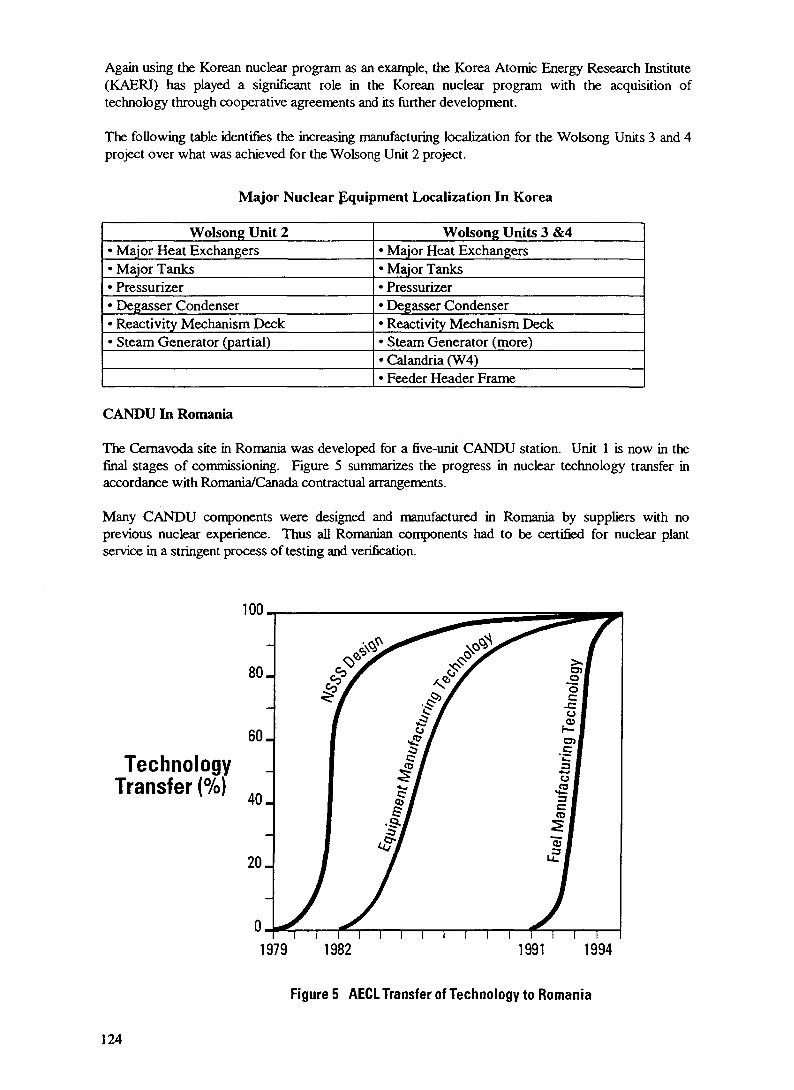
Again using the Korean nuclear program as an example, the Korea Atomic Energy Research Institute(KAERI) has played a significant role in the Korean nuclear program with the acquisition oftechnology through cooperative agreements and its further development.
The following table identifies the increasing manufacturing localization for the Wolsong Units 3 and 4project over what was achieved for the Wolsong Unit 2 project.
Major Nuclear Equipment Localization In Korea
Wolsong Unit 2• Major Heat Exchangers• Major Tanks• Pressurizer• Degasser Condenser• Reactivity Mechanism Deck• Steam Generator (partial)
Wolsong Units 3 &4• Major Heat Exchangers• Major Tanks• Pressurizer• Degasser Condenser• Reactivity Mechanism Deck• Steam Generator (more)• Calandria (W4)• Feeder Header Frame
CANDU In Romania
The Cemavoda site in Romania was developed for a five-unit CANDU station. Unit 1 is now in thefinal stages of commissioning. Figure 5 summarizes the progress in nuclear technology transfer inaccordance with Romania/Canada contractual arrangements.
Many CANDU components were designed and manufactured in Romania by suppliers with noprevious nuclear experience. Thus all Romanian components had to be certified for nuclear plantservice in a stringent process of testing and verification.
100-
TechnologyTransfer (%)
80.
60.
40.
20.
0_
4{
/I
ii
i i i i i
ral
uOS
cs
CO
1979 1982 1991 1994
Figure 5 AECL Transfer of Technology to Romania
124

Small process equipment such as pumps, heat exchangers and valves went through certification insupplier facilities or in national laboratories. Other components such as 200 electric motors receivedfinal certification at the plant site.
The qualification of major equipment such as the Main Circulating Water Cooling Pumps and the ClassED Stand-By Diesel Generators offered special challenges. Components with their characteristics andsize had never been tested in Romania.
4 3 Lessons Learned
To date, AECL's experience in nuclear technology transfer has provided some insight into the factorsthat contribute to the success of technology transfer. Some of the lessons kamed are:
people are important;
Without the availability of trained personnel to interpret the documentation and implement thetechnology, the technology is of little practical value.
• training is essential;
Training is a necessary ingredient in technology transfer for not all the technology resides indocumented form. Much of it can only be transferred through personal communication.
• practice is essential;
It is well recognized that on-the-job experience is one of the most effective ways of transferringtechnology. This, therefore, has been a cornerstone of all our technology transfer programs.However, if the technology once transferred is not put into practice but is put to one side to beaddressed at a later date, the expertise that has been created will quickly dissipate and the technologywill have to be releamed. This reinforces the argument that only those technologies of immediateinterest should be considered.
• technology must be appropriate;
Experience indicates that adjustments in manufacturing techniques and equipment or in the skillsdemanded of labour will often be essential.
• there will be environmental differences;
The broader socio-economic-technological differences which influence the ways in which peoplebehave and how work is achieved must be recognized. In nuclear technology transfer, the concepts ofnuclear safety and quality have to be properly communicated and their importance clearly establishedwithin the nation's infrastructure.
potential conflicts must be recognized;
It is likely that more than one objective will exist. For example, the use of local suppliers of equipmentand services may appear to conflict with maintaining project schedules and overall costs. It is essentialthat both parties recognize the various objectives and reach an understanding regarding their relativepriority.
• there may be cost impacts;
On-the-job training is an effective way to learn. However, this often extends the time taken tocomplete the job.
125

• misconceptions and misinterpretations will occur; and
Despite the best intentions of both parties, there will be misconceptions and misinterpretations aboutwhat is involved in or expected of the technology transfer. A very precise definition of the scope oftechnology to be supplied and the processes to be followed could minimize these problems.
• there is a need for a coordinating organization.
The reactor supplier does not control all the potential technology involved although it has access to it.Several companies, therefore, will be involved in the transfer of technology. In the receiving nation,many companies will be engaged each with its own interests and goals. The coordinating organizationin the receiving nation will:
ensure that the necessary infrastructure for providing adequately trainedpersonnel is in place;determine priorities for the areas of technology to be transferred and ensure adequate allocationof funds and human resources;determine the most effective recipients who will receive and eventually develop thetechnology; andmonitor and coordinate the actual technology transfer process.
5.0 A Framework For Success
Well over 100 billion US dollars have been spent in developing nuclear technology to its present state.Therefore, careful consideration should be given by all to building on the experience and expertisewhich exists in the world's nuclear community.
Experience has shown that the transfer of nuclear technology is a very demanding task requiring largecommitments of both financial and human resources. Success in such a large undertaking can only beachieved if the right framework or environment is put into place. This framework will have severalessential components:
Comprehensive National Planning. The receiver of the technology must carry out a thorough reviewof the objectives it sees for the technology transfer program, the present capabilities which can beapplied to the development of a nuclear power program and more importantly the gaps which exist.
Organize To Develop Infrastructure. Experience shows that establishing a lead agency to coordinatethe technology transfer enhances the chance of success. This agency will eventually put in place thecomplete infrastructure to support a nuclear power program.
Commit Resources. Within the scope of the technology transfer program decided upon, it is essentialto make a firm commitment of both financial and human resources.
Firm Management. Because of the large scope and diversity technology transfer program in terms ofresources, the program is a project in its own right which may equal the nuclear power plant project interms of complexity and importance. Dedicated, effective and efficient project management by bothreceiver and supplier is imperative for program success.
Develop Relationships. The success of the program will depend on the will of both parties to succeed.In this respect, the development of relationships between parties which are based on mutual trust and
respect is most important.
126
SETTING-UP OF SMR IN A DEVELOPING XA9846711COUNTRY - INDIAN EXPERIENCE
C.N. BAP AT, P.D. SHARMANuclear Power Corporation of India,Anushaktinagar, India
Abstract
India envisaged a 3 stage Nuclear PowerProgramme on long term basis with a view to make use of largedeposits of Thorium. The first stage involved PressurizedHeavy Water Reactors (PHWRs) based on natural uranium. Firsttwo PHWRs in 220 MWe range were set-up under collaboration withCanadians and subsequent were set-up and operated with totallydeveloped indigenous technology. The designs for 220 MWe &500 MWe PHWRs are ready. The size of reactors, coming underSmall & Medium Reactor Categories, is ideal for a developingcountry from indigenisation of technology, synchronizing withgrid and financing point of view. The paper gives Indianapproach and experience gained in setting-up series of PHWRs inSMR range in India.
1. INTRODUCTION
The setting-up of Nuclear Power Plants (NPPs) inIndia is entrusted to Nuclear Power Corporation of India Ltd.(NPCIL). This is Govt. of India owned company set-up in Sept.,1987 to give impetus to Nuclear Power Programme in India. Thecorporation is sole organization that is responsible fordesign, engineering, procurement of equipment/components, siteconstruction, commissioning, operation and maintenance ofNuclear Power Plants. The Nuclear Power Production in Indiastarted way back in mid 60' s when two Boiling Water Reactortype Nuclear Power Plants of 200 MWe capacity were set-up atTarapur on 'Turn-key' basis from USA. Around that time. Dr.Homi Bhabha, along with energy planners, assessed the potentialof nuclear power vis-a-vis available resources in naturaluranium and abundant thorium reserves. As a result, long rangenuclear power programme comprising three distinct and basicstages was evolved. The three stages were :
I Setting-up of small/medium range PressurizedHeavy Water Reactors {PHWRs) based on naturaluranium and heavy water. This stageyields plutonium which is to be used for nextstage.
II Setting-up of Fast Breeder Reactors (FBRs)based on natural uranium - plutonium fuelwith depleted uranium and thorium used asblanket that gets converted into plutoniumand Uranium-233 which can be used in thirdstage i.e.
127

I l l Setting-up of Uranium-233 thorium based FastBreeder Reactors. The reactor generates moref i s s i l e material from thorium than isconsumed in terms of Uranium-233. This stagethus provides abundant and continual sourcefor power production.
2 . APPROACH
Thus it was very clear in the beginning thatfuture of nuclear power in India lies in PHWR technology andtherefore after setting-up two BWRs at Tarapur, the focus wasshifted to PHWRs and accordingly all the efforts were directedtowards acquiring and absorbing PHWR technology from the leaderviz. Atomic Energy of Canada Limited (AECL). Accordinglycollaboration agreement was reached between AECL and Departmentof Atomic Energy (DAE). As a result, two units at Rajasthanviz. RAPS-1 and RAPS-2, each 220 MWe PHWR, were set-up in thejoint collaboration. Indians were trained in Canada on DouglasPoint Generating Station and were also involved in certaindesign and engineering activities. For the first unit ofRajasthan Atomic Power Plant, the design, engineering andsupply of major equipment was from Canada, while siteconstruction, commissioning and operation was done by Indiansunder supervision of AECL. The second unit though constructedunder supervision of Canadians, was commissioned, operated andmaintained by only Indians. Some of the equipment were alsomanufactured indigenously. Then on, there was never lookingback and Indians took on responsibility of design, engineering,operations and maintenance for series of PHWRs. As of nowthere are 8 PHWRs of 220 MWe capacity which are being operatedand maintained at various locations in the country. Four moreunits of 220 MWe PHWRs are under construction. Four units of220 MWe are in future plan at identified sites. Two units of500 MWe PHWR have been designed and long delivery items havealready been procured. The units are likely to be launchedshortly. Thus it can be seen that India has fully developedtechnology to design, construct, operate and maintain PHWRs inSMR range. The two PHWR types - PHWR-220 and PHWR-500 - havealready been shortlisted by IAEA in 'detailed design stage'category.
3. PROSPECTS FOR FUTURE
In addition, a 100 MWth reactor set-up mainlyfor isotope production and R&D work has been designed,constructed, operated and maintained by Bhabha Atomic ResearchCentre (BARC), Mumbai. One Fast Breeder Test Reactor (FBTR) atKalpakkam is under commissioning trials. This is 14 MWe testreactor being connected to the grid in very near future. Workis in progress for design of 500 MWe Prototype Fast BreederReactor (PFBR) on the basis of experience gained from FBTR.Design of Advanced Heavy Water Reactor (AHWR) is also inprogress at BARC and these reactors would also be in a state ofreadiness within next five years. Thus a beginning is alreadymade in second stage of Nuclear Power Programme aftersuccessfully acquiring technology for implementing first stageof the Programme.
128

4. RESEARCH AND DEVELOPMENT (R&D)
Self reliance being one of the prominentingredient of the Nuclear Power Programme, efforts weresimultaneously made to establish strong R&D base and trainingprogramme for which BARC and other sister organizations underDAE were set-up. The various DAE units engaged in variousaspects of supporting Nuclear Power Programme are given below :
4.1. Indian Rare Earths (IRE)
Mining of Rare Earth elements.
4.2. Uranium Corporation of India Ltd. (UCIL)
Mining of Natural Uranium.
4.3. Nuclear Fuel Complex (NFC)
Fabrication of fuel elements and fuel bundles,manufacturing of coolant tubes (pressure tubes), calandriatubes etc.
4.4. Heavy Water Board (HWB)
Production of Heavy Water.
4.5. Electronics Corporation of India Ltd.(ECIL)
Reactor control and instrumentation,consoles,software development & simulators.
4.5. Bhabha Atomic Research Centre (BARC)
This is basic R&D establishment which,interalia, develops basic engineering concepts and technologiesrequired for Nuclear Power Programme implementation. Thebasic research and development work is then transferred, aspart of Technology Transfer, to either above mentionedsister organizations or industries for large scale productionon commercially competitive manner.
The BARC is also providing one year NuclearOrientation Training Course to fresh engineering & sciencegraduates since 1957. Total capabilities exist in completenuclear fuel cycle including waste management and reprocessing.
5 . MANUFACTURING CAPABILITIES
The equipment manufacturing in the country startedright from second PHWR (Viz .RAPS-2) i t se l f and as of now,following organizations in Public & Private sector havedeveloped capabilities to manufacture nuclear power plantequipment and components as given below :
5.1 . Bharat Heavy Electricals Limited (BHEL)
Balance Of Plant (BOP) i . e . secondary s ideequipment including Turbine - Generator se ts , condensers
129

etc.. Steam Generators, Pressure Vessels/Tanks, Heavy WaterHeat Exchangers, Electrical Motors.
5.2. Bharat Heavy Plate & Vessels Ltd. (BHPV)
Pressure Vessels/Tanks, Main Air-Locks, HeavyWater Heat Exchangers, Condensers, etc.
5.3. Bharat Pumps & Compressors Ltd. (BPCL)
Centrifugal and recipocating pumps andcompressors in medium range.
5.4. National Government Electrical Factory (NGEF)
Motors in all size ranges including for PrimaryCoolant Pumps.
5.5. Larsen & Toubro Ltd. (L&T)
Steam Generators, Calandria, End Shields,Pressure Vessels/Tanks, Heavy Water Heat Exchangers, etc.
5.6. Walchandnagar Industries Limited (WIL)
Calandria, End Shields, Heavy Water HeatExchangers, Pressure Vessels/Tanks,etc.
5.7. Kirloskar Brothers Limited (KBL)
Electrical Motors in medium range centrifugalpumps-mech. seal type and canned type.
5.8. KSB Pumps Ltd.
Manufacturing Primary Coolant Pumps.
5.9. Machine Tools Aids and Reconditioning (MTAR)
Precision Machinery and Manufacturing ofintricate components.
5.10. Hindustan Construction Company Ltd.(HCCL), Presteel &Elecon Construction Company (ECC)
Civil construction including containmentbuilding.
Many of above manufactures have acquired or inprocess of acquiring ISO-9000 certification.
6 . CONSULTANCY
In addition to above mentioned equipment/component manufacturers, there are number of consultancyorganizations in the country which render assistance in designand detailed analysis work required to validate the design orprovide Safety Analysis for Licensing purposes. Some of the
130

major organizations engaged are within DAE while others are ineducational and industrial sectors.
7. TRAINING
The plant personnel operating and maintainingthe Nuclear Power Stations are given thorough training atNuclear Training Centres located near Rajasthan Atomic PowerStation (RAPS). They are selected on the basis of minimumrequired educational qualification. First operators haveminimum graduation (degree) qualifications. The trainingconsists of l ec tu res , plant walk through, check l i s t s ,emergency procedures and simulators before they are givenindependent responsibility to operate and maintain the nuclearpower station. The training includes retraining at periodicintervals.
The design, manufacturing, operation andmaintenance of nuclear power station by highly skilled andprofessional personnel is demonstrated by the fact that inapprox. 121 reactor years of operation, no accident ofradiological nature and above level 3 of the InternationalNuclear Event Scale (INES) has taken place. Neverthelessaccidents of non radiological consequences have taken place butthey have been handled quite effectively; without allowing themto escalate into serious ones. Engineering challenges poseddue to equipment mal-function, mechanical fault, operator erroror natural events have been successfully tackled within theresources and infrastructure facilities available indigenously.Some of such situations have been : inadvertent dousing, endshield brittleness, coolant channel inspection, fire in turbinebuilding, flooding of plant site etc.
8. DESIGN FEATURES
The standard designs now available in India are220 MWe PHWRs and 500 MWe PHWRs. This size range is ideallysuited for Indian conditions viz. strength of the powerdistribution grid, evolving manufacturing facilities andlimited availability of funds and could be prevalent in manydeveloping countries. The salient features of the two nuclearpower plants are given below :
Parameters 220 MWe PHWR 500 MWe PHWR
(1) Core
Pitch
Horizontal PressureTubes
Fuel Bundle
No. of Fuel Bundles/Channel
Thermal Power
Av. no. of fuel Bundlesreplaced per full power day
306
229
nos.
mm
19 Elements
12
770
8
MW
392 nos.
286 mm
37 Elements
13
1736 MW
14
131

Parameters 220 MWe PHWR 500 MWe PHWR
Weight of all fuel bundles 60Tonnes
(2) Primary Coolant Circuit
Primary Coolant PumpsSteam GeneratorsReactor Headers
(3) Total Heavy Water Requirement
(4) Containment : RCC double withsuppression pool
(5) Shutdown provisions PSS + SSSPSS - Primary Shutdown Systeir.SSS - Secondary Shutdown System
(6) Engineered Safety Feature Provided
(7) Capability to cope with ProvidedStation Black Out
121
Single
444
250
Yes
Loop
Te
Two Loops
448
500 Te
Yes
(8) Spent Fuel Storage Bay
(9) Waste Management
(10) Construction Period
10 Years +1 Core Unload
at Site
< 7 Years
PSS + SSS
Provided
Provided
10 Years +1 Core Unload
at Site
approx. 7.5Years
9. CONSTRUCTION SCHEDULE
The construction experience with regard tovarious 220 MWe PHWRs in terms of construction period is givenbelow :
20 I
15
in 10a:crUJ
0
INOIGENISflTION PHflSE5IGNIFICHNT DESIGNIMPROVEMENTS
COLLRBORflTION
TURNKEY
CONSOLIDATION 8.STflNDflRDISflTION
FIG. I. Trend in schedules Indian nuclear power projects
132

It is seen that the project schedules haveextended beyond expectations, however, for each case there werevalid reasons in terms of either component availability ormanufacturing troubles faced during the process of learning.The manufacturer's capability and technical requirements haveto be continuously assessed and alternative solution to befound out which help manufacturer to overcome his difficultybut do not comprise on technical and safety requirements. TheNPPs could also not be standardized in order to progressivelyaccommodate evolutionary designs and evolving safetyrequirements. Thus each subsequent project itself presentedchallenges in newer areas; however, now there is semblance ofstandardization with respect to 220 MWe PHWRs. Manufacturershave also developed and acquired 'state-of-the-art' technologythat is commercially competitive. In most of the cases thereare more than one manufacturers and that encouragescompetition. On the basis of this strength a constructionschedule of less than 7 years is very much realistic for 220MWe PHWR. Extrapolation of this and experience gained inprocurement and manufacturing of some of capital equipment for500 MWe PHWR also indicate schedule of construction around 7.5years provided unhindered cash flow requirements are met andlead tiwe to complete site specific design details isavailable.
10. FINANCING AND CONTRACTUAL AGREEMENTS
At a time when technological capabilities werefully demonstrated, the resource crunch-typical to a developingcountry has started affecting schedules. Initially, i.e., uptoSeptember, 1987, the funding of Nuclear Power Plants was doneby the Government and funds required on yearly basis were madeavailable from National Budget. However, subsequent toformation of NPCIL in '87, the Governmental support startedreceding with every passing year. The rationale behind thiswas to give impetus to the Nuclear Power ProgrammeImplementation in India and also to allow NPCIL to effectivelygenerate its own resources from operation of existing NuclearPower Stations in competitive manner- Initially the Governmentproposed 1:1 Debt. Equity ratio for funds, but later on thisratio is also gradually changing. This forces NPCIL to borrowfunds from free market at market rate to meet costs of newprojects under construction. Thus the financing principles andassumptions very much dictate Unit Energy Cost and cost per MWof installed capacity. The utilization of generation surplusand market borrowing is flexible option in changing marketeconomy.
India has not yet offered Nuclear Power Plantpackage to any other country and therefore, contractualagreements are not existing. The previous contractualagreements in nuclear field were in sixties but those were asbuyer country and not as supplier country.
The pricing of nuclear power plant within homecountry and for export model is not identical . This is sobecause the taxation and duties levied are different. Thereare concessions available for export items and these change to
133

• OPERATING• UNOER CONSTRUCTION
I TO BE LRUNCHED
NflRORfl• 2x220 MVe
RflJflSTHRN• 1x100, 1x200 MVe• 2x220 MVe
KRKRflPflR• 2x220 MVe
TflRflPUR• 2x160 MWea 2x500 MWe
KfllGfl,•2x220 MWe
MflORflS• 2x220 MVe
NUCLEAR POWER PROGRAMME IN INDIAPRESENT STATUS
some extent with time. It is , therefore, not quite appropriateto project the figures but can be at best taken as indicative.These figures will emerge only at the time of negotiationstaking place and the prevailing economic scenario.
As on date NPCIL is not able to finance anyNuclear Power Plant outside India. Various financial optionswhich could be available at the time of negotiations are :
Financing by buyer country within i t sresources.
Financial assistance from world financingorganizations.
Supplier 's credit for theequipments/components manufactured by thesupplier (i.e. manufacturer in this case).
134

MILESTONES
RPRIL 15, 1948 i flTOMIC ENERGY RCT 15 PASSED
fiUGUST 10, 1948 i flTOMIC ENERGY COMMISSION15 SET-UP
RUGU5T 03, 1954 i DEPORTMENT OF RTOMIC ENERGYIS CRERTED
RUGU5T 0 1 , 1955 THORIUM PLRNT HT TROMBRYGOES INTO PRODUCTION
RUGU5T 04 , 1956 i RPSflRfl REflCTOR - THE FIRSTIN flSIfl - GOES CRITICflL
JRN. 20 , 1957
JflN. 30 , -1959
OCT., 1969
DEC, 1973
NOV. 19, 1982
MflRCH 0 4 , 1985
i flTOMIC ENERGY ESTRBLISHMENT,TROMBflY NOW (BflRC) INRUGURflTED
i URflNIUM METRL PLflNT RT TROMBflY
PRODUCES NUCLERR GRRDE URflNIUM
: TRRRPUR flTOMIC POWER STflTION( BWR ) COMMERCIRL OPERRTION
« RflJRSTHRN flTOMIC POWER STflTION( PHWR ) COMMERCIflL OPERflTION
i POWER REflCTOR FUEL REPROCESSINGPLflNT flT TflRflPUR REPROCESSESURflNIUM OXIDE FUEL
i WflSTE IMMOBILISflTION PLflNTflT TflRflPUR IS COMMISSIONED.
135

DESIGN FEATURES - 220 MWe PHWR1. CORE i HORIZONTAL PRESSURE
TUBES
PITCH
No. FUEL BUNDLE
No.OF FUEL BUNDLES/CHfiNNEL
THERMflL POWER
flv.No.OF FUEL BUNDLESREPLflCED PER FULL POWER DRY
WEIGHT OF flLL FUELBUNDLES TONNES
2. PRIMflRY COOLflNT CIRCUIT
PRIflMRY COOLflNT PUMPS
5TERM GENERflTORS
REflCTOR HEflDERS
3. TOTflL HEflVY WflTER REQUIREMENT
4. CONTfllNMENT i RCC DOUBLE WITHSUPPRESSION POOL
5 . SHUTDOWN PROVISIONSPSS - PRIMflRY SHUTDOWN SY5TEMSSS - SECONDflRY SHUTDOWN SYSTEM
6. ENGINEERED SflFETY FEflTURE
7. CflPflBILITY TO COPE WITHSTflTION BLflCK OUT
8. SPENT FUEL STORflGE BflY
9. WflSTE MFlNflGEMENT
10. CONSTRUCTION PERIOD
306
229
Nos.
mm
19 ELEMENTS
12
770
8
MW
60
SINGLE LOOP
4
4
4
250 Te
YES
PSS + SSS
PROVIDED
PROVIDED
10 YEflRS +1 CORE UNLORO
flT SITE
< 7 YEflRS
136

DESIGN FEATURES - 500 MWe PHWR
i. CORE > HORIZONTHL PRESSURETUBES
PITCH
No. FUEL BUNDLE
No.OF FUEL BUNDLES/CHflNNEL
THERMRL POWER
flv.No.OF FUEL BUNDLES
392 Nos.
286 mm
37 ELEMENTS
13
1736 MW
14REPLRCED PER FULL POWER DRY
WEIGHT OF FILL FUELBUNDLES TONNES
2. PRIMflRY COOLRNT CIRCUIT
PRIflMRY COOLRNT PUMPS
5TERM GENERRTORS
REflCTOR HERDERS
3. TOTRL HERVY WRTER REQUIREMENT
4. CONTRINMENT i RCC DOUBLE WITHSUPPRESSION POOL
5. SHUTDOWN PROVISIONSPSS - PRIMflRY SHUTDOWN SYSTEMSS5 - SECONDARY SHUTDOWN SYSTEM
6. ENGINEERED SflFETY FEflTURE
7. CRPflBILITY TO COPE WITHSTRTION BLRCK OUT
8. SPENT FUEL STORRGE BRY
9. WRSTE MRNRGEMENT
10. CONSTRUCTION PERIOD
12
TWO LOOPS
4
4
6500 Te
YES
PSS + 555
PROVIDED
PROVIDED
10 YERR5 +1 CORE UNLORD
RT SITE
RPPR0X.7.5YERRS
137

INDIAN NUCLEAR POWER PROGRAMME
UNIT
TRRRPUR-U2
RflJflSTHflN-1
RFIJFI5THflN-2
MRDRR5-U2
NflRORfl-18,2
KRKRRPRR-1&2
RRJfl5THFiN-3&4
KFIIGR-1&2
TRRRPUR-3&4
CflPflCITY
2 x 160
100
200
2 x 220
2 x 220
2 x 220
2 x 220
2 x 220
2 x 500
REMARKS
COMMERCIflL OCT
—— DEC
- . — RPR
——JRN'84&MRR
—— JRN'918JUL
—— MflY'93&FEB
CRITICflLITY BY
CRITICflLITY BY
LflUNCH BY
'69
'73
'81
'86
'92
'95
KflPP I & I I
DEGREE OF 1NDIGENISATI0N INNUCLEAR POWER PROJECTS
138

POTENTIAL DESIGN
D DHRUVR 100 MWe
D FR5T BREEDER TEST REfiCTOR 14 MWe
D PROTOTYPE FR5T BREEDER REflCTOR 500 MWe
D flDVRNCED HERVY WRTER RERCTOR 220 MWe
Deferred payments towards expenses incurredby NPCIL and its sister organizations.
Market borrowing from financial institutions.
These options very much depend on credit ratingof and soundness of economy in the buyer country.
11. LICENCING AND PUBLIC ACCEPTANCE
The need to separate the organization engaged inNuclear Power Programme and the organization that is custodianof nuclear safety and has Licencing Authority was recognizedand accordingly Atomic Energy Regulatory Board (AERB) wasconstituted in 1983. This body is totally independent from allother sister organizations of DAE and NPCIL. With growingconcern for nuclear safety world over and in post TMI andChernobyl accidents, the responsibility and accountability toPublic (of AERB) has tremendously increased in recent past andemphasis on thorough safety analysis and documentation hasincreased. Some of the delays are attributable to preparationand approval of Safety Reports and documents.
Public acceptance of nuclear power is dependenton accident free operation of nuclear power plants and rightkind of communication between NPCIL and general public. Inrecognition of this fact, NPCIL formed separate directorate forEnvironment and Public Awareness in 1988. This directorateliaise with educational institution and organizes regularexhibition, seminars, press briefings and topical discussionson environment friendly and benign generation of nuclear power.
1 2 . SUMMARY
To sum-up, India has acquired total capabilitiesin setting-up SMR in developing country. The size of reactorvery well matches with connecting grids and indigenousmanufacturing capabi l i t i es . The NPPs are capital costintensive units and require matching financial resources. Theenergy needs of the country on long term basis vis-a-vis
139

available resources have to be properly assessed. Induction ofNuclear Power Programme with a view of indigenization needsproper evaluation in terms of set t ing-up of largeinfrastructural facilities and available financial resources.Once committed i t is most expensive to abandon a Nuclear PowerProgramme for any reason whatsoever.
140

XA9846712KARACHI NUCLEAR POWER PLANT -A REVIEW OF PERFORMANCE, PROBLEMS AND UPGRADES
S.B. HUSSAINKarachi Nuclear Power Complex,Karachi, Pakistan
Abstract
The Karachi Nuclear Power Plant (KANUPP), a 137 MWe CANDU Unit is located 30 Km west of thecity of Karachi, Pakistan. It is the first commercial CANDU PHWR, built on turn-key basis bythe Canadian General Electric Company for the Pakistan Atomic Energy Commission. It was
declared in-service on 4 October 1972 and since then operated with a life time average availabilityfactor of 55.9%
KANUPP during its 23 years of operation has experienced multiple challenges in keeping the plant operating andsupplying safe and economical power to the Karachi grid. The biggest challenge was faced in 1976, when the originalvendor imposed unilateral embargo leading to the stoppage of supplies of essential spare-parts, nuclear fuel, heavywater and technical support. This forced KANUPP to a new way of operating the plant which necessarily had to bebased on indigenous support.
Obsolescence of C&I components became evident soon after plant went into commercial operation because of explosivedevelopment and advancement in the electronic and computer technology. KANUPP was, however, able to cope withthe normal maintenance and improvement of its process, mechanical and electrical equipment till 80's. However, manyof the critical components are now reaching the end of their designed life and developing chronic problems due toageing. The only technically suitable and commercially viable alternative is the complete replacement of CC&Icomponents. KANUPP has already undertaken this job alongwith other related work under 'Technological UpgradationProject".
In order to manage ageing related degradation and carry out full scale assessment of the health of reactor fuel channelsKANUPP prepared an '"Integrated Safety Master Action Plan" and submitted it to IAEA for arranging internationalassistance. After intense negotiations and with the IAEA's cooperation in May 1990, Canadian policy towardsKANUPP was revised allowing it to provide assistance for Safe Operation of KANUPP (SOK) through the IAEA andonly for the IAEA suggested remedial actions. Work under SOK is being carried out to
• Combat ageing and obsolescence problems• Modernize Operational Safety practices• Improve safety systems design
This paper describes KANUPP" s efforts in overcoming different problems mentioned above.
1. Introduction
The Karachi Nuclear Power Plant (KANUPP) consists of a single CANDU PHWR unit with a total grossgeneration capacity of 137,000 kilowatts. It is a natural Uranium, Heavy Water cooled and Moderated Nucleargenerating station located at Paradise Point on the arid Arabian Sea Coast, about 15 miles to the west ofKarachi. It is the oldest operating CANDU-PHWR.
Civil construction began in September 1965, following a tum-key contract with the Canadian General ElectricCompany (CGE). The reactor attained criticality on 1 August 1971 and subsequent full power operation, on 4October 1972. The Plant is now operating as integral part of Karachi Electric Supply Corporation (KESC)system, contributing approximately 10% of the total demand of power in Karachi. During its two decades ofoperation, the plant has generated about 7.9 billion units of electricity with an average life time availabilityfactor of 55.9%. KANUPP which has a design life of 30 years has now completed nearly 23 years of itssuccessful commercial operation.
141

2.0 Plant Main Features
LocationOwnerPrime Contractor and DesignerCivil ConsultantReactor Type
FuelModeratorCoolantThermal OutputElectrical Output GrossElectrical Output Net
Paradise Point, KarachiPakistan Atomic Energy CommissionCanadian General Electric CompanyMontreal Engineering CompanyCANadian Deuterium Uranium (CANDU)Pressurized Heavy Water (PHWR)Natural UraniumHeavy WaterHeavy Water432.8 MWth137 MWe125 MWe
3.0 Operation Objectives
The operation of KANUPP is optimized to meet the following two prime objectives.
• Public, plant workers and environmental safety shall be ensured.• Continuous efforts shall be made to produce economic and reliable electricity.
The management ensures that the designed features, the procedures and the workers are developed to the bestpossible standards and that the necessary environment is created and maintained to achieve the aboveobjectives. The safety features of the plant to achieve these objectives are
• Defence-in-DepthA defence-in-depth concept, in the form of several successive barriers preventing the release ofradioactive material to the environment, has been implemented.
• Automatic Safety SystemAutomatic systems safely shut down the reactor and maintain it in a safe and cooled state.
• Normal and Emergency Heat RemovalHeat transport systems are designed for reliable and efficient heat removal in normal and abnormaloperation. Provision is also made for alternative means to restore and maintain fuel cooling underaccident conditions.
• Conduct of OperationThe Plant is operated by well qualified, trained and licensed personnel.
• TrainingStandard programmes are followed for training and re-training of operating personnel. Training isparticularly intensive for control room staff.
• Emergency Operating ProceduresEmergency Operating Procedure have been established, documented and approved to provide a basisfor suitable operator response to any abnormal event.
• Maintenance, Testing and InspectionSafety related structures, components, and system are subjected to regular preventive maintenance,inspection and testing to ensure that they meet their design intent.
• Quality Assurance in OperationAn Operation Quality Assurance Programme (OQAP) provides for ensuring satisfactory performanceof all plant activities related to safety.
142

Containment of Radioactive MaterialThe Plant is capable of retaining the bulk of radioactive material that could be released from the fuelduring accident conditions.
Emergency PreparednessA "Karachi Emergency Relief Plan (KERP)" for radiological hazards has been chalked out outliningprocedures for protection of public and plant personnel in the event of accident.
4.0 Organization
Pakistan Atomic Energy Commission (PAEC) exerts full responsibilities for the safe operation of the plantthrough a strong organizational structure as defined in Figure-1 under the line authority of General Manager(KANUPP). The General Manager ensures that all elements for safe plant operation are in place, including anadequate number of qualified and experienced personnel. Consequent to the challenges of embargoes andcommitment to self-reliance, the following divisions and units were either established or upgraded:
Computer Development Division (CDD)
Mechanical Design & Development Division (D&D)
Technical Division (TD)
For long term solution of real timeComputer Control and other relatedproblems.
For local design and Manufacture ofprecision and custom made mechanicalcomponents.
For providing effective technical supportin the field of design changes,modifications, plant chemistry, operatingexperience feedback, planning andnuclear material control
Quality Assurance Division (QAD)
Karachi Nuclear Power Training Centre (KNPTC)
In-Plant Training Centre (IPTC)
In-Service Inspection (ISI) & NDT Laboratory
Control & Instrumentation ApplicationLaboratory (CIAL)
Health Physics Division (HPD)
For ensuring effective establishment andexecution of quality assurance programmein accordance with internationalstandards and guidelines.
For imparting specific training toengineers and technicians in basic nucleartechnology.
For providing advanced training toengineers & technicians leading tooperating license for KANUPP.
For non-destructive testing, evaluationand inspection of plant components.
For long term solutions of C&I problemincluding in-house static calibration anddynamic verification of pressure, temp-erature, flow and level instruments underplant operating conditions.
For ensuring effective implementationand control of radiological protectionmeasures and for minimizing personnelradiation dose.
Maintenance Division For safe and efficient conductance ofpreventive and predictive maintenance onplant systems and equipments.
143

•
DEPUTYPLANT MANAGER
(PRODUCTION)
MANAGEROPERATIONDIVISION
HEIN-P
ftDLANT
TRAININGCENTRE
GENERAL MANAGER
MANAGERMAINTENANCE
DIVISION
HEADMATERIAL
MANAGEMENT
MANAGERTECHNICALDIVISION
HEADI.S.I
DEPUTYPLANT MANAGER
(ENGINEERING)
MANAGERDESIGN K
DEVELOPMENTDIVISION
MANAGERCOMPUTER
DEVELOPMENTDIVISION
PRINCIPALENGINEER
PROCUREMENT
PRINCIPALSECURITY•rFICER
DIRECTORK I N P 0 E
PROJECTDIRECTORC 1 A L
PRINCIPALMEDICALDFF1CER
MANAGERQUALITY
ASSURANCEDIVISION
PRINCIPALPROCUREMENT
ENGINEER
CHIEFACCOUNTANT
MANAGERHEALTHPHYSICSDIVISION
RADIATIONCONTROLDfFICER
PRINCIPALADMINIS-TRATOR
FIG. I. KANUPP functional organization chart.

5.0 Interface with Regulatory Authority
Nuclear power is regulated in Pakistan by Directorate of Nuclear Safety and Radiation Protection (DNS&RP).
The distribution of responsibilities between regulatory body and KANUPP is such that:
• Primary responsibility for safe plant operation lies with KANUPP.
• Regulatory body sets achievable performance requirements and subsequently monitors these to ensureits compliance.
• Regulatory body has also the authority to accept or reject or modify any proposal submitted byKANUPP on system/equipment design changes, modifications and backfits.
• Regulatory body carries out annual performance review of the plant which includes quantitativemeasurement of safety and safety related system performance.
• Regulatory body is also responsible for arranging independent safety review of the plant after everyfive years in close co-operation with experts and consultants who have international experience inplant safety reviews, such as OSART.
• The regulatory body, whenever, finds its necessary and in consultation with KANUPP, provides anindependent international assessment through IAEA ASSET missions for identifying areas whichrequire potential improvements, so as to prevent incidents and also to attain an international standardof excellence.
KANUPP 'Operating Policies & Principle (OP&P)' is the key document which acts as an interface betweenKANUPP and DNS&RP. The OP&P clearly identifies and differentiates between actions where discretion maybe applied by KANUPP and where jurisdictional authorization is required by DNS&RP.
On the basis of regulatory and operating policies and principles it is mandatory for KANUPP to report unusualevents to DNS&RP within a specified time interval. These are
• Events with major safety significance are communicated promptly (within 24 hrs. of the recognitionthat event occurred).
• Events with lesser safety significance are communicated within a few days (usually 7 days) of therecognition that the event occurred.
6.0 Plant Performance
Since its connection with the KESC grid in 1972, plant has been operating as a base load Station. Inspite of theearly post commissioning phase problems, KANUPP operated with relatively high availability factors upto theyear 1977 with an annual average of about 70% (1973-1979). The plant achieved relatively low availabilityduring the period 1978 to 1980 mainly due to non-availability of fuel and essential spare parts from the vendorcountry. In the wake of the Indian nuclear explosion on May 18, 1974, Canada cut off all technical assistanceto Pakistan including operating and design information essential to the operation of KANUPP. The unilateraldecision of imposing an embargo on the supplies of fuel, heavy water and spare parts for KANUPP resulted inthe curtailment of power production and ultimate shutdown of the plant for most of the period in 1979.
The Pakistan Atomic Energy Commission started fabricating its own fuel in 1979 and since September 1980,KANUPP is operating on indigenously produced fuel. The plant availability started increasing in 1981 and itachieved the highest availability factor of 85.81% in 1994.
In 1982 the plant had to be shutdown for a period of nearly six months to carry out essential maintenance ofthe plant critical equipments. The major maintenance job undertaken during 1982 was the repair and overhaulof moderator system valves.
The plant was shutdown for a period of about 4 months in 1985 to carryout complete overhauling of turbine,modification on Main Generator, and maintenance jobs related to conventional, electrical, reactor, andprotective system.
145

In 1993 the plant was shutdown for about three months to carryout the In-service inspection of reactor and toremove one sagged reactor fuel channels.
The Plant has so far generated over 7.9 billion units of electricity with an average life time availability factor of55.9% and an average load factor of 28.4%. Its performance during the year 1994 was exceptionally goodwhen it achieved the highest availability factor of 85.81%. On ten different occasions, the plant operatedcontinuously for over two months including the longest continuous run of over 113 days in 1995. Theperformance of the plant over the last three years (1992-95) improved considerably when it produced on theaverage 530 million units of electricity per year with an availability factor of 74% and capacity factor of 44%
Feeding a relatively small grid, KANUPP during its initial 15 years of operation was required to operate atlower than full power output mainly because of limitations of the load demand and stability of the Karachigrid. Load variations over a period of 24 hours were quite large and hence the utility could not apportion toKANUPP a larger base load. KANUPP is not in a position to load-follow as the excess reactivity available hasnot been designed to cater for such large load variations as are experienced in the Karachi grid. During theperiod of 1989 to 1993, the regulatory authority restricted the operation at about 60% capacity due to problemsassociated with one of its reactor fuel channels.
During the 23 years of its operation the plant had, therefore, to operate at an average of 60-70% of its netcapacity. This resulted in relatively low load factors the maximum being 48.8%. The performance factors ofKANUPP are shown in Figure-2 & 3.
600-1
500
400
300
200 H
100
MILLION UNITS
i r i i i i i i i \ i i r
72 74 76 78 80 82 84 86 88 90 92 94
YEAR
FIG. 2. Generation 1972-1995 (up to 19-09-1995).
146

100
80
60
40-
20-
i i i i i i r i i T i r i r i i i i i i T i
72 74 76 78 80 82 84 86 88 90 92 94
YEAR
FIG. 3. Availability 1972 (up to 19-09-1995).
7.0 Plant Outages
Plant Outages during its 23 years of operation, have been high as compared to other Canadian plants. A totalof 280 outages have been experienced, the average being 12 outages/year. The outage causes and theircontributions have been classified as:
Outages Causes
•
•
•
•
•
EquipmentRegulationGrid Transient.Human ErrorForcedPlannedSafety
Percentage Contribution
25.3620.3612.867.86
20.717.55.36
Operating KANUPP without vendor's support can be attributed as the major reason for such high outage rate.Many essential equipment and components which were supposed to be replaced on routine basis could not beattended in time causing unplanned plant outages. The other contributing reasons are
• Unstable Grid.• Heavy Water Leaks (End Fitting, Valves & Pump Gland etc.)• Fault in Controlling Computers.• Sea Weed in rush.• Condenser Tube leak etc.
147

8.0 Radiation Protection
Inspite of problems of sorts, KANUPP faithfully adhered to its original safety and public risk targets. Theradiation control safety record has been extremely satisfactory as testified by regular testing and reliabilityanalysis. Average personnel radiation exposure has been well within the prescribed limits of InternationalCommission on Radiological Protection (ICRP). Refer Figure-4. Release of radioactive material throughgaseous and liquid effluent has remained within 3 % of the Derived Release Limits. Refer Figure-5 & 6.
EXTERNAL • INTERNAL -*- RUNNING AVG. SINCE CRITICALITY
700
f 600CC CC
S I 5 0 0
LU DC
O LU
400^
300^
I S 200< CC
£100
0
Maximum PermissibleICRP .Limit .= 5 Rem per year
71 73 75 77 79 81 83 85 87 89 91 93 95
YEAR
FIG. 4. Average dose per person and running average since criticality.
4000
3500 -
0.6 %
0.45 % *•a
0.3%
0.15%
0%
aa-
oQ.XIS
S
YEAR
FIG. 5. Release of radioactivity to the environments via liquid effluent.
148

Thousands10
"o
111CO
HI_J111a.
8 ---
6 -_
5 %Max. Release (17.S6*/. in 1989)
71 73 75 77 79 81 83 85 87 89 91 93
FIG. 6. Release of radioactivity to the environments via gaseou effluent.
9.0 Major Operating Problems and Remedial Actions
Some of the major operating problems experienced during its 23 years of operation and actions taken to resolvethem are described below.
9.1 Problems Unique to KANUPP - Embargo and Commitment to Self-Reliance
Two decades of Plant operation since October 1971, when the first nuclear power unit was produced byKANUPP, have proved quite eventful. Following the explosion of a nuclear device by India in 1974, all sortsof nuclear assistance to KANUPP was suspended and a unilateral embargo was imposed by the vendor countryon supply of technical assistance, spare parts and fuel in 1976.
Operating KANUPP in the environment of complete embargo was a difficult task, especially in the absence oftechnical infrastructure required to fulfill the station needs. However, a determined effort on the part of itsowner, Pakistan Atomic Energy Commission (PAEC) in general and KANUPP in particular kept it operatingsafely.
The embargoes, however, proved a blessing in disguise. A self-reliance programme launched by PakistanAtomic Energy Commission (PAEC) began to yield results, in 1980, PAEC successfully produced nuclear fuelfor KANUPP while it made all-out efforts to create the technical infrastructures, Industrial resources andpersonnel expertise necessary to support station operation. The Design & Development Division (Mechanical),Computer Development Division, In-service Inspection Labs, Control and Instrumentation ApplicationLaboratory and Quality Assurance Division were subsequently established at KANUPP. At about the sametime, the Technical and Health Physics Divisions were strengthened to provide necessary backup for technicaland radiation control support. The Karachi Nuclear Power Training Centre (KNPTC) and In-Plant TrainingCentre (IPTC) were established for imparting basic and advanced training in nuclear power technology toengineers and technicians engaged in the operation and maintenance of the plant
Such technical support does not form part of nuclear power plant operation in developed countries but in thecase of KANUPP, there was no other choice. Incidentally, KANUPP is the only nuclear power plant in theworld which has been operating without an active technical and material support from the vendor which isvividly indicative of PAEC's commitment to self-reliance.
149

9.2 Normal Operating Problems.
9.2.1 Nuclear Island
9.2.1.1 Standby Heat Exchangers
Tubes of one of the two heavy water standby heat exchangers failed due to fretting caused by process waterflow induced vibration only after three years of plant operation. All tubes of heat exchangers were checked byECT and the tubes showing thinning in excess of acceptable limit were plugged. The tube bundles were alsostrengthened by installing more fasteners. Later inspections showed no or slight ageing effect. However, thetube bundles of one of the standby heavy water heat exchangers was fabricated locally and installed. It isplanned to fabricate and replace the tube bundle of all the three remaining standby and charging heavy waterheat exchangers.
9.2.1.2 Moderator System valve Gasket
As against the current practice of providing double gasket arrangement, valves in the Moderator System atKANUPP are provided with conventional single gasket arrangement using neoprene gasket at the bonnet. Thisneoprene gasket in one of the moderator pump discharge valves failed (ageing degradation due toembrittlement) and caused a large D2O spill.
The frequency of inspection/replacement of the gasket of all such valves has been increased.
9.2.1.3 Differential Pressure Transmitter Casing Bolts.
A differential pressure transmitter between south outlet and north inlet-header failed due to breaking of two outof four chrome plated steel bolts used for joining the two metal casings enclosing the bellows assembly,resulting in D2O leakage.
The bolts on all such transmitters have been replaced.
9.2.1.4 Steam Generators
KANUPP has six steam generators with Monel 400 tubes. Tube failure with ageing is a well known andexpected phenomenon. In fact the performance of KANUPP has been better than expected in this area.
Steam Generator # 3 developed a small leak in 1989, which developed upto 4 Kg/hr over two weeks at the endof 1990. The plant had to be shutdown for more than a month and a special procedure was developed to isolatethe leaky boilers and operate the plant with four instead of six steam generators in service.
After performing necessary modifications the plant was operated with four out of the normal six boilers. Thiswas a unique operation as no such previous experience was available in any CANDU nuclear power plant. Theregulatory body, gave short-term permission to operate in this condition at 50% power. The leaky tube (onlyone) was later plugged after acquiring necessary training and confidence on locally assembled steam generatortest mock-up.
9.2.1.5 Dump Valves
Six dump valves, connected in series parallel arrangement, are provided in the helium balance line to trip thereactor. The valves are 10 inch butterfly valves with diaphragms and elastomer seals connected to the upstreampressure to minimize leakage when the valves are closed.
The dump valves, provided by the vendor, were modified and special elastomer seals were installed byCanadian General Electric. No spare seals, their drawings and other parts are available. Only once a dumpvalve was opened for inspection. Due to daily trip tests and relatively frequent plant trips experienced, thedump valves have been subjected to rather severe duty. It is planned to replace the valves with new ones, andefforts are underway for their procurement.
150

9.2.1.6 Fuelling Machines/Fuel Handling.
Fuelling Machines and end fitting components are a critical part of the primary pressure boundary when inuse. They are highly complex, custom built, and subject to very high radiation levels. We have experienced thefollowing ageing-induced problems so far. Some have been solved for now, but the basic issue of fabricatingreplacements for custom-built parts remains and becomes more serious with time.
• A D2O hose ruptured leading to a major heavy water spill.• D2O head circulating pump canned motor developed micro-crack due to excessive rubbing. D2O seeped
into stator winding deforming the stator can.• Snout jaws developed cracks over a period of time within & along the groove, being the maximum stressed
areas. The snout jaws cracks propagated in 1988 as revealed by ISI. Plant operation was not allowed by theregulatory body till replacement with locally manufactured and extensively tested snout jaws.
• Failure of mechanical seal 'o' ring installed in charge tube axial drive due to ageing.• Closure plug locking problem. The shield plug was found damaged and the charge tube latch finger had
broken inside the end fitting.• Shield plugs sticking on rotation. Investigation revealed that tail end was causing restriction both in axial
and rotary motion due to bulging/deformation. Machined to original size before replacement.• Two fuel bundles entangled due to damaged end plate of one, entered Fuelling machine magazine together
and prevented rotation. Dislodged by special procedures. The incident is attributed to hammering receivedby the bundle against the channel sealing surface.
9.2.1.7 Reactcr Fuel Channels
In 1989, fuelling problems led to detection of two sagged reactor fuel channels in cold shutdown condition.Subsequent inspection revealed reactor fuel channel G-12 to be sagged by 49 mm and F-15 by 12 mm. Theproblem is not unique to KANUPP as similar problems had been discovered in other Canadian plants andrectified successfully. In 1993, the Canadians under the IAEA assistance carried out an assessment of the fuelchannel integrity and removed G-12 to identify the root cause of its retraction. The problem was found to bespecific with only G-12, whereas all other reactor channels inspected were found to be in perfectly goodcondition. The reactor resumed operation with one channel removed.
9.2.2 Plant Computers
9 2.2 1 Control Computer
Plant Control computers consist of a dual redundant digital computers, GE-PAC-4020, for reactor powerregulation. These computers were designed in mid sixties and were installed as part of reactor control systemby the original vendor.
The computers were maintained through indigenous modifications until 1989. The modification includerecoding of the real time computer control software, a 15 man year effort which considerably improved theperformance of main plant control system. Performance of these computers have now deteriorated to theextent that their replacement is essential for reliability and continued safe operation of the plant. Thereplacement of regulating computers is being undertaken as part of Technical Upgradation Project(TUP).
9.2.2.2 Fuel Handling Computers
The existing PDP-S computer system for Fuel Handling Control has been replaced by an Industrial IBM PC-AT Computer system, utilizing the expertise available in PAEC. A new software package written in Microsoft-86 assembly language has been provided to execute the same functions as the PDP-8 fuel handling controlcomputer.
9.2.3 Control and Instrumentation (C&T)
During the last decade extensive advancement and innovation has taken place in computers and hightechnology electronics and informatics. This has completely changed the design and operational philosophy ofmodern nuclear plants. Nowadays, the modern plants are being controlled by a very sophisticated software
151

based technology. The Control & Instrumentations systems of KANUPP were designed in mid sixties and havenow become totally outdated and obsolete. Due to their obsolescence and ageing extreme difficulty is beingencountered in their maintenance and upkeep. In fact, at a certain stage, it was felt that due to ageing andobsolescence their maintainability may aggravate to a level where it will become very difficult to ensurereliability and safety of plant operation. Therefore, a systematic and comprehensive programme has beenprepared for functional replacement of obsolete C&I equipment. A Technological Upgradation Project (TUP)has been initiated and a contract has been signed with a foreign firm for the supply of CC&I equipment thedesign of which has been completed by KANUPP engineers. New CC&I equipment is expeaed to be installedand made operational by end of 1996. In addition, the following C&I jobs have already been completed eitherindigenously or in association with some other foreign vendors.
Replacement of T/G Instrumentation.Upgradation of Plant Communication System.Installation of a close circuit TV system for monitoring various areas of Reactor Building.Radiation monitoring system.Plant Switch Yard Extension etc
9.2.4 Conventional Systems
Following steps have been taken to resolve problems due to proximity to sea (corrosion due to airborne sea-salts) and use of sea water for condensing steam and for Cooling Process Water, causing corrosion, erosion,carry-over of silt, sea weeds, in-rush of sardines and barnacles growth on pump house equipment andassociated systems.
• Traveling intake salt water screens replaced with corrosion resistant material such as stainless steel.• Condenser tubes kept clean by reversing flow, and ferrous sulfate addition at frequent intervals to create
protective layer on tubes.• Process cooling water pump casing and main headers piping replaced.• Radiator air cooling installed for diesel generators, replacing the sea water cooling.• Other equipment i.e. meteorological tower, station transformer radiators and high voltage transmission
towers, which were badly affected by corrosion, were replaced.• Frequency of painting of all the plant equipment which is exposed to corrosive atmosphere/environment
increased.• Complete retubing of Process salt water Heat exchangers with titanium tubes.• Replacement of chlorinating plant.• Salt Water pumps and casings.• Boiler Blowdown line replacement• TLO separater replacement.• Complete replacement of Fire Water Ring, etc.
10.0 International Co-Operation and Safety Updgradation
10.1 Role of IAEA
The Three Mile Island and Chernobyl accidents have greatly increased the role of IAEA in ensuring safe plantoperation all over the world. KANUPP has been inspected by 'IAEA Operation Safety & Review Team(OSART)' in 1985 and in 1989 and on both occasions the plant was found to conform to IAEA operationalstandards. An IAEA 'Assessment of Safety Significant Evaluation Team (ASSET)' mission also visitedKANUPP in 1989 and performed in-depth analysis of plant operational safety practices. The ASSET missionmade several recommendations for improving the safety of the plant. An overall plan identifying, prioritizingand scheduling the activities important to plant safety was developed based on the experience of KANUPP andthe recommendations of ASSET missions. An 'Integrated Safety Review Master Plan (ISARMAP)' wasestablished in 1991. Based on ISARMAP, the IAEA approved initially a four year (now revised till 1997)technical assistance project namely 'Safe Operation of KANUPP (SOK)' and approached the CanadianGovernment which agreed to provide initial consultancy for expert assessment and planning for the requiredsafety improvement through CANDU Owner's Group (COG) of which KANUPP was a member. The objectiveof this IAEA project (PAK/9/010 'Safe Operation of KANUPP) was to arrange the necessary internationaltechnical support for the tasks listed in ISARMAP. The support under PAK/9/010 was envisaged in followingthree ways.
152

10.3 Integrated Safety Review Master Plan (ISARMAP) Task and Status
SR.NO.01.
02.
03.
04.
ISARMAP | CURRENTTASK I STATUS
Project Management
a) Establish an Integrated Master Plan forSOK.
b) Umbrella agreement with COG forCanadian Technical Assistance.
Equipment Ageing Affecting Safety
a) Fuel Channel Integrity Assessment(FCIA).
b) Improve CO2 Annuals Gas System
c) Repair of Steam Generator
d) Fuelling Machine Ageing
Ecuipment Obsolescence Affecting Safetv
a) Replacement of RadiationInstrumentation
b) Replacement of obsolete ComputersControl & Instrumentation.
Improve Operational Safetv Practices
a) ISI of Steam Generator and BOP Piping.
Established in 1991. Reviewed by SteeringCommittee five times.
Only safety investigations, assessmentdiagnostics tasks and expert and services havebeen allowed.
Sagged pressure tube G-12 was removed and ISIof this and other 7 selective reactor channels,done with Canadian technical support. A local,non-generic problem with only G-12 due to aleaky rolled joint was identified.
The CO2 system at KANUPP is once throughand needs review for its adequacy to provideleak-before-break detection. This is important asa creak in pressure tube could be detected wellbefore it reaches the critical crack length(~15hrs).
One leaky tube was detected and plugged byKANUPP. Canadian Technical support wasproposed but ultimately not required.
The fuelling machine forms a part of the coolantpressure boundary during on-power fuelling.Replacement of its aged parts is essential,however, Canadian government has so far notconsidered it as a safety issue.
Obsolete radiation monitoring instrument hasbeen replaced.
- Fuelling Machine PDP-8 computers havebeen replaced with Industrial Grade PCs.
- Replacement of plant regulating computersGEPAC-4020 and instrumentation is plannedin 1996.
Primary system pressure boundary and criticalBOP pipings were inspected in 1992 byCanadian specialists. The Systems were found inexcellent condition. Eddy current testing of twosteam generators was done in May 1993 byB&W Canada and tube conditions were found tobe very good. Only one tube in steam generator #3 with 26% "Through Wall Thickness (TWT)'detected & plugged.
153

SR.NO.
05.
JSARMAPTASK
b) Review of modern MaintenanceTechnique.
c) Improvement of Safety Culture.
d) Review of Modem EmergencyPreparedness
e) QA Programme,
f) Operating Experience Feedback.
Improve Design Safctv
a) Update of Final Safety Analysis Report(KFSAR)
b) Probabilistic Safety Analysis Level-1.
c) Equipment Qualifications (EQ) ReviewAgainst LOCA.
d) Booster Cooling,
e) Emergency Boiler Feed Water Supply.
CURRENTSTATUS
Techniques followed in modern CANDU plantssuch as infra-red thermography & laser shaftalignment are being implemented.
Courses to improve safety culture at KANUPPwere arranged in 1991 by IAEA. Two IAEAexperts delivered lecture in 'Basic SafetyPrinciples for Nuclear Power Plants' and'Analysis and Prevention of Safety SignificantEvents. Root cause analysis of safety significantevents have been established after these course.
Emergency preparedness arrangements inmodem Candu were reviewed by a KANUPPspecialist in 1992. Required improvements andpractices are being adopted in KANUPP.
Operations Quality Assurance programme wasreviewed by a Canadian specialist in July 1994and found in line with Canadian practices.
Internationa] Operating experience feedback hasbeen computerized on an internal LAN,connected to CANDU OWNERS GROUP (COG)and WANO, INPO Networks.
Work on Phase-I (Analysis of special safetysystems against limiting large break LOCA) hasbeen completed. Work on Phase-2, i.e. completeupdating of final safety report is planned to beundertaken in 1996.
The work on KANUPP PSA Level-1 is inprogress and expected to be completed by end of1996. Reviews are done by IAEA experts atrequired intervals.
Expert review was done in 1993 by twoCanadians. No major problem identified,however, they recommended establishment of asystematic EQ programme. Few modificationswere implemented as part of EQ programme.
The use of booster has been discontinued becauseof the safety concerns with respect to its cooling.Canadian plants do not use boosters any more.
In order to provide an un-interrupted heat sink toreactor, an independent supply of emergencyfeed water to steam generator is being planned.Independent review by a Canadian expert of thedesign has been done. New system is expected tobe installed by early next year.
154

SR.NO.
ISARMAPTASK
0 Adequacy of Emergency Power,
g) Containment Testing at Higher Pressure.
h) Seismic Walkthrough of the Plant.
CURRENTSTATUS
KANUPP has two standby Diesel Generators. Athird Diesel generator is being added to improvethe emergency power supply needs and decreasethe allowed outage times.
The containment Pressure test was done at fullpressure (27 psig) during commissioning andafterwards it is being done at 2 psig. In order toassess the leak rate at higher boiler roompressure it is now planned to perform the test atelevated pressure. Test at 5 psig has already beendone successfully. KANUPP is now approachingCOG to provide expert services from PointLepreau NGS for developing necessaryprocedures, to test containment at a reasonablyhigh pressure.
KANUPP is designed for 0.1 g earthquake. Awalkthrough by IAEA experts in 1993 concludedthat KANUPP can withstand twice the designbasis earthquake with minor modifications.Necessary steps being taken to implement therecommendations.
• Foreign Experts visit to KANUPP• Some Assistance in purchase of equipment• Some fellowship assistance for KANUPP personnel.
A steering committee was also constituted by IAEA to review the ISARMAP tasks, their scope and priorities,the results of the activities for the enhancement of KANUPP safety system and recommendations for furtheractions.
The ISARMAP could be broadly classified into the following five areas with a number of tasks in each area.
Project ManagementAgeingObsolescenceOperational SafetyDesign Safety Improvements.
A detailed description of the tasks alongwith their current status is given in section 10.3
10.2 Role of Other International Organizations
The complete isolation of KANUPP from international channels of communication partially ended in 1989following the Three Mile Island and Chernobyl incidents which aroused an instant realization among thenuclear community to promote global safety in nuclear power plant operation. The CANDU Owners Group(COG) and, later, the World Association of Nuclear Operators (WANO) were formed to provide a forum forpromoting closer co-operation among nuclear utilities in matters relating to operational experience feedback,human performance and plant safety. KANUPP joined COG and WANO in 1989 and has now access to publicdomain informations from nuclear utilities around the world.
COG is playing the leading role in accomplishment of jobs under the 'Safe Operation of KANUPP (SOK)'Project An agreement to this context exists between KANUPP and COG.
155

WANO has done a two week 'Peer Review' of KANUPP in November 1994 and 20 experts from all over theworld conducted in-depth safety review of the plant. The identified weak areas are being strengthened. Underthe aegis of WANO-TC, a number of technical exchange visits to other nuclear power plants has also beenarranged, providing opportunity for operational experience exchange.
11.0 Conclusion
It is an accepted fact that nuclear power plant must operate with the technical support of the vendor countryand other international help, since the quantum of R&D, design and operational & safety experience of thevendor country can not be matched by NPP operating country alone. This aspect of nuclear power plantoperation has been recognized well by the international community and as a consequence institutions such asINPO, WANO & COG have been created. These institutions alongwith IAEA are playing vital role inproviding necessary technical services and support to the operating power plants in assessing the extent towhich they are complying with their original safety standards and also suggesting the improvements andmodifications required to achieve an acceptable level of current international safety standards.
KANUPP has amply demonstrated that nuclear power is feasible in a developing country. The plant canoperate despite heavy odds and numerous challenges. It has also established that nuclear power isenvironmentally clean and safety remains paramount in the operation of a nuclear power station.
In more than 20 years of operation, not a single KANUPP employee has lost a day's work due to radiationexposure - a testimony to the good design and safe operation of the plant.
Radioactive emission to the environment throughout the operational history of KANUPP has remained below3% of the Derived Release Limits.
Various safety reviews and investigations done in the past by IAEA and other international organizationsconfinned that KANUPP has maintained an excellent safety record and that its critical components such asReactor, Boilers and Turbine Generator are in perfect condition.
KANUPP is striving hard to resolve its current ageing-induced equipment problems to satisfy the originalsafety requirements and public risk targets which are still internationally acceptable. However, as a policy themanagement is committed to upgrade the safety as far as possible, towards current standards and criteria.
It is envisaged that the economical life of the plant would be extended 10 years beyond its design life of 30years after providing all the required replacements of its obsolete informatics and refurbishing of nuclear islandas well as conventional equipments.
REFERENCES
1. Javeed IqleemComputer Control and Instrumentation Backfitting in a PHWR Plant.Paper presented at, IAEA Technical Committee and work shop progress in Heavy Water ReactorDesign and Technology.Montreal, Canada 6-9 December, 1988.
2. M A . Ghafoor, J. A. Hashmi, Zia Siddiqui,Identification of Efforts Required for Continued Safe Operation of KANUPP.Paper presented at, Second PHWR Operating Experience Meeting, held at Embalse, Argentina fromApril 3-5, 1991.
3. Syed Badshah HussainPlant Performance, Maintenance and Development Activities.KANUPP-STR-88-2
156

4. Reactor Safety Re-evaluation, a Common Basis for JudgmentSafety of All Operating Nuclear Power Plants Built to Earlier Standards.Report of a Consultants' Meeting International Atomic Energy Agency 8-12 November 1993 Vienna,Austria.
5. Javed Iqleem, Zia Siddiqui, Parvez ButtExperience with Operational Safety Improvements at the Karachi Nuclear Power PlantInternational Conference on Advance in the Operational Safety of Nuclear Power Plants,Vienna, Austria, 4-8 September 1995.
6. Syed Badshah HussainKANUPP Operating ExperiencePaper presented at, IAEA Technical Committee Meeting on Exchange of Operational SafetyExperience of Pressurized Heavy Water Reactors. 20-24 February 1989 Vienna, Austria.
7. M. A. Ghafoor, Syed Mazhar Hasan, M. Qamar-ul-Hoda, Safdar HabibMeeting the Challenge of KANUPP Operation.
8. Babar GhiasKANUPP Outage RecordKANUPP-STR-95-02
9. Syed Badshah HussainRegulatory Practices Relating to Monitoring Assessment of Ageing at Karachi Nuclear Power Plant.
NEXTPAGE(S)left BLANK
157

THE ROMANIAN EXPERIENCE ON INTRODUCTION OFCANDU-600 REACTOR AT THE CERNAVODA NPP
S.N. RAPEANU, A. BUJORNational Agency for Atomic Energy
O. COMSA
Center of Technology and Engineering for Nuclear Projects
Bucharest, Romania
Abstract
The Cernavoda Nuclear Power Plant (NPP) Project is a keycomponent of the Romanian nuclear development program. Selectionof the CANDU design represents a major contribution to thisdevelopment, due to the technological feasibility formanufacturing of parts, components and the nuclear fuel based onthe uranium resources in Romania. The Romanian nucleardevelopment program also involves a nuclear fuel manufacturingplant, a heavy water production plant and organizationsspecialized in research, engineering, manufacturing andcompletion for systems and components. The agreement ontechnological transfer between Canada and Romania is supportingthe Romanian involvement to the achievement of the Project, witha degree of participation that is gradually increasing from thefirst to the last NPP Unit.
1. INTRODUCTION
The need of diversification of energy sources, independencefrom foreign supplies and modernization of economy, has been themost important reason that led Romania's authorities to decidethe implementation in Romania of the nuclear energy. In thisrespect, the initial thinking has highly regarded the Canadianheavy water CANDU reactors for their advanced safety features anduse of natural uranium as fuel and heavy water as moderator andcoolant, both being materials possible to be manufactured by thedomestic industry.
A first nuclear power plant with four units CANDU-600 hasbeen decided to be built at the site of Cernavoda, in the easternpart of the country, with the aim to further extend the role ofatomic energy by construction in the future of other units [1].
With that in mind, a contract with Atomic Energy of CanadaLimited (AECL) has been negotiated and concluded in 1979,covering licensing of generic CANDU-600 design, the nuclear steamplant design, supply of equipment and technical assistance indetailed local engineering from Canada, quality assurance andconstruction [2] and [3].
At the same time, contracts were negotiated for the supplyof equipment and technical assistance related to the Balance ofPlant and for the turbine-generator group for the first twounits, with Ansaldo Impianti (Italy) and General Electric. As a
159

result, several licenses and technical cooperation agreementswere signed between Canadian companies, Italian companies, G.E.and Romanian manufacturers, with the aim to allow manufacturingin Romania of most of the equipment, with an increasing domesticparticipation from the first to the last planned NPP units atCernavoda [4] and [5].
Simultaneously, at the national level, steps have been madefor insuring appropriate advances in other related areas (Figure1) : research and development, fuel cycle, heavy watermanufacturing, personnel training and implementation of newstandards for design, quality assurance and safety regulation[6] ,
R2HE1 - Romanian Electricity Autority
RAlffi - Rare and Radioactive Metals Board
Figure 1 Romanian nuclear fuel cycle - related activities
160

2. POLITICAL WILLINGNESS AND PUBLIC ACCEPTANCE
The Romanian nuclear program is based on the principle ofpeaceful use of the nuclear energy. The system of nuclearguaranties and measures for physical protection and nuclearmaterials accounting are implemented at all of the facilitiesrelated to fuel cycle activities, research reactors, research anddevelopment institutes, and at the Cernavoda NPP.
At the political level, the program for introducing thenuclear energy, that is the CANDU option, has received andreceives now, an appropriate degree of priority and support.Despite that, until 1990, the development of the project sufferedfrom disadvantages of a highly centralized economy, and thedecisions were taken from political rather than technical andeconomical reasons.
Project management was not recognized and structured as anautonomous activity. The decisions were taken at different levelsof central and local administration and the responsibility wasdiluted between various ministries. The severe limitations ofimports and hard currency expenditures, imposed after 1982, madethe continuation and completion of the project impossible in theplanned time schedule because the volume of both the technicalassistance and the equipment to be imported was minimal. Also,the training of the Romanian personnel in the field of nuclearplant design, operation and maintenance was limited. These werethe main reasons that contributed to the delays in the completionof this project.
The year of 1990 has brought important changes in theeconomical, social and political life of the country. Thedifficulties of the transition period toward free market economyhave led, between others, to the decrease of the industrialactivity and implicitly, to a reduction of the demand ofelectricity, and to hardships in the possibilities of financing.These factors, together with the existence of others importantand complex problems to be solved, have caused the postponementof the decision regarding the continuation of the nationalnuclear program. The present situation is under evaluation, forestablishing a realistic program based on the assessment for costanalyses, environmental impact and evolution of the electricitydemand [8] .
The acute crisis of energy suffered by the Romanian societyand economy in the '80's and, on the other hand, the advancednuclear safety features of the CANDU design, fully at the westernlevel, have insured from the beginning a very good level ofpublic acceptance for the nuclear option. The history of safeoperation and good economic performance of the existing CANDUstations as well as the introduction of the licensing standardsand procedures inspired from the american practice, have alsocontributed to the acceptability of CANDU design. These reasonswere completed by safeguards and safety requirements whichincreased the trust of the population in nuclear field andinfluenced positively the public opinion.
Still, at present, there is no significant opposition to thenuclear energy, despite the existence in Romania of the means andrights for doing so, specific to the opening democracies.
161

3. CERNAVODA NPP STATUS
As it is well-known the reactor CANDU-600 is based onnatural uranium fuel and heavy water as moderator and coolant.The reactor has 380 horizontal pressure channels placed in acylindrical horizontal reactor vessel (called calandria), eachchannel having 12 fuel bundles with 37 fuel rods each, Figure 2.The fuel is made by sinterized U02 powder pellets, enclosed inzircalloy sheath [2], [3] Figure 3.
The moderator is heavy water with 99.8% Deuterium at normalpressure and working temperature of 69°C, placed in the calandriavessel between the fuel channels. The coolant is pressurizedheavy water, flowing between the fuel elements inside thepressure tubes.
According to the contract between the Romanian authoritiesand AECL, in 1979 has started the work at the Unit 1 of theCernavoda NPP. Subsequent, the civil engineering work was startedfor the units 2-4 and in 1982 the fifth unit has been added.Further on, the work has been carried out simultaneously for allthe five units of the plant.
The important delays accumulated until 1990 made necessaryan overall review of the project, realized with the support ofAIEA. A stopwork has been ordered and measures meant toreorganize and accelerate the project have been taken. A newstrategy has been adopted having the following key features:
- concentration of all managerial, human, financial andorganizational resources for completing as soon aspossible the first unit of the Cernavoda NPP
- stop of work, except conservation activities, for theunits U3-U5, having a status of completeness between 5%and 25%
- enhancement of the expert assistance in construction,management commissioning and early operation of Ultogether with AECL and Ansaldo Impianti.
In this respect in December 1990, AECL and Ansaldo formedthe AECL-Ansaldo Consortium (AAC). The newly formed RomanianElectricity Authority RENEL and AAC concluded a new contract in1991, through which the Consortium performs the projectmanagement with the aim of commissioning Unit 1 by March 1995.AAC will also operate the plant for the initial period andprovide both formal and on the job training for the Romanianpersonnel who will operate the Unit 1 when AAC lives the site.
At present, an important part of the commissioning processis completed, such that the Unit 1 is now at the stage of solvingthe problems for allowing the first criticality [8].
The National Commission for Control of Nuclear Activities(CNCAN), which is the Romanian regulatory body, has alreadyauthorized the following:
- loading of D2O in the moderator system- manual loading of the nuclear fuel- loading the coolant (heavy water) in the primary heattransport system
- performance of high temperature tests for the primary heattransport system
- leak test for the containment.The next steps to be achieved are:- first criticality- physics tests at zero power
162

- gradually increase of the reactor power and test operation- operation at nominal power (authorization for guaranties)- normal operation.Following the present schedule, the reactor will become
critical to the end of 1995, with the other steps of thecommissioning program being scheduled to be performed in thefirst half of 1996.
In this situation, it can be stated that a large part of theproblems related to the reactor have been solved; among them, itcan be mentioned:
- the final safety report phase 1- documentation support for nuclear safety- a large part of the reliability and stress analyses- a large part of the documentation for normal operation- a large part of the safety and process systems has been
tested and commissioned and most of the objectives of thecommissioning process have been fulfilled
- an important part of the operation personnel has beenauthorized
It is also important to note that the commissioning processis closely watched by the utility owner and by the regulatoryauthorities.
4. NATIONAL PARTICIPATION
The possibility of participation of national industries inthe Nuclear Power Program was one of the important reasons in thedecision of implementing CANDU reactors in Romania.
Our own participation was established in the followingfields.
4.1. Nuclear Fuel
An important factor supporting the decision of implementingCANDU reactors was to manufacture the nuclear fuel in Romaniausing the existing resources of uranium ores. Decisions have beentaken for developing the domestic facilities at various stagesof processing: mining, milling, concentration and conversion toU02 powder [7] .
Early in 1979 the activities for preparing the Romaniancapabilities for manufacturing of the CANDU fuel assemblies havebeen started. In a first stage, a pilot plant has been organizedon at the site of Pitesti for implementing domestic technologyfollowing the Canadian specifications [3] and [6].
Simultaneously, theoretical activities have been carried outfor design and simulation of the structural behaviour of fuelunder both normal operation and accident condition. Fuel elementsand CANDU fuel bundles have been manufactured and tested inirradiation facilities in the TRIGA reactor at Pitesti and abroad(Belgium, Germany and Canada) .
In 1987, as the capability for manufacturing CANDU fuel hasbeen proven, a decision was taken to extend the pilot stationinto a fuel manufacturing plant with the capacity to provide thenuclear fuel for all the reactors of the Cernayoda NPP [6] .
In 1990 the fuel manufacturing was stopped. In order toupdate the technological process, the production was reorganizedand the production flow was modernized and improved. The
163

production has been resumed in 1994 following the licensing bythe Canadian company Zircatec Production Ind. (ZPI), an importantsupplier of Canadian fuel. Based on this licence, the first loadof Unit 1 contains a number of 2 00 fuel bundles manufactured inRomania. All the fuel required for the future operation of theplant will be produced in Romania.
4.2. Heavy water
Heavy water is one of the major components in the technicaland economical assessment of CANDU NPP.
In order to reduce the costs associated with production andsupply of heavy water it was decided to produce in Romania byour own forces the whole quantity of heavy water necessary forthe national nuclear programme.
Based on this decision, a research and development programwas carried out.
A domestical technology was developed and tested through aheavy water pilot plant and an industrial dimension was latercreated.
It is noteworthy that there are now two out of four modulesin operation which can produce the entire necessary heavy waterquantities at a high purity level (99.9%) . Cernavoda 1 uses animportant part of the initial supply of heavy water fromdomestical production.
According to a national heavy water production program, allnecessary heavy water for the next units and for Unit 1 annualconsumption will be made in Romania [6] .
4.3. Research, development and engineering
The national nuclear program has also included research anddevelopment activities for:
- design, development of technology and testing of fuel- technology for manufacturing of heavy water- behaviour of materials in neutron flux- design of systems and components for the nuclear islandand the balance of plant
- testing of the nuclear equipment assimilated by thenational industry
- reactor physics, fuel management and nuclear safety- risk assessment and evaluation of the radiological impacton the environment
- design of equipment for dosimetry and radiologicalprotection
For these purposes a new research institute, the Institutefor Nuclear Power Reactors, has been established in 1977, withdepartments specialized for reactor calculations and nuclearsafety, design of nuclear systems and components, technologicaldevelopments for nuclear fuel, in-pile and out-of-pile testingfacilities. In addition to that, the other tasks of research,development and engineering have been distributed among the otherexisting institutions with experience in nuclear physics, powerengineering, chemistry, metallurgy and mechanics.
The resources and efforts invested in this direction havefinally allowed the following items to be performed in Romania[6] :
- development of the technologies for manufacturing ofheavy water and of CANDU fuel
164

- preliminary and final safety reports- assimilation of the methodology for fuel managementcalculations
- execution projects for all the five units of the CernavodaNPP
- testing of the equipment manufactured in the country forthe Units 1 and 2.
At the same time, the performance in Romania of theseactivities has created opportunities for the development of ahighly qualified personnel and of a national competence infields of major importance for the further progress of thenuclear energy program.
4.4. Technology transfer
The agreement on technology transfer between Canada andRomania is supporting the involvement of the Romanian industryto the achievement of the project, with an increasing degree ofparticipation through [2],[3]:
- assimilation of new materials- assimilation and implementation of technologies formanufacturing of systems and components
- introduction and implementation of advanced design codesand quality assurance procedures at all the levels related
with the construction of the nuclear power plant.Based on the licenses purchased from the foreign partner,
it was developed a national industrial infrastructure, throughthe endowment with modern equipment of industrial companies inthe fields of metallurgy, electrotechnics and electronics andmechanical tools.
The creation of this infrastructure required major financialefforts, with the result of generating a modern and performantnuclear industry.
Similar efforts have been required for the achievement ofthe transfer of technology that involved:
- technical assistance from AECL for project management- technical assistance for personnel training- acquisition of licenses for fabrication of most ofequipment including the calandria vessel, pressurizer,degaser vessel, steam generators, control devices,pressure tubes, pumps, turbine, fueling machines, etc.
- implementation of the QA system in all the companies whichprovide equipment and services for Cernavoda NPP
- assimilation and implementation in design, execution andmontage of the ASME code
- implementation in the nuclear industry of the nuclearsafety culture
- implementation of modern regulations for the nuclearactivities, and their adaptation to the specificcomponents of the project
The start of the work at the Cernavoda NPP has found thetechnology transfer program under implementation with many of itscomponents not fully completed. The further progress of thisprogram and of the on site work were not synchronized, soleading to the introduction of distortions that have negativelyinfluenced the evolution of the project.
165

4.5. Personnel training
A well trained competent management and technical staff isessential to the safe and a reliable operation of a nuclear powerstation and other nuclear facilities.
The qualification and training of personnel, able to operatethe station and to satisfy nuclear facilities' requirements, isachieved through a program, whose objective is to ensure thetraining at an appropriate level of quality.
In this respect in Romania has been developed a specifictraining program which includes, at different levels:
- post secondary school specialized in nuclear powersciences
- departments for nuclear engineering and nuclear physicsat technical and science universities
- on the job training at Cernavoda N.P.P., including use offull-scope simulators
- specific training in Canada under the agreement with AECLfor the future operation of the plant
- final training during commissioning- specific training in Canada and Romania for personnel forother research and nuclear facilities.
The training program has been developed in the '80's. Themain purpose, the training of Romanian personnel for nuclearplant design, operation and maintenance, was limited and theopportunities offered by the existing agreements or by the IAEAwere not entirely used.
Under these circumstances, the utility RENEL and AAC haveconcluded a new contract in 1991 through which the Consortiumwill perform the management of the project, will operate theplant for an initial period of 18 months and will provide formaland on-the-job training for the Romanian personnel who will lateroperate the plant. In addition, a complement personnel is workingon the Project Management Team (PMT), under the direction of theCanadian and Italian Managers, in order to achieve a transfer ofmanagement skills.
For other specific activities (i.e fuel fabrication, heavywater production, nuclear industries) the necessary personnel wasalready trained through a particular arrangement with IAEA, PNUD,ONUDI and Canadian partners.
5. CONCLUSIONS
From the results mentioned above, the approach tointroducing nuclear energy in Romania is characterized byspecific features, generated by strategy and objectives, as:
- buying of a licence for a nuclear power plant based on theCANDU-600 reactor with advanced safety features andsuitable for the domestic conditions and resources
- buying of a licence for manufacturing of equipment for theplant
- preparing the Romanian industry for the modernrequirements of the nuclear technologies
- assimilation of the Canadian concept of management
- training of qualified personnel
166

CALANOniACALANORIA - SIDE TUBESHEETCALANORIA TUBESEMOEOMENT RINGFUELLING MACHINE - SIDE TU6£SH£ETENO SHIELD LATTICE TUBESENO SHIELO COOLING PIPES• NLET-OUTLET STRAINERSTEEL BALL SHIELDING€NO FITTINGSFEEDER PIPES !MODERATOR OUTLETMOOERATOR INLETHORIZONTAL FLUX OETgCTOR UNIT
16.16.1 J.18.19.20.21 .22.23.2* .25.26.27.28.29.
ION CHAMOEREARTHQUAKE RESTRAINTCALANORIA VAULT WALLMOOERATOR EXPANSION TO HEAD TANKCURTAIN SHIELDING SLABSPRESSURE RELIEF PIPESRUPTURE OISC 'REACTIVITY CONTROL UNIT NOZZLESVIEWING PORTSHUTOFF UNITAOJUSTER UNITCONTROL AOSORBER UNITZONE CONTROL UNITVERTICAL FLUX OETECTOR'UNITLIQUIO INJECTION SHUTDOWN NOZZLE
Figure 2 CANDU-600 reactor assembly
167

- implementation of modern nuclear regulations and of thesafety culture in all the stages of completion of theproject
- development of research and development capabilities fora permanent domestic support of the project.
The process of implementation and achievement of theseobjectives have required great efforts from the national economy.In this respect, the main conclusions and lessons learned are:
- It is important to select a partner with high scientificand technological potential and disponibility for transfer
of this knowledge.
- It is essential to ensure a good management of theproject, eventually with the participation of the partner,using the local resources that must be fully used in the
project.
- It is necessary to insure the continuity of the work atthe five units of the plant, for allowing a smoothtransfer of the teams of specialists from one unit toanother. This requirement is essential for the economicity
of the work.
- The requirements for construction and manufacturing ofnuclear components must be respected. This will lead tothe overall improvement of the level of quality of theproduction with beneficial effects on the economicity of
the work, stability of the personnel, while maintainingthe opening toward high technologies. A direct consequenceis the necessity of establishing a regulatory and control
body, which is independent from the plant owner.
- The existence of a national competence in research,development and engineering is very important for the
management of the project, plant operation and for furtherimprovements and updating. Related to that, emphasisshould be put on personnel training and an educationalsystem based on a curriculum which is applicable to theparticular design of the reactor and of the nuclear powerplant. This is important due to the differences that do
exist between the design and operation procedures ofdifferent NPP's, even if they have the same type ofreactor.
- It is necessary that the licensing and authorizationprocess will not introduce distortions and will not make
derogations regarding:- completitude of the safety documentation- reliability of the systems and equipment- performance in the commissioning tests- training and licensing of the personnel- management of the project changes.
We trust that the conclusions derived from the existingexperience will be put in practice for the future development ofthe Romanian nuclear power program, particularly in the work tocomplete the other units of Cernavoda NPP and in the developmentof related activities.
168

REFERENCES
[1] "Energy and Nuclear Power Planning Study for Romania(1989-2010)", IAEA, TECDOC-820
[2] "Engineering Services Agreement (ESA)", AECL, 1978[3] "Licensing Services Agreement (LSA)", AECL, 1981[4] Mingiuc, C , Panait, A., et al, "Cernavoda Nuclear
Power Plant - Status and Prospects", IAEA, TECDOC-738[5] Mingiuc, C., "ISPE contribution to NPP development in
Romania", Bucharest, 1991[6] Comsa, O., "Cernavoda Nuclear Power Plant Fuel Supply
Aternatives", Bucharest 1992[7] Georgescu, D. , Vasile, C. , "Uranium Resources
Evaluation for Nuclear Power Program", Bucharest 1995[8] "Electric Power Production, Transport and Distribution
in Romania; Tendencies and Concerns", RENEL, Bucharest1993
NEXT PAGE(S)left BLANK
169

POTENTIAL ROLE OF THE ROMANIAN XA9846714RESEARCH AND INDUSTRY ON THE SMALLAND MEDIUM REACTORS MARKET
S.N. RAPEANU, A. BUJORNational Agency for Atomic Energy
O. COMSA
Center of Technology and Engineering for Nuclear Projects
Bucharest, Romania
Abstract
The need of diversifying the energy sources, independence from foreign suppliesand modernization of economy have constituted the major factors in implementation of nuclear energyin Romania. The choice of the heavy water reactor CANDU-600 was made on grounds of advancedsafety features, proven efficient economic operation as well as on the technologic feasibility formanufacturing of components, equipment, instrumentation, heavy water and natural uranium fuel inRomania.
Unlike turn-key acquisition approaches, the Romanian option provided an activenational participation in construction the Cernavoda NPP. As consequence, important support wasbeing given to development of the industries involved in the nuclear fuel cycle, manufacturing ofequipment and nuclear materials, construction-montage, engineering, consulting, services, etc. Thiswas done based on technology transfer, implementation of advanced design and execution standards,quality assurance procedures and modern nuclear safety requirements at international level.
The efforts materialized in an important national participation in the constructionof the Cernavoda NPP and all related programs are successful. Now, Romanian firms are alsoinvolved in supplying components, equipment and services to NPP's in other eastern and centralEuropeans countries.
The paper presents the achievements of the Romanian economy in this field andthe effort of the Romanian companies on the small and medium power reactors market. Lists withmain P&D institutes, nuclear fuel cycle facilities as well as potential equipment suppliers are attached.
1. Introduction
The need of diversifying the energy sources, independence from foreignsuppliers and modernization of economy have constituted the major factors in implementation ofnuclear energy in Romania. The choice of the heavy water reactor CANDU-600 was made on groundsof advanced safety features, proven efficient economic operation as well as on the technologicfeasibility for manufacturing of components, equipment, instrumentation, heavy water and naturaluranium fuel in Romania [1].
As result of the national energy policy, in 1979 a contract was concludedbetween the Romanian authorities and Atomic Energy of Canada Limited (AECL) for the license ofbuilding CANDU power plants in Romania. This contract had the following main features:
- Romania buys the license for building of CANDU-600 reactors in Romania;- AECL provides technical assistance for design of CANDU NPP, Romania
having the quality of general designer of the plant;
171

Romania buys the reference project including the execution documentation, thetechnical specifications for all equipment of NPP and the internal reports regarding the research madeat AECL-Chalk River Research Laboratories.
In 1982 a similar contract was signed for the Balance Of Plant (BOP) withAnsaldo Impianti (Italy) and General Electric, and in 1984-1985 the contracts with equipment mainsuppliers were concluded.
Romanian option provided an active national participation in construction theCernavoda NPP (fig. 1). As consequence, important support was being given to development of theindustries involved in the nuclear fuel cycle, manufacturing of equipment and nuclear materials,construction-montage, engineering, consulting, services, etc. This was done based on technologytransfer, implementation of advanced design and execution standards, quality assurance proceduresand modern nuclear safety requirements at international level [2].
The efforts materialized in an important national participation in the constructionof the Cernavoda NPP and all related programs are successful. Now, Romanian firms are alsoinvolved in supplying components, equipment and services to NPP's in other eastern and centralEuropeans countries [3].
2. Nuclear fuel cycle
2.1. CANDU fuel fabrication
An important factor supporting the decision of implementing CANDU-PHWRwas the capability of manufacturing the nuclear fuel in Romania using the existing resources ofuranium ores and accessible technologies. As a result, measures have been taken for developingdomestic facilities in all the processing stages of nuclear fuel cycle (fig. 2).
Domestical uranium resources are estimated to be sufficient for RomanianNuclear Power Program, which involved five units at Cernavoda NPP [4].
Extraction and processing of uranium ores is made by the Rare Metals Company(RAMR). The technological processes cover the following stages :
- mining and milling of uranium ores;- concentration up to 60% uranium in Natrium Uranate (UNa) and Natrium di-Uranate (DUNa);- conversion, purification in U3O8 (yellow cake);- reduction of U3Og into nuclear grade syntherizable UO2 powder.
Following AECL specifications, a Romanian technology for manufacturingCANDU fuel was developed. In a first stage a pilot station was built on a site near Pitesti in 1980.In 1987, as the capability of manufacturing CANDU fuel was proven, the pilot station was extendedinto a fuel fabrication plant. More than 31000 CANDU fuel bundles (fig. 3) were fabricated before1990 [5].
In parallel to that, theoretical activities for design and simulation of thestructural behavior of the fuel were carried out. Fuel elements and CANDU fuel bundles were testedin the TRIGA reactor at Pitesti and abroad (Belgium, Germany, Canada).
Out of pile testing of fuel bundles and experimental investigations were alsoperformed.
172

ECO IllphPioume Building '
Einorjinnny Power -Supply flullrilng
Doconlmnlnatlon Centre
Servlco Building Turbine Hall
Spent rur>l Sloinyo Dny
Standby Diesel
CoolingVentilating
Fig. 1. 5 x 700 MWe Cernavoda NPP

After 1990 the production was reorganized and the process flow wasmodernized. In 1994-1995 the fuel plant was licensed as qualified CANDU nuclear fuel supplier bythe Canadian company Zircatec Precision Ind. (ZPI) and AECL. Based on this license the first fuelload of Cernavoda NPP - Unit 1 contains a number of fuel bundles manufactured in Romania. Theoverall production capacity of the plant is 110 t/year , covering the annual consumption of Unit 1.However, this capacity will be extended so that all the fuel required for the future operation of thefive units of Cernavoda NPP will be produced in Romania [6].
REHEL - Romanian Electricity AutorityRAMR - Rare and Radioactive Metals Board
Fig. 2. Nuclear Fuel Cycle - Related Activities
174

Zircaloy fuel sheath
UO,
Fuel elements
Zircaloy bearing pads
CANLUB graphite interlayer
Uranium dioxide (U02) fuel pellets
Zircaloy fuel sheath
Inter element spacersZircaloy end support plate
End caps
End view Inside pressure tube
Fig. 3. CANDU - Fuel Bundle
The main future objectives in fuel fabrication field are:
- to supply the necessary fuel for Cernavoda;- to recover the fuel fabricated before the qualification- to assure fuel performance at international level;- to introduce advanced fuel in CANDU for the next units.
2.2. Heavy water manufacturing
The possibility of Domestical heavy water production was another reason in thedecision of the introduction of CANDU PHW reactors in Romania.
For reducing the costs and the dependencies associated with the supply of heavywater, it was decided to produce in Romania the entire quantity of heavy water necessary for thenuclear power program.
The manufacturing technology developed by Romanian specialists is based onthe process of isotopic exchange between water and hydrogen sulfide, followed by a stage of vacuumdistillation. The technology was tested on a pilot station developed by Institute of Cryogenics andIsotopic Separation (ICSI) Rm. Valcea and then an industrial facility was built.
175

At ROMAG, the Romanian heavy water plant, there are now in operation twoout of four modules with a production capacity of 90 t/year each. It produces heavy water with a highpurity level (99.90% Wt.), higher than CANDU technology requires. This opens importantimprovement opportunities since studies have shown that an 1 % increase of deuterium concentrationcan lead to a 6-7 % increase of fuel burnup; the decrease of the fuel consumption results in changesof annual operation costs around 900,000 US dollars. Also, the heavy water produced at ROMAGhas a high neutral ph (7.5 ±0.5) with favorable effects in reducing corrosion.
For the Unit 1 of Cernavoda NPP more than 180 t of heavy water wereproduced in Romania and 335 t were leased from Canada (75 t of leased heavy water was alreadyreturned in Canada). It is provided that all the necessary heavy water for the operation of the nextunits at Cernavoda NPP will be fabricated in Romania.
ROMAG is now the largest heavy water supplier in Europe with a designcapacity of 360 t/year [7].
Romania has today specialized teams for each stage of heavy water production:design, construction, commissioning, operation, process control, special surface treatment for packingand G.S. Columns
An important aim for future developments is to assure a preventive maintenanceand to reduce impact on population and environment.
An other objective in heavy water processing is to realize a D2O detritiationfacility to process tritiated heavy water from Cernavoda NPP. Such a project will to be completed atInstitute of Cryogenics and Isotopic Separation (ICSI) Rm. Valcea.
2.3. CANDU reactor physics and fuel management
The CANDU reactors feature the unique characteristic of continuous refuellingduring operation. The two refuelling machines and the associated systems are able to automaticallytransfer the fresh fuel bundles from store to the fuelling machine head, select the channel to berefuelled, perform the replacement of the irradiated fuel with the fresh one and transfer the irradiatedfuel to the spent fuel storage pool in the plant. Since these operations do not require reactorshutdown, it opens the possibility of achieving high disponibility factors and thus a good economicefficiency of the plant.
However, this requires that physics calculation of the reactor core are performedon a routine basis (daily). The calculations take into account all the current operation events (real fluxdistribution, power levels, shutdowns) reflected in the irradiation history of each of the 4560 fuelbundles in the core and, based on these results, the plant physicist selects the fuel channels to berefuelled. The objectives and criteria considered when choosing the channels to be refuelled involve,between others, the maximization of fuel burnup and the uniformity of neutron flux distribution inthe core, while maintaining the maximum channel power and the maximum fuel bundle power insidethe allowed limits.
The contracts with the Canadian partner allowed for the transfer of the computerprograms and the associated know-how. They also provided the specialization of Romanian physiciststhrough tenures with foreign CANDU operators (Argentina and Canada) and through on the jobtraining at the Cernavoda NPP during the first 18 full power months at Unit 1. These activities,together with the experience acquired in R & D applications have contributed to the creation of astrong national competence in this field in Cernavoda NPP and specialized institute in Pitesti andBucharest.
176

3. Research and development
An ambitious program for research & development was developed in Romaniato sustain the high level of national participation in national nuclear program.
As main components of this program, great support was given to research anddevelopment activities in areas, as:
- reactor physics and fuel management;- nuclear safety;"- CANDU reactor improvements;- risk assessment and evaluation of the radiological impact on the environment;- development of technologies for fuel cycle, including manufacturing of theheavy water and of the CANDU nuclear fuel;- design of equipment for dosimetry and radiological protection;- behavior of materials in reactor flux;- design of systems and equipment for the nuclear island and for the balance ofplant;- testing of the nuclear equipment assimilated by the national industry.
For these purposes in 1977, the Institute for Nuclear Power Reactors (IRNE),Pitesti, was established, with specialized divisions for reactor calculations and reactor safety, designof nuclear systems and components, technological developments for nuclear fuel, in-core and out-of-core testing facilities. In addition to that, the other tasks of research and development were distributedto other existing institutions with experience in nuclear physics, dosimetry, radiological protection,power engineering, electronics, electrotechnics, automation, metallurgy and mechanics, as the Institutefor Atomic Physics (IFA) and the Center of Technology and Engineering for Nuclear Projects(CITON), both near Bucharest.
Important investments have also been made for commissioning and operationof major research and testing facilities. In this respect, we can mention the WR-S and TRIGAreactors used for researches materials and nuclear fuel testing, the Hot Cells facilities, the testingfacility for the CANDU Fuelling Machine and the EUROTEST facilities for environmentalqualification (tests at vibrations, seismical and LOCA conditions) of electrical equipment used innuclear power plants.
The resources and efforts invested in research and development have alsocontributed to creation of major opportunities for the development of a national professionalcompetence in fields of major importance for the further progress of the nuclear program.
The National Agency for Atomic Energy (NAAE), the governmental bodywhich ensues the promotion of activities and develops national strategy for peaceful use of atomic andnuclear processes and phenomena, plays an important role in the co-ordination of the research anddevelopment activities. NAAE has initiated various programs for analysis of the research projects,identification of the optimization possibilities of the technological processes in the nuclear fuel cycleand for increasing the degree of participation of the national economy to the Cernavoda NPP project.This proved necessary for recovering the disadvantages arisen from the lack of co-ordination of theresearch in the nuclear field in the period 1990-1994.
The main topics included in the 1995 and 1996 NAAE R&D contracts are:1. Evaluation of the nuclear fuel cycle for the CANDU reactors and of the
possible alternatives for installation of the nuclear groups at the Cernavoda NPP.2. Evaluation of the possibilities for implementation of solutions for improving
the performance and nuclear safety at NPP with CANDU reactors.
177

3. Evaluation of the opportunities for participation of the national industryat the completion of U2 - U5 of Cernavoda NPP.
The results will contribute to improvements identification in nuclear fuel cyclestages, heavy water manufacturing included, with cost benefits.
Another governmental institutions involved in nuclear power research anddevelopment are Romanian Electricity Authority (RENEL), Rare Metals Company (RAMR) andInstitute of Atomic Physics (IFA), which carried out research & development program for HWRsthrough their main research & development institutes:
- Institute for Nuclear Research - ICN Pitesti;- Center of Technology and Engineering for Nuclear Objectives - CITON,Bucharest;- Research and Engineering Group of RENEL - GSCI;- Institute of Research and Design for Rare and Radioactive Metals - ICPMRR,Bucharest;- Institute of Cryogenics and Isotopic Separation - ICSI, Rm. Valcea.
RENEL research & development programs refer to:- nuclear safety;- nuclear fuel;- CANDU technologies;- radiation protection, decontamination;- radwaste management and decommissioning ;- improvement of operation and safety in heavy water production;- radioisotopes, irradiation techniques and conversion of TRIGA - INR Reactor;- computer assisting of activities.
All this components of research & development are co-ordinate by NAAEwhich bring it together in the national strategy of nuclear activities.
A list with the main research & development institutes and facilities is presentedin Appendix 3.
4. Manufacturing and installation of components and systems for NPP
The increasing degree of participation of the national economy in the programof implementation of CANDU-600 in Romania was one of the main objectives of the agreementsconcluded with AECL. It envisaged the assimilation of new materials, assimilation and implementationof technologies for manufacturing of systems and components and introduction and implementationof advanced design codes and quality assurances procedures.
The implementation of this program required important financial efforts, withresult of generating a modern and performant nuclear industry. As consequence, some 50 firms arenow qualified as manufacturers of components, equipment and systems for nuclear plants. These unitscover the production of :
- mechanical components (pipes, fittings, tanks, heat exchanger, CANDU fuelchannel components and tools, reactivity control devices, filters, sub-systems for fuel handling andfor fuelling machine, etc.)
- electrical installations and devices (low and medium voltage equipment, highvoltage stations and networks, cables, etc.)
- technological equipment (pumps, valves, compressors, pre-heaters, Dieselgroups, overhead cranes, etc.)
178

- instrumentation and control devices (dosimetry and radiological protectionequipment, gamma monitoring system, tritium monitoring system, system for detection of D2O leaksin H2O, failed fuel location system, gas and liquid monitors, etc.).
Two other major component - nuclear fuel and heavy water - complete the listof industrial capability of Romania in nuclear field.
Now the Romanian industry is already an active presence in the reactorscomponents market. In this respect we can mention here FECNE SA (the Nuclear Power PlantEquipment Manufacturing Company) Bucharest which produced emergency tanks for VVER-440 andfor WER-1000 power plants in the Czech Republic (Mohovce NPP and Duchovany NPP). TheRomanian industry has also brought an important contribution, outlined in the attached promotionalmaterials, in providing equipment and components for the Cernavoda NPP.
Lists with the most important supplier for nuclear equipment are presented inAppendix 1, 2.
A national competence in installation field of nuclear and conventionalequipments was also developed through specialized companies, working under the quality assurancesystem in compliance with the specific national and international standards.
5. Engineering, technical assistance and general services
5.1. Technical assistance and project management
Starting from the opening of the work on the Cernavoda NPP site and until 1992the technical assistance was insured by Romanian experts provided by specialized institutes as theInstitute for Nuclear Power Reactors-Design and the Institute for Power Studies and Design,Bucharest. The size and composition of this group corresponded to the size and scope of the worksand problems encountered on the NPP site. The immediate management and coordination of the workwas insured in this period by the plant owner together with appropriate bodies in the Ministry forElectric Energy.
In 1992, according to the contract between the newly formed RomanianElectricity Authority (RENEL) and the AAC (AECL-Ansaldo Consortium), the whole process ofcompletion, commissioning, grid connection and initial commercial operation for 18 months of theCernavoda NPP - Unit 1 came under the responsibility of AAC. As result, a Project ManagementTeam (PMT) was constituted, containing a Design Authority Representative (DAR) with specialistsrepresenting the Romanian design authority - CITON (Center for Technological Engineering forNuclear Objectives). The responsibility of DAR span over the support systems of the plant.
The plant owner participates as secondant of AAC in the PMT regarding qualityassurance program, nuclear safety, commissioning and operation activities; this position will continuefor the duration of AAC involvement, according to the present contract. However, the Romanianpersonnel will gradually take over the responsibilities at both execution and management levels, sothat after the first 18 months all the activities related to the operation of the Unit 1 will be performedonly by Romanian staff.
Due to the great importance of this objective, the size of investment, the mostimportant in Romania, the large number of employees, Cemavoda NPP has always been in theattention, and received great support from the political leadership of Romania. As it was underlinedwith the occasion of the achievement of the first criticality of Unit 1, April 17, this year, thegovernment is giving a high appreciation to the efforts and results obtained at Cernavoda NPP, andfull support for development of the nuclear power program in Romania as well, which involve thecompletion of the 5 x 700 CANDU-PHWR at Cemavoda NPP.
179

5.2. Quality assurance
In 1981 the first QA program in the nuclear field was elaborated formanagement of activities related to erection of nuclear objectives and installations. This program wasstructured based on Canadian and IAEA standards. IAEA subsequently, it was reviewed and updatedwith new Romanian standards, at international level, developed after 1983, for activities in design,construction, commissioning and operation of nuclear facilities. Also, areas as personnel training,metrology control, provisioning, as well as audit, corrective actions, document control and qualityrecords were put under QA requirements. Later, in 1992, the law of introduction of QA standardsat nuclear level for suppliers of products and services and for entrepreneurs was adopted, so that nowall the participants to the construction of NPP have implemented QA programs.
The established QA programs were confirmed and are continuously monitoredthrough technical examinations performed by experts from AECL and from the Institute for Researchand Modernization in Power Engineering, Bucharest. This ensures that the level of quality of theproducts and services provided by Romanian firms in the nuclear field are fully at the level requiredby the technical specifications ordered by the customer.
The national competence in QA programs, standards and procedures isrepresented by National Commission for Control of Nuclear Activities (CNCAN)
5.3. Nuclear safety
In Romania original legislation and authorization procedures are in place, basedon approaches developed in other advanced countries (USA, Canada) and able to respond to the IAEAreccomendations. These ensure the compliance of all the activities performed on Cernavoda site andat other nuclear objectives, with safety requirements at international level. In 1995 Romania hassigned the Nuclear Safety Convention which stipulate a continuous improvement and update of safetyrequirements in the pace of international evolutions.
The Romanian regulatory body is the National Commission for Control ofNuclear Activities (CNCAN). Although CNCAN operates as department of the Ministry of theWaters, Forests and Environment Protection, it enjoys a great independence from politic, economicand other interests. CNCAN displays a strong disponibility for safety analyses, inspections andauthorizations release activities.
In parallel to that, since the original agreement between Romania and Canadadid not include co-operation in detailed safety aspects of the CANDU-600 reactor, a nationalcompetence in nuclear safety was developed in Romania. As result, the Preliminary Safety Analysis,the Preliminary Safety Report and the Final Safety Report - Phase A, as well as safety assessmentsfor design changes and updating at Cernavoda NPP are performed in Romania. Romanian staff is nowsuccessfully completing activities related to the licensing of the Cernavoda NPP Unit 1.
Romania disposes, through specialized institutes as the Institute for NuclearResearches (ICN), Pitesti, and the Center for Technology and Engineering for Nuclear Projects(CITON), Bucharest, of a computer programs and data bank and the capability to performdeterministic and probabilistic safety analyses for a CANDU NPP, for study and authorizationpurposes.
The main safety topics CITON and INR are involved in, are: operation andlicensing, probabilistic safety analyses, accident analyses, sever accident management, pressure tubestress analyses, fuel behavior, CANDU improvement.
180

5.4. Waste management and eNvraoNMENTAL PROTECTION
The main purpose of waste management and environmental protection programis to design and commissioning processing and storage facilities for all types of wastes resulted fromthe operation of NPP and from other nuclear units as well as for spent nuclear fuel elements withrespect of environmental protection and safety rules [8].
For storage of both the average and low level active wastes, the results of aseries of studies were elaborated, lead to the possibility of building a Final Storage Facility, close toCernavoda NPP.
Along 1995, a pre-feasibility study for the Final Storage Facility of both lowand medium active wastes has been issued, this building following to be put into operation in 2002,as the latest date.
Referring to the management of the spent fuel, the studies elaborated at presentby CITON have shown the necessity of performing a Spent Fuel Intermediate Storage which has tobe put into operation during 2002 -r- 2003, considering that the optimum storage period of the spentfuel at NPP is about 7 H- 10 years since NPP commissioning, depending also on the depositing typewhich can be either dry or wet. Under such circumstances elaboration of a pre-feasibility study shouldbe advisable starting with 1996, when the optimum technical solution should be settled.
Another major project of this program represents the building of the Final Storefor Spent Fuel, forecasting its commissioning somewhere towards 2025 years.
All these studies will finalize the first stage of radioactive wastes and spent fuelmanagement obtaining thus, all the design data for opening up, in 1997, the investments of thefollowing projects:
- Final Store for Low and Medium Active Wastes (DFDSMA), having itscommissioning date: 2002;
- Spent Fuel Intermediate Store (DICA) having its commissioning date:2002-2003.
In the next stage, the period 1997-2002, the program will be in progress bysupporting the performance of all the proposed investments in the field of developing the techniques,methodologies, testing procedures of radioactive wastes storage containers and casks, radioprotectioncalculations, evaluation of performance etc.
We would like to underline here the permanent support which was granted bythe IAEA through technical co-operation programs for our research and development works.
5.5. Personnel training
A well trained competent management and technical staff is essential to the safeand reliable operation of nuclear power station as well as of other nuclear facilities.
The qualification and training of personnel, able to operate the station andsatisfy nuclear facilities requirements, is achieved through a program, whose objective is to ensurethe training at an appropriate level of quality.
181

In this respect in Romania has developed a specific training program whichinclude, at different levels:
- post secondary school specialized in nuclear power sciences- departments for nuclear engineering and nuclear physics at technical andscience universities- on the job training at Cemavoda N.P.P., including use of full-scope simulators- specific training in Canada and Romania for personnel for other research andnuclear facilities.
The training program has been developed in the '80's. The main purpose, thetraining of Romanian personnel for nuclear plant design, operation and maintenance, was limited andthe opportunities offered by the existing agreements or by the IAEA were not fully used before 1990.
A new training program for all types of personnel involved in nuclear powerprogram and R & D activities is in train to be defined and developed to assure the necessary level oftraining required by the international legislation and practices.
6. Training simulator for PHWR
6.1. General considerations
International experience of the NPPs operating demonstrated that around 50%from the major NPP accidents are due to the human factors and an important objective for a safework of NPPs consists in the control room operators training using sophisticated tools like full-scopesimulators, located in the frame of the NPP Training Center, replica of the NPP control room. Thisfull-scope simulator is used to train the team who work in the control room and to validate this team,but it is improper for individual training. To offer the individual training possibility, the NPPTraining Centers are equipped with simplified training simulator like MicroSimulators. These toolsconsists in a computers network on which screens the imagine of the control rooms panels isreproduced to show the evolution of the process variables and to take over the operator manoeuvre.
To assure a safe operating of the Cernavoda NPP, all these aspects of thecontrol room operators training were kept in the Cernavoda Training Center. To realize this importantobjective, the works were started ten years ago, involving two Romanian institutions: NuclearResearch Center Pitesti (ICN), and Center of Technology and Engineering for Nuclear ProjectsBucharest (CITON). In the first stage, the Reactor Panel Simulator was realized using a Romaniancomputer named CORAL. After December 1989, the modern and powerful computers becameavailable for simulations purposes, and international collaboration programs were initiated throughthe IAEA.
In 1993 RENEL decided to buy a full-scope simulator from the Canadiancompany: CAE Electronics Ltd., for the Cernavoda Training Center. Also, in September 1992 wasstarted the IAEA Project ROM/0/004 "Support of Cernavoda Training Center", and this projectincluded four work packages (WP) developed by the Spanish company Technatom SA:
1.WP1 defined the project content and schedule.2. WP2 included the phase of the training, and 5 sections were included: WP2.1
Training for elaboration and use of the acceptance test procedures (ATP); WP2.2 Local area networktraining; WP2.3 UNIX and simulation architectures course; WP2.4 Simulation models training;WP2.5 Instructor station and interactive graphic simulator features.
3. WP3 Elaboration phase included two sections: WP3.1 Microsimulatorimprovement; WP3.2 Simulator configuration management.
182

4. WP4 Training implementation phase included six sections: WP4.1 Evaluationand design review of Training System Development; WP4.2 Methodology to elaborate trainingmanuals; WP4.3 Training programs for instructors; WP4.4 Analysis of Romanian training material;WP4.5 Evaluation of training program using Simulator; WP4.6 Continuing Training.
As deliverables from the project were included: Project Specifications Report, Comments to the FullScope Simulator ATP's sample, Courses Documentation, Courses Reports, Certificates of trainingAttendance. The computer platform (hardware and software configuration) to support theMicrosimulator development, The Tecnatom Microsimulator Environment and associated licenses.This project was completed in September 1995.
Now, in Romania exists the possibilities to realize Training Simulator forNuclear Training Centers, and we can split these simulators into two main categories: Full-ScopeSimulators (FSS) and MicroSimulators (MS). As for the beginning, it is preferable to be involved ina program for MicroSimulators fabrication, and this type of simulator is considered in the followings.
6.2. Romanian concept
Four main sections concur to Microsimulator (MS) fabrication: (a) HardwareFabrication, (b) Real Time Execution Software, (c) Simulation Models, (d) Graphic Screen Programs.In the first and second section, not specific activities for nuclear field are included, because thepowerful computers fabrication with an adequate operating system is an objective for all simulators.The third and fourth sections are particular for nuclear fields, and these activities can be developedby specialists in NPPs.
Hardware Fabrication
In this section all equipment fabrication it is included. The Microsimulator(MS) hardware includes a small PC-Network with 2 or more PersonalComputers (PC), and one PC must be equipped with a powerful processor likeIntel-Pentium, with 130 MHz or more. Also, the powerful computer can besubstituted by an workstation equipped with RISC processor and UNIXoperating system. In this case the cost of the Microsimulator gets up.
Real Time Execution Software (RTES)
RTES is the main task which assure : (1) simulation program control, (2)execution control of models program, (3) debugger for simulation program, (4)database program for data area, in a real time execution.
Simulation program control (SPC)
SPC includes the following functions: simulation load generation,simulation execution management, simulation control management,data interchange, snapshot.
Execution control of models program (ECMP)
ECMP includes models ordered execution and execution timemeasurement.
Debugger for simulation program (DSP)DSP allows the simulation status monitoring, simulation variablesvalues monitoring, simulation variables values setting, dynamicmonitoring and to save values to files.
183

Database program for data area (DBP)
DBP is an auxiliary executive used to create or to update thevariables databases.
Simulation Models (SM)
Simulation Models are executives to simulate, through a mathematical model,the dynamic operating of the NPP's systems. Some tens of executives are usedto complete all the NPP's systems, and all executives use a common memoryarea for their common variables.
Graphic Screen Programs (GSP)
Graphic Screen Programs (GSP) are interfaces between the users, instructor orstudents, and the simulation program. Usually GSPs are installed on the non-powerful PCs of the Microsimulator Network. These PCs are used as ainstructor or/and student station. GSP assure a friendly interface between userand the values of the variables simulated by the Simulation Models. Also, GSPallows the instructor or students to change dynamically the value of one ormore variable and to initialize a malfunction or a manoeuvre
6.3. Romanian possibilities
Romanian Institutions, has the possibility to realize all these sections of theMicrosimulator fabrication.
Hardware Fabrication
Using abroad-made components, it is possible to be made in Romania theMicrosimulator Network Pcs. Also, it is possible to realize the communicationinterfaces between these Pcs, because the computer technique is now accessible.
Real Time Execution Software
This software is the Romanian main achievement. Remarkable is that thissoftware run on the low cost Pcs, under Windows'95 operating system. Also,for the Hewlett Packard workstations, it is available the UNIX Real TimeExecution System developed by Spanish company Tecnatom SA and deliveredto a Romanian company in the frame of the above mentioned IAEA project.
Simulation Models
It is available and active all the standard algorithms to simulate the NPPprocesses like: nuclear reactor physics and thermodynamics, heat transfer,hydraulics of the nuclear and conventional circuits and equipment,electrodynamics of the electric systems, and the logic of the control systems.For all these types of processes, algorithms and simulation methods areavailable and Romanian institution involved in nuclear program work now torealize model builders.
Graphic Screen ProgramsIt is available a graphic library to write quickly software for graphic screenprograms and interfaces between users and models, including indicators,
184

buttons, and other equipment of the control room panels. Also, flow chartelements are available to quickly draw a flow diagram for the NPP system. Ina short time will be available a graphic screen builder and an interface builder.
Romanian Nuclear Authorities paid a special attention to the Cemavoda NPPoperators training: the Cemavoda Training Center was built; a full-scope simulator was bought fromthe CAE Electronics Ltd., the main company for CANDU simulators fabrication; a special programwas developed with the Tecnatom SA, under the IAEA umbrella. Romanian companies involved inthe nuclear program are now able to complete a training simulator program and to realize thisimportant tool including the documentation. Romania is interested to maintain and improve thesecapabilities through its participation in international program developed by IAEA.
7. Conclusions
The key feature of the Romanian nuclear program was the implementation ofthe CANDU - PHWR, with a comprehensive participation of the domestic economy, in an increasingdegree from the first to the last NPP unit. Thus, the introduction of the nuclear energy was regardedas a major opportunity for modernization of economy through endowment with modem equipmentof industrial companies, assimilation of new technologies and implementation of modem design codesand QA procedures. It also allowed for the creation of a national competence in the field based ontheoretical and experimental research programs in nuclear physics pursued in various universities andresearch institutions, this is a required for solving current operation problems, introduction oftechnological improvements and updating and for the further operation of the plant.
For insuring an optimum correlation the activities in different areas, unitary co-ordination proved to be necessary. For this reason, in order to cope with the situation arisen after1990, characterized by the lack of a complete legislation system and appropriate organizationalinfrastructure, the National Agency for Atomic Energy was created, with responsibilities in definingthe strategies and development programs in the field and in co-ordination of the horizontal industry,research and development institutions efforts, and of the international co-operation, in theaccomplishment of the objectives proposed. In this respect, the National Nuclear Program, which isnow under the elaboration and the co-ordination of NAAE will define, in an integrated unitaryapproach the objectives, and directions of work in all the related areas of activity until the year 2010.
A reference moment in the development of the nuclear power in Romania wasthe successful achievement of the commissioning of Cernavoda NPP - Unit 1. It also provided theopportunity for renewing the political support given for the completion of this project. We would liketo underline here our co-operation with the foreign partners, AECL-Ansaldo Consortium, as well asby the IAEA in research, development, personnel training, as well as in all the other activities relatedto introduction of nuclear power in Romania and completion of the Cernavoda NPP project.
We trust further progress in the finalization and the good expected operationalperformance of Unit 1 in terms of economic efficiency and safety, will be able to provide a boost inthe development of the activities mentioned in the National Nuclear Program, and in the publicacceptance of the nuclear power as well.
Main lessons learned from Romanian Nuclear Development Program are:- to develop a governmental body to ensure national strategy and nuclearactivities promotion;- to select a partner with high scientific and technological potential anddisponibility to transfer it;- to ensure a good management of the project with involvement of the partnerand of the local resources;- to ensure clear defining at all the levels of competencies and responsibilities;
185

- existence of a regulatory body independent from the plant owner;- to ensure implementation and compliance with the technical standards, QAsystem and safety requirements in all stages of the program;- to establish a national educational and training system specific to the particulardesign;- to develop a national competence in research development, engineering andindustry;- to define the optimum level, the categories of equipments, and the area ofnational participation;- to correlate national participation and nuclear industry development withnuclear power program dimensions- to manage the transfer of technology to improve industrial level.
REFERENCES
[1] RAPEANU, S.N., BUJOR, A., CRISTIAN, I., "Nuclear Energy in Romania, Workshop WorldWatch 1996 (WWW '96) on Sustainable Development and International Co-operation", Bucharest -Romania (march 1996).[2] RAPEANU, S.N., BUJOR, A., COMSA, O., "The Romanian Experience on Introduction ofCANDU-600 Reactor at the Cernavoda NPP", AGM on Status and Introduction of Small and MediumPower Reactors in Developing Countries, Rabat, Morocco (October 1995).[3] RENEL-Romanian Electricity Authority, "Annual Report - 1995", Bucharest, Romania (June1996).[4] GEORGESCU, D., VASILE, C , "Uranium Resources Evaluation for Nuclear Power Program",Bucharest, Romania, (October 1990).[5] GALERIU, A.C., PASCU, A., "Nuclear Fuel Fabrication in Romania", Third InternationalConference on CANDU Fuel, Chalk River, Canada (October 1992).[6] GALERIU, A.C., ANDREI, Gh., BAILESCU, A., PASCU, A., ILIESCU, M.L., "Romanian -Canadian Joint Program for Qualification of FCN as CANDU Fuel Supplier", Fourth InternationalConference CANDU Fuel, Pembroke, Canada (October 1993).[7] PAVELESCU, M., "Romanian Heavy Water Production Features", International Nuclear IndustryExhibition, Beijing, China (March 1996).[8] MINGIUC, C , PANAIT, A., RAPEANU, S.N., CHIRICA, M.T., "Main Objectives ofRomanian HWR Program", Technical Committee Meeting on Advances in Heavy Water Reactors,Bombay, India (February 1996).[9] RAPEANU, S.N., BUJOR, A., COMSA, O., "Romanian Nuclear Development Program", EAESCombined Meeting 1996, Aghia Pelagia, Crete, Greece, (May 1996).
186

Appendix 1
NUCLEAR FUEL CYCLE FACILITIES
Institution Contact person
Rare Metals Company (RAMR) Bucharest Manager: Constantin BejenaruPhone: 401-659.49.88Fax: 401-659.20.35Profile: Exploration, exploitation and
processing of U, Ti, Mo ,Bj, Co
Zn,N,
"R", "E" Plant Feldioara, Manager: Constantin BejenaruPhone: 401-659.49.88Fax: 401-659.20.35Profile: Uranium concentrates production
Fuel Bundle ManufacturingPlant (FCN)-Pitesti
Manager:Phone:
Fax:Profile:
Constantin GALERIU40-048.68.10.8040-048.61.26.50401-613.12.58Fuel bundle fabrication
Cernavoda Nuclear Power Plant Manager: Viorel MARCULESCUPhone: 40-041.23.96.46.Fax: 40-041.23.96.79Profile: Electricity production
"ROMAG" Drobeta- Tr. Severin Manager: Mihai POPAPhone: 40-052.22.23.97Fax: 40-052.31.79.08Profile: Heavy water production
STDR Pitesti Manager: Serban VALECAPhone: 401-312.58.96Fax: 401-312.58.%Profile: Fuel cycle activities LLW
processing and storage
STDR Bucharest MANAGER:
PHONE:
FAX:
PROFILE:
processing
Gheorghe MATEESCU401-780.70.4040M20.91.50
Research activities LLW
and storage
"Baita" Repository Manager: Constantin BejenaruPhone: 401-659.49.88Fax: 401-659.20.35Profile: LLW repository
187

Appendix 2
ROMANIAN NUCLEAR INDUSTRY
Institution Contact Person
FtCNE Bucuresti S.A Manager:Phone:Fax:
Virgiliu Craciunescu401-330.84.60401-330.34.04
GENERAL TURBO S.A. Manager: Dumitru CONSTANTINPhone: 401-684.03.20Fax: 401-311.03.58
UMGB S.A. Manager:Phone:Fax:
GIURGIU401-410.15.00401-312.39.28
TITAN Echipamente Nucleare
IMGB S.A.
Manager:Phone:Fax:
Manager:Phone:Fax:
Mihail CIOABA401-628.64.80401-312.81.00
Constantin COJOCARU401-683.39.95401-684.69.30
UZUC Ploiesti
VENTILATORUL S.A. Bucuresti
UPET Targoviste
AIT Electroputere Craiova
Uzinele Electroputere Craiova
FCN Pitesti
ROMAG Drobeta Tr. Severin
Uzina "R", "E" Feldioara
Nuclear Montaj Cernavoda
Manager:Phone:Fax.:Manager:Phone:Fax:
Manager:Phone:Fax:
Manager:Phone:Fax.:
Manager:Phone:Fax:Manager:Phone:Fax:
Manager:Phone:Fax:
Manager:Phone:Fax:Manager:Phone:Fax:
Vasile DASCALESCU40-044.14.36.5140-044.11.03.29
Pompiliu IONESCU40M10.22.76401-312.34.87
Oprea BANGHEA40-044.63.16.0040-045.61.71.05
Cornel MONDREA40-051.14.44.4140-051.19.08.29loan LUPULESCU40-051.14.77.5340-051.19.98.97Constantin GALERIU40-048.61.41.6040-048.61.26.50MihaiPOPA40-052.22.23.9740-052.31.70.08Constantin BEJENARU401-659.49.88401-659.20.35Aurel OVEZEA40-041.23.76.3040-041.23.89.04
ICPE Electrostatica S.A. Manager:PHONE:
FAX:
Radu CRAMARIUC401-312.61.99401-312.61.98
188

Appendix 2 (Cont.)
MICROELECTRONICA Manager:Phone:Fax:
Emilia GHIATA401-633.44.45401- 679.55.75
AUTOMATICA S.A. Manager:Phone:
Fax:
Liviu MUNTEANU401-212.28.04401-633.30.81401-212.28.41
ICME S.A.
FEA S.A.
AVERSA S.A. Bucuresti
CASTUMAG S.A. Bucuresti
Manager:Phone:Fax:Manager:Phone::Fax:Manager:Phone:Fax:Manager:Phone:Fax:
Stan TEODOR401-312.81.45401-312.81.45
Grigore NEPELCU401-312.76.83401-212.15.51
Andrei PANOIU401-635.19.63401-642.35.93Nicolae SIANU401-652.10.20401-337.35.04
ENERGOMONTAJ S.A. Bucuresti Manager:Phone:Fax:
Viorel PETRESCU401-622.50.54401-322.04.13401-321.13.60
ELECTROTEHNICA S.A. Bucuresti
MECANICA FINA S.A. Bucuresti
SC RETROM S.A. Pascani
S.C. PEROM S.A. Bacau
APARATAJ ELECTRIC S.A. Titu
TRAFO Electroputere Craiova
ELBA Timisoara
BETA Buzau
Manager:Phone:Fax:Manager:Phone:Fax:Manager:Phone:Fax:Manager:Fax.:Manager:Phone:Fax:Manager:Phone:Fax:Manager:Phone:Fax:Manager:Phone:Fax:
Adrian ROTARU401-745.73.55401-312.13.60
Mircea RUSU401-635.00.00401-250.31.16
Radu NEMTEANU40-032.76.24.5940-032.76.41.05
Gheorge Gabriel OLTUL40-034.17.35.48Ion DAIA
40-045.65.04.6540-045.65.04.12Ionel BALAN40-051.14.43.9540-051.19.08.51
Gheorghe COCEAN40-056.19.03.1440-056.19.00.58Cornel MARICA40-038.43.53.3240-038.71.07.79
189

Appendix 3
NUCLEAR RESEARCH AND DEVELOPMENT INSTITUTIONS
Institution Contact person
Center of Technology and Engineering forNuclear Projects (CITON), Bucharest
Manager: Adrian PANAITPhone: 401-780.69.25Fax: 401420.88.16Adress: Bucharest - Magurele,
P.O.Box: 5204-MG4Profile: Design and engineering
services for nuclear andconventional projects
Nuclear Research Institute (ICN), Pitesti Manager: Serban V ALEC APhone: 401-312.58.96Fax: 401-312.58.96Adress: P.O.Box 78 Code:0300PitestiProfile: Research and development in
nuclear power and materialtesting
Research and Engineering Group of RENEL(GSCI), Bucharest
Manager: Mihail PETRESCUPhone: 401-321.69.66
401.323.67.30Fax: 401-321.10.10Adress: 8, Energeticienilor St.
Code: 79619 BucharestProfile: Power plant general research and
engineering
Research and Design Institute for Rare andRadioactive Metals (ICPMRR),Bucharest
Manager: Ion IONESCUPhone: 401-613.52.54
401-615.78.94Fax: 401-613.12.58Adress: 78, Republicii Bd.
Code: 70132 BucharestProfile: Research and design of mining,
milling and uranium processingtechnology
Institute of Atomic Physics (IFA), Bucharest Manager: Teodor NECSOIUPhone: 401-420.14.47.Fax: 401-420.91.50Adress: P.O.Box MG-6Profile: Theoretical and experimental
analysis in nuclear and atomicphysics
190

Appendix 3 (cont.)
Institute of Cryogenics and Isotope Separation(ICSI), Rm. Valcea
Institute of Physics and Engineering (IFIN),Bucharest
National Institute of Materials Physics(IFTM), Bucharest
Metallurgical Research Institute (ICEM),Bucharest
Manager:Phone:Fax:Adress:
Profile:
Manager:Phone:Fax:Adress:
Profile:
Manager:Phone:Fax:Adress:Profile:
Manager:Phone:Fax:Adress:
Profile:
loan STEFANESCU40-050.71.27.4440-050.71.27.46P.O.Box 10
Code: 1000 Rm. ValceaCryogenic and separation processesfor hydrogen isotopes (deuteriumand tritium) research anddevelopment
Gheorghe MATEESCU401-780.70.40401-420.91.501 Atomistilor St.
Code: 76900 Bucharest -MagureleResearch and development fornuclear technology
Mircea MORARIU401-780.34.6940M20.37.00P.O.Box MG-6
Physics and Technology ofMaterials
Vasile URSU401-220.55.06401-220.42.9539, Mehadia St.
Code: 77769 BucharestResearch and development
for special Alloys
EUROTEST S.A., Bucharest Manager: Ovidiu DUMITRESCUPhone: 401-321.72.42Fax: 401-323.26.28Adress: 313, Splaiul Unirii
Code: 73204, BucharestP.O.Box 4-77
Profile: Research, equipment testingengineering and scientificservices
Research and Development Institute forElectrical Engineering (ICPE), Bucharest
Manager: Vasile NICOLAEPhone: 401-322.28.13
401-322.01.10Fax: 401-321.37.69Adress: 313, Splaiul Unirii
Code: 74204, BucharestProfile: Research and development
for electrical engineering
I NEXT PAGE(S)left BLANK 191

THE MAIN STEPS OF THE ROMANIAN NUCLEAR XA9846715POWER PROGRAM DEVELOPMENT -ACCUMULATED EXPERIENCE
T. CHIRICA, D. POPESCU, M. CONDU, M. VATAMANURomanian Electricity Authority,Romania
Abstract
The paper presents a historical summary of the Romanian Nuclear Power Programdevelopment, providing details for: the main criteria and principles the Program wasbased upon, the contracts signed with the foreign partners to implement it, and thenational participation (site contractors, suppliers and design organizations). The effectof the equipment assimilation program on the NPP Cernavoda (5x700 MWe) andespecially on Unit 1 schedule and performance is analyzed.
Further on the impact of the transition from centralized to a market economy over theRomanian Nuclear Power Program development is analyzed, providing information's onits actual status and perspectives for the next 20 years. A description of the NPPCemavoda Unit 1 actual progress and of the main steps performed by RENEL to getfinance to complete NPP Cemavoda Unit 2 is included.
Finally there is summarized the accumulated experience, and its feed back on RENELstrategy to complete NPP Cernavoda Unit 2.
1.0 INTRODUCTION
The Romanian nuclear power program has been developed around the first Romaniannuclear power plant (NPP) sited at Cernavoda, in the south-east area of Romania, inDobrogea region on the right side of the Danube River, about 160 km east of Bucharest.
Cernavoda NPP will have, at the final capacity, 5 nuclear reactor CANDU-type, turbine-generator units, each of them with a 700 MW nameplate power.
2.0 THE HISTORY
2.1 Before December 1989
The story of our nuclear power program goes back to the first contact with suppliers in1960*s. In 1977 the Romanian and the Canadian Governments formally agreed to co-operate in the field of peaceful use of atomic energy. A joint team prepared a feasibilitystudy which led to the decision that CANDU-6 was the basic plant upon the which theRomanian build its nuclear program. The option for a Western technology was based onseveral reasons:
-the CANDU-6 plant was a proven one with good experience in construction andoperation in developing countries;
-#ie CANDU-6 reactors have excellent operating and safety records;-the CANDU design placed a singular emphasis on safety matters (containment,
193

seismic design) which were in advance of approaches widely accepted at that time inEastern Europe;
-the use of natural uranium as fuel and heavy water as coolant and moderatorenables Romania to be self sufficient in nuclear power;
-the process equipment does not require as large an investment in manufacturingplants as that for other types of nuclear power stations.
In December 1978 Romania concluded CANDU licence contract with AECL as well asother contracts by which, the Canadian party provided engineering and technicalassistance services, equipment and materials procurement from import, necessary for thenuclear part of the unit 1. The services, engineering and procurement contracts wereextended for unit 2, in 1981. In February 1981 it was signed the contract for theconventional part of the unit 1 and 2 (turbogenerator set, electric generator and theirauxiliaries) with General Electric (USA) and Ansaldo Spa (Italy) companies.
Increased efforts were made in Romania to manufacture many components in the country.In some areas this meant that new industrial technologies had to be introduced in manyareas with the inevitable delays and problems associated with the learning period. Ingeneral many of the basic hardware technology problems have been solved, but therehave been difficulties regarding aspects of quality and quality assurance documentation.
Limited work was also started on the Cemavoda units 3, 4 and 5 under the licensingagreement with AECL.
2.2 From December 1989 to present
The new political order installed in Romania after December 1989 recognised that theconstruction and operation of a nuclear power station requires transparency and theawareness of the necessity to perform all the work and tasks meeting all the requirements.
In October 1990, the IAEA was asked by the Romanian nuclear regulatory body to reviewthe project A Pre-OSART team confirmed the stop of work and repair programmerecommended by the Romanian management and AECL in January 1990. The key IAEArecommendations were:
- to give more responsibility and financial control to the owner of the station;- to reduce interference from various government ministries, in order to promotequality;- to implement a proper management and to ensure adherence to establishedprocedures;- to seek and enhance expert assistance from outside Romania, especially in siteconstruction management
The Romanian Electricity Authority (RENEL) and the consortium formed by AECL-Canadaand ANSALDO-ltaly (AAC), signed a new contract, in August 1991, which enabled theconsortium to perform the project management with the aim of commissioning Cemavodaunit 1 by the end of 1995. The Consortium will operate the plant for the first 18 months, andprovides both formal and on-th&job training for the Romanian personnel who will operatethe unit when the AAC leaves the site. A group of Romanian specialists is working on theproject management team (PMT), under the direction of the Canadian and Italianmanagers, in order to acquire the necessary management skills.
194

To reduce hard currency expenditures for imported fuels, the new strategy focus oncompleted unit 1 as quickly as possible. The strategy included:
- Resolving the complex government approach. Now, one customer isresponsible for the project - RENEL the newly formed Romanian utility.- Improving the site and living conditions at Cemavoda. The government hasimplemented a large package of infrastructure improvements, including newhousing for the workers, a hospital and shops.- Limiting work on other units to preservation activities, in order to focus oncompleting unit 1, including the materials and resources.
2.3 The project management team (PMT) and its activities
The signature of the Project Management Contract (PMC) between RENEL and AACrepresented the start of the first significant co-operation between western organisationsand a utility of Central Europe for the completion of an NPP.
The Cemavoda plant is based on the CANDU technology, and this makes it different fromany other nuclear installation in Central and Eastern Europe. However, from many otherviewpoints the conditions of the site when it was taken over by RENEL and AAC in 1989were similar to those of other nuclear sites in the former Communist world where NPPconstruction was interrupted. Most of the mechanical and electrical equipment alreadyexisted for the first two units; this equipment had been supplied under previous contractsby Canadian, Italians, United States (GE) and Romanian suppliers, but its condition after along period of storage had to be checked; civil works were in different phases of progressfor the five units; construction work had started on the first unit, but its quality did notappeared to be satisfactory; documentation had to be checked. Major changes wereneeded in the site organization and in particular in the overall project management.
The AAC PMT has been given full authority to manage the project on behalf of and in theinterest of RENEL. Nevertheless, every effort was made to utilize to the maximum extentpossible the personnel of RENEL and the Romanian contractors who already worked onsite. As station owner, RENEL has the ultimate authority with regard to all aspects ofconstruction, commissioning and operation. AAC has the responsibility and authority todetermine expenditure allocations within the established annual budget The total fundsrequired for project completion have been estimated jointly, and the annual budgetexpenditures have to be kept within this limit
After the signature of the PMC and the establishment of the integrated AAC - RENEL PMTon the site, several actions were started in parallel:
-establishment of a new QA and quality control (QC) organization;- review of the overall plant design;- assessment of all construction work already performed and definition of thenecessary corrective actions;- verification of the status of all existing material and equipment;- establishment of an integrated procurement unit;- negotiation of new contracts with the Romanian contractors based on westernpractice;- procurement of adequate tools and erection equipment;- on-the-job training of Romanian manpower;
195

- start of a social programme aimed at improving the living conditions forRomanian personnel working at Cemavoda;- provision of a town site for foreign staff.
Today all the working practices and systems of AAC are fully operational, includingcomputerized systems for material and document control and computerized scanning ofthe drawings. In addition the site work-force has been reduced to a more manageable5.000 persons.
The Cemavoda unit 1 reactor has been loaded with nuclear fuel in June 1995 while thereactor criticality and first synchronisation to grid are planned for the end of 1995.
The completion of Cemavoda unit 2, being a replica of unit 1, will benefit from the overallprogress of the work so far done (approx. 25%) and presently kept in preservation, of aqualified organized and trained personnel, domestic and expatriate, and of existinginfrastructures and technical facilities.
4.0 KEY LESSONS
When initiating a nuclear power programme, a realistic assessment of the skills andcapabilities available in the country must be made in order to define the optimum role anddegree of localization. The extended schedule of the Cemavoda project was to a large partdue to the strong emphasis on localization for a first nuclear unit and the assignment of themanagement of this complex programme to organizations that did not have sufficientexperience. A contract for a first nuclear unit should essentially be of turnkey type, withsubcontracts and training provided to develop the basis for increased future localization.
In the area of manufacturing, technology transfer agreements were made with experiencedforeign vendors. However, while the production of local components was successful (40%local participation for unit 1), delays in manufacturing and the time taken to develop aneffective QA programme led to major delays. Localizations of manufacturing anddecisions on the sources and scope of supply should start well in advance of construction.
Regarding plant construction, the suppliers should organize a familiarization programmefor the local contractors to inform them of the requirements and quality needs of a nuclearconstruction programme before a project contract is concluded. The necessity of rework,low productivity and inability of people to adapt to new work practices and requirementshave delayed construction of Cemavoda. A large amount of civil and mechanical reworkwas successfully carried out, but at the expense of major delays.
Project management proved to be the weakest area in the initial phase of Cemavoda unit1. Unfamiliarity with project management systems (document control, material control,critical path scheduling), and lack of detailed planning for the execution of the work led tosignificant delays. Excess focus on "hard' areas, such as materials, concrete, equipmentand welds, without the necessary attention to "soft" areas, as QA, procedures, projectplanning and project systems, resulted in much rework and delays.
Training is an essential part of a first nuclear project. Because the political circumstancesin Romania, a large part of the training programme provided for in the original contractswas not carried on. This resulted in both lack of understanding by Romanian organizationsof the work and the programme and a lack of appreciation by the foreign suppliers of localcustoms and work practices. This contribute to misunderstandings and delays.
196

After the PMC signing the training of Romanian operating staff at a sister CANDU 6 powerstation, Point Lepreau in Canada was a success. Also, the co-operation of the foreignspecialists with the Romanian contractors led to increases in productivity, ranging fromfactors of to 10, due to better tools, better planning and better understanding of thedetailed work requirements.
An additional contribution to delays of the work were delays in local currency financing.The cost impact of interest during construction was often neglected.
A key factor in project construction and quality of the work was the difficulty of introducingand implementing a QA programme according to international standards. When Canadianand Romanian Authorities agreed on the Cemavoda project in 1979, the western conceptof the owner did not fit into the old Romanian system. The contractors at the site reportedto various ministries and also to a group that was designated as the owner, IntreprindereaNucleara Cemavoda (INC). These groups did not worked together to build the station in alogical and controlled fashion. Instead of integrating QA into the quality system existingwithin the companies, it was imposed on them and therefore perceived by them as anotherbureaucratic measure without much meaning. Also the importance and priority of the roleof QA was not adequately recognised by the management of the plant.
ft was intended that INC should develop and implement a QA programme to cover allphases of the project activities, but this implementation was not successful. INC was notconceived or sized as a project manager in the Western sense but rather was an owner'srepresentative. The level of effort and skills needed to manage the completion of acomplex large project was not fully appreciated or understood. What emerged as a QAsite organization generally met western standards but it did not have the expertise andauthority to enforce application of the QA programme to the project This was largely dueto interference by outside organizations.
The following points illustrate some of the difficulties experienced during the old system:
- the QA programme of INC focused on construction/installation activities anddid not address other project activities;- the QA programme of INC and of site contractors were difficult to understandand use by the Romanian staff;- audits INC and site contractors were ineffective because lack of experienceand training and also lack management support. The observations were vagueand it was only tried to resolve specific events or symptoms, not to review thesystem to establish the root cause of problems.
With the installation of the new Romanian government and the consolidation of the AAC,well defined lines of responsibility and functions were developed for all phases of theproject. AAC and RENEL have developed a QA programme to cover all project activities,ft complies with the applicable norms, codes and standards as formulated in the designdefinition.
AAC has implemented a QA organization that is capable of reviewing and reporting on allQA activities for the project. The organization is led by a QA manager and is comprised ofquality specialists, seconded by quality auditors from Canada, Italy and Romania. Itsmission is to perform QA engineering and project audit activities.
197

The QA manager of AAC reports directly to the project director, but he has also to report tothe home offices (AECL for NSP related activities, Ansaldo for BOP activities and theRomanian design organization (CITON) for support systems engineered in Romania).
AAC has also executed a verification programme to review and assess all work performedto date at Cemavoda unit 1. The programme determines conformance with the designrequirement and ensures that all deviations and changes are reviewed for acceptance.
Related to QA but different in focus and scope is the issue of the safety culture whichneeds to be addressed early in a nuclear programme. The IAEA Pre-OSART report refersto the need for a cultural changes to facilitate the safe operation of the Cemavoda station.These cultural changes must be introduced at least in the station working environment,since broader political changes may take time.
The successful performance of Cemavoda during the last few years makes us confidentthat unit 1 of Romania's first NPP will be commissioned and operated with observance ofthe strongest safety requirements and will provide a reliable source of electricity for theRomanian economy.
4.0 UNIT 2 THE CHALLENGE FOR AN ADVANCED FINANCING SCHEME
4.1 Unit 2 completion part of RENEL'S power system development program
At the and of 1994, the nameplate power installed in the Romanian national power systemwas 21.808 MWe, with an overall electricity production of 53.507 GWh, of which 39,5%generated in lignite and coal fired plants, 28,6 % generated in hydrocarbon fired plantsand 26,5 % in hydropower plants. The rest of 5,4 % is generated by independentproducers. Considering the age, the nameplate power installed may be ranked as follow:36 % up to 15 years, 23 % among 15 and 20 years, and the rest (41 %) over 20 years.
The actual forecast, based on a minimum economic growth scenario, shows an increase ofthe electricity demand, which in the year 2000 will be about 62.500 GWh.The available maximum power output is evaluated to be, at present, 9.000 MWe, less than50 % of the nameplate power. Maximum power demand, in 1994, was about 8.500 MWe,evidencing the low margin of the system.The national grid least cost development studies performed by Ewbank Preece Ltd. andRomanian Institute of Power Studies and Design (ISPE) demonstrate the opportunity to completeand put in commercial operation, up to year 2000, units 1 and 2 of Cemavoda NPP.
After the commissioning, Cemavoda unit 1 will provide, to the grid, about 4.200 GWh,about 8 % of the electricity generated in Romania, concurrent with a significant reductionof the hydrocarbon imports (about 1,4 millions' tones) and of the pollutant emissions fromfossil fuel firing.
The electricity generated in Cemavoda unit 2 will be purchased integrally by RENEL. It isnot excluded the possibility of some exports.
198

4.2 The actual status of the unit 2
4.2.1 Activities already performed
The completion of unit 2, being a replica of unit 1, will benefit from the overall progress ofthe work so far done (about 662 millions USD) and presently kept in preservation. Basedon a RENEL analysis, the unit 2 status at the end of 1994 was:
• equipment/material procurement: about 68 % of the required quantities arealready purchased (about 545 millions USD, of which 290 millions USD localsupplies);
• construction works on site: the overall progress is about 24 % (67 % civilconstruction, 5 % mechanical construction and 1 % electrical and I&Cconstruction).
4.2.1 Activities to be performed
Continuing the partnership with his traditional partners, AECL and ANSALDO, a jointRENEL-AECL-ANSALDO performed, during the last half of 1994 and first half of 1995, adetailed evaluation of the activities to be performed to complete unit 2, including the costassociated to. These are summerized in Table 1.
The time schedule, from the starting of the Project up to the first grid synchronisation of unit 2,foresees 40 months for construction and 16 months for commissioning. However, optimisationstudies in progress might allow to reach the target of 34 months for the construction phase and14 months for the commissioning phase.
Table 1 Activities required to complete unit 2 and their costs
Equipment/ materials procurement
Constructions-erection works
Engineering, technical assistance, commissioning,staff training, social costs
Insurances
Subtotal 1
Contingencies (5%)
Subtotal 2 (fuel and heavy water exclusive)
Fuel (initial loading)
Heavy water
TOTAL
Total(mill. US doll)
256,6
67,4
221,7
12
557,7
27,9
585,6
6,1
116
708
Of which import(millions US. doll)
92,7
-
170,6
12
275,3
13,8
289,1
199

4.3 Main features of the project
4.3.1 Nuclear fuel
Romania devoted very large capital resources to develop a nuclear fuel bundle factory atPitesti, with a capacity of approx. 10.000 CANDU type fuel bundles per year (sufficient for2 CANDU 6 units), qualified for use in CANDU 6 reactors. Recently the equipment and themanufacturing technology have been up-graded in collaboration with the Canadiansupplier ZIRCATEC PRECISION INDUSTRY, and the system and procedures have beenqualified by AECL and ZIRCATEC.
4.3.2 Heavy water
The heavy water requirement for each 700 MWe Cemavoda NPP unit is 500 t for theinitial inventory and approx. 7 t/y for yearly losses. Romania has already built a heavywater production plant (ROMAG), at Tumu Severin, having an installed capacity of 360 t/yover four modules of 90 t/y capacity each. For the next two years only two, and after threeof the four modules will be in operation. ROMAG has already delivered 1501 of D2O forthe initial inventory of Cemavoda unit 1.
4.3.6 Safety issues
The safety standards applied for the construction and operation of Cemavoda Unit 1 and 2are in line with all principles set out by IAEA regulations and guides.
CNCAN has already granted the Site Permit for Unit 2, based on the submission of theInitial Safety Analysis. Partial construction permits for civil works and some processsystems were granted on the basis of the submission of a Preliminary Safety AnalysisReport and other specific documents. The work so far executed at site, for Unit 2, has beenbased on the above partial construction permits.
The licensing process of Unit 1 is in a very advanced stage focusing on the evaluation ofthe Criticality License Application. The licensing process for Unit 2 may fully benefit of theexperience already acquired on Unit 1. CNCAN position is that the licensing process andrequirements for Unit 2 will be similar to the Unit 1.
4.3.7 National participation
The completion of unit 2, being a replica of unit 1, will benefit of qualified organised andtrained personnel, and of existing infrastructures and technical facilities, set up during unit1 completion.
There are:
local site contractors, qualified to work in nuclear/conventional islands, stateowned or privatised, existing the pre-requisites of a competition framework;domestic manufacturers, part of them having manufacturing licenses. It is tobe noted that Romanian suppliers for the unit 2 were qualified, with respect tothe technical capabilities, quality assurance program, and manufacturingprocedures, similar as AECL traditional suppliers;
200

design and research organisations with personnel trained in developedcountries and within unit 1 Project management Team, and with detailknowledge of the CANDU 6 design.
4.3.7 Construction and operation personnel
To day unit 1 is 98 % completed, so there is an experience to overcome programdifficulties inherited from the past, and is presumed to be easily and profitably transferredto the unit 2, avoiding major organisational and technical problems.
The project maagement tarn, on the basis of its extensive experience in the construction,commissioning and operating of CANDU nuclear power plants, has considerably improvedworking methodologies and made operative the concepts of quality, efficiency and teamapproach, clearly defining responsibilities and objectives of all Cemavoda plantdepartments and section involved in the various activities, unit 2 completion will fullybenefit of o local personnel (owner, site contractors, suppliers, designers) qualified andorganised.
NPP Cemavoda has a training centre with a full scope simulator, which together with unit 1in operation provide the conditions to select and train the unit 2 operation personnel.
4.3.8 The challange for an advanced financing scheme
The opportunity of works completion and commissioning of NPP Cemavoda Unit 2 wasdemonstrated within the study "Least Cost Capacity Development between 1994-2010"performed by EWBANK PREECE in collaboration with ISPE, in 1994. This unit completionwas also included in RENEL development Strategy, providing the year 2000 ascommissioning term.
The value of the investment carried out, up to now, was estimated at 662 mill. USD andthe difference remained for the works completion, at about 708 mill. USD. The executionperiod up to Unit 2 commercial putting into operation, was appraised at 58 months, startingfrom the actual stage of the already performed works and assuming the experienceaccumulated for Unit 1 achievement.
The electricity generated in Cemavoda Unit 2 will be purchased integrally by RENEL at aprice that will allow to reimburse the investors and the loans, and from the potentialparticipants to the physical completion of the project will be preferred those participating toits financing.
The economic analysis performed by RENEL has emphasised the economic efficiency ofthe Cemavoda NPP unit 2 completion, under a joint venture financing scenario whichshould provide the financial resources to cover the import part as well as a portion of thelocal part of the project.
201

PART III
SMALL AND MEDIUM REACTORS POTENTIALMARKET AND APPLICATIONS
WEXY PAGE(S)

ASSESSMENT OF THE WORLD MARKET FOR XA9846716SMALL AND MEDIUM REACTORS
B.J. CSIKInternational Atomic Energy Agency,Vienna
Abstract
The market for SMRs until 2015 was assessed by individual countries, taking into accountenergy demand and supply patterns, growth rates, energy resources, economic and financialresources, electric grids, industrial and technical development, infrastructure availability,environmental and nuclear safety concerns and other policy issues. The market assessment includesall applications of these reactors, that is electricity generation as well as the supply of process headand district heating.
It is expected that SMRs will be deployed primarily in countries which have already startednuclear projects, in particular in countries which have developed SMR designs themselves. Thus,projects would be supplied predominantly by domestic sources in the years ahead; later, the exportmarket is expected to attain more importance. It is further expected that over two thirds of the SMRunits would be in the medium size range, i.e. from 300 to 700 MW(e), the rest would be smaller.About one third of the SMRs to be implemented are expected to supply heat and/or electricity tointegrated seawater desalination plants. More than half of these reactors would be below 300 MW(e)or 1000 MVV(th).
The overall market is estimated at about 60 to 100 SMR units to be implemented up to theyear 2015. It is recognized that forecasts, just like national development plans, tend to err on theoptimistic side. Therefore, an overall market estimate of 70 to 80 units seems reasonable.
1. Introduction
Nuclear power has been used over the last four decades and has been one of the fastest growingenergy options. By the end of 1995, there were 437 power reactors in operation worldwide, with a totalinstalled capacity of 344 GW(e). There were also 34 reactors under construction, with a total capacity of33 GW(e). At present, about 17% of electricity is generated by nuclear power. Though the rate at whichnuclear power has penetrated the world energy market has declined, it has retained a subtantial share, andis expected to continue as a viable option well into the future.
The present generation of nuclear power plants has been developed to satisfy primarily the need ofthe largest market for these plants, which corresponds to the industrialized countries with electric grids thatadmit the introduction of large units. Currently, the largest power reactors are rated at about 1400-1500MW(e). There seem to be no incentives for achieving any further increase in size, and in fact, there are noefforts directed to this end by designers. The worldwide market for nuclear power is, however, by no meanslimited to large reactors; SMRs always had a share of this market and this situation is expected to prevailin the foreseeable future.
A substantial number of nuclear reactor designs have been developed worldwide within the smalland medium power range. Some of these have been built or are under construction, others are still in theconceptual, basic or detailed design stage. Few of the design stage reactors are under active development,most are "on hold", waiting for potential customers to express their interest All of the currently pursuedadvanced designs share the common goals of achieving improvements in safety, reliability and economics,with different levels of emphasis placed on these aspects. It is also recognized that there are technologythresholds which allow some technical solutions within limits of size and which contribute to the abovegoals, but which cannot be used in larger size reactors.
205

What is being offered on the market is relatively easy to assess. Designers and vendors are willingand interested in providing information on their concepts, especially regarding technical aspects. They are,however, somewhat reluctant to provide cost estimates. The recently published TECDOC-881 of theAgency (Design and development status of small and medium reactor systems 1995) contains a review ofmost of the designs currently pursued. Complementing the information contained in the TECDOC-881,some additional designs are described in the present document. It can be concluded that there is certainlyno lack of potential vendors, who offer a large variety of reactors from which potential buyers may choose.
While the assessment of what is being offered on the market is basically a "status review", theassessment of the demand is directed to the future, that is, it has the character of a "forecast". This is amore difficult task, and the results obtained will strongly depend on the assumptions, criteria andmethodology adopted and applied.
Forecasts are necessarily based on past experience and current knowledge, but they are directed topredicting the future. To achieve reasonably reliable results, it is essential to base the predictions on whatis realistically and objectively expected to happen, and not on what one would wish or would like to happen.Even if reality consistently refuses to follow predictions, as shown by experience, forecasts are neededbecause they form the basis of planning and decision making.
Regarding the overall nuclear power market, the IAEA performs annually a "forecast". The latestversion (July 1996 edition), was published under the title Energy, Electricity and Nuclear Power Estimatesfor the Period up to 2015 (Reference Data Series No. 1). The nuclear generating capacity estimates werederived from a country by country bottom-up approach, and include reactors pertaining to all size ranges.The low and high estimates reflect contrasting but not extreme underlying assumptions on the differentdriving factors that have an impact on nuclear power development. These factors, and the ways they mightevolve, vary from country to country.
The present market assessment is intended to cover only SMRs, without including large reactors.It is recognized that SMRs as well as large reactors constitute an integral part of the overall nuclear powermarket, however, they may address different specific needs. Most of the factors which affect the evolutionof the overall nuclear market are equally relevant to any nuclear reactor whatever size range it belongs to.There are, however, differences too, and these have to be taken into account.
2. Reactor size ranges
The choice of ranges is somewhat arbitrary but there has been the usual practice to take the upperlimit of the SMR range as approximately half of the power of the largest reactors in operation. Accordingly,reactors up to 700 MW(e) are currently considered as SMRs. Other limits are defined by continuing to takereduction by a factor of two. The ranges adopted therefore are:
Very small reactors < 150 MW(e)Small reactors 150-300 MW(e)Medium reactors 300-700 MW(e)Large reactors >700 MW(e)
For heat-only or co-generation reactors, the range limits are applied to the electrical equivalenciesof the thermal power. For very small heat-only reactors, for example, the upper limit adopted is 500MW(th).
It is understood that very small, small, medium or large are relative concepts, related to the powerlevel of the largest reactors in operation. That is, at the time when the largest reactors in operation wereof the order of 200 MW(e), the corresponding upper limit of the SMR range was 100 MW(e), when 600MW(e) units came into operation, the SMR range increased to 300 MW(e), and so on. As there are noongoing efforts to further increase the power level of the largest units, the currently accepted SMR rangeis assumed to prevail for a considerable period.
206

Applying the current definition of the SMR range, more than a third of the operating nuclear powerreactors would qualify as SMRs. However, it should be noted that at the time when most of these plantswere designed and built, they were considered large reactors according to the then-prevailing definition ofthe term.
The above defined ranges for medium, small and very small reactors expressed in power levels(MW(e)), are to be interpreted more as orders of magnitude and less as precise numbers. The large varietyof reactors with different characteristics which are included in each of these ranges, are intended to respondto different requirements and uses, which need to be taken into account in order to facilitate the assessmentof the potential market.
Medium size reactors are eminently power reactors whose objective is electricity generation. Theycan also be applied as cogeneration plants supplying both electricity and heat, but the main product remainselectricity. As such, they are intended for introduction into interconnected electric grid systems of suitablesize (at least 6 to 10 times the unit power) and operated as base load plants. If operated in the cogenerationmode, the heat supply would be up to about 20% of the energy produced. Economic competitiveness withequivalent alternative fossil-fueled plants is expected to be achievable under most conditions.
Small reactors are either power or cogeneration reactors which may have a substantial share of heatsupply. Due to the size effect, small reactors for electricity generation only, or operated in the cogenerationmode, are not expected to be economically competitive with medium or large size nuclear power plants.They are therefore intended for special situations where the interconnected grid size does not admit larger(medium or large size) units and where alternative energy options are relatively expensive.
Very small reactors are not intended for electricity production under commercially competitiveconditions as base load units integrated into interconnected electrical systems. Clearly, very small reactorsof current designs are not to be regarded as competitors of large, medium or even small power reactors,of which they are not scaled-down versions. Very small reactors address specific objectives such as thesupply of heat and electricity or heat only (at either high or low temperature) for industrial processes, oilextraction, desalination, district heating, etc., propulsion of vessels or energy supply of concentrated loadsin remote locations. They could also serve as focal projects and very effective stimulus for the developmentof nuclear infrastructures in countries starting a nuclear power programme.
The consideration of the specific objectives of the reactors included in each power range has majorrelevance for the assessment of the respective markets.
3. Basic assumptions, criteria, scope and methodology
Availability of SMRs. The market assessment is based on the assumption that suitable nuclear reactorswill be available both for domestic implementation and for export, when required by interested buyers.Suitability is interpreted by meeting the technical and economic conditions as defined by potential buyers,which are often called user requirements. The user requirements must be reasonable and not be a wish-listcontaining a collection of desirable goals impossible to achieve simultaneously. The nuclear reactors mustbe licensable; the technical features must not require further research to demonstrate their viability andreliability; the costs must be within an acceptable range. Understanding the costs and benefits in the widersense instead of only in monetary terms, the buyers must find a favorable cost/benefit ratio.
Currently, six countries have 14 SMRs under construction, 5 units in the small and 9 in the mediumsize ranges. These reactors should start operation before the year 2000 or soon thereafter (Table 1). TheIAEA-TECDOC-881 contains descriptions of 29 SMRs designs, of which 10 are classified as being in thedetailed design stage. Including additional concepts on which information is available, the overall numberof SMRs in different design stages is of the order of 50 reactors. The assessment of the current situationshows that there is considerable activity in the field of SMRs, which can be interpreted as a positive signfor further development.
207

TABLE 1
SMRs CURRENTLY UNDER CONSTRUCTION
COUNTY
ARGENTINAINDIAINDIAINDIAINDIAKOREA, REP. OFKOREA, REP. OFKOREA, REP. OFPAKISTANROMANIASLOVAKIASLOVAKIASLOVAKIASLOVAKIA
REACTOR
ATUCHA-2KAIGA-1KAIGA-2RAJASTHAN-3RAJASTHAN-4WOLSONG-2WOLSONG-3WOLSONG-4CHASNUPP-1CERNAVODA-2MOCHOVCE-1MOCHOVCE-2MOCHOVCE-3MOCHOVCE-4
NET CAPACITYMW(E)
692202202202202650650650300650388388388388
CONSTRUCTIONSTART
1981-61989-91989-121990-21990-101992-91994-31994-71993-81983-71983-101983-101985-11985-1
Source: IAEA - PRIS
Note In addition, construction has been suspended but is expected to proceed on thefollowing reactors:
Cuba - Juragua-1 - 408 MW(e) 1983-10Cuba - Juragua-2 - 408 MW(e) 1985-02Romania - Cernavoda-3 - 625 MW(e) 1984Romania - Cernavoda-4 - 625 MW(e) 1985Romania - Cernavoda-5 - 625 MW(e) 1986
The information and data provided by designers and vendors, as well as studies and plans of variouscountries regarding the launching of power reactor projects in the SMR range, support the above-mentioned assumption.
Governmental role and national policy. Possibly the most decisive factor which promotes nucleardevelopment is Governmental commitment and active support of nuclear power as part of medium to long-term national energy development and supply policy. In fact, this is considered a "necessary" condition tobe fulfilled for any country expecting to proceed with a nuclear programme. In the absence of activeGovernmental support, neither publicly owned utilities which directly respond to national policies, norprivately owned utilities which function in a highly regulated environment, can be expected to initiate newnuclear projects. Public acceptance is understood to be a factor which affects Governmental policies andactions. Its significance depends on the influence of public opinion on political power.
Several countries have adopted and have in force medium to long-term energy development andsupply policies which exclude consideration of the nuclear option, or which only provide passive supportor a somewhat reluctant acceptance of nuclear power as a last resort. Governmental policies, however, donot necessarily last forever. As shown by experience, Governments as well as policies may change in time.
208

Infrastructure availability. For any country, the viability of starting a nuclear power programme willdepend on the availability of adequate infrastructures. These infrastructures are technological, manpower,industrial, economic, financial and institutional. In principle, any country can develop its infrastructures toan adequate level, but this requires time and effort, both of which may be substantial. Countries which arenot in a position to proceed with investing the effort required for developing their infrastructures on anappropriate timescale, or where such efforts are not reasonably justified by medium to long-term prospectsof using nuclear power for their energy supply, are not likely to start a nuclear power programme. Theyare even less likely to start with the acquisition of a large size nuclear reactor, even if their interconnectedelectrical systems could admit such units, which usually is not the case.
Very small or small reactors present a more attractive option to start a nuclear power programme.Though these also need the availability of adequate infrastructures, relatively less development effort isrequired, which is therefore more easily achievable.
Programmes with large units. Several countries with operating nuclear power plants or with ongoingnuclear power programmes have interconnected electrical grid systems which readily accept large size units.Unless there are special situations which might require or which would promote the use of SMRs, thesecountries are expected to add further similar large size units when required to satisfy the growing electricaldemand.
Economic and financial constraints. Countries with chronic economic problems, high indebtedness andscarce financial resources are not expected to invest in capital intensive projects, such as nuclear reactors.In some countries which have effectively initiated nuclear power projects, persistent economic and financialconstraints have led to long and costly delays or even to interruption of construction. Countries which areexpected to remain in such a situation at least in the near future, are not considered as potential market fornew nuclear projects.
Scope. The assessment includes all countries, and is not limited to those which already have ongoingnuclear power programmes, or which expressed intentions of launching SMR projects. All countries areconsidered on an individual basis. All uses are included, electricity generation, heat only, and cogeneration.Military applications are excluded from the scope of the assessment. Reactors on which construction hasbeen started are not considered in the market assessment, which is for new projects only.
It is considered that membership in the IAEA shows at least a certain interest in the use of nuclearenergy, even though some Member States do have anti-nuclear policies in force, at least for the present.The reverse, i.e., no current interest at all in nuclear energy is assumed to be in general applicable to all non-Members, with a few exceptions such as Taiwan (China) or the Democratic People's Republic of Korea.It is noted that according to general practice within the IAEA, the use of particular designations ofcountries or territories does not imply any judgement by the IAEA as to the legal status of such countriesand territories, or their authorities and institutions, or of the delimitation of their boundaries.
Time frames. The market assessment is for reactors coming on line up to the year 2015. This is also theperiod covered by current IAEA forecasts of overall nuclear power development. Beyond this date, thatis beyond a period of about 20 years, forecasts become very speculative. They would be based more onpostulated scenarios and general statistical analysis, than on country by country and project by projectconsiderations, which is be basic approach adopted for the present assessment.
Construction time (measured form the first pouring of concrete to grid connection) has been onaverage about 8 years for reactors coming on line during the last decade. Some reactors have been built inhalf this time but others have taken 10 years or more. While construction schedules usually quoted bydesigners-vendors are much shorter, experience shows that delays do occur. For the purpose of the marketassessment, the construction times assumed for medium, small and very small reactors are 6, 5 and 4 yearsrespectively, as average values.
209

Up to the year 2000, only reactors currently under construction can be expected to start operation.New projects could only come on-line after this date. Lead-times for preparatory activities (planning, sitequalification, feasibility studies, acquisition, infrastructure development or upgrading, institutionalarrangements, etc.) will vary according to specific projects and the particular conditions and situationprevailing in each individual country. They are therefore assessed on a case by case basis.
Methodology. A two-phase procedure is applied. In a first phase, individual countries are assessed applyingthe above-mentioned assumptions and criteria in a general and global manner. As a result, a short list ofcountries is obtained (Table 2), which contains those countries that are assessed as having a potentialdemand for SMRs within the period considered, and which therefore deserve a more thoroughconsideration.
TABLE 2
LIST OF COUNTRIES FOR FURTHER CONSIDERATION
FIRST PROJECTS HAVE BEENSTARTED
ArgentinaCanadaChinaHungaryIndiaIran, Islamic Republic ofItalyKorea, Republic ofMexicoPakistanPolandRussian FederationSouth AfricaUnited States of America
NO NUCLEAR POWER PROJECTSTARTED
AlgeriaBelarusChileCroatiaEgyptIndonesiaIsraelLibyan Arab JamahiriyaMalaysiaMoroccoPortugalSaudi ArabiaSyriaThailandTunisiaTurkey
It is noted that some countries not included in the short list might initiate and implement SMRswithin the time frame adopted. Conversely, not all countries selected might fulfill the expectations regardingthe implementation of new projects. This, however, should not alter substantially the overall results of themarket assessment. Neither exclusion from nor inclusion in the short list, are to be interpreted asrecommendations regarding individual countries or projects.
The countries selected for further consideration have been grouped according to their nuclearpower development status, i.e., those which have already started implementation of their first nuclear powerproject, and those which have not yet done so. The countries cover a very wide range of differentcharacteristics and conditions. The common feature of those included in the first group is that in each ofthese countries, at least construction of a nuclear power plant has been started, while those included in thesecond group are still at the planning and study stage, some of them since several decades. Having startedconstruction of a first reactor implies basic infrastructure availability as well as experience in launchingnuclear projects.
210

In a second phase, the market for SMRs is assessed for each selected country, taking into accountin addition to the plans or intentions of the individual countries, the previously mentioned criteria and aseries of factors affecting the market, which are identified and discussed in the following section.
The market for medium, small and very small reactors is assessed separately, and also the marketfor reactors expected to be imported or of domestic supply.
It has been attempted to be objective, practical and realistic. High and low estimates are obtained,which do not correspond to a too optimistic theoretical maximum, nor to an overly pessimistic absoluteminimum. The estimates are rather the result of expectations under more or under less favourable conditionsand scenarios, as applicable to both overall nuclear power development and to the role and market shareof SMRs. In general, the high and low estimates reflect contrasting but not extreme underlying assumptions.
4. Factors affecting the market
Among the many relevant factors with affect the market either promoting or opposing theimplementation of nuclear power programmes and of SMRs in particular, the most important ones areidentified and briefly discussed, complementing the criteria previously established.
Energy resources and supply diversification. High dependence on imported fossil energy sources (oil,gas, coal) and little or no diversification in the pattern of energy supply, are promotional conditions fornuclear power development. Countries which present these characteristics are more likely to proceed withnuclear power, then those which have abundant and cheap conventional (fossil-fuel or hydraulic) energyresources. The availability of uranium resources can be considered as promotional for nuclear power.
Economic and financial resources. Nuclear power is capital-intensive and requires substantialinvestments. Countries with strong economies and good access to financial resources are in a better positionto launch nuclear projects than those with struggling economies, high indebtedness, and a general lack ofcapital. Privatization and deregulation of the electricity market are characterized by short-term objectives.Privatization and deregulation often discourage the implementation of nuclear projects because of the highcapital requirements and long-term return of investment. Within this negative context for nuclearimplementation, SMRs are favored versus large plants due to less capital requirements, easier financing andshorter construction times.
Interconnected electrical systems. Due to the relatively large share or the fixed cost component in theenergy production costs of nuclear power, base load operation is required to achieve favorable economicconditions. Therefore, nuclear power plants intended for electricity generation as the only or the mainproduct, are required to be integrated into the interconnected electrical grid systems. The totalinterconnected generating capacity limits the maximum unit size that can be added. The optimal unit size,which is determined through generation system expansion planning, however, is often smaller than theacceptable maximum unit size.
Growth rates. Countries characterized with sustained high GDP, large industrial production, high energyand electricity consumption growth rates are more likely to proceed with nuclear power programs thanthose with stagnant economies or in recession. High population growth rates not accompanied by economicand industrial development are not favorable to nuclear power.
Energy demand pattern. Increasing share of electricity in overall energy consumption, high share ofindustrial demand in overall energy demand, and high base load to peak load ratio are favorablecharacteristics promoting nuclear power. Concentrated large demand for energy in the form of heat favorscogeneration or heat-only reactors. Remote and isolated areas with relatively large energy (electricity andheat) demand and with lack of local energy resources present favorable conditions for small and very smallreactors.
211

Electricity supply structure. Large utilities with solid economic and financial structures supported by arentable tariff system are more likely to possess the investment capability and credit rating required fornuclear projects, than small and weak utilities and subsidized tariff systems (governmental monetarysupport). Experiences of power plant operation with high availability factors, reliable transmission anddistribution systems with low break down rate and low supply interruption rate and in particular experiencein nuclear power, provide a favorable background for new nuclear projects.
Industrial and technical development If adopted as priority national development goals, they act infavour of nuclear programmes. As shown by experience, nuclear projects promote quality improvements,transfer of technology, and in general the development of domestic capabilities. The side effects of nuclearpower programmes are recognized as important contributions, even though they are difficult to identify andmeasure.
Environmental and nuclear safety concerns. Worldwide concerns about environmental pollution fromconventional energy sources show an increasing trend and should in principle promote nuclear powerdevelopment. On the other hand, concerns regarding nuclear safety and radioactive waste disposal tend todiscourage decision makers from turning to this option. How these concerns balance and which will havea more dominant role has a substantial influence on national policies and therefore affects the market.Concerns about nuclear safety do have a positive influence on the development and market potential ofSMRs, which are perceived as offering improved safety features and safety levels.
5. Market estimates
According to the methodology adopted, the market for SMRs is assessed for each country selectedfor further consideration, as listed in Table 2. The overall results obtained (high and low estimates) arepresented in Table 3, discriminated by geographical regions and by reactor size range (medium, small andvery small). A summary is presented in Table 4, which also contains an estimate of the market sharescorresponding to domestic and foreign supply sources. The following are brief comments which refer tothe various countries with a potential market for SMRs.
Among the countries which have ongoing nuclear power programmes, China, India and the RussianFederation represent a substantial market for SMRs. In China, there is an ambitious nuclear powerprogramme firmly supported by the Government. In addition to large reactors and some imported mediumsize units, a series of domestic design medium size, some small and also several very small units (includingheat-only reactors) are expected to be implemented. There is continuing firm Governmental support to thenuclear power programme in India, and a large demand for new generation capacity. It is expected that thecountry will proceed with its programme based on domestic design small size reactors followed by a seriesof medium size units. In the Russian Federation there is an ongoing nuclear power programme based mainlyon large size units, but limited by economic and financial constraints. Several designs are underdevelopment, in particular in the medium and the very small reactor ranges. It is expected that a series ofunits in these ranges will be implemented in addition to larger plants. It is estimated that the market forSMRs in the above-mentioned three countries is of the order of 30 to 40 units (low and high estimates),of which more than half correspond to medium size reactors.
Argentina, the Islamic Republic of Iran, the Republic of Korea and Pakistan have ongoing nuclearpower programmes which include reactors under construction. In Argentina, follow-up nuclear powerplants are expected to be in the medium size range. The development of a very small domestic designreactor has been pursued, and it is intended to build a first unit. In the Islamic Republic of Iran, theconstruction of two large power reactors has been recently reinitiated, and it is planned to acquire two smallunits. In Pakistan, a further small reactor is expected to be followed by a series of medium size units.Though large power reactors constitute the basis of the ongoing substantial nuclear power programme ofthe Republic of Korea, more units in the medium range are expected to be added. Also, implementation ofa domestic-design very small reactor is expected. The overall estimate for the four countries is 10 to 15units within the period considered.
212

TABLE 3
SMR MARKET ASSESSMENT BY GEOGRAPHIC AREAS
HIGH ESTIMATE
Region
North America
South andCentralAmerica
European Union
Eastern Europe
Africa
Middle Eastand South &Middle Asia
Southeast Asiaand the Pacific
Far East
World Total
Size
MS
vsMSVS
MSVS
MSVS
MSVS
MSVS
M
sVS
M
sVS
MSVS
2001-2005
000
001
000
101
001
120
000
502
725
2006-2010
200
000
200
402
202
550
200
422
2176
2011-2015
100
410
700
702
331
1011
401
213
3868
Total(2001-15)
300
411
900
1205
534
1681
601
1137
661519
LOW ESTIMATE
2001-2005
000
000
000
000
000
110
000
301
411
2006-2010
000
000
100
202
000
340
100
412
1154
2011-2015
000
210
300
601
501
501
200
412
2725
Total(2001-15)
000
210
400
803
501
951
300
1125
42810
Size definition M: 300-700 MW(e), S: 150-300 MW(e), VS: < 150 Mwe or equivalent
Canada might install some additional units to replace older plants when taken out of service,Hungary would require follow-up nuclear reactors to satisfy the growing electricity demand withoutunduely increasing its import dependence; Italy has shut down all its nuclear power reactors following apolitical decision, a change in attitude and in policy could lead to the reinitiation of a nuclear programmewith advanced reactors; Mexico could follow-up its operating reactors with new projects; Poland canceledits nuclear reactors which were under construction, but it could very well reconsider its attitude towardnuclear power and implement new projects; South Africa is interested in implementing some very smallreactor projects for remote locations; and finally, the USA which has about 100,000 MW(e) operatingnuclear capacity, could terminate its de-facto nuclear moratorium and implement some advanced reactorprojects it has been developing with considerable effort.
213

TABLE 4
SMR MARKET ASSESSMENT SUMMARY
HIGHESTIMATE
MEDIUM
SMALL
VERY SMALL
TOTAL
2001-2005
7(5+2)
2(0+2)
5(4+1))
14(9+5)
2006-2010
21(11 + 10)
7(6 + 1)
6(4+2)
34(21 + 13)
2011-2015
38(8+30)
6(1+5)
8(6+2)
52(15+37)
TOTAL
66(24+42)
15(7+8)
19(14+5)
100(45+55)
LOWESTIMATE
MEDIUM
SMALL
VERY SMALL
TOTAL
2001-2005
4(2+2)
1(0+1)
1(1+0)
6(3+3)
2006-2010
11(8+3)
5(3+2)
4(4+0)
20(15+5)
2011-2015
27(9+18)
2(1 + 1)
5(4+1)
34(14+20)
TOTAL
42(19+23)
8(4+4)
10(9+1)
60(32+28)
Note: Numbers in brackets refer to units of domestic supply + units of foreign supply.
None of the above mentioned countries have nuclear reactors under construction, but all possessadequate infrastructures for launching nuclear projects. Any or all of them could reinitiate their nuclearpower programmes and implement projects within the period considered. It is expected that prevalentconditions and existing situations will gradually change in favour of nuclear development. Assuming this,the expected market for SMRs would be 5 to 15 units, most of them in the medium power range.
Among the countries that have not yet initiated any nuclear power projects, Turkey and Indonesiaare in the acquisition stage of their first units. Both have been intending to go nuclear for a long time.Turkey has invited bids and Indonesia is expected to do so shortly. Malaysia and Thailand have performedvarious studies which have indicated the convenience of the nuclear option, and the launching of a nuclearpower programme is expected within the market assessment period. All four countries present a potentialmarket for medium size reactors, in addition, Indonesia might implement a very small cogeneration unit fora remotely located site. The implementation of 5 to 10 SMR units is expected for this group of countries.
The North African countries: Algeria, Egypt, the Libyan Arab Jamahiriya, Morocco and Tunisia,show a high degree of interest in initiating nuclear power programmes. All have performed relevant studiesand preparatory activities, including in some cases attempts to acquire nuclear power reactors. It isexpected that new attempts will finally achieve success, leading to the implementation of 5 to 10 SMRs,including very small, small and medium size units.
214

Several countries which have not yet initiated nuclear power projects have performed studies andindicated interest in launching nuclear programmes. Belarus has persistent energy supply constraints andmight acquire some medium size units from the Russian Federation. In Chile, the implementation of a smallreactor could effectively contribute to energy supply diversification, in a situation characterized by a fastgrowing economy and corresponding energy and electricity demand, in particular in the center-north region.In Croatia, a follow-up unit to the 600 MW(e) plant built in Slovenia was planned. A new attempt couldlead to implementing a medium size unit by the end of the period considered. Israel has consistentlyindicated interest in nuclear power, it has a solid nuclear technology infrastructure and could achieveimplementation of a nuclear project, subject to successful conclusion of the middle east peace process. Thisapplies also to Syria, which has intentions to proceed with medium size units. Portugal was on the vergeof launching a nuclear power programme in the past, but has then desisted. A new attempt to implementmedium size units could achieve success. Saudi Arabia has very large low cost oil and gas resources, butenergy supply diversification seems advisable. A nuclear power programme starting with a very small orsmall reactor might be lounched. In addition, some other countries, have indicated interest in nuclear powerand in SMRs in particular, performing studies and proceeding with building-up relevant infrastructures.Peru, Uruguay, Bangladesh are examples. There are also others, such as Cuba or the Philippines, where theconstruction of SMRs was suspended. In these countries, finishing the projects would have priority overthe initiation of new plants. The market for SMRs estimated in the above mentioned countries is 5 to 10units alltogether.
6. Results
The market estimates are summarized in Table 3 and Table 4, discriminated by geographic areas,for medium, small and very small units, five year intervals, high and low estimates, and also according tosources of supply, i.e., domestic or foreign.
Overall market. The results obtained indicate a market consisting of 60 to 100 units to be implementedup to the year 2015, which is a rather wide range. Probably not all countries will evolve according to eitherthe high or to the low estimates. It seems reasonable to assume that there will be a certain compensatoryeffect. Also, it is recognized that forecasts, just like national development plans, tend to err on theoptimistic side. Therefore, an overall market estimate of 70 to 80 units seems reasonable.
Evolution of the market There is a sustained gradually increasing trend of the overall market. At first,countries which have already started nuclear projects, have a predominant role. Throughout the assessmentperiod, these countries have a share of about 70% of the market. Also, at first, projects implemented willbe predominantly supplied by domestic sources, only during the latter part is the import market expectedto attain major importance. Considering the overall period, domestic and foreign market shares are similar.
Market for medium size reactors. About 70% of the SMR units expected to be implemented are in themedium size range. An initially predominant position of domestic supplies is expected to gradually shift toa larger share of the foreign market. Three countries, China, India and the Russian Federation, representtogether about 40% of the overall market for this size of reactors.
Market for small and very small reactors. Together, they represent about 30% of the overall SMRmarket, expressed in numbers of units. Very small reactors have a somewhat larger share of the market thensmall reactors. They are expected to be supplied predominantly by domestic sources, with the RussianFederation, China and the Republic of Korea accounting for about 60% of the units expected to beimplemented. For small reactors, domestic and foreign market shares appear similar.
7. Market assessment of nuclear desalination
The market assessment of SMRs includes all applications of these reactors, that is electricitygeneration as well as the supply of heat for industrial processess or district heating. In view of the increasinginterest in the use of nuclear energy for seawater desalination, an assessment of the market for thisapplication in particular, is undertaken.
215

Seawater desalination requires energy, which can be electricity only, or heat and some electricity.When desalination plants are supplied with electricity from an electric grid which contains nuclear powergenerating capacity, a corresponding part of their energy consumption is effectively supplied by nuclearpower. This applies to any type of industrial installation supplied with electricity from a grid, and is notconsidered "nuclear desalination", which has been denned as follows:
The notion of nuclear desalination is taken to mean an integrated facility in which both thenuclear reactor and the desalination system are located on a common site and energy isproduced on-site for use in the desalination system. It also involves at least some degree ofcommon or shared facilities, services, staff,operating strategies, outage planning, andpossibly control facilities and seawater intake and outage structures.
The criteria, assumptions, scope and methodology applied in the preceding market assessment ofSMRs and the results obtained are used for the present assessment. In addition, the results of the marketassessment of seawater desalination, which was performed within the framework of the "OptionsIdentification Programme" (IAEA TECDOC-898), are also used. These provide an indication of which arethe water-poor countries and regions, and what will be their demand for desalinated seawater.
Only the market for nuclear desalination as defined above is considered, though there are alreadyand there will be more situations, where seawater desalination plants are supplied by electricity from a gridthat contains nuclear power generating capacity. Nuclear desalination plants, in which the desalinated waterproduced is only used for the supply of the internal requirements of the facility, are not taken into accountin the market assessment. Such installations create their own market for their product, and are not intendedfor the supply of outside consumers.
Based on the cost estimates provided by potential supplyers and the results of comparativeeconomic assessments that were performed, it is assumed that economic competitivity is achievable undermost conditions. It is also assumed that there will be an adequate level of confidence to implement nucleardesalination projects in general.
According to the procedure adopted, in a first phase, screening criteria are applied which lead toa list of countries assessed as having a potential market for nuclear desalination. For a country to beincluded in this list, i.e., to be selected for further consideration, two necessary conditions have to befulfilled simultaneously. There has to be first of all a potential market for nuclear reactors and second, therehas to be a demand of seawater desalination within the period of the market assessment.
In principle, any size of nuclear reactor (large, medium, small or very small) can be combined witha desalination system to constitute a nuclear desalination plant. Large reactors, however, appear lessattractive for this application than SMRs. Large reactors are used essentially for electricity generation asbase load plants integrated into large interconnected systems. When combined with seawater desalination,even for very large, 500,000 m3 /d potable water production capacity, the electricity supplied to the gridwould only be reduced by about 10 to 15%. They are therefore optimized for the conditions pertaining tothe electricity market.
In the market assessment of SMRs, the application of the screening process resulted in theidentification of a group of countries for further consideration. These countries were then individuallyassessed, and their markets for SMRs were estimated. They all comply with the first necessary conditionfor having a potential market for nuclear desalination. Considering the second condition, the aboveidentified group of countries are assessed from the point of view of their expected demand for seawaterdesalination up to the year 2015. As a result, 20 countries are identified for further consideration. They arelisted in Table 5. Each of these countries has a potential market for SMRs as well as for seawaterdesalination.
In addition to the countries with a potential market for SMRs, there are others with a market forlarge reactors only. These are assessed from the point of view of their potential demand for seawater
216

desalination, and it is found that none of them show conditions which could justify their furtherconsideration for nuclear desalination within the period considered.
The selected countries are assessed individually regarding their potential market for nucleardesalination. The market for SMRs has been assessed in all these countries, and the high and low estimatescorrespond to all potential applications, including seawater desalination. These estimates are taken as a basisfor the assessment of the nuclear desalination market, which is an integral part of the SMR market. It isnoted that some of the countries in the short list have a market for large reactors as well as for SMRs. Itis assumed that in these countries, SMRs will be the preferred choices for nuclear desalination projects.
Within the group of countries which have experience in nuclear power projects, Argentina is nota water-poor country in general, but some regions on the sea shore have scarce fresh water resources.China is proceeding with demonstration activities in the field of nuclear desalination. Some of the very smalland small reactor projects are expected to supply potable water to satisfy the demand in coastal locationswith inadequate fresh water resources. Though India is not a water-poor country in general, it hassubstantial potable water supply problems in several regions. There are ongoing demonstration activitiesin nuclear desalination, and some of the small and medium size reactor projects might to be combined withdesalination. The Islamic Republic of Iran has a substantial market for seawater desalination. Its nuclearreactors to be implemented are expected to be combined with desalination. In Italy, regional potable watersupply problems have led to an increasing use of seawater desalination, which is expected to grow from thecurrent overall installed capacity of about 100,000 m3/d, to more than ten times that amount by the year2015. Nuclear desalination is an option. There is interest in the Republic of Korea in desalination, and thereare ongoing activities concerning the design and implementation of a very small reactor expected to becombined with seawater desalination. Some regions in Mexico with inadequate fresh water resourcesincreasingly turn to seawater desalination, which by the year 2015 is expected to reach more than 700,000m3/d overall installed capacity. Combining a nuclear plant with desalination might be considered. Pakistanhas some water-poor regions where seawater desalination combined with one of the nuclear power projectsof the country could offer a viable and convenient solution. In the Russian Federation, there is experiencein nuclear desalination and interest in the export market. For the supply of energy and potable water inremote locations of the country, some very small reactor projects might be combined with seawaterdesalination. In South Africa, very small reactors coupled to desalination are expected to be implemented,to supply energy and potable water in remote coastal locations. In the above considered group of countries,it is estimated that 16 to 23 nuclear desalination plants will be implemented within the period consideredfor the market assessment.
Among the group of countries which have yet to start their first nuclear reactor project, Algeria isa water-poor country and interested in nuclear desalination. The central-northern region of Chile lacksadequate fresh water resources and has fast growing energy demand. The nuclear power reactors to beimplemented in Egypt are expected to include seawater desalination to supply regional demand for potablewater. The site selected for the first nuclear project in Indonesia has practically no fresh water resources,and is planned to supply both internal water requirements of the plant and the demand in the adjacent regionby sewater desalination. Israel is a water-poor country, and its reactor projects are expected to becombined with desalination. The Libyan Arab Jamahiriya has substantial demand for potable water and isvery interested in nuclear desalination. In Morocco, there are on going activities directed to theimplementation of a demonstration project of nuclear desalination with a very small reactor. Saudi Arabiahas the largest installed seawater desalination capacity (about 4,000.000 m3/d) of the world, which isexpected to triple by the year 2015. Combining the generation of electricity with desalination is normalpractice in the country. Syria and Tunisia are water-poor countries interested in nuclear desalination. Themarket estimate for nuclear desalination in the above mentioned group of countries is of 9 to 17 units.
The results of the market assessment of nuclear desalination are summarized in Table 6,discriminated by size of reactor, five-year periods, and according to domestic or foreign sources of supplyof the reactors.
217

TABLE 5
NUCLEAR DESALINATION MARKET ASSESSMENTLIST OF COUNTRIES FOR FURTHER CONSIDERATION
First projects have been started
ARGENTINACHINAINDIAIRAN, ISAMIC REPUBLIC OFITALYKOREA, REPUBLIC OFMEXICOPAKISTANRUSSIAN FEDERATIONSOUTH AFRICA
No nuclear power project started
ALGERIACHILEEGYPTINDONESIAISRAELLIBYAN ARAB JAMAHIRIYAMOROCCOSAUDI ARABIASYRIAN ARAB REPUBLICTUNISIA
TABLE 6
NUCLEAR DESALINATION MARKET ASSESSMENT SUMMARY
HIGHESTIMATE
MEDIUM
SMALL
VERY SMALL
TOTAL
2001-2005
-
2(0+2)
3(2+1)
5(2+3)
2006-2010
5(0+5)
3(3+0)
4(3 + 1)
12(6+6)
2011-2015
12(2+10)
5(0+5)
6(4+2)
23(6+17)
TOTAL
17(2+15)
10(3+7)
13(9+4)
40(14+26)
LOWESTIMATE
MEDIUM
SMALL
VERY SMALL
TOTAL
2001-2005
-
1(0+1)
-
1(0+1)
2006-2010
1(0+1)
4(2+2)
4(3 + 1)
8(5+3)
2011-2015
8(0+8)
2(1 + 1)
5(4+1)
15(5 + 10)
TOTAL
9(0+9)
7(3+4)
9(7+2)
25(10 + 15)
218

Nuclear desalination. The results obtained indicate a market for nuclear desalination consisting of 25 to40 units expected to be implemented up to the year 2015. All nuclear desalination plants are expected tobe in the SMR size range. The high and low estimates of the nuclear desalination market assessment havebeen based on the respective high and low estimates of the SMR market. This implies combinedexpectations under more, or under less favourable conditions and scenarios, as applicable to overall nuclear
power development, the market of SMRs, and finally the market share of nuclear desalination. The overalleffect of the combined expectations may result in too optimistic estimates. Therefore, the low estimate ofabout 25 units seems to be more reasonable. This corresponds to about a third of the SMR market.
The evolution of the market. There is a sustained gradually increasing trend of the market. The projectsexpected to be implemented are distributed among the countries identified as having a potential market,with no particular country or group of countries showing a predominant role. There is, however, a clearconcentration of the market in the Middle East, South Asia and in North Africa. These regions account formore then half of the overall market. Regarding supplies from domestic or from foreign sources, the overallmarket to be supplied from foreign sources appears to be nearly twice as large as the one to be suppliedby domestic sources.
Nuclear desalination with medium size reactors. About 40% of the units expected to be implementedare in this size range, practically all of them to be provided by foreign sources of supply. As a rule, it isexpected that the nuclear desalination projects will consist of twin-unit stations, with both units capable ofsupplying energy to the desalination system. All medium size units are expected to be integrated into theinterconnected electric grid system, to which they supply most of the energy they produce.
Nuclear desalination with small and very small reactors. Together, they represent about 60% of theunits expected to be implemented, wit a somewhat larger share corresponding to the very small reactors.While most of the very small units are expected to be of domestic supply, a larger share of the small unitsis expected to be imported from foreign sources.
NEXT PAGE(S)left BLANK
219

POTENTIAL ROLE OF NUCLEAR POWER IN XA9846717THE MOROCCAN ENERGY PROGRAMME
A.A. HADDOU, M. TABETCentre National de l'Energie des Scienceset des Techniques Nucleaires,Rabat, Morocco
Abstract
Morocco has very limited energy resources; it imports over 90% of its commercial energy. Rainfallsare irregular; seawater desalination is increasing in the southern arid zone. In the context of thenational energy and water plans, small and medium-size nuclear power plants are considered both forelectricity generation and seawater desalination.
1. INTRODUCTION
Morocco is a north African country with a coast length of 3446 km extended alongthe Atlantic Ocean (2934 km) and the Mediterranean Sea.
Nearly 50% of the total area which is 710 850 km2 is located in the semi-arid and aridzones. The total population in 1995 was 26 910 000 with an average growth of 2.5 %. Urbanpopulation is about 51 % located essentially in the cities between the Atlas mountains and thecoast line.
Considering its liberal and galloping economy, and due to its very limitedconventional energy resources, Morocco gives a great importance to nuclear energy optionwith a view to electricity generation and seawater desalination.
To reach this important goal, many preliminary actions have been undertaken toprepare the country for nuclear energy introduction on the horizon of the year 2010-2015.
Among these actions, continuous attention is paid to new developments of nucleartechnology taking a particular interest in small and medium power reactors.
2. OVERVIEW OF ENERGY SECTOR IN MOROCCO
Morocco has very limited fossil resources including coal reserves. Hydropowerpotential fluctuates between 2% and 7% depending strongly on hydrological conditions.Furthermore, it is important to give priority to the irrigation rather than electricity generation.
In 1995, the total energy consumption was 8 285 000 TOE. It was covered by oil(74.1%), Coal (23.8%), Hydro (1.9%) and Gas (0.2%). The consumption per capita isestimated at 0.31 TOE. More than 90% of the commercial energy demand is imported andabout 3 million TOE is firewood consumed by rural populations.
3. SITUATION OF THE ELECTRICAL ENERGY SECTOR AT THE END OF 1995
In 1995, electricity consumption totalled 10 829 GWh produced by the National Officeof Electricity (10 523 GWh), independent production (65 GWh) and 241 GWh supplied byAlgeria.
221

The total installed capacity of 3451 MW(e) at the end of 1995 comes from 23hydropower plants (920 MW(e)), 5 fossil power plants and 8 gas turbines (2531 MW(e)).
The projects in progress are the following:
Coal 2 x 330 MW(e)Combined Cycle 300 to 450 MW(e)Combined Cycle 350 to 450 MW(e)Aerogenerator 50 MW(e)
Based on 5 to 7% growth rate, forecasts for the year 2000 and 2005 are 5300 MW(e)and 7000 MW(e) installed capacity and a consumption of 19000 GWh and 23000 GWhrespectively.
4. NEW ENERGETIC ORIENTATIONS AND STRATEGY
The major changes occurred recently in the energy sector of Morocco are as follows:
Deregulation concerning concessional production of electricity and private investmentencouraging,Restructure and institutional development of energy sector,Diversification of consumed energetic products, mainly gas and coal,Good energy husbandry and efficiency taking into account the protection of theenvironment,Decentralization and regional development giving priority to the rural electrification,Interconnection with Algeria and Spain,Maghreb-Europe pipeline installation through Moroccan territory,Oil prospection strengthening,National nuclear power programme follow-up.
5. ACTIONS UNDERTAKEN TOWARD SEAWATER DESALINATION
The key data concerning the water resources and water status in Morocco are givenbelow:
Irregularity of rainfails,125 Bm3 / y of average rainfall,70 large dams with a total storage capacity of 11 Bm3,5 Bm3/ y of ground water, 60% of which are presently utilized,Tens of small cities in the south and arid zones have or will have recourse during thenext 25 years, to desalination with capacities of 3000 to 20000 rriV day per city,The total needs of desalted water could reach then 150 000 to 200 000 rrf/day,Big desalination units are not suitable for Moroccan case.
For these last three reasons, Morocco is considering the desalination using smallRO or MED units.
Recently, a feasibility study for nuclear desalination using a 10 MW heating reactorhas been launched.
222

6. NATIONAL NUCLEAR POWER PROGRAMME STATUS
Until now, the preliminary steps to introduce nuclear energy in Morocco have beenaccomplished. The most important of them are:
The establishment of the National Council of Nuclear Energy (CNEN) withpromotional missions aiming at nuclear activities orientation and coordination, andregulation aspects,The establishment of the National Center for Nuclear Energy Sciences and Techniques(CNESTEN) as a technical and scientific institution with missions of research anddevelopment, training and promotion of nuclear technology and techniques in thecountry. The first realization of CNESTEN is a Nuclear Research Center around 2MW Triga Mark II Reactor and many modern laboratories. The construction of thecenter will start at the beginning of 1997.The establishment of the National Center of Radiation Protection (CNRP) as a controlbody for all radiation protection aspects.The adoption of regulations concerning radiation protection, nuclear installationslicensing and safety committee set-up.The siting and feasibility studies have been conducted successfully by the NationalOffice of Electricity for the implementation of the first nuclear power plant but, thedecision to embark has not yet been taken.As it has been said before, nuclear desalination is considered using a small nuclearheating reactor coupled with a MED desalination plant. A feasibility study isundertaken in collaboration with China.
7. CONCLUSION: MOST LIKELY SCENARIOS FOR A NUCLEARPOWER PROGRAMME IN MOROCCO
A nuclear power programme could be brought to a successful issue only if it isderived from a national energy plan and a long-term electric system expansion plan.
An average time span of 20 years and at least 5 units to be installed during this periodseem to be optimum conditions for Morocco.
If we take into account the growth rate of electricity demand and the size ofconventional units already installed or to be installed in the near future, the most suitablesizes of the foreseen nuclear power plants would be in the range of 300 to 600 MW(e), whichis the range of small and medium power reactors.
Concerning the reactor type(s), it will depend strongly on technology development,safety level, competitiveness and technology transfer willingness.
NEXT PAGE(S)left BLANK
223

MARKET POTENTIAL OF SMALL AND MEDIUM XA9846718POWER REACTORS IN SYRIA
1. KHAMIS, A. HAINOUNAtomic Energy Commission of Syria,Damascus,Syrian Arab Republic
Abstract
Analysis of the Syrian energy demand and forecasting was briefly introduced. The need to install an averageof 500 MW annually the year 2003 was established. Moreover, short introduction of the main energyresources in the country was made. A primitive criteria for the selection of SMPR was emphasized. Anemphasis for the process of introducing the first nuclear power in the country was also recognized.
1. INTRODUCTION
Syria has witnessed an important development in the field of electricity demand and generation over the lasttwenty five years. Such development corresponded to other developments in many other sectors of life such associal and economical ones. As a result, huge investment was made in the field of electricity generation wherethe total planned to-be-installed capacity will reach about 4000 MW by the 1995. In addition, another projectto install 600 MW thermal plant is being considered.
Recent studies indicate that such capacities as well as already installed ones will meet the demand at bothbase and peak power till the years 2003 to 2004. Other statistics indicate that despite the large increase ofpopulation in Syria, the average rate of increase in energy production has reached almost 13% which is one ofthe highest rate in the world (see figure 1). Energy forecasting studies indicated that energy demand for theyear 2000 will be about 25 billion KW.h. That means that the rate of increase in energy production will bearound 9% . In addition, for the periods 2000 to 2005 and 2005 to 2020, the rate of increase will be 6% and5% respectively. In this case, demand on energy will be 42.7 and 70 billion KW.h for the years 2010 and2020. Considering the rate of increase of population about 3.31%, the expected population for the years 2000,2010, and 2020 will be 16.79, 23.25, and 32.2 million inhabitants respectively. The person share of producedenergy will be 1489,1836, and 2174 KW.h annually (see figure 2) . However, despite the fact that this shareis lower than the current average worldwide rate which is 2200 KW.h, it is much higher than that in manydeveloping countries. Keeping the same rate of population increase, the peak power demand will reach 4200MW in the year 2000 and it will be 7172 and 11682 MW for 2010 and 2020 respectively.
Taking all consideration into accounts, including the already installed and contracted to be installedcapacities, as well as the effective life time of such generating plants, the total available capacity in the year2000 will be about 6900 MW. This shows the need for additional 8000 MW to cover the demand during theperiod 2003 and 2020. It means that, starting from the year 2003, on the average a 500 MW is annuallyrequired, with an approximate cost of 600 million of the 1996-US dollar is needed to cover both the capitalcost of generating and transforming stations. The total cost covering all 8000 MW plants with their requiredtransforming stations will be around 12 billion 1996-US dollar.
2. ENERGY RESOURCES
Electricity generation in Syria depends on three main resources, namely, water, natural gas, and fuel oil. Thecurrent annual estimated water-generated energy using all possible resources is about 2500 million KW.hwhich makes less than 6% of the total production rate. The rest of production should be made out of thermalresources. This totals to about 40 000 million KW.h in the year 2010, and almost 67 500 million KW.h in2020. And, based on current average specific fuel consumption, a total of 10 and 17 millions equivalent tonsof fuel oil are required for the years 2010 and 2020 .respectively. Hence, if one considers the current price ofone equivalent ton of fuel oil to be 100 US dollars, an estimated amount of 1000 million US dollars isrequired annually in the year 2010, and 1700 million US dollars in 2020 to cover thermal energy productionusing gas and fuel oil only.
225

otou<vua
a£3enSo
zzuu
1900
1600
1300
1000
700
400
-
-
-
-
A A
A
_A
-
AA
-
-
I f I
1960 1 9 8 0 2 0 0 0 2 0 2 0
Y e a r
Fig. 1. CONSUMPTION PER PERSON vs. YEAR
1960 1980 2 0 0 0 2 0 2 0
Y e a r
Fig. 2. TOTAL CONSUMPTION vs. YEAR
In addition to water resources, natural gas production is expected to make an important contribution to powerproduction. The total estimated quantity that is expected to be produced in the year 2000 is about 15.85million m3 daily. The energy designated share out of this total is 13.5 million m3, and the rest is diverted tobe used in industrial and refinery applications. This share is expected to enable the production of 13 600million KW.h in accordance with current strategy, where Syria is currently implementing a program tomodify all gas driven turbine plants from fuel fired only to combined cycle i.e. fuel oil plus gas fired plants.The rate of electricity production is expected to reach around 17000 million KW.h after modification of allplants is over.
Fuel oil is produced locally in Syria at an annual rate of 4.3 million tons. The designated share of this rate forenergy production is estimated to be 2.8 million tons for the year 2010. However, the estimated requiredquantity of fuel oil for the same year is approximately 6.580 million ton. In this case, the predicted deficit infuel oil is 3.78 million tons. To substitute for such additional deficit, more refineries are required with totaloutput roughly about 9.5 million tons for the year 2010. Whereas for the year 2020, and even in cases ofkeeping the current rate of natural gas production constant, and modification of all gas driven turbines isfinished, the need for fuel oil will be around 12.5 million tons annually. According to the current capacities ofavailable refineries, the 2020-deficit will be about 10 million tons annually. As a result, Syria should eitherimport an equivalent of this deficit or erect additional refineries with total capacities equal to 25 million tons,taking into consideration that fuel oil production percentage is 40%.
Based on the aforementioned forecasting, the required 12 billion US dollars estimated cost, the additionalcost of fuel resources which will be about 1.7 billion US dollars, and taking into consideration the lateststudies published by IAEA in regard to the increasing demand on electricity in such a way that such demandwill be overcome by the sharp increase in its prices which will lead finally to a global increase on energywhich in turns, might reach 70% at the year 2020, the nuclear option seems very realistic and muchpromising one for a country like Syria.
226

3.SMPR CONSIDERATIONS
Despite all efforts being invested in the field of energy production in Syria, the situation is still not veryprosperous. Especially if one looks at other disadvantages of installation of such large number of thermalplants, mainly, the environmental aspects of such sole choice of affordable energy. Therefor, otherconsiderations are also being investigated. In fact, decision makers tried to go nuclear in the 80' sand stillconsider such option ever since. However, the least one could say that financing of such option seems alwaysformidable. Simultaneously, diversification of energy resources seems to be inevitable and the nuclear optionseems to be the last resort available so long as urgency for such option is increasing with decreasing resourcesof hydro, oil, and natural gas.
Recognizing that a single unit should not exceed a given fraction of the grid size, and the annually expectedrequired energy is about 500 MW, favor of small to medium power reactor is recognized over larger units.The early choice during the 80's was 440-WER type power plant. Among other consideration at that timewas the size of such relatively medium reactor. Still, the same size option or even smaller one is favored.
Other requirements for the introduction of first nuclear power plant in the country are being investigatedincluding are : manpower development, organizational structures such as regulations, program planning,project implementation, plant operation and maintenance, and industrial support.It is widely known and became apparent that SMPR has many advantages over large nuclear power plants forthe followings:
- Modularization and/or standardization of SMPR in small units tends to lower economic risk through evendistribution among plants,
- SMPR plants are more suitable for small and medium size electric grids,- SMPR offers lower absolute capital cost and shorter planning and construction time,- SMPR are more convenient for low load growth as is the case of most developing countries, and- SMPR plants may offer better reliability in case of loss of load probability.
It should also be mentioned that, standardization feature of SMPR will be a very persuasive advantage fordecision makers in Syria. Among many other reasons, it fits the predicted annual required energy on one sideand requires lower total capital investment for a standardized plant in series on the other side. However, thefirst foreseen nuclear power plant project in the country is not expected before 2003. Later on, at least two tofour units are widely perceived.
The main factor that influences the quick implementation of the nuclear option will continue to be thefinancing and economics of such project. In other words, the more easy to facilitate financing of nuclearpower plant, the more quickly the decision will be made to embark and implement such project. This mightalso be very true for many countries worldwide. Of course urgency for energy is much more recognized in thedeveloping countries where more than two billion people are without sufficient source of energy or theirenergy consumption is much less than the average share of person in many countries. Still, the immediateprospect of SMPR project in the developing countries is not seen in the near future, say till the end of 2000.However, the potential market for SMPRs in the range of 300 MW is well established. The estimated numberof such units is expected to exceed 20 over a period of 10 to 20 years starting at the beginning of the 21stcentury. Of course, there are considerable number of uncertainties affecting this estimate mainly due toeconomics and characteristics of nuclear power plant project implementation.
4. FACTORS FACILITATING SMPR PROJECT IMPLEMENTATION
One of the key factors -influencing decision making is the availability of qualified manpower. In general,availability of competent manpower continues to pose a major problem that always affect the launching ofnuclear power program and forms a constraint that might hinder the early introduction of such program. It iswell recognized that nuclear technology transfer plays an essential rule in development of adequate manpowerthrough education and training. The number and qualification of staff will depend strongly on the two sides ofthe contract on one hand, and on the national policy of the country embarking on nuclear power program onthe other hand. In all cases, a manpower development program should clearly be established and many yearsbefore the first nuclear power plant is expected to operate.
227

Assistance in manpower development before launching of the first nuclear power plant project is consideredthe vital rule of IAEA. Such assistance should be stressed not only in manpower training development butalso in many other activities related to the setup of national infrastructure dedicated to the introduction ofnuclear power programmed such as : required organizational infrastructure, national regulating and licensingstructure, survey of national industrial sector and its participation and development within a nuclear powerprogram, electrical grid analysis, financing...etc. In this regard, computer software and computer simulationshould be very strongly emphasized. It should also be stressed that real time or full scale simulation is notrequired as a first step for training. Instead, general purpose and theoretical oriented application could easilyfulfill this task. Later on, the more the national nuclear program is enhanced the more the full scalesimulation and on-job-training is required. In addition, since so many technical papers and documents havebeen published regarding SMPR, it is advisable that a yearly updated version about this subject should bedone in order to keep buyers informed on what is available of SMPR in the market. Accompanied with thisupdated version, a small scale PC oriented simulator is suggested. Furthermore, sharing of successful andunsuccessful experience on establishment, execution, and implementation of nuclear power program amongmember states through IAEA will enable many countries to study the idea of launching such program verycarefully. Hence, assistance from IAEA will be minimized. Simultaneously, it should be acknowledged thatvarious publications by IAEA give solid guidelines and advises in this area. Finally, It might be advisable thatIAEA could lead the way by establishing contact with many SMPR producing companies with large share ofexperience in designing and manufacturing* such nuclear power plant simulators to make it available formember states especially from developing countries.
REFERENCES
[1] ALLAO, S., Electricity demand in Syria and the future perspectives, Al shabakatJournal, Damascus (1996).
[2] IAEA-TECDOC-739, Case study on the Feasibility of Small and Medium Power Plantsin Egypt, Vienna (1994).
[3] IAEA-TECDOC-347, Small and Medium Power Reactors: Project Initiation Study,Phase I, Vienna (1985).
[4] IAEA-TECDOC-445 Small and Medium Power Reactors 1987, Vienna (1987).[5] IAEA-TECDOC-376, Small and medium Power Reactors 1985, Vienna (1986).
228

XA9846719SUMMARY OF SURVEY ON SMR MARKETPOTENTIAL IN JAPAN
T. HOSHI, M. OCHIAIJapan Atomic Energy Research Institute,Ibaraki, Japan
Abstract
The nuclear power generation in Japan has grown to more than30 % of the total electricity generation as of the end of 1995.Considering the increase of energy demand in the future, thesteadily energy supply is requested.
The paper presents the outlook of energy supply andconsumption in the future, the status of nuclear power generationand market potentials of the small and medium nuclear powerplants in Japan.
1. Demands of Energy in Japan
Records and outlook of the primary energy supply and of theend-energy consumption in Japan are shown in Table 1 and 2 Cl].In the tables, estimates were made for amounts of primary energydemand and end-energy consumption for the target years of 2000and 2010, for which two scenarios were created: one only usingexisting measures and the other using energy saving measures.
In Fig. 1 and Fig 2, the percentage of electricity generationin the primary energy consumption and the energy sources forelectricity production are shown, respectively.
2. Nuclear Power Generation
(1) Nuclear Power Plant
The first nuclear electric power was generated in 1963 at theJAERI (Japan Atomic Energy Research Institute) by the JPDR (JapanPower Demonstration Reactor( 12.5 MWe BWR) which was designed andconstructed by the GE, U.S.A. and had been operated by the JAERIfor the experiment and research as well as operator training.
In 1966, the first commercial nuclear power plant beganoperation and the nuclear power generation has steadily grown toabout 41 GWe by 50 NPPs ( 26 BWRs, 22 PWRs, 1 GCR and 1 ATR ) asof the end of 1995, which accounts for 31 % of the totalelectric power consumption in Japan. In addition, 4 NPPsincluding the prototype FBR "MONJU" are under construction andmore than 6 NPPs in planning.
The map of NPP sites and the specification of plants aregiven in Fig. 3 and Table 3.
(2) Operating Records and Cost of Electricity Generation
Average capacity factor of total NPPs in FY 1993 was 75.4 %(BWR: 76.7%, PWR: 74.7% ). Recent operating record of each NPPsis given in Table 4 [2].
229

The construction cost of a power plant and the generationcost in FY 1992 is shown in Table 5 [3]. Trend of the operationand maintenance cost is given in Fig. 4 [4].
Medium size NPPs are in operation in which NPPs less than apower output of 600 MWe are as follows;
Size (MWe) BWR PWR GCR ATR
< 200 0 O i l200 - 400 1 1 0 0400 - 600 4 6 0 0
(3) Decommissioning
Decommissioning of the first experimental power plant, JPDRwas completed in March 1996 in the condition of IAEA Stage 3(Dismantlement), of which work was performed by the JAERI.
Regard with commercial nuclear plants, the first commercialpower plant, Tokai NPP, 166 MWe GCR, is planned to shutdown in1998 for decommissioning.
In Japan, the electric power company is requested to reservethe decommissioning cost of NPPs during their operation- Decom-missioning cost of a 1,100 MWe NPP has been estimated of about 30billion yen which was evaluated in 1985 by the AdvisoryCommittee for Energy, an advisory organ to the MITI (Ministry ofInternational Trade and Industry).
3. Organizations Related to Nuclear Power Generation
Outlook of the related organizations on the nuclear energyusage in Japan is shown in Table 6.
(1) Administrative Organs
In Japan, the development and utilization of atomic energyare subjected to the" Atomic Energy Basic Law" established in1955.
In order to accomplish the national policy and administrationintentionally and democratically, the Atomic Energy Commissionand the Nuclear Safety Commission have been formed in the PrimeMinister's Office according to the Atomic Energy Basic Law. TheAtomic Energy Commission has a responsibility for planning,deliberation and decision regarding the promotion for thedevelopment and utilization of atomic energy. On the other hand,the Nuclear Safety Commission has a responsibility for planning,deliberation and decision regarding the safety assurance on thedevelopment and utilization of atomic energy.
Safety regulation on the usage of atomic energy are strictlygoverned by the "Law for Regulations of Nuclear Source Material,Nuclear Fuel Material and Reactors" established in 1957.
Under the above laws, the actual regulation for construction,operation and decommissioning are made by the Competent Ministersin accordance with the kind of usage as follows;
STA (Science and Technology Agency):- research reactor and proto-type reactor- refining business, fabricating business and reprocessing
230

- waste disposal business- use of nuclear fuel materials, etc.
MITI (Ministry of International Trade and Industry)- commercial power reactor
MOT (Ministry of Transport)- marine reactor- transportation of nuclear fuel materials
(2) Research Organs•
Many organs, administration-related and private, are in Japanfor the research and development of atomic energy usage. Typicalresearch organs are;
Administration-related:- JAERI (Japan Atomic Energy Research Institute)- PNC (Power Reactor and Nucl. Fuel Development Corp.)- NUPEC (Nuclear Power Engineering Center)- SRI (Ship Research Institute)
Private:- CRIEPI (Central Res.Institute of Electric Power Industry)
(3) Electricity Utilities
The electric power generation and supply are made by nineelectric power companies ( utilities) who ought to supply theelectricity for the prescribed districts in Japan.
For the education and training of operators and maintenanceengineers for the NPPs, the training centers are beingestablished for the BWR NPP and the PWR NPP.
To decide the basic direction in the nuclear power as well asother fields in the electric companies, the Federation ofElectric Power Companies (FEPCO) plays a role.
(4) Manufacturers
Typical manufacturers related to the NPPs and theircomponents are listed in Table 6.
4. SMR Market Potentials
(1) Questionnaires to Suppliers
Taking into consideration of the research and developmentactivities carried out for SMRs in Japan, the IAEA questionnaireswere forwarded to the research organizations and manufacturers.
Replies were made by following organizations.
Research organization;JAERICRIEPIPNC
MRX, SPWR, JPSRMDP, 4SDSFR, SATR
Manufacturer;Hitachi : HSBWR, SBWR, BWR-5Toshiba : SBWR, BWR-5Mitsubishi : MS-600
Typical design features of each reactor are summarized inTable 7.
231

(2) Questionnaires to Buyers
At present the electric utilities are interesting in thelarge NPPs for power supply because the large increase ofelectricity demand is expected in the future and the sites ofinstallation of the NPPs are limited. No answer was, therefore,made by the electric utilities.
Table 1 Primary Energy Supply
Total Supply of Primary Energy
(Units: Million Crude-Oil-Equivalent Kiloliters)
Pf
Total Primary
Energy Supply
Co
mp
on
ent
Rat
io 1
%)
on
Coal
Natural Gas
Nuclear
Hydro
Geothermal
New Energy
73
414
77.4
15.5
1.5
0.6
4.1
0.0
0.9
79
442
71.5
13.8
5.2
3.9
4.6
0.1
1.0
85
436
(0.6)
56.3
19.4
9.4
8.9
4.7
0.1
1.2
86
435
(sO.S)
56.6
18.2
9.8
9.4
4.S
0.1
1.2
87
457
(5.0)
56.9
18.0
9.7
10.0
4.1
0.1
u
88
481
(5.4)
57.3
18.1
9.6
9.0
4.6
0.1
1.3
89
499
(3.7)
57.9
17.3
10.0
8.9
4.6
0.1
I J
90
526
(5.3)
58.3
16.6
10.1
9.4
4.2
0.1
1.3
91
531
11.0)
56.7
16.9
10.6
9.8
4.6
0.1
13
92
541
(2.01
58.2
16.1
10.6
10.0
3.8
0.1
1.2
93
548
(1.2)
56.5
16.1
10.7
11.1
4.3
0.1
1.2
(Source: M1TI)
Note: Figures in parentheses show percentage changes from previous FY (s means decrease)
Outlook for Pr imary Energy Supply
FY
Total primaryenergy supply(10* kl)
OP(10* kl)
Coal(10* tons)
Natural gas(10* tons)
Nuclear(10*kWh)
Hydro(general)(10*kWh)
Geothermal(10* kf)
RenewabledCki )
1992
541
315
58.2%
11,630
16.1%
4.070
10.8%
2.230
10.0%
790
3.8%
55
0.1%
670
1.2%
2000
Existingm«»iur»«leenarlo
589
315
53.5%
13.400
16.6%
5.400
12.8%
3.100
12.1%
860
3.1%
100
0.2%
880
1.5%
Additionalm»itur«t•canarlo
582
309
53.1%
13.000
16.5%
5.320
12.8%
3.100
12.3%
860
3.1%
100
0.2%
1.140
2.0%
2010
Exit tingmtiturntctnarlo
660
331
50.1%
14.000
15.4%
6.000
12.8%
4.800
16.2%
1.050
3.2%
380
0.6%
1.090
1.6%
Addhlorulmtisurtttetnirlo
635
302
47.7%
13.400
15.3ft
5.800
12.8%
4.800
16.9%
1.050
3 J %
380
0.6%
2.080
3.3%
Note: Figures in the lower line of each matrix ahow ratio ofperscctor energy supply to the total primary energyaupply.
232

Table 2 End-Energy Consumption
(Units:. Million Crude-Oil-Equivalent Kiloliters)
FY
Final Energy
Consumption
Industry
House-holds
Transportation
73
285
187
52
47
79
301
178
63
60
85
292
(1.2)
158
(•0.4)
71
(3.7)
64
(2.4)
86
294
(0.4)
156
(A1.2)
72
(1.0)
66
(3.5)
87
308
(4.8)
163
(4.8)
76
(5.2)
69
(4.1)
88
325
(5.6)
173
(5.9)
80
(5.4)
72
(5.1)
89
336
D.5)
178
(2.8)
82
(2.2)
77
(6.8)
90
349
(3.8)
183
(3.2)
85
(4.6)
80
(4.5)
91
358
(2.6)
185
(0.7)
89
(4.9)
84
(4.5)
92
360
(0.4)
181
(•2.0)
93
(3.9)
86
(2.2)
93
362
(0.7)
181
(0.4)
94
(1.1)
87
(0.9)
Notes 1) Figures in parentheses show percentage changes from previous FY ( • means decrease)
2) In "Industry" category, non-energy consumption is included.
Outlook for End-Energy Consumption
(Unit: million kl.)
FY
End-energyconsumption
Industry
Civil
Transpor-tation
1992
360
181
93
86
2000
Existingmiitutti
tctnarlo
395(1.2)
187(0.4)
113(2.4)
95(1.3)
Additionalmmur«ttetmrio
390(1.0)
187(0.4)
109(2.0)
93(1.0)
2010
Existingm*a*urtsutnario
446(1.2)
205(0.9)
136(1.9)
105(0.9)
Additionalmusurtsscenario
425(0.9)
200(0.7)
128(1.6)
97(0.4)
(Source: MITI)
Note: Figures in parentheses show annual average growth ratesfor fiscal 1992 to 2000 and fiscal 2000 to 2010, respectively.
233

to Table 3 Specifications of NPPs in Japan (BWR)
TohokuElectric Povrsr
TokyoBtct/te Power
ChubuDoctrle Power
HokurlkuDtelile Power
ChugokuElectric Power
Japan Atomic Powe
Unit namt
Onagawe
ukushlmaOnllchl
!ukushlmaOalnl
(ashlwaiaktUrlwa
Hameoka
Shlkt
Shlmena
1
2
1
7
3
4
9
8
1
2
3
4
1
3
3
4
5
e
7
1
i
3
4
1
1
1
Tsuruge-1
Tokol Oolnl
Ettctrlc output(MW)
524
I2S
460
l i t
114
714
714
I I M
MM
I IM
MM
MOO
I IM
I IM
I IM
MM
MM
I3S6
1356
540
140
t IM
1137
$10
460
120
3S7
I IM
Thermal output(MW)
ISM
tot,
1310
2311
2311
2311
2311
32)3
3293
32)3
3293
32)3
3*13
32)3 -
32)3
32)3
32)3
3)26
3926
1593
2436
3293
3293
IS93
1310
2*36
1064
32)3
Typa
BWR-4
BWR-S
8WR-3
BWR-4
BWR-t
BWR-4
BWR-4
BWR-5
BWR-5
8WR-J
BWR-5
BWR-S
BWR-)
BWR-S
BWR-5
BWR-S
BWR-S
ABWfl
ABWR
BWR-4
BWR-4
BWR-S
BWR-5
BWR-5
BWR-3
BWR-S
BWR-2
BWR-S
Fuel layout
I X I
IX 1
I X I
I X I
IX 1
I X I
I X I
I X I
I X I
I X I
IX 1
I X I
I X I
I X I
I X I
IX 1
I X I
I X I
I X I
I X I
I X I
I X I
• XI
I X I
I X I
IX 1
IX I
IX 1
Power denilly(kW/l)
SO
SI
41
SO
SO
so
50
so
so
so
so
50
50
50
so
50
so
SI
SI
51
so.s
so
so
50.3
41
so
41
so
Forced reclrcutailon system
Raelrculatlon system
pump + ]ai pump
Dump -f lot pump
pump + |al pump
pump + 1st pump
pump + |at pump
pump + Jal pump
pump + lot pump
pump 4- |at pump
pimp + |el pump
pump + lot pump
pump -t- lot pump
pump + |at pump
pump -f /at pump
pump -f |at pump
pump + |at pump
pump + |at pump
pump + jat pump
raaetor Intamal pump
raaclor Internal pump
pump + lot pump
pump 4- lot pump
pump + lot pump
pump + lot pump
pump + |at pump
pump -f Jal pump
pump + |el pump
pump
pump + lot pump
numbar of pumps
2
2
2
2
2
2
2
2
2
2
2
2
2
2
2
2
2
•to
10
2
2
2
2
2
J
2
3
2
control system
MO sat
Thyilstor
MO set
MO SOI
MO sat
MO sat
MO sat
MO sat
MO set
MO sot
MO SOI
MO set
MO sal
MO sat
Thyrlslor
Thyilltc*
MO tot
Thyrlslor
Thyrlstor
MO set
MO SOI
MO let
Thyrlstot
Thyrtslor
MQ sot
MO sol
MO set
Dow control valve
PCV model
MARK-I
Improvod MARK-I
MARK.I
MARK-I
MARK-I
MARK-I
MARK-I
MARK-n
MARK-tl
Improved MARK-II
Improved MARK-II
Improved MABK-II
MARK-H
Improved MAflK-ll
Improved MARK-II
Improved MARK-II
Improved MARK-II
Relnloreed concrete
Reinforced concrete
MAP.K-1
MARK-I
Improved MAflK-l
Improved MARK-I
Improved MARK-I
MARK-I
Improved MARK-I
MARK-1
MARK-II
Main contractors
Toshiba
Toshiba
QE
GErToihlba
Toshiba
Hitachi
Toshiba
QE/Toshlba
Toshiba
Hitachi
Toshiba
Hitachi
Toshiba
Toshiba
Toshiba
Hitachi
Hitachi
Toshlba/OE/HltacN
Hltachl/OE/Toshlba
Toshiba
Toshlba/Hllachl
Toshiba/Hitachi
Toshlba/Hllachl
Hitachi
HIiacN
Hitachi
GE
GE/Hltachl/Shlmltu
Commercial
Jun. ISM
Undoi comtruclion
Mar. 1971
Jul. 1974
Mar. 1979
Oct. IS78
Apr. 1979
Oct. 1979
Apr. 198}
Feb. 1904
jun.ises
Augr. 19(7
Sap. I9SS
Sap. 1990
Under conilrucllon
Under construction
Apr. 1990
Under construction
Undar constiuctlon
Mar. 19)8
Nov. 1978
Aug. 1907
Under construction
Under construction
Mar. 1974
Feb. 1989
Ms/. 1970
Nov. 1978

Table 3 (continued) Specifications of NPPs in Japan (PWR & GCR)
PVYR Plants
Utility
HokkaidoEJsctrlc Powar
KantalElielrlc Powar
00
ShlkokuElacl'le Powar
KiutnuElacl/k Powar
Japtn Atomic Powa
Unit nama
Tomiul
Mlha/na
Takahama
Ohl
mala
Gankal
Sandal
1
t
1
7
3
1
2
3
4
1
*
3
4
1
2
3
1
3
3
4
1
3
Tiuruga 2
Elactrlc output(MW)
S7S
$79
340
500
•26
m
(21
170
170
I I7S
1 ITS
1110
1110
566
566
HO
554
559
11*0
11*0
no
190
1 ISO
Tharmat output
(MW)
1650
ItSO
1011
ms
2440
2440
2440
2«Su
2teo
142)
3423
3423
3421
1650
1850
mo
1650
1650
3423
3423
2SS0
2(60
3423
No. ol loops
2
2
2
t
3
3
3 ,
3
3
4
4
4
4
2
2
3
2
2
4
4
3
3
4
Fu«l layout
14X14
14X14
14X14
14X14
15X15
15X15
15X15
17X17
17X17
17X17
17X17
17X17
17X17
14X14
14X14
17X17
14X14
14X14
17X17
17X17
17X17
17X17
17X17
Powar dtnstty 1(kW/l) |
« ii
" i<4
»2
92
J2
100
100
104
104
10$
105
J5
JS
100
!$
J5
I0S
I0S
100
100
105
Steam genaratcr
Modal
sir
SIF
CE
44
51
St
SI
5!F
SIF
SIA
SIA
53FA
53FA
51
SIM
53F
51
SIM
53FA
•5JFA
SIM
SIF
61F
Ktihf HriK« IN* l̂ (
4,780
4,710
3,381
4,130
4.7SS
4,785
4.7IS
4,7»0
4,780
4,71$
l,7«5
4.170
4,170
4,785
4,780
4,170
4,785
4,710
4,170
4,170
4,780
4,780
4,710
RCP flow rata
U/M20,100
20,100
l$,)00
20,200
20,100
20.100
20,100
20.100
20,100
to,too
20,100
20,100
20,100
20,200
20,200
20,100
20,200
20,200
20,100
20,100
20,100
20,100
20,100
Conlalnmant v»siel tyoa
Sltal doubt*
SlMl doubla
Slatt iwnl-doubla
Sl««l iKml-double
S I M I doubl*
Staal aaml-doubla
Slaal taml-doubla
Staal doubla
StMl doubla
le« condanaar
let eondanaar
PCCV
POCV
Slatl aacnMoubla
Slaal aaml-doubta
Staal tamMoubl*
Slaal i«ml-doubl»
Staal loml-doubla
POCV
PCCV
Slatl doubt*
S I M ! doubla
PCCV
Main contractor
MHI
MM
WH/MAPI
MAPI
Mltlublthl Corp.
WH/Mlliublihl Corp.
MlllublShl Corp.
Mltiubllhl Corp.
Wluubllhl Corp.
WH/Mllaublthl Corp.
WH/MltaubltM Coip.
Mllsubllhl Corp.
Mlliubljhl Corp.
MHI
MHI
MHI
MHI
MHI
MHI
MHI
MHI
MHI
MHI
Cornmarclaloparatlon
Jun.1080
Apr. 1MI
Nov. IS7O
Jul. 1973
Oac. 1878
Nov. 1074
Nov. I07S
Jan. 1999
Jun. 108S
Mar. 1870
Oac 1879
Dae. 1891
Fab. IM3
S«p. 1077
Ma/. 1982
Undar construction
Ocl. t»75
Mar. I«SI
Undar conitvcllon
Undar conifructlon
Jul. m*
Nov. 1985
Fab. IM7
to
GCR Plant
Ullity
Jipm Atomic Powar
UnH nama
Tokal
Elaclrle output
(MW)
161
Tnaimal output
(MW)
517
Typ»
Caldar Hall lypa
No. ol otnarttori
2
Powar danalty(VW/I)
0.11
Kind ol rual
MalatDc natural uranium
Haat axenangar
Typa
Vtrllcal torcad drculallondoubta ataam wafar tuba typa
Haallng surlac* arta (•'!
121,910
Main contractor
O E C / S O
Commarclaloparatlon
Jul. 1090

Table 4 Operating Records( May 1996 )
of Nuclear Power Plant
No
1
234
56789
101112131 4
15161718192021222324252627282930313233343536373839404142434 4
4546474849
50
Power Plant
TokaiTokai-Oaini (II)Tsuruga-1Tsuruga-2Tomari-1Tomari-2Onagawa-1Onagawa-2Fukushima 1-1Fukushima I-2Fukushima I-3Fukushima I-4Fukushima I-5Fukushima I-6Fukushima 11-1Fukushima II-2Fukushima li-3Fukushima I MKashiwazaki Kariwa-1Kashiwazaki Kariwa-2Kashiwazaki Kariwa-3Kashiwazaki Kariwa-4Kashiwazaki Kariwa-SHamaoka-1Hamaoka-2Hamaoka-3Hamaoka-4Shika-1Mihama-1Mihama-2Mihama-3Takahama-1Takahama-2Takahama-3Takahama-4Ohi-1Ohi-2Ohi-3Ohi-4Shimane-1Shimane-2lkata-1lkata-2lkata-3Genkai-1Genkai-2Genkai-3Sendai-1Sendai-2
Commerctal ReactorTotal/Average(previous Month)
Fugen
ReactorType
GCRBWRBWRPWRPWRPWRBWRBWRBWRBWRBWRBWRBWRBWRBWRBWRBWRBWRBWRBWRBWRBWRBWRBWRBWRBWRBWRBWRPWRPWRPWRPWRPWRPWRPWRPWRPWRPWRPWRBWRBWRPWRPWRPWRPWRPWRPWRPWRPWR
ATR
Total/Average(previous Month)
[Remarks]
GrossCapacity
(MWe)
1661100357
1160579579524825460784784784784
1100110011001100110011001100110011001100
540840
11001137
540340500826826826870870
1175117511801180
460820566566890559559
1180890890
41191(41191)
165
41356(41356)
( I ^Shutdown due ui periodic inspection. ( 16. Apr.-)
Operatinghours
(h)
744744744744744
0703408744744744
0744519
0744744504744744744192744744744603744482744744744
0744
0744706744744744
0627744
0744744181
0744744
27.989
0
27.989
( 2 >Shutdown due to inenasc of pressure in conlainnieni \osc l . (24. Apr.- 2.i 3 ^Shutdown due to interim inspect on. (3-17. tlav - >( 4 )Shuulown due to periodic inspection. (2 1 Apr. - )< 5 )Shufaiown due lo interim inspect on. (11-20 Mav - )( 6 )Shutdown due lo periodic inspection. (22. Apr. - )( 7 )SHutdown due lo interim inspection. (1-10.( S )Shtttdown due to periodic inspeci ion. (•>. Ma
llav - )v - 1
< ° )Srundown due lo interim in>pcclion. (27. Apr. - 6. Marl
Availability Factor (%)
May. 96
100100100100100
094.554.8100100100
0100
69.80
100100
67.7100100100
25.8100100100
81.0100
64.8100100100
0100
0100
94.9100100100
084.3100
0100100
24.3 !
o :ioo :100 '
76.8
0 '
75.2
Mar)
(lOlShuttlown due lo malfunction of shaft seal pan in recirculation pump B. (15-25.May)
Apr. 96
100100100100100
53.378.2100
68.6100
89.666.7100100
70.0100
55.41001.5100100100100100
31.287.6100100100100100
0100
0100100100100100
0100100
53.456.3100
o i40.1 i
IOO ;IOO :
80.6
71.7 •
80.5
May. 95
1000
100100
32.3100100—0
100100100100
0100100100
64.5100100100
87.525.874.8100
62.0100100
0100
0100100100
0100
0100100100
00
100100100100100
0100
73.9
100
74.4
GeneratedOutput(MWh)
104.640818.400265.608862.907430.729
0364.442322.471342.240583.296583.296
0583.296549.200
0818.400818.400540.900809.790818.400818.400206.240818.400401.758624.956651.301845.923245.847252.716371.720614.454
0614.458
0647.255823.585873.885877.800877.800
0492.231420.566
0662.118415.74644.143
0662.067662.070
23.541.854
0
23.541.854
Capacity Factor (%)
May. 96
84.7100100100100
093.552.5100100100
0100
67.10
100100
66.198.9100100
25.2100100100
79.6100
61.299.999.9100
0100
0100
94.2100100100
080.799.9
0100100
10.6 !0 ;
100 ;
IOO :76.8
0 •
76.5 ,
(11 iShuidown due to periodic inspection. I 16. Jan. - I(l2)Shuid.~nduelo(l.itShuldownducui
periodic inspection. (27. Mar. - )periodic inspection. (S. Feb. - )
< MlShuldown due lo interim inspection. < 13-13. May(I.MShuldomtduclo(InlShuhlownduelo(l7)Shutdo»nducto(ISlShuukmndueto
periodic nupcciion. (17. Apr. -
Apr. 9S
86.7100100100100
52.777.9100
66.3100
85.566.1100100
68.8100
52.199.40.2100100
99.9100100
28.787.2100100
99.999.9100
0100
0100100100100100
0100
99.953.143.2100
039.7100100
80.9
71.5
80.9
- i
; May. 9S
; 84.30
99.4100
31.7100
99.2—0
100100100100
0100100100
63.9100100100
84.825.172.7100
56.5100100
099.9
0100100100
085.0
0100100100o0
100100100100100
0100
73.3
100
73.4
periodic inspection. 110. Mar. -) iBacL lo line on M. MX*riodic inspectUm. 113. Apr. - )periodic inspection. ( 22. Apr. -1
Remark*;* l^t • IQI r̂ d
( I I
(21
(3)
(J)
13)
(6)
(7)
(S)
(»l
(10)
( I I )
(12)
(131
(!-<)
(15)
(16)
(17)
(LSI
j
1
•> •>
|
j
j
236

Table 5 Cost of Construction andElectricity Generation (FY 1992)
NuclearHydroOilLNGCoal
310,000600,000190,000200,000300,000
Type Construction Generation (% of fuel cost)
¥/kW 9 ¥/kWh (about 20 %)13 ( - )10 (about 60 )9 (about 50 )10 (about 30 )
Remarks:
(1) Method of evaluation used is that of the OECD used.
(2) Conditions for evaluation:
Unit/site Durable years Capacity factorType
NuclearHydroOi 1LNGCoal
Power(MWe)
1,10
, 100- 40600600600
4 16 7040 45
4 15 704 15 704 15 70
(3) Costs for fuel cycle, decommissioning and waste treatment anddisposal are included for the evaluation of NPP.
237

Table 6 Organizations Related to Nuclear Energy Usage
Administrative Organs R & D Organ
JEARI
PNC
-j NUPEC
•j SRI
Electric Uti1i ty CRIEPI
Electric power Co.(Hokkaido, Tohoku, Tokyo, Chubu,Kansai, Hokuriku, Chugoku, Shikoku, Kyushu)
Electric Power Develop. Co. (JAPCO, EPDC)
BWR and PWR Training Centers
Manufacturers (for LWRs)
jpiants |-
Nuclear Fuels]
Conversion
—\ Fabrication
Hitachi Ltd. (BWR)Toshiba Corp.(BWR)Mitsubishi Heavy Indust.(PWR)
Mitsubishi Nucl. Fuel Co.Japan Nucl. Fuel Conversion
Mitsubishi Nucl. Fuel Co.Nihon Nucl. Fuel Develop. CoNuclear Fuel Industry Ltd.PNC
—| Enrichment | 1 Japan Nuclear Fuel Ltd
—( Reprocessing]—[PNC |
I Components Many manufacturers
238

Table 7
[ LWR ]
Design Features of The SMRs in Japen
Model of Reac. MRX SPWR JPSR
Des ign/Supplier
JAERI JAERI JAERI
Reac. TypePower: MWt
MWeCoo 1 an tOut Temp.( C)Press. (MPa)Fuel/Clad.Appli cat i on
Integral-PWR100
L Wtr.29812
UO2ZryShip, etc.
Integral-PWR1,800
600L Wtr.
31413.5
UO2/ZryElect.
Loop-PWR1,853660
L Wtr.29812
UO2ZryElect.
Status (*) BD CD CD
[ LWR ]
Model of Reac. HSBWR SBWR BWR-5 MS-600
Des ign/Supplier
Hi tachi GE, ToshibaHitachi
GE, ToshibaHitachi
Mi tsubi shi
Reac. TypePower: MWt
MWeCoolantOut Temp.( C)Press. (MPa)Fuel/Clad.Applicat i on
Loop-BWR1,800
600L Wtr.
2867
UO2/ZryElect.
Loop-BWR2,000
600L Wtr.
2877.2
UO2/ZryElect.
Loop-BWR1,600-3,300
540-1,100L Wtr.
2877.2
UO2/ZryElect.
Reac. TypePower: MWt
MWeCool antOut Temp.( C)Press. (MPa)Fuel/Clad.
Appli cat i on
Channel-ATR Modular FBR500 x 2
330H Wtr.
2846.9
MOX/Zry
Elect.
840325
Sodium530
U-Pu-Zr/Oxide-di sp.
Ferri tic SteelElect.
I n t.-FBR12550
Sodium510
U-Pu-Zr/SUSSUS
Multi-pur.
Loop-PWR1,820
630L Wtr.
32515.5
UO2/ZryElect.
Status (*)
[ HWR and LMRs ]
Model of Reac.
Des ign/Supplier
CD
SATR
PNC
DD
MDP
CRIEPI
CN
4S
CRIEPI
BD
DFBR
PNC
Loop-FBR
0.01-0.04Sodium
550
UN or MN/Has tel 1oy
Deep-sea
CDStatus (*) CD CD CD
(*) StatusCD: Conceptual designBD: Basic designDD: Detailed designCN: Construction
239

12000
10000
sooo
GOOO
4000
2000
Generated Electricity by Source
Oil. eic.(20) Undecided
(0.4) > * ! *New E
EnclorFY 1995(I^slimaled Ucsull)
Eml of I'Y 2000 End of FY 2005
FY
Fig. 1 Primary Energy Consumptionfor Electricity Generation
Fig. 2 Ratio of Electricity Generationby Energy Sources

Q IISDISMKI NPS. Hokwlku EPCo KwhiwlnH Kariwl NPS, Tokyo EPCo
Tiurnga PS. Jaean Alomic Powti Co
ISOnajawa NPS. Tohoku EPCo
• • • I I Ifukuinlma Oalcnl NPS. Tokyo EPCo
• IIIfuKu»lilm« O»lnl NPS. Tokyo EFCo
Toktl PS. Jaoan Alomic Poovet Co
Tokai Oalnl PS. Japan Alomic Power Co
BWR: PWR: GCR: A
Fig. 3 Nuclear Power Plants in Japan( In operation 1995 )
Fig- 4 Operation and Maintenance Cost of A NPP
241

5. Concluding Remarks
Steadily energy supply is requested in the future in Japanand the nuclear energy will be one of the important resources.
The large increase of electricity demand is expected andsites for the installation of NPPs is limited, therefore largesize NPPs are interested in the electric utilities at present.However, design studies on SMRs are progressing both in theresearch organizations and in the manufacturers.
REFERENCES
[1] MITI; Draft Report on the Long-term Supply and DemandOutlook for Energy, 1994
[2] Atoms in Japan, June 1996C33 ATOMIC ENERGY COMMISSION; White Paper on Atomic Energy, 1995[4] UEBAYASHI, T.; "The Operation and Maintenance of Japanese
Nuclear Power Plant - Today and Tomorrow", The 2nd Inter-national Conference on Nuclear Engineering (ICONE-2), SanFrancisco, U.S.A., March 1993
242

EXPERIENCE AND PROSPECTS OF DESALINATION IN MOROCCO
; P H H „ .. iigiiiiiiiiiiildes Etudes et de 1 Assamissement, XA9846720
Rabat, Morocco
Abstract
At the current stage of studies of Guiding Schemes for Integrated Planningof hydrographic basins, and all the various schemes considered for thedevelopment of water resources and the transfer possibilities provided for, somehydrographic basins remain in a deficit situation in the prospect of 2020,especially Oum-Er-Rbia (240 Mm3)', Tensift (60 Mm3) and the Souss-Massa (140Mm3). Besides, it is worth mentioning that the drought periods recentlyexperienced have also shown that the available hydraulic potential is veryvulnerable to rainfall deficits, which could lead to deficits, well before 2020. Inthis respect, to preserve the future in the area of production and mobilization ofwater resources, it is more judicious to reconsider the planning of conventionalwater resources within the framework of a global vision that also integrates theuse of unconventional water resources, especially desalination of sea water forDrinking Water Supply (DWS), mainly in the basins of Tensift, Souss-Massa andthe South Atlas. Already, the future sites for the establishment of sea waterdesalination plants for DWS are to be located at the level of cities situated in thehydrographic basins, especially in the zones overlooking the Atlantic coast. It isthe case mainly of Agadir, Tan-Tan and Essaouira. In 1977, a first desalinationplant using the technique of mechanical vapor compression was set up inBoujdour. Its production capacity stood at 250 m3/day. This plant was renovatedin 1990 and operates normally. Seeking to face the demand of water in theSouthern Provinces and to fill the water deficit amplified by the region'spopulation and industrial development, ONEP strengthened drinking waterproduction by setting up two RO (Reverse osmosis) plants in Boujdour (800m3/d) and Laayoune (7,000 m3/d).
1. EXPERIENCE
Desalination constitutes the most widely used exploitation means of non-conventional resources in Morocco. ONEP and OCP (Office Cherifien desPhosphates) are the main operators in this respect. As for OCP, desalination wasthe means adopted for the production of water for industrial purposes, at the levelof the Phos-Boucraa company in Laayoune, owing to the TDS (Total DissolvedSolids) sought of 25 ppm. The experience of ONEP is rather more diversified,considering the variety of techniques used.
* Million of cubic meters
243

1.1. Processes implemented by ONEP
As of 1973, the national guiding scheme of drinking water supply hasshown the need for using the desalination of brackish water and sea water as asource of drinking water supply. In this paper, we will only deal with theexperience of ONEP relating to sea water desalination.
In 1977, a first desalination plant using the technique of mechanical vaporcompression was set up in Boujdour. Its production capacity stood at 250 nrVday.This plant was renovated in 1990 and operates normally (See features inAppendix I Table II annexed).
1.2. Actions undertaken by ONEP
Seeking to face the demand of water in the Southern Provinces and to fillthe water deficit amplified by the region's population and industrial development,ONEP strengthened drinking water production by setting up two RO (Reverseosmosis) plants in Boujdour and Laayoune(See description in Appendices II andIII)
With the establishment of these two projects, the production of fresh waterby ONEP will make it possible to bring the allocation per inhabitant (LPC, literper capita) in the Saharan Provinces to a satisfactory level.
2. DESALINATION PROSPECTS IN MOROCCO
At the current stage of studies of Guiding Schemes for Integrated Planningof hydrographic basins, and all the various schemes considered for thedevelopment of water resources and the transfer possibilities provided for, somehydrographic basins remain in a deficit situation in the prospect of 2020,especially Oum-Er-Rbia (240 Mm3), Tensift (60 Mm3) and the Souss-Massa (140Mm3).
Besides, it is worth mentioning that the drought periods recentlyexperienced have also shown that the available hydraulic potential is veryvulnerable to rainfall deficits, which could lead to deficits, well before 2020.
In this respect, to preserve the future in the area of production andmobilization of water resources, it is more judicious to reconsider the planning ofconventional water resources within the framework of a global vision that alsointegrates the use of unconventional water resources, especially desalination ofsea water for Drinking Water Supply (DWS), mainly in the basins of Tensift,Souss-Massa and the South Atlas.
244

The future sites for the establishment of sea water desalination plants forDWS are to be located at the level of cities situated in the hydrographic basins,especially in the zones overlooking the Atlantic coast. It is the case mainly ofAgadir, Tan-Tan and Essaouira.
2.1. The city of Agadir
The water resources currently mobilized or on the verge of mobilization,for DWS of Agadir will be saturated before 2020. After this date, other resourcesmust be generated to cope with water demand. The transfer possibilities are notconsidered, owing to the fact that the neighboring basins are not in a surplussituation. Consequently, the only option with respect to mobilization of waterresources consists in desalinating sea water.
The desalination plants will be dimensioned to produce a capacity of45,000 nrVday to meet the demand until 2030. After this date, the needs will bemet through extension of such units. Owing to the necessary production capacity(relatively significant), the idea of using nuclear power might prove interestingand requires the carrying out of a specific thorough study before deciding on thisvariant, although the results of the regional study conducted by the IAEA showthat the cost of 1 m3 of desalinated water produced by using nuclear power is thesame as that of the one produced by means of fossil energy.
It is worth mentioning that desalination for the strengthening of drinkingwater supply of this town may be envisaged before the year 2000, owing to theimportance of the risk of lack of water during drought cycles.
2.2. The city of Tan-Tan
The water resources currently available for the city of Tan-Tan areexpected to deplete by 2000. After that year, two variants for DWS are underidentification and assessment within the framework of the Guiding Plan for Ziz,Guir, Rhis and Draa, namely:
* DWS from the Guelta Zerga dam,* Reinforcement of DWS from the Guelmim water expanse.
Owing to the vulnerability of volumes in the Southern dams caused bypluviometry deficits (arid region), as well as to the fact that the potential of theGuelmim expanse is not controlled at the present moment, in addition to reasonsof DWS security for the city of Tan-Tan, another variant should be taken intoaccount, namely the desalination of sea water.
245

This solution would make it possible to preserve the summonable potentialat the level of the expanse for DWS of Guelmim. With this option, thedesalination plant will be designed for a production capacity of 7,000 m3/day tomeet the needs up until 2020. After this date, the needs will be met through theextension of the desalination plants. The possibility of sea water desalination forthe DWS of the city of Tan-Tan through the use of thermal power resulting from asolar pond and/or the energy of exhaust gas from the turbines of the ONE (OfficeNational de FElectricite) station, located at the port of Tan-Tan, is under study.
2.3. The city of Essaouira
The DWS of the city of Essaouira is ensured exclusively from theunderground sources. Following the persistence of drought which prevails in theregion, a significant decrease was registered at the level of resources. In the mid-term, the DWS of Essaouira is considered from the underground resources of theMeskala or Ounara region in order to meet the needs until 2006. After that year,the DWS of the city will be ensured from the waters of the future Zerrar dam.
Considering the fragility of underground water resources and for reasons ofsecuring the drinking water supply of Essaouira, it would be timely to consider anDWS option through sea water desalination. The production plants will bedesigned for a global production capacity of 13,000 m3/day to meet the needsuntil 2020.
2.4. Overview
The following table reviews the data relating to the desalination sitesexamined in the previous paragraphs.
246

TABLE I. OVERVIEW OF DATA RELATING TO THE POTENTIAL SITESFOR SEA WATER DESALINATION
CITY
Laayoune
Boujdour
Agadir
Tan-Tan
Essaouira
EXISTINGCapacity(m3/day)
7,000
800
Saturation
2000
2020
FUTURECapacity(m3/day)
14,000
45,000
7,000
13,000
Saturation
2020
2030
2020
2020
NOTES
Extension of presentplants to enable thecoverage of mid- andlong-term water needsof the city.The present plant willmeet the city's long-term water needs.Desalination may beenvisaged for the year2000, owing to theimportance of the risk oflack of water duringdrought cycles.Desalination of seawater can be consideredas of 2000.Resort to desalinationmight be considered asof 2006.
247

APPENDIX I. TABLE II. SEA WATER DISTILLATION PLANT OFBOUJDOURCAPACITY: 250 m3/d
PopulationCapacityUserDesalination process
Total capital cost
Commissioned inOperating cost:
* Energy* Chemicals* Manpower
Energy consumption (kW (e).h/m3)Total water cost
Chemicals dosage:* Sodium chlorite* Sodium bicarbonate* Sodium hexametaphosphate
3,000 inhabitants250 m3/d
100% for human consumptionMechanical vapor compression
(MED/VCM, Multi-effectdistillation/mechanical vapor
compression) 1 effectDhs (Dirhams) 7,000,000 all tax inclusive
(1977)1977
Dhs 18.723/m3
Dhs 16.875/m3
Dhs 0.128/m3
Dhs 1.72/m3
27Dhs 50/m3 (The investment required bythe rehabilitation of the plant is includedin this price).
15.33 g/m3
18.33 g/m3
13 g/m3
248

APPENDIX II. TABLE III. SEA WATER REVERSE OSMOSIS PLANT OFBOUJDOUR.CAPACITY: 800 m3/d
PopulationCapacityUserDesalination processTotal capital costCommissioned inOperating cost:
* Energy* Chemicals* Manpower* Spare parts
Specific energy consumptionTotal water costChemicals dosage:
* Chlorine (Cl2)* Coagulant (FeCl3)* Sulfuric acid (H2SO4)* Sequestering agent (flocon 100)* Dechlorination (NaHSO3)* Correction of pH
Conversion factorSalt content in water product
15,000 inhabitants800 m3/d
100% for human consumptionReverse osmosis (R.O.)
Dhs 60,000,000 all tax inclusive (1992)November 95Dhs 5.86/m3
Dhs4.13/m3
Dhs 0.20/m3
Dhs 0.73/m3
Dhs 0.80/m3
5.11kW(e)h/m3
Dhs 42/m3
7.5 g/m3
25g/m3
49 g/m3
10 g/m3
10 g/m3
20 g/m3
4 0 %500 ppm
249

APPENDIX III. TABLE IV. SEA WATER REVERSE OSMOSIS PLANT OFLAAYOUNE. CAPACITY: 7,000 m3/d
PopulationCapacityUserDesalination processTotal capital costCommissioned inOperating cost:
* Energy* Chemicals* Manpower* Spare parts
Specific energy consumption (kW(e)h/m3)Total water costChemicals dosage:
* Chlorine (Cl2)* Coagulant (FeCl3)* Sulfuric acid (H2SO4)* Sequestering agent (flocon 100)* Dechlorination (NaHSO3)* Correction of pH
Conversion factorSalt content in water product
132,000 inhabitants7000 m3/d
100% for human consumptionReverse osmosis (R.O.)
Dhs 223,000,000 all tax inclusive (1992)November 95Dhs 8.85/m3
Dhs 6.07/m3
Dhsl.64/m3
Dhs 0.72/m3
Dhs 0.42/m3
5.07Dhs 21/m3
2.5 g/m3
10g/m3
26.5 g/m3
6.5 g/m3
3 g/m3
24 g/m3
4 5 %500 ppm
250

PART IV
DESIGN DESCRIPTIONS
NEXT PAGE(S)left BLANK

CAREM PROJECT: XA98467211995 STATUS OF ENGINEERING AND DEVELOPMENT
HJ. BOADO, J.P. ORDONEZCarem Project, INVAPBariloche
A. HEY
CNEA, Buenos Aires
Argentina
AbstractThe CAREM Project is a low power NPP of 25 MWe, with an integrated self pressurized primary system.
The cooling of the primary system is of the natural circulation type, featuring several passive safety systems. Theproject is owned by Argentina's CNEA (Comision National de Energia Atomica) and its associated company, INVAP,which in turn is its main contractor.In this work the present status of the CAREM Project is presented. The possible evolution of the CAREM project ismentioned in relation with a new containment design. Brief descriptions of the Experimental Facilities, listed below,already in operation or under construction are included:
• CAPCN High Pressure Loop. A natural convection loop to verify dynamic response and critical heat flux.• RA-8 .Critical Facility, designed and constructed for the CAREM Project (that can be used as a general use
facility).• RPV Internals. The whole assembly of absorbent rods, connecting rods and the rod guides is being
constructed on a 1:1 scale. The aims of this experimental facility are vibration analysis and manufacturingparameter definitions.
• Control Drive Mechanisms. A series of verifications and tests are being carried out on these hydraulicallydriven mechanisms.
• Other development activities are mentioned in relation with the Thermohydraulics, Steam Generators andControl.
1. CAREM PROJECT. PRESENT STATUS.
1.1. Introduction
The CAREM, a small NPP Project owned by the CNEA " ' is being developed jointly by CNEA and INVAP m Theconcept was bom in the 80's when the idea was presented in LIMA, Peru, during an IAEA conference back in 1984. At thattime, the Argentinean nuclear experience was: several Research Reactor (RR) built (RA-0; RA-1; RA-2; RA-3; RA-6; RP-0)several projects on RR, an enrichment plant and the experience gained in the follow-up of two NPP in operation (CNA-1 andCNE). It was thought that the next step to reach nuclear maturity should be to work on the design and construction of anNPP. This development in a medium size economy and restricted financial resources should carry limited risk and so the focuswas set on a small NPP. In addition the NPP should be able to operate in isolated cities, a common situation in Argentina.This means: reduced ability to obtain help in operational incidents/accidents by the operating personnel, reduced industrial/technical resources on site, long distances from fully developed areas, reduced roads and transportation capacities. And beingthe first domestic NPP, it was also considered convenient to work on an electrical plant with a low output. Similar conditionscan be found in a good number of countries.
The above mentioned criteria lead to the CAREM technical characteristics i.e. a LWR with Integrated PrimarySystem and extensive use of the so called passive systems (e.g. natural circulation cooling).The power was initially fixed at IS MWe, a R&D program was set up and the construction of a thermohydraulic lab and acritical facility was undertaken.
At present the ongoing work is for 25 MWe but a version of 100 MWe is also foreseen.
1.2. OrganizationCNEA has subcontracted the engineering of the CAREM to INVAP. However CNEA itself is working on the
development of the Fuel Elements and on part of the nuclear instrumentation. The follow-up activities on the CAREM Projectare being carried out by CNEA with a Coordination Group which receives all the engineering from INVAP. Afterwards the
253

engineering enters into a revision process inside CNEA under groups specially appointed by the CAREM Coordinator. Everythree months the Coordination Group has a meeting with its counterpart in INVAP where technical discussions are held.Visits to and revisions of the experimental work are conducted. For some special topics such as RPV design andmanufacturing, foreign experts are invited to assist and make special revisions. Experts from other companies are alsosometimes required.
1.3. Engineering Stage
The CAREM Project is undergoing the development of the Detail Engineering needed to start its construction Atechnical revision was made by the owner of the project (CNEA) in 1992 and a cost estimation following TRS 269 wasfinished in 1993.
During the present year the main tasks have been devoted to work on subjects in which we lacked experience and inwhich research and development were needed such as: RPV, Containment, Internals, Thermohydraulics of different Systems(RPV, Secondary, Primary, Containment, etc.) and lay-out. These in-depth studies encouraged the Project Personnel to seekdifferent solutions for the containment and RPV. From left to right in the following picture we have the original design andthe one on which studies are being conducted at present are showed. The containment of the original design is totallyencompassed in steel; the RPV is conical. However, the solution proposed for the fixing of the containment was difficult fromthe point of view of civil engineering. The second design, with its lower part made from concrete, features larger availablespace. This solution increases the maintainability of the NPP, (mainly the SG are more accessible for repairs), improving oneof the weaker points in the original design. The increased available space allows also the change of the SG feeding pipes fromvertical to horizontal type, which in turn permits an easier manufacturing solution.
In the following sections brief descriptions of the activities in progress for the CAREM Project, except for those related withthe SG, are given. Regarding the SG, a Special Program is being conducted. This Program has called for the construction of amini SG to be tested in a high pressure loop. Studies are under way to define the whole scope of data that should be obtainedfrom a 1:1 model. These studies include the qualification process and the search of a facility for testing the SG.
2. CAPCN: HIGH PRESSURE LOOP.
2.1. Description the Loop
The High Pressure Natural Convection Loop is a part of the Thermal Hydraulics Laboratory designed, constructedand operated by INVAP for the CNEA. Its purposes are to verify the thermal hydraulic engineering of CAREM NPP mainlyin two areas: dynamic response and critical heat flux. These verifications are accomplished by the validation of the calculationprocedures and of the codes for the rig working in states corresponding (by similarity criteria) to the operating states of theCAREM reactor.
The CAPCN resembles CAREM in the primary loop, while the secondary loop is designed only to produce adequateboundary conditions for the steam generator. Operational parameters are reproduced approximately for intensive magnitudes(Pressures, temperatures, void fractions, heat flux, etc.) and scaled for extensive magnitudes (flow, heating power, size, etc.).Height was kept on a 1:1 scale.
254

The CAPCN was constructed according to ASME, with the following parameters: 150 bar, 340°C for the primaryand 60 bar 340°C for the secondary. The level difference between center points of core and steam generator is ~ 5.7 m.. Theprimary loop can operate in saturated regime (self-pressurized), or subcooled (dome pressure increased by nitrogen injection),with heating power up to 300 kW and different hydraulic resistance.
CAPCN states corresponding to full power of CAREMPRIMARY
PressureHot leg temperatureCold leg temperatureNatural circulation flowHeating powerRiser qualityHeating control
122.5 bar326. °C (saturation)280. °C1.08 kg/sec263. kW- 1 %feedback loop of pressure+ core dynamic
SECONDARYSteam pressureSteam temperatureCold leg temperatureFlow
47. bar290. °C (superheated)200. °C0.128 kg/sec
The nuclear core is reproduced by electric heaters operated by a feedback control loop on dome pressure. For thedynamic tests the heaters are 1.2 meters long.
The heater bundle that will be used for the CHF tests differs from the one used for the dynamic ones, in order to havea configuration that allows heat fluxes high enough to ensure the departure from nucleate boiling for the complete range ofpressures, flows and subcoolings. The heated length is 400 mm. The seven rod bundle features two rods which allow anoverpower of 20%. These rods have six thermocouples each in order to ensure the measurement of the exact location of CHF.The rest of the rods have only two thermocouples each that guarantee CHF detection should it occur on one of these rods. Allthe thermocouples are located near the upper end of the heated zone because the axial power distribution is uniform in theCHF heaters bundle.
The group of states foreseen for these tests include the following range of main parameters:
Mass flow fkg/m2s]Pressure fbarl
Heaters outlet quality[%1
Upper value7501305
Lower value200115
-30
The natural circulation flow can be regulated either by a valve in the cold leg or a by pass to the bottom of the riser. Agamma densitometer is available for void fraction measurements. The heat exchanger (SG) is of coiled, once through type. Forthe CHF tests the steam generator is useful only as a cold source, so the secondary loop operating parameters are not relevant.
The secondary loop pressures and cold leg temperatures are controlled through valves. The pump regulates the flow.The condenser is an air cooled type with flow control.
Both loops allow automatic control and can be pressurized by nitrogen injection.The combination of primary and secondary states is limited only by conditions attainable with the heat transfer
capacity of the heat exchanger. As a consequence the loop will permit the validation of the calculational tools used on theCAREM Project (RETRAN and ESCAREM) in those conditions.
The inclusion of a SG (15 tubes) with a design similar to that of the CAREM will allow a full 1-D thermohydraulicsanalogy, allowing the extrapolation of results directly to the CAREM-25.
The thermal-hydraulic design of CAREM reactor core was carried out using a version of 3-D, two fluid model THERMITcode. In order to take into account the strong coupling of the thermal-hydraulics and neutronics of the core, THERMIT waslinked with an improved version of CITATION code (developed in INVAP, and called CITVAP). This coupled model allowsthe drawing of a 3-D map of power and thermal-hydraulic parameters at any stage of the burnup cycle.The thermal limits were calculated using the 1986 AECL-UO Critical Heat Flux Lookup Table, validated with all theavailable measurements in the operational range in order to ensure a 95/95 reliability/confidence in the thermal limit. TheCAPCN CHF test results will be used to improve these calculations by increasing the experimental data in the operatingrange and fuel element geometry of the CAREM core.
2.2. Experimental ProgramThe Program is divided in two main subjects
Dynamic Tests™
In order to reduce the range of experiments it was defined that the studies would be limited to the regimes,states and perturbations expected for the CAREM 25. These studies would be limited to those parameters included inthe modeling by computer codes.
255

Several boundary conditions were established:• The existence of secondary subcooled and saturated states depends on the method adopted for the start up.
These situation can be avoided if vapor is available.• The primary subcooled state is relevant only during the start up of the CAREM• Nitrogen in the dome was limited up to 30 Kg/cm2.
• Possible perturbations in the Primary Side are produced by neutronic changes and power extraction from thesecondary side.Parameters of interest are: thermal balances; water flow; thermal transference coefficients in SG, dome, andvoid fractions in the riser; primary and secondary pressure and temperature; dome volume; hydraulic drag;neutron kinetics.This stage of experiments is under way at present and will be finished by March next year.
CHF Tests/4"*"6t
It is known that to perform reliable thermohydraulic calculations it is necessary to perform CHF experimentsfor the start up and nominal power states. The CAPCN will be used, with some modifications in the control system,in order to obtain stable values for the pressure, water flow, and water quality, with a positive power ramp. Part of theexperimental work to be started next year will be devoted to determine limits and operational conditions for the CHFexperiments. A detailed study has already been conducted with the corresponding Program. For the CHF experimentsthemselves it was necessary to make careful studies because it was not possible to install a section of the samedimensions as for CAREM Fuel Element. Variables kept the same as in CAREM are rod diameter, pitch and ratio oftotal section to water flow section. Preliminary experiments for temperature oscillations due to slug flow patterns willbe made before starting the CHF experiments.
2.3. Start-up and experimental results
The start-up program was carried out during the Spring of 1993. The accomplished phases are:• Hydraulics characterization, cold state.• Primary isolated: self pressurization test, control loops calibration. Degasification of primary side.• Whole system operation. Secondary side in liquid phase. Initial calibration of condensed tank control loops in
temperature and flow. Thermal balance.• Whole system operation. Operating regime at low power with overheated vapor and automatic control.
To date the following results have been obtained:• Self pressurization in the operating range of CAREM-25 with natural convection was confirmed.• The Thermohydraulic Process was controlled during the different power conditions with no major problems.• The production of over heated vapor is compatible with the CAREM operating conditions.
Considering the loop as an experimental machine the following experience has been obtained:
• The Data Acquisition and Control System has fulfilled its required performance. However some problems relatedwith hardware characteristics arose: temperatures were measured with an accuracy lower than required. Aninterface between the DACS and the sensors was frequently in need of recalibration. And finally during a testconducted to improve Power control and due to a human error the electrical heaters were damaged. They werereplaced and a safety controller was added to the Supervision System. During the repair time of the electricalheaters some improvements were made: a new fuel assembly separator (CAREM design) was installed in order toconduct a durability test of this component; new measurements in the heat exchanger and new improvements inthe valves used for control. Some modifications in the condenser design were also needed to reach the full powerstate (300 kW of electrical heat). In order to reduce experimental errors several data will also be recordedthrough a new interface, with lower error and frequency of calibration needs. Improvements in the thermalisolation were made during the repair time .
3. RA-8. CRITICAL FACILITY.
3.1 DescriptionThe RA-8 critical assembly has been designed and constructed as an experimental facility to measure neutronic
parameters of the CAREM NPP. It can be used, with relatively minor changes, as a facility to perform experiments for otherlight water reactors. It provides a reactor shielding block and reactor tanks that can be adapted to hold custom designedreactor cores.
256

The RA-8 critical facility is located in the PILCA IV Sector of the PELCANIYEU INDUSTRIAL COMPLEX, in theProvince of Rio Negro, Argentina, approximately 30 km East of San Carlos de Bariloche. It occupies the main hall of abuilding shared with the Laboratory for Thermohydraulic Tests (LET), described in Section 2 of this report, and other specialfacilities for CAREM Project. Geometry and location of core shielding inside the main haJl are such that radiation dose levelsare acceptable in adjacent rooms, for all operational conditions.
General Characteristics of the RA-8.Design features are:
« Low operating power, which makes cooling systems unnecessary.• Extinction systems: Rapid insertion of control rods.
Dumping of the moderator.• Regulation and safety rods. There are at present 13 mechanisms to drive control rods in and out of the core. The
Control System allows the definition and use of some of the control rods as Regulation Rods, and some as SafetyRods. The number of rods assigned to each function depends on the specific core being tested.The Argentine Regulatory Authority imposes the following requirements for the design of control rods for critical
facilities:• Negative reactivity introduced by control rods must be higher than 50% of the critical assembly reactivity excess.• Core reactivity with control rods must be negative and higher than 3000 pern.• Core must remain subcritical in at least 500 pem after extraction of the control rod of maximum negative
reactivity.• Reactivity value of control rods defined as regulation rods must be such that their insertion makes the core
remain subcritical in at least 500 pern.• Movement of any control rod mechanism must not produce a reactivity insertion higher than 20 pem/sec.
There are two possible ways of operation:• Operation by critical height. Reactivity is determined by the moderator level surrounding the core.• Operation with control rods. Reactivity is regulated by the amount of absorbing material introduced in the core.
Water level is controlled by the Control System. During operation water simultaneously fills two concentric andconnected tanks. The inner tank is designed to hold the core, its structural components, and nuclear instrumentation. Thewater in the outer tank serves the purposes of shielding and reflecting. The tanks are filled in two stages: a first stage of fastpumping, followed by a second stage of slow pumping to approach operating level. Safety Logic takes into account theposition of safety and control rods to allow pumping of the moderator into the reactor tanks. The tanks are emptied by meansof two butterfly valves, located in the center of the inner tank, which drains water into the storage cistem, below the reactorblock. It takes no more than 4 seconds to empty the inner tank.
The water system also features a provision for boron to be added and for cleaning, draining and recirculating water.Water temperature can be varied up to approximately 75 °C
REMOVABLE HANDRAIL
PLATFORM
DOERMH- TANK
Data acquisition is made simultaneously andindependently by two means: the "hard logic"Instrumentation and Control system needed to operatethe facility, and the Control and Data AcquisitionSystem, a microprocessor based system, by means ofwhich the reactor operator is informed of reactor andexperiment related parameters.
At present the facility is being finished andthe cold initial start-up is programmed for the end ofthe present year (1995). The fuel elements are in theprocess of being manufactured and are expected to befinished in the first half of next year (1996). Theexperimental program is expected to last for aboutone year and a half
3.2. Experimental ProgramThe cores to be used for CAREM related
experiments are made from fuel rods with the sameradial geometry as the ones for CAREM, but shorter,(80 cm.). The pitch of the core was studied bycalculation and is the same as for the CAREM. The
core calculations are made with a Diffusion Code (CITVAP), so the size of the core has to be such as to have good results. Acentral homogeneous zone is needed to study perturbations such as: rods loaded with different concentrations of burnablepoisons, absorbing rods, guide tubes, structural materials, etc. The maximum core reactivity covering all the experiments isaround 7500 pcm. To meet the requirements of the Regulatory Authority and to comply with the experimental conditions,plate type absorbers made from bare Ag-In-Cd are used. The distribution of the absorber elements is given in the followingfigure. The central absorber is not shown.
257

Studies will be conducted on different cores using two enrichments (E= 1.8 % and E= 3.4 %). Some of the definedcores are:
A. One region of E= 1.8 %.B. Two regions: inner of E= 3.4%, outer of E= 1.8%.C. One region of E= 1.8% , perturbed with non fuel rods (guide tubes, control rods, burnable poisons)
homogeneously distributed in the core.D. Two regions, the inner with E= 1.8% and perturbed with non fuel rods, the outer region with E= 3.4%.E. Two regions, the inner with fuel rods resembling CAREM fuel elements, the outer with the fuel rods necessary to
reach enough criticality to perform experiments with different configurations for the CAREM FE.A detailed experimental program defines the experiments to be conducted with each core type. Some of the already
defined measurements to be carried out are:• Influence of different Boron concentrations at different temperatures.• Extensive properties such as: critical height, critical buckling and reflector saving.• Intensive properties such as: disadvantage factors, fission ratio (U235 & U 238), epithermal to thermal fission ratio,
epithermal to thermal absorption ratio, average spectra in fuel and moderator.• Fluxes and spectra in non fuel rods (control rod guides).• Fluxes and spectra in macrocells (assembly of non fuel rods with neighboring fuel rods).• Power distribution.• Mutual influence in CAREM Control Rod positioning.• Reactivity changes for different Boron concentrations, different temperatures and different void fractions.• Determination of control rod reactivity• Determination of fuel rod.• Reactivity with different concentrations of burnable poisons.
NOTAS: •>03••0.1
1) Contidad total de agujeros diametro 9.5 : 3500 ( tres milquinientos ) sobre 0850
258

4. NEUTR0N1C CODE VALIDATIONS
4.1 Nuclear Data
The ESIN library originated from the WIMS (1976) updated with data for Ag, In, Cd and Gd from ENDF/B-4 andNb from WTMCAL-88 (COREA). The WIMS has been in use by INVAP with validated good results in Plate Type FE (forRR) of 20% enrichment and fresh cores. The Gd isotopes were tested using the CONDOR in two numerical benchmarks withgood results; however the results given by participants vary widely.
4.2 Cell Code CONDOR 1.3 "'
A preliminary validation with 91 typical PWR cells (fresh) was made /10//11/, with a difference of 400±800 pern Twomore benchmarks 'l2/''"' with mini FE of PWR using burnable poisons were made with satisfactory results. Recently morecomparisons (49 cases) were made with results obtained for cores similar to that of the CAREM "*''nsi.
4.3 Core Code CITVAP.The code was validated for plate type fuel elements of 20% enrichment with good results. For 90% enriched FE the
results are not as good. Further validations to the calculation line are under way in order to reduce experimental work with theRA-8.
5. REACTOR PRESSURE VESSEL INTERNALS
STRAIGHT PRESSSUREVESSEL
1: CONTROL DRIVE2: CORE UPPER GRID3: CORE PRESSURE SEAL4; FUEL aEMENTS5: CORE LOWER CRDB: CORE SUPPORT STRUCTURE7; ABSORBNG ELEMENT»: VAPOUR GENERATOR8: CONTROL DRIVE
ROD STRUCTURE10: CONTROL DRIVE ROD1 1 : POOSSBLE PRESSURE VESSEL
SUPPORT ELEMENTS
At this stage of the CAREM Project, ithas become apparent that several design aspectsin the internals require experimentalverifications. The aim of these experiments is toverify their behavior under normal and abnormalconditions and to define manufacturing andassembling allowances as well as handlingprocedures and auxiliary tools. Following is abrief description of the arrays under constructionand the foreseen experiments plans for each ofthem:
A dummy of a sector of the corecontaining the following items:
Core support, three FE, upper structureswith control rod guides. The experiments will becarried out with water at room temperature. Theaim is to make fine adjustments in the designand manufacturing and to determine theinfluence of the different variables on thebehavior of the assembly. Also to verify the
design of couplings and auxiliary tools. This stage will be started by the end of the present year.
A 1:1 length of a Sector of the Control Rod Drive Structure (for one Control Rod)
The Connecting Rod attached to the dummy core mentioned above and a Drive Mechanism. The experiments will becarried out with air and water at room temperature. The objectives are to obtain manufacturing and operational allowances.
Examples of the experiments to be conducted during this stage are: definitions related with alignment, clearances inlinear bearings, dynamic analysis to determine natural frequencies and mode shapes and responses of the system undervarious external stimuli.
6. CONTROL DRIVE MECHANISM
The CAREM mechanisms are hydraulic type, lodged inside the RPV. The driving circuit of water provides a constantwater flow over which positive or negative pulses produce the movement of the rod. The development of the mechanismsinvolves four different stages:
Preliminary conceptual verification: made to verify that theoretical approach and numerical results were inagreement with experimental results.
"Cold" Prototype. To determine experimentally the minimum base flow and its operational limits: the minimumflow to support the column and the maximum without extracting the rod. Characteristics of pulse and improvements in theSCRAM valve were part of this stage. We also found manufacturing hints that simplify the design, improve reliability andreduce costs. The objectives of these experiments were almost totally achieved. At present work is being conducted carriedout to reduce SCRAM time. Once finished, a "final" prototype will be manufactured to perform the characterization. Theseexperiments are expected to be finished during 1995.
259

Reactor normal operation
Upward flow
.SCRAM valve
Reactor SCRAM
Piston free fall
Downward flow
Water output
5 Waterinpui Water input
interrupted
"Warm" Experiment. T= 80 °C, atmospheric pressure. To characterize the mechanism and the driving water circuitat different temperatures. Study of abnormal situations: increase in drag forces; pump failure; primary level influence;SCRAM valve failure; uncontrolled water flow and temperature; two phase water injection; suspended particle influence; airbubble influence; drainage blockage.
"Hot" Experiment. A simple loop is under design to reach CAREM nominal operational values in normal andabnormal conditions. The objectives are the characterization of the mechanisms, durability tests, and behavior of systemsunder abnormal conditions: breakage of feeding pipes; LOCA; behavior during operation of relief valves.
7. INSTRUMENTATION AND CONTROL
7.1. Drive Mechanism Instrumentation
The position of the piston in the Drive Mechanism gives the position of the neutron absorber in the core. The lengthof the piston is 300 mm and the length of the cylindrical cover is 1850 mm. The method used to measure the piston position iscalled Variable Magnetic Inductance.
The piston, made from magnetic stainless steel, moves inside the cylinder provided with an electrical coil with highconcentration of rings on one end, decreasing toward the other. All other parts of the Drive Mechanism are non-magnetic. Afine measurement of the inductance gives the measurement of the piston position and consequently of the absorber position.The resolution obtained was better than 1%.
The tests during which the inductance was measured were carried out at room conditions. Interference and very lowfrequencies were a challenge that had to be surmounted so instruments of high complexity and cost were used. The design of aspecially dedicated instrument to measure inductance was finished and a prototype to operate at CAREM conditions will betested in the "warm" and "hot" test mentioned in Section 6.
7.2. Reactor Protection System (RPS)
Description
The RPS is based on solid state intelligent processing units and hard-wired multiplexed voting and protective logicunits. It has four redundant, independent channels, whose main features are:
• High reliability and availability as a result of design criteria and technology• Fault-tolerance with on line auto-verification routines and auto-announcing capability• Compactness and robustness• High simplicity
260

REACTOR PROTECTION SYSTEM
Sensots Trip Unit
Conditioner
Voters
logic
Initiolmq
Devices
Current development: The current developments originate inthe Safety Requirement Specifications of the RPS.
Trip Unit: The trip unit performs the data acquisition of thesafety variables and compares them against the Safety SystemSettings to initiate protective actions in case of anticipatedoperational occurrences or accident conditions. The development ofthe Trip Unit is subdivided into the following stages:
• Software Requirements Specifications & prototype• Software design, code and implementation• Hardware Requirements Specifications & prototype• Hardware design and implementation• Integration Requirements Specifications• Integration Hardware/Software• Validation• Installation & Commissioning• Operation & MaintenanceAt present, the status of the development is at design stage
both in hardware and software.
Voting and Protective Logic UnitThe voting and protective logic unit performs the voting of
the redundant safety trip signals coming from the Trip Units in alogic arrangement of 2 out of 4 and then, according to the logicrelations of the trip signals and initiation criteria, triggers theprotective actions.
The development of the Trip Unit is subdivided into the following stages:• Hardware Requirements Specifications & prototype• Hardware Requirements Specifications• Hardware design and implementation
7.3. Supervision and Control System
7.3.1 Description
The highly automated digital Supervision & Control System, has an architecture of 5-level hierarchical withdistributed processing and modem control technology. It is conformed by different types of processing units:
• Supervision Units (SU)• Information Units (IU)• Control Units (CU)• Field Units (FU)The Supervision & Control System is totally independent of the RPS. High system reliability and availability are
achieved by the use of redundancy and fault-tolerance in the communications and processing unit.Operator interface is based on digital visual display units for safety, alarms, logic's, processes and documentation
presentation in the reactor main control room and at other supervision and control centers. Modem technologies such astouch-screens, track-balls, custom made keyboards, etc. are used.
7.3.2 Current Developments
The Supervision & Control System includes the development of a Control Operating System that implements all thelow level functions such as
Real-Time Data BaseCommunication SystemControl FunctionsSystem Management
Historical Data BaseMan-Machine InterfaceSignal Acquisition and Actuation
This Control Operating System acts as a software platform on which the Supervision & Control System application isbuilt. The development process is divided into the following phases:
Software Requirements Specifications & PrototypeSoftware Coding, Implementation & IntegrationInstallation & Operation
Software Design SpecificationsValidation & Verification
261

The Ward & Mellor Methodology is applied in every phase of the development process. At present, the status of thedevelopment is at Coding phase.
8. FUEL ELEMENTS
The activities in this subject are being carried out by the CNEA itself. At present the detail engineering for the Fuelelement and absorbers are under execution.
Development of equipment for components and FE manufacturing: The following tasks have already been carriedout:
• Development and construction of equipment for cap welding by TIG method.• Development and construction of dies for stamping and cutting elastic separator components.• Development and construction of FE assembly and final control boards.• Construction of different manufacturing and metrological control devices for FE manufacturing.• Prototype of elastic separator for the FE.• Dummy FE to define handling tools.Current developments: The following tests are at a definition stage:• Elastic separators mechanical and stress tests.• Fuel element seismic behavior test.• Thermohydraulic behavior in a low pressure loop.• Thermohydraulic behavior in a high pressure test.
REFERENCES
IV Deninins, M ; Memoria descriptiva del CAPCN; INVAP 0758 5302 2IASS 315 10 (1994).III Carrica, Pablo; Analisis de Analogias entre el reactor CAREM-25 y el Circuito CAPCN, INVAP, O758-8700-2TATN-OO3-1O (1994).IV Masriera, Nestor; Ensayos Dinamicos previstos para el CAPCN; INVAP 0758 8680 3IAIN 012 1O (1994)./4/ Carrica, P & Balina 1; Plan de Ensayos de FCC, Parte I; caracterizacion de la instalacion; INVAP 0758-8720-3IAIN-001-1A(1994).151 Carrica, P & Balina J.; Plan de Ensayos de FCC, Parte II; Ensayos Preliminares; INVAP 0758-8720-3IAIN-OO2-1AO(1994).161 Carrica, P & Balina J.; Plan de Ensayos de FCC, Parte III; Ensayos Finales; INVAP 0758-8720-3IAIN-O03-1O (1994).Ill RA-8; Preliminary Safety Report;191 CONDOR 1.3, Villarino Eduardo, INVAP (1995)1101 Strawbidge and Barry, Criticality Calculations for Uniform Water Moderated Lattices, NSE, 23, 58 (1965)./11/ Raslog, Muligroup Methods in Thermal Reactors: Lattice Calculation, Lecture, Bogota, Colombia.I\7J Maeder and Wydler, International Comparison Calculations for a BWR Lattice with Adjacent Gadolinium Pins, EER-Bericht 532, NEACRP-L-271 (1984)./ I3 / Arkuszewsky, MCNP Analysis of the Nine-Cell LWR Gadolinium Benchmark, PSI-Beritch 13 (Aug 1988).t\4/ Szatmary, Experimental Investigation of the Physical Properties of WWER-Type Uranium Water Lattices, Final Reportof TIC, Vol I, Akademiai Kiado, Budapest (1985)./15/ Id /14/ Vol IE.
262

THE CANDU 80 XA9846722
R.S. HARTAECL-CANDU,Mississauga, Ontario, Canada
Abstract
AECL has completed the conceptual design of a small CANDU plant with anoutput in the range of 300 MWth, suitable for a variety of electrical and co-generationapplications including desalination, oil sands oil extraction and processing, and the provision ofelectricity and heat to areas with low demand.
The design of this plant, called the CANDU 80, builds on AECL's extensiveexperience with small nuclear power plants, including NPD (22 MW(e)), KANUPP(125 MW(e)), Douglas Point (220 MW(e)) and Gentilly-1 (250 MW(e)), while taking advantageof the technological advances made by the latest large CANDU plants in the areas of designtechnology, construction methods, control and instrumentation, materials, and chemistry.
The "economy of scale" disadvantage is partly overcome through simplification,exploitation of the inherent characteristics of small reactor size, and incorporation of relativelylow peak bundle powers (about 60% of those for large CANDU plants). For example the smallcore is stable, requiring no spatial control, and the limiting transients are relatively slow.
The station and plant layouts for the a CANDU 80, dedicated to electricityproduction and located at a coastal site are shown in Figures 1 and 2 respectively. These layoutsare readily adapted to suit various co-generation and site conditions. Section and plan views ofthe containment system, showing the location of major components, are presented in Figures 3and 4 respectively.
The CANDU 80 makes extensive use of component designs available from largerCANDU plants; these include two Pickering steam generators, two Pickering HTS pumps, theGentilly-1 fuelling machine, and the same pressure tubes as Wolsong 3 and 4 (length reducedfrom 6 m to 5 m). Proven designs and operating parameters are used throughout (for example,heat transport system conditions are essentially the same as Pickering), while a limited numberof new features serve to simplify operation, increase operating margins, and to enhance safetyare incorporated.
Safety features include: low power density; stability and slow transients providedby the small core; two independent shutdown systems; double containment; fully capableemergency core cooling; low man-rem maintenance capability; passive decay heat removal viasteam generators; passive moderator heat removal; passive shield cooling; and passive primarycontainment cooling.
This paper provides a brief overview of the CANDU 80, and discusses keyfeatures contributing to safety and operational margins.
1. INTRODUCTION
1.1 Background
The CANDU 80 is ideally suited to a variety of electricity and co-generationapplications, including desalination, oil sands oil extraction and processing, and the provision ofelectricity and heat to areas with a relatively small demand. CANDU 80 can also fill a valuable
263

role in the economic development of infrastructure in countries planning a large nuclearprogram, effectively bridging the gap between research reactors and the large (500 MW(e) to1500 MW(e)) nuclear power plants currently available.
The CANDU 80 features low power density and large operating margins, therebyfacilitating many simplifications and providing highly tolerant operating characteristics relativeto large nuclear power plants. CANDU 80 takes advantage of the small CANDU reactorexperience gained with early plants such as NPD, KANUPP, and Douglas Point, and theequipment, materials and chemistry advances made in the latest large CANDU reactors, whileintroducing a limited number of advanced features that enhance safety and reduce operation andmaintenance costs.
Proven technology is used throughout the CANDU 80, updated with relevantfeatures resulting from ongoing Canadian research and development. The CANDU 80 builds onthe reactor and process system designs of the established CANDU plants, and incorporatesadvanced construction methods and operational features. The fuel and fuel channel technologyand thermohydraulic and neutronic operating characteristics are the same as those of operatingCANDU plants, and have been confirmed by extensive materials and full-scale fuel channeltests.
A high level of standardization has always been a feature of CANDU reactors.This theme is emphasized in the CANDU 80; all key components (for example, steamgenerators, coolant pumps, and pressure tubes) are of the same design as those proven in servicein operating CANDU power stations.
1.2 CANDU 80 Accomplishments
A number of significant accomplishments are evident in the CANDU 80 design.These include:
1) The development of an economic small nuclear power plant (in the range of300 MW(th)/100 MW(e)) thereby providing a nuclear power option for meeting manyrelatively small energy demands.
2) The maintenance of all traditional CANDU features including horizontal fuel channels,heavy water moderator and coolant, on power refuelling, and the ability to operate on avariety of low fissile content fuels including natural uranium.
3) The use of many proven component designs from previous CANDU plants without anysignificant design changes. These include steam generators and heat transport pumpsfrom Pickering, pressure tubes from Wolsong 3 and 4, and the Gentilly 1 fuellingmachine.
4) The use of proven system concepts and operating conditions. For example, the heattransport system conditions are essentially the same as those in Pickering.
5) The incorporation of large operating and safety margins, and ease of operation. The peakfuel bundle power for example is only 60% of that of CANDU 6.
6) The inclusion of a number of passive heat rejection systems to enhance safety, increasesimplicity of operation, and reduce testing requirements.
7) A relatively short 24 month construction schedule.
8) The allocation of space within the containment structures for isotope production and/ortest loop facilities.
264

1.3 CANDU 80 Safety
The CANDU 80 provides an extremely high level of safety through the provisionof large operating margins and the incorporation of both traditional and advanced safety andsafety support features. These include:
1) Two independent, fully capable safety shutdown systems. Both systems are passive,using gravity to inject neutron absorbing liquid into incore tubes.
2) A fully capable (pumped) emergency core cooling system to assure fuel coolingfollowing a loss of coolant accident (LOCA). This system is backed up by twoindependent, passive decay heat removal systems (the moderator system and the shieldcooling system).
3) A double containment system including a steel primary containment and a reinforcedconcrete secondary containment. The primary containment is passive, with passive postaccident (LOCA or steam line failure) cooling.
4) Reject condensers to remove decay heat from the steam generators in the event of a lossof feedwater; this system is completely passive, requiring no valve or operator action toinitiate operation.
5) A passive backup moderator cooling system capable of removing decay heat from thefuel via the moderator immediately after reactor shutdown.
6) The Reserve Water System, which can remove decay heat via the steam generators, themoderator system or the shield cooling system, and provide cooling of the primarycontainment for a minimum of 3 days without external cooling or power, or watermakeup.
2. DESIGN SUMMARY
2.1 Layout
The principal structures of the CANDU 80 Nuclear Generating Station includethe secondary containment building, the reactor auxiliary building, the maintenance building anda heat utilization building. The turbine building shown in the station layout, Figure 1, is typicalof a heat utilization building for a CANDU 80 dedicated to electricity production and located ata coastal site; this facility can be modified as required to comply with specific co-generation orheat application requirements. Auxiliary structures include the administration building, anddepending on site conditions and application, a pumphouse and/or cooling tower.
The distribution of equipment and services among the buildings is primarily byfunction. To the maximum extent possible, the structures are self-contained units with aminimum number of connections to other structures. The plant layout is presemted in Figure 2.
The layout provides for a short construction schedule by simplifying, minimizingand localizing interfaces, by allowing the parallel fabrication of equipment modules and civilconstruction, by reducing construction congestion, by the provision of construction access to allareas, by providing flexible equipment installation sequences, and by reducing material handlingrequirements. The layout also benefits from the application of modern human factors designpractices, including a plant-wide "Link Analysis"; this serves to improve operations andmaintenance efficiency, and to minimize the potential for human error.
265

ON
1 Secondary ContaJnmtnt BuHdlng
2
3 MaJntenine* BuMhg
4
S WtttfTl»»tm«nt Plant
« Switch Y*rd
7 PumpHciu*
8
» PuHngAnt
TW8INEAUXUAflV
BAY
Figure 1 Station Layout Figure 2 Plant Layout

The CANDU 80 incorporates a double containment system that builds on theoperational features proven in-service at the Ontario Hydro Bruce and Darlington stations.Specifically, the high energy nuclear systems are housed within a compact Primary Containment,while key nuclear steam plant services are accommodated within confinements adjacent to theprimary containment. In CANDU 80, the primary containment and the confinements are housedwithin a robust Secondary Containment. The CANDU 80 containment system is illustrated inFigures 3 and 4. The principal advantages of the CANDU 80 containment system includeenhanced safety, reduced exclusion radius, ease of maintenance, and reduced capital andoperating costs.
2.1.1 Grouping and Separation
All process systems and services in CANDU 80 are assigned to one of threegroups (Group A, Group B, or Conventional Plant (CP) Services). Group A and Group Bsystems are primarily located in the Nuclear Steam Plant portion of the station, while CPServices are primarily located in the Conventional Plant portion of the station.
V«D
Figure 3 Containment System, Section View
267

D - * -SSCONOARYCONTAINMENTAKLOCX
FUEL TRANSFERTUBES
RENTOftCED CONCRETESECONDARY CONTAINMENT
R C . SECONDARYCONTAINMENT
Figure 4 Containment System, Plan View
Group A and Group B systems each serve about half of the Nuclear Steam Plant(NSP) loads, and each include two of the four special safety systems; shutdown system No. 1and the emergency core cooling system are assigned to Group A, while shutdown system No. 2and the containment system are assigned to Group B. The control room is located in Group A;the secondary shutdown area is located in Group B. Group A and Group B services are providedto most of the principal nuclear steam plant systems; for example, the equipment served by theGroup A recirculated cooling water system includes one moderator heat exchanger, oneemergency core cooling system heat exchanger, and one primary containment cooling systemheat exchanger, while the second heat exchanger in each system is served by the Group Brecirculated cooling water system. In general, both Group A and Group B services are requiredfor plant operation at full power, while safety requirements can be supplied by either Group A orGroup B services, or in some cases, without the need for either Group A or Group B services.Group A and Group B systems are seismically and environmentally qualified, and tornadoprotected consistent with site requirements.
The CP Services are generally dedicated to normal power production, and areseismically qualified to local building code requirements.
268

To guard against cross-linked and common mode events, the Group A systems,Group B systems, and CP Services are, to the greatest extent possible, located in separate areasof the station, as shown in Figure 5. This approach to the grouping and separation of systems, anextension of current CANDU practice, results from studies that considered safety, operability,human factors, and cost.
3. SAFETY AND OPERATIONAL MARGINS
3.1 Overview
The CANDU 80 incorporates many features that enhance safety and increaseoperational margins. These include the approach to grouping and separation and the doublecontainment system discussed in the previous section. Other features, including low powerdensity and the incorporation of several passive heat removal systems, are discussed in thefollowing sub-sections.
CP SERVICES
GROUP A
Figure 5 Area Allocation by Group
269

3.2 Power Density
C ANDU 80 features peak fuel bundle powers that are about 60% of those ofcurrent larger CANDU plants. At the same time, heat transport system coolant conditions areabout the same as those in the Pickering plants. This is accomplished by a unique fuel channelarrangement, in which the reactor coolant passes through two fuel channels, each containing 10fuel bundles (each channel contains 12 bundles in large CANDU plants) connected in series, asshown in Figure 6. This arrangement, while making use of standard CANDU components andtechnology, provides the desired combination of low bundle power and Pickering HTSconditions.
3.3 Moderator System Passive Cooling
In all CANDU plants, including CANDU 80, the centre element of the fuelbundle is located less than 50 mm from the cool D2O moderator surrounding the fuel channel.Hence, in the unlikely event of a loss of coolant from the heat transport system coincident withthe failure of the emergency core cooling system, fuel can be cooled by heat rejection to themoderator. In CANDU 80 passive cooling of the moderator D2O is provided for events thatinclude the loss of active cooling systems.
The moderator system shown in Figure 7, circulates heavy water through thecalandria to remove the nuclear heat generated in the moderator, and the heat transferred to themoderator from the fuel channels. The moderator system includes two 50% moderator pumps,two 50% plate type heat exchanger, and a head tank. The moderator pumps and heat exchangersare located in separate confinement areas, located in the interspace between the primarycontainment and the secondary containment. The moderator system head tank is located insidethe primary containment.
During normal operation the moderator pumps draw D2O from the top of thecalandria via the moderator heat exchanger. The moderator heat exchangers are cooled byfeedwater provided by the condensate extraction pumps during normal plant operation (seeSection 5.4). Should feedwater flow be unavailable recirculated cooling water is directed to thesecondary side of one moderator heat exchanger, to remove shutdown heat; Group Arecirculating cooling water is available to one moderator heat exchanger while Group Brecirculated cooling water is available to the other moderator heat exchanger.
InterconnectVault
Fuel ChannelInterconnect
10 Fuel Bundes
Free End Rfling
End Shield-
Fuel Channel (108)
Fueing MachineVault
FuelChannelPair
Outlet fuel channelInlet fuel channel
End Shield
Figure 6 Arrangement of Fuel Channel Pairs
270

To/From Cover Gas System
Moderator/ System Pumps
C<lani*ia
Figure 7 Moderator System Flowsheet
In the event that the moderator system pumps and/or heat exchangers are lost, thereactor is shut down, and flashing in the riser initiates natural convection circulation of themoderator. In this mode, heat is rejected to the water in the reserve water tank via a cooling coillocated in the moderator system head tank, utilizing natural convection. The capacity of thismode of moderator cooling is sufficient to remove decay power under conditions of coincidentloss of coolant and loss of emergency core cooling, without makeup water or cooling beingprovided to the reserve water tank, for a period of 72 hours. The reserve water tank includesfour sub-sections; one sub-section is devoted to moderator system cooling (see Section 3.4).
Initiation of moderator cooling via the head tank cooling coil/reserve water tank istotally passive. No operator or control action is required.
3.4 The Reserve Water System
The Reserve Water System provides passive decay heat removal from the steamgenerators (via the reject condenser), the moderator system, the shield cooling system, and the
271

primary containment internal environment. The principal component of the reserve watersystem is a large water storage tank (the reserve water tank) located at a high elevation in theinterspace between the secondary and primary containment structures (see Figure 8). The lowerportion of the reserve water tank is divided four compartments, each of which is open to thecommon upper portion of the reserve water tank. This arrangement is conceptually illustrated inFigure 8. Each compartment is dedicated to heat removal from one of the four associatedsystems (reject condensers, moderator system, shield cooling system, and primary containment).Each compartment contains sufficient water to remove decay heat for 24 hours following reactorshutdown. The common (upper) portion of the tank contains water for an additional 48 hours ofdecay heat removal. Hence, 72 hours of decay heat removal are available via any one of theassociated systems. The section of the reserve water tank dedicated to primary containmentcooling contains two cooling coils, one cooled by the Group A recirculated cooling water systemand one cooled by the Group B recirculated cooling water system, each capable of removingdecay heat. The water from the shield cooling system passes through the shield cooling systemheat exchanger, cooled by Group B recirculated cooling water, before returning to the reservewater tank.
A vent line from the reserve water tank allows any steam produced in the reservewater tank to discharge to the atmosphere.
A purification system, consisting of a small pump, filter, ion exchange column,and sampling and chemical addition facilities maintains the chemistry and purity of the reservewater tank water within the design limits.
3.5 The Steam Reject System
The steam reject system, shown in Figure 9, includes a reject condenser,connected to each steam generator.
Reserve Water Tank
Vent
1
t
2 3 4
\
Water Allocation
Volume 1Volume 2 -Volume 3 -Volume 4 -Volume 5 -
Reject CondensersPrimary ContainmentModeratorShield CoolingCommon
\Dividers
Figure 8 Reserve Water Tank Water Allocation
272

Figure 9 Reject Condenser System
When water level in the steam generator is within the specified operating range,the condensing coil in the reject condenser is filled with water, and circulation is prevented bythe vapour (steam) lock in the pipe connecting the reject condenser inlet to the steam generator.In the event that feedwater flow is lost, and the water level in the steam generator dropssignificantly below the top reject condenser coils, steam is condensed in the reject condensercoils, and the condensate is returned to the steam generator downcomer.
The secondary side of the reject condenser is cooled by natural convection, viaflow from and to the reserve water tank. The water available to the reject condensers from thereserve water tank (water in the reject condenser compartment plus the water in the commonportion of the reserve water tank) is sufficient to remove decay heat, via evaporation, for a periodof 72 hours without makeup or cooling to the reserve water tank.
The operation of the reject condenser system is fully passive; no valve operationor operator action is needed to initiate operation.
273

3.6 Shield Cooling System
The shield cooling system, shown in Figure 10 removes the nuclear heatgenerated in the shield water and structures and the heat transferred to the shield water, vianatural circulation through the reserve water tank. During normal operation heat is removedfrom the shield water before returning to the reserve water tank by the shield cooling sytstemheat exchanger, which is cooled by the Group A recirculated cooling water system. The flow ofcool water into the reserve water tank helps maintains the temperature of the water in the reservewater tank within the specified range. In the event that cooling water to the heat exchanger islost, the water available to the shield cooling system (the water in the shield cooling systemcompartment of the reserve water tank plus the water in the common position of the reservewater tank) is sufficient to provide cooling to the end shields and shield tank for 72 hours,without makeup or cooling to the reserve water tank.
3.7 Primary Containment Cooling
The Primary Containment is inaccessible with the reactor at power. Humidity andtemperature are therefore maintained at levels sufficiently low to protect the equipment locatedin the Primary Containment.
The Primary Containment is cooled via a water circuit, with coils located within acooling duct inside the primary containment, which connect to the reserve water tank (seeFigure 11). Two cooling coils in the reserve water tank, one provided with Group A recirculated
ReserveWaterTank
GroupARCW
Shield Cooler
Shield Tank
C
\ Calandria
Shield Tank
End Shield
Figure 10 Shield Cooling System
274

cooling water and one provided with Group B recirculated cooling water maintain thetemperature of the water in the reserve water tank within the design range during normal plantoperations. During normal operation, 2 x 50% circulating fans located in the cooling duct and2 x 50% pumps in the water circuit assure that temperatures in the primary containment do notexceed 50°C. One fan and one pump are provided with power from the Group A electricaldistribution system while the other fan and pump are powered by the Group B electricaldistribution system.
\Primary Containment
Secondary Containment
Reserve Water Tank
2 x 50%Evapourating Coils
2 x 50% Circulation Fans
Figure 11 Primary Containment Cooling System
275

Following a postulated accident (Loss of Coolant Accident or a steam line failurewithin the primary containment), all circulation fans and pumps may be lost. Under theseconditions, natural convection in the water circuit and the cooling duct maintain the primarycontainment temperature below 125°C (except for an initial transient period).
4. SUMMARY
The CANDU 80 is an economic nuclear plant, ideally suited for a variety ofelectrical production and co-generation applications, including desalination. This paper providesa brief overview of key CANDU 80 features. A CANDU 80 Technical Outline is available fromthe author on request.
276

XA9846723ISIS, SAFETY AND ECONOMIC ASPECTS IN VIEWOF CO-GENERATION OF HEAT AND ELECTRICITY
L. CINOTTIANSALDO Nuclear Division,Genoa, Italy
Abstract
ANSALDO has conceived a reactor called ISIS (Inherently Safe Immersed System), an innovativelight water reactor with easily understandable safety characteristics.
The main targets are: passively safe behaviour, no pressurization of the Reactor Containment underany accident condition, control of plant capital cost and construction schedule by virtue of the modularconcept and the compact layout.
The ISIS concept, described in general terms in the paper, builds up on the Density Lock conceptoriginally proposed by ABB ATOM for the PIUS plant (ref. / I / ) , featuring innovative ideas derivedfrom ANSALDO experience and based on proven technology from both LWR and LMR.
1. MAIN TARGETS OF THE ISIS CONCEPT
1.1 Safety targets
Significant progress has been made in the last years towards nuclear reactors that rely to thesmallest possible extent on safety-related active systems, which, even using up-to-date technology, arefelt by the public as prone-to-fail, no matter how low the frequency target for their loss is set.
The ISIS concept, under development in ANSALDO, largely embodies this progress. The mainsafety targets may be summarized asfollows:- No core melt-down and negligible release of radioactivity in any accident condition, by virtue of the
reactor concept itself.- Prompt reactor shut down occurring naturally after any abnormal condition.- Reactor cooling in natural circulation for unlimited time.
Self-depressurization of the reactor after a postulated failure of the pressure boundary.
1.2 Economic targets
The economic target aims at a viable industrial power plant based on specific overnight-capital costand construction time competitive with those of the Light-Water Reactors under development. This isachievable by means of following features:
Modular reactor.- Integrated components (Compact layout).- No pressurization to be taken into account in the design of the reactor containment.
Primary system installation after reactor building completion.
2. BASIC CHARACTERISTICS OF THE ISIS CONCEPT
The Inner Vessel (fig. 1), which encloses the circulating, low boron concentration,pressurized hotwater of the Primary System, is immersed in the highly borated pressurized cold water of theIntermediate Plenum. The Inner Vessel is provided with Wet Insulation to limit heat losses towards theIntermediate Plenum in normal operation.
The Reactor Vessel, which is the essential part of the pressure boundary, encloses the IntermediatePlenum and contains the Integrated Components of the Reactor Module.
277

Fig. 1 - ISIS Reactor Building
- The Reactor Vessel is immersed in the cold borated water of a large Reactor Pool at atmosphericpressure. The Reactor Vessel is not insulated; this allows heat transfer to the surrouding water of theReactor Pool under accident conditions.- The Pressurizer upper portion performs the pressure control function; the lower portion containscold water and provides additional heat transfer surface to the Reactor Pool under accident condition.
3. THE ISIS PRIMARY SYSTEM
The Primary System of the ISIS reactor is of the integrated type (fig. 2), with the Steam GeneratorUnit (SGU) housed in the Reactor Vessel, to which feedwater and steam piping are connected.
Within the Reactor Vessel, an Inner Vessel provided with wet metallic insulation separates thecirculating low-boron primary water from the surrounding highly borated cold water.
Hot and cold plena are hydraulically connected at the bottom and at the top of the Inner Vessel bymeans of open-ended tube bundles, referred to in the following as Lower and Upper Density Locks.The Inner Vessel houses the Core, the Steam Generator Unit and the Primary Pumps.
Outstanding feature is the complete immersion of the Pressure Boundary, made up, for eachmodule, of a Reactor Vessel and of a separated Pressurizer with interconnecting Pipe Ducts, in a largepool of cold water.
278

ISIS overall design Parameters
Thermal power 650 MWthNet electric power 200 MWeCore inlet temp. 271 °CCore outlet temp. 310 CCOperating pressure 14 MPaFeedwater temp. 120 °CSteam pressure 4,6 MPaSteam outlet temp. 290 °C
Fig. 2 - ISIS Reactor Module
During normal operation, the heat generated in the core is transferred to the SGU via the watercirculated by the Primary Pumps, which are located at the top of the Inner Vessel. In case ofunavailability of this heat transfer route, the cold and highly borated water of the Intermediate Plenumenters the Primary Circuit from the bottom, mixes up with the hot primary water, shuts down thereactor and cools the core in natural circulation. The same process, by heating the intermediate plenumwater and the Pressure Boundary metal, activates the natural heat transfer route towards the ReactorPool, which contains approximately 6.000 cubic meters of cold water.
The water inventory in the Reactor Pool is large enough to allow the water itself to remain below theboiling point after removal of the decay heat for about a week.
Cooling down of the plant pool is guaranteed, anyway, for an unlimited time, by virtue of two loopsprovided with water-air heat exchangers in natural circulation, sized to reject to the atmosphere, atsteady state, approximately 2 MW and thereby capable to prevent the pool water from boiling.
Similarly to the PIUS reactor concept, the shut down and cooling functions of the core are carriedout, in any condition, by the highly borated cold water of a plenum, which is hydraulically connected tothe primary system by means of density locks.
However, unlike the PIUS, the intermediate plenum of ISIS contains a relatively small inventory ofcold water (approximately 300 cubic meters per reactor module) at primary system pressure.
4. MAIN COMPONENTS
Reactor VesselThe Reactor Vessel is of cylindrical shape with hemispherical heads.The construction material is low-alloy carbon steel, internally lined with auslenitic stainless steel.The main openings of the Reactor Vessel are the water/steam nozzles and the two connections to
the Pressurizer.
CoreThe reactor core consists of 69 typical (17 X 17) PWR fuel assemblies with a reduced length to limit
pressure losses.
279

Steam Generator Unit (SGU)The SG features an annular tube bundle with helicoidal tubing.The steam is generated tube-side. The feed water piping is connected to feed water headers, located
symmetrically inside the reactor vessel within a calm zone, provided each with two tubeplates laid outvertically. The tubes depart circumferentially from the tubeplates.
A similar arrangement is provided at the top for the two steam headers connections.The vertical arrangement of the tubeplates aims at preventing crud deposition at the
tube-to-tubeplate connections, where the corrosion is likely to occur.The higher outer rather than inner tube pressure, a reversed situation with respect to a conventional
SGU, reduces the risk of flaw growth in the tubes.
Primary Circulation PumpsThe two Primary Pumps of the variable speed, glandless, wet winding type (like the pumps
manufactured by Hayward Tyler Fluid Dynamics) are fully enclosed within the Reactor Vessel. Thepump motor is cooled by the water of the Intermediate Plenum.
Above Core Structure (ACS)The ACS, shaped like a flat-bottom cylindrical glass, provides the support for the core
instrumentation and forms the inner wall of the annular riser of the primary water. The ACS is open atthe top. The water within it is part of the intermediate plenum and this helps to limit the primary waterinventory in the reactor module to a minimum. The ACS is flanged to and suspended from the top ofthe Inner Vessel for easy removal to allow standard fuel handling.
PressurizerThe Pressurizer is of a slim cylindrical shape with hemispherical heads.The pressure control function is carried out in the upper part, which is externally insulated to limit
heat losses from the steam and hot water plena.The remaining bottom part contains a cold water plenum, hydraulically connected to the upper hot
water plenum by means of a number of pipes.The function of the pipes is to enhance mixing of the hot water with the cold water, in case of water
flow towards the reactor vessel during transients.
Interconnecting Pipe DuctsThe two Pipe Ducts between Pressurizer and Reactor Vessel connect hydraulically the top and the
bottom of the respective cold water plena in order to create a common cold water plenum.The choice of two connection levels makes natural circulation possible in case of temperature
difference between cold plena. If the normal decay heat removal route (i.e. the active steam/watersystem) is lost, the uninsulated wall portion of the Pressurizer would thus help removing by conductionthe decay heat towards the Plant Pool.
Conveyed water to and from each vessel, belonging to a common cold water plenum, does notsignificantly contribute to the thermal loadings on the pressure boundary during transients.
Air CoolersTwo finned-tube Air Coolers are arranged in loops in natural circulation.Each Air Cooler is rated 1 MWth at 30 °C ambient air and 95 °C pool water inlet temperature.The onset of natural circulation occurs every time the pool water temperature becomes higher than
the ambient air temperature.Operation of the air coolers would prevent, for unlimited time, the pool water from boiling, in case
of long-term loss of the operational decay heat removal system.The technology of the air coolers in natural circulation is derived from the design and operating
experience of ANSALDO in the field of the LMFBRs.
280

5. FULL-POWER OPERATION OF THE ISIS REACTOR
During normal operation the hot/cold water interface level in the Lower Density Lock is maintainedconstant by varying the speed of the Primary Pumps.
Any rising of the interface level is counteracted by an increase of the pump motor speed. Anylowering of the interface level is counteracted by slowing down the pump speed.
Dynamic Analysis of ISIS Control System is in progress. Preliminary results, not yet published,confirm that the reactor power is controlled by the concentration of boron in the primary water and bythe intrinsic negative feedback of the core.
6. NATURAL BEHAVIOUR OF THE ISIS REACTOR UNDER ACCIDENT CONDITIONS
In the design of ISIS emphasis has been put in the prevention of core damaging accidents.The two main safety functions, reactor shutdown and decay heat removal, are performed without
recourse to the usual sensor-logic-actuator chain, i.e. with no inputs of "intelligence", nor external powersources or moving mechanical parts, according to the definition of Category B Passive Components (ref.
An active Reactor Protection System, aimed at anticipating passive system interventions, is includedin the design, but is not credited in the safety analysis.
As anticipated in the Reactor System Description, mixing of the Primary Water with theIntermediate Water and the consequent natural heat transfer toward the Reactor Pool is the basicfeature to assure safety under Design Basis Accidents such as Loss Of the Station Service Power andLoss of Heat Sink (ref. /3/).
During these DB Accidents the pressure boundary integrity assures the availability of water to coolthe core and to transfer the decay heat to the Reactor Pool.
In case of LOCA Accidents, the Core shutdown and cooling functions are possible only if a sufficientinventory of water remains available.
The design features of ISIS guarantee the availability of this water because of the prompt self-depressurization of the system which is the consequence of the same hot-cold water mixing process.
To illustrate the effectiveness of this self-depressurization capability, the two following DB Accidentsare presented:- double ended break of the lower pipe connection between RPV and Pressurizer;
Steam Generator tube rupture.Additionally, the extremely fast transient following an hypothetical break at the bottom of the RPV is
reported as an exercise to better understand the thermalhydraulic phenomena linked to the self-depressurization.
All transient analyses have been carried out using the RELAP5 computer code, with a nodalizationmade up of 256 control volumes 262 flow junctions and 78 heat structures; neutronic point kinetics hasbeen used to evaluate the power in the core.
Loss Of Coolant AccidentThis accident consists in a double ended break of the lower, 150 mm nominal diameter line connectingthe RPV and the Pressurizer. This accident scenario has been chosen because this is the largest line ofthe pressure boundary and also because the break location is far from both Density Locks, thusworsening the loss of cold water from the vessels (ref. /4/).
Considering that, the break location is 25 m below the Reactor Pool water level, the absolutepressure at the break outside the RPV is 3.5 bar. No action is credited of any active protection orcontrol system.
When the accident starts, interconnected thermalhydraulic phenomena occur simultaneously withinboth RPV and Pressurizer. Cold water outflows from both RPV and Pressurizer; hot primary waterreplaces the losses in the Intermediate Plenum through both Density Locks. This phase lasts about 2-3seconds. Then flashing hot water causes Primary Pumps cavitation which, in turn, allows the inlet ofintermediate water into the primary system and the Core via the Lower Density Lock with a quickdecrease of generated power.
281

The Reactor behaviour can now be explained considering that the Primary Pumps remain cavitatingall over the transient and the primary system behaves like two channels hydraulically connected inparallel.
Both channels, the one made up by the Core and the Riser, and the second by the Downcomer andthe SGU, are alternatively flooded by intermediate water entering the primary system through theLower Density Lock.Self-depressurization of the system takes place mainly because of the following two water mixing effects(fig. 3):
In the RPV. hot primary water flowing from the Upper Density Lock mixes up with the large volumeof cold intermediate water of the RPV Head, purposely provided for this function.
In the Pressurizer. hot water flowing down through the vertical pipes mixes up with the large volumeof cold intermediate water underneath.
The system pressure at the break equals the external pressure in about 450 seconds.
00 700 3OO 400 SOO 6OO 700 6OO 900 I0O0
TIME <s)
Fig. 3-LOCACore pressure
I I I ,—•—I , 1 1 1—
UK) :MX> iOO «00 'JOO 6O0 /OO BOO 900 IOOO
TIME(s)
Fig. 4 - LOCANuclear power
Fig. 5 - L O C ACumulated water loss
Fig. 6 - LOCAMaximum temperature of average fuel rod
At this moment the RPV water stops flowing out and reversal flow of cold, high-boron water from theReactor Pool sets on.The core is shutdown (fig. 4) by intermediate water entering through the Lower Density Lock.
Figure 5 shows that the maximum cumulated amount of water loss is less than 120t (approximately25% of the initial inventory) and only the following regions of the Reactor Module remaintemporary uncovered:- the Head of the RPV (with the water level always remaining above the Upper Density Lock);- the Pumps, the upper part of the Riser and the SGU;- the hot region of the Pressurizer.
282

Later on in the transient, reversal flow from the Reactor Pool starts recovering the water level in theRPV; at the end of the computer run (i.e. after 900 seconds) about 40 t of water have already enteredthe RPV from the Reactor Pool.
During the transient the Core never uncovers or heats up as shown in Figure 6. The maximumtemperature of the "average" fuel rod has remained lower than at nominal conditions. A similarbehaviour is shown for the clad surface temperature.
Steam Generator Tube RuptureIn this accident a break of 10 cm^ cross section located at the connection between SGU tubes and
steam headers is simulated; the break size is approximately equivalent to the cumulated cross sections of8 SGU tubes.
No credit has been taken for action of active systems that can mitigate the consequence of the 1
accident, but for the Primary Pumps Speed Control System which delays the inlet of highly boratedwater through the Lower Density Lock. The steam pressure and the feedwater flow rate are assumedaccordingly to remain constant during the transient1
When the accident occurs, water from the primary system enters the SGU ruptured tubes at a maxmass flow rate of 96.5 Kg/s.
An equal amount of intermediate water enters the primary system through the Upper Density Lockas long as the Primary Pump Control System is capable to control the hot-cold interface level in theLower Density Lock. Primary water with increasing boron concentration enters the core and reduces thegenerated power (fig. 7).
The amount of intermediate water entering the Upper Density Lock is replaced in the RPV by waterleaving the Pressurizer. In the Pressurizer itself fast depressurization takes place because of the hot-coldwater mixing process already explained above for the LOCA transient.
TIME (s)
Fig. 7 - Steam Generator Tube RuptureNuclear power
Fig. 8 - Steam Generator Tube RuptureCore pressure
TIME(S)
Both effects of reduced core power with associated lower primary water temperature and Pressurizerself-depressurization reduce the overall primary system pressure (fig. 8) down to the secondary systempressure (tube-side SGU pressure) which has been assumed to remain at its nominal value.
At this time the primary water stops flowing into the SGU tubes. Figure 9 shows that the cumulatedamount of water loss is less than 8 tonnes which corresponds to the inventory of the hot water in thepressurizer.
The curve of the fuel temperature shows a steadely decreasing pattern, fig. 10.
1 Crediting the SGU isolation, the transient would behave very similar to the transient of loss of heatsink which has been shown to cause a fast reactor shutdown (ref. /4/)
283

/OO(!
<>000
•,OOO
4OO0
iOOO
WOO
IOOO
/
/
I I0 /I)
/
/
1
/
/
160
180
_
r1 0 0
lI/O MO
UR
EI
I/IP
ER
AT
TEl
1100
1000
900
BOO
/OO
600
tXKl
< C X J
• » ~
TIME (s)
Fig. 9 - Steam Generator Tube RuptureCumulated water loss
TIME (s)
Fig. 10 - Steam Generator Tube RuptureMaximum temperature of average fuel rod
»0
I
O _
Break at the bottom of the Pressure VesselIn this exercise an hypothetical break of 500 cm2 cross section has been assumed to occur at the
bottom of reactor pressure vessel; this accident scenario is arbitrary and imagined to generate a verysevere thermalhydraulic transient; in fact the break is positioned at the lowest location of pressureboundary and therefore has the potential of completely emptying the RPV. This exercise is intended todemonstrate that the self-depressurization process can avoid the uncovering of the core even in thiscase. No protection or control systems, no any other active system was credited during the accidentanalysis.
When the transient starts, there is a large blowdown of intermediate water from the RPV andPrcssurizer into the Reactor Pool (the initial mass flow rate through the break is about 7000 kg/s). Theescaping flow rate is fed by displaced primary water which is mostly contained in the SGU. Primarywater leaves the SGU from the bottom via the Downcomer and, after few seconds, also from the top viathe Primary Pumps and Upper Density Lock.
20x1O*
1S«KJ*
10K 1O4
"5-1O*
OxKf
200 400 600 800 1000 1200 5»1O*
TIME(s)
Fig. 11 - Break at the bottom of the RPVCore pressure
1
1
\
\ \\\ \
-
200 •4O0 600 8 0 0 1000 1200
•niriE(s)
Fig. 12 - Break at the bottom of the RPVCumulated water loss
At the very begining of the transient the water flowing down through the Downcamer splits in twostreams: the one leaves the Inner Vessel through the Lower Density Lock and the second flows upthrough the Core, the Riser and leaves the Inner Vessel through the Upper Density Lock. The reactorcore is continously fed by primary water flowing upwards and its temperature is contuiuously decreasingbecause it is kept cooled since the beginning of the transient.
At the time of about 7 seconds, with Primary Pumps in cavitation, the primary water stops leavingthe Inner Vessel through the Lower Density Lock and a reversal flow of intermediate water sets onflooding the core.
284

At this moment the usual way of natural circulation of ISIS reactor is recovered and the primarysystem fed with cold and borated water.
The mixing of cold and hot water initiates the self-depressurization of the system in the waydescribed before for the case of LOCA (fig. 11).
The system continues its depressurization up to the time of about 200 seconds when its pressuredrops below the Reactor Pool pressure at the break location.
At this moment, the total mass of displaced water (figure 12) is less than 200 tonnes (approximately50% of the total inventory of one module) and the RPV has been emptied only down to about thecenter line of the SGU.
After about 1000 seconds, the initial water inventory is completely recovered and the reactor is in thestate of stable cold shutdown.
The evolution of the generated power is shown in fig. 13; the power reduction during the first 7seconds is caused by the void effect associated to the depressurization and the following shutdown isassured by the borated water.
The fuel temperature steadily decreases as shown in fig. 14 and 15.
6 0 0
4 0 0
2OO
0 0
• — • -
. . _
- . . . . . . . . .
. -
— . -
-
- -
200 6 0 0 800 '000 l?00
TINE(s)
1200
1000
geooIDVC= 6O0
£ «oo£Ult-
?oo
o
Fig. 13 - Break at the bottom of the RPVNuclear power
K .: • . • • • : • v . - j
2OO 4 0 0 6 0 0 eoo IOOO 120:
TIME (s)
Fig. 14 - Break at the bottom of the RPVMaximum temperature of average fuel rod
200 400 6 0 0 BOO 1000 t2O0TIME (s)
7. MODULAR PLANT
Fig. 15 - Break at the bottom of the RPVdad surface temperature at different elevations
The present international trend in the nuclear industry focuses on the simplification of the nuclearplants and on the reduction of the construction time. The reduced size of the most attractive modularreactors is dictated by the design target to remove the decay heat directly through the wall of the reactorvessel itself, thereby drastically reducing the number of safety-related systems.
285

The selected unit power of the ISIS Reactor Module (200 MWe) is consistent with this design target.Layout studies of the ISIS power plant are in progress in ANSALDO, to optimize component
arrangement and reduce the erection time of the Reactor Modules and of the Balance of the Plant.
8. ECONOMIC ASPECTS
At the beginning of the development of the ISIS concept (about seven years ago) it seemedreasonable to foreseen a moderate increase of the cost of the fossil fuels in the near future which wouldhave improved the economic competitiveness of nuclear energy. Today, instead, two facts worsen thiscompetitiveness:
the fossil fuels price has remained low and stable,the efficiency of the modern electric energy generating fossil fuelled power plants has importantlyincreased.The importance of the second fact is such that it will drastically affect the energy market, in
particular the market of nuclear energy.In the past, the efficiency of electricity production of the nuclear power plants was similar to that of
the conventional power plants. Under that condition it was profitable to generate electricity by the large-size nuclear power plants that dominate the nuclear panorama.
Today, the efficiency of the modern Combined Cycle Turbo-Gas (CCTG) Power Plants hasexceeded 50% and in the near future (before the year 2000) will reach and perhaps trespass 60%, whilethe efficiency of the nuclear water reactors stagnates at about 33%.The higher efficiency of the CCTG will have two main consequences in the energy market.The first consequence is that, at stable fossil fuel cost, the cost of electricity will be reduced while thecost of heat will remain substantially stable.The capital cost of the nuclear power plants, at stable O&M and nuclear fuel costs, should be reduced tomaintain the same level of competitiveness.Fig. 16 shows how much the capital cost of a nuclear power plant would have to be reduced in the rangeof 50 to 60 % electrical generation efficiency of CCTG considered at stable capital cost.The second consequence is that the fraction of power that can be extracted at low cost as useful heat fordistrict heating or industrial use from a modern fossil fuelled cogenerative power plant reduces with theincreasing efficiency in electricity generation.A balanced mix of nuclear and fossil-fuelled plants can help to achieve the optimum ratio of thermal toelectric energy generation for sites with high heat demand.
1.2 T
1.1
I
0.9
o.a
0.7
0.6SO S2 S4 56 58 60
CCTG Efficiency (%)
Fig 16 - Reduction of the capital cost of anuclear power plant needed to maintain thecompetitiveness with the modern CCTG plants
Max. efficiency in electricity generation of the plant(*)
Fig. 17 - Ratio of the low cost heat to electricoutput of a cogenerative fossil fuelled plant
286

Fig. 17 gives the fraction of the thermal energy that can be extracted at low cost from a fossil-fuelledplant vs the max. efficiency in electricity generation of the same plant when used only for electricitygeneration.
A preliminary economic evaluation carried out comparing 60% efficient CCTG, co-generativeCCTG, conventional boilers and nuclear power plants, has shown that nuclear power plants couldrecover part of their economic attractiveness if used as co-generating or as thermal power plants.
The co-generative use appears attractive from 3000 hours/yr. upwards. That means an increase ofcapital cost of the economically viable nuclear plant of more than 50% over the capital cost needed forcompetitiveness with the CCTG plants in case of electric energy generation only, in other words anincrease of the value of the cogenerative plant in the order of more than 50 %.
The increase of the value of the nuclear plant can even exceed 100% for specific site conditionswhere heat can be used during the most part of the year.
An obvious condition for interest of a prospective utility in a co-generative nuclear plant is thatan adequate reactor design exists, that, besides featuring public-acceptablecharacteristics of radiological safety, be designedto overcome the unfavourable scale-effect on cost ofdownsizing, because the thermal power needed is in the order of hundreds of megawatts against thethousands of megawatts available from the today large nuclear reactors.
In the view of a designer, the smaller reactor can be competitive, in spite of downsizing, providedthat:- the number of the active safety related systems of the larger plants is strongly reduced,
the mass of steel to installed power ratio is not significantly increased,the operation & maintenance costs do not become excessive.The ISIS reactor has been designed to cope with these requirements.The technical features and the results of preliminary analyses for an use of ISIS as co-generating
reactor can be summarised as follows:no active systems are necessary to assure safety. All active safety systems can be eliminated.
- the specific mass of steel of the ISIS NSSS is comparable to that of the large modern PWRs. This ispossible also because of the milder operating conditions of a reactor designed for co-generation (e.g.,lower operating pressure).Ongoing studies explore furthermore the possibility of reducing operating & maintenance costs,
taking profit of the predicted simple operation of ISIS and of the modular approach that makes possibleto share facilities, such as the fuel and component handling equipment, for servicing identical reactormodules of a multi-module ISIS NPP.
9. CONCLUSION
The ISIS is an innovative Nuclear Power Plant under development in ANSALDO. It is based onoriginal ideas derived by ANSALDO experience on proven LWR and LMR technologies.The main features of ISIS are as follows:- Outstanding passively safe behaviour of the Reactor, which means core shutdown and cooling
functions ensured in all accident conditions and no release of primary coolant outside the ReactorBuilding.Compact reactor layout and modular fabrication, made possible by the integrated design of theprimary circuit.
- Flexible reactor concept for electricity generation or combined generation of heat and electricity,made possible by its modular solution and low cost sensitivity to downsizing.
287

REFERENCES
/ I / PIUS, the forgiving reactor by ASEA-ATOM, Modern Power System (October 1985)flf INTERNATIONAL ATOMIC ENERGY AGENCY, 1991 - Safety related terms for advanced
nuclear plants - IAEA - TECDOC - 626, Vienna./ 3 / AMATO S., MONASTEROLO U., MONTI R, ORAZI A., 1991 - Response of the Inherently Safe
Immersed System (ISIS) Reactor to Accident Conditions - Third Int. Sem. on SMNRs, New Delhi./ 4 / AMATO S., ORAZI A., 1993 - Advanced Safety Features in Conception of Mew Passive Reactors:
the Inherently Safe Immersed System (ISIS) Reactor - IAEA Technical Committee Meeting onThermohydraulic of Cooling Systems in Advanced Water Cooled Reactor, Villigen, Switzerland.
15/ CINOTTI L., RIZZO F.L., 1993 - The Inherently Safe Immersed System (ISIS) reactor - Nucl. Eng.Des. Vol. 143; pp. 295-300.
/ 6 / AMATO S., CINOTTI L., 1994 - Using prompt self-depressurization as a key feature to assure safety- Int. Conf. on New Trends in Nuclear System Termohydraulics, Pisa, Italy
288

XA9846724DESIGN AND SAFETY ASPECT OFSMALL LEAD-/LEAD-BISMUTH-COOLED FAST REACTORS
H. SEKIMOTOResearch Laboratory for Nuclear Reactors, Tokyo Institute of Technology,Tokyo, Japan
Abstract
A conceptual design study and accident analysis of small long-life nuclear powerreactors used for remote or isolated area has been performed. Lead as well as lead-bismuth isemployed as its coolant, and both metallic and nitride fuels are investigated. There are somesevere requirements on these reactors for operability, maintainability, safety and proliferationresistance. Some important characteristics of the proposed designs (150MWt) are:transportability between reactor factory and operation site; capability of long-life operation(12 years) without refueling or fuel shuffling while maintaining burnup reactivity swing lessthan 0. l%Ak; omission of intermediate heat exchanger; relatively large contribution of naturalcirculation; negative total core coolant void coefficient of reactivity over all burnup period.
These two coolants require quite different operating temperature, and the lead-bismuthworks in a wider range of operating temperature. The problem caused by 2iop0 producedfrom lead-bismuth is not significant, but may be even desirable from nuclear-proliferationresistance point. For the lead-bismuth coolant, the amount of resources as well as price maybecome problem.
All of the reactors proposed in this study can survive the UTOP, ULOF, UTOP-ULOF and UTOP-ULOF-ULOHS accidents without any help of operator or active devices.All reactivity feedback components are negative for the above accidents. For the nitride fuelreactors, the Doppler effect plays important role during the unprotected accidents. On theother hands, for the metallic fuel reactors the axial fuel expansion plays important role. Theradial core expansion is important for both metallic and nitride fuel reactors. The most severecriterion for the accidents is the maximum permissible temperature of cladding for metallicfuel. The margin of this temperature is small for the UTOP-ULOF-ULOHS accident. Thelead-bismuth cooled reactors give better performance for the severe accidents compared to thelead cooled reactors due to their lower operating temperature.
1. INTRODUCTION
In the 21st century, the energy demand in developing countries and local areas issupposed to increase drastically. We can not expect in such places either many skillfuloperators and technicians or good infrastructures. In such cases small reactors are usuallymore desirable than large reactors. They are considered as power reactors providing better fitin terms of grid size and demand growth rate, or other industrial projects.
289

The small nuclear power plants proposed for the use in relatively isolated area,however, should satisfy some severe important requirements such as easy operation, easymaintenance, easy construction and decommissioning, inherent/passive safety, and nuclear-proliferation resistance. Such kind of nuclear power plant may be built in a well-developedcountry, transported to the target area, operated there up to its end of life (EOL) withoutrefueling or fuel shuffling, and then transported back to the country of its maker.
The transportation requires the reactor compact. The capability of long life operationwith neither refueling nor fuel shuffling means easy operation and maintenance. It means alsothat refueling equipment is not required in reactor site.
The inherent/passive safety feature means that during any kind of abnormal conditionsthe reactor can change its own power level to the decay heat level without any help of activedevices or operator and without causing coolant boiling or fuel melting. In order to improvesafety performance of the liquid metal cooled fast power reactor, among important optionsare reducing excess reactivity during burnup to be smaller than jSeff and reducing positivecoolant dilatation and void coefficients of reactivity or even making them negative.
i n the recent few years there are many efforts for satisfying these requirements.Included in these categories is minimizing excess reactivity during burnup up to few tens % ofjSeff for about 1 year operation of sodium cooled LMFBR such as PRISM and SAFR.However these reactors still have positive coolant dilatation and void coefficients, thoughtheir overall reactivity coefficients are negative. There are several efforts to reduce or makenegative coolant dilatation and void coefficients of sodium cooled fast reactor by increasingcore surface or by inserting moderator or absorber material. However, in such a case generallyits reactivity swing becomes larger. This excess reactivity is controlled usually usingconventional control rod. Designing the long life fast power reactor, which can be operateduntil EOL without refueling and fuel shuffling with very small excess reactivity change (belowj3efj) during burnup and negative coolant dilatation and void coefficients, is much moredifficult to be attained especially for sodium cooled fast reactors.
In the present study some conceptual designs of long life small power reactor areproposed, which does not require either refueling or fuel shuffling during operation and canovercome the above problems of excess reactivity and coolant dilatation and void coefficients.Lead and lead-bismuth are used as a reactor coolant instead of sodium, and both metallic andnitride fuels are investigated. General overview of the proposed design and main designparameters are shown in Fig. 1 and Table I, respectively.
In this design the intermediate heat exchanger is eliminated, so that heat from theprimary coolant system is directly transferred to the water-steam loop through steamgenerator. The reactor core, pump, and steam generator are arranged to achieve a compactdesign. The coolant flows from the cool pool into the pump, enters the core through orificeblock, and flows to the hot pool after removing heat from the core. From the hot pool itflows to the steam generator, transferring the heat into water/vapor side and goes back into thecool pool. From the cool pool the coolant is pumped back to the core.
290

REACTORVESSEL
pump
HOT POOL
tshieldingreflector
CORE
SG
steamsubcooled
water
RVACSRVACS
inlet
FIG. 1. Design overview of the proposed small long-life power reactor, showing aspects ofthe steam generator (SG) and reactor vessel auxiliary cooling system (RVACS).
TABLE I. Main Reactor Design Parameters
Reactor power (MWt)Lifetime (years)Volume of internal blanket (m3)Fuel
Shielding materialStructural materialPin pitch/diameterPin diameter (cm)Cladding thickness (mm)Steam generator
Inlet water temperature pC)System pressure (MPa)Secondary flow rate (kg/s)Height (m)Pipe diameter (cm)
Reactivity swing (%dk/k)
150121.5U-Pu-10%Zr metallic fuel, orUN-PuN nitride fuelB4CHT9/SS3161.21.00.8
225760-704.02.5-2.2<1.2
291

2. DESIGN CONCEPT
In the present design excess reactivity along burnup is minimized by the followingmethod[l-3]. The core is divided into three regions (central, middle and outer cores). Enoughamount of fertile material is inserted in the central core in order to compensate the reactivitydecrease along burnup. The middle and outer cores work as drivers filled with fuels ofdifferent plutonium enrichments. The plutonium enrichment is higher in the outer core.Relatively high fuel volume fraction (45-50%) is employed in order to get high internalconversion ratio and also compact core design. In radial direction, a coolant region is putbetween the outer core and shielding. This region is also prepared for insertion of control rod.The width of each region was adjusted to minimize the excess reactivity and coolant voidcoefficient during burnup. As burnup proceeds, accumulation of plutonium in the central coreraises power density in this region, but the power peak still remains in the middle core.
Charging the central core with fertile material also improves the coolant dilatation andvoid coefficients, since the most active component locates in the outer core resulting in thehigher neutron leakage for coolant dilatation or voiding. The use of lead and lead-bismuth ascoolant results in relatively hard neutron spectrum which also facilitates negative reactivitycoefficient of coolant dilatation and void.
Operation of the reactor up to the end of life (EOL) without refueling tias someconsequence on the thermal hydraulic system design. Since the power density patternchanges during burnup, the coolant outlet temperature distribution also changes with burnup.However, in the present design, by using small adjustment in the orificing system, the coolantflow-rate distribution is adjusted to make the coolant outlet temperature peaking factor assmall as possible for both BOL and EOL conditions.
The melting points of lead and lead-bismuth are 327 and 125°C, respectively, then theiroperation temperatures are chosen to be around 400-600t and 250-500°C, respectively.The lower operation temperature for the lead-bismuth coolant means not only easieroperability but superior corrosion resistance for the lead-bismuth cooled reactor.
The use of lead-bismuth as coolant may result in production of 2iop0 which is a strongalpha emitter. Study on this problem[4] showed that radiation level due to gamma activity inthe core is more significant and tends to impose greater restrictions on accessibility to thecore. However the present reactors are designed so that no access to the core is required untilthe EOL and in case of troubles they are brought back to the maker. It may be even desirablefrom nuclear-proliferation resistance point.
For the lead-bismuth coolant, the amount of resources as well as price may becomeproblem.
292

3. -CALCULATION RESULTS FOR STATIC ANALYSIS
TABLE II. Sample Design Parameters
Case Coolanta Fuelb Widtte (cm) Burnup (%HM)
Inner core Middle+outer core Average Peak
Radial Axial Radial Axial
ABCD
PbPbPb-BiPb-Bi
MtNMtN
36.333.534.134.0
44.445.045.245.4
44.444.244.843.8
29.928.229.928.1
6.06.275.876.26
9.4510.39.3310.1
a Pb: lead, Pb-Bi: lead (44.5%)-bismuth (55.5%).b Mt: metallic, N: nitride.c Axial reflector width 6.0 cm, radial reflector width 10 cm.
In the present study, eight group diffusion calculation and one group burnupcalculations were performed for two dimensional r-z geometry. Their group constants wereobtained from cell calculations with SLAROM code. Cross sections for burnup calculationwere obtained by collapsing the group constants using neutron spectrum in each spatial mesh.Diffusion calculation was performed every year, and renormalization of the neutron flux byreactor power every month. In this paper four cases are discussed, whose design parametersare shown in Table II.
It has been shownfl] that this concept enables negative total core coolant voidcoefficient over reactor life with less than 0.1% Ak of reactivity swing. These results showhighly passive safety feature of the proposed nuclear plant.
The temperature reactivity feedback coefficients of Doppler effect, coolant dilatation,core radial expansion and fuel axial expansion for each type of core at the BOL and EOL areshown in Table III. The nitride fuel gives more negative Doppler coefficient than the metallicfuel. On the other hand the coolant density coefficient of metallic fueled cores is more negativethan the nitride fueled cores. The metallic fuel gives more negative reactivity feedbackcoefficient of the axial fuel expansion. The feedback coefficients of the radial expansion arethe most negative for all designs.
Comparing the lead cooled and lead-bismuth cooled designs, the lead-bismuth cooleddesigns in general give slightly more negative Doppler coefficient and more negative coolantdensity coefficient, but they give almost similar results for fuel axial expansion coefficient andcore radial expansion coefficient. Average enrichment of the fuel is slightly different for eachdesign, and makes the Doppler coefficient slightly different. The difference of coolant densitycoefficients is mainly attributed to the difference in the scattering cross sections. More detailexplanations are found in Ref. [3].
293

TABLE III. Reactivity Feedback Coefficient at the BOL and EOL
Time
BOLBOLBOLBOLEOLEOLEOLEOL
Case8
ABCDABCD
Reactivity coefficient (10-6
Doppler
-2.26-5.42-2.67-5.66-2.13-5.02-2.64-5.26
Coolantdensity
-1.18 .-0.73-1.77-0.94-0.77-0.20-1.35-0.41
RadialExpansion
-9.69-8.57-9.50-8.69-9.02-7.69-8.79-7.74
tM)
Axialexpansion
-3.55-1.35-3.47-1.40-3.01-1.05-2.98-1.08
neutron
generationtime(10-7 S)
1.832.251.822.231.882.331.872.23
(103)
4.464.374.474.374.244.284.254.14
a See Table n.
Coolant void reactivity coefficient was calculated for the case that all coolant in the coreregions is completely voided and the coolant in the other regions is in normal condition (notvoided). The obtained coefficient is negative over whole burnup period for all designs. Themetallic fuel gives better coolant void reactivity coefficient than the nitride fuel, and lead-bismuth cooled reactors give slightly better coefficient than the lead cooled reactors.
Effective delayed neutron fraction is larger for these designs than the conventionalsodium cooled FBR due to lower enrichment and harder spectrum so that contribution from238U fast fission becomes more important.
The power density of the proposed designs is much lower than conventional LMFBR,and fuel pin pitch is taken to be large. Therefore the contribution of the natural convection isabout 30-40% of the total circulation.
4. CALCULATION RESULTS FOR ACCIDENT ANALYSIS
In this chapter we discuss the safety performance of these reactors during hypotheticalaccidents, ULOF, UTOP and ULOHS accidents and their simultaneous accidents. Theaccident conditions are given in Table IV. Mathematical models of both thermal-hydraulic andneutron kinetic calculation are given in Ref. [7] with some discussions.
4.1. ULOF accident at the BOL
Fig. 2 shows the hot spot temperature change during the ULOF accident at the BOL forthe design cases A through D. The maximum allowable temperature is different between thenitride and metallic fuels. The melting temperature for nitride fuel pellet is about 2500 °Cwhile for metallic fuel is about 1000°C. The coolant boiling temperature is 1740°C for lead
294

TABLE IV. Accident Conditions
ULOF
ULOHS
UTOP
UTOP+ULOFUTOP+ULOF
+ULOHS
Loss of primary loop pumping power at t=0, all primary looppumps start to coast down, pump at coast-down half-time of 12 sLoss of secondary loop pumping power at t=0, all secondary looppumps start to coast down, pump at coast-down half-time of 12 sComplete withdrawal of all control rods from normal operation att=0, the withdrawal finishes in about 15 sSimultaneous UTOP and ULOF accidentSimultaneous UTOP, ULOF and ULOHS accident
and 1670°C for lead-bismuth. The maximum allowable temperature for cladding is the mostcritical. For the metallic fuel, it is desirable that cladding temperature does not exceed itseutectic temperature so that there will be no interaction between fuel and cladding. Previouslythe allowable cladding temperature was conservatively set to be about 725°C. However therecent results [8,9] show higher than 800°C for U-Pu-10%Zr metallic fuel. For the nitride fuel
case:HOT SPOT
ULOF1200f- case A :Pb.Mt
oUJcc
iCL
UJ
1000
800
600
400
coolant boiling—>
luel melting
max.pellet temp.
. max.clad.temp.
coolant temp.
! 1 I I I I I I I50
TIME(S)
100
1740
1200
1000
800
600
400
1200
oUJ 1000cc
a. 800UJCL
H 600
400
case:HOT SPOT
ULOFCaseB :Pb.N
luel melting
coolant boiling—>
man.pellet temp,max.clad.temp.
cooiamit temp.
JL_J50
TIME(S)
I 1. I—L100
2500C
1740
1200
1000
800
600
400
1200
OUTIOOO
<r
a. 800UJO.2K 600
400
case:HOT SPOTcoolant boiling—*
ULOF fuel meltingCase C :PbBi.Mt
\
max.pellet temp.
jlant temp.
i i t i i I50
TIME(S)
100
1670
1200
1000
800
600
400
o
UJ
UJ
1200
'1000
800
600
400
case:HOT SPOT
ULOFCase D:PbBi.N
fuel melting
coolant boiling—>
max.pellet temp.
- max.clad.temp.
coolant temp.
' • ' • '—I—I 1 ' ' I t50
TiME(S)
100
2S00C
1670
1200
1000
800
600
400
FIG. 2. Hot spot temperature during ULOF accident at BOL for design cases A to D.
295

this limit can be expected to be higher because of better compatibility between nitride fuel andcladding material [9]. Under the ULOF accident caused by the failure of primary pumpsystem, the reactor can reduce its own power level into natural circulation level withoutexceeding any temperature limits for cladding, fuel pellet and coolant. The coolant temperaturemargin to the boiling temperature is large, and also the fuel pellet temperature margin frommelting is large especially for nitride fuel.
Fig. 3 shows the changes of peak and average coolant temperatures, hot pooltemperature, and cool pool temperature during the ULOF accident for the design case D. Ingeneral, the maximum temperature of coolant occurs after about 40s, the temperature increasein the hot pool is much faster than the cool pool. This behavior is about the same for otherdesign cases.
800. —i—i—i—i—i—rpeak outlet
- aver.outlet
O 600.a>
a.400.
200.
i—i i—rULOF
Case P:PbBi.N
hot pool
cool pool
i i i i ! L50Time(s)
100J L
FIG. 3. Coolant temperature at the core outlet, hot pool and cool pool during ULOF accidentat BOL for design case D.
4.2. UTOP accident at the BOL
Fig. 4 shows that the temperature limits for cladding, fuel pellet and coolant are notexceeded under the UTOP accident at the BOL. And as in the ULOF accident, the coolanttemperature margin to the boiling temperature is large, and also the fuel pellet temperaturemargin from melting is large especially for the nitride fuel.
Fig. 5 shows the change of peak and average coolant temperatures, hot pooltemperature, and cool pool temperature for the design case D during the accident. The coolanttemperature increases rapidly until all control rods are withdrawn. After then the rate oftemperature increase becomes lower. This pattern can be understood from the pattern of thereactor power change during the accident. On the other hands, the temperatures of hot pooland cool pool increase slowly. This behavior is about the same for other design cases.
296

1200
1000OUJcrD1-<r 800Hi0.5Ul
i- 600
400
case:HOT SPOT
UTOPCase A :Pb,Mt
coolanl boiling—>
fuel melting
max.pellet temp.. max.clad.temp.
I J a
coolant temp.
i i i i i i i I i50
TIME(S)
100
1740
1200
1000
800
600
400
1200
uT 1000a.
tx. 8000.
H 600
400
case:HOT SPOT
UTOPCasefl :Pb.N
luel melting
coolant boiling—?
max.pellet temp,max.clad.lemp.
coolant temp.I i i i i t i t i i I
50
TIME{S)
100
2500C
1740
1200
1000
800
600
400
1200
Ow 1000cr
£ 800o.
UJ
I- 600
400'
case:HOT SPOT
UTOPCase
coolant boiling—>
luel melting
max.pellet temp.- max.clad.temp.
coola" --
mt temp.
I i i i i i i i i i I i i
50 100
TIME(S)
1670
1200
1000
800
600
400
3t-
UJ
o.UJ
1200
'1000
800
600
400
case:HOT SPOT
UTOPCase p :PbBi.N
luel melting
coolanl boiling—>
max.pellet temp.- max.clad.temp.
I I
coolant temp.
i i i i t
50
TIME(S)
100
2500C
1670
1200
1000
800
600
400
FIG. 4. Hot spot temperature during UTOP accident at BOL for design cases A to D.
4.3. Simultaneous UTOP and ULOF accident at the BOL
Fig. 6 shows that the maximum fuel pellet and coolant temperature are not exceededunder the simultaneous UTOP and ULOF accident at the BOL. And as in the two previousaccidents, the coolant temperature margin to the boiling temperature is large, and also the fuelpellet temperature margin from melting is large especially for the nitride fuel.
800
O 600.
3
5>Q.
400.
200.
| l l I 1 I
peak outletaver.outlet I
T i i i i rUTOP
Case D :PbBi.N
hot pool
cool pool
i i i i i i i i i I i i50 100Time(s)
FIG. 5. Coolant temperature at the core outlet, hot pool and cool pool during UTOP accidentat BOL for design case D.
297

1200
osr 1000
t-
5 800Q_
K 600
400
KHOTSPOT Smel t ing-
coolanl boiling—>
UTOP*ULOFCase I>:PbBi.N
max.peliet temp.- max.clad.temp.
.-i,,r\
J__J
coolant temp.
J I l_50
TIME(S)
i I i itoo
2500C
1670
1200
1000
800
600
100
FIG. 6. Hot spot temperature during UTOP+ULOF accident at BOL for design case D.
The changes of peak and average coolant temperatures, hot pool temperature, and coolpool temperature during the accident are similar to those of Fig. 3. The coolant temperatureincreases until about 40s, and then slowly decreases. And as in the two previous accidentsthe temperatures of hot and cool pools increase slowly.
4.4. Simultaneous UTOP, ULOF and ULOHS accident at the BOL
Fig. 7 shows the coolant peak outlet temperature, maximum cladding temperature, andmaximum fuel pellet temperature under the simultaneous UTOP, ULOF and ULOHS accidentat the BOL. Compared with the UTOP-ULOF accident, the temperatures are about 40-50 °Chigher. However, these values are still lower than the respective limit temperatures forcladding, fuel pellet and coolant. And as in the three previous accidents, the coolanttemperature margin to the boiling temperature is large, and also fuel pellet temperature marginfrom melting is large especially for the nitride fuel.
1200
oS" 1000
UJ0.
800
600
400
fuel melting-case:HOT SPOT
coolant boiling—>
UTOP+ULOF+ULOHSCase D :PbBi.N
max.pellet temp.
- max.clad.temp:
coolant temp.
i i i i i i I i i50
TiME(S)
100
2500C
1670
1200
1000
BOO
600
400
FIG. 7. Hot spot temperature during UTOP+ULOF+ULOHS accident at BOL for designcaseD.
298

Total flow-rate of coolant in the core and in the primary side of steam generator duringthis accident drops to the value smaller than the UTOP-ULOF accident, and after 125seconds it becomes 1200-1300 kg/s and still decreases slowly.
Fig. 8 shows the changes of peak and average coolant temperatures, hot pooltemperature, and cool pool temperature during this accident. The pattern of change is similarto the UTOP-ULOF accident. The hot pool and cool pool temperatures are almost same forboth types of accident, but the coolant outlet temperature for this accident is slightly higherthan the UTOP-ULOF accident.
4.5. Simultaneous ULOF, UTOP and ULOHS at the EOL.
The hot spot temperature during the UTOP-ULOF-ULOHS accident at the EOL forthe design case D is shown in Fig. 9. In this simulation the value of the inserted externalexcess reactivity is assumed to be the same value for the simulation at BOL. However, thisvalue is an overestimate of the actual value for this simulation. But the obtained results are
1000.
800. -o.0)
2 600.to
CD
"~ 400. h
200.
1
-
1
1 1 1 1 1 1 1 1 1
UTOP+ULOF+ULOHSCase P -.PbBi.N
peak outlet
y~ . . . ./ -— aver.outlet
- — ' " " hot pool
cool pool
i i i i i i i i i
1 ' '
-
= •
-
-
1 i i
50
Time(s)
100
FIG. 8. Coolant temperature at the core outlet, hot pool and cool pool duringUTOP+ULOF+ULOHD accident at BOL for design case D.
1200
oUJ 1000
400
case:HOT SPOT fuel melting
coolant boiling—>
UTOP+ULOF+ULOHSCase 0 .ORIGINAL CORE
EOL
max.pellet temp.- max.clad.temp.
coolant temp.
i i i i i i I i100
2500C
1670
1200
1000
800
600
40050
TIME(S)
FIG. 9. Hot spot temperature during UTOP+ULOF+ULOHS accident at EOL for designcase D.
299

acceptable from the safety point of view. The obtained temperatures are slightly higher thanthose at the BOL. It can be expected by the smaller feedback coefficients at the EOL shownin Table III. Anyway, all the temperature margins are large enough at the EOL also.
5. CONCLUSIONS
The conclusions are summarized as follows:
(1) Long-life small safe reactor used for remote or isolated areas can be designed withmetallic or nitride fuel using lead or lead-bismuth as coolant, which can be operated with verylow excess reactivity during burnup and negative coolant void coefficient over whole bumupperiod (12 years).
(2) Chemical inertness of the coolant eliminates the intermediate heat exchanger and acompact design is employed by containing the steam generator in the core. The relativelylarge contribution of natural circulation (30-40%) can be attained by lower power density andlarger fuel pin pitch compared to the conventional design.
(3) The metallic fuel gives slightly better results for coolant void coefficient. The lead andlead-bismuth as coolant for long-life small reactor give almost the same physics results,though the lead-bismuth coolant gives slightly better void reactivity coefficient.
(4) These two coolants require quite different operating temperature, and the lead-bismuthworks in a wider range of operating temperature.
(5) The problem caused by 2iop0 produced from lead-bismuth is not significant, but maybe even desirable from nuclear-proliferation resistance point.
(6) All of the small long-life fast reactors proposed in this study can survive the UTOP,ULOF, simultaneous UTOP and ULOF and UTOP-ULOF-ULOHS accidents without anyhelp of operator or active devices.
(7) All reactivity feedback components are negative for the above accidents. Thecontribution of the coolant density change to the reactivity is generally small especially forthe UTOP accident. For the nitride fuel reactors, the Doppler effect plays important roleduring the unprotected accidents. On the other hands, for the metallic fuel reactors the axialfuel expansion plays important role. The radial core expansion is important for both metallicand nitride fuel reactors.
(8) The most severe criterion for the accidents is the maximum permissible temperature ofcladding for metallic fuel. The margin of this temperature is small for the UTOP-ULOF-ULOHS accident.
300

(9) The lead-bismuth cooled reactors give better performance for the severe accidentscompared to the lead cooled reactors due to their lower operating temperature.
(10) For the lead-bismuth coolant, the amount of resources as well as price may becomeproblem.
REFERENCES
[1] ZAKI S., SEKTMOTO, H., "A concept of long-life small safe reactor", Potential of SmallNuclear Reactors for Future Clean and Safe Energy Sources (Proc. Int. Symp. Tokyo,Japan, 1991) Elsevier, Amsterdam (1992) 225-234.
[2] ZAKI S., SEKIMOTO, H., "Reactor physics characteristics of lead cooled and lead-bismuth cooled fast reactors", Design and Safety of Advanced Nuclear Power Plants(Proc. Int. Symp. Tokyo, 1992) P9.7-16.
[3] SEKIMOTO, H., ZAKI S., Design study of lead- and lead-bismuth-cooled small long-lifenuclear power reactors using metallic and nitride fuel, Nucl. Technol., 109 (1995) 307-313.
[4] TUPPER, R. B., et al., "Polonium Hazards Associated with Lead Bismuth used as aReactor Coolant", Fast Reactor and Related Fuel Cycles (Proc. Int. Conf., Kyoto, 1991)P5.6-1.
[5] ZAKI S., SEKIMOTO, H., Safety aspect of long-life small safe power reactors, Ann.Nucl. Energy, 22 (1995) 711-722.
[6] ZAKI S., SEKIMOTO, H., Design and safety aspect of lead and lead-bismuth cooledlong-life small safe fast reactors for various core configurations, J. Nucl. Sci. Technol., 32(1995) 834-845.
[7] ZAKI S., SEKIMOTO, H., Accident analysis of lead or lead-bismuth cooled small safelong-life fast reactor using metallic and nitride fuel, Nucl. Engin. and Design, 162 (1996)205-222.
[8] W ALTAR, A.E., REYNOLDS, A. B., Fast Breeder Reactors, Pergamon Press, New York(1981)411 pp.
[9] HAND A, M., et al., The characteristics and irradiation behaviours of U-Pu mixed oxide,carbide, nitride and metal fuels for FBRs, Journal of Atomic Energy Society ofJapan(AESJ), 31 (1989) 10 pp. ( in Japanese).
NEXT PAOE(S)left BLANK
301

PRELIMINARY DESIGN CONCEPT OF AN ADVANCED XA9846725INTEGRAL REACTOR
K.S. MOON, D.J. LEE, K.K. KIM, M.H. CHANG, S.H. KIMKorea Atomic Research Institute,Taejon, Republic of Korea
Abstract
An integral reactor on the basis of PWR technology is being conceptually
developed at KAERI. Advanced technologies such as intrinsic and passive
safety features are implemented in establising the design concepts of the
reactor to enhance the safety and performance. Research and development
including laboratory-scale tests are concurrently underway for confirming the
technical adoption of those concepts to the reactor design. The power output
of the reactor will be in the range of lOOMWe to 600MWe which is relatively
small compared to the existing loop type reactors. The detailed analysis to
assure the design concepts is in progress.
1. Introduction
The nuclear reactors currently under development in the worldwide nuclear
societies are largely categorized into two different concepts with respect to the
configurations of major primary components ; namely, loop type and integral
type. Most of power reactors that are currently in operation and under
development have loop type configurations which enable large-scale power
output and thus provide economical power generation. On the other hand,
integral reactors receive a wide and strong attention due to its characteristics
capable of enhancing the reactor safety and performance through the removal
t>f pipes connecting major primary components, even for a certain power limit
due to the limited reactor vessel size which can be manufactured and
transportable. The relatively small scale in the power output of integral
reactors compared to the loop type reactors, however, draws a special concern
for the various utilization of the reactor as an energy source, as well as power
generation especially for the small-sized grid system.
Small and medium reactors with integral configurations of major primary
components are actively being developed in many countries. The design
concepts of those reactor vary with the purposes of application. Since the
303

second half of 1995, Korea Atomic Energy Research Institute (KAERI) has
been putting efforts to research and develop new and elemental technologies
for the implementation to the advanced reactors. In parallel with those efforts,
an advanced integral PWR by implementing those technologies and also
passive safety features is under conceptual development. The electrial power
output of the reactor will be in the range of lOOMWe to 600MWe depending
on the purpose of utilization such as power generation, energy supply for the
seawater desalination and others. As far as the electricity generation
concerned, this range of power output is considered as suitable for energy
supply to the industrial complexes, remotely located islands, and specially
isolated areas. The reactor core is conceptually designed with no soluble
boron and hexagonal fuel assemblies to enhance the operational flexibility and
to improve the fuel utilization. The reactor safety systems primarily function
in a passive manner when required.
This paper describes the conceptual design features of the advanced integral
reactor under development at KAERI, and also important R&D subjects
concurrently in progress in order to prove and confirm the technical feasibility
of design concepts.
2. Reactor Design Concepts
In general, an integral type of reactor contains all major primary components
such as core, steam generator, pressurizer, and reactor coolant pumps in a
single pressurized reactor vessel, which mainly differs in concept from the loop
type reactor. KAERI's advanced integral reactor also applies the same general
definition of integral reactors.
2.1. Reactor Core and Fuel
The achievement of intrinsic safety and operational reliability is a concern of
most importance in the core design. To this end, the low core power density
and soluble boron free operation are implemented as major design features" of
the core. The low core power density and thus increased thermal margins with
regard to the critical heat flux ensure the core thermal reliability under normal
operation and accident conditions. This feature, furthermore, provides passive
safety benefits with respect to the enhanced negative feedback for lower
operating fuel temperatures and inherent power distribution stability. The
304

elimination of soluble boron from the primary coolant becomes a major potential
simplification for the advanced reactors. From the point of the view of the
reactor control and safety, soluble boron free operation offers potential benefits
through the presence of a strong negative moderator temperature coefficient over
the entire fuel cycle. This design feature thus provides much improved passive
response for a variety of performance transients and load changes. As a result
of the above two important design features, the core is more stable and
resistant to transients, and therefore provides improved operational flexibility.
The longer refueling cycle such as 18months or longer is adopted for the
purpose of improving the plant availabilty.
Fuel assembly adapts a semi-tight hexagonal geometry to improve the fuel
utilization through a relatively high plutonium conversion ratio compared to the
conventional LWRs. The fuel design is based on the existing Korean Optimized
Fuel Assembly (KOFA) design technology. The hexagonal fuel assembly yields
the lower moderator to fuel volume ratioCVn/Vf) and the hardened neutron
spectrum which result in stronger moderator temperature coefficients and higher
plutonium conversion ratio. The fuel rods are the same as those of the KOFA
except geometrical arrangement which is changed from the square array to the
hexagonal array. Fuel utilizes low enrichment, uranium dioxide fuel, which is
operated at a low specific power density(l9.6kW/kgUO2). The uranium
enrichment of the fuel will be selected to achieve the 18 months(or longer)
operating cycle. As shown in Fig.l, the fuel assembly is a hexagon with
22.9cm in lattice pitch and is provided to accommodate the control assembly in
each fuel assembly. The fuel assembly consists of 360 fuel rods and 36 guide
tubes for control absorbers and/or insertable burnable absorbers and 1 guide
tube for central in-core instrument. The same fuel assembly is utilized in the
core design regardless of the reactor power output.
For lOOMWe and 600MWe power output as examples, the reactor core is rated
at 300 MWt with 55 fuel assemblies and 1933MWt with 151 fuel assemblies,
respectively. The corresponding average linear heat generation rates are 8.4
kW/m and 9.7 KW/m which are much lower that of conventional PWRs. Table
1 shows major design parameters of the conceptual designs for the core and
fuel.
305

2.2. Primary Circuit
Fig. 2 shows the general arrangement of the primary components and internal
structures of the reactor pressure vessel. Above the reactor core, helically
coiled once-through steam generator is located between the core support barrel
and reactor vessel. Thermal shields are provided around the core to reduce
the neutron fluences on the reactor vessel. The canned motor pumps are
horizontally installed on the reactor vessel above the steam generators. The
upper plenum of the vessel forms a pressurizer to maintain the operating
pressure of the reactor. Since all the primary system components are installed
in a single pressure vessel, there is no primary pipings between major primary
components and thus it completely eliminates the large break LOCA. The
primary circuit is designed to provide the enhanced natural circulation
capability through the sufficient temperature difference between cold and hot
water along with the sufficient difference in height between the core and
steam generator to produce the driving force to circulate the primary coolant.
The reactor vessel is surrounded, as shown in Fig. 3, with another vessel
called as safe guard vessel which contains water up to the level of the top of
steam generator. The water in the safe guard vessel is pressurized with the
nitrogen gas at approximately the atomospheric pressure, and is served as an
interim heat sink for the emergency decay heat removal system that will be
described in the next section. This section describes the design concepts of
major primary components, and Table 1 summarizes some of basic design
parameters of the reactor systems.
1 Steam Generator : The helically coiled once-through steam generator(SG)
is located within the reactor vessel in the annular space between the core
support barrel and the reactor vessel inner wall. The SG is designed to
completely evaporate the secondary coolant in a single pass through the S/G
tube side. Since the current design concept adopts primary circuit natural
circulation operation to produce approximately 50% of full power for a
relatively small power output reactor design, the SG will be located high
above the core considering the current manufacturing capability of a single
pressure vessel. The SG consists of groups of tube bundles, downcomer, feed
water and steam headers, shrouds to guide the primary flow, and tube
supporting structures. The design utilizes Inconel 690 tubing and the tube
bundles are supported by perforated radial support plates so that the load can
be transferred to the bottom support structure located on the supporting lug.
306

TABLE 1. BASIC PARAMETERS OF ADVANCED INTEGRAL REACTOR
Reactor Core and Fuel
Nominal Core Power, MWtPower Density, KW/1Avg. Linear Heat Rate. KW/mActive Core Height, mEffective Core Diameter, mNumber of FAsFuel Rod Descriptions
Fuel TypeEnrichment(Equil.), w/oClad Material
Fuel Pellet OD, cm
Clad OD, cm
Primarv Circuit
Design Pressure, MPaOperating Pressure, MPaCoolant Inlet Temperature, °CCoolant Outlet Temperature. °CCoolant Flow, Kg/sec
Pressurizer
1933(a) 300(b)77.3(a) 66.7(b)9.7(a) 8.4(b)
3.66(a) l.S(b)3.12(a) 2.0(b)151(a) 55(b)
UO2
~ 3.5Zircaloy-4
0.784
0.91
17
12.5285315
1.2xl0\a) 1.8xlO3(b)
Type Gas/Steam Self-Pressurizer
Steam Generator
Steam Temperature, °C 290Steam Pressure. MPa 4.7Superheat. °C 30Feedwater Temperature, *C 240Tube Material 1690 T/TTube Diameter, mm 19
Reactor Coolant Pump
Type Glandless, Wet WindingCanned Motor
Number 4
Containment Overpressure Protection
Type Passive, Steam DrivenInjector
Reactor Safetv Systems
Decay Heat Removal Passive, Natural ConvectionHydraulic Valve/Heat Pipe
Reactor Shutdown Control Rods/Boron InjectionEmergency Core Cooling Not required
Note : (a) for 600MWe, and (b) for lOOMWe Power Output
The size of the SG will be selected depending on the sclae of power output
with consideration of simplifying many of operational concerns including the
access for in-service inspection and maintenance.
I Pressurizer : The large free volume above the primary coolant level is
designed as a self-pressurizing pressurizer This upper part of the reactor
vessel is thus filled with the mixture of nitrogen gas and steam providing a
surface in the primary circuit where liquid and vapor are maintained in
equilibrium at saturated condition. The pressure of the primary system is
equal to the gas partial pressure plus the saturated steam pressure
corresponding to the core outlet temperature. The reactor therefore operates
at its own operating pressure matched with the system status. The nitrogen
gas partial pressure is chosen to maintain subcooling at the core exit to avoid
boiling in the hot channel during transients. The volume of gas space is
large enough to prevent the safety valves from opening during the most
severe design basis transients.
307

I Reactor Coolant Pump : The reactor coolant pumps are sealed type
canned rotor pumps with added inertia to increase the pump rundown time.
With no shaft seals in the pump, the small LOCA associated with seal failure
of the pump as in the conventional standard design is eliminated. The
required number of pumps and pump capacity to circulate the primary coolant
can be reduced by the design characteristics of the primary circuit natural
circulation capability.
I Control Element Drive Mechanism (CEDM) •' The design of soluble
boron free core results in the only use of control rods for the reactivity-
control and load change operation and thus requires a fine positioning control
capability of the control rod. In addition, the adoption of a self-pressurizer in
the upper plenum of the reactor vessel introduces difficulties in lubricating the
moving parts with the primary coolant since the latch mechanism of control
rods will be located in the steam-gas region of the pressurizer. These
reasons yield the useless of the existing magnetic jack type CEDM.
Consequently, a new concept of CEDM is developed and adopted. The design
of CEDM consists of position encoder, brushless DC servo motor, lift magnet
coil, rare earth permanent magnet rotor, driving tube, and split ball nut
assembly. The fine control capability of CEDM is assured by the use of ball
nut-lead screw mechanism. When the scram of the reactor is required, the
current supply to the lift magnet coil is cut off once the signal is issued , and
then the split ball nut releases the lead screw to drop down the control rods
by gravity and spring forces. The worth of control rods provides sufficient
shutdown margin at any conditions of reactor operation.
2.3. Engineered Safety Features
The safety concepts of the advanced integral reactor under currently
conceptual development are basically taking advantages from the characteristics
of intrinsic and passive safety principles on which most of small and medium
reactors rely. The passive safety concept applies to the major engineered
safety features as shown in Fig. 3 and described below.
1 Passive Decay Heat Removal System : When the normal decay heat
removal is required, the steam generators with turbine bypass system are used
to reject the heat to the condenser. This can be achieved by natural
circulation on the primary side but requires feed pumps and other equipments
308

on the secondary system. If the secondary system is not available, active
decay heat removal systems with steam generators are used and the heat is
removed through the component cooling system. Should there be no ac power
available, the core decay heat is removed to the water contained in the safe
guard vessel through the natural convection system, as shown in Fig. 3, with
passive actuation of initiation valves installed on the side and bottom of "the
reactor vessel. The heat is then passively removed through the heat pipes to
the outside of the containment. Therefore, there provides theoretically infinite
time of heat removal without any intervention by operator. One of the
advantages of the passive decay heat removal system usinh heat pipes is that
the system can be continuously operating during normal operation to remove
the heat transferred from the reactor vessel to the water in the safe guard
vessel through the wet thermal insulation.
I Passive Emergency Core Cooling System : Since all large primary-
circuit pipes are eliminated, the large LOCA is intrinsically not considered and
thus no conventional emergency core cooling system is required. However,
the break in the connection pipe from the chemical and volume control
system(CVCS) may cause the loss of the primary inventory through the
siphoning effect. To prevent the siphoning loss of the reactor water inventory
in the hypothetical event of a CVCS line break, the installation of a siphon
breaker is conceptually considered. Since the reactor vessel is always
externally flooded with the water in the safe guard vessel, there is no need
for the external emergency core make-up. The safe guard vessel is sized to
provide a minimum of 72 hours heat removal without the operator intervention.
Lattice Pitch: 22.9cmRod Pitch: 1.142cmFlow Area: 196cm2
No of Rods: 397No of Fuel Rod: 360No of GT for CR: 36No of GT for Instrument: 1
Figure 1. Hexagonal Fuel Assembly
309

Con t r oI Elemen tDrive Mechanism
S t eam/Feedwo te rHeader
Upper Core Suppor tStructure Assembly
SG Suppor t
The rmoI Shield
Lower Suppor tSt rue ture
FIow D i s t r i bu t i onPlate
Steam-Gas Pressurizer
Pressur i zer Spray
Main Coolant Pump
Once Through He I icalS teom Gene ra t or
Reac tor PressureVesseI
Core Support Barrel
Bo t torn ThermaIShield
Figure 2. General Arrangement of Primary Components and Reactor Internals

MS/FWS
Generator ^ Turbine
SBS Condensatestoragetank
Condenser [Hotwell ^
CondensatePump
Sea MainWater FeedPun)P Pump
<J
l/VV
RHR Pump
CCV/S CCWS
RHRS
CONTAINMENT
MSSV
CCS
Water StorageTank
eves
Figure 3. Schematic Diagram of Advanced Integral Reactor Systems

1 Reactor Shut-Down System : The reactor shut-down system is consisted
of the control rods and the emergency boron injection system. The reactor
trip at emergency is accomplished by simutaneous insertion of control rods
into the reactor core by gravity following the control element drive mechanism
de-energization which is actuated by trip signals from the automatic control
system. In case of failure to actuate the eletromechanical protection system,
the borated water from the emergency boron injection system shutdowns the
reactor. The individual system is fully capable of shutdowning the reactor
and provides sufficient shutdown margin to keep the reactor in a subcritical
condition.
I Passive Containment Cooling System '• The containment overpressure
protection is provided by a passive containment spray system. Since the
hypothetical pipe break is small-sized, the pressurization rate of the
containment is much slow compared to that of the conventional loop fype
reactors. When the energy removal from the containment is required to
prevent the containment pressure from exceeding the design pressure, the
steam injector driven containment spray system passively actuates as the
containment energy released from the break is supplied to the system. The
steam injector is a simple and compact passive pump that is driven by
supersonic steam jet condition. The steam injector pumps up the water from
a water storage tank to the spray nozzles located at the top of the
containment.
3. Research and Development Activities
In parallel with preliminarily constructing the design concepts of an advanced
integral reactor, various R&D subjects are concurrently under study. The
purposes of those R&D activities are two folds : to provide the proper
technical data for the design features, and to evaluate the technical feasibility
and characteristics of those design concepts. Major R&D activities are as
follows :
1 Hexagonal Semi-Tight Lattice Fuel Assemby : Neutronic Design and
analysis methodology is under development for analyzing the reactor core with
hehxagonal semi-tight lattice fuel assmblies. Thermal-hydraulic tests such as
critical heat flux and pressure drop tests will be conducted to evaluate the
312

T/H phenomena and behavior of the fuel assembly. The suitable T/H
analytical models including T/H correlations will also be developed.
1 No Soluble Boron Core Concept : The use of no soluble boron in the
core design causes to utilize large amount of lumped burnable absorbers to
properly hold down the excess reactivity at the beginning of cycle and to
install considerable number of control rods for the reactor control and
operation. The optimization in the number of burnable absorbers and control
rods is required with respect to the reactivity compensation with fuel bumup
and reactor control through the cycle, and this study in conjunction with the
core design with hexagonal fuel assemblies are thus investigated in this R&D
subject.
I Natural Circulation for Integral Reactor : The natural circulation is an
important design feature of the reactor. The thermal-hydraulic characteristics
of the primary circuit is thus being investigated to prove and confirm the
design concept through experimental tests and the analysis using computer
codes.
I Helically Coiled Once-Through Steam Generator : A thermal-hydraulic
design and performance anlaysis code - ONCESG for a once-through SG has
been developed and tested against available design data of similar types of SG
which are designed for other integral reactors. Further improvements of the
code are under progress for the application to more complicated geometrical
design and analysis. Experimental investigations are also being performed to
generate the proper heat transfer and pressure drop correlation applicalble to
the current design concept.
1 Passive Equipments for Residual Heat Removal System : The
characteristics of the two important passive installations, hydraulic valve and
heat pipe, is currently investigated regarding their performance and reliability.
A small scale of those equipments will be experimentally tested. Analytical
models of those installations are also being developed for the use in the
analysis of the thermal-hydraulic behaviors.
I Steam Injector Application to Passive Containment Cooling System '•
In order to investigate the performance and technical application of a steam
injector concept, theoretical and experimental study is being conducted through
313

this R&D acticity. A computer code is also under development for the
analysis of thermal-hydraulic behaviors of the steam injector.
1 Wet Thermal Insulation : This concept is implemented to properly
protect the unnecssary heat transfer from the reactor vessel to the water
contained in the safe guard vessel. An experimenatal investigation is
underway for the proper material selection and performance tests for the wet
thermal insulation concept.
I Fluidic Diode Application to Passive Pressurizer Spray System : A
study on the fluidic diode device is experimentally being conducted for it's use
in the passive pressurizer spray system. The study also includes the
development of analytical models and computer codes for the analysis of the
thermal-hydraulic behavior of the device.
1 Other R&D Activities : Besides the above major R&D activities, several
elemental technologies are currently being studied at KAERI to seek for their
possible application to the advanced reactor design.
4. Summary and Remarks
A small and medium advanced integral reactor under currently conceptual
development at KAERI based on PWR technology fundamentally utilizes the
intrinsic and passive safety features to enhance the safety and reliability of
the reactor. The fundamental safety charateristics of the reactor are
summarized as follow :
I Low core power density that results in the increase in thermal margins
provides much improved passive response for a variety of performance
transients.
I Subtantially large negative MTC resulting from no use of soluble boron
offers potential benefits on the inherent power stability and resistance to
transients.
I Integral configuration of primary components in a single pressure vessel
basically eliminates the large-size pipings and thus large break of loss of
coolant accident.
I Large volume of primary coolant provides more thermal inertia and thus
much enhanced resistance to transients.
I Large passive pressurizer significantly reduces the pressure increase for
the decreased heat removal events.
314

I No reactor coolant pump seals eliminates a potential of small LOCA
associated with the seal failure.
• Adoption of various passive safety systems enhances the reactor safety
and reliability which are the key concerns in advanced reactor
development.
The preliminarily established design concepts of the reactor require more
detailed evaluation and analysis for both the integrated concept and individual
design features to technically prove and confirm its concepts. The overall
evaluation and analysis is now in progress. Advanced technologies adopted in
constructing the design concepts are also independently being studied to assure
its technical feasibility and to generate necessary basic data for the analysis
and evaluation of integrated reactor design concepts. The further evaluation
and analysis may possibly result in some changes and modifications in design
concepts.
NEXT PAGE(S)toft BLANK
315

APPLICATION OF NUCLEAR STEAM SUPPLY SYSTEM OFNIKA SERIES FOR SEAWATER DESALINATION
L.A. ADAMOVICH, A.N. ACHKASOV, G.I. GRECHKO,V.L. PAVLOV, V.A. SHISHKINResearch and Development Institute of Power Engineering,Moscow, Russian Federation
Abstract
The nuclear steam supply system (NSSS) NIKA has been developed on the basis of experienceavailable in Russia in designing, construction and operation of similar systems for ship propulsion reactors.Major systems and equipment of the NSSS are designed to take advantage of the proven engineering featuresand to meet Russian regulations, standards, practices and up-to-date safety philosophy. NSSS NIKA-75 hasbeen designed for arrangement on barge. This permits to manufacture all NSSS equipment at the factory andto deliver it to the exploitation area ready for operation. NSSS NIKA-300 is designed for erection on land. Itseems very interesting to use those NSSS types for seawater desalination.The main technical solutions, concept statements, technical and economical evaluations of NIKA series nuclearsteam supply systems for seawater desalination are described.
Reactor design
The NSSS of the NIKA series use the integral type reactor (see Fig. 1,2) that provides space-savingarrangement of equipment and media characterized of their own or induced radioactivity andenhances reliability of the plant as a whole due to minimization of pipes operated under primarycoolant pressure. Materials, parameters and media characteristics chosen for NSSS are broadly usedin Russian and worldwide practice of reactor designing. In combination with proven engineeringfeatures for major equipment (e.g., core, steam generator etc.) such an approach enables to makeuse of extensive research experience in thermal hydraulics, properties of structural materials,corrosion, water chemistry and so on, thus eliminating the need for any further research studies andonly focusing on the minimum scope of R&D activities required for development of the pilot plant.
The core has a negative reactivity coefficient in the whole range of coolant parametersvariation. This feature ensures core self-control capability and is beneficial in terms of safety.
To compensate for reactivity change, burnable poison rods and control rods assembled ingroups are provided. Each group is equipped with an individual drive mechanism based on linearstep motor for NIKA-300 and on rotary step motor for NIKA-75. Drive mechanisms of such designhave shown high-reliability performance during long-term operation at the power and ship reactors.
Primary coolant circulation is provided by means of main circulation pumps (MCP) installedon the reactor cover and fitted with sealed electrical drive mechanisms (2 MCP for NIKA-75 and 4MCP for NIKA-300). The pump prototypes underwent long-term operation under similar conditionsand demonstrated a high reliability. Simplicity of the design of the primary coolant path ensureshigh flow rate of natural circulation sufficient for trouble-free core cooldown in case of loss ofpower to MCP.
In-vessel once-through helical steam generator made of titanium alloys is incorporated inNSSS. The steam generator consists of cassettes (16 for NIKA-75 and 12 for NIKA-300), each ofthem comprising 6 modules. From the secondary side, the steam generator is divided into 4sections. In case of leaks in heat transfer surface, these sections can be isolated on power operationusing special isolating valves. Steam generators of similar design have been in operation for manyyears and demonstrated a high reliability of their performance.
All primary equipment do not require on-load maintenance and therefore can be placed inthe strong leaktight safeguard vessel which is non-attended while on power operation. Under thedesign basis accidents radioactivity release from the primary circuit will be mitigated in thesafeguard vessel.
This paper was prepared as a follow-up contribution to the meeting in Tunis, Tunisia, 3-6 September 1996.
317

Fig. 1. General view of the reactor principle for NIKA-75.
I - drive fastening frame; 2 - shim rod group (SG) drive (7 pieces); 3 - SG-EPdrive (9 pieces); 4 - MCP (2 pieces); 5 - thermal insulation; 6 - annular cover;7 - pressurizer; 8 - displacers; 9 - metal work with control rod clusters; 10 - SG;I1 - vessel; 12 - core barrel; 13 - fuel assembly (379 pieces); 14 - side screen.
318

Fig_2. Genera! view of the reactor NIKA-300
1 - MSP (4 pieces ); 2 - drive fastening frame; 3 - shim rods drive (25 pieces); 4 - thermal insulation; 5 - annularcover, 6 - pressurizer, 7 - displacers; 8 - steam generator, 9 - protection tubes unit; 10 - vessel; 11 - core barrel;12 - fuel assembly (57 pieces); 13 - side screen; 14 - partition.
319

To provide capabilities for retention of radioactive substances in case of beyond designbasis events, NSSS is housed in the strong leaktight containment accessible for the purposes ofequipment repair and maintenance.
NSSS will provide long-term and steady operation in the power range from 20 to 100% offull power irrespective of the number of power changes.
To prevent progression of the emergency situations into the accidents and to minimize theirpossible consequences, NSSS is fitted with a number of engineered safety features, namely:systems for emergency cooldown; emergency core cooling system (ECCS); reactor safeguardvessel and containment overpressure protection system; independent equipment cooling systemand severe accident mitigation system. All the above systems are passive, i.e. they will come intoaction without the intervention of an operator and control systems.
In developing NSSS design concepts for medium size CNPP, primary consideration wasgiven to ensuring operational reliability and safety of such a plant at all stages of its life cycle. Itwas assumed that the CNPP would meet safety requirements if its radiation effects on personnel,public and environment under normal operation and during design-basis accidents are significantlylower or at least are found within the specified limits of personnel and public exposure andstandards for permissible releases and content of radioactive substances in the environment. In caseof beyond design-basis accidents, such effects should be limited as much as possible.
The main design features adopted for the NSSS are aimed at ruling out any core damagebeyond the specified limits of safe operation during all design-basis accidents without personnel'sintervention or external assistance for no less than 72 hours. This problem should be also solvedfor the beyond design-basis accidents caused by any initiating events considered credited andaccompanied by postulated failures of electrical control systems and active systems which rely onpower supply for their operation.
Essential to a high safety level of NSSS is implementation of the following:1. Use of an integral water-cooled water-moderated reactor with elaborated inherent self-protection and the following unique features:• negative power and temperature coefficients of reactivity throughout the operating range ofparameters;• high flow rate of natural circulation of the coolant which affords effective cooling and heatremoval from the core during design-basis and beyond design-basis accidents;• high heat storage capacity of metal structures and a great mass of coolant in the reactor whichresult in a relatively slow progression of transients during accidents with upset heat removal fromthe core.2. Defense-in-depth provided as a system of barriers to off-site release of ionizing radiationand radioactive uranium fission products, and implementation of a package of engineering andorganizational measures to protect these barriers against internal and external impacts.The system of safety barriers includes:• fuel matrix;• fuel cladding;• leaktight primary circuit;• safeguard vessel;• isolating valves;• containment.3. Use of passive systems and safety features whose operation is based on natural processeswith no need for external power supply.Such systems include:• CPS drives design which provides assured insertion of control rods into the core by gravityand drop springs;• interlocks in CPS drives which prevent unauthorized withdrawal of control rods from the coreduring commissioning, maintenance and repair;• passive systems for emergency residual heat removal;
320

• a safeguard vessel which ensures core coverage with coolant and heat removal under all severeaccidents, and guarantees radioactivity confinement in case of a leak in the primary circuit;• a containment which limits radioactive releases in case of the safeguard vessel opening andunder beyond design-basis accidents;• iron and water biological shielding which apart from its direct functions, serves as bubbler tanksto hold cooling water supply as well as to remove heat from the reactor vessel to avoid its meltthrough under a postulated beyond design-basis accident with core dryout.• molten core catcher(only for NIKA-300).4. Safety systems reliabilityHigh reliability of the safety systems is provided owing to the following philosophy:• the systems are passive, i.e. they need as few as possible special actuators to initiate them, if anyat all:• the safety systems and features are diverse which are based on the different principles of systemoperation (for example, electromechanical CPS drives and liquid poison injection system are usedfor emergency shutdown);• the safety systems are redundant (for instance, the redundancy of the shutdown system is 2 x100% , of ECCS - 4 x 50%, etc.)• systems and equipment are subjected to periodic in-service inspection or continuousmonitoring.5. Protection against human errorsThe design safety philosophy pays much attention to prevention, or mitigation of the consequencesof human errors and deliberate actions meant to render the nuclear plant inoperative.These measures include:• minimum scope of on-load maintenance and repair of major systems and equipment;• design solutions and organizational measures intended to prevent an unauthorized access toNSSS systems (all vital systems are housed in the safeguard vessel or containment);• use of systems satisfying as far as possible the safe failure principle (the system componentfailures transfer the system to safety function performance or in a safe state);• passive safety systems and features are used so that they do not have to be actuated with specialmeans (a safeguard vessel, a containment) or they can be brought into action in a passive way(emergency cooldown systems, ECCS, system for reducing overpressure in the safeguard vesseland containment);• reliable control systems are used, which minimize or disable erroneous operator's actions, withpersonnel given no access to interlocks and setpoints;• operator support systems are provided, which rapidly assess the plant state and suggest optimumcontrol actions;• special hardware is used for training and maintaining the skills and knowledge of the operatingand maintenance personnel, in particular, a simulator is used to drill operating personnel in varioussituations, including emergencies.
6. Protection against external impactsBuilding structures of the power plant shall guarantee undamaged state of the NSSS containmentand safeguard vessel under such external impacts as typhoon, hurricane, heavy snow and icing aswell as in case of helicopter or airplane crash onto the CNPP.
Technical and economic estimation of seawater desalinationThe technical and economic estimation has been carried out with the use of spreadsheets IAEA
COGENERATION/DESALINATION COST MODEL [1], which, using the technical and economicindexes of nuclear plants, allows to calculate basic performances of nuclear water desalination plants.As initial data it was accepted specific cost of power plant construction 2000 $/kWe for NIKA-3000and 3500 $/kWe for NIKA-75. The net electical power is 15 MW(e) for NIKA-75 and 100 MW(e) for
321

NIKA-300. The other initial data were taken from the spreadsheet [1], for example, specific water plantcost 1440 $/(m3/day) for multi-effect distillation, 1125 $/(mVday) for reverse osmosis; interest rate 8 %.Some results of calculations are submitted in Table 2 and Fig. 3-5.
2.00
1.50
inOO
LLJ
1.00
0.50
0.00
0 100 200 300 400 500AVERAGE DAILY WATER PRODUCTION, 1000*M3/DAY
Multi-Effect Distillation(MED):• - for NIKA-75; • - for NIKA-300
Contiguous Reverse Osmosis(CRO):A - f o r NIKA-75; A -for NIKA-300
Multi-Effect Distillation with Reverse Osmosis(MED+RO)^ - for NIKA-75;^ -for NIKA-300
Fig. 3. Water cost versus water production.
322

<D
01111
OQ.HI_JCO<HI
i\-LU
100.0 —
10.0 -
1.0 -
-•-inKA- 75
1 1 1
\
\
-Hr-i
I6
\
\T
1-4I
1 ' / ^ T"
L
sf
T IT1 10 100 1000
AVERAGE DAILY WATER PRODUCTION, 1000*M3/DAY
• - MULTI-EFFECT DISTILLATION(MED)
A - REVERSE OSMOSIS(RO)
^ - MED+RO
Fig. 4. Net saleable power versus water production
323

COOo
UJ
COUJ
O
uuu -98765
4
3
2
•inn1UU
9876
5
4
3
2
innu
D
/
X
m
i V
f
, LfM
J
7
*S /
V
2
/ .
/
t £ e 7 £
|
)
10 100 1000
AVERAGE DAILY WATER PRODUCTION, 1000*M3/DAY
Multi-Effect Distillation(MED):• - for NIKA-75; • - for NIKA-300
Contiguous Reverse Osmosis(CRO):A-for NIKA-75; A - for NIKA-300
Multi-Effect Distillation with Reverse Osmosis(MED+RO)^ - for NIKA-75; 4- - for NIKA-300
Power Plant:• -NIKA-75; • -NIKA-300
Fig. 5. Total investment cost versus water production.
324

TABLE 1. DESIGN CHARACTERISTICS OF NSSS
No.
1
2
3
4
5
6
7
8
9
10
11
12
Characteristic
Thermal power of the core
Net electrical power
Steam generating capacity
Superheated steam pressure
Superheated steam temperature, at least
Feed water temperature
Nominal pressure in primary circuit
Primary coolant temperature while operating atnominal power:
at core inletat core outlet
Operating range of power change
Effective campaign of core
Core - water-water type:equivalent diameterheight
Fuel:U235 enrichment
U235 loadspecific power rating .
Service life
Unit
MWth
MWe
kg/s
MPa
°C
°C
MPa
°C
%Nnom
years
mmmm
%kg
kW/1
years
NIKA-75
75
15
27
3.0
274
60
15
260300
20-H 100
5
15001200
19.726036.7
30
NIKA-300
330
100
152.7
3.0
274
180
15
270310
20 - 100
4
18002000
568162.6
60
In Fig.3 dependence of fresh water cost on average daily water production is presented. Thewater cost decreases with increase of water production and can compete to cost of water produced byfossil cogeneration plants.
In Fig.4 dependence of net saleable electrical power on fresh water production is presented. It isvisible, that electrical capacity of power plant is enough for water desalination over a wide range offresh water flowrates. The net saleable electrical energy can be used for supply of other consumers.
In Fig. 5 dependence of total investment cost on water production is presented. For water plantsthe size of cost increases with increase of water production.
325

TABLE 2
Characteristic and water plant type
Average daily fresh water production
Multi-Effect Distillation(MED)
Stand-Alone Reverse Osmoses(SARO)
Contiguous Reverse Osmoses(CRO)
Hybrid (MED+ RO)
Fresh water cost
MED
SARO
CRO
MED+RO
Total investment cost
Power Plant
MED
SARO
CRO
MED+RO
Unit
1000*m3/day
$/m3
M$
NIKA-75
14.5
12...60
12.09...60.42
36.04...72
1.8
1.12...1.38
1.05... 1.22
1.25...1.55
70
54
24...93
17...79
73...121
NIKA-300
54.95
12 ...456
12.09...459
84...457
1.2
0.86...1.25
0.83...1.09
0.89...1.18
267
152
24...553
17...514
170...598
Conclusion
New generation NSSS of NIKA series has been developed in accordance with modern safetyrequirements. One possible use of those NSSS is seawater desalination. Power plants based on NSSSof NIKA series can be coupled with water production plants of various types for potable waterproduction from 12000 to 72000 m3/day for NKA-75 and from 12000 to 459000 m3/day for NKA-300. The water production costs could compete economically.
REFERENCE
[1] Technical and Economic Evaluation of Potable Water Production Through Desalination ofSeawater by Using Nuclear Energy and Other Means, International Atomic Energy Agency,IAEA-TECDOC-666, Vienna, September 1992.
326

PARTV
SIMULATION OF NUCLEAR REACTORS
NEXT PAGE(S)toft BLANK

CAE ADVANCED REACTOR DEMONSTRATORS FOR XA9846727CANDU, PWR AND BWR NUCLEAR POWER PLANTS
R.S. HARTAECL-CANDU,Mississauga, Ontario,Canada
Abstract
CAE, a private Canadian company specializing in full scope flight, industrial, andnuclear plant simulators, will provide a license to IAEA for a suite of nuclear power plantdemonstrators. This suite will consist of CANDU, PWR and BWR demonstrators, and willoperate on a 486 or higher level PC. The suite of demonstrators will be provided to IAEA atno cost to IAEA.
The IAEA has agreed to make the CAE suite of nuclear power plant demonstratorsavailable to all member states at no charge under a sub-license agreement, and to sponsortraining courses that will provide basic training on the reactor types covered, and on theoperation of the demonstrator suite, to all those who obtain the demonstrator suite.
The suite of demonstrators will be available to the IAEA by March 1997.
1. INTRODUCTION
CAE, a private Canadian company with considerable experience in the design ofnuclear power plant simulators, has agreed to provide IAEA with a suite of nuclear powerplant demonstrators at no charge to IAEA. The suite of nuclear power plant demonstratorswill consist of CANDU, PWR and BWR demonstrators and will operate on a 486 or higherlevel PC.
IAEA has agreed to make the CAE suite of nuclear power plant demonstratorsavailable to member states at no cost to the recipients, and to provide training on the reactortypes covered by the suite of demonstrators and on the operation of the demonstrators, to allorganizations receiving the CAE suite of demonstrators.
2. CAE
2.1 Background
CAE Inc., with headquarters in Toronto, Canada, and facilities throughout Canada, theUnited States, Europe, Asia and Australia, is the world leader in the design and production ofcommercial flight simulators and visual simulation systems. The company, with over 6,200highly skilled employees, is a leading supplier of military simulation systems, electroniccontrol systems, and maintenance, repair, modification and overhaul services for militaryaircraft and offers a complete range of technical information development and deliveryservices. CAE is also a leading supplier of nuclear power plant simulators, and is the onlysimulator supplier to provide full scope simulators for CANDU, PWR and BWR plants. CAE'sIndustrial Technologies Group is a leading supplier of environmentally friendly aqueous-based cleaning equipment, sophisticated separation technologies for various industries,
329

• ATTAC™ (Advanced Two-Phase Thermal Hydraulic Code Generator), which is used togenerate models for key systems that may experience two-phase flow, including the" heattransport system (RCS), steam generators, pressurizer and pressure relief tank; and
• TIGERS™ (The Interactive Graphics Environment for Real-time Systems), which allowsthe operator of the simulator to generate graphics for data and control panel mimics.
The CAE simulators incorporate integrated test and validation tools, and include anintegrated instructor/operator station.
3.2 Simulator Operation
The CAE simulators replicate the performance of the Nuclear Steam Supply System(NSSS) and the impact on the plant performance of key Balance of Plant (BOP) systemsThe basic graphic displays for CANDU, PWR and BWR are presented in Figures 1, 2, 3 and4 respectively; actual displays are in colour.
The simulators include a menu of typical plant malfunctions and animated pages thatare used by the simulator operator to control and monitor the simulations.
The CAE simulators make extensive use of colour graphics to display data (forexample, core flux, core temperature, HTS/RCS void, HTS/RCS temperature, and steamgenerator secondary side level), and to display the status of devices such as pumps andvalves.
Animation features include the ability to zoom, resize and reposition displays; the abilityto overlay data (from current or previous simulations). These features are enhanced by the"Windows" environment.
The simulations can be conducted in slow motion, real time, or accelerated time (forrelatively slow transients).
The suite of nuclear power plant demonstrators (CANDU, PWR, BWR) operate in muchthe same manner and incorporate similar features and operational characteristics for each ofthe nuclear plant types. The instructor can therefore conduct simulations of the differentreactor types with ease, utilizing a common approach and format.
The CAE suite of demonstrators are extremely capable and very user friendly; they aretherefore of interest to both novices and experienced workers in the nuclear energy field.
The suite of nuclear power plant demonstrators will represent generic plants (CANDU,PWR, BWR) in the 600 MW(e) or larger size range. However, to assure precise simulation,detailed models of plant features/characteristics will be incorporated. This requires that thesimulations be plant specific in many cases; however, the demonstrators will not identify thespecific basis of the simulation, and will be made to appear as generic as possible.
4. USES OF THE CAE "PC BASED" DEMONSTRATORS
The suite of "PC based" CANDU, PWR and BWR nuclear power plant demonstrators isintended to provide basic information and training to a variety of people/organizations in thefield of nuclear power, providing a level of knowledge regarding the operation of nuclearpower plants.
330

rf t
»."= ~- —
-—' -->£
rd
r- — >- ",- 4 S-. '
~J
331

"~ -**""./-.^ im ~^-^ - -~ *"
,'-W '-?.'--;•
C'i
;
332

333

CORE RXIRL NODflLIZRTION
•r . :
POVER
PLOT
FIG. 4.
The intended audiences include research organizations, universities and utilities thatanticipate a future involvement with nuclear power, and which do not have a basicunderstanding of nuclear power plant operation.
The suite of demonstrators is not intended for plant operator training, or to form thebasis of the specific evaluations of reactor types.
334

5. TRAINING
The individuals/organizations receiving the CAE suite of demonstrators must be familiarwith both the basic characteristics of the reactor types (CANDU, PWR and BWR), and theoperation of the simulators in order to derive real benefit from operation of thedemonstrators. Hence, completion of a training program covering reactor characteristics andsimulator operation is a prerequisite to obtaining the suite of demonstrators.
The IAEA has agreed to sponsor the training courses. The training courses will includeexperts in the reactor types (likely to be provided by reactor vendors) and experts inoperation of the demonstrators (to be provided by CAE).
6. SUMMARY
The suite of nuclear power plant demonstrators (CANDU, PWR, BWR) provided byCAE will make very capable user friendly PC based simulators available to a wide variety oforganizations world-wide, without cost, via the IAEA. These simulators will substantiallyenhance the nuclear power knowledge base, particularly in developing countries, andpromote the understanding and acceptance of nuclear power world-wide.
The CAE suite of demonstrators would normally sell for several hundred thousanddollars for each seat (user). Making the suite of simulators available world-wide at no cost isa very generous offering by CAE, and of substantial benefit to users.
NEXT PAGE(S)left BLANK
335

UTILIZATION OF EL DABAA BASIC SIMULATOR XA9846728FOR MANPOWER DEVELOPMENT
W.A. WAHAB, S.B. ABDEL HAMIDNuclear Power Plants Authority,Cairo, Egypt
Abstract
Training with basic simulators is considered as an essential
tool for training and retraining of the nuclear power plant staff.
To achieve that objective ; Nuclear Power Plants Authority (NPPA)
has installed a basic training simulator for PWR and PHWR
simulation at El Dabaa site . The basic simulator simulates a
3-loops PWR-900 MW(e) and 2-loops PHWR-600 MW(e) . The simulator
has passed in-plant acceptance tests in CEA/CENG, Grenoble, France
and passed successfully on-site completion tests at El Dabaa site
in Novmber 1991 • This paper presents the main features of the
simulator ; training capabilities, hardware configuration and
software architectures . Also training methodology by NPPA and the
training experience gained by using the simulator are presented .
1. TRAINING CAPABILITIES OF EL DABAA SIMULATOR
Utilization of El Dabaa simulator for training can be
achieved in two stages of training ; basic training and retraining
stages .
1.1 Basic training
Training with basic simulator would meet several needs for
candidate operators , among these needs :
(1) basic simulator is a valuable complete to theoritical training
(2) team-work during various states of plant operation ; start-up,
full power operation, go back to zero power, and during abnormal
situations ,
(3) application of several required manual manouvers during
start-up sequences ,
(A) decreasing of starting time ,
(5) achieving economic aspects ; the operators are educated and
trained in such a way that they can take care of the plant as the
unit is completed and ready for commercial production .
337

1-2 Retraining
As a complement to basic training , retraining is implemented
every year or two years .The need for retraining will be concluded
in :
(1)theoritical and practical training education , and
(2)analyzing malfunctions and abnormal situations .
1.3 Training capabilities
El Dabaa basic simulator has the capability to simulate three
separate modules ; PWR basic principle simulation (BPS-module),
high level incidents simulation for PWR, (ACCID-module) and PHWR
basic principle simulation (CANDU-module)
The simulator has several training capabilities ;
(1) planning of the excercises ,
(2) changing the time scale ; accelaration factor up to 10000 and
deaccelaration down to 0.01 ,
(3) stop or freez the exercise to study and analyze the situation
(4) change easly from one state to another ,
(5) demonstration of both low level and high level incidents shown
in tables (1) thru (3) ,
(6) taking a snap shot at any instant during exercise ,
(7) replay of the exercise ,
(8) demonstration Xenon poisoning simulation .
5. TRAINING EXPERIENCES GAINED BY USING EL DABAA SIMULATOR
(1) An introductory theoritical training course is essential to the
trainees having different backgrounds ,
(2) active participation of trainees during practical training
assist them to be acquainted with the simulator and the operational
procedures ,
(3) the trainees gained a comprehensive understanding of nuclear
power plant operation principles either in normal or abnormal
conditions ,
(A) it recommended to analyze the status of the plant during the
exercises ,
(5) well planned training program will upgrade training benefits.
338

TABLE 1. MALFUNCTIONS OF THE BASIC PRINCIPLES MODULE
type
CORECORECORECORECORECORELOSSLOSS
CSPUMPSPUMPSPUMPSLEAKSLEAKSLEAKSPUMPS
CSCSCSCS
LOSSLOSS
SGCSCS
LOSSCSTGTGTGTG
nature of the incident
Control rod failureControl rods drive failureControl rod cluster ejectionNuclear instrumentation failureFuel claddingReactor tripAutomatic reactor trip failureLoss of components coolingAverage temperature control system freezePrimary pump #1 failurePrimary pump #2 failurePrimary pump #3 failureSmall primary leakSmall primary leak CVCS 1Small primary leak CVCS 2RHRS failurePressurizer pressure control system freezePressurizer control and CVCS failureCVCS failureCVCS openingLoss of protection systemLoss of service waterSteam generator discharge openingAtmospheric bypass discharge openingCondenser bypass discharge openingLoss of condenser vacuumCondenser level control system freezeActive power positive stepActive power negative stepTurbine tripGenerator trip
parameter
reactivity
reactivity
flowrateflowrateflowrate
openingopening
powerpower
adjustmentrange
0-1000 pern0/1
0- 200 pem0/10/10/10/10/10/10/10/10/1
0 - 30 rn^/h0 - 30 mtyi0 - 30 m /̂h
0/10/10/10/10/10/10/10/1
0-100 %0-100 %
0/10/1
0-100 %0-100 %
0/10/1
339

TABLE 2. MALFUNCTIONS OF THE "HIGH-LEVEL INCIDENT" MODULE
I he incidents, or accidents, available in the "I ligh-Lcvcl Incident" module;nc the following :
nature of (he incident
Steam Generator lube RuptuieCold Leg LOCA1 loi Leg LOCAMain Steam Line BreakRelief Valve failuicSaicly Valve failuieLoss of Electrical powerOne coolant Pump failureTwo coolant Tumps failuicJ[hiec coolant Pumps failuicLoss of Nonnal l:ecdwaterLoss of NFWS anil AFWSMain Feed Line Uieak
parameter
nb of tubesdiameterdiameterdiameter
diameter
adjustmentrange0 - 10
0-203.2 mn0-203.2 mn0 - 753 mm
0/10/10/10/10/10/10/10/1
0 - '100 mm
"0/1" refers to binary incidents, for which failure is defined.
TABLE 3. THE INCIDENTS AVAILABLE IN THE CANDU MODULE
nature of 1 lie incident
Cunttol Rod failureReactor TripSmall Coolant Circuit hieak.Small M(xlerator breakLoss of Primary Pump H1Loss of Pritnarv Pump illLoss ofboilTPrimary PumpsMCi I 1 'eecl water opening.SGI Safety Valve ojXJiung•SG2 Fcedwaicr openingSG2 Salely Valve openingLoss of Condenser VacuumTnibincTrip
' parameter
reactivity
flowratcllowratc
opening
opening
adjustmentrange
0-100 pern0/1
0-100 kg/s0-900 kg/s
0/10/10/1
0-100 %0/1
0-100 %0/10/10/1
"ll/l" refers to hiuarv incidents, for which lailurc is defined.
340

Tape 327 Mb
207 Mb
19" mono
Spaic Slalioh 2
1
koyboa.'cl. mouse
19" color 19" color
Sparc Slalion I PC
keyboard mouse
RS232
Ellieriict 2
Ethernet
RS232
RG8
Videoprojector
prlnler
MlMlC PAKlEL
Macinlosh
R38
Hard copy
Figure 1. Hardware architecture
341

CONTROL DESKSUN 1PC
2 COLOR DISPLAYS
| accespupi
| gestet ernet
spvbpm am
paquets (SPV2) paquets (SPV1)
spvbpm
gestmac
RS232
Macintosh
SUN SPARC 2MONOCHROM DISPLAY
FIGURE 2 . PWR BASIC PRINCIPLES SIMULATION ARCHITECTURE

SUNIPC2 COLOR DISPLAYS
PrinterRS232
spvaccid spvaccidl
CSPVldatabase
paquets (SPV1) paquets (SPV2)
Ethernet 1 t1
paquets (model) paquets (PI)
ir
PI database
supervaccid(+model) PI
SUN SPARC 2MONOCHROME DISPLAY
FIGURE 3 . HIGH LEVEL INCIDENT SIMULATION ARCHITECTURE
SUN IPC2 COLOR DISPLAYS
Printer
spvcandu} anil spvcandu
jaquets (SPV1)
candu(model)
RS232superv_candu
/ \PI am
SUN SPARC 2MONOCHROME DISPLAY
FIGURE A . CANDU SIMULATION ARCHITECTURE
343

6. CONCLUSION
The basic simulator have been used successfully as a main tool
to develop the capabilities of the NPPA staff. It is planned to
upgrade the capabilities simulator staff .
REFERENCES
(1) Bengt Ahlamann ; Utilities Views of the Need of Operation
Training on a Simulator , IAEA Specialists Meeting on Simulator for
Training of Nuclear Power Plant Operators and Technical Staff ,
Studusvik , Sweden , Oct. 1979
(2) El Dabaa Simulator Software Manual , CEA/CENG Nov. 1991 .
(3) El Dabaa Simulator Hatdware Manual , CEA/CENG, Nov. 1991 .
(A) S. B. Abdel Hamid and Wasfy Abdel Wahab, Basic Simulator for
PWR and PHWR plants, Conference of Nuclear Science and Application
, Cairo , Egypt , Feb. 1992 .
344

DEVELOPMENT OF SIMULATORS FOR SMRs XA9846729
M.N. JAFRI, P. BUTTPakistan Atomic Energy Commission,Islamabad, Pakistan
Abstract
The first step towards the introduction of simulator culture in Pakistan Atomic EnergyCommission (PAEC) was taken in 1976 when the work on the development of analogcomputer based Basic Principles Simulator of KANUPP was initiated to test the ModifiedReal Time Control software. The project was revitalized in 1988 to develop a digitalcomputer model of major KANUPP systems along with real-time simulation executivesoftware and man-machine interface software in FORTRAN-77 on VAX-11/780. Thissimulator was later ported on microcomputers using C-language with four display units,entitled as KANUPP Test Simulator (KTS), and is presently being employed for training andteaching at KANUPP Inplant Plant Training Center(INPTC) and Institute of Nuclear PowerEngineering (KINPOE) respectively. The acquisition of Advanced Process SimulatorSoftware (APROS) in 1991 laid the foundation for establishing an enhanced simulatorenvironment to meet the present day requirements and scope of simulators. The developmentof APROS based Engineering Analyzer for KANUPP was initiated in 1992. With the contractfor 300 MWe two loop PWR nuclear power plant from China the development of Full ScopeTraining Simulator for CHASNUPP-1 was initiated in 1993, which is scheduled to becompleted in end 1997. The process of development of simulators for SMRs provided theopportunities to achieve indigenous capabilities for the design and development of controlroom with real time I/O interface, real time data communication using RTPs and a generalpurpose security guarded real-time graphics display system, as well as considerableexperience on the design and development of SMRs simulators. This paper presentsinformation on the present state of SMRs simulator development and the achievements madein PAEC.
1.0 Introduction
Simulators by definition are the presentation of physical or technological systems withouttheir being actually present. These representations depict the dynamic behavior of actualsystems. Simulators are widely being used for design, development, modifications, analysis,design of control strategies and safety aspects, and to impart training for maintainingcompetence to ensure safe and reliable operation of nuclear power plants. The present trendsare to set up training of plant personnel in the utilities planning for their first nuclear powerplants or upgrading training facilities for existing plants by introducing the use of simulators.
The identification of operator errors in the Three Mile Island and Chernobyl accidents havedemonstrated that human error has been a large contributing factor and that inadequatetraining or knowledge of the plant personnel has contributed to this aspect. This realizationhas promoted the evolution of safety culture resulting in the development of simulators whichcould be capable of providing an in-depth knowledge of normal and abnormal plantoperations, as well as the consequences of ensuing events related to abnormal behavior. Thisrequires the need for the adoption of a systematic approach to simulator training to establishand maintain the qualification and competence of nuclear power plant operations personnelfor all operating organizations. Furthermore, the revolution in the field of computertechnology has led to a major breakthrough and it has now become possible to develop plant
345

analyzers on desktop computers under real time operation. Simulators are now being usedadvantageously in strengthening operator skills and proficiency under a variety of simulatedplant conditions in probabilistic risk assessment, confirmation and modification oT operatingprocedures, development of accident management strategies and severe accident studies.
For a country like Pakistan, which is in the process of implementing nuclear power program,operation and maintenance is a major challenge which could only be met by establishment ofsimulator facilities. In realization of the above, PAEC decided to initiate a programme for thedevelopment of SMRs simulators. This program gradually evolved and ultimately promptedthe development of engineering analyzers and Full scope training simulators for PHWRs andPWRs.
The IAEA's proposal for the development of desktop simulators reinforces the PC basedsimulator programme launched at PAEC. Such simulators can effectively be used to facilitateunderstanding of dynamical behavior of systems and sub-systems of SMRs. The desktopmultifunctional simulators are cost economic and can effectively be utilized for post graduatestudents, engineers and technical personnel for safe and efficient operation of nuclear powerplants.
The indigenous efforts made towards the development of simulators for SMRs in Pakistan arepresented in the proceeding sections.
2.0 Development of Basic Principles Simulator of KANUPP
The initial work on a simulator for KANUPP was initiated in 1976. This was done bydeveloping an Analog-Hybrid computer based Basic Principles Simulator of KANUPP fortesting the Modified Real Time Control Software of KANUPP before implementing on plantcontrol computers.
The Computer Control System at KANUPP originally developed by GEC, Canada wasreliability oriented rather than being availability oriented. Therefore, the control algorithmswere modified to make the operation of the plant more efficient and safe. The changes in thecontrol software were quite substantial and the possibility of wrong coding and bugs couldnot be ruled out. In case, the new software package was loaded and employed for plantcontrol without prior testing, it could result in certain incident. Therefore, the new softwarepackage had to be tested under simulated plant conditions.
In order to carry out the testing of the modified software package, the following equipmentwas used: a digital computer similar to the computer used for plant control, a medium sizedanalog-hybrid computer to simulate plant systems, analog and digital check out panels,control room mock up and reactor regulation console, peripheral devices like teleprinter,teletypes, recorders, etc.
The following systems were simulated on the analog computer: Reactor kinetics model,Primary heat transport system, Turbine steam and boiler feedwater system, Moderator andHelium gas system, Blow-off and turbine unloader. In addition to the above systems, thedigitally simulated Rod control system and Plant load control system were integrated with theanalog model.
The reactor kinetics was represented by assuming a point reactor with six delayed neutrongroups. The process system behavior was presented by linear and non-linear differentialequations, look up tables and algebraic relations. This simplified simulated system was
346

interfaced with simplified console and the control computers. The control software wasloaded on the digital computers (GEPAC 4020) and the usual dynamic tests on the plantmodel were carried out [1], The project was completed in 1979. The organization of thesimulator is shown in Fig. 1
DIGITAL COMPUTER
MODERATORLEVEL
' t_
PRIMARYHEAT
TRANSPORT
PREHEATER
BOILER OUTLETTEMP.
STEAMTEMP.
STEAMTEMP
LOADDEMAND
REACTIVITY |~~]
POISON I *\\ IREACTIVITY |—-W ) '
MODERATOR I \REACTIVITY
^
Fig. 1 Organization of Basic Principles Simulator of KANUPP
This project was revitalized again in 1988 with the objective to develop the digital computermodel. An enhanced version with additional systems was developed in FORTRAN-77 onVAX 11/780 along with indigenously developed real time management software and man-machine interface software for concurrent processing and interactive graphic display systemfor presentation of mimics, alarms and critical parameters. This Basic Principles, ReducedScope Simulator model of KANUPP entitled "KANUPP Test Simulator" (KTS) wasvalidated against the recorded KANUPP transients and visual experience of senior KANUPPoperators and managers.
However, in view of the non-existence of a VAX 11/780 computer at KANUPP/INPTC, theabove simulator was ported on microcomputers using C language with four display units. It isbeing employed at KANUPP Institute of Nuclear Power Engineering (KINPOE) for teachingand at In-Plant Training Center for training of engineers and study of plant dynamics undernormal and abnormal conditions.
The simulator software is integrated in form of four software modules:
• plant model software
• control programs software
• display management software
• simulation executive software
347

KTS comprises of the following hardware:
• Simulation Computer (IBM PC or Compatible)
• Pentium 90 MHz, 16 MB RAM, 2 GB Hard Disk
• SVGA display card 1 MB display RAM and 17" color monitor
• 2 serial 1 parallel port, keyboard and mouse
• Display computer (IBM PC or Compatible)
• Intel 486 DX4, 16 MB RAM, 2 GB Hard Disk
• 4 port MVP card with 1 MB Display RAM for each port and 4 monitors
• 2 serial 1 parallel port, keyboard and mouse)
• Text printer
• HP InkJet Color Printer.
3.0 Establishment Of Simulation Environment
Advance Process Simulator Software (APROS) [2] was acquired from VTT, TechnicalResearch Center of Finland in 1991 for VAX/VMS computer system. A six months jointengineering of ICCC and VTT for developing simulator using APROS was carried out atVTT. As a result, a basic Design and Development simulator of CHASNUPP-1 NPP coveringall the major systems was developed.
In 1992, two VAX 3600 computers each with 16 MB RAM, two 550 MB hard disks andVMS operating system, interconnected on DECNET LAN were installed. On the network, sixPCs were connected with X-terminal emulation. In order to accommodate more users, fourtext terminals were interfaced with the computers on RS232 serial link. One heavy dutyprinter was also made available. APROS was loaded on the aforementioned computers andsimulation environment was made available to the application developers.
In parallel to the APROS environment on VAX/VMS, a graphics display system of APROSwas installed on PCs. This system communicates with APROS application on VAX/VMSover network for the collection of simulated data on regular intervals, presents the dynamicdata in plant mimic diagrams, generates off-line/on-line trends of preselected variables andcreates history, etc.
Considering the emerging technical needs of displays versus constraints of the availablegraphics display system and plant process computer requirements for Full Scope TrainingSimulator (FSTS), indigenous development of a graphics display system package commencedin 1992. The indigenously developed package has now all the necessary features ofcommercially available packages [3]. The package is being continuously upgraded toaccommodate all the emerging requirements and being used for the plant process computer ofFSTS for CHASNUPP-1 (Cl).
In 1993, it was decided to switch over to RSIC from CISC for more and economicalcomputation power. Two SPARC computers, TATUNG Super COMPStation 7/30 computerswith SOLARIS operating system were acquired. The two computers were installed in anetwork environment with two X-terminals and more than sixteen PCs as X-terminals. Theprinter and text terminals were also added to environment. Once the environment wasestablished, APROS was made available on these computers.
348

For the real time I/O interface of control room and simulation computer, an indigenous effortof using micro controller 8031 has been made. As a result, a complete real time I/O interfacebased on 8031 micro controller and mini control room for the KANUPP Analyzer isdeveloped [4]. The interface is capable of handling 444 digital inputs, 963 digital outputs and9 analog outputs.
For the real time I/O interface of FSTS for Cl, Real Time Products (RTPs) were chosen. Inorder to have a complete command to use RTPs, a representative panel of Cl control roomhas been designed and developed [5]. The representative panel is interfaced using RTPs withsimulation computer and it can handle a maximum of 112 digital inputs, 1836 digital outputs,32 analog inputs and 32 analog outputs. The existing simulation environment is shown inFig.2.
CONTROLANDINTERFACING
INSTRUCTOR STATIONDEVELOPEMENT
Mini Control Ro<
GRAPHICS DISPLAY SYSTEM
ICCC developed GDS for DOS
PROCESS MODELDEVELOPEMENT
SECTION
ALPHA PC Pentium PCWin. WT * DOS
•RELAP -ROAP' FORTRAN * FORTRAN
GRAPHICS DISPLAYDEVELOPEMENT
* Sortand C * PC-NFS* TNT DOS Extender • MS Win. NT* 9GI Toolkit ' Code Runne* 8ond Checker * PathWorks* Lead Tool * ProtoGen
* SymanSc Tools
VERIFICATION &VALIDATION STATION
Fig. 2 Simulation Environment at PAEC
4.0 Engineering Analyzer of KANUPP
In 1992, PAEC decided to develop an Engineering Analyzer for KANUPP using AdvancedProcess Simulator Software (APROS). This engineering analyzer is to be used for training,understanding the dynamic behavior of the plant including normal and abnormal transients,study of plant modifications, procedure development, alarm setpoint studies and for testingthe control loops after backfitting of C&I systems.
Keeping in view the plant personnel's requirements, the depth of simulation for each of thesystems considered was discussed in detail and the scope of the Analyzer was defined. Work
349

on plant data collection started in Dec. 1992 and was completed by the end of 1993.Thereafter, the development of individual models of systems was initiated and. all systemscontributing to the plant dynamics were included. The standalone models were prepared andtested in steady state. The individual models were finally integrated in Dec. 1994. Thiscompleted the first phase of development and the Analyzer operated at 100% steady statepower.
The second phase shall cover the inclusion of moderator level control and properties of heavywater in APROS software. This shall be completed under Technical Co-operation Program ofIAEA, Project PAK/4/039 "Development of a Simulator for Nuclear Power Plants".Thereafter, PAEC engineers shall implement the interlocks and operating sequence logic andvalidate the simulator against operational transients of KANUPP.
The summary for the present status of KANUPP Analyzer is as follows:• The dual core concept represented by utilizing the 1-dim dynamic reactor core modules of
APROS.• A total of 33 systems have been simulated, including the complete PHT system with six
boilers, three per loop.• A total of 498 nodes with 280 nodes for two-phase flow and 218 nodes for homogeneous
flow• A total of 570 branches with 314 branches for two-phase flow and 256 for homogeneous
flow• A total of 364 heat nodes and 270 heat branches• 6 turbine sections, 19 pumps and 158 valves• The system meets ANSI-ANS/3.5 requirements at 100% steady state power• The Analyzer is interfaced with an indigenously developed mini control room, Fig.3, and
real time I/O interface using 8031 micro-controllers with dual port RAM concept [4].• An indigenously developed security guarded real-time Graphics Display System (GDS)
provides an on-line facility for plant diagnostics and analyses by presenting processsystem displays, flexible trend diagrams, alarm surveillance and log-books [3].
Fig. 3 Mini Control Room of KANUPP Analyzer
350

KANUPP Analyzer comprises of the following hardware:
• simulation computer
• TATUNG Super COMPStation 7/30 with• 128 MB memory and 4 GB Hard Disk• CD ROM and 525 MB Wangteck Tape• GX Graphics Card and 17" color monitor• 2 serial 1 parallel port, keyboard and mouse• Ethernet card
• Display computer
• IBM PC or Compatible• Intel 486 DX4, 16 MB RAM, 2 GB Hard Disk• 4 port MVP card with 1 MB Display RAM for each port• 4 SVGA color monitors• 2 serial 1 parallel port, keyboard and mouse• Ethernet Card)
• Text printer
• HP InkJet Color Printer
The hardware organization is shown in Fig.4.
-6D
Fig. 4 Hardware Organization of KANUPP Analyzer
5.0 The Full Scope Training Simulator of CHASNUPP-1
5.1 Background
The 300 MWe two loop PWR nuclear power plant contracted from China is expected tocome in operation by the end of 1998. Training of plant operators through simulators is nowaccepted as standard practice. It was, therefore, decided in 1994 that PAEC should develop aFull Scope Training Simulator for CHASNUPP-1 based on APROS simulation environment.The replica control room of CHASNUPP-1 FSTS is being acquired from Shanghai NuclearEngineering Research and Design Institute (SNERDI). The elements of Full Scope TrainingSimulator for CHASNUPP-1 are shown in Fig.5.
351

SIMULATION COMPUTER WHH ?-^•RELEVANT HARDWARE j t~S
DYNAMIC RESPONSE FIDELITY
OPERATIONAL FIDELITY
• i
i
ELEMENTS OF FULL SCOPE TRAINING SIMULATOR OF CHASNUPP-1
Fig. 5 Elements of Full Scope Training Simulator for CHASNUPP-l
5.2 Salient Features and Scope of Simulation
The Full Scope Training Simulator is to be used for initial and continued training ofCHASNUPP-1 plant personnel to enable them to perform their tasks and functions safely andefficiently. It shall provide a valuable opportunity to develop and assess operating team skills,demonstrate and practice operator response, achieve high fidelity in training and permitobservations of trainee's performance. The simulator is also intended to be used for theconfirmation of plant control strategies and operating procedures and study of plantmodifications.
The simulator and the training programme shall meet the ANSI/ANS-3.5 and 3.1requirements in terms of physical, dynamic and operational fidelities. The scope of processsimulation covers the main energy generation and conversion cycle with associated auxiliarysystems, instrumentation and control systems, protection systems, engineered safety featuresand electrical power distribution systems.
The modelled reactor core is 1-dim dynamic (axial neutron flux distribution) and 3-dim static(radial neutron flux distribution). For 1-dim dynamic representation, the core has been axiallydivided into 20 sections and for 3d static flux into 37 representative channels each centeredaround a rod cluster assembly. The neutronic computations are based on 2-energy groupneutron diffusion with six groups of delayed neutron precursors.
352

Physical models adapted to represent plant dynamics are based on 2-phase flow (5-equationdrift flux model) for the Reactor Coolant system including the pressurizer and its reliefsystem as well as the Main Steam and Feedwater sub-systems of the Nuclear Island: Whereas,homogeneous flow (3-equation model) has been adopted for the nuclear auxiliary systems andthe systems of the conventional island. Systems that are not important for the dynamics of thetotal plant are either represented in a simplified form or presented by logical simulation.
Simulation models are currently based on the available design data supplemented byaccumulated experience of PAEC engineers involved in design of the reference plant. Thesimulation models will ultimately be tuned by use of data obtained in pre-operational testsand the initial start-up tests of CHASNUPP-1.
5.3 Simulator Development Strategy
A proposal for the design, development and building of the Full Scope Training Simulatorfor CHASNUPP-1 NPP was prepared in 1993 [6]. The proposal contained the details for thetraining objectives, functional requirements and performance criteria for the development ofFSTS. It also contained details of the software being employed for the development of FSTSand the proposed scope of simulator. The proposal was discussed and mutually agreedbetween the supplier and the end user which are basically sister organizations of PAEC. As afollow up the scope and extent of simulation was prepared and mutually agreed upon [7].Keeping in view the local training needs, a systematic methodology for the development andimplementation of initial and continued training programme in a cost effective manner wasprepared [8].
The plant data was extracted from design documents and other relevant resource documentsrelated to the CHASNUPP-1, and a database in Micro Soft Excel is being generated.Thereafter, the development of individual models for the systems and sub-systems wasinitiated. The standalone models were prepared and tested for steady state performance.
The individual models have been integrated and are being tested in integrated state. This willresult in an Engineering Analyzer, which will be validated and verified for normal operations,operational transients and abnormal transients against the benchmarks generated by referencecodes. The analyzer shall then be integrated with the replicated control room of FSTS.
The validation and verification is planned to be carried out jointly by PAEC, SNERDI,Operations experts from QINSHAN NPP and APROS designers from VTT, Finland. Asystematic methodology to perform and document the simulator verification and validationhas been prepared [9].
5.4 Present Status
• A total of 87 systems have been simulated• This includes 34 systems for the process and 53 systems for the EI&C• Seven of the process systems have been logically simulated
• Process simulation is currently based on• a total of 650 nodes with 150 nodes for two phase flow and 500 nodes for
homogeneous flow• a total of 750 branches with 180 branches for two phase flow and 570 for
homogeneous flow• A total of 264 heat nodes and 172 heat branches• 8 turbine sections, 24 pumps and 297 valves
353

• Nodes and branches may be modified during the final integration phase, if required
• For the replicated control room a total of 3970 digital inputs, 4318 digital outputs, and1219 analog outputs are to be generated
• Plant Process Computer and Instructor Station are being developed indigenously
5.5 Hardware Organization
The hardware organization of FSTS for CHASNUPP-1 comprises of:• Simulation Computer
• TATUNG Super COMPStation 20• Super SPARC CPU 80 Mhz• 128 MB memory and 8 GB Hard Disk• CD ROM and 8 GB DAT Tape• TGX Graphics Card and 17" color monitor,• 2 serial, 1 parallel port, keyboard and mouse• Ethernet card
• Plant Computer, Instructor Station And RMS
• DEC Venturis 575 (7Pc's)• Intel Pentium CPU 75 MHz, 16 MB RAM, 540 MB Hard Disk• SVGA Display card with 1 MB Display RAM and 19" color monitor• 2 serial 1 parallel port, keyboard and mouse• Ethernet Card
• Interface PC's with RTPs for I/O with Control Room
• Replica of Plant Control Room
The hardware organization is shown in Fig.6.
SIMULATION COMPUTERSuperCOMPstation 20/812
Clock 85 MHzSPECmt 148/cpuSPECfp 143/cpu
MIPS - 300MFIops - 35
PLANT COMPUTERbased on
Multi PC (P575)x7over
Ethernet
CONTROL ROOM PANELS WITH ALL THE APPROPRIATE INSTRUMENTATION INSTALLED
Fig. 6. Hardware organization of full scope training simulator for CHANUPP-1
354

6.0 Technical Fallouts of the Simulator Development Programme
The capabilities achieved/expected to be achieved by PAEC during the indigenous efforts indeveloping SMRs simulators are the following:
• Design, develop and build training simulators including development of microcomputerbased Compact Simulators for nuclear power plants for real time decision making,development of engineering analyzers using soft panel approach and development of fullscope training simulators based on APROS simulation environment.
• Development of MMI software as an aid to NPP operators
• Control, Instrumentation and protection system studies to modify, design and developProtection and Regulation systems for NPP
• Development of software for Instructor Stations
• Design and development of Control Rooms and Real Time I/O Interface
• Development of general purpose security guarded real-time Graphics Display Systems(GDS), for providing on-line facility for plant diagnostics and analysis by presentingprocess system displays, flexible trend diagrams, alarm surveillance and log-books, etc.
7.0 Conclusion
The PAEC has achieved a vast experience in the field of training simulators, operator aids,real time data communication and high speed graphical display systems. It is engaged in thedevelopment of engineering analyzers, soft panel based training simulators and SCAD Asystems. It has the capability to modify C&I systems and Control room design for SMRs.PAEC can take up similar projects for other countries in collaboration with IAEA.
REFERENCES
1. Jafri M.N., "KANUPP Simulation For Testing Of New Computer Control Software AndStudying Plant Performance Under Transient Conditions, KANUPP-STR-80-1, March,1980."
2. Silvennoinen E., Juslin K., Hanninen M., Tiihonen O., Kurki J. Porkholm K., "TheAPROS Software For Process Simulation And Model Development, Technical ResearchCentre of Finland, Espoo, 1989."
3. Jafri M.N., Ali S., Mustafa G., "Graphics Display System (GDS), TR-ICCC-15, Nov.1994"
4. Jafri M.N., Ali S., Ahmed Z., "Mini Control Room For KANUPP Analyzer, TR-ICCC-25,1995"
5. Jafri M.N., Ali S., Ahmed Z., "Representative Panel for the FSTS of C-l, TR-ICCC-33,1996"
355

6. Jafri M.N., "A Proposal For Indigenous Development Of 300 MWe CHASNUPP-1 NPPSimulator, TD-ICCC-4, June, 1993"
7. Jafri M.N., Ali S., Hassan M.W., "Detailed Specifications Of CHASNUPP-1 NPPSimulator, TD-ICCC-5, Feb. 1994"
8. Jafri M.N., Ali S., Hassan M.W., "A Proposal For Initial And Continuing Training OfCHASNUPP Plant Personnel On FSTS Of CHASNUPP-1, TD-ICCC-6, Sept. 1995"
9. Jafri M.N., Ali S., Hassan M.W., "A proposed Methodology For Qualification of FSTSFor CHASNUPP-1, TD-ICCC-7, Sept. 1996"
356

LIST OF PARTICIPANTS
Abderrahmane, K.
Al-Rushudi, S.
Alter, J.
Aissa, M.
Ali, Hamza M.
Al-Mugrabi, M.A.(Scientific Secretary)
Balz, W.
Bapat, C,N.
Barakat, M.F.
Centre National de l'Energie, des Sciences et desTechniques Nucleaires (CNESTEN)65, Rue Tansift AguedalRabat, Morocco
Institute of Atomic Energy ResearchKing Abdulaziz City of Science and TechnologyP.O. Box 6086, Riyadh 11442Saudi Arabia
Israel Atomic Energy Research Commission(Permanent Mission of Israel to the IAEA)Anton Frankgasse 10A-l 180 Vienna, Austria
Societe Tunisienne d'Electricite et du Gaz (STEG)38, Rue Kamel Attaturk1080 TunisTunisia
Centre National des Sciences et Technologies Nucleaires(CNESTN)BP. 204, 1080 Tunis CedexTunisia
International Atomic Energy Agency (IAEA)Wagramerstrasse 5P.O. Box 100A-1400 Vienna, Austria
European CommissionDirectorate General XIIRue de la Loi 200B-1049 BruxellesBelgium
Nuclear Power Corporation of India Ltd.Vikram, Sarabhai BhavanAnushakti Nagar, Mumbai - 400094India
Arab Atomic Energy Agency, AAEAP.O. Box 402Elmanzah, 1004 TunisTunisia
357

Baranaev, Youry D.
Bittermann, D.
Butt, P.
Chermanne, J.
Cinotti, L.
Fiorini, G.L.
Ghurbal, S.
Gibson, I.
Giora, A.
Haddou, Ait A.
Institute of Physics and Power EngineeringBondarenko Sq. 1249 020 Obninsk, Kaluga RegionRussian Federation
Siemens, KWUKoldastrasse 16, Postfach 322091058 Erlangen, Germany
Pakistan Atomic Energy CommissionP.O. Box 1114Islamabad, Pakistan
Consulting in nuclear and renewable energies40 avenue des becasinnesB-l 160 BrusselsBelgium
ANSALDO, Nuclear DivisionCor so Perrone, 25, 16161 GenoaItaly
CEA, Direction des reacteurs nucleairesDepartement d'etudes des reacteursCentre d'etudes de CadaracheDER/SISBat211, B.P. No. 1F-13108 Saint-paul-lez Durance CedexFrance
TNRC, Ministry of Scientific ResearchP.O. Box 30878(Tajoura) Tripoli, Libyan Arab Jamahiriya
Cat Bells, 3 Hardy CloseMartinstown, DorchesterDorset, DT2 9JSUnited Kingdom
Israel Atomic Energy Commission1 Brazil StreetTel Aviv 69460Israel
Centre National de 1'Energie, des Sciences et desTechniques Nucleaires (CNESTEN)65, Rue Tansift AguedalRabat, Morocco
358

Hainoun, A.
Hamroun, A.
Hart, R.
Hoshi, T.
Hussain, B.
Issa, M.
Jerbi, H.
Karouani.K.
Kataoka, K.(Co-Scientific Secretary)
Kerris, M. A.
Atomic Energy Commission of SyriaP.O. Box 6091DamascusSyrian Arab Republic
Societe Tunisienne d'Electricite et du Gaz (STEG)38, Rue Kamel Attaturk1080 TunisTunisia
AECL-CANDU, Advanced Products2251 Speakman DriveMississauga, Ontario, L5K 1B2Canada
Office of Nuclear Ship Research and DevelopmentJapan Atomic Energy Research Institute (JAERI)2-4, Shirakata-shirane, Tokai-mura, Ibaraki-ken319-11 Japan
Karachi Nuclear Power Complex (KNPC)P. O. Box No. 3183Karachi-75400Pakistan
Societe Tunisienne d'Electricite et du Gaz (STEG)38, Rue Kamel Attaturk1080 TunisTunisia
Centre National des Sciences et Technologies Nucleaires(CNESTN)BP. 204, 1080 Tunis CedexTunisia
Centre National de l'Energie, des Sciences et desTechniques Nucleaires (CNESTEN)65, Rue Tansift AguedalRabat, Morocco
International Atomic Energy Agency (IAEA)Wagramerstrasse 5P.O. Box 100A-1400 Vienna, Austria
Centre de Developpement de Systemes EnergetiquesB.P. 180, Ain Duccera Wilaya de DjelfaAlgeria
359

Khamis, I.
Kim, Hwa-Sup.
Kraiem, Hedi B.
Ksouri, A.
Kupitz, J.
Marzouk, A. A.
Minato, A.
Moon, K.-S.
Omar, Abdel W.
Ordonez, Juan P.
Atomic Energy Commission of SyriaP.O. Box 6091DamascusSyrian Arab Republic
Korea Atomic Energy Research InstituteP.O. Box 105, YuseongTaejon, Korea 305-600Republic of Korea
Centre National des Sciences et Technologies Nucleaires(CNESTN)BP. 204, 1080 Tunis CedexTunisia
Societe Tunisienne d'Electricite et du Gaz (STEG)38, Rue Kamel Attaturk1080 TunisTunisia
International Atomic Energy Agency (IAEA)Division of Nuclear Power and the Fuel CycleWagramerstrasse -5P.O. Box 100A-1400 Vienna
SONEDE23, rue JawaherB.P. 1300, El-Nehu, MontfleuryTunisia
CRIEPI, Ohtemachi Building1-6-1 OhtemachiChiyoda-Ku, Tokyo 100Japan
Korea Atomic Energy Research InstituteP.O. Box 105, Yusong, Taejon 305-600Republic of Korea
Nuclear Power Plants Authority - NPPA4 El - Nasr Avenue, Nasr CityP.O. Box 108, Code No: 11381 AbbasiaCairo, Egypt
INVAP S.E.Moreno 1089, C.C. 9618400 San Carlos de BarilocheRio Negro, Argentina
360

Oukili, B.
Raguigui, N.
Rahal, L. B.
Raouan, M.
Rapeanu, S.
Razek, Ibrahim D.A.
Sekimoto, H.
Tabet, M.
Tajeddine, B.K.
Titescu, G.
National Office of Potable Water (ONEP)6, rue Patrice LumumbaB.P. Rabat Sheila, RabatMorocco
Centre National des Sciences et Technologies Nucleaires(CNESTN)BP. 204, 1080 Tunis CedexTunisia
Societe Tunisienne d'Electricite et du Gaz (STEG)38, Rue Kamel Attaturk1080 TunisTunisia
Ministry of Industries17Av.K. Pacha1002 TunisTunisia
National Agency for Atomic Energy21-25 Mendeleev Street70 168 Bucharest, Sector 1Romania
Atomic Energy Authority101 Kasr El-Aini StreetCairo, Egypt
Research Laboratory for Nuclear ReactorsTokyo Institute of TechnologyO-okayama, Meguro-ku, Tokyo 152Japan
Centre National de l'Energie, des Sciences et desTechniques Nucleaires (CNESTEN)65, Rue Tansift AguedalRabat, Morocco
Office National d'Electricite' (ONE)65, rue Othmane Ben AffaneEx, aspirant lafuente, CasablancaMorocco
Institute of Cryogenics and Isotope Separation1000, Ramnicu ValceaP.O. Box 10, Romania
361

Varga, P.
Xue, D.
Yahia, B.
Yasso, Khalil A.F.
Yaara, M.
Soc. Com. Nuclearmontaj S.A. BucharestStr. Berceni No: 104, Sector 4Bucharest, Romania
Institute of Nuclear Energy TechnologyTsinghua University100084 BeijingChina
Centre National de l'Energie, des Sciences et desTechniques Nucleaires (CNESTEN)65, Rue Tansift AguedalRabat, Morocco
Nuclear Power Plants Authority (NPPA)P.O. Box 8191, Nasr City11371 Cairo, Egypt
SONEDE23, rue JawaherB.P. 1300, El-Nehu, MontfleuryTunisia
tCOCOino
362
Related Documents