1 Introduction and Layered Network Architecture Introduction and Layered Network Architecture EEE 538 Dr. Nail Akar Bilkent University Electrical and Electronics Engineering Department

Welcome message from author
This document is posted to help you gain knowledge. Please leave a comment to let me know what you think about it! Share it to your friends and learn new things together.
Transcript
1
Introduction and Layered Network Architecture
Introduction and Layered Network Architecture
EEE 538Dr. Nail Akar
Bilkent UniversityElectrical and Electronics Engineering
Department

2
Fundamental Aspects of Network AnalysisFundamental Aspects of Network Analysis
Architecture– Layering– Topology design
Protocols– Pt.-to-Pt.– Multiple access– End-to-end
Algorithms– Error recovery– Routing– Flow Control
Analysis tools– Probabilistic modeling– Queueing Theory

3
Course InformationCourse Information
Lecturer: Nail Akar x2337 [email protected] Hour: Friday 9:30 – 11:30Grading– 4 Quiz Exams (3 BEST will be counted, 15 %)– Project (20 % of grade)– Midterm exam (25 %)– Final Exam week (40 %)
Textbook: Bertsekas & Gallager, Data Networks (2nd Edition)Other Books– Schwartz, Telecommunication Networks– Kleinrock, Queueing Systems
4
SyllabusSyllabus
1 Introduction, Layered Network Architecture, Data Link Control Layer, Framing, Error Correction2 Retransmission Algorithms, Introduction to QueueingModels 3 Markov Chains 4 M/M/1, M/M/c, M/M/c/c queues etc.5 M/G/1 queues, M/G/1 w/ vacations, priority queues6 Networks of Queues7 Multiple Access, Aloha
5
SyllabusSyllabus
8 Carrier Sensing, CSMA/CD, Ethernet, Packet RadioMIDTERM 9 Packet Switching Architectures, input/output queueing10 Routing11 Shortest Path Routing Algorithms12 Optimal Routing13 Flow and Congestion Control14 Flow and Congestion Control Continued15 Technology Primer, TCP/UP, ATM, MPLS, Optical
6
Network ApplicationsNetwork Applications
Resource sharing– Computing– Mainframe computer (old days)
Today, computers cheaper than communications (except LANS)– Printers, peripherals– Information– Database access and updates
E.g., Financial, Airline reservations, etc.
Services– Email, FTP, Telnet, Web access– Video conferencing– DB access– Client/server applications

7
Network Coverage AreasNetwork Coverage AreasWide Area Networks (WANs)– Span large areas (countries, continents, world)– Use leased phone lines (expensive!)– 1980’s: 10 Kbps, 2000’s: 2.5 Gbp– User access rates: 56Kbps – 155 Mbps typical– Shared comm links: switches and routers
E.g, IBM SNA, X.25 networks, Internet
Local Area Networks (LANs)– Span office or building– Single hop (shared channel) (cheap!)– User rates: 10 Mbps – 1 Gbps
E.g., Ethernet, Token rings, Apple-talk
Metro Area networks (MANs)Storage area networks
8
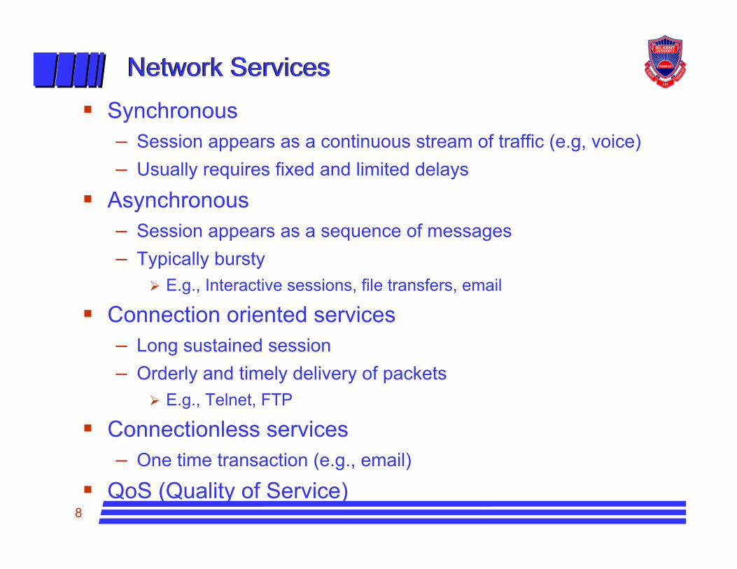
Network ServicesNetwork ServicesSynchronous– Session appears as a continuous stream of traffic (e.g, voice)– Usually requires fixed and limited delays
Asynchronous– Session appears as a sequence of messages– Typically bursty
E.g., Interactive sessions, file transfers, email
Connection oriented services– Long sustained session– Orderly and timely delivery of packets
E.g., Telnet, FTP
Connectionless services– One time transaction (e.g., email)
QoS (Quality of Service)

9
Switching TechniquesSwitching Techniques
Circuit Switching– Dedicated resources
Packet Switching– Shared resources– Virtual Circuits– Datagrams

10
Circuit SwitchingCircuit Switching
Each session is allocated a fixed fraction of the capacity on each link along its path– Dedicated resources– Fixed path– If capacity is used, calls are blocked– E.g., telephone network, 2G wireless systems like GSM
Advantages of circuit switching– Fixed delays– Guaranteed continuous delivery
Disadvantages– Circuits are not used when session is idle– Inefficient for bursty traffic– Circuit switching usually done using a fixed rate stream (e.g., 64 Kbps)– Difficult to support variable data rates

11
Problems of Circuit SwitchingProblems of Circuit Switching
L=message lengths– λ=arrival rate of messages– R=channel rate in bits per second– X=message transmission delay =L/R
R must be large enough to keep X smallBursty traffic => λX << 1 => low utilization
Example– L=1000 bytes (8000 bits)– λ=1 message per second– X<0.1 seconds (delay requirement)=> R> 8000/0.1 = 80,000 bps– Utilization = 8000/80000 = 10%
With packet switching channel can be shared among many sessions to achieve higher utilization

12
Packet SwitchingPacket Switching

13
Packet SwitchingPacket Switching
Datagram packet switching– Route chosen on packet-by-packet basis– Different packets may follow different routes– Packets may arrive out of order at the destination– E.g., IP (The Internet Protocol)
Virtual Circuit packet switching– All packets associated with a session follow the same path– Route is chosen at start of session– Packets are labeled with a VC# designating the route– The VC number must be unique on a given link but can change from
link to linkImagine having to set up connections between 1000 nodes in a meshUnique VC numbers imply 1 Million VC numbers that must be represented and stored at each nodeE.g., ATM (Asynchronous transfer mode)

14
Virtual Circuit Packet SwitchingVirtual Circuit Packet Switching
For datagrams, addressing information must uniquely distinguish each network node and session– Need unique source and destination addresses
For virtual circuits, only the virtual circuits on a link need be distinguished by addressing, – Global address needed to set-up virtual circuit– Once established, local virtual circuit numbers can then be used to
represent the virtual circuits on a given link: VC number changes from link to link
Merits of virtual circuits- Save on route computation, fixed size lookup table- Need only be done once at start of session– Save on header size– Facilitate QoS provisioning– More complex– Less flexible

15
Circuit vs Packet SwitchingCircuit vs Packet SwitchingAdvantages of packet switching– Efficient for bursty data– Easy to provide bandwidth on demand with variable rates
Disadvantages of packet switching– Variable delays– Difficult to provide QoS assurances (Best-effort service)– Packets can arrive out-of-order
ConnectionlessDatagram
Connection orientedVirtual circuits
Asynchronous (e.g., Data)Packet switching
Synchronous (e.g., voice)Circuit switching
Network serviceSwitching Technique
16
Circuit vs Packet SwitchingCircuit vs Packet Switching
Can circuit switched network be used to support data traffic?Can packet switched network be used for connection oriented traffic (e.g., voice)?Need for Quality of service (QoS) mechanisms in packet networks– Guaranteed bandwidth– Guaranteed delays– Guaranteed delay variations– Packet loss rate– Etc...
17
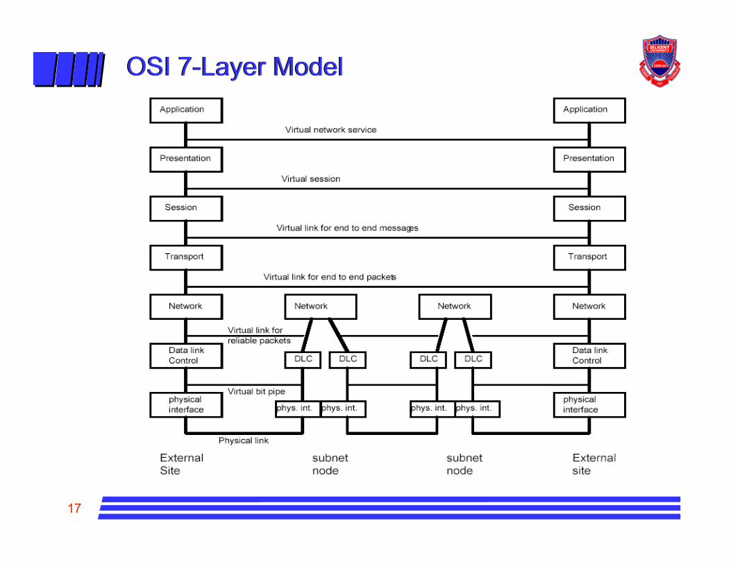
OSI 7-Layer ModelOSI 7-Layer Model
18
LayersLayers
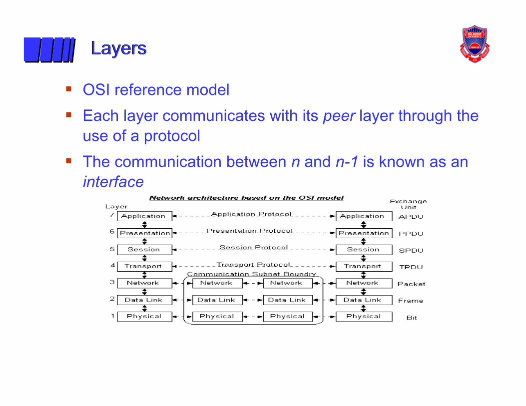
OSI reference model Each layer communicates with its peer layer through the use of a protocolThe communication between n and n-1 is known as an interface
19
LayersLayers
Physical Layer– The physical later is concerned with transmitting raw bits over a
communication channel. – The design issues have to do with making sure that when one side
sends a 1 bit, it is received by the other side as a 1 bit, not as a 0 bit. – Typical questions here are how many volts should be used to represent
a 1 and how many for a 0, how many microseconds a bit lasts, whether transmission may proceed simultaneously in both directions, how the initial connection is established and how it is torn down when both sides are finished, and how many pins the network connector has and what each pin is used for.
– The design issues here deal largely with mechanical, electrical, and procedural interfaces, and the physical transmission medium, which lies below the physical layer. Physical layer design can properly be considered to be within the domain of the electrical engineer.
– Examples: RS232C, X.25, Ethernet

20
LayersLayers
Data Link Control Layer– Sometimes called the link layer transmits chunks of information
across a link.– It deals with problems such as
FramingChecksumming to detect data corruptionError correction
• RetransmissionsCoordinating the use of shared media as in LAN (Local Area Network); and addressing (when multiple systems are reachable asin a LAN)
– It is common for different links to implement different data link layers and for a node to support several data link layer protocols, one for each of the types of links to which the node is attached.
– Example: HDLC, SDLC, X.25, Ethernet, ATM

21
LayersLayers
Network Layer– The network layer enables any pair of systems to communicate with
each other.– A fully connected network is one in which every pair of nodes has a
direct link between its nodes, but this kind of topology does not scale beyond a few nodes
– Network layer must find a path through a series of connected nodes and nodes along the path should forward packets in the appropriate direction.
– The network layer deals with problems such as route calculation, packet assembly and reassembly (when different links on the path have different maximum packet sizes), and congestion control.
– Examples: IP, IPX, ATM– The network layer provides a virtual end to end packet pipe to the
transport layer packets

22
LayersLayers
Transport Layer– This layer provides a reliable communications stream between a pair of
systems– It deals with errors that can be introduced by the network layer, such as
lost packets, duplicated packets, packet reordering, and fragmentation and reassembly
– It is also nice if the transport layer reacts to congestion in the network– Example: TCP (Transmission Control Protocol)– The transport layer provides a virtual end to end message service to the
higher layers.– The functions of the transport layer are:
Break messages into packets and reassemble packets of size suitable to network layerMultiplex sessions with same source/destination nodesResequence packets at destination Recover from residual errors and failures Provide end-to-end flow control
23
Layers Layers
Session Layer– The session layer assumes that a reliable virtual point-to-point
connection has been made and contains specs for the dialog between the two end systems such as dialog discipline, data grouping, and recovery of an interrupted session. Specs are also included for initiating and concluding a session. Many network specs contain little or no session specs and leave these decisions to the applications.
Presentation Layer– Provides transformation of data to standardize the application interface.
Also provides some network services such as encryption, compression, and text re-formatting.
Application Layer– This layer plays the same role as the 'application interface' in operating
systems. Provides network services to users (applications) of the network in a distributed processing environment: examples transaction server, file transfer protocol, network management, electronic mail, and terminal access to remote applications.
24
Service ModelsService Models
Layer n-1 can provide either a connectionless service or connection-oriented service– Communication consists of three phases in a CO-service
Connection setupData transferConnnection release
– Associated with each of these phases are two functions:Layer n initiates the functionLayer n-1 informs layer n that some layer n process in some other node is requesting a connection
Services can vary in their degree of reliability– Datagram service (also known as best-effort) accepts data but makes
no guarantees as to delivery in that data may be lost, duplicated, delivered out of order, or mangled.
– A reliable service guarantees the data will be delivered in the order transmitted, without corrupting, duplication or loss.

25
ExamplesExamples
X.25Reliable
IP, IPX, DECnetATMDatagram
Connectionless
Connection-oriented
Service
• In the TCP/IP protocol suite, network layer is connectionless, TCP offers reliable connection-oriented service, UDPs datagram service• ATM offers a connection-oriented, unreliable service that can be viewed as a network layer. For IP over ATM, ATM is viewed by IP as a data link layer• It’s good to know about layering but it should not be taken that seriously; however it is a good learning and communication tool.

26
TCP/IP StackTCP/IP Stack
Application– Some TCP/IP application layer protocols are full-fledged user
applications which generate network-service requests, such as TELNET and FTP. Other protocols provide support to applications in the form of services, such as the Domain Name System (DNS) and the Simple Network Management Protocol (SNMP).
Transport– As in the OSI model, the transport layer provides end-to-end
communications services in the form of two protocols: the Transmission Control Protocol (TCP) and the User Datagram Protocol (UDP).
Internet– The internet layer contains IP (the Internet Protocol), which is
responsible for the packaging, addressing, and routing of data to its destination. Also operating at this layer are the Internet Control Message Protocol (ICMP) and the Internet Group Management Protocol (IGMP).

27
TCP/IP StackTCP/IP StackLink– The link layer contains protocols used to facilitate the transmission of IP
data over the existing network medium. The TCP/IP standards do not define the functionality of the OSI data link and physical layers. Instead, the standards define protocols like the Address Resolution Protocol (ARP) that provide an interface between TCP/IP and physical layer
Application
Internet
PresentationSession
TransportNetwork
Data Link
Application
Physical
Transport TCP, UDP
Link
OSI Reference
Model
TCPIP
Stack

28
Internet protocol stackInternet protocol stack
application: supporting network applications– ftp, smtp, http
transport: host-host data transfer– tcp, udp
network: routing of datagrams from source to destination– ip, routing protocols
link: data transfer between neighboring network elements– ppp, ethernet
physical: bits “on the wire”
application
transport
network
link
physical
29
Layering: logical communication Layering: logical communication
applicationtransportnetwork
linkphysical
applicationtransportnetwork
linkphysical application
transportnetwork
linkphysical
applicationtransportnetwork
linkphysical
networklink
physical
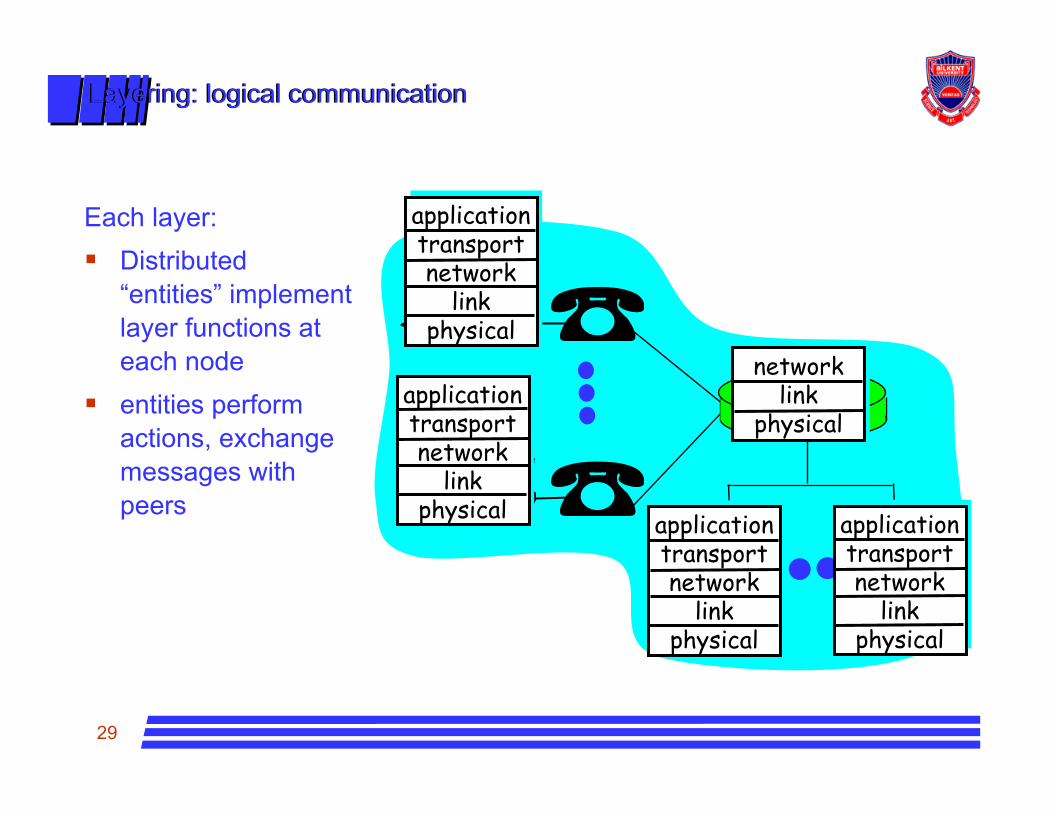
Each layer:Distributed “entities” implement layer functions at each nodeentities perform actions, exchange messages with peers

30
Layering: logical communication Layering: logical communication
applicationtransportnetwork
linkphysical
applicationtransportnetwork
linkphysical application
transportnetwork
linkphysical
applicationtransportnetwork
linkphysical
networklink
physical
data
dataE.g.: transport
take data from appadd addressing, reliability check info to form “datagram”send datagram to peerwait for peer to ack receipt
data
transport
transport
ack

31
Protocol layering and dataProtocol layering and data
Each layer takes data from aboveadds header information to create new data unitpasses new data unit to layer below
applicationtransportnetwork
linkphysical
applicationtransportnetwork
linkphysical
source destinationMMMM
Ht
HtHnHtHnHl
MMMM
Ht
HtHnHtHnHl
messagesegmentdatagramframe

32
Internet structure: network of networksInternet structure: network of networks
roughly hierarchicalnational/international backbone providers (NBPs)– e.g. BBN/GTE, Sprint, AT&T,
IBM, UUNet– interconnect (peer) with each
other privately, or at public Network Access Point (NAPs)
regional ISPs– connect into NBPs
local ISP, company– connect into regional ISPs
NBP A
NBP B
NAP NAP
regional ISP
regional ISP
localISP
localISP
Related Documents