Page : 1/39 Company Profile Tel. : (+66) 0 2728-7582 Fax : (+66) 0 2728-1779 [email protected] www.Enertric.com Reference ©Copyright by Enertric Basic systems Info Enertric Limited…..Company Profile Scope of Work Systems Integrated of Electrical systems Design and Install Electrical Power Communication, Telephone, CCTV Scada and control system equipment Integrate with software for monitoring and supervisory control Consult and Improve the existing system. Design and install Programming control control systems •Address: 25/113 Soi RamKhamHaeng 124, Saphansoong, SaphanSoong, Bangkok 10240 •Tel : (66) 2728 7582, Fax:(66) 2728 1779 www.enertric.com Introduce Introduce

Welcome message from author
This document is posted to help you gain knowledge. Please leave a comment to let me know what you think about it! Share it to your friends and learn new things together.
Transcript

Page : 1/39 Company Profile
Tel. : (+66) 0 2728-7582 Fax : (+66) 0 2728-1779
www.Enertric.com
Reference
©Copyright by Enertric
Introduce Basic systems Info
Enertric Limited…..Company Profile
Scope of Work
Systems Integrated of Electrical systems Design and Install Electrical Power Communication, Telephone, CCTV Scada and control system equipment Integrate
with software for monitoring and supervisory control
Consult and Improve the existing system. Design and install Programming control control
systems
•Address: 25/113 Soi RamKhamHaeng 124, Saphansoong, SaphanSoong, Bangkok 10240
•Tel : (66) 2728 7582, Fax:(66) 2728 1779 www.enertric.com
Introduce
Introduce

Page : 2/39 Company Profile
Tel. : (+66) 0 2728-7582 Fax : (+66) 0 2728-1779
www.Enertric.com
Reference
©Copyright by Enertric
Introduce Basic systems Info
ประวติั ความเป็นมาของบริษทัฯ
บรษัิท เอ็นเนอรท์รคิ จํากดั ใหบ้รกิารแบบครบวงจร ตามหลกัวศิวกรรม เพือ่ความปลอดภยัและประหยดั ดําเนนิงานอยา่งมอือาชพี
ออกแบบระบบไฟฟ้าเพือ่การตดิตัง้ หรอื เพือ่ปรับปรงุระบบไฟฟ้าในโรงงานอตุสาหกรรม ประกอบตูส้วทิชบ์อรด์,ตูค้วบคมุมอเตอร ์และระบบควบคมุเครือ่งจักรทกุประเภท ออกแบบ ตดิตัง้ระบบสํารองไฟฟ้า ออกแบบ ตดิตัง้ระบบจา่ยไฟฟ้าอตัโนมัต ิ ตดิตัง้ระบบลอ่ฟ้า / ระบบป้องกนัอนัตรายฟ้าผา่อาคารสงู ใหคํ้าปรกึษาดา้นปัญหาไฟฟ้า,การควบคมุเครือ่งจักรเพือ่การประหยัดพลงังาน ระบบดบัเพลงิ งานระบบทอ่ และอืน่ๆ
Introduce

Page : 3/39 Company Profile
Tel. : (+66) 0 2728-7582 Fax : (+66) 0 2728-1779
www.Enertric.com
Reference
©Copyright by Enertric
Introduce Basic systems Info
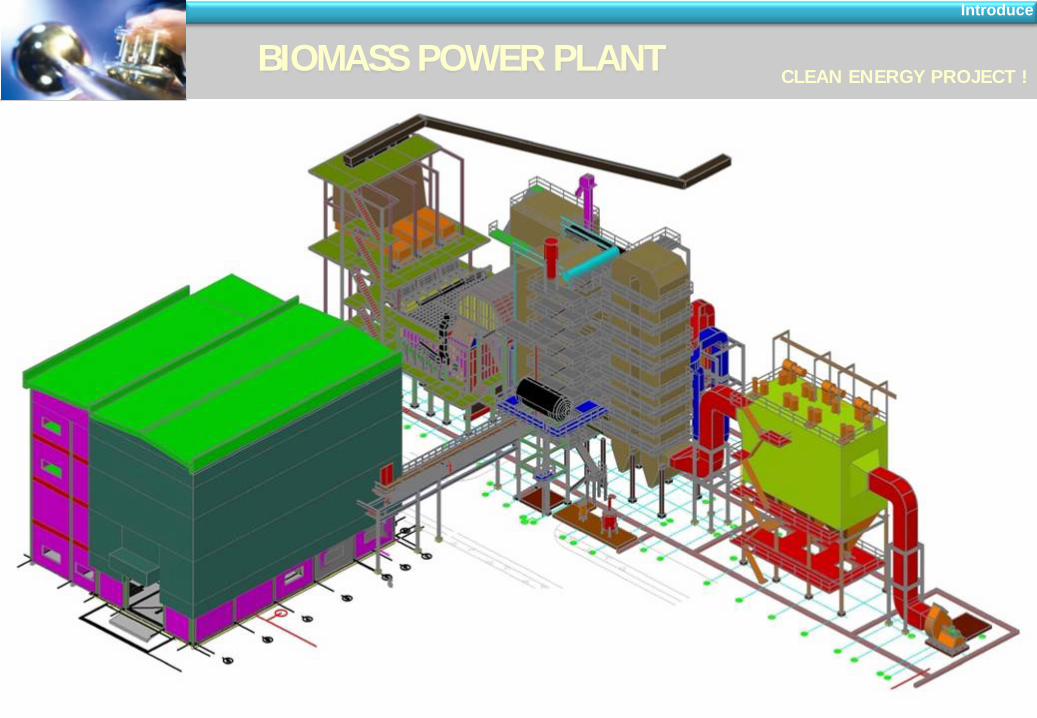
BIOMASS POWER PLANT CLEAN ENERGY PROJECT !
Introduce
Introduce
Design and Turnkey กอ่สรา้งโรงไฟฟ้า Bio Mass Power Plant

Page : 4/39 Company Profile
Tel. : (+66) 0 2728-7582 Fax : (+66) 0 2728-1779
www.Enertric.com
Reference
©Copyright by Enertric
Introduce Basic systems Info
BIOMASS POWER PLANT CLEAN ENERGY PROJECT !
Introduce
Introduce
Page : 5/39 Company Profile
Tel. : (+66) 0 2728-7582 Fax : (+66) 0 2728-1779
www.Enertric.com
Reference
©Copyright by Enertric
Introduce Basic systems Info
BIOMASS POWER PLANT CLEAN ENERGY PROJECT !
Introduce
Introduce

Page : 6/39 Company Profile
Tel. : (+66) 0 2728-7582 Fax : (+66) 0 2728-1779
www.Enertric.com
Reference
©Copyright by Enertric
Introduce Basic systems Info
Basic systems Info
Basic systems of Biomass process General information

Page : 7/39 Company Profile
Tel. : (+66) 0 2728-7582 Fax : (+66) 0 2728-1779
www.Enertric.com
Reference
©Copyright by Enertric
Introduce Basic systems Info
Basic systems Info
Basic systems of Biomass process General information

Page : 8/39 Company Profile
Tel. : (+66) 0 2728-7582 Fax : (+66) 0 2728-1779
www.Enertric.com
Reference
©Copyright by Enertric
Introduce Basic systems Info
ข ัน้ตอนการเผาแกลบ และดกัเถา้แกลบ General information
Basic systems Info

Page : 9/39 Company Profile
Tel. : (+66) 0 2728-7582 Fax : (+66) 0 2728-1779
www.Enertric.com
Reference
©Copyright by Enertric
Introduce Basic systems Info
RICE HUSK WOOD CHIPS & WASTE WOOD
ลกัษณะของเชือ้เพลงิ Biomass General information
Basic systems Info

Page : 10/39 Company Profile
Tel. : (+66) 0 2728-7582 Fax : (+66) 0 2728-1779
www.Enertric.com
Reference
©Copyright by Enertric
Introduce Basic systems Info
Fuel Conveyor
The fuel can be transported from fuel storage by:
- moving floor
-chain or belt conveyors (horizontal)
- Conveyors and bucket elevators.
Basic systems Info

Page : 11/39 Company Profile
Tel. : (+66) 0 2728-7582 Fax : (+66) 0 2728-1779
www.Enertric.com
Reference
©Copyright by Enertric
Introduce Basic systems Info
Moving floor:
The storage capacity of the moving floor is appr. 6 hours. The moving floor is
load by front end loader.
Chain or belt conveyors
Bucket elevators
Fuel supply systems Basic systems Info

Page : 12/39 Company Profile
Tel. : (+66) 0 2728-7582 Fax : (+66) 0 2728-1779
www.Enertric.com
Reference
©Copyright by Enertric
Introduce Basic systems Info
40 MW EtaComb furnace during erection
View inside of a 40 MW furnace
ETAComb FURNACE/Combusion
Moving grates
multi fuel dosing
chambercombustion
post combustionchamber
rice husk dosing
Basic systems Info

Page : 13/39 Company Profile
Tel. : (+66) 0 2728-7582 Fax : (+66) 0 2728-1779
www.Enertric.com
Reference
©Copyright by Enertric
Introduce Basic systems Info
EQUIPMENT FOR THE STEAM CYCLE At this page the main equipment for the steam cycle is shown
Feed water tank / deaerator: The feed water tank contains a one hour feed water reserve at boiling temperature. The tank is heated up by turbine bleeding steam. Further more the dissolved oxygen and CO2in the feed water will be removed.
Boiler feed water pump
This pump is a high pressure pump that transfers the condense from feed water tank into the steam boiler. The discharge pressure of these pumps is higher than live steam operation pressure.
Condense pump
The condense pumps are low pressure pumps that transfers the condensate from steam condenser or low pressure heater to the feed water tank.
cooling water pump
The cooling water pumps are designed for high volume flows to supply the cooling water from cooling towers or natural sources to the steam condenser.
Valves and piping: The valves in the plant can be operate with electric and pneumatic drives or manual.
Demin water plant: During plant operation boiler water from steam cycle is lost. This loss has to be balanced by demineralized water that is produced by the demin plant. The demin water plant refurbishes the water from natural sources into water with boiler water quality (removal of all dissolved materials). The plant consists of different filters, RO membranes, mixed bed polisher and chemical dosing units.
Basic systems Info

Page : 14/39 Company Profile
Tel. : (+66) 0 2728-7582 Fax : (+66) 0 2728-1779
www.Enertric.com
Reference
©Copyright by Enertric
Introduce Basic systems Info
economizer
air preheater
radiant chamber
Steam boiler
The flue gas heat coming from ETAComb furnace passes the boiler and generates the steam. The used boiler type is a water-tube boiler. The hot flue gas passes the boiler trough radiant chamber, two stage superheated, evaporator, economiser and air preheated. The flue gas is cooled down in the boiler up to 160°C. The transferred heat heats up the boiler feed water and generates the superheated steam with temperature up to 450°C.
feed water - in (120°C)
live steam – out (450°C)
evaporator
evaporator
flue gas - in (950°C)
flue gas - out (160°C)
superheater
designed by
LAWI Engineering GmbH
WASTE HEAT STEAM BOILER
Basic systems Info

Page : 15/39 Company Profile
Tel. : (+66) 0 2728-7582 Fax : (+66) 0 2728-1779
www.Enertric.com
Reference
©Copyright by Enertric
Introduce Basic systems Info
STEAM BOILER
Basic systems Info

Page : 16/39 Company Profile
Tel. : (+66) 0 2728-7582 Fax : (+66) 0 2728-1779
www.Enertric.com
Reference
©Copyright by Enertric
Introduce Basic systems Info
Fuel gas Dedusting
Fuel gas deducting
The flue gas cleaning plant controls the environmental dust pollution and the life time of the recirculation gas duct system and recirculation gas fan.
For cleaning of the recirculation gas multi cyclones are used that can remove the fly ash to sufficient clean gas values.
The bag filter is used for cleaning the flue gas that passes the stack. With a bag filter the dust content could be reduced up to <10 mg/m³.
The result is that the ETAPlant emissions couldn‘t be observed at the stack. Flue gas bag filter
Bag filter elements
Multi stage cyclone
Basic systems Info

Page : 17/39 Company Profile
Tel. : (+66) 0 2728-7582 Fax : (+66) 0 2728-1779
www.Enertric.com
Reference
©Copyright by Enertric
Introduce Basic systems Info
Cooling Systems And Condensing
Wet cooling tower – fan driven
Condensing and cooling system
The condensing and cooling system consists of the steam condenser that returns the steam fully into liquid form. The condensing process emits heat that is transferred to the cooling water. The cooling water for the condenser is supplied from the cooling tower. After condenser the water is heated up to 40°C. This warmed up water returns back to the cooling tower and it will be sprayed in this one. The water is cooled down by water evaporation and ambient air at atmospheric conditions and is collected at cooling water basin. From here it feeds the steam condenser by cooling water pump.
Water cooled steam condenser
„Cold end“ of the power plant
Basic systems Info

Page : 18/39 Company Profile
Tel. : (+66) 0 2728-7582 Fax : (+66) 0 2728-1779
www.Enertric.com
Reference
©Copyright by Enertric
Introduce Basic systems Info
Turbine Generator
Complete mounted turbine with gear box
Steam extraction turbine – cross section
Turbine generator plant – schematic drawing
Turbo generator plant The turbo generator plant consists of the steam turbine and the generator.
The generator is driven by a steam condensing turbine. The steam expands in the turbine and turns the turbine shaft. The turbine shaft is connected with the generator shaft by gear. The expansion of the steam is generally performed in multi stages. After some stages an amount of steam is bleeder of the turbine and is used for heat recovery. The pressure at the turbine exhaust side is bellow the atmospheric pressure. This allows a high electric efficiency.
To avoid a overheating of the generator it is air / water cooled.
Basic systems Info

Page : 19/39 Company Profile
Tel. : (+66) 0 2728-7582 Fax : (+66) 0 2728-1779
www.Enertric.com
Reference
©Copyright by Enertric
Introduce Basic systems Info
Eefficiency Increasing
Under the point of view of worldwide raising fuel costs and shortage in fuel supply an advanced power plant should be well engineered to achieve a good plant efficiency.
The main target is to reduce the heat losses at the plant and to increase the electric energy production. The main heat losses are: - the cooling tower air/evaporation loss (heat transfer from steam condenser) can be reduced by bleeding steam heated condensate repeaters and the flue gas heat loss at stack can be reduced by patented ETAComb recirculation gas technology.
Basic systems Info

Page : 21/39 Company Profile
Tel. : (+66) 0 2728-7582 Fax : (+66) 0 2728-1779
www.Enertric.com
Reference
©Copyright by Enertric
Introduce Basic systems Info
Enertric ผลงานทีผ่า่นมา / Project and Working reference
ผลงานทีผ่า่นมา : Reference
Electrical Power System • HT/Medium Voltage 22 kV system • Power Transformer 22/11 kV • HV/MV Switch Gear 22 kV • DC Power supply 110 VDC systems • UPS 3AC/1AC systems • NGR Panel • MDB/MCB/MCC Panel • Power Factor Correction (CAP Bank) • Power plug / Lighting Systems • Diesel Standby Generator • Grounding /Lightning System
Automation / Control System • DCS/PLC systems • Instruments / Process controller • Variable Speed Drives • Soft Starter Panel (SST) • CCTV Systems
Mechanical Systems • Water pumping / Piping systems • Fire Fighting Systems • Blower Installation • Motor Installation • HDPE Pipe, Galvanize pipe • Valve and accessories

Page : 22/39 Company Profile
Tel. : (+66) 0 2728-7582 Fax : (+66) 0 2728-1779
www.Enertric.com
Reference
©Copyright by Enertric
Introduce Basic systems Info

Page : 23/39 Company Profile
Tel. : (+66) 0 2728-7582 Fax : (+66) 0 2728-1779
www.Enertric.com
Reference
©Copyright by Enertric
Introduce Basic systems Info
Reference : Electrical work
หมอ้แปลง / TR 15MVA 22 kV Design / Supply / Installation
“EKARAT” Transformer Power : 12.5/15 MVA Voltage : 22/11 kV Type : YNd11, 50 Hz : ONAF Oil OLTC 17 Step +/- 8x1.25%

Page : 24/39 Company Profile
Tel. : (+66) 0 2728-7582 Fax : (+66) 0 2728-1779
www.Enertric.com
Reference
©Copyright by Enertric
Introduce Basic systems Info
MV 22 kV SWGs, Design / Supply / Installation
Reference : Electrical work

Page : 25/39 Company Profile
Tel. : (+66) 0 2728-7582 Fax : (+66) 0 2728-1779
www.Enertric.com
Reference
©Copyright by Enertric
Introduce Basic systems Info
Reference : Electrical work
“SIEMENS” Bus duct 2500 A Design / Supply / Installation

Page : 26/39 Company Profile
Tel. : (+66) 0 2728-7582 Fax : (+66) 0 2728-1779
www.Enertric.com
Reference
©Copyright by Enertric
Introduce Basic systems Info
Reference : Electrical work
ตูไ้ฟฟ้า LV MDB/MCCB SWGs Design / Supply / Installation

Page : 27/39 Company Profile
Tel. : (+66) 0 2728-7582 Fax : (+66) 0 2728-1779
www.Enertric.com
Reference
©Copyright by Enertric
Introduce Basic systems Info
Reference : Electrical work
ตูไ้ฟฟ้า LV MDB/MCCB SWGs Design / Supply / Installation

Page : 28/39 Company Profile
Tel. : (+66) 0 2728-7582 Fax : (+66) 0 2728-1779
www.Enertric.com
Reference
©Copyright by Enertric
Introduce Basic systems Info
Reference : Electrical work
ตูไ้ฟฟ้า LV MDB/MCCB SWGs Design / Supply / Installation

Page : 29/39 Company Profile
Tel. : (+66) 0 2728-7582 Fax : (+66) 0 2728-1779
www.Enertric.com
Reference
©Copyright by Enertric
Introduce Basic systems Info
Reference : Electrical work
Standby Diesel Generator Design / Supply / Installation
Engine : “CUMMIN” 6LTAA8.9-G2 (DCEC) Alternator : “STAMFORD” UCDI 274 K Power : 250 KVA Standby Rated Voltage : 400 V3AC 50 Hz

Page : 30/39 Company Profile
Tel. : (+66) 0 2728-7582 Fax : (+66) 0 2728-1779
www.Enertric.com
Reference
©Copyright by Enertric
Introduce Basic systems Info
Grounding Design and Installation
Reference : Electrical work

Page : 31/39 Company Profile
Tel. : (+66) 0 2728-7582 Fax : (+66) 0 2728-1779
www.Enertric.com
Reference
©Copyright by Enertric
Introduce Basic systems Info
Reference : Electrical work
ระบบป้องกนัฟ้าผา่ / Lightning at stracker Design / Supply / Installation

Page : 32/39 Company Profile
Tel. : (+66) 0 2728-7582 Fax : (+66) 0 2728-1779
www.Enertric.com
Reference
©Copyright by Enertric
Introduce Basic systems Info
Under ground Electrical HDPE work, Design / Supply / Installation
Reference : Electrical work

Page : 33/39 Company Profile
Tel. : (+66) 0 2728-7582 Fax : (+66) 0 2728-1779
www.Enertric.com
Reference
©Copyright by Enertric
Introduce Basic systems Info
SCADA/PLC Automation Systems Design / Supply / Installation
Reference : Electrical work

Page : 34/39 Company Profile
Tel. : (+66) 0 2728-7582 Fax : (+66) 0 2728-1779
www.Enertric.com
Reference
©Copyright by Enertric
Introduce Basic systems Info

Page : 35/39 Company Profile
Tel. : (+66) 0 2728-7582 Fax : (+66) 0 2728-1779
www.Enertric.com
Reference
©Copyright by Enertric
Introduce Basic systems Info
Cooling Water pump 3 set
Flow rated : 1300 Qm/hr
Head : 24 M
Motor Power : 132 kW.
Cooling water pump installation Design / Supply / Installation
Reference : Mechanical work

Page : 36/39 Company Profile
Tel. : (+66) 0 2728-7582 Fax : (+66) 0 2728-1779
www.Enertric.com
Reference
©Copyright by Enertric
Introduce Basic systems Info
Under ground piping work, Design / Supply / Installation
Reference : Mechanical work
Under Ground piping work
We are EPC with design, Supply, Installation of under ground HDPE piping DN630 for cooling water from cooling tower to condenser unit with flow rate 1300 Qm/hr.

Page : 37/39 Company Profile
Tel. : (+66) 0 2728-7582 Fax : (+66) 0 2728-1779
www.Enertric.com
Reference
©Copyright by Enertric
Introduce Basic systems Info
Under ground piping work, Design / Supply / Installation
Reference : Mechanical work
Under Ground piping work
We are EPC with design, Supply, Installation of under ground HDPE piping DN250 for Auxiliary cooling water from cooling tower to turbine Generator and Screw jacket unit with flow rate 300 Qm/hr.

Page : 38/39 Company Profile
Tel. : (+66) 0 2728-7582 Fax : (+66) 0 2728-1779
www.Enertric.com
Reference
©Copyright by Enertric
Introduce Basic systems Info
Fire pump / piping / Fire hose systems Design / Supply / Installation
Reference : Mechanical work

Page : 39/39 Company Profile
Tel. : (+66) 0 2728-7582 Fax : (+66) 0 2728-1779
www.Enertric.com
Reference
©Copyright by Enertric
Introduce Basic systems Info
THANK YOU FOR COOPERATION
Related Documents