Updated March 2015 16751-1 SECTION 16751 MC - INTRABUILDING DATA/COMMUNICATION CABLE SYSTEMS PART 1 - GENERAL A. RELATED DOCUMENTS: 1. Division 16 Basic Materials and Methods sections apply to work specified in this section. The Contractor is held responsible to be familiarized with the provisions contained therein and in this Section. 2. Additional Notes: 3. UT Rack Layout Prototype: Section 16751-Page-73 4. UT IT Closet Build Characteristics: Section 16751- Page-75 5. Parts List Update for Intra Building: Appendix “A”-Section 16751- Page -65 6. IT Standards Cheat Sheet Section 16751 Page 79 B. SCOPE OF WORK: 1. Types of data/communication cable systems specified in this section include the following: a. Fiber Optic Cable Systems b. Telephone/Voice Communication Cable Systems c. Data/Telecommunication Cable Systems d. Multi-Media/CATV Communication Cable Systems e. Associated Conduit Raceway Distribution and Equipment Rack/Cabinet Systems F. Wireless Page 35 “T” G. Security Cameras-Page 35 “TT” 2. The Contractor shall furnish, install and test as required: conduits, conduit boxes, pull-boxes, conduit bushings, cable trays, cables, cable supports, cable ladders, cable ladder hardware, conduit sleeves, fire-stopping, fiber optic cable, fiber optic patch cords, fiber optic patch panels, inner duct, pull- rope, user voice cable, user data cable, voice and data patch cords and connectors, Category-6 and Category-3 patch panels, patch panel organizers, 66M1-50 Blocks and 89B/D Brackets, system and cable labels and designation strips, data equipment racks, equipment shelves, grounding, distribution blocks, interconnection cables, etc., as indicated on the Engineering Drawings and in this and other specifications and other contract documents. 3. The Contractor shall bid the project as specified and shown on the drawings and documents. The drawings illustrate the work specified and

Welcome message from author
This document is posted to help you gain knowledge. Please leave a comment to let me know what you think about it! Share it to your friends and learn new things together.
Transcript

Updated March 2015 16751-1
SECTION 16751 MC - INTRABUILDING DATA/COMMUNICATION CABLE SYSTEMS PART 1 - GENERAL A. RELATED DOCUMENTS:
1. Division 16 Basic Materials and Methods sections apply to work specified in this section. The Contractor is held responsible to be familiarized with the provisions contained therein and in this Section.
2. Additional Notes: 3. UT Rack Layout Prototype: Section 16751-Page-73 4. UT IT Closet Build Characteristics: Section 16751- Page-75 5. Parts List Update for Intra Building: Appendix “A”-Section 16751- Page -65 6. IT Standards Cheat Sheet Section 16751 Page 79 B. SCOPE OF WORK: 1. Types of data/communication cable systems specified in this section
include the following: a. Fiber Optic Cable Systems b. Telephone/Voice Communication Cable Systems c. Data/Telecommunication Cable Systems d. Multi-Media/CATV Communication Cable Systems e. Associated Conduit Raceway Distribution and Equipment
Rack/Cabinet Systems F. Wireless Page 35 “T” G. Security Cameras-Page 35 “TT” 2. The Contractor shall furnish, install and test as required: conduits, conduit
boxes, pull-boxes, conduit bushings, cable trays, cables, cable supports, cable ladders, cable ladder hardware, conduit sleeves, fire-stopping, fiber optic cable, fiber optic patch cords, fiber optic patch panels, inner duct, pull-rope, user voice cable, user data cable, voice and data patch cords and connectors, Category-6 and Category-3 patch panels, patch panel organizers, 66M1-50 Blocks and 89B/D Brackets, system and cable labels and designation strips, data equipment racks, equipment shelves, grounding, distribution blocks, interconnection cables, etc., as indicated on the Engineering Drawings and in this and other specifications and other contract documents.
3. The Contractor shall bid the project as specified and shown on the
drawings and documents. The drawings illustrate the work specified and

Updated March 2015 16751-2
are intended to agree in every respect with one another and with the specifications. Any discrepancies shall be brought to the attention of the Associate for correction. No omission from any drawing shall release the Contractor from furnishing equipment, materials or services called for by the specifications or other drawings.
** [4. The Contractor, the Cable Manufacturer, the Connectivity Manufacturer and the Distributor shall collaborate and work in partnership with one another as to provide the Owner with a U.L. or E.T.L. independently verified cabling installation that is guaranteed to perform at levels above and beyond the EIA/TIA-568-B-1, -B2, -B2 Addendum 1, -B3 and specifications for Category-6 standards, as per the minimum acceptable Full Channel Performance specification contained herein. The partnership shall make available optional U.L. or E.T.L. independent testing and verification of the completed installation. The partnership shall provide full written registration and certification of the installation under the "VIP 2000" program or Associate/Owner approved equal to the Owner upon completion.] 5. Qualified bidders are encouraged to submit a voluntary alternate proposal
based upon the design criteria contained herein, meeting all specifications and standards for installation and materials. The voluntary alternate proposal shall include only the substitution of materials and equipment as per Appendix "A" Owner/Associate approved material list.
6. Any deviation, alteration, or substitution from the drawings and
specifications shall be fully documented by the Contractor and submitted as a voluntary alternate to the base bid with the amount of deduct to the base bid specified. Approval of requests for substitution of products, processes, or procedures other than those specified will be contingent upon submission of fully acceptable documentation to the Associate and shall be the sole decision of the Associate.
7. All equipment furnished shall be new and of the quality specified in the
specification. No equipment may be furnished that has ever been in use either in the present installation or in another installation except as noted in the project specification or the drawings.
8. Products that are submitted for substitution must be electrically and
mechanically interchangeable with the specified product. Substitutions will only be allowed with written approval of the Associate. Samples of proposed substitutions must be submitted prior to approval at the discretion of the Associate. Any substitutions without the written approval of the Associate are done so at the risk of the Contractor. Substitutions unacceptable to the Associate will be rejected without explanation or appeal.
9. The Contractor shall clean and organize his work areas daily. He shall be

Updated March 2015 16751-3
responsible for maintaining cleanliness in all work areas so as to not ** Delete if Annex “F” is utilized (Use for minor renovation projects only, Utilize Annex “F” for
all major renovations and all new construction) adversely affect other trades, Contractors, vendors, suppliers, or the Owner
in the timely installation of equipment and/or implementation and completion of concurrent responsibilities.
10. The Contractor shall also be responsible for protecting any and all
equipment and materials from damage during his installation process. Any equipment, material and/or facilities damaged by the Contractor during, or due to, or in the performance of his contract, shall be replaced or repaired at the expense of the Contractor as directed by the Associate.
11. All drawings, specifications and other contract documents, and the Owner's
proprietary information shall be returned to the Owner/Associate/Architect upon satisfactory completion of the contractual work as per the contract documents.
12. The Contractor shall provide for a manufacturers certified and warranted
installation with an extended guarantee. The warranty shall be based fully upon the design criteria contained herein, meeting all specifications and standards for installation and materials. The warranty shall include shop drawings and cut sheets on all equipment and materials, documentation verifying the Contractors certification by the manufacturer, details of the manufacturer’s certification program, and full details of the extended warranty. The warranty shall be provided by the cable manufacturer and supported by the connectivity manufacturer.
C. QUALITY ASSURANCE: 1. Manufacturers: Firms regularly engaged in the manufacture of data and
communication cabling system components of the types specified herein and on the drawings and whose products have been satisfactorily used in similar applications for not less than five years.
** [2. Data/Telecommunications Contractor: Shall be fully capable and
experienced in the information transport systems specified. This contractor and/or all subcontractors engaged in this Data/Telecommunications Installation, shall have experience in the business of Data/ Telecommunications Systems installations of not less than five (5) years and shall have successfully completed a minimum of five (5) projects of similar size and complexity. They shall be fully capable and experienced in the information transport systems specified and shall provide at minimum five (5) reference accounts at which similar work (both in scope and design) has been successfully completed by the Contractor and his sub-

Updated March 2015 16751-4
contractor(s) within the last five (5) years. Client reference information shall include but not be limited to the following items:
** Delete if Annex “F” is utilized (Use for minor renovation projects only, Utilize Annex “F” for
all major renovations and all new construction) a. Client Company Name and Address b. Contact Name, Title and Telephone Number c. Installation Start-up, Completion & Acceptance Dates d. Brief Description of Project] ** [3. Failure to provide client reference accounts and project information will
eliminate the bid from consideration.] ** [4. The Contractor shall specify all sub-contractors who will be utilized in the
project. The bid will include: a. Sub-Contractor responsibilities and scope of work b. Supportive documentation verifying sub-contractor qualifications] ** [5. The Associate may, with full cooperation of the Contractor, visit client
installations to observe equipment operations and consult with references. Specified visits shall be arranged by the Contractor. However, the Contractor may not be present during discussions with references.]
*** [6. Reference “Annex F” for detailed Contractor qualifications,
registrations, certifications, reference submittal requirements.] D. STANDARDS COMPLIANCE: 1. NEC Compliance: Comply with NEC Article 800, National, State and Local
codes as applicable to wiring methods, construction and installation of data and communication cabling systems. Comply with NEC Article 770, National, State and Local codes as applicable to the installation of fiber optic cable systems.
2. NFPA Compliance: Comply with NFPA, National, State and Local codes as
applicable to wiring methods, construction and installation of data and communication cabling systems.
3. NEMA Compliance: Comply with applicable portions of NEMA-250
standards (et.al.) pertaining to electrical and/or communication equipment and enclosures.

Updated March 2015 16751-5
** Delete if Annex “F” is utilized (Use for minor renovation projects only, Utilize Annex “F” for
all major renovations and all new construction) *** Delete if Annex “F” is not utilized 4. EIA/TIA Compliance: Comply with EIA/TIA-568-B1, -B2, -B2 Addendum 1,
-B3, specifications for Category-6, 569A, 606A, 607A, National, State and Local standards for commercial building wiring for voice and data communications as applicable.
5. IEEE, ANSI and ISO Compliance: Comply with data and communication
cabling system standards of IEEE, ANSI and ISO as applicable. 6. U.L. Compliance: All components shall comply with U.L.1863 standards
(et.al.) and be U.L. listed and labeled as applicable. 7. Drawings, specifications and other contract documents are intended to
comply with or exceed industry standards and code requirements. The Contractor shall notify the Associate in writing of any discrepancies or conflicts for resolution. In the absence of a written Associate accepted resolution, the more stringent criteria shall apply.
E. INSPECTION OF WORK/CONSTRUCTION AREA: 1. Authorized representatives of the Owner, Associate and/or Architect shall
have access to the construction site at any reasonable time to inspect equipment, material, the installation and to obtain information on work progress and delivery.
F. ON-SITE PROJECT TEAM: 1. The Project Manager/Foreman will be responsible to the RCDD and
Associate, Architect and/or Owner for all aspects of project quality of installation and compliance with standards, specifications and the Engineering drawings. The Project Manager/Foreman shall have an office at the project site and shall be on-site whenever work is being performed and installation crews are present.
2. The Project Manager/Foreman shall maintain and update all job-related
documentation including but not limited to record drawings, specifications, addenda, and bulletins. He shall keep a master copy of project schedules and as-builts in his office at all times.
*** 3. The Project Manager/Foreman shall be approved by the Associate and
shall be a BICSI Registered Installation Cabling Technician, NJATC certified installer/technician journeyman or an Associate approved equal. The Contractor shall provide the Project Manager's (Foreman's) name,

Updated March 2015 16751-6
resume and supportive documentation for registered installer/ technician, or equal qualifications as directed. [See Annex “F”]
*** Delete if Annex “F” is not utilized 4. All workmanship by the Contractor shall be of the highest quality. All
tradesmen and technicians performing work under this specification and associated data/communication specifications shall be enrolled in or have completed the NJATC installer/technician apprenticeship program, be a BISCI registered installation cabling installer-1/installer-2/technician or an Associate approved equal. All apprentices or tradesmen with two (2) years or less experience after completion of an approved training program shall work under the direct supervision of a BICSI Registered Installation Cabling Installer or a tradesman with a minimum of five (5) years of Associate approved experience after completion of an approved training program.
*** 5. All tradesmen and technicians performing data/telecommunications
installation functions under this specification shall be registered certified installers for the vendor/manufacturers extended warranty program. The Contractor shall provide documentation with his submittal package verifying all tradesmen/technician's registered certification. [See Appendix “F”]
6. The On-Site Project Manager/Foreman shall be a management employee
and shall be minimally involved in personally performing craft installation work. The Project Manager/Foreman shall coordinate all activities and interaction with other trades and Contractors on-site, and he shall direct and supervise all tradesmen and subcontractors working under him.
7. The Contractor shall maintain on the job-site, current updated copies of all
specifications, addenda, bulletins, drawings and other pertinent contract documents. These documents shall be readily and conveniently available to the tradesman and technicians for reference.
8. The Contractor’s Project Manager/Foreman/RCDD shall make weekly
written project progress reports to the Associate. This report shall include, but not be limited to; work completed, problems encountered, corrective solutions proposed, resolution actions approved and/or taken, all changes, bulletin items, alternative proposals or solutions for consideration, approval or implemented, scheduling or delivery problems, conflicts and/or coordination problems with other trades, Contractors or in design elements, etc. This report shall be prepared by the Project Manager/Foreman/RCDD, and shall include the name, company and telephone numbers of all pertinent individuals involved in report items, as applicable (i.e. suppliers, vendor reps, other trades, Owner representatives, etc.)
9. The Contractor's Project Manager/Foreman shall immediately notify the

Updated March 2015 16751-7
Associate of any existing or developing conditions which may adversely affect the quality, completion date or performance of the installation.
*** Delete if Annex “F” is not utilized Notification of the Associate shall be made in a timely manner, as to
minimize or eliminate changes and rework. G. EQUIPMENT WARRANTIES: 1. The Contractor shall guarantee the installation to be free from inherent
defects in design, workmanship and material. The installation shall function properly and continually under all operating conditions required, specified or reasonably implied in the contract documents. The Contractor shall replace, at no expense to the Owner, all equipment, materials or any component thereof, found defective, upon delivery or within two (2) years from date of final inspection and written acceptance by the Owner and/or Associate.
H. SPECIAL CONDITIONS: 1. Computer and voice systems may or may not be required to be taken off-
line or removed from service during this contract. Other specific instructions may be found in the Project Specification accompanying this document.
2. The computer, telephone and other systems associated with this work will
not be taken off-line or removed from service during normal working hours. These systems are critical to the provision of services to the Owner's clients and shall not be interrupted by the Contractor's activities. Arrangements must be made by the Contractor to coordinate any such activities. The Contractor shall be required to work around the above conditions, as well as work with the Owner's staff to minimize disruptions to normal Owner activities.
* 3. The Contractor shall provide timely written notice of the need to disconnect
any existing voice, computer or other system to the Owner and copy the Associate. The Owner, Associate, Architect and Contractor shall schedule such outages as required, directed or as stipulated elsewhere in the project specifications, appendices, or schedules. System outages shall be performed only with the authorized consent of the Owner, Associate and Architect. The Contractor shall perform no testing, outages, modifications, or other functions on active operating systems without prior approval of the Owner, Associate and Architect. The Contractor will be responsible for any damages, expenses incurred, or losses suffered by the Owner or others caused by his unauthorized actions. [Reference Annex “G” for submittal requirements]

Updated March 2015 16751-8
* SPECIFICER TO MAKE SELECTION PART 2 - PRODUCTS A. GENERAL: 1. Design and workmanship shall be in accordance with the requirements of
the contract documents and subject to acceptance by the Associate. Components shall be of the latest type and design, manufactured for the intended use, and shall be laid out and installed so as to afford easy maintenance and/or replacement without major disassembly of adjacent components.
2. All products shall be bid as specified. Any deviation from the products
specified shall be noted in the bid and listed as a voluntary alternate to the base bid with price deducts listed. All substitutions require ten (10) days for evaluation for prior approval by the Associate. Products substituted must be demonstrated to the Associate to be electrically and mechanically interchangeable with the specified product. Samples of the substituted product may be requested from the Contractor to validate claims that the substituted product will meet the electrical and mechanical constraints of the specified product.
* 3. Eight (8) sets of shop drawings shall be submitted in a timely manner for all
specified equipment and substituted equipment to the Associate for approval prior to purchase, installation, or fabrication. Shop drawing submittals shall indicate full complete compliance with all Specifications herein. Shop drawings not indicating full compliance will be returned unapproved for resubmittal. Non-approved materials and equipment shall be immediately removed and replaced at the Contractor's expense. [Reference Annex “G” for submittal requirements]
4. See Appendix "A" for Owner/Associate approved material list. B. CABLES: 1. Horizontal Voice Cables: a. Dedicated horizontal voice cables shall consist of four (4) 24 AWG
solid copper unshielded twisted pairs that meet or exceed the EIA/TIA-568-B2 Specification for Category-3 cable.
b. The maximum length for horizontal voice cables shall be limited to
90 meters (295 ft.) from user telecommunication outlet faceplate to

Updated March 2015 16751-9
the voice distribution cross-connect block or patch panel. * SPECIFICER TO MAKE SELECTION c. All horizontal voice cables shall be of a single manufacturer and
manufacturer’s part number unless approved by the Associate in writing.
d. The horizontal voice cable shall be as specified on the Engineering
Drawings; color white. e. The horizontal voice cable shall be CMP-Plenum Rated unless
otherwise noted on the Engineering Drawings. f. The horizontal voice cable shall be independently U.L. or E.T.L.
verified Category-3 compliant, and marked accordingly on the cable jacket. Shop drawing submittals shall indicate U.L./E.T.L. verification.
2. Voice Riser/Tie Cables: a. Multiple Pair Telecommunications cables between the Main Cross-
Connect (MC) and the Intermediate Cross-Connect (IC)/Horizontal Cross-Connect (HC) shall consist of 24 AWG solid copper twisted pairs, CM, CMR or CMP rated depending on applications that comply with the EIA/TIA-568-B2 Specification for Category-3 cables.
b. CM rated cables shall be acceptable when routed, end-to-end,
through conduits or used as tie cables within the telecommunications closet only.
c. CMR rated cables shall be acceptable when routed exposed in non-
return air spaces and risers, in sleeves through fire rated floors between stacked wiring closets or CM rated applications. All other cables shall be plenum rated, unless noted otherwise on the detailed Engineering Drawings.
d. Multiple pair cables shall be constructed of 25, 50, or 100 pairs and
shall be 100 OHM Unshielded Twisted Pair (UTP). Cables shall be color-coded as per the band strip color coding convention standards which uses 10 colors to identify 25 pairs. When cables are larger than 25 pairs, the cable shall be sub-divided into sub-units of 25 pairs, with each 25 pair sub-unit identified by color-coded binders.
e. The cables (thru 100 pairs) shall be independently verified
Category-3 by E.T.L. or UL. All shop drawing submittals shall

Updated March 2015 16751-10
indicate cable verification. f. The voice riser/tie cable shall be as specified or Associate approved
equal. 3. Horizontal User Data Cables: a. Horizontal User Data Cables shall consist of four (4) 24 AWG solid
copper unshielded twisted pairs that exceed EIA/TIA-568-B2 and the specification for Category-6 cable.
b. The maximum length for user data cables shall be limited to 90
meters (295 ft.) from user telecommunication outlet faceplate to the data distribution cross-connect patch panel.
c. All horizontal user data cables shall be of a single manufacturer and
manufacturer’s part number or part number series for multiple color cables, unless approved by the Associate in writing.
d. The horizontal user data cables shall be as specified on the
Engineering Drawings; color blue. e. The horizontal user data cable shall be CMP-Plenum Rated unless
otherwise noted on the Engineering Drawings. f. All four (4) pairs of conductors shall be insulated with a common
FEP material, thus assuring stable performance characteristics, a common nominal value of propagation for all four (4) pairs and a resulting minimum skew. It shall be the responsibility of the Vendor/Contractor to assure that the cable submitted shall meet the minimum installed channel performance specifications as noted elsewhere, herein.
g. The cables shall be independently verified Category-6 by E.T.L. or
U.L. All shop drawing submittals shall indicate cable verification. 4. Fiber Optic Cable - Indoor Backbone and Horizontal Station: a. Fiber optic cable shall be used for longer runs as specified on the
drawings and project specification. Backbone cables typically run from the Main Cross-Connect (MC) to each Intermediate Cross-Connect (IC) and to each horizontal cross-connect (HC). Cable shall be new, unused and of current design and manufacture. Fiber optic cable shall be manufactured in an ISO 9001 Certified Manufacturing Facility.
b. Fiber optic cable shall be multimode (50um/62.5um) Consult with
UT IT Network Department per project basis or single-mode cable

Updated March 2015 16751-11
and of tight buffered construction suitable for indoor use and be OFNR or OFNP rated depending upon application, as specified on the drawings and project specifications.
c. Fiber Optic Backbone Cable requirements shall include but not be
limited to the following: 1) Optical Fiber Type: Tight-buffered, multimode, graded
index fiber and/or single-mode stepped indexed fiber, as specified.
2) Proof Test: All fiber shall be subjected to a
minimal proof test of 0.7 Cpa (100 kpsi).
3) Multimode Fiber Core Dimensions: Core diameter 50 um or 62.5 um + 3.0 um Cladding diameter 125 um + 2.0 um Core-to-cladding offset < 3.0 um Numerical Aperture 0.275 The University of Toledo is moving towards 50 um Multimode Fiber Build (OM2,OM3 or OM4) and each project should be discussed with the University of Toledo Network Management Team on a per project basis. 4) Single-Mode Fiber Core Dimensions: Core diameter 8.7 um + 0.5 um Cladding diameter 125 um + 1.0 um Core to cladding offset < 0.8 um Numerical Aperture 0.13 5) Temperature Ranges: Operating Temperature Range -20°C to +65°C Storage Temperature Range -40°C to +65°C Humidity 5% to 95% 6) Minimum Bending Radius: a) Under Full Tensile Load - bending radius not less
than 20 times outside diameter. b) Under No Load - bending radius not less than 10
times outside diameter. c) NEC Rated OFNP (Optical Fiber Non-conducting

Updated March 2015 16751-12
Plenum Rated) or OFNR (Optical Fiber Non-conducting Riser Rated) as specified on drawings and project specifications. Refer to NEC Sections 770-51 (a) and 770-53 (a) for compliance.
7) Multimode Operating Windows: See operating parameters for OM2, OM3 and OM4. 850 nm Attenuation < 3.5 dB/Km @ 200 Mhz 1300 nm Attenuation < 1.0 dB/Km @ 500 Mhz 850 nm OFL Bandwidth > 200 Mhz-Km 1300 nm OFL Bandwidth > 500 Mhz-Km Effective Modal Bandwidth @ 850 nm > 385 Mhz-Km * 1GbE Distance @ 850 nm > [300 meters] [500 meters] * 1GbE Distance @ 1300 nm > [500 meters] [1000 meters] 10 GbE Distance @ 850 nm > 33 meters 8) Single-Mode Operating Windows: Loose Tube Tight Buffered 1310 nm Attenuation < 0.4 dB/Km < 1.0 dB/Km 1383 nm Attenuation < 0.4 dB/Km < 0.4 dB/Km 1550 nm Attenuation < 0.3 dB/Km < 0.75 dB/Km Zero Dispersion < 0.093 ps/(Km-Nm2) Enhanced Water Peak 9) The optical fiber shall be manufactured by Corning Glass,
Inc. or Associate approved equal. All shop drawing submittals shall indicate the supplier and manufacturer of the optical fiber.
d. Tight-Buffer Construction: 1) Tight-buffered optical fiber shall consist of a central glass
optical fiber surrounded by a dual layered UV-cured acrylate polymer buffer to 900 um. The fiber optic cable shall be assembled by laying dielectric aramid yarns parallel to the fiber optic strands as additional strength members and extruding a flame resistant jacket over the combination to complete a sub-unit of six (6) or twelve (12) fibers. The sub-units are then stranded around a dielectric central strength member. A flexible, flame resistant outer jacket is then

Updated March 2015 16751-13
extruded over the cabled core assembly. Appropriate materials are utilized to achieve an OFNR (riser) or OFNP (plenum) rating. Fibers are 900 um buffered for standard connectorization, aramid yarn provides strength and high flexibility. OFNR-UL1666 riser rated of OFNP-UL910
* SPECIFICER TO MAKE SELECTION plenum rated. Designed, manufactured and tested to meet
or exceed Bellcore GR-20 and GR-409 specifications, ICEA-640 and ICEA-696 standards. Indoor/outdoor rated, where installed in the exterior, below grade, under the slab or otherwise exposed to the elements, dry-waterblocked construction shall be utilized. The outer jacket shall be smooth and free from holes, splits, blisters and other surface flaws. The jacket shall be designed for easy removal without damage to the optical fibers by incorporating a ripcord under the jacket. The cable shall be all-dielectric. Printed on the outer jacket shall be the manufacturer's identification and required UL markings. Included on the manufacturer's identification shall be the date of manufacture, part number, and sequential meter markings. Length marks shall have tolerance ratings of -0% to +1% actual length measurements. Height of the markings shall nominally be 2.5 mm. Cable markings shall be in clearly defined contrast to the outer jacket.
2) Outer Jacket Color To Be: a) Orange for OFNP multimode 62.5, Aqua for 50um
Fiber. Yellow for single-mode cable, and/or as Associate approved.
3) The tight buffered fiber coating primary colors shall be per
Standard EIA-STD-RS-389 as follows:
Fiber 1 Blue Fiber 7 Red Fiber 2 Orange Fiber 8 Black Fiber 3 Green Fiber 9 Yellow Fiber 4 Brown Fiber 10 Violet Fiber 5 Slate Fiber 11 Rose Fiber 6 White Fiber 12 Aqua
e. Cable shall be as specified on the Engineering Drawings. 5. 75 OHM Impedance Coaxial Cable:

Updated March 2015 16751-14
a. 75 OHM Impedance Coaxial Broadband Trunk Cable: 0.109" copper clad aluminum center conductor, 0.450" diameter dielectric of foamed FEP, 0.500" diameter solid aluminum sheath (0.025 thick), 0.524" O.D. solid kynar PVC of jacket (0.012 thick), CATVP plenum rated; Comm Scope #P3-500-JCAP.
1) The Contractor shall allow for a minimum of thirty feet (30’)
of spare cable length (or other lesser approved cable length, as approved by the Owner and Buckeye CableSystems), to be coiled at the backboard, adjacent to the designated cable termination area for future use as required by others.
2) The broadband coaxial cable shall be terminated and
balanced (including the system design and installation of all splitters taps, amplifiers, etc.) by Buckeye CableSystems, at the Contractor’s expense.
3) All termination and balancing of the 0.50" coaxial cable
system shall be included in the Construction Contract. b. 75 OHM Impedance Coaxial CATV Trunk Cable: RG-11/U type,
plenum rated CATVP, 14 AWG bare copper center conductor, foamed "FEP" dielectric, dual-laminated foil shield, 63% tinned aluminum braid shield, plenum grade PVC jacket, 0.352" O.D. nominal:
1) West Penn No. 25821 or Associate approved equal c. 75 OHM Impedance Coaxial CATV Station Cable: RG-6/U type,
plenum rated CATVP, 18 AWG copper covered, steel center conductor, foamed "FEP" dielectric, dual-laminated foil shield, 95% tinned aluminum braid shield, plenum grade PVC jacket, 0.244" O.D. nominal:
1) West Penn No. 25841 or Associate approved equal d. Where it has been indicated on the Drawings that a dual cable
"Cable System" installation shall be provided, two (2) runs of plenum rated, RG-6, 75 Ohm CATVP cable:
1) Comm Scope #2-2227V shall be provided to each outlet
from the "headend" equipment as per the specifications of the "Cable System" provider. Contractor shall verify vendor requirements.
e. Where it has been indicated on the Drawings that a single cable

Updated March 2015 16751-15
“Cable System” installation shall be provided, one (1) run of plenum rated, RG-6, 75 Ohm CATVP Cable:
1) Comm Scope #2227V shall be provided to each outlet from
the “headend” equipment as per the specifications of the “Cable System” provider. Contractor shall verify vendor requirements.
f. Where specifically indicated by the Associate for Owner specified and furnished dedicated systems, the CATV/CCTV station wiring shall be one (1) RG-59/U, plenum-rated CATVP cable; Belden No. 89108 or Associate approved equal. Contractor to verify cable requirements.
C. CONNECTIVITY HARDWARE: 1. Telecommunication Faceplate: a. Unless specified otherwise, the standard telecommunication outlet
shall be equipped with a tele/communication faceplate. Outlet locations shall consist of a faceplate mounted on a conduit outlet box, floor mounted outlet box, surface mounted raceway system, or as otherwise specified on the detailed Engineering Drawings and/or Specifications. Wall mounted conduit outlet boxes, etc. shall be as per Telephone/Data Raceway Systems, Specification Section 16741.
b. Faceplates shall be flush mounting, with label fields, colored to
match the electrical faceplates as specified by the Architect. Faceplates shall be designed for flush mounting of jacks unless noted otherwise. Label fields shall allow for the individual identification of each outlet location. Mounting screws shall be captive, which retains the mounting screws during installation. The faceplate shall be molded from 94-VO rated thermoplastic or equal and U.L. rated. Stenciling or engraving of pre-labeled markings shall be by the thermal ink transfer method or Associate approved equal.
c. Unless specified otherwise on the drawings or in the contract
documents, faceplates shall be as follows: 1) Single-gang, 6-port, flush plate: 2.75"W x 4.5"H, U.L./CSA
listed, Contractor to verify the color. 2) Double-gang, 9-port, flush plate: 4.5"W x 4.5"H, U.L./CSA
listed, Contractor to verify the color. 3) Contractor shall coordinate faceplate material (i.e.

Updated March 2015 16751-16
thermoplastic or stainless steel) with the appropriate Division 16 electrical specification (i.e. 16140) for electrical devices and faceplates. Contractor to notify the Associate of any conflict prior to purchase of materials, for clarification.
4) The tele/communication faceplates shall be as specified or
Associate approved equal. d. Surface Mounted Enclosures: * 1) In areas requiring the telecommunication faceplate assembly
to be surface mounted on a wall, a single gang or double gang deep [metallic] [non-metallic] surface mounted box, [office white] [ivory] [gray] in color shall be utilized as required.
2) The surface mounted box shall be secured to the wall with a
minimum of two (2) panhead screws or mushroom headed nail anchors, located in diagonally opposite corners.
3) Non-metallic surface mounted boxes shall be provided with
double-sided, self-adhesive tape backing to aid in the positioning of the box prior to screw fastening and anchoring.
4) Coordinate the surface mounted box with the surface
mounted raceway as required. * 5) Utilize [office white] [ivory] [gray] faceplates and snap-in
fittings ("CATV", "F/O" and blanks) to match the raceway in color.
6) Surface mounted outlet enclosures and raceway shall be as
specified. e. Standard Wall Phone Faceplate: 1) The standard wall phone faceplate for use at wall phone,
pay phone and emergency phone locations shall be a stainless steel plate with one (1) telco ivory 8-position AT&T jack for wall phones, U.L. listed, as specified or Associate approved equal.
f. 2-Port Duplex Receptacle Mounting: 1) The 2-port duplex receptacle mounting (designed for use in
pedestals, monuments, recessed floor boxes, poke-throughs, flush floor boxes, communication poles, surface

Updated March 2015 16751-17
mounted raceway, etc., which has an electrical duplex opening) shall be a 106 series jack mounting frame, color to match the faceplates, U.L. listed; as specified or Associate approved equal.
* SPECIFICER TO MAKE SELECTION g. Furnish and install jacks in the faceplates as per the Connectivity
Schedule on the drawings or elsewhere in the contract documents. 2. Voice/Data/CATV/Fiber Optic Communication Jacks: a. Unless specified otherwise on the drawings or in the contract
documents, voice/data/ CATV/fiber optic communication jacks for faceplates shall be as follows:
1) Modular 8-position, 8-conductor “Voice” jacks shall be office
white in color (unless noted otherwise), non-keyed, terminated according to T568A sequence, U.L. or E.T.L. verified Category-3 rated, meet FCC Part 68.5 specifications, with insulation displacement contact (IDC) terminations. The IDC contacts shall be tin-lead plated for #22 to #26 AWG solid conductors. Modular jack contacts shall be beryllium copper with a minimum of 50 micro inches of gold plating, molded of high impact 94-VO rated thermoplastic material, U.L./CSA listed. Modular voice jack shall be as specified. All modular jacks shall be provided with stuffer caps and dust covers installed.
2) Modular 8-position, 8-conductor data jacks shall be blue
(unless otherwise noted) in color, non-keyed and terminated according to T568B sequence, U.L. or E.T.L. verified Category-6 rated, meet FCC Part 68.5 specifications, with insulation displacement contact (IDC) terminations. The IDC contacts shall be tin-lead plated for #22 to #26 AWG solid conductors. Modular jack contacts shall be beryllium copper with a minimum of 50 micro inches of gold plating, molded of high impact 94-VO rated thermoplastic material, U.L./CSA listed. Modular data jacks shall exceed the EIA/TIA-568-B1, -B2, -B2 Addendum 1 and specifications for Category-6 modular connectors. The cable manufacturer and the connectivity manufacturer shall have collaborated to match their respective component products to provide maximum channel performance, exceeding proposed draft specifications. See test specifications herein.
3) All Category-3,6 and Category-6A modular jacks shall be

Updated March 2015 16751-18
independently verified Cat-3/Cat-6/Cat-6a by E.T.L. or U.L. All shop drawing submittals shall indicate connector verification.
4) The modular fitting with female/female F-Connector for
CATV, color to match the faceplate, U.L. listed shall be as specified.
5) The modular duplex “SC” coupler fittings for multimode fiber
optic cable at the outlet faceplate shall be mechanically compatible with NTT-SC type and the EIA/TIA-568-B3 standard “568SC” connectors as specified or Associate approved equal. All “SC” coupler/adapters are to be provided with dust covers installed.
a) Modular "SC" couplers shall be: (1) SC: Hubbell P/N SFFSCEI b) Modular "SC" couplers shall be of the same
manufacturer as the "SC" connectors. 6) The modular "SC/PC" coupler fittings for single-mode fiber
optic cable shall be mechanically compatible with EIA/TIA-604-4 standard connectors with highly concentric precision zirconia ceramic alignment sleeve as specified or Associate approved equal. All "SC/PC" coupler adapters are to be provided with dust covers installed.
a) Modular "SC/PC" couplers shall be: (1) SC/PC: Hubbell P/N SFFSCEI b) Modular "SC/PC" couplers shall be of the same
manufacturer as the "FC/PC" connectors. 7) The blank modular jack insert "snap-in" fitting, color to match
the faceplate, faceplates to be as specified or Associate approved equal.
8) Install all voice and data modules in accordance with the
manufacturer's instructions, using a single-punch 110 style impact tool or as specified for cable termination by the connectivity manufacturer.
9) The multimode fiber optic interbuilding and/or intrabuilding

Updated March 2015 16751-19
cables shall be terminated with permanently installed connectors per EIA/TIA-455-21. The median multimode connector loss shall be 0.15 dB or less. The "SC" connectors shall be mechanically compatible with the NTT-SC type and the EIA/TIA-568B3 standard "568SC" connectors. The connectors shall exhibit less than 0.2 dB change after 500 mating cycles, operating temperature range to be –40°C to +85°C. The "SC" compatible connectors shall be heat cured or UV cured epoxy adhesive type with pre-radiused precision ground ceramic ferrule and composite housing, with the following ferrule specifications:
Outside Diameter: 2.5 mm (.0984") +0.5 um Capillary Diameter: 128 um +2/-0 um - Multimode Concentricity: < 2 um Out of Roundness < 1 um a) The multimode "SC" connectors shall be Corning P/N
95-000-40, 95-050-41 or “3M” P/N 6300 with beige body or Associate approved equal. The "SC" connectors shall be installed and polished according to the manufacturers recommended instructions. All "SC" connectors shall be provided with dust covers installed.
10) The multimode fiber optic workstation outlet cables shall be
terminated with permanently installed connectors per EIA/TIA-455-21. The median multimode connector loss shall be 0.15 dB or less. The median single-mode connector loss shall be 0.2 dB or less. The “SC” connectors shall be mechanically compatible with the NTT-SC type and the EIA/TIA-568B3 standard “568SC” connectors The connectors shall exhibit less than 0.2 dB change after 500 mating cycles, operating temperature range to be –40°C to +85°C. The “SC” compatible connectors shall be a “cleave and crimp” type with factory pre-polished end-face and stub fiber in a mechanical splice with index matching gel. The connector shall have a pre-radiused precision ground ceramic ferrule and composite housing, with the following ferrule specifications:
Outside Diameter: 2.5 mm (.0984") +0.5 um Capillary Diameter: 128 um +2/-0 um - Multimode 126 um +1/-0 um - Single-Mode Concentricity: < 2 um Out of Roundness < 1 um

Updated March 2015 16751-20
a) The multimode "SC" connectors shall be Corning “Unicam” P/N 95-000-40, 95-050-41 with beige body or Associate approved equal. The single-mode “SC” connectors shall be Corning “Unicam” P/N 95-200-41 with blue body or Associate approved equal. The “SC” connectors shall be installed according to the manufacturers recommended instructions. All “SC” connectors shall be provided with dust covers installed.
b) Maximum optical attenuation per connector pair shall
not exceed 0.5 dB per EIA/TIA-455-34 or EIA/TIA-455-59.
c) Mean connector pair loss for the system shall be 0.3
dB or less when measured at 1300-1310 nm. 11) The single-mode fiber optic interbuilding and/or intrabuilding
cables shall be terminated with permanently installed connectors per EIA/TIA-455-21. The median single-mode connector loss shall be 0.2 dB or less. The "SC/PC" connectors shall be mechanically compatible with NTT FC Type and EIA/TIA-604-4 standard connectors, and conform to JIS-C-5970. The connectors shall exhibit less than 0.15 dB change after 1000 mating cycles, operating temperature range to be –20°C to +70°C. The "SC/PC" compatible connectors shall be heat cured or UV cured epoxy adhesive type with pre-radiused precision ground ceramic ferrule and metal housing, with the following ferrule specifications:
Outside Diameter: 2.5 mm (.0984") +0.5 um Capillary Diameter: 126 um +1/-0 um - Single-Mode Concentricity: < 2 um Out of Roundness < 1 um a) The single-mode "SC/PC" connectors shall be
Corning P/N 95-200-41 with yellow body or Associate approved equal. The "SC/PC" connector shall be installed and polished according to the manufacturers recommended instructions. All SC/PC connectors shall be provided with dust covers installed.
b) Maximum optical attenuation per connector pair shall
not exceed 0.3 dB per EIA/TIA-455-34 or EIA/TIA-455-59.

Updated March 2015 16751-21
c) Mean connector pair loss for the system shall be 0.2 dB or less when measured at 1310-1550 nm.
* 12) The Contractor [may] [shall] furnish and install factory pre-
manufactured and polished SC m/m and/or "SC/PC", s/m fiber optic “pig-tail” assemblies per the above specifications. The Contractor shall furnish and install Associate approved splice panels and enclosures, compatible with the specified fiber optic patch panels. Light loss budget for the spliced “pig-tail” assembly shall be as noted above.
a) Optical fibers utilized for fiber optic "pigtail"
assemblies shall be constructed of dispersion and modal matched fiber of the identical manufacture as the optical cable fibers. The Contractor shall provide documentation certifying the fiber match.
b) The single-mode pigtail assemblies shall be fusion
spliced in fiber optic splice trays utilizing an Associate approved fusion splicing machine. Contractor shall submit shop drawings/specification sheets for the equipment proposed to be utilized for the Associate's review and acceptance.
c) The fusion splices shall be protected with optical fiber
heat shrink protective sleeves, 3M #2170 or Associate approved equal.
d) The multi-mode pigtail assemblies shall be fusion
spliced in fiber optic splice trays utilizing an Associate approved Fusion. Contractor shall submit shop drawings/specification sheets for the equipment proposed to be utilized for the Associate's review and acceptance.
13) 75 OHM impedance RG-59/U, RG-6/U and RG-11/U type
coaxial cables shall be terminated with Universal "F" type connectors of a "crimp" type single piece brass construction with a 1/2" attached ferrule as manufactured by Gilbert, LCR, Crown or Associate approved equal. Install as per the manufacturer's instructions with approved tooling. "Twist-on" Type F-Connector are not acceptable.

Updated March 2015 16751-22
* SPECIFICER TO MAKE SELECTION D. CROSS-CONNECT HARDWARE: 1. General: a. Unless specified otherwise on the drawings and detailed
engineering documents, the Contractor shall provide voice, data, fiber optic, and CATV cross-connect hardware as per the detailed Engineering Drawings and documents. The cross-connect hardware shall be mounted on equipment racks, in cabinets, or on backboards as indicated on the drawings.
2. Distribution Rack Frames: * a. The distribution rack frames shall be as per EIA Specification
RS310C standards for open relay type equipment racks for 19" wide equipment. Racks shall be of heavy duty aluminum construction, 84” high x 20-1/4" wide x 15" deep overall, with 3.0" x 1.265" x 1/4" thick, side channels, two (2) 3-1/2" x 6" x 3/8" thick base angles, two (2) 1-1/2" x 1-1/2" x 1/4" top angles, 12-24 rolled thread panel mounting holes in front and rear mounting flanges, universal 5/8"-5/8"-1-1/2" hole pattern, finish [clear chemical anodize] [flat black enamel], including all hardware and 12-24 x 5/8" pan head pilot point mounting screws. The equipment rack shall have a minimum of 44 1-3/4" mounting spaces. The distribution rack frame shall be as specified or Associate approved equal. Provide the equipment rack with two (2) guard rails for protection of equipment, minimum 5-1/4" deep, one (1) rack base dust cover and one (1) rack installation anchoring kit as per the Equipment Schedule or Associate approved equal. Install equipment racks as per the manufacturer's recommendations and instructions.
b. The Contractor shall provide and install equipment and materials in
the equipment racks as per the detailed Engineering Drawings and documents. Additional equipment racks shall be provided as indicated on the drawings and documents for the installation and mounting of Owner furnished equipment and/or as otherwise indicated.
c. Where specified and/or indicated on the drawings and engineering
documents, the Contractor shall provide and install wall mounted open equipment frames as per the Equipment Schedule or Associate approved equal.

Updated March 2015 16751-23
* SPECIFICER TO MAKE SELECTION 3. Equipment Cabinets and Enclosures: a. The free standing distribution equipment cabinets shall be provided
and installed as indicated on the detailed Engineering Drawings and documents, for the housing of materials and equipment where such materials and equipment must be enclosed and secured for appearance and/or security purposes. Free standing distribution equipment cabinets shall be double (front and back) accessible with provisions for adjustable 19" rack mounting rails and accessories and provisions for power (120 VAC) and ventilation as indicated. Free standing distribution equipment cabinets shall be as specified or Associate approved equal, with accessories and features as indicated.
b. The wall mounted distribution equipment cabinets shall be provided
and installed as indicated on the detailed Engineering drawings and documents for the housing of materials and equipment, in such locations as where space for such equipment and material is limited, a controlled environment is limited, security and protection of the equipment is required. Wall mounted distribution equipment cabinets shall provide 19" rack mounting on a swing frame for double (front and back) access to equipment on the 19" frame and access to equipment mounted on the back panel. Enclosure shall be provided with knockouts on the top and bottom for cable access, a lockable full access front door over the swing frame, and provisions for power (120 VAC) and ventilation as indicated. Wall mounted distribution equipment cabinets shall be as specified or Associate approved equal, with accessories and features as indicated.
4. Patch Cord and Cable Organizers: a. The Contractor shall provide and install single and double space
horizontal patch cord and cable organizers on the equipment racks and/or cabinets between patch panels as indicated on the detailed Engineering Drawings and documents. Generally, single space patch cord and cable organizers shall be located at the top and bottom of the rack only, with double space organizers located between 48-port patch panels and/or distribution equipment as indicated. Generally, patch cord and cable organizers shall be of the "front side only" design where cable support bars are utilized; and also selected for use with or without vertical patch cord and cable organizers. Patch cord and cable organizers shall have welded metal primary cable management rings and loops, be as manufactured by Homaco, Inc., Southwest Data Products, (unless

Updated March 2015 16751-24
noted otherwise) as per the Equipment Schedule or Associate approved equal.
b. In cases where the specified patch panel is not provided with rear side cable support bar/bars, the Contractor shall provide cable support bars: Homaco #310-19E, Saunders #SB-718-19-E or Newton #4065 (one bar per 24 patch panel ports).
c. The Contractor shall provide and install vertical patch cord and
cable organizers between distribution equipment rack frames as indicated on the detailed Engineering Drawings and documents, for the routing of patch cords and cables vertically between equipment racks of high cable/port density. Mount organizer with the rings to the front, to organize the patch cables. Where applicable and/or indicated on the drawings, Contractor shall mount the multi-outlet power distribution strip on the backside of the vertical organizer. The vertical patch cord and cable organizer shall be 3" or 6" wide, as indicated on the drawings, have welded metal primary cable management rings and loops, as manufactured by Homaco Inc., Southwest Data Products, (unless noted otherwise) or Associate approved equal.
d. The Contractor shall provide and install horizontal interbay
organizers for the horizontal bulk routing of patch cords between distribution equipment racks as indicated on the detailed Engineering Drawings and documents. Horizontal interbay organizers shall have welded metal primary cable management rings and loops, as manufactured by Homaco, Inc., Southwest Data Products, (unless noted otherwise) or Associate approved equal.
5. Patch Panels: a. The Contractor shall furnish and install unloaded 24- or 48-port 8-
position, 8-conductor Category-6 modular keystone jacks to 110 type connector terminated patch panels as indicated on the detailed Engineering Drawings and documents, for the termination of user side Category-6 data cables at the MC/IC/HC's. The patch panels shall be wired according to T568B wiring sequence and shall be installed as per the detailed Engineering Drawings and documents. The Category-6 patch panels must be verified by U.L. or E.T.L. to exceed EIA/TIA-568-B2, -B2 Addendum 1 and specifications for Category-6 performance. Patch panels shall be furnished with stuffer caps, cable support bars and designation label kits.
b. The Contractor shall furnish and install equipment shelves,
brackets, keyboard trays, equipment tie-downs, power strips, printer/paper shelves and trays, modem racks, etc., and such other equipment and accessories as indicated on the detailed

Updated March 2015 16751-25
Engineering Drawings. Contractor shall install the above equipment and Owner furnished equipment as required and indicated, and completely wire and interconnect the same as per the manufacturer's and Owner's instructions to provide a complete and functioning system.
6. Cross-Connect Blocks: a. The Contractor shall furnish and install 50 pair cross-connect wiring
blocks for #22 26 AWG conductors; Siemon #M1-50 or Associate approved equal, as indicated on the detailed Engineering Drawings and documents. Install cross-connect blocks on a pre-fabricated modulate frame or on 89B stand-off brackets on the telephone backboard, for termination of user side Category-3 voice cables and voice tie/trunk cables at the MC/IC/HC's, as indicated on the detailed Engineering Drawings and documents. The pre-fabricated modular frame for M1-50 blocks shall be the 50M Series module as manufactured by Homaco, Inc., or Associate approved equal.
b. Provide a clear “snap-on” plastic cover (Siemon’s #MC4) to be
installed on each “66-Block” to prevent the label information from being rubbed off.
c. The Contractor shall furnish and install distribution rings (D-rings),
Avaya 20A wire distribution spools, etc. or Associate approved equals as indicated and/or required to provide a clean organized cross-connect field with orderly management of cross-connect jumpers. D-rings shall be cast metal; Allen-Tel No. 13A, 13B or 13C or Associate approved equal.
7. Fiber Optic Interconnect Centers: a. The Contractor shall furnish and install fiber optic interconnect
centers in the MC/IC/HC's as indicated on the detailed Engineering Drawings and documents, to provide storage and protection for fiber optic cable, terminations and connectors. A fiber optic interconnect center shall contain mounting provisions for multi-fiber cables to facilitate the field termination of fiber optic cables, by providing a point to secure the conductors. Termination of the fiber optic cable shall be with "SC", and/or "FC/PC" connectors as specified above. The fiber optic interconnect centers shall be the 36-port units as indicated on the detailed Engineering Drawings and documents.
b. The fiber optic interconnect centers shall be equipped with multiple
6-port connector panels, equipped with multimode "SC" andr single-mode "SC/PC" coupler adapters as specified on the detailed Engineering Drawings and documents. The FC connector is being
Updated March 2015 16751-26
phased out in favor of SC connectors. c. For fiber optic interconnect centers requiring the utilization of fiber
optic splice trays, provide a separate fiber splice enclosure below. Utilize 10" splice trays (24 fiber) for all applications.
d. The fiber optic interconnect centers shall be furnished and installed
in the telecommunications/data wiring closets on the equipment distribution racks as indicated on the detailed Engineering Drawings, in accordance with the manufacturer's recommended instructions.
e. The wall mounted interconnect centers shall be as specified or
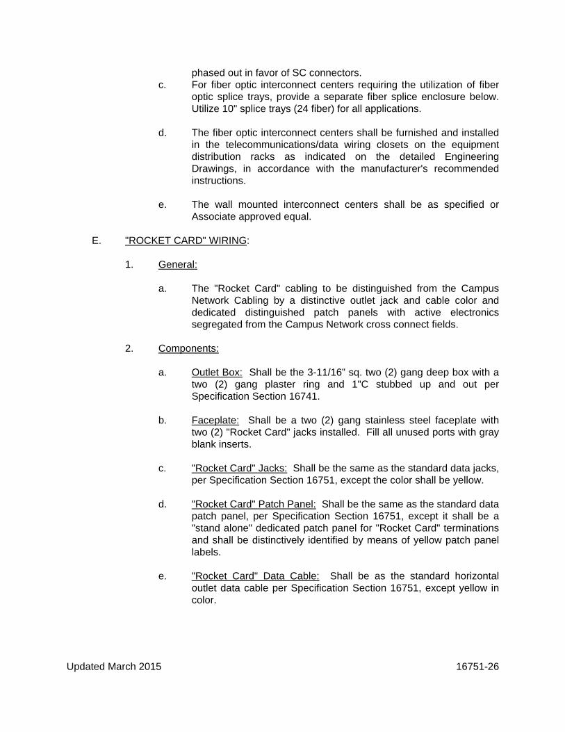
Associate approved equal. E. "ROCKET CARD" WIRING: 1. General: a. The "Rocket Card" cabling to be distinguished from the Campus
Network Cabling by a distinctive outlet jack and cable color and dedicated distinguished patch panels with active electronics segregated from the Campus Network cross connect fields.
2. Components: a. Outlet Box: Shall be the 3-11/16” sq. two (2) gang deep box with a
two (2) gang plaster ring and 1"C stubbed up and out per Specification Section 16741.
b. Faceplate: Shall be a two (2) gang stainless steel faceplate with
two (2) "Rocket Card" jacks installed. Fill all unused ports with gray blank inserts.
c. "Rocket Card" Jacks: Shall be the same as the standard data jacks,
per Specification Section 16751, except the color shall be yellow. d. "Rocket Card" Patch Panel: Shall be the same as the standard data
patch panel, per Specification Section 16751, except it shall be a "stand alone" dedicated patch panel for "Rocket Card" terminations and shall be distinctively identified by means of yellow patch panel labels.
e. "Rocket Card" Data Cable: Shall be as the standard horizontal
outlet data cable per Specification Section 16751, except yellow in color.

Updated March 2015 16751-27
f. "Rocket Card" IP Converter Shelf: Shall be a 19"W x 12.5" Deep x 3.5" High equipment shelf, black: VMP #ER-S1E or Owner/Associate approved equal. Provide one (1) shelf per thirty-two (32) ports of "Rocket Card" network utilized (2 x 16 port IP Converters).
3. Installation: a. Intermixed routing of cables with standard data cables is
permissible. b. Separate out the "Rocket Card" cables for termination in sequential
order on the designated patch panel. c. The "Rocket Card" patch panel or panels shall be located adjacent
to (above and/or below) the IP Converter Shelf. d. The "Rocket Card" network equipment shall be located as directed
by the Owner in the standard 19" equipment racks, separated from the Campus Data Network cross connect fields such as to minimize errant connections, yet convenient for IP Converter interconnection to the local network switch/hub.
e. "Rocket Card" outlet locations may be required above the ceiling for
interconnection to special application readers such as door access controllers, point of sale (P.O.S.) outlet, etc.
f. Above ceiling outlet boxes shall be housed in a single gang handy
box, utilizing a two (2) port stainless steel faceplate with two (2) "Rocket Card" jacks installed. The outlet box shall be anchored to building structure utilizing a beam clamp, dedicated drop wire and drop wire clip, "T"-bar and "T"-bar clip, etc. as required. Provide grommeting and strain relief for the cables at the outlet box.
g. Outlet, jack and cable identification shall be provided per The
University Standard, Annex "A", implement the same as data outlets.
h. It is recommended that only one (1) "Rocket Card" reader device
should be connected to a network port. i. However it is possible for more than one reader device to share a
port. Multiple "Rocket Card" outlet jacks shall not be wired to a single data cable. If multiple reader devices must share a single port, modifications to the wiring must be made external to the structured wiring, at the reader devices and shall be performed by the Owner or under the direction of the Owner only.

Updated March 2015 16751-28
j. The location of all "Rocket Card" outlets shall be coordinated with and approved by the "Rocket Card" office.
4. Testing: a. "Rocket Card" network cabling shall be tested as per standard
Specification Section 16751 method, procedures and standards. 1) Segregate the "Rocket Card" network cabling test reports
from the Campus Network Cabling Test Reports, do not intermix reports.
2) Include the "Rocket Card" test reports with the Campus
Network Cabling Reports. F. MISCELLANEOUS: 1. Backboards: a. The Contractor shall furnish and install in the areas or rooms as
indicated on the detailed Engineering Drawings and documents, telephone backboards for mounting electrical, electronic, data and telecommunication equipment as per the Telephone/Data Raceway Systems, Specification Section 16741.
2. Non-Metallic Surface Mounted Raceway: a. Unless otherwise specified on the detailed Engineering Drawings
and documents, the surface mounted non-metallic raceway, office white, ivory or gray in color, shall be sized for the cable fill as required. Contractor to verify the raceway color with the Architect. The surface mounted non-metallic raceway shall be furnished with a double-sided foam tape self-adhesive backing. The surface mounted non-metallic raceway shall be as specified or Associate approved equal, by Hubbell, Panduit, Carlon or Multilink.
b. Contractor to furnish and install EIA/TIA-569A compliant fittings and
accessories as required to provide and maintain minimum wiring space and cable bend radii requirements. Contractor to coordinate raceway size with cable fill requirements.
c. Contractor to install the surface mounted raceway in accordance
with the manufacturer's instructions and recommendations, utilizing factory furnished accessories and fittings as required. Each section of surface mounted raceway shall be secured to the wall with panhead screws or mushroom headed nail anchors on 16" nominal maximum spacing, with a minimum of two (2) anchors per section.

Updated March 2015 16751-29
Anchors shall be located 6" or less from the end of each raceway section as required to retain raceway tight to the surface.
d. All raceway materials shall be neatly installed, running
perpendicular or parallel to the floor as required. All raceway to be cut and neatly trimmed with an appropriate miter saw. No rough or exposed edges will be permitted. No exposed cables will be permitted.
e. Non-metallic raceway shall not be utilized for combined
data/telecommunication and power distribution without written approval of the Associate. Metallic raceway with a metal divider only shall be used for combined data/telecommunication and power distribution.
3. Conduit and Metallic Raceways: a. Unless specifically stated otherwise on the detailed Engineering
Drawings and documents, all data/communication conduits and raceways shall be installed in full compliance with applicable sections of the National Electrical Code, EIA/TIA-569A standards, national, state and local codes which may apply, and the Telephone/Data Raceway Systems Specification, Section 16741.
4. Furniture Partition Raceways: a. When the data/communication outlet is to be mounted on modular
furniture, the surface mounted outlet shall be mounted to the modular furniture utilizing the appropriate Leviton Modular Furniture Adapter P/N 49222-HAO as required, or Associate approved equal.
b. The data/communication outlet shall be located as directed by the
Owner/Architect. c. Where available, the modular partition furniture raceway should be
utilized for the through routing of cables only, modular connectors shall not be installed in the built-in raceway system.
5. Metallic Surface Mounted Raceway: * a. The surface mounted metallic raceway shall be as specified, [office
white], [ivory] or [gray] enamel finished, with cover and divider as required, or Associate approved equal. Contractor to verify the color with the Architect.
* SPECIFIER TO MAKE SELECTION

Updated March 2015 16751-30
b. Contractor to furnish and install EIA/TIA-569A compliant fittings and accessories as required to provide and maintain minimum wiring space and cable bend radii requirements. Contractor shall coordinate raceway size with cable fill requirements.
c. Contractor to install the surface mounted metallic raceway in
accordance with the manufacturer's instructions and recommendations, utilizing factory furnished accessories and fittings as required.
* d. In locations where the data/communication outlets are installed in
metallic surface mounted raceway, a 106 duplex mounting frame, [office white], [ivory] or [gray] in color as specified, shall be utilized to provide support for up to two (2) modular jacks. Contractor to verify the color with the Architect.
6. Patch Cords: To be provided by the UT Network department per project for the IT closet link end only. Desk top Patch cords is not a UT Network Department responsibility but part of Project cost PART 3 - GROUNDING AND BONDING A. Contractor to provide an isolated, low A.C. impedance path to ground, and a stable
"0" volt to ground reference point for the data/telecommunication system. The ground system shall comply with EIA/TIA-607A standards and NEC as may apply, see Data/Telecommunication Grounding Specification, Section 16453 as applicable.
B. The ground conductor shall originate from the electrical service entrance ground
bus, shall be sized as indicated on the drawings or in the engineering documents (#2 AWG minimum), shall be run in PVC conduit to the main teleboard, main distribution frame, main wiring closet or as indicated, terminating on an approved
* SPECIFIER TO MAKE SELECTION distribution bus bar located at/or near the telephone service entrance protection
equipment. The data/ telecommunication ground conductor shall be utilized to ground service entrance protection equipment, surge suppression equipment, data/communication equipment, rack frames, cabinets, raceways, etc. The ground shall be sized as noted, and extended as required to ground the Computer Room raised floor systems. The ground shall not be utilized for the electrical power distribution system ground or building lightning protection ground. The data/telecommunication ground shall meet NEC Article 250 and 800 requirements. All equipment racks, cabinets, frames, etc. shall be provided with an approved grounding means.
C. Setscrew type and/or box lug type terminations are not acceptable for the
data/telecommunication grounding system. Joined segments of the
Updated March 2015 16751-31
data/telecommunication grounding system shall be connected using only irreversible compression-type connectors, exothermic welding, bronze bolt, star washers and nut connections. Crimp type lugs are not acceptable. Common zinc-cad and nickel plated steel hardware fasteners are not acceptable. The Contractor shall provide oxide inhibiting joint compound on all compression, nut and bolt, and mechanical type terminations.
D. Upon completion of the installation of the data/telecommunication cabling system,
the Contractor shall perform standard ground resistance and ground current tests with approved ground resistance test equipment and procedures as per Specification 16453.
PART 4 - EXECUTION A. Whenever possible, cable and raceway routing paths shall follow the logical
structure of the building (e.g. follow hallways, aisles and corridors). When walls must be breached, cables shall pass through pre-established metal conduit sleeved openings. Cables shall enter and/or exit areas at right angles to the structure. Route all data/communication cables and raceways parallel to or perpendicular to the building structure. No diagonal runs will be permitted unless noted otherwise or pre-approved by the Associate. Corridor crossovers shall be kept to a minimum.
B. For the purpose of this specification, all above ceiling space shall be
considered "return air plenum space", unless noted otherwise. All above ceiling cables shall be plenum rated, unless specified otherwise. All non-plenum rated cables must be routed in conduits or enclosed raceways unless noted otherwise. It is the responsibility of the Contractor to verify "non-plenum" rating requirements.
C. All data/communication cables shall be installed as single continuous runs from
cross-connect field to cross-connect field, workstation outlet faceplate to patch panel, etc. No in-line connector or splices, etc. will be permitted. Cabling shall be
free of bridges, splices, taps, splitters, baluns, and other connections between workstation outlet faceplate and the cross-connect field or patch panel.
D. The Contractor shall purchase the cable on 1000-foot minimum reels only.
Boxed and/or coiled cable is unacceptable. All cable shall be new cable, manufactured as specified on the Drawings, purchased for the project. Salvaged, leftover, or reused cable is not acceptable. Factory seconds and/or factory shorts are not acceptable. All cable of a given type shall be of a single manufacturer and manufacturers part number unless approved in writing by the Associate. All unacceptable cable shall be removed immediately from the jobsite. All unapproved and/or unacceptable cable will be removed and replaced at the Contractor's expense.

Updated March 2015 16751-32
E. The Contractor shall verify that all equipment and materials meet the Specifications
and descriptions. The Contractor shall be responsible for notifying the Associate in writing if the vendor/manufacturer alters his product specification, description, part number, etc. Such notification shall be made in a timely manner such that changes may be properly evaluated and corrective measures implemented as required. Products, materials and equipment installed which do not meet the Specifications and/or product description will be replaced at the Contractor's expense.
F. Data/communication cables that are routed above a suspended ceiling or in open
exposed space and not routed in conduit, shall be supported by Associate approved cable tray and channel or supported by an Associate approved open ceiling distribution system. An open ceiling distribution system shall not be installed above inaccessible ceiling areas, such as "lock-in" type ceiling tiles, drywall or plaster. Suspended ceiling tiles shall be of the removable "lay-in" type, and located at a maximum height of 11'-0" above the floor. Adequate and suitable space shall be available in the ceiling area for the distribution system. A minimum of 3" of clearance space all around shall be available for the "open wiring" distribution system installation, this shall be clear accessible space not required for the removal of tile, light fixtures or for service and access to other systems.
G. Cables shall be supported on Caddy brand “Cable-Cat” hangers or Associate
approved equal supports from the building structure, and shall be neatly bunched, bundled and routed above the suspended ceiling supported from the bar joist or trusses. The “open” wiring should be accessible from an 8’-0” stepladder. The suspended ceiling and/or lighting fixture support wire or rod shall not be utilized to support data/communication cables. Do not support cables from ductwork, plumbing lines, fire suppression or mechanical systems, etc. Do not lay data/ communication cables on ductwork, piping, plumbing systems or on top of lay-in ceiling tile and lighting fixtures.
H. All power devices and power sources emit a given amount of radio frequency
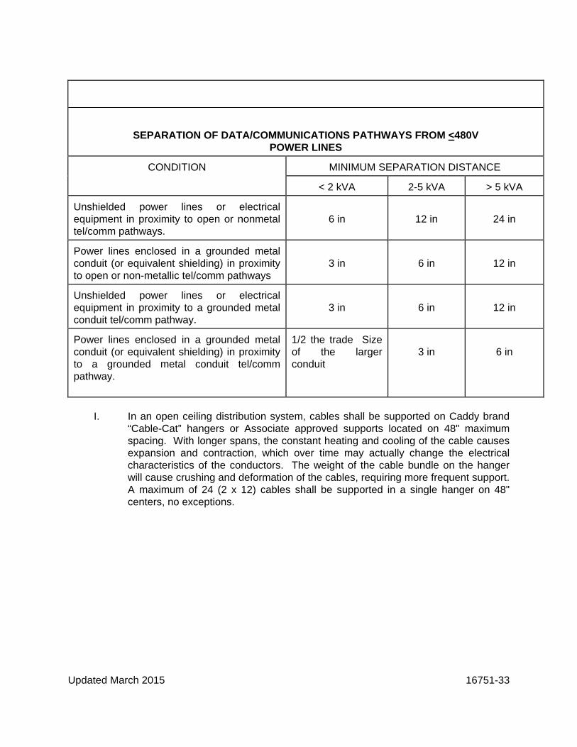
interference (RFI) and/or electro-magnetic interference (EMI). To reduce or eliminate the field effects of RFI/EMI on data traffic on a given cable channel, cable runs shall be kept at the maximum possible distance from such sources. Running cables through the center of the building can reduce the external interference effects of RFI/EMI. Open wiring or non-metallic raceway shall be routed a minimum of six (6") inches away from fluorescent fixtures. Special attention shall be given to the routing of such pathways away from lighting ballasts and high intensity discharge devices. The minimum separation distances between data/communication distribution pathways and power wiring of 480 Volts or less shall be per Table-1 herein.
Updated March 2015 16751-33
SEPARATION OF DATA/COMMUNICATIONS PATHWAYS FROM <480V
POWER LINES
CONDITION MINIMUM SEPARATION DISTANCE
< 2 kVA 2-5 kVA > 5 kVA
Unshielded power lines or electrical equipment in proximity to open or nonmetal tel/comm pathways.
6 in
12 in
24 in
Power lines enclosed in a grounded metal conduit (or equivalent shielding) in proximity to open or non-metallic tel/comm pathways
3 in
6 in
12 in
Unshielded power lines or electrical equipment in proximity to a grounded metal conduit tel/comm pathway.
3 in
6 in
12 in
Power lines enclosed in a grounded metal conduit (or equivalent shielding) in proximity to a grounded metal conduit tel/comm pathway.
1/2 the trade Size of the larger conduit
3 in
6 in
I. In an open ceiling distribution system, cables shall be supported on Caddy brand
“Cable-Cat” hangers or Associate approved supports located on 48" maximum spacing. With longer spans, the constant heating and cooling of the cable causes expansion and contraction, which over time may actually change the electrical characteristics of the conductors. The weight of the cable bundle on the hanger will cause crushing and deformation of the cables, requiring more frequent support. A maximum of 24 (2 x 12) cables shall be supported in a single hanger on 48" centers, no exceptions.

Updated March 2015 16751-34
J. In no case will unsupported spans of greater than 48" be approved by the Associate. For spans longer than 48", the Contractor shall provide cable tray, channel, ladder, conduit, wire way, messenger wire, J-Hooks or other Associate approved cable support. Note: J-Hooks maybe used as designed only, for short distances or areas where there are less than 25 cables or cable pathways will not allow basket tray etc., spacing must be 4 feet or less between J-Hooks.
K. Open unsupported spans between cable trays, conduit sleeves and trays, etc. shall
not exceed 12” horizontally, 24” vertically. Provide “drop-out” supports for changes in elevation as required.
L. Where data/telecommunication cables are routed in an open ceiling distribution
system or routed on cable tray, channels and ladders or routed through surface mounted raceways and/or wireway, cables shall be separately bundled in groups of twelve (12) cables as described below.
M. “Velcro” type cable ties shall be utilized for organizational purposes and on
horizontal cable runs only, “Velcro” type cable ties are not acceptable for providing vertical cable support. Utilize large (3/16” wide) plastic cable ties, installed in a “Figure 8” pattern around the support and over the cable bundle, pulled up to minimum tension to provide cable bundle support without pinching or deforming the cables.
N. Data, telephone, CATV, and fiber optic cables are to be separately bundled as
required to maintain a neat and orderly installation. Data, telephone, CATV, and/or fiber optic cable bundles may be supported in the same or separate hangers. Cables within the bundles shall be straight and parallel, free of twists, tanglements, kinks, knots, etc. Cable supports shall not pinch, bind, crimp or in any way cause physical damage to the data/communication cables. Cables shall be free from tension at both ends and for the entire length of the cable. In cases where a cable or cables must bear some stress (e.g. vertical risers, etc.), "Kellem" grips shall be used to distribute the strain over a longer length of the cable(s). All vertically routed cables shall be neatly bundled and supported on a vertical cable ladder or rings, by means of cable ties on 24" centers or as directed.
O. Where required to meet maximum cable loads (e.g. for multi-pair trunk and tie
cables), a vertical messenger cable shall be installed in the riser. The messenger cable shall be grounded to the data/telecommunication grounding system at both ends and shall not be used in itself as a grounding conductor. The messenger cable shall be utilized to support the multi-pair trunk and tie cables only. Supporting of various and miscellaneous cables or bundles of cables from the messenger will not be approved.
P. The Contractor shall install multi-pair telephone riser cables as per AT&T Standard
Practices #627-610-225. Q. Cabling Contractor shall take care to assure that during the installation and upon

Updated March 2015 16751-35
completion, all cables have been installed free from kinks, twists, knots, sharp bends, gouges or cuts to the cable jacket or conductor insulation, or any other physical damage. During installation, the Contractor shall not allow the cables to lay on the floor and be exposed to foot, vehicle or equipment traffic, or be exposed to any other forms of abuse which may pinch, crush, bind, over tension, or in any way cause any physical damage to the data/ communication cables. Such physical damage to the data/ communication cables may cause electrical characteristic alterations to the cables, which may or may not be detected by standard testing procedures, cables exhibiting such physical damage or an attempt by the Contractor to correct, cover-up, hide or otherwise conceal such damage will be replaced at the Contractor's expense.
R. Cables that require service loops or additional length should be coiled at 200% of
their recommended minimum bend radius or in a 16" diameter coil (whichever is larger). The coil shall then be cable tied and attached to a nearby support. The coil shall be located, if possible, above the workstation, individually bundled and tagged with the cable number.
S. Minimum Category-6 horizontal cable segment length shall be 15 meters (50
ft.). A typical horizontal cable segment shall include, but not be limited to: 1. Patch panel/cross-connect to the wall outlet. 2. Patch panel/cross-connect to the Consolidation Point/MUTOA. 3. The Consolidation Point to the wall outlet. Manage excess cable length by
means of cable routing path, DO NOT utilize slack cable coils. T. Spare cable sets, cable sets for wireless access points, etc. shall be of sufficient
length to reach any point within the intended service area, and shall be individually coiled at 200% of their recommended minimum radius or 16" diameter coil, whichever is larger. The coil shall then be cable tied and supported on "J-Hooks". The coil shall be located, if possible, above the workstation, individually tagged with the cable identification number. All wireless access points will receive 2 category 6A superior Essex data cables to be terminated at a specified location based on the wireless survey as determined by the University IT Network Department.
TT. Security Cameras
All cameras will be purchased with the Milestones license.
Contact Tony Miller/ UT Network Service Department ASAP for IP addresses HSC Campus. MC-IT Network Service.=s.
The manufacturer that we use is Axis, the type of cameras are IP based.

Updated March 2015 16751-36
The model of camera will need to be determined by location and the need of views. Prefer cameras that are dome type with auto focus.
Only authorized by UT contractors are permitted to activate license and install the cameras in our Milestones security system. They will also have to be Axis authorized and Milestones certified.
When replacing existing coax cameras with IP cameras, all of the old cabling and related items will be removed completely.
Installations:
Utilizing our data specs, a cat6 cable will be used and not to exceed the 295ft rule. Any distance over 295ft will require Fiber optic cable w/SC connectors to be used with fiber converters and patch cables.
All connections will be located in a weather proof location and easily accessible. If the location is in a pole outside, there will be an approved water proof enclosure for all equipment connections. Cameras mounted on the side of buildings will have connections located on the inside wall above a removable ceiling with a patch cable going through a sleeve in the wall to the camera.
Terminations in the data closet: All cables will be terminated on a separate 48 port patch panel. The panel will have a label on it stating it is for cameras only. The labels on the patch panel, both ends of the cable and on the faceplate will state CAM closet# and Port #. The port number will also be located on the flange of the camera, viewable from the ground.
A print with the locations of cameras will be provided to UT upon completion of the project.
As with any wall penetrations, the walls will be fire-stopped!
Material:
Manufacturer Part Number Color if applicable
Cameras Axis to be determined N/A
Cable Cat6 Superior/ Essex 54-246-2B Blue
Fiber Optics Depends on cable amount and distance Orange w/SC ends
Aqua-W/SC for MM 50um.
Jacks Cat6 Hubbell HXJ6B Blue

Updated March 2015 16751-37
Face Plates Hubbell 1FP1GY Gray
Biscuit Hubbell ISB1E1 Optional
Fiber Converter Transition Networks E-100BTX-FX-05(SC) N/A
Fiber Conv. Waterproof Transition Networks M/E-ISW-FX-01(SC) N/A
Power injector AXIS T8133 (30w) N/A
AXIS T8124 (60w) N/A
Power inj. Water proof AXIS T8123-E (30w) N/A
AXIS T8124-E (60w) N/A
Lightning Arrestors L-Com HGLND-CAT6J N/A
All changes in material must be put in writing and approved by UT’s Information Technology Network Department, UT’s Maintenance Department and the project Manager.
U. Fiber optic trunk and tie cables shall be provided with a minimum 40-foot service
loop at each end. See example below:
V. The Cabling Contractor shall observe all minimum bend radius and tension
limitations, etc. as specified by the cable manufacturer and/or the EIA/TIA standards when installing the cables. The maximum pulling tension for 4 pair

Updated March 2015 16751-38
24 AWG horizontal UTP cables shall not exceed 25 ft./lbs. to avoid disturbing the conductors configuration during installation, however it should be noted that this tension is capable of causing jacket or other unacceptable damage. The minimum bending radius for any data/communication cable shall be 1"R. The minimum radius for Category-6 UTP cable shall be 1-1/2"R. When conflict exists between manufacturer’s specifications and this specification, the more stringent criteria shall apply.
W. Cables routed from cable trays, cable ladder, channel or other raceways onto the
telephone backboard, onto a distribution frame or onto the equipment distribution racks shall be neatly organized and supported by cable support brackets, distribution rings, cable clips, cable loops, or by other Associate approved method as required to minimize tension or stress on the connector block terminations.
X. It is absolutely imperative that extreme care be exercised when installing the
Category-6 data cables, as any sharp bends, cable kinks, crushing, or other abuse will cause deformity of the cable, discontinuity of twisted pairs and their relationship to one another, which will adversely affect the high speed electrical performance of the cable. Category-6 data cables must be terminated in accordance with the EIA/TIA-568-B1, -B2, -B2 Addendum 1, Category-6 standards and the most current industry practices. Since cable performance is adversely affected by wiring practices, it is important that the Contractor preserve wiring pair twist as close as possible to the point of termination. The amount of "un-twisting" of a pair as the result of termination to the connector hardware shall be no greater than 0.5" (Cat-3) or 0.38" (Cat-6). To maintain the inter-relationship of pairs, the amount of "un-jacketing" of the cable shall be limited to 0.5 inches or less at the point of termination, unless noted otherwise.
Y. Where cables pass through walls, the Contractor shall provide a conduit sleeve,
sized as per the Telephone/Data Raceway Specification, Section 16741. All conduits and sleeves shall be reamed and provided with insulated bushings, grounding bushings shall be provided as required. The Contractor shall patch and repair any holes, removals, adds, etc. or other damage, and paint the area to match.
Z. All ceiling removal and restoration required for the execution of this work shall be
the responsibility of the Cabling Contractor. AA. The Contractor shall verify with the Architect or the local building authority, the fire
rating requirements of any wall or floor to be breached by a conduit, cable, raceway or other penetration as per ASTM E-119 (NFPA-251 and U.L.-263) standards. The Contractor shall notify the Associate, Architect and Owner in writing of all existing non-compliant conditions for resolution. The presence of existing non-compliant conditions will not exempt the Contractor from meeting the installation fire rating requirements for new work.
AB. The Contractor shall provide through penetration firestops as per ASTM E-814 and

Updated March 2015 16751-39
U.L.-1479. Firestop systems shall have been tested by U.L. and meet the rating criteria, as published in the U.L. Fire Resistance Directory. The Contractor is referenced to the EIA/TIA-569A, Annex A, Firestopping and the 9th Edition of the BICSI Telecommunications Distribution Methods Manual (TDMM) for general guidelines and an overview of firestop technology and methods. Contractor shall consult individual manufacturer's instructions for specific application details.
AC. Openings around cable trays, cable channels, conduits or in sleeves penetrating
fire-rated floor slabs, walls, partitions, ceilings or smoke partitions, shall be sealed at both sides of the partition. Pack openings with calcium silicate blocks, 3M Brand Fire Barrier Caulk "CP25" and Putty "303", 3M Brand Series 7902/7904 systems for floor and walls, Nelson Flame Seal System, or an Associate accepted material having the same fire-rating as the floor or wall penetrated. Fiberglass is not acceptable.
AD. Cables should be laid in cable trays as opposed to being pulled through, if
possible. Where cable must be pulled through cable tray, the Contractor shall station an installer at each turn and intersection in the cable tray to guide the cables around the corners and through the intersections.
AE. Cable pulls longer than 100 feet in length are not authorized by the Associate.
Pulls greater than 100 feet are made solely at the Contractor's risk. Cable shall be neatly coiled in a figure "8" pattern at the completion of a pull in preparation for the next pull.
AF. Inside plant data/telecommunication and fiber optic cables shall not be stored or
installed in an unheated building where the temperature is less than 40°F. The structure and the cable must be brought to a minimum 50°F. ambient for a minimum of 48 hours prior to installation of the cables. Failure to observe this precaution may result in damage to the cable and will result in the cable being replaced at the Contractor's expense.
AG. The Contractor shall coordinate the location of all partition furniture workstation
outlets with the Architectural Furniture Lay-Out Drawings, and the Architect prior to installation. It shall be the responsibility of the Architect and the furniture partition manufacturer to assure that the furniture partitions meet all requirements of the cabling system, which shall include but are not limited to the following:
1. Adequate separation with shielding between power and
data/communication pathways. 2. Adequate cable routing pathways and space for the intended application,
based upon recognized industry standards. 3. Provides for minimum cable bending radius for the intended application (1-
1/2" min. radius nominal U.N.O.).

Updated March 2015 16751-40
4. Provides adequate back wiring space behind outlets for the intended
application, based upon recognized industry standards. Back wiring space should not intrude into cable routing space.
5. Provide vertical, as well as horizontal cable routing paths through the
partition panels, providing for universal outlet location capability. (The Associate does not recommend data/communication outlets be located
flush in the partition base kick-panel, due to high exposure to damage.) AH. The surface mounted outlet enclosure for use in modular furniture partition
locations shall be securely mounted, utilizing a modular furniture adapter bracket designed for the modular furniture system, such as manufactured by Leviton or an Associate approved equal, or the enclosure may be secured to the underside of the modular furniture work surface as directed, with a minimum of two (2) pan head screws in diagonal corners or as required, to assure a flat flush installation. Cables shall be anchored with a cable tie to the enclosure, so as to relieve any stress to the terminations. All cable markers shall be unexposed inside the enclosure. All exposed cables shall be neatly bundled and tied and routed on the partition surface from the surface mounted enclosure, back to the partition raceway. Surface routed exposed cables shall be secured to the partition, using "hair pin" clips or other approved retainers as available from the furniture partition manufacturer, subject to the approval of the Associate.
AI. The Cabling Contractor shall provide in his bid, prices for providing and installing
grommetted holes, chaffing gear, split convoluted tubing, etc. as required and/or as directed by the Associate, Architect and/or Owner, to enclose and/or protect cables from damage.
AJ. With the Associate's prior approval, at those locations where pre-stubbed conduits
and outlet boxes have not or can not be installed in the wall, the Contractor shall install an approved Caddy brand single gang and/or double gang mounting plate/bracket (e.g. #MPLS, MPLS2 or Associate approved equal), and fish the cables within the existing wall structure, to a location above the ceiling. The Contractor shall provide and install an approved bushing or grommet in all metal studs, to prevent damage to cables. In those locations where data/communication cables must be fished through a concrete block wall to a "mudded-in" rework box, the Contractor shall fish the wall with approved convoluted sleeving, non-metallic tubing or greenfield as required, to prevent damage to the cables. The Contractor shall insure that all faceplates, labels and associated items are properly aligned, centered and installed perpendicular and/or parallel to the floor as required.
AK. All wall openings will be neatly cut and trimmed with a drywall saw. No rough or
exposed edges will be permitted. The faceplate or surface mounted box shall be neatly installed and plumb to the floor. No exposed cables will be permitted.

Updated March 2015 16751-41
AL. Standard flush mounted faceplates shall be mounted on the standard data/communication outlet with the appropriate (single gang or double gang) plaster ring, as per Specification 16741 or shall be mounted on appropriate surface mounted (single gang or double gang) deep raceway boxes (i.e. "FD" series cast, 2-3/4" deep metallic or non-metallic) as indicated on the Drawings.
AM. Maintain separation of dedicated telephone and data cables when and where the telephone system in service is an analog phone system utilizing signaling levels of 25 Volts or greater (i.e. ringer voltage). Contractor to verify. AN. The Cabling Contractor shall maintain separation of dedicated telephone and data
cables wherever required, with the exception of the vertical feeder conduit from the workstation data/communication outlet box, to above the ceiling or joist space, or in furniture partition raceway. Where cables must occupy the same raceway, maintain maximum separation and/or loose coupling between the cables as possible.
AO. All items of voice and data equipment, including racks, cables, fiber optic
conductors and their respective terminations, shall be identified and labeled as indicated on the detailed Engineering Drawings and documents, and/or according to EIA/TIA-606A standard. Cable identification shall be by means of permanently applied, pre-printed wraparound wire markers (e.g. "Brady-Wrap" B-292, LAT-18, or LAT-19 self-laminating markers or Associate approved equal). These labels must withstand the requirements of U.L.969 as outlined in the EIA/TIA-606A standard. All horizontal and backbone subsystem cables shall be labeled at each end. At the faceplate end of the cable, the label shall be installed within 3-6" of the module termination, and shall not be visible from the outside of the faceplate or surface mounted enclosure. Additional cable labeling shall be required at intermediate locations, such as in pull boxes, where cables pass between floors through sleeves in a riser, or where cables exit a "zone" conduit to feed an open area.
AP. Cable identification, outlet numbering, equipment labeling, etc. shall be provided by
the Associate. AQ. The Contractor shall label all patch panels with pre-printed labels enclosed in self-
adhesive clear strips (e.g. Hubbell #LPH174 or Associate approved equal). Patch panel labels shall be printed with the associated user outlet location identification and jack identification number as indicated on the detailed Engineering Drawings and documents. All cables must be terminated and labeled in sequential alphanumeric order on the patch panels. The Contractor shall provide a pre-printed laminated label (e.g. "Brady Wrap" or Associate approved equal) black letters on a white background on each patch panel, indicating the facility floor or area served from the panel as indicated on the drawings.
AR. The Contractor shall label all cross-connect wiring blocks with pre-printed color-
coded labels. Labels shall be printed with the associated user outlet location

Updated March 2015 16751-42
identification and jack identification numbers as indicated on the detailed Engineering Drawings and documents. All cables must be terminated and labeled in sequential alphanumeric order on the cross-connect wiring blocks.
AS. The Contractor shall install a permanent clear pre-printed laminated label with
black lettering (e.g. Brady Label #CL-311-621 or LAT-7-722-10 or Associate approved equal), on each data/telecommunication outlet faceplate. The faceplate shall be labeled according to the detailed Engineering Drawings and documents.
AT. The Contractor shall install a permanent engraved laminated phenolic nameplate
on each distribution rack frame or equipment cabinet. The nameplate shall be engraved with the distribution frame rack designation as indicated on the drawings (e.g. "IDF-5E Rack 02"). The nameplate shall have 5/16" high black gothic letters on a white background, 1/2" high x length as required.
AU. All 120 VAC rack or cabinet mounted power strips, dedicated power outlets, etc. in
the Wiring Closets and Equipment Room shall be provided with a pre-printed laminated permanently affixed legend plate. The legend plate shall be printed with the receptacle distribution panel identification and circuit number information that the receptacle is served from, if the receptacle is dedicated to a specific piece of equipment or purpose, include that information on the legend plate.
AV. All labeling, nameplates, legend plates, etc. with proposed text, shall be submitted
to the Associate for prior approval. "Dymo Tape Writer" labels, hand written labels, single digit tape markers, etc. are not acceptable.
AW. The distribution equipment rack frames shall be securely anchored to the floor at
all four (4) corners, using anchors into the concrete floor, or toggle bolts through raised floors as per the manufacturer's recommendations and instructions. When specified on the Engineering Drawings and documents or otherwise required, the Contractor shall provide and install "raised floor rack support" kits for the installation of distribution equipment racks on raised floors. The tops of the distribution equipment racks shall be securely tied together and braced from the wall from behind or from structural steel from above.
AX. Free standing cabinets shall be securely anchored to the floor at all four (4)
corners, using anchors into the concrete floor, or toggle bolts through the raised floors as per the manufacturer's recommendations and instructions. Wall mounted cabinets and wall mounted racks shall be securely mounted to the walls as required. The Contractor shall provide for the installation of special blocking and bracing as required between studding in the walls, etc. and shall provide additional bracing and support as required from the floor and/or ceiling structure above as approved by the Associate.
AY. Distribution equipment racks and/or cabinets shall be laid out and located as

Updated March 2015 16751-43
indicated on the detailed Engineering Drawings and documents, with vertical cable organizers located between racks as indicated. All racks and cabinets shall be bonded to the data/ telecommunication grounding system. Patch panels, cable organizers, fiber interconnect cabinets, etc. shall be mounted in the racks and cabinets as indicated on the drawings. Discrepancies or conflicts shall be brought to the attention of the Associate for resolution, before proceeding with the installation. Power strip installation, cable and cord routing on the equipment rack and/or in the equipment cabinet, shall not obstruct or restrict the mounting of rack mounted equipment or access to said equipment. The completed distribution equipment rack with installed equipment and/or the completed equipment cabinet with installed equipment shall be such, that there shall be complete unobstructed access to all equipment, components, cables, terminations, etc., without requiring the removal of one item to gain access to another. Each item of equipment shall be removable from the rack or cabinet, without having to remove another piece. No mounting space in the rack or cabinet shall be made unusable by the inappropriate mounting of another component, item or cable routing. Distribution equipment racks and equipment cabinets shall be installed such as, to afford the maximum accessibility and working space in and around the equipment as indicated on the detailed Engineering Drawings. Any discrepancies or conflicts shall be brought to the attention of the Associate.
AZ. The cable ladder installation shall be as shown on the detailed Engineering
Drawings and documents. The cable ladder installation shall be self-supporting, independent of the distribution equipment racks, except for the ladder support bar or unistrut support at the top of the rack. The cable ladder shall not be mounted directly to the distribution rack mounting channel or in any way, block access to or the availability of the rack mounting channel. The ladder support bar or unistrut brace shall be utilized approximately every other rack or as required. The unistrut support may when applicable, be extended to the backwall, to act as a brace. Vertical elements of the cable ladder assembly shall be anchored to the floor, using proper end support brackets and anchor bolts per the manufacturer's recommendations and instructions. The cable ladder structure shall be located with the inside rail approximately 3" behind the distribution equipment rack channel. The cable ladder system shall be bonded to the data/telecommunication grounding system.
BA. The power strip shall be mounted centered on the backside of the vertical
organizer, between the distribution equipment racks, with the cord to the top. The power for the power strips shall be provided by means of a split duplex receptacle in a surface mounted handy-box, centrally located between the power strips at the top of the racks, or by means of 2-1/2" x 2-1/2" electrical wireway. The handy-box to be mounted horizontally on the top of the rack rear top angle, with the conduit routed along the rack top and outlets located as required. The duplex receptacle is to be split with a dedicated circuit to each receptacle, as indicated. An alternative and sometimes preferred solution is to cut off the power cord plug, provide a flexible cord connector on the raceway and hard wire the power strip installation.

Updated March 2015 16751-44
BB. The Contractor to provide two (2) 20A-120V-2P-3W NEMA 5-20 connector body
receptacle (Hubbell #5369C) on a 2#12, 1#12G “SO” drop cord, elev. 42” A.F.F., each on a dedicated circuit, for Owner use. Receptacles shall be located between the racks as directed by the Owner. Each Data Rack shall have at least one 20AMP Power Strip and one L630P for two racks. No power will be run from wall to racks, all power to be hard wired within the racks. See Pictures below.
L630P Stranahan North room 3125 BC. The data/communication room(s), wiring closet(s), etc. shall contain the
mechanical terminations for the horizontal workstation wiring, voice and data trunk cable terminations, fiber optic backbone cable terminations, distribution and cross-connect fields, patch panels, key switch unit (KSU) equipment, private branch exchange (PBX) equipment, service entrance equipment, surge protection, network system side electronic equipment, etc., which may be furnished and installed as part of the contract and/or by others. Facilities for this equipment and services may or may not be included under this contract and as such, are covered under separate specifications.
BD. Wiring closet layout guidelines and recommended perimeters are described and
illustrated in the detailed Engineering Drawings.

Updated March 2015 16751-45
BE. Unless otherwise indicated, equipment racks and wall mounted equipment shall be installed such that a minimum of 36" clearance is available from all sides for installation and maintenance.
BF. Provide a minimum of 12" clearance from the corner to the wall mounted 66M
block distribution frame, mount the top of the frame a maximum of 74" off the floor and the bottom of the frame a minimum of 34" off the floor. 110 block cross-connect fields shall be similarly mounted.
BG. All "voice" station cables, telephone riser and tie cables shall enter the wall
mounted cross-connect distribution frame at the bottom right. BH. Cast “D” rings shall be utilized only for the support and management of high pair
count “voice” backbone cables and fiber optic backbone cables in inner duct. “D” rings shall not be utilized for the support and management of horizontal distribution voice, data, fiber optic and coaxial cables.
BI. Voice and data cables shall be arranged on the patch panels and/or connector
blocks in alphanumerical order according to the faceplate number scheme. BJ. Voice Riser cables shall be arranged on the cross-connect fields in alphanumerical
order by cable pair per PIC color code. BK. The Contractor shall obtain shop drawings of pay telephones and emergency
telephones, prior to rough-in, to assure proper installation. BL. Total cooperation, coordination and communication between the different
contractors, the Owner and the Associate are required for the timely scheduling and completion of all elements and components of the total construction project. It shall be recognized and acknowledged by all participants, that all phases and elements cannot finish the same day, and certain elements and items must be completed prior to the start of other elements. The Contractor shall provide to the Associate, at the very start of the project, a construction schedule that is coordinated with the other elements of the project, indicating significant construction and project milestones and completion dates. This schedule shall be adjusted and modified by the Associate and/or Project Construction Manager, as required to meet the overall project schedule requirements.
BM. The Project Construction Manager and others shall be made aware of and
understand the importance and necessity for the completion of general contract work on the data/telecommunication spaces, wiring closets, equipment rooms, etc. prior to the installation of equipment and pulling cables to these areas. The spaces shall be essentially completed, cleaned and secure prior to the installation of equipment and cables. Equipment racks, cabinets, cable ladders, cable trays, backboards, distribution frames, power, raceways, lighting, HVAC systems, etc. shall be in place prior to pulling any cable in the area. Pre-pulling cable to the area and building the space around the cable is not acceptable.

Updated March 2015 16751-46
BN. Cable routing from the outlet location conduit stub, through the open ceiling
distribution system “j-hooks”, to zone conduits, cable trays and cable ladders, and onto the telephone backboard distribution frames, into the data/communication cabinet, or onto the cable ladder system and onto the distribution equipment rack patch panels shall be neatly organized and supported by cable support brackets, cable clips, cable ties, cable loops, etc. as required to minimize tension and stress on the cables, conductors, terminations, connectors and connector blocks.
BO. All racks, cabinets, and raceways shall be bonded to the data/telecommunication
grounding system. Each rack or cabinet shall be provided with a ground bar or grounding stud, see Specification Section 16452.
BP. All cable trays, ladders, equipment racks, cabinets, etc. shall be securely bolted
and installed according to the manufacturer's recommendations and instructions. Only factory manufactured parts, accessories and components shall be utilized for the construction, contractor fabricated components and assemblies are subject to the Associate's approval.
BQ. All unistrut, cable channel, cable tray, cable ladder, bracket, etc. shall be cleanly
and squarely cut with the appropriate metal cutting saw, then filed and chamfered clean and free from all burrs and sharp edges. All drilled holes shall be de-burred and chamfered free from sharp edges. Associate approved chaffing gear shall be provided on all holes, edges, and corners subject to possible cable exposure.
BR. The Contractor shall remove at his expense, all unusable, unacceptable, or
otherwise unapproved cables or materials from the installation, no cable or materials shall be abandoned in place without written approval of the Associate.
BS. Provide a minimum of two (2) meters (78") of service slack in each fiber optic
conductor at each termination or splice. Slack to be coiled on the fiber storage spacer rings provided.
BT. The Contractor shall identify and remove all abandoned and unused cables
from the conduits, cable trays, chases, risers, and from above the ceilings or below the floors, in the areas of renovation. Remove cables complete back to the source.
PART 5 - SYSTEM TESTING AND VERIFICATION A. GENERAL: 1. Upon completion of the cable installation, the Contractor shall perform and
submit for approval, complete cable documentation and verification testing reports. Required testing and reports shall include, but shall not be limited to providing the following information:
Updated March 2015 16751-47
a. Continuity checks of all cable, all pairs, checking for opens and
shorts. b. Determining and recording all cable lengths. c. Checking all cables, all pairs for proper termination and correct pair
polarity. d. Verifying correct cable labeling at both ends of the cable, the outlet
faceplate and jack labeling, and the cross-connect field and patch panel labeling.
e. Test equipment model and serial number. f. Date testing was performed and the name of the
Technician/Operator performing the tests and/or inspections. g. Completely test all data/telecommunications and fiber optic cables
installed and terminated by the Contractor, including but not limited to horizontal UTP voice and data cables, multi-twisted pair trunk, riser and tie cables, coaxial CATV and computer cables, and multimode/single-mode fiber optic cables as described herein.
2. The purpose of the systems testing and verification requirements are
twofold: a. To verify and document that the completed installation meets or
exceeds minimum systems performance and quality standards as outlined herein.
b. Established base standard criteria against which the completed
installation can be tested and compared to in the future, to facilitate troubleshooting and maintenance.
3. The Contractor shall at the onset of the project, submit to the Associate for approval cut sheets, shop drawings, technical specifications, operator manuals, etc. as provided by the manufacturer of the testing equipment proposed for use by the Contractor, to test and verify his installation.
4. Such equipment shall be subject to the approval of the Associate. The
Contractor and his representative Technician/Operator shall demonstrate to the satisfaction of the Associate, a thorough knowledge and understanding of the test equipment proposed to be utilized, and a proficiency in its operation. The Contractor shall provide a written detailed test equipment set-up procedure, indicating how all test parameters are entered into the tester equipment. Approved set-up procedures will be provided to the

Updated March 2015 16751-48
Owner as a component of the final submittals, providing the Owner with all information required to duplicate the original test conditions and parameters.
5. The Contractor shall provide U.L. or E.T.L. verified EIA/TIA-568-B1, -B2
Level III test equipment with accessories, software, etc. as described elsewhere here within. This equipment shall be pre-programmed to perform a custom "auto-test", including test parameters as noted. This equipment shall be of the latest model, with the latest current software installed and factory calibrated within 30 days. The equipment shall be factory calibrated prior to testing for each project phase and/or a minimum of once a year, whichever is most frequent. The tester shall be self-calibrated a minimum of once daily during normal use.
6. Approved U.L. or E.T.L. verified EIA/TIA-568-B1, -B2, Level III or higher
test equipment with accessories, software, etc. shall be: a. A Fluke "DSX-5000"or Fluke “DTX” digital cable test meter complete
with "smart remote", "Link Ware" software, PC interface cable, carrying case, AC/DC adapter/charger, calibration module, rechargeable batteries, coax adapter cable, Cat-5e/6 channel/traffic adapters (2), extended internal/external memory and memory card reader, two (2) talk sets, etc.
b. An Agilent Technologies "Wire Scope 350" digital cable test meter
complete with "dual remote", Scope Data Pro software, PC interface cable, power supplies, two (2) Cat-6 channel probes, operator manuals, two (2) talk sets and Type II compact flash memory card.
c. A Fluke (Micro Test) "Omni Scanner II" digital cable test meter
complete with "Remote II', Scan Link Tools software, PC interface cable, carrying case, AC/DC adapter/charger, rechargeable
batteries, calibration cable, coax cable adapter, Cat-5e/6, channel adapters, flash memory card, operators manual, etc.
d. Contractor shall provide documentation that the test
equipment proposed for utilization has been updated to the most currently available upgrades from the manufacturer.
7. The Contractor shall obtain from the cable manufacturer and submit to the
associate, copies of the manufacturing Master Reel Test Reports indicating the worst case minimal electrical performance for each pair of each cable reel for all Category-6 cable.
8. The Contractor shall obtain from the cable manufacturer and submit to the

Updated March 2015 16751-49
associate, copies of the manufacturing Master Reel Test Reports indicating factory OTDR readings for the fiber optic cable.
9. The Contractor shall submit for approval only tests performed on
cables which have been completely installed, terminated and visually inspected. All connectors are to be installed, conductors terminated, faceplates installed and mounted, cable routed, bundled, etc.
10. The Contractor shall submit for approval, only test reports which
indicate full compliance with minimum acceptable standards and specifications indicated here-in. Marginally acceptable test results, as indicated by some test equipment manufacturers as within a 15% Fault Anomaly Threshold, * or other notation will not be acceptable.
11. It is strongly recommended that the Contractor perform minimum
verification testing of all cables on the reels before pulling and installation. The Contractor shall be responsible for all cable installed, and all cable must be fully acceptable and verified upon completion.
12. Category-6 cable testing shall be performed utilizing pre-manufactured,
factory terminated, U.L. verified Cat-6 patch cords or factory manufacture field tester patch cords. Test patch cords shall be provided in designated pair sets. Each test patch cord set shall be utilized for no more than 750 insertion/withdrawal cycles before being replaced. Upon changing test patch cord sets, the tester shall be reself-calibrated and the last three (3) cables tested are to be retested and the test results compared. Test results shall not vary by greater than 5% from the original results, results greater than 5% shall be reported to the Associate immediately for review. Test cord sets shall be turned over to the Associate at project completion.
13. Each voice/data communication outlet and each backbone cable shall pass a complete "active" operational test as performed by and acceptable to the Owner. 14. Any outlet, cable or component not satisfactorily passing all of the "static"
visual inspections, electronic micro-computer based automatic scanner testing, Owner performed "passive" testing, "active" operational tests or failing to meet quality installation standards as described in the specifications and standards herein, shall be repaired and/or replaced as directed by the Associate at the Contractor's expense.
15. The Contractor shall prepare complete cable test reports for all installed
cables, for review and acceptance by the Associate prior to final acceptance of the cabling system. It is recommended that the Contractor coordinate with the Associate for a visual inspection and preliminary acceptance of the physical installation prior to performing certification testing, as any rework, changes, or alterations will necessitate retesting. Test reports on completed and acceptable installations only shall be

Updated March 2015 16751-50
submitted. All test reports shall be signed and dated by the Technician performing the tests and/or inspection.
16. A copy of the final completed and reviewed cable test reports shall be
enclosed in clear vinyl protective covers, and posted in the wiring closet and/or as directed by the Associate for use and reference by the Owner.
17. The Contractor shall recognize that the available programmable micro-
computer based automatic scanner test equipment for copper media, and the fiber optic power meter test equipment described herein is limited in its ability to completely test all pertinent parameters of an acceptable cabling installation and as such, a "pass" test result will not be the determining criteria for acceptability of an installation which does not otherwise meet the standards and intent of this specification and the Engineering documents.
18. The Contractor shall provide a minimum of 48 hours (two working days)
notice to the Associate and Owner prior to commencing with cable testing. The Associate shall at the Associate's discretion, observe any and/or all cable testing procedures. Cable testing procedures shall be acceptable to the Associate and Owner.
19. The Contractor shall coordinate with the Owner, to perform at the Owner's
discretion, concurrent Owner testing of randomly selected outlets and cables as to be determined by the Owner.
B. HORIZONTAL UNSHIELDED TWISTED PAIR CABLES: 1. Cable testing shall be conducted by an Associate approved testing facility,
utilizing a programmable microcomputer based automatic scanner/tester capable of generating complete alphanumerical and graphical printed test reports. Agilent Technologies "Wire Scope-350", Fluke "DSX-5000 with two-way injector for Adjacent and Remote "NEXT" testing shall be utilized for verification testing of cable.
2. Cable installations shall be fully tested and verified in accordance with
EIA/TIA-568-B1, -B2, -B2 Addendum 1, Level III Accuracy and enhanced Category-6 Standards for Full Channel Performance. Written descriptions of the proposed calibration and testing procedures shall be submitted to the Associate for prior approval before beginning any testing. Minimum EIA/TIA-568-B1, -B2, -B2 Addendum 1 testing will not be accepted.
3. The test instrument manufacturer shall make available to the
Contractor/User/Owner a simple procedure for verifying, reporting and Owner recording the calibration of the tester. The Contractor shall utilize this procedure to daily verify the calibration of the test instrument, and after the instrument has been dropped or has received other abuse. The

Updated March 2015 16751-51
Contractor shall submit for approval the calibration procedure and shall document the verification/calibration.
4. The "DSX-5000", “DTX”, Wire Scope-350 or "Omni Scanner II" shall be pre-
programmed with a custom "auto-test" program to include the following channel parameters:
a. Wire Map b. Channel Length (< 328 ft.) c. Propagation Delay (< 540 nsec) d. Delay Skew (< 30 nsec) e. Impedance (100 +15%) f. Insertion Loss (Attenuation) g. NEXT - Adjacent & Remote h. ELFEXT - Adjacent & Remote i. ACR - Adjacent & Remote j. PS-NEXT - Adjacent & Remote k. PS-ELFEXT - Adjacent & Remote l. PS-ACR - Adjacent & Remote m. Return Loss - Adjacent & Remote 5. The "DSX-5000" “DTX”, Wire Scope-350 or "Omni Scanner II" shall have
the capability to provide ambient threshold noise level (<0.2 Impulses/Sec. @ 260 mV threshold) readings as a manually selected single test function. The "DSX-5000" “DTX”, Wire Scope-350 or "Omni Scanner II" shall support time domain analysis on NEXT (TDX) for fault analysis and shall monitor 10 Base-T and 100 Base-TX ethernet traffic.
6. Category-6 Full Channel testing shall be performed utilizing two (2)
dedicated manufactured 12 foot long, yellow Cat-6 patch cords as manufactured by the connectivity manufacturer, as per the test instrument manufacturer’s instructions.
7. The "DSP-4000", “DTX”, Wire Scope-350 or "Omni Scanner II" shall
provide the following additional information on the Test Report:

Updated March 2015 16751-52
a. Contractor's Name (Name of Company) b. Job Site Location (i.e. Jobsite, City) c. Operator's Name d. Cable Tester Manufacturer, Model Number, Serial Number e. Test Summary (i.e. Pass/Fail) f. Cable Identification Number g. Date and Time h. Test Standard (i.e. VIP 2000 Test) i. Limits Version j. Software Version (e.g. 5.4) 8. Category-3 "voice cables" shall be tested to Category-3 Permanent Link
Test Parameters (limits) and margins as per EIA/TIA-568-B1, -B2, -B2 Addendum 1, Level III standards, utilizing the Fluke, "DSP-4000", “DTX”, Wire Scope-350 or "Omni Scanner II" manufactured test cords.
9. Category-6 "data cables" shall be tested to parameters exceeding EIA/TIA-
568-B1, -B2 –B2 Addendum 1 for Category-6 for Full Channel Performance as follows:
MINIMUM CATEGORY-6 CHANNEL PERFORMANCE Insertion Loss 34.0 dB Max. NEXT 35.4 dB Min. PS-NEXT 34.0 dB Min. EL-FEXT 15.8 dB Min. PS-ELFEXT 12.8 dB Min. Return Loss 10.0 dB Min. PS-ACR 0.1 dB Min. Prop. Delay @ 10 MHz 480 ns Max. Delay Skew @ 1 MHz 50 ns Max. TEST FREQUENCY: 250 MHz
a. A custom channel test standard for the VIP 2000 program is
available on the Fluke Web Site for downloading. Contractor shall consult his tester manufacturer for compliance information.

Updated March 2015 16751-53
10. Copies of the horizontal UTP cable test reports shall be provided in hard
copy (printed form) and in soft copy (CD-ROM). Test Reports provided on diskette shall include a copy of the appropriate software for managing the reports in CSV file formats. After the horizontal cable tests have been performed, the Contractor shall install the permanent faceplate labels, modular jack dust covers and permanent pre-printed patch panel labels. Where the Contractor submits cable verification test reports generated by the micro-computer based tester, the submittal shall include a cover letter and/or cover sheet (Form 1A) providing all additional required information not available on the printouts, or the Contractor shall complete Test Report Form 1, included herein or Associate approved equal.
C. MULTI-TWISTED PAIR TRUNK, RISER AND TIE CABLES (SHIELDED &
UNSHIELDED): 1. All cables and all pairs shall be tested for opens, shorts, continuity, pair-
reversals (flips), and inspected for proper 25 pair color code sequence, 25 pair primary unit color code sequence, and 100 pair multi-unit color code designation termination sequence. In addition, the first pair in each 25 pair binder group, shall be tested for loop-resistance to the nearest 0.1 Ohms. Test and inspection results shall be recorded on Test Report Form 2, included herein or Associate approved equal.
D. COAXIAL CABLES: 1. All coaxial cables shall be tested for "opens", "shorts", continuity,
capacitance, impedance, loop resistance and length. Coaxial cables shall be tested utilizing a programmable microcomputer based automatic scanner/tester capable of generating complete printed test reports as noted above. Written descriptions of the proposed calibration and testing procedures shall be submitted to the Associate for prior approval, before beginning any testing. When the Contractor submits cable verification test reports generated by the micro-computer based tester, the submittal shall include a cover letter and/or cover sheet providing all additional required information not available on the printouts, or the Contractor shall complete Test Report Form 3, included herein or Associate approved equal.
2. Where applicable or otherwise noted on the Engineering Drawings or
documents, the Contractor shall perform such additional testing of the coaxial cable system as is required and/or indicated. For a CATV system installation, the Contractor shall verify and record the incoming signal level. The Contractor shall test the frequency response of system and shall provide filters as required to provide a flat response from 50 MHz to 750 MHz. The maximum deviation shall be less than +5 dB. Contractor shall record and document (1) the location and value of all taps, splitters, directional couplers, attenuators, end of line resistors, amplifiers, filters,

Updated March 2015 16751-54
equalizers, etc. and (2) the loss/gain (+dB) at each location. Other coaxial cable systems shall be tested as directed.
E. 62.5/125 UM / 50UM MULTIMODE AND 8.7/125 UM SINGLE-MODE FIBER
OPTIC CABLE: 1. All fiber optic cables shall be fully tested for continuity and attenuation,
utilizing a fiber optic power meter and fiber optic LED/laser light source. The fiber optic test equipment shall be capable of testing multimode and/or single-mode fiber cable. The LED light source shall only be utilized for 850 nm testing.
2. The fiber optic test equipment shall consist of the Siecor Handheld Fiber
Optic Power Meter, Model #OTS-210-55/SC with electronic microcontroller providing automatic self-testing and data storage and the Siecor Handheld Fiber Optic LED/ Laser Light Source, Model #OS-301D or Associate approved equal. The Contractor shall provide shop drawings, catalog cut sheets and operational procedures describing the test equipment proposed to be utilized for the Associate's review and approval.
3. Fiber conductor shall be tested with the cable completely installed and in
final placement, with connector installed and polished out. The "SC" connectors shall be inspected for proper termination techniques, workmanship, labeling, etc. and verified by the Contractor to be free from any visual defects, such as scratches and chips. All connector installations exhibiting any defects and/or improper assembly procedures shall be replaced at the Contractor's expense.
4. Each fiber shall be tested at both frequencies, in both directions, with
all readings recorded. The worst case readings will be utilized to determine acceptability of the fiber.
5. Attenuation shall be recorded for each fiber at 850 and 1300 nm for
multimode fiber optic cable and at 1310 nm and 1550 nm for single-mode fiber optic cable. The measurements shall be recorded to the nearest 1/100th dB. Fiber optic cable link test procedures shall be based upon EIA/TIA-568-B3 Annex "H" standard procedures. "Reference dB" is defined as the recurring loss associated with test equipment connections, test fiber optic jumper cords, and connections to the fiber optic cable under test. Many manufacturers of test equipment provide a means to "O", "Null" or "Tare" out, this reference dB loss from the test results. The technician performing the fiber optic verification tests should periodically check and verify the reference dB loss. It is highly recommended that the Contractor provide his fiber optic test equipment with special high quality, high performance, low loss fiber optic jumper cords for the purpose of obtaining the most accurate and consistent test results. All fiber optic "SC", and/or "FC/PC" connectors and couplers shall be thoroughly cleaned before and

Updated March 2015 16751-55
after testing, and dust caps installed after the test procedures have been completed.
6. The fiber optic cable test report shall provide the following
information: a. Contractor's name b. Test equipment identification: Manufacturer, model number and
serial number c. Client/Owner identification d. Date test performed e. Cable manufacturer and part number f. Cable identification number g. Cable location (i.e. building - from/to) h. Cable description (i.e. number of fibers, S/M, M/M) i. Name, signature and date of signature of Technician performing the
tests. j. Cable length k. Proper conductor termination verification, both ends l. Link attenuation (loss) measurement in dB per fiber m. Reference dB n. Visual connector (both ends) inspection verification o. Calculated fiber loss based on fiber length and factory OTDR
readings p. Calculated optical attenuation per connector pair (fiber link
attenuation loss measurement), less the calculated fiber loss, less the reference dB equals optical attenuation per connector pair
q. Test results (i.e. Pass/Fail) 7. Maximum optical attenuation per connector pair for multimode fiber
connectors shall be 0.3 dB or less when measured at 850/1300 nm in

Updated March 2015 16751-56
accordance with ANSI/EIA/TIA-526-14A, Method A.1. Maximum optical attenuation per connector pair for single-mode fiber connectors shall be 0.5 dB or less when measured at 1310/1550 nm in accordance with ANSI/EIA/TIA-526-7, Method B. (NOTE: It is recognized by the Associate that this specification is much more stringent than the EIA/TIA-568-B3 Annex "H" standard.) Reflection shall be > 45dB. The Contractor shall provide written descriptions of the proposed calibration and testing procedures to the Associate, for prior approval before beginning any testing.
8. Copies of the fiber optic cable testing and inspection results shall be
provided in hard copy (printed form) and/or soft copy (CD-Rom or diskette) form. Test reports provided in diskette form shall include a copy of the appropriate software for managing the reports in a CSV file format or Windows-based program. Where the Contractor submits cable test verification reports generated by the microcomputer based tester, the submittal shall include a cover letter and/or cover sheet, providing all additional required information not available on the print outs or the Contractor shall complete Test Report Form 4, included herein or Associate approved equal.
* [9. With the Associate's approval and/or at the Associate's option, all fiber optic
cable shall be tested for continuity and optical attenuation losses utilizing a fiber optic time domain reflectometer (OTDR). The fiber optic test results from the OTDR shall be submitted in both hard and soft copy (printed and Flash Drive) formats. Soft copy formatted submittals shall
* SPECIFIER TO MAKE SELECTION include Microsoft Windows data base management software preloaded with
the cable test results. All fiber optic cable tests shall be performed utilizing a Fluke Optifiber or Associate approved equal. The fiber optic OTDR test equipment shall test multimode fiber at both 850 and 1300 nm, and single-mode fiber at both 1310 and 1500 nm. Measurements to be recorded to the nearest 1/100 dB. The fiber optic OTDR Test Report shall include all information requested, including the "Pass-Fail" test parameters as indicated in Items "a" through "q" above. Provide OTDR generated trace diagrams in addition to the generated test report in lieu of Test Report Form 4.]
F. INDEPENDENT SYSTEM VERIFICATION: 1. The above described testing procedures are the minimum acceptable.
Additional independent system verification testing may be required as described in the drawings and/or documentation. In addition, independent system verification testing may be required at the Contractor's expense, in the event of non-performance of specified testing procedures and submittals or contested materials and/or installation procedures.

Updated March 2015 16751-57
Independent testing shall be determined by and arranged by the Associate at the Contractor's expense.
G. CABLING TEST REPORTING FORMS INCLUDED: * [1. Form 1 – 100 OHM U.T.P. Test Report] * [2. Form 1A – 100 OHM U.T.P. Cover Sheet] * [3. Form 2 – 100 OHM Multi-Twisted Pair Test Report] * [4. Form 3 – Coaxial Cable Test Report] * [5. Form 4 – Fiber Optic Test Report] PART 6 - SUBMITTALS A. RECORD DRAWINGS: 1. The Contractor shall keep in the field and open to inspection, an accurate,
current, progressive record of the actual installation of the data/communication cabling system. Upon completion of the work, the Contractor shall deliver marked up prints showing the actual routing of cable runs, outlet locations, outlet/cable identifications, cable tray sizes and
* SPECIFIER TO MAKE SELECTION routes, conduit sizes and routes, distribution frame layouts, punchdown
block locations, coax cable system splitter and tap locations with dB values and signal levels indicating system loading and balancing, etc.
2. Where applicable or otherwise noted on the Engineering Drawings or
documents, the Associate will provide to the Contractor an Auto-Cad diskette of the appropriate available floor plans and/or drawings as required for the Contractor to update and/or provide the required record documentation.
B. CABLING SYSTEM INSTRUCTION MANUALS: 1. Provide complete written system instruction manuals, which shall include,
but not be limited to the following: a. First Page: Title of job, Owner, address, date of submittal and
name of Contractor. b. Second Page: Index of Contents

Updated March 2015 16751-58
c. Third Page: Introduction to first section containing a cross-
reference to the equipment schedule and cable schedule. d. First Section: One copy each of accepted shop drawings,
equipment catalog cuts and manufacturer's instructions for all components and materials utilized in the data/communication cabling system.
e. Second Section: One copy each of accepted test equipment
catalog cuts, operating instructions and manufacturer's test instructions and procedures as incorporated into the testing of the data/communication cabling system.
f. Third Section: One copy each of completed and accepted cable
test reports unless noted otherwise. 2. Bind the written system instruction manual's information and materials into
a hardback binder of 8-1/2" x 11" size. 3. Submit two (2) copies to the Associate for approval. 4. After approval, submit four (4) copies to the Associate for delivery to the
Owner. 5. Submit two (2) complete sets of record drawings to the Associate for
review. * [6. Reference “Annex-G” for submittal requirements, listings schedules,
etc.]
END OF SECTION 16751 * DELETE IF “ANNEX G” IS NOT UTILIZED

Updated March 2015 16751-59

Updated March 2015 16751-60
CABLE VERIFICATION COVER SHEET I. CABLE TYPES INSTALLED (Check as Applicable) A. "Voice" Cables ( ) 1. Cat-3 ( ), Cat-5 ( ), Cat-5E ( ), Cat-6 ( ) Cat 6a ( ) 2. Rating: CMP ( ), CMR ( ) 3. Manufacturer: Part Number: Specified NVP: (Per Mfg. Submittal) 4. Termination Sequence: T568A ( ), T568B ( ) B. "Data" Cables ( ) 1. Cat-5 ( ), Cat-5E ( ), Cat-6 ( ) Cat 6a ( ) 2. Rating: CMP ( ), CMR ( ) 3. Manufacturer: Part Number: Specified NVP: (Per Mfg. Submittal) 4. Termination Sequence: T568A ( ), T568B ( ) 5. Factory Furnished Manufacturing Test Reports Enclosed For Category-5E or 6,
Cat 6a Cables: Yes ( ) No ( ) II. COMPUTER GENERATED PERFORMANCE TEST REPORTS ENCLOSED: (Yes ( ) No ( ) A. Required shop drawings, test equipment and test procedure submittals made and
approved: Yes ( ) No ( ) B. Cable verified with a: (Model Number). 1. Manufacturer: FORM 1A: 100 OHM U.T.P. COVER SHEET 2. Serial Number:

Updated March 2015 16751-61
3. Software Revision: 4. Tester Owned by: 5. Cable Analyzer Factory Calibrated: III. CABLE INSTALLATION VISUAL INSPECTION TO BE PERFORMED BY THE CONTRACTOR
PROJECT MANAGER (Check as Applicable) A. Proper color-coded conductor to pin termination at each end. ( ) B. Continuous continuity of cable from end to end, no splices. ( ) C. No shorts between any two or more conductors, or conductor to ground. ( ) D. No exposed or damaged conductor, no damaged cable jacket. ( ) E. Maintenance of all pair twist and pair relationships achieved. ( ) F. Specified cable support provided, maximum span, cable bundling furnished, with no
pinching or kinking. ( ) G. Minimum bend radius and wiring spacing maintained. ( ) H. Active tests performed and accepted by the Owner. ( ) IV. THIS CABLE VERIFICATION TEST COVER SHEET HAS BEEN REVIEWED, ATTESTED TO
AND COMPLETED BY: A. Contractor: B. Tested/Inspected By: C. Title: D. Date: E. Signature: V. ASSOCIATEING REVIEW: A. Reviewed By: B. For: C. Date: FORM 1A: 100 OHM U.T.P. COVER SHEET

Updated March 2015 16751-62

Updated March 2015 16751-63

Updated March 2015 16751-64

Updated March 2015 16751-65
APPENDIX "A" – OWNER/ASSOCIATE APPROVED MATERIAL LIST List updated by Tom Baldwin-February 2015
A. CABLE:
^4UTP, Cat-6a, CPM, Blue, “Wireless” Superior Essex #6H-272-2B 1) 4UTP, Cat-6, CMR, Blue, "Data" Superior Essex #54-272-2A
1)
4UTP, Cat-6, CMP, Blue, "Data" Superior Essex #54-272-2B
1)
4UTP, Cat-3, CMR, White, "Voice" Superior Essex #18-241-43
1)
4UTP, Cat-3, CMP, White, "Voice" Superior Essex #18-241-46
1)
4UTP, Cat-6, CMR, Yellow, "Rocket Card" Superior Essex #54-272-6A
1)
4UTP, Cat-6, CMP, Yellow, "Rocket Card" Superior Essex #54-272-6B
1)
25UTP, Cat-3, CMR, Gray, "Voice" Superior Essex #18-475-33
1)
25UTP, Cat-3, CMP, Gray, "Voice" Superior Essex #18-475-36
1)
50UTP, Cat-3, CMR, Gray, "Voice" Superior Essex #18-579-33
1)
50UTP, Cat-3, CMP, Natural, "Voice" Superior Essex #18-579-86
1)
100UTP, Cat-3, CMR, Gray, "Voice" Superior Essex #18-789-33
1)
100UTP, Cat-3, CMP, Natural, "Voice" Superior Essex #18-799-86
1)
25-Pair, Type "ARMM", CMR, "Voice-Tie" Superior Essex #02-097-03
1), 2)
50-Pair, Type "ARMM", CMR, "Voice-Tie" Superior Essex #02-100-03
1), 2)
100-Pair, Type "ARMM", CMR, "Voice-Tie" Superior Essex #02-104-03
1), 2)
200-Pair, Type "ARMM", CMR, "Voice-Tie" Superior Essex #02-108-03
1), 2)
NOTES: 1) Or Associate approved equal by General Cable or Associate and Owner approved
Hubbell Partner equal, offered as a voluntary alternate. 2) Higher pair count Type "ARMM" cables available, see Superior Essex Catalog for
part numbers.
A. CABLE: (continued)
4UTP Cat-5e Broadband OSP, “BBDE” Superior Essex #04-001-58 1)
4UTP Cat-6 Broadband OSP, “BBD6” Superior Essex #04-001-68 1)
4STP Cat-5e (Shielded) Broadband, OSP, Superior Essex #04-001-54 1) “BBDNE”

Updated March 2015 16751-66
4STP Cat-6 (Shielded) Broadband, OSP, “BBDN6”
Superior Essex #04-001-64 1)
25STP Cat-5 (Shielded) Broadband, OSP, Superior Essex #04-097-31 1) “Megapic-NF”
100STP Cat-5 (Shielded) Broadband, OSP, “Megapic-NF”
Superior Essex #04-104-31 1)
25-Pair, Type “BKMA”, OSP, Voice Feeder Superior Essex #20-097-42 1)
50-Pair, Type “BKMA”, OSP, Voice Feeder Superior Essex #20-100-42 1)
100-Pair, Type “BKMA”, OSP, Voice Feeder Superior Essex #20-104-42 1)
200-Pair, Type “BKMA”, OSP, Voice Feeder Superior Essex #20-108-42 1)
300-Pair, Type “BKMA”, OSP, Voice Feeder Superior Essex #20-110-42 1)
400-Pair, Type “BKMA”, OSP, Voice Feeder Superior Essex #20-112-42 1)
600-Pair, Type “BKMA”, OSP, Voice Feeder Superior Essex #20-116-42 1)
900-Pair, Type “BKMA”, OSP, Voice Feeder Superior Essex #20-118-42 1)
^6-Pair, 24 AWG, “Sealpic-FSF” Type (RUS PE-89), OSP, Voice Feeder
Superior Essex #04-092-02 1)
^12-Pair, 24 AWG, “Sealpic-FSF” Type (RUS PE-89), OSP, Voice Feeder
Superior Essex #04-094-02 1)
25-Pair, 24 AWG, “Sealpic-FSF” Type (RUS PE-89), OSP, Voice Feeder
Superior Essex #04-097-02 1)

Updated March 2015 16751-67
NOTES: 1) Or Associate approved equal by General Cable or Associate and Owner approved Hubbell Partner equal, offered as a voluntary alternate.
A. CABLE: (continued)
^50-Pair, 24 AWG, “Sealpic-FSF” Type (RUS PE 89), OSP, Voice Feeder
Superior Essex #04-100-02 1)
^100-Pair, 24 AWG, “Sealpic-FSF” Type (RUS PE 89), OSP, Voice Feeder
Superior Essex #04-104-02 1)
^200-Pair, 24 AWG, “Sealpic-FSF” Type (RUS PE 89), OSP, Voice Feeder
Superior Essex #04-108-02 1)
^300-Pair, 24 AWG, “Sealpic-FSF” Type (RUS PE 89), OSP, Voice Feeder
Superior Essex #04-110-02 1)
^400-Pair, 24 AWG, “Sealpic-FSF” Type (RUS PE 89), OSP, Voice Feeder
Superior Essex #04-112-02 1)
^600-Pair, 24 AWG, “Sealpic-FSF” Type (RUS PE 89), OSP, Voice Feeder
Superior Essex #04-116-02 1)
25-Pair, Type “ANMW”, OSP, Voice Feeder Superior Essex #22-097-83 1)
50-Pair, Type “ANMW”, OSP, Voice Feeder Superior Essex #22-100-83 1)
100-Pair, Type “ANMW”, OSP, Voice Feeder Superior Essex #22-104-83 1)
300-Pair, Type “ANMW”, OSP, Voice Feeder Superior Essex #22-108-83 1)
300-Pair, Type “ANMW”, OSP, Voice Feeder Superior Essex #22-110-83 1)
400-Pair, Type “ANMW”, OSP, Voice Feeder Superior Essex #22-112-83 1)
600-Pair, Type “ANMW”, OSP, Voice Feeder Superior Essex #22-116-83 1)
900-Pair, Type “ANMW”, OSP, Voice Feeder Superior Essex #22-118-83 1)
1” Dia., 75 OHM Broadband Coax Feeder CommScope #QR-860-
JCASS

Updated March 2015 16751-68
NOTES: 1) Or Associate Fiber approved equal by General Cable, Corning or
Associate and Owner approved Hubbell Partner equal, offered as a voluntary alternate.
A. CABLE: (continued)
48-Strand Multimode, OFNR, 900 um, I/O Superior Essex #W30486G01 1), 3), 4)
48-Strand Multimode, 50u, OM3 Superior Essex #W3048NG01 48-Strand Multimode, OFNP, 900 um, I/O Superior Essex #240486G01 1), 3), 4)
48-Strand Multimode, 50u, OM3 Superior Essex #24048NG01 12-Strand Singlemode, OFNR, 900 um Superior Essex #W30123101 1), 3), 4)
12-Strand Singlemode, OFNP, 900 um Superior Essex #240123101 1), 3), 4)
24-Strand Multimode, OFNR, 900 um Superior Essex #W30246G01 1), 3), 4)
24-Strand Multimode, 50u, OM3 Superior Essex #W3024NG01 24-Strand Multimode, OFNP, 900 um Superior Essex #240246G01 1), 3), 4)
24-Strand Multimode, 50u, OM3 Superior Essex #24024NG01
24-Strand Singlemode, OFNR, 900 um Superior Essex #W30243101 1), 3), 4)
24-Strand Singlemode, OFNP, 900 um Superior Essex #240243101 1), 3), 4)
24-Strand Singlemode, 48-Strand Multimode, OFNR, I/O, 900 um HYBRID
Superior Essex #W3072HGA1 1), 2), 3), 4)
24-Strand Singlemode, 48-Strand Multimode, OFNP, I/O, 900 um HYBRID
Superior Essex #24072HGA1 1), 2), 3), 4)
24-Strand Multimode, 12-Strand Singlemode, OFNR, I/O, 900 um HYBRID
Superior Essex #W3036HGA1 1), 2), 3), 4)
24-Strand Multimode, 12-Strand Singlemode, OFNP, I/O, 900 um HYBRID
Superior Essex #24036HGA1 1), 2), 3), 4)

Updated March 2015 16751-69
NOTES: 1) Or Associate approved equal by General Cable or Associate and Owner approved Hubbell Partner equal, offered as a voluntary alternate.
2)
Minimum order quantity is 3,280 feet for custom HYBRID cable designs, specify multimode and singlemode strand counts.
3)
Custom Superior Essex P/N per U.T. Spec.
4)
First digit "2" indicates non-water blocked, for dry water blocking construction change first digit from "2" to "W".
B. CONNECTIVITY:
“Wireless) Jack, Cat-6a, Blue Hubbell #HJ6AB 1)
"Data" Jack, Cat-6, Blue Hubbell #HXJ6B 1)
"Voice" Jack, Cat-3, Office White Hubbell #HXJ3OW 1)
"Rocket Card", Cat-6, Yellow Hubbell #HXJ6Y 1)
Blank Insert Module, Office White Hubbell #SFB10 1)
Blank Insert Module, Electrical Ivory Hubbell #SFBE10 1)
Blank Insert Module, Gray Hubbell #SFBG10 1)
"F" Type Bulkhead Coupler, Office White Hubbell #SFFX 1)
"F" Type Bulkhead Coupler, Electrical Ivory Hubbell #SFFEX 1)
"F" Type Bulkhead Coupler, Gray Hubbell #SFFGX 1)
"SC" Type F/O Coupler Adapter, Office White
Hubbell #SFFSC 1)
"SC" Type F/O Coupler Adapter, Electrical Ivory
Hubbell #SFFSCEI 1)
"SC" Type F/O Coupler Adapter, Gray
Hubbell #SFFSCG 1)
Single Gang Faceplate, 6-Port, Office White Hubbell #IFP160W 1)
Single Gang Faceplate, 6-Port, Electrical Ivory Hubbell #IFP16EI
1)

Updated March 2015 16751-70
Single Gang Faceplate, 6-Port, Gray Hubbell #IFP16GY 1)
Double Gang Faceplate, 9-Port, Office White
Hubbell #IFP290W 1)
Double Gang Faceplate, 9-Port, Electrical Ivory
Hubbell #IFP29EI 1)
NOTES: 1) Or Associate and Owner approved equal by Leviton, offered as a voluntary alternate.
B. CONNECTIVITY: (continued)
Double Gang Faceplate, 9-Port, Gray
Hubbell
#IFP29GY
1)
Furniture Faceplate, 2-Port, Black
Hubbell
#FP2BK
1)
Furniture With Herman Miller Adapter Plate
Hubbell
#HMRBBK
1)
Standard Wall phone jack
Allen-Tel
#AT630A-4
1)
106 Duplex Frame, Office White
Hubbell
#BR106C
1)
106 Duplex Frame, Electrical Ivory
Hubbell
#BR106E
1)
106 Duplex Frame, Gray
Hubbell
#BR106G
1)
Single Gang S.S. Faceplate, 2-Port
Hubbell
#SSFL-12
1)
Single Gang S.S. Faceplate, 6-Port
Hubbell
#SSFL-16
1)
Double Gang S.S. Faceplate, 12-Port
Hubbell
#SSFL212
1)
NOTES: 1) Or Associate approved equal by Leviton, offered as a voluntary alternate.
C. EQUIPMENT:
Distribution Rack 19" x 84" 2 Post Rack
Hubbell Ortronic
s CPI
#HPW84RR19 #OR-19-84T2SDB #55053-703

Updated March 2015 16751-71
C. EQUIPMENT: (continued)
Distribution Rack 19" x 84" Ortronics #OR-19-84T4SDA2132 4 Post Rack, 27-32" Deep CPI #50120-703
Vertical Cable Organizer – 3” x 84” Ortronics CPI
#OR-VO-84-T3E #11730-703
Vertical Cable Organizer – 6” x 84” Ortronics
CPI #OR-VO-84-T6E #11374703
NOTES: 1) Or Associate and Owner approved equal by Leviton, offered as a
voluntary alternate.
Patch Cord Organizer – 1RMU Ortronics #OR-FCM19-1SRC Hubbell #HC 119 CE1N
Patch Cord Organizer – 2RMU Ortronics #OR-FCM19-2SRC
Hubbell #HC 219 CE1N
Interbay Organizer – 2RMU Ortronics #OR-FCM19-2XL Hubbell #HC 119 CE1N
24-Port Unloaded Patch Panel Hubbell #UDX24E 1)
48-Port Unloaded Patch Panel Hubbell #UDX48E 1)
19" Rear Cable Management Bar Hubbell ^ #CMBR 1)
Fiber Optic Rack Mount Panel, 12-6 Pack Hubbell ^ #FCR3U12SP 1)
Loaded 6 Pack Adapter Panel, Duplex SC- Hubbell ^#FSPSCDM3GR Orange MM (62.5um)
Loaded 6 Pack Adapter Panel, Duplex SC- Aqua MM-50um Hubbell #FSPSCDM3AQ
Loaded 6 Pack Adapter Panel, Duplex SC- Hubbell ^#FSPSCDS3GY Yellow MM
Fiber Optic Splice Enclosure – 6 Tray Hubbell #FCR350SE 1)

Updated March 2015 16751-72
24 Fiber, Fusion Splice, Splice Tray Hubbell #STRAY 24F 1) Vertical Power St
Distribution Rack Dust Cover, 19" Ortronics #OR DC-19B 2 Post Rack Hubbel
CPI
#SB-595-01 #41050-719
Distribution Rack Dust Cover, 19" 4 Post Rack, 27-32" Depth
Ortronics #OR-DC2732-19
NOTES: 1) Or Associate and Owner approved equal by Leviton, offered as a voluntary
alternate.
C. EQUIPMENT: (continued)
Distribution Rack Guard Rail, 19" Ortronics CPI
#OR-GR-19B #40058-719
Distribution Rack Ground Bar CPI
^ Hubbell #10610-019 #HBBBHR19KT
50-Pair 66M1-50 Block Mounted on an 89B Bracket
Siemons Siemons
^#M1-50 #S89D
66M1-50 Wall Mount Module, 400 Pair B-Line #SB-720-0204-C-FB
66M1-50 Wall Mount Module, 600 Pair B-Line ^#SB-720-0304-C-FB
66M1-50 Wall Mount Module, 9 00 Pair B-Line ^#SB-720-0306-C-FB
66M1-50 Wall Mount Module, 2000 Pair B-Line ^#SB-720-0410-C-FB
Telecommunications Main Grounding Bus Bar (TMGB)
Newton CPI Panduit
#30560010 #40158-020 ^#GB4B0624TPI-1
Telecommunications Grounding Bus Bar (TGB)
Newton CPI Panduit
#30580010 #40156-012 ^#GB4B0612TPI-1
Equipment Shelf; 19"W x 15.5"D x 3.5"H Equipment Shelf, Black Laptop Computer Shelf CPI #11744-719
NOTE: ̂ = Changes made January 2015.
Ortronics CPI
End Appendix “A”
#OR-ES-19-3B #11293-719

Updated March 2015 16751-73
University of Toledo Data Rack Layout Prototype All IT closet should have a minimum of two 84” by 19 inch racks as shown above. It will become standard for all new closet builds to follow the layout above. The number of racks will be determined by the size of the area being serviced and the perceived future growth. Retro fits or adding to existing IT Closet Builds presents challenges and it will depend on how many cables are to be added to existing frames/racks and what is going to be removed however the end result is to move to the model layout above whether through attrition, transition or complete makeover. Each retro fit will need to be discussed with the IT Network Management group to get optimal builds under these circumstances. All racks must have vertical cable management installed as well as back frame ladder rack perpendicular to the vertical cable management between and on the ends of all 19 inch racks. Overhead 12 inch ladder rack will be incorporated into the build to facilitate cable and fiber being fed into the frames. Example of Rack and Ladder layout see: Example of a proper Rack and Ladder layout see: Stranahan North Room 3125.
Vertical Cable Manage-ment
Vertical Cable Manage-ment
Vertical Cable Manage-ment
Rack #1 Rack #2
4U cable MGT 4U cable MGT Horizontal Transition MGT Horizontal Transition MGT
48 Port Patch Data Fiber Rack 2U
48 Port Switch 1U
48 Port Patch Data
48 Port Patch Data-WAP 2U 2U 48 Port Switch 1U
48 Port Switch 1U 48 Port Patch Data
48 Port Patch Data-CAM 2U 2U 48 Port Switch 1U
48 Port Switch 1U 48 Port Patch Data 2U
UPS
Front View

Updated March 2015 16751-74
Note: The picture above shows a 2U 48 Port Data Patch Panel and a 1U Switch alternating this patter from top down with upper floors starting at the top.
Frontal view of the 48 port patch panel alternating with a 48 port switch. 4U Horizontal Cable Management –Transition very top of each rack. A pathway between racks will be necessary.

Updated March 2015 16751-75
University of Toledo IT Closet Characteristics
Card Swipe Light-50 foot Candles
36 inch minDOOR
FRONT
BACK12Foot
36 inch minLight-50 foot Candles
12 foot
Coax Terminations Voice Frame B-Line Frame sized for job TGBB
19 inch Racks by 84 inches high, Hubbell or Ortronics, number of racks determined by scope of work and growth potential. Cable management and patch cord managment as requested by UT Standards.
Plywood all four walls: Paint with fire retardent paint
Clearance shall be 36 inches on either side of data racks.
Floors shall be sealed: if concrete or tiled and sealed: No carpet
Each Data Rack shall have at least one 20AMP Power Strip and one L630P for two racks. No power will be run from wall to racks, all power to be hard wiried within the racks.
No Drop Ceiling is preferred. Floor to Deck above should be sealed. Pathways in and out of the room shall be fire stopped per industry standards.
Cable Trays and Ladder Rack designed to optimize pathways in/outof closet andprovide growth for Fiber, Copper cable and coax transistions to Data Racks, voice and coax backboards.
The minimum data/telecommunication space shall be an area of 12'-0" x 12'-0"
Complete floor plans and layouts of all spaces, equipment layouts of alltelephone backboards and equipment racks, service entrance facility details,cable routing, pathways and cable management details, data/telecommunication grounding details and power distribution
The ideal IT closet would take into consideration the "location first". You will reduce costs with the best location by limiting costs of materials, closet builds, and catastrophic events due to poor locations. It is best to have one closet service one floor however, for economic reasons we can service the floor above and below the IT closet as long as proper pathway distribution standards and distances are adhered to. Access to the closet should be off a common hallway to reduce interruptions to daily activities in the areas being served. If a Data cable or voice cable cannot be run properly within the IT standards of 295 feet from the service location jack to the patch panel a new IT closet or another closet location should be considered for the area to be serviced.
The size of the closet meets immediate requirements as well growth potential. Knowledge of the serviced areas and potential for new services will help with this determination. The layout of the closet is critical to allow for optimal service. Every service must have a logical useable space to operate efficiently. Those could include any or all of the following: Voice, Data, Security Cameras and doors, Wireless Services, Coax-Cable TV, Fire and Alarm, etc. (Follow 2 rack minimum for all New IT closets). It is this reason that all closets have plywood backboards (painted with fire retardant paint) on all 4 walls to allow for easy installations of other services that will end up in these IT closets.
Pathway allocation for all cables from the closet to workstation/service location is critical when defining the location of the closet in relation to the pathways and amount of materials required to service the area. Try to minimize the distance without compromising UT Standards. Make sure pathway growth is scalable to the location being served. All voice and data jacks shall not exceed 295 feet from workstation jack to IT closet jack at patch panel. Level III testers will not test any of these cables beyond this distance.

Updated March 2015 16751-76
Proper labeling Identification (Annex A) is critical to our record keeping and must be followed per our standards.
IT Rooms with active equipment must have climate control to include humidity and AC controls for the area. Preferred that these systems be on battery backup or backup generator in case of power loss. IT rooms should be clean with low levels on dust and contaminates. (See sealed floors and painted walls)
Security and sealed IT closets will provide higher security and save money on utilities. Drop ceilings are not recommended and floors should be sealed and walls should run from floor to the floor deck above the room. Security shall require a minimum of a Keyed lock for IT closets only, however we prefer all IT closets have a card swipe to allow for IT access logs for those using the closets.
Power is major component to any IT closet and should always be on emergency backup power, Generator Preferred. All active equipment should be on UPS of some sort. The power layout in IT closets builds should include power to the data racks, outlets in the room and lighting which all must meet optimal design standards. The Contractor to provide two (2) 20A-120V-2P-3W NEMA 5-20 connector body receptacle (Hubbell #5369C) on a 2#12, 1#12G “SO” drop cord, elev. 42” A.F.F., each on a dedicated circuit, for Owner use. Receptacles to be located between the racks as directed by the Owner. Each Data Rack shall have at least one 20AMP Power Strip and one L630P for two racks. No power will be run from wall to racks, all power to be hard wired within the racks. We do not want trip hazards or the potential for equipment to be unplugged by accident by installing these outlets on walls instead of the racks.

Updated March 2015 16751-77
L630P All IT Closets require proper Grounding which must be adhered to per UT standards. Improper grounding can create many problems. Proper grounding protects life and property. Telecom Grounding Bus Bar: See Section 16453
UT Telecom Backboard layout with B-Line Frame:

Updated March 2015 16751-78
Feeder cables will always be to the far left followed by workstation category 3 voice cables. Note that the new Labeling scheme uses the same identification as Data however a typed (Excel) cross reference sheet must be supplied to UT IT Network/Telecom for room identification. Example circuit 2-1 1002 is in room 1220.
The IT Network Department, Contractors and Facilities collaboration is critical from the beginning stages of all projects to make sure we start on a solid foundation when it comes to the IT Infrastructures. With many retro fit situations it becomes even more important to be involved in early planning stages. (Planning, Layout (Blueprints), Job monitoring and job punch lists upon completion with a follow-up to correct problems)
IT Standards Cheat Sheet:

Updated March 2015 16751-79
IT CLOSET BREAKDOWN AND REQUIRMENTS UT STANDARDS/EXPLANATION
http://www.utoledo.edu/facilities/construction/standards.html Control Click on website in left corner to find the standards below. See Appendix
"D" for MC or HSC Campus Reference
IT Closet-TYPE/IDENTIFIER and LABELS (SEE ALL OF ANNEX "A")
Building-Example ANNEX "A" Room # ANNEX "A"
Floor ANNEX "A" Floor Type ANNEX "E" FLOORS
Ceiling ANNEX "E" PART 5- R Walls ANNEX "E" PART 5- Z,I, 16731-pg-24
Fire stopping ANNEX "E" Part 5-R, K, O,Z Climate Controlled ANNEX "E" (AC,AD,AE,AF,AND AG)
Security-Key / Card swipe ANNEX "E" G. Telecom Room Security/Access Control
Size ANNEX "E" (AM & AN) IT Closet Identifier-IT Closets ANNEX "A"
Lighting ANNEX "E" Design Considerations "Q"
Grounding Section-16453, 16731-pg-25-26, 29, 31, 34. 16751-pg-1,29,34,36,40,41,43
B-Line 66M50 Voice Termination Frame and Telecom Backboards
Section: INTRA-16751-Appendix "A" 16751-pg-8-9
19 inch Data rack, 84 inches High(Hubbell or Ortronics) Section: INTRA-16751-Appendix "A"
COPPER CATEGORY 3 Section: 16751-pg-8-9 COPPER CATEGORY 6 Section: 16751-pg-10-11
COAX RG 6 OR 11 Section: 16751-pg-19-20 MM FIBER- 62.5 and 50um Section: 16751-pg-10-11,18-21
COPPER Section: 16751-pg-9-11 SM FIBER Section: 16751-pg-11-14 ALL FIBER Pigtail-Fusion splice: SECTION 16751-PG-
19-20 Copper 6A -Wireless Section 16751-pg-35
16751-PG-65-All Annex “D” Testing Fiber, Copper and Coax 16751-page 46-58
Related Documents


