International Journal of Computer Networks & Communications (IJCNC) Vol.5, No.6, November 2013 DOI : 10.5121/ijcnc.2013.5601 01 INTERWORKING QOS M ANAGEMENT SUBSYSTEM INTO IMS-B ASED A RCHITECTURE MULTI PROVIDERS: IMS-IQMS MP Imene Elloumi 1, 2 , Thierry Desprats 2 , Michelle Sibilla 2 and Sami Tabbane 1 1 Université de Carthage, MEDIATRON Sup’Com, City of Communication Technologies 2083 Ariana, TUNISIE 2 IRIT UMR 5505, Université Paul Sabatier 31062 Toulouse cedex 9, FRANCE A BSTRACT The third-generation partnership project 3GPP and 3GPP2 have standardized the IP mul timedia subsystem (IMS) to provide ubiquitous and access network-independent IP-based services for next-generation networks via merging cellular networks and the Internet. The IP Multimedia Subsystem (IMS) seems to be the technology that will prevail in Next Generation Networks (NGNs). The users wish to communicate through collections of networks using different protocols; rendering service mapping from one network to another with the similar QoS is a complex issue thereby. The heterogeneous networks are collections of communication platforms using different protocols. This heterogeneity implies the need to offer many different services on the market within short time. In this paper we propose a heterogeneous network model based on the IMS that provides guaranteed QoS. Our method presents, in the first, an informational solution. Decisional information is added to the HSS basis to enrich the knowledge base, which is expressed under the form of "profile of QoS R ", where the new information informs directly the decisions to be taken according to the user’s profile (preferences QoS and pricing, bandwidth, location ...). In the second, a solution for multi provider’s context which can allow a subscriber to register with one or more operator(s) according to QoS offered. Thirdly, a mechanism which can be deployed in heterogeneous networks to preserve the original QoS values of the user session and thus eliminate the cumulative effect of QoS rounding across the entire communication path. And it is feasible via the “Interworking QoS Management Sub-network” while adding the new interworking management components, namely: SICs, DIC, QPA AS and HSS-PQoS R . K EYWORDS IMS, IQMS mp , NGN, mobility management, QoS management, SIP, Profile of QoS R 1. INTRODUCTION Next generation networks consist of integrating different access networks providing always-on connectivity. IP Multimedia System (IMS) is become the main technology for delivering rich- content multimedia communications through ubiquitous networking usage scenarios, as well as exhibiting seamless mobility and single sign-on service experience. Indeed, IMS is a single point of convergence for broadband services realization that allows both traditional telecommunications and IP networks to be involved. Besides, it offers the frame for the realization of multimedia calls practically in any network and on any terminal type. In IMS, homogenization in communications

Welcome message from author
This document is posted to help you gain knowledge. Please leave a comment to let me know what you think about it! Share it to your friends and learn new things together.
Transcript
8/13/2019 Interworking QOS Management Subsystem Into IMS-Based Architecture Multi Providers IMS-IQMSMP
http://slidepdf.com/reader/full/interworking-qos-management-subsystem-into-ims-based-architecture-multi-providers 1/21
International Journal of Computer Networks & Communications (IJCNC) Vol.5, No.6, November 2013
DOI : 10.5121/ijcnc.2013.5601 01
INTERWORKING QOS M ANAGEMENT SUBSYSTEM
INTO IMS-B ASED A RCHITECTURE MULTI
PROVIDERS: IMS-IQMSMP
Imene Elloumi 1, 2
, Thierry Desprats2, Michelle Sibilla
2 and Sami Tabbane
1
1Université de Carthage, MEDIATRON Sup’Com, City of Communication Technologies 2083
Ariana, TUNISIE2IRIT UMR 5505, Université Paul Sabatier 31062 Toulouse cedex 9, FRANCE
A BSTRACT
The third-generation partnership project 3GPP and 3GPP2 have standardized the IP multimedia subsystem
(IMS) to provide ubiquitous and access network-independent IP-based services for next-generation
networks via merging cellular networks and the Internet. The IP Multimedia Subsystem (IMS) seems to be
the technology that will prevail in Next Generation Networks (NGNs). The users wish to communicate
through collections of networks using different protocols; rendering service mapping from one network to
another with the similar QoS is a complex issue thereby. The heterogeneous networks are collections of
communication platforms using different protocols. This heterogeneity implies the need to offer many
different services on the market within short time. In this paper we propose a heterogeneous network model
based on the IMS that provides guaranteed QoS. Our method presents, in the first, an informational
solution. Decisional information is added to the HSS basis to enrich the knowledge base, which is
expressed under the form of "profile of QoS R", where the new information informs directly the decisions to
be taken according to the user’s profile (preferences QoS and pricing, bandwidth, location ...). In the
second, a solution for multi provider’s context which can allow a subscriber to register with one or moreoperator(s) according to QoS offered. Thirdly, a mechanism which can be deployed in heterogeneous
networks to preserve the original QoS values of the user session and thus eliminate the cumulative effect of
QoS rounding across the entire communication path. And it is feasible via the “Interworking QoS
Management Sub-network” while adding the new interworking management components, namely: SICs,
DIC, QPA AS and HSS-PQoS R.
K EYWORDS
IMS, IQMS mp , NGN, mobility management, QoS management, SIP, Profile of QoS R
1. INTRODUCTION
Next generation networks consist of integrating different access networks providing always-on
connectivity. IP Multimedia System (IMS) is become the main technology for delivering rich-
content multimedia communications through ubiquitous networking usage scenarios, as well as
exhibiting seamless mobility and single sign-on service experience. Indeed, IMS is a single pointof convergence for broadband services realization that allows both traditional telecommunications
and IP networks to be involved. Besides, it offers the frame for the realization of multimedia calls
practically in any network and on any terminal type. In IMS, homogenization in communications
8/13/2019 Interworking QOS Management Subsystem Into IMS-Based Architecture Multi Providers IMS-IQMSMP
http://slidepdf.com/reader/full/interworking-qos-management-subsystem-into-ims-based-architecture-multi-providers 2/21
International Journal of Computer Networks & Communications (IJCNC) Vol.5, No.6, November 2013
2
over heterogeneous networks is almost achieved with the use of the SIP protocol for user
operations management and the SDP protocol [1] for session description. By employing these
protocols, IMS wishes to offer mechanisms for user sessions mapping between networkssupporting different QoS capabilities.
However, before it is commercially launched, a number of hindering issues should be resolved.As IMS is formed of compilations of heterogeneous networks, service establishment is very likely
to undergo performance deteriorations due to QoS mismatches that may distort communicationquality at the expense of user charging. The method we describe can mitigate the effect of these
limitations, which is caused by the inevitable adaptation of the original QoS settings to those of
the intermediate networks. This is done by allowing original descriptions of user sessions and
charging records to migrate, along with the data call, across the entire communication path, via a
complementary network in order to be used by local networks for the restoration of service
quality and billing accuracy.
This paper tackles some problems and proposes a method for preserving the QoS values and
charging data of users communicating over IMS networks. It explains how the method can be
applied on real IMS networks for the preservation of QoS and charging records across thecommunication path in the multi providers context. The reminder of the paper is organized as
follows. In the next section, we give a brief overview of the IMS architecture and its building
elements. We focus on the analysis of IMS potential contributions, their limitations in addressing
these requirements and the related works. In section three, we propose a solution for QoS values
interworking for multi providers to satisfy the objective of a trans-organizational context where a
user could subscribe with one or more operators and a method for QoS and charging profile
interworking through the notion of QoSRequested profile and of “Interworking QoS Management
Sub-network: IQMS”. We, also draw up a methodology for applying this method in real IMS
networks. In the last section, we introduce the scenario against which we validate our method
using the platform Open Source IMS and LTE downlink systems. The Open IMS Core is an Open
Source implementation of IMS CSCFs and a lightweight HSS, which together form the core
elements of all IMS/NGN architectures.
2. IMS-BASED ARCHITECTURE OVERVIEW
The 3GPP IMS comes as a solution for integrating 3GPP and non-3GPP since the system offers
the needed interworking environment which is independent of any access technology. [2] and [3]
proposed methods to use combination of MIP and SIP within IMS network to resolve the problem
of vertical handovers. In this context, [6] has the same architectural elements as [4] with use of
the application server (AS) of IMS as the correspondent node CN of MIP. Architecture to connect
3GPP or 3GPP2 and Broadband Wireless Access (BWA) system, such as WiMax or WLAN
networks is proposed in [7]. Performance results indicate that these solutions are moderately
effective in reducing handover latency and eliminating packet loss at the cost of increased
signalling load and thus battery consumption. [4] proposed a coupling interworking model forUMTS, WiMax and WLAN in 3GPP IMS architecture. This solution can provide faster handoverwith less signalling compared to MIP-SIP handover. Nevertheless, it has a scalability problem
since every time the number of access networks increases, the traffic will increase on the
integration point and P-CSCF node as well. In [5], the IMS Core enables various services to be
defined and deployed by its ability to integrate multiple services as application servers. The
System Architecture Evolution architecture is expected to make the part of the IMS able to
8/13/2019 Interworking QOS Management Subsystem Into IMS-Based Architecture Multi Providers IMS-IQMSMP
http://slidepdf.com/reader/full/interworking-qos-management-subsystem-into-ims-based-architecture-multi-providers 3/21
International Journal of Computer Networks & Communications (IJCNC) Vol.5, No.6, November 2013
3
connect the signalling with the QoS on the access networks in the 3GPP IMS specifications, thus
connecting the offered signalled services to the data transmission path in a standardized manner
[5]. HSS is used for user authentication and authorization. An evolved Policy and Charging RulesFunction (PCRF) provides the necessary information for controlling the data information received
from the user end-points [5].
2.1. Requirements for the heterogeneous and ubiquitous networks
Mobility and heterogeneous characteristics of IMS produce new requirements for QoS, namely
[8] [14]:
- If we change the access network, it is necessary to ensure the QoS handover with new
elements. This will allow us to ensure the relay of QoS between heterogeneous sub-networks.
- If the crossed sub-networks do not have the same QoS contracts, it is imperative to ensure
the QoS interworking, which will enable us to interconnect the QoS within these networks.
- As for the convergence, it imposes functions of end-to-end transparency.
- We must also have a real time and dynamic charging, with possibility to be "online" or
"offline".- Therefore, the requirement to eliminate the cumulative effect of QoS rounding across the
entire communication path to all these usages.
- The ability to choose the best provider according to best available QoS.
2.2. Related works
Currently, IMS performs charging in a completely decoupled way, having its own mechanisms
for collecting users’ CDRs (Charging Data Record) and performing Authentication and billing.
Particularly, in the IMS version of 3GPP [9], the CCF interacts with the S-CSCF and P-CSCF to
charge the user at application and network level, getting the charging data from both the sessiondescription contained in SDP and the CDRs collected on GGSN. But, it proves inadequate to
service mixed calls involving heterogeneous networks (fixed or wireless networks). Because ofthe different charging schemes applied on the different access networks, in a mixed call the IMS
network would have failed to retrieve the charging parameters of the fuser when, for example, the
later was calling from a fixed network. In addition, tariffing of roaming users would have been
also impossible. Our solution can allow the homogenizing of IMS networks with regard to the
utilized QoS settings and charging policy. We give solutions to both problems of mapping QoS
on heterogeneous networks and implementing service level charging independently of the
underlying network. Our solution proposes a restoration mechanism which can be deployed in
heterogeneous networks to preserve the original QoS values of the user session and thus eliminate
the cumulative effect of QoS rounding across the entire communication path in the multi
providers context.
3. THE PROPOSED SOLUTION FOR QOS VALUES INTERWORKING FOR A
MULTI PROVIDERS CONTEXT
3.1. QoSR Profile
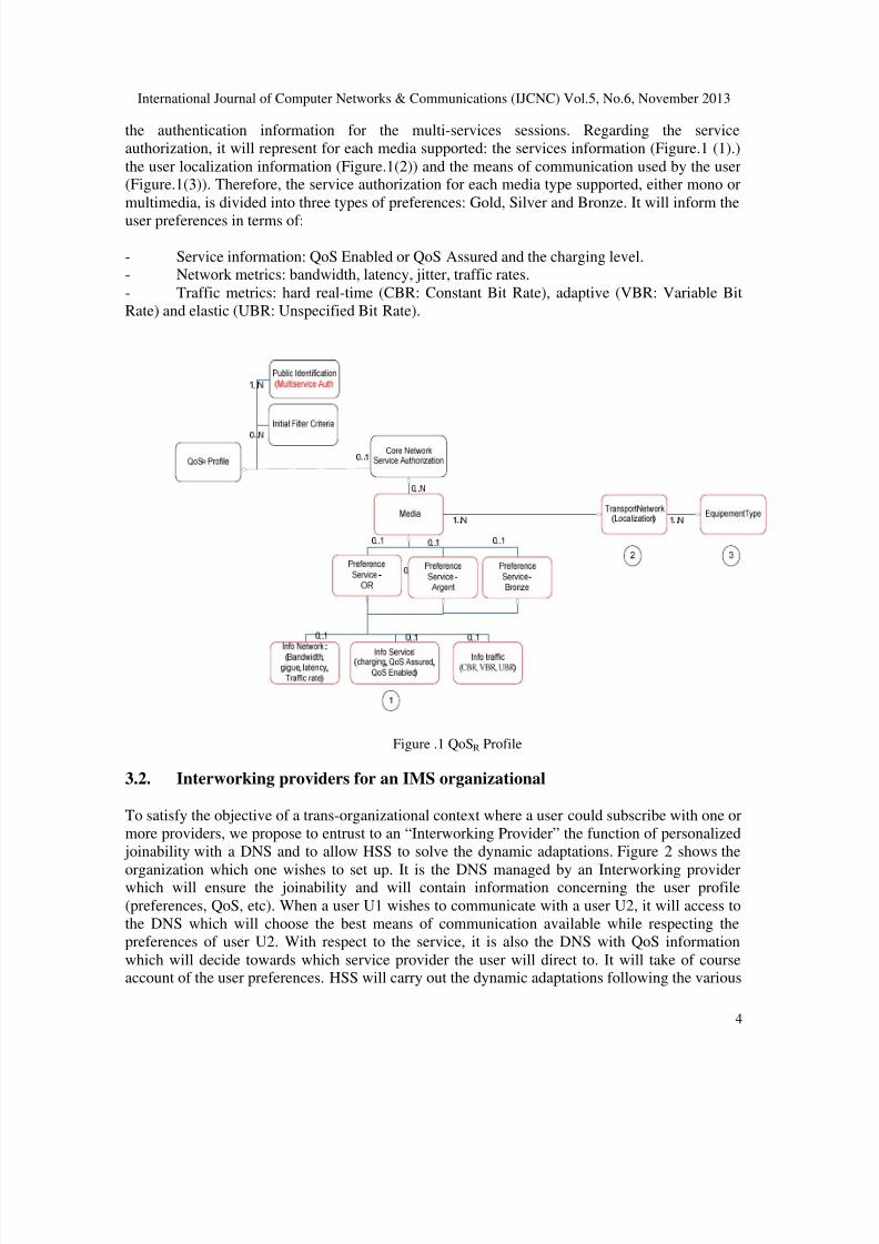
The QoSRequested profile that we propose is divided into three parts: public identification, Service
Authorization and Initial Filter Criteria. We are adding to public identification of the subscriber
8/13/2019 Interworking QOS Management Subsystem Into IMS-Based Architecture Multi Providers IMS-IQMSMP
http://slidepdf.com/reader/full/interworking-qos-management-subsystem-into-ims-based-architecture-multi-providers 4/21
International Journal of Computer Networks & Communications (IJCNC) Vol.5, No.6, November 2013
4
the authentication information for the multi-services sessions. Regarding the service
authorization, it will represent for each media supported: the services information (Figure.1 (1).)
the user localization information (Figure.1(2)) and the means of communication used by the user(Figure.1(3)). Therefore, the service authorization for each media type supported, either mono or
multimedia, is divided into three types of preferences: Gold, Silver and Bronze. It will inform the
user preferences in terms of:
- Service information: QoS Enabled or QoS Assured and the charging level.- Network metrics: bandwidth, latency, jitter, traffic rates.
- Traffic metrics: hard real-time (CBR: Constant Bit Rate), adaptive (VBR: Variable Bit
Rate) and elastic (UBR: Unspecified Bit Rate).
Figure .1 QoSR Profile
3.2. Interworking providers for an IMS organizational
To satisfy the objective of a trans-organizational context where a user could subscribe with one or
more providers, we propose to entrust to an “Interworking Provider” the function of personalized
joinability with a DNS and to allow HSS to solve the dynamic adaptations. Figure 2 shows the
organization which one wishes to set up. It is the DNS managed by an Interworking providerwhich will ensure the joinability and will contain information concerning the user profile
(preferences, QoS, etc). When a user U1 wishes to communicate with a user U2, it will access to
the DNS which will choose the best means of communication available while respecting the
preferences of user U2. With respect to the service, it is also the DNS with QoS information
which will decide towards which service provider the user will direct to. It will take of courseaccount of the user preferences. HSS will carry out the dynamic adaptations following the various
8/13/2019 Interworking QOS Management Subsystem Into IMS-Based Architecture Multi Providers IMS-IQMSMP
http://slidepdf.com/reader/full/interworking-qos-management-subsystem-into-ims-based-architecture-multi-providers 5/21
International Journal of Computer Networks & Communications (IJCNC) Vol.5, No.6, November 2013
5
changes of access networks and terminals networks. Thanks to this HSS and to the DNS, the IMS
will have a larger cover of the needs of the user-centric of NGN.
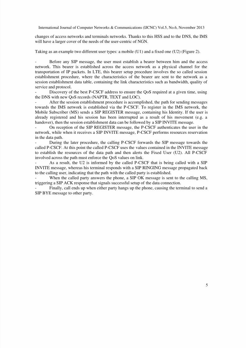
Taking as an example two different user types: a mobile (U1) and a fixed one (U2) (Figure 2).
- Before any SIP message, the user must establish a bearer between him and the accessnetwork. This bearer is established across the access network as a physical channel for the
transportation of IP packets. In LTE, this bearer setup procedure involves the so called sessionestablishment procedure, where the characteristics of the bearer are sent to the network as a
session establishment data table, containing the link characteristics such as bandwidth, quality of
service and protocol.
- Discovery of the best P-CSCF address to ensure the QoS required at a given time, using
the DNS with new QoS records (NAPTR, TEXT and LOC).
- After the session establishment procedure is accomplished, the path for sending messages
towards the IMS network is established via the P-CSCF. To register in the IMS network, the
Mobile Subscriber (MS) sends a SIP REGISTER message, containing his Identity. If the user is
already registered and his session has been interrupted as a result of his movement (e.g. a
handover), then the session establishment data can be followed by a SIP INVITE message.- On reception of the SIP REGISTER message, the P-CSCF authenticates the user in the
network, while when it receives a SIP INVITE message, P-CSCF performs resources reservation
in the data path.
- During the later procedure, the calling P-CSCF forwards the SIP message towards the
called P-CSCF. At this point the called P-CSCF uses the values contained in the INVITE message
to establish the resources of the data path and then alerts the Fixed User (U2). All P-CSCF
involved across the path must enforce the QoS values on link.
- As a result, the U2 is informed by the called P-CSCF that is being called with a SIP
INVITE message, whereas his terminal responds with a SIP RINGING message propagated back
to the calling user, indicating that the path with the called party is established.
- When the called party answers the phone, a SIP OK message is sent to the calling MS,
triggering a SIP ACK response that signals successful setup of the data connection.- Finally, call ends up when either party hangs up the phone, causing the terminal to send a
SIP BYE message to other party.
8/13/2019 Interworking QOS Management Subsystem Into IMS-Based Architecture Multi Providers IMS-IQMSMP
http://slidepdf.com/reader/full/interworking-qos-management-subsystem-into-ims-based-architecture-multi-providers 6/21
International Journal of Computer Networks & Communications (IJCNC) Vol.5, No.6, November 2013
6
Figure 2.Interworking Providers
DNS allows users to determine how and where their contacts can communicate with them. This ispossible by direct storage of data in the DNS. Storing data in the DNS has three types of DNS
records: NAPTR, TXT and LOC.
NAPTR records can publish and manage contact information for users. These NAPTR recordscan also point to other NAPTR record, which allows you to navigate a tree of coordinates basedon geography.
Textual (or TXT) records stored directly in the DNS. These allow the publication of text-based
information, such as preferences for QoS depending on the location and the different means of
communication, which will help users to better reach users they want to contact and taking intoaccount their preferences.
Likewise, the location (or LOC) records to publish the location information of the users.
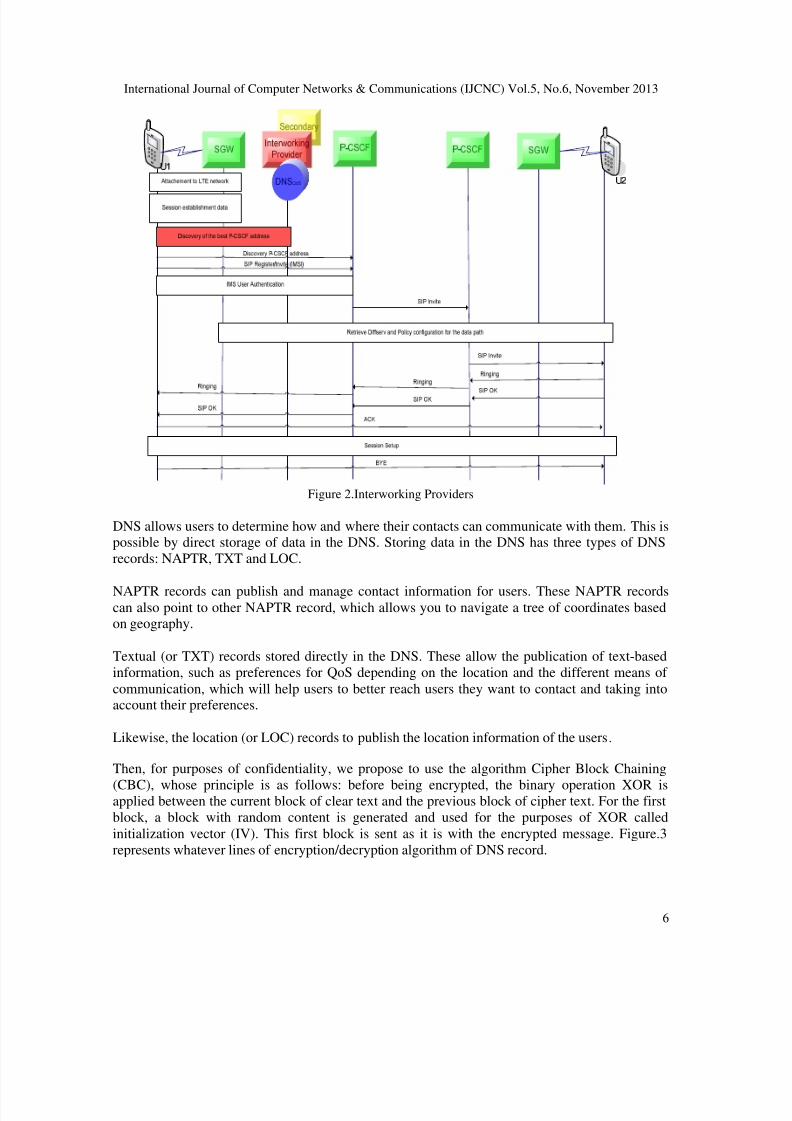
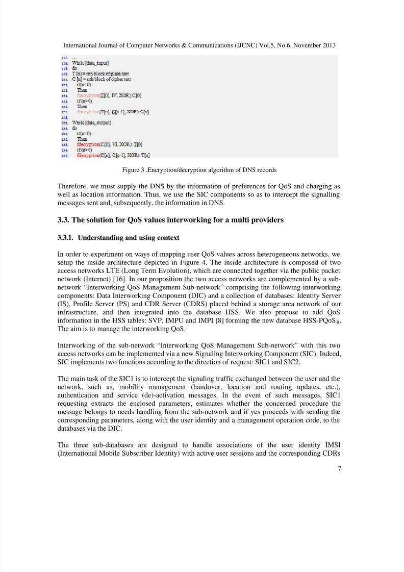
Then, for purposes of confidentiality, we propose to use the algorithm Cipher Block Chaining
(CBC), whose principle is as follows: before being encrypted, the binary operation XOR isapplied between the current block of clear text and the previous block of cipher text. For the first
block, a block with random content is generated and used for the purposes of XOR called
initialization vector (IV). This first block is sent as it is with the encrypted message. Figure.3
represents whatever lines of encryption/decryption algorithm of DNS record.
8/13/2019 Interworking QOS Management Subsystem Into IMS-Based Architecture Multi Providers IMS-IQMSMP
http://slidepdf.com/reader/full/interworking-qos-management-subsystem-into-ims-based-architecture-multi-providers 7/21
International Journal of Computer Networks & Communications (IJCNC) Vol.5, No.6, November 2013
7
Figure 3 .Encryption/decryption algorithm of DNS records
Therefore, we must supply the DNS by the information of preferences for QoS and charging as
well as location information. Thus, we use the SIC components so as to intercept the signalling
messages sent and, subsequently, the information in DNS.
3.3. The solution for QoS values interworking for a multi providers
3.3.1. Understanding and using context
In order to experiment on ways of mapping user QoS values across heterogeneous networks, we
setup the inside architecture depicted in Figure 4. The inside architecture is composed of twoaccess networks LTE (Long Term Evolution), which are connected together via the public packet
network (Internet) [16]. In our proposition the two access networks are complemented by a sub-
network “Interworking QoS Management Sub-network” comprising the following interworking
components: Data Interworking Component (DIC) and a collection of databases: Identity Server
(IS), Profile Server (PS) and CDR Server (CDRS) placed behind a storage area network of our
infrastructure, and then integrated into the database HSS. We also propose to add QoS
information in the HSS tables: SVP, IMPU and IMPI [8] forming the new database HSS-PQoS R.
The aim is to manage the interworking QoS.
Interworking of the sub-network “Interworking QoS Management Sub-network” with this two
access networks can be implemented via a new Signaling Interworking Component (SIC). Indeed,
SIC implements two functions according to the direction of request: SIC1 and SIC2.
The main task of the SIC1 is to intercept the signaling traffic exchanged between the user and the
network, such as, mobility management (handover, location and routing updates, etc.),
authentication and service (de)-activation messages. In the event of such messages, SIC1
requesting extracts the enclosed parameters, estimates whether the concerned procedure themessage belongs to needs handling from the sub-network and if yes proceeds with sending the
corresponding parameters, along with the user identity and a management operation code, to the
databases via the DIC.
The three sub-databases are designed to handle associations of the user identity IMSI
(International Mobile Subscriber Identity) with active user sessions and the corresponding CDRs
8/13/2019 Interworking QOS Management Subsystem Into IMS-Based Architecture Multi Providers IMS-IQMSMP
http://slidepdf.com/reader/full/interworking-qos-management-subsystem-into-ims-based-architecture-multi-providers 8/21
International Journal of Computer Networks & Communications (IJCNC) Vol.5, No.6, November 2013
8
generated by the access network. These user ID-CDR associations can be one-to-one or one-to-
many in cases of multi-party calls (e.g. videoconferencing). Therefore, the SIC can intercept and
store in the sub-network, QoS and CDR values assigned to user sessions by the access network,so that they are available for other SICs involved along the communication path. On the other
communication end or at the intermediate points, corresponding SICs may retrieve this
information, using as an index the identity of the calling user. Thereby, the original values of userdata sessions can be maintained across the whole communication path so as to be retrieved at
points where data traffic undergoes QoS “rounding”.
Since such operations mostly concern multi-operator communication environments, the need of
gaining access to private user data is protected by exclusive peer agreements between operators
and service providers and therefore is strictly forbidden to the wider public, if a LTE user is
initially attached in the network. During message exchange with the MME (Mobility
Management Entity) and the SGW (Serving Gateway), the attached message is intercepted by the
SIC and a record is opened in the IS database. When the attached user activates an application, a
session establishment data is sent towards the SGW.
This message conveys the QoS parameters (service ID, traffic rate and QoS class) and othercharacteristics (e.g. multiparty, client/server, etc.) of the user session to be applied on the data
path. When the SGW returns a session establishment response, the SIC creates an association
between the identity IMSI of the user and the service ID of the user has activated in the PS, and
initializes a corresponding CDR in the CDRS to use for keeping service utilization time. At the
other communication side, the corresponding SIC intercepts all arriving SIP messages and
processes those that are marked by the called P-CSCF with the IP address of the called user. On
reception of the corresponding INVITE message, the SIC2 creates an end-to-end association
between the called user ID, the original QoS values of the call, and those assigned by the local
access network.
The SIC maintains this association locally for the whole lifecycle of the call in order to retrieve
session’s original characteristics when the called user performs handover or roaming. Similarly,ID-local QoS values associations can be created and maintained by every network involved in the
call so as to be used for retrieving the original QoS values every time QoS undergoes “rounding”
due to QoS mismatches among the networks involved in the call. When the path is successfully
established, the SICs involved along the communication path initialize the corresponding CDRs,
using the tariffing policy of the local network, thus enabling implementation of accurate charging.
Seen from our logic, the DIC can be incorporated in the P-CSCF. Such an assumption is valid as
the main task of P-CSCF is guaranteed. Therefore P-CSCF is the most suitable component for
hosting DIC mechanisms for home network tracking.
Furthermore, since P-CSCF makes use of the SIP protocol for its communication with the
neighbouring IMS components, then it can accommodate an additional SIP based interface for the
communication with the SIC. Assuming that such an interface exists, the databases for the storageof the ID-QoS/CDR associations can be integrated within the database of the HSS-PQoSR of the
host IMS network. In IMS networks, HSS is accessible by the P-CSCF, through the S-CSCF, over
a SIP-based interface making use of the Diameter protocol [10].
SICs can communicate with the components of the IMS network with SIP messages. Therefore,
all queries towards the IS, PS, CDRS sub-databases can be sent to the P-CSCF encapsulated in
the SDP protocol field of a SIP message or in SIP DIALOG messages. Messages circulated using
8/13/2019 Interworking QOS Management Subsystem Into IMS-Based Architecture Multi Providers IMS-IQMSMP
http://slidepdf.com/reader/full/interworking-qos-management-subsystem-into-ims-based-architecture-multi-providers 9/21
International Journal of Computer Networks & Communications (IJCNC) Vol.5, No.6, November 2013
9
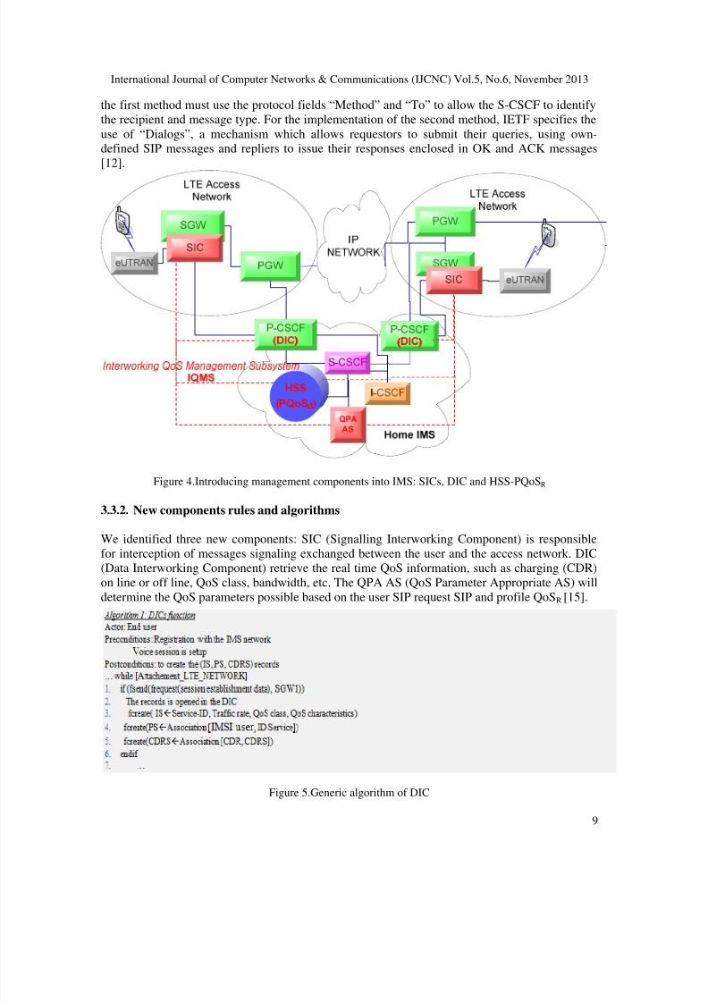
the first method must use the protocol fields “Method” and “To” to allow the S-CSCF to identify
the recipient and message type. For the implementation of the second method, IETF specifies the
use of “Dialogs”, a mechanism which allows requestors to submit their queries, using own-defined SIP messages and repliers to issue their responses enclosed in OK and ACK messages
[12].
Figure 4.Introducing management components into IMS: SICs, DIC and HSS-PQoSR
3.3.2. New components rules and algorithms
We identified three new components: SIC (Signalling Interworking Component) is responsible
for interception of messages signaling exchanged between the user and the access network. DIC
(Data Interworking Component) retrieve the real time QoS information, such as charging (CDR)
on line or off line, QoS class, bandwidth, etc. The QPA AS (QoS Parameter Appropriate AS) will
determine the QoS parameters possible based on the user SIP request SIP and profile QoSR [15].
Figure 5.Generic algorithm of DIC
8/13/2019 Interworking QOS Management Subsystem Into IMS-Based Architecture Multi Providers IMS-IQMSMP
http://slidepdf.com/reader/full/interworking-qos-management-subsystem-into-ims-based-architecture-multi-providers 10/21
International Journal of Computer Networks & Communications (IJCNC) Vol.5, No.6, November 2013
10
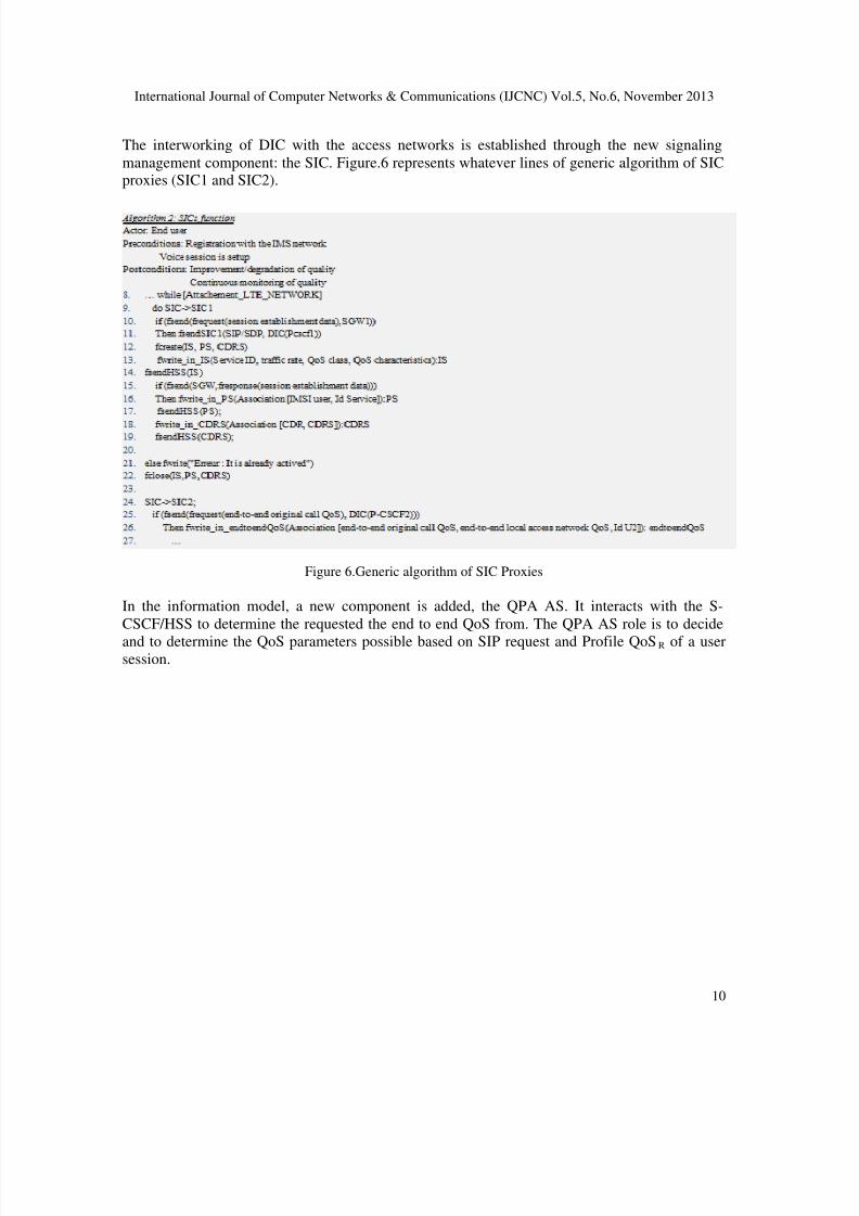
The interworking of DIC with the access networks is established through the new signaling
management component: the SIC. Figure.6 represents whatever lines of generic algorithm of SICproxies (SIC1 and SIC2).
Figure 6.Generic algorithm of SIC Proxies
In the information model, a new component is added, the QPA AS. It interacts with the S-
CSCF/HSS to determine the requested the end to end QoS from. The QPA AS role is to decide
and to determine the QoS parameters possible based on SIP request and Profile QoS R of a usersession.
8/13/2019 Interworking QOS Management Subsystem Into IMS-Based Architecture Multi Providers IMS-IQMSMP
http://slidepdf.com/reader/full/interworking-qos-management-subsystem-into-ims-based-architecture-multi-providers 11/21
International Journal of Computer Networks & Communications (IJCNC) Vol.5, No.6, November 2013
11
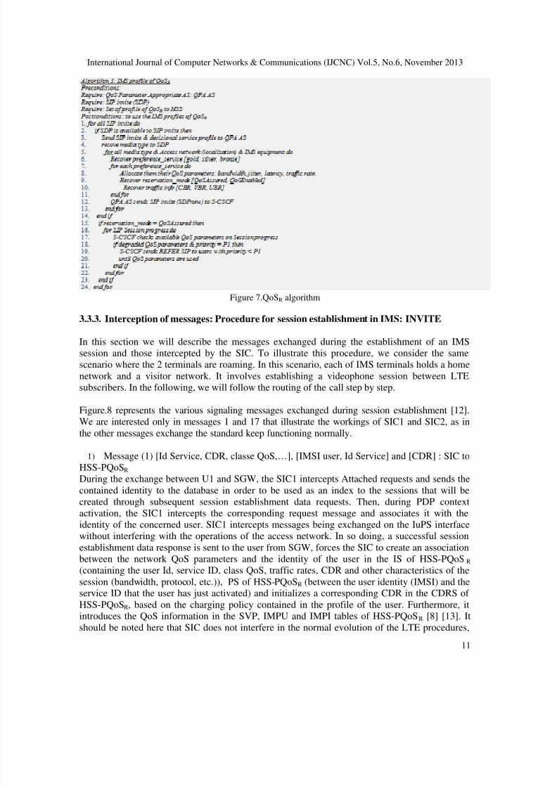
Figure 7.QoSR algorithm
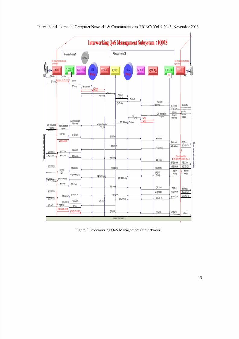
3.3.3. Interception of messages: Procedure for session establishment in IMS: INVITE
In this section we will describe the messages exchanged during the establishment of an IMS
session and those intercepted by the SIC. To illustrate this procedure, we consider the same
scenario where the 2 terminals are roaming. In this scenario, each of IMS terminals holds a home
network and a visitor network. It involves establishing a videophone session between LTE
subscribers. In the following, we will follow the routing of the call step by step.
Figure.8 represents the various signaling messages exchanged during session establishment [12].We are interested only in messages 1 and 17 that illustrate the workings of SIC1 and SIC2, as in
the other messages exchange the standard keep functioning normally.
1) Message (1) [Id Service, CDR, classe QoS,…], [IMSI user, Id Service] and [CDR] : SIC to
HSS-PQoSR
During the exchange between U1 and SGW, the SIC1 intercepts Attached requests and sends the
contained identity to the database in order to be used as an index to the sessions that will be
created through subsequent session establishment data requests. Then, during PDP context
activation, the SIC1 intercepts the corresponding request message and associates it with the
identity of the concerned user. SIC1 intercepts messages being exchanged on the IuPS interface
without interfering with the operations of the access network. In so doing, a successful session
establishment data response is sent to the user from SGW, forces the SIC to create an associationbetween the network QoS parameters and the identity of the user in the IS of HSS-PQoS R
(containing the user Id, service ID, class QoS, traffic rates, CDR and other characteristics of the
session (bandwidth, protocol, etc.)), PS of HSS-PQoSR (between the user identity (IMSI) and theservice ID that the user has just activated) and initializes a corresponding CDR in the CDRS of
HSS-PQoSR, based on the charging policy contained in the profile of the user. Furthermore, it
introduces the QoS information in the SVP, IMPU and IMPI tables of HSS-PQoSR [8] [13]. It
should be noted here that SIC does not interfere in the normal evolution of the LTE procedures,
8/13/2019 Interworking QOS Management Subsystem Into IMS-Based Architecture Multi Providers IMS-IQMSMP
http://slidepdf.com/reader/full/interworking-qos-management-subsystem-into-ims-based-architecture-multi-providers 12/21
International Journal of Computer Networks & Communications (IJCNC) Vol.5, No.6, November 2013
12
which means that the signaling messages are exchanged between the user and the network
without to undergo any content modification. The main fields of this message comprise:
- IS: Contains the service ID, traffic rate, QoS class, bandwidth, protocol used, QoS-
Enabled, QoS-Assured, etc.
- PS: Contains the association between user U1 ID and service ID that was initialized inPS.
- SDP content: These fields describe the session. They indicate that it is a SDP offer(Session Description Protocol) with bandwidth.
- Route: Contains the address of the P-CSCF determined from the Discovery Procedure
and value of the port number of the P-CSCF; it also involves the value of Service-Route header
obtained during the registration, i.e. the address of the S-CSCF in the home network.
- CDRS: Contains the timing for the registry of charging service.
2) Message (17) End-to-end [IMSI user called, QoS visitor network 1 & 2]
The SIC2 of the visitor network-2 intercepts all SIP messages with the IP address of U2 (the
called user). Upon receipt of the corresponding Invite message, SIC2 creates an end-to-endassociation between the called user Id, the original values of the QoS of the call, and thoseassigned by the local access network. It keeps the association locally for the entire lifecycle of the
call to retrieve the characteristics of original session, where U2 performs a handover or roaming.
- End-to-end association: contains the end-to-end association between the called user ID,
the original values of the QoS of the call and the QoS values of the local access network.
8/13/2019 Interworking QOS Management Subsystem Into IMS-Based Architecture Multi Providers IMS-IQMSMP
http://slidepdf.com/reader/full/interworking-qos-management-subsystem-into-ims-based-architecture-multi-providers 13/21
International Journal of Computer Networks & Communications (IJCNC) Vol.5, No.6, November 2013
13
Figure 8 .interworking QoS Management Sub-network
8/13/2019 Interworking QOS Management Subsystem Into IMS-Based Architecture Multi Providers IMS-IQMSMP
http://slidepdf.com/reader/full/interworking-qos-management-subsystem-into-ims-based-architecture-multi-providers 14/21
International Journal of Computer Networks & Communications (IJCNC) Vol.5, No.6, November 2013
14
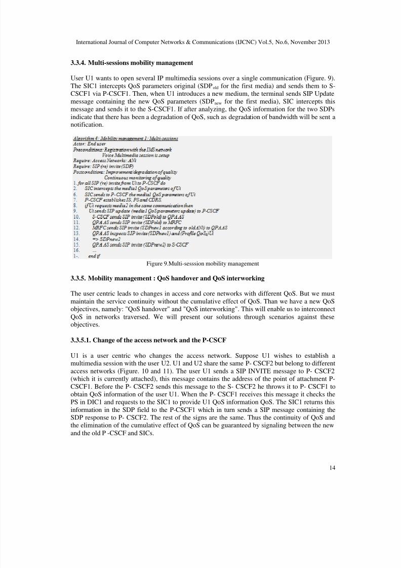
3.3.4. Multi-sessions mobility management
User U1 wants to open several IP multimedia sessions over a single communication (Figure. 9).
The SIC1 intercepts QoS parameters original (SDPold for the first media) and sends them to S-CSCF1 via P-CSCF1. Then, when U1 introduces a new medium, the terminal sends SIP Update
message containing the new QoS parameters (SDPnew for the first media), SIC intercepts thismessage and sends it to the S-CSCF1. If after analyzing, the QoS information for the two SDPs
indicate that there has been a degradation of QoS, such as degradation of bandwidth will be sent anotification.
Figure 9.Multi-sesssion mobility management
3.3.5. Mobility management : QoS handover and QoS interworking
The user centric leads to changes in access and core networks with different QoS. But we must
maintain the service continuity without the cumulative effect of QoS. Than we have a new QoSobjectives, namely: "QoS handover" and "QoS interworking". This will enable us to interconnect
QoS in networks traversed. We will present our solutions through scenarios against theseobjectives.
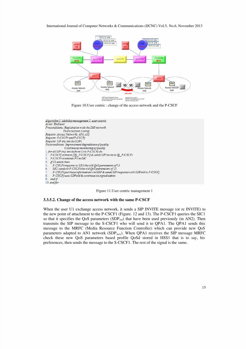
3.3.5.1. Change of the access network and the P-CSCF
U1 is a user centric who changes the access network. Suppose U1 wishes to establish amultimedia session with the user U2. U1 and U2 share the same P- CSCF2 but belong to different
access networks (Figure. 10 and 11). The user U1 sends a SIP INVITE message to P- CSCF2(which it is currently attached), this message contains the address of the point of attachment P-
CSCF1. Before the P- CSCF2 sends this message to the S- CSCF2 he throws it to P- CSCF1 toobtain QoS information of the user U1. When the P- CSCF1 receives this message it checks the
PS in DIC1 and requests to the SIC1 to provide U1 QoS information QoS. The SIC1 returns this
information in the SDP field to the P-CSCF1 which in turn sends a SIP message containing theSDP response to P- CSCF2. The rest of the signs are the same. Thus the continuity of QoS andthe elimination of the cumulative effect of QoS can be guaranteed by signaling between the new
and the old P -CSCF and SICs.
8/13/2019 Interworking QOS Management Subsystem Into IMS-Based Architecture Multi Providers IMS-IQMSMP
http://slidepdf.com/reader/full/interworking-qos-management-subsystem-into-ims-based-architecture-multi-providers 15/21
International Journal of Computer Networks & Communications (IJCNC) Vol.5, No.6, November 2013
15
Figure 10.User centric : change of the access network and the P-CSCF
Figure 11.User centric management 1
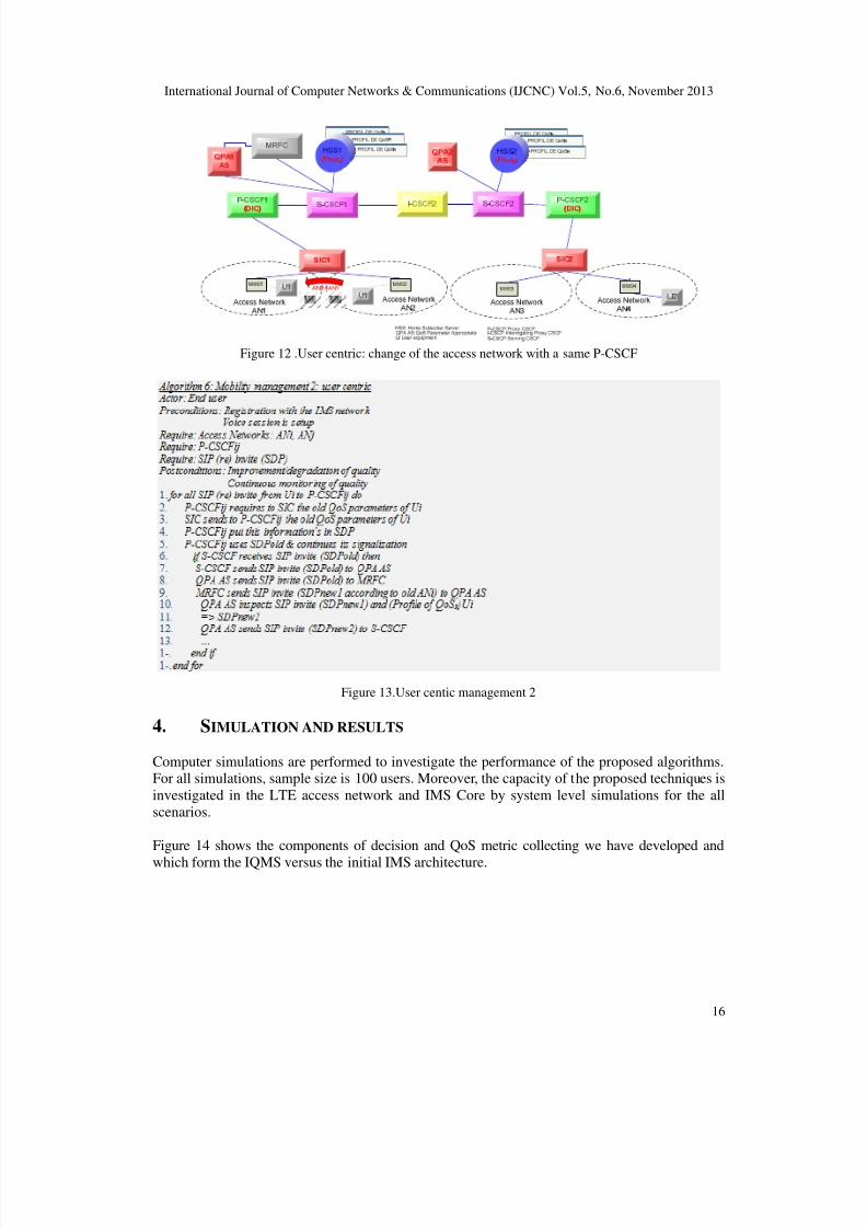
3.3.5.2. Change of the access network with the same P-CSCF
When the user U1 exchange access network, it sends a SIP INVITE message (or re INVITE) to
the new point of attachment to the P-CSCF1 (Figure. 12 and 13). The P-CSCF1 queries the SIC1
so that it specifies the QoS parameters (SDPold) that have been used previously (in AN2). Thentransmits the SIP message to the S-CSCF1 who will send it to QPA1. The QPA1 sends this
message to the MRFC (Media Resource Function Controller) which can provide new QoS
parameters adapted to AN1 network (SDPnew). When QPA1 receives the SIP message MRFCcheck these new QoS parameters based profile QoSd stored in HSS1 that is to say, his
preferences, then sends the message to the S-CSCF1. The rest of the signal is the same.
8/13/2019 Interworking QOS Management Subsystem Into IMS-Based Architecture Multi Providers IMS-IQMSMP
http://slidepdf.com/reader/full/interworking-qos-management-subsystem-into-ims-based-architecture-multi-providers 16/21
International Journal of Computer Networks & Communications (IJCNC) Vol.5, No.6, November 2013
16
Figure 12 .User centric: change of the access network with a same P-CSCF
Figure 13.User centic management 2
4. SIMULATION AND RESULTS
Computer simulations are performed to investigate the performance of the proposed algorithms.For all simulations, sample size is 100 users. Moreover, the capacity of the proposed techniques is
investigated in the LTE access network and IMS Core by system level simulations for the all
scenarios.
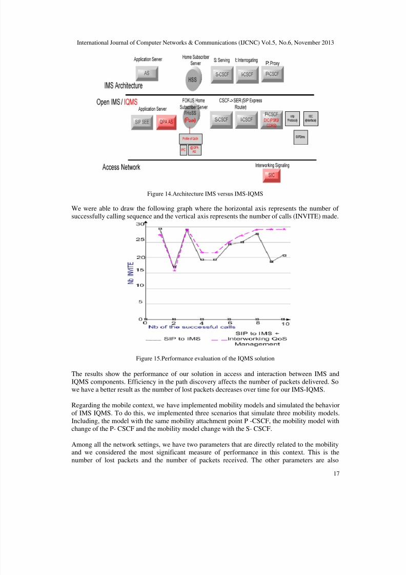
Figure 14 shows the components of decision and QoS metric collecting we have developed and
which form the IQMS versus the initial IMS architecture.
8/13/2019 Interworking QOS Management Subsystem Into IMS-Based Architecture Multi Providers IMS-IQMSMP
http://slidepdf.com/reader/full/interworking-qos-management-subsystem-into-ims-based-architecture-multi-providers 17/21
International Journal of Computer Networks & Communications (IJCNC) Vol.5, No.6, November 2013
17
Figure 14.Architecture IMS versus IMS-IQMS
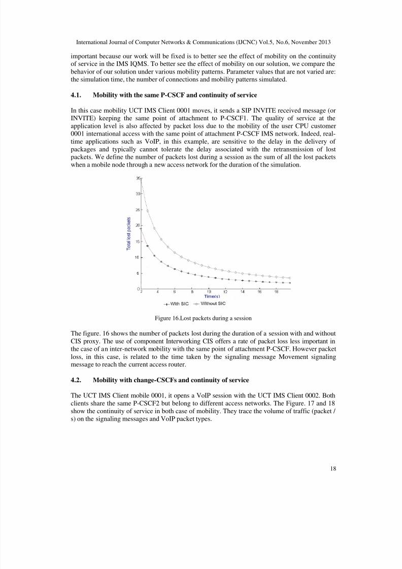
We were able to draw the following graph where the horizontal axis represents the number ofsuccessfully calling sequence and the vertical axis represents the number of calls (INVITE) made.
Figure 15.Performance evaluation of the IQMS solution
The results show the performance of our solution in access and interaction between IMS and
IQMS components. Efficiency in the path discovery affects the number of packets delivered. Sowe have a better result as the number of lost packets decreases over time for our IMS-IQMS.
Regarding the mobile context, we have implemented mobility models and simulated the behaviorof IMS IQMS. To do this, we implemented three scenarios that simulate three mobility models.
Including, the model with the same mobility attachment point P -CSCF, the mobility model withchange of the P- CSCF and the mobility model change with the S- CSCF.
Among all the network settings, we have two parameters that are directly related to the mobilityand we considered the most significant measure of performance in this context. This is the
number of lost packets and the number of packets received. The other parameters are also
8/13/2019 Interworking QOS Management Subsystem Into IMS-Based Architecture Multi Providers IMS-IQMSMP
http://slidepdf.com/reader/full/interworking-qos-management-subsystem-into-ims-based-architecture-multi-providers 18/21
International Journal of Computer Networks & Communications (IJCNC) Vol.5, No.6, November 2013
18
important because our work will be fixed is to better see the effect of mobility on the continuityof service in the IMS IQMS. To better see the effect of mobility on our solution, we compare the
behavior of our solution under various mobility patterns. Parameter values that are not varied are:the simulation time, the number of connections and mobility patterns simulated.
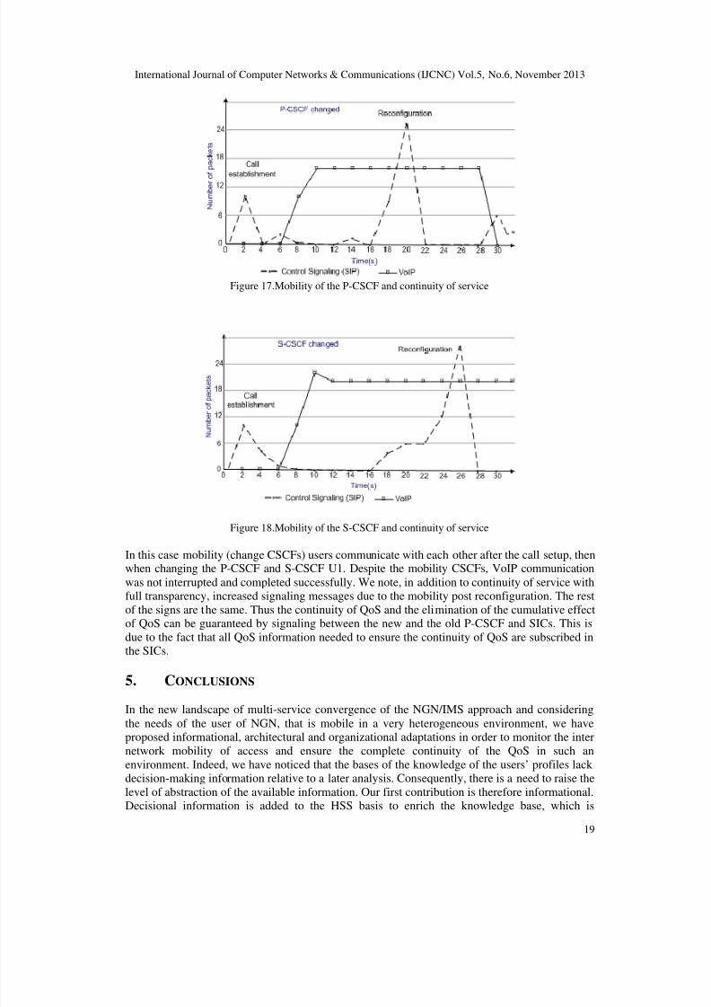
4.1. Mobility with the same P-CSCF and continuity of service
In this case mobility UCT IMS Client 0001 moves, it sends a SIP INVITE received message (orINVITE) keeping the same point of attachment to P-CSCF1. The quality of service at the
application level is also affected by packet loss due to the mobility of the user CPU customer0001 international access with the same point of attachment P-CSCF IMS network. Indeed, real-
time applications such as VoIP, in this example, are sensitive to the delay in the delivery of
packages and typically cannot tolerate the delay associated with the retransmission of lostpackets. We define the number of packets lost during a session as the sum of all the lost packetswhen a mobile node through a new access network for the duration of the simulation.
Figure 16.Lost packets during a session
The figure. 16 shows the number of packets lost during the duration of a session with and without
CIS proxy. The use of component Interworking CIS offers a rate of packet loss less important inthe case of an inter-network mobility with the same point of attachment P-CSCF. However packet
loss, in this case, is related to the time taken by the signaling message Movement signalingmessage to reach the current access router.
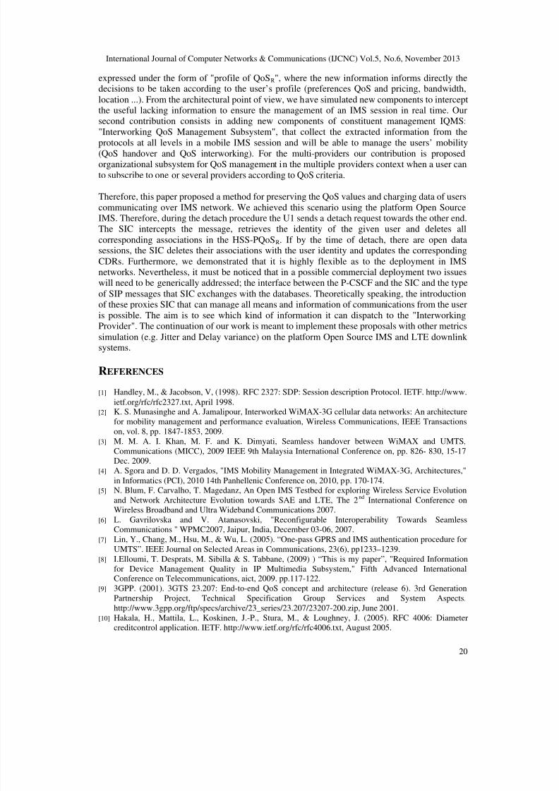
4.2. Mobility with change-CSCFs and continuity of service
The UCT IMS Client mobile 0001, it opens a VoIP session with the UCT IMS Client 0002. Bothclients share the same P-CSCF2 but belong to different access networks. The Figure. 17 and 18
show the continuity of service in both case of mobility. They trace the volume of traffic (packet /s) on the signaling messages and VoIP packet types.
8/13/2019 Interworking QOS Management Subsystem Into IMS-Based Architecture Multi Providers IMS-IQMSMP
http://slidepdf.com/reader/full/interworking-qos-management-subsystem-into-ims-based-architecture-multi-providers 19/21
International Journal of Computer Networks & Communications (IJCNC) Vol.5, No.6, November 2013
19
Figure 17.Mobility of the P-CSCF and continuity of service
Figure 18.Mobility of the S-CSCF and continuity of service
In this case mobility (change CSCFs) users communicate with each other after the call setup, thenwhen changing the P-CSCF and S-CSCF U1. Despite the mobility CSCFs, VoIP communication
was not interrupted and completed successfully. We note, in addition to continuity of service withfull transparency, increased signaling messages due to the mobility post reconfiguration. The rest
of the signs are the same. Thus the continuity of QoS and the elimination of the cumulative effectof QoS can be guaranteed by signaling between the new and the old P-CSCF and SICs. This is
due to the fact that all QoS information needed to ensure the continuity of QoS are subscribed inthe SICs.
5. CONCLUSIONS
In the new landscape of multi-service convergence of the NGN/IMS approach and consideringthe needs of the user of NGN, that is mobile in a very heterogeneous environment, we haveproposed informational, architectural and organizational adaptations in order to monitor the inter
network mobility of access and ensure the complete continuity of the QoS in such an
environment. Indeed, we have noticed that the bases of the knowledge of the users’ profiles lackdecision-making information relative to a later analysis. Consequently, there is a need to raise the
level of abstraction of the available information. Our first contribution is therefore informational.Decisional information is added to the HSS basis to enrich the knowledge base, which is
8/13/2019 Interworking QOS Management Subsystem Into IMS-Based Architecture Multi Providers IMS-IQMSMP
http://slidepdf.com/reader/full/interworking-qos-management-subsystem-into-ims-based-architecture-multi-providers 20/21
International Journal of Computer Networks & Communications (IJCNC) Vol.5, No.6, November 2013
20
expressed under the form of "profile of QoSR", where the new information informs directly thedecisions to be taken according to the user’s profile (preferences QoS and pricing, bandwidth,
location ...). From the architectural point of view, we have simulated new components to interceptthe useful lacking information to ensure the management of an IMS session in real time. Oursecond contribution consists in adding new components of constituent management IQMS:
"Interworking QoS Management Subsystem", that collect the extracted information from the
protocols at all levels in a mobile IMS session and will be able to manage the users’ mobility
(QoS handover and QoS interworking). For the multi-providers our contribution is proposedorganizational subsystem for QoS management in the multiple providers context when a user can
to subscribe to one or several providers according to QoS criteria.
Therefore, this paper proposed a method for preserving the QoS values and charging data of users
communicating over IMS network. We achieved this scenario using the platform Open SourceIMS. Therefore, during the detach procedure the U1 sends a detach request towards the other end.The SIC intercepts the message, retrieves the identity of the given user and deletes all
corresponding associations in the HSS-PQoSR. If by the time of detach, there are open datasessions, the SIC deletes their associations with the user identity and updates the corresponding
CDRs. Furthermore, we demonstrated that it is highly flexible as to the deployment in IMSnetworks. Nevertheless, it must be noticed that in a possible commercial deployment two issueswill need to be generically addressed; the interface between the P-CSCF and the SIC and the type
of SIP messages that SIC exchanges with the databases. Theoretically speaking, the introductionof these proxies SIC that can manage all means and information of communications from the user
is possible. The aim is to see which kind of information it can dispatch to the "InterworkingProvider". The continuation of our work is meant to implement these proposals with other metrics
simulation (e.g. Jitter and Delay variance) on the platform Open Source IMS and LTE downlinksystems.
REFERENCES
[1] Handley, M., & Jacobson, V, (1998). RFC 2327: SDP: Session description Protocol. IETF. http://www.
ietf.org/rfc/rfc2327.txt, April 1998.
[2]
K. S. Munasinghe and A. Jamalipour, Interworked WiMAX-3G cellular data networks: An architecturefor mobility management and performance evaluation, Wireless Communications, IEEE Transactions
on, vol. 8, pp. 1847-1853, 2009.
[3] M. M. A. I. Khan, M. F. and K. Dimyati, Seamless handover between WiMAX and UMTS,
Communications (MICC), 2009 IEEE 9th Malaysia International Conference on, pp. 826- 830, 15-17
Dec. 2009.
[4] A. Sgora and D. D. Vergados, "IMS Mobility Management in Integrated WiMAX-3G, Architectures,"
in Informatics (PCI), 2010 14th Panhellenic Conference on, 2010, pp. 170-174.
[5] N. Blum, F. Carvalho, T. Magedanz, An Open IMS Testbed for exploring Wireless Service Evolution
and Network Architecture Evolution towards SAE and LTE, The 2nd
International Conference on
Wireless Broadband and Ultra Wideband Communications 2007.
[6] L. Gavrilovska and V. Atanasovski, "Reconfigurable Interoperability Towards Seamless
Communications " WPMC2007, Jaipur, India, December 03-06, 2007.
[7] Lin, Y., Chang, M., Hsu, M., & Wu, L. (2005). “One-pass GPRS and IMS authentication procedure for
UMTS”. IEEE Journal on Selected Areas in Communications, 23(6), pp1233–1239.
[8] I.Elloumi, T. Desprats, M. Sibilla & S. Tabbane, (2009) ) “This is my paper”, "Required Information
for Device Management Quality in IP Multimedia Subsystem," Fifth Advanced InternationalConference on Telecommunications, aict, 2009. pp.117-122.
[9] 3GPP. (2001). 3GTS 23.207: End-to-end QoS concept and architecture (release 6). 3rd Generation
Partnership Project, Technical Specification Group Services and System Aspects.
http://www.3gpp.org/ftp/specs/archive/23_series/23.207/23207-200.zip, June 2001.
[10] Hakala, H., Mattila, L., Koskinen, J.-P., Stura, M., & Loughney, J. (2005). RFC 4006: Diameter
creditcontrol application. IETF. http://www.ietf.org/rfc/rfc4006.txt, August 2005.

8/13/2019 Interworking QOS Management Subsystem Into IMS-Based Architecture Multi Providers IMS-IQMSMP
http://slidepdf.com/reader/full/interworking-qos-management-subsystem-into-ims-based-architecture-multi-providers 21/21
International Journal of Computer Networks & Communications (IJCNC) Vol.5, No.6, November 2013
21
[11] ITU-T. (1996). Q.713: Switching and Signalling Specifications of Signalling System No. 7-Signalling
Connection Control Part (SCCP)—Signalling Connection Control Formats and Codes. ITU-T Q-Series
Recommendations.
[12] http://www.itu.int/rec/dologin_pub.as?lang=e&id=T-REC-Q. 713-199607-S!!PDF-E&type=items, July
1996.
[13] http://www.openimscore.org/
[14] I.Elloumi, T.Desprats, M.Sibilla, S.Tabbane, (2008), “This is my paper”, “Internet MultimediaServices Architecture and Applications”, IMSAA 2008. 2nd International Conference on Volume,Issue, 10-12 Dec. 2008 pp1-6.
[15] I.Elloumi, T.Desprats, M.Sibilla, S.Tabbane, (2010), “This is my paper”, Interworking Components for
the end-to-end QoS into IMS-Based Architecture mono provider”, The 15th IEEE Symposium on
Computers and Communications, Riccione– Italy, 22-25 June, 2010.
[16] Mohamed A. Abd El-Gawad, Mohsen M. Tantawy and Mohamed El-Mahallawy, LTE QoS dynamicresource block allocation with power source limitation and queue stability constraints, International
Journal of Computer Networks & Communications (IJCNC), Vol.5, No.3, May 2013.
Related Documents


