UNIVERSITY OF TWENTE,FACULTY OF EEMCS INTERNSHIP INX International Ink Co. Motion sequences of multi-axis systems Evyatar Bukai - s1573136 Company supervisor: J. Lambert UT supervisor: J. Broenink September 14 - December 25, 2015 1

Welcome message from author
This document is posted to help you gain knowledge. Please leave a comment to let me know what you think about it! Share it to your friends and learn new things together.
Transcript

UNIVERSITY OF TWENTE, FACULTY OF EEMCSINTERNSHIP
INX International Ink Co.Motion sequences of multi-axis systems
Evyatar Bukai - s1573136
Company supervisor: J. LambertUT supervisor: J. Broenink
September 14 - December 25, 2015
1
CONTENTS
1 Introducing the company 3
2 Overview 4
3 CMMP 63.1 ACR-View programs . . . . . . . . . . . . . . . . . . . . . . . . . . . . . . . . . . . 6
3.1.1 Homing routines . . . . . . . . . . . . . . . . . . . . . . . . . . . . . . . . 73.1.2 Printing program . . . . . . . . . . . . . . . . . . . . . . . . . . . . . . . . 8
3.2 Printing mode - fully-engaged . . . . . . . . . . . . . . . . . . . . . . . . . . . . . 9
4 Test sled 134.1 CAM Profile . . . . . . . . . . . . . . . . . . . . . . . . . . . . . . . . . . . . . . . . 14
4.1.1 Given and calculated constants . . . . . . . . . . . . . . . . . . . . . . . 154.1.2 Calculating necessary parameters in order to obtain the required z1
and z2 elevations . . . . . . . . . . . . . . . . . . . . . . . . . . . . . . . . 164.1.3 Conditional statements for the printhead’s path . . . . . . . . . . . . . 184.1.4 Final motion profile and plotted path . . . . . . . . . . . . . . . . . . . . 22
4.2 ACR-View programs . . . . . . . . . . . . . . . . . . . . . . . . . . . . . . . . . . . 234.2.1 Homing routine . . . . . . . . . . . . . . . . . . . . . . . . . . . . . . . . . 234.2.2 Printing program . . . . . . . . . . . . . . . . . . . . . . . . . . . . . . . . 24
5 Conclusion 26
6 Appendix 276.1 Homing routine of linear Axis on the CMMP . . . . . . . . . . . . . . . . . . . . 276.2 Homing routine of rotary Axis of the CMMP . . . . . . . . . . . . . . . . . . . . . 276.3 Printing program for the CMMP . . . . . . . . . . . . . . . . . . . . . . . . . . . . 296.4 Homing routing for the maneuverable printhead on the Test-Sled . . . . . . . 316.5 Bottle detection for the Test-sled . . . . . . . . . . . . . . . . . . . . . . . . . . . 336.6 Printing program for the Test-sled . . . . . . . . . . . . . . . . . . . . . . . . . . 336.7 Test of Mini-Test-sled . . . . . . . . . . . . . . . . . . . . . . . . . . . . . . . . . . 39
2

1 INTRODUCING THE COMPANY
INX International is a global supplier as part of Sakata INX, a $1.3 billion company. The mainfocus being on formulations for printing, from basic chemistry to finished end user merchan-dise, they provide advanced ink systems and services for digital printing operations support-ing their products.
Their collaborative R&D facilities, located in more than 50 locations around the globe, leadto the production of enhanced products, systems and services. In addition to leading in theink-jet inks for digital printing industry, they offer a complement of technology, applicationand system integration services.
Owning 60% of the worlwide market of prints on aluminum cans, and almost 100% in theUnited states, their success does not lie solely on their ink technology. The success of theirproducts allowing the use of direct object printing has significantly increased by the self-development of the technologies able to do so.
The facility of INX International in Huntsville, once Innovative Solutions Inc., was acquireddue to their unique and revolutionaries developed technologies in the industry. They arecomposed of highly technical staff consisting of Electrical Engineers, Software Engineers,Printer System Architects, Printing Technology Experts, Motion Control Engineers and more.Their unique patents for printing on cylindrical objects, alone, made them one of the leadersin the field of R&D.
The facility recently develloped revolutionary motion machinery using Parker motion sys-tems. In addition to get intuitive and work on their main focus, the PM3 - an ink supply-ing control system, I was charged with the task to experiment and propose new functional-ity that could be available through the motion controllers of those systems. The systems Imostly got to work with were the Continuous Multi-Motion Printer (CMMP and the new non-symmetrical multi-motion object printing system, the Test-sled - both of which are still underdevelopment and highly confidential. It is important to note that those systems are not yetavailable on the market, and the reader’s discretion is imperative.
3

2 OVERVIEW
In order for me to get accustomed and get started in the printing industry field, I was giventhe opportunity to see and work with many projects in parallel. The company allowed me towork with many engineers and people within different positions so I get a real feeling of howdoes a company in this scale works, have a wide overview over the composition it requires, aswell as get familiarise with the many technologies they developed over the years.
Since INX International’s main focus is on selling ink, the first weeks I was allowed to gothrough the ink production process in the facility located in Prague, Czech Republic. Re-ceiving background knowledge on the end user’s product was vital in order to later be ableto understand how the many complex systems can process it. Ranging from the studies ofthe chemical components they are using in order to produce their fluids/ink while assistingchemical engineers, to running assisted demos on the available machinery for testing, cali-brating and tuning parameters to get an ultimate desired result, I was exposed to highly con-fidential and crucial information in order to get started with my internship. I was not allowedto take any detailed notes in this period of my internship, such as the chemical componentsand the respective processing of the ink itself.
After my arrival to Huntsville, Alabama, I followed a training week with the presence of manyprofessionals that arrived from around the country. This week was about servicing alreadyexisting technologies, troubleshooting, tech training, equipment and software overview, is-sue handling, repairing and replacing components and much more. I was handed many userguides to study, from their most successful technology - JetINX printing and ink recirculationsystem - to the many drivers and software they are using in their daily routines.
The main focus of my internship was aimed at the experimentation with motions of two dif-ferent systems - the CMMP and the Test-sled. The implemented controllers, drivers andservo-motors on both of those systems where of Parker Hannifin’s products. In order to beable to experiment with those technologies, it was required to get acquainted with them bylearning to use ACR-View software - the communication platform between the user and theAries9000-EPL controllers. This also included learning the structured text programming ofthe motion control system - ACR-Basic.
The first step for both of the systems was to tune some motion parameters for the best achiev-able systems’ performance. This included, withal, tuning the PID gains for the control algo-rithm, as well as setting up the system’s gearing parameters. Those were tuned in order tomeet the system’s requirements, and keeping it stable at all times. We considered parameterssuch as the rising time, overshoot - which could lead to jerking specific parts of the system,settling time, as well as steady state error.We also had to create several motion sequences. Those included homing routines, for re-peatability and definition of initial conditions for the maneuverable parts of the system. Thoseinitial positions allowed us to later on provide information through the possible range of mo-tion of the machine. Hence, by knowing the required motion of our system for successful
4

printing to be accomplished, we were able to write printing programs relating those motionsand control programs of the inkjet printhead in order to fulfill the instructed tasks.Some motion sequences involved were straightforward, combining linear and rotational motions-as for the CMMP. For the Test-sled, the requirement of printing on a basseball bat entailed usto create a non-linear motion sequence on the multi-axis system.In addition to the experimentation with motion system on the two different machines, thereader can find in this report a discussion about a different and more efficient, in specificcases, printing mode for the CMMP - fully-engaged. The calculationx of the motion profileof the maneuvarable printhead on the Test-sled can also be found, allowing us to follow theprofile of the baseball bat.
At the end of this report, in the Appendix, the reader can find all the motion programs writtenfor the studied systems. Those programs were tested, and work properly in order to be ableto print images on the different substrates those two offer.
5

3 CMMP
The CMMP is composed of a printhead mounted on a linear axis and a substrate mounted ona rotational axis. While a rotational motor rotates the substrate object at a certain velocity, theprinthead prints on the object by controlled jet output of ink while moving linearly in orderto cover the whole object’s length. The rotation of the object is continuous, and the printingof images is done one color layer at a time.
Figure 3.1: CMMP system
3.1 ACR-VIEW PROGRAMS
The functions of the mechanical components of the inkjet printing system are controlled bythe software that drives the printer. With the information we send, processing is taking placein order to tell the printer what to do, or when to print, mostly with the use of Raster ImageProcessing - RIP. The drive electronics’ responsibility is to interpret the pixels to be printedin terms of layout of the printhead, the voltage it requires, the timing of the start of printing- but also its speed and motion over the substrate to be printed on. On multi-axis printingsystems, as we those we are dealing with, placing drops of ink of the right size in the rightplace is highly dependent of the overall axis motions of the system.Considering the CMMP in composed of an ACR controller, combined with Aries servo/stepperdrives, we are using a code-development tool to assist us with their use - ACR-View. In com-bination with parameter signals obtained from the company’s printing control C# codes, andthe processing carried out in the RIP software, we are able to perform adequate systems’ ac-tions and motions in order to perform satisfactory printing process. We are using ACR-Basicin order to implement such functionalities.We will first view several homing routines which will allow us to place our loads, such as thesubstrate’s support or the printhead with its recirculation system, in well-defined points -Home positions. This is very important, especially considering the types of encoders imple-mented on the CMMP. We will then present the printing program that will allow us to performadequate actions on the servo-drives in order to obtain the results we expect.
6

3.1.1 HOMING ROUTINES
As in every modern control systems, the CMMP is equipped with feedback devices that areused to ensure that the motor/load reaches the commanded position/velocity. Due to its lowcost and ability to provide signals easily interpretable by the implemented system’s controller,an incremental encoder is used on the machine. In contrast with an absolute feedback, rela-tive feedback requires to be used in conjunction with a type of absolute feedback in order todetermine the initial position - limit switch. Knowing this initial position allows us to later onprovide information through the possible range of motion.It is important to create homing routines, a sequence of moves, that position an axis usingHome Limit inputs - positioning the load in a well-defined point, the Home position. Thisposition will later be the starting point of every executable operation. When the homingoperation successfully completes, the controller sets the absolute position register to zero,establishing a zero reference position.
As we are using two axis of the CMMP, we have two homing routines to perform.
Linear-axis homing routine
The homing routine of the linear axis is pretty straight forward.We will first set a defined pulses per programming unit for the axis. This allows programmingin units other than pulses, for example inches/millimiters. It is obviously greatly dependenton the lines of the encoder set on the specific motor actuating the axis.Next we define the JOG profile. As we are having no specific requirements, those have beenchosen so that the load - the PM3 - on the linear axis will not have a significant jerk.Finally, we simply home the axis by using the JOG HOME command.
The corresponding written program can be found in the APPENDIX section. Please note thatthe green text in this section are comments for the user to be able to follow the procedure ofthe routines.
Rotational-axis homing routine
The rotary axis is not as simple as we previously saw. We need to take into account severaladditional parameters.First of all we should assign the axis’ position feedback signal to some slave. We will thereforeattach it to Axis3, for example.Considering the system is composed of a reducing gearbox, with a ratio of 1
32 between outputand input, and the motor has 8000-line encoder (pulses per revolution), we need to define anew pulses per programming unit for our rotational axis:
PPU = 8000∗32 (3.1)
After clearing all necessary flags for well examination of our homing routine, we reset the ac-
7

tual position of both the encoder and axis to zero. We then define a JOG profile, as we did inthe homing routine of the linear axis.The homing routine begins by jogging the motor forward. We do so until there is an hard-ware position capture from the encoder, which is triggered by a specified source defined bythe hardware’s capture register. The trigger causes the hardware to latch the encoder countof the position feedback encoder of the axis, stores the value in the desired capture registerand sets an interrupt. When the capture is done, we stop the jogging and store Axis3 and theencoder’s positions.Finally, we reset the rotational axis to be the difference between the Axis3 and the encoder’spositions (considering the number of counts of the rotary encoder to be 472000), and we jogan increment of the previous position of AXIS1 (considering the number of counts of the ro-tary axis).
The corresponding written program can be found in the APPENDIX section.
3.1.2 PRINTING PROGRAM
Every system has its own required motion to be executed in order to print on the designatedobject. The nozzles of the printhead are shot via software control. Nevertheless, we requirea specific motion, hardcoded beforehand, in order to print on the wanted substrate. In thesubsections before, we saw homing routines that would allow us to home different axis - whatwe could consider being an absolute initial condition for repetitive actions performed bycorresponding actuators. In this subsection, we will go through the printing program itself.Considering the Test-sled is composed of a similar controller and servo/stepper-drives as theCMMP, we will see that their printing programs just differ by the actual motions required tobe performed.
This program is applied to each color layer to be printed. The idea is to collect parametersthat we require in order to apply the necessary motion for the printing process. In our case,considering helical printing, we require the following parameters:
• Lines to advance with each revolution - which we will obtain from the selected printingmode
• Resolution of printing - in our case, it is the image’s vertical DPI (Dots Per Inch)
• The rotary speed of the tube-like object/support -
inch printed per sec
π diameterbot t le(3.2)
with,
inch printed per sec = printhead fire freq (by drop size)
dpi to print= printhead fire freq (by drop size)
horizontal dpihorizontal interleave
(3.3)
8

• Rotation count, calculated as -
printhead’s range+ image’s vertical dotsvertical dots per inch
lines to advanceresolution of printing (image’s vertical dpi)
(3.4)
• Start printing position - the initial position of the printhead
In addition, for appropriate motions on the CMMP, we need to establish a couple of param-eters for our linear axis X considering the gearing and ratios with regards to the previousparameters we will use for the printing process. The following commands were used:
GEAR SRC enables us to specify the gear source for the axis to be Encoder 8
GEAR PPU establishes a relationship between the source encoder and the input shaft of theelectronic gearbox. In our case, it should be the counts of the rotary encoder: 472 000.
GEAR RATIO settles the ratio between the input and output shafts of the electronic gearbox.In our case, this ratio would be equivalent to the lines we have to advance per revolution,devided by the image’s vertical DPI. Also, since we consider our units in mm, the gear ratio ofour axis should be equivalent to:
GearRatioX = Lines to advance with each rev
Resolution of printing * 25.4(3.5)
Finally, we can produce the necessary motions for printing on the objects.We need to move the printhead to the starting position by moving our linear axis, wait forthe layer to be ready to be printed - throughout a flag from the printing control C# code, androtate the second/rotary axis with the necessary velocity. The printing takes then place byallowing both motions to run simultaneously. After the printing is finished, we proceed tothe next layer to be printed - until all required layers are acheived on the object. Once this isdone, we turn off all gearing and terminate the process.
The appropriate program can be found in the APPENDIX section.
3.2 PRINTING MODE - FULLY-ENGAGED
In the following description, we are assuming helical printing on the CMMP. We saw that witheach revolution of the object to be printed on, the printhead advances a certain distance, cov-ering a specific area on that object. We also established that depending on the printing mode,the various motions of the systems differ in order to successfully print an image on an object.In this section, we are comparing the usual printing mode with the fully-engaged one, as well
9
as discuss their use in different printing processes.
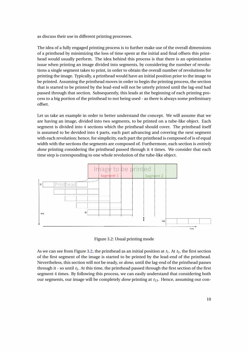
The idea of a fully engaged printing process is to further make use of the overall dimensionsof a printhead by minimizing the loss of time spent at the initial and final offsets this print-head would usually perform. The idea behind this process is that there is an optimizationissue when printing an image divided into segments, by considering the number of revolu-tions a single segment takes to print, in order to obtain the overall number of revolutions forprinting the image. Typically, a printhead would have an initial position prior to the image tobe printed. Assuming the printhead moves in order to begin the printing process, the sectionthat is started to be printed by the lead-end will not be utterly printed until the lag-end hadpassed through that section. Subsequently, this leads at the beginning of each printing pro-cess to a big portion of the printhead to not being used - as there is always some preliminaryoffset.
Let us take an example in order to better understand the concept. We will assume that weare having an image, divided into two segments, to be printed on a tube-like object. Eachsegment is divided into 4 sections which the printhead should cover. The printhead itselfis assumed to be devided into 4 parts, each part advancing and covering the next segmentwith each revolution; hence, for simplicity, each part the printhead is composed of is of equalwidth with the sections the segments are composed of. Furthermore, each section is entirelydone printing considering the printhead passed through it 4 times. We consider that eachtime step is corresponding to one whole revolution of the tube-like object.
Figure 3.2: Usual printing mode
As we can see from Figure 3.2, the printhead as an initial position at t1. At t2, the first sectionof the first segment of the image is started to be printed by the lead-end of the printhead.Nevertheless, this section will not be ready, or done, until the lag-end of the printhead passesthrough it - so until t5. At this time, the printhead passed through the first section of the firstsegment 4 times. By following this process, we can easily understand that considering bothour segments, our image will be completely done printing at t13. Hence, assuming our con-
10

ditions, the image will be printed in 12 revolutions.
Figure 3.3: Fully
Let us now assume a fully engaged process. From Figure 3.3, it can be observed that we as-sumed that with each revolution, the printhead advances just 1
4 the distance it advanced pri-orly. In order to print the first section of the first segment, we advance 4 revolutions - the firstsection is done printing at t5. Nevertheless, this process also allowed us to print the remain-ing 3 sections of the first segment, so that the whole segment was done printing at t5. We arethen offsetting the printhead to be ready to print the second segment at t6. Segment 2 is doneprinting at t10. Asssuming our previous conditions, we can say that it took us 9 revolutions toprint the whole image.
From the example, above we can obviously see that in our case, and assuming our conditions,it takes less time to print our image in a fully engaged mode than not. Obviously, we can notgeneralise every case and need to assume the number of segments we have per image, as wellas the number of revolutions it takes us to print the segment. Let us consider Z to be the totalnumber of revolutions for printing the image, Y the number of revolutions to print a segment
11
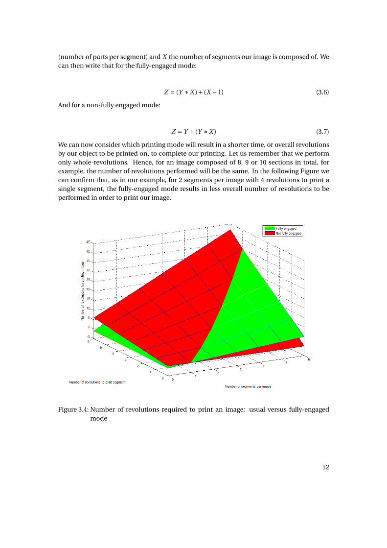
(number of parts per segment) and X the number of segments our image is composed of. Wecan then write that for the fully-engaged mode:
Z = (Y ∗X )+ (X −1) (3.6)
And for a non-fully engaged mode:
Z = Y + (Y ∗X ) (3.7)
We can now consider which printing mode will result in a shorter time, or overall revolutionsby our object to be printed on, to complete our printing. Let us remember that we performonly whole-revolutions. Hence, for an image composed of 8, 9 or 10 sections in total, forexample, the number of revolutions performed will be the same. In the following Figure wecan confirm that, as in our example, for 2 segments per image with 4 revolutions to print asingle segment, the fully-engaged mode results in less overall number of revolutions to beperformed in order to print our image.
Figure 3.4: Number of revolutions required to print an image: usual versus fully-engagedmode
12

4 TEST SLED
The Test-sled enables us to print on non-symmetrical objects, given its ability to move objectsin different directions. In order for us to print on tube-like objects, helical printing is used.While our object moves linearly in the x-direction, it rotates in the y-direction; by controllingthe motion of the object with respect to what end result we require, this allows us to print onthe whole surface of the tube-like object in a fast and consistent manner.Helical printing was used until this day in order to print on objects such as cans. Given theirprofile, it was enough for the printing head to be placed statically on the printing machine,while the object moved and rotated on itself. This obviously worked, due to the fact that thedistance between the printing head and the object itself did not change throughout the wholeprocess.
Taking a step further, and considering we want to print an object where its profile is not uni-form: its radius would be varying, we need to consider yet another motion of our printingsystem. It would be possible to think that placing the printhead far enough from the objectslargest radius could be enough to print on its whole length. Nevertheless, considering theimportance of the printheads placement with regards to the quality and end result obtained- more specifically, the change of the ink’s characteristics when leaving the nozzles - we couldnot expect a proper printing outcome.A solution that was designed in order to compensate for this issue is placing the printhead ona varying fixture. By fixing to it two linear motors side by side, the printhead is able to changethe height of its leading, or lagging, ends in order for it to induce a certain angle with respectto the x-axis. By creating specific motion profiles for the required object to be printed on, thisenables the printhead to follow along the change of profile of the object itself. The distancebetween the printhead and this object would now be homogeneous throughout the printingprocess.
13

Figure 4.1: Test-sled system
4.1 CAM PROFILE
In this section we will describe the steps that were necessary in order to acheive the obtentionof the CAM profile for a baseball bat.The following figures are a schematic of the baseball bat’s profile, as well as the printhead’sdimensions. z1 and z2 are the elevations in the z direction of the stepper motors connectedto the printhead. x0 through x5 describe the different sections of the bat. r1 and r2 representthe radius between the line crossing the middle of the bat and the distance we would like theprinthead to be from its surface.
14

Figure 4.2: Schematic of the basseball bat’s profile
Figure 4.3: Printhead’s dimensions
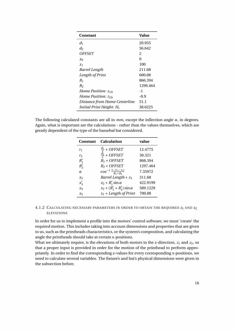
4.1.1 GIVEN AND CALCULATED CONSTANTS
We will obtain all the necessary calculations in order for us to draw the motion profile ofthe printhead. Nevertheless in order to do so, we need to provide constants and calculatedconstants from a specific baseball bat profile, as well as several necessary dimensions andparameters. All constants unit are in mm. Please note, that while those constants are correctfor a specific bat type, those values may differ for different types of bats. The following valuesare mainly for example purposes and should be thoroughly checked with the actual usedmaterials before any implementation into the machine is performed.
15
Constant Value
d1 20.955d2 56.642OFFSET 2x0 0x1 100Barrel Length 211.68Length of Print 600.08R1 866.394R2 1299.464Home Position: z1h -1Home Position: z2h -0.9Distance from Home Centerline 51.1Initial Print Height: Hi 38.6225
The following calculated constants are all in mm, except the inflection angle α, in degrees.Again, what is important are the calculations - rather than the values themselves, which aregreatly dependent of the type of the bassebal bat considered.
Constant Calculation value
r1d12 +OFFSET 12.4775
r2d22 +OFFSET 30.321
R ′1 R1 +OFFSET 868.394
R ′2 R2 +OFFSET 1297.464
α cos−1 1−|r1−r2|R1+R2
7.35972
x2 Barrel Length + x1 311.68x ′
3 x2 +R ′1 sinα 422.9199
x4 x2 + (R ′1 +R ′
2)sinα 589.1229x5 x1 +Length of Print 700.08
4.1.2 CALCULATING NECESSARY PARAMETERS IN ORDER TO OBTAIN THE REQUIRED z1 AND z2
ELEVATIONS
In order for us to implement a profile into the motors’ control software, we must ’create’ therequired motion. This includes taking into account dimensions and properties that are givento us, such as the printheads characteristics, or the system’s composition, and calculating theangle the printheads should take at certain x-positions.What we ultimately require, is the elevations of both motors in the z-direction, z1 and z2, sothat a proper input is provided in order for the motion of the printhead to perform appro-priately. In order to find the corresponding z-values for every corresponding x-positions, weneed to calculate several variables. The fixture’s and bat’s physical dimensions were given inthe subsection before.
16

Looking at the baseball bat profile, we can devide it into four sections. The section of thebarrel, where it is straight; before x2. The section between x2 and the inflection point x ′
3. Thesection between the inflection point x ′
3 and x4. And finally, the section of the handle, whereit is once again straight; after x4. It is natural that the printhead would be parallel to the x-axis at the barrel’s and handle’s sections. What we are more interested about, are the sectionforming the "S-shape" of the bat.
• Distance to hard stop of the system: 0.773"• Distance to hard sensor: 0.653"• Distance from rail: 1.371"
and
• Offset to biggest bat: 0.058"• Offset to smallest barrel: 0.244"• Distance to handle: 0.946"
Section between x2 and x ′3
With xmp , being the x-position of the midpoint of the printhead, as well as xi , the nozzle’slead x-position, we know that
x2 + 70.5556
2< xi < x ′
3 +70.5556
2x2 < xmp < x ′
3
with
xmp = xi −35.278
∆x = xmp −x2
β= si n−1∆x
R ′1
(4.1)
So in order to achieve this angle, we need a change in the z axis for the specific motor
∆z1 =−si n(β)distance between pivots
2=−40.64si n(β)
∆z2 = 40.64si n(β)(4.2)
To determine translational move in height, considering Hi the initial printing height,
∆zmp =−R ′1cos(β)+R ′
1
Hi mp = Hi +∆zmp = Hi + (R ′1 −R ′
1cos(β))(4.3)
17

So
z1i = Hi + (R ′1 −R ′
1cos(β))−40.64si n(β)
z2i = Hi + (R ′1 −R ′
1cos(β))+40.64si n(β)(4.4)
Inflection point x ′3
Since we know the angle at the inflection point to be α, it is pretty straight forward to writethat on x = x ′
3 or x = inf,
Hi n f = Hi + (R ′1 −R ′
1cos(α)) (4.5)
Section between x ′3 and x4
As we did for the previous subsection, we can write that
x ′3 +35.278 < xi < x4 +35.278
x ′3 < xmp < x4
and
ω= si n−1 x4 −xmp
R ′2
(4.6)
With
∆H = R ′2(cos(ω)− cos(α))
Hi mp = Hi + (R ′1 −R ′
1cos(β))+R ′2(cos(ω)− cos(α))
(4.7)
So that
z1i = Hi + (R ′1 −R ′
1cos(β))+R ′2(cos(ω)− cos(α))−40.64si n(β)
z2i = Hi + (R ′1 −R ′
1cos(β))+R ′2(cos(ω)− cos(α))+40.64si n(β)
(4.8)
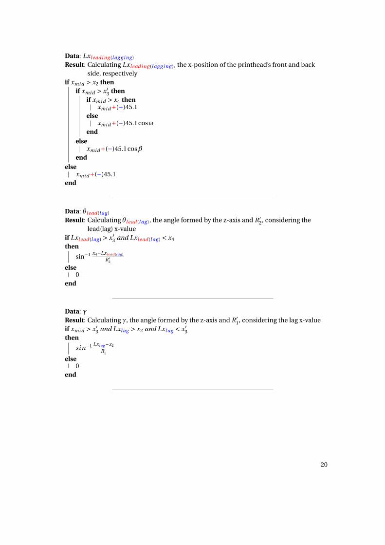
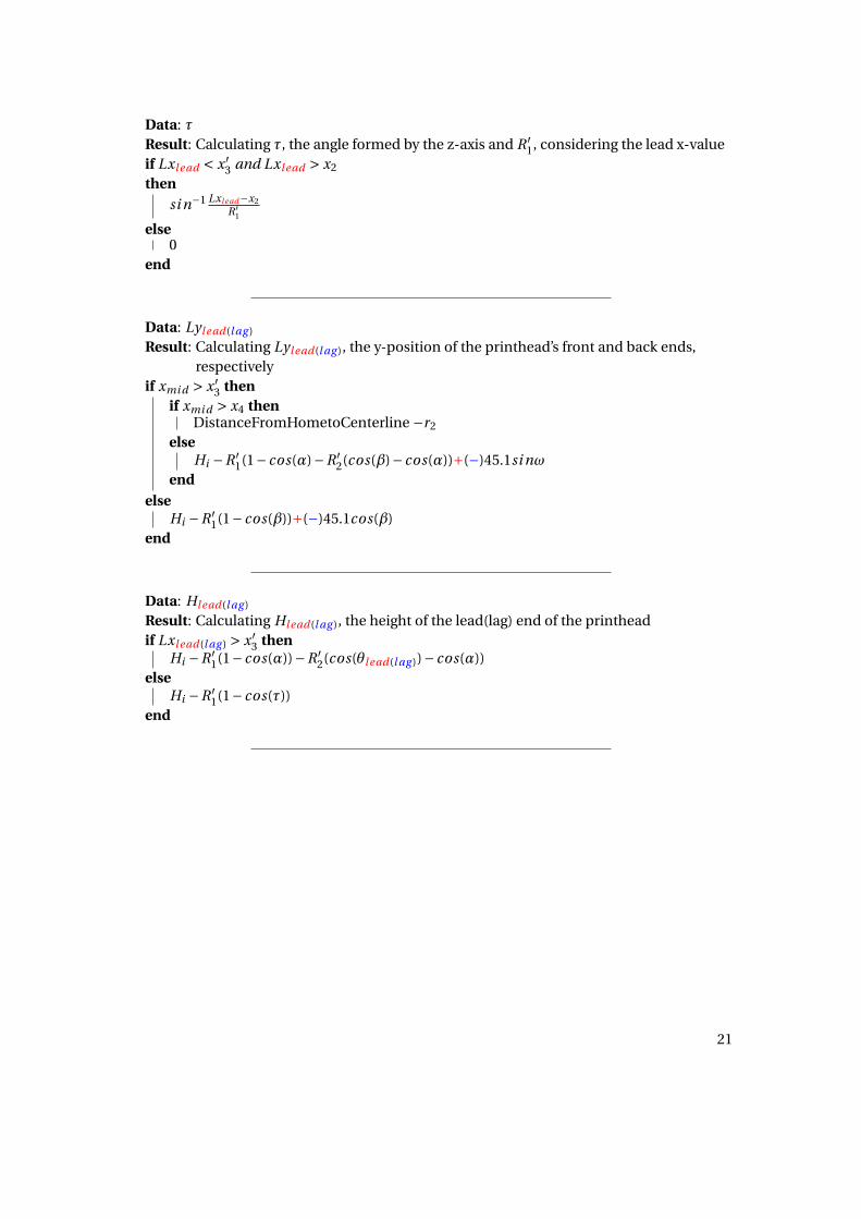
4.1.3 CONDITIONAL STATEMENTS FOR THE PRINTHEAD’S PATH
We have now obtained the necessary equations to further invistigate the printhead’s path.
18

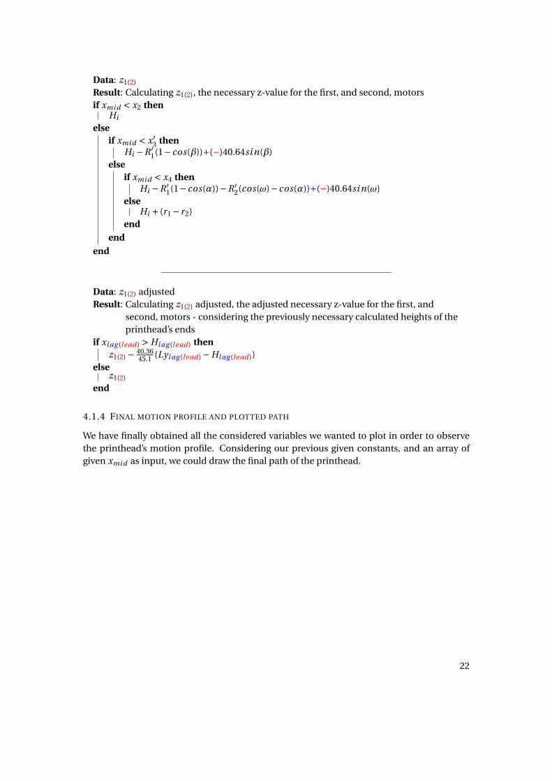
In order for us to draw the path of the printhead, we use conditional statements to create amotion profile able to perform the appropriate printhead’s movement with respect to its lo-cation on the x-axis. Considering the printhead is having specific dimensions and that justa fraction of is actually composed of nozzles, we need to take into account the avoidance ofcrashes that could occur with the bat.xmi d posi t i on , being the middle point of the printhead in the x-axis, will be given as an inputand allow us to calculate the necessary values of the elevations.
The reason we write down the possible path of the printhead in conditional statements is be-cause it is the most forward and clear way we could present the calculation of the printhead’selevations providing the parameter values we obtained previously. The reader is advised tofollow the previous diagrams in order to fully understand the obtained results.
Data: βResult: Calculating β, the angle formed by the z-axis and R ′
1, considering the midpointxmi d as x-value
if xmi d > x2 and xmi d ≤ x ′3
thensi n−1 xmi d−x2
R ′1
else0
end
Data: ωResult: Calculating ω, the angle formed by the z-axis and R ′
2, considering the midpointxmi d as x-value
if xmi d > x ′3 and xmi d ≤ x4
thensi n−1 x4−xmi d
R ′2
else0
end
19
Data: Lxl eadi ng (l ag g i ng )
Result: Calculating Lxleadi ng (l ag g i ng ), the x-position of the printhead’s front and backside, respectively
if xmi d > x2 thenif xmi d > x ′
3 thenif xmi d > x4 then
xmi d+(−)45.1else
xmi d+(−)45.1cosωend
elsexmi d+(−)45.1cosβ
endelse
xmi d+(−)45.1end
Data: θlead(l ag )
Result: Calculating θlead(l ag ), the angle formed by the z-axis and R ′2, considering the
lead(lag) x-valueif Lxlead(l ag ) > x ′
3 and Lxlead(l ag ) < x4
then
sin−1 x4−Lxlead(l ag )
R ′2
else0
end
Data: γResult: Calculating γ, the angle formed by the z-axis and R ′
1, considering the lag x-valueif xmi d > x ′
3 and Lxl ag > x2 and Lxl ag < x ′3
then
si n−1 Lxl ag−x2
R ′1
else0
end
20
Data: τResult: Calculating τ, the angle formed by the z-axis and R ′
1, considering the lead x-valueif Lxlead < x ′
3 and Lxl ead > x2
thensi n−1 Lxlead−x2
R ′1
else0
end
Data: Lyl ead(l ag )
Result: Calculating Lylead(l ag ), the y-position of the printhead’s front and back ends,respectively
if xmi d > x ′3 then
if xmi d > x4 thenDistanceFromHometoCenterline −r2
elseHi −R ′
1(1− cos(α)−R ′2(cos(β)− cos(α))+(−)45.1si nω
endelse
Hi −R ′1(1− cos(β))+(−)45.1cos(β)
end
Data: Hlead(l ag )
Result: Calculating Hl ead(l ag ), the height of the lead(lag) end of the printheadif Lxlead(l ag ) > x ′
3 thenHi −R ′
1(1− cos(α))−R ′2(cos(θlead(l ag ))− cos(α))
elseHi −R ′
1(1− cos(τ))end
21
Data: z1(2)
Result: Calculating z1(2), the necessary z-value for the first, and second, motorsif xmi d < x2 then
Hi
elseif xmi d < x ′
3 thenHi −R ′
1(1− cos(β))+(−)40.64si n(β)else
if xmi d < x4 thenHi −R ′
1(1− cos(α))−R ′2(cos(ω)− cos(α))+(−)40.64si n(ω)
elseHi + (r1 − r2)
endend
end
Data: z1(2) adjustedResult: Calculating z1(2) adjusted, the adjusted necessary z-value for the first, and
second, motors - considering the previously necessary calculated heights of theprinthead’s ends
if xl ag (lead) > Hl ag (l ead) thenz1(2) − 40.36
45.1 (Lyl ag (lead) −Hl ag (lead))else
z1(2)
end
4.1.4 FINAL MOTION PROFILE AND PLOTTED PATH
We have finally obtained all the considered variables we wanted to plot in order to observethe printhead’s motion profile. Considering our previous given constants, and an array ofgiven xmi d as input, we could draw the final path of the printhead.
22

Figure 4.4: Motion profile of the printhead following the curve of a basseball bat
4.2 ACR-VIEW PROGRAMS
4.2.1 HOMING ROUTINE
As in the CMMP, the test sled is equipped with feedback devices used to ensure the motorsare reaching the commanded positions/velocities. The homing routine of the linear axis issimilar to the one we saw on the CMMP, hence we will only observe the homing routine ofthe step motors on the articulating head.
The homing routine would be pretty straightforward in our case.We will first set a JOG profile, which will not matter much - as we are not having any timerequirements for our routine. This will also include the homing final velocity, JOG HOMVF,which specifies the velocity of the homing operation at its final approach.We will then clear some homing flags as with each time we run the homing routine we wouldlike to start the process anew; those flags would be, for example: Found Home, Home BackupEnable, Negative Final Direction.We will instruct the controller to search for the home position in a certain direction, in ourcase the negative one. This is due to the fact that this negative direction, for the controller,would be the positive direction in the z-axis for us. In the case we would have set in the posi-tive direction for the controller, an end-of-travel limit would be activated while reaching ourlowest z-point, and the controller would start searching for Home in the opposite direction.This would obviously work, but take a longer time - since our home point is almost at thehighest z-point our motors can reach.A simple if condition would allow us to check the Found Home flag in case we successfullyaccomplished the operation.
23

The appropriate program can be found in the APPENDIX section.
4.2.2 PRINTING PROGRAM
Similarly to what we saw previously for the CMMP, the Test-sled requires a program thatwould order the printheads to print on the baseball-bats when defined conditions have beenmet. As indicated before, the CMMP and Test-sled have a comparable controller, as well asservo-drives - hence our program will follow the same guidelines. Furthermore, we will usethe previously calculated CAM profile in order to define the appropriate motions of the ma-neuverable printhead.
We are using three slaves in order to define the four actuation acting in the system. First, Axis0will be the linear axis, moving the base-ball in a linear motion in the X-direction. Axis1 willbe the rotary axis, allowing the bat to rotate about itself and moving in the Y -direction. Axis2and Axis3 will define both of our stepper motors, moving the printhead in the Z-directionand yielding to a specific angle with respect to the X-axis.
Considering this is once again helical printing, we define our five parameters, used from theC# code relating the printed image and the action done by the printhead’s nozzles, as we didfor the CMMP. We are also running the head crash detection program in order to avoid crashwith the bat.Gearing parameters for the X-axis are defined once again; specifying the gear source for theaxis to be Encoder 8, Pulse Per Unit establishing the relationship between the source encoderand the input shaft of the electronic gearbox - counts of the rotary encoder divided by two:327680
2 = 163840, and defining the gear ratio.Next, we are moving the basseball bat to the starting position on the X-axis. Using bits re-served for the uv lamp ON/OFF for each layer from the PrintControl.cs code, we assign thelamp to the Aries-EPL output 2 or 3 in order to use the curing lamp if available.
We are starting the Z-axis motion part by defining the JOG-profile. The stepper motors allowus to define high acceleration and deceleration without producing much jerk. Next, we areallocating memory space for long array references. This allows us to enter the obtained pa-rameters from the CAM profile, and the specific values for both of our stepper motors in theZ-direction, with respect to the basseball bat’s X-position.As our bat is divided into 3 segments, we define it as such using allocated memory for long ar-rays. The handle is defined as the first segment, of length 266 mm. We then have the segmentwhere our CAM profile takes place, of length 324 mm - and where we are using the calculatedvalues in the previous subsection. Finally, we have the barrel of length 115 mm.
We can now finally start the "camming" motion. We do so while jogging Axis1, the rotary axis,with the necessary rotation counts and speed. The printing process is now similar to the onewe used on the CMMP - the printing is done by layers, and using the c-sharp PrintControl.cscode to use the necessary parameters and flags for successful and appropriate printing of
24

our image. When all layers have been successfully printed, we clear all previously used flags,home the stepper motors and turn all gears off.
As we can observe, the main issue and limitation of coding CAM motion in ACR-Basic is hard-coding the CAM table into the program. It would be of more ease to be able to refer to thisCAM table written in an Excel table, for example, so that changing the required motion withrespect to a specific baseball bat would be of less work. Unfortunately, ACR-Basic does notallow us to do so.Furthermore, ACR-Basic does not seem to be a user-friendly language code to write. Theuse of Bits and Parameters in order to define our actions are slowing coding speed dramat-ically. Due to this, and in combination to many more downsides of the coding language, itwas decided that the company will slowly shift into a different controller so that a better pro-gramming platform can be used. Mostly, and most importantly, the IEC 61131-3 standard forprogrammable logic controllers would need to be available.
The appropriate program can be found in the APPENDIX section.
25
5 CONCLUSION
Receiving background knowledge on the ink used in the printing systems I worked with wasof vital importance. There is a great deal in understanding the process of ink-jets and print-head’s functionality when dealing with motion required to print an image on a substrate ina consistent and appropriate manner. The values and features of the end-user products area result of many parameters: the quality of the ink used, the technologies of the hardwaremechanisms, the algorithms used for the nozzle’s jet control, the precision and robustness ofthe motions of the system and many more.Being responsible of the motion created by the substrate, and printhead, thanks to multi-axissystems was just a cog in a very complex mechanism in order to print an image on an object.
It was important, at first, to make sure all considered parameters in our motion profiles arecorrectly tuned on our systems. This allowed us later for better system’s performance. Deal-ing with the system’s controllers and defining correct input for the gearing trains and powertransmissions was as important as carefully tuning the PID gains, considering specific re-quirements, for the control algorithm used. Following, it was possible to create motion se-quences.Homing routines allowed us to return loads, such as the printhead, to a repeatable startinglocation. The controller sets the absolute position register to zero when ’home’ was reached,and allowed us for determined use of absolute motion with respect to a reference position. Itwas vital to properly code those routines, as every sequence of motions was later on begin-ning with those.The motion sequences for the printing programs of the CMMP and Test-Sled involved the useof parameters obtained from external C-sharp programs. Specific velocity profiles, startingpositions, motion requirements are all inherited from programs relating the printing mode,image’s end-product needs and functionality of the printhead/nozzles. Using those, we wereable to create the necessary linear and non-linear motion sequences on those two multi-axissystems. And, whereas some sequences were straightforward, when dealing with more com-plex objects to be printed on some elaborated calculations were needed.
After dealing with the controllers interface, ACR-View, it was possible to observe the com-plexity of coding those motion sequences. After long research, and compatibility check withthe already existing servo-motors available on both our systems, we were able to find a moresuited system’s implementation that will both fulfill the requirements for the motions of oursystems, as well as ease their future use.Instead of the use of the ACR-9000 EPL controller, combined with the Aries-EPL drives onboth of our systems - a combination of the Compax3 drive from Parker-Hannifin with theMC4N-Mini Ethercat Master controller from TRIO Motion Technology was decided to be im-plemented on the systems next. This would allow the future coding of the motions of thedifferent axis on our systems to be done in MotionPerfect’s interface, a much more straight-forward and thoroughgoing platform to deal with introducing the IEC 61131-3 standard forprogrammable logic controllers.
26
6 APPENDIX
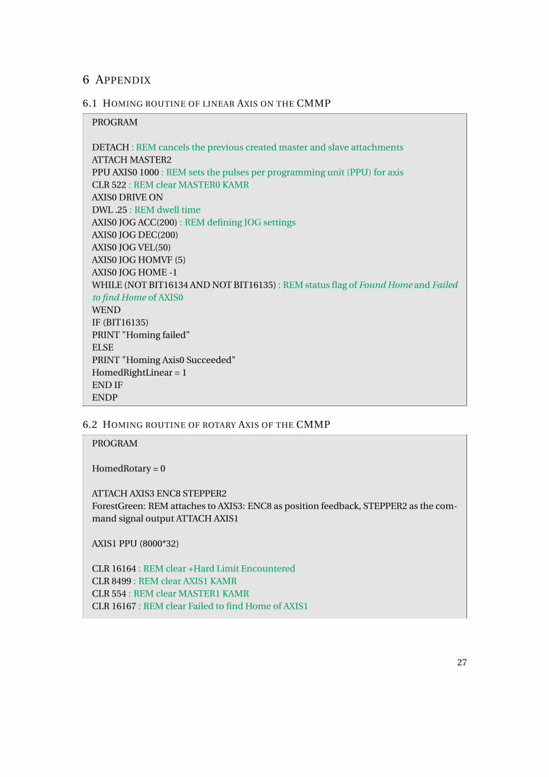
6.1 HOMING ROUTINE OF LINEAR AXIS ON THE CMMP
PROGRAM
DETACH : REM cancels the previous created master and slave attachmentsATTACH MASTER2PPU AXIS0 1000 : REM sets the pulses per programming unit (PPU) for axisCLR 522 : REM clear MASTER0 KAMRAXIS0 DRIVE ONDWL .25 : REM dwell timeAXIS0 JOG ACC(200) : REM defining JOG settingsAXIS0 JOG DEC(200)AXIS0 JOG VEL(50)AXIS0 JOG HOMVF (5)AXIS0 JOG HOME -1WHILE (NOT BIT16134 AND NOT BIT16135) : REM status flag of Found Home and Failedto find Home of AXIS0WENDIF (BIT16135)PRINT "Homing failed"ELSEPRINT "Homing Axis0 Succeeded"HomedRightLinear = 1END IFENDP
6.2 HOMING ROUTINE OF ROTARY AXIS OF THE CMMP
PROGRAM
HomedRotary = 0
ATTACH AXIS3 ENC8 STEPPER2ForestGreen: REM attaches to AXIS3: ENC8 as position feedback, STEPPER2 as the com-mand signal output ATTACH AXIS1
AXIS1 PPU (8000*32)
CLR 16164 : REM clear +Hard Limit EncounteredCLR 8499 : REM clear AXIS1 KAMRCLR 554 : REM clear MASTER1 KAMRCLR 16167 : REM clear Failed to find Home of AXIS1
27

AXIS1 JOG OFFINH -824 : REM wait until jogging is stoppedIF (BIT8497=0) : REM flag Drive Enable Output of AXIS1AXIS1 DRIVE ONDWL 0.2ENDIFAXIS1 RES : REM set the commanded and actual position to zeroAXIS3 RESPRINT "HOMING Rotary Axis..."AXIS1 JOG ACC (10)AXIS1 JOG DEC (10)AXIS1 JOG VEL (1)AXIS1 JOG HOMVF (0.25) : REM set Home Final VelocityAXIS1 JOG JRK (0)AXIS1 JOG RENBIT830=0 : REM turn off jog limitsBIT831=0 : REM JOG lock out offCLR 16164 : REM clear +Hard Limit EncounteredCLR 8499 : REM clear AXIS1 KAMRCLR 554 : REM clear MASTER1 KAMRCLR 16167 : REM clear failed to find homeAXIS1 JOG INC (-0.01)INH -824 : REM wait until jogging is stoppedAXIS3 INTCAP 16 CAP3 P13060 : REM enable hardware position capture triggered forAXIS3 at mode10 (trigger when rising of third external is found), hold the captured posi-tion in register CAP3, using Hardware Capture flag for AXIS3 to store the captured valueafter it is passed from the capture registerAXIS1 JOG FWD : REM JOG forwardINH 873 : REM wait till capture completeAXIS1 JOG OFF
PRINT P13060 : REM capture position for AXIS3 when marker crossedIF (BIT 16167) THEN PRINT "FAILED TO HOME"
INH -824 : REM wait until jogging is stoppedPRINT P13060 : REM current position of AXIS3PRINT P6272: REM position of ENC8
RES AXIS1 ((P13060 - P6272)/472000) : REM set axis per captured ENC8PRINT P12546 : REM actual position of AXIS1RES AXIS3 (-(P13060 - P6272))
28

CLR 16164 : REM clear +Hard Limit EncounteredCLR 8499 : REM clear AXIS1 KAMRCLR 554 : REM clear MASTER1 KAMRCLR 16167 : REM clear failed to find home
PRINT P12546
AXIS1 JOG INC (-P12546/256000)
INH -824 : REM wait until jogging is stoppedPRINT P12546HomedRotary = 1PRINT "Done Homing Axis1"ENDP
6.3 PRINTING PROGRAM FOR THE CMMP
PROGRAMDIM LV(3) : REM allocates memory space for 4 bytes element (32 bit integers) + 4 bytesDIM DV(1) : REM allocates memory space for 8 bytes per element (64 bit floating point)+ 4 bytesLV0 = (472000/20000) : REM rotary counts before engaging gearLV1 = 0LV2 = 0LV3 = 0
DETACHATTACH MASTER0ATTACH SLAVE0 AXIS0 "X"
CLR 16132 : REM Clear +Hard Limit EncounteredCLR 8467 : REM Clear AXIS0 KAMRCLR 522 : REM Clear MASTER0 KAMR
_LAYERLOOP
LinesToAdvancePerRev = P(18+LV1)PrintResolution = P(26+LV1)RotarySpeed = P(34+LV1)RotationCount = P(42+LV1) + P(58+LV1)StartPosition = P(50+LV1)
DV0 = LinesToAdvancePerRev / PrintResolution * 25.4
29

INH -824 : REM wait -> flag: JOG active - axis 1
ENC8 RES : REM commanded and actual position to zero
PPU X800 : REM sets the pulses per programming unit (PPU) for axisGEAR OFF X
GEAR SRC X P6272 : REM SET ENCODER 8 AS X GEAR INPUT SOURCE
GEAR PPU X(472000)GEAR RATIO X(DV0)
PRINT "Move to position"IF (BIT8465=0)DRIVE ON XDWL 1.0ENDIF
X(StartPosition) : REM move head
INH -516 : REM flag - Axis0 in motion
WHILE (BIT(144+LV1)=0) : REM hold waiting for layer readyWEND
GEAR ON X IHPOS (-LV0) : REM Enable gear on source encoder position
PRINT "Turn rotary drive on"IF (BIT8497=0)AXIS1 DRIVE ONDWL 1.0ENDIF
AXIS1 JOG VEL(RotarySpeed)AXIS1 JOG INC(RotationCount)
IHPOS -P6272((P(64+LV1) * -472000), 0) : REM wait for encoder8 pos to destination ->Inhibit on Position (FINISHED WITH LAYER)
GEAR OFF XINH -789 : REM wait until gear off
IF (P(42+LV1) > P(64+LV1))
30

IHPOS -P6272((P(42+LV1) * -472000), 0)ENDIFSET 3842 : SET 3843 : REM EPL output2 / EPL output 3 for EPLD 0
GEAR RES X
LV1 = LV1+1IF (LV1 < LayerCount)GOTO LAYERLOOPENDIF
GEAR OFF XINH -789 : REM wait until gear offCLR 16132 : REM Clear +Hard Limit EncounteredCLR 8467 : REM Clear AXIS0 KAMRCLR 522 : REM Clear MASTER0 KAMRIF (BIT8465=0)DRIVE ON XDWL 1.0ENDIF
X(5)INH -516INH -824 : REM wait until rotary jog offREM HALT PROG1
ENDP
6.4 HOMING ROUTING FOR THE MANEUVERABLE PRINTHEAD ON THE TEST-SLED
PROGRAM
SET 5651 : Rem Line numbers
DETACH
CLR 8467 : REM kill motion request of the four AxisCLR 8499CLR 8531CLR 8563CLR 522 : REM kill moves of Axis0
HEADHOMED=0
31

REM P11=0AXIS2 jog vel 10AXIS2 jog acc 1000AXIS2 jog dec 1000
AXIS3 jog vel 10AXIS3 jog acc 1000AXIS3 jog dec 1000
SET 8528 : REM make ACR run stepper Axis 2 in CW / CCW modeSET 8560 : REM make ACR run stepper AXIS 3 in CW / CCW mode
AXIS2 DRIVE ONAXIS3 DRIVE ON
AXIS2 JOG HOMVF .5AXIS3 JOG HOMVF .5CLR 16198 : REM clear flag Found HomeCLR 16230 : REM clear homed flag
CLR 16216 : REM backup to home disabled - clear Home Backup EnableCLR 16248 : REM backup to home disabled
CLR 16218 : REM final direction positive - clear Home Negative Final DirectionCLR 16250 : REM final direction positive
CLR 16217 : REM positive edge - clear Home Negative Edge SelectCLR 16249 : REM positive edge
PRINT "HOMING AXIS2 AXIS 3"
AXIS2 JOG HOME -1AXIS3 JOG HOME -1
WHILE (NOT BIT 16198 OR NOT BIT 16230)
IF (BIT16199 OR BIT16231)PRINT "HOMING FAILED"HEADHOMED=0REM P11=0ENDIFWEND
32

ENDP
6.5 BOTTLE DETECTION FOR THE TEST-SLED
PROGRAM
CLR 200
WHILE (BIT11 AND BIT10) : REM looking for crash sensorsWEND
SET 200
PRINT "CRASH SENSOR TRIPPED"
CAM OFF AXIS2 AXIS3JOG OFF AXIS2 AXIS3GEAR OFF AXIS0JOG OFF AXIS1
HALT PROG0HALT PROG1
ENDP
6.6 PRINTING PROGRAM FOR THE TEST-SLED
ATTACH AXIS2 STEPPER0 STEPPER0ATTACH AXIS3 STEPPER1 STEPPER1ATTACH SLAVE1 AXIS2 "Z"ATTACH SLAVE2 AXIS3 "A"
PROGRAMDIM LV(3)DIM DV(1)
LV0 = 327680 / 2LV1 = 0
DETACHATTACH MASTER0ATTACH SLAVE0 AXIS0 "X"ATTACH AXIS2 STEPPER0 STEPPER0
33

ATTACH AXIS3 STEPPER1 STEPPER1ATTACH SLAVE1 AXIS2 "Z"ATTACH SLAVE2 AXIS3 "A"
CLR 16132 : REM Clear +Hard Limit EncounteredCLR 8467 : REM Clear AXIS0 KAMRCLR 522 : REM Clear MASTER0 KAMRREM RUN PROG1 : REM Start checking bottle detectRUN PROG4 : REM head crash detection
_LAYERLOOPLinesToAdvancePerRev = P(18+LV1)PrintResolution = P(26+LV1)RotarySpeed = P(34+LV1)RotationCount = P(42+LV1) + P(58+LV1)StartPosition = P(50+LV1)
DV0 = LinesToAdvancePerRev / PrintResolution * 25.4INH -824REM turn off uv lampCLR 3842 : CLR 3843
RES AXIS1ENC8 RES
PPU X1000GEAR OFF XGEAR SRC X P6272 : REM set Encoder 8 as X gear input sourceGEAR PPU X(163840)GEAR RATIO X(DV0)GEAR ON X IHPOS +(LV0)
PRINT "Move to position"IF (BIT8465=0)DRIVE ON XDWL 1.0ENDIFX(-StartPosition)INH -516
IF (BIT133) : REM check if bottle missingCLR 3842 : CLR 3843GOTO PROG0EXIT
34

ENDIF
WHILE (BIT(144+LV1)=0) : REM BIT144 – BIT151 reserved as ready to go for each layerWEND
PRINT "Turn rotary drive on"IF (BIT8497=0)AXIS1 DRIVE ONDWL 1.0ENDIF
IF (BIT(228+LV1)) : REM BIT228 – BIT135 reserved as lamp ON/OFF for each layerSET 3842 : SET 3843 : REM EPLD0 output 2 and 3 for uv lampELSECLR 3842 : CLR 3843ENDIF
: REM CAM profile
SET 5651 : REM line number when listing program
jog vel Z 10jog acc Z 5000jog dec Z 5000
jog vel A 10jog acc A 5000jog dec A 5000
SET 8528 : REM make ACR run stepper Z axis in CW/CCW modeSET 8560 : REM make ACR run stepper A axis in CW/CCW modeJOG ABS Z38.6225 A38.6225 : REM Initial print height = Distance from home to center-line (51.1) - r1 (12.4775)
INH -856 : REM wait while JOG active Z axisINH -888 : REM wait while JOG active A axis
: REM distance in array is in (mm * 1000)
: REM Z Axis2 arrayDIM LA(4)DIM LA0(2)LA0(0)=0
35

LA0(1)=0DIM LA1(325)LA1(0)=0LA1(1)=0LA1(2)=0.. Copy/paste calculated values from Excel file.LA1(323)=-178396LA1(324)=-178435
: REM A Axis3 arrayDIM LA2(2)LA2(0)=-178435LA2(1)=-178435DIM LA3(325)LA3(0)=0LA3(1)=-1LA3(2)=-10.. Copy/paste calculated values from Excel file.LA3(323)=-178473LA3(324)=-178435
: REM CAM axis PPU is 16 000: REM SEG distance is the distance in (mm * PPU) of the source axis (1000): REM SEG distance must equal the total distance of the source move
CAM DIM Z3CAM DIM A3 : REM allocate cam segments - 3 cam segmentsCAM SEG Z(0,50000,LA0) : REM define cam segments - 266 mm X 1000CAM SEG Z(1,324000,LA1) : REM 324 mm X 1000CAM SEG Z(2,59000,LA2) : REM 115 mm X 1000
CAM SEG A(0,50000,LA0)CAM SEG A(1,324000,LA3)CAM SEG A(2,59000,LA2)
CAM SCALE Z(1/10000) A(1/10000) : REM CAM output scaling (mm)
PRINT "SET CAM SOURCE"
36

CAM SRC Z P12295 A P12295 :CAM ON Z A : REM Start "camming"
PRINT "CAM STARTED ,TURN ON ROTARY AXIS"
AXIS1 JOG VEL(RotarySpeed)AXIS1 JOG INC(RotationCount)
IHPOS +P6272(P(64+LV1) * 163840,60) : REM printingGEAR OFF XINH -789 : REM wait until gear off
PRINT "CAM OFF NORMAL"
IF (P(42+LV1) > P(64+LV1))IHPOS +P6272(P(42+LV1) * 163840,60)ENDIFSET 3842 : SET 3843
GEAR RES X
LV1 = LV1+1IF (LV1 < LayerCount)GOTO LAYERLOOPENDIF
_PROG0EXIT
CAM SHIFT ZCAM SHIFT A
CAM OFF Z AINH -854INH -886
CLR 8467CLR 8499CLR 8531CLR 8563CLR 522
HEADHOMED=0REM P11=0AXIS2 jog vel 10
37

AXIS2 jog acc 1000AXIS2 jog dec 1000
AXIS3 jog vel 10AXIS3 jog acc 1000AXIS3 jog dec 1000
SET 8528 : REM MAKE ACR RUN STEPPER Axis 2 IN CW / CCW MODESET 8560 : REM MAKE ACR RUN STEPPER AXIS 3 IN CW / CCW MODE
AXIS2 DRIVE ONAXIS3 DRIVE ON
AXIS2 JOG HOMVF .5 : REM HOME Axis 2 AND Axis 3AXIS3 JOG HOMVF .5CLR 16198 : REM CLEAR HOMED FLAGCLR 16230 : REM CLEAR HOMED FLAG
CLR 16216 : REM BACKUP TO HOME DISABLEDCLR 16248 : REM BACKUP TO HOME DISABLED
CLR 16218 : REM FINAL DIRECTION POSITIVECLR 16250 : REM FINAL DIRECTION POSITIVE
CLR 16216 : REM POSITIVE EDGECLR 16249 : REM POSITIVE EDGE
PRINT "HOMING AXIS2 & AXIS 3"
AXIS2 JOG HOME -1AXIS3 JOG HOME -1
WHILE (NOT BIT 16198 OR NOT BIT 16230)IF (BIT16199 OR BIT16231)PRINT "HOMING FAILED"HEADHOMED=0REM P11=0ENDIFWEND
AXIS2 JOG ABS 1: AXIS3 JOG ABS 1
INH -856
38

INH -888
AXIS2 JOG RESAXIS3 JOG RES
AXIS2 JOG RENAXIS3 JOG REN
AXIS2 RESAXIS3 RES
GEAR OFF XINH -789 : REM wait until gear offCLR 16132 : REM Clear +Hard Limit EncounteredCLR 8467 : REM Clear AXIS0 KAMRCLR 522 : REM Clear MASTER0 KAMRIF (BIT8465=0)DRIVE ON XDWL 1.0ENDIF
X(-1850)INH -516INH -824 : REM wait until rotary jog offHALT PROG1HALT PROG4
ENDP
6.7 TEST OF MINI-TEST-SLED
PROGRAM
_EnableEPLNetwork : REM enable the EPL Link
INH 16648 : REM check for controller to aknowledge EPL cardIF (NOT BIT16649) THEN EPLC ON : REM if EPL not operational., start EPLC networkDWL 0.2WHILE (BIT16640) : REM wait for EPL network to startWENDIF (BIT16649) THEN PRINT "EPL NETWORK OPERATIONAL"IF (BIT16650) THEN PRINT "EPL NETWORK START FAILED, GOING TO RESET NET-WORK"
39

IF (NOT BIT16649)EPLC OFF : REM reset EPL networkSET ResetEPLNetwork : REM set reset EPL network latched bitINH -16657 : REM inh until EPL network resetsEPLC ON : REM start it againINH -16656 : REM inh program until start EPL network has finishedENDIFIF ((NOT BIT16649) AND (ResetEPLNetwork))PRINT "EPL network problem occurred."HALTENDIF
: REM Homing Z-AXIS_HOMEZ
DRIVE ON ZJOG VEL Z200 : REM set axes jog parameters used during homingJOG ACC Z2000JOG DEC Z2000HLBIT Z3328 : REM assign hardware limitHLIM Z3 : REM enable end-of-travel limit checking for Z axisJOG HOMVF Z40 : REM Set backup to home velocityREM SET 16208 SET 16209 : REM invert axis2 level of limit inputsSET 16216 : REM disable backup to homeCLR 16217 : REM look for positive edge of sensorCLR 16218 : REM final homing direction will be positiveJOG HOME Z1
WHILE (((NOT BIT16198) AND (NOT BIT16199))) : REM stay in this loop until axis2 haseither passed or failed homing processWEND
REM IF (BIT16199) THENREM PRINT "HOME FAILED"REM HALTREM END IFPRINT "HOME ROUTINE COMPLETE"
_MAIN
VEL 330Z 400 : REM move to print pos.INH-516 : wait for motion to complete
40

PRINT "Done"INH 31 : REM wait for input bit 31PRINT "Done2"DWL 1
DAC1 OFFSET -10 : REM se lamp intensity, DAC1 offset to 10 Volts - negative numbersfor positive outputCLR 8500 : REM clear the enable drive I/O flag to allow setting the state of direct I/OcommandsPRINT P38144Z -30 : REM move to final pos.IHPOS -P38144(250000,0) : REM inh execution until given setpoint (in PPU) is reachedPRINT P38144SET 41 : REM turn on lamp to output0INH-516 : REM wait for motion to completeCLR 41 : REM turn off lampZ 400 : REM move to start positionINH -516 : REM wait for motion to complete
GOTO MAIN
ENDP
41

REFERENCES
[1] E. Knight, C. Lynn, Industrial Inkjet For Dummies, XAAR Special Edition, Wiley-Publishing, Inc., 2010. ISBN: 978-0-470-92047-3
[2] INX Internation Ink Co., PM3 Servicing, Troubleshooting and Tech Training, July 2015.
[3] Parker Hannifin Co., ACR Programmer’s Guide, July 2010. Version: 88-028698-01D
[4] Parker Hannifin Co., ACR Command Language Reference, July 2010. Version: 88-025604-01H
[5] Parker Hannifin Co., ACR Parameter and Bit Reference, July 2010. Version: 88-025605-01H
[6] Parker Hannifin Co., Aries EPL Hardware Installation Guide, October 2008. Version: 88-027024-01B
[7] Parker Hannifin Co., Aries User Guide, September 2008. Version: 88-021610-01G
42