AS/400 Advanced Series IBM Internetwork Packet Exchange (IPX**) Support Version 4 SC41-5400-00

Welcome message from author
This document is posted to help you gain knowledge. Please leave a comment to let me know what you think about it! Share it to your friends and learn new things together.
Transcript

AS/400 Advanced Series IBM
Internetwork Packet Exchange (IPX**)SupportVersion 4
SC41-5400-00


AS/400 Advanced Series IBM
Internetwork Packet Exchange (IPX**)SupportVersion 4
SC41-5400-00
Note
Before using this information and the product it supports, be sure to read the general information under “Notices” on page 181.
First Edition (August 1997)
This edition applies to the licensed program IBM Operating System/400 (Program 5769-SS1), Version 4 Release 1 Modification 0,and to all subsequent releases and modifications until otherwise indicated in new editions.
Make sure that you are using the proper edition for the level of the product.
Order publications through your IBM representative or the IBM branch serving your locality. If you live in the United States, PuertoRico, or Guam, you can order publications through the IBM Software Manufacturing Solutions at 1-800-879-2755. Publications arenot stocked at the address given below.
IBM welcomes your comments. A form for readers' comments may be provided at the back of this publication. You can also mailyour comments to the following address:
IBM CorporationAttention Department 542IDCLERK3605 Highway 52 NRochester, MN 55901-7829 USA
or you can fax your comments to:
United States and Canada: 1-800-937-3430Other countries: 1-507-253-5192
If you have access to the Internet, you can send your comments electronically to [email protected]; IBMMAIL,to IBMMAIL(USIB56RZ).
When you send information to IBM, you grant IBM a nonexclusive right to use or distribute the information in any way it believesappropriate without incurring any obligation to you.
Copyright International Business Machines Corporation 1997. All rights reserved.Note to U.S. Government Users — Documentation related to restricted rights — Use, duplication or disclosure is subject torestrictions set forth in GSA ADP Schedule Contract with IBM Corp.
Contents
About IPX Support (SC41-5400) . . . . . . . . . . . . . . . . . . . . . . . . . . . ixWho Should Read This Book . . . . . . . . . . . . . . . . . . . . . . . . . . . . . . ixConventions and Terminology Used in This Book . . . . . . . . . . . . . . . . . . ix
Task Indicator . . . . . . . . . . . . . . . . . . . . . . . . . . . . . . . . . . . . . ixNote Indicator . . . . . . . . . . . . . . . . . . . . . . . . . . . . . . . . . . . . . xTip Indicator . . . . . . . . . . . . . . . . . . . . . . . . . . . . . . . . . . . . . . x
Prerequisite and Related Information . . . . . . . . . . . . . . . . . . . . . . . . . xInformation Available on the World Wide Web . . . . . . . . . . . . . . . . . . . . x
Internetwork Packet Exchange Networks and Protocols–Introduction . . . . 1Networks . . . . . . . . . . . . . . . . . . . . . . . . . . . . . . . . . . . . . . . . . . 1
Internetwork Communications . . . . . . . . . . . . . . . . . . . . . . . . . . . . 2Serving . . . . . . . . . . . . . . . . . . . . . . . . . . . . . . . . . . . . . . . . . . . 2What is Internetwork Packet Exchange (IPX) Support? . . . . . . . . . . . . . . . 2
History of Internetwork Packet Exchange (IPX) . . . . . . . . . . . . . . . . . . 3Introduction to IPX Protocols . . . . . . . . . . . . . . . . . . . . . . . . . . . . . . 3Upper Protocol Layers . . . . . . . . . . . . . . . . . . . . . . . . . . . . . . . . . . 5
Simple Network Management Protocol (SNMP) . . . . . . . . . . . . . . . . . . 5Sockets Interface . . . . . . . . . . . . . . . . . . . . . . . . . . . . . . . . . . . 5
Transport Protocol Layer . . . . . . . . . . . . . . . . . . . . . . . . . . . . . . . . 7Sequenced Packet Exchange (SPX) . . . . . . . . . . . . . . . . . . . . . . . . 7Multiprotocol Transport Networking Architecture (MPTN) . . . . . . . . . . . . 8
Network Protocol Layer . . . . . . . . . . . . . . . . . . . . . . . . . . . . . . . . . 8Internetwork Packet Exchange (IPX) Protocol . . . . . . . . . . . . . . . . . . . 8Routing Information Protocol (RIP) . . . . . . . . . . . . . . . . . . . . . . . . . 9Service Advertising Protocol (SAP) . . . . . . . . . . . . . . . . . . . . . . . . . 9NetWare Link Services Protocol (NLSP) . . . . . . . . . . . . . . . . . . . . . . 9
Lower Layer Protocols . . . . . . . . . . . . . . . . . . . . . . . . . . . . . . . . . . 9Relationship among the IPX Functions . . . . . . . . . . . . . . . . . . . . . . . . 9IPX Network . . . . . . . . . . . . . . . . . . . . . . . . . . . . . . . . . . . . . . . 10
IPX Node Address . . . . . . . . . . . . . . . . . . . . . . . . . . . . . . . . . 11IPX Circuit . . . . . . . . . . . . . . . . . . . . . . . . . . . . . . . . . . . . . . 12
Routing . . . . . . . . . . . . . . . . . . . . . . . . . . . . . . . . . . . . . . . . . 12IPX Routers . . . . . . . . . . . . . . . . . . . . . . . . . . . . . . . . . . . . . 12IPX Server . . . . . . . . . . . . . . . . . . . . . . . . . . . . . . . . . . . . . . 13AS/400 IPX Internal Network . . . . . . . . . . . . . . . . . . . . . . . . . . . 14IPX Internal Network Number . . . . . . . . . . . . . . . . . . . . . . . . . . . 15NetWare on the Integrated PC Server . . . . . . . . . . . . . . . . . . . . . . 15
Configuring the Internetwork Packet Exchange (IPX) Support . . . . . . . 19Configuring IPX–Overview . . . . . . . . . . . . . . . . . . . . . . . . . . . . . . 21Ethernet Network Example . . . . . . . . . . . . . . . . . . . . . . . . . . . . . . 23
Step 1–Creating an Internetwork Packet Exchange (IPX) Description . . . 23 Step 2–Configuring Line Descriptions for IPX Support–Ethernet . . . . . . . 30 Step 3–Adding an Internetwork Packet Exchange (IPX) Circuit . . . . . . . 35Step 4–Adding Route Information . . . . . . . . . . . . . . . . . . . . . . . . . 45Step 5–Adding Service Information . . . . . . . . . . . . . . . . . . . . . . . . 45
X.25 Network Example . . . . . . . . . . . . . . . . . . . . . . . . . . . . . . . . 45 Step 1–Creating an IPX Description–X.25 . . . . . . . . . . . . . . . . . . . 46 Step 2–Configuring a Line Description for IPX Support–X.25 . . . . . . . . 46
Copyright IBM Corp. 1997 iii
Step 3–Adding an IPX Circuit for an X.25 SVC Line . . . . . . . . . . . . . . 52Circuit Routes and Circuit Services–Overview . . . . . . . . . . . . . . . . . . . 56
Step 4–Adding Circuit Route Information . . . . . . . . . . . . . . . . . . . . 57Step 5–Adding Circuit Service Information . . . . . . . . . . . . . . . . . . . . 61Sample CL Program . . . . . . . . . . . . . . . . . . . . . . . . . . . . . . . . 65
Additional IPX Configuration Options . . . . . . . . . . . . . . . . . . . . . . . . 65
Operating and Managing IPX Support . . . . . . . . . . . . . . . . . . . . . . 67Starting and Ending IPX Support . . . . . . . . . . . . . . . . . . . . . . . . . . . 67
Before You Start IPX Support . . . . . . . . . . . . . . . . . . . . . . . . . . . 67Starting IPX . . . . . . . . . . . . . . . . . . . . . . . . . . . . . . . . . . . . . 69Ending IPX . . . . . . . . . . . . . . . . . . . . . . . . . . . . . . . . . . . . . . 70
IPX Status Support . . . . . . . . . . . . . . . . . . . . . . . . . . . . . . . . . . . 72Work with IPX Status Menu . . . . . . . . . . . . . . . . . . . . . . . . . . . . 72Working with IPX Circuit Status . . . . . . . . . . . . . . . . . . . . . . . . . . 72Working with IPX/SPX Connection Status . . . . . . . . . . . . . . . . . . . . 81
Advanced IPX Configuration . . . . . . . . . . . . . . . . . . . . . . . . . . . . 89Configuration for NetWare Support . . . . . . . . . . . . . . . . . . . . . . . . . 89
IPX Description . . . . . . . . . . . . . . . . . . . . . . . . . . . . . . . . . . . 89IPX Circuit Definition . . . . . . . . . . . . . . . . . . . . . . . . . . . . . . . . 90
X.25 Network and Integrated PC Server Example . . . . . . . . . . . . . . . . . 90X.25 Network Configuration . . . . . . . . . . . . . . . . . . . . . . . . . . . . . . 91
Step 1–Creating an Internetwork Packet Exchange (IPX) Description . . . 92Performance Considerations for IPX Descriptions . . . . . . . . . . . . . . . 93 Step 2–Configuring an X.25 Line Description for System D . . . . . . . . . 95 Step 3–Adding an IPX Circuit for an X.25 SVC Line on System D . . . . . 98Step 4–Adding Circuit Route Information for System D . . . . . . . . . . . 100Considerations for Adding Route Information . . . . . . . . . . . . . . . . . 104
Controlling NLSP Route Selection . . . . . . . . . . . . . . . . . . . . . . . . . 107
IPX Support and AnyNet/400 . . . . . . . . . . . . . . . . . . . . . . . . . . . 109IP over IPX . . . . . . . . . . . . . . . . . . . . . . . . . . . . . . . . . . . . . . 110SNA over IPX . . . . . . . . . . . . . . . . . . . . . . . . . . . . . . . . . . . . . 111Configuring AnyNet/400 Support using the Configure IPX Menu . . . . . . . 111IP over IPX AnyNet Configuration–Overview . . . . . . . . . . . . . . . . . . . 112IP over IPX AnyNet Configuration-Example . . . . . . . . . . . . . . . . . . . . 112
Assumptions . . . . . . . . . . . . . . . . . . . . . . . . . . . . . . . . . . . . 113Step 1–Configuring IPX Support . . . . . . . . . . . . . . . . . . . . . . . . 113Step 2–Configuring the IP over IPX Interface . . . . . . . . . . . . . . . . . 114Step 3–Adding IP over IPX Routes Configuration . . . . . . . . . . . . . . 117Step 4–Adding IP over IPX Addresses Configuration . . . . . . . . . . . . 117Step 5–Allow AnyNet/400 Support for IP over IPX Support . . . . . . . . . 120Step 6–Activating the IP over IPX Support . . . . . . . . . . . . . . . . . . 121Changing the IP Over IPX Configuration . . . . . . . . . . . . . . . . . . . . 121Matching Parameters for IP over IPX Support . . . . . . . . . . . . . . . . 122IP over IPX Common Configuration Errors . . . . . . . . . . . . . . . . . . 123
APPC over IPX Configuration–Overview . . . . . . . . . . . . . . . . . . . . . 123APPC over IPX Configuration-Example . . . . . . . . . . . . . . . . . . . . . . 124
Assumptions . . . . . . . . . . . . . . . . . . . . . . . . . . . . . . . . . . . . 124Step 1–IPX Configuration . . . . . . . . . . . . . . . . . . . . . . . . . . . . 124Step 2–Creating the APPC Controllers . . . . . . . . . . . . . . . . . . . . . 124 Step 3–Adding Remote Locations to the APPN Remote Location Lists . . 127 Step 4–Adding Local Locations to the APPN Local Locations Lists . . . . 129
iv OS/400 Internetwork Packet Exchange (IPX) Support V4R1

Step 5–Adding APPC over IPX Location Name Addressing Configuration 131Step 6–Allow AnyNet/400 Support . . . . . . . . . . . . . . . . . . . . . . . 134Step 7–Activating APPC over IPX Support . . . . . . . . . . . . . . . . . . 134APPC over IPX Common Configuration Errors . . . . . . . . . . . . . . . . 135Matching Parameters . . . . . . . . . . . . . . . . . . . . . . . . . . . . . . . 135
Appendix A. CL Program for the IPX Configuration Example . . . . . . . 137
Appendix B. Database Files Used by IPX Support . . . . . . . . . . . . . 139Saving and Restoring Configuration Files . . . . . . . . . . . . . . . . . . . . . 139Displaying Configuration Files . . . . . . . . . . . . . . . . . . . . . . . . . . . 140IPX Database Files for OS/400 . . . . . . . . . . . . . . . . . . . . . . . . . . . 140
File QAZSPPADR (IP over IPX Addresses) . . . . . . . . . . . . . . . . . . 141File QAZSPPLOC (SNA over IPX Locations) . . . . . . . . . . . . . . . . . 141File QAZSPPCCT (IPX Circuits) . . . . . . . . . . . . . . . . . . . . . . . . . 142File QAZSPPRTE (IPX Routes) . . . . . . . . . . . . . . . . . . . . . . . . . 143File QAZSPPSRV (IPX Circuit Services) . . . . . . . . . . . . . . . . . . . . 143
Appendix C. Security for IPX Commands and Objects . . . . . . . . . . . 145*IOSYSCFG Authority Required . . . . . . . . . . . . . . . . . . . . . . . . . . 145Command Object Authority . . . . . . . . . . . . . . . . . . . . . . . . . . . . . 145*IOSYSCFG Authority Not Required . . . . . . . . . . . . . . . . . . . . . . . . 146
Command Object Authority . . . . . . . . . . . . . . . . . . . . . . . . . . . 146Object Authority Required . . . . . . . . . . . . . . . . . . . . . . . . . . . . . . 146
Command Object Authority . . . . . . . . . . . . . . . . . . . . . . . . . . . 146
Appendix D. IPX Performance . . . . . . . . . . . . . . . . . . . . . . . . . . 149Main Storage Pool Size . . . . . . . . . . . . . . . . . . . . . . . . . . . . . . . 149IPX Jobs . . . . . . . . . . . . . . . . . . . . . . . . . . . . . . . . . . . . . . . . 149IPX Protocol Support Provided by IOP . . . . . . . . . . . . . . . . . . . . . . 149
Packet Rollup . . . . . . . . . . . . . . . . . . . . . . . . . . . . . . . . . . . 150Packet Train . . . . . . . . . . . . . . . . . . . . . . . . . . . . . . . . . . . . 150Service Advertising Protocol (SAP) Off-load . . . . . . . . . . . . . . . . . . 150Routing Information Protocol (RIP) Off-load . . . . . . . . . . . . . . . . . . 150NetWare Link Services Protocol (NLSP) Off-load . . . . . . . . . . . . . . . 151
Simple Network Management Protocol (SNMP) Support . . . . . . . . . . . . 151
Appendix E. IPX Problem Analysis . . . . . . . . . . . . . . . . . . . . . . . 153Working with the Job Log and Message Queues . . . . . . . . . . . . . . . . 153Common Configuration Errors . . . . . . . . . . . . . . . . . . . . . . . . . . . 154Tracing IPX Protocol Layer Problems . . . . . . . . . . . . . . . . . . . . . . . 154
Setting Up a Licensed Internal Code Trace . . . . . . . . . . . . . . . . . . 154Starting Component Traces . . . . . . . . . . . . . . . . . . . . . . . . . . . 156
SNA Over IPX Debugging Capabilities . . . . . . . . . . . . . . . . . . . . . . 157Tracing SNA over IPX Problems . . . . . . . . . . . . . . . . . . . . . . . . 158IP over IPX Debugging Capabilities . . . . . . . . . . . . . . . . . . . . . . . 159
Additional Debugging IP over IPX Configurations Information . . . . . . . . . 160Tracing IP over IPX Problems . . . . . . . . . . . . . . . . . . . . . . . . . . 160
Collecting a Communications Trace . . . . . . . . . . . . . . . . . . . . . . . . 161Planning to Set up a Trace . . . . . . . . . . . . . . . . . . . . . . . . . . . 162Accessing the Start Service Tool (SST) Function . . . . . . . . . . . . . . . 163Starting a Communications Trace . . . . . . . . . . . . . . . . . . . . . . . . 164Stopping a Communications Trace . . . . . . . . . . . . . . . . . . . . . . . 167Formatting and Saving the Communications Trace . . . . . . . . . . . . . . 168
Contents v
Verifying the Contents of the Communications Trace . . . . . . . . . . . . 168Return Codes and Messages Issued by IPX Support . . . . . . . . . . . . . . 171
Alertable Messages . . . . . . . . . . . . . . . . . . . . . . . . . . . . . . . . 174
Appendix F. NetWare for SAA Product Offering . . . . . . . . . . . . . . . 177What is NetWare for SAA? . . . . . . . . . . . . . . . . . . . . . . . . . . . . . 177NetWare for SAA and Client Access/400 . . . . . . . . . . . . . . . . . . . . . 178AS/400 Application Support . . . . . . . . . . . . . . . . . . . . . . . . . . . . . 179
Notices . . . . . . . . . . . . . . . . . . . . . . . . . . . . . . . . . . . . . . . . 181Trademarks . . . . . . . . . . . . . . . . . . . . . . . . . . . . . . . . . . . . . . 181
Bibliography . . . . . . . . . . . . . . . . . . . . . . . . . . . . . . . . . . . . . 183AS/400 Communications Books . . . . . . . . . . . . . . . . . . . . . . . . . . 183Programming Books . . . . . . . . . . . . . . . . . . . . . . . . . . . . . . . . . 183System Books . . . . . . . . . . . . . . . . . . . . . . . . . . . . . . . . . . . . . 184Architecture Books . . . . . . . . . . . . . . . . . . . . . . . . . . . . . . . . . . 184NetWare** Books . . . . . . . . . . . . . . . . . . . . . . . . . . . . . . . . . . . 184Other Printed Information . . . . . . . . . . . . . . . . . . . . . . . . . . . . . . 184
Index . . . . . . . . . . . . . . . . . . . . . . . . . . . . . . . . . . . . . . . . . . 187
vi OS/400 Internetwork Packet Exchange (IPX) Support V4R1

Tables
1. Socket Numbers . . . . . . . . . . . . . . . . . . . . . . . . . . . . . . . . . . 62. Supported Input/Output Adapters . . . . . . . . . . . . . . . . . . . . . . . 303. Supported Input/Output Adapters for the 6506 Integrated PC Server . . . 304. Supported Input/Output Adapters—6616 Integrated PC Server . . . . . . 315. Supported Input/Output Adapters—2850 Integrated PC Server . . . . . . 316. Frame Type Values Allowed by Line Type . . . . . . . . . . . . . . . . . . 397. Novell Terminology for OS/400 Frame Type Values . . . . . . . . . . . . 398. Default Costs . . . . . . . . . . . . . . . . . . . . . . . . . . . . . . . . . . 1089. Physical Database Files and Record Lengths . . . . . . . . . . . . . . . 140
10. QAZSPPADR Member Format (IP over IPX Address MappingConfiguration Data) . . . . . . . . . . . . . . . . . . . . . . . . . . . . . . 141
11. QAZSPPLOC Member Format (SNA over IPX Location Name MappingConfiguration Data) . . . . . . . . . . . . . . . . . . . . . . . . . . . . . . 141
12. QAZSPPCCT Member Format (IPX Circuit Configuration Data) . . . . . 14213. QAZSPPRTE Member Format (IPX Circuit Routes Configuration Data) 14314. QAZSPPSRV Member Format (IPX Circuit Service Configuration Data) 14315. Common IP over IPX Configuration Errors . . . . . . . . . . . . . . . . . 16016. Trace Status . . . . . . . . . . . . . . . . . . . . . . . . . . . . . . . . . . 16617. Return Codes and Associated Data Description . . . . . . . . . . . . . . 17118. Alertable Messages . . . . . . . . . . . . . . . . . . . . . . . . . . . . . . 174
Copyright IBM Corp. 1997 vii

viii OS/400 Internetwork Packet Exchange (IPX) Support V4R1
About IPX Support (SC41-5400)
This book contains information on configuring and using the Internetwork PacketExchange** (IPX**) support on AS/400 business computing systems. The book con-tains the following sections:
For beginners:
� Installing IPX support
� IPX concepts and terminology
� Configuring IPX
� Using the Work with IPX status menu to view and manage IPX routes, services,and connections
For experienced users:
� Advanced IPX configuration information
� IPX support and AnyNet/400 information
� Appendices for Security, Performance, and Problem Analysis
Who Should Read This BookThis book is intended for network administrators or managers as well as systemand application programmers who need to:
� Understand IPX concepts and terminology
� Install and configure IPX support
� View and manage IPX routes, services, and connections
NetWare users of this book should become familiar with the following:
� Basic communications, which are described in the Discover/Education Introduc-tion to Data Communications course
� AS/400 menus and commands, which are described in the System Operationbook and the System Operation for New Users book.
Conventions and Terminology Used in This BookThis book includes several usability aids and conventions to help you find and iden-tify the information you need. The following sections describe these usability aidsand conventions.
Task IndicatorMany tasks provide background information to help you become familiar with thetask you will perform. Following this background information, an arrow in the marginidentifies where the actual steps begin. For example, the network server descriptionsection provides background information about user IDs. Following the backgroundinformation, the steps begin as follows:
Copyright IBM Corp. 1997 ix
To create a network server description:
1. From the Configure Network Server menu, select option 1 (Createnetwork server description).
The Create Network Server Desc (CRTNWSD) display appears.
Note IndicatorNotes provide important information that can affect the operation of the product orthe completion of the task. A note is indicated by a note pad symbol next to thenote as shown in the following example:
If you connect more than one cable to a single Integrated PC Serverport, only the token-ring line will work.
Tip IndicatorA symbol indicates helpful information or tips that help you complete a task withfewer steps, as shown in the following example:
Use the name of your system for the IPX description name.
Prerequisite and Related InformationFor information about Advanced 36 publications, see the Advanced 36 InformationDirectory, SC21-8292, in the AS/400 Softcopy Library.
For information about other AS/400 publications (except Advanced 36), see eitherof the following:
� The Publications Reference, SC41-5003, in the AS/400 Softcopy Library.
� The AS/400 Information Directory, SK2T-2226, a unique, multimedia interfaceto a searchable database that contains descriptions of titles available from IBMor from selected other publishers.
For a list of related publications, see the “Bibliography” on page 183.
Information Available on the World Wide WebMore AS/400 information is available on the World Wide Web. You can access thisinformation from the AS/400 home page, which is at the following uniform resourcelocator (URL) address:
http://www.as4ðð.ibm.com
Select the Information Desk, and you will be able to access a variety of AS/400information topics from that page.
x OS/400 Internetwork Packet Exchange (IPX) Support V4R1

Internetwork Packet Exchange Networks andProtocols–Introduction
This chapter provides an overview of computer networks and internetworking byusing the OS/400 Internetwork Packet Exchange (IPX) support that is provided onthe AS/400.
You can use the following AS/400 programs over this IPX support:
� Client Access/400 for Windows 95/NT.
See Client Access for Windows 95/NT - Setup, SC41-3512 for more informa-tion.
� Enhanced NetWare Integration
See Integrating AS/400 with Novell NetWare, SC41-5124 for more information.
NetworksA computer network is a collection of computer nodes that are physically connectedby a suitable communications medium. A computer node can be a microcomputer,a computer workstation, or a larger computer system. The arrangement and con-nection of network nodes are known as the network topology, as shown inFigure 1.
Bus Topology
Point-to-PointTopology
Ring Topology
RV3W239-1
Figure 1. Network Topologies Examples
The purpose of a computer network is to provide communications between nodesfor resource sharing and distributed data processing. Examples of communicationsapplications include electronic mail, remote logon, file transfer, and remote printing.
A designated computer on the network, the server , makes specialized servicesavailable to other computers on the network (the clients) and handles requests fromprograms on those computers. The client can be any program that communicateswith or uses the services of the server. Different computers provide different ser-vices for the benefit of the entire network.
Copyright IBM Corp. 1997 1
A network where all nodes are treated the same, regardless of size, is called apeer-to-peer network.
Internetwork CommunicationsAn internetwork, or internet , is a collection of packet-switched physical networksthat are connected by gateways to form a single, large, virtual network. Packetsare units of data that are sent across packet-switched networks. All nodes in theinternet communicate as if they are on the same physical network, regardless oftheir specific hardware architecture or their software architecture. This cooperationamong otherwise incompatible networks and systems is known as interoperability.
ServingClient/serving generally refers to a computing model where two or more computersinteract in such a way that one provides services to the other.
As the term implies, client/serving has two basic components: a client and a server.The client requests a service to be performed. This service might be to run anapplication, query a database, print a document, or even perform a backup orrecovery procedure. The server is the resource that handles the client’s request.Clients are typically thought of as personal computers and servers are typicallythought of as a midrange or mainframe system; however, a server can be anotherpersonal computer on the network.
What is Internetwork Packet Exchange (IPX) Support?The IPX** (Internetwork Packet Exchange**) support on AS/400 business com-puting systems refers to the implementation of most of the protocols that make upthe NetWare** protocol suite. Protocols that are implemented as part of IPX supportinclude Internetwork Packet Exchange (IPX), Sequenced Packet Exchange (SPXand SPX2), Routing Information Protocol (RIP), Service Advertising Protocol (SAP),and NetWare Link Services Protocol (NLSP). This support is also referred to asOS/400 IPX support in this book.
The IPX support provides peer-to-peer connectivity functions for both local andwide area networks. Because IPX is the base protocol of the NetWare protocolsuite, the term IPX is the commonly used name for the whole suite.
The NetWare Core Protocol (NCP) is a service protocol that is used byNetWare to let users send requests for a service. The kinds of servicesrange from file transfer to directory service lookups. NCP is availablewith the NetWare network operating system installed on the IntegratedPC Server (formerly known as the file server I/O processor or FSIOP).NCP is not available as part of OS/400 IPX support.
2 OS/400 Internetwork Packet Exchange (IPX) Support V4R1
History of Internetwork Packet Exchange (IPX)NetWare is a network operating system and related support services environmentthat was introduced in the early 1980s by Novell**, Inc.. NetWare is composed ofseveral different communication protocols. The NetWare architecture resemblesand is based on the architecture of XNS** (Xerox Network Systems**). Xerox**developed and released XNS in 1981. Novell adapted IPX from the InternetworkDatagram Packet (IDP) protocol of XNS.
The services that are provided by NetWare include file and printer sharing, elec-tronic mail transfer, database access, and other remote services. These servicesare provided in a client/server environment in which a workstation (client) requestsand receives the services that are provided by various servers on the network.
Introduction to IPX ProtocolsNetwork protocols are sets of rules that control the communication and transfer ofdata between two or more devices in a communications system.
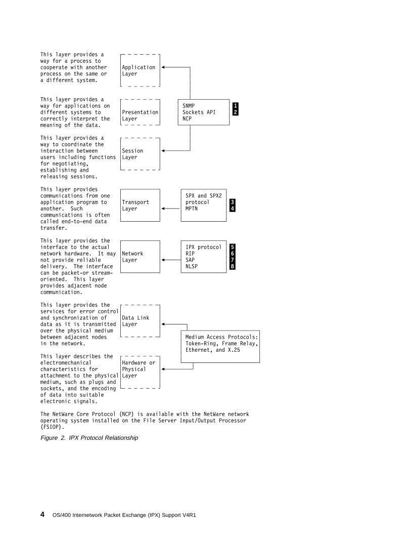
IPX consists of a layered structure of protocols that range from low-level, hardware-dependent programs, to middle-level transport and network layers. These layersallow other applications to control the application layer, presentation layer, andsession layer services. Each IPX layer provides services to the layer above it anduses the services that are provided by the layer below it.
Figure 2 on page 4 shows the relationship between the IPX protocols and func-tions within the IPX layered architecture and a model for the seven-layered archi-tecture.
The topics that follow discuss only those protocols that are available onAS/400 business computing systems.
Internetwork Packet Exchange Networks and Protocols–Introduction 3
This layer provides a ┌─ ─ ─ ─ ─ ─ ┐
way for a process to │ │
cooperate with another │Application │%────────┐
process on the same or │Layer │ │
a different system. │ │ │
└ ─ ─ ─ ─ ─ ┘ │
│
This layer provides a ┌ ─ ─ ─ ─ ─ ─┐ ┌───┴────────────┐
way for applications on │ │ │ SNMP │.1/different systems to │Presentation│ │ Sockets API │.2/correctly interpret the │Layer │ │ NCP │
meaning of the data. └ ─ ─ ─ ─ ─ ─┘ └───┬────────────┘
│
This layer provides a ┌ ─ ─ ─ ─ ─ ─┐ │
way to coordinate the │ │ │
interaction between │Session │%────────┘
users including functions │Layer │
for negotiating, │ │
establishing and └─ ─ ─ ─ ─ ─ ┘
releasing sessions.
This layer provides ┌────────────┐ ┌──────────────┐
communications from one │ │ │ SPX and SPX2 │
application program to │Transport │ │ protocol │.3/another. Such │Layer │%─────│ MPTN │.4/communications is often │ │ │ │
called end-to-end data └────────────┘ └──────────────┘
transfer.
This layer provides the ┌────────────┐ ┌──────────────┐
interface to the actual │ │ │ IPX protocol │.5/network hardware. It may │Network │ │ RIP │.6/not provide reliable │Layer │%─────┤ SAP │.7/delivery. The interface │ │ │ NLSP │.8/can be packet-or stream- └────────────┘ └──────────────┘
oriented. This layer
provides adjacent node
communication.
This layer provides the ┌ ─ ─ ─ ─ ─ ─┐
services for error control│ │
and synchronization of │Data Link │
data as it is transmitted │Layer │%───────┐
over the physical medium │ │ ┌─┴───────────────────────┐
between adjacent nodes └ ─ ─ ─ ─ ─ ─┘ │ Medium Access Protocols:│
in the network. │ Token-Ring, Frame Relay,│
│ Ethernet, and X.25 │
This layer describes the ┌ ─ ─ ─ ─ ─ ─┐ │ │
electromechanical │Hardware or │ └───┬─────────────────────┘
characteristics for │Physical │%─────────┘
attachment to the physical│Layer │
medium, such as plugs and │ │
sockets, and the encoding └─ ─ ─ ─ ─ ─ ┘
of data into suitable
electronic signals.
The NetWare Core Protocol (NCP) is available with the NetWare network
operating system installed on the File Server Input/Output Processor
(FSIOP).
Figure 2. IPX Protocol Relationship
4 OS/400 Internetwork Packet Exchange (IPX) Support V4R1

Upper Protocol LayersThe application layer, presentation layer, and the session layer are not part of theOS/400 IPX support as currently implemented on AS/400. IPX support allows otherfunctions to perform the application services. These functions can be any one ofthe following:
� Simple Network Management Protocol (SNMP)
� Sockets API
� NetWare Core Protocol (NCP)
Simple Network Management Protocol (SNMP).1/SNMP is a protocol used by network hosts to exchange information that is usedin the management of networks. The client/server model is based on SNMPnetwork management. Each host that is to be managed runs a process that iscalled an agent. The agent is a server process that maintains the ManagementInformation Base (MIB) database for the host network.
SNMP is a standard OS/400 system management application.
The OS/400 SNMP agent has added support for the IPX-defined MIBs.
Notes:
1. AS/400 supports the ability to get the SNMP data over AnyNet/400 or TCP/IPapplications.
2. AS/400 does not support the SNMP over IPX RFC 1420.
For additional information on SNMP, see the Simple Network Management Protocol(SNMP) Support book.
Sockets Interface.2/ The Sockets Interface is an API that allows customers the ability to write appli-cations directly to different protocol stacks. Sockets allow unrelated processes toexchange data locally and over networks.
On the AS/400 system, the sockets interface can be used to write applicationsdirectly to the SPX and IPX protocols. It allows you to access the Service Adver-tising Protocol (SAP) functions and allows access to the NLSP and RIP routinginformation. Sockets operate over the IPX support by using an address family ofNS (AF_NS). The Sockets interface can also be used over IPX by usingAnyNet/400 and running AF_INET sockets.
For additional information on sockets, see the Sockets Programming book.
SocketA socket is a method of communication between two processes. A socket is anidentifier that the application uses to uniquely identify an end point of communi-cations. The user associates a protocol address with the socket by associating asocket address with the socket.
Internetwork Packet Exchange Networks and Protocols–Introduction 5

IPX Socket NumbersSocket numbers are used by IPX and SPX protocols to identify a unique origin ordestination of communications within an application. Socket numbers or ports areinteger values from 1 to 65535.
These socket numbers can be either static or dynamic.
Static socket numbers are also referred to as well-known sockets . Well-knownsocket numbers that are assigned by Novell begin at hexadecimal 8000 and gothrough hexadecimal FFFF. They are assigned to specific processes. For example,hexadecimal 9001 is the socket number that identifies NLSP. Socket numbersabove hexadecimal 8000 should not be used by your application programs unlessthey are registered for that application with Novell. You can contact Novell toreserve well-known sockets for applications that you are writing.
Socket numbers between hexadecimal 4000 and hexadecimal 7FFF are dynamicsockets. These sockets are used by systems in a network to communicate with fileservers and other network devices.
The following list of socket numbers is not exhaustive and lists only the socketnumbers that are assigned to services that are widely implemented or of generalinterest.
Table 1. Socket Numbers
Socket Number Socket Process
Hexadecimal 0451 NetWare Core Protocol (NCP) Process
Hexadecimal 0452 Service Advertising Protocol (SAP)Process
Hexadecimal 0453 Routing Information Protocol (RIP)Process
Hexadecimal 0455 NetBIOS Process
Hexadecimal 0456 Diagnostics Process
Hexadecimal 0890 NetWare Enhanced Integration forOS/400
Hexadecimal 4000 through 7FFF Dynamic sockets; used by workstationsfor interaction with file servers and othernetwork communications
Hexadecimal 8000 through FFFF Well-known sockets
Hexadecimal 8795 AnyNet over SPX
Hexadecimal 8796 AnyNet over IPX
Hexadecimal 9001 NetWare Link Services Protocol (NLSP)
Hexadecimal 9004 IW2 protocol
Hexadecimal 9086 IPX Ping
6 OS/400 Internetwork Packet Exchange (IPX) Support V4R1
Transport Protocol LayerThe Sequenced Packet Exchange (SPX) protocol and the Multiprotocol TransportNetworking Architecture (MPTN) provide transport services for IPX support.
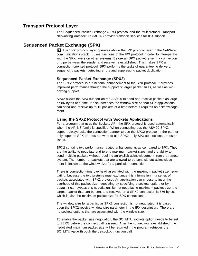
Sequenced Packet Exchange (SPX).3/ The SPX protocol layer operates above the IPX protocol layer in the NetWarecommunications stack. It uses functions of the IPX protocol in order to interoperatewith the SPX layers on other systems. Before an SPX packet is sent, a connectionor pipe between the sender and receiver is established. This makes SPX aconnection-oriented protocol. SPX performs the tasks of guaranteeing delivery,sequencing packets, detecting errors and suppressing packet duplication.
Sequenced Packet Exchange (SPX2)The SPX2 protocol is a functional enhancement to the SPX protocol. It providesimproved performance through the support of larger packet sizes, as well as win-dowing support.
SPX2 allows the SPX support on the AS/400 to send and receive packets as largeas 8K bytes at a time. It also increases the window size so that SPX applicationscan send and receive up to 16 packets at a time before it requires an acknowledge-ment.
Using the SPX2 Protocol with Sockets ApplicationsFor a program that uses the Sockets API, the SPX protocol is used automaticallywhen the AF_NS family is specified. When connecting out, the AS/400 SPX2support always asks the connection partner to use the SPX2 protocol. If the partneronly supports SPX or does not want to use SPX2, only SPX connections are estab-lished.
SPX2 contains two performance-related enhancements as compared to SPX. Theyare the ability to negotiate end-to-end maximum packet sizes, and the ability tosend multiple packets without requiring an explicit acknowledgment from the remotesystem. The number of packets that are allowed to be sent without acknowledg-ment is known as the window size for a particular connection.
There is connection-time overhead associated with the maximum packet size nego-tiating, because the two systems must exchange this information in a series ofpackets associated with SPX2 protocol. An application can choose to incur theoverhead of this packet size negotiating by specifying a sockets option, or bydefault it can bypass this negotiation. By not negotiating maximum packet size, thelargest packet that can be sent and received on a SPX2 connection is 576 bytes,which is also the maximum packet size for SPX connections.
The window size for a particular SPX2 connection is not negotiated; it is basedupon the SPX2 receive window size parameter in the IPX description. There areno sockets options that are associated with the window size.
To enable the packet size negotiation, the SO_MTU sockets option needs to be setto ZERO before the connect call is issued. After the connection is established, thenegotiated maximum packet size will be returned if the program retrieves theSO_MTU value through the getsockopt function call.
Internetwork Packet Exchange Networks and Protocols–Introduction 7

For an AS/400 server listening and waiting for a connect request, an SPX2 con-nection will be established if the client requests the use of the SPX2 protocol. Thepacket size negotiation will also be enabled if the client requests it (in this case, theserver does not have to set the SO_MTU to zero).
If your applications are using SPX2, the sockets option SO_KEEPALIVE is treatedby the SPX2 support as ON even if the program set it to OFF because the SPX2protocol requires the watchdog function to be active for all SPX2 connections.
Multiprotocol Transport Networking Architecture (MPTN).4/ MPTN on AS/400 systems allows Common Programming Interface Communi-cations (CPI-Communications), intersystem communications function (ICF), andsockets to flow over TCP/IP, SNA, or IPX. On AS/400 systems, MPTN is known as,and provided through, AnyNet/400 support. AnyNet/400 support is included with theOS/400 licensed program.
Examples of AnyNet/400 support for IPX are:
� APPC over IPX
The APPC over IPX support allows APPC applications that are written forCPI-Communications and ICF APIs to communicate between systems in an IPXnetwork. Both systems running the APPC applications (such as display stationpass-through) must have APPC over IPX support.
When using AnyNet/400 support, APPC over IPX allows CPI-Communicationsor ICF applications to run with no changes over an IPX network.
� AF_INET Sockets over IPX
The AF_INET Sockets over IPX support allows sockets applications to commu-nicate between systems in an IPX network. Both systems running the socketsapplications (such as file transfer protocol) must have AF_INET Sockets overIPX support.
For more information about AnyNet/400, see IPX Support and AnyNet/400.
Network Protocol LayerThe internetwork package exchange (IPX) protocol is the most important protocol inthis layer because IPX is the base protocol of the NetWare protocol suite. All otherNetWare protocols are carried inside an IPX packet.
Internetwork Packet Exchange (IPX) Protocol.5/ The IPX protocol provides transportation rules for communications betweensystems on the different networks that make up an internetwork. The IPX protocoldoes things like addressing, routing, and switching information packets from onelocation to another on the IPX internetwork. The IPX protocol defines internetworkand intranode by addressing schemes, while relying on the network hardware forthe definition of node addressing.
8 OS/400 Internetwork Packet Exchange (IPX) Support V4R1
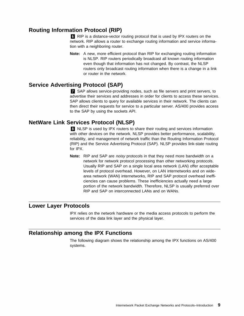
Routing Information Protocol (RIP).6/ RIP is a distance-vector routing protocol that is used by IPX routers on thenetwork. RIP allows a router to exchange routing information and service informa-tion with a neighboring router.
Note: A new, more efficient protocol than RIP for exchanging routing informationis NLSP. RIP routers periodically broadcast all known routing informationeven though that information has not changed. By contrast, the NLSProuters only broadcast routing information when there is a change in a linkor router in the network.
Service Advertising Protocol (SAP).7/ SAP allows service-providing nodes, such as file servers and print servers, toadvertise their services and addresses in order for clients to access these services.SAP allows clients to query for available services in their network. The clients canthen direct their requests for service to a particular server. AS/400 provides accessto the SAP by using the sockets API.
NetWare Link Services Protocol (NLSP).8/ NLSP is used by IPX routers to share their routing and services informationwith other devices on the network. NLSP provides better performance, scalability,reliability, and management of network traffic than the Routing Information Protocol(RIP) and the Service Advertising Protocol (SAP). NLSP provides link-state routingfor IPX.
Note: RIP and SAP are noisy protocols in that they need more bandwidth on anetwork for network protocol processing than other networking protocols.Usually RIP and SAP on a single local area network (LAN) offer acceptablelevels of protocol overhead. However, on LAN internetworks and on wide-area network (WAN) internetworks, RIP and SAP protocol overhead ineffi-ciencies can cause problems. These inefficiencies actually need a largeportion of the network bandwidth. Therefore, NLSP is usually preferred overRIP and SAP on interconnected LANs and on WANs.
Lower Layer ProtocolsIPX relies on the network hardware or the media access protocols to perform theservices of the data link layer and the physical layer.
Relationship among the IPX FunctionsThe following diagram shows the relationship among the IPX functions on AS/400systems.
Internetwork Packet Exchange Networks and Protocols–Introduction 9

┌──────────────────────────────────────────────────────────────────┐
│ User Applications │
│ │
└──────────────────┬────────────────────────────────┬──────────────┘
┌─────┴─────┐ │
│ SNMP │ │ .1/ │ │ │
└────┬──────┘ │
┌─────────────────┼────────────────┐ ┌─────────────┴──────────────┐
│AF_INET Sockets AF_NS Sockets │ │ ICF and CPIC │ .2/│ over IPX │ │ over IPX │
│ │ │ │
└────┬───────┬────┴──┬───────┬─────┘ └───────┬─────────────────┬──┘
│ │ │ │ │ │
─ ─ ─ ─ ─ ─ ─ ─ ─ ─ ─ ─ ─ ─ ─ ─ ─ ─ ─ ─ ─ ─ ┼ ─ ─ ─ ─ ─ ─ ─ ─ ┼ ─ Machine
│ │ │ │ │ │ Interface
│ │ │ ┌──┴────────────────┴─────────────┐ │
│ │ │ │ │ │ .3/│ └───────┼────┤ Sequenced Packet Exchange │ │ .4/│ │ │ (SPX and SPX2) │ │
│ │ └─────────────┬───────────────────┘ │
│ │ │ │
┌────┴───────────────┴──────────────────┴───────────────────────┴──┐
│ ┌─────┐ ┌──────┐ ┌─────┐ │ .5/ .6/│ Internetwork Packet Exchange │ RIP │ │ SAP │ │NLSP │ │ .7/ .8/│ (IPX) └─────┘ └──────┘ └─────┘ │
└────────────────────────────────┬─────────────────────────────────┘
│
│
┌────────────────────────────────┴─────────────────────────────────┐
│ │
│ Interface Drivers │
│ │
└───┬─────────────────┬────────────┬────────────┬─────────────┬────┘
│ │ │ │ │
┌───┴─────┐ ┌─────┴────┐ ┌───┴───┐ ┌────┴──────┐ ┌───┴────┐
│ X.25 │ │IEEE 8ð2.2│ │ Frame │ │ Ethernet │ │Ethernet│
│ SVC/PVC │ └─┬──────┬─┘ │ Relay │ │ Version 2 │ │NetWare │
│ │ │ │ │ │ │ │ │ │
└─────────┘ ┌─────┴──┐ ┌─┴───┐ └───────┘ └───────────┘ └────────┘
│ 8ð2.3 │ │8ð2.5│
│Ethernet│ │token│
└────────┘ │ring │
└─────┘
Figure 3. IPX Support on AS/400
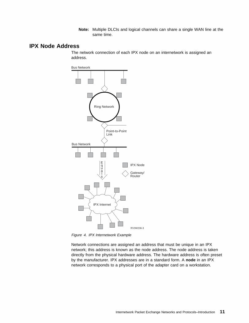
IPX NetworkA physical network segment is generally defined as an IPX network. In Figure 4 onpage 11, three separate IPX networks are connected by IPX routers.
An IPX network can be used with local area networks (LANs) and wide area net-works (WANs).
� For LANs, an IPX network is defined as running on a unique source serviceaccess point (SSAP) of a line. Multiple IPX networks with different SSAPs canrun over a single LAN.
� For WANs, OS/400 IPX support uses data link connection identifiers (DLCIs)when running over Frame Relay. OS/400 IPX support uses logical channelidentifiers when running over X.25 support.
10 OS/400 Internetwork Packet Exchange (IPX) Support V4R1
Note: Multiple DLCIs and logical channels can share a single WAN line at thesame time.
IPX Node AddressThe network connection of each IPX node on an internetwork is assigned anaddress.
RV3W236-3
Equals
Bus Network
Ring Network
Bus Network
Point-to-PointLink
Gateway/Router
IPX Node
IPX Internet
Figure 4. IPX Internetwork Example
Network connections are assigned an address that must be unique in an IPXnetwork; this address is known as the node address. The node address is takendirectly from the physical hardware address. The hardware address is often presetby the manufacturer. IPX addresses are in a standard form. A node in an IPXnetwork corresponds to a physical port of the adapter card on a workstation.
Internetwork Packet Exchange Networks and Protocols–Introduction 11

IPX CircuitAn IPX circuit on AS/400 systems represents a path for IPX communications for alocal area network (LAN) and a wide area network (WAN).
� For a LAN, an IPX circuit defines the path or point of attachment from the IPXprotocol layer to the IPX network.
� For a WAN, an IPX circuit provides the path from the IPX protocol layer to aremote IPX node or system.
Each circuit is associated with a line description.
For information about working with IPX circuits, refer to “ Step 3–Adding an Inter-network Packet Exchange (IPX) Circuit” on page 35.
RoutingRouting is the process of mapping a path to send a packet to its destination IPXnetwork address. Routing can be direct or indirect.
Direct routing is used when the source and destination nodes are on the samephysical network. When direct routing is used, the source node sends the packeton the network together with the destination hardware address in the media accesscontrol layer. The destination node hardware detects its own address in the packetheader and accepts the packet.
Indirect routing is used when the source and destination nodes are not on the samephysical network. The source node uses its routing tables to determine which routerwill forward packets to the destination node. The packet is put on the network withthe router hardware address in the network header, and the destination IPX nodeaddress in the IPX header. The router hardware then receives the packet from thenetwork, and the IPX router software determines the packet destination from theIPX header.
IPX RoutersRouters are used to connect two or more similar or dissimilar networks and providerouting services that are based on logical end to end connections.
An IPX router routes IPX packets among the networks to which it is connecteduntil the packet can be delivered to the final destination directly across one physicalnetwork. An IPX packet is the basic unit of data. IPX packets can be routed acrossup to 127 data links or hops between the source and destination of the packet. Ahop implies that the packet was routed across an IPX router.
AS/400 can be a router in an IPX network. See Figure 5 on page 13.
12 OS/400 Internetwork Packet Exchange (IPX) Support V4R1
RV3W235-3
AS/400Acting asa Router
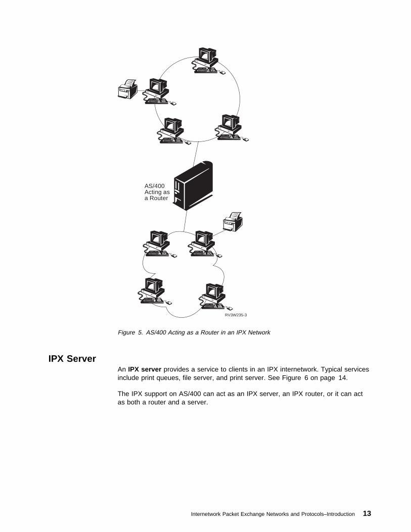
Figure 5. AS/400 Acting as a Router in an IPX Network
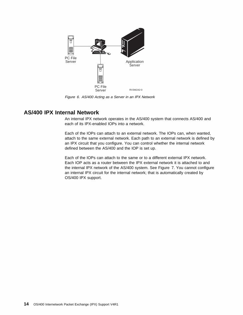
IPX ServerAn IPX server provides a service to clients in an IPX internetwork. Typical servicesinclude print queues, file server, and print server. See Figure 6 on page 14.
The IPX support on AS/400 can act as an IPX server, an IPX router, or it can actas both a router and a server.
Internetwork Packet Exchange Networks and Protocols–Introduction 13
RV3W242-0
Application Server
PC FileServer
PC FileServer
Figure 6. AS/400 Acting as a Server in an IPX Network
AS/400 IPX Internal NetworkAn internal IPX network operates in the AS/400 system that connects AS/400 andeach of its IPX-enabled IOPs into a network.
Each of the IOPs can attach to an external network. The IOPs can, when wanted,attach to the same external network. Each path to an external network is defined byan IPX circuit that you configure. You can control whether the internal networkdefined between the AS/400 and the IOP is set up.
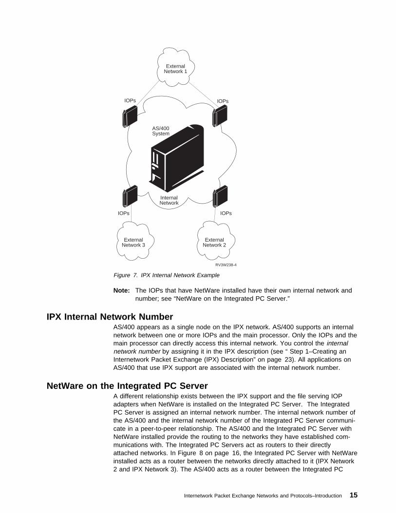
Each of the IOPs can attach to the same or to a different external IPX network.Each IOP acts as a router between the IPX external network it is attached to andthe internal IPX network of the AS/400 system. See Figure 7. You cannot configurean internal IPX circuit for the internal network; that is automatically created byOS/400 IPX support.
14 OS/400 Internetwork Packet Exchange (IPX) Support V4R1
RV3W238-4
AS/400System
Internal Network
ExternalNetwork 2
ExternalNetwork 3
ExternalNetwork 1
IOPs
IOPs
IOPs
IOPs
Figure 7. IPX Internal Network Example
Note: The IOPs that have NetWare installed have their own internal network andnumber; see “NetWare on the Integrated PC Server.”
IPX Internal Network NumberAS/400 appears as a single node on the IPX network. AS/400 supports an internalnetwork between one or more IOPs and the main processor. Only the IOPs and themain processor can directly access this internal network. You control the internalnetwork number by assigning it in the IPX description (see “ Step 1–Creating anInternetwork Packet Exchange (IPX) Description” on page 23). All applications onAS/400 that use IPX support are associated with the internal network number.
NetWare on the Integrated PC ServerA different relationship exists between the IPX support and the file serving IOPadapters when NetWare is installed on the Integrated PC Server. The IntegratedPC Server is assigned an internal network number. The internal network number ofthe AS/400 and the internal network number of the Integrated PC Server communi-cate in a peer-to-peer relationship. The AS/400 and the Integrated PC Server withNetWare installed provide the routing to the networks they have established com-munications with. The Integrated PC Servers act as routers to their directlyattached networks. In Figure 8 on page 16, the Integrated PC Server with NetWareinstalled acts as a router between the networks directly attached to it (IPX Network2 and IPX Network 3). The AS/400 acts as a router between the Integrated PC
Internetwork Packet Exchange Networks and Protocols–Introduction 15
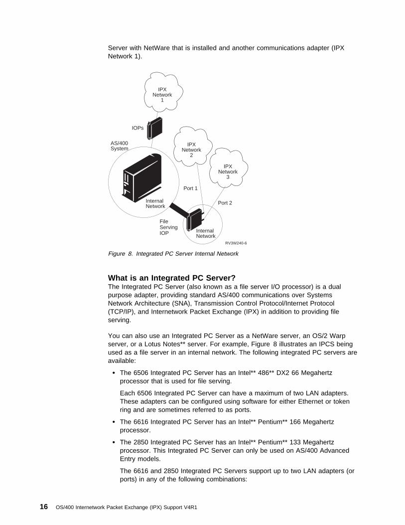
Server with NetWare that is installed and another communications adapter (IPXNetwork 1).
RV3W240-6
AS/400System
InternalNetwork
InternalNetwork
IOPs
FileServingIOP
Port 2
Port 1
IPXNetwork
1
IPXNetwork
2
IPXNetwork
3
Figure 8. Integrated PC Server Internal Network
What is an Integrated PC Server?The Integrated PC Server (also known as a file server I/O processor) is a dualpurpose adapter, providing standard AS/400 communications over SystemsNetwork Architecture (SNA), Transmission Control Protocol/Internet Protocol(TCP/IP), and Internetwork Packet Exchange (IPX) in addition to providing fileserving.
You can also use an Integrated PC Server as a NetWare server, an OS/2 Warpserver, or a Lotus Notes** server. For example, Figure 8 illustrates an IPCS beingused as a file server in an internal network. The following integrated PC servers areavailable:
� The 6506 Integrated PC Server has an Intel** 486** DX2 66 Megahertzprocessor that is used for file serving.
Each 6506 Integrated PC Server can have a maximum of two LAN adapters.These adapters can be configured using software for either Ethernet or tokenring and are sometimes referred to as ports.
� The 6616 Integrated PC Server has an Intel** Pentium** 166 Megahertzprocessor.
� The 2850 Integrated PC Server has an Intel** Pentium** 133 Megahertzprocessor. This Integrated PC Server can only be used on AS/400 AdvancedEntry models.
The 6616 and 2850 Integrated PC Servers support up to two LAN adapters (orports) in any of the following combinations:
16 OS/400 Internetwork Packet Exchange (IPX) Support V4R1
– Two Ethernet ports
– Two token-ring ports
– One Ethernet port and one token-ring port
– One Ethernet port
– One token-ring port
Registering IPX Network NumbersIf you want to connect your IPX network to another IPX network or internetwork,you must ensure that all internal and external network addresses in the connectedinternetwork are unique. Novell provides the Novell Network Registry service toassign and track IPX network addresses and organization names. Such a registryallows participating organizations to share data between interconnected IPX net-works without name and IPX address conflicts.
The Novell Network Registry assigns contiguous blocks of IPX addresses that areunique to your organization.
� To learn more about the Novell Network Registry
� To reserve a block of IPX addresses
� To request a copy of the Novell Network Registry book
Call 1-408-321-1506
FAX 1-408-956-0463
Send Internet e-mail to [email protected]
If your IPX network will never be connected to another IPX network, youcan select any IPX network number for your AS/400 internal andexternal IPX network numbers.
Internetwork Packet Exchange Networks and Protocols–Introduction 17

18 OS/400 Internetwork Packet Exchange (IPX) Support V4R1

Configuring the Internetwork Packet Exchange (IPX) Support
Configuring IPX–Overview . . . . . . . . . . . . . . . . . . . . . . . . . . . . . . 21Ethernet Network Example . . . . . . . . . . . . . . . . . . . . . . . . . . . . . . 23
Step 1–Creating an Internetwork Packet Exchange (IPX) Description . . . 23IPX Description . . . . . . . . . . . . . . . . . . . . . . . . . . . . . . . . . . 24IPX Internal Network Number . . . . . . . . . . . . . . . . . . . . . . . . . 25IPX Routing Protocol . . . . . . . . . . . . . . . . . . . . . . . . . . . . . . 25IPX Router Name . . . . . . . . . . . . . . . . . . . . . . . . . . . . . . . . 26IPX Maximum Datagram Size . . . . . . . . . . . . . . . . . . . . . . . . . 26Additional Parameters . . . . . . . . . . . . . . . . . . . . . . . . . . . . . . 27Sample IPX Descriptions . . . . . . . . . . . . . . . . . . . . . . . . . . . . 28
Step 2–Configuring Line Descriptions for IPX Support–Ethernet . . . . . . . 30Line Description . . . . . . . . . . . . . . . . . . . . . . . . . . . . . . . . . 32Resource Name . . . . . . . . . . . . . . . . . . . . . . . . . . . . . . . . . 32Ethernet Standard . . . . . . . . . . . . . . . . . . . . . . . . . . . . . . . . 33Source Service Access Point . . . . . . . . . . . . . . . . . . . . . . . . . . 33Text 'description' . . . . . . . . . . . . . . . . . . . . . . . . . . . . . . . . . 34Sample Ethernet Line Descriptions . . . . . . . . . . . . . . . . . . . . . . 34
Step 3–Adding an Internetwork Packet Exchange (IPX) Circuit . . . . . . . 35Circuit Name . . . . . . . . . . . . . . . . . . . . . . . . . . . . . . . . . . . 38Line Description . . . . . . . . . . . . . . . . . . . . . . . . . . . . . . . . . 38IPX Network Number . . . . . . . . . . . . . . . . . . . . . . . . . . . . . . 38Frame Type . . . . . . . . . . . . . . . . . . . . . . . . . . . . . . . . . . . . 38Enable for NLSP . . . . . . . . . . . . . . . . . . . . . . . . . . . . . . . . . 40MAC Channel for NLSP . . . . . . . . . . . . . . . . . . . . . . . . . . . . . 40Router Priority for NLSP . . . . . . . . . . . . . . . . . . . . . . . . . . . . 40Cost Override for NLSP . . . . . . . . . . . . . . . . . . . . . . . . . . . . . 41Additional Parameters . . . . . . . . . . . . . . . . . . . . . . . . . . . . . . 41Displaying the Circuit Configurations . . . . . . . . . . . . . . . . . . . . . 42Sample IPX Circuits . . . . . . . . . . . . . . . . . . . . . . . . . . . . . . . 43
Step 4–Adding Route Information . . . . . . . . . . . . . . . . . . . . . . . . . 45Step 5–Adding Service Information . . . . . . . . . . . . . . . . . . . . . . . . 45
X.25 Network Example . . . . . . . . . . . . . . . . . . . . . . . . . . . . . . . . 45 Step 1–Creating an IPX Description–X.25 . . . . . . . . . . . . . . . . . . . 46 Step 2–Configuring a Line Description for IPX Support–X.25 . . . . . . . . 46
Line Description . . . . . . . . . . . . . . . . . . . . . . . . . . . . . . . . . 47Resource Name . . . . . . . . . . . . . . . . . . . . . . . . . . . . . . . . . 47Logical Channel Entries . . . . . . . . . . . . . . . . . . . . . . . . . . . . . 48Local Network Address . . . . . . . . . . . . . . . . . . . . . . . . . . . . . 49Connection Initiation . . . . . . . . . . . . . . . . . . . . . . . . . . . . . . . 49Default Packet Size . . . . . . . . . . . . . . . . . . . . . . . . . . . . . . . 49Maximum Packet Size . . . . . . . . . . . . . . . . . . . . . . . . . . . . . . 50Default Window Size . . . . . . . . . . . . . . . . . . . . . . . . . . . . . . . 50Sample X.25 Line Description . . . . . . . . . . . . . . . . . . . . . . . . . 50
Step 3–Adding an IPX Circuit for an X.25 SVC Line . . . . . . . . . . . . . . 52Circuit Name . . . . . . . . . . . . . . . . . . . . . . . . . . . . . . . . . . . 53Line Description . . . . . . . . . . . . . . . . . . . . . . . . . . . . . . . . . 53X.25 PVC Logical Channel ID . . . . . . . . . . . . . . . . . . . . . . . . . 53X.25 SVC Network Address . . . . . . . . . . . . . . . . . . . . . . . . . . 53X.25 SVC Call Type . . . . . . . . . . . . . . . . . . . . . . . . . . . . . . . 53X.25 Default Packet Size . . . . . . . . . . . . . . . . . . . . . . . . . . . . 54
Copyright IBM Corp. 1997 19

X.25 Default Window Size . . . . . . . . . . . . . . . . . . . . . . . . . . . 54Automatic Start . . . . . . . . . . . . . . . . . . . . . . . . . . . . . . . . . . 54RIP State . . . . . . . . . . . . . . . . . . . . . . . . . . . . . . . . . . . . . 54SAP State . . . . . . . . . . . . . . . . . . . . . . . . . . . . . . . . . . . . . 55Sample X.25 Circuit Display . . . . . . . . . . . . . . . . . . . . . . . . . . 55
Circuit Routes and Circuit Services–Overview . . . . . . . . . . . . . . . . . . . 56Step 4–Adding Circuit Route Information . . . . . . . . . . . . . . . . . . . . 57
Circuit Routes or Static Routes . . . . . . . . . . . . . . . . . . . . . . . . 57Circuit Name . . . . . . . . . . . . . . . . . . . . . . . . . . . . . . . . . . . 59Remote IPX Network Number . . . . . . . . . . . . . . . . . . . . . . . . . 59Number of Hops . . . . . . . . . . . . . . . . . . . . . . . . . . . . . . . . . 59Number of Ticks . . . . . . . . . . . . . . . . . . . . . . . . . . . . . . . . . 60Sample Circuit Routes . . . . . . . . . . . . . . . . . . . . . . . . . . . . . . 60
Step 5–Adding Circuit Service Information . . . . . . . . . . . . . . . . . . . . 61Circuit Services or Static Services . . . . . . . . . . . . . . . . . . . . . . . 61Circuit Name . . . . . . . . . . . . . . . . . . . . . . . . . . . . . . . . . . . 63Service Name . . . . . . . . . . . . . . . . . . . . . . . . . . . . . . . . . . 63Service Type . . . . . . . . . . . . . . . . . . . . . . . . . . . . . . . . . . . 64Remote Network Number . . . . . . . . . . . . . . . . . . . . . . . . . . . . 64Remote Node Address . . . . . . . . . . . . . . . . . . . . . . . . . . . . . 64Remote Socket Address . . . . . . . . . . . . . . . . . . . . . . . . . . . . 64Number of Hops . . . . . . . . . . . . . . . . . . . . . . . . . . . . . . . . . 64Sample Circuit Services . . . . . . . . . . . . . . . . . . . . . . . . . . . . . 65
Sample CL Program . . . . . . . . . . . . . . . . . . . . . . . . . . . . . . . . 65Additional IPX Configuration Options . . . . . . . . . . . . . . . . . . . . . . . . 65
This chapter explains how to configure AS/400 business computing systems for IPXsupport. If this is the first time that you have configured the IPX support on AS/400systems, please read the entire chapter before performing any of the configurationtasks.
If you are unfamiliar with OS/400 IPX support, you should also consider readingInternetwork Packet Exchange Networks and Protocols–Introduction.
This chapter will show you how to configure AS/400 systems in the sample networkthat is shown in Figure 9 on page 22.
Notes:
� If you want to configure IPX support in a Frame Relay network, youneed to create a network interface description, also. For more infor-mation about working with a Frame Relay network, see the LAN andFrame Relay Support book.
� Your user profile must have the *IOSYSCFG special authority inorder to configure the IPX support.
� The initial displays and menus that are shown when you configureIPX on your system may not contain any entries. The sample dis-plays in this chapter may already contain data, which we entered inprevious configuration steps.
20 OS/400 Internetwork Packet Exchange (IPX) Support V4R1
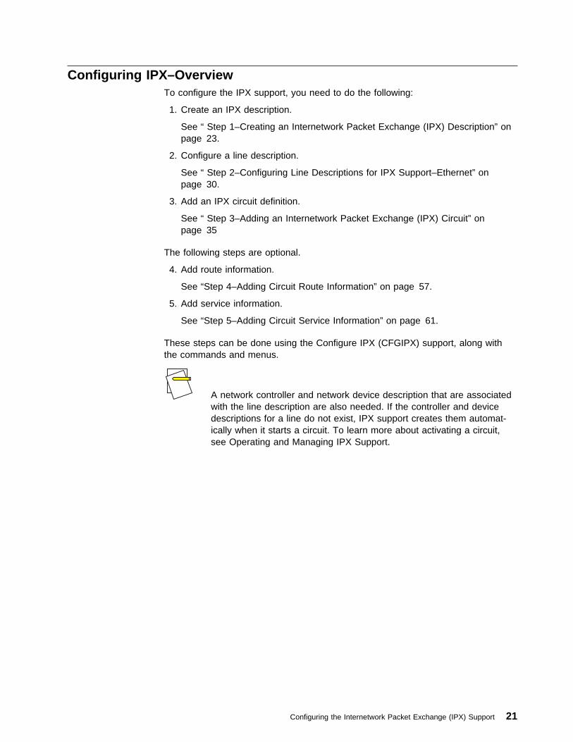
Configuring IPX–OverviewTo configure the IPX support, you need to do the following:
1. Create an IPX description.
See “ Step 1–Creating an Internetwork Packet Exchange (IPX) Description” onpage 23.
2. Configure a line description.
See “ Step 2–Configuring Line Descriptions for IPX Support–Ethernet” onpage 30.
3. Add an IPX circuit definition.
See “ Step 3–Adding an Internetwork Packet Exchange (IPX) Circuit” onpage 35
The following steps are optional.
4. Add route information.
See “Step 4–Adding Circuit Route Information” on page 57.
5. Add service information.
See “Step 5–Adding Circuit Service Information” on page 61.
These steps can be done using the Configure IPX (CFGIPX) support, along withthe commands and menus.
A network controller and network device description that are associatedwith the line description are also needed. If the controller and devicedescriptions for a line do not exist, IPX support creates them automat-ically when it starts a circuit. To learn more about activating a circuit,see Operating and Managing IPX Support.
Configuring the Internetwork Packet Exchange (IPX) Support 21
Ethernet Bus Network
┌────────────────────┬────────────────────┐
│ │ │
│ │ │
┌──────┴──────┐ ┌──────┴──────┐ ┌──────┴──────┐
│ │ │ │ │ │
│ AS/4ðð A ├──────┤ AS/4ðð C ├──────┤ AS/4ðð B │
│ │ │ │ │ │
│ │ │ │ │ │
└─────────────┘ └─────┬───────┘ └─────────────┘
│
\\│\ \
\ \ \ \
\ \
\ \
\ X.25 \
\ Network \
\ \
\ \
\ \ \ \
\ \│\ \
│
┌─────┴──────┐
│ │
│ AS/4ðð D │
│ │
│ FSIOP (D1) │
│ │
└─────┬──────┘
│
│
│
\\\
┌─────────────┐ \ \ ┌───────────┐
│ E │ \ Token \ │ F │
│ Novell ├───────────\ Ring \────────────┤ Novell │
│ NetWare │ \ Network\ │ NetWare │
│ 4.1 Client │ \ \ │ 3.x Client│
└─────────────┘ \\\ └───────────┘
│
│
│
┌─────┴──────┐
│ │ ┌─────────┐
│ AS/4ðð G ├──────┤ Printer │
│ │ └─────────┘
│ │
└────────────┘
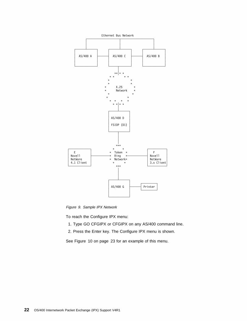
Figure 9. Sample IPX Network
To reach the Configure IPX menu:
1. Type GO CFGIPX or CFGIPX on any AS/400 command line.
2. Press the Enter key. The Configure IPX menu is shown.
See Figure 10 on page 23 for an example of this menu.
22 OS/400 Internetwork Packet Exchange (IPX) Support V4R1

à ð CFGIPX Configure IPX SYSTEM: SYSNAMXX
Select one of the following:
Configure IPX
1. Configure IPX circuits
2. Work with IPX descriptions
3. Work with IPX status
Configure AnyNet/4ðð over IPX
1ð. Work with IP over IPX interfaces
11. Work with IP over IPX routes
12. Work with IP over IPX addresses
2ð. Work with SNA over IPX locations
Selection or command
===>
F3=Exit F4=Prompt F9=Retrieve F12=Cancel
á ñ
Figure 10. Configure IPX Menu Example
The following steps describe how to configure the IPX support and show specificexamples on how to configure parts of the sample network.
Ethernet Network ExampleThe Ethernet network is the first part of the sample network to configure.
Let’s configure systems A, B, and C, which are part of the sample network. Thesethree AS/400s are connected by an Ethernet bus.
Ethernet Bus Network
┌────────────────────┬────────────────────┐
│ │ │
│ │ │
┌──────┴──────┐ ┌──────┴──────┐ ┌──────┴──────┐
│ │ │ │ │ │
│ AS/4ðð A ├──────┤ AS/4ðð C ├──────┤ AS/4ðð B │
│ │ │ │ │ │
│ │ │ │ │ │
└─────────────┘ └─────────────┘ └─────────────┘
Step 1–Creating an Internetwork Packet Exchange (IPX) DescriptionEach AS/400 must have its own IPX description that defines global system defaultvalues for IPX. One IPX description is defined for the OS/400 IPX support on eachAS/400.
You can define multiple IPX descriptions for IPX support on the systemat any given time. However, the only time you would want to have mul-tiple IPX descriptions is when you require different default values.
To create an IPX description to use the IPX support on AS/400:
Configuring the Internetwork Packet Exchange (IPX) Support 23
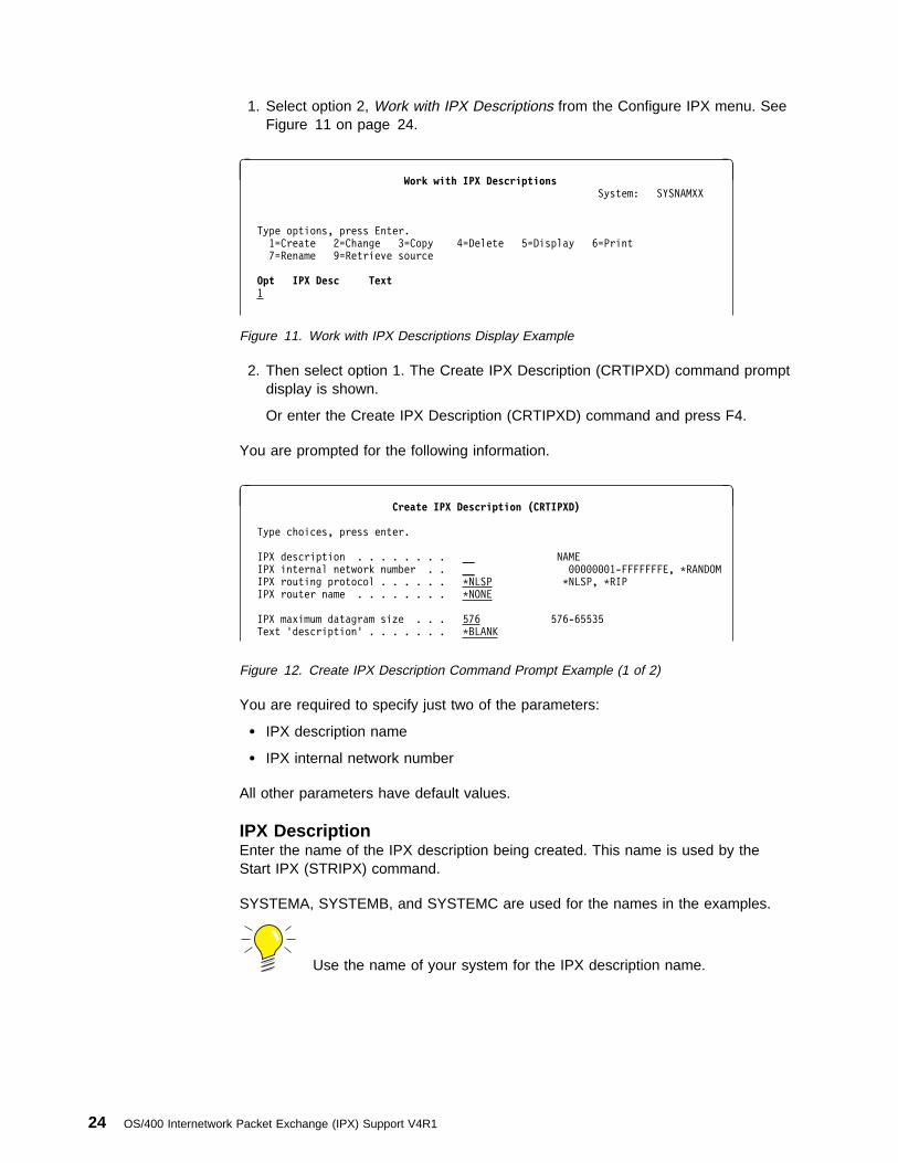
1. Select option 2, Work with IPX Descriptions from the Configure IPX menu. SeeFigure 11 on page 24.
à ðWork with IPX Descriptions
System: SYSNAMXX
Type options, press Enter.
1=Create 2=Change 3=Copy 4=Delete 5=Display 6=Print
7=Rename 9=Retrieve source
Opt IPX Desc Text 1
Figure 11. Work with IPX Descriptions Display Example
2. Then select option 1. The Create IPX Description (CRTIPXD) command promptdisplay is shown.
Or enter the Create IPX Description (CRTIPXD) command and press F4.
You are prompted for the following information.
à ðCreate IPX Description (CRTIPXD)
Type choices, press enter.
IPX description . . . . . . . . __ NAME
IPX internal network number . . __ ððððððð1-FFFFFFFE, \RANDOM
IPX routing protocol . . . . . . \NLSP \NLSP, \RIP
IPX router name . . . . . . . . \NONE
IPX maximum datagram size . . . 576 576-65535
Text 'description' . . . . . . . \BLANK
Figure 12. Create IPX Description Command Prompt Example (1 of 2)
You are required to specify just two of the parameters:
� IPX description name
� IPX internal network number
All other parameters have default values.
IPX DescriptionEnter the name of the IPX description being created. This name is used by theStart IPX (STRIPX) command.
SYSTEMA, SYSTEMB, and SYSTEMC are used for the names in the examples.
Use the name of your system for the IPX description name.
24 OS/400 Internetwork Packet Exchange (IPX) Support V4R1
IPX Internal Network NumberEnter the number of the internal IPX network specifying the internal IPX network forwhich all services and applications that run on the IPX and SPX protocol stacks onAS/400.
This internal network number is reachable through all adjacent IPX networks,whose network numbers are configured in the IPX circuit definitions.
The internal network number is specified in the form, nnnnnnnn, where nnnnnnnn isa hexadecimal number ranging from 00000001 through FFFFFFFE.
Or you can specify *RANDOM to generate a number for your system. You mustmake sure that this is a unique number on the network. There is no default.
For the IPX internal network number in this example, use 00000001 for SYSTEMA,00000002 for SYSTEMB, and 00000003 for SYSTEMC.
When duplicate network numbers are found, the data is prevented fromreaching the correct destination. Use the Work with IPX Descriptions(WRKIPXD) command to display the internal network number that isassociated with the IPX description that exists on this AS/400 system.The *RANDOM option generates an IPX internal network number whenthe IPX description is created, so this command shows you the internalnetwork number that is generated by the AS/400 IPX support.
You can also use the Work with IPX Status (WRKIPXSTS) command, to display theactive IPX description on this AS/400 system.
To check for other IPX network numbers in use, start the IPX support by using theStart IPX (STRIPX) command, start an IPX circuit, and then use WRKIPXSTScommand, to display IPX route information.
For more information, see the “Work with IPX Status (WRKIPXSTS) command” in“IPX Status Support” on page 72.
IPX Routing ProtocolEnter the value to control whether IPX support uses this IPX description for RIProuting and SAP packet processing (RIP/SAP) only or for NLSP with RIP/SAP com-patibility.
The *NLSP value gives you RIP/SAP compatibility. This means that the AS/400NLSP router can interoperate on a network that uses RIP and SAP packets. *NLSPis the default.
Use the *RIP value if your network only supports RIP routing and SAP packet proc-essing and does not contain any NLSP enabled routers.
Configuring the Internetwork Packet Exchange (IPX) Support 25
IPX Router NameEnter the name of the IPX router that is enabled by this IPX description on the localsystem. Using a symbolic name for the router is useful for network managementpurposes. The name can be 1 to 47 characters in length. All 7-bit ASCII charactersare valid for router names.
*NONE is the default.
If you want your IPX router name to match the system name, you canmanually type that system name in the router name field. Use theDSPNETA command to view the current system name. Use CHGNETAto change the system name.
You can also use the IPX description name as the router name (forexample, if you are using a 2-port Integrated PC Server). The IPXdescription name must meet the criteria that are specified for a routername if it is to be used for the router name.
IPX Maximum Datagram SizeEnter the maximum size of IPX data that can be contained in a single IPX packet.This maximum also applies to the SPX protocol, because SPX data is sent in IPXpackets.
This value is important because there is no end-to-end negotiation of maximumdatagram size, and there may be intermediate hops in a route to the destinationsystem that have a smaller maximum datagram size than the directly attached linksto the AS/400 system.
You must determine the maximum packet size that is allowed between the AS/400system and the destination system and set this value in the IPX description accord-ingly. Make this value as large as possible for performance reasons. If an IPXrouter between the AS/400 system and the destination system cannot supportreceiving packets that are the maximum datagram size, it discards the packet.
All routers must support 576 byte datagrams.
The IPX maximum datagram value is used by the initial open of a socket (whenusing the sockets API) to determine the size of the data to transmit. At socket opentime, the actual circuit that the data will be transmitted on is not known. Also, if youare using sockets to communicate between two local processes out on a network, acircuit might not be needed.
Valid values range from 576 through 65,535 bytes; the default is 576.
Tips:
� This value is used by the initial open on a socket to determine thesize of the data to send on the socket. There is not a fixed corre-lation between a socket and a circuit. A socket may be activelyusing one or more circuits. The sockets usage of a circuit changesas the other networks are addressed by the applications or whenroute changes occur.
26 OS/400 Internetwork Packet Exchange (IPX) Support V4R1
� The Add IPX Circuit (ADDIPXCCT) command has a defaultmaximum datagram parameter that needs to be considered whensetting the IPX maximum datagram parameter for an IPXdescription. If the IPX maximum datagram value of the IPXdescription is larger than the default maximum datagram value ofthe IPX circuit on a circuit chosen for the IPX connection, thensending the packet over this circuit may fail.
� Also, the IPX maximum datagram size of the IPX description is usedwith the maximum datagram size parameter in the SSAP definitionof the line description associated with the circuit to determine theactual maximum IPX packet size that is sent on a physical line.
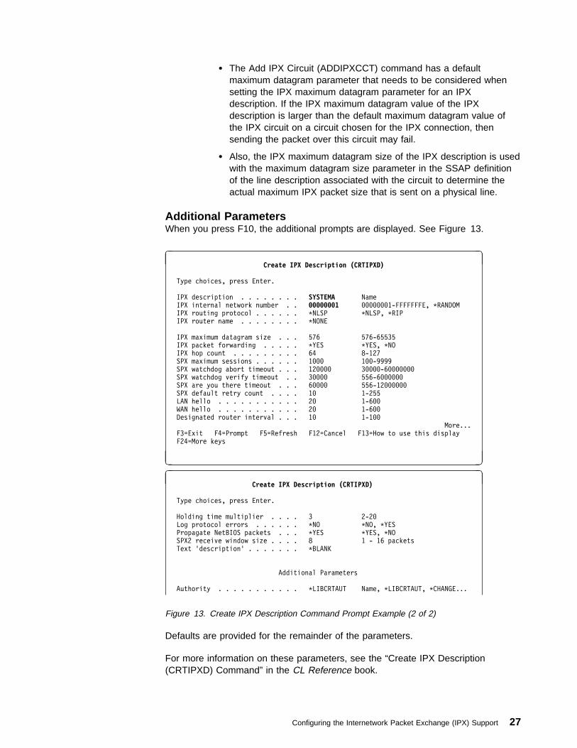
Additional ParametersWhen you press F10, the additional prompts are displayed. See Figure 13.
à ðCreate IPX Description (CRTIPXD)
Type choices, press Enter.
IPX description . . . . . . . . SYSTEMA Name
IPX internal network number . . ððððððð1 ððððððð1-FFFFFFFE, \RANDOM
IPX routing protocol . . . . . . \NLSP \NLSP, \RIP
IPX router name . . . . . . . . \NONE
IPX maximum datagram size . . . 576 576-65535
IPX packet forwarding . . . . . \YES \YES, \NO
IPX hop count . . . . . . . . . 64 8-127
SPX maximum sessions . . . . . . 1ððð 1ðð-9999
SPX watchdog abort timeout . . . 12ðððð 3ðððð-6ððððððð
SPX watchdog verify timeout . . 3ðððð 556-6ðððððð
SPX are you there timeout . . . 6ðððð 556-12ðððððð
SPX default retry count . . . . 1ð 1-255
LAN hello . . . . . . . . . . . 2ð 1-6ðð
WAN hello . . . . . . . . . . . 2ð 1-6ðð
Designated router interval . . . 1ð 1-1ðð
More...
F3=Exit F4=Prompt F5=Refresh F12=Cancel F13=How to use this display
F24=More keys
á ñ
à ðCreate IPX Description (CRTIPXD)
Type choices, press Enter.
Holding time multiplier . . . . 3 2-2ð
Log protocol errors . . . . . . \NO \NO, \YES
Propagate NetBIOS packets . . . \YES \YES, \NO
SPX2 receive window size . . . . 8 1 - 16 packets
Text 'description' . . . . . . . \BLANK
Additional Parameters
Authority . . . . . . . . . . . \LIBCRTAUT Name, \LIBCRTAUT, \CHANGE...
Figure 13. Create IPX Description Command Prompt Example (2 of 2)
Defaults are provided for the remainder of the parameters.
For more information on these parameters, see the “Create IPX Description(CRTIPXD) Command” in the CL Reference book.
Configuring the Internetwork Packet Exchange (IPX) Support 27
Changes to an IPX description only take effect when:
� IPX support is started again (if the support is currently active).
� IPX support is started (if the support is not active).
See Operating and Managing IPX Support for more information.
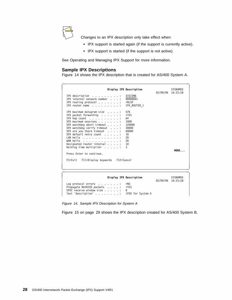
Sample IPX DescriptionsFigure 14 shows the IPX description that is created for AS/400 System A.
à ðDisplay IPX Description SYSNAMXX
ð2/ð9/96 16:33:28
IPX description . . . . . . . . . : SYSTEMA
IPX internal network number . . . : ððððððð1
IPX routing protocol . . . . . . . : \NLSP
IPX router name . . . . . . . . . : IPX_ROUTER_1
IPX maximum datagram size . . . . : 576
IPX packet forwarding . . . . . . : \YES
IPX hop count . . . . . . . . . . : 64
SPX maximum sessions . . . . . . . : 1ððð
SPX watchdog abort timeout . . . . : 12ðððð
SPX watchdog verify timeout . . . : 3ðððð
SPX are you there timeout . . . . : 6ðððð
SPX default retry count . . . . . : 1ð
LAN hello . . . . . . . . . . . . : 2ð
WAN hello . . . . . . . . . . . . : 2ð
Designated router interval . . . . : 1ð
Holding time multiplier . . . . . : 3
MORE... Press Enter to continue.
F3=Exit F11=Display keywords F12=Cancel
á ñ
à ðDisplay IPX Description SYSNAMXX
ð2/ð9/96 16:33:28
Log protocol errors . . . . . . . : \NO
Propagate NetBIOS packets . . . . : \YES
SPX2 receive window size . . . . . : 8
Text 'description' . . . . . . . . : IPXD for System A
Figure 14. Sample IPX Description for System A
Figure 15 on page 29 shows the IPX description created for AS/400 System B.
28 OS/400 Internetwork Packet Exchange (IPX) Support V4R1

à ðDisplay IPX Description SYSNAMXX
ð2/ð9/96 16:33:28
IPX description . . . . . . . . . : SYSTEMB
IPX internal network number . . . : ððððððð2
IPX routing protocol . . . . . . . : \NLSP
IPX router name . . . . . . . . . : IPX_ROUTER_2
IPX maximum datagram size . . . . : 576
IPX packet forwarding . . . . . . : \YES
IPX hop count . . . . . . . . . . : 64
SPX maximum sessions . . . . . . . : 1ððð
SPX watchdog abort timeout . . . . : 12ðððð
SPX watchdog verify timeout . . . : 3ðððð
SPX are you there timeout . . . . : 6ðððð
SPX default retry count . . . . . : 1ð
LAN hello . . . . . . . . . . . . : 2ð
WAN hello . . . . . . . . . . . . : 2ð
Designated router interval . . . . : 1ð
Holding time multiplier . . . . . : 3
MORE... Press Enter to continue.
F3=Exit F11=Display keywords F12=Cancel
á ñ
à ðDisplay IPX Description SYSNAMXX
ð2/ð9/96 16:33:28
Log protocol errors . . . . . . . : \NO
Propagate NetBIOS packets . . . . : \YES
SPX2 receive window size . . . . . : 8
Text 'description' . . . . . . . . : IPXD for System B
Figure 15. Sample IPX Description for System B
Figure 16 on page 30 shows the IPX description after it is created for System C.
Configuring the Internetwork Packet Exchange (IPX) Support 29

à ðDisplay IPX Description SYSNAMXX
ð2/ð9/96 16:33:28
IPX description . . . . . . . . . : SYSTEMC
IPX internal network number . . . : ððððððð3
IPX routing protocol . . . . . . . : \NLSP
IPX router name . . . . . . . . . : IPX_ROUTER_3
IPX maximum datagram size . . . . : 576
IPX packet forwarding . . . . . . : \YES
IPX hop count . . . . . . . . . . : 64
SPX maximum sessions . . . . . . . : 1ððð
SPX watchdog abort timeout . . . . : 12ðððð
SPX watchdog verify timeout . . . : 3ðððð
SPX are you there timeout . . . . : 6ðððð
SPX default retry count . . . . . : 1ð
LAN hello . . . . . . . . . . . . : 2ð
WAN hello . . . . . . . . . . . . : 2ð
Designated router interval . . . . : 1ð
Holding time multiplier . . . . . : 3
MORE... Press Enter to continue.
F3=Exit F11=Display keywords F12=Cancel
á ñ
à ðDisplay IPX Description SYSNAMXX
ð2/ð9/96 16:33:28
Log protocol errors . . . . . . . : \NO
Propagate NetBIOS packets . . . . : \YES
SPX2 receive window size . . . . . : 8
Text 'description' . . . . . . . . : IPXD for System C
Figure 16. Sample IPX Description for System C
Step 2–Configuring Line Descriptions for IPX Support–EthernetBefore you can add an IPX circuit, you must configure a line description for IPXprocessing. The line types are based on the communications input/output adapteron AS/400. See the following tables for a complete list of the supported IOAs forIPX support.
Table 2. Supported Input/Output Adapters
Protocol Adapters
Ethernet 2617, 2723, 6181Token Ring 2619, 2724, 6149Frame Relay 2666, 2699X.25 Any IOP that supports X.25 will support IPXIntegrated PC Server Any Integrated PC Server will support IPX
Table 3. Supported Input/Output Adapters for the 6506 Integrated PC Server
Memory One-Port Adapter Two-Port Adapter
16MB 6516 652632MB 6517 652748MB 6518 652864MB 6519 6529
30 OS/400 Internetwork Packet Exchange (IPX) Support V4R1

You can use a line description that is already configured if it is one of these types.
For our network example, each system has one Ethernet line description.
To create a line description, do the following:
1. Type CRTLINETH on any command line.
2. Press F4 and the Create Line Description (Ethernet) (CRTLINETH) commandprompt display is shown. See Figure 17 on page 32.
Certain values have special meaning for IPX support.
Table 4. Supported Input/Output Adapters—6616 Integrated PC Server
Options Order Number
Ethernet/IEEE 802.3 adapter 618116/4 Mbps Token-Ring adapter 614932MB memory 2861128MB memory 2862Ordering Example: To order a base 6616 with 32MB of memory to be used with an Ethernetnetwork, you would need to specify feature codes: 6616, 2861, and 6181. The 6616 doesnot come with any memory.
Table 5. Supported Input/Output Adapters—2850 Integrated PC Server
Options Order Number
Ethernet/IEEE 802.3 adapter 272316/4 Mbps Token-Ring adapter 272432MB memory 3861128MB memory 2860Ordering Example: To order a base 2850 with 32MB of additional memory to be used withan Ethernet network, you would need to specify feature codes: 2850, 2860, and 2723. The2850 comes with 32MB of memory.
Configuring the Internetwork Packet Exchange (IPX) Support 31

à ðCreate Line Desc (Ethernet) (CRTLINETH)
Type choices, press Enter.
Line description . . . . . . . . > AETHLINE .1/ Name
Resource name . . . . . . . . . > CMNð6 .2/ Name, \NWID, \NWSD
Online at IPL . . . . . . . . . \YES \YES, \NO
Vary on wait . . . . . . . . . . \NOWAIT \NOWAIT, 15-18ð (1 second)
Local adapter address . . . . . \ADPT ð2ðððððððððð-7EFFFFFFFFFF..
Exchange identifier . . . . . . \SYSGEN ð56ððððð-ð56FFFFF, \SYSGEN
Ethernet standard . . . . . . . \ALL .3/ \ETHV2, \IEEE8ð23, \ALL
SSAP list: _
Source service access point . \SYSGEN .4/ ð2-FE, \SYSGEN
SSAP maximum frame . . . . . . _______ \MAXFRAME, 265-1496, 265...
SSAP type . . . . . . . . . . ______ \CALC, \NONSNA, \SNA, \HPR
+ for more values _
Text 'description' . . . . . . . \BLANK
BottomF3=Exit F4=Prompt F5=Refresh F1ð=Additional parameters F12=Cancel
F13=How to use this display F24=More keys
á ñ
Figure 17. Create Line Description (Ethernet) Command Prompt Example
The important parameters in an Ethernet line description for IPX are as follows:
Line Description.1/ Uniquely identifies the name of the line description that is to be used for IPXsupport on the system.
Use AETHLINE, BETHLINE, and CETHLINE for the line description names in thisexample.
Resource Name.2/ Indicates the name of the communications port to which the hardware is that isattached.
Use the Work with Hardware Resources (WRKHDWRSC) commandwith *CMN that is specified as the Type value to help determine theresource name. The resource name consists of the IOA resource nameand the port number on the IOA.
Figure 18 on page 33 shows the IOAs that could be available for IPX support onAS/400. See Table 2 on page 30 for the IOAs that IPX supports.
32 OS/400 Internetwork Packet Exchange (IPX) Support V4R1

à ðWork with Communication Resources
System: SYSNAMXX
Type options, press Enter.
2=Edit 4=Remove 5=Work with configuration descriptions
Opt Resource Type Status Text
CCð1 ðð85 Operational Combined function IOP
LINð7 2617 Operational LAN Adaptor
CMNð6 2617 Operational Ethernet Port
LINð8 6ð5A Operational Virtual Controller
Figure 18. Work with Communication Resources Display Example
For System A in this example, the resource name that is associated with this linedescription is CMN06.
Ethernet Standard.3/ Specifies the Ethernet standard frame type that is used on this line. Possiblevalues are:
� *ALL: All Ethernet standards are used.
SNA data is only packaged in IEEE 802.3 frames.
� *ETHV2: Ethernet Version 2 frames are used for all data.
� *IEEE8023: IEEE 802.3 frames are used for all data.
We have specified the default value, *ALL in this example.
This value must be *ALL when the line is used for an Ethernet NetWareprotocol network.
Source Service Access Point.4/ Specifies the source service access point (SSAP) information, including anSSAP value, a maximum frame size, and an SSAP type. The line type determineswhich SSAP needs to be specified for IPX support.
The default value, *SYSGEN, automatically defines source service access points:04, 12, AA, or C8.
There is no need to explicitly define SSAPs in the line description unless the linedescription is to be shared with other protocols. If the line description is to beshared with other protocols, define the SSAPs that are required by the other proto-cols.
Tips:
� If the X'E0' SSAP is to be used for an IPX circuit, it must not beexplicitly defined in the line description.
Configuring the Internetwork Packet Exchange (IPX) Support 33

� The X'AA' SSAP is unique because it can be shared by multiplecommunications protocols at the same time; therefore the X'AA'SSAP value can be explicitly defined on the line description withoutcausing a conflict (for example, TCP/IP uses the X'AA' SSAPvalue).
Text 'description'Specify text that briefly describes the line description. *BLANK indicates there is notext description.
Sample Ethernet Line DescriptionsFigure 19 shows the Ethernet line description for System A.
à ðDisplay Line Description SYSNAMXX
ð2/23/96 13:46:15
Line description . . . . . . . . . : AETHLINE
Option . . . . . . . . . . . . . . : \BASIC
Category of line . . . . . . . . . : \ELAN
Resource name . . . . . . . . . . : CMNð6
Online at IPL . . . . . . . . . . : \YES
Vary on wait . . . . . . . . . . . : \NOWAIT
Local adapter address . . . . . . : \ADAPT
Exchange identifier . . . . . . . : ð56Aðð36
Ethernet standard . . . . . . . . : \ALL
Maximum controllers . . . . . . . : 4ð
Error threshold level . . . . . . : \OFF
Text . . . . . . . . . . . . . . . : 'Line description for System A'
Figure 19. Sample Ethernet Line Description for System A
Figure 20 displays the Ethernet line description for System B.
à ðDisplay Line Description SYSNAMXX
ð2/23/96 13:46:34
Line description . . . . . . . . . : BETHLINE
Option . . . . . . . . . . . . . . : \BASIC
Category of line . . . . . . . . . : \ELAN
Resource name . . . . . . . . . . : CMNð6
Online at IPL . . . . . . . . . . : \YES
Vary on wait . . . . . . . . . . . : \NOWAIT
Local adapter address . . . . . . : \ADAPT
Exchange identifier . . . . . . . : ð56Aðð36
Ethernet standard . . . . . . . . : \ALL
Maximum controllers . . . . . . . : 4ð
Error threshold level . . . . . . : \OFF
Text . . . . . . . . . . . . . . . : 'Line description for System B'
Figure 20. Sample Ethernet Line Description for System B
Figure 21 on page 35 shows the Ethernet line description for AS/400 System C.
34 OS/400 Internetwork Packet Exchange (IPX) Support V4R1
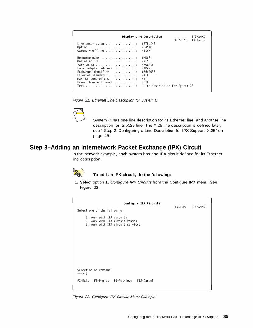
à ðDisplay Line Description SYSNAMXX
ð2/23/96 13:46:34
Line description . . . . . . . . . : CETHLINE
Option . . . . . . . . . . . . . . : \BASIC
Category of line . . . . . . . . . : \ELAN
Resource name . . . . . . . . . . : CMNð6
Online at IPL . . . . . . . . . . : \YES
Vary on wait . . . . . . . . . . . : \NOWAIT
Local adapter address . . . . . . : \ADAPT
Exchange identifier . . . . . . . : ð56Aðð36
Ethernet standard . . . . . . . . : \ALL
Maximum controllers . . . . . . . : 4ð
Error threshold level . . . . . . : \OFF
Text . . . . . . . . . . . . . . . : 'Line description for System C'
Figure 21. Ethernet Line Description for System C
System C has one line description for its Ethernet line, and another linedescription for its X.25 line. The X.25 line description is defined later,see “ Step 2–Configuring a Line Description for IPX Support–X.25” onpage 46.
Step 3–Adding an Internetwork Packet Exchange (IPX) CircuitIn the network example, each system has one IPX circuit defined for its Ethernetline description.
To add an IPX circuit, do the following:
1. Select option 1, Configure IPX Circuits from the Configure IPX menu. SeeFigure 22.
à ðConfigure IPX Circuits
SYSTEM: SYSNAMXX
Select one of the following:
1. Work with IPX circuits
2. Work with IPX circuit routes
3. Work with IPX circuit services
Selection or command
===> 1
F3=Exit F4=Prompt F9=Retrieve F12=Cancel
á ñ
Figure 22. Configure IPX Circuits Menu Example
Configuring the Internetwork Packet Exchange (IPX) Support 35
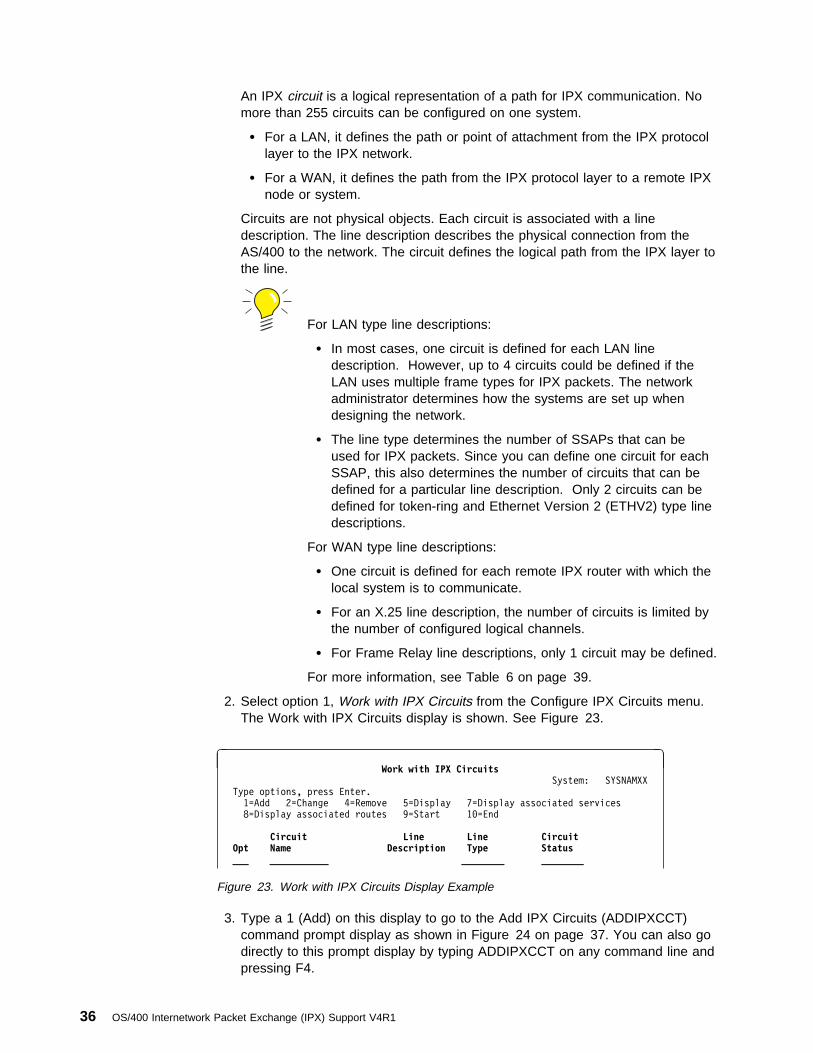
An IPX circuit is a logical representation of a path for IPX communication. Nomore than 255 circuits can be configured on one system.
� For a LAN, it defines the path or point of attachment from the IPX protocollayer to the IPX network.
� For a WAN, it defines the path from the IPX protocol layer to a remote IPXnode or system.
Circuits are not physical objects. Each circuit is associated with a linedescription. The line description describes the physical connection from theAS/400 to the network. The circuit defines the logical path from the IPX layer tothe line.
For LAN type line descriptions:
� In most cases, one circuit is defined for each LAN linedescription. However, up to 4 circuits could be defined if theLAN uses multiple frame types for IPX packets. The networkadministrator determines how the systems are set up whendesigning the network.
� The line type determines the number of SSAPs that can beused for IPX packets. Since you can define one circuit for eachSSAP, this also determines the number of circuits that can bedefined for a particular line description. Only 2 circuits can bedefined for token-ring and Ethernet Version 2 (ETHV2) type linedescriptions.
For WAN type line descriptions:
� One circuit is defined for each remote IPX router with which thelocal system is to communicate.
� For an X.25 line description, the number of circuits is limited bythe number of configured logical channels.
� For Frame Relay line descriptions, only 1 circuit may be defined.
For more information, see Table 6 on page 39.
2. Select option 1, Work with IPX Circuits from the Configure IPX Circuits menu.The Work with IPX Circuits display is shown. See Figure 23.
à ðWork with IPX Circuits
System: SYSNAMXX
Type options, press Enter.
1=Add 2=Change 4=Remove 5=Display 7=Display associated services
8=Display associated routes 9=Start 1ð=End
Circuit Line Line Circuit Opt Name Description Type Status ___ ___________ ________ ________
Figure 23. Work with IPX Circuits Display Example
3. Type a 1 (Add) on this display to go to the Add IPX Circuits (ADDIPXCCT)command prompt display as shown in Figure 24 on page 37. You can also godirectly to this prompt display by typing ADDIPXCCT on any command line andpressing F4.
36 OS/400 Internetwork Packet Exchange (IPX) Support V4R1

à ðAdd IPX Circuit (ADDIPXCCT)
Type choices, press Enter.
Circuit name . . . . . . . . . . > CCT1ALine description . . . . . . . . > AETHLINE Name
IPX network number . . . . . . . 2FFFFFFF ððððððð1-FFFFFFFD
Frame type . . . . . . . . . . . \SSAP \SSAP, \SNAP, \ETHV2, \ETHNTW
Enable for NLSP . . . . . . . . \YES \YES, \NO
MAC channel for NLSP . . . . . . \BROADCAST \BROADCAST, \MULTICAST
Router priority for NLSP . . . . 44 ð-127
Cost override for NLSP . . . . . \CALC 1-63, \CALC
BottomF3=Exit F4=Prompt F5=Refresh F1ð=Additional parameters F12=Cancel
F13=How to use this display F24=More keys
á ñ
Figure 24. Add IPX Circuit Command Prompt Example (1 of 2)
When you press F10, the additional prompts are displayed ( Figure 25).
à ðAdd IPX Circuit (ADDIPXCCT)
Type choices, press Enter.
Circuit name . . . . . . . . . . > CCT1ALine description . . . . . . . . > AETHLINE Name
IPX network number . . . . . . . 2FFFFFFF ððððððð1-FFFFFFFD
Frame type . . . . . . . . . . . \SSAP \SSAP, \SNAP, \ETHV2, \ETHNTW
Enable for NLSP . . . . . . . . \YES \YES, \NO
MAC channel for NLSP . . . . . . \BROADCAST \BROADCAST, \MULTICAST
Router priority for NLSP . . . . 44 ð-127
Cost override for NLSP . . . . . \CALC 1-63, \CALC
Additional Parameters
Default maximum datagram size . \LIND .1/ 576-16388, \LIND
Throughput . . . . . . . . . . . \CALC 3ðð-4294967295, \CALC
Delay time . . . . . . . . . . . \CALC .2/ 1-5ðððððð, \CALC
Automatic start . . . . . . . . \YES .3/ \YES, \NO
RIP state . . . . . . . . . . . \AUTO \ON, \OFF, \AUTO
More...F3=Exit F4=Prompt F5=Refresh F12=Cancel F13=How to use this display
F24=More keys
á ñ
Figure 25. Add IPX Circuit Command Prompt Example (2 of 2)
The important prompts in an IPX circuit for an Ethernet line description are asfollows:
Configuring the Internetwork Packet Exchange (IPX) Support 37
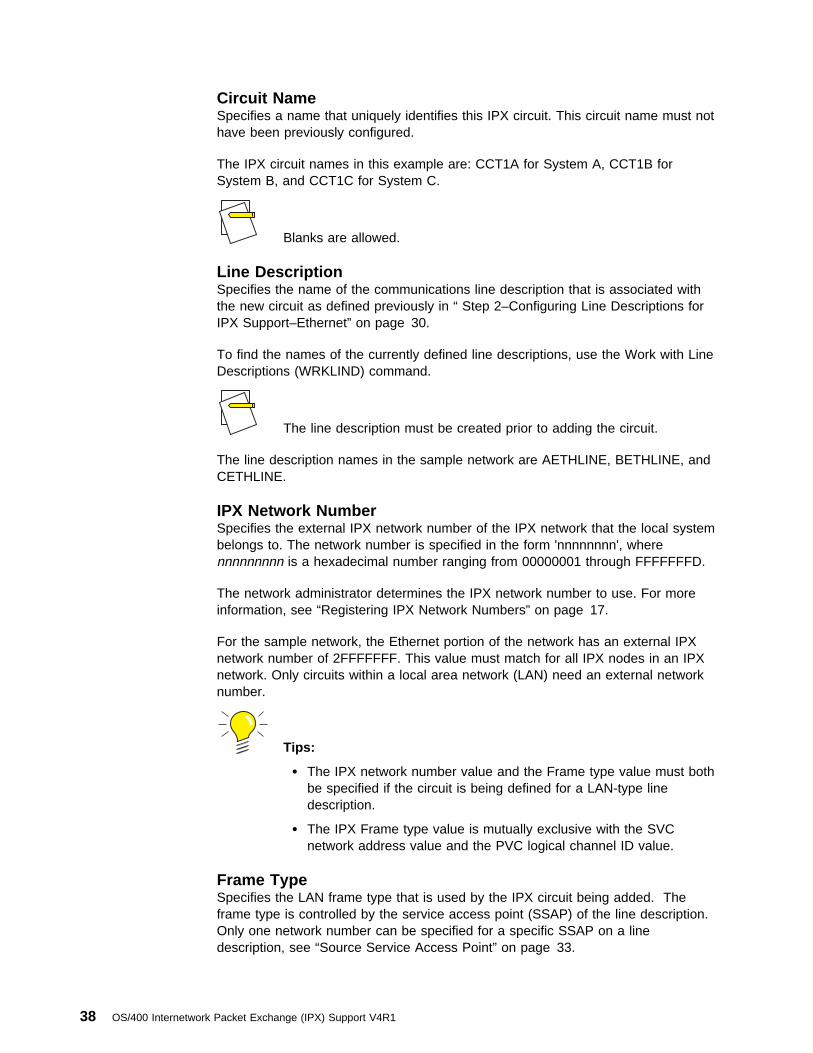
Circuit NameSpecifies a name that uniquely identifies this IPX circuit. This circuit name must nothave been previously configured.
The IPX circuit names in this example are: CCT1A for System A, CCT1B forSystem B, and CCT1C for System C.
Blanks are allowed.
Line DescriptionSpecifies the name of the communications line description that is associated withthe new circuit as defined previously in “ Step 2–Configuring Line Descriptions forIPX Support–Ethernet” on page 30.
To find the names of the currently defined line descriptions, use the Work with LineDescriptions (WRKLIND) command.
The line description must be created prior to adding the circuit.
The line description names in the sample network are AETHLINE, BETHLINE, andCETHLINE.
IPX Network NumberSpecifies the external IPX network number of the IPX network that the local systembelongs to. The network number is specified in the form 'nnnnnnnn', wherennnnnnnnn is a hexadecimal number ranging from 00000001 through FFFFFFFD.
The network administrator determines the IPX network number to use. For moreinformation, see “Registering IPX Network Numbers” on page 17.
For the sample network, the Ethernet portion of the network has an external IPXnetwork number of 2FFFFFFF. This value must match for all IPX nodes in an IPXnetwork. Only circuits within a local area network (LAN) need an external networknumber.
Tips:
� The IPX network number value and the Frame type value must bothbe specified if the circuit is being defined for a LAN-type linedescription.
� The IPX Frame type value is mutually exclusive with the SVCnetwork address value and the PVC logical channel ID value.
Frame TypeSpecifies the LAN frame type that is used by the IPX circuit being added. Theframe type is controlled by the service access point (SSAP) of the line description.Only one network number can be specified for a specific SSAP on a linedescription, see “Source Service Access Point” on page 33.
38 OS/400 Internetwork Packet Exchange (IPX) Support V4R1

The Frame Type value must match for all IPX circuits in an IPX network. In thisexample, we have chosen the default value, *SSAP, to indicate that the X'E0'SSAP will be used for this circuit.
Tips:
� The Frame Type value and the IPX network number value mustboth be specified if the circuit is being defined for a LAN-type linedescription.
� The Frame Type value is mutually exclusive with the SVC networkaddress value and the PVC logical channel identifier when an X.25description is specified for the line description value.
Table 6 shows the Frame Type values allowed for each of the line types.
Table 6. Frame Type Values Allowed by Line Type
Line Type
OS/400 Circuit Frame Type MaximumNumber ofCircuitsAllowed
*SNAP(X'AA')
*SSAP (X'E0')See note 1. *ETHV2
*ETHNTW Seenote 2.
Token Ring X X 2
Ethernet 802.3 X X 2
Ethernet V2 X 1
Ethernet *ALL X X X X 4
Notes:
1. The X'E0' SSAP must not exist in the token-ring or Ethernet line descriptions. If it does, the circuit will fail tostart.
2. Be careful when you use the *ETHNTW value for Novell’s Raw Ethernet frame type. Problems may arise withthe sharing of addresses.
If you have a Novell network already configured, the following table, Table 7,should help you determine the Frame Type to use on AS/400.
Table 7. Novell Terminology for OS/400 Frame Type Values
OS/400 Circuit Frame Type Novell Frame Type
Ethernet *SNAP Ethernet_SNAP
Ethernet *SSAP Ethernet_802.2
Ethernet *ETHV2 Ethernet_II
Ethernet Standard *ALL *ETHNTW Ethernet_802.3
Token ring *SNAP Token-ring_SNAP
Token ring *SSAP Token-ring
Configuring the Internetwork Packet Exchange (IPX) Support 39

Enable for NLSPEnables NLSP processing for this circuit. If the circuit does not support NLSP proc-essing, change the value to *NO.
If a value of *RIP is specified for the IPX routing protocol value on theIPX description that is active when a circuit is active, then the Enable forNLSP value will not be used.
MAC Channel for NLSPSpecifies whether broadcast or multicast capabilities are supported for NLSP onthis circuit.
Broadcast allows all devices on the LAN to receive the transmitted packets. This isthe default value, because some older systems do not support multicasting capabili-ties.
Multicast allows only those devices by listening for a special multicast packetaddress to accept the routing information packet. Using multicast allows for reducedload on systems that are not listening for the multicast address. Use of the multi-cast transmission method requires all NLSP routes on the LAN to be configured formulticast. Otherwise, the broadcast transmission method is used.
When multicast by addressing is specified for a circuit, the associated linedescription must have the correct multicast address enabled.
� For the Ethernet line description, the Group Address value must be09001BFFFFFF.
� For the token-ring line description, the Functional Address value must beC00010000000.
This parameter is only valid for LANs.
Router Priority for NLSPSpecifies the priority that is assigned to this router for the NLSP designated routerselection process. The designated router is the NLSP router responsible for theexchange of link state information on behalf of all other NLSP routers on the sameLAN. You should set the priority value high for the most stable router with enoughmemory to process NLSP routing information for your LAN.
Valid values are 0 through 127; 44 is the default.
Tips:
� This value is the default starting point for the router priority. Therouter priority can be automatically changed by NLSP processingwhen this system is elected as the designated router. If this AS/400system is elected as the designated router, NLSP processing auto-matically increases the router priority value by 20. If this system laterresigns as the designated router, NLSP processing automatically
40 OS/400 Internetwork Packet Exchange (IPX) Support V4R1

decreases the router priority value by 20. This returns the router pri-ority value to its original value.
� The Enable for NLSP value must be *YES before this parametertakes effect.
� The Router Priority for NLSP value is only valid for LAN type linedescriptions.
Cost Override for NLSPSpecifies the cost associated with the circuit. This value is used by NLSP to helpdetermine the network paths over which to forward IPX packets. A lower valuemeans less cost associated with that circuit and a better chance that the circuit willbe selected. A value of *CALC means to determine the value based on the circuitline description's line type and line medium’s throughput.
The Enable for NLSP value must be *YES before this parameter takeseffect.
The cost override must be a value from 1 to 63; default is *CALC.
See “Controlling NLSP Route Selection” on page 107 for more information aboutthroughput and default cost that is illustrated in the NLSP cost table.
Additional ParametersDefault values are provided for the additional prompts.
Default Maximum Datagram Size: .1/ Specifies the maximum IPX packet sizethat can be sent over this circuit. This value includes the count of bytes up to andincluding the IPX header but not the LLC or MAC level header or trailer. Thismaximum also applies to the SPX protocol, because SPX data is sent in IPXpackets. The maximum frame size of the line description is used only if *LIND isspecified here. The default maximum datagram value is used with the maximumframe size value of the line description’s SSAP value to determine the actualmaximum packet size that is sent on a particular line. The minimum value allowedis 576.
This value is important because there is no end-to-end negotiation of maximumdatagram size in IPX processing, and there may be intermediate hops in the pathto a destination system that have a smaller maximum datagram size than thedirectly attached links to the AS/400 system.
The IPX description has an IPX maximum datagram value that needs tobe considered when setting this value. If the IPX maximum datagramvalue of the IPX description is larger than the default maximumdatagram value of the IPX circuit chosen for the IPX connection, thenthe sending of the packet will fail. You are requested to provide asmaller packet size that can fit on the circuit.
Configuring the Internetwork Packet Exchange (IPX) Support 41

For *SNAP circuits defined using an Ethernet line, the value used by thesystem when the default maximum datagram size equals *LIND is basedon the maximum frame size of the X'AA' SSAP.
For all other Ethernet type circuits, the system uses 1496.
Delay: .2/ Specifies the time, in microseconds, to send a byte of information fromone system to another. NLSP uses the delay and throughput values to calculate thenumber of ticks for a path to a destination network when communicating with arouting information protocol (RIP) router. The number of ticks is directly proportionalto the delay. One tick equals 55000 microseconds or approximately 1/18 of asecond. Valid values range from 1 through 5000000 microseconds. Delay is mostcommonly used for WAN networks.
When *CALC is specified for LAN-type line descriptions, the delay valueis 200 microseconds. When *CALC is specified for WAN-type linedescriptions, and the Enable for IW2 parameter is equal to *NO, Delayis set to a value of 15000 microseconds.
Automatic Start: .3/ Specifies whether the IPX circuit is started automaticallywhenever IPX is started. The default is *YES. If you choose *NO, you must startthe circuit yourself by using the Start IPX Circuit (STRIPXCCT) command or byselecting option 9 (Start) on the Work with IPX Circuits display as shown inFigure 23 on page 36.
Displaying the Circuit ConfigurationsTo display the circuit for System A:
1. Select option 1, Work with IPX Circuits from the Configure IPX Circuits menu.
2. Press Enter.
The Work with IPX Circuits display would look like Figure 26.
à ðWork with IPX Circuits
SYSTEM: SYSNAMXX
Type options, press Enter.
1=Add 2=Change 4=Remove 5=Display 7=Display associated services
8=Display associated routes 9=Start 1ð=End
Circuit Line Line Circuit Opt Name Description Type Status ___ ___________________
___ CC1A ETHLINEA \ELAN Inactive
5__ NTWð1ð1 NTWð1ð1 \TRLAN \FSIOP
Figure 26. Work with IPX Circuits Display Example
Any change to the IPX circuit definition, except for the Automatic Startparameter, takes effect immediately.
42 OS/400 Internetwork Packet Exchange (IPX) Support V4R1
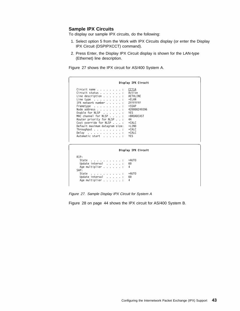
Sample IPX CircuitsTo display our sample IPX circuits, do the following:
1. Select option 5 from the Work with IPX Circuits display (or enter the DisplayIPX Circuit (DSPIPXCCT) command).
2. Press Enter, the Display IPX Circuit display is shown for the LAN-type(Ethernet) line description.
Figure 27 shows the IPX circuit for AS/400 System A.
à ðDisplay IPX Circuit
Circuit name . . . . . . . . : CCT1A
Circuit status . . . . . . . : Active
Line description . . . . . . : AETHLINE
Line type . . . . . . . . . : \ELAN
IPX network number . . . . . : 2FFFFFFF
Frametype . . . . . . . . . : \SSAP
Node address . . . . . . . . : 42ðððð249396
Enable for NLSP . . . . . . : YES
MAC channel for NLSP . . . . : \BROADCAST
Router priority for NLSP . . : 44
Cost override for NLSP . . . : \CALC
Default maximum datagram size: \LIND
Throughput . . . . . . . . . : \CALC
Delay . . . . . . . . . . . : \CALC
Automatic start . . . . . . : YES
à ðDisplay IPX Circuit
RIP:
State . . . . . . . . . . : \AUTO
Update interval . . . . . : 6ð
Age multiplier . . . . . . : 4
SAP:
State . . . . . . . . . . : \AUTO
Update interval . . . . . : 6ð
Age multiplier . . . . . . : 4
Figure 27. Sample Display IPX Circuit for System A
Figure 28 on page 44 shows the IPX circuit for AS/400 System B.
Configuring the Internetwork Packet Exchange (IPX) Support 43

à ðDisplay IPX Circuit
Circuit name . . . . . . . . : CCT1B
Circuit status . . . . . . . : Active
Line description . . . . . . : BETHLINE
Line type . . . . . . . . . : \ELAN
IPX network number . . . . . : 2FFFFFFF
Frametype . . . . . . . . . : \SSAP
Node address . . . . . . . . : 42ðððð249396
Enable for NLSP . . . . . . : YES
MAC channel for NLSP . . . . : \BROADCAST
Router priority for NLSP . . : 44
Cost override for NLSP . . . : \CALC
Default maximum datagram size: \LIND
Throughput . . . . . . . . . : \CALC
Delay . . . . . . . . . . . : \CALC
Automatic start . . . . . . : YES
MORE... Press Enter to continue.
F3=Exit F12=Cancel
à ðDisplay IPX Circuit
RIP:
State . . . . . . . . . . : \AUTO
Update interval . . . . . : 6ð
Age multiplier . . . . . . : 4
SAP:
State . . . . . . . . . . : \AUTO
Update interval . . . . . : 6ð
Age multiplier . . . . . . : 4
Figure 28. Sample Display IPX Circuit for System B
Figure 29 on page 45 shows the IPX circuit for AS/400 System C.
44 OS/400 Internetwork Packet Exchange (IPX) Support V4R1

à ðDisplay IPX Circuit
Circuit name . . . . . . . . : CCT1C
Circuit status . . . . . . . : Active
Line description . . . . . . : CETHLINE
Line type . . . . . . . . . : \ELAN
IPX network number . . . . . : 2FFFFFFF
Frametype . . . . . . . . . : \SSAP
Node address . . . . . . . . : 42ðððð249398
Enable for NLSP . . . . . . : YES
MAC channel for NLSP . . . . : \BROADCAST
Router priority for NLSP . . : 44
Cost override for NLSP . . . : \CALC
Default maximum datagram size: \LIND
Throughput . . . . . . . . . : \CALC
Delay . . . . . . . . . . . : \CALC
Automatic start . . . . . . : YES
MORE... Press Enter to continue.
F3=Exit F12=Cancel
à ðDisplay IPX Circuit
RIP:
State . . . . . . . . . . : \AUTO
Update interval . . . . . : 6ð
Age multiplier . . . . . . : 4
SAP:
State . . . . . . . . . . : \AUTO
Update interval . . . . . : 6ð
Age multiplier . . . . . . : 4
Figure 29. Sample Display IPX Circuit for System C
Step 4–Adding Route InformationYou do not need to create any IPX circuit routes for this sample network becausethe systems are connected using a LAN.
Step 5–Adding Service InformationYou do not need to create any IPX circuit services for this sample network becausethe systems are connected using a LAN.
X.25 Network ExampleThis next section describes the configuration steps to complete defining System Cin the sample IPX internetwork. The additional configuration steps that need to becompleted on System C are:
1. Create an IPX description. See “ Step 1–Creating an Internetwork PacketExchange (IPX) Description” on page 23.
2. Configure an X.25 line description. See “ Step 2–Configuring a Line Descriptionfor IPX Support–X.25” on page 46.
3. Add an IPX circuit for the X.25 line description. See “Step 3–Adding an IPXCircuit for an X.25 SVC Line” on page 52.
Configuring the Internetwork Packet Exchange (IPX) Support 45

4. Adding circuit route information. See “Step 4–Adding Circuit Route Information”on page 57.
5. Adding circuit service information. See “Step 5–Adding Circuit ServiceInformation” on page 61.
Besides being a node in the Ethernet network, System C has an X.25 link to thetoken-ring network.
┌──────────────┐
│ │
│ AS/4ðð C │
│ │
│ │
└──────┬───────┘
│
\ \│\ \
\ \ \ \
\ \
\ \
\ X.25 \
\ Network \
\ \
\ \
\ \ \ \
\ \│\ \
│
┌─────┴──────┐
│ │
│ AS/4ðð D │
│ │
│ FSIOP (D1) │
│ │
└────────────┘
Figure 30. X.25 Network Example
Step 1–Creating an IPX Description–X.25The IPX description for System C has already been created. See “ Step 1–Creatingan Internetwork Packet Exchange (IPX) Description” on page 23.
Step 2–Configuring a Line Description for IPX Support–X.25
To create a X.25 line description, do the following:
1. Type CRTLINX25 on any command line.
2. Press Enter.
3. Press Enter again to see all of the parameters on the display.
You must enter certain values that have special meaning for IPX support. Theseparameters are discussed in the following sections.
Usually you need only one line description for each wide area network that AS/400can connect to.
46 OS/400 Internetwork Packet Exchange (IPX) Support V4R1
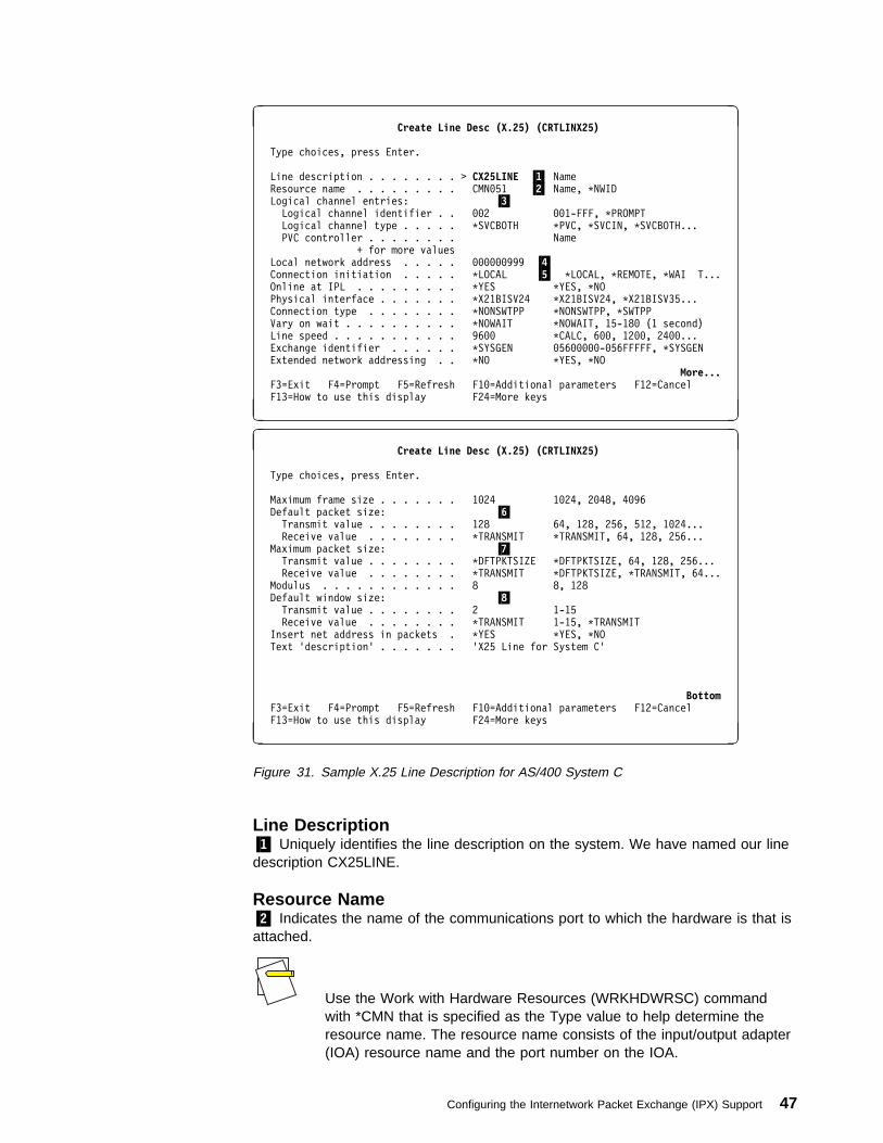
à ðCreate Line Desc (X.25) (CRTLINX25)
Type choices, press Enter.
Line description . . . . . . . . > CX25LINE .1/ Name Resource name . . . . . . . . . CMNð51 .2/ Name, \NWID Logical channel entries: .3/
Logical channel identifier . . ðð2 ðð1-FFF, \PROMPT
Logical channel type . . . . . \SVCBOTH \PVC, \SVCIN, \SVCBOTH...
PVC controller . . . . . . . . Name
+ for more values
Local network address . . . . . ðððððð999 .4/ Connection initiation . . . . . \LOCAL .5/ \LOCAL, \REMOTE, \WAI T...
Online at IPL . . . . . . . . . \YES \YES, \NO
Physical interface . . . . . . . \X21BISV24 \X21BISV24, \X21BISV35...
Connection type . . . . . . . . \NONSWTPP \NONSWTPP, \SWTPP
Vary on wait . . . . . . . . . . \NOWAIT \NOWAIT, 15-18ð (1 second)
Line speed . . . . . . . . . . . 96ðð \CALC, 6ðð, 12ðð, 24ðð...
Exchange identifier . . . . . . \SYSGEN ð56ððððð-ð56FFFFF, \SYSGEN
Extended network addressing . . \NO \YES, \NO
More...F3=Exit F4=Prompt F5=Refresh F1ð=Additional parameters F12=Cancel
F13=How to use this display F24=More keys
á ñ
à ðCreate Line Desc (X.25) (CRTLINX25)
Type choices, press Enter.
Maximum frame size . . . . . . . 1ð24 1ð24, 2ð48, 4ð96
Default packet size: .6/Transmit value . . . . . . . . 128 64, 128, 256, 512, 1ð24...
Receive value . . . . . . . . \TRANSMIT \TRANSMIT, 64, 128, 256...
Maximum packet size: .7/Transmit value . . . . . . . . \DFTPKTSIZE \DFTPKTSIZE, 64, 128, 256...
Receive value . . . . . . . . \TRANSMIT \DFTPKTSIZE, \TRANSMIT, 64...
Modulus . . . . . . . . . . . . 8 8, 128
Default window size: .8/Transmit value . . . . . . . . 2 1-15
Receive value . . . . . . . . \TRANSMIT 1-15, \TRANSMIT
Insert net address in packets . \YES \YES, \NO
Text 'description' . . . . . . . 'X25 Line for System C'
BottomF3=Exit F4=Prompt F5=Refresh F1ð=Additional parameters F12=Cancel
F13=How to use this display F24=More keys
á ñ
Figure 31. Sample X.25 Line Description for AS/400 System C
Line Description.1/ Uniquely identifies the line description on the system. We have named our linedescription CX25LINE.
Resource Name.2/ Indicates the name of the communications port to which the hardware is that isattached.
Use the Work with Hardware Resources (WRKHDWRSC) commandwith *CMN that is specified as the Type value to help determine theresource name. The resource name consists of the input/output adapter(IOA) resource name and the port number on the IOA.
Configuring the Internetwork Packet Exchange (IPX) Support 47
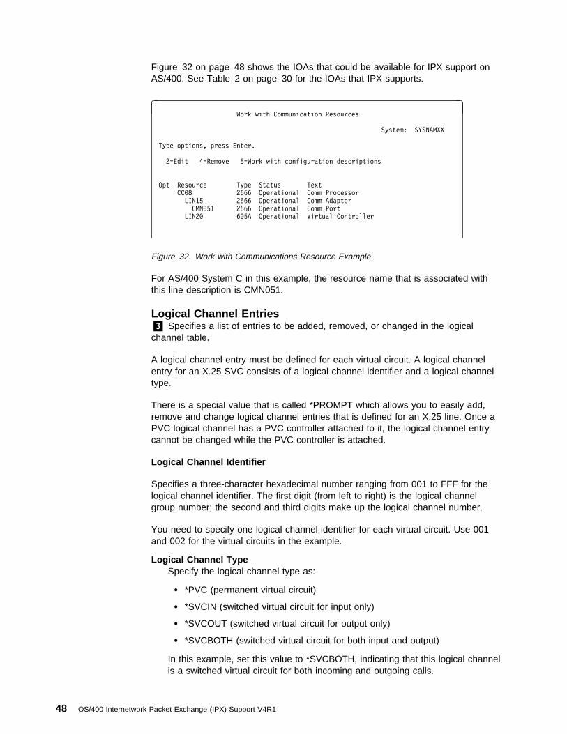
Figure 32 on page 48 shows the IOAs that could be available for IPX support onAS/400. See Table 2 on page 30 for the IOAs that IPX supports.
à ðWork with Communication Resources
System: SYSNAMXX
Type options, press Enter.
2=Edit 4=Remove 5=Work with configuration descriptions
Opt Resource Type Status Text
CCð8 2666 Operational Comm Processor
LIN15 2666 Operational Comm Adapter
CMNð51 2666 Operational Comm Port
LIN2ð 6ð5A Operational Virtual Controller
Figure 32. Work with Communications Resource Example
For AS/400 System C in this example, the resource name that is associated withthis line description is CMN051.
Logical Channel Entries.3/ Specifies a list of entries to be added, removed, or changed in the logicalchannel table.
A logical channel entry must be defined for each virtual circuit. A logical channelentry for an X.25 SVC consists of a logical channel identifier and a logical channeltype.
There is a special value that is called *PROMPT which allows you to easily add,remove and change logical channel entries that is defined for an X.25 line. Once aPVC logical channel has a PVC controller attached to it, the logical channel entrycannot be changed while the PVC controller is attached.
Logical Channel Identifier
Specifies a three-character hexadecimal number ranging from 001 to FFF for thelogical channel identifier. The first digit (from left to right) is the logical channelgroup number; the second and third digits make up the logical channel number.
You need to specify one logical channel identifier for each virtual circuit. Use 001and 002 for the virtual circuits in the example.
Logical Channel TypeSpecify the logical channel type as:
� *PVC (permanent virtual circuit)
� *SVCIN (switched virtual circuit for input only)
� *SVCOUT (switched virtual circuit for output only)
� *SVCBOTH (switched virtual circuit for both input and output)
In this example, set this value to *SVCBOTH, indicating that this logical channelis a switched virtual circuit for both incoming and outgoing calls.
48 OS/400 Internetwork Packet Exchange (IPX) Support V4R1

PVC Controller (Optional)Specifies the name of the permanent virtual circuit (PVC) controller that isassigned to the logical channel. This field is only valid when the channel type is*PVC.
Local Network Address.4/ Specifies the local network address for this system. Up to 17 characters can bespecified, if *YES is specified for the Extend Network Address parameter value.Otherwise, up to 15 characters can be specified.
Use 000000999 for the X.25 network address for the sample network. This numberis assigned by the network administrator when the network is designed.
Connection Initiation.5/ Specifies the method that is used to establish the X.25 data link connection.
� *LOCAL means the local system initiates the connection.
� *REMOTE means the remote system initiates the connection while the localsystem waits for the connection to be established.
� *WAIT means the local system waits for a disconnect (DISC) or disconnectmode (DM) from the data circuit-terminating equipment (DCE) before attemptingto activate the link.
� *CALLER means the connection is initiated from either the local system or theremote system that is based on call direction.
� For the sample network, this is a DTE-to-DTE connection, so *LOCAL is used.
Default Packet Size.6/ Specifies the packet size value used by the X.25 network for transmission andreception.
Transmit ValueSpecify a packet size for transmission to all circuits that is attached to this line.The circuit definition can override this value with the packet size value on theAdd IPX Circuit (ADDIPXCCT) or Change IPX Circuit (CHGIPXCCT) com-mands. The valid values for the packet size are 64, 128, 256, 512, 1024, 2048,and 4096.
The default packet size is 128. This value should match the packet size of thenetwork you are communicating with.
Receive ValueSpecifies a packet size for reception from all circuits that are attached to thisline. The circuit definition can override this value with the packet size value onthe ADDIPXCCT or CHGIPXCCT commands. The valid values for the packetsize are 64, 128, 256, 512, 1024, 2048, and 4096. If the transmit value is spec-ified, the default packet size for transmission is used as the default for recep-tion.
Configuring the Internetwork Packet Exchange (IPX) Support 49

Maximum Packet Size.7/ Specify the maximum packet size value for transmission and reception on anX.25 network. The value that is specified must not be less than the default packetsize specified.
Transmit ValueThe maximum packet size for transmission is the same as that specified as thedefault packet size for transmission on the default packet size value when the*DFTPKTSIZE value is used.
The valid values for the packet size are 64, 128, 256, 512, 1024, 2048, and4096.
Receive ValueThe maximum packet size for reception is the same as that specified as thedefault package size for reception when the *DFTPKTSIZE value is used.
The value specified as the packet size for transmission is used as the defaultfor reception when the *TRANSMIT value is used.
The default packet size value on the controller commands can override thedefault value.
Default Window Size.8/ Specifies the packet window size for transmission and reception on circuits thatare attached to this line. The window size value on the controller commands canoverride this value. Usually a default value is already specified, so you do not haveto choose it.
Transmit ValueSpecifies the appropriate default window size. Valid values range from 1through 7 for networks that use modulus 8 packet numbering. Valid valuesrange from 1 through 15 for networks that use modulus 128 packet numbering.
The default packet window size is 2; modulus 8 is supported on the X.25 linedescription for this example.
Receive ValueSpecifies the appropriate default window size.
Valid values range from 1 through 7 for networks that use modulus 8 packetnumbering and from 1 through 15 for networks that use modulus 128 packetnumbering.
When the Transmit value is specified, the default window size for transmissionis used as the value for reception.
Sample X.25 Line DescriptionWhen you are finished specifying the information on system C, the X.25 linedescription would look like Figure 33 on page 51.
50 OS/400 Internetwork Packet Exchange (IPX) Support V4R1

à ðDisplay Line Description SYSNAMXX
ð2/ð9/96 11:51:23
Line description . . . . . . . . . : CX25LINE
Option . . . . . . . . . . . . . . : \BASIC
Category of line . . . . . . . . . : \X.25
Resource name . . . . . . . . . . : CMNð51
Local network address . . . . . . : 12345
Extended network addressing . . . : \NO
Connection initiation . . . . . . : \LOCAL
Online at IPL . . . . . . . . . . : \YES
Physical interface . . . . . . . . : \X21BISV24
Connection type . . . . . . . . . : \NONSWTPP
X.25 DCE support . . . . . . . . . : \NO
Vary on wait . . . . . . . . . . . : \NOWAIT
Clocking . . . . . . . . . . . . . : \MODEM
Line speed . . . . . . . . . . . . : 96ðð
Exchange identifier . . . . . . . : ð56ððð33
Maximum frame size . . . . . . . . : 1ð24
More... Press Enter to continue.
F3=Exit F11=Display keywords F12=Cancel
à ðDisplay Line Description SYSNAMXX
ð2/ð9/96 11:51:23
Line description . . . . . . . . . : CX25LINE
Option . . . . . . . . . . . . . . : \BASIC
Category of line . . . . . . . . . : \X.25
Default packet size:
Transmit value . . . . . . . . . : 128
Receive value . . . . . . . . . : \TRANSMIT
Maximum packet size:
Transmit value . . . . . . . . . : \DFTPKTSIZE
Receive value . . . . . . . . . : \TRANSMIT
Modulus . . . . . . . . . . . . . : 8
Default window size:
Transmit value . . . . . . . . . : 2
Receive value . . . . . . . . . : \TRANSMIT
Insert net address in packets . . : \YES
Error threshold level . . . . . . : \OFF
Modem type supported . . . . . . . : \NORMAL
More... Press Enter to continue.
F3=Exit F11=Display keywords F12=Cancel
à ðDisplay Line Description SYSNAMXX
ð2/ð9/96 11:51:23
Line description . . . . . . . . . : SKRX25PVC
Option . . . . . . . . . . . . . . : \BASIC
Category of line . . . . . . . . . : \X.25
Switched connection type . . . . . : \DIAL
Autoanswer type . . . . . . . . . : \DTR
Text . . . . . . . . . . . . . . . : 'X.25 line for System C'
Figure 33. Sample Display X.25 Line Description for AS/400 System C
For more information about working with an X.25 network, see the X.25 NetworkSupport book.
Configuring the Internetwork Packet Exchange (IPX) Support 51
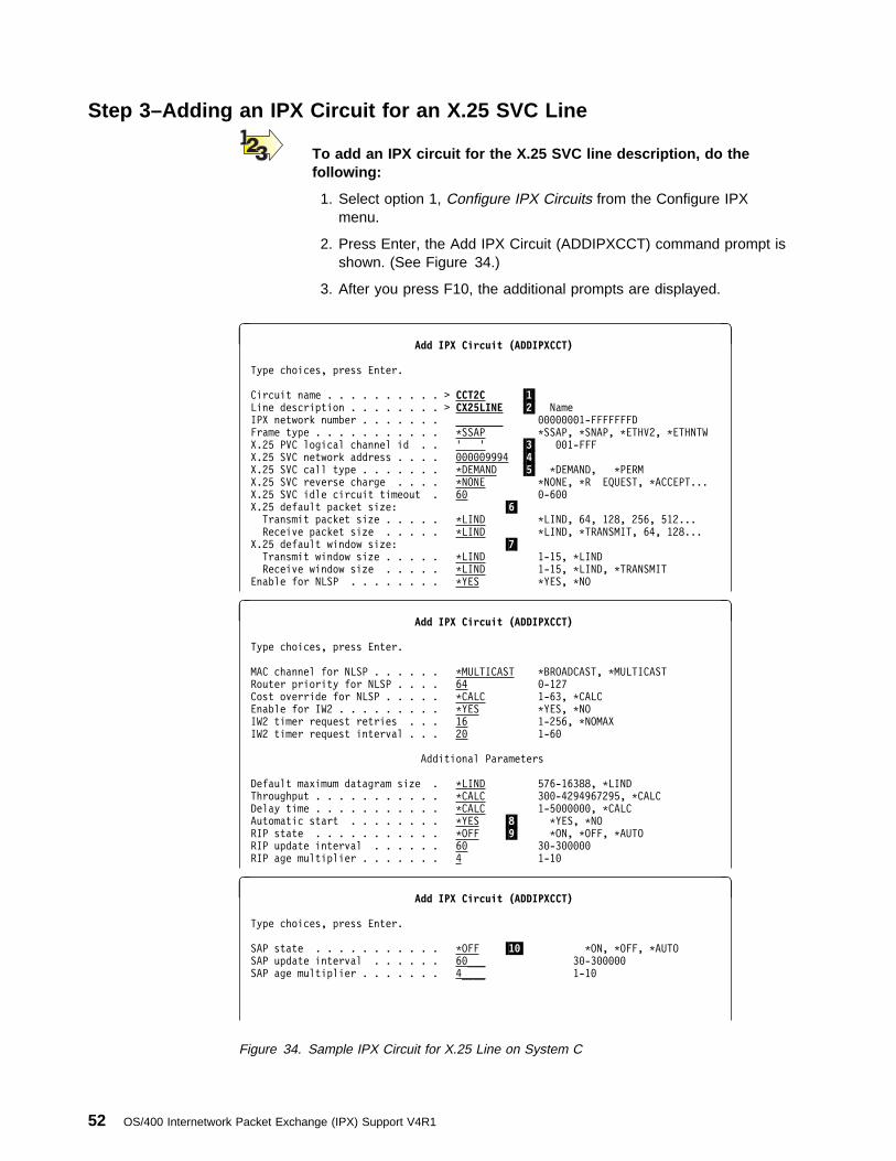
Step 3–Adding an IPX Circuit for an X.25 SVC Line
To add an IPX circuit for the X.25 SVC line description, do thefollowing:
1. Select option 1, Configure IPX Circuits from the Configure IPXmenu.
2. Press Enter, the Add IPX Circuit (ADDIPXCCT) command prompt isshown. (See Figure 34.)
3. After you press F10, the additional prompts are displayed.
à ðAdd IPX Circuit (ADDIPXCCT)
Type choices, press Enter.
Circuit name . . . . . . . . . . > CCT2C .1/Line description . . . . . . . . > CX25LINE .2/ Name
IPX network number . . . . . . . ________ ððððððð1-FFFFFFFD
Frame type . . . . . . . . . . . \SSAP \SSAP, \SNAP, \ETHV2, \ETHNTW
X.25 PVC logical channel id . . ' ' .3/ ðð1-FFF
X.25 SVC network address . . . . ððððð9994 .4/X.25 SVC call type . . . . . . . \DEMAND .5/ \DEMAND, \PERM
X.25 SVC reverse charge . . . . \NONE \NONE, \R EQUEST, \ACCEPT...
X.25 SVC idle circuit timeout . 6ð ð-6ðð
X.25 default packet size: .6/Transmit packet size . . . . . \LIND \LIND, 64, 128, 256, 512...
Receive packet size . . . . . \LIND \LIND, \TRANSMIT, 64, 128...
X.25 default window size: .7/Transmit window size . . . . . \LIND 1-15, \LIND
Receive window size . . . . . \LIND 1-15, \LIND, \TRANSMIT
Enable for NLSP . . . . . . . . \YES \YES, \NO
à ðAdd IPX Circuit (ADDIPXCCT)
Type choices, press Enter.
MAC channel for NLSP . . . . . . \MULTICAST \BROADCAST, \MULTICAST
Router priority for NLSP . . . . 64 ð-127
Cost override for NLSP . . . . . \CALC 1-63, \CALC
Enable for IW2 . . . . . . . . . \YES \YES, \NO
IW2 timer request retries . . . 16 1-256, \NOMAX
IW2 timer request interval . . . 2ð 1-6ð
Additional Parameters
Default maximum datagram size . \LIND 576-16388, \LIND
Throughput . . . . . . . . . . . \CALC 3ðð-4294967295, \CALC
Delay time . . . . . . . . . . . \CALC 1-5ðððððð, \CALC
Automatic start . . . . . . . . \YES .8/ \YES, \NO
RIP state . . . . . . . . . . . \OFF .9/ \ON, \OFF, \AUTO
RIP update interval . . . . . . 6ð 3ð-3ððððð
RIP age multiplier . . . . . . . 4 1-1ð
à ðAdd IPX Circuit (ADDIPXCCT)
Type choices, press Enter.
SAP state . . . . . . . . . . . \OFF .1ð/ \ON, \OFF, \AUTO
SAP update interval . . . . . . 6ð___ 3ð-3ððððð
SAP age multiplier . . . . . . . 4____ 1-1ð
Figure 34. Sample IPX Circuit for X.25 Line on System C
52 OS/400 Internetwork Packet Exchange (IPX) Support V4R1
The important values in an IPX circuit for an X.25 SVC line are as follows:
Circuit Name.1/ Use CCT2C for the IPX circuit name in this example.
Line Description.2/ Identifies the line description that is associated with the circuit. CX25LINE is thename of the line description in this example.
X.25 PVC Logical Channel ID.3/ Specifies the permanent virtual circuit (PVC) channel identifier that can beestablished on an X.25 circuit by the IPX support. Only 1 unique channel identifiermay be specified. Valid ranges are 001 to FFF. The PVC value must have beenpreviously specified on the X.25 line description value.
The X.25 PVC Logical Channel ID is only required if the SVC NetworkAddress value is not specified and an X.25 line description is used.
X.25 SVC Network Address.4/ Specifies the DTE that is associated with the remote X.25 system (that is, theDTE address of the remote system). The value can be a decimal number that is 1through 17 digits in length.
The SVC Network Address is only valid for X.25 line descriptions. ThePVC Logical Channel ID or the SVC Network Address must be specifiedif an X.25 line description is being used.
Use 0000009994 for the network address for System D in this example. This valuemust match the value in the line description on System D. and it must match thevalue specified at the remote system for its X.25 SVC local network address.
X.25 SVC Call Type.5/ Specifies either an on-demand or a permanent X.25 SVC connection call.
� *DEMAND means that the SVC connection is established only when there isdata to transfer to the remote destination. It is active for the duration of the datatransfer plus the idle timeout value. The SVC connection is ended wheneverthe connection has not had any data for longer than the idle virtual circuittimeout value.
� *PERM means that the SVC connection is set up for data transfer when thecircuit is activated. It is active for as long as the circuit is active. A permanentSVC connection is ended when the circuit is ended.
� *DEMAND is used for the sample network because the circuit is to be activatedonly when there is data to transfer to the remote systems.
Configuring the Internetwork Packet Exchange (IPX) Support 53
X.25 Default Packet Size.6/ Specifies the default packet size that is used by the X.25 network for trans-mission and reception. The values specified on this parameter should match thedefault values that are used by the X.25 network.
Transmit Packet SizeSpecify a packet size for transmission. The valid values for the packet size are64, 128, 256, 512, 1024, 2048, and 4096; *LIND is the default.
Receive Packet SizeSpecify a packet size for reception. The valid values for the packet size are 64,128, 256, 512, 1024, 2048, 4096, and *TRANSMIT; *LIND is the default.
X.25 Default Window Size.7/ Specifies the packet window size for transmission to and reception from remotesystems attached to an X.25 line.
Transmit Window SizeSpecify the transmit window size. Valid values range from 1 through 7 for net-works that use modulus 8 packet numbering. Valid values range from 1 through15 for networks that use 128 packet numbering. The modulus value is specifiedon the X.25 line description; *LIND is the default.
Receive Window SizeSpecify the appropriate default window size. Valid values range from 1 through7 for networks that use modulus 8 packet numbering. Valid values range from 1through 15 for networks that use 128 packet numbering. The modulus is speci-fied on the X.25 line description; *LIND is the default.
Automatic Start.8/ Specifies whether the IPX circuit is started automatically whenever IPX isstarted. The default is *YES. If you choose *NO, start the circuit yourself by usingthe Start IPX Circuit (STRIPXCCT) command or by selecting option 9 (Start) on theWork with IPX Circuits display.
RIP State.9/ Specifies the routing information protocol (RIP) indicator mode of support onthis circuit. Setting this parameter determines how RIP packets are processed onthis circuit.
If you want to minimize RIP packets on your network but still need thesupport provided by RIP processing, you can set this parameter’s valueto *OFF and then define static routes associated with the system orsystems with which you are networking. In order to fully minimize RIPtraffic on your network, you would need to define static routes on allservers and routers in your network. You can define static routes byusing the Add Circuit Route (ADDCCTRTE) command.
� *AUTO will initially disable the transmission of RIP broadcasts but will automat-ically enable RIP routing if non-NLSP devices are operating on the network.*AUTO allows the network to eliminate RIP processing once all routers andservers in the network are running NLSP.
54 OS/400 Internetwork Packet Exchange (IPX) Support V4R1
� *ON enables RIP routing on this circuit and allows backward compatibility withRIP routers and servers that depend on RIP.
� *OFF disables RIP routing on this circuit and disables backward compatibilitywith RIP routers and servers that depend on RIP.
For our sample network, the RIP state value is *OFF to ensure that no RIP packetsare sent over this circuit.
SAP State.1ð/ Specifies the Service Advertising Protocol (SAP) indicator mode of support onthis circuit. Setting this parameter will determine how SAP packets are processedon this circuit.
If you want to minimize SAP packets on your network but still need thesupport provided by SAP processing, you can set this parameter’s valueto *OFF and then define static services associated with the system orsystems with which you are networking. In order to fully minimize SAPtraffic on your network, you would need to define static services on allservers and routers in your network. You can define static services byusing the Add Circuit Service (ADDCCTSRV) command.
� *AUTO initially disables the transmission of SAP broadcasts but will automat-ically enable SAP broadcasts if non-NLSP devices are operating on thenetwork. *AUTO allows the network to eliminate SAP processing once allrouters and servers in the network are running NLSP.
� *ON enables SAP broadcasts on this circuit and allows backward compatibilitywith SAP routers and servers that depend on SAP.
� *OFF disables SAP broadcasts on this circuit and disables backward compat-ibility with SAP routers and servers that depend on SAP.
For our sample network, the SAP state value is *OFF to ensure that no SAPpackets are sent over this circuit.
The defaults are used for the other values in this IPX Circuit definition.
Sample X.25 Circuit DisplayFigure 35 on page 56 shows the X.25 circuit we just added.
Configuring the Internetwork Packet Exchange (IPX) Support 55

à ðDisplay IPX Circuit
Circuit name . . . . . . . . . . . . . . : CCT2C
Circuit status . . . . . . . . . . . . . : Inactive
Line description . . . . . . . . . . . . : CX25LINE
Line type . . . . . . . . . . . . . . . : \X25
SVC network address . . . . . . . . . . : ððððð9994
SVC call type . . . . . . . . . . . . . : \DEMAND
SVC reverse charge . . . . . . . . . . . : \NONE
Idle virtual circuit time out . . . . . : 6ð
Default packet size:
Transmit . . . . . . . . . . . . . . . : \LIND
Receive . . . . . . . . . . . . . . . : \LIND
Default window size:
Transmit . . . . . . . . . . . . . . . : \LIND
Receive . . . . . . . . . . . . . . . : \LIND
Enable for NLSP . . . . . . . . . . . . : \YES
Cost override for NLSP . . . . . . . . . : \CALC
Default maximum datagram size . . . . . : \LIND
More... Press Enter to continue.
F3=Exit F12=Cancel
á ñ
à ðDisplay IPX Circuit
Throughput . . . . . . . . . . . . . . . : \CALC
Delay . . . . . . . . . . . . . . . . . : \CALC
Automatic start . . . . . . . . . . . . : \YES
RIP:
State . . . . . . . . . . . . . . . . : \OFF
Update interval . . . . . . . . . . . : 6ð
Age multiplier . . . . . . . . . . . . : 4
SAP:
State . . . . . . . . . . . . . . . . : \OFF
Update interval . . . . . . . . . . . : 6ð
Age multiplier . . . . . . . . . . . . : 4
Figure 35. Display X.25 Circuit Example
Circuit Routes and Circuit Services–OverviewAdding circuit route and circuit service information is optional for any IPX network.
Novell calls these static routes and static services.
For the sample network, IPX circuit route entries are defined to the systems thatare reachable by means of this X.25 circuit definition. In order for the token-ringnetwork to be accessible from the Ethernet network, you must define circuit routesfor systems in the token-ring network. Figure 36 shows these routes to System D,System E, System F, and System G.
56 OS/400 Internetwork Packet Exchange (IPX) Support V4R1
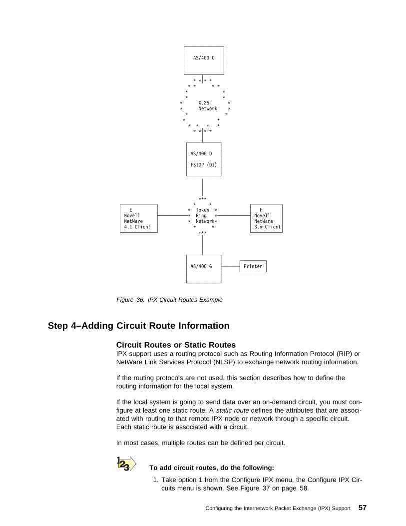
┌──────────────┐
│ │
│ AS/4ðð C │
│ │
│ │
└──────┬───────┘
\ \│\ \
\ \ \ \
\ \
\ \
\ X.25 \
\ Network \
\ \
\ \
\ \ \ \
\ \│\ \
│
┌─────┴──────┐
│ │
│ AS/4ðð D │
│ │
│ FSIOP (D1) │
│ │
└────────────┘
│
│
│
\\\
┌─────────────┐ \ \ ┌───────────┐
│ E │ \ Token \ │ F │
│ Novell ├───────────\ Ring \────────────┤ Novell │
│ NetWare │ \ Network\ │ NetWare │
│ 4.1 Client │ \ \ │ 3.x Client│
└─────────────┘ \\\ └───────────┘
│
│
│
┌─────┴──────┐
│ │ ┌─────────┐
│ AS/4ðð G ├──────┤ Printer │
│ │ └─────────┘
│ │
└────────────┘
Figure 36. IPX Circuit Routes Example
Step 4–Adding Circuit Route Information
Circuit Routes or Static RoutesIPX support uses a routing protocol such as Routing Information Protocol (RIP) orNetWare Link Services Protocol (NLSP) to exchange network routing information.
If the routing protocols are not used, this section describes how to define therouting information for the local system.
If the local system is going to send data over an on-demand circuit, you must con-figure at least one static route. A static route defines the attributes that are associ-ated with routing to that remote IPX node or network through a specific circuit.Each static route is associated with a circuit.
In most cases, multiple routes can be defined per circuit.
To add circuit routes, do the following:
1. Take option 1 from the Configure IPX menu, the Configure IPX Cir-cuits menu is shown. See Figure 37 on page 58.
Configuring the Internetwork Packet Exchange (IPX) Support 57

à ðConfigure IPX Circuits
System: SYSNAMXX
Select one of the following:
1. Work with IPX circuits
2. Work with IPX circuit routes
3. Work with IPX circuit services
Selection or command
===> 2
F3=Exit F4=Prompt F9=Retrieve F12=Cancel
á ñ
Figure 37. Configure IPX Circuits Menu Example
2. Use option 2, Work with Circuit Routes on the Configure IPX Circuitsmenu. See Figure 38.
The Work with Circuits display is shown.
3. Usee option 1 to create the circuit route.
à ðWork with Circuit Routes
System: SYSNAMXX
Type options, press Enter.
1=Add 2=Change 4=Remove 5=Display
Circuit Remote Number Number Next Hop Opt Name Network of Hops of Ticks Node Address
_ ________________ ________
1 CCT1D ððððððð1 2 12 \NONE
Figure 38. Work with Circuit Routes Display Example
Use the name of your system for the IPX description name.
� You do not need to, and in most cases will not use static route defi-nitions for a LAN.
� A static route can be defined for a LAN circuit in order to minimizethe amount of RIP packets on the LAN.
� If you do use static routes for a circuit (WAN or LAN), it is recom-mended that you set the RIP State value on the circuit definition to*OFF.
� The circuit must have been previously configured.
The Add Circuit Route prompt display is shown. See Figure 39 on page 59.
58 OS/400 Internetwork Packet Exchange (IPX) Support V4R1

à ðAdd Circuit Route (ADDCCTRTE)
Type choices, press Enter.
Circuit name . . . . . . . . . . _____ Remote IPX network number . . . _____ ððððððð1-FFFFFFFE
Number of hops . . . . . . . . . ___ 1-127
Number of ticks. . . . . . . . . ___ 1-32767
Figure 39. Add Circuit Route Command Prompt Example
Because IPX routing information is not exchanged for on-demand WAN links, youmust define static routes for all networks that you want to communicate through aWAN link.
Generally, you choose the internal IPX network number of these systems in theinterconnected IPX networks. You must define the internal IPX networks forSystems D, E, F, and G in the sample IPX internetwork.
The important parameters in an IPX circuit route entry for an X.25 line descriptionare as follows:
Circuit NameIdentifies the unique name of the circuit for which this static route is being defined.This is a required value. The static route is associated only with this circuit.
In this example, all of the circuit routes are associated with the previously definedIPX Circuit, CCT2C which is an X.25 SVC on demand type circuit.
Remote IPX Network NumberIdentifies the remote network number or system this route connects to. The remoteIPX network number is usually the internal IPX network number of the remoteserver or router. This is a required parameter value. The remote IPX networknumber is specified in the form, nnnnnnnn, where nnnnnnnn is a hexadecimalnumber ranging from 00000001 through FFFFFFFE.
In the sample network, you must be able to reach Systems D, E, F, and G throughthis circuit. Four circuit routes must be created, each specifying a different remoteIPX network number.
Number of HopsSpecifies the number of hops to the remote network. The number of hops is equalto the number of routers that are crossed in order to reach the network or systemidentified by the Remote network number value. The number of hops must be lessthan or equal to the IPX hop count value that is associated with the local AS/400active IPX description. If the number of hops for this route is greater than the IPXhop count value in the IPX description that is active at the time you are using IPXon the AS/400, then this route cannot be used by IPX.
The range of values that are allowed for this parameter is 1 to 127; the default is 1.
In the sample network, System D acts as a gateway system into the Token-Ringnetwork, and is 1 hop away from System C. All of the other systems are 2 hopsaway from System C on this circuit.
Configuring the Internetwork Packet Exchange (IPX) Support 59

Number of TicksSpecifies the number of ticks that are needed to reach the destination networkidentified by the Remote network number. A tick is equal to 1/18th of a second. Themaximum value that is allowed is 32767 ticks, which equals approximately 30minutes. This value is usually used in comparison with tick values on other routesin the route table. It is used as a relative value that is compared to the other routeentries.
In the sample network, System D is one hop away and therefore should be reach-able in fewer ticks than systems E, F, and G. System D is 10 ticks away; SystemE, F, and G are 12 ticks away.
Sample Circuit RoutesFigure 40 shows the Add Circuit Route display for route 000000004.
à ðAdd Circuit Route (ADDCCTRTE)
Type choices, press Enter.
Circuit name . . . . . . . . . . CCT2C Remote IPX network number . . . ðððððððð4 ððððððð1-FFFFFFFE Number of hops . . . . . . . . . 1 1-127
Number of ticks . . . . . . . . 1ð 1-32767
Figure 40. Add Circuit Route Example for IPX Network Number 00000004
Figure 41 shows the Add Circuit Route display for the route 00000005.
à ðAdd Circuit Route (ADDCCTRTE)
Type choices, press Enter.
Circuit name . . . . . . . . . . CCT2C Remote IPX network number . . . ððððððð5 ððððððð1-F FFFFFFE
Number of hops . . . . . . . . . 2 1-127
Number of ticks . . . . . . . . 12 1-32767
Figure 41. Add Circuit Route Example for IPX Network Number 00000005
Figure 42 shows the Add Circuit Route display for the route 00000006.
à ðAdd Circuit Route (ADDCCTRTE)
Type choices, press Enter.
Circuit name . . . . . . . . . . CCT2C Remote IPX network number . . . ððððððð6 ððððððð1-FFFFFFFE
Number of hops . . . . . . . . . 2 1-127
Number of ticks . . . . . . . . 12 1-32767
Next hop node address. . . . . . \NONE ð2ðððððððððð-7FFFFFFFFFF
Route source. . . . . . . . . . \CFG
Figure 42. Add Circuit Route Example for Route 00000006
Figure 43 on page 61 shows the Add Circuit Route display for the route 00000007.
60 OS/400 Internetwork Packet Exchange (IPX) Support V4R1

à ðAdd Circuit Route (ADDCCTRTE)
Type choices, press Enter.
Circuit name . . . . . . . . . . CCT2C 1
Remote IPX network number . . . ððððððð7 2 ððððððð1-FFFFFFFE
Number of hops . . . . . . . . . 2 3 1-127
Number of ticks . . . . . . . . 12 4 1-32767
Nexthop node address . . . . . . None 5 ð2ðððððððððð-7FFFFFFFFFF
Route source . . . . . . . . . . \CFG
Figure 43. Add Circuit Route Example for Route 00000007
The Work with Circuit Routes display shows the routes we have just added. SeeFigure 44 on page 61.
à ðWork with Circuit Routes
System: SYSNAMXX
Type options, press Enter.
1=Add 2=Change 4=Remove 5=Display
Circuit Remote Number Number Next Hop Opt Name Network of Hops of Ticks Node Address
_ ____________ ________
5 CCT2C ððððððð4 2 12 \NONE
_ CCT2C ððððððð5 2 12 \NONE
_ CCT2C ððððððð6 2 12 \NONE
_ CCT2C ððððððð7 2 12 \NONE
Figure 44. Work with Circuit Routes Display Example
Use option 5 to display one of the circuit routes you just created. See Figure 45.
à ðDisplay Circuit Route (DSPCCTRTE)
Circuit name . . . . . . . . . . . . : CCT2C
Remote IPX network number . . . . . : ððððððð4
Number of hops . . . . . . . . . . . : 1
Number of ticks . . . . . . . . . . : 1ð
Next hop node address . . . . . . . : \NONE
Route source . . . . . . . . . . . . : \CFG
Figure 45. Display Circuit Route Command Prompt Example
Step 5–Adding Circuit Service Information
Circuit Services or Static ServicesIPX Support uses the Service Advertising Protocol (SAP) or the NetWare Link Ser-vices Protocol (NLSP) to convey information about network services and theaddresses of those network services. Through SAP, servers advertise their servicesand addresses. This is usually accomplished on a LAN by using SAP broadcastpackets. Routers maintain the list of available services that are based on the SAPbroadcast packets. When a client needs a service, it can find that service andwhere the service resides on the network from the routers.
Configuring the Internetwork Packet Exchange (IPX) Support 61

If NLSP or SAP are not used, this section describes how to define the servicesinformation for the local system.
If the local system is going to access a service over an on-demand circuit, youmust configure a static service for that circuit.
A static service is a specification of a service available on a remote IPX node ornetwork through a particular circuit. A static service also defines the attributes thatare associated with a service on a remote IPX node or network. Each static serviceis associated with a circuit. Multiple services can be defined for each circuit. SeeFigure 46.
│
│
┌─────┴──────┐
│ │ ┌─────────┐
│ AS/4ðð G │──────│ Printer │
│ │ └─────────┘
│ │
└────────────┘
Figure 46. Adding a Static Service to the Network Example
To add a circuit service to the sample network, do the following:
1. Use Option 3, Work with Circuit Services, on the Configure IPX Cir-cuits display.
2. Use option 1, to add a circuit service to our network. See Figure 47.
à ðWork with Circuit Services
System: SYSNAMXX
Type options, press Enter.
1=Add 2=Change 4=Remove 5=Display
Circuit Service Service RemoteOpt Name Name Type Network
1 ______________ ______________ ___________
Figure 47. Work with Circuit Services Display Example
The Add Circuit Service prompt display is shown in Figure 48 on page 63.
Tips:
� You do not need to, and in most cases will not, use static servicesfor a LAN.
� A static service can be added for a LAN circuit, in order to minimizethe amount of SAP packets on the LAN.
� If you do use static services for a circuit (WAN or LAN), it is recom-mended that you set the SAP state value on the circuit definition to*OFF.
� A circuit may have multiple services added to it, but each servicemust have a unique service name and service type combination.
62 OS/400 Internetwork Packet Exchange (IPX) Support V4R1

à ðAdd Circuit Service (ADDCCTSRV)
Type choices, press Enter.
Circuit name . . . . . . . . . . CCT2CService name . . . . . . . . . . > 'network printer 'Service type . . . . . . . . . . \PRTSVR ðððð-FFFF, \ADVPRTSVR...
Remote IPX network number . . . 6 ððððððð1-FFFFFFFE
Remote IPX node address . . . . 4ðððððððððED ððððððððððð1-FFFFFFFFFFFE
Remote socket address . . . . . ððð1 ððð1-FFFF
Number of hops . . . . . . . . . 2 1-127
Figure 48. Add Circuit Service Command Prompt Example
Circuit NameIdentifies unique name of the circuit that this static service is reached from. This isa required value. The static service is associated only through this circuit.
For the sample network, CCT2C is an X.25 SVC on-demand type circuit. This is thename of the circuit we created under “Step 3–Adding an IPX Circuit for an X.25SVC Line” on page 52.
Service NameIdentifies the name of the service available on the remote system. This is arequired value.
The service name can be 1 to 48 characters; the last character must be a nullcharacter. Therefore, the actual size of the service name is 47 characters plus thenull character. Any characters in the 7-bit ASCII code page 1009 are allowed forthis value except for the following:
� slash (/)
� back slash (\)
� semicolon (;)
� colon (:)
� comma (,)
� asterisk (*)
� question mark (?)
� plus sign (+)
� greater than (>)
� less than (<)
If there is not a translation table available on your system to translatefrom the job CCSID or if the job CCSID is 65535, you cannot add,change, remove, or display a circuit service because the translation fromthe OS/400 EBCDIC to ASCII 850 has not occurred.
Configuring the Internetwork Packet Exchange (IPX) Support 63
Service TypeSpecifies the type of service available on the remote system. This is a requiredparameter. A set of special values are allowed, including *PRTQ and *FILESVR,that represent the well known server type values. You can also enter a 2-bytehexadecimal value.
The hexadecimal values of 0000 through 8000 and FFFF are reservedservice type values.
For a list of these special values, see the “Add Circuit Service (ADDCCTSRV)command” in the CL Reference book.
Remote Network NumberIdentifies the remote IPX network number where this service can be found. If thisservice is available on a server or router, the service IPX network number shouldbe equal to the internal network number of that server or router. This is a requiredvalue.
The service IPX network number is specified in the form nnnnnnnn, wherennnnnnnn is a hexadecimal number ranging from 00000001 through FFFFFFFE.
Remote Node AddressIdentifies the node address where the service resides. If this service is available ona NetWare 3.X or 4.X server or router, the service IPX node address should be 1. Ifthe server or router does not have an internal network number, such as a NetWare2 file server, specify the NIC (network interface card) or MAC address of the serveradapter for the service IPX node address. This is a required parameter.
The service IPX node address is specified in the form, nnnnnnnnnnnn, wherennnnnnnnnnnn is a 6-byte hexadecimal number ranging from 000000000001through FFFFFFFFFFFF.
Remote Socket AddressIdentifies the socket on which this service listens for incoming requests. This is thesocket address that is found on the remote system. For example, for file services,the standard socket address is hexadecimal 0451. The socket address is a 2-bytehexadecimal value that can range from hexadecimal 0001 to FFFF. This is arequired parameter.
Number of HopsSpecifies the number of hops to the remote network. The number of hops is equalto the number of routers that are crossed in order to reach the network or systemidentified by the remote network number value. The number of hops must be lessthan or equal to the IPX hop count limit that is associated with the local AS/400active IPX description. If the number of hops for this service is greater than the IPXhop count for the IPX description that is active at the time you are using IPX on theAS/400, then you will be unable to reach this service.
Possible values are 1 to 127; the default is 1.
64 OS/400 Internetwork Packet Exchange (IPX) Support V4R1
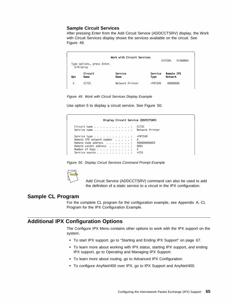
Sample Circuit ServicesAfter pressing Enter from the Add Circuit Service (ADDCCTSRV) display, the Workwith Circuit Services display shows the services available on the circuit. SeeFigure 49.
à ðWork with Circuit Services
SYSTEM: SYSNAMXX
Type options, press Enter.
5=Display
Circuit Service Service Remote IPX Opt Name Name Type Network
5 CCT2C Network Printer \PRTSRV ððððððð6
Figure 49. Work with Circuit Services Display Example
Use option 5 to display a circuit service. See Figure 50.
à ðDisplay Circuit Service (DSPCCTSRV)
Circuit name . . . . . . . . . . . . : CCT2C
Service name . . . . . . . . . . . . : Network Printer
Service type . . . . . . . . . . . . : \PRTSVR
Remote IPX network number . . . . . : 6
Remote node address . . . . . . . . : 4ðððððððððED
Remote socket address . . . . . . . : ððð1
Number of hops . . . . . . . . . . . : 2
Service source . . . . . . . . . . . : \CFG
Figure 50. Display Circuit Services Command Prompt Example
Add Circuit Service (ADDCCTSRV) command can also be used to addthe definition of a static service to a circuit in the IPX configuration.
Sample CL ProgramFor the complete CL program for the configuration example, see Appendix A, CLProgram for the IPX Configuration Example.
Additional IPX Configuration OptionsThe Configure IPX Menu contains other options to work with the IPX support on thesystem.
� To start IPX support, go to “Starting and Ending IPX Support” on page 67.
� To learn more about working with IPX status, starting IPX support, and endingIPX support, go to Operating and Managing IPX Support.
� To learn more about routing, go to Advanced IPX Configuration.
� To configure AnyNet/400 over IPX, go to IPX Support and AnyNet/400.
Configuring the Internetwork Packet Exchange (IPX) Support 65

66 OS/400 Internetwork Packet Exchange (IPX) Support V4R1
Operating and Managing IPX Support
Starting and Ending IPX Support . . . . . . . . . . . . . . . . . . . . . . . . . . . 67Before You Start IPX Support . . . . . . . . . . . . . . . . . . . . . . . . . . . 67
Configuration . . . . . . . . . . . . . . . . . . . . . . . . . . . . . . . . . . . 67IPX Jobs . . . . . . . . . . . . . . . . . . . . . . . . . . . . . . . . . . . . . . 68
Starting IPX . . . . . . . . . . . . . . . . . . . . . . . . . . . . . . . . . . . . . 69Ending IPX . . . . . . . . . . . . . . . . . . . . . . . . . . . . . . . . . . . . . . 70
IPX Status Support . . . . . . . . . . . . . . . . . . . . . . . . . . . . . . . . . . . 72Work with IPX Status Menu . . . . . . . . . . . . . . . . . . . . . . . . . . . . 72Working with IPX Circuit Status . . . . . . . . . . . . . . . . . . . . . . . . . . 72
Displaying IPX Circuits . . . . . . . . . . . . . . . . . . . . . . . . . . . . . 73Working with Associated Routes and Services . . . . . . . . . . . . . . . . 74Displaying IPX Route Information . . . . . . . . . . . . . . . . . . . . . . . 78Displaying IPX Service Information . . . . . . . . . . . . . . . . . . . . . . 79
Working with IPX/SPX Connection Status . . . . . . . . . . . . . . . . . . . . 81Displaying IPX and SPX Connections . . . . . . . . . . . . . . . . . . . . . 83Ending IPX Connections . . . . . . . . . . . . . . . . . . . . . . . . . . . . 85Displaying an Active IPX Description . . . . . . . . . . . . . . . . . . . . . 86
This chapter discusses starting and ending IPX support and managing your systemIPX processing by using the Work with IPX Status menu.
Simple Network Management Protocol (SNMP can manage IPX support on AS/400systems). For information on SNMP, see the Simple Network Management Protocol(SNMP) Support book.
The IPX configuration commands, commands for activating IPX support, and thecommands for deactivating IPX support require special authority. Refer toAppendix C, Security for IPX Commands and Objects for more information.
Starting and Ending IPX SupportIPX support runs in various jobs in the QSYSWRK subsystem. You can start andend IPX support by using menus or commands.
You must start IPX support by using the Start IPX (STRIPX) command beforeattempting to use the OS/400 IPX support.
Before You Start IPX SupportConsider the following before starting IPX support:
ConfigurationIf you want your AS/400 system to operate within an IPX network, you must havepreviously configured IPX as described in “Configuring the Internetwork PacketExchange (IPX) Support” on page 19.
IP over IPX jobs can also be started automatically when IPX is activated. If youplan on using AnyNet/400 support for IP over IPX or APPC over IPX, then youneed to do further configuration. This is described in IPX Support and AnyNet/400.
Copyright IBM Corp. 1997 67
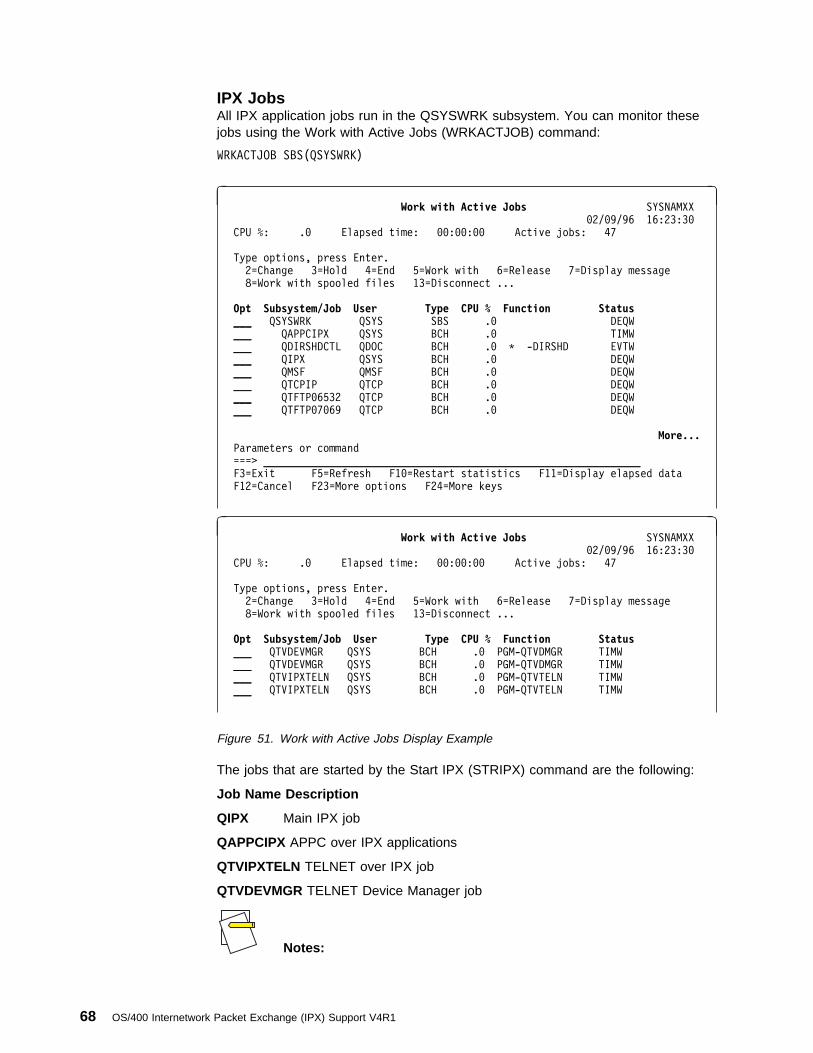
IPX JobsAll IPX application jobs run in the QSYSWRK subsystem. You can monitor thesejobs using the Work with Active Jobs (WRKACTJOB) command:
WRKACTJOB SBS(QSYSWRK)
à ðWork with Active Jobs SYSNAMXX
ð2/ð9/96 16:23:3ð
CPU %: .ð Elapsed time: ðð:ðð:ðð Active jobs: 47
Type options, press Enter.
2=Change 3=Hold 4=End 5=Work with 6=Release 7=Display message
8=Work with spooled files 13=Disconnect ...
Opt Subsystem/Job User Type CPU % Function Status___ QSYSWRK QSYS SBS .ð DEQW
___ QAPPCIPX QSYS BCH .ð TIMW
___ QDIRSHDCTL QDOC BCH .ð \ -DIRSHD EVTW
___ QIPX QSYS BCH .ð DEQW
___ QMSF QMSF BCH .ð DEQW
___ QTCPIP QTCP BCH .ð DEQW
___ QTFTPð6532 QTCP BCH .ð DEQW
___ QTFTPð7ð69 QTCP BCH .ð DEQW
More... Parameters or command
===> _______________________________________________________________
F3=Exit F5=Refresh F1ð=Restart statistics F11=Display elapsed data
F12=Cancel F23=More options F24=More keys
à ðWork with Active Jobs SYSNAMXX
ð2/ð9/96 16:23:3ð
CPU %: .ð Elapsed time: ðð:ðð:ðð Active jobs: 47
Type options, press Enter.
2=Change 3=Hold 4=End 5=Work with 6=Release 7=Display message
8=Work with spooled files 13=Disconnect ...
Opt Subsystem/Job User Type CPU % Function Status ___ QTVDEVMGR QSYS BCH .ð PGM-QTVDMGR TIMW
___ QTVDEVMGR QSYS BCH .ð PGM-QTVDMGR TIMW
___ QTVIPXTELN QSYS BCH .ð PGM-QTVTELN TIMW
___ QTVIPXTELN QSYS BCH .ð PGM-QTVTELN TIMW
Figure 51. Work with Active Jobs Display Example
The jobs that are started by the Start IPX (STRIPX) command are the following:
Job Name Description
QIPX Main IPX job
QAPPCIPX APPC over IPX applications
QTVIPXTELN TELNET over IPX job
QTVDEVMGR TELNET Device Manager job
Notes:
68 OS/400 Internetwork Packet Exchange (IPX) Support V4R1
� There may be other jobs running in the QSYSWRK subsystem thatare not associated with the OS/400 IPX support.
� The IPX jobs in QSYSWRK run under the QSYS user profile.
� The job description that is used for the QIPX job isQSYS/QZSPJOB). The job description for QAPPCIPX job isQSYS/QZSPSNAIPX.
� To use APPC over IPX applications, you must set the network attri-bute Allow AnyNet (ALWANYNET) to *YES and activate IPX supportusing the STRIPX command.
Starting IPXYou must issue the Start IPX (STRIPX) command before any IPX processing canbe performed on the AS/400.
The STRIPX command is used to:
� Initialize and activate IPX processing
� Start the QIPX job in the QSYSWRK subsystem
� Start the QTVIPXTELN jobs in the QSYWRK subsystem
� Start the QTVDEVMGR jobs in the QSYWRK subsystem
� Start the IPX circuits that have AUTOSTART set to *YES
Notes:
� If the network attribute Allow AnyNet (ALWANYNET) is set to *YESwhen you enter the STRIPX command or, if you change the attri-bute from *NO to *YES when IPX is already active, the followingoccurs:
– The SNA over IPX support is activated, which includes startingthe QAPPCIPX job in the QSYSWRK subsystem
– The IP over IPX support is activated
– The IP over IPX interfaces are started
� To use Client Access/400 over IPX after you start IPX, you mayneed to end and then restart the host servers by using theENDHOSTSVR and STRHOSTSVR commands.
To start IPX support, do the following:
1. Type STRIPX and press F4. Figure 52 on page 70 is shown.
2. Enter the name of the IPX description you want to start.
Use SYSTEMA for our sample network.
Operating and Managing IPX Support 69
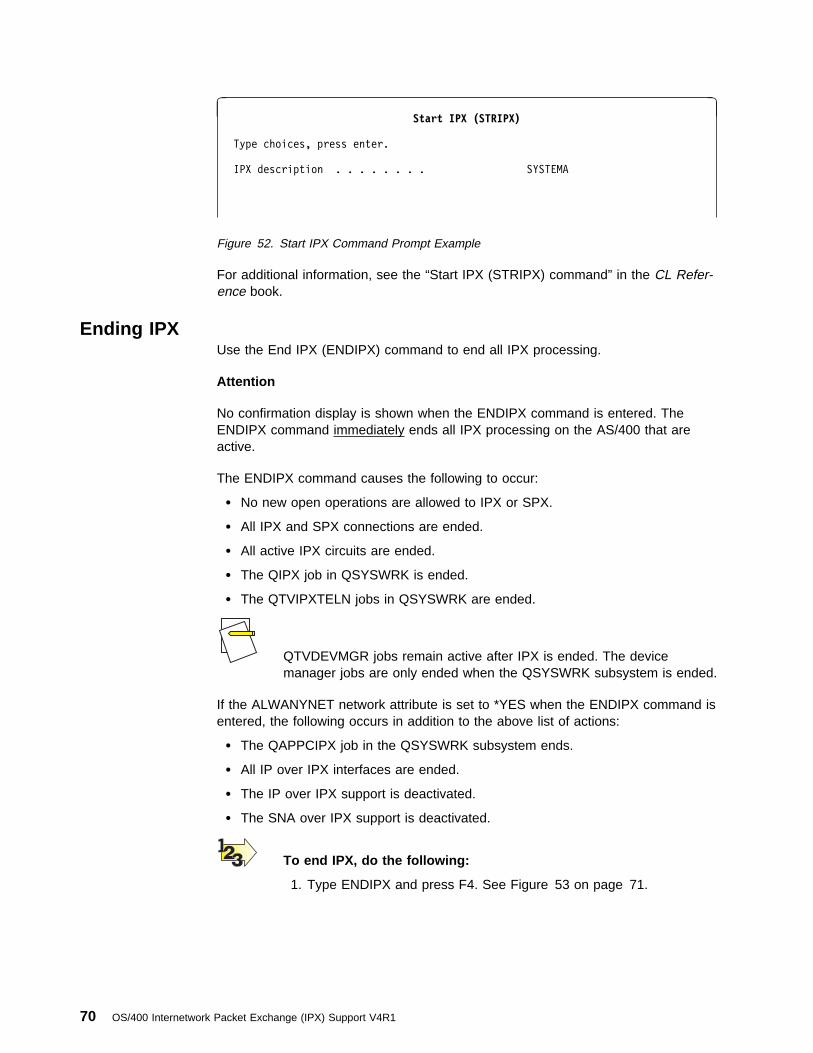
à ðStart IPX (STRIPX)
Type choices, press enter.
IPX description . . . . . . . . SYSTEMA
Figure 52. Start IPX Command Prompt Example
For additional information, see the “Start IPX (STRIPX) command” in the CL Refer-ence book.
Ending IPXUse the End IPX (ENDIPX) command to end all IPX processing.
Attention
No confirmation display is shown when the ENDIPX command is entered. TheENDIPX command immediately ends all IPX processing on the AS/400 that areactive.
The ENDIPX command causes the following to occur:
� No new open operations are allowed to IPX or SPX.
� All IPX and SPX connections are ended.
� All active IPX circuits are ended.
� The QIPX job in QSYSWRK is ended.
� The QTVIPXTELN jobs in QSYSWRK are ended.
QTVDEVMGR jobs remain active after IPX is ended. The devicemanager jobs are only ended when the QSYSWRK subsystem is ended.
If the ALWANYNET network attribute is set to *YES when the ENDIPX command isentered, the following occurs in addition to the above list of actions:
� The QAPPCIPX job in the QSYSWRK subsystem ends.
� All IP over IPX interfaces are ended.
� The IP over IPX support is deactivated.
� The SNA over IPX support is deactivated.
To end IPX, do the following:
1. Type ENDIPX and press F4. See Figure 53 on page 71.
70 OS/400 Internetwork Packet Exchange (IPX) Support V4R1

Bottom Type command, press Enter.
===> ENDIPX
_______________________________________________________________________
_______________________________________________________________________
_______________________________________________________________________
F3=Exit F4=Prompt F9=Retrieve F1ð=Include detailed messages
F11=Display full F12=Cancel F13=Information Assistant F24=More keys
á ñ
The following message is displayed.
> ENDIPXENDIPX successfully completed.
Bottom Type command, press Enter.
===> ________________________________________________________________
_______________________________________________________________________
_______________________________________________________________________
_______________________________________________________________________
F3=Exit F4=Prompt F9=Retrieve F1ð=Include detailed messages
F11=Display full F12=Cancel F13=Information Assistant F24=More keys
á ñ
Figure 53. End IPX Display Example
The ENDIPX command should be used carefully. Partially updated datamay result if an application is processing data and has not completed anoperation when this command is issued. Do the following:
1. Notify all users before issuing the command so that they can endtheir applications.
2. Issue the ENDIPX command at a time when you know that no IPXactivity is occurring on the system.
To display the current IPX activity on the AS/400 system,choose option 3, Work with IPX Status from the Con-figure IPX menu, and then choose option 4. Work withIPX Connection Status from the Work with IPX Statusmenu. The Work with IPX/SPX Connection Status menuis described under “IPX Status Support” on page 72.
The ENDIPX command does not end the NetWare Support processing. For IPXconsiderations for NetWare Support, see Advanced IPX Configuration.
For additional information, see the “End IPX (ENDIPX) command” in the CL Refer-ence book.
Operating and Managing IPX Support 71
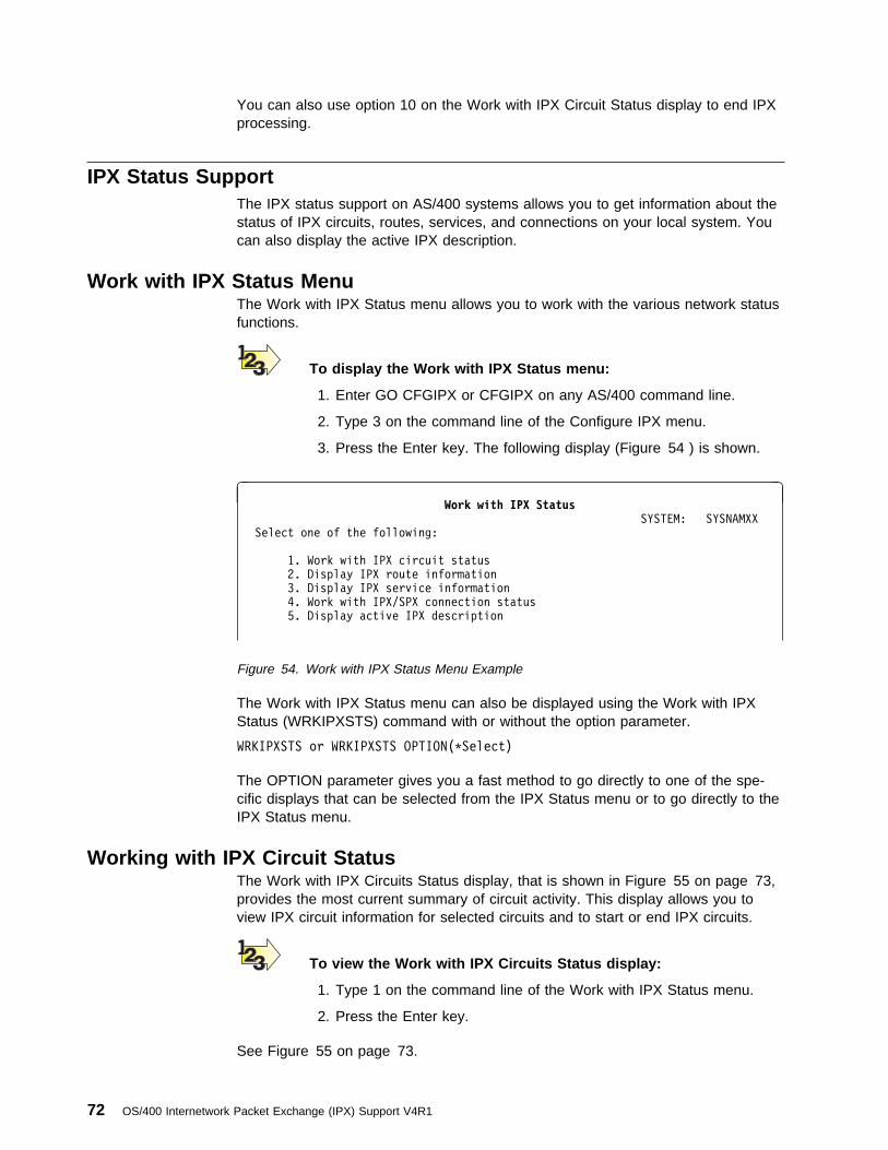
You can also use option 10 on the Work with IPX Circuit Status display to end IPXprocessing.
IPX Status SupportThe IPX status support on AS/400 systems allows you to get information about thestatus of IPX circuits, routes, services, and connections on your local system. Youcan also display the active IPX description.
Work with IPX Status MenuThe Work with IPX Status menu allows you to work with the various network statusfunctions.
To display the Work with IPX Status menu:
1. Enter GO CFGIPX or CFGIPX on any AS/400 command line.
2. Type 3 on the command line of the Configure IPX menu.
3. Press the Enter key. The following display (Figure 54 ) is shown.
à ðWork with IPX Status
SYSTEM: SYSNAMXX
Select one of the following:
1. Work with IPX circuit status
2. Display IPX route information
3. Display IPX service information
4. Work with IPX/SPX connection status
5. Display active IPX description
Figure 54. Work with IPX Status Menu Example
The Work with IPX Status menu can also be displayed using the Work with IPXStatus (WRKIPXSTS) command with or without the option parameter.
WRKIPXSTS or WRKIPXSTS OPTION(\Select)
The OPTION parameter gives you a fast method to go directly to one of the spe-cific displays that can be selected from the IPX Status menu or to go directly to theIPX Status menu.
Working with IPX Circuit StatusThe Work with IPX Circuits Status display, that is shown in Figure 55 on page 73,provides the most current summary of circuit activity. This display allows you toview IPX circuit information for selected circuits and to start or end IPX circuits.
To view the Work with IPX Circuits Status display:
1. Type 1 on the command line of the Work with IPX Status menu.
2. Press the Enter key.
See Figure 55 on page 73.
72 OS/400 Internetwork Packet Exchange (IPX) Support V4R1

à ðWork with IPX Circuits Status
SYSTEM: SYSNAMXX
Type options, press Enter.
5=Display details 7=Display associated services
8=Display associated routes 9=Start 1ð=End
12=Work with configuration status
Circuit Line Line Circuit Opt Name Description Type Status___ CCTC2 TRNLINE \TRLAN Active
___ CCTC3 X25PVC \X25 Inactive
___ CCTC4 X25SVC \X25 Inactive
Figure 55. Work with IPX Circuits Status Display Example
The WRKIPXSTS command can also be used to go directly to this display byentering the following command:
WRKIPXSTS OPTION(\CCT)
Displaying IPX CircuitsTo display more detailed information about the status for specific IPX circuits:
1. On the Work with IPX Circuit Status display, type 5 in the option field for eachcircuit that you want more information about.
2. Press the Enter key.
If you requested status for a token-ring circuit, the information is displayed asshown in Figure 56 on page 74. The information that is displayed for a LAN circuitis slightly different from that for a WAN circuit.
Referring back to our definition of LANs and WANs, “IPX Network” on page 10 mayhelp you as you view the circuit descriptions.
Operating and Managing IPX Support 73

à ðDisplay IPX Circuit
Circuit name . . . . . . . . : CCTC2
Circuit status . . . . . . . : Active
Line description . . . . . . : TRNLINE
Line type . . . . . . . . . : \TRLAN
IPX network number . . . . . : ððððð123
Frametype . . . . . . . . . : \SSAP
Node address . . . . . . . . : 4ðððð1234567
Enable for NLSP . . . . . . : \YES
MAC channel for NLSP . . . . : \BROADCAST
Router priority for NLSP . . : 44
Cost override for NLSP . . . : \CALC
Enable for IW2 . . . . . . . : \YES
Default maximum datagram size: 576
Throughput . . . . . . . . . : 394967295
Delay . . . . . . . . . . . : 2ðð
Automatic start . . . . . . : \YES
á ñ
à ðDisplay IPX Circuit
RIP:
State . . . . . . . . . . : \AUTO
Update interval . . . . . : 6ð
Age multiplier . . . . . . : 4
SAP:
State . . . . . . . . . . : \AUTO
Update interval . . . . . : 6ð
Age multiplier . . . . . . : 4
Change date/time . . . . . . . : ð8/ð6/95 1ð:16:34
Figure 56. Display IPX Circuit LAN Example
If you have requested circuit status information for more than one circuit, press theEnter key to view the remaining displays.
Working with Associated Routes and ServicesThe following tasks can also be completed from the Work with IPX Circuit Statusmenu.
Displaying Associated Services: To display information about the services asso-ciated with a specific circuit:
1. On the Work with IPX Circuit Status display, type 7 in the option field for eachcircuit for which you want to see the associated service information.
2. Press the Enter key.
See Figure 57 on page 75 for an example of the Associated Services display.
If you have requested associated service information for more than one circuit,press the Enter key to view the remaining displays.
74 OS/400 Internetwork Packet Exchange (IPX) Support V4R1
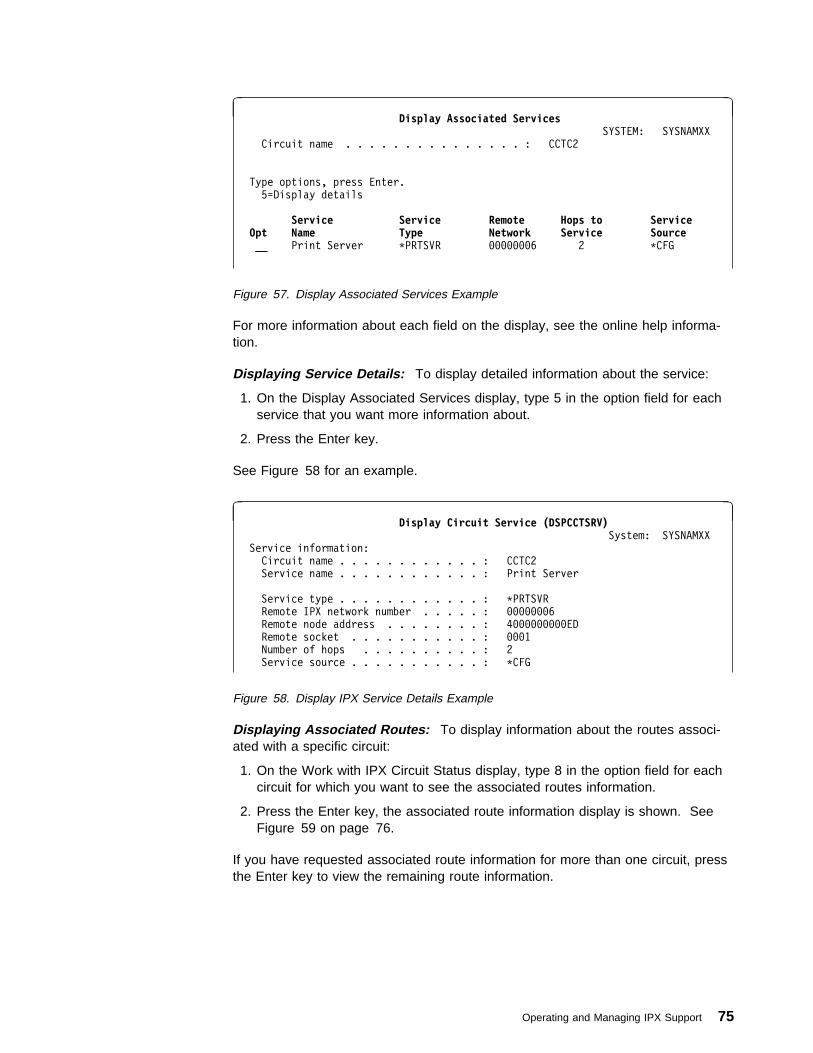
à ðDisplay Associated Services
SYSTEM: SYSNAMXX
Circuit name . . . . . . . . . . . . . . . : CCTC2
Type options, press Enter.
5=Display details
Service Service Remote Hops to Service Opt Name Type Network Service Source __ Print Server \PRTSVR ððððððð6 2 \CFG
Figure 57. Display Associated Services Example
For more information about each field on the display, see the online help informa-tion.
Displaying Service Details: To display detailed information about the service:
1. On the Display Associated Services display, type 5 in the option field for eachservice that you want more information about.
2. Press the Enter key.
See Figure 58 for an example.
à ðDisplay Circuit Service (DSPCCTSRV)
System: SYSNAMXX
Service information:
Circuit name . . . . . . . . . . . . : CCTC2
Service name . . . . . . . . . . . . : Print Server
Service type . . . . . . . . . . . . : \PRTSVR
Remote IPX network number . . . . . : ððððððð6
Remote node address . . . . . . . . : 4ðððððððððED
Remote socket . . . . . . . . . . . : ððð1
Number of hops . . . . . . . . . . : 2
Service source . . . . . . . . . . . : \CFG
Figure 58. Display IPX Service Details Example
Displaying Associated Routes: To display information about the routes associ-ated with a specific circuit:
1. On the Work with IPX Circuit Status display, type 8 in the option field for eachcircuit for which you want to see the associated routes information.
2. Press the Enter key, the associated route information display is shown. SeeFigure 59 on page 76.
If you have requested associated route information for more than one circuit, pressthe Enter key to view the remaining route information.
Operating and Managing IPX Support 75

à ðDisplay Associated Routes
SYSTEM: SYSNAMXX
Circuit name . . . . . . . . . . . . . . . : CCTC2
Type options, press Enter.
5=Display details
Remote Number Number Next Hop Route Opt Network of Hops of Ticks Node Address Source ___ ðððððð34 1 1ð \NONE \CFG
Figure 59. Display Associated Routes Example
Displaying Route Details: To display detailed information about the route:
1. On the Display Associated Routes display, type 5 in the option field for eachroute that you want more information about.
2. Press the Enter key.
Figure 60 is an example.
à ðDisplay IPX Route Details
System: SYSNAMXX
Route information:
Circuit name . . . . . . . . . . . . : CCTC2
Remote IPX network number . . . . . : ðððððð34
Number of hops . . . . . . . . . . . : 1
Number of ticks . . . . . . . . . . : 1ð
Next hop node address . . . . . . . : \None
Route source . . . . . . . . . . . . : \CFG
Figure 60. Display IPX Route Details Example
The circuit information is shown only when this is a locally known circuit.
Starting IPX Circuits: IPX circuits can be started using either the:
Work with IPX Circuit Status menu
or the
Start IPX Circuit (STRIPXCCT) command
76 OS/400 Internetwork Packet Exchange (IPX) Support V4R1

à ðWork with IPX Circuit Status
SYSTEM: SYSNAMXX
Type options, press Enter.
5=Display details 7=Display associated services
8=Display associated routes 9=Start 1ð=End
12=Work with configuration status
Circuit Line Line Circuit Opt Name Description Type Status__ CCTC2 TRNLINE \TRLAN Active
__ CCTC3 X25PVC \X25 Inactive
__ CCTC4 X25SVC \X25 Inactive
Figure 61. Work with IPX Circuits Status Display Example
To start an IPX circuit from the Work with IPX Circuit Status menu, do the following:
1. Type 9 in the option field for each circuit that you want to start.
2. Press the Enter key.
To start an IPX circuit by using the STRIPXCCT command:
1. Type STRIPXCCT on the command line.
2. Press F4 (Prompt).
3. Type the circuit name of the IPX circuit you want to start.
4. Press the Enter key.
For more information, see the “Start IPX Circuit (STRIPXCCT) command” in the CLReference book.
Ending IPX Circuits: The End IPX Circuit (ENDIPXCCT) command ends anexisting IPX circuit immediately. As a result, all IPX connections by using this circuitalso end immediately. However, the operation of any other IPX or IP over IPX inter-face that is using the same line description as the circuit being ended is notaffected.
IPX circuits can be ended using either the:
� Work with IPX Circuits Status display
or the
� End IPX Circuit (ENDIPXCCT) command
To end an IPX circuit from the Work with IPX Circuit Status display:
1. Type 10 in the option field for each circuit that you want to end.
2. Press the Enter key.
To end an IPX circuit by using the ENDIPXCCT command:
1. Type ENDIPXCCT on the command line.
2. Press F4 (Prompt).
3. Type the circuit name of the circuit you want to end.
4. Press the Enter key.
Operating and Managing IPX Support 77
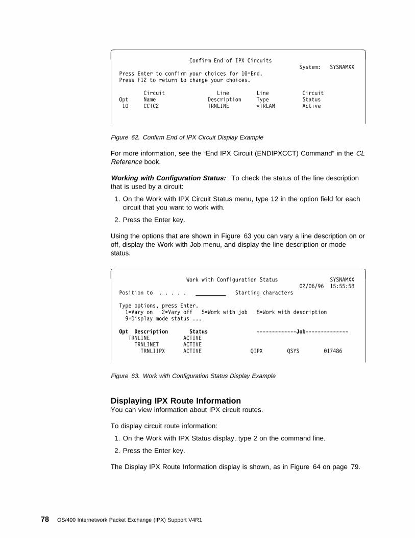
à ðConfirm End of IPX Circuits
System: SYSNAMXX
Press Enter to confirm your choices for 1ð=End.
Press F12 to return to change your choices.
Circuit Line Line Circuit
Opt Name Description Type Status
1ð CCTC2 TRNLINE \TRLAN Active
Figure 62. Confirm End of IPX Circuit Display Example
For more information, see the “End IPX Circuit (ENDIPXCCT) Command” in the CLReference book.
Working with Configuration Status: To check the status of the line descriptionthat is used by a circuit:
1. On the Work with IPX Circuit Status menu, type 12 in the option field for eachcircuit that you want to work with.
2. Press the Enter key.
Using the options that are shown in Figure 63 you can vary a line description on oroff, display the Work with Job menu, and display the line description or modestatus.
à ðWork with Configuration Status SYSNAMXX
ð2/ð6/96 15:55:58
Position to . . . . . __________ Starting characters
Type options, press Enter.
1=Vary on 2=Vary off 5=Work with job 8=Work with description
9=Display mode status ...
Opt Description Status -------------Job-------------- TRNLINE ACTIVE
TRNLINET ACTIVE
TRNLIIPX ACTIVE QIPX QSYS ð17486
Figure 63. Work with Configuration Status Display Example
Displaying IPX Route InformationYou can view information about IPX circuit routes.
To display circuit route information:
1. On the Work with IPX Status display, type 2 on the command line.
2. Press the Enter key.
The Display IPX Route Information display is shown, as in Figure 64 on page 79.
78 OS/400 Internetwork Packet Exchange (IPX) Support V4R1
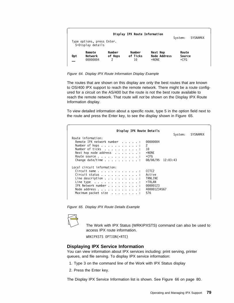
à ðDisplay IPX Route Information
System: SYSNAMXX
Type options, press Enter.
5=Display details
Remote Number Number Next Hop Route Opt Network of Hops of Ticks Node Address Source __ ððððððð4 2 1ð \NONE \CFG
Figure 64. Display IPX Route Information Display Example
The routes that are shown on this display are only the best routes that are knownto OS/400 IPX support to reach the remote network. There might be a route config-ured for a circuit on the AS/400 but the route is not the best route available toreach the remote network. That route will not be shown on the Display IPX RouteInformation display.
To view detailed information about a specific route, type 5 in the option field next tothe route and press the Enter key, to see the display shown in Figure 65.
à ðDisplay IPX Route Details
System: SYSNAMXX
Route information:
Remote IPX network number . . . . . : ððððððð4
Number of hops . . . . . . . . . . . : 2
Number of ticks . . . . . . . . . . : 1ð
Next hop node address . . . . . . . : \NONE
Route source . . . . . . . . . . . . : \CFG
Change date/time . . . . . . . . . . : ð8/ð6/95 12:ð3:43
Local circuit information:
Circuit name . . . . . . . . . . . . : CCTC2
Circuit status . . . . . . . . . . . : Active
Line description . . . . . . . . . . : TRNLINE
Line type . . . . . . . . . . . . . : \TRLAN
IPX Network number . . . . . . . . . : ððððð123
Node address . . . . . . . . . . . . : 4ðððð1234567
Maximum packet size . . . . . . . . : 576
Figure 65. Display IPX Route Details Example
The Work with IPX Status (WRKIPXSTS) command can also be used toaccess IPX route information.
WRKIPXSTS OPTION(\RTE)
Displaying IPX Service InformationYou can view information about IPX services including: print serving, printerqueues, and file serving. To display IPX service information:
1. Type 3 on the command line of the Work with IPX Status display
2. Press the Enter key.
The Display IPX Service Information list is shown. See Figure 66 on page 80.
Operating and Managing IPX Support 79
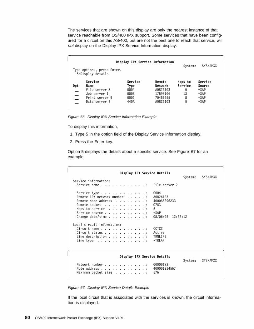
The services that are shown on this display are only the nearest instance of thatservice reachable from OS/400 IPX support. Some services that have been config-ured for a circuit on this AS/400, but are not the best one to reach that service, willnot display on the Display IPX Service Information display.
à ðDisplay IPX Service Information
System: SYSNAMXX
Type options, press Enter.
5=Display details
Service Service Remote Hops to Service Opt Name Type Network Service Source__ File server 2 ððð4 Að8261ð3 5 \SAP
__ Job server 1 ððð5 1759ð1ð6 13 \SAP
__ Print server 9 ððð7 7ð452655 8 \SAP
__ Data server B 44ðA Að8261ð3 5 \SAP
Figure 66. Display IPX Service Information Example
To display this information,
1. Type 5 in the option field of the Display Service Information display.
2. Press the Enter key.
Option 5 displays the details about a specific service. See Figure 67 for anexample.
à ðDisplay IPX Service Details
System: SYSNAMXX
Service information:
Service name . . . . . . . . . . . . : File server 2
Service type . . . . . . . . . . . . : ððð4
Remote IPX network number . . . . . : Að8261ð3
Remote node address . . . . . . . . : 4ðððA5296233
Remote socket . . . . . . . . . . . : ð783
Hops to service . . . . . . . . . . : 5
Service source . . . . . . . . . . . : \SAP
Change date/time . . . . . . . . . . : ð8/ð6/95 12:38:12
Local circuit information:
Circuit name . . . . . . . . . . . . : CCTC2
Circuit status . . . . . . . . . . . : Active
Line description . . . . . . . . . . : TRNLINE
Line type . . . . . . . . . . . . . : \TRLAN
à ðDisplay IPX Service Details
System: SYSNAMXX
Network number . . . . . . . . . . . : ððððð123
Node address . . . . . . . . . . . . : 4ðððð1234567
Maximum packet size . . . . . . . . : 576
Figure 67. Display IPX Service Details Example
If the local circuit that is associated with the services is known, the circuit informa-tion is displayed.
80 OS/400 Internetwork Packet Exchange (IPX) Support V4R1
The WRKIPXSTS command can also be used as a fast path method togo to the IPX Service Information display.
WRKIPXSTS OPTION(\SRV)
Working with IPX/SPX Connection StatusThe Work with IPX/SPX Connection Status display allows you to display or end anIPX connection between a local system and a remote system.
When you display an SPX2 connection, the following state Values are possible:
NegotiatingThis state occurs during connection establishment. This state involves negoti-ating with the remote system for support of SPX2, maximum packet size, andother SPX2 options.
RenegotiatingThis state occurs during the reestablishment of an existing SPX2 connectionfollowing a route failure.
Release-wait-1This state occurs during the orderly release of a connection. The local systemhas sent a request for an orderly release, and is waiting for an acknowledge-ment from the other system.
Release-wait-2This state occurs during the orderly release of a connection. The local systemhas already sent a request for an orderly release. The remote system hasresponded with an acknowledgement, and the local system is waiting for anorderly release request from the remote system.
Close-waitThe remote system has sent a request for an orderly release, the local SPXsupport has informed the application program that the orderly release requesthas been received, and the remote system is waiting for a close from the localapplication program.
Last-ACKThis state occurs during the orderly release of a connection. Orderly releaserequests have been sent by both the remote and local system, and the localsystem is waiting for a final orderly release acknowledgment from the remotesystem.
These connection states are only possible if both sides of the con-nection support the SPX2 protocol.
To display the Work with IPX Connection Status display:
1. Type 4 on the command line of the Work with IPX Status menu.
2. Press the Enter key.
Operating and Managing IPX Support 81

The Work with IPX/SPX Connection Status display is shown in Figure 70 onpage 82.
à ðWork with IPX/SPX Connection Status
System: SYSNAMXX
Type options, press Enter.
4=End 5=Display details
Remote Remote Remote LocalOpt Network Node Address Socket Socket Idle Time State __ \ \ \ 8795 ðð1:26:47 Listen
__ Að8261ð3 4ðððA5296233 416A 41AF ð17:45:17 Established
Press the F11 key to display more information about each connection.
Figure 68. Work with IPX/SPX Connection Status (1 of 3)
à ðWork with IPX/SPX Connection Status
System: SYSNAMXX
Type options, press Enter.
4=End 5=Display details
Remote Remote Remote LocalOpt Network Node Address Socket Socket Type Bytes Out Bytes In __ \ \ \ 8795 \IPX ð ð
__ Að8261ð3 4ðððA5296233 416A 41AF \SPX 43647ð 57ðð
Press the F11 key to display the user of each connection.
Figure 69. Work with IPX/SPX Connection Status (2 of 3)
à ðWork with IPX/SPX Connection Status
System: SYSNAMXX
Type options, press Enter.
4=End 5=Display details
Remote Remote Remote LocalOpt Network Node Address Socket Socket User __ \ \ \ 8795 QSYS
__ Að8261ð3 4ðððA5296233 416A 41AF JDOE
Figure 70. Work with IPX/SPX Connection Status Display Connection State Example (3 of3)
When an application requests a connection to a listening socket, a new connectionis created. The remote network number and node address are shown for the newconnection. The listening sockets always remain in the list of connections.
82 OS/400 Internetwork Packet Exchange (IPX) Support V4R1

The WRKIPXSTS command can also be used reach the Work withIPX/SPX Connection Status display.
WRKIPXSTS OPTION(\CNN)
Displaying IPX and SPX ConnectionsYou can request more detailed information for IPX connections shown on the Workwith IPX/SPX Connection Status display. This information includes timing informa-tion and transmission statistics for the connection that is displayed.
To display more information about the listed connections:
1. Type 5 in the option field for each connection that you want more informationabout.
2. Press the Enter key.
A series of up to four displays for each connection is presented.
The contents of the displays vary depending on the type of connection: IPX or SPX.The displays in Figure 71 on page 84 are for an SPX connection.
Operating and Managing IPX Support 83
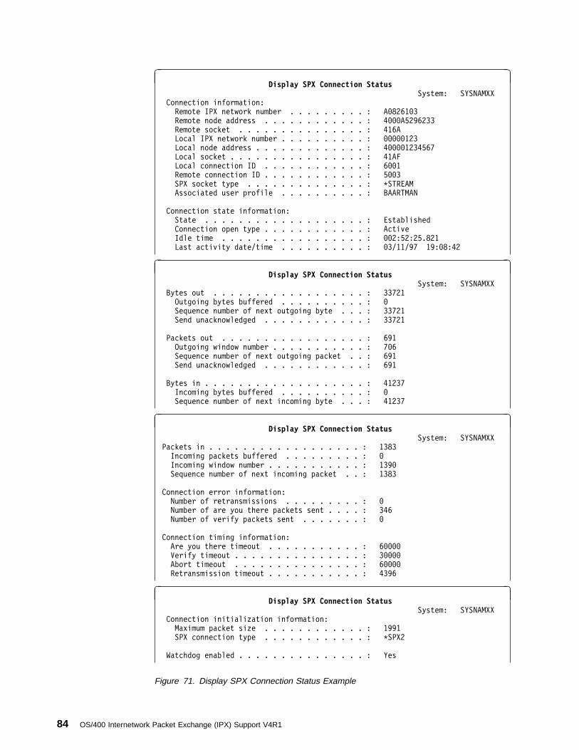
à ðDisplay SPX Connection Status
System: SYSNAMXX
Connection information:
Remote IPX network number . . . . . . . . . : Að8261ð3
Remote node address . . . . . . . . . . . . : 4ðððA5296233
Remote socket . . . . . . . . . . . . . . . : 416A
Local IPX network number . . . . . . . . . . : ððððð123
Local node address . . . . . . . . . . . . . : 4ðððð1234567
Local socket . . . . . . . . . . . . . . . . : 41AF
Local connection ID . . . . . . . . . . . . : 6ðð1
Remote connection ID . . . . . . . . . . . . : 5ðð3
SPX socket type . . . . . . . . . . . . . . : \STREAM
Associated user profile . . . . . . . . . . : BAARTMAN
Connection state information:
State . . . . . . . . . . . . . . . . . . . : Established
Connection open type . . . . . . . . . . . . : Active
Idle time . . . . . . . . . . . . . . . . . : ðð2:52:25.821
Last activity date/time . . . . . . . . . . : ð3/11/97 19:ð8:42
à ðDisplay SPX Connection Status
System: SYSNAMXX
Bytes out . . . . . . . . . . . . . . . . . . : 33721
Outgoing bytes buffered . . . . . . . . . . : ð
Sequence number of next outgoing byte . . . : 33721
Send unacknowledged . . . . . . . . . . . . : 33721
Packets out . . . . . . . . . . . . . . . . . : 691
Outgoing window number . . . . . . . . . . . : 7ð6
Sequence number of next outgoing packet . . : 691
Send unacknowledged . . . . . . . . . . . . : 691
Bytes in . . . . . . . . . . . . . . . . . . . : 41237
Incoming bytes buffered . . . . . . . . . . : ð
Sequence number of next incoming byte . . . : 41237
à ðDisplay SPX Connection Status
System: SYSNAMXX
Packets in . . . . . . . . . . . . . . . . . . : 1383
Incoming packets buffered . . . . . . . . . : ð
Incoming window number . . . . . . . . . . . : 139ð
Sequence number of next incoming packet . . : 1383
Connection error information:
Number of retransmissions . . . . . . . . . : ð
Number of are you there packets sent . . . . : 346
Number of verify packets sent . . . . . . . : ð
Connection timing information:
Are you there timeout . . . . . . . . . . . : 6ðððð
Verify timeout . . . . . . . . . . . . . . . : 3ðððð
Abort timeout . . . . . . . . . . . . . . . : 6ðððð
Retransmission timeout . . . . . . . . . . . : 4396
à ðDisplay SPX Connection Status
System: SYSNAMXX
Connection initialization information:
Maximum packet size . . . . . . . . . . . . : 1991
SPX connection type . . . . . . . . . . . . : \SPX2
Watchdog enabled . . . . . . . . . . . . . . . : Yes
Figure 71. Display SPX Connection Status Example
84 OS/400 Internetwork Packet Exchange (IPX) Support V4R1
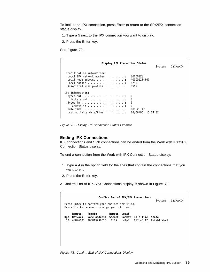
To look at an IPX connection, press Enter to return to the SPX/IPX connectionstatus display.
1. Type a 5 next to the IPX connection you want to display.
2. Press the Enter key.
See Figure 72.
à ðDisplay IPX Connection Status
System: SYSNAMXX
Identification information:
Local IPX network number . . . . . . : ððððð123
Local node address . . . . . . . . . : 4ðððð1234567
Local socket . . . . . . . . . . . . : 8795
Associated user profile . . . . . . : QSYS
IPX information:
Bytes out . . . . . . . . . . . . . : ð
Packets out . . . . . . . . . . . : ð
Bytes in . . . . . . . . . . . . . . : ð
Packets in . . . . . . . . . . . . : ð
Idle time . . . . . . . . . . . . . : ðð1:26:47
Last activity date/time . . . . . . : ð8/ð6/96 13:ð4:32
Figure 72. Display IPX Connection Status Example
Ending IPX ConnectionsIPX connections and SPX connections can be ended from the Work with IPX/SPXConnection Status display.
To end a connection from the Work with IPX Connection Status display:
1. Type a 4 in the option field for the lines that contain the connections that youwant to end.
2. Press the Enter key.
A Confirm End of IPX/SPX Connections display is shown in Figure 73.
à ðConfirm End of IPX/SPX Connections
System: SYSNAMXX
Press Enter to confirm your choices for 4=End.
Press F12 to return to change your choices.
Remote Remote Remote LocalOpt Network Node Address Socket Socket Idle Time State 1ð Að8261ð3 4ðððA5296233 416A 41AF ð17:45:17 Established
Figure 73. Confirm End of IPX Connections Display
Operating and Managing IPX Support 85

To end the IPX connections you have chosen, press the Enter key from theConfirm End of IPX Connections display.
If you decide not to end an IPX connection or if you want to change your choices,press F12 (Cancel).
Tips:
� If errors occur during the process, the closing of the connection issuspended and the Work with IPX Connection Status List is dis-played again with all unprocessed options in place.
� If the processing completes successfully, the connection is removedfrom the list.
Displaying an Active IPX DescriptionTo display the IPX description that was activated using the Start IPX (STRIPX)command for OS/400 IPX support, do the following on Work with IPX Status menu:
1. Type option 5 on the command line.
2. Press Enter.
See Figure 74 for an example.
à ðDisplay IPX Description SYSNAMXX
ð2/ð8/96 ð8:ð7:ð4
IPX description . . . . . . . . . : SYSTEMA
IPX internal network number . . . : ððððððð1
IPX routing protocol . . . . . . . : \NLSP
IPX router name . . . . . . . . . : IPX_Router_Name
IPX maximum datagram size . . . . : 576
IPX packet forwarding . . . . . . : \YES
IPX hop count . . . . . . . . . . : 64
SPX maximum sessions . . . . . . . : 1ððð
SPX watchdog abort timeout . . . . : 12ðððð
SPX watchdog verify timeout . . . : 3ðððð
SPX are you there timeout . . . . : 6ðððð
SPX default retry count . . . . . : 1ð
LAN hello . . . . . . . . . . . . : 2ð
WAN hello . . . . . . . . . . . . : 2ð
Designated router interval . . . . : 1ð
Holding time multiplier . . . . . : 3
More... Press Enter to continue.
F3=Exit F11=Display keywords F12=Cancel
á ñ
à ðDisplay IPX Description SYSNAMXX
ð2/ð8/96 ð8:ð7:ð4
Log protocol errors . . . . . . . : \NO
Propagate NetBIOS packets . . . . : \YES
SPX2 receive window size . . . . . : 8
Text 'description' . . . . . . . . : IPXD for System A
Figure 74. Display Active IPX Description Example
The currently active IPX description for OS/400 IPX support is displayed. If youwant to use a different IPX description for the OS/400 IPX support, you need to:
86 OS/400 Internetwork Packet Exchange (IPX) Support V4R1

� End IPX processing by using the End IPX (ENDIPX) command.
� Start IPX using the Start IPX (STRIPX) command. The IPX description param-eter in the STRIPX command must be set to the name of the IPX descriptionyou want to activate
Operating and Managing IPX Support 87

88 OS/400 Internetwork Packet Exchange (IPX) Support V4R1
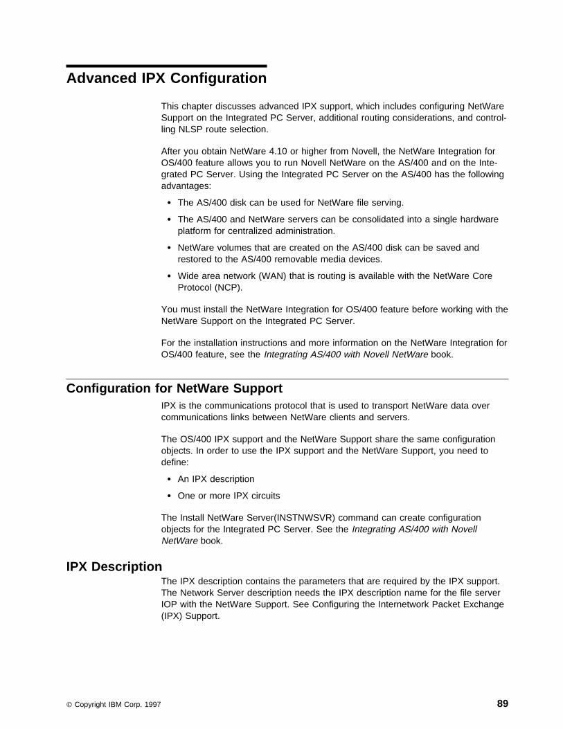
Advanced IPX Configuration
This chapter discusses advanced IPX support, which includes configuring NetWareSupport on the Integrated PC Server, additional routing considerations, and control-ling NLSP route selection.
After you obtain NetWare 4.10 or higher from Novell, the NetWare Integration forOS/400 feature allows you to run Novell NetWare on the AS/400 and on the Inte-grated PC Server. Using the Integrated PC Server on the AS/400 has the followingadvantages:
� The AS/400 disk can be used for NetWare file serving.
� The AS/400 and NetWare servers can be consolidated into a single hardwareplatform for centralized administration.
� NetWare volumes that are created on the AS/400 disk can be saved andrestored to the AS/400 removable media devices.
� Wide area network (WAN) that is routing is available with the NetWare CoreProtocol (NCP).
You must install the NetWare Integration for OS/400 feature before working with theNetWare Support on the Integrated PC Server.
For the installation instructions and more information on the NetWare Integration forOS/400 feature, see the Integrating AS/400 with Novell NetWare book.
Configuration for NetWare SupportIPX is the communications protocol that is used to transport NetWare data overcommunications links between NetWare clients and servers.
The OS/400 IPX support and the NetWare Support share the same configurationobjects. In order to use the IPX support and the NetWare Support, you need todefine:
� An IPX description
� One or more IPX circuits
The Install NetWare Server(INSTNWSVR) command can create configurationobjects for the Integrated PC Server. See the Integrating AS/400 with NovellNetWare book.
IPX DescriptionThe IPX description contains the parameters that are required by the IPX support.The Network Server description needs the IPX description name for the file serverIOP with the NetWare Support. See Configuring the Internetwork Packet Exchange(IPX) Support.
Copyright IBM Corp. 1997 89
IPX Circuit DefinitionTo associate an external IPX network number with an AS/400 line description andIPX circuit is added. The NetWare Support as it is for the OS/400 IPX supportrequires an IPX circuit definition. See “Configuring the Internetwork PacketExchange (IPX) Support” on page 19.
X.25 Network and Integrated PC Server ExampleFigure 75 on page 91 shows the sample network that was configured in Config-uring the Internetwork Packet Exchange (IPX) Support.
� The NetWare Support has been installed on a file server IOP on System D.
� An X.25 communications adapter is also installed on System D.
� System D is a node in the token-ring network and has an X.25 link to theEthernet network.
� The Integrated PC Server is installed on a LAN.
� The Integrated PC Server is used for file serving.
� The Integrated PC Server should be near to the people who are using it.
90 OS/400 Internetwork Packet Exchange (IPX) Support V4R1
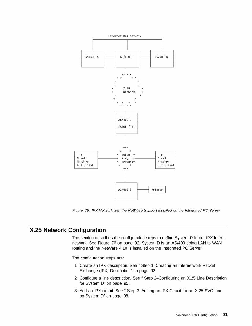
Ethernet Bus Network
┌────────────────────┬────────────────────┐
│ │ │
│ │ │
┌──────┴──────┐ ┌──────┴──────┐ ┌──────┴──────┐
│ │ │ │ │ │
│ AS/4ðð A ├──────┤ AS/4ðð C ├──────┤ AS/4ðð B │
│ │ │ │ │ │
│ │ │ │ │ │
└─────────────┘ └─────┬───────┘ └─────────────┘
│
\\│\ \
\ \ \ \
\ \
\ \
\ X.25 \
\ Network \
\ \
\ \
\ \ \ \
\ \│\ \
│
┌─────┴──────┐
│ │
│ AS/4ðð D │
│ │
│ FSIOP (D1) │
│ │
└────────────┘
│
│
│
\\\
┌─────────────┐ \ \ ┌───────────┐
│ E │ \ Token \ │ F │
│ Novell ├───────────\ Ring \────────────┤ Novell │
│ NetWare │ \ Network\ │ NetWare │
│ 4.1 Client │ \ \ │ 3.x Client│
└─────────────┘ \\\ └───────────┘
│
│
│
┌─────┴──────┐
│ │ ┌─────────┐
│ AS/4ðð G ├──────┤ Printer │
│ │ └─────────┘
│ │
└────────────┘
Figure 75. IPX Network with the NetWare Support Installed on the Integrated PC Server
X.25 Network ConfigurationThe section describes the configuration steps to define System D in our IPX inter-network. See Figure 76 on page 92. System D is an AS/400 doing LAN to WANrouting and the NetWare 4.10 is installed on the Integrated PC Server.
The configuration steps are:
1. Create an IPX description. See “ Step 1–Creating an Internetwork PacketExchange (IPX) Description” on page 92.
2. Configure a line description. See “ Step 2–Configuring an X.25 Line Descriptionfor System D” on page 95.
3. Add an IPX circuit. See “ Step 3–Adding an IPX Circuit for an X.25 SVC Lineon System D” on page 98.
Advanced IPX Configuration 91

4. Adding route information. See “Step 4–Adding Circuit Route Information forSystem D” on page 100.
\ \\ \
\ \ \ \
\ \
\ \
\ X.25 \
\ Network \
\ \
\ \
\ \ \ \
\ \│\ \
│
┌─────┴──────┐
│ │
│ AS/4ðð D │
│ │
│ FSIOP (D1) │
│ │
└────────────┘
Figure 76. X.25 Network Example
You must create two IPX descriptions for System D in our sample network.
� One IPX description that defines global system default values for the AS/400IPX support. See “ Step 1–Creating an Internetwork Packet Exchange (IPX)Description.”
� An IPX description is needed for one or both ports of the 1-port or 2-port Inte-grated PC Server.
The configuration steps that are needed for the AS/400 IPX support are following.
Step 1–Creating an Internetwork Packet Exchange (IPX) Description
To create an IPX description for the OS/400 IPX support on SystemD, do the following :
1. Enter the Create IPX Description (CRTIPXD) command.
2. Press F4.
You are prompted for the following information.
à ðCreate IPX Description (CRTIPXD)
Type choices, press Enter.
IPX description . . . . . . . . SYSTEMD .1/ Name
IPX internal network number . . ððððððð4 .2/ ðððððð1-FFFFFFFE,\RANDOM
IPX routing protocol . . . . . . \NLSP \NLSP, \RIP
IPX router name . . . . . . . . \NONE
IPX maximum datagram size . . . 576 576-65535
Text 'description' . . . . . . . 'IPX description for System D'
Figure 77. Create IPX Description (CRTIPXD) Command Prompt Example for System D
92 OS/400 Internetwork Packet Exchange (IPX) Support V4R1

You must specify values for two parameters. These parameters are:
� The IPX description name
� The IPX internal network number
IPX Description.1/ Enter the name of the IPX description object that is being created. This name ishow the IPX description object is referred to when you want to start IPX processingby using the Start IPX (STRIPX) command.
Use SYSTEMD for the IPX description name in the sample network.
IPX Internal Network Number.2/ Enter the number of the internal IPX network of this AS/400 system. Theinternal IPX network number specifies the AS/400 on which all services and appli-cations that run on the IPX and SPX protocol stacks reside. For more information,see “IPX Internal Network Number” on page 15.
This internal IPX network number is reachable through all adjacent IPX networks,whose network numbers are configured in the IPX circuit definitions.
The internal network number is specified in the form, nnnnnnnn, where nnnnnnnn isa hexadecimal number ranging from 00000001 through FFFFFFFE.
A number is generated for your systemif you specify *RANDOM. You must makesure that this is a unique number on the network. There is no default.
The internal IPX network number is defined as 00000004 for System D in thissample network.
The data might not reach the correct destination when duplicate networknumbers are found. Use the Work with IPX Descriptions display tocheck for duplicate IPX numbers and change them as needed.
After typing in the first set of parameters, press Enter. The IPX description iscreated.
Default values are provided for the remainder of the parameters.
Performance Considerations for IPX DescriptionsUsing the Change IPX Description (CHGIPXD) command, you can control theruntime performance of SPX by changing some key parameters. These parametersinclude the following:
� SPX maximum sessions:
It is recommended that this value should always be 1000 or less.
� SPX watchdog abort timeout (SPXABTTIMO):
It is recommended that this value be set to:
– 120000, if you plan to run more than 30 SPX connections
– 240000, if more than 100 SPX connections.
Advanced IPX Configuration 93

– 600000, if more than 200 SPX connections.
– 60000000, (the maximum value) if more than 500 SPX connections
It is possible to turn off the SPX watchdog abort timer for a specific SPX con-nection by setting the SO_KEEPALIVE option to *OFF by using the socketsAPI. This reduces the performance overhead that is caused by the periodictransmission of the SPX watchdog packets and improves the overall perform-ance of IPX and SPX.
The SPX watchdog abort timeout parameter is not used for SPX2connections; however, the SPX2 protocol does use the Aborttimeout parameter.
� SPX watchdog verify timeout:
It is recommended that this value be set to:
– 30000, if you plan to run more than 30 SPX connections
– 60000, if more than 100 SPX connections.
– 150000, if more than 200 SPX connections.
– 6000000, (the maximum value) if more than 500 SPX connections.
It is possible to turn off the SPX watchdog verify timer for a specific SPX con-nection by setting the SO_KEEPALIVE option to *OFF using the sockets API.This reduces the performance overhead that is caused by the periodic trans-mission of the SPX watchdog packets and improves the overall performance ofIPX and SPX.
� SPX are you there timeout (SPXAYTTIMO):
It is recommended that this value be set to:
– 60000, if you plan to run more than 30 SPX connections
– 120000, if more than 100 SPX connections.
– 300000, if more than 200 SPX connections.
– 12000000, (the maximum value) if more than 500 SPX connections
It is possible to turn off the SPX are you there timer for a specific SPX con-nection by setting the SO_KEEPALIVE option to *OFF using the sockets API.This reduces the performance overhead that is caused by the periodic trans-mission of the SPX watchdog packets and improves the overall performance ofIPX and SPX.
The SPX are you there timeout parameter is not used for SPX2connections; however, the SPX2 protocol does use the Are you
there timeout parameter.
� SPX2 receive window size:
Specify a size greater than 1 to allow remote applications to send more databefore having to wait for an acknowledgement from the local AS/400.
94 OS/400 Internetwork Packet Exchange (IPX) Support V4R1
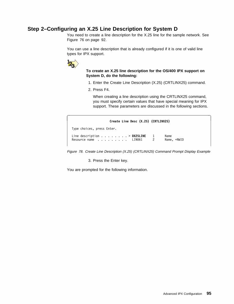
Step 2–Configuring an X.25 Line Description for System DYou need to create a line description for the X.25 line for the sample network. SeeFigure 76 on page 92.
You can use a line description that is already configured if it is one of valid linetypes for IPX support.
To create an X.25 line description for the OS/400 IPX support onSystem D, do the following:
1. Enter the Create Line Description (X.25) (CRTLINX25) command.
2. Press F4.
When creating a line description using the CRTLINX25 command,you must specify certain values that have special meaning for IPXsupport. These parameters are discussed in the following sections.
à ðCreate Line Desc (X.25) (CRTLINX25)
Type choices, press Enter.
Line description . . . . . . . . > DX25LINE 1 Name
Resource name . . . . . . . . . LINð61 2 Name, \NWID
Figure 78. Create Line Description (X.25) (CRTLINX25) Command Prompt Display Example
3. Press the Enter key.
You are prompted for the following information.
Advanced IPX Configuration 95
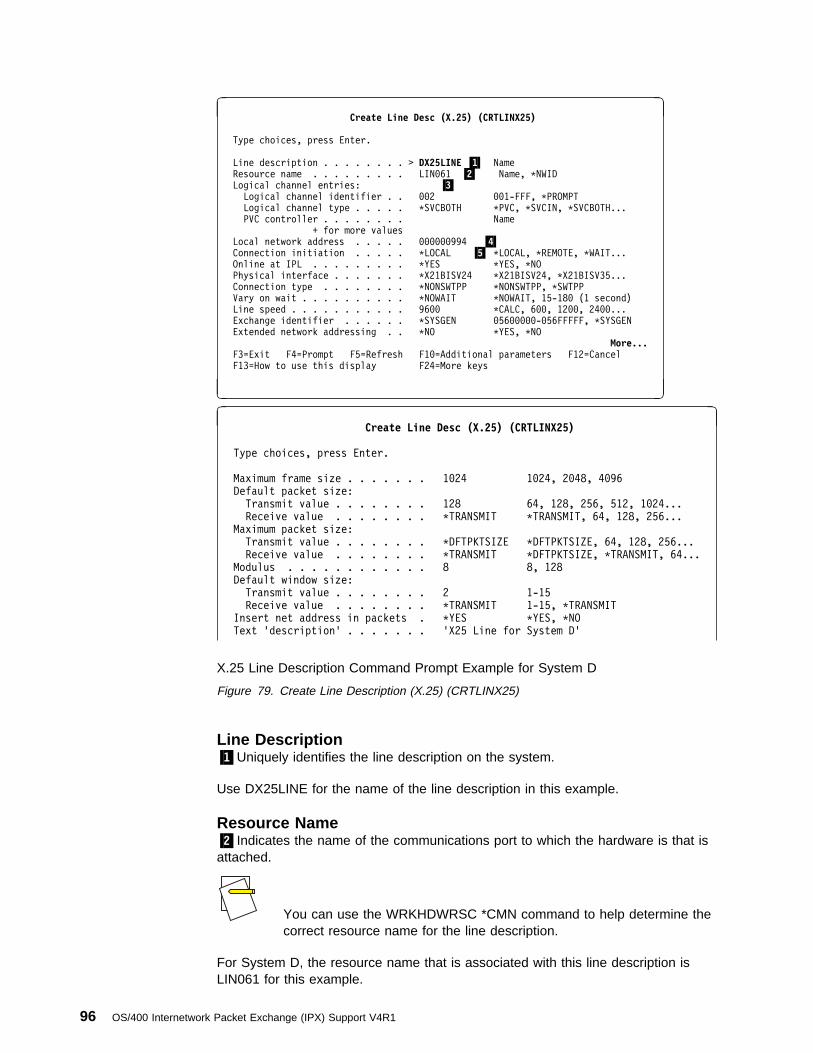
à ðCreate Line Desc (X.25) (CRTLINX25)
Type choices, press Enter.
Line description . . . . . . . . > DX25LINE .1/ Name
Resource name . . . . . . . . . LINð61 .2/ Name, \NWID
Logical channel entries: .3/Logical channel identifier . . ðð2 ðð1-FFF, \PROMPT
Logical channel type . . . . . \SVCBOTH \PVC, \SVCIN, \SVCBOTH...
PVC controller . . . . . . . . Name
+ for more values
Local network address . . . . . ðððððð994 .4/ Connection initiation . . . . . \LOCAL .5/ \LOCAL, \REMOTE, \WAIT... Online at IPL . . . . . . . . . \YES \YES, \NO
Physical interface . . . . . . . \X21BISV24 \X21BISV24, \X21BISV35...
Connection type . . . . . . . . \NONSWTPP \NONSWTPP, \SWTPP
Vary on wait . . . . . . . . . . \NOWAIT \NOWAIT, 15-18ð (1 second)
Line speed . . . . . . . . . . . 96ðð \CALC, 6ðð, 12ðð, 24ðð...
Exchange identifier . . . . . . \SYSGEN ð56ððððð-ð56FFFFF, \SYSGEN
Extended network addressing . . \NO \YES, \NO
More...F3=Exit F4=Prompt F5=Refresh F1ð=Additional parameters F12=Cancel
F13=How to use this display F24=More keys
á ñ
à ðCreate Line Desc (X.25) (CRTLINX25)
Type choices, press Enter.
Maximum frame size . . . . . . . 1ð24 1ð24, 2ð48, 4ð96
Default packet size:
Transmit value . . . . . . . . 128 64, 128, 256, 512, 1ð24...
Receive value . . . . . . . . \TRANSMIT \TRANSMIT, 64, 128, 256...
Maximum packet size:
Transmit value . . . . . . . . \DFTPKTSIZE \DFTPKTSIZE, 64, 128, 256...
Receive value . . . . . . . . \TRANSMIT \DFTPKTSIZE, \TRANSMIT, 64...
Modulus . . . . . . . . . . . . 8 8, 128
Default window size:
Transmit value . . . . . . . . 2 1-15
Receive value . . . . . . . . \TRANSMIT 1-15, \TRANSMIT
Insert net address in packets . \YES \YES, \NO
Text 'description' . . . . . . . 'X25 Line for System D'
X.25 Line Description Command Prompt Example for System D
Figure 79. Create Line Description (X.25) (CRTLINX25)
Line Description.1/Uniquely identifies the line description on the system.
Use DX25LINE for the name of the line description in this example.
Resource Name.2/Indicates the name of the communications port to which the hardware is that isattached.
You can use the WRKHDWRSC *CMN command to help determine thecorrect resource name for the line description.
For System D, the resource name that is associated with this line description isLIN061 for this example.
96 OS/400 Internetwork Packet Exchange (IPX) Support V4R1

The following values are X.25 specific.
Logical Channel Entries.3/Specifies a list of entries to be added, removed, or changed in the logicalchannel table.
A logical channel entry must be defined for each virtual circuit. A logical channelentry for an X.25 SVC consists of a logical channel identifier and a logical channeltype.
There is a special value that is called *PROMPT which allows you to easily add,remove, and change logical channel entries that is defined for an X.25 line. Once aPVC logical channel has a PVC controller attached to it the logical channel entrycannot be changed.
Logical Channel Identifier
Specifies a three-character hexadecimal number that ranges from 001 to FFF forthe logical channel identifier. The first digit (from left to right) is the logical channelgroup number; the second and third digits make up the logical channel number.
You must specify one logical channel identifier for each virtual circuit. We havedefined 2 virtual circuits, with identifiers 001 and 002.
Logical Channel Type
Specify the logical channel type as:
*PVC (permanent virtual circuit
*SVCIN (switched virtual circuit for input only),
*SVCOUT (switched virtual circuit for output only)
*SVCBOTH (switched virtual circuit for both input and output)
For this example, this value is set to *SVCBOTH, for both virtual circuits, indicatingthat this logical channel is a Switched Virtual Circuit for both incoming and outgoingcalls.
PVC Controller (Optional)
Specifies the name of the permanent virtual circuit (PVC) controller that is assignedto the logical channel. This field is only valid when the channel type is *PVC.
Local Network Address.4/Specifies the local network address for this system. Up to 17 characters can bespecified if *YES is specified for the Extend Network Address parameter. Otherwiseup to 15 characters can be specified.
Use 000000994 for the X.25 network address for this example. This number isknown by the network administrator.
Advanced IPX Configuration 97
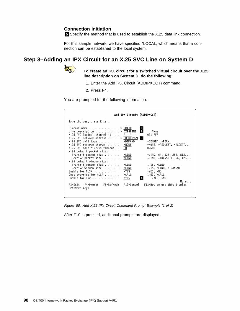
Connection Initiation.5/Specify the method that is used to establish the X.25 data link connection.
For this sample network, we have specified *LOCAL, which means that a con-nection can be established to the local system.
Step 3–Adding an IPX Circuit for an X.25 SVC Line on System D
To create an IPX circuit for a switched virtual circuit over the X.25line description on System D, do the following:
1. Enter the Add IPX Circuit (ADDIPXCCT) command.
2. Press F4.
You are prompted for the following information.
à ðAdd IPX Circuit (ADDIPXCCT)
Type choices, press Enter.
Circuit name . . . . . . . . . . > CCT1D .1/ Line description . . . . . . . . > DX25LINE .2/ Name
X.25 PVC logical channel id . . ' ' ðð1-FFF
X.25 SVC network address . . . . > ðððððð999 .3/ X.25 SVC call type . . . . . . . \DEMAND \DEMAND, \PERM
X.25 SVC reverse charge . . . . \NONE \NONE, \REQUEST, \ACCEPT...
X.25 SVC idle circuit timeout . 6ð ð-6ðð
X.25 default packet size:
Transmit packet size . . . . . \LIND \LIND, 64, 128, 256, 512...
Receive packet size . . . . . \LIND \LIND, \TRANSMIT, 64, 128...
X.25 default window size:
Transmit window size . . . . . \LIND 1-15, \LIND
Receive window size . . . . . \LIND 1-15, \LIND, \TRANSMIT
Enable for NLSP . . . . . . . . \YES \YES, \NO
Cost override for NLSP . . . . . \CALC 1-63, \CALC
Enable for IW2 . . . . . . . . . \YES .4/ \YES, \NO
More...F3=Exit F4=Prompt F5=Refresh F12=Cancel F13=How to use this display
F24=More keys
á ñ
Figure 80. Add X.25 IPX Circuit Command Prompt Example (1 of 2)
After F10 is pressed, additional prompts are displayed.
98 OS/400 Internetwork Packet Exchange (IPX) Support V4R1

à ðAdd IPX Circuit (ADDIPXCCT)
Type choices, press Enter.
Additional Parameters
Default maximum datagram size . \LIND 576-16388, \LIND
Throughput . . . . . . . . . . . \CALC 3ðð-4294967295, \CALC
Delay time . . . . . . . . . . . \CALC 1-5ðððððð, \CALC
Automatic start . . . . . . . . \YES \YES, \NO
RIP state . . . . . . . . . . . \OFF \ON, \OFF, \AUTO
RIP update interval . . . . . . 6ð 3ð-3ððððð
RIP age multiplier . . . . . . . 4 1-1ð
SAP state . . . . . . . . . . . \OFF \ON, \OFF, \AUTO
SAP update interval . . . . . . 6ð 3ð-3ððððð
SAP age multiplier . . . . . . . 4 1-1ð
Figure 81. Add X.25 IPX Circuit Command Prompt Example (2 of 2)
The required parameters on an IPX circuit for an X.25 SVC line are as follows:
Circuit Name.1/Enter the name of the circuit.
Use CCT1D for the IPX circuit name in this sample network.
Line Description.2/Identifies the line description that is associated with the circuit.
DX25LINE is the name of the line description you created in the “ Step2–Configuring a Line Description for IPX Support–X.25” on page 46 for this samplenetwork.
X.25 PVC Logical Channel IdentifierSpecifies the permanent virtual circuit (PVC) channel identifier that IPX support canestablish on an X.25 circuit. Only 1 unique channel identifier may be specified.Valid ranges are 001 to FFF. The PVC value must have been previously specifiedon the X.25 line description value.
The X.25 PVC Logical Channel ID is only required if the SVC NetworkAddress value is not specified and an X.25 line description is used.
Because the sample network is using an SVC logical channel, this parameter is notneeded.
X.25 SVC Network Address.3/Enter the DTE that is associated with the remote X.25 system (the DTE addressof the remote system). This value can be a decimal number that is 1 through 17digits in length.
Advanced IPX Configuration 99

The SVC Network Address is only valid for X.25 line descriptions. If anX.25 line description is being used, the PVC Logical Channel ID or theSVC Network Address must be specified.
The network address for System D is 000000994 for this example.
Enable for IW2.4/Specifies whether the IW2 negotiations for a WAN are enabled for this circuit ornot.
IW2 is the protocol used by Novell to exchange necessary router to router informa-tion prior to exchanging standard IPX routing information and traffic over WAN net-works, such as X.25 and Frame Relay networks. Part of IW2 exchange includes thenegotiation of the IPX network and node numbers to be assigned to the WANcircuit.
Some systems may not support IW2 negotiations. In order to interoperate withthese systems, set this value to *NO. However, because IW2 exchange is not per-formed when this value is *NO, an IPX network number must be specified so it canbe assigned to the circuit. The system derives an associated node number thatconsists of the specified network number that is followed by two bytes of binaryzeros. For example, an IPX network number of X'10045D08' would result in thegeneration of X'10045D080000'.
For our example, we are using the default; *YES.
Default values are used for the other parameters in this IPX circuit definition. Formore information about these parameters, see the “Add IPX Circuit (ADDIPXCCT)Command” in the CL Reference book.
Step 4–Adding Circuit Route Information for System DIPX circuit route entries (or static route entries) need to be added for the systemsthat can be reached by this X.25 line description. Figure 82 on page 101 showsthese routes.
100 OS/400 Internetwork Packet Exchange (IPX) Support V4R1
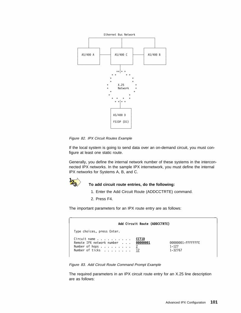
Ethernet Bus Network
┌────────────────────┬────────────────────┐
│ │ │
│ │ │
┌──────┴──────┐ ┌──────┴──────┐ ┌──────┴──────┐
│ │ │ │ │ │
│ AS/4ðð A ├──────┤ AS/4ðð C ├──────┤ AS/4ðð B │
│ │ │ │ │ │
│ │ │ │ │ │
└─────────────┘ └─────┬───────┘ └─────────────┘
│
\\│\ \
\ \ \ \
\ \
\ \
\ X.25 \
\ Network \
\ \
\ \
\ \ \ \
\ \│\ \
│
┌─────┴──────┐
│ │
│ AS/4ðð D │
│ │
│ FSIOP (D1) │
│ │
└────────────┘
Figure 82. IPX Circuit Routes Example
If the local system is going to send data over an on-demand circuit, you must con-figure at least one static route.
Generally, you define the internal network number of these systems in the intercon-nected IPX networks. In the sample IPX internetwork, you must define the internalIPX networks for Systems A, B, and C.
To add circuit route entries, do the following:
1. Enter the Add Circuit Route (ADDCCTRTE) command.
2. Press F4.
The important parameters for an IPX route entry are as follows:
à ðAdd Circuit Route (ADDCCTRTE)
Type choices, press Enter.
Circuit name . . . . . . . . . . CCT1D Remote IPX network number . . . ððððððð1 ððððððð1-FFFFFFFE
Number of hops . . . . . . . . . 2 1-127
Number of ticks . . . . . . . . 12 1-32767
Figure 83. Add Circuit Route Command Prompt Example
The required parameters in an IPX circuit route entry for an X.25 line descriptionare as follows:
Advanced IPX Configuration 101
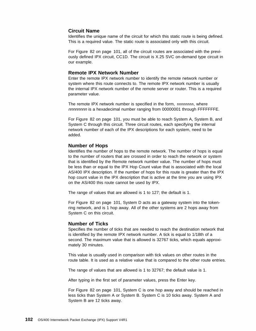
Circuit NameIdentifies the unique name of the circuit for which this static route is being defined.This is a required value. The static route is associated only with this circuit.
For Figure 82 on page 101, all of the circuit routes are associated with the previ-ously defined IPX circuit, CC1D. The circuit is X.25 SVC on-demand type circuit inour example.
Remote IPX Network NumberEnter the remote IPX network number to identify the remote network number orsystem where this route connects to. The remote IPX network number is usuallythe internal IPX network number of the remote server or router. This is a requiredparameter value.
The remote IPX network number is specified in the form, nnnnnnnn, wherennnnnnnn is a hexadecimal number ranging from 00000001 through FFFFFFFE.
For Figure 82 on page 101, you must be able to reach System A, System B, andSystem C through this circuit. Three circuit routes, each specifying the internalnetwork number of each of the IPX descriptions for each system, need to beadded.
Number of HopsIdentifies the number of hops to the remote network. The number of hops is equalto the number of routers that are crossed in order to reach the network or systemthat is identified by the Remote network number value. The number of hops mustbe less than or equal to the IPX Hop Count value that is associated with the localAS/400 IPX description. If the number of hops for this route is greater than the IPXhop count value in the IPX description that is active at the time you are using IPXon the AS/400 this route cannot be used by IPX.
The range of values that are allowed is 1 to 127; the default is 1.
For Figure 82 on page 101, System D acts as a gateway system into the token-ring network, and is 1 hop away. All of the other systems are 2 hops away fromSystem C on this circuit.
Number of TicksSpecifies the number of ticks that are needed to reach the destination network thatis identified by the remote IPX network number. A tick is equal to 1/18th of asecond. The maximum value that is allowed is 32767 ticks, which equals approxi-mately 30 minutes.
This value is usually used in comparison with tick values on other routes in theroute table. It is used as a relative value that is compared to the other route entries.
The range of values that are allowed is 1 to 32767; the default value is 1.
After typing in the first set of parameter values, press the Enter key.
For Figure 82 on page 101, System C is one hop away and should be reached inless ticks than System A or System B. System C is 10 ticks away. System A andSystem B are 12 ticks away.
102 OS/400 Internetwork Packet Exchange (IPX) Support V4R1
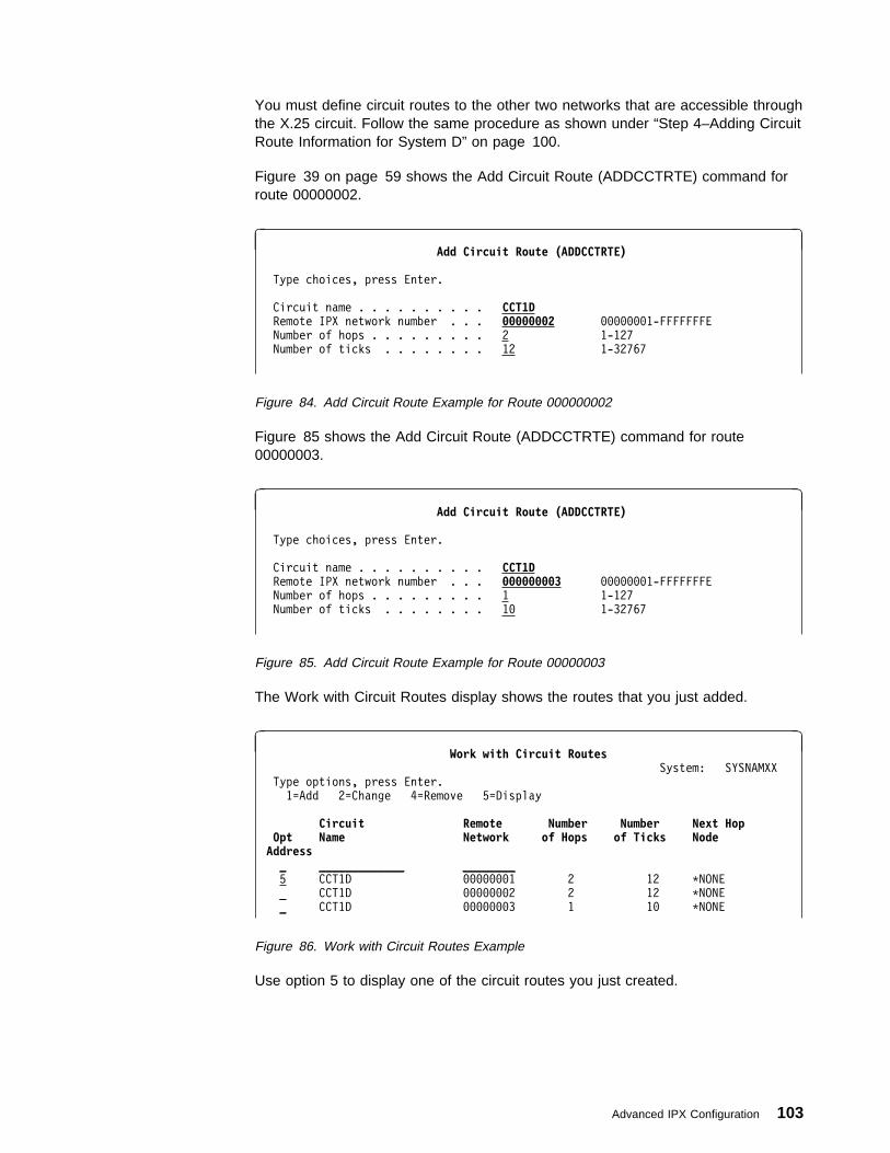
You must define circuit routes to the other two networks that are accessible throughthe X.25 circuit. Follow the same procedure as shown under “Step 4–Adding CircuitRoute Information for System D” on page 100.
Figure 39 on page 59 shows the Add Circuit Route (ADDCCTRTE) command forroute 00000002.
à ðAdd Circuit Route (ADDCCTRTE)
Type choices, press Enter.
Circuit name . . . . . . . . . . CCT1D Remote IPX network number . . . ððððððð2 ððððððð1-FFFFFFFE
Number of hops . . . . . . . . . 2 1-127
Number of ticks . . . . . . . . 12 1-32767
Figure 84. Add Circuit Route Example for Route 000000002
Figure 85 shows the Add Circuit Route (ADDCCTRTE) command for route00000003.
à ðAdd Circuit Route (ADDCCTRTE)
Type choices, press Enter.
Circuit name . . . . . . . . . . CCT1D Remote IPX network number . . . ðððððððð3 ððððððð1-FFFFFFFE
Number of hops . . . . . . . . . 1 1-127
Number of ticks . . . . . . . . 1ð 1-32767
Figure 85. Add Circuit Route Example for Route 00000003
The Work with Circuit Routes display shows the routes that you just added.
à ðWork with Circuit Routes
System: SYSNAMXX
Type options, press Enter.
1=Add 2=Change 4=Remove 5=Display
Circuit Remote Number Number Next Hop Opt Name Network of Hops of Ticks NodeAddress _ _____________ ________
5 CCT1D ððððððð1 2 12 \NONE
_ CCT1D ððððððð2 2 12 \NONE
_ CCT1D ððððððð3 1 1ð \NONE
Figure 86. Work with Circuit Routes Example
Use option 5 to display one of the circuit routes you just created.
Advanced IPX Configuration 103

à ðDisplay Circuit Route (DSPCCTRTE)
Circuit name . . . . . . . . . . . . : CCT1D
Remote IPX network number . . . . . : ððððððð1
Number of hops . . . . . . . . . . . : 2
Number of ticks . . . . . . . . . . : 12
Next hop node address . . . . . . . : \NONE
Route source . . . . . . . . . . . . : \CFG
Figure 87. Display Circuit Route 00000003 Example
Considerations for Adding Route InformationThe AS/400 can be configured as a router in an IPX network. Two routing proto-cols, NLSP and RIP, are provided by the OS/400 IPX support. The ability to con-figure and use static routes is also supported. Four parameters that are used in theIPX configuration control how IPX routing works on the AS/400.
� The actual routing protocol in use by the AS/400 is dependent on the followingparameter values:
– The IPX routing protocol parameter on the Create IPX Description(CRTIPXD) and Change IPX Description (CHGIPXD) commands
– The IPX packet forwarding parameter on the CRTIPXD command andCHGIPXD command
– The Enable for NLSP parameter on the Add IPX Circuit (ADDIPXCCT)command and CHGIPXCCT (Change IPX Circuit) command
– The RIP state parameter on the ADDIPXCCT commands and CHGIPXCCTcommands
These parameters values must be considered together because they affecteach other. As a group, these parameters determine the type of IPX routing tobe performed by the AS/400 system.
� Another parameter that should also be considered when configuring the routingprotocol to be used on AS/400, is the Service Advertising Protocol (SAP) stateparameter on the ADDIPXCCT and CHGIPXCCT commands.
IPX Description Considerations for RoutingThe parameters on the Create IPX Description (CRTIPXD) and the Change IPXDescription (CHGIPXD) commands to be considered are: IPX routing protocol andIPX packet forwarding.
� The IPX routing protocol parameter determines the overall routing protocol thatis used for the AS/400 IPX support. The IPX routing protocol parameter allowsvalues of *NLSP and *RIP. The default is *NLSP.
� The IPX packet forwarding parameter determines if the AS/400 passes informa-tion information about routes and services from one circuit to another.
� The IPX packet forwarding parameter allows values of *YES and *NO. Thedefault is *YES.
If this value is *NO, then the IPX routing protocol parameter is ignored and theOS/400 IPX support will not act as a router for the attached networks. Thisparameter makes the AS/400 IPX support appear as a client or server if it is
104 OS/400 Internetwork Packet Exchange (IPX) Support V4R1
*NO. When IPX packet forwarding is disabled, the internal network and locallydefined services are still advertised using RIP and SAP. Other information thatis learned about services and networks is not shared from one circuit toanother.
IPX Circuit Considerations for RoutingThe parameters on the Add IPX Circuit (ADDIPXCCT) and Change IPX Circuit(CHGIPXCCT) command are: Enable for NLSP and RIP state.
� The Enable for NLSP value determines whether a circuit is enabled for NLSPprocessing or not.
� The values for Enable for NLSP parameter are *YES and *NO. The default is*YES. The value of this parameter is used and is dependent on the IPX routingprotocol value in the currently active IPX description. An IPX description isactive if it has been specified on the STRIPX command.
� If the IPX routing protocol value is *NLSP and the Enable for NLSP value is*NO, then RIP is used as a routing protocol on this circuit (depending on thevalue of the RIP state parameter).
� If the IPX routing protocol value is *NLSP and the Enable for NLSP value is*YES, then NLSP is used as a routing protocol on this circuit. The RIP stateparameter indicates if RIP will be concurrently supported on this circuit or not.
If the IPX routing protocol value is *RIP, then the Enable for NLSP value isignored.
� The RIP state parameter specifies the routing information protocol (RIP) modeof support on a circuit. The RIP state values are *AUTO, *ON and *OFF. Thedefault is *AUTO. Setting this parameter determines how RIP advertises andhow general RIP requests are processed on this circuit. A general RIP requestis a request for all routes known to a system. A specific RIP request is arequest for information about a specific route.
Whatever the RIP state parameter is set for a circuit (*ON, *AUTOor *OFF), a specific RIP request is always processed by AS/400 IPXsupport.
– *ON means to use normal RIP routing on this circuit. TheAS/400 advertises routes by using RIP. The AS/400 IPX supportcan process general and specific RIP requests.
– *AUTO is defined as “Don’t generate RIP routing advertisementsunless another RIP router is advertising.”
With the RIP state value set to *AUTO, the AS/400 advertisesroutes by using RIP, if another RIP router exists in the networkthat is also advertising. This mode allows an AS/400 by usingNLSP for routing to be compatible with order RIP routers thatmay exist in the network.
– *OFF means that no RIP routing is supported on this circuit. TheAS/400 does not advertise routes by using RIP. However, theAS/400 will respond to specific RIP requests.
� The RIP state value is dependent on the IPX routing protocol value in the cur-rently ACTIVE IPX description and the value of the ENBNLSP parameter on
Advanced IPX Configuration 105
the same circuit. An IPX description is active if it has been specified on theSTRIPX command.
Considerations for Combining Values for RoutingThe different combinations of values for these parameters are discussed next.
When the following situations occur the parameters should be considered in combi-nation are:
1. If the IPX routing protocol value is NLSP, the Enable for NLSP value is *NO,and the RIP state value is *ON, then the circuit acts as a normal RIP circuit.
2. If the IPX routing protocol value is *NLSP, the Enable for NLSP parameter is*NO, the RIP state value is *AUTO, then *AUTO is interpreted as *ON.
To prevent the following situation:
� Two systems are configured for RIP processing with the values are set as men-tioned above. The systems could both be AS/400s or they could be oneAS/400 and some other type of system.
� Both systems have IPX activated. For the AS/400s, you would use the STRIPXcommand and specify an IPX description.
� Since *AUTO is originally defined as “do not advertise unless specificallyrequested to do so” neither system exchanges routing information, neithersystem would find out about the other router in the network. No routes wouldbe exchanged.
If you want to have a RIP network where no RIP traffic is present, then youshould set the RIP state value to *OFF. You would have to configure staticroutes and services for this circuit in order to route data over this circuit. Seethe following discussion.
– If IPX routing protocol is *NLSP, Enable for NLSP is *NO, and RIP state is*OFF, then the circuit does not use any routing protocol. Static routeswould have to be configured in order to use this circuit for IPX data.
– If IPX routing protocol is *NLSP and Enable for NLSP is *YES, then theRIP state of *AUTO, *ON and *OFF will operate as defined above. NLSP isused as a routing protocol on this circuit and RIP may also be used to becompatible with older RIP routers.
– If the IPX routing protocol value is *RIP, the Enable for NLSP value isignored. When the RIP state value is *AUTO , the *AUTO value is inter-preted as *ON to avoid the situation where no routing information would beexchanged.
Considerations for SAP State Parameter for RoutingWhen determining the type of routing that you want on a circuit, there are consider-ations for the SAP state parameter. The SAP state parameter allows the samevalues as the RIP state parameter: *ON, *AUTO, and *OFF. The default is *AUTO.The SAP state parameter operates in much the same manner as the RIP stateparameter.
� *ON means to use normal SAP advertising on this circuit. The AS/400 adver-tises services using SAP. The AS/400 IPX support will respond to general andspecific SAP requests.
106 OS/400 Internetwork Packet Exchange (IPX) Support V4R1
� *AUTO is defined as “don’t generate SAP advertisements unless another SAProuter is advertising.” When the SAP state value is *AUTO, the AS/400 adver-tises services by using SAP if another SAP router exists in the network that isalso advertising. This allows for SAP compatibility on an NLSP circuit.
� *OFF means that no SAP advertising will not be generated or absorbed on thiscircuit. Specific SAP requests will be responded to.
The SAP state value is not dependent on the RIP state value. You can haveRIP routing set to *OFF on a circuit while having SAP advertising set to *ON.You can also have RIP routing *ON and SAP advertising *OFF on a circuit.
Considerations for WAN Line DescriptionsFor circuits that are defined to WAN line descriptions, there are some special con-siderations.
� If NLSP is not enabled and if the RIP state of a circuit is turned off, you mustcreate at least one static route in order to use the circuit.
� For X.25 line descriptions, the service type (SVCTYPE) parameter on theADDIPXCCT and CHGIPXCCT commands determines the type of SVC circuit.The values that are allowed are *DEMAND and *PERM. *DEMAND is thedefault
� If *DEMAND is configured, then at least one static route must be configured forthis circuit before the AS/400 initiates a call, regardless of the routing protocol.You should also consider configuring static services if you want to be able toaccess the services of the remote systems by using this circuit.
Controlling NLSP Route SelectionThis section explains how to override the cost that is associated with a circuit. Usethis information if you need to manually control the selection of routes in an NLSPnetwork.
Advanced IPX Configuration 107

The cost that is associated with a circuit is used by NLSP to determine that thenetwork route over which to forward IPX packets. The end-to-end path with thelowest cost is selected as the preferred route. By default, the cost for a circuit isbased on the throughput of the associated line type. For example, a circuit associ-ated with a 10 megabit per second ethernet line would have a default cost of 20whereas a circuit associated with a 16 megabit per second token-ring line wouldhave a lower default cost of 19.
You can override the default cost that is associated with a circuit by setting theCSTOVRNLSP parameter when you create or change a circuit.
Table 8. Default Costs. Throughput rates are estimated per second.
Throughput At Least Throughput Less Than Default Cost
0 kilobits 16 kilobits 61
16 kilobits 48 kilobits 55
48 kilobits 128 kilobits 45
128 kilobits 256 kilobits 40
256 kilobits 512 kilobits 35
512 kilobits 1 megabit 30
1 megabit 2 megabits 27
2 megabits 4 megabits 26
4 megabits 8 megabits 25
8 megabits 10 megabits 23
10 megabits 16 megabits 20
16 megabits 32 megabits 19
32 megabits 64 megabits 15
64 megabits 128 megabits 14
128 megabits 512 megabits 9
512 megabits 4 gigabits 6
4 gigabit 32 gigabits 3
108 OS/400 Internetwork Packet Exchange (IPX) Support V4R1
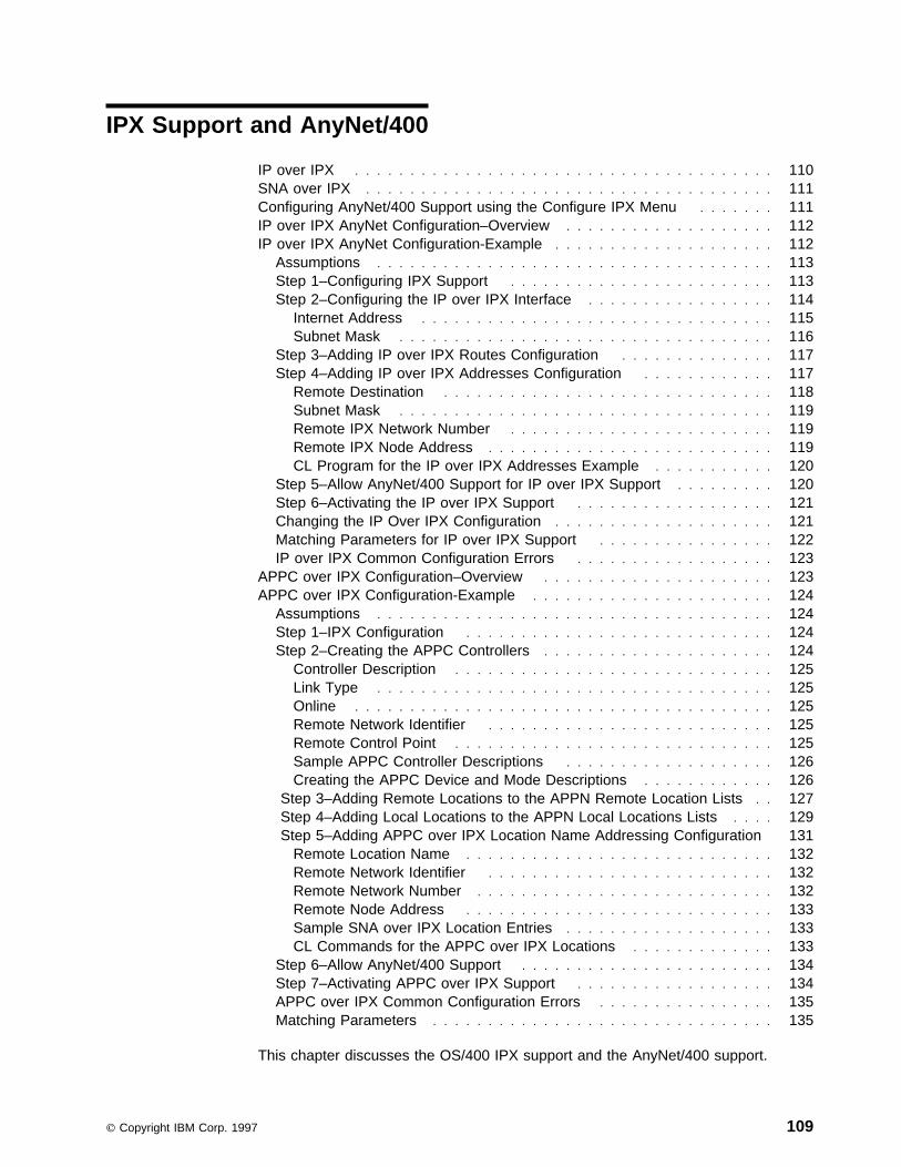
IPX Support and AnyNet/400
IP over IPX . . . . . . . . . . . . . . . . . . . . . . . . . . . . . . . . . . . . . . 110SNA over IPX . . . . . . . . . . . . . . . . . . . . . . . . . . . . . . . . . . . . . 111Configuring AnyNet/400 Support using the Configure IPX Menu . . . . . . . 111IP over IPX AnyNet Configuration–Overview . . . . . . . . . . . . . . . . . . . 112IP over IPX AnyNet Configuration-Example . . . . . . . . . . . . . . . . . . . . 112
Assumptions . . . . . . . . . . . . . . . . . . . . . . . . . . . . . . . . . . . . 113Step 1–Configuring IPX Support . . . . . . . . . . . . . . . . . . . . . . . . 113Step 2–Configuring the IP over IPX Interface . . . . . . . . . . . . . . . . . 114
Internet Address . . . . . . . . . . . . . . . . . . . . . . . . . . . . . . . . 115Subnet Mask . . . . . . . . . . . . . . . . . . . . . . . . . . . . . . . . . . 116
Step 3–Adding IP over IPX Routes Configuration . . . . . . . . . . . . . . 117Step 4–Adding IP over IPX Addresses Configuration . . . . . . . . . . . . 117
Remote Destination . . . . . . . . . . . . . . . . . . . . . . . . . . . . . . 118Subnet Mask . . . . . . . . . . . . . . . . . . . . . . . . . . . . . . . . . . 119Remote IPX Network Number . . . . . . . . . . . . . . . . . . . . . . . . 119Remote IPX Node Address . . . . . . . . . . . . . . . . . . . . . . . . . . 119CL Program for the IP over IPX Addresses Example . . . . . . . . . . . 120
Step 5–Allow AnyNet/400 Support for IP over IPX Support . . . . . . . . . 120Step 6–Activating the IP over IPX Support . . . . . . . . . . . . . . . . . . 121Changing the IP Over IPX Configuration . . . . . . . . . . . . . . . . . . . . 121Matching Parameters for IP over IPX Support . . . . . . . . . . . . . . . . 122IP over IPX Common Configuration Errors . . . . . . . . . . . . . . . . . . 123
APPC over IPX Configuration–Overview . . . . . . . . . . . . . . . . . . . . . 123APPC over IPX Configuration-Example . . . . . . . . . . . . . . . . . . . . . . 124
Assumptions . . . . . . . . . . . . . . . . . . . . . . . . . . . . . . . . . . . . 124Step 1–IPX Configuration . . . . . . . . . . . . . . . . . . . . . . . . . . . . 124Step 2–Creating the APPC Controllers . . . . . . . . . . . . . . . . . . . . . 124
Controller Description . . . . . . . . . . . . . . . . . . . . . . . . . . . . . 125Link Type . . . . . . . . . . . . . . . . . . . . . . . . . . . . . . . . . . . . 125Online . . . . . . . . . . . . . . . . . . . . . . . . . . . . . . . . . . . . . . 125Remote Network Identifier . . . . . . . . . . . . . . . . . . . . . . . . . . 125Remote Control Point . . . . . . . . . . . . . . . . . . . . . . . . . . . . . 125Sample APPC Controller Descriptions . . . . . . . . . . . . . . . . . . . 126Creating the APPC Device and Mode Descriptions . . . . . . . . . . . . 126
Step 3–Adding Remote Locations to the APPN Remote Location Lists . . 127 Step 4–Adding Local Locations to the APPN Local Locations Lists . . . . 129 Step 5–Adding APPC over IPX Location Name Addressing Configuration 131
Remote Location Name . . . . . . . . . . . . . . . . . . . . . . . . . . . . 132Remote Network Identifier . . . . . . . . . . . . . . . . . . . . . . . . . . 132Remote Network Number . . . . . . . . . . . . . . . . . . . . . . . . . . . 132Remote Node Address . . . . . . . . . . . . . . . . . . . . . . . . . . . . 133Sample SNA over IPX Location Entries . . . . . . . . . . . . . . . . . . . 133CL Commands for the APPC over IPX Locations . . . . . . . . . . . . . 133
Step 6–Allow AnyNet/400 Support . . . . . . . . . . . . . . . . . . . . . . . 134Step 7–Activating APPC over IPX Support . . . . . . . . . . . . . . . . . . 134APPC over IPX Common Configuration Errors . . . . . . . . . . . . . . . . 135Matching Parameters . . . . . . . . . . . . . . . . . . . . . . . . . . . . . . . 135
This chapter discusses the OS/400 IPX support and the AnyNet/400 support.
Copyright IBM Corp. 1997 109

AnyNet/400 configuration should be done by the experienced pro-grammer.
Address mapping and location names are used to configure AS/400 systems forAnyNet/400 support for IP over IPX and SNA over IPX.
IP over IPXThe IP over IPX support allows socket applications that are written to the AF_INETaddress family to communicate over an IPX network without any changes in theapplication.
Configuring IP over IPX support consists of working with IP addresses and remotenodes. Configuring IP over IPX requires the following steps:
1. Configuring OS/400 IPX support, which includes creating an IPX description,and a line description for IPX support to use and adding an IPX circuit defi-nition.
2. Designating the local IP address or address assigned to the local node. TheseIP addresses are normally referred to as interfaces in the IP network.
3. Designating the IP routes to the remote nodes. These routes are requiredwhenever a remote node is not part of the same IP network. The node must bereached by means of a gateway. The IP route indicates the first gateway on thepath to the remote node. This first gateway is known as the next hop and mustbe on the same IP network or subnetwork as the local node.
4. Mapping remote IPX network number and node address to IP address for eachremote node that the local node wants to communicate with. You can eithermanually map or use the automatic mapping function for the IP address toremote IPX network number and node address. A special value of *CALC per-forms the automatic mapping.
When configuring an IP over IPX address entry and the remote des-tination system is an AS/400, the remote node address value mustbe equal to *CALC.
5. Setting the ALWANYNET (Allow AnyNet Support) network attribute to *YES.
6. Using the Start IPX (STRIPX) command to activate IP over IPX support.
For a sample IP over IPX configuration, refer to “IP over IPX AnyNet Configuration-Example” on page 112.
You can also define or change the IP over IPX configuration. Refer to “Changingthe IP Over IPX Configuration” on page 121 for more information.
110 OS/400 Internetwork Packet Exchange (IPX) Support V4R1

SNA over IPXThe SNA over IPX support allows CPI Communications and ICF applications to runwithout change over an IPX internetwork. SNA over IPX is more accurately referredto as APPC over IPX.
When referring to SNA over IPX support, it will be stated as APPC overIPX support in the remainder of this chapter.
APPC over IPX support consists of working with IPX location name entries. Theconfiguration for SNA over IPX requires the following:
1. Configuring OS/400 IPX support, which includes creating an IPX descriptionand a line description for IPX support to use and adding an IPX circuit defi-nition.
2. Creating the APPC controller and devices.
3. Changing the remote location list to establish sessions with the remote system,depending on the remote control point name in the *ANYNW APPC controller,the remote location name, and the local location name.
4. Changing the APPN local location to define the local location name to be usedby APPC over IPX support.
5. Mapping APPC LU names (remote location and remote network identifier) toremote IPX network and remote IPX node addresses by adding SNA over IPXlocations entries. You can use the Add SNA over IPX Location (ADDSNILOC)command to identify the mappings.
When configuring an SNA over IPX location mapping entry and the remote des-tination is an AS/400 system, the remote node address value must be equal to*AS400.
6. Setting the ALWANYNET network attribute to *YES.
7. Using the STRIPX command to activate APPC over IPX support.
Steps 3 and 5 are only necessary if a session is to be initiated from alocal system to the remote system.
For an APPC over IPX example network, refer to “APPC over IPX Configuration-Example” on page 124.
Configuring AnyNet/400 Support using the Configure IPX MenuTo configure the AnyNet/400 support, you use the Configure IPX menu. At thecommand line, enter:
GO CFGIPX
or
CFGIPX
The Configure IPX menu is displayed.
IPX Support and AnyNet/400 111

à ð CFGIPX Configure IPX System: SYSTEMA
Select one of the following:
Configure IPX
1. Configure IPX circuits
2. Work with IPX descriptions
3. Work with IPX status
Configure AnyNet/4ðð over IPX
1ð. Work with IP over IPX interfaces
11. Work with IP over IPX routes
12. Work with IP over IPX addresses
2ð. Work with SNA over IPX locations
Selection or command
===> __________________________________________________________________
________________________________________________________________________
F3=Exit F4=Prompt F9=Retrieve F12=Cancel
á ñ
Figure 88. Configure IPX Menu Example
IP over IPX AnyNet Configuration–OverviewTo configure IP over IPX support, do the following:
1. Create an IPX description. See “ Step 1–Creating an Internetwork PacketExchange (IPX) Description” on page 23.
2. Create a line description for IPX support. See “ Step 2–Configuring LineDescriptions for IPX Support–Ethernet” on page 30.
3. Add an IPX circuit. See “ Step 3–Adding an Internetwork Packet Exchange(IPX) Circuit” on page 35.
4. Add an IP over IPX interface. See “Step 2–Configuring the IP over IPXInterface” on page 114.
5. Add IP over IPX routes. See “Step 3–Adding IP over IPX Routes Configuration”on page 117.
6. Add IP over IPX addresses. See “Step 4–Adding IP over IPX AddressesConfiguration” on page 117.
IP over IPX AnyNet Configuration-ExampleThis section shows the displays and commands that can be used to perform IPover IPX configuration for Figure 89 on page 113.
The three systems are the same as in Figure 9 on page 22.
112 OS/400 Internetwork Packet Exchange (IPX) Support V4R1

Assumptions1. All three systems are AS/400s.
2. IPX support is already configured on each AS/400.
3. An IP address of 123.4.5.0 is assigned to this IPX network. Figure 89 showsan existing IPX network.
4. The subnet mask is 255.255.255.0. Performing a logical AND operation on theIP address of 123.4.5.0 and subnet mask 255.255.255.0 gives a subset of IPnetwork addresses of 123.4.5.1 through 123.4.5.254. These are the addressesto be used by the IP over IPX support. This allows for 254 different IPaddresses which means up to 254 different IPX nodes.
5. Figure 89 shows the IP addresses that are assigned to the IPX network.
a. The choice of IP addresses that are shown leaves gaps in the numberingof the IP addresses to allow room for future additions to the network. Forexample, new systems in this network would use IP addresses between123.4.5.3 and 123.4.5.254.
b. Your choice of IP addresses should allow room for future additions thatfollow a pattern that makes sense for your network. By following, a patternyou can avoid confusion that is caused when two systems try to use thesame IP addresses.
System A
┌───────────────────────────────┐
│IPX internal net id: ððððððð1 │
│IP address for │%────┐
│ IPX network: 123.4.5.1 │ │
│IP subnet mask: 255.255.255.ð │ │
└───────────────────────────────┘ │
│
System B │
┌───────────────────────────────┐ │
│IPX internal net id: ððððððð2 │ │
│IP address for │%────┤
│ IPX network: 123.4.5.2 │ │
│IP subnet mask: 255.255.255.ð │ │
└───────────────────────────────┘ │
│
System C │
┌───────────────────────────────┐ │
│ IPX internal net id: ððððððð3 │ │
│ IP address for │%────┘
│ IPX network: 123.4.5.3 │
│ IP subnet mask: 255.255.255.ð │
└───────────────────────────────┘
Figure 89. IP over IPX Network Example
Step 1–Configuring IPX SupportOS/400 IPX Support is already configured on these three systems in our network.For configuring OS/400 IPX support on the systems in our sample network, seeConfiguring the Internetwork Packet Exchange (IPX) Support.
IPX Support and AnyNet/400 113

Step 2–Configuring the IP over IPX InterfaceThe Add IP over IPX Interface (ADDIPIIFC) command is used to define anAF_INET socket (IP) over IPX interface. An interface is an IP address by which thelocal system is known to IP.
Interfaces that are defined by the ADDIPIIFC command are logical interfaces. Theyare not physical interfaces and they are not associated with any line description ornetwork interface. There can be multiple AF_INET sockets over IPX logical inter-faces that are defined on a host.
To define the IP over IPX interfaces, use the Work with IP over IPXInterfaces display.
1. Select option 10 from the Configure IPX menu.
2. Press the Enter key. The Work with IP over IPX Interfaces menu isshown.
3. Select option 1 to add an IP over IPX interface.
4. Press the Enter key.
à ðWork with IP over IPX Interfaces
System: SYSTEMA
Type options, press Enter.
1=Add 2=Change 4=Remove 9=Start 1ð=End
Internet Subnet Interface Opt Address Mask Status 1 ____________
_ ____________
Figure 90. Work with IP over IPX Interfaces Example
à ðAdd IP over IPX Interface (ADDIPIIFC)
Type choices, press Enter.
Internet address . . . . . . . . __________ Subnet mask . . . . . . . . . . __________
Figure 91. Add IP over IPX Interface Command Prompt Example
You need to add an IP over IPX interface for each of the internet addresses.
You are prompted for the following information:
114 OS/400 Internetwork Packet Exchange (IPX) Support V4R1
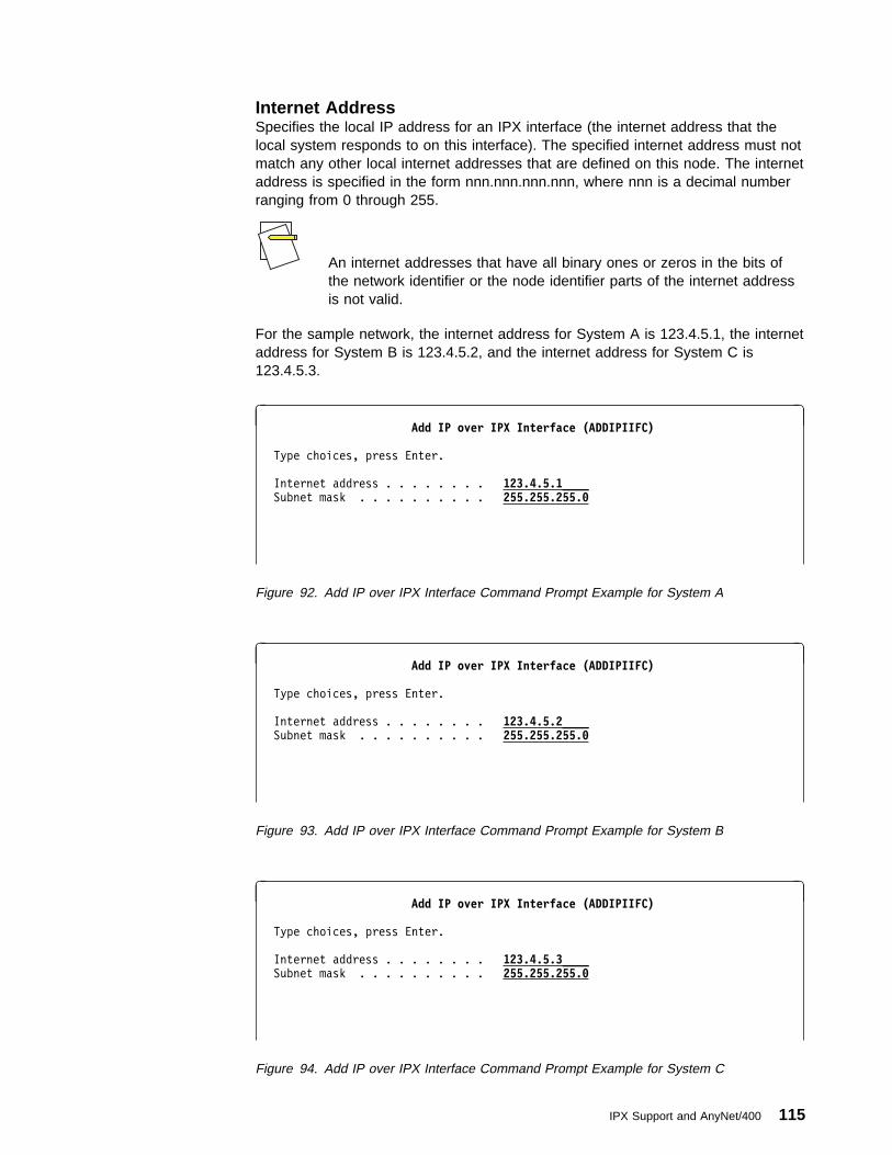
Internet AddressSpecifies the local IP address for an IPX interface (the internet address that thelocal system responds to on this interface). The specified internet address must notmatch any other local internet addresses that are defined on this node. The internetaddress is specified in the form nnn.nnn.nnn.nnn, where nnn is a decimal numberranging from 0 through 255.
An internet addresses that have all binary ones or zeros in the bits ofthe network identifier or the node identifier parts of the internet addressis not valid.
For the sample network, the internet address for System A is 123.4.5.1, the internetaddress for System B is 123.4.5.2, and the internet address for System C is123.4.5.3.
à ðAdd IP over IPX Interface (ADDIPIIFC)
Type choices, press Enter.
Internet address . . . . . . . . 123.4.5.1____ Subnet mask . . . . . . . . . . 255.255.255.ð
Figure 92. Add IP over IPX Interface Command Prompt Example for System A
à ðAdd IP over IPX Interface (ADDIPIIFC)
Type choices, press Enter.
Internet address . . . . . . . . 123.4.5.2____ Subnet mask . . . . . . . . . . 255.255.255.ð
Figure 93. Add IP over IPX Interface Command Prompt Example for System B
à ðAdd IP over IPX Interface (ADDIPIIFC)
Type choices, press Enter.
Internet address . . . . . . . . 123.4.5.3____ Subnet mask . . . . . . . . . . 255.255.255.ð
Figure 94. Add IP over IPX Interface Command Prompt Example for System C
IPX Support and AnyNet/400 115

Subnet MaskSpecifies the mask of the network and node address fields of the internet addressthat defines a subnetwork. The subnet mask is in the form nnn.nnn.nnn.nnn, wherennn is a decimal number ranging in value from 0 through 255. The subnet maskmust mask off all bits of the network class’s network ID part of the internet address.
For more information on this value, see the “Add IP over IPX Address (ADDIPIIFC)Command” in the CL Reference book.
The Work with IP over IPX Interfaces display shows the successfully added IP overIPX interfaces.
à ðWork with IP over IPX Interfaces
System: SYSTEMA
Type options, press Enter.
1=Add 2=Change 4=Remove 9=Start 1ð=End
Internet Subnet Interface Opt Address Mask Status _ _________
_ 123.4.5.1 255.255.255.ð Active
Bottom F3=Exit F5=Refresh F6=Print list F1ð=Work with TCP/IP interfaces
F12=Cancel F17=Top F18=Bottom
IP over IPX interface added successfully.á ñ
Figure 95. Work with IP over IPX Interfaces Display Example for System A
à ðWork with IP over IPX Interfaces
System: SYSTEMB
Type options, press Enter.
1=Add 2=Change 4=Remove 9=Start 1ð=End
Internet Subnet Interface Opt Address Mask Status _ _________
_ 123.4.5.2 255.255.255.ð Active
Bottom F3=Exit F5=Refresh F6=Print list F1ð=Work with TCP/IP interfaces
F12=Cancel F17=Top F18=Bottom
IP over IPX interface added successfully.á ñ
Figure 96. Work with IP over IPX Interfaces Display Example for System B
116 OS/400 Internetwork Packet Exchange (IPX) Support V4R1

à ðWork with IP over IPX Interfaces
System: SYSTEMC
Type options, press Enter.
1=Add 2=Change 4=Remove 9=Start 1ð=End
Internet Subnet Interface Opt Address Mask Status _ _________
_ 123.4.5.3 255.255.255.ð Active
Bottom F3=Exit F5=Refresh F6=Print list F1ð=Work with TCP/IP interfaces
F12=Cancel F17=Top F18=Bottom
IP over IPX interface added successfully.á ñ
Figure 97. Work with IP over IPX Interfaces Display Example for System C
Step 3–Adding IP over IPX Routes ConfigurationThe Add IP over IPX Route (ADDIPIRTE) command designates the IP routes toremote nodes. These routes are required whenever a remote node is not part ofthe same IP network.
The IP over IPX route entries define the path to the remote nodes that can beaccessed by way of the IPX transport. These route entries can designate a singlenode, or a group of nodes within a single network or subnetwork. If the route to theremote node traverse interconnected networks or subnetworks by using a gateway,the internet address of the next hop in the route must be supplied.
This network does not require routes, so you do not need to add IP overIPX route entries.
Step 4–Adding IP over IPX Addresses ConfigurationThe Add IP over IPX Address (ADDIPIADR) command can add an addressmapping entry.
In order to enable IP over IPX processing, there must be a mapping of the remoteIPX network number and node address to an IP address for each remote node thatthe local node communicates with. IP over IPX mapping entries define the remoteIPX addresses that are associated with each remote node identified in the IP overIPX route entries and the local node interfaces identified in the IP over IPX inter-faces. This can be a manual mapping process or an automatic mapping function ofIP address to remote IPX network number and node addresses. Automatic mappingis done by specifying a special value of *CALC.
Before you can use IP over IPX support, you must define the IP over IPXaddresses.
IPX Support and AnyNet/400 117
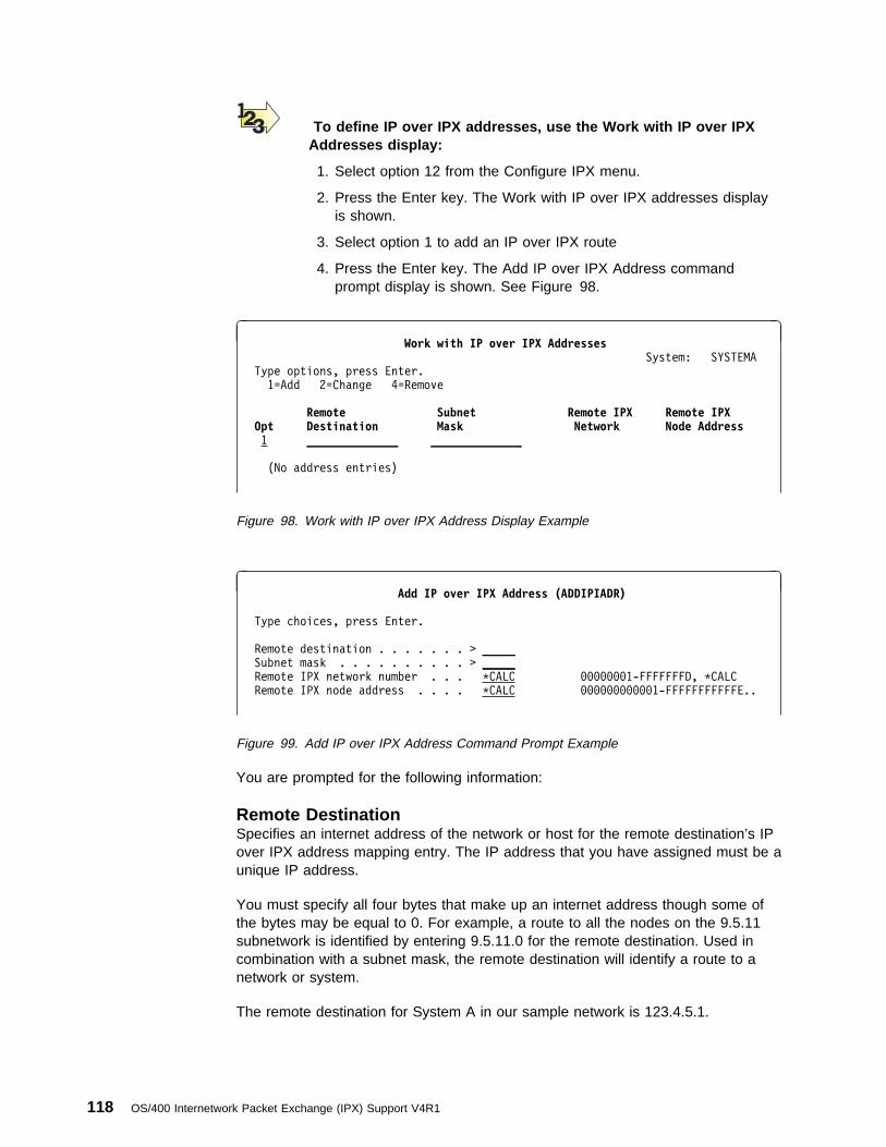
To define IP over IPX addresses, use the Work with IP over IPXAddresses display:
1. Select option 12 from the Configure IPX menu.
2. Press the Enter key. The Work with IP over IPX addresses displayis shown.
3. Select option 1 to add an IP over IPX route
4. Press the Enter key. The Add IP over IPX Address commandprompt display is shown. See Figure 98.
à ðWork with IP over IPX Addresses
System: SYSTEMA
Type options, press Enter.
1=Add 2=Change 4=Remove
Remote Subnet Remote IPX Remote IPX Opt Destination Mask Network Node Address 1 ______________ ______________
(No address entries)
Figure 98. Work with IP over IPX Address Display Example
à ðAdd IP over IPX Address (ADDIPIADR)
Type choices, press Enter.
Remote destination . . . . . . . > _____ Subnet mask . . . . . . . . . . > _____ Remote IPX network number . . . \CALC ððððððð1-FFFFFFFD, \CALC
Remote IPX node address . . . . \CALC ððððððððððð1-FFFFFFFFFFFE..
Figure 99. Add IP over IPX Address Command Prompt Example
You are prompted for the following information:
Remote DestinationSpecifies an internet address of the network or host for the remote destination’s IPover IPX address mapping entry. The IP address that you have assigned must be aunique IP address.
You must specify all four bytes that make up an internet address though some ofthe bytes may be equal to 0. For example, a route to all the nodes on the 9.5.11subnetwork is identified by entering 9.5.11.0 for the remote destination. Used incombination with a subnet mask, the remote destination will identify a route to anetwork or system.
The remote destination for System A in our sample network is 123.4.5.1.
118 OS/400 Internetwork Packet Exchange (IPX) Support V4R1

Subnet MaskSpecify the mask of the network and node address fields of the internet addressthat defines a subnetwork. The subnet mask is in the form nnn.nnn.nnn.nnn, wherennn is a decimal number ranging in value from 0 through 255. The subnet maskmust mask off all bits of the network class’s network ID part of the internet address.
*HOST is the default value. The internet address value of the route destination isused. The subnet mask value is calculated to be 255.255.255.255.
Remote IPX Network NumberSpecifies the remote IPX network that is associated with this IP network or IPaddress. Specify an 8-character IPX network number. Valid values range from00000001 through FFFFFFFD.
*CALC is the default value.
For more information on this value, see the “Add IP over IPX Address(ADDIPIADR) command” in the CL Reference book.
For our sample network, use 00000001 which is the internal IPX network numberfor System A.
Remote IPX Node AddressSpecifies the remote node address (IPX node) that is associated with this IPnetwork, subnetwork, or IP address.
When configuring an IP over IPX address mapping entry and the remotedestination host is an AS/400, the remote node address value must beequal to *CALC. If the remote destination is actually a network with oneor more AS/400s on that network, any valid remote node address valuemay be entered.
Specify a 12-character IPX node address. Valid values range from 000000000001through FFFFFFFFFFFE.
*CALC is the default value.
For more information on this value, see the “Add IP over IPX Address(ADDIPIADR) command” in the CL Reference book.
The Work with IP over IPX Address display shows the successfully added addressmapping entries for all three AS/400s. See Figure 100 on page 120.
IPX Support and AnyNet/400 119

à ðWork with IP over IPX Addresses
System: SYSTEMA
Type options, press Enter.
1=Add 2=Change 4=Remove
Remote Subnet Remote IPX Remote IPX Opt Destination Mask Network Node Address _ ______________ ____________
_ 123.4.5.1 \HOST ððððððð1 \CALC
_ 123.4.5.2 \HOST ððððððð2 \CALC
_ 123.4.5.3 \HOST ððððððð3 \CALC
IP over IPX address successfully added.
Figure 100. Successfully Added IP Over IPX Address Example
CL Program for the IP over IPX Addresses ExampleFigure 101 shows the CL commands to run on all the systems to map the IPaddress of that system to the IPX network ID and IPX node address in our samplenetwork.
This program should be sent to all systems.
ADDIPIADR RMTDEST('123.4.5.1') SUBNETMASK(\HOST) +
RMTNETNBR(ððððððð1) RMTNDEADR(\CALC)
ADDIPIADR RMTDEST('123.4.5.2') SUBNETMASK(\HOST) +
RMTNETNBR(ððððððð2) RMTNDEADR(\CALC)
ADDIPIADR RMTDEST('123.4.5.3') SUBNETMASK(\HOST) +
RMTNETNBR(ððððððð3) RMTNDEADR(\CALC)
Figure 101. CL Commands for the IP over IPX Configuration Example
Step 5–Allow AnyNet/400 Support for IP over IPX SupportTo communicate using IP over IPX support, the systems must allow AnyNet/400support and IPX support to be active. To allow AnyNet/400 support, the AllowAnyNet support (ALWANYNET) network attribute must be *YES.
Specifying ALWANYNET(*YES) enables and allows all AnyNet/400*support. In other words, this network attribute affects not only IP overIPX support but also TCP/IP over SNA support, APPC over TCP/IPsupport, and APPC over IPX support.
The following command, that is issued on all three systems, ensures that thesystems allow the use of AnyNet/400 support, which includes IP over IPX support.
CHGNETA ALWANYNET(\YES)
The CL Reference has more information about the CHGNETA command.
120 OS/400 Internetwork Packet Exchange (IPX) Support V4R1
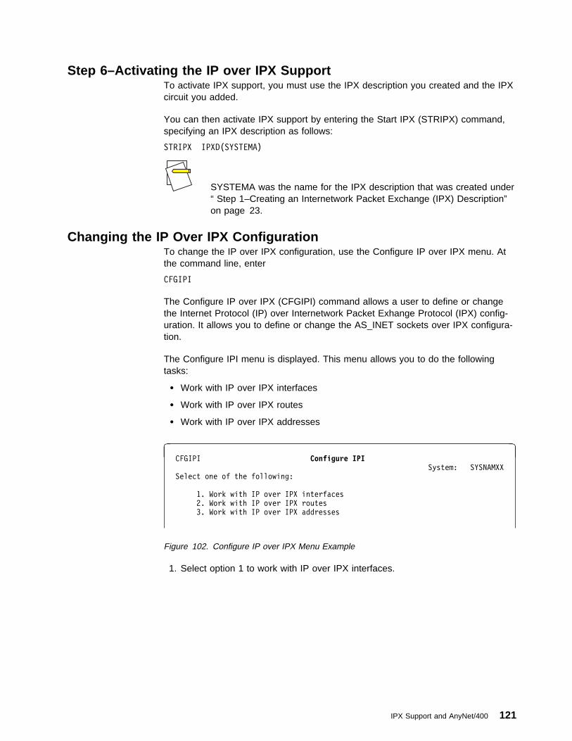
Step 6–Activating the IP over IPX SupportTo activate IPX support, you must use the IPX description you created and the IPXcircuit you added.
You can then activate IPX support by entering the Start IPX (STRIPX) command,specifying an IPX description as follows:
STRIPX IPXD(SYSTEMA)
SYSTEMA was the name for the IPX description that was created under“ Step 1–Creating an Internetwork Packet Exchange (IPX) Description”on page 23.
Changing the IP Over IPX ConfigurationTo change the IP over IPX configuration, use the Configure IP over IPX menu. Atthe command line, enter
CFGIPI
The Configure IP over IPX (CFGIPI) command allows a user to define or changethe Internet Protocol (IP) over Internetwork Packet Exhange Protocol (IPX) config-uration. It allows you to define or change the AS_INET sockets over IPX configura-tion.
The Configure IPI menu is displayed. This menu allows you to do the followingtasks:
� Work with IP over IPX interfaces
� Work with IP over IPX routes
� Work with IP over IPX addresses
à ð CFGIPI Configure IPI System: SYSNAMXX
Select one of the following:
1. Work with IP over IPX interfaces
2. Work with IP over IPX routes
3. Work with IP over IPX addresses
Figure 102. Configure IP over IPX Menu Example
1. Select option 1 to work with IP over IPX interfaces.
IPX Support and AnyNet/400 121
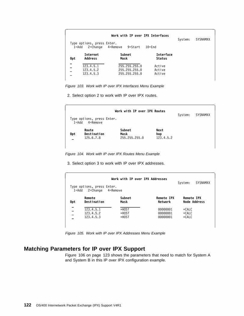
à ðWork with IP over IPX Interfaces
System: SYSNAMXX
Type options, press Enter.
1=Add 2=Change 4=Remove 9=Start 1ð=End
Internet Subnet Interface Opt Address Mask Status _ ____________ ____________
_ 123.4.5.1 255.255.255.ð Active
_ 123.4.5.2 255.255.255.ð Active
_ 123.4.5.3 255.255.255.ð Active
Figure 103. Work with IP over IPX Interfaces Menu Example
2. Select option 2 to work with IP over IPX routes.
à ðWork with IP over IPX Routes
System: SYSNAMXX
Type options, press Enter.
1=Add 4=Remove
Route Subnet Next Opt Destination Mask hop _ 125.6.7.8 255.255.255.ð 123.4.5.2
Figure 104. Work with IP over IPX Routes Menu Example
3. Select option 3 to work with IP over IPX addresses.
à ðWork with IP over IPX Addresses
System: SYSNAMXX
Type options, press Enter.
1=Add 2=Change 4=Remove
Remote Subnet Remote IPX Remote IPX Opt Destination Mask Network Node Address _ _______________ ___________
_ 123.4.5.1 \HOST ððððððð1 \CALC
_ 123.4.5.2 \HOST ððððððð1 \CALC
_ 123.4.5.3 \HOST ððððððð1 \CALC
Figure 105. Work with IP over IPX Addresses Menu Example
Matching Parameters for IP over IPX SupportFigure 106 on page 123 shows the parameters that need to match for System Aand System B in this IP over IPX configuration example.
122 OS/400 Internetwork Packet Exchange (IPX) Support V4R1

AS/4ðð System A: AS/4ðð System B:
Network Attributes Network Attributes
ALWANYNET \YES ALWANYNET \YES
IPX Description IPX Description
IPXD SYSTEMA IPXD SYSTEMB
IPXNETNBR ððððððð1 %──────┐ ┌───────5 IPXNETNBR ððððððð2
│ │
│ │
IP over IPX interface │ │ IP over IPX interface
INTNETADR 123.4.5.1 %────┐ │┌─┼───────5 INTNETADR 123.4.5.2
SUBNETMASK 255.255.255.ð └─┼┼─┼─┐ SUBNETMASK 255.255.255.ð
││ │ │
││ │ │
││ │ │
IP over IPX address ││ │ │ IP over IPX address
RMTDEST 123.4.5.2 %──────┼┘ │ └────5 RMTDEST 123.4.5.1
SUBNETMASK \HOST ┌───┼──┘ SUBNETMASK \HOST
RMTNETNBR ððððððð2 %──┘ └─────────5 RMTNETNBR ððððððð1
RMTNETADR \CALC RMTNETADR \CALC
Figure 106. IP over IPX Configuration Matching Parameter Example
IP over IPX Common Configuration ErrorsFor some common configuration errors, refer to “IP over IPX DebuggingCapabilities” on page 159.
APPC over IPX Configuration–OverviewTo configure SNA over IPX support, you need to do the following:
1. Create an IPX description, see “ Step 1–Creating an Internetwork PacketExchange (IPX) Description” on page 23.
2. Create a line description for IPX support, see “ Step 2–Configuring LineDescriptions for IPX Support–Ethernet” on page 30.
3. Add an IPX circuit, see “ Step 3–Adding an Internetwork Packet Exchange(IPX) Circuit” on page 35.
4. Create an APPC controller description with LINKTYPE(*ANYNW), see “Step2–Creating the APPC Controllers” on page 124.
5. Add a remote location list entry, see “ Step 3–Adding Remote Locations to theAPPN Remote Location Lists” on page 127.
6. Add a local Location list entry, see “ Step 4–Adding Local Locations to theAPPN Local Locations Lists” on page 129.
7. Add APPC over SNA location mappings, see “ Step 5–Adding APPC over IPXLocation Name Addressing Configuration” on page 131.
IPX Support and AnyNet/400 123
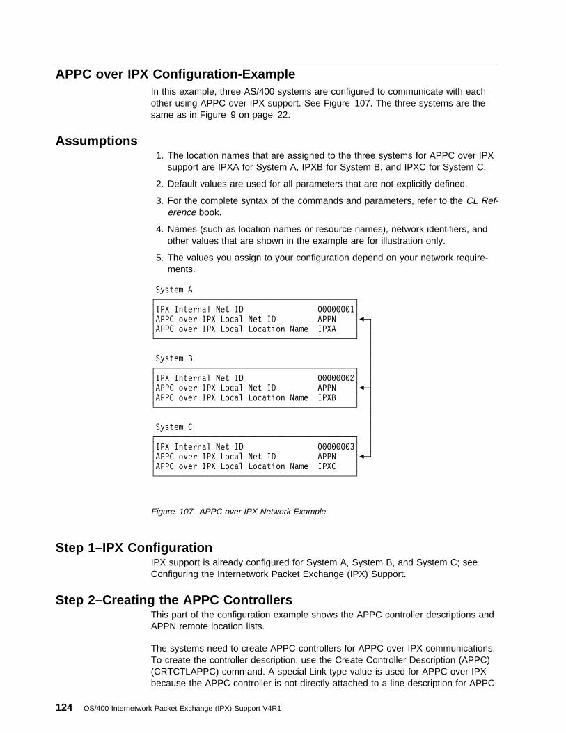
APPC over IPX Configuration-ExampleIn this example, three AS/400 systems are configured to communicate with eachother using APPC over IPX support. See Figure 107. The three systems are thesame as in Figure 9 on page 22.
Assumptions1. The location names that are assigned to the three systems for APPC over IPX
support are IPXA for System A, IPXB for System B, and IPXC for System C.
2. Default values are used for all parameters that are not explicitly defined.
3. For the complete syntax of the commands and parameters, refer to the CL Ref-erence book.
4. Names (such as location names or resource names), network identifiers, andother values that are shown in the example are for illustration only.
5. The values you assign to your configuration depend on your network require-ments.
System A
┌───────────────────────────────────────────┐
│IPX Internal Net ID ððððððð1│
│APPC over IPX Local Net ID APPN │%─┐
│APPC over IPX Local Location Name IPXA │ │
└───────────────────────────────────────────┘ │
│
System B │
┌───────────────────────────────────────────┐ │
│IPX Internal Net ID ððððððð2│ │
│APPC over IPX Local Net ID APPN │%─┤
│APPC over IPX Local Location Name IPXB │ │
└───────────────────────────────────────────┘ │
│
System C │
┌───────────────────────────────────────────┐ │
│IPX Internal Net ID ððððððð3│ │
│APPC over IPX Local Net ID APPN │%─┘
│APPC over IPX Local Location Name IPXC │
└───────────────────────────────────────────┘
Figure 107. APPC over IPX Network Example
Step 1–IPX ConfigurationIPX support is already configured for System A, System B, and System C; seeConfiguring the Internetwork Packet Exchange (IPX) Support.
Step 2–Creating the APPC ControllersThis part of the configuration example shows the APPC controller descriptions andAPPN remote location lists.
The systems need to create APPC controllers for APPC over IPX communications.To create the controller description, use the Create Controller Description (APPC)(CRTCTLAPPC) command. A special Link type value is used for APPC over IPXbecause the APPC controller is not directly attached to a line description for APPC
124 OS/400 Internetwork Packet Exchange (IPX) Support V4R1
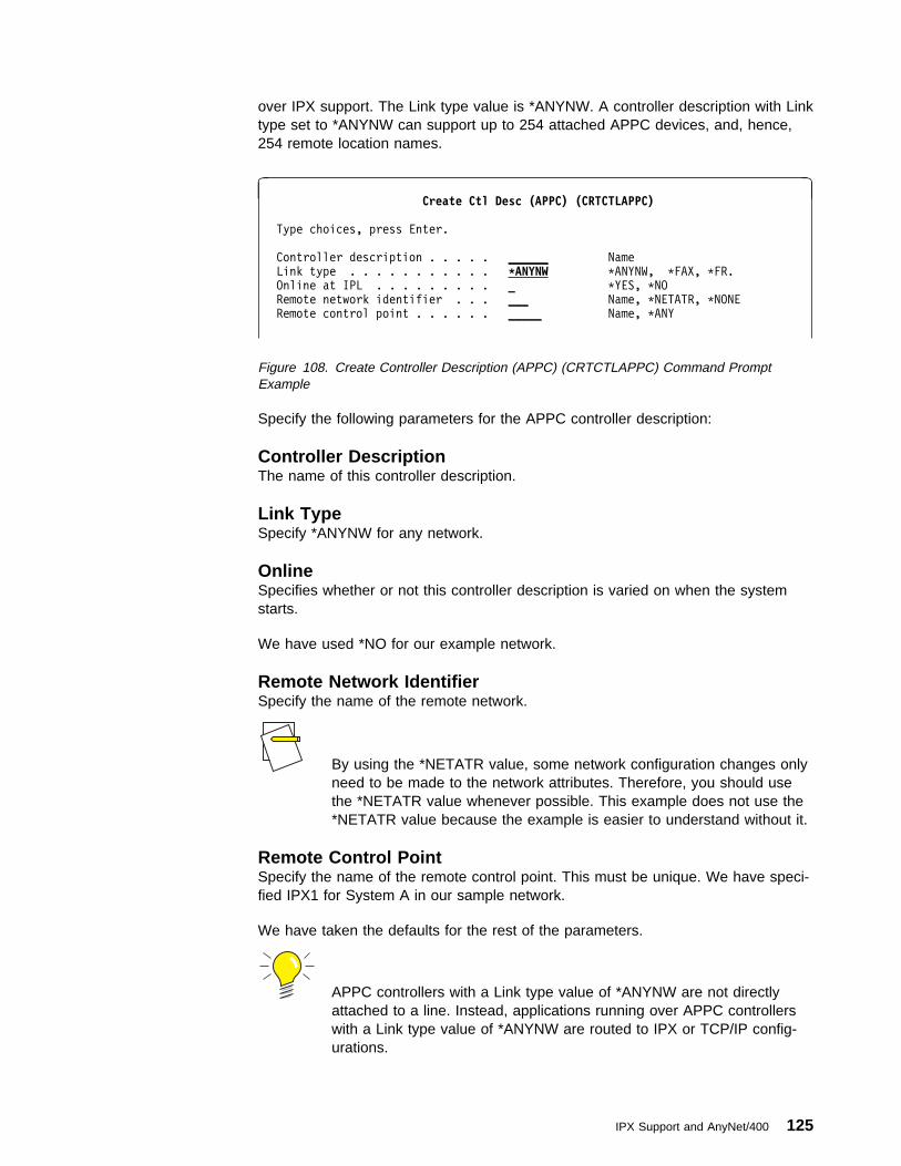
over IPX support. The Link type value is *ANYNW. A controller description with Linktype set to *ANYNW can support up to 254 attached APPC devices, and, hence,254 remote location names.
à ðCreate Ctl Desc (APPC) (CRTCTLAPPC)
Type choices, press Enter.
Controller description . . . . . ______ Name
Link type . . . . . . . . . . . \ANYNW \ANYNW, \FAX, \FR.
Online at IPL . . . . . . . . . _ \YES, \NO
Remote network identifier . . . ___ Name, \NETATR, \NONE
Remote control point . . . . . . _____ Name, \ANY
Figure 108. Create Controller Description (APPC) (CRTCTLAPPC) Command PromptExample
Specify the following parameters for the APPC controller description:
Controller DescriptionThe name of this controller description.
Link TypeSpecify *ANYNW for any network.
OnlineSpecifies whether or not this controller description is varied on when the systemstarts.
We have used *NO for our example network.
Remote Network IdentifierSpecify the name of the remote network.
By using the *NETATR value, some network configuration changes onlyneed to be made to the network attributes. Therefore, you should usethe *NETATR value whenever possible. This example does not use the*NETATR value because the example is easier to understand without it.
Remote Control PointSpecify the name of the remote control point. This must be unique. We have speci-fied IPX1 for System A in our sample network.
We have taken the defaults for the rest of the parameters.
APPC controllers with a Link type value of *ANYNW are not directlyattached to a line. Instead, applications running over APPC controllerswith a Link type value of *ANYNW are routed to IPX or TCP/IP config-urations.
IPX Support and AnyNet/400 125

Sample APPC Controller DescriptionsFigure 109, Figure 110, and Figure 111 shows the example controller descriptionsfor system A, B, and C.
à ðCreate Ctl Desc (APPC) (CRTCTLAPPC)
Type choices, press Enter.
Controller description . . . . . IPXCTLA Name
Link type . . . . . . . . . . . \ANYNW \ANYNW, \FAX, \FR.
Online at IPL . . . . . . . . . \NO \YES, \NO
Remote network identifier . . . APPN Name, \NETATR, \NONE
Remote control point . . . . . . IPX1 Name, \ANY
Figure 109. APPC Controller Display Example on AS/400 System A
à ðCreate Ctl Desc (APPC) (CRTCTLAPPC)
Type choices, press Enter.
Controller description . . . . . IPXCTLB Name
Link type . . . . . . . . . . . \ANYNW \ANYNW, \FAX, \FR.
Online at IPL . . . . . . . . . \NO \YES, \NO
Remote network identifier . . . APPN Name, \NETATR, \NONE
Remote control point . . . . . . IPX2 Name, \ANY
Figure 110. APPC Controller Example on AS/400 System B
à ðCreate Ctl Desc (APPC) (CRTCTLAPPC)
Type choices, press Enter.
Controller description . . . . . IPXCTLC Name
Link type . . . . . . . . . . . \ANYNW \ANYNW, \FAX, \FR.
Online at IPL . . . . . . . . . \NO \YES, \NO
Remote network identifier . . . APPN Name, \NETATR, \NONE
Remote control point . . . . . . IPX3 Name, \ANY
Figure 111. APPC Controller Display Example on AS/400 System C
These controllers can also be used as APPC controllers for TCP/IP net-works.
Creating the APPC Device and Mode DescriptionsThe system automatically creates APPC device descriptions as they are needed. Inthis example, the default mode description is used.
APPC over IPX support uses mode descriptions in the same way that APPC usesthem.
126 OS/400 Internetwork Packet Exchange (IPX) Support V4R1
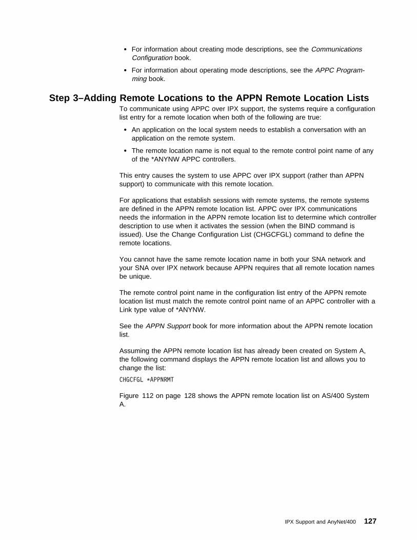
� For information about creating mode descriptions, see the CommunicationsConfiguration book.
� For information about operating mode descriptions, see the APPC Program-ming book.
Step 3–Adding Remote Locations to the APPN Remote Location ListsTo communicate using APPC over IPX support, the systems require a configurationlist entry for a remote location when both of the following are true:
� An application on the local system needs to establish a conversation with anapplication on the remote system.
� The remote location name is not equal to the remote control point name of anyof the *ANYNW APPC controllers.
This entry causes the system to use APPC over IPX support (rather than APPNsupport) to communicate with this remote location.
For applications that establish sessions with remote systems, the remote systemsare defined in the APPN remote location list. APPC over IPX communicationsneeds the information in the APPN remote location list to determine which controllerdescription to use when it activates the session (when the BIND command isissued). Use the Change Configuration List (CHGCFGL) command to define theremote locations.
You cannot have the same remote location name in both your SNA network andyour SNA over IPX network because APPN requires that all remote location namesbe unique.
The remote control point name in the configuration list entry of the APPN remotelocation list must match the remote control point name of an APPC controller with aLink type value of *ANYNW.
See the APPN Support book for more information about the APPN remote locationlist.
Assuming the APPN remote location list has already been created on System A,the following command displays the APPN remote location list and allows you tochange the list:
CHGCFGL \APPNRMT
Figure 112 on page 128 shows the APPN remote location list on AS/400 SystemA.
IPX Support and AnyNet/400 127
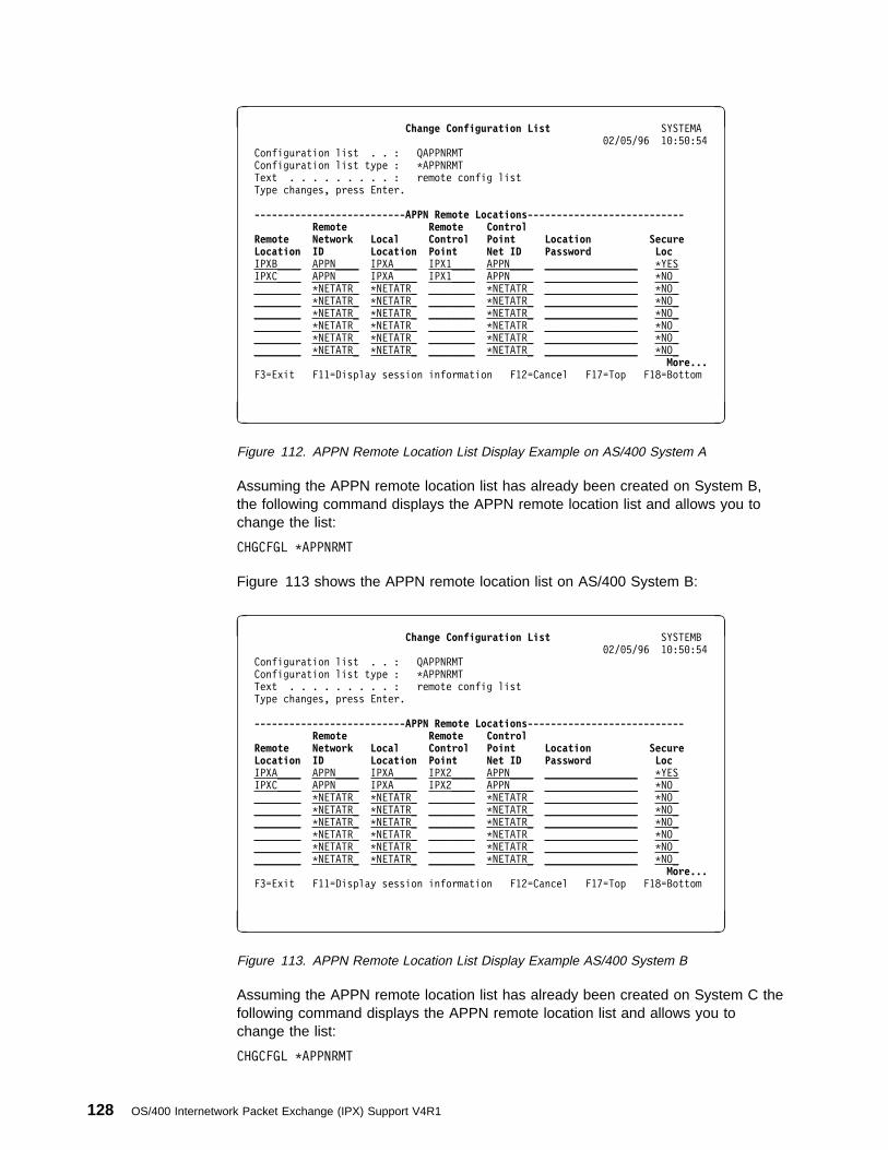
à ðChange Configuration List SYSTEMA
ð2/ð5/96 1ð:5ð:54
Configuration list . . : QAPPNRMT
Configuration list type : \APPNRMT
Text . . . . . . . . . : remote config list
Type changes, press Enter.
--------------------------APPN Remote Locations--------------------------- Remote Remote Control Remote Network Local Control Point Location Secure Location ID Location Point Net ID Password Loc
IPXB____ APPN____ IPXA____ IPX1____ APPN____ ________________ \YES
IPXC____ APPN____ IPXA____ IPX1____ APPN____ ________________ \NO_
________ \NETATR_ \NETATR_ ________ \NETATR_ ________________ \NO_
________ \NETATR_ \NETATR_ ________ \NETATR_ ________________ \NO_
________ \NETATR_ \NETATR_ ________ \NETATR_ ________________ \NO_
________ \NETATR_ \NETATR_ ________ \NETATR_ ________________ \NO_
________ \NETATR_ \NETATR_ ________ \NETATR_ ________________ \NO_
________ \NETATR_ \NETATR_ ________ \NETATR_ ________________ \NO_
More... F3=Exit F11=Display session information F12=Cancel F17=Top F18=Bottom
á ñ
Figure 112. APPN Remote Location List Display Example on AS/400 System A
Assuming the APPN remote location list has already been created on System B,the following command displays the APPN remote location list and allows you tochange the list:
CHGCFGL \APPNRMT
Figure 113 shows the APPN remote location list on AS/400 System B:
à ðChange Configuration List SYSTEMB
ð2/ð5/96 1ð:5ð:54
Configuration list . . : QAPPNRMT
Configuration list type : \APPNRMT
Text . . . . . . . . . : remote config list
Type changes, press Enter.
--------------------------APPN Remote Locations--------------------------- Remote Remote Control Remote Network Local Control Point Location Secure Location ID Location Point Net ID Password Loc
IPXA____ APPN____ IPXA____ IPX2____ APPN____ ________________ \YES
IPXC____ APPN____ IPXA____ IPX2____ APPN____ ________________ \NO_
________ \NETATR_ \NETATR_ ________ \NETATR_ ________________ \NO_
________ \NETATR_ \NETATR_ ________ \NETATR_ ________________ \NO_
________ \NETATR_ \NETATR_ ________ \NETATR_ ________________ \NO_
________ \NETATR_ \NETATR_ ________ \NETATR_ ________________ \NO_
________ \NETATR_ \NETATR_ ________ \NETATR_ ________________ \NO_
________ \NETATR_ \NETATR_ ________ \NETATR_ ________________ \NO_
More... F3=Exit F11=Display session information F12=Cancel F17=Top F18=Bottom
á ñ
Figure 113. APPN Remote Location List Display Example AS/400 System B
Assuming the APPN remote location list has already been created on System C thefollowing command displays the APPN remote location list and allows you tochange the list:
CHGCFGL \APPNRMT
128 OS/400 Internetwork Packet Exchange (IPX) Support V4R1

Figure 114 on page 129 shows the APPN remote location list on AS/400 SystemC:
à ðChange Configuration List SYSTEMC
ð2/ð5/96 1ð:5ð:54
Configuration list . . : QAPPNRMT
Configuration list type : \APPNRMT
Text . . . . . . . . . : remote config list
Type changes, press Enter.
--------------------------APPN Remote Locations--------------------------- Remote Remote Control Remote Network Local Control Point Location Secure Location ID Location Point Net ID Password Loc
IPXA____ APPN____ IPX3____ IPX3____ APPN____ ________________ \YES
IPXB____ APPN____ IPX3____ IPX3____ APPN____ ________________ \NO_
________ \NETATR_ \NETATR_ ________ \NETATR_ ________________ \NO_
________ \NETATR_ \NETATR_ ________ \NETATR_ ________________ \NO_
________ \NETATR_ \NETATR_ ________ \NETATR_ ________________ \NO_
________ \NETATR_ \NETATR_ ________ \NETATR_ ________________ \NO_
________ \NETATR_ \NETATR_ ________ \NETATR_ ________________ \NO_
________ \NETATR_ \NETATR_ ________ \NETATR_ ________________ \NO_
More... F3=Exit F11=Display session information F12=Cancel F17=Top F18=Bottom
á ñ
Figure 114. APPN Remote Location List Display Example on AS/400 System C
Step 4–Adding Local Locations to the APPN Local Locations ListsFor APPC over IPX support, you have to have a unique local location name. Thedefault local location name is defined in the network attributes. If the default locallocation name is going to be used for AS/400 SNA or SNA over TCP/IP, then youmust define a unique local location name in the APPN local location list for use byAPPC over IPX support.
See the APPN Support book for more information about the APPN local locationlist.
Assuming the APPN local location list has already been created on System A, thefollowing command displays the APPN local location list and allows you to changethe list:
CHGCFGL \APPNLCL
Figure 115 on page 130 shows the APPN local location list on AS/400 System A.
IPX Support and AnyNet/400 129
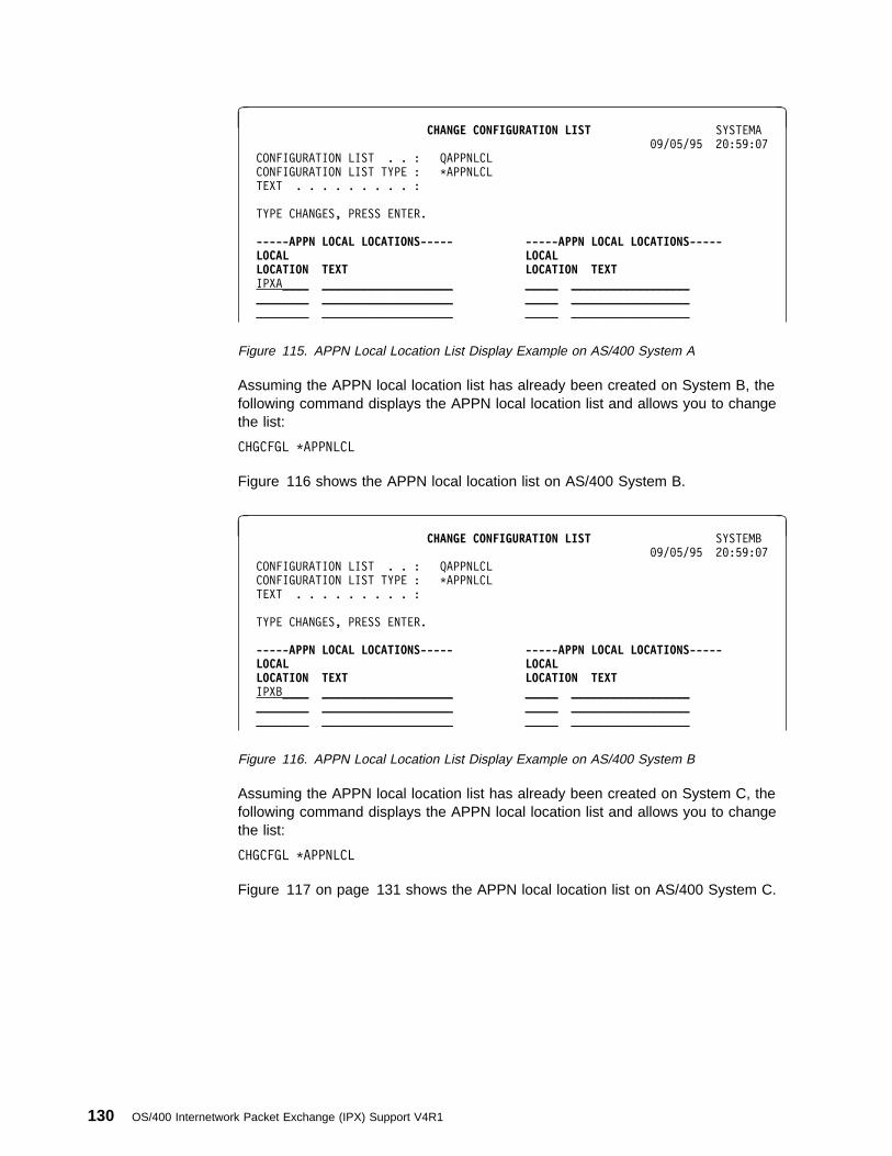
à ðCHANGE CONFIGURATION LIST SYSTEMA
ð9/ð5/95 2ð:59:ð7
CONFIGURATION LIST . . : QAPPNLCL
CONFIGURATION LIST TYPE : \APPNLCL
TEXT . . . . . . . . . :
TYPE CHANGES, PRESS ENTER.
-----APPN LOCAL LOCATIONS----- -----APPN LOCAL LOCATIONS----- LOCAL LOCAL LOCATION TEXT LOCATION TEXT IPXA____ ____________________ _____ __________________
________ ____________________ _____ __________________
________ ____________________ _____ __________________
Figure 115. APPN Local Location List Display Example on AS/400 System A
Assuming the APPN local location list has already been created on System B, thefollowing command displays the APPN local location list and allows you to changethe list:
CHGCFGL \APPNLCL
Figure 116 shows the APPN local location list on AS/400 System B.
à ðCHANGE CONFIGURATION LIST SYSTEMB
ð9/ð5/95 2ð:59:ð7
CONFIGURATION LIST . . : QAPPNLCL
CONFIGURATION LIST TYPE : \APPNLCL
TEXT . . . . . . . . . :
TYPE CHANGES, PRESS ENTER.
-----APPN LOCAL LOCATIONS----- -----APPN LOCAL LOCATIONS----- LOCAL LOCAL LOCATION TEXT LOCATION TEXT IPXB____ ____________________ _____ __________________
________ ____________________ _____ __________________
________ ____________________ _____ __________________
Figure 116. APPN Local Location List Display Example on AS/400 System B
Assuming the APPN local location list has already been created on System C, thefollowing command displays the APPN local location list and allows you to changethe list:
CHGCFGL \APPNLCL
Figure 117 on page 131 shows the APPN local location list on AS/400 System C.
130 OS/400 Internetwork Packet Exchange (IPX) Support V4R1
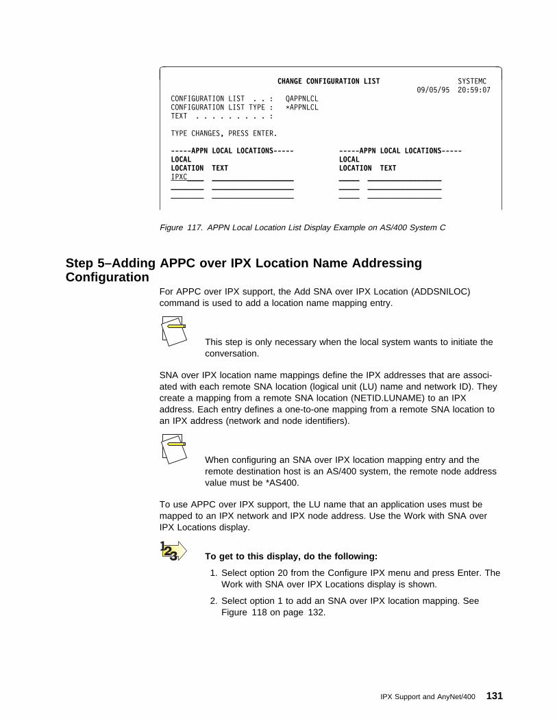
à ðCHANGE CONFIGURATION LIST SYSTEMC
ð9/ð5/95 2ð:59:ð7
CONFIGURATION LIST . . : QAPPNLCL
CONFIGURATION LIST TYPE : \APPNLCL
TEXT . . . . . . . . . :
TYPE CHANGES, PRESS ENTER.
-----APPN LOCAL LOCATIONS----- -----APPN LOCAL LOCATIONS----- LOCAL LOCAL LOCATION TEXT LOCATION TEXT IPXC____ ____________________ _____ __________________
________ ____________________ _____ __________________
________ ____________________ _____ __________________
Figure 117. APPN Local Location List Display Example on AS/400 System C
Step 5–Adding APPC over IPX Location Name AddressingConfiguration
For APPC over IPX support, the Add SNA over IPX Location (ADDSNILOC)command is used to add a location name mapping entry.
This step is only necessary when the local system wants to initiate theconversation.
SNA over IPX location name mappings define the IPX addresses that are associ-ated with each remote SNA location (logical unit (LU) name and network ID). Theycreate a mapping from a remote SNA location (NETID.LUNAME) to an IPXaddress. Each entry defines a one-to-one mapping from a remote SNA location toan IPX address (network and node identifiers).
When configuring an SNA over IPX location mapping entry and theremote destination host is an AS/400 system, the remote node addressvalue must be *AS400.
To use APPC over IPX support, the LU name that an application uses must bemapped to an IPX network and IPX node address. Use the Work with SNA overIPX Locations display.
To get to this display, do the following:
1. Select option 20 from the Configure IPX menu and press Enter. TheWork with SNA over IPX Locations display is shown.
2. Select option 1 to add an SNA over IPX location mapping. SeeFigure 118 on page 132.
IPX Support and AnyNet/400 131

à ðWork with SNA over IPX Locations
System: SYSTEMA
Type options, press Enter.
1=Add 2=Change 4=Remove
Remote SNA Remote SNA Network Remote IPX Remote IPX Opt Location Name Identifier Network Node Address 1
(No location entries)
Figure 118. Work with SNA over IPX Locations Display Example
3. Press the Enter key. The Add SNA over IPX Location (ADDSNILOC)command prompter display is shown. See Figure 119.
You are prompted for the following information.
à ðAdd SNA over IPX Location (ADDSNILOC)
Type choices, press Enter.
Remote location . . . . . . . . ____ Name
Remote network identifier . . . ____ Name, \NETATR
Remote IPX network number . . . ____ ððððððð1-FFFFFFFD
Remote IPX node address . . . . ____ ððððððð1-FFFFFFFFFFFE...
Figure 119. Add SNA over IPX Location Command Prompt Example
The required parameters for SNA over IPX locations are as follows:
Remote Location NameSpecifies the remote location name to be associated with a specific remote IPXnetwork number and remote IPX node address.
Specify an 8-character SNA remote location name for the remote host.
Remote Network IdentifierSpecifies the SNA remote network identifier to be associated with a specific remoteIPX network number and remote IPX node address.
*NETATR specifies that the network identifier in the network attributes for this hostis used, or you specify an 8-character SNA network identifier for the remote host.
Remote Network NumberSpecifies the remote IPX network to be associated with this SNA remote locationname and remote network identifier. This network number usually is the IPXinternal network number of the remote system.
Specify an 8-character IPX network number. Valid values range from 00000001through FFFFFFFD.
132 OS/400 Internetwork Packet Exchange (IPX) Support V4R1

Remote Node AddressSpecifies the remote IPX node address to be associated with this SNA remotelocation name and remote network identifier.
When configuring an SNA over IPX location mapping entry and theremote destination host is an AS/400, the remote IPX node addressvalue must be equal to *AS400.
Specify a 12-character IPX node address. Valid values range from 000000000001through FFFFFFFFFFFE.
Sample SNA over IPX Location EntriesFigure 120 shows the example SNA over IPX location mapping entry for System A.
à ðAdd SNA over IPX Location (ADDSNILOC)
Type choices, press Enter.
Remote location . . . . . . . . IPXA Name
Remote network identifier . . . APPN Name, \NETATR
Remote IPX network number . . . ððððððð1 ððððððð1-FFFFFFFD
Remote IPX node address . . . . \AS4ðð ððððððð1-FFFFFFFFFFFE...
Figure 120. Add SNA over IPX Locations Command Prompt Example
The Work with SNA over IPX Locations display shows the location mappings thatwere successfully added. See Figure 121.
à ðWork with SNA over IPX Locations
System: SYSTEMA
Type options, press Enter.
1=Add 2=Change 4=Remove
Remote SNA Remote SNA Network Remote IPX Remote IPX Opt Location Name Identifier Network Node Address
IPXA APPN ððððððð1 \AS4ðð
IPXB APPN ððððððð2 \AS4ðð
IPXC APPN ððððððð3 \AS4ðð
Figure 121. Successfully added SNA over IPX Locations Example
CL Commands for the APPC over IPX LocationsOn all the systems, the following commands add the APPC over IPX location map-pings of the System A, System B, and System C.
IPX Support and AnyNet/400 133

ADDSNILOC RMTLOCNAME(IPXA) RMTNETID(\APPN) +
RMTNETNBR(ððððððð1) RMTNDEADR(\AS4ðð)
ADDSNILOC RMTLOCNAME(IPXB) RMTNETID(\APPN) +
RMTNETNBR(ððððððð2) RMTNDEADR(\AS4ðð)
ADDSNILOC RMTLOCNAME(IPXC) RMTNETID(\APPN) +
RMTNETNBR(ððððððð3) RMTNDEADR(\AS4ðð)
The same configuration can be used on the other two systems.
The mapping for the local system (IPXA on System A) is ignored andwill not cause any problems.
Step 6–Allow AnyNet/400 SupportTo communicate using APPC over IPX support, the systems must allowAnyNet/400 support and IPX support must be active. To allow AnyNet/400 support,the allow AnyNet support (ALWANYNET) network attribute must be *YES.
Specify *YES for the allow AnyNet support (ALWANYNET) network attribute usingthe Change Network Attribute (CHGNETA) CL command. The system looks for LUnames in the IPX location address mapping information only if ALWANYNET is*YES.
Specifying ALWANYNET(*YES) enables and allows all AnyNet/400*support. In other words, this network attribute affects not only APPCover IPX support but also TCP/IP over SNA support, APPC over TCP/IPsupport, and TCP/IP over IPX support.
The following command, issued on all three systems, ensures that the systemsallow the use of AnyNet/400 support, which includes APPC over IPX support.
CHGNETA ALWANYNET(\YES)
The CL Reference has more information about the CHGNETA command.
Step 7–Activating APPC over IPX SupportTo activate IPX support, you must have previously created an IPX description andIPX circuit.
You can then activate IPX support by entering the Start IPX (STRIPX) commandspecifying an IPX description as follows:
STRIPX IPXD(SYSTEMA)
This IPX description was configuration in “ Step 1–Creating an Internet-work Packet Exchange (IPX) Description” on page 23.
134 OS/400 Internetwork Packet Exchange (IPX) Support V4R1
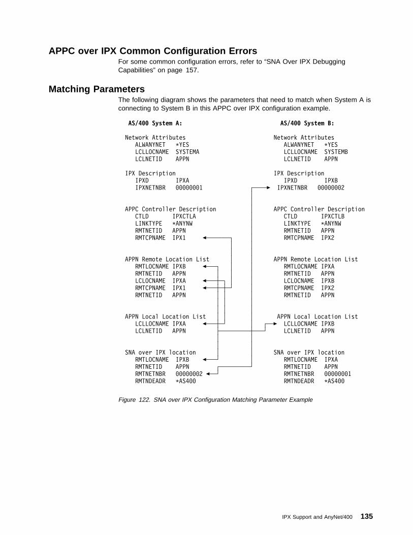
APPC over IPX Common Configuration ErrorsFor some common configuration errors, refer to “SNA Over IPX DebuggingCapabilities” on page 157.
Matching ParametersThe following diagram shows the parameters that need to match when System A isconnecting to System B in this APPC over IPX configuration example.
AS/4ðð System A: AS/4ðð System B:
Network Attributes Network Attributes
ALWANYNET \YES ALWANYNET \YES
LCLLOCNAME SYSTEMA LCLLOCNAME SYSTEMB
LCLNETID APPN LCLNETID APPN
IPX Description IPX Description
IPXD IPXA IPXD IPXB
IPXNETNBR ððððððð1 ┌────5 IPXNETNBR ððððððð2
│
│
APPC Controller Description │ APPC Controller Description
CTLD IPXCTLA │ CTLD IPXCTLB
LINKTYPE \ANYNW │ LINKTYPE \ANYNW
RMTNETID APPN │ RMTNETID APPN
RMTCPNAME IPX1 %───────┐ │ RMTCPNAME IPX2
│ │
│ │
APPN Remote Location List │ │ APPN Remote Location List
RMTLOCNAME IPXB %───┐ │ │ RMTLOCNAME IPXA
RMTNETID APPN │ │ │ RMTNETID APPN
LCLOCNAME IPXA %───┼─┐ │ │ LCLOCNAME IPXB
RMTCPNAME IPX1 %───┼─┼─┘ │ RMTCPNAME IPX2
RMTNETID APPN │ │ │ RMTNETID APPN
│ │ │
│ │ │
APPN Local Location List │ │ │ APPN Local Location List
LCLLOCNAME IPXA %───┼─┘ │ ┌──5 LCLLOCNAME IPXB
LCLNETID APPN ├─────────┼───┘ LCLNETID APPN
│ │
│ │
SNA over IPX location │ │ SNA over IPX location
RMTLOCNAME IPXB %───┘ │ RMTLOCNAME IPXA
RMTNETID APPN ┌─────────┘ RMTNETID APPN
RMTNETNBR ððððððð2 %──┘ RMTNETNBR ððððððð1
RMTNDEADR \AS4ðð RMTNDEADR \AS4ðð
Figure 122. SNA over IPX Configuration Matching Parameter Example
IPX Support and AnyNet/400 135

136 OS/400 Internetwork Packet Exchange (IPX) Support V4R1

Appendix A. CL Program for the IPX Configuration Example
The following CL commands can define the sample network in Configuring theInternetwork Packet Exchange (IPX) Support.
/\ System A: AS/4ðð \/
/\ IPX Description \/
CRTIPXD IPXD(SYSTEMA) IPXNETNBR(ððððððð1) +
TEXT('IPXD for System A')
/\ Ethernet Line \/
CRTLINETH LIND(AETHLINE) RSRCNAME(CMN181) +
ADPTADR(\ADPT) ETHSTD(\ALL) +
SSAP(\SYSGEN) +
TEXT('Ethernet Line for System A')
/\ IPX Circuit \/
ADDIPXCCT CCTNAME(CCT1A) LIND(AETHLINE) IPXNETNBR(2FFFFFFF) +
FRAMETYPE(\SSAP)
/\ System B: AS/4ðð \/
/\ IPX Description \/
CRTIPXD IPXD(SYSTEMB) IPXNETNBR(ððððððð2) +
TEXT('IPXD for System B')
/\ Ethernet Line Description \/
CRTLINETH LIND(BETHLINE) RSRCNAME(CMN181) +
ADPTADR(\ADPT) ETHSTD(\ALL) +
SSAP(\SYSGEN) +
TEXT('Ethernet Line for System B')
/\ IPX Circuit Definition \/
ADDIPXCCT CCTNAME(CCT1B) LIND(BETHLINE) IPXNETNBR(2FFFFFFF) +
FRAMETYPE(\SSAP)
/\ System C: AS/4ðð \/
/\ IPX Description \/
CRTIPXD IPXD(SYSTEMC) IPXNETNBR(ððððððð3) +
TEXT('IPXD for System C')
/\ Ethernet Line Description \/
CRTLINETH LIND(CETHLINE) RSRCNAME(CMN181) +
ADPTADR(\ADPT) ETHSTD(\ALL) +
SSAP(\SYSGEN) +
TEXT('Ethernet Line for System C')
/\ X.25 Line Description \/
CRTLINX25 LIND(CX25LINE) RSRCNAME(CMNð51)
LGLCHLE((ðð2 \SVCBOTH)) NETADR(ðððððð999) +
CNNINIT(\LOCAL) ONLINE(\YES) INTERFACE(\X21BISV24) +
CNN(\NONSWTPP) EXNNETADR(\NO) X25DCE(\NO) +
TEXT('X25 Line for System C')
/\ X.25 IPX Circuits \/
ADDIPXCCT CCTNAME(CCT1C) LIND(CETHLINE) IPXNETNBR(2FFFFFFF) +
FRAMETYPE(\SSAP)
ADDIPXCCT CCTNAME(CCT2C) LIND(CX25LINE) SVCNETADR('ððððð9994') +
RIPSTATE(\OFF) SAPSTATE(\OFF)
/\ Circuit Route Entries \/
ADDCCTRTE CCTNAME(CCT2C) RMTNETNBR(ððððððð4) +
NBRHOP(1) NBRTICK(1ð)
ADDCCTRTE CCTNAME(CCT2C) RMTNETNBR(ððððððð5) +
NBRHOP(2) NBRTICK(12)
ADDCCTRTE CCTNAME(CCT2C) RMTNETNBR(ððððððð6) +
Copyright IBM Corp. 1997 137
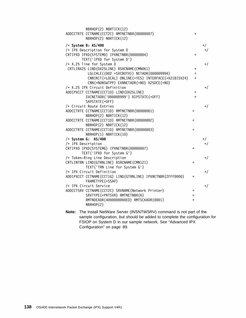
NBRHOP(2) NBRTICK(12)
ADDCCTRTE CCTNAME(CCT2C) RMTNETNBR(ððððððð7) +
NBRHOP(2) NBRTICK(12)
/\ System D: AS/4ðð \/
/\ IPX Description for System D \/
CRTIPXD IPXD(SYSTEMD) IPXNETNBR(ððððððð4) +
TEXT('IPXD for System D')
/\ X.25 line for System D \/
CRTLINX25 LIND(DX25LINE) RSRCNAME(CMNð61) +
LGLCHLE((ðð2 \SVCBOTH)) NETADR(ððððð9994) +
CNNINIT(\LOCAL) ONLINE(\YES) INTERFACE(\X21BISV24) +
CNN(\NONSWTPP) EXNNETADR(\NO) X25DCE(\NO)
/\ X.25 IPX Circuit Definition \/
ADDIPXCCT CCTNAME(CCT1D) LIND(DX25LINE) +
SVCNETADR('ðððððð999') RIPSTATE(\OFF) +
SAPSTATE(\OFF)
/\ Circuit Route Entries \/
ADDCCTRTE CCTNAME(CCT1D) RMTNETNBR(ððððððð1) +
NBRHOP(2) NBRTICK(12)
ADDCCTRTE CCTNAME(CCT1D) RMTNETNBR(ððððððð2) +
NBRHOP(2) NBRTICK(12)
ADDCCTRTE CCTNAME(CCT1D) RMTNETNBR(ððððððð3) +
NBRHOP(1) NBRTICK(1ð)
/\ System G: AS/4ðð \/
/\ IPX Description \/
CRTIPXD IPXD(SYSTEMG) IPXNETNBR(ððððððð7) +
TEXT('IPXD for System G')
/\ Token-Ring Line Description \/
CRTLINTRN LIND(GTRNLINE) RSRCNAME(CMN121) +
TEXT('TRN Line for System G')
/\ IPX Circuit Definition \/
ADDIPXCCT CCTNAME(CCT1G) LIND(GTRNLINE) IPXNETNBR(2FFFðððð) +
FRAMETYPE(\SSAP)
/\ IPX Circuit Service \/
ADDCCTSRV CCTNAME(CCT2C) SRVNAME(Network Printer) +
SRVTYPE(\PRTSVR) RMTNETNBR(6) +
RMTNDEADR(4ðððððððððED) RMTSCKADR(ððð1) +
NBRHOP(2)
Note: The Install NetWare Server (INSNTWSRV) command is not part of thesample configuration, but should be added to complete the configuration forFSIOP on System D in our sample network. See “Advanced IPXConfiguration” on page 89.
138 OS/400 Internetwork Packet Exchange (IPX) Support V4R1
Appendix B. Database Files Used by IPX Support
Saving and Restoring Configuration Files . . . . . . . . . . . . . . . . . . . . . 139Displaying Configuration Files . . . . . . . . . . . . . . . . . . . . . . . . . . . 140IPX Database Files for OS/400 . . . . . . . . . . . . . . . . . . . . . . . . . . . 140
File QAZSPPADR (IP over IPX Addresses) . . . . . . . . . . . . . . . . . . 141File QAZSPPLOC (SNA over IPX Locations) . . . . . . . . . . . . . . . . . 141File QAZSPPCCT (IPX Circuits) . . . . . . . . . . . . . . . . . . . . . . . . . 142File QAZSPPRTE (IPX Routes) . . . . . . . . . . . . . . . . . . . . . . . . . 143File QAZSPPSRV (IPX Circuit Services) . . . . . . . . . . . . . . . . . . . . 143
The configuration data that is associated with IPX support is stored in a set of data-base files. These database files are found in the QUSRSYS library. As a user, youshould never need to change or manipulate these files. The information that isgiven is only for your information and can be used to assist in problem analysis.Any time you make configuration changes using the Configure IPX menu options 1,10, 11, 12, 20, or the CL commands associated with these options, the configura-tion database files are updated to reflect these changes. All the configurationchanges that are made with the previous options, except for option 20, take effectimmediately in the protocol stack if IPX support is active.
Each of the configuration functions stores its data in a separate keyed physical filein the QUSRSYS library. Keyed access for physical and logical files is used, whererequired, to access the data. For example, the circuits configuration data is storedin a file that is called QAZSPPCCT, member CIRCUITS.
Other database files and members are used for work areas or for storing informa-tion.
Saving and Restoring Configuration FilesYou should save and restore all IPX configuration files as a group. Many logicalfiles are defined; their names are:
Saving just the physical files and then restoring them will cause problems. Thelogical files used by different functions to access the data stored in the physicalfiles will point to a renamed physical file if just a physical file is restored. Therestore database functions have created the renamed physical file to maintain theindexes to the logical files. Another reason to save and restore the configurationfiles as a group is that there are some dependencies between some of the files.Saving and restoring just a subset of the files could cause problems especiallywhen activating IPX processing.
One way to save all IPX files is to enter the following command:
QAZSPLADR QUSRSYS System-supplied IP over IPX address file that isdefined on QAZSPPADR physical file
QAZSPLCCT QUSRSYS System-supplied IPX circuit logical file that isdefined on QAZSPPCCT physical file
QAZSPLRTE QUSRSYS System-supplied IPX route logical file that isdefined on QAZSPPRTE physical file
QAZSPLSRV QUSRSYS System-supplied IPX service logical file that isdefined on QAZSPPSRV physical file
Copyright IBM Corp. 1997 139
SAVOBJ OBJ(QAZSP\) LIB(QUSRSYS)
DEV(your-device) OBJTYPE(\FILE)
One way to restore all IPX files is to enter the following command:
RSTOBJ OBJ(QAZSP\) SAVLIB(QUSRSYS)
DEV(your-device) OBJTYPE(\FILE)
If you restore previous released versions of any of the IPX configurationfiles, you must reinstall the QUSRSYS and QGPL libraries for the oper-ating system release level of your AS/400. This ensures that the installexit file conversion programs are run against the IPX configuration files.
If you plan to scratch install your AS/400 and save your current IPX con-figuration, do the following steps:
1. Save the IPX configuration files
2. Scratch install your AS/400
3. Delete all QAZSP* files in QUSRSYS
4. Restore the IPX configuration files
5. Reinstall QUSRSYS and QGPL libraries
Displaying Configuration FilesTo display these files, use the Work with Members Using PDM (WRKMBRPDM)command and specify QUSRSYS/xxx for the FILE parameter:
WRKMBRPDM FILE(QUSRSYS/xxx)
where xxx is the name of an IPX file. You are shown the members that are con-tained in the file. Use option 5 (Display) to see the contents of the file member.
You can also use the Display Physical File Member (DSPPFM) command to showthe contents of a member in a file.
IPX Database Files for OS/400The physical database files and members that define the IPX protocol stack config-uration are listed in Table 9 and the member formats are described in subsequenttables. In addition, logical files that correspond to the physical files are used toaccess configuration data (when required). The logical files are not listed.
Table 9 (Page 1 of 2). Physical Database Files and Record Lengths
Library/File.member DescriptionRecordlength
QUSRSYS/QAZSPPADR.ADDRESSES, see “File QAZSPPADR(IP over IPX Addresses)” on page 141
IP over IPX address mappingconfiguration data
128
QUSRSYS/QAZSPPLOC.LOCATIONS, see “File QAZSPPLOC(SNA over IPX Locations)” on page 141
SNA over IPX locations con-figuration data
64
140 OS/400 Internetwork Packet Exchange (IPX) Support V4R1

Table 9 (Page 2 of 2). Physical Database Files and Record Lengths
Library/File.member DescriptionRecordlength
QUSRSYS/QAZSPPCCT.CIRCUITS, see “File QAZSPPCCT (IPXCircuits)” on page 142
IPX circuit configuration data 528
QUSRSYS/QAZSPPRTE.ROUTES, see “File QAZSPPRTE (IPXRoutes)” on page 143
IPX circuit route configurationdata
256
QUSRSYS/QAZSPPSRV.SERVICES, see “File QAZSPPSRV(IPX Circuit Services)” on page 143
IPX circuit service configura-tion data
256
QUSRSYS/QATOCIFC.INTERFACES, see the TCP/IP Configura-tion and Reference book.
IP over IPX interface config-uration data
512
QUSRSYS/QATOCRTE.ROUTES, see the TCP/IP Configurationand Reference book.
IP over IPX route configura-tion data
256
File QAZSPPADR (IP over IPX Addresses)Table 10. QAZSPPADR Member Format (IP over IPX Address Mapping ConfigurationData)
Field StartingColumn
Length Allowed Values
INTNETADR 1 15 Internet Address
BININTNET 16 4 Binary Internet Address
SUBNETMASK 20 15 Subnet Mask
BINSUBNET 35 4 Subnet Mask in Binary
IPXNETNBR 39 4 Remote IPX Network Number
IPXNODEADR 43 6 IPX Node Address
Reserved 49 80 Reserved for future use
Total Length 128
File QAZSPPLOC (SNA over IPX Locations)Table 11. QAZSPPLOC Member Format (SNA over IPX Location Name Mapping Con-figuration Data)
Field StartingColumn
Length Allowed Values
RMTLOCNAME 1 8 Remote Location Name
RMTNETID 9 8 Remote SNA Network Identifier
IPXNETNBR 17 4 Remote IPX Network Number
IPXNODEADR 21 6 Remote IPX Node Address
Reserved 27 38 Reserved for future use
Total Length 64
Appendix B. Database Files Used by IPX Support 141

File QAZSPPCCT (IPX Circuits)Table 12. QAZSPPCCT Member Format (IPX Circuit Configuration Data)
Field StartingColumn
Length Allowed Values
CIRCUITNME 1 48 Circuit Name
CIRCUIT_ID 49 4 Circuit ID
LIND 53 10 Line Description
NETNBR 63 4 Network Number
NETNBR_C 67 8 Network Number in Character
FRAMETYPE 75 1 Frame Type
DFTMAXDTG 76 4 Default Maximum Datagram
THROUGHPUT 80 4 Throughput
DELAY 84 4 Delay
AUTOSTART 88 1 Automatic Start
PVC 89 3 PVC Channel ID
SVCNETADR 92 17 SVC Network Address
SVCTYPE 109 1 SVC Call Type
SVCRVSCRG 110 1 SVC Reverse Charge
IDLVCTIMO 111 2 IDLVCTIMO in Binary Format
RCVPKTSIZE 113 4 Receive Packet Size
TRNPKTSIZE 117 4 Transmit Packet Size
RCVWDWSIZE 121 4 Receive Window Size
TRNWDWSIZE 125 4 Transmit Window Size
NLSP 129 1 Enabled for NLSP
MACCHLNLSP 130 1 MAC Channel for NLSP
RTRPTYNLSP 131 2 Router Priority
CSTOVRNLSP 133 2 Cost Override NLSP
IW2 135 1 Enable for IW2
RIPSTATE 136 1 RIP State
RIPUPDITV 137 4 RIP Update Interval
RIPAGEMLT 141 4 RIP Age Multiplier
SAPSTATE 145 1 SAP State
SAPUPDITV 146 4 SAP Update Interval
SAPAGEMLT 150 4 SAP Age Multiplier
FSIOP 154 1 FSIOP Circuit
IW2TMRRTY 155 2 IW2 Timer Request Retry
IW2TMRITV 157 2 IW2 Timer Request Interval
Reserved 159 370 Reserved for future use
Total Length 528
142 OS/400 Internetwork Packet Exchange (IPX) Support V4R1

File QAZSPPRTE (IPX Routes)Table 13. QAZSPPRTE Member Format (IPX Circuit Routes Configuration Data)
Field StartingColumn
Length Allowed Values
CIRCUITNAME 1 48 Circuit Name
NETNBR 49 4 Remote Network Number
NETNBR_C 53 8 Network Number in Character
NBRHOPS 61 2 Number of Hops
NBRTICKS 63 2 Number of Ticks
NEXTHOP 65 6 Next Hop Node Address
NEXTHOP_C 71 12 Next Hop in Character
Reserved 83 174 Reserved for future use
Total Length 256
File QAZSPPSRV (IPX Circuit Services)Table 14. QAZSPPSRV Member Format (IPX Circuit Service Configuration Data)
Field StartingColumn
Length Allowed Values
CIRCUITNME 1 48 Circuit Name
SERVICENME 49 48 Service Name
SRVNMEASC 97 48 Service Name in ASCII
SRVTYPE 145 2 Service Type
SRVTYPE_C 147 4 Service Type in Character
RTNETNBR 151 4 Remote Network Number
RMTNETNBR_C 155 8 Network Number in Character
RNODEADR 163 6 Remote Node Address
RNODEADR_C 169 12 Remote Node in Character
RMTSOCKADR 181 2 Remote Socket Address
RSOCKADR_C 183 4 Remote Socket Address in Character
NBRHOPS 187 2 Number of Hops
Reserved 189 68 Reserved for future use
Total Length 256
Appendix B. Database Files Used by IPX Support 143

144 OS/400 Internetwork Packet Exchange (IPX) Support V4R1
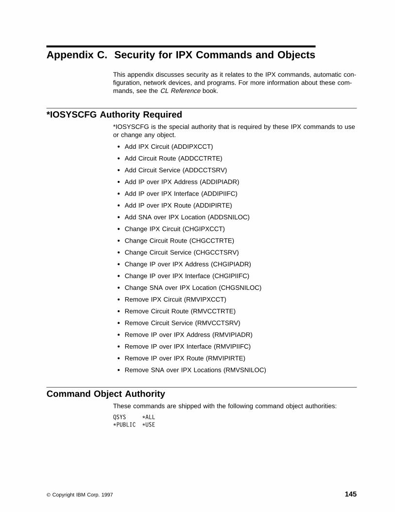
Appendix C. Security for IPX Commands and Objects
This appendix discusses security as it relates to the IPX commands, automatic con-figuration, network devices, and programs. For more information about these com-mands, see the CL Reference book.
*IOSYSCFG Authority Required*IOSYSCFG is the special authority that is required by these IPX commands to useor change any object.
� Add IPX Circuit (ADDIPXCCT)
� Add Circuit Route (ADDCCTRTE)
� Add Circuit Service (ADDCCTSRV)
� Add IP over IPX Address (ADDIPIADR)
� Add IP over IPX Interface (ADDIPIIFC)
� Add IP over IPX Route (ADDIPIRTE)
� Add SNA over IPX Location (ADDSNILOC)
� Change IPX Circuit (CHGIPXCCT)
� Change Circuit Route (CHGCCTRTE)
� Change Circuit Service (CHGCCTSRV)
� Change IP over IPX Address (CHGIPIADR)
� Change IP over IPX Interface (CHGIPIIFC)
� Change SNA over IPX Location (CHGSNILOC)
� Remove IPX Circuit (RMVIPXCCT)
� Remove Circuit Route (RMVCCTRTE)
� Remove Circuit Service (RMVCCTSRV)
� Remove IP over IPX Address (RMVIPIADR)
� Remove IP over IPX Interface (RMVIPIIFC)
� Remove IP over IPX Route (RMVIPIRTE)
� Remove SNA over IPX Locations (RMVSNILOC)
Command Object AuthorityThese commands are shipped with the following command object authorities:
QSYS \ALL
\PUBLIC \USE
Copyright IBM Corp. 1997 145

*IOSYSCFG Authority Not RequiredThese IPX commands do not require any special authority.
� Change IPX Description (CHGIPXD)
� Change IPX Description (CHGIPXD)
� Configure IP over IPX (CFGIPI)
� Configure IPX (CFGIPX)
� Create IPX Description (CRTIPXD)
� Display IPX Circuit (DSPIPXCCT)
� Display IPX Description (DSPIPXD)
� Display Circuit Route (DSPCCTRTE)
� Display Circuit Service (DSPCCTSRV)
� IPXPING (see Verify IPX Connection)
� Verify IPX Connection (VRYIPXCNN)
� Work with Circuit Route (WRKCCTRTE)
� Work with Circuit Service (WRKCCTSRV)
� Work with IPX Circuit (WRKIPXCCT)
� Work with IPX Description (WRKIPXD)
� Work with IPX Status (WRKIPXSTS)
Command Object AuthorityThese commands are shipped with the following command object authorities:
QSYS \ALL
\PUBLIC \USE
Object Authority RequiredThese IPX commands do not require any special authority.
� End IPX (ENDIPX)
� End IP over IPX Interface (ENDIPIIFC)
� End IPX Circuit (ENDIPXCCT)
� Start IPX (STRIPX)
� Start IPX Circuit (STRIPXCCT)
� Start IP over IPX Interface (STRIPIIFC)
Command Object AuthorityThese commands are shipped with the following command object authorities:
146 OS/400 Internetwork Packet Exchange (IPX) Support V4R1

QSYS \ALL
QSRV \USE
QSRVBAS \USE
QSYSOPR \USE
QPGMR \USE
\PUBLIC \EXCLUDE
Authority can be changed using the Revoke Object Authority (RVKOBJAUT)command and the Grant Object Authority (GRTOBJAUT) command. To remove theauthority of the QSYSOPR user profile from the End IPX Circuit (ENDIPXCCT)command, the following example command could be used:
RVKOBJAUT OBJ(ENDIPXCCT)
OBJTYPE(\CMD) USER(QSYSOPR)
AUT(\USE)
To give another user authority to the ENDIPXCCT command, the GRTOBJAUTcommand could be used as follows:
GRTOBJAUT OBJ(ENDIPXCCT)
OBJTYPE(\CMD) USER(RUNEB)
AUT(\USE)
These commands can be used in the same way to revoke or grant user authority toalmost any object on the AS/400. To be able to view which users have authority toan object, use the Edit Object Authority (EDTOBJAUT) command. This commandcan be issued by a user with all rights to the object to revoke and grant userauthority to the object from a single display.
Object Security for Network ConfigurationIPX uses the information in the line description associated with an IPX circuit todetermine which communications line to use. The line description can also be usedto identify the attached network controller and the network device objects that theIPX protocol uses when the circuit is started. The line description is also used toidentify the network server description object or network interface description objectthat the line description is attached to. To view or change the line description asso-ciated with an IPX circuit, select option 1 (Work with IPX circuits) from the Con-figure IPX menu (reached by typing GO CFGIPX or CFGIPX on the command line).
If the network controller and network device do not exist, IPX uses the automaticconfiguration support to create them when the first circuit that is associated with theline description is started. If the network controller or device is created by automaticconfiguration, *PUBLIC will be granted *CHANGE authority to the controller anddevice. Therefore, the objects are not secure.
IPX is an OS/400 system service and will function correctly no matterwhat authority you specify for the network configuration objects it uses.Use the Grant Object Authority (GRTOBJAUT) command to change theauthority to access a communications line configuration object.
The QIPX job that runs in the QSYSWRK subsystem will lock the network devicewhen any circuit that uses that network device is started. This prevents the linefrom being varied off while an IPX circuit is using it. To remove the lock that is heldby the QIPX job, do one of the following:
Appendix C. Security for IPX Commands and Objects 147

� Use the End IPX Circuit (ENDIPXCCT) command to end the circuit that is usingthe line.
� Use the End IPX (ENDIPX) command to end all IPX processing. The ENDIPXcommand will end all IPX circuits and the QIPX job.
148 OS/400 Internetwork Packet Exchange (IPX) Support V4R1

Appendix D. IPX Performance
Main Storage Pool Size . . . . . . . . . . . . . . . . . . . . . . . . . . . . . . . 149IPX Jobs . . . . . . . . . . . . . . . . . . . . . . . . . . . . . . . . . . . . . . . . 149IPX Protocol Support Provided by IOP . . . . . . . . . . . . . . . . . . . . . . 149
Packet Rollup . . . . . . . . . . . . . . . . . . . . . . . . . . . . . . . . . . . 150Packet Train . . . . . . . . . . . . . . . . . . . . . . . . . . . . . . . . . . . . 150Service Advertising Protocol (SAP) Off-load . . . . . . . . . . . . . . . . . . 150Routing Information Protocol (RIP) Off-load . . . . . . . . . . . . . . . . . . 150NetWare Link Services Protocol (NLSP) Off-load . . . . . . . . . . . . . . . 151
Simple Network Management Protocol (SNMP) Support . . . . . . . . . . . . 151
The following performance items should be considered when using IPX support.
The IPX protocol stack always runs in the main storage pool on the AS/400 system.If the main storage pool is not given enough storage, IPX does not perform at itsoptimal level.
Main Storage Pool SizeAlthough it is possible to run in pools of less than 4000 KB of storage, it is sug-gested that the main storage pool be configured to use at least 4000 KB of storage.You can use the Work with System Storage (WRKSYSSTS) command to view andchange pool sizes on AS/400 systems. Another alternative is to change the pool inwhich the IPX jobs run.
IPX JobsIPX jobs, like other jobs on your system, are created from job descriptions andassociated classes. The job descriptions and classes should be adequate in mostcases; however, they may be changed to fit your system needs.
The IPX job description has a number of items associated with it that define howthe application runs on the AS/400. One of these pieces of information is therouting entry compare value. This value identifies which routing entry in a sub-system description is used when this job is submitted. By changing that routingentry, you can select in which storage pool to run the jobs for a particular applica-tion.
For information on compare values, see the Work Management book.
Other items that can be changed or selected on the QIPX and QAPPCIPX jobsinclude the job priority, the logging level for messages, and the initial library list.
IPX Protocol Support Provided by IOPThe input/output processor (IOP) performs protocol assistance functions for IPX,RIP, SAP, and NLSP. This protocol assistance off-loads work from the AS/400processor to the IOP, which reduces the processing requirements and usage forthe IPX support on AS/400.
Copyright IBM Corp. 1997 149
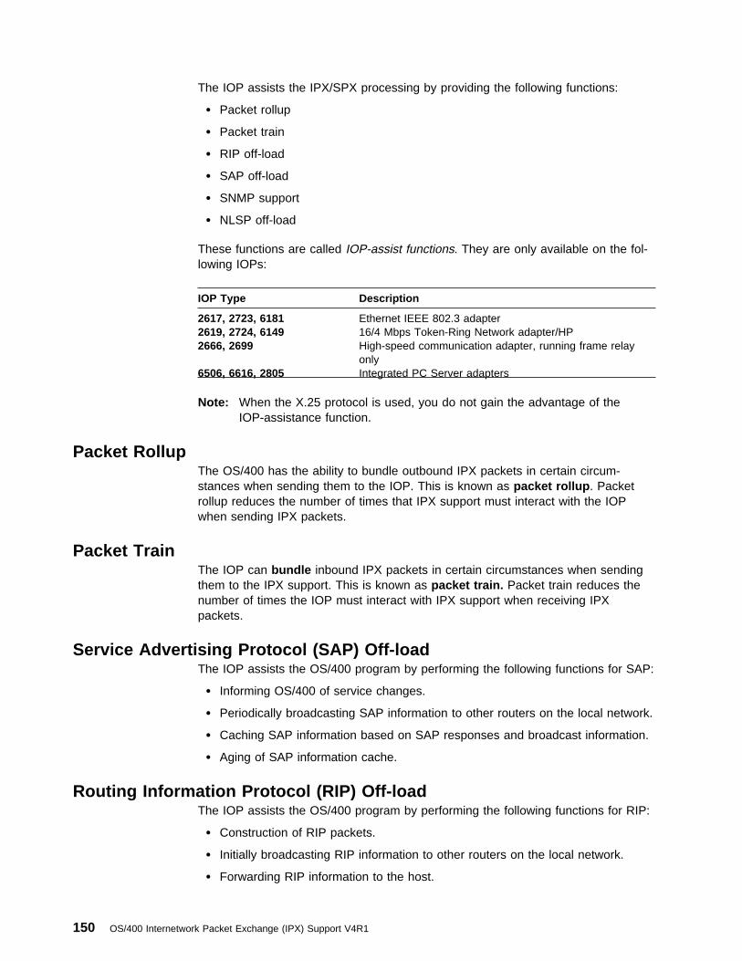
The IOP assists the IPX/SPX processing by providing the following functions:
� Packet rollup
� Packet train
� RIP off-load
� SAP off-load
� SNMP support
� NLSP off-load
These functions are called IOP-assist functions. They are only available on the fol-lowing IOPs:
Note: When the X.25 protocol is used, you do not gain the advantage of theIOP-assistance function.
IOP Type Description
2617, 2723, 6181 Ethernet IEEE 802.3 adapter2619, 2724, 6149 16/4 Mbps Token-Ring Network adapter/HP2666, 2699 High-speed communication adapter, running frame relay
only6506, 6616, 2805 Integrated PC Server adapters
Packet RollupThe OS/400 has the ability to bundle outbound IPX packets in certain circum-stances when sending them to the IOP. This is known as packet rollup . Packetrollup reduces the number of times that IPX support must interact with the IOPwhen sending IPX packets.
Packet TrainThe IOP can bundle inbound IPX packets in certain circumstances when sendingthem to the IPX support. This is known as packet train. Packet train reduces thenumber of times the IOP must interact with IPX support when receiving IPXpackets.
Service Advertising Protocol (SAP) Off-loadThe IOP assists the OS/400 program by performing the following functions for SAP:
� Informing OS/400 of service changes.
� Periodically broadcasting SAP information to other routers on the local network.
� Caching SAP information based on SAP responses and broadcast information.
� Aging of SAP information cache.
Routing Information Protocol (RIP) Off-loadThe IOP assists the OS/400 program by performing the following functions for RIP:
� Construction of RIP packets.
� Initially broadcasting RIP information to other routers on the local network.
� Forwarding RIP information to the host.
150 OS/400 Internetwork Packet Exchange (IPX) Support V4R1

� Periodically broadcasting RIP information to other routers on the local network.
� Caching RIP information based on RIP responses and broadcast information.
� Aging of RIP information cache.
� Supporting next hop routing.
NetWare Link Services Protocol (NLSP) Off-loadThe IOP assists the OS/400 program by performing the local neighborhood dis-covery, or adjacency, part of the NetWare Link Services Protocol. The IOP per-forms the following functions:
� Caching adjacency information (other routers on the network) and forwardingchanges to OS/400
� Periodically transmitting the NLSP Hello packet
� Electing the NLSP designated router
Simple Network Management Protocol (SNMP) SupportThe IOP and OS/400 maintain all relevant SNMP information. The portion of theSNMP information for IPX support is accessed by the SNMP agent support on theAS/400. The IOP maintains management information base (MIB) information for theIPX functions: packet rollup, packet train, RIP off-load, SAP off-load, SNMPsupport, and NLSP off-load. When someone wants the MIB information, the OS/400SNMP agent works with the OS/400 IPX support and the IOP to retrieve the infor-mation.
AS/400 supports the Novell MIB structure, which consists of three subtrees: IPX,RIP/SAP, and NLSP.
The IPX MIB defines the framework for the management of systems implementingthe IPX protocol. The RIP/SAP MIB provides information about each instance ofRIP and SAP running on one system. The NLSP MIB provides the managementinformation for the NLSP protocol running in an IPX environment.
Novell allows Set functionality against most of the MIB objects, but the implementa-tion in OS/400 does not allow Sets against any of the MIB objects.
The TCP/IP protocol must be used between the SNMP manager and SNMP agentto submit MIB requests for the IPX MIB. Requests using the IPX protocol are notsupported.
For more information about the OS/400 SNMP Agent support, see the SimpleNetwork Management Protocol (SNMP) Support book.
Appendix D. IPX Performance 151

152 OS/400 Internetwork Packet Exchange (IPX) Support V4R1

Appendix E. IPX Problem Analysis
Working with the Job Log and Message Queues . . . . . . . . . . . . . . . . 153Common Configuration Errors . . . . . . . . . . . . . . . . . . . . . . . . . . . 154Tracing IPX Protocol Layer Problems . . . . . . . . . . . . . . . . . . . . . . . 154
Setting Up a Licensed Internal Code Trace . . . . . . . . . . . . . . . . . . 154Starting Component Traces . . . . . . . . . . . . . . . . . . . . . . . . . . . 156
SNA Over IPX Debugging Capabilities . . . . . . . . . . . . . . . . . . . . . . 157Tracing SNA over IPX Problems . . . . . . . . . . . . . . . . . . . . . . . . 158IP over IPX Debugging Capabilities . . . . . . . . . . . . . . . . . . . . . . . 159
Additional Debugging IP over IPX Configurations Information . . . . . . . . . 160Tracing IP over IPX Problems . . . . . . . . . . . . . . . . . . . . . . . . . . 160
Collecting a Communications Trace . . . . . . . . . . . . . . . . . . . . . . . . 161Planning to Set up a Trace . . . . . . . . . . . . . . . . . . . . . . . . . . . 162Accessing the Start Service Tool (SST) Function . . . . . . . . . . . . . . . 163Starting a Communications Trace . . . . . . . . . . . . . . . . . . . . . . . . 164Stopping a Communications Trace . . . . . . . . . . . . . . . . . . . . . . . 167Formatting and Saving the Communications Trace . . . . . . . . . . . . . . 168Verifying the Contents of the Communications Trace . . . . . . . . . . . . 168
Return Codes and Messages Issued by IPX Support . . . . . . . . . . . . . . 171Alertable Messages . . . . . . . . . . . . . . . . . . . . . . . . . . . . . . . . 174
This appendix is intended to be used for determining solutions to problems that areencountered while using IPX.
Working with the Job Log and Message QueuesIPX is shipped with job descriptions. The job descriptions and their associated jobsare as follows:
� QZSPJOBD for the QIPX (the QIPX job)
� QZSPSNAIPX for the QAPPCIPX (the SNA over IPX job)
The job descriptions are stored in the QSYS library. They are shipped with amessage logging level of 4, a message logging severity of 0, and a messagelogging text value of *NOLIST. They are shipped with these values to prevent joblogs from being created with only job-started and job-ended messages in them.
If you are having problems with the operation of IPX, one of the first things to do isto change the message logging level to *SECLVL on the job description for theapplication you are having problems with. Changing the message logging level gen-erates a job log for that application as long as you end the current job and restart itusing the updated job description.
CHGJOBD JOBD(QTCP/QZSPJOBD) LOG(4 ð \SECLVL)
CHGJOBD JOBD(QTCP/QZSPSNAIPX) LOG(4 ð \SECLVL)
Copyright IBM Corp. 1997 153

Common Configuration ErrorsSome common configuration errors are:
� Not starting host servers for Client Access/400 after you start IPX support. See“Starting IPX” on page 69 for more information.
� Not starting the circuits you want to use to reach a remote network. See“Starting IPX Circuits” on page 76 for more information.
� Not configuring the static services and routes associated with on demand SVCcircuits. See “Step 4–Adding Circuit Route Information” on page 57 and “Step5–Adding Circuit Service Information” on page 61 for more information.
� Not creating the correct line descriptions for IPX support. See “ Step2–Configuring Line Descriptions for IPX Support–Ethernet” on page 30. Morethan one CPE0003 message is displayed when this error occurs.
� Attempting to use the same IPX description for both OS/400 IPX support and a*NETWARE FSIOP. Each FSIOP and the OS/400 IPX support must use aunique IPX description. See “ Step 1–Creating an Internetwork PacketExchange (IPX) Description” on page 23 for more information.
Tracing IPX Protocol Layer ProblemsIf an IPX protocol layer problem occurs, you can perform a Licensed Internal Code(LIC) trace of the IPX component to capture the problem.
This LIC component can be traced using the system service tools (SST). Thisservice function is accessed using the Start System Service Tools (STRSST)command. This function allows you to generate a LIC trace of the AS/400 IPXsupport.
Contact the security officer or system administrator to get serviceauthority to use SST. This authority is necessary to use SST.
Setting Up a Licensed Internal Code Trace1. To setup a LIC trace, enter:
STRSST
The System Service Tools (SST) menu is shown.
154 OS/400 Internetwork Packet Exchange (IPX) Support V4R1

à ðSystem Service Tools (SST)
Select one of the following:
1. Start a service tool
2. Work with active service tools
3. Work with disk units
4. Work with diskette data recovery
Selection
1
F3=Exit F1ð=Command entry F12=Cancel
á ñ
2. Use option 1 (Start a service tool). The following display is shown:
à ðStart a Service Tool
Warning: Incorrect use of this service tool can cause damage
to data in this system. Contact your service representative
for assistance.
Select one of the following:
1. Product activity log
2. Trace Licensed Internal Code
3. Work with communications trace
4. Display/Alter/Dump
5. Licensed Internal Code log
6. Main storage dump manager
7. Hardware service manager
Selection
2
F3=Exit F12=Cancel F16=SST menu
á ñ
3. Use option 2 to trace licensed internal code:
Appendix E. IPX Problem Analysis 155
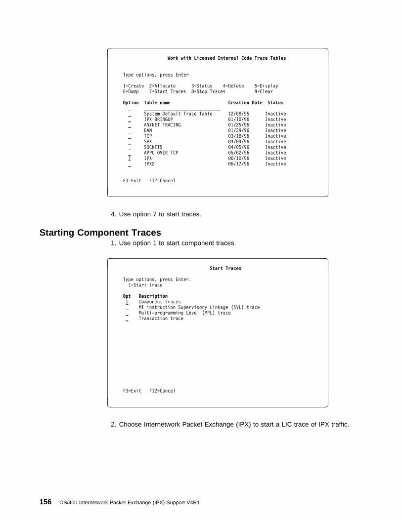
à ðWork with Licensed Internal Code Trace Tables
Type options, press Enter.
1=Create 2=Allocate 3=Status 4=Delete 5=Display
6=Dump 7=Start Traces 8=Stop Traces 9=Clear
Option Table name Creation Date Status _ _____________________________
_ System Default Trace Table 12/ð8/95 Inactive
_ IPX BRINGUP ð1/1ð/96 Inactive
_ ANYNET TRACING ð1/25/96 Inactive
_ DAN ð1/29/96 Inactive
_ TCP ð3/18/96 Inactive
_ SPX ð4/ð4/96 Inactive
_ SOCKETS ð4/ð5/96 Inactive
_ APPC OVER TCP ð5/ð2/96 Inactive
7 IPX ð6/1ð/96 Inactive
_ IPX2 ð6/17/96 Inactive
F3=Exit F12=Cancel
á ñ
4. Use option 7 to start traces.
Starting Component Traces1. Use option 1 to start component traces.
à ð Start Traces
Type options, press Enter.
1=Start trace
Opt Description 1 Component traces
_ MI instruction Supervisory Linkage (SVL) trace
_ Multi-programming Level (MPL) trace
_ Transaction trace
F3=Exit F12=Cancel
á ñ
2. Choose Internetwork Packet Exchange (IPX) to start a LIC trace of IPX traffic.
156 OS/400 Internetwork Packet Exchange (IPX) Support V4R1

à ðStart Component Traces
Type options, press Enter.
1=Start trace
Opt Description_ Display station passthru
_ Environmental Recording, Editing and Printing (EREP)
_ Error Log
_ Event management
_ Exception management
_ Hardware Resources
_ Heap manager
_ Independent index
_ Integrated File System (IFS)
1 Internetwork Packet Exchange (IPX)
_ Inter-process Communications Facility (IPCF)
_ Journal management
_ Link test service function
_ Load/Dump
_ Machine Interface (MI) Transformer
More. F3=Exit F12=Cancel
á ñ
SNA Over IPX Debugging CapabilitiesDebugging SNA over IPX problems is often a matter of doing standard debug of anAPPC application. However, some additional problems can occur when firstattempting to run the application over an IPX network.
� When an APPC application on the AS/400 attempts to open a connection to aremote location across a IPX network, three configuration steps are oftenoverlooked:
– If the APPN remote configuration list does not have an entry for the remotelocation that the APPC program is attempting to open to, the AS/400attempts to find an APPN route to the remote location. This will fail with aCPF8933 message (or similar failure), stating that a route to the specifiedlocation was not found.
You need to tie this location to APPC over IPX by adding the remotelocation to the remote configuration list.
– If the SNA over IPX database file does not contain the location name toIPX address mapping, the APPC over IPX job is not able to resolve the IPXrouting to the remote location. A CPIE007 message is logged as aQSYSOPR message. Additionally, the QAPPCIPX job in the QSYSWRKsubsystem logs a CPDE00A message.
You need to tie this location to a particular IPX address by adding theremote location to IPX address mapping in the SNA over IPX database fileusing the ADD SNA over IPX Location (ADDSNILOC) command.
– If SNA over TCP support is active (the job QAPPCTCP in the QSYSWRKsubsystem is active), then it is possible that TCP/IP routing is being used toconnect with the remote location. Any mapping that is defined for SNA overTCP support in the host table or remote name server will take precedenceover mappings that are defined for SNA over IPX support. Look in theQAPPCTCP job description for messages containing the remote location to
Appendix E. IPX Problem Analysis 157
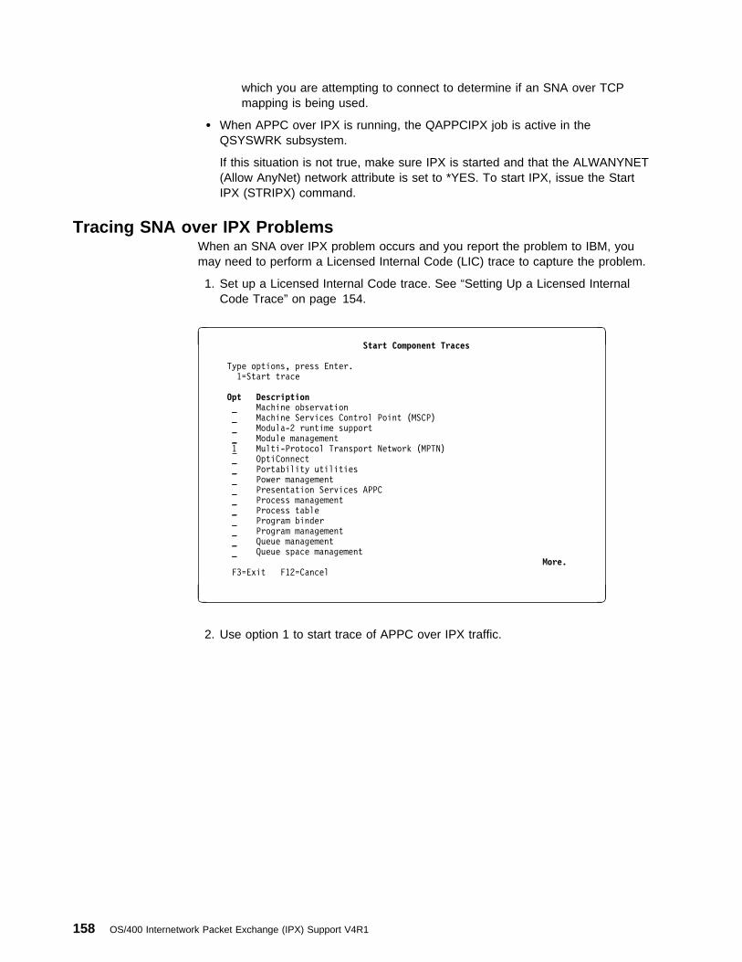
which you are attempting to connect to determine if an SNA over TCPmapping is being used.
� When APPC over IPX is running, the QAPPCIPX job is active in theQSYSWRK subsystem.
If this situation is not true, make sure IPX is started and that the ALWANYNET(Allow AnyNet) network attribute is set to *YES. To start IPX, issue the StartIPX (STRIPX) command.
Tracing SNA over IPX ProblemsWhen an SNA over IPX problem occurs and you report the problem to IBM, youmay need to perform a Licensed Internal Code (LIC) trace to capture the problem.
1. Set up a Licensed Internal Code trace. See “Setting Up a Licensed InternalCode Trace” on page 154.
à ðStart Component Traces
Type options, press Enter.
1=Start trace
Opt Description _ Machine observation
_ Machine Services Control Point (MSCP)
_ Modula-2 runtime support
_ Module management
1 Multi-Protocol Transport Network (MPTN)
_ OptiConnect
_ Portability utilities
_ Power management
_ Presentation Services APPC
_ Process management
_ Process table
_ Program binder
_ Program management
_ Queue management
_ Queue space management
More. F3=Exit F12=Cancel
á ñ
2. Use option 1 to start trace of APPC over IPX traffic.
158 OS/400 Internetwork Packet Exchange (IPX) Support V4R1

à ðStart Multi-Protocol Transport Network Traces
Type options, press Enter.
1=Start trace
Opt Description_ AF INET Multi-Protocol Transport Network
_ AF INET Protocol Enveloper and Complementer
1 APPC over a TCP/IP Multi-Protocol Transport Network
F3=Exit F12=Cancel
á ñ
3. Multiprotocol Transport Networking (MPTN) is an option of the ComponentTrace option of LIC Trace.
IP over IPX Debugging CapabilitiesWhen you are debugging IP over IPX on the AS/400 system, check the followingconfiguration steps:
1. Does the local IP address exist in the IP over IPX interface configuration list?To add an IP over IPX interface, use the Add IP over IPX Interface(ADDIPIIFC) command.
2. Does the IP route to the remote node in the IP over IPX route configurationlist? These routes are required whenever a remote node is not part of the sameIP network. To add an IP over IPX route, use the Add IP over IPX Route(ADDIPIRTE) command.
3. Does the IP over IPX address mapping entry exist in the IP over IPX addressmapping configuration list? A mapping entry maps a remote IPX networknumber and node address to IP address for each remote node that the localnode may communicate with.
4. Is the IP over IPX interface active? There are three reasons that the IP overIPX interface is not active.
a. The Start IPX (STRIPX) command has not been issued.
b. The Allow AnyNet (ALWANYNET) network attribute is not *YES.
c. There are already more than the maximum allowed IP over IPX interfacesactive.
Appendix E. IPX Problem Analysis 159

Debugging IP over IPX
Additional Debugging IP over IPX Configurations InformationTwo CL commands can be helpful in debugging IP over IPX configurations:
� The Verify IPX Connection (VFYIPXCNN, also known as IPXPING) commandcan help you determine if your IPX configuration is correct. As input to theIPXPING command, you need the remote IPX network number and nodeaddress. You can determine the remote network number and node addressfrom the destination IP address by using option 12 (Work with IP over IPXaddresses) from the Configure IPX menu (CFGIPX).
� The Verify TCP/IP Connection (VFYTCPCNN, also known as PING) commandcan help you determine if your AnyNet configuration is correct.
Note: When PING fails, it does not give a detailed reason for the failure. Toget a detailed reason, you should run a sockets program that reportsthe value for errno when the failure occurs.
Table 15. Common IP over IPX Configuration Errors
Sockets Error (value of errno) Possible Causes
EHOSTUNREACH 1. Missing ADDIPIADR command on client system.
2. Missing ADDIPIIFC command on client system.
3. ADDIPIADR command on client system resulted in a IPX remotenetwork number that is not found.
EADDRNOTAVAIL 1. AnyNet not active on client system (ALWANYNET attribute set to *NO),but TCP is started.
2. IPX not started on client system.
EUNATTACH 1. AnyNet not active on client system (ALWANYNET attribute set to *NO),and TCP is not started.
ECONNREFUSED 1. AnyNet not active on client system (ALWANYNET attribute set to *NO).
2. listen() not active on server system.
ECONNABORTED 1. Line error.
2. IPX ended on client or server system while in use.
ETIMEDOUT 1. ADDIPIADR command on client system points to an IPX remote nodeaddress that does not exist or is on a system that is not responding inthe IPX network.
2. Messages (especially inquiry messages) on message queue QSYSOPRare waiting for a reply.
EACCES 1. User not authorized to port on client system.
Tracing IP over IPX ProblemsWhen a IP over IPX problem occurs and you report the problem to IBM, you mayneed to perform a LIC trace to capture the problem.
1. See “Setting Up a Licensed Internal Code Trace” on page 154 for theinstructions to perform a trace.
160 OS/400 Internetwork Packet Exchange (IPX) Support V4R1

à ðStart Component Traces
Type options, press Enter.
1=Start trace
Opt Description _ Machine observation
_ Machine Services Control Point (MSCP)
_ Modula-2 runtime support
_ Module management
1 Multi-Protocol Transport Network (MPTN)
_ OptiConnect
_ Portability utilities
_ Power management
_ Presentation Services APPC
_ Process management
_ Process table
_ Program binder
_ Program management
_ Queue management
_ Queue space management
More... F3=Exit F12=Cancel
á ñ
2. Type option 1, to start trace of APPC over IPX traffic.
à ðStart Multi-Protocol Transport Network Traces
Type options, press Enter.
1=Start trace
Opt Description1 AF INET Multi-Protocol Transport Network
1 AF INET Protocol Enveloper and Complementer
_ APPC over a TCP/IP Multi-Protocol Transport Network
F3=Exit F12=Cancel
á ñ
3. Choose AF_INET Multi-Protocol Transport Network and AF_INET ProtocolEnveloper and Complementer to start a LIC trace of IP over IPX traffic.
Collecting a Communications TraceA communications trace can be used to isolate errors. You can start communi-cations traces from SST or by using the following CL commands:
� Check Communications Trace (CHKCMNTRC)
� Delete Communications Trace (DLTCMNTRC)
� End Communications Trace (ENDCMNTRC)
Appendix E. IPX Problem Analysis 161
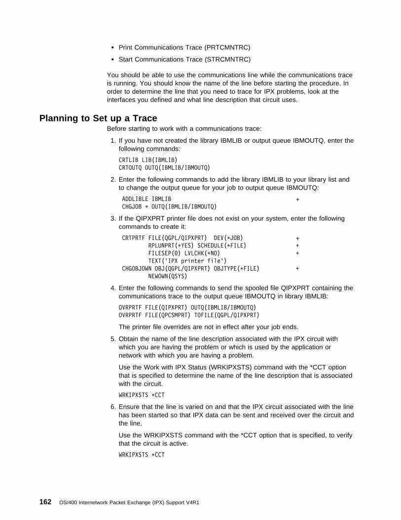
� Print Communications Trace (PRTCMNTRC)
� Start Communications Trace (STRCMNTRC)
You should be able to use the communications line while the communications traceis running. You should know the name of the line before starting the procedure. Inorder to determine the line that you need to trace for IPX problems, look at theinterfaces you defined and what line description that circuit uses.
Planning to Set up a TraceBefore starting to work with a communications trace:
1. If you have not created the library IBMLIB or output queue IBMOUTQ, enter thefollowing commands:
CRTLIB LIB(IBMLIB)
CRTOUTQ OUTQ(IBMLIB/IBMOUTQ)
2. Enter the following commands to add the library IBMLIB to your library list andto change the output queue for your job to output queue IBMOUTQ:
ADDLIBLE IBMLIB + CHGJOB \ OUTQ(IBMLIB/IBMOUTQ)
3. If the QIPXPRT printer file does not exist on your system, enter the followingcommands to create it:
CRTPRTF FILE(QGPL/QIPXPRT) DEV(\JOB) + RPLUNPRT(\YES) SCHEDULE(\FILE) +
FILESEP(ð) LVLCHK(\NO) +
TEXT('IPX printer file')
CHGOBJOWN OBJ(QGPL/QIPXPRT) OBJTYPE(\FILE) +
NEWOWN(QSYS)
4. Enter the following commands to send the spooled file QIPXPRT containing thecommunications trace to the output queue IBMOUTQ in library IBMLIB:
OVRPRTF FILE(QIPXPRT) OUTQ(IBMLIB/IBMOUTQ)
OVRPRTF FILE(QPCSMPRT) TOFILE(QGPL/QIPXPRT)
The printer file overrides are not in effect after your job ends.
5. Obtain the name of the line description associated with the IPX circuit withwhich you are having the problem or which is used by the application ornetwork with which you are having a problem.
Use the Work with IPX Status (WRKIPXSTS) command with the *CCT optionthat is specified to determine the name of the line description that is associatedwith the circuit.
WRKIPXSTS \CCT
6. Ensure that the line is varied on and that the IPX circuit associated with the linehas been started so that IPX data can be sent and received over the circuit andthe line.
Use the WRKIPXSTS command with the *CCT option that is specified, to verifythat the circuit is active.
WRKIPXSTS \CCT
162 OS/400 Internetwork Packet Exchange (IPX) Support V4R1

Use the Work with IPX Status menu to print copies of the circuits, routes, andservice information for problem analysis. The information helps determine wherethe errors can be found.
à ðWork with IPX Status
SYSTEM: SYSNAMXX
Select one of the following:
1. Work with IPX circuit status
2. Display IPX route information
3. Display IPX service information
4. Work with IPX/SPX connection status
5. Display active IPX description
Selection or command
===> 1______________________________________________________________________
_____________________________________________________________________________
F3=Exit F4=Prompt F9=Retrieve F12=Cancel
á ñ
Figure 123. Work with IPX Status Menu Example
Each of the displays accessible from the Work with IPX Status menu has an F6(Print or Print list) that is associated with it. Use the F6 key to print out the informa-tion on the status of IPX support on AS/400.
Accessing the Start Service Tool (SST) FunctionTo access SST:
1. Enter STRSST on a command line. The following display appears:
Appendix E. IPX Problem Analysis 163

à ðSystem Service Tools (SST)
Select one of the following:
1. Start a service tool
2. Work with active service tools
3. Work with disk units
4. Work with diskette data recovery
Selection
1
F3=Exit F1ð=Command entry F12=Cancel
á ñ
Figure 124. System Service Tools (SST) Display Example
2. Select option 1 (Start a service tool). The following display is shown:
à ðStart a Service Tool
Warning: Incorrect use of this service tool can cause damage
to data in this system. Contact your service representative
for assistance.
Select one of the following:
1. Product activity log
2. Trace Licensed Internal Code
3. Work with communications trace
4. Display/Alter/Dump
5. Licensed Internal Code log
6. Main storage dump manager
7. Hardware service manager
Selection
3
F3=Exit F12=Cancel F16=SST menu
á ñ
Figure 125. Start a Service Tool Menu Example
3. Select option 3 (Work with communications trace).
Starting a Communications TraceTo start a communications trace:
1. If you are instructed by the service provider to vary off the line, enter the fol-lowing command; otherwise, continue with the next step.
VRYCFG CFGOBJ(line-name) CFGTYPE(\LIN)
STATUS(\OFF)
2. After you select option 3, the following display is shown:
164 OS/400 Internetwork Packet Exchange (IPX) Support V4R1
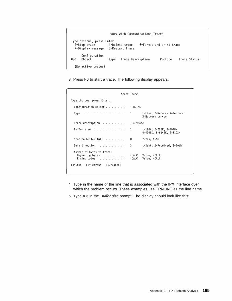
à ðWork with Communications Traces
Type options, press Enter.
2=Stop trace 4=Delete trace 6=Format and print trace
7=Display message 8=Restart trace
Configuration
Opt Object Type Trace Description Protocol Trace Status
(No active traces)
3. Press F6 to start a trace. The following display appears:
à ð Start Trace
Type choices, press Enter.
Configuration object . . . . . . . TRNLINE
Type . . . . . . . . . . . . . . 1 1=Line, 2=Network interface
3=Network server
Trace description . . . . . . . . IPX trace
Buffer size . . . . . . . . . . . 1 1=128K, 2=256K, 3=2ð48K
4=4ð96K, 5=6144K, 6=8192K
Stop on buffer full . . . . . . . N Y=Yes, N=No
Data direction . . . . . . . . . 3 1=Sent, 2=Received, 3=Both
Number of bytes to trace:
Beginning bytes . . . . . . . . \CALC Value, \CALC
Ending bytes . . . . . . . . . \CALC Value, \CALC
F3=Exit F5=Refresh F12=Cancel
á ñ
4. Type in the name of the line that is associated with the IPX interface overwhich the problem occurs. These examples use TRNLINE as the line name.
5. Type a 6 in the Buffer size prompt. The display should look like this:
Appendix E. IPX Problem Analysis 165

à ð Start Trace
Type choices, press Enter.
Configuration object . . . . . . . TRNLINE
Type . . . . . . . . . . . . . . 1 1=Line, 2=Network interface
3=Network server
Trace description . . . . . . . . IPX trace
Buffer size . . . . . . . . . . . 6 1=128K, 2=256K, 3=2ð48K
4=4ð96K, 5=6144K, 6=8192K
Stop on buffer full . . . . . . . N Y=Yes, N=No
Data direction . . . . . . . . . 3 1=Sent, 2=Received, 3=Both
Number of bytes to trace:
Beginning bytes . . . . . . . . \CALC Value, \CALC
Ending bytes . . . . . . . . . \CALC Value, \CALC
F3=Exit F5=Refresh F12=Cancel
á ñ
Figure 126. Start Trace Example
6. Press the Enter key. The following display appears:
à ðWork with Communications Traces
Type options, press Enter.
2=Stop trace 4=Delete trace 6=Format and print trace
7=Display message 8=Restart trace
Configuration
Opt Object Type Trace Description Protocol Trace Status
TRNLINE LINE IPX TRACE TRN ACTIVE
Figure 127. Work with Communications Traces Display Example
7. Do one of the following:
8. Press F3 (Exit) until you obtain the display that requests that you press Enter tocontinue ending SST.
The trace does not stop if you exit SST while the trace is running.
9. Press the Enter key to exit SST.
10. If you did step 1 on page 164 previously or the line is varied off, then enter thefollowing command to vary on the line:
Table 16. Trace Status
If the Trace Status Is Go to Step
Waiting 1 on page 164
Error 1 on page 168
Other than waiting or error 11 on page 167
166 OS/400 Internetwork Packet Exchange (IPX) Support V4R1

VRYCFG CFGOBJ(line-name) CFGTYPE(\LIN)
STATUS(\ON)
Ensure that the circuit that is associated with the line description is started. Youcan use the Start IPX Circuit (STRIPXCCT) command to start a circuit.
11. Enter the commands and names of the programs that caused the problem.Trace the data on the line for a period of time that is specified by your serviceprovider.
12. Go to “Stopping a Communications Trace” after the error occurs.
Stopping a Communications TraceTo stop the trace:
1. If you are at the Work with Communications Traces display, type a 2 in the Optcolumn next to the name of the line you want to stop tracing.
If the status is waiting, press F5 (Refresh) to refresh the status onthe Work with Communications Traces display.
2. Press the Enter key. In this example, the trace status changed to stopping. Thefollowing display appears:
à ðWork with Communications Traces
Type options, press Enter.
2=Stop trace 4=Delete trace 6=Format and print trace
7=Display message 8=Restart trace
Configuration
Opt Object Type Trace Description Protocol Trace Status
TRNLINE LINE IPX TRACE TRN STOPPING
3. Press F5 (Refresh) to refresh the display. In this example, the trace statuschanged to stopped. The following display appears:
à ðWork with Communications Traces
Type options, press Enter.
2=Stop trace 4=Delete trace 6=Format and print trace
7=Display message 8=Restart trace
Configuration
Opt Object Type Trace Description Protocol Trace Status
TRNLINE LINE IPX TRACE TRN STOPPED
4. Continue with “Formatting and Saving the Communications Trace” on page 168to format and save the trace.
Appendix E. IPX Problem Analysis 167
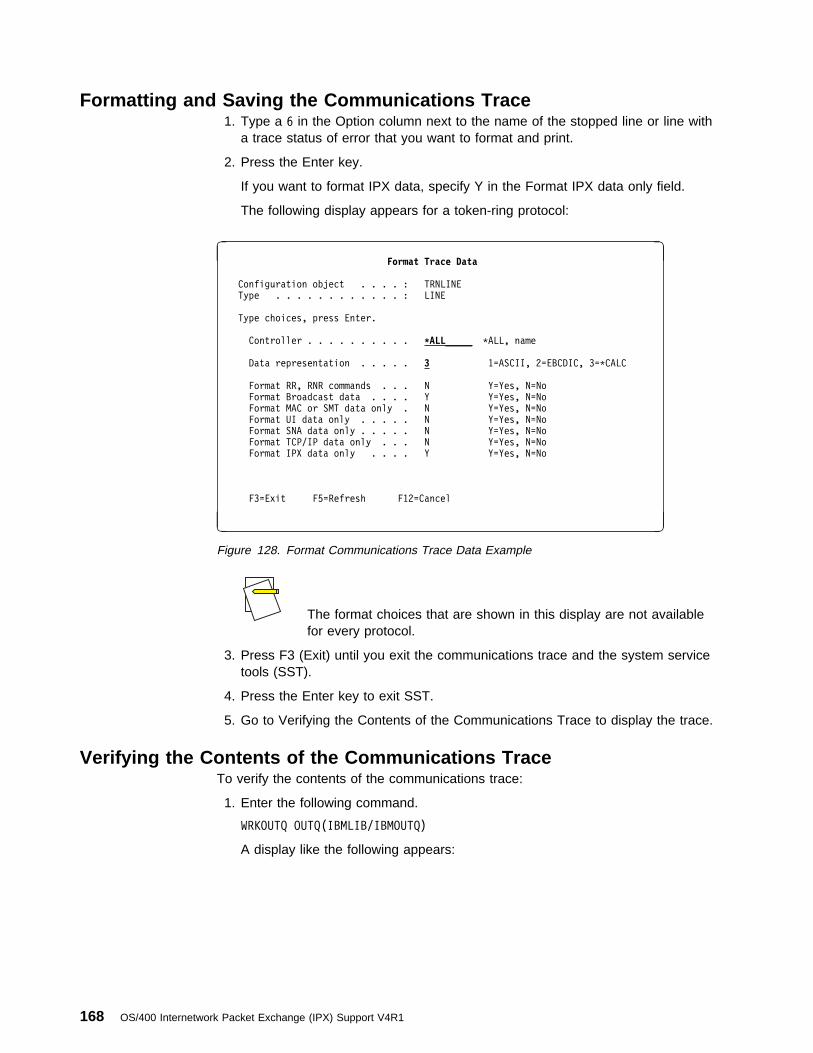
Formatting and Saving the Communications Trace1. Type a 6 in the Option column next to the name of the stopped line or line with
a trace status of error that you want to format and print.
2. Press the Enter key.
If you want to format IPX data, specify Y in the Format IPX data only field.
The following display appears for a token-ring protocol:
à ðFormat Trace Data
Configuration object . . . . : TRNLINE
Type . . . . . . . . . . . . : LINE
Type choices, press Enter.
Controller . . . . . . . . . . \ALL_____ \ALL, name
Data representation . . . . . 3 1=ASCII, 2=EBCDIC, 3=\CALC
Format RR, RNR commands . . . N Y=Yes, N=No
Format Broadcast data . . . . Y Y=Yes, N=No
Format MAC or SMT data only . N Y=Yes, N=No
Format UI data only . . . . . N Y=Yes, N=No
Format SNA data only . . . . . N Y=Yes, N=No
Format TCP/IP data only . . . N Y=Yes, N=No
Format IPX data only . . . . Y Y=Yes, N=No
F3=Exit F5=Refresh F12=Cancel
á ñ
Figure 128. Format Communications Trace Data Example
The format choices that are shown in this display are not availablefor every protocol.
3. Press F3 (Exit) until you exit the communications trace and the system servicetools (SST).
4. Press the Enter key to exit SST.
5. Go to Verifying the Contents of the Communications Trace to display the trace.
Verifying the Contents of the Communications TraceTo verify the contents of the communications trace:
1. Enter the following command.
WRKOUTQ OUTQ(IBMLIB/IBMOUTQ)
A display like the following appears:
168 OS/400 Internetwork Packet Exchange (IPX) Support V4R1
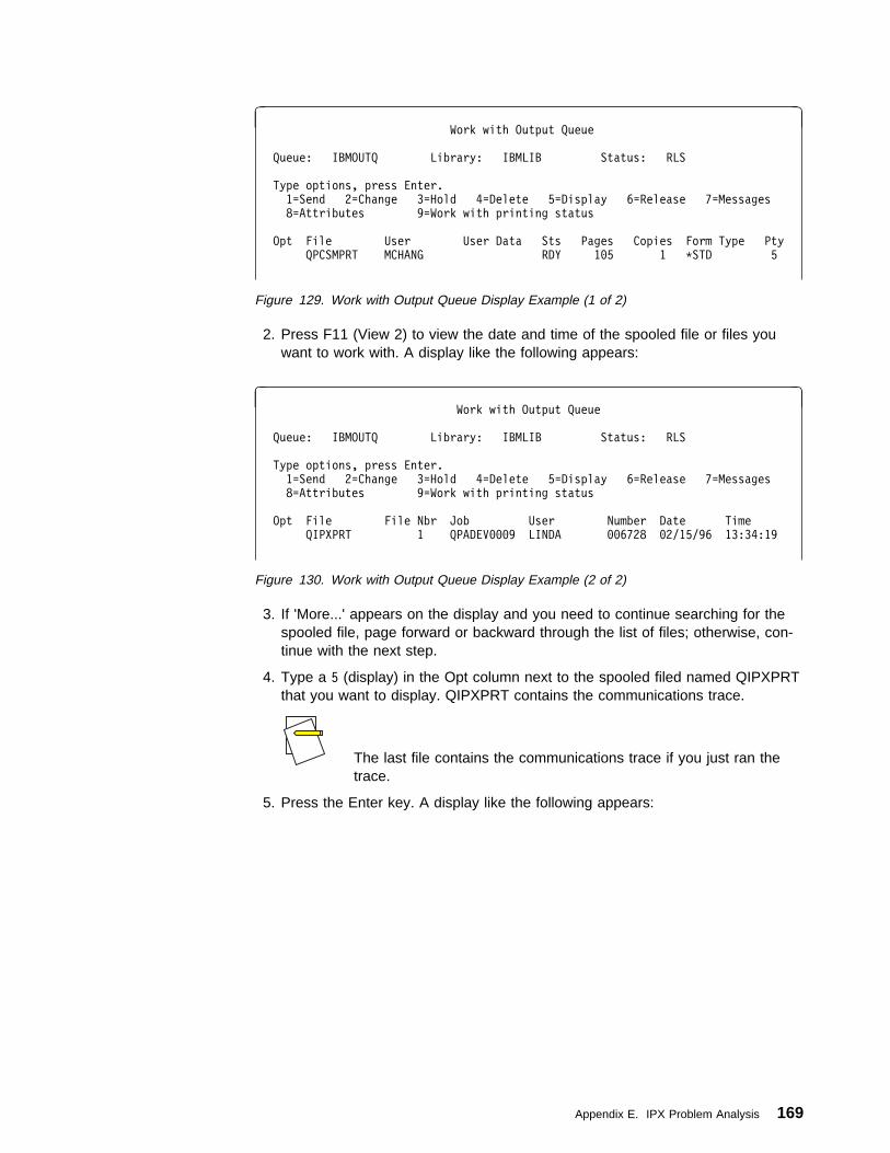
à ðWork with Output Queue
Queue: IBMOUTQ Library: IBMLIB Status: RLS
Type options, press Enter.
1=Send 2=Change 3=Hold 4=Delete 5=Display 6=Release 7=Messages
8=Attributes 9=Work with printing status
Opt File User User Data Sts Pages Copies Form Type Pty
QPCSMPRT MCHANG RDY 1ð5 1 \STD 5
Figure 129. Work with Output Queue Display Example (1 of 2)
2. Press F11 (View 2) to view the date and time of the spooled file or files youwant to work with. A display like the following appears:
à ðWork with Output Queue
Queue: IBMOUTQ Library: IBMLIB Status: RLS
Type options, press Enter.
1=Send 2=Change 3=Hold 4=Delete 5=Display 6=Release 7=Messages
8=Attributes 9=Work with printing status
Opt File File Nbr Job User Number Date Time
QIPXPRT 1 QPADEVððð9 LINDA ðð6728 ð2/15/96 13:34:19
Figure 130. Work with Output Queue Display Example (2 of 2)
3. If 'More...' appears on the display and you need to continue searching for thespooled file, page forward or backward through the list of files; otherwise, con-tinue with the next step.
4. Type a 5 (display) in the Opt column next to the spooled filed named QIPXPRTthat you want to display. QIPXPRT contains the communications trace.
The last file contains the communications trace if you just ran thetrace.
5. Press the Enter key. A display like the following appears:
Appendix E. IPX Problem Analysis 169

à ðDisplay Spooled File
File . . . . . : QPCSMPRT Page/Line 1/1
Control . . . . . ________ Columns 1 - 78
Find . . . . . . ______________________________
\...+....1....+....2....+....3....+....4....+....5....+....6....+....7....+...COMMUNICATIONS TRACE Title: IPX COMM TRACE ð2/14/96
Trace Description . . . . . : IPX COMM TRACE
Configuration object . . . . : IPXASSIST2
Type . . . . . . . . . . . . : 1 1=Line, 2=Network Interface
3=Network server
Object protocol . . . . . . : ETHERNET
Start date/Time . . . . . . : ð2/14/96 16:13:17
End date/Time . . . . . . . : ð9/14/96 16:13:48
Bytes collected . . . . . . : 173ð
Buffer size . . . . . . . . : 1 1=128K, 2=256K, 3=2ð48K
4=4ð96K, 5=6144K, 6=8192K
Data direction . . . . . . . : 3 1=Sent, 2=Received, 3=Both
Stop on buffer full . . . . : N Y=Yes, N=No
Number of bytes to trace
Beginning bytes . . . . . : \CALC Value, \CALC
Ending bytes . . . . . . : \CALC Value, \CALC
More...F3=Exit F12=Cancel F19=Left F2ð=Right F24=More keys
á ñ
Figure 131. Display Spooled File Display Example (1 of 3)
6. Verify that this is a communications trace for the line that is traced and that thetime the trace started and ended are correct.
The trace that is collected by the service tool is automatically deleted if you performan IPL; however, the spooled file is still saved.
If you page down to the start of the actual IPX data in the communications trace,you will see displays similar to the following:
à ðDisplay Spooled File
File . . . . . : QPCSMPRT Page/Line 1/24
Control . . . . . ________ Columns 1 - 78
Find . . . . . . ______________________________
\...+....1....+....2....+....3....+....4....+....5....+....6....+....7....+...Controller name . . . . . . : \ALL \ALL, name
Data representation . . . . : 3 1=ASCII, 2=EBCDIC, 3=\CALC
Format SNA data only . . . . : N Y=Yes, N=No
Format RR, RNR commands . . : N Y=Yes, N=No
Format TCP/IP data only . . : N Y=Yes, N=No
Format UI data only . . . . : N Y=Yes, N=No
Select Ethernet data . . . . : 3 1=8ð2.3, 2=ETHV2, 3=Both
Format Broadcast data . . . : Y Y=Yes, N=No
COMMUNICATIONS TRACE Title: IPX COMM TRACE ð2/14/96
Record Number . . . . Number of record in trace buffer (decimal)
S/R . . . . . . . . . S=Sent R=Received M=Modem Change
Data Length . . . . . Amount of data in record (decimal)
Record Status . . . . Status of record
Record Timer . . . . Time stamp (Seconds, 1ðð millisecond resolution,
decimal). Range is ð to 6553.5 seconds
Data Type . . . . . . EBCDIC data, ASCII data or Blank=Unknown
More...F3=Exit F12=Cancel F19=Left F2ð=Right F24=More keys
á ñ
Figure 132. Display Spooled File Display Example (2 of 3)
170 OS/400 Internetwork Packet Exchange (IPX) Support V4R1
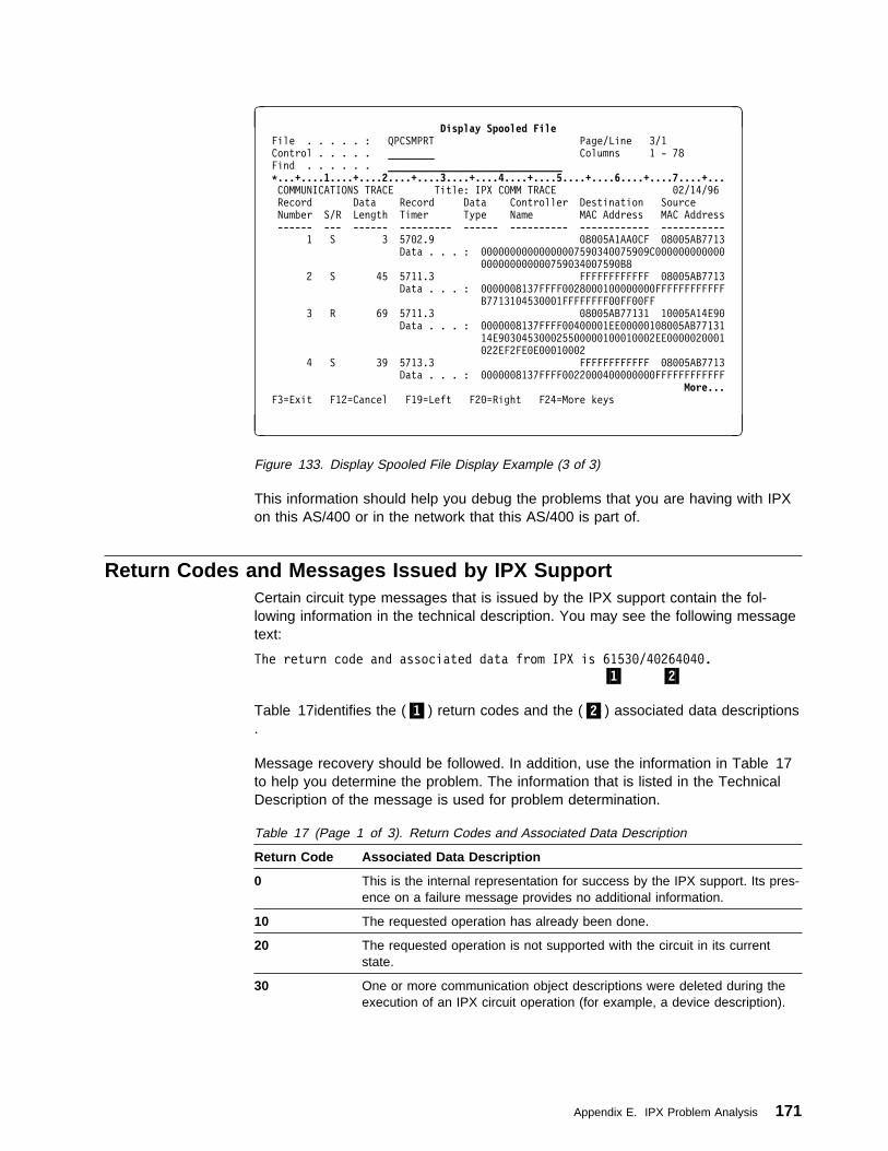
à ðDisplay Spooled File
File . . . . . : QPCSMPRT Page/Line 3/1
Control . . . . . ________ Columns 1 - 78
Find . . . . . . ______________________________
\...+....1....+....2....+....3....+....4....+....5....+....6....+....7....+...COMMUNICATIONS TRACE Title: IPX COMM TRACE ð2/14/96
Record Data Record Data Controller Destination Source
Number S/R Length Timer Type Name MAC Address MAC Address
------ --- ------ --------- ------ ---------- ------------ -----------
1 S 3 57ð2.9 ð8ðð5A1AAðCF ð8ðð5AB7713
Data . . . : ðððððððððððððððð759ð34ðð759ð9Cðððððððððððð
ðððððððððððð759ð34ðð759ðB8
2 S 45 5711.3 FFFFFFFFFFFF ð8ðð5AB7713
Data . . . : ðððððð8137FFFFðð28ððð1ððððððððFFFFFFFFFFFF
B77131ð453ððð1FFFFFFFFððFFððFF
3 R 69 5711.3 ð8ðð5AB77131 1ððð5A14E9ð
Data . . . : ðððððð8137FFFFðð4ðððð1EEððððð1ð8ðð5AB77131
14E9ð3ð453ððð255ððððð1ððð1ððð2EEððððð2ððð1
ð22EF2FEðEððð1ððð2
4 S 39 5713.3 FFFFFFFFFFFF ð8ðð5AB7713
Data . . . : ðððððð8137FFFFðð22ððð4ððððððððFFFFFFFFFFFF
More...F3=Exit F12=Cancel F19=Left F2ð=Right F24=More keys
á ñ
Figure 133. Display Spooled File Display Example (3 of 3)
This information should help you debug the problems that you are having with IPXon this AS/400 or in the network that this AS/400 is part of.
Return Codes and Messages Issued by IPX SupportCertain circuit type messages that is issued by the IPX support contain the fol-lowing information in the technical description. You may see the following messagetext:
The return code and associated data from IPX is 6153ð/4ð264ð4ð.
.1/ .2/
Table 17identifies the (.1/) return codes and the (.2/) associated data descriptions.
Message recovery should be followed. In addition, use the information in Table 17to help you determine the problem. The information that is listed in the TechnicalDescription of the message is used for problem determination.
Table 17 (Page 1 of 3). Return Codes and Associated Data Description
Return Code Associated Data Description
0 This is the internal representation for success by the IPX support. Its pres-ence on a failure message provides no additional information.
10 The requested operation has already been done.
20 The requested operation is not supported with the circuit in its currentstate.
30 One or more communication object descriptions were deleted during theexecution of an IPX circuit operation (for example, a device description).
Appendix E. IPX Problem Analysis 171

Table 17 (Page 2 of 3). Return Codes and Associated Data Description
Return Code Associated Data Description
40 The value specified in the IPX network number (IPXNETNBR) parameterof the circuit is different that the value currently in use by other systems onthe network. The associated data contains the network number being usedby other systems.
50 The line description resources required by the circuit are currently unavail-able.
The resource required by a circuit is determined by the Frame type(FRAMETYPE) circuit parameter for LAN line descriptions, the X.25 PVClogical channel ID (PVCLGLCHLI) parameter for X.25 line descriptions, orunavailable logical channels in the associated line.
60 The circuit was ended by the user or by IPX support. This usually is dueto the exhaustion of error recovery during the InterWorking exchange(IW2) processing of circuit startup. This is not a circuit error.
70 IPX support received an IW2 packet on a circuit which is currently active.This indicates that the adjacent system restarted IPX communication onthe circuit. Typically, the AS/400 system will attempt to reestablish commu-nication with the adjacent system.
80 The adjacent system is using the same IPX internal network number asthe local system (for example, IPXNETNBR parameter in the IPXdescription specified on the STRIPX command). The associated data con-tains the network number.
90 The routing capabilities offered by the adjacent system during the IW2exchange are incompatible with those configured for this circuit. Theparameters affecting routing capabilities are the IPX routing protocol(IPXRTGPCL) parameter and IPX packet forward (IPXPKTFWD) param-eter in the IPX description specified on the STRIPX command, and theEnable for NLSP (ENBNLSP) and RIP state (RIPSTATE) parameters inthe circuit. The default values for these parameters are the least restric-tive, and should prevent this type of failure. However, a common exampleof failure would be to not offer RIP (RIPSTATE(*OFF)) when the adjacentsystem requires it.
100 IW2 exchange did not complete. Circuit not activated. The adjacentsystem did not behave as required during the IW2 protocol exchange.
110 IW2 exchange did not complete. Circuit not activated. A negative acknowl-edgement was received by the adjacent system during the IW2 exchange.This is typically received from an adjacent system that encountered a pro-tocol error during the IW2 exchange.
120 IW2 exchange did not complete. Circuit not activated. An IW2 TimerResponse packet was not received from the adjacent system. For WANtype circuits over X.25 PVC or frame relay, the adjacent system is not yetready for communications.
130 IW2 exchange did not complete. Circuit not activated. After the IW2exchange was started, a Throughput Response was not received from theadjacent system.
140 IW2 exchange did not complete. Circuit not activated. After the IW2exchange was started, a Delay Response was not received from the adja-cent system.
150 IW2 exchange did not complete. Circuit not activated. After the IW2exchange was started, an Information Response was not received fromthe adjacent system.
172 OS/400 Internetwork Packet Exchange (IPX) Support V4R1
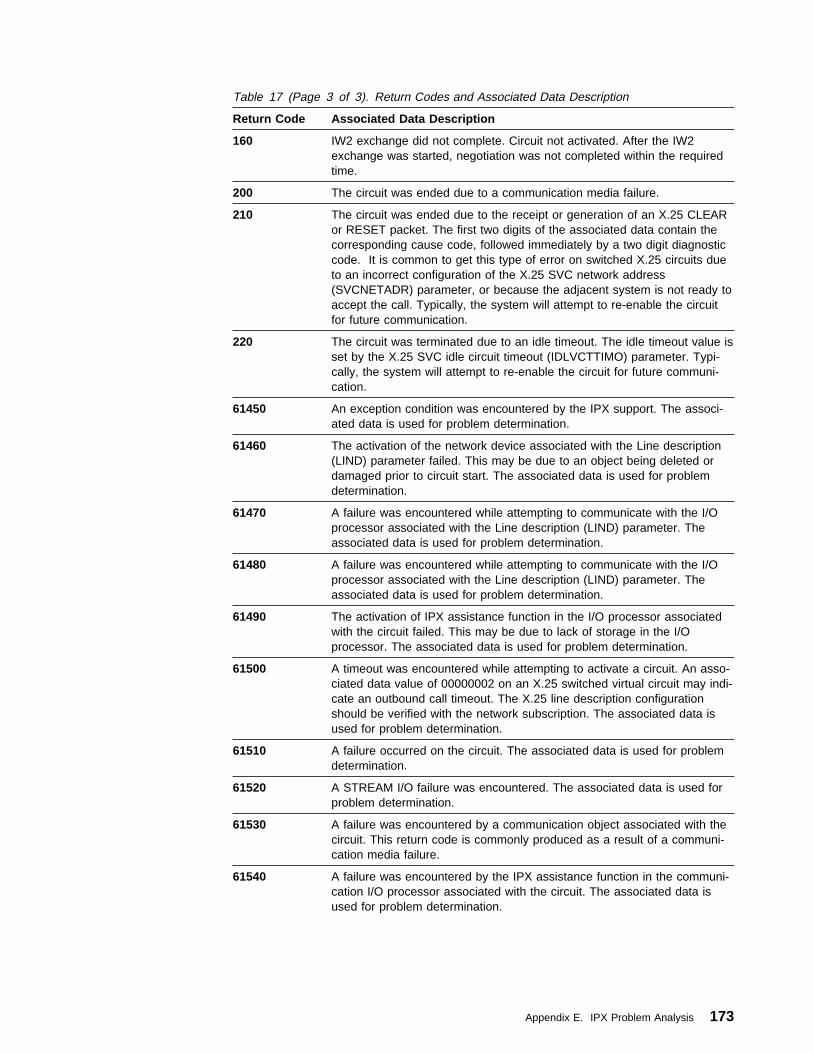
Table 17 (Page 3 of 3). Return Codes and Associated Data Description
Return Code Associated Data Description
160 IW2 exchange did not complete. Circuit not activated. After the IW2exchange was started, negotiation was not completed within the requiredtime.
200 The circuit was ended due to a communication media failure.
210 The circuit was ended due to the receipt or generation of an X.25 CLEARor RESET packet. The first two digits of the associated data contain thecorresponding cause code, followed immediately by a two digit diagnosticcode. It is common to get this type of error on switched X.25 circuits dueto an incorrect configuration of the X.25 SVC network address(SVCNETADR) parameter, or because the adjacent system is not ready toaccept the call. Typically, the system will attempt to re-enable the circuitfor future communication.
220 The circuit was terminated due to an idle timeout. The idle timeout value isset by the X.25 SVC idle circuit timeout (IDLVCTTIMO) parameter. Typi-cally, the system will attempt to re-enable the circuit for future communi-cation.
61450 An exception condition was encountered by the IPX support. The associ-ated data is used for problem determination.
61460 The activation of the network device associated with the Line description(LIND) parameter failed. This may be due to an object being deleted ordamaged prior to circuit start. The associated data is used for problemdetermination.
61470 A failure was encountered while attempting to communicate with the I/Oprocessor associated with the Line description (LIND) parameter. Theassociated data is used for problem determination.
61480 A failure was encountered while attempting to communicate with the I/Oprocessor associated with the Line description (LIND) parameter. Theassociated data is used for problem determination.
61490 The activation of IPX assistance function in the I/O processor associatedwith the circuit failed. This may be due to lack of storage in the I/Oprocessor. The associated data is used for problem determination.
61500 A timeout was encountered while attempting to activate a circuit. An asso-ciated data value of 00000002 on an X.25 switched virtual circuit may indi-cate an outbound call timeout. The X.25 line description configurationshould be verified with the network subscription. The associated data isused for problem determination.
61510 A failure occurred on the circuit. The associated data is used for problemdetermination.
61520 A STREAM I/O failure was encountered. The associated data is used forproblem determination.
61530 A failure was encountered by a communication object associated with thecircuit. This return code is commonly produced as a result of a communi-cation media failure.
61540 A failure was encountered by the IPX assistance function in the communi-cation I/O processor associated with the circuit. The associated data isused for problem determination.
Appendix E. IPX Problem Analysis 173
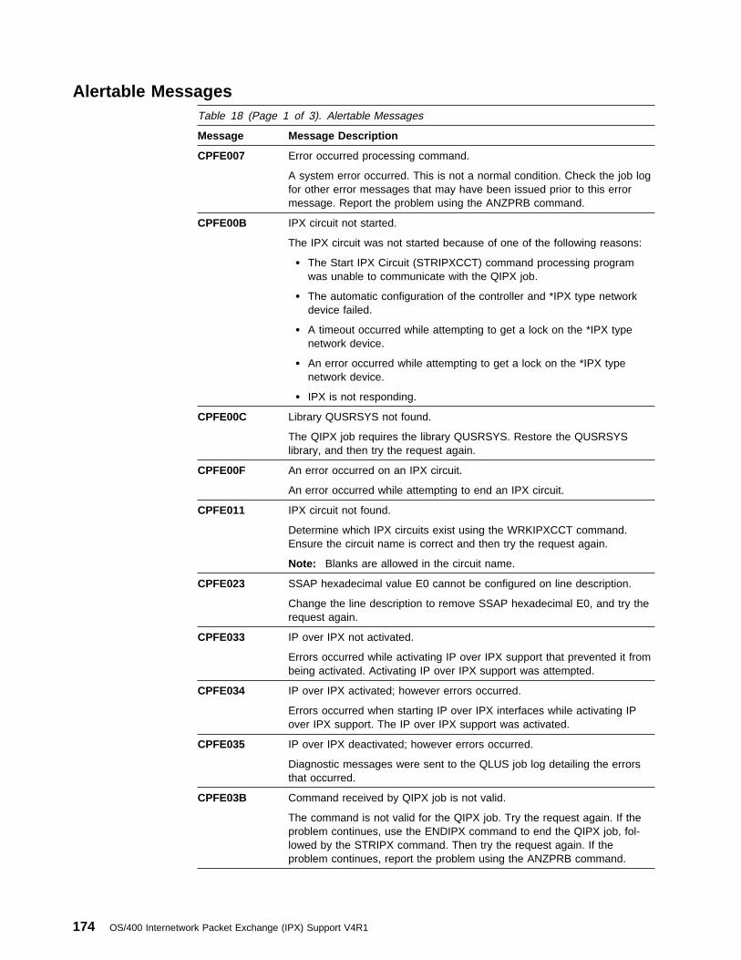
Alertable MessagesTable 18 (Page 1 of 3). Alertable Messages
Message Message Description
CPFE007 Error occurred processing command.
A system error occurred. This is not a normal condition. Check the job logfor other error messages that may have been issued prior to this errormessage. Report the problem using the ANZPRB command.
CPFE00B IPX circuit not started.
The IPX circuit was not started because of one of the following reasons:
� The Start IPX Circuit (STRIPXCCT) command processing programwas unable to communicate with the QIPX job.
� The automatic configuration of the controller and *IPX type networkdevice failed.
� A timeout occurred while attempting to get a lock on the *IPX typenetwork device.
� An error occurred while attempting to get a lock on the *IPX typenetwork device.
� IPX is not responding.
CPFE00C Library QUSRSYS not found.
The QIPX job requires the library QUSRSYS. Restore the QUSRSYSlibrary, and then try the request again.
CPFE00F An error occurred on an IPX circuit.
An error occurred while attempting to end an IPX circuit.
CPFE011 IPX circuit not found.
Determine which IPX circuits exist using the WRKIPXCCT command.Ensure the circuit name is correct and then try the request again.
Note: Blanks are allowed in the circuit name.
CPFE023 SSAP hexadecimal value E0 cannot be configured on line description.
Change the line description to remove SSAP hexadecimal E0, and try therequest again.
CPFE033 IP over IPX not activated.
Errors occurred while activating IP over IPX support that prevented it frombeing activated. Activating IP over IPX support was attempted.
CPFE034 IP over IPX activated; however errors occurred.
Errors occurred when starting IP over IPX interfaces while activating IPover IPX support. The IP over IPX support was activated.
CPFE035 IP over IPX deactivated; however errors occurred.
Diagnostic messages were sent to the QLUS job log detailing the errorsthat occurred.
CPFE03B Command received by QIPX job is not valid.
The command is not valid for the QIPX job. Try the request again. If theproblem continues, use the ENDIPX command to end the QIPX job, fol-lowed by the STRIPX command. Then try the request again. If theproblem continues, report the problem using the ANZPRB command.
174 OS/400 Internetwork Packet Exchange (IPX) Support V4R1

Table 18 (Page 2 of 3). Alertable Messages
Message Message Description
CPFE03C DFTMAXDTG value not valid.
The Default Maximum Datagram size (DFTMAXDTG) parameter value forthe IPX circuit is greater than the maximum frame size on the linedescription.
CPFE03D DFTPKTSIZE value not valid.
The transmit or receive parameter value of the default packet size isgreater than the maximum packet size parameter value on the linedescription.
CPFE03E DFTWDWSIZE value not valid.
The transmit or receive parameter value of the default window size isgreater than the default window size parameter value on the linedescription.
CPFE03F SVCNETADR value not valid.
The Switched Virtual Circuit Network Address (SVCNETADR) parametervalue for the IPX circuit cannot be more than 15 digits if the extendednetwork addressing (EXNNETADR) parameter value for the linedescription is *NO. Up to 17 digits can be specified if extended networkaddressing is *YES.
CPFE040 Cannot start the IPX circuit.
The IPX circuit has the same network number as the active IPXdescription.
CPFE041 IPXNETNBR does not match attached IPX network number.
The IPX Network Number (IPXNETNBR) parameter value for the IPXcircuit does not match the attached IPX network number.
CPFE04C SVC not valid for the IPX circuit.
An IPX circuit was specified as an SVC circuit. The SVC specified on theline description does not allow outgoing calls. This type of SVC is not validfor IPX circuits.
CPFE04D THROUGHPUT value *CALC not valid.
A throughput (THROUGHPUT) parameter value of *CALC was specifiedand the line description has a resource name value of *NWID. A networkinterface description (NWID) was not found so the THROUGHPUT param-eter value could not be calculated.
CPFE04F QIPX job did not start.
The QIPX job was unable to access system objects that are required forthe QIPX job. The QIPX job did not start.
CPFE056 Remote system not responding on IPX circuit.
The local system attempted to establish contact with the remote systemusing the IPX circuit. However, the local system received no responsewithin the required time limit.
CPFE057 Unable to establish circuit with remote system.
The local system attempted to negotiate communication capabilities withthe remote system using the circuit. However, the communication capabili-ties between the two systems are not compatible, and the circuit wasended.
Appendix E. IPX Problem Analysis 175
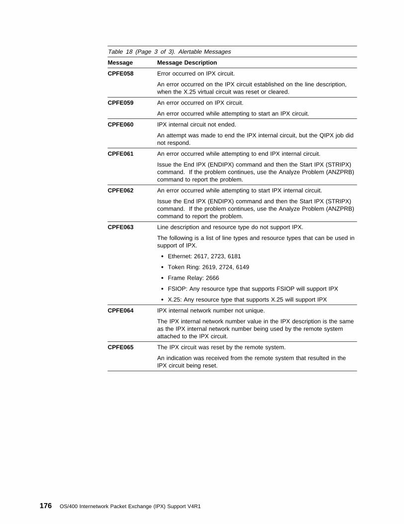
Table 18 (Page 3 of 3). Alertable Messages
Message Message Description
CPFE058 Error occurred on IPX circuit.
An error occurred on the IPX circuit established on the line description,when the X.25 virtual circuit was reset or cleared.
CPFE059 An error occurred on IPX circuit.
An error occurred while attempting to start an IPX circuit.
CPFE060 IPX internal circuit not ended.
An attempt was made to end the IPX internal circuit, but the QIPX job didnot respond.
CPFE061 An error occurred while attempting to end IPX internal circuit.
Issue the End IPX (ENDIPX) command and then the Start IPX (STRIPX)command. If the problem continues, use the Analyze Problem (ANZPRB)command to report the problem.
CPFE062 An error occurred while attempting to start IPX internal circuit.
Issue the End IPX (ENDIPX) command and then the Start IPX (STRIPX)command. If the problem continues, use the Analyze Problem (ANZPRB)command to report the problem.
CPFE063 Line description and resource type do not support IPX.
The following is a list of line types and resource types that can be used insupport of IPX.
� Ethernet: 2617, 2723, 6181
� Token Ring: 2619, 2724, 6149
� Frame Relay: 2666
� FSIOP: Any resource type that supports FSIOP will support IPX
� X.25: Any resource type that supports X.25 will support IPX
CPFE064 IPX internal network number not unique.
The IPX internal network number value in the IPX description is the sameas the IPX internal network number being used by the remote systemattached to the IPX circuit.
CPFE065 The IPX circuit was reset by the remote system.
An indication was received from the remote system that resulted in theIPX circuit being reset.
176 OS/400 Internetwork Packet Exchange (IPX) Support V4R1
Appendix F. NetWare for SAA Product Offering
What is NetWare for SAA? . . . . . . . . . . . . . . . . . . . . . . . . . . . . . 177NetWare for SAA and Client Access/400 . . . . . . . . . . . . . . . . . . . . . 178AS/400 Application Support . . . . . . . . . . . . . . . . . . . . . . . . . . . . . 179
This appendix introduces the NetWare for SAA product and relates it to the AS/400.
What is NetWare for SAA?The NetWare for SAA product from Novell is a set of NetWare Loadable Modules(NLMs) that integrates NetWare networks with AS/400 and mainframe environ-ments. It can support as many as 508 concurrent host sessions to multiple hostsover Ethernet, token-ring, SDLC, QLLC/X.25, and channel attachment data links.
NetWare for SAA is more than a gateway. A wide range of applications built onNetWare for SAA enable transparent integration of the AS/400 environment andNetWare networks. These LAN-to-host products provide such services as softwaredistribution and host database access. They also include electronic mail gateways,print services applications, LAN-over-SNA protocol routers, financial applications,and others.
Novell offers two such products: NetWare HostPrint and NetWare SNA Links .The NetWare HostPrint NLM** runs on a NetWare for SAA server and enables youto send host print jobs directly to LAN printers. NetWare SNA Links is an NLM thatworks with NetWare for SAA to route IPX/SPX protocols over an existing SNAbackbone network.
NetWare for SAA offers both host-based and network-based network managementsolutions. It supports IBM's NetView management by enabling NetView manage-ment system, by enabling NetView monitoring capabilities, and by providing acommand interface that enables the host operator to control NetWare serversdirectly from the host. For network-based management, NetWare for SAA includesa comprehensive set of network management and administrative tools. NetWare forSAA Service Manager application provides extensive network management capabil-ities for monitoring, controlling, and maintaining multiple NetWare for SAA serversfrom NetWare Management System (NMS) console.
See Figure 134 on page 178 for an example of integrating NetWare for SAA withAS/400.
Copyright IBM Corp. 1997 177

RV3W241-0
AS/400
NetWareServer
Client
- File/Print Services- NetWare for SAA
- Client Access/400- Requester
- Business Applications- OfficeVision/400- Client Access/400
NetWare Network
Figure 134. Integrating NetWare for SAA with the AS/400 Example
NetWare for SAA and Client Access/400NetWare for SAA extends the Client Access/400 program by providing an interfacefor DOS and Windows workstations. It transmits Client Access/400 calls over IPXsupport to the NetWare for SAA server. NetWare for SAA then handles all SNAcommunications with the AS/400. The AS/400 interface included in NetWare forSAA includes the following:
� Single transport protocol. Because NetWare for SAA enables Client Access/400to communicate over IPX/SPX, the NetWare shell can run alongside ClientAccess/400 functions.
� Reduced workstation memory. NetWare for SAA uses about 5KB of RAM at theworkstation for its AS/400 interface. The AS/400 interface can use as much as60 KB. Network Driver Interface Specification (NDIS) drivers used in Ethernetenvironments require even more memory.
� Support for a variety of topologies and adapters. NetWare for SAA supportstoken-ring, ARCNET, and Ethernet topologies over all adapters that are testedby Novell.
� Compatibility with existing routers. NetWare for SAA ensures compatibility withall routers, so Client Access/400 users can access AS/400 applications withoutneeding additional source routing bridges.
� Switched connectivity for remote workstations. NetWare for SAA, in conjunctionwith NetWare Access Services v1.3, allows remote dial-in access to bothNetWare resources and the AS/400 over the same asynchronous link.
� Remote connectivity for workgroups. NetWare for SAA allows a single SDLC orQLLC/X.25 connection to be shared among users on a NetWare network forconnection to a remote AS/400 without needing communications adapters orthe 5494 Remote Controller.
178 OS/400 Internetwork Packet Exchange (IPX) Support V4R1
� Macintosh access to AS/400 applications. NetWare Access Services v1.3, pro-vides a means for Macintosh users to run any Client Access/400 application(except shared folders).
For additional information on NetWare for SAA, see the online information providedwith the product or call IBM at 1-800-IBM-3040.
AS/400 Application SupportNetWare for SAA is completely compatible with Client Access/400 applications andAPIs. It also supports products for DOS with Extended Memory client and forWindows 3.1, including:
� Workstation function (for Windows 3.1)
� Elite/400** (for Windows 3.1)
Supported Client Access/400 functions include:
� Shared folders (DOS with Extended Memory client, for Windows 3.1, and Opti-mized for OS/2)
� Virtual print (DOS with Extended Memory client, for Windows 3.1, and Opti-mized for OS/2)
� File transfer (DOS with Extended Memory client, for Windows 3.1, and Opti-mized for OS/2)
� Organizer (DOS with Extended Memory client, for Windows 3.1, and Optimizedfor OS/2)
� PC5250 (DOS with Extended Memory client, for Windows 3.1, and Optimizedfor OS/2)
� Remote commands (DOS with Extended Memory client, for Windows 3.1, andOptimized for OS/2)
� RUMBA/400** (for Windows 3.1)
Original Equipment Manufacturer (OEM) products that allow network applications toaccess AS/400 databases include:
� SQL Router to AS/400**
� ShowCase**
� PROGRESS/400**
For additional information on OEM products, refer to the NetWare for SAA Sol-utions Guide.
Appendix F. NetWare for SAA Product Offering 179

180 OS/400 Internetwork Packet Exchange (IPX) Support V4R1
Notices
References in this publication to IBM products, pro-grams, or services do not imply that IBM intends tomake these available in all countries in which IBM oper-ates. Any reference to an IBM product, program, orservice is not intended to state or imply that only thatIBM product, program, or service may be used. Subjectto IBM's valid intellectual property or other legallyprotectable rights, any functionally equivalent product,program, or service may be used instead of the IBMproduct, program, or service. The evaluation and verifi-cation of operation in conjunction with other products,except those expressly designated by IBM, are theresponsibility of the user.
IBM may have patents or pending patent applicationscovering subject matter in this document. The furnishingof this document does not give you any license to thesepatents. You can send license inquiries, in writing, to:
IBM Director of LicensingIBM Corporation500 Columbus AvenueThornwood, NY 10594U.S.A
Licensees of this program who wish to have informationabout it for the purpose of enabling: (i) the exchange ofinformation between independently created programsand other programs (including this one) and (ii) themutual use of the information which has beenexchanged, should contact the software interoperabilitycoordinator. Such information may be available, subjectto appropriate terms and conditions, including in somecases, payment of a fee. Address your questions to:
IBM CorporationSoftware Interoperability Coordinator3605 Highway 52 NRochester, MN 55901-7829U.S.A.
This publication could contain technical inaccuracies ortypographical errors.
This publication may refer to products that are not cur-rently available. IBM makes no commitment to makeavailable any unannounced products referred to herein.
The final decision to announce any product is based onIBM's business and technical judgment.
This publication is for planning purposes only. The infor-mation herein is subject to change before the productsdescribed become available.
Trademarks
The following terms are trademarks of the IBM Corpo-ration in the United States or other countries or both:
Advanced Peer-to-Peer NetworkingAnyNetAnyNet/400Application System/400APPNAS/400C/400Client AccessDiscover/EducationIBMInformation AssistantIntegrated Language EnvironmentNetViewOperating System/400OS/2OS/400SAASystem 36System 38System Application Architecture400
Microsoft, Windows, and the Windows 95 logo aretrademarks or registered trademarks of Microsoft Corpo-ration.
UNIX is a registered trademark in the United States andother countries licensed exclusively through X/OpenCompany Limited
Other company, product, and service names, whichmay be denoted by a double asterisk (**), may betrademarks or service marks of others.
Copyright IBM Corp. 1997 181

182 OS/400 Internetwork Packet Exchange (IPX) Support V4R1
Bibliography
The publications that are listed in this bibliographyprovide additional information about topics that aredescribed or referred to in this book. The following pub-lications are listed with their full title, short title, andorder number. When these books are referred to in text,a shortened version of the title is used.
AS/400 Communications Books� APPN Support, SC41-5407. Provides information
about the concepts of AS/400 Advanced Peer-to-Peer Networking (APPN) and about planning APPNnetworks.
� APPC Programming, SC41-5443. Describes theadvanced program-to-program communications(APPC) support for the AS/400 system and providesthe information necessary for developing communi-cations application programs.
� Communications Configuration, SC41-5401.Describes the objects, commands, and parametersthat areused to configure OS/400 communications.It includes a general discussion of the objects andmethods used to configure communications anddetailed descriptions of all parameters that can bespecified for the commands used to create the con-figuration objects.
� Communications Management, SC41-5406. Con-tains information on working with communicationsstatus, errors, performance, line speed, and storagerequirements.
� Integration Services for the Integrated PC Server,SC41-5123. Describes how to configure, install, anduse the Integration Services for the Integrated PCServer.
� LAN and Frame Relay Support, SC41-5404.Describes the AS/400 support for IBM token-ring,distributed data interface (DDI), Ethernet, andwireless local area networks and frame relay widearea networks. This manual also includes informa-tion about AS/400 functions that are used forproblem determination and management of localarea networks.
� Integrating AS/400 with Novell NetWare,SC41-5124. Describes how to install and set up theNetWare 4.0 product from Novell, Inc., as well asthe Enhanced NetWare product.
� DSNX Support, SC41-5409. Provides informationfor configuring an AS/400 system to use the changemanagement support (distributed systems nodeexecutive), problem management support (alerts),and the Simple Network Management Protocol(SNMP) agent.
� Sockets Programming, SC41-5422. Provides infor-mation about for the system programmer for usingthe sockets programming interface for the AS/400system.
� X.25 Network Support, SC41-5405. Provides infor-mation on how to use the AS/400 X.25 support.Descriptions of various connection methods, diag-nostic information, and configuration examples areincluded.
Programming Books� Application Display Programming, SC41-5715. Con-
tains information about managing files, and creatingjob queues and output queues.
� CL Programming, SC41-5721. Provides the applica-tion programmer or programmer with a wide-rangingdiscussion of AS/400 programming topics, such asa general discussion of objects and libraries, controllanguage (CL) programming, messages andmessage handling, user-defined commands andmenus, and application testing.
� CL Reference, SC41-5722. Provides the applicationprogrammer or system programmer with adescription of the AS/400 control language (CL) andits commands. Command descriptions include asyntax diagram, parameters, default values andkeywords.
� System API Reference, SC41-5801. Provides infor-mation for the experienced programmer on how touse the application programming interfaces (APIs)to such OS/400 functions as:
– Dynamic Screen Manager
– Files (database, spooled, hierarchical)
– Message handling
– National language support
– Network management
– Objects
– Problem management
– Registration facility
– Security
– Software products
– Source debug
– UNIX-type
– User-defined communications
– User interface
Copyright IBM Corp. 1997 183
– Work management
System Books� Local Device Configuration, SC41-5121. Provides
the system operator or system administrator withinformation on how to do an initial hardware config-uration and how to change that configuration. Alsoincluded is a description of the different keyboardlanguage types.
� International Application Development, SC41-5603.Provides information that is required to understandand use the national language support function onthe AS/400 system. This manual prepares theAS/400 user for planning and using the national lan-guage support (NLS) and the multilingual support ofthe AS/400 system.
� Work Management, SC41-5306. Provides program-mers with information about how to effectivelymanage their system workload by changing workmanagement objects to meet their needs. The publi-cation provides guidelines for performance tuning;descriptions of system values; and information oncollecting performance data, gathering system usedata, using work entries, and scheduling batch jobs.
Architecture Books
The following book provides a technical overview ofMPTN architecture.
� Multiprotocol Transport Networking (MPTN)Architecture: Technical Overview, GC31-7073.
NetWare** Books
The following books are available with the NetWare4.10 Network Operating System from Novell.
� Getting Started with NetWare 4.0, PN100-001561-001
� NetWare for Macintosh Installation andMaintenance, PN 100-001795-001
� NetWare for Macintosh Print Services, PN100-001797-001
� NetWare 4.0 Basics and Installation, PN100-001562-001
� NetWare 4.0 Concepts, PN 100-001417-001
� NetWare 4.0 Installation and Upgrade, PN100-001414-001
� NetWare 4.0 Installation and Operation, PN100-001305-001
� NetWare 4.0 Master Index, PN 100-001421-001
� NetWare 4.0 Printer Services, PN 100-001419-001
� NetWare 4.0 Supervising the Network, PN100-001415-001
� NetWare 4.0 System Messages I, PN100-001563-001
� NetWare 4.0 System Messages II, PN100-001564-001
� NetWare 4.0 TCP/IP Transport Supervisor's Guide,PN 100-000945-002
� NetWare 4.0 Utilities Reference, PN100-001416-001
� NetWare 4.0 Workstation for DOS and Windows,PN 100-001623-001
� Using NetWare for Macintosh Client, PN100-001796-001
The following books are available with the Novell Multi-protocol Router 3.0 from Novell.
� NetWare MultiProtocol Router (TM) 3.0 Installationand Basic Configuration Guide, PN 100-002094-001
� NetWare MultiProtocol Router (TM) 3.0 AdvancedConfiguration and Management Guide, PN100-002091-001
� WAN Extensions 3.0 Installation and ConfigurationGuide PN 100-002138-001
� NetWare MultiProtocol Router (TM) 3.0 NLSP (TM)Migration Guide, PN 100-002088-001
Other Novell documents:
� The Novell Network Registry, PN 461-000248-001
� NetWare Link Services Protocol In-Depth PN481-000085-001
� Novell NetWare Link Services Protocol (NLSP)Specification, PN 100-001708-002
� IPX Router Specification, PN 107-000029-001
� NetWare for SAA Solutions Guide
Other Printed Information
The following non-IBM books provide detailed informa-tion about various communications standards.
� American National Standards Institute/Institute ofElectrical and Electronics Engineers 802.2,1985 -Logical Link Control, International Organization forStandardization/Draft International Standard 8802/2
� American National Standards Institute/Institute ofElectrical and Electronics Engineers 802.3,1985 -Carrier Sense Multiple Access with CollisionDetection, International Organization forStandardization/Draft International Standard 8802/3
184 OS/400 Internetwork Packet Exchange (IPX) Support V4R1

� American National Standards Institute/Institute ofElectrical and Electronics Engineers 802.3a, b, d, c,1988 -Supplements to Carrier Sense MultipleAccess with Collision Detection American NationalStandards Institute/Institute of Electrical and Elec-tronics Engineers Standard 802.3, 1985.
� American National Standards Institute/Institute ofElectrical and Electronics Engineers 802.5,1985 -
Token Passing Ring, International Organization forStandardization/Draft International Standard 8802/5
� The International Telegraph and TelephoneConsultative Committee, Red Book, Volume VIII -Facscicle VIII.3, Data Communications NetworksInterfaces, Recommendations X.20 - X.32, VIIIthPlenary Assembly, Malaga-Torremolinos, October8-19, 1984.
Bibliography 185

186 OS/400 Internetwork Packet Exchange (IPX) Support V4R1

Index
Special Characters*IOSYSCFG authority
configurationcommands 145
*SYSGEN default value 33
Numerics2850 Integrated PC Server 302850 Integrateed PC server 166506 Integrated PC server 16, 306616 Integrated PC server 16, 30
Aaccessing
SST 163activating
APPC over IPX Support 134IP over IPX Support 121
active IPX descriptiondisplaying 86
add circuit routecommand prompt example 59, 101example 103
for IPX network number 00000004 60for IPX network number 00000005 60for IPX network number 00000006 60
Add Circuit Route (ADDCCTRTE) command 57, 100add circuit service
command prompt example 63Add Circuit Service (ADDCCTSRV) command 61Add IP over IPX
address command prompt 118Interface (ADDIPIIFC) 114interface command prompt example 114, 115
add IPX circuit command prompt example 37Add SNA over IPX Location
(ADDSNILOC) command 131command prompt example 132, 133
add X.25 IPX circuit command prompt example 98ADDCCTRTE (Add Circuit Route) command 100ADDCCTSRV (Add Circuit Service) command 61adding a circuit service to the network example 62adding an IPX circuit
for X.25 SVC line 52hint 35
adding an X.25 SVC line description 98adding APPC over IPX location name addressing con-
figuration 131adding circuit route information for system D 100
adding circuit servicehint 62information 61
adding IP over IPX route (ADDIPIRTE) command 117adding IP over IPX routes configuration
adding IP over IPX route (ADDIPIRTE)command 117
adding route entries 100adding route informations 104considerations 104IPX considerations for routing 104
adding route information 45adding service information 45adding static routes
adding static route information 57hint 58
adding the remote locations to the APPN remotelocation lists 127
adding X.25 circuitfor X.25 SVC line 98
additional IPX configuration options 65address
node 11physical hardware 11
advanced configurationIPX support 89
AF_INET sockets over IPX 8alertable messages 174allow AnyNet support (ALWANYNET) network
attribute 134allow AnyNet/400 support for IP over IPX Support 120ALWANYNET (allow AnyNet support network
attribute) 134AnyNet/400 and IPX support
IP over IPX addresses configurationadding 117
IP over IPX interface configuration 114overview 112
AnyNet/400 over IPXIP over IPX routes configuration 117
AnyNet/400 support 109changing the IP over IPX configuration 121configure IPX menu 111
AnyNet/400 support for IP 120APPC configuration 124
adding the remote locations to the APPN remotelocation lists 127
creating the APPC Device and ModeDescriptions 126
APPC controller descriptionhint 125
Copyright IBM Corp. 1997 187

APPC Controller display example 126APPC mode description 126APPC over IPX
activating 134common configuration errors 135configuration 123
allow AnyNet support network attribute 134APPC controllers 124APPC mode description 126APPN remote location list 127controller description parameter 125link type parameter 125local locations lists 129location name addressing 131online parameter 125remote control point name parameter 125remote location name parameter 132remote network identifier parameter 125, 132remote network number parameter 132remote node address parameter 133
configuration example 124IPX configuration 124
configuration overview 123CPI-Communications applications 8definition 8intersystem communications function (ICF) applica-
tions 8support
allow AnyNet support network attribute 134APPC over IPX support
matching configuration parameters 135APPN remote location list 127
display example 128, 129, 130architecture books 184associated routes and services
working with 74authority
for usersQPGMR authority 145QSECOFR authority 145QSRV authority 145QSRVBAS authority 145QSYSOPR authority 145
automatic startdefinition 54parameter 42
circuit configuration 54Sample IPX circuit 54
Bbooks
architecture 184communications 183NetWare 184programming 183
books (continued)system 184
broadcastdefinition 40
bus topology 1
CCFGIPI (Configure IPI) command 121Change Line Description (Ethernet) (CHGLINETH)
command 51Change Line Description (Token-Ring) (CHGLINTRN)
command 51Change Line Description (X25) (CHGLINX25)
command 51, 98Change Network Attribute (CHGNNETA)
command 134channel entries 48Check Communications Trace (CHKCMNTRC)
command 161checking
communications trace 161CHKCMNTRC (Check Communications Trace)
command 161circuit
Internetwork Packet Exchange (IPX)definition 12
IPX (Internetwork Packet Exchange)definition 12
Start IPX Circuits (STRIPXCCT) command 76circuit name
parameter 38circuit route 59, 102circuit service 63IPX circuit 53
circuit name parameter 99circuit route
adding 57definition 57, 61example 57overview 56sample 60
circuit serviceadding 61definition 61overview 56sample 65
circuit service to the network exampleadding 62
circuitsEnd IPX Circuits (ENDIPXCCT) command 77
CL commandsAPPC over IPX
example 133IP over IPX configuration
example 120
188 OS/400 Internetwork Packet Exchange (IPX) Support V4R1

CL program for configuration example 137client
definition 1collecting
communications trace 161combining values for routing
considerations 106command prompt
create line description (Ethernet) 30Create Line Description (X25) 46
commandsAdd Circuit Route (ADDCCTRTE) 57, 100Add Circuit Service (ADDCCTSRV) 61add IP over IPX address (ADDIPIADR) 117Add IP over IPX Interface (ADDIPIIFC) 114Add SNA over IPX Location (ADDSNILOC) 131ADDCCTRTE (Add Circuit Route) 100ADDCCTSRV (Add Circuit Service) 61CFGIPI (Configure IPI) 121Change Line Description (Ethernet)
(CHGLINETH) 51Change Line Description (Token-Ring)
(CHGLINTRN) 51Change Line Description (X25) (CHGLINX25) 51,
98Change Network Attribute (CHGNNETA) 134Check Communications Trace (CHKCMNTRC) 161CHKCMNTRC (Check Communications Trace) 161configuration
special authorities 145Configure IPI (CFGIPI) command 121Create Controller Description (CRTCTLAPPC) 124Create Line Description (Ethernet
(CRTLINETH)) 30Create Line Description (Ethernet)
(CRTLINETH) 51Create Line Description (Token-Ring)
(CRTLINTRN) 51Create Line Description (X.25) (CRTLINX25) 95Create Line Description (X25) (CHGLINX25) 51, 98Create Line Description (X25) (CRTLINX25) 46CRTCTLAPPC (Create Controller Description) 124CRTLINETH 51CRTLINTRN 51CRTLINX25 46, 51, 98Delete Communications Trace (DLTCMNTRC) 161Display Line Description (DSPLIND) 51, 98Display Physical File Member (DSPPFM) 140DLTCMNTRC (Delete Communications Trace) 161DLTLIND 51, 98DSPLIND 51DSPPFM (Display Physical File Member) 140End Communications Trace (ENDCMNTRC) 161ENDCMNTRC (End Communications Trace) 161IPXPING (Verify IPX Connection) 160Print Communications Trace (PRTCMNTRC) 161
commands (continued)PRTCMNTRC (Print Communications Trace) 161Start Communications Trace (STRCMNTRC) 161STRCMNTRC (Start Communications Trace) 161Verify IPX Connection (IPXPING) 160Verify IPX Connection (VFYIPXCNN) 160VFYIPXCNN (Verify IPX Connection) 160Work with IPX Status (WRKIPXSTS) 162Work with Members Using PDM
(WRKMBRPDM) 140WRKIPXSTS (Work with IPX Status) 162WRKMBRPDM (Work with Members Using
PDM) 140common configuration
APPC over IPX 135errors 123problem analysis 154
communications books 183communications trace
checking 161collecting 161deleting 161display 164ending 161example 165formatting 168printing 161saving 168starting 161, 164stopping 167verifying contents 168
component traces 156configuration
AnyNet/400APPC over IPX 123
APPC over IPX 123circuit 35
X.25 52, 98debugging
IPXPING (Verify IPX Connection) 160Verify IPX Connection (VFYIPXCNN)
command 160Ethernet network example 23Integrated PC Server example 90Internetwork Packet Exchange (IPX)
NetWare Support 89line 30
X.25 46line descriptions
Ethernet 30X.25 95
matching parametersAPPC over IPX support 135IP over IPX support 122
multi-protocolAPPC over IPX 123
Index 189

configuration (continued)restoring configuration files 139saving configuration files 139X.25 network example 45, 90, 91
configuration filesdisplaying 140saving configuration files 139
configuration optionsadditional 65
configuration statuswork with 78
Configure IPI (CFGIPI) command 121configure IPX circuits menu example 35, 58configure IPX menu
AnyNet/400 support 111configure IPX menu example 21, 111configuring IPX
CL program example 137configuring IPX support 20
IPX over IPX 113configuring X.25 line description 95confirm end of IPX circuit display example 77confirm end of IPX connections display example 85confirm end of SPX connections display example 85connection
display IPX connections 83display SPX connections 83status, work with IPX connection 81status, work with SPX connection 81
connection initiation 98connection initiation parameter 49, 98considerations
configuration 67security 145
considerations for combining values for routing 106considerations for SAPSTATE parameter for
routing 106considerations for WAN line descriptions 107controller description parameter 125cost override for NLSP
parameter 41CPI-Communications 8CPI-Communications application program
APPC over IPX support of 123SNA over IPX support of 123
Create Controller Description (CRTCTLAPPC)command 124
Create IPX Description (CRTIPXD) commandprompt example 93
create IPX description command prompt example 23Create Line Description (Ethernet (CRTLINETH))
command 30Create Line Description (Ethernet) (CRTLINETH)
command 51Create Line Description (Token-Ring) (CRTLINTRN)
command 51
Create Line Description (X.25) (CRTLINX25 )command 95
Create Line Description (X25) (CRTLINX25)command 46, 51, 98
creating an Internetwork Packet Exchange (IPX)description 23
creating an IPX (Internetwork Packet Exchange)description 23
creating an IPX description 46for X.25 network 92
creating the APPC controller description 124creating the APPC Device and Mode Descriptions 126CRTLINETH (Create Line Description) (Ethernet)
command 30CRTLINX25 command 46
Ddatabase files 140database files used by IPX support 139datagram size 26, 41debugging capabilities 157, 159debugging IP over IPX configurations
IPXPING (Verify IPX Connection) 160Verify IPX Connection (IPXPING) 160Verify IPX Connection (VFYIPXCNN) 160VFYIPXCNN (Verify IPX Connection) 160
default maximum datagram sizehint 41parameter 41
default packet size parameter 49receive value 49transmit value 49
default window size parameter 50delay
parameter 42Delete Communications Trace (DLTCMNTRC)
command 161deleting
communications trace 161direct routing 12display
active IPX description example 86associated routes example 75associated services example 74circuit route command prompt example 61 circuit route example 104circuit services command prompt examplef 65format trace data 168IPX circuits LAN example 73IPX connection status example 83IPX route details example 76, 78IPX route information display example 78IPX service details example 74, 79IPX service information example 79
190 OS/400 Internetwork Packet Exchange (IPX) Support V4R1

display (continued)spooled file display example 170SPX connection status example 83start a service tool for SST 154, 164start trace 165system service tools (SST) 163work with communications traces 164X.25 circuit example 56
Display Line Description (DSPLIND) command 51Display Physical File Member (DSPPFM)
command 140displaying
an active IPX description 86associated routes 75associated services 74circuit configurations 42circuit status 73communications trace 168configuration files 140IPX route information 78IPX service information 79physical file member 140route details 76service details 75
distributed data processing 1DLTCMNTRC (Delete Communications Trace)
command 161DSPPFM (Display Physical File Member)
command 140
EEnable for IW2
parameterIPX circuit 100
Enable for NLSPparameter
IPX circuit 40End Communications Trace (ENDCMNTRC)
command 161End IPX Circuits (ENDIPXCCT) command 77ENDCMNTRC (End Communications Trace)
command 161ending
communications trace 161IPX (Internetwork Packet Exchange) support
End IPX (ENDIPX) command 70ending IPX
connections 85ending IPX connections
hint 85ending IPX support 67
hint 70ending SPX
connections 85
ENDIPXCCT (End IPX Circuit) command 77errors
IP over IPX configuration 160Ethernet
supported adapters 30Ethernet line description
examplefor system a 34for system b 34for system c 35
Ethernet network configuration 23Ethernet standard parameter 33example 32, 72, 81, 118
add circuit route 103add circuit route command prompt 59, 101add circuit route for IPX network number
00000004 60add circuit route for IPX network number
00000005 60add circuit route for IPX network number
00000006 60add circuit service command prompt 63add IP over IPX interface command prompt 114,
115add IPX circuit command prompt 37add SNA over IPX location command prompt 132add SNA over IPX locations command prompt 133add X.25 IPX circuit command prompt 98adding a circuit service to the network example 62APPC controller display 126APPC over IPX configuration 124APPN remote location list display 128, 129, 130CL commands for the APPC over IPX 133CL commands for the IP over IPX configuration 120CL program 137configure IPX circuits menu 35, 58configure IPX menu 21, 111confirm end of IPX circuit display 77confirm end of IPX connections display 85confirm end of SPX connections display 85Create IPX Description (CRTIPXD) command
prompt 93create IPX description command prompt 23create line description (Ethernet) (CRTLINETH)
command prompt 30display active IPX description 86display associated routes 75display associated services 74display circuit route 104display circuit route command prompt 61display circuit services command prompt 65display IPX circuit for system A 43display IPX circuit for system B 44display IPX circuit for system c 45display IPX circuits LAN 73display IPX connection status 83
Index 191

example (continued)display IPX route details 76, 78display IPX route information 78display IPX service details 74, 79display IPX service information 79display spooled file display 170display SPX connection status 83display X.25 circuit 56Ethernet line description 34Ethernet line description for system A 34Ethernet line description for system B 34Ethernet line description for system c 35format trace data 168integrating NetWare for SAA with the AS/400 178IP over IPX configuration 120IPX Circuit for X.25 line on system C 53IPX circuit routes 57, 100IPX description for system A 28IPX description for system b 28IPX description for system c 28IPX internetwork 11IPX network
configuring 21IPX network to be added to the IP network 113IPX protocol relationship 3IPX support
Integrated PC Server 15network 21protocol relationship 3restoring IPX configuration 140saving IPX configuration 139single IP network and single IPX network 112start a service tool menu 164Start IPX command prompt 69start trace 165, 166successfully added IP over IPX address 120system service tools (SST) display 164work with active jobs display 68work with circuit routes 103work with circuit routes display 61work with circuit routes display example 58work with circuit services display 62, 65work with communications resource 48work with communications traces display 166work with configuration status display 78work with IP over IPX address display 118work with IP over IPX interface display 116Work with IP over IPX Interfaces 114work with IPX circuits display 36, 42work with IPX circuits status display 76work with IPX descriptions display 23work with IPX status menu 72, 163work with IPX/SPX connection status display con-
nection state 81work with IPX/SPX connection status display
user 81
example (continued)work with output queue display 169work with SNA over IPX locations display 132X.25 line description command prompt example for
system D 96X.25 line description for AS/400 system C 47, 51X.25 network 46
Fformat communications trace data example 168format IPX data 168formatting
communications trace 168frame relay
supported adapters 30frame type
hint 38Novell 38parameter
IPX circuit 38FSIOP 2
See also Integrated PC Server
Ggeneral RIP request
definition 105getting started
working with communications trace 162
Hhint
adding an IPX circuit 35adding circuit service 62adding static routes 58APPC controller description 125default maximum datagram size 41ending IPX connections 85ending IPX support 70frame type 38IPX description name 24IPX internal network number 25, 93IPX maximum datagram parameter 26IPX network number 38router priority for NLSP 40source service access point parameter 33
history of Internetwork Packet Exchange (IPX)support 3
hopdefinition 12
hopsparameter
circuit route 59circuit service 64
192 OS/400 Internetwork Packet Exchange (IPX) Support V4R1
IICF (intersystem communications function)
application programAPPC over IPX, support of 123SNA over IPX support of 123
ICF applications 8indirect routing 12input/output (I/O) adapters
communicationsIntegrated PC Server 30
Integrated PC Server 2definition 16input/output (I/O) adapters 30internal network 15IPX support 15NetWare 15supported adapters 30
integrating NetWare for SAA with the AS/400example 178
internal networkInternetwork Packet Exchange (IPX)
definition 14internal network number 25internet
definition 2internet address parameter 115Internetwork Packet Exchange (IPX)
circuit 12history 3internal network 14introduction 1job
QAPPCIPX 68QIPX 68
jobs 68network
definition 10internal 14
network numberinternal network 15
networks 1problem analysis 153protocol
definition 3, 8protocols 1QSYSWRK subsystem 68routing 12server
definition 13software 3support
definition 2history 3
support, operatingconfiguration considerations 67
Internetwork Packet Exchange (IPX) circuitadding 35
Internetwork Packet Exchange (IPX) functionsrelationship among 9
Internetwork Packet Exchange (IPX) networkexample 21
Internetwork Packet Exchange (IPX) network numberregistering 17
Internetwork Packet Exchange (IPX) node address 11Internetwork Packet Exchange (IPX) packet
definition 12hop 12
Internetwork Packet Exchange (IPX) supportconfiguring 20
overview 21ending
hint 70operating 67routing 107starting
Start IPX (STRIPX) command 69Internetwork Packet Exchange Protocol (IPX) support
jobdescription 149
interoperabilitydefinition 2
IOAscommunications
Integrated PC Server 30IOP
IPX performance 149IOP-assist functions
definition 150NetWare Link Services Protocol (NLSP) assist 151packet rollup 150packet train 150routing information protocol (RIP) off-load 150service advertising protocol (SAP) off-load 150Simple Network Management Protocol SNMP)
support 151IP or IPX configuration examples
single IP network and single IPX network 112IP over IPX
activating 121addresses configuration
allow AnyNet/400 support 120common configuration errors 123configuring IPX support 113definition 110matching configuration parameters 122matching parameters 122problem analysis
debugging capabilities 159IP over IPX addresses
physical file 141
Index 193

IP over IPX addresses configurationparameter
remote IPX network number 119remote destination parameter 118remote IPX node address parameter 119subnet mask parameter 119
IP over IPX configurationAdd IP over IPX Interface (ADDIPIIFC)
command 114errors 160overview 112
IP over IPX configuration example 120IP over IPX interface configuration 114
internet address parameter 115subnet mask parameter 116work with IP over IPX interface display 116
IP over IPX menuchanging the configuraiton 121
IPX (Internetwork Packet Exchange)APPC over
configuration example 124matching configuration parameters 135
circuit 12ending
before you end 67introduction 1job
QAPPCIPX 68QIPX 68
jobs 68network
definition 10networks 1problem analysis 153protocol
definition 3protocols 1QSYSWRK subsystem 68router
definition 12routing 12server
definition 13starting
before you start 67support
definition 2history 3
support, operatingconfiguration considerations 67
IPX (Internetwork Packet Exchange) functionsrelationship among 9
IPX (Internetwork Packet Exchange) network numberregistering 17
IPX (Internetwork Packet Exchange) node address 11
IPX (Internetwork Packet Exchange) packetdefinition 12hop 12
IPX (Internetwork Packet Exchange) supportconfiguring 20ending
End IPX (ENDIPX) command 70hint 70
jobdescription 149
routing 107starting 69
IPX and AnyNet/400changing the IP over IPX configuration 121configure IPX menu 111support 109
IPX circuitadding 35additional parameters 41considerations for routing 105for X.25 SVC line description
adding 52IPX circuit considerations for routing 105IPX circuit definition
configurationNetWare Support 90
IPX circuit routes example 57, 100IPX circuit services
physical file 143IPX circuits
ending 77physical file 142sample 43
IPX configurationadding route information 45adding service information 45CL program example 137X.25 network configuration 46
IPX connectionsdisplaying 83
IPX database files for OS/400 140table 140
IPX descriptioncreating 23NetWare Support
configuration 89parameter 93
IPX description considerations for routing 104IPX description name
hint 24IPX description parameter 24IPX descriptions
performance 93IPX internal network number
hint 25, 93parameter 93
194 OS/400 Internetwork Packet Exchange (IPX) Support V4R1

IPX internal network number parameter 25IPX internetwork example 11IPX maximum datagram parameter 26
hint 26IPX network example 21IPX network number
hint 38parameter 38
circuit route 59circuit service 63
tip 38IPX network to be added to the IP network
example 113IPX node address 119IPX performance
protocol support provided by IOP 149IPX protocol layer problems, tracing 154IPX protocol relationship 3IPX route information
displaying 78IPX router name parameter 26IPX routes
physical file 143IPX routing 25IPX routing protocol parameter 25IPX service information
displaying 79IPX status
circuit statuswork with 72
IPX status forwork with 72
IPX Status menuproblem analysis 162
IPX supportadvanced configuration
NetWare Support on the Integrated PCServer 89
routing considerations 89configuring
IPX network example 21overview 21
database files 139input/output (I/O) adapters 30Integrated PC Server
example 15operating 67
IPX support and AnyNet/400add IP over IPX address (ADDIPIADR)
command 117IPX support on AS/400 9IPX virtual network
defined 14IPXPING (Verify IPX Connection) 160
Jjob
IPX 149job log
working with 153jobs
IPX 68
Lline description
parameter 38IPX circuit 53
line description name parameter 32line description parameter 47, 96, 99local network address parameter 97logical channel entries
logical channel identifier 97logical channel type 97PVC controller 97
logical channel entries parameter 48, 97logical channel ID 53logical channel identifier 48, 97logical channel type 48, 97logical network address parameter 49
MMAC (media access control), definition 40MAC Channel for NLSP
parameter 40main storage pool size 149manuals
architecture 184communications 183NetWare 184programming 183system 184
matching configuration parametersAPPC over IPX support 135IP over IPX support 122
matching parameters 122, 135maximum packet size parameter 50members using PDM
working with 140message queue
working with 153messages, alertable 174MPTN (Multiprotocol Transport Networking Architecture)
application protocoldefinition 8
multicastdefinition 40
Multiprotocol Transport Networking Architecture (MPTN)application protocol
definition 8
Index 195

NNetWare
Integrated PC Server 15NetWare books 184NetWare for SAA
AS/400 application support 179Client Access/400 178definition 177integrating with the AS/400 example 178
NetWare link services protocol (NLSP)definition 9
NetWare link services protocol (NLSP) off-loaddefinition 151
NetWare Supportconfiguration
circuit definition 90Internetwork Packet Exchange (IPX) 89IPX description 89
networkdefinition 1peer-to-peer 1protocols 3software 3topology examples 1
network address 97network configuration
object security 147network example 21
Internetwork Packet Exchange (IPX) 21network number 38, 93
internal 15Novell Network Registry 17registering 17
network protocolNetWare link services protocol (NLSP) 9
network protocol layer 8Internetwork Packet Exchange (IPX) 8IPX (Internetwork Packet Exchange) 8RIP (routing information protocol) 8routing information protocol (RIP) 8service advertising protocol (SAP) 9
network status for IPXconnections
display 85end 85
NLSP (NetWare link services protocol)cost override 41definition 9enable for 40MAC channel 40router priority 40
tip 40NLSP off-load
definition 151
NLSP route selection 107node
addressing 11definition 1
node addressparameter
circuit service 64Novell
frame type 38Novell Network Registry
duties 17registering
network number 17number of hops
parametercircuit route 59, 102circuit service 64
number of ticksparameter
circuit route 60, 102
Oobject authority
configurationcommands 146
object securitynetwork configuration 147
operating IPX supportmanaging IPX support 67
option 161See also work with...
Ppacket
definition 2packet rollup
definition 150packet size 50, 54
receive size 54receive value 50transmit size 54
packet traindefinition 150
parameter 119automatic start 54automatic start (AUTOSTART) 42circuit name 38, 53, 59, 63, 99
circuit route 102circuit service 63connection initiation 49, 98controller description 125cost override for NLSP 41default maximum datagram size 41default packet size 49
196 OS/400 Internetwork Packet Exchange (IPX) Support V4R1
parameter (continued)default window size 50delay (DELAY) 42Enable for IW2 100Enable for NLSP (Enable for NLSP) 40Ethernet standard 33frame type 38internet address parameter 115IPX description 24, 93IPX internal network number 25, 93IPX maximum datagram 26IPX network number 38, 59IPX router name 26IPX routing protocol 25line 38
See also line descriptionline description 47, 53, 96, 99line description name 32link type 125local network address 97logical channel entries 48, 97logical network address 49MAC Channel for NLSP 40maximum packet size 50number of hops 64
circuit route 59, 102number of ticks 60
circuit route 102online 125remote control point name 125remote destination 118remote IPX network number 59, 119
circuit service 63remote location name 132remote network identifier 125, 132remote network number 132
circuit route 102remote node address 64, 133remote socket address 64resource name 32, 47, 96RIP state 54router priority for NLSP 40SAP state 55source service access point 33subnet mask 116, 119SVC Call Type 53text 34X.25 default window size 54X.25 PVC logical channel ID 53X.25 PVC logical channel identifier 99X.25 SVC network address 53, 99
parametersadditional for IPX circuit 41
peer-to-peer network 1performance
IPX descriptions 93
performance (continued)IPX jobs 149main storage pool size 149NLSP off-load 151packet rollup 150packet train 150RIP off-load 150SAP off-load 150Simple Network Management Protocol (SNMP)
AS/400 SNMP agent 151physical database files
table 140physical database files for IPX support table 140physical file
QAZSPPADR 141QAZSPPCCT 142QAZSPPLOC 141QAZSPPRTE 143QAZSPPSRV 143
physical file memberdisplaying 140IPX configuration 140
planningwork with communications trace 162
Work with IPX Status (WRKIPXSTS)command 162
WRKIPXSTS (Work with IPX Status)command 162
point-to-point topology 1pool size 149Print Communications Trace (PRTCMNTRC)
command 161printing
communications trace 161problem analysis
common errors 154communications trace 161, 164
formatting 168saving 168stopping 167verifying contents 168
IP over IPXdebugging capabilities 159tracing 160
IPXalertable messages 174working with the job log 153working with the message queue 153
IPX protocol layer problems 154IPX Status menu 162IPX support 153return codes and messages 171SNA over IPX debugging capabilities 157
programmingbooks 183
Index 197
protocolapplication
Multiprotocol Transport Networking Architecture(MPTN) 8
Simple Network Management Protocol(SNMP) 5
sockets 5definition 3network
definition 3Internetwork Packet Exchange (IPX) 8NetWare link services protocol 9Service Advertising Protocol (SAP) 9
network layerRIP (routing information protocol) 8routing information protocol (RIP) 8
transport layerSequenced Packet Exchange (SPX) 7
protocol layer problemstracing 154
protocol layer, protocol 8protocol layer, transport 7protocol layers
upper 5protocol relationship example 3protocol support provided by IOP
IPX performance 149PRTCMNTRC (Print Communications Trace)
command 161PVC controller 48, 97PVC logical channel identifier 99
QQAPPCIPX job 68QAZSPPADR physical file 141QAZSPPCCT physical file 142QAZSPPLOC physical file 141QAZSPPRTE physical file 143QAZSPPSRV physical file 143QIPX job 68QPGMR authority 145QSECOFR authority 145QSRV authority 145QSRVBAS authority 145QSYSOPR authority 145QSYSWRK subsystem 68
Rreceive packet size 54receive value 49, 50receive window size 54records lengths
table 140
registering IPX network numbers 17relationship among the
IPX functions 9remote control point name parameter 125remote destination parameter 118remote IPX network number
parametercircuit route 59
remote IPX network number parameter 119remote IPX node address 119remote IPX node address parameter 119remote location name parameter 132remote network identifier parameter 125, 132remote network number
parametercircuit route 102
remote network number parameter 132remote node address
parametercircuit service 64
remote node address parameter 133remote socket address
parametercircuit service 64
resource name parameter 32, 47, 96resource sharing 1restoring
configuration files 139return codes and messages
problem analysis 171ring topology 1RIP (routing information protocol)
definition 8RIP off-load
definition 150RIP state
parameterIPX circuit 54
routeIPX route information, display 78
route detailsdisplaying 76
route informationadding 45
route selection 107router
Internetwork Packet Exchange (IPX)definition 12
router name 26router priority for NLSP
hint 40parameter 40
routing 107definition 12direct 12indirect 12
198 OS/400 Internetwork Packet Exchange (IPX) Support V4R1

routing information protocol (RIP)definition 8
routing information protocol (RIP) off-loaddefinition 150
Ssample 28
display IPX circuit for system A 43display IPX circuit for system c 45Ethernet line description 34Ethernet line description for system A 34Ethernet line description for system B 34Ethernet line description for system c 35X.25 line description for AS/400 system C 47, 51
sample circuit services 65sample display IPX circuit for system B 44sample IPX Circuit for X.25 line on system C 53sample IPX circuits 43sample X.25 line description 50SAP (Service Advertising Protocol)
definition 9SAP off-load
definition 150SAP state
parameterIPX circuit 55
SAPSTATE parameter for routingconsiderations 106
savingcommunications trace 168configuration files 139
saving IPX configuration example 139security
authority for usersQPGMR 145QSECOFR 145QSRV 145QSRVBAS 145QSYSOPR 145
considerations 145network configuration 147
Sequenced Packet Exchange (SPX)protocol
definition 7Sequenced packet exchange (SPX2)
definition 7Sockets applications 7
serverdefinition 1, 13
server jobIPX 68QAPPCIPX 68QIPX 68
servicestatus, work with IPX 79
Service Advertising Protocol (SAP)definition 9
Service Advertising Protocol (SAP) off-loaddefinition 150
service informationadding 45
service nameparameter
circuit service 63service type
parametercircuit service 63
servingintroduction 2
setting uplicensed internal code trace 154
Simple Network Management Protocol (SNMP)application protocol
upper layer 5Simple Network Management Protocol (SNMP)
support 151single IP network and single IPX Network
example 112SNA over IPX
definition 111problem analysis 157
tracing 158SNA over IPX configuration
overview 123SNA over IPX Locations
physical file 141SNMP (Network Management Protocol)
application protocolupper layer 5
SNMP supportIOP-assist functions
performance 151socket
definition 5well-known
table 6socket address
parametercircuit service 64
socket numbers 6socket numbers table 6sockets interface
application protocol 5software, network 3source service access point parameter 33
hint 33specific RIP request
definition 105SPX (Sequenced Packet Exchange)
protocoldefinition 7
Index 199

SPX connectionsdisplaying 83
SPX2State Values 81
SSAPs 33SST (system service tools)
accessing 163standard frame type 33start 54
communications trace display 165start a service tool menu example 164Start Communications Trace (STRCMNTRC)
command 161Start IPX Circuits (STRIPXCCT) command 76Start IPX command prompt example 69Start Trace Example 166starting
communications trace 161, 164work with communications trace 162
starting IPX circuits 76starting IPX support 67static route
adding 57definition 57, 61
static servicedefinition 61
status for IPXcircuit
work with configuration status 78circuit status
display 73circuits
display associated routes 75display associated services 74working with associated routes and services 74
connections 81display 83
displaying route details 76ending circuits 77information
service 79route information, display 78starting circuits 76
status for SPXconnections
display 83general information 81
status support 72stopping
communications trace 167storage pool size 149STRCMNTRC (Start Communications Trace)
command 161STRIPXCCT (Start IPX Circuits) command 76subnet mask parameter 116, 119
successfully added IP over IPX address example 120SVC call type 53SVC network address 53, 99system books 184system service tools (SST)
accessing 163display 163
example 164
Ttable, socket numbers 6text parameter 34ticks
parametercircuit route 60
tipIPX network number 38router priority 40
token ringsupported adapters 30
topologybus 1network 1point-to-point 1ring 1
tracecommunications
formatting 168saving 168
starting communications 164stopping communications 167verifying contents of communications 168working with communications 161
tracing IP over IPX problems 160tracing protocol layer problems 154tracing SNA over IPX Problems 158transmit packet size 54transmit value 49, 50transmit window size 54transport protocol layer 7
Sequenced Packet Exchange (SPX) 7
Uupper layers
protocol 5upper protocol layers 5user authority
QPGMR 145QSECOFR 145QSRV 145QSRVBAS 145QSYSOPR 145
200 OS/400 Internetwork Packet Exchange (IPX) Support V4R1

VVerify IPX Connection (IPXPING) 160Verify IPX Connection (VFYIPXCNN) command 160verifying
contents of communications trace 168VFYIPXCNN (Verify IPX Connection) command 160virtual network
definition 14
Wwell-known sockets
definition 6well-known sockets, definition 6window size 50, 54
receive 54receive value 50transmit 54transmit value 50
work with active jobs display example 68work with circuit routes display example 58, 61work with circuit routes example 103work with circuit services display example 62, 65work with communications resource display 32work with communications resource display
example 32work with communications resource example 48work with communications traces display example 166work with configuration status display example 78work with IP over IPX address display example 118work with IP over IPX interface display example 116work with IP over IPX interfaces example 114work with IPX circuits display example 36, 42work with IPX circuits status display 72work with IPX circuits status display example 72, 76work with IPX connection status 81work with IPX descriptions display example 23Work with IPX Status (WRKIPXSTS) command 72,
162Work with IPX Status menu 72work with IPX Status menu example 72, 163work with IPX/SPX connection status display byte
counts 81work with IPX/SPX connection status display byte
counts example 81work with IPX/SPX connection status display connection
state 81work with IPX/SPX connection status display user
example 81Work with Members Using PDM (WRKMBRPDM)
command 140work with output queue display example 169work with SNA over IPX locations display
example 132
work with SPX connection status 81working with
members using PDM 140WRKIPXSTS (Work with IPX Status) command 72,
162WRKMBRPDM (Work with Members Using PDM)
command 140
XX.25
supported adapters 30X.25 circuit display
sample 55X.25 default packet size
parameter 54IPX circuit 54
X.25 default window sizeparameter
IPX circuit 54X.25 line description
configuring 46for AS/400 system c
example 51sample 50
X.25 line description command prompt 96X.25 network
adding an IPX circuit 98configuring line description 95example 45IPX description 92
X.25 network example 46X.25 PVC logical channel ID
parameterIPX circuit 53
X.25 PVC logical channel identifierparameter
IPX circuit 99X.25 SVC call type
parameterIPX circuit 53
X.25 SVC network addressparameter
IPX circuit 53, 99
Index 201
Communicating Your Comments to IBM
AS/400 Advanced SeriesInternetwork Packet Exchange (IPX**)SupportVersion 4
Publication No. SC41-5400-00
If you especially like or dislike anything about this book, please use one of the methodslisted below to send your comments to IBM. Whichever method you choose, make sure yousend your name, address, and telephone number if you would like a reply.
Feel free to comment on specific errors or omissions, accuracy, organization, subject matter,or completeness of this book. However, the comments you send should pertain to only theinformation in this manual and the way in which the information is presented. To requestadditional publications, or to ask questions or make comments about the functions of IBMproducts or systems, you should talk to your IBM representative or to your IBM authorizedremarketer.
When you send comments to IBM, you grant IBM a nonexclusive right to use or distributeyour comments in any way it believes appropriate without incurring any obligation to you.
If you are mailing a readers' comment form (RCF) from a country other than the UnitedStates, you can give the RCF to the local IBM branch office or IBM representative forpostage-paid mailing.
� If you prefer to send comments by mail, use the RCF at the back of this book.
� If you prefer to send comments by FAX, use this number:
– United States and Canada: 1-800-937-3430– Other countries: 1-507-253-5192
� If you prefer to send comments electronically, use this network ID:
– IBMMAIL(USIB56RZ) – [email protected]
Make sure to include the following in your note:
� Title and publication number of this book� Page number or topic to which your comment applies.

Readers' Comments — We'd Like to Hear from You
AS/400 Advanced SeriesInternetwork Packet Exchange (IPX**)SupportVersion 4
Publication No. SC41-5400-00
Overall, how satisfied are you with the information in this book?
How satisfied are you that the information in this book is:
Please tell us how we can improve this book:
Thank you for your responses. May we contact you? Ø Yes Ø No
When you send comments to IBM, you grant IBM a nonexclusive right to use or distribute your commentsin any way it believes appropriate without incurring any obligation to you.
Name Address
Company or Organization
Phone No.
Very
Satisfied Satisfied Neutral DissatisfiedVery
Dissatisfied
Overall satisfaction Ø Ø Ø Ø Ø
Very
Satisfied Satisfied Neutral DissatisfiedVery
Dissatisfied
Accurate Ø Ø Ø Ø ØComplete Ø Ø Ø Ø ØEasy to find Ø Ø Ø Ø ØEasy to understand Ø Ø Ø Ø ØWell organized Ø Ø Ø Ø ØApplicable to your tasks Ø Ø Ø Ø Ø

Cut or FoldAlong Line
Cut or FoldAlong Line
Readers' Comments — We'd Like to Hear from YouSC41-5400-00 IBM
Fold and Tape Please do not staple Fold and Tape
NO POSTAGENECESSARYIF MAILED IN THEUNITED STATES
BUSINESS REPLY MAILFIRST-CLASS MAIL PERMIT NO. 40 ARMONK, NEW YORK
POSTAGE WILL BE PAID BY ADDRESSEE
IBM CORPORATIONATTN DEPT 542 IDCLERK3605 HWY 52 NROCHESTER MN 55901-7829
Fold and Tape Please do not staple Fold and Tape
SC41-5400-00


IBM
Printed in the United States of Americaon recycled paper containing 10%recovered post-consumer fiber.
SC41-54ðð-ðð
Spine information:
IBM AS/400 Advanced Series SupportInternetwork Packet Exchange (IPX**)
Version 4
Related Documents