Welcome message from author
This document is posted to help you gain knowledge. Please leave a comment to let me know what you think about it! Share it to your friends and learn new things together.
Transcript
Internet Engineering Task Force Audio-Video Transport Working GroupINTERNET-DRAFT H. Schulzrinnedraft-ietf-avt-issues-01.ps AT&T Bell Laboratories
October 20, 1993Expires: 03/01/94
Issues in Designing a Transport Protocol for Audio and Video Conferences andother Multiparticipant Real-Time Applications
Status of this Memo
This document is an Internet Draft. Internet Drafts are working documents of the Internet Engi-neering Task Force (IETF), its Areas, and its Working Groups. Note that other groups may alsodistribute working documents as Internet Drafts.
Internet Drafts are draft documents valid for a maximum of six months. Internet Drafts may beupdated, replaced, or obsoleted by other documents at any time. It is not appropriate to useInternet Drafts as reference material or to cite them other than as a \working draft" or \work inprogress."
Please check the I-D abstract listing contained in each Internet Draft directory to learn the currentstatus of this or any other Internet Draft.
Distribution of this document is unlimited.
Abstract
This memorandum is a companion document to the current version of the RTP protocolspeci�cation draft-ietf-avt-rtp-*.ftxt,psg. It discusses aspects of transporting real-time services(such as voice or video) over the Internet. It compares and evaluates design alternatives for areal-time transport protocol, providing rationales for the design decisions made for RTP. Alsocovered are issues of port assignment and multicast address allocation. A comprehensive glossaryof terms related to multimedia conferencing is provided.
This document is a product of the Audio-Video Transport working group within the InternetEngineering Task Force. Comments are solicited and should be addressed to the working group'smailing list at [email protected] and/or the author(s).
INTERNET-DRAFT draft-ietf-avt-issues-01.ps October 20, 1993
Contents
1 Introduction 4
1.1 T : : : : : : : : : : : : : : : : : : : : : : : : : : : : : : : : : : : : : : : : : : : : : : : 4
2 Goals 6
3 Services 8
3.1 Duplex or Simplex? : : : : : : : : : : : : : : : : : : : : : : : : : : : : : : : : : : : : : 10
3.2 Framing : : : : : : : : : : : : : : : : : : : : : : : : : : : : : : : : : : : : : : : : : : : 12
3.3 Version Identi�cation : : : : : : : : : : : : : : : : : : : : : : : : : : : : : : : : : : : : 12
3.4 Conference Identi�cation : : : : : : : : : : : : : : : : : : : : : : : : : : : : : : : : : : 13
3.4.1 Demultiplexing : : : : : : : : : : : : : : : : : : : : : : : : : : : : : : : : : : : 13
3.4.2 Aggregation : : : : : : : : : : : : : : : : : : : : : : : : : : : : : : : : : : : : : 14
3.5 Media Encoding Identi�cation : : : : : : : : : : : : : : : : : : : : : : : : : : : : : : : 14
3.5.1 Audio Encodings : : : : : : : : : : : : : : : : : : : : : : : : : : : : : : : : : : 15
3.5.2 Video Encodings : : : : : : : : : : : : : : : : : : : : : : : : : : : : : : : : : : 16
3.6 Playout Synchronization : : : : : : : : : : : : : : : : : : : : : : : : : : : : : : : : : : 17
3.6.1 Synchronization Methods : : : : : : : : : : : : : : : : : : : : : : : : : : : : : 18
3.6.2 Detection of Synchronization Units : : : : : : : : : : : : : : : : : : : : : : : : 20
3.6.3 Interpretation of Synchronization Bit : : : : : : : : : : : : : : : : : : : : : : : 21
3.6.4 Interpretation of Timestamp : : : : : : : : : : : : : : : : : : : : : : : : : : : 22
3.6.5 End-of-talkspurt indication : : : : : : : : : : : : : : : : : : : : : : : : : : : : 26
3.6.6 Recommendation : : : : : : : : : : : : : : : : : : : : : : : : : : : : : : : : : : 26
3.7 Segmentation and Reassembly : : : : : : : : : : : : : : : : : : : : : : : : : : : : : : : 27
3.8 Source Identi�cation : : : : : : : : : : : : : : : : : : : : : : : : : : : : : : : : : : : : 28
H. Schulzrinne Expires 03/01/94 [Page 2]
INTERNET-DRAFT draft-ietf-avt-issues-01.ps October 20, 1993
3.8.1 Bridges, Translators and End Systems : : : : : : : : : : : : : : : : : : : : : : 28
3.8.2 Address Format Issues : : : : : : : : : : : : : : : : : : : : : : : : : : : : : : : 29
3.8.3 Globally unique identi�ers : : : : : : : : : : : : : : : : : : : : : : : : : : : : : 30
3.8.4 Locally unique addresses : : : : : : : : : : : : : : : : : : : : : : : : : : : : : : 31
3.9 Energy Indication : : : : : : : : : : : : : : : : : : : : : : : : : : : : : : : : : : : : : : 32
3.10 Error Control : : : : : : : : : : : : : : : : : : : : : : : : : : : : : : : : : : : : : : : : 32
3.11 Security and Privacy : : : : : : : : : : : : : : : : : : : : : : : : : : : : : : : : : : : : 35
3.11.1 Introduction : : : : : : : : : : : : : : : : : : : : : : : : : : : : : : : : : : : : 35
3.11.2 Con�dentiality : : : : : : : : : : : : : : : : : : : : : : : : : : : : : : : : : : : 36
3.11.3 Message Integrity and Authentication : : : : : : : : : : : : : : : : : : : : : : 37
3.12 Security for RTP vs. PEM : : : : : : : : : : : : : : : : : : : : : : : : : : : : : : : : : 38
3.13 Quality of Service Control : : : : : : : : : : : : : : : : : : : : : : : : : : : : : : : : : 39
3.13.1 QOS Measures : : : : : : : : : : : : : : : : : : : : : : : : : : : : : : : : : : : 39
3.13.2 Remote measurements : : : : : : : : : : : : : : : : : : : : : : : : : : : : : : : 40
3.13.3 Monitoring by Third Party : : : : : : : : : : : : : : : : : : : : : : : : : : : : 41
4 Conference Control Protocol 41
5 The Use of Pro�les 42
6 Port Assignment 42
7 Multicast Address Allocation 43
7.1 Channel Sensing : : : : : : : : : : : : : : : : : : : : : : : : : : : : : : : : : : : : : : 44
7.2 Global Reservation Channel with Scoping : : : : : : : : : : : : : : : : : : : : : : : : 45
7.3 Local Reservation Channel : : : : : : : : : : : : : : : : : : : : : : : : : : : : : : : : 45
H. Schulzrinne Expires 03/01/94 [Page 3]

INTERNET-DRAFT draft-ietf-avt-issues-01.ps October 20, 1993
7.3.1 Hierarchical Allocation with Servers : : : : : : : : : : : : : : : : : : : : : : : 45
7.3.2 Distributed Hierarchical Allocation : : : : : : : : : : : : : : : : : : : : : : : : 46
7.4 Restricting Scope by Limiting Time-to-Live : : : : : : : : : : : : : : : : : : : : : : : 46
8 Security Considerations 47
A Glossary 47
B Address of Author 55
1 Introduction
This memorandum
1.1 T
he transport protocol for real-time applications (RTP) discussed in the pr this memorandum aimsto provide services commonly required by interactive multimedia conferences, such as playout syn-chronization, demultiplexing, media identi�cation and active-party identi�cation. However, RTPis not restricted to multimedia conferences; it is anticipated that other real-time services such asremote data acquisition and control may �nd its services of use.
In this context, a conference describes associations that are characterized by the participationof two or more agents, interacting in real time with one or more media of potentially di�erenttypes. The agents are anticipated to be human, but may also be measurement devices, remotemedia servers, simulators and the like. Both two-party and multiple-party associations are to besupported, where one or more agents can take active roles, i.e., generate data. Thus, applicationsnot commonly considered a conference fall under this wider de�nition, for example, one-way mediasuch as the network equivalent of closed-circuit television or radio, traditional two-party telephoneconversations or real-time distributed simulations. Even though intended for real-time interactiveapplications, the use of RTP for the storage and transmission of recorded real-time data should bepossible, with the understanding that the interpretation of some �elds such as timestamps may bea�ected by this o�-line mode of operation.
RTP uses the services of an end-to-end transport protocol such as UDP, TCP, OSI TP1 or TP4,ST-II or the like1 . The services used are: end-to-end delivery, framing, demultiplexing and multi-
1ST-II is not properly a transport protocol, as it is visible to intermediate nodes, but it provides services such asprocess demultiplexing commonly associated with transport protocols.
H. Schulzrinne Expires 03/01/94 [Page 4]
INTERNET-DRAFT draft-ietf-avt-issues-01.ps October 20, 1993
cast. The underlying network is not assumed to be reliable and can be expected to lose, corrupt,arbitrarily delay and reorder packets. However, the use of RTP within quality-of-service (e.g., rate)controlled networks is anticipated to be of particular interest. Network layer support for multicas-ting is desirable, but not required. RTP is supported by a real-time control protocol (RTCP) in arelationship similar to that between IP and ICMP. However, RTP can be used, with reduced func-tionality, without a control protocol. The control protocol RTCP provides minimum functionalityfor maintaining conference state for one or more ows within a single transport association. RTCPis not guaranteed to be reliable; each participant simply sends the local information periodically toall other conference participants.
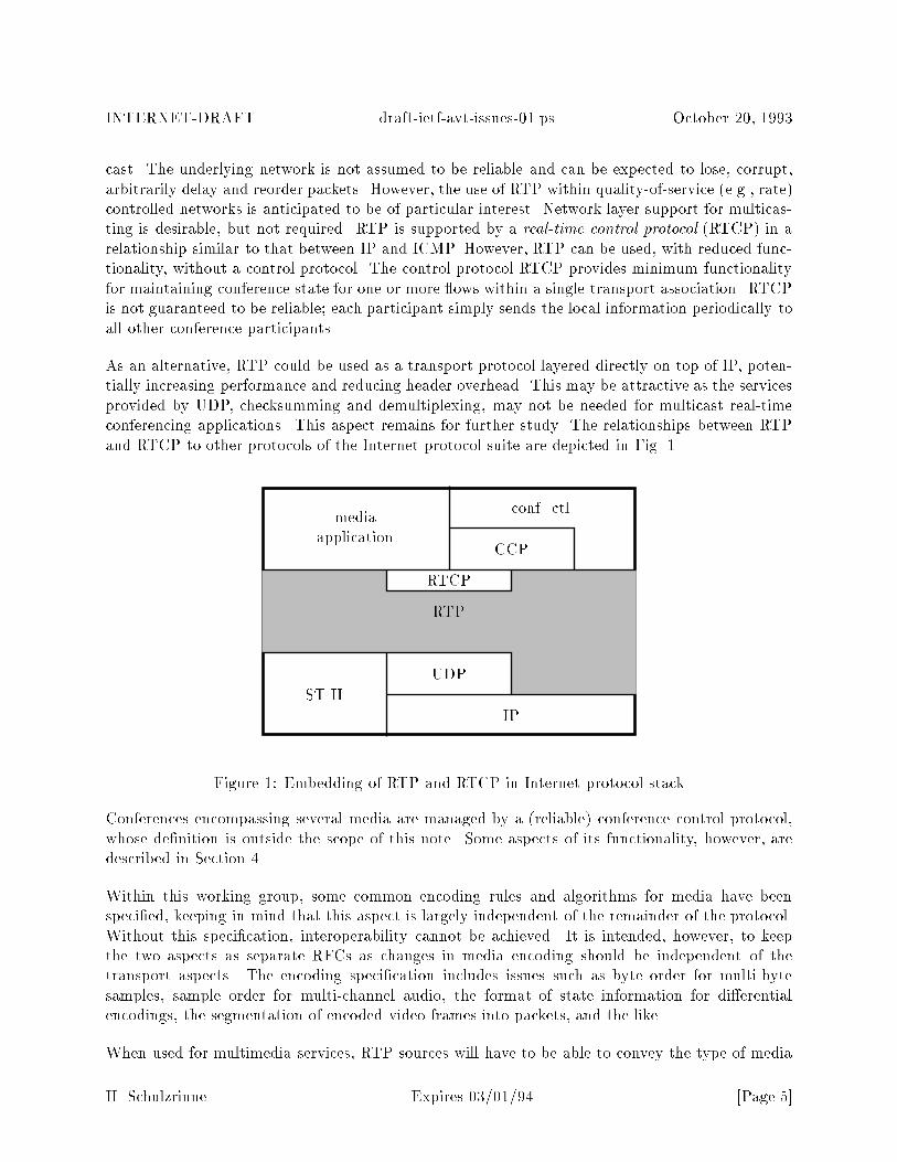
As an alternative, RTP could be used as a transport protocol layered directly on top of IP, poten-tially increasing performance and reducing header overhead. This may be attractive as the servicesprovided by UDP, checksumming and demultiplexing, may not be needed for multicast real-timeconferencing applications. This aspect remains for further study. The relationships between RTPand RTCP to other protocols of the Internet protocol suite are depicted in Fig. 1.
RTP
ST-II
IP
UDP
RTCP
mediaapplication
conf. ctl.
CCP
Figure 1: Embedding of RTP and RTCP in Internet protocol stack
Conferences encompassing several media are managed by a (reliable) conference control protocol,whose de�nition is outside the scope of this note. Some aspects of its functionality, however, aredescribed in Section 4.
Within this working group, some common encoding rules and algorithms for media have beenspeci�ed, keeping in mind that this aspect is largely independent of the remainder of the protocol.Without this speci�cation, interoperability cannot be achieved. It is intended, however, to keepthe two aspects as separate RFCs as changes in media encoding should be independent of thetransport aspects. The encoding speci�cation includes issues such as byte order for multi-bytesamples, sample order for multi-channel audio, the format of state information for di�erentialencodings, the segmentation of encoded video frames into packets, and the like.
When used for multimedia services, RTP sources will have to be able to convey the type of media
H. Schulzrinne Expires 03/01/94 [Page 5]
INTERNET-DRAFT draft-ietf-avt-issues-01.ps October 20, 1993
encoding used to the receivers. The number of encodings potentially used is rather large, but asingle application will likely restrict itself to a small subset of that. To allow the participants inconferences to unambiguously communicate to each other the current encoding, the working groupis de�ning a set of encoding names to be registered with the Internet Assigned Numbers Authority(IANA). Also, short integers for a default mapping of common encodings are speci�ed.
The issue of port assignment will be discussed in more detail in Section 6. It should be emphasized,however, that UDP port assignment does not imply that all underlying transport mechanisms sharethis or a similar port mechanism.
This memorandum aims to summarize some of the discussions held within the audio-video transport(AVT) working group chaired by Stephen Casner, but the opinions are the author's own. Wherepossible, references to previous work are included, but the author realizes that the attribution ofideas is far from complete. The memorandum builds on operational experience with Van Jacobson'sand Steve McCanne's vat audio conferencing tool as well as implementation experience with theauthor's Nevot network voice terminal. This note will frequently refer to NVP [1], the networkvoice protocol, a protocol used in two versions for early Internet wide-area packet voice experiments.CCITT has standardized as recommendations G.764 and G.765 a packet voice protocol stack foruse in digital circuit multiplication equipment.
The name RTP was chosen to re ect the fact that audio and video conferences may not be theonly applications employing its services, while the real-time nature of the protocol is important,setting it apart from other multimedia-transport mechanisms, such as the MIME multimedia maile�ort [2].
The remainder of this memorandum is organized as follows. Section 2 summarizes the design goalsof this real-time transport protocol. Then, Section 3 describes the services to be provided in moredetail. Section 4 brie y outlines some of the services added by a higher-layer conference controlprotocol; a more detailed description is outside the scope of this document. Two appendices discussthe issues of port assignment and multicast address allocation, respectively. A glossary de�nes termsand acronyms, providing references for further detail. The actual protocol speci�cation embodyingthe recommendation and conclusions of this report is contained in a separate document.
2 Goals
Design decisions should be measured against the following goals, not necessarily listed in order ofimportance:
content exibility: While the primary applications that motivate the protocol design are confer-ence voice and video, it should be anticipated that other applications may also �nd the servicesprovided by the protocol useful. Some examples include distribution audio/video (for exam-ple, the \Radio Free Ethernet"application by Sun), distributed simulation and some forms of(loss-tolerant) remote data acquisition (for example, active badge systems [3, 4]). Note that
H. Schulzrinne Expires 03/01/94 [Page 6]
INTERNET-DRAFT draft-ietf-avt-issues-01.ps October 20, 1993
it is possible that the same packet header �eld may be interpreted in di�erent ways depend-ing on the content (e.g., a synchronization bit may be used to indicate the beginning of atalkspurt for audio and the beginning of a frame for video). Also, new formats of establishedmedia, for example, high-quality multi-channel audio or combined audio and video sources,should be anticipated where possible.
extensible: Researchers and implementors within the Internet community are currently only be-ginning to explore real-time multimedia services such as video conferences. Thus, the RTPshould be able to incorporate additional services as operational experience with the protocolaccumulates and as applications not originally anticipated �nd its services useful. The samemechanisms should also allow experimental applications to exchange application-speci�c in-formation without jeopardizing interoperability with other applications. Extensibility is alsodesirable as it will hopefully speed along the standardization e�ort, making the consequencesof leaving out some group's favorite �xed header �eld less drastic.
It should be understood that extensibility and exibility may con ict with the goals of band-width and processing e�ciency.
independent of lower-layer protocols: RTP should make as few assumptions about the under-lying transport protocol as possible. It should, for example, work reasonably well with UDP,TCP, ST-II, OSI TP, VMTP and experimental protocols, for example, protocols that supportresource reservation and quality-of-service guarantees. Naturally, not all transport protocolsare equally suited for real-time services; in particular, TCP may introduce unacceptable de-lays over anything but low-error-rate LANs. Also, protocols that deliver streams rather thanpackets needs additional framing services as discussed in Section 3.2.
It remains to be discussed whether RTP may use services provided by the lower-layer protocolsfor its own purposes (time stamps and sequence numbers, for example).
The goal of independence from lower-layer considerations also a�ects the issue of addressrepresentation. In particular, anything too closely tied to the current IP 4-byte addressesmay face early obsolescence. It is to be anticipated, however, that experience gained willsuggest a new protocol revision in any event by that time.
bridge-compatible: Operational experience has shown that RTP-level bridges are necessary anddesirable for a number of reasons. First, it may be desirable to aggregate several mediastreams into a single stream and then retransmit it with possibly di�erent encoding, packetsize or transport protocol. A packet \translator" that achieves multicasting by user-levelcopying may be needed where multicast tunnels or IP connectivity are unavailable or theend-systems are not multicast-capable.
bandwidth e�cient: It is anticipated that the protocol will be used in networks with a widerange of bandwidths and with a variety of media encodings. Despite increasing bandwidthswithin the national backbone networks, bandwidth e�ciency will continue to be important fortransporting conferences across 56 kb links, o�ce-to-home high-speed modem connections andinternational links. To minimize end-to-end delay and the e�ect of lost packets, packetizationintervals have to be limited, which, in combination with e�cient media encodings, leadsto short packet sizes. Generally, packets containing 16 to 32 ms of speech are consideredoptimal [5{7]. For example, even with a 65 ms packetization interval, a 4800 b/s encoding
H. Schulzrinne Expires 03/01/94 [Page 7]
INTERNET-DRAFT draft-ietf-avt-issues-01.ps October 20, 1993
produces 39 byte packets. Current Internet voice experiments use packets containing around20 ms of audio, which translates into 160 bytes of audio information coded at 64 kb/s. Videopackets are typically much longer, so that header overhead is less of a concern.
For UDP multicast (without counting the overhead of source routing as currently used intunnels or a separate IP encapsulation as planned), IPv4 incurs 20 bytes and UDP an addi-tional 8 bytes of header overhead, to which datalink layer headers of at least 4 bytes mustbe added. With RTP header lengths between 4 and 8 bytes, the total overhead amounts tobetween 36 and 40 (or more) bytes per audio or video packet. For 160-byte audio packets,the overhead of 8-byte RTP headers together with UDP, IP and PPP (as an example of adatalink protocol) headers is 25%. For low bitrate coding, packet headers can easily doublethe necessary bit rate.
Thus, it appears that any �xed headers beyond eight bytes would have to make a signi�cantcontribution to the protocol's capabilities as such long headers could stand in the way ofrunning RTP applications over low-speed links. The current �xed header lengths for NVPand vat are 4 and 8 bytes, respectively. It is interesting to note that G.764 has a totalheader overhead, including the LAPD data link layer, of only 8 bytes, as the voice transportis considered a network-layer protocol. The overhead is split evenly between layers 2 and 3.
Bandwidth e�ciency can be achieved by transporting non-essential or slowly changing pro-tocol state in optional �elds or in a separate low-bandwidth control protocol. Also, headercompression [8] may be used.
international: Even now, audio and video conferencing tools are used far beyond the NorthAmerican continent. It would seem appropriate to give considerations to internationalizationconcerns, for example to allow for the European A-law audio companding and non-US-ASCIIcharacter sets in textual data such as site identi�cation.
processing e�cient: With arrival rates of on the order of 40 to 50 packets per second for a singlevoice or video source, per-packet processing overhead may become a concern, particularly ifthe protocol is to be implemented on other than high-end workstations. Multiplication anddivision operations should be avoided where possible and �elds should be aligned to theirnatural size, i.e., an n-byte integer is aligned on an n-byte multiple, where possible.
implementable now: Given the anticipated lifetime and experimental nature of the protocol, itmust be implementable with current hardware and operating systems. That does not precludethat hardware and operating systems geared towards real-time services may improve theperformance or capabilities of the protocol, e.g., allow better intermedia synchronization.
3 Services
The services that may be provided by RTP are summarized below. Note that not all services haveto be o�ered. Services anticipated to be optional are marked with an asterisk.
� framing (*)
H. Schulzrinne Expires 03/01/94 [Page 8]
INTERNET-DRAFT draft-ietf-avt-issues-01.ps October 20, 1993
� demultiplexing by conference/association (*)
� demultiplexing by media source
� demultiplexing by conference
� determination of media encoding
� playout synchronization between a source and a set of destinations
� error detection (*)
� encryption (*)
� quality-of-service monitoring (*)
In the following sections, we will discuss how these services are re ected in the proposed packetheader. Information to be conveyed within the conference can be roughly divided into informationthat changes with every data packet and other information that stays constant for longer timeperiods. State information that does not change with every packet can be carried in several di�erentways:
as a �xed part of the RTP header: This method is easiest to decode and ensures state syn-chronization between sender and receiver(s), but can be bandwidth ine�cient or restrict theamount of state information to be conveyed.
as a header option: The information is only carried when needed. It requires more processing bythe sending and receiving application. If contained in every packet, it is also less bandwidth-e�cient than the �rst method.
within RTCP packets: This approach is roughly equivalent to header options in terms of pro-cessing and bandwidth e�ciency. Some means of identifying when a particular option takese�ect within the data stream may have to be provided.
within a multicast conference announcement: Instead of residing at a well-known conferenceserver, information about on-going or upcoming conferences may be multicast to a well-knownmulticast address.
within conference control: The state information is conveyed when the conference is estab-lished or when the information changes. As for RTCP packets, a synchronization mechanismbetween data and control may be required for certain information.
through a conference directory: This is a variant of the conference control mechanism, witha (distributed) directory at a well-known (multicast) address maintaining state informationabout on-going or scheduled conferences. Changing state information during a conference isprobably more di�cult than with conference control as participants need to be told to lookat the directory for changed information. Thus, a directory is probably best suited to holdinformation that will persist through the life of the conference, for example, its multicastgroup, list of media encodings, title and organizer.
H. Schulzrinne Expires 03/01/94 [Page 9]
INTERNET-DRAFT draft-ietf-avt-issues-01.ps October 20, 1993
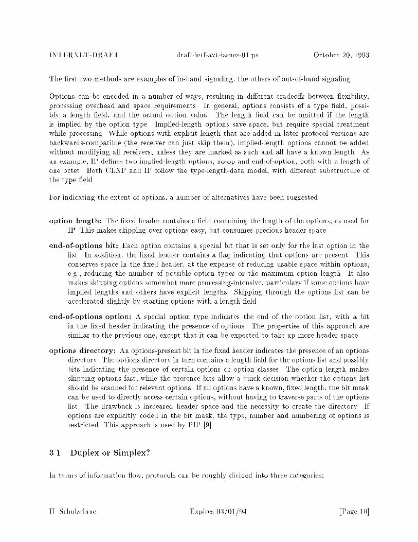
The �rst two methods are examples of in-band signaling, the others of out-of-band signaling.
Options can be encoded in a number of ways, resulting in di�erent tradeo�s between exibility,processing overhead and space requirements. In general, options consists of a type �eld, possi-bly a length �eld, and the actual option value. The length �eld can be omitted if the lengthis implied by the option type. Implied-length options save space, but require special treatmentwhile processing. While options with explicit length that are added in later protocol versions arebackwards-compatible (the receiver can just skip them), implied-length options cannot be addedwithout modifying all receivers, unless they are marked as such and all have a known length. Asan example, IP de�nes two implied-length options, no-op and end-of-option, both with a length ofone octet. Both CLNP and IP follow the type-length-data model, with di�erent substructure ofthe type �eld.
For indicating the extent of options, a number of alternatives have been suggested.
option length: The �xed header contains a �eld containing the length of the options, as used forIP. This makes skipping over options easy, but consumes precious header space.
end-of-options bit: Each option contains a special bit that is set only for the last option in thelist. In addition, the �xed header contains a ag indicating that options are present. Thisconserves space in the �xed header, at the expense of reducing usable space within options,e.g., reducing the number of possible option types or the maximum option length. It alsomakes skipping options somewhat more processing-intensive, particulary if some options haveimplied lengths and others have explicit lengths. Skipping through the options list can beaccelerated slightly by starting options with a length �eld.
end-of-options option: A special option type indicates the end of the option list, with a bitin the �xed header indicating the presence of options. The properties of this approach aresimilar to the previous one, except that it can be expected to take up more header space.
options directory: An options-present bit in the �xed header indicates the presence of an optionsdirectory. The options directory in turn contains a length �eld for the options list and possiblybits indicating the presence of certain options or option classes. The option length makesskipping options fast, while the presence bits allow a quick decision whether the options listshould be scanned for relevant options. If all options have a known, �xed length, the bit maskcan be used to directly access certain options, without having to traverse parts of the optionslist. The drawback is increased header space and the necessity to create the directory. Ifoptions are explicitly coded in the bit mask, the type, number and numbering of options isrestricted. This approach is used by PIP [9].
3.1 Duplex or Simplex?
In terms of information ow, protocols can be roughly divided into three categories:
H. Schulzrinne Expires 03/01/94 [Page 10]
INTERNET-DRAFT draft-ietf-avt-issues-01.ps October 20, 1993
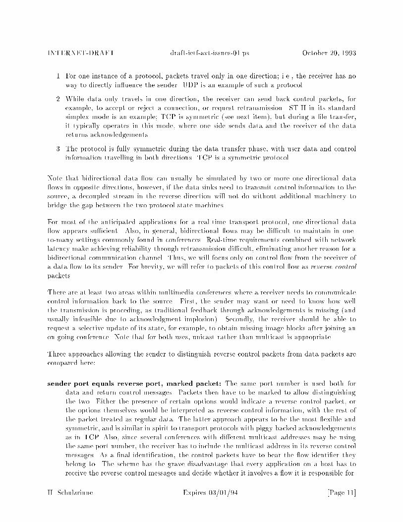
1. For one instance of a protocol, packets travel only in one direction; i.e., the receiver has noway to directly in uence the sender. UDP is an example of such a protocol.
2. While data only travels in one direction, the receiver can send back control packets, forexample, to accept or reject a connection, or request retransmission. ST-II in its standardsimplex mode is an example; TCP is symmetric (see next item), but during a �le transfer,it typically operates in this mode, where one side sends data and the receiver of the datareturns acknowledgements.
3. The protocol is fully symmetric during the data transfer phase, with user data and controlinformation travelling in both directions. TCP is a symmetric protocol.
Note that bidirectional data ow can usually be simulated by two or more one-directional data ows in opposite directions, however, if the data sinks need to transmit control information to thesource, a decoupled stream in the reverse direction will not do without additional machinery tobridge the gap between the two protocol state machines.
For most of the anticipated applications for a real-time transport protocol, one-directional data ow appears su�cient. Also, in general, bidirectional ows may be di�cult to maintain in one-to-many settings commonly found in conferences. Real-time requirements combined with networklatency make achieving reliability through retransmission di�cult, eliminating another reason for abidirectional communication channel. Thus, we will focus only on control ow from the receiver ofa data ow to its sender. For brevity, we will refer to packets of this control ow as reverse controlpackets.
There are at least two areas within multimedia conferences where a receiver needs to communicatecontrol information back to the source. First, the sender may want or need to know how wellthe transmission is proceding, as traditional feedback through acknowledgements is missing (andusually infeasible due to acknowledgment implosion). Secondly, the receiver should be able torequest a selective update of its state, for example, to obtain missing image blocks after joining anon-going conference. Note that for both uses, unicast rather than multicast is appropriate.
Three approaches allowing the sender to distinguish reverse control packets from data packets arecompared here:
sender port equals reverse port, marked packet: The same port number is used both fordata and return control messages. Packets then have to be marked to allow distinguishingthe two. Either the presence of certain options would indicate a reverse control packet, orthe options themselves would be interpreted as reverse control information, with the rest ofthe packet treated as regular data. The latter approach appears to be the most exible andsymmetric, and is similar in spirit to transport protocols with piggy-backed acknowledgementsas in TCP. Also, since several conferences with di�erent multicast addresses may be usingthe same port number, the receiver has to include the multicast address in its reverse controlmessages. As a �nal identi�cation, the control packets have to bear the ow identi�er theybelong to. The scheme has the grave disadvantage that every application on a host has toreceive the reverse control messages and decide whether it involves a ow it is responsible for.
H. Schulzrinne Expires 03/01/94 [Page 11]
INTERNET-DRAFT draft-ietf-avt-issues-01.ps October 20, 1993
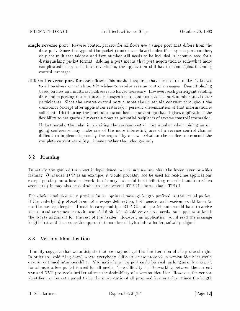
single reverse port: Reverse control packets for all ows use a single port that di�ers from thedata port. Since the type of the packet (control vs. data) is identi�ed by the port number,only the multicast address and ow number still needs to be included, without a need for adistinguishing packet format. Adding a port means that port negotiation is somewhat morecomplicated; also, as in the �rst scheme, the application still has to demultiplex incomingcontrol messages.
di�erent reverse port for each ow: This method requires that each source makes it knownto all receivers on which port it wishes to receive reverse control messages. Demultiplexingbased on ow and multicast address is no longer necessary. However, each participant sendingdata and expecting return control messages has to communicate the port number to all otherparticipants. Since the reverse control port number should remain constant throughout theconference (except after application restarts), a periodic dissemination of that information issu�cient. Distributing the port information has the advantage that it gives applications the exibility to designate only certain ows as potential recipients of reverse control information.
Unfortunately, the delay in acquiring the reverse control port number when joining an on-going conference may make one of the more interesting uses of a reverse control channeldi�cult to implement, namely the request by a new arrival to the sender to transmit thecomplete current state (e.g., image) rather than changes only.
3.2 Framing
To satisfy the goal of transport independence, we cannot assume that the lower layer providesframing. (Consider TCP as an example; it would probably not be used for real-time applicationsexcept possibly on a local network, but it may be useful in distributing recorded audio or videosegments.) It may also be desirable to pack several RTPDUs into a single TPDU.
The obvious solution is to provide for an optional message length pre�xed to the actual packet.If the underlying protocol does not message delineation, both sender and receiver would know touse the message length. If used to carry multiple RTPDUs, all participants would have to arriveat a mutual agreement as to its use. A 16-bit �eld should cover most needs, but appears to breakthe 4-byte alignment for the rest of the header. However, an application would read the messagelength �rst and then copy the appropriate number of bytes into a bu�er, suitably aligned.
3.3 Version Identi�cation
Humility suggests that we anticipate that we may not get the �rst iteration of the protocol right.In order to avoid \ ag days" where everybody shifts to a new protocol, a version identi�er couldensure continued interoperability. Alternatively, a new port could be used, as long as only one port(or at most a few ports) is used for all media. The di�culty in interworking between the currentvat and NVP protocols further a�rms the desirability of a version identi�er. However, the versionidenti�er can be anticipated to be the most static of all proposed header �elds. Since the length
H. Schulzrinne Expires 03/01/94 [Page 12]

INTERNET-DRAFT draft-ietf-avt-issues-01.ps October 20, 1993
of the header and the location and meaning of the option length �eld may be a�ected by a versionchange, encoding the version within an optional �eld is not feasible.
Putting the version number into the control protocol packets would make RTCP mandatory andwould make rapid scanning of conferences signi�cantly more di�cult.
vat currently o�ers a 2-bit version �eld, while this capability is missing from NVP. Given the low bitusage and their utility in other contexts (IP, ST-II), it may be prudent to include a version identi�er.To be useful, any version �eld must be placed at the very beginning of the header. Assigning aninitial version value of one to RTP allows interoperability with the current vat protocol.
3.4 Conference Identi�cation
A conference identi�er (conference ID) could serve two mutually exclusive functions: providinganother level of demultiplexing or a means of logically aggregating ows with di�erent networkaddresses and port numbers. vat speci�es a 16-bit conference identi�er.
3.4.1 Demultiplexing
Demultiplexing by RTP allows one association characterized by destination address and port num-ber to carry several distinct conferences. However, this appears to be necessary only if the numberof conferences exceeds the demultiplexing capability available through (multicast) addresses andport numbers.
E�ciency arguments suggest that combining several conferences or media within a single multicastgroup is not desirable. Combining several conferences or media within a single multicast addressreduces the bandwidth e�ciency a�orded by multicasting if the sets of destinations are di�erent.Also, applications that are not interested in a particular conference or capable of dealing withparticular medium are still forced to handle the packets delivered for that conference or medium.Consider as an example two separate applications, one for audio, one for video. If both share thesame multicast address and port, being di�erentiated only by the conference identi�er, the operatingsystem has to copy each incoming audio and video packet into two application bu�ers and performa context switch to both applications, only to have one immediately discard the incoming packet.
Given that application-layer demultiplexing has strong negative e�ciency implications and giventhat multicast addresses are not an extremely scarce commodity, there seems to be no reason toburden every application with maintaining and checking conference identi�ers for the purpose ofdemultiplexing. However, if this protocol is to be used as a transport protocol, demultiplexingcapability is required.
It is also not recommended to use a conference identi�er to distinguish between di�erent encodings,as it would be di�cult for the application to decide whether a new conference identi�er means thata new conference has arrived or simply all participants should be moved to the new conference with
H. Schulzrinne Expires 03/01/94 [Page 13]

INTERNET-DRAFT draft-ietf-avt-issues-01.ps October 20, 1993
a di�erent encoding. Since the encoding may change for some but not all participants, we could�nd ourselves breaking a single logical conference into several pieces, with a fairly elaborate controlmechanism to decide which conferences logically belong together.
3.4.2 Aggregation
Particularly within a network with a wide range of capacities, di�ering multicast groups for eachmedia component of a conference allows to tailor the media distribution to the network bandwidthsand end-system capabilities. It appears useful, however, to have a means of identifying groups thatlogically belong together, for example for purposes of time synchronization.
A conference identi�er used in this manner would have to be globally unique. It appears thatsuch logical connections would better be identi�ed as part of the higher-layer control protocol byidentifying all multicast addresses belonging to the same logical conference, thereby avoiding theassignment of globally unique identi�ers.
3.5 Media Encoding Identi�cation
This �eld plays a similar role to the protocol �eld in data link or network protocols, indicating thenext higher layer (here, the media decoder) that the data is meant for. For RTP, this �eld wouldindicate the audio or video or other media encoding. In general, the number of distinct encodingsshould be kept as small as possible to increase the chance that applications can interoperate. A newencoding should only be recognized if it signi�cantly enhances the range of media quality or thetypes of networks conferences can be conducted over. The unnecessary proliferation of encodingscan be reduced by making reference implementations of standard encoders and decoders widelyavailable.
It should be noted that encodings may not be enumerable as easily as, say, transport protocols. Aparticular family of related encoding methods may be described by a set of parameters, as discussedbelow in the sections on audio and video encoding.
Encodings may change during the duration of a conference. This may be due to changed networkconditions, changed user preference or because the conference is joined by a new participant thatcannot decode the current encoding. If the information necessary for the decoder is conveyed out-of-band, some means of indicating when the change is e�ective needs to be incorporated. Also,the indication that the encoding is about to change must reach all receivers reliably before the �rstpacket employing the new encoding. Each receiver needs to track pending changes of encodingsand check for every incoming packet whether an encoding change is to take e�ect with this packet.
Conveying media encodings rapidly is also important to allow scanning of conferences or broadcastmedia. Note that it is not necessary to convey the whole encoder description, with all parameters;an index into a table of well-known encodings is probably preferable. An index would also make iteasier to detect whether the encoding has changed.
H. Schulzrinne Expires 03/01/94 [Page 14]

INTERNET-DRAFT draft-ietf-avt-issues-01.ps October 20, 1993
Alternatively, a directory or announcement service could provide encoding information for on-going conferences, without carrying the information in every packet. This may not be su�cient,however, unless all participants within a conference use the same encoding. As soon as the encodinginformation is separated from the media data, a synchronization mechanism has to be devised thatensures that sender and receiver interpret the data in the same manner after the out-of-bandinformation has been updated.
There are at least two approaches to indicating media encoding, either in-band or out-of-band:
conference-speci�c: Here, the media identi�er is an index into a table designating the approvedor anticipated encodings (together with any particular version numbers or other parameters)for a particular conference or user community. The table can be distributed through RTCP,a higher-layer conference control protocol, a conference announcement service or some otherout-of-band means. Since the number of encodings used during a single conference is likely tobe small, the �eld width in the header can likewise be small. Also, there is no need to agree onan Internet-wide list of encodings. It should be noted that conveying the table of encodingsthrough RTCP forces the application to maintain a separate mapping table for each sender asthere can be no guarantee that all senders will use the same table. Since the control protocolproposed here is unreliable, changing the meaning of encoding indices dynamically is fraughtwith possibilities for misinterpretation and lost data unless this mapping is carried in everypacket.
global: Here, the media identi�er is an index into a global table of encodings. A global listreduces the need for out-of-band information. Transmitting the parameters associated withan encoding may be di�cult, however, if it has to be done within the header space constraintsof per-packet signaling.
To make detecting coder mismatches easier, encodings for all media should be drawn from the samenumbering space. To facilitate experimentation with new encodings, a part of any global encodingnumbering space should be set aside for experimental encodings, with numbers agreed upon withinthe community experimenting with the encoding, with no Internet-wide guarantee of uniqueness.
3.5.1 Audio Encodings
Audio data is commonly characterized by three independent descriptors: encoding (the translationof one or more audio samples into a channel symbol), the number of channels (mono, stereo, : : :)and the sampling rate.
Theoretically, sampling rate and encoding are (largely) independent. We could, for example, applymu-law encoding to any sampling rate even though it is traditionally used with a rate of 8,000 Hz.In practical terms, it may be desirable to limit the combinations of encoding and sampling rate tothe values the encoding was designed for.2 Channel counts between 1 and 6 should be su�cienteven for surround sound.
2Given the wide availability of mu-law encoding and its low overhead, using it with a sampling rate of 16,000
H. Schulzrinne Expires 03/01/94 [Page 15]

INTERNET-DRAFT draft-ietf-avt-issues-01.ps October 20, 1993
The audio encodings listed in Table 1 appear particularly interesting, even though the list is by nomeans exhaustive and does not include some experimental encodings currently in use, for examplea non-standard form of LPC. The bit rate is shown per channel. k samples/s, b/sample and kb/sdenote kilosamples per second, bits per sample and kilobits per second, respectively. If samplingrates are to be speci�ed separately, the values of 8, 16, 32, 44.1, and 48 kHz suggest themselves,even though other values (11.025 and 22.05 kHz) are supported on some workstations (the SiliconGraphics audio hardware and the Apple Macintosh, for example). Clearly, little is to be gained byallowing arbitrary sampling rates, as conversion particularly between rates not related by simplefractions is quite cumbersome and processing-intensive [10].
Org. Name k samples/s b/sample kb/s descriptionCCITT G.711 8.0 8 64 mu-law PCMCCITT G.711 8.0 8 64 A-law PCMCCITT G.721 8.0 4 32 ADPCMIntel DVI 8.0 4 32 APDCMCCITT G.723 8.0 3 24 ADPCMCCITT G.726 ADPCMCCITT G.727 ADPCMNIST/GSA FS 1015 8.0 2.4 LPC-10ENIST/GSA FS 1016 8.0 4.8 CELPNADC IS-54 8.0 7.95 N. American Digital Cellular, VSELPCCITT G.728 8.0 16 LD-CELPGSM 8.0 13 RPE-LTPCCITT G.722 8.0 64 7 kHz, SB-ADPCMISO 3-11172 256 MPEG audio
32.0 16 512 DAT44.1 16 705.6 CD, DAT playback48.0 16 786 DAT record
Table 1: Standardized and common audio encodings
3.5.2 Video Encodings
Common video encodings are listed in Table 2. Encodings with tunable rate can be con�gured fordi�erent rates, but produce a �xed-rate stream. The average bit rate produced by variable-ratecodecs depends on the source material.
or 32,000 Hz might be quite appropriate for high-quality audio conferences, even though there are other encodings,such as G.722, speci�cally designed for such applications. Note that the signal-to-noise ratio of mu-law encoding isabout 38 dB, equivalent to an AM receiver. The \telephone quality" associated with G.711 is due primarily to thelimitation in frequency response to the 200 to 3500 Hz range.
H. Schulzrinne Expires 03/01/94 [Page 16]

INTERNET-DRAFT draft-ietf-avt-issues-01.ps October 20, 1993
Org. name rate remarks
CCITT JPEG tunableCCITT MPEG variable, tunableCCITT H.261 tunable, p� 64 kb/sBolter variable, tunablePictureTel ??Cornell U. CU-SeeMe variableXerox Parc nv variable, tunableBBN DVC variable, tunable block di�erences
Table 2: Common video encodings
3.6 Playout Synchronization
A major purpose of RTP is to provide the support for various forms of synchronization, withoutnecessarily performing the synchronization itself. We can distinguish three kinds of synchronization:
playout synchronization: The receiver plays out the medium a �xed time after it was generatedat the source (end-to-end delay). This end-to-end delay may vary from synchronization unitto synchronization unit. In other words, playout synchronization assures that a constant ratesource at the sender again becomes a constant rate source at the receiver, despite delay jitterin the network.
intra-media synchronization: All receivers play the same segment of a medium at the sametime. Intra-media synchronization may be needed during simulations and wargaming.
inter-media synchronization: The timing relationship between several media sources is recon-structed at the receiver. The primary example is the synchronization between audio andvideo (lip-sync). Note that di�erent receivers may experience di�erent delays between themedia generation time and their playout time.
Playout synchronization is required for most media, while intra-media and inter-media synchro-nization may or may not be implemented. In connection with playout synchronization, we cangroup packets into playout units, a number of which in turn form a synchronization unit. Morespeci�cally, we de�ne:
synchronization unit: A synchronization unit consists of one or more playout units (see below)that, as a group, share a common �xed delay between generation and playout of each part ofthe group. The delay may change at the beginning of such a synchronization unit. The mostcommon synchronization units are talkspurts for voice and frames for video transmission.
playout unit: A playout unit is a group of packets sharing a common timestamp. (Naturally,packets whose timestamps are identical due to timestamp wrap-around are not considered
H. Schulzrinne Expires 03/01/94 [Page 17]
INTERNET-DRAFT draft-ietf-avt-issues-01.ps October 20, 1993
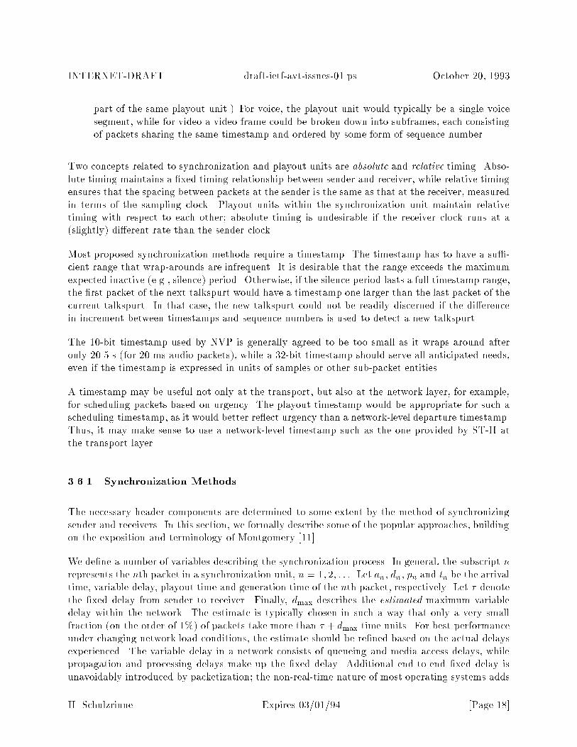
part of the same playout unit.) For voice, the playout unit would typically be a single voicesegment, while for video a video frame could be broken down into subframes, each consistingof packets sharing the same timestamp and ordered by some form of sequence number.
Two concepts related to synchronization and playout units are absolute and relative timing. Abso-lute timing maintains a �xed timing relationship between sender and receiver, while relative timingensures that the spacing between packets at the sender is the same as that at the receiver, measuredin terms of the sampling clock. Playout units within the synchronization unit maintain relativetiming with respect to each other; absolute timing is undesirable if the receiver clock runs at a(slightly) di�erent rate than the sender clock.
Most proposed synchronization methods require a timestamp. The timestamp has to have a su�-cient range that wrap-arounds are infrequent. It is desirable that the range exceeds the maximumexpected inactive (e.g., silence) period. Otherwise, if the silence period lasts a full timestamp range,the �rst packet of the next talkspurt would have a timestamp one larger than the last packet of thecurrent talkspurt. In that case, the new talkspurt could not be readily discerned if the di�erencein increment between timestamps and sequence numbers is used to detect a new talkspurt.
The 10-bit timestamp used by NVP is generally agreed to be too small as it wraps around afteronly 20.5 s (for 20 ms audio packets), while a 32-bit timestamp should serve all anticipated needs,even if the timestamp is expressed in units of samples or other sub-packet entities.
A timestamp may be useful not only at the transport, but also at the network layer, for example,for scheduling packets based on urgency. The playout timestamp would be appropriate for such ascheduling timestamp, as it would better re ect urgency than a network-level departure timestamp.Thus, it may make sense to use a network-level timestamp such as the one provided by ST-II atthe transport layer.
3.6.1 Synchronization Methods
The necessary header components are determined to some extent by the method of synchronizingsender and receivers. In this section, we formally describe some of the popular approaches, buildingon the exposition and terminology of Montgomery [11].
We de�ne a number of variables describing the synchronization process. In general, the subscript nrepresents the nth packet in a synchronization unit, n = 1; 2; : : :. Let an, dn, pn and tn be the arrivaltime, variable delay, playout time and generation time of the nth packet, respectively. Let � denotethe �xed delay from sender to receiver. Finally, dmax describes the estimated maximum variabledelay within the network. The estimate is typically chosen in such a way that only a very smallfraction (on the order of 1%) of packets take more than � + dmax time units. For best performanceunder changing network load conditions, the estimate should be re�ned based on the actual delaysexperienced. The variable delay in a network consists of queueing and media access delays, whilepropagation and processing delays make up the �xed delay. Additional end-to-end �xed delay isunavoidably introduced by packetization; the non-real-time nature of most operating systems adds
H. Schulzrinne Expires 03/01/94 [Page 18]
INTERNET-DRAFT draft-ietf-avt-issues-01.ps October 20, 1993
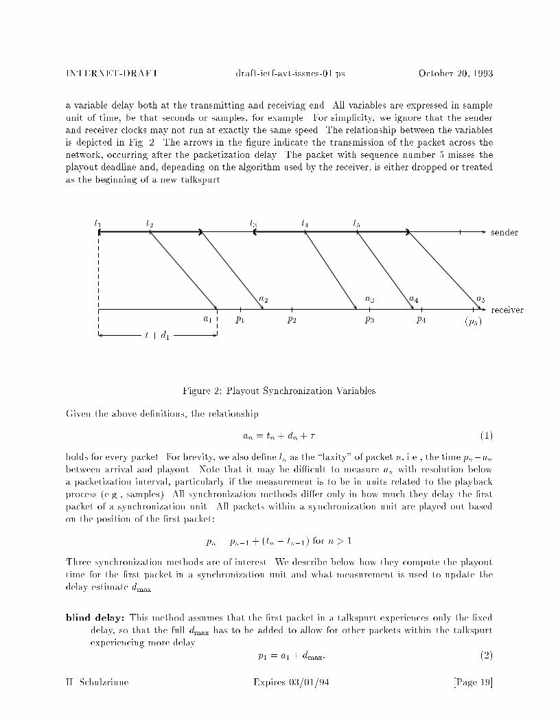
a variable delay both at the transmitting and receiving end. All variables are expressed in sampleunit of time, be that seconds or samples, for example. For simplicity, we ignore that the senderand receiver clocks may not run at exactly the same speed. The relationship between the variablesis depicted in Fig. 2. The arrows in the �gure indicate the transmission of the packet across thenetwork, occurring after the packetization delay. The packet with sequence number 5 misses theplayout deadline and, depending on the algorithm used by the receiver, is either dropped or treatedas the beginning of a new talkspurt.
sendert1 t2 t3 t4 t5
receiverp1 p2 p3 p4 (p5)a1
a2 a3 a4 a5
t + d1
Figure 2: Playout Synchronization Variables
Given the above de�nitions, the relationship
an = tn + dn + � (1)
holds for every packet. For brevity, we also de�ne ln as the \laxity" of packet n, i.e., the time pn�anbetween arrival and playout. Note that it may be di�cult to measure an with resolution belowa packetization interval, particularly if the measurement is to be in units related to the playbackprocess (e.g., samples). All synchronization methods di�er only in how much they delay the �rstpacket of a synchronization unit. All packets within a synchronization unit are played out basedon the position of the �rst packet:
pn = pn�1 + (tn � tn�1) for n > 1
Three synchronization methods are of interest. We describe below how they compute the playouttime for the �rst packet in a synchronization unit and what measurement is used to update thedelay estimate dmax.
blind delay: This method assumes that the �rst packet in a talkspurt experiences only the �xeddelay, so that the full dmax has to be added to allow for other packets within the talkspurtexperiencing more delay.
p1 = a1 + dmax: (2)
H. Schulzrinne Expires 03/01/94 [Page 19]
INTERNET-DRAFT draft-ietf-avt-issues-01.ps October 20, 1993
The estimate for the variable delay is derived from measurements of the laxity ln, so thatthe new estimate after n packets is computed dmax;n = f(l1; : : : ; ln), where the function f(�)is a suitably chosen smoothing function. Note that blind delay does not require timestampsto determine p1, only an indication of the beginning of a synchronization unit. Timestampsmay be required to compute pn, however, unless tn � tn�1 is a known constant.
absolute timing: If the packet carries a timestamp measured in time units known to the receiver,we can improve our determination of the playout point:
p1 = t1 + � + dmax:
This is, clearly, the best that can be accomplished. Here, instead of estimating dmax, weestimate � + dmax as some function of pn � tn. For this computation, it does not matterwhether p and t are measured with clocks sharing a common starting point.
added variable delay: Each node adds the variable delay experienced within it to a delay accu-mulator within the packet, yielding dn.
p1 = a1 � d1 + dmax
From Eq. 1, it is readily apparent that absolute delay and added variable delay yield thesame playout time. The estimate for dmax is based on the measurements for d. Given aclock with suitably high resolution, these estimates can be better than those based on thedi�erence between a and p; however, it requires that all routers can recognize RTP packets.Also, determining the residence time within a router may not be feasible.
In summary, absolute timing is to be preferred due to its lower delays compared to blind delay,while synchronization using added variable delays is currently not feasible within the Internet (itis, however, used for G.764).
3.6.2 Detection of Synchronization Units
The receiver must have a way of readily detecting the beginning of a synchronization unit, as theplayout scheduling of the �rst packet in a synchronization unit di�ers from that in the remainder ofthe unit. This detection has to work reliably even with packet reordering; for example, reorderingat the beginning of a talkspurt is particularly likely since common silence detection algorithms senda group of stored packets at the beginning of the talkspurt to prevent front clipping.
Two basic methods have been proposed:
timestamp and sequence number: The sequence number increases by one with each packettransmitted, while the timestamp re ects the total time covered, measured in some appro-priate unit. A packet is declared to start a new synchronization unit if (a) it has the highesttimestamp and sequence number seen so far (within this wraparound cycle) and (b) the dif-ference in timestamp values (converted into a packet count) between this and the previouspacket is greater than the di�erence in sequence number between those two packets.
H. Schulzrinne Expires 03/01/94 [Page 20]
INTERNET-DRAFT draft-ietf-avt-issues-01.ps October 20, 1993
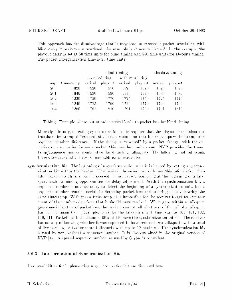
This approach has the disadvantage that it may lead to erroneous packet scheduling withblind delay if packets are reordered. An example is shown in Table 3. In the example, theplayout delay is set at 50 time units for blind timing and 550 time units for absolute timing.The packet intergeneration time is 20 time units.
blind timing absolute timingno reordering with reordering
seq. timestamp arrival playout arrival playout arrival playout200 1020 1520 1570 1520 1570 1520 1570201 1040 1530 1590 1530 1590 1530 1590202 1220 1720 1770 1725 1750 1725 1770203 1240 1725 1790 1720 1770 1720 1790204 1260 1792 1810 1791 1790 1791 1810
Table 3: Example where out-of-order arrival leads to packet loss for blind timing
More signi�cantly, detecting synchronization units requires that the playout mechanism cantranslate timestamp di�erences into packet counts, so that it can compare timestamp andsequence number di�erences. If the timespan \covered" by a packet changes with the en-coding or even varies for each packet, this may be cumbersome. NVP provides the times-tamp/sequence number combination for detecting talkspurts. The following method avoidsthese drawbacks, at the cost of one additional header bit.
synchronization bit: The beginning of a synchronization unit is indicated by setting a synchro-nization bit within the header. The receiver, however, can only use this information if nolater packet has already been processed. Thus, packet reordering at the beginning of a talk-spurt leads to missing opportunities for delay adjustment. With the synchronization bit, asequence number is not necessary to detect the beginning of a synchronization unit, but asequence number remains useful for detecting packet loss and ordering packets bearing thesame timestamp. With just a timestamp, it is impossible for the receiver to get an accuratecount of the number of packets that it should have received. While gaps within a talkspurtgive some indication of packet loss, the receiver cannot tell what part of the tail of a talkspurthas been transmitted. (Example: consider the talkspurts with time stamps 100, 101, 102,110, 111. Packets with timestamp 100 and 110 have the synchronization bit set. The receiverhas no way of knowing whether it was supposed to have received two talkspurts with a totalof �ve packets, or two or more talkspurts with up to 12 packets.) The synchronization bitis used by vat, without a sequence number. It is also contained in the original version ofNVP [12]. A special sequence number, as used by G.764, is equivalent.
3.6.3 Interpretation of Synchronization Bit
Two possibilities for implementing a synchronization bit are discussed here.
H. Schulzrinne Expires 03/01/94 [Page 21]

INTERNET-DRAFT draft-ietf-avt-issues-01.ps October 20, 1993
start of synchronization unit: The �rst packet in a synchronization unit is marked with a setsynchronization bit. With this use of the synchronization bit, the receiver detects the begin-ning of a synchronization unit with the following simple algorithm:
if synchronization bit = 1
and current sequence number > maximum sequence number seen so far
then
this packet starts a new synchronization unit
if current sequence number > maximum sequence number
then
maximum sequence number := current sequence number
endif
Comparisons and arithmetic operations are modulo the sequence number range.
end of synchronization unit: The last packet in a synchronization unit is marked. As pointedout elsewhere, this information may be useful for initiating appropriate �ll-in during silenceperiods and to start processing a completed video frame. If a voice silence detector uses nohangover, it may have di�culty deciding which is the last packet in a talkspurt until it judgesthe �rst packet to contain no speech. The detection of a new synchronization unit by thereceiver is only slightly more complicated than with the previous method:
if sync_flag then
if sequence number >= sync_seq then
sync_flag := FALSE
endif
if sequence number = sync_seq then
signal beginning of synchronization unit
endif
endif
if synchronization bit = 1 then
sync_seq := sequence number + 1
sync_flag := TRUE
endif
By changing the equal sign in the second comparison to 'if sequence number > sync seq', anew synchronization unit is detected even if packets at the beginning of the synchronizationunit are reordered. As reordering at the beginning of a synchronization unit is particularlylikely, for example when transmitting the packets preceding the beginning of a talkspurt, thisshould signi�cantly reduce the number of missed talkspurt beginnings.
3.6.4 Interpretation of Timestamp
Several proposals as to the interpretation of the timestamp have been advanced:
H. Schulzrinne Expires 03/01/94 [Page 22]

INTERNET-DRAFT draft-ietf-avt-issues-01.ps October 20, 1993
packet or frame interval: Each packetization or (video/audio) frame interval increments thetimestamp. This approach very e�cient in terms of processing and bit-use, but cannot beused without out-of-band information if the time interval of media \covered" by a packetvaries from packet to packet. This occurs for example with variable-rate encoders or if thepacketization interval is changed during a conference. This interpretation of a timestamp isassumed by NVP, which de�nes a frame as a block of PCM samples or a single LPC frame.Note that there is no inherent necessity that all participants within a conference use the samepacketization interval. Local implementation considerations such as available clocks maysuggest di�erent intervals. As another example, consider a conference with feedback. Forthe lecture audio, a long packetization interval may be desirable to better amortize packetheaders. For side chats, delays are more important, thus suggesting a shorter packetizationinterval.3
sample: This method simply counts samples, allowing a direct translation between time stamp andplayout bu�er insertion point. It is just as easily computable as the per-packet timestamp.However, for some media and encodings4 , it may not be quite clear what a sample is. Also,some care must be taken at the receiver and sender if streams use di�erent sampling rates.This method is currently used by vat.
Milliseconds: A timestamp incremented every millisecond would wrap around once every 49 days.The resolution is su�cient for most applications, except that the natural packetization intervalfor LPC-coded speech is 22.5 ms. Also, with a video frame rate of 30 Hz, an internal timestampof higher resolution would need to be truncated to millisecond resolution to approximate 33.3ms intervals. This time increment has the advantage of being used by some Unix delayfunctions, which might be useful for playing back video frames with proper timing. It mightbe useful to take the second value from the current system clock to allow delay estimates forsynchronized clocks.
subset of NTP timestamp: 16 bits encode seconds relative to midnight (0 hours), January 1,1900 (modulo 65536) and 16 bits encode fractions of a second, with a resolution of approx-imately 15.2 microseconds, which is smaller than any anticipated audio sampling or videoframe interval. This timestamp is the same as the middle 32 bits of the 64-bit NTP times-tamp [13]. It wraps around every 18.2 hours. If it should be desirable to reconstruct absolutetransmission time at the receiver for logging or recording purposes, it should be easy to de-termine the most signi�cant 16 bits of the timestamp. Otherwise, wrap-arounds are not asigni�cant problem as long as they occur 'naturally', i.e., at a 16 or 32 bit boundary, sothat explicit checking on arithmetic operations is not required. Also, since the translationmechanism would probably treat the timestamp as a single integer without accounting for itsdivision into whole and fractional part, the exact bit allocation between seconds and fractionsthereof is less important. However, the 16/16 approach simpli�es extraction from a full NTPtimestamp. Sixteen bits of fractional seconds also allows a timestamp without wrap-around,
3Nevot for example, allows each participant to have a di�erent packetization interval, independent of the pack-
etization interval used by Nevot for its outgoing audio. Only the packetization interval for outgoing audio for allconferences this Nevot participates in must be the same.
4Examples include frame-based encodings such as LPC and CELP. Here, given that these encodings are based on8,000 Hz input samples, the preferred interpretation would probably be in terms of audio samples, not frames, assamples would be used for reconstruction and mixing.
H. Schulzrinne Expires 03/01/94 [Page 23]

INTERNET-DRAFT draft-ietf-avt-issues-01.ps October 20, 1993
i.e, with 32 bits of full seconds encoding time since January 1, 1990, to �t into the 52 bits ofa IEEE oating point number.
The NTP-like timestamp has the disadvantage that its resolution does not map into any ofthe common sample or packetization intervals. Thus, there is a potential uncertainty of onesample at the receiver as to where to place the beginning of the received packet, resulting inthe equivalent of a one-sample slip. CCITT recommendation G.821 postulates a mean sliprate of less than 1 slip in 5 hours, with degraded but acceptable service for less than 1 slipin 2 minutes. Tests with appropriate rounding conducted by the author showed that thisuncertainty is not likely to cause problems. In any event, a double-precision oating pointmultiplication is needed to translate between this timestamp and the integer sample countavailable on transmission and required for playout.5
MPEG timestamps: MPEG uses a 33 bit clock with a resolution of 90 kHz [14] as the systemclock reference and for presentation time stamps. The frequency was chosen based on thedivisibility by the nominal video picture rates of 24 Hz, 25 Hz, 29.97 Hz and 30 Hz [14, p.42].The frequency would also �t nicely with the 20 ms audio packetization interval. The lengthof 33 bit is clearly inappropriate, however, for software implementations. 32 bit timestampsstill cover more than half a day and thus can be readily extended to full unique timestampsor 33 bits if needed.
Microseconds: A 32-bit timestamp incremented every microsecond wraps around once every 71.5minutes. The resolution is high enough that round-o� errors for video frame intervals and suchshould be tolerable without maintaining a higher-precision internal counter. This resolutionis also provided, at least nominally, by the Unix gettimeofday() system call.
QuickTime: The Apple QuickTime �le format is a generalization of the previous formats as itcombines a 32-bit counter with a 32-bit media time scale expressed in time units per second.The four previously mentioned timestamps can be represented by time scales of 1000, 65536,90,000 and 1,000,000. For the sample and packet-based case, the value would depend on themedia content, e.g., 8,000 for standard PCM-coded audio.
Timestamps based on wallclock time rather than samples or frames have the advantage that areceiver does not necessarily need to know about the meaning of the encoding contained in thepacket in order to process the timestamp. For example, a quality-of-service monitor within thenetwork could measure delay variance easily, without caring what kind of audio information, say,is contained in the packet. Other tools, such as a recording and playback tool, can also be writtenwithout concern about the mapping between timestamp and wallclock units.
A time stamp could re ect either real time or sample time. A real time timestamp is de�ned totrack wallclock time plus or minus a constant o�set. Sample time increases by the nominal samplinginterval for each sample. The two clocks in general do not agree since the clock source used forsampling will in all likelihood be slightly o� the nominal rate. For example, typical crystals withouttemperature control are only accurate to � 50 { 100 ppm (parts per million), yielding a potentialdrift of 0.36 seconds per hour between the sampling clock and wallclock time.
5The multiplication with an appropriate factor can be approximated to the desired precision by an integer multi-plication and division, but multiplication by a oating point value is actually much faster on some modern processors.
H. Schulzrinne Expires 03/01/94 [Page 24]
INTERNET-DRAFT draft-ietf-avt-issues-01.ps October 20, 1993
It has been suggested to use timestamps relative to the beginning of �rst transmission from asource. This makes correlation between media from di�erent participants di�cult and seems tohave no technical or implementation advantages, except for avoiding wrap-around during mostconferences. As pointed out above, that seems to be of little bene�t. Clearly, the reliability of awallclock-synchronized timestamps depends on how closely the system clocks are synchronized, butthat does not argue for giving up potential real-time synchronization in all cases.
Using real time rather than sample time allows for easier synchronization between di�erent mediaand users (e.g., during playback of a recorded conference) and to compensate for slow or fastsample clocks. Note that it is neither desirable nor necessary to obtain the wall clock time wheneach packet was sampled. Rather, the sender determines the wallclock time at the beginning ofeach synchronization unit (e.g., a talkspurt for voice and a frame for video) and adds the nominalsample clock duration for all packets within the talkspurt to arrive at the timestamp value carriedin packets. The real time at the beginning of a talkspurt is determined by estimating the truesample rate for the duration of the conference.
The sample rate estimate has to be accurate enough to allow placing the beginning of a talkspurt,say, to within at most 50 to 100 ms, otherwise the lack of synchronization may be noticeable, delaycomputations are confused and successive talkspurts may be concatenated.
Estimating the true sampling instant to within a few milliseconds is surprisingly di�cult for currentoperating systems. The sample rate r can to be estimated as
r =s + q
t� t0:
Here, t is the current time, t0 the time elapsed since the �rst sample was acquired, s is the numberof samples read, q is the number of samples ready to be read (queued) at time t. Let p denote thenumber of samples in a packet. The timestamp in the synchronization packet re ects the samplinginstant of the �rst sample of that packet and is computed as t � (p + q)=r. Unfortunately, only s
and p are known precisely. The accuracy of the estimate for t0 and t depend on how accuratelythe beginning of sampling and the last reading from the audio device can be measured. There is anon-zero probability that the process will get preempted between the time the audio data is readand the instant the system clock is sampled. It remains unclear whether indications of currentbu�er occupancy, if available, can be trusted. Even with increasing sample count, the absoluteaccuracy of the timestamp is roughly the same as the measurement accuracy of t, as di�erentiatingwith respect to t shows. Experiments with the SunOS audio driver showed signi�cant variations ofthe estimated sample rate, with discontinuities of the computed timestamps of up to 25 ms. Kernelsupport is probably required for meaningful real time measurements.
Sample time increments with the sampling interval for every sample or (sub)frame received from theaudio or video hardware. It is easy to determine, as long as care is taken to avoid cumulative round-o� errors incurred by simply repeatedly adding the approximate packetization interval. However,synchronization between media and end-to-end delay measurements are then no longer feasible.(Example: Consider an audio and a video stream. If the audio sample clock is slightly faster thanthe real clock and the video sampling clock, a video and audio frame belonging together would bemarked by di�erent timestamps, thus played out at di�erent instants.)
H. Schulzrinne Expires 03/01/94 [Page 25]
INTERNET-DRAFT draft-ietf-avt-issues-01.ps October 20, 1993
If we choose to use sample time, the advantage of using an NTP-format timestamp disappears, asthe receiver can easily reconstruct a NTP sample-based timestamp from the sample count if needed,but would not have to if no cross-media synchronization is required. RTCP could relate the timeincrement per sample in full precision. The de�nition of a \sample" will depend on the particularmedium, and could be a audio sample, a video or a voice frame (as produced by a non-waveformcoder). The mapping fails if there is no time-invariant mapping between sample units and time.
It should be noted that it may not be possible to associate an meaningful notion of time withevery packet. For example, if a video frame is broken into several fragments, there is no naturaltimestamp associated with anything but the �rst fragment, particularly if there is not even asequential mapping from screen scan location into packets. Thus, any timestamp used would bepurely arti�cial. A synchronization bit could be used in this particular case to mark beginning ofsynchronization units. For packets within synchronization units, there are two possible approaches:�rst, we can introduce an auxiliary sequence number that is only used to order packets within aframe. Secondly, we could abuse the timestamp �eld by incrementing it by a single unit for eachpacket within the frame, thus allowing a variable number of frames per packet. The latter approachis barely workable and rather kludgy.
3.6.5 End-of-talkspurt indication
An end-of-talkspurt indication is useful to distinguish silence from lost packets. The receiver wouldwant to replace silence by an appropriate background noise level to avoid the \noise-pumping"associated with silence detection. On the other hand, missing packets should be reconstructedfrom previous packets. If the silence detector makes use of hangover, the transmitter can easily setthe end-of-talkspurt indicator on the last bit of the last hangover packet. If the talkspurts followend-to-end, the end-of-talkspurt indicator has no e�ect except in the case where the �rst packet ofa talkspurt is lost. In that case, the indicator would erroneously trigger noise �ll instead of lossrecovery. The end-of-talkspurt indicator is implemented in G.764 as a \more" bit which is set toone for all but the last packet within a talkspurt.
3.6.6 Recommendation
Given the ease of cross-media synchronization and the media independence, the use of 32-bit 16/16timestamps representing the middle part of the NTP timestamp is suggested. Generally, a wallclock-based timestamp appears to be preferable to a sample-based one, but it may only be approximatelyrealizable for some current operating systems. Inter-media synchronization to below 10 to 20 ms hasto await mechanisms that can accurately determine when a particular sample was actually receivedby the A/D converter. Particularly with sample- or wallclock-based timestamp, a synchronizationbit simpli�es the detection of the beginning of a synchronization unit. Indicating either the end orbeginning of a synchronization unit is roughly equivalent, with tradeo�s between the two.
H. Schulzrinne Expires 03/01/94 [Page 26]

INTERNET-DRAFT draft-ietf-avt-issues-01.ps October 20, 1993
3.7 Segmentation and Reassembly
For high-bandwidth video, a single frame may not �t into the maximum transport unit (MTU).Thus, some form of frame sequence number is needed. If possible, the same sequence number shouldbe used for synchronization and fragmentation. Six possibilities suggest themselves:
overload the timestamp: No sequence number is used. Within a frame, the timestamp has nomeaning. Since it is used for synchronization only when the synchronization bit is set, theother timestamps can just increase by one for each packet. However, as soon as the �rst framegets lost or reordered, determining positions and timing becomes di�cult or impossible.
packet count: The sequence number is incremented for every packet, without regard to frameboundaries. If a frame consists of a variable number of packets, it may not be clear whatposition the packet occupies within the frame if packets are lost or reordered. Continuoussequence numbers make it possible to determine if all packets for a particular frame havearrived, but only after the �rst packet of the next frame, distinguished by a new timestamp,has arrived.
packet count within a frame: The sequence number is reset to zero at the beginning of eachframe. This approach has properties complementary to continuous sequence numbers.
packet count and �rst-packet sequence number: Packets use a continuously incrementingsequence number plus an option �eld in every packet indicating the initial sequence num-ber within the playout unit6 . Carrying both a continuous and packet-within-frame countachieves the same e�ect.
packet count with last-packet sequence number: Packets carry a continuous sequence num-ber plus an option in every packet indicating the last sequence number within the playoutunit. This has the advantage that the receiver can readily detect when the last packet for aplayout unit has been received. The transmitter may not know, however, at the beginning ofa playout unit how many packets it will comprise. Also, the position within the playout unitis more di�cult to determine if the initial packet and the previous frame is lost.
packet count and frame count: The sequence number counts packets, without regard to frameboundaries. A separate counter increments with each frame. Detecting the end of a frame isdelayed until the �rst packet belonging to the next frame. Also, the frame count cannot helpto determe the position of the packet within a frame.
It could be argued that encoding-speci�c location information should be contained within the mediapart, as it will likely vary in format and use from one media to the next. Thus, frame count, thesequence number of the last or �rst packet in a frame etc. belong into the media-speci�c header.
The size of the sequence number �eld should be large enough to allow unambiguous counting ofexpected vs. received packets. A 16-bit sequence number would wrap around every 20 minutes fora 20 ms packetization interval. Using 16 bits may also simplify modulo arithmetic.
6suggested by Steve Casner
H. Schulzrinne Expires 03/01/94 [Page 27]
INTERNET-DRAFT draft-ietf-avt-issues-01.ps October 20, 1993
3.8 Source Identi�cation
3.8.1 Bridges, Translators and End Systems
It is necessary to be able to identify the origin of the real-time data in terms meaningful to theapplication. First, this is required to demultiplex sites (or sources) within the same conference.Secondly, it allows an indication of the currently active source.
Currently, NVP makes no explicit provisions for this, assuming that the network source addresscan be used. This may fail if intermediate agents intervene between the content source and �naldestination. Consider the example in Fig. 3. An RTP-level bridge is de�ned as an entity thattransforms either the RTP header or the RTP media data or both. Such a bridge could for examplemerge two successive packets for increased transport e�ciency or, probably the most commoncase, translate media encodings for each stream, say from PCM to LPC (called transcoding). Asynchronizing bridge is de�ned here as a bridge that recreates a synchronous media stream, possiblyafter mixing several sources. An application that mixes all incoming streams for a particularconference, recreates a synchronous audio stream and then forwards it to a set of receivers is anexample of a synchronizing bridge. A synchronizing bridge could be built from two end systemapplications, with the �rst application feeding the media output to the media input of the secondapplication and vice versa.
In �gure 3, the bridges are used to translate audio encodings, from PCM and ADPCM to LPC. Thebridge could be either synchronizing or not. Note that a resynchronizing bridge is only necessaryif audio packets depend on their predecessors and thus cannot be transcoded independently. Itmay be advantageous if the packetization interval can be increased. Also, for low speed linksthat are barely able to handle one active source at a time, mixing at the bridge avoids excessivequeueing delays when several sources are active at the same time. A synchronizing bridge has thedisadvantage that it always increases the end-to-end delay.
We de�ne translators as transport-level entities that translate between transport protocols, butleave the RTP protocol unit untouched. In the �gure, the translator connects a multicast group toa group of hosts that are not multicast capable by performing transport-level replication.
We de�ne an end system as an entity that receives and generates media content, but does notforward it.
We de�ne three types of sources: the content source is the actual origins of the media, e.g., thetalker in an audiocast; a synchronization source is the combination of several content sources withits own timing; network source is the network-level origin as seen by the end system receiving themedia.
The end system has to synchronize its playout with the synchronization source, indicate the activeparty according to the content source and return media to the network source. If an end systemreceives media through a resynchronizing bridge, the end system will see the bridge as the networkand synchronization source, but the content sources should not be a�ected. The translator does
H. Schulzrinne Expires 03/01/94 [Page 28]
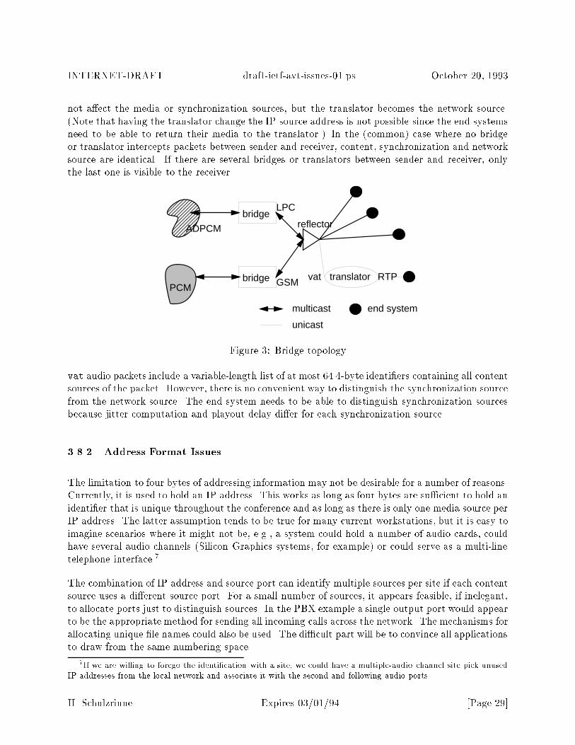
INTERNET-DRAFT draft-ietf-avt-issues-01.ps October 20, 1993
not a�ect the media or synchronization sources, but the translator becomes the network source.(Note that having the translator change the IP source address is not possible since the end systemsneed to be able to return their media to the translator.) In the (common) case where no bridgeor translator intercepts packets between sender and receiver, content, synchronization and networksource are identical. If there are several bridges or translators between sender and receiver, onlythe last one is visible to the receiver.
PCM
LPC
multicast
unicast
end system
bridge
bridge
ADPCM
GSM
reflector
translatorvat RTP
Figure 3: Bridge topology
vat audio packets include a variable-length list of at most 64 4-byte identi�ers containing all contentsources of the packet. However, there is no convenient way to distinguish the synchronization sourcefrom the network source. The end system needs to be able to distinguish synchronization sourcesbecause jitter computation and playout delay di�er for each synchronization source.
3.8.2 Address Format Issues
The limitation to four bytes of addressing information may not be desirable for a number of reasons.Currently, it is used to hold an IP address. This works as long as four bytes are su�cient to hold anidenti�er that is unique throughout the conference and as long as there is only one media source perIP address. The latter assumption tends to be true for many current workstations, but it is easy toimagine scenarios where it might not be, e.g., a system could hold a number of audio cards, couldhave several audio channels (Silicon Graphics systems, for example) or could serve as a multi-linetelephone interface.7
The combination of IP address and source port can identify multiple sources per site if each contentsource uses a di�erent source port. For a small number of sources, it appears feasible, if inelegant,to allocate ports just to distinguish sources. In the PBX example a single output port would appearto be the appropriate method for sending all incoming calls across the network. The mechanisms forallocating unique �le names could also be used. The di�cult part will be to convince all applicationsto draw from the same numbering space.
7If we are willing to forego the identi�cation with a site, we could have a multiple-audio channel site pick unusedIP addresses from the local network and associate it with the second and following audio ports.
H. Schulzrinne Expires 03/01/94 [Page 29]
INTERNET-DRAFT draft-ietf-avt-issues-01.ps October 20, 1993
For e�ciency in the common case of one source per workstation, the convention (used in vat) ofusing the network source address, possibly combined with the user id or source port, as media andsynchronization source should be maintained.
There are several possible approaches to naming sources. We compare here two examples repre-senting naming through globally unique network addresses and through a concatenation of locallyunique identi�ers.
The receiver needs to be able to uniquely identify the content source so that speaker indication andlabeling work. For playout synchronization, the synchronization source needs to be determined.The identi�cation mechanism has to continue to work even if the path between sender and receivercontains multiple bridges and translators.
Also, in the common case of no bridges or translators, the only information available at the receiveris the network address and source port. This can cause di�culties if there is more than oneparticipant per host in a certain conference. If this can occur, it is necessary that the applicationopens two sockets, one for listening bound to the conference port number and one for sending, boundto some locally unique port. That randomly chosen port should also be used for reverse applicationdata, i.e., requests from the receiver back to the content source. Only the listening socket needsto be a member of the IP multicast group. If an application multiplexes several locally generatedsources, e.g., an interface to an audio bridge, it should follow the rules for bridges, that is, insertcontent source information.
3.8.3 Globally unique identi�ers
Sources are identi�ed by their network address and the source port number. The source portnumber rather than some other integer has to be chosen for the common case that RTP packetscontain no SSRC or CSRC options. Since the SDES option contains an address, it has to be thenetwork address plus source port, no other information being available to the receiver for matching.(The SDES address is not strictly needed unless a bridge with mixing is involved, but carrying itkeeps the receiver from having to distinguish those cases.) Since tying a protocol too closely to oneparticular network protocol is considered a bad idea (witness the di�culty of adopting parts of FTPfor non-IP protocols), the address should probably have the form of a type-lenght-value �eld. Toavoid having to manage yet another name space, it appears possible to re-use the Ethertype values,as all commonly used protocols with their own address space appear to have been assigned sucha value. Other alternatives, such as using the BSD Unix AF constants su�er from the drawbackthat there does not appear to be a universally agreed-upon numbering. NSAPs can contain otheraddresses, but not every address format (such as IP) has an NSAP representation. The receiverapplication does not need to interpret the addresses themselves; it treats address format identi�er(e.g., the Ethertype �eld) and address as a globally unique byte string. We have to assure a singlehost does not use two network addresses, one for transmission and a di�erent one in the SDESoption.
The rules for adding CSRC and SSRC options are simple:
H. Schulzrinne Expires 03/01/94 [Page 30]
INTERNET-DRAFT draft-ietf-avt-issues-01.ps October 20, 1993
end system: End systems do not insert CSRC or SSRC options. The receiver remembers theCSRC address for each site; if none is explicitly speci�ed, the SSRC address is used. If that isalso missing, the network address is used. SDES options are matched to this content sourceaddress.
bridge: A bridge adds the network source address of all sources contributing to a particular out-going packet as CSRC options. A bridge that receives a packet containing CSRC optionsmay decide to copy those CSRC options into an outgoing packet that contains data from thatbridge.
translator: The translator checks whether the packet already contains a SSRC (inserted by anearlier translator). If so, no action is required. Otherwise, the translator inserts an SSRCcontaining the network address of the host from which the packet was received.
The SSRC option is set only by the translator, unless the packet already bears such an option.
Globally unique identi�ers based on network addresses have the advantage that they simplify de-bugging, for example, allowing to determine which bridge processed a message, even after the packethas passed through a translator.
3.8.4 Locally unique addresses
In this scheme, the SSRC, CSRC and SDES options contain locally unique identi�ers of some length.For lengths of at least four bytes, it is su�cient to have the application pick one at random, withoutlocal coordination, with su�ciently low probability of collision within a single host. The receivercreates a globally unique identi�er by concatenating the network address and one or more randomidenti�ers. The synchronization source is identi�ed by the concatenation of the SSRC identi�erand the network address. Only translators are allowed to set the SSRC option. If a translatorreceives an RTP packet which already contains an SSRC option, as can occur if a packet traversesseveral translators, the translator has to choose a new set of values, mapping packets with the samenetwork source, but di�erent incoming SSRC value into di�erent outgoing SSRC values. Note thatthe SSRC constitute a label-swapping scheme similar to that used for ATM networks, except thatthe assocation setup is implicit. If a translator loses state (say, after rebooting), the mapping issimply reestablished as packets arrive from end systems or other translators. Until the receiverstimeout, a single source may appear twice and there may be a temporary confusion of sources andtheir descriptors.
The rules are:
end system: An end system never inserts CSRC options and typically does not insert an SSRCoption. An end system application may insert an SSRC option if it originates more than onestream for a single conference through a single network and transport address, e.g., a singleUDP port. The SDES option contains a zero for the identi�er, indicating that the receiver is
H. Schulzrinne Expires 03/01/94 [Page 31]
INTERNET-DRAFT draft-ietf-avt-issues-01.ps October 20, 1993
to much on network address only. The receiver determines the synchronization source as theconcatenation of network source and synchronization source.
bridge: A bridge assigns each source its own CSRC identi�er (non-zero), which is then used alsoin the SDES option.
translator: The translator maintains a list of all incoming sources, with their network and SSRC,if present. Sources without SSRC are assigned an SSRC equal to zero. Each of these sourcesis assigned a new local identi�er, which is then inserted into the SSRC option.
Local identi�ers have advantages: the length of the identi�ers within the packet are signi�cantlyshorter (four to six vs. at least ten bytes with padding); comparison of content and synchronizationsource are quicker (integer comparison vs. variable-length string comparison). The identi�ers aremeaningless for debugging. In particular, it is not easy for the receiver sitting behind a translatorand a bridge to determine where a bridge is located, unless the bridge identi�es itself periodically,possibly with another SDES-like option containing the actual network address.
The major drawbacks appear to be the additional translator complexity: translators needs tomaintain a mapping from incoming network/SSRC to outgoing SSRC.
Note that using IP addresses as \random" local identi�ers is not workable if there is any possibilitythat two sources participating in the same conference can coexist on the same host.
A somewhat contrived scenaria is shown in Fig. 4.
3.9 Energy Indication
G.764 contains a 4-bit noise energy �eld, which encodes the white noise energy to be played bythe receiver in the silences between talkspurts. Playing silence periods as white noise reduces thenoise-pumping where the background noise audible during the talkspurt is audibly absent at thereceiver during silence periods. Substituting white noise for silence periods at the receiver is notrecommended for multi-party conferences, as the summed background noise from all silent partieswould be distractive. Determining the proper noise level appears to be di�cult. It is suggested thatthe receiver simply takes the energy of the last packet received before the beginning of a silenceperiod as an indication of the background noise. With this mechanism, an explicit indication inthe packet header is not required.
3.10 Error Control
In principle, the receiver has four choices in handling packets with bit errors [15]:
no checking: the receiver provides no indication whether a data packet contains bit errors, eitherbecause a checksum is not present or is not checked.
H. Schulzrinne Expires 03/01/94 [Page 32]
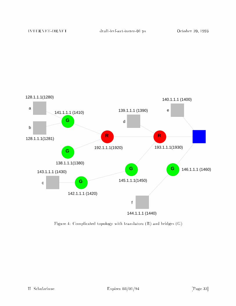
INTERNET-DRAFT draft-ietf-avt-issues-01.ps October 20, 1993
G
R
G
R
G
a
b
145.1.1.1(1450)
138.1.1.1(1380)
192.1.1.1(1920) 193.1.1.1(1930)
128.1.1.1(1280)
139.1.1.1 (1390)
140.1.1.1 (1400)
141.1.1.1 (1410)
G
142.1.1.1 (1420)
c
e
d
143.1.1.1 (1430)
128.1.1.1(1281)
G
f
144.1.1.1 (1440)
146.1.1.1 (1460)
Figure 4: Complicated topology with translators (R) and bridges (G)
H. Schulzrinne Expires 03/01/94 [Page 33]
INTERNET-DRAFT draft-ietf-avt-issues-01.ps October 20, 1993
discard: the receiver discards errored packets, with no indication to the application.
receive: the receiver delivers and ags errored packets to the application.
correct: the receiver drops errored packets and requests retransmission.
It remains to be decided whether the header, the whole packet or neither should be protected bychecksums. NVP protects its header only, while G.764 has a single 16-bit check sequence coveringboth datalink and packet voice header. However, if UDP is used as the transport protocol, achecksum over the whole packet is already computed by the receiver. (Checksumming for UDP cantypically be disabled by the sending or receiving host, but usually not on a per-port basis.) ST-IIdoes not compute checksums for its payload. Many data link protocols already discard packetswith bit errors, so that packets are rarely rejected due to higher-layer checksums.
Bit errors within the data part may be easier to tolerate than a lost packet, particularly since somemedia encoding formats may provide built-in error correction. The impact of bit errors within theheader can vary; for example, errors within the timestamp may cause the audio packet to be playedout at the wrong time, probably much more noticeable than discarding the packet. Other noticeablee�ects are caused by a wrong ow or encoding identi�er. If a separate checksum is desired for thecases where the underlying protocols do not already provide one, it should be optional. Onceoptional, it would be easy to de�ne several checksum options, covering just the header, the headerplus a certain part of the body or the whole packet.
A checksum can also be used to detect whether the receiver has the correct decryption key, avoidingnoise or (worse) denial-of-service attacks. For that application, the checksum should be computedacross the whole packet, before encrypting the content. Alternatively, a well-known signature couldbe added to the packet and included in the encryption, as long as known plaintext does not weakenthe encryption security.
Embedding a checksum as an option may lead to undiscovered errors if the the presence of thechecksum is masked by errors. This can occur in a number of ways, for example by an alteredoption type �eld, a �nal-option bit erroneously set in options prior to the checksum option or anerroneous �eld length �eld. Thus, it may be preferable to pre�x the RTP packet with a checksumas part of the speci�cation of running RTP over some network or transport protocol. To avoidthe overhead of including a checksum even in the common case where it is not needed, it might beappropriate to distinguish two RTP protocol variations through the next-protocol value in the lower-layer protocol header; the �rst would include a checksum, the second would not. The checksumitself o�ers a number of encoding possibilities8 :
� have two 16-bit checksums, one covering the header, the other the data part
� combine a 16-bit checksum with a byte count indicating its coverage, thus allowing either aheader-only or a header-plus-data checksum
8suggested by S. Casner
H. Schulzrinne Expires 03/01/94 [Page 34]

INTERNET-DRAFT draft-ietf-avt-issues-01.ps October 20, 1993
The latter has the advantage that the checksum can be computed without determining the headerlength.
The error detection performance and computational cost of some common 16-bit checksummingalgorithms are summarized in Table 4. The implementations were drawn from [16] and compiled ona SPARC IPX using the Sun ANSI C compiler with optimization. The checksum computation wasrepeated 100 times; thus, due to data cache e�ects, the execution times shown are probably betterthan would be measured in an actual application. The relative performance, however, should besimilar. Among the algorithms, the CRC has the strongest error detection properties, particularlyfor burst errors, while the remaining algorithms are roughly equivalent [16]. The Fletcher algorithmwith modulo 255 (shown here) has the peculiar property that a transformation of a byte from 0 to255 remains undetected. CRC, the IP checksum and Fletcher's algorithm cannot detect spuriouszeroes at the end of a variable-length message [17]. The non-CRC checksums have the advantagethat they can be updated incrementally if only a few bytes have changed. The latter property isimportant for translators that insert synchronization source indicators.
algorithm ms
IP checksum 0.093Fletcher's algorthm, optimized [17] 0.192CRC CCITT 0.310Fletcher's algorithm, non-optimized [18] 2.044
Table 4: Execution time of common 16-bit checksumming algorithms, for a 1024-byte packet, inmilliseconds
3.11 Security and Privacy
3.11.1 Introduction
The discussions in this sections are based on the work of the privacy enhanced mail (PEM) workinggroup within the Internet Engineering Task Force, as documented in [19,20] and related documents.The reader is referred to RFC 1113 [19] or its successors for terminology. Also relevant is the workon security for SNMP Version 2. We discuss here how the following security-related services maybe implemented for packet voice and video:
Con�dentiality: Measures that ensure that only the intended receiver(s) can decode the receivedaudio/video data; for others, the data contains no useful information.
Authentication: Measures that allow the receiver(s) to ascertain the identity of the sender ofdata or to verify that the claimed originator is indeed the originator of the data.
Message integrity: Measures that allow the receiver(s) to detect whether the received data hasbeen altered.
H. Schulzrinne Expires 03/01/94 [Page 35]
INTERNET-DRAFT draft-ietf-avt-issues-01.ps October 20, 1993
As for PEM [19], the following privacy-related concerns are not addressed at this time:
� access control
� tra�c ow con�dentiality
� routing control
� assurance of data receipt and non-deniability of receipt
� duplicate detection, replay prevention, or other stream-oriented services
These services either require connection-oriented services or support from the lower layers that iscurrently unavailable. A reasonable goal is to provide privacy at least equivalent to that providedby the public telephone system (except for tra�c ow con�dentiality).
As for privacy-enhanced mail, the sender determines which privacy enhancements are to be per-formed for a particular part of a data transmission. Therefore, mechanisms should be provided thatallow the sender to determine whether the desired recipients are equipped to process any privacy-enhancements. This is functionally similar to the negotiation of, say, media encodings and shouldprobably be handled by similar mechanisms. It is anticipated that privacy-enhanced mail will beused in the absence of or in addition to session establishment protocols and agents to distributedkeys or negotiate the enhancements to be used during a conference.
3.11.2 Con�dentiality
Only data encryption can provide con�dentiality as long as intruders can monitor the channel.It is desirable to specify an encryption algorithm and provide implementations without exportrestrictions. Although DES is widely available outside the United States, its use within softwarein both source and binary form remains di�cult.
We have the choice of either encrypting and/or authenticating the whole packet or only the optionsand payload. Encrypting the �xed header denies the intruder knowledge about some conferencedetails (such as timing and format) and protects against replay attacks. Encrypting the �xedheader also allows some heuristic detection of key mismatches, as the version identi�er, timestampand other header information are somewhat predictable. However, header encryption makes packettraces and debugging by external programs di�cult. Also, since translators may need to inspectand modify the header, but do not have access to the sender's key, at least part of the header needsto remain unencrypted, with the ability for the receiver to discern which part has been encrypted.Given these complications and the uncertain bene�ts of header encryption, it appears appropriateto limit encryption to the options and payload part only.
In public key cryptography, the sender uses the receiver's public key for encryption. Public keycryptography does not work for true multicast systems since the public encoding key for every re-cipient di�ers, but it may be appropriate when used in two-party conversations or application-level
H. Schulzrinne Expires 03/01/94 [Page 36]

INTERNET-DRAFT draft-ietf-avt-issues-01.ps October 20, 1993
multicast. In that case, mechanisms similar to privacy enhanced mail will probably be appro-priate. Key distribution for symmetric-key encryption such as DES is beyond the scope of thisrecommendation, but the services of privacy enhanced mail [19, 21] may be appropriate.
For one-way applications, it may desirable to prohibit listeners from interrupting the broadcast.(After all, since live lectures on campus get disrupted fairly often, there is reason to fear that asu�ciently controversial lecture carried on the Internet could su�er a similar fate.) Again, asym-metric encryption can be used. Here, the decryption key is made available to all receivers, while theencryption key is known only to the legitimate sender. Current public-key algorithms are probablytoo computationally intensive for all but low-bit-rate voice. In most cases, �ltering based on sourceswill be su�cient.
3.11.3 Message Integrity and Authentication
The usual message digest methods are applicable if only the integrity of the message is to beprotected against tampering. Again, services similar to that of privacy-enhanced mail [22] may beappropriate. The MD5 message digest [23] appears suitable. It translates any size message into a128-bit (16-byte) signature. On a SPARCstation IPX (Sun 4/50), the computation of a signaturefor a 180-byte audio packet takes approximately 0.378 ms9 De�ning the signature to apply toall data beginning at the signature option allows operation when translators change headers. Thereceiver has to be able to locate the public key of the claimed sender. This poses two problems:�rst, a way of identifying the sender unambiguously needs to be found. The current methods ofidenti�cation, such as the SMTP (e-mail) address, are not unambiguous. Use of a distinguishedname as described in RFC 1255 [24] is suggested.
The authentication process is described in RFC 1422 [21]:
In order to provide message integrity and data origin authentication, the originatorgenerates a message integrity code (MIC), signs (encrypts) the MIC using the privatecomponent of his public-key pair, and includes the resulting value in the message headerin the MIC-Info �eld. The certi�cate of the originator is (optionally) included in theheader in the Certi�cate �eld as described in RFC 1421. This is done in order tofacilitate validation in the absence of ubiquitous directory services. Upon receipt of aprivacy enhanced message, a recipient validates the originator's certi�cate (using theIPRA public component as the root of a certi�cation path), checks to ensure that ithas not been revoked, extracts the public component from the certi�cate, and uses thatvalue to recover (decrypt) the MIC. The recovered MIC is compared against the locallycalculated MIC to verify the integrity and data origin authenticity of the message.
For audio/video applications with loose control, the certi�cate could be carried periodically to allow
9The processing rates for Sun 4/50 (40 MHz clock) and SPARCstation 10's (36 MHz clock) are 0.95 and 2.2 MB/s,respectively, measured for a single 1000-byte block. Note that timing the repeated application of the algorithm forthe same block of data gives optimistic results since the data then resides in the cache.
H. Schulzrinne Expires 03/01/94 [Page 37]
INTERNET-DRAFT draft-ietf-avt-issues-01.ps October 20, 1993
new listeners to obtain it and to achieve a measure of reliability.
Symmetric key methods such as DES can also be used. Here, the key is simply pre�xed to themessage when computing the message digest (MIC), but not transmitted. The receiver has toobtain the sender's key through a secure channel, e.g., a PEM message. The method has theadvantage that no cryptography is involved, thus alleviating export-control concerns. It is used forSNMP Version 2 authentication.
3.12 Security for RTP vs. PEM
It is the author's opinion that RTP should aim to reuse as much of the PEM technology and syntaxas possible, unless there are strong reasons in the nature of real-time tra�c to deviate. This hasthe advantage that terminology, implementation experience, certi�cate mechanisms and possiblycode can be reused. Also, since it is hoped that RTP �nds use in a range of applications, a broadspectrum of security mechanisms should be provided, not necessarily limited by what is appropriatefor large-distribution audio and video conferences.
It should be noted that connection-oriented security architectures are probably unsuitable for RTPapplications as they rely on reliable stream transmission and an explicit setup phase with typicallyonly a single sender and receiver.
There are a number of di�erences between the security requirements of PEM and RTP that shouldbe kept in mind:
Transparency: Unlike electronic mail, it is safe to assume that the channel will carry 8 bit dataunaltered. Thus, a conversion to a canonical form or encoding binary data into a 64-elementsubset as done for PEM is not required.
Time: As outlined at the beginning of this document, processing speed and packet overhead have tobe major considerations, much more so than with store-and-forward electronic mail. Messagedigest algorithms and DES can be implemented su�ciently fast even in software to be usedfor voice and possibly for low-bit rate video. Even for short signatures, RSA encryption isfairly slow.
Note that the ASN.1/BER encoding of asymmetrically-encrypted MICs and certi�cates addsno signi�cant processing load. For the MICs, the ASN.1 algorithm yields only additionalconstant bytes which a paranoid program can check, but does not need to decode. Certi�-cates are carried much more infrequently and are relatively simple structures. It would seemunnecessary to supply a complete ASN.1/BER parser for any of the datastructures.
Space: Encryption algorithm require a minimum data input equal to their keylength. Thus, forthe suggested key length for RSA encryption of 508 to 1024 bits, the 16-byte message digestexpands to a 53 to 128 byte MIC. This is clearly rather burdensome for short audio packets.Applying a single message digest to several packets seems possible if the packet loss ratesare su�ciently low, even though it does introduce minor security risks in the case where
H. Schulzrinne Expires 03/01/94 [Page 38]

INTERNET-DRAFT draft-ietf-avt-issues-01.ps October 20, 1993
the receiver is forced to decide between accepting as authentic an incomplete sequence ofpackets or rejecting the whole sequence. Note that it would not be necessary to wait withplayback until a complete authenticated block has been received; in general, a warning thatauthentication has failed would be su�cient for human users. The application should alsoissue a warning if no complete block could be authenticated for several blocks, as that mightindicate that an impostor was feigning the presence of MIC-protected data by strategicallydropping packets.
The initialization vector for DES in cipher block mode adds another eight bytes.
Scale: The symmetric key authentication algorithm used by PEM does not scale well for a largenumber of receivers as the message has to contain a separate MIC for each receiver, encryptedwith the key for that particular sender-receiver pair. If we forgo the ability to authenticatean individual user, a single session key shared by all participants can thwart impostors fromoutside the group holding the shared secret.
3.13 Quality of Service Control
Because real-time services cannot a�ord retransmissions, they are directly a�ected by packet lossand delays. Delay jitter and packet loss, for example, provide a good indication of network con-gestion and may suggest switching to a lower-bandwidth coding. To aid in fault isolation andperformance monitoring, quality-of-service (QOS) measurement support is useful. QOS of servicemonitoring is useful for the receiver of real-time data, the sender of that data and possibly a third-party monitor, e.g., the network provider, that is itself not part of the real-time data distribution.
3.13.1 QOS Measures
For real-time services, a number of QOS measures are of interest, roughly in order of importance:
� packet loss
� packet delay variation (variance, minimum/maximum)
� relative clock drift (delay between sender and receiver timestamp)
In the following, the terms receiver and sender pertain to the real-time data, not any returned QOSdata. If the receiver is to measure packet loss, an indication of the number of packets actuallytransmitted is required. If the receiver itself does not need to compute packet loss percentages,it is su�cient for the receiver to indicate to the sender the number of packets received and therange timestamps covered, thus avoiding the need for sequence numbers. Translation into loss atthe sender is somewhat complicated, however, unless restrictions on permissible timestamps (e.g.,those starting a synchronization unit) are enforced. If sequence numbers are available, the receiverhas to track the number of times that the sequence number has wrapped around, even in the face
H. Schulzrinne Expires 03/01/94 [Page 39]
INTERNET-DRAFT draft-ietf-avt-issues-01.ps October 20, 1993
of packet reordering. If c denotes the cycle count, M the sequence number modulus and sn thesequence number of the n received packet, where sn is not necessarily larger than sn�1, we canwrite:
cn = cn�1 + 1 for �M < sn � sn�1 < �M=2cn = cn�1 � 1 for M=2 < sn � sn�1 < Mcn = cn�1 otherwise
For example, the sequence number sequence 65534; 2; 65535; 1; 3; 5; 4 would yield the cycle numbersequence 0; 1; 0; 1; 1; 1; 1 forM = 65536, i.e., 16-bit sequence numbers. The total number of expectedpackets is then computed simply as sn +M � cn � s0 + 1, where the �rst received packet has index0.
The user of the measurements should also have some indication as to the time period they coverso that the degree of con�dence in these statistical meassurements can be established.
3.13.2 Remote measurements
It may be desirable for the sender, interested multicast group members or a non-group member(third party) to have automatic access to quality-of-service measurements. In particular, it isnecessary for the sender to gather a number of reception reports from di�erent parts of the Internetto \triangulate" where packets get lost or delayed.
Two modes of operation can be distinguished: monitor-driven or receiver-driven. In the monitor-driven case, a site interested in QOS data for a particular sender contacts the receiver through aback channel and requests a reception report. Alternatively, each site can send reception reportsto a monitoring multicast group or as session data, along with the \regular station identi�cation"to the same multicast group used for data. The �rst approach requires the most implementatione�ort, but produces the least amount of data. The other two approaches have complementaryproperties.
In most cases, sender-speci�c quality of service information is more useful for tracking networkproblems than aggregrate data for all senders. Since a site cannot transmit reception reports for allsenders it has ever heard from, some selection mechanism is needed, such as most-recently-heardor cycling through sites.
Source identi�cation poses some di�culties since the network address seen by the receiver may notbe meaningful to other members of the multicast group, e.g., after IP-SIP address translation. Onthe other hand, network addresses are easier to correlate with other network-level tools such asthose used for Mbone mapping.
minimum and maximum di�erence between departure and arrival timestamp. This has the ad-vantage that the �xed delay can also be estimated if sender and receiver clocks are known to be
H. Schulzrinne Expires 03/01/94 [Page 40]
INTERNET-DRAFT draft-ietf-avt-issues-01.ps October 20, 1993
synchronized. Unfortunately, delay extrema are noisy measurement that give only limited indica-tion of the delay variability. The receiver could also return the playout delay value it uses, althoughfor absolute timing, that again depends on the clock di�erential, as well as on the particular delayestimation algorithm employed by the receiver. In summary, a minimal set of useful measurementsappears to be the expected and received packet count, combined with the minimum and maximumtimestamp di�erence.
3.13.3 Monitoring by Third Party
Except for delay estimates based on sequence number ranges, the above section applies for thiscase as well.
4 Conference Control Protocol
Currently, only conference control functions used for loosely controlled conferences (open admission,no explicit conference set-up) have been considered in depth. Support for the following functionalityneeds to be speci�ed:
� authentication
� oor control, token passing
� invitations, calls
� call forwarding, call transfer
� discovery of conferences and resources (directory service)
� media, encoding and quality-of-service negotiation
� voting
� conference scheduling
� user locator
The functional speci�cation of a conference control protocol is beyond the scope of this memoran-dum.
H. Schulzrinne Expires 03/01/94 [Page 41]

INTERNET-DRAFT draft-ietf-avt-issues-01.ps October 20, 1993
5 The Use of Pro�les
RTP is intended to be a rather 'thin' protocol, partially because it aims to serve a wide variety ofreal-time services. The RTP speci�cation intentionally leaves a number of issues open for other doc-uments (pro�les), which in turn have the goal of making it easy to build interoperable applicationsfor a particular application domain, for example, audio and video conferences.
Some of the issues that a pro�le should address include:
� the interpretation of the 'content' �eld with the CDESC option
� the structure of the content-speci�c part at the end of the CDESC option
� the mechanism by which applications learn about and de�ne the mapping between the 'con-tent' �eld in the RTP �xed header and its meaning
� the use of the optional framing �eld pre�xed to RTP packets (not used, used only if underlyingtransport protocol does not provide framing, used by some negotiation mechanism, alwaysused)
� any RTP-over-x issues, that is, de�nitions needed to allow RTP to use a particular underlyingprotocol
� content-speci�c RTP, RTCP or reverse control options
� port assignments for data and reverse control
6 Port Assignment
Since it is anticipated that UDP and similar port-oriented protocols will play a major role in carryingRTP tra�c, the issue of port assignment needs to be addressed. The way ports are assigned mainlya�ects how applications can extract the packets destined for them. For each medium, there alsoneeds to be a mechanism for distinguishing data from control packets.
For unicast UDP, only the port number is available for demultiplexing. Thus, each media willneed a separate port number pair unless a separate demultiplexing agent is used. However, forone-to-one connections, dynamically negotiating a port number is easy. If several UDP streams areused to provide multicast by transport-level replication, the port number issue becomes somewhatmore di�cult. For ST-II, a common port number has to be agreed upon by all participants, whichmay be di�cult particularly if a new site wants to join an on-going connection, but is already usingthe port number in a di�erent connection.
For UDP multicast, an application can select to receive only packets with a particular port numberand multicast address by binding to the appropriate multicast address10 . Thus, for UDP multicast,
10This extension to the original multicast socket semantics is currently in the process of being deployed.
H. Schulzrinne Expires 03/01/94 [Page 42]
INTERNET-DRAFT draft-ietf-avt-issues-01.ps October 20, 1993
there is no need to distinguish media by port numbers, as each medium could have its designatedand unique multicast group. Any dynamic port allocation mechanism would fail for large, dynamicmulticast groups, but might be appropriate for small conferences and two-party conversations.
Data and control packets for a single medium can either share a single port or use two di�erent portnumbers. (Currently, two adjacent port numbers, 3456 and 3457, are used.) A single port for dataand control simpli�es the receiver code and translators and, less important, conserves port numbers.With the proliferation of �rewalls, limiting the number of ports has assumed additional importance.Sharing a single port requires some other means of identifying control packets, for example as aspecial encoding code. Alternatively, all control data could be carried as options within datapackets, akin to the NVP protocol options. Since control messages are also transmitted if no actualmedium data is available, header content of packets without media data needs to be determined.With the use of a synchronization bit, the issue of how sequence numbers and timestamps are to betreated for these packets is less critical. It is suggested to use a zero timestamp and to increment thesequence number normally. Due to the low bandwidth requirements of typical control information,the issue of accomodating control information in any bandwidth reservation scheme should bemanageable. The penalty paid is the eight-byte overhead of the RTP header for control packetsthat do not require time stamps, encoding and sequence number information.
Using a single RTCP stream for several media may be advantageous to avoid duplicating, forexample, the same identi�cation information for voice, video and whiteboard streams. This worksonly if there is one multicast group that all members of a conference subscribe to. Given therelatively low frequency of control messages, the coordination e�ort between applications and thenecessity to designate control messages for a particular medium are probably reasons enough tohave each application send control messages to the same multicast group as the data.
In conclusion, for multicast UDP, one assigned port number, for both data and control, seems too�er the most advantages, although the data/control split may o�er some bandwidth savings.
7 Multicast Address Allocation
A �xed, permanent allocation of network multicast addresses to invidual conferences by somenaming authority such as the Internet Assigned Numbers Authority is clearly not feasible, sincethe lifetime of conferences is unknown, the potential number of conferences is rather large and theavailable number space limited to about 228, of which 216 have been set aside for dynamic allocationby conferences.
The alternative to permanent allocation is a dynamic allocation, where an initiator of a multicastapplication obtains an unused multicast address in some manner (discussed below). The address isthen made available again, either implicitly or explicitly, as the application terminates.
The address allocation may or may not be handled by the same mechanism that provides conferencenaming and discovery services. Separating the two has the advantage that dynamic (multicast)
H. Schulzrinne Expires 03/01/94 [Page 43]

INTERNET-DRAFT draft-ietf-avt-issues-01.ps October 20, 1993
address allocation may be useful to applications other than conferencing. Also, di�erent mechanisms(for example, periodic announcements vs. servers) may be appropriate for each.
We can distinguish two methods of multicast address assignment:
function-based: all applications of a certain type share a common, global address space. Cur-rently, a reservation of a 16-bit address space for conferences is one example. The advantageof this scheme is that directory functions and allocation can be readily combined, as is donein the sd tool by Van Jacobson. A single namespace spanning the globe makes it neces-sary to restrict the scope of addresses so that allocation does not require knowing about anddistributing information about the existence of all global conferences.
hierarchical: Based on the location of the initiator, only a subset of addresses are available.This limits the number of hosts that could be involved in resolving collisions, but, like mosthierarchical assignment, leads to sparse allocation. Allocation is independent of the functionthe address is used for.
Clearly, combinations are possible, for example, each local namespace could be functionally dividedif su�ciently large. With the current allocation of 216 addresses to conferences, hierarchical divisionexcept on a very coarse scale is not feasible.
To a limited extent, multicast address allocation can be compared to the well-known channelmultiple access problem. The multicast address space plays the role of the common channel, witheach address representing a time slot.
All the following schemes require cooperation from all potential users of the address space. Thereis no protection against an ignorant or malicious user joining a multicast group.
7.1 Channel Sensing
In this approach, the initiator randomly selects a multicast address from a given range, joins themulticast group with that address and listens whether some other host is already transmitting onthat address. This approach does not require a separate address allocation protocol or an addressserver, but it is probably infeasible for a number of reasons. First, a user process can only bindto a single port at one time, making 'channel sensing' di�cult. Secondly, unlike listening to atypical broadcast channel, the act of joining the multicast group can be quite expensive both forthe listening host and the network. Consider what would happen if a host attached through alow-bandwidth connection joins a multicast group carrying video tra�c, say.
Channel sensing may also fail if two sections of the network that were separated at the time ofaddress allocation rejoin later. Changes in time-to-live values can make multicast groups 'visible'to hosts that previously were outside their scope.
H. Schulzrinne Expires 03/01/94 [Page 44]
INTERNET-DRAFT draft-ietf-avt-issues-01.ps October 20, 1993
7.2 Global Reservation Channel with Scoping
Each range of multicast addresses has an associated well-known multicast address and port whereall initiators (and possibly users) advertise the use of multicast addresses. An initiator �rst picksa multicast address at random, avoiding those already known to be in use. Some mechanism forcollision resolution has to be provided in the unlikely event that two initiators simultaneously choosethe same address. Also, since address advertisement will have to be sent at fairly long intervalsto keep tra�c down, an application wanting to start a conference, for example, has to wait for anextended period of time unless it continuously monitors the allocation multicast group.
To limit tra�c, it may seem advisable to only have the initiator multicast the address usageadvertisement. This, however, means that there needs to be a mechanism for another site totake over advertising the group if the initiator leaves, but the multicast group continues to exist.Time-to-live restrictions pose another problem. If only a single source advertises the group, theadvertisement may not reach all those sites that could be reached by the multicast transmissionsthemselves.
The possibility of collisions can be reduced by address reuse with scoping, discussed further below,and by adding port numbers and other identi�ers as further discriminators. The latter approachappears to defeat the purpose of using multicast to avoid transmitting information to hosts thathave no interest in receiving it. Routers can only �lter based on group membership, not ports orother higher-layer demultiplexing identi�ers. Thus, even though two conferences with the samemulticast address and di�erent ports, say, could coexist at the application layer, this would forcehosts and networks that are interested in only one of the conferences to deal with the combinedtra�c of the two conferences.
7.3 Local Reservation Channel
Instead of sharing a global namespace for each application, this scheme divides the multicast addressspace hierarchically, allowing an initiator within a given network to choose from a smaller set ofmulticast addresses, but independent of the application. As with many allocation problems, wecan devise both server-based and fully distributed versions.
7.3.1 Hierarchical Allocation with Servers
By some external means, address servers, distributed throughout the network, are provided withnon-overlapping regions of the multicast address space. An initiator asks its favorite address serverfor an address when needed. When it no longer needs the address, it returns it to the server.To prevent addresses from disappearing when the requestor crashes and looses its memory aboutallocated addresses, requests should have an associated time-out period. This would also (to someextent) cover the case that the initiator leaves the conference, without the conference itself disband-ing. To decrease the chances that an initiator cannot be provided with an address, either the local
H. Schulzrinne Expires 03/01/94 [Page 45]

INTERNET-DRAFT draft-ietf-avt-issues-01.ps October 20, 1993
server could 'borrow' an address from another server or could point the initiator to another server,somewhat akin to the methods used by the Domain Name Service (DNS). Provisions have to bemade for servers that crash and may loose knowledge about the status of its block of addresses, inparticular their expiration times. The impact of such failures could be mitigated by limiting themaximum expiration time to a few hours. Also, the server could try to request status by multicastfrom its clients.
7.3.2 Distributed Hierarchical Allocation
Instead of a server, each network is allocated a set of multicast addresses. Within the currentIP address space, both class A, B and C networks would get roughly 120 addresses, taking intoaccount those that have been permanently assigned. Contention for addresses works like the globalreservation channel discussed earlier, but the reservation group is strictly limited to the localnetwork. (Since the address ranges are disjoint, address information that inadvertently leaks outsidethe network, is harmless.)
This method avoids the use of servers and the attendant failure modes, but introduces other prob-lems. The division of the address space leads to a barely adequate supply of addresses (althoughlarger address formats will probably make that less of an issue in the future). As for any distributedalgorithm, splitting of networks into temporarily unconnected parts can easily destroy the unique-ness of addresses. Handling initiators that leave on-going conferences is probably the most di�cultissue.
7.4 Restricting Scope by Limiting Time-to-Live
Regardless of the address allocation method, it may be desirable to distinguish multicast addresseswith di�erent reach. A local address would be given out with the restriction of a maximum time-to-live value and could thus be reused at a network su�ciently removed, akin to the combination ofcell reuse and power limitation in cellular telephony. Given that many conferences will be local orregional (e.g., broadcasting classes to nearby campuses of the same university or a regional group ofuniversities, or an electronic town meeting), this should allow signi�cant reuse of addresses. Reuseof addresses requires careful engineering of thresholds and would probably only be useful for verysmall time-to-live values that restrict reach to a single local area network. Using time-to-live �eldsto restrict scope rather than just prevent looping introduces di�cult-to-diagnose failure modes intomulticast sessions. In particular, reachability is no longer transitive, as B may have A and C in itsscope, but A and B may be outside each other's scope (or A may be in the scope of B, but not viceversa, due to asymmetric routes, etc.). This problem is aggravated by the fact that routers (forobvious reasons) are not supposed to return ICMP time exceeded messages, so that the sender canonly guess why multicast packets do not reach certain receivers.
H. Schulzrinne Expires 03/01/94 [Page 46]
INTERNET-DRAFT draft-ietf-avt-issues-01.ps October 20, 1993
8 Security Considerations
Security issues are discussed in Section 3.11.
Acknowledgments
This draft is based on discussion within the AVT working group chaired by Stephen Casner. EveSchooler and Stephen Casner provided valuable comments.
This work was supported in part by the O�ce of Naval Research under contract N00014-90-J-1293,the Defense Advanced Research Projects Agency under contract NAG2-578 and a National ScienceFoundation equipment grant, CERDCR 8500332.
A Glossary
The glossary below brie y de�nes the acronyms used within the text. Further de�nitions can befound in RFC 1392, \Internet User's Glossary". Some of the general Internet de�nitions beloware copied from that glossary. The quoted passages followed by a reference of the form \(G.701)"are drawn from the CCITT Blue Book, Fascicle I.3, De�nitions. The glossary of the document\Recommended Practices for Enhancing Digital Audio Compatibility in Multimedia Systems",published by the Interactive Multimedia Association was used for some terms marked with [IMA].The section on MPEG is based on text written by Mark Adler (Caltech).
4:1:1 Refers to degree of subsampling of the two chrominance signals with respect to the luminancesignal. Here, each color di�erence component has one quarter the resolution of the luminancecomponent.
4:2:2 Refers to degree of subsampling of the two chrominance signals with respect to the lumi-nance signal. Here, each color di�erence component has half the resolution of the luminancecomponent.
16/16 timestamp: a 32-bit integer timestamp consisting of a 16-bit �eld containing the number ofseconds followed by a 16-bit �eld containing the binary fraction of a second. This timestampcan measure about 18.2 hours with a resolution of approximately 15 microseconds.
n=m timestamp: a n+m bit timestamp consisting of an n-bit second count and anm-bit fraction.
ADPCM: Adaptive di�erential pulse code modulation. Rather than transmitting ! PCM sam-ples directly, the di�erence between the estimate of the next sample and the actual sampleis transmitted. This di�erence is usually small and can thus be encoded in fewer bits thanthe sample itself. The ! CCITT recommendations G.721, G.723, G.726 and G.727 describe
H. Schulzrinne Expires 03/01/94 [Page 47]
INTERNET-DRAFT draft-ietf-avt-issues-01.ps October 20, 1993
ADPCM encodings. \A form of di�erential pulse code modulation that uses adaptive quan-tizing. The predictor may be either �xed (time invariant) or variable. When the predictoris adaptive, the adaptation of its coe�cients is made from the quantized di�erence signal."(G.701)
adaptive quantizing: \Quantizing in which some parameters are made variable according to theshort term statistical characteristics of the quantized signal." (G.701)
A-law: a type of audio !companding popular in Europe.
CCIR: Comite Consultativ International de Radio. This organization is part of the United Na-tions International Telecommunications Union (ITU) and is responsible for making technicalrecommendations about radio, television and frequency assignments. The CCIR has recentlychanged its name to ITU-TR; we maintain the more familiar name. !CCITT
CCIR-601: The CCIR-601 digital television standard is the base for all the subsampled inter-change formats such as SIF, CIF, QCIF, etc. For NTSC (PAL/SECAM), it is 720 (720)pixels by 243 (288) lines by 60 (50) �elds per second, where the �elds are interlaced whendisplayed. The chrominance channels horizontally subsampled by a factor of two, yielding360 (360) pixels by 243 (288) lines by 60 (50) �elds a second.
CCITT: Comite Consultatif International de Telegraphique et Telephonique (CCITT). This orga-nization is part of the United Nations International Telecommunications Union (ITU) and isresponsible for making technical recommendations about telephone and data communicationssystems. X.25 is an example of a CCITT recommendation. Every four years CCITT holdsplenary sessions where they adopt new recommendations. Recommendations are known bythe color of the cover of the book they are contained in. (The 1988 edition is known as theBlue Book.) The CCITT has recently changed its name to ITU-TS; we maintain the familiarname. !CCIR
CELP: code-excited linear prediction; audio encoding method for low-bit rate codecs; !LPC.
CD: compact disc.
chrominance: color information in a video image. For !H.261, color is encoded as two colordi�erences: CR (\red") and CB (\blue"). !luminance
CIF: common interchange format; interchange format for video images with 288 lines with 352pixels per line of luminance and 144 lines with 176 pixel per line of chrominance information.!QCIF, SCIF
CLNP: ISO connectionless network-layer protocol (ISO 8473), similar in functionality to !IP.
codec: short for coder/decoder; device or software that ! encodes and decodes audio or videoinformation.
companding: contraction of compressing and expanding; reducing the dynamic range of audioor video by a non-linear transformation of the sample values. The best known methods foraudio are mu-law, used in North America, and A-law, used in Europe and Asia. !G.711 For
H. Schulzrinne Expires 03/01/94 [Page 48]

INTERNET-DRAFT draft-ietf-avt-issues-01.ps October 20, 1993
a given number of bits, companded data uses a greater number of binary codes to representsmall signal levels than linear data, resulting in a greater dynamic range at the expense of apoorer signal-to-nose ratio. [25]
DAT: digital audio tape.
decimation: reduction of sample rate by removal of samples [IMA].
delay jitter: Delay jitter is the variation in end-to-end network delay, caused principally by vary-ing media access delays, e.g., in an Ethernet, and queueing delays. Delay jitter needs to becompensated by adding a variable delay (refered to as ! playout delay) at the receiver.
DVI: (trademark) digital video interactive. Audio/video compression technology developed byIntel's DVI group. [IMA]
dynamic range: a ratio of the largest encodable audio signal to the smallest encodable signal,expressed in decibels. For linear audio data types, the dynamic range is approximately sixtimes the number of bits, measured in dB.
encoding: transformation of the media content for transmission, usually to save bandwidth, butalso to decrease the e�ect of transmission errors. Well-known encodings are G.711 (mu-lawPCM), and ADPCM for audio, JPEG and MPEG for video. ! encryption
encryption: transformation of the media content to ensure that only the intended recipients canmake use of the information. ! encoding
end system: host where conference participants are located. RTP packets received by an endsystem are played out, but not forwarded to other hosts (in a manner visible to RTP).
FIR: �nite (duration) impulse response. A signal processing �lter that does not use any feedbackcomponents [IMA].
frame: unit of information. Commonly used for video to refer to a single picture. For audio,it refers to a data that forms a encoding unit. For example, an LPC frame consists of thecoe�cients necessary to generate a speci�c number of audio samples.
frequency response: a system's ability to encode the spectral content of audio data. The samplerate has to be at least twice as large as the maximum possible signal frequency.
G.711: ! CCITT recommendation for! PCM audio encoding at 64 kb/s using mu-law or A-lawcompanding.
G.721: ! CCITT recommendation for 32 kbit/s adaptive di�erential pulse code modulation (!ADPCM, PCM).
G.722: ! CCITT recommendation for audio coding at 64 kbit/s; the audio bandwidth is 7 kHzinstead of 3.5 kHz for G.711, G.721, G.723 and G.728.
G.723: ! CCITT recommendation for extensions of Recommendation G.721 adapted to 24 and40 kbit/s for digital circuit multiplication equipment.
H. Schulzrinne Expires 03/01/94 [Page 49]
INTERNET-DRAFT draft-ietf-avt-issues-01.ps October 20, 1993
G.728: ! CCITT recommendation for voice coding using code-excited linear prediction (CELP)at 16 kbit/s.
G.764: ! CCITT recommendation for packet voice; speci�es both ! HDLC-like data link andnetwork layer. In the draft stage, this standard was referred to as G.PVNP. The standard isprimarily geared towards digital circuit multiplication equipment used by telephone companiesto carry more voice calls on transoceanic links.
G.821: ! CCITT recommendation for the error performance of an international digital connectionforming part of an integrated services digital network.
G.822: ! CCITT recommendation for the controlled !slip rate objective on an internationaldigital connection.
G.PVNP: designation of CCITT recommendation ! G.764 while in draft status.
GOB: (H.261) groups of blocks; a !CIF picture is divided into 12 GOBs, a QCIF into 3 GOBs.A GOB is composed of 3 macro blocks (!MB) and contains luminance and chrominanceinformation for 8448 pixels.
GSM: Group Speciale Mobile. In general, designation for European mobile telephony standard.In particular, often used to denote the audio coding used. Formally known as the EuropeanGSM 06.10 provisional standard for full-rate speech transcoding, prI-ETS 300 036. It usesRPE/LTP (residual pulse excitation/long term prediction) at 13 kb/s using frames of 160samples covering 20 ms.
H.261: ! CCITT recommendation for the compression of motion video at rates of P � 64 kb/s(where p = 1 : : :30. Originally intended for narrowband !ISDN.
hangover: [26] Audio data transmitted after the silence detector indicates that no audio data ispresent. Hangover ensures that the ends of words, important for comprehension, are trans-mitted even though they are often of low energy.
HDLC: high-level data link control; standard data link layer protocol (closely related to LAPDand SDLC).
IMA: Interactive Multimedia Assocation; trade association located in Annapolis, MD.
ICMP: Internet Control Message Protocol; ICMP is an extension to the Internet Protocol. Itallows for the generation of error messages, test packets and informational messages relatedto ! IP.
in-band: signaling information is carried together (in the same channel or packet) with the actualdata. ! out-of-band.
interpolation: increase in sample rate by introduction of processed samples.
IP: internet protocol; the Internet Protocol, de�ned in RFC 791, is the network layer for theTCP/IP Protocol Suite. It is a connectionless, best-e�ort packet switching protocol [27].
H. Schulzrinne Expires 03/01/94 [Page 50]

INTERNET-DRAFT draft-ietf-avt-issues-01.ps October 20, 1993
IP address: four-byte binary host interface identi�er used by !IP for addressing. An IP addressconsists of a network portion and a host portion. RTP treats IP addresses as globally unique,opaque identi�ers.
IPv4: current version (4) of ! IP.
ISDN: integrated services digital network; refers to an end-to-end circuit switched digital networkintended to replace the current telephone network. ISDN o�ers circuit-switched bandwidth inmultiples of 64 kb/s (B or bearer channel), plus a 16 kb/s packet-switched data (D) channel.
ISO: International Standards Organization. A voluntary, nontreaty organization founded in 1946.Its members are the national standardards organizations of the 89 member countries, includingANSI for the U.S. (Tanenbaum)
ISO 10646: !ISO standard for the encoding of characters from all languages into a single 32-bitcode space (Universal Character Set). For transmission and storage, a one-to-�ve octet code(UTF) has been de�ned which is upwardly compatible with US-ASCII.
JPEG: ISO/CCITT joint photographic experts group. Designation of a variable-rate compressionalgorithm using discrete cosine transforms for still-frame color images.
jitter: ! delay jitter.
linear encoding: a mapping from signal values to binary codes where each binary level representsthe same signal increment !companding.
loosely controlled conference: Participants can join and leave the conference without connec-tion establishment or notifying a conference moderator. The identity of conference partici-pants may or may not be known to other participants. See also: tightly controlled conference.
low-pass �lter: a signal processing function that removes spectral content above a cuto� fre-quency. [IMA]
LPC: linear predictive coder. Audio encoding method that models speech as a parameters of alinear �lter; used for very low bit rate codecs.
luminance: brightness information in a video image. For black-and-white (grayscale) images, onlyluminance information is required. !chrominance
MB: (H.261) macroblock, consisting of six blocks, four eight-by-eight luminance blocks and twochrominance blocks.
MPEG: ISO/CCITT motion picture experts group JTC1/SC29/WG11. Designates a variable-rate compression algorithm for full motion video at low bit rates; uses both intraframe andinterframe coding. It de�nes a bit stream for compressed video and audio optimized to �tinto a bandwidth (data rate) of 1.5 Mbits/s. This rate is special because it is the data rateof (uncompressed) audio CD's and DAT's. The draft is in three parts, video, audio, andsystems, where the last part gives the integration of the audio and video streams with theproper timestamping to allow synchronization of the two. MPEG phase II is to de�ne abitstream for video and audio coded at around 3 to 10 Mbits/s.
H. Schulzrinne Expires 03/01/94 [Page 51]
INTERNET-DRAFT draft-ietf-avt-issues-01.ps October 20, 1993
MPEG compresses YUV SIF images. Motion is predicted from frame to frame, while DCTsof the di�erence signal with quantization make use of spatial redundancy. DCTs are per-formed on 8 by 8 blocks, the motion prediction on 16 by 16 blocks of the luminance signal.Quantization changes for every 16 by 16 macroblock.
There are three types of coded frames. Intra (\I") frames are coded without motion prediction,Predicted (\P") frames are di�erence frames to the last P or I frame. Each macroblock in aP frame can either come with a vector and di�erence DCT coe�cients for a close match inthe last I or P frame, or it can just be intra coded (like in the I frames) if there was no goodmatch. Lastly, there are "B" or bidirectional frames. They are predicted from the closest twoI or P frames, one in the past and one in the future. These are searched for matching blocksin those frames, and three di�erent things tried to see which works best: the forward vector,the backward vector, and the average of the two blocks from the future and past frames,and subtracting that from the block being coded. If none of those work well, the block isintra-coded.
There are 12 frames from I to I, based on random access requirements.
MPEG-1: Informal name of proposed !MPEG (ISO standard DIS 1172).
media source: entity (user and host) that produced the media content. It is the entity that isshown as the active participant by the application.
MTU: maximum transmission unit; the largest frame length which may be sent on a physicalmedium.
Nevot: network voice terminal; application written by the author.
network source: entity denoted by address and port number from which the ! end system re-ceives the RTP packet and to which the end system send any RTP packets for that conferencein return.
NTP timestamp: \NTP timestamps are represented as a 64-bit unsigned �xed-point number, inseconds relative to 0 hours on 1 January 1900. The integer part is in the �rst 32 bits and thefraction part in the last 32 bits." [13] NTP timestamps do not include leap seconds, i.e., eachand every day contains exactly 86,400 NTP seconds.
NVP: network voice protocol; original packet format used in early packet voice experiments;de�ned in [1].
octet: An octet is an 8-bit datum, which may contain values 0 through 255 decimal. Commonlyused in ISO and CCITT documents, also known as a byte.
OSI: Open System Interconnection; a suite of protocols, designed by ISO committees, to be theinternational standard computer network architecture.
out of band: signaling and control information is carried in a separate channel or separate packetsfrom the actual data. For example, ICMP carries control information out-of-band, that is, asseparate packets, for IP, but both ICMP and IP usually use the same communication channel(in band).
H. Schulzrinne Expires 03/01/94 [Page 52]
INTERNET-DRAFT draft-ietf-avt-issues-01.ps October 20, 1993
parametric coder: coder that encodes parameters of a model representing the input signal. Forexample, LPC models a voice source as segments of voice and unvoiced speech, representedby a set of
parametric coder: coder that encodes parameters of a model representing the input signal. Forexample, LPC models a voice source as segments of voice and unvoiced speech, representedby �lter parameters. Examples include LPC, CELP and GSM. !waveform coder.
PCM: pulse-code modulation; speech coding where speech is represented by a given number of�xed-width samples per second. Often used for the coding employed in the telephone network:64,000 eight-bit samples per second.
pel, pixel: picture element. \Smallest graphic element that can be independently addressed withina picture; (an alternative term for raster graphics element)." (T.411)
playout: Delivery of the medium content to the �nal consumer within the receiving host. Foraudio, this implies digital-to-analog conversion, for video display on a screen.
playout unit: A playout unit is a group of packets sharing a common timestamp. (Naturally,packets whose timestamps are identical due to timestamp wrap-around are not consideredpart of the same playout unit.) For voice, the playout unit would typically be a singlevoice segment, while for video a video frame could be broken down into subframes, eachconsisting of packets sharing the same timestamp and ordered by some form of sequencenumber. !synchronization unit
plesiochronous: \The essential characteristic of time-scales or signals such that their correspond-ing signi�cant instants occur at nominally the same rate, any variation in rate being con-strained within speci�ed limits. Two signals having the same nominal digit rate, but notstemming from the same clock or homochronous clocks, are usually plesiochronous. There isno limit to the time relationship between corresponding signi�cant instants." (G.701, Q.9) Inother words, plesiochronous clocks have (almost) the same rate, but possibly di�erent phase.
pulse code modulation (PCM): \A process in which a signal is sampled, and each sample isquantized independently of other samples and converted by encoding to a digital signal."(G.701)
PVP: packet video protocol; extension of ! NVP to video data [28]
QCIF: quarter common interchange format; format for exchanging video images with half as manylines and half as many pixels per line as CIF, i.e., luminance information is coded at 144 linesand 176 pixels per line. !CIF, SIF
RTCP: real-time control protocol; adjunct to ! RTP.
RTP: real-time transport protocol; discussed in this memorandum.
sampling rate: \The number of samples taken of a signal per unit time." (G.701)
SB: subband; as in subband codec. Audio or video encoding that splits the frequency contentof a signal into several bands and encodes each band separately, with the encoding �delitymatched to human perception for that particular frequency band.
H. Schulzrinne Expires 03/01/94 [Page 53]

INTERNET-DRAFT draft-ietf-avt-issues-01.ps October 20, 1993
SCIF: standard video interchange format; consists of four !CIF images arranged in a square.!CIF, QCIF
SIF: standard interchange format; format for exchanging video images of 240 lines with 352 pixelseach for NTSC, and 288 lines by 352 pixels for PAL and SECAM. At the nominal �eld ratesof 60 and 50 �elds/s, the two formats have the same data rate. !CIF, QCIF
slip: In digital communications, slip refers to bit errors caused by the di�erent clock rates ofnominally synchronous sender and receiver. If the sender clock is faster than the receiverclock, occasionally a bit will have to be dropped. Conversely, a faster receiver will needto insert extra bits. The problem also occurs if the clock rates of encoder and decoder arenot matched precisely. Information loss can be avoided if the duration of pauses (silenceperiods between talkspurts or the inter-frame duration) can be adjusted by the receiver.\The repetition or deletion of a block of bits in a synchronous or plesiochronous bit streamdue to a discrepancy in the read and write rates at a bu�er." (G.810)!G.821, G.822
ST-II: stream protocol; connection-oriented unreliable, non-sequenced packet-oriented networkand transport protocol with process demultiplexing and provisions for establishing ow pa-rameters for resource control; de�ned in RFC 1190 [29,30].
Super CIF: video format de�ned in Annex IV of !H.261 (1992), comprising 704 by 576 pixels.
synchronization unit: A synchronization unit consists of one or more !playout units that, as agroup, share a common �xed delay between generation and playout of each part of the group.The delay may change at the beginning of such a synchronization unit. The most commonsynchronization units are talkspurts for voice and frames for video transmission.
TCP: transmission control protocol; an Internet Standard transport layer protocol de�ned in RFC793. It is connection-oriented and stream-oriented, as opposed to UDP [31].
TPDU: transport protocol data unit.
tightly controlled conference: Participants can join the conference only after an invitation froma conference moderator. The identify of all conference participants is known to the moderator.!loosely controlled conference.
transcoder: device or application that translates between several encodings, for example between! LPC and ! PCM.
UDP: user datagram protocol; unreliable, non-sequenced connectionless transport protocol de�nedin RFC 768 [32].
vat: visual audio tool written by Steve McCanne and Van Jacobson, Lawrence Berkeley Laboratory.
vt: voice terminal software written at the Information Sciences Institute.
VMTP: Versatile message transaction protocol; de�ned in RFC 1045 [33].
waveform coder: a coder that tries to reproduce the waveform after decompression; examplesinclude PCM and ADPCM for audio and video and discrete-cosine-transform based codersfor video; !parametric coder.
H. Schulzrinne Expires 03/01/94 [Page 54]

INTERNET-DRAFT draft-ietf-avt-issues-01.ps October 20, 1993
Y: Common abbreviation for the luminance or luma signal.
YCbCr: YCbCr coding is employed by D-1 component video equipment.
B Address of Author
Henning SchulzrinneAT&T Bell LaboratoriesMH 2A244600 Mountain AvenueMurray Hill, NJ 07974-0636telephone: +1 908 582 2262facsimile: +1 908 582 5809electronic mail: [email protected]
References
[1] D. Cohen, \A network voice protocol: NVP-II," technical report, University of Southern Cal-ifornia/ISI, Marina del Ray, California, Apr. 1981.
[2] N. Borenstein and N. Freed, \MIME (multipurpose internet mail extensions) mechanisms forspecifying and describing the format of internet message bodies," Network Working GroupRequest for Comments RFC 1341, Bellcore, June 1992.
[3] R. Want, A. Hopper, V. Falcao, and J. Gibbons, \The active badge location system," ACMTransactions on Information Systems, vol. 10, pp. 91{102, Jan. 1992.
[4] R. Want and A. Hopper, \Active badges and personal interactive computing objects," Tech-nical Report ORL 92-2, Olivetti Research, Cambridge, England, Feb. 1992. also in IEEETransactions on Consumer Electronics, Feb. 1992.
[5] J. G. Gruber and L. Strawczynski, \Subjective e�ects of variable delay and speech clipping indynamically managed voice systems," IEEE Transactions on Communications, vol. COM-33,pp. 801{808, Aug. 1985.
[6] N. S. Jayant, \E�ects of packet losses in waveform coded speech and improvements dueto an odd-even sample-interpolation procedure," IEEE Transactions on Communications,vol. COM-29, pp. 101{109, Feb. 1981.
[7] D. Minoli, \Optimal packet length for packet voice communication," IEEE Transactions onCommunications, vol. COM-27, pp. 607{611, Mar. 1979.
[8] V. Jacobson, \Compressing TCP/IP headers for low-speed serial links," Network WorkingGroup Request for Comments RFC 1144, Lawrence Berkeley Laboratory, Feb. 1990.
H. Schulzrinne Expires 03/01/94 [Page 55]

INTERNET-DRAFT draft-ietf-avt-issues-01.ps October 20, 1993
[9] P. Francis, \A near-term architecture for deploying Pip," IEEE Network, vol. 7, pp. 30{37,May 1993.
[10] IMA Digital Audio Focus and Technical Working Groups, \Recommended practices for en-hancing digital audio compatibility in multimedia systems," tech. rep., Interactive MultimediaAssociation, Annapolis, Maryland, Oct. 1992.
[11] W. A. Montgomery, \Techniques for packet voice synchronization," IEEE Journal on SelectedAreas in Communications, vol. SAC-1, pp. 1022{1028, Dec. 1983.
[12] D. Cohen, \A protocol for packet-switching voice communication," Computer Networks, vol. 2,pp. 320{331, September/October 1978.
[13] D. L. Mills, \Network time protocol (version 3) { speci�cation, implementation and analysis,"Network Working Group Request for Comments RFC 1305, University of Delaware, Mar. 1992.
[14] ISO/IEC JTC 1, ISO/IEC DIS 11172: Information technology | coding of moving picturesand associated audio for digital storage media up to about 1.5 Mbit/s. International Organiza-tion for Standardization and International Electrotechnical Commission, 1992.
[15] L. Delgrossi, C. Halstrick, R. G. Herrtwich, and H. St�uttgen, \HeiTP: a transport protocol forST-II," in Proceedings of the Conference on Global Communications (GLOBECOM), (Orlando,Florida), pp. 1369{1373 (40.02), IEEE, Dec. 1992.
[16] G. J. Holzmann, Design and Validation of Computer Protocols. Englewood Cli�s, New Jersey:Prentice Hall, 1991.
[17] A. Nakassis, \Fletcher's error detection algorithm: how to implement it e�ciently and how toavoid the most common pitfalls," ACM Computer Communication Review, vol. 18, pp. 63{88,Oct. 1988.
[18] J. G. Fletcher, \An arithmetic checksum for serial transmission," IEEE Transactions on Com-munications, vol. COM-30, pp. 247{252, Jan. 1982.
[19] J. Linn, \Privacy enhancement for Internet electronic mail: Part III | algorithms, modes andidenti�ers," Network Working Group Request for Comments RFC 1115, IETF, Aug. 1989.
[20] D. Balenson, \Privacy enhancement for internet electronic mail: Part III: Algorithms, modes,and identi�ers," Network Working Group Request for Comments RFC 1423, IETF, Feb. 1993.
[21] S. Kent, \Privacy enhancement for internet electronic mail: Part II: Certi�cate-based keymanagement," Network Working Group Request for Comments RFC 1422, IETF, Feb. 1993.
[22] J. Linn, \Privacy enhancement for Internet electronic mail: Part I | message enciphermentand authentication procedures," Network Working Group Request for Comments RFC 1113,IETF, Aug. 1989.
[23] R. Rivest, \The MD5 message-digest algorithm," Network Working Group Request for Com-ments RFC 1321, IETF, Apr. 1992.
H. Schulzrinne Expires 03/01/94 [Page 56]
INTERNET-DRAFT draft-ietf-avt-issues-01.ps October 20, 1993
[24] North American Directory Forum, \A naming scheme for c=US," Network Working GroupRequest for Comments RFC 1255, North American Directory Forum, 1991.
[25] N. S. Jayant and P. Noll, Digital Coding of Waveforms. Englewood Cli�s, New Jersey: PrenticeHall, 1984.
[26] P. T. Brady, \A model for generating on-o� speech patterns in two-way conversation," BellSystem Technical Journal, vol. 48, pp. 2445{2472, Sept. 1969.
[27] J. Postel, \Internet protocol," Network Working Group Request for Comments RFC 791,Information Sciences Institute, Sept. 1981.
[28] R. Cole, \PVP - a packet video protocol," W-Note 28, Information Sciences Institute, Univer-sity of Southern California, Los Angeles, California, Aug. 1981.
[29] C. Topolcic, S. Casner, C. Lynn, Jr., P. Park, and K. Schroder, \Experimental internet streamprotocol, version 2 (ST-II)," Network Working Group Request for Comments RFC 1190, BBNSystems and Technologies, Oct. 1990.
[30] C. Topolcic, \ST II," in First International Workshop on Network and Operating SystemSupport for Digital Audio and Video, no. TR-90-062 in ICSI Technical Reports, (Berkeley,California), 1990.
[31] J. B. Postel, \DoD standard transmission control protocol," Network Working Group Requestfor Comments RFC 761, Information Sciences Institute, Jan. 1980.
[32] J. B. Postel, \User datagram protocol," Network Working Group Request for Comments RFC768, ISI, Aug. 1980.
[33] D. R. Cheriton, \VMTP: Versatile Message Transaction Protocol speci�cation," in NetworkInformation Center RFC 1045, (Menlo Park, California), pp. 1{123, SRI International, Feb.1988.
H. Schulzrinne Expires 03/01/94 [Page 57]
Related Documents