INTERNATIONAL TELECOMMUNICATION UNION ITU-T G.993.2 TELECOMMUNICATION STANDARDIZATION SECTOR OF ITU Amendment 3 (08/2008) SERIES G: TRANSMISSION SYSTEMS AND MEDIA, DIGITAL SYSTEMS AND NETWORKS Digital sections and digital line system – Access networks Very high speed digital subscriber line transceivers 2 (VDSL2) Amendment 3: CAUTION ! PREPUBLISHED RECOMMENDATION This prepublication is an unedited version of a recently approved Recommendation. It will be replaced by the published version after editing. Therefore, there will be differences between this prepublication and the published version.

Welcome message from author
This document is posted to help you gain knowledge. Please leave a comment to let me know what you think about it! Share it to your friends and learn new things together.
Transcript
INTERNATIONAL TELECOMMUNICATION UNION
ITU-T G.993.2TELECOMMUNICATION STANDARDIZATION SECTOR OF ITU
Amendment 3(08/2008)
SERIES G: TRANSMISSION SYSTEMS AND MEDIA, DIGITAL SYSTEMS AND NETWORKS Digital sections and digital line system – Access networks
Very high speed digital subscriber line transceivers 2 (VDSL2) Amendment 3:
CAUTION ! PREPUBLISHED RECOMMENDATION
This prepublication is an unedited version of a recently approved Recommendation. It will be replaced by the published version after editing. Therefore, there will be differences between this prepublication and the published version.
FOREWORD
The International Telecommunication Union (ITU) is the United Nations specialized agency in the field of telecommunications. The ITU Telecommunication Standardization Sector (ITU-T) is a permanent organ of ITU. ITU-T is responsible for studying technical, operating and tariff questions and issuing Recommendations on them with a view to standardizing telecommunications on a worldwide basis.
The World Telecommunication Standardization Assembly (WTSA), which meets every four years, establishes the topics for study by the ITU-T study groups which, in turn, produce Recommendations on these topics.
The approval of ITU-T Recommendations is covered by the procedure laid down in WTSA Resolution 1.
In some areas of information technology which fall within ITU-T's purview, the necessary standards are prepared on a collaborative basis with ISO and IEC.
NOTE
In this Recommendation, the expression "Administration" is used for conciseness to indicate both a telecommunication administration and a recognized operating agency.
Compliance with this Recommendation is voluntary. However, the Recommendation may contain certain mandatory provisions (to ensure e.g. interoperability or applicability) and compliance with the Recommendation is achieved when all of these mandatory provisions are met. The words "shall" or some other obligatory language such as "must" and the negative equivalents are used to express requirements. The use of such words does not suggest that compliance with the Recommendation is required of any party.
INTELLECTUAL PROPERTY RIGHTS
ITU draws attention to the possibility that the practice or implementation of this Recommendation may involve the use of a claimed Intellectual Property Right. ITU takes no position concerning the evidence, validity or applicability of claimed Intellectual Property Rights, whether asserted by ITU members or others outside of the Recommendation development process.
As of the date of approval of this Recommendation, ITU [had/had not] received notice of intellectual property, protected by patents, which may be required to implement this Recommendation. However, implementers are cautioned that this may not represent the latest information and are therefore strongly urged to consult the TSB patent database at http://www.itu.int/ITU-T/ipr/.
© ITU 2008
All rights reserved. No part of this publication may be reproduced, by any means whatsoever, without the prior written permission of ITU.
ITU-T Rec. G.993.2 (2006)/Amd.3 (08/2008) – Prepublished version
1
G.vdsl: Proposed G.993.2 Amendment 3
Very high speed digital subscriber line transceivers 2 (VDSL2)
1. To support accuracy of test parameters, add new §11.4.1.2 as follows:
11.4.1.2 Accuracy of test parameters This sub-clause defines accuracy requirements for test parameters defined in §11.4.1.1. The accuracy requirement is expressed as a tolerance relative to a reference value. Both the reference value and the allowed tolerance are defined in this sub-clause.
The accuracy requirements of test parameters are optional. A VTU may comply with the accuracy requirements for all or a subset of the test parameters.
NOTE – The measurement of test parameter reference values involves the use of test equipment. The accuracy requirements defined in this sub-clause do not take into account test equipment tolerance. Test equipment tolerance is out of the scope of this Recommendation and is to be added to the tolerances defined in this sub-clause.
11.4.1.2.1 Accuracy of Channel characteristics function per sub-carrier group (CCF-ps)
11.4.1.2.1.1 Accuracy of Hlog(k × G × Δf) The downstream Hlog(f) reference value for frequency k × G × Δf shall be defined as:
HLOG_reference_ds(k × G × Δf) = MREFPSDds(k × G × Δf) PSD_UR2(k × G × Δf),
where PSD_UR2(k × G × Δf) is the PSD measured at the U-R2 reference point with the VTU-O connected to the loop and frozen in the O-P-MEDLEY stage of initialization with the SOC in the O-IDLE state, and with the VTU-R replaced by an RN=100 Ohm resistance terminating the loop.
The upstream Hlog(f) reference value for frequency k × G × Δf shall be defined as:
HLOG_reference_us(k × G × Δf) = MREFPSDus(k × G × Δf) PSD_UO2(k × G × Δf),
where PSD_UO2(k × G × Δf) is the PSD measured at the U-O2 reference point with the VTU-R connected to the loop and frozen in the R-P-MEDLEY stage of initialization with the SOC in the R-IDLE state, and with the VTU-O replaced by an RN=100 Ohm resistance terminating the loop.
NOTE – The feature to freeze a VTU in the MEDLEY stage of initialization exists solely to allow a test bed to be constructed for the purpose of measuring the Hlog(f) reference values. It applies only to specific transceivers serving as the ‘transmit transceiver’ of the test environment, and is not a requirement for compliance with this Recommendation.
The receiving VTU shall measure the Hlog(f) values under the same loop, noise, temperature, and configuration settings that are used for measuring the Hlog(f) reference values.
The accuracy requirements for the Hlog(k × G × Δf) shall only apply to those sub-carrier groups with an SNR (as defined in § 11.4.1.1.3) ≥ 12 dB, where the SNR is the SNR value measured during initialization, after the Channel Discovery phase.
The accuracy requirements for the downstream Hlog(k × G × Δf) (G.997.1 parameter HLOGpsds):
• shall not apply to sub-carrier groups that contain sub-carriers from the downstream BLACKOUT set, and
ITU-T Rec. G.993.2 (2006)/Amd.3 (08/2008) – Prepublished version
2
• shall not apply to sub-carrier groups that contain sub-carriers in the RFI bands or that contain any of the 15 sub-carriers adjacent to each side of the RFI bands, and
• shall only apply to sub-carrier groups for which all sub-carriers within the group fall within the following frequency ranges (defined as a part of the passband):
o For Annex A, Masks D-32, D-48, and D-64 of Table A-8/G.993.2-Amendment 1
Sub-carrier 92 to Sub-carrier 869 and Sub-carrier 1206 to Sub-carrier 1971 for profiles 8a, 8b, 8c, 8d, 12a, and 12b and 17a.
o For Annex A Mask D-128 of Table A-8/G.993.2-Amendment 1
Sub-carrier 184 to Sub-carrier 869 and Sub-carrier 1206 to Sub-carrier 1971 for profiles 8a, 8b, 8c, 8d, 12a and, 12b and 17a.
o For Annex B Band Plan 998 of Table B-1/G.993.2-Amendment 1
Sub-carrier 92 to Sub-carrier 869 and Sub-carrier 1206 to Sub-carrier 1971 for profiles 8a, 8b, 8c, 8d, 12a, and 12b and 17a.
o For Annex B Band Plan 997 of Table B-1/G.993.2-Amendment 1
Sub-carrier 92 to Sub-carrier 695 and Sub-carrier 1183 to Sub-carrier 1634 for profiles 8a, 8b, 8c, 8d, 12a, and 12b and 17a.
o For Annex C, Masks in Table C-1, C-2, C-5 and C-6/G.993.2 -Amendment 1
Sub-carrier 92 to Sub-carrier 869 and Sub-carrier 1206 to Sub-carrier 1971 for profiles 8a, 8b, 8c, 8d, 12a, and 12b and 17a.
o For Annex C, Masks in Table C-9/G.993.2-Amendment 1
Sub-carrier 214 to Sub-carrier 869 and Sub-carrier 1206 to Sub-carrier 1971 for profiles 8a, 8b, 8c, 8d, 12a, and 12b and 17a.
For Profile 17a, the accuracy requirements shall be applied inside these specified ranges.
Accuracy requirements for Annex B band plans 998ADE and HPE are for further study.
Accuracy requirements for Profile 30a are for further study.
Accuracy requirements outside these specified ranges are for further study.
The accuracy requirements for the upstream Hlog(k × G × Δf) (G.997.1 parameter HLOGpsus):
• shall not apply to sub-carrier groups that contain sub-carriers from the upstream BLACKOUT set, and
• shall not apply to sub-carrier groups that contain sub-carriers in the RFI bands or that contain any of the 15 sub-carriers adjacent to each side of the RFI bands, and
• shall only apply to sub-carrier groups for which all sub-carriers within the group fall within the following frequency ranges (defined as a part of the passband):
o For Annex A, Annex B Band Plan 998 of Table B-1/G.993.2-Amendment 1, and Annex C
Sub-carrier 870 to Sub-carrier 1205 for profiles 8a, 8b, 8c and 8d., and

ITU-T Rec. G.993.2 (2006)/Amd.3 (08/2008) – Prepublished version
3
Sub-carrier 870 to Sub-carrier 1205 and Sub-carrier 1972 to Sub-carrier 2782 for profiles 12a, and 12b and 17a.
o For Annex B Band Plan 997 of Table B-1/G.993.2-Amendment 1
Sub-carrier 696 to Sub-carrier 1182 for profile 8c,
Sub-carrier 696 to Sub-carrier 1182 and Sub-carrier 1635 to Sub-carrier 2047 for profiles 8a, 8b and 8d., and
Sub-carrier 696 to Sub-carrier 1182 and Sub-carrier 1635 to Sub-carrier 2782 for profiles 12a, and 12b and 17a.
For Profile 17a, the accuracy requirements shall be applied inside these specified ranges.
Accuracy requirements for Annex B band plans 998ADE and HPE are for further study.
Accuracy requirements for Profile 30a are for further study.
Accuracy requirements for the US0 bands (for all relevant profiles) areare for further study.
Accuracy requirements outside these frequency ranges are for further study.
NOTE – Having such specified ranges for accuracy requirements avoids variations due to the tolerances and effects of the filtering at the low ends of the passband and of the effects of folding at the high end of the passband.
The accuracy requirements for downstream and upstream Hlog(k × G × Δf) shall only apply for those sub-carrier groups where the loop impedance (Zloop) falls within the following ranges for all the sub-carriers in the group:
• Impedance magnitude is between 100 Ω and 120 Ω;
• Impedance imaginary component is between -20 Ω and 0 Ω.
Zloop is defined as the impedance seen by the receiving transceiver under test, looking into the loop, including the transmitting transceiver connected to the loop at the far end.
Accuracy requirements for downstream and upstream Hlog(k × G × Δf), for frequencies where Zloop falls outside this range, are for further study.
NOTE – Appendix II provides an informative discussion of the effects on the accuracy of Hlog(f) measurements caused by impedance mismatch between a nominal 100Ω termination of the loop and possible termination impedances (ZVTU) actually provided by a modemVTU.
For each sub-carrier group where the accuracy requirement for downstream Hlog(k × G × Δf) applies (based on its sub-carrier indexes and downstream SNR(k × G × Δf)ps_ds value only, and not considering restrictions related to its Zloop values), and where HLOGps_reference_ds(k × G × Δf) is above -90dB, a downstream Hlog(k × G × Δf) value different from the special value defined in §11.4.1.1.1 shall be reported.
For each sub-carrier group where the accuracy requirement for downstream Hlog(k × G × Δf) applies, and where HLOGps_reference_ds(k × G × Δf) is above 90dB, the absolute error between the downstream Hlog(k × G × Δf) and HLOGps_reference_ds(k × G × Δf) shall be ≤ 3 dB.
Requirements for the Mean Absolute Error of the downstream Hlog(k × G × Δf) is for further study.
ITU-T Rec. G.993.2 (2006)/Amd.3 (08/2008) – Prepublished version
4
Accuracy requirements related to the difference over adjacent sub-carrier groups of the absolute error between the downstream Hlog(k × G × Δf) and HLOGps_reference_ds(k × G × Δf) is for further study.
The accuracy requirements for downstream Hlog(k × G × Δf) shall apply to its measurement either during Initialization or in Loop Diagnostic mode.
For each sub-carrier group where the accuracy requirement for upstream Hlog(k × G × Δf) applies (based on its sub-carrier indexes and upstream SNR(k × G × Δf)ps_us value only, and not considering restrictions related to its Zloop values), and where HLOGps_reference_us(k × G × Δf) is above -90dB, an upstream Hlog(k × G × Δf) value different from the special value defined in § 11.4.1.1.1 shall be reported.
For each sub-carrier group where the accuracy requirement for upstream Hlog(k × G × Δf) applies, and where HLOGps_reference_us(k × G × Δf) is above 90dB, the absolute error between the upstream Hlog(k × G × Δf) and the HLOGps_reference_us(k × G × Δf) shall be ≤ 3 dB.
Requirements for the Mean Absolute Error of the upstream Hlog(k × G × Δf) is for further study.
Accuracy requirements related to the difference over adjacent sub-carrier groups of the absolute error between the upstream Hlog(k × G × Δf) and HLOGps_reference_us(k × G × Δf) is for further study.
The accuracy requirements for upstream Hlog(k × G × Δf) shall apply to its measurement either during Initialization or in Loop Diagnostic mode.
11.4.1.1.1.2 Accuracy of Hlin(k × G × Δf) The Hlin(k × G × Δf) reference values and Hlin(k × G × Δf) accuracy requirements are for further study.
11.4.1.1.2 Accuracy of quiet line noise PSD per sub-carrier group (QLN-ps) The downstream QLN(f) reference value for sub-carrier group k including sub-carriers i = k × G to ((k + 1) × G) 1 shall be defined as:
QLNps_reference_ds(k × G × Δf) = ∑−+
=
1)1(1 Gk
kGiGPSDps_UR2(i × Δf),
where PSDps_UR2(i × Δf) is the downstream PSD (in logarithmic scale) at frequency i × Δf measured at the U-R2 reference point in the downstream bands, after initialization of the line up to an O-P-QUIET stage, in which stage the VTU-O is frozen and the VTU-R subsequently replaced by an RN=100 Ohm resistance.
The upstream QLN(f) reference value for sub-carrier group k including sub-carriers i = k × G to ((k + 1) × G) 1 shall be defined as:
QLNps_reference_us(k × G × Δf) = ∑−+
=
1)1(1 Gk
kGiGPSDps_UO2(i × Δf),
where PSDps_UO2(i × Δf) is the upstream PSD (in logarithmic scale) at frequency i × Δf measured at the U-O2 reference point in the upstream bands, after initialization of the line up to an R-P-QUIET stage, in which stage the VTU-R is frozen and the VTU-O subsequently replaced by an RN=100 Ohm resistance.
NOTE – The feature to freeze a VTU in a QUIET stage exists solely to allow a test bed to be constructed for the purpose of measuring the QLN(f) reference value. It applies only to
ITU-T Rec. G.993.2 (2006)/Amd.3 (08/2008) – Prepublished version
5
specific transceivers serving as the ‘transmit transceiver’ of the test environment, and is not a requirement for compliance with this Recommendation.
The receiving VTU shall measure the QLN(f) values under the same loop, noise, temperature, and configuration settings as are used for measuring the QLN(f) reference values.
The accuracy requirements for the downstream QLN(k × G × Δf) (G.997.1 parameter QLNpsds) shall apply to the sub-carrier groups in the same frequency bands and with the same loop impedance (Zloop) restrictions as where the downstream Hlog(k × G × Δf) accuracy requirements apply (see § 11.4.1.1.2).
The accuracy requirements for the upstream QLN(k × G × Δf) (G.997.1 parameter QLNpsus) shall apply to the sub-carrier groups in the same frequency bands and with the same loop impedance (Zloop) restrictions as where the upstream Hlog(k × G × Δf) accuracy requirements apply (see § 11.4.1.1.2).
Accuracy requirements outside these frequency ranges are for further study.
NOTE – Having such specified ranges for accuracy requirements avoids variations due to the tolerances and effects of the filtering at the low ends of the passband and of the effects of folding at the high end of the passband.
For each sub-carrier group where the accuracy requirement for downstream QLN(k × G × Δf) applies (based on its sub-carrier indexes only, and not considering restrictions related to its Zloop values), and where QLNps_reference_ds(k × G × Δf) is above -130dBm/Hz, a downstream QLN(k × G × Δf) value different from the special value defined in §11.4.1.1.2 shall be reported.
For each sub-carrier group where the accuracy requirement for downstream QLN(k × G × Δf) applies, and where QLNps_reference_ds(k × G × Δf) is above 130dBm/Hz, the absolute error between the downstream QLN(k × G × Δf) and the QLNps_reference_ds(k × G × Δf) shall be ≤ 3.0 dB. To account for sinusoidal noise sources internal to the VTU-R, this requirement does not apply to up to 5 clusters of N consecutive sub-carrier groups5 sub-carrier groups per 2.2MHz bandwidth, which can be selected at the VTU-R vendor’s discretion, with N = 1 + ceil(W/ G) and W = 12.
For each sub-carrier group where the accuracy requirement for downstream QLN(k × G × Δf) applies, and where QLNps_reference_ds(k × G × Δf) is above 130dBm/Hz, the statistical sample variance of downstream QLN(k × G × Δf) measurements (within a 10 minutes of each othermeasurement window, and under the same loop, noise, temperature, and configuration settings) shall be ≤ 0.5dB. To account for sinusoidal noise sources internal to the VTU-R, this requirement does not apply to up to 5 clusters of N consecutive sub-carrier groups per 2.2MHz bandwidth, which can be selected at the VTU-R vendor’s discretion, with N = 1 + ceil(W/ G) and W = 12.
The accuracy requirements for downstream QLN(k × G × Δf) shall apply to its measurement either during Initialization or in Loop Diagnostic mode.
For each sub-carrier group where the accuracy requirement for upstream QLN(k × G × Δf) applies (based on its sub-carrier indexes only, and not considering restrictions related to its Zloop values), and where QLNps_reference_us(k × G × Δf) is above 130120dBm/Hz, an upstream QLN(k × G × Δf) value different from the special value defined in §11.4.1.1.2 shall be reported.
For each sub-carrier group where the accuracy requirement for upstream QLN(k × G × Δf) applies, and where QLNps_reference_us(k × G × Δf) is above 130120dBm/Hz, the absolute error between the upstream QLN(k × G × Δf) and the QLNps_reference_us(k × G × Δf) shall be ≤ 3.0 dB. To account for sinusoidal noise sources internal to the VTU-O, this requirement does not apply to up to
ITU-T Rec. G.993.2 (2006)/Amd.3 (08/2008) – Prepublished version
6
10 clusters of N consecutive sub-carrier groups per 2.2MHz bandwidth, which can be selected at the VTU-O vendor’s discretion, with N = 1 + ceil(W/ G) and W = 12.
For each sub-carrier group where the accuracy requirement for upstream QLN(k × G × Δf) applies, and where QLNps_reference_us(k × G × Δf) is above 130120dBm/Hz, the statistical sample variance of upstream QLN(k × G × Δf) measurements (within a 10 minutes of each othermeasurement window, and under the same loop, noise, temperature, and configuration settings) shall be ≤ 0.5dB. To account for sinusoidal noise sources internal to the VTU-O, this requirement does not apply to up to 10 clusters of N consecutive sub-carrier groups per 2.2MHz bandwidth, which can be selected at the VTU-O vendor’s discretion, with N = 1 + ceil(W/ G) and W = 12.
The accuracy requirements for upstream QLN(k × G × Δf) shall apply to its measurement either during Initialization or in Loop Diagnostic mode.
11.4.1.1.3 Accuracy of signal-to-noise ratio per sub-carrier group (SNR-ps) Editor’s note: This section needs further editorial alignment with G.993.2.
Noise PSD changes over time shall be reflected in the reported SNR(k × G × Δf). This sectionsub-clause defines accuracy requirements for the change in SNR(k × G × Δf) over a time interval [T1,T2], relative to a reference value. The downstream and upstream reference values for sub-carrier group k including sub-carriers i = k × G to ((k + 1) × G) 1 are defined as:
ΔSNRps_reference_ds(k × G × Δf) = Noise_PSDps_UR2_T1(k × G × Δf) – Noise_PSDps_UR2_T2(k × G × Δf),
ΔSNRps_reference_us(k × G × Δf) = Noise_PSDps_UO2_T1(k × G × Δf) – Noise_PSDps_UO2_T2(k × G × Δf),
where
Noise_PSDps_UR2_T1 is the stationary noise PSD (in dBm/Hz) present on the line at the U-R2 reference point at time instant T1, and for at least one minute before T1;
Noise_PSDps_UR2_T2 is the stationary noise PSD (in dBm/Hz) present on the line at the U-R2 reference point at time instant T2, and for at least one minute before T2;
Noise_PSDps_UO2_T1 is the stationary noise PSD (in dBm/Hz) present on the line at the U-O2 reference point at time instant T1, and for at least one minute before T1;
Noise_PSDps_UO2_T2 is the stationary noise PSD (in dBm/Hz) present on the line at the U-O2 reference point at time instant T2, and for at least one minute before T2;
These four Noise_PSDps’s areshall be measured by the same method as is used to measure the QLNps_reference (see §11.4.1.1.2) and before the SNR measurements. Before the actual measurements of SNR, the two noise PSD’s (for time T1 and T2) shall be measured while the transmitting VTU is frozen in a QUIET state. Then the transmitting VTU is allowed to enter SHOWTIME and the SNR values are measurementsd are made under the same two Noise_PSDps’s. The SNR measurements shall be made under the same loop and temperature conditions as the Noise_PSDps measurements.
The SNRps_ds accuracy requirements for the downstream SNR(k × G × Δf) (G.997.1 parameter SNRpsds) shall apply to those sub-carrier groups in the downstream passband where all of the following conditions hold:
Sub-carriers in the sub-carrier group are at least 50kHz away from the lower and higher passband edge,
ITU-T Rec. G.993.2 (2006)/Amd.3 (08/2008) – Prepublished version
7
bi_T1(i) > 0 and bi_T2(i) > 0 for at least one sub-carrier i in the sub-carrier group (i between k × G and (k+1) × G- – 1 for sub-carrier group k),
Noise_PSDps_UR2_T1(k × G × Δf) and Noise_PSDps_UR2_T2(k × G × Δf) are larger than -110120dBm/ Hz;
(SNRps_T1(k × G × Δf) – ∑−+
=
1)1(1 Gk
kGiGgi_T1(i)) and (SNRps_T2(k × G × Δf) –
∑−+
=
1)1(1 Gk
kGiGgi_T2(i)) are both smaller than 40dB,
where
gi_T1(i) and gi_T2(i) are the downstream fine gains (in dB) at time instants T1 and T2;
bi_T1(i) and bi_T2(i) are the downstream bit loading at time instants T1 and T2;
SNRps_T1(k × G × Δf) and SNRps_T2(k × G × Δf) are the downstream SNRs (in dB), measured during showtime, at time instants T1 and T2.
The SNRps_us accuracy requirements for the upstream SNR(k × G × Δf) (G.997.1 parameter SNRpsus) shall apply to those sub-carrier groups in the upstream passband where all of the following conditions hold:
Sub-carriers in the sub-carrier group are at least 50kHz away from the lower and higher passband edge,
bi_T1(i) > 0 and bi_T2(i) > 0, for at least one sub-carrier i in the sub-carrier group (i between k × G and (k+1) × G – -1 for sub-carrier group k),
Noise_PSDps_UO2_T1(k × G × Δf) and Noise_PSDps_UO2_T2(k × G × Δf) are larger than -120dBm/ Hz;
(SNRps_T1(k × G × Δf) – ∑−+
=
1)1(1 Gk
kGiGgi_T1(i)) and (SNRps_T2(k × G × Δf) –
∑−+
=
1)1(1 Gk
kGiGgi_T2(i)) are both smaller than 40dB,
where
gi_T1(i) and gi_T2(i) are the upstream fine gains (in dB) at time instants T1 and T2;
bi_T1(i) and bi_T2(i) are the upstream bit loading at time instants T1 and T2;
SNRps_T1(k × G × Δf) and SNRps_T2(k × G × Δf) are the upstream SNRps (in dB), measured during showtime, at time instants T1 and T2.
If the line does not re-initialize over a time period T1 to T2, the following requirements shall be met for downstream sub-carrier groups where the SNR(k × G × Δf)ps_ds accuracy requirement applies:
|(SNRps_T2(k × G × Δf) –- ∑−+
=
1)1(1 Gk
kGiG gi_T2(i)) – (SNRps_T1(k × G × Δf) – ∑
−+
=
1)1(1 Gk
kGiG gi_T1(i)) –-
ΔSNRps_reference_ds(k × G × Δf)| ≤ 0.8dB.
Accuracy requirements for downstream sub-carrier groups where (SNRps_T1 – gi_T1) or (SNRps_T2 –- gi_T2) is greater than 40dB, are for further study.
ITU-T Rec. G.993.2 (2006)/Amd.3 (08/2008) – Prepublished version
8
For each downstream sub-carrier group where the SNR(k × G × Δf)ps_ds accuracy requirement applies, the statistical sample variance of SNR(k × G × Δf)ps_ds measurements (all samples taken within a 10 minute time interval, without line re-initialization in this time interval, and under the same loop, noise, temperature, and configuration settings) shall be equal to or smaller than 0.5dB.
If the line does not re-initialize over a time period T1 to T2, the following requirements shall be met for upstream sub-carrier groups where the SNR(k × G × Δf)ps_us accuracy requirement applies:
|(SNRps_T2(k × G × Δf) - ∑−+
=
1)1(1 Gk
kGiGgi_T2(i)) – (SNRps_T1(k × G × Δf) – ∑
−+
=
1)1(1 Gk
kGiG gi_T1(i)) -
ΔSNRps_reference_us(k × G × Δf)| ≤ 0.8dB.
Accuracy requirements for upstream sub-carrier groups where (SNRps_T1 – gi_T1) or (SNRps_T2 –- gi_T2) is greater than 40dB, are for further study.
For each upstream sub-carrier group where the SNR(k × G × Δf)ps_us accuracy requirement applies, the statistical sample variance of SNR(k × G × Δf)ps_us measurements (all samples taken within a 10 minute interval, without line re-initialization in this time interval, and under the same loop, noise, temperature, and configuration settings) shall be equal to or smaller than 0.5dB.
NOTE – In verification tests, noise changes should be applied gradually over time, and not simultaneously at the U-O2 and U-R2 reference point, as not to force a re-initialization of the line.
11.4.1.1.4 Accuracy of loop attenuation (LATN) For further study.
11.4.1.1.5 Accuracy of signal attenuation (SATN) For further study.
11.4.1.1.6 Accuracy of signal-to-noise ratio margin (SNRM) For further study.
11.4.1.1.7 Accuracy of attainable net data rate (ATTNDR) For further study.
11.4.1.1.8 Accuracy of actual aggregate transmit power (ACTATP) The VTU-O near-end ACTATP reference value shall be defined as follows:
ACTATP_reference_UO2 = sum_over_all_frequencies [PSDps_UO2(i)],
where PSDps_UO2(i) is the downstream PSD measured at the U-O2 reference point, after initialization of the line up to the SHOWTIME state, in which state the VTU-O is frozen and the VTU-O subsequently connected to an RN=100 Ohms.
The VTU-R near-end ACTATP reference value shall be defined as follows:
ACTATP_reference_UR2 = sum_over_all_frequencies [PSDps_UR2(i)] ,
where PSDps_UR2(i) is the upstream PSD measured at the U-R2 reference point, after initialization of the line up to the SHOWTIME state, in which state the VTU-R is frozen and the VTU-R subsequently connected to an RN=100 Ohms.
NOTE – The ACTATP should be measured first. Subsequently, the VTU should be frozen in SHOWTIME and the PSDps_Ux should then be measured without re-initialization.
ITU-T Rec. G.993.2 (2006)/Amd.3 (08/2008) – Prepublished version
9
NOTE – The measurement of the PSDps_Ux involves freezing in SHOWTIME of the transceiver under test. Specification of special test modes for the transceiver under test is outside the scope of this Recommendation.
The absolute error between the VTU-O near-end ACTATP_ds and the ACTATP_reference_UO2 shall be equal to or smaller than 1.0 dB.
The statistical sample variance of the VTU-O near-end ACTATP_ds measurements (all samples taken over a 10 minutes time interval, without line re-initialization and bit/gain-swaps in this time interval, and under the same loop, noise, temperature, and configuration settings) shall be equal to or smaller than 0.5dB.
NOTE - The ACTATP_ds samples are to be taken after sufficient time is allowed after initialization for bit and gain swaps to stabilize.
The absolute error between the VTU-R near-end ACTATP_us and the ACTATP_reference_UR2 shall be equal to or smaller than 1.0 dB.
The statistical sample variance of the VTU-R near-end ACTATP_us measurements (all samples taken over a 10 minutes time interval, without line re-initialization and bit/gain-swaps in this time interval, and under the same loop, noise, temperature, and configuration settings) shall be equal to or smaller than 0.5dB.
NOTE – The ACTATP_us samples are to be taken after sufficient time is allowed after initialization for bit and gain swaps to stabilize.
2. To support accuracy of test parameters, add new Appendix II as follows:
Appendix II
Impact of Loop and VTU Impedance Mismatch on the Hlog accuracy
This appendix provides a discussion regarding the effects on measured accuracy of Hlog(f) when there is a mismatch between a nominal loop termination impedance of 100 Ω and the actual termination impedance (ZVTU) provided by the VTU. This appendix is meant to provide additional technical details regarding the accuracy requirements for the Hlog(k × G × Δf) test parameter.
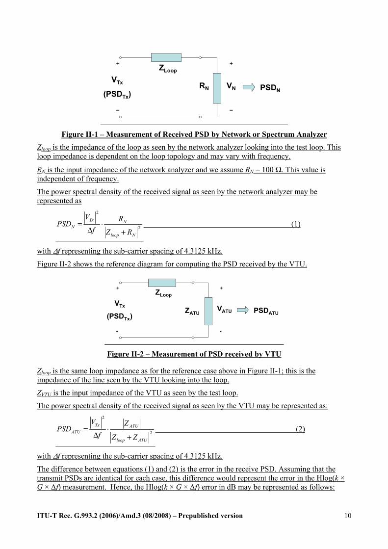
Figure II-1 shows the reference diagram for computing reference received PSD with a spectrum or network analyzer.
ITU-T Rec. G.993.2 (2006)/Amd.3 (08/2008) – Prepublished version
10
+
−
+
−
VN PSDNRN
ZLoop
VTx
(PSDTx)
Figure II-1 – Measurement of Received PSD by Network or Spectrum Analyzer Zloop is the impedance of the loop as seen by the network analyzer looking into the test loop. This loop impedance is dependent on the loop topology and may vary with frequency.
RN is the input impedance of the network analyzer and we assume RN = 100 Ω. This value is independent of frequency.
The power spectral density of the received signal as seen by the network analyzer may be represented as
2
2
Nloop
NTxN
RZ
Rf
VPSD
+⋅
Δ= (1)
with Δf representing the sub-carrier spacing of 4.3125 kHz.
Figure II-2 shows the reference diagram for computing the PSD received by the VTU.
+
-
+
-
VATU PSDATUZATU
ZLoop
VTx
(PSDTx)
Figure II-2 – Measurement of PSD received by VTU
Zloop is the same loop impedance as for the reference case above in Figure II-1; this is the impedance of the line seen by the VTU looking into the loop.
ZVTU is the input impedance of the VTU as seen by the test loop.
The power spectral density of the received signal as seen by the VTU may be represented as:
2
2
ATUloop
ATUTxATU
ZZ
Zf
VPSD
+⋅
Δ= (2)
with Δf representing the sub-carrier spacing of 4.3125 kHz.
The difference between equations (1) and (2) is the error in the receive PSD. Assuming that the transmit PSDs are identical for each case, this difference would represent the error in the Hlog(k × G × Δf) measurement. Hence, the Hlog(k × G × Δf) error in dB may be represented as follows:
ITU-T Rec. G.993.2 (2006)/Amd.3 (08/2008) – Prepublished version
11
( )⎟⎟⎟
⎠
⎞
⎜⎜⎜
⎝
⎛
+
+⋅⋅=⎟⎟
⎠
⎞⎜⎜⎝
⎛⋅= 2
2
log10log10loopN
loopATU
ATU
N
ATU
NdB
ZR
ZZ
ZR
PSDPSDError (3)
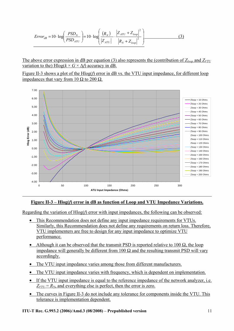
The above error expression in dB per equation (3) also represents the (contribution of Zloop and ZVTU variation to the) Hlog(k × G × Δf) accuracy in dB.
Figure II-3 shows a plot of the Hlog(f) error in dB vs. the VTU input impedance, for different loop impedances that vary from 10 Ω to 200 Ω.
-4.00
-3.00
-2.00
-1.00
0.00
1.00
2.00
3.00
4.00
5.00
6.00
7.00
0 50 100 150 200 250 300
ATU Input Impedance (Ohms)
Hlo
g Er
ror (
dB)
Zloop = 10 Ohms
Zloop = 20 Ohms
Zloop = 30 Ohms
Zloop = 40 Ohms
Zloop = 50 Ohms
Zloop = 60 Ohms
Zloop = 70 Ohms
Zloop = 80 Ohms
Zloop = 90 Ohms
Zloop = 100 Ohms
Zloop = 110 Ohms
Zloop = 120 Ohms
Zloop = 130 Ohms
Zloop = 140 Ohms
Zloop = 150 Ohms
Zloop = 160 Ohms
Zloop = 170 Ohms
Zloop = 180 Ohms
Zloop = 190 Ohms
Zloop = 200 Ohms
Figure II-3 – Hlog(f) error in dB as function of Loop and VTU Impedance Variations.
Regarding the variation of Hlog(f) error with input impedances, the following can be observed:
• This Recommendation does not define any input impedance requirements for VTUs. Similarly, this Recommendation does not define any requirements on return loss. Therefore, VTU implementers are free to design for any input impedance to optimize VTU performance.
• Although it can be observed that the transmit PSD is reported relative to 100 Ω, the loop impedance will generally be different from 100 Ω and the resulting transmit PSD will vary accordingly.
• The VTU input impedance varies among those from different manufacturers.
• The VTU input impedance varies with frequency, which is dependent on implementation.
• If the VTU input impedance is equal to the reference impedance of the network analyzer, i.e. ZVTU = RN, and everything else is perfect, then the error is zero.
• The curves in Figure II-3 do not include any tolerance for components inside the VTU. This tolerance is implementation dependent.
ITU-T Rec. G.993.2 (2006)/Amd.3 (08/2008) – Prepublished version
12
The actual input impedance of a VTU is complex. The impedance values shown in Figure II-3 are the equivalent real Ohmic values.
3. Revise sub-clauses in Annex B of G.993.2 Amendment 1 as follows:
B.2.1 General requirements in the band below 4 kHz A psophometric weighted measurement limit for the PSD within the band 0 to 4 kHz is for further study. This would require the power in the band to be measured with a psophometric weighting as defined in ITU-T O.41 Annex A. The noise in the voice band measured with psophometric weighting according to ITU-T O.41[1] section §3.3 shall not exceed -68 dBm. The psophometer shall be used in bridging mode and shall be calibrated for 600 ohm termination.
[1] Psophometer for use on telephone-type circuits, ITU-T Recommendation O.41, 10/94
ITU-T Rec. G.993.2 (2006)/Amd.3 (08/2008) – Prepublished version
13
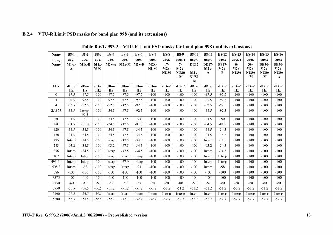
B.2.4 VTU-R Limit PSD masks for band plan 998 (and its extensions)
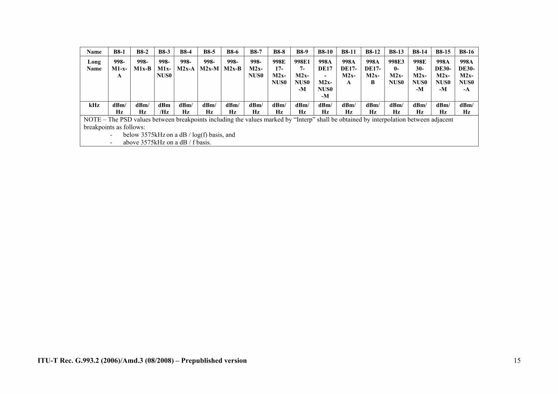
Table B-6/G.993.2 – VTU-R Limit PSD masks for band plan 998 (and its extensions) Name B8-1 B8-2 B8-3 B8-4 B8-5 B8-6 B8-7 B8-8 B8-9 B8-10 B8-11 B8-12 B8-13 B8-14 B8-15 B8-16
Long Name
998- M1-x-
A
998- M1x-B
998- M1x-NUS0
998- M2x-A
998- M2x-M
998- M2x-B
998- M2x-NUS0
998E17-
M2x-NUS0
998E17-
M2x-NUS0
-M
998ADE17
-M2x-NUS0
-M
998ADE17-M2x-
A
998ADE17-M2x-
B
998E30-
M2x-NUS0
998E30-
M2x-NUS0
-M
998ADE30-M2x-NUS0
-M
998ADE30-M2x-NUS0
-A
kHz dBm/Hz
dBm/Hz
dBm/Hz
dBm/Hz
dBm/Hz
dBm/Hz
dBm/Hz
dBm/Hz
dBm/Hz
dBm/Hz
dBm/Hz
dBm/Hz
dBm/Hz
dBm/Hz
dBm/Hz
dBm/Hz
0 -97.5 -97.5 -100 -97.5 -97.5 -97.5 -100 -100 -100 -100 -97.5 -97.5 -100 -100 -100 -100 4 -97.5 -97.5 -100 -97.5 -97.5 -97.5 -100 -100 -100 -100 -97.5 -97.5 -100 -100 -100 -100 4 -92.5 -92.5 -100 -92.5 -92.5 -92.5 -100 -100 -100 -100 -92.5 -92.5 -100 -100 -100 -100
25.875 -34.5 Interp-92.5
-100 -34.5 -37.5 -92.5 -100 -100 -100 -100 -34.5 -92.5 -100 -100 -100 -100
50 -34.5 -90 -100 -34.5 -37.5 -90 -100 -100 -100 -100 -34.5 -90 -100 -100 -100 -100 80 -34.5 -81.8 -100 -34.5 -37.5 -81.8 -100 -100 -100 -100 -34.5 -81.8 -100 -100 -100 -100 120 -34.5 -34.5 -100 -34.5 -37.5 -34.5 -100 -100 -100 -100 -34.5 -34.5 -100 -100 -100 -100 138 -34.5 -34.5 -100 -34.5 -37.5 -34.5 -100 -100 -100 -100 -34.5 -34.5 -100 -100 -100 -100 225 Interp -34.5 -100 Interp -37.5 -34.5 -100 -100 -100 -100 Interp -34.5 -100 -100 -100 -100 243 -93.2 -34.5 -100 -93.2 -37.5 -34.5 -100 -100 -100 -100 -93.2 -34.5 -100 -100 -100 -100 276 Interp -34.5 -100 Interp -37.5 -34.5 -100 -100 -100 -100 Interp -34.5 -100 -100 -100 -100 307 Interp Interp -100 Interp Interp Interp -100 -100 -100 -100 Interp Interp -100 -100 -100 -100
493.41 Interp Interp -100 Interp -97.9 Interp -100 -100 -100 -100 Interp Interp -100 -100 -100 -100 508.8 Interp -98 -100 Interp Interp -98 -100 -100 -100 -100 Interp -98 -100 -100 -100 -100 686 -100 -100 -100 -100 -100 -100 -100 -100 -100 -100 -100 -100 -100 -100 -100 -100
3575 -100 -100 -100 -100 -100 -100 -100 -100 -100 -100 -100 -100 -100 -100 -100 -100 3750 -80 -80 -80 -80 -80 -80 -80 -80 -80 -80 -80 -80 -80 -80 -80 -80 3750 -56.5 -56.5 -56.5 -51.2 -51.2 -51.2 -51.2 -51.2 -51.2 -51.2 -51.2 -51.2 -51.2 -51.2 -51.2 -51.2 5100 -56.5 -56.5 -56.5 Interp Interp Interp Interp Interp Interp Interp Interp Interp Interp Interp Interp Interp 5200 -56.5 -56.5 -56.5 -52.7 -52.7 -52.7 -52.7 -52.7 -52.7 -52.7 -52.7 -52.7 -52.7 -52.7 -52.7 -52.7

ITU-T Rec. G.993.2 (2006)/Amd.3 (08/2008) – Prepublished version
14
Name B8-1 B8-2 B8-3 B8-4 B8-5 B8-6 B8-7 B8-8 B8-9 B8-10 B8-11 B8-12 B8-13 B8-14 B8-15 B8-16
Long Name
998- M1-x-
A
998- M1x-B
998- M1x-NUS0
998- M2x-A
998- M2x-M
998- M2x-B
998- M2x-NUS0
998E17-
M2x-NUS0
998E17-
M2x-NUS0
-M
998ADE17
-M2x-NUS0
-M
998ADE17-M2x-
A
998ADE17-M2x-
B
998E30-
M2x-NUS0
998E30-
M2x-NUS0
-M
998ADE30-M2x-NUS0
-M
998ADE30-M2x-NUS0
-A
kHz dBm/Hz
dBm/Hz
dBm/Hz
dBm/Hz
dBm/Hz
dBm/Hz
dBm/Hz
dBm/Hz
dBm/Hz
dBm/Hz
dBm/Hz
dBm/Hz
dBm/Hz
dBm/Hz
dBm/Hz
dBm/Hz
5200 -80 -80 -80 -80 -80 -80 -80 -80 -80 -80 -80 -80 -80 -80 -80 -80 5375 -100 -100 -100 -100 -100 -100 -100 -100 -100 -100 -100 -100 -100 -100 -100 -100 8325 -100 -100 -100 -100 -100 -100 -100 -100 -100 -100 -100 -100 -100 -100 -100 -100 8500 -80 -80 -80 -80 -80 -80 -80 -80 -80 -80 -80 -80 -80 -80 -80 -80 8500 -56.5 -56.5 -56.5 -54.8 -54.8 -54.8 -54.8 -54.8 -54.8 -54.8 -54.8 -54.8 -54.8 -54.8 -54.8 -54.8 10000 -56.5 -56.5 -56.5 -55.5 -55.5 -55.5 -55.5 -55.5 -55.5 -55.5 -55.5 -55.5 -55.5 -55.5 -55.5 -55.5 12000 -56.5 -56.5 -56.5 -55.5 -55.5 -55.5 -55.5 -55.5 -55.5 -55.5 -55.5 -55.5 -55.5 -55.5 -55.5 -55.5 12000 -80 -80 -80 -80 -80 -80 -80 -56.5 -56.5 -80 -80 -80 -56.5 -56.5 -80 -80 12175 -100 -100 -100 -100 -100 -100 -100 -56.5 -56.5 -100 -100 -100 -56.5 -56.5 -100 -100 14000 -100 -100 -100 -100 -100 -100 -100 -56.5 -56.5 -100 -100 -100 -56.5 -56.5 -100 -100 14000 -100 -100 -100 -100 -100 -100 -100 -80 -80 -100 -100 -100 -80 -80 -100 -100 14175 -100 -100 -100 -100 -100 -100 -100 -100 -100 -100 -100 -100 -100 -100 -100 -100 21275 -100 -100 -100 -100 -100 -100 -100 -100 -100 -100 -100 -100 -100 -100 -100 -100 21450 -100 -100 -100 -100 -100 -100 -100 -100 -100 -100 -100 -100 -80 -80 -100 -100 21450 -100 -100 -100 -100 -100 -100 -100 -100 -100 -100 -100 -100 -56.5 -56.5 -100 -100 24715 -100 -100 -100 -100 -100 -100 -100 -100 -100 -100 -100 -100 -56.5 -56.5 -100 -100 24890 -100 -100 -100 -100 -100 -100 -100 -100 -100 -100 -100 -100 -56.5 -56.5 -80 -80 24890 -100 -100 -100 -100 -100 -100 -100 -100 -100 -100 -100 -100 -80 -80 -56.5 -56.5 25065 -100 -100 -100 -100 -100 -100 -100 -100 -100 -100 -100 -100 -100 -100 -56.5 -56.5 30000 -100 -100 -100 -100 -100 -100 -100 -100 -100 -100 -100 -100 -100 -100 -56.5 -56.5 30000 -110 -110 -110 -110 -110 -110 -110 -110 -110 -110 -110 -110 -110 -110 -80 -80 30175 -110 -110 -110 -110 -110 -110 -110 -110 -110 -110 -110 -110 -110 -110 -110 -110 ≥30175 -110 -110 -110 -110 -110 -110 -110 -110 -110 -110 -110 -110 -110 -110 -110 -110
ITU-T Rec. G.993.2 (2006)/Amd.3 (08/2008) – Prepublished version
15
Name B8-1 B8-2 B8-3 B8-4 B8-5 B8-6 B8-7 B8-8 B8-9 B8-10 B8-11 B8-12 B8-13 B8-14 B8-15 B8-16
Long Name
998- M1-x-
A
998- M1x-B
998- M1x-NUS0
998- M2x-A
998- M2x-M
998- M2x-B
998- M2x-NUS0
998E17-
M2x-NUS0
998E17-
M2x-NUS0
-M
998ADE17
-M2x-NUS0
-M
998ADE17-M2x-
A
998ADE17-M2x-
B
998E30-
M2x-NUS0
998E30-
M2x-NUS0
-M
998ADE30-M2x-NUS0
-M
998ADE30-M2x-NUS0
-A
kHz dBm/Hz
dBm/Hz
dBm/Hz
dBm/Hz
dBm/Hz
dBm/Hz
dBm/Hz
dBm/Hz
dBm/Hz
dBm/Hz
dBm/Hz
dBm/Hz
dBm/Hz
dBm/Hz
dBm/Hz
dBm/Hz
NOTE – The PSD values between breakpoints including the values marked by “Interp” shall be obtained by interpolation between adjacent breakpoints as follows: - below 3575kHz on a dB / log(f) basis, and - above 3575kHz on a dB / f basis.
ITU-T Rec. G.993.2 (2006)/Amd.3 (08/2008) – Prepublished version
16
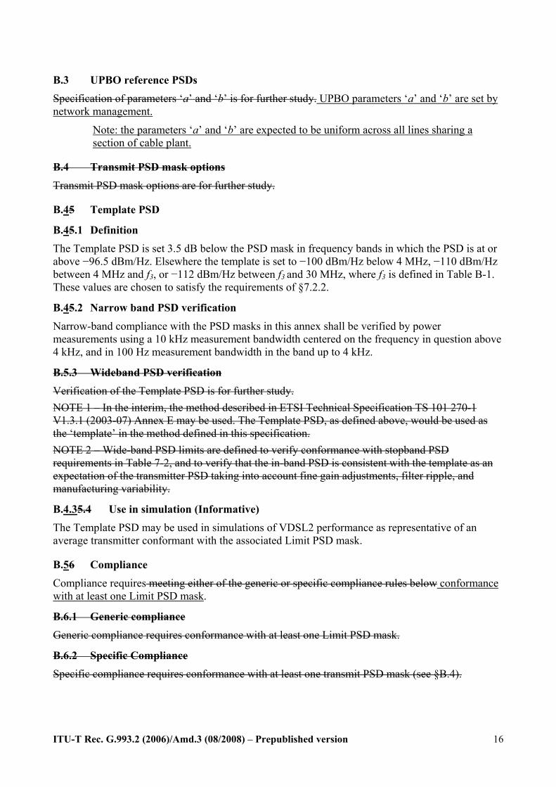
B.3 UPBO reference PSDs Specification of parameters ‘a’ and ‘b’ is for further study. UPBO parameters ‘a’ and ‘b’ are set by network management.
Note: the parameters ‘a’ and ‘b’ are expected to be uniform across all lines sharing a section of cable plant.
B.4 Transmit PSD mask options Transmit PSD mask options are for further study.
B.45 Template PSD
B.45.1 Definition The Template PSD is set 3.5 dB below the PSD mask in frequency bands in which the PSD is at or above −96.5 dBm/Hz. Elsewhere the template is set to −100 dBm/Hz below 4 MHz, −110 dBm/Hz between 4 MHz and f3, or −112 dBm/Hz between f3 and 30 MHz, where f3 is defined in Table B-1. These values are chosen to satisfy the requirements of §7.2.2.
B.45.2 Narrow band PSD verification Narrow-band compliance with the PSD masks in this annex shall be verified by power measurements using a 10 kHz measurement bandwidth centered on the frequency in question above 4 kHz, and in 100 Hz measurement bandwidth in the band up to 4 kHz.
B.5.3 Wideband PSD verification Verification of the Template PSD is for further study. NOTE 1 – In the interim, the method described in ETSI Technical Specification TS 101 270-1 V1.3.1 (2003-07) Annex E may be used. The Template PSD, as defined above, would be used as the ‘template’ in the method defined in this specification. NOTE 2 – Wide-band PSD limits are defined to verify conformance with stopband PSD requirements in Table 7-2, and to verify that the in-band PSD is consistent with the template as an expectation of the transmitter PSD taking into account fine gain adjustments, filter ripple, and manufacturing variability.
B.4.35.4 Use in simulation (Informative) The Template PSD may be used in simulations of VDSL2 performance as representative of an average transmitter conformant with the associated Limit PSD mask.
B.56 Compliance
Compliance requires meeting either of the generic or specific compliance rules below conformance with at least one Limit PSD mask.
B.6.1 Generic compliance Generic compliance requires conformance with at least one Limit PSD mask.
B.6.2 Specific Compliance Specific compliance requires conformance with at least one transmit PSD mask (see §B.4).
ITU-T Rec. G.993.2 (2006)/Amd.3 (08/2008) – Prepublished version
17
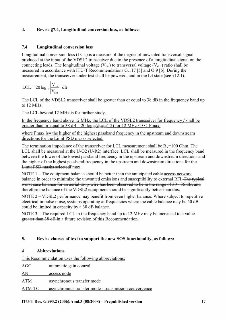
4. Revise §7.4, Longitudinal conversion loss, as follows:
7.4 Longitudinal conversion loss Longitudinal conversion loss (LCL) is a measure of the degree of unwanted transversal signal produced at the input of the VDSL2 transceiver due to the presence of a longitudinal signal on the connecting leads. The longitudinal voltage (Vcm) to transversal voltage (Vdiff) ratio shall be measured in accordance with ITU-T Recommendations G.117 [5] and O.9 [6]. During the measurement, the transceiver under test shall be powered, and in the L3 state (see §12.1).
cm10
diff
VLCL 20logV
= dB.
The LCL of the VDSL2 transceiver shall be greater than or equal to 38 dB in the frequency band up to 12 MHz.
The LCL beyond 12 MHz is for further study.
In the frequency band above 12 MHz, the LCL of the VDSL2 transceiver for frequency f shall be greater than or equal to 38 dB – 20 log10(f[MHz]/12) for 12 MHz < f < Fmax,
where Fmax is= the higher of the highest passband frequency in the upstream and downstream directions for the Limit PSD masks selected.
The termination impedance of the transceiver for LCL measurement shall be RV=100 Ohm. The LCL shall be measured at the U-O2 (U-R2) interface. LCL shall be measured in the frequency band between the lower of the lowest passband frequency in the upstream and downstream directions and the higher of the highest passband frequency in the upstream and downstream directions for the Limit PSD masks selectedFmax. NOTE 1 – The equipment balance should be better than the anticipated cable access network balance in order to minimize the unwanted emissions and susceptibility to external RFI. The typical worst case balance for an aerial drop-wire has been observed to be in the range of 30 - 35 dB, and therefore the balance of the VDSL2 equipment should be significantly better than this. NOTE 2 – VDSL2 performance may benefit from even higher balance. Where subject to repetitive electrical impulse noise, systems operating at frequencies where the cable balance may be 50 dB could be limited in capacity by a 38 dB balance. NOTE 3 – The required LCL in the frequency band up to 12 MHz may be increased to a value greater than 38 dB in a future revision of this Recommendation.
5. Revise clauses of text to support the new SOS functionality, as follows:
4 Abbreviations This Recommendation uses the following abbreviations:
AGC automatic gain control
AN access node
ATM asynchronous transfer mode
ATM-TC asynchronous transfer mode - transmission convergence
ITU-T Rec. G.993.2 (2006)/Amd.3 (08/2008) – Prepublished version
18
BER bit error ratio
CE cyclic extension
CPE customer premises equipment
CRC cyclic redundancy check
DMT discrete multi-tone
DS downstream
DSL digital subscriber line
EC echo canceller (or cancellation)
EIA external OAM interface adaptor
eoc embedded operations channel
FCS frame check sequence
FDD frequency division duplexing
FEC forward error correction
flcd-n far-end loss of cell delineation defect
flpr far-end loss of power primitive
GSTN general switched telephone network
HDLC high-level data link control
HPF high-pass filter
IB indicator bit
IDFT inverse discrete Fourier transform
INP impulse noise protection
ISDN Integrated Services Digital Network
lcd-n loss of cell delineation defect
LCL longitudinal conversion loss
LOF loss of frame
lom loss of margin defect
lom-fe far-end loss of margin defect
LOS loss of signal
los loss of signal defect
los-fe far-end loss of signal defect
LPF low-pass filter
lpr loss of power primitive
LSB least significant bit
LTR local timing reference
MBDC minimum bi-directional net data rate capability
ITU-T Rec. G.993.2 (2006)/Amd.3 (08/2008) – Prepublished version
19
MDF mux data frame
MIB management information base
MPS-TC management protocol specific - transmission convergence
MSB most significant bit
mux multiplex
NMS network management system
NSCus number of sub-carriers in MEDLEYus set
NSCds number of sub-carriers in MEDLEYds set
NSF non-standard facility
NT network termination
NTR network timing reference
OAM operations, administration and maintenance
OH overhead
OLR on-line reconfiguration
ONU optical network unit
PMD physical media dependent
PMS physical media specific
PMS-TC physical media specific - transmission convergence
POTS plain old telephone service; one of the services using the voiceband; sometimes used as a descriptor for all voiceband services
PRBS pseudo-random binary sequence
PSD power spectral density
PTM packet transfer mode
PTM-TC packet transfer mode - transmission convergence
QAM quadrature amplitude modulation
rdi remote defect indication defect
RFI radio frequency interference
rms root mean square
ROC robust overhead channel
RS Reed-Solomon
RX (Rx) receiver
SC segment code
sef severely errored frame defect
SNR signal-to-noise ratio
SOC special operations channel
ITU-T Rec. G.993.2 (2006)/Amd.3 (08/2008) – Prepublished version
20
STM synchronous transfer mode
STM-TC synchronous transfer mode - transmission convergence
TA timing advance
TC transmission convergence
TCM-ISDN time compression multiplexed Integrated Services Digital Network
TEQ time-domain equalizer
TPS transport protocol specific
TPS-TC transport protocol specific - transmission convergence
TX (Tx) transmitter
UPBO upstream power back-off
US upstream
VDSL very high speed digital subscriber line
VME VDSL2 management entity
VTU VDSL2 transceiver unit
VTU-O VTU at the ONU (or central office, exchange, cabinet, etc., i.e., operator end of the loop)
VTU-R VTU at the remote site (i.e., subscriber end of the loop)
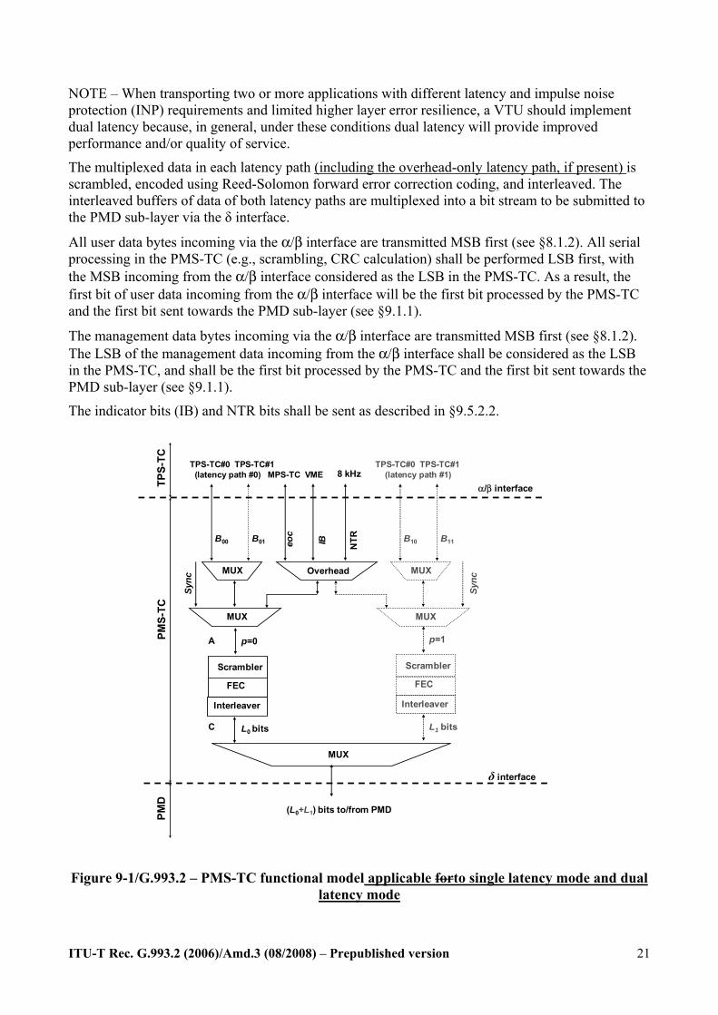
9.1 PMS-TC functional model The PMS-TC functional models is are presented in Figure 9-1 applicable forto single latency mode and dual latency mode, and Figure 9-1.1 applicable forto single data latency path with ROC modeadditional overhead-only latency path ("robust eoc").
Up to two bearer channels of transmit user data originated by various TPS-TCs, management data originated by the MPS-TC, and NTR data are incoming via the α/β interface in a uniform format, as specified in §8.1.2. The incoming user data and the overhead data are multiplexed into one or two latency paths. Each bearer channel is carried over a single latency path (i.e., shall not be split across 2 latency paths). A Syncbyte is added to each latency path for OH frame alignment.
Three different modes are allowed: - single latency mode: support of one latency path. The VTU shall support this mode. In this
caseFor this mode, latency path #0 shall be enabled. - dual latency mode: support of two latency paths (#0 and #1). The VTU may support this
mode. For this mode, latency paths #0 and #1 shall be enabled. - single latency with ROC moderobust eoc: support of a single latency path for data with a
second overhead-only latency path ("robust eoc"). The VTU may support this mode. For this mode, the data shall use latency path#1 and the ROC shall use latency path #0.The overhead-only latency path shall be latency path #0.
The VTU shall support at least one latency path; support of two latency paths is optional. If only one latency path is enabled, it shall be latency path #0. Support of single latency with robust eoc is optional. The robust eoc shall be latency path#0.
ITU-T Rec. G.993.2 (2006)/Amd.3 (08/2008) – Prepublished version
21
NOTE – When transporting two or more applications with different latency and impulse noise protection (INP) requirements and limited higher layer error resilience, a VTU should implement dual latency because, in general, under these conditions dual latency will provide improved performance and/or quality of service.
The multiplexed data in each latency path (including the overhead-only latency path, if present) is scrambled, encoded using Reed-Solomon forward error correction coding, and interleaved. The interleaved buffers of data of both latency paths are multiplexed into a bit stream to be submitted to the PMD sub-layer via the δ interface.
All user data bytes incoming via the α/β interface are transmitted MSB first (see §8.1.2). All serial processing in the PMS-TC (e.g., scrambling, CRC calculation) shall be performed LSB first, with the MSB incoming from the α/β interface considered as the LSB in the PMS-TC. As a result, the first bit of user data incoming from the α/β interface will be the first bit processed by the PMS-TC and the first bit sent towards the PMD sub-layer (see §9.1.1).
The management data bytes incoming via the α/β interface are transmitted MSB first (see §8.1.2). The LSB of the management data incoming from the α/β interface shall be considered as the LSB in the PMS-TC, and shall be the first bit processed by the PMS-TC and the first bit sent towards the PMD sub-layer (see §9.1.1).
The indicator bits (IB) and NTR bits shall be sent as described in §9.5.2.2.
MUX
α/β interfaceTPS-
TC
FEC
PMD
δ interface
PMS-
TC
Scrambler
FEC
Scrambler
Interleaver
L1 bitsL0 bits
Interleaver
p=1p=0
B00 B01 B10 B11eoc
IB NTR
Sync
Overhead
8 kHz
MUX
MUX MUX
MUX
TPS-TC#0 TPS-TC#1 TPS-TC#0 TPS-TC#1(latency path #0) MPS-TC VME (latency path #1)
(L0+L1) bits to/from PMD
Sync
A
C
Figure 9-1/G.993.2 – PMS-TC functional model applicable forto single latency mode and dual latency mode
ITU-T Rec. G.993.2 (2006)/Amd.3 (08/2008) – Prepublished version
22
MUX
α /β - interface
TPS
-TC
FEC
PMD
δ- interface
PMS-
TC
Scrambler
L1 bitsL0 bits
Interleav er
p=0
10 11
Syn
c
MUX
TPS- TC#0 TPS - TC#1(latency path #0)
MPS-TC VME(latency path #1)
(L0+L1) bits to/from PMD
Syn
c
A
C
B B
IBeoc
NT
R
8 kHz
Overhead
p =1
Interleav er
Scrambler
FEC
MUX
MUX
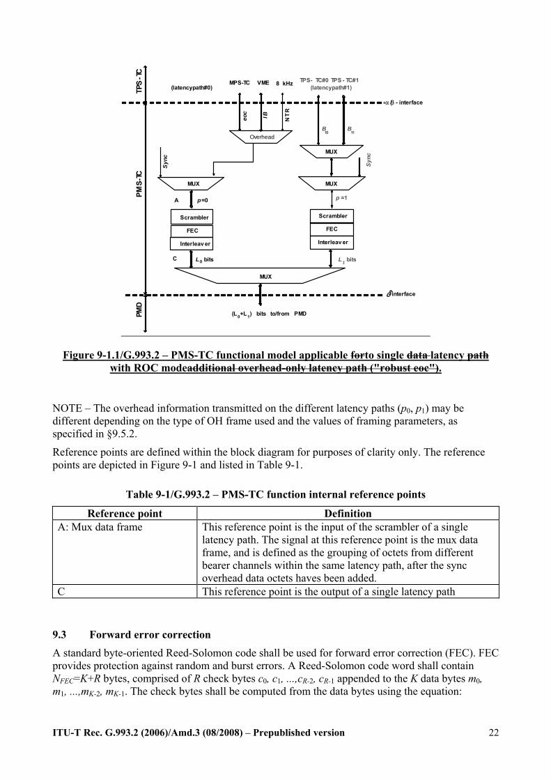
Figure 9-1.1/G.993.2 – PMS-TC functional model applicable forto single data latency path with ROC modeadditional overhead-only latency path ("robust eoc").
NOTE – The overhead information transmitted on the different latency paths (p0, p1) may be different depending on the type of OH frame used and the values of framing parameters, as specified in §9.5.2.
Reference points are defined within the block diagram for purposes of clarity only. The reference points are depicted in Figure 9-1 and listed in Table 9-1.
Table 9-1/G.993.2 – PMS-TC function internal reference points
Reference point Definition A: Mux data frame This reference point is the input of the scrambler of a single
latency path. The signal at this reference point is the mux data frame, and is defined as the grouping of octets from different bearer channels within the same latency path, after the sync overhead data octets haves been added.
C This reference point is the output of a single latency path
9.3 Forward error correction A standard byte-oriented Reed-Solomon code shall be used for forward error correction (FEC). FEC provides protection against random and burst errors. A Reed-Solomon code word shall contain NFEC=K+R bytes, comprised of R check bytes c0, c1, ...,cR-2, cR-1 appended to the K data bytes m0, m1, ...,mK-2, mK-1. The check bytes shall be computed from the data bytes using the equation:
ITU-T Rec. G.993.2 (2006)/Amd.3 (08/2008) – Prepublished version
23
)(mod)()( DGDDMDC R= ,
where
122
11
0 ...)( −−−− ⊕⊕⊕⊕= KK
KK mDmDmDmDM is the data polynomial,
122
11
0 ...)( −−−− ⊕⊕⊕⊕= RR
RR cDcDcDcDC is the check polynomial, and
∏ ⊕= )()( iDDG α is the generator polynomial of the Reed-Solomon code, where the index of the product runs from i= 0 to R-1.
The polynomial C(D) is the remainder obtained from dividing RDDM )( by G(D). The arithmetic shall be performed in the Galois Field GF(256), where α is a primitive element that satisfies the primitive binary polynomial 12348 ⊕⊕⊕⊕ xxxx . A data byte ),,...,,( 0167 dddd is identified with the Galois Field element 01
66
77 ... dddd ⊕⊕⊕⊕ ααα .
Both K and R shall be programmable parameters. Valid values for the number of check bytes R in the codeword are 0, 2, 4, 6, 8, …, 16. Valid values for the number of bytes in the codeword NFEC (codeword size) are all integers from 32 to 255, inclusive. A VTU shall support all valid values of R and NFEC.
The FEC infor the ROCrobust eoc shall only supportuse R=16 and NFEC values from 32 to 66 with q = 1.
9.4 Interleaving Interleaving shall be provided in all supported latency paths to protect the data against bursts of errors by spreading the errors over a number of Reed-Solomon codewords. The convolutional interleaver adopted for VDSL2 shall follow the rule:
I is the interleaver block size in bytes. Each of the I bytes in an interleaver block B0B1 …. BI-
1 shall be delayed by the interleaver by an amount that varies linearly with the byte index. More precisely byte Bj (with index j) shall be delayed by Δ[j] =(D−1)×j bytes, where D is the interleaver depth in bytes, and D and I are co-prime (have no common divisor except for 1).
For any interleaver input of size D × I bytes, the relationship between the index of each input byte (nin) and the index of each output byte (nout) is given by nout = (nin + Δ[j]), where j = nin mod I and Δ[j] =(D−1)×j.
The total delay of the interleaver/de-interleaver combination is (D−1) × (I−1) bytes.
The RS codeword length NFEC shall be an integer multiple of I, i.e., NFEC = q × I, where q is an integer between 1 and 8 inclusive. All values of q shall be supported. Codewords shall be mapped to interleaver blocks such that the first I bytes of the codeword map to the I bytes B0B1 …. BI-1 of the first interleaver block.
The interleaver depth shall be set to meet the requirements for error-burst protection and latency. The VTU shall support all integer values of D from 1 to Dmax, as specified for the particular profile (see Table 6-1). At any data rate, the minimum latency occurs when the interleaver is turned off. If both latency paths are supported, interleaving shall be supported on both latency paths. The same valid and mandatory configuration parameters shall apply to all supported latency paths.
The interleaving for the ROCrobust eoc channel shall only supportuse D values up to 20.
ITU-T Rec. G.993.2 (2006)/Amd.3 (08/2008) – Prepublished version
24
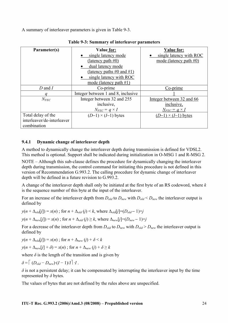
A summary of interleaver parameters is given in Table 9-3.
Table 9-3: Summary of interleaver parameters
Parameter(s) Value for: • single latency mode
(latency path #0) • dual latency mode
(latency paths #0 and #1) • single latency with ROC
mode (latency path #1)
Value for: • single latency with ROC
mode (latency path #0)
D and I Co-prime Co-prime q Integer between 1 and 8, inclusive 1
NFEC Integer between 32 and 255 inclusive,
NFEC = q × I
Integer between 32 and 66 inclusive,
NFEC = q × I Total delay of the interleaver/de-interleaver combination
(D−1) × (I−1) bytes (D−1) × (I−1) bytes
9.4.1 Dynamic change of interleaver depth A method to dynamically change the interleaver depth during transmission is defined for VDSL2. This method is optional. Support shall be indicated during initialization in O-MSG 1 and R-MSG 2. NOTE – Although this sub-clause defines the procedure for dynamically changing the interleaver depth during transmission, the control command for initiating this procedure is not defined in this version of Recommendation G.993.2. The calling procedure for dynamic change of interleaver depth will be defined in a future revision to G.993.2.
A change of the interleaver depth shall only be initiated at the first byte of an RS codeword, where k is the sequence number of this byte at the input of the interleaver.
For an increase of the interleaver depth from Dold to Dnew with Dold < Dnew the interleaver output is defined by
y(n + Δold[j]) = x(n) ; for n + Δold (j) < k, where Δold[j]=(Dold − 1)×j
y(n + Δnew[j]) = x(n) ; for n + Δold (j) ≥ k, where Δnew[j]=(Dnew − 1)×j
For a decrease of the interleaver depth from Dold to Dnew with Dold > Dnew the interleaver output is defined by
y(n + Δold[j]) = x(n) ; for n + Δnew (j) + δ < k
y(n + Δnew[j] + δ) = x(n) ; for n + Δnew (j) + δ ≥ k
where δ is the length of the transition and is given by
δ = ⎡ (Dold − Dnew)·(I − 1)/I⎤ ·I .
δ is not a persistent delay; it can be compensated by interrupting the interleaver input by the time represented by δ bytes.
The values of bytes that are not defined by the rules above are unspecified.
ITU-T Rec. G.993.2 (2006)/Amd.3 (08/2008) – Prepublished version
25
If a change of the interleaver depth is to be accompanied by a corresponding change of the data rate in the particular latency path (e.g., SRA – see §13.1), the change of D shall be coordinated with the corresponding change of parameter Lp (see Table 9-6) as described in §13.3.
Dynamic change of interleaver depth shall not be used for the ROCrobust eoc.
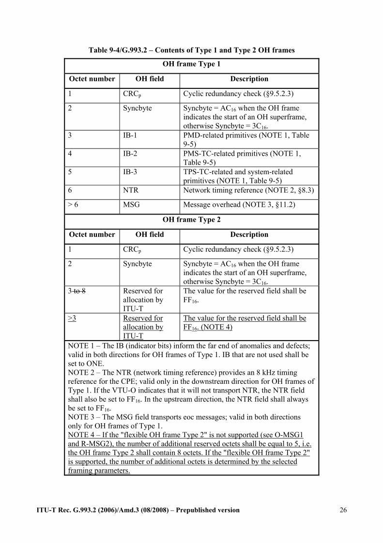
9.5.2.2 Mapping of the OH data The mapping of the OH data to the OH frame shall be as presented in Table 9-4. Two types of OH frames shall be supported:
Type 1 – Full frame;
Type 2 – Auxiliary frame.
For single latency, the latency path shall use OH frame Type 1. For Dual Latency, one latency path shall use OH frame Type 1 and the other shall use OH frame Type 2. For single latency with ROCrobust eoc, the ROCrobust eoc (ini.e. latency path 0) shall use OH frame Type 1 and latency path 1 shall use OH frame Type 2. The latency path selected for OH frames of Type 1 shall be indicated during initialization by the parameter value in the MSGLP field (see §12.3.5.2.1.3, §12.3.5.2.2.3). When the ROCrobust eoc is used, MSGLP (see Table 12-46 and 12-53) shall have the value 0.
ITU-T Rec. G.993.2 (2006)/Amd.3 (08/2008) – Prepublished version
26
Table 9-4/G.993.2 – Contents of Type 1 and Type 2 OH frames
OH frame Type 1
Octet number OH field Description
1 CRCp Cyclic redundancy check (§9.5.2.3)
2 Syncbyte Syncbyte = AC16 when the OH frame indicates the start of an OH superframe, otherwise Syncbyte = 3C16.
3 IB-1 PMD-related primitives (NOTE 1, Table 9-5)
4 IB-2 PMS-TC-related primitives (NOTE 1, Table 9-5)
5 IB-3 TPS-TC-related and system-related primitives (NOTE 1, Table 9-5)
6 NTR Network timing reference (NOTE 2, §8.3)
> 6 MSG Message overhead (NOTE 3, §11.2)
OH frame Type 2
Octet number OH field Description
1 CRCp Cyclic redundancy check (§9.5.2.3)
2 Syncbyte Syncbyte = AC16 when the OH frame indicates the start of an OH superframe, otherwise Syncbyte = 3C16.
3 to 8 Reserved for allocation by ITU-T
The value for the reserved field shall be FF16.
>3 Reserved for allocation by ITU-T
The value for the reserved field shall be FF16. (NOTE 4)
NOTE 1 – The IB (indicator bits) inform the far end of anomalies and defects; valid in both directions for OH frames of Type 1. IB that are not used shall be set to ONE. NOTE 2 – The NTR (network timing reference) provides an 8 kHz timing reference for the CPE; valid only in the downstream direction for OH frames of Type 1. If the VTU-O indicates that it will not transport NTR, the NTR field shall also be set to FF16. In the upstream direction, the NTR field shall always be set to FF16. NOTE 3 – The MSG field transports eoc messages; valid in both directions only for OH frames of Type 1. NOTE 4 – If the "flexible OH frame Type 2" is not supported (see O-MSG1 and R-MSG2), the number of additional reserved octets shall be equal to 5, i.e. the OH frame Type 2 shall contain 8 octets. If the "flexible OH frame Type 2" is supported, the number of additional octets is determined by the selected framing parameters.

ITU-T Rec. G.993.2 (2006)/Amd.3 (08/2008) – Prepublished version
27
Mapping of the CRC, IB and NTR bits to the OH frame fields shall be as specified in Table 9-5; the LSB shall be transmitted first. Mapping of the MSG bytes into the OH frame shall be LSB first, as specified in §8.2.3 and §9.1.
Table 9-5/G.993.2 – OH bit mapping OH field D7(MSB) D6 D5 D4 D3 D2 D1 D0(LSB) Defined in
CRC crc7 crc6 crc5 crc4 crc3 crc2 crc1 crc0 §9.5.2.3 IB-1 los rdi lpr 1 1 1 1 1 §11.2.4, §11.3 IB-2 1 1 1 1 1 1 1 1 IB-3 TIB#0-0 TIB#0-1 TIB#0-2 TIB#0-3 TIB#1-0 TIB#1-1 TIB#1-2 TIB#1-3 §11.2.4,
Annex K NTR ntr7 ntr6 ntr5 ntr4 ntr3 ntr2 ntr1 ntr0 §8.3
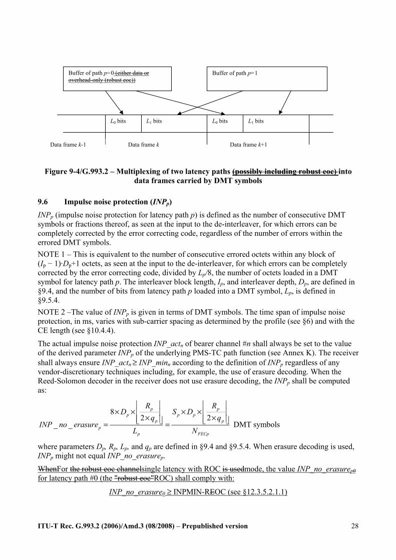
9.5.3 Multiplexing of data from two latency paths
9.5.3.1 Robust overhead channel (ROC)eoc As defined in §9.5.2.2, all eoc overhead traffic is mapped into one of the latency paths. Optionally, the modems canmay negotiate an ROC "robust eoc" channel (see §9.1). The ROCrobust eoc channel is effectively a latency path that carries only overhead data. When the ROCrobust eoc is enabled (single latency with ROC mode), all overhead data (see §11.2.3.3) shall be sent through latency path #0. In this mode, latency path #0 willis also be referred to as the "robust overhead channeleoc".
9.5.3.2 Multiplexing The assigned number of bits, L0 and L1, from the RS codewords of latency paths #0 and #1, respectively, shall be mapped to the data frame as shown in Figure 9-4. The bits shall be extracted from the octets of the RS codewords in sequential order, LSB first. The first bit of each extracted group of L0 bits shall be the first bit of the data frame. When the modem operates in "robust eoc"single latency with ROC mode (see §9.1), L0 shall be an integer number of bytes consisting of overhead data only.
When single latency with ROC mode is enabled, the L0 bits shall not share the same sub-carriers with L1 bits.
ITU-T Rec. G.993.2 (2006)/Amd.3 (08/2008) – Prepublished version
28
Figure 9-4/G.993.2 – Multiplexing of two latency paths (possibly including robust eoc) into data frames carried by DMT symbols
9.6 Impulse noise protection (INPp) INPp (impulse noise protection for latency path p) is defined as the number of consecutive DMT symbols or fractions thereof, as seen at the input to the de-interleaver, for which errors can be completely corrected by the error correcting code, regardless of the number of errors within the errored DMT symbols. NOTE 1 – This is equivalent to the number of consecutive errored octets within any block of (Ip − 1)·Dp+1 octets, as seen at the input to the de-interleaver, for which errors can be completely corrected by the error correcting code, divided by Lp/8, the number of octets loaded in a DMT symbol for latency path p. The interleaver block length, Ip, and interleaver depth, Dp, are defined in §9.4, and the number of bits from latency path p loaded into a DMT symbol, Lp, is defined in §9.5.4. NOTE 2 –The value of INPp is given in terms of DMT symbols. The time span of impulse noise protection, in ms, varies with sub-carrier spacing as determined by the profile (see §6) and with the CE length (see §10.4.4).
The actual impulse noise protection INP_actn of bearer channel #n shall always be set to the value of the derived parameter INPp of the underlying PMS-TC path function (see Annex K). The receiver shall always ensure INP_actn ≥ INP_minn according to the definition of INPp regardless of any vendor-discretionary techniques including, for example, the use of erasure decoding. When the Reed-Solomon decoder in the receiver does not use erasure decoding, the INPp shall be computed as:
82 2
_ _
p pp p p
p pp
p FECp
R RD S D
q qINP no erasure
L N
⎢ ⎥ ⎢ ⎥× × × ×⎢ ⎥ ⎢ ⎥× ×⎢ ⎥ ⎢ ⎥⎣ ⎦ ⎣ ⎦= = DMT symbols
where parameters Dp, Rp, Lp, and qp are defined in §9.4 and §9.5.4. When erasure decoding is used, INPp might not equal INP_no_erasurep.
WhenFor the robust eoc channelsingle latency with ROC is usedmode, the value INP_no_erasurep0 for latency path #0 (the "robust eoc"ROC) shall comply with:
INP_no_erasure0 ≥ INPMIN-REOC (see §12.3.5.2.1.1)
Buffer of path p=0 (either data or overhead-only (robust eoc))
Buffer of path p=1
L0 bits L1 bits L0 bits L1 bits
Data frame k+1 Data frame k Data frame k-1
ITU-T Rec. G.993.2 (2006)/Amd.3 (08/2008) – Prepublished version
29
During initialization, the VTU-O, under direction from the CO MIB, can set a bit in initialization to require that the VTU-R receiver select framing parameters so that INPp = INP_no_erasurep on both latency paths. Regardless of whether this bit is set, the receiver shall always ensure INP_actn ≥ INP_minn. This bit is referred to as “INP_no_erasure_required”, bit 7 in the “Impulse noise protection” field in Table 12-42, §12.3.5.2.1.1.
During initialization, the VTU-R declares if it is using erasure decoding on either latency path. This field is referred to as “Erasure decoding used” in Table 12-53, §12.3.5.2.2.3.
Erasure decoding is vendor discretionary at both VTUs.
9.7 Delay
When the interleaver is disabled (interleaver depth = 1), the one-way delay between the α and β interfaces shall not exceed 2ms.
The actual delay in milliseconds introduced by the interleaver to latency path p shall be computed as:
⎟⎟⎠
⎞⎜⎜⎝
⎛−×
×−×
=FECp
p
sp
ppp N
qfq
DSdelay 1
)1( ms,
where Dp is the interleaving depth set for the latency path p, Sp is the parameter defined in Table 9-6, qp is the number of interleaver blocks in an FEC codeword for latency path p, NFECp is the FEC codeword size for latency path p, and fs is the data symbol rate in ksymbols/s.
The interleaver delay in milliseconds for the specific bearer channel n is constrained by the value of delay_maxn defined in the CO MIB.
When the robust eoc channel is usedFor single latency with ROC mode, the value delayp0 for latency path #0 (the "robust eoc"ROC) shall comply with:
delay0 ≤ 8 ms
10.3.1 Tone ordering During initialization, the receive PMD function shall calculate the numbers of bits and the relative gains to be used for every sub-carrier in the MEDLEY set (either MEDLEYus or MEDLEYds, depending on the transmission direction), as well as the order in which sub-carriers are assigned bits (i.e., the tone ordering). The calculated bits and gains and the tone ordering shall be sent back to the transmit PMD function during the Channel Analysis & Exchange phase of initialization (see §12.3.5.2). The number of sub-carriers in MEDLEYus and MEDLEYds is denoted by NSCus and NSCds, respectively.
The pairs of bits and relative gains are defined, in ascending order of frequency or sub-carrier index i, as a bit allocation table b and gain table g (i.e., bi and gi, for all sub-carrier indices i that belong to the MEDLEY set). If trellis coding is used, the receive PMD function shall include an even number of 1-bit sub-carriers (NCONEBIT) in the bit allocation table b.
The tone ordering table t is defined as the sequence tk in which sub-carriers from the MEDLEY set are assigned bits from the input bitstream (tk for k = 1 to NSCus for the upstream tones, k = 1 to NSCds for the downstream tones) with constellation mapping beginning on sub-carrier with index i = t1 and ending on the sub-carrier with index i = tNSC (for example, t75 = 160 means that the sub-carrier with index 160 is the 75th sub-carrier to be assigned bits from the input bit stream). The tone ordering table t shall be created and exchanged during initialization (O-PMD, R-PMD messages,
ITU-T Rec. G.993.2 (2006)/Amd.3 (08/2008) – Prepublished version
30
§12.3.5.2) and shall remain unchanged until the next initialization.
If the ROC is enabled, the bits of buffer L0 and buffer L1 shall not share the same sub-carrier. With trellis encoding, this means that all the bits u1 to uz' that are used to encode a 4-dimensional symbol belong to the same buffer (see §10.3.2).
Following reception of the tables b, g and t, the transmit PMD function shall calculate a re-ordered bit table b' and a re-ordered tone table t' from the original tables b and t. Constellation mapping shall occur in sequence according to the re-ordered tone table t', with the number of bits per sub-carrier as defined by the original bit table b. Trellis coding shall occur according to the re-ordered bit table b' and re-ordered tone table t'.
If trellis coding is not used, b' = b and t' = t.
If trellis coding is used, the re-ordering of table t shall be performed by the transmit PMD function. The re-ordered tone table t' shall be generated according to the following rules:
• Indices of all sub-carriers supporting 0 bits or 2 or more bits appear first in t', in the same order as in table t.
• Indices of all sub-carriers supporting 1 bit appear last in table t', in the same order as in table t.
If the bit allocation does not include any 1-bit sub-carriers, the re-ordered tone table t' is identical to the original tone table t.
The (even number of) 1-bit sub-carriers shall be paired to form 2-dimensional constellation points as input to the trellis encoder. The pairing shall be determined by the order in which the 1-bit sub-carriers appear in the original tone ordering table t.
The table b' shall be generated by re-ordering the entries of table b according to the following rules: • The first NCONEBIT/2 entries of b' shall be 0, where NCONEBIT (by definition, even) is
the number of sub-carriers supporting 1 bit. • The next entries of b' shall be 0, corresponding to all sub-carriers that support 0 bits. • The next entries of b' shall be non-zero, corresponding to the sub-carriers that support 2 or
more bits. The entries shall be determined using the new tone table t' in conjunction with the original bit table b.
• The last NCONEBIT/2 entries of b' correspond to the paired 1-bit constellations (i.e., 2 bits per entry).
The tables b' and t' shall be calculated from the original tables b and t as shown in the sub-carrier pairing and bit re-ordering processes below.
/*** CONSTRUCT THE TONE RE-ORDERING TABLE ***/
/*
Tone ordering table is denoted as array 't' and tone re-ordering
table is denoted as array 'tp'. The indices to these arrays are
denoted as 't_index' and 'tp_index', respectively.
*/
/*
Fill out tone re-ordering table with entries of tone ordering table
but skip 1-bit tones.

ITU-T Rec. G.993.2 (2006)/Amd.3 (08/2008) – Prepublished version
31
*/
tp_index = 1;
for (t_index = 1; t_index ≤ NSC; t_index++)
tone = t[t_index];
bits = b[tone];
if (bits != 1)
tp[tp_index++] = tone;
/*
Add the 1-bit tones to the end of tone re-ordering table.
*/
for (t_index = 1; t_index ≤ NSC; t_index++)
tone = t[t_index];
bits = b[tone];
if (bits == 1)
tp[tp_index++] = tone;
/* RE-ORDERING THE BIT ARRAY */
/*
The bit table is denoted as array 'b' and the ordered bit table is
denoted as array 'bp'.
The indexes to these arrays are denoted as 'b_index' and bp_index',
respectively.
*/
/* First, count the number of loaded tones and also 1-bit tones. */
NCONEBIT = 0; /* NCONEBIT is the number of sub-carriers with 1 bit */
NCUSED = 0; /* NCUSED is the number of loaded sub-carriers */
for (all i ∈ MEDLEY set)
if (b[i] > 0)
NCUSED++;
if (b[i] == 1)
NCONEBIT++;
ITU-T Rec. G.993.2 (2006)/Amd.3 (08/2008) – Prepublished version
32
/* Fill initial zero entries for unloaded tones and half the number of 1-bit tones */
for (bp_index = 1; bp_index ≤ (NSC - (NCUSED - NCONEBIT/2));
bp_index++)
bp[bp_index] = 0;
for (tp_index = 1; tp_index ≤ NSC; tp_index++)
tone = tp[tp_index];
bits = b[tone];
if (bits == 0)
/* skip unloaded tones */
if (bits == 1)
/* pair 2 consecutive 1-bit tones and add a
single entry with 2 bits */
bp[bp_index++] = 2;
tp_index++;
if (bits > 1)
bp[bp_index++] = bits;
ITU-T Rec. G.993.2 (2006)/Amd.3 (08/2008) – Prepublished version
33
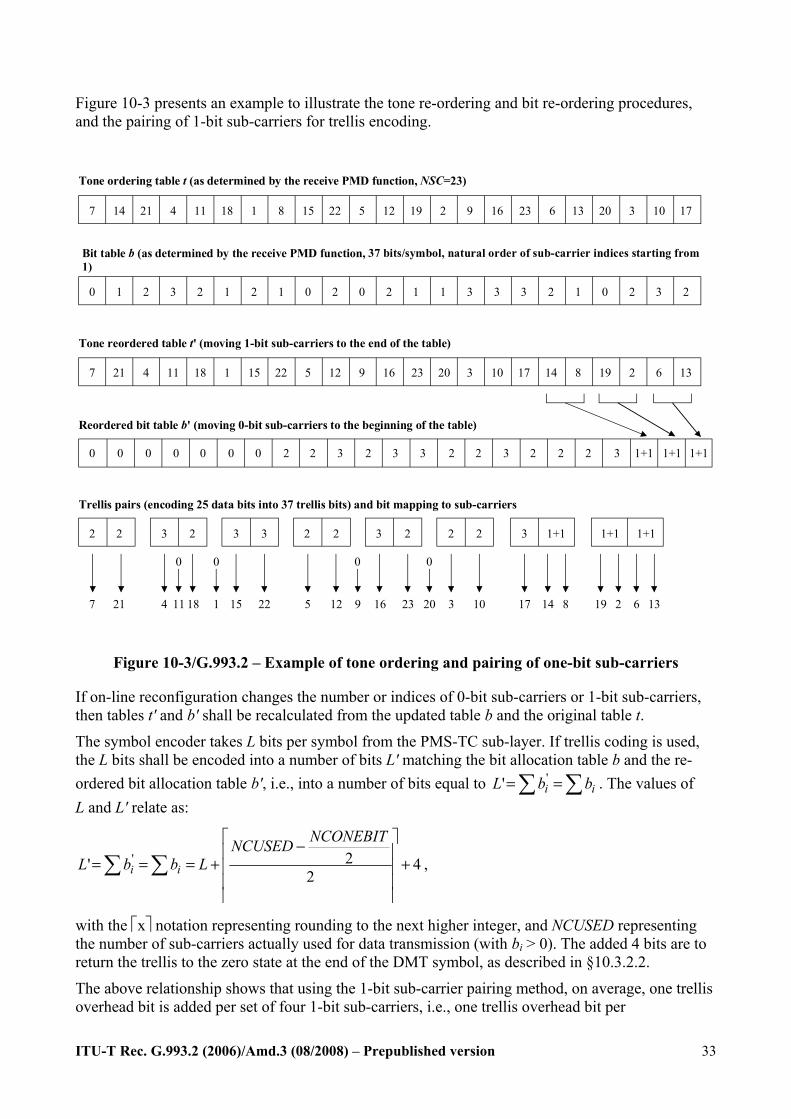
Figure 10-3 presents an example to illustrate the tone re-ordering and bit re-ordering procedures, and the pairing of 1-bit sub-carriers for trellis encoding.
7 14 21 4 11 18 1 8 15 22 5 12 19 2 9 16 23 6 13 20 3 10 17
Tone ordering table t (as determined by the receive PMD function, NSC=23)
Bit table b (as determined by the receive PMD function, 37 bits/symbol, natural order of sub-carrier indices starting from 1)
0 1 2 3 2 1 2 1 0 2 0 2 1 1 3 3 3 2 1 0 2 3 2
7 21 4 11 18 1 15 22 5 12 9 16 23 20 3 10 17 14 8 19 2 6 13
Tone reordered table t' (moving 1-bit sub-carriers to the end of the table)
0 0 0 0 2 2 3 2 3 3 2 2 3 2 2 2 3 1+1 1+1 1+1
Reordered bit table b' (moving 0-bit sub-carriers to the beginning of the table)
0 0 0
2 2 3 2 3 3 2 2 3 2 2 2 3
Trellis pairs (encoding 25 data bits into 37 trellis bits) and bit mapping to sub-carriers
1+1 1+1 1+1
7 21 4 18 15 22 5 12 16 23 3 10 17 14 19 68 132
0
11
0
1
0
9
0
20
Figure 10-3/G.993.2 – Example of tone ordering and pairing of one-bit sub-carriers
If on-line reconfiguration changes the number or indices of 0-bit sub-carriers or 1-bit sub-carriers, then tables t' and b' shall be recalculated from the updated table b and the original table t.
The symbol encoder takes L bits per symbol from the PMS-TC sub-layer. If trellis coding is used, the L bits shall be encoded into a number of bits L' matching the bit allocation table b and the re-ordered bit allocation table b', i.e., into a number of bits equal to ∑∑ == ii bbL '' . The values of L and L' relate as:
42
2' ' +⎥⎥⎥
⎥
⎤
⎢⎢⎢
⎢
⎡ −+=== ∑∑
NCONEBITNCUSEDLbbL ii ,
with the ⎡x⎤ notation representing rounding to the next higher integer, and NCUSED representing the number of sub-carriers actually used for data transmission (with bi > 0). The added 4 bits are to return the trellis to the zero state at the end of the DMT symbol, as described in §10.3.2.2.
The above relationship shows that using the 1-bit sub-carrier pairing method, on average, one trellis overhead bit is added per set of four 1-bit sub-carriers, i.e., one trellis overhead bit per
ITU-T Rec. G.993.2 (2006)/Amd.3 (08/2008) – Prepublished version
34
4-dimensional constellation.
In case trellis coding is not used, the value of L shall match the bit allocation table, i.e.,
∑= .ibL NOTE – A complementary tone re-ordering procedure should be performed in the receive PMD function. It is not necessary, however, to send the re-ordered bit table b' and the re-ordered tone table t' to the receive PMD function because they are generated in a deterministic way from the bit allocation table and tone ordering tables originally generated in the receive PMD function, and therefore the receive PMD function has all the information necessary to perform the constellation de-mapping and trellis decoding (if used).
11.2.3.3 On-line reconfiguration (OLR) commands and responses The VTU shall be capable of sending and receiving the OLR commands and responses listed in Tables 11-5 and 11-6, respectively, for the supported type(s) of OLR (see §13.1). Any OLR command specified in Table 11-5 may be initiated by either VTU. The responding VTU may either reject the initiator’s request using responses listed in Table 11-6 with reason codes listed in Table 11-7, or positively acknowledge the initiator’s request by transmitting a time marker for the reconfiguration. The time marker shall be communicated by transmission of a Syncflag (see §10.5.3). Changes may be requested concurrently by both VTUs; each transaction shall follow the procedure described in this sub-clause.
The first octet of all OLR commands and responses shall be the assigned value for the OLR command type, as shown in Table 11-2. The remaining octets shall be as shown in Tables 11-5 (for commands) and in Tables 11-6 and 11-7 (for responses). The octets of the OLR commands and responses shall be sent over the link as described in §11.2.3.1.
The list of parameters for any command in Table 11-5 shall be selected such that the length of the eoc message in octets (prior to HDLC encapsulation) doesn’t exceed the maximum length P specified in §11.2.3.1. If more parameters are to be re-configured simultaneously, the initiator shall segment the Request command to meet the maximum message size. The number of segments shall not exceed 64. The multi-segment transmission is supported by the segment code (SC) octet in the Request command and by the intermediate acknowledge (IACK) octet in the response. The responding VTU shall send an IACK response after every intermediate segment has been received. After all segments have been received, the responding VTU shall send the Defer or Reject response with a reason code if the request can’t be processed, or send the time marker (Syncflag, see §10.5.3) to implement the request. The requesting VTU shall not send the next segment until it receives the IACK for the current segment. If an IACK for an intermediate segment is not received before the time-out, the requesting VTU may either re-send it or abandon the request. The responding VTU shall consider the OLR command abandoned if no more valid segments are received within 1 second of the last segment.
The two MSBs of the SC shall be set to 002 for intermediate segments, and set to 112 for the last segment. The 6 LSBs shall contain the serial number of the segment starting from 0000002. The SC octet of an IACK shall be the same as the SC octet of the acknowledged segment.
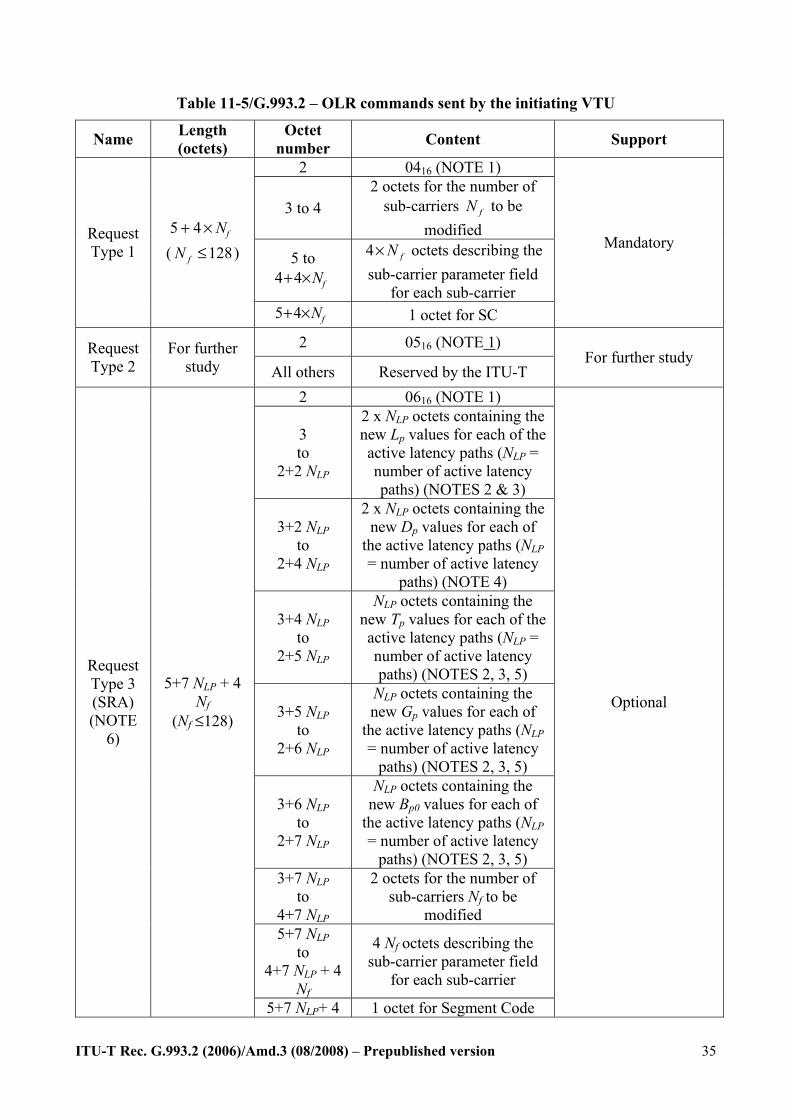
ITU-T Rec. G.993.2 (2006)/Amd.3 (08/2008) – Prepublished version
35
Table 11-5/G.993.2 – OLR commands sent by the initiating VTU
Name Length (octets)
Octet number Content Support
2 0416 (NOTE 1)
3 to 4 2 octets for the number of
sub-carriers fN to be modified
5 to fN×+44
4 fN× octets describing the sub-carrier parameter field
for each sub-carrier
Request Type 1
fN×+ 45 ( 128fN ≤ )
fN×+45 1 octet for SC
Mandatory
2 0516 (NOTE 1) Request Type 2
For further study All others Reserved by the ITU-T
For further study
2 0616 (NOTE 1)
3 to
2+2 NLP
2 x NLP octets containing the new Lp values for each of the active latency paths (NLP = number of active latency paths) (NOTES 2 & 3)
3+2 NLP to
2+4 NLP
2 x NLP octets containing the new Dp values for each of
the active latency paths (NLP = number of active latency
paths) (NOTE 4)
3+4 NLP to
2+5 NLP
NLP octets containing the new Tp values for each of the active latency paths (NLP = number of active latency paths) (NOTES 2, 3, 5)
3+5 NLP to
2+6 NLP
NLP octets containing the new Gp values for each of
the active latency paths (NLP = number of active latency
paths) (NOTES 2, 3, 5)
3+6 NLP to
2+7 NLP
NLP octets containing the new Bp0 values for each of
the active latency paths (NLP = number of active latency
paths) (NOTES 2, 3, 5) 3+7 NLP
to 4+7 NLP
2 octets for the number of sub-carriers Nf to be
modified 5+7 NLP
to 4+7 NLP + 4
Nf
4 Nf octets describing the sub-carrier parameter field
for each sub-carrier
Request Type 3 (SRA) (NOTE
6)
5+7 NLP + 4 Nf
(Nf ≤128)
5+7 NLP+ 4 1 octet for Segment Code
Optional
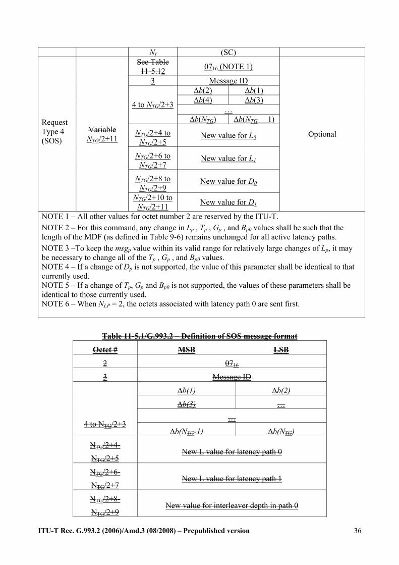
ITU-T Rec. G.993.2 (2006)/Amd.3 (08/2008) – Prepublished version
36
Nf (SC) See Table 11-5.12 0716 (NOTE 1)
3 Message ID ∆b(2) ∆b(1) ∆b(4) ∆b(3)
… 4 to NTG/2+3
∆b(NTG) ∆b(NTG 1)
NTG/2+4 to NTG/2+5
New value for L0
NTG/2+6 to NTG/2+7
New value for L1
NTG/2+8 to NTG/2+9
New value for D0
Request Type 4 (SOS)
Variable NTG/2+11
NTG/2+10 to NTG/2+11 New value for D1
Optional
NOTE 1 – All other values for octet number 2 are reserved by the ITU-T. NOTE 2 – For this command, any change in Lp , Tp , Gp , and Bp0 values shall be such that the length of the MDF (as defined in Table 9-6) remains unchanged for all active latency paths. NOTE 3 –To keep the msgp value within its valid range for relatively large changes of Lp, it may be necessary to change all of the Tp , Gp , and Bp0 values. NOTE 4 – If a change of Dp is not supported, the value of this parameter shall be identical to that currently used. NOTE 5 – If a change of Tp, Gp and Bp0 is not supported, the values of these parameters shall be identical to those currently used. NOTE 6 – When NLP = 2, the octets associated with latency path 0 are sent first.
Table 11-5.1/G.993.2 – Definition of SOS message format
Octet # MSB LSB
2 0716
3 Message ID
∆b(1) ∆b(2)
∆b(3) …
…
4 to NTG/2+3 ∆b(NTG-1) ∆b(NTG)
NTG/2+4-
NTG/2+5 New L value for latency path 0
NTG/2+6-
NTG/2+7 New L value for latency path 1
NTG/2+8-
NTG/2+9 New value for interleaver depth in path 0
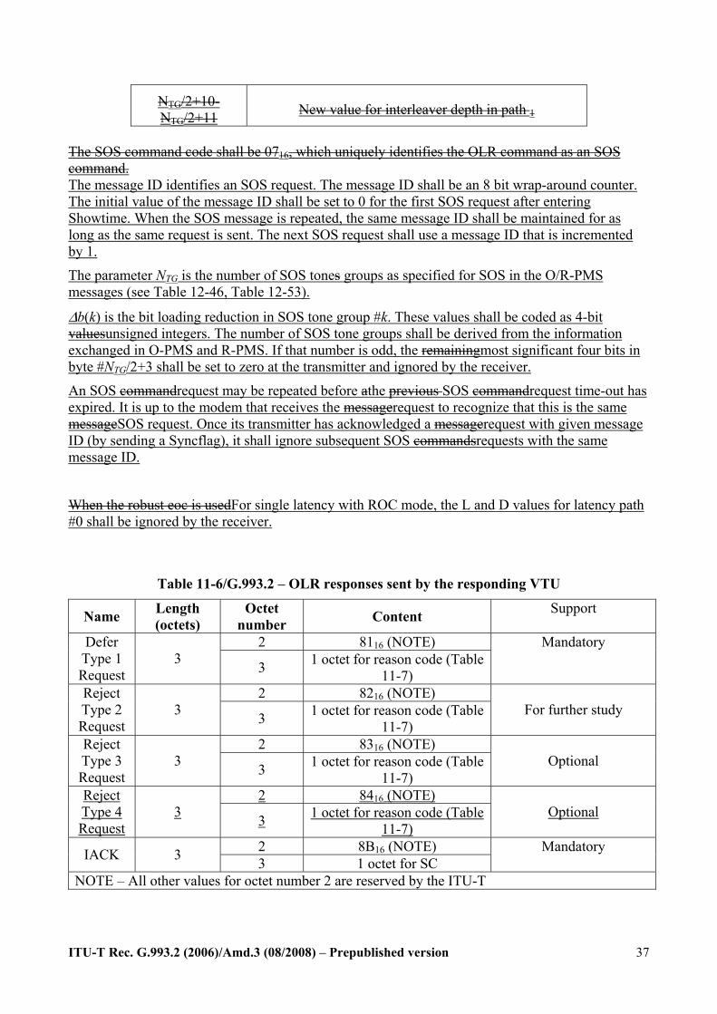
ITU-T Rec. G.993.2 (2006)/Amd.3 (08/2008) – Prepublished version
37
NTG/2+10-NTG/2+11 New value for interleaver depth in path 1
The SOS command code shall be 0716, which uniquely identifies the OLR command as an SOS command. The message ID identifies an SOS request. The message ID shall be an 8 bit wrap-around counter. The initial value of the message ID shall be set to 0 for the first SOS request after entering Showtime. When the SOS message is repeated, the same message ID shall be maintained for as long as the same request is sent. The next SOS request shall use a message ID that is incremented by 1.
The parameter NTG is the number of SOS tones groups as specified for SOS in the O/R-PMS messages (see Table 12-46, Table 12-53).
Δb(k) is the bit loading reduction in SOS tone group #k. These values shall be coded as 4-bit valuesunsigned integers. The number of SOS tone groups shall be derived from the information exchanged in O-PMS and R-PMS. If that number is odd, the remainingmost significant four bits in byte #NTG/2+3 shall be set to zero at the transmitter and ignored by the receiver.
An SOS commandrequest may be repeated before athe previous SOS commandrequest time-out has expired. It is up to the modem that receives the messagerequest to recognize that this is the same messageSOS request. Once its transmitter has acknowledged a messagerequest with given message ID (by sending a Syncflag), it shall ignore subsequent SOS commandsrequests with the same message ID.
When the robust eoc is usedFor single latency with ROC mode, the L and D values for latency path #0 shall be ignored by the receiver.
Table 11-6/G.993.2 – OLR responses sent by the responding VTU
Name Length (octets)
Octet number Content Support
2 8116 (NOTE) Defer Type 1 Request
3 3 1 octet for reason code (Table 11-7)
Mandatory
2 8216 (NOTE) Reject Type 2 Request
3 3 1 octet for reason code (Table 11-7)
For further study
2 8316 (NOTE) Reject Type 3 Request
3 3 1 octet for reason code (Table 11-7)
Optional
2 8416 (NOTE) Reject Type 4 Request
3 3 1 octet for reason code (Table 11-7)
Optional
2 8B16 (NOTE) IACK 3 3 1 octet for SC Mandatory
NOTE – All other values for octet number 2 are reserved by the ITU-T

ITU-T Rec. G.993.2 (2006)/Amd.3 (08/2008) – Prepublished version
38
Each sub-carrier parameter field shall contain 4 octets formatted as [0000 iiii iiii iiii gggg gggg gggg bbbb] to convey the gi (12 bits) and the bi (4 bits) values of the sub-carrier index i (12 bits). The sub-carrier index i shall be coded in the four LSBs of the first octet and the entire second octet of the sub-carrier field. The LSBs of the sub-carrier index i shall be contained in the second octet. The gi shall be contained in the third octet and the four MSBs of the fourth octet. The LSBs of gi shall be contained in the fourth octet. The bi shall be contained in the four LSBs of the fourth octet.
Table 11-7/G.993.2 – Reason codes for OLR responses
Reason Octet value Applicable to Defer Type 1
Applicable to Reject Type 2
Applicable to Reject Type 3
Applicable to Reject Type 4
Busy 0116 Xyes Xyes Xyes no Invalid parameters
0216 Xyes Xyes Xyes yes
Upon sending an OLR command, the initiator shall await a response. The OLR response may be deferring or rejecting the reconfiguration, or it may be a Syncflag indicating when the reconfiguration shall take effect. If the initiator receives an OLR response to defer or reject the change, it shall abandon the last requested OLR command. A new command may be initiated immediately, including the command abandoned, rejected or deferred earlier.
NOTE 1 – In the case of reason code 0216, repeating of the OLR request is not expected to be helpful. NOTE 2 – When an OLR command has been sent, the initiator has no means to cancel the command. The initiator needs to wait for a response or a time-out before it can send a different OLR command. For example, if the SOS triggering conditions become active when there is a pending bitswap or SRA, the SOS commandrequest needs to be delayed until full execution or time-out of the bitswap/SRA procedure.
Upon reception of an OLR command, the responder shall send either an OLR response to defer or to reject the reconfiguration, or a Syncflag that indicates when the reconfiguration shall take effect. After sending the Syncflag, the responder shall reconfigure the affected PMD, PMS-TC, and TPS-TC functions starting from the tenth symbol in the next DMT superframe, as described in §13.3. The responder may defer or reject the OLR request; in this case it shall supply a reason code from those specified in Table 11-7.
Upon reception of the Syncflag, the initiator shall reconfigure the affected PMD or PMS-TC functions starting from the tenth DMT symbol in the next DMT superframe, as described in §13.3.
11.2.3.11 PMD Test Parameter Read commands and responses The PMD Test Parameter Read commands shall be used to retrieve the values of the PMD test parameters that are specified in §11.4.1 and maintained by the far-end VTU. The PMD Test Parameter Read commands are shown in Table 11-25, and may be initiated by either VTU. The responses shall be as shown in Table 11-26. The first octet of all PMD Test Parameter Read commands and responses shall be the assigned value for the PMD Test Parameter Read command type, as shown in Table 11-4. The subsequent octets of the commands shall be as shown in Table 11-25. The subsequent octets of the responses shall be as shown in Table 11-26. The octets shall be sent using the format described in §11.2.3.1.
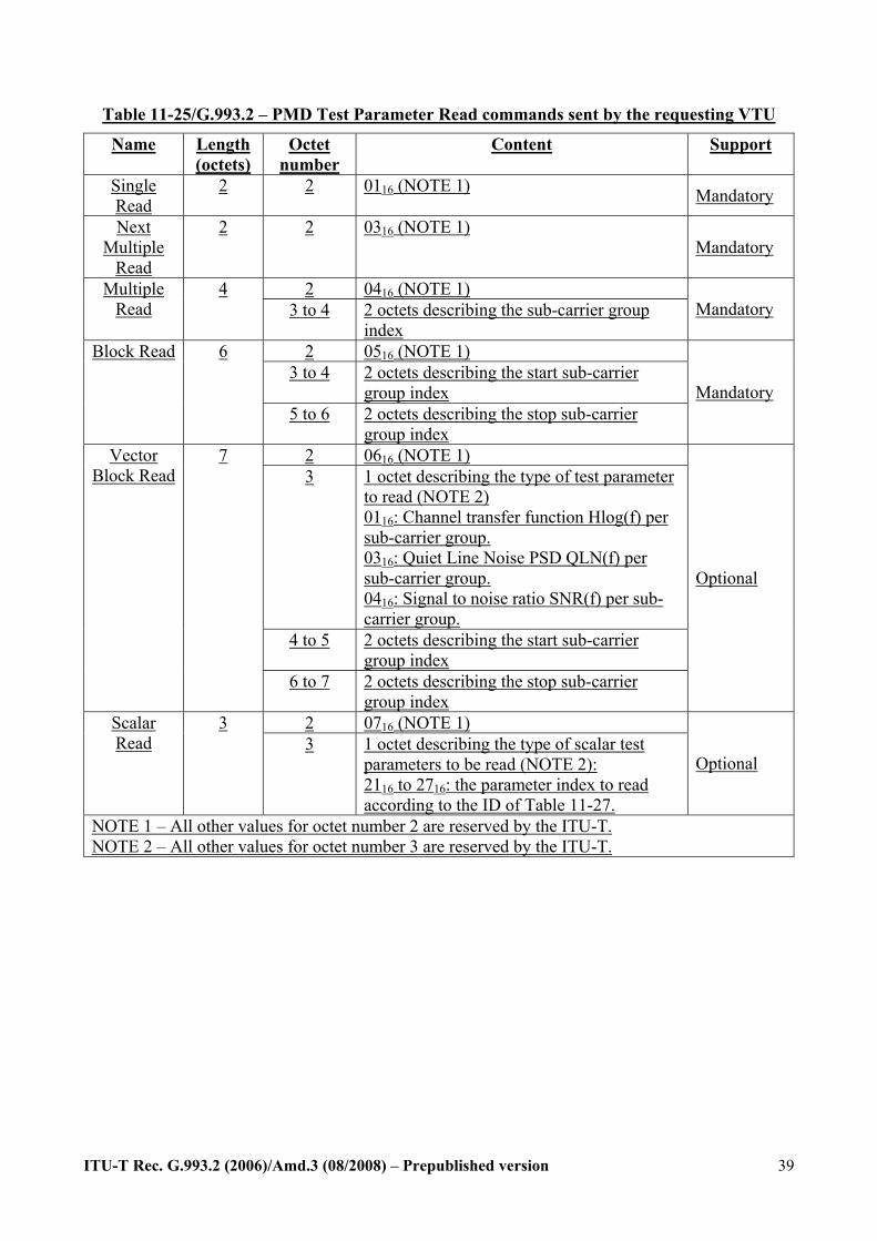
ITU-T Rec. G.993.2 (2006)/Amd.3 (08/2008) – Prepublished version
39
Table 11-25/G.993.2 – PMD Test Parameter Read commands sent by the requesting VTU
Name Length (octets)
Octet number
Content Support
Single Read
2 2 0116 (NOTE 1) Mandatory
Next Multiple
Read
2 2 0316 (NOTE 1) Mandatory
2 0416 (NOTE 1) Multiple Read
4 3 to 4 2 octets describing the sub-carrier group
index Mandatory
2 0516 (NOTE 1) 3 to 4 2 octets describing the start sub-carrier
group index
Block Read 6
5 to 6 2 octets describing the stop sub-carrier group index
Mandatory
2 0616 (NOTE 1) 3 1 octet describing the type of test parameter
to read (NOTE 2) 0116: Channel transfer function Hlog(f) per sub-carrier group. 0316: Quiet Line Noise PSD QLN(f) per sub-carrier group. 0416: Signal to noise ratio SNR(f) per sub-carrier group.
4 to 5 2 octets describing the start sub-carrier group index
Vector Block Read
7
6 to 7 2 octets describing the stop sub-carrier group index
Optional
2 0716 (NOTE 1) Scalar Read
3 3 1 octet describing the type of scalar test
parameters to be read (NOTE 2): 2116 to 2716: the parameter index to read according to the ID of Table 11-27.
Optional
NOTE 1 – All other values for octet number 2 are reserved by the ITU-T. NOTE 2 – All other values for octet number 3 are reserved by the ITU-T.
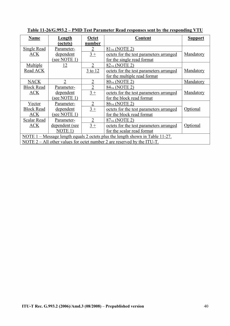
ITU-T Rec. G.993.2 (2006)/Amd.3 (08/2008) – Prepublished version
40
Table 11-26/G.993.2 – PMD Test Parameter Read responses sent by the responding VTU
Name Length (octets)
Octet number
Content Support
2 8116 (NOTE 2) Single Read ACK
Parameter-dependent
(see NOTE 1) 3 + octets for the test parameters arranged
for the single read format Mandatory
2 8216 (NOTE 2) Multiple Read ACK
12 3 to 12 octets for the test parameters arranged
for the multiple read format Mandatory
NACK 2 2 8016 (NOTE 2) Mandatory 2 8416 (NOTE 2) Block Read
ACK Parameter-dependent
(see NOTE 1) 3 + octets for the test parameters arranged
for the block read format Mandatory
2 8616 (NOTE 2) Vector Block Read
ACK
Parameter-dependent
(see NOTE 1) 3 + octets for the test parameters arranged
for the block read format Optional
2 8716 (NOTE 2) Scalar Read ACK
Parameter-dependent (see
NOTE 1) 3 + octets for the test parameters arranged
for the scalar read format Optional
NOTE 1 – Message length equals 2 octets plus the length shown in Table 11-27. NOTE 2 – All other values for octet number 2 are reserved by the ITU-T.
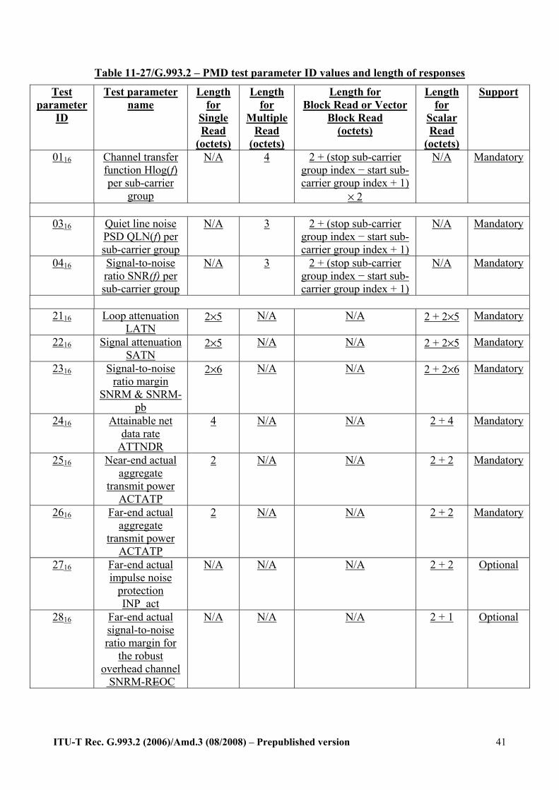
ITU-T Rec. G.993.2 (2006)/Amd.3 (08/2008) – Prepublished version
41
Table 11-27/G.993.2 – PMD test parameter ID values and length of responses
Test parameter
ID
Test parameter name
Length for
Single Read
(octets)
Length for
Multiple Read
(octets)
Length for Block Read or Vector
Block Read (octets)
Length for
Scalar Read
(octets)
Support
0116 Channel transfer function Hlog(f) per sub-carrier
group
N/A 4 2 + (stop sub-carrier group index − start sub-carrier group index + 1)
× 2
N/A Mandatory
0316 Quiet line noise
PSD QLN(f) per sub-carrier group
N/A 3 2 + (stop sub-carrier group index − start sub-carrier group index + 1)
N/A Mandatory
0416 Signal-to-noise ratio SNR(f) per sub-carrier group
N/A 3 2 + (stop sub-carrier group index − start sub-carrier group index + 1)
N/A Mandatory
2116 Loop attenuation
LATN 2×5 N/A N/A 2 + 2×5 Mandatory
2216 Signal attenuation SATN
2×5 N/A N/A 2 + 2×5 Mandatory
2316 Signal-to-noise ratio margin
SNRM & SNRM-pb
2×6 N/A N/A 2 + 2×6 Mandatory
2416 Attainable net data rate
ATTNDR
4 N/A N/A 2 + 4 Mandatory
2516 Near-end actual aggregate
transmit power ACTATP
2 N/A N/A 2 + 2 Mandatory
2616 Far-end actual aggregate
transmit power ACTATP
2 N/A N/A 2 + 2 Mandatory
2716 Far-end actual impulse noise
protection INP_act
N/A N/A N/A 2 + 2 Optional
2816 Far-end actual signal-to-noise ratio margin for
the robust overhead channel SNRM-REOC
N/A N/A N/A 2 + 1 Optional
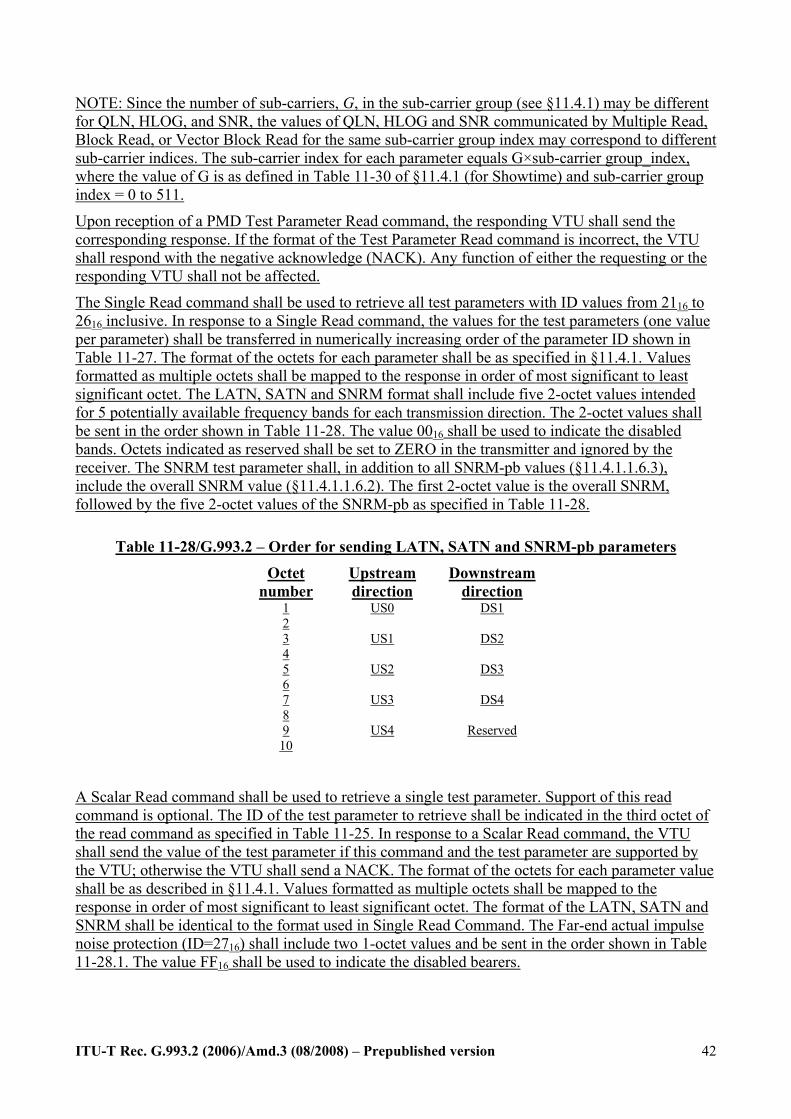
ITU-T Rec. G.993.2 (2006)/Amd.3 (08/2008) – Prepublished version
42
NOTE: Since the number of sub-carriers, G, in the sub-carrier group (see §11.4.1) may be different for QLN, HLOG, and SNR, the values of QLN, HLOG and SNR communicated by Multiple Read, Block Read, or Vector Block Read for the same sub-carrier group index may correspond to different sub-carrier indices. The sub-carrier index for each parameter equals G×sub-carrier group_index, where the value of G is as defined in Table 11-30 of §11.4.1 (for Showtime) and sub-carrier group index = 0 to 511.
Upon reception of a PMD Test Parameter Read command, the responding VTU shall send the corresponding response. If the format of the Test Parameter Read command is incorrect, the VTU shall respond with the negative acknowledge (NACK). Any function of either the requesting or the responding VTU shall not be affected.
The Single Read command shall be used to retrieve all test parameters with ID values from 2116 to 2616 inclusive. In response to a Single Read command, the values for the test parameters (one value per parameter) shall be transferred in numerically increasing order of the parameter ID shown in Table 11-27. The format of the octets for each parameter shall be as specified in §11.4.1. Values formatted as multiple octets shall be mapped to the response in order of most significant to least significant octet. The LATN, SATN and SNRM format shall include five 2-octet values intended for 5 potentially available frequency bands for each transmission direction. The 2-octet values shall be sent in the order shown in Table 11-28. The value 0016 shall be used to indicate the disabled bands. Octets indicated as reserved shall be set to ZERO in the transmitter and ignored by the receiver. The SNRM test parameter shall, in addition to all SNRM-pb values (§11.4.1.1.6.3), include the overall SNRM value (§11.4.1.1.6.2). The first 2-octet value is the overall SNRM, followed by the five 2-octet values of the SNRM-pb as specified in Table 11-28.
Table 11-28/G.993.2 – Order for sending LATN, SATN and SNRM-pb parameters
Octet number
Upstream direction
Downstream direction
1 2
US0 DS1
3 4
US1 DS2
5 6
US2 DS3
7 8
US3 DS4
9 10
US4 Reserved
A Scalar Read command shall be used to retrieve a single test parameter. Support of this read command is optional. The ID of the test parameter to retrieve shall be indicated in the third octet of the read command as specified in Table 11-25. In response to a Scalar Read command, the VTU shall send the value of the test parameter if this command and the test parameter are supported by the VTU; otherwise the VTU shall send a NACK. The format of the octets for each parameter value shall be as described in §11.4.1. Values formatted as multiple octets shall be mapped to the response in order of most significant to least significant octet. The format of the LATN, SATN and SNRM shall be identical to the format used in Single Read Command. The Far-end actual impulse noise protection (ID=2716) shall include two 1-octet values and be sent in the order shown in Table 11-28.1. The value FF16 shall be used to indicate the disabled bearers.
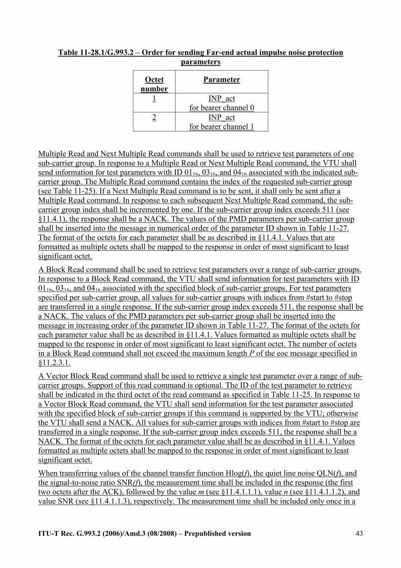
ITU-T Rec. G.993.2 (2006)/Amd.3 (08/2008) – Prepublished version
43
Table 11-28.1/G.993.2 – Order for sending Far-end actual impulse noise protection parameters
Octet number
Parameter
1 INP_act for bearer channel 0
2 INP_act for bearer channel 1
Multiple Read and Next Multiple Read commands shall be used to retrieve test parameters of one sub-carrier group. In response to a Multiple Read or Next Multiple Read command, the VTU shall send information for test parameters with ID 0116, 0316, and 0416 associated with the indicated sub-carrier group. The Multiple Read command contains the index of the requested sub-carrier group (see Table 11-25). If a Next Multiple Read command is to be sent, it shall only be sent after a Multiple Read command. In response to each subsequent Next Multiple Read command, the sub-carrier group index shall be incremented by one. If the sub-carrier group index exceeds 511 (see §11.4.1), the response shall be a NACK. The values of the PMD parameters per sub-carrier group shall be inserted into the message in numerical order of the parameter ID shown in Table 11-27. The format of the octets for each parameter shall be as described in §11.4.1. Values that are formatted as multiple octets shall be mapped to the response in order of most significant to least significant octet.
A Block Read command shall be used to retrieve test parameters over a range of sub-carrier groups. In response to a Block Read command, the VTU shall send information for test parameters with ID 0116, 0316, and 0416 associated with the specified block of sub-carrier groups. For test parameters specified per sub-carrier group, all values for sub-carrier groups with indices from #start to #stop are transferred in a single response. If the sub-carrier group index exceeds 511, the response shall be a NACK. The values of the PMD parameters per sub-carrier group shall be inserted into the message in increasing order of the parameter ID shown in Table 11-27. The format of the octets for each parameter value shall be as described in §11.4.1. Values formatted as multiple octets shall be mapped to the response in order of most significant to least significant octet. The number of octets in a Block Read command shall not exceed the maximum length P of the eoc message specified in §11.2.3.1.
A Vector Block Read command shall be used to retrieve a single test parameter over a range of sub-carrier groups. Support of this read command is optional. The ID of the test parameter to retrieve shall be indicated in the third octet of the read command as specified in Table 11-25. In response to a Vector Block Read command, the VTU shall send information for the test parameter associated with the specified block of sub-carrier groups if this command is supported by the VTU; otherwise the VTU shall send a NACK. All values for sub-carrier groups with indices from #start to #stop are transferred in a single response. If the sub-carrier group index exceeds 511, the response shall be a NACK. The format of the octets for each parameter value shall be as described in §11.4.1. Values formatted as multiple octets shall be mapped to the response in order of most significant to least significant octet.
When transferring values of the channel transfer function Hlog(f), the quiet line noise QLN(f), and the signal-to-noise ratio SNR(f), the measurement time shall be included in the response (the first two octets after the ACK), followed by the value m (see §11.4.1.1.1), value n (see §11.4.1.1.2), and value SNR (see §11.4.1.1.3), respectively. The measurement time shall be included only once in a
ITU-T Rec. G.993.2 (2006)/Amd.3 (08/2008) – Prepublished version
44
response to a Block Read or Vector Block Read command, and shall be included in each response to a Multiple Read or Next Multiple Read command.
The values of some test parameters are represented using fewer bits than contained in the corresponding field defined for the response in Table 11-27. In the case that the field has more than one octet, the bits shall be mapped to the LSBs of the multi-octet field in the response. Unused MSBs in the multi-octet field shall be set to ZERO for unsigned quantities and to the value of the sign bit for signed quantities.
11.3 OAM primitives Among the standard OAM primitives, this document specifies only anomalies and defects. The system shall use the corresponding failure specifications of ITU-T Recommendation G.997.1 [4].
Both the near-end and the far-end primitives shall be represented at the VTU-O; representation of the far-end anomalies and defects at the VTU-R is optional.
OAM primitives shall not be generated for the overhead-only latency path (ROC).
11.3.3 Power-related primitives OAM primitives shall not be generated for the overhead-only latency path (robust eoc).
11.3.3.1 Near-end primitives Loss of power (lpr): This primitive occurs when the VTU power supply (mains) voltage drops below the manufacturer-determined level required for proper VTU operation. An lpr terminates when the power level exceeds the manufacturer-determined minimum power level.
11.3.3.2 Far-end primitives Far-end loss of power (flpr): This primitive detected at the far end is reported by the flpr indicator, which shall be coded 1 to indicate that no lpr is being reported and shall be coded 0 for the next 3 lpr indicator transmissions to indicate that an flpr (i.e., “dying gasp”) is being reported. An flpr occurs when 2 or more out of 3 consecutively received lpr indicators are set to ZERO. An flpr terminates when, for a period of 0.5 seconds, the received lpr indicator bit is set to ONE and no near-end los is present.
11.4.1 Test parameters The test parameters are measured by the PMD transmit or receive function and shall be reported on request to the near-end VME. Test parameters can be used to identify possible issues with the physical loop and to check for adequate physical media performance margin at acceptance and after repair verification, or at any other time following the initialization of the VDSL2 system.
The following test parameters shall be passed on request from the receive PMD transmit function to the near-end VME:
• Channel characteristics function H(f) per sub-carrier (CCF-ps); • Quiet line noise PSD QLN(f) per sub-carrier (QLN-ps); • Signal-to-noise Ratio SNR(f) per sub-carrier (SNR-ps); • Loop attenuation per band (LATN-pb); • Signal attenuation per band (SATN-pb); • Signal-to-noise ratio margin per band (SNRM-pb);
• Signal-to-noise ratio margin for the ROC (SNRM-ROC) • Attainable net data rate (ATTNDR);
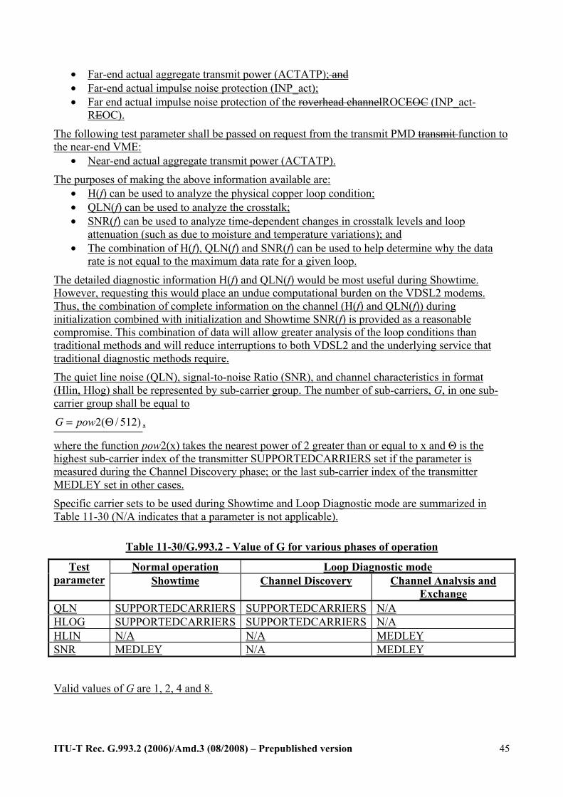
ITU-T Rec. G.993.2 (2006)/Amd.3 (08/2008) – Prepublished version
45
• Far-end actual aggregate transmit power (ACTATP); and • Far-end actual impulse noise protection (INP_act); • Far end actual impulse noise protection of the roverhead channelROCEOC (INP_act-
REOC).
The following test parameter shall be passed on request from the transmit PMD transmit function to the near-end VME:
• Near-end actual aggregate transmit power (ACTATP). The purposes of making the above information available are:
• H(f) can be used to analyze the physical copper loop condition; • QLN(f) can be used to analyze the crosstalk; • SNR(f) can be used to analyze time-dependent changes in crosstalk levels and loop
attenuation (such as due to moisture and temperature variations); and • The combination of H(f), QLN(f) and SNR(f) can be used to help determine why the data
rate is not equal to the maximum data rate for a given loop.
The detailed diagnostic information H(f) and QLN(f) would be most useful during Showtime. However, requesting this would place an undue computational burden on the VDSL2 modems. Thus, the combination of complete information on the channel (H(f) and QLN(f)) during initialization combined with initialization and Showtime SNR(f) is provided as a reasonable compromise. This combination of data will allow greater analysis of the loop conditions than traditional methods and will reduce interruptions to both VDSL2 and the underlying service that traditional diagnostic methods require.
The quiet line noise (QLN), signal-to-noise Ratio (SNR), and channel characteristics in format (Hlin, Hlog) shall be represented by sub-carrier group. The number of sub-carriers, G, in one sub-carrier group shall be equal to
2( / 512)G pow= Θ ,
where the function pow2(x) takes the nearest power of 2 greater than or equal to x and Θ is the highest sub-carrier index of the transmitter SUPPORTEDCARRIERS set if the parameter is measured during the Channel Discovery phase; or the last sub-carrier index of the transmitter MEDLEY set in other cases.
Specific carrier sets to be used during Showtime and Loop Diagnostic mode are summarized in Table 11-30 (N/A indicates that a parameter is not applicable).
Table 11-30/G.993.2 - Value of G for various phases of operation
Normal operation Loop Diagnostic mode Test parameter Showtime Channel Discovery Channel Analysis and
Exchange QLN SUPPORTEDCARRIERS SUPPORTEDCARRIERS N/A HLOG SUPPORTEDCARRIERS SUPPORTEDCARRIERS N/A HLIN N/A N/A MEDLEY SNR MEDLEY N/A MEDLEY
Valid values of G are 1, 2, 4 and 8.
ITU-T Rec. G.993.2 (2006)/Amd.3 (08/2008) – Prepublished version
46
11.4.1.1.6 Signal-to-noise ratio margin
11.4.1.1.6.1 General definition of signal-to-noise ratio margin The signal-to-noise ratio margin is the maximum increase (scalar gain, in dB) of the reference noise PSD (at all relevant frequencies), such that the BER of each TPS-TC stream does not exceed the maximum BER specified for the corresponding TPS-TC stream, without any change of PMD parameters (e.g., bits and gains) and PMS-TC parameters (e.g., Lp, FEC parameters). The BER is referenced to the output of the PMS-TC function (i.e., the α/β interface).
The definition of the reference noise PSD depends on the control parameter SNRM_MODE.
11.4.1.1.6.1.1 SNRM_MODE = 1 SNRM_MODE = 1 is a mandatory capability for both VTUs.
The reference noise PSD equals the received current-condition external noise PSD only, as measured by the near-end transceiver (i.e., equal to the PSD of the noise measured by the near-end transceiver at the constellation decoder or other relevant internal reference point when the only noise source is the external stationary noise applied to the U interface and no internal noise sources are present). NOTE – Mathematically this can be illustrated by:
2RXfilterReceived_External_Noise_PSD H ( ) External_Noise_PSD_at_U_interfacef= ×
11.4.1.1.6.1.2 SNRM_MODE = 2 SNRM_MODE = 2 is an optional capability for both VTUs.
The reference noise PSD equals the maximum of the received current-condition external noise PSD (as defined in SNRM_MODE=1) and the received virtual noise PSD, at a common internal reference point.
The received virtual noise PSD shall be determined by the transceiver as defined in the following equation.
2Received_Virtual_Noise_PSD H( ) TXREFVNf= ×
where TXREFVN is the transmitter referred virtual noise PSD MIB parameter. 2H( )f is calculated as:
2 Actual_Received_Signal_PSDH( )Actual_Transmit_Signal_PSD
f =
where,
Actual_Transmit_Signal_PSD is the actual transmit signal PSD at the far-end transmitter as calculated by the near-end transceiver.
Actual_Received_Signal_PSD is the actual received signal PSD at the near-end transceiver as measured by the near-end transceiver (i.e., equal to the PSD measured by the near-end transceiver at the constellation decoder or other relevant internal reference point) during initialization and Showtime.
Mathematically this can be expressed as:
ITU-T Rec. G.993.2 (2006)/Amd.3 (08/2008) – Prepublished version
47
2RXfilterActual_ Re ceived_Signal_PSD H ( ) Received_Signal_PSD_at_U_interfacef= ×
NOTE – A measurement of the current-condition external noise PSD could be overly optimistic, as it only represents a snapshot in time, not taking into account the future increase in noise PSD (e.g., due to additional VDSL2 lines being switched on). The SNRM_MODE=2 is defined to prevent the VTU’s bit loading algorithm from assigning an overly optimistic number of bits to a sub-carrier. This is achieved by defining (via the transmitter referred virtual noise PSD parameter TXREFVN) an anticipated noise PSD, which may be a function of frequency that can be used for bit loading.
This method can be used to avoid or reduce periods with excessive BER and retrains, in order to assure service quality and stability. It is expected that the configuration, via the MIB, is based on anticipated service penetration and noise environment.
11.4.1.1.6.2 Signal-to-noise ratio margin parameter (SNRM) The signal-to-noise ratio margin parameter, SNRM, is the signal-to-noise ratio margin (as defined in §11.4.1.1.6.1) measured over all sub-carriers, except the sub-carriers assigned to the ROC, in a transmission direction for which bi > 0. The received virtual noise PSD as defined in §11.4.1.1.6.1.2 shall be taken into account when configured in SNRM_MODE=2.
The signal-to-noise ratio margin (SNRM) shall be measured by the receive PMD function during initialization. The measurement may be updated autonomously and shall be updated on request during Showtime. The SNRM shall be sent to the far-end VTU during initialization and Loop Diagnostic mode and shall be sent on request to the near-end VME at any time. The near-end VME shall send the SNRM to the far-end VME on request during Showtime.
To determine the SNRM, the receive PMD function must be able to first determine the bits and gains table. During Loop Diagnostic mode, the receive PMD function shall use the special value to indicate that the SNRM value was not measured.
ITU-T Rec. G.993.2 (2006)/Amd.3 (08/2008) – Prepublished version
48
The signal-to-noise ratio margin in the downstream direction shall be represented as a 10-bit twos complement signed integer snrm, with the value of SNRMds defined as SNRMds = snrm/10 dB. This data format supports an SNRMds granularity of 0.1 dB and an SNRMds dynamic range of 102.2 dB (−51.1 to +51.1 dB).
An SNRMds value indicated as snrm = −512 is a special value. It indicates that the signal-to-noise ratio margin is out of the range to be represented. During Loop Diagnostic mode, the special value shall be used to indicate that the SNRMds value was not measured.
The same definition and representation shall apply to the signal-to-noise ratio margin in the upstream direction, SNRMus.
11.4.1.1.6.3 Signal-to-noise ratio margin per band (SNRM-pb) The signal-to-noise ratio margin in the mth downstream band is denoted as SNRM_D(m), and the signal-to-noise ratio margin in the mth upstream band is denoted as SNRM_U(m). For ease of notation, this sub-clause provides requirements and definitions in terms of the downstream signal-to-noise ratio margin, but the same definitions and requirements also apply to SNRM_U(m).
The signal-to-noise ratio margin per band parameter SNRM-pb is the signal-to-noise ratio margin (as defined in §11.4.1.1.6.1) measured over all sub-carriers in a particular band for which bi > 0. The received virtual noise PSD as defined in §11.4.1.1.6.1.2 shall be taken into account when configured in SNRM_MODE=2.
The signal-to-noise ratio margin per band is the maximum increase (in dB) in the received noise power that can be tolerated in this band, such that the VTU can still meet all target BERs over all bearer channels.
The signal-to-noise ratio margin per band shall be measured by the receive PMD function during initialization. The measurement may be updated autonomously and shall be updated on request during Showtime. The signal-to-noise ratio margin per band shall be sent to the far-end VME during initialization and Loop Diagnostic mode and shall be sent on request to the near-end VME at any time. The near-end VME shall send the SNRM-pb to the far-end VME on request during Showtime.
To determine the SNRM-pb, the receive PMD function must be able to first determine the bits and gains table. During Loop Diagnostic mode, the receive PMD function shall use the special value to indicate that the SNRM-pb value was not measured.
The signal-to-noise ratio margin per downstream band shall be represented as a 10-bit twos complement signed integer snrm, with the value of SNRM_D(m) defined as SNRM_D(m) = snrm/10 dB. This data format supports an SNRM_D(m) granularity of 0.1 dB and an SNRM_D(m) dynamic range of 102.2 dB (−51.1 to +51.1 dB).
An SNRM_D(m) value indicated as snrm = −512 is a special value. It indicates that the signal-to-noise ratio margin is out of the range to be represented. During Loop Diagnostic mode, the special value shall be used to indicate that the SNRM_D(m) value was not measured.
11.4.1.1.6.4 Signal-to-noise ratio margin for the ROC (SNRM-ROC) The SNRM-ROC is the signal-to-noise ratio margin related to transmission of the ROC, as defined in §9.1, Figure 9-1.1. The definition of SNRM-ROC is as in §11.4.1.1.6.1 applied to the MPS-TC and BER=10-7 for all bits transmitted over latency path #0, Figure 9-1.1. The SNRM-ROC shall be measured over all sub-carriers assigned to the ROC for which bi > 0 in a transmission direction. The received virtual noise PSD as defined in §11.4.1.1.6.1.2 shall be taken into account when configured in SNRM_MODE=2.
ITU-T Rec. G.993.2 (2006)/Amd.3 (08/2008) – Prepublished version
49
The SNRM-ROC shall be measured by the receive PMD function during initialization. The measurement may be updated autonomously and shall be updated on request during Showtime. The SNRM-ROC shall be sent to the far-end VTU during initialization and shall be sent on request to the near-end VME at any time. The near-end VME shall send the SNRM-ROC to the far-end VME on request during Showtime. The receive PMD function shall use a special value to indicate that the SNRM value was not measured (e.g., in Loop Diagnostic mode or if the ROC is not enabled or not supported).
The SNRM-ROC shall use the same representation as defined for SNRM in §11.4.1.1.6.2.
11.4.1.1.10 Actual impulse noise protection of the ROC (INP_act-ROC) The INP_act-ROC is the actual impulse noise protection of the ROC, as defined in §9.1, Figure 9-1.1. It shall be computed as INP_act-ROC = INP_no_erasure0 (see §9.6). The format shall be identical to that of the actual impulse noise protection INP_act of the bearer channels (see §11.4.1.1.9).
12.1.4 Deactivation, power loss, and persistent link failure The deactivation procedure allows an orderly shutdown of the link. The modem shall follow the procedures described in §11.2.3.9 to transition from the L0 state to the L3 state.
In the case of loss of receive power (power loss) or persistent link failure, the VTU shall transition from L0 state to L3 state.
The VTU shall declare a power loss when a Persistent LOS Failure is declared. Persistent LOS Failure is declared after 2.5 ± 0.5 s of near-end LOS Failure with the los (see §11.3.1.3) still present. An LOS Failure is declared after 2.5 ± 0.5 s of contiguous los, or, if los is present when the criteria for LOF Failure declaration have been met (see LOF Failure definition below). An LOS Failure is cleared after 10 ± 0.5 s of no los.
The VTU shall declare a persistent link failure when a Persistent LOF Failure is declared. A Persistent LOF Failure is declared after 2.5 ± 0.5 s of near-end LOF Failure with the sef (see §11.3.1.3) still present. An LOF Failure is declared after 2.5 ± 0.5 s of contiguous near-end sef, except when an los or LOS Failure is present (see LOS Failure definition above). An LOF Failure is cleared when LOS Failure is declared, or after 10 ± 0.5 s of no sef.
WhenIf the number of successful SOS procedures performed within a 120- seconds interval exceeds MAX-SOS, the modem shall transition to the L3 state. The 120-second measurement interval shall be started at the first successful SOS procedure after getting into Showtime and re-started at the first successful SOS procedure occurring after a previous 120-second period interval has expired with the number of successful SOS procedures being less than MAX-SOS. The 120 second measurement intervals shall be sequential periods, not a sliding window.
The SOS procedure shall be considered as successful when the modem initiating the SOS receives the SyncFlag in response (regardless whether the SyncFlag was received after a single or multiple SOS requests).
When the actual bitnet data rate, net_actn, remains below the mMinimum net dData rRate, net_minn, for any bearer channel for more than five minutes20 seconds, the modem shall transition to the L3 state.
NOTE – From this L3 state a VTU may transition to an initialization procedure.
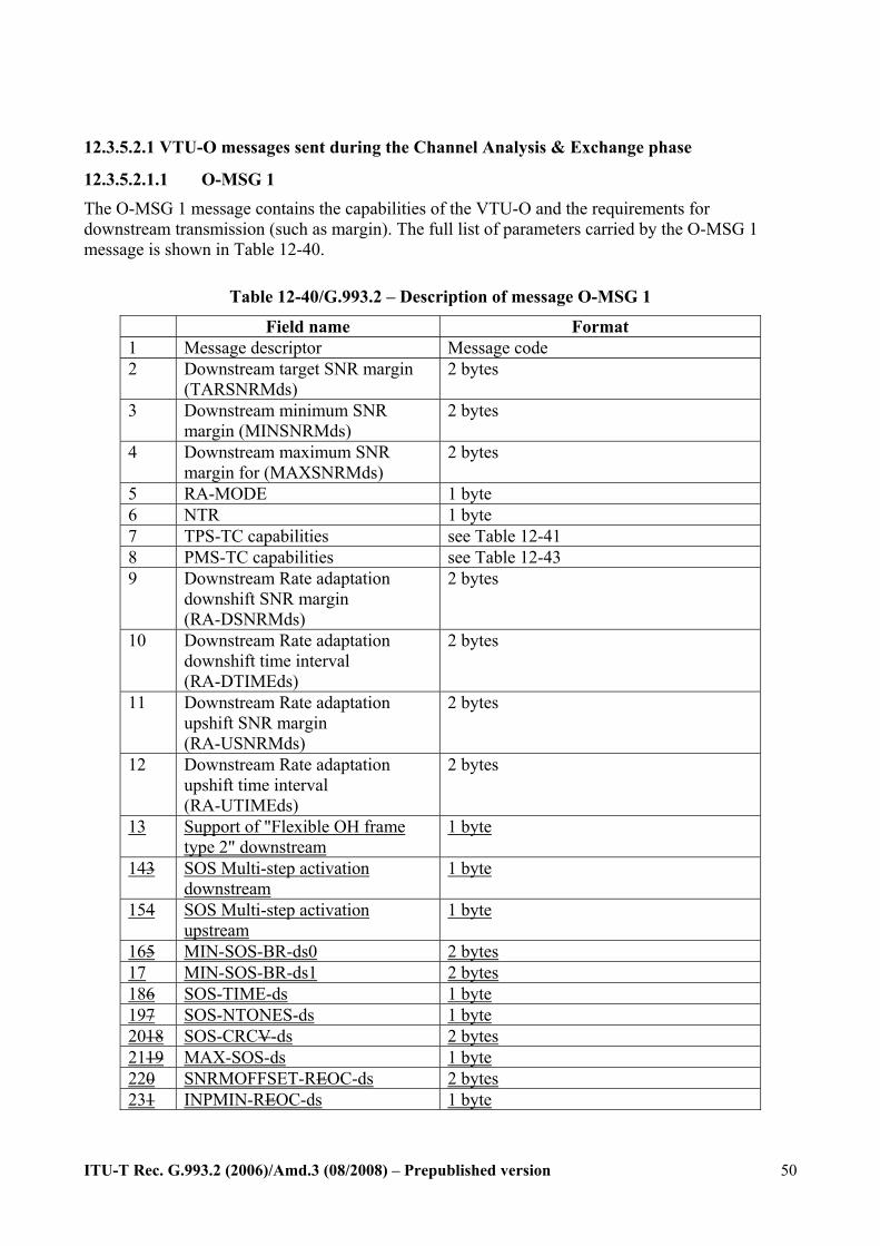
ITU-T Rec. G.993.2 (2006)/Amd.3 (08/2008) – Prepublished version
50
12.3.5.2.1 VTU-O messages sent during the Channel Analysis & Exchange phase
12.3.5.2.1.1 O-MSG 1 The O-MSG 1 message contains the capabilities of the VTU-O and the requirements for downstream transmission (such as margin). The full list of parameters carried by the O-MSG 1 message is shown in Table 12-40.
Table 12-40/G.993.2 – Description of message O-MSG 1
Field name Format 1 Message descriptor Message code 2 Downstream target SNR margin
(TARSNRMds) 2 bytes
3 Downstream minimum SNR margin (MINSNRMds)
2 bytes
4 Downstream maximum SNR margin for (MAXSNRMds)
2 bytes
5 RA-MODE 1 byte 6 NTR 1 byte 7 TPS-TC capabilities see Table 12-41 8 PMS-TC capabilities see Table 12-43 9 Downstream Rate adaptation
downshift SNR margin (RA-DSNRMds)
2 bytes
10 Downstream Rate adaptation downshift time interval (RA-DTIMEds)
2 bytes
11 Downstream Rate adaptation upshift SNR margin (RA-USNRMds)
2 bytes
12 Downstream Rate adaptation upshift time interval (RA-UTIMEds)
2 bytes
13 Support of "Flexible OH frame type 2" downstream
1 byte
143 SOS Multi-step activation downstream
1 byte
154 SOS Multi-step activation upstream
1 byte
165 MIN-SOS-BR-ds0 2 bytes 17 MIN-SOS-BR-ds1 2 bytes 186 SOS-TIME-ds 1 byte 197 SOS-NTONES-ds 1 byte 2018 SOS-CRCV-ds 2 bytes 2119 MAX-SOS-ds 1 byte 220 SNRMOFFSET-REOC-ds 2 bytes 231 INPMIN-REOC-ds 1 byte

ITU-T Rec. G.993.2 (2006)/Amd.3 (08/2008) – Prepublished version
51
Field #1 “Message descriptor” is a unique one-byte code that identifies the message. See Table 12-2 for a complete list of codes.
Field #2 “Downstream target SNR margin (TARSNRMds)” indicates the target SNR margin of the VTU-R receiver. The definition and use of this parameter shall be the same as for the parameter “Downstream Target Noise Margin (TARSNRMds)” specified in ITU-T Recommendation G.997.1 [4]. The value and format of this parameter shall be the same as that in Field #12 of O-SIGNATURE (see §12.3.3.2.1.1).
Field #3 “Downstream minimum SNR margin for (MINSNRMds)” is the minimum SNR margin the VTU-R shall tolerate. The definition and use of this parameter shall be the same as for the parameter “Downstream Minimum Noise Margin (MINSNRMds)” specified in ITU-T Recommendation G.997.1 [4]. The field shall be formatted as a 16-bit unsigned integer with LSB weight of 0.1dB and a valid range between 0 and 31dB.
Field #4 “Downstream maximum SNR margin (MAXSNRMds).” The value and format for this parameter shall be the same as in Field #11 of O-SIGNATURE (see §12.3.3.2.1.1). NOTE – Improper setting of one or more of the following parameters - maximum net data rate, downstream maximum SNR margin, impulse noise protection, maximum interleaving delay (in SNRM_MODE=1), and TXREFVN (in SNRM_MODE= 2) - can result in high levels of transmit power that can lead to high crosstalk experienced by DSLs on other pairs in the same binder. Specifically, high values of maximum net data rate, downstream maximum SNR margin, impulse noise protection, low values of maximum interleaving delay (in SNRM_MODE=1), and high values of TXREFVN (in SNRM_MODE= 2) are of concern.
Field #5 “RA-MODE” specifies the mode of operation of a rate-adaptive VTU-O in the downstream direction as defined in ITU-T Recommendation G.997.1 [4]. This field shall be coded as an 8-bit integer with valid values 0116, 0216, and 0316 and 0416 for RA-MODE 1, 2, and 3, and 4 respectively.
Field #6 “NTR” shall be set to 0116 if the VTU-O is transporting the NTR signal in the downstream direction, otherwise it shall be set to 0016.
Field #7 “TPS-TC capabilities” indicates the TPS-TC capabilities of the VTU-O as shown in Table 12-41.
Field #8 “PMS-TC capabilities” indicates the PMS-TC capabilities of the VTU-O. This includes the supported latency paths at the VTU-O (DS and US) and the capabilities per path (such as supported coding and interleaver parameters), as shown in Table 12-43.
Field #9 “Downstream Rate adaptation downshift SNR margin (RA-DSNRMds)”: The definition and use of this parameter is specified in §13.4. The field shall be formatted as a 16-bit unsigned integer with LSB weight of 0.1 dB and has a valid range between 0 and 31.0 dB.
Field #10 “Downstream Rate adaptation downshift time interval (RA-DTIMEds)”: The definition and use of this parameter is specified in §13.4. The field shall be formatted as a 16-bit unsigned integer with LSB weight of 1 s and has a valid range between 0 to 16383 s.
Field #11 “Downstream Rate adaptation upshift SNR margin (RA-USNRMds)”: The definition and use of this parameter is specified in §13.4. The field shall be formatted as a 16-bit unsigned integer with LSB weight of 0.1 dB and has a valid range between 0 and 31.0 dB.
Field #12 “Downstream Rate adaptation upshift time interval (RA-UTIMEds)”: The definition and use of this parameter is specified in §13.4. The field shall be formatted as a 16-bit unsigned integer with LSB weight of 1 s and has a valid range between 0 to 16383 s.
Field #13 indicates the support by the VTU-O of the "Flexible OH Frame Type 2" in the
ITU-T Rec. G.993.2 (2006)/Amd.3 (08/2008) – Prepublished version
52
downstream direction. The field shall be formatted as [0000 000a]. The VTU-O shall indicate support by setting the LSB of the field to 1. Other bits shall be set to 0 and are reserved by ITU-T.
Field #143 indicates the capabilities of the VTU-O to execute the SOS request in one step or in multiple steps in the downstream direction. The field is formatted as [gggg 0000]. The first four MSBs [gggg] indicate the maximum number of tones (GSOS) that can be executed in a single step (GSOS) in the downstream direction. The valid values are:
- [0000]: All tones - [0010]: GSOS=256 tones - [0011]: GSOS=512 tones - [0100]: GSOS=1024 tones
If SOS is supported, value GSOS = 256 tones is a mandatory capability. If the VTU supports a particular value of GSOS, it shall support all smaller values of GSOS (and values TSOS associated with them, as presented in Table 13-4).
Each GSOS has an value of DTSOS associated with it, where DTSOS is the time (in symbols) between the execution of two successive groups of tones (see §13.3).
If the CO does not support SOS in the downstream direction, this field shall contain a value within the specified valid range. This value shall be ignored at the receiver.
Field #154 indicates the capabilities of the VTU-O to execute the SOS request in one step or in multiple steps in the upstream direction. The format of the field and the valid values shall be the same as for field #143.
If the CO does not support SOS in the upstream direction, this field shall contain a value within the specified valid range. This value shall be ignored at the receiver. If the VTU supports a particular value of GSOS, it shall support all smaller values of GSOS (and values DSOS associated with them, as presented in Table 13-4).
Field #165 Contains the value of the MIN-SOS-BR-ds0 as definedspecified in G.997.1the MIB. The parameter MIN-SOS-BR-ds0 is defined as the minimum bitnet data rate required for a successfulvalid SOS request in the downstream direction (see §13.4) for bearer channel 0. The value shall be coded as an unsigned integer representing the data rate as a multiple of 8 kbit/s.
Field #17 Contains the value of the MIN-SOS-BR-ds1 as specified in the MIB. The parameter MIN-SOS-BR-ds1 is defined as the minimum net data rate required for a valid SOS request in the downstream direction (see §13.4) for bearer channel 1. The value shall be coded as an unsigned integer representing the data rate as a multiple of 8 kbit/s.
When only one bearer channel is supported, the value of Field#16 or Field#17 corresponding to the other bearer channel shall be set to FFFF16. When two bearer channels are supported (as would be the case for dual latency or single latency with two bearer channels mapped into the single latency path) both fields shall contain valid values.
Field #186 Contains the value of the SOS triggering parameter SOS-TIME-ds as definedspecified in G.997.1the MIB. The parameter is used in the specification of the receiver initiated SOS (see §13.4.3). The time window applies to sequential time steps, and not a sliding window. The special value zero, indicates that the standard SOS triggering criteria are disabled. If the value of this parameter is not zero, the standard SOS triggering criteria are enabled, and the value corresponds with duration of the time window used in the standard SOS triggering criteria.If the value of this parameter is not zero, the VTU-R shall comply with the triggering condition given in 13.4.3. If the value of this parameter is zero, the VTU-R may use its proprietary triggering criterion.
ITU-T Rec. G.993.2 (2006)/Amd.3 (08/2008) – Prepublished version
53
The value isshall be coded as an unsigned integer representing the duration of the time windowa time period as a multiple of 64 msec. The valid range of the non-zero values is from 64 to 16320 ms.
Field #197 Contains the value of the SOS triggering parameter SOS-NTONES-ds as definedspecified in G.997.1the MIB. The parameter is used in the specification of the receiver initiated SOS (see §13.4.3). The parameter SOS-NTONES-ds is defined as a percentage of tones.The minimum percentage of tones in the MEDLEY SET that must be degraded throughout the time window SOS-TIME-ds before a SOS may be triggered in the downstream direction. The tones need not be contiguous.
The valid range of values is from 01 to 100 in steps of 1. A special value of 0 indicates that SOS-NTONES-ds is not used in the decision criteria.
Field #2018 Contains the value of the SOS triggering parameter SOS-CRCV-ds as definedspecified in G.997.1the MIB. The parameter is used in the specification of the receiver initiated SOS (see §13.4.3).The error sub-condition is satisfied, if during a time window of SOS-TIME the “count of normalized CRC anomalies” in the downstream direction becomes larger than SOS-CV-ds. The “count of normalized CRC anomalies” shall be incremented by the ∆CRCsecp (the one-second normalized CRC anomaly counter increment, as defined in Table 9-6/G.993.2) for each occurrence of a crc-p anomaly. The valid range of SOS-CRCV-ds values is 0.02 to ((2^16)-1)*0.02, in steps of 0.02.
Field #2119 Contains the value of MAX-SOS-ds as definedspecified in G.997.1the MIB. This parameter contains the maximum allowed number of successful SOS procedures within 120 seconds before the VTU-R shall transition to L3 state (see §12.1.4).A full-initialization shall be performed if more than MAX-SOS recoveries are triggered in the downstream direction within 120 seconds. The valid range of values is from 01 to 15. A special value of 0 indicates that there is no limit on the maximum allowed number of SOS recoveries within this time interval.
If the CO does not support SOS in the downstream direction, the fields #16 to #21 shall contain a value within the specified valid range for each of the parameters. These values shall be ignored at the receiver.
Field #220 contains the value of Noise Margin offset for the SNRMOFFSET-REOCds channel as specified in the MIB. The parameter is defined as the SNR Margin offset for the ROC in the downstream direction. This means that the target margin for the robust eocROC is obtained by adding this value to TARSNRM (i.e., TARSNRM-ROC = TARSNRM + SNRMOFFSET-ROC).
The parameter TARSNRM-ROC is used in the specification of the Channel Initialization Policy (see §12.3.7.1).The VTU-R receiver shall try to achieve this value at initialization. If this margin is not achievable at initialization, the VTU-R shall still complete initialization, only if the Noise Margin on the REOC channel is above TARSNRM.
The value shall be coded as an 16 bit unsigned integer with LSB weight of 0.1 dB. The valid range of values is from 0 to 31 dB with 0.1 dB steps.
Field #231 contains the value of required impulse noise protection for the robust eocINPMIN-ROCds as specified in the MIB. The parameter is defined as the required INP_no_erasure value for the ROC (see §9.6). INPMIN-REOC is an integer in the range offrom 0 to 16.
If the CO does not support a robust overhead channel in the downstream direction, the fields #22 and #23 shall contain a value within the specified valid range for each of the parameters. These values shall be ignored at the receiver.

ITU-T Rec. G.993.2 (2006)/Amd.3 (08/2008) – Prepublished version
54
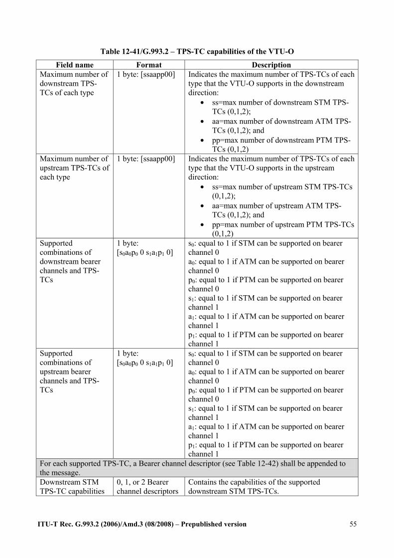
ITU-T Rec. G.993.2 (2006)/Amd.3 (08/2008) – Prepublished version
55
Table 12-41/G.993.2 – TPS-TC capabilities of the VTU-O
Field name Format Description Maximum number of downstream TPS-TCs of each type
1 byte: [ssaapp00]
Indicates the maximum number of TPS-TCs of each type that the VTU-O supports in the downstream direction:
• ss=max number of downstream STM TPS-TCs (0,1,2);
• aa=max number of downstream ATM TPS-TCs (0,1,2); and
• pp=max number of downstream PTM TPS-TCs (0,1,2)
Maximum number of upstream TPS-TCs of each type
1 byte: [ssaapp00]
Indicates the maximum number of TPS-TCs of each type that the VTU-O supports in the upstream direction:
• ss=max number of upstream STM TPS-TCs (0,1,2);
• aa=max number of upstream ATM TPS-TCs (0,1,2); and
• pp=max number of upstream PTM TPS-TCs (0,1,2)
Supported combinations of downstream bearer channels and TPS-TCs
1 byte: [s0a0p0 0 s1a1p1 0]
s0: equal to 1 if STM can be supported on bearer channel 0 a0: equal to 1 if ATM can be supported on bearer channel 0 p0: equal to 1 if PTM can be supported on bearer channel 0 s1: equal to 1 if STM can be supported on bearer channel 1 a1: equal to 1 if ATM can be supported on bearer channel 1 p1: equal to 1 if PTM can be supported on bearer channel 1
Supported combinations of upstream bearer channels and TPS-TCs
1 byte: [s0a0p0 0 s1a1p1 0]
s0: equal to 1 if STM can be supported on bearer channel 0 a0: equal to 1 if ATM can be supported on bearer channel 0 p0: equal to 1 if PTM can be supported on bearer channel 0 s1: equal to 1 if STM can be supported on bearer channel 1 a1: equal to 1 if ATM can be supported on bearer channel 1 p1: equal to 1 if PTM can be supported on bearer channel 1
For each supported TPS-TC, a Bearer channel descriptor (see Table 12-42) shall be appended to the message. Downstream STM TPS-TC capabilities
0, 1, or 2 Bearer channel descriptors
Contains the capabilities of the supported downstream STM TPS-TCs.

ITU-T Rec. G.993.2 (2006)/Amd.3 (08/2008) – Prepublished version
56
Downstream ATM TPS-TC capabilities
0, 1, or 2 Bearer channel descriptors
Contains the capabilities of the supported downstream ATM TPS-TCs.
Downstream PTM TPS-TC capabilities
0, 1, or 2 Bearer channel descriptors
Contains the capabilities of the supported downstream PTM TPS-TCs.
Upstream STM TPS-TC capabilities
0, 1, or 2 Bearer channel descriptors
Contains the capabilities of the supported upstream STM TPS-TCs.
Upstream ATM TPS-TC capabilities
0, 1, or 2 Bearer channel descriptors
Contains the capabilities of the supported upstream ATM TPS-TCs.
Upstream PTM TPS-TC capabilities
0, 1, or 2 Bearer channel descriptors
Contains the capabilities of the supported upstream PTM TPS-TCs.
NOTE – The number of Bearer channel descriptors for the TPS-TC capabilities depends on the fields “Maximum number of downstream/upstream TPS-TCs.”
Table 12-42/G.993.2 – Bearer channel descriptor
Octet Content of field 1-2 Minimum net data rate (net_minn) 3-4 Maximum net data rate (net_maxn) 5-6 Reserved net data rate (net_reserven) (NOTE) 7 Maximum interleaving delay 8 Impulse noise protection and dynamic interleaver
reconfiguration 9 TPS-TC options NOTE – This parameter is not used in this version of G.993.2 and shall be set to the value of the minimum net data rate in octets 1 and 2. The OLR procedures that utilize this parameter will be defined in a future revision of G.993.2.
In the fields “Minimum net data rate”, “Maximum net data rate” and “Reserved net data rate”, the parameter values for net_minn, net_maxn and net_reserven, respectively, shall be coded as unsigned integers representing the data rate as a multiple of 8 kbit/s.
The fields “Maximum interleaving delay” and “Impulse noise protection” are not applicable in O-MSG 1 (which communicates capabilities), and the values of octets 7 and 8 in each Bearer channel descriptor shall be ignored by the VTU-R receiver.
The field “TPS-TC options” shall contain one octet to negotiate and select the options for this bearer. The content depends on the type of TPS-TC mapped on this bearer.
For a bearer mapped to a PTM TPS-TC, the octet shall be coded as follows:
Bit 0: If the VTU-O supports pre-emption in this bearer (Annex N.3.2.1/G.992.3 [10]), the bit shall be set to ONE.
Bit 1: If the VTU-O supports short packets in this bearer (Annex N.3.2.2/G.992.3 [10]), the bit shall be set to ONE.
Bits 2-7 are reserved by the ITU-T and set to ZERO.
For a bearer mapped to an ATM or STM TPS-TC, the TPS-TC options field is reserved by the ITU-T and shall be set to 0016.
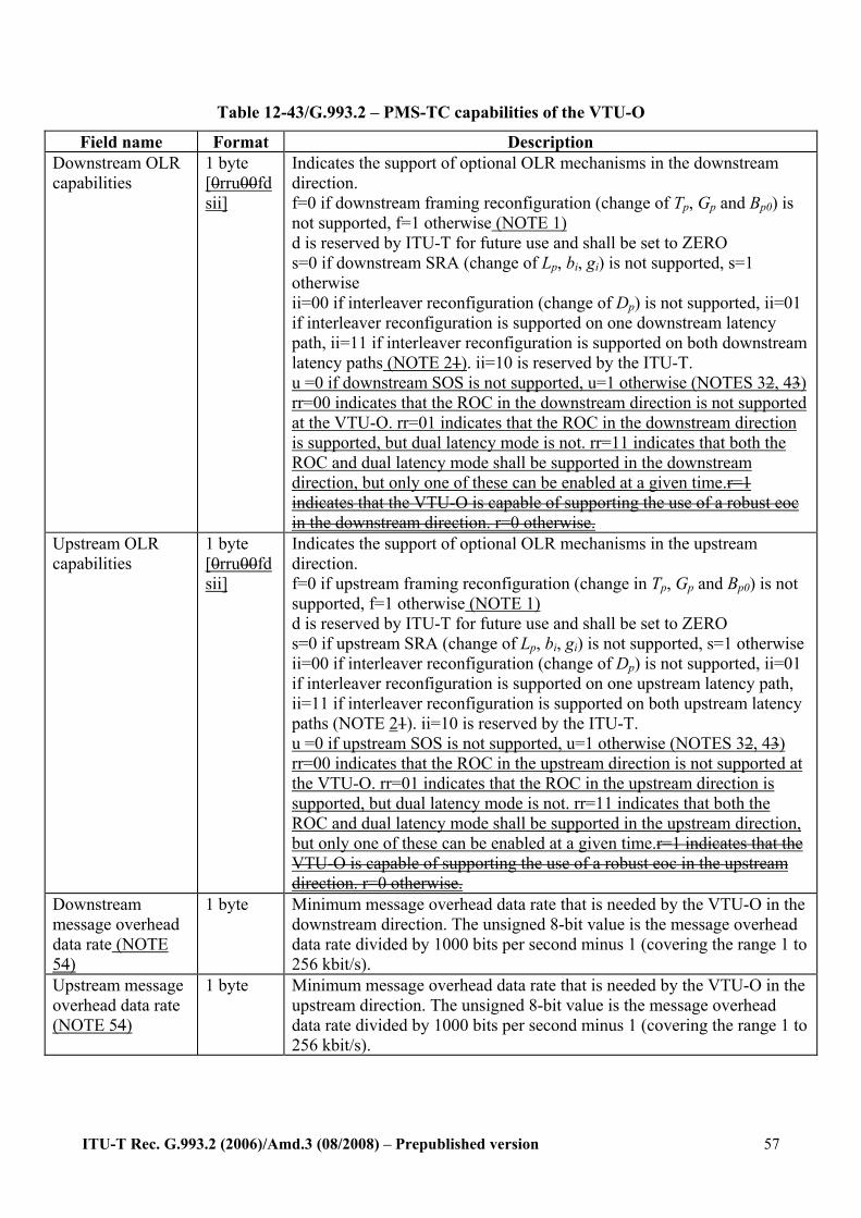
ITU-T Rec. G.993.2 (2006)/Amd.3 (08/2008) – Prepublished version
57
Table 12-43/G.993.2 – PMS-TC capabilities of the VTU-O
Field name Format Description Downstream OLR capabilities
1 byte [0rru00fdsii]
Indicates the support of optional OLR mechanisms in the downstream direction. f=0 if downstream framing reconfiguration (change of Tp, Gp and Bp0) is not supported, f=1 otherwise (NOTE 1) d is reserved by ITU-T for future use and shall be set to ZERO s=0 if downstream SRA (change of Lp, bi, gi) is not supported, s=1 otherwise ii=00 if interleaver reconfiguration (change of Dp) is not supported, ii=01 if interleaver reconfiguration is supported on one downstream latency path, ii=11 if interleaver reconfiguration is supported on both downstream latency paths (NOTE 21). ii=10 is reserved by the ITU-T. u =0 if downstream SOS is not supported, u=1 otherwise (NOTES 32, 43) rr=00 indicates that the ROC in the downstream direction is not supported at the VTU-O. rr=01 indicates that the ROC in the downstream direction is supported, but dual latency mode is not. rr=11 indicates that both the ROC and dual latency mode shall be supported in the downstream direction, but only one of these can be enabled at a given time.r=1 indicates that the VTU-O is capable of supporting the use of a robust eoc in the downstream direction. r=0 otherwise.
Upstream OLR capabilities
1 byte [0rru00fdsii]
Indicates the support of optional OLR mechanisms in the upstream direction. f=0 if upstream framing reconfiguration (change in Tp, Gp and Bp0) is not supported, f=1 otherwise (NOTE 1) d is reserved by ITU-T for future use and shall be set to ZERO s=0 if upstream SRA (change of Lp, bi, gi) is not supported, s=1 otherwise ii=00 if interleaver reconfiguration (change of Dp) is not supported, ii=01 if interleaver reconfiguration is supported on one upstream latency path, ii=11 if interleaver reconfiguration is supported on both upstream latency paths (NOTE 21). ii=10 is reserved by the ITU-T. u =0 if upstream SOS is not supported, u=1 otherwise (NOTES 32, 43) rr=00 indicates that the ROC in the upstream direction is not supported at the VTU-O. rr=01 indicates that the ROC in the upstream direction is supported, but dual latency mode is not. rr=11 indicates that both the ROC and dual latency mode shall be supported in the upstream direction, but only one of these can be enabled at a given time.r=1 indicates that the VTU-O is capable of supporting the use of a robust eoc in the upstream direction. r=0 otherwise.
Downstream message overhead data rate (NOTE 54)
1 byte Minimum message overhead data rate that is needed by the VTU-O in the downstream direction. The unsigned 8-bit value is the message overhead data rate divided by 1000 bits per second minus 1 (covering the range 1 to 256 kbit/s).
Upstream message overhead data rate (NOTE 54)
1 byte Minimum message overhead data rate that is needed by the VTU-O in the upstream direction. The unsigned 8-bit value is the message overhead data rate divided by 1000 bits per second minus 1 (covering the range 1 to 256 kbit/s).
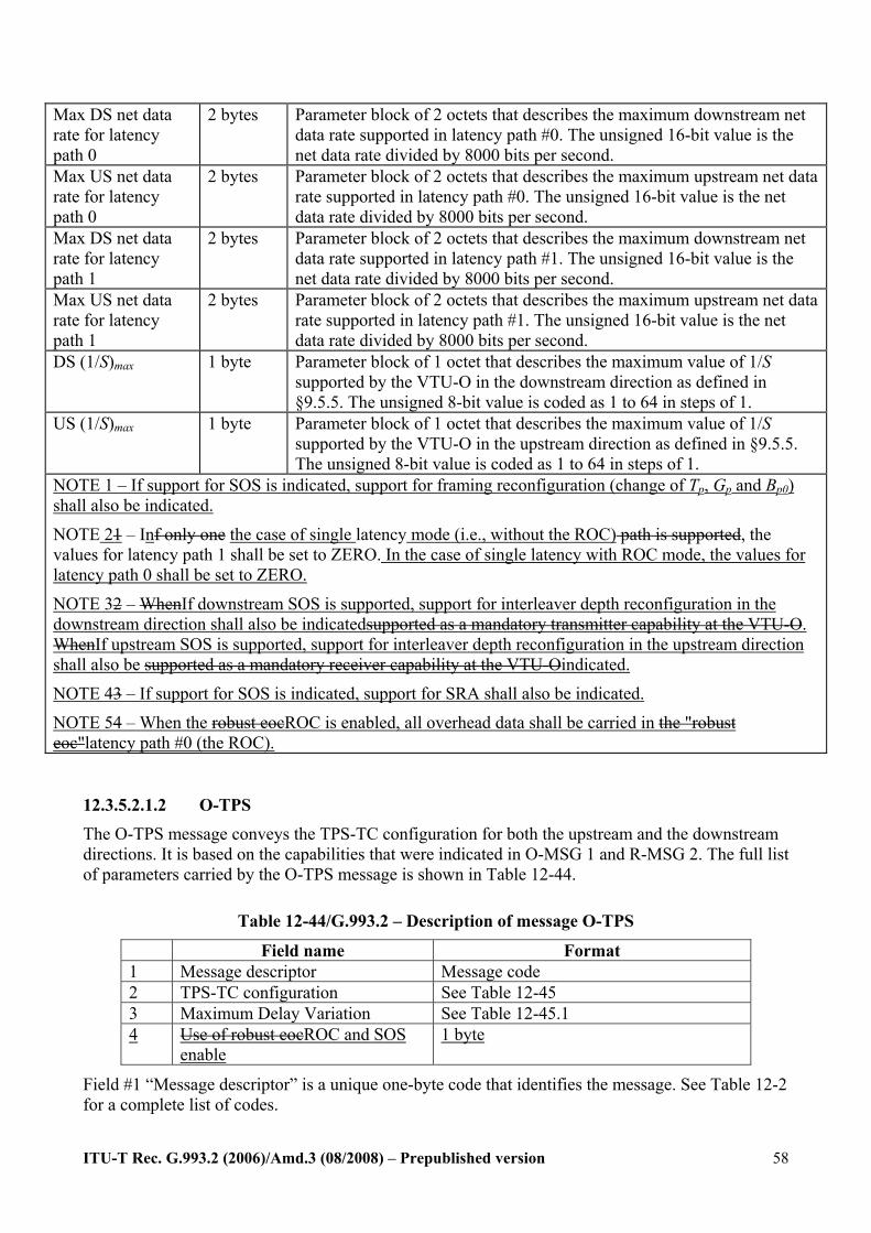
ITU-T Rec. G.993.2 (2006)/Amd.3 (08/2008) – Prepublished version
58
Max DS net data rate for latency path 0
2 bytes Parameter block of 2 octets that describes the maximum downstream net data rate supported in latency path #0. The unsigned 16-bit value is the net data rate divided by 8000 bits per second.
Max US net data rate for latency path 0
2 bytes Parameter block of 2 octets that describes the maximum upstream net data rate supported in latency path #0. The unsigned 16-bit value is the net data rate divided by 8000 bits per second.
Max DS net data rate for latency path 1
2 bytes Parameter block of 2 octets that describes the maximum downstream net data rate supported in latency path #1. The unsigned 16-bit value is the net data rate divided by 8000 bits per second.
Max US net data rate for latency path 1
2 bytes Parameter block of 2 octets that describes the maximum upstream net data rate supported in latency path #1. The unsigned 16-bit value is the net data rate divided by 8000 bits per second.
DS (1/S)max 1 byte Parameter block of 1 octet that describes the maximum value of 1/S supported by the VTU-O in the downstream direction as defined in §9.5.5. The unsigned 8-bit value is coded as 1 to 64 in steps of 1.
US (1/S)max 1 byte Parameter block of 1 octet that describes the maximum value of 1/S supported by the VTU-O in the upstream direction as defined in §9.5.5. The unsigned 8-bit value is coded as 1 to 64 in steps of 1.
NOTE 1 – If support for SOS is indicated, support for framing reconfiguration (change of Tp, Gp and Bp0) shall also be indicated.
NOTE 21 – Inf only one the case of single latency mode (i.e., without the ROC) path is supported, the values for latency path 1 shall be set to ZERO. In the case of single latency with ROC mode, the values for latency path 0 shall be set to ZERO.
NOTE 32 – WhenIf downstream SOS is supported, support for interleaver depth reconfiguration in the downstream direction shall also be indicatedsupported as a mandatory transmitter capability at the VTU-O. WhenIf upstream SOS is supported, support for interleaver depth reconfiguration in the upstream direction shall also be supported as a mandatory receiver capability at the VTU-Oindicated.
NOTE 43 – If support for SOS is indicated, support for SRA shall also be indicated.
NOTE 54 – When the robust eocROC is enabled, all overhead data shall be carried in the "robust eoc"latency path #0 (the ROC).
12.3.5.2.1.2 O-TPS
The O-TPS message conveys the TPS-TC configuration for both the upstream and the downstream directions. It is based on the capabilities that were indicated in O-MSG 1 and R-MSG 2. The full list of parameters carried by the O-TPS message is shown in Table 12-44.
Table 12-44/G.993.2 – Description of message O-TPS
Field name Format 1 Message descriptor Message code 2 TPS-TC configuration See Table 12-45 3 Maximum Delay Variation See Table 12-45.1 4 Use of robust eocROC and SOS
enable 1 byte
Field #1 “Message descriptor” is a unique one-byte code that identifies the message. See Table 12-2 for a complete list of codes.

ITU-T Rec. G.993.2 (2006)/Amd.3 (08/2008) – Prepublished version
59
Field #2 “TPS-TC configuration” specifies the TPS-TC configuration in the upstream and downstream directions, and is structured as shown in Table 12-45.
Field #3 “Maximum delay variation” specifies the maximum delay variation for each active bearer channel in the downstream direction, and is structured as shown in Table 12-45.1.
Field #4 indicates whether the robust eocROC and SOS shall be usedare enabled. It is a one byte value [ssss rrrr].
The value rrrr isshall be coded as follows: - A value rrrr=0000 indicates that the ROC is not enabled in either upstream or downstream. A value rrrr=0011 indicates that the robust eoc shall be enabled in both upstream and
downstream. - A value rrrr=0001 indicates that the robust eocROC shall beis enabled in upstream but not in
downstream. - A value rrrr=0010 indicates that the robust eocROC shall beis enabled in downstream but
not in upstream. - A value rrrr=0011 indicates that the ROC is enabled in both upstream and downstream. A value rrrr=0000 indicates that the robust eoc is not used in either upstream or
downstream.
The value ssss isshall be coded as follows: - A value ssss=0000 indicates that SOS shallis not be usedenabled. - A value ssss=0001 indicates that SOS may be usedis enabled in upstream but not in
downstream. - A value ssss=0010 indicates that SOS may be usedis enabled in downstream but not in
upstream. - A value ssss=0011 indicates that SOS may be usedis enabled in both upstream and
downstream.
The value of ssss shall be set in accordance with G.997.1 parameters RA-MODEds and RA-MODEus and the OLR capabilities in O-MSG 1 and R-MSG 2.

ITU-T Rec. G.993.2 (2006)/Amd.3 (08/2008) – Prepublished version
60
Table 12-45/G.993.2 – TPS-TC configuration
Field name Format Description Mapped configurations of downstream bearer channels and TPS-TC types (NOTE 1)
1 byte: [aaaa bbbb] aaaa = TPS-TC type that is mapped to DS bearer channel 0 aaaa=1000: STM-TC aaaa=0100: ATM-TC aaaa=0010: PTM-TC aaaa =0000: inactive bearer channel bbbb = TPS-TC type that is mapped to DS bearer channel 1 bbbb =1000: STM-TC bbbb =0100: ATM-TC bbbb =0010: PTM-TC bbbb =0000: inactive bearer channel
Mapped configurations of upstream bearer channels and TPS-TC types (NOTE 1)
1 byte: [cccc dddd]
cccc = TPS-TC type that is mapped to US bearer channel 0 cccc =1000: STM-TC cccc =0100: ATM-TC cccc =0010: PTM-TC cccc =0000: inactive bearer channel dddd = TPS-TC type that is mapped to US bearer channel 1 dddd =1000: STM-TC dddd =0100: ATM-TC dddd =0010: PTM-TC dddd =0000: inactive bearer channel
Downstream rate adaptation ratio
1 byte This field contains the rate adaptation ratio of downstream bearer channel 0 as specified in G.997.1 [4]. This field shall be coded as an unsigned integer in the range from 0 to 100. A value of 100 means that the whole excess capacity is allocated to bearer channel 0.
For each active bearer channel in each direction, a Bearer channel descriptor (see Table 12-42) shall be appended to the message: Downstream bearer channel 0 configuration
0, or 1 Bearer channel descriptor
Contains the required configuration of the downstream bearer 0
Downstream bearer channel 1 configuration
0, or 1 Bearer channel descriptor
Contains the required configuration of the downstream bearer 1
Upstream bearer channel 0 configuration
0, or 1 Bearer channel descriptor
Contains the required configuration of the upstream bearer 0
Upstream bearer channel 1 configuration
0 or 1 Bearer channel descriptor
Contains the required configuration of the upstream bearer 1
NOTE 1: Some simultaneous mappings of TPS-TCs are invalid (see §8.1.3.1). NOTE 2: The number of Bearer channel descriptors for the bearer channel configurations depends on the number of active bearer channels in each direction.
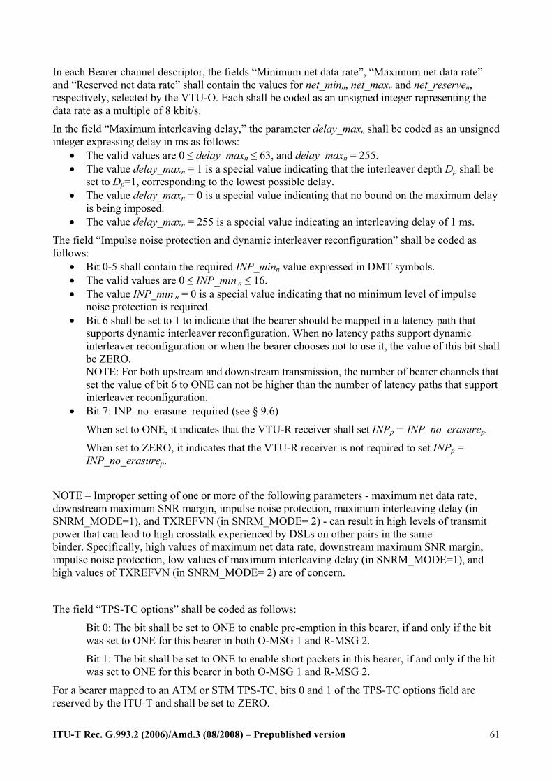
ITU-T Rec. G.993.2 (2006)/Amd.3 (08/2008) – Prepublished version
61
In each Bearer channel descriptor, the fields “Minimum net data rate”, “Maximum net data rate” and “Reserved net data rate” shall contain the values for net_minn, net_maxn and net_reserven, respectively, selected by the VTU-O. Each shall be coded as an unsigned integer representing the data rate as a multiple of 8 kbit/s.
In the field “Maximum interleaving delay,” the parameter delay_maxn shall be coded as an unsigned integer expressing delay in ms as follows:
• The valid values are 0 ≤ delay_maxn ≤ 63, and delay_maxn = 255. • The value delay_maxn = 1 is a special value indicating that the interleaver depth Dp shall be
set to Dp=1, corresponding to the lowest possible delay. • The value delay_maxn = 0 is a special value indicating that no bound on the maximum delay
is being imposed. • The value delay_maxn = 255 is a special value indicating an interleaving delay of 1 ms.
The field “Impulse noise protection and dynamic interleaver reconfiguration” shall be coded as follows:
• Bit 0-5 shall contain the required INP_minn value expressed in DMT symbols. • The valid values are 0 ≤ INP_min n ≤ 16. • The value INP_min n = 0 is a special value indicating that no minimum level of impulse
noise protection is required. • Bit 6 shall be set to 1 to indicate that the bearer should be mapped in a latency path that
supports dynamic interleaver reconfiguration. When no latency paths support dynamic interleaver reconfiguration or when the bearer chooses not to use it, the value of this bit shall be ZERO. NOTE: For both upstream and downstream transmission, the number of bearer channels that set the value of bit 6 to ONE can not be higher than the number of latency paths that support interleaver reconfiguration.
• Bit 7: INP_no_erasure_required (see § 9.6)
When set to ONE, it indicates that the VTU-R receiver shall set INPp = INP_no_erasurep.
When set to ZERO, it indicates that the VTU-R receiver is not required to set INPp = INP_no_erasurep.
NOTE – Improper setting of one or more of the following parameters - maximum net data rate, downstream maximum SNR margin, impulse noise protection, maximum interleaving delay (in SNRM_MODE=1), and TXREFVN (in SNRM_MODE= 2) - can result in high levels of transmit power that can lead to high crosstalk experienced by DSLs on other pairs in the same binder. Specifically, high values of maximum net data rate, downstream maximum SNR margin, impulse noise protection, low values of maximum interleaving delay (in SNRM_MODE=1), and high values of TXREFVN (in SNRM_MODE= 2) are of concern.
The field “TPS-TC options” shall be coded as follows:
Bit 0: The bit shall be set to ONE to enable pre-emption in this bearer, if and only if the bit was set to ONE for this bearer in both O-MSG 1 and R-MSG 2.
Bit 1: The bit shall be set to ONE to enable short packets in this bearer, if and only if the bit was set to ONE for this bearer in both O-MSG 1 and R-MSG 2.
For a bearer mapped to an ATM or STM TPS-TC, bits 0 and 1 of the TPS-TC options field are reserved by the ITU-T and shall be set to ZERO.
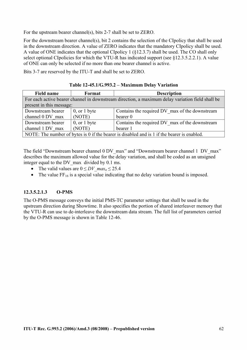
ITU-T Rec. G.993.2 (2006)/Amd.3 (08/2008) – Prepublished version
62
For the upstream bearer channel(s), bits 2-7 shall be set to ZERO.
For the downstream bearer channel(s), bit 2 contains the selection of the CIpolicy that shall be used in the downstream direction. A value of ZERO indicates that the mandatory CIpolicy shall be used. A value of ONE indicates that the optional CIpolicy 1 (§12.3.7) shall be used. The CO shall only select optional CIpolicies for which the VTU-R has indicated support (see §12.3.5.2.2.1). A value of ONE can only be selected if no more than one bearer channel is active.
Bits 3-7 are reserved by the ITU-T and shall be set to ZERO.
Table 12-45.1/G.993.2 – Maximum Delay Variation
Field name Format Description For each active bearer channel in downstream direction, a maximum delay variation field shall be present in this message: Downstream bearer channel 0 DV_max
0, or 1 byte (NOTE)
Contains the required DV_max of the downstream bearer 0
Downstream bearer channel 1 DV_max
0, or 1 byte (NOTE)
Contains the required DV_max of the downstream bearer 1
NOTE: The number of bytes is 0 if the bearer is disabled and is 1 if the bearer is enabled.
The field “Downstream bearer channel 0 DV_max” and “Downstream bearer channel 1 DV_max” describes the maximum allowed value for the delay variation, and shall be coded as an unsigned integer equal to the DV_max divided by 0.1 ms.
• The valid values are 0 ≤ DV_maxn ≤ 25.4 • The value FF16 is a special value indicating that no delay variation bound is imposed.
12.3.5.2.1.3 O-PMS The O-PMS message conveys the initial PMS-TC parameter settings that shall be used in the upstream direction during Showtime. It also specifies the portion of shared interleaver memory that the VTU-R can use to de-interleave the downstream data stream. The full list of parameters carried by the O-PMS message is shown in Table 12-46.
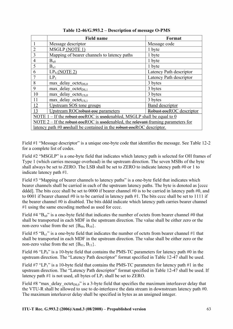
ITU-T Rec. G.993.2 (2006)/Amd.3 (08/2008) – Prepublished version
63
Table 12-46/G.993.2 – Description of message O-PMS
Field name Format 1 Message descriptor Message code 2 MSGLP (NOTE 1) 1 byte 3 Mapping of bearer channels to latency paths 1 byte 4 Bx0 1 byte 5 Bx1 1 byte 6 LP0 (NOTE 2) Latency Path descriptor 7 LP1 Latency Path descriptor 8 max_delay_octetDS,0 3 bytes 9 max_delay_octetDS,1 3 bytes 10 max_delay_octetUS,0 3 bytes 11 max_delay_octetUS,1 3 bytes 12 Upstream SOS tone groups Band descriptor 13 Upstream ROCrobust eoc parameters Robust eocROC descriptor NOTE 1 – If the robust eocROC is usedenabled, MSGLP shall be equal to 0 NOTE 2 – If the robust eocROC is usedenabled, the relevant framing parameters for latency path #0 areshall be contained in the robust eocROC descriptor.
Field #1 “Message descriptor” is a unique one-byte code that identifies the message. See Table 12-2 for a complete list of codes.
Field #2 “MSGLP” is a one-byte field that indicates which latency path is selected for OH frames of Type 1 (which carries message overhead) in the upstream direction. The seven MSBs of the byte shall always be set to ZERO. The LSB shall be set to ZERO to indicate latency path #0 or 1 to indicate latency path #1.
Field #3 “Mapping of bearer channels to latency paths” is a one-byte field that indicates which bearer channels shall be carried in each of the upstream latency paths. The byte is denoted as [cccc dddd]. The bits cccc shall be set to 0000 if bearer channel #0 is to be carried in latency path #0, and to 0001 if bearer channel #0 is to be carried in latency path #1. The bits cccc shall be set to 1111 if the bearer channel #0 is disabled. The bits dddd indicate which latency path carries bearer channel #1 using the same encoding method as used for cccc.
Field #4 “Bx0” is a one-byte field that indicates the number of octets from bearer channel #0 that shall be transported in each MDF in the upstream direction. The value shall be either zero or the non-zero value from the set B00, B10.
Field #5 “Bx1” is a one-byte field that indicates the number of octets from bearer channel #1 that shall be transported in each MDF in the upstream direction. The value shall be either zero or the non-zero value from the set B01, B11.
Field #6 “LP0” is a 10-byte field that contains the PMS-TC parameters for latency path #0 in the upstream direction. The “Latency Path descriptor” format specified in Table 12-47 shall be used.
Field #7 “LP1” is a 10-byte field that contains the PMS-TC parameters for latency path #1 in the upstream direction. The “Latency Path descriptor” format specified in Table 12-47 shall be used. If latency path #1 is not used, all bytes of LP1 shall be set to ZERO.
Field #8 “max_delay_octetDS,0” is a 3-byte field that specifies the maximum interleaver delay that the VTU-R shall be allowed to use to de-interleave the data stream in downstream latency path #0. The maximum interleaver delay shall be specified in bytes as an unsigned integer.
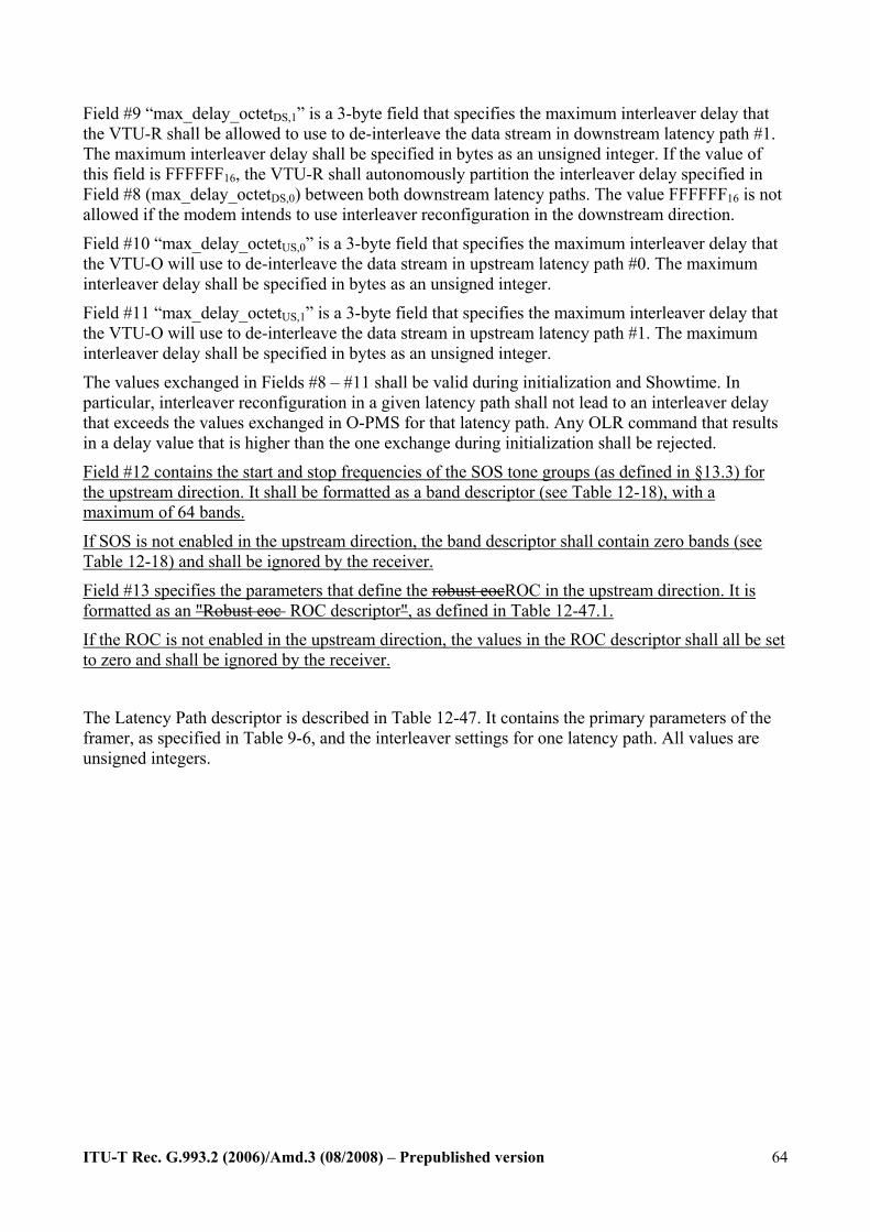
ITU-T Rec. G.993.2 (2006)/Amd.3 (08/2008) – Prepublished version
64
Field #9 “max_delay_octetDS,1” is a 3-byte field that specifies the maximum interleaver delay that the VTU-R shall be allowed to use to de-interleave the data stream in downstream latency path #1. The maximum interleaver delay shall be specified in bytes as an unsigned integer. If the value of this field is FFFFFF16, the VTU-R shall autonomously partition the interleaver delay specified in Field #8 (max_delay_octetDS,0) between both downstream latency paths. The value FFFFFF16 is not allowed if the modem intends to use interleaver reconfiguration in the downstream direction.
Field #10 “max_delay_octetUS,0” is a 3-byte field that specifies the maximum interleaver delay that the VTU-O will use to de-interleave the data stream in upstream latency path #0. The maximum interleaver delay shall be specified in bytes as an unsigned integer.
Field #11 “max_delay_octetUS,1” is a 3-byte field that specifies the maximum interleaver delay that the VTU-O will use to de-interleave the data stream in upstream latency path #1. The maximum interleaver delay shall be specified in bytes as an unsigned integer.
The values exchanged in Fields #8 – #11 shall be valid during initialization and Showtime. In particular, interleaver reconfiguration in a given latency path shall not lead to an interleaver delay that exceeds the values exchanged in O-PMS for that latency path. Any OLR command that results in a delay value that is higher than the one exchange during initialization shall be rejected.
Field #12 contains the start and stop frequencies of the SOS tone groups (as defined in §13.3) for the upstream direction. It shall be formatted as a band descriptor (see Table 12-18), with a maximum of 64 bands.
If SOS is not enabled in the upstream direction, the band descriptor shall contain zero bands (see Table 12-18) and shall be ignored by the receiver.
Field #13 specifies the parameters that define the robust eocROC in the upstream direction. It is formatted as an "Robust eoc ROC descriptor", as defined in Table 12-47.1.
If the ROC is not enabled in the upstream direction, the values in the ROC descriptor shall all be set to zero and shall be ignored by the receiver.
The Latency Path descriptor is described in Table 12-47. It contains the primary parameters of the framer, as specified in Table 9-6, and the interleaver settings for one latency path. All values are unsigned integers.
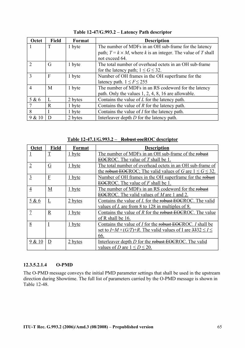
ITU-T Rec. G.993.2 (2006)/Amd.3 (08/2008) – Prepublished version
65
Table 12-47/G.993.2 – Latency Path descriptor
Octet Field Format Description 1 T 1 byte The number of MDFs in an OH sub-frame for the latency
path; T = k × M, where k is an integer. The value of T shall not exceed 64.
2 G 1 byte The total number of overhead octets in an OH sub-frame for the latency path; 1 ≤ G ≤ 32.
3 F 1 byte Number of OH frames in the OH superframe for the latency path. 1 ≤ F ≤ 255
4 M 1 byte The number of MDFs in an RS codeword for the latency path. Only the values 1, 2, 4, 8, 16 are allowable.
5 & 6 L 2 bytes Contains the value of L for the latency path. 7 R 1 byte Contains the value of R for the latency path. 8 I 1 byte Contains the value of I for the latency path. 9 & 10 D 2 bytes Interleaver depth D for the latency path.
Table 12-47.1/G.993.2 – _Robust eocROC descriptor
Octet Field Format Description 1 T 1 byte The number of MDFs in an OH sub-frame of the robust
EOCROC. The value of T shall be 1. 2 G 1 byte The total number of overhead octets in an OH sub-frame of
the robust EOCROC; The valid values of G are 1 ≤ G ≤ 32. 3 F 1 byte Number of OH frames in the OH superframe for the robust
EOCROC. The value of F shall be 1. 4 M 1 byte The number of MDFs in an RS codeword for the robust
EOCROC. The valid values of M are 1 and 2. 5 & 6 L 2 bytes Contains the value of L for the robust EOCROC. The valid
values of L are from 8 to 128 in multiples of 8. 7 R 1 byte Contains the value of R for the robust EOCROC. The value
of R shall be 16. 8 I 1 byte Contains the value of I for the robust EOCROC. I shall be
set to I=M ×(G/T)+R. The valid values of I are 3332 ≤ I ≤ 66.
9 & 10 D 2 bytes Interleaver depth D for the robust EOCROC. The valid values of D are 1 ≤ D ≤ 20.
12.3.5.2.1.4 O-PMD The O-PMD message conveys the initial PMD parameter settings that shall be used in the upstream direction during Showtime. The full list of parameters carried by the O-PMD message is shown in Table 12-48.
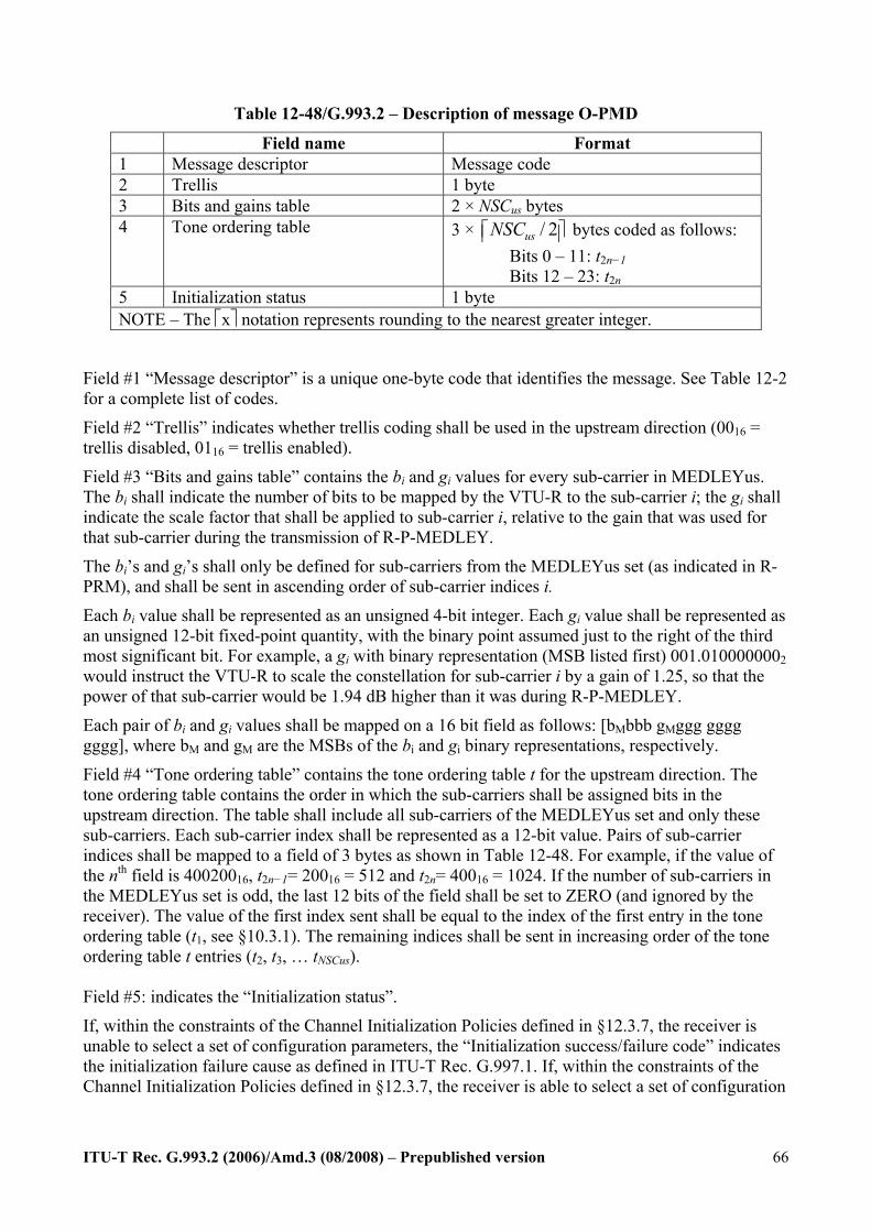
ITU-T Rec. G.993.2 (2006)/Amd.3 (08/2008) – Prepublished version
66
Table 12-48/G.993.2 – Description of message O-PMD
Field name Format 1 Message descriptor Message code 2 Trellis 1 byte 3 Bits and gains table 2 × NSCus bytes 4 Tone ordering table 3 × / 2usNSC⎡ ⎤⎢ ⎥ bytes coded as follows:
Bits 0 – 11: t2n−1 Bits 12 – 23: t2n
5 Initialization status 1 byte NOTE – The ⎡x⎤ notation represents rounding to the nearest greater integer.
Field #1 “Message descriptor” is a unique one-byte code that identifies the message. See Table 12-2 for a complete list of codes.
Field #2 “Trellis” indicates whether trellis coding shall be used in the upstream direction (0016 = trellis disabled, 0116 = trellis enabled).
Field #3 “Bits and gains table” contains the bi and gi values for every sub-carrier in MEDLEYus. The bi shall indicate the number of bits to be mapped by the VTU-R to the sub-carrier i; the gi shall indicate the scale factor that shall be applied to sub-carrier i, relative to the gain that was used for that sub-carrier during the transmission of R-P-MEDLEY.
The bi’s and gi’s shall only be defined for sub-carriers from the MEDLEYus set (as indicated in R-PRM), and shall be sent in ascending order of sub-carrier indices i.
Each bi value shall be represented as an unsigned 4-bit integer. Each gi value shall be represented as an unsigned 12-bit fixed-point quantity, with the binary point assumed just to the right of the third most significant bit. For example, a gi with binary representation (MSB listed first) 001.0100000002 would instruct the VTU-R to scale the constellation for sub-carrier i by a gain of 1.25, so that the power of that sub-carrier would be 1.94 dB higher than it was during R-P-MEDLEY.
Each pair of bi and gi values shall be mapped on a 16 bit field as follows: [bMbbb gMggg gggg gggg], where bM and gM are the MSBs of the bi and gi binary representations, respectively.
Field #4 “Tone ordering table” contains the tone ordering table t for the upstream direction. The tone ordering table contains the order in which the sub-carriers shall be assigned bits in the upstream direction. The table shall include all sub-carriers of the MEDLEYus set and only these sub-carriers. Each sub-carrier index shall be represented as a 12-bit value. Pairs of sub-carrier indices shall be mapped to a field of 3 bytes as shown in Table 12-48. For example, if the value of the nth field is 40020016, t2n−1= 20016 = 512 and t2n= 40016 = 1024. If the number of sub-carriers in the MEDLEYus set is odd, the last 12 bits of the field shall be set to ZERO (and ignored by the receiver). The value of the first index sent shall be equal to the index of the first entry in the tone ordering table (t1, see §10.3.1). The remaining indices shall be sent in increasing order of the tone ordering table t entries (t2, t3, … tNSCus). Field #5: indicates the “Initialization status”.
If, within the constraints of the Channel Initialization Policies defined in §12.3.7, the receiver is unable to select a set of configuration parameters, the “Initialization success/failure code” indicates the initialization failure cause as defined in ITU-T Rec. G.997.1. If, within the constraints of the Channel Initialization Policies defined in §12.3.7, the receiver is able to select a set of configuration

ITU-T Rec. G.993.2 (2006)/Amd.3 (08/2008) – Prepublished version
67
parameters, the “Initialization success/failure code” indicates the initialization success. Valid Initialization success/failure codes are as follows:
8016: initialization success 8116: configuration error 8216: configuration not feasible on line 0016: feature not supported
Other values are reserved by the ITU-T.
If an initialization success/failure code 8116 or 8216 is set:
• all values in Field #2 to 4 shall be set to 0, and
• the VTU-O shall return to L3 link state instead of L0 link state at the completion of the initialization procedures.
12.3.5.2.2 VTU-R messages sent during the Channel Analysis & Exchange phase
12.3.5.2.2.1 R-MSG 2 The R-MSG 2 message conveys VTU-R information to the VTU-O. The full list of parameters carried by the R-MSG 2 message is shown in Table 12-49.
Table 12-49/G.993.2 – Description of message R-MSG 2
Field name Format 1 Message descriptor Message code 2 TPS-TC capabilities See Table 12-50 3 PMS-TC capabilities See Table 12-51 4 Support of "Flexible OH frame
type 2" upstream 1 byte
54 SOS Multi-step activation downstream
1 byte
65 SOS Multi-step activation upstream
1 byte
Field #1 “Message descriptor” is a unique one-byte code that identifies the message. See Table 12-2 for a complete list of codes.
Field #2 “TPS-TC capabilities” indicates the TPS-TC capabilities of the VTU-R, as shown in Table 12-50.
Field #3 “PMS-TC capabilities” indicates the PMS-TC capabilities of the VTU-R. This includes the supported latency paths at the VTU-R (DS and US) and the capabilities per path (such as supported coding and interleaver parameters), as shown in Table 12-51.
Field #4 indicates the support by the VTU-R of the "Flexible OH Frame Type 2" in the downstream direction. The field shall be formatted as [0000 000a]. The VTU-R shall indicate support by setting the LSB of the field to 1. Other bits shall be set to 0 and are reserved by ITU-T.
Field #54 indicates the capabilities of the VTU-R to execute the SOS request in one step or in multiple steps in the downstream direction. The field is formatted as [gggg 0000]. The first four MSBs [gggg] indicate the maximum number of tones (GSOS) that can be executed in a single step (GSOS)in the downstream direction. The valid values are:
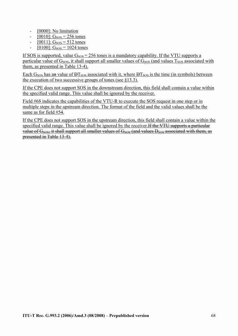
ITU-T Rec. G.993.2 (2006)/Amd.3 (08/2008) – Prepublished version
68
- [0000]: No limitation - [0010]: GSOS = 256 tones - [0011]: GSOS = 512 tones - [0100]: GSOS = 1024 tones
If SOS is supported, value GSOS = 256 tones is a mandatory capability. If the VTU supports a particular value of GSOS, it shall support all smaller values of GSOS (and values TSOS associated with them, as presented in Table 13-4).
Each GSOS has an value of DTSOS associated with it, where DTSOS is the time (in symbols) between the execution of two successive groups of tones (see §13.3).
If the CPE does not support SOS in the downstream direction, this field shall contain a value within the specified valid range. This value shall be ignored by the receiver.
Field #65 indicates the capabilities of the VTU-R to execute the SOS request in one step or in multiple steps in the upstream direction. The format of the field and the valid values shall be the same as for field #54.
If the CPE does not support SOS in the upstream direction, this field shall contain a value within the specified valid range. This value shall be ignored by the receiver.If the VTU supports a particular value of GSOS, it shall support all smaller values of GSOS (and values DSOS associated with them, as presented in Table 13-4).
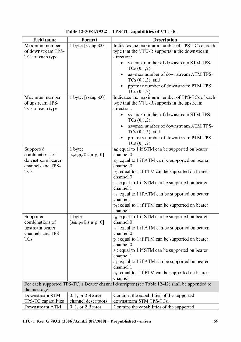
ITU-T Rec. G.993.2 (2006)/Amd.3 (08/2008) – Prepublished version
69
Table 12-50/G.993.2 – TPS-TC capabilities of VTU-R
Field name Format Description Maximum number of downstream TPS-TCs of each type
1 byte: [ssaapp00]
Indicates the maximum number of TPS-TCs of each type that the VTU-R supports in the downstream direction:
• ss=max number of downstream STM TPS-TCs (0,1,2);
• aa=max number of downstream ATM TPS-TCs (0,1,2); and
• pp=max number of downstream PTM TPS-TCs (0,1,2).
Maximum number of upstream TPS-TCs of each type
1 byte: [ssaapp00]
Indicates the maximum number of TPS-TCs of each type that the VTU-R supports in the upstream direction:
• ss=max number of downstream STM TPS-TCs (0,1,2);
• aa=max number of downstream ATM TPS-TCs (0,1,2); and
• pp=max number of downstream PTM TPS-TCs (0,1,2).
Supported combinations of downstream bearer channels and TPS-TCs
1 byte: [s0a0p0 0 s1a1p1 0]
s0: equal to 1 if STM can be supported on bearer channel 0 a0: equal to 1 if ATM can be supported on bearer channel 0 p0: equal to 1 if PTM can be supported on bearer channel 0 s1: equal to 1 if STM can be supported on bearer channel 1 a1: equal to 1 if ATM can be supported on bearer channel 1 p1: equal to 1 if PTM can be supported on bearer channel 1
Supported combinations of upstream bearer channels and TPS-TCs
1 byte: [s0a0p0 0 s1a1p1 0]
s0: equal to 1 if STM can be supported on bearer channel 0 a0: equal to 1 if ATM can be supported on bearer channel 0 p0: equal to 1 if PTM can be supported on bearer channel 0 s1: equal to 1 if STM can be supported on bearer channel 1 a1: equal to 1 if ATM can be supported on bearer channel 1 p1: equal to 1 if PTM can be supported on bearer channel 1
For each supported TPS-TC, a Bearer channel descriptor (see Table 12-42) shall be appended to the message. Downstream STM TPS-TC capabilities
0, 1, or 2 Bearer channel descriptors
Contains the capabilities of the supported downstream STM TPS-TCs.
Downstream ATM 0, 1, or 2 Bearer Contains the capabilities of the supported
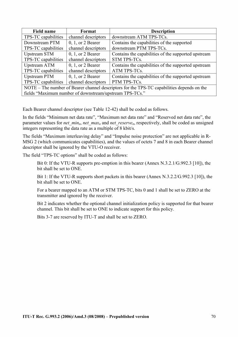
ITU-T Rec. G.993.2 (2006)/Amd.3 (08/2008) – Prepublished version
70
Field name Format Description TPS-TC capabilities channel descriptors downstream ATM TPS-TCs. Downstream PTM TPS-TC capabilities
0, 1, or 2 Bearer channel descriptors
Contains the capabilities of the supported downstream PTM TPS-TCs.
Upstream STM TPS-TC capabilities
0, 1, or 2 Bearer channel descriptors
Contains the capabilities of the supported upstream STM TPS-TCs.
Upstream ATM TPS-TC capabilities
0, 1, or 2 Bearer channel descriptors
Contains the capabilities of the supported upstream ATM TPS-TCs.
Upstream PTM TPS-TC capabilities
0, 1, or 2 Bearer channel descriptors
Contains the capabilities of the supported upstream PTM TPS-TCs.
NOTE – The number of Bearer channel descriptors for the TPS-TC capabilities depends on the fields “Maximum number of downstream/upstream TPS-TCs.”
Each Bearer channel descriptor (see Table 12-42) shall be coded as follows.
In the fields “Minimum net data rate”, “Maximum net data rate” and “Reserved net data rate”, the parameter values for net_minn, net_maxn and net_reserven, respectively, shall be coded as unsigned integers representing the data rate as a multiple of 8 kbit/s.
The fields “Maximum interleaving delay” and “Impulse noise protection” are not applicable in R-MSG 2 (which communicates capabilities), and the values of octets 7 and 8 in each Bearer channel descriptor shall be ignored by the VTU-O receiver.
The field “TPS-TC options” shall be coded as follows:
Bit 0: If the VTU-R supports pre-emption in this bearer (Annex N.3.2.1/G.992.3 [10]), the bit shall be set to ONE.
Bit 1: If the VTU-R supports short packets in this bearer (Annex N.3.2.2/G.992.3 [10]), the bit shall be set to ONE.
For a bearer mapped to an ATM or STM TPS-TC, bits 0 and 1 shall be set to ZERO at the transmitter and ignored by the receiver.
Bit 2 indicates whether the optional channel initialization policy is supported for that bearer channel. This bit shall be set to ONE to indicate support for this policy.
Bits 3-7 are reserved by ITU-T and shall be set to ZERO.
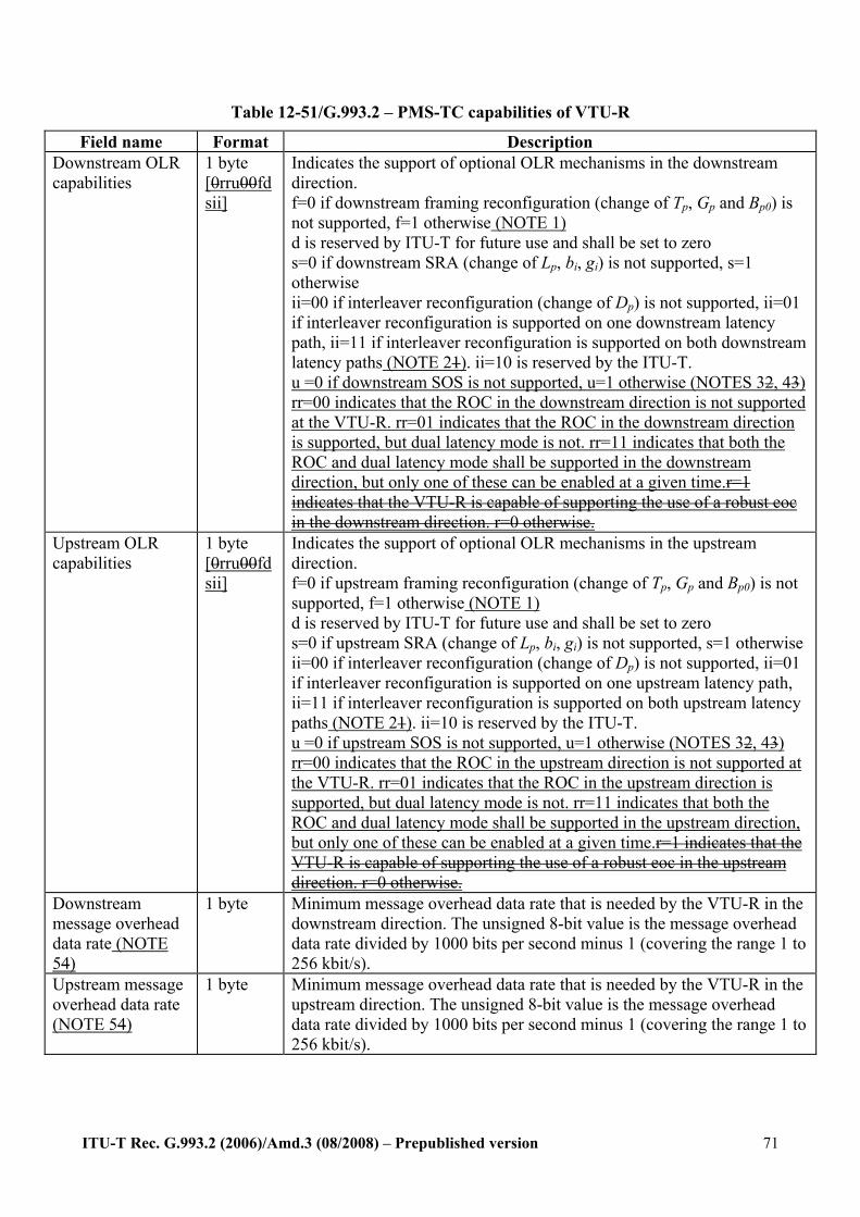
ITU-T Rec. G.993.2 (2006)/Amd.3 (08/2008) – Prepublished version
71
Table 12-51/G.993.2 – PMS-TC capabilities of VTU-R
Field name Format Description Downstream OLR capabilities
1 byte [0rru00fdsii]
Indicates the support of optional OLR mechanisms in the downstream direction. f=0 if downstream framing reconfiguration (change of Tp, Gp and Bp0) is not supported, f=1 otherwise (NOTE 1) d is reserved by ITU-T for future use and shall be set to zero s=0 if downstream SRA (change of Lp, bi, gi) is not supported, s=1 otherwise ii=00 if interleaver reconfiguration (change of Dp) is not supported, ii=01 if interleaver reconfiguration is supported on one downstream latency path, ii=11 if interleaver reconfiguration is supported on both downstream latency paths (NOTE 21). ii=10 is reserved by the ITU-T. u =0 if downstream SOS is not supported, u=1 otherwise (NOTES 32, 43) rr=00 indicates that the ROC in the downstream direction is not supported at the VTU-R. rr=01 indicates that the ROC in the downstream direction is supported, but dual latency mode is not. rr=11 indicates that both the ROC and dual latency mode shall be supported in the downstream direction, but only one of these can be enabled at a given time.r=1 indicates that the VTU-R is capable of supporting the use of a robust eoc in the downstream direction. r=0 otherwise.
Upstream OLR capabilities
1 byte [0rru00fdsii]
Indicates the support of optional OLR mechanisms in the upstream direction. f=0 if upstream framing reconfiguration (change of Tp, Gp and Bp0) is not supported, f=1 otherwise (NOTE 1) d is reserved by ITU-T for future use and shall be set to zero s=0 if upstream SRA (change of Lp, bi, gi) is not supported, s=1 otherwise ii=00 if interleaver reconfiguration (change of Dp) is not supported, ii=01 if interleaver reconfiguration is supported on one upstream latency path, ii=11 if interleaver reconfiguration is supported on both upstream latency paths (NOTE 21). ii=10 is reserved by the ITU-T. u =0 if upstream SOS is not supported, u=1 otherwise (NOTES 32, 43) rr=00 indicates that the ROC in the upstream direction is not supported at the VTU-R. rr=01 indicates that the ROC in the upstream direction is supported, but dual latency mode is not. rr=11 indicates that both the ROC and dual latency mode shall be supported in the upstream direction, but only one of these can be enabled at a given time.r=1 indicates that the VTU-R is capable of supporting the use of a robust eoc in the upstream direction. r=0 otherwise.
Downstream message overhead data rate (NOTE 54)
1 byte Minimum message overhead data rate that is needed by the VTU-R in the downstream direction. The unsigned 8-bit value is the message overhead data rate divided by 1000 bits per second minus 1 (covering the range 1 to 256 kbit/s).
Upstream message overhead data rate (NOTE 54)
1 byte Minimum message overhead data rate that is needed by the VTU-R in the upstream direction. The unsigned 8-bit value is the message overhead data rate divided by 1000 bits per second minus 1 (covering the range 1 to 256 kbit/s).
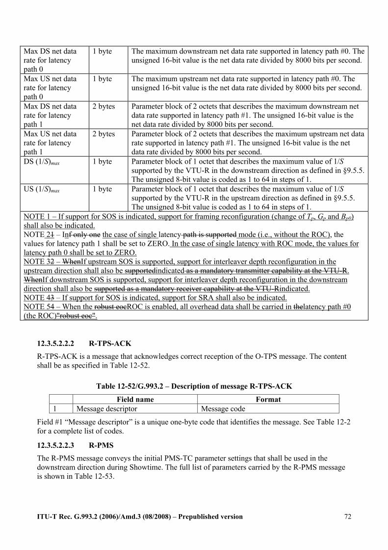
ITU-T Rec. G.993.2 (2006)/Amd.3 (08/2008) – Prepublished version
72
Max DS net data rate for latency path 0
1 byte The maximum downstream net data rate supported in latency path #0. The unsigned 16-bit value is the net data rate divided by 8000 bits per second.
Max US net data rate for latency path 0
1 byte The maximum upstream net data rate supported in latency path #0. The unsigned 16-bit value is the net data rate divided by 8000 bits per second.
Max DS net data rate for latency path 1
2 bytes Parameter block of 2 octets that describes the maximum downstream net data rate supported in latency path #1. The unsigned 16-bit value is the net data rate divided by 8000 bits per second.
Max US net data rate for latency path 1
2 bytes Parameter block of 2 octets that describes the maximum upstream net data rate supported in latency path #1. The unsigned 16-bit value is the net data rate divided by 8000 bits per second.
DS (1/S)max 1 byte Parameter block of 1 octet that describes the maximum value of 1/S supported by the VTU-R in the downstream direction as defined in §9.5.5. The unsigned 8-bit value is coded as 1 to 64 in steps of 1.
US (1/S)max 1 byte Parameter block of 1 octet that describes the maximum value of 1/S supported by the VTU-R in the upstream direction as defined in §9.5.5. The unsigned 8-bit value is coded as 1 to 64 in steps of 1.
NOTE 1 – If support for SOS is indicated, support for framing reconfiguration (change of Tp, Gp and Bp0) shall also be indicated. NOTE 21 – Inf only one the case of single latency path is supported mode (i.e., without the ROC), the values for latency path 1 shall be set to ZERO. In the case of single latency with ROC mode, the values for latency path 0 shall be set to ZERO. NOTE 32 – WhenIf upstream SOS is supported, support for interleaver depth reconfiguration in the upstream direction shall also be supportedindicated as a mandatory transmitter capability at the VTU-R. WhenIf downstream SOS is supported, support for interleaver depth reconfiguration in the downstream direction shall also be supported as a mandatory receiver capability at the VTU-Rindicated. NOTE 43 – If support for SOS is indicated, support for SRA shall also be indicated. NOTE 54 – When the robust eocROC is enabled, all overhead data shall be carried in thelatency path #0 (the ROC)"robust eoc".
12.3.5.2.2.2 R-TPS-ACK
R-TPS-ACK is a message that acknowledges correct reception of the O-TPS message. The content shall be as specified in Table 12-52.
Table 12-52/G.993.2 – Description of message R-TPS-ACK
Field name Format 1 Message descriptor Message code
Field #1 “Message descriptor” is a unique one-byte code that identifies the message. See Table 12-2 for a complete list of codes.
12.3.5.2.2.3 R-PMS The R-PMS message conveys the initial PMS-TC parameter settings that shall be used in the downstream direction during Showtime. The full list of parameters carried by the R-PMS message is shown in Table 12-53.
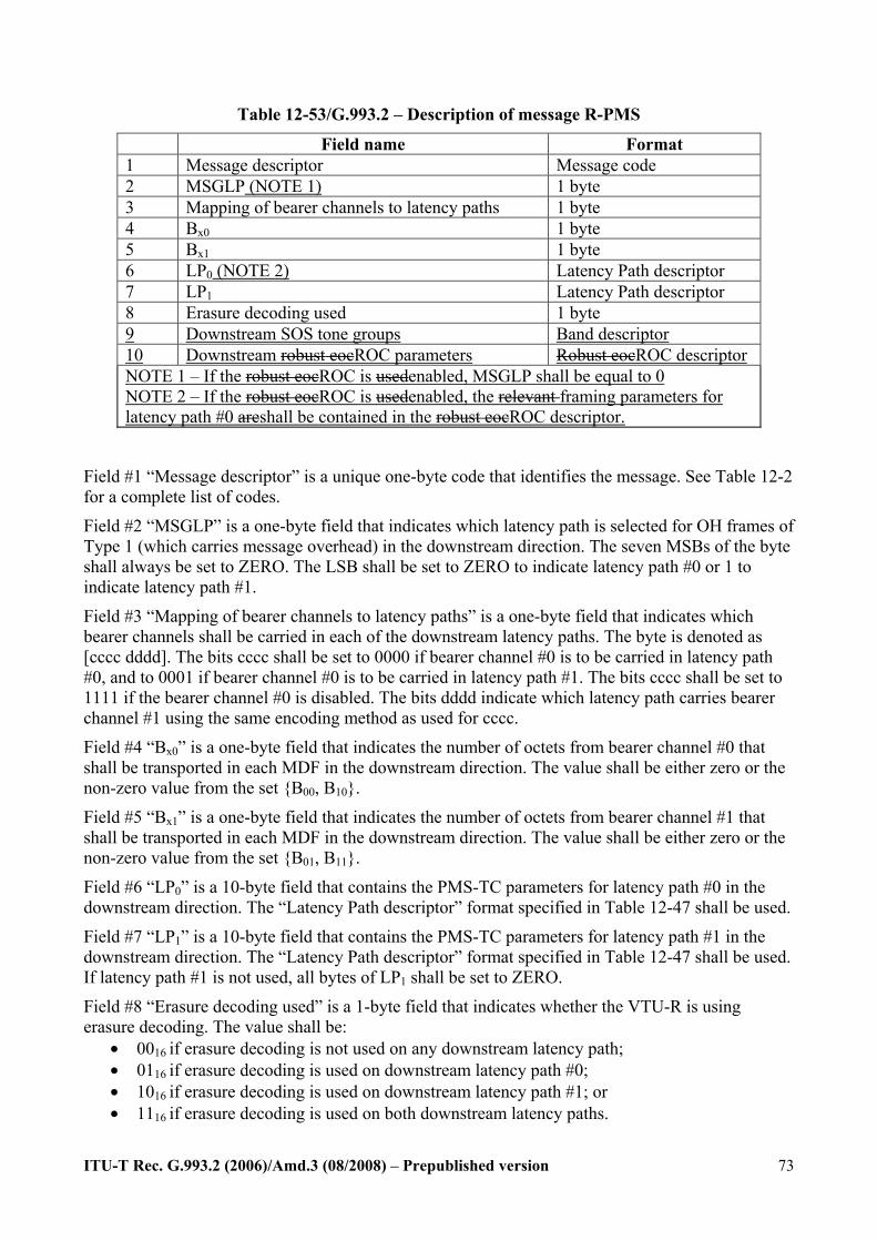
ITU-T Rec. G.993.2 (2006)/Amd.3 (08/2008) – Prepublished version
73
Table 12-53/G.993.2 – Description of message R-PMS
Field name Format 1 Message descriptor Message code 2 MSGLP (NOTE 1) 1 byte 3 Mapping of bearer channels to latency paths 1 byte 4 Bx0 1 byte 5 Bx1 1 byte 6 LP0 (NOTE 2) Latency Path descriptor 7 LP1 Latency Path descriptor 8 Erasure decoding used 1 byte 9 Downstream SOS tone groups Band descriptor 10 Downstream robust eocROC parameters Robust eocROC descriptor NOTE 1 – If the robust eocROC is usedenabled, MSGLP shall be equal to 0 NOTE 2 – If the robust eocROC is usedenabled, the relevant framing parameters for latency path #0 areshall be contained in the robust eocROC descriptor.
Field #1 “Message descriptor” is a unique one-byte code that identifies the message. See Table 12-2 for a complete list of codes.
Field #2 “MSGLP” is a one-byte field that indicates which latency path is selected for OH frames of Type 1 (which carries message overhead) in the downstream direction. The seven MSBs of the byte shall always be set to ZERO. The LSB shall be set to ZERO to indicate latency path #0 or 1 to indicate latency path #1.
Field #3 “Mapping of bearer channels to latency paths” is a one-byte field that indicates which bearer channels shall be carried in each of the downstream latency paths. The byte is denoted as [cccc dddd]. The bits cccc shall be set to 0000 if bearer channel #0 is to be carried in latency path #0, and to 0001 if bearer channel #0 is to be carried in latency path #1. The bits cccc shall be set to 1111 if the bearer channel #0 is disabled. The bits dddd indicate which latency path carries bearer channel #1 using the same encoding method as used for cccc.
Field #4 “Bx0” is a one-byte field that indicates the number of octets from bearer channel #0 that shall be transported in each MDF in the downstream direction. The value shall be either zero or the non-zero value from the set B00, B10.
Field #5 “Bx1” is a one-byte field that indicates the number of octets from bearer channel #1 that shall be transported in each MDF in the downstream direction. The value shall be either zero or the non-zero value from the set B01, B11.
Field #6 “LP0” is a 10-byte field that contains the PMS-TC parameters for latency path #0 in the downstream direction. The “Latency Path descriptor” format specified in Table 12-47 shall be used.
Field #7 “LP1” is a 10-byte field that contains the PMS-TC parameters for latency path #1 in the downstream direction. The “Latency Path descriptor” format specified in Table 12-47 shall be used. If latency path #1 is not used, all bytes of LP1 shall be set to ZERO.
Field #8 “Erasure decoding used” is a 1-byte field that indicates whether the VTU-R is using erasure decoding. The value shall be:
• 0016 if erasure decoding is not used on any downstream latency path; • 0116 if erasure decoding is used on downstream latency path #0; • 1016 if erasure decoding is used on downstream latency path #1; or • 1116 if erasure decoding is used on both downstream latency paths.

ITU-T Rec. G.993.2 (2006)/Amd.3 (08/2008) – Prepublished version
74
Field #9 contains the start and stop frequencies of the SOS tone groups (as defined in §13.3) for the downstream direction. It shall be formatted as a band descriptor (see Table 12-18), with a maximum of 64 bands.
If SOS is not activated in the downstream direction, the band descriptor shall contain zero bands (see Table 12-18) and shall be ignored by the receiver.
Field #10 specifies the parameters that define the robust eocROC in the downstream direction. It is formatted as an ROC"Robust eoc descriptor", as defined in Table 12-47.1.
If the ROC is not enabled in the downstream direction, the values in the ROC descriptor shall all be set to zero and shall be ignored by the receiver.
12.3.7 Channel initialization policies The method used by the receiver to select the values of transceiver parameters described in this sub-clause is implementation dependent. However, within the limit of the total data rate provided by the local PMD, the selected values shall meet all of the constraints communicated by the transmitter prior to the Channel Analysis & Exchange phase, including:
• Message overhead data rate ≥ Minimum message overhead data rate; • Net data rate ≥ Minimum net data rate for all bearer channels; • Impulse noise protection ≥ Minimum impulse noise protection for all bearer channels; • Delay ≤ Maximum delay for all bearer channels. • SNR Margin ≥ TARSNRM
Within those constraints, the receiver shall select the values as to optimize in the priority given in one of the priority lists below, where the selection of the list is configured through the CO-MIB Channel Initialization Policy Parameter (CIPOLICY, see §7.3.2.10/G.997.1).: The Channel Initialization Policy applies only for the selection of the values exchanged during initialization, and does not apply during SHOWTIME.
The following Channel Initialization policies are defined:
Policy ZERO if CIpolicyn=0, then:
1) Maximize net data rate for all bearer channels, per the allocation of the net data rate, in excess of the sum of the minimum net data rates over all bearer channels (see §12.3.5).
2) Minimize excess margin with respect to the maximum SNR margin MAXSNRM through gain adjustments (see §10.3.4.2). Other control parameters may be used to achieve this (e.g., MAXMASK, see §7.2.3).
Policy ONE if CIpolicyn=1, then:
1) Maximize INP_actn for the bearer channel.
If the CO-MIB sets the CIPOLICY to ONE for a bearer channel, it shall have the minimum net data rate set equal to the maximum net data rate and shall have the MAXSNRM set to infinity.
If only a single bearer channel is configured through the CO-MIB, then the CIPOLICY shall be set to ZERO or ONE. If multiple bearer channels are configured through the CO-MIB, then the CIPOLICY shall be set to ZERO for each of the bearer channels. The use of the Channel Initialization Policy ONE with multiple bearer channels is for further study.

ITU-T Rec. G.993.2 (2006)/Amd.3 (08/2008) – Prepublished version
75
Support of Channel Initialization Policy ZERO is mandatory. Support of Channel Initialization Policy ONE is optional. Additional Channel Initialization Policies are for further study. The CIpolicyn parameter values other than 0 and 1 are reserved for use by the ITU-T.
12.3.7.1 Channel initialization policies with ROCrobust eoc The method used by the receiver to select the values of transceiver parameters described in this sub-clause is implementation dependent. However, within the limit of the total data rate provided by the local PMD, the selected values shall meet all of the constraints communicated by the transmitter prior to the Channel Analysis & Exchange phase, including:
• Message overhead data rate ≥ Minimum message overhead data rate; • Net data rate ≥ Minimum net data rate for all bearer channels; • Impulse noise protection ≥ Minimum impulse noise protection for all bearer channels; • Delay ≤ Maximum delay for all bearer channels. • SNR Margin ≥ TARSNRM • SNR Margin onfor the ROCrobust eoc ≥ TARSNRM
Within those constraints, the receiver shall select the values as to optimize in the priority given in one of the priority lists below, where the selection of the list is configured through the CO-MIB Channel Initialization Policy Parameter (CIPOLICY, see §7.3.2.10/G.997.1).: The Channel Initialization Policy applies only for the selection of the values exchanged during initialization, and does not apply during SHOWTIME.
The following Channel Initialization policyies areis defined: Policy ZERO if CIpolicyn=0, then:
1) Maximize the SNR Margin onfor the robust eocROC up to REOC-TARSNRM-ROC
2) Maximize net data rate for all bearer channels, per the allocation of the net data rate, in excess of the sum of the minimum net data rates over all bearer channels (see §12.3.5) .
3) Maximize the SNR Margin onfor the robust eocROC above REOC-TARSNRM-ROC
4) Minimize excess margin with respect to the maximum SNR margin MAXSNRM through gain adjustments (see §10.3.4.2). Other control parameters may be used to achieve this (e.g., MAXMASK, see §7.2.3).
Policy ONE if CIpolicyn=1, then:
Maximize INP_actn for the bearer channel.
If the CO-MIB sets the CIPOLICY to ONE for a bearer channel, it shall have the minimum net data rate set equal to the maximum net data rate and shall have the MAXSNRM set to infinity.
If only a single bearer channel is configured through the CO-MIB, then the CIPOLICY shall be set to ZERO or ONE. If multiple bearer channels are configured through the CO-MIB, then the CIPOLICY shall be set to ZERO for each of the bearer channels. The use of the Channel Initialization Policy ONE with multiple bearer channels is for further study. The use of the Channel Initialization Policy ONE with robust eoc is for further study.
Support of Channel Initialization Policy ZERO is mandatory. Support of Channel Initialization Policy ONE is optional. Additional Channel Initialization Policies are for further study. The CIpolicyn parameter values other than 0 and 1 are reserved for use by the ITU-T.

ITU-T Rec. G.993.2 (2006)/Amd.3 (08/2008) – Prepublished version
76
13.1 Types of on-line reconfiguration Types of OLR include bit swapping, and seamless rate adaptation (SRA), and SOS.
Bit swapping reallocates bits and power (i.e., margin) among the allowed sub-carriers without modification of the higher layer features of the physical layer. Bit swapping reconfigures the bit and gain (bi, gi) parameters without changing any other PMD or PMS-TC control parameters. After a bit swapping reconfiguration, the total data rate (ΣLp) × fs is unchanged, and the total data rate on each latency path (Lp × fs) is unchanged.
Because bit swapping is used autonomously to maintain the operating conditions of the modem during changing environment conditions, bit swapping is a mandatory capability. The procedure for bit swapping is defined in §11.2.3.3 (OLR commands) and shall be implemented using Type 1 OLR messages as shown in Table 11-5 and Table 11-6.
NOTE – When the ROC is enabled, bits L0 and L1 do not share the same sub-carrier (see §10.3.1).
Seamless rate adaptation (SRA) is used to reconfigure the total data rate (ΣLp) by modifying the framing parameters (Lp) and modifications to the bits and fine gains (bi, gi) parameters. Since the total data rate is modified, at least one latency path (or more) will have a new data rate (Lp) after the SRA. Since SRA is optional, the ability to support it is identified during the initialization procedure. The procedure for SRA is defined in §11.2.3.3 (OLR commands) and shall be implemented using Type 3 OLR messages as shown in Table 11-5 and Table 11-6.
SOS provides the receiver with a means to rapidly perform a bit loading reduction in a specified part of the frequency spectrum. This can be used in case of sudden noise increases. During initialization, the modems may define a number of SOS tone groups in both the upstream and downstream directions. An SOS commandrequest reduces the bit loading on all tones in a group by the same number of bits (multiple groups can be changed in a single command). The SOS commandrequest can also explicitly reconfigure the values of L0 and L1 (in case of dual latency)framing parameters Lp and the interleaver depth Dp in each of the latency paths.
NOTE – For a wideband sudden noise increase, it is a goal that VTUs improve the data transmission within 1 second after the SOS trigger to achieve a BER≤1E-7. The desired data rate after this time is at least 80% of the data rate that would be obtained if the VTU were to (re-) initialize in the high noise condition using the same Transmit PSD level.
Sudden noise increases of up to 30 dB may occur in real networks.
Interleaver reconfiguration (within SRA) allows to dynamically change the interleaver depth Dp on one or more latency paths. SRA may be accompanied by a change of the framing parameters Tp, Gp and Bp0. Interleaver reconfiguration and modification of framing parameters Tp, Gp and Bp0 are optional.
The procedure for interleaver reconfiguration is defined in §9.4.1 and §11.2.3.3 (OLR commands) and shall be implemented using Type 3 OLR messages as shown in Table 11-5 and Table 11-6.
13.2 Control parameters
13.2.1 Control parameters controlled by the OLR procedures On-line reconfiguration of the PMD is accomplished by a coordinated change to the bits and gain values on two or more sub-carriers. The bit and gain parameters described in Table 13-1 may be changed through on-line reconfiguration within the limits described.
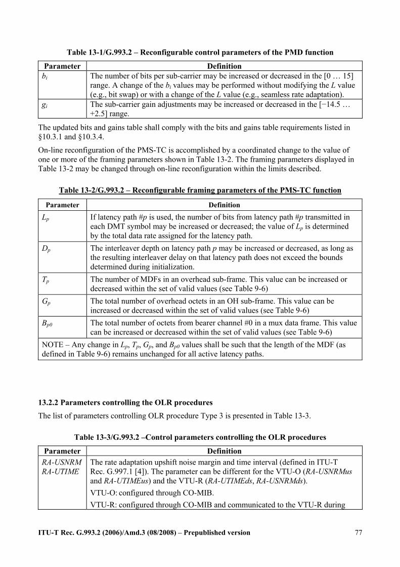
ITU-T Rec. G.993.2 (2006)/Amd.3 (08/2008) – Prepublished version
77
Table 13-1/G.993.2 – Reconfigurable control parameters of the PMD function
Parameter Definition bi The number of bits per sub-carrier may be increased or decreased in the [0 … 15]
range. A change of the bi values may be performed without modifying the L value (e.g., bit swap) or with a change of the L value (e.g., seamless rate adaptation).
gi The sub-carrier gain adjustments may be increased or decreased in the [−14.5 … +2.5] range.
The updated bits and gains table shall comply with the bits and gains table requirements listed in §10.3.1 and §10.3.4.
On-line reconfiguration of the PMS-TC is accomplished by a coordinated change to the value of one or more of the framing parameters shown in Table 13-2. The framing parameters displayed in Table 13-2 may be changed through on-line reconfiguration within the limits described.
Table 13-2/G.993.2 – Reconfigurable framing parameters of the PMS-TC function
Parameter Definition
Lp If latency path #p is used, the number of bits from latency path #p transmitted in each DMT symbol may be increased or decreased; the value of Lp is determined by the total data rate assigned for the latency path.
Dp The interleaver depth on latency path p may be increased or decreased, as long as the resulting interleaver delay on that latency path does not exceed the bounds determined during initialization.
Tp The number of MDFs in an overhead sub-frame. This value can be increased or decreased within the set of valid values (see Table 9-6)
Gp The total number of overhead octets in an OH sub-frame. This value can be increased or decreased within the set of valid values (see Table 9-6)
Bp0 The total number of octets from bearer channel #0 in a mux data frame. This value can be increased or decreased within the set of valid values (see Table 9-6)
NOTE – Any change in Lp, Tp, Gp, and Bp0 values shall be such that the length of the MDF (as defined in Table 9-6) remains unchanged for all active latency paths.
13.2.2 Parameters controlling the OLR procedures The list of parameters controlling OLR procedure Type 3 is presented in Table 13-3.
Table 13-3/G.993.2 –Control parameters controlling the OLR procedures
Parameter Definition RA-USNRM RA-UTIME
The rate adaptation upshift noise margin and time interval (defined in ITU-T Rec. G.997.1 [4]). The parameter can be different for the VTU-O (RA-USNRMus and RA-UTIMEus) and the VTU-R (RA-UTIMEds, RA-USNRMds). VTU-O: configured through CO-MIB. VTU-R: configured through CO-MIB and communicated to the VTU-R during
ITU-T Rec. G.993.2 (2006)/Amd.3 (08/2008) – Prepublished version
78
initialization (O-MSG 1).
The valid values for RA-USNRMus and RA-USNRMds are values between 0 and 31.0 dB in steps of 0.1 dB. The valid values for RA-UTIMEus and RA-UTIMEds are values between 0 to 16383 s in steps of 1 s.
RA-DSNRM RA-DTIME
The rate adaptation downshift noise margin and time interval (defined in ITU-T Rec. G.997.1 [4]). The parameter can be different for the VTU-O (RA-DSNRMus and RA-DTIMEus) and the VTU-R (RA-DTIMEds, RA-DSNRMds). VTU-O: configured through the CO-MIB. VTU-R: configured through the CO-MIB and communicated to the VTU-R during
initialization (O-MSG 1).
The valid values for RA-DSNRMus and RA-DSNRMds are values between 0 and 31.0 dB in steps of 0.1 dB. The valid values for RA-DTIMEus and RA-DTIMEds are values between 0 to 16383 s in steps of 1 s.
DVp The delay variation occurring in an OLR on latency path p. It is defined here as DVp = (delayp_H* Lp _H – delayp_L* Lp _L) / Lp _H
where Lp_L is the lower value of Lp in an OLR procedure
Lp_H is the higher value of Lp in an OLR procedure
delayp_L = the actual delay in ms in the steady state corresponding with Lp_L delayp_H = the actual delay in ms in the steady state corresponding with Lp_H
The delay variation DVn of bearer channel #n shall always be set to the value of DVp of the underlying PMS-TC path function (see Annex K)
DVmaxn The maximum allowed value for the delay variation DVn of bearer channel #n It ranges from 0.1 to 25.4 in steps of 0.1 ms The value 25.5 indicates that no delay variation bound is imposed. The parameter can be different for the VTU-O and the VTU-R. VTU-O: configured through the CO-MIB. VTU-R: configured through the CO-MIB and communicated to the VTU-R during initialization (O-TPS).
13.3 Timing of changes in sub-carrier configuration In both the upstream and the downstream directions, the reconfiguration of the PMD functions shall take effect starting with the tenth symbol that follows transport of the Syncflag for OLR type 1. As defined in §10.2, the sync symbol is transmitted after every 256 data symbols. The reconfiguration of the PMD function shall take effect starting with the symbol at symbol count 9 in the next DMT superframe, where the first symbol in each DMT superframe is the symbol at symbol count 0.
For OLR Type 3, when performed in the latency path p, the change in Lp values and bi, gi values shall take effect starting from the 66th symbol that follows the Syncflag, i.e., the symbol with
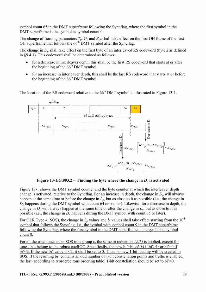
ITU-T Rec. G.993.2 (2006)/Amd.3 (08/2008) – Prepublished version
79
symbol count 65 in the DMT superframe following the Syncflag, where the first symbol in the DMT superframe is the symbol at symbol count 0.
The change of framing parameters Tp, Gp and Bp0 shall take effect on the first OH frame of the first OH superframe that follows the 66th DMT symbol after the Syncflag.
The change in Dp shall take effect on the first byte of an interleaved RS codeword (byte k as defined in §9.4.1). This codeword shall be determined as follows:
• for a decrease in interleaver depth, this shall be the first RS codeword that starts at or after the beginning of the 66th DMT symbol
• for an increase in interleaver depth, this shall be the last RS codeword that starts at or before the beginning of the 66th DMT symbol
The location of the RS codeword relative to the 66th DMT symbol is illustrated in Figure 13-1.
Sync 0 1 2 64 65
FECpNΔ NFECp NFECp
Lp
FECpFECp
FECppp N
N
NLN *
8/65
⎥⎥
⎦
⎥
⎢⎢
⎣
⎢ Δ−+Δ
FECpFECp
FECppFECp N
N
NLN *
8/65
⎥⎥
⎥
⎤
⎢⎢
⎢
⎡ Δ−+Δ
NFECp
Incr
ease
in D
Dec
reas
e in
D
65 Lp/8-ΔNFECp bytes
Figure 13-1/G.993.2 – Finding the byte where the change in Dp is activated
Figure 13-1 shows the DMT symbol counter and the byte counter at which the interleaver depth change is activated, relative to the Syncflag. For an increase in depth, the change in Dp will always happen at the same time or before the change in Lp, but as close to it as possible (i.e., the change in Dp happens during the DMT symbol with count 64 or sooner). Likewise, for a decrease in depth, the change in Dp will always happen at the same time or after the change in Lp, but as close to it as possible (i.e., the change in Dp happens during the DMT symbol with count 65 or later).
For OLR Type 4 (SOS), the change in Lp values and bi values shall take effect starting from the 10th symbol that follows the Syncflag, i.e., the symbol with symbol count 9 in the DMT superframe following the Syncflag, where the first symbol in the DMT superframe is the symbol at symbol count 0.
For all the used tones in an SOS tone group k, the same bi reduction Δb(k) is applied, except for tones that belong to the robust eocROC. Specifically, the new bi’=bi-Δb(k) if bi’>1; or bi’=0 if bi’<2. If the new bi’ value is <2, it shall be set to 0. Thus, no new 1-bit loading will be created in SOS. If the resulting bi’ contains an odd number of 1-bit constellation points and trellis is enabled, the last (according to reordered tone ordering table) 1-bit constellation should be set to bi’=0.

ITU-T Rec. G.993.2 (2006)/Amd.3 (08/2008) – Prepublished version
80
When the SOS commandrequest is executed in multiple steps, the tones shall be updated in groups of size GSOS, where GSOS is the minimum of the values indicated by VTU-R and VTU-O in R-MSG2 and O-MSG1 respectively. The tones shall be updated in the order determined by the reordered tone ordering table. To insure that the bit-loading after each step contains an even number of 1-bit constellation, the tone with the unpaired 1-bit constellation shall be removed from this step and included in the next step.
The change in bit loading for the first group of tones shall be done at the 6610th symbol that follows the Syncflag. The change for subsequent groups shall be done DTSOS symbols after the execution of the previous group (on the symbol count 659+s*DTSOS, s = 1, 2, … N-1, sync symbols are not counted) until all tones have been changed. The last group may have less than GSOS tones. The value of DTSOS depends on the selected value of GSOS and shall be as presented in Table 13-4.
Table 13-4/G.993.2 – GSOS and associated values of DTSOS
GSOS DTSOS (4.3125 kHz) DTSOS (8.625 kHz)
256 48 96
512 72 144
1024 96 192
All tones N/A N/A
NOTE – The number of steps N depends on the total number of tones, W, subject to bit loading change during the SOS. It can be computed as N = ceiling(W/GSOS). Assuming the maximum number of tones in the transmit direction for the band plans defined in Annexes A, B and C, N doesn’t exceed 12 for GSOS = 256, 6 for GSOS = 512, and 3 for GSOS = 1024.
In the case of multi-step, the value of D (interleaver depth) shall be changed with the last group of tones. The change shall happen at the same symbol or at the first opportunity after the change of bit loading for the last group of tones (during the DMT symbol with count 659 + (N-1)*DTSOS or later).
When the SOS commandrequest is executed in a single step, the value of D shall be changed as described in §13.3this sub-clause for OLR type 3, but in this case at the 10th symbol that follows the Syncflag, i.e., the symbol with symbol count 9 in the DMT superframe following the Syncflag, where the first symbol in the DMT superframe is the symbol at symbol count 0.
After it has received an SOS request, the modem shall respond within 200 msec with either a Syncflag or a reject type 4 invalid parameters response (see Table 11-7) NACK. When the execution is done in multiple steps, the total time between reception of the message and full execution of the command shall not exceed 300 msec. In addition, the modem shall respond within 160.5146.5 ms after it has received an SOS request with either a Syncflag or a reject type 4 invalid parameters responseNACK. The response shall be sent at the first opportunity after the SOS request is received provided there is enough time to execute the first step of a multi-step activation.
During the transition of OLR type 4 in single or multiple steps, bit errors may occur, but shall stop once the transition is complete (unless line condition doesn’t allow error-free operation). Once the transition is completed, the modem shall operate at a BER not exceeding the nominal BER, unless the line conditions do not allow it.
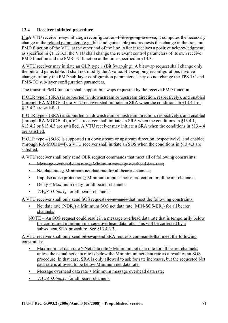
ITU-T Rec. G.993.2 (2006)/Amd.3 (08/2008) – Prepublished version
81
13.4 Receiver initiated procedure If aA VTU receiver may initiates a reconfiguration. If it is going to do so, it computes the necessary change in the related parameters (e.g., bits and gains table) and requests this change in the transmit PMD function of the VTU at the other end of the line. After it receives a positive acknowledgment, as specified in §11.2.3.3, the VTU shall change the relevant control parameters of its own receive PMD function and the PMS-TC function at the time specified in §13.3.
A VTU receiver may initiate an OLR type 1 (Bit Swapping). A bit swap request shall change only the bits and gains table. It shall not modify the L value. Bit swapping reconfigurations involve changes of only the PMD sub-layer configuration parameters. They do not change the TPS-TC and PMS-TC sub-layer configuration parameters.
The transmit PMD function shall support bit swaps requested by the receive PMD function.
If OLR type 3 (SRA) is supported (in downstream or upstream direction, respectively), and enabled (through RA-MODE=3), a VTU receiver shall initiate an SRA when the conditions in §13.4.1 or §13.4.2 are satisfied.
If OLR type 3 (SRA) is supported (in downstream or upstream direction, respectively), and enabled (through RA-MODE=4), a VTU receiver shall initiate an SRA when the conditions in §13.4.1, §13.4.2 or §13.4.3 are satisfied. A VTU receiver may initiate a SRA when the conditions in §13.4.4 are satisfied. If OLR type 4 (SOS) is supported (in downstream or upstream direction, respectively), and enabled (through RA-MODE=4), a VTU receiver shall initiate an SOS when the conditions in §13.4.3 are satisfied.
A VTU receiver shall only send OLR request commands that meet all of following constraints: • Message overhead data rate ≥ Minimum message overhead data rate; • Net data rate ≥ Minimum net data rate for all bearer channels; • Impulse noise protection ≥ Minimum impulse noise protection for all bearer channels; • Delay ≤ Maximum delay for all bearer channels • DVn ≤ DVmaxn for all bearer channels.
A VTU receiver shall only send SOS requests commands that meet the following constraints: • Net data rate (NDRn) ≥ Minimum SOS net data rate (MIN-SOS-BRn) for all bearer
channels; NOTE – An SOS request could result in a message overhead data rate that is temporarily below
the configured minimum message overhead data rate. This will be corrected by a subsequent SRA procedure. See §13.4.3.3.
A VTU receiver shall only send bit-swap and SRA requests commands that meet the following constraints:
• Maximum net data rate ≥ Net data rate ≥ Minimum net data rate for all bearer channels, unless the actual net data rate is below the Mminimum net data rate as a result of an SOS procedure. In that case, SRA is only allowed to ask for rate increases, but the requested Net data rate is allowed to be below Minimum net data rate.
• Message overhead data rate ≥ Minimum message overhead data rate; • DVn ≤ DVmaxn for all bearer channels.
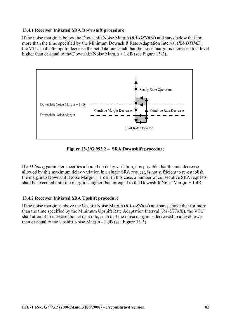
ITU-T Rec. G.993.2 (2006)/Amd.3 (08/2008) – Prepublished version
82
13.4.1 Receiver Initiated SRA Downshift procedure If the noise margin is below the Downshift Noise Margin (RA-DSNRM) and stays below that for more than the time specified by the Minimum Downshift Rate Adaptation Interval (RA-DTIME), the VTU shall attempt to decrease the net data rate, such that the noise margin is increased to a level higher than or equal to the Downshift Noise Margin + 1 dB (see Figure 13-2).
Steady State Operation
Downshift Noise Margin + 1 dB
Downshift Noise Margin
Start Rate Decrease
Continue Rate Decrease Continue Margin Decrease
Figure 13-2/G.993.2 – SRA Downshift procedure
If a DVmaxp parameter specifies a bound on delay variation, it is possible that the rate decrease allowed by this maximum delay variation in a single SRA request, is not sufficient to re-establish the margin to Downshift Noise Margin + 1 dB. In this case, a number of consecutive SRA requests shall be executed until the margin is higher than or equal to the Downshift Noise Margin + 1 dB.
13.4.2 Receiver Initiated SRA Upshift procedure
If the noise margin is above the Upshift Noise Margin (RA-USNRM) and stays above that for more than the time specified by the Minimum Upshift Rate Adaptation Interval (RA-UTIME), the VTU shall attempt to increase the net data rate, such that the noise margin is decreased to a level lower than or equal to the Upshift Noise Margin - 1 dB (see Figure 13-3).
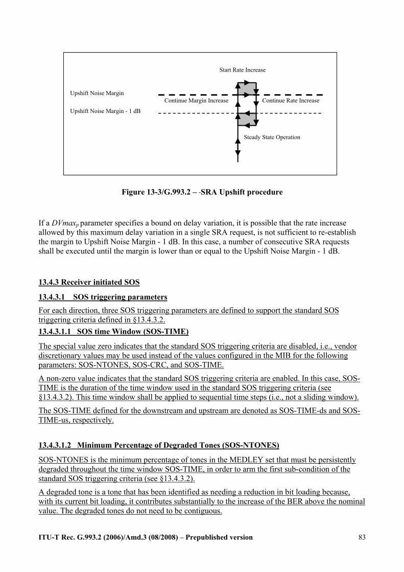
ITU-T Rec. G.993.2 (2006)/Amd.3 (08/2008) – Prepublished version
83
Steady State Operation
Upshift Noise Margin - 1 dB
Upshift Noise Margin
Start Rate Increase
Continue Rate Increase Continue Margin Increase
Figure 13-3/G.993.2 – SRA Upshift procedure
If a DVmaxp parameter specifies a bound on delay variation, it is possible that the rate increase allowed by this maximum delay variation in a single SRA request, is not sufficient to re-establish the margin to Upshift Noise Margin - 1 dB. In this case, a number of consecutive SRA requests shall be executed until the margin is lower than or equal to the Upshift Noise Margin - 1 dB.
13.4.3 Receiver initiated SOS
13.4.3.1 SOS triggering parameters For each direction, three SOS triggering parameters are defined to support the standard SOS triggering criteria defined in §13.4.3.2. 13.4.3.1.1 SOS time Window (SOS-TIME)
The special value zero indicates that the standard SOS triggering criteria are disabled, i.e., vendor discretionary values may be used instead of the values configured in the MIB for the following parameters: SOS-NTONES, SOS-CRC, and SOS-TIME.
A non-zero value indicates that the standard SOS triggering criteria are enabled. In this case, SOS-TIME is the duration of the time window used in the standard SOS triggering criteria (see §13.4.3.2). This time window shall be applied to sequential time steps (i.e., not a sliding window).
The SOS-TIME defined for the downstream and upstream are denoted as SOS-TIME-ds and SOS-TIME-us, respectively.
13.4.3.1.2 Minimum Percentage of Degraded Tones (SOS-NTONES)
SOS-NTONES is the minimum percentage of tones in the MEDLEY set that must be persistently degraded throughout the time window SOS-TIME, in order to arm the first sub-condition of the standard SOS triggering criteria (see §13.4.3.2).
A degraded tone is a tone that has been identified as needing a reduction in bit loading because, with its current bit loading, it contributes substantially to the increase of the BER above the nominal value. The degraded tones do not need to be contiguous.
ITU-T Rec. G.993.2 (2006)/Amd.3 (08/2008) – Prepublished version
84
The SOS-NTONES defined for the downstream and upstream are denoted as SOS-NTONES-ds and SOS-NTONES-us, respectively.
13.4.3.1.3 Minimum Number of normalized CRC anomalies (SOS-CRC)
SOS-CRC is the minimum number of normalized CRC anomalies received in SOS-TIME seconds, in order to arm the second sub-condition of the standard SOS triggering criteria (see §13.4.3.2).
The “count of normalized CRC anomalies” shall be incremented by the ∆CRCsecp (the one-second normalized CRC anomaly counter increment, as defined in Table 9-6/G.993.2) for each occurrence of a crc-p anomaly.
The SOS-CRC defined for the downstream and upstream are denoted as SOS-CRC-ds and SOS-CRC-us, respectively.
13.4.3.2 Standard SOS triggering criteria
If the following conditions hold:
• the standard SOS triggering criteria are enabled (through SOS-TIME ≠ 0);, • the percentage of tones in the MEDLEY SET that are persistently degraded throughout the
time window SOS-TIME exceeds SOS-NTONES, where a degraded tone is a tone that the modem has identified as needing a reduction in bit loading because the tone is unable to sustain error-free transmission with the current bit loading,; and
• the normalized count of normalized CRC anomalies throughout the same time window SOS-TIME exceeds SOS-CRCV during the same window of time,;
then the VTU shall:
• shall send either an SOS request or an SRA request if the number of degraded tones is ≤ 128 and the message length of the SRA request has a duration less than 100 ms, or
• shall send an SOS request commandif the number of degraded tones > 128 or if the message length of the SRA request has a duration more than 100 ms.
These SRA requests are not required to respect either RA-TIME or RA-SNRM.
. The time between the moment that the SOS trigger conditions have become valid, and the VTU SOS request or SRA request sent by the VTU appearsing onat the U-interface, shall be less than 128 msec if there is no other outstanding OLR request.
When the number of successful SOS procedures within 120 seconds exceeds MAX-SOS, the modem shall transition to the L3 state.
If the standard SOS triggering criteria are disabled (through SOS-TIME = 0), then the VTU may send SOS requests or SRA requests commands based on vendor-discretionary SOS triggering criteria. After each successful SOS, or SRA based on SOS triggering criteria, the count of normalized CRC anomalies shall be reset and a new time window shall be started.
13.4.3.3 Generic requirements for receiver initiated SOS The VTU shall not send an SOS request command if SOS is disabled (RA-MODE ≠ 4).
ITU-T Rec. G.993.2 (2006)/Amd.3 (08/2008) – Prepublished version
85
In the case the SOS results in a PERp value outside the bounds given in Table 9-6, the VTU that initiated the SOS request shall send a subsequent SRA request within 1 second to bring the PERp back within these bounds. In the case the SOS results in an msgp value outside the bounds given in Table 9-6, the VTU that initiated the SOS request shall send a subsequent SRA request within 1 second to bring the msgp back within these bounds.
13.4.4 Receiver Initiated SRA following an SOS procedure A VTU shall send one or more SRA requests following an SOS procedure to remediate the situation in which the current rate is less than Minimum Net Data Rate. As long as the current bit rate is less than Minimum Net Data Rate, these SRA requests are not required to respect either RA-UTIME or RA-USNRM.
NOTE – Although these SRA requests can be issued at the discretion of the VTU, the note in §13.1 defines a goal for the overall duration of the SOS procedure.
K.1.7 Control parameters The configuration of the STM-TC function is controlled by a set of control parameters defined in Table K-2 in addition to those specified in the main body of this Recommendation. The values of these control parameters shall be set and communicated during initialization or reconfiguration (if applicable) of a VTU pair. All the values are determined by application requirements and means that are beyond the scope of this Recommendation.
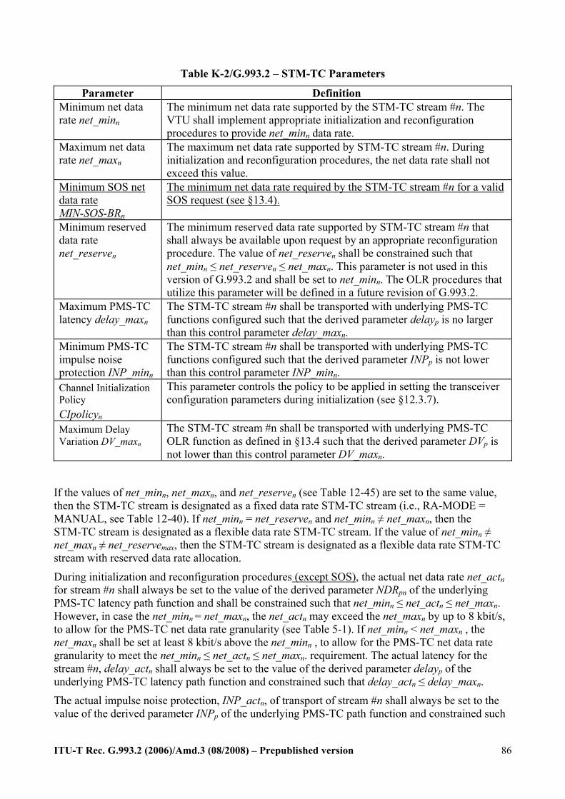
ITU-T Rec. G.993.2 (2006)/Amd.3 (08/2008) – Prepublished version
86
Table K-2/G.993.2 – STM-TC Parameters
Parameter Definition Minimum net data rate net_minn
The minimum net data rate supported by the STM-TC stream #n. The VTU shall implement appropriate initialization and reconfiguration procedures to provide net_minn data rate.
Maximum net data rate net_maxn
The maximum net data rate supported by STM-TC stream #n. During initialization and reconfiguration procedures, the net data rate shall not exceed this value.
Minimum SOS net data rate MIN-SOS-BRn
The minimum net data rate required by the STM-TC stream #n for a valid SOS request (see §13.4).
Minimum reserved data rate net_reserven
The minimum reserved data rate supported by STM-TC stream #n that shall always be available upon request by an appropriate reconfiguration procedure. The value of net_reserven shall be constrained such that net_minn ≤ net_reserven ≤ net_maxn. This parameter is not used in this version of G.993.2 and shall be set to net_minn. The OLR procedures that utilize this parameter will be defined in a future revision of G.993.2.
Maximum PMS-TC latency delay_maxn
The STM-TC stream #n shall be transported with underlying PMS-TC functions configured such that the derived parameter delayp is no larger than this control parameter delay_maxn.
Minimum PMS-TC impulse noise protection INP_minn
The STM-TC stream #n shall be transported with underlying PMS-TC functions configured such that the derived parameter INPp is not lower than this control parameter INP_minn.
Channel Initialization Policy CIpolicyn
This parameter controls the policy to be applied in setting the transceiver configuration parameters during initialization (see §12.3.7).
Maximum Delay Variation DV_maxn
The STM-TC stream #n shall be transported with underlying PMS-TC OLR function as defined in §13.4 such that the derived parameter DVp is not lower than this control parameter DV_maxn.
If the values of net_minn, net_maxn, and net_reserven (see Table 12-45) are set to the same value, then the STM-TC stream is designated as a fixed data rate STM-TC stream (i.e., RA-MODE = MANUAL, see Table 12-40). If net_minn = net_reserven and net_minn ≠ net_maxn, then the STM-TC stream is designated as a flexible data rate STM-TC stream. If the value of net_minn ≠ net_maxn ≠ net_reservemax, then the STM-TC stream is designated as a flexible data rate STM-TC stream with reserved data rate allocation.
During initialization and reconfiguration procedures (except SOS), the actual net data rate net_actn for stream #n shall always be set to the value of the derived parameter NDRpn of the underlying PMS-TC latency path function and shall be constrained such that net_minn ≤ net_actn ≤ net_maxn. However, in case the net_minn = net_maxn, the net_actn may exceed the net_maxn by up to 8 kbit/s, to allow for the PMS-TC net data rate granularity (see Table 5-1). If net_minn < net_maxn , the net_maxn shall be set at least 8 kbit/s above the net_minn , to allow for the PMS-TC net data rate granularity to meet the net_minn ≤ net_actn ≤ net_maxn. requirement. The actual latency for the stream #n, delay_actn shall always be set to the value of the derived parameter delayp of the underlying PMS-TC latency path function and constrained such that delay_actn ≤ delay_maxn.
The actual impulse noise protection, INP_actn, of transport of stream #n shall always be set to the value of the derived parameter INPp of the underlying PMS-TC path function and constrained such

ITU-T Rec. G.993.2 (2006)/Amd.3 (08/2008) – Prepublished version
87
that INP_actn ≥ INP_minn. The values net_actn, delay_actn and INP_actn are not control parameters; these values are the result of specific initialization and reconfiguration procedures.
During SOS reconfiguration procedures, the net data rates, INP and delay shall comply with §13.4.
K.1.7.1 Valid configurations The configurations listed in Table K-3 are valid for the STM-TC function.
Table K-3/G.993.2 – Valid configuration for STM-TC function
Parameter Capability typen 1 net_minn net_minn may be supported for all valid framing configurations. net_maxn net_maxn may be supported for all valid framing configurations. net_reserven net_reserven may be supported for all valid framing configurations. MIN-SOS-BRn MIN-SOS-BRn may be supported for all valid framing configurations. delay_maxn All valid values of delay_maxn (see Table 12-42 Bearer channel descriptor).INP_minn All valid values of INP_minn (Table 12-42 Bearer channel descriptor). CIpolicyn 0, 1
K.2.7 Control parameters The configuration of the ATM-TC function is controlled by a set of control parameters defined in Table K-8 in addition to those specified in the main body of this Recommendation. The values of these control parameters shall be set and communicated during initialization or reconfiguration (if applicable) of a VTU pair. All the values are determined by application requirements and means that are beyond the scope of this Recommendation.

ITU-T Rec. G.993.2 (2006)/Amd.3 (08/2008) – Prepublished version
88
Table K-8/G.993.2 – ATM-TC parameters
Parameter Definition Minimum net data rate net_minn
The minimum net data rate supported by the ATM-TC stream #n. The VTU shall implement appropriate initialization and reconfiguration procedures to provide net_minn data rate.
Maximum net data rate net_maxn
The maximum net data rate supported by ATM-TC stream #n. During activation and reconfiguration procedures, the net data rate shall not exceed this value.
Minimum SOS net data rate MIN-SOS-BRn
The minimum net data rate required by the ATM-TC stream #n for a valid SOS request (see §13.4).
Minimum reserved data rate net_reserven
The minimum reserved data rate supported by ATM-TC stream #n that shall always be available upon request by an appropriate reconfiguration procedure. The value of net_reserven shall be constrained such that net_minn ≤ net_reserven ≤ net_maxn. This parameter is not used in this version of G.993.2 and shall be set to net_minn. The OLR procedures that utilize this parameter will be defined in a future revision of G.993.2.
Maximum PMS-TC latency delay_maxn
The ATM-TC stream #n shall be transported with underlying PMS-TC functions configured such that the derived parameter delayp is no larger than this control parameter delay_maxn.
Minimum PMS-TC impulse noise protection INP_minn
The ATM-TC stream #n shall be transported with underlying PMS-TC functions configured such that the derived parameter INPp is not lower than this control parameter INP_minn.
Channel Initialization Policy CIpolicyn
This parameter controls the policy to be applied in setting the transceiver configuration parameters during initialization (see §12.3.7).
Maximum Delay Variation DV_maxn
The ATM-TC stream #n shall be transported with underlying PMS-TC OLR function as defined in §13.4 such that the derived parameter DVp is not lower than this control parameter DV_maxn.
If the values of net_minn, net_maxn, and net_reserven (see Table 12-45) are set to the same value, then the ATM-TC stream is designated as a fixed data rate ATM-TC stream (i.e., RA-MODE = MANUAL, see Table 12-40). If net_minn = net_reserven and net_minn ≠ net_maxn, then the ATM-TC stream is designated as a flexible data rate ATM-TC stream. If the value of net_minn ≠ net_maxn ≠ net_reservemax, then the ATM-TC stream is designated as a flexible data rate ATM-TC stream with reserved data rate allocation.
During initialization and reconfiguration procedures (except SOS), the actual net data rate net_actn for stream #n shall always be set to the value of the derived parameter NDRpn of the underlying PMS-TC latency path function and shall be constrained such that net_minn ≤ net_actn ≤ net_maxn. However, in case the net_minn = net_maxn, the net_actn may exceed the net_maxn by up to 8 kbit/s, to allow for the PMS-TC net data rate granularity (see Table 5-1). If net_minn < net_maxn , the net_maxn shall be set at least 8 kbit/s above the net_minn , to allow for the PMS-TC net data rate granularity to meet the net_minn ≤ net_actn ≤ net_maxn requirement. The actual latency delay_actn of transport of stream #n shall always be set to the value of the derived parameter delayp of the underlying PMS-TC path function and constrained such that delay_minn ≤ delay_actn ≤ delay_maxn. The values net_actn and delay_actn are not control parameters; these values are the result of specific initialization and reconfiguration procedures.
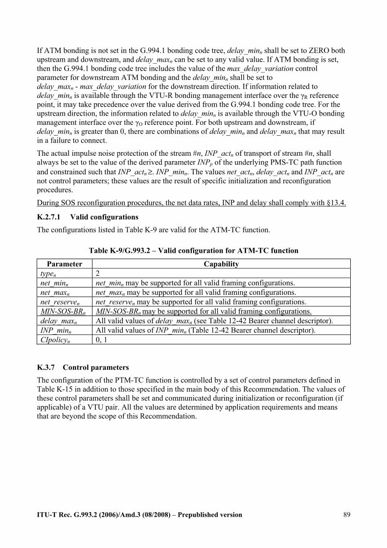
ITU-T Rec. G.993.2 (2006)/Amd.3 (08/2008) – Prepublished version
89
If ATM bonding is not set in the G.994.1 bonding code tree, delay_minn shall be set to ZERO both upstream and downstream, and delay_maxn can be set to any valid value. If ATM bonding is set, then the G.994.1 bonding code tree includes the value of the max_delay_variation control parameter for downstream ATM bonding and the delay_minn shall be set to delay_maxn - max_delay_variation for the downstream direction. If information related to delay_minn is available through the VTU-R bonding management interface over the γR reference point, it may take precedence over the value derived from the G.994.1 bonding code tree. For the upstream direction, the information related to delay_minn is available through the VTU-O bonding management interface over the γO reference point. For both upstream and downstream, if delay_minn is greater than 0, there are combinations of delay_minn and delay_maxn that may result in a failure to connect.
The actual impulse noise protection of the stream #n, INP_actn of transport of stream #n, shall always be set to the value of the derived parameter INPp of the underlying PMS-TC path function and constrained such that INP_actn ≥. INP_minn. The values net_actn, delay_actn and INP_actn are not control parameters; these values are the result of specific initialization and reconfiguration procedures.
During SOS reconfiguration procedures, the net data rates, INP and delay shall comply with §13.4.
K.2.7.1 Valid configurations The configurations listed in Table K-9 are valid for the ATM-TC function.
Table K-9/G.993.2 – Valid configuration for ATM-TC function
Parameter Capability typen 2 net_minn net_minn may be supported for all valid framing configurations. net_maxn net_maxn may be supported for all valid framing configurations. net_reserven net_reserven may be supported for all valid framing configurations. MIN-SOS-BRn MIN-SOS-BRn may be supported for all valid framing configurations. delay_maxn All valid values of delay_maxn (see Table 12-42 Bearer channel descriptor). INP_minn All valid values of INP_minn (Table 12-42 Bearer channel descriptor). CIpolicyn 0, 1
K.3.7 Control parameters The configuration of the PTM-TC function is controlled by a set of control parameters defined in Table K-15 in addition to those specified in the main body of this Recommendation. The values of these control parameters shall be set and communicated during initialization or reconfiguration (if applicable) of a VTU pair. All the values are determined by application requirements and means that are beyond the scope of this Recommendation.

ITU-T Rec. G.993.2 (2006)/Amd.3 (08/2008) – Prepublished version
90
Table K-15/G.993.2 – PTM-TC parameters
Parameter Definition Minimum net data rate net_minn
The minimum net data rate supported by the PTM-TC stream #n. The VTU shall implement appropriate initialization and reconfiguration procedures to provide net_minn data rate.
Maximum net data rate net_maxn
The maximum net data rate supported by PTM-TC stream #n. During initialization and reconfiguration procedures, the net data rate shall not exceed this value.
Minimum SOS net data rate MIN-SOS-BRn
The minimum net data rate required by the PTM-TC stream #n for a valid SOS request (see §13.4).
Minimum reserved data rate net_reserven
The minimum reserved data rate supported by PTM-TC stream #n that shall always be available upon request by an appropriate reconfiguration procedure. The value of net_reserven shall be constrained such that net_minn ≤ net_reserven ≤ net_maxn. This parameter is not used in this version of G.993.2 and shall be set to net_minn. The OLR procedures that utilize this parameter will be defined in a future revision of G.993.2.
Maximum PMS-TC latency delay_maxn
The PTM-TC stream #n shall be transported with underlying PMS-TC functions configured such that the derived parameter delayp is no larger than this control parameter delay_maxn.
Minimum PMS-TC impulse noise protection INP_minn
The PTM-TC stream #n shall be transported with underlying PMS-TC functions configured such that the derived parameter INPp is not lower than this control parameter INP_minn.
Channel Initialization Policy CIpolicyn
This parameter controls the policy to be applied in setting the transceiver configuration parameters during initialization (see §12.3.7).
Maximum Delay Variation DV_maxn
The PTM-TC stream #n shall be transported with underlying PMS-TC OLR function as defined in §13.4 such that the derived parameter DVp is not lower than this control parameter DV_maxn.
If the values of net_minn, net_maxn, and net_reserven (see Table 12-45) are set to the same value, then the PTM-TC stream is designated as a fixed data rate PTM-TC stream (i.e., RA-MODE = MANUAL, see Table 12-40). If net_minn = net_reserven and net_minn ≠ net_maxn, then the PTM-TC stream is designated as a flexible data rate PTM-TC stream. If the value of net_minn ≠ net_maxn ≠ net_reserven, then the PTM-TC stream is designated as a flexible data rate PTM-TC stream with reserved data rate allocation.
During initialization and reconfiguration procedures (except SOS), the actual net data rate net_actn for stream #n shall always be set to the value of the derived parameter NDRpn of the underlying PMS-TC latency path function and shall be constrained such that net_minn ≤ net_actn ≤ net_maxn. However, in case the net_minn = net_maxn, the net_actn may exceed the net_maxn by up to 8 kbit/s, to allow for the PMS-TC net data rate granularity (see Table 5-1). If net_minn < net_maxn , the net_maxn shall be set at least 8 kbit/s above the net_minn , to allow for the PMS-TC net data rate granularity to meet the net_minn ≤ net_actn ≤ net_maxn requirement. The actual latency delay_actn of transport of stream #n shall always be set to the value of the derived parameter delayp of the underlying PMS-TC latency path function and constrained such that delay_actn ≤ delay_maxn.
The actual impulse noise protection INP_actn of transport of stream #n shall always be set to the value of the derived parameter INPp of the underlying PMS-TC path function and constrained such
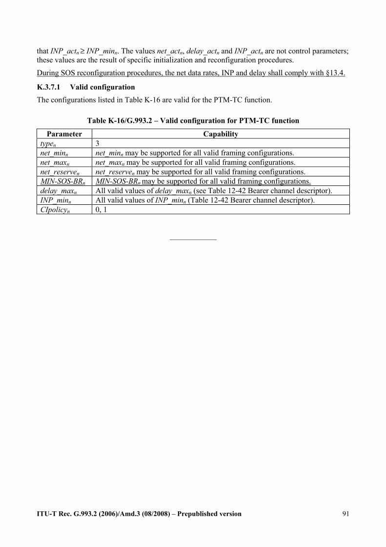
ITU-T Rec. G.993.2 (2006)/Amd.3 (08/2008) – Prepublished version
91
that INP_actn ≥ INP_minn. The values net_actn, delay_actn and INP_actn are not control parameters; these values are the result of specific initialization and reconfiguration procedures.
During SOS reconfiguration procedures, the net data rates, INP and delay shall comply with §13.4.
K.3.7.1 Valid configuration The configurations listed in Table K-16 are valid for the PTM-TC function.
Table K-16/G.993.2 – Valid configuration for PTM-TC function
Parameter Capability typen 3 net_minn net_minn may be supported for all valid framing configurations. net_maxn net_maxn may be supported for all valid framing configurations. net_reserven net_reserven may be supported for all valid framing configurations. MIN-SOS-BRn MIN-SOS-BRn may be supported for all valid framing configurations. delay_maxn All valid values of delay_maxn (see Table 12-42 Bearer channel descriptor). INP_minn All valid values of INP_minn (Table 12-42 Bearer channel descriptor). CIpolicyn 0, 1
____________
Related Documents