JSC-48536 International Space Station Robotics Group Robotics Book - Generic All Expedition Flights Mission Operations Directorate Operations Division 22 DEC 04 National Aeronautics and Space Administration Lyndon B. Johnson Space Center Houston, Texas PST CODE: ROBO E10 GEN 6

Welcome message from author
This document is posted to help you gain knowledge. Please leave a comment to let me know what you think about it! Share it to your friends and learn new things together.
Transcript

JSC-48536
International Space Station Robotics Group Robotics Book - Generic
All Expedition Flights
Mission Operations Directorate Operations Division
22 DEC 04
National Aeronautics and Space Administration
Lyndon B. Johnson Space Center Houston, Texas
PST CODE: ROBO E10 GEN 6


United States Systems Operations Data File JSC-48536
Incorporates the following:
CR: Rob Gen U288 Rob Gen U292 Rob Gen U294 Rob Gen U295 Rob Gen U296 Rob Gen U297 Rob Gen U298A Rob Gen U299 Rob Gen U301 Rob Gen U304 Rob Gen U305A Rob Gen U306A Rob Gen U307
Rob Gen U310A Rob Gen U313 Rob Gen U321 Rob Gen U322 Rob Gen U324 Rob Gen U325A Rob Gen U326A Rob Gen U328 Rob Gen U329 Rob Gen U330 Rob Gen U331 Rob Gen U332 Rob Gen U333
Rob Gen U334 Rob Gen U335 Rob Gen U336 Rob Gen U337 Rob Gen U338A Rob Gen U339A Rob Gen U340 Rob Gen U341 Rob Gen U342 Rob Gen U343 Rob Gen U344
Uplinked Messages (or Approved Flight Notes) replaced by this revision, remove from Book:
None
22 DEC 04 ii ROBO GEN
CONTENTS
NOMINAL 1..................................................................................................................
RWS CHECKOUT
6.101 Display and Control Panel Checkout 3........................................................6.102 Hand Controller (THC and RHC) Diagnostic 9............................................
RWS HARDWARE OPERATIONS
6.112 Robotic Workstation CUP(LAB) External Rack Relocation 13.....................6.113 CUP(LAB) Artificial Vision Unit (AVU) Hard Disk Drive (HDD) Changeout 15..........................................................................................................6.114 LAB(CUP) RWS UOP Bypass Cable Reconfiguration 17...........................
RWS STATE TRANSITIONS
6.123 Backup Robotic Workstation CUP(LAB) Designation 19.............................
MT CHECKOUT
6.201 MT Pre-Translation IMCA Checkout 21.......................................................
MT GENERIC TRANSLATIONS
6.210 MT Generic Auto Translation Using String A(B) IMCAS 27........................
MBS CHECKOUT AND DIAGNOSTICS
6.311 MBS POA Diagnostics 39............................................................................
POA OPERATIONS
6.321 MBS POA Checkout 41...............................................................................6.322 MBS POA Calibration 43.............................................................................6.323 MBS POA Setup For Capture 45.................................................................6.325 MBS POA Automatic Release 47.................................................................6.327 MBS POA Semi-Manual Release 51...........................................................
MBS STATE TRANSITIONS
6.331 MBS Powerup From Off to Keep-Alive on Both Strings 55.........................6.332 MSS Powerup From Keep-Alive to Operational 57.....................................6.334 MSS Powerdown From Operational to Keep-Alive 63.................................6.335 MBS Powerdown to Off on Prime(Redundant) String 67............................
POA STATE TRANSITIONS
22 DEC 04 iii ROBO GEN

6.341 MBS POA Powerup From Off to Keep-Alive on Both Strings 69.................6.342 MBS POA Powerup to Operational on PRIME(REDUNDANT) String 71.................................................................................................................6.343 MBS POA Powerdown From Operational to Keep-Alive on PRIME(REDUNDANT) String 73............................................................................6.344 MBS POA Powerdown to Off on Both Strings 75........................................
MBS MCAS LATCH
6.351 MBS MCAS Latch Checkout Close 77.........................................................6.352 MBS MCAS Latch Checkout Open 81.........................................................6.353 MBS MCAS Latch Capture 85.....................................................................6.354 MBS MCAS Latch Release 91....................................................................
MBS MCAS UMA
6.360 MBS MCAS UMA Mate 95..........................................................................6.361 MBS MCAS UMA Demate 99......................................................................
SSRMS DIAGNOSTICS
6.401 SSRMS Joint Brake Test 105......................................................................6.402 SSRMS Joint Electronics Unit Diagnostics 107...........................................6.403 SSRMS LEE Diagnostics 109.....................................................................
SSRMS GENERIC MANEUVERS
6.417 SSRMS Base PDGF Pre-Launch Checkout 111.........................................
SSRMS LEE OPERATIONS
6.421 LEE Calibration 115.....................................................................................6.422 LEE Checkout 117.......................................................................................6.423 Automatic Capture 121................................................................................6.424 Automatic Release 125................................................................................6.425 Semi-Manual Capture 127...........................................................................6.426 Semi-Manual Release 131..........................................................................6.427 Force Moment Sensor (FMS) Calibration 135.............................................6.428 LEE Setup for Capture 137.........................................................................
SSRMS STATE TRANSITIONS
6.431 SSRMS Powerup From Off to Keep-Alive on Both Strings 139...................6.434 SSRMS Powerdown to Off on Both Strings 141..........................................6.435 SSRMS Operating Base Change 143..........................................................
VIDEO AND AVU ACTIVATION & CHECKOUT
6.604 CUP(LAB) Artificial Vision Unit (AVU) Powerup 145...................................6.607 CUP(LAB) Artificial Vision Unit (AVU) Checkout with VTR 2(1) 147............6.608 CUP(LAB) Artificial Vision Unit (AVU) Database Load 153.........................6.609 CUP(LAB) Artificial Vision Unit (AVU) Powerdown 155..............................
22 DEC 04 iv ROBO GEN
6.617 MSS Video Derouting 157...........................................................................
MALFUNCTION 159....................................................................................................
7.001 MSS FAILURE RESPONSE AND RECOVERY 161....................................7.100 RWS Power-up failure 187...........................................................................7.101 RWS TRANSITION TO ACTIVE FAILURE 199............................................7.110 MBS POWER-UP FROM OFF TO KA FAILURE 201..................................7.111 MBS POWER-UP FROM KA TO OPERATIONAL FAILURE 205.................7.120 SSRMS Power-up from Off to KA Failure 207..............................................7.121 SSRMS POWER-UP FROM KA TO OPERATIONAL FAILURE 213...........7.200 MSS POWER REMOVED FAILURE 215.....................................................7.201 MSS COMM FAILURE 221..........................................................................7.300 ACTIVE RWS FAILURE 229........................................................................7.500 SSRMS Brakes Failure 241..........................................................................7.501 SSRMS Resolver Cross Check Failure 243.................................................7.502 SSRMS Joint Motion Failure 249.................................................................7.510 SSRMS LEE Capture Failure 257.................................................................7.511 SSRMS LEE Release Failure 275.................................................................7.700 MSS Video Power On Command Failure 281..............................................7.701 MSS Video Failure 283.................................................................................7.702 MSS Camera Command Failure 291............................................................7.900 MSS Persistent Cat-2 Error 299...................................................................
CORRECTIVE 315.......................................................................................................
8.101 Manual Capture with Calibrated LEE 317....................................................8.102 Manual Release with Calibrated LEE 321...................................................8.103 Manual Release with Uncalibrated LEE 325................................................8.104 MSS Checkpoint Data Reset 329.................................................................8.106 SSRMS Reboot Prime(Redundant) String 335............................................8.107 SSRMS Switch To Redundant(Prime) String 337.......................................8.108 SSRMS Subunit Reboot 341.......................................................................8.109 DDCU Powerdown MSS Power Configuration 343.....................................8.110 Manual Capture with Uncalibrated LEE 347................................................8.111 LEE Miscapture 351....................................................................................8.112 SSRMS Capture Abort Recovery 353..........................................................8.201 MT Manual UMA MSW Acquisition 357.......................................................8.202 MT Manual UMA Mate 365..........................................................................8.204 MT Manual LTU Latch (ED Disengage) 371................................................8.205 MT Manual LTU Unlatch (ED Engage) 387.................................................8.206 MT Manual LDU Drive Changeover 397......................................................8.208 MT TUS Initialization 403............................................................................8.209 MT TUS Cable Cut 411...............................................................................8.210 MT Translate To Nearest Logical Worksite 415..........................................8.211 MT Autosequence Failed Recovery 423......................................................8.212 MT Generic Modify Previous Init Frame 431...............................................8.213 MT Manual Worksite Sensor Acquisition 435..............................................8.214 MT Manual TD Swap 443............................................................................8.306 MBS Reboot Prime(Redundant) String 451.................................................8.307 MBS SWITCH TO REDUNDANT(PRIME) STRING 453.............................8.310 MBS POA Reboot 455.................................................................................8.311 MBS POA Switch To Redundant(Prime) String 457....................................
22 DEC 04 v ROBO GEN

8.601 CUP(LAB) AVU LCDM Configuration As MON1(2) 461..............................
REFERENCE 463.........................................................................................................
RWS
9.101 RWS Peripherals Configuration 1 465.........................................................
SSRMS
9.404 SSRMS Single Joint Mnemonics 471..........................................................9.405 SSRMS 7 Joint Singularity Cues 473...........................................................9.408 Timing Data For LEE Operations 475..........................................................9.409 Nominal Robotics Advisories 477.................................................................9.410 SSRMS Mechanical & Electrical Components Schematic 479....................
VIDEO AND AVU
9.907 MSS/ISS Camera Number Table 481..........................................................
CUE CARD
SSRMS LEE CUE CARD 483................................................................................
22 DEC 04 vi ROBO GEN

NOMINAL
NO
MIN
AL
22 DEC 04
1

This Page Intentionally Blank
NO
MIN
AL
22 DEC 04
2

6.101 DISPLAY AND CONTROL PANEL CHECKOUT (RBT GEN/ULF1 - ALL/FIN) Page 1 of 5 pages
11 FEB 03 12680.doc
1. CUP(LAB) RWS STATUS CHECK PCS MSS: RWS
√‘LAS5(LAP5) CEU Mode’ – Backup
* ************************************************************************ ****
If LAS5(LAP5) CEU Mode – Active For currently Active RWS, perform {6.123 BACKUP ROBOTIC WORKSTATION CUP(LAB) DESIGNATION}, all (SODF: RBT GEN: NOMINAL), then:
* ************************************************************************ 2. PANEL/INST LIGHTING
NOTE Hold switches and pushbuttons until the talkback indication appears. Release after 5 seconds if no talkback appears.
MSS: LAS5(LAP5) DCP: Cupola(Lab) DCP Status
DCP ‘PANEL/INST LIGHTING’ PCS ‘PANEL/INST LIGHTING’
sel LAMP TEST Verify all DCP lights are on.
Verify dial at LAMP TEST.
sel OFF Verify all DCP lights are off.
Verify dial at OFF.
sel first tick mark Verify DCP lighting present.
Verify dial at first tick mark.
sel second tick mark Verify increase in DCP lighting.
Verify dial at second tick mark.
sel third tick mark Verify increase in DCP lighting.
Verify dial at third tick mark.
sel fourth tick mark Verify increase in DCP lighting.
Verify dial at fourth tick mark.
sel fifth tick mark Verify increase in DCP lighting.
Verify dial at fifth tick mark.
sel sixth tick mark Verify increase in DCP lighting.
Verify dial at sixth tick mark.
sel BRT Verify increase in DCP lighting.
Verify dial at BRIGHT.
DCP Position PANEL/INST LIGHTING rotary switch for desired brightness.
3
6.101 DISPLAY AND CONTROL PANEL CHECKOUT (RBT GEN/ULF1 - ALL/FIN) Page 2 of 5 pages
11 FEB 03 12680.doc
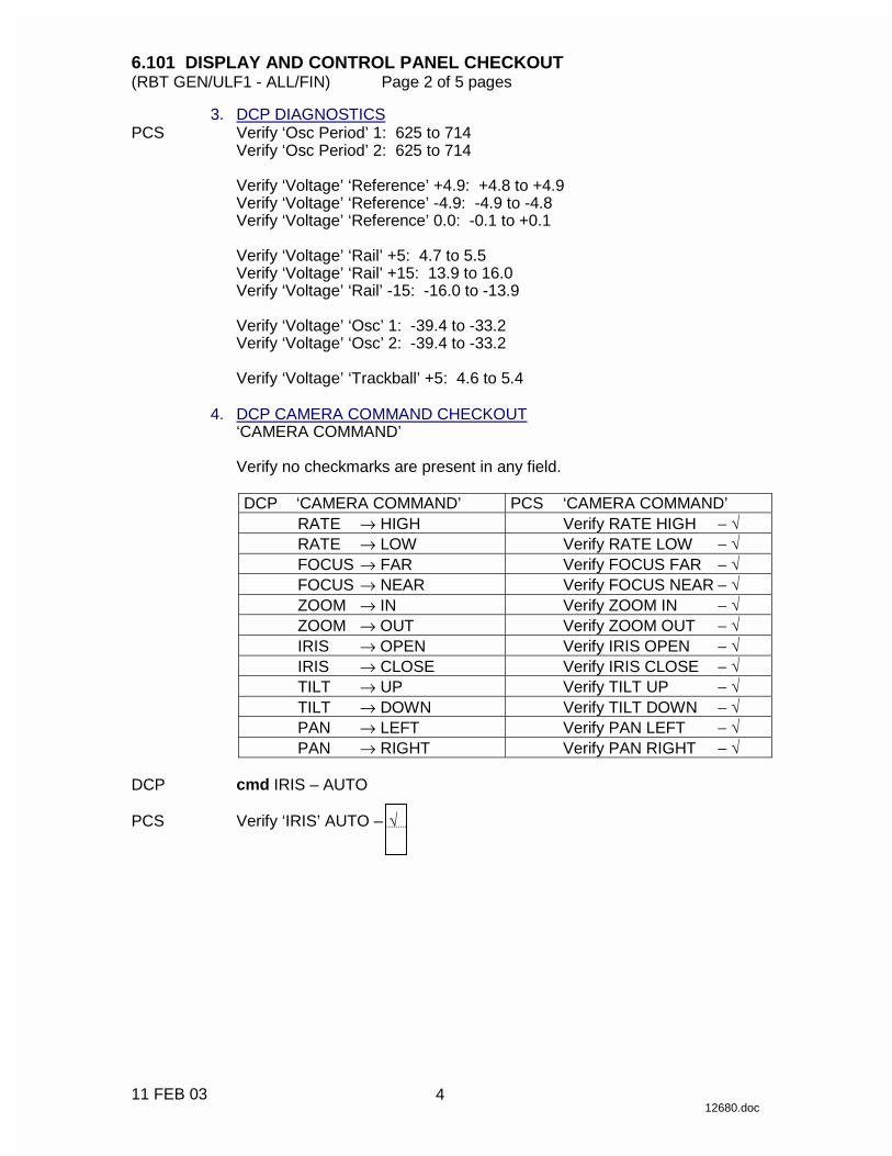
3. DCP DIAGNOSTICS PCS Verify ‘Osc Period’ 1: 625 to 714
Verify ‘Osc Period’ 2: 625 to 714
Verify ‘Voltage’ ‘Reference’ +4.9: +4.8 to +4.9 Verify ‘Voltage’ ‘Reference’ -4.9: -4.9 to -4.8 Verify ‘Voltage’ ‘Reference’ 0.0: -0.1 to +0.1
Verify ‘Voltage’ ‘Rail’ +5: 4.7 to 5.5 Verify ‘Voltage’ ‘Rail’ +15: 13.9 to 16.0 Verify ‘Voltage’ ‘Rail’ -15: -16.0 to -13.9
Verify ‘Voltage’ ‘Osc’ 1: -39.4 to -33.2 Verify ‘Voltage’ ‘Osc’ 2: -39.4 to -33.2
Verify ‘Voltage’ ‘Trackball’ +5: 4.6 to 5.4
4. DCP CAMERA COMMAND CHECKOUT
‘CAMERA COMMAND’
Verify no checkmarks are present in any field.
DCP ‘CAMERA COMMAND’ PCS ‘CAMERA COMMAND’ RATE → HIGH Verify RATE HIGH − √ RATE → LOW Verify RATE LOW − √ FOCUS → FAR Verify FOCUS FAR − √ FOCUS → NEAR Verify FOCUS NEAR − √ ZOOM → IN Verify ZOOM IN − √ ZOOM → OUT Verify ZOOM OUT − √ IRIS → OPEN Verify IRIS OPEN − √ IRIS → CLOSE Verify IRIS CLOSE − √ TILT → UP Verify TILT UP − √ TILT → DOWN Verify TILT DOWN − √ PAN → LEFT Verify PAN LEFT − √ PAN → RIGHT Verify PAN RIGHT − √
DCP cmd IRIS – AUTO PCS Verify ‘IRIS’ AUTO – √
4

6.101 DISPLAY AND CONTROL PANEL CHECKOUT (RBT GEN/ULF1 - ALL/FIN) Page 3 of 5 pages
11 FEB 03 12680.doc
5. MONITOR SELECT CHECKOUT ‘MONITOR SELECT’
Verify no checkmarks are present in any field.
DCP ‘MONITOR SELECT’ PCS ‘MONITOR SELECT’
cmd MON 1 Verify MON 1 −
Verify MON 1 –
cmd MON 2 Verify MON 2 −
Verify MON 2 –
cmd MON 3 Verify MON 3 −
Verify MON 3 –
6. MULTIPLEX UNIT CHECKOUT PCS ‘MULTIPLEX UNIT’
Verify no checkmarks are present in any field.
DCP ‘MULTIPLEX UNIT’ PCS ‘MULTIPLEX UNIT’ cmd MUX A LEFT
Verify MUX A LEFT −
Verify MUX A LEFT –
cmd MUX A RIGHT
Verify MUX A RIGHT −
Verify MUX A RIGHT –
cmd MUX B LEFT
Verify MUX B LEFT −
Verify MUX B LEFT –
cmd MUX B RIGHT
Verify MUX B RIGHT −
Verify MUX B RIGHT –
7. CAMERA SELECT CHECKOUT
NOTE 1. To prevent camera routing commands from being sent, a different
monitor is selected after each camera select pushbutton is pressed. Failure to do this may cause the DCP to become unresponsive for a few minutes.
2. The CAMERA SELECT pushbuttons should be held down until
instructed to release. PCS ‘CAMERA SELECT’
Verify no checkmarks are present in any field. DCP ‘CAMERA SELECT’
√ Lt
√ Lt
√ Lt
√ Lt
√ Lt
√ Lt
√ Lt
5
6.101 DISPLAY AND CONTROL PANEL CHECKOUT (RBT GEN/ULF1 - ALL/FIN) Page 4 of 5 pages
11 FEB 03 12680.doc
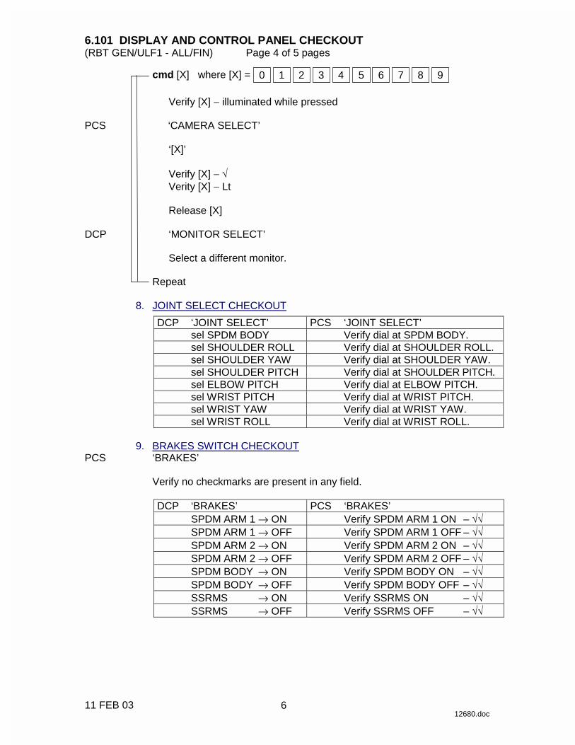
cmd [X] where [X] = 3210 4 8765 9
Verify [X] − illuminated while pressed PCS ‘CAMERA SELECT’
‘[X]’
Verify [X] − √ Verity [X] − Lt
Release [X]
DCP ‘MONITOR SELECT’
Select a different monitor.
Repeat 8. JOINT SELECT CHECKOUT
DCP ‘JOINT SELECT’ PCS ‘JOINT SELECT’ sel SPDM BODY Verify dial at SPDM BODY. sel SHOULDER ROLL Verify dial at SHOULDER ROLL. sel SHOULDER YAW Verify dial at SHOULDER YAW. sel SHOULDER PITCH Verify dial at SHOULDER PITCH. sel ELBOW PITCH Verify dial at ELBOW PITCH. sel WRIST PITCH Verify dial at WRIST PITCH. sel WRIST YAW Verify dial at WRIST YAW. sel WRIST ROLL Verify dial at WRIST ROLL.
9. BRAKES SWITCH CHECKOUT PCS ‘BRAKES’
Verify no checkmarks are present in any field.
DCP ‘BRAKES’ PCS ‘BRAKES’ SPDM ARM 1 → ON Verify SPDM ARM 1 ON – √√ SPDM ARM 1 → OFF Verify SPDM ARM 1 OFF – √√ SPDM ARM 2 → ON Verify SPDM ARM 2 ON – √√ SPDM ARM 2 → OFF Verify SPDM ARM 2 OFF – √√ SPDM BODY → ON Verify SPDM BODY ON – √√ SPDM BODY → OFF Verify SPDM BODY OFF – √√ SSRMS → ON Verify SSRMS ON – √√ SSRMS → OFF Verify SSRMS OFF – √√
6
6.101 DISPLAY AND CONTROL PANEL CHECKOUT (RBT GEN/ULF1 - ALL/FIN) Page 5 of 5 pages
11 FEB 03 12680.doc
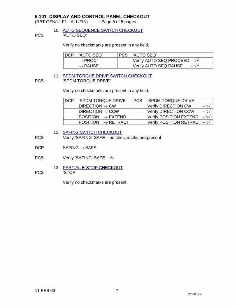
10. AUTO SEQUENCE SWITCH CHECKOUT PCS ‘AUTO SEQ’
Verify no checkmarks are present in any field.
DCP ‘AUTO SEQ’ PCS ‘AUTO SEQ’ → PROC Verify AUTO SEQ PROCEED – √√ → PAUSE Verify AUTO SEQ PAUSE – √√
11. SPDM TORQUE DRIVE SWITCH CHECKOUT PCS ‘SPDM TORQUE DRIVE’
Verify no checkmarks are present in any field.
DCP ‘SPDM TORQUE DRIVE’ PCS ‘SPDM TORQUE DRIVE’ DIRECTION → CW Verify DIRECTION CW – √√ DIRECTION → CCW Verify DIRECTION CCW – √√ POSITION → EXTEND Verify POSITION EXTEND – √√ POSITION → RETRACT Verify POSITION RETRACT – √√
12. SAFING SWITCH CHECKOUT PCS Verify ‘SAFING’ SAFE − no checkmarks are present DCP SAFING → SAFE PCS Verify ‘SAFING’ SAFE − √√ 13. PARTIAL E-STOP CHECKOUT PCS ‘STOP’
Verify no checkmarks are present.
7

This Page Intentionally Blank
22 DEC 04
8
6.102 HAND CONTROLLER (THC AND RHC) DIAGNOSTIC (RBT GEN/ULF1 - ALL/FIN) Page 1 of 3 pages
11 FEB 03 12681.doc
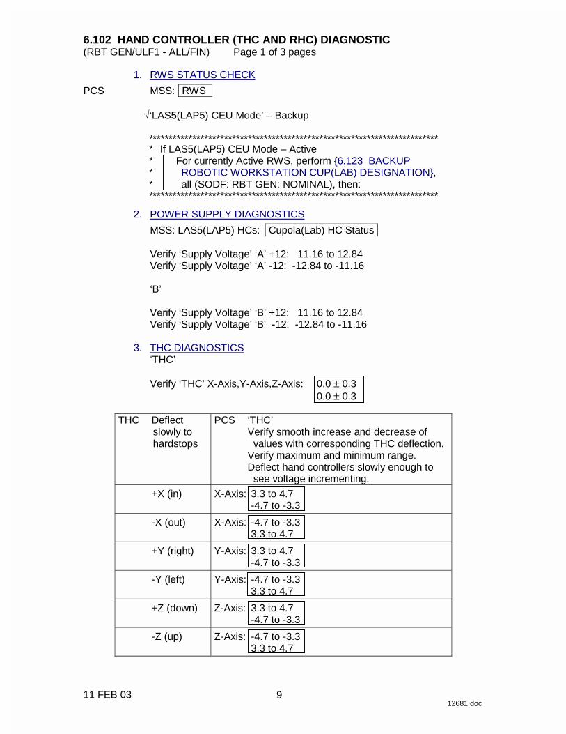
1. RWS STATUS CHECK PCS MSS: RWS
√‘LAS5(LAP5) CEU Mode’ – Backup
* ************************************************************************ ****
If LAS5(LAP5) CEU Mode – Active For currently Active RWS, perform {6.123 BACKUP ROBOTIC WORKSTATION CUP(LAB) DESIGNATION}, all (SODF: RBT GEN: NOMINAL), then:
* ************************************************************************ 2. POWER SUPPLY DIAGNOSTICS
MSS: LAS5(LAP5) HCs: Cupola(Lab) HC Status
Verify ‘Supply Voltage’ ‘A’ +12: 11.16 to 12.84 Verify ‘Supply Voltage’ ‘A’ -12: -12.84 to -11.16
‘B’
Verify ‘Supply Voltage’ ‘B’ +12: 11.16 to 12.84 Verify ‘Supply Voltage’ ‘B’ -12: -12.84 to -11.16
3. THC DIAGNOSTICS
‘THC’
Verify ‘THC’ X-Axis,Y-Axis,Z-Axis: 0.0 ± 0.3 0.0 ± 0.3
THC Deflect slowly to hardstops
PCS ‘THC’ Verify smooth increase and decrease of values with corresponding THC deflection. Verify maximum and minimum range. Deflect hand controllers slowly enough to see voltage incrementing.
+X (in) X-Axis: 3.3 to 4.7 -4.7 to -3.3
-X (out) X-Axis: -4.7 to -3.3 3.3 to 4.7
+Y (right) Y-Axis: 3.3 to 4.7 -4.7 to -3.3
-Y (left) Y-Axis: -4.7 to -3.3 3.3 to 4.7
+Z (down) Z-Axis: 3.3 to 4.7 -4.7 to -3.3
-Z (up) Z-Axis: -4.7 to -3.3 3.3 to 4.7
9

6.102 HAND CONTROLLER (THC AND RHC) DIAGNOSTIC (RBT GEN/ULF1 - ALL/FIN) Page 2 of 3 pages
11 FEB 03 12681.doc
4. RHC DIAGNOSTICS ‘RHC’
Verify ‘RHC’ Pitch-Axis,Yaw-Axis,Roll-Axis: 0.0 ± 0.3 0.0 ± 0.3
RHC Deflect slowly to hardstops
PCS ‘RHC’ Verify smooth increase and decrease of values with corresponding RHC deflection.
Verify maximum and minimum range. Deflect hand controllers slowly enough to see voltage incrementing.
+Pitch Pitch-Axis: 3.7 to 4.7 -4.7 to -3.7
-Pitch Pitch-Axis: -4.7 to -3.7 3.7 to 4.7
+Yaw Yaw-Axis: 3.7 to 4.7 -4.7 to -3.7
-Yaw Yaw-Axis: -4.7 to -3.7 3.7 to 4.7
+Roll Roll-Axis: 3.6 to 4.7 -4.7 to -3.6
-Roll Roll-Axis -4.7 to -3.6 3.6 to 4.7
RHC √Rate − COARSE ‘Coarse/Vern’ PCS Verify ‘Coarse/Vern’ Coarse – RHC RATE → VERNIER PCS Verify ‘Vern’ –
√ √
√ √
10

6.102 HAND CONTROLLER (THC AND RHC) DIAGNOSTIC (RBT GEN/ULF1 - ALL/FIN) Page 3 of 3 pages
11 FEB 03 12681.doc
‘Rate Hold’
If ‘Rate Hold’ Rate Hold – RHC Press Rate Hold. PCS Verify Rate Hold – RHC Press Rate Hold. PCS Verify Rate Hold –
If ‘Rate Hold’ Rate Hold – RHC Press Rate Hold. PCS Verify Rate Hold – RHC Press Rate Hold. PCS Verify Rate Hold – RHC Press and hold release trigger. PCS Verify Release – RHC Release release trigger. PCS Verify Release – RHC Press and hold capture trigger. PCS Verify Capture – RHC Release capture trigger. PCS Verify Capture –
√ √
√ √
√ √
√ √
√ √
11

This Page Intentionally Blank
22 DEC 04
12
6.112 ROBOTIC WORKSTATION CUP(LAB) EXTERNAL RACK RELOCATION
(RBT GEN/X2R4 - ALL/FIN) Page 1 of 2 pages
14 DEC 04 8682.doc
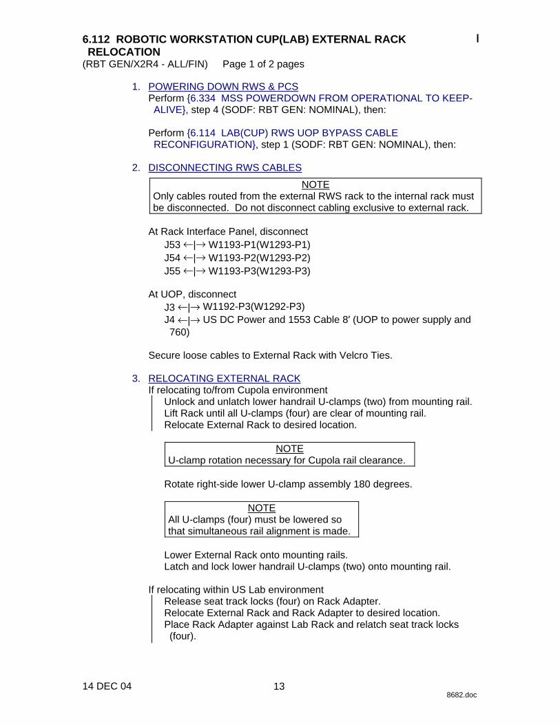
1. POWERING DOWN RWS & PCS Perform {6.334 MSS POWERDOWN FROM OPERATIONAL TO KEEP-ALIVE}, step 4 (SODF: RBT GEN: NOMINAL), then:
Perform {6.114 LAB(CUP) RWS UOP BYPASS CABLE RECONFIGURATION}, step 1 (SODF: RBT GEN: NOMINAL), then:
2. DISCONNECTING RWS CABLES
NOTE Only cables routed from the external RWS rack to the internal rack must be disconnected. Do not disconnect cabling exclusive to external rack.
At Rack Interface Panel, disconnect
J53 ←|→ W1193-P1(W1293-P1) J54 ←|→ W1193-P2(W1293-P2) J55 ←|→ W1193-P3(W1293-P3)
At UOP, disconnect
J3 ←|→ W1192-P3(W1292-P3) J4 ←|→ US DC Power and 1553 Cable 8′ (UOP to power supply and 760)
Secure loose cables to External Rack with Velcro Ties.
3. RELOCATING EXTERNAL RACK
If relocating to/from Cupola environment Unlock and unlatch lower handrail U-clamps (two) from mounting rail. Lift Rack until all U-clamps (four) are clear of mounting rail. Relocate External Rack to desired location.
NOTE
U-clamp rotation necessary for Cupola rail clearance.
Rotate right-side lower U-clamp assembly 180 degrees.
NOTE All U-clamps (four) must be lowered so that simultaneous rail alignment is made.
Lower External Rack onto mounting rails. Latch and lock lower handrail U-clamps (two) onto mounting rail.
If relocating within US Lab environment
Release seat track locks (four) on Rack Adapter. Relocate External Rack and Rack Adapter to desired location. Place Rack Adapter against Lab Rack and relatch seat track locks (four).
13

6.112 ROBOTIC WORKSTATION CUP(LAB) EXTERNAL RACK RELOCATION
(RBT GEN/X2R4 - ALL/FIN) Page 2 of 2 pages
14 DEC 04 8682.doc
4. CONNECTING RWS CABLES At Rack Interface Panel, connect
J53 →|← W1193-P1(W1293-P1) (RS-422/ Discrete lines) J54 →|← W1193-P2(W1293-P2) (Video) J55 →|← W1193-P3(W1293-P3) (Scar)
At UOP, connect
J3 →|← W1192-P3(W1292-P3) J4 →|← US DC Power and 1553 Cable 8′ (UOP to power supply and 760)
14
6.113 CUP(LAB) ARTIFICIAL VISION UNIT (AVU) HARD DISK DRIVE (HDD) CHANGEOUT
(RBT GEN/ULF1 - ALL/FIN 1) Page 1 of 1 page
12 FEB 03 11572.doc
1. EXTERNAL RACK RELOCATION Perform {6.112 ROBOTIC WORKSTATION CUP(LAB) EXTERNAL RACK RELOCATION}, steps 1 to 3 (SODF: RBT GEN: NOMINAL), then:
2. AVU HARD DRIVE REMOVAL LAS5 Open access panel and secure. (LAP5) AVU Loosen thumbscrews on AVU HDD.
Remove AVU HDD. Notify MCC-H of serial number on HDD removed.
Stow AVU HDD. 3. AVU HARD DRIVE INSTALLATION
Notify MCC-H of serial number on HDD being installed. AVU Install new AVU HDD.
Tighten thumbscrews. LAS5 Close access panel and secure. (LAP5) 4. EXTERNAL RACK RELOCATION
Go to {6.112 ROBOTIC WORKSTATION CUP(LAB) EXTERNAL RACK RELOCATION}, steps 3 and 4 (SODF: RBT GEN: NOMINAL).
15

This Page Intentionally Blank
22 DEC 04
16
6.114 LAB(CUP) RWS UOP BYPASS CABLE RECONFIGURATION (RBT GEN/E10 - ALL/FIN) Page 1 of 2 pages
14 DEC 04 15586.doc
OBJECTIVE: Reconfigure the Lab (or Cupola) RWS UOP Bypass Cable by demating (or mating) the DCP leg of the bypass cable. This procedure will allow the DCP to be powered down while still providing power to the PCS located on the RWS workstation.
NOTE 1. The following assumption can be made:
CEU is powered OFF (to prevent loss of comm between CEU and DCP).
2. Entire time between removing power and reapplying
power is less than 1 hr (to prevent the PCS battery from depleting when power is removed for more than 1 hr).
LOCATION: MSS Avionics Rack 2(1), LAB1P5(LAB1S5)
DURATION: 10 minutes
PARTS: None
MATERIALS: Kapton Tape (for demate) Velcro Tie Wraps (for demate)
TOOLS REQUIRED: None
REFERENCED PROCEDURE(S): None
1. DCP POWERDOWN/CABLE DEMATE
WARNING Failure to remove power and apply close inhibit could result in electrical shock hazard.
1.1 Open and Close – Inhibit LAP51A4A-A(LAS52A3B-A) RPC 18
LAB: EPS: LAB1P5(LAB1S5): RPCM LAP51A4A(RPCM LAS52A3B): ‘RPC’ 18 RPCM_LAP51A4A_A_RPC_18(RPCM_LAS52A3B_A_RPC_18)
cmd ‘RPC Position’ Open (Verify – Op) cmd ‘Close Cmd’ Inhibit (Verify – Inh)
1.2 DCP J1 ←|→ P1 (UOP PWR BYPASS 1J00137-1)
17

6.114 LAB(CUP) RWS UOP BYPASS CABLE RECONFIGURATION (RBT GEN/E10 - ALL/FIN) Page 2 of 2 pages
14 DEC 04 15586.doc
1.3 Install tethered protective cap on P1 (UOP PWR BYPASS 1J00137-1).
Cover DCP J1 (Kapton Tape). 1.4 Secure DCP leg of bypass cable to DC P/S leg of bypass cable
(Velcro Tie Wraps). 1.5
CAUTION The 760XD laptop main battery must indicate a minimum of 50% state of charge prior to turning on the laptop. A charge less than 50% can cause damage to the USOS 120VDC power supply due to excessive current draw.
If laptop battery state of charge is below 50%, let the battery charge before turning on the laptop.
1.6 Close – Enable and Close LAP51A4A-A(LAS52A3B-A) RPC 18
LAB: EPS: LAB1P5(LAB1S5): RPCM LAP51A4A(RPCM LAS52A3B): ‘RPC’ 18 RPCM_LAP51A4A_A_RPC_18(RPCM_LAS52A3B_A_RPC_18)
cmd ‘Close Cmd’ Enable (Verify – Ena) cmd ‘RPC Position’ Close (Verify – Cl)
2. CABLE MATE/DCP POWERUP
WARNING Failure to remove power and apply close inhibit could result in electrical shock hazard.
2.1 Perform step 1.1 to Open and Close – Inhibit LAP51A4A-
A(LAS52A3B-A) RPC 18. 2.2 Detach Velcro securing DCP leg of bypass cable to DC P/S leg of
bypass cable. 2.3 Uncap P1 (UOP PWR BYPASS 1J00137-1)
Remove Kapton Tape from DCP J1. 2.4 DCP J1 →|← P1 (UOP PWR BYPASS 1J00137-1) 2.5 Perform steps 1.5 and 1.6 to Close – Enable and Close LAP51A4A-
A(LAS52A3B-A) RPC 18.
18

6.123 BACKUP ROBOTIC WORKSTATION CUP(LAB) DESIGNATION (RBT GEN/R2 - ALL/FIN) Page 1 of 1 page
28 FEB 02 12668.doc
BACKUP ROBOTIC WORKSTATION CUP(LAB) DESIGNATION PCS MSS: LAS5(LAP5) CEU Mode: CEU Mode
cmd Active CEU − Backup (Verify previously Active RWS is Backup)
19

This Page Intentionally Blank
22 DEC 04
20
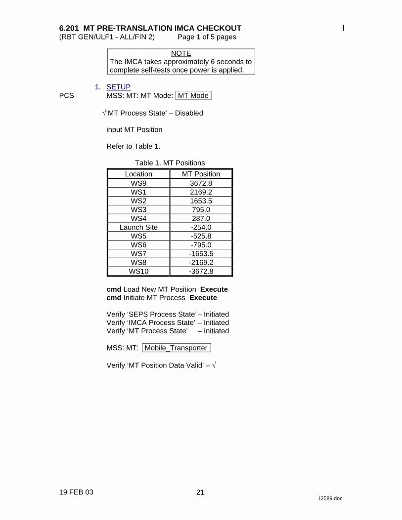
6.201 MT PRE-TRANSLATION IMCA CHECKOUT (RBT GEN/ULF1 - ALL/FIN 2) Page 1 of 5 pages
19 FEB 03 12589.doc
NOTE The IMCA takes approximately 6 seconds to complete self-tests once power is applied.
1. SETUP PCS MSS: MT: MT Mode: MT Mode
√‘MT Process State’ – Disabled
input MT Position
Refer to Table 1.
Table 1. MT Positions
Location MT Position WS9 3672.8 WS1 2169.2 WS2 1653.5 WS3 795.0 WS4 287.0
Launch Site -254.0 WS5 -525.8 WS6 -795.0 WS7 -1653.5 WS8 -2169.2
WS10 -3672.8
cmd Load New MT Position Execute cmd Initiate MT Process Execute
Verify ‘SEPS Process State’ – Initiated Verify ‘IMCA Process State’ – Initiated Verify ‘MT Process State’ – Initiated
MSS: MT: Mobile_Transporter
Verify ‘MT Position Data Valid’ – √
21
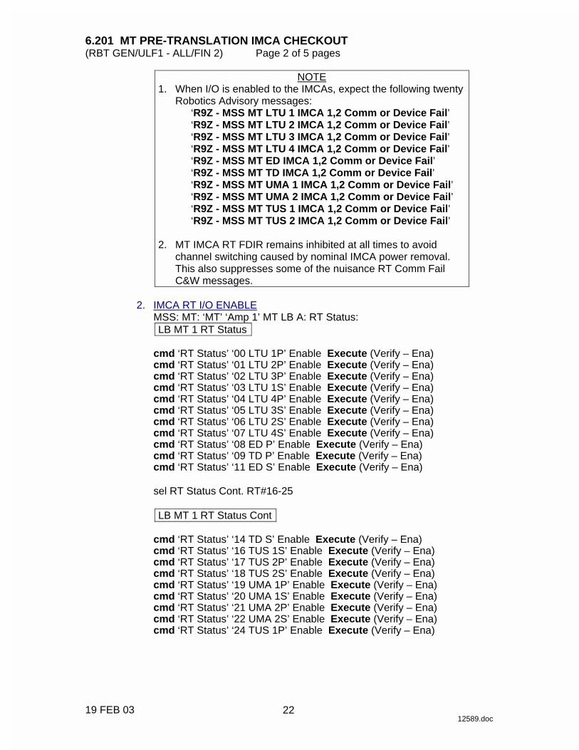
6.201 MT PRE-TRANSLATION IMCA CHECKOUT (RBT GEN/ULF1 - ALL/FIN 2) Page 2 of 5 pages
19 FEB 03 12589.doc
NOTE 1. When I/O is enabled to the IMCAs, expect the following twenty
Robotics Advisory messages: ‘R9Z - MSS MT LTU 1 IMCA 1,2 Comm or Device Fail’ ‘R9Z - MSS MT LTU 2 IMCA 1,2 Comm or Device Fail’ ‘R9Z - MSS MT LTU 3 IMCA 1,2 Comm or Device Fail’ ‘R9Z - MSS MT LTU 4 IMCA 1,2 Comm or Device Fail’ ‘R9Z - MSS MT ED IMCA 1,2 Comm or Device Fail’ ‘R9Z - MSS MT TD IMCA 1,2 Comm or Device Fail’ ‘R9Z - MSS MT UMA 1 IMCA 1,2 Comm or Device Fail’ ‘R9Z - MSS MT UMA 2 IMCA 1,2 Comm or Device Fail’ ‘R9Z - MSS MT TUS 1 IMCA 1,2 Comm or Device Fail’ ‘R9Z - MSS MT TUS 2 IMCA 1,2 Comm or Device Fail’
2. MT IMCA RT FDIR remains inhibited at all times to avoid
channel switching caused by nominal IMCA power removal. This also suppresses some of the nuisance RT Comm Fail C&W messages.
2. IMCA RT I/O ENABLE
MSS: MT: ‘MT’ ‘Amp 1’ MT LB A: RT Status: LB MT 1 RT Status
cmd ‘RT Status’ ‘00 LTU 1P’ Enable Execute (Verify – Ena) cmd ‘RT Status’ ‘01 LTU 2P’ Enable Execute (Verify – Ena) cmd ‘RT Status’ ‘02 LTU 3P’ Enable Execute (Verify – Ena) cmd ‘RT Status’ ‘03 LTU 1S’ Enable Execute (Verify – Ena) cmd ‘RT Status’ ‘04 LTU 4P’ Enable Execute (Verify – Ena) cmd ‘RT Status’ ‘05 LTU 3S’ Enable Execute (Verify – Ena) cmd ‘RT Status’ ‘06 LTU 2S’ Enable Execute (Verify – Ena) cmd ‘RT Status’ ‘07 LTU 4S’ Enable Execute (Verify – Ena) cmd ‘RT Status’ ‘08 ED P’ Enable Execute (Verify – Ena) cmd ‘RT Status’ ‘09 TD P’ Enable Execute (Verify – Ena) cmd ‘RT Status’ ‘11 ED S’ Enable Execute (Verify – Ena)
sel RT Status Cont. RT#16-25
LB MT 1 RT Status Cont
cmd ‘RT Status’ ‘14 TD S’ Enable Execute (Verify – Ena) cmd ‘RT Status’ ‘16 TUS 1S’ Enable Execute (Verify – Ena) cmd ‘RT Status’ ‘17 TUS 2P’ Enable Execute (Verify – Ena) cmd ‘RT Status’ ‘18 TUS 2S’ Enable Execute (Verify – Ena) cmd ‘RT Status’ ‘19 UMA 1P’ Enable Execute (Verify – Ena) cmd ‘RT Status’ ‘20 UMA 1S’ Enable Execute (Verify – Ena) cmd ‘RT Status’ ‘21 UMA 2P’ Enable Execute (Verify – Ena) cmd ‘RT Status’ ‘22 UMA 2S’ Enable Execute (Verify – Ena) cmd ‘RT Status’ ‘24 TUS 1P’ Enable Execute (Verify – Ena)
22
6.201 MT PRE-TRANSLATION IMCA CHECKOUT (RBT GEN/ULF1 - ALL/FIN 2) Page 3 of 5 pages
19 FEB 03 12589.doc
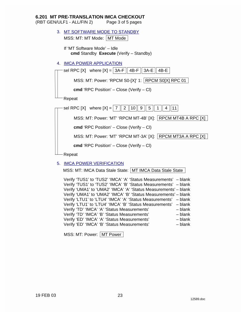
3. MT SOFTWARE MODE TO STANDBY
MSS: MT: MT Mode: MT Mode
If ‘MT Software Mode’ – Idle cmd Standby Execute (Verify – Standby)
4. IMCA POWER APPLICATION
sel RPC [X] where [X] = 3A-F 4B-F 3A-E 4B-E
MSS: MT: Power: ‘RPCM S0-[X]’ 1: RPCM S0[X] RPC 01
cmd ‘RPC Position’ – Close (Verify – Cl)
Repeat
sel RPC [X] where [X] = 9 10 2 7 1 5 4 11
MSS: MT: Power: ‘MT’ ‘RPCM MT-4B’ [X]: RPCM MT4B A RPC [X]
cmd ‘RPC Position’ – Close (Verify – Cl)
MSS: MT: Power: ‘MT’ ‘RPCM MT-3A’ [X]: RPCM MT3A A RPC [X]
cmd ‘RPC Position’ – Close (Verify – Cl)
Repeat 5. IMCA POWER VERIFICATION
MSS: MT: IMCA Data Stale State: MT IMCA Data Stale State
Verify ‘TUS1’ to ‘TUS2’ ‘IMCA’ ‘A’ ‘Status Measurements’ – blank Verify ‘TUS1’ to ‘TUS2’ ‘IMCA’ ‘B’ ‘Status Measurements’ – blank Verify ‘UMA1’ to ‘UMA2’ ‘IMCA’ ‘A’ ‘Status Measurements’ – blank Verify ‘UMA1’ to ‘UMA2’ ‘IMCA’ ‘B’ ‘Status Measurements’ – blank Verify ‘LTU1’ to ‘LTU4’ ‘IMCA’ ‘A’ ‘Status Measurements’ – blank Verify ‘LTU1’ to ‘LTU4’ ‘IMCA’ ‘B’ ‘Status Measurements’ – blank Verify ‘TD’ ‘IMCA’ ‘A’ ‘Status Measurements’ – blank Verify ‘TD’ ‘IMCA’ ‘B’ ‘Status Measurements’ – blank Verify ‘ED’ ‘IMCA’ ‘A’ ‘Status Measurements’ – blank Verify ‘ED’ ‘IMCA’ ‘B’ ‘Status Measurements’ – blank
MSS: MT: Power: MT Power
23

6.201 MT PRE-TRANSLATION IMCA CHECKOUT (RBT GEN/ULF1 - ALL/FIN 2) Page 4 of 5 pages
19 FEB 03 12589.doc
Verify ‘TUS1’ ‘RPCM S0-3A-F’ ‘Mode’ – Standby Verify ‘TUS1’ ‘RPCM S0-3A-F’ ‘Fault’ – blank Verify ‘TUS1’ ‘RPCM S0-4B-F’ ‘Mode’ – Standby Verify ‘TUS1’ ‘RPCM S0-4B-F’ ‘Fault’ – blank Verify ‘TUS2’ ‘RPCM S0-3A-E’ ‘Mode’ – Standby Verify ‘TUS2’ ‘RPCM S0-3A-E’ ‘Fault’ – blank Verify ‘TUS2’ ‘RPCM S0-4B-E’ ‘Mode’ – Standby Verify ‘TUS2’ ‘RPCM S0-4B-E’ ‘Fault’ – blank
Verify ‘MT’ ‘RPCM MT-4B’ ‘UMA1’ to ‘UMA2’ ‘Mode’ – Standby Verify ‘MT’ ‘RPCM MT-4B’ ‘UMA1’ to ‘UMA2’ ‘Fault’ – blank Verify ‘MT’ ‘RPCM MT-3A’ ‘UMA1’ to ‘UMA2’ ‘Mode’ – Standby Verify ‘MT’ ‘RPCM MT-3A’ ‘UMA1’ to ‘UMA2’ ‘Fault’ – blank Verify ‘MT’ ‘RPCM MT-4B’ ‘LTU1’ to ‘LTU4’ ‘Mode’ – Standby Verify ‘MT’ ‘RPCM MT-4B’ ‘LTU1’ to ‘LTU4’ ‘Fault’ – blank Verify ‘MT’ ‘RPCM MT-3A’ ‘LTU1’ to ‘LTU4’ ‘Mode’ – Standby Verify ‘MT’ ‘RPCM MT-3A’ ‘LTU1’ to ‘LTU4’ ‘Fault’ – blank Verify ‘MT’ ‘RPCM MT-4B’ ‘TD’ ‘Mode’ – Standby Verify ‘MT’ ‘RPCM MT-4B’ ‘TD’ ‘Fault’ – blank Verify ‘MT’ ‘RPCM MT-3A’ ‘TD’ ‘Mode’ – Standby Verify ‘MT’ ‘RPCM MT-3A’ ‘TD’ ‘Fault’ – blank Verify ‘MT’ ‘RPCM MT-4B’ ‘ED’ ‘Mode’ – Standby Verify ‘MT’ ‘RPCM MT-4B’ ‘ED’ ‘Fault’ – blank Verify ‘MT’ ‘RPCM MT-3A’ ‘ED’ ‘Mode’ – Standby Verify ‘MT’ ‘RPCM MT-3A’ ‘ED’ ‘Fault’ – blank
6. IMCA POWER REMOVAL
sel RPC [X] where [X] = 3A-F 4B-F 3A-E 4B-E
MSS: MT: Power: ‘RPCM S0-[X]’ 1: RPCM S0[X] RPC 01
cmd ‘RPC Position’ – Open (Verify – Op)
Repeat
sel RPC [X] where [X] = 9 10 2 7 1 5 4 11
MSS: MT: Power: ‘MT’ ‘RPCM MT-4B’ [X]: RPCM MT4B A RPC [X]
cmd ‘RPC Position’ – Open (Verify – Op)
MSS: MT: Power: ‘MT’ ‘RPCM MT-3A’ [X]: RPCM MT3A A RPC [X]
cmd ‘RPC Position’ – Open (Verify – Op)
Repeat
24

6.201 MT PRE-TRANSLATION IMCA CHECKOUT (RBT GEN/ULF1 - ALL/FIN 2) Page 5 of 5 pages
19 FEB 03 12589.doc
7. MT SOFTWARE SHUTDOWN MSS: MT: MT Mode: MT Mode
cmd Idle Execute (Verify ‘MT Software Mode’ – Idle) cmd Disable MT Process Execute (Verify ‘MT Process State’ – Disabled)
8. IMCA RT I/O INHIBIT
MSS: MT: ‘MT’ ‘Amp 1’ MT LB A: RT Status: LB MT 1 RT Status
cmd ‘RT Status’ ‘00 LTU 1P’ Inhibit Execute (Verify – Inh) cmd ‘RT Status’ ‘01 LTU 2P’ Inhibit Execute (Verify – Inh) cmd ‘RT Status’ ‘02 LTU 3P’ Inhibit Execute (Verify – Inh) cmd ‘RT Status’ ‘03 LTU 1S’ Inhibit Execute (Verify – Inh) cmd ‘RT Status’ ‘04 LTU 4P’ Inhibit Execute (Verify – Inh) cmd ‘RT Status’ ‘05 LTU 3S’ Inhibit Execute (Verify – Inh) cmd ‘RT Status’ ‘06 LTU 2S’ Inhibit Execute (Verify – Inh) cmd ‘RT Status’ ‘07 LTU 4S’ Inhibit Execute (Verify – Inh) cmd ‘RT Status’ ‘08 ED P’ Inhibit Execute (Verify – Inh) cmd ‘RT Status’ ‘09 TD P’ Inhibit Execute (Verify – Inh) cmd ‘RT Status’ ‘11 ED S’ Inhibit Execute (Verify – Inh)
sel RT Status Cont. RT#16-25
LB MT 1 RT Status Cont
cmd ‘RT Status’ ‘14 TD S’ Inhibit Execute (Verify – Inh) cmd ‘RT Status’ ‘16 TUS 1S’ Inhibit Execute (Verify – Inh) cmd ‘RT Status’ ‘17 TUS 2P’ Inhibit Execute (Verify – Inh) cmd ‘RT Status’ ‘18 TUS 2S’ Inhibit Execute (Verify – Inh) cmd ‘RT Status’ ‘19 UMA 1P’ Inhibit Execute (Verify – Inh) cmd ‘RT Status’ ‘20 UMA 1S’ Inhibit Execute (Verify – Inh) cmd ‘RT Status’ ‘21 UMA 2P’ Inhibit Execute (Verify – Inh) cmd ‘RT Status’ ‘22 UMA 2S’ Inhibit Execute (Verify – Inh) cmd ‘RT Status’ ‘24 TUS 1P’ Inhibit Execute (Verify – Inh)
25

This Page Intentionally Blank
22 DEC 04
26

6.210 MT GENERIC AUTO TRANSLATION USING STRING A(B) IMCAS (RBT GEN/X2R4 - ALL/FIN) Page 1 of 12 pages
14 DEC 04 12985.doc
NOTE 1. IMCAs take approximately 6 seconds to complete self-tests once
power is applied. 2. MT IMCA RT FDIR is enabled to the TUS IMCAs during the
translation (step 17). This allows the software in the EXT MDM to halt MT motion in the case of a TUS IMCA failure. Enabling TUS IMCA FDIR only during the translation limits annunciation of nuisance IMCA Comm Fail Robotics advisories and MT Local Bus channel switching. The nuisance messages and channel switching only occur when all of the following are true: IO and FDIR are enabled, EXT MDM detects RPC closed, and EXT MDM detects loss of comm with the IMCA (SCR 28581).
1. IMCA RT I/O ENABLE PCS MSS: MT: Auto Translate: MT Auto Translate
Verify ‘SEPS Process State’ – Initiated Verify ‘IMCA Process State’ – Initiated
MSS: MT: ‘MT’ ‘Amp1’ MT LB A: RT Status: LB MT 1 RT Status
cmd ‘RT Status’ ‘00 LTU 1P’ Enable Execute (Verify – Ena) cmd ‘RT Status’ ‘01 LTU 2P’ Enable Execute (Verify – Ena) cmd ‘RT Status’ ‘02 LTU 3P’ Enable Execute (Verify – Ena) cmd ‘RT Status’ ‘03 LTU 1S’ Enable Execute (Verify – Ena) cmd ‘RT Status’ ‘04 LTU 4P’ Enable Execute (Verify – Ena) cmd ‘RT Status’ ‘05 LTU 3S’ Enable Execute (Verify – Ena) cmd ‘RT Status’ ‘06 LTU 2S’ Enable Execute (Verify – Ena) cmd ‘RT Status’ ‘07 LTU 4S’ Enable Execute (Verify – Ena) cmd ‘RT Status’ ‘08 ED P’ Enable Execute (Verify – Ena) cmd ‘RT Status’ ‘09 TD P’ Enable Execute (Verify – Ena) cmd ‘RT Status’ ‘11 ED S’ Enable Execute (Verify – Ena)
sel RT Status Cont. RT#16-25
LB MT 1 RT Status Cont
cmd ‘RT Status’ ‘14 TD S’ Enable Execute (Verify – Ena) cmd ‘RT Status’ ‘16 TUS 1S’ Enable Execute (Verify – Ena) cmd ‘RT Status’ ‘17 TUS 2P’ Enable Execute (Verify – Ena) cmd ‘RT Status’ ‘18 TUS 2S’ Enable Execute (Verify – Ena) cmd ‘RT Status’ ‘19 UMA 1P’ Enable Execute (Verify – Ena) cmd ‘RT Status’ ‘20 UMA 1S’ Enable Execute (Verify – Ena) cmd ‘RT Status’ ‘21 UMA 2P’ Enable Execute (Verify – Ena) cmd ‘RT Status’ ‘22 UMA 2S’ Enable Execute (Verify – Ena) cmd ‘RT Status’ ‘24 TUS 1P’ Enable Execute (Verify – Ena)
27

6.210 MT GENERIC AUTO TRANSLATION USING STRING A(B) IMCAS (RBT GEN/X2R4 - ALL/FIN) Page 2 of 12 pages
14 DEC 04 12985.doc
2. MT ORU TEMPERATURE VERIFICATION CAUTION
Damage or reduced lifetime to MT components may result if the startup temperatures within this step are equal to or higher than the value shown. The IMCAs should not exceed 71.4 deg C in operation.
2.1 Non-IMCA Temperature Verification
MSS: MT: Thermal: MT Thermal
Verify ‘TUS1’ to ‘TUS2’ ‘Gearbox’ (two) < 47.8 deg C Verify ‘MT’ ‘RPCM MT-4B’ ‘RPCM Bracket Temp’ < 48.9 deg C Verify ‘MT’ ‘RPCM MT-3A’ ‘RPCM Bracket Temp’ < 48.9 deg C
2.2 IMCA Power Application
sel RPCM [X] where [X] = 3A-F 4B-F 3A-E 4B-E
MSS: MT: Power: ‘RPCM S0-[X]’ 1: RPCM S0[X] RPC 01
cmd ‘RPC Position’ – Close (Verify – Cl)
Repeat
sel RPC [X] where [X] = 9 10 2 7 1 5 4 11
MSS: MT: Power: ‘MT’ ‘RPCM MT-4B’ [X]: RPCM MT4B A RPC [X]
cmd ‘RPC Position’ – Close (Verify – Cl)
MSS: MT: Power: ‘MT’ ‘RPCM MT-3A’ [X]: RPCM MT3A A RPC [X]
cmd ‘RPC Position’ – Close (Verify – Cl)
Repeat
28
6.210 MT GENERIC AUTO TRANSLATION USING STRING A(B) IMCAS (RBT GEN/X2R4 - ALL/FIN) Page 3 of 12 pages
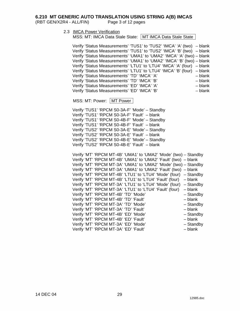
14 DEC 04 12985.doc
2.3 IMCA Power Verification MSS: MT: IMCA Data Stale State: MT IMCA Data Stale State
Verify ‘Status Measurements’ ‘TUS1’ to ‘TUS2’ ‘IMCA’ ‘A’ (two) – blank Verify ‘Status Measurements’ ‘TUS1’ to ‘TUS2’ ‘IMCA’ ‘B’ (two) – blank Verify ‘Status Measurements’ ‘UMA1’ to ‘UMA2’ ‘IMCA’ ‘A’ (two) – blank Verify ‘Status Measurements’ ‘UMA1’ to ‘UMA2’ ‘IMCA’ ‘B’ (two) – blank Verify ‘Status Measurements’ ‘LTU1’ to ‘LTU4’ ‘IMCA’ ‘A’ (four) – blank Verify ‘Status Measurements’ ‘LTU1’ to ‘LTU4’ ‘IMCA’ ‘B’ (four) – blank Verify ‘Status Measurements’ ‘TD’ ‘IMCA’ ‘A’ – blank Verify ‘Status Measurements’ ‘TD’ ‘IMCA’ ‘B’ – blank Verify ‘Status Measurements’ ‘ED’ ‘IMCA’ ‘A’ – blank Verify ‘Status Measurements’ ‘ED’ ‘IMCA’ ‘B’ – blank
MSS: MT: Power: MT Power
Verify ‘TUS1’ ‘RPCM S0-3A-F’ ‘Mode’ – Standby Verify ‘TUS1’ ‘RPCM S0-3A-F’ ‘Fault’ – blank Verify ‘TUS1’ ‘RPCM S0-4B-F’ ‘Mode’ – Standby Verify ‘TUS1’ ‘RPCM S0-4B-F’ ‘Fault’ – blank Verify ‘TUS2’ ‘RPCM S0-3A-E’ ‘Mode’ – Standby Verify ‘TUS2’ ‘RPCM S0-3A-E’ ‘Fault’ – blank Verify ‘TUS2’ ‘RPCM S0-4B-E’ ‘Mode’ – Standby Verify ‘TUS2’ ‘RPCM S0-4B-E’ ‘Fault’ – blank
Verify ‘MT’ ‘RPCM MT-4B’ ‘UMA1’ to ‘UMA2’ ‘Mode’ (two) – Standby Verify ‘MT’ ‘RPCM MT-4B’ ‘UMA1’ to ‘UMA2’ ‘Fault’ (two) – blank Verify ‘MT’ ‘RPCM MT-3A’ ‘UMA1’ to ‘UMA2’ ‘Mode’ (two) – Standby Verify ‘MT’ ‘RPCM MT-3A’ ‘UMA1’ to ‘UMA2’ ‘Fault’ (two) – blank Verify ‘MT’ ‘RPCM MT-4B’ ‘LTU1’ to ‘LTU4’ ‘Mode’ (four) – Standby Verify ‘MT’ ‘RPCM MT-4B’ ‘LTU1’ to ‘LTU4’ ‘Fault’ (four) – blank Verify ‘MT’ ‘RPCM MT-3A’ ‘LTU1’ to ‘LTU4’ ‘Mode’ (four) – Standby Verify ‘MT’ ‘RPCM MT-3A’ ‘LTU1’ to ‘LTU4’ ‘Fault’ (four) – blank Verify ‘MT’ ‘RPCM MT-4B’ ‘TD’ ‘Mode’ – Standby Verify ‘MT’ ‘RPCM MT-4B’ ‘TD’ ‘Fault’ – blank Verify ‘MT’ ‘RPCM MT-3A’ ‘TD’ ‘Mode’ – Standby Verify ‘MT’ ‘RPCM MT-3A’ ‘TD’ ‘Fault’ – blank Verify ‘MT’ ‘RPCM MT-4B’ ‘ED’ ‘Mode’ – Standby Verify ‘MT’ ‘RPCM MT-4B’ ‘ED’ ‘Fault’ – blank Verify ‘MT’ ‘RPCM MT-3A’ ‘ED’ ‘Mode’ – Standby Verify ‘MT’ ‘RPCM MT-3A’ ‘ED’ ‘Fault’ – blank
29
6.210 MT GENERIC AUTO TRANSLATION USING STRING A(B) IMCAS (RBT GEN/X2R4 - ALL/FIN) Page 4 of 12 pages
14 DEC 04 12985.doc
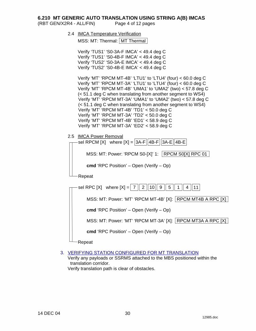
2.4 IMCA Temperature Verification MSS: MT: Thermal: MT Thermal
Verify ‘TUS1’ ‘S0-3A-F IMCA’ < 49.4 deg C Verify ‘TUS1’ ‘S0-4B-F IMCA’ < 49.4 deg C Verify ‘TUS2’ ‘S0-3A-E IMCA’ < 49.4 deg C Verify ‘TUS2’ ‘S0-4B-E IMCA’ < 49.4 deg C
Verify ‘MT’ ‘RPCM MT-4B’ ‘LTU1’ to ‘LTU4’ (four) < 60.0 deg C Verify ‘MT’ ‘RPCM MT-3A’ ‘LTU1’ to ‘LTU4’ (four) < 60.0 deg C Verify ‘MT’ ‘RPCM MT-4B’ ‘UMA1’ to ‘UMA2’ (two) < 57.8 deg C (< 51.1 deg C when translating from another segment to WS4) Verify ‘MT’ ‘RPCM MT-3A’ ‘UMA1’ to ‘UMA2’ (two) < 57.8 deg C (< 51.1 deg C when translating from another segment to WS4) Verify ‘MT’ ‘RPCM MT-4B’ ‘TD1’ < 50.0 deg C Verify ‘MT’ ‘RPCM MT-3A’ ‘TD2’ < 50.0 deg C Verify ‘MT’ ‘RPCM MT-4B’ ‘ED1’ < 58.9 deg C Verify ‘MT’ ‘RPCM MT-3A’ ‘ED2’ < 58.9 deg C
2.5 IMCA Power Removal
sel RPCM [X] where [X] = 3A-F 4B-F 3A-E 4B-E
MSS: MT: Power: ‘RPCM S0-[X]’ 1: RPCM S0[X] RPC 01
cmd ‘RPC Position’ – Open (Verify – Op)
Repeat
sel RPC [X] where [X] = 9 10 2 7 1 5 4 11
MSS: MT: Power: ‘MT’ ‘RPCM MT-4B’ [X]: RPCM MT4B A RPC [X]
cmd ‘RPC Position’ – Open (Verify – Op)
MSS: MT: Power: ‘MT’ ‘RPCM MT-3A’ [X]: RPCM MT3A A RPC [X]
cmd ‘RPC Position’ – Open (Verify – Op)
Repeat 3. VERIFYING STATION CONFIGURED FOR MT TRANSLATION
Verify any payloads or SSRMS attached to the MBS positioned within the translation corridor.
Verify translation path is clear of obstacles.
30

6.210 MT GENERIC AUTO TRANSLATION USING STRING A(B) IMCAS (RBT GEN/X2R4 - ALL/FIN) Page 5 of 12 pages
14 DEC 04 12985.doc
4. MT AUTOSAFING ENABLED VERIFICATION MSS: MT: Auto Safing: MT Autosafing
√‘MT Autosafing State’ – ENA
5. MT POSITION CHECK
MSS: MT: MT Mode: MT Mode
√‘MT Process State’ – Disabled
MSS: MT: Mobile Transporter
√‘MT Position’ – Matches value shown in Table 1 to within ±12 cm
Table 1. MT Positions
Location MT Position (cm) WS9 3672.8 WS1 2169.2 WS2 1653.5 WS3 795.0 WS4 287.0
Launch Site -254.0 WS5 -525.8 WS6 -795.0 WS7 -1653.5 WS8 -2169.2
WS10 -3672.8 6. MT SOFTWARE PROCESS INITIATION AND MODE TO AUTO
MSS: MT: Auto Translate: MT Auto Translate
cmd Initiate MT Process Execute (Verify ‘MT Process State’ – Initiated) cmd Mode MT to Standby Execute (Verify ‘MT Software Mode’ – Standby) cmd Mode MT to Auto Execute (Verify ‘MT Software Mode’ – Auto)
7. HARDWARE CONFIGURATION SELECTION
NOTE If HW Config C1 selected, apply power to only RPCM MT-4B IMCAs in following procedures. Likewise, if HW Config C2 selected, apply power to only RPCM MT-3A IMCAs.
√MCC-H for MT Hardware Configuration Selection
cmd ‘HW Config’ 1(2) Execute (Verify – C1(C2))
31
6.210 MT GENERIC AUTO TRANSLATION USING STRING A(B) IMCAS (RBT GEN/X2R4 - ALL/FIN) Page 6 of 12 pages
14 DEC 04 12985.doc
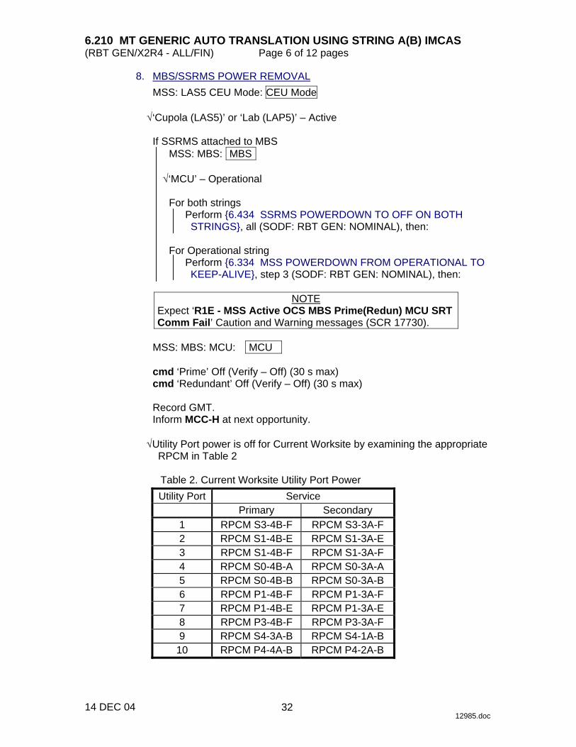
8. MBS/SSRMS POWER REMOVAL MSS: LAS5 CEU Mode: CEU Mode
√‘Cupola (LAS5)’ or ‘Lab (LAP5)’ – Active
If SSRMS attached to MBS
MSS: MBS: MBS
√‘MCU’ – Operational
For both strings Perform {6.434 SSRMS POWERDOWN TO OFF ON BOTH STRINGS}, all (SODF: RBT GEN: NOMINAL), then:
For Operational string
Perform {6.334 MSS POWERDOWN FROM OPERATIONAL TO KEEP-ALIVE}, step 3 (SODF: RBT GEN: NOMINAL), then:
NOTE
Expect ‘R1E - MSS Active OCS MBS Prime(Redun) MCU SRT Comm Fail’ Caution and Warning messages (SCR 17730).
MSS: MBS: MCU: MCU
cmd ‘Prime’ Off (Verify – Off) (30 s max) cmd ‘Redundant’ Off (Verify – Off) (30 s max)
Record GMT. Inform MCC-H at next opportunity.
√Utility Port power is off for Current Worksite by examining the appropriate
RPCM in Table 2
Table 2. Current Worksite Utility Port Power
Utility Port Service Primary Secondary
1 RPCM S3-4B-F RPCM S3-3A-F 2 RPCM S1-4B-E RPCM S1-3A-E 3 RPCM S1-4B-F RPCM S1-3A-F 4 RPCM S0-4B-A RPCM S0-3A-A 5 RPCM S0-4B-B RPCM S0-3A-B 6 RPCM P1-4B-F RPCM P1-3A-F 7 RPCM P1-4B-E RPCM P1-3A-E 8 RPCM P3-4B-F RPCM P3-3A-F 9 RPCM S4-3A-B RPCM S4-1A-B
10 RPCM P4-4A-B RPCM P4-2A-B
32
6.210 MT GENERIC AUTO TRANSLATION USING STRING A(B) IMCAS (RBT GEN/X2R4 - ALL/FIN) Page 7 of 12 pages
14 DEC 04 12985.doc
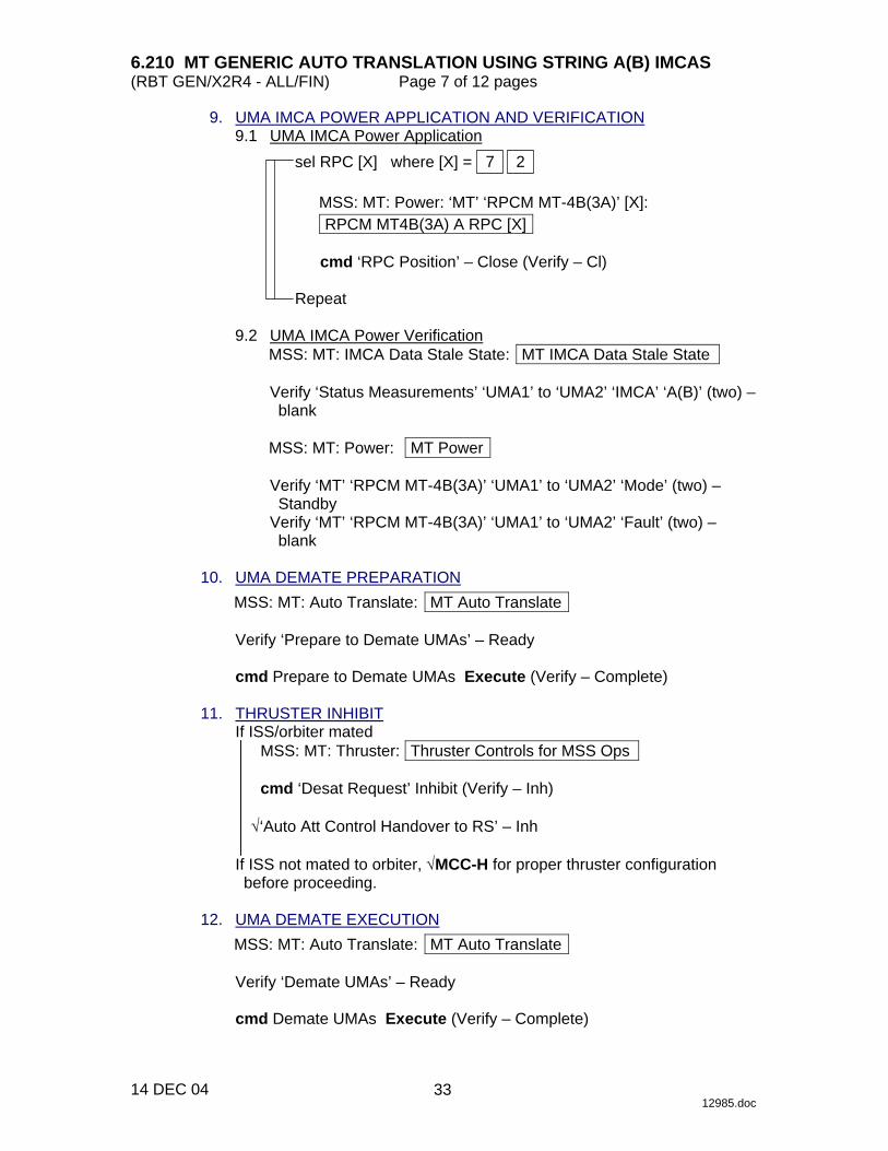
9. UMA IMCA POWER APPLICATION AND VERIFICATION 9.1 UMA IMCA Power Application
sel RPC [X] where [X] = 2 7
MSS: MT: Power: ‘MT’ ‘RPCM MT-4B(3A)’ [X]: RPCM MT4B(3A) A RPC [X]
cmd ‘RPC Position’ – Close (Verify – Cl)
Repeat
9.2 UMA IMCA Power Verification
MSS: MT: IMCA Data Stale State: MT IMCA Data Stale State
Verify ‘Status Measurements’ ‘UMA1’ to ‘UMA2’ ‘IMCA’ ‘A(B)’ (two) – blank
MSS: MT: Power: MT Power
Verify ‘MT’ ‘RPCM MT-4B(3A)’ ‘UMA1’ to ‘UMA2’ ‘Mode’ (two) – Standby
Verify ‘MT’ ‘RPCM MT-4B(3A)’ ‘UMA1’ to ‘UMA2’ ‘Fault’ (two) – blank
10. UMA DEMATE PREPARATION
MSS: MT: Auto Translate: MT Auto Translate
Verify ‘Prepare to Demate UMAs’ – Ready
cmd Prepare to Demate UMAs Execute (Verify – Complete) 11. THRUSTER INHIBIT
If ISS/orbiter mated MSS: MT: Thruster: Thruster Controls for MSS Ops
cmd ‘Desat Request’ Inhibit (Verify – Inh)
√‘Auto Att Control Handover to RS’ – Inh
If ISS not mated to orbiter, √MCC-H for proper thruster configuration before proceeding.
12. UMA DEMATE EXECUTION
MSS: MT: Auto Translate: MT Auto Translate
Verify ‘Demate UMAs’ – Ready
cmd Demate UMAs Execute (Verify – Complete)
33
6.210 MT GENERIC AUTO TRANSLATION USING STRING A(B) IMCAS (RBT GEN/X2R4 - ALL/FIN) Page 8 of 12 pages
14 DEC 04 12985.doc
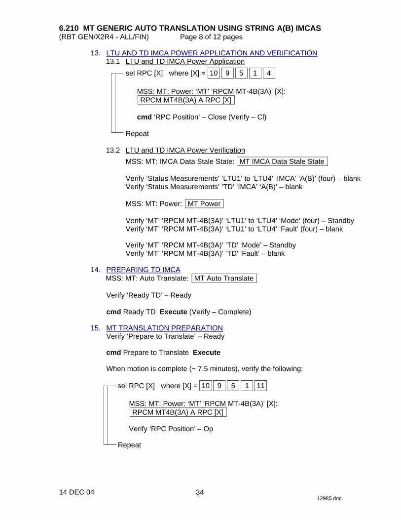
13. LTU AND TD IMCA POWER APPLICATION AND VERIFICATION 13.1 LTU and TD IMCA Power Application
sel RPC [X] where [X] = 1 5 9 10 4
MSS: MT: Power: ‘MT’ ‘RPCM MT-4B(3A)’ [X]: RPCM MT4B(3A) A RPC [X]
cmd ‘RPC Position’ – Close (Verify – Cl)
Repeat
13.2 LTU and TD IMCA Power Verification
MSS: MT: IMCA Data Stale State: MT IMCA Data Stale State
Verify ‘Status Measurements’ ‘LTU1’ to ‘LTU4’ ‘IMCA’ ‘A(B)’ (four) – blank Verify ‘Status Measurements’ ‘TD’ ‘IMCA’ ‘A(B)’ – blank
MSS: MT: Power: MT Power
Verify ‘MT’ ‘RPCM MT-4B(3A)’ ‘LTU1’ to ‘LTU4’ ‘Mode’ (four) – Standby Verify ‘MT’ ‘RPCM MT-4B(3A)’ ‘LTU1’ to ‘LTU4’ ‘Fault’ (four) – blank
Verify ‘MT’ ‘RPCM MT-4B(3A)’ ‘TD’ ‘Mode’ – Standby Verify ‘MT’ ‘RPCM MT-4B(3A)’ ‘TD’ ‘Fault’ – blank
14. PREPARING TD IMCA
MSS: MT: Auto Translate: MT Auto Translate
Verify ‘Ready TD’ – Ready
cmd Ready TD Execute (Verify – Complete) 15. MT TRANSLATION PREPARATION
Verify ‘Prepare to Translate’ – Ready
cmd Prepare to Translate Execute
When motion is complete (~ 7.5 minutes), verify the following:
sel RPC [X] where [X] = 1 5 9 10 11
MSS: MT: Power: ‘MT’ ‘RPCM MT-4B(3A)’ [X]: RPCM MT4B(3A) A RPC [X]
Verify ‘RPC Position’ – Op
Repeat
34

6.210 MT GENERIC AUTO TRANSLATION USING STRING A(B) IMCAS (RBT GEN/X2R4 - ALL/FIN) Page 9 of 12 pages
14 DEC 04 12985.doc
16. TUS IMCA RT FDIR ENABLE MSS: MT: ‘MT’ ‘Amp1’ MT LB A: RT Status: RT Status Cont. RT#16-25
LB MT 1 RT Status Cont If HW Config C1 selected in step 7
cmd ‘RT FDIR Status’ ‘24 TUS 1P’ Enable FDIR Execute (Verify – Ena) cmd ‘RT FDIR Status’ ‘17 TUS 2P’ Enable FDIR Execute (Verify – Ena)
If HW Config C2 selected in step 7
cmd ‘RT FDIR Status’ ‘16 TUS 1S’ Enable FDIR Execute (Verify – Ena) cmd ‘RT FDIR Status’ ‘18 TUS 2S’ Enable FDIR Execute (Verify – Ena)
17. MT TRANSLATION AND LATCH/MATE EXECUTION
NOTE Pause function only available during the following:
Translate Phase 1 portion of Translate Inboard of SARJ. Translate Phase 1 and Translate Phase 3 portion of Translate across SARJ.
If Current and Destination Worksite ≤ 8
MSS: MT: Auto Translate: Translate Inboard of SARJ: MT Translate Inboard of SARJ
Verify ‘Event in progress’ – Ready
sel ‘Current Worksite’ – as desired sel ‘Destination Worksite’ – as desired sel ‘Payload Mass’ – as desired
cmd Translate Inboard of SARJ Execute
If Current or Destination Worksite ≥ 9
MSS: MT: Auto Translate: Translate across SARJ: MT Translate across SARJ
Verify ‘Event in progress’ – Ready
sel ‘Current Worksite’ – as desired sel ‘Destination Worksite’ – as desired
cmd Translate across SARJ Execute
MSS: MT: Mobile Transporter
Verify ‘Destination WS’ – as chosen Verify ‘MT Position’ – changing Verify ‘MT Velocity’: -3.0 to 3.0 Verify MT bug is moving from Current to Destination Worksite.
35

6.210 MT GENERIC AUTO TRANSLATION USING STRING A(B) IMCAS (RBT GEN/X2R4 - ALL/FIN) Page 10 of 12 pages
14 DEC 04 12985.doc
NOTE Because FDIR is Enabled to the TUS IMCAs, expect the following messages to annunciate and return to Norm twice: once during the IMCA Built In Test (communication is interrupted for several seconds during the BIT) and again when power is removed (SPN 3265). If HW Config C1 is selected:
R9Z - MSS MT TUS 1 IMCA 1 Comm or Device Fail R9Z - MSS MT TUS 2 IMCA 1 Comm or Device Fail
If HW Config C2 is selected: R9Z - MSS MT TUS 1 IMCA 2 Comm or Device Fail R9Z - MSS MT TUS 2 IMCA 2 Comm or Device Fail
MSS: MT: Auto Translate: Translate Inboard of SARJ (Translate across SARJ): MT Translate Inboard of SARJ (MT Translate across SARJ)
Verify ‘Event in progress’ – Complete
18. THRUSTER ENABLE
If ISS/orbiter mated MSS: MT: Thruster: Thruster Controls for MSS Ops
cmd ‘Desat Request’ Enable (Verify – Ena)
If ISS not mated to orbiter, √MCC-H for proper thruster configuration.
19. TUS AND MT IMCA POWER REMOVAL VERIFICATION 19.1 TUS IMCA Power Removal Verification
sel RPC [X] where [X] = 3A-F 4B-F 3A-E 4B-E
MSS: MT: Power: ‘RPCM S0-[X]’ 1: RPCM S0[X] RPC 01
Verify ‘RPC Position’ – Op
Repeat 19.2 MT IMCA Power Removal Verification
sel RPC [X] where [X] = 9 10 2 7 11 4 1 5
MSS: MT: Power: ‘MT’ ‘RPCM MT-4B(3A)’ [X]: RPCM MT4B(3A) A RPC [X]
Verify ‘RPC Position’ – Op
Repeat
36

6.210 MT GENERIC AUTO TRANSLATION USING STRING A(B) IMCAS (RBT GEN/X2R4 - ALL/FIN) Page 11 of 12 pages
14 DEC 04 12985.doc
20. MT SOFTWARE SHUTDOWN MSS: MT: Auto Translate: MT Auto Translate
cmd Mode MT to Standby Execute (Verify ‘MT Software Mode’ – Standby)
cmd Mode MT to Idle Execute (Verify ‘MT Software Mode’ – Idle) cmd Disable MT Process Execute (Verify ‘MT Process State’ – Disabled)
21. MT POSITION RESET
MSS: MT: MT Mode: MT Mode
input ‘MT Position’ per Table 3
Table 3. MT Positions
Location MT Position (cm) WS9 3672.8 WS1 2169.2 WS2 1653.5 WS3 795.0 WS4 287.0
Launch Site -254.0 WS5 -525.8 WS6 -795.0 WS7 -1653.5 WS8 -2169.2
WS10 -3672.8
cmd Load New MT Position Execute cmd Initiate MT Process Execute (Verify ‘MT Process State’ – Initiated)
MSS: MT: Mobile Transporter
Verify ‘MT Position Data Valid’ – √
MSS: MT: MT Mode: MT Mode
cmd Disable MT Process Execute (Verify ‘MT Process State’ – Disabled)
22. MSS POWERUP
Inform MCC-H, go for MBS Powerup (and SSRMS Powerup if based on MBS).
37

6.210 MT GENERIC AUTO TRANSLATION USING STRING A(B) IMCAS (RBT GEN/X2R4 - ALL/FIN) Page 12 of 12 pages
14 DEC 04 12985.doc
23. IMCA RT I/O AND FDIR INHIBIT MSS: MT: ‘MT’ ‘Amp1’ MT LB A: RT Status: LB MT 1 RT Status
cmd ‘RT Status’ ‘00 LTU 1P’ Inhibit Execute (Verify – Inh) cmd ‘RT Status’ ‘01 LTU 2P’ Inhibit Execute (Verify – Inh) cmd ‘RT Status’ ‘02 LTU 3P’ Inhibit Execute (Verify – Inh) cmd ‘RT Status’ ‘03 LTU 1S’ Inhibit Execute (Verify – Inh) cmd ‘RT Status’ ‘04 LTU 4P’ Inhibit Execute (Verify – Inh) cmd ‘RT Status’ ‘05 LTU 3S’ Inhibit Execute (Verify – Inh) cmd ‘RT Status’ ‘06 LTU 2S’ Inhibit Execute (Verify – Inh) cmd ‘RT Status’ ‘07 LTU 4S’ Inhibit Execute (Verify – Inh) cmd ‘RT Status’ ‘08 ED P’ Inhibit Execute (Verify – Inh) cmd ‘RT Status’ ‘09 TD P’ Inhibit Execute (Verify – Inh) cmd ‘RT Status’ ‘11 ED S’ Inhibit Execute (Verify – Inh)
sel RT Status Cont. RT#16-25
LB MT 1 RT Status Cont
If HW Config C1 selected in step 7
cmd ‘RT FDIR Status’ ‘24 TUS 1P’ Inhibit FDIR Execute (Verify – Inh) cmd ‘RT FDIR Status’ ‘17 TUS 2P’ Inhibit FDIR Execute (Verify – Inh)
If HW Config C2 selected in step 7
cmd ‘RT FDIR Status’ ‘16 TUS 1S’ Inhibit FDIR Execute (Verify – Inh) cmd ‘RT FDIR Status’ ‘18 TUS 2S’ Inhibit FDIR Execute (Verify – Inh)
cmd ‘RT Status’ ‘14 TD S’ Inhibit Execute (Verify – Inh) cmd ‘RT Status’ ‘16 TUS 1S’ Inhibit Execute (Verify – Inh) cmd ‘RT Status’ ‘17 TUS 2P’ Inhibit Execute (Verify – Inh) cmd ‘RT Status’ ‘18 TUS 2S’ Inhibit Execute (Verify – Inh) cmd ‘RT Status’ ‘19 UMA 1P’ Inhibit Execute (Verify – Inh) cmd ‘RT Status’ ‘20 UMA 1S’ Inhibit Execute (Verify – Inh) cmd ‘RT Status’ ‘21 UMA 2P’ Inhibit Execute (Verify – Inh) cmd ‘RT Status’ ‘22 UMA 2S’ Inhibit Execute (Verify – Inh) cmd ‘RT Status’ ‘24 TUS 1P’ Inhibit Execute (Verify – Inh)
38

6.311 MBS POA DIAGNOSTICS (RBT GEN/X2R4 - ALL/FIN 2/SPN) Page 1 of 1 page
14 DEC 04 13520.doc
1. SETUP PCS MSS: MBS: MBS
√‘MBS Safing’ – Safed
Verify ‘POA’ Loaded – blank 2. DIAGNOSTICS
MSS: MBS: Diagnostic: MBS Diagnostics
cmd ‘Diagnostics’ Test POA
NOTE The operator may cancel the current test by Safing (SPN 2467).
MSS: MBS: Discrete Log: MSS Discrete Log
Verify ‘Diagnostic Test: MBS POA … Test Passed’ (eleven) (SCR 30060).
If any tests fail, record which tests fail.
DCP SAFING → SAFE (Verify – ON) (SCR 21456, 23261) 3. CHECKPOINT DATA UPDATE PCS MSS: SSRMS: Checkpoint Data: Checkpoint Data
cmd Checkpoint Current Data (SCR 23238)
39

This Page Intentionally Blank
22 DEC 04
40
6.321 MBS POA CHECKOUT (RBT GEN/E9 - ALL/FIN 2/SPN) Page 1 of 2 pages
30 NOV 04 13522.doc
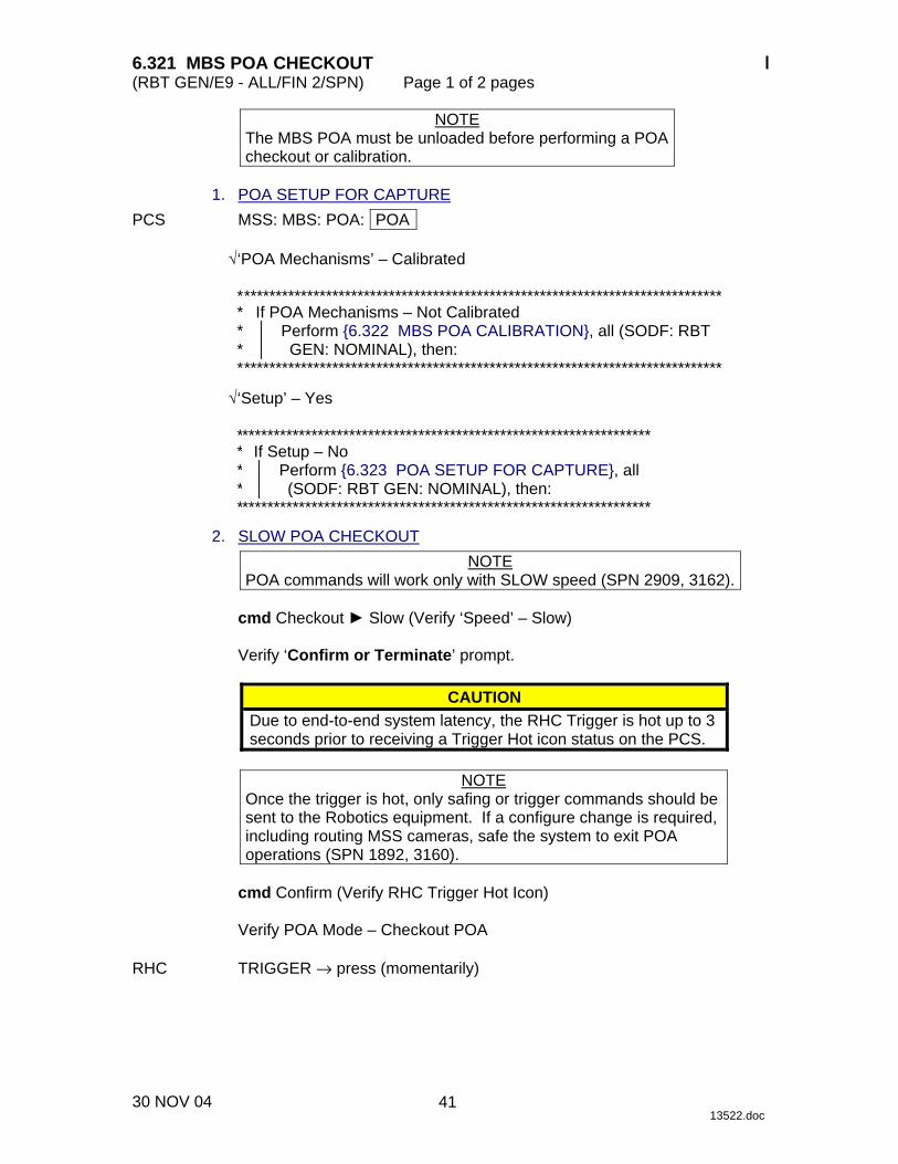
NOTE The MBS POA must be unloaded before performing a POA checkout or calibration.
1. POA SETUP FOR CAPTURE PCS MSS: MBS: POA: POA
√‘POA Mechanisms’ – Calibrated
* ***************************************************************************** * *
If POA Mechanisms – Not Calibrated Perform {6.322 MBS POA CALIBRATION}, all (SODF: RBT GEN: NOMINAL), then:
* ****************************************************************************
√‘Setup’ – Yes
****************************************************************** ***
If Setup – No Perform {6.323 POA SETUP FOR CAPTURE}, all (SODF: RBT GEN: NOMINAL), then:
****************************************************************** 2. SLOW POA CHECKOUT
NOTE POA commands will work only with SLOW speed (SPN 2909, 3162).
cmd Checkout ► Slow (Verify ‘Speed’ – Slow)
Verify ‘Confirm or Terminate’ prompt.
CAUTION Due to end-to-end system latency, the RHC Trigger is hot up to 3 seconds prior to receiving a Trigger Hot icon status on the PCS.
NOTE
Once the trigger is hot, only safing or trigger commands should be sent to the Robotics equipment. If a configure change is required, including routing MSS cameras, safe the system to exit POA operations (SPN 1892, 3160).
cmd Confirm (Verify RHC Trigger Hot Icon)
Verify POA Mode – Checkout POA
RHC TRIGGER → press (momentarily)
41

6.321 MBS POA CHECKOUT (RBT GEN/E9 - ALL/FIN 2/SPN) Page 2 of 2 pages
30 NOV 04 13522.doc
PCS Verify ‘Snare’ Close – blue (12 s max) Verify ‘Carriage’ Retract – blue (90 s max) Verify ‘Latch’ Latch – blue (65 s max) Verify ‘Umbilical’ Mate – blue (10 s max) Verify ‘Umbilical’ Demate – blue (10 s max) Verify ‘Latch’ Unlatch – blue (65 s max) Verify ‘Carriage’ Derigidize – blue (90 s max) Verify ‘Snare’ Open – blue (12 s max) Verify ‘Carriage’ Extend – blue (90 s max)
42
6.322 MBS POA CALIBRATION (RBT GEN/X2R4 - ALL/FIN 2/SPN) Page 1 of 1 page
20 DEC 04 13523.doc
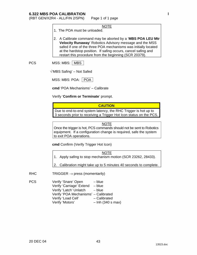
NOTE 1. The POA must be unloaded. 2. A Calibrate command may be aborted by a ‘MBS POA LEU Mtr
Velocity Runaway’ Robotics Advisory message and the MSS safed if one of the three POA mechanisms was initially located at the hardstop position. If safing occurs, cancel safing and restart this procedure from the beginning (SCR 20379).
PCS MSS: MBS: MBS
√‘MBS Safing’ – Not Safed
MSS: MBS: POA: POA
cmd ‘POA Mechanisms’ – Calibrate
Verify ‘Confirm or Terminate’ prompt.
CAUTION Due to end-to-end system latency, the RHC Trigger is hot up to 3 seconds prior to receiving a Trigger Hot Icon status on the PCS.
NOTE
Once the trigger is hot, PCS commands should not be sent to Robotics equipment. If a configuration change is required, safe the system to exit POA operations.
cmd Confirm (Verify Trigger Hot Icon)
NOTE
1. Apply safing to stop mechanism motion (SCR 23262, 28433). 2. Calibration might take up to 5 minutes 40 seconds to complete.
RHC TRIGGER → press (momentarily) PCS Verify ‘Snare’ Open – blue
Verify ‘Carriage’ Extend – blue Verify ‘Latch’ Unlatch − blue Verify ‘POA Mechanisms’ – Calibrated Verify ‘Load Cell’ – Calibrated Verify ‘Motors’ – Inh (340 s max)
43

This Page Intentionally Blank
22 DEC 04
44

6.323 MBS POA SETUP FOR CAPTURE (RBT GEN/E10 - ALL/FIN 2/SPN) Page 1 of 1 page
29 NOV 04 13524.doc
NOTE 1. The POA must be unloaded and calibrated. 2. If no POA response is observed within 70 seconds of a
command being issued, safe and reattempt (SCR 19378). PCS MSS: MBS: POA: POA
cmd Capture ► Setup ► Slow (Verify ‘Speed’ – Slow) (SCR 23242)
Verify ‘Confirm or Terminate’ prompt.
CAUTION Due to end-to-end system latency, the RHC Trigger is hot up to three seconds prior to receiving a Trigger Hot Icon status on the PCS.
NOTE
Once the trigger is hot, PCS commands should not be sent to Robotics equipment. If a configuration change is required, safe the system to exit POA operations.
cmd Confirm (Verify RHC Trigger Hot Icon)
NOTE
Apply safing to stop mechanism motion (SCR 23262, 14662). RHC TRIGGER → press (momentarily) PCS Verify ‘Snare’ Open – blue
Verify ‘Carriage’ Extend – blue Verify ‘Latch’ Unlatch – blue Verify ‘Motors’ – Inh (340 s max)
45

This Page Intentionally Blank
22 DEC 04
46

6.325 MBS POA AUTOMATIC RELEASE (RBT GEN/E10 - ALL/FIN 2/SPN) Page 1 of 3 pages
20 DEC 04 13526.doc
NOTE If no POA response is observed within 70 seconds of a command being issued, safe and reattempt (SCR 19378).
1. POA CALIBRATION STATUS VERIFICATION PCS MSS: MBS: POA: POA
If POA Mechanisms – Not Calibrated Go to {8.212 POA MANUAL RELEASE WITH UNCALIBRATED POA}, all (SODF: RBT GEN: CORRECTIVE).
2. POA CARRIAGE RIGIDIZATION
MSS: MBS: MBS
√ ‘MSS Safing’ - Not Safed
MSS: MBS: POA: POA
If ‘Latch’ Latch – blue and ‘Carriage’ Tension < 2891 N cmd Rigidize ► Slow (Verify Speed – Slow) (SCR 23242)
Verify ‘Confirm or Terminate’ prompt.
NOTE
1. Once the trigger is hot, PCS commands should not be sent to Robotics equipment.
2. If a configuration change is required, safe the system to exit
POA operations.
cmd Confirm (Verify RHC Trigger Hot icon)
NOTE Apply safing to stop mechanism motion (SCR 23262, 28433).
RHC TRIGGER → press (momentarily) PCS Verify Tension > 2891 N (90 s max) 3. POA FILE CONFIGURATION
MSS: MBS: MBS
√POA Payload – as required
47
6.325 MBS POA AUTOMATIC RELEASE (RBT GEN/E10 - ALL/FIN 2/SPN) Page 2 of 3 pages
20 DEC 04 13526.doc
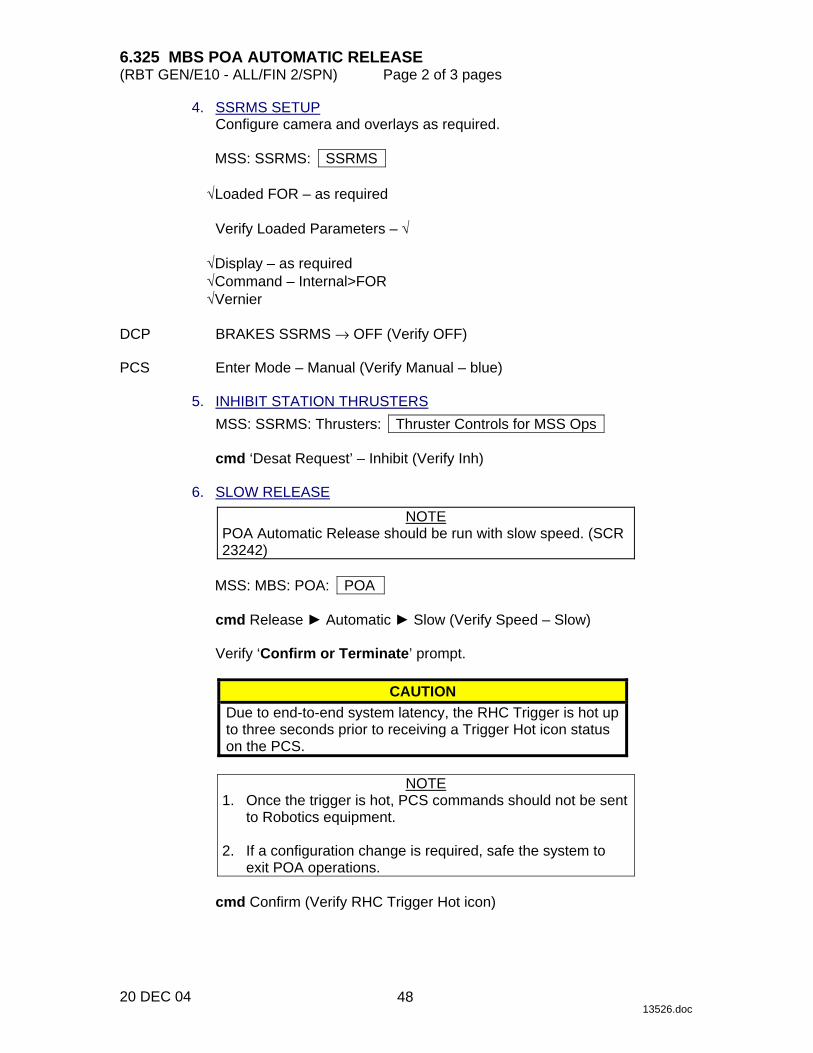
4. SSRMS SETUP Configure camera and overlays as required.
MSS: SSRMS: SSRMS
√Loaded FOR – as required
Verify Loaded Parameters – √
√Display – as required √Command – Internal>FOR √Vernier
DCP BRAKES SSRMS → OFF (Verify OFF) PCS Enter Mode – Manual (Verify Manual – blue) 5. INHIBIT STATION THRUSTERS
MSS: SSRMS: Thrusters: Thruster Controls for MSS Ops
cmd ‘Desat Request’ – Inhibit (Verify Inh) 6. SLOW RELEASE
NOTE POA Automatic Release should be run with slow speed. (SCR 23242)
MSS: MBS: POA: POA
cmd Release ► Automatic ► Slow (Verify Speed – Slow)
Verify ‘Confirm or Terminate’ prompt.
CAUTION Due to end-to-end system latency, the RHC Trigger is hot up to three seconds prior to receiving a Trigger Hot icon status on the PCS.
NOTE
1. Once the trigger is hot, PCS commands should not be sent to Robotics equipment.
2. If a configuration change is required, safe the system to
exit POA operations.
cmd Confirm (Verify RHC Trigger Hot icon)
48

6.325 MBS POA AUTOMATIC RELEASE (RBT GEN/E10 - ALL/FIN 2/SPN) Page 3 of 3 pages
20 DEC 04 13526.doc
NOTE Apply safing to stop mechanism motion (SCR 23262, 28433).
RHC TRIGGER → press (momentarily)
If POA was mated PCS Verify ‘Umbilical’ Demate – blue (10 s max)
If POA was latched Verify ‘Latch’ Unlatch – blue [65 s(13 s) max]
Verify ‘Carriage’ Derigidize − blue [90 s(18 s) max] Verify ‘Snare’ Open − blue [12 s(3 s) max]
THC Back off from POA until grapple fixture pin is clear. PCS Verify ‘Carriage’ Extend – blue [90 s(18 s) max] 7. ENABLE STATION THRUSTERS MSS: SSRMS: Thrusters: Thruster Controls for MSS Ops
cmd ‘Desat Request’ – Enable (Verify Ena)
49

This Page Intentionally Blank
22 DEC 04
50
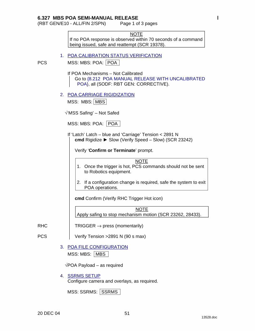
6.327 MBS POA SEMI-MANUAL RELEASE (RBT GEN/E10 - ALL/FIN 2/SPN) Page 1 of 3 pages
20 DEC 04 13528.doc
NOTE If no POA response is observed within 70 seconds of a command being issued, safe and reattempt (SCR 19378).
1. POA CALIBRATION STATUS VERIFICATION PCS MSS: MBS: POA: POA
If POA Mechanisms – Not Calibrated Go to {8.212 POA MANUAL RELEASE WITH UNCALIBRATED POA}, all (SODF: RBT GEN: CORRECTIVE).
2. POA CARRIAGE RIGIDIZATION
MSS: MBS: MBS
√‘MSS Safing’ – Not Safed
MSS: MBS: POA: POA
If ‘Latch’ Latch – blue and ‘Carriage’ Tension < 2891 N cmd Rigidize ► Slow (Verify Speed – Slow) (SCR 23242)
Verify ‘Confirm or Terminate’ prompt.
NOTE
1. Once the trigger is hot, PCS commands should not be sent to Robotics equipment.
2. If a configuration change is required, safe the system to exit
POA operations.
cmd Confirm (Verify RHC Trigger Hot icon)
NOTE Apply safing to stop mechanism motion (SCR 23262, 28433).
RHC TRIGGER → press (momentarily) PCS Verify Tension >2891 N (90 s max) 3. POA FILE CONFIGURATION
MSS: MBS: MBS
√POA Payload – as required 4. SSRMS SETUP
Configure camera and overlays, as required.
MSS: SSRMS: SSRMS
51

6.327 MBS POA SEMI-MANUAL RELEASE (RBT GEN/E10 - ALL/FIN 2/SPN) Page 2 of 3 pages
20 DEC 04 13528.doc
√Loaded FOR – as required
Verify Loaded Parameters – √
√Display – as required √Command – Internal>FOR √Vernier
DCP BRAKES SSRMS → OFF (Verify OFF) PCS Enter Mode – Manual (Verify Manual – blue) 5. INHIBITING STATION THRUSTERS
MSS: SSRMS: Thrusters: Thruster Controls for MSS Ops
cmd ‘Desat Request’ – Inhibit (Verify Inh) 6. SLOW RELEASE (SCR 23242)
NOTE POA Semi-manual Release should be run with slow speed unless otherwise specified.
MSS: MBS: POA: POA
PCS cmd Release ► Semi-Manual ► Slow (Verify Speed – Slow)
Verify ‘Confirm or Terminate’ prompt.
CAUTION Due to end-to-end system latency, the RHC Trigger is hot up to three seconds prior to receiving a Trigger Hot icon status on the PCS.
NOTE
1. Once the trigger is hot, PCS commands should not be sent to Robotics equipment.
2. If a configuration change is required, safe the system to
exit POA operations.
cmd Confirm (Verify RHC Trigger Hot icon)
NOTE Apply safing to stop mechanism motion (SCR 23262, 28433).
If ‘Umbilical’ Mate – blue
RHC TRIGGER → press (hold until ‘Latch’ Demate – blue) (10 s max)
52

6.327 MBS POA SEMI-MANUAL RELEASE (RBT GEN/E10 - ALL/FIN 2/SPN) Page 3 of 3 pages
20 DEC 04 13528.doc
PCS If ‘Latch’ Latch – blue RHC TRIGGER → press (hold until ‘Latch’ Unlatch – blue) [65 s(13 s) max]
TRIGGER → press (hold until ‘Carriage’ Derigidize – blue) [90 s(18 s) max]
TRIGGER → press (hold until ‘Snare’ Open – blue) [12 s(3 s) max] THC Back off from POA until grapple fixture pin is clear. RHC TRIGGER → press (hold until ‘Carriage’ Extend – blue) [90 s(18 s) max] 7. ENABLING STATION THRUSTERS PCS MSS: SSRMS: Thrusters: Thruster Controls for MSS Ops
cmd ‘Desat Request’ – Enable (Verify Ena)
53

This Page Intentionally Blank
22 DEC 04
54

6.331 MBS POWERUP FROM OFF TO KEEP-ALIVE ON BOTH STRINGS (RBT/UF2 - ALL/FIN) Page 1 of 1 page
13 DEC 04 13529.doc
NOTE 1. All power statuses on the MBS page, except for ‘MT UOP’,
‘Pwr 1’, and ‘Pwr 2’, do not reflect the current hardware status when MBS is not Operational. No telemetry is available when MBS is in the Keep-Alive state.
2. The MT position shown on the Mobile Transporter PCS
display must match the actual position of the MT for the MBS Keep-Alive Command to be accepted and succeed.
1. TRANSITION MBS PRIME STRING FROM OFF TO KEEP-ALIVE
MSS: MBS: MCU: MCU
cmd ‘Prime’ Keep-Alive (Verify Keep-Alive) (30 s max) 2. TRANSITION MBS REDUNDANT STRING FROM OFF TO KEEP-ALIVE
cmd ‘Redundant’ Keep-Alive (Verify Keep-Alive) (30 s max)
55

This Page Intentionally Blank
22 DEC 04
56

6.332 MSS POWERUP FROM KEEP-ALIVE TO OPERATIONAL (RBT GEN/X2R4 - ALL/FIN/SCR) Page 1 of 6 pages
16 DEC 04 13530.doc
1. ROBOTIC WORKSTATION CUP(LAB) POWERUP Perform {6.114 LAB(CUP) RWS UOP BYPASS CABLE RECONFIGURATION}, step 2 (SODF: RBT GEN: NOMINAL), then:
NOTE
The Firmware Start, Start WHS, VGS 1, 2 and 3 and OCS fields will show stale data until a Frame Count is acquired at the end of step 1.2 (SCR 11448).
1.1 CEU Initialization PCS MSS: LAS5(LAP5) Initialize: LAS5(LAP5) Initialization
cmd ‘B. CEU’ Close (Verify – √)
Wait 60 seconds for POST to complete. 1.2 Comm Enable
NOTE CEU-1/CEU-2 I/O will always be displayed as Enabled even when the CEU RT I/O is Inhibited. Use ‘Frame Count’ increments to verify I/O Enabled (SCR 16057).
cmd ‘C. CB Ext 2(1) Bus comm’ Enable
Verify ‘Frame Count’ increments. Verify ‘Firmware Start’ – √
1.3 WHS Download
NOTE The Set File and Set Address commands must be sent within 180 seconds of each other.
cmd ‘D. Download WHS’ Set File cmd ‘D. Download WHS’ Set Address
Wait 1.5 minutes for download to complete.
1.4 WHS Startup
cmd ‘E. Start WHS’ Start (Verify – √)
*************************************** ****
If Start not √ Wait 1 minute.
cmd Start (Verify Start – √)
*************************************** DCP If PANEL/INST LIGHTING – OFF
PANEL/INST LIGHTING → Desired background light intensity
57

6.332 MSS POWERUP FROM KEEP-ALIVE TO OPERATIONAL (RBT GEN/X2R4 - ALL/FIN/SCR) Page 2 of 6 pages
16 DEC 04 13530.doc
1.5 FDIR Enable PCS cmd ‘F. FDIR’ Enable (Verify – √) 1.6 VGS and OCS Download
NOTE 1. Download of VGS and OCS should take approximately
4 to 7.5 minutes to complete. 2. An ‘R9Z - MSS CUP(LAB) OCS WHS Cmd Sequence
Err’ Robotics Advisory message may be annunciated (SCR 19996).
cmd ‘G. Set RWS location’ – Cupola(Lab)
Verify VGS 1 – √ Verify VGS 2 – √ Verify VGS 3 – √ Verify OCS – √ Verify CEU Mode: Backup – √
DCP Verify RWS STATUS BACKUP – MON Verify monitor number appears and is flashing in upper left-hand 1,2,3 corner. 1.7 First and Second CVIU Initialization PCS cmd ‘H. Power CVIU4(12)’ Close (Verify – √)
cmd ‘I. Power CVIU5(2)’ Close (Verify – √) 1.8 Third CVIU Initialization
If VTR or an orbiter video view is required cmd ‘J. Power CVIU6(3)’ Close (Verify – √)
2. ACTIVE ROBOTIC WORKSTATION CUP(LAB) DESIGNATION
NOTE Video overlay data from the Active RWS will not be available on a Backup RWS unless the Backup RWS is powered up before the other RWS is made Active. If two RWSs are to be used for MSS operations and video overlay data is to be shared, both RWSs must be in Backup before one is made Active.
PCS MSS: LAS5(LAP5) CEU Mode: CEU Mode
If alternate RWS is Active cmd Active CEU − Backup (Verify alternate RWS is Backup)
cmd Cupola(Lab) − Active (Verify Cupola(Lab) − Active)
58
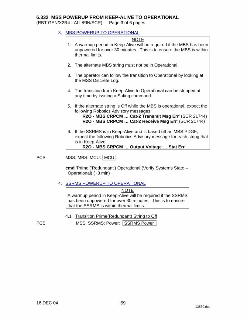
6.332 MSS POWERUP FROM KEEP-ALIVE TO OPERATIONAL (RBT GEN/X2R4 - ALL/FIN/SCR) Page 3 of 6 pages
16 DEC 04 13530.doc
3. MBS POWERUP TO OPERATIONAL NOTE
1. A warmup period in Keep-Alive will be required if the MBS has been unpowered for over 30 minutes. This is to ensure the MBS is within thermal limits.
2. The alternate MBS string must not be in Operational. 3. The operator can follow the transition to Operational by looking at
the MSS Discrete Log. 4. The transition from Keep-Alive to Operational can be stopped at
any time by issuing a Safing command. 5. If the alternate string is Off while the MBS is operational, expect the
following Robotics Advisory messages: ‘R2O - MBS CRPCM … Cat-2 Transmit Msg Err’ (SCR 21744) ‘R2O - MBS CRPCM … Cat-2 Receive Msg Err’ (SCR 21744)
6. If the SSRMS is in Keep-Alive and is based off an MBS PDGF,
expect the following Robotics Advisory message for each string that is in Keep-Alive:
‘R2O - MBS CRPCM … Output Voltage … Stat Err’ PCS MSS: MBS: MCU: MCU
cmd ‘Prime’(‘Redundant’) Operational (Verify Systems State – Operational) (~3 min)
4. SSRMS POWERUP TO OPERATIONAL
NOTE A warmup period in Keep-Alive will be required if the SSRMS has been unpowered for over 30 minutes. This is to ensure that the SSRMS is within thermal limits.
4.1 Transition Prime(Redundant) String to Off PCS MSS: SSRMS: Power: SSRMS Power
59

6.332 MSS POWERUP FROM KEEP-ALIVE TO OPERATIONAL (RBT GEN/X2R4 - ALL/FIN/SCR) Page 4 of 6 pages
16 DEC 04 13530.doc
If SSRMS based on MBS PDGF and ‘SSRMS’ Prime(Redundant) not Off
NOTE 1. It might take up to 30 seconds for the Off status indication
to appear on the PCS. 2. Expect the ‘R1E - MSS Active OCS SSRMS
Prime(Redun) ACU SRT Comm Fail’ Robotics Advisory message (SCR 17730).
3. If the SSRMS is based on an MBS PDGF, expect the
following Robotics Advisory message to go to Norm for the commanded SSRMS string that was in Keep-Alive:
‘R2O - MBS CRPCM … Output Voltage … Stat Err’
cmd ‘SSRMS’ Prime(Redundant) – Off (Verify – Off) 4.2 Transition Prime(Redundant) String to Keep-Alive
If ‘SSRMS’ Prime(Redundant) – Off NOTE
It might take up to 30 seconds for the Keep-Alive status indication to appear on PCS.
MSS: SSRMS: Power: SSRMS Power
cmd ‘SSRMS’ Prime(Redundant) – Keep-Alive (Verify Keep-Alive)
4.3 Transition Redundant(Prime) String to Off
If ‘SSRMS’ Redundant(Prime) not Off NOTE
1. It might take up to 30 seconds for the Off status indication to appear on the PCS.
2. Expect the ‘R1E - MSS Active OCS SSRMS Prime(Redun)
ACU SRT Comm Fail’ Robotics Advisory message (SCR 17730).
3. If the SSRMS is based on an MBS PDGF, expect the
following Robotics Advisory message to go to Norm for the commanded SSRMS string that was in Keep-Alive:
‘R2O - MBS CRPCM … Output Voltage … Stat Err’
MSS: SSRMS: Power: SSRMS Power
cmd ‘SSRMS’ Redundant(Prime) – Off (Verify – Off)
60

6.332 MSS POWERUP FROM KEEP-ALIVE TO OPERATIONAL (RBT GEN/X2R4 - ALL/FIN/SCR) Page 5 of 6 pages
16 DEC 04 13530.doc
4.4 Transition Prime(Redundant) String to Operational NOTE
1. The transition from Keep-Alive to Operational can be stopped at any time by commanding SAFING on the DCP.
2. The operator can follow the transition to Operational by looking at
the MSS discrete log. 3. If Tip LEE is mated to a PDGF connected to ISS Ground, expect
‘R3L - SSRMS Pwr Flags Fail’ Robotics Advisory message (SCR 19019).
4. While the SSRMS transitions from Keep-Alive to Operational, the
following 17 LEE inhibit errors will go to Norm approximately 10 seconds after they are raised:
‘R9B - SSRMS LEE … Inh Err’
cmd ‘SSRMS’ Prime(Redundant) – Operational
Verify ‘Systems State’ – Operational (~6 minutes) 5. MSS VIDEO COMPONENTS POWERUP 5.1 Video Distribution Units Powerup PCS MSS: MBS: VDU1: MSS VDUs
sel [X] where [X] = MBS 2 MBS 1
√‘Primary’,‘Redundant’ Keep-Alive
Repeat
NOTE Expect ‘R6F - MBS… PFM Carrier On Video 1 Err’ Robotics Advisory message as each VDU is powered on. Message may toggle in and out of alarm until video is routed to the defined VDU (SCR 24376).
sel ‘[X]’ as required where [X] = Base LEE Base Elbow
MSB 2 MSB 1 Tip Lee Tip Elbow POA
cmd ‘[X]’ On (Verify – On)
Repeat
61
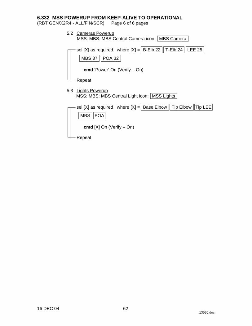
6.332 MSS POWERUP FROM KEEP-ALIVE TO OPERATIONAL (RBT GEN/X2R4 - ALL/FIN/SCR) Page 6 of 6 pages
16 DEC 04 13530.doc
5.2 Cameras Powerup MSS: MBS: MBS Central Camera icon: MBS Camera
sel [X] as required where [X] = B-Elb 22 T-Elb 24 LEE 25
POA 32 MBS 37
cmd ‘Power’ On (Verify – On)
Repeat
5.3 Lights Powerup
MSS: MBS: MBS Central Light icon: MSS Lights
sel [X] as required where [X] = Base Elbow Tip Elbow Tip LEE
POA MBS
cmd [X] On (Verify – On)
Repeat
62
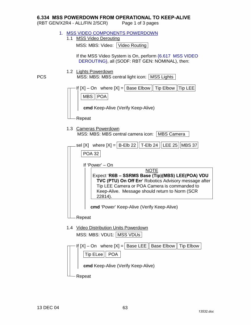
6.334 MSS POWERDOWN FROM OPERATIONAL TO KEEP-ALIVE (RBT GEN/X2R4 - ALL/FIN 2/SCR) Page 1 of 3 pages
13 DEC 04 13532.doc
1. MSS VIDEO COMPONENTS POWERDOWN 1.1 MSS Video Derouting
MSS: MBS: Video: Video Routing
If the MSS Video System is On, perform {6.617 MSS VIDEO DEROUTING}, all (SODF: RBT GEN: NOMINAL), then:
1.2 Lights Powerdown PCS MSS: MBS: MBS central light icon: MSS Lights
If [X] – On where [X] = Base Elbow Tip Elbow Tip LEE
POAMBS
cmd Keep-Alive (Verify Keep-Alive)
Repeat 1.3 Cameras Powerdown
MSS: MBS: MBS central camera icon: MBS Camera
sel [X] where [X] = B-Elb 22 T-Elb 24 LEE 25 MBS 37
POA 32
If ‘Power’ – On NOTE
Expect ‘R6B � SSRMS Base (Tip)(MBS) LEE(POA) VDU TVC (PTU) On Off Err’ Robotics Advisory message after Tip LEE Camera or POA Camera is commanded to Keep-Alive. Message should return to Norm (SCR 22814).
cmd ‘Power’ Keep-Alive (Verify Keep-Alive)
Repeat
1.4 Video Distribution Units Powerdown
MSS: MBS: VDU1: MSS VDUs
If [X] – On where [X] = Base LEE Base Elbow Tip Elbow
POATip ELee
cmd Keep-Alive (Verify Keep-Alive)
Repeat
63
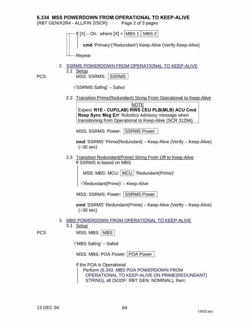
6.334 MSS POWERDOWN FROM OPERATIONAL TO KEEP-ALIVE (RBT GEN/X2R4 - ALL/FIN 2/SCR) Page 2 of 3 pages
13 DEC 04 13532.doc
If [X] – On where [X] = MBS 2MBS 1
cmd ‘Primary’(‘Redundant’) Keep-Alive (Verify Keep-Alive)
Repeat 2. SSRMS POWERDOWN FROM OPERATIONAL TO KEEP-ALIVE 2.1 Setup PCS MSS: SSRMS: SSRMS
√‘SSRMS Safing’ – Safed 2.2 Transition Prime(Redundant) String From Operational to Keep-Alive
NOTE Expect ‘R1E - CUP(LAB) RWS CEU PLB(MLB) ACU Cmd Resp Sync Msg Err’ Robotics Advisory message when transitioning from Operational to Keep-Alive (SCR 31294).
MSS: SSRMS: Power: SSRMS Power
cmd ‘SSRMS’ Prime(Redundant) – Keep-Alive (Verify – Keep-Alive) (~30 sec)
2.3 Transition Redundant(Prime) String From Off to Keep-Alive
If SSRMS is based on MBS
MSS: MBS: MCU: MCU ‘Redundant(Prime)’
√‘Redundant(Prime)’ – Keep-Alive
MSS: SSRMS: Power: SSRMS Power
cmd ‘SSRMS’ Redundant(Prime) – Keep-Alive (Verify – Keep-Alive) (~30 sec)
3. MBS POWERDOWN FROM OPERATIONAL TO KEEP-ALIVE 3.1 Setup PCS MSS: MBS: MBS
√‘MBS Safing’ – Safed
MSS: MBS: POA Power: POA Power
If the POA is Operational Perform {6.343 MBS POA POWERDOWN FROM OPERATIONAL TO KEEP-ALIVE ON PRIME(REDUNDANT) STRING}, all (SODF: RBT GEN: NOMINAL), then:
64

6.334 MSS POWERDOWN FROM OPERATIONAL TO KEEP-ALIVE (RBT GEN/X2R4 - ALL/FIN 2/SCR) Page 3 of 3 pages
13 DEC 04 13532.doc
3.2 Transition MBS Prime(Redundant) String From Operational to Keep-Alive
MSS: MBS: MCU: MCU ‘Prime (Redundant)’
√‘Redundant(Prime)’ – Keep-Alive
cmd ‘Keep-Alive’ (Verify – ‘Keep-Alive’) (30 s max) 4. ROBOTIC WORKSTATION CUP(LAB) POWERDOWN 4.1 CUP(LAB) CEU Designation as Backup PCS MSS: LAS5(LAP5) CEU Mode: CEU Mode
cmd Active CEU – Backup (Verify previously Active RWS is Backup) 4.2 CUP(LAB) RWS Powerdown
MSS: LAS5(LAP5) Pwr Dn: LAS5(LAP5) Power Down
cmd ‘C. CVIU 5(2)’ Open (Verify – √) cmd ‘D. CVIU 4(12)’ Open (Verify – √)
Verify ‘E. AVU’ Off – √
cmd ‘F. FDIR’ Inhibit (Verify – √) cmd ‘G. CB Ext 2(1) Bus Comm’ Inhibit
Verify Frame Count stops incrementing (SPN 494).
cmd ‘H. CEU’ Open (Verify – √)
5. ROBOTIC WORKSTATION CUP(LAB) DCP POWERDOWN
Go to {6.114 LAB(cUP) RWS UOP BYPASS CABLE RECONFIGURATION}, step 1 (SODF: RBT GEN: NOMINAL).
65

This Page Intentionally Blank
22 DEC 04
66

6.335 MBS POWERDOWN TO OFF ON PRIME(REDUNDANT) STRING (RBT GEN/X2R4 - ALL/FIN 1/SCR) Page 1 of 2 pages
16 DEC 04 13533.doc
NOTE The MT position shown on the Mobile Transporter PCS display must match the actual position of the MT for the MBS Powerdown Command to be accepted and succeed.
1. SETUP PCS MSS: MBS: MBS
If the MBS is Operational √‘MBS Safing’ – Safed, then:
MSS: MBS: POA P/L Power: POA Payload Power
√‘Prime’(‘Redundant’) – Off
MSS: MBS: MCAS P/L Power: MCAS Payload Power
√‘Prime’(‘Redundant’) – Off
MSS: MBS: EVA1(2): EVA Power
√‘EVA’ 1(2) – Off
MSS: MBS: Video: Video Routing
If SSRMS is not OFF on MBS String being powered OFF
Perform {6.434 SSRMS POWERDOWN TO OFF ON BOTH STRINGS}, steps 1 to 3, as required (SODF: RBT GEN: NOMINAL), then:
If Keep-Alive string of the MBS is being powered OFF while the MBS is
Operational: NOTE
Expect the following Robotics Advisory messages: ‘R2O - MBS CRPCM … Cat-2 Transmit Msg Err’ (SCR 21744) ‘R2O - MBS CRPCM … Cat-2 Receive Msg Err’ (SCR 21744)
√MCC has verified VDUs are receiving power from Operational MBS
String (SCR 24292)
If Operational string of the MBS is being powered OFF If the MBS Video System is On
Perform {6.617 MSS VIDEO DEROUTING}, all (SODF: RBT GEN: NOMINAL), then:
MSS: MBS: POA Power: POA Power
~
67

6.335 MBS POWERDOWN TO OFF ON PRIME(REDUNDANT) STRING (RBT GEN/X2R4 - ALL/FIN 1/SCR) Page 2 of 2 pages
16 DEC 04 13533.doc
If the POA is Operational
Perform {6.343 MBS POA POWERDOWN FROM OPERATIONAL TO KEEP-ALIVE ON PRIME(REDUNDANT) STRING}, all (SODF: RBT GEN: NOMINAL), then:
2. TRANSITION MBS PRIME(REDUNDANT) STRING TO OFF
NOTE Expect ‘R1E - MSS Active OCS MBS Prime(Redun) MCU SRT Comm Fail’ Caution and Warning messages (SCR 17730).
MSS: MBS: MCU: MCU
cmd ‘Prime’(‘Redundant’) Off (Verify – Off) (30 s max)
~
68

6.341 MBS POA POWERUP FROM OFF TO KEEP ALIVE ON BOTH STRINGS
(RBT GEN/UF2 - ALL/FIN) Page 1 of 1 page
01 DEC 03 13534.doc
1. MBS POA POWERUP FROM OFF TO KEEP-ALIVE ON PRIME STRING PCS MSS: MBS: POA Power: POA Power
Verify ‘Redundant’ – not Operational
cmd ‘Prime’ Keep-Alive (Verify Keep-Alive) (30 s max) 2. MBS POA POWERUP FROM OFF TO KEEP-ALIVE ON REDUNDANT
STRING PCS MSS: MBS: POA Power: POA Power
Verify ‘Prime’ – not Operational
cmd ‘Redundant’ Keep-Alive (Verify Keep-Alive) (30 s max)
69

This Page Intentionally Blank
22 DEC 04
70

6.342 MBS POA POWERUP TO OPERATIONAL ON PRIME(REDUNDANT) STRING
(RBT GEN/X2R4 - ALL/FIN 2/SPN) Page 1 of 1 page
20 DEC 04 13535.doc
1. SETUP PCS MSS: MBS: MCU: MCU
Verify ‘Prime’(‘Redundant’) – Operational
MSS: MBS: MBS
√‘MBS Safing ’ – Safed 2. TRANSITION REDUNDANT(PRIME) TO OFF
MSS: MBS: POA Power: POA Power
If ‘Redundant’(‘Prime’) – not Off cmd ‘Redundant’(‘Prime’) Off (Verify Off) (30 s max)
3. TRANSITION PRIME(REDUNDANT) STRING TO KEEP-ALIVE
MSS: MBS: POA Power: POA Power
If ‘Prime’(‘Redundant’) – Off cmd ‘Prime’(‘Redundant’) Keep-Alive (Verify Keep-Alive) (30 s max)
4. TRANSITION PRIME(REDUNDANT) STRING TO OPERATIONAL
MSS: MBS: Latch: MCAS Latch
Verify Active MBS IMCA – None
NOTE 1. The transition from Keep-Alive to Operational can be stopped
at anytime by commanding SAFING on the DCP. 2. If the transition is not complete in 2.5 minutes, apply SAFING
on the DCP to stop transition (SCR 22619). 3. If the transition is interrupted by Operator Safing or by a
system failure, the MBS string will have to be commanded to Operational again before the POA transition can be reattempted.
4. The operator can follow the transition to Operational by
looking at the MSS discrete log.
MSS: MBS: POA Power: POA Power
cmd ‘Prime’(‘Redundant’) Operational (Verify Operational) (SCR 22616)
71

This Page Intentionally Blank
22 DEC 04
72
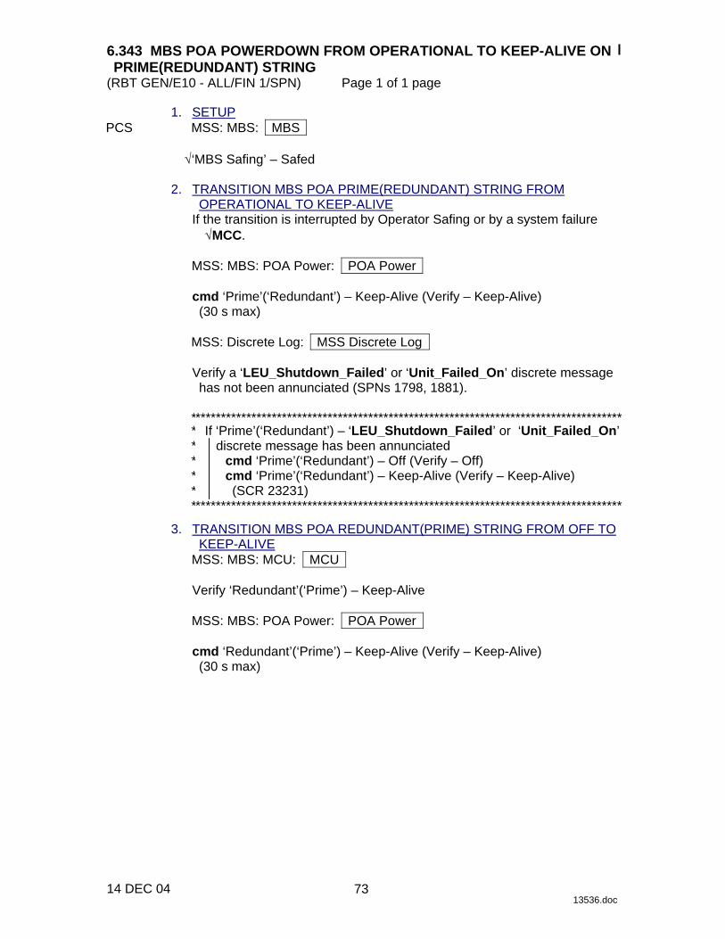
6.343 MBS POA POWERDOWN FROM OPERATIONAL TO KEEP-ALIVE ON PRIME(REDUNDANT) STRING
(RBT GEN/E10 - ALL/FIN 1/SPN) Page 1 of 1 page
14 DEC 04 13536.doc
1. SETUP PCS MSS: MBS: MBS
√‘MBS Safing’ – Safed 2. TRANSITION MBS POA PRIME(REDUNDANT) STRING FROM
OPERATIONAL TO KEEP-ALIVE If the transition is interrupted by Operator Safing or by a system failure
√MCC.
MSS: MBS: POA Power: POA Power
cmd ‘Prime’(‘Redundant’) – Keep-Alive (Verify – Keep-Alive) (30 s max)
MSS: Discrete Log: MSS Discrete Log
Verify a ‘LEU_Shutdown_Failed’ or ‘Unit_Failed_On’ discrete message has not been annunciated (SPNs 1798, 1881).
************************************************************************************* *****
If ‘Prime’(‘Redundant’) – ‘LEU_Shutdown_Failed’ or ‘Unit_Failed_On’ discrete message has been annunciated
cmd ‘Prime’(‘Redundant’) – Off (Verify – Off) cmd ‘Prime’(‘Redundant’) – Keep-Alive (Verify – Keep-Alive) (SCR 23231)
************************************************************************************* 3. TRANSITION MBS POA REDUNDANT(PRIME) STRING FROM OFF TO
KEEP-ALIVE MSS: MBS: MCU: MCU
Verify ‘Redundant’(‘Prime’) – Keep-Alive
MSS: MBS: POA Power: POA Power
cmd ‘Redundant’(‘Prime’) – Keep-Alive (Verify – Keep-Alive) (30 s max)
73

This Page Intentionally Blank
22 DEC 04
74

6.344 MBS POA POWERDOWN TO OFF ON BOTH STRINGS (RBT GEN/X2R4 - ALL/FIN) Page 1 of 1 page
20 DEC 04 13537.doc
NOTE The MBS POA should not be left with both strings in the Off state for extended periods due to thermal constraints.
1. SETUP PCS MSS: MBS: MBS
√‘MBS Safing’ – Safed √MCU – Operational
2. TRANSITION MBS POA PRIME STRING TO OFF
MSS: MBS: POA Power: POA Power
If ‘Prime’ not Off cmd ‘Prime’ Off (Verify Off) (30 s max)
3. TRANSITION MBS POA REDUNDANT STRING TO OFF
MSS: MBS: POA Power: POA Power
If ‘Redundant’ not Off cmd ‘Redundant’ Off (Verify Off) (30 s max)
75

This Page Intentionally Blank
22 DEC 04
76

6.351 MBS MCAS LATCH CHECKOUT CLOSE (RBT GEN/X2R4 - ALL/FIN 2/SPN) Page 1 of 3 pages
10 DEC 04 13538.doc
NOTE Expect sporadic ‘R4H - MBS MCU MCAS Latch Cat-2 Cksum Fail’ Robotics Advisory messages (SCR 22667).
1. POWER ON PRIME(REDUNDANT) MCAS LATCH IMCA PCS MSS: MBS: POA Power: POA Power
√‘Prime’ – Off (Keep-Alive) √‘Redundant’ – Off (Keep-Alive)
MSS: MBS: MBS
√‘MBS Safing’ – Not Safed
MSS: MBS: Latch: MCAS Latch
Verify ‘Active MBS IMCA’ – None Verify ‘Power’ – Off
MSS: MBS: Latch: Power: MCAS Latch IMCA Power
cmd Enable (Verify √) cmd Confirm (Verify √) cmd On (Verify √)
MSS: MBS: Latch: MCAS Latch
Verify ‘Active MBS IMCA’ – MCAS Latch Verify ‘Mode’ – Standby (6 seconds)
2. VERIFY POST TESTS
MSS: MBS: Latch: Commands ► BIT: MCAS Latch POST and BIT
Verify all – blank 3. SETUP
Configure cameras and overlays as required. 4. INITIALIZE MCAS LATCH IMCA WITH SAFING INITFRAME
MSS: MBS: Latch: MCAS Latch
Verify ‘Latch’ Closed – blank Verify ‘Latch’ Open – √
MSS: MBS: Latch: Commands ► Checkout: MCAS Latch Checkout Commands
77

6.351 MBS MCAS LATCH CHECKOUT CLOSE (RBT GEN/X2R4 - ALL/FIN 2/SPN) Page 2 of 3 pages
10 DEC 04 13538.doc
cmd Safing Initframe
MSS: MBS: Latch: MCAS Latch
Verify ‘Command Response’ Initframe Received – √ Verify ‘Command Response’ Parameter Checksum Failed – blank
MSS: MBS: Latch: Commands ► Checkout: MCAS Latch Checkout Commands
Initframe Details: MBS IMCA Initframe Details
Verify ‘Limits’ Position Change – High: 0 Rev
5. MODE IMCA TO ON
MSS: MBS: Latch: Commands ► Checkout: MCAS Latch Checkout Commands
cmd On
MSS: MBS: Latch: MCAS Latch
Verify Mode – On
6. CHECKOUT CLOSE
MSS: MBS: Latch: Commands ► Checkout: MCAS Latch Checkout Commands
cmd Close
MSS: MBS: Latch: MCAS Latch
Verify ‘Command Response’ Parameter Checksum Failed – blank
MSS: MBS: Latch: Commands ► Checkout: MCAS Latch Checkout Commands
Initframe Details: MBS IMCA Initframe Details
Verify ‘Limits’ Position Change – High: 3110 Rev (± 2)
NOTE
1. For MSS: MBS: Latch: MCAS Latch ‘Motor Status’, expect large fluctuations in values for Acceleration and Current. The data is unreliable.
2. The Actuate command will initiate full opening of the MCAS Latch
Mechanism. 3. To pause IMCA motion, mode IMCA back to On.
78
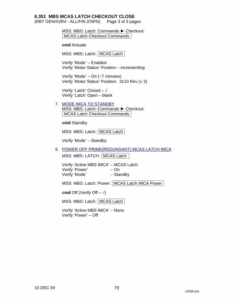
6.351 MBS MCAS LATCH CHECKOUT CLOSE (RBT GEN/X2R4 - ALL/FIN 2/SPN) Page 3 of 3 pages
10 DEC 04 13538.doc
MSS: MBS: Latch: Commands ► Checkout: MCAS Latch Checkout Commands
cmd Actuate
MSS: MBS: Latch: MCAS Latch
Verify ‘Mode’ – Enabled Verify ‘Motor Status’ Position – incrementing
Verify ‘Mode’ – On (~7 minutes) Verify ‘Motor Status’ Position: 3110 Rev (± 2)
Verify ‘Latch’ Closed – √ Verify ‘Latch’ Open – blank
7. MODE IMCA TO STANDBY
MSS: MBS: Latch: Commands ► Checkout: MCAS Latch Checkout Commands
cmd Standby
MSS: MBS: Latch: MCAS Latch
Verify ‘Mode’ – Standby
8. POWER OFF PRIME(REDUNDANT) MCAS LATCH IMCA
MSS: MBS: LATCH: MCAS Latch
Verify ‘Active MBS IMCA’ – MCAS Latch Verify ‘Power’ – On Verify ‘Mode’ – Standby
MSS: MBS: Latch: Power: MCAS Latch IMCA Power
cmd Off (Verify Off – √)
MSS: MBS: Latch: MCAS Latch
Verify ‘Active MBS IMCA’ – None Verify ‘Power’ – Off
79

This Page Intentionally Blank
22 DEC 04
80
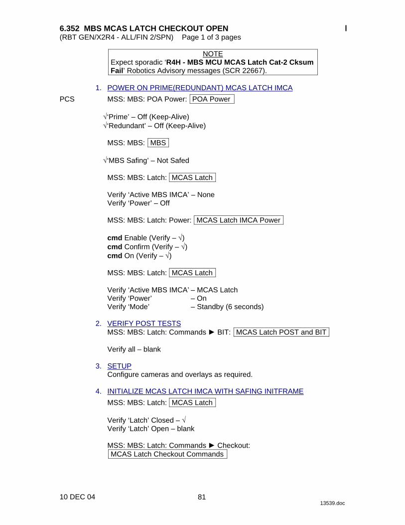
6.352 MBS MCAS LATCH CHECKOUT OPEN (RBT GEN/X2R4 - ALL/FIN 2/SPN) Page 1 of 3 pages
10 DEC 04 13539.doc
NOTE Expect sporadic ‘R4H - MBS MCU MCAS Latch Cat-2 Cksum Fail’ Robotics Advisory messages (SCR 22667).
1. POWER ON PRIME(REDUNDANT) MCAS LATCH IMCA PCS MSS: MBS: POA Power: POA Power
√‘Prime’ – Off (Keep-Alive) √‘Redundant’ – Off (Keep-Alive)
MSS: MBS: MBS
√‘MBS Safing’ – Not Safed
MSS: MBS: Latch: MCAS Latch
Verify ‘Active MBS IMCA’ – None Verify ‘Power’ – Off
MSS: MBS: Latch: Power: MCAS Latch IMCA Power
cmd Enable (Verify – √) cmd Confirm (Verify – √) cmd On (Verify – √)
MSS: MBS: Latch: MCAS Latch
Verify ‘Active MBS IMCA’ – MCAS Latch Verify ‘Power’ – On Verify ‘Mode’ – Standby (6 seconds)
2. VERIFY POST TESTS
MSS: MBS: Latch: Commands ► BIT: MCAS Latch POST and BIT
Verify all – blank 3. SETUP
Configure cameras and overlays as required. 4. INITIALIZE MCAS LATCH IMCA WITH SAFING INITFRAME
MSS: MBS: Latch: MCAS Latch
Verify ‘Latch’ Closed – √ Verify ‘Latch’ Open – blank
MSS: MBS: Latch: Commands ► Checkout: MCAS Latch Checkout Commands
81
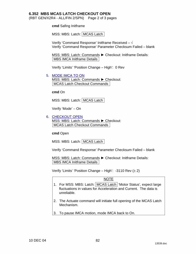
6.352 MBS MCAS LATCH CHECKOUT OPEN (RBT GEN/X2R4 - ALL/FIN 2/SPN) Page 2 of 3 pages
10 DEC 04 13539.doc
cmd Safing Initframe
MSS: MBS: Latch: MCAS Latch
Verify ‘Command Response’ Initframe Received – √ Verify ‘Command Response’ Parameter Checksum Failed – blank
MSS: MBS: Latch: Commands ► Checkout: Initframe Details: MBS IMCA Initframe Details
Verify ‘Limits’ ‘Position Change – High’: 0 Rev
5. MODE IMCA TO ON
MSS: MBS: Latch: Commands ► Checkout: MCAS Latch Checkout Commands
cmd On
MSS: MBS: Latch: MCAS Latch
Verify ‘Mode’ – On
6. CHECKOUT OPEN
MSS: MBS: Latch: Commands ► Checkout: MCAS Latch Checkout Commands
cmd Open
MSS: MBS: Latch: MCAS Latch
Verify ‘Command Response’ Parameter Checksum Failed – blank
MSS: MBS: Latch: Commands ► Checkout: Initframe Details: MBS IMCA Initframe Details
Verify ‘Limits’ ‘Position Change – High’: -3110 Rev (± 2)
NOTE
1. For MSS: MBS: Latch: MCAS Latch ‘Motor Status’, expect large fluctuations in values for Acceleration and Current. The data is unreliable.
2. The Actuate command will initiate full opening of the MCAS Latch
Mechanism. 3. To pause IMCA motion, mode IMCA back to On.
82

6.352 MBS MCAS LATCH CHECKOUT OPEN (RBT GEN/X2R4 - ALL/FIN 2/SPN) Page 3 of 3 pages
10 DEC 04 13539.doc
MSS: MBS: Latch: Commands ► Checkout: MCAS Latch Checkout Commands
cmd Actuate
MSS: MBS: Latch: MCAS Latch
Verify ‘Mode’ – Enabled Verify ‘Motor Status’ Position – decrementing
Verify ‘Mode’ – On (~7 minutes) Verify ‘Motor Status’ Position: -3110 Rev (± 2)
Verify ‘Latch’ Closed – blank Verify ‘Latch’ Open – √
7. MODE IMCA TO STANDBY
MSS: MBS: Latch: Commands ► Checkout: MCAS Latch Checkout Commands
cmd Standby
MSS: MBS: Latch: MCAS Latch
Verify ‘Mode’ – Standby
8. POWER OFF PRIME(REDUNDANT) MCAS LATCH IMCA
MSS: MBS: Latch: MCAS Latch
Verify ‘Active MBS IMCA’ – MCAS Latch Verify ‘Power’ – On Verify ‘Mode’ – Standby
MSS: MBS: Latch: Power: MCAS Latch IMCA Power
cmd Off (Verify Off – √)
MSS: MBS: Latch: MCAS Latch
Verify ‘Active MBS IMCA’ – None Verify ‘Power’ – Off
83

This Page Intentionally Blank
22 DEC 04
84
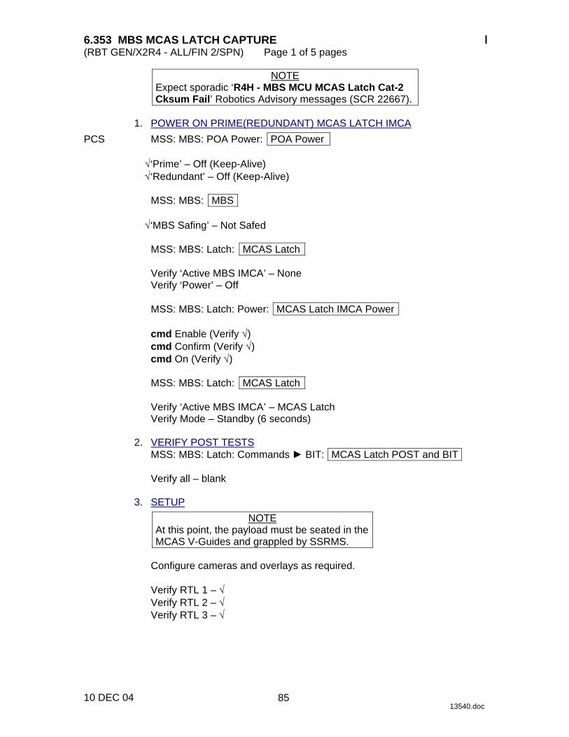
6.353 MBS MCAS LATCH CAPTURE (RBT GEN/X2R4 - ALL/FIN 2/SPN) Page 1 of 5 pages
10 DEC 04 13540.doc
NOTE Expect sporadic ‘R4H - MBS MCU MCAS Latch Cat-2 Cksum Fail’ Robotics Advisory messages (SCR 22667).
1. POWER ON PRIME(REDUNDANT) MCAS LATCH IMCA PCS MSS: MBS: POA Power: POA Power
√‘Prime’ – Off (Keep-Alive) √‘Redundant’ – Off (Keep-Alive)
MSS: MBS: MBS
√‘MBS Safing’ – Not Safed
MSS: MBS: Latch: MCAS Latch
Verify ‘Active MBS IMCA’ – None Verify ‘Power’ – Off
MSS: MBS: Latch: Power: MCAS Latch IMCA Power
cmd Enable (Verify √) cmd Confirm (Verify √) cmd On (Verify √)
MSS: MBS: Latch: MCAS Latch
Verify ‘Active MBS IMCA’ – MCAS Latch Verify Mode – Standby (6 seconds)
2. VERIFY POST TESTS
MSS: MBS: Latch: Commands ► BIT: MCAS Latch POST and BIT
Verify all – blank 3. SETUP
NOTE At this point, the payload must be seated in the MCAS V-Guides and grappled by SSRMS.
Configure cameras and overlays as required.
Verify RTL 1 – √ Verify RTL 2 – √ Verify RTL 3 – √
85
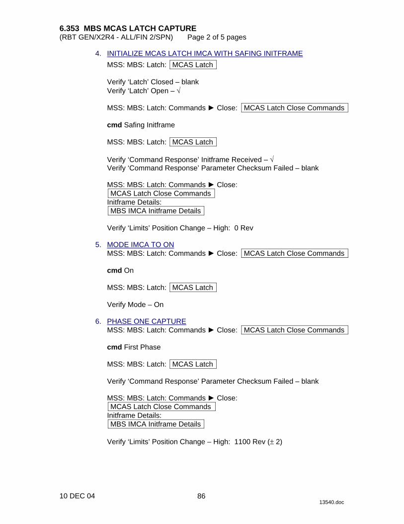
6.353 MBS MCAS LATCH CAPTURE (RBT GEN/X2R4 - ALL/FIN 2/SPN) Page 2 of 5 pages
10 DEC 04 13540.doc
4. INITIALIZE MCAS LATCH IMCA WITH SAFING INITFRAME MSS: MBS: Latch: MCAS Latch
Verify ‘Latch’ Closed – blank Verify ‘Latch’ Open – √
MSS: MBS: Latch: Commands ► Close: MCAS Latch Close Commands
cmd Safing Initframe
MSS: MBS: Latch: MCAS Latch
Verify ‘Command Response’ Initframe Received – √ Verify ‘Command Response’ Parameter Checksum Failed – blank
MSS: MBS: Latch: Commands ► Close: MCAS Latch Close Commands
Initframe Details: MBS IMCA Initframe Details
Verify ‘Limits’ Position Change – High: 0 Rev
5. MODE IMCA TO ON
MSS: MBS: Latch: Commands ► Close: MCAS Latch Close Commands
cmd On
MSS: MBS: Latch: MCAS Latch
Verify Mode – On 6. PHASE ONE CAPTURE
MSS: MBS: Latch: Commands ► Close: MCAS Latch Close Commands
cmd First Phase
MSS: MBS: Latch: MCAS Latch
Verify ‘Command Response’ Parameter Checksum Failed – blank
MSS: MBS: Latch: Commands ► Close: MCAS Latch Close Commands
Initframe Details: MBS IMCA Initframe Details
Verify ‘Limits’ Position Change – High: 1100 Rev (± 2)
86
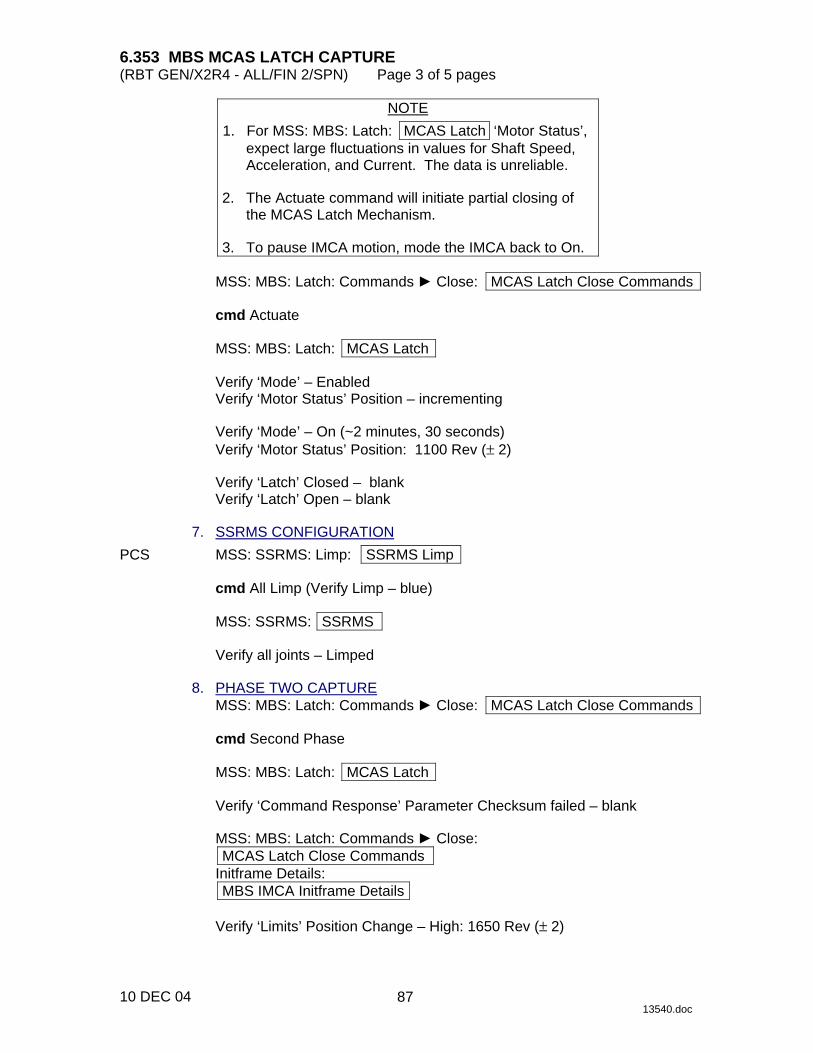
6.353 MBS MCAS LATCH CAPTURE (RBT GEN/X2R4 - ALL/FIN 2/SPN) Page 3 of 5 pages
10 DEC 04 13540.doc
NOTE 1. For MSS: MBS: Latch: MCAS Latch ‘Motor Status’, expect large fluctuations in values for Shaft Speed,
Acceleration, and Current. The data is unreliable. 2. The Actuate command will initiate partial closing of
the MCAS Latch Mechanism. 3. To pause IMCA motion, mode the IMCA back to On.
MSS: MBS: Latch: Commands ► Close: MCAS Latch Close Commands
cmd Actuate
MSS: MBS: Latch: MCAS Latch
Verify ‘Mode’ – Enabled Verify ‘Motor Status’ Position – incrementing
Verify ‘Mode’ – On (~2 minutes, 30 seconds) Verify ‘Motor Status’ Position: 1100 Rev (± 2)
Verify ‘Latch’ Closed – blank Verify ‘Latch’ Open – blank
7. SSRMS CONFIGURATION PCS MSS: SSRMS: Limp: SSRMS Limp
cmd All Limp (Verify Limp – blue)
MSS: SSRMS: SSRMS
Verify all joints – Limped 8. PHASE TWO CAPTURE
MSS: MBS: Latch: Commands ► Close: MCAS Latch Close Commands
cmd Second Phase
MSS: MBS: Latch: MCAS Latch
Verify ‘Command Response’ Parameter Checksum failed – blank
MSS: MBS: Latch: Commands ► Close: MCAS Latch Close Commands
Initframe Details: MBS IMCA Initframe Details
Verify ‘Limits’ Position Change – High: 1650 Rev (± 2)
87

6.353 MBS MCAS LATCH CAPTURE (RBT GEN/X2R4 - ALL/FIN 2/SPN) Page 4 of 5 pages
10 DEC 04 13540.doc
NOTE 1. For MSS: MBS: Latch: MCAS Latch ‘Motor Status’, expect large fluctuations in values for Acceleration and
Current. The data is unreliable. 2. The Actuate command will initiate partial closing of the
MCAS Latch Mechanism. 3. To pause IMCA motion, mode IMCA back to On.
MSS: MBS: Latch: Commands ► Close: MCAS Latch Close Commands
cmd Actuate
MSS: MBS: Latch: MCAS Latch
Verify ‘Mode’ – Enabled Verify ‘Motor Status’ Position – incrementing
Verify ‘Mode’ – On (~1 minute, 15 seconds) Verify ‘Motor Status’ Position: 1650 Rev (± 2)
Verify ‘Latch’ Closed – blank Verify ‘Latch’ Open – blank
9. PHASE THREE CAPTURE
MSS: MBS: Latch: Commands ► Close: MCAS Latch Close Commands
cmd Third Phase
MSS: MBS: Latch: MCAS Latch
Verify ‘Command Response’ Parameter Checksum Failed – blank
MSS: MBS: Latch: Commands ► Close: MCAS Latch Close Commands
Initframe Details: MBS IMCA Initframe Details
Verify ‘Limits’ Position Change – High: 3110 Rev (± 2)
NOTE
1. For MBS: MCAS Latch: MCAS Latch ‘Motor Status’, expect large fluctuations in values for Acceleration and
Current. The data is unreliable. 2. The Actuate command will initiate full closing of the
MCAS Latch Mechanism. 3. To pause IMCA motion, mode IMCA back to On.
88

6.353 MBS MCAS LATCH CAPTURE (RBT GEN/X2R4 - ALL/FIN 2/SPN) Page 5 of 5 pages
10 DEC 04 13540.doc
MSS: MBS: Latch: Commands ► Close: MCAS Latch Close Commands
cmd Actuate
MSS: MBS: Latch: MCAS Latch
Verify ‘Mode’ – Enabled Verify ‘Motor Status’ Position – incrementing
Verify ‘Mode’ – On (~3 minutes, 20 seconds) Verify ‘Motor Status’ Position: 3110 Rev (± 2)
Verify ‘Latch’ Closed – √ Verify ‘Latch’ Open – blank
10. MODE IMCA TO STANDBY
MSS: MBS: Latch: Commands ► Close: MCAS Latch Close Commands
cmd Standby
MSS: MBS: Latch: MCAS Latch
Verify ‘Mode’ – Standby 11. SSRMS CONFIGURATION PCS MSS: SSRMS: Limp: SSRMS Limp
cmd None Limp (Verify Standby – blue) 12. POWER OFF PRIME(REDUNDANT) MCAS LATCH IMCA
MSS: MBS: Latch: MCAS Latch
Verify ‘Active MBS IMCA’ – MCAS Latch Verify ‘Power’ – On Verify ‘Mode’ – Standby
MSS: MBS: Latch: Power: MCAS Latch IMCA Power
cmd Off (Verify Off – √)
MSS: MBS: Latch: MCAS Latch
Verify ‘Active MBS IMCA’ – None Verify ‘Power’ – Off
89

This Page Intentionally Blank
22 DEC 04
90
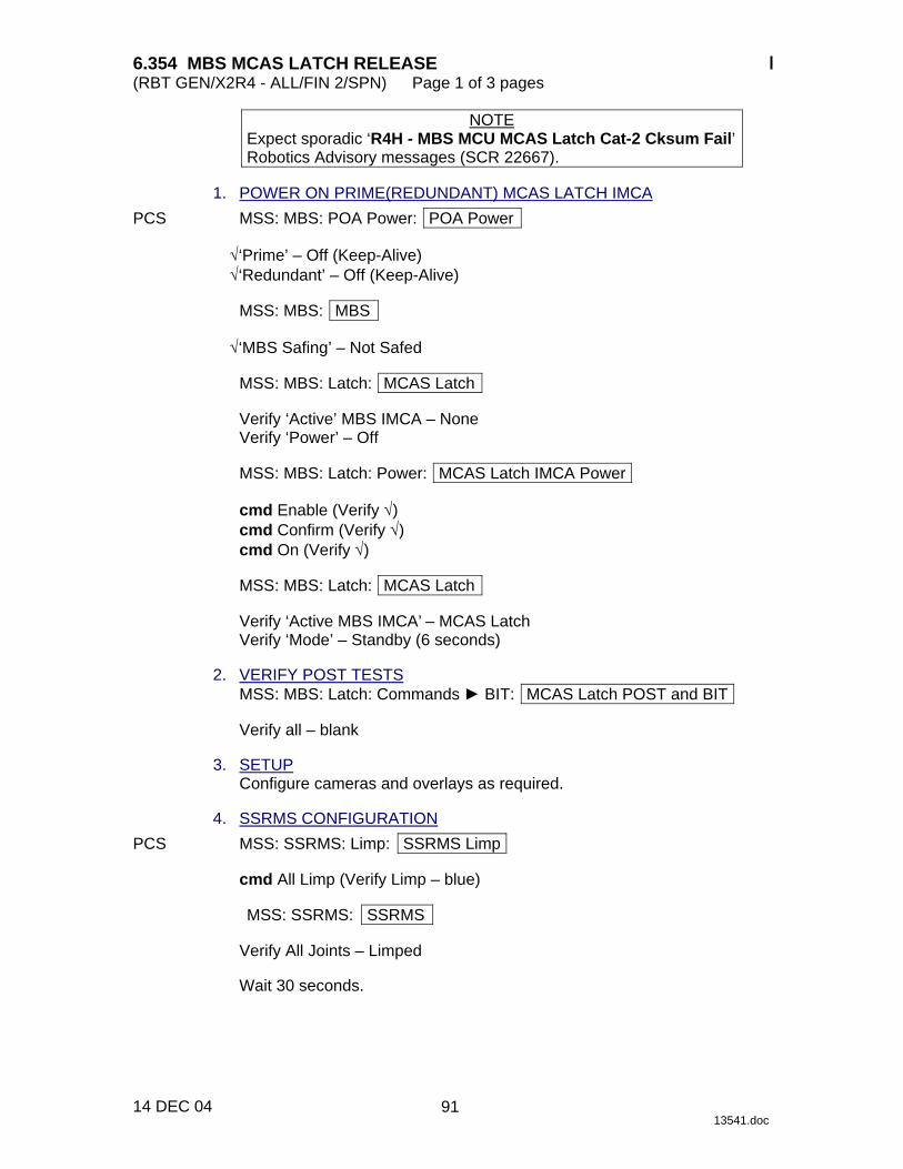
6.354 MBS MCAS LATCH RELEASE (RBT GEN/X2R4 - ALL/FIN 2/SPN) Page 1 of 3 pages
14 DEC 04 13541.doc
NOTE Expect sporadic ‘R4H - MBS MCU MCAS Latch Cat-2 Cksum Fail’ Robotics Advisory messages (SCR 22667).
1. POWER ON PRIME(REDUNDANT) MCAS LATCH IMCA PCS MSS: MBS: POA Power: POA Power
√‘Prime’ – Off (Keep-Alive) √‘Redundant’ – Off (Keep-Alive)
MSS: MBS: MBS
√‘MBS Safing’ – Not Safed
MSS: MBS: Latch: MCAS Latch
Verify ‘Active’ MBS IMCA – None Verify ‘Power’ – Off
MSS: MBS: Latch: Power: MCAS Latch IMCA Power
cmd Enable (Verify √) cmd Confirm (Verify √) cmd On (Verify √)
MSS: MBS: Latch: MCAS Latch
Verify ‘Active MBS IMCA’ – MCAS Latch Verify ‘Mode’ – Standby (6 seconds)
2. VERIFY POST TESTS
MSS: MBS: Latch: Commands ► BIT: MCAS Latch POST and BIT
Verify all – blank 3. SETUP
Configure cameras and overlays as required. 4. SSRMS CONFIGURATION PCS MSS: SSRMS: Limp: SSRMS Limp
cmd All Limp (Verify Limp – blue)
MSS: SSRMS: SSRMS
Verify All Joints – Limped
Wait 30 seconds.
91
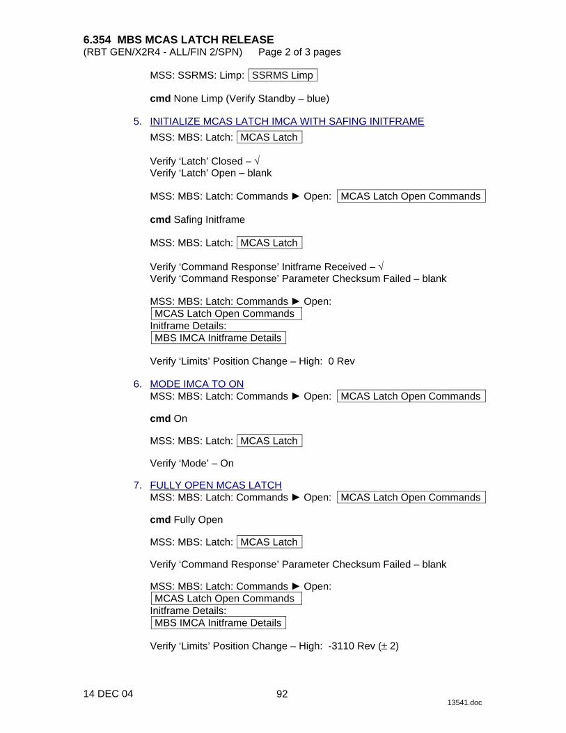
6.354 MBS MCAS LATCH RELEASE (RBT GEN/X2R4 - ALL/FIN 2/SPN) Page 2 of 3 pages
14 DEC 04 13541.doc
MSS: SSRMS: Limp: SSRMS Limp
cmd None Limp (Verify Standby – blue) 5. INITIALIZE MCAS LATCH IMCA WITH SAFING INITFRAME
MSS: MBS: Latch: MCAS Latch
Verify ‘Latch’ Closed – √ Verify ‘Latch’ Open – blank
MSS: MBS: Latch: Commands ► Open: MCAS Latch Open Commands
cmd Safing Initframe
MSS: MBS: Latch: MCAS Latch
Verify ‘Command Response’ Initframe Received – √ Verify ‘Command Response’ Parameter Checksum Failed – blank
MSS: MBS: Latch: Commands ► Open: MCAS Latch Open Commands
Initframe Details: MBS IMCA Initframe Details
Verify ‘Limits’ Position Change – High: 0 Rev
6. MODE IMCA TO ON
MSS: MBS: Latch: Commands ► Open: MCAS Latch Open Commands
cmd On
MSS: MBS: Latch: MCAS Latch
Verify ‘Mode’ – On 7. FULLY OPEN MCAS LATCH
MSS: MBS: Latch: Commands ► Open: MCAS Latch Open Commands
cmd Fully Open
MSS: MBS: Latch: MCAS Latch
Verify ‘Command Response’ Parameter Checksum Failed – blank
MSS: MBS: Latch: Commands ► Open: MCAS Latch Open Commands
Initframe Details: MBS IMCA Initframe Details
Verify ‘Limits’ Position Change – High: -3110 Rev (± 2)
92
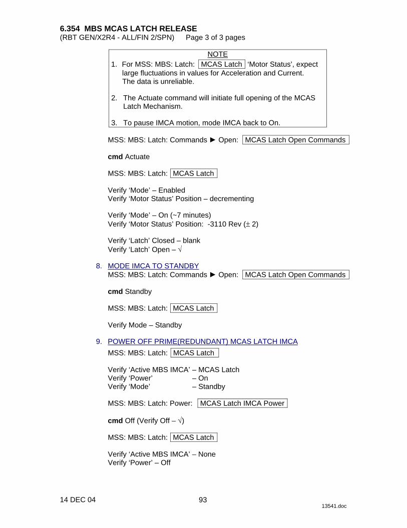
6.354 MBS MCAS LATCH RELEASE (RBT GEN/X2R4 - ALL/FIN 2/SPN) Page 3 of 3 pages
14 DEC 04 13541.doc
NOTE 1. For MSS: MBS: Latch: MCAS Latch ‘Motor Status’, expect
large fluctuations in values for Acceleration and Current. The data is unreliable.
2. The Actuate command will initiate full opening of the MCAS
Latch Mechanism. 3. To pause IMCA motion, mode IMCA back to On.
MSS: MBS: Latch: Commands ► Open: MCAS Latch Open Commands
cmd Actuate
MSS: MBS: Latch: MCAS Latch
Verify ‘Mode’ – Enabled Verify ‘Motor Status’ Position – decrementing
Verify ‘Mode’ – On (~7 minutes) Verify ‘Motor Status’ Position: -3110 Rev (± 2)
Verify ‘Latch’ Closed – blank Verify ‘Latch’ Open – √
8. MODE IMCA TO STANDBY
MSS: MBS: Latch: Commands ► Open: MCAS Latch Open Commands
cmd Standby
MSS: MBS: Latch: MCAS Latch
Verify Mode – Standby 9. POWER OFF PRIME(REDUNDANT) MCAS LATCH IMCA
MSS: MBS: Latch: MCAS Latch
Verify ‘Active MBS IMCA’ – MCAS Latch Verify ‘Power’ – On Verify ‘Mode’ – Standby
MSS: MBS: Latch: Power: MCAS Latch IMCA Power
cmd Off (Verify Off – √)
MSS: MBS: Latch: MCAS Latch
Verify ‘Active MBS IMCA’ – None Verify ‘Power’ – Off
93

This Page Intentionally Blank
22 DEC 04
94

6.360 MBS MCAS UMA MATE (RBT GEN/X2R4 - ALL/FIN 2) Page 1 of 4 pages
10 DEC 04 13546.doc
NOTE 1. Only one MBS mechanism (MCAS UMA, MTCL, POA or MCAS
Latch) can be Operational at one time. 2. Expect sporadic ‘R4H - MBS MCU MCAS UMA Cat-2 Cksum
Fail’ Robotics Advisory messages (SPN 1910). 3. A sporadic ‘R4H - MBS MCU MCAS Abnormal Stop Cond’
Robotics Advisory message may be raised when a new IMCA init frame is loaded. This message may be ignored unless it is raised immediately following the end of the IMCA trajectory (SCR 28923).
1. SETUP PCS MSS: MBS: POA Power: POA Power
Verify ‘Prime’ – Keep-Alive(Off) Verify ‘Redundant’ – Keep-Alive(Off)
MSS: MBS: UMA: MCAS UMA
Verify ‘Active MBS IMCA’ – None
2. CANCEL MBS SAFING
MSS: MBS: MBS Safing: MBS Safing
cmd Remove (Verify Not Safed) 3. POWER ON MCAS UMA IMCA
MSS: MBS: UMA: Power: MCAS UMA IMCA Power
cmd Enable (Verify – √) cmd Confirm (Verify – √) cmd On (Verify – √)
MSS: MBS: UMA: MCAS UMA
Verify ‘Power’ – On (6 seconds)
4. VERIFY POST AND BIT TESTS
MSS: MBS: UMA: Commands ► BIT: MCAS UMA Post and BIT
Verify all – blank
95

6.360 MBS MCAS UMA MATE (RBT GEN/X2R4 - ALL/FIN 2) Page 2 of 4 pages
10 DEC 04 13546.doc
5. INITIALIZE MCAS UMA IMCA WITH SAFING INITFRAME MSS: MBS: UMA: MCAS UMA
Verify ‘Mated’ – blank Verify ‘Demated’ – √
MSS: MBS: UMA: Commands ► Mate: MCAS UMA Mate Commands
cmd Safing Initframe
MSS: MBS: UMA: MCAS UMA ‘Command Response’
Verify ‘Initframe Received’ – √ Verify ‘Parameter Checksum Failed’ – blank
MSS: MBS: UMA: Command ► Mate: Initframe Details: MBS IMCA Initframe Details
Verify ‘Limits’ ‘Position Change – High’: 0
MSS: MBS: UMA: Commands ► Mate: MCAS UMA Mate Commands
cmd On
MSS: MBS: UMA: MCAS UMA
Verify ‘Mode’ – On
6. THRUSTERS INHIBIT
If ISS/orbiter mated MSS: SSRMS: Thrusters: Thruster Controls for MSS Ops
cmd ‘Desat Request’ Inhibit (Verify – Inh)
√‘Auto Att Control Handover to RS’ – Inh
If ISS not mated to orbiter, √MCC-H for proper thruster configuration before proceeding.
7. FIRST STAGE MATE
MSS: MBS: UMA: Commands ► Mate: MCAS UMA Mate Commands
cmd First Phase
MSS: MBS: UMA: MCAS UMA
Verify ‘Command Response’ ‘Parameter Checksum Failed’ – blank
MSS: MBS: UMA: Commands ► Mate: Initframe Details: MBS IMCA Initframe Details
Verify ‘Limits’ ‘Position Change – High’: -450
96
6.360 MBS MCAS UMA MATE (RBT GEN/X2R4 - ALL/FIN 2) Page 3 of 4 pages
10 DEC 04 13546.doc
NOTE For MSS: MBS: UMA: MCAS UMA ‘Motor Status’, expect large fluctuations in values for Acceleration and Current. The data is unreliable.
MSS: MBS: UMA: Commands ► Mate: MCAS UMA Mate Commands
cmd Actuate
MSS: MBS: UMA: MCAS UMA
Verify ‘Mode’ – Enabled Verify ‘Motor Status’ ‘Position’ – decrementing
Verify ‘Mode’ – On (~1 minute) Verify ‘Motor Status’ ‘Position’: -450 ± 2
Verify ‘Mated’ – blank Verify ‘Demated’ – blank
8. SECOND STAGE MATE
MSS: MBS: UMA: Commands ► Mate: MCAS UMA Mate Commands
cmd Second Phase
MSS: MBS: UMA: MCAS UMA
Verify ‘Command Response’ ‘Parameter Checksum Failed’ – blank
MSS: MBS: UMA: Commands ► Mate: Initframe Details: MBS IMCA Initframe Details
Verify ‘Limits’ ‘Position Change – High’: -516
NOTE
1. For MSS: MBS: UMA: MCAS UMA ‘Motor Status’, expect large fluctuations in values for Acceleration and Current. The data is unreliable.
2. A timing problem between the MCU and IMCA may cause the
MBS to safe and remove power from the UMA IMCAS after the mated microswitch is tripped. The following messages will be raised for one cycle:
‘R2O – MBS MCU UMA Inadvertent Pwr On’ ‘R2P – MSS OCS MBS Prime(Redun) MCU SRT Inh Fail’ ‘R4H – MBS MCU UMA Stop Cond Err’
The state of the mated microswitch can be verified by canceling safing and applying power to the UMA IMCA.
97

6.360 MBS MCAS UMA MATE (RBT GEN/X2R4 - ALL/FIN 2) Page 4 of 4 pages
10 DEC 04 13546.doc
MSS: MBS: UMA: Commands ► Mate: MCAS UMA Mate Commands
cmd Actuate
MSS: MBS: UMA: MCAS UMA
Verify ‘Mode’ – Enabled Verify ‘Motor Status’ ‘Position’ – decrementing
Verify ‘Mode’ – On (~35 seconds) Verify ‘Latch Status’ – Switch 1 Verify ‘Motor Status’ ‘Position’: -505 ± 5
Verify ‘Mated’ – √ Verify ‘Demated’ – blank
9. MODE IMCA TO STANDBY
MSS: MBS: UMA: Commands ► Mate: MCAS UMA Mate Commands
cmd Standby
MSS: MBS: UMA: MCAS UMA
Verify ‘Mode’ – Standby 10. IMCA POWER REMOVAL
MSS: MBS: UMA: Power: MCAS UMA IMCA Power
cmd Off (Verify – √) 11. THRUSTERS ENABLE
If ISS/orbiter mated MSS: SSRMS: Thrusters: Thruster Controls for MSS Ops
cmd ‘Desat Request’ Enable (Verify – Ena)
If ISS not mated to orbiter, √MCC-H for proper thruster configuration.
98

6.361 MBS MCAS UMA DEMATE (RBT GEN/X2R4 - ALL/FIN 2/SPN) Page 1 of 5 pages
10 DEC 04 13547.doc
NOTE 1. Only one MBS mechanism (MCAS UMA, MTCL, POA or MCAS
Latch) can be Operational at one time. 2. Expect sporadic ‘R4H - MBS MCU MCAS UMA Cat-2 Cksum
Fail’ Robotics Advisory messages (SCR 22667). 3. A sporadic ‘R4H - MBS MCU MCAS Abnormal Stop Cond’
Robotics Advisory message may be raised when a new IMCA init frame is loaded. This message may be ignored unless it is raised immediately following the end of the IMCA trajectory (SPN 3302).
1. SETUP PCS MSS: MBS: POA Power: POA Power
Verify ‘Prime’ – Keep-Alive(Off) Verify ‘Redundant’ – Keep-Alive(Off)
MSS: MBS: UMA: MCAS UMA
Verify ‘Active MBS IMCA’ – None
2. CANCEL MBS SAFING
MSS: MBS: MBS Safing: MBS Safing
cmd Remove (Verify Not Safed) 3. POWER ON MCAS UMA IMCA
MSS: MBS: UMA: Power: MCAS UMA IMCA Power
cmd Enable (Verify – √) cmd Confirm (Verify – √) cmd On (Verify – √)
MSS: MBS: UMA: MCAS UMA
Verify ‘Power’ – On (6 seconds)
4. VERIFY POST AND BIT TESTS
MSS: MBS: UMA: Commands � BIT: MCAS UMA Post and BIT
Verify all – blank
99

6.361 MBS MCAS UMA DEMATE (RBT GEN/X2R4 - ALL/FIN 2/SPN) Page 2 of 5 pages
10 DEC 04 13547.doc
5. INITIALIZE MCAS UMA IMCA WITH SAFING INITFRAME MSS: MBS: UMA: MCAS UMA
Verify ‘Mated’ – √ Verify ‘Demated’ – blank
MSS: MBS: UMA: Commands � Demate: MCAS UMA Demate Commands
cmd Safing Initframe
MSS: MBS: UMA: MCAS UMA ‘Command Response’
Verify ‘Initframe Received’ – √ Verify ‘Parameter Checksum Failed’ – blank
MSS: MBS: UMA: Commands ► Demate: Initframe Details: MBS IMCA Initframe Details
Verify ‘Limits’ ‘Position Change – High’: 0
MSS: MBS: UMA: Commands � Demate: MCAS UMA Demate Commands
cmd On
MSS: MBS: UMA: MCAS UMA
Verify ‘Mode’ – On
6. THRUSTERS INHIBIT
If ISS/orbiter mated MSS: SSRMS: Thrusters: Thruster Controls for MSS Ops
cmd ‘Desat Request’ Inhibit (Verify – Inh)
√‘Auto Att Control Handover to RS’ – Inh
If ISS not mated to orbiter, √MCC-H for proper thruster configuration before proceeding.
7. FIRST STAGE DEMATE
MSS: MBS: UMA: Commands � Demate: MCAS UMA Demate Commands
cmd First Phase
MSS: MBS: UMA: MCAS UMA
Verify ‘Command Response’ ‘Parameter Checksum Failed’ – blank
100
6.361 MBS MCAS UMA DEMATE (RBT GEN/X2R4 - ALL/FIN 2/SPN) Page 3 of 5 pages
10 DEC 04 13547.doc
MSS: MBS: UMA: Commands ► Demate: Initframe Details: MBS IMCA Initframe Details
Verify ‘Limits’ ‘Position Change – High’: 450
NOTE
For MSS: MBS: UMA: MCAS UMA ‘Motor Status’, expect large fluctuations in values for Acceleration and Current. The data is unreliable.
MSS: MBS: UMA: Commands � Demate: MCAS UMA Demate Commands
cmd Actuate MSS: MBS: UMA: MCAS UMA
Verify ‘Mode’ – Enabled Verify ‘Motor Status’ ‘Position’ – incrementing
Verify ‘Mode’ – On (~1 minute) Verify ‘Motor Status’ ‘Position’: 450 ± 2
Verify ‘Mated’ – blank Verify ‘Demated’ – blank
8. SECOND STAGE DEMATE
MSS: MBS: UMA: Commands � Demate: MCAS UMA Demate Commands
cmd Second Phase
MSS: MBS: UMA: MCAS UMA
Verify ‘Command Response’ ‘Parameter Checksum Failed’ – blank
MSS: MBS: UMA: Commands ► Demate: Initframe Details: MBS IMCA Initframe Details
Verify ‘Limits’ ‘Position Change – High’: 516
101
6.361 MBS MCAS UMA DEMATE (RBT GEN/X2R4 - ALL/FIN 2/SPN) Page 4 of 5 pages
10 DEC 04 13547.doc
NOTE 1. For MSS: MBS: UMA: MCAS UMA ‘Motor Status’, expect
large fluctuations in values for Acceleration and Current. The data is unreliable.
2. A timing problem between the MCU and IMCA may cause the
MBS to safe and remove power from the UMA IMCAS after the demated microswitch is tripped. The following messages will be raised for one cycle:
‘R2O – MBS MCU UMA Inadvertent Pwr On’ ‘R2P – MSS OCS MBS Prime(Redun) MCU SRT Inh Fail’ ‘R4H – MBS MCU UMA Stop Cond Err’
The state of the demated microswitch can be verified by canceling safing, and applying power to the UMA IMCA.
MSS: MBS: UMA: Commands � Demate: MCAS UMA Demate Commands
cmd Actuate
MSS: MBS: UMA: MCAS UMA
Verify ‘Mode’ – Enabled Verify ‘Motor Status’ ‘Position’– incrementing
Verify ‘Mode’ – On (~35 seconds) Verify ‘Latch Status’ – Switch 2
Verify ‘Motor Status’ ‘Position’: 505 ± 5
Verify ‘Mated’ – blank Verify ‘Demated’ – √
9. MODE IMCA TO STANDBY
MSS: MBS: UMA: Commands � Demate: MCAS UMA Demate Commands
cmd Standby
MSS: MBS: UMA: MCAS UMA
Verify ‘Mode’ – Standby 10. IMCA POWER REMOVAL
MSS: MBS: UMA: Power: MCAS UMA IMCA Power
cmd Off (Verify – √)
102
6.361 MBS MCAS UMA DEMATE (RBT GEN/X2R4 - ALL/FIN 2/SPN) Page 5 of 5 pages
10 DEC 04 13547.doc
11. THRUSTERS ENABLE If ISS/orbiter mated
MSS: SSRMS: Thrusters: Thruster Controls for MSS Ops
cmd ‘Desat Request’ Enable (Verify – Ena)
If ISS not mated to orbiter, √MCC-H for proper thruster configuration.
103

This Page Intentionally Blank
22 DEC 04
104

6.401 SSRMS JOINT BRAKE TEST (RBT GEN/X2R4 - ALL/FIN 1/SPN) Page 1 of 1 page
20 DEC 04 12684.doc
1. SETUP PCS MSS: SSRMS: SSRMS
√‘SSRMS Safing’ – Safed √Coarse
2. DIAGNOSTICS
NOTE If this procedure is called as part of a nominal checkout, all joints should be selected as part of diagnostics. If this procedure is called from a malfunction procedure, only the joint(s) specified in the malfunction procedure should be selected.
MSS: SSRMS: Diagnostic: SSRMS Diagnostics
sel ‘Joints’ SR,SY,SP,EP,WP,WY,WR – as required
√‘Joint Brakes’ Stop on Error button is deselected
cmd Brake Test
MSS: SSRMS: Discrete Log: MSS Discrete Log
Verify test status messages (four per joint selected) – Passed (SCR 19062)
MSS: CW Summ Robotics: Caution & Warning Summary
If any Robotics Advisories were annunciated during the diagnostics
DCP SAFING → SAFE (Verify ON) (SCR 23261)
105

This Page Intentionally Blank
22 DEC 04
106
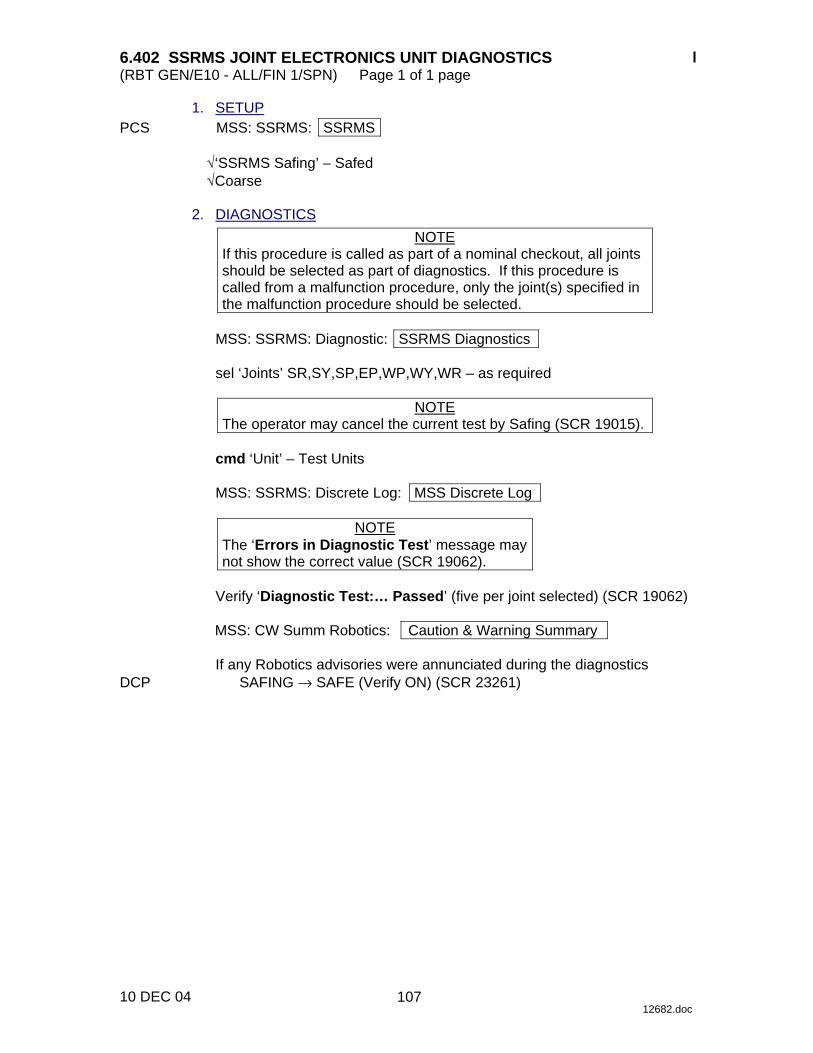
6.402 SSRMS JOINT ELECTRONICS UNIT DIAGNOSTICS (RBT GEN/E10 - ALL/FIN 1/SPN) Page 1 of 1 page
10 DEC 04 12682.doc
1. SETUP PCS MSS: SSRMS: SSRMS
√‘SSRMS Safing’ − Safed √Coarse
2. DIAGNOSTICS
NOTE If this procedure is called as part of a nominal checkout, all joints should be selected as part of diagnostics. If this procedure is called from a malfunction procedure, only the joint(s) specified in the malfunction procedure should be selected.
MSS: SSRMS: Diagnostic: SSRMS Diagnostics
sel ‘Joints’ SR,SY,SP,EP,WP,WY,WR – as required
NOTE
The operator may cancel the current test by Safing (SCR 19015).
cmd ‘Unit’ – Test Units
MSS: SSRMS: Discrete Log: MSS Discrete Log
NOTE The ‘Errors in Diagnostic Test’ message may not show the correct value (SCR 19062).
Verify ‘Diagnostic Test:… Passed’ (five per joint selected) (SCR 19062)
MSS: CW Summ Robotics: Caution & Warning Summary
If any Robotics advisories were annunciated during the diagnostics
DCP SAFING → SAFE (Verify ON) (SCR 23261)
107

This Page Intentionally Blank
22 DEC 04
108
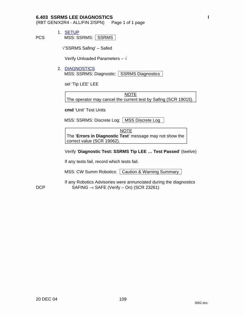
6.403 SSRMS LEE DIAGNOSTICS (RBT GEN/X2R4 - ALL/FIN 2/SPN) Page 1 of 1 page
20 DEC 04 3662.doc
1. SETUP PCS MSS: SSRMS: SSRMS
√‘SSRMS Safing’ – Safed
Verify Unloaded Parameters – √ 2. DIAGNOSTICS
MSS: SSRMS: Diagnostic: SSRMS Diagnostics
sel ‘Tip LEE’ LEE
NOTE The operator may cancel the current test by Safing (SCR 19015).
cmd ‘Unit’ Test Units
MSS: SSRMS: Discrete Log: MSS Discrete Log
NOTE
The ‘Errors in Diagnostic Test’ message may not show the correct value (SCR 19062).
Verify ‘Diagnostic Test: SSRMS Tip LEE … Test Passed’ (twelve)
If any tests fail, record which tests fail.
MSS: CW Summ Robotics: Caution & Warning Summary
If any Robotics Advisories were annunciated during the diagnostics
DCP SAFING → SAFE (Verify – On) (SCR 23261)
109

This Page Intentionally Blank
22 DEC 04
110
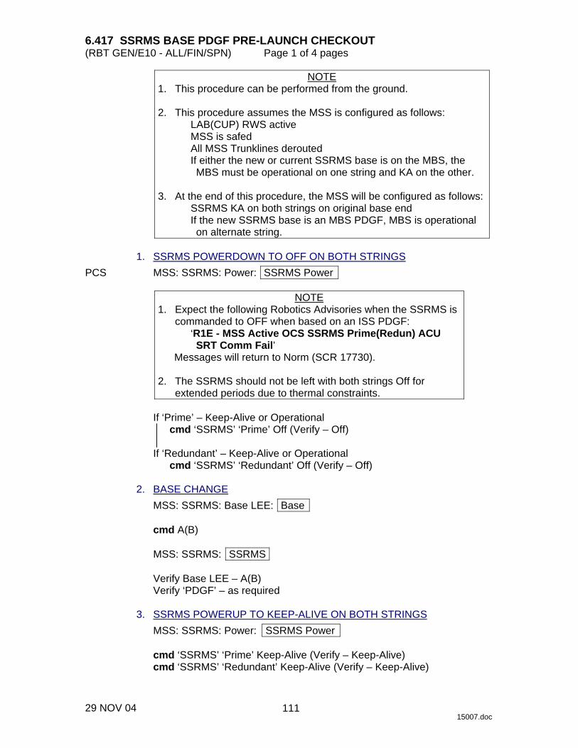
6.417 SSRMS BASE PDGF PRE-LAUNCH CHECKOUT (RBT GEN/E10 - ALL/FIN/SPN) Page 1 of 4 pages
29 NOV 04 15007.doc
NOTE 1. This procedure can be performed from the ground. 2. This procedure assumes the MSS is configured as follows:
LAB(CUP) RWS active MSS is safed All MSS Trunklines derouted If either the new or current SSRMS base is on the MBS, the MBS must be operational on one string and KA on the other.
3. At the end of this procedure, the MSS will be configured as follows:
SSRMS KA on both strings on original base end If the new SSRMS base is an MBS PDGF, MBS is operational on alternate string.
1. SSRMS POWERDOWN TO OFF ON BOTH STRINGS PCS MSS: SSRMS: Power: SSRMS Power
NOTE 1. Expect the following Robotics Advisories when the SSRMS is
commanded to OFF when based on an ISS PDGF: ‘R1E - MSS Active OCS SSRMS Prime(Redun) ACU SRT Comm Fail’
Messages will return to Norm (SCR 17730). 2. The SSRMS should not be left with both strings Off for
extended periods due to thermal constraints.
If ‘Prime’ – Keep-Alive or Operational cmd ‘SSRMS’ ‘Prime’ Off (Verify – Off)
If ‘Redundant’ – Keep-Alive or Operational
cmd ‘SSRMS’ ‘Redundant’ Off (Verify – Off) 2. BASE CHANGE
MSS: SSRMS: Base LEE: Base
cmd A(B)
MSS: SSRMS: SSRMS
Verify Base LEE – A(B) Verify ‘PDGF’ – as required
3. SSRMS POWERUP TO KEEP-ALIVE ON BOTH STRINGS
MSS: SSRMS: Power: SSRMS Power
cmd ‘SSRMS’ ‘Prime’ Keep-Alive (Verify – Keep-Alive) cmd ‘SSRMS’ ‘Redundant’ Keep-Alive (Verify – Keep-Alive)
111
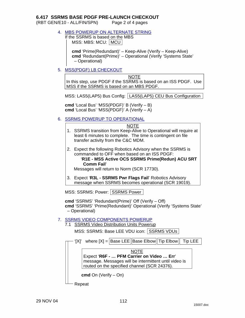
6.417 SSRMS BASE PDGF PRE-LAUNCH CHECKOUT (RBT GEN/E10 - ALL/FIN/SPN) Page 2 of 4 pages
29 NOV 04 15007.doc
4. MBS POWERUP ON ALTERNATE STRING If the SSRMS is based on the MBS
MSS: MBS: MCU: MCU
cmd ‘Prime(Redundant)’ – Keep-Alive (Verify – Keep-Alive) cmd ‘Redundant(Prime)’ – Operational (Verify ‘Systems State’ – Operational)
5. MSS(PDGF) LB CHECKOUT
NOTE In this step, use PDGF if the SSRMS is based on an ISS PDGF. Use MSS if the SSRMS is based on an MBS PDGF.
MSS: LAS5(LAP5) Bus Config: LAS5(LAP5) CEU Bus Configuration
cmd ‘Local Bus’ ‘MSS(PDGF)’ B (Verify – B) cmd ‘Local Bus’ ‘MSS(PDGF)’ A (Verify – A)
6. SSRMS POWERUP TO OPERATIONAL
NOTE 1. SSRMS transition from Keep-Alive to Operational will require at
least 6 minutes to complete. The time is contingent on file transfer activity from the C&C MDM.
2. Expect the following Robotics Advisory when the SSRMS is
commanded to OFF when based on an ISS PDGF: ‘R1E - MSS Active OCS SSRMS Prime(Redun) ACU SRT Comm Fail’
Messages will return to Norm (SCR 17730). 3. Expect ‘R3L - SSRMS Pwr Flags Fail’ Robotics Advisory
message when SSRMS becomes operational (SCR 19019).
MSS: SSRMS: Power: SSRMS Power
cmd ‘SSRMS’ ‘Redundant(Prime)’ Off (Verify – Off) cmd ‘SSRMS’ ‘Prime(Redundant)’ Operational (Verify ‘Systems State’ – Operational)
7. SSRMS VIDEO COMPONENTS POWERUP 7.1 SSRMS Video Distribution Units Powerup
MSS: SSRMS: Base LEE VDU icon: SSRMS VDUs
‘[X]’ where [X] = Base LEE Base Elbow Tip Elbow Tip LEE
NOTE Expect ‘R6F - … PFM Carrier on Video … Err’ message. Messages will be intermittent until video is routed on the specified channel (SCR 24376).
cmd On (Verify – On)
Repeat
112

6.417 SSRMS BASE PDGF PRE-LAUNCH CHECKOUT (RBT GEN/E10 - ALL/FIN/SPN) Page 3 of 4 pages
29 NOV 04 15007.doc
7.2 Cameras Powerup MSS: SSRMS: [X] Camera icon: SSRMS Camera
‘[X]’ where [X] = Base Elbow Tip Elbow Tip LEE
cmd ‘Power’ On (Verify – On)
Repeat
8. VIDEO ROUTING TEST
Perform the following SSRMS video routes.
SOURCE DESTINATION SSRMS Tip LEE Mon 1 SSRMS Tip Elbow Mon 2 SSRMS Base Elbow Mon 3
9. SSRMS POWERDOWN TO OFF 9.1 Derouting MSS Video
MSS: Video: Trunkline Usage: Trunkline Usage ‘MSS Trunklines’
sel MSS Trunkline [X]
where [X] = 4 3 2 1 5 9 8 7 6
MSS Trunkline [X]
Note all destinations with “√”.
MSS: Video: Video Overview: Video Overview
Repeat the following for all destinations noted.
sel Destination icon
[Destination name]
cmd ‘Deroute Video Signal’ Deroute
Repeat
113
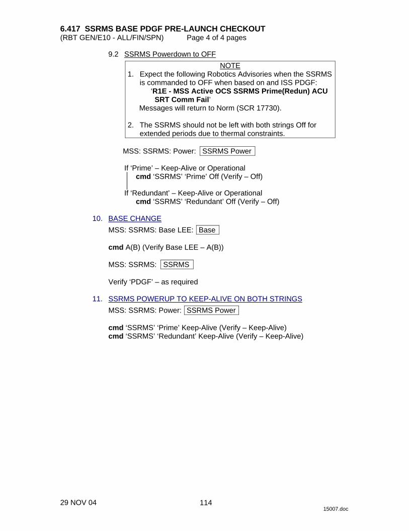
6.417 SSRMS BASE PDGF PRE-LAUNCH CHECKOUT (RBT GEN/E10 - ALL/FIN/SPN) Page 4 of 4 pages
29 NOV 04 15007.doc
9.2 SSRMS Powerdown to OFF NOTE
1. Expect the following Robotics Advisories when the SSRMS is commanded to OFF when based on and ISS PDGF:
‘R1E - MSS Active OCS SSRMS Prime(Redun) ACU SRT Comm Fail’
Messages will return to Norm (SCR 17730). 2. The SSRMS should not be left with both strings Off for
extended periods due to thermal constraints.
MSS: SSRMS: Power: SSRMS Power
If ‘Prime’ – Keep-Alive or Operational cmd ‘SSRMS’ ‘Prime’ Off (Verify – Off)
If ‘Redundant’ – Keep-Alive or Operational
cmd ‘SSRMS’ ‘Redundant’ Off (Verify – Off) 10. BASE CHANGE
MSS: SSRMS: Base LEE: Base
cmd A(B) (Verify Base LEE – A(B))
MSS: SSRMS: SSRMS
Verify ‘PDGF’ – as required 11. SSRMS POWERUP TO KEEP-ALIVE ON BOTH STRINGS
MSS: SSRMS: Power: SSRMS Power
cmd ‘SSRMS’ ‘Prime’ Keep-Alive (Verify – Keep-Alive) cmd ‘SSRMS’ ‘Redundant’ Keep-Alive (Verify – Keep-Alive)
114

6.421 LEE CALIBRATION (RBT GEN/E9 - ALL/FIN 2/SPN) Page 1 of 1 page
14 DEC 04 12685.doc
NOTE 1. The SSRMS must be unloaded. 2. A Calibrate command may be aborted by a ‘SSRMS LEE LEU Mtr
Velocity Runaway’ Robotics Advisory message, and the MSS Safed if one of the three LEE mechanisms was initially located at the hardstop position. If Safing occurs, cancel Safing and restart this procedure from the beginning (SCR 20379).
PCS MSS: SSRMS: Tip LEE: SSRMS Tip LEE
cmd ‘LEE Mechanism’ – Calibrate
Verify ‘Confirm or Terminate’ prompt.
CAUTION Due to end-to-end system latency, the RHC Trigger is hot up to 3 seconds prior to receiving a Trigger Hot Icon status on the PCS.
NOTE
Once the trigger is hot, PCS commands should not be sent to Robotics equipment. If a configuration change is required, safe the system to exit LEE operations.
cmd Confirm (Verify Trigger Hot Icon)
NOTE
1. Apply safing to stop mechanism motion (SCR 23262, 28433). 2. Calibration might take up to 5 minutes, 40 seconds to
complete. RHC TRIGGER → press (momentarily) PCS Verify ‘Snare’ Open – blue
Verify ‘Carriage’ Extend – blue Verify ‘Latch’ Unlatch – blue Verify ‘LEE Mechanisms’ – Calibrated Verify ‘Load Cell’ – Calibrated Verify ‘Motors’ – Inh (340 s max)
115

This Page Intentionally Blank
22 DEC 04
116

6.422 LEE CHECKOUT (RBT GEN/E8 - ALL/FIN 2/SPN) Page 1 of 3 pages
13 NOV 03 12686.doc
NOTE The SSRMS must be unloaded to perform a LEE Checkout.
1. SETUP DCP √BRAKES SSRMS ON −
If SSRMS wrist configuration is not
WP WY -20.0 -170.0
Note current wrist configuration.
WP WY
DCP BRAKES SSRMS → OFF (Verify OFF) PCS MSS: SSRMS: SSRMS
√Vernier
input Mode – Single (Verify Single – blue)
WARNING The active joint must be checked on the PCS before initiating motion. Failure to do so may result in movement of the wrong joint.
THC Maneuver to the following wrist configuration.
WP WY -20.0 -170.0
DCP BRAKES SSRMS → ON (Verify ON)
NOTE 1. The LEE mechanisms are now visible through the Tip Elbow
camera. 2. If no LEE response is observed within 70 seconds of a
command being issued, safe and reattempt (SPN 2045). 2. LEE SETUP FOR CAPTURE PCS MSS: SSRMS: Tip LEE: SSRMS Tip LEE
√‘LEE Mechanisms’ – Calibrated
117
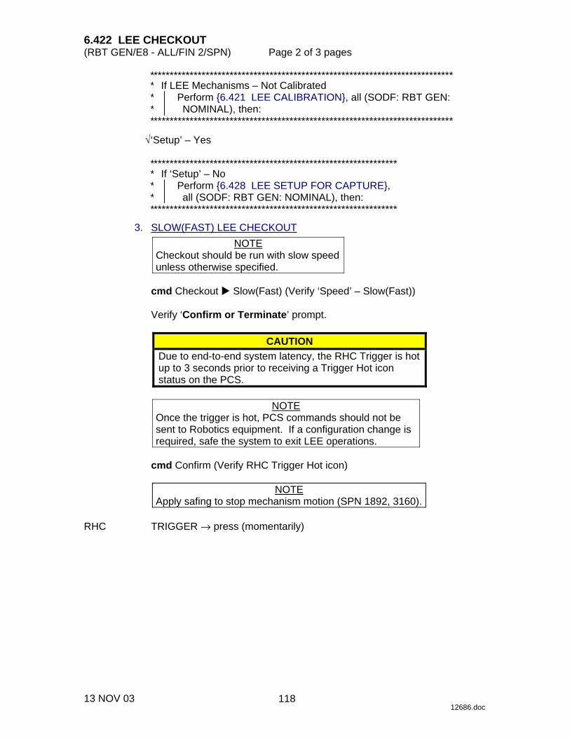
6.422 LEE CHECKOUT (RBT GEN/E8 - ALL/FIN 2/SPN) Page 2 of 3 pages
13 NOV 03 12686.doc
**************************************************************************** ***
If LEE Mechanisms – Not Calibrated Perform {6.421 LEE CALIBRATION}, all (SODF: RBT GEN: NOMINAL), then:
****************************************************************************
√‘Setup’ – Yes
************************************************************** ***
If ‘Setup’ – No Perform {6.428 LEE SETUP FOR CAPTURE}, all (SODF: RBT GEN: NOMINAL), then:
************************************************************** 3. SLOW(FAST) LEE CHECKOUT
NOTE Checkout should be run with slow speed unless otherwise specified.
cmd Checkout � Slow(Fast) (Verify ‘Speed’ – Slow(Fast))
Verify ‘Confirm or Terminate’ prompt.
CAUTION Due to end-to-end system latency, the RHC Trigger is hot up to 3 seconds prior to receiving a Trigger Hot icon status on the PCS.
NOTE
Once the trigger is hot, PCS commands should not be sent to Robotics equipment. If a configuration change is required, safe the system to exit LEE operations.
cmd Confirm (Verify RHC Trigger Hot icon)
NOTE
Apply safing to stop mechanism motion (SPN 1892, 3160). RHC TRIGGER → press (momentarily)
118

6.422 LEE CHECKOUT (RBT GEN/E8 - ALL/FIN 2/SPN) Page 3 of 3 pages
13 NOV 03 12686.doc
PCS Verify ‘Snare’ Close − blue (12 s(3 s) max) Verify ‘Carriage’ Retract − blue (90 s(18 s)max) Verify ‘Latch’ Latch – blue (65 s(13 s)max) Verify ‘Umbilical’ Mate – blue (10 s max) Verify ‘Umbilical’ Demate – blue (10 s max) Verify ‘Latch’ Unlatch – blue (65 s(13 s) max) Verify ‘Carriage’ Derigidize – blue (90 s(18 s) max) Verify ‘Snare’ Open – blue (12 s(3 s) max) Verify ‘Carriage’ Extend – blue (90 s(18 s) max)
4. RECONFIGURE WRIST
If wrist joints were reconfigured for the checkout DCP BRAKES SSRMS → OFF (Verify OFF) PCS MSS: SSRMS: SSRMS
√Vernier
input Mode – Single (Verify Single – blue)
WARNING The active joint must be checked on the PCS before initiating motion. Failure to do so may result in movement of the wrong joint.
THC Maneuver back to original wrist configuration as recorded in step 1. DCP BRAKES SSRMS → ON (Verify ON)
119

This Page Intentionally Blank
22 DEC 04
120

6.423 AUTOMATIC CAPTURE (RBT GEN/X2R4 - ALL/FIN 3/SPN) Page 1 of 3 pages
10 DEC 04 12689.doc
1. SETUP PCS MSS: SSRMS: Tip LEE: SSRMS Tip LEE
√LEE Mechanisms – Calibrated
****************************************************** ***
If LEE Mechanisms – Not Calibrated Perform {6.421 LEE CALIBRATION}, all (SODF: RBT GEN: NOMINAL), then:
******************************************************
√Setup – Yes
************************************************************* ***
If Setup – No Perform {6.428 LEE SETUP FOR CAPTURE}, all (SODF: RBT GEN: NOMINAL), then:
*************************************************************
Prior to beginning payload capture, review {SSRMS LEE CUE CARD}, all (SODF: RBT GEN: REFERENCE}, then:
NOTE
The LEE camera must be fully zoomed out to correspond to the target overlay.
Configure cameras and overlays for grapple.
MSS: SSRMS: SSRMS
√Manual – blue √Vernier
2. SLOW(FAST) CAPTURE COMMANDS
NOTE Automatic Capture should be run with slow speed unless otherwise specified.
MSS: SSRMS: Tip LEE: SSRMS Tip LEE
cmd Capture � Automatic � Slow(Fast), Limp
Verify Speed – Slow(Fast) Verify ‘Confirm or Terminate’ prompt.
121

6.423 AUTOMATIC CAPTURE (RBT GEN/X2R4 - ALL/FIN 3/SPN) Page 2 of 3 pages
10 DEC 04 12689.doc
CAUTION Due to end-to-end system latency, the RHC Trigger is hot up to 3 seconds prior to receiving a Trigger Hot icon status on the PCS.
NOTE
Once the trigger is hot, only safing or trigger commands should be sent to the Robotics equipment. If a configuration change is required, including routing MSS cameras, safe the system to exit LEE operations (SCR 23262, 14662).
cmd Confirm (Verify RHC Trigger Hot icon)
Verify LEE Mode – Auto Capture
3. GRAPPLE MANEUVER RHC/ Maneuver to within grapple envelope. THC 4. GRAPPLE RHC TRIGGER → press (momentarily) PCS Verify ‘Snare’ Close, Capture (two) – blue (12 s(3 s) max)
********************************************************* ****
If ‘Snare’ Capture – not blue Perform {8.111 LEE MISCAPTURE}, all (SODF: RBT GEN: CORRECTIVE), then:
If top choice performed >> *********************************************************
If capturing a PDGF
Verify Capture to Latch – Yes (SCR 19282)
If capturing an FRGF Verify Capture to Latch – No (SCR 19282)
Verify ‘Carriage’ Tension ~5500 N (90 s(24 s) max)
Verify ‘Carriage’ Retract – blue
If capturing an FRGF >>
Verify ‘Latch’ Latch – blue (65 s(13 s) max)
122
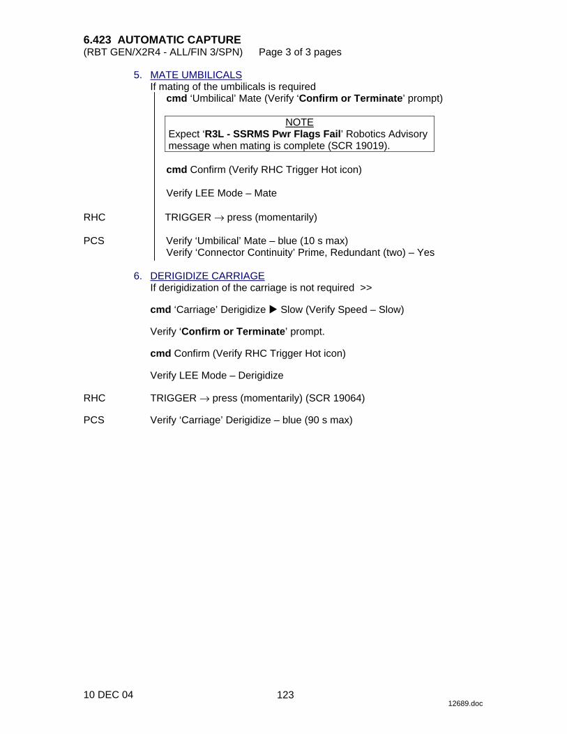
6.423 AUTOMATIC CAPTURE (RBT GEN/X2R4 - ALL/FIN 3/SPN) Page 3 of 3 pages
10 DEC 04 12689.doc
5. MATE UMBILICALS If mating of the umbilicals is required
cmd ‘Umbilical’ Mate (Verify ‘Confirm or Terminate’ prompt)
NOTE Expect ‘R3L - SSRMS Pwr Flags Fail’ Robotics Advisory message when mating is complete (SCR 19019).
cmd Confirm (Verify RHC Trigger Hot icon)
Verify LEE Mode – Mate
RHC TRIGGER → press (momentarily) PCS Verify ‘Umbilical’ Mate – blue (10 s max)
Verify ‘Connector Continuity’ Prime, Redundant (two) – Yes 6. DERIGIDIZE CARRIAGE
If derigidization of the carriage is not required >>
cmd ‘Carriage’ Derigidize � Slow (Verify Speed – Slow)
Verify ‘Confirm or Terminate’ prompt.
cmd Confirm (Verify RHC Trigger Hot icon)
Verify LEE Mode – Derigidize RHC TRIGGER → press (momentarily) (SCR 19064) PCS Verify ‘Carriage’ Derigidize – blue (90 s max)
123

This Page Intentionally Blank
22 DEC 04
124

6.424 AUTOMATIC RELEASE (RBT GEN/E9 - ALL/FIN 4/SPN) Page 1 of 2 pages
30 NOV 04 12692.doc
1. VERIFY LEE CALIBRATION STATUS PCS MSS: SSRMS: Tip LEE: SSRMS Tip LEE
If LEE Mechanisms – Not Calibrated Go to {8.103 MANUAL RELEASE WITH UNCALIBRATED LEE}, all (SODF: RBT GEN: CORRECTIVE).
2. ENTER MODE DCP √BRAKES SSRMS OFF − PCS MSS: SSRMS: Limp: SSRMS Limp
cmd All Limp (Verify Limp − blue)
MSS: SSRMS: SSRMS
Verify All Joints − Limped
Wait 30 seconds.
MSS: SSRMS: Limp: SSRMS Limp
cmd None Limp (Verify Standby – blue)
Enter Mode – Manual (Verify blue)
√Vernier 3. RIGIDIZE CARRIAGE PCS MSS: SSRMS: Tip LEE: SSRMS Tip LEE
If ‘Latch’ Latch – blue and ‘Carriage’ Tension < 2891 N cmd ‘Carriage’ Rigidize � Slow (Verify Speed – Slow)
Verify ‘Confirm or Terminate’ prompt.
CAUTION
Due to end-to-end system latency, the RHC Trigger is hot up to 3 seconds prior to receiving a Trigger Hot icon status on the PCS.
NOTE
Once the trigger is hot, only safing or trigger commands should be sent to the Robotics equipment. If a configuration change is required, including routing MSS cameras, safe the system to exit LEE operations (SCR 23262, 14662).
cmd Confirm (Verify RHC Trigger Hot icon)
Verify LEE Mode – Rigidize
RHC TRIGGER → press (momentarily) (SCR 19064) PCS Verify ‘Carriage’ Tension ~5500 N (~8 s, 90 s max)
Verify ‘Carriage’ Retract – blue
125

6.424 AUTOMATIC RELEASE (RBT GEN/E9 - ALL/FIN 4/SPN) Page 2 of 2 pages
30 NOV 04 12692.doc
4. SLOW(FAST) RELEASE NOTE
Automatic Release should be run with slow speed unless otherwise specified.
PCS cmd Release � Automatic � Slow(Fast) (Verify Speed – Slow(Fast))
Verify ‘Confirm or Terminate’ prompt.
CAUTION Due to end-to-end system latency, the RHC Trigger is hot up to 3 seconds prior to receiving a Trigger Hot icon status on the PCS.
NOTE
Once the trigger is hot, only safing or trigger commands should be sent to the Robotics equipment. If a configuration change is required, including routing MSS cameras, safe the system to exit LEE operations (SCR 23262, 14662).
cmd Confirm (Verify RHC Trigger Hot icon)
Verify LEE Mode – Auto Release
RHC TRIGGER → press (momentarily) PCS Verify ‘Umbilical’ Demate – blue (10 s max)
Verify ‘Latch’ Unlatch – blue (65 s(13 s) max) Verify ‘Carriage’ Derigidize − blue (90 s(24 s) max) Verify ‘Snare’ Open − blue (12 s(3 s) max)
THC Back off from grapple fixture until clear of pin. PCS Verify ‘Carriage’ Extend – blue (90 s(24 s) max)
126
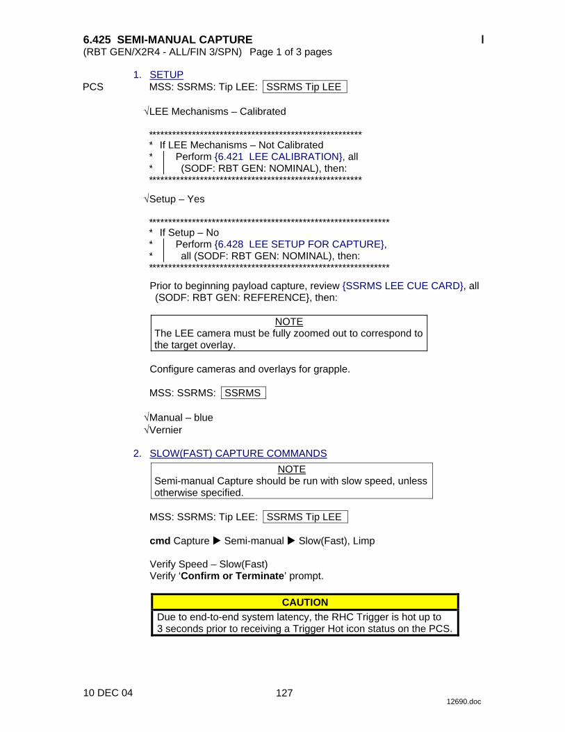
6.425 SEMI-MANUAL CAPTURE (RBT GEN/X2R4 - ALL/FIN 3/SPN) Page 1 of 3 pages
10 DEC 04 12690.doc
1. SETUP PCS MSS: SSRMS: Tip LEE: SSRMS Tip LEE
√LEE Mechanisms – Calibrated
****************************************************** ***
If LEE Mechanisms – Not Calibrated Perform {6.421 LEE CALIBRATION}, all (SODF: RBT GEN: NOMINAL), then:
******************************************************
√Setup – Yes
************************************************************* ***
If Setup – No Perform {6.428 LEE SETUP FOR CAPTURE}, all (SODF: RBT GEN: NOMINAL), then:
*************************************************************
Prior to beginning payload capture, review {SSRMS LEE CUE CARD}, all (SODF: RBT GEN: REFERENCE}, then:
NOTE
The LEE camera must be fully zoomed out to correspond to the target overlay.
Configure cameras and overlays for grapple.
MSS: SSRMS: SSRMS
√Manual – blue √Vernier
2. SLOW(FAST) CAPTURE COMMANDS
NOTE Semi-manual Capture should be run with slow speed, unless otherwise specified.
MSS: SSRMS: Tip LEE: SSRMS Tip LEE
cmd Capture � Semi-manual � Slow(Fast), Limp
Verify Speed – Slow(Fast) Verify ‘Confirm or Terminate’ prompt.
CAUTION Due to end-to-end system latency, the RHC Trigger is hot up to 3 seconds prior to receiving a Trigger Hot icon status on the PCS.
127

6.425 SEMI-MANUAL CAPTURE (RBT GEN/X2R4 - ALL/FIN 3/SPN) Page 2 of 3 pages
10 DEC 04 12690.doc
NOTE Once the trigger is hot, only safing or trigger commands should be sent to the Robotics equipment. If a configuration change is required, including routing MSS cameras, safe the system to exit LEE operations (SCR 23262, 14662).
cmd Confirm (Verify RHC Trigger Hot icon)
Verify LEE Mode – Semi-manual Capture
3. GRAPPLE MANEUVER RHC/ Maneuver to within grapple envelope. THC 4. GRAPPLE RHC TRIGGER → press (hold until ‘Snare’ Brakes – On) (12 s(3 s) max) PCS Verify ‘Snare’ Close, Capture (two) – blue
********************************************************* ****
If ‘Snare’ Capture – not blue Perform {8.111 LEE MISCAPTURE}, all (SODF: RBT GEN: CORRECTIVE), then:
If top choice performed >> *********************************************************
If capturing a PDGF
Verify Capture to Latch – Yes (SCR 19282)
If capturing an FRGF Verify Capture to Latch – No (SCR 19282)
RHC TRIGGER → press (hold until ’Carriage’ Brakes – On) (90 s(24 s) max) PCS Verify ‘Carriage’ Tension ~5500 N (90 s(24 s) max)
Verify ‘Carriage’ Retract – blue
If capturing an FRGF >> RHC TRIGGER → press (hold until ‘Latch’ Brakes – On) (65 s(13 s) max) PCS Verify ‘Latch’ Latch – blue
128
6.425 SEMI-MANUAL CAPTURE (RBT GEN/X2R4 - ALL/FIN 3/SPN) Page 3 of 3 pages
10 DEC 04 12690.doc
5. MATE UMBILICALS If mating of the umbilicals is required
PCS cmd ‘Umbilical’ Mate (Verify ‘Confirm or Terminate’ prompt)
NOTE Expect ‘R3L - SSRMS Pwr Flags Fail’ Robotics Advisory message when mating is complete (SCR 19019).
cmd Confirm (Verify RHC Trigger Hot icon)
Verify LEE Mode – Mate
RHC TRIGGER → press (momentarily) PCS Verify ‘Umbilical’ Mate – blue (10 s max)
Verify ‘Connector Continuity’ Prime, Redundant (two) – Yes 6. DERIGIDIZE CARRIAGE
If derigidization of the carriage is not required >>
cmd ‘Carriage’ Derigidize � Slow (Verify Speed – Slow)
Verify ‘Confirm or Terminate’ prompt.
cmd Confirm (Verify RHC Trigger Hot icon)
Verify LEE Mode – Derigidize RHC TRIGGER → press (momentarily) (SCR 19064) PCS Verify ‘Carriage’ Derigidize – blue (90 s max)
129

This Page Intentionally Blank
22 DEC 04
130

6.426 SEMI-MANUAL RELEASE (RBT GEN/E9 - ALL/FIN 4/SPN) Page 1 of 3 pages
01 DEC 04 12693.doc
1. VERIFY LEE CALIBRATION STATUS PCS MSS: SSRMS: Tip LEE: SSRMS Tip LEE
If LEE Mechanisms – Not Calibrated Go to {8.103 MANUAL RELEASE WITH UNCALIBRATED LEE}, all (SODF: RBT GEN: CORRECTIVE).
2. ENTER MODE DCP √BRAKES SSRMS OFF − PCS MSS: SSRMS: Limp: SSRMS Limp
cmd All Limp (Verify Limp − blue)
MSS: SSRMS: SSRMS
Verify All Joints − Limped
Wait 30 seconds.
MSS: SSRMS: Limp: SSRMS Limp
cmd None Limp (Verify Standby – blue)
Enter Mode – Manual (Verify blue)
√Vernier 3. RIGIDIZE CARRIAGE PCS MSS: SSRMS: Tip LEE: SSRMS Tip LEE
If ‘Latch’ Latch – blue and ‘Carriage’ Tension < 2891 N cmd ‘Carriage’ Rigidize � Slow (Verify Speed – Slow)
Verify ‘Confirm or Terminate’ prompt.
CAUTION Due to end-to-end system latency, the RHC Trigger is hot up to 3 seconds prior to receiving a Trigger Hot icon status on the PCS.
NOTE
Once the trigger is hot, only safing or trigger commands should be sent to the Robotics equipment. If a configuration change is required, including routing MSS cameras, safe the system to exit LEE operations (SCR 23262, 14662).
~
131
6.426 SEMI-MANUAL RELEASE (RBT GEN/E9 - ALL/FIN 4/SPN) Page 2 of 3 pages
01 DEC 04 12693.doc
cmd Confirm (Verify RHC Trigger Hot icon)
Verify LEE Mode – Rigidize
RHC TRIGGER → press (momentarily) (SCR 19064) PCS Verify ‘Carriage’ Tension ~5500 N (~8 s, 90 s max)
Verify ‘Carriage’ Retract – blue 4. SLOW(FAST) RELEASE
NOTE Semi-manual Release should be run with slow speed unless otherwise specified.
cmd Release � Semi-manual � Slow(Fast) (Verify Speed – Slow(Fast))
Verify ‘Confirm or Terminate’ prompt.
CAUTION Due to end-to-end system latency, the RHC Trigger is hot up to 3 seconds prior to receiving a Trigger Hot icon status on the PCS.
NOTE
Once the trigger is hot, only safing or trigger commands should be sent to the Robotics equipment. If a configuration change is required, including routing MSS cameras, safe the system to exit LEE operations (SCR 23262, 14662).
cmd Confirm (Verify RHC Trigger Hot icon)
Verify LEE Mode – Semi-manual Release
If ‘Umbilical’ Mate − blue
RHC TRIGGER → press (hold until ’Latch’ Brakes – On) (10 s max) PCS Verify ‘Umbilical’ Demate – blue PCS If ‘Latch’ Latch − blue RHC TRIGGER → press (hold until ‘Latch’ Brakes – On) (65 s(13 s) max) PCS Verify ‘Latch’ Unlatch – blue
TRIGGER → press (hold until ‘Carriage’ Brakes – On) (90 s(24 s) max) PCS Verify ‘Carriage’ Derigidize – blue
TRIGGER → press (hold until ‘Snare’ Brakes – On) (12 s(3 s) max)
~
132

6.426 SEMI-MANUAL RELEASE (RBT GEN/E9 - ALL/FIN 4/SPN) Page 3 of 3 pages
01 DEC 04 12693.doc
PCS Verify ‘Snare’ Open – blue THC Back off from grapple fixture until clear of pin. RHC TRIGGER → press (hold until ‘Carriage’ Brakes – On) (90 s(24 s) max) PCS Verify ‘Carriage’ Extend – blue
133

This Page Intentionally Blank
22 DEC 04
134

6.427 FORCE MOMENT SENSOR (FMS) CALIBRATION (RBT GEN/R2 - ALL/FIN) Page 1 of 1 page
04 MAR 02 12688.doc
NOTE When performing an FMS calibration: 1. The SSRMS tip or grappled payload should not be in
contact with the structure. 2. The SSRMS should be Safed, Braked, in Standby
mode or in Position Hold. 3. Observed SSRMS dynamic oscillations should be
negligible. 1. THRUSTER INHIBIT PCS MSS: SSRMS: Thrusters: Thruster Controls for MSS Ops
cmd ‘Desat Request’ Inhibit (Verify Inh) 2. FMS CALIBRATION
MSS: SSRMS: Tip LEE: SSRMS Tip LEE
cmd ‘FMS’ Calibrate (Verify Calibrated) 3. THRUSTER ENABLE
MSS: SSRMS: Thrusters: Thruster Controls for MSS Ops
cmd ‘Desat Request’ Enable (Verify Ena)
135

This Page Intentionally Blank
22 DEC 04
136
6.428 LEE SETUP FOR CAPTURE (RBT GEN/E8 - ALL/FIN 2/SPN) Page 1 of 1 page
13 NOV 03 12634.doc
NOTE The SSRMS must be unloaded.
PCS MSS: SSRMS: Tip LEE: SSRMS Tip LEE
If Setup – Yes >>
cmd Capture � Setup � Slow (Verify Speed – Slow)
Verify ‘Confirm or Terminate’ prompt.
CAUTION Due to end-to-end system latency, the RHC Trigger is hot up to 3 seconds prior to receiving a Trigger Hot icon status on the PCS.
NOTE
Once the trigger is hot, only safing or trigger commands should be sent to the Robotics equipment. If a configuration change is required, including routing MSS cameras, safe the system to exit LEE operations (SPN 1892, 3160).
cmd Confirm (Verify Trigger Hot icon)
Verfiy LEE Mode – Setup for Capture
RHC TRIGGER → press (momentarily) PCS Verify ‘Snare’ Open – blue
Verify ‘Carriage’ Extend – blue Verify ‘Latch’ Unlatch – blue Verify Motors – Inh (340 s max)
137

This Page Intentionally Blank
22 DEC 04
138
6.431 SSRMS POWERUP FROM OFF TO KEEP-ALIVE ON BOTH STRINGS (RBT GEN/X2R4 - ALL/FIN) Page 1 of 1 page
10 DEC 04 12700.doc
1. BASE LOCATION CHECK PCS MSS: SSRMS: SSRMS
Verify ‘Base LEE’ Base LEE – as required Verify ‘Base LEE’ PDGF – as required
NOTE
It might take up to 30 seconds for the Keep-Alive status indication to appear on the PCS.
2. TRANSITION PRIME STRING TO KEEP-ALIVE
MSS: SSRMS: Power: SSRMS Power
cmd ‘SSRMS’ Prime – Keep-Alive (Verify Keep-Alive) 3. TRANSITION REDUNDANT STRING TO KEEP-ALIVE
MSS: SSRMS: Power: SSRMS Power
cmd ‘SSRMS’ Redundant – Keep-Alive (Verify Keep-Alive)
139

This Page Intentionally Blank
22 DEC 04
140

6.434 SSRMS POWERDOWN TO OFF ON BOTH STRINGS (RBT GEN/X2R4 - ALL/FIN 1/SCR) Page 1 of 1 page
10 DEC 04 12707.doc
NOTE The SSRMS should not be left with both strings in the Off state for extended periods due to thermal constraints.
1. SAFING STATUS CHECK PCS MSS: SSRMS: Power: SSRMS Power
If ‘SSRMS’ Prime or Redundant – Operational MSS: SSRMS: SSRMS
√’SSRMS Safing’ – Safed
2. TRANSITION PRIME STRING TO OFF
MSS: SSRMS: Power: SSRMS Power
If ‘SSRMS’ Prime not Off NOTE
1. It might take up to 30 seconds for the Off status indication to appear on the PCS.
2. Expect the ‘R1E - MSS Active OCS SSRMS Prime ACU SRT
Comm Fail’ Robotics Advisory message (SCR 17730). 3. If the SSRMS is Operational, expect the ‘R1E - CUP(LAB)
RWS CEU PLB (MLB) ACU Cmd Resp Sync Msg Err’ Robotics Advisory message (SCR 31294).
cmd ‘SSRMS’ Prime – Off (Verify – Off)
3. TRANSITION REDUNDANT STRING TO OFF
If ‘SSRMS’ Redundant not Off NOTE
1. It might take up to 30 seconds for the Off status indication to appear on the PCS.
2. Expect the ‘R1E - MSS Active OCS SSRMS Redun ACU SRT
Comm Fail’ Robotics Advisory message (SCR 17730). 3. If the SSRMS is Operational, expect the ‘R1E - CUP(LAB)
RWS CEU PLB (MLB) ACU Cmd Resp Sync Msg Err’ Robotics Advisory message (SCR 31294).
cmd ‘SSRMS’ Redundant – Off (Verify – Off)
141

This Page Intentionally Blank
22 DEC 04
142

6.435 SSRMS OPERATING BASE CHANGE (RBT GEN/R2 - ALL/FIN) Page 1 of 1 page
26 OCT 01 12679.doc
1. SSRMS POWER STATE CHECK PCS MSS: SSRMS: Power: SSRMS Power
√Prime − Off √Redundant − Off
2. BASE CHANGE
MSS: SSRMS: SSRMS
If Base LEE – A MSS: SSRMS: Base LEE: Base
cmd B
MSS: SSRMS: SSRMS
Verify Base LEE − B
If Base LEE – B
MSS: SSRMS: Base LEE: Base
cmd A
MSS: SSRMS: SSRMS
Verify Base LEE − A 3. PDGF CHECK
Verify PDGF − as required
143

This Page Intentionally Blank
22 DEC 04
144

6.604 CUP(LAB) ARTIFICIAL VISION UNIT (AVU) POWERUP (RBT GEN/R2 - ALL/FIN) Page 1 of 2 pages
29 JUL 02 12656.doc
1. VIDEO SETUP DCP ‘MONITOR SELECT’
cmd MON [X] where X = 3 2 1
Verify MON [X] −
cmd ‘CAMERA SELECT’ 9,5 MON [X] Verify Test Pattern.
Repeat 2. AVU POWERUP LCDM √Power On PCS MSS: LAS5(LAP5) AVU: LAS5(LAP5) AVU
cmd ‘Power’ On
NOTE AVU bootup could take up to 4 minutes.
LCDM Observe AVU bootup sequence. 3. CHECKING POWER STATUS PCS MSS: RWS
Verify ‘LAS5’(‘LAP5’) ‘RPC3’ – closed (blue) Verify ‘LAS5’(‘LAP5’) ‘Status from OCS’ – On
4. SWITCHING LCDM MODE LCDM cmd MENU (Verify Brightness)
cmd UP (Verify Video Mode) cmd SELECT (Verify RGB) cmd UP (Verify COMPOSITE) cmd SELECT
Verify AVU Systems Display appears.
NOTE
Where applicable, AVU Hotkeys are shown in the following manner: <hotkey>.
145

6.604 CUP(LAB) ARTIFICIAL VISION UNIT (AVU) POWERUP (RBT GEN/R2 - ALL/FIN) Page 2 of 2 pages
29 JUL 02 12656.doc
5. CHECKING AVU SYSTEM CONFIGURATION LCDM/ MON1
International Space Station Space Vision System
cmd OK <Alt-O> (window closes automatically in ~8 seconds)
‘Message’
Verify messages
‘AVU: 1553 COMMUNICATION GROUND TELEMETRY RESTORED’
‘AVU: 1553 COMMUNICATION GROUND TELEMETRY SEND FAILED’
‘SYNC SIGNAL DETECTED ON VIDEO INPUT CHANNEL 2’ ‘SYNC SIGNAL DETECTED ON VIDEO INPUT CHANNEL 1’
NOTE
‘GMT EXTRACTION UNAVAILABLE, VID IN 1’ AVU system message may also appear in the AVU Message queue.
sel Clear All <Alt-L> cmd Clear <Alt-L>
If new AVU hardware or software installed since last powerup
Space Vision System
cmd Advanced <Alt-A>
sel Help <Alt-H> � About SVS <A>
International Space Station Space Vision System
Verify ‘Software Version:’ as required. Verify ‘Systems Display Version:’ as required. Verify ‘Database File:’ - svs.dat Verify ‘Database ID:’ as required.
cmd OK <Alt-O>
sel View <Alt-V> � Advisory Page <Alt-A>
146
6.607 CUP(LAB) ARTIFICIAL VISION UNIT (AVU) CHECKOUT WITH VTR 2(1)
(RBT GEN/R2 - ALL/FIN) Page 1 of 5 pages
10 SEP 02 12657.doc
1. VIDEO SETUP PCS MSS: Video: SCU1: SCU1 Function: SCU1 Func
cmd ‘SCU Function Control’ ‘Split Screen Processor’ Inhibit (Verify Inhibit) cmd ‘SCU Function Control’ ‘Time Base Correction’ Enable (Verify Enable)
NOTE
Messages may appear in the message queue on the AVU Systems display when changing video inputs to the AVU.
DCP cmd ‘MONITOR SELECT’ MON1 (Verify )
cmd ‘MULTIPLEX UNIT’ MUX A RIGHT (Verify ) cmd ‘CAMERA SELECT’ 9,2(1) cmd ‘MONITOR SELECT’ MON3 (Verify ) cmd ‘CAMERA SELECT’ 9,3
2. VTR SETUP
Get AVU Checkout Videotape from storage location. VTR2(1) Unlock and open cassette door.
Insert videotape. Close and lock cassette door.
√Local/Remote button – Remote
PCS MSS: Video: VTR2(1): Video Tape Recorder 2(1)
Verify ‘Tape Status’ Cassette In – Detected
sel ‘VTR Control’ Mode cmd PLAY (Verify ‘VTR Operation Mode’ Play)
MON3 Verify wiretray targets are visible.
147

6.607 CUP(LAB) ARTIFICIAL VISION UNIT (AVU) CHECKOUT WITH VTR 2(1)
(RBT GEN/R2 - ALL/FIN) Page 2 of 5 pages
10 SEP 02 12657.doc
Figure 1.- Wiretray Targets.
NOTE 1. Where applicable, AVU Keyboard Hotkeys are shown in the
following manner: <hotkey>. 2. If systems display disappears completely, triple-click the right
button on the keyboard trackball or the bottom button on the AVU CCD to make the systems display appear on all outputs.
3. LOADING VIDEO ROUTING CHECKOUT SCRIPT FILE
NOTE Perform step 3 using keyboard trackball only.
LCDM cmd Browse
sel/csvs/scripts/AVU/051_Routing_Checkout.act cmd Load (script proceeds to ‘12: READY (P)’)
NOTE
Perform steps 4 to 11 using keyboard shortcuts only.
148

6.607 CUP(LAB) ARTIFICIAL VISION UNIT (AVU) CHECKOUT WITH VTR 2(1)
(RBT GEN/R2 - ALL/FIN) Page 3 of 5 pages
10 SEP 02 12657.doc
Required Operator Action
cmd Start <Alt-S> (script proceeds to ‘22: VERIFY VIDEO CONFIG 1 (P)’) √Video configuration:
MON 1 MON 2 LCDM
VTR Test pattern Sys Disp
4.
cmd Start <Alt-S> (script proceeds to ‘33: VERIFY VIDEO CONFIG 2 (P)’)
√Video configuration:
MON 1 MON 2 LCDM
Test Pattern Sys Disp VTR
5.
cmd Start <Alt-S> (script proceeds to ‘44: VERIFY VIDEO CONFIG 3 (P)’)
√Video configuration:
MON 1 MON 2 LCDM
Sys Disp VTR Steer Disp
MON2 6.
cmd Start <Alt-S> (script proceeds to ‘55: VERIFY VIDEO CONFIG 4 (P)’)
√Video configuration:
MON 1 MON 2 LCDM
Sys Disp Steer Disp Test pattern
MON1 7.
cmd Start <Alt-S> (script proceeds to ‘65: VERIFY VIDEO CONFIG 5 (P)’)
√Video configuration:
MON 1 MON 2 LCDM
Enh Test pattern VTR Sys Disp
8.
cmd Start <Alt-S> (script proceeds to ‘76: VERIFY VIDEO CONFIG 6 (P)’)
√Video configuration: MON 1 MON 2 LCDM
Enh VTR VTR Sys Disp
LCDM 9.
cmd Start <Alt-S> (script proceeds to ‘85: VERIFY VIDEO CONFIG 7 (P)’)
√Video configuration: MON 1 MON 2 LCDM
Steer Disp VTR Sys Disp
10.
11. cmd Start <Alt-S> (script proceeds to ‘97: --------END--------’)
12. LOADING AVU CHECKOUT SCRIPT FILE
NOTE Perform steps 12 to 16 using AVU trackball only.
cmd Browse
sel/csvs/scripts/AVU/052_AVU_Checkout.act cmd Load (script proceeds to ‘22: READY (P)’)
149

6.607 CUP(LAB) ARTIFICIAL VISION UNIT (AVU) CHECKOUT WITH VTR 2(1)
(RBT GEN/R2 - ALL/FIN) Page 4 of 5 pages
10 SEP 02 12657.doc
Required Operator Action
LCDM MON1
13. cmd Start <Alt-S> (script proceeds to ‘33: CHECK PRESET WINDOWS (P)’) Verify windows over targets (centered not required)
LCDM MON1
14. cmd Start <Alt-S> (script proceeds to ‘94: CHECK TRACKING WINDOWS (P)’) * *************************************************************** **
If script proceeds to ‘78: ACQUIRE MANUALLY (P)’ Go to step 20.
* *************************************************************** Verify ‘Window Tracking Status:’ is green for all ‘Task 1:’ windows. Verify windows tracking targets correctly.
LCDM 15. cmd Start <Alt-S> (script proceeds to ‘104: CHECK TASK 1 IN RUN (P)’) Verify ‘Task 1:’ is in run (green).
LCDM
16. cmd Start <Alt-S> (script proceeds to ‘123: ------ END ------’)
17. TESTING PATTERN ROUTING
NOTE Messages may appear in the message queue on the AVU Systems Display when changing video inputs to the AVU.
DCP cmd ‘MONITOR SELECT’ MON1 (Verify )
cmd ‘CAMERA SELECT’ 9,5 18. VTR STOP PCS MSS: Video: VTR2(1): Mode: VTR2(1) Mode
cmd STOP (Verify ‘VTR Operation Mode’ Stop) cmd Rewind (Verify ‘VTR Operation Mode’ Rewind)
When tape is fully rewound
Verify ‘VTR Operation Mode’ – Unthread VTR2(1) Unlock and open cassette door.
Remove Videotape. Close and lock cassette door.
√Local/Remote button – Remote
Return AVU Checkout Videotape to storage location.
150
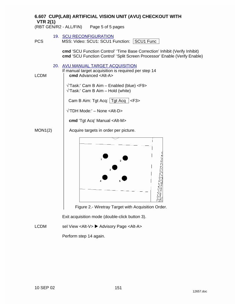
6.607 CUP(LAB) ARTIFICIAL VISION UNIT (AVU) CHECKOUT WITH VTR 2(1)
(RBT GEN/R2 - ALL/FIN) Page 5 of 5 pages
10 SEP 02 12657.doc
19. SCU RECONFIGURATION PCS MSS: Video: SCU1: SCU1 Function: SCU1 Func
cmd ‘SCU Function Control’ ‘Time Base Correction’ Inhibit (Verify Inhibit) cmd ‘SCU Function Control’ ‘Split Screen Processor’ Enable (Verify Enable)
20. AVU MANUAL TARGET ACQUISITION
If manual target acquisition is required per step 14 LCDM cmd Advanced <Alt-A>
√‘Task:’ Cam B Aim – Enabled (blue) <F9> √‘Task:’ Cam B Aim – Hold (white)
Cam B Aim: Tgt Acq: Tgt Acq <F3>
√‘TDH Mode:’ – None <Alt-D>
cmd ‘Tgt Acq’ Manual <Alt-M>
MON1(2) Acquire targets in order per picture.
Figure 2.- Wiretray Target with Acquisition Order.
Exit acquisition mode (double-click button 3). LCDM sel View <Alt-V> � Advisory Page <Alt-A>
Perform step 14 again.
4
151

This Page Intentionally Blank
22 DEC 04
152
6.608 CUP(LAB) ARTIFICIAL VISION UNIT (AVU) DATABASE LOAD (RBT GEN/R2 - ALL/FIN 1) Page 1 of 1 page
09 SEP 02 12658.doc
NOTE Where applicable, AVU Keyboard Hotkeys are shown in the following manner: <hotkey>.
1. DATABASE LOAD MON2 Verify Steering Display has yellow Hold symbol. LCDM Space Vision System
cmd Advanced <Alt-A>
sel File <Alt-F> � Load Database cmd Don’t Save
Database File Selector
sel file as required cmd Load
2. DATABASE LOAD VERIFICATION
Space Vision System ‘Db File:’
Verify file as previously selected.
153

This Page Intentionally Blank
22 DEC 04
154
6.609 CUP(LAB) ARTIFICIAL VISION UNIT (AVU) POWERDOWN (RBT GEN/R2 - ALL/FIN 1) Page 1 of 1 page
27 OCT 03 12659.doc
NOTE Where applicable, AVU Keyboard Hotkeys are shown in the following manner: “hotkey”.
1. AVU SHUTDOWN
Verify system is in Hold. LCDM Space Vision System
cmd Advanced [Alt-A]
sel File [Alt-F] � Exit cmd Don’t Save cmd Shutdown
AVU In the QNX shell on the LCDM, input – p h s h u t d o w n KYBD
cmd Enter LCDM Verify ‘System may now be powered down’ message appears. 2. SWITCH LCDM MODE LCDM cmd MENU (Verify Brightness)
cmd UP (Verify Video Mode) cmd SELECT (Verify COMPOSITE) cmd UP (Verify RGB) cmd SELECT
3. AVU POWERDOWN PCS MSS: LAS5(LAP5) AVU: LAS5(LAP5) AVU
NOTE Expect two ‘R1E - MSS Active OCS AVU Comm Fail’ Robotics Advisory messages after commanding AVU to Off. Both messages should return to Norm (SPN 1175).
cmd ‘Power’ Off
4. POWER STATUS PCS MSS: RWS
Verify ‘LAS5’(‘LAP5’) RPC3 – Open (gray) Verify ‘LAS5’(‘LAP5’) Status from OCS – Off
155

This Page Intentionally Blank
22 DEC 04
156

6.617 MSS VIDEO DEROUTING (RBT GEN/ULF1 - ALL/FIN) Page 1 of 1 page
11 FEB 03 12666.doc
PCS MSS: Video: Trunkline Usage: Trunkline Usage ‘MSS Trunkline’
sel MSS Trunkline [X]
where [X] = 4 3 2
1 5 9 8 7 6
MSS Trunkline [X]
Note all destinations with “√.”
MSS: Video: Video Overview: Video Overview
Repeat the following for all destinations noted sel Destination icon
[Destination name]
cmd ‘Deroute Video Signal’ Deroute
Repeat
157

This Page Intentionally Blank
22 DEC 04
158

MALFUNCTION
MA
LFU
NC
TIO
N
22 DEC 04
159

This Page Intentionally Blank
MA
LFU
NC
TIO
N
22 DEC 04
160

MSS 7.001 MSS FAILURE RESPONSE AND RECOVERY (RBT GEN/X2R4 - ALL/FIN/SPN) Page 1 of 26 pages
20 DEC 04 16016.doc
1 Unless otherwise indicated, all displays in the procedures are on the PCS.
2 Time-critical recovery is intended to regain MSS functionality (SSRMS motion capability) in situations where immediate operator response is required to ensure the safety of the crew, ISS, or a visiting vehicle. Time-critical recovery can be performed by the on-orbit crew without assistance from the ground. Time-critical recovery steps do not account for MT, LEE or any MBS mechanism failures. Time-critical recovery assumes the MSS is configured as follows: One RWS Backup One RWS Active SSRMS Operational with video system powered MBS Operational on one string with video system powered, Keep-Alive on the other.
1 Time Critical Recovery
Is the recovery time-critical?
C&W ROBOTICS
C&W messages starting with ‘Rxx - �’
2 Operator Initiated Safing
Did the operator safe the SSRMS in response to uncommanded motion?
3 DCP HC Voltage
MSS: LAS5(LAP5) HCs Cupola(Lab) HC Status
Does the ‘THC/RHC’ axes show a voltage over 0.4V?
MSS or ISS Failure Causing Robotics C&W Messages and/or Interruption to Robotics Operations.
2 1
Yes
No
No
Yes
4 Continue Ops
MSS: SSRMS: SSRMS Safing SSRMS Safing
• cmd Remove (Verify not Safed)
(DCP) • BRAKES SSRMS → Off
(Verify – Off) • Continue operations.
Failure may return or an ‘R3K’ may be raised.
• Return to block 53, if error returns.
5 Active RWS Status
One or more of the following indications are present: For the currently Active RWS
MSS: RWS ‘LAS5(LAP5) CEU MODE’ – Backup or Unconfigured
or MSS: SSRMS: CW Summ Robotics Caution & Warning Summary
The following messages are in alarm: ‘R1B - �’ or ‘R1D - �’ or DCP lights off and video is lost from all active RWS monitors.
None of the above.
6 Switch Active RWS
MSS: LAS5(LAP5) CEU MODE CEU Mode
• cmd ‘Active CEU’ Backup
For alt RWS • cmd ‘Cupola’(‘Lab’) –
Active (Verify Cupola(Lab) – Active)
7 Switch Active RWS
For the active RWS MSS: LAS5(LAP5) Pwr Dn LAS5(LAP5) Power Down
• cmd ‘G. CB Ext 2(1) Bus Comm’ – Inhibit
If ‘H. CEU’ Not √ • cmd ‘H. CEU’ – Open
MSS: LAS5(LAP5) CEU MODE CEU Mode
For alt RWS • cmd ‘Cupola’(‘Lab’) –
Active (Verify Cupola(Lab) – Active)
Yes
No
67
65 53
8
65
161
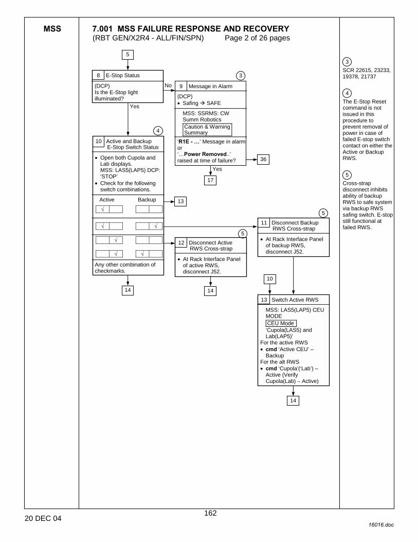
MSS 7.001 MSS FAILURE RESPONSE AND RECOVERY (RBT GEN/X2R4 - ALL/FIN/SPN) Page 2 of 26 pages
20 DEC 04 16016.doc
3 SCR 22615, 23233, 19378, 21737 4 The E-Stop Reset command is not issued in this procedure to prevent removal of power in case of failed E-stop switch contact on either the Active or Backup RWS. 5 Cross-strap disconnect inhibits ability of backup RWS to safe system via backup RWS safing switch. E-stop still functional at failed RWS.
8 E-Stop Status
(DCP) Is the E-Stop light illuminated?
9 Message in Alarm
(DCP) • Safing ! SAFE
MSS: SSRMS: CW Summ Robotics Caution & Warning Summary
‘R1E - �’ Message in alarm or ‘…Power Removed..’ raised at time of failure?
10 Active and Backup E-Stop Switch Status
• Open both Cupola and Lab displays. MSS: LAS5(LAP5) DCP: ‘STOP’
• Check for the following switch combinations.
Active Backup
√
√ √
√
√ √ Any other combination of checkmarks.
11 Disconnect Backup RWS Cross-strap
• At Rack Interface Panel of backup RWS, disconnect J52.
12 Disconnect Active RWS Cross-strap
• At Rack Interface Panel of active RWS, disconnect J52.
13 Switch Active RWS
MSS: LAS5(LAP5) CEU MODE CEU Mode ‘Cupola(LAS5) and Lab(LAP5)’
For the active RWS • cmd ‘Active CEU’ –
Backup For the alt RWS • cmd ‘Cupola’(‘Lab’) –
Active (Verify Cupola(Lab) – Active)
Yes
No
Yes
3
4
5
10
5
13
14 14
36
17
14
5
162

MSS 7.001 MSS FAILURE RESPONSE AND RECOVERY (RBT GEN/X2R4 - ALL/FIN/SPN) Page 3 of 26 pages
20 DEC 04 16016.doc
6 Power up the previously operational strings. Due to a known SPN condition (SCR 20380), the MBS and SSRMS power to operational commands may not complete after the first attempt. 7 SCR 21749
14 SSRMS Base Location
MSS: SSRMS SSRMS ‘PDGF’
MBS1(2,3,4)? 15 SSRMS and MBS Powerup
MSS: MBS: MCU MCU
• cmd ‘Prime’, ‘Redundant’ (two) – Keep-Alive (Verify Keep-Alive)
If an Operational MBS is required • cmd ‘Prime’
(‘Redundant’) – Operational (Verify – Operational)
If MBS not Operational MSS: LAS5(LAP5) CEU MODE CEU Mode
• cmd Active CEU – Backup (Verify RWS is Backup) For the previously active RWS
• cmd Cupola(Lab) – Active (Verify Cupola(Lab) – Active) MSS: MBS: MCU MCU
• cmd ‘Prime’ (‘Redundant’) – Operational (Verify ‘Systems State’ –Operational)
MSS: SSRMS: Power SSRMS Power
• cmd ‘SSRMS’ Prime(Redundant) – Keep-Alive (Verify Keep-Alive)
• cmd ‘SSRMS’ Prime(Redundant) – Operational (Verify ‘System State’ – Operational)
If Systems State not Operational • cmd ‘SSRMS’
Prime(Redundant) – Operational (Verify ‘System State’ – Operational)
16 Checkpoint Data Reset
MSS: LAS5(LAP5) CEU MODE CEU Mode
• cmd Active CEU – Backup (Verify RWS is Backup)
PCSCDS Main Control Panel
• sel Commands ! File Transfer File and Memory Transfer
• sel Commands ! Indirect Data Load Indirect Data Load
• sel Target Node ! CCS CCD2
• cmd Apply File and Memory Transfer
• Verify ‘Active Transfers’ Transfer Status – OK
• Verify ‘Completed Transfers’ Transfer Status – COMPLETED
• Command RWS back to
Active MSS: LAS5(LAP5) CEU MODE CEU Mode
• cmd Cupola(Lab) – Active (Verify Cupola(Lab) – Active)
Yes
No
12 13 10
6
16
7
15
64
163
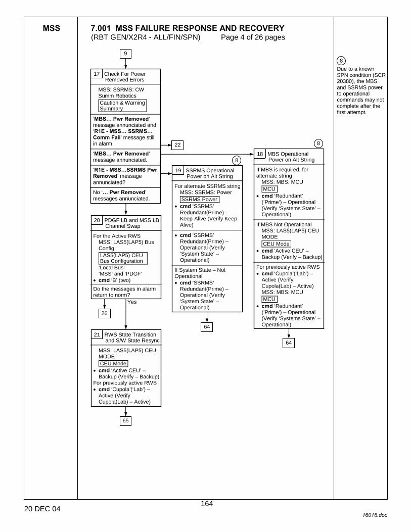
MSS 7.001 MSS FAILURE RESPONSE AND RECOVERY (RBT GEN/X2R4 - ALL/FIN/SPN) Page 4 of 26 pages
20 DEC 04 16016.doc
8 Due to a known SPN condition (SCR 20380), the MBS and SSRMS power to operational commands may not complete after the first attempt.
17 Check For Power Removed Errors
MSS: SSRMS: CW Summ Robotics Caution & Warning Summary
‘MBS� Pwr Removed’ message annunciated and ‘R1E - MSS� SSRMS� Comm Fail’ message still in alarm.
‘MBS� Pwr Removed’ message annunciated.
‘R1E - MSS�SSRMS Pwr Removed’ message annunciated?
No ‘� Pwr Removed’ messages annunciated.
18 MBS Operational Power on Alt String
If MBS is required, for alternate string
MSS: MBS: MCU MCU
• cmd ‘Redundant’ (‘Prime’) – Operational (Verify ‘Systems State’ – Operational)
If MBS Not Operational
MSS: LAS5(LAP5) CEU MODE CEU Mode
• cmd ‘Active CEU’ – Backup (Verify – Backup)
For previously active RWS • cmd ‘Cupola’(‘Lab’) –
Active (Verify Cupola(Lab) – Active) MSS: MBS: MCU MCU
• cmd ‘Redundant’ (‘Prime’) – Operational (Verify ‘Systems State’ – Operational)
19 SSRMS Operational Power on Alt String
For alternate SSRMS string MSS: SSRMS: Power SSRMS Power
• cmd ‘SSRMS’ Redundant(Prime) – Keep-Alive (Verify Keep-Alive)
• cmd ‘SSRMS’
Redundant(Prime) – Operational (Verify ‘System State’ – Operational)
If System State – Not Operational • cmd ‘SSRMS’
Redundant(Prime) – Operational (Verify ‘System State’ – Operational)
20 PDGF LB and MSS LB Channel Swap
For the Active RWS MSS: LAS5(LAP5) Bus Config LAS5(LAP5) CEU Bus Configuration ‘Local Bus’ ‘MSS’ and ‘PDGF’
• cmd ‘B’ (two) Do the messages in alarm return to norm?
21 RWS State Transition and S/W State Resync
MSS: LAS5(LAP5) CEU MODE CEU Mode
• cmd ‘Active CEU’ – Backup (Verify – Backup)
For previously active RWS • cmd ‘Cupola’(‘Lab’) –
Active (Verify Cupola(Lab) – Active)
9
22 8
8
26
Yes
64
64
65
164
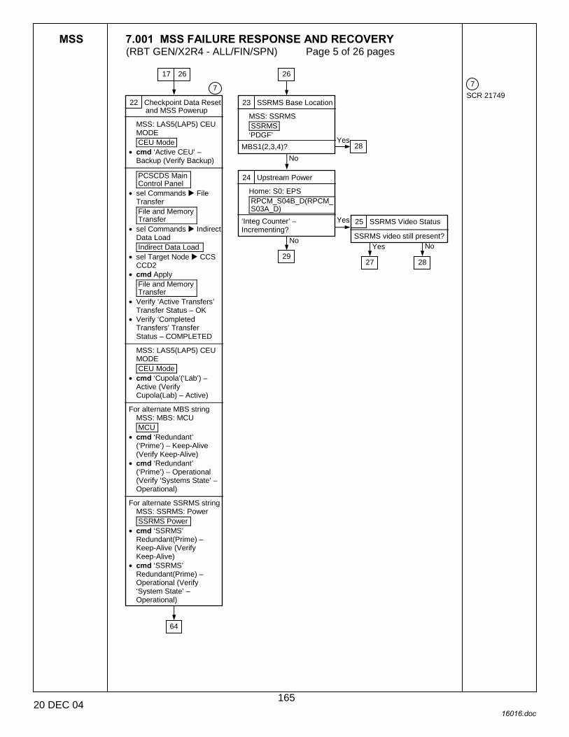
MSS 7.001 MSS FAILURE RESPONSE AND RECOVERY (RBT GEN/X2R4 - ALL/FIN/SPN) Page 5 of 26 pages
20 DEC 04 16016.doc
7 SCR 21749 22 Checkpoint Data Reset
and MSS Powerup
MSS: LAS5(LAP5) CEU MODE CEU Mode
• cmd ‘Active CEU’ – Backup (Verify Backup)
PCSCDS Main Control Panel
• sel Commands ! File Transfer File and Memory Transfer
• sel Commands ! Indirect Data Load Indirect Data Load
• sel Target Node ! CCS CCD2
• cmd Apply File and Memory Transfer
• Verify ‘Active Transfers’ Transfer Status – OK
• Verify ‘Completed Transfers’ Transfer Status – COMPLETED
MSS: LAS5(LAP5) CEU MODE CEU Mode
• cmd ‘Cupola’(‘Lab’) – Active (Verify Cupola(Lab) – Active)
For alternate MBS string
MSS: MBS: MCU MCU
• cmd ‘Redundant’ (‘Prime’) – Keep-Alive (Verify Keep-Alive)
• cmd ‘Redundant’ (‘Prime’) – Operational (Verify ‘Systems State’ – Operational)
For alternate SSRMS string
MSS: SSRMS: Power SSRMS Power
• cmd ‘SSRMS’ Redundant(Prime) – Keep-Alive (Verify Keep-Alive)
• cmd ‘SSRMS’ Redundant(Prime) – Operational (Verify ‘System State’ – Operational)
23 SSRMS Base Location
MSS: SSRMS SSRMS ‘PDGF’
MBS1(2,3,4)?
25 SSRMS Video Status
SSRMS video still present?
24 Upstream Power
Home: S0: EPS RPCM_S04B_D(RPCM_S03A_D)
‘Integ Counter’ – Incrementing?
7
17 26 26
28 No
Yes
No
27 28
Yes No
Yes
29
64
165
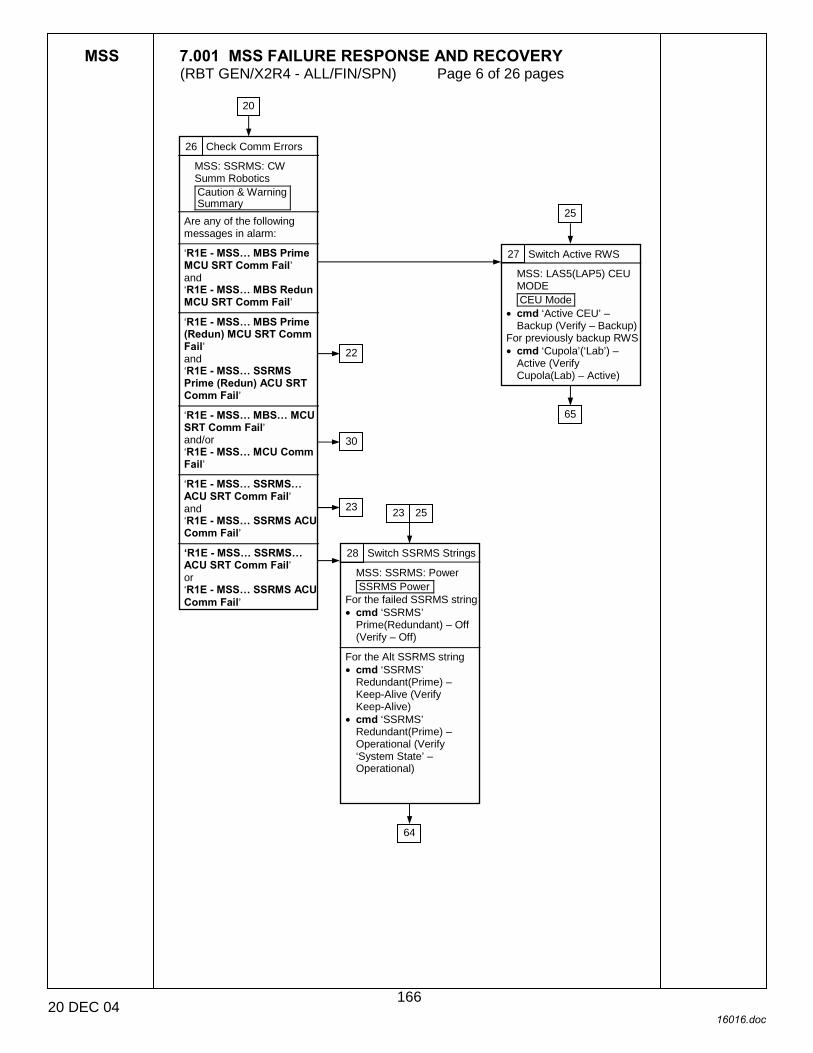
MSS 7.001 MSS FAILURE RESPONSE AND RECOVERY (RBT GEN/X2R4 - ALL/FIN/SPN) Page 6 of 26 pages
20 DEC 04 16016.doc
26 Check Comm Errors
MSS: SSRMS: CW Summ Robotics Caution & Warning Summary
Are any of the following messages in alarm:
‘R1E - MSS� MBS Prime MCU SRT Comm Fail’ and ‘R1E - MSS� MBS Redun MCU SRT Comm Fail’
‘R1E - MSS� MBS Prime (Redun) MCU SRT Comm Fail’ and ‘R1E - MSS� SSRMS Prime (Redun) ACU SRT Comm Fail’
‘R1E - MSS� MBS� MCU SRT Comm Fail’ and/or ‘R1E - MSS� MCU Comm Fail’
‘R1E - MSS� SSRMS� ACU SRT Comm Fail’ and ‘R1E - MSS� SSRMS ACU Comm Fail’
�R1E - MSS� SSRMS� ACU SRT Comm Fail’ or ‘R1E - MSS� SSRMS ACU Comm Fail’
27 Switch Active RWS
MSS: LAS5(LAP5) CEU MODE CEU Mode
• cmd ‘Active CEU’ – Backup (Verify – Backup)
For previously backup RWS • cmd ‘Cupola’(‘Lab’) –
Active (Verify Cupola(Lab) – Active)
28 Switch SSRMS Strings
MSS: SSRMS: Power SSRMS Power
For the failed SSRMS string• cmd ‘SSRMS’
Prime(Redundant) – Off (Verify – Off)
For the Alt SSRMS string • cmd ‘SSRMS’
Redundant(Prime) – Keep-Alive (Verify Keep-Alive)
• cmd ‘SSRMS’ Redundant(Prime) – Operational (Verify ‘System State’ – Operational)
20
25
22
30
23 23 25
65
64
166
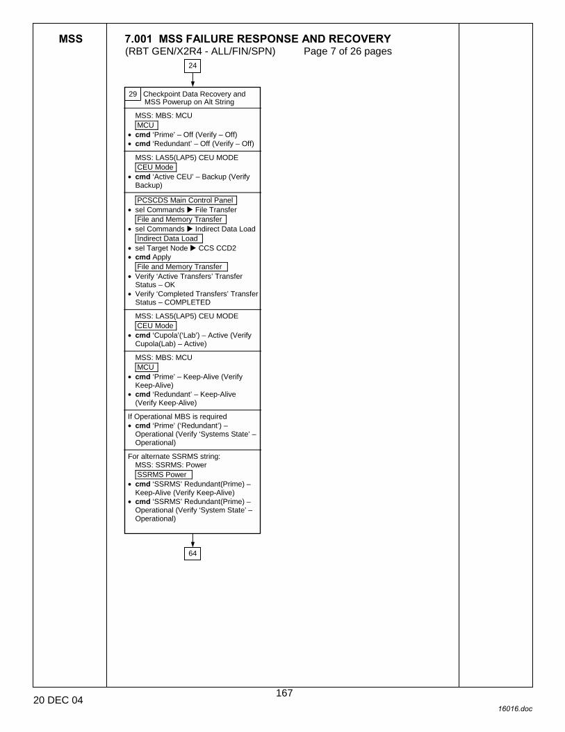
MSS 7.001 MSS FAILURE RESPONSE AND RECOVERY (RBT GEN/X2R4 - ALL/FIN/SPN) Page 7 of 26 pages
20 DEC 04 16016.doc
29 Checkpoint Data Recovery and MSS Powerup on Alt String
MSS: MBS: MCU MCU
• cmd ‘Prime’ – Off (Verify – Off) • cmd ‘Redundant’ – Off (Verify – Off)
MSS: LAS5(LAP5) CEU MODE CEU Mode
• cmd ‘Active CEU’ – Backup (Verify Backup)
PCSCDS Main Control Panel
• sel Commands ! File Transfer File and Memory Transfer
• sel Commands ! Indirect Data Load Indirect Data Load
• sel Target Node ! CCS CCD2 • cmd Apply
File and Memory Transfer • Verify ‘Active Transfers’ Transfer
Status – OK • Verify ‘Completed Transfers’ Transfer
Status – COMPLETED
MSS: LAS5(LAP5) CEU MODE CEU Mode
• cmd ‘Cupola’(‘Lab’) – Active (Verify Cupola(Lab) – Active)
MSS: MBS: MCU MCU
• cmd ‘Prime’ – Keep-Alive (Verify Keep-Alive)
• cmd ‘Redundant’ – Keep-Alive (Verify Keep-Alive)
If Operational MBS is required • cmd ‘Prime’ (‘Redundant’) –
Operational (Verify ‘Systems State’ – Operational)
For alternate SSRMS string:
MSS: SSRMS: Power SSRMS Power
• cmd ‘SSRMS’ Redundant(Prime) – Keep-Alive (Verify Keep-Alive)
• cmd ‘SSRMS’ Redundant(Prime) – Operational (Verify ‘System State’ – Operational)
24
64
167
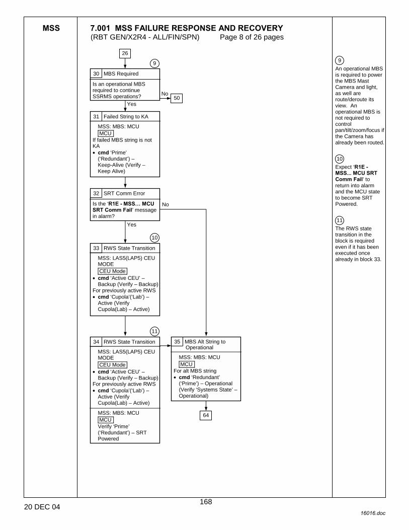
MSS 7.001 MSS FAILURE RESPONSE AND RECOVERY (RBT GEN/X2R4 - ALL/FIN/SPN) Page 8 of 26 pages
20 DEC 04 16016.doc
9 An operational MBS is required to power the MBS Mast Camera and light, as well are route/deroute its view. An operational MBS is not required to control pan/tilt/zoom/focus if the Camera has already been routed. 10 Expect ‘R1E - MSS... MCU SRT Comm Fail’ to return into alarm and the MCU state to become SRT Powered. 11 The RWS state transition in the block is required even if it has been executed once already in block 33.
30 MBS Required
Is an operational MBS required to continue SSRMS operations?
31 Failed String to KA
MSS: MBS: MCU MCU
If failed MBS string is not KA • cmd ‘Prime’
(‘Redundant’) – Keep-Alive (Verify – Keep Alive)
32 SRT Comm Error
Is the ‘R1E - MSS� MCU SRT Comm Fail’ message in alarm?
33 RWS State Transition
MSS: LAS5(LAP5) CEU MODE CEU Mode
• cmd ‘Active CEU’ – Backup (Verify – Backup)
For previously active RWS • cmd ‘Cupola’(‘Lab’) –
Active (Verify Cupola(Lab) – Active)
34 RWS State Transition
MSS: LAS5(LAP5) CEU MODE CEU Mode
• cmd ‘Active CEU’ – Backup (Verify – Backup)
For previously active RWS • cmd ‘Cupola’(‘Lab’) –
Active (Verify Cupola(Lab) – Active)
MSS: MBS: MCU MCU Verify ‘Prime’ (‘Redundant’) – SRT Powered
35 MBS Alt String to Operational
MSS: MBS: MCU MCU
For alt MBS string • cmd ‘Redundant’
(‘Prime’) – Operational (Verify ‘Systems State’ – Operational)
Yes
No
9
26
Yes
No
10
11
50
64
168
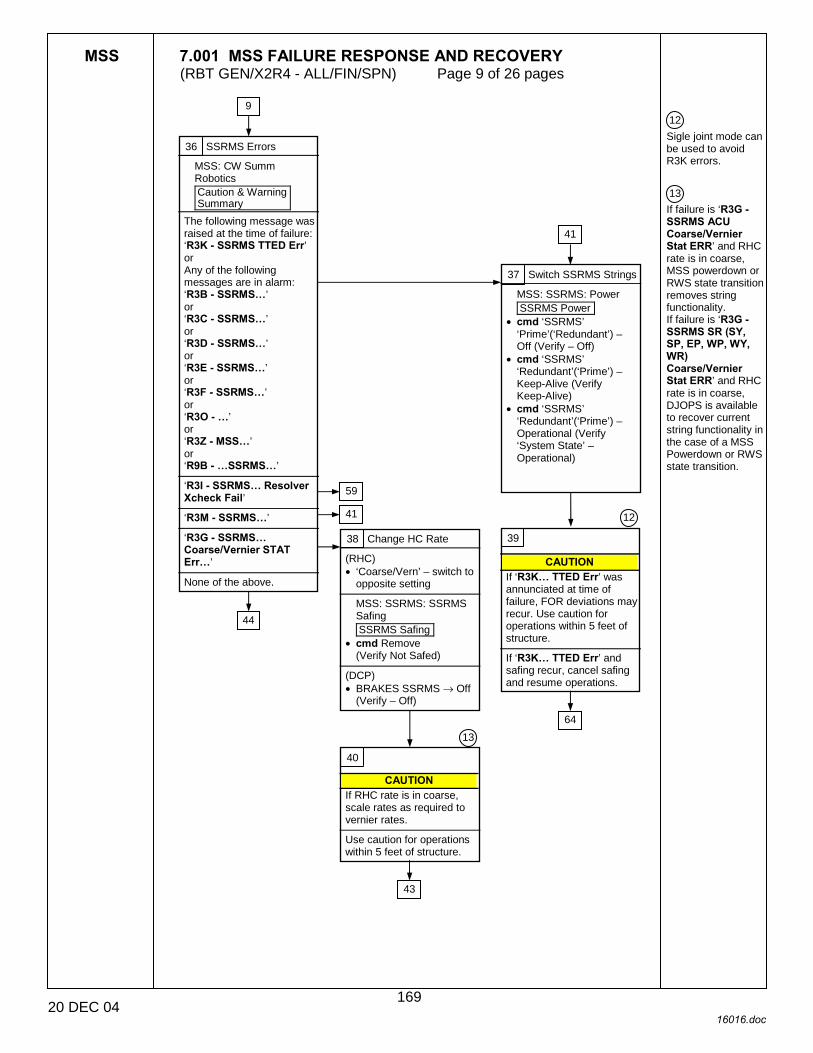
MSS 7.001 MSS FAILURE RESPONSE AND RECOVERY (RBT GEN/X2R4 - ALL/FIN/SPN) Page 9 of 26 pages
20 DEC 04 16016.doc
12 Sigle joint mode can be used to avoid R3K errors. 13 If failure is ‘R3G - SSRMS ACU Coarse/Vernier Stat ERR’ and RHC rate is in coarse, MSS powerdown or RWS state transition removes string functionality. If failure is ‘R3G - SSRMS SR (SY, SP, EP, WP, WY, WR) Coarse/Vernier Stat ERR’ and RHC rate is in coarse, DJOPS is available to recover current string functionality in the case of a MSS Powerdown or RWS state transition.
36 SSRMS Errors
MSS: CW Summ Robotics Caution & Warning Summary
The following message was raised at the time of failure: ‘R3K - SSRMS TTED Err’ or Any of the following messages are in alarm: ‘R3B - SSRMS�’ or ‘R3C - SSRMS�’ or ‘R3D - SSRMS�’ or ‘R3E - SSRMS�’ or ‘R3F - SSRMS�’ or ‘R3O - �’ or ‘R3Z - MSS�’ or ‘R9B - �SSRMS�’
‘R3I - SSRMS� Resolver Xcheck Fail’
‘R3M - SSRMS�’
‘R3G - SSRMS� Coarse/Vernier STAT Err�’
None of the above.
37 Switch SSRMS Strings
MSS: SSRMS: Power SSRMS Power
• cmd ‘SSRMS’ ‘Prime’(‘Redundant’) – Off (Verify – Off)
• cmd ‘SSRMS’ ‘Redundant’(‘Prime’) – Keep-Alive (Verify Keep-Alive)
• cmd ‘SSRMS’ ‘Redundant’(‘Prime’) – Operational (Verify ‘System State’ – Operational)
38 Change HC Rate
(RHC) • ‘Coarse/Vern’ – switch to
opposite setting
MSS: SSRMS: SSRMS Safing SSRMS Safing
• cmd Remove (Verify Not Safed)
(DCP) • BRAKES SSRMS → Off
(Verify – Off)
39
CAUTION If ‘R3K� TTED Err’ was annunciated at time of failure, FOR deviations may recur. Use caution for operations within 5 feet of structure.
If ‘R3K� TTED Err’ and safing recur, cancel safing and resume operations.
40
CAUTION If RHC rate is in coarse, scale rates as required to vernier rates.
Use caution for operations within 5 feet of structure.
9
12
13
44
59
41
41
64
43
169

MSS 7.001 MSS FAILURE RESPONSE AND RECOVERY (RBT GEN/X2R4 - ALL/FIN/SPN) Page 10 of 26 pages
20 DEC 04 16016.doc
41 PDGF LB and MSS LB Channel Swap
For the Active RWS MSS: LAS5(LAP5) Bus Config LAS5(LAP5) CEU Bus Configuration ‘Local Bus’ ‘MSS’ and ‘PDGF’
• cmd ‘B’ (two) Do the messages in alarm return to norm?
42 Continue with Ops
MSS: SSRMS: SSRMS Safing SSRMS Safing
• cmd Remove (Verify Not Safed)
(DCP) • BRAKES SSRMS → Off
(Verify – Off)
43 • Continue operations.
36
37
Yes
No
40
170

MSS 7.001 MSS FAILURE RESPONSE AND RECOVERY (RBT GEN/X2R4 - ALL/FIN/SPN) Page 11 of 26 pages
20 DEC 04 16016.doc
9 An operational MBS is required to power the MBS Mast Camera and light, as well are route/deroute its view. An operational MBS is not required to control pan/tilt/zoom/focus if the Camera has already been routed.
44 MBS Errors
MSS: CW Summ Robotics Caution & Warning Summary
Are any of the following messages in alarm: ‘R2Q - MBS�’ ‘R2P - �’ ‘R3F - POA Pwr Cntl Err’ ‘R2O - MBS �’?
45 Is an Operational MBS required to continue SSRMS operations?
46 MBS Errors
MSS: CW Summ Robotics Caution & Warning Summary
Are any of the following messages in alarm:
‘R2Q - MBS�’
‘R2P - MSS OCS� SRT Stat Fail’
‘R2P - MBS�’ or ‘R3F - POA Pwr Cntl Err’ or ‘R2O - MBS � Inh Err’ or ‘R2O - MBS � Power On’
47 Switch MBS Strings
MSS: MBS: MCU MCU
For currently Operational MBS string • cmd ‘Prime’
(‘Redundant’) – Keep-Alive (Verify Keep-Alive)
For Alternate (failed) MBS string • cmd ‘Redundant’
(‘Prime’) – Operational (Verify ‘Systems State’ – Operational)
48 Switch MBS Strings
MSS: MBS: MCU MCU
For Failed MBS string: • cmd ‘Prime’
(‘Redundant’) – Keep-Alive (Verify Keep-Alive)
For Alternate MBS string • cmd ‘Redundant’
(‘Prime’) – Operational (Verify ‘Systems State’ – Operational)
36
51
Yes
No
9
50 No
Yes
49
49
64
64
171
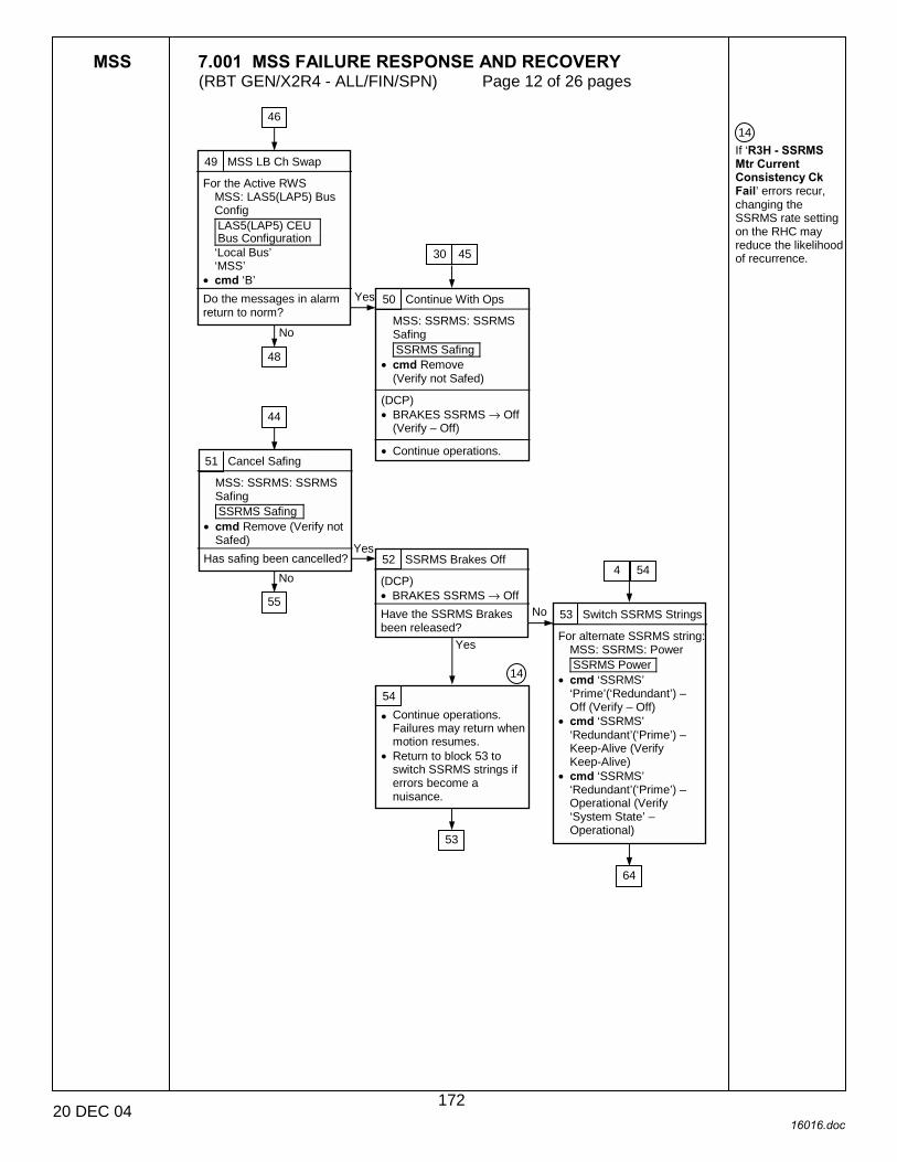
MSS 7.001 MSS FAILURE RESPONSE AND RECOVERY (RBT GEN/X2R4 - ALL/FIN/SPN) Page 12 of 26 pages
20 DEC 04 16016.doc
14 If ‘R3H - SSRMS Mtr Current Consistency Ck Fail’ errors recur, changing the SSRMS rate setting on the RHC may reduce the likelihood of recurrence.
49 MSS LB Ch Swap
For the Active RWS MSS: LAS5(LAP5) Bus Config LAS5(LAP5) CEU Bus Configuration ‘Local Bus’ ‘MSS’
• cmd ‘B’ Do the messages in alarm return to norm?
50 Continue With Ops
MSS: SSRMS: SSRMS Safing SSRMS Safing
• cmd Remove (Verify not Safed)
(DCP) • BRAKES SSRMS → Off
(Verify – Off) • Continue operations.
51 Cancel Safing
MSS: SSRMS: SSRMS Safing SSRMS Safing
• cmd Remove (Verify not Safed)
Has safing been cancelled? 52 SSRMS Brakes Off
(DCP) • BRAKES SSRMS → Off
Have the SSRMS Brakes been released?
53 Switch SSRMS Strings
For alternate SSRMS string: MSS: SSRMS: Power SSRMS Power
• cmd ‘SSRMS’ ‘Prime’(‘Redundant’) – Off (Verify – Off)
• cmd ‘SSRMS’ ‘Redundant’(‘Prime’) – Keep-Alive (Verify Keep-Alive)
• cmd ‘SSRMS’ ‘Redundant’(‘Prime’) – Operational (Verify ‘System State’ – Operational)
54
• Continue operations. Failures may return when motion resumes.
• Return to block 53 to switch SSRMS strings if errors become a nuisance.
No
Yes
48
30 45
46
44
No
55
Yes
Yes
No
4 54
14
53
64
172

MSS 7.001 MSS FAILURE RESPONSE AND RECOVERY (RBT GEN/X2R4 - ALL/FIN/SPN) Page 13 of 26 pages
20 DEC 04 16016.doc
5 Cross-strap disconnect inhibits ability of backup RWS to safe system via backup RWS safing switch. E-stop still functional at failed RWS.
55 Safing Switch Status
For the Active RWS MSS: LAS5(LAP5) DCP Cupola(Lab) DCP Status
• Verify number of Safing Switch checkmarks:
‘Safing’ – (two) √√
‘Safing’ – no checkmarks
56 Disconnect Backup RWS Cross-Strap
• At Rack Interface Panel of backup RWS, disconnect J52.
57 Switch Active RWS
MSS: LAS5(LAP5) CEU MODE CEU Mode ‘Cupola(LAS5) and Lab(LAS5)’
• cmd ‘Active CEU’ – Backup
For the previously backup RWS • cmd ‘Cupola’(‘Lab’) –
Active (Verify Cupola(Lab) – Active)
51
5
58 Disconnect Active RWS Cross-Strap
• At Rack Interface Panel of active RWS, disconnect J52.
5
65
65
173
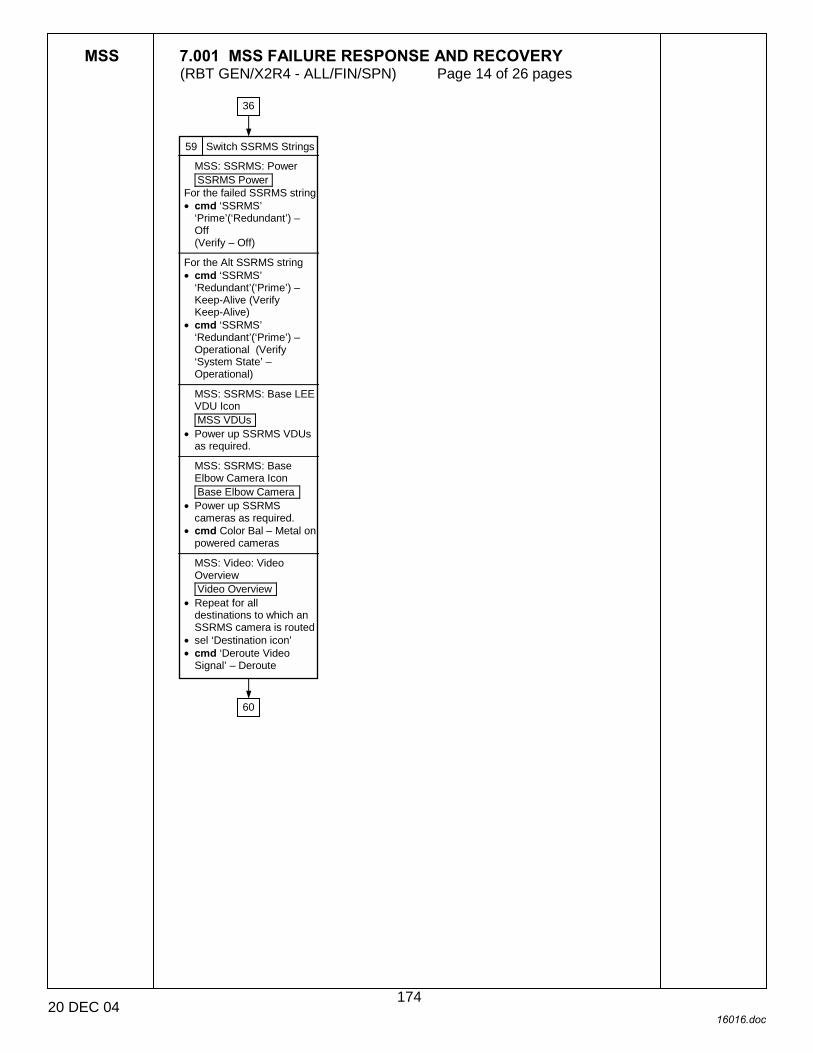
MSS 7.001 MSS FAILURE RESPONSE AND RECOVERY (RBT GEN/X2R4 - ALL/FIN/SPN) Page 14 of 26 pages
20 DEC 04 16016.doc
59 Switch SSRMS Strings
MSS: SSRMS: Power SSRMS Power
For the failed SSRMS string • cmd ‘SSRMS’
‘Prime’(‘Redundant’) – Off (Verify – Off)
For the Alt SSRMS string • cmd ‘SSRMS’
‘Redundant’(‘Prime’) – Keep-Alive (Verify Keep-Alive)
• cmd ‘SSRMS’ ‘Redundant’(‘Prime’) – Operational (Verify ‘System State’ – Operational)
MSS: SSRMS: Base LEE VDU Icon MSS VDUs
• Power up SSRMS VDUs as required.
MSS: SSRMS: Base Elbow Camera Icon Base Elbow Camera
• Power up SSRMS cameras as required.
• cmd Color Bal – Metal on powered cameras
MSS: Video: Video Overview Video Overview
• Repeat for all destinations to which an SSRMS camera is routed
• sel ‘Destination icon’ • cmd ‘Deroute Video
Signal’ – Deroute
36
60
174
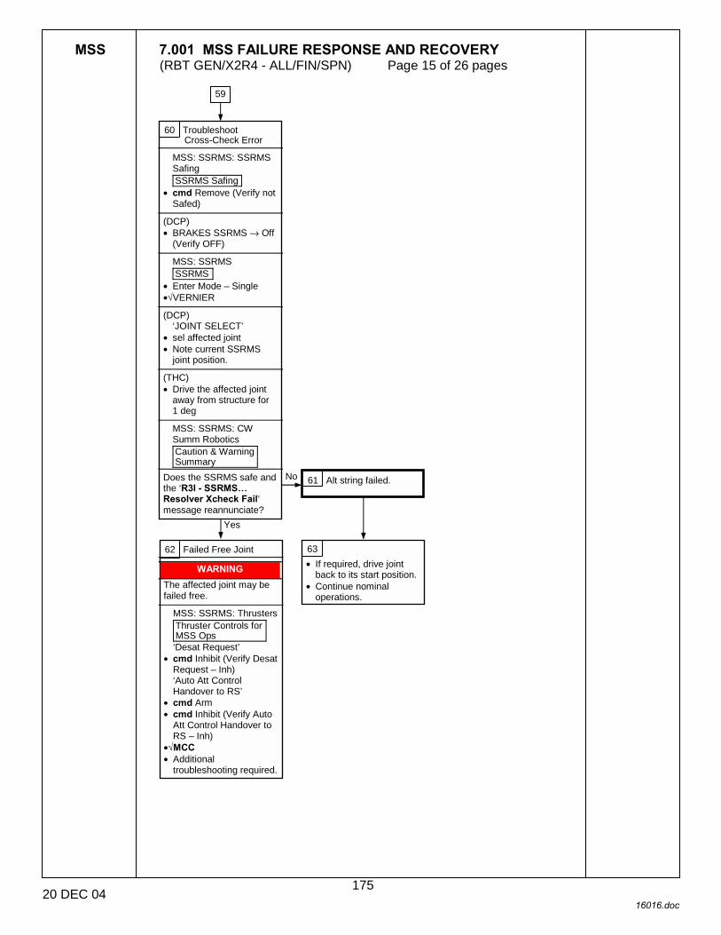
MSS 7.001 MSS FAILURE RESPONSE AND RECOVERY (RBT GEN/X2R4 - ALL/FIN/SPN) Page 15 of 26 pages
20 DEC 04 16016.doc
60 Troubleshoot Cross-Check Error
MSS: SSRMS: SSRMS Safing SSRMS Safing
• cmd Remove (Verify not Safed)
(DCP) • BRAKES SSRMS → Off
(Verify OFF)
MSS: SSRMS SSRMS
• Enter Mode – Single •√VERNIER
(DCP)
‘JOINT SELECT’ • sel affected joint • Note current SSRMS
joint position. (THC) • Drive the affected joint
away from structure for 1 deg
MSS: SSRMS: CW Summ Robotics Caution & Warning Summary
Does the SSRMS safe and the ‘R3I - SSRMS� Resolver Xcheck Fail’ message reannunciate?
62 Failed Free Joint
WARNING The affected joint may be failed free.
MSS: SSRMS: Thrusters Thruster Controls for MSS Ops ‘Desat Request’
• cmd Inhibit (Verify Desat Request – Inh) ‘Auto Att Control Handover to RS’
• cmd Arm • cmd Inhibit (Verify Auto
Att Control Handover to RS – Inh)
•√MCC • Additional
troubleshooting required.
63 • If required, drive joint
back to its start position. • Continue nominal
operations.
59
Yes
No 61 Alt string failed.
175
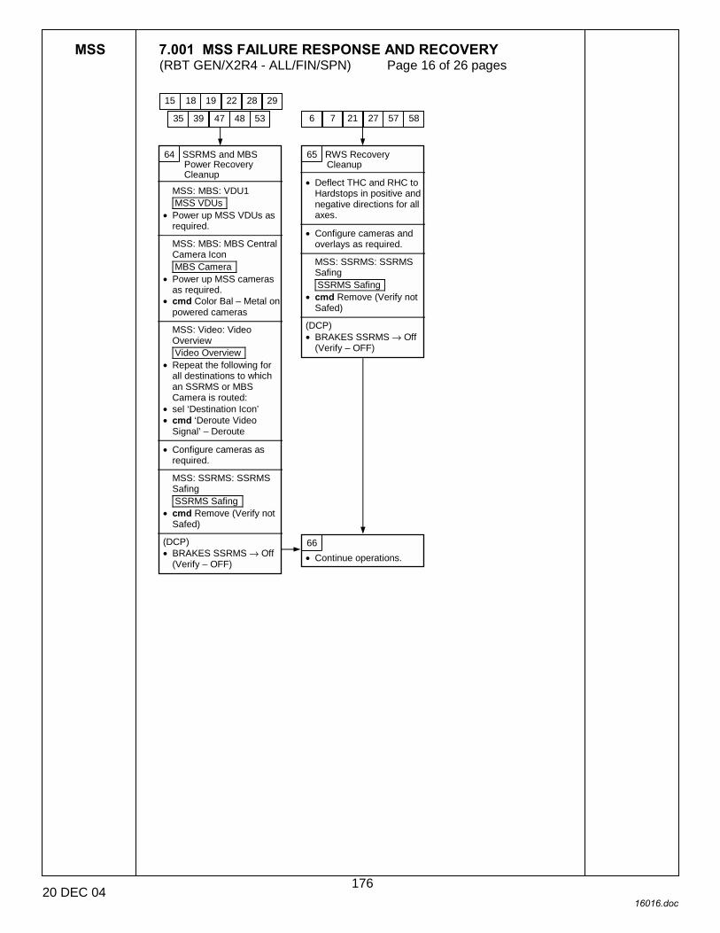
MSS 7.001 MSS FAILURE RESPONSE AND RECOVERY (RBT GEN/X2R4 - ALL/FIN/SPN) Page 16 of 26 pages
20 DEC 04 16016.doc
64 SSRMS and MBS Power Recovery Cleanup
MSS: MBS: VDU1 MSS VDUs
• Power up MSS VDUs as required.
MSS: MBS: MBS Central Camera Icon MBS Camera
• Power up MSS cameras as required.
• cmd Color Bal – Metal on powered cameras
MSS: Video: Video Overview Video Overview
• Repeat the following for all destinations to which an SSRMS or MBS Camera is routed:
• sel ‘Destination Icon’ • cmd ‘Deroute Video
Signal’ – Deroute • Configure cameras as
required.
MSS: SSRMS: SSRMS Safing SSRMS Safing
• cmd Remove (Verify not Safed)
(DCP) • BRAKES SSRMS → Off
(Verify – OFF)
65 RWS Recovery Cleanup
• Deflect THC and RHC to Hardstops in positive and negative directions for all axes.
• Configure cameras and
overlays as required.
MSS: SSRMS: SSRMS Safing SSRMS Safing
• cmd Remove (Verify not Safed)
(DCP) • BRAKES SSRMS → Off
(Verify – OFF)
66 • Continue operations.
15 18 19 22 28 29
35 39 47 48 53 6 7 21 27 57 58
176

MSS 7.001 MSS FAILURE RESPONSE AND RECOVERY (RBT GEN/X2R4 - ALL/FIN/SPN) Page 17 of 26 pages
20 DEC 04 16016.doc
15 Non time-critical recovery is lead by MCC-H. √MCC-H before executing procedures
67 MT Failure During Auto Translation
MT IMCA power command failed.
MT command rejected.
MT auto-sequence failed.
None of the above
68 • Go to {7.800 MT IMCA POWER COMMAND FAILURE},
all (SODF: RBT GEN: MALFUNCTION).
69 • Go to {7.801 MT AUTO-TRANSLATION COMMAND
REJECTED}, all (SODF: RBT GEN: MALFUNCTION).
70 • Go to {7.802 MT AUTO-TRANSLATION ABORTS}, all
(SODF: RBT GEN: MALFUNCTION).
71 RWS Failure The RWS experienced a failure while powering up the RWS to backup.
The RWS experienced a failure while transitioning to active.
MSS: ‘LAS5(LAP5) CEU MODE’
The RWS status change from Active to Backup/ Unconfigured on the PCS. or The DCP lights and RWS monitors lose power. or
MSS: SSRMS: CW Summ Robotics Caution & Warning Summary
The following message received:
‘R1D - �’ or ‘R1B -�’
None of the above
72 • Go to {7.100 RWS POWER-UP FAILURE}, all
(SODF: RBT GEN: MALFUNCTION).
73 • Go to {7.101 RWS TRANSITION TO ACTIVE
FAILURE}, all (SODF: RBT GEN: MALFUNCTION).
74 • Go to {7.300 ACTIVE RWS FAILURE}, all
(SODF: RBT GEN: MALFUNCTION).
1
15
75
177
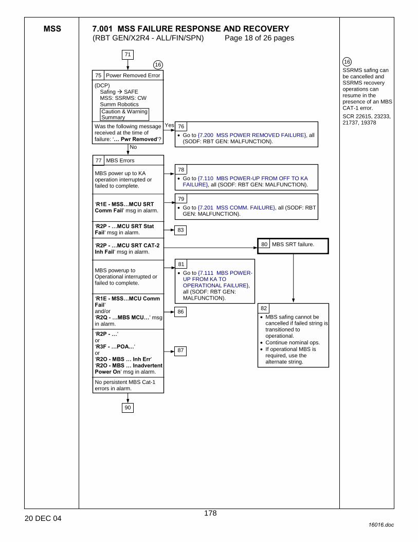
MSS 7.001 MSS FAILURE RESPONSE AND RECOVERY (RBT GEN/X2R4 - ALL/FIN/SPN) Page 18 of 26 pages
20 DEC 04 16016.doc
16 SSRMS safing can be cancelled and SSRMS recovery operations can resume in the presence of an MBS CAT-1 error. SCR 22615, 23233, 21737, 19378
75 Power Removed Error
(DCP) Safing ! SAFE MSS: SSRMS: CW Summ Robotics Caution & Warning Summary
Was the following message received at the time of failure: ‘� Pwr Removed’?
76 • Go to {7.200 MSS POWER REMOVED FAILURE}, all
(SODF: RBT GEN: MALFUNCTION).
77 MBS Errors MBS power up to KA operation interrupted or failed to complete.
‘R1E - MSS�MCU SRT Comm Fail’ msg in alarm.
‘R2P - �MCU SRT Stat Fail’ msg in alarm.
‘R2P - �MCU SRT CAT-2 Inh Fail’ msg in alarm.
MBS powerup to Operational interrupted or failed to complete.
‘R1E - MSS�MCU Comm Fail’ and/or ‘R2Q - �MBS MCU�’ msg in alarm.
‘R2P - �’ or ‘R3F - �POA�’ or ‘R2O - MBS � Inh Err’ ‘R2O - MBS � Inadvertent Power On’ msg in alarm.
No persistent MBS Cat-1 errors in alarm.
78 • Go to {7.110 MBS POWER-UP FROM OFF TO KA
FAILURE}, all (SODF: RBT GEN: MALFUNCTION).
79 • Go to {7.201 MSS COMM. FAILURE}, all (SODF: RBT
GEN: MALFUNCTION).
81 • Go to {7.111 MBS POWER-
UP FROM KA TO OPERATIONAL FAILURE}, all (SODF: RBT GEN: MALFUNCTION).
82 • MBS safing cannot be
cancelled if failed string is transitioned to operational.
• Continue nominal ops. • If operational MBS is
required, use the alternate string.
16
No
Yes
90
86
87
80 MBS SRT failure.
83
71
178
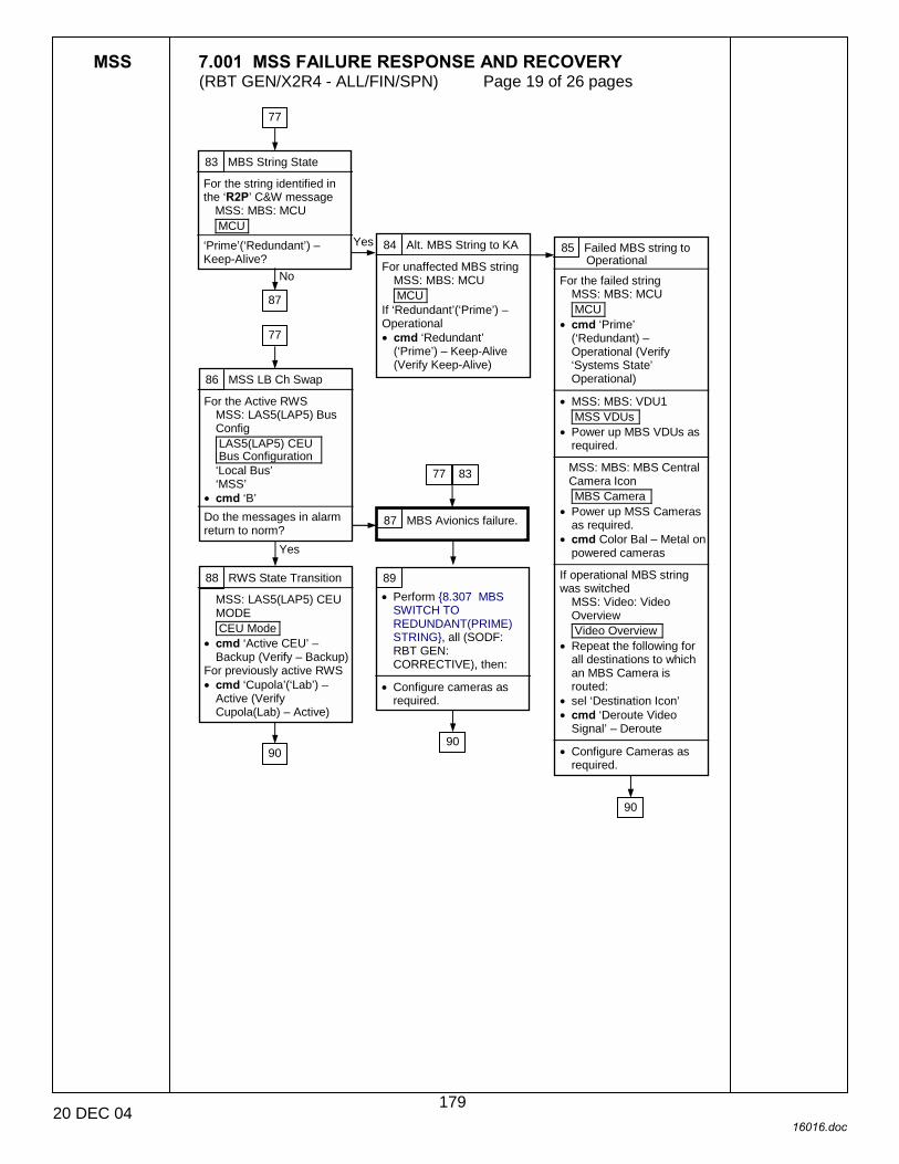
MSS 7.001 MSS FAILURE RESPONSE AND RECOVERY (RBT GEN/X2R4 - ALL/FIN/SPN) Page 19 of 26 pages
20 DEC 04 16016.doc
83 MBS String State
For the string identified in the ‘R2P’ C&W message
MSS: MBS: MCU MCU
‘Prime’(‘Redundant’) – Keep-Alive?
84 Alt. MBS String to KA
For unaffected MBS string MSS: MBS: MCU MCU
If ‘Redundant’(‘Prime’) – Operational • cmd ‘Redundant’
(‘Prime’) – Keep-Alive (Verify Keep-Alive)
85 Failed MBS string to Operational
For the failed string MSS: MBS: MCU MCU
• cmd ‘Prime’ (‘Redundant) – Operational (Verify ‘Systems State’ Operational)
• MSS: MBS: VDU1
MSS VDUs • Power up MBS VDUs as
required.
MSS: MBS: MBS Central Camera Icon MBS Camera
• Power up MSS Cameras as required.
• cmd Color Bal – Metal on powered cameras
If operational MBS string was switched
MSS: Video: Video Overview Video Overview
• Repeat the following for all destinations to which an MBS Camera is routed:
• sel ‘Destination Icon’ • cmd ‘Deroute Video
Signal’ – Deroute • Configure Cameras as
required.
86 MSS LB Ch Swap
For the Active RWS MSS: LAS5(LAP5) Bus Config LAS5(LAP5) CEU Bus Configuration ‘Local Bus’ ‘MSS’
• cmd ‘B’ Do the messages in alarm return to norm?
88 RWS State Transition
MSS: LAS5(LAP5) CEU MODE CEU Mode
• cmd ‘Active CEU’ – Backup (Verify – Backup)
For previously active RWS • cmd ‘Cupola’(‘Lab’) –
Active (Verify Cupola(Lab) – Active)
89 • Perform {8.307 MBS
SWITCH TO REDUNDANT(PRIME) STRING}, all (SODF: RBT GEN: CORRECTIVE), then:
• Configure cameras as
required.
87 MBS Avionics failure.
77
87
No
Yes
77
Yes
77 83
90 90
90
179

MSS 7.001 MSS FAILURE RESPONSE AND RECOVERY (RBT GEN/X2R4 - ALL/FIN/SPN) Page 20 of 26 pages
20 DEC 04 16016.doc
17 If SSRMS is based on end A, Tip LEE is LEU2. If SSRMS is based on end B, Tip LEE is LEU1. 18 If joint has previously failed on, reboot entire string per {8.106 SSRMS REBOOT PRIME (REDUNDANT) STRING}, all (SODF: RBT: GEN: CORRECTIVE) 19 SCR 28722
90 SSRMS Errors SSRMS powerup to KA operation interrupted or failed to complete.
‘R1E - MSS�ACU SRT Comm Fail’ msg in alarm.
�R3C - �ACU SRT Stat Fail’ msg in alarm.
‘R3C - �ACU SRT CAT-2 Inh Fail’ msg in alarm.
SSRMS power up to Operational interrupted or failed to complete.
‘R1E - MSS�ACU Comm Fail’ or ‘R3M - �SSRMS ACU�’ msg in alarm.
‘R3�CAT-1 Transmit(Receive) Msg Err’ in alarm for multiple subunits. ‘R3B - �SSRMS�Brk..’ or ‘R3C - �SSRMS ACU...’ or ‘R3C -�SSRMS LEU�’ or ‘R3O -�’ or ‘R3Z - �SSRMS�SRT�’ or ‘R9B - �SACS-AHS�’ msgs in alarm.
‘R3C - �SSRMS �JEU...’ or ‘R3D - �SSRMS �JEU�’ msgs in alarm.
‘R3E - �SSRMS LEE...’ or ‘R9B - �SSRMS LEE�’ msgs in alarm.
‘R3F - SSRMS�’ msg for Tip LEE in alarm.
‘R3F - SSRMS�’ msg for Base LEE in alarm.
‘R3G - �Coarse/Vernier Stat Err’ msg in alarm.
‘R3I - � Resolver Xcheck Fail’ msg in alarm.
No Cat-1 messages in alarm.
91 • Go to {7.120 SSRMS POWER-UP FROM OFF TO KA
FAILURE}, all (SODF: RBT GEN: MALFUNCTION).
92 • Go to {7.201 MSS COMM FAILURE}, all (SODF: RBT
GEN: MALFUNCTION)
93 SSRMS SRT Failure
• SSRMS safing cannot be cancelled if failed string is transitioned to operational.
• Continue nominal ops. If operational SSRMS is required, use the alternate string.
94 Go to {7.121 SSRMS POWER-UP KA TO OPERATIONAL FAILURE}, all (SODF: RBT GEN: MALFUNCTION)
95 Failed Joint Reboot
For the joint identified in the R3C or R3
MSS: SSRMS: Power: Reset Unit SSRMS Reset Unit
• cmd SR (SY, EP, WP, WY, WR) MSS: SSRMS: Power SSRMS Power
• Verify SR (SY, SP, EP, WP, WY, WR) – K-A
• Verify SR (SY, SP, EP, WP, WY, WR) – Init
• Verify SR (SY, SP, EP, WP, WY, WR) – Go
• Verify Systems State – Operational
Messages reannunciated or SSRMS string state is Failed?
96 RWS State Transition
MSS: LAS5(LAP5) CEU MODE CEU Mode
• cmd ‘Active CEU’ – Backup (Verify – Backup)
For previously active RWS • cmd ‘Cupola’(‘Lab’) –
Active (Verify Cupola(Lab) – Active)
97 • Go to {7.501 SSRMS
RESOLVER CROSS CHECK FAILURE}, all (SODF: RBT GEN: MALFUNCTION).
102
103
109
109
95
98
106
98
90
18
Yes
111 19
109
17
77 85 88 89
112
109
180
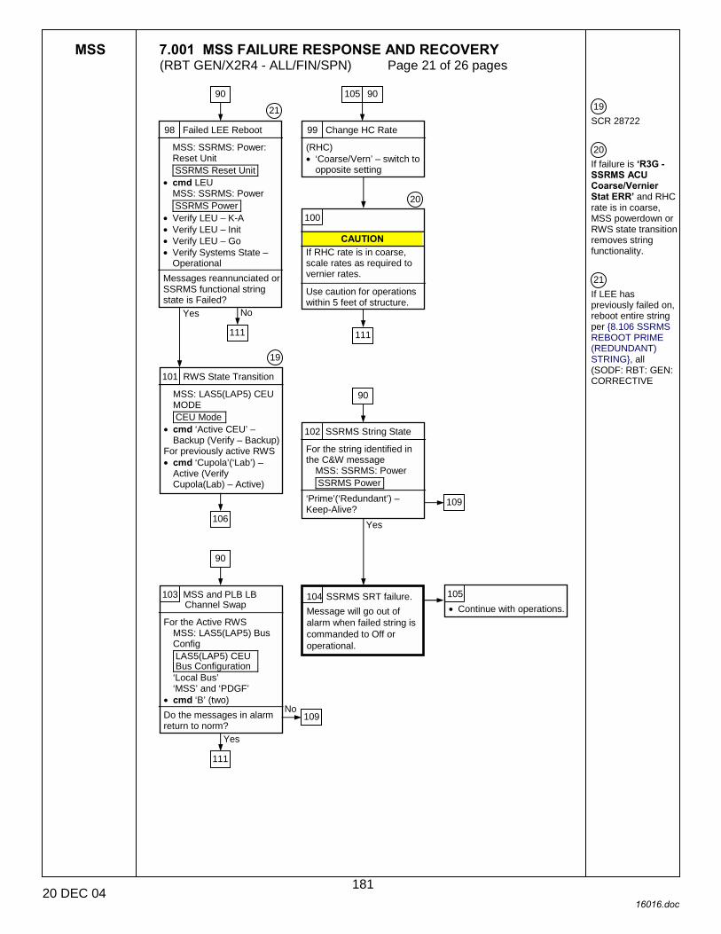
MSS 7.001 MSS FAILURE RESPONSE AND RECOVERY (RBT GEN/X2R4 - ALL/FIN/SPN) Page 21 of 26 pages
20 DEC 04 16016.doc
19 SCR 28722 20 If failure is �R3G - SSRMS ACU Coarse/Vernier Stat ERR� and RHC rate is in coarse, MSS powerdown or RWS state transition removes string functionality. 21 If LEE has previously failed on, reboot entire string per {8.106 SSRMS REBOOT PRIME (REDUNDANT) STRING}, all (SODF: RBT: GEN: CORRECTIVE
98 Failed LEE Reboot
MSS: SSRMS: Power: Reset Unit SSRMS Reset Unit
• cmd LEU MSS: SSRMS: Power SSRMS Power
• Verify LEU – K-A • Verify LEU – Init • Verify LEU – Go • Verify Systems State –
Operational Messages reannunciated or SSRMS functional string state is Failed?
99 Change HC Rate
(RHC) • ‘Coarse/Vern’ – switch to
opposite setting
100
CAUTION If RHC rate is in coarse, scale rates as required to vernier rates.
Use caution for operations within 5 feet of structure.
101 RWS State Transition
MSS: LAS5(LAP5) CEU MODE CEU Mode
• cmd ‘Active CEU’ – Backup (Verify – Backup)
For previously active RWS • cmd ‘Cupola’(‘Lab’) –
Active (Verify Cupola(Lab) – Active)
102 SSRMS String State
For the string identified in the C&W message
MSS: SSRMS: Power SSRMS Power
‘Prime’(‘Redundant’) – Keep-Alive?
103 MSS and PLB LB Channel Swap
For the Active RWS MSS: LAS5(LAP5) Bus Config LAS5(LAP5) CEU Bus Configuration ‘Local Bus’ ‘MSS’ and ‘PDGF’
• cmd ‘B’ (two) Do the messages in alarm return to norm?
105 • Continue with operations.
104 SSRMS SRT failure. Message will go out of alarm when failed string is commanded to Off or operational.
90
19
Yes
111
No
105
20
111
106
21
90
Yes
109
90
111
109
Yes
No
90
181

MSS 7.001 MSS FAILURE RESPONSE AND RECOVERY (RBT GEN/X2R4 - ALL/FIN/SPN) Page 22 of 26 pages
20 DEC 04 16016.doc
22 SCR 28418 106 LEE Requirement
Is the LEE required for the planned operation?
107 Failed LEE State
MSS: SSRMS: Power SSRMS Power ‘LEU’ – Init or Go
‘LEU’ – KA
108 Failed LEE Power Dn
MSS: SSRMS: Power SSRMS Power MSS: SSRMS: Power: Shutdown Unit SSRMS Shutdown Unit
• cmd LEU
MSS: SSRMS: Power SSRMS Power
• Verify ‘LEU’ – KA If ‘System State’ not Operational • cmd ‘SSRMS’
Redundant’(‘Prime’) – Operational (Verify ‘System State’ – Operational)
109 Switch SSRMS Strings
• Perform {8.107 SSRMS SWITCH TO REDUNDANT(PRIME) STRING}, all (SODF: RBT GEN: CORRECTIVE)
• Configure Camera as required.
110 Failed LEE Power Dn
MSS: SSRMS: Power SSRMS Power MSS: SSRMS: Power: Reset Unit SSRMS Reset Unit
• cmd LEU
MSS: SSRMS: Power SSRMS Power
• Verify ‘LEU’ – KA If ‘System State’ not Operational • cmd ‘SSRMS’
Redundant’(‘Prime’) – Operational (Verify ‘System State’ – Operational)
111 Continue Recovery
MSS: SSRMS: SSRMS Safing SSRMS Safing
• cmd Remove (Verify not Safed)
Yes
No
90 101
22
90 96
102 103
22
117
95 98
103100
182
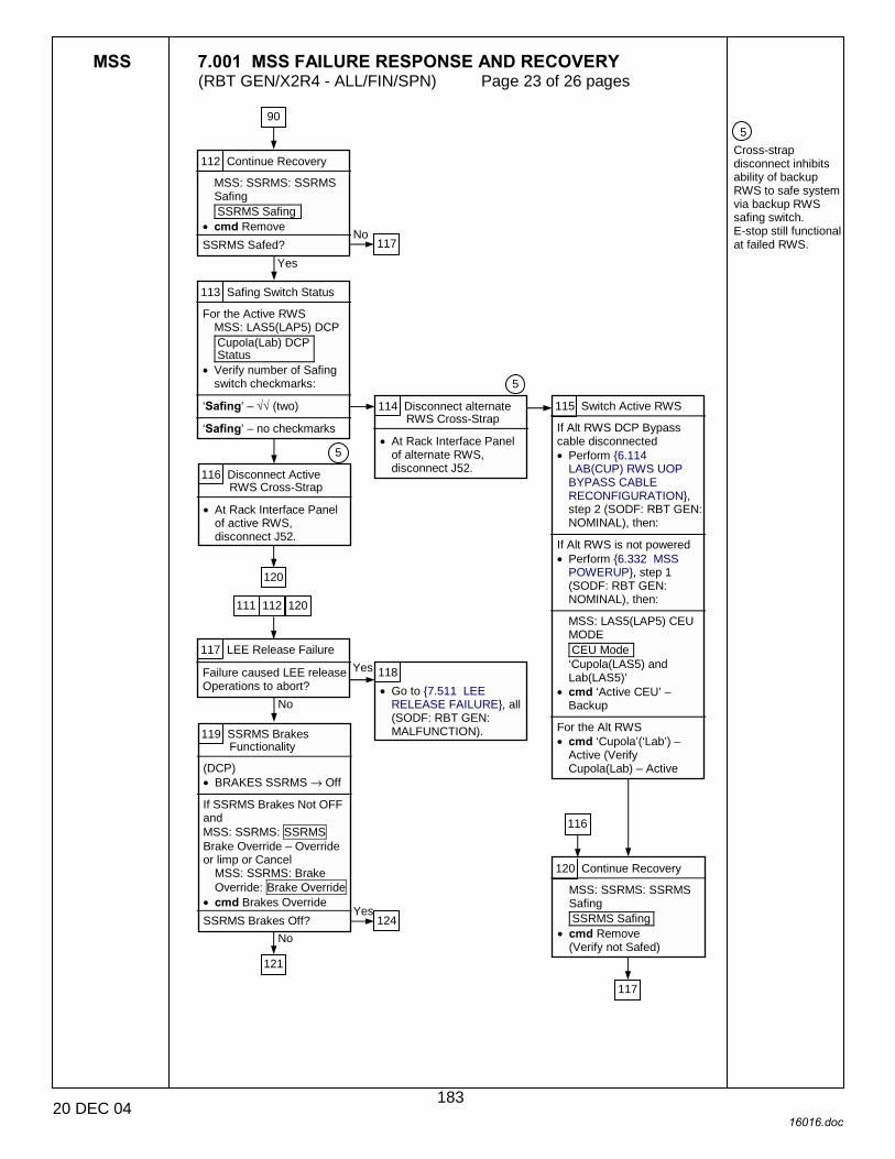
MSS 7.001 MSS FAILURE RESPONSE AND RECOVERY (RBT GEN/X2R4 - ALL/FIN/SPN) Page 23 of 26 pages
20 DEC 04 16016.doc
5 Cross-strap disconnect inhibits ability of backup RWS to safe system via backup RWS safing switch. E-stop still functional at failed RWS.
112 Continue Recovery
MSS: SSRMS: SSRMS Safing SSRMS Safing
• cmd Remove SSRMS Safed?
113 Safing Switch Status
For the Active RWS MSS: LAS5(LAP5) DCP Cupola(Lab) DCP Status
• Verify number of Safing switch checkmarks:
‘Safing’ – √√ (two)
‘Safing’ – no checkmarks
114 Disconnect alternate RWS Cross-Strap
• At Rack Interface Panel of alternate RWS, disconnect J52.
115 Switch Active RWS
If Alt RWS DCP Bypass cable disconnected • Perform {6.114
LAB(CUP) RWS UOP BYPASS CABLE RECONFIGURATION}, step 2 (SODF: RBT GEN: NOMINAL), then:
If Alt RWS is not powered • Perform {6.332 MSS
POWERUP}, step 1 (SODF: RBT GEN: NOMINAL), then:
MSS: LAS5(LAP5) CEU MODE CEU Mode ‘Cupola(LAS5) and Lab(LAS5)’
• cmd ‘Active CEU’ – Backup
For the Alt RWS • cmd ‘Cupola’(‘Lab’) –
Active (Verify Cupola(Lab) – Active
116 Disconnect Active RWS Cross-Strap
• At Rack Interface Panel of active RWS, disconnect J52.
117 LEE Release Failure
Failure caused LEE release Operations to abort?
118 • Go to {7.511 LEE
RELEASE FAILURE}, all (SODF: RBT GEN: MALFUNCTION). 119 SSRMS Brakes
Functionality
(DCP) • BRAKES SSRMS → Off
If SSRMS Brakes Not OFF and MSS: SSRMS: SSRMS Brake Override – Override or limp or Cancel
MSS: SSRMS: Brake Override: Brake Override
• cmd Brakes Override SSRMS Brakes Off?
120 Continue Recovery
MSS: SSRMS: SSRMS Safing SSRMS Safing
• cmd Remove (Verify not Safed)
117
Yes
90
No
5
5
120
Yes
111 112 120
No
121
No 124
Yes
116
117
183

MSS 7.001 MSS FAILURE RESPONSE AND RECOVERY (RBT GEN/X2R4 - ALL/FIN/SPN) Page 24 of 26 pages
20 DEC 04 16016.doc
121 Joint Drive Error
MSS: SSRMS: CW Summ Robotics Caution & Warning Summary
Any of the following messages raised when brake failed to release:
‘R3H - SSRMS� JEU Mtr Current Consistency Ck Fail’
‘R3D - SSRMS� JEU� RDC BIT fail’ or ‘R3C - �CAT-1 Transmit Msg Err’ or ‘R3C - � CAT-1 Receive Msg Err’
None of the above.
122 Change HC Rate
(RHC) • ‘Coarse/Vern’ – switch to
opposite setting MSS: SSRMS: SSRMS Safing SSRMS Safing
• cmd Remove (Verify not Safed)
(DCP) • BRAKES SSRMS → Off
If SSRMS Brakes Not OFF and MSS: SSRMS: SSRMS Brake Override – Override or Limp or Cancel
MSS: SSRMS: Brake Override: Brake Override
• cmd Brakes Override SSRMS Brakes Off?
123 • Go to {7.500 SSRMS
BRAKES FAILURE}, all (SODF: RBT GEN: MALFUNCTION).
124 LEE Operation Recovery
Failure caused LEE Capture operation to abort?
125 • Go to {7.510 SSRMS
LEE CAPTURE FAILURE}, all (SODF: RBT GEN: MALFUNCTION). 126
CAUTION
If RHC rate is in coarse, scale rates as required to vernier rates.
Use caution for operations within 5 feet of structure.
127 SSRMS Strings
Was the SSRMS string switched during recovery?
119
Yes
131
131
119 126 134
No
Yes
124
132
No128
Yes
184

MSS 7.001 MSS FAILURE RESPONSE AND RECOVERY (RBT GEN/X2R4 - ALL/FIN/SPN) Page 25 of 26 pages
20 DEC 04 16016.doc
128 SSRMS Motion Related Failure
MSS: SSRMS: CW Summ Robotics Caution & Warning Summary
Were any of the following messages annunciated with the original safing event: ‘R3H - SSRMS� JEU Mtr Current Consistency Ck Fail’ or ‘R3K - SSRMS TTED Err’ or ‘R3D - SSRMS� JEU� RDC BIT fail’ or Operator applied safing in response to uncommanded motion?
�R3C - �Transmit Msg Err’ or ‘R3C - �Receive Msg Err’ raised while driving the SSRMS joints
None of the above
129 • Go to {7.502 SSRMS
JOINT MOTION FAILURE}, all (SODF: RBT GEN: MALFUNCTION)
131
130 Continue operations
If failures return when motion resumes: • Perform {8.107 SSRMS
SWITCH TO REDUNDANT(PRIME) STRING}, all (SODF: RBT GEN: CORRECTIVE), then:
• Configure Camera as required
127
185

MSS 7.001 MSS FAILURE RESPONSE AND RECOVERY (RBT GEN/X2R4 - ALL/FIN/SPN) Page 26 of 26 pages
20 DEC 04 16016.doc
131 Switch SSRMS Strings
• Perform {8.107 SSRMS SWITCH TO REDUNDANT(PRIME) STRING}, all (SODF: RBT GEN: CORRECTIVE), then:
• Configure Cameras as
required.
132 Operation Based Recovery
From the list below, determine the MSS operation being performed at the time of the failure
MSS video component powerup
Video routing/derouting, Loss of video, degraded video
Camera commanding
None of the above.
133 • Go to {7.700 MSS
VIDEO POWER ON COMMAND FAILURE}, (SODF: RBT GEN: MALFUNCTION). 134 Continue Recovery
MSS: SSRMS: SSRMS Safing SSRMS Safing
• cmd Remove (Verify not Safed)
(DCP) • BRAKES SSRMS → Off
If SSRMS Brakes not OFF and
MSS: SSRMS: SSRMS Brake Override – Override or Limp or Cancel
MSS: SSRMS: Brake Override: Brake Override
• cmd Brakes Override
135 • Go to {7.701 MSS VIDEO
FAILURE} (SODF: RBT GEN: MALFUNCTION).
136 • Go to {7.702 MSS
CAMERA COMMAND FAILURE} (SODF: RBT GEN: MALFUNCTION).
137 MSS Non-Safing Errors
MSS: SSRMS: CW Summ Robotics Caution & Warning Summary
Are any of the following Cat-2 Robotics advisories in alarm: ‘R1C - � ROM �Err’ or ‘R2O - �’ or ‘R3L - SSRMS Pwr Flags Fail’ or ‘R3O � SSRMS LEE Stat Switches I/F Test Fail’ or ‘R5Z - SSRMS� Brake Slip’ or ‘R7A - �’ or ‘R7C - �’ or �R9C - ��
138 • Go to {7.900 MSS
PERSISTENT CAT-2 ERROR}, all (SODF: RBT GEN: MALFUNCTION).
139 Recovery complete. 140 • Continue nominal ops.
121 128122 127
124
No
186
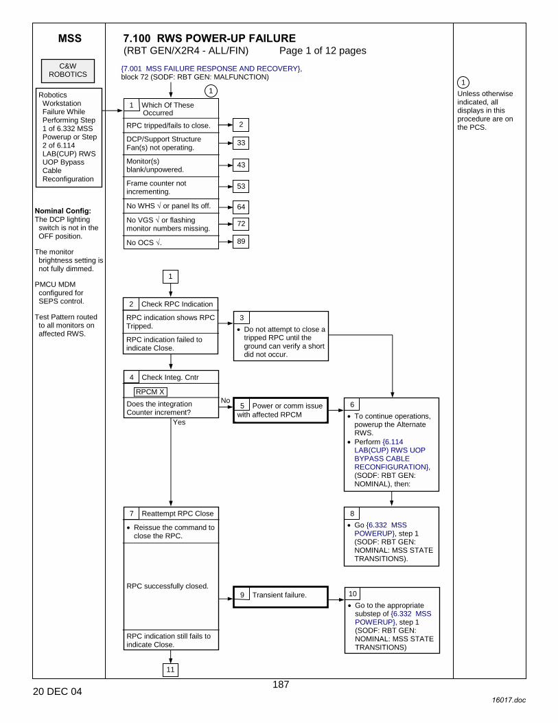
MSS 7.100 RWS POWER-UP FAILURE (RBT GEN/X2R4 - ALL/FIN) Page 1 of 12 pages
20 DEC 04 16017.doc
1 Unless otherwise indicated, all displays in this procedure are on the PCS.
9 Transient failure.
C&W ROBOTICS
{7.001 MSS FAILURE RESPONSE AND RECOVERY}, block 72 (SODF: RBT GEN: MALFUNCTION)
1 Which Of These Occurred
RPC tripped/fails to close. DCP/Support Structure Fan(s) not operating.
Monitor(s) blank/unpowered.
Frame counter not incrementing.
No WHS √ or panel lts off.
No VGS √ or flashing monitor numbers missing.
No OCS √.
1
2 Check RPC Indication
RPC indication shows RPC Tripped.
RPC indication failed to indicate Close.
3 • Do not attempt to close a
tripped RPC until the ground can verify a short did not occur.
4 Check Integ. Cntr
RPCM X Does the integration Counter increment?
1
2
Yes
No 5 Power or comm issue with affected RPCM
6 • To continue operations,
powerup the Alternate RWS.
• Perform {6.114 LAB(CUP) RWS UOP BYPASS CABLE RECONFIGURATION}, (SODF: RBT GEN: NOMINAL), then:
7 Reattempt RPC Close
• Reissue the command to close the RPC.
RPC successfully closed.
RPC indication still fails to indicate Close.
10 • Go to the appropriate
substep of {6.332 MSS POWERUP}, step 1 (SODF: RBT GEN: NOMINAL: MSS STATE TRANSITIONS)
8 • Go {6.332 MSS
POWERUP}, step 1 (SODF: RBT GEN: NOMINAL: MSS STATE TRANSITIONS).
Robotics Workstation Failure While Performing Step 1 of 6.332 MSS Powerup or Step 2 of 6.114 LAB(CUP) RWS UOP Bypass Cable Reconfiguration
Nominal Config: The DCP lighting switch is not in the OFF position.
The monitor brightness setting is not fully dimmed.
PMCU MDM configured for SEPS control.
Test Pattern routed to all monitors on affected RWS.
33
43
53
64
72
89
11
187

MSS 7.100 RWS POWER-UP FAILURE (RBT GEN/X2R4 - ALL/FIN) Page 2 of 12 pages
20 DEC 04 16017.doc
2 This step can only be performed by onboard crew. 3 Ground will perform required steps for powerdown/cleanup.
11 • Determine which RPC
RPC 6 (CVIU) or RPC 1 (VTR)
RPC 2 (CEU)
RPC 4 or 5 (CVIUs)
RPC 18 (DCP)
14 • Go to to the appropriate
substep of {6.332 MSS POWERUP}, step 1 (SODF: RBT GEN: NOMINAL: MSS STATE TRANSITIONS).
15 Check Video
• Route test pattern (If CUP: Camera Select: 95; If LAB: Camera Select 96) to all three monitors.
Does video appear on all monitors?
12 RPC or RPC status failed.
16 RPC failed. 17 User Choice
Video channel(s) lost on this RWS. • If required video is
displayed, perform the appropriate substep of {6.332 MSS POWERUP}, step 1 (SODF: RBT GEN: NOMINAL: MSS STATE TRANSITIONS), then:
If video not displayed • Power up the Alternate
RWS. • Perform {6.114
LAB(CUP) RWS UOP BYPASS CABLE RECONFIGURATION}, then:
18 RPC status failed. 19 • Go to the appropriate
substep of {6.332 MSS POWERUP}, step 1 (SODF: RBT GEN: NOMINAL: MSS STATE TRANSITIONS).
20 • Go to {6.332 MSS
POWERUP}, step 1.2 (SODF: RBT GEN: NOMINAL: MSS STATE TRANSITIONS).
7
11
2
Yes
No
3
27
15
21
13 If RPC 1 failed, 1 VTR lost. If RPC 6 failed, 1 channel of orbiter video lost and/or 1 VTR lost.
188

MSS 7.100 RWS POWER-UP FAILURE (RBT GEN/X2R4 - ALL/FIN) Page 3 of 12 pages
20 DEC 04 16017.doc
2 This step can only be performed by onboard crew. 3 Ground will perform required steps for powerdown/cleanup.
21 Check Fans/Monitors
Are DCP Fans running, or do Monitors display valid video or a ‘No Sync’ message?
11
22 RPC Status failed for RPC 2.
23 • Go to {6.332 MSS
POWERUP}, step 1.2 (SODF: RBT GEN: NOMINAL: MSS STATE TRANSITIONS).
24 RPC 18 failed. 25 Switch to Alt RWS
All capability lost for RWS External Rack. • Powerup the Alternate
RWS. Perform {6.114 LAB(CUP) RWS UOP BYPASS CABLE RECONFIGURATION}, all (SODF: RBT GEN: NOMINAL), then:
26 • Go to {6.332 MSS
POWERUP}, step 1 (SODF: RBT GEN: NOMINAL: MSS STATE TRANSITIONS).
27 Check Frame Count
MSS: LAS5(LAP5) Initialize LAS5(LAP5) Initialization
• cmd ‘C. CB Ext 2(1) Bus comm’ Enable
Does Frame Count increment?
28 RPC Status failed for RPC 2.
29 • Go to {6.332 MSS
POWERUP}, step 1.3 (SODF: RBT GEN: NOMINAL: MSS STATE TRANSITIONS).
31 Switch to Alt RWS
• Power up the Alternate RWS.
• Perform {6.114 LAB(CUP) RWS UOP BYPASS CABLE RECONFIGURATION}, all (SODF: RBT GEN: NOMINAL), then:
32 • Go to {6.332 MSS
POWERUP}, step 1 (SODF: RBT GEN: NOMINAL: MSS STATE TRANSITIONS).
2
No
Yes
11
No
Yes
30 RPC 2 failed. CEU cannot be powered.
3
189

MSS 7.100 RWS POWER-UP FAILURE (RBT GEN/X2R4 - ALL/FIN) Page 4 of 12 pages
20 DEC 04 16017.doc
2 This step can only be performed by onboard crew. 4 DCP touch temperature violation may occur. Analysis shows a potential overtemp of 2.6 deg with one fan failed. 5 The fan mounted underneath the PCS can be swapped out with a failed DCP fan to recover full DCP cooling.
33 Check DCP & Support Structure Fan(s) (3)
Only two fans are operating. No fans are operating.
34 Fan failure or power harness failure. DCP cooling may be partially lost.
35 The affected RWS can be initialized. If the lost fan is DCP-mounted fan, the RWS may exceed touch temperature limits.
36 • Go to the appropriate
substep of {6.332 MSS POWERUP}, step 1 (SODF: RBT GEN: NOMINAL: MSS STATE TRANSITIONS).
2
5 4
1
37
190
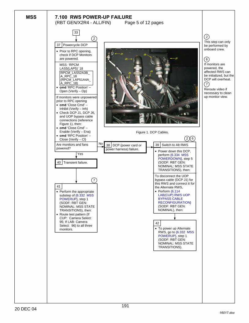
MSS 7.100 RWS POWER-UP FAILURE (RBT GEN/X2R4 - ALL/FIN) Page 5 of 12 pages
20 DEC 04 16017.doc
2 This step can only be performed by onboard crew. 6 If monitors are powered, the affected RWS can be initialized, but the DCP will overheat. 7 Reroute video if necessary to clean up monitor view.
37 Powercycle DCP
• Prior to RPC opening, check if DCP Monitors are powered.
MSS: ‘RPCM LAS5(LAP5)’ 18 RPCM_LAS52A3B_ A_RPC_18 (RPCM_LAP51A4A_ A_RPC_18)
• cmd ‘RPC Position’ – Open (Verify – Op)
If monitors were unpowered prior to RPC opening • cmd ‘Close Cmd’ –
Inhibit (Verify – Inh) • Check DCP J1, DCP J6,
and UOP bypass cable connections (reference Figure 1), then:
• cmd ‘Close Cmd’ – Enable (Verify – Ena)
• cmd ‘RPC Position’ – Close (Verify – Cl)
Are monitors and fans powered?
Figure 1. DCP Cables.
2
33
38 DCP (power card or power harness) failure.
39 Switch to Alt RWS
• Power down this DCP, perform {6.334 MSS POWERDOWN}, step 5 (SODF: RBT GEN: NOMINAL: MSS STATE TRANSITIONS), then:
To disconnect the UOP bypass cable (DCP J1) for this RWS and connect it for the Alternate RWS, • Perform {6.114
LAB(CUP) RWS UOP BYPASS CABLE RECONFIGURATION} (SODF: RBT GEN: NOMINAL), then:
40 Transient failure.
41 • Perform the appropriate
substep of {6.332 MSS POWERUP}, step 1 (SODF: RBT GEN: NOMINAL: MSS STATE TRANSITIONS), then:
• Route test pattern (If CUP: Camera Select: 95; If LAB: Camera Select: 96) to all three monitors.
42 • To power up Alternate
RWS, go to {6.332 MSS POWERUP}, step 1 (SODF: RBT GEN: NOMINAL: MSS STATE TRANSITIONS).
6 2
Yes
No
7
191

MSS 7.100 RWS POWER-UP FAILURE (RBT GEN/X2R4 - ALL/FIN) Page 6 of 12 pages
20 DEC 04 16017.doc
2 This step can only be performed by onboard crew. 3 Ground will perform required steps for powerdown/cleanup.
43 Power cycle DCP
• Note how many monitors are blank/unpowered. MSS: ‘RPCM LAS5(LAP5)’ 18: RPCM_LAS52A3B_ A_RPC_18 (RPCM_LAP51A4A_ A_RPC_18)
• cmd ‘RPC Position’ – Open (Verify – Op)
If only one RWS monitor was blank/unpowered • cmd ‘Close Cmd’ –
Inhibit (Verify – Inh) • Verify secure J1
connection to inoperable monitor.
• cmd ‘Close Cmd’ – Enable (Verify – Ena)
• cmd ‘RPC Position’ –
Close (Verify – Cl) • If {6.332 MSS
POWERUP}, step 1.6 (SODF: RBT GEN: NOMINAL: MSS STATE TRANSITIONS) is complete, route a test pattern (If CUP: Camera Select: 95; If LAB: Camera Select 96) to all three monitors.
All RWS monitors display ‘No Sync’ or valid video.
One RWS monitor is blank/unpowered.
Two RWS monitors are blank/unpowered.
All three RWS monitors are blank/unpowered.
44 Transient failure.
45 DCP, monitor, or wire harness failure.
47 User Choice
If one monitor is adequate • Perform the appropriate
substep of {6.332 MSS POWERUP}, step 1 (SODF: RBT GEN: NOMINAL: MSS STATE TRANSITIONS), then:
• If two or three monitors are required, power up the Alternate RWS.
• Perform {6.114 LAB(CUP) RWS UOP BYPASS CABLE RECONFIGURATION}, then:
48 DCP (power card) failure. All DCP video functionality lost for the affected RWS.
1
2
46 DCP failure. Only one monitor usable with this RWS.
3
49
51
50
192
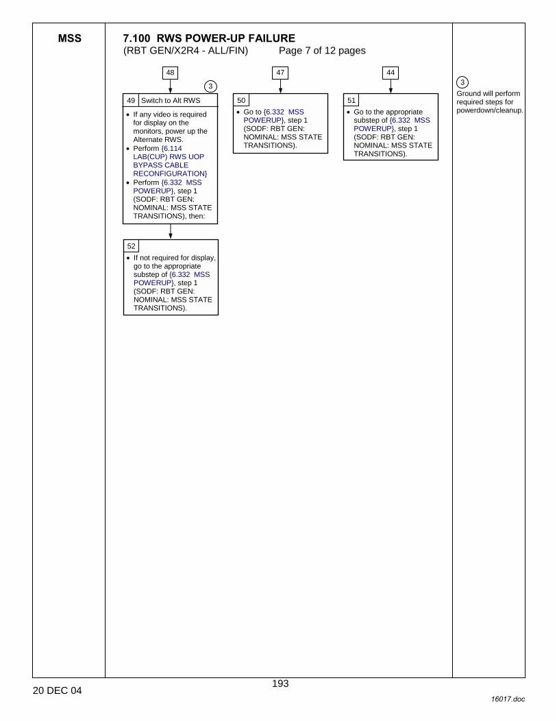
MSS 7.100 RWS POWER-UP FAILURE (RBT GEN/X2R4 - ALL/FIN) Page 7 of 12 pages
20 DEC 04 16017.doc
3 Ground will perform required steps for powerdown/cleanup.
49 Switch to Alt RWS
• If any video is required for display on the monitors, power up the Alternate RWS.
• Perform {6.114 LAB(CUP) RWS UOP BYPASS CABLE RECONFIGURATION}
• Perform {6.332 MSS POWERUP}, step 1 (SODF: RBT GEN: NOMINAL: MSS STATE TRANSITIONS), then:
50 • Go to {6.332 MSS
POWERUP}, step 1 (SODF: RBT GEN: NOMINAL: MSS STATE TRANSITIONS).
51 • Go to the appropriate
substep of {6.332 MSS POWERUP}, step 1 (SODF: RBT GEN: NOMINAL: MSS STATE TRANSITIONS).
52 • If not required for display,
go to the appropriate substep of {6.332 MSS POWERUP}, step 1 (SODF: RBT GEN: NOMINAL: MSS STATE TRANSITIONS).
3
47 44 48
193

MSS 7.100 RWS POWER-UP FAILURE (RBT GEN/X2R4 - ALL/FIN) Page 8 of 12 pages
20 DEC 04 16017.doc
3 Ground will perform required steps for powerdown/cleanup. 8 A comm failure in any of the other RT’s on CB-EXT1(2) may cause the C&C to swap back to the channel on which the CEU cannot communicate. If that occurs, the ground will to determine which of the two failed RTs are required.
53 Is FDIR already enabled?
1
54 Switch Channels
C&DH: C&C Primary: CB EXT 2(1): Bus Status CB EXT 2(1) Bus Status
• cmd Select Ch B(A) Is the Frame Counter incrementing?
55 Power Cycle CEU
• Perform {6.334 MSS POWERDOWN}, step 4.2 (SODF: RBT GEN: NOMINAL: MSS STATE TRANSITIONS), then:
• Perform {6.332 MSS POWERUP}, steps 1.1 and 1.2 (SODF: RBT GEN: NOMINAL: MSS STATE TRANSITIONS), then:
Is Frame Counter now incrementing?
56 Unable to communicate on original channel, or CEU failure.
59 • Go to the appropriate
substep of {6.332 MSS POWERUP}, step 1 (SODF: RBT GEN: NOMINAL: MSS STATE TRANSITIONS).
60 • Continue operations on
new channel. • So that FDIR remains
disabled do not perform {6.332 MSS POWERUP}, step 1.5 (SODF: RBT GEN: NOMINAL: MSS STATE TRANSITIONS), then:
61 Switch to Alt RWS
• Power up the Alternate RWS. Perform {6.114 LAB(CUP) RWS UOP BYPASS CABLE RECONFIGURATION} (SODF: RBT GEN: NOMINAL), then:
62 • Go to the appropriate
substep of {6.332 MSS POWERUP}, step 1 (SODF: RBT GEN: NOMINAL: MSS STATE TRANSITIONS).
63 • Go to {6.332 MSS
POWERUP}, step 1 (SODF: RBT GEN: NOMINAL: MSS STATE TRANSITIONS).
58 CEU Comm failure.
No
Yes
No
No
Yes 57 Transient failure.
8
3
Yes
194

MSS 7.100 RWS POWER-UP FAILURE (RBT GEN/X2R4 - ALL/FIN) Page 9 of 12 pages
20 DEC 04 16017.doc
3 Ground will perform required steps for powerdown/cleanup. 9 Ground must verify correct WHS file size and proper completion of file download.
64 Powercycle CEU
• Perform {6.334 MSS POWERDOWN}, step 4.2 (SODF: RBT GEN: NOMINAL: MSS STATE TRANSITIONS), then:
With hands off alternate RWS and all other PCS • Perform {6.332 MSS
POWERUP}, steps 1.1 thru 1.4 (SODF: RBT GEN: NOMINAL: MSS STATE TRANSITIONS), then:
‘E. Start WHS’ shows “√”
‘E. Start WHS’ fails to show a √ and MCC reports that file transfer was ok.
MCC reports that file transfer had a problem.
65 Transient failure. 66 • Go to the appropriate
substep of {6.332 MSS POWERUP}, step 1 (SODF: RBT GEN: NOMINAL: MSS STATE TRANSITIONS).
67 CEU failure. 68 • Power up Alternate RWS. • Perform {6.114
LAB(CUP) RWS UOP BYPASS CABLE RECONFIGURATION}, then:
69 • Go to {6.332 MSS
POWERUP}, step 1 (SODF: RBT GEN: NOMINAL: MSS STATE TRANSITIONS).
70 File transfer issues. Problem could be due to corrupt SSMMU file, which affects both RWS.
71 • Additional
troubleshooting required.
1
9
3
195
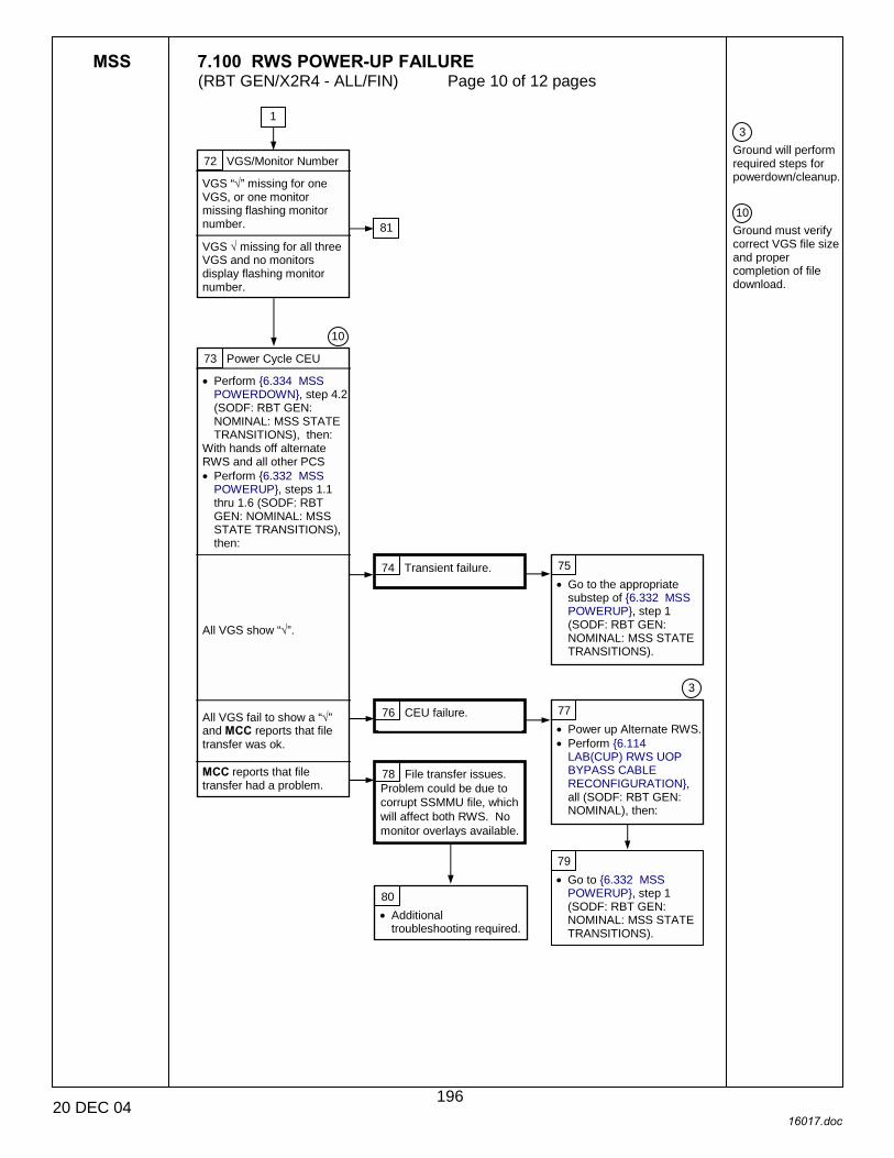
MSS 7.100 RWS POWER-UP FAILURE (RBT GEN/X2R4 - ALL/FIN) Page 10 of 12 pages
20 DEC 04 16017.doc
3 Ground will perform required steps for powerdown/cleanup. 10 Ground must verify correct VGS file size and proper completion of file download.
72 VGS/Monitor Number
VGS “√” missing for one VGS, or one monitor missing flashing monitor number.
VGS √ missing for all three VGS and no monitors display flashing monitor number.
73 Power Cycle CEU
• Perform {6.334 MSS POWERDOWN}, step 4.2 (SODF: RBT GEN: NOMINAL: MSS STATE TRANSITIONS), then:
With hands off alternate RWS and all other PCS • Perform {6.332 MSS
POWERUP}, steps 1.1 thru 1.6 (SODF: RBT GEN: NOMINAL: MSS STATE TRANSITIONS), then:
All VGS show “√”.
All VGS fail to show a “√” and MCC reports that file transfer was ok.
MCC reports that file transfer had a problem.
74 Transient failure. 75 • Go to the appropriate
substep of {6.332 MSS POWERUP}, step 1 (SODF: RBT GEN: NOMINAL: MSS STATE TRANSITIONS).
76 CEU failure. 77 • Power up Alternate RWS. • Perform {6.114
LAB(CUP) RWS UOP BYPASS CABLE RECONFIGURATION}, all (SODF: RBT GEN: NOMINAL), then:
78 File transfer issues. Problem could be due to corrupt SSMMU file, which will affect both RWS. No monitor overlays available.
79 • Go to {6.332 MSS
POWERUP}, step 1 (SODF: RBT GEN: NOMINAL: MSS STATE TRANSITIONS).
80 • Additional
troubleshooting required.
1
10
3
81
196

MSS 7.100 RWS POWER-UP FAILURE (RBT GEN/X2R4 - ALL/FIN) Page 11 of 12 pages
20 DEC 04 16017.doc
2 This step can only be performed by onboard crew. 3 Ground will perform required steps for powerdown/cleanup.
81 VGC failure. CEU (VGC) failure. All overlays lost on affected monitor.
82 Is affected monitor required to support operations?
83
• Go to the appropriate substep of {6.332 MSS POWERUP}, step 1 (SODF: RBT GEN: NOMINAL: MSS STATE TRANSITIONS).
72
Yes
Yes
No
84 Power Cycle CEU
• Perform {6.334 MSS POWERDOWN}, step 4.2 parts F,G, and H (SODF: RBT GEN: NOMINAL: MSS STATE TRANSITIONS), then:
• Verify secure J1 connection to inoperable monitor.
• With hands off alternate RWS and all othe PCS, perform {6.332 MSS POWERUP}, steps 1.1 to 1.6 (SODF: RBT GEN: NOMINAL: MSS STATE TRANSITIONS), then:
Does the problem recur?
2
No
Yes 85 CEU (VGC), Monitor, or Monitor Wire Harness Failure. All video and overlays lost on affected monitor.
86 Two other monitors remain for this RWS. If all three monitors required
• Powerup the Alternate RWS. Perform {6.114 LAB(CUP) RWS UOP BYPASS CABLE RECONFIGURATION}, then:
• Perform {6.332 MSS POWERUP}, step 1 (SODF: RBT GEN: NOMINAL: MSS STATE TRANSITIONS), then:
If all three monitors not required
• Go to the appropriate substep of {6.332 MSS POWERUP}, step 1 (SODF: RBT GEN: NOMINAL: MSS STATE TRANSITIONS).
3
87 Transient failure.
88 • Go to the appropriate
substep of {6.332 MSS POWERUP}, step 1 (SODF: RBT GEN: NOMINAL: MSS STATE TRANSITIONS).
197

MSS 7.100 RWS POWER-UP FAILURE (RBT GEN/X2R4 - ALL/FIN) Page 12 of 12 pages
20 DEC 04 16017.doc
3 Ground will perform required steps for powerdown/cleanup. 11 Ground must verify correct OCS file size and proper completion of file download.
89 Power Cycle CEU
• Perform {6.334 MSS POWERDOWN}, step 4 (SODF: RBT GEN: NOMINAL: MSS STATE TRANSITIONS), then:
• With hands off alternate RWS and all other PCS, perform {6.332 MSS POWERUP}, steps 1.1 to 1.6 (SODF: RBT GEN: NOMINAL: MSS STATE TRANSITIONS), then:
OCS shows “√”.
OCS fails to show a “√” and MCC reports that file transfer was ok.
MCC reports that file transfer had a problem.
11
1
90 Transient failure. 91 • Go to the appropriate
substep of {6.332 MSS POWERUP}, step 1 (SODF: RBT GEN: NOMINAL: MSS STATE TRANSITIONS).
92 CEU failure. 93 • Power up the Alternate
RWS. • Perform {6.114
LAB(CUP) RWS UOP BYPASS CABLE RECONFIGURATION}, then:
3
94 • Go to {6.332 MSS
POWERUP}, step 1 (SODF: RBT GEN: NOMINAL: MSS STATE TRANSITIONS).
95 File transfer issue. Problem could be due to corrupt SSMMU file, which will affect both RWS.
96 • Additional
troubleshooting required.
198

MSS 7.101 RWS TRANSITION TO ACTIVE FAILURE (RBT GEN/X2R4 - ALL/FIN/SPN) Page 1 of 2 pages
16 DEC 04 16018.doc
1 Unless otherwise indicated, all displays in the procedure are on the PCS. 2 SCR 24574
RWS Does Not Transition to Active When Commanded
Nominal Config: The affected RWS initialized with software downloaded.
The alternate RWS is not Active.
1 Reattempt
MSS: LAS5(LAP5) CEU Mode: CEU Mode
• cmd Cupola(Lab) – Active (Verify Cupola(Lab) – Active )
Is RWS active? 2 Recovery complete.
3 Check C&W and Discrete Messages
MSS: CW Summ Robotics Caution & Warning Summary
• Determine which of the following messages appeared:
Any messages starting with ‘R1�’ annunciated
MSS: MBS: Discrete Log: MSS Discrete Log
‘OCS> Coordinate System Parameters File Rejected’ discrete message raised
‘OCS> CEU Mode Active (Abo) Checkpoint Data Invalid’ discrete message raised
Yes
No
4 • Continue nominal
operations.
1
{7.001 MSS FAILURE RESPONSE AND RECOVERY}, block 73 (SODF: RBT GEN: MALFUNCTION)
2
5 • Go to (7.300 ACTIVE
RWS FAILURE}, all (SODF: RBT GEN: RECOVERY).
C&W ROBOTICS
6 Possible coordinate system file corruption issue. Ground to perform file transfer or uplink of affected file.
7 Reset Checkpoint Data
• Perform {8.104 MSS CHECKPOINT DATA RESET}, steps 2 to 6 (SODF: RBT GEN: CORRECTIVE), then:
Is RWS active? Yes
No
10
8
9
199

MSS 7.101 RWS TRANSITION TO ACTIVE FAILURE (RBT GEN/X2R4 - ALL/FIN/SPN) Page 2 of 2 pages
16 DEC 04 16018.doc
3 LEE and POA calibrations are lost. Use hard stops until calibrated. 4 Video deroutes are only required if video routes were in place at the time of the MSS powerdown. 5 The steps in this block can only be performed after the SSRMS has been powered up to Operational.
12 Configure Frames and Parameters
• Configure Command and Display frames, as required.
• Set unloaded and loaded payload parameters, as required.
• Set rate scale, as desired.
• Configure cameras and overlays.
13 Recovery complete. 14 • Continue nominal
operations.
5
8 Switch RWS
For alternate RWS: • Perform {6.332 MSS
POWERUP}, steps 1 to 2, as required (SODF: RBT GEN: NOMINAL), then:
Is RWS active?
11 Reconfigure to Initial Conditions
• Perform {6.332 MSS POWERUP}, steps 3 to 5 as required (SODF: RBT GEN: NOMINAL), then: MSS: Video: Video Overview: Video Overview
• Repeat the following for all destinations to which an SSRMS or MBS camera is routed:
• sel ‘Destination Icon’ • cmd ‘Deroute Video
Signal’ – Deroute
4
Yes
10 Possible checkpoint data file corruption issue. Ground to perform file transfer or uplink of checkpoint data files.
7
9 • Perform {8.104 MSS
CHECKPOINT DATA RESET}, steps 7 to 8 (SODF: RBT GEN: CORRECTIVE), then:
3
7
7
200

MBS 7.110 MBS POWER-UP FROM OFF TO KA FAILURE (RBT GEN/X2R4 - ALL/FIN/SPN) Page 1 of 3 pages
15 DEC 04 16019.doc
Table 1. Utility Port RPCMs
1 All displays in this procedure are on the PCS. 2 An inability to provide power to both MBS strings indicates an EXT MDM (or lower tier Truss MDM) problem.
{7.001 MSS FAILURE RESPONSE AND RECOVERY}, block 78 (SODF: RBT GEN: MALFUNCTION)
MBS Powerup From Off to Keep-Alive Fails
1 String State
MSS: MBS: MCU: MCU ‘Prime’(‘Redundant’) – SRT Powered On?
2 Check RPC Status
MSS: MBS: MT UOP: Work Site Power
• Examine the appropriate RPCM as shown in Table 1 to determine the RPC status.
‘RPC’ ‘Trip’ – √
‘RPC’ ’Position’ – Cl
‘RPC’ ’Position’ – Op
7 Reattempt Keep-Alive
MSS: MBS: MCU: MCU • cmd ‘Prime’(‘Redundant’)
Keep-Alive ‘Prime’(‘Redundant’) Keep-Alive?
8 • Continue nominal
operations.
9 Yes
No
2
3 Close MBS RPC
• Command RPC closed that is associated with current worksite and string, as shown in Table 1.
‘RPC’ ’Position’ – Cl? No
Yes
4 Switch Strings
MSS: MBS: MCU: MCU If alternate string is Not Keep-Alive or Operational • cmd ‘Redundant’(‘Prime’)
Keep-Alive ‘Redundant’(‘Prime’) Keep-Alive?
Yes
No
6 • Continue nominal
operations without Prime (Redundant) string.
4 No
Yes
1
7
7
Nominal Config: RWS powered and in Active state.
MT SSBAs powered. POA off or KA on alternate MBS string.
MBS Base Location in checkpoint data is set to MT.
EXT, S0(P1, S1) MDMs configured for SEPS control.
5 Power App Failure. Inability to provide power to both MBS strings. Further troubleshooting required by the ground prior to proceeding with MSS operations.
2
201

MBS 7.110 MBS POWER-UP FROM OFF TO KA FAILURE (RBT GEN/X2R4 - ALL/FIN/SPN) Page 2 of 3 pages
15 DEC 04 16019.doc
3 The communication bus between the RWS and MBS consists of 1553 converter cards in the CEU and MCU, and the 1553 cables in the wire harnesses. If any of these fail, at least one channel will be affected. 4 Ground can determine required length of wait time or whether it is required.
9 Reattempt Keep-Alive
MSS: MBS: MCU: MCU • cmd ‘Prime’(‘Redundant’)
Off (Verify – Off) • cmd ‘Prime’(‘Redundant’)
Keep-Alive Keep-Alive? 10 Transient failure.
11 Switch Bus Channels
For the Active RWS MSS: LAS5(LAP5) Bus Config LAS5(LAP5) CEU Bus Configuration ‘Local Bus’ ‘Mss’
• cmd B For affected string
MSS: MBS: MCU: MCU • cmd ‘Prime’(‘Redundant’)
Off (Verify – Off) • cmd ‘Prime’(‘Redundant’)
Keep-Alive Keep-Alive?
12 • Continue nominal
operations.
13 Possible MSS LB channel failure.
14 • Continue nominal
operations.
15 Check Other String
MSS: MBS: MCU: MCU ‘Redundant’(‘Prime’) – Keep-Alive or Operational
‘Redundant’(‘Prime’) – Off
16 Check Comm Status
MSS: CW Summ Robotics: Caution & Warning Summary
Is ‘R1E - �MBS�Comm Fail’ in alarm for the ‘Redundant’(‘Prime’) string? 17 Powerup Other String
MSS: MBS: MCU: MCU • cmd ‘Redundant’(‘Prime’)
Keep-Alive Keep-Alive? 18 MCU or CRPCM
2P(2R) failure on original string.
19 • Continue nominal
operations without Prime (Redundant) string.
20 Warm Equipment
• Wait for equipment to warm up, if required.
1
Yes
No
Yes
No
3
Yes
No
4
Yes
No
22
21
202
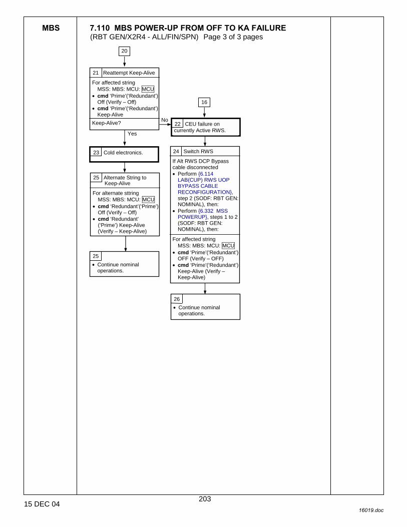
MBS 7.110 MBS POWER-UP FROM OFF TO KA FAILURE (RBT GEN/X2R4 - ALL/FIN/SPN) Page 3 of 3 pages
15 DEC 04 16019.doc
21 Reattempt Keep-Alive
For affected string MSS: MBS: MCU: MCU
• cmd ‘Prime’(‘Redundant’) Off (Verify – Off)
• cmd ‘Prime’(‘Redundant’) Keep-Alive
Keep-Alive?
23 Cold electronics.
25 • Continue nominal
operations.
26 • Continue nominal
operations.
No
Yes
22 CEU failure on currently Active RWS.
24 Switch RWS
If Alt RWS DCP Bypass cable disconnected • Perform {6.114
LAB(CUP) RWS UOP BYPASS CABLE RECONFIGURATION}, step 2 (SODF: RBT GEN: NOMINAL), then:
• Perform {6.332 MSS POWERUP}, steps 1 to 2 (SODF: RBT GEN: NOMINAL), then:
For affected string
MSS: MBS: MCU: MCU • cmd ‘Prime’(‘Redundant’)
OFF (Verify – OFF) • cmd ‘Prime’(‘Redundant’)
Keep-Alive (Verify – Keep-Alive)
16
20
25 Alternate String to Keep-Alive
For alternate sttring MSS: MBS: MCU: MCU
• cmd ‘Redundant’(‘Prime’) Off (Verify – Off)
• cmd ‘Redundant’ (‘Prime’) Keep-Alive (Verify – Keep-Alive)
203

This Page Intentionally Blank
22 DEC 04
204
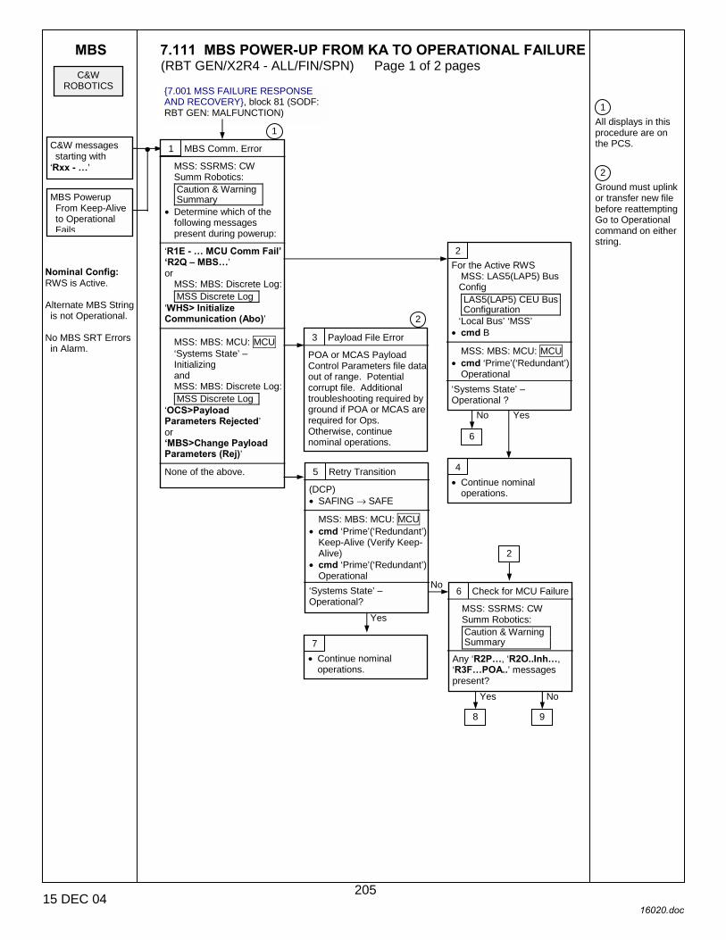
MBS 7.111 MBS POWER-UP FROM KA TO OPERATIONAL FAILURE (RBT GEN/X2R4 - ALL/FIN/SPN) Page 1 of 2 pages
15 DEC 04 16020.doc
1 All displays in this procedure are on the PCS. 2 Ground must uplink or transfer new file before reattempting Go to Operational command on either string.
{7.001 MSS FAILURE RESPONSE AND RECOVERY}, block 81 (SODF: RBT GEN: MALFUNCTION)
C&W ROBOTICS
C&W messages starting with
‘Rxx - �’
Nominal Config: RWS is Active. Alternate MBS String is not Operational.
No MBS SRT Errors in Alarm.
MBS Powerup From Keep-Alive to Operational Fails
1 MBS Comm. Error
MSS: SSRMS: CW Summ Robotics: Caution & Warning Summary
• Determine which of the following messages present during powerup:
‘R1E - � MCU Comm Fail� �R2Q � MBS�’ or
MSS: MBS: Discrete Log: MSS Discrete Log
‘WHS> Initialize Communication (Abo)’
MSS: MBS: MCU: MCU ‘Systems State’ –Initializing and MSS: MBS: Discrete Log: MSS Discrete Log
‘OCS>Payload Parameters Rejected’ or �MBS>Change Payload Parameters (Rej)’
None of the above.
2 For the Active RWS
MSS: LAS5(LAP5) Bus Config LAS5(LAP5) CEU Bus Configuration
‘Local Bus’ ‘MSS’ • cmd B
MSS: MBS: MCU: MCU
• cmd ‘Prime’(‘Redundant’) Operational
‘Systems State’ – Operational ?
3 Payload File Error
POA or MCAS Payload Control Parameters file data out of range. Potential corrupt file. Additional troubleshooting required by ground if POA or MCAS are required for Ops. Otherwise, continue nominal operations.
4 • Continue nominal
operations.
5 Retry Transition
(DCP) • SAFING → SAFE
MSS: MBS: MCU: MCU
• cmd ‘Prime’(‘Redundant’) Keep-Alive (Verify Keep-Alive)
• cmd ‘Prime’(‘Redundant’) Operational
‘Systems State’ – Operational?
6 Check for MCU Failure
MSS: SSRMS: CW Summ Robotics: Caution & Warning Summary
Any ‘R2P�, ‘R2O..Inh�, ‘R3F�POA..’ messages present?
7 • Continue nominal
operations.
No
Yes
6
Yes No
2
8 9
Yes No
1
2
205
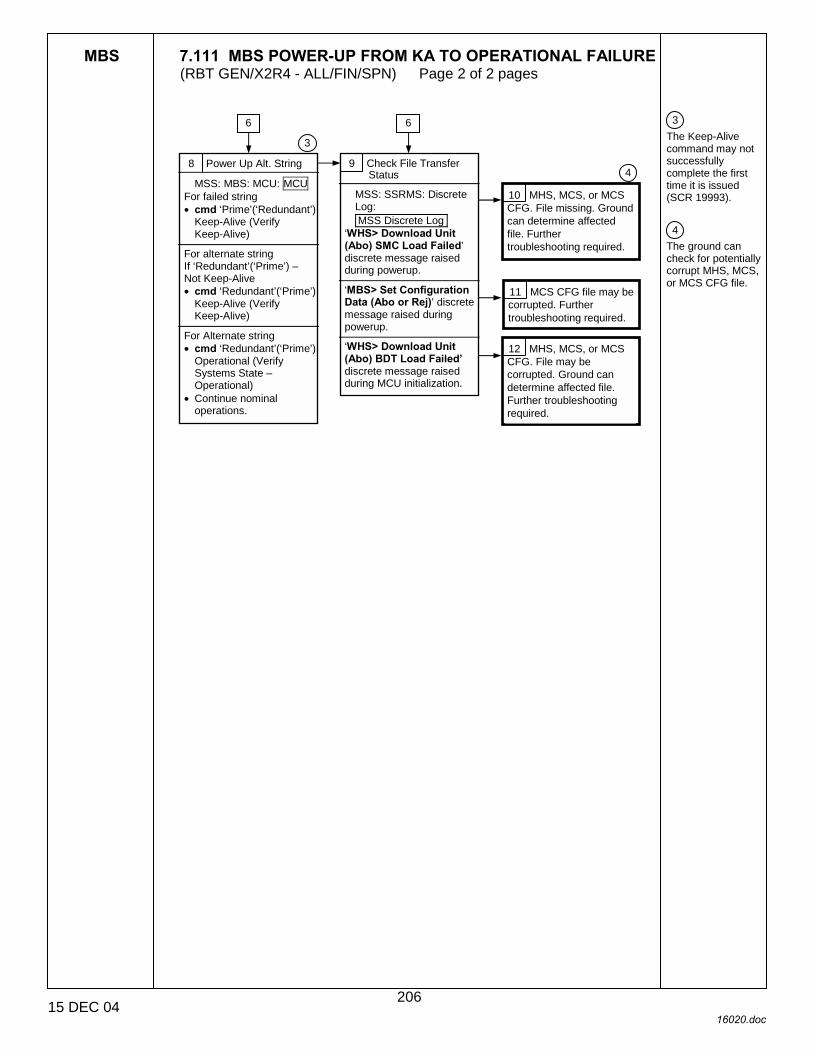
MBS 7.111 MBS POWER-UP FROM KA TO OPERATIONAL FAILURE (RBT GEN/X2R4 - ALL/FIN/SPN) Page 2 of 2 pages
15 DEC 04 16020.doc
3 The Keep-Alive command may not successfully complete the first time it is issued (SCR 19993). 4 The ground can check for potentially corrupt MHS, MCS, or MCS CFG file.
8 Power Up Alt. String
MSS: MBS: MCU: MCU For failed string • cmd ‘Prime’(‘Redundant’)
Keep-Alive (Verify Keep-Alive)
For alternate string If ‘Redundant’(‘Prime’) – Not Keep-Alive • cmd ‘Redundant’(‘Prime’)
Keep-Alive (Verify Keep-Alive)
For Alternate string • cmd ‘Redundant’(‘Prime’)
Operational (Verify Systems State – Operational)
• Continue nominal operations.
9 Check File Transfer Status
MSS: SSRMS: Discrete Log: MSS Discrete Log
‘WHS> Download Unit (Abo) SMC Load Failed’ discrete message raised during powerup.
‘MBS> Set Configuration Data (Abo or Rej)’ discrete message raised during powerup.
‘WHS> Download Unit (Abo) BDT Load Failed� discrete message raised during MCU initialization.
10 MHS, MCS, or MCS CFG. File missing. Ground can determine affected file. Further troubleshooting required.
11 MCS CFG file may be corrupted. Further troubleshooting required.
12 MHS, MCS, or MCS CFG. File may be corrupted. Ground can determine affected file. Further troubleshooting required.
6 6
3
4
206
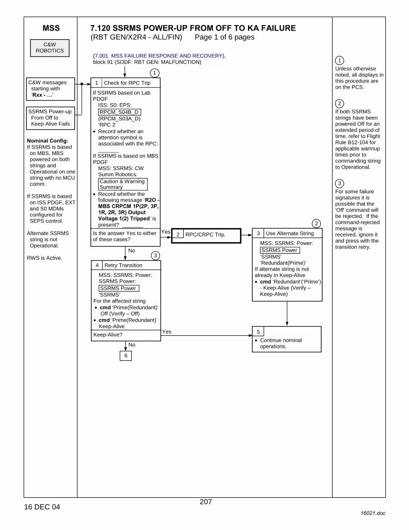
MSS 7.120 SSRMS POWER-UP FROM OFF TO KA FAILURE (RBT GEN/X2R4 - ALL/FIN) Page 1 of 6 pages
16 DEC 04 16021.doc
1 Unless otherwise noted, all displays in this procedure are on the PCS. 2 If both SSRMS strings have been powered Off for an extended period of time, refer to Flight Rule B12-104 for applicable warmup times prior to commanding string to Operational. 3 For some failure signatures it is possible that the 'Off' command will be rejected. If the command-rejected message is received, ignore it and press with the transition retry.
{7.001 MSS FAILURE RESPONSE AND RECOVERY}, block 91 (SODF: RBT GEN: MALFUNCTION)
C&W ROBOTICS
SSRMS Power-up From Off to Keep-Alive Fails
Nominal Config: If SSRMS is based on MBS, MBS powered on both strings and Operational on one string with no MCU comm.
If SSRMS is based on ISS PDGF, EXT and S0 MDMs configured for SEPS control.
Alternate SSRMS string is not Operational.
RWS is Active.
1 Check for RPC Trip
If SSRMS based on Lab PDGF
ISS: S0: EPS: RPCM_S04B_D (RPCM_S03A_D) ‘RPC 2’
• Record whether an attention symbol is associated with the RPC: _______
If SSRMS is based on MBS PDGF
MSS: SSRMS: CW Summ Robotics: Caution & Warning Summary
• Record whether the following message ‘R2O - MBS CRPCM 1P(2P, 3P, 1R, 2R, 3R) Output Voltage 1(2) Tripped’ is present? _______
Is the answer Yes to either of these cases?
2 RPC/CRPC Trip. Yes 3 Use Alternate String
MSS: SSRMS: Power: SSRMS Power ‘SSRMS’ ‘Redundant(Prime)’
If alternate string is not already in Keep-Alive • cmd ‘Redundant’(‘Prime’)
- Keep-Alive (Verify – Keep-Alive)
4 Retry Transition
MSS: SSRMS: Power: SSRMS Power: SSRMS Power ‘SSRMS’
For the affected string • cmd ‘Prime(Redundant)’
Off (Verify – Off) • cmd ‘Prime(Redundant)’
Keep-Alive Keep-Alive?
6
2
3
No
Yes 5 • Continue nominal
operations.
C&W messages starting with ‘Rxx - �’
1
No
207

MSS 7.120 SSRMS POWER-UP FROM OFF TO KA FAILURE (RBT GEN/X2R4 - ALL/FIN) Page 2 of 6 pages
16 DEC 04 16021.doc
2 If both SSRMS strings have been powered Off for an extended period of time, refer to Flight Rule B12-104 for applicable warmup times prior to commanding string to Operational. 4 PDGF LB if SSRMS is based on Lab PDGF, MSS LB if based on MBS PDGF.
8 Power Alternate String
For the alternate string MSS: SSRMS: Power: SSRMS Power: SSRMS Power ‘Redundant(Prime)’
• cmd Keep-Alive Keep-Alive?
6 Check Alternate String
For the alternate string MSS: SSRMS: Power: SSRMS Power: SSRMS Power
‘Prime’(‘Redundant’) Off?
7 Check for Communication Error
For the alternate string MSS: SSRMS: CW Summ Robotics: Caution & Warning Summary
Is the following message in alarm: ‘R1E - MSS�SSRMS �Comm Fail’?
4
9 Check RPCs/CPRCs
MSS: SSRMS: Power: PDGF Power: PDGF Power
• Referring to Table 1, check RPC/CRPC status for the string that failed.
Does the appropriate RPC/CRPC show closed?
10 • Determine Base
SRMS based on Lab PDGF.
SSRMS based on MBS PDGF.
9
7
11 EPS or CDH failure. Loss of affected string on this PDGF. Proceed using alternate string.
13 Retry Transition
For the string that failed MSS: SSRMS: Power: SSRMS Power ‘SSRMS’ ‘Prime(Redundant)’
• cmd Off • cmd Keep-Alive
Keep-Alive? 14 Determine Base
SSRMS based on MBS PDGF.
SSRMS based on Lab PDGF.
15 Local Bus channel failure.
16
17
24
36
No
Yes
2
No
Yes
12 Change LB Channels
For the Active RWS MSS: RWS: LAS5(LAP5) Bus Config: LAS5(LAP5) CEU Bus Configuration ‘PDGF(MSS)’
• cmd B
No
Yes
Yes
No
7 8
12
12
No
Yes
4
208

MSS 7.120 SSRMS POWER-UP FROM OFF TO KA FAILURE (RBT GEN/X2R4 - ALL/FIN) Page 3 of 6 pages
16 DEC 04 16021.doc
16 Clean Up Alternate String
For the alternate string If MSS: SSRMS: Power:
SSRMS Power ‘SSRMS’ ‘Redundant(Prime)’ not OFF, then:
• cmd Off Alternate string may now be transitioned to desired state.
15
17 Check Alternate String
For the alternate string MSS: SSRMS: Power: SSRMS Power: SSRMS Power ‘Redundant(Prime)’ failed Keep-Alive
or MSS: SSRMS: CW Summ Robotics: Caution & Warning Summary
‘R1E - MSS � SSRMS � Comm Fail’ messages present?
18 • Proceed using alternate
string.
19 Change RWS
If alternate RWS is not powered • Perform {6.332 MSS
POWERUP}, steps 1 to 2 (SODF: RBT GEN: NOMINAL), then:
14
20 Retry Transition
For the string that failed MSS: SSRMS: Power: SSRMS Power ‘SSRMS’ ‘Prime(Redundant)’
• cmd Off • cmd Keep-Alive
Keep-Alive? 21 RWS CEU (1553 card) failure. Failed RWS unable to communicate with SSRMS, AVU, or alternate RWS on both PDGF LB channels. MSS overlay data is not valid on the failed RWS when in backup mode.
22 Further troubleshooting needed to proceed with operations.
23 Clean Up Alternate String
For the alternate string If MSS: SSRMS: Power:
SSRMS Power ‘SSRMS’ ‘Redundant(Prime)’ failed Keep-Alive, then:
• cmd Off Alternate string may now be transitioned to desired state.
Yes
No
Yes
No
209

MSS 7.120 SSRMS POWER-UP FROM OFF TO KA FAILURE (RBT GEN/X2R4 - ALL/FIN) Page 4 of 6 pages
16 DEC 04 16021.doc
24 Power Cycle MBS
MSS: MBS: MCU: MCU ‘Prime(Redundant)’
• Record which string of MBS is Operational: ________________
For both strings of the SSRMS
MSS: SSRMS: Power: SSRMS Power ‘SSRMS’ ‘Prime(Redundant)’
• cmd Off For both strings of the MBS
MSS: MBS: MCU: MCU ‘Prime(Redundant)’
• cmd Off • cmd Keep-Alive
For MBS string that was recorded above as Operational • cmd Operational
14
25 Retry Transition
For the string that failed MSS: SSRMS: Power: SSRMS Power ‘SSRMS’ ‘Prime(Redundant)’
• cmd Keep-Alive Keep-Alive? 26 Check Alternate String
For the alternate string MSS: SSRMS: Power: SSRMS Power: SSRMS Power ‘Redundant(Prime)’
• cmd Keep-Alive Keep-Alive? 29 CRPCM, Power cable
harness, DFRU or ACU (1553 card) failure on original SSRMS string.
27 MBS (MCU) transient.
No
Yes
Yes
No
28 • Proceed with operations.
31 • Proceed using alternate
string.
30 Switch MBS Strings
MSS: MBS: MCU: MCU ‘Prime(Redundant)’
• Record which string of the MBS is Operational __________________
For the string recorded above • cmd Keep-Alive
For the alternate string • cmd Operational
32
210

MSS 7.120 SSRMS POWER-UP FROM OFF TO KA FAILURE (RBT GEN/X2R4 - ALL/FIN) Page 5 of 6 pages
16 DEC 04 16021.doc
2 If both SSRMS strings have been powered Off for an extended period of time, refer to Flight Rule B12-104 for applicable warm-up times prior to commanding string to Operational.
32 Retry Transition
For the string that failed MSS: SSRMS: Power: SSRMS Power ‘SSRMS’ ‘Prime(Redundant)’
• cmd Keep-Alive Keep-Alive?
30
33 CRPCM or MCU (1553 Card) failure on original MBS string.
34 Further troubleshooting needed to proceed with operations.
35 Clean up Alternate String
For the alternate string If MSS: SSRMS: Power:
SSRMS Power ‘SSRMS’ ‘Redundant(Prime)’
not OFF, then: • cmd Off
Alternate string may now be transitioned to desired state.
36 Switch MBS Strings
MSS: MBS: MCU: MCU ‘Prime(Redundant)’
• Record which string of the MBS is Operational __________________
For the string recorded above • cmd Keep-Alive
For the alternate string • cmd Operational
37 Retry Transition
For the string that failed MSS: SSRMS: Power: SSRMS Power ‘SSRMS’ ‘Prime(Redundant)’
• cmd Keep-Alive Keep-Alive? 38 CRPCM failure. Loss
of affected SSRMS string on this PDGF.
40 CRPCM MCU failure on original MBS string.
10
35
No
Yes
40
No
Yes
39 Use Alternate String
If alternate string is not already in Keep-Alive
MSS: SSRMS: Power: SSRMS Power ‘SSRMS’ ‘Redundant(Prime)’
• cmd Keep-Alive
2
41 • Continue nominal
operations.
41
35
211

MSS 7.120 SSRMS POWER-UP FROM OFF TO KA FAILURE (RBT GEN/X2R4 - ALL/FIN) Page 6 of 6 pages
16 DEC 04 16021.doc
Table 1. RPC/CRPC Reference Data Base Location
Lab PDGF MBS PDGF 1 MBS PDGF 2 MBS PDGF 3 MBS PDGF 4
‘S0 RPCs’ ‘MBS CRPCs’ ‘MBS CRPCs’ ‘MBS CRPCs’ ‘MBS CRPCs’ Prime 4B-D RPC 2 1P RPC 2 2P RPC 2 3P RPC 1 3P RPC 2 Redundant 3A-D RPC 2 1R RPC 2 2R RPC 2 3R RPC 1 3R RPC 2
212
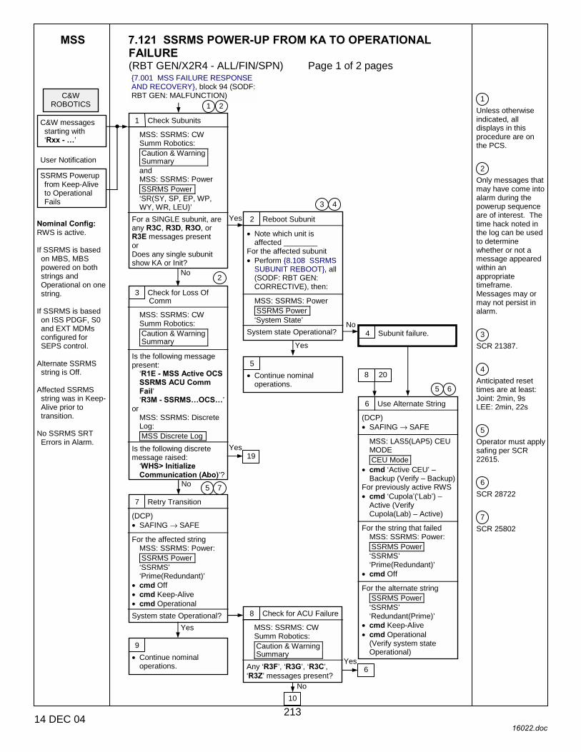
MSS 7.121 SSRMS POWER-UP FROM KA TO OPERATIONAL FAILURE (RBT GEN/X2R4 - ALL/FIN/SPN) Page 1 of 2 pages
14 DEC 04 16022.doc
1 Unless otherwise indicated, all displays in this procedure are on the PCS. 2 Only messages that may have come into alarm during the powerup sequence are of interest. The time hack noted in the log can be used to determine whether or not a message appeared within an appropriate timeframe. Messages may or may not persist in alarm. 3 SCR 21387. 4 Anticipated reset times are at least: Joint: 2min, 9s LEE: 2min, 22s 5 Operator must apply safing per SCR 22615. 6 SCR 28722 7 SCR 25802
{7.001 MSS FAILURE RESPONSE AND RECOVERY}, block 94 (SODF: RBT GEN: MALFUNCTION)
1 Check Subunits
MSS: SSRMS: CW Summ Robotics: Caution & Warning Summary and MSS: SSRMS: Power SSRMS Power ‘SR(SY, SP, EP, WP, WY, WR, LEU)’
For a SINGLE subunit, are any R3C, R3D, R3O, or R3E messages present or Does any single subunit show KA or Init?
C&W ROBOTICS
Nominal Config: RWS is active. If SSRMS is based on MBS, MBS powered on both strings and Operational on one string.
If SSRMS is based on ISS PDGF, S0 and EXT MDMs configured for SEPS control.
Alternate SSRMS string is Off.
Affected SSRMS string was in Keep-Alive prior to transition.
No SSRMS SRT Errors in Alarm.
C&W messages starting with ‘Rxx - �’
3 Check for Loss Of Comm
MSS: SSRMS: CW Summ Robotics: Caution & Warning Summary
Is the following message present:
‘R1E - MSS Active OCS SSRMS ACU Comm Fail’ ‘R3M - SSRMS�OCS�’
or MSS: SSRMS: Discrete Log: MSS Discrete Log
Is the following discrete message raised:
‘WHS> Initialize Communication (Abo)’?
1 2
SSRMS Powerup from Keep-Alive to Operational Fails
User Notification
No
2 Reboot Subunit
• Note which unit is affected ________
For the affected subunit • Perform {8.108 SSRMS
SUBUNIT REBOOT}, all (SODF: RBT GEN: CORRECTIVE), then:
MSS: SSRMS: Power SSRMS Power ‘System State’
System state Operational?
Yes
No
Yes
2
4 3
4 Subunit failure.
5 • Continue nominal
operations.
6 Use Alternate String
(DCP) • SAFING → SAFE
MSS: LAS5(LAP5) CEU MODE CEU Mode
• cmd ‘Active CEU’ – Backup (Verify – Backup)
For previously active RWS • cmd ‘Cupola’(‘Lab’) –
Active (Verify Cupola(Lab) – Active)
For the string that failed
MSS: SSRMS: Power: SSRMS Power ‘SSRMS’ ‘Prime(Redundant)’
• cmd Off For the alternate string
SSRMS Power ‘SSRMS’ ‘Redundant(Prime)’
• cmd Keep-Alive • cmd Operational
(Verify system state Operational)
6 5
20 8
No
7 Retry Transition
(DCP) • SAFING → SAFE
For the affected string
MSS: SSRMS: Power: SSRMS Power ‘SSRMS’ ‘Prime(Redundant)’
• cmd Off • cmd Keep-Alive • cmd Operational
System state Operational?
19
7 5
8 Check for ACU Failure
MSS: SSRMS: CW Summ Robotics: Caution & Warning Summary
Any ‘R3F’, ‘R3G’, ‘R3C’, ‘R3Z’ messages present?
10
6
Yes
9 • Continue nominal
operations.
Yes
Yes
No
213

MSS 7.121 SSRMS POWER-UP FROM KA TO OPERATIONAL FAILURE (RBT GEN/X2R4 - ALL/FIN/SPN) Page 2 of 2 pages
14 DEC 04 16022.doc
5 Operator must apply safing per SCR 22615. 8 The ground can check the ODIN File Transfer Status display to confirm the cause of the aborted file transfer. 9 PDGF LB if SSRMS is based on Lab PDGF, MSS LB if based on MBS PDGF.
10 Check for File Transfer Issues
For the affected string MSS: SSRMS: Power SSRMS Power
• Determine which of the following apply: ‘System State’ Initializing
MSS: SSRMS: Discrete Log: MSS Discrete Log ‘WHS> Download Unit (Abo) SMC Load Failed’ discrete message raised during powerup
‘SSRMS> Start LEU Download (Abo or Rej)’ discrete message raised during powerup
‘SSRMS> Start JEU Download (Abo or Rej)’ discrete message raised during powerup
‘SSRMS> Set Configuration Data (Abo or Rej)’ discrete message raised during powerup
‘WHS> Download Unit (Abo) BDT Load Failed’ discrete message raised during ACU initialization
8
8
11 Reload Payload Parameters
• Reload desired payload parameters.
MSS: SSRMS: Power SSRMS Power ‘System State’
System state Operational? 12 Missing or corrupt payload file. Further troubleshooting required. It may be possible to resume operations with an alternate set of payload files.
13 • Continue nominal
operations.
Yes
No
14 File missing. Ground can determine affected file. Further troubleshooting required.
15 LCS , LCS CFG or FMS file(s) corrupted. Further troubleshooting required.
16 JCS or JCS CFG file(s) corrupted. Further troubleshooting required.
17 SACS Config file corrupted. Further troubleshooting required.
18 AHS or SACS file(s) corrupted. Further troubleshooting required.
19 Change LB Channels
For the Active RWS MSS:LAS5(LAP5) Bus Config: LAS5(LAP5) Bus Configuration ‘PDGF(MSS)’
• cmd B
9
3
20 Retry Transition
(DCP) • SAFING → SAFE
For the string that failed
MSS: SSRMS: Power: SSRMS Power ‘SSRMS’ ‘Prime(Redundant)’
• cmd Off • cmd Keep-Alive • cmd Operational
System state Operational?
5
6 Yes
21 Local bus channel failure.
22 • Continue nominal
operations.
214

MSS 7.200 MSS POWER REMOVED FAILURE (RBT GEN/X2R4 - ALL/FIN/SPN) Page 1 of 5 pages
14 DEC 04 16023.doc
1 Unless otherwise indicated, all displays in this procedure are on the PCS. 2 In place of the crew checkpoint procedure, ground should perform {8.270 GROUND MSS CHECKPOINT DATA RESET}, steps 2, 4, 6, 8 (GROUND HANDBOOK: ROBOTICS: NOMINAL) (SCR 21749).
{7.001 MSS FAILURE RESPONSE AND RECOVERY}, block 76 (SODF: RBT GEN: MALFUNCTION)
1 Stop Switch Status
(DCP) Is the STOP button illuminated?
C&W ROBOTICS
Nominal Config: RWS is active.
C&W Messages with ‘… MSS � Pwr Removed’ in the Text
1
2 MBS Power Removed
MSS: SSRMS: CW Summ Robotics Caution & Warning Summary
‘MBS � Pwr Removed’ annunciated?
Yes
No
Yes
No 3 Loss of SSRMS Prime (Redun) string due to power failure.
9 4 Comm With SSRMS
MSS: SSRMS: CW Summ Robotics Caution & Warning Summary
‘R1E - MSS Active OCS SSRMS Prime (Redun) ACU SRT Comm Fail’ annunciated?
No
Yes 5 Loss of MBS & SSRMS Prime (Redun) string due to power failure.
6 Loss of MBS Prime (Redun) string, and SSRMS Prime (Redun) string if based on MBS due to power failure.
10
7 Checkpoint Data Reset
MSS: LAS5(LAP5) CEU MODE CEU Mode
• cmd ‘Active CEU’ Backup
• Perform {8.104
CHECKPOINT DATA RESET}, steps 1, 2, 4, 9(for alternate string only) (SODF: RBT GEN: CORRECTIVE), then:
For the alternate string • Perform {6.332 MSS
POWERUP}, steps 3 to 5 (SODF: RBT GEN: NOMINAL), then:
MSS: MBS: MBS Central Camera Icon MBS Camera
• cmd Color Bal – Metal on powered cameras
MSS: SSRMS: Video: Video Overview Video Overview ‘Video Routing Status’
• Deroute all destinations to which an MBS Camera is routed.
2
8 {7.001 MSS FAILURE RESPONSE AND RECOVERY}, block 77 (SODF: RBT GEN: MALFUNCTION)
13
215
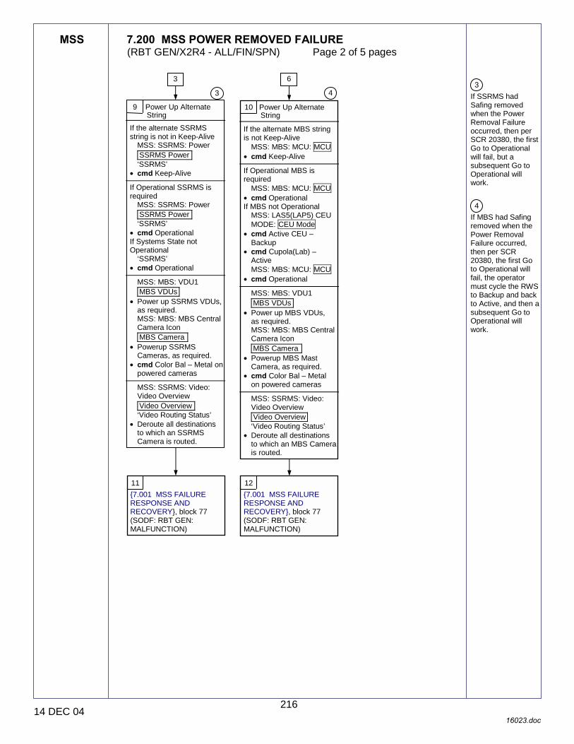
MSS 7.200 MSS POWER REMOVED FAILURE (RBT GEN/X2R4 - ALL/FIN/SPN) Page 2 of 5 pages
14 DEC 04 16023.doc
3 If SSRMS had Safing removed when the Power Removal Failure occurred, then per SCR 20380, the first Go to Operational will fail, but a subsequent Go to Operational will work. 4 If MBS had Safing removed when the Power Removal Failure occurred, then per SCR 20380, the first Go to Operational will fail, the operator must cycle the RWS to Backup and back to Active, and then a subsequent Go to Operational will work.
9 Power Up Alternate String
If the alternate SSRMS string is not in Keep-Alive
MSS: SSRMS: Power SSRMS Power ‘SSRMS’
• cmd Keep-Alive If Operational SSRMS is required
MSS: SSRMS: Power SSRMS Power ‘SSRMS’
• cmd Operational If Systems State not Operational
‘SSRMS’ • cmd Operational
MSS: MBS: VDU1 MBS VDUs
• Power up SSRMS VDUs, as required. MSS: MBS: MBS Central Camera Icon MBS Camera
• Powerup SSRMS Cameras, as required.
• cmd Color Bal – Metal on powered cameras
MSS: SSRMS: Video: Video Overview Video Overview ‘Video Routing Status’
• Deroute all destinations to which an SSRMS Camera is routed.
3
3
10 Power Up Alternate String
If the alternate MBS string is not Keep-Alive
MSS: MBS: MCU: MCU • cmd Keep-Alive
If Operational MBS is required
MSS: MBS: MCU: MCU • cmd Operational If MBS not Operational
MSS: LAS5(LAP5) CEU MODE: CEU Mode
• cmd Active CEU – Backup
• cmd Cupola(Lab) – Active MSS: MBS: MCU: MCU
• cmd Operational
MSS: MBS: VDU1 MBS VDUs
• Power up MBS VDUs, as required. MSS: MBS: MBS Central Camera Icon MBS Camera
• Powerup MBS Mast Camera, as required.
• cmd Color Bal – Metal on powered cameras
MSS: SSRMS: Video: Video Overview Video Overview ‘Video Routing Status’
• Deroute all destinations to which an MBS Camera is routed.
4
6
11 {7.001 MSS FAILURE RESPONSE AND RECOVERY}, block 77 (SODF: RBT GEN: MALFUNCTION)
12 {7.001 MSS FAILURE RESPONSE AND RECOVERY}, block 77 (SODF: RBT GEN: MALFUNCTION)
216
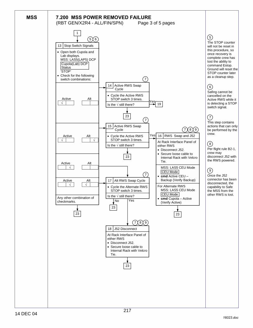
MSS 7.200 MSS POWER REMOVED FAILURE (RBT GEN/X2R4 - ALL/FIN/SPN) Page 3 of 5 pages
14 DEC 04 16023.doc
5 The STOP counter will not be reset in this procedure, so once recovery is complete crew has lost the ability to command Estop. Ground will reset the STOP counter later as a cleanup step. 6 Safing cannot be cancelled on the Active RWS while it is detecting a STOP switch signal. 7 This step contains actions that can only be performed by the crew. 8 Per flight rule B2-1, crew may disconnect J52 with the RWS powered. 9 Once the J52 connector has been disconnected, the capability to Safe the MSS from the other RWS is lost.
13 Stop Switch Signals
• Open both Cupola and Lab displays. MSS: LAS5(LAP5) DCP Cupola(Lab) DCP Status ‘STOP’
• Check for the following switch combinations:
Active Alt
√
Active Alt √ √
Active Alt
√ Active Alt
√ √ Any other combination of checkmarks.
1
6 5
23
14 Active RWS Swap Cycle
• Cycle the Active RWS STOP switch 3 times.
Is the √ still there?
7
23
19
15 Active RWS Swap Cycle
• Cycle the Active RWS STOP switch 3 times.
Is the √ still there?
7
Yes
23
16 RWS Swap and J52
At Rack Interface Panel of either RWS • Disconnect J52. • Secure loose cable to
Internal Rack with Velcro Tie.
MSS: LAS5 CEU Mode CEU Mode
• cmd Active CEU – Backup (Verify Backup)
For Alternate RWS
MSS: LAS5 CEU Mode CEU Mode
• cmd Cupola – Active (Verify Active)
9 8 7
23
17 Alt RWS Swap Cycle
• Cycle the Alternate RWS STOP switch 3 times.
Is the √ still there?
7
Yes
23
No
18 J52 Disconnect
At Rack Interface Panel of either RWS • Disconnect J52. • Secure loose cable to
Internal Rack with Velcro Tie.
9 8 7
23
Yes
217

MSS 7.200 MSS POWER REMOVED FAILURE (RBT GEN/X2R4 - ALL/FIN/SPN) Page 4 of 5 pages
14 DEC 04 16023.doc
7 This step contains actions that can only be performed by the crew. 8 Per flight rule B2-1, crew may disconnect J52 with the RWS powered. 9 Once the J52 connector has been disconnected, the capability to Safe the MSS from the other RWS is lost.
19 Alt RWS Status
Is the Alternate RWS mode Backup?
14
Yes
No
20 RWS Swap
MSS: LAS5 CEU Mode CEU Mode
• cmd Active CEU – Backup (Verify Backup)
For Alternate RWS MSS: LAS5 CEU Mode CEU Mode
• cmd Cupola(Lab) – Active (Verify Active)
23
21 RWS Swap
If Alt RWS DCP Bypass cable disconnected • Perform {6.114
LAB(CUP) RWS UOP BYPASS CABLE RECONFIGURATION}, step 2 (SODF: RBT GEN: NOMINAL), then:
• Perform {6.332 MSS
POWERUP}, step 1 (SODF: RBT GEN: NOMINAL), then:
Does the new backup RWS DCP display indicates the following?
MSS: LAS5(LAP5) DCP: Cupola(Lab) DCP Status ‘STOP’
√
23
22 J52 Disconnect
At Rack Interface Panel of either RWS • Disconnect J52. • Secure loose cable to
Internal Rack with Velcro Tie.
MSS: LAS5 CEU Mode CEU Mode
• cmd Active CEU – Backup (Verify Backup)
For Alternate RWS
MSS: LAS5 CEU Mode CEU Mode
• cmd Cupola – Active (Verify Active)
Yes
No
7
23
8 9
218
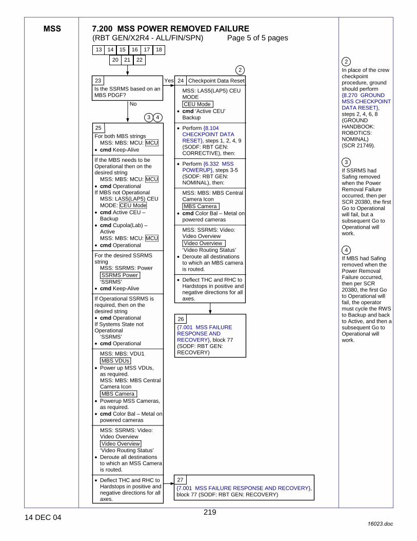
MSS 7.200 MSS POWER REMOVED FAILURE (RBT GEN/X2R4 - ALL/FIN/SPN) Page 5 of 5 pages
14 DEC 04 16023.doc
2 In place of the crew checkpoint procedure, ground should perform {8.270 GROUND MSS CHECKPOINT DATA RESET}, steps 2, 4, 6, 8 (GROUND HANDBOOK: ROBOTICS: NOMINAL) (SCR 21749). 3 If SSRMS had Safing removed when the Power Removal Failure occurred, then per SCR 20380, the first Go to Operational will fail, but a subsequent Go to Operational will work. 4 If MBS had Safing removed when the Power Removal Failure occurred, then per SCR 20380, the first Go to Operational will fail, the operator must cycle the RWS to Backup and back to Active, and then a subsequent Go to Operational will work.
23 Is the SSRMS based on an MBS PDGF?
Yes
No
24 Checkpoint Data Reset
MSS: LAS5(LAP5) CEU MODE CEU Mode
• cmd ‘Active CEU’ Backup
• Perform {8.104
CHECKPOINT DATA RESET}, steps 1, 2, 4, 9 (SODF: RBT GEN: CORRECTIVE), then:
• Perform {6.332 MSS
POWERUP}, steps 3-5 (SODF: RBT GEN: NOMINAL), then:
MSS: MBS: MBS Central Camera Icon MBS Camera
• cmd Color Bal – Metal on powered cameras
MSS: SSRMS: Video: Video Overview Video Overview ‘Video Routing Status’
• Deroute all destinations to which an MBS camera is routed.
• Deflect THC and RHC to
Hardstops in positive and negative directions for all axes.
2
25 For both MBS strings
MSS: MBS: MCU: MCU • cmd Keep-Alive
If the MBS needs to be Operational then on the desired string
MSS: MBS: MCU: MCU • cmd Operational If MBS not Operational
MSS: LAS5(LAP5) CEU MODE: CEU Mode
• cmd Active CEU – Backup
• cmd Cupola(Lab) – Active MSS: MBS: MCU: MCU
• cmd Operational For the desired SSRMS string
MSS: SSRMS: Power SSRMS Power ‘SSRMS’
• cmd Keep-Alive If Operational SSRMS is required, then on the desired string • cmd Operational If Systems State not Operational
‘SSRMS’ • cmd Operational
MSS: MBS: VDU1 MBS VDUs
• Power up MSS VDUs, as required. MSS: MBS: MBS Central Camera Icon MBS Camera
• Powerup MSS Cameras, as required.
• cmd Color Bal – Metal on powered cameras
MSS: SSRMS: Video: Video Overview Video Overview ‘Video Routing Status’
• Deroute all destinations to which an MSS Camera is routed.
• Deflect THC and RHC to
Hardstops in positive and negative directions for all axes.
3 4
26 {7.001 MSS FAILURE RESPONSE AND RECOVERY}, block 77 (SODF: RBT GEN: RECOVERY)
27 {7.001 MSS FAILURE RESPONSE AND RECOVERY}, block 77 (SODF: RBT GEN: RECOVERY)
20 21 22
13 14 15 16 17 18
219

This Page Intentionally Blank
22 DEC 04
220

MSS 7.201 MSS COMM FAILURE (RBT GEN/X2R4 - ALL/FIN/SPN) Page 1 of 8 pages
16 DEC 04 16029.doc
1 Unless otherwise noted, all displays in the procedures are on the PCS.
Nominal Config: RWS is Active. EXT, S0(S1,P1) MDMs configured for SEPS control.
MT SSBAs powered.
1 Swap Local Bus Chan
PDGF LB CHANNEL MSS: LAS5 (LAP5) Bus Config: LAS5 (LAP5) Bus Configuration ‘PDGF’
• cmd B (Verify B) ‘MSS’
• cmd B (Verify B) Messages return to norm? 2 Unable to
communicate on original PLB/MLB. 4 Check Comm Errors
MSS: SSRMS: CW Summ Robotics Caution & Warning Summary
‘R1E - MSS Active OCS MBS Prime MCU SRT Comm Fail’ and ‘R1E - MSS Active OCS MBS Redun MCU SRT Comm Fail’ msgs in alarm
‘R1E - MSS Active OCS MBS Prime (Redun) MCU SRT Comm Fail’ and ‘R1E - MSS Active OCS SSRMS Prime (Redun) ACU SRT Comm Fail’ msgs in alarm
‘R1E - MSS Active OCS MBS Prime (Redun) MCU SRT Comm Fail’ and ‘R1E - MSS Active OCS MCU Comm Fail’ msgs in alarm
‘R1E - MSS Active OCS MBS Prime (Redun) MCU SRT Comm Fail’ msgs in alarm
‘R1E - MSS Active OCS SSRMS Prime ACU SRT Comm Fail’ and ‘R1E - MSS Active OCS SSRMS Redun ACU SRT Comm Fail’ msgs in alarm
‘R1E - MSS Active OCS SSRMS Prime (Redun) ACU SRT Comm Fail’ and ‘R1E - MSS Active OCS SSRMS ACU Comm Fail’ msgs in alarm
‘R1E - MSS Active OCS SSRMS Prime (Redun) ACU SRT Comm Fail’ msgs in alarm
3 RWS State Transition
MSS: LAP5 (LAS5) CEU Mode: CEU Mode
• cmd ‘Active CEU’ Backup (Verify previously Active RWS is Backup)
• cmd ‘Lab (LAP5) (Cupola (LAS5))’ Active (Verify – Active)
Yes
No
11
16
24
5
1
34
C&W ROBOTICS
C&W Messages with ‘R1E - MSS � SRT COMM’ in the Text
{7.001 MSS FAILURE RESPONSE AND RECOVERY}, block 78, and 92 (SODF: RBT GEN: MALFUNCTION).
42
42
53
221
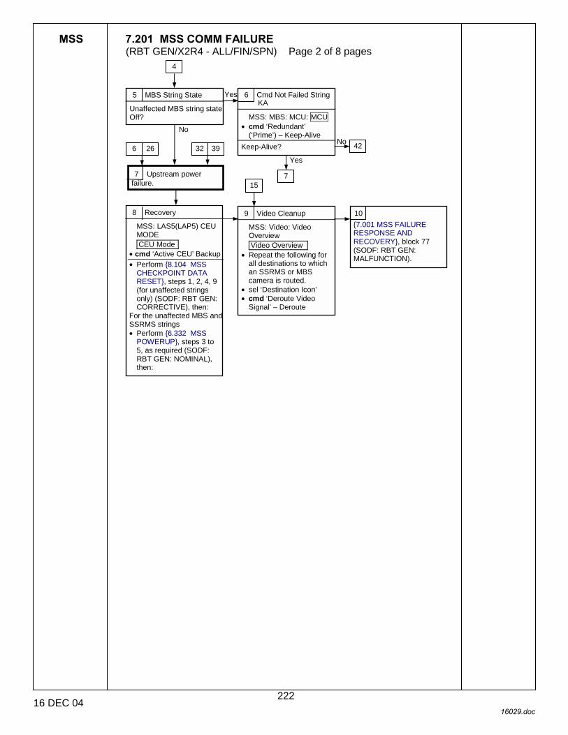
MSS 7.201 MSS COMM FAILURE (RBT GEN/X2R4 - ALL/FIN/SPN) Page 2 of 8 pages
16 DEC 04 16029.doc
5 MBS String State
Unaffected MBS string state Off?
8 Recovery
MSS: LAS5(LAP5) CEU MODE CEU Mode
• cmd ‘Active CEU’ Backup • Perform {8.104 MSS
CHECKPOINT DATA RESET}, steps 1, 2, 4, 9 (for unaffected strings only) (SODF: RBT GEN: CORRECTIVE), then:
For the unaffected MBS and SSRMS strings • Perform {6.332 MSS
POWERUP}, steps 3 to 5, as required (SODF: RBT GEN: NOMINAL), then:
7 Upstream power failure.
6 Cmd Not Failed String KA
MSS: MBS: MCU: MCU • cmd ‘Redundant’
(‘Prime’) – Keep-Alive Keep-Alive?
Yes
No
7
Yes
No
4
9 Video Cleanup
MSS: Video: Video Overview Video Overview
• Repeat the following for all destinations to which an SSRMS or MBS camera is routed.
• sel ‘Destination Icon’ • cmd ‘Deroute Video
Signal’ – Deroute
15
6 26 32 39
10 {7.001 MSS FAILURE RESPONSE AND RECOVERY}, block 77 (SODF: RBT GEN: MALFUNCTION).
42
222
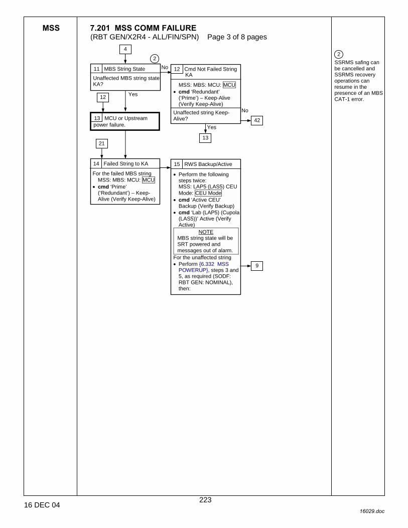
MSS 7.201 MSS COMM FAILURE (RBT GEN/X2R4 - ALL/FIN/SPN) Page 3 of 8 pages
16 DEC 04 16029.doc
2 SSRMS safing can be cancelled and SSRMS recovery operations can resume in the presence of an MBS CAT-1 error.
11 MBS String State
Unaffected MBS string state KA?
14 Failed String to KA
For the failed MBS string MSS: MBS: MCU: MCU
• cmd ‘Prime’ (‘Redundant’) – Keep-Alive (Verify Keep-Alive)
13 MCU or Upstream power failure.
12 Cmd Not Failed String KA
MSS: MBS: MCU: MCU • cmd ‘Redundant’
(‘Prime’) – Keep-Alive (Verify Keep-Alive)
Unaffected string Keep-Alive?
Yes
No
15 RWS Backup/Active
• Perform the following steps twice: MSS: LAP5 (LAS5) CEU Mode: CEU Mode
• cmd ‘Active CEU’ Backup (Verify Backup)
• cmd ‘Lab (LAP5) (Cupola (LAS5))’ Active (Verify Active)
NOTE MBS string state will be SRT powered and messages out of alarm.
For the unaffected string • Perform {6.332 MSS
POWERUP}, steps 3 and 5, as required (SODF: RBT GEN: NOMINAL), then:
No
13
Yes
12
4
2
9
21
42
223

MSS 7.201 MSS COMM FAILURE (RBT GEN/X2R4 - ALL/FIN/SPN) Page 4 of 8 pages
16 DEC 04 16029.doc
2 SSRMS safing can be cancelled and SSRMS recovery operations can resume in the presence of an MBS CAT-1 error.
MT Worksite Prime Redundant 1 RPCM S34B F RPCM S33A F 2 RPCM S14B E RPCM S13A E 3 RPCM S14B F RPCM S13A F 4 RPCM S04B A RPCM S03A A 5 RPCMS04B B RPCM S03A B 6 RPCM P14B F RPCM P13A F 7 RPCM P14B E RPCM P13A E 8 RPCM P34B F RPCM P33A F 9 RPCM S43A B RPCM S41A B 10 RPCM P44A B RPCM P42A B
16 MBS String State
Unaffected MBS string state Off? Yes
18 Verify Power
Upstream RPCM counter (per Table 1) incrementing?
17 Power Unaffected String to KA
MSS: MBS: MCU: MCU • cmd ‘Redundant’
(‘Prime’) – Keep-Alive (Verify Keep-Alive)
Keep-Alive? No
No
18 17
No
21 MBS String State
MBS Operational on failed string?
19 Upstream power failure.
20 Recovery
For failed string MSS: MBS: MCU: MCU
• cmd ‘Prime’ (‘Redundant’) – OFF (Verify SRT Powered)
MSS: LAP5 (LAS5) CEU Mode: CEU Mode
• cmd ‘Active CEU’ Backup (Verify Backup)
• cmd ‘Lab (LAP5) (Cupola (LAS5))’ Active (Verify Active)
NOTE MBS string state will be SRT powered and messages out of alarm.
No
Yes
22 Recovery
• Perform the following steps twice: MSS: LAP5 (LAS5) CEU Mode: CEU Mode
• cmd ‘Active CEU’ Backup (Verify Backup)
• cmd ‘Lab (LAP5) (Cupola (LAS5))’ Active (Verify Active)
NOTE MBS string state will be SRT powered and messages out of alarm.
Table 1. Upstream RPCM Checks
Yes
4
2
14
Yes
23 {7.001 MSS FAILURE RESPONSE AND RECOVERY}, block 77 (SODF: RBT GEN: MALFUNCTION), then:
42
224

MSS 7.201 MSS COMM FAILURE (RBT GEN/X2R4 - ALL/FIN/SPN) Page 5 of 8 pages
16 DEC 04 16029.doc
24 SSRMS Location
SSRMS based on MBS PDGF?
26 Verify Power
Home: S0: EPS RPCM_S04B_D (RPCM_S03A_D)
RPCM counter incrementing?
25 SSRMS or CRPCM power failure.
7 No
Yes
27 Video Status
Check SSRMS video on monitor/downlink.
Video good.
Video lost.
Video not routed at time of failure or not sure.
42
No
Yes
28 Check PDGFLB
SSRMS to KA For failed SSRMS string
MSS: SSRMS: Power SSRMS Power
• cmd ‘Prime’ (‘Redundant’) – Keep-Alive (Verify Keep-Alive)
SSRMS to KA For unaffected SSRMS string • cmd ‘Redundant’
(‘Prime’) – Keep-Alive Unaffected SSRMS string KA?
No
Yes 29 SSRMS string failed. 30 Recovery
For the unaffected SSRMS string • Perform {6.332 MSS
POWERUP}, steps 4 to 5, as required (SODF: RBT GEN: NOMINAL), then:
32
4
33
31 {7.001 MSS FAILURE RESPONSE AND RECOVERY}, block 77 (SODF: RBT GEN: MALFUNCTION)
28
225
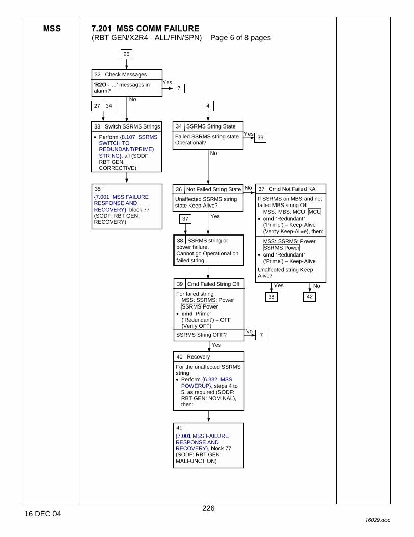
MSS 7.201 MSS COMM FAILURE (RBT GEN/X2R4 - ALL/FIN/SPN) Page 6 of 8 pages
16 DEC 04 16029.doc
33 Switch SSRMS Strings
• Perform {8.107 SSRMS SWITCH TO REDUNDANT(PRIME) STRING}, all (SODF: RBT GEN: CORRECTIVE)
No
Yes
32 Check Messages
‘R2O - �’ messages in alarm?
25
7 Yes
No
34 SSRMS String State
Failed SSRMS string state Operational?
4
No
33 Yes
36 Not Failed String State
Unaffected SSRMS string state Keep-Alive?
38 SSRMS string or power failure. Cannot go Operational on failed string.
39 Cmd Failed String Off
For failed string MSS: SSRMS: Power SSRMS Power
• cmd ‘Prime’ (‘Redundant’) – OFF (Verify OFF)
SSRMS String OFF?
40 Recovery
For the unaffected SSRMS string • Perform {6.332 MSS
POWERUP}, steps 4 to 5, as required (SODF: RBT GEN: NOMINAL), then:
7 No
Yes
37
27 34
37 Cmd Not Failed KA
If SSRMS on MBS and not failed MBS string Off
MSS: MBS: MCU: MCU • cmd ‘Redundant’
(‘Prime’) – Keep-Alive (Verify Keep-Alive), then:
MSS: SSRMS: Power SSRMS Power
• cmd ‘Redundant’ (‘Prime’) – Keep-Alive
Unaffected string Keep-Alive?
No
38
Yes
41 {7.001 MSS FAILURE RESPONSE AND RECOVERY}, block 77 (SODF: RBT GEN: MALFUNCTION)
35 {7.001 MSS FAILURE RESPONSE AND RECOVERY}, block 77 (SODF: RBT GEN: RECOVERY)
42
226

MSS 7.201 MSS COMM FAILURE (RBT GEN/X2R4 - ALL/FIN/SPN) Page 7 of 8 pages
16 DEC 04 16029.doc
42 SSRMS Base Location
SSRMS double mated to MBS PDGFs?
43 SSRMS String State
MSS: SSRMS: Power SSRMS Power
‘Prime’ – OFF?
Yes
No
44 CEU Failure
If Alt RWS DCP Bypass cable disconnected • Perform {6.114
LAB(CUP) RWS UOP BYPASS CABLE RECONFIGURATION}, step 2 (SODF: RBT GEN: NOMINAL), then:
For alt RWS • Perform {6.332 MSS
POWERUP}, steps 1 to 2 (SODF: RBT GEN: NOMINAL), then:
• Deflect THC and RHC to Hardstops in positive and negative directions for all axes.
45 Prime String to OFF
MSS: SSRMS: Power SSRMS Power • cmd ‘Prime’ – OFF
All R1E messages return to Norm?
46 Prime SSRMS DFRU Failure.
47 SSRMS String State
MSS: SSRMS: Power SSRMS Power
‘Redundant’ – OFF?
48 Redun String to OFF
MSS: SSRMS: Power SSRMS Power • cmd ‘Redundant’ – OFF
All R1E messages return to Norm?
49 Redundant SSRMS DFRU Failure.
50 SSRMS to Failed KA
MSS: SSRMS: Power SSRMS Power • cmd ‘Prime’(‘Redundant’)
– Keep-Alive (Verify Failed KA)
51 SSRMS Power Up
For the alternate SSRMS string • Perform {6.332 MSS
POWERUP}, as required (SODF: RBT GEN: NOMINAL) to configure the SSRMS, then:
52 {7.001 MSS FAILURE RESPONSE AND RECOVERY}, block 77 (SODF: RBT GEN: MALFUNCTION)
4 6 12
17 27 28 51
47 Yes
No
51
Yes
No43
50 Yes
No
Yes
No47
44
46
50
53
227
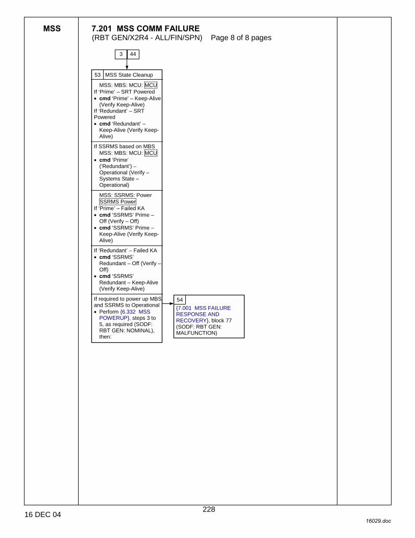
MSS 7.201 MSS COMM FAILURE (RBT GEN/X2R4 - ALL/FIN/SPN) Page 8 of 8 pages
16 DEC 04 16029.doc
53 MSS State Cleanup
MSS: MBS: MCU: MCU If ‘Prime’ – SRT Powered • cmd ‘Prime’ – Keep-Alive
(Verify Keep-Alive) If ‘Redundant’ – SRT Powered • cmd ‘Redundant’ –
Keep-Alive (Verify Keep-Alive)
If SSRMS based on MBS
MSS: MBS: MCU: MCU • cmd ‘Prime’
(‘Redundant’) – Operational (Verify – Systems State – Operational)
MSS: SSRMS: Power SSRMS Power
If ‘Prime’ – Failed KA • cmd ‘SSRMS’ Prime –
Off (Verify – Off) • cmd ‘SSRMS’ Prime –
Keep-Alive (Verify Keep-Alive)
If ‘Redundant’ – Failed KA • cmd ‘SSRMS’
Redundant – Off (Verify – Off)
• cmd ‘SSRMS’ Redundant – Keep-Alive (Verify Keep-Alive)
If required to power up MBS and SSRMS to Operational • Perform {6.332 MSS
POWERUP}, steps 3 to 5, as required (SODF: RBT GEN: NOMINAL), then:
54 {7.001 MSS FAILURE RESPONSE AND RECOVERY}, block 77 (SODF: RBT GEN: MALFUNCTION)
3 44
228

MSS 7.300 ACTIVE RWS FAILURE (RBT GEN/X2R4 - ALL/FIN/SPN) Page 1 of 11 pages
16 DEC 04 16030.doc
1 Unless otherwise indicated, all displays in this procedure are on the PCS.
C&W ROBOTICS
C&W Messages With ‘R1�’ in the Text in Alarm
Nominal Config: CB-EXT FDIR enabled for affected RWS.
DCP Lighing switch not in OFF position.
Monitor brightness not fully dimmed.
2 RPC Status
MSS: RWS ‘RPCM LAS5 2A/3B(LAP5 1A/4A)’ 2 RPCM_LAS52A3B_ A_RPC_02(RPCM_ LAP51A4A_A_RPC_02)
Has the RPCM Integration counter stopped incrementing or Is there an RPC tripped attention symbol present or Is the RPC opened?
3 Other RT Fail
C&DH: C&C Primary: CB EXT 2(1): RT Status CB EXT 2(1) RT Status ‘RT Comm Failed Status’
‘Fail’ continuously alternating between RWS CEU and another RT?
No Yes
No Yes
4 Verify No C&W
Caution & Warning Summary
Are there any new messages starting with �R1�’ currently in Alarm?
No
5 CEU Comm Status
MSS: LAS5(LAP5) Pwr Dn LAS5(LAP5 Power Down ‘Frame Count’
Is the RWS Frame Counter incrementing?
Yes
Yes
No
6 RWS Reboot
MSS: LAS5(LAP5) Pwr Dn LAS5(LAP5 Power Down
• cmd ‘F. FDIR’ – Inhibit • cmd ‘G. CB Ext2(1) Bus
Comm’ – Inhibit • cmd ‘H. CEU’ – Open
MSS: LAS5(LAP5) Initialize LAS5(LAP5) Initialization
• cmd ‘B. CEU’ – Close • Wait 60 seconds. • cmd ‘C. CB EXT 2(1)
Bus Comm’ – Enable Is Frame Count incrementing and Firmware Start − ‘√’?
No Yes
7
8
9
76
RWS Drops to Backup or Unconfigured from Active
or DCP Lost Power or OCS Frame Counter Stops Incrementing.
{7.001 MSS FAILURE RESPONSE AND RECOVERY}, block 74 (SODF: RBT GEN: MALFUNCTION) {7.101 RWS TRANSITION TO ACTIVE FAILURE}, block 5, (SODF:RBT: GEN: MALFUNCTION
1 C&W Check
Caution & Warning Summary
Were any of the following messages annunciated?
C&W messages starting with ‘R1B - �’,
C&W messages starting with ‘R1D - �’ or MCC verified that the OCS frame count has stopped incrementing
C&W messages starting with ‘R1G - �’
C&W messages starting with ‘R1H - �’
C&W messages starting with ‘R1I - �’
None of the above.
14
27
55
34
76
1
73
74
73
4
1
229

MSS 7.300 ACTIVE RWS FAILURE (RBT GEN/X2R4 - ALL/FIN/SPN) Page 2 of 11 pages
16 DEC 04 16030.doc
2 List of remote terminals on CB EXT 1: 13 LCA IMCA-1 22 RWS CEU-1 24 MDM EXT1 25 RPCM S0-1A-C 26 MDM PMCU1 List of remote terminals on CB EXT 2: 13 LCA IMCA-2 22 RWS CEU-2 24 MDM EXT2 25 RPCM S0-2B-C 26 MDM PMCU2
3 This step is ground only and requires coordination within the flight control team.
7
CAUTION Do not attempt to reapply power due to possible Electrical Power Failure.
2
8 Continue Power Up
• Perform {6.332 MSS POWERUP}, steps 1.3 to 2 (SODF: RBT GEN: NOMINAL), then:
Were all steps successful?
6
Yes No
9 Communication between the CEU and C&C is lost on one CB EXT 2(1) bus channel and communication between another RT and C&C is lost on the opposite CB EXT 2(1) bus channel. Communication on both CB EXT bus channels is effectively lost until the conflict is resolved.
10 Is loss of comm with the other failed RT on this bus acceptable?
3
3 2
NoYes
11 CEU failure.
12 Disable Other RT
Disable FDIR to the other failed RT.
14 OCS Fatal Failure
MSS: C&W Summ Robotics Caution & Warning Summary
Was the following message annunciated: ‘R1D - CUP(LAB) RWS CEU WHS-OCS Comm Shut Down’ or Has MCC verified that the OCS frame count has stopped incrementing?
16 Check C&W
MSS: C&W Summ Robotics Caution & Warning Summary
Were any messages annunciated with ‘R1D �MECB NDP� or ‘R1D �SECB� in the message text?
17 CEU failure. The failed RWS can not be transitioned to Active.
No Yes
Yes
No
15 • Check for known causes
of OCS fatal failure. Video being routed or derouted.
Data logging being terminated.
Handover between the SSRMS and the POA in progress.
None of the above.
18
74
19
20
13 • Go to {7.001 MSS
FAILURE RESPONSE AND RECOVERY}, block 75 (SODF: RBT GEN: RECOVERY).
78
73
73
1
21
22
23
230

MSS 7.300 ACTIVE RWS FAILURE (RBT GEN/X2R4 - ALL/FIN/SPN) Page 3 of 11 pages
16 DEC 04 16030.doc
18
CAUTION Transition of failed RWS to OFF or removal of system power could result in permanent loss of remaining functionality for the failed RWS.
17
19 OCS fatal failures can be caused by multiple video related commands at the same time. SCR 26165: If route commands are sent to a SSRMS VDU and a MBS VDU at the same time, OCS goes fatal. Fatal Failure Code = EXRM_Reservation_Error (332). SCR 23238: When 2 deroute video commands are executed in rapid succession, OCS goes fatal. Fatal Failure Code = COCD_Queue_is_full (1)
15
20 OCS fatal failures can be caused by the terminate data logging command. SCR 23099: OCS goes fatal upon receipt of a terminate data logging command if data logging was not enabled to that unit. Fatal Failure Code = MBUT_Conversion_Sw_ Error (152)
15
21 OCS fatal failures can be caused by attempting to hand off an SSRMS payload to the POA with the brakes ON. SCR 21421: If SSRMS is brakes on when the RHC trigger is pulled to initiate an SSRMS-to-POA handover, OCS goes fatal. Operator should ensure that the SSRMS Brakes are disengaged prior to initiating the POA Ready-Arm-Fire Protocol. Fatal Failure Code = RBOT_Backdriving_Call_Sw_Error (214)
15
74
22
22
22
231
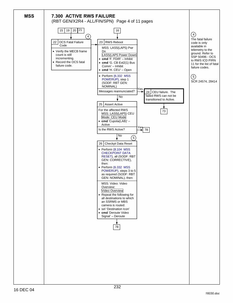
MSS 7.300 ACTIVE RWS FAILURE (RBT GEN/X2R4 - ALL/FIN/SPN) Page 4 of 11 pages
16 DEC 04 16030.doc
4 The fatal failure code is only available in telemetry to the ground. Refer to SSP 50496 - OCS to RWS ICD PIRN 11 for the list of fatal failure codes. 5 SCR 24574, 28414
22 OCS Fatal Failure Code
• Verify the MECB frame count is still incrementing.
• Record the OCS fatal failure code.
15 19 21 20
4
23 RWS Reboot
MSS: LAS5(LAP5) Pwr Dn LAS5(LAP5 Power Down
• cmd ‘F. FDIR’ – Inhibit • cmd ‘G. CB Ext2(1) Bus
Comm’ – Inhibit • cmd ‘H. CEU’ – Open
• Perform {6.332 MSS
POWERUP}, step 1 (SODF: RBT GEN: NOMINAL)
Messages reannunciated? 24 CEU failure. The failed RWS can not be transitioned to Active.
No
Yes
16
25 Assert Active
For the affected RWS MSS: LAS5(LAP5) CEU Mode: CEU Mode
• cmd ‘Cupola(LAB)’ – Active
Is the RWS Active? Yes
No
26 Checkpt Data Reset
• Perform {8.104 MSS CHECKPOINT DATA RESET}, all (SODF: RBT GEN: CORRECTIVE), then:
• Perform {6.332 MSS POWERUP}, steps 3 to 5 as required (SODF: RBT GEN: NOMINAL), then:
MSS: Video: Video Overview: Video Overview
• Repeat the following for all destinations to which an SSRMS or MBS camera is routed:
• sel ‘Destination Icon’ • cmd ‘Deroute Video
Signal’ – Deroute
73
78
78
5
232

MSS 7.300 ACTIVE RWS FAILURE (RBT GEN/X2R4 - ALL/FIN/SPN) Page 5 of 11 pages
16 DEC 04 16030.doc
6 PCS at the failed RWS will be on battery power while the RPC is opened. 7 This step must be performed by the crew. 8 Expect ‘R1G - �’, ‘R1H’ and ‘R1J’ messages to be annunciated when this block is executed. If the power cycle is successful, all messages should return to NORM when DCP power is reapplied. Monitors may display anomalous video when power is reapplied to the DCP. Valid video can be recovered by routing a test pattern or another video view to each
28
CAUTION Possible electrical short. Do not attempt to reapply power to the RPC.
29 C&W Summary
MSS: CW Summ Robotics Caution & Warning Summary
Are the ‘R1G �.’ messages still in alarm?
Yes No
30 DCP Power Check
Are any DCP lights illuminated or Are any of the RWS fans or monitors powered?
31 RWS/DCP Cycle
MSS: RWS ‘LAS5’(‘LAP5’)
• sel RPC 18 RPCM_LAS52A3B_A_RPC_18 (RPCM_LAP51A4A_A_RPC_18)
• cmd RPC Position – Open (Verify Op)
• cmd RPC Position – Close (Verify Cl)
Yes
No
32 DCP, CEU, or RWS Local Bus harness failure. Loss of DCP functionality on affected RWS. The failed RWS can not be transitioned to Active.
33 Bypass Cable √
For the failed RWS Perform {6.114 LAB(CUP) RWS UOP BYPASS CABLE RECONFIGURATION}, all steps (SODF: RBT GEN: NOMINAL), then
6
33 31
8 6
7 6
27 RPC Status
MSS: RWS ‘LAS5(LAP5)’ 18 RPCM_LAS52A3B_ A_RPC_18(RPCM_ LAP51A4A_A_RPC_18)
Has the RPCM Integration counter stopped incrementing or Is there an RPC tripped attention symbol present or Is the RPC opened?
8
7
1
76
29
29
74
74
233
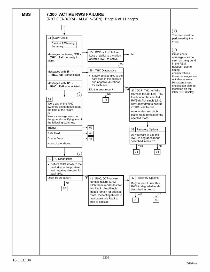
MSS 7.300 ACTIVE RWS FAILURE (RBT GEN/X2R4 - ALL/FIN/SPN) Page 6 of 11 pages
16 DEC 04 16030.doc
7 This step must be performed by the crew. 9 Cross check messages can be seen on the ground in the REM; however, due to timing considerations, these messages are not always seen. Persistent cross checks can also be identified on the PCS DCP display.
34 C&W Check
Caution & Warning Summary
Messages containing ‘R1I - �THC�Fail’ currently in alarm.
Messages with ‘R1I - �THC�Fail’ annunciated.
Messages with ‘R1I - �RHC�Fail’ annunciated.
35 DCP or THC failure. Loss of ability to transition affected RWS to Active.
36 THC Diagnostics
• Slowly deflect THC to the hard stop in the positive and negative directions for each axis.
Did the error recur?
7
37 DCP, THC, or Wire Harness failure. Lost THC function for the affected RWS (MAM, single joint). RWS may drop to backup if THC is deflected. Auto modes and pitch plane mode remain for the affected RWS.
Yes
No
38 Were any of the RHC switches being deflected at the time of the failure or Was a message seen on the ground specifying any of the following switches:
Trigger
Rate Hold
Coarse Vern
None of the above.
9
39 Recovery Options
Do you want to use this RWS in degraded mode described in box 37
40 HC Diagnostics
• Deflect RHC slowly to the hard stop in the positive and negative direction for each axis.
Does failure recur?
7
Yes
No 41 RHC, DCP or wire harness failure. MAM/ Pitch Plane modes lost for this RWS. Auto/Single Modes remain for affected RWS. Deflecting this RHC may cause this RWS to drop to backup.
42 Recovery Options
Do you want to use this RWS in degraded mode described in box 41
52
43
Yes No
Yes No
1
74
76
76 74
76 74
76
49
234
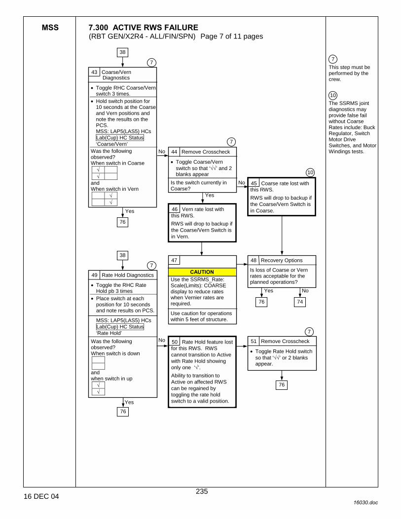
MSS 7.300 ACTIVE RWS FAILURE (RBT GEN/X2R4 - ALL/FIN/SPN) Page 7 of 11 pages
16 DEC 04 16030.doc
7 This step must be performed by the crew. 10 The SSRMS joint diagnostics may provide false fail without Coarse Rates include: Buck Regulator, Switch Motor Drive Switches, and Motor Windings tests.
43 Coarse/Vern Diagnostics
• Toggle RHC Coarse/Vern switch 3 times.
• Hold switch position for 10 seconds at the Coarse and Vern positions and note the results on the PCS. MSS: LAP5(LAS5) HCs Lab(Cup) HC Status ‘Coarse/Vern’
Was the following observed? When switch in Coarse
√ √
and When switch in Vern
√ √
7
44 Remove Crosscheck
• Toggle Coarse/Vern switch so that ‘√√’ and 2 blanks appear
Is the switch currently in Coarse?
7
No
Yes
45 Coarse rate lost with this RWS. RWS will drop to backup if the Coarse/Vern Switch is in Coarse.
No
Yes
46 Vern rate lost with this RWS. RWS will drop to backup if the Coarse/Vern Switch is in Vern.
10
49 Rate Hold Diagnostics
• Toggle the RHC Rate Hold pb 3 times
• Place switch at each position for 10 seconds and note results on PCS.
MSS: LAP5(LAS5) HCs Lab(Cup) HC Status ‘Rate Hold’
Was the following observed? When switch is down
and when switch in up
√ √
7
50 Rate Hold feature lost for this RWS. RWS cannot transition to Active with Rate Hold showing only one ‘√’. Ability to transition to Active on affected RWS can be regained by toggling the rate hold switch to a valid position.
51 Remove Crosscheck
• Toggle Rate Hold switch so that ‘√√’ or 2 blanks appear.
7
Yes
No
38
76
38
76
76
47
CAUTION Use the SSRMS_Rate: Scale(Limits): COARSE display to reduce rates when Vernier rates are required.
Use caution for operations within 5 feet of structure.
48 Recovery Options
Is loss of Coarse or Vern rates acceptable for the planned operations?
76
Yes No
74
235

MSS 7.300 ACTIVE RWS FAILURE (RBT GEN/X2R4 - ALL/FIN/SPN) Page 8 of 11 pages
16 DEC 04 16030.doc
7 This step must be performed by the crew. 11 MSS software does not distinguish between the Lower and Upper side of the Capture/Release Trigger switch. The operator-defined action from the LEE page is executed whenever the trigger is moved from the neutral position regardless of direction. 12 Both on orbit and in simulations the RWS has dropped to backup when assertive DCP switch throws were not used.
52 Trigger Diagnostics
• Toggle the RHC Capture/ Release trigger 3 times in each direction.
• Hold switch at each position for 10 seconds and note the results on PCS. MSS: LAP5(LAS5) HCs Lab(Cup) HC Status ‘RHC’
Single ‘√’ appears persistently at either the Capture or Release positions while the switch is in the Neutral position.
Single ‘√’ appears when switch is at Capture position or Single ‘√’ appears when switch is at Release position.
Nominal switch behavior.
7
53 RHC failure. Loss of ability to transition affected RWS to Active.
54 RHC or cable harness failure. Upper or Lower side of the switch is lost. Alternate side of switch remains with no loss of functinality. Holding the trigger switch in the failed position for more than 2 seconds will cause the RWS to drop to backup and the SSRMS to safe.
55 Were any of the following switches being actuated at the time of the failure or Was a message seen on the ground specifying any of the following switches:
Joint Select
Brakes
Auto Seq
None of the above.
12 7
38
76
76
76
74
61
68
56
1
11
236
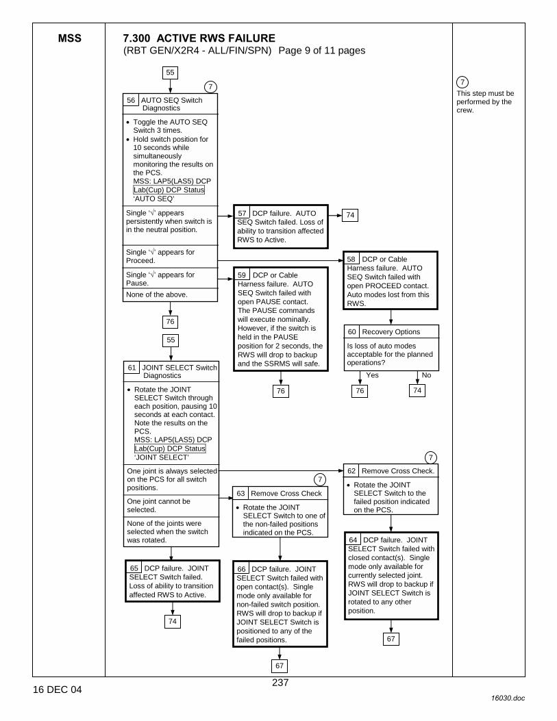
MSS 7.300 ACTIVE RWS FAILURE (RBT GEN/X2R4 - ALL/FIN/SPN) Page 9 of 11 pages
16 DEC 04 16030.doc
7 This step must be performed by the crew.
56 AUTO SEQ Switch Diagnostics
• Toggle the AUTO SEQ Switch 3 times.
• Hold switch position for 10 seconds while simultaneously monitoring the results on the PCS. MSS: LAP5(LAS5) DCP Lab(Cup) DCP Status ‘AUTO SEQ’
Single ‘√’ appears persistently when switch is in the neutral position.
Single ‘√’ appears for Proceed.
Single ‘√’ appears for Pause.
None of the above.
7
57 DCP failure. AUTO SEQ Switch failed. Loss of ability to transition affected RWS to Active.
58 DCP or Cable Harness failure. AUTO SEQ Switch failed with open PROCEED contact. Auto modes lost from this RWS.
59 DCP or Cable Harness failure. AUTO SEQ Switch failed with open PAUSE contact. The PAUSE commands will execute nominally. However, if the switch is held in the PAUSE position for 2 seconds, the RWS will drop to backup and the SSRMS will safe.
60 Recovery Options
Is loss of auto modes acceptable for the planned operations?
Yes No 61 JOINT SELECT Switch
Diagnostics
• Rotate the JOINT SELECT Switch through each position, pausing 10 seconds at each contact. Note the results on the PCS. MSS: LAP5(LAS5) DCP Lab(Cup) DCP Status ‘JOINT SELECT’
One joint is always selected on the PCS for all switch positions.
One joint cannot be selected.
None of the joints were selected when the switch was rotated.
62 Remove Cross Check.
• Rotate the JOINT SELECT Switch to the failed position indicated on the PCS.
7
63 Remove Cross Check
• Rotate the JOINT SELECT Switch to one of the non-failed positions indicated on the PCS.
64 DCP failure. JOINT SELECT Switch failed with closed contact(s). Single mode only available for currently selected joint. RWS will drop to backup if JOINT SELECT Switch is rotated to any other position.
65 DCP failure. JOINT SELECT Switch failed. Loss of ability to transition affected RWS to Active.
66 DCP failure. JOINT SELECT Switch failed with open contact(s). Single mode only available for non-failed switch position. RWS will drop to backup if JOINT SELECT Switch is positioned to any of the failed positions.
76
76 76
7
55
55
74
67
67
74
74
237

MSS 7.300 ACTIVE RWS FAILURE (RBT GEN/X2R4 - ALL/FIN/SPN) Page 10 of 11 pages
16 DEC 04 16030.doc
7 This step must be performed by the crew.
67 Recovery Options
Is the loss of the JOINT SELECT Switch functionality acceptable for the planned operations?
Yes No
68 Brake Switch Diagnostics
• Toggle the SSRMS Brake Switch 3 times to both positions.
• Hold switch position for 10 seconds while monitoring the results on the PCS. MSS: LAP5(LAS5) DC Lab(Cup) DCP Status ‘BRAKES’
Single ‘√’ appears persistently when switch is in the neutral position.
Single ‘√’ appears for Brakes Off.
Single ‘√’ appears for Brakes On.
None of the above.
7
69 DCP failure. Brake Switch failed. Loss of ability to transition affected RWS to Active.
70 DCP or Cable Harness failure. BRAKES sw OFF contact failed open. Ability to remove brakes using failed RWS is lost.
71 DCP or Cable Harness failure. BRAKES ON switch contact failed open. The BRAKES ON command will execute nominally. However, if the switch is held in the BRAKES ON position for 2 seconds the RWS will drop to backup and the SSRMS will safe.
72 Recovery Options
Is the inability to remove brakes acceptable for the planned operations?
Yes No
76 74
76
76
76
64 66
55
74
74
238

MSS 7.300 ACTIVE RWS FAILURE (RBT GEN/X2R4 - ALL/FIN/SPN) Page 11 of 11 pages
16 DEC 04 16030.doc
13 If failed workstation status remains in Backup in the CCS after power is removed, expect ‘R1E - MSS Active OCS Other RWS Comm Fail’ when powering up the alternate RWS. 14 Ground will perform required cleanup of the failed RWS.
15 SCR 24574, 28414
73 Disable Failed RWS
MSS: LAS5(LAP5) Pwr Dn LAS5(LAP5 Power Down
• cmd ‘G. CB Ext2(1) Bus Comm’ – Inhibit
• cmd ‘H. CEU’ – Open
6 24 10 11 5
74 Transition to Alternate RWS
For the Alternate RWS • Perform {6.332 MSS
POWERUP}, steps 1 (SODF: RBT GEN: NOMINAL), then:
5
35
32 7 28 18
39 57 42 48 53
65 72 67 69
78 Complete Recovery
For the THC and RHC • Deflect the HC to
hardstop in positive and negative directions for all axes
• Configure cameras and overlays as required.
14 13
60
No
Yes
75 Assert Active
For the affected RWS MSS: LAS5(LAP5) CEU Mode: CEU Mode
• cmd ‘Cupola(LAB)’ – Active
Is the RWS Active? 77 Checkpt Data Reset
• Perform {8.104 MSS CHECKPOINT DATA RESET}, all (SODF: RBT GEN: CORRECTIVE), then:
• Perform {6.332 MSS POWERUP}, steps 3 to 5 as required (SODF: RBT GEN: NOMINAL), then:
MSS: Video: Video Overview: Video Overview
• Repeat the following for all destinations to which an SSRMS or MBS Camera is routed:
• sel ‘Destination Icon’ • cmd ‘Deroute Video
Signal’ – Deroute
15 76 Assert Active
For the affected RWS MSS: LAS5(LAP5) CEU Mode: CEU Mode
• cmd ‘Cupola(LAB)’ – Active
Is the RWS Active?
29 42 36 40 39
43 52 48 51 49 54
59 56 55 60
72
67
71 68
Yes
No
4
1
79 • Go to {7/001 MSS
FAILURE RESPONSE AND RECOVERY}, block 75 (SODF: RBT GEN: RECOVERY. 78
8 25 26 77
239

This Page Intentionally Blank
22 DEC 04
240

MSS 7.500 SSRMS BRAKES FAILURE (RBT GEN/X2R4 - ALL/FINI) Page 1 of 2 pages
14 DEC 04 16031.doc
1 Unless otherwise indicated, all displays in this procedure are on the PCS. 2 This step requires DCP operator input and therefore can only be performed by onboard crew. 3 Time permitting, High Speed Data Log should be collected during all the diagnostics tests in this procedures.
{7.001 MSS FAILURE RESPONSE AND RECOVERY}, block 123 (SODF: RBT GEN: MALFUNCTION)
C&W ROBOTICS
SSRMS Brakes Fail On or Cannot Be Removed.
Nominal Config: RWS is Active. SSRMS is operational on the affected string and not Safed.
If SSRMS is based on MBS, MBS powered on both strings and Operational on one string.
If SSRMS is based on ISS PDGF, S0 and EXT MDMs configured for SEPS control.
1 Run Brake Diagnostics
(DCP) • SAFING → SAFE
For each joint, one joint at a time • Perform {6.401 SSRMS
JOINT BRAKE TEST}, all (SODF: RBT GEN: NOMINAL: SSRMS DIAGNOSTICS), then:
MSS: SSRMS: CW Summ Robotics: Caution & Warning Summary
Any of the following messages raised during the diagnostics tests: ‘R3B � MSS OCS � Brk�’ or ‘R3B � SSRMS�SRT�’ or ‘R3C � �Brk Cntl’ or ‘R3C - �Brk Voltage Cntl’ or ‘R3Z - �Cat-1 Brk Stat Fail’
MSS: SSRMS: Discrete Log: MSS Discrete Log
Only one joint failed any of the diagnostic tests.
More than one joint failed any of the diagnostic tests.
None of the above.
2 ACU or cable harness failure. SSRMS Brakes cannot be removed on affected string. Auto Capture and Semi-manual Capture capability lost on affected string.
3 Repeat Diagnostics
For all seven joints at the same time • Perform the following
three times {6.401 SSRMS JOINT BRAKE TEST}, all (SODF: RBT GEN: NOMINAL: SSRMS DIAGNOSTICS), then:
MSS: SSRMS: Discrete Log: MSS Discrete Log
• Record Discrete Log messages for any test reporting failed.
For the final time that diagnostics were run, did one or more joints fail any of the diagnostic tests?
5
8
1 2 C&W messages starting with
‘R3x - �’
3
7
4 Yes
No
241
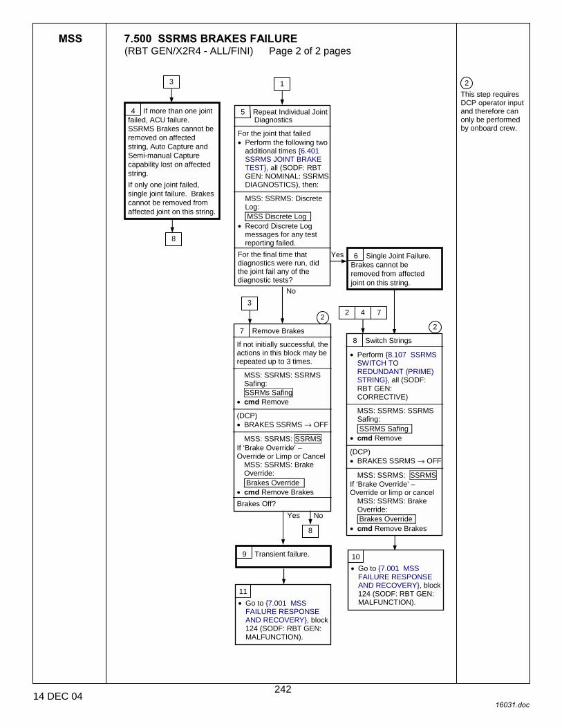
MSS 7.500 SSRMS BRAKES FAILURE (RBT GEN/X2R4 - ALL/FINI) Page 2 of 2 pages
14 DEC 04 16031.doc
2 This step requires DCP operator input and therefore can only be performed by onboard crew.
7 Remove Brakes
If not initially successful, the actions in this block may be repeated up to 3 times.
MSS: SSRMS: SSRMS Safing: SSRMs Safing
• cmd Remove (DCP) • BRAKES SSRMS → OFF
MSS: SSRMS: SSRMS
If ‘Brake Override’ – Override or Limp or Cancel
MSS: SSRMS: Brake Override: Brakes Override
• cmd Remove Brakes Brakes Off?
5 Repeat Individual Joint Diagnostics
For the joint that failed • Perform the following two
additional times {6.401 SSRMS JOINT BRAKE TEST}, all (SODF: RBT GEN: NOMINAL: SSRMS DIAGNOSTICS), then:
MSS: SSRMS: Discrete Log: MSS Discrete Log
• Record Discrete Log messages for any test reporting failed.
For the final time that diagnostics were run, did the joint fail any of the diagnostic tests?
6 Single Joint Failure. Brakes cannot be removed from affected joint on this string.
Yes
1
No3
2
9 Transient failure.
Yes
8 Switch Strings
• Perform {8.107 SSRMS SWITCH TO REDUNDANT (PRIME) STRING}, all (SODF: RBT GEN: CORRECTIVE)
MSS: SSRMS: SSRMS Safing: SSRMS Safing
• cmd Remove (DCP) • BRAKES SSRMS → OFF
MSS: SSRMS: SSRMS
If ‘Brake Override’ – Override or limp or cancel
MSS: SSRMS: Brake Override: Brakes Override
• cmd Remove Brakes
2 4
2
7
4 If more than one joint failed, ACU failure. SSRMS Brakes cannot be removed on affected string, Auto Capture and Semi-manual Capture capability lost on affected string. If only one joint failed, single joint failure. Brakes cannot be removed from affected joint on this string.
8
3
8
10 • Go to {7.001 MSS
FAILURE RESPONSE AND RECOVERY}, block 124 (SODF: RBT GEN: MALFUNCTION).
11 • Go to {7.001 MSS
FAILURE RESPONSE AND RECOVERY}, block 124 (SODF: RBT GEN: MALFUNCTION).
No
242
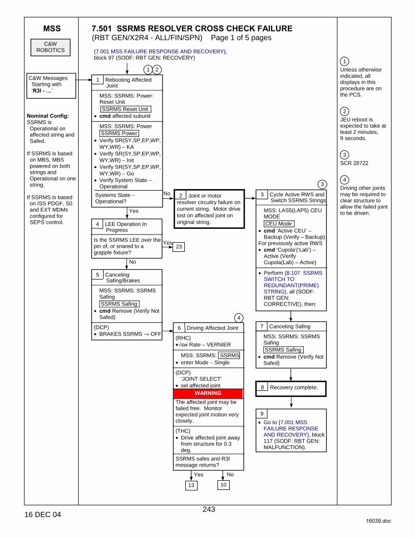
MSS 7.501 SSRMS RESOLVER CROSS CHECK FAILURE (RBT GEN/X2R4 - ALL/FIN/SPN) Page 1 of 5 pages
16 DEC 04 16039.doc
1 Unless otherwise indicated, all displays in this procedure are on the PCS. 2 JEU reboot is expected to take at least 2 minutes, 9 seconds. 3 SCR 28722 4 Driving other joints may be required to clear structure to allow the failed joint to be driven.
{7.001 MSS FAILURE RESPONSE AND RECOVERY}, block 97 (SODF: RBT GEN: RECOVERY)
C&W ROBOTICS
C&W Messages Starting with ‘R3I - �’
Nominal Config: SSRMS is Operational on affected string and Safed.
If SSRMS is based on MBS, MBS powered on both strings and Operational on one string.
If SSRMS is based on ISS PDGF, S0 and EXT MDMs configured for SEPS control.
1 Rebooting Affected Joint
MSS: SSRMS: Power: Reset Unit SSRMS Reset Unit
• cmd affected subunit
MSS: SSRMS: Power SSRMS Power
• Verify SR(SY,SP,EP,WP, WY,WR) − KA
• Verify SR(SY,SP,EP,WP, WY,WR) − Init
• Verify SR(SY,SP,EP,WP, WY,WR) − Go
• Verify System State − Operational
Systems State – Operational?
No
Yes
2 Joint or motor resolver circuitry failure on current string. Motor drive lost on affected joint on original string.
3 Cycle Active RWS and Switch SSRMS Strings
MSS: LAS5(LAP5) CEU MODE CEU Mode
• cmd ‘Active CEU’ – Backup (Verify – Backup)
For previously active RWS • cmd ‘Cupola’(‘Lab’) –
Active (Verify Cupola(Lab) – Active)
• Perform {8.107 SSRMS
SWITCH TO REDUNDANT(PRIME) STRING}, all (SODF: RBT GEN: CORRECTIVE), then:
4 LEE Operation In Progress
Is the SSRMS LEE over the pin of, or snared to a grapple fixture?
Yes
No
7 Canceling Safing
MSS: SSRMS: SSRMS Safing SSRMS Safing
• cmd Remove (Verify Not Safed)
8 Recovery complete.
2 1
23
3
9 • Go to {7.001 MSS
FAILURE RESPONSE AND RECOVERY}, block 117 (SODF: RBT GEN: MALFUNCTION).
5 Canceling Safing/Brakes
MSS: SSRMS: SSRMS Safing SSRMS Safing
• cmd Remove (Verify Not Safed)
(DCP) • BRAKES SSRMS → OFF
6 Driving Affected Joint
(RHC) •√sw Rate − VERNIER
MSS: SSRMS: SSRMS
• enter Mode − Single (DCP)
‘JOINT SELECT’ • sel affected joint
WARNING The affected joint may be failed free. Monitor expected joint motion very closely.
(THC) • Drive affected joint away
from structure for 0.3 deg.
SSRMS safes and R3I message returns?
13 10
NoYes
4
243

MSS 7.501 SSRMS RESOLVER CROSS CHECK FAILURE (RBT GEN/X2R4 - ALL/FIN/SPN) Page 2 of 5 pages
16 DEC 04 16039.doc
13 Switch SSRMS Strings
• Perform {8.107 SSRMS SWITCH TO REDUNDANT(PRIME) STRING}, all (SODF: RBT GEN: CORRECTIVE), then:
10 Transient failure. 11 (THC) • Drive affected joint back
to starting position.
14 Cancel Safing/Brakes
MSS: SSRMS: SSRMS Safing SSRMS Safing
• cmd Remove (Verify not Safed)
(DCP) • BRAKES SSRMS → OFF
15 Drive Affected Joint
(RHC) •√sw Rate − VERNIER
MSS: SSRMS: SSRMS
• enter Mode − Single (DCP)
‘JOINT SELECT’ • sel affected joint
17 Joint or motor resolver circuitry failure on original string. Motor drive lost on affected joint on original string. 19 Joint failed free. Both
strings affected.
No
Yes
18 (THC) • Drive affected joint back
to starting position.
16
WARNING The affected joint may be failed free. Monitor expected joint motion very closely.
(THC) • Drive affected joint away
from structure for 0.3 deg.
SSRMS safes and R3I message returns?
21
12 • Go to {7.001 MSS
FAILURE RESPONSE AND RECOVERY}, block 132 (SODF: RBT GEN: RECOVERY).
20 • Go to {7.001 MSS
FAILURE RESPONSE AND RECOVERY}, block 132 (SODF: RBT GEN: RECOVERY).
6
6
244

MSS 7.501 SSRMS RESOLVER CROSS CHECK FAILURE (RBT GEN/X2R4 - ALL/FIN/SPN) Page 3 of 5 pages
16 DEC 04 16039.doc
21
WARNING Motor drive and braking lost on affected joint.
19
22 Inhibit ISS Thrusters
MSS: SSRMS: Thrusters Thruster Controls for MSS Ops ‘Desat Request’
• cmd Inhibit (Verify Desat Request − Inh) ‘Auto Att Control Handover to RS’
• cmd Arm • cmd Inhibit (Verify Auto
Att Control Handover to RS − Inh)
24 Other six joints may be driveable in Single at very low rates.
Joint back-driving may result in movement of the affected joint, resulting in another JEU Resolver Xcheck Fail.
Each subsequent JEU Resolver Xcheck Fail recurrence will require affected JEU subunit to be rebooted before other single joint ops can proceed.
25 Additional troubleshooting required.
37
23 Cancel Safing/Brakes
MSS: SSRMS: SSRMS Safing SSRMS Safing
• cmd Remove (Verify not Safed)
(DCP) • BRAKES SSRMS → OFF
MSS: SSRMS: SSRMS
If ‘Brake Override’ – Override or limp or cancel
MSS: SSRMS: Brake Override: Brakes Override
• cmd Remove Brakes
4 30
26
245
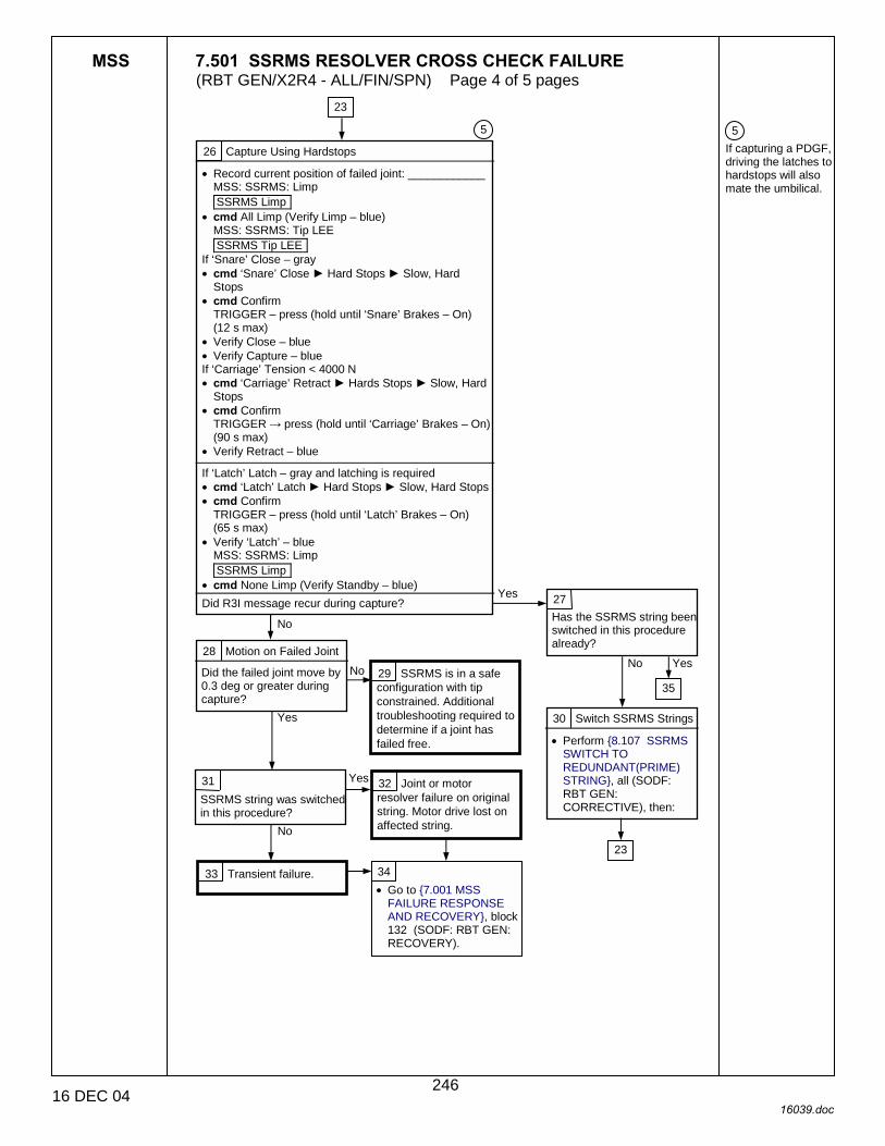
MSS 7.501 SSRMS RESOLVER CROSS CHECK FAILURE (RBT GEN/X2R4 - ALL/FIN/SPN) Page 4 of 5 pages
16 DEC 04 16039.doc
5 If capturing a PDGF, driving the latches to hardstops will also mate the umbilical.
28 Motion on Failed Joint
Did the failed joint move by 0.3 deg or greater during capture?
26 Capture Using Hardstops
• Record current position of failed joint: ____________ MSS: SSRMS: Limp SSRMS Limp
• cmd All Limp (Verify Limp – blue) MSS: SSRMS: Tip LEE SSRMS Tip LEE
If ‘Snare’ Close – gray • cmd ‘Snare’ Close ► Hard Stops ► Slow, Hard
Stops • cmd Confirm
TRIGGER – press (hold until ‘Snare’ Brakes – On) (12 s max)
• Verify Close – blue • Verify Capture – blue If ‘Carriage’ Tension < 4000 N • cmd ‘Carriage’ Retract ► Hards Stops ► Slow, Hard
Stops • cmd Confirm
TRIGGER → press (hold until ‘Carriage’ Brakes – On) (90 s max)
• Verify Retract – blue If ‘Latch’ Latch – gray and latching is required • cmd ‘Latch’ Latch ► Hard Stops ► Slow, Hard Stops • cmd Confirm
TRIGGER – press (hold until ‘Latch’ Brakes – On) (65 s max)
• Verify ‘Latch’ – blue MSS: SSRMS: Limp SSRMS Limp
• cmd None Limp (Verify Standby – blue) Did R3I message recur during capture?
23
No
Yes 27 Has the SSRMS string been switched in this procedure already?
No Yes
30 Switch SSRMS Strings
• Perform {8.107 SSRMS SWITCH TO REDUNDANT(PRIME) STRING}, all (SODF: RBT GEN: CORRECTIVE), then:
29 SSRMS is in a safe configuration with tip constrained. Additional troubleshooting required to determine if a joint has failed free.
No
Yes
31 SSRMS string was switched in this procedure?
No
Yes 32 Joint or motor resolver failure on original string. Motor drive lost on affected string.
33 Transient failure.
35
23
5
34 • Go to {7.001 MSS
FAILURE RESPONSE AND RECOVERY}, block 132 (SODF: RBT GEN: RECOVERY).
246

MSS 7.501 SSRMS RESOLVER CROSS CHECK FAILURE (RBT GEN/X2R4 - ALL/FIN/SPN) Page 5 of 5 pages
16 DEC 04 16039.doc
2 JEU reboot is expected to take at least 2 minutes 9 seconds.\ 6 The path of blocks 23, 26, 27, 35, 36, and 37 should be repeated as required until capture is complete.
36 Capture State
MSS: SSRMS: Tip LEE SSRMS Tip LEE
Capturing a PDGF and ‘Latch’ Latch – gray or Capturing an FRGF and ‘Carriage’ Retract – gray
Capturing a PDGF and ‘Latch’ Latch – blue or Capturing an FRGF and ‘Carriage’ Retract – blue
35 Joint failed free. Both strings affected.
37 Reboot Affected Joint
MSS: SSRMS: Power: Reset Unit SSRMS Reset Unit
• cmd affected subunit
MSS: SSRMS: Power SSRMS Power
• Verify SR(SY,SP,EP,WP, WY,WR) − KA
• Verify SR(SY,SP,EP,WP, WY,WR) − Init
• Verify SR(SY,SP,EP,WP, WY,WR) − Go
• Verify System State − Operational
38 SSRMS in a safe config with tip constrained. Additional troubleshooting required.
6 2
27
23
247

This Page Intentionally Blank
22 DEC 04
248

MSS 7.502 SSRMS JOINT MOTION FAILURE (RBT GEN/X2R4 - ALL/FIN) Page 1 of 7 pages
16 DEC 04 16040.doc
1 Unless otherwise indicated, all displays in this procedure are on the PCS. 2 This block contains steps to be carried out by Ground only.
{7.001 MSS FAILURE RESPONSE AND RECOVERY}, block 129 (SODF: RBT GEN: MALFUNCTION)
C&W ROBOTICS
C&W Messages starting with
‘R3D, R3H, R3K’
Nominal Config: SSRMS is Operational on affected string with brakes OFF.
If SSRMS is based on MBS, MBS powered on both strings and Operational on one string.
If SSRMS is based on ISS PDGF, S0 and EXT MDMs configured for SEPS control.
Crew Applies Safing or Motion Failure Causes Safing
1 Check C&W Summary
MSS: SSRMS: CW Summ Robotics Caution & Warning Summary
�R3D � SSRMS SR (SY, SP, EP, WP, WY, WR) JEU Joint (Mtr) RDC Bit Fail� or �R3H � SSRMS SR (SY, SP, EP, WP, WY, WR) JEU Mtr Current Consistency Ck Fail� messages raised during initial safing event?
Yes
No
1
3 Did the operator initiate Safing due to uncommand motion?
Yes No
7 Joint Current Draw
GROUND ONLY: • Check RT Plots/ODRC
and verify the current draw at the time of failure for each joint.
• Mtr current should have stabilized at approximately 0.5 amps (loaded or unloaded).
Did any joint(s) display an excessive current draw over a period of greater than 20 second?
Yes
No
8
25
2
2 Set Vernier Rates
(RHC) •√sw Rate – Vernier
MSS: SSRMS
•√SSRMS Safing Status – Not Safed
(DCP) •√BRAKES SSRMS – OFF
19
4 Joint and Brake Diags
For all joints • Perform {6.401 SSRMS
JOINT BRAKE TEST}, all (SODF: RBT GEN: NOMINAL: SSRMS DIAGNOSTICS), then:
• Perform {6.402 SSRMS JOINT ELECTRONICS UNIT DIAGNOSTICS}, all (SODF: RBT GEN: NOMINAL: SSRMS DIAGNOSTICS), then:
Did all tests pass?
No
Yes
8
6 Joint failure. Joint drive lost on current string. Single Joint drive possible on other joints.
47
5 Were current operations being conducted in Single Joint mode?
Yes31
22
No
249
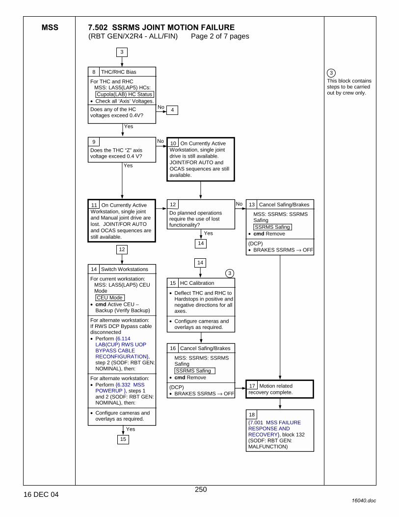
MSS 7.502 SSRMS JOINT MOTION FAILURE (RBT GEN/X2R4 - ALL/FIN) Page 2 of 7 pages
16 DEC 04 16040.doc
3 This block contains steps to be carried out by crew only.
8 THC/RHC Bias
For THC and RHC MSS: LAS5(LAP5) HCs: Cupola(LAB) HC Status
• Check all ‘Axis’ Voltages. Does any of the HC voltages exceed 0.4V?
9 Does the THC “Z” axis voltage exceed 0.4 V?
Yes
No
Yes
10 On Currently Active Workstation, single joint drive is still available. JOINT/FOR AUTO and OCAS sequences are still available.
No
3
4
11 On Currently Active Workstation, single joint and Manual joint drive are lost. JOINT/FOR AUTO and OCAS sequences are still available.
14 Switch Workstations
For current workstation: MSS: LAS5(LAP5) CEU Mode CEU Mode
• cmd Active CEU – Backup (Verify Backup)
For alternate workstation: If RWS DCP Bypass cable disconnected • Perform {6.114
LAB(CUP) RWS UOP BYPASS CABLE RECONFIGURATION}, step 2 (SODF: RBT GEN: NOMINAL), then:
For alternate workstation: • Perform {6.332 MSS
POWERUP }, steps 1 and 2 (SODF: RBT GEN: NOMINAL), then:
• Configure cameras and
overlays as required.
16 Cancel Safing/Brakes
MSS: SSRMS: SSRMS Safing SSRMS Safing
• cmd Remove (DCP) • BRAKES SSRMS → OFF
17 Motion related recovery complete.
15 HC Calibration
• Deflect THC and RHC to Hardstops in positive and negative directions for all axes.
• Configure cameras and
overlays as required.
3
12 Do planned operations require the use of lost functionality?
Yes
13 Cancel Safing/Brakes
MSS: SSRMS: SSRMS Safing SSRMS Safing
• cmd Remove (DCP) • BRAKES SSRMS → OFF
No
14 12
18 {7.001 MSS FAILURE RESPONSE AND RECOVERY}, block 132 (SODF: RBT GEN: MALFUNCTION)
Yes
15
14
250

MSS 7.502 SSRMS JOINT MOTION FAILURE (RBT GEN/X2R4 - ALL/FIN) Page 3 of 7 pages
16 DEC 04 16040.doc
3 This block contains steps to be carried out by crew only. The drive duration will be determined by the ground based on SSRMS clearances at the current config.
19 Drive Joint
MSS: SSRMS SSRMS
• Enter Mode – Single (DCP)
‘Joint Select’ • sel affected joint
(THC) • Drive away from structure
using full HC deflection for TBD degrees as specified by ground.
• Return the affected joint to original value.
MSS: SSRMS: CW Summ Robotics Caution & Warning Summary
• Determine which of the following messages occurred:
‘R3D � SSRMS SR (SP, SY, EP,WP, WY, WR) JEU Joint (Mtr) RDC Bit Fail’
‘R3H � SSRMS SR (SP, SY, EP, WP, WY, WR) JEU Mtr Current Consistency Ck Fail’
No failure messages reocurred.
2
20 Joint failure. Joint drive lost on current string.
Yes
3
21 • Enter an X in box 1 of
Block 39.
47
38
Yes
38
251

MSS 7.502 SSRMS JOINT MOTION FAILURE (RBT GEN/X2R4 - ALL/FIN) Page 4 of 7 pages
16 DEC 04 16040.doc
4 This block contains steps to be carried out by Ground only
3 This block contains steps to be carried out by crew only.
22 Drive Affected Joint(s)
(RHC) • set sw Rate – Vernier
MSS: SSRMS: SSRMS Safing SSRMS Safing
• cmd Remove (DCP) • BRAKES SSRMS – OFF
MSS: SSRMS SSRMS
• Enter Mode – Single For each affected joint (DCP)
‘Joint Select’ • sel affected joint
(THC) • Drive away from structure
using full HC deflection for TBD degrees as specified by ground.
• Return affected joint to original value.
GROUND ONLY: Did the stall current signature reoccur on the affected joint(s)?
23
23 Switch Strings
• Perform {8.107 SSRMS SWITCH TO REDUNDANT(PRIME) STRING}, all (SODF: RBT GEN: CORRECTIVE), then:
• Configure cameras and
overlays as required.
24 Drive Affected Joint(s)
(RHC) •√sw Rate – Vernier
MSS: SSRMS: SSRMS Safing SSRMS Safing
• cmd Remove (DCP) • BRAKES SSRMS – OFF
MSS: SSRMS SSRMS
• Enter Mode – Single For each affected joint (DCP)
‘Joint Select’ • sel affected joint
(THC) • Drive away from structure
using full HC deflection for TBD degrees as specified by ground.
• Return the affected joint to original value.
GROUND ONLY: Did the stall current signature reoccur on the affected joint(s)?
26 The affected joint has seized or become sluggish on both strings. Single joint drive available for other six joints. For SR and SY failures, it may be possible to achieve 6-DOF control using base joint locking.
25 Transient error or high commanded FOR rates. Subsequent TTED errors are possible.
22
29 Motion related recovery complete.
No Yes 7
No
Yes
7
27 The affected joint has failed on original string.
28 • Continue using FOR
modes with POHS/Line Tracking ON with reduced commanded rates or Single mode to reduce undetected deviations.
3
2 3
30 {7.001 MSS FAILURE RESPONSE AND RECOVERY}, block 132 (SODF: RBT GEN: MALFUNCTION)
252
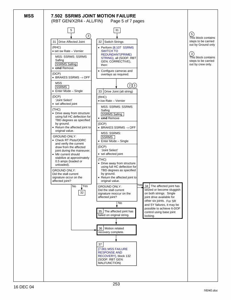
MSS 7.502 SSRMS JOINT MOTION FAILURE (RBT GEN/X2R4 - ALL/FIN) Page 5 of 7 pages
16 DEC 04 16040.doc
5 This block contains steps to be carried out by Ground only
3 This block contains steps to be carried out by crew only.
31 Drive Affected Joint
(RHC) • set sw Rate – Vernier
MSS: SSRMS: SSRMS Safing SSRMS Safing
• cmd Remove (DCP) • BRAKES SSRMS → OFF
MSS SSRMS
• Enter Mode – Single (DCP)
‘Joint Select’ • sel affected joint
(THC) • Drive away from structure
using full HC deflection for TBD degrees as specified by ground.
• Return the affected joint to original value.
GROUND ONLY: • Check RT Plots/ODRC
and verify the current draw from the affected joint during the maneuver.
• Mtr current should stabilize at approximately 0.5 amps (loaded or unloaded).
GROUND ONLY: Did the stall current signature occur on the affected joint?
32 Switch Strings
• Perform {8.107 SSRMS SWITCH TO REDUNDANT(PRIME) STRING}, all (SODF: RBT GEN: CORRECTIVE), then:
• Configure cameras and
overlays as required.
31
33 Drive Joint (alt string)
(RHC) •√sw Rate – Vernier
MSS: SSRMS: SSRMS Safing SSRMS Safing
• cmd Remove (DCP) • BRAKES SSRMS → OFF
MSS: SSRMS: SSRMS
• Enter Mode – Single (DCP)
‘Joint Select’ • sel affected joint
(THC) • Drive away from structure
using full HC deflection for TBD degrees as specified by ground.
• Return the affected joint to original value.
GROUND ONLY: Did the stall current signature reoccur on the affected joint?
34 The affected joint has seized or become sluggish on both strings. Single joint drive available for other six joints. For SR and SY failures, it may be possible to achieve 6-DOF control using base joint locking.
32
36 Motion related recovery complete.
Yes
No
35 The affected joint has failed on original string.
5
3
2 3
No Yes
37 {7.001 MSS FAILURE RESPONSE AND RECOVERY}, block 132 (SODF: RBT GEN: MALFUNCTION)
253

MSS 7.502 SSRMS JOINT MOTION FAILURE (RBT GEN/X2R4 - ALL/FIN) Page 6 of 7 pages
16 DEC 04 16040.doc
3 This block contains steps to be carried out by crew only. The drive duration will be determined by the ground based on SSRMS clearances at the current config.
38 Set Coarse Rates
(RHC) • set sw Rate – Coarse
MSS: SSRMS: SSRMS Safing SSRMS Safing
• cmd Remove (DCP) • BRAKES SSRMS → OFF
Did the following message occur: ‘R3H � SSRMS SR (SP, SY, EP, WP, WY, WR) JEU Mtr Current Consistency Ck Fail’?
39 Coarse/Vern Matrix
Failure Box: 1 2 Box:
Select matching matrix:
1 2 Box: X X
1 2 Box: X
1 2 Box: X
1 2 Box:
43 Motion related recovery complete.
Yes
No
42 44
46
52
41 Transient Failure.
40 Indicated joint failure. Joint drive lost on current string.
47
42
• Enter an X in box 2 of Block 39.
39
44 Drive Joint
MSS: SSRMS SSRMS
• Enter Mode – Single (DCP)
‘Joint Select’ • sel affected joint
(THC) • Drive away from structure
using full HC deflection for TBD degrees as specified by ground.
• Return the affected joint to original value.
MSS: SSRMS: CW Summ Robotics Caution & Warning Summary
If the following message occurred: ‘R3H � SSRMS SR (SP, SY, EP, WP, WY, WR) JEU Mtr Current Consistency Ck Fail’ then: • Enter an X in box 2 of
block 39.
39
3
19
45 {7.001 MSS FAILURE RESPONSE AND RECOVERY}, block 132 (SODF: RBT GEN: MALFCUNTION)
254
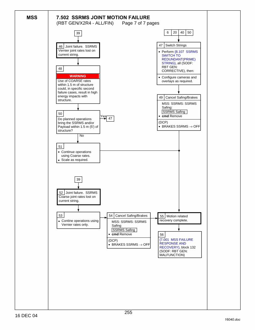
MSS 7.502 SSRMS JOINT MOTION FAILURE (RBT GEN/X2R4 - ALL/FIN) Page 7 of 7 pages
16 DEC 04 16040.doc
47 Switch Strings
• Perform {8.107 SSRMS SWITCH TO REDUNDANT(PRIME) STRING}, all (SODF: RBT GEN: CORRECTIVE), then:
• Configure cameras and
overlays as required.
46 Joint failure. SSRMS Vernier joint rates lost on current string.
48
WARNING Use of COARSE rates within 1.5 m of structure could, in specific second failure cases, result in high energy impacts with structure.
49 Cancel Safing/Brakes
MSS: SSRMS: SSRMS Safing: SSRMS Safing
• cmd Remove (DCP) • BRAKES SSRMS → OFF
50 Do planned operations bring the SSRMS and/or Payload within 1.5 m (5') of structure?
No
39 6 20 40
47 Yes
51 • Continue operations
using Coarse rates. • Scale as required.
50
52 Joint failure. SSRMS Coarse joint rates lost on current string.
39
55 Motion related recovery complete.
53
• Contine operations using Vernier rates only.
54 Cancel Safing/Brakes
MSS: SSRMS: SSRMS Safing SSRMS Safing
• cmd Remove (DCP) • BRAKES SSRMS → OFF
56 {7.001 MSS FAILURE RESPONSE AND RECOVERY}, block 132 (SODF: RBT GEN: MALFUNCTION)
255

This Page Intentionally Blank
22 DEC 04
256
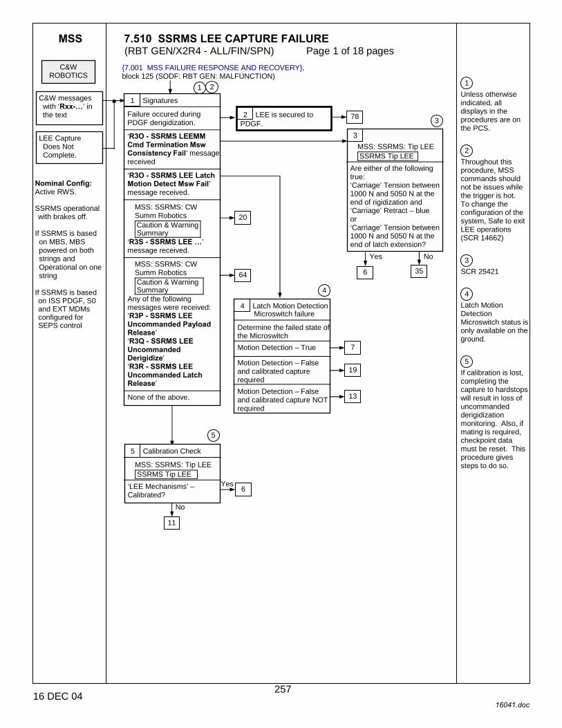
MSS 7.510 SSRMS LEE CAPTURE FAILURE (RBT GEN/X2R4 - ALL/FIN/SPN) Page 1 of 18 pages
16 DEC 04 16041.doc
1 Unless otherwise indicated, all displays in the procedures are on the PCS. 2 Throughout this procedure, MSS commands should not be issues while the trigger is hot. To change the configuration of the system, Safe to exit LEE operations (SCR 14662) 3 SCR 25421 4 Latch Motion Detection Microswitch status is only available on the ground. 5 If calibration is lost, completing the capture to hardstops will result in loss of uncommanded derigidization monitoring. Also, if mating is required, checkpoint data must be reset. This procedure gives steps to do so.
C&W ROBOTICS
C&W messages with ‘Rxx-�’ in the text
Nominal Config: Active RWS. SSRMS operational with brakes off.
If SSRMS is based on MBS, MBS powered on both strings and Operational on one string
If SSRMS is based on ISS PDGF, S0 and EXT MDMs configured for SEPS control
LEE Capture Does Not Complete.
1 Signatures
Failure occured during PDGF derigidization.
‘R3O - SSRMS LEEMM Cmd Termination Msw Consistency Fail’ message received
‘R3O - SSRMS LEE Latch Motion Detect Msw Fail’ message received.
MSS: SSRMS: CW Summ Robotics Caution & Warning Summary
‘R3S - SSRMS LEE �’ message received.
MSS: SSRMS: CW Summ Robotics Caution & Warning Summary
Any of the following messages were received: ‘R3P - SSRMS LEE Uncommanded Payload Release’ ‘R3Q - SSRMS LEE Uncommanded Derigidize’ ‘R3R - SSRMS LEE Uncommanded Latch Release’
None of the above.
3 MSS: SSRMS: Tip LEE SSRMS Tip LEE
Are either of the following true: ‘Carriage’ Tension between 1000 N and 5050 N at the end of rigidization and ‘Carriage’ Retract – blue or ‘Carriage’ Tension between 1000 N and 5050 N at the end of latch extension?
5 Calibration Check
MSS: SSRMS: Tip LEE SSRMS Tip LEE
‘LEE Mechanisms’ – Calibrated?
6 Yes
No
2 LEE is secured to PDGF.
6
Yes No
11
20
2 1
3
4 Latch Motion Detection Microswitch failure
Determine the failed state of the Microswitch
Motion Detection – True Motion Detection – False and calibrated capture required
Motion Detection – False and calibrated capture NOT required
78
64
7
19
13
35
4
5
{7.001 MSS FAILURE RESPONSE AND RECOVERY}, block 125 (SODF: RBT GEN: MALFUNCTION)
257
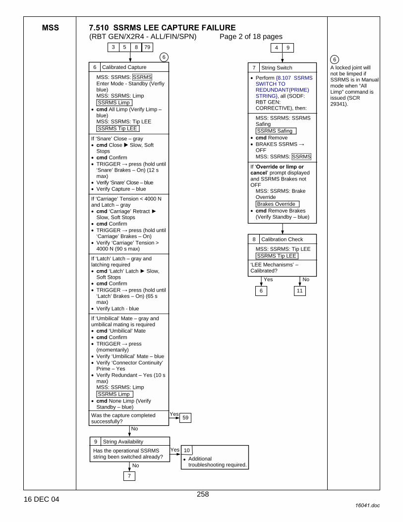
MSS 7.510 SSRMS LEE CAPTURE FAILURE (RBT GEN/X2R4 - ALL/FIN/SPN) Page 2 of 18 pages
16 DEC 04 16041.doc
6 A locked joint will not be limped if SSRMS is in Manual mode when “All Limp” command is issued (SCR 29341).
6 Calibrated Capture
MSS: SSRMS: SSRMS Enter Mode - Standby (Verfiy blue) MSS: SSRMS: Limp SSRMS Limp
• cmd All Limp (Verify Limp – blue) MSS: SSRMS: Tip LEE SSRMS Tip LEE
If ‘Snare’ Close – gray • cmd Close ! Slow, Soft
Stops • cmd Confirm • TRIGGER → press (hold until
‘Snare’ Brakes – On) (12 s max)
• Verify ‘Snare’ Close – blue • Verify Capture – blue
If ‘Carriage’ Tension < 4000 N and Latch – gray • cmd ‘Carriage’ Retract ►
Slow, Soft Stops • cmd Confirm • TRIGGER → press (hold until
‘Carriage’ Brakes – On) • Verify ‘Carriage’ Tension >
4000 N (90 s max) If ‘Latch’ Latch – gray and latching required • cmd ‘Latch’ Latch ► Slow,
Soft Stops • cmd Confirm • TRIGGER → press (hold until
‘Latch’ Brakes – On) (65 s max)
• Verify Latch - blue If ‘Umbilical’ Mate – gray and umbilical mating is required • cmd ‘Umbilical’ Mate • cmd Confirm • TRIGGER → press
(momentarily) • Verify ‘Umbilical’ Mate – blue • Verify ‘Connector Continuity’
Prime – Yes • Verify Redundant – Yes (10 s
max) MSS: SSRMS: Limp SSRMS Limp
• cmd None Limp (Verify Standby – blue)
Was the capture completed successfully?
9 String Availability
Has the operational SSRMS string been switched already?
10
• Additional troubleshooting required.
3 5
Yes
7 String Switch
• Perform {8.107 SSRMS SWITCH TO REDUNDANT(PRIME) STRING}, all (SODF: RBT GEN: CORRECTIVE), then:
MSS: SSRMS: SSRMS Safing SSRMS Safing
• cmd Remove • BRAKES SSRMS →
OFF MSS: SSRMS: SSRMS
If ‘Override or limp or cancel’ prompt displayed and SSRMS Brakes not OFF
MSS: SSRMS: Brake Override Brakes Override
• cmd Remove Brakes (Verify Standby – blue)
8 Calibration Check
MSS: SSRMS: Tip LEE SSRMS Tip LEE
‘LEE Mechanisms’ – Calibrated?
6
Yes No
11
6
8 79 4 9
59 Yes
No
7
No
258
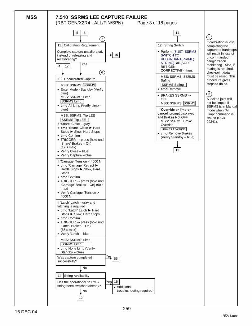
MSS 7.510 SSRMS LEE CAPTURE FAILURE (RBT GEN/X2R4 - ALL/FIN/SPN) Page 3 of 18 pages
16 DEC 04 16041.doc
5 If calibration is lost, completing the capture to hardstops will result in loss of uncommanded derigidization monitoring. Also, if mating is required, checkpoint data must be reset. This procedure gives steps to do so. 6 A locked joint will not be limped if SSRMS is in Manual mode when “All Limp” command is issued (SCR 29341).
11 Calibration Requirement
Complete capture uncalibrated, instead of releasing and recalibrating?
13 Uncalibrated Capture
MSS: SSRMS: SSRMS • Enter Mode - Standby (Verfiy
blue) MSS: SSRMS: Limp SSRMS Limp
• cmd All Limp (Verify Limp – blue)
MSS: SSRMS: Tip LEE SSRMS Tip LEE
If ‘Snare’ Close – gray • cmd ‘Snare’ Close ► Hard
Stops ► Slow, Hard Stops • cmd Confirm • TRIGGER → press (hold until
‘Snare’ Brakes – On) (12 s max)
• Verify Close – blue • Verify Capture – blue
If ‘Carriage’ Tension < 4000 N • cmd ‘Carriage’ Retract ►
Hards Stops ► Slow, Hard Stops
• cmd Confirm • TRIGGER → press (hold until
‘Carriage’ Brakes – On) (90 s max)
• Verify Carriage’ Tension > 4000 N
If ‘Latch’ Latch – gray and latching is required • cmd ‘Latch’ Latch ► Hard
Stops ► Slow, Hard Stops • cmd Confirm • TRIGGER → press (hold until
‘Latch’ Brakes – On) (65 s max)
• Verify ‘Latch’ – blue
MSS: SSRMS: Limp SSRMS Limp
• cmd None Limp (Verify Standby – blue)
Was capture completed successfully?
14 String Availability
Has the operational SSRMS string been switched already?
15
• Additional troubleshooting required.
12 String Switch
• Perform {8.107 SSRMS SWITCH TO REDUNDANT(PRIME) STRING}, all (SODF: RBT GEN: CORRECTIVE), then:
MSS: SSRMS: SSRMS Safing SSRMS Safing
• cmd Remove • BRAKES SSRMS →
OFF MSS: SSRMS: SSRMS
If ‘Override or limp or cancel’ prompt displayed and Brakes Not OFF
MSS: SSRMS: Brake Override Brakes Override
• cmd Remove Brakes (Verify Standby – blue)
14
13
4 12
5 8
5
6
Yes
No
No
Yes
16
55 Yes
12
259

MSS 7.510 SSRMS LEE CAPTURE FAILURE (RBT GEN/X2R4 - ALL/FIN/SPN) Page 4 of 18 pages
16 DEC 04 16041.doc
7 A Calibrate command may be aborted by a ‘SSRMS LEE LEU Mtr Velocity Runaway’ Robotics Advisory message and the MSS safed if one of the three LEE mechanisms was initially located at the hardstop position. If safing occurs, cancel safing and command Calibrate again (SCR 20379). 8 When extending until derigidize – blue, the trigger must be released once the derigidize indication turns blue.
16 Uncalibrated Release and Recalibration
MSS: SSRMS: Limp SSRMS Limp
• cmd All Limp (Verify Limp – blue)
MSS: SSRMS: Tip LEE: SSRMS Tip LEE If ‘Latch’ Unlatch – gray • cmd ‘Latch’ Unlatch ► Hard Stops ► Slow,
Hard Stops • cmd Confirm • TRIGGER → press (hold until ‘Latch’
Brakes – On) (65 s max) • Verify ‘Latch’ Unlatch – blue
If Carriage Derigidize – gray • cmd ‘Carriage’ Extend ► Hard Stops ►
Slow, Hard Stops • cmd Confirm • TRIGGER → press (hold until Derigidize –
blue) (20 s max) • Verify Derigidize – blue • cmd Terminate
If ‘Snare’ Open – gray • cmd ‘Snare’ Open ► Hard Stops ► Slow,
Hard Stops • cmd Confirm • TRIGGER → press (hold until ‘Snare’
Brakes – On) (12 s max) • Verify ‘Snare’ Open – blue
If ‘Carriage’ Extend – gray • cmd ‘Carriage’ Extend ► Hard Stops ►
Slow, Hard Stops • cmd Confirm • TRIGGER → press (hold until ‘Carriage’
Brakes – On) (90 s max) • Verify Extend – blue
MSS: SSRMS: Limp: SSRMS Limp
• cmd None Limp (Verify Standby – blue) MSS: SSRMS: SSRMS
• Enter Mode – Manual (Verify Manual – blue) MSS: SSRMS: Manual: Joint Lock Joint Lock
• Lock the joint that was originally locked during the capture.
• Back off until clear of GF pin.
MSS: SSRMS: Tip LEE SSRMS Tip LEE
• cmd ‘LEE Mechanism’ Calibrate • cmd Confirm • TRIGGER → press (momentarily) • Verify ‘LEE Mechanisms’ – Calibrated
(340 s max) Were the steps completed successful?
No
Yes
11 19
17
8 7
79
260
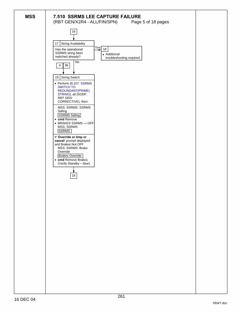
MSS 7.510 SSRMS LEE CAPTURE FAILURE (RBT GEN/X2R4 - ALL/FIN/SPN) Page 5 of 18 pages
16 DEC 04 16041.doc
17 String Availability
Has the operational SSRMS string been switched already?
18
• Additional troubleshooting required.
19 String Switch
• Perform {8.107 SSRMS SWITCH TO REDUNDANT(PRIME) STRING}, all (SODF: RBT GEN: CORRECTIVE), then:
MSS: SSRMS: SSRMS Safing SSRMS Safing
• cmd Remove • BRAKES SSRMS → OFF
MSS: SSRMS SSRMS
If ‘Override or limp or cancel’ prompt displayed and Brakes Not OFF
MSS: SSRMS: Brake Override Brakes Override
• cmd Remove Brakes (Verify Standby – blue)
Yes
No
16
4
16
36
261

MSS 7.510 SSRMS LEE CAPTURE FAILURE (RBT GEN/X2R4 - ALL/FIN/SPN) Page 6 of 18 pages
16 DEC 04 16041.doc
8 When extending until derigidize – blue, the trigger must be released once the derigidize indication turns blue.
20 Hard Stops Release After ‘R3S �’
MSS: SSRMS: Limp SSRMS Limp
• cmd All Limp (Verify Limp – blue) MSS: SSRMS: Tip LEE SSRMS Tip LEE
If ‘Latch’ Unlatch – gray • cmd ‘Latch’ Unlatch ► Hard Stops ► Slow,
Hard Stops • cmd Confirm • TRIGGER → press (hold until ‘Latch’ • Brakes – On) (65 s max) • Verify ‘Latch’ Unlatch – blue
If ‘Carriage’ Derigidize – gray • cmd ‘Carriage’ Extend ► Hard Stops ►
Slow, Hard Stops • cmd Confirm • TRIGGER → press (hold until Derigidize –
blue) (20 s max) • Verify Derigidize – blue • cmd Terminate
If ‘Snare’ Open – gray • cmd ‘Snare’ Open ► Hard Stops ► Slow,
Hard Stops • cmd Confirm • TRIGGER → press (hold until ‘Snare’
Brakes – On) (12 s max) • Verify ‘Snare’ Open – blue
If ‘Carriage’ Extend – gray • cmd ‘Carriage’ Extend ► Hard Stops ►
Slow, Hard Stops • cmd Confirm • TRIGGER → press (hold until ‘Carriage’
Brakes – On) (90 s max) • Verify Extend – blue
MSS: SSRMS: Limp SSRMS Limp
• cmd None Limp (Verify Standby – blue) MSS: SSRMS SSRMS
• Enter Mode – Manual (Verify Manual – blue) MSS: SSRMS: Manual: Joint Lock Joint Lock
• Lock the joint that was originally locked during the capture.
• Back off until clear of GF pin. Was the release completed successfully?
8
1 24
21 No
25
Yes
262
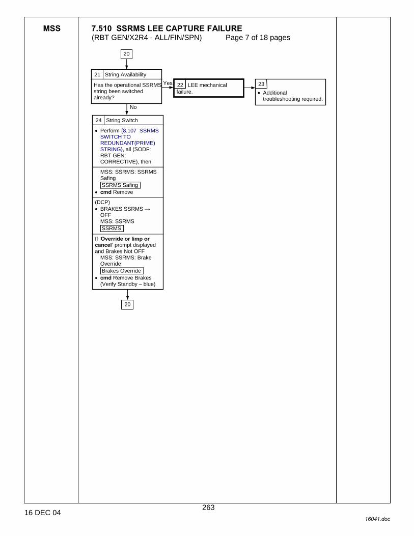
MSS 7.510 SSRMS LEE CAPTURE FAILURE (RBT GEN/X2R4 - ALL/FIN/SPN) Page 7 of 18 pages
16 DEC 04 16041.doc
21 String Availability
Has the operational SSRMS string been switched already?
22 LEE mechanical failure.
23 • Additional
troubleshooting required.
24 String Switch
• Perform {8.107 SSRMS SWITCH TO REDUNDANT(PRIME) STRING}, all (SODF: RBT GEN: CORRECTIVE), then:
MSS: SSRMS: SSRMS Safing SSRMS Safing
• cmd Remove (DCP) • BRAKES SSRMS →
OFF MSS: SSRMS SSRMS
If ‘Override or limp or cancel’ prompt displayed and Brakes Not OFF
MSS: SSRMS: Brake Override Brakes Override
• cmd Remove Brakes (Verify Standby – blue)
Yes
No
20
20
263

MSS 7.510 SSRMS LEE CAPTURE FAILURE (RBT GEN/X2R4 - ALL/FIN/SPN) Page 8 of 18 pages
16 DEC 04 16041.doc
7 A Calibrate command may be aborted by a ‘SSRMS LEE LEU Mtr Velocity Runaway’ Robotics Advisory message and the MSS safed if one of the three LEE mechanisms was initially located at the hardstop position. If safing occurs, cancel safing and command Calibrate again (SCR 20379).
25 String Change Status
Has the operational SSRMS string been switched already?
Yes
No
26 Alternate String Checkout
MSS: SSRMS: Tip LEE SSRMS Tip LEE
If ‘LEE Mechanisms’ – Not Calibrated • cmd ‘LEE Mechanism’
Calibrate • cmd Confirm • TRIGGER → press
(momentarily) Verify ‘LEE Mechanisms’ – Calibrated (340 s max)
• cmd Checkout ► Slow • cmd Confirm • TRIGGER → press
(momentarily) • Verify Checkout
completed (440 s max) Were the steps completed successfully (440 s max)?
27 Diagnostics
• SAFING → SAFE MSS: SSRMS: Diagnostic SSRMS Diagnostics
• sel ‘Tip LEE’ LEE • cmd ‘Unit’ Test Units
MSS: SSRMS: Discrete Log MSS Discrete Log
Are any ‘Diagnostic Test: SSRMS Tip LEE � Failed’ messages displayed?
28 Diagnostics Passed
MSS: SSRMS: SSRMS Safing SSRMS Safing
• cmd Remove
MSS: SSRMS: Tip LEE SSRMS Tip LEE
If ‘LEE Mechanisms’ – Not Calibrated • cmd ‘LEE Mechanism’
Calibrate • cmd Confirm • TRIGGER → press
(momentarily) • Verify ‘LEE Mechanisms’
– Calibrated (340 s max) • cmd Checkout ► Slow • cmd Confirm • TRIGGER → press
(momentarily) • Verify Checkout
completed (440 s max) Were the steps completed successfully?
Yes
No
Yes
29 Electrical failure on current string.
7
7
30 Diagnostics Failed
• Perform {8.107 SSRMS SWITCH TO REDUNDANT(PRIME) STRING}, all (SODF:RBT GEN: CORRECTIVE), then:
MSS: SSRMS: SSRMS Safing SSRMS Safing
• cmd Remove (DCP) • BRAKES SSRMS →
OFF (Verify Standby – blue)
MSS: SSRMS: Tip LEE SSRMS Tip LEE
If ‘LEE Mechanisms’ – Not Calibrated • cmd ‘LEE Mechanism’
Calibrate • cmd Confirm • TRIGGER → press
(momentarily) • Verify ‘LEE Mechanisms’
– Calibrated (340 s max)
Yes No
No
7 32
20
77
31
77
79
264
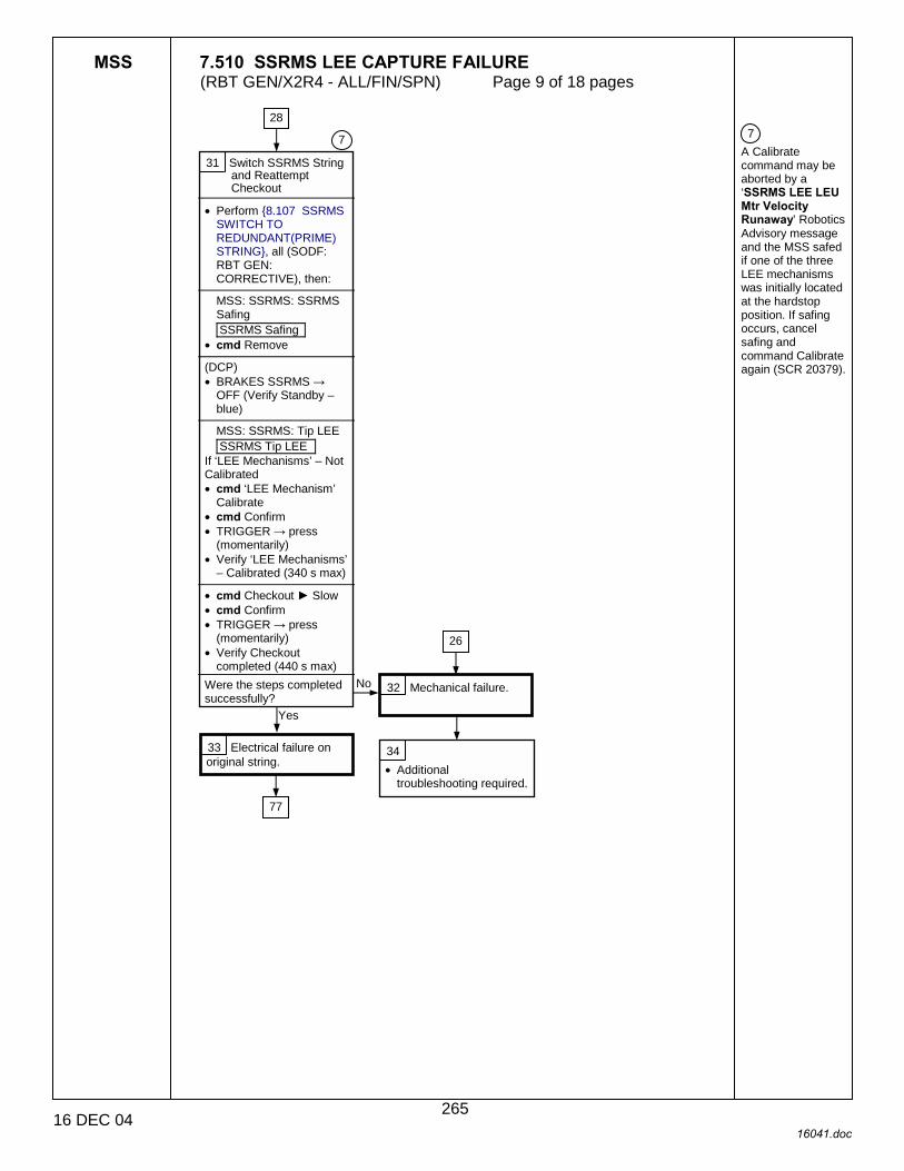
MSS 7.510 SSRMS LEE CAPTURE FAILURE (RBT GEN/X2R4 - ALL/FIN/SPN) Page 9 of 18 pages
16 DEC 04 16041.doc
7 A Calibrate command may be aborted by a ‘SSRMS LEE LEU Mtr Velocity Runaway’ Robotics Advisory message and the MSS safed if one of the three LEE mechanisms was initially located at the hardstop position. If safing occurs, cancel safing and command Calibrate again (SCR 20379).
31 Switch SSRMS String and Reattempt Checkout
• Perform {8.107 SSRMS SWITCH TO REDUNDANT(PRIME) STRING}, all (SODF: RBT GEN: CORRECTIVE), then:
MSS: SSRMS: SSRMS Safing SSRMS Safing
• cmd Remove (DCP) • BRAKES SSRMS →
OFF (Verify Standby – blue)
MSS: SSRMS: Tip LEE SSRMS Tip LEE
If ‘LEE Mechanisms’ – Not Calibrated • cmd ‘LEE Mechanism’
Calibrate • cmd Confirm • TRIGGER → press
(momentarily) • Verify ‘LEE Mechanisms’
– Calibrated (340 s max) • cmd Checkout ► Slow • cmd Confirm • TRIGGER → press
(momentarily) • Verify Checkout
completed (440 s max) Were the steps completed successfully?
32 Mechanical failure.
34 • Additional
troubleshooting required.
33 Electrical failure on original string.
Yes
28
7
26
No
77
265

MSS 7.510 SSRMS LEE CAPTURE FAILURE (RBT GEN/X2R4 - ALL/FIN/SPN) Page 10 of 18 pages
16 DEC 04 16041.doc
5 If calibration is lost, completing the capture to hardstops will result in loss of uncommanded derigidization monitoring. Also, if mating is required, checkpoint data must be reset. 9 The carriage position is only available on the ground.
35 Microswitch or loadcell failure.
3
36 MSS: SSRMS: Tip LEE SSRMS Tip LEE
Do either of the following apply: ‘LEE Mechanisms’ – Calibrated or It is prefereable to complete capture uncalibrated, instead of switching strings, releasing, and recalibrating?
5
Yes
19 No
37 Failure Determination
MSS: SSRMS: Tip LEE SSRMS Tip LEE
‘Snare’ Close – gray and Capture – blue
‘Carriage’ Retract – gray, and Carriage position ≥ 23.0 cm
‘Carriage’ Retract – blue, Tension > 5950 N
‘Carriage’ Retract – blue, Tension ≤ 1000 N
‘Latch’ Latch – gray, Unlatch – gray
‘Connector Continuity’ Prime – No or Redundant – No and ‘Umbilical’ Mate – blue at the end of mating
38 Loadcell failure.
9
39
41
50
42
46 45
266

MSS 7.510 SSRMS LEE CAPTURE FAILURE (RBT GEN/X2R4 - ALL/FIN/SPN) Page 11 of 18 pages
16 DEC 04 16041.doc
40 Complete Capture
MSS: SSRMS: Limp SSRMS Limp
• cmd All Limp (Verify Limp – blue)
MSS: SSRMS: Tip LEE SSRMS Tip LEE
If ‘Carriage’ Retract - gray • cmd ‘Carriage’ Retract ►
Hards Stops ► Slow, Hard Stops
• cmd Confirm • TRIGGER → press (hold
until ‘Carriage’ Brakes – On) (90 s max)
• Verify ‘Carriage’ Retract − blue
If ‘Latch’ Latch – gray and latching is required • cmd ‘Latch’ Latch ►
Hard Stops ► Slow, Hard Stops
• cmd Confirm • TRIGGER → press (hold
until ‘Latch’ Brakes – On) (65 s max)
• Verify ‘Latch’ – blue
MSS: SSRMS: Limp SSRMS Limp
• cmd None Limp (Verify Standby – blue)
39 Close microswitch failed.
37
55
267

MSS 7.510 SSRMS LEE CAPTURE FAILURE (RBT GEN/X2R4 - ALL/FIN/SPN) Page 12 of 18 pages
16 DEC 04 16041.doc
41 Retract microswitch failed.
42 Latch microswitch failed.
45 Capture Continuation
MSS: SSRMS: Tip LEE SSRMS Tip LEE
If ‘Latch’ Latch – gray and latching is required
MSS: SSRMS: Limp SSRMS Limp
• cmd All Limp (Verify Limp – blue) MSS: SSRMS: Tip LEE SSRMS Tip LEE
• cmd ‘Latch’ Latch ► Hard Stops ► Slow, Hard Stops
• cmd Confirm • TRIGGER → press (hold
until ‘Latch’ Brakes – On) (65 s max)
• Verify ‘Latch’ – blue MSS: SSRMS: Limp SSRMS Limp
• cmd None Limp (Verify Standby – blue)
43 Is umbilical mating required?
44 Unlatch and Switch SSRMS Strings
MSS: SSRMS: Tip LEE SSRMS Tip LEE
• cmd ‘Latch’ Unlatch ► Hard Stops ► Slow, Hard Stops
• cmd Confirm • TRIGGER → press (hold
until ‘Latch’ • Brakes – On) (65 s max) • Verify ‘Latch’ Unlatch –
blue • Perform {8.107 SSRMS
SWITCH TO REDUNDANT(PRIME) STRING}, all (SODF: RBT GEN: CORRECTIVE), then:
MSS: SSRMS: SSRMS Safing SSRMS Safing
• cmd Remove
37 37
Yes
64
55
No
54
69 38
55
268

MSS 7.510 SSRMS LEE CAPTURE FAILURE (RBT GEN/X2R4 - ALL/FIN/SPN) Page 13 of 18 pages
16 DEC 04 16041.doc
46 Connector Continuity
• Perform {8.107 SSRMS SWITCH TO REDUNDANT(PRIME) STRING}, all (SODF: RBT GEN: CORRECTIVE), then:
MSS: SSRMS: Tip LEE SSRMS Tip LEE
‘Connector Continuity’ Prime – Yes and Redundant – Yes?
47
• Additional troubleshooting required.
48 Failed connector continuity indication on original string.
49 Remove Safing
MSS: SSRMS: SSRMS Safing SSRMS Safing
• cmd Remove
50 Loadcell failure.
51 Capture Continuation
MSS: SSRMS: Limp SSRMS Limp
• cmd All Limp (Verify Limp – blue)
MSS: SSRMS: Tip LEE SSRMS Tip LEE
• cmd ‘Carriage’ Retract ► Hards Stops ► Slow, Hard Stops
• cmd Confirm • TRIGGER → press (hold
until ‘Carriage’ Brakes – On) (90 s max)
If ‘Latch’ Latch – gray and latching is required • cmd ‘Latch’ Latch ►
Hard Stops ► Slow, Hard Stops
• cmd Confirm • TRIGGER → press (hold
until ‘Latch’ Brakes – On) (65 s max)
• Verify ‘Latch’ – blue
MSS: SSRMS: Limp SSRMS Limp
• cmd None Limp (Verify Standby – blue)
No
Yes
37
37
55
55
269

MSS 7.510 SSRMS LEE CAPTURE FAILURE (RBT GEN/X2R4 - ALL/FIN/SPN) Page 14 of 18 pages
16 DEC 04 16041.doc
10 When extending until Derigidize - blue, the trigger must be released once the derigidize indication turns blue. Fully extending the carriage while the SSRMS is braked may cause hardware damage. 11 The UMB Status is only available on the ground.
54 Hardstops Latching
MSS: SSRMS: Tip LEE SSRMS Tip LEE
• cmd Latch Latch ► Hard Stops ► Slow, Hard Stops
• cmd Confirm • TRIGGER → press (hold
until ‘Latch’ Brakes – On) (10 s max)
• Verify Mate – blue, ‘Connector Continuity’ Prime – Yes and Redundant – Yes
55 Derigidize Requirement
MSS: SSRMS: Tip LEE SSRMS Tip LEE
Derigidization required and ‘Carriage’ Derigidize – gray?
Yes No
13 40 43
45 49 51
44
53 Mating Requirement
MSS: SSRMS: Tip LEE SSRMS Tip LEE
Mating required and ‘Umbilical’ Mate – gray?
Yes
No
52 Calibration Check
MSS: SSRMS: Tip LEE SSRMS Tip LEE
‘LEE Mechanisms’ – Calibrated?
No
Yes
56 Extending to Derigidize
MSS: SSRMS: Tip LEE SSRMS Tip LEE
• cmd ‘Carriage’ Extend ► Hard Stops ► Slow, Hard Stops
• cmd Confirm • TRIGGER → press (hold
until Derigidize – blue) (20 s max)
• cmd Terminate
57 Mating Requirement
MSS: SSRMS: Tip LEE SSRMS Tip LEE
‘Umbilical’ Mate – gray and mating required?
58 Soft Stops Mating
MSS: SSRMS: Tip LEE SSRMS Tip LEE
• cmd ‘Umbilical’ Mate • cmd Confirm • TRIGGER → press
(momentarily) • Verify Mate – blue • Verify ‘Connector
Continuity’ Prime – Yes • Verify Redundant – Yes
(10 s max)
59 Derigidize requirement
MSS: SSRMS: Tip LEE SSRMS Tip LEE
‘Carriage’ Derigidize – gray and derigidization required?
60 Umbilical Status Check
Mating required and checkpoint data indicates umbilicals are demated?
61 Derigidizing
MSS: SSRMS: Tip LEE SSRMS Tip LEE
• cmd ‘Carriage’ Derigidize ► Slow
• cmd Confirm • TRIGGER → press
(momentarily) • Verify Derig – blue
(90 s max)
55
11
No
Yes
NoYes
10
65
60
76
6
63 62
No Yes
63
63
270
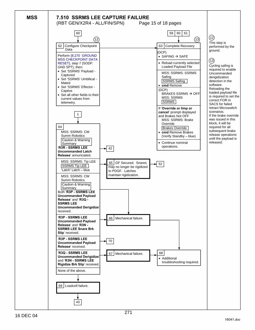
MSS 7.510 SSRMS LEE CAPTURE FAILURE (RBT GEN/X2R4 - ALL/FIN/SPN) Page 15 of 18 pages
16 DEC 04 16041.doc
12 This step is performed by the ground. 13 Cycling safing is required to enable Uncommanded derigidization detection in the software. Reloading the loaded payload file is required to set the correct FOR in SACS for failed retract Microswitch scenarios. If the brake override was issued in this block, it will be required for all subsequent brake release operations until the payload is released.
62 Configure Checkpoint Data
Perform {8.270 GROUND MSS CHECKPOINT DATA RESET}, step 7 (SODF: GND SPT), then: • Set ‘SSRMS’ Payload -
Captured • Set ‘SSRMS’ Umbilical -
Mated • Set ‘SSRMS’ Effector -
Captive • Set all other fields to their
current values from telemetry.
63 Complete Recovery
(DCP) • SAFING ! SAFE
• Reload currently selected
Loaded Payload File
MSS: SSRMS: SSRMS Safing SSRMS Safing
• cmd Remove (DCP)
BRAKES SSRMS ! OFF MSS: SSRMS SSRMS
If ‘Override or limp or cancel’ prompt displayed and Brakes Not OFF
MSS: SSRMS: Brake Override Brakes Override
• cmd Remove Brakes (Verify Standby – blue)
• Continue nominal
operations.
12
59 60 61
13
64 MSS: SSRMS: CW Summ Robotics Caution & Warning Summary
‘R3R - SSRMS LEE Uncommanded Latch Release’ annunciated.
MSS: SSRMS: Tip LEE SSRMS Tip LEE ‘Latch’ Latch – blue
MSS: SSRMS: CW Summ Robotics Caution & Warning Summary
Both ‘R3P - SSRMS LEE Uncommanded Payload Release’ and ‘R3Q - SSRMS LEE Uncommanded Derigidize’ received.
‘R3P - SSRMS LEE Uncommanded Payload Release’ and ‘R3N - SSRMS LEE Snare Brk Slip’ received.
‘R3P - SSRMS LEE Uncommanded Payload Release’ received.
‘R3Q - SSRMS LEE Uncommanded Derigidize’ and ‘R3N - SSRMS LEE Rigidize Brk Slip’ received.
None of the above.
1
42
65 GF Secured. Snares may no longer be rigidized to PDGF. Latches maintain rigidization.
52
66 Mechanical failure.
67 Mechanical failure. 68 • Additional
troubleshooting required.
69 Loadcell failure.
43
60
70
271

MSS 7.510 SSRMS LEE CAPTURE FAILURE (RBT GEN/X2R4 - ALL/FIN/SPN) Page 16 of 18 pages
16 DEC 04 16041.doc
8 When extending until derigidize – blue, the trigger must be released once the derigidize indication turns blue.
70 Switch SSRMS Strings
• Perform {8.107 SSRMS SWITCH TO REDUNDANT(PRIME) STRING}, all (SODF:RBT GEN: CORRECTIVE), then:
MSS: SSRMS: SSRMS Safing SSRMS Safing
• cmd Remove (DCP) • BRAKES SSRMS →
OFF MSS: SSRMS SSRMS
If ‘Override or limp or cancel’ prompt displayed and Brakes Not OFF
MSS: SSRMS: Brake Override Brakes Override
• cmd Remove Brakes (Verify Standby – blue)
64
71 Uncalibrated Release
MSS: SSRMS: Limp SSRMS Limp
• cmd All Limp (Verify Limp – blue)
MSS: SSRMS: Tip LEE: SSRMS Tip LEE If ‘Latch’ Unlatch – gray • cmd ‘Latch’ Unlatch ► Hard Stops ► Slow,
Hard Stops • cmd Confirm • TRIGGER → press (hold until ‘Latch’
Brakes – On) (65 s max) • Verify ‘Latch’ Unlatch – blue
If Carriage Derigidize – gray • cmd ‘Carriage’ Extend ► Hard Stops ►
Slow, Hard Stops • cmd Confirm • TRIGGER → press (hold until Derigidize –
blue) (20 s max) • Verify Derigidize – blue • cmd Terminate
If ‘Snare’ Open – gray • cmd ‘Snare’ Open ► Hard Stops ► Slow,
Hard Stops • cmd Confirm • TRIGGER → press (hold until ‘Snare’
Brakes – On) (12 s max) • Verify ‘Snare’ Open – blue If ‘Carriage’ Extend – gray • cmd ‘Carriage’ Extend ► Hard Stops ►
Slow, Hard Stops • cmd Confirm • TRIGGER → press (hold until ‘Carriage’
Brakes – On) (90 s max) • Verify Extend – blue
MSS: SSRMS: Limp: SSRMS Limp
• cmd None Limp (Verify Standby – blue) MSS: SSRMS: SSRMS
• Enter Mode – Manual (Verify Manual – blue) MSS: SSRMS: Manual: Joint Lock Joint Lock
• Lock the joint that was originally locked during the capture.
• Back off until clear of GF pin.
8
72
272

MSS 7.510 SSRMS LEE CAPTURE FAILURE (RBT GEN/X2R4 - ALL/FIN/SPN) Page 17 of 18 pages
16 DEC 04 16041.doc
6 A locked joint will not be limped if SSRMS is in Manual mode when “All Limp” command is issued (SCR 29314). 7 A Calibrate command may be aborted by a ‘SSRMS LEE LEU Mtr Velocity Runaway’ Robotics Advisory message and the MSS safed if one of the three LEE mechanisms was initially located at the hardstop position. If safing occurs, cancel safing and command Calibrate again (SCR 20379).
72 Calibration
MSS: SSRMS: Tip LEE SSRMS Tip LEE
• cmd ‘LEE Mechanism’ Calibrate
• cmd Confirm • TRIGGER → press
(momentary) • Verify ‘LEE Mechanisms’
– Calibrated (340 s max)
7 6
73 Capture Re-attempt
• Maneuver to within grapple envelope.
MSS: SSRMS: Limp SSRMS Limp
• cmd All Limp (Verify Limp – blue)
MSS: SSRMS: Tip LEE SSRMS Tip LEE
• cmd ‘Snare’ Close ► Slow, Soft Stops
• cmd Confirm • TRIGGER → press
(momentarily) • Verify ‘Snare’ Close –
blue (12s max) ‘Snare’ Capture – blue? 74 Mechanical failure.
Additional troubleshooting required.
75 Capture microswitch failure on original string.
76 Capture Completion
MSS: SSRMS: Tip LEE SSRMS Tip LEE
• cmd ‘Carriage’ Retract ► Slow, Soft Stops
• cmd Confirm • TRIGGER → press (hold
until ‘Carriage’ Brakes – On) (90 s max)
If latching required • cmd ‘Latch’ Latch ► Soft
Stops ► Slow, Soft Stops
• cmd Confirm • TRIGGER → press (hold
until ‘Latch’ Brakes – On) (65 s max)
• Verify ‘Latch’ – blue
MSS: SSRMS: Limp SSRMS Limp
• cmd None Limp (Verify Standby – blue)
57
71
No
Yes
273

MSS 7.510 SSRMS LEE CAPTURE FAILURE (RBT GEN/X2R4 - ALL/FIN/SPN) Page 18 of 18 pages
16 DEC 04 16041.doc
10 When extending until Derigidize - blue, the trigger must be released once the derigidize indication turns blue. Fully extending the carriage while the SSRMS is braked may cause hardware damage.
77 Capture Maneuver
MSS: SSRMS SSRMS
• Enter Mode − Manual (Verify Manual – blue)
MSS: SSRMS: Manual Joint Lock Joint Lock
• Lock the joint that was originally locked during the capture.
28 30 33
78 Extending to Derigidize
MSS: SSRMS: Tip LEE SSRMS Tip LEE
If Tension > 445 N and Derigidize – gray • cmd ‘Carriage’ Extend ►
Hard Stops ► Slow, Hard Stops
• cmd Confirm • TRIGGER → press (hold
until Derigidize – blue) (20 s max)
• cmd Terminate Derigidize – blue or T < 445 N?
2
10
79 • Maneuver to within the
capture envelope.
16 26
6
80 String Switch
• Perform {8.107 SSRMS SWITCH TO REDUNDANT(PRIME) STRING}, all (SODF: RBT GEN: CORRECTIVE), then:
MSS: SSRMS: SSRMS Safing SSRMS Safing
• cmd Remove
MSS: SSRMS: Tip LEE SSRMS Tip LEE
• cmd ‘Carriage’ Extend ► Hard Stops ► Slow, Hard Stops
• cmd Confirm • TRIGGER → press (hold
until Derigidize – blue) (20 s max)
• cmd Terminate Derigidize – blue?
10 No
Yes
81 Recovery complete. Yes
No
82 Mechanical failure.
83 • Additional
troubleshooting required.
274

MSS 7.511 SSRMS LEE RELEASE FAILURE (RBT GEN/X2R4 - ALL/FIN/SPN) Page 1 of 5 pages
20 DEC 04 16033.doc
1 Unless otherwise noted, all displays are on PCS. 2 This table can be used by Ground for reference on LEE mechanism positions.
3 Throughout this procedure, MSS commands should not be issues while the trigger is hot. To change the configuration of the system, Safe to exit LEE operations (SCR 14662). 4 This block contains some ground only telemetry verification. 5 Do not switch strings if previously switched within this recovery procedure, or switched within a previously run recovery procedure.
MECH POSN
Retract 23.4cm
Demate 12.5cm
Unlatch 0
Derig 20.6cm
Open 0
Extend -0.076cm
LEE Release does Not Complete
1 • Determine operation
when abort occurred: Demate
Unlatch
Derigidize
Snare Open
Extend
Rerigidize (Retract)
3 Mated Status
‘R3O - �Msw Consistency Fail’ message raised when release aborted at end of demate?
7 Retract Status
MSS: SSRMS SSRMS Tip LEE
‘Carriage’ Retract – blue? Yes
No
5 MSS: SSRMS SSRMS Tip LEE
One of the following indications present: ‘Umbilical’ Mate – blue or ‘Connector Continuity’ Prime – Yes or ‘Connector Continuity’ Redundant – Yes?
No Yes
6 Switch Strings
• Perform {8.107 SSRMS SWITCH TO PRIME (REDUNDANT) STRING} (SODF: RBT GEN: CORRECTIVE), then:
MSS: SSRMS: SSRMS Safing SSRMS Safing
• cmd Remove
5
12
15
18
14
Yes
14 9
14
8
2 Retract Status
MSS: SSRMS SSRMS Tip LEE
Are any two of the following indications present: ‘Carriage’ Retract – blue or Mech Posn – 23.4 cm (9.2 in) or ‘R3O - �Msw Consistency Fail’ message raised at end of rigidization?
No
Yes
4 Retract
MSS: SSRMS SSRMS Tip LEE
• cmd Retract ►Slow, Hardstops
• cmd Confirm • TRIGGER → press
(Hold until ‘Carriage’ Brakes – ON, 90 s max)
Are any two of the following indications present: ‘Carriage’ Retract – blue Tension > 4000N Mech Posn – 23.4 cm (9.2 in)?
No
Yes
14
2 1
4
C&W ROBOTICS
C&W Messages Starting With
‘Rxx - �’
Nominal Config: Active RWS. SSRMS operational with Safing removed.
If SSRMS is based on MBS, MBS powered on both strings and Operational on one string.
If SSRMS is based on ISS PDGF, S0 and EXT MDMs configured for SEPS control.
3
{7.001 MSS FAILURE RESPONSE AND RECOVERY}, block 118 (SODF: RBT GEN: MALFUNCTION)
4
No
28
14
275

MSS 7.511 SSRMS LEE RELEASE FAILURE (RBT GEN/X2R4 - ALL/FIN/SPN) Page 2 of 5 pages
20 DEC 04 16033.doc
4 This block contains some Ground only telemetry verification. 5 Do not switch strings if previously switched within this recovery procedure, or switched within a previously run recovery procedure. 6 EVA workaround to release the Grapple Fixture pin may be possible. 7 When extending until Derigidize – blue, the trigger must be released once the Derigidize indication turns blue.
8 Retract
MSS: SSRMS SSRMS Tip LEE
• cmd Retract ►Slow, Hardstops
• cmd Confirm • TRIGGER → press
(Hold until ‘Carriage’ Brakes – ON, 90 s max)
‘Carriage’ Retract– blue? Yes
No
7
9 Switch Strings
• Perform {8.107 SSRMS SWITCH TO PRIME (REDUNDANT) STRING} (SODF: RBT GEN: CORRECTIVE), then:
MSS: SSRMS: SSRMS Safing
SSRMS Safing • cmd Remove
5
5 14
10 LEE mechanical failure. Additional troubleshooting required.
11 Unlatch
MSS: SSRMS SSRMS Tip LEE
• cmd Unlatch ►Slow, Hardstops
• cmd Confirm • TRIGGER → press
(Hold until ‘Latch’ Brakes – ON, 10 s max)
‘Latch’ Unlatch – blue?
No
16
Yes
13 LEE Mechanical failure. Additional troubleshooting required.
12 Latch Microswitch Status
‘R3O - � Latch Motion Detect Msw Fail’ raised during unlatch
and Latch Motion Detection – True
MSS: SSRMS SSRMS Tip LEE
‘Latch’ Unlatch – blue or ‘R3O - �Msw Consistency Fail’ message raised when release aborted at end of unlatch
None of the above.
15 Derigidize Status
MSS: SSRMS SSRMS Tip LEE
‘Carriage’ Derigidize – blueor ‘R3O - �Msw Consistency Fail’ message raised when release aborted at end of derigidize?
No 16 Derigidize
MSS: SSRMS SSRMS Tip LEE
• cmd Extend ►Slow, Hardstops
• cmd Confirm • TRIGGER → press
(Hold until Derigidize msw – blue, 20 s max)
‘Carriage’ Derigidize – blue?
No
14 Unlatch
MSS: SSRMS SSRMS Tip LEE
• cmd Unlatch ►Slow, Hardstops
• cmd Confirm • TRIGGER → press
(Hold until ‘Latch’ Brakes – ON, 65 s max)
‘Latch’ Unlatch – blue?
No
14
1
9
19 25
Yes
1
16
Yes Yes
11 14 12
6
16
2 3 8
17
7 5 4
6
9
12
4
7
276
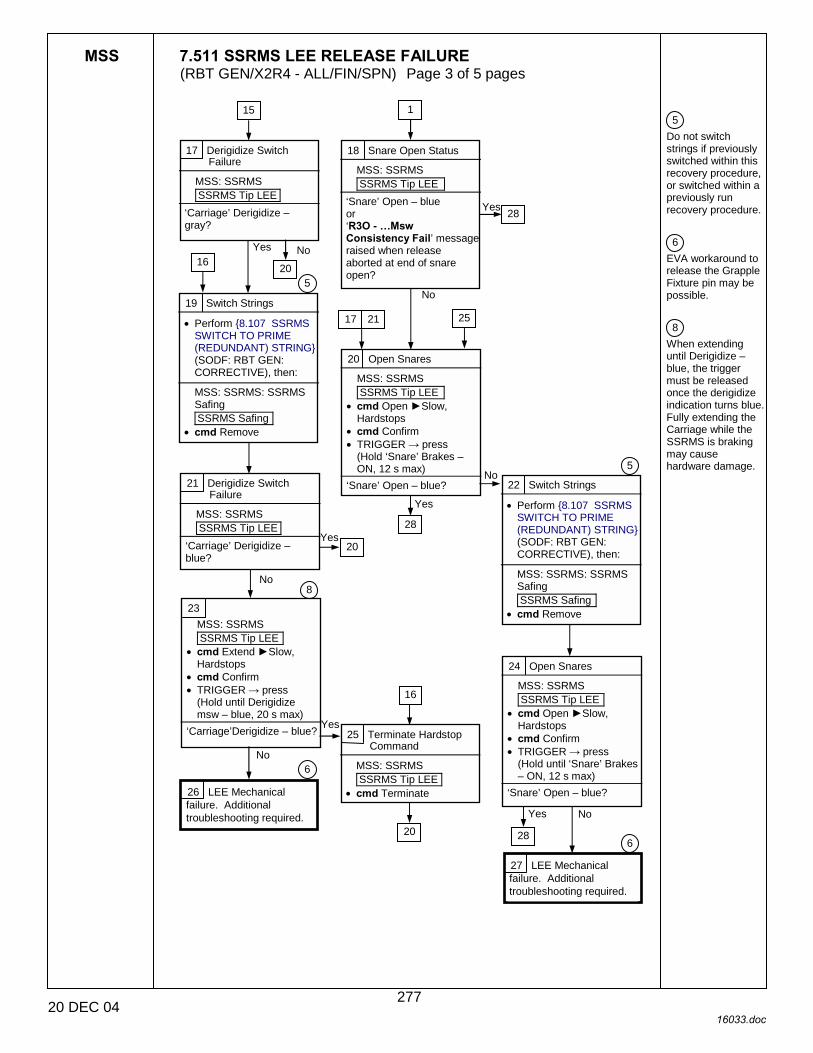
MSS 7.511 SSRMS LEE RELEASE FAILURE (RBT GEN/X2R4 - ALL/FIN/SPN) Page 3 of 5 pages
20 DEC 04 16033.doc
5 Do not switch strings if previously switched within this recovery procedure, or switched within a previously run recovery procedure. 6 EVA workaround to release the Grapple Fixture pin may be possible. 8 When extending until Derigidize – blue, the trigger must be released once the derigidize indication turns blue. Fully extending the Carriage while the SSRMS is braking may cause hardware damage.
19 Switch Strings
• Perform {8.107 SSRMS SWITCH TO PRIME (REDUNDANT) STRING} (SODF: RBT GEN: CORRECTIVE), then:
MSS: SSRMS: SSRMS Safing SSRMS Safing
• cmd Remove
5
23 MSS: SSRMS SSRMS Tip LEE
• cmd Extend ►Slow, Hardstops
• cmd Confirm • TRIGGER → press
(Hold until Derigidize msw – blue, 20 s max)
‘Carriage’Derigidize – blue?
No
Yes
17 Derigidize Switch Failure
MSS: SSRMS SSRMS Tip LEE
‘Carriage’ Derigidize – gray?
Yes
18 Snare Open Status
MSS: SSRMS SSRMS Tip LEE
‘Snare’ Open – blue or ‘R3O - �Msw Consistency Fail’ message raised when release aborted at end of snare open?
Yes
No
20 Open Snares
MSS: SSRMS SSRMS Tip LEE
• cmd Open ►Slow, Hardstops
• cmd Confirm • TRIGGER → press
(Hold ‘Snare’ Brakes – ON, 12 s max)
‘Snare’ Open – blue? 22 Switch Strings
• Perform {8.107 SSRMS SWITCH TO PRIME (REDUNDANT) STRING} (SODF: RBT GEN: CORRECTIVE), then:
MSS: SSRMS: SSRMS Safing SSRMS Safing
• cmd Remove
5
25 Terminate Hardstop Command
MSS: SSRMS SSRMS Tip LEE
• cmd Terminate 26 LEE Mechanical failure. Additional troubleshooting required.
15
16
No
Yes
16
1
No
No
Yes
No
20
17 21
20
21 Derigidize Switch Failure
MSS: SSRMS SSRMS Tip LEE
‘Carriage’ Derigidize – blue?
25
6
27 LEE Mechanical failure. Additional troubleshooting required.
24 Open Snares
MSS: SSRMS SSRMS Tip LEE
• cmd Open ►Slow, Hardstops
• cmd Confirm • TRIGGER → press
(Hold until ‘Snare’ Brakes – ON, 12 s max)
‘Snare’ Open – blue?
No Yes
6 20
8
28
28
28
277

MSS 7.511 SSRMS LEE RELEASE FAILURE (RBT GEN/X2R4 - ALL/FIN/SPN) Page 4 of 5 pages
20 DEC 04 16033.doc
5 Do not switch strings if previously switched within this recovery procedure, or switched within a previously run recovery procedure.
28 SSRMS Brakes Release
(DCP) • BRAKES SSRMS → OFF
Brakes OFF?
29 • Perform {8.107 SSRMS
SWITCH TO PRIME (REDUNDANT) STRING} (SODF: RBT GEN: CORRECTIVE), then:
MSS: SSRMS: SSRMS Safing SSRMS Safing
• cmd Remove (DCP) • BRAKES SSRMS → OFF
30 Extend Status
MSS: SSRMS SSRMS Tip LEE
‘Carriage’ Extend – blue or ‘R3O - �Msw Consistency Fail’ message raised when release aborted at end of extend?
31 Extend
MSS: SSRMS: Limp SSRMS Limp
• cmd All Limp (Verify Limp – blue) MSS: SSRMS SSRMS Tip LEE
• cmd Extend ►Slow, Hardstops
• cmd Confirm • TRIGGER → press
(Hold until motor – Inh) (90 s max)
‘Carriage’ Extend – blue? 32 MSS: SSRMS: Limp SSRMS Limp
• cmd None Limp (Verify Standby – blue)
33 Back off Maneuver
MSS: SSRMS: SSRMS • Enter Mode – Manual
MSS: SSRMS: Manual Joint Lock Joint Lock
• cmd SR(SY) Lock as required
Back off from Grapple fixture until clear of pin.
28
30 Yes
No
Yes
Yes
No
1 24 18 20
37
34
38
5
278
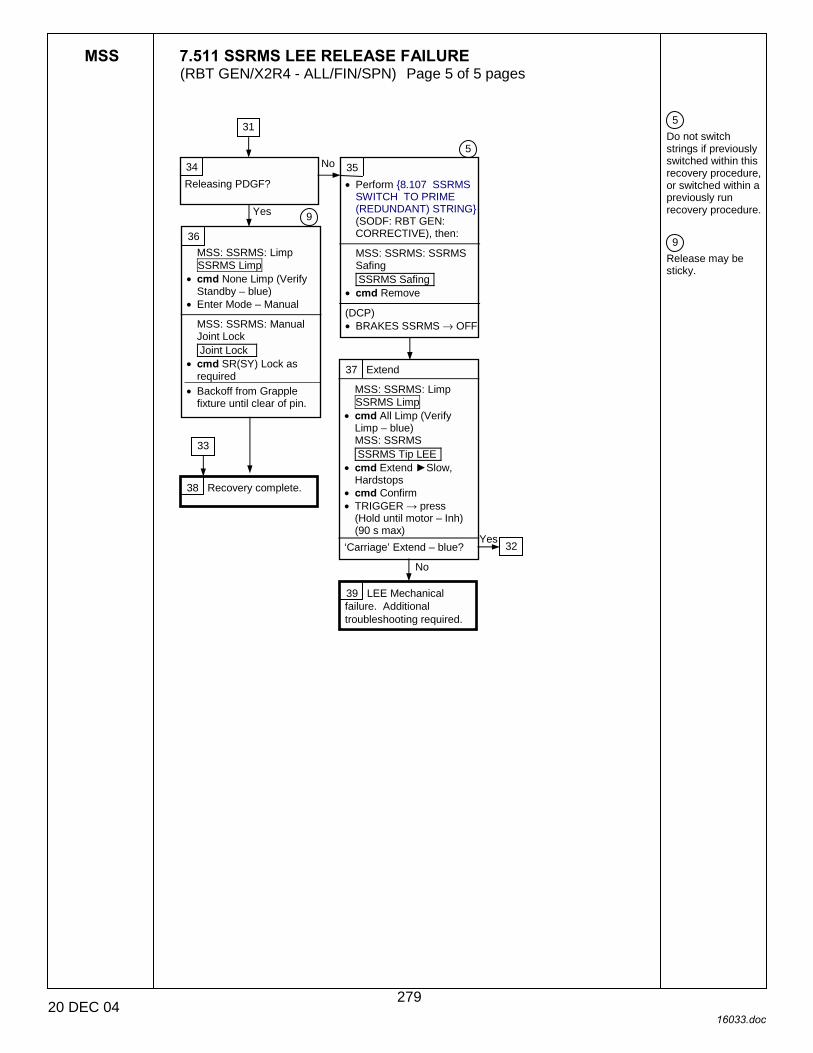
MSS 7.511 SSRMS LEE RELEASE FAILURE (RBT GEN/X2R4 - ALL/FIN/SPN) Page 5 of 5 pages
20 DEC 04 16033.doc
5 Do not switch strings if previously switched within this recovery procedure, or switched within a previously run recovery procedure. 9 Release may be sticky.
34 Releasing PDGF?
35 • Perform {8.107 SSRMS
SWITCH TO PRIME (REDUNDANT) STRING} (SODF: RBT GEN: CORRECTIVE), then:
MSS: SSRMS: SSRMS Safing SSRMS Safing
• cmd Remove (DCP) • BRAKES SSRMS → OFF
37 Extend
MSS: SSRMS: Limp SSRMS Limp
• cmd All Limp (Verify Limp – blue) MSS: SSRMS SSRMS Tip LEE
• cmd Extend ►Slow, Hardstops
• cmd Confirm • TRIGGER → press
(Hold until motor – Inh) (90 s max)
‘Carriage’ Extend – blue?
38 Recovery complete.
39 LEE Mechanical failure. Additional troubleshooting required.
Yes
No
No
31
33
36 MSS: SSRMS: Limp SSRMS Limp
• cmd None Limp (Verify Standby – blue)
• Enter Mode – Manual
MSS: SSRMS: Manual Joint Lock Joint Lock
• cmd SR(SY) Lock as required
• Backoff from Grapple fixture until clear of pin.
5
9
32 Yes
279

This Page Intentionally Blank
22 DEC 04
280

MSS 7.700 MSS VIDEO POWER ON COMMAND FAILURE (RBT GEN/X2R4 - ALL/FIN/SPN) Page 1 of 2 pages
13 DEC 04 16034.doc
{7.001 MSS FAILURE RESPONSE AND RECOVERY}, block 133 (SODF: RBT GEN: MALFUNCTION)
1 Unless otherwise noted, all displays in this procedure are on PCS.
Unsuccessful Power On of an MSS Video Unit
1 Equipment Needed
Is the VDU, camera, or light required for MSS Operations?
3 VDU Power Cycle
For MSS Video Derouting MSS: Video: Video Overview Video Overview
• Repeat the following for all destinations to which the camera associated with the failed video unit is routed:
• sel ‘Destination Icon’ • cmd ‘Deroute Video
Signal’ – Deroute For the affected VDU, camera and light
MSS: MBS: MBS central camera icon MBS Camera
•√‘Power’ Keep-Alive •√‘Light’ Keep-Alive
MSS: MBS: VDU1 MSS VDUs
•√Keep-Alive • cmd On If required
MSS: MBS: MBS central camera icon MBS Camera
• cmd ‘Power’ On • cmd ‘Light’ On
Was the power cycle completed nominally?
4 Transient failure. Yes
No
5 Isolate Failure
• Determine failed video component.
For failed VDU
For failed CLA, CLPA, or LA.
6 • Continue nominal
operations.
7 • Continue MSS operations
with remaining VDUs, cameras, and lights.
1
Yes
No
8
Nominal Config: RWS is Active. Affected element is Operational.
If SSRMS is based on MBS, MBS powered on both strings and Operational on one string.
S0(S1,P1) and EXT MDMs configured for SEPS control.
2 Check C&W
MSS: SSRMS: CW Summ Robotics: Caution & Warning Summary
‘R9Z - MSS OCS � Cmd Sequence Err’message raised?
No
1
7
8 Yes
281
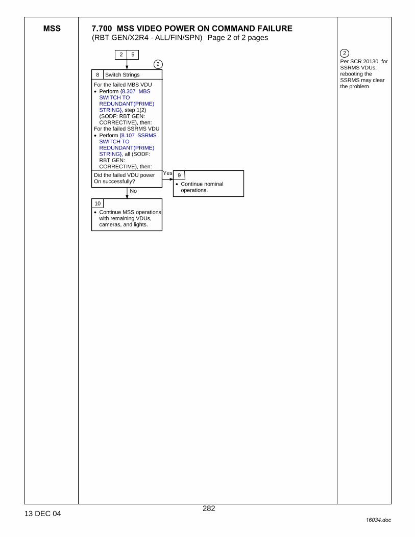
MSS 7.700 MSS VIDEO POWER ON COMMAND FAILURE (RBT GEN/X2R4 - ALL/FIN/SPN) Page 2 of 2 pages
13 DEC 04 16034.doc
2 Per SCR 20130, for SSRMS VDUs, rebooting the SSRMS may clear the problem.
8 Switch Strings
For the failed MBS VDU • Perform {8.307 MBS
SWITCH TO REDUNDANT(PRIME) STRING}, step 1(2) (SODF: RBT GEN: CORRECTIVE), then:
For the failed SSRMS VDU • Perform {8.107 SSRMS
SWITCH TO REDUNDANT(PRIME) STRING}, all (SODF: RBT GEN: CORRECTIVE), then:
Did the failed VDU power On successfully?
2
9 • Continue nominal
operations.
10 • Continue MSS operations
with remaining VDUs, cameras, and lights.
Yes
No
2
5
282

MSS 7.701 MSS VIDEO FAILURE (RBT GEN/X2R4 - ALL/FIN/SPN) Page 1 of 8 pages
20 DEC 04 16035.doc
1 Unless otherwise indicated all displays in this procedure are on the PCS.
{7.001 MSS FAILURE RESPONSE AND RECOVERY}, block 135 (SODF: RBT GEN: MALFUNCTION)
C&W Robotics
C&W messages starting with ‘R6�’
Nominal Config: DCP powered in correct sequence.
Monitor brightness and monitor viewing angle appropriate.
CVIUs powered. AVU is not powered. Sync is enabled on both channels to the MSS VDUs.
MSS Video Route/Deroute Failure, Loss of Video, or Degraded Video
1 Video Failure Signature
MSS: SSRMS: CW Summ Robotics: Caution & Warning Summary
Any messages starting with ‘R6�’ currently in alarm.
Image degradation or loss of video.
Route or deroute problem to/from an RWS monitor.
2
Loss or degradation of video image
Lighting issues affecting the image.
Image degradation not related to lighting.
No video or frozen video.
3 Routing Status Message
C&T:Video: Video Overview ‘Last Attempted Route’ ‘Status’
No path available
Invalid command
No MSS response
Video sw failure
SCU not active or no CSR available
No status message
4 DCP Camera Select Button Checkout
(DCP) While monitoring DCP Status page on the PCS. • Depress and hold each
camera select button for 10 seconds.
MSS: LAS5(LAP5) DCP: Lab (Cup) DCP Status ‘Camera Select’
• Verify checkmark appears for all buttons when selected
Checkmark appears for all camera select buttons?
5 Video system issue. No SCU currently active or all EVSU 1 and 2 CSRs currently in use.
43
12
18
36
28
9
46
44 9
No Yes
40
1
6 IVSU or EVSU Switch failure. The ISVU/EVSU sw configuration does not match commanded.
3
7 • Coordinate with CATO
for troubleshooting the USOS video system.
283

MSS 7.701 MSS VIDEO FAILURE (RBT GEN/X2R4 - ALL/FIN/SPN) Page 2 of 8 pages
20 DEC 04 16035.doc
8 MSS did not respond to a route/deroute command within 60 seconds.
9 The source and or destination for the route/deroute is not valid.
10 • Verify the VDU
associated with the Camera is powered On.
• Reattempt route/deroute.
11 • Reference {9.907
MSS/ISS CAMERA NUMBER TABLE} (SODF: RBT GEN: REFERENCE) to verify source and destination DCPL ID and reattempt route/deroute.
12 Lighting problem.
13 Image washed out or a hot spot in the image.
Not enough light or image too dark.
14 Too much light.
16 • Pan/tilt to remove hot
spot from image. • Turn off light in the FOV
causing the hot spot. • Change Camera settings
to counteract the hot spot (Peek, Avg, Norm, or manually adjust Iris and shutter speed).
• Wait for sun or reflection to move out the FOV.
17 • Ensure the Camera’s light
is on. • Use other Camera lights
as spot lights. • Verify that Camera is not
pointed at black space. • Adjust Gamma to .45 for
better view in shadowed regions.
• Wait for sunrise.
15 Not enough light.
3 4
2
284
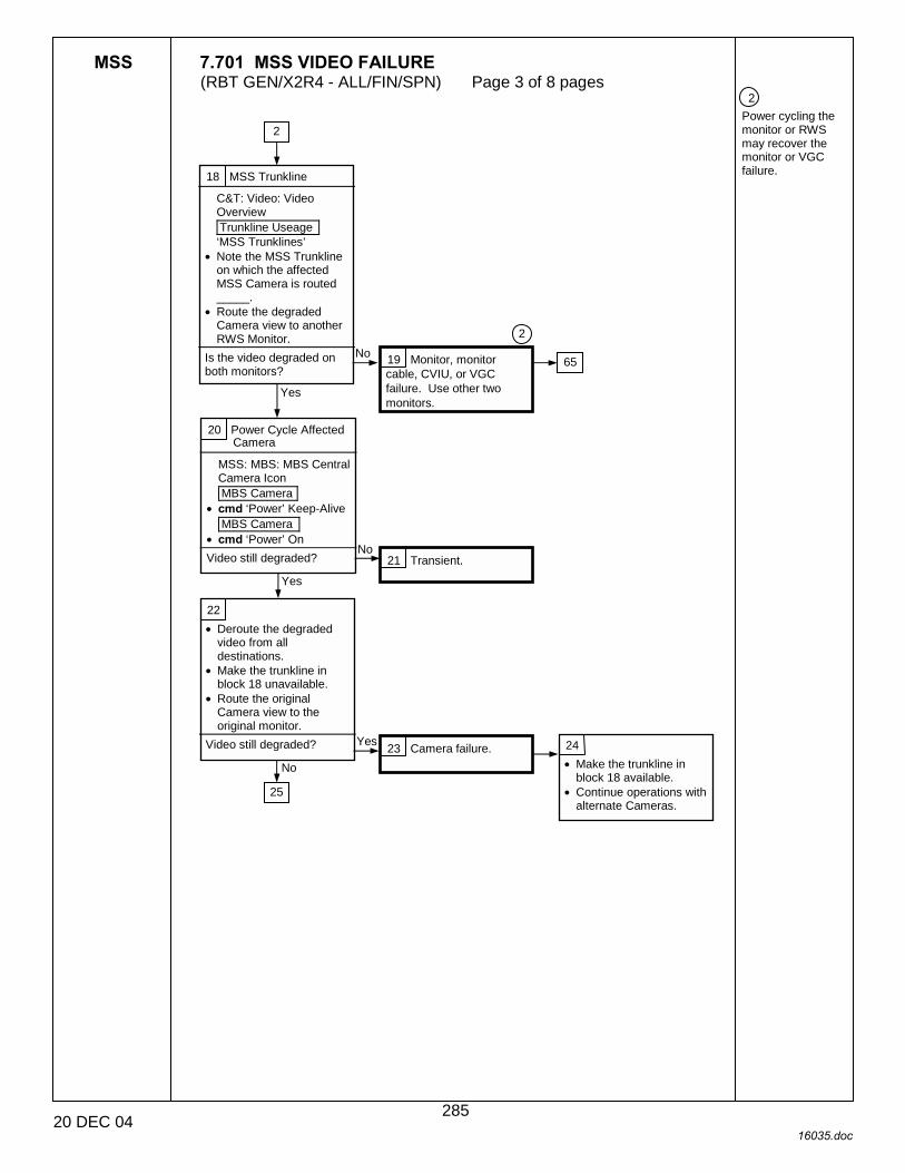
MSS 7.701 MSS VIDEO FAILURE (RBT GEN/X2R4 - ALL/FIN/SPN) Page 3 of 8 pages
20 DEC 04 16035.doc
2 Power cycling the monitor or RWS may recover the monitor or VGC failure.
18 MSS Trunkline
C&T: Video: Video Overview Trunkline Useage ‘MSS Trunklines’
• Note the MSS Trunkline on which the affected MSS Camera is routed _____.
• Route the degraded Camera view to another RWS Monitor.
Is the video degraded on both monitors?
19 Monitor, monitor cable, CVIU, or VGC failure. Use other two monitors.
20 Power Cycle Affected Camera
MSS: MBS: MBS Central Camera Icon MBS Camera
• cmd ‘Power’ Keep-Alive MBS Camera
• cmd ‘Power’ On Video still degraded? 21 Transient.
22 • Deroute the degraded
video from all destinations.
• Make the trunkline in block 18 unavailable.
• Route the original Camera view to the original monitor.
Video still degraded? 23 Camera failure. 24 • Make the trunkline in
block 18 available. • Continue operations with
alternate Cameras.
2
65
25
Yes
No
No
Yes
No
Yes
2
285
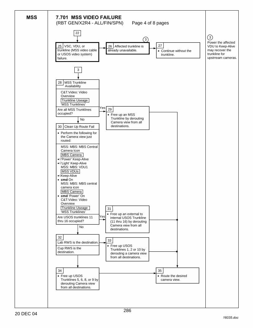
MSS 7.701 MSS VIDEO FAILURE (RBT GEN/X2R4 - ALL/FIN/SPN) Page 4 of 8 pages
20 DEC 04 16035.doc
3 Power the affected VDU to Keep-Alive may recover the trunkline for upstrream cameras.
25 VSC, VDU, or trunkline (MSS video cable or USOS video system) failure.
26 Affected trunkline is already unavailable.
27 • Continue without the
trunkline.
28 MSS Trunkline Availability
C&T:Video: Video Overview Trunkline Useage ‘MSS Trunklines’
Are all MSS Trunklines occupied?
29 • Free up an MSS
Trunkline by derouting Camera view from all destinations. 30 Clean Up Route Fail
• Perform the following for the Camera view just routed:
MSS: MBS: MBS Central Camera Icon MBS Camera
•√‘Power’ Keep-Alive •√‘Light’ Keep-Alive
MSS: MBS: VDU1 MSS VDUs
•√Keep-Alive • cmd On
MSS: MBS: MBS central camera icon MBS Camera
• cmd ‘Power’ On C&T:Video: Video Overview Trunkline Useage ‘MSS Trunklines’
Are USOS trunklines 11 thru 16 occupied?
31 • Free up an external to
internal USOS Trunkline (11 thru 16) by derouting Camera view from all destinations.
32 Lab RWS is the destination.
Cup RWS is the destination.
33 • Free up USOS
Trunklines 1, 2 or 10 by derouting a camera view from all destinations.
34 • Free up USOS
Trunklines 5, 6, 8, or 9 by derouting Camera view from all destinations.
35 • Route the desired
camera view.
22
3
3
Yes
No
Yes
No
286

MSS 7.701 MSS VIDEO FAILURE (RBT GEN/X2R4 - ALL/FIN/SPN) Page 5 of 8 pages
20 DEC 04 16035.doc
4 VSC failure may affect multiple MSS Trunklines.
Table 1. Base = Lab DGF Base = MBS PDGF 1 or 2 Base = MBS PDGF 3 or 4
Camera MSS T/L
! EVSU Camera MSS T/L ! EVSU Camera MSS
T/L ! EVSU
1 ! EVSU
3 4 !EVSU
1 5 ! EVSU
1
2 ! EVSU
2 6 !EVSU
2 7 ! EVSU
2 SSRMS Cameras
3 ! EVSU
1
SSRMS Cameras
9 !EVSU
3
SSRMS Cameras
8 ! EVSU
3 MBS Camera 5 !
EVSU 1
MBS Camera 5 !
EVSU 1
MBS Camera 9 !
EVSU 3
36 Is the monitor ID blinking for the affected monitor.
37 Monitor, monitor cable harness, or VGC failure.
38 VSC power supply failure or USOS video system failure.
39 • Coordinate with CATO
for troubleshooting the USOS video system.
40 C&T: Video: Video Overview Trunkline Useage ‘MSS Trunklines’
Is affected Camera on more than one MSS Trunkline?
41 • Deroute Camera from all
destinations. MSS: MBS: MBS Central Camera Icon MBS Camera
•√‘Power’ Keep-Alive •√‘Light’ Keep-Alive
MSS: MBS: VDU1 MSS VDUs
•√Keep-Alive • cmd On
MSS: MBS: MBS Central Camera Icon MBS Camera
• cmd ‘Power’ On • Reattempt original route.
42 • Route the source to a
different monitor. Was route successful? 43 Transient.
44 DCP button failure.
45 • Reassign affected
Cameras to different DCPL numbers or use PCS to route desired Camera.
2
No
Yes
4
3
Yes
No
4 No
Yes
65
287
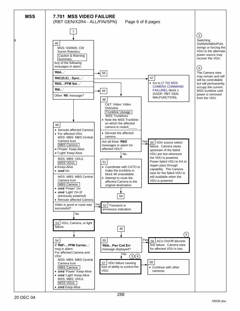
MSS 7.701 MSS VIDEO FAILURE (RBT GEN/X2R4 - ALL/FIN/SPN) Page 6 of 8 pages
20 DEC 04 16035.doc
9
5 Switching SSRMS/MBS/POA strings or forcing the VDU to the alternate power source may recover the VDU. 6 The Camera view may remain and will still be controllable but will permanently occupy the current MSS trunkline until power is removed from the VDU.
46 MSS: SSRMS: CW Summ Robotics: Caution & Warning Summary
Any of the following messages in alarm:
‘R6A�’
‘R6C(D,E)�Sync�’
‘R6G�PFM Sel�’
‘R6I�’
Other ‘R6’ message?
47 • Go to {7.702 MSS
CAMERA COMMAND FAILURE}, block 1 (SODF: RBT GEN: MALFUNCTION).
48 C&T: Video: Video Overview Trunkline Useage ‘MSS Trunklines’
• Note the MSS Trunkline on which the affected camera is routed_____
• Deroute the affected
camera. Are all three ‘R6G’ messages in alarm for affected VDU?
52 Transient or erroneous indication.
53 VDU, Camera, or light failure.
54 If ‘R6F-�PFM Carrier�’ msg in alarm For affected Camera and VDU
MSS: MBS: MBS Central Camera Icon MBS Camera
• cmd ‘Power’ Keep-Alive • cmd ‘Light’ Keep-Alive
MSS: MBS: VDU1 MSS VDUs
• cmd Keep-Alive
55 ‘R6A�Pwr Cntl Err’ message displayed?
56 ACU On/Off discrete line failure. Camera view for affected VDU is lost.
57 VDU failure causing loss of ability to control the VDU.
58 • Continue with other
cameras.
1
55
64
51 • Coordinate with CATO to
make the trunkline in block 48 unavailable.
• Attempt to route the affected Camera to the original destination.
Yes
No
No
Yes
49 • Deroute affected Camera • For affected VDU
MSS: MBS: MBS Central Camera Icon MBS Camera
•√‘Power’ Keep-Alive •√‘Light’ Keep-Alive
MSS: MBS: VDU1 MSS VDUs
•√Keep-Alive • cmd On
MSS: MBS: MBS Central Camera Icon MBS Camera
• cmd ‘Power’ On • cmd ‘Light’ On (if
previously powered) • Reroute affected Camera
Video is good or route was successful?
No
Yes
50 VDU source select failure. Camera views upstream of the failed VDU are lost whenever the VDU is powered. Power failed VDU to KA to regain pass through capability. The Camera view for the failed VDU is still available when the VDU is powered.
59
5 6
46
5
288

MSS 7.701 MSS VIDEO FAILURE (RBT GEN/X2R4 - ALL/FIN/SPN) Page 7 of 8 pages
20 DEC 04 16035.doc
7 The ground can perform the following if desired: Perform {8.260 MSS POWERDOWN}, steps 5 to 6.4 (SODF: GND: RBT: NOMINAL) Perform {8.250 MSS POWERUP}, steps 1.2 to 2 (SODF: GND: RBT: NOMINAL)
59 Was route successful?
60 VDU failure affecting the trunkline in block 44.
61 VDU SWEP or VDU source select failure. Camera view associated with the failed VDU is lost.
62 • Make the trunkline in
block 48 available. • Deroute affected camera
from all destination.
63 For affected Camera and VDU
MSS: MBS: MBS central camera icon X Camera
• cmd ‘Power’ Keep-Alive • cmd ‘Light’ Keep-Alive
MSS: MBS: VDU1 MSS VDUs
• cmd Keep-Alive
64 ‘R6I�VGS Comm Shut Down VGC�’ message displayed?
65 Is the monitor required for operations?
66 RWS Power Cycle
(DCP) • SAFING ! SAFE
• Perform {6.334 MSS
POWERDOWN} step 4 (SODF: RBT GEN: NOMINAL), then:
• Perform {6.332 MSS POWERUP}, steps 1 to 2 (SODF: RBT GEN: NOMINAL), then:
‘R6I � VGS Comm Shut Down�’ message recurs?
67 • Continue operations with
other monitors.
68 Is the Monitor/Video view black?
69 VGC failure causing degraded video on associated monitor.
70 MSS: SSRMS: Overlay Overlay Control ‘Cupola(Lab) W/S’
For affected monitor • cmd Video – Off • cmd Video – On
Did video return?
71 Configure RWS
• Deflect THC and RHC to Hardstops in positive and negative directions for all axes.
• Configure Cameras and
overlays as required. • Continue operations.
72 MSS: SSRMS: Overlay Overlay Control ‘Cupola(Lab) W/S’
For affected monitor • cmd Overlay – On • cmd Quad 1 – Joint
Did error recur? 73 Transient. 74 • Continue operations.
51
46
76
Yes No
Yes
No No
Yes
No
Yes
65
75
No
Yes
No
Yes
69 37 70 19
7
65
Yes
289

MSS 7.701 MSS VIDEO FAILURE (RBT GEN/X2R4 - ALL/FIN/SPN) Page 8 of 8 pages
20 DEC 04 16035.doc
75 VGC failure. Loss of overlay capability on associated monitor. Video will be lost on affected monitor if its overlays are commanded.
76 Power Up Alt RWS
If Alt RWS DCP Bypass cable disconnected • Perform {6.114
LAB(CUP) RWS UOP BYPASS CABLE RECONFIGURATION}, step 2 (SODF: RBT GEN: NOMINAL), then:
• Perform {6.332 MSS POWERUP}, steps 1 and 2 (SODF: RBT GEN: NOMINAL), then:
• Deflect THC and RHC to Hardstops in positive and negative directions for all axes.
• Configure Cameras and
overlays as required.
77 Restore Video to the Monitor
MSS: SSRMS: Overlay Overlay Control ‘Cupola(Lab) W/S’
For affected monitor • cmd Video – Off • cmd Video – On
72 66
290

MSS 7.702 MSS CAMERA COMMAND FAILURE (RBT GEN/X2R4 - ALL/FIN/SPN) Page 1 of 8 pages
20 DEC 04 16036.doc
1 Unless otherwise indicated, all displays in this procedure are on the PCS. 2 This block contains some Ground-only telemetry verification. 3 OCS will only annunciate the ‘R6C - �.. Pass Thru (Regen) Sync 1(2) Err’ when a SWEP is issued. 4 Reference figures 1 and 2 for description of upstream/ downstream, and Sync path. 5 Do not command MBS and SSRMS VDUs to switch Sync channels with the same command. Due to SCR 26165 this will cause an OCS Fatal Failure.
{7.701 MSS VIDEO FAILURE}, block 47 (SODF: RBT GEN: MALFUNCTION){7.001 MSS FAILURE RESPONSE AND RECOVERY}, block 136 (SODF: RBT GEN: MALFUNCTION)
No Response or Unexpected Response from Camera Cmd.
Nominal Config: MSS Camera units and/or external camera units are on.
If SSRMS is based on MBS, MBS powered on both strings and Operational on one string.
S0(S1, P1) and EXT MDMs configured for SEPS control.
1 Caution and Warning
MSS: SSRMS: CW Summ Robotics: Caution & Warning Summary
Is ‘R6D - �.. PFM Carrier On Sync 1(2) Err’ in alarm for the most upstream powered VDU and all downstream VDUs in a given Sync path?
Is ‘R6C - �.. Pass Thru (Regen) Sync 1(2) Err’ in alarm, and/or is the PT/Regen switch in PT for affected VDU on Video Routing Ground Display or Is ‘R6E - �.. Baseband Sync Output Err’ in alarm or Is ‘R6D - �.. PFM Carrier On Sync 1(2) Err’ in alarm for any VDU(s)?
Did multiple Cameras respond to the Camera command?
No Camera response seen or wrong Camera responds?
Uncommanded Camera response?
2 Sync Verification
• Ground will verify Sync is enabled to the MSS Cameras.
• Resend Camera command.
Did command operate correctly?
No Yes
3 Swap Sync Channel
• Ground will verify Sync is available on alternate channel. MSS: Video: VSU1: MSS Sync Config MSS Sync Config ‘MSS VDU Sync’
• Configure appropriate VDUs Sync
• cmd alternate channel • Resend Camera
command. Did command operate correctly?
4 3 2 1
2
2
9
8 17
5
C&W ROBOTICS
C&W Messages Starting With
‘R6�’
4 Switch Failure Check
MSS: LAP5(LAS5) DCP: Lab(Cupola) DCP Status ‘CAMERA COMMAND’
Do any of the Camera Command switches show a check?
5 • For the affected Camera,
perform the following for the failed Camera functionality: MSS: MBS: MBS Central Camera Icon MBS Camera
• cmd Stop
6 The DCP switch failed closed for the respective command.
7 Anytime a new Monitor is selected the command associated with the failed switch will be sent to the Camera assigned to the monitor. Must use one of the following workarounds: • Send Stop cmd on PCS
each time a new monitor is selected
• Use PCS for video routing & video control
• Switch RWSs
17
25
21
No
Yes
3 1
No Yes
291
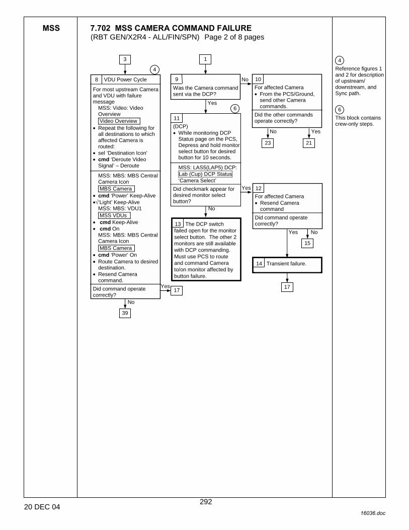
MSS 7.702 MSS CAMERA COMMAND FAILURE (RBT GEN/X2R4 - ALL/FIN/SPN) Page 2 of 8 pages
20 DEC 04 16036.doc
4 Reference figures 1 and 2 for description of upstream/ downstream, and Sync path. 6 This block contains crew-only steps.
8 VDU Power Cycle
For most upstream Camera and VDU with failure message
MSS: Video: Video Overview Video Overview
• Repeat the following for all destinations to which affected Camera is routed:
• sel ‘Destination Icon’ • cmd ‘Deroute Video
Signal’ – Deroute
MSS: MBS: MBS Central Camera Icon MBS Camera
• cmd ‘Power’ Keep-Alive •√‘Light’ Keep-Alive
MSS: MBS: VDU1 MSS VDUs
• cmd Keep-Alive • cmd On
MSS: MBS: MBS Central Camera Icon MBS Camera
• cmd ‘Power’ On • Route Camera to desired
destination. • Resend Camera
command. Did command operate correctly?
3
Yes
No
4
9 Was the Camera command sent via the DCP?
10 For affected Camera • From the PCS/Ground,
send other Camera commands.
Did the other commands operate correctly?
No
Yes
11 (DCP) • While monitoring DCP
Status page on the PCS, Depress and hold monitor select button for desired button for 10 seconds.
MSS: LAS5(LAP5) DCP: Lab (Cup) DCP Status ‘Camera Select’
Did checkmark appear for desired monitor select button?
6
12 For affected Camera • Resend Camera
command Did command operate correctly? 13 The DCP switch
failed open for the monitor select button. The other 2 monitors are still available with DCP commanding. Must use PCS to route and command Camera to/on monitor affected by button failure.
14 Transient failure.
17
39
15
Yes No
23 21
No Yes
Yes
No
1
17
292

MSS 7.702 MSS CAMERA COMMAND FAILURE (RBT GEN/X2R4 - ALL/FIN/SPN) Page 3 of 8 pages
20 DEC 04 16036.doc
6 This block contains crew-only steps.
17 Recovery complete. • Continue nominal
operations.
15 Camera Checkout
For affected Camera (DCP)
‘CAMERA COMMAND’ • RATE → HIGH • FOCUS → FAR • FOCUS → NEAR • ZOOM → IN • ZOOM → OUT • IRIS → OPEN • IRIS → CLOSE • PAN → UP • PAN → DOWN • TILT → LEFT • TILT → RIGHT
All Camera functions perform correctly?
No Camera functions work? Two or more Camera mechanisms not working?
One Camera mechanism not working?
12
16 Transient failure.
18 For MSS Cameras
MSS: MBS: MBS Central Camera Icon MBS Camera
• Select the appropriate Camera and send the original command again.
For non-MSS Cameras MSS: Video: Video Overview: External Video Video External Window
• Select the appropriate Camera and send the original command again.
Did command operate correctly?
Yes
No
19 The DCP switch failed open for the respective command. Must use PCS for lost functionality while on current RWS.
21 Is failed Camera an MSS Camera?
22 • Check with CATO for
Recovery steps.
Yes
No
23 Is failed Camera an MSS Camera?
Yes
No 24 • Check with CATO for
Recovery steps.
23
2 14 3 8
20 • Continue nominal
operations.
35
6
4 10
35 10 15
34
293
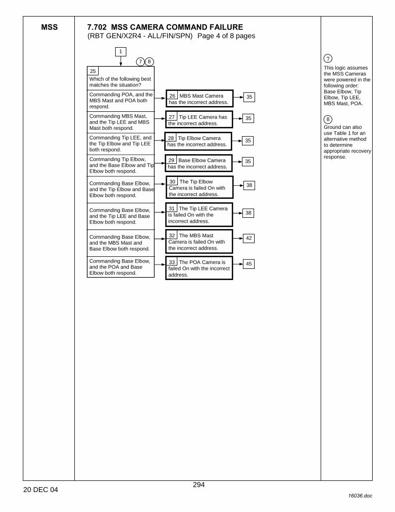
MSS 7.702 MSS CAMERA COMMAND FAILURE (RBT GEN/X2R4 - ALL/FIN/SPN) Page 4 of 8 pages
20 DEC 04 16036.doc
7 This logic assumes the MSS Cameras were powered in the following order: Base Elbow, Tip Elbow, Tip LEE, MBS Mast, POA. 8 Ground can also use Table 1 for an alternative method to determine appropriate recovery response.
25 Which of the following best matches the situation?
Commanding POA, and the MBS Mast and POA both respond.
Commanding MBS Mast, and the Tip LEE and MBS Mast both respond.
Commanding Tip LEE, and the Tip Elbow and Tip LEE both respond.
Commanding Tip Elbow, and the Base Elbow and Tip Elbow both respond.
Commanding Base Elbow, and the Tip Elbow and Base Elbow both respond.
Commanding Base Elbow, and the Tip LEE and Base Elbow both respond.
Commanding Base Elbow, and the MBS Mast and Base Elbow both respond.
Commanding Base Elbow, and the POA and Base Elbow both respond.
1
8 7
26 MBS Mast Camera has the incorrect address.
27 Tip LEE Camera has the incorrect address.
28 Tip Elbow Camera has the incorrect address.
29 Base Elbow Camera has the incorrect address.
30 The Tip Elbow Camera is failed On with the incorrect address.
31 The Tip LEE Camera is failed On with the incorrect address.
32 The MBS Mast Camera is failed On with the incorrect address.
33 The POA Camera is failed On with the incorrect address.
35
35
35
35
38
38
42
45
294

MSS 7.702 MSS CAMERA COMMAND FAILURE (RBT GEN/X2R4 - ALL/FIN/SPN) Page 5 of 8 pages
20 DEC 04 16036.doc
2 This block contains some Ground-only telemetry verification. 7 This logic assumes the MSS Cameras were powered in the following order: Base Elbow, Tip Elbow, Tip LEE, MBS Mast, POA. 9 Power cycling the failed camera will reset camera functions to default settings.
Table 1. Recovery Response to Camera Failure
Affected Camera Routed to CSR
Camera ID Shown on CSR Recovery Block
Base Elbow Tip Elbow 34
Tip Elbow Base Elbow 37
Tip Elbow Tip LEE 34
Tip LEE Base Elbow 37
Tip LEE MBS Mast 34
MBS Mast Base Elbow 41
MBS Mast POA 34
POA Base Elbow 44
None of the above (Camera ID shown on the CSR is the same as the affected Camera or no Camera ID shown)
34
34 • Ground should check that
all powered MSS Cameras are routed through CSRs.
• Refer to Table 1 to determine appropriate Recovery response.
7 2
35 • Perform following steps
for failed Camera: MSS: MBS: MBS Central Camera Icon MBS Camera
• cmd Power – Keep-Alive • cmd Power – On • Try original command
again. Did command operate correctly?
36 Recovery complete. • Continue nominal
operations. 37 • Continue operations
without failed Camera or failed Camera functionality.
Yes
No
21 29 26 28 27
9
23
15
295
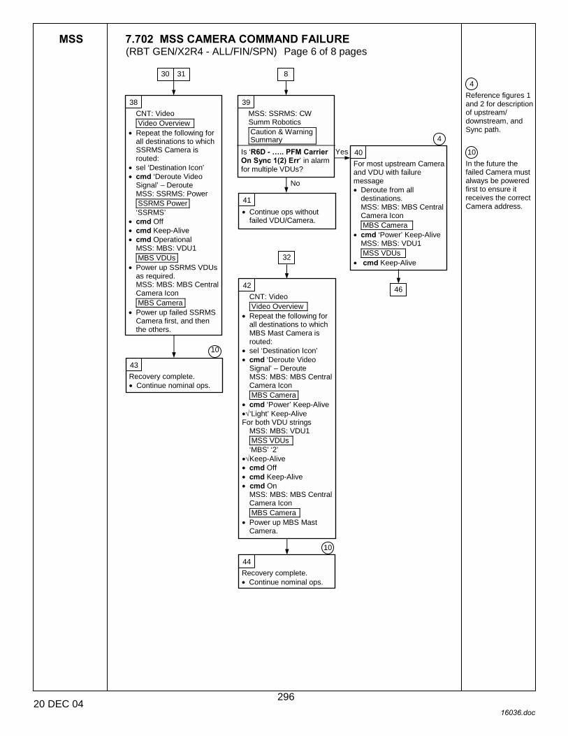
MSS 7.702 MSS CAMERA COMMAND FAILURE (RBT GEN/X2R4 - ALL/FIN/SPN) Page 6 of 8 pages
20 DEC 04 16036.doc
4 Reference figures 1 and 2 for description of upstream/ downstream, and Sync path. 10 In the future the failed Camera must always be powered first to ensure it receives the correct Camera address.
38 CNT: Video Video Overview
• Repeat the following for all destinations to which SSRMS Camera is routed:
• sel ‘Destination Icon’ • cmd ‘Deroute Video
Signal’ – Deroute MSS: SSRMS: Power SSRMS Power ‘SSRMS’
• cmd Off • cmd Keep-Alive • cmd Operational
MSS: MBS: VDU1 MBS VDUs
• Power up SSRMS VDUs as required. MSS: MBS: MBS Central Camera Icon MBS Camera
• Power up failed SSRMS Camera first, and then the others.
39 MSS: SSRMS: CW Summ Robotics Caution & Warning Summary
Is ‘R6D - �.. PFM Carrier On Sync 1(2) Err’ in alarm for multiple VDUs?
40 For most upstream Camera and VDU with failure message • Deroute from all
destinations. MSS: MBS: MBS Central Camera Icon MBS Camera
• cmd ‘Power’ Keep-Alive MSS: MBS: VDU1 MSS VDUs
• cmd Keep-Alive
4
41 • Continue ops without
failed VDU/Camera.
42 CNT: Video Video Overview
• Repeat the following for all destinations to which MBS Mast Camera is routed:
• sel ‘Destination Icon’ • cmd ‘Deroute Video
Signal’ – Deroute MSS: MBS: MBS Central Camera Icon MBS Camera
• cmd ‘Power’ Keep-Alive •√‘Light’ Keep-Alive For both VDU strings
MSS: MBS: VDU1 MSS VDUs ‘MBS’ ‘2’
•√Keep-Alive • cmd Off • cmd Keep-Alive • cmd On
MSS: MBS: MBS Central Camera Icon MBS Camera
• Power up MBS Mast Camera.
43 Recovery complete. • Continue nominal ops.
44 Recovery complete. • Continue nominal ops.
30 31
10
10
Yes
No
8
32
46
296
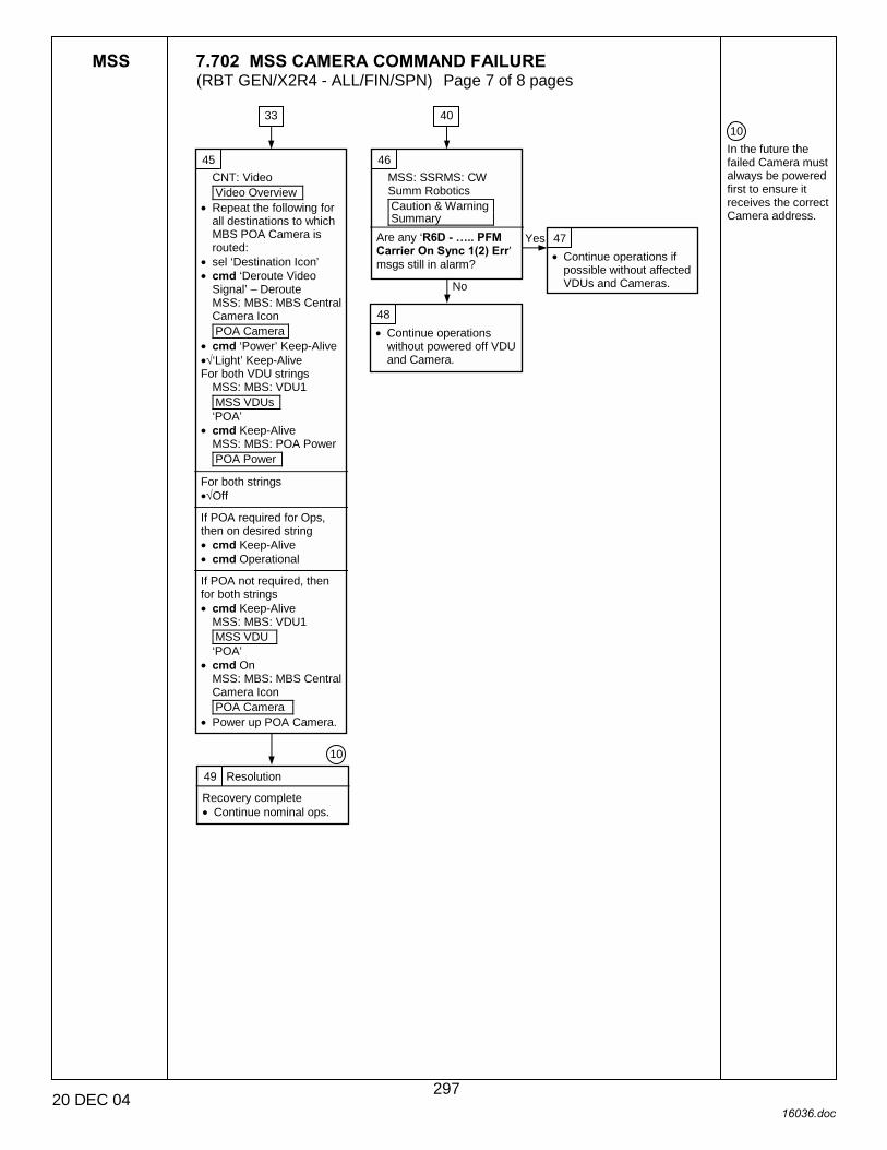
MSS 7.702 MSS CAMERA COMMAND FAILURE (RBT GEN/X2R4 - ALL/FIN/SPN) Page 7 of 8 pages
20 DEC 04 16036.doc
10 In the future the failed Camera must always be powered first to ensure it receives the correct Camera address.
45 CNT: Video Video Overview
• Repeat the following for all destinations to which MBS POA Camera is routed:
• sel ‘Destination Icon’ • cmd ‘Deroute Video
Signal’ – Deroute MSS: MBS: MBS Central Camera Icon POA Camera
• cmd ‘Power’ Keep-Alive •√‘Light’ Keep-Alive For both VDU strings
MSS: MBS: VDU1 MSS VDUs ‘POA’
• cmd Keep-Alive MSS: MBS: POA Power POA Power
For both strings •√Off
If POA required for Ops, then on desired string • cmd Keep-Alive • cmd Operational
If POA not required, then for both strings • cmd Keep-Alive
MSS: MBS: VDU1 MSS VDU ‘POA’
• cmd On MSS: MBS: MBS Central Camera Icon POA Camera
• Power up POA Camera.
46 MSS: SSRMS: CW Summ Robotics Caution & Warning Summary
Are any ‘R6D - �.. PFM Carrier On Sync 1(2) Err’ msgs still in alarm?
47 • Continue operations if
possible without affected VDUs and Cameras.
Yes
No
48 • Continue operations
without powered off VDU and Camera.
49 Resolution
Recovery complete • Continue nominal ops.
10
33 40
297

MSS 7.702 MSS CAMERA COMMAND FAILURE (RBT GEN/X2R4 - ALL/FIN/SPN) Page 8 of 8 pages
20 DEC 04 16036.doc
SSRMS BASE LEE
SSRMS BASE ELBOW
SSRMS TIP ELBOW
SSRMS TIP LEE
SSRMS PAYLOAD
POA PAYLOAD
MBS
SSRMS
Upstream
Downstream MBS VDU 1 or VDU 2
PDGF 1(2)(3)(4) POA VDU
Figure 1.- Downstream vs. Upstream.
Figure 2.- MSS Sync Flow Diagram.
TUS 1 (EVSU 2 VFOT 14)
TUS 1 (EVSU 3 VFOT 2)
TUS 2 (EVSU 3 VFOT 14)
TUS 2 (EVSU 2 VFOT 2)
298

7.900 MSS PERSISTENT CAT-2 ERROR (RBT GEN/X2R4 - ALL/FIN/SPN) Page 1 of 16 pages
16 DEC 04 16037.doc
1 Unless otherwise indicated, all displays in this procedure are on the PCS.
{7.001 MSS FAILURE RESPONSE AND RECOVERY}, block 138 (SODF: RBT GEN: MALFUNCTION) C&W
ROBOTICS
C&W messages starting with ‘Rxx - �
Nominal Config: R1C: affected unit is powered and ready for operations
R2O: MBS is operational on one string, keep-alive on the other
R3L: SSRMS is operational
R5Z: SSRMS is operational with brakes on
R7A: SSRMS(MBS) is operational
R7C: S0 MDM PTCS is enabled, heaters are in closed loop mode
R9C: SSRMS is transitioning from Keep-Alive to Operational
R3O: SSRMS is Operational
EXT, S0(S1, P1) MDMs configured for SEPS Control
Persistent MSS Cat-2 C&W Message is in Alarm.
1 Message Identification
MSS: MBS: CW Summ Robotics Caution & Warning Summary
• Identify the Cat-2 message received.
‘R2O - MBS CRPCM �’
‘R3L - SSRMS Pwr Flags Fail’
‘R5Z - SSRMS SR(SY, SP, EP, WP, WY, WR) Brk Slip’
‘R7A - SSRMS(MBS) Temp Out of Limits’
‘R7C - TUS Temp Out of Limits’
�R9C - MSS OCS SSRMS SR(SY,SP,EP,WP,WY,WR) Joint Init Posn Err�
�R3O - SSRMS LEE Stat Switches I/F Test Fail�
‘R1C - �OCS(ACU, MCU, JEU, LEU) ROM�’
1
5
92
101
106
114
128
131
2 ROM Checksum Failed
CAUTION For SSRMS failures, transition to off or KA or removal of power will result in permanent loss of the SSRMS string until the failed ACU, JEU, or LEU is replaced.
For POA failures, transition of the POA to off or KA or transition of the MBS to off or keep-alive or removal of power will result in permanent loss of the POA on that MBS string until the failed LEU is replaced.
For MBS (non-POA) failures, transition to off or KA or removal of power will result in permanent loss of the MBS string until the failed MCU is replaced.
For RWS failures, transition from Active or Backup to off will result in permanent loss of the RWS until the failed CEU is replaced.
3 Recovery complete.
4 • Continue nominal
operations.
299
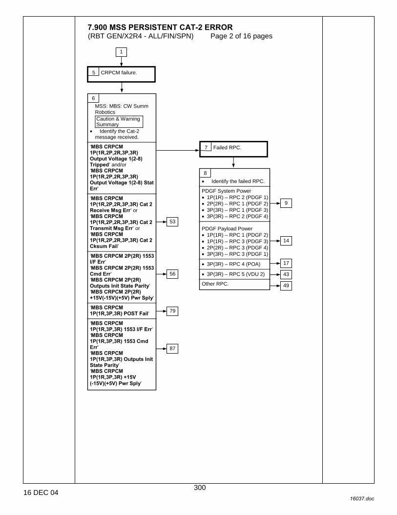
7.900 MSS PERSISTENT CAT-2 ERROR (RBT GEN/X2R4 - ALL/FIN/SPN) Page 2 of 16 pages
16 DEC 04 16037.doc
5 CRPCM failure.
1
6 MSS: MBS: CW Summ Robotics Caution & Warning Summary
• Identify the Cat-2 message received.
‘MBS CRPCM 1P(1R,2P,2R,3P,3R) Output Voltage 1(2-8) Tripped’ and/or ‘MBS CRPCM 1P(1R,2P,2R,3P,3R) Output Voltage 1(2-8) Stat Err’
‘MBS CRPCM 1P(1R,2P,2R,3P,3R) Cat 2 Receive Msg Err’ or ‘MBS CRPCM 1P(1R,2P,2R,3P,3R) Cat 2 Transmit Msg Err’ or ‘MBS CRPCM 1P(1R,2P,2R,3P,3R) Cat 2 Cksum Fail’
‘MBS CRPCM 2P(2R) 1553 I/F Err’ ‘MBS CRPCM 2P(2R) 1553 Cmd Err’ ‘MBS CRPCM 2P(2R) Outputs Init State Parity’ ‘MBS CRPCM 2P(2R) +15V(-15V)(+5V) Pwr Sply’
‘MBS CRPCM 1P(1R,3P,3R) POST Fail’
‘MBS CRPCM 1P(1R,3P,3R) 1553 I/F Err’ ‘MBS CRPCM 1P(1R,3P,3R) 1553 Cmd Err’ ‘MBS CRPCM 1P(1R,3P,3R) Outputs Init State Parity’ ‘MBS CRPCM 1P(1R,3P,3R) +15V (-15V)(+5V) Pwr Sply’
7 Failed RPC.
53
56
79
87
8 • Identify the failed RPC.
PDGF System Power • 1P(1R) – RPC 2 (PDGF 1) • 2P(2R) – RPC 1 (PDGF 2) • 3P(3R) – RPC 1 (PDGF 3) • 3P(3R) – RPC 2 (PDGF 4)
PDGF Payload Power • 1P(1R) – RPC 1 (PDGF 2) • 1P(1R) – RPC 3 (PDGF 3) • 2P(2R) – RPC 3 (PDGF 4) • 3P(3R) – RPC 3 (PDGF 1)
• 3P(3R) – RPC 4 (POA)
• 3P(3R) – RPC 5 (VDU 2)
Other RPC.
9
14
17
43
49
300

7.900 MSS PERSISTENT CAT-2 ERROR (RBT GEN/X2R4 - ALL/FIN/SPN) Page 3 of 16 pages
16 DEC 04 16037.doc
9 SSRMS Location
MSS: SSRMS: SSRMS ‘PDGF’
Is the SSRMS based on the PDGF for which the message was annunciated?
8
10 SSRMS Power
MSS: SSRMS: Power SSRMS Power
Is the SSRMS in Keep-Alive or Operational on the power string for which the message was annunciated?
11 RPC false indication.
12 Erroneous indication that the RPC that powers the SSRMS is open.
A command to transition the SSRMS from KA to Off or Off to KA will be rejected.
13 RPC failed.
No
Yes
Yes
No
14 RPC may be failed closed. Do not attempt a walk-off from or to this PDGF while the corresponding MBS string is in keep-alive or operational since the PDGF could be powered, which could cause hardware damage due to arcing/sparking.
A command to transition the SSRMS from Off to KA will fail [if affected RPC supplies power to the SSRMS (not payload)].
15 Recovery complete.
16 • Continue nominal
operations.
8
301

7.900 MSS PERSISTENT CAT-2 ERROR (RBT GEN/X2R4 - ALL/FIN/SPN) Page 4 of 16 pages
16 DEC 04 16037.doc
17 POA Status
Is the POA required for upcoming ops?
8
18 POA S/W Status
Was the POA operational at the time of the failure?
19 POA Powerup
• Perform {6.342 MBS POA POWERUP TO OPERATIONAL ON PRIME(REDUNDANT) STRING}, all (SODF: RBT GEN: NOMINAL), then:
MSS: MBS: POA Power POA Power
‘Prime(Redundant)’ – Operational?
25
20 RPC false indication.
21 Erroneous indication that the RPC that powers the POA is open.
A command to transition the POA from KA to Off or Off to KA on the affected string will be rejected.
22 POA Power Status
MSS: MBS: MBS • Verify the alternate
MBS string is KA or operational and that the alternate RPC is closed.
A command to transition the POA from KA to Off or Off to KA on the affected string will be rejected.
23 Recovery complete.
24 • Continue nominal
operations.
No
Yes
Yes
No
Yes
No
302

7.900 MSS PERSISTENT CAT-2 ERROR (RBT GEN/X2R4 - ALL/FIN/SPN) Page 5 of 16 pages
16 DEC 04 16037.doc
25 MBS Power Status
Is the MCU Operational on the string for which the failure was annunciated?
19
26 MBS Switch Strings
• Perform {8.307 MBS SWITCH TO REDUNDANT(PRIME) STRING}, all (SODF: RBT GEN: RECOVERY), then:
27 SSRMS Base Location
Is the SSRMS based on the MBS and receiving power from the failed MBS string?
28 MBS Switch Strings
• Perform {6.334 MSS POWERDOWN}, step 3.1 (SODF: RBT GEN: NOMINAL), then:
MSS: MBS: MCU
• cmd ‘Prime’(‘Redundant’) Off (Verify – Off) ~ 30 s max
For the non-failed MBS string
MSS: MBS: MCU: MCU • cmd ‘Redundant’(‘Prime’)
Operational (Verify – Operational) ~ 3 min
MSS: MBS: POA Power POA Power
• cmd ‘Redundant’(‘Prime’) Keep-Alive (Verify Keep-Alive) (30 s max)
MSS: MBS: POA Power POA Power
• cmd ‘Redundant’(‘Prime’) Operational (Verify –Operational)
MSS: MBS: VDU 1 MSS VDUs
• sel MBS 2 • cmd On (Verify On)
MSS: MBS: MBS Central Camera icon MBS Camera
• sel MBS 37 • cmd ‘Power’ On (Verify
On)
MSS: Video: Video Overview Video Overview
• Deroute the Mast Camera.
29 POA Powerup
• Perform {6.342 MBS POA POWERUP TO OPERATIONAL ON PRIME(REDUNDANT) STRING}, all (SODF: RBT GEN: NOMINAL), then:
MSS: MBS: POA Power POA Power
‘Redundant’(‘Prime’) – Operational?
35
30 Switch SSRMS Strings
• Perform {8.107 SSRMS SWITCH TO REDUNDANT(PRIME) STRING}, all (SODF: RBT GEN: RECOVERY), then:
28
30
No
Yes
No
Yes
No Yes
31 Erroneous indication that the RPC that powers the POA on the current string is open. A command to transition the POA from KA to Off or Off to KA on the affected string will be rejected.
32 • Continue nominal
operations.
33 POA RPC tripped or failed open on original string.
34 • Continue nominal
operations.
303

7.900 MSS PERSISTENT CAT-2 ERROR (RBT GEN/X2R4 - ALL/FIN/SPN) Page 6 of 16 pages
16 DEC 04 16037.doc
35 MBS Switch Strings
• Perform {8.307 MBS SWITCH TO REDUNDANT(PRIME) STRING}, all (SODF: RBT GEN: RECOVERY), then:
29
36 SSRMS Base Location
Is the SSRMS based on the MBS and receiving power from the failed MBS string?
37 SSRMS Switch Strings
• Perform {8.107 SSRMS SWITCH TO REDUNDANT(PRIME) STRING}, all (SODF: RBT GEN: RECOVERY), then:
38 MBS Powerdown
For MBS string in Keep-Alive
MSS: MBS: MCU: MCU • cmd ‘Redundant’(‘Prime’)
Off (Verify Off) (30 s max)
39 POA Powerup
MSS: MBS: POA Power POA Power
• cmd ‘Prime’(‘Redundant’) Keep-Alive (Verify Keep-Alive) (30 s max)
40 POA Powerup
MSS: MBS: POA Power POA Power
• cmd ‘Prime’(‘Redundant’) Operational (Verify − Operational)
41
RPC that powers the POA tripped or failed open on alternate string. A command to transition the POA from KA to Off or Off to KA on the affected string will be rejected.
42 • Continue nominal
operations.
No
Yes
304
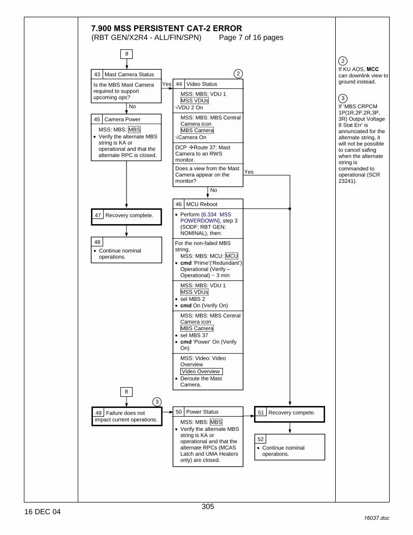
7.900 MSS PERSISTENT CAT-2 ERROR (RBT GEN/X2R4 - ALL/FIN/SPN) Page 7 of 16 pages
16 DEC 04 16037.doc
2 If KU AOS, MCC can downlink view to ground instead. 3 If ‘MBS CRPCM 1P(1R,2P,2R,3P, 3R) Output Voltage 8 Stat Err’ is annunciated for the alternate string, it will not be possible to cancel safing when the alternate string is commanded to operational (SCR 23241).
43 Mast Camera Status
Is the MBS Mast Camera required to support upcoming ops?
8
44 Video Status
MSS: MBS: VDU 1 MSS VDUs
√VDU 2 On
MSS: MBS: MBS Central Camera icon MBS Camera
√Camera On DCP !Route 37: Mast Camera to an RWS monitor.
Does a view from the Mast Camera appear on the monitor?
2
Yes
No
45 Camera Power
MSS: MBS: MBS • Verify the alternate MBS
string is KA or operational and that the alternate RPC is closed.
46 MCU Reboot
• Perform {6.334 MSS POWERDOWN}, step 3 (SODF: RBT GEN: NOMINAL), then:
For the non-failed MBS string,
MSS: MBS: MCU: MCU • cmd ‘Prime’(‘Redundant’)
Operational (Verify – Operational) ~ 3 min
MSS: MBS: VDU 1 MSS VDUs
• sel MBS 2 • cmd On (Verify On)
MSS: MBS: MBS Central Camera icon MBS Camera
• sel MBS 37 • cmd ‘Power’ On (Verify
On)
MSS: Video: Video Overview Video Overview
• Deroute the Mast Camera.
47 Recovery complete.
48 • Continue nominal
operations.
49 Failure does not impact current operations.
3
8
50 Power Status
MSS: MBS: MBS • Verify the alternate MBS
string is KA or operational and that the alternate RPCs (MCAS Latch and UMA Heaters only) are closed.
51 Recovery compete.
52 • Continue nominal
operations.
Yes
No
305
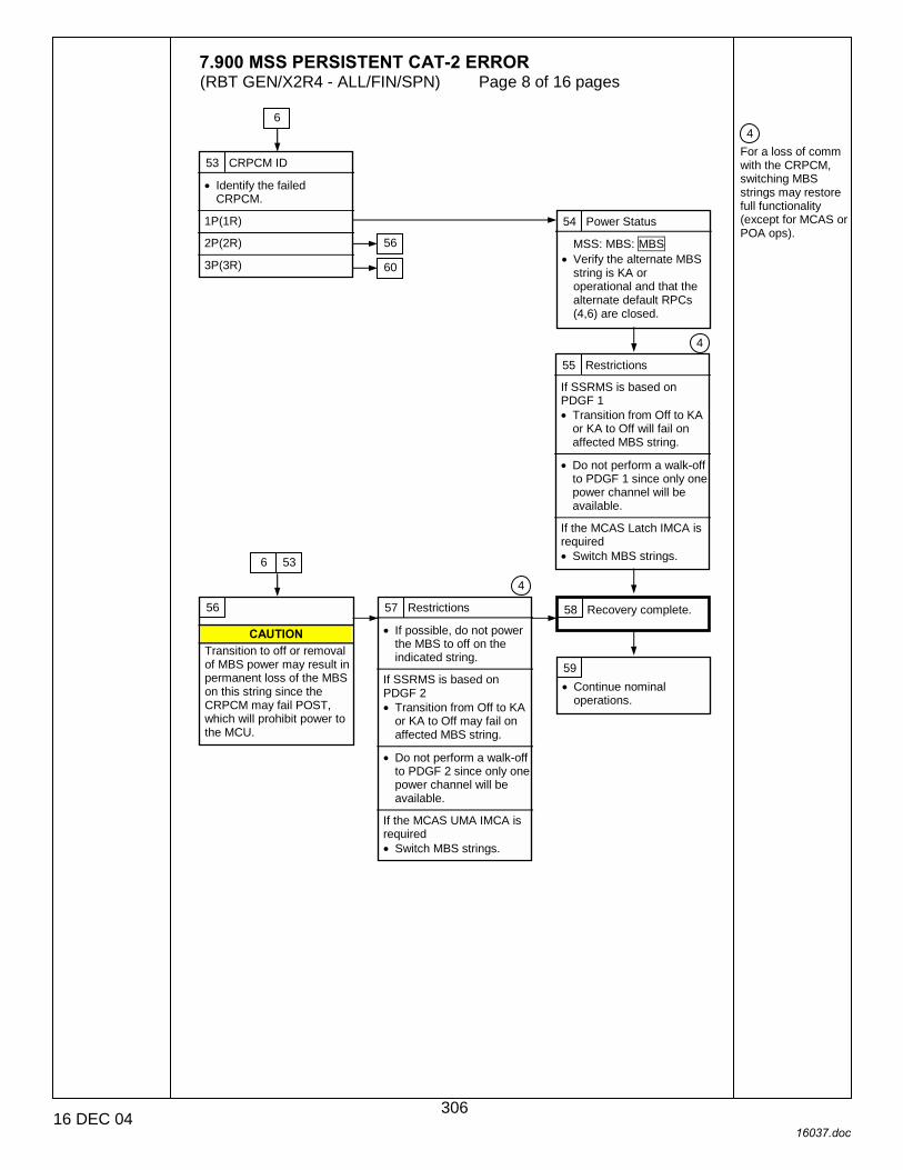
7.900 MSS PERSISTENT CAT-2 ERROR (RBT GEN/X2R4 - ALL/FIN/SPN) Page 8 of 16 pages
16 DEC 04 16037.doc
4 For a loss of comm with the CRPCM, switching MBS strings may restore full functionality (except for MCAS or POA ops).
53 CRPCM ID
• Identify the failed CRPCM.
1P(1R)
2P(2R)
3P(3R)
6
56
60
54 Power Status
MSS: MBS: MBS • Verify the alternate MBS
string is KA or operational and that the alternate default RPCs (4,6) are closed.
55 Restrictions
If SSRMS is based on PDGF 1 • Transition from Off to KA
or KA to Off will fail on affected MBS string.
• Do not perform a walk-off
to PDGF 1 since only one power channel will be available.
If the MCAS Latch IMCA is required • Switch MBS strings.
56
CAUTION Transition to off or removal of MBS power may result in permanent loss of the MBS on this string since the CRPCM may fail POST, which will prohibit power to the MCU.
57 Restrictions
• If possible, do not power the MBS to off on the indicated string.
If SSRMS is based on PDGF 2 • Transition from Off to KA
or KA to Off may fail on affected MBS string.
• Do not perform a walk-off
to PDGF 2 since only one power channel will be available.
If the MCAS UMA IMCA is required • Switch MBS strings.
58 Recovery complete.
4
6 53
59 • Continue nominal
operations.
4
306

7.900 MSS PERSISTENT CAT-2 ERROR (RBT GEN/X2R4 - ALL/FIN/SPN) Page 9 of 16 pages
16 DEC 04 16037.doc
2 If KU AOS, MCC can downlink view to ground instead.
60 POA Status
Is the POA required for the upcoming ops?
53
61 POA S/W Status
MSS: MBS: POA Power POA Power
Was the POA Operational at the time of the failure?
62 Mast Camera Status
Is the MBS Mast Camera required for upcoming ops?
73
No Yes
No
Yes
Yes
No
63 Mast Camera
Is the Mast Camera required for the current ops?
86
64 Power Status
MSS: MBS: MBS • Verify the alternate MBS
string is KA or operational and that the alternate default RPCs (4,5,7) are closed.
86
65 Video Status
MSS: MBS: VDU 1 MSS VDUs
√VDU 2 On
MSS: MBS: MBS Central Camera icon MBS Camera
√Camera On DCP !Route 37: Mast Camera to an RWS monitor.
Does a view from the Mast Camera appear on the monitor?
66 MBS Reboot
MSS: MBS: POA Power POA Power
• cmd ‘Prime’(‘Redundant’) Keep Alive (Verify Keep-Alive) (30 s max)
• Perform {6.334 MSS
POWERDOWN}, step 3 (SODF: RBT GEN: NOMINAL), then:
For the MBS string that was previously operational
MSS: MBS: MCU: MCU • cmd ‘Prime’(‘Redundant’)
Operational (Verify – Operational) ~ 3 min
MSS: MBS: POA Power POA Power
• cmd ‘Prime’(‘Redundant’) Operational (Verify – Operational)
MSS: MBS: VDU 1 MSS VDUs
• sel MBS 2 • cmd On (Verify On)
MSS: MBS: MBS Central Camera icon MBS Camera
• sel MBS 37 • cmd ‘Power’ On (Verify
On)
MSS: Video: Video Overview Video Overview
• Deroute the Mast Camera.
66 86
No Yes
2
65
No
Yes
86
67
307

7.900 MSS PERSISTENT CAT-2 ERROR (RBT GEN/X2R4 - ALL/FIN/SPN) Page 10 of 16 pages
16 DEC 04 16037.doc
67 MBS Power Status
Is the MCU Operational on the string for which the failure was annunciated?
61
72 No
Yes
68 POA Powerup
• Perform {6.342 MBS POA POWERUP TO OPERATIONAL ON PRIME(REDUNDANT) STRING}, all (SODF: RBT GEN: NOMINAL), then:
MSS: MBS: POA Power POA Power
‘Prime’(‘Redundant’) – Operational?
86
69 SSRMS Base Location
Is the SSRMS based on the MBS and receiving power from the failed MBS string?
70 MBS Switch Strings
• Perform {6.334 MSS POWERDOWN}, step 3.1 (SODF: RBT GEN: NOMINAL), then:
MSS: MBS: MCU
• cmd ‘Prime’(‘Redundant’) Off (Verify – Off) ~ 30 s max
For the non-failed MBS string
MSS: MBS: MCU: MCU • cmd ‘Redundant’(‘Prime’)
Operational (Verify – Operational) ~ 3 min
MSS: MBS: POA Power POA Power
• cmd ‘Redundant’(‘Prime’) Keep-Alive (Verify Keep-Alive) (30 s max)
MSS: MBS: POA Power POA Power
• cmd ‘Redundant’(‘Prime’) Operational (Verify –Operational)
MSS: MBS: VDU 1 MSS VDUs
• sel MBS 2 • cmd On (Verify On)
MSS: MBS: MBS Central Camera icon MBS Camera
• sel MBS 37 • cmd ‘Power’ On (Verify
On)
MSS: Video: Video Overview Video Overview
• Deroute the Mast Camera.
71 Switch SSRMS Strings
• Perform {8.107 SSRMS SWITCH TO REDUNDANT(PRIME) STRING}, all (SODF: RBT GEN: RECOVERY), then:
70
71
86
Yes
No
No
Yes
308

7.900 MSS PERSISTENT CAT-2 ERROR (RBT GEN/X2R4 - ALL/FIN/SPN) Page 11 of 16 pages
16 DEC 04 16037.doc
72 MBS Switch Strings
• Perform {8.307 MBS SWITCH TO REDUNDANT(PRIME) STRING}, all (SODF: RBT GEN: RECOVERY), then:
67
73 Video Status
MSS: MBS: VDU 1 MSS VDUs
•√VDU 2 On
MSS: MBS: MBS Central Camera icon MBS Camera
•√Camera On • DCP → Route 37: Mast
Camera to an RWS monitor.
Does a view from the Mast Camera appear on the monitor?
74 POA Powerup
• Perform {6.342 MBS POA POWERUP TO OPERATIONAL ON PRIME(REDUNDANT) STRING}, all (SODF: RBT GEN: NOMINAL), then:
MSS: MBS: POA Power POA Power
‘Redundant’(‘Prime’) – Operational?
62
86
75 MBS Reboot
• Perform {6.334 MSS POWERDOWN}, step 3 (SODF: RBT GEN: NOMINAL), then:
For the non-failed MBS string
MSS: MBS: MCU: MCU • cmd ‘Prime’(‘Redundant’)
Operational (Verify – Operational) ~ 3 min
MSS: MBS: VDU 1 MSS VDUs
• sel MBS 2 • cmd On (Verify On)
MSS: MBS: MBS Central Camera icon MBS Camera
• sel MBS 37 • cmd ‘Power’ On (Verify
On)
MSS: Video: Video Overview Video Overview
• Deroute the Mast Camera.
86
86
No
Yes
Yes
No
76 MBS Switch Strings
• Perform {8.307 MBS SWITCH TO REDUNDANT(PRIME) STRING}, all (SODF: RBT GEN: RECOVERY), then:
77
309
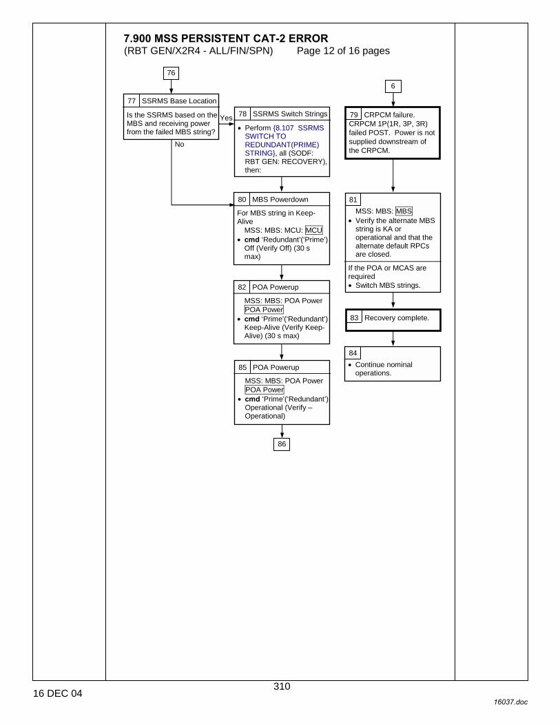
7.900 MSS PERSISTENT CAT-2 ERROR (RBT GEN/X2R4 - ALL/FIN/SPN) Page 12 of 16 pages
16 DEC 04 16037.doc
77 SSRMS Base Location
Is the SSRMS based on the MBS and receiving power from the failed MBS string?
76
78 SSRMS Switch Strings
• Perform {8.107 SSRMS SWITCH TO REDUNDANT(PRIME) STRING}, all (SODF: RBT GEN: RECOVERY), then:
79 CRPCM failure. CRPCM 1P(1R, 3P, 3R) failed POST. Power is not supplied downstream of the CRPCM.
80 MBS Powerdown
For MBS string in Keep-Alive
MSS: MBS: MCU: MCU • cmd ‘Redundant’(‘Prime’)
Off (Verify Off) (30 s max)
6
81 MSS: MBS: MBS
• Verify the alternate MBS string is KA or operational and that the alternate default RPCs are closed.
If the POA or MCAS are required • Switch MBS strings. 82 POA Powerup
MSS: MBS: POA Power POA Power
• cmd ‘Prime’(‘Redundant’) Keep-Alive (Verify Keep-Alive) (30 s max)
83 Recovery complete.
84 • Continue nominal
operations. 85 POA Powerup
MSS: MBS: POA Power POA Power
• cmd ‘Prime’(‘Redundant’) Operational (Verify – Operational)
86
Yes
No
310
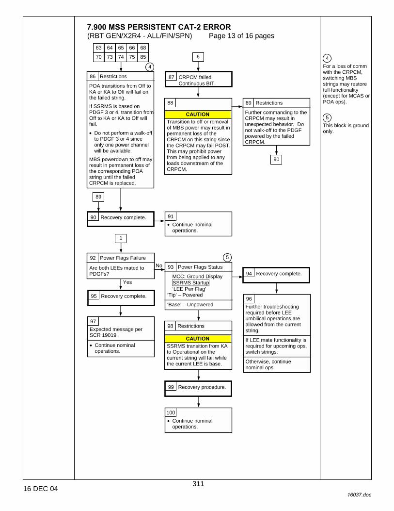
7.900 MSS PERSISTENT CAT-2 ERROR (RBT GEN/X2R4 - ALL/FIN/SPN) Page 13 of 16 pages
16 DEC 04 16037.doc
4 For a loss of comm with the CRPCM, switching MBS strings may restore full functionality (except for MCAS or POA ops). 5 This block is ground only.
86 Restrictions
POA transitions from Off to KA or KA to Off will fail on the failed string. If SSRMS is based on PDGF 3 or 4, transition from Off to KA or KA to Off will fail. • Do not perform a walk-off
to PDGF 3 or 4 since only one power channel will be available.
MBS powerdown to off may result in permanent loss of the corresponding POA string until the failed CRPCM is replaced.
4
87 CRPCM failed Continuous BIT.
88
CAUTION Transition to off or removal of MBS power may result in permanent loss of the CRPCM on this string since the CRPCM may fail POST. This may prohibit power from being applied to any loads downstream of the CRPCM.
89 Restrictions
Further commanding to the CRPCM may result in unexpected behavior. Do not walk-off to the PDGF powered by the failed CRPCM.
90 Recovery complete.
90
89
91 • Continue nominal
operations.
6
92 Power Flags Failure
Are both LEEs mated to PDGFs?
1
Yes
93 Power Flags Status
MCC: Ground Display SSRMS Startup ‘LEE Pwr Flag’
‘Tip’ – Powered ‘Base’ – Unpowered
94 Recovery complete.
95 Recovery complete. 96 Further troubleshooting required before LEE umbilical operations are allowed from the current string.
If LEE mate functionality is required for upcoming ops, switch strings.
Otherwise, continue nominal ops.
97 Expected message per SCR 19019.
• Continue nominal
operations.
98 Restrictions
CAUTION SSRMS transition from KA to Operational on the current string will fail while the current LEE is base.
5 No
99 Recovery procedure.
100 • Continue nominal
operations.
63 64 65 66 68
70 73 74 75 85
311

7.900 MSS PERSISTENT CAT-2 ERROR (RBT GEN/X2R4 - ALL/FIN/SPN) Page 14 of 16 pages
16 DEC 04 16037.doc
5 This block is ground only.
101 Joint Brake Test
For affected joint(s) • Perform {6.401 SSRMS
JOINT BRAKE TEST}, all (SODF: RBT GEN: NOMINAL), then: MSS: SSRMS: Discrete Log: MSS Discrete Log
SSRMS>Brake Friction Test: SR(SY, SP, EP, WP, WY, WR) Passed?
1
102 Recovery complete. 103 External loading on the joint (EVA/thrusters) or joint resolver failure with no associated C&W messages.
• For resolver failures,
expect potential safing event when motion is attempted.
• Continue nominal operations.
104 Remove Brakes
MSS: SSRMS: SSRMS Safing SSRMS Safing
• cmd Remove (Verify not Safed)
(DCP) • BRAKES SSRMS → OFF
Yes
No
105 Reduced Brake Torque
WARNING SSRMS braking torque in specified joint is degraded on both strings.
Failed SSRMS joint is currently in ‘Position Hold’, so the joint motor is holding the joint in place. Brake torque may not be sufficient to hold joint position.
If safing or brakes are applied during SSRMS motion, joint will continue to move until friction or reduced brake torque has stopped the joint.
SSRMS motion should only be performed in Vernier with scaled rates.
Expect an increase in stopping distance if brakes are applied.
106 Temp Out of Limits
Extract data from Orbiter Data Reduction Complex (ODRC) for failed unit.
Data indicates a gradual temperature increase(decrease) or “Klixon” behavior (reference SCR 24576 for description).
Data indicates an instantaneous temperature increase(decrease).
5
1
107 Equipment is Hot(Cold)
Hot(Cold) thermal environment or heater is failed on(off). • If temperatures are at
upper limit and continue to increase, power down the equipment.
• If camera is hot(cold), verify light is off(on).
• If CRPCMs are hot, power off MBS string that is in keep-alive. If temperatures continue to increase, switch strings.
108 Temperature sensor failure.
109 • Continue nominal
operations. 110 Recovery complete.
111 Recovery complete. 112 • Continue nominal ops
while monitoring temperatures.
113 • Continue ops.
128
312

7.900 MSS PERSISTENT CAT-2 ERROR (RBT GEN/X2R4 - ALL/FIN/SPN) Page 15 of 16 pages
16 DEC 04 16037.doc
5 This block is ground only.
114 Hot or Cold
MSS: MBS: CW Summ Robotics Caution & Warning Summary
• Identify the Cat-2 message received.
‘R7C - MSS MT Cold Alarm TUS 1(2) Htr’
‘R7C - MSS MT Hot Alarm TUS 1(2) Htr’
1
115 IMCA Powerup
MSS: MT: ‘‘MT’Amp-1’ MT LB A: RT Status LB MT 1 RT Status
• sel RT Status Cont RT 16 to 25 LB MT 1 RT Status Cont
• cmd ‘RT Status’ ‘16(18) TUS 1S(2S)’ Enable Execute (Verify – Ena)
MSS: MT: Power MT Power ‘RPCM S0-3A-F (S0-3A-E)’
• sel RPC 1 RPCM S03A F(S03A E) RPC 01 ‘RPC Position’
• cmd Close (Verify – Cl)
122
116 Heater Status
MSS: MT: MT Thermal ‘RPCM S0-4B-F’ ‘Gearbox Heater’
Is the heater off? 117 Hot thermal environment or sensor failure.
118 Heater RPC failed closed.
119 Recovery complete.
120 • ROBO: Coordinate with
Phalcon to open RPC to heater.
121 • Continue nominal
operations.
122 Heater Status
MSS: MT: MT Thermal ‘RPCM S0-4B-F’ ‘Gearbox Heater’
Is the heater on?
5
Yes
No
115
126
123 Temperature Check
MSS: MT: Thermal MT Thermal ‘TUS1(TUS2)’
Is the IMCA temperature within 10 degrees of the gearbox temperature?
Yes
No
124 Cold Environment
Cold thermal environment. Leave IMCA powered until temperture increases.
125 Heater Control Mode
MSS: MT: Thermal Gearbox Heater MT TUS 1(2) Gearbox Heater ‘Control Mode State’
• cmd Open Loop (Verify –Open Loop)
126 Recovery complete.
122
127 • Continue nominal
operations.
No
Yes
313
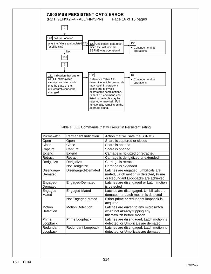
7.900 MSS PERSISTENT CAT-2 ERROR (RBT GEN/X2R4 - ALL/FIN/SPN) Page 16 of 16 pages
16 DEC 04 16037.doc
Table 1: LEE Commands that will result in Persistent safing
Microswitch Permanent Indication Action that will safe the SSRMS Open Open Snare is captured or closed Close Close Snare is opened Capture Capture Snare is opened Extend Extend Carriage is rigidized or retracted Retract Retract Carriage is derigidized or extended
Derigidize Carriage is retracted Derigidize Not Derigidize Carriage is extended
Disengage-Demated
Disengaged-Demated Latches are engaged, umbilicals are mated, Latch motion is detected, Prime or Redundant Loopbacks are achieved
Engaged-Demated
Engaged-Demated Latches are disengaged or Latch motion is detected
Engaged-Mated Latches are disengaged, Umbilicals are demated, or Latch motion is detected
Engaged-Mated
Not Engaged-Mated Either prime or redundant loopback is acquired
Motion Detection
Motion Detection Latches are driven to any microswitch when not already tripping any microswitch before motion
Prime Loopback
Prime Loopback Latches are disengaged, Latch motion is detected, or Umbilicals are demated
Redundant Loopback
Redundant Loopback Latches are disengaged, Latch motion is detected, or Umbilicals are demated
128 Failure Location
Was the failure annunciated for all joints?
1
129 Checkpoint data reset since the last time the SSRMS was operational.
130 • Continue nominal
operations.
131 Indication that one or all LEE microswitch circuity has failed such that the state of the microswitch cannot be changed.
101
132 Reference Table 1 to determine which commands may result in persistent safing due to invalid microswitch combinations. Other LEE commands not listed in the table may be rejected or may fail. Full functionality remains on the alternate string.
133 • Continue nominal
operations.
Yes
No
1
314

CORRECTIVE
CO
RR
EC
TIV
E
22 DEC 04
315

This Page Intentionally Blank
CO
RR
EC
TIV
E
22 DEC 04
316

8.101 MANUAL CAPTURE WITH CALIBRATED LEE (RBT GEN/X2R4 - ALL/FIN 3/SPN) Page 1 of 4 pages
14 DEC 04 12691.doc
1. SETUP PCS MSS: SSRMS: Tip LEE: SSRMS Tip LEE
√LEE Mechanisms – Calibrated
****************************************************** ***
If LEE Mechanisms – Not Calibrated Perform {6.421 LEE CALIBRATION}, all (SODF: RBT GEN: NOMINAL), then:
******************************************************
√Setup – Yes
************************************************************* ***
If Setup – No Perform {6.428 LEE SETUP FOR CAPTURE}, all (SODF: RBT GEN: NOMINAL), then:
*************************************************************
Prior to beginning payload capture, review {SSRMS LEE CUE CARD}, all (SODF: RBT GEN: REFERENCE), then:
NOTE
The LEE Camera must be fully zoomed out to correspond to the target overlay.
Configure cameras and overlays for grapple.
MSS: SSRMS: SSRMS
√Manual – blue √Vernier
2. GRAPPLE MANEUVER RHC/ Maneuver to within grapple envelope. THC 3. LIMP SSRMS
MSS: SSRMS: Limp: SSRMS Limp
cmd All Limp (Verify Limp – blue) PCS MSS: SSRMS: SSRMS
Verify all joints – Limped 4. CLOSE SNARES PCS MSS: SSRMS: Tip LEE: SSRMS Tip LEE
cmd ‘Snare’ Close � Slow, Soft Stops
317

8.101 MANUAL CAPTURE WITH CALIBRATED LEE (RBT GEN/X2R4 - ALL/FIN 3/SPN) Page 2 of 4 pages
14 DEC 04 12691.doc
Verify Speed – Slow Verify Stops – Soft Verify ‘Confirm or Terminate’ prompt.
CAUTION Due to end-to-end system latency, the RHC Trigger is hot up to 3 seconds prior to receiving a Trigger Hot icon status on the PCS.
NOTE
Once the trigger is hot, only Safing or Trigger commands should be sent to the Robotics equipment. If a configuration change is required, including routing MSS cameras, safe the system to exit LEE operations (SCR 23262, 14662).
cmd Confirm (Verify RHC Trigger Hot icon)
Verify LEE Mode – Close Snares
RHC TRIGGER → press (hold until ’Snare’ Brakes – On) (12 s(3 s) max) PCS Verify ‘Snare’ Close, Capture (two) – blue 5. RETRACT CARRIAGE PCS MSS: SSRMS: Tip LEE: SSRMS Tip LEE
cmd ‘Carriage’ Retract � Slow, Soft Stops
Verify Speed – Slow Verify Stops – Soft Verify ‘Confirm or Terminate’ prompt.
cmd Confirm (Verify RHC Trigger Hot icon)
Verify LEE Mode – Retract Carriage
RHC TRIGGER → press (hold until ‘Carriage’ Brakes – On) (90 s(24 s) max) PCS Verify ‘Carriage’ Retract – blue Verify ‘Carriage’ Tension > 4003 N 6. LATCH
If grapple fixture is an FRGF or latching is not required, go to step 8.
MSS: SSRMS: Tip LEE: SSRMS Tip LEE
cmd ‘Latch’ Latch � Slow, Soft Stops
Verify Speed – Slow Verify Stops – Soft Verify ‘Confirm or Terminate’ prompt.
318

8.101 MANUAL CAPTURE WITH CALIBRATED LEE (RBT GEN/X2R4 - ALL/FIN 3/SPN) Page 3 of 4 pages
14 DEC 04 12691.doc
cmd Confirm (Verify RHC Trigger Hot icon)
Verify LEE Mode – Latch RHC TRIGGER → press (hold until ’Latch’ Brakes – On) (65 s(13 s) max)
Verify ‘Latch’ Latch – blue 7. MATE UMBILICALS
If mating of the umbilicals is required PCS MSS: SSRMS: Tip LEE: SSRMS Tip LEE
cmd ‘Umbilical’ Mate (Verify ‘Confirm or Terminate’ prompt)
NOTE Expect ‘R3L - SSRMS Pwr Flags Fail’ Robotics Advisory message when mating is complete (SCR 19019).
cmd Confirm (Verify RHC Trigger Hot icon)
Verify LEE Mode – Mate
RHC TRIGGER → press (momentarily) PCS Verify ‘Umbilical’ Mate – blue (10 s max)
Verify ‘Connector Continuity’ Prime, Redundant (two) – Yes 8. DELIMP SSRMS PCS MSS: SSRMS: Limp: SSRMS Limp
cmd None Limp (Verify Standby – blue) 9. SSRMS DEADSTART CALIBRATION
NOTE 1. This step should only be performed if uncommanded Derig
detection is required for the planned operations. 2. Expect the following message when safing is commanded:
‘R3Z - MSS OCS SSRMS Prime(Redun) ACU SRT Cat-1 Brk Stat Fail’ (SCR 17495)
All messages should return to Norm. DCP SAFING ! SAFE (Verify Safed) PCS MSS: SSRMS: SSRMS Safing: SSRMS Safing
cmd Remove (Verify Not Safed) DCP SSRMS BRAKES ! OFF (Verify OFF)
319

8.101 MANUAL CAPTURE WITH CALIBRATED LEE (RBT GEN/X2R4 - ALL/FIN 3/SPN) Page 4 of 4 pages
14 DEC 04 12691.doc
10. DERIGIDIZE CARRIAGE If derigidization of the carriage is not required >>
PCS MSS: SSRMS: Tip LEE: SSRMS Tip LEE
cmd ‘Carriage’ Derigidize � Slow (Verify Speed – Slow)
Verify ‘Confirm or Terminate’ prompt.
cmd Confirm (Verify RHC Trigger Hot icon)
Verify LEE Mode – Derigidize RHC TRIGGER → press (momentarily) (SCR 19064) PCS Verify ‘Carriage’ Derigidize – blue (90 s max)
320

8.102 MANUAL RELEASE WITH CALIBRATED LEE (RBT GEN/E9 - ALL/FIN 4/SPN) Page 1 of 4 pages
01 DEC 04 12694.doc
1. VERIFY LEE CALIBRATION STATUS PCS MSS: SSRMS: Tip LEE: SSRMS Tip LEE
If LEE Mechanisms – Not Calibrated Go to {8.103 MANUAL RELEASE WITH UNCALIBRATED LEE}, all (SODF: RBT GEN: CORRECTIVE).
2. RIGIDIZE CARRIAGE
MSS: SSRMS: Tip LEE: SSRMS Tip LEE
If ‘Latch’ Latch – blue and ‘Carriage’ Tension < 2891 N cmd ‘Carriage’ Rigidize � Slow (Verify Speed – Slow)
Verify ‘Confirm or Terminate’ prompt.
CAUTION Due to end-to-end system latency, the RHC Trigger is hot up to 3 seconds prior to receiving a Trigger Hot icon status on the PCS.
NOTE
Once the trigger is hot, only safing or trigger commands should be sent to the Robotics equipment. If a configuration change is required, including routing MSS cameras, safe the system to exit LEE operations (SCR 23262, 14662).
cmd Confirm (Verify RHC Trigger Hot icon)
Verify LEE Mode – Rigidize
RHC TRIGGER → press (momentarily) (SCR 19064) PCS Verify ‘Carriage’ Tension ~5500 N (90 s max)
Verify ‘Carriage’ Retract – blue 3. LIMP SSRMS AND ENTER MODE PCS MSS: SSRMS: Limp: SSRMS Limp
cmd All Limp (Verify Limp – blue)
MSS: SSRMS: SSRMS
Verify All Joints − Limped
Wait 30 seconds.
MSS: SSRMS: Limp: SSRMS Limp
cmd None Limp (Verify Standby – blue)
321
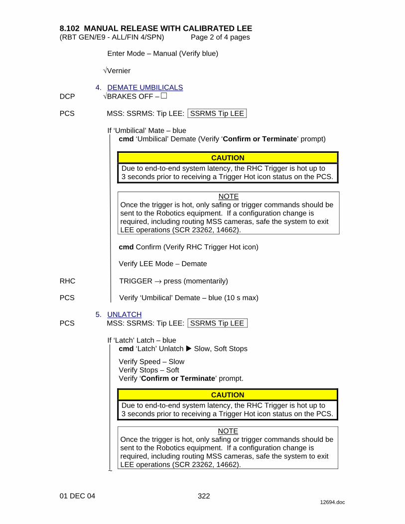
8.102 MANUAL RELEASE WITH CALIBRATED LEE (RBT GEN/E9 - ALL/FIN 4/SPN) Page 2 of 4 pages
01 DEC 04 12694.doc
Enter Mode – Manual (Verify blue)
√Vernier 4. DEMATE UMBILICALS DCP √BRAKES OFF – PCS MSS: SSRMS: Tip LEE: SSRMS Tip LEE
If ‘Umbilical’ Mate – blue cmd ‘Umbilical’ Demate (Verify ‘Confirm or Terminate’ prompt)
CAUTION Due to end-to-end system latency, the RHC Trigger is hot up to 3 seconds prior to receiving a Trigger Hot icon status on the PCS.
NOTE
Once the trigger is hot, only safing or trigger commands should be sent to the Robotics equipment. If a configuration change is required, including routing MSS cameras, safe the system to exit LEE operations (SCR 23262, 14662).
cmd Confirm (Verify RHC Trigger Hot icon)
Verify LEE Mode – Demate
RHC TRIGGER → press (momentarily) PCS Verify ‘Umbilical’ Demate – blue (10 s max) 5. UNLATCH PCS MSS: SSRMS: Tip LEE: SSRMS Tip LEE
If ‘Latch’ Latch – blue cmd ‘Latch’ Unlatch � Slow, Soft Stops
Verify Speed – Slow Verify Stops – Soft Verify ‘Confirm or Terminate’ prompt.
CAUTION
Due to end-to-end system latency, the RHC Trigger is hot up to 3 seconds prior to receiving a Trigger Hot icon status on the PCS.
NOTE
Once the trigger is hot, only safing or trigger commands should be sent to the Robotics equipment. If a configuration change is required, including routing MSS cameras, safe the system to exit LEE operations (SCR 23262, 14662). ~
322

8.102 MANUAL RELEASE WITH CALIBRATED LEE (RBT GEN/E9 - ALL/FIN 4/SPN) Page 3 of 4 pages
01 DEC 04 12694.doc
cmd Confirm (Verify RHC Trigger Hot icon)
Verify LEE Mode – Unlatch RHC TRIGGER → press (hold until ’Latch’ Brakes – On) (65 s max)
Verify ‘Latch’ Unlatch – blue 6. DERIGIDIZE CARRIAGE
MSS: SSRMS: Tip LEE: SSRMS Tip LEE
cmd ‘Carriage’ Derigidize � Slow (Verify Speed – Slow)
Verify ‘Confirm or Terminate’ prompt.
CAUTION Due to end-to-end system latency, the RHC Trigger is hot up to 3 seconds prior to receiving a Trigger Hot icon status on the PCS.
NOTE
Once the trigger is hot, only safing or trigger commands should be sent to the Robotics equipment. If a configuration change is required, including routing MSS cameras, safe the system to exit LEE operations (SCR 23262, 14662).
cmd Confirm (Verify RHC Trigger Hot icon)
Verify LEE Mode – Derigidize
RHC TRIGGER → press (momentarily) (SCR 19064) PCS Verify ‘Carriage’ Derigidize – blue (90 s max) 7. OPEN SNARES PCS MSS: SSRMS: Tip LEE: SSRMS Tip LEE
cmd ‘Snare’ Open � Slow, Soft Stops
Verify Speed – Slow Verify Stops – Soft Verify ‘Confirm or Terminate’ prompt.
cmd Confirm (Verify RHC Trigger Hot icon)
Verify LEE Mode – Open Snares
RHC TRIGGER → press (hold until ’Snare’ Brakes – On) (12 s max)
Verify ‘Snare’ Open – blue
~
323
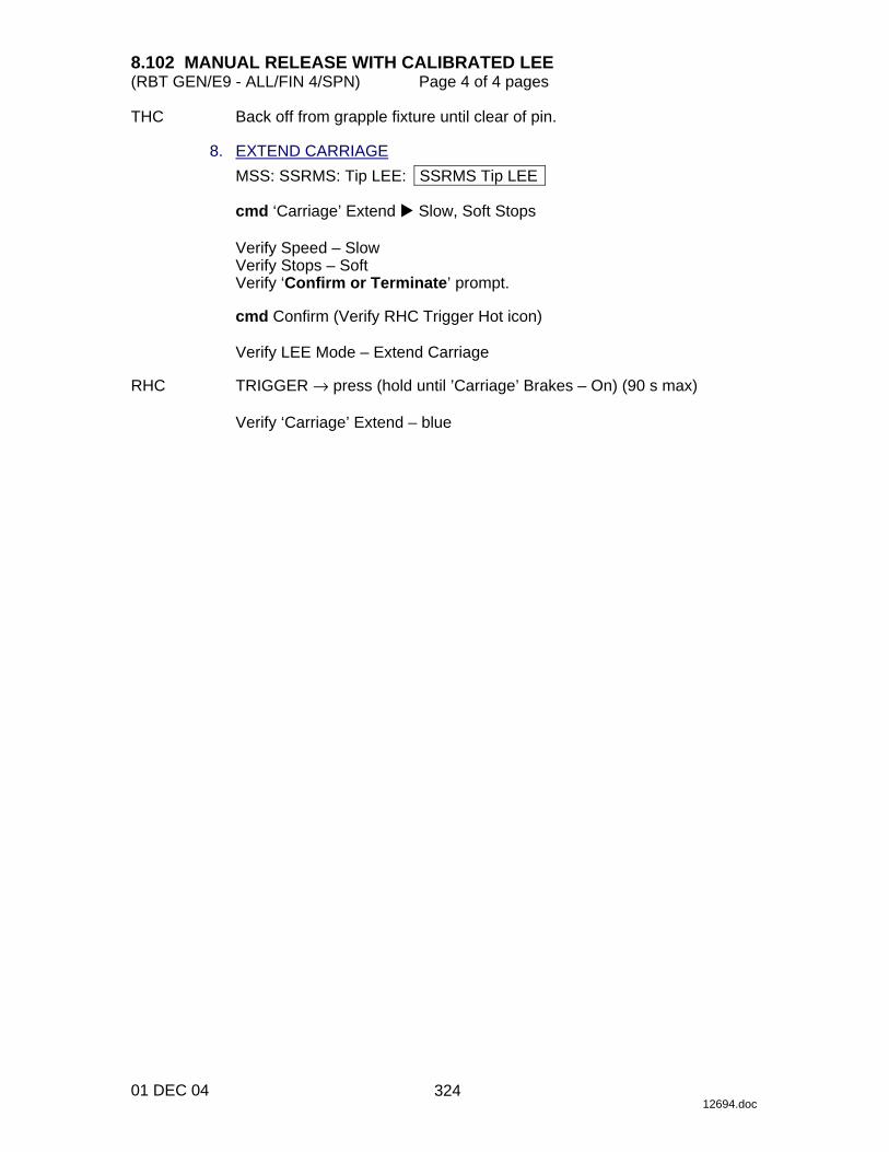
8.102 MANUAL RELEASE WITH CALIBRATED LEE (RBT GEN/E9 - ALL/FIN 4/SPN) Page 4 of 4 pages
01 DEC 04 12694.doc
THC Back off from grapple fixture until clear of pin. 8. EXTEND CARRIAGE
MSS: SSRMS: Tip LEE: SSRMS Tip LEE
cmd ‘Carriage’ Extend � Slow, Soft Stops
Verify Speed – Slow Verify Stops – Soft Verify ‘Confirm or Terminate’ prompt.
cmd Confirm (Verify RHC Trigger Hot icon)
Verify LEE Mode – Extend Carriage
RHC TRIGGER → press (hold until ’Carriage’ Brakes – On) (90 s max)
Verify ‘Carriage’ Extend – blue
324

8.103 MANUAL RELEASE WITH UNCALIBRATED LEE (RBT GEN/E9 - ALL/FIN 4/SPN) Page 1 of 3 pages
01 DEC 04 12702.doc
1. RETRACT CARRIAGE PCS MSS: SSRMS: Tip LEE: SSRMS Tip LEE
If ‘Latch’ Latch – blue and ‘Carriage’ Retract − gray cmd ‘Carriage’ Retract � Hard Stops � Slow, Hard Stops
Verify Speed – Slow Verify Stops – Hard Verify ‘Confirm or Terminate’ prompt.
CAUTION Due to end-to-end system latency, the RHC Trigger is hot up to 3 seconds prior to receiving a Trigger Hot icon status on the PCS.
NOTE
Once the trigger is hot, only safing or trigger commands should be sent to the Robotics equipment. If a configuration change is required, including routing MSS cameras, safe the system to exit LEE operations (SPN 1892, 3160).
cmd Confirm (Verify RHC Trigger Hot icon)
Verify LEE Mode – Retract Carriage
RHC TRIGGER → press (hold until ’Carriage’ Brakes – On) (90 s max)
Verify ‘Carriage’ Retract – blue 2. LIMP SSRMS AND ENTER MODE PCS MSS: SSRMS: Limp: SSRMS Limp
cmd All Limp (Verify Limp – blue)
MSS: SSRMS: SSRMS
Verify All Joints − Limped
Wait 30 seconds.
MSS: SSRMS: Limp: SSRMS Limp
cmd None Limp (Verify Standby – blue)
Enter Mode – Manual (Verify blue)
√Vernier
325
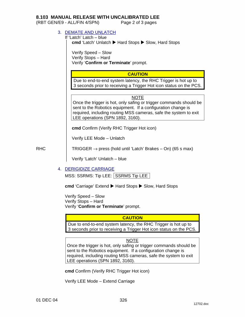
8.103 MANUAL RELEASE WITH UNCALIBRATED LEE (RBT GEN/E9 - ALL/FIN 4/SPN) Page 2 of 3 pages
01 DEC 04 12702.doc
3. DEMATE AND UNLATCH If ‘Latch’ Latch – blue
cmd ‘Latch’ Unlatch � Hard Stops � Slow, Hard Stops
Verify Speed – Slow Verify Stops – Hard Verify ‘Confirm or Terminate’ prompt.
CAUTION Due to end-to-end system latency, the RHC Trigger is hot up to 3 seconds prior to receiving a Trigger Hot icon status on the PCS.
NOTE
Once the trigger is hot, only safing or trigger commands should be sent to the Robotics equipment. If a configuration change is required, including routing MSS cameras, safe the system to exit LEE operations (SPN 1892, 3160).
cmd Confirm (Verify RHC Trigger Hot icon)
Verify LEE Mode – Unlatch
RHC TRIGGER → press (hold until ’Latch’ Brakes – On) (65 s max)
Verify ‘Latch’ Unlatch – blue 4. DERIGIDIZE CARRIAGE
MSS: SSRMS: Tip LEE: SSRMS Tip LEE
cmd ‘Carriage’ Extend � Hard Stops � Slow, Hard Stops
Verify Speed – Slow Verify Stops – Hard Verify ‘Confirm or Terminate’ prompt.
CAUTION Due to end-to-end system latency, the RHC Trigger is hot up to 3 seconds prior to receiving a Trigger Hot icon status on the PCS.
NOTE
Once the trigger is hot, only safing or trigger commands should be sent to the Robotics equipment. If a configuration change is required, including routing MSS cameras, safe the system to exit LEE operations (SPN 1892, 3160).
cmd Confirm (Verify RHC Trigger Hot icon)
Verify LEE Mode – Extend Carriage
326

8.103 MANUAL RELEASE WITH UNCALIBRATED LEE (RBT GEN/E9 - ALL/FIN 4/SPN) Page 3 of 3 pages
01 DEC 04 12702.doc
CAUTION The trigger must be released once the Derigidize indication turns blue. Failure to do so will cause the carriage to hit the grapple fixture cams, possibly causing hardware damage.
RHC TRIGGER → press (hold until ‘Carriage’ Derigidize – blue) (90 s max) PCS cmd Terminate 5. OPEN SNARES PCS MSS: SSRMS: Tip LEE: SSRMS Tip LEE
cmd ‘Snare’ Open � Hard Stops � Slow, Hard Stops
Verify Speed – Slow Verify Stops – Hard Verify ‘Confirm or Terminate’ prompt.
cmd Confirm (Verify RHC Trigger Hot icon)
Verify LEE Mode – Open Snares
RHC TRIGGER → press (hold until ’Snare’ Brakes – On) (12 s max) PCS Verify ‘Snare’ Open – blue THC Back off from grapple fixture until clear of pin. 6. EXTEND CARRIAGE PCS MSS: SSRMS: Tip LEE: SSRMS Tip LEE
cmd ‘Carriage’ Extend � Hard Stops � Slow, Hard Stops
Verify Speed – Slow Verify Stops – Hard Verify ‘Confirm or Terminate’ prompt.
cmd Confirm (Verify RHC Trigger Hot icon)
Verify LEE Mode – Extend Carriage
RHC TRIGGER → press (hold until ’Carriage’ Brakes – On) (90 s max)
Verify ‘Carriage’ Extend – blue
327

This Page Intentionally Blank
22 DEC 04
328

8.104 MSS CHECKPOINT DATA RESET (RBT GEN/X2R4 - ALL/FIN/SPN) Page 1 of 5 pages
13 DEC 04 12662.doc
NOTE This procedure was created for SPN 956.
1. CHECKING FOR ACTIVE RWS
If either RWS is Active, for Active RWS PCS MSS: LAP5(LAS5) Initialize: LAP5(LAS5) Initialization
Verify ‘Frame Count’ incrementing
MSS: SSRMS: Checkpoint Data: Checkpoint Data
cmd Checkpoint Current Data >> 2. MSS CYCLIC CHECKPOINT DATA LOAD PCS If PCSCDS Main Control Panel is an icon, restore the ‘cds_ui’ icon.
PCSCDS Main Control Panel
sel Commands ! File Transfer
File and Memory Transfer
sel Commands ! Indirect Data Load
Indirect Data Load
sel Target Node ! CCS CCD2
NOTE Opening displays or initiating other file transfers on this or any other PCS during the MSS Event Driven Checkpoint Data load could cause the load to fail.
cmd Apply
File and Memory Transfer
Verify ‘Active Transfers’ Transfer Status – OK
NOTE
This file load could take up to 2 minutes. The progress of the file load can be determined by selecting the entry in the Active Transfers window and then selecting Status. An entry will appear in the window at the bottom of the display with the current status.
Verify ‘Completed Transfers’ Transfer Status – COMPLETED
329

8.104 MSS CHECKPOINT DATA RESET (RBT GEN/X2R4 - ALL/FIN/SPN) Page 2 of 5 pages
13 DEC 04 12662.doc
3. MSS EVENT DRIVEN CHECKPOINT DATA LOAD Indirect Data Load
sel Target Node ! CCS EDCD3
NOTE
Opening displays or initiating other file transfers on this or any other PCS during the MSS Event Driven Checkpoint Data load could cause the load to fail.
cmd Apply
File and Memory Transfer
Verify ‘Active Transfers’ Transfer Status – OK
NOTE
This file load could take up to 2 minutes. The progress of the file load can be determined by selecting the entry in the Active Transfers window and then selecting Status. An entry will appear in the window at the bottom of the display with the current status.
Verify ‘Completed Transfers’ Transfer Status – COMPLETED
sel Commands ! Close
Verify Shutdown
sel Yes
4. VERIFY CYCLIC CHECKPOINT DATA LOAD
MSS: SSRMS: SSRMS
Verify SSRMS Joint and FOR configuration. SR SY SP EP WP WY WR 0.0 0.0 0.0 0.0 0.0 0.0 0.0 X Y Z Pitch Yaw Roll
0.0 0.0 0.0 0.0 0.0 0.0 5. VERIFY EVENT DRIVEN CHECKPOINT DATA LOAD
NOTE The following values may not reflect the current system configuration but are used to confirm a successful event driven checkpoint data load. These values will be updated in step 7 with the actual system configuration.
Verify ‘Base LEE’ – B Verify ‘PDGF’ – LAB
330

8.104 MSS CHECKPOINT DATA RESET (RBT GEN/X2R4 - ALL/FIN/SPN) Page 3 of 5 pages
13 DEC 04 12662.doc
6. RWS POWERUP If neither LAB nor Cupola RWS is initialized
Perform {6.332 MSS POWERUP}, step 1 (SODF: RBT GEN: NOMINAL), then:
7. SET CURRENT CHECKPOINT DATA PCS MSS: LAP5 CEU Mode: CEU Mode
cmd ‘Cupola (LAS5)’ (‘Lab (LAP5)’) Active (Verify – Active)
NOTE SSRMS/MBS data referenced in this step may be incorrect on the PCS. The selection should reflect the actual state of the system. If the actual state of the system is unknown, √MCC.
MSS: SSRMS: Checkpoint Data: Checkpoint Data
Enter ‘SSRMS’ ‘Payload’ per Table 1.
Table 1. SSRMS/POA Payload Selection
Description Payload Snares are open or closed with no capture indication. ReleasedIf GF is PDGF
Snares are closed with capture indication but not latched (may be rigidized).
If GF is FRGF or RSGF Snares are closed with capture indication but not rigidized.
Captive
If GF is PDGF Snares are closed with capture indication, rigidized, and latched.
If GF is FRGF or RSGF Snares are closed with capture indication and rigidized.
Captured
Enter ‘SSRMS’ ‘Umbilical’ per Table 2.
Table 2. SSRMS/POA/MCAS Umbilical Selection
Description Umbilical Umbilical is not mated to a payload. Demated Umbilical is mated to a payload. Mated
331
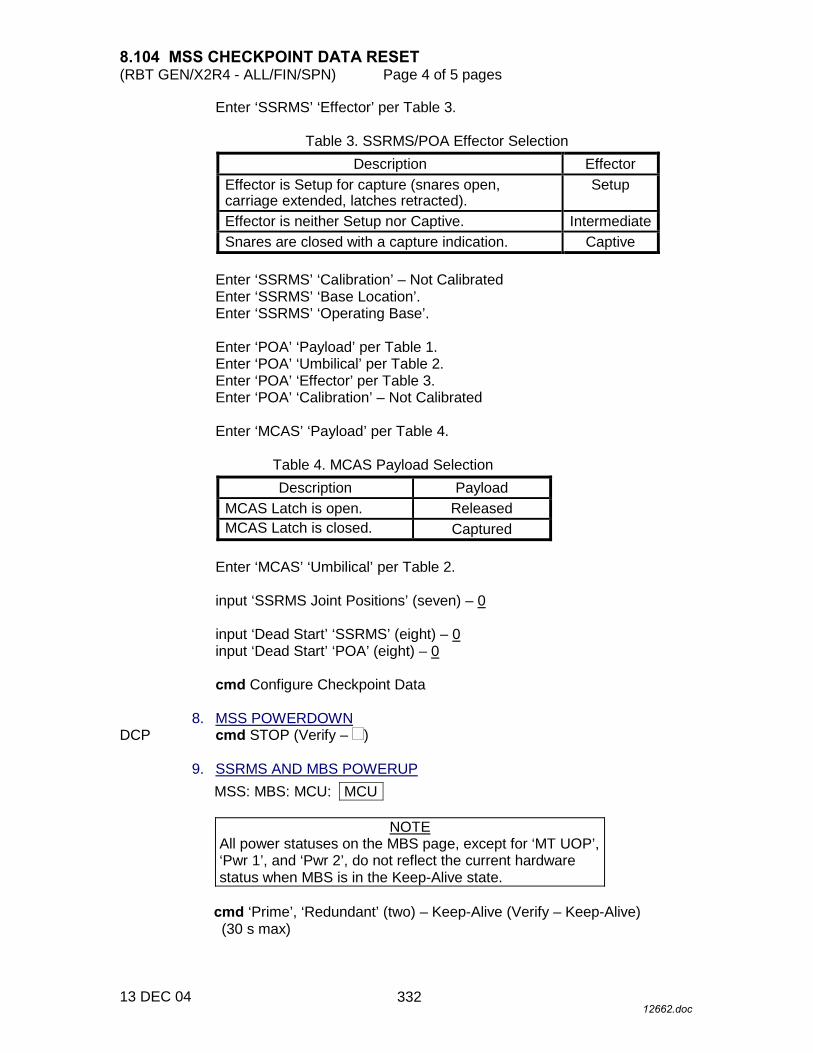
8.104 MSS CHECKPOINT DATA RESET (RBT GEN/X2R4 - ALL/FIN/SPN) Page 4 of 5 pages
13 DEC 04 12662.doc
Enter ‘SSRMS’ ‘Effector’ per Table 3.
Table 3. SSRMS/POA Effector Selection Description Effector
Effector is Setup for capture (snares open, carriage extended, latches retracted).
Setup
Effector is neither Setup nor Captive. Intermediate Snares are closed with a capture indication. Captive
Enter ‘SSRMS’ ‘Calibration’ – Not Calibrated Enter ‘SSRMS’ ‘Base Location’. Enter ‘SSRMS’ ‘Operating Base’.
Enter ‘POA’ ‘Payload’ per Table 1. Enter ‘POA’ ‘Umbilical’ per Table 2. Enter ‘POA’ ‘Effector’ per Table 3. Enter ‘POA’ ‘Calibration’ – Not Calibrated
Enter ‘MCAS’ ‘Payload’ per Table 4.
Table 4. MCAS Payload Selection Description Payload
MCAS Latch is open. Released MCAS Latch is closed. Captured
Enter ‘MCAS’ ‘Umbilical’ per Table 2.
input ‘SSRMS Joint Positions’ (seven) – 0
input ‘Dead Start’ ‘SSRMS’ (eight) – 0 input ‘Dead Start’ ‘POA’ (eight) – 0
cmd Configure Checkpoint Data
8. MSS POWERDOWN DCP cmd STOP (Verify – ) 9. SSRMS AND MBS POWERUP
MSS: MBS: MCU: MCU
NOTE All power statuses on the MBS page, except for ‘MT UOP’, ‘Pwr 1’, and ‘Pwr 2’, do not reflect the current hardware status when MBS is in the Keep-Alive state.
cmd ‘Prime’, ‘Redundant’ (two) – Keep-Alive (Verify – Keep-Alive) (30 s max)
332

8.104 MSS CHECKPOINT DATA RESET (RBT GEN/X2R4 - ALL/FIN/SPN) Page 5 of 5 pages
13 DEC 04 12662.doc
NOTE 1. The operator can follow the transition to Operational by
looking at the MSS discrete log. 2. The transition from Keep-Alive to Operational can be
stopped at anytime by commanding SAFING on the DCP.
cmd ‘Prime’(‘Redundant’) – Operational
Verify Systems State – Operational) (~3 min)
MSS: SSRMS: Power: SSRMS Power
cmd ‘SSRMS’ ‘Prime’, ‘Redundant’ (two) – Keep-Alive (Verify – Keep-Alive)
NOTE
When the SSRMS is next taken to Operational, expect the following Robotics Advisory messages:
‘R9C - MSS OCS SSRMS SR Joint Init Posn Err’ ‘R9C - MSS OCS SSRMS SY Joint Init Posn Err’ ‘R9C - MSS OCS SSRMS SP Joint Init Posn Err’ ‘R9C - MSS OCS SSRMS EP Joint Init Posn Err’ ‘R9C - MSS OCS SSRMS WP Joint Init Posn Err’ ‘R9C - MSS OCS SSRMS WY Joint Init Posn Err’ ‘R9C - MSS OCS SSRMS WR Joint Init Posn Err’
10. E-STOP RESET MSS: RWS: Reset: E-Stop Reset
cmd Yes
333

This Page Intentionally Blank
22 DEC 04
334
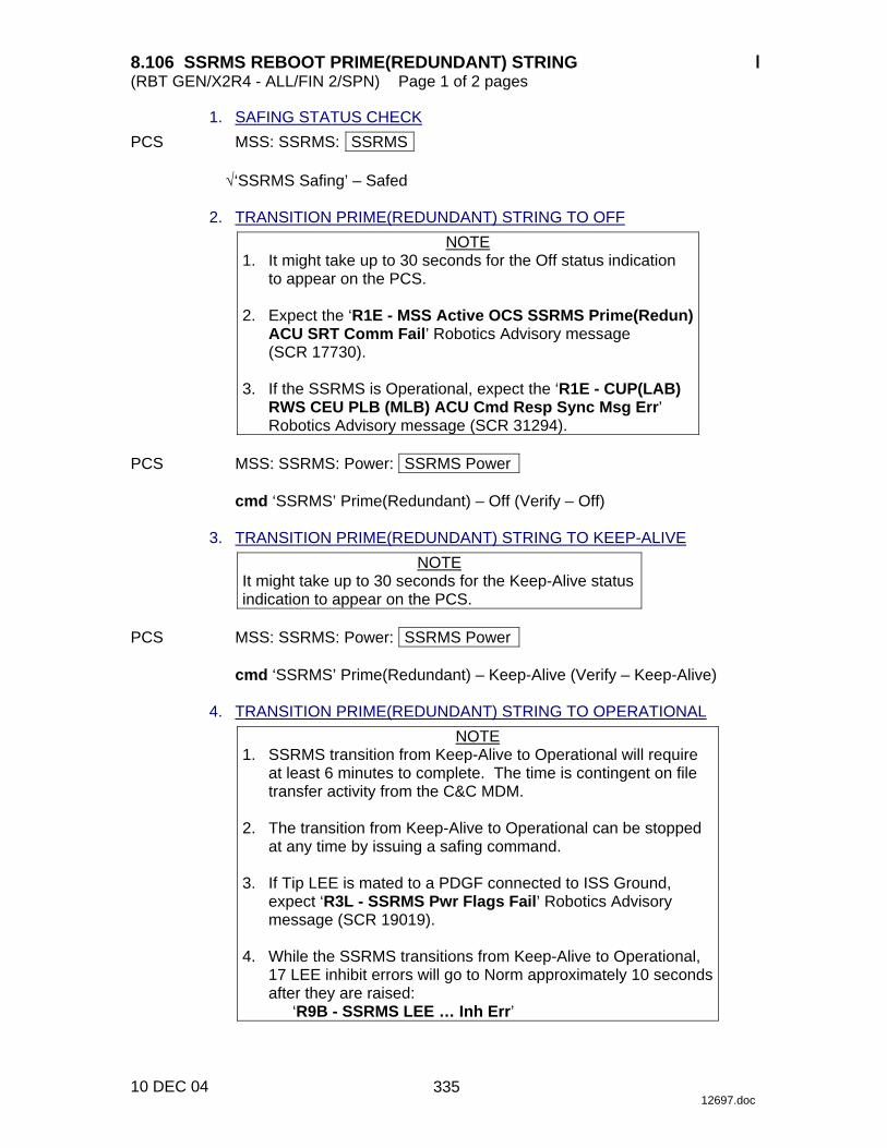
8.106 SSRMS REBOOT PRIME(REDUNDANT) STRING (RBT GEN/X2R4 - ALL/FIN 2/SPN) Page 1 of 2 pages
10 DEC 04 12697.doc
1. SAFING STATUS CHECK PCS MSS: SSRMS: SSRMS
√‘SSRMS Safing’ – Safed 2. TRANSITION PRIME(REDUNDANT) STRING TO OFF
NOTE 1. It might take up to 30 seconds for the Off status indication
to appear on the PCS. 2. Expect the ‘R1E - MSS Active OCS SSRMS Prime(Redun)
ACU SRT Comm Fail’ Robotics Advisory message (SCR 17730).
3. If the SSRMS is Operational, expect the ‘R1E - CUP(LAB)
RWS CEU PLB (MLB) ACU Cmd Resp Sync Msg Err’ Robotics Advisory message (SCR 31294).
PCS MSS: SSRMS: Power: SSRMS Power
cmd ‘SSRMS’ Prime(Redundant) – Off (Verify – Off) 3. TRANSITION PRIME(REDUNDANT) STRING TO KEEP-ALIVE
NOTE It might take up to 30 seconds for the Keep-Alive status indication to appear on the PCS.
PCS MSS: SSRMS: Power: SSRMS Power
cmd ‘SSRMS’ Prime(Redundant) – Keep-Alive (Verify – Keep-Alive) 4. TRANSITION PRIME(REDUNDANT) STRING TO OPERATIONAL
NOTE 1. SSRMS transition from Keep-Alive to Operational will require
at least 6 minutes to complete. The time is contingent on file transfer activity from the C&C MDM.
2. The transition from Keep-Alive to Operational can be stopped
at any time by issuing a safing command. 3. If Tip LEE is mated to a PDGF connected to ISS Ground,
expect ‘R3L - SSRMS Pwr Flags Fail’ Robotics Advisory message (SCR 19019).
4. While the SSRMS transitions from Keep-Alive to Operational,
17 LEE inhibit errors will go to Norm approximately 10 seconds after they are raised:
‘R9B - SSRMS LEE … Inh Err’
335

8.106 SSRMS REBOOT PRIME(REDUNDANT) STRING (RBT GEN/X2R4 - ALL/FIN 2/SPN) Page 2 of 2 pages
10 DEC 04 12697.doc
MSS: SSRMS: Power: SSRMS Power
cmd ‘SSRMS’ Prime(Redundant) – Operational
Verify Systems State – Operational 5. VIDEO SYSTEM POWERUP
NOTE Expect ‘R6F - SSRMS… PFM Carrier On Video …Err’ Robotics Advisory message as each VDU is powered on. Message may toggle in and out of alarm until video is routed to the defined VDU (SCR 24376).
PCS MSS: SSRMS: Base LEE VDU: MSS VDUs
sel ‘[X]’ as required where [X] = Base LEE Base Elbow
Tip Elbow Tip LEE
cmd ‘[X]’ On (Verify – On)
Repeat
MSS: SSRMS: Base Elbow Camera icon: SSRMS Base Elbow Camera
sel [X] as required where [X] = T-Elb 24 B-Elb 22 LEE 25
cmd ‘Power’ On (Verify – On)
Repeat 6. SSRMS VIDEO DEROUTING
MSS:Video: Video Routing
Repeat the following for all destinations to which an SSRMS Camera is routed:
sel ‘Destination Icon’
cmd ‘Deroute Video Signal’ – Deroute
336
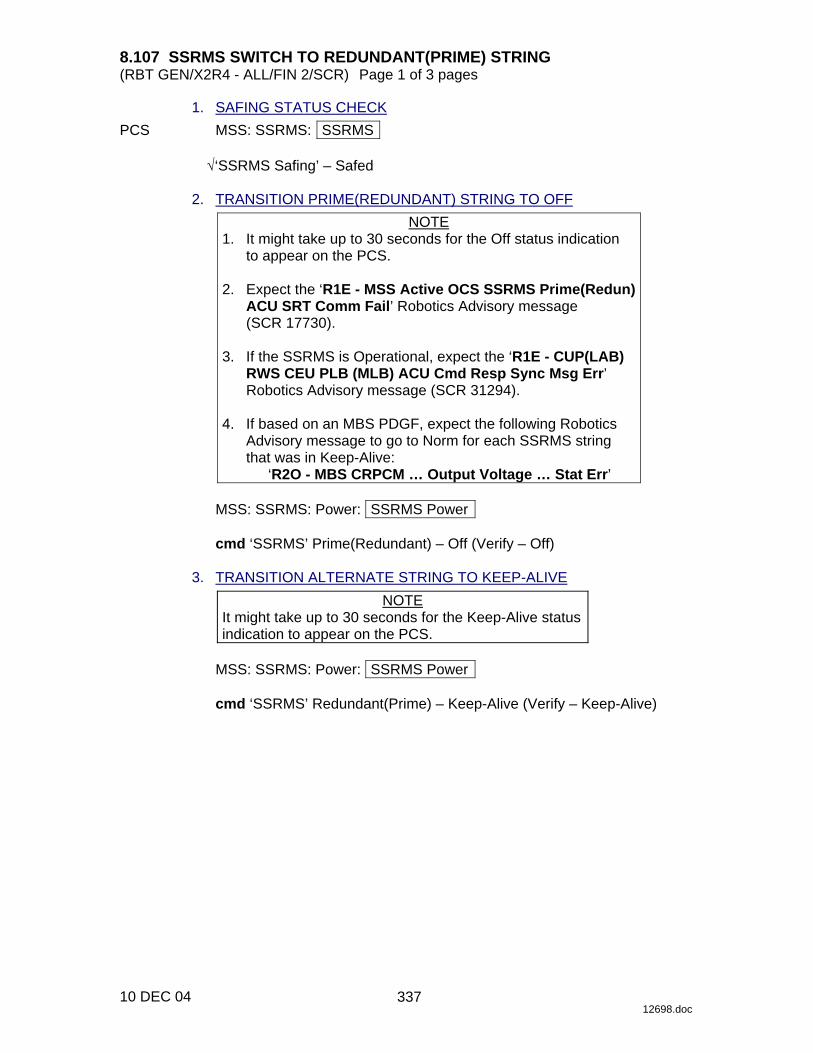
8.107 SSRMS SWITCH TO REDUNDANT(PRIME) STRING (RBT GEN/X2R4 - ALL/FIN 2/SCR) Page 1 of 3 pages
10 DEC 04 12698.doc
1. SAFING STATUS CHECK PCS MSS: SSRMS: SSRMS
√‘SSRMS Safing’ – Safed 2. TRANSITION PRIME(REDUNDANT) STRING TO OFF
NOTE 1. It might take up to 30 seconds for the Off status indication
to appear on the PCS. 2. Expect the ‘R1E - MSS Active OCS SSRMS Prime(Redun)
ACU SRT Comm Fail’ Robotics Advisory message (SCR 17730).
3. If the SSRMS is Operational, expect the ‘R1E - CUP(LAB)
RWS CEU PLB (MLB) ACU Cmd Resp Sync Msg Err’ Robotics Advisory message (SCR 31294).
4. If based on an MBS PDGF, expect the following Robotics
Advisory message to go to Norm for each SSRMS string that was in Keep-Alive:
‘R2O - MBS CRPCM … Output Voltage … Stat Err’
MSS: SSRMS: Power: SSRMS Power
cmd ‘SSRMS’ Prime(Redundant) – Off (Verify – Off) 3. TRANSITION ALTERNATE STRING TO KEEP-ALIVE
NOTE It might take up to 30 seconds for the Keep-Alive status indication to appear on the PCS.
MSS: SSRMS: Power: SSRMS Power
cmd ‘SSRMS’ Redundant(Prime) – Keep-Alive (Verify – Keep-Alive)
337
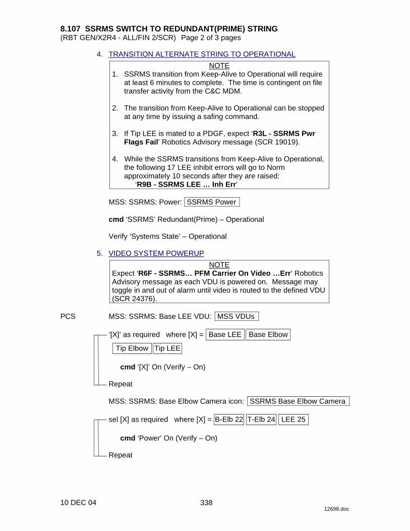
8.107 SSRMS SWITCH TO REDUNDANT(PRIME) STRING (RBT GEN/X2R4 - ALL/FIN 2/SCR) Page 2 of 3 pages
10 DEC 04 12698.doc
4. TRANSITION ALTERNATE STRING TO OPERATIONAL NOTE
1. SSRMS transition from Keep-Alive to Operational will require at least 6 minutes to complete. The time is contingent on file transfer activity from the C&C MDM.
2. The transition from Keep-Alive to Operational can be stopped
at any time by issuing a safing command. 3. If Tip LEE is mated to a PDGF, expect ‘R3L - SSRMS Pwr
Flags Fail’ Robotics Advisory message (SCR 19019). 4. While the SSRMS transitions from Keep-Alive to Operational,
the following 17 LEE inhibit errors will go to Norm approximately 10 seconds after they are raised:
‘R9B - SSRMS LEE … Inh Err’
MSS: SSRMS: Power: SSRMS Power
cmd ‘SSRMS’ Redundant(Prime) – Operational
Verify ‘Systems State’ – Operational 5. VIDEO SYSTEM POWERUP
NOTE Expect ‘R6F - SSRMS… PFM Carrier On Video …Err’ Robotics Advisory message as each VDU is powered on. Message may toggle in and out of alarm until video is routed to the defined VDU (SCR 24376).
PCS MSS: SSRMS: Base LEE VDU: MSS VDUs
‘[X]’ as required where [X] = Base LEE Base Elbow
Tip Elbow Tip LEE
cmd ‘[X]’ On (Verify – On)
Repeat
MSS: SSRMS: Base Elbow Camera icon: SSRMS Base Elbow Camera
sel [X] as required where [X] = B-Elb 22 T-Elb 24 LEE 25
cmd ‘Power’ On (Verify – On)
Repeat
338

8.107 SSRMS SWITCH TO REDUNDANT(PRIME) STRING (RBT GEN/X2R4 - ALL/FIN 2/SCR) Page 3 of 3 pages
10 DEC 04 12698.doc
6. SSRMS VIDEO DEROUTING MSS: Video: Video Routing
Repeat the following for all destinations to which an SSRMS Camera is routed:
sel ‘Destination Icon’
cmd ‘Deroute Video Signal’ – Deroute
339

This Page Intentionally Blank
22 DEC 04
340

8.108 SSRMS SUBUNIT REBOOT (RBT GEN/R3 - ALL/FIN 3/SPN) Page 1 of 1 page
10 DEC 04 12709.doc
NOTE When rebooting the LEU and if the Tip LEE is mated to a PDGF connected to ISS Ground, expect ‘R3L - SSRMS Pwr Flags Fail’ Robotics Advisory message (SCR 19019).
PCS MSS: SSRMS: SSRMS
√SSRMS Safing – Safed
MSS: SSRMS: Power: Reset Unit: SSRMS Reset Unit
cmd SR(SY,SP,EP,WP,WY,WR,LEU)
MSS: SSRMS: Power: SSRMS Power
Verify SR(SY,SP,EP,WP,WY,WR,LEU) – K-A Verify SR(SY,SP,EP,WP,WY,WR,LEU) – Init Verify SR(SY,SP,EP,WP,WY,WR,LEU) – Go (~2 minutes, 9 seconds for a JEU and ~2 minutes, 22 seconds for the LEU)
If ‘SSRMS’ Prime(Redundant) – Failed
cmd ‘SSRMS’ Prime(Redundant) – Operational
Verify Systems State – Initializing Verify Systems State – Operational
341

This Page Intentionally Blank
22 DEC 04
342
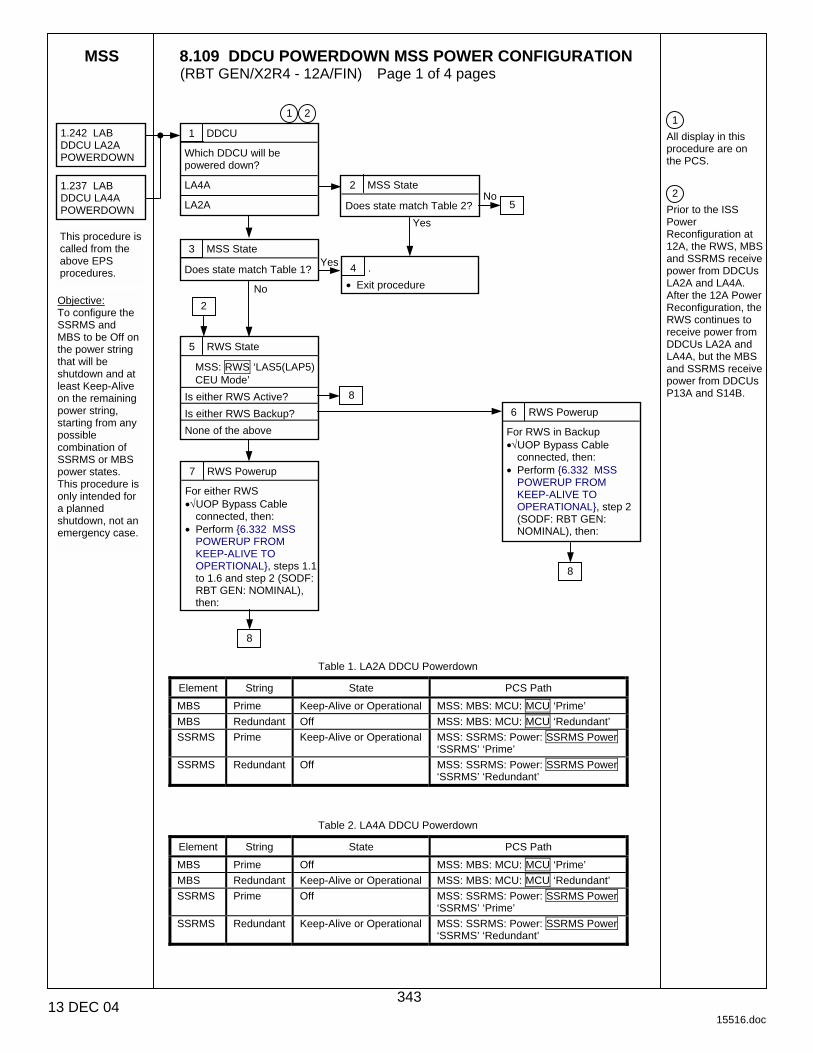
MSS 8.109 DDCU POWERDOWN MSS POWER CONFIGURATION (RBT GEN/X2R4 - 12A/FIN) Page 1 of 4 pages
13 DEC 04 15516.doc
Table 1. LA2A DDCU Powerdown
Element String State PCS Path
MBS Prime Keep-Alive or Operational MSS: MBS: MCU: MCU ‘Prime’
MBS Redundant Off MSS: MBS: MCU: MCU ‘Redundant’
SSRMS Prime Keep-Alive or Operational MSS: SSRMS: Power: SSRMS Power ‘SSRMS’ ‘Prime’
SSRMS Redundant Off MSS: SSRMS: Power: SSRMS Power ‘SSRMS’ ‘Redundant’
Table 2. LA4A DDCU Powerdown
Element String State PCS Path
MBS Prime Off MSS: MBS: MCU: MCU ‘Prime’
MBS Redundant Keep-Alive or Operational MSS: MBS: MCU: MCU ‘Redundant’
SSRMS Prime Off MSS: SSRMS: Power: SSRMS Power ‘SSRMS’ ‘Prime’
SSRMS Redundant Keep-Alive or Operational MSS: SSRMS: Power: SSRMS Power ‘SSRMS’ ‘Redundant’
1
All display in this procedure are on the PCS.
2
Prior to the ISS Power Reconfiguration at 12A, the RWS, MBS and SSRMS receive power from DDCUs LA2A and LA4A. After the 12A Power Reconfiguration, the RWS continues to receive power from DDCUs LA2A and LA4A, but the MBS and SSRMS receive power from DDCUs P13A and S14B.
1 DDCU
Which DDCU will be powered down?
LA4A
LA2A
1.242 LAB DDCU LA2A POWERDOWN
3 MSS State
Does state match Table 1?
No
Yes 4 .
• Exit procedure
2 MSS State
Does state match Table 2?
Yes
No 1.237 LAB DDCU LA4A POWERDOWN
This procedure is called from the above EPS procedures.
2
Objective: To configure the SSRMS and MBS to be Off on the power string that will be shutdown and at least Keep-Alive on the remaining power string, starting from any possible combination of SSRMS or MBS power states. This procedure is only intended for a planned shutdown, not an emergency case.
1
5 RWS State
MSS: RWS ‘LAS5(LAP5) CEU Mode’
Is either RWS Active?
Is either RWS Backup?
None of the above
2
5
6 RWS Powerup
For RWS in Backup •√UOP Bypass Cable
connected, then: • Perform {6.332 MSS
POWERUP FROM KEEP-ALIVE TO OPERATIONAL}, step 2 (SODF: RBT GEN: NOMINAL), then:
7 RWS Powerup
For either RWS •√UOP Bypass Cable
connected, then: • Perform {6.332 MSS
POWERUP FROM KEEP-ALIVE TO OPERTIONAL}, steps 1.1 to 1.6 and step 2 (SODF: RBT GEN: NOMINAL), then:
8
8
8
343
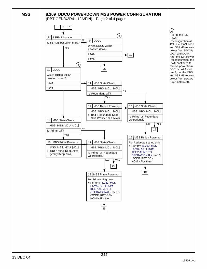
MSS 8.109 DDCU POWERDOWN MSS POWER CONFIGURATION (RBT GEN/X2R4 - 12A/FIN) Page 2 of 4 pages
13 DEC 04 15516.doc
2
Prior to the ISS Power Reconfiguration at 12A, the RWS, MBS and SSRMS receive power from DDCUs LA2A and LA4A. After the 12A Power Reconfiguration, the RWS continues to receive power from DDCUs LA2A and LA4A, but the MBS and SSRMS receive power from DDCUs P13A and S14B.
8 SSRMS Location
Is SSRMS based on MBS?
Yes
No
10 DDCU
Which DDCU will be powered down?
LA4A
LA2A
2
11 MBS State Check
MSS: MBS: MCU: MCU Is ‘Redundant’ Off?
12 MBS Redun Powerup
MSS: MBS: MCU: MCU • cmd ‘Redundant’ Keep-
Alive (Verify Keep-Alive)
No
Yes
9 DDCU
Which DDCU will be powered down?
LA4A
LA2A
2
13 MBS State Check
MSS: MBS: MCU: MCU Is ‘Prime’ or ‘Redundant’ Operational? 14 MBS State Check
MSS: MBS: MCU: MCU Is ‘Prime’ Off?
16 MBS Prime Powerup
MSS: MBS: MCU: MCU • cmd ‘Prime’ Keep-Alive
(Verify Keep-Alive)
No Yes
17 MBS State Check
MSS: MBS: MCU: MCU Is ‘Prime’ or ‘Redundant’ Operational?
No Yes
No
Yes
18 MBS Prime Powerup
For Prime string only • Perform {6.332 MSS
POWERUP FROM KEEP-ALIVE TO OPERATIONAL}, step 3 (SODF: RBT GEN: NOMINAL), then:
5 7 6
19
25
19
25
15 MBS Redun Powerup
For Redundant string only • Perform {6.332 MSS
POWERUP FROM KEEP-ALIVE TO OPERATIONAL}, step 3 (SODF: RBT GEN: NOMINAL), then:
19
25
344
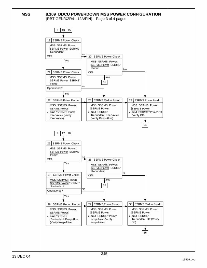
MSS 8.109 DDCU POWERDOWN MSS POWER CONFIGURATION (RBT GEN/X2R4 - 12A/FIN) Page 3 of 4 pages
13 DEC 04 15516.doc
25 SSRMS Power Check
MSS: SSRMS: Power: SSRMS Power ‘SSRMS’ ‘Prime’
Off?
30 SSRMS Redun Pwrdn
MSS: SSRMS: Power: SSRMS Power
• cmd ‘SSRMS’ ‘Redundant’ Off (Verify Off)
Yes
Yes
28 SSRMS Redun Pwrdn
MSS: SSRMS: Power: SSRMS Power
• cmd ‘SSRMS’ ‘Redundant’ Keep-Alive (Verify Keep-Alive)
19 SSRMS Power Check
MSS: SSRMS: Power: SSRMS Power ‘SSRMS’ ‘Redundant’
Off?
Yes
24 SSRMS Prime Pwrdn
MSS: SSRMS: Power: SSRMS Power
• cmd ‘SSRMS’ ‘Prime’ Off (Verify Off)
20 SSRMS Power Check
MSS: SSRMS: Power: SSRMS Power ‘SSRMS’ ‘Prime’
Off?
Yes
No 21 SSRMS Power Check
MSS: SSRMS: Power: SSRMS Power ‘SSRMS’ ‘Prime’
Operational? No
Yes
22 SSRMS Prime Pwrdn
MSS: SSRMS: Power: SSRMS Power
• cmd ‘SSRMS’ ‘Prime’ Keep-Alive (Verify Keep-Alive)
23 SSRMS Redun Pwrup
MSS: SSRMS: Power: SSRMS Power
• cmd ‘SSRMS’ ‘Redundant’ Keep-Alive (Verify Keep-Alive)
26 SSRMS Power Check
MSS: SSRMS: Power: SSRMS Power ‘SSRMS’ ‘Redundant’
Off? 27 SSRMS Power Check
MSS: SSRMS: Power: SSRMS Power ‘SSRMS’ ‘Redundant’
Operational?
No
29 SSRMS Prime Pwrup
MSS: SSRMS: Power: SSRMS Power
• cmd ‘SSRMS’ ‘Prime’ Keep-Alive (Verify Keep-Alive)
No
No
Yes
9 15 13
No
31
31
9 18 17
35
35
345
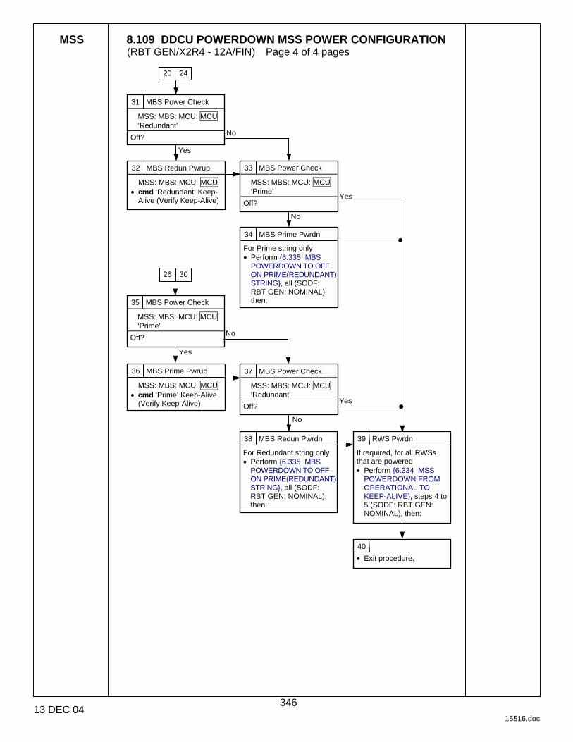
MSS 8.109 DDCU POWERDOWN MSS POWER CONFIGURATION (RBT GEN/X2R4 - 12A/FIN) Page 4 of 4 pages
13 DEC 04 15516.doc
31 MBS Power Check
MSS: MBS: MCU: MCU ‘Redundant’
Off?
32 MBS Redun Pwrup
MSS: MBS: MCU: MCU • cmd ‘Redundant’ Keep-
Alive (Verify Keep-Alive)
34 MBS Prime Pwrdn
For Prime string only • Perform {6.335 MBS
POWERDOWN TO OFF ON PRIME(REDUNDANT) STRING}, all (SODF: RBT GEN: NOMINAL), then:
Yes
No
33 MBS Power Check
MSS: MBS: MCU: MCU ‘Prime’
Off? Yes
No
35 MBS Power Check
MSS: MBS: MCU: MCU ‘Prime’
Off? No
Yes
36 MBS Prime Pwrup
MSS: MBS: MCU: MCU • cmd ‘Prime’ Keep-Alive
(Verify Keep-Alive)
37 MBS Power Check
MSS: MBS: MCU: MCU ‘Redundant’
Off?
38 MBS Redun Pwrdn
For Redundant string only • Perform {6.335 MBS
POWERDOWN TO OFF ON PRIME(REDUNDANT) STRING}, all (SODF: RBT GEN: NOMINAL), then:
39 RWS Pwrdn
If required, for all RWSs that are powered • Perform {6.334 MSS
POWERDOWN FROM OPERATIONAL TO KEEP-ALIVE}, steps 4 to 5 (SODF: RBT GEN: NOMINAL), then:
40
• Exit procedure.
20 24
26 30
Yes
No
346

8.110 MANUAL CAPTURE WITH UNCALIBRATED LEE (RBT GEN/E9 - ALL/FIN 3/SPN) Page 1 of 3 pages
01 DEC 04 12672.doc
1. SETUP Prior to beginning payload capture, review {SSRMS LEE CUE CARD}, all (SODF: RBT GEN: REFERENCE), then:
NOTE
The LEE Camera must be fully zoomed out to correspond to the target overlay.
Configure cameras and overlays for grapple.
PCS MSS: SSRMS: SSRMS
√Manual – blue √Vernier
2. GRAPPLE MANEUVER RHC/ Maneuver to within grapple envelope. THC 3. LIMP SSRMS
MSS: SSRMS: Limp: SSRMS Limp
cmd All Limp (Verify Limp – blue) PCS MSS: SSRMS: SSRMS
Verify all joints – Limped 4. CLOSE SNARES
MSS: SSRMS: Tip LEE: SSRMS Tip LEE
cmd ‘Snare’ Close � Hard Stops � Slow, Hard Stops
Verify Speed – Slow Verify Stops – Hard Verify ‘Confirm or Terminate’ prompt.
CAUTION
Due to end-to-end system latency, the RHC Trigger is hot up to 3 seconds prior to receiving a Trigger Hot icon status on the PCS.
NOTE
Once the trigger is hot, only safing or trigger commands should be sent to the Robotics equipment. If a configuration change is required, including routing MSS cameras, safe the system to exit LEE operations (SPN 1892, 3160).
cmd Confirm (Verify RHC Trigger Hot icon)
Verify LEE Mode – Close Snares
RHC TRIGGER → press (hold until ’Snare’ Brakes – On) (12 s max)
347
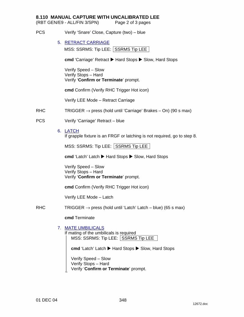
8.110 MANUAL CAPTURE WITH UNCALIBRATED LEE (RBT GEN/E9 - ALL/FIN 3/SPN) Page 2 of 3 pages
01 DEC 04 12672.doc
PCS Verify ‘Snare’ Close, Capture (two) – blue 5. RETRACT CARRIAGE
MSS: SSRMS: Tip LEE: SSRMS Tip LEE
cmd ‘Carriage’ Retract � Hard Stops � Slow, Hard Stops
Verify Speed – Slow Verify Stops – Hard Verify ‘Confirm or Terminate’ prompt.
cmd Confirm (Verify RHC Trigger Hot icon)
Verify LEE Mode – Retract Carriage
RHC TRIGGER → press (hold until ’Carriage’ Brakes – On) (90 s max) PCS Verify ‘Carriage’ Retract – blue 6. LATCH
If grapple fixture is an FRGF or latching is not required, go to step 8.
MSS: SSRMS: Tip LEE: SSRMS Tip LEE
cmd ‘Latch’ Latch � Hard Stops � Slow, Hard Stops
Verify Speed – Slow Verify Stops – Hard Verify ‘Confirm or Terminate’ prompt.
cmd Confirm (Verify RHC Trigger Hot icon)
Verify LEE Mode – Latch
RHC TRIGGER → press (hold until ‘Latch’ Latch – blue) (65 s max)
cmd Terminate 7. MATE UMBILICALS
If mating of the umbilicals is required MSS: SSRMS: Tip LEE: SSRMS Tip LEE
cmd ‘Latch’ Latch � Hard Stops � Slow, Hard Stops
Verify Speed – Slow Verify Stops – Hard Verify ‘Confirm or Terminate’ prompt.
~
348

8.110 MANUAL CAPTURE WITH UNCALIBRATED LEE (RBT GEN/E9 - ALL/FIN 3/SPN) Page 3 of 3 pages
01 DEC 04 12672.doc
NOTE
Expect ‘R3L - SSRMS Pwr Flags Fail’ Robotics Advisory message when mating is complete (SPN 2599).
cmd Confirm (Verify RHC Trigger Hot icon) Verify LEE Mode – Latch
RHC TRIGGER → press (hold until ’Latch’ Brakes – On) (65 s max)
Verify ‘Umbilical’ Mate – blue Verify ‘Connector Continuity’ Prime, Redundant (two) – Yes
8. DELIMP SSRMS
MSS: SSRMS: Limp: SSRMS Limp
cmd None Limp (Verify Standby – blue) 9. DERIGIDIZE CARRIAGE
If derigidization of the carriage is not required >>
MSS: SSRMS: Tip LEE: SSRMS Tip LEE
cmd ‘Carriage’ Extend � Hard Stops � Slow, Hard Stops
Verify Speed – Slow Verify Stops – Hard Verify ‘Confirm or Terminate’ prompt.
cmd Confirm (Verify RHC Trigger Hot icon)
Verify LEE Mode – Extend Carriage
CAUTION The trigger must be released once the derigidize indication turns blue. Failure to do so will cause the carriage to hit the grapple fixture cams, possibly causing hardware damage.
RHC TRIGGER → press (hold until ‘Carriage’ Derigidize – blue) (90 s max)
cmd Terminate
~
349

This Page Intentionally Blank
22 DEC 04
350

8.111 LEE MISCAPTURE (RBT GEN/X2R4 - ALL/FIN 1) Page 1 of 2 pages
14 DEC 04 13298.doc
RECOVERY If LEE visually confirmed far enough over the grapple pin for a good capture
NOTE Expect the following message when Safing is commanded:
‘R3Z - MSS OCS SSRMS Prime(Redun) ACU SRT Cat-1 Brk Stat Fail’ (SCR 17495)
Message should return to Norm. DCP SAFING → SAFE (Verify ON) PCS MSS: SSRMS: SSRMS Safing: SSRMS Safing
cmd Remove (Verify Not Safed) DCP BRAKES SSRMS → OFF (Verify OFF)
CAUTION In the case of a failed capture microswitch, the payload parameter state will not update to Loaded following the successful grapple. Differences in FOR and translation/rotation rates may be apparent and trajectory redesign may be required before proceeding with loaded operations.
Go to {8.101 MANUAL CAPTURE WITH CALIBRATED LEE}, steps 3 and 5 to 10 (SODF: RBT GEN: CORRECTIVE).
If no visual confirmation after attempting an Auto Capture
RHC TRIGGER → press (momentarily) PCS Verify Setup – Yes RHC/ Maneuver to within grapple envelope. THC RHC TRIGGER → press (momentarily) PCS Verify ‘Snare’ Close, Capture (two) – blue (12 s(3 s) max)
351
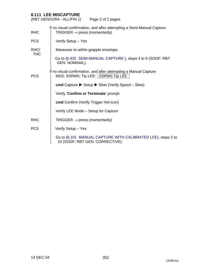
8.111 LEE MISCAPTURE (RBT GEN/X2R4 - ALL/FIN 1) Page 2 of 2 pages
14 DEC 04 13298.doc
If no visual confirmation, and after attempting a Semi-Manual Capture RHC TRIGGER → press (momentarily) PCS Verify Setup – Yes RHC/ Maneuver to within grapple envelope. THC
Go to {6.425 SEMI-MANUAL CAPTURE }, steps 4 to 6 (SODF: RBT GEN: NOMINAL).
If no visual confirmation, and after attempting a Manual Capture
PCS MSS: SSRMS: Tip LEE: SSRMS Tip LEE
cmd Capture � Setup � Slow (Verify Speed – Slow)
Verify ‘Confirm or Terminate’ prompt.
cmd Confirm (Verify Trigger Hot icon)
Verfiy LEE Mode – Setup for Capture RHC TRIGGER → press (momentarily) PCS Verify Setup – Yes
Go to {8.101 MANUAL CAPTURE WITH CALIBRATED LEE}, steps 2 to 10 (SODF: RBT GEN: CORRECTIVE).
352

8.112 SSRMS CAPTURE ABORT RECOVERY (RBT GEN/X2R4 - ALL/FIN) Page 1 of 3 pages
20 DEC 04 15591.doc
NOTE 1. This procedure can be executed if an SSRMS automatic LEE
capture sequence aborts due to one of the following: Loadcell tension at the end of rigidization is below 5055 N.
Loadcell tension at the end of latching is below 5055 N.
Loadcell tension at the end of rigidization is nominal, but the retract microswitch is not tripped.
2. The minimum loadcell tension for proper latch
engagement/disengagement is 4003 N. 1. LEE DEADSTART CALIBRATION PCS MSS: SSRMS: SSRMS Safing: SSRMS Safing
cmd Remove (Verify Not Safed)
MSS: SSRMS: Tip LEE: SSRMS Tip LEE
Verify LEE Mechanisms, Load Cell (two) – Calibrated 2. LIMP SSRMS
NOTE 1. The caution ‘R3Q – SSRMS LEE Uncommanded Derigidize’
may be raised when the SSRMS joints are limped and/or when the latches are driven (tension drops below 4003 N).
2. In this step, the brakes will not be released until the override
command is issued. DCP BRAKES SSRMS → OFF PCS MSS: SSRMS: SSRMS
Verify Brake Override – True
MSS: SSRMS: Brake Override: Brakes Override
cmd Remove Brakes and Limping
MSS: SSRMS: SSRMS
Verify Limp – blue Verify All Joints – Limp
3. RETRACT CARRIAGE
MSS: SSRMS: Tip LEE: SSRMS Tip LEE
cmd ‘Carriage’ Retract � Soft Stops � Slow, Soft Stops
Verify Speed – Slow Verify Stops – Soft Verify ‘Confirm or Terminate’ prompt.
353
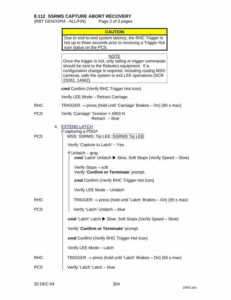
8.112 SSRMS CAPTURE ABORT RECOVERY (RBT GEN/X2R4 - ALL/FIN) Page 2 of 3 pages
20 DEC 04 15591.doc
CAUTION Due to end-to-end system latency, the RHC Trigger is hot up to three seconds prior to receiving a Trigger Hot icon status on the PCS.
NOTE
Once the trigger is hot, only safing or trigger commands should be sent to the Robotics equipment. If a configuration change is required, including routing MSS cameras, safe the system to exit LEE operations (SCR 23262, 14662).
cmd Confirm (Verify RHC Trigger Hot Icon)
Verify LEE Mode – Retract Carriage
RHC TRIGGER → press (hold until ‘Carriage’ Brakes – On) (90 s max) PCS Verify ‘Carriage’ Tension > 4003 N
Retract – blue 4. EXTEND LATCH
If capturing a PDGF PCS MSS: SSRMS: Tip LEE: SSRMS Tip LEE
Verify ‘Capture to Latch’ – Yes
If Unlatch – gray cmd ‘Latch’ Unlatch � Slow, Soft Stops (Verify Speed – Slow)
Verify Stops – soft Verify ‘Confirm or Terminate’ prompt.
cmd Confirm (Verify RHC Trigger Hot Icon)
Verify LEE Mode – Unlatch
RHC TRIGGER → press (hold until ’Latch’ Brakes – On) (65 s max) PCS Verify ‘Latch’ Unlatch – blue
cmd ‘Latch’ Latch � Slow, Soft Stops (Verify Speed – Slow)
Verify ‘Confirm or Terminate’ prompt.
cmd Confirm (Verify RHC Trigger Hot Icon)
Verify LEE Mode – Latch RHC TRIGGER → press (hold until ’Latch’ Brakes – On) (65 s max) PCS Verify ‘Latch’ Latch – blue
354

8.112 SSRMS CAPTURE ABORT RECOVERY (RBT GEN/X2R4 - ALL/FIN) Page 3 of 3 pages
20 DEC 04 15591.doc
5. MATE UMBILICAL If umbilical mating is required
cmd ‘Umbilical’ Mate (Verify ‘Confirm or Terminate’ prompt) cmd Confirm (Verify RHC Trigger Hot Icon)
Verify LEE Mode – Mate
RHC TRIGGER → press (momentarily) PCS Verify ‘Umbilical’ Mate − blue (10 s max)
Verify ‘Connector Continuity’ Prime, Redundant (two) – Yes 6. DERIGIDIZE CARRIAGE
If carriage derigidization is required cmd ‘Carriage’ Derigidize � Slow (Verify ‘Speed’ – Slow)
Verify ‘Confirm or Terminate’ prompt.
cmd Confirm (Verify RHC Trigger Hot Icon)
Verify ‘LEE Mode’ – Derigidize
RHC TRIGGER → press (momentarily) (SCR 19064) PCS Verify ‘Carriage’ Derigidize − blue (90 s max) 7. DELIMP SSRMS MSS: SSRMS: Limp SSRMS Limp
cmd None Limp
MSS: SSRMS: SSRMS
Verify Standby – blue 8. SSRMS DEADSTART CALIBRATION
NOTE This step should only be performed if uncommanded Derig detection is required for the planned operations.
DCP SAFING → SAFE (Verify ON) PCS MSS: SSRMS: SSRMS Safing: SSRMS Safing
cmd Remove (Verify Not Safed) DCP SSRMS BRAKES → OFF (Verify OFF)
355

This Page Intentionally Blank
22 DEC 04
356

8.201 MT MANUAL UMA MSW ACQUISITION (RBT GEN/ULF1 - ALL/FIN 1) Page 1 of 7 pages
23 JAN 03 12594.doc
NOTE 1. The IMCA automatically returns to On mode after the programmed
trajectory has completed. 2. A pause command can be issued by commanding the IMCA to On
mode on the following page MSS: MT: Manual Translate: MT Manual Translate ‘IMCA Commands’
3. The IMCA takes approximately 6 seconds to complete self-tests
once power is applied. 1. UMA IMCA RT I/O ENABLE PCS MSS: MT: ‘MT’ ‘Amp1’ MT LB A: RT Status: RT Status Cont.
RT#16-25: LB MT 1 RT Status Cont
cmd ‘RT Status’ ‘19 UMA 1P’ Enable Execute (Verify – Ena) cmd ‘RT Status’ ‘20 UMA 1S’ Enable Execute (Verify – Ena) cmd ‘RT Status’ ‘21 UMA 2P’ Enable Execute (Verify – Ena) cmd ‘RT Status’ ‘22 UMA 2S’ Enable Execute (Verify – Ena)
2. MT SOFTWARE PROCESS INITIATION
CAUTION If, at any time during this procedure, a UMA IMCA temperature reaches or surpasses 60.0° C, power off that IMCA.
MSS: MT: MT Mode: MT Mode
If ‘MT Process State’ – Disabled
cmd Initiate MT Process Execute
Verify ‘SEPS Process State’ – Initiated Verify ‘IMCA Process State’ – Initiated Verify ‘MT Process State’ – Initiated
If ‘MT Software Mode’ – Idle or Auto
cmd Standby Execute (Verify – Standby)
If ‘MT Software Mode’ – Standby cmd Manual Execute (Verify – Manual)
3. UMA MICROSWITCH VERIFICATION 3.1 MT Power Verification
MSS: MT: Power: MT Power
Verify ‘TUS1’ ‘RPCM S0-4B-F’ 17 – Cl Verify ‘MT’ ‘RPCM MT-4B’ 13,14 (two) – Cl Verify ‘TUS2’ ‘RPCM S0-3A-E’ 18 – Cl Verify ‘MT’ ‘RPCM MT-3A’ 13,14 (two) – Cl
357
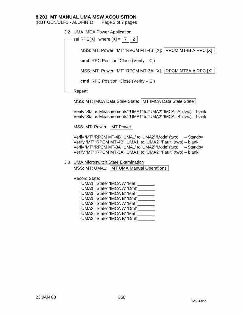
8.201 MT MANUAL UMA MSW ACQUISITION (RBT GEN/ULF1 - ALL/FIN 1) Page 2 of 7 pages
23 JAN 03 12594.doc
3.2 UMA IMCA Power Application sel RPC[X] where [X] = 2 7
MSS: MT: Power: ‘MT’ ‘RPCM MT-4B’ [X]: RPCM MT4B A RPC [X]
cmd ‘RPC Position’ Close (Verify – Cl)
MSS: MT: Power: ‘MT’ ‘RPCM MT-3A’ [X]: RPCM MT3A A RPC [X]
cmd ‘RPC Position’ Close (Verify – Cl)
Repeat
MSS: MT: IMCA Data Stale State: MT IMCA Data Stale State
Verify ‘Status Measurements’ ‘UMA1’ to ‘UMA2’ ‘IMCA’ ‘A’ (two) – blank Verify ‘Status Measurements’ ‘UMA1’ to ‘UMA2’ ‘IMCA’ ‘B’ (two) – blank
MSS: MT: Power: MT Power
Verify ‘MT’ ‘RPCM MT-4B’ ‘UMA1’ to ‘UMA2’ ‘Mode’ (two) – Standby Verify ‘MT’ ‘RPCM MT-4B’ ‘UMA1’ to ‘UMA2’ ‘Fault’ (two) – blank Verify ‘MT’ ‘RPCM MT-3A’ ‘UMA1’ to ‘UMA2’ ‘Mode’ (two) – Standby Verify ‘MT’ ‘RPCM MT-3A’ ‘UMA1’ to ‘UMA2’ ‘Fault’ (two) – blank
3.3 UMA Microswitch State Examination
MSS: MT: UMA1: MT UMA Manual Operations
Record State: ‘UMA1’ ‘State’ ‘IMCA A’ ‘Mat’ _______ ‘UMA1’ ‘State’ ‘IMCA A’ ‘Dmt’ _______ ‘UMA1’ ‘State’ ‘IMCA B’ ‘Mat’ _______ ‘UMA1’ ‘State’ ‘IMCA B’ ‘Dmt’ _______ ‘UMA2’ ‘State’ ‘IMCA A’ ‘Mat’ _______ ‘UMA2’ ‘State’ ‘IMCA A’ ‘Dmt’ _______ ‘UMA2’ ‘State’ ‘IMCA B’ ‘Mat’ _______ ‘UMA2’ ‘State’ ‘IMCA B’ ‘Dmt’ _______
358
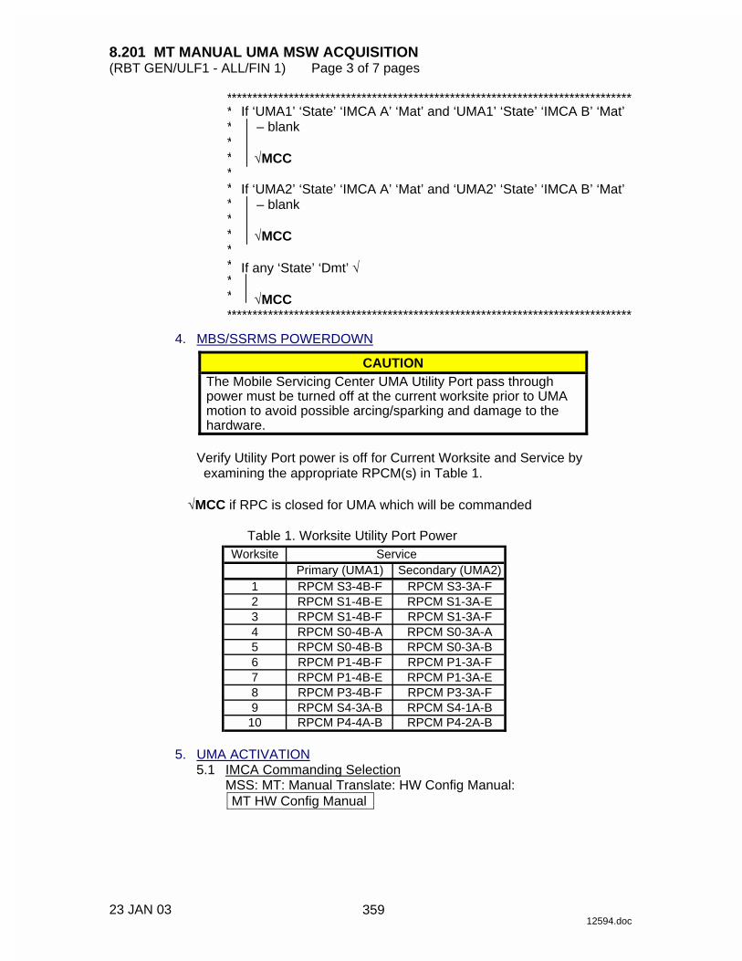
8.201 MT MANUAL UMA MSW ACQUISITION (RBT GEN/ULF1 - ALL/FIN 1) Page 3 of 7 pages
23 JAN 03 12594.doc
* ***************************************************************************** * * * * * * * ******
If ‘UMA1’ ‘State’ ‘IMCA A’ ‘Mat’ and ‘UMA1’ ‘State’ ‘IMCA B’ ‘Mat’ – blank
√MCC
If ‘UMA2’ ‘State’ ‘IMCA A’ ‘Mat’ and ‘UMA2’ ‘State’ ‘IMCA B’ ‘Mat’
– blank
√MCC
If any ‘State’ ‘Dmt’ √
√MCC * *****************************************************************************
4. MBS/SSRMS POWERDOWN
CAUTION The Mobile Servicing Center UMA Utility Port pass through power must be turned off at the current worksite prior to UMA motion to avoid possible arcing/sparking and damage to the hardware.
Verify Utility Port power is off for Current Worksite and Service by examining the appropriate RPCM(s) in Table 1.
√MCC if RPC is closed for UMA which will be commanded
Table 1. Worksite Utility Port Power
WorksitePrimary (UMA1) Secondary (UMA2)
1 RPCM S3-4B-F RPCM S3-3A-F2 RPCM S1-4B-E RPCM S1-3A-E3 RPCM S1-4B-F RPCM S1-3A-F4 RPCM S0-4B-A RPCM S0-3A-A5 RPCM S0-4B-B RPCM S0-3A-B6 RPCM P1-4B-F RPCM P1-3A-F7 RPCM P1-4B-E RPCM P1-3A-E8 RPCM P3-4B-F RPCM P3-3A-F9 RPCM S4-3A-B RPCM S4-1A-B
10 RPCM P4-4A-B RPCM P4-2A-B
Service
5. UMA ACTIVATION 5.1 IMCA Commanding Selection
MSS: MT: Manual Translate: HW Config Manual: MT HW Config Manual
359

8.201 MT MANUAL UMA MSW ACQUISITION (RBT GEN/ULF1 - ALL/FIN 1) Page 4 of 7 pages
23 JAN 03 12594.doc
If ‘UMA1’ ‘State’ ‘IMCA A’ ‘Mat’ recorded in step 3.3 – blank sel ‘UMA1’ ‘IMCA Selection’ – CMD IMCA A
If ‘UMA1’ ‘State’ ‘IMCA B’ ‘Mat’ recorded in step 3.3 – blank
sel ‘UMA1’ ‘IMCA Selection’ – CMD IMCA B
If ‘UMA2’ ‘State’ ‘IMCA A’ ‘Mat’ recorded in step 3.3 – blank sel ‘UMA2’ ‘IMCA Selection’ – CMD IMCA A
If ‘UMA2’ ‘State’ ‘IMCA B’ ‘Mat’ recorded in step 3.3 – blank
sel ‘UMA2’ ‘IMCA Selection’ – CMD IMCA B
cmd Load HW Config
Verify ‘UMA1’ ‘State’ – matches selection Verify ‘UMA2’ ‘State’ – matches selection Verify all others – none
5.2 Safing Init Frame Selection
MSS: MT: Manual Translate: Init Frame Config: MT Init Frame Config
input ‘UMA’ ‘Init Frame’ – 2
cmd Load Init Frame Config (Verify ‘UMA’ ‘State’: 2)
√all others: 0
5.3 IMCA Initialization
MSS: MT: Manual Translate: MT Manual Translate
cmd ‘IMCA Commands’ Initialize Execute
MSS: MT: IMCA Cmd State: MT IMCA Cmd State
If UMA1 IMCA selected in IMCA Commanding Selection Verify ‘Initialize’ ‘UMA1’ ‘IMCA’ ‘A(B)’ – √
If UMA2 IMCA selected in IMCA Commanding Selection
Verify ‘Initialize’ ‘UMA2’ ‘IMCA’ ‘A(B)’– √ 5.4 IMCA Mode to On
MSS: MT: Manual Translate: MT Manual Translate
cmd ‘IMCA Commands’ On Execute
MSS: MT: Manual Translate: UMA: MT UMA Manual Operations
360

8.201 MT MANUAL UMA MSW ACQUISITION (RBT GEN/ULF1 - ALL/FIN 1) Page 5 of 7 pages
23 JAN 03 12594.doc
If UMA1 IMCA selected in IMCA Commanding Selection Verify ‘UMA1’ ‘IMCA A(B)’ ‘Mode’ – On
If UMA2 IMCA selected in IMCA Commanding Selection
Verify ‘UMA2’ ‘IMCA A(B)’ ‘Mode’ – On 5.5 Initialization Frame Selection
MSS: MT: Manual Translate: Init Frame Config: MT Init Frame Config
input ‘UMA’ ‘Init Frame’ – 5
cmd Load Init Frame Config (Verify ‘UMA’ ‘State’: 5)
√all others: 0
5.6 IMCA Initialization
MSS: MT: Manual Translate: MT Manual Translate
cmd ‘IMCA Commands’ Initialize Execute
MSS: MT: IMCA Cmd State: MT IMCA Cmd State
If UMA1 IMCA selected in IMCA Commanding Selection Verify ‘Initialize’ ‘UMA1’ ‘IMCA’ ‘A(B)’– √
If UMA2 IMCA selected in IMCA Commanding Selection
Verify ‘Initialize’ ‘UMA2’ ‘IMCA’ ‘A(B)’– √
5.7 IMCA Movement Initiation Verify IMCA motion using the following page
MSS: MT: Manual Translate: UMA: MT UMA Manual Operations
CAUTION Moding the IMCA to On, if it is still enabled after 30 seconds, will avoid possible damage to the hardstops.
MSS: MT: Manual Translate: MT Manual Translate
cmd ‘IMCA Commands’ Actuate Execute
MSS: MT: Manual Translate: UMA: MT UMA Manual Operations
361
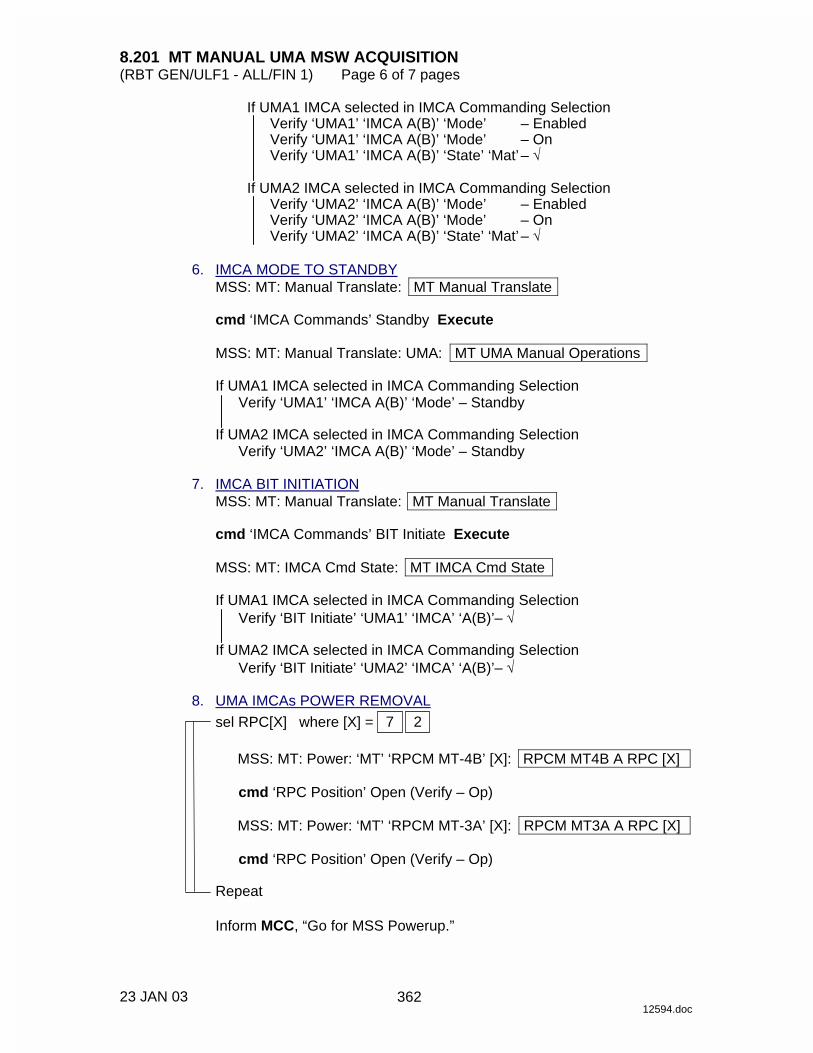
8.201 MT MANUAL UMA MSW ACQUISITION (RBT GEN/ULF1 - ALL/FIN 1) Page 6 of 7 pages
23 JAN 03 12594.doc
If UMA1 IMCA selected in IMCA Commanding Selection Verify ‘UMA1’ ‘IMCA A(B)’ ‘Mode’ – Enabled Verify ‘UMA1’ ‘IMCA A(B)’ ‘Mode’ – On Verify ‘UMA1’ ‘IMCA A(B)’ ‘State’ ‘Mat’ – √
If UMA2 IMCA selected in IMCA Commanding Selection
Verify ‘UMA2’ ‘IMCA A(B)’ ‘Mode’ – Enabled Verify ‘UMA2’ ‘IMCA A(B)’ ‘Mode’ – On Verify ‘UMA2’ ‘IMCA A(B)’ ‘State’ ‘Mat’ – √
6. IMCA MODE TO STANDBY
MSS: MT: Manual Translate: MT Manual Translate
cmd ‘IMCA Commands’ Standby Execute
MSS: MT: Manual Translate: UMA: MT UMA Manual Operations
If UMA1 IMCA selected in IMCA Commanding Selection Verify ‘UMA1’ ‘IMCA A(B)’ ‘Mode’ – Standby
If UMA2 IMCA selected in IMCA Commanding Selection
Verify ‘UMA2’ ‘IMCA A(B)’ ‘Mode’ – Standby 7. IMCA BIT INITIATION
MSS: MT: Manual Translate: MT Manual Translate
cmd ‘IMCA Commands’ BIT Initiate Execute
MSS: MT: IMCA Cmd State: MT IMCA Cmd State
If UMA1 IMCA selected in IMCA Commanding Selection Verify ‘BIT Initiate’ ‘UMA1’ ‘IMCA’ ‘A(B)’– √
If UMA2 IMCA selected in IMCA Commanding Selection
Verify ‘BIT Initiate’ ‘UMA2’ ‘IMCA’ ‘A(B)’– √ 8. UMA IMCAs POWER REMOVAL
sel RPC[X] where [X] = 2 7
MSS: MT: Power: ‘MT’ ‘RPCM MT-4B’ [X]: RPCM MT4B A RPC [X]
cmd ‘RPC Position’ Open (Verify – Op)
MSS: MT: Power: ‘MT’ ‘RPCM MT-3A’ [X]: RPCM MT3A A RPC [X]
cmd ‘RPC Position’ Open (Verify – Op)
Repeat
Inform MCC, “Go for MSS Powerup.”
362

8.201 MT MANUAL UMA MSW ACQUISITION (RBT GEN/ULF1 - ALL/FIN 1) Page 7 of 7 pages
23 JAN 03 12594.doc
9. MT SOFTWARE SHUTDOWN MSS: MT: MT Mode: MT Mode
cmd Standby Execute (Verify – Standby) cmd Idle Execute (Verify – Idle) cmd Disable MT Process Execute (Verify – Disabled)
10. UMA IMCA RT I/O INHIBIT MSS: MT: ‘MT’ ‘Amp1’ MT LB A: RT Status: RT Status Cont.
RT#16-25: LB MT 1 RT Status Cont
cmd ‘RT Status’ ‘19 UMA 1P’ Inhibit Execute (Verify – Inh) cmd ‘RT Status’ ‘20 UMA 1S’ Inhibit Execute (Verify – Inh) cmd ‘RT Status’ ‘21 UMA 2P’ Inhibit Execute (Verify – Inh) cmd ‘RT Status’ ‘22 UMA 2S’ Inhibit Execute (Verify – Inh)
363

This Page Intentionally Blank
22 DEC 04
364

8.202 MT MANUAL UMA MATE (RBT GEN/E7 - ALL/FIN 1/SPN) Page 1 of 6 pages
10 DEC 03 12595.doc
NOTE 1. The IMCA automatically returns to On mode after the programmed
trajectory has completed. 2. A pause command can be issued by commanding the IMCA to On
mode on the following page MSS: MT: Manual Translate: MT Manual Translate ‘IMCA Commands’
3. The IMCA takes approximately 6 seconds to complete self-tests
once power is applied. 1. UMA IMCA RT I/O ENABLE PCS MSS: MT: ‘MT’ ‘Amp1’ MT LB A: RT Status:
RT Status Cont. RT#16-25 LB MT 1 RT Status Cont
cmd ‘RT Status’ ‘19 UMA 1P’ Enable Execute (Verify – Ena) cmd ‘RT Status’ ‘20 UMA 1S’ Enable Execute (Verify – Ena) cmd ‘RT Status’ ‘21 UMA 2P’ Enable Execute (Verify – Ena) cmd ‘RT Status’ ‘22 UMA 2S’ Enable Execute (Verify – Ena)
2. MT SOFTWARE PROCESS INITIATION MSS: MT: MT Mode: MT Mode
If ‘MT Process State’ – Disabled
cmd Initiate MT Process Execute
Verify ‘SEPS Process State’ – Initiated Verify ‘IMCA Process State’ – Initiated Verify ‘MT Process State’ – Initiated
If ‘MT Software Mode’ – Idle or Auto
cmd Standby Execute (Verify – Standby)
If ‘MT Software Mode’ – Standby
cmd Manual Execute (Verify – Manual)
3. TUS POWER VERIFICATION
MSS: MT: Power: MT Power
Verify ‘TUS1’ ‘RPCM S0-4B-F’ 17 – Cl Verify ‘TUS2’ ‘RPCM S0-3A-E’ 18 – Cl Verify ‘MT’ ‘RPCM MT-4B’ 13,14(two) – Cl Verify ‘MT’ ‘RPCM MT-3A’ 13,14(two) – Cl
365
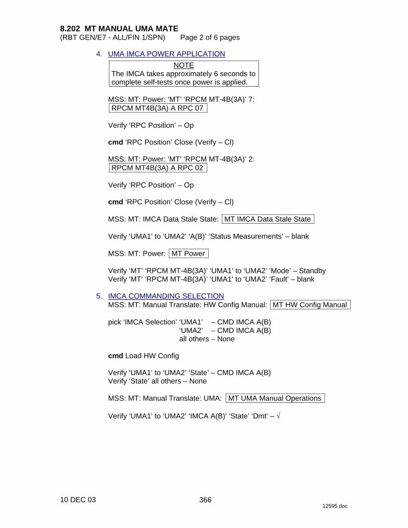
8.202 MT MANUAL UMA MATE (RBT GEN/E7 - ALL/FIN 1/SPN) Page 2 of 6 pages
10 DEC 03 12595.doc
4. UMA IMCA POWER APPLICATION NOTE
The IMCA takes approximately 6 seconds to complete self-tests once power is applied.
MSS: MT: Power: ‘MT’ ‘RPCM MT-4B(3A)’ 7: RPCM MT4B(3A) A RPC 07
Verify ‘RPC Position’ – Op
cmd ‘RPC Position’ Close (Verify – Cl)
MSS: MT: Power: ‘MT’ ‘RPCM MT-4B(3A)’ 2: RPCM MT4B(3A) A RPC 02
Verify ‘RPC Position’ – Op
cmd ‘RPC Position’ Close (Verify – Cl)
MSS: MT: IMCA Data Stale State: MT IMCA Data Stale State
Verify ‘UMA1’ to ‘UMA2’ ‘A(B)’ ‘Status Measurements’ – blank
MSS: MT: Power: MT Power
Verify ‘MT’ ‘RPCM MT-4B(3A)’ ‘UMA1’ to ‘UMA2’ ‘Mode’ – Standby Verify ‘MT’ ‘RPCM MT-4B(3A)’ ‘UMA1’ to ‘UMA2’ ‘Fault’ – blank
5. IMCA COMMANDING SELECTION
MSS: MT: Manual Translate: HW Config Manual: MT HW Config Manual
pick ‘IMCA Selection’ ‘UMA1’ – CMD IMCA A(B) ‘UMA2’ – CMD IMCA A(B) all others – None
cmd Load HW Config
Verify ‘UMA1’ to ‘UMA2’ ‘State’ – CMD IMCA A(B) Verify ‘State’ all others – None
MSS: MT: Manual Translate: UMA: MT UMA Manual Operations
Verify ‘UMA1’ to ‘UMA2’ ‘IMCA A(B)’ ‘State’ ‘Dmt’ – √
366
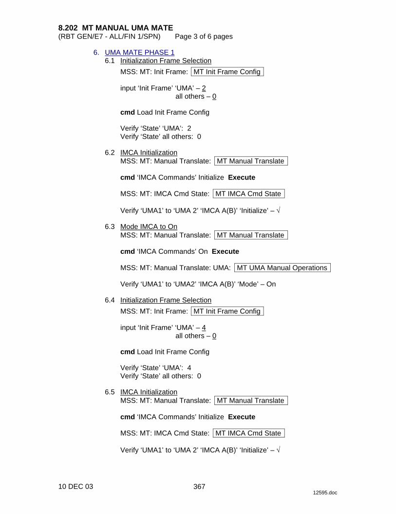
8.202 MT MANUAL UMA MATE (RBT GEN/E7 - ALL/FIN 1/SPN) Page 3 of 6 pages
10 DEC 03 12595.doc
6. UMA MATE PHASE 1 6.1 Initialization Frame Selection
MSS: MT: Init Frame: MT Init Frame Config
input ‘Init Frame’ ‘UMA’ – 2 all others – 0
cmd Load Init Frame Config
Verify ‘State’ ‘UMA’: 2 Verify ‘State’ all others: 0
6.2 IMCA Initialization
MSS: MT: Manual Translate: MT Manual Translate
cmd ‘IMCA Commands’ Initialize Execute
MSS: MT: IMCA Cmd State: MT IMCA Cmd State
Verify ‘UMA1’ to ‘UMA 2’ ‘IMCA A(B)’ ‘Initialize’ – √ 6.3 Mode IMCA to On
MSS: MT: Manual Translate: MT Manual Translate
cmd ‘IMCA Commands’ On Execute
MSS: MT: Manual Translate: UMA: MT UMA Manual Operations
Verify ‘UMA1’ to ‘UMA2’ ‘IMCA A(B)’ ‘Mode’ – On 6.4 Initialization Frame Selection
MSS: MT: Init Frame: MT Init Frame Config
input ‘Init Frame’ ‘UMA’ – 4 all others – 0
cmd Load Init Frame Config
Verify ‘State’ ‘UMA’: 4 Verify ‘State’ all others: 0
6.5 IMCA Initialization
MSS: MT: Manual Translate: MT Manual Translate
cmd ‘IMCA Commands’ Initialize Execute
MSS: MT: IMCA Cmd State: MT IMCA Cmd State
Verify ‘UMA1’ to ‘UMA 2’ ‘IMCA A(B)’ ‘Initialize’ – √
367

8.202 MT MANUAL UMA MATE (RBT GEN/E7 - ALL/FIN 1/SPN) Page 4 of 6 pages
10 DEC 03 12595.doc
6.6 Thruster Inhibit If ISS/orbiter mated
MSS: MT: Thruster: Thruster Controls for MSS Ops
cmd ‘Desat Request’ Inhibit (Verify – Inh)
√‘Auto Att Control Handover to RS’ – Inh
If ISS not mated to orbiter, √MCC-H for proper thruster configuration before proceeding.
6.7 IMCA Movement Initiation
CAUTION To avoid damage to the hardstop, mode the IMCA to On if still Enabled after 67 seconds.
Verify IMCA motion using the following page
MSS: MT: Manual Translate: UMA: MT UMA Manual Operations
MSS: MT: Manual Translate: MT Manual Translate
cmd ‘IMCA Commands’ Actuate Execute
MSS: MT: Manual Translate: UMA: MT UMA Manual Operations
Verify ‘UMA1’ to ‘UMA2’ ‘IMCA A(B)’ ‘Mode’ – Enable Verify ‘UMA1’ to ‘UMA2’ ‘IMCA A(B)’ ‘State’ ‘Mat’ and ‘Dmt’ – blank Verify ‘UMA1’ to ‘UMA2’ ‘IMCA A(B)’ ‘Position’ – decreasing Verify ‘UMA1’ to ‘UMA2’ ‘IMCA A(B)’ ‘Shaft Spd’ ≤ 415 rpm Verify ‘UMA1’ to ‘UMA2’ ‘IMCA A(B)’ ‘Mode’ – On
7. UMA MATE PHASE 2 7.1 Initialization Frame Selection
MSS: MT: Init Frame: MT Init Frame Config
input ‘Init Frame’ ‘UMA’ – 5 all others – 0
cmd Load Init Frame Config
Verify ‘State’ ‘UMA’: 5 Verify ‘State’ all others: 0
7.2 IMCA Initialization
MSS: MT: Manual Translate: MT Manual Translate
cmd ‘IMCA Commands’ Initialize Execute
368

8.202 MT MANUAL UMA MATE (RBT GEN/E7 - ALL/FIN 1/SPN) Page 5 of 6 pages
10 DEC 03 12595.doc
MSS: MT: IMCA Cmd State: MT IMCA Cmd State
Verify ‘UMA1’ to ‘UMA 2’ ‘IMCA A(B)’ ‘Initialize’ – √ 7.3 IMCA Movement Initiation
CAUTION To avoid damage to the hardstop, mode the IMCA to On if still Enabled after 40 seconds.
Verify IMCA motion using the following page
MSS: MT: Manual Translate: UMA: MT UMA Manual Operations
MSS: MT: Manual Translate: MT Manual Translate
cmd ‘IMCA Commands’ Actuate Execute
MSS: MT: Manual Translate: UMA: MT UMA Manual Operations
Verify ‘UMA1’ to ‘UMA2’ ‘IMCA A(B)’ ‘Mode’ – Enable Verify ‘UMA1’ to ‘UMA2’ ‘IMCA A(B)’ ‘State’ ‘Mat’ and ‘Dmt’ – blank Verify ‘UMA1’ to ‘UMA2’ ‘IMCA A(B)’ ‘Position’ – decreasing Verify ‘UMA1’ to ‘UMA2’ ‘IMCA A(B)’ ‘Shaft Spd’ ≤ 100 rpm
Verify ‘UMA1’ to ‘UMA2’ ‘IMCA A(B)’ ‘Mode’ – On Verify ‘UMA1’ to ‘UMA2’ ‘IMCA A(B)’ ‘State’ ‘Mat’ – √
8. THRUSTER ENABLE
If ISS/orbiter mated MSS: MT: Thruster: Thruster Controls for MSS Ops
cmd ‘Desat Request’ Enable (Verify – Ena)
If ISS not mated to orbiter, √MCC-H for proper thruster configuration.
9. COMMANDING IMCA TO STANDBY
MSS: MT: Manual Translate: MT Manual Translate
cmd ‘IMCA Commands’ Standby Execute
MSS: MT: Manual Translate: UMA: MT UMA Manual Operations
Verify ‘UMA1’ to ‘UMA2’ ‘IMCA A(B)’ ‘Mode’ – Standby 10. UMA IMCA POWER REMOVAL
MSS: MT: Power: ‘MT’ ‘RPCM MT-4B(3A)’ 7: RPCM MT4B(3A) A RPC 07
cmd ‘RPC Position’ Open (Verify – Op)
369
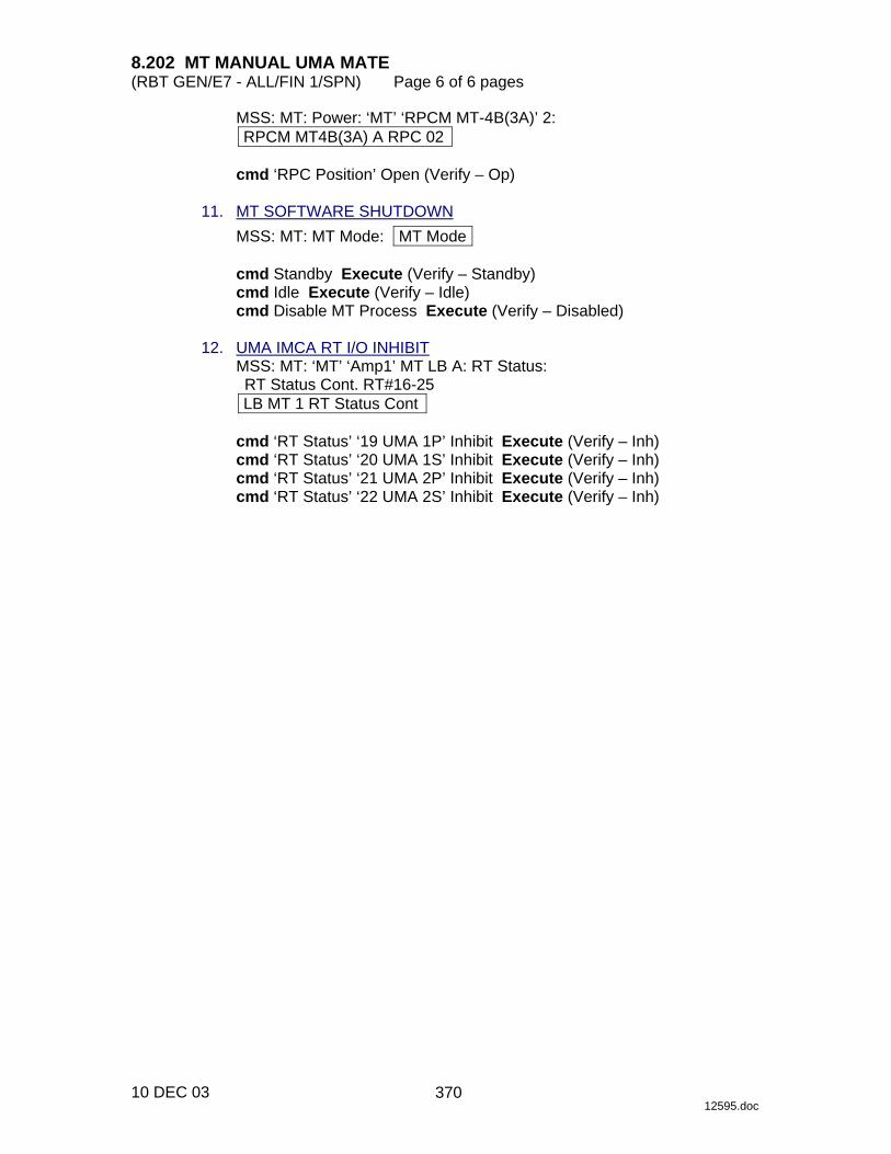
8.202 MT MANUAL UMA MATE (RBT GEN/E7 - ALL/FIN 1/SPN) Page 6 of 6 pages
10 DEC 03 12595.doc
MSS: MT: Power: ‘MT’ ‘RPCM MT-4B(3A)’ 2: RPCM MT4B(3A) A RPC 02
cmd ‘RPC Position’ Open (Verify – Op)
11. MT SOFTWARE SHUTDOWN
MSS: MT: MT Mode: MT Mode
cmd Standby Execute (Verify – Standby) cmd Idle Execute (Verify – Idle) cmd Disable MT Process Execute (Verify – Disabled)
12. UMA IMCA RT I/O INHIBIT
MSS: MT: ‘MT’ ‘Amp1’ MT LB A: RT Status: RT Status Cont. RT#16-25 LB MT 1 RT Status Cont
cmd ‘RT Status’ ‘19 UMA 1P’ Inhibit Execute (Verify – Inh) cmd ‘RT Status’ ‘20 UMA 1S’ Inhibit Execute (Verify – Inh) cmd ‘RT Status’ ‘21 UMA 2P’ Inhibit Execute (Verify – Inh) cmd ‘RT Status’ ‘22 UMA 2S’ Inhibit Execute (Verify – Inh)
370

8.204 MT MANUAL LTU LATCH (ED DISENGAGE) (RBT GEN/ULF1 - ALL/FIN 2) Page 1 of 15 pages
12 FEB 03 12597.doc
NOTE 1. The IMCA automatically returns to On mode after the programmed
trajectory has completed. 2. A pause command can be issued by commanding the IMCA to On
mode on the following page: MSS: MT: Manual Translate: MT Manual Translate ‘IMCA Commands’
3. The IMCA takes approximately 6 seconds to complete self-tests
once power is applied. 4. When I/O is enabled to the IMCAs, expect the following twenty
Robotics Advisory messages: ‘R9Z - MSS MT LTU 1 IMCA 1,2 Comm or Device Fail’ ‘R9Z - MSS MT LTU 2 IMCA 1,2 Comm or Device Fail’ ‘R9Z - MSS MT LTU 3 IMCA 1,2 Comm or Device Fail’ ‘R9Z - MSS MT LTU 4 IMCA 1,2 Comm or Device Fail’ ‘R9Z - MSS MT ED IMCA 1,2 Comm or Device Fail’ ‘R9Z - MSS MT TD IMCA 1,2 Comm or Device Fail’ ‘R9Z - MSS MT UMA 1 IMCA 1,2 Comm or Device Fail’ ‘R9Z - MSS MT UMA 2 IMCA 1,2 Comm or Device Fail’ ‘R9Z - MSS MT TUS 1 IMCA 1,2 Comm or Device Fail’ ‘R9Z - MSS MT TUS 2 IMCA 1,2 Comm or Device Fail’
5. MT IMCA RT FDIR remains inhibited at all times to avoid channel
switching caused by nominal IMCA power removal. This also suppresses some of the nuisance RT Comm Fail C&W messages.
6. The ‘LTU2’ ‘IMCA B’ ‘Mode’ field is incorrect on
MSS: MT: Manual Translate: LTU ED: MT LTU ED Manual Operations
The mode of this IMCA must be verified on MSS: MT: Power: MT Power
1. IMCA RT I/O ENABLE
If MT IMCAs I/O not Enabled MSS: MT: ‘MT’ ‘Amp 1’ MT LB A: RT Status: LB MT 1 RT Status ‘RT Status’
cmd ‘00 LTU 1P’ Enable Execute (Verify – Ena) cmd ‘01 LTU 2P’ Enable Execute (Verify – Ena) cmd ‘02 LTU 3P’ Enable Execute (Verify – Ena) cmd ‘03 LTU 1S’ Enable Execute (Verify – Ena) cmd ‘04 LTU 4P’ Enable Execute (Verify – Ena) cmd ‘05 LTU 3S’ Enable Execute (Verify – Ena) cmd ‘06 LTU 2S’ Enable Execute (Verify – Ena) cmd ‘07 LTU 4S’ Enable Execute (Verify – Ena) cmd ‘08 ED P’ Enable Execute (Verify – Ena)
~
371
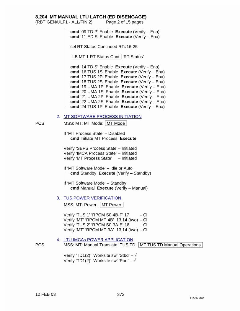
8.204 MT MANUAL LTU LATCH (ED DISENGAGE) (RBT GEN/ULF1 - ALL/FIN 2) Page 2 of 15 pages
12 FEB 03 12597.doc
cmd ‘09 TD P’ Enable Execute (Verify – Ena) cmd ‘11 ED S’ Enable Execute (Verify – Ena)
sel RT Status Continued RT#16-25
LB MT 1 RT Status Cont ‘RT Status’
cmd ‘14 TD S’ Enable Execute (Verify – Ena) cmd ‘16 TUS 1S’ Enable Execute (Verify – Ena) cmd ‘17 TUS 2P’ Enable Execute (Verify – Ena) cmd ‘18 TUS 2S’ Enable Execute (Verify – Ena) cmd ‘19 UMA 1P’ Enable Execute (Verify – Ena) cmd ‘20 UMA 1S’ Enable Execute (Verify – Ena) cmd ‘21 UMA 2P’ Enable Execute (Verify – Ena) cmd ‘22 UMA 2S’ Enable Execute (Verify – Ena) cmd ‘24 TUS 1P’ Enable Execute (Verify – Ena)
2. MT SOFTWARE PROCESS INITIATION PCS MSS: MT: MT Mode: MT Mode
If ‘MT Process State’ – Disabled cmd Initiate MT Process Execute
Verify ‘SEPS Process State’ – Initiated Verify ‘IMCA Process State’ – Initiated Verify ‘MT Process State’ – Initiated
If ‘MT Software Mode’ – Idle or Auto
cmd Standby Execute (Verify – Standby)
If ‘MT Software Mode’ – Standby cmd Manual Execute (Verify – Manual)
3. TUS POWER VERIFICATION
MSS: MT: Power: MT Power
Verify ‘TUS 1’ ‘RPCM S0-4B-F’ 17 – Cl Verify ‘MT’ ‘RPCM MT-4B’ 13,14 (two) – Cl Verify ‘TUS 2’ ‘RPCM S0-3A-E’ 18 – Cl Verify ‘MT’ ‘RPCM MT-3A’ 13,14 (two) – Cl
4. LTU IMCAs POWER APPLICATION PCS MSS: MT: Manual Translate: TUS TD: MT TUS TD Manual Operations
Verify ‘TD1(2)’ ‘Worksite sw’ ‘Stbd’ – √ Verify ‘TD1(2)’ ‘Worksite sw’ ‘Port’ – √
~
372

8.204 MT MANUAL LTU LATCH (ED DISENGAGE) (RBT GEN/ULF1 - ALL/FIN 2) Page 3 of 15 pages
12 FEB 03 12597.doc
sel RPC [X] where [X] = 1 5 9 10
MSS: MT: Power: ‘MT’ ‘RPCM MT-4B(3A)’ [X]: RPCM MT 4B(3A) A RPC[X]
cmd ‘RPC Position’ – Close (Verify – Cl)
Repeat
MSS: MT: Power: MT Power
Verify ‘MT’ ‘RPCM MT-4B(3A)’ ‘LTU1’ to ‘LTU4’ ‘Mode’ (four) – Standby Verify ‘MT’ ‘RPCM MT-4B(3A)’ ‘LTU1’ to ‘LTU4’ ‘Fault’ (four) – blank
MSS: MT: IMCA Data Stale State: MT IMCA Data Stale State
Verify ‘LTU1’ to ‘LTU4’ ‘IMCA’ ‘A(B)’ ‘Status Measurements’ (four) – blank
5. LTU LATCH PHASE 1 5.1 LTU IMCA Commanding Selection
MSS: MT: Manual Translate: HW Config Manual: MT HW Config Manual
√‘LTU1’ to ‘LTU4’ ‘IMCA Selection’ (four) – CMD IMCA A(B) √all others – none
cmd Load HW Config
Verify ‘LTU1’ to ‘LTU4’ ‘State’ (four) – CMD IMCA A(B)
Verify all others – none
MSS: MT: Manual Translate: LTU ED: MT LTU ED Manual Operations
Verify ‘LTU1’ to ‘LTU4’ ‘IMCA A(B)’ ‘State’ ‘Rel’ (four) – √
5.2 LTU Initialization Frame Selection
MSS: MT: Init Frame: MT Init Frame Config
input ‘Init Frame’ ‘LTU’ – 2 all others – 0
cmd Load Init Frame Config (Verify ‘LTU’ ‘State’: 2)
Verify all others: 0
373

8.204 MT MANUAL LTU LATCH (ED DISENGAGE) (RBT GEN/ULF1 - ALL/FIN 2) Page 4 of 15 pages
12 FEB 03 12597.doc
5.3 LTU IMCA Initialization MSS: MT: Manual Translate: MT Manual Translate
cmd ‘IMCA Commands’ Initialize Execute
MSS: MT: IMCA Cmd State: MT IMCA Cmd State
Verify ‘LTU1’ to ‘LTU4’ ‘IMCA’ ‘A(B)’ ‘Initialize’ (four) – √
5.4 Moding LTU IMCAs to On
MSS: MT: Manual Translate: MT Manual Translate
cmd ‘IMCA Commands’ On Execute
MSS: MT: Manual Translate: LTU ED: MT LTU ED Manual Operations
Verify ‘LTU1’ to ‘LTU4’ ‘Mode’ ‘IMCA A(B)’ (four) – On 5.5 LTU Initialization Frame Selection
MSS: MT: Init Frame: MT Init Frame Config
input ‘Init Frame’ ‘LTU’ – 9 all others – 0
cmd Load Init Frame Config (Verify ‘LTU’ ‘State’: 9)
Verify all others: 0
NOTE
Initialization frame 9 commands phase 1 latch of the LTUs. 5.6 LTU IMCA Initialization
MSS: MT: Manual Translate: MT Manual Translate
cmd ‘IMCA Commands’ Initialize Execute
MSS: MT: IMCA Cmd State: MT IMCA Cmd State
Verify ‘LTU1’ to ‘LTU4’ ‘IMCA’ ‘A(B)’ ‘Initialize’ (four) – √ 5.7 LTU IMCA Movement Initiation
CAUTION Mode IMCA to On if it is still Enabled after 100 seconds.
MSS: MT: Manual Translate: MT Manual Translate
cmd ‘IMCA Commands’ Actuate Execute
374

8.204 MT MANUAL LTU LATCH (ED DISENGAGE) (RBT GEN/ULF1 - ALL/FIN 2) Page 5 of 15 pages
12 FEB 03 12597.doc
MSS: MT: Manual Translate: LTU ED: MT LTU ED Manual Operations
Verify ‘LTU1’ to ‘LTU4’ ‘IMCA A(B)’ ‘Mode’ (four) – Enabled Verify ‘LTU1’ to ‘LTU4’ ‘IMCA A(B)’ ‘Position’ (four) – decreasing Verify ‘LTU1’ to ‘LTU4’ ‘IMCA A(B)’ ‘Shaft Spd’ (four) ��������
After motion complete Verify ‘LTU1’ to ‘LTU4’ ‘IMCA A(B)’ ‘Mode’ (four) – On
MSS: MT: Manual Translate: MT Manual Translate
cmd ‘IMCA Commands’ Standby Execute
MSS: MT: Manual Translate: LTU ED: MT LTU ED Manual Operations
Verify Standby ‘LTU1’ to ‘LTU4’ ‘IMCA A(B)’ ‘Mode’ (four) – Standby
6. LTU LATCH PHASE 2A 6.1 LTU IMCA Commanding Selection
MSS: MT: Manual Translate: HW Config Manual: MT HW Config Manual
sel ‘LTU3’ to ‘LTU4’ ‘IMCA Selection’ (two) – CMD IMCA A(B) sel all others – none
cmd Load HW Config
Verify ‘LTU3’ to ‘LTU4’ ‘State’ (two) – CMD IMCA A(B)
Verify all others – none
6.2 LTU Initialization Frame Selection
MSS: MT: Init Frame: MT Init Frame Config
input ‘Init Frame’ ‘LTU’ – 1 3 all others – 0
cmd Load Init Frame Config (Verify ‘LTU’ ‘State’: 13)
Verify all others: 0
NOTE
Initialization frame 13 commands phase 2A latching of the LTUs.
375

8.204 MT MANUAL LTU LATCH (ED DISENGAGE) (RBT GEN/ULF1 - ALL/FIN 2) Page 6 of 15 pages
12 FEB 03 12597.doc
6.3 LTU IMCA Initialization MSS: MT: Manual Translate: MT Manual Translate
cmd ‘IMCA Commands’ Initialize Execute
MSS: MT: IMCA Cmd State: MT IMCA Cmd State
Verify Initialize ‘LTU3’ to ‘LTU4’ ‘IMCA’ ‘A(B)’ ‘Initialize’ (two) – √
6.4 Moding LTU IMCAs to On
MSS: MT: Manual Translate: MT Manual Translate
cmd ‘IMCA Commands’ On Execute
MSS: MT: Manual Translate: LTU ED: MT LTU ED Manual Operations
Verify ‘LTU3’ to ‘LTU4’ ‘IMCA A(B)’ ‘Mode’ (two) – On 6.5 LTU IMCA Movement Initiation
CAUTION Mode IMCA to On if it is still Enabled after 120 seconds.
MSS: MT: Manual Translate: MT Manual Translate
cmd ‘IMCA Commands’ Actuate Execute
MSS: MT: Manual Translate: LTU ED: MT LTU ED Manual Operations
Verify ‘LTU3’ to ‘LTU4’ ‘IMCA A(B)’ ‘Mode’ (two) – Enabled Verify ‘LTU3’ to ‘LTU4’ ‘IMCA A(B)’ ‘Position’ (two) – increasing Verify ‘LTU3’ to ‘LTU4’ ‘IMCA A(B)’ ‘Shaft Spd’ (two) ���������
After motion complete Verify ‘LTU3’ to ‘LTU4’ ‘IMCA A(B)’ ‘Mode’ (two) – On
7. LTU LATCH PHASE 2B 7.1 LTU IMCA Commanding Selection
MSS: MT: Manual Translate: HW Config Manual: MT HW Config Manual
sel ‘LTU1’ to ‘LTU2’ ‘IMCA Selection’ (two) – CMD IMCA A(B) sel all others – none
cmd Load HW Config
376
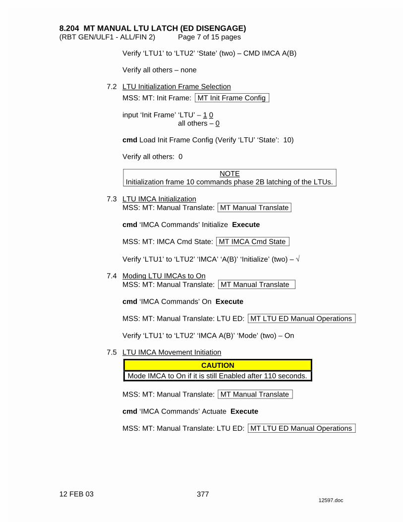
8.204 MT MANUAL LTU LATCH (ED DISENGAGE) (RBT GEN/ULF1 - ALL/FIN 2) Page 7 of 15 pages
12 FEB 03 12597.doc
Verify ‘LTU1’ to ‘LTU2’ ‘State’ (two) – CMD IMCA A(B)
Verify all others – none 7.2 LTU Initialization Frame Selection
MSS: MT: Init Frame: MT Init Frame Config
input ‘Init Frame’ ‘LTU’ – 1 0 all others – 0
cmd Load Init Frame Config (Verify ‘LTU’ ‘State’: 10)
Verify all others: 0
NOTE
Initialization frame 10 commands phase 2B latching of the LTUs. 7.3 LTU IMCA Initialization
MSS: MT: Manual Translate: MT Manual Translate
cmd ‘IMCA Commands’ Initialize Execute
MSS: MT: IMCA Cmd State: MT IMCA Cmd State
Verify ‘LTU1’ to ‘LTU2’ ‘IMCA’ ‘A(B)’ ‘Initialize’ (two) – √ 7.4 Moding LTU IMCAs to On
MSS: MT: Manual Translate: MT Manual Translate
cmd ‘IMCA Commands’ On Execute
MSS: MT: Manual Translate: LTU ED: MT LTU ED Manual Operations
Verify ‘LTU1’ to ‘LTU2’ ‘IMCA A(B)’ ‘Mode’ (two) – On 7.5 LTU IMCA Movement Initiation
CAUTION Mode IMCA to On if it is still Enabled after 110 seconds.
MSS: MT: Manual Translate: MT Manual Translate
cmd ‘IMCA Commands’ Actuate Execute
MSS: MT: Manual Translate: LTU ED: MT LTU ED Manual Operations
377

8.204 MT MANUAL LTU LATCH (ED DISENGAGE) (RBT GEN/ULF1 - ALL/FIN 2) Page 8 of 15 pages
12 FEB 03 12597.doc
Verify ‘LTU1’ to ‘LTU2’ ‘IMCA A(B)’ ‘Mode’ (two) – Enabled Verify ‘LTU1’ to ‘LTU2’ ‘IMCA A(B)’ ‘Position’ (two) – increasing Verify ‘LTU1’ to ‘LTU2’ ‘IMCA A(B)’ ‘Shaft Spd’ (two) ���������
After motion complete Verify ‘LTU1’ to ‘LTU2’ ‘IMCA A(B)’ ‘Mode’ – On
8. TD GAIN CHANGE 8.1 TD IMCA Commanding Selection
MSS: MT: Manual Translate: HW Config Manual: MT HW Config Manual
sel ‘TD’ ‘IMCA Selection’ – CMD IMCA A(B) sel all others – none
cmd Load HW Config (Verify ‘TD’ ‘State’ – CMD IMCA A(B))
Verify all others – none
8.2 TD Initialization Frame Selection
MSS: MT: Init Frame: MT Init Frame Config
input ‘Init Frame’ ‘TD’ – 2 6 0 all others – 0
cmd Load Init Frame Config (Verify ‘TD’ ‘State’: 260)
Verify all others: 0
NOTE
Initialization frame 260 changes the gain of the TD. 8.3 TD IMCA Initialization
MSS: MT: Manual Translate: MT Manual Translate
cmd ‘IMCA Commands’ Initialize Execute
MSS: MT: IMCA Cmd State: MT IMCA Cmd State
Verify ‘TD’ ‘IMCA’ ‘A(B)’ ‘Initialize’ – √
378
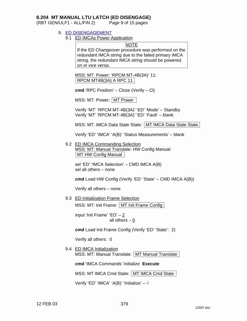
8.204 MT MANUAL LTU LATCH (ED DISENGAGE) (RBT GEN/ULF1 - ALL/FIN 2) Page 9 of 15 pages
12 FEB 03 12597.doc
9. ED DISENGAGEMENT 9.1 ED IMCAs Power Application
NOTE If the ED Changeover procedure was performed on the redundant IMCA string due to the failed primary IMCA string, the redundant IMCA string should be powered on or vice versa.
MSS: MT: Power: ‘RPCM MT-4B(3A)’ 11: RPCM MT4B(3A) A RPC 11
cmd ‘RPC Position’ – Close (Verify – Cl)
MSS: MT: Power: MT Power
Verify ‘MT’ ‘RPCM MT-4B(3A)’ ‘ED’ ‘Mode’ – Standby Verify ‘MT’ ‘RPCM MT-4B(3A)’ ‘ED’ ‘Fault’ – blank
MSS: MT: IMCA Data Stale State: MT IMCA Data Stale State
Verify ‘ED’ ‘IMCA’ ‘A(B)’ ‘Status Measurements’ – blank
9.2 ED IMCA Commanding Selection
MSS: MT: Manual Translate: HW Config Manual: MT HW Config Manual
sel ‘ED’ ‘IMCA Selection’ – CMD IMCA A(B) sel all others – none
cmd Load HW Config (Verify ‘ED’ ‘State’ – CMD IMCA A(B))
Verify all others – none
9.3 ED Initialization Frame Selection
MSS: MT: Init Frame: MT Init Frame Config
input ‘Init Frame’ ‘ED’ – 2 all others – 0
cmd Load Init Frame Config (Verify ‘ED’ ‘State’: 2)
Verify all others: 0
9.4 ED IMCA Initialization
MSS: MT: Manual Translate: MT Manual Translate
cmd ‘IMCA Commands’ Initialize Execute
MSS: MT IMCA Cmd State: MT IMCA Cmd State
Verify ‘ED’ ‘IMCA’ ‘A(B)’ ‘Initialize’ – √
379
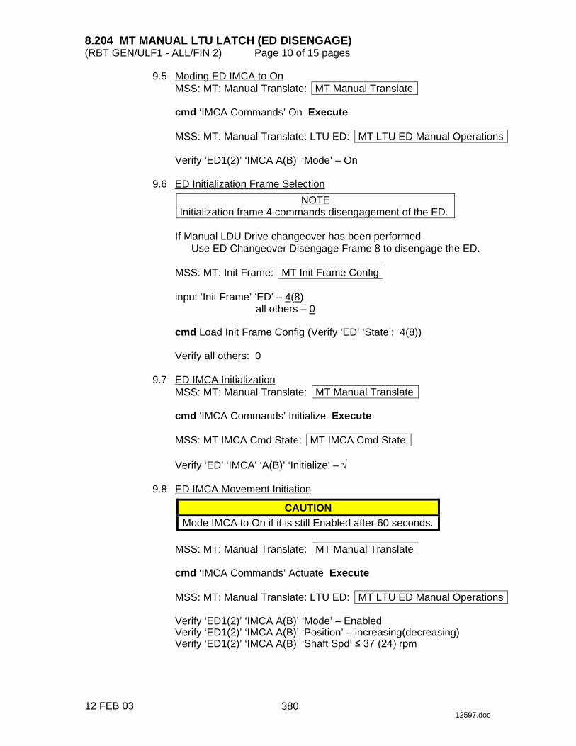
8.204 MT MANUAL LTU LATCH (ED DISENGAGE) (RBT GEN/ULF1 - ALL/FIN 2) Page 10 of 15 pages
12 FEB 03 12597.doc
9.5 Moding ED IMCA to On MSS: MT: Manual Translate: MT Manual Translate
cmd ‘IMCA Commands’ On Execute
MSS: MT: Manual Translate: LTU ED: MT LTU ED Manual Operations
Verify ‘ED1(2)’ ‘IMCA A(B)’ ‘Mode’ – On
9.6 ED Initialization Frame Selection
NOTE Initialization frame 4 commands disengagement of the ED.
If Manual LDU Drive changeover has been performed
Use ED Changeover Disengage Frame 8 to disengage the ED.
MSS: MT: Init Frame: MT Init Frame Config
input ‘Init Frame’ ‘ED’ – 4(8) all others – 0
cmd Load Init Frame Config (Verify ‘ED’ ‘State’: 4(8))
Verify all others: 0
9.7 ED IMCA Initialization
MSS: MT: Manual Translate: MT Manual Translate
cmd ‘IMCA Commands’ Initialize Execute
MSS: MT IMCA Cmd State: MT IMCA Cmd State
Verify ‘ED’ ‘IMCA’ ‘A(B)’ ‘Initialize’ – √ 9.8 ED IMCA Movement Initiation
CAUTION Mode IMCA to On if it is still Enabled after 60 seconds.
MSS: MT: Manual Translate: MT Manual Translate
cmd ‘IMCA Commands’ Actuate Execute
MSS: MT: Manual Translate: LTU ED: MT LTU ED Manual Operations
Verify ‘ED1(2)’ ‘IMCA A(B)’ ‘Mode’ – Enabled Verify ‘ED1(2)’ ‘IMCA A(B)’ ‘Position’ – increasing(decreasing) Verify ‘ED1(2)’ ‘IMCA A(B)’ ‘Shaft Spd’ ��� ���������
380

8.204 MT MANUAL LTU LATCH (ED DISENGAGE) (RBT GEN/ULF1 - ALL/FIN 2) Page 11 of 15 pages
12 FEB 03 12597.doc
After motion is complete Verify ‘ED1(2)’ ‘IMCA A(B)’ ‘Switch States’ ‘Engaged’ – blank Verify ‘ED1(2)’ ‘IMCA A(B)’ ‘Switch States’ ‘Disengage Trigger’ – √ Verify ‘ED1(2)’ ‘IMCA A(B)’ ‘Switch States’ ‘Disengage Verify’ – √ Verify ‘ED1(2)’ ‘IMCA A(B)’ ‘Switch States’ ‘Alt Disengage’ – √ Verify ‘ED1(2)’ ‘IMCA A(B)’ ‘Mode’ – On
9.9 Commanding ED IMCA to Standby
MSS: MT: Manual Translate: MT Manual Translate
cmd ‘IMCA Commands’ Standby Execute
MSS: MT: Manual Translate: LTU ED: MT LTU ED Manual Operations
Verify ‘ED1(2)’ ‘IMCA A(B)’ ‘Mode’ – Standby 9.10 ED IMCAs Power Removal
MSS: MT: Power: ‘RPCM MT-4B(3A)’ 11: RPCM MT4B(3A) A RPC 11
cmd ‘RPC Position’ – Open (Verify − Op) 10. TD POWER OFF 10.1 TD IMCA Commanding Selection
MSS: MT: Manual Translate: HW Config Manual: MT HW Config Manual
sel ‘TD’ ‘IMCA Selection’ – CMD IMCA A(B) sel all others – none
cmd Load HW Config (Verify ‘TD’ ‘State’ – CMD IMCA A(B))
Verify all others – none
10.2 Commanding TD IMCA to Standby
MSS: MT: Manual Translate: MT Manual Translate
cmd ‘IMCA Commands’ Standby Execute
MSS: MT: Manual Translate: TUS TD: MT TUS TD Manual Operations
Verify ‘TD1(2)’ ‘IMCA A(B)’ ‘Mode’ – Standby 10.3 TD IMCAs Power Removal
MSS: MT: Power: ‘RPCM MT-4B(3A)’ 4: RPCM MT4B(3A) A RPC 4
cmd ‘RPC Position’ – Open (Verify − Op)
11. LTU LATCH PHASE 3A
381
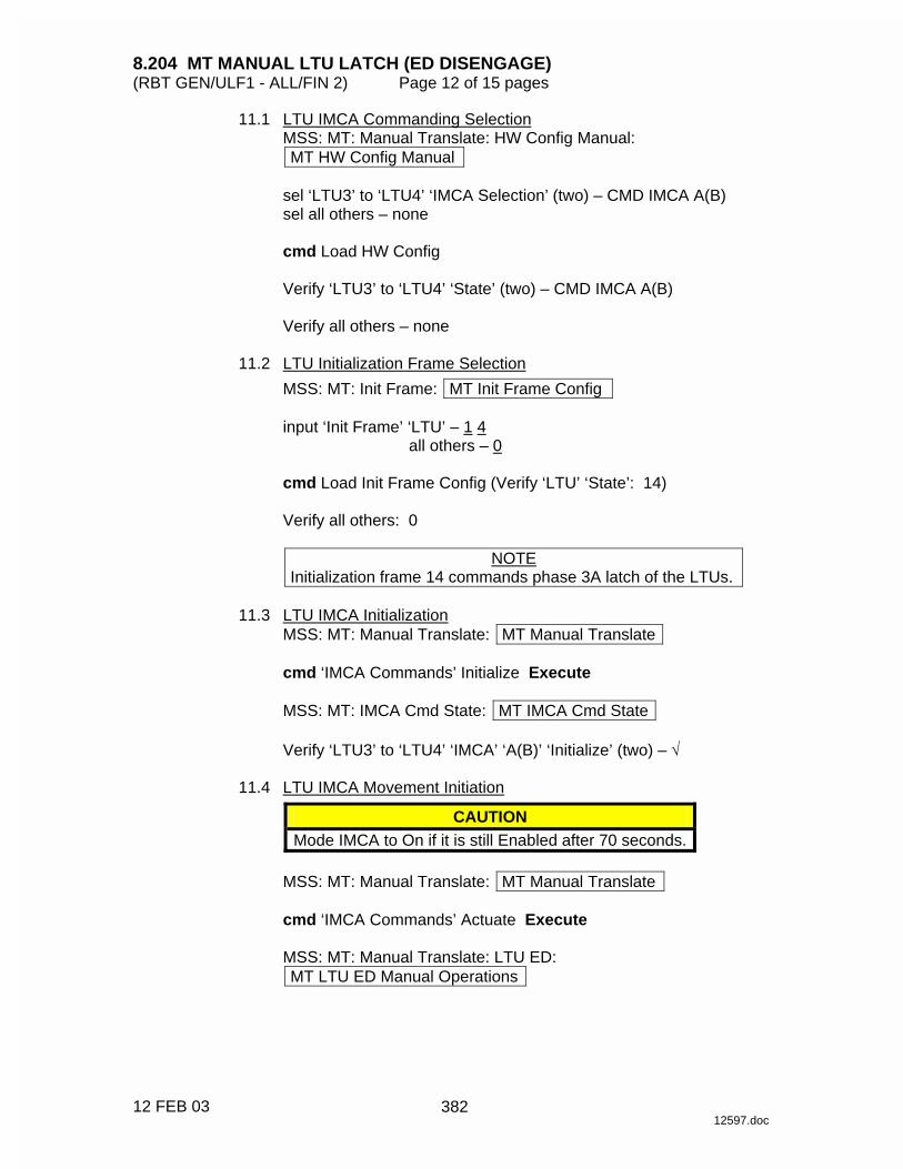
8.204 MT MANUAL LTU LATCH (ED DISENGAGE) (RBT GEN/ULF1 - ALL/FIN 2) Page 12 of 15 pages
12 FEB 03 12597.doc
11.1 LTU IMCA Commanding Selection MSS: MT: Manual Translate: HW Config Manual: MT HW Config Manual
sel ‘LTU3’ to ‘LTU4’ ‘IMCA Selection’ (two) – CMD IMCA A(B) sel all others – none
cmd Load HW Config
Verify ‘LTU3’ to ‘LTU4’ ‘State’ (two) – CMD IMCA A(B)
Verify all others – none
11.2 LTU Initialization Frame Selection
MSS: MT: Init Frame: MT Init Frame Config
input ‘Init Frame’ ‘LTU’ – 1 4 all others – 0
cmd Load Init Frame Config (Verify ‘LTU’ ‘State’: 14)
Verify all others: 0
NOTE
Initialization frame 14 commands phase 3A latch of the LTUs. 11.3 LTU IMCA Initialization
MSS: MT: Manual Translate: MT Manual Translate
cmd ‘IMCA Commands’ Initialize Execute
MSS: MT: IMCA Cmd State: MT IMCA Cmd State
Verify ‘LTU3’ to ‘LTU4’ ‘IMCA’ ‘A(B)’ ‘Initialize’ (two) – √ 11.4 LTU IMCA Movement Initiation
CAUTION Mode IMCA to On if it is still Enabled after 70 seconds.
MSS: MT: Manual Translate: MT Manual Translate
cmd ‘IMCA Commands’ Actuate Execute
MSS: MT: Manual Translate: LTU ED: MT LTU ED Manual Operations
382
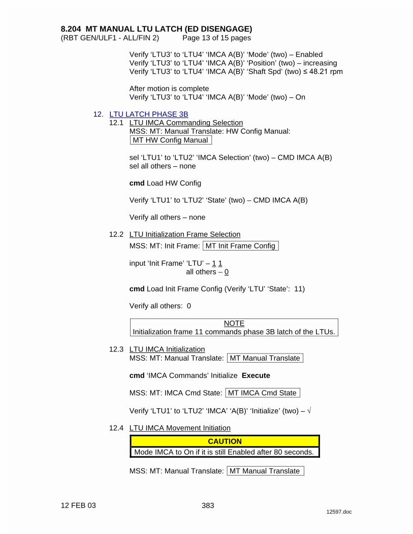
8.204 MT MANUAL LTU LATCH (ED DISENGAGE) (RBT GEN/ULF1 - ALL/FIN 2) Page 13 of 15 pages
12 FEB 03 12597.doc
Verify ‘LTU3’ to ‘LTU4’ ‘IMCA A(B)’ ‘Mode’ (two) – Enabled Verify ‘LTU3’ to ‘LTU4’ ‘IMCA A(B)’ ‘Position’ (two) – increasing Verify ‘LTU3’ to ‘LTU4’ ‘IMCA A(B)’ ‘Shaft Spd’ (two) ���������
After motion is complete Verify ‘LTU3’ to ‘LTU4’ ‘IMCA A(B)’ ‘Mode’ (two) – On
12. LTU LATCH PHASE 3B 12.1 LTU IMCA Commanding Selection
MSS: MT: Manual Translate: HW Config Manual: MT HW Config Manual
sel ‘LTU1’ to ‘LTU2’ ‘IMCA Selection’ (two) – CMD IMCA A(B) sel all others – none
cmd Load HW Config
Verify ‘LTU1’ to ‘LTU2’ ‘State’ (two) – CMD IMCA A(B)
Verify all others – none
12.2 LTU Initialization Frame Selection
MSS: MT: Init Frame: MT Init Frame Config
input ‘Init Frame’ ‘LTU’ – 1 1 all others – 0
cmd Load Init Frame Config (Verify ‘LTU’ ‘State’: 11)
Verify all others: 0
NOTE
Initialization frame 11 commands phase 3B latch of the LTUs. 12.3 LTU IMCA Initialization
MSS: MT: Manual Translate: MT Manual Translate
cmd ‘IMCA Commands’ Initialize Execute
MSS: MT: IMCA Cmd State: MT IMCA Cmd State
Verify ‘LTU1’ to ‘LTU2’ ‘IMCA’ ‘A(B)’ ‘Initialize’ (two) – √ 12.4 LTU IMCA Movement Initiation
CAUTION Mode IMCA to On if it is still Enabled after 80 seconds.
MSS: MT: Manual Translate: MT Manual Translate
383
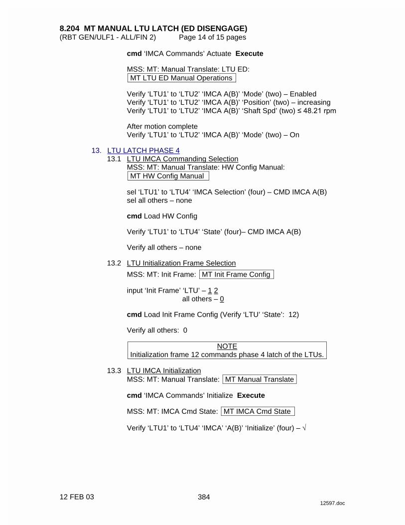
8.204 MT MANUAL LTU LATCH (ED DISENGAGE) (RBT GEN/ULF1 - ALL/FIN 2) Page 14 of 15 pages
12 FEB 03 12597.doc
cmd ‘IMCA Commands’ Actuate Execute
MSS: MT: Manual Translate: LTU ED: MT LTU ED Manual Operations
Verify ‘LTU1’ to ‘LTU2’ ‘IMCA A(B)’ ‘Mode’ (two) – Enabled Verify ‘LTU1’ to ‘LTU2’ ‘IMCA A(B)’ ‘Position’ (two) – increasing Verify ‘LTU1’ to ‘LTU2’ ‘IMCA A(B)’ ‘Shaft Spd’ (two) ���������
After motion complete Verify ‘LTU1’ to ‘LTU2’ ‘IMCA A(B)’ ‘Mode’ (two) – On
13. LTU LATCH PHASE 4 13.1 LTU IMCA Commanding Selection
MSS: MT: Manual Translate: HW Config Manual: MT HW Config Manual
sel ‘LTU1’ to ‘LTU4’ ‘IMCA Selection’ (four) – CMD IMCA A(B) sel all others – none
cmd Load HW Config
Verify ‘LTU1’ to ‘LTU4’ ‘State’ (four)– CMD IMCA A(B)
Verify all others – none
13.2 LTU Initialization Frame Selection
MSS: MT: Init Frame: MT Init Frame Config
input ‘Init Frame’ ‘LTU’ – 1 2 all others – 0
cmd Load Init Frame Config (Verify ‘LTU’ ‘State’: 12)
Verify all others: 0
NOTE
Initialization frame 12 commands phase 4 latch of the LTUs. 13.3 LTU IMCA Initialization
MSS: MT: Manual Translate: MT Manual Translate
cmd ‘IMCA Commands’ Initialize Execute
MSS: MT: IMCA Cmd State: MT IMCA Cmd State
Verify ‘LTU1’ to ‘LTU4’ ‘IMCA’ ‘A(B)’ ‘Initialize’ (four) – √
384
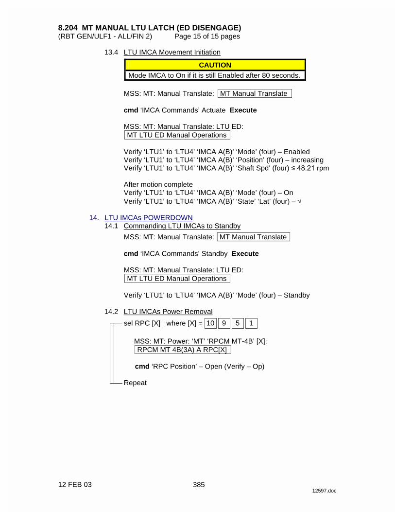
8.204 MT MANUAL LTU LATCH (ED DISENGAGE) (RBT GEN/ULF1 - ALL/FIN 2) Page 15 of 15 pages
12 FEB 03 12597.doc
13.4 LTU IMCA Movement Initiation CAUTION
Mode IMCA to On if it is still Enabled after 80 seconds.
MSS: MT: Manual Translate: MT Manual Translate
cmd ‘IMCA Commands’ Actuate Execute
MSS: MT: Manual Translate: LTU ED: MT LTU ED Manual Operations
Verify ‘LTU1’ to ‘LTU4’ ‘IMCA A(B)’ ‘Mode’ (four) – Enabled Verify ‘LTU1’ to ‘LTU4’ ‘IMCA A(B)’ ‘Position’ (four) – increasing Verify ‘LTU1’ to ‘LTU4’ ‘IMCA A(B)’ ‘Shaft Spd’ (four) ���������
After motion complete Verify ‘LTU1’ to ‘LTU4’ ‘IMCA A(B)’ ‘Mode’ (four) – On Verify ‘LTU1’ to ‘LTU4’ ‘IMCA A(B)’ ‘State’ ‘Lat’ (four) – √
14. LTU IMCAs POWERDOWN 14.1 Commanding LTU IMCAs to Standby
MSS: MT: Manual Translate: MT Manual Translate
cmd ‘IMCA Commands’ Standby Execute
MSS: MT: Manual Translate: LTU ED: MT LTU ED Manual Operations
Verify ‘LTU1’ to ‘LTU4’ ‘IMCA A(B)’ ‘Mode’ (four) – Standby
14.2 LTU IMCAs Power Removal
sel RPC [X] where [X] = 1 5 9 10
MSS: MT: Power: ‘MT’ ‘RPCM MT-4B’ [X]: RPCM MT 4B(3A) A RPC[X]
cmd ‘RPC Position’ – Open (Verify – Op)
Repeat
385

This Page Intentionally Blank
22 DEC 04
386

8.205 MT MANUAL LTU UNLATCH (ED ENGAGE) (RBT GEN/ULF1 - ALL/FIN 2) Page 1 of 10 pages
18 FEB 03 12598.doc
NOTE 1. The IMCA automatically returns to On mode after the programmed
trajectory has completed. 2. A pause command can be issued by commanding the IMCA to On
mode on the following page: MSS: MT: Manual Translate: MT Manual Translate ‘IMCA Commands’
3. The IMCA takes approximately 6 seconds to complete self-tests
once power is applied. 4. When I/O is enabled to the IMCAs, expect the following Robotics
Advisory messages: ‘R9Z - MSS MT LTU 1 IMCA 1,2 Comm or Device Fail’ ‘R9Z - MSS MT LTU 2 IMCA 1,2 Comm or Device Fail’ ‘R9Z - MSS MT LTU 3 IMCA 1,2 Comm or Device Fail’ ‘R9Z - MSS MT LTU 4 IMCA 1,2 Comm or Device Fail’ ‘R9Z - MSS MT ED IMCA 1,2 Comm or Device Fail’ ‘R9Z - MSS MT TD IMCA 1,2 Comm or Device Fail’ ‘R9Z - MSS MT UMA 1 IMCA 1,2 Comm or Device Fail’ ‘R9Z - MSS MT UMA 2 IMCA 1,2 Comm or Device Fail’ ‘R9Z - MSS MT TUS 1 IMCA 1,2 Comm or Device Fail’ ‘R9Z - MSS MT TUS 2 IMCA 1,2 Comm or Device Fail’
5. MT IMCA RT FDIR remains inhibited at all times to avoid channel
switching caused by nominal IMCA power removal. This also suppresses some of the nuisance RT Comm Fail C&W messages.
6. The ‘LTU2’ ‘IMCA B’ ‘Mode’ field is incorrect on
MSS: MT: Manual Translate: LTU ED: MT LTU ED Manual Operations
The mode of this IMCA must be verified on MSS: MT: Power: MT Power (SPN 2422)
1. IMCA RT I/O ENABLE
If MT IMCAs I/O not Enable MSS: MT: ‘MT’ ‘Amp 1’ MT LB A: RT Status: LB MT 1 RT Status
‘RT Status’
cmd ‘00 LTU 1P’ Enable Execute (Verify – Ena) cmd ‘01 LTU 2P’ Enable Execute (Verify – Ena) cmd ‘02 LTU 3P’ Enable Execute (Verify – Ena) cmd ‘03 LTU 1S’ Enable Execute (Verify – Ena) cmd ‘04 LTU 4P’ Enable Execute (Verify – Ena) cmd ‘05 LTU 3S’ Enable Execute (Verify – Ena) cmd ‘06 LTU 2S’ Enable Execute (Verify – Ena) cmd ‘07 LTU 4S’ Enable Execute (Verify – Ena) cmd ‘08 ED P’ Enable Execute (Verify – Ena) cmd ‘09 TD P’ Enable Execute (Verify – Ena)
~
387

8.205 MT MANUAL LTU UNLATCH (ED ENGAGE) (RBT GEN/ULF1 - ALL/FIN 2) Page 2 of 10 pages
18 FEB 03 12598.doc
cmd ‘11 ED S’ Enable Execute (Verify – Ena)
sel RT Status Continued RT#16-25
LB MT 1 RT Status Cont ‘RT Status’
cmd ‘14 TD S’ Enable Execute (Verify – Ena) cmd ‘16 TUS 1S’ Enable Execute (Verify – Ena) cmd ‘17 TUS 2P’ Enable Execute (Verify – Ena) cmd ‘18 TUS 2S’ Enable Execute (Verify – Ena) cmd ‘19 UMA 1P’ Enable Execute (Verify – Ena) cmd ‘20 UMA 1S’ Enable Execute (Verify – Ena) cmd ‘21 UMA 2P’ Enable Execute (Verify – Ena) cmd ‘22 UMA 2S’ Enable Execute (Verify – Ena) cmd ‘24 TUS 1P’ Enable Execute (Verify – Ena)
2. MT SOFTWARE PROCESS INITIATION PCS MSS: MT: MT Mode: MT Mode
If ‘MT Process State’ – Disabled cmd Initiate MT Process Execute
Verify ‘SEPS Process State’ – Initiated Verify ‘IMCA Process State’ – Initiated Verify ‘MT Process State’ – Initiated
If ‘MT Software Mode’ – Idle or Auto
cmd Standby Execute (Verify – Standby)
If ‘MT Software Mode’ – Standby cmd Manual Execute (Verify – Manual)
3. TUS POWER VERIFICATION
MSS: MT: Power: MT Power
Verify ‘TUS1’ ‘RPCM S0-4B-F’ 17 – Cl Verify ‘MT’ ‘RPCM MT-4B’ 13,14 (two) – Cl Verify ‘TUS2’ ‘RPCM S0-3A-E’ 18 – Cl Verify ‘MT’ ‘RPCM MT-3A’ 13,14 (two) – Cl
4. TD IMCA POWER APPLICATION
MSS: MT: Power: ‘RPCM MT-4B(3A)’ 4: RPCM MT4B(3A) A RPC 04
cmd ‘RPC Position’ – Close (Verify – Cl)
MSS: MT: Power: MT Power Verify ‘MT’ ‘RPCM MT-4B(3A)’ ‘TD’ ‘Mode’ – Standby Verify ‘MT’ ‘RPCM MT-4B(3A)’ ‘TD’ ‘Fault’ – blank
~
388

8.205 MT MANUAL LTU UNLATCH (ED ENGAGE) (RBT GEN/ULF1 - ALL/FIN 2) Page 3 of 10 pages
18 FEB 03 12598.doc
MSS: MT: IMCA Data Stale State: MT IMCA Data Stale State
Verify ‘TD’ ‘IMCA’ ‘A(B)’ ‘Status Measurements’ – blank 5. TD POSITION HOLD 5.1 TD IMCA Commanding Selection
MSS: MT: Manual Translate: HW Config Manual: MT HW Config Manual
sel ‘TD’ ‘IMCA Selection’ – CMD IMCA A(B) sel all others – none
cmd Load HW Config (Verify ‘TD’ ‘State’ – CMD IMCA A(B))
Verify all others – none
5.2 TD Initialization Frame Selection
MSS: MT: Init Frame: MT Init Frame Config
input ‘Init Frame’ ‘TD’ – 2 all others – 0
cmd Load Init Frame Config (Verify ‘TD’ ‘State’: 2)
Verify all others: 0
NOTE
Initialization frame 2 places the TD in position hold to prevent motion once the LTU is unlatched.
5.3 TD IMCA Initialization
MSS: MT: Manual Translate: MT Manual Translate
cmd ‘IMCA Commands’ Initialize Execute
MSS: MT: IMCA Cmd State: MT IMCA Cmd State
Verify ‘TD’ ‘IMCA’ ‘A(B)’ ‘Initialize’ – √ 5.4 Moding TD IMCAs to On
MSS: MT: Manual Translate: MT Manual Translate
cmd ‘IMCA Commands’ On Execute
MSS: MT: Manual Translate: TUS TD: MT TUS TD Manual Operations
Verify ‘TD1(2)’ ‘IMCA A(B)’ ‘Mode’ – On
389
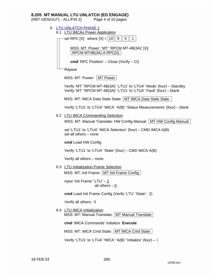
8.205 MT MANUAL LTU UNLATCH (ED ENGAGE) (RBT GEN/ULF1 - ALL/FIN 2) Page 4 of 10 pages
18 FEB 03 12598.doc
6. LTU UNLATCH PHASE 1 6.1 LTU IMCAs Power Application
sel RPC [X] where [X] = 1 5 9 10
MSS: MT: Power: ‘MT’ ‘RPCM MT-4B(3A)’ [X]: RPCM MT4B(3A) A RPC[X]
cmd ‘RPC Position’ – Close (Verify – Cl)
Repeat
MSS: MT: Power: MT Power
Verify ‘MT’ ‘RPCM MT-4B(3A)’ ‘LTU1’ to ‘LTU4’ ‘Mode’ (four) – Standby Verify ‘MT’ ‘RPCM MT-4B(3A)’ ‘LTU1’ to ‘LTU4’ ‘Fault’ (four) – blank
MSS: MT: IMCA Data Stale State: MT IMCA Data Stale State
Verify ‘LTU1’ to ‘LTU4’ ‘IMCA’ ‘A(B)’ ‘Status Measurements’ (four) – blank
6.2 LTU IMCA Commanding Selection
MSS: MT: Manual Translate: HW Config Manual: MT HW Config Manual
sel ‘LTU1’ to ‘LTU4’ ‘IMCA Selection’ (four) – CMD IMCA A(B) sel all others – none
cmd Load HW Config
Verify ‘LTU1’ to ‘LTU4’ ‘State’ (four) – CMD IMCA A(B)
Verify all others – none
6.3 LTU Initialization Frame Selection
MSS: MT: Init Frame: MT Init Frame Config
input ‘Init Frame’ ‘LTU’ – 2 all others – 0
cmd Load Init Frame Config (Verify ‘LTU’ ‘State’: 2)
Verify all others: 0
6.4 LTU IMCA Initialization
MSS: MT: Manual Translate: MT Manual Translate
cmd ‘IMCA Commands’ Initialize Execute
MSS: MT: IMCA Cmd State: MT IMCA Cmd State
Verify ‘LTU1’ to ‘LTU4’ ‘IMCA’ ‘A(B)’ ‘Initialize’ (four) – √
390

8.205 MT MANUAL LTU UNLATCH (ED ENGAGE) (RBT GEN/ULF1 - ALL/FIN 2) Page 5 of 10 pages
18 FEB 03 12598.doc
6.5 Moding LTU IMCAs to On MSS: MT: Manual Translate: MT Manual Translate
cmd ‘IMCA Commands’ On Execute
MSS: MT: Manual Translate: LTU ED: MT LTU ED Manual Operations
Verify ‘LTU1’ to ‘LTU4’ ‘IMCA A(B)’ ‘Mode’ (four) – On
6.6 LTU Initialization Frame Selection
MSS: MT: Init Frame: MT Init Frame Config
input ‘Init Frame’ ‘LTU’ – 5 all others – 0
cmd Load Init Frame Config (Verify ‘LTU’ ‘State’: 5)
Verify all others: 0
NOTE
Initialization frame 5 commands phase 1 unlatching of the LTUs. 6.7 LTU IMCA Initialization
MSS: MT: Manual Translate: MT Manual Translate
cmd ‘IMCA Commands’ Initialize Execute
MSS: MT: IMCA Cmd State: MT IMCA Cmd State
Verify ‘LTU1’ to ‘LTU4’ ‘IMCA’ ‘A(B)’ ‘Initialize’ (four) – √ 6.8 LTU IMCA Movement Initiation
CAUTION Mode IMCA to On if it is still Enabled after 110 seconds.
MSS: MT: Manual Translate: MT Manual Translate
cmd ‘IMCA Commands’ Actuate Execute
MSS: MT: Manual Translate: LTU ED: MT LTU ED Manual Operations
Verify ‘LTU1’ to ‘LTU4’ ‘IMCA A(B)’ ‘Mode’ (four) – Enabled Verify ‘LTU1’ to ‘LTU4’ ‘IMCA A(B)’ ‘Position’ (four) – decreasing Verify ‘LTU1’ to ‘LTU4’ ‘IMCA A(B)’ ‘Shaft Spd’ (four) ≤ 48.21 rpm
After motion complete Verify ‘LTU1’ to ‘LTU4’ ‘IMCA A(B)’ ‘Mode’ (four) – On
391
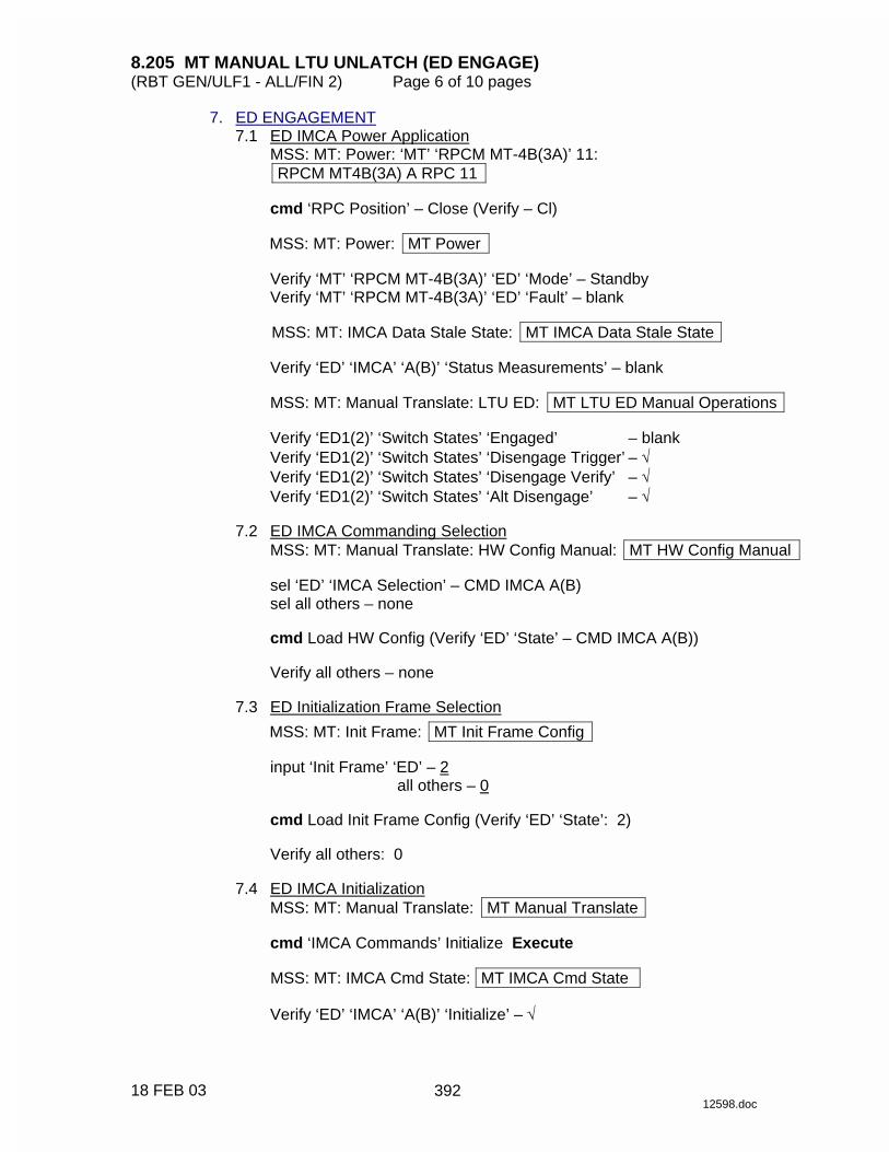
8.205 MT MANUAL LTU UNLATCH (ED ENGAGE) (RBT GEN/ULF1 - ALL/FIN 2) Page 6 of 10 pages
18 FEB 03 12598.doc
7. ED ENGAGEMENT 7.1 ED IMCA Power Application
MSS: MT: Power: ‘MT’ ‘RPCM MT-4B(3A)’ 11: RPCM MT4B(3A) A RPC 11
cmd ‘RPC Position’ – Close (Verify – Cl)
MSS: MT: Power: MT Power
Verify ‘MT’ ‘RPCM MT-4B(3A)’ ‘ED’ ‘Mode’ – Standby Verify ‘MT’ ‘RPCM MT-4B(3A)’ ‘ED’ ‘Fault’ – blank
MSS: MT: IMCA Data Stale State: MT IMCA Data Stale State
Verify ‘ED’ ‘IMCA’ ‘A(B)’ ‘Status Measurements’ – blank
MSS: MT: Manual Translate: LTU ED: MT LTU ED Manual Operations
Verify ‘ED1(2)’ ‘Switch States’ ‘Engaged’ – blank Verify ‘ED1(2)’ ‘Switch States’ ‘Disengage Trigger’ – √ Verify ‘ED1(2)’ ‘Switch States’ ‘Disengage Verify’ – √ Verify ‘ED1(2)’ ‘Switch States’ ‘Alt Disengage’ – √
7.2 ED IMCA Commanding Selection
MSS: MT: Manual Translate: HW Config Manual: MT HW Config Manual
sel ‘ED’ ‘IMCA Selection’ – CMD IMCA A(B) sel all others – none
cmd Load HW Config (Verify ‘ED’ ‘State’ – CMD IMCA A(B))
Verify all others – none
7.3 ED Initialization Frame Selection
MSS: MT: Init Frame: MT Init Frame Config
input ‘Init Frame’ ‘ED’ – 2 all others – 0
cmd Load Init Frame Config (Verify ‘ED’ ‘State’: 2)
Verify all others: 0
7.4 ED IMCA Initialization
MSS: MT: Manual Translate: MT Manual Translate
cmd ‘IMCA Commands’ Initialize Execute
MSS: MT: IMCA Cmd State: MT IMCA Cmd State
Verify ‘ED’ ‘IMCA’ ‘A(B)’ ‘Initialize’ – √
392

8.205 MT MANUAL LTU UNLATCH (ED ENGAGE) (RBT GEN/ULF1 - ALL/FIN 2) Page 7 of 10 pages
18 FEB 03 12598.doc
7.5 Moding ED IMCAs to On MSS: MT: Manual Translate: MT Manual Translate
cmd ‘IMCA Commands’ On Execute
MSS: MT: Manual Translate: LTU ED: MT LTU ED Manual Operations
Verify ‘ED1(2)’ ‘IMCA A(B)’ ‘Mode’ – On
7.6 ED Initialization Frame Selection
MSS: MT: Init Frame: MT Init Frame Config
input ‘Init Frame’ ‘ED’ – 3 all others – 0
cmd Load Init Frame Config (Verify ‘ED’ ‘State’: 3)
Verify all others: 0
NOTE
Initialization Frame 3 commands the lowering of the TD wheel to the ITS Rail.
7.7 ED IMCA Initialization
MSS: MT: Manual Translate: MT Manual Translate
cmd ‘IMCA Commands’ Initialize Execute
MSS: MT: IMCA Cmd State: MT IMCA Cmd State
Verify ‘ED’ ‘IMCA’ ‘A(B)’ ‘Initialize’ – √ 7.8 ED IMCA Movement Initiation
CAUTION Mode IMCA to On if it is still Enabled after 50 seconds.
MSS: MT: Manual Translate: MT Manual Translate
cmd ‘IMCA Commands’ Actuate Execute
MSS: MT: Manual Translate: LTU ED: MT LTU ED Manual Operations
Verify ‘ED1(2)’ ‘IMCA A(B)’ ‘Mode’ – Enabled Verify ‘ED1(2)’ ‘IMCA A(B)’ ‘Position’ – decreasing Verify ‘ED1(2)’ ‘IMCA A(B)’ ‘Shaft Spd’ ��������
393
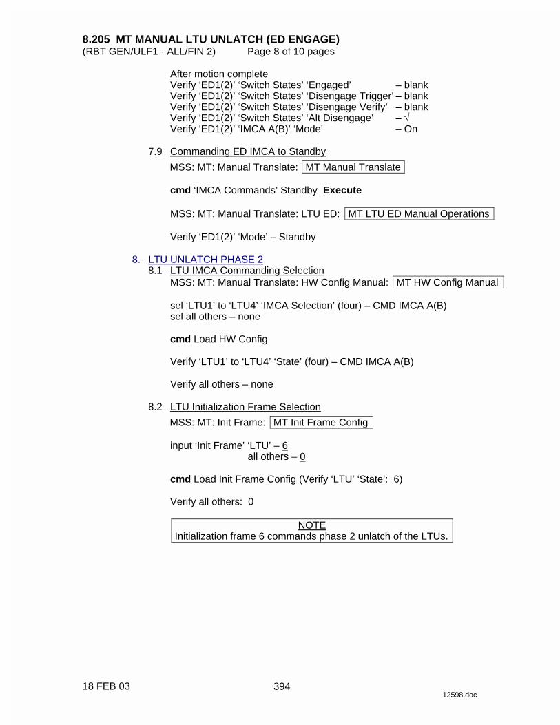
8.205 MT MANUAL LTU UNLATCH (ED ENGAGE) (RBT GEN/ULF1 - ALL/FIN 2) Page 8 of 10 pages
18 FEB 03 12598.doc
After motion complete Verify ‘ED1(2)’ ‘Switch States’ ‘Engaged’ – blank Verify ‘ED1(2)’ ‘Switch States’ ‘Disengage Trigger’ – blank Verify ‘ED1(2)’ ‘Switch States’ ‘Disengage Verify’ – blank Verify ‘ED1(2)’ ‘Switch States’ ‘Alt Disengage’ – √ Verify ‘ED1(2)’ ‘IMCA A(B)’ ‘Mode’ – On
7.9 Commanding ED IMCA to Standby
MSS: MT: Manual Translate: MT Manual Translate
cmd ‘IMCA Commands’ Standby Execute
MSS: MT: Manual Translate: LTU ED: MT LTU ED Manual Operations
Verify ‘ED1(2)’ ‘Mode’ – Standby 8. LTU UNLATCH PHASE 2 8.1 LTU IMCA Commanding Selection
MSS: MT: Manual Translate: HW Config Manual: MT HW Config Manual
sel ‘LTU1’ to ‘LTU4’ ‘IMCA Selection’ (four) – CMD IMCA A(B) sel all others – none
cmd Load HW Config
Verify ‘LTU1’ to ‘LTU4’ ‘State’ (four) – CMD IMCA A(B)
Verify all others – none
8.2 LTU Initialization Frame Selection
MSS: MT: Init Frame: MT Init Frame Config
input ‘Init Frame’ ‘LTU’ – 6 all others – 0
cmd Load Init Frame Config (Verify ‘LTU’ ‘State’: 6)
Verify all others: 0
NOTE
Initialization frame 6 commands phase 2 unlatch of the LTUs.
394
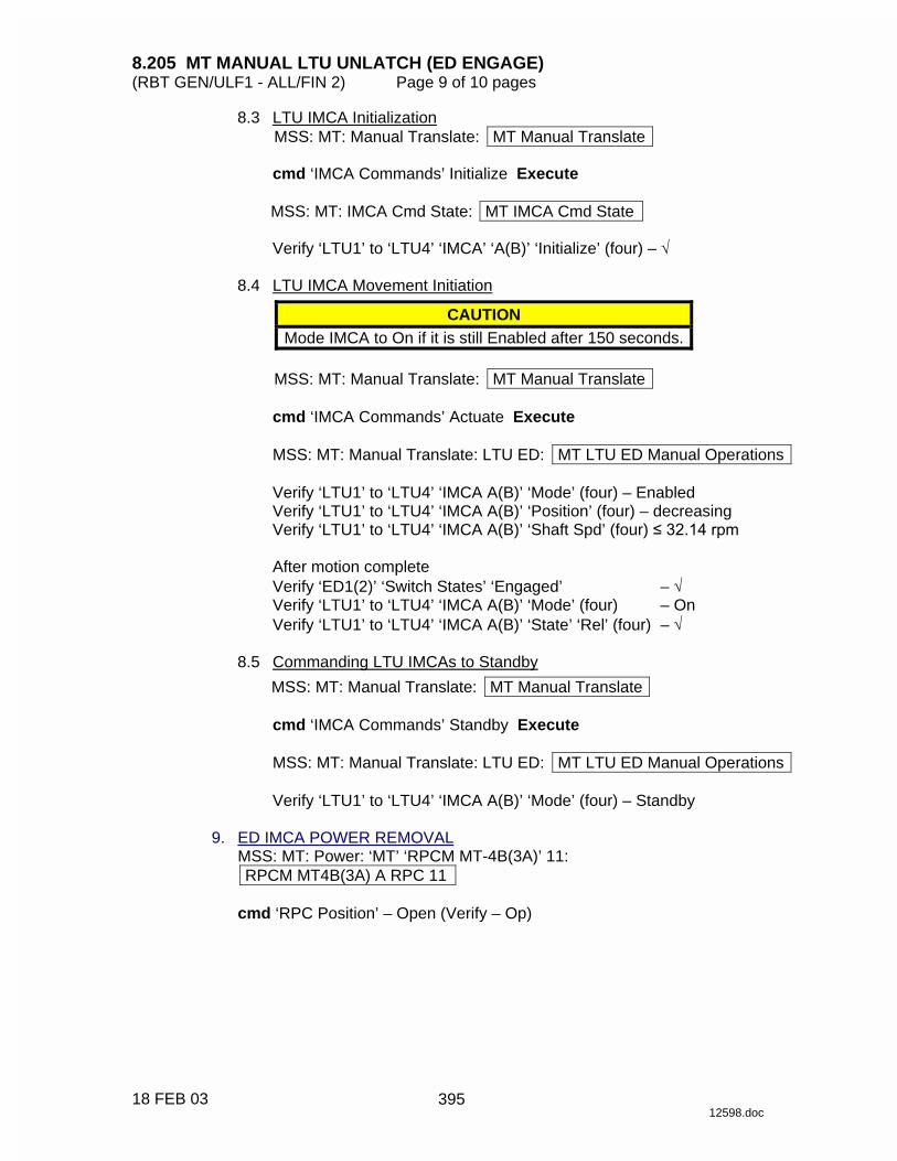
8.205 MT MANUAL LTU UNLATCH (ED ENGAGE) (RBT GEN/ULF1 - ALL/FIN 2) Page 9 of 10 pages
18 FEB 03 12598.doc
8.3 LTU IMCA Initialization MSS: MT: Manual Translate: MT Manual Translate
cmd ‘IMCA Commands’ Initialize Execute
MSS: MT: IMCA Cmd State: MT IMCA Cmd State
Verify ‘LTU1’ to ‘LTU4’ ‘IMCA’ ‘A(B)’ ‘Initialize’ (four) – √
8.4 LTU IMCA Movement Initiation
CAUTION Mode IMCA to On if it is still Enabled after 150 seconds.
MSS: MT: Manual Translate: MT Manual Translate
cmd ‘IMCA Commands’ Actuate Execute
MSS: MT: Manual Translate: LTU ED: MT LTU ED Manual Operations
Verify ‘LTU1’ to ‘LTU4’ ‘IMCA A(B)’ ‘Mode’ (four) – Enabled Verify ‘LTU1’ to ‘LTU4’ ‘IMCA A(B)’ ‘Position’ (four) – decreasing Verify ‘LTU1’ to ‘LTU4’ ‘IMCA A(B)’ ‘Shaft Spd’ (four) ���������
After motion complete Verify ‘ED1(2)’ ‘Switch States’ ‘Engaged’ – √ Verify ‘LTU1’ to ‘LTU4’ ‘IMCA A(B)’ ‘Mode’ (four) – On Verify ‘LTU1’ to ‘LTU4’ ‘IMCA A(B)’ ‘State’ ‘Rel’ (four) – √
8.5 Commanding LTU IMCAs to Standby
MSS: MT: Manual Translate: MT Manual Translate
cmd ‘IMCA Commands’ Standby Execute
MSS: MT: Manual Translate: LTU ED: MT LTU ED Manual Operations
Verify ‘LTU1’ to ‘LTU4’ ‘IMCA A(B)’ ‘Mode’ (four) – Standby 9. ED IMCA POWER REMOVAL
MSS: MT: Power: ‘MT’ ‘RPCM MT-4B(3A)’ 11: RPCM MT4B(3A) A RPC 11
cmd ‘RPC Position’ – Open (Verify – Op)
395
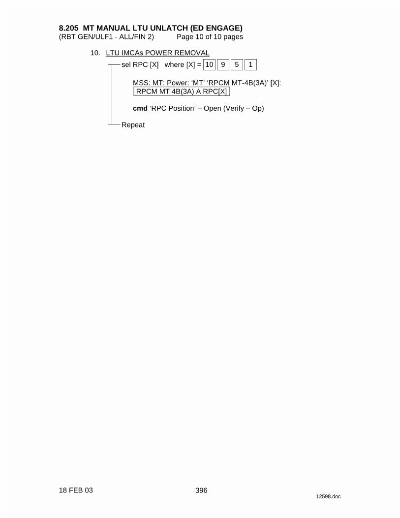
8.205 MT MANUAL LTU UNLATCH (ED ENGAGE) (RBT GEN/ULF1 - ALL/FIN 2) Page 10 of 10 pages
18 FEB 03 12598.doc
10. LTU IMCAs POWER REMOVAL sel RPC [X] where [X] = 1 5 9 10
MSS: MT: Power: ‘MT’ ‘RPCM MT-4B(3A)’ [X]: RPCM MT 4B(3A) A RPC[X]
cmd ‘RPC Position’ – Open (Verify – Op)
Repeat
396

8.206 MT MANUAL LDU DRIVE CHANGEOVER (RBT GEN/12A - ALL/FIN) Page 1 of 6 pages
12 NOV 03 12599.doc
NOTE 1. Procedure assumes failure occurred on the Prime string. 2. The IMCA automatically returns to On mode after the programmed
trajectory has completed. 3. A pause command can be issued by commanding the IMCA to On
mode on the following page: MSS: MT: Manual Translate: MT Manual Translate ‘IMCA Commands’
4. The IMCA takes approximately 6 seconds to complete self-tests
once power is applied. 1. MT SOFTWARE PROCESS INITIATION PCS MSS: MT: MT Mode: MT Mode
If MT Process State – Disabled cmd Initiate MT Process Execute
Verify ‘SEPS Process State’ – Initiated Verify ‘IMCA Process State’ – Initiated Verify ‘MT Process State’ – Initiated
If MT Software Mode – Idle or Auto
cmd Standby Execute (Verify – Standby)
If MT Software Mode – Standby cmd Manual Execute (Verify – Manual)
2. TUS POWER VERIFICATION
MSS: MT: Power: MT Power
Verify ‘TUS1’ ‘RPCM S0-4B-F’ 17 – Cl Verify ‘MT’ ‘RPCM MT-4B’ 13,14 (two) – Cl Verify ‘TUS2’ ‘RPCM S0-3A-E’ 18 – Cl Verify ‘MT’ ‘RPCM MT-3A’ 13,14 (two) – Cl
3. TD 1(2) IMCA POWER REMOVAL
MSS: MT: Power: ‘MT’ ‘RPCM MT-4B(3A)’ 4: RPCM MT4B(3A) A RPC 04
cmd RPC Position – Open (Verify – Op) 4. TD 2(1) IMCA POWER APPLICATION
MSS: MT: Power: ‘MT’ ‘RPCM MT-3A(4B)’ 4: RPCM MT3A(4B) A RPC 04
cmd RPC Position – Close (Verify – Cl)
397

8.206 MT MANUAL LDU DRIVE CHANGEOVER (RBT GEN/12A - ALL/FIN) Page 2 of 6 pages
12 NOV 03 12599.doc
5. TD 2(1) COMMANDING ON 5.1 IMCA Commanding Selection
MSS: MT: Manual Translate: HW Config Manual: MT HW Config Manual
sel ‘TD’ ‘IMCA Selection’ – CMD IMCA B(A)
cmd Load HW Config (Verify ‘TD’ ‘State’ – CMD IMCA B(A))
Verify all others – none
5.2 Initialization Frame Selection
MSS: MT: Init Frame: MT Init Frame Config
input ‘Init Frame’ ‘TD’ – 2 all others – 0
cmd Load Init Frame Config (Verify ‘TD’ ‘State’: 2)
√all others: 0
5.3 IMCA Initialization
MSS: MT: Manual Translate: MT Manual Translate
cmd ‘IMCA Commands’ Initialize Execute
MSS: MT: IMCA Cmd State: MT IMCA Cmd State
Verify ‘TD’ ‘IMCA’ ‘B(A)’ ‘Initialize’ – √ 5.4 Mode TD IMCA to On
MSS: MT: Manual Translate: MT Manual Translate
cmd ‘IMCA Commands’ On Execute
MSS: MT: Manual Translate: TUS TD: MT TUS TD Manual Operations
Verify ‘TD 2(1)’ ‘IMCA B(A)’ Mode – On 6. ED IMCA SETUP PCS 6.1 ED IMCA Power Application
MSS: MT: Power: ‘MT’ ‘RPCM MT-3A(4B)’ 11: RPCM MT3A(4B) A RPC 11
cmd RPC Position – Close (Verify – Cl)
6.2 IMCA Commanding Selection
MSS: MT: Manual Translate: HW Config Manual: MT HW Config Manual
398

8.206 MT MANUAL LDU DRIVE CHANGEOVER (RBT GEN/12A - ALL/FIN) Page 3 of 6 pages
12 NOV 03 12599.doc
sel ‘ED’ ‘IMCA Selection’– CMD IMCA B(A)
cmd Load HW Config (Verify ‘ED’ ‘State’– CMD IMCA B(A))
√all others – none
MSS: MT: Manual Translate: LTU ED: MT LTU ED Manual Operations
Verify ‘ED 2(1)’ ‘Switch States’ ‘Engaged’ – blank Verify ‘ED 2(1)’ ‘Switch States’ ‘Disengage Trigger’ – √ Verify ‘ED 2(1)’ ‘Switch States’ ‘Disengage Verify’ – √ Verify ‘ED 2(1)’ ‘Switch States’ ‘Center Cam Alt Disengage’ – blank
7. TD CHANGEOVER PART 1 7.1 Initialization Frame Selection
MSS: MT: Init Frame: MT Init Frame Config
input ‘Init Frame’ ‘ED’ – 2 all others – 0
cmd Load Init Frame Config (Verify ‘ED’ ‘State’: 2)
√all others: 0
7.2 IMCA Initialization
MSS: MT: Manual Translate: MT Manual Translate
cmd ‘IMCA Commands’ Initialize Execute
MSS: MT: IMCA Cmd State: MT IMCA Cmd State
Verify ‘ED’ ‘IMCA’ ‘B(A)’ ‘Initialize’ – √ 7.3 Mode ED IMCA to On
MSS: MT: Manual Translate: MT Manual Translate
cmd ‘IMCA Commands’ On Execute
MSS: MT: Manual Translate: LTU ED: MT LTU ED Manual Operations
Verify ‘ED’ ‘IMCA B(A)’ ‘Mode’ – On 7.4 Initialization Frame Selection
MSS: MT: Init Frame: MT Init Frame Config
input ‘Init Frame’ ‘ED’ – 5 all others – 0
cmd Load Init Frame Config (Verify ‘ED’ ‘State’: 5)
√all others: 0
399
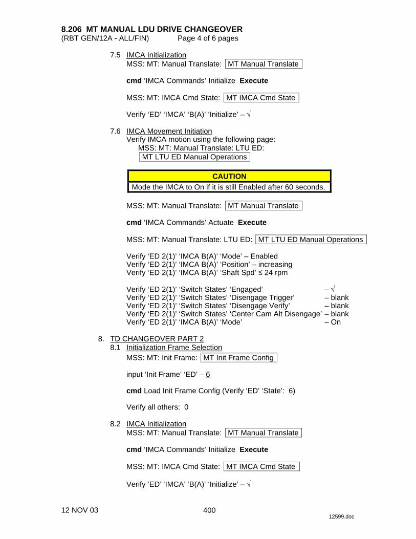
8.206 MT MANUAL LDU DRIVE CHANGEOVER (RBT GEN/12A - ALL/FIN) Page 4 of 6 pages
12 NOV 03 12599.doc
7.5 IMCA Initialization MSS: MT: Manual Translate: MT Manual Translate
cmd ‘IMCA Commands’ Initialize Execute
MSS: MT: IMCA Cmd State: MT IMCA Cmd State
Verify ‘ED’ ‘IMCA’ ‘B(A)’ ‘Initialize’ – √
7.6 IMCA Movement Initiation
Verify IMCA motion using the following page: MSS: MT: Manual Translate: LTU ED: MT LTU ED Manual Operations
CAUTION Mode the IMCA to On if it is still Enabled after 60 seconds.
MSS: MT: Manual Translate: MT Manual Translate
cmd ‘IMCA Commands’ Actuate Execute
MSS: MT: Manual Translate: LTU ED: MT LTU ED Manual Operations
Verify ‘ED 2(1)’ ‘IMCA B(A)’ ‘Mode’ – Enabled Verify ‘ED 2(1)’ ‘IMCA B(A)’ ‘Position’ – increasing Verify ‘ED 2(1)’ ‘IMCA B(A)’ ‘Shaft Spd’ ≤ 24 rpm
Verify ‘ED 2(1)’ ‘Switch States’ ‘Engaged’ – √ Verify ‘ED 2(1)’ ‘Switch States’ ‘Disengage Trigger’ – blank Verify ‘ED 2(1)’ ‘Switch States’ ‘Disengage Verify’ – blank Verify ‘ED 2(1)’ ‘Switch States’ ‘Center Cam Alt Disengage’ – blank Verify ‘ED 2(1)’ ‘IMCA B(A)’ ‘Mode’ – On
8. TD CHANGEOVER PART 2 8.1 Initialization Frame Selection
MSS: MT: Init Frame: MT Init Frame Config
input ‘Init Frame’ ‘ED’ – 6
cmd Load Init Frame Config (Verify ‘ED’ ‘State’: 6)
Verify all others: 0 8.2 IMCA Initialization
MSS: MT: Manual Translate: MT Manual Translate
cmd ‘IMCA Commands’ Initialize Execute
MSS: MT: IMCA Cmd State: MT IMCA Cmd State
Verify ‘ED’ ‘IMCA’ ‘B(A)’ ‘Initialize’ – √
400

8.206 MT MANUAL LDU DRIVE CHANGEOVER (RBT GEN/12A - ALL/FIN) Page 5 of 6 pages
12 NOV 03 12599.doc
8.3 IMCA Movement Initiation Verify IMCA motion using the following page:
MSS: MT: Manual Translate: LTU ED: MT LTU ED Manual Operations
CAUTION Mode the IMCA to On if it is still Enabled after 50 seconds.
MSS: MT: Manual Translate: MT Manual Translate
cmd ‘IMCA Commands’ Actuate Execute
MSS: MT: Manual Translate: LTU ED: MT LTU ED Manual Operations
Verify ‘ED2(1)’ ‘IMCA B(A)’ ‘Mode’ – Enabled Verify ‘ED2(1)’ ‘IMCA B(A)’ ‘Position’ – increasing Verify ‘ED2(1)’ ‘IMCA B(A)’ ‘Shaft Spd’ ≤ 24 rpm
Verify ‘ED2(1)’ ‘Switch States’ ‘Engaged’ – √ Verify ‘ED2(1)’ ‘Switch States’ ‘Disengage Trigger’ – blank Verify ‘ED2(1)’ ‘Switch States’ ‘Disengage Verify’ – blank Verify ‘ED2(1)’ ‘Switch States’ ‘Center Cam Alt Disengage’ – √ Verify ‘ED2(1)’ ‘IMCA B(A)’ ‘Mode’ – On
9. TD CHANGEOVER PART 3 9.1 Initialization Frame Selection
MSS: MT: Init Frame: MT Init Frame Config
input ‘Init Frame’ ‘ED’ – 7 all others – 0
cmd Load Init Frame Config (Verify ‘ED’ ‘State’: 7)
Verify all others: 0
9.2 IMCA Initialization
MSS: MT: Manual Translate: MT Manual Translate
cmd ‘IMCA Commands’ Initialize Execute
MSS: MT: IMCA Cmd State: MT IMCA Cmd State
Verify ‘ED’ ‘IMCA’ ‘B(A)’ ‘Initialize’ – √ 9.3 IMCA Movement Initiation
Verify IMCA motion using the following page: MSS: MT: Manual Translate: LTU ED: MT LTU ED Manual Operations
401
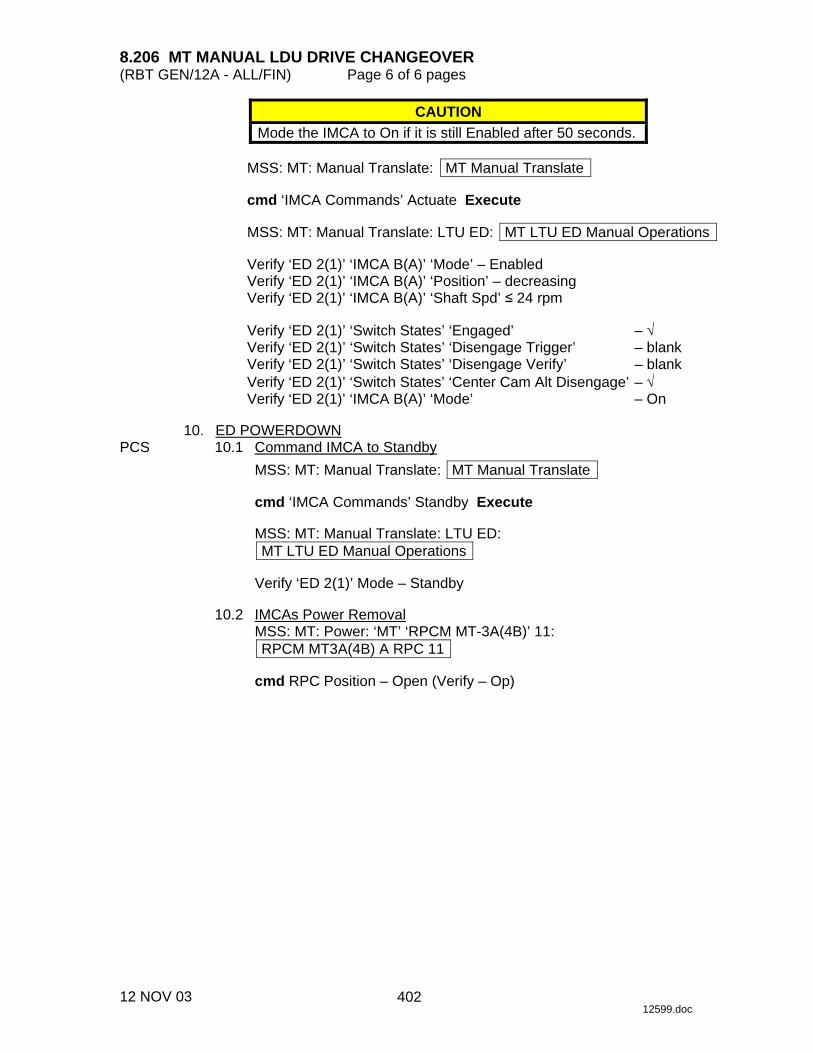
8.206 MT MANUAL LDU DRIVE CHANGEOVER (RBT GEN/12A - ALL/FIN) Page 6 of 6 pages
12 NOV 03 12599.doc
CAUTION Mode the IMCA to On if it is still Enabled after 50 seconds.
MSS: MT: Manual Translate: MT Manual Translate
cmd ‘IMCA Commands’ Actuate Execute
MSS: MT: Manual Translate: LTU ED: MT LTU ED Manual Operations
Verify ‘ED 2(1)’ ‘IMCA B(A)’ ‘Mode’ – Enabled Verify ‘ED 2(1)’ ‘IMCA B(A)’ ‘Position’ – decreasing Verify ‘ED 2(1)’ ‘IMCA B(A)’ ‘Shaft Spd’ ≤ 24 rpm
Verify ‘ED 2(1)’ ‘Switch States’ ‘Engaged’ – √ Verify ‘ED 2(1)’ ‘Switch States’ ‘Disengage Trigger’ – blank Verify ‘ED 2(1)’ ‘Switch States’ ‘Disengage Verify’ – blank Verify ‘ED 2(1)’ ‘Switch States’ ‘Center Cam Alt Disengage’ – √ Verify ‘ED 2(1)’ ‘IMCA B(A)’ ‘Mode’ – On
10. ED POWERDOWN PCS 10.1 Command IMCA to Standby
MSS: MT: Manual Translate: MT Manual Translate
cmd ‘IMCA Commands’ Standby Execute
MSS: MT: Manual Translate: LTU ED: MT LTU ED Manual Operations
Verify ‘ED 2(1)’ Mode – Standby
10.2 IMCAs Power Removal
MSS: MT: Power: ‘MT’ ‘RPCM MT-3A(4B)’ 11: RPCM MT3A(4B) A RPC 11
cmd RPC Position – Open (Verify – Op)
402

8.208 MT MANUAL TUS INITIALIZATION (RBT GEN/ULF1 - ALL/FIN 1) Page 1 of 7 pages
10 DEC 03 12601.doc
NOTE 1. The IMCA automatically returns to On mode after the programmed
trajectory has completed. 2. A pause command can be issued by commanding the IMCA to On
mode on the following page MSS: MT: Manual Translate: MT Manual Translate ‘IMCA Commands’
3. The IMCA takes approximately 6 seconds to complete self-tests
once power is applied. 1. MT SOFTWARE PROCESS INITIATION PCS MSS: MT: MT Mode: MT Mode
If ‘MT Process State’ – Disabled cmd Initiate MT Process Execute
Verify ‘SEPS Process State’ – Initiated Verify ‘IMCA Process State’ – Initiated Verify ‘MT Process State’ – Initiated
If ‘MT Software Mode’ – Idle or Auto
cmd Standby Execute (Verify – Standby)
If ‘MT Software Mode’ – Standby cmd Manual Execute (Verify – Manual)
2. TUS IMCAs POWER APPLICATION
NOTE The IMCA takes approximately 6 seconds to complete self-tests once power is applied.
MSS: MT: Power MT Power
‘TUS1’
sel RPCM S0-3A-F
RPCM S03A_F
sel RPC 1
RPCM S03A_F_RPC_01
Verify ‘RPC Position’ – Op
MSS: MT: Power MT Power
‘TUS1’
403

8.208 MT MANUAL TUS INITIALIZATION (RBT GEN/ULF1 - ALL/FIN 1) Page 2 of 7 pages
10 DEC 03 12601.doc
sel RPCM S0-4B-F
RPCM S04B_F
sel RPC 1
RPCM S04B_F_RPC_01
Verify ‘RPC Position’ – Op
MSS: MT: Power MT Power
‘TUS2’
sel RPCM S0-3A-E
RPCM S03A_E
sel RPC 1
RPCM S03A_E_RPC_01
Verify ‘RPC Position’ – Op
MSS: MT: Power MT Power
‘TUS2’
sel RPCM S0-4B-E
RPCM S04B_E
sel RPC 1
RPCM S04B_E_RPC_01
Verify ‘RPC Position’ – Op
MSS: MT: Power MT Power
‘TUS1’
sel RPCM S0-4B(3A)-F
RPCM S04B(3A)_F
sel RPC 1
RPCM S04B(3A)_F_RPC_01
404

8.208 MT MANUAL TUS INITIALIZATION (RBT GEN/ULF1 - ALL/FIN 1) Page 3 of 7 pages
10 DEC 03 12601.doc
cmd ‘RPC Position’ – Close (Verify – Cl)
MSS: MT: Power MT Power
‘TUS2’
sel RPCM S0-4B(3A)-E
RPCM S04B(3A) E
sel RPC 1
RPCM S04B(3A) E RPC 01
cmd ‘RPC Position’ – Close (Verify – Cl)
MSS: MT: IMCA Data Stale State: MT IMCA Data Stale State
Verify Status Measurements ‘TUS1’ to ‘TUS2’ ‘IMCA A(B)’ (two) – blank
MSS: MT: Power: MT Power
Verify ‘TUS1’ ‘RPCM S0-4B(3A)-F’ Mode – Standby Verify ‘TUS1’ ‘RPCM S0-4B(3A)-F’ Fault – blank Verify ‘TUS2’ ‘RPCM S0-4B(3A)-E’ Mode – Standby Verify ‘TUS2’ ‘RPCM S0-4B(3A)-E’ Fault – blank
3. IMCA COMMANDING SELECTION
MSS: MT: Manual Translate: HW Config Manual: MT HW Config Manual
sel ‘TUS1’ to ‘TUS2’ ‘IMCA Selection’ (two) – CMD IMCA A(B)
cmd Load HW Config
Verify ‘TUS1’ to ‘TUS2’ ‘State’ (two) – CMD IMCA A(B) Verify all others – none
4. TUS INITIALIZATION (PHASE 1) 4.1 TUS Initialization Frame Selection
MSS: MT: Manual Translate: Init Frame Config: MT Init Frame Config
input ‘TUS Init Frame’ – 2
cmd Load Init Frame Config (Verify ‘TUS’ ‘State’: 2)
Verify ‘State’ all others – 0
405
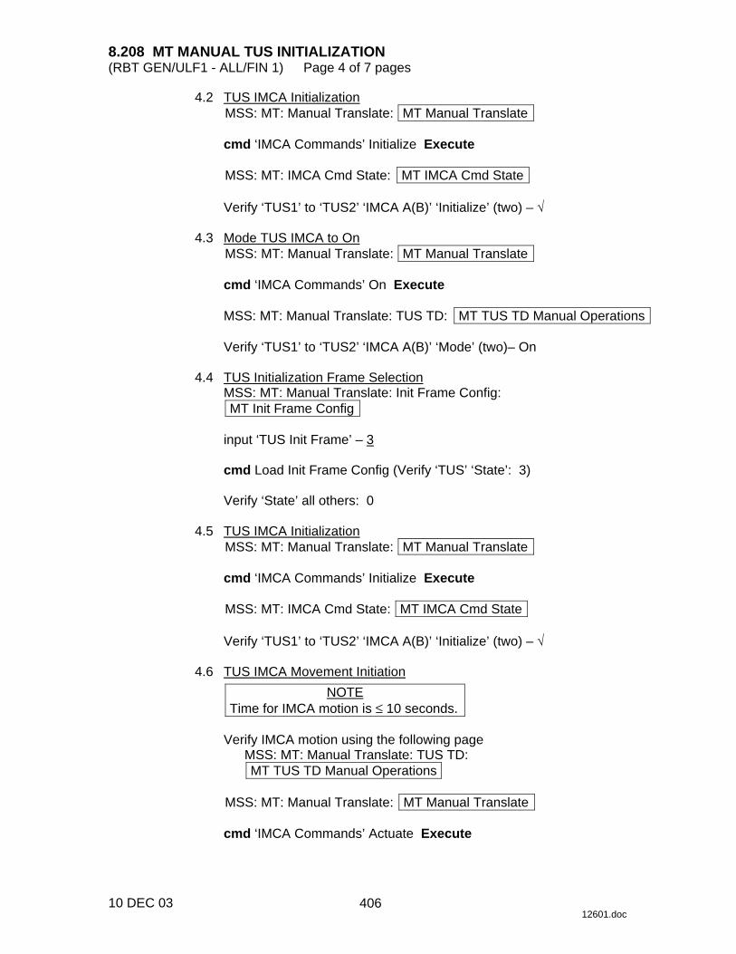
8.208 MT MANUAL TUS INITIALIZATION (RBT GEN/ULF1 - ALL/FIN 1) Page 4 of 7 pages
10 DEC 03 12601.doc
4.2 TUS IMCA Initialization MSS: MT: Manual Translate: MT Manual Translate
cmd ‘IMCA Commands’ Initialize Execute
MSS: MT: IMCA Cmd State: MT IMCA Cmd State
Verify ‘TUS1’ to ‘TUS2’ ‘IMCA A(B)’ ‘Initialize’ (two) – √
4.3 Mode TUS IMCA to On
MSS: MT: Manual Translate: MT Manual Translate
cmd ‘IMCA Commands’ On Execute
MSS: MT: Manual Translate: TUS TD: MT TUS TD Manual Operations
Verify ‘TUS1’ to ‘TUS2’ ‘IMCA A(B)’ ‘Mode’ (two)– On 4.4 TUS Initialization Frame Selection
MSS: MT: Manual Translate: Init Frame Config: MT Init Frame Config
input ‘TUS Init Frame’ – 3
cmd Load Init Frame Config (Verify ‘TUS’ ‘State’: 3)
Verify ‘State’ all others: 0
4.5 TUS IMCA Initialization
MSS: MT: Manual Translate: MT Manual Translate
cmd ‘IMCA Commands’ Initialize Execute
MSS: MT: IMCA Cmd State: MT IMCA Cmd State
Verify ‘TUS1’ to ‘TUS2’ ‘IMCA A(B)’ ‘Initialize’ (two) – √ 4.6 TUS IMCA Movement Initiation
NOTE Time for IMCA motion is ≤ 10 seconds.
Verify IMCA motion using the following page
MSS: MT: Manual Translate: TUS TD: MT TUS TD Manual Operations
MSS: MT: Manual Translate: MT Manual Translate
cmd ‘IMCA Commands’ Actuate Execute
406

8.208 MT MANUAL TUS INITIALIZATION (RBT GEN/ULF1 - ALL/FIN 1) Page 5 of 7 pages
10 DEC 03 12601.doc
MSS: MT: Manual Translate: TUS TD: MT TUS TD Manual Operations
Verify ‘TUS1’ to ‘TUS2’ ‘IMCA A(B)’ ‘Mode’ (two) – On Verify ‘TUS1’ to ‘TUS2’ ‘IMCA A(B)’ ‘Outer sw’ ‘Hi’ to ‘Lo’ (four) – blank Verify ‘TUS1’ to ‘TUS2’ ‘IMCA A(B)’ ‘Inner sw’ ‘Hi’ to ‘Lo’ (four) – blank
4.7 Mode IMCA to Standby
MSS: MT: Manual Translate: MT Manual Translate
cmd ‘IMCA Commands’ Standby Execute
MSS: MT: Manual Translate: TUS TD: MT TUS TD Manual Operations
Verify ‘TUS1’ to ‘TUS2’ ‘IMCA A(B)’ ‘Mode’ (two) – Standby 5. TUS INITIALIZATION (PHASE 2) 5.1 TUS Initialization Frame Selection
MSS: MT: Manual Translate: Init Frame Config: MT Init Frame Config
input ‘TUS Init Frame’ – 4
cmd Load Init Frame Config (Verify ‘TUS’ ‘State’: 4)
Verify ‘State’ all others: 0 5.2 TUS IMCA Initialization
MSS: MT: Manual Translate: MT Manual Translate
cmd ‘IMCA Commands’ Initialize Execute
MSS: MT: IMCA Cmd State: MT IMCA Cmd State
Verify ‘TUS1’ to ‘TUS2’ ‘IMCA A(B)’ ‘Initialize’ (two) – √ 5.3 Mode TUS IMCA to On
MSS: MT: Manual Translate: MT Manual Translate
cmd ‘IMCA Commands’ On Execute
MSS: MT: Manual Translate: TUS TD: MT TUS TD Manual Operations
Verify ‘TUS1’ to ‘TUS2’ ‘IMCA A(B)’ ‘Mode’ (two) – On 5.4 IMCA Movement Initiation
NOTE Time for IMCA motion is ≤ 15 seconds.
Verify IMCA motion using the following page
MSS: MT: Manual Translate: TUS TD: MT TUS TD Manual Operations
407

8.208 MT MANUAL TUS INITIALIZATION (RBT GEN/ULF1 - ALL/FIN 1) Page 6 of 7 pages
10 DEC 03 12601.doc
MSS: MT: Manual Translate: MT Manual Translate
cmd ‘IMCA Commands’ Actuate Execute
MSS: MT: Manual Translate: TUS TD: MT TUS TD Manual Operations
Verify ‘TUS1’ to ‘TUS2’ ‘IMCA A(B)’ ‘Mode’ (two) – On Verify ‘TUS1’ to ‘TUS2’ ‘IMCA A(B)’ ‘Outer sw’ ‘Hi’ – blank Verify ‘TUS1’ to ‘TUS2’ ‘IMCA A(B)’ ‘Inner sw’ ‘Hi’ – blank Verify ‘TUS1’ to ‘TUS2’ ‘IMCA A(B)’ ‘Outer sw’ ‘Lo’ – √ Verify ‘TUS1’ to ‘TUS2’ ‘IMCA A(B)’ ‘Inner sw’ ‘Lo’ – √
6. TUS INITIALIZATION (PHASE 3) 6.1 TUS Initialization Frame Selections
MSS: MT: Manual Translate: Init Frame Config: MT Init Frame Config
input ‘TUS’ ‘Init Frame’ – 5
cmd Load Init Frame Config (Verify ‘TUS’ ‘State’: 5)
Verify ‘State’ all others: 0
6.2 TUS IMCA Initialization
MSS: MT: Manual Translate: MT Manual Translate
cmd ‘IMCA Commands’ Initialize Execute
MSS: MT: IMCA Cmd State: MT IMCA Cmd State
Verify ‘TUS1’ to ‘TUS2’ ‘IMCA A(B)’ ‘Initialize’ (two) – √ 6.3 TUS IMCA Movement Initialization
NOTE Time for IMCA motion is ≤ 30 seconds.
Verify IMCA motion using the following page
MSS: MT: Manual Translate: TUS TD: MT TUS TD Manual Operations
MSS: MT: Manual Translate: MT Manual Translate
cmd ‘IMCA Commands’ Actuate Execute
MSS: MT: Manual Translate: TUS TD: MT TUS TD Manual Operations
Verify ‘TUS1’ to ‘TUS2’ ‘IMCA A(B)’ ‘Mode’ – On Verify ‘TUS1’ to ‘TUS2’ ‘IMCA A(B)’ ‘Outer sw’ ‘Hi’ – √ Verify ‘TUS1’ to ‘TUS2’ ‘IMCA A(B)’ ‘Inner sw’ ‘Hi’ – √ Verify ‘TUS1’ to ‘TUS2’ ‘IMCA A(B)’ ‘Outer sw’ ‘Lo’ – blank Verify ‘TUS1’ to ‘TUS2’ ‘IMCA A(B)’ ‘Inner sw’ ‘Lo’ – blank
408
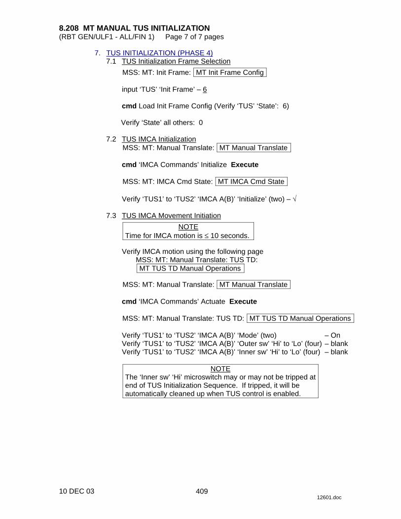
8.208 MT MANUAL TUS INITIALIZATION (RBT GEN/ULF1 - ALL/FIN 1) Page 7 of 7 pages
10 DEC 03 12601.doc
7. TUS INITIALIZATION (PHASE 4) 7.1 TUS Initialization Frame Selection
MSS: MT: Init Frame: MT Init Frame Config
input ‘TUS’ ‘Init Frame’ – 6
cmd Load Init Frame Config (Verify ‘TUS’ ‘State’: 6)
Verify ‘State’ all others: 0 7.2 TUS IMCA Initialization
MSS: MT: Manual Translate: MT Manual Translate
cmd ‘IMCA Commands’ Initialize Execute
MSS: MT: IMCA Cmd State: MT IMCA Cmd State
Verify ‘TUS1’ to ‘TUS2’ ‘IMCA A(B)’ ‘Initialize’ (two) – √ 7.3 TUS IMCA Movement Initiation
NOTE Time for IMCA motion is ≤ 10 seconds.
Verify IMCA motion using the following page
MSS: MT: Manual Translate: TUS TD: MT TUS TD Manual Operations
MSS: MT: Manual Translate: MT Manual Translate
cmd ‘IMCA Commands’ Actuate Execute
MSS: MT: Manual Translate: TUS TD: MT TUS TD Manual Operations
Verify ‘TUS1’ to ‘TUS2’ ‘IMCA A(B)’ ‘Mode’ (two) – On Verify ‘TUS1’ to ‘TUS2’ ‘IMCA A(B)’ ‘Outer sw’ ‘Hi’ to ‘Lo’ (four) – blank Verify ‘TUS1’ to ‘TUS2’ ‘IMCA A(B)’ ‘Inner sw’ ‘Hi’ to ‘Lo’ (four) – blank
NOTE
The ‘Inner sw’ ‘Hi’ microswitch may or may not be tripped at end of TUS Initialization Sequence. If tripped, it will be automatically cleaned up when TUS control is enabled.
409

This Page Intentionally Blank
22 DEC 04
410

8.209 MT TUS CABLE CUT (RBT GEN/ULF1 - ALL/FIN) Page 1 of 3 pages
12 FEB 03 12602.doc
1. VERIFICATION PCS MSS: MT: MT Mode: MT Mode
Verify SEPS Process State – Initiated
MSS: MT: Power: MT Power
If failed cable − TUS1 √‘TUS2’ RPCM S0-3A-E RPC 18 – Cl √‘TUS1’ RPCM S0-4B-F RPC 17 − Op
sel RPCM S0-4B-F RPC 17
cmd Close Cmd inhibit (Verify – Inh)
Go to step 2.
If failed cable − TUS2
√‘TUS1’ RPCM S0-4B-F RPC 17 − Cl √‘TUS2’ RPCM S0-3A-E RPC 18 − Op
sel RPCM S0-3A-E RPC 18
cmd Close Cmd inhibit (Verify – Inh)
Go to step 3.
2. TUS1 CUT 2.1 TUS1 Cable Cutter Relay A Power
MSS: MT: TUS1 Cut: RPCM MT3A RPC 03: RPCM MT3A A RPC 03
cmd ‘RPC Position’ – Close (Verify – Cl)
2.2 TUS1 Cable Cutter Relay B Power
MSS: MT: TUS1 Cut: RPCM MT3A RPC 06: RPCM MT3A A RPC 06
cmd ‘RPC Position’ – Close (Verify – Cl)
2.3 TUS1 Cable Cut
CAUTION The following step will sever the TUS1 Cable.
MSS: MT: TUS1 Cut: RPCM MT3A RPC 17: RPCM MT3A A RPC 17
cmd ‘RPC Position’ – Close (Verify – Cl)
411

8.209 MT TUS CABLE CUT (RBT GEN/ULF1 - ALL/FIN) Page 2 of 3 pages
12 FEB 03 12602.doc
2.4 TUS1 Cable Cutter Unpower cmd ‘RPC Position’ – Open (Verify – Op)
2.5 TUS1 Cable Cutter Relay B Unpower
MSS: MT: TUS1 Cut: RPCM MT3A RPC 06: RPCM MT3A A RPC 06
cmd ‘RPC Position’ – Open (Verify – Op)
2.6 TUS1 Cable Cutter Relay A Unpower
MSS: MT: TUS1 Cut: RPCM MT3A RPC 03: RPCM MT3A RPC 03
cmd ‘RPC Position’ – Open (Verify – Op) >>
3. TUS2 CUT 3.1 TUS2 Cable Cutter Relay A Power
MSS: MT: TUS2 Cut: RPCM MT4B RPC 03: RPCM MT4B A RPC 03
cmd ‘RPC Position’ – Close (Verify – Cl)
3.2 TUS2 Cable Cutter Relay B Power
MSS: MT: TUS2 Cut: RPCM MT4B RPC 06: RPCM MT4B A RPC 06
cmd ‘RPC Position’ – Close (Verify – Cl)
3.3 TUS2 Cable Cut
CAUTION The following step will sever the TUS2 Cable.
MSS: MT: TUS2 Cut: RPCM MT4B RPC 17: RPCM MT4B A RPC 17
cmd ‘RPC Position’ – Close (Verify – Cl)
3.4 TUS2 Cable Cutter Unpower
cmd ‘RPC Position’ – Open (Verify – Op) 3.5 TUS2 Cable Cutter Relay B Unpower
MSS: MT: TUS2 Cut: RPCM MT4B RPC 06: RPCM MT4B A RPC 06
cmd ‘RPC Position’ – Open (Verify – Op)
412
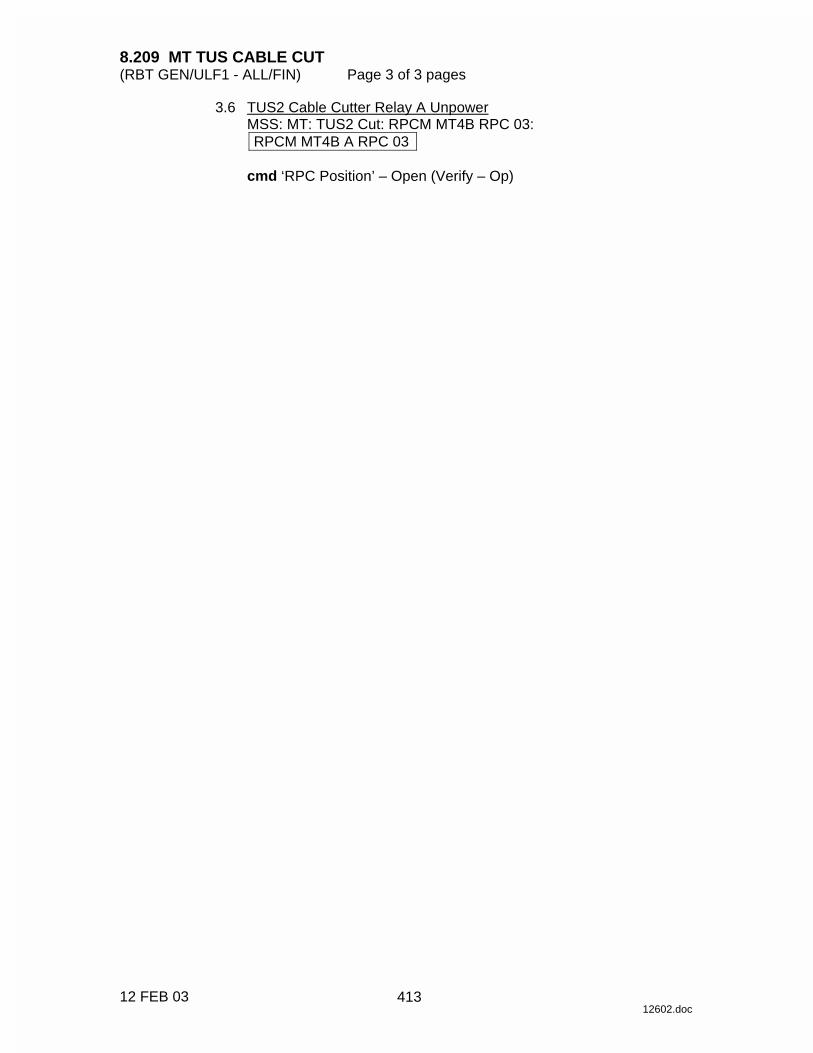
8.209 MT TUS CABLE CUT (RBT GEN/ULF1 - ALL/FIN) Page 3 of 3 pages
12 FEB 03 12602.doc
3.6 TUS2 Cable Cutter Relay A Unpower MSS: MT: TUS2 Cut: RPCM MT4B RPC 03: RPCM MT4B A RPC 03
cmd ‘RPC Position’ – Open (Verify – Op)
413

This Page Intentionally Blank
22 DEC 04
414
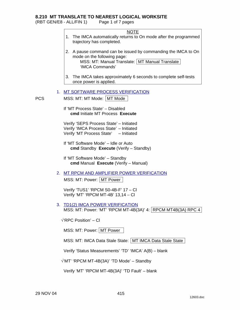
8.210 MT TRANSLATE TO NEAREST LOGICAL WORKSITE (RBT GEN/E8 - ALL/FIN 1) Page 1 of 7 pages
29 NOV 04 12603.doc
NOTE 1. The IMCA automatically returns to On mode after the programmed
trajectory has completed. 2. A pause command can be issued by commanding the IMCA to On
mode on the following page: MSS: MT: Manual Translate: MT Manual Translate ‘IMCA Commands’
3. The IMCA takes approximately 6 seconds to complete self-tests
once power is applied. 1. MT SOFTWARE PROCESS VERIFICATION PCS MSS: MT: MT Mode: MT Mode
If ‘MT Process State’ – Disabled cmd Initiate MT Process Execute
Verify ‘SEPS Process State’ – Initiated Verify ‘IMCA Process State’ – Initiated Verify ‘MT Process State’ – Initiated
If ‘MT Software Mode’ – Idle or Auto
cmd Standby Execute (Verify – Standby)
If ‘MT Software Mode’ – Standby cmd Manual Execute (Verify – Manual)
2. MT RPCM AND AMPLIFIER POWER VERIFICATION
MSS: MT: Power: MT Power
Verify ‘TUS1’ ‘RPCM S0-4B-F’ 17 – Cl Verify ‘MT’ ‘RPCM MT-4B’ 13,14 – Cl
3. TD1(2) IMCA POWER VERIFICATION
MSS: MT: Power: ‘MT’ ‘RPCM MT-4B(3A)’ 4: RPCM MT4B(3A) RPC 4
√‘RPC Position’ – Cl
MSS: MT: Power: MT Power
MSS: MT: IMCA Data Stale State: MT IMCA Data Stale State
Verify ‘Status Measurements’ ‘TD’ ‘IMCA’ A(B) – blank
√‘MT’ ‘RPCM MT-4B(3A)’ ‘TD Mode’ – Standby
Verify ‘MT’ ‘RPCM MT-4B(3A)’ ‘TD Fault’ – blank
415

8.210 MT TRANSLATE TO NEAREST LOGICAL WORKSITE (RBT GEN/E8 - ALL/FIN 1) Page 2 of 7 pages
29 NOV 04 12603.doc
4. TD PHASE 2 SETUP 4.1 TD IMCA Commanding Selection
MSS: MT: Manual Translate HW Config Manual: MT HW Config Manual
pick ‘TD’ ‘IMCA Selection’ – CMD IMCA A(B) pick all others – none
cmd Load HW Config (Verify ‘State’ ‘TD’ – CMD IMCA A(B))
Verify all others – none
4.2 Loading Position Hold Init Frame
MSS: MT: Manual Translate: Init Frame Config: MT Init Frame Config
input ‘TD’ ‘Init Frame’ – 2 input all others – 0
cmd Load Init Frame Config (Verify ‘TD’ ‘State’: 2)
Verify all others: 0
4.3 TD IMCA Initialization
MSS: MT: Manual Translate: MT Manual Translate
cmd ‘IMCA Commands’ Initialize Execute
MSS: MT: IMCA Cmd State: MT IMCA Cmd State
Verify ‘TD’ ‘IMCA’ A(B) ‘Initialize’– √ 4.4 TD IMCA Mode to On
MSS: MT: Manual Translate: MT Manual Translate
cmd ‘IMCA Commands’ On Execute
MSS: MT: Manual Translate: TUS TD: MT TUS TD Manual Operations
Verify ‘TD1(2)’ ‘IMCA’ A(B) Mode – On 4.5 TD Initialization Frame Selection
Table 1. Initialization Frame Selection
Nearest Logical Worksite Location Init Frame Starboard (+Y) 140 Port (-Y) 148
MSS: MT: Manual Translate: Init Frame Config: MT Init Frame Config
input ‘TD’ ‘Init Frame’ (Refer to Table 1)
cmd Load Init Frame Config (Verify ‘TD’ ‘State’, refer to Table 1)
Verify all others: 0
416
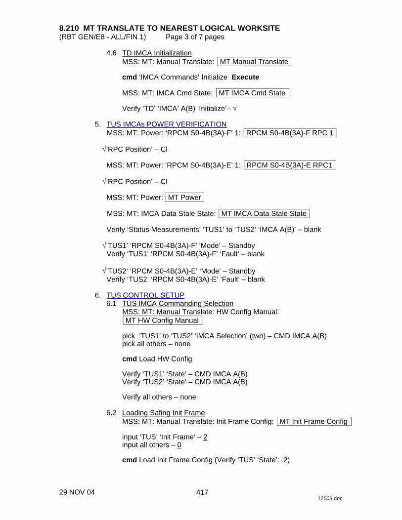
8.210 MT TRANSLATE TO NEAREST LOGICAL WORKSITE (RBT GEN/E8 - ALL/FIN 1) Page 3 of 7 pages
29 NOV 04 12603.doc
4.6 TD IMCA Initialization MSS: MT: Manual Translate: MT Manual Translate
cmd ‘IMCA Commands’ Initialize Execute
MSS: MT: IMCA Cmd State: MT IMCA Cmd State
Verify ‘TD’ ‘IMCA’ A(B) ‘Initialize’– √
5. TUS IMCAs POWER VERIFICATION MSS: MT: Power: ‘RPCM S0-4B(3A)-F’ 1: RPCM S0-4B(3A)-F RPC 1
√‘RPC Position’ – Cl
MSS: MT: Power: ‘RPCM S0-4B(3A)-E’ 1: RPCM S0-4B(3A)-E RPC1
√‘RPC Position’ – Cl
MSS: MT: Power: MT Power
MSS: MT: IMCA Data Stale State: MT IMCA Data Stale State
Verify ‘Status Measurements’ ‘TUS1’ to ‘TUS2’ ‘IMCA A(B)’ – blank
√‘TUS1’ ‘RPCM S0-4B(3A)-F’ ‘Mode’ – Standby Verify ‘TUS1’ ‘RPCM S0-4B(3A)-F’ ‘Fault’ – blank
√‘TUS2’ ‘RPCM S0-4B(3A)-E’ ‘Mode’ – Standby
Verify ‘TUS2’ ‘RPCM S0-4B(3A)-E’ ‘Fault’ – blank 6. TUS CONTROL SETUP 6.1 TUS IMCA Commanding Selection
MSS: MT: Manual Translate: HW Config Manual: MT HW Config Manual
pick ‘TUS1’ to ‘TUS2’ ‘IMCA Selection’ (two) – CMD IMCA A(B) pick all others – none
cmd Load HW Config
Verify ‘TUS1’ ‘State’ – CMD IMCA A(B) Verify ‘TUS2’ ‘State’ – CMD IMCA A(B)
Verify all others – none
6.2 Loading Safing Init Frame
MSS: MT: Manual Translate: Init Frame Config: MT Init Frame Config
input ‘TUS’ ‘Init Frame’ – 2 input all others – 0
cmd Load Init Frame Config (Verify ‘TUS’ ‘State’: 2)
417
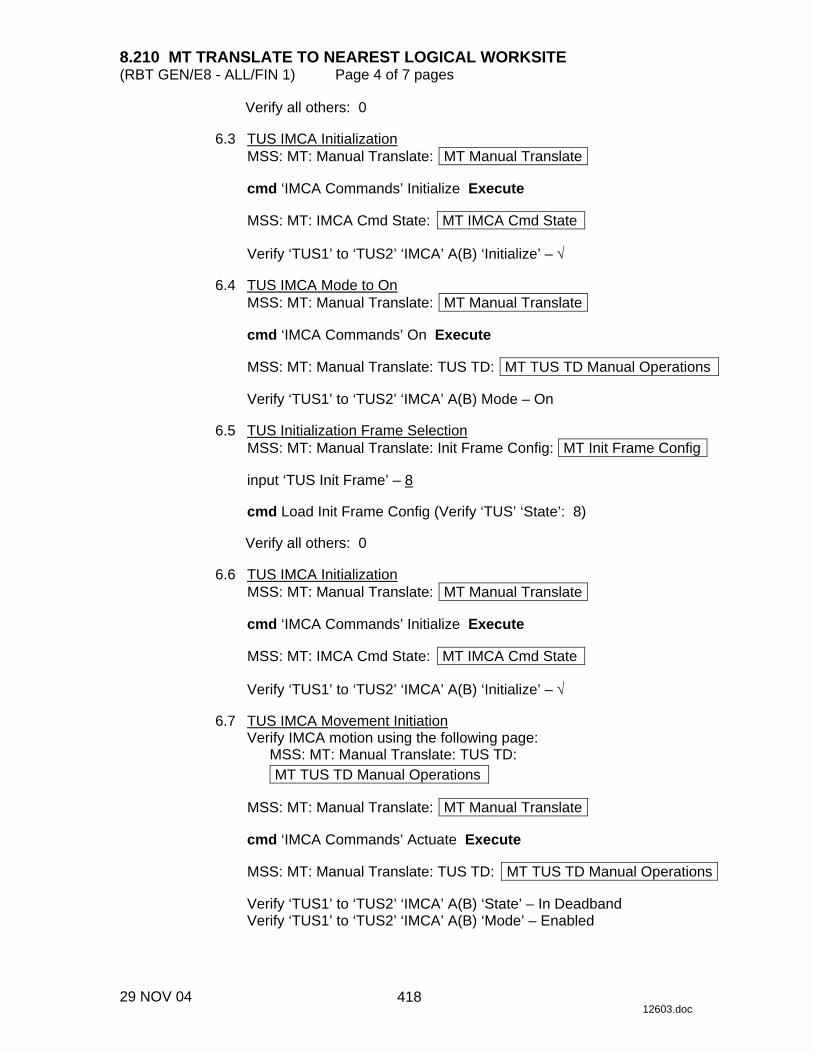
8.210 MT TRANSLATE TO NEAREST LOGICAL WORKSITE (RBT GEN/E8 - ALL/FIN 1) Page 4 of 7 pages
29 NOV 04 12603.doc
Verify all others: 0 6.3 TUS IMCA Initialization
MSS: MT: Manual Translate: MT Manual Translate
cmd ‘IMCA Commands’ Initialize Execute
MSS: MT: IMCA Cmd State: MT IMCA Cmd State
Verify ‘TUS1’ to ‘TUS2’ ‘IMCA’ A(B) ‘Initialize’ – √ 6.4 TUS IMCA Mode to On
MSS: MT: Manual Translate: MT Manual Translate
cmd ‘IMCA Commands’ On Execute
MSS: MT: Manual Translate: TUS TD: MT TUS TD Manual Operations
Verify ‘TUS1’ to ‘TUS2’ ‘IMCA’ A(B) Mode – On 6.5 TUS Initialization Frame Selection
MSS: MT: Manual Translate: Init Frame Config: MT Init Frame Config
input ‘TUS Init Frame’ – 8
cmd Load Init Frame Config (Verify ‘TUS’ ‘State’: 8)
Verify all others: 0 6.6 TUS IMCA Initialization
MSS: MT: Manual Translate: MT Manual Translate
cmd ‘IMCA Commands’ Initialize Execute
MSS: MT: IMCA Cmd State: MT IMCA Cmd State
Verify ‘TUS1’ to ‘TUS2’ ‘IMCA’ A(B) ‘Initialize’ – √ 6.7 TUS IMCA Movement Initiation
Verify IMCA motion using the following page: MSS: MT: Manual Translate: TUS TD: MT TUS TD Manual Operations
MSS: MT: Manual Translate: MT Manual Translate
cmd ‘IMCA Commands’ Actuate Execute
MSS: MT: Manual Translate: TUS TD: MT TUS TD Manual Operations
Verify ‘TUS1’ to ‘TUS2’ ‘IMCA’ A(B) ‘State’ – In Deadband Verify ‘TUS1’ to ‘TUS2’ ‘IMCA’ A(B) ‘Mode’ – Enabled
418

8.210 MT TRANSLATE TO NEAREST LOGICAL WORKSITE (RBT GEN/E8 - ALL/FIN 1) Page 5 of 7 pages
29 NOV 04 12603.doc
7. TD PHASE 2 TRANSLATE TO NEAREST WORKSITE 7.1 TD IMCA Commanding Selection
MSS: MT: Manual Translate: HW Config Manual: MT HW Config Manual
pick ‘TD’ ‘IMCA Selection’ – CMD IMCA A(B) pick all others – none
cmd Load HW Config (Verify ‘State’ ‘TD’ – CMD IMCA A(B))
Verify all others – none
7.2 TD IMCA Movement Initiation
Verify IMCA motion using the following page: MSS: MT: Manual Translate: TUS TD: MT TUS TD Manual Operations
MSS: MT: Manual Translate: MT Manual Translate
cmd ‘IMCA Commands’ Actuate Execute
MSS: MT: Manual Translate: TUS TD: MT TUS TD Manual Operations
Verify ‘TD’1(2) ‘Mode’ – Enabled Verify ‘TD’1(2) ‘Position’ – changing Verify ‘TD’1(2) ‘Shaft Spd’ ≤ 33 rpm (+ if motion to port, - if starboard) Verify ‘TD’1(2) ‘Mode’ – On
8. TD PHASE 3 TRANSLATE TO NEAREST WORKSITE 8.1 TD Initialization Frame Selection
Table 2. Initialization Frame Selection
Nearest Logical Worksite Location Init Frame Starboard (+Y) 197 Port (-Y) 205
MSS: MT: Manual Translate: Init Frame Config: MT Init Frame Config
input ‘TD’ ‘Init Frame’ (Refer to Table 2) input all others – 0
cmd Load Init Frame Config (Verify ‘TD’ ‘State’, refer to Table 2)
Verify all others: 0
8.2 TD IMCA Initialization
MSS: MT: Manual Translate: MT Manual Translate
cmd ‘IMCA Commands’ Initialize Execute
MSS: MT: IMCA Cmd State: MT IMCA Cmd State
Verify ‘TD’ ‘IMCA’ A(B) ‘Initialize’ – √
419

8.210 MT TRANSLATE TO NEAREST LOGICAL WORKSITE (RBT GEN/E8 - ALL/FIN 1) Page 6 of 7 pages
29 NOV 04 12603.doc
8.3 TD IMCA Movement Initiation Verify IMCA motion using the following page:
MSS: MT: Manual Translate: TUS TD: MT TUS TD Manual Operations
MSS: MT: Manual Translate: MT Manual Translate
cmd ‘IMCA Commands’ Actuate Execute
MSS: MT: Manual Translate: TUS TD: MT TUS TD Manual Operations
Verify ‘TD’1(2) ‘Mode’ – Enabled Verify ‘TD’1(2) ‘Position’ – changing Verify ‘TD’1(2) ‘Shaft Spd’ ≤ 9 rpm (+ if motion to port, - if starboard)
Verify ‘TD’1(2) ‘Mode’ – On Verify ‘TD’1(2) ‘Worksite sw stbd’ – √ Verify ‘TD’1(2) ‘Worksite sw port’ – √
9. TUS SHUTDOWN 9.1 TUS IMCA Commanding Selection
MSS: MT: Manual Translate HW Config Manual: MT HW Config Manual
pick ‘TUS1’ to ‘TUS2’ ‘IMCA Selection’ (two) – CMD IMCA A(B) pick all others – none
cmd Load HW Config
Verify ‘TUS1’ to ‘TUS2’ ‘State’ (two) – CMD IMCA A(B) Verify all others – none
9.2 TUS IMCA Mode to On
MSS: MT: Manual Translate: MT Manual Translate
cmd ‘IMCA Commands’ On Execute
MSS: MT: Manual Translate: TUS TD: MT TUS TD Manual Operations
Verify ‘TUS1’ to ‘TUS2’ ‘IMCA A(B)’ ‘Mode’ – On 9.3 TUS IMCA Mode to Standby
MSS: MT: MT Translate: MT Manual Translate
cmd ‘IMCA Commands’ Standby Execute
MSS: MT: Manual Translate: TUS TD: MT TUS TD Manual Operations
Verify ‘TUS1’ to ‘TUS2’ ‘IMCA A(B)’ ‘Mode’ – Standby
420

8.210 MT TRANSLATE TO NEAREST LOGICAL WORKSITE (RBT GEN/E8 - ALL/FIN 1) Page 7 of 7 pages
29 NOV 04 12603.doc
9.4 TUS IMCA BIT Initiation MSS: MT: Manual Translate: MT Manual Translate
cmd ‘IMCA Commands’ BIT Initiate Execute
MSS: MT: IMCA Cmd State: MT IMCA Cmd State
Verify ‘TUS1’ to ‘TUS2’ ‘IMCA’ A(B) ‘BIT Initiate’ – √
9.5 TUS IMCA Powerdown MSS: MT: Power: ‘RPCM S0-4B(3A)-F’ 1: RPCM S0-4B(3A)-F RPC 1
cmd ‘RPC Position’ – Open (Verify – Op)
MSS: MT: Power: ‘RPCM S0-4B(3A)-E’ 1: RPCM S0-4B(3A)-E RPC1
cmd ‘RPC Position’ – Open (Verify – Op)
421

This Page Intentionally Blank
22 DEC 04
422
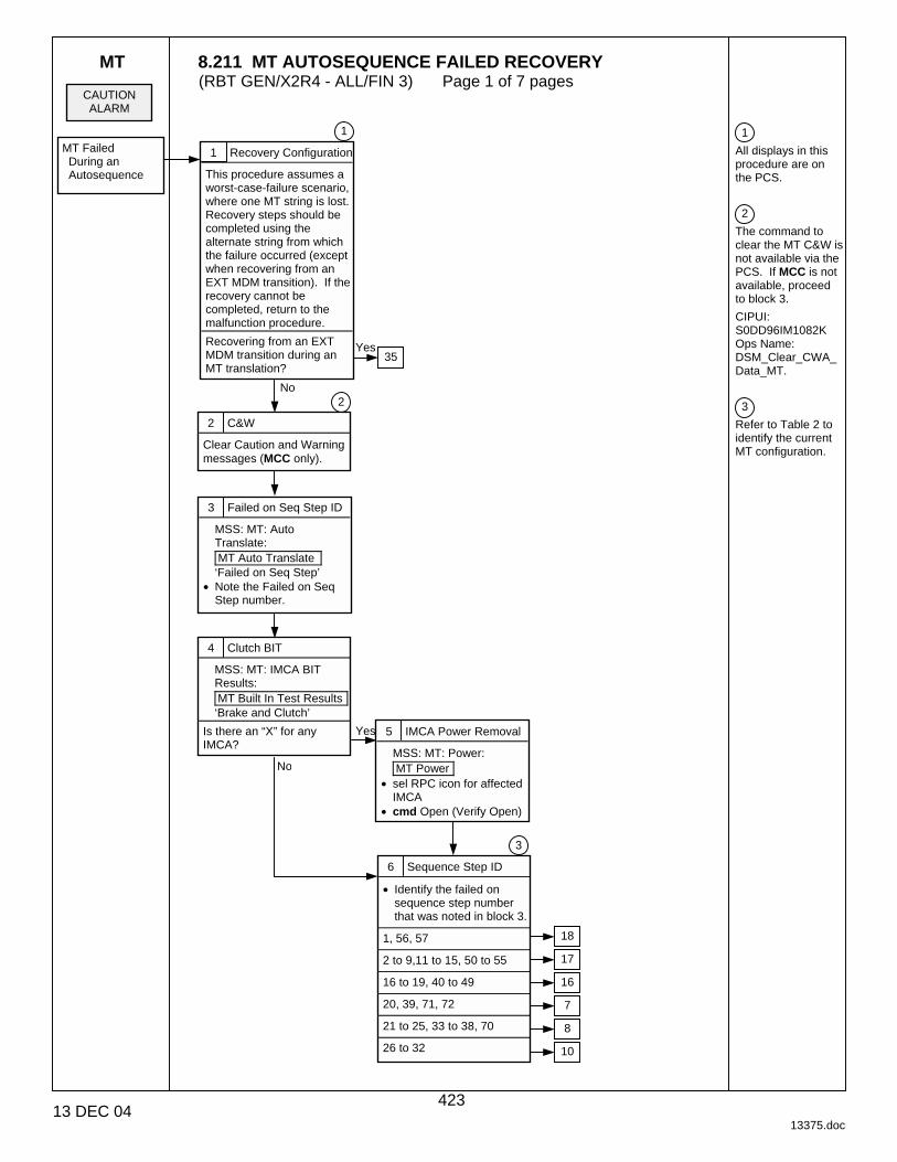
MT 8.211 MT AUTOSEQUENCE FAILED RECOVERY (RBT GEN/X2R4 - ALL/FIN 3) Page 1 of 7 pages
13 DEC 04 13375.doc
1
All displays in this procedure are on the PCS.
2
The command to clear the MT C&W is not available via the PCS. If MCC is not available, proceed to block 3.
CIPUI: S0DD96IM1082K Ops Name: DSM_Clear_CWA_Data_MT.
3
Refer to Table 2 to identify the current MT configuration.
CAUTION ALARM
MT Failed During an Autosequence
1 Recovery Configuration
This procedure assumes a worst-case-failure scenario, where one MT string is lost. Recovery steps should be completed using the alternate string from which the failure occurred (except when recovering from an EXT MDM transition). If the recovery cannot be completed, return to the malfunction procedure.
Recovering from an EXT MDM transition during an MT translation?
1
2 C&W
Clear Caution and Warning messages (MCC only).
2
4 Clutch BIT
MSS: MT: IMCA BIT Results: MT Built In Test Results ‘Brake and Clutch’
Is there an “X” for any IMCA?
5 IMCA Power Removal
MSS: MT: Power: MT Power
• sel RPC icon for affected IMCA
• cmd Open (Verify Open)
6 Sequence Step ID
• Identify the failed on sequence step number that was noted in block 3.
1, 56, 57
2 to 9,11 to 15, 50 to 55
16 to 19, 40 to 49
20, 39, 71, 72
21 to 25, 33 to 38, 70
26 to 32
Yes
No
3 Failed on Seq Step ID
MSS: MT: Auto Translate: MT Auto Translate ‘Failed on Seq Step’
• Note the Failed on Seq Step number.
Yes
No
3
35
18
17
16
7
8
10
423
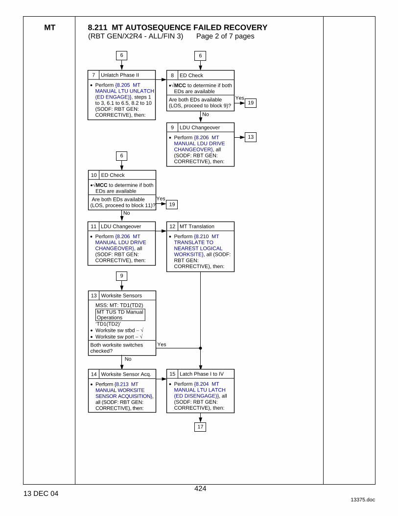
MT 8.211 MT AUTOSEQUENCE FAILED RECOVERY (RBT GEN/X2R4 - ALL/FIN 3) Page 2 of 7 pages
13 DEC 04 13375.doc
7 Unlatch Phase II
• Perform {8.205 MT MANUAL LTU UNLATCH (ED ENGAGE)}, steps 1 to 3, 6.1 to 6.5, 8.2 to 10 (SODF: RBT GEN: CORRECTIVE), then:
8 ED Check
•√MCC to determine if both EDs are available
Are both EDs available (LOS, proceed to block 9)?
Yes
No
9 LDU Changeover
• Perform {8.206 MT MANUAL LDU DRIVE CHANGEOVER}, all (SODF: RBT GEN: CORRECTIVE), then:
10 ED Check
•√MCC to determine if both EDs are available
Are both EDs available (LOS, proceed to block 11)?
Yes
No
11 LDU Changeover
• Perform {8.206 MT MANUAL LDU DRIVE CHANGEOVER}, all (SODF: RBT GEN: CORRECTIVE), then:
12 MT Translation
• Perform {8.210 MT TRANSLATE TO NEAREST LOGICAL WORKSITE}, all (SODF: RBT GEN: CORRECTIVE), then:
13 Worksite Sensors
MSS: MT: TD1(TD2) MT TUS TD Manual Operations ‘TD1(TD2)’
• Worksite sw stbd − √ • Worksite sw port − √
Both worksite switches checked?
15 Latch Phase I to IV
• Perform {8.204 MT MANUAL LTU LATCH (ED DISENGAGE)}, all (SODF: RBT GEN: CORRECTIVE), then:
Yes
No
14 Worksite Sensor Acq.
• Perform {8.213 MT MANUAL WORKSITE SENSOR ACQUISITION}, all (SODF: RBT GEN: CORRECTIVE), then:
6 6
19
13
19
6
9
17
424

MT 8.211 MT AUTOSEQUENCE FAILED RECOVERY (RBT GEN/X2R4 - ALL/FIN 3) Page 3 of 7 pages
13 DEC 04 13375.doc
4
This note is for MCC use only. If the crew is performing this procedure, proceed with block 19.
If the ED and TD IMCAS on the original string are both healthy, the TD swap can be skipped, but this will require a mixed hardware configuration to be used in block 25. The MT translation in block 21, if required, can be completed using the TD on the original string.
5
This is the same Failed on Seq Step Number as in block 6.
17 UMA Mate Phase II
• Perform {8.202 MT MANUAL UMA MATE}, steps 1 to 6.3, 7 to 10 (SODF: RBT GEN: CORRECTIVE), then:
18 MSS Powerup
MT is in a safe configuration. • Perform {6.210 MT
GENERIC AUTO TRANSLATION USING STRING A(B) IMCAS}, steps 18 to 23 (SODF: RBT GEN: NOMINAL), then:
For the MBS based on the MT • Perform {6.331 MBS
POWERUP FROM OFF TO KEEP-ALIVE ON BOTH STRINGS}, all (SODF: RBT GEN: NOMINAL), then:
For the SSRMS based on the MBS • Perform {6.332 MSS
POWERUP FROM KEEP-ALIVE TO OPERATIONAL, step 3 (SODF: RBT GEN: NOMINAL), then:
• Perform {6.431 SSRMS POWERUP FROM OFF TO KEEP-ALIVE ON BOTH STRINGS}, all (SODF: RBT GEN: NOMINAL), then:
19 TD Swap
• Perform {8.214 MT MANUAL TD SWAP}, all (SODF: RBT GEN: CORRECTIVE), then:
20 Sequence Step ID
MSS: MT: Auto Translate: MT Auto Translate ‘Failed on Seq Step’
• Identify sequence step number where the failure occurred.
26 to 32
20 to 25, 33 to 39, 70 to 72
5
21 MT Translation
• Perform {8.210 MT TRANSLATE TO NEAREST LOGICAL WORKSITE}, all (SODF: RBT GEN: CORRECTIVE), then:
22 Worksite Sensors
MSS: MT: TD1(TD2) MT TUS TD Manual Operations ‘TD1(TD2)’
• Worksite sw stbd − √ • Worksite sw port − √
Both worksite switches checked?
23 Worksite Sensor Acq.
• Perform {8.213 MT MANUAL WORKSITE SENSOR ACQUISITION}, all (SODF: RBT GEN: CORRECTIVE), then:
Yes
No
16 Latch Phase IV
• Perform {8.204 MT MANUAL LTU LATCH (ED DISENGAGE)}, steps 1 to 5.4, 13.2 to 14 (SODF: RBT GEN: CORRECTIVE), then:
4
6 6 15 6 27
8 10
24
24
24
28
425

MT 8.211 MT AUTOSEQUENCE FAILED RECOVERY (RBT GEN/X2R4 - ALL/FIN 3) Page 4 of 7 pages
13 DEC 04 13375.doc
5
This is the same Failed on Seq Step Number as in block 6.
24 Auto Setup
MSS: MT: MT Mode: MT Mode
When MT Software Mode – Idle or Manual • cmd Standby Execute • Verify MT Software
Mode – Standby When MT Mode – Standby • cmd Auto Execute • Verify MT Software
Mode – Auto
25 H/W Configuration
MSS: MT: Auto Translate: MT Auto Translate ‘HW Config’
• cmd 1(2) Execute • Verify HW Config –
C1(C2)
27 Auto Latch Mate
MSS: MT: MT Mode: MT Mode
• cmd Latch Mate Execute
MSS: MT: LTU1 MT LTU ED Manual Operations ‘State’
• Verify − Latched
MSS: MT: UMA1 MT UMA Manual Operations ‘State’
• Verify − Mated
28 Sequence Step ID
MSS: MT: Auto Translate: MT Auto Translate ‘Failed on Seq Step’
• Identify sequence step number where the failure occurred.
Has failure occurred on 19 or 42 to 44?
5
29 ED Check
•√MCC to determine if both EDs are available
Are both EDs available (LOS, proceed to block 32)?
No
Yes
31
Recovery complete. No
Yes
32 LDU Changeover
• Perform {8.206 MT MANUAL LDU DRIVE CHANGEOVER}, steps 1 to 9 (SODF: RBT GEN: CORRECTIVE), then:
33 TD Disengagement
• Perform {8.204 MT MANUAL LTU LATCH (ED DISENGAGE)}, steps 9.6 to 10 (SODF: RBT GEN: CORRECTIVE), then:
26 S/W Configuration
For C1(C2) • sel RPC [X] where [X] =
7 10 2 5 9 1
MSS: MT: Power: ‘MT’ ‘RPCM MT - 4B(3A)’ [X] RPCM MT4B(3A) A RPC [X]
• cmd ‘RPC Position’ Close (Verify Cl)
• cmd ‘RPC Position’ − Open (Verify Op)
• Repeat for [X]
34
Recovery complete.
30 TD Disengagement
• Perform {8.204 MT MANUAL LTU LATCH (ED DISENGAGE)}, steps 9 and 10 (SODF: RBT GEN: CORRECTIVE), then:
18
18
21 22 23
426
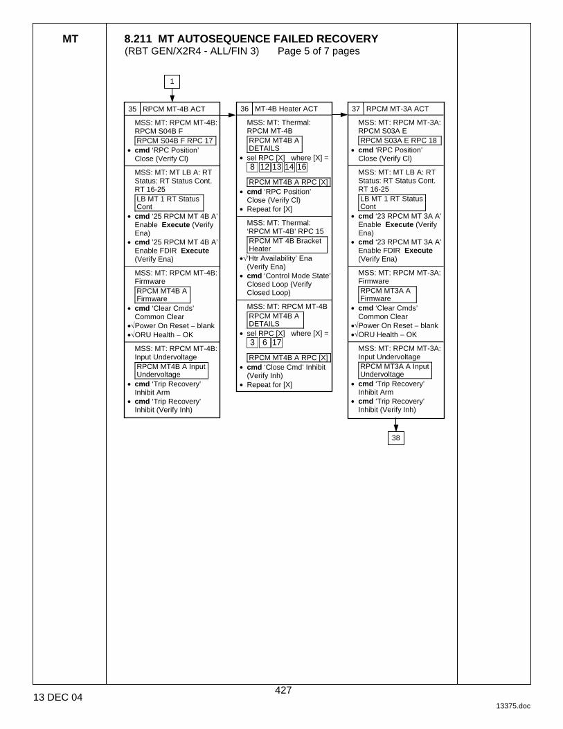
MT 8.211 MT AUTOSEQUENCE FAILED RECOVERY (RBT GEN/X2R4 - ALL/FIN 3) Page 5 of 7 pages
13 DEC 04 13375.doc
35 RPCM MT-4B ACT
MSS: MT: RPCM MT-4B: RPCM S04B F RPCM S04B F RPC 17
• cmd ‘RPC Position’ Close (Verify Cl)
MSS: MT: MT LB A: RT Status: RT Status Cont. RT 16-25 LB MT 1 RT Status Cont
• cmd ‘25 RPCM MT 4B A’ Enable Execute (Verify Ena)
• cmd ’25 RPCM MT 4B A’ Enable FDIR Execute (Verify Ena)
MSS: MT: RPCM MT-4B: Firmware RPCM MT4B A Firmware
• cmd ‘Clear Cmds’ Common Clear
•√Power On Reset − blank •√ORU Health − OK
MSS: MT: RPCM MT-4B: Input Undervoltage RPCM MT4B A Input Undervoltage
• cmd ‘Trip Recovery’ Inhibit Arm
• cmd ‘Trip Recovery’ Inhibit (Verify Inh)
36 MT-4B Heater ACT
MSS: MT: Thermal: RPCM MT-4B RPCM MT4B A DETAILS
• sel RPC [X] where [X] = 8 13 12 16 14
RPCM MT4B A RPC [X]
• cmd ‘RPC Position’ Close (Verify Cl)
• Repeat for [X]
MSS: MT: Thermal: ‘RPCM MT-4B’ RPC 15 RPCM MT 4B Bracket Heater
•√‘Htr Availability’ Ena (Verify Ena)
• cmd ‘Control Mode State’ Closed Loop (Verify Closed Loop)
MSS: MT: RPCM MT-4B RPCM MT4B A DETAILS
• sel RPC [X] where [X] = 3 17 6
RPCM MT4B A RPC [X]
• cmd ‘Close Cmd’ Inhibit (Verify Inh)
• Repeat for [X]
37 RPCM MT-3A ACT
MSS: MT: RPCM MT-3A: RPCM S03A E RPCM S03A E RPC 18
• cmd ‘RPC Position’ Close (Verify Cl)
MSS: MT: MT LB A: RT Status: RT Status Cont. RT 16-25 LB MT 1 RT Status Cont
• cmd ‘23 RPCM MT 3A A’ Enable Execute (Verify Ena)
• cmd ‘23 RPCM MT 3A A’ Enable FDIR Execute (Verify Ena)
MSS: MT: RPCM MT-3A: Firmware RPCM MT3A A Firmware
• cmd ‘Clear Cmds’ Common Clear
•√Power On Reset − blank •√ORU Health − OK
MSS: MT: RPCM MT-3A: Input Undervoltage RPCM MT3A A Input Undervoltage
• cmd ‘Trip Recovery’ Inhibit Arm
• cmd ‘Trip Recovery’ Inhibit (Verify Inh)
38
1
427

MT 8.211 MT AUTOSEQUENCE FAILED RECOVERY (RBT GEN/X2R4 - ALL/FIN 3) Page 6 of 7 pages
13 DEC 04 13375.doc
6
The default state for the MT IMCAs following an EXT transition is to have FDIR and I/O enabled. Therefore, step 2 may not be required if ODIN's EXT MDM transition recovery script has not already disabled FDIR and I/O. Note that FDIR is nominally always disabled. Expect RT Fail messages for IMCAS until power is applied. Expect bus channel swapping until IMCA is powered or FDIR is inhibited.
39 MT Position/Switches
• Perform {6.201 MT PRE-TRANSLATION IMCA CHECKOUT}, steps 1 to 6 (SODF: RBT GEN: CORRECTIVE), then:
40 UMA Microswitches
MSS: MT: UMA1: MT UMA Manual Operations ‘UMA1(2)’ ‘State’
• Denote the state of the Mate and Demate microswitches. ‘Mat’ − ______ ‘Dmt’ − ______
41 TD Microswitches
MSS: MT: TD1: MT TUS TD Manual Operations ‘TD1(2)’ ‘Worksite sw’
• Denote the state of the Stbd and Port worksite sensors. ‘Stbd’ − ______ ‘Port’ − ______
42 LTU/ED Microswitches
MSS: MT: LTU1: MT LTU ED Manual Operations ‘LTU1(2,3,4)’ ‘State’
• Denote the state of the Latch and Unlatch microswitches.
‘Lat’ − _____ ‘Rel’ − _____
‘ED1(2)’ ‘Engaged’
• Denote the state of the engaged microswitches.
‘Engaged’ − _____ ‘Disengage Trigger’ − ___
43 Recovery
• Identify the current microswitch config in Table 1, then go to the directed block to complete the recovery.
• Complete the flow of recovery blocks unless otherwise indicated in the table.
38 MT-3A Heater ACT
MSS: MT: Thermal: RPCM MT-3A RPCM MT3A A DETAILS
• sel RPC [X] where [X] = 8 13 12 16 14
RPCM MT3A A RPC [X]
• cmd ‘RPC Position’ Close (Verify Cl)
• Repeat for [X]
MSS: MT: Thermal: ‘RPCM MT-3A’ RPC 15 RPCM MT 3A Bracket Heater
•√‘Htr Availability’ Ena (Verify Ena)
• cmd ‘Control Mode State’ Closed Loop (Verify Closed Loop)
MSS: MT: RPCM MT-3A RPCM MT3A A
• sel RPC [X] where [X] = 3 17 6
RPCM MT3A A RPC [X]
• cmd ‘Close Cmd’ Inhibit (Verify Inh)
• Repeat for [X]
37
6
428

MT 8.211 MT AUTOSEQUENCE FAILED RECOVERY (RBT GEN/X2R4 - ALL/FIN 3) Page 7 of 7 pages
13 DEC 04 13375.doc
Table 1. MDM Transition Recovery
Microswitch Configuration Action Go to Block:
UMAs demated, LTUs latched Mate UMAs Phase II 17[1]
LTUs in intermediate state, EDs not engaged
Latch LTUs Phase IV 16[2]
LTUs in intermediate state, one ED engaged
Unlatch Phase II 7[1],[3],[4]
LTUs unlatched, worksite sensors are acquired
Latch/Mate 24[1],[4]
LTUs unlatched, worksite sensors are not acquired
Translate to nearest logical worksite 21[1],[4]
[1] Stop after completing block 18.
[2] If the ED is in an intermediate state, the answer for block 28 is ‘Yes’.
[3] After completing block 7, proceed to block 22.
[4] Skip block 26.
Table 2. MT Configuration based on Failed Sequence Step Number
Failed on Sequence Step Number MT Configuration
1, 56, 57 UMAs are mated
2 to 9, 11 to 15, 50 to 55 LTUs are latched, UMAs are not mated
16 to 19, 40 to 49 LTUs in intermediate state, prizmoids are engaged, ED may be engaged
20, 39, 71, 72 LTUs in intermediate state, prizmoids are not engaged, ED is engaged
21 to 25, 33 to 38, 70 LTUs are unlatched, ED is engaged
26 to 32 MT is between worksites
429

This Page Intentionally Blank
22 DEC 04
430

8.212 MT GENERIC MODIFY PREVIOUS INIT FRAME (RBT GEN/ULF1 - ALL/FIN 1) Page 1 of 4 pages
28 JAN 03 13322.doc
1. RECORDING MECHANISM DATA Record mechanism(s) and IMCA to be commanded and Init Frame to be modified in Table 1.
Table 1. Recording Mechanism Data
Mechanism(s) to be commanded (ED, TD, LTU, UMA, or TUS?) ________ IMCA to be commanded (A or B?) ________ Init Frame to be modified ________
2. RECORDING MODIFIED INIT FRAME PARAMETERS
Record applicable Modified Init Frame parameters in Table 2.
NOTE Table 2 is a complete list of all parameters for all mechanisms. Some parameters will not be available for all mechanisms.
Table 2. Recording Modified Init Frame Parameters
Item Modified Init Frame Parameters Value 1 ‘Position Change’ ‘Stop On’ ______
2 ‘Position Change’ ‘Limits’ ______
3 ‘Shaft Speed’ ‘Limits’
4 ‘Controller Temperature’ ‘Stop On’ ______
5 ‘Controller Temperature’ ‘Limits’ ______
6 ‘Torque’ ‘Stop On’ ______
7 ‘Torque’ ‘Limits’ ______ 8 ‘Power’ Limits’ ______ 9 ‘Accel/Decel Time’ ‘Limits’ ______
10 ‘Engaged’ (‘Vert Bogey Wheel Indicator’, ‘Unlatched’, ‘Demated’, ‘Deploy Emergency Stop’) ‘Stop On’ ______
11 ‘Disengage Trigger’ (‘Horiz Bogey Wheel Indicator’, ‘Latched’, ‘Mated’, ‘Retract Emergency Stop’) ‘Stop On’ ______
12 ‘Disengage Verify’ (‘+Y WS Sensor’, ‘Retract Tension Control’) ‘Stop On’
______
13 ‘Center Cam Alt Disengage’ (‘-Y WS Sensor’, ‘Deploy Tension Control’) ‘Stop On’ ______
14 ‘Alt Disengage’ ‘Stop On’ ______ 15 ‘Electrical Temperature’ ‘Stop On’ ______ 16 ‘Rate Error’ ‘Stop On’ ______ 17 ‘Enable Limit Switch Error Calculations’ ‘Clutch/Switch Settings’ ______ 18 ‘Perform Overspeed/Reverse Speed Test’ ‘Clutch/Switch ______ 19 ‘Enable Clutch’ ‘Clutch/Switch Settings’ ______ 20 ‘Enable Brake’ ‘Clutch/Switch Settings’ ______
431
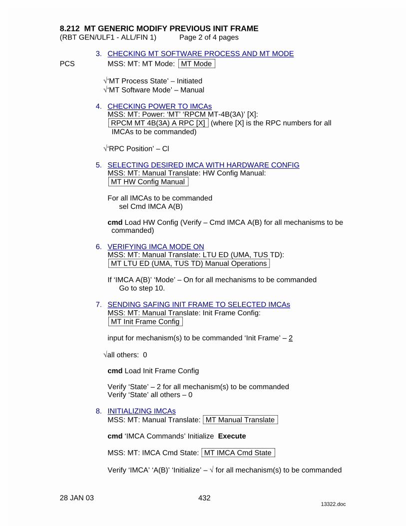
8.212 MT GENERIC MODIFY PREVIOUS INIT FRAME (RBT GEN/ULF1 - ALL/FIN 1) Page 2 of 4 pages
28 JAN 03 13322.doc
3. CHECKING MT SOFTWARE PROCESS AND MT MODE PCS MSS: MT: MT Mode: MT Mode
√‘MT Process State’ – Initiated √‘MT Software Mode’ – Manual
4. CHECKING POWER TO IMCAs
MSS: MT: Power: ‘MT’ ‘RPCM MT-4B(3A)’ [X]: RPCM MT 4B(3A) A RPC [X] (where [X] is the RPC numbers for all
IMCAs to be commanded)
√‘RPC Position’ – Cl 5. SELECTING DESIRED IMCA WITH HARDWARE CONFIG
MSS: MT: Manual Translate: HW Config Manual: MT HW Config Manual
For all IMCAs to be commanded
sel Cmd IMCA A(B)
cmd Load HW Config (Verify – Cmd IMCA A(B) for all mechanisms to be commanded)
6. VERIFYING IMCA MODE ON
MSS: MT: Manual Translate: LTU ED (UMA, TUS TD): MT LTU ED (UMA, TUS TD) Manual Operations
If ‘IMCA A(B)’ ‘Mode’ – On for all mechanisms to be commanded
Go to step 10. 7. SENDING SAFING INIT FRAME TO SELECTED IMCAs
MSS: MT: Manual Translate: Init Frame Config: MT Init Frame Config
input for mechanism(s) to be commanded ‘Init Frame’ – 2
√all others: 0
cmd Load Init Frame Config
Verify ‘State’ – 2 for all mechanism(s) to be commanded Verify ‘State’ all others – 0
8. INITIALIZING IMCAs
MSS: MT: Manual Translate: MT Manual Translate
cmd ‘IMCA Commands’ Initialize Execute
MSS: MT: IMCA Cmd State: MT IMCA Cmd State
Verify ‘IMCA’ ‘A(B)’ ‘Initialize’ – √ for all mechanism(s) to be commanded
432

8.212 MT GENERIC MODIFY PREVIOUS INIT FRAME (RBT GEN/ULF1 - ALL/FIN 1) Page 3 of 4 pages
28 JAN 03 13322.doc
9. MODING IMCAs TO ON MODE MSS: MT: Manual Translate: MT Manual Translate
cmd ‘IMCA Commands’ On Execute
MSS: MT: Manual Translate: LTU ED (UMA, TUS TD): MT LTU ED (UMA, TUS TD) Manual Operations
Verify ‘IMCA A(B)’ ‘Mode’ – On for all mechanism(s) to be commanded
10. SELECTING INIT FRAME TO BE MODIFIED
MSS: MT: Manual Translate: Init Frame Config: MT Init Frame Config
input for all mechanism(s) to be commanded ‘Init Frame’ – per Table 1
cmd Load Init Frame Config
Verify ‘State’ – per Table 1 for all mechanism(s) to be commanded Verify ‘State’ all others – 0
11. INITIALIZING IMCAs
MSS: MT: Manual Translate: MT Manual Translate
cmd ‘IMCA Commands’ Initialize Execute
MSS: MT: IMCA Cmd State: MT IMCA Cmd State
Verify ‘IMCA’ ‘A(B)’ ‘Initialize’ – √ for all mechanism(s) to be commanded 12. MODIFYING INIT FRAME
MSS: MT: Manual Translate: Init Frame Config: IMCA Controller Parameters: ‘[X]’ IMCA A(B): [X] IMCA Modify Previous Init Frame: MT [X] IMCA Modify Previous Init Frame
(where [X] is the mechanism name)
input Modified Values – per Table 2
cmd Load Modified Init Frame Parameters 13. SELECTING MODIFIED INIT FRAME
MSS: MT: Manual Translate: Init Frame Config: MT Init Frame Config
input ‘[X]’ ‘Init Frame’ – 1 (where [X] is the mechanism(s) to be commanded)
cmd Load Init Frame Config
Verify ‘State’ – 1 for all mechanism(s) to be commanded Verify ‘State’ all others – 0
433

8.212 MT GENERIC MODIFY PREVIOUS INIT FRAME (RBT GEN/ULF1 - ALL/FIN 1) Page 4 of 4 pages
28 JAN 03 13322.doc
14. INITIALIZING IMCAs MSS: MT: Manual Translate: MT Manual Translate
cmd ‘IMCA Commands’ Initialize Execute
MSS: MT: Manual Translate: Init Frame Config: IMCA Controller Parameters: ‘[X]’ IMCA A(B): MT [X] IMCA A(B) Controller Parameters
Verify all fields are correct per Table 2.
15. ACTUATING IMCA
NOTE 1. The IMCA automatically returns to On mode after
the programmed trajectory has completed. 2. A pause command can be issued by commanding
the IMCA to On mode. 3. Verify IMCA motion using the following page:
MSS: MT: Manual Translate: UMA: MT UMA Manual Operations
MSS: MT: Manual Translate: MT Manual Translate
cmd ‘IMCA Commands’ Actuate Execute
MSS: MT: Manual Translate: LTU ED (UMA, TUS TD): MT LTU ED (UMA, TUS TD) Manual Operations
For all Mechanism(s) to be Commanded:
Verify ‘IMCA A(B)’ ‘Mode’ – Enabled Verify ‘IMCA A(B)’ ‘Position’ – increasing or decreasing as expected Verify ‘IMCA A(B)’ ‘Shaft Spd’ – as expected Verify ‘IMCA A(B)’ ‘Mode’ – On
16. MODING IMCA BACK TO STANDBY
MSS: MT: Manual Translate: MT Manual Translate
cmd ‘IMCA Command’ Standby Execute
MSS: MT: Manual Translate: LTU ED (UMA, TUS TD): MT LTU ED (UMA, TUS TD) Manual Operations
Verify ‘IMCA A(B)’ ‘Mode’ – Standby for all mechanism(s) to be commanded
434
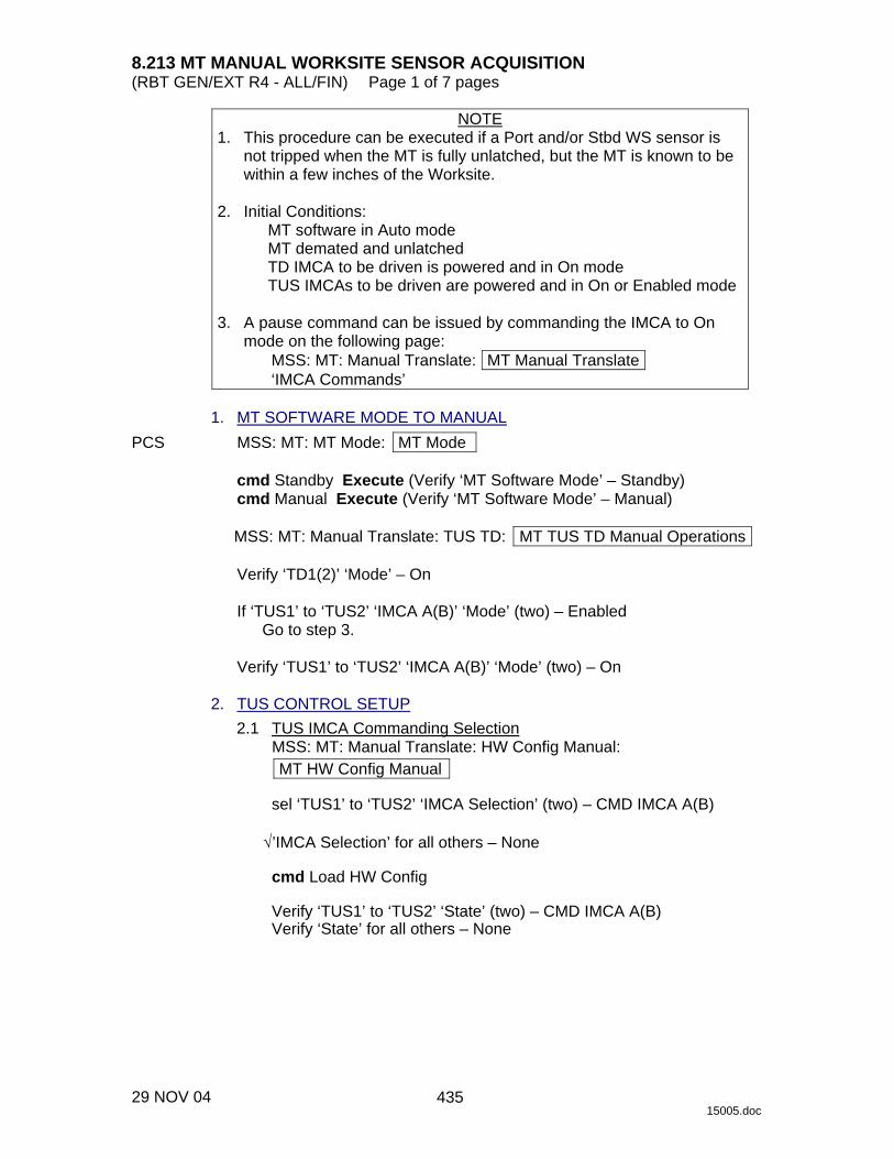
8.213 MT MANUAL WORKSITE SENSOR ACQUISITION (RBT GEN/EXT R4 - ALL/FIN) Page 1 of 7 pages
29 NOV 04 15005.doc
NOTE 1. This procedure can be executed if a Port and/or Stbd WS sensor is
not tripped when the MT is fully unlatched, but the MT is known to be within a few inches of the Worksite.
2. Initial Conditions:
MT software in Auto mode MT demated and unlatched TD IMCA to be driven is powered and in On mode TUS IMCAs to be driven are powered and in On or Enabled mode
3. A pause command can be issued by commanding the IMCA to On
mode on the following page: MSS: MT: Manual Translate: MT Manual Translate ‘IMCA Commands’
1. MT SOFTWARE MODE TO MANUAL PCS MSS: MT: MT Mode: MT Mode
cmd Standby Execute (Verify ‘MT Software Mode’ – Standby) cmd Manual Execute (Verify ‘MT Software Mode’ – Manual)
MSS: MT: Manual Translate: TUS TD: MT TUS TD Manual Operations
Verify ‘TD1(2)’ ‘Mode’ – On
If ‘TUS1’ to ‘TUS2’ ‘IMCA A(B)’ ‘Mode’ (two) – Enabled
Go to step 3.
Verify ‘TUS1’ to ‘TUS2’ ‘IMCA A(B)’ ‘Mode’ (two) – On 2. TUS CONTROL SETUP 2.1 TUS IMCA Commanding Selection
MSS: MT: Manual Translate: HW Config Manual: MT HW Config Manual
sel ‘TUS1’ to ‘TUS2’ ‘IMCA Selection’ (two) – CMD IMCA A(B)
√’IMCA Selection’ for all others – None
cmd Load HW Config
Verify ‘TUS1’ to ‘TUS2’ ‘State’ (two) – CMD IMCA A(B) Verify ‘State’ for all others – None
435

8.213 MT MANUAL WORKSITE SENSOR ACQUISITION (RBT GEN/EXT R4 - ALL/FIN) Page 2 of 7 pages
29 NOV 04 15005.doc
2.2 TUS Initialization Frame Selection MSS: MT: Manual Translate: Init Frame Config: MT Init Frame Config
input ‘TUS’ ‘Init Frame’ – 8
√all others: 0
cmd Load Init Frame Config (Verify ‘TUS’ ‘State’: 8)
Verify ‘State’ for all others: 0
2.3 TUS IMCA Initialization
MSS: MT: Manual Translate: MT Manual Translate
cmd ‘IMCA Commands’ Initialize Execute
MSS: MT: IMCA Cmd State: MT IMCA Cmd State
Verify ‘TUS1’ to ‘TUS2’ ‘IMCA’ ‘A(B)’ ‘Initialize’ (two) – √ 2.4 TUS IMCA Movement Initiation
MSS: MT: Manual Translate: MT Manual Translate
cmd ‘IMCA Commands’ Actuate Execute
MSS: MT: Manual Translate: TUS TD: MT TUS TD Manual Operations
Verify ‘TUS1’ to ‘TUS2’ ‘IMCA A(B)’ ‘Mode’ (two) – Enabled 3. TD PART 1: MOTION AWAY FROM CURRENT WS
NOTE This step will translate the MT in the direction of the lost worksite sensor for a distance of approximately 6 cm.
3.1 TD IMCA Commanding Selection
MSS: MT: Manual Translate: HW Config Manual: MT HW Config Manual
sel ‘TD’ ‘IMCA Selection’ – CMD IMCA A(B)
√’IMCA Selection’ for all others – None
cmd Load HW Config (Verify ‘TD’ ‘State’ – CMD IMCA A(B))
Verify ‘State’ for all others – None
436

8.213 MT MANUAL WORKSITE SENSOR ACQUISITION (RBT GEN/EXT R4 - ALL/FIN) Page 3 of 7 pages
29 NOV 04 15005.doc
3.2 TD Initial Position Check and/or Reset MSS: MT: Manual Translate: TUS TD: MT TUS TD Manual Operations
If ‘TD1(2)’ ‘Position’ ≠ 0.0
3.2.1 Moding TD IMCA to Standby MSS: MT: Manual Translate: MT Manual Translate
cmd ‘IMCA Commands’ Standby Execute
MSS: MT: Manual Translate: TUS TD: MT TUS TD Manual Operations
Verify ‘TD1(2)’ ‘Mode’ – Standby
3.2.2 TD Safing Initialization Frame Selection
MSS: MT: Manual Translate: Init Frame Config: MT Init Frame Config
input ‘TD’ ‘Init Frame’ – 2
√all others: 0
cmd Load Init Frame Config (Verify ‘TD’ ‘State’: 2)
Verify ‘State’ for all others: 0
3.2.3 TD IMCA Initialization
MSS: MT: Manual Translate: MT Manual Translate
cmd ‘IMCA Commands’ Initialize Execute
MSS: MT: IMCA Cmd State: MT IMCA Cmd State
Verify ‘TD’ ‘IMCA’ ‘A(B)’ ‘Initialize’ – √ 3.2.4 Moding TD IMCA to On
MSS: MT: Manual Translate: MT Manual Translate
cmd ‘IMCA Commands’ On Execute
MSS: MT: Manual Translate: TUS TD: MT TUS TD Manual Operations
Verify ‘TD1(2)’ ‘Mode’ – On
437

8.213 MT MANUAL WORKSITE SENSOR ACQUISITION (RBT GEN/EXT R4 - ALL/FIN) Page 4 of 7 pages
29 NOV 04 15005.doc
3.3 TD Initialization Frame Selection MSS: MT: Manual Translate: Init Frame Config: MT Init Frame Config
input ‘TD’ ‘Init Frame’ – 2 0 5
√all others: 0
cmd Load Init Frame Config (Verify ‘TD’ ‘State’: 205)
Verify ‘State’ for all others: 0
3.4 TD IMCA Initialization
MSS: MT: Manual Translate: MT Manual Translate
cmd ‘IMCA Commands’ Initialize Execute
MSS: MT: IMCA Cmd State: MT IMCA Cmd State
Verify ‘TD’ ‘IMCA’ ‘A(B)’ ‘Initialize’ – √ 3.5 TD Init Frame Modification
MSS: MT: Manual Translate: Init Frame Config: IMCA Controller Parameters: ‘TD’ IMCA A(B): TD IMCA Modify Previous Init Frame: MT TD IMCA Modify Previous Init Frame
input Modified Values per Tables 1 and 2
Table 1. Modified Init Frame Stop On Parameters
Stop On Limits Position Change 1 Per Table 2 Shaft Speed 8.1965 Controller Temperature 1 1360 Torque 0 1.1 Power 3733.7 Accel/Decel Time 8.55 Vert Bogey Wheel Indicator 0 Horiz Bogey Wheel Indicator 0 +Y WS Sensor 0 -Y WS Sensor 0 Electrical Temperature 1 Rate Error 0 Clutch/ Switch Settings Enable Limit Switch Error Calculation 0 Perform Overspeed/Reverse Speed Test 0 Enable Clutch 1 Enable Brake 1
438
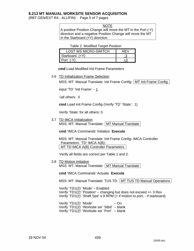
8.213 MT MANUAL WORKSITE SENSOR ACQUISITION (RBT GEN/EXT R4 - ALL/FIN) Page 5 of 7 pages
29 NOV 04 15005.doc
NOTE A positive Position Change will move the MT in the Port (-Y) direction and a negative Position Change will move the MT in the Starboard (+Y) direction.
Table 2. Modified Target Position
LOST WS MICRO-SWITCH REV Starboard (+Y) -3 Port (-Y) +3
cmd Load Modified Init Frame Parameters
3.6 TD Initialization Frame Selection
MSS: MT: Manual Translate: Init Frame Config: MT Init Frame Config
input ‘TD’ ‘Init Frame’ – 1
√all others: 0
cmd Load Init Frame Config (Verify ‘TD’ ‘State’: 1)
Verify ‘State’ for all others: 0 3.7 TD IMCA Initialization
MSS: MT: Manual Translate: MT Manual Translate
cmd ‘IMCA Commands’ Initialize Execute
MSS: MT: Manual Translate: Init Frame Config: IMCA Controller Parameters: ‘TD’ IMCA A(B): MT TD IMCA A(B) Controller Parameters
Verify all fields are correct per Table 1 and 2.
3.8 TD Motion Initiation
MSS: MT: Manual Translate: MT Manual Translate
cmd ‘IMCA Commands’ Actuate Execute
MSS: MT: Manual Translate: TUS TD: MT TUS TD Manual Operations
Verify ‘TD1(2)’ ‘Mode’ – Enabled Verify ‘TD1(2)’ ‘Position’ – changing but does not exceed +/- 3 Rev Verify ‘TD1(2)’ ‘Shaft Spd’ ≤ 9 RPM (+ if motion to port, - if starboard)
Verify ‘TD1(2)’ ‘Mode’ – On Verify ‘TD1(2)’ ‘Worksite sw’ ‘Stbd’ – blank Verify ‘TD1(2)’ ‘Worksite sw’ ‘Port’ – blank
439
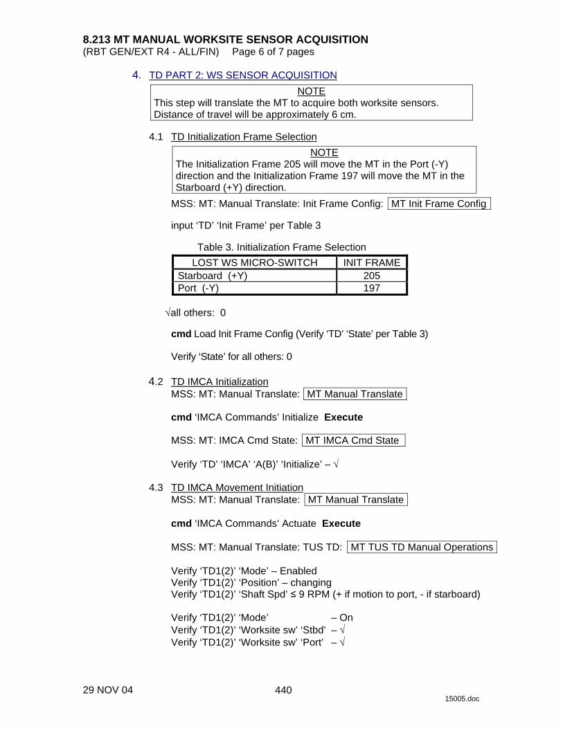
8.213 MT MANUAL WORKSITE SENSOR ACQUISITION (RBT GEN/EXT R4 - ALL/FIN) Page 6 of 7 pages
29 NOV 04 15005.doc
4. TD PART 2: WS SENSOR ACQUISITION NOTE
This step will translate the MT to acquire both worksite sensors. Distance of travel will be approximately 6 cm.
4.1 TD Initialization Frame Selection
NOTE The Initialization Frame 205 will move the MT in the Port (-Y) direction and the Initialization Frame 197 will move the MT in the Starboard (+Y) direction.
MSS: MT: Manual Translate: Init Frame Config: MT Init Frame Config
input ‘TD’ ‘Init Frame’ per Table 3
Table 3. Initialization Frame Selection
LOST WS MICRO-SWITCH INIT FRAME Starboard (+Y) 205 Port (-Y) 197
√all others: 0
cmd Load Init Frame Config (Verify ‘TD’ ‘State’ per Table 3)
Verify ‘State’ for all others: 0
4.2 TD IMCA Initialization
MSS: MT: Manual Translate: MT Manual Translate
cmd ‘IMCA Commands’ Initialize Execute
MSS: MT: IMCA Cmd State: MT IMCA Cmd State
Verify ‘TD’ ‘IMCA’ ‘A(B)’ ‘Initialize’ – √ 4.3 TD IMCA Movement Initiation
MSS: MT: Manual Translate: MT Manual Translate
cmd ‘IMCA Commands’ Actuate Execute
MSS: MT: Manual Translate: TUS TD: MT TUS TD Manual Operations
Verify ‘TD1(2)’ ‘Mode’ – Enabled Verify ‘TD1(2)’ ‘Position’ – changing Verify ‘TD1(2)’ ‘Shaft Spd’ ≤ 9 RPM (+ if motion to port, - if starboard)
Verify ‘TD1(2)’ ‘Mode’ – On Verify ‘TD1(2)’ ‘Worksite sw’ ‘Stbd’ – √ Verify ‘TD1(2)’ ‘Worksite sw’ ‘Port’ – √
440

8.213 MT MANUAL WORKSITE SENSOR ACQUISITION (RBT GEN/EXT R4 - ALL/FIN) Page 7 of 7 pages
29 NOV 04 15005.doc
5. MODING TUS IMCA TO ON 5.1 TUS IMCA Commanding Selection
MSS: MT: Manual Translate: HW Config Manual: MT HW Config Manual
sel ‘TUS1’ to ‘TUS2’ ‘IMCA Selection’ (two) – CMD IMCA A(B)
√’IMCA Selection’ for all others – None
cmd Load HW Config
Verify ‘TUS1’ to ‘TUS2’ ‘State’ (two) – CMD IMCA A(B) Verify ’State’ for all others – None
5.2 Moding TUS IMCA to On
MSS: MT: Manual Translate: MT Manual Translate
cmd ‘IMCA Commands’ On Execute
MSS: MT: Manual Translate: TUS TD: MT TUS TD Manual Operations
Verify ‘TUS1’ to ‘TUS2’ ‘IMCA A(B)’ ‘Mode’ (two) – On 6. MODING MT SOFTWARE TO AUTO MSS: MT: Auto Translate: MT Auto Translate
cmd Mode MT to Standby Execute (Verify ‘MT Software Mode’ – Standby)
cmd Mode MT to Auto Execute (Verify ‘MT Software Mode’ – Auto) cmd ‘HW Config’ 1(2) Execute (Verify – C1(C2))
441

This Page Intentionally Blank
22 DEC 04
442
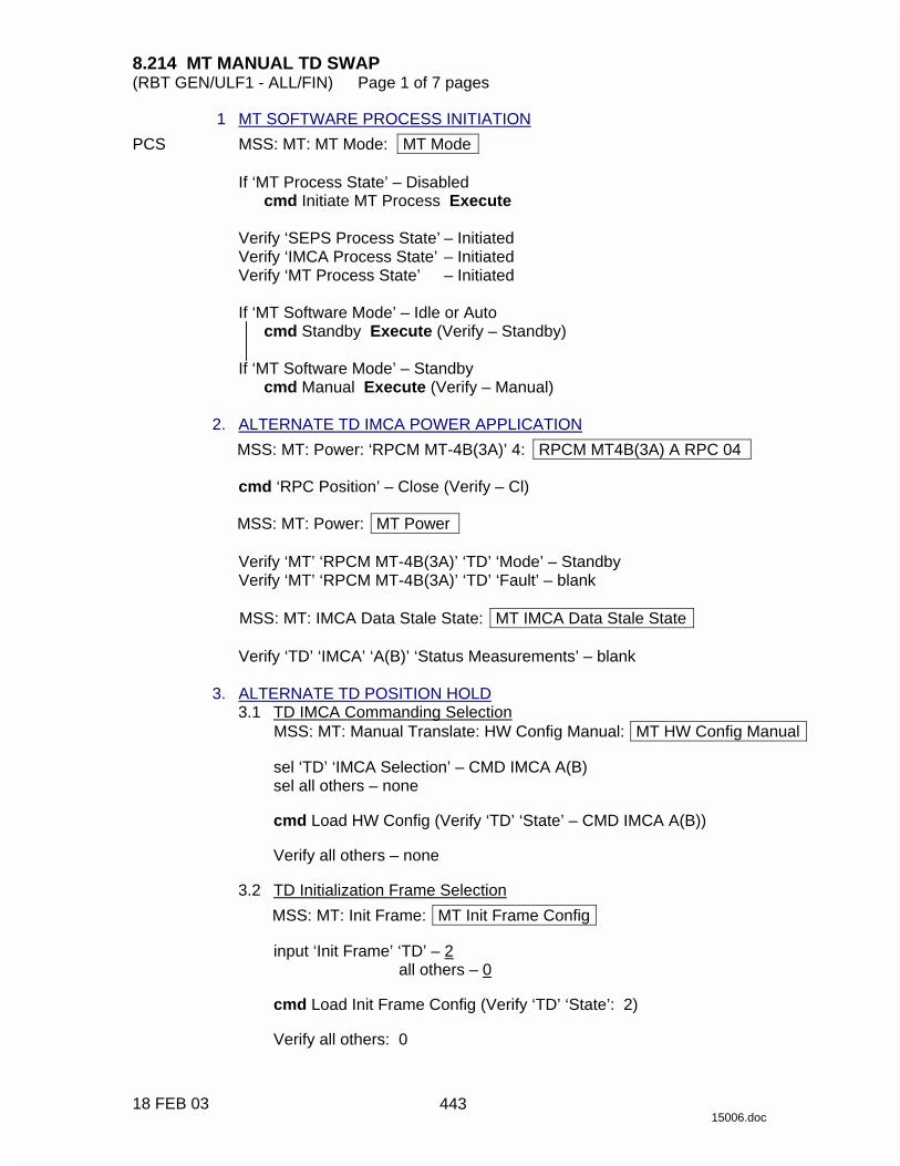
8.214 MT MANUAL TD SWAP (RBT GEN/ULF1 - ALL/FIN) Page 1 of 7 pages
18 FEB 03 15006.doc
1 MT SOFTWARE PROCESS INITIATION PCS MSS: MT: MT Mode: MT Mode
If ‘MT Process State’ – Disabled cmd Initiate MT Process Execute
Verify ‘SEPS Process State’ – Initiated Verify ‘IMCA Process State’ – Initiated Verify ‘MT Process State’ – Initiated
If ‘MT Software Mode’ – Idle or Auto
cmd Standby Execute (Verify – Standby)
If ‘MT Software Mode’ – Standby cmd Manual Execute (Verify – Manual)
2. ALTERNATE TD IMCA POWER APPLICATION
MSS: MT: Power: ‘RPCM MT-4B(3A)’ 4: RPCM MT4B(3A) A RPC 04
cmd ‘RPC Position’ – Close (Verify – Cl)
MSS: MT: Power: MT Power
Verify ‘MT’ ‘RPCM MT-4B(3A)’ ‘TD’ ‘Mode’ – Standby Verify ‘MT’ ‘RPCM MT-4B(3A)’ ‘TD’ ‘Fault’ – blank
MSS: MT: IMCA Data Stale State: MT IMCA Data Stale State
Verify ‘TD’ ‘IMCA’ ‘A(B)’ ‘Status Measurements’ – blank
3. ALTERNATE TD POSITION HOLD 3.1 TD IMCA Commanding Selection
MSS: MT: Manual Translate: HW Config Manual: MT HW Config Manual
sel ‘TD’ ‘IMCA Selection’ – CMD IMCA A(B) sel all others – none
cmd Load HW Config (Verify ‘TD’ ‘State’ – CMD IMCA A(B))
Verify all others – none
3.2 TD Initialization Frame Selection
MSS: MT: Init Frame: MT Init Frame Config
input ‘Init Frame’ ‘TD’ – 2 all others – 0
cmd Load Init Frame Config (Verify ‘TD’ ‘State’: 2)
Verify all others: 0
443

8.214 MT MANUAL TD SWAP (RBT GEN/ULF1 - ALL/FIN) Page 2 of 7 pages
18 FEB 03 15006.doc
3.3 TD IMCA Initialization MSS: MT: Manual Translate: MT Manual Translate
cmd ‘IMCA Commands’ Initialize Execute
MSS: MT: IMCA Cmd State: MT IMCA Cmd State
Verify ‘TD’ ‘IMCA’ ‘A(B)’ ‘Initialize’ – √
3.4 Moding TD IMCA to On
MSS: MT: Manual Translate: MT Manual Translate
cmd ‘IMCA Commands’ On Execute
MSS: MT: Manual Translate: TUS TD: MT TUS TD Manual Operations
Verify ‘TD1(2)’ ‘IMCA A(B)’ ‘Mode’ – On 4. ALTERNATE ED ENGAGEMENT 4.1 ED IMCA Power Application
MSS: MT: Power: ‘MT’ ‘RPCM MT-4B(3A)’ 11: RPCM MT4B(3A) A RPC 11
cmd ‘RPC Position’ – Close (Verify – Cl)
MSS: MT: Power: MT Power
Verify ‘MT’ ‘RPCM MT-4B(3A)’ ‘ED’ ‘Mode’ – Standby Verify ‘MT’ ‘RPCM MT-4B(3A)’ ‘ED’ ‘Fault’ – blank
MSS: MT: IMCA Data Stale State: MT IMCA Data Stale State
Verify ‘ED’ ‘IMCA’ ‘A(B)’ ‘Status Measurements’ – blank
MSS: MT: Manual Translate: LTU ED: MT LTU ED Manual Operations
Verify ‘ED1(2)’ ‘Switch States’ ‘Engaged’ – blank Verify ‘ED1(2)’ ‘Switch States’ ‘Disengage Trigger’ – √ Verify ‘ED1(2)’ ‘Switch States’ ‘Disengage Verify’ – √ Verify ‘ED1(2)’ ‘Switch States’ ‘Alt Disengage’ – blank
4.2 ED IMCA Commanding Selection
MSS: MT: Manual Translate: HW Config Manual: MT HW Config Manual
sel ‘ED’ ‘IMCA Selection’ – CMD IMCA A(B) sel all others – none
cmd Load HW Config (Verify ‘ED’ ‘State’ – CMD IMCA A(B))
Verify all others – none
444
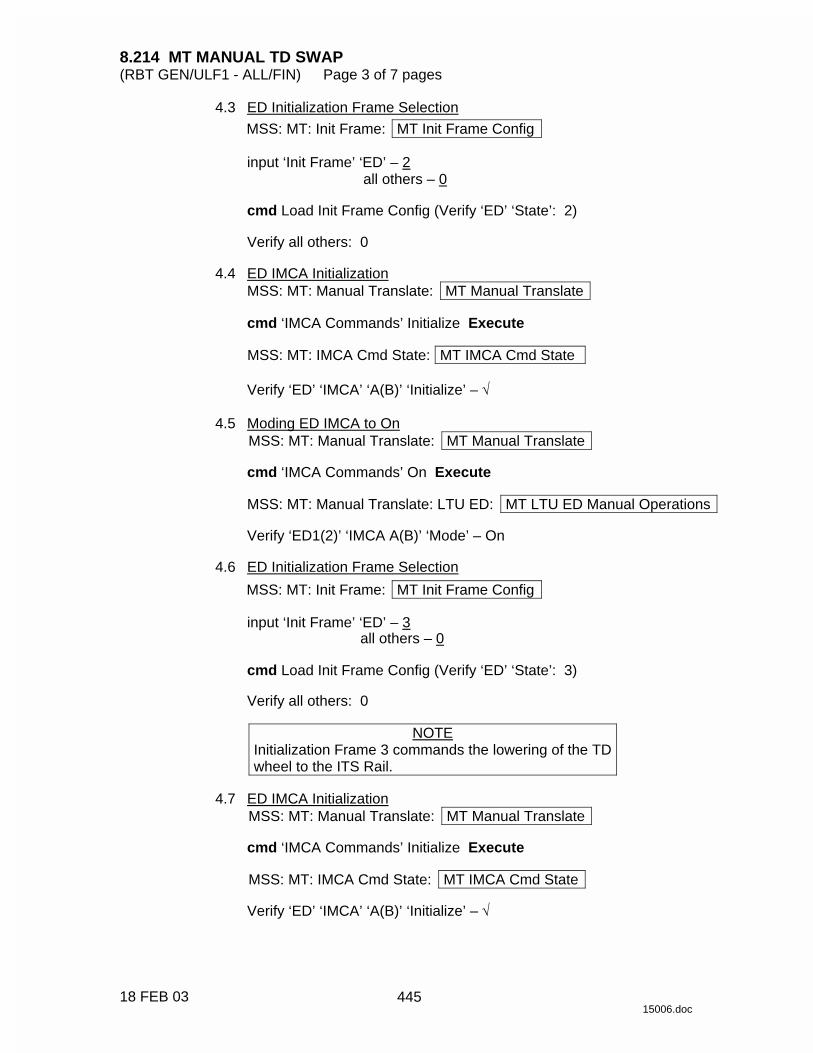
8.214 MT MANUAL TD SWAP (RBT GEN/ULF1 - ALL/FIN) Page 3 of 7 pages
18 FEB 03 15006.doc
4.3 ED Initialization Frame Selection MSS: MT: Init Frame: MT Init Frame Config
input ‘Init Frame’ ‘ED’ – 2 all others – 0
cmd Load Init Frame Config (Verify ‘ED’ ‘State’: 2)
Verify all others: 0
4.4 ED IMCA Initialization
MSS: MT: Manual Translate: MT Manual Translate
cmd ‘IMCA Commands’ Initialize Execute
MSS: MT: IMCA Cmd State: MT IMCA Cmd State
Verify ‘ED’ ‘IMCA’ ‘A(B)’ ‘Initialize’ – √ 4.5 Moding ED IMCA to On
MSS: MT: Manual Translate: MT Manual Translate
cmd ‘IMCA Commands’ On Execute
MSS: MT: Manual Translate: LTU ED: MT LTU ED Manual Operations
Verify ‘ED1(2)’ ‘IMCA A(B)’ ‘Mode’ – On 4.6 ED Initialization Frame Selection
MSS: MT: Init Frame: MT Init Frame Config
input ‘Init Frame’ ‘ED’ – 3 all others – 0
cmd Load Init Frame Config (Verify ‘ED’ ‘State’: 3)
Verify all others: 0
NOTE
Initialization Frame 3 commands the lowering of the TD wheel to the ITS Rail.
4.7 ED IMCA Initialization
MSS: MT: Manual Translate: MT Manual Translate
cmd ‘IMCA Commands’ Initialize Execute
MSS: MT: IMCA Cmd State: MT IMCA Cmd State
Verify ‘ED’ ‘IMCA’ ‘A(B)’ ‘Initialize’ – √
445
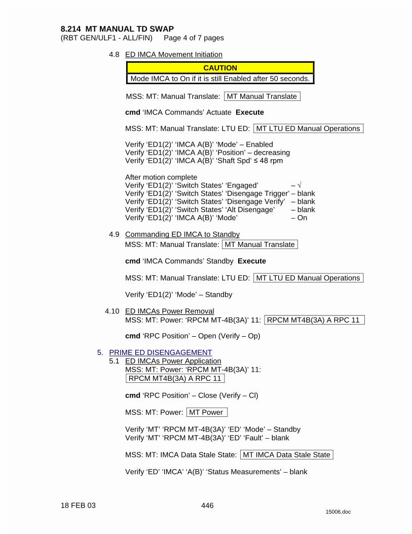
8.214 MT MANUAL TD SWAP (RBT GEN/ULF1 - ALL/FIN) Page 4 of 7 pages
18 FEB 03 15006.doc
4.8 ED IMCA Movement Initiation CAUTION
Mode IMCA to On if it is still Enabled after 50 seconds.
MSS: MT: Manual Translate: MT Manual Translate
cmd ‘IMCA Commands’ Actuate Execute
MSS: MT: Manual Translate: LTU ED: MT LTU ED Manual Operations
Verify ‘ED1(2)’ ‘IMCA A(B)’ ‘Mode’ – Enabled Verify ‘ED1(2)’ ‘IMCA A(B)’ ‘Position’ – decreasing Verify ‘ED1(2)’ ‘IMCA A(B)’ ‘Shaft Spd’ ��������
After motion complete Verify ‘ED1(2)’ ‘Switch States’ ‘Engaged’ – √ Verify ‘ED1(2)’ ‘Switch States’ ‘Disengage Trigger’ – blank Verify ‘ED1(2)’ ‘Switch States’ ‘Disengage Verify’ – blank Verify ‘ED1(2)’ ‘Switch States’ ‘Alt Disengage’ – blank Verify ‘ED1(2)’ ‘IMCA A(B)’ ‘Mode’ – On
4.9 Commanding ED IMCA to Standby
MSS: MT: Manual Translate: MT Manual Translate
cmd ‘IMCA Commands’ Standby Execute
MSS: MT: Manual Translate: LTU ED: MT LTU ED Manual Operations
Verify ‘ED1(2)’ ‘Mode’ – Standby 4.10 ED IMCAs Power Removal
MSS: MT: Power: ‘RPCM MT-4B(3A)’ 11: RPCM MT4B(3A) A RPC 11
cmd ‘RPC Position’ – Open (Verify – Op) 5. PRIME ED DISENGAGEMENT 5.1 ED IMCAs Power Application
MSS: MT: Power: ‘RPCM MT-4B(3A)’ 11: RPCM MT4B(3A) A RPC 11
cmd ‘RPC Position’ – Close (Verify – Cl)
MSS: MT: Power: MT Power
Verify ‘MT’ ‘RPCM MT-4B(3A)’ ‘ED’ ‘Mode’ – Standby Verify ‘MT’ ‘RPCM MT-4B(3A)’ ‘ED’ ‘Fault’ – blank
MSS: MT: IMCA Data Stale State: MT IMCA Data Stale State
Verify ‘ED’ ‘IMCA’ ‘A(B)’ ‘Status Measurements’ – blank
446

8.214 MT MANUAL TD SWAP (RBT GEN/ULF1 - ALL/FIN) Page 5 of 7 pages
18 FEB 03 15006.doc
5.2 ED IMCA Commanding Selection MSS: MT: Manual Translate: HW Config Manual MT HW Config Manual
sel ‘ED’ ‘IMCA Selection’ – CMD IMCA A(B) sel all others – none
cmd Load HW Config (Verify ‘ED’ ‘State’ – CMD IMCA A(B))
Verify all others – none
5.3 ED Initialization Frame Selection
MSS: MT: Init Frame: MT Init Frame Config
input ‘Init Frame’ ‘ED’ – 2 all others – 0
cmd Load Init Frame Config (Verify ‘ED’ ‘State’: 2)
Verify all others: 0
5.4 ED IMCA Initialization
MSS: MT: Manual Translate: MT Manual Translate
cmd ‘IMCA Commands’ Initialize Execute
MSS: MT IMCA Cmd State: MT IMCA Cmd State
Verify ‘ED’ ‘IMCA’ ‘A(B)’ ‘Initialize’ – √ 5.5 Moding ED IMCA to On
MSS: MT: Manual Translate: MT Manual Translate
cmd ‘IMCA Commands’ On Execute
MSS: MT: Manual Translate: LTU ED: MT LTU ED Manual Operations
Verify ‘ED1(2)’ ‘IMCA A(B)’ ‘Mode’ – On 5.6 ED Initialization Frame Selection
NOTE Initialization frame 4 commands disengagement of the ED.
MSS: MT: Init Frame: MT Init Frame Config
input ‘Init Frame’ ‘ED’ – 4 all others – 0
cmd Load Init Frame Config (Verify ‘ED’ ‘State’: 4)
Verify all others: 0
447
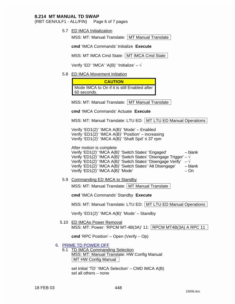
8.214 MT MANUAL TD SWAP (RBT GEN/ULF1 - ALL/FIN) Page 6 of 7 pages
18 FEB 03 15006.doc
5.7 ED IMCA Initialization MSS: MT: Manual Translate: MT Manual Translate
cmd ‘IMCA Commands’ Initialize Execute
MSS: MT IMCA Cmd State: MT IMCA Cmd State
Verify ‘ED’ ‘IMCA’ ‘A(B)’ ‘Initialize’ – √
5.8 ED IMCA Movement Initiation
CAUTION Mode IMCA to On if it is still Enabled after 60 seconds.
MSS: MT: Manual Translate: MT Manual Translate
cmd ‘IMCA Commands’ Actuate Execute
MSS: MT: Manual Translate: LTU ED: MT LTU ED Manual Operations
Verify ‘ED1(2)’ ‘IMCA A(B)’ ‘Mode’ – Enabled Verify ‘ED1(2)’ ‘IMCA A(B)’ ‘Position’ – increasing Verify ‘ED1(2)’ ‘IMCA A(B)’ ‘Shaft Spd’ �������
After motion is complete Verify ‘ED1(2)’ ‘IMCA A(B)’ ‘Switch States’ ‘Engaged’ – blank Verify ‘ED1(2)’ ‘IMCA A(B)’ ‘Switch States’ ‘Disengage Trigger’ – √ Verify ‘ED1(2)’ ‘IMCA A(B)’ ‘Switch States’ ‘Disengage Verify’ – √ Verify ‘ED1(2)’ ‘IMCA A(B)’ ‘Switch States’ ‘Alt Disengage’ – blank Verify ‘ED1(2)’ ‘IMCA A(B)’ ‘Mode’ – On
5.9 Commanding ED IMCA to Standby
MSS: MT: Manual Translate: MT Manual Translate
cmd ‘IMCA Commands’ Standby Execute
MSS: MT: Manual Translate: LTU ED: MT LTU ED Manual Operations
Verify ‘ED1(2)’ ‘IMCA A(B)’ ‘Mode’ – Standby 5.10 ED IMCAs Power Removal
MSS: MT: Power: ‘RPCM MT-4B(3A)’ 11: RPCM MT4B(3A) A RPC 11
cmd ‘RPC Position’ – Open (Verify − Op) 6. PRIME TD POWER OFF 6.1 TD IMCA Commanding Selection
MSS: MT: Manual Translate: HW Config Manual: MT HW Config Manual
sel initial ‘TD’ ‘IMCA Selection’ – CMD IMCA A(B) sel all others – none
448

8.214 MT MANUAL TD SWAP (RBT GEN/ULF1 - ALL/FIN) Page 7 of 7 pages
18 FEB 03 15006.doc
cmd Load HW Config (Verify ‘TD’ ‘State’ – CMD IMCA A(B))
Verify all others – none 6.2 Commanding TD IMCA to Standby
MSS: MT: Manual Translate: MT Manual Translate
cmd ‘IMCA Commands’ Standby Execute
MSS: MT: Manual Translate: TUS TD: MT TUS TD Manual Operations
Verify ‘TD1(2)’ ‘IMCA A(B)’ ‘Mode’ – Standby 6.3 TD IMCA Power Removal
MSS: MT: Power: ‘RPCM MT-4B(3A)’ 4: RPCM MT4B(3A) A RPC 4
cmd ‘RPC Position’ – Open (Verify – Op)
449

This Page Intentionally Blank
22 DEC 04
450

8.306 MBS REBOOT PRIME(REDUNDANT) STRING (RBT GEN/X2R4 - ALL/FIN) Page 1 of 2 pages
13 DEC 04 13549.doc
NOTE POA must not be Operational.
1. SETUP PCS MSS: MBS: MBS
√‘MBS Safing’ – Safed 2. TRANSITION MBS PRIME(REDUNDANT) STRING TO OFF
NOTE 1. If SSRMS is based on MBS, it must be Off on commanded string. 2. Expect the following Caution and Warning messages while
performing the next command: ‘R1E - MSS Active OCS MBS Prime(Redun) MCU SRT Comm Fail’
PCS MSS: MBS: MCU: MCU
cmd ‘Prime(Redundant)’ Off (Verify – Off) (30 s max) 3. TRANSITION MBS PRIME(REDUNDANT) STRING FROM OFF TO
KEEP-ALIVE cmd ‘(Prime)Redundant’ Keep-Alive (Verify – Keep-Alive) (30 s max)
4. TRANSITION MBS PRIME(REDUNDANT) STRING FROM KEEP-ALIVE
TO OPERATIONAL NOTE
1. The transition from Keep-Alive to Operational can be stopped at any time by issuing a safing command.
2. The MBS transition from Keep-Alive to Operational will require
approximately 3 minutes. The time is contingent on file transfer activity from the C&C MDM.
c 3. If the alternate string is Off while the MBS is Operational, expect
the following Robotics Advisory messages: ‘R2O - MSS MBS CRPCM 1R(1P) Cat-2 Transmit Msg Err’ ‘R2O - MSS MBS CRPCM 2R(2P) Cat-2 Transmit Msg Err’ ‘R2O - MSS MBS CRPCM 3R(3P) Cat-2 Transmit Msg Err’ ‘R2O - MSS MBS CRPCM 1R(1P) Cat-2 Receive Msg Err’ ‘R2O - MSS MBS CRPCM 2R(2P) Cat-2 Receive Msg Err’ ‘R2O - MSS MBS CRPCM 3R(3P) Cat-2 Receive Msg Err’ (SCR 21744)
cmd ‘Prime(Redundant)’ Operational (Verify Systems State – Operational)
451

8.306 MBS REBOOT PRIME(REDUNDANT) STRING (RBT GEN/X2R4 - ALL/FIN) Page 2 of 2 pages
13 DEC 04 13549.doc
5. MBS VIDEO COMPONENTS POWERUP PCS MSS: MBS: VDU1: MSS VDUs
sel ‘[X]’ where [X] = MBS 2 MBS 1
√‘Primary’,‘Redundant’ Keep-Alive
Repeat
NOTE Expect ‘R6F - MBS… PFM Carrier On Video 1 Err’ Robotics Advisory message as each VDU is powered on. Message may toggle in and out of alarm until video is routed to the defined VDU (SCR 24376).
sel ‘[X]’ as required where [X] = POA MBS 2 MBS 1
cmd On (Verify – On)
Repeat
MSS: MBS: MBS Central Camera icon: MBS Camera
sel [X] as required where [X] = MBS 37 POA 32
cmd ‘Power’ On (Verify – On)
Repeat 6. MBS VIDEO DEROUTING
MSS:Video: Video Routing
Repeat the following for all destinations to which an MBS Camera is routed:
sel ‘Destination Icon’
cmd ‘Deroute Video Signal’ – Deroute
452
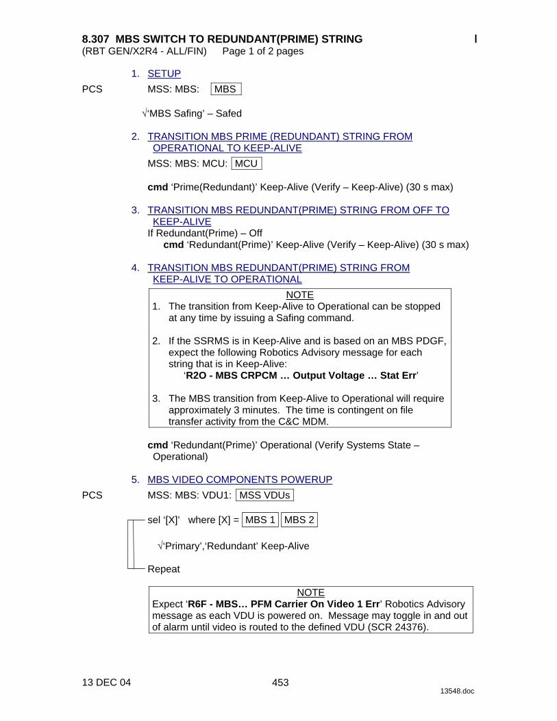
8.307 MBS SWITCH TO REDUNDANT(PRIME) STRING (RBT GEN/X2R4 - ALL/FIN) Page 1 of 2 pages
13 DEC 04 13548.doc
1. SETUP PCS MSS: MBS: MBS
√‘MBS Safing’ – Safed 2. TRANSITION MBS PRIME (REDUNDANT) STRING FROM
OPERATIONAL TO KEEP-ALIVE MSS: MBS: MCU: MCU
cmd ‘Prime(Redundant)’ Keep-Alive (Verify – Keep-Alive) (30 s max) 3. TRANSITION MBS REDUNDANT(PRIME) STRING FROM OFF TO
KEEP-ALIVE If Redundant(Prime) – Off
cmd ‘Redundant(Prime)’ Keep-Alive (Verify – Keep-Alive) (30 s max) 4. TRANSITION MBS REDUNDANT(PRIME) STRING FROM
KEEP-ALIVE TO OPERATIONAL NOTE
1. The transition from Keep-Alive to Operational can be stopped at any time by issuing a Safing command.
2. If the SSRMS is in Keep-Alive and is based on an MBS PDGF,
expect the following Robotics Advisory message for each string that is in Keep-Alive:
‘R2O - MBS CRPCM … Output Voltage … Stat Err’ 3. The MBS transition from Keep-Alive to Operational will require
approximately 3 minutes. The time is contingent on file transfer activity from the C&C MDM.
cmd ‘Redundant(Prime)’ Operational (Verify Systems State – Operational)
5. MBS VIDEO COMPONENTS POWERUP PCS MSS: MBS: VDU1: MSS VDUs
sel ‘[X]’ where [X] = MBS 2 MBS 1
√‘Primary’,‘Redundant’ Keep-Alive
Repeat
NOTE Expect ‘R6F - MBS… PFM Carrier On Video 1 Err’ Robotics Advisory message as each VDU is powered on. Message may toggle in and out of alarm until video is routed to the defined VDU (SCR 24376).
453

8.307 MBS SWITCH TO REDUNDANT(PRIME) STRING (RBT GEN/X2R4 - ALL/FIN) Page 2 of 2 pages
13 DEC 04 13548.doc
sel ‘[X]’ as required where [X] = POA MBS 2 MBS 1
cmd On (Verify – On)
Repeat
MSS: MBS: MBS Central Camera icon: MBS Camera
sel [X] as required where [X] = MBS 37 POA 32
cmd ‘Power’ On (Verify – On)
Repeat 6. MBS VIDEO DEROUTING
MSS:Video: Video Routing
Repeat the following for all destinations to which an MBS Camera is routed:
sel ‘Destination Icon’
cmd ‘Deroute Video Signal’ – Deroute
454

8.310 MBS POA REBOOT (RBT GEN/X2R4 - ALL/FIN) Page 1 of 1 page
13 DEC 04 13543.doc
1. SETUP PCS MSS: MBS: MBS
√‘MBS Safing’ – Safed 2. TRANSITION MBS PRIME(REDUNDANT) POA STRING TO
KEEP-ALIVE MSS: MBS: POA Power: POA Power
cmd ‘Prime(Redundant)’ Keep-Alive (Verify Keep-Alive) (30 s max)
3. TRANSITION MBS PRIME(REDUNDANT) POA STRING TO
OPERATIONAL NOTE
1. The transition from Keep-Alive to Operational can be stopped at any time by issuing a Safing command.
2. If the transition is not complete in 2.5 minutes, apply Safing
on the DCP to stop transition (SCR 22619). 3. If the transition is interrupted by Operator Safing or by a
system failure, the MBS string will have to be commanded to Operational again before the POA transition can be reattempted.
4. The MCU status on the MBS page will be incorrect during the
POA transition.
MSS: MBS: POA Power: POA Power
cmd ‘Prime(Redundant)’ Operational (Verify Operational) (SCR 22616)
455

This Page Intentionally Blank
22 DEC 04
456

8.311 MBS POA SWITCH TO REDUNDANT(PRIME) STRING (RBT GEN/X2R4 - ALL/FIN) Page 1 of 3 pages
13 DEC 04 13542.doc
1. SETUP PCS MSS: MBS: MBS
√‘MBS Safing’ – Safed 2. POA VDU POWERDOWN TO KEEP-ALIVE PCS MSS: MBS: POA VDU: MSS VDUs
If ‘MBS’ ‘POA’ – On cmd ‘MBS’ ‘POA’ Keep-Alive (Verify Keep-Alive)
3. TRANSITION MBS PRIME(REDUNDANT) POA STRING FROM
OPERATIONAL TO OFF MSS: MBS: POA Power: POA Power
cmd ‘Prime(Redundant)’ Off (Verify – Off) (30 s max)
4. TRANSITION MBS REDUNDANT(PRIME) STRING FROM OFF TO
KEEP-ALIVE MSS: MBS: MCU: MCU
If Redundant (Prime) – Off
cmd ‘Redundant(Prime)’ Keep-Alive (Verify Keep-Alive) (30 s max) 5. TRANSITION MBS PRIME(REDUNDANT) STRING FROM
OPERATIONAL TO KEEP-ALIVE MSS: MBS: MCU: MCU
cmd ‘Prime(Redundant)’ Keep-Alive (Verify Keep-Alive) (30 s max)
6. TRANSITION MBS REDUNDANT(PRIME) STRING FROM
KEEP-ALIVE TO OPERATIONAL NOTE
1. The transition from Keep-Alive to Operational can be stopped at any time by issuing a Safing command.
2. If the SSRMS is in Keep-Alive and is based off an MBS PDGF,
expect the following Robotics Advisory message for each string that is in Keep-Alive:
‘R2O - MBS CRPCM … Output Voltage … Stat Err’
MSS: MBS: MCU: MCU
cmd ‘Redundant(Prime)’ Operational (Verify Operational)
457

8.311 MBS POA SWITCH TO REDUNDANT(PRIME) STRING (RBT GEN/X2R4 - ALL/FIN) Page 2 of 3 pages
13 DEC 04 13542.doc
7. TRANSITION MBS REDUNDANT(PRIME) POA STRING FROM KEEP-ALIVE TO OPERATIONAL
NOTE 1. The transition from Keep-Alive to Operational can be stopped
at any time by issuing a Safing command. 2. If the transition is not complete in 2.5 minutes, apply Safing
on the DCP to stop transition (SCR 22619). 3. If the transition is interrupted by Operator Safing or by a
system failure, the MBS string will have to be commanded to Operational again before the POA transition can be reattempted.
4. The MCU status on the MBS page will be incorrect during the
POA transition.
MSS: MBS: POA Power: POA Power
cmd ‘Redundant(Prime)’ Operational (Verify – Operational) (SCR 22616) 8. MBS VIDEO COMPONENTS POWERUP PCS MSS: MBS: VDU1: MSS VDUs
sel ‘[X]’ where [X] = MBS 2 MBS 1
√‘Primary’,‘Redundant’ Keep-Alive
Repeat
NOTE Expect ‘R6F - MBS… PFM Carrier On Video 1 Err’ Robotics Advisory message as each VDU is powered on. Message may toggle in and out of alarm until video is routed to the defined VDU (SCR 24376).
sel ‘[X]’ as required where [X] = POA MBS 2 MBS 1
cmd On (Verify – On)
Repeat
MSS: MBS: MBS Central Camera icon: MBS Camera
sel [X] as required where [X] = POA 32 MBS 37
cmd ‘Power’ On (Verify – On)
Repeat
458

8.311 MBS POA SWITCH TO REDUNDANT(PRIME) STRING (RBT GEN/X2R4 - ALL/FIN) Page 3 of 3 pages
13 DEC 04 13542.doc
9. MBS VIDEO DEROUTING MSS:Video: Video Routing
Repeat the following for all destinations to which an MBS Camera is routed:
sel ‘Destination Icon’
cmd ‘Deroute Video Signal’ – Deroute
459

This Page Intentionally Blank
22 DEC 04
460

8.601 CUP(LAB) AVU LCDM CONFIGURATION AS MON 1(2) (RBT GEN/9A - ALL/FIN) Page 1 of 1 page
05 SEP 02 14299.doc
1. VIDEO SETUP DCP cmd Monitor/Camera – 1/95
cmd Monitor/Camera – 2/95 2. AVU POWERUP LCDM √Power On PCS MSS: LAS5(LAP5) AVU: LAS5(LAP5) AVU
cmd ‘Power’ On
NOTE AVU bootup could take up to 4 minutes.
MSS: RWS
Verify ‘LAS5’(‘LAP5’) ‘RPC3’ – closed (blue) Verify ’LAS5’(‘LAP5’) ‘Status from OCS’ – On
3. LCDM MODE
NOTE This step needs to be performed only if the LCDM mode was switched to RGB prior to powering the AVU down the last time.
LCDM cmd MENU (Verify Brightness)
cmd UP (Verify Video Mode) cmd SELECT (Verify RGB) cmd UP (Verify Composite) cmd SELECT
Verify AVU Systems Display appears.
4. AVU VIDEO OUTPUT ROUTING
NOTE This step will remove the AVU Systems Display from all monitors. To regain it, triple click button 3.
cmd Advanced <Alt-A>
‘Vid Out’
pick ‘Out1:’ Raw Vid 1 pick ‘Out2:’ Raw Vid 2 pick ‘Out3:’ Raw Vid 1(2)
Verify Test Pattern appears on LCDM and MON 1(2).
461

This Page Intentionally Blank
22 DEC 04
462

REFERENCE
REF
EREN
CE
22 DEC 04
463

This Page Intentionally Blank
REF
EREN
CE
22 DEC 04
464

9.101 RWS PERIPHERALS CONFIGURATION 1 (RBT GEN/5A.1 - ALL/FIN 2) Page 1 of 5 pages
12 SEP 02 11547.doc
NOTE 1. Standard ISS LAB configuration has a single PCS dedicated to ISS
Overhead and C&W. This is not the PCS located on the workstation for MSS operations.
2. The RWS UOP Bypass Cables provide power and data to the RWS
PCS and the RWS DCP. 3. Some of the hardware, data cables and power cables may already
be located on the RWS or on the Alternate RWS. 1. HARDWARE
Retrieve the following hardware components:
Laptop Stands (four PER RWS) AVU LCDM (one PER RWS) P/N 000681-05 AVU Keyboard (one PER RWS) P/N 002247-01 SSC (two per RWS) SSC-MCIU Card Assembly (one PER RWS) P/N 51140-2357-1
2. DATA CABLES
Retrieve the following data cables:
RS232 Y Cable (one PER RWS) P/N SED39124826-307 Keyboard Cable (one PER RWS) P/N 000845-04 LCDM Cable (one PER RWS) P/N 000783-05 AVU-SSC MCIU Serial Cable (one PER RWS) P/N SED39126965-301 AVU Quad Cable (one PER RWS) P/N 004397-01
3. POWER CABLES
Retrieve the following Power Cables:
For Cupola RWS configuration: STORAGE DEVICE PWR CABLE (UOP to MACE) P/N SEG46117493-301
120VDC PEEK POWER CABLE, 20' P/N SEG33112596-303 Three Additional Power cables (all three do not have to be the same type):
POWER CABLE ASSEMBLY, PCS-UOP 120VDC P/N SEZ39129260-305 or 120VDC PEEK POWER CABLE, 20' P/N SEG33112596-303
For Lab RWS configuration:
120VDC PEEK POWER CABLE, 20' P/N SEG33112596-303 Three Additional power cables (all three do not have to be the same type):
POWER CABLE ASSEMBLY, PCS-UOP 120VDC P/N SEZ39129260-305 or 120VDC PEEK POWER CABLE, 20' P/N SEG33112596-303
465
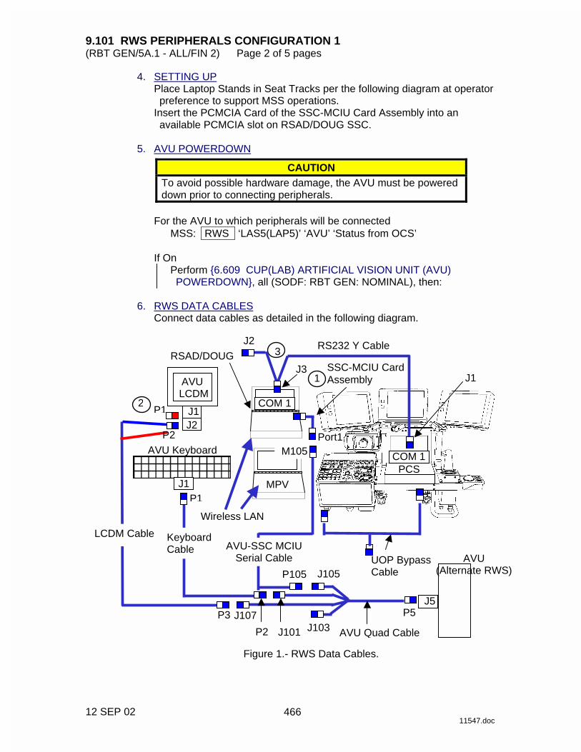
9.101 RWS PERIPHERALS CONFIGURATION 1 (RBT GEN/5A.1 - ALL/FIN 2) Page 2 of 5 pages
12 SEP 02 11547.doc
4. SETTING UP Place Laptop Stands in Seat Tracks per the following diagram at operator preference to support MSS operations.
Insert the PCMCIA Card of the SSC-MCIU Card Assembly into an available PCMCIA slot on RSAD/DOUG SSC.
5. AVU POWERDOWN
CAUTION To avoid possible hardware damage, the AVU must be powered down prior to connecting peripherals.
For the AVU to which peripherals will be connected
MSS: RWS ‘LAS5(LAP5)’ ‘AVU’ ‘Status from OCS’
If On Perform {6.609 CUP(LAB) ARTIFICIAL VISION UNIT (AVU) POWERDOWN}, all (SODF: RBT GEN: NOMINAL), then:
6. RWS DATA CABLES
Connect data cables as detailed in the following diagram.
RS232 Y Cable J2
AVU (Alternate RWS)
AVU Quad Cable
AVU-SSC MCIU Serial Cable
Keyboard Cable
LCDM Cable
AVU LCDM
AVU Keyboard
MPV
PCS
1
2
Wireless LAN
3
J1
J1
J105 P105
J107 P3
J101 P2 J103
J5 P5
COM 1
RSAD/DOUG
Port1 M105
SSC-MCIU Card Assembly
J2
P1
P1
P2
COM 1
J3 J1
UOP Bypass Cable
Figure 1.- RWS Data Cables.
466

9.101 RWS PERIPHERALS CONFIGURATION 1 (RBT GEN/5A.1 - ALL/FIN 2) Page 3 of 5 pages
12 SEP 02 11547.doc
Ops Name Part Number AVU LCDM 000681-05 Keyboard/trackball 002247-01 RS232 Y Cable SED39124826-307 LCDM Cable 000783-05 Keyboard Cables 000845-04 AVU Quad Cable 004397-01 SSC-MCIU Card Assembly 51140-2357-1 AVU-SSC MCIU Serial Cable SED39126965-301 UOP Bypass Cable 1J00138
NOTE
1. SSC-MCIU Card Assembly consists of the PCMCIA Card and attached cable. Insert PCMCIA Card of SSC-MCIU Card Assembly into RSAD/DOUG SSC.
2. LCDM Cable (“Y”) provides both data and power to LCDM.
Connector design insures correct configuration. 3. Connect the J3 end of the “Y” cable to 9 pin port labeled COM 1 on
back of RSAD/DOUG SSC and PCS. Do not connect anything to the J2 end of the “Y” cable. Deviations from this configuration may cause the PCS to fail to halt or application to terminate.
467
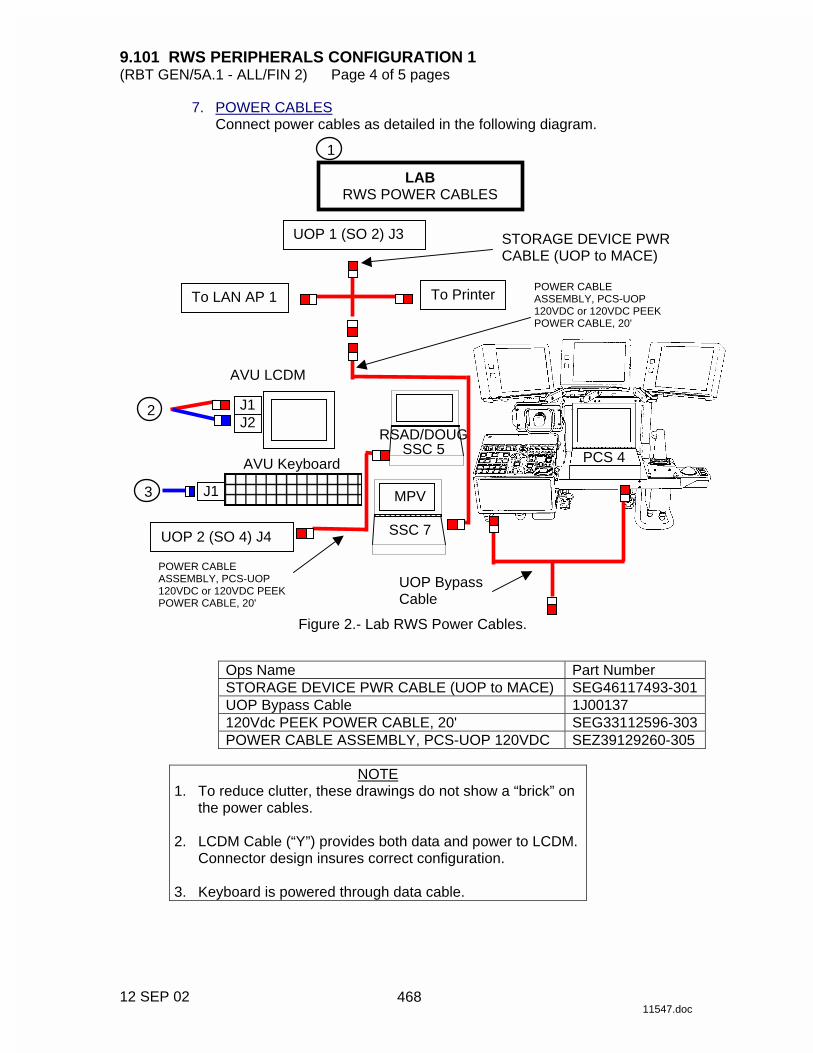
9.101 RWS PERIPHERALS CONFIGURATION 1 (RBT GEN/5A.1 - ALL/FIN 2) Page 4 of 5 pages
12 SEP 02 11547.doc
7. POWER CABLES Connect power cables as detailed in the following diagram.
Ops Name Part Number STORAGE DEVICE PWR CABLE (UOP to MACE) SEG46117493-301 UOP Bypass Cable 1J00137 120Vdc PEEK POWER CABLE, 20' SEG33112596-303 POWER CABLE ASSEMBLY, PCS-UOP 120VDC SEZ39129260-305
NOTE
1. To reduce clutter, these drawings do not show a “brick” on the power cables.
2. LCDM Cable (“Y”) provides both data and power to LCDM.
Connector design insures correct configuration. 3. Keyboard is powered through data cable.
AVU Keyboard
LAB RWS POWER CABLES
1
UOP 1 (SO 2) J3
UOP 2 (SO 4) J4
AVU LCDM
RSAD/DOUG SSC 5
MPV
SSC 7
PCS 4
2
3 J1
J1 J2
POWER CABLE ASSEMBLY, PCS-UOP 120VDC or 120VDC PEEK POWER CABLE, 20'
To Printer To LAN AP 1
STORAGE DEVICE PWR CABLE (UOP to MACE)
POWER CABLE ASSEMBLY, PCS-UOP 120VDC or 120VDC PEEK POWER CABLE, 20'
UOP Bypass Cable
Figure 2.- Lab RWS Power Cables.
468
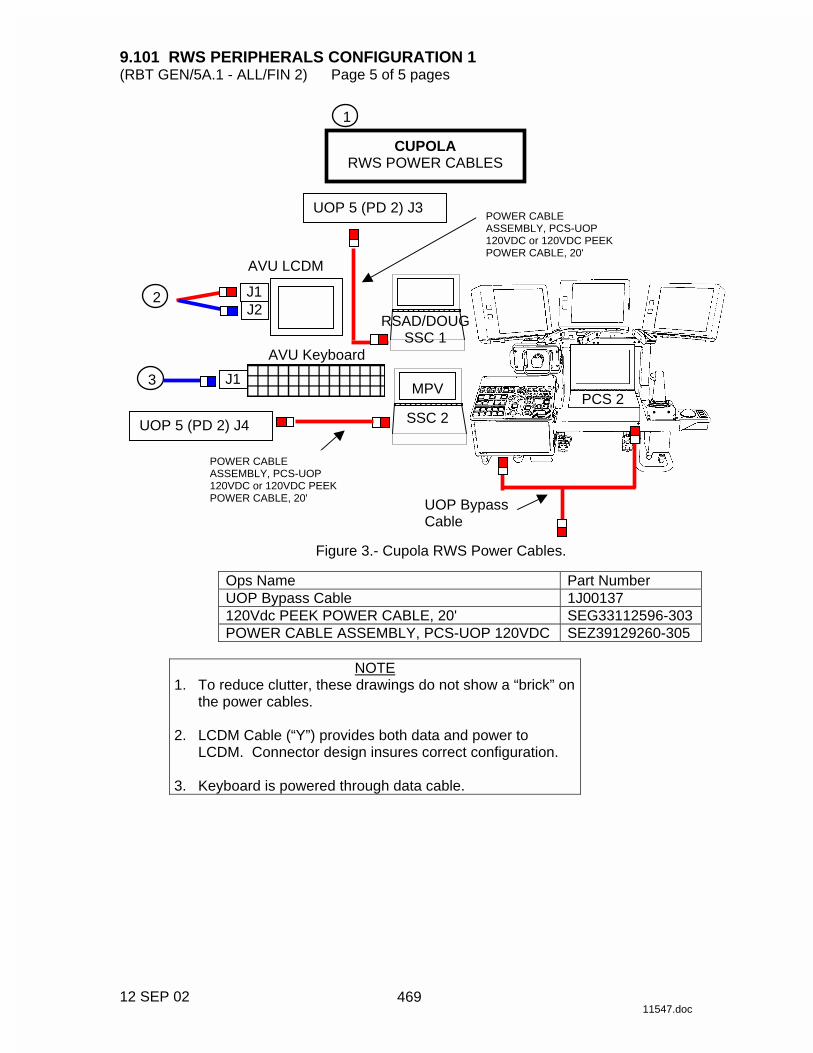
9.101 RWS PERIPHERALS CONFIGURATION 1 (RBT GEN/5A.1 - ALL/FIN 2) Page 5 of 5 pages
12 SEP 02 11547.doc
Ops Name Part Number UOP Bypass Cable 1J00137 120Vdc PEEK POWER CABLE, 20' SEG33112596-303 POWER CABLE ASSEMBLY, PCS-UOP 120VDC SEZ39129260-305
NOTE
1. To reduce clutter, these drawings do not show a “brick” on the power cables.
2. LCDM Cable (“Y”) provides both data and power to
LCDM. Connector design insures correct configuration. 3. Keyboard is powered through data cable.
AVU Keyboard
CUPOLA RWS POWER CABLES
UOP 5 (PD 2) J3
UOP 5 (PD 2) J4
AVU LCDM
RSAD/DOUG SSC 1
MPV
SSC 2 PCS 2
2
3 J1
J1 J2
1
POWER CABLE ASSEMBLY, PCS-UOP 120VDC or 120VDC PEEK POWER CABLE, 20'
POWER CABLE ASSEMBLY, PCS-UOP 120VDC or 120VDC PEEK POWER CABLE, 20'
UOP Bypass Cable
Figure 3.- Cupola RWS Power Cables.
469

This Page Intentionally Blank
22 DEC 04
470

9.404 SSRMS SINGLE JOINT MNEMONICS (RBT/6A - ALL/FIN) Page 1 of 2 pages
04 APR 01 11660.doc
Joint rotation axes are illustrated, with circular arrows denoting positive rotation, and the dotted line is the initial position. The diagram also illustrates the right hand rule: point thumb of right hand along positive direction of a vector, curling fingers around the vector’s shaft. The fingers give the direction of positive rotation around the vector. Given the joint rotation axes, the operator needs to determine the direction of positive/negative rotation for each joint. This is useful when commanding the SSRMS in Single Mode. The following set of mnemonics use the right hand rule to help determine the direction of positive rotation for each joint:
Pitch Joints (Mnemonic: 3 Trail, 2 Lead (3T2L)) - The three pitch joint axes (SP, EP & WP) are parallel and remain parallel for any arm configuration. Therefore, determine the positive direction for one of the three joints and infer the others. The fact that boom A has three electronics (the “3” on Figure 1), compared to boom B which has only two (the “2” on Figure 1), provides an easy landmark (i.e., 3 boxes vs. 2 boxes). These boxes are highlighted in gray in Figure 1. For positive pitch joint motion, the booms will always move so that the three boxes trail boom A while the two boxes lead boom B (3 Trail 2 Lead or 3T2L).
Figure 2.- Yaw Joint Mnemonics.
Yaw Joints (Mnemonic: Away from the LEE) - For the two yaw joints (SY & WY), to obtain the positive rotation direction, simply use the right-hand rule pointing the thumb along the yaw axis, away from the LEE (as seen in Figure 2).
Base
Base3
2
Boom A
Boom B
Figure 1.- Pitch Joint Mnemonics.
471

9.404 SSRMS SINGLE JOINT MNEMONICS (RBT/6A - ALL/FIN) Page 2 of 2 pages
04 APR 01 11660.doc
Roll Joints (Mnemonic: Power flow) -
For the two roll joints (SR & WR), to obtain the positive rotation direction, also use the right hand-rule, pointing the thumb into the base LEE and out of the Tip LEE. As a memory aid, think of power flowing into the base LEE and out of the Tip LEE towards a payload (as shown in Figure 3).
Base
Tip
3 Boxes
2 Boxes
SY
SR
SP
EP
WY WR
Single Joint Mnemonics Summary Pitch: 3 boxes trailing 2 boxes leading Yaw: Thumb away from LEE Roll: Thumb into base and out of tip
The Right Hand Rule
Figure 4.- Single Joint Mnemonics.
Base
Figure 3.- Roll Joint Mnemonics.
472

9.405 SSRMS 7 JOINT SINGULARITY CUES (RBT/6A - ALL/FIN) Page 1 of 2 pages
04 APR 01 11659.doc
Table 1. Singularity Configuration Cues
Singularity Name And Description
Angles Conditions
Other Necessary Conditions
Lost DOFs
Elbow Pitch Singularity
Shoulder
Wrist
Wrist
EP = 0° or
EP = ± 180° None
Translation along the boom axis.
Shoulder
Wrist
Yaw Singularity
WY and SY at
± 90° *
None
Translation perpendicular to the pitch plane becomes coupled with rotations.
Wrist Yaw Singularity
WristWrist
Wrist Yaw Axis
WY = ± 90° *
Wrist YAW
axis** points toward the shoulder cluster.
Translation perpendicular to the pitch plane becomes coupled with rotations.
473
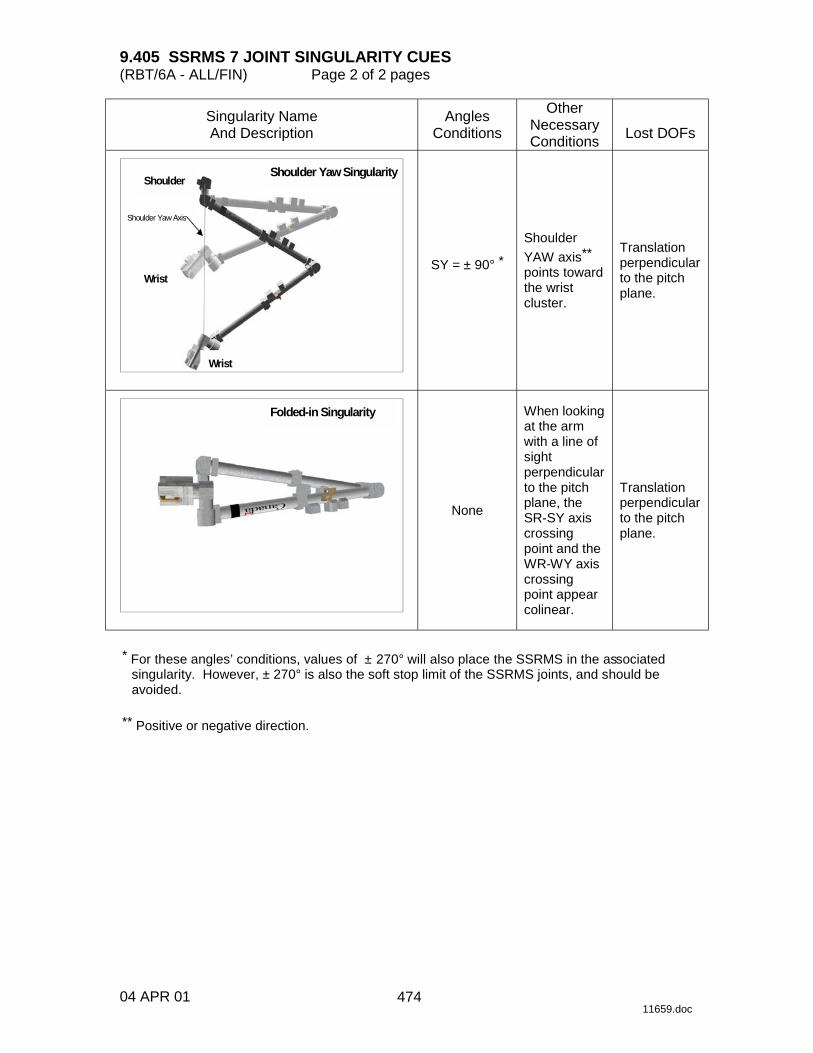
9.405 SSRMS 7 JOINT SINGULARITY CUES (RBT/6A - ALL/FIN) Page 2 of 2 pages
04 APR 01 11659.doc
Singularity Name And Description
Angles Conditions
Other Necessary Conditions
Lost DOFs
Shoulder Yaw Singularity
Wrist
Wrist
Shoulder
Shoulder Yaw Axis
SY = ± 90° *
Shoulder
YAW axis**
points toward the wrist cluster.
Translation perpendicular to the pitch plane.
Folded-in Singularity
None
When looking at the arm with a line of sight perpendicular to the pitch plane, the SR-SY axis crossing point and the WR-WY axis crossing point appear colinear.
Translation perpendicular to the pitch plane.
* For these angles’ conditions, values of ± 270° will also place the SSRMS in the associated
singularity. However, ± 270° is also the soft stop limit of the SSRMS joints, and should be avoided.
** Positive or negative direction.
474

9.408 TIMING DATA FOR LEE OPERATIONS (RBT GEN/12A - ALL/FIN 1) Page 1 of 1 page
24 JAN 03 11647.doc
Table 1. LEE/POA Timing Data
Fast Speed Slow Speed Mechanism Nominal
(seconds) Maximum (seconds)
Nominal (seconds)
Maximum (seconds)
Snare 2 3 7 12
Rigidize 16 18 60 90
Latch 10 13 43 65
Mate N/A N/A 3 10
475

This Page Intentionally Blank
22 DEC 04
476
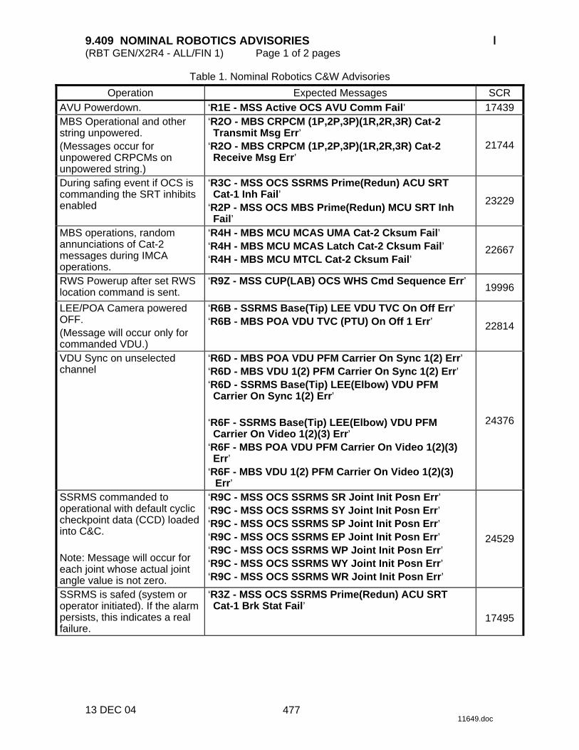
9.409 NOMINAL ROBOTICS ADVISORIES (RBT GEN/X2R4 - ALL/FIN 1) Page 1 of 2 pages
13 DEC 04 11649.doc
Table 1. Nominal Robotics C&W Advisories
Operation Expected Messages SCR AVU Powerdown. ‘R1E - MSS Active OCS AVU Comm Fail’ 17439 MBS Operational and other string unpowered. (Messages occur for unpowered CRPCMs on unpowered string.)
‘R2O - MBS CRPCM (1P,2P,3P)(1R,2R,3R) Cat-2 Transmit Msg Err’
‘R2O - MBS CRPCM (1P,2P,3P)(1R,2R,3R) Cat-2 Receive Msg Err’
21744
During safing event if OCS is commanding the SRT inhibits enabled
‘R3C - MSS OCS SSRMS Prime(Redun) ACU SRT Cat-1 Inh Fail’
‘R2P - MSS OCS MBS Prime(Redun) MCU SRT Inh Fail’
23229
MBS operations, random annunciations of Cat-2 messages during IMCA operations.
‘R4H - MBS MCU MCAS UMA Cat-2 Cksum Fail’ ‘R4H - MBS MCU MCAS Latch Cat-2 Cksum Fail’ ‘R4H - MBS MCU MTCL Cat-2 Cksum Fail’
22667
RWS Powerup after set RWS location command is sent.
‘R9Z - MSS CUP(LAB) OCS WHS Cmd Sequence Err’
19996
LEE/POA Camera powered OFF. (Message will occur only for commanded VDU.)
‘R6B - SSRMS Base(Tip) LEE VDU TVC On Off Err’ ‘R6B - MBS POA VDU TVC (PTU) On Off 1 Err’ 22814
VDU Sync on unselected channel
‘R6D - MBS POA VDU PFM Carrier On Sync 1(2) Err’ ‘R6D - MBS VDU 1(2) PFM Carrier On Sync 1(2) Err’ ‘R6D - SSRMS Base(Tip) LEE(Elbow) VDU PFM Carrier On Sync 1(2) Err’
‘R6F - SSRMS Base(Tip) LEE(Elbow) VDU PFM Carrier On Video 1(2)(3) Err’
‘R6F - MBS POA VDU PFM Carrier On Video 1(2)(3) Err’
‘R6F - MBS VDU 1(2) PFM Carrier On Video 1(2)(3) Err’
24376
SSRMS commanded to operational with default cyclic checkpoint data (CCD) loaded into C&C. Note: Message will occur for each joint whose actual joint angle value is not zero.
‘R9C - MSS OCS SSRMS SR Joint Init Posn Err’ ‘R9C - MSS OCS SSRMS SY Joint Init Posn Err’ ‘R9C - MSS OCS SSRMS SP Joint Init Posn Err’ ‘R9C - MSS OCS SSRMS EP Joint Init Posn Err’ ‘R9C - MSS OCS SSRMS WP Joint Init Posn Err’ ‘R9C - MSS OCS SSRMS WY Joint Init Posn Err’ ‘R9C - MSS OCS SSRMS WR Joint Init Posn Err’
24529
SSRMS is safed (system or operator initiated). If the alarm persists, this indicates a real failure.
‘R3Z - MSS OCS SSRMS Prime(Redun) ACU SRT Cat-1 Brk Stat Fail’
17495
477
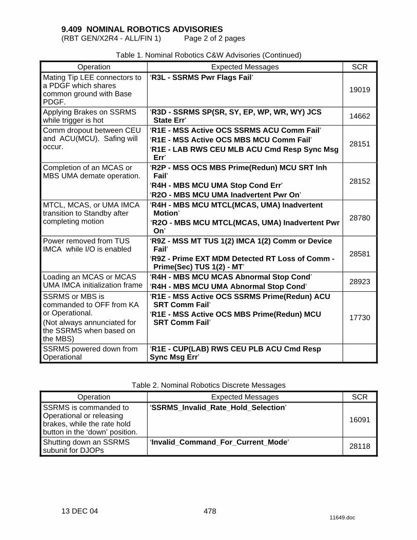
9.409 NOMINAL ROBOTICS ADVISORIES (RBT GEN/X2R4 - ALL/FIN 1) Page 2 of 2 pages
13 DEC 04 11649.doc
Table 1. Nominal Robotics C&W Advisories (Continued)
Operation Expected Messages SCR Mating Tip LEE connectors to a PDGF which shares common ground with Base PDGF.
‘R3L - SSRMS Pwr Flags Fail’
19019
Applying Brakes on SSRMS while trigger is hot
‘R3D - SSRMS SP(SR, SY, EP, WP, WR, WY) JCS State Err’ 14662
Comm dropout between CEU and ACU(MCU). Safing will occur.
‘R1E - MSS Active OCS SSRMS ACU Comm Fail’ ‘R1E - MSS Active OCS MBS MCU Comm Fail’ ‘R1E - LAB RWS CEU MLB ACU Cmd Resp Sync Msg Err’
28151
Completion of an MCAS or MBS UMA demate operation.
‘R2P - MSS OCS MBS Prime(Redun) MCU SRT Inh Fail’
‘R4H - MBS MCU UMA Stop Cond Err’ ‘R2O - MBS MCU UMA Inadvertent Pwr On’
28152
MTCL, MCAS, or UMA IMCA transition to Standby after completing motion
‘R4H - MBS MCU MTCL(MCAS, UMA) Inadvertent Motion’
‘R2O - MBS MCU MTCL(MCAS, UMA) Inadvertent Pwr On’
28780
Power removed from TUS IMCA while I/O is enabled
‘R9Z - MSS MT TUS 1(2) IMCA 1(2) Comm or Device Fail’
‘R9Z - Prime EXT MDM Detected RT Loss of Comm - Prime(Sec) TUS 1(2) - MT’
28581
Loading an MCAS or MCAS UMA IMCA initialization frame
‘R4H - MBS MCU MCAS Abnormal Stop Cond’ ‘R4H - MBS MCU UMA Abnormal Stop Cond’
28923
SSRMS or MBS is commanded to OFF from KA or Operational. (Not always annunciated for the SSRMS when based on the MBS)
‘R1E - MSS Active OCS SSRMS Prime(Redun) ACU SRT Comm Fail’
‘R1E - MSS Active OCS MBS Prime(Redun) MCU SRT Comm Fail’
17730
SSRMS powered down from Operational
‘R1E - CUP(LAB) RWS CEU PLB ACU Cmd Resp Sync Msg Err’
Table 2. Nominal Robotics Discrete Messages
Operation Expected Messages SCR SSRMS is commanded to Operational or releasing brakes, while the rate hold button in the ‘down’ position.
‘SSRMS_Invalid_Rate_Hold_Selection’
16091
Shutting down an SSRMS subunit for DJOPs
‘Invalid_Command_For_Current_Mode’ 28118
478

9.410 SS
RM
S M
EC
HA
NIC
AL
& E
LE
CT
RIC
AL
CO
MP
ON
EN
TS
SC
HE
MA
TIC
(R
BT
/6A - A
LL/FIN
1) P
age 1 of 1 page
24 JAN
03 11657.doc
Figure 1.- S
SR
MS
Electrical C
omponents.
479

This Page Intentionally Blank
22 DEC 04
480

9.907 MSS/ISS CAMERA NUMBER TABLE (RBT GEN/E8 - ALL/FIN) Page 1 of 1 page
19 JAN 04 11648.doc
CAUTION Routing video sources that do not exist may cause the Primary C&C to drop into Diagnostics Mode and lead to a C&C Transition. There is no concern for sources listed in this table.
Table 1. MSS/ISS Camera Number Title
Address Port Video Source Displayed
Name Software ID DCPL
2 S1 Upper Outboard S1UPOB 2 02
3 S1 Lower Outboard S1LOOB 4 03
4 S1 Upper Inboard S1UPIB 7 04
5 S1 Lower Inboard S1LOIB 8 05
6 P1 Upper Inboard P1UPIB 11 06
7 P1 Lower Inboard P1LOIB 14 07
8 P1 Upper Outboard P1UPOB 16 08
9 P1 Lower Outboard P1LOOB 19 09
12 Node 1 Zenith NOD1UP 26 12
13 Lab Starboard/Zenith LAB_S 28 13
SSRMS Base LEE BASE 40 21
SSRMS Base Elbow B_ELB 43 22
SSRMS Tip Elbow T_ELB 48 24
SSRMS Tip LEE LEE 51 25
MBS POA POA 32 32
MBS Mast MBS 37 37
AVU1 Channel A AVU1A 52 81
AVU1 Channel B AVU1B 53 82
AVU2 Channel A AVU2A 54 83
AVU2 Channel B AVU2B 55 84
VTR1 PLAYBACK/Orbiter Channel 2* VTR1 23 91
VTR2 PLAYBACK/Orbiter Channel 1* VTR2 24 92
SCU 1 MUX Output MUX1 3 93
SCU 2 MUX Output MUX2 12 94
SCU 1 Test Pattern TEST1 15 95
SCU 2 Test Pattern TEST2 20 96
LAB Camcorder LABCAM 68
Airlock Camcorder AL_CAM 77
Node 1 Camcorder N1_CAM 79
* Video source dependent on VTR Bypass Cable routing.
481

This Page Intentionally Blank
22 DEC 04
482
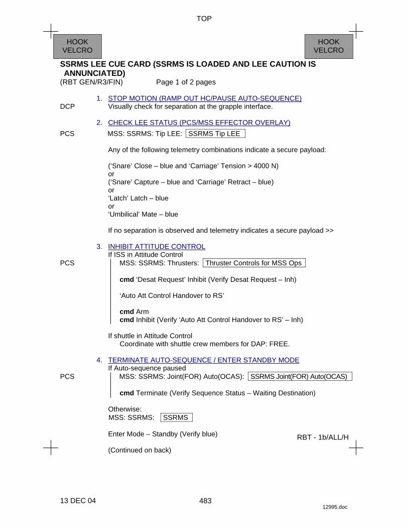
TOP
SSRMS LEE CUE CARD (SSRMS IS LOADED AND LEE CAUTION IS ANNUNCIATED)
(RBT GEN/R3/FIN) Page 1 of 2 pages
13 DEC 04 12995.doc
HOOK VELCRO
HOOK VELCRO
RBT - 1b/ALL/H
1. STOP MOTION (RAMP OUT HC/PAUSE AUTO-SEQUENCE) DCP Visually check for separation at the grapple interface. 2. CHECK LEE STATUS (PCS/MSS EFFECTOR OVERLAY) PCS MSS: SSRMS: Tip LEE: SSRMS Tip LEE
Any of the following telemetry combinations indicate a secure payload:
(‘Snare’ Close – blue and ‘Carriage’ Tension > 4000 N) or (‘Snare’ Capture – blue and ‘Carriage’ Retract – blue) or ‘Latch’ Latch – blue or ‘Umbilical’ Mate – blue
If no separation is observed and telemetry indicates a secure payload >>
3. INHIBIT ATTITUDE CONTROL
If ISS in Attitude Control PCS MSS: SSRMS: Thrusters: Thruster Controls for MSS Ops
cmd ‘Desat Request’ Inhibit (Verify Desat Request – Inh)
‘Auto Att Control Handover to RS’
cmd Arm cmd Inhibit (Verify ‘Auto Att Control Handover to RS’ – Inh)
If shuttle in Attitude Control
Coordinate with shuttle crew members for DAP: FREE. 4. TERMINATE AUTO-SEQUENCE / ENTER STANDBY MODE
If Auto-sequence paused PCS MSS: SSRMS: Joint(FOR) Auto(OCAS): SSRMS Joint(FOR) Auto(OCAS)
cmd Terminate (Verify Sequence Status – Waiting Destination)
Otherwise: MSS: SSRMS: SSRMS
Enter Mode – Standby (Verify blue)
(Continued on back)
483

TOP
SSRMS LEE CUE CARD (SSRMS IS LOADED AND LEE CAUTION IS ANNUNCIATED)
(RBT GEN/R3/FIN) Page 2 of 2 pages
13 DEC 04 12995.doc
HOOK VELCRO
HOOK VELCRO
RBT - 1b/ALL/H
5. RETRACT CARRIAGE If ‘Snare’ Capture – blue and (‘R3N - SSRMS LEE Rigidize Brk Slip’ and/or
‘R3Q - SSRMS LEE Uncommanded Derigidize’ Cautions were annunciated)
PCS MSS: SSRMS: Tip LEE: SSRMS Tip LEE
cmd ‘Carriage’ Retract � Slow, Hard Stops (Verify ‘Stops’ – Hard)
Verify ‘Confirm or Terminate’ prompt.
cmd Confirm (Verify Hot Trigger icon) RHC TRIGGER → press (hold until ‘Carriage’ Brakes – On) >>
WARNING
The following procedure will release the payload, and should not be performed unless the operator has determined that releasing is the safest course of action.
6. RELEASE PAYLOAD AND MANEUVER SSRMS CLEAR
Only perform this procedure if the crew has determined that releasing the payload is the safest course of action.
PCS MSS: SSRMS: SSRMS
√Command – Internal √Vernier
Enter Mode – Manual (Verify blue)
√Base joint locked as required
MSS: SSRMS: Tip LEE: SSRMS Tip LEE
cmd ‘Snare’ Open � Slow, Hard Stops (Verify Stops – Hard)
Verify ‘Confirm or Terminate’ Prompt
cmd Confirm (Verify Hot Trigger icon)
RHC TRIGGER → press (hold until ‘Snare’ Brakes – On) THC/ Maneuver SSRMS to safe distance.
RHC
484

Related Documents


![Robotics 1deluca/rob1_en/rob1_en_2014-15/02... · [see the course “Medical Robotics”] overview of the operating room command station ... EUropean RObotics research Network, with](https://static.cupdf.com/doc/110x72/5abe037b7f8b9ad8278c9c5f/robotics-1-delucarob1enrob1en2014-1502see-the-course-medical-robotics.jpg)