Polar plasticity of thin-walled composites made of ideal fibre-reinforced material Kostas P. Soldatos ⇑ School of Mathematical Sciences, University of Nottingham, Nottingham NG7 2RD, UK Spencer Institute of Theoretical and Computational Mechanics, University of Nottingham, Nottingham NG7 2RD, UK article info Article history: Received 23 December 2011 Received in revised form 2 November 2012 Available online 5 January 2013 Keywords: Bimodal plasticity Fibre-reinforced materials Matrix dominated mode Non-symmetric plasticity Polar material plasticity Yield surfaces abstract The present study investigates the influence that polar material response has on the plastic behaviour of thin-walled structures made of ideal fibre-reinforced materials (Spencer, 1972); or, equivalently, on the response of thin-walled fibrous composites within the first branch of the matrix dominated form (MDM) of the bimodal theory of plasticity (Soldatos, 2011; Dvorak and Bahei-El-Din, 1987). The plasticity studies mentioned above assume that fibres are infinitely thin and, therefore, perfectly flexible. They possess no bending stiffness and, hence, their negligible bending resistance cannot influence the developed stress state, which is accordingly described by a symmetric stress tensor. In contrast, the present study consid- ers that if fibres resistant in bending are embedded in a material at high volume concentrations, their flexure produces couple-stress and, as a result of this kind of polar material behaviour, the stress tensor becomes non-symmetric. Under plane stress conditions that dominate behaviour of thin-walled struc- tures, the stress-space and, therefore, conditions of plastic yield and relevant yield surfaces are thus four-dimensional. However, shapes and properties of initial yield surfaces relevant to the f 1 -branch of MDM are studied comprehensively by considering their projection on particular planes of such a four- dimensional stress-space. It then becomes easier understood that, in the regime of polar material response, a thin-walled structure made of ideal fibre-reinforced material deforms plastically when suit- able combinations of shear stress values are reached simultaneously, rather than when only one of two unequal shear stress components reaches some maximum absolute value. Thus, polar material plasticity dismisses the conventional concept of material yield stress in shear and replaces it with a pair of two independent yield moduli. Existence of the latter is perceived as a theoretical justification of the expec- tation that, due to the presence of fibres, two rather than one shear yield parameters of the composite should be present and accountable for. The non-zero values of those parameters are shown to exert par- amount influence on the form of the yield surface of the ideal fibre-reinforced material of interest. Ó 2013 Elsevier Ltd. All rights reserved. 1. Introduction The plasticity theory of ideal fibre-reinforce materials was initi- ated by Spencer and his collaborators (Mulhern et al., 1967) and communicated for publication by R. Hill, FRS, at a time that the set of corresponding experimental data available was essentially negligible. Despite the good and encouraging agreement of its pre- dictions with that particularly limited set of available experimental data (Cooper, 1966; Jackson and Cratchley, 1966), Spencer (1992) admittedly quoted later that ‘‘the theory had to be regarded in a rather tentative manner’’ for approximately two decades; that is, until the bimodal theory of plasticity became available (Dvorak and Bahei-El-Din, 1987) and its validity was underpinned by a comprehensive amount of relevant experimental measurements (see also Dvorak et al., 1988, 1991; Nigam et al., 1994a, 1994b). The striking similarity between important characteristics of those two differently established plasticity models was noted immediately by Dvorak and Bahei-El-Din (1987), Dvorak et al. (1988), Dvorak (2000) and was also welcomed by Spencer (1992). However, it is only recently, almost two more decades later (Soldatos, 2011), that complete elucidation is achieved of the man- ner in which the experimentally established bimodal theory (Dvo- rak and Bahei-El-Din, 1987; Dvorak et al., 1988, 1991; Nigam et al., 1994a,b) relates physically and mathematically to the plasticity theory of ideal fibre-reinforced solids (Mulhern et al. 1967, 1969; Spencer, 1972, 1992). Arguments of the invariant theory of tensor representations made accordingly clear (Soldatos, 2011) that activation of the ma- trix dominated mode (MDM) in bimodal plasticity is possible only if the applied stress state allows fibres to respond like they are practically inextensible. Moreover, activation of the more domi- nant, among the two MDM plastic slip branches is possible only if conditions of material incompressibility also apply, together with the implied constraint of fibre inextensibility. It is thus shown in 0020-7683/$ - see front matter Ó 2013 Elsevier Ltd. All rights reserved. http://dx.doi.org/10.1016/j.ijsolstr.2012.12.010 ⇑ Corresponding author. Address: School of Mathematical Sciences, University of Nottingham, Nottingham NG7 2RD, UK. Fax: +44 0 115 951 3837. E-mail address: [email protected] International Journal of Solids and Structures 50 (2013) 1078–1092 Contents lists available at SciVerse ScienceDirect International Journal of Solids and Structures journal homepage: www.elsevier.com/locate/ijsolstr

Welcome message from author
This document is posted to help you gain knowledge. Please leave a comment to let me know what you think about it! Share it to your friends and learn new things together.
Transcript

International Journal of Solids and Structures 50 (2013) 1078–1092
Contents lists available at SciVerse ScienceDirect
International Journal of Solids and Structures
journal homepage: www.elsevier .com/locate / i jsolst r
Polar plasticity of thin-walled composites made of ideal fibre-reinforced material
Kostas P. Soldatos ⇑School of Mathematical Sciences, University of Nottingham, Nottingham NG7 2RD, UKSpencer Institute of Theoretical and Computational Mechanics, University of Nottingham, Nottingham NG7 2RD, UK
a r t i c l e i n f o a b s t r a c t
Article history:Received 23 December 2011Received in revised form 2 November 2012Available online 5 January 2013
Keywords:Bimodal plasticityFibre-reinforced materialsMatrix dominated modeNon-symmetric plasticityPolar material plasticityYield surfaces
0020-7683/$ - see front matter � 2013 Elsevier Ltd. Ahttp://dx.doi.org/10.1016/j.ijsolstr.2012.12.010
⇑ Corresponding author. Address: School of MathemNottingham, Nottingham NG7 2RD, UK. Fax: +44 0 11
E-mail address: [email protected]
The present study investigates the influence that polar material response has on the plastic behaviour ofthin-walled structures made of ideal fibre-reinforced materials (Spencer, 1972); or, equivalently, on theresponse of thin-walled fibrous composites within the first branch of the matrix dominated form (MDM)of the bimodal theory of plasticity (Soldatos, 2011; Dvorak and Bahei-El-Din, 1987). The plasticity studiesmentioned above assume that fibres are infinitely thin and, therefore, perfectly flexible. They possess nobending stiffness and, hence, their negligible bending resistance cannot influence the developed stressstate, which is accordingly described by a symmetric stress tensor. In contrast, the present study consid-ers that if fibres resistant in bending are embedded in a material at high volume concentrations, theirflexure produces couple-stress and, as a result of this kind of polar material behaviour, the stress tensorbecomes non-symmetric. Under plane stress conditions that dominate behaviour of thin-walled struc-tures, the stress-space and, therefore, conditions of plastic yield and relevant yield surfaces are thusfour-dimensional. However, shapes and properties of initial yield surfaces relevant to the f1-branch ofMDM are studied comprehensively by considering their projection on particular planes of such a four-dimensional stress-space. It then becomes easier understood that, in the regime of polar materialresponse, a thin-walled structure made of ideal fibre-reinforced material deforms plastically when suit-able combinations of shear stress values are reached simultaneously, rather than when only one of twounequal shear stress components reaches some maximum absolute value. Thus, polar material plasticitydismisses the conventional concept of material yield stress in shear and replaces it with a pair of twoindependent yield moduli. Existence of the latter is perceived as a theoretical justification of the expec-tation that, due to the presence of fibres, two rather than one shear yield parameters of the compositeshould be present and accountable for. The non-zero values of those parameters are shown to exert par-amount influence on the form of the yield surface of the ideal fibre-reinforced material of interest.
� 2013 Elsevier Ltd. All rights reserved.
1. Introduction
The plasticity theory of ideal fibre-reinforce materials was initi-ated by Spencer and his collaborators (Mulhern et al., 1967) andcommunicated for publication by R. Hill, FRS, at a time that theset of corresponding experimental data available was essentiallynegligible. Despite the good and encouraging agreement of its pre-dictions with that particularly limited set of available experimentaldata (Cooper, 1966; Jackson and Cratchley, 1966), Spencer (1992)admittedly quoted later that ‘‘the theory had to be regarded in arather tentative manner’’ for approximately two decades; that is,until the bimodal theory of plasticity became available (Dvorakand Bahei-El-Din, 1987) and its validity was underpinned by acomprehensive amount of relevant experimental measurements(see also Dvorak et al., 1988, 1991; Nigam et al., 1994a, 1994b).
ll rights reserved.
atical Sciences, University of5 951 3837.
The striking similarity between important characteristics ofthose two differently established plasticity models was notedimmediately by Dvorak and Bahei-El-Din (1987), Dvorak et al.(1988), Dvorak (2000) and was also welcomed by Spencer(1992). However, it is only recently, almost two more decades later(Soldatos, 2011), that complete elucidation is achieved of the man-ner in which the experimentally established bimodal theory (Dvo-rak and Bahei-El-Din, 1987; Dvorak et al., 1988, 1991; Nigam et al.,1994a,b) relates physically and mathematically to the plasticitytheory of ideal fibre-reinforced solids (Mulhern et al. 1967, 1969;Spencer, 1972, 1992).
Arguments of the invariant theory of tensor representationsmade accordingly clear (Soldatos, 2011) that activation of the ma-trix dominated mode (MDM) in bimodal plasticity is possible onlyif the applied stress state allows fibres to respond like they arepractically inextensible. Moreover, activation of the more domi-nant, among the two MDM plastic slip branches is possible onlyif conditions of material incompressibility also apply, together withthe implied constraint of fibre inextensibility. It is thus shown in

K.P. Soldatos / International Journal of Solids and Structures 50 (2013) 1078–1092 1079
(Soldatos, 2011) that within the regime of the more dominantbranch of MDM, which is termed as the f1-branch of MDM, the re-sponse of the fibrous composite is that of an ideal fibre-reinforcedmaterial (Spencer, 1972).
It is now emphasised that all of the plasticity studies mentionedabove assume that fibres are infinitely thin and, therefore, perfectlyflexible. They possess no bending stiffness and, hence, their negli-gible bending resistance cannot possibly influence the developedstress state; the later is accordingly described by a symmetricstress tensor. However, arguments associated with elastic defor-mation of ideal fibre-reinforced materials made recently evident(Soldatos, 2009b, 2010a; Dagher and Soldatos, 2011) that thereare cases in which strong/stiff fibres may exhibit considerablebending resistance and, therefore, possess considerable bendingstiffness. These results favour the postulates of a new hyper-elasticity theory which accounts for fibre resistance in bending(Spencer and Soldatos, 2007). In particular, the fact that fibre bend-ing resistance produces couple-stress and makes thus the stresstensor non-symmetric becomes a feature of predominant impor-tance and influence in this investigation.
The anti-symmetric part of possible non-symmetric stress maybe of considerable influence if fibres resistant in bending areembedded in a material at high volume concentrations and, there-fore, cannot be always ignored or neglected. Nevertheless, suchanti-symmetric stress contribution exerts direct influence on theshear stress components only which, in the case of plastic re-sponse, are of predominant importance in the description of thef1-branch of MDM. Because the presence of couple-stress rendersthe fibre-reinforced composite of interest with properties of a polarmaterial, it is appropriate to distinguish the present analysis fromthe afore mentioned ‘‘symmetric’’ plasticity studies, by referring toit as ‘‘non-symmetric’’ or ‘‘polar’’ plasticity of fibre-reinforcedmaterials; for a definition of ‘‘polar’’ media see, for instance,(Truesdell and Noll, 1965; p. 389).
Due to stress non-symmetry (rij – rji), yield surfaces in three-dimensional polar plasticity are generally described in a nine-rather than a six-dimensional stress space; in the plane stress case,which is associated with plastic failure of thin-walled composites,these are described in a four- rather than a three-dimensionalstress space. It follows that the symmetric plasticity counterpartof the actual yield surface of a polar material is only the projectionof the actual yield surface in the corresponding symmetric stressspace. This reduction of the actual dimensions of the stress spacemay result in the loss of important information regarding the plas-tic behaviour of the polar material of interest.
For instance, the conventional (symmetric plasticity) f1-branchof MDM suggests that, when fibres are straight and aligned withthe x1-axis of a suitably chosen two-dimensional Cartesian co-ordi-nate system, the thin-walled fibrous composite of interest yieldsplastically as soon as the absolute value of the symmetric shearstress component (r21 = r12) reaches some maximum (Spencer,1972; Dvorak and Bahei-El-Din, 1987; Soldatos, 2011). However,when fibres are not perfectly flexible, the outlined polar plasticityarguments reveal that the ultimate, polar plasticity version of theMDM yield surface will be described in a four- rather than athree-dimensional stress space. Hence, plastic failure of the com-posite within its f1-branch of MDM should rather be reached bysuitable combinations of the values of r21 and r12 which, moregenerally, are expected to be unequal.
Under these considerations, the present study investigates theinfluence that the outlined polar plasticity concepts have on the re-sponse of thin-walled structures made of ideal fibre-reinforcedmaterial; or, equivalently, on the response of thin-walled fibrouscomposites within the f1-branch of MDM of bimodal plasticity. Inthis context, Section 2 introduces basic theoretical concepts thatunderpin relevant developments under the plane stress conditions
that dominate response of thin-walled structures. Section 2 servesalso as a link between the outlined bimodal plasticity concepts forpolar fibre-reinforced materials and relevant theoretical resultsstemming from the invariant theory of tensor representations.Those results are initially provided for fibres of general shape butthey are also specialised for the particular case of straight fibresconsidered in experiments (Dvorak and Bahei-El-Din, 1987).
Postulates which are commonly employed in conventional plas-ticity theory favour yield surfaces which are (i) polynomials in theindependent stress invariants, and (ii) quadratic in the stresses.Being employed in Section 3, these equip the present study withability to search for and to establish the most general relevant formof a yield condition within the f1-branch of bimodal polar materialplasticity. The particular case of straight fibres makes thus under-stood that the projection (cross-section) of that yield surface on theaforementioned principal plane of stress-space, that is the r21r12-plane, will have the form of a conic section. Hence, the polar mate-rial version sought of the f1-branch of MDM emerges as a choiceamong four potential yield surfaces; a pair of single-parameterand a pair of two-parameter surfaces.
The case of straight fibres becomes thus the pilot case of studyin Section 4 and Section 5 where, for simplicity, one of the single-and one of the double-parameter surfaces, respectively, is consid-ered and investigated thoroughly. Completeness of the presentstudy requires a similarly comprehensive investigation of theremaining couple of a potential yield surfaces. However, for sim-plicity, this is outlined in corresponding Appendices because itresembles the analysis outlined in Section 4 and Section 5 to a con-siderable extent. A considerable and complete amount of valuableinformation is thus obtained, regarding the manner in which plas-tic slip is initiated in ideal fibre-reinforced composites that exhibitpolar material behaviour.
Section 6 returns afterwards to and discusses the relevant form-invariant generalisation of the f1-branch of the MDM, where fibresresistant in bending are considered to be of general shape; certainimportant features of an associated flow rule are also discussed inthat section. Finally, Section 7 gives a comprehensive summary ofthe most important findings of this investigation.
2. Preliminary physical concepts and relevant mathematicalfoundation
Consider a thin layer of a unidirectional fibrous compositewhich is in a macroscopically uniform state of plane stress. Themiddle-plane of the layer coincides with the x1x2-plane of a Carte-sian co-ordinate system Oxi; the Ox3-axis is directed upwards (La-tin indices take the values 1, 2 and 3). The unidirectional family offibres embedded in the layer is assumed lying on planes parallel tothe x1x2-plane. The fibre shape and direction is completely deter-mined by a unit plane vector a, with non-zero components aa(Greek indices take values 1 and 2); the material thus behaves aslocally transverse isotropic, with a defining the local direction oftransverse isotropy. The so-called n-curves are the orthogonal tra-jectories of the a-curves in the x1x2-plane; they have tangent vectorn = (n1, n2)T = (�a2, a1)T and are not material curves. Those twofamilies of curves may form an alternative, local, rectangular, cur-vilinear co-ordinate system on the x1x2-plane. The assumed state ofuniform plane stress suggests that the Cauchy stress tensor, r, is aplane tensor with non-zero components rab only.
Consideration of fibre bending resistance necessitates introduc-tion of a couple-stress vector, m, with non-zero components ma3
(Soldatos, 2009a, 2010a,b, 2012). Hence, unlike (Dvorak andBahei-El-Din, 1987; Soldatos, 2011) where fibres are consideredperfectly flexible, the present study postulates that the considered
1080 K.P. Soldatos / International Journal of Solids and Structures 50 (2013) 1078–1092
state of plane stress is non-symmetric. The Cauchy stress tensor isaccordingly susceptible to the standard decomposition
rab ¼ rðabÞ þ r½ab�; ð2:1aÞ
where, the appearing symmetric and anti-symmetric parts of stressare respectively defined as follows:
rðabÞ ¼12ðrab þ rbaÞ;r½ab� ¼
12ðrab � rbaÞ: ð2:1bÞ
Moreover, the anti-symmetric part of stress relates to couple-stress as follows (Soldatos, 2009b, 2010a,b):
r½21� ¼ �r½12� ¼12
ma3;a; ð2:2Þ
here, as well as in what follows, the usual summation convention ofrepeated indices is employed. It is recalled that, within the regimeof elastic material response, r(ab) and ma3 are constitutionally inde-pendent; in the sense that they relate with the deformation inde-pendently, through constitutive equations of the type outlined in(Spencer and Soldatos, 2007; Soldatos, 2009a, 2010a,b, 2011). Byvirtue of (2.2) which are essentially equilibrium requirements,r(ab) and r[ab] are, therefore, also constitutionally independent inthe elastic deformation regime, and they are expected to remainso within the regime of plastic deformation.
In accordance with standard principles of plasticity theory, thepresent development postulates existence of a yield functionf ðrab; aaÞ; such that f 6 0 in admissible plane stress states; whenf < 0 the material responds elastically while plastic deformationmay occur as soon as f = 0. The fact that the stress tensor is non-symmetric (r21 – r21) implies that the stress-space is four-dimen-sional. In this regard, the three-dimensional stress-spacesr11r22r21 and r11r22r12, which may be considered geometricallyidentical in symmetric plasticity (Dvorak and Bahei-El-Din, 1987;Soldatos, 2011), are now three-dimensional subspaces of the ac-tual, four-dimensional r11r22r21r21-space; as such they are inde-pendent and distinct, both physically and geometrically. Thereobviously exist two more three-dimensional subspaces of ther11r22r21r21-space; namely r11r21r12 and r22r21r12.
Under these considerations, the general form of a yield functionbecomes susceptible to the following dual representation
f ðrab; aaÞ ¼ f ðrðabÞ; r½ab�; aaÞ: ð2:3Þ
This should obey standard objectivity rules and should, there-fore, be expressible as a function the following isotropic invariantsof r(ab), r[ab] and aa:
J1 ¼ raa � aarabab ¼ raa � aarðabÞab; J2 ¼ 12 ½rðabÞrðbaÞ � rccðraa � 2rabaaabÞ�;
J3 ¼ aarabab ¼ aarðabÞab; K1 ¼ � 12 r½ab�r½ba� ¼ 1
2 r½ab�r½ab�; K2 ¼ 12 aarðabÞr½bc�ac:
ð2:4Þ
The subset {J1, J2, J3} consists the irreducible set of independentisotropic invariants employed in the symmetric bimodal plasticitymodel (Soldatos, 2011). The additional invariants K1 and K2 make(2.4) an irreducible set of independent isotropic invariants (e.g.,Korsgaard, 1990; Zheng, 1994) in the present non-symmetricstress space. The latter pair of invariants is associated with anti-symmetric stress action and, therefore, with effects of fibre resis-tance in bending. Their dismissal should, therefore, be expectedto (and will) reduce the results of the present study into their sym-metric plasticity counterparts (Soldatos, 2011).
2.1. The yield surface of the Matrix Dominated Mode (MDM) insymmetric (non-polar) plasticity
In symmetric plasticity (Dvorak and Bahei-El-Din, 1987; Solda-tos, 2011), the MDM mode of the bimodal plasticity theory consistsof two branches; these are denoted as f1 and f2 in Soldatos (2011).
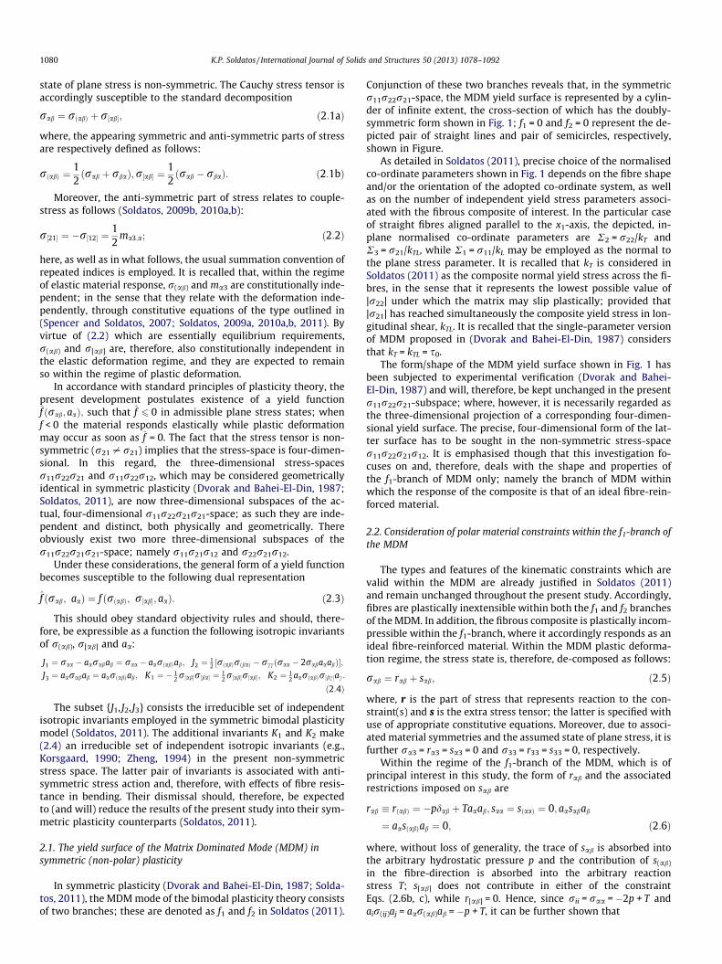
Conjunction of these two branches reveals that, in the symmetricr11r22r21-space, the MDM yield surface is represented by a cylin-der of infinite extent, the cross-section of which has the doubly-symmetric form shown in Fig. 1; f1 = 0 and f2 = 0 represent the de-picted pair of straight lines and pair of semicircles, respectively,shown in Figure.
As detailed in Soldatos (2011), precise choice of the normalisedco-ordinate parameters shown in Fig. 1 depends on the fibre shapeand/or the orientation of the adopted co-ordinate system, as wellas on the number of independent yield stress parameters associ-ated with the fibrous composite of interest. In the particular caseof straight fibres aligned parallel to the x1-axis, the depicted, in-plane normalised co-ordinate parameters are R2 = r22/kT andR3 = r21/kTL, while R1 = r11/kL may be employed as the normal tothe plane stress parameter. It is recalled that kT is considered inSoldatos (2011) as the composite normal yield stress across the fi-bres, in the sense that it represents the lowest possible value of|r22| under which the matrix may slip plastically; provided that|r21| has reached simultaneously the composite yield stress in lon-gitudinal shear, kTL. It is recalled that the single-parameter versionof MDM proposed in (Dvorak and Bahei-El-Din, 1987) considersthat kT = kTL = s0.
The form/shape of the MDM yield surface shown in Fig. 1 hasbeen subjected to experimental verification (Dvorak and Bahei-El-Din, 1987) and will, therefore, be kept unchanged in the presentr11r22r21-subspace; where, however, it is necessarily regarded asthe three-dimensional projection of a corresponding four-dimen-sional yield surface. The precise, four-dimensional form of the lat-ter surface has to be sought in the non-symmetric stress-spacer11r22r21r12. It is emphasised though that this investigation fo-cuses on and, therefore, deals with the shape and properties ofthe f1-branch of MDM only; namely the branch of MDM withinwhich the response of the composite is that of an ideal fibre-rein-forced material.
2.2. Consideration of polar material constraints within the f1-branch ofthe MDM
The types and features of the kinematic constraints which arevalid within the MDM are already justified in Soldatos (2011)and remain unchanged throughout the present study. Accordingly,fibres are plastically inextensible within both the f1 and f2 branchesof the MDM. In addition, the fibrous composite is plastically incom-pressible within the f1-branch, where it accordingly responds as anideal fibre-reinforced material. Within the MDM plastic deforma-tion regime, the stress state is, therefore, de-composed as follows:
rab ¼ rab þ sab; ð2:5Þ
where, r is the part of stress that represents reaction to the con-straint(s) and s is the extra stress tensor; the latter is specified withuse of appropriate constitutive equations. Moreover, due to associ-ated material symmetries and the assumed state of plane stress, it isfurther ra3 = ra3 = sa3 = 0 and r33 = r33 = s33 = 0, respectively.
Within the regime of the f1-branch of the MDM, which is ofprincipal interest in this study, the form of rab and the associatedrestrictions imposed on sab are
rab � rðabÞ ¼ �pdab þ Taaab; saa ¼ sðaaÞ ¼ 0; aasabab
¼ aasðabÞab ¼ 0; ð2:6Þ
where, without loss of generality, the trace of sab is absorbed intothe arbitrary hydrostatic pressure p and the contribution of s(ab)
in the fibre-direction is absorbed into the arbitrary reactionstress T; s[ab] does not contribute in either of the constraintEqs. (2.6b, c), while r[ab] = 0. Hence, since rii = raa = �2p + T andair(ij)aj = aar(ab)ab = �p + T, it can be further shown that

Fig. 1. The cross-section of the cylindrical surface that represents the MDM yield surface in the conventional stress-space; the normalised co-ordinate parameters R2 and R3
are defined in the text.
K.P. Soldatos / International Journal of Solids and Structures 50 (2013) 1078–1092 1081
�p ¼ raa � aarðabÞab; T ¼ 2aarðabÞab � raa;
s2ð12Þ � s11s22 ¼ 1
2 ðsðabÞsðbaÞ � saasbbÞ � ðssÞ2 P 0:ð2:7Þ
It is recalled (Soldatos, 2011) that the inequality (2.7c) becomesavailable as soon as the ratio a2/a1 is regarded as solution of thequadratic Eq. (2.6c).
Here, as well as in what follows, ss represents the symmetricpart of the shear component of the extra stress, when the latteris measured in the local co-ordinate system formed by the a- andthe n-curves; the same quantity is denoted with s in (Spencer,1972), where the normal component of the extra stress actingacross the fibres is further noted with sn. In the present, non-sym-metric stress case, the outlined notation is complemented by sa,which represents the anti-symmetric part of the local shearextra-stress component; as shown in (Soldatos, 2010a,b), it is sa =s[21] = r[21]. A combination of (2.5), (2.6a) and (2.7a, b) yields thenthe components of the extra stress tensor as follows:
sðabÞ ¼ rðabÞ � ðrll � rðlmÞalamÞdab þ ðrll � 2rðlmÞalamÞaaab;
s½21� ¼ sa ¼ r½21�: ð2:8Þ
With (2.8), the stress state becomes independent of either T or pwithin the f1-branch of the MDM. Hence, (2.3) reduces tof 1ðsab; aaÞ ¼ f1ðsðabÞ; s½ab�; aaÞ and is, therefore, a function of atmost two independent invariants; namely
~I1 ¼12
sðabÞsðbaÞ ¼ ðssÞ2; ~K ¼ 12
s½ab�s½ab� ¼ ðsaÞ2: ð2:9Þ
This is because the constraint Eqs. (2.6b,c) dismiss contributionsof the invariants (2.4a,c) while, at the same time, they prove redun-dant the invariant (2.4e); see Appendix A. It follows that, withinthe first branch of the MDM, the form (2.3) of a yield surface re-duces to
f 1ðrab; aaÞ ¼ f1ð~I1; ~KÞ: ð2:10Þ
Particular attention is finally given to the particular type ofthin-walled fibrous composites considered in (Dvorak and Bahei-El-Din, 1987) and in subsequent relevant experimental investiga-tions (Dvorak et al., 1988, 1991; Nigam et al., 1994a,b). It is recalledthat, in the elastic deformation regime (f < 0), that particular typeof fibrous composites was found to behave in a linearly elasticmanner. Hence, no distinction between reference and current con-
figuration was found necessary in the elastic deformation regime.The composites considered in (Dvorak and Bahei-El-Din, 1987;Dvorak et al., 1988, 1991; Nigam et al., 1994a,b) were reinforcedby straight fibres. This is a case in which considerable mathemat-ical simplification is achieved by choosing a = (1,0)T and, hence,aligning the x1-axis of the fixed Cartesian co-ordinate system alongthe fibre direction. With use of (2.5) and (2.6) within the class ofideal fibre-reinforced materials, it is thus seen that s11 = s22 = 0and s(21) = r(21) and hence, the stress invariants (2.9) obtain thesimplifying form
~I1 ¼ s2ð21Þ ¼ r2
ð21Þ;~K ¼ s2
½21� ¼ r2½21�: ð2:11Þ
3. The f1-branch of the MDM in polar plasticity
Yield functions in plasticity theory of fibre-reinforced materialsare traditionally chosen to be quadratic in the stress components(e.g., Mulhern et al., 1967; Spencer, 1972, 1992; Dvorak and Ba-hei-El-Din, 1987; Dvorak et al., 1988, 1991; Nigam et al. 1994a,b;Soldatos, 2011). That trend is historically associated with the suc-cess of the isotropic plasticity yield criteria of von Misses and theTresca and will still guide the present investigation. Morever,terms which are linear in the stresses will not be considered. Suchterms describe Bauschinger or back stress effects in an initial or asubsequent yield surface, respectively (e.g., Soldatos, 2011). Theirincorporation into the present analysis does not alter the resultsand conclusions of principal interest and, if necessary, may be pur-suit at some later stage with relative ease. Hence, for the sake ofsimplicity, the present analysis focuses on the f1-branch of the ini-tial MDM yield surface only and, also, disregards the influence ofBauschinger effects.
Analysis thus begins with the most general form that a yieldcondition may attain within the class of ideal fibre-reinforcedmaterials, when the associated yield function is (i) at most strictlyquadratic in the stresses and (ii) a polynomial in the associated pairof independent stress invariant (2.9). This is necessarily as follows:
f1ð~I1; ~KÞ � a1~I1 þ a2
~K � 1 ¼ 0; ð3:1Þ
where, the coefficients a1 and a2 are real and independent of the ex-tra stress components and of their invariants. By virtue of (2.9),

1082 K.P. Soldatos / International Journal of Solids and Structures 50 (2013) 1078–1092
these coefficients cannot be simultaneously negative or simulta-neously zero. They may generally be regarded as material yieldparameters of the particular fibre-reinforced material of interestand, as a consequence, their values are due to be determined exper-imentally. Since the f1-branch of MDM is solely related to shearstress action, both a1 and a2 are regarded as material parametersrelevant to plastic response of the composite in shear.
It is thus important to recall that the symmetric plasticity ver-sion of the bimodal theory was initially introduced as a single-parameter plasticity model, where the single material parameterinvolved, s0, was employed to represent the matrix yield stressin shear (Dvorak and Bahei-El-Din, 1987; Nigam et al., 1994a,b);or the composite yield stress in longitudinal shear (Dvorak et al.,1988, 1991). The appearance in (3.1) or (3.2) of two independentcoefficients, a1 and a2, consists a proper theoretical justificationof the intuitive claim that, due to the presence of fibres, two shearyield parameters of the composite should, in general, be present.
The special case of straight fibres is thus a case of particularimportance because, apart from its simplicity, it also serves as aconnection between the present theoretical analysis and theexperimental evidence reported in (Dvorak and Bahei-El-Din,1987; Dvorak et al., 1988, 1991; Nigam et al. 1994a). In that case,expression (3.1) simplifies and, by virtue of (2.11), becomes
f1ð~I1; ~KÞ � a1r2ð21Þ þ a2r2
½12� � 1 ¼ 0: ð3:2Þ
By observing that, with use of (2.1b), (3.2) takes the alternativeform
f 1 �14ða1 þ a2Þðr2
21 þ r212Þ þ
12ða1 � a2Þr21r12 � 1 ¼ 0; ð3:3Þ
the latter expressions serves as connection between the presenttheoretical analysis and the experimental evidence reported in(Dvorak and Bahei-El-Din, 1987; Dvorak et al., 1988, 1991; Nigamet al. 1994a). In either of its alternative forms, (3.2) and (3.3), thisis a quadratic equation in the shear stresses and, in general, repre-sents a conic section in the r21r12-plane of the four-dimensionalstress-space r11r22r21r12.
Different choices of the coefficients a1 and a2 lead to differentgeometrical forms of to the f1-branch of MDM. If both a1 and a2
are positive, then (3.2) and, therefore, (3.3) represents an ellipsecentred at the origin of the r21r12-plane and having its principalaxes along the bisectors of the right angles formed by the r21-and r12-axes. If one of a1 and a2 is positive while the other is neg-ative, then (3.2) and, therefore, (3.3) is a hyperbola of similar fea-tures; that is, centred at the origin of the r21r12-plane and havingits principal axes along the bisectors of the aforementioned right an-gles. Thus, with non-zero values of a1 and a2, (3.2) represents a pairof two-parameter polar material versions of the f1-branch of MDM.If, on the other hand, one of the real coefficients a1 and a2 is zero,then (3.2) transforms into a single-parameter yield condition, pro-vided that the remaining non-zero coefficient is positive.
Wherever in what follows the stress subspaces r22r21r12 orr11r21r12 are employed or implied for a three-dimensional geomet-rical representation of the f1-branch of MDM, the r22- or the r11-axis,respectively, is perceived normal to the plane of the conic (3.2) or,equivalently, (3.3). Thus, regardless of its actual shape, that conic al-ways represents the cross-sectional curve of a cylindrical surface ofinfinite extent; the generator of that cylinder is parallel to the r22-or r11-axis in the r22r21r12- or r11r21r12-subspace, respectively.
Among the two single-parameter yield surfaces that emergefrom (3.2), that for which a2 = 0 will be regarded as the principalsuch and, due to its relative simplicity, will be introduced andstudied separately in Section 4. It is emphasised, and will be alsobecome clear in Section 4, that the zero value assigned to a2
implies neither that fibres are perfectly flexible nor that the
resulting yield surfaces reduces to its symmetric elasticity counter-part. In symmetric plasticity a2 cannot be felt and/or becomeunderstood, not because it is negligible or exactly equal to zerobut because the assumption of perfectly flexible fibres either con-siders negligible or ignores the contribution of r[21]. In this regard,incorporation into the corresponding symmetric plasticity modelof two plastic yield material parameters may be attempted onlythrough their necessary and simultaneous connection with the sin-gle coefficient, a1, which remains active in the resulting yield con-dition. Such an attempt gave rise to two different f1-branches in thesymmetric MDM regime; see Section 4 of (Soldatos, 2011), wherethose material parameters, termed as kTL and kLT, are associatedwith the composite plastic yield in longitudinal and transverseshear, respectively.
In a similar manner, only one of the two two-parameter yieldsurfaces emerging from (3.2) is considered and studied separatelyin the main body of this investigation. This is the case (see Sec-tion 5) in which both a1 and a2 are considered positive and, hence,(3.2) represents the elliptic cross-section of a corresponding yieldsurface on the r21r12-plane. Nevertheless, it is pointed out thatcompleteness of the present study requires, similarly, a compre-hensive study of the remaining couple of potential yield surfacesthat emerge from (3.2). For simplicity and brevity, these studiesare outlined in Appendices B and C because they resemble to a con-siderable extent their counterparts detailed in Section 4 and Sec-tion 5, respectively. In this context, it should be further pointedout that any of the four different forms of a yield surface emergingfrom (3.2) or, more generally, (3.1) may currently be regarded astentative but possible; in the sense that its existence in nature re-quires experimental verification and, consequently, associationwith some particular class of unidirectional fibrous composites.
4. The principal single-parameter form of the f1-branch of theMDM in polar plasticity
The form of (3.2) obtained by setting a2 = 0 will be called theprincipal single-parameter of the f1-branch of the MDM when fi-bres are straight. Provided that a1 > 0, this leads to the yieldcondition
f1ðr21;r12Þ � ðrð21Þ=kðTLÞ � 1Þðrð21Þ=kðTLÞ þ 1Þ ¼ 0; kðTLÞ
¼ 1=ffiffiffiffiffia1p
; ð4:1Þ
where k(TL) is a real and positive yield stress parameter. This param-eter will be shown relevant to purely symmetric stress action andmay accordingly be regarded as predominantly relevant to the com-posite yield response in longitudinal shear.
The alternative single-parameter form of (3.2) is obtained bysetting a1 = 0 but, for reasons mentioned already, a comprehensiveanalysis of it is outlined in Appendix B. The additional, indepen-dent yield parameter, k[LT], introduced there is shown relevant topurely anti-symmetric shear stress action. That yield parametercannot influence developments in the present section. However,together with k(TL), it plays an important role in the geometricalinterpretation of the two-parameter forms of the f1-branch ofMDM discussed later (see Section 5 and Appendix C).
Expression (4.1) makes immediately understood that, in thisform, the f1-branch of the MDM yield surface may still be repre-sented graphically in the convenient three-dimensional mannerdepicted in Fig. 1; by choosing
R3 ¼ ðr21 þ r12Þ=2s0; ð4:2Þ
and leaving R2 = r22/kT. Consideration of a third stress dimension,with co-ordinate parameter either R1 = r11/s0 or R1 = r11/kL, mightthen conveniently transform the actual four-dimensional stress-space into an effectively three-dimensional such. Nevertheless,
K.P. Soldatos / International Journal of Solids and Structures 50 (2013) 1078–1092 1083
discussion in what follows is still based on the previously estab-lished concepts of a four-dimensional stress-space.
4.1. Geometric representation and interpretation of the yield surface
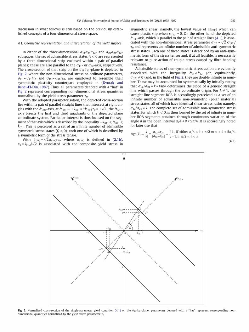
In either of the three-dimensional r11r21r12- and r22r21r12-subspaces, the set of admissible stress states f1 6 0 are representedby a three-dimensional strip enclosed within a pair of parallelplanes; these are also parallel to the r11- or r22-axis, respectively.The cross-section of that strip on the r21r12-plane is depicted inFig. 2, where the non-dimensional stress co-ordinate parameters,r21 = r21/s0 and r12 = r12/s0, are employed to resemble theirsymmetric plasticity counterpart employed in (Dvorak andBahei-El-Din, 1987). Thus, all parameters denoted with a ‘‘hat’’ inFig. 2 represent corresponding non-dimensional stress quantitiesnormalised by the yield stress parameter s0.
With the adopted parameterisation, the depicted cross-sectionlies within a pair of parallel straight lines that intersect at right an-gles with the rð21Þ-axis, at rð21Þ ¼ �kðTLÞ = ±k(TL)/s0 = �
ffiffiffi2p
; the rð21Þ-axis bisects the first and third quadrants of the depicted planeco-ordinate system. Particular interest is thus focused on the seg-ment of that axis which is described by the inequality�kðTLÞ 6 rð21Þ 6
kðTLÞ. This is perceived as a set of an infinite number of admissiblesymmetric stress states (f16 0), each one of which is described bya symmetric form of the stress tensor.
With rð21Þ =ffiffiffi2p
r(21)/s0, where r(21) is defined in (2.1b),s0 = k(TL)/
ffiffiffi2p
is associated with the composite yield stress in
Fig. 2. Normalised cross-section of the single-parameter yield condition (4.1) on thdimensional quantities normalised by the yield stress parameter s0.
symmetric shear; namely, the lowest value of |r(21)| which cancause plastic slip when r[12] = 0. On the other hand, the depictedr½12�-axis, which is parallel to the pair of straight lines (4.1), is asso-ciated with the non-dimensional stress parameter r½12� =
ffiffiffi2p
r[12]/s0 and represents an infinite number of admissible anti-symmetricstress states. Each one of these states is described by an anti-sym-metric form of the stress tensor and, if at all feasible, is necessarilyrelevant to pure action of couple stress caused by fibre bendingresistance.
Admissible states of non-symmetric stress action are evidentlyassociated with the inequality r21–r12 (or, equivalently,r½12� – 0) and, in the light of Fig. 2, they are double infinite in num-ber. These may be accounted for systematically by initially notingthat r12=r21 = k = tanh determines the slope of a generic straightline which passes through the co-ordinate origin. For k – 1, thestraight line segment BOA is accordingly perceived as a set of aninfinite number of admissible non-symmetric (polar material)stress states, all of which have identical shear stress ratio; namely,r12/r21 = k. The complete set of admissible non-symmetric stressstates, for which f1 6 0, is then formed by the set of infinite in num-ber BOA segments obtained through continuous variation of theangle h in the open interval p/4 < h < 5p/4. It is accordingly notedfor later use that
signðkÞ ¼ kjkj �
r12=r21
jr12=r21j¼
1; if either p=4 < h < p=2 or p < h < 5p=4;�1; if p=2 < h < p:
�ð4:3Þ
e r21r12-plane; parameters denoted with a ‘‘hat’’ represent corresponding non-

1084 K.P. Soldatos / International Journal of Solids and Structures 50 (2013) 1078–1092
The particular case h = 3p/4 represents, for instance, the afore-mentioned set of polar material stress states which, if at all feasi-ble, lie on the r½12�-axis. Since a2 = 0, that axis, which necessarilyrepresents anti-symmetric forms of the stress tensor, never crossesthe depicted yield surface. Hence, in the present case, couple-stresscan never impose by itself plastic deformation within the regime ofthe f1-branch of the MDM. Coincidentally, this is trivially true insymmetric plasticity where the concept of perfectly flexible fibres(r[21] = 0) dismisses by default any kind of couple-stress action,even if a2 is non-zero.
In the exceptional case h = p/4 (or, equivalently, k = 1), BOA rep-resents the aforementioned set of admissible symmetric stressstates which lie on the rð21Þ-axis. Thus, as far as symmetric plastic-ity is concerned, there is no mathematical difference in describinga stress state by using either the r12� or the r21� axis depicted inFig. 2. It is thus seen that, for loading paths which preserve stresssymmetry, the parameters r21/s0 and r12/s0 are practically equiv-alent and, thus, either of them may be associated with the R3-axisdepicted in Fig. 1. Fig. 2 makes then understood that the co-ordi-nates of the points rð21Þ ¼ �kðTLÞ ¼ �
ffiffiffi2p
of the rð21Þ-axis, namelyr12 ¼ r21 = ±1, are the projections on the r21r12-plane of the f1-branches of the yield surface depicted in Fig. 1; recall thatR2 = r22/kT in Fig. 1 and that the R2-axis is considered normal tothe plane of Fig. 2.
A geometric connection is thus established between symmet-ric and polar material plasticity. This is clarified further in Fig. 2by denoting with �kTL = ± kTL/s0 and �kLT = ±kLT/s0 the r21- andthe r12-coordinates, respectively, of the depicted points A andB; both kTL and kLT are considered positive and kLT = |k|kTL. It isthen seen that the pair of straight lines R3 = ±1, which determinethe position of the f1-branch in Fig. 1, moves to R3 = �kTL in thepolar plasticity case. However, if the vertical axis R3 = r21/s0
is re-parameterised as R3 = r12/s0 in Fig. 1, then the corre-sponding pair of straight lines emerges at R3 = �kLT ¼ �jkjkTL.The latter pair of lines may therefore be thought of as an addi-tional f1-branch of the MDM, similar in nature to its symmetricplasticity counterpart considered in Section 4.2 of (Soldatos,2011).
Under these considerations, kTL and kLT are perceived as a pair ofyield stress parameters which are solely associated with a subset ofpolar material stress states having a common constant ratio r12/r21 = k = tanh. If |r21| < kTL or, equivalently, |r12| < kLT = |k|kTL, thematerial responds elastically; plastic slip of the matrix emergesas soon as |r21| = kTL or, equivalently, |r12| = kLT = |k|kTL. Neverthe-less, rotation of the ray AOB about the origin makes further under-stood that, in contrast with relevant symmetric plasticityassumptions (Soldatos, 2011), the anticipated values of kTL andkLT are neither constant nor independent. They both depend onthe value of a single yield material parameter, namely the yieldstress in symmetric shear s0 = k(TL)/
ffiffiffi2p
, to which they interrelateas follows:
kTL þ signðkÞkLT ¼ �ffiffiffi2p
kðTLÞ ¼ �2s0; ð4:4Þhere, use of (4.3) is also made.
Thus, symmetric plasticity response is associated only withone of the aforementioned possible loading paths. If feasible,that path requires that k = 1 and, therefore, kLT = kTL = s0 =kðTLÞ=
ffiffiffi2p
. In particular cases where fibres are considered per-fectly flexible (Dvorak and Bahei-El-Din, 1987; Soldatos,2011), this becomes the only loading path that can possiblybe associated with the response of the fibrous composite ofinterest.
4.2. Refinement and simplification of the yield surface interpretation
It is now observed that use of r12 = kr21 converts (4.2) into
R3 ¼ r21=s0ðkÞ; s0ðkÞ ¼2s0
ð1þ kÞ ¼ffiffiffi2p
kðTLÞ
ð1þ kÞ ; ð4:5Þ
where the new normalisation stress parameter, s0ðkÞ, depends onthe loading path and is, therefore, variable. Sinces0ð1Þ ¼ s0 ¼ kðTLÞ=
ffiffiffi2p
, association of the parameter (4.5) with thevertical axis of Fig. 1 endorses that Figure as an accurate represen-tation of the f1-branch of MDM yield surface, both in its present,single-parameter polar plasticity form and in its symmetric plastic-ity counterpart (Dvorak and Bahei-El-Din, 1987; Soldatos, 2011).Hence, with (4.5) and R2 = r22/kT, the f1-branch of MDM depictedin Fig. 1 is still able to represent the cross-section, on the r22r21-plane, of the corresponding part of the four-dimensional yield sur-face, regardless of the value of the variable k and, hence, regardlessof the loading path followed.
In a similar manner, the f1-branch of MDM depicted in Fig. 1represents further the cross-section of the same part of the actual,four-dimensional yield surface on the r11r12-plane. This becomespossible by employing R2 = r11/kL in Fig. 1 and, with use ofr21 = r12/k, by converting (4.2) into
R3 ¼ r12=~s0ðkÞ; ~s0ðkÞ ¼2s0
ð1þ 1=kÞ ¼ffiffiffi2p
kðTLÞ
ð1þ 1=kÞ : ð4:6Þ
Note that ~s0ð1Þ ¼ s0 ¼ kðTLÞ=ffiffiffi2p
and, therefore, there is again nocontroversy between the present, polar plasticity version of Fig. 1and its symmetric plasticity counterpart; the latter is again a par-ticular case of the former.
It is further observed that on the parts of the yield surfaceswhich lie within the first and the third quadrants of the r21r12-plane (Fig. 2), it is either jr21jP 1 and jr12j 6 1 or jr21j 6 1 andjr12jP 1. However, if jr21 þ r12j < 2 in the neighbourhood ofthose regions, the response of the composite is still elastic, despitethat, in general, the magnitude of one shear stress component ex-ceeds s0. This observation holds also true within the second andthe fourth quadrants of the r21r12-plane where, in many cases,elastic response seems possible even if jr21j and jr12j are bothgreater than one.
It becomes thus evident that the parameter s0 = kðTLÞ=ffiffiffi2p
maystill be perceived as a yield stress under conditions of symmetricshear but cannot anymore be regarded as the composite yieldstress in shear (Dvorak and Bahei-El-Din, 1987). This is because,within the non-symmetric stress regions (r21–r12), the materialdeforms plastically when suitable combinations of r21- and r12-values are reached simultaneously, rather than when only one ofr21 and r12 reaches some maximum absolute value. Such combi-nations of r21- and r12-values are dictated by the yield condition(4.1), which implies that, in certain regions of the r21r12-plane,the magnitude of one or both shear stresses, r21 and r12, may be-come considerably greater than s0 = kðTLÞ=
ffiffiffi2p
.
4.3. Further discussion and comments
The outlined revelations suggest that experimental verificationof this kind of polar plastic behaviour may become possible only ifthe values of both r21 and r12 are measured simultaneouslythroughout the loading process of a relevant fibrous compositespecimen. The set of values attained by the ratio k = r12/r21 willthus become also known during the entire course of such a loadingprocess; including its final stage, at which the associated (r21, r12)-pair will mark initiation of plastic slip, and the relevant (|r21|,|r12|)-pair will make available the corresponding (kTL, kLT)-pair. Dif-ferent loading processes are, in general, expected to end at differ-ent (r21,r12)-pairs, marking thus different (kTL,kLT) points on theyield surface. Nevertheless, the ratio k = r12/r21, which will thusbe always known, does not need to remain constant throughoutsuch a loading process.
K.P. Soldatos / International Journal of Solids and Structures 50 (2013) 1078–1092 1085
If the specimen obeys the described single-parameter rule ofplastic behaviour, the recorded (r21,r12)-pairs which are associ-ated with plastic slip initiation will be Cartesian co-ordinates ofpoints lying on two parallel straight lines of the r21r12-plane; eachline being mirror image of the other with respect to the bisector ofthe second and fourth quadrant of that plane. The value of the yieldparameter k(TL) =
ffiffiffi2p
s0 may thus be determined as the half dis-tance of these parallel lines. By normalising the obtained experi-mental results with s0, these are transformed into corresponding(�kTL; �kLT )-pairs and the ultimate form of this cross-section ofthe f1-branch of the yield surface will cross the normalised co-ordi-nate axes at ±2 (see Fig. 2).
It is anticipated that, in practice, neither |r21| nor |r12| can everbe infinitely large when plastic slip emerges in a fibrous composite.Parts of the depicted yield surfaces which are considerably remotefrom the rð21Þ-axis should, therefore, be regarded practically unat-tainable. The reachable parts of the yield surfaces (4.1) are accord-ingly expected to form bands which contain the points withco-ordinates r21 = ±1 and r12 = ±1. The width of those bands willdepend on the flexibility of the fibres involved in the particularfibrous composite of interest; the more flexible the fibres thenarrower the bands. Thus, those bands degenerate naturally tothe points (r21; r12) = (±1,±1) in the limiting case of perfectlyflexible fibres.
5. The first (elliptic) two-parameter form of the f1-branch of theMDM for straight fibres
In cases that both a1 and a2 are non-zero in (3.2), these coeffi-cients may be considered directly connected with and, therefore,replaced by the positive yield parameters k(TL) and k[LT] introducedin (4.1) and (B.1). Such a replacement renders k(TL) and k[LT] statusof independent material moduli and is straightforward when a1
and a2 are both positive; (3.2) is then an ellipse centred at the ori-gin of the r21r12-plane. However, if a1 and a2 have opposite signs,(3.2) converts into corresponding hyperbolas and the relationshipbetween the pairs (a1,a2) and (k(TL),k[LT]) requires appropriatereconsideration. Those two cases present considerable similaritybut also substantial difference. They are accordingly treated anddiscussed separately; the first in this section while, for brevity,the second in Appendix C. In this context, the composite yieldstresses in symmetric and anti-symmetric shear are respectivelydefined as follows:
kðTLÞ ¼ ja1j�1=2; k½LT� ¼ ja2j�1=2
: ð5:1Þ
It is recalled that a1 and a2 cannot be simultaneously negative,since (3.2) would represent an imaginary ellipse in that case.
5.1. Geometric representation and interpretation of the yield surface
If both a1 and a2 are positive, use of (5.1) converts the yield con-dition (3.2) into
f1ð~I1; ~KÞ � r2ð21Þ=k2
ðTLÞ þ r2½12�=k2
½LT� � 1 ¼ 0: ð5:2Þ
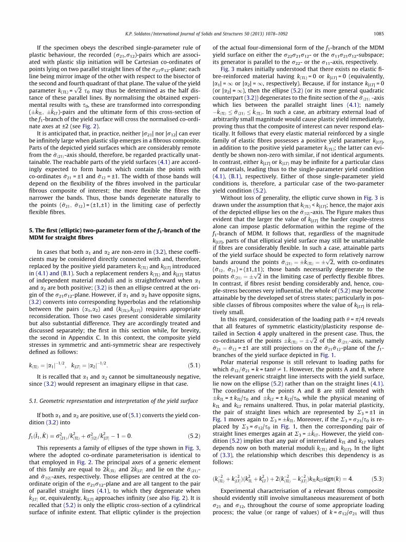
This represents a family of ellipses of the type shown in Fig. 3,where the adopted co-ordinate parameterisation is identical tothat employed in Fig. 2. The principal axes of a generic elementof this family are equal to 2kðTLÞ and 2k½LT� and lie on the rð21Þ-and r½12�-axes, respectively. Those ellipses are centred at the co-ordinate origin of the r21r12-plane and are all tangent to the pairof parallel straight lines (4.1), to which they degenerate whenk½LT� or, equivalently, k[LT] approaches infinity (see also Fig. 2). It isrecalled that (5.2) is only the elliptic cross-section of a cylindricalsurface of infinite extent. That elliptic cylinder is the projection
of the actual four-dimensional form of the f1-branch of the MDMyield surface on either the r22r21r12- or the r11r21r12-subspace;its generator is parallel to the r22- or the r11-axis, respectively.
Fig. 3 makes initially understood that there exists no elastic fi-bre-reinforced material having k(TL) = 0 or k[LT] = 0 (equivalently,|a1| =1 or |a2| =1, respectively). Because, if for instance k[LT] = 0(or |a2| =1), then the ellipse (5.2) (or its more general quadraticcounterpart (3.2)) degenerates to the finite section of the rð21Þ -axiswhich lies between the parallel straight lines (4.1); namely�kðTLÞ � rð21Þ � kðTLÞ. In such a case, an arbitrary external load ofarbitrarily small magnitude would cause plastic yield immediately,proving thus that the composite of interest can never respond elas-tically. It follows that every elastic material reinforced by a singlefamily of elastic fibres possesses a positive yield parameter k[LT],in addition to the positive yield parameter k(TL); the latter can evi-dently be shown non-zero with similar, if not identical arguments.In contrast, either k[LT] or k(LT) may be infinite for a particular classof materials, leading thus to the single-parameter yield condition(4.1), (B.1), respectively. Either of those single-parameter yieldconditions is, therefore, a particular case of the two-parameteryield condition (5.2).
Without loss of generality, the elliptic curve shown in Fig. 3 isdrawn under the assumption that k(TL) < k[LT]; hence, the major axisof the depicted ellipse lies on the r½12�-axis. The Figure makes thusevident that the larger the value of k[LT] the harder couple-stressalone can impose plastic deformation within the regime of thef1-branch of MDM. It follows that, regardless of the magnitudek[LT], parts of that elliptical yield surface may still be unattainableif fibres are considerably flexible. In such a case, attainable partsof the yield surface should be expected to form relatively narrowbands around the points rð21Þ ¼ �kðTLÞ ¼ �
ffiffiffi2p
, with co-ordinates(r12; r21) = (±1,±1); those bands necessarily degenerate to thepoints rð21Þ ¼ �
ffiffiffi2p
in the limiting case of perfectly flexible fibres.In contrast, if fibres resist bending considerably and, hence, cou-ple-stress becomes very influential, the whole of (5.2) may becomeattainable by the developed set of stress states; particularly in pos-sible classes of fibrous composites where the value of k[LT] is rela-tively small.
In this regard, consideration of the loading path h = p/4 revealsthat all features of symmetric elasticity/plasticity response de-tailed in Section 4 apply unaltered in the present case. Thus, theco-ordinates of the points �kðTLÞ ¼ �
ffiffiffi2p
of the rð21Þ-axis, namelyr21 ¼ r12 = ±1 are still projections on the r21r12-plane of the f1-branches of the yield surface depicted in Fig. 1.
Polar material response is still relevant to loading paths forwhich r12=r21 = k = tanh – 1. However, the points A and B, wherethe relevant generic straight line intersects with the yield surface,lie now on the ellipse (5.2) rather than on the straight lines (4.1).The coordinates of the points A and B are still denoted with�kTL = ± kTL/s0 and �kLT = ± kLT/s0, while the physical meaning ofkTL and kLT remains unaltered. Thus, in polar material plasticity,the pair of straight lines which are represented by R3 = ±1 inFig. 1 moves again to R3 = �kTL. Moreover, if the R3 = r21/s0 is re-placed by R3 = r12/s0 in Fig. 1, then the corresponding pair ofstraight lines emerges again at R3 = �kLT . However, the yield con-dition (5.2) implies that any pair of interrelated kTL and kLT valuesdepends now on both material moduli k(TL) and k[LT]. In the lightof (3.3), the relationship which describes this dependency is asfollows:
ðk�2ðTLÞ þ k�2
½LT�Þðk2TL þ k2
LTÞ þ 2ðk�2ðTLÞ � k�2
½LT�ÞkTLkLT signðkÞ ¼ 4: ð5:3Þ
Experimental characterisation of a relevant fibrous compositeshould evidently still involve simultaneous measurement of bothr21 and r12, throughout the course of some appropriate loadingprocess; the value (or range of values) of k = r12/r21 will thus
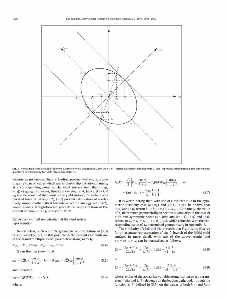
Fig. 3. Normalised cross-section of the two-parameter yield condition (5.2) on the r21r12-plane; parameters denoted with a ‘‘hat’’ represent corresponding non-dimensionalquantities normalised by the yield stress parameter s0.
1086 K.P. Soldatos / International Journal of Solids and Structures 50 (2013) 1078–1092
become again known. Such a loading process will end at some(r21,r12)-pair of values which marks plastic slip initiation; namely,at a corresponding point on the yield surface such that (|r21|,|r12|) = (kLT,kTL). However, though k = r12/r21 and, hence, |k| = kLT/kTL will be known at that point of the yield surface, the rather com-plicated form of either (5.2), (5.3) prevents derivation of a rela-tively simple mathematical formula which, in analogy with (4.2),would allow a straightforward geometrical representation of thepresent version of the f1-branch of MDM.
5.2. Refinement and simplification of the yield surfacerepresentation
Nevertheless, such a simple geometric representation of (5.3)or, equivalently, (5.2) is still possible in the present case with useof the standard elliptic curve parameterisation; namely
rð21Þ ¼ kðTLÞ cos u; r½12� ¼ k½LT� sinu: ð5:4Þ
It can then be shown that
kTL ¼ffiffiffi2p
kðTLÞcos u1þ k
��������; kTL ¼ jkjkTL ¼
ffiffiffi2p
k½LT�sin u
1� k�1
��������; ð5:5Þ
and, therefore,
kTL þ signðkÞkLT ¼ �2�s0ðkÞ; ð5:6Þ
where,
�s0ðkÞ ¼ffiffiffi2p
2
�����kðTLÞcos u1þ k
��������þ signðkÞk½LT�
sinu1� k�1
�������������; u
¼ tan�1 �k; �k ¼ kðTLÞ
k½LT�
k� 1kþ 1
: ð5:7Þ
It is worth noting that, with use of Hospital’s rule in the sym-metric plasticity case (h = p/4 and k = 1), it can be shown that(5.5) and (5.6) return kTL = kLT = �s0ð1Þ ¼ kðTLÞ=
ffiffiffi2p
; namely, the valueof s0 determined geometrically in Section 4. Similarly, in the case ofpure anti-symmetric shear (h = 3p/4 and k =�1), (5.5) and (5.6)reduce to kTL = kLT = �s0ð�1Þ ¼ k½LT�=
ffiffiffi2p
, which coincides with the cor-responding value of s0 determined geometrically in Appendix B.
The similarity of (5.6) and (4.4) reveals that Fig. 1 can still servefor an accurate representation of the f1-branch of the MDM yieldsurface. In more detail, with use of the above results andr12 = kr21, r(21) can be normalised as follows:
R3 ¼ðr21 þ r12Þ
2�s0ðkÞ¼ r21
s0ðkÞ; s0ðkÞ ¼
2�s0ðkÞð1þ kÞ ; ð5:8Þ
or
R3 ¼ðr21 þ r12Þ
2�s0ðkÞ¼ r12
~s0ðkÞ; ~s0ðkÞ ¼
2�s0ðkÞð1þ 1=kÞ ; ð5:9Þ
where, either of the appearing variable normalisation stress param-eters, s0ðkÞ and ~s0ðkÞ, depends on the loading path; and, through thefunction �s0ðkÞ defined in (5.7), on the values of both k(TL) and k[LT].

Fig. 4. Normalised cross-section of the single-parameter yield condition (B.1) on the r21r12-plane; parameters denoted with a ‘‘hat’’ represent corresponding non-dimensional quantities normalised by the yield stress parameter s0.
K.P. Soldatos / International Journal of Solids and Structures 50 (2013) 1078–1092 1087
Thus, with (5.8) and R2 = r22/kT, the f1-branch of MDM depicted inFig. 1 is an appropriately normalised representation of the cross-section of the corresponding part of the four-dimensional yield sur-face on the r22r21-plane. With (5.9) and R2 = r11/kL, Fig. 1 depictsan appropriately normalised form of the cross-section of the samepart of the yield surface on the r11r12-plane.
If the described form of the yield condition represents plasticbehaviour of some class of fibre-reinforced materials, the different(r21, r12)-pairs associated in a relevant experiment with plasticslip initiation would be Cartesian co-ordinates of points lying onan ellipse centred at the origin of the r21r12-plane and having itsprincipal axes along the bisectors of the right angle Or21r12. Thevalue of the yield parameters k(TL) =
ffiffiffi2p
�s0ð1Þ and k½LT� ¼ffiffiffi2p
�s0ð�1Þmay then be determined as the principal semi-axes of that ellipse.By normalising the obtained experimental results with �s0ð1Þ and,hence, replacing them with corresponding (�kTL; �kLT )-pairs, theultimate elliptic form of this cross-section of the f1-branch of theMDM yield surface becomes tangent to the straight lines (4.1);namely, the pair of parallel straight lines which cross the norma-lised co-ordinate axes at ±2 (see Fig. 3).
6. Fibres of general shape: form invariant representation of thef1-branch of the MDM
The yield condition (3.1) serves already as the form-invariantrepresentation of the f1-branch of the MDM, as long as the
associated yield function is (i) at most quadratic in the stressesand (ii) a polynomial in the associated pair of independent stressinvariant (2.9). It is accordingly directly applicable to relevant plas-ticity problems, regardless of the shape of the fibres or the orienta-tion of the co-ordinate system. In its explicit form the yieldcondition (3.1) is as follows:
f1ðsðabÞ; s½ab�Þ � a1sðabÞsðabÞ þ a1s½ab�s½ab� � 2 ¼ 0; ð6:1Þ
and may be seem relatively unattractive if compared with itsstraight fibres counterpart (3.2).
However, the physical interpretation and relevant conceptsassociated with the invariants (2.9) transform (3.1) or, equiva-lently, (6.1) into
f1ðss; saÞ � a1ðssÞ2 þ a2ðsaÞ2 � 1 ¼ 0; ð6:2Þ
and, hence, render this general form of the yield condition the geo-metrical interpretation and properties associated with (3.2). Recall-ing that ss and sa represent the symmetric and the anti-symmetricpart, respectively, of the shear component of the extra stress mea-sured in the orthogonal curvilinear co-ordinate system formed bythe a- and the n-curves, it is seen that (6.2) or, equivalently, (3.1)and (6.1) still represents a conic section in the r21r12-plane of theconventional four-dimensional stress-space r11r22r21r12. The prin-cipal axes of that conic are along the angle bisectors formed by ofshear stress components acting along and across that a-curves; ori-entation of those axes may, therefore, vary on the r21r12-plane.
1088 K.P. Soldatos / International Journal of Solids and Structures 50 (2013) 1078–1092
6.1. New co-ordinate parameterisation
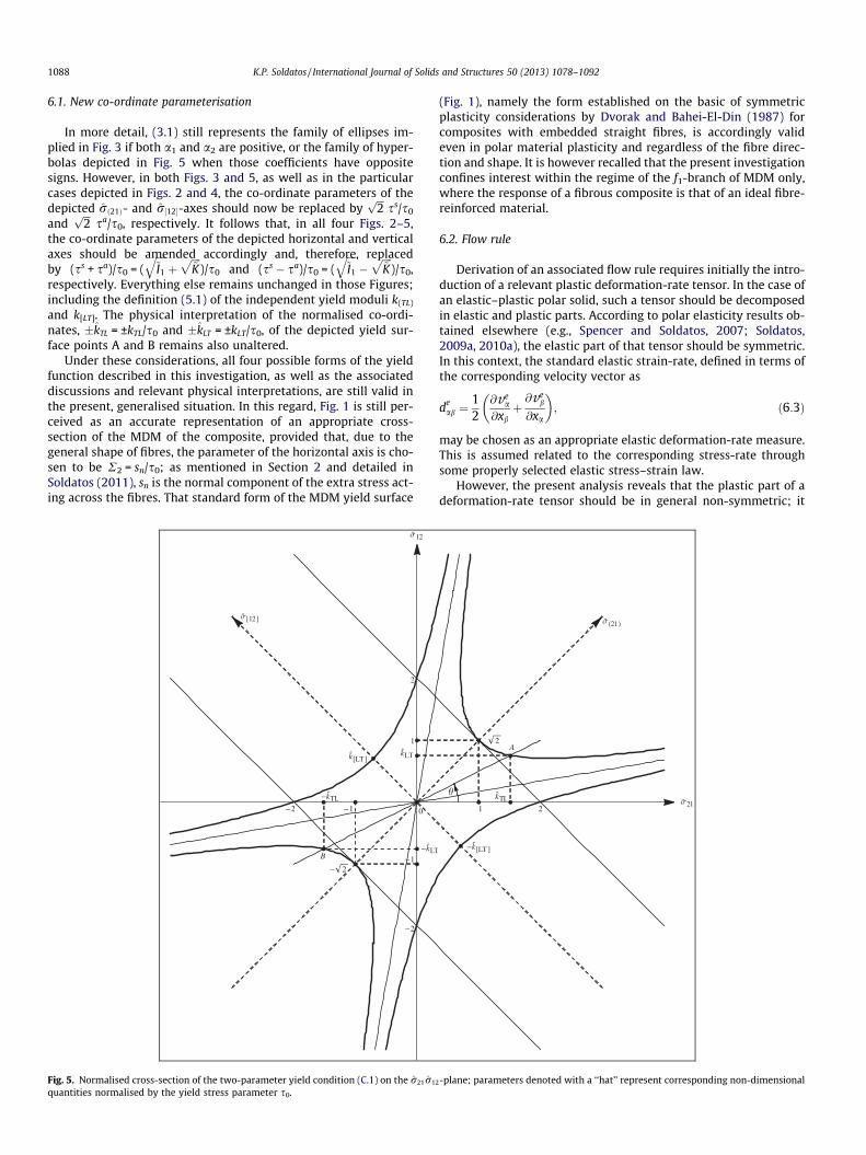
In more detail, (3.1) still represents the family of ellipses im-plied in Fig. 3 if both a1 and a2 are positive, or the family of hyper-bolas depicted in Fig. 5 when those coefficients have oppositesigns. However, in both Figs. 3 and 5, as well as in the particularcases depicted in Figs. 2 and 4, the co-ordinate parameters of thedepicted rð21Þ- and r½12�-axes should now be replaced by
ffiffiffi2p
ss/s0
andffiffiffi2p
sa/s0, respectively. It follows that, in all four Figs. 2–5,the co-ordinate parameters of the depicted horizontal and verticalaxes should be amended accordingly and, therefore, replacedby (ss + sa)/s0 = (
ffiffiffiffi~I1
qþ
ffiffiffiffi~K
p)/s0 and (ss � sa)/s0 = (
ffiffiffiffi~I1
q�
ffiffiffiffi~K
p)/s0,
respectively. Everything else remains unchanged in those Figures;including the definition (5.1) of the independent yield moduli k(TL)
and k[LT]. The physical interpretation of the normalised co-ordi-nates, �kTL = ±kTL/s0 and �kLT = ±kLT/s0, of the depicted yield sur-face points A and B remains also unaltered.
Under these considerations, all four possible forms of the yieldfunction described in this investigation, as well as the associateddiscussions and relevant physical interpretations, are still valid inthe present, generalised situation. In this regard, Fig. 1 is still per-ceived as an accurate representation of an appropriate cross-section of the MDM of the composite, provided that, due to thegeneral shape of fibres, the parameter of the horizontal axis is cho-sen to be R2 = sn/s0; as mentioned in Section 2 and detailed inSoldatos (2011), sn is the normal component of the extra stress act-ing across the fibres. That standard form of the MDM yield surface
Fig. 5. Normalised cross-section of the two-parameter yield condition (C.1) on the r21r12
quantities normalised by the yield stress parameter s0.
(Fig. 1), namely the form established on the basic of symmetricplasticity considerations by Dvorak and Bahei-El-Din (1987) forcomposites with embedded straight fibres, is accordingly valideven in polar material plasticity and regardless of the fibre direc-tion and shape. It is however recalled that the present investigationconfines interest within the regime of the f1-branch of MDM only,where the response of a fibrous composite is that of an ideal fibre-reinforced material.
6.2. Flow rule
Derivation of an associated flow rule requires initially the intro-duction of a relevant plastic deformation-rate tensor. In the case ofan elastic–plastic polar solid, such a tensor should be decomposedin elastic and plastic parts. According to polar elasticity results ob-tained elsewhere (e.g., Spencer and Soldatos, 2007; Soldatos,2009a, 2010a), the elastic part of that tensor should be symmetric.In this context, the standard elastic strain-rate, defined in terms ofthe corresponding velocity vector as
deab ¼
12
@vea
@xbþ@ve
b
@xa
� �; ð6:3Þ
may be chosen as an appropriate elastic deformation-rate measure.This is assumed related to the corresponding stress-rate throughsome properly selected elastic stress–strain law.
However, the present analysis reveals that the plastic part of adeformation-rate tensor should be in general non-symmetric; it
-plane; parameters denoted with a ‘‘hat’’ represent corresponding non-dimensional
K.P. Soldatos / International Journal of Solids and Structures 50 (2013) 1078–1092 1089
may, therefore, be decomposed into a symmetric and an anti-sym-metric part. The arguments put forward in (Soldatos, 2011) suggestfurther that the relatively simple and generally accepted rule
qpab ¼ _k
@f1
@rab; ð6:4Þ
where, _k is a certain proportionality scalar, may still be consideredas a point of departure for the derivation of the plastic part of thedeformation-rate tensor. This choice is facilitated by the fact that,although the experiments associated with B/Al fibrous composites(Dvorak et al., 1988; Nigam et al., 1994a,b) made evident consider-able deviation of the overall plastic-strain vector from the normal tothe yield surface, that deviation is not apparent on the f1-branch ofthe MDM yield surface. In fact, among the considerable amount ofresults demonstrating plastic strain direction in (Dvorak et al.,1988; Nigam et al., 1994a,b), only one seems directly relevant tothe f1-branch of the MDM yield surface. This is associated withthe point 73 in Figure 35 of (Dvorak et al., 1988) and shows thatthe plastic-strain vector is clearly normal to a straight line whichresembles the f1-branch of the yield surface.
Under these considerations, (6.4) gives
qpab ¼ _k
@f1
@rab¼ _k
@f1
@~I1
@~I1
@sðlmÞ
@sðlmÞ
@rabþ @f1
@~K
@~K@s½lm�
@s½lm�
@rab
!: ð6:5Þ
With use of (3.1), (2.8), and (2.9), one obtains
@f1@~I1¼ a1;
@f1@ ~K¼ a2;
@~I1@sðlmÞ¼ sðlmÞ;
@~K@s½lm�¼ s½lm� ¼ r½lm�;
@sðlmÞ@rab¼ 1
2 ðdaldbm þ damdbl � 2dabdlmÞ þ dlmaaab þ dabalam � 2aaabalam:
ð6:6Þ
Upon inserting these into (6.5) with simultaneous use of theconstraint equations (2.6b, c), it is seen that
qpab ¼ _kða1sðabÞ þ a2r½ab�Þ; ð6:7Þ
thus showing that qpab is naturally decomposed into symmetric and
anti-symmetric parts.The same flow rule is alternatively obtained by defining the
plastic strain-rate and the plastic-rotation as follows:
dpab ¼ _k @f1
@rðabÞ¼ _k1a1sðabÞ � qp
ðabÞ;
xpab ¼ _k @f1
@r½ab�¼ _k1a2r½ab� � qp
½ab�;ð6:8Þ
and, thus, noting further that these coincide with the symmetricand anti-symmetric part of the deformation-rate tensor, qp
ab,respectively.
It becomes then evident that both qpab and dp
ab satisfy the con-straint Eqs. (2.6b, c), in the sense that
dpaa ¼ qp
ðaaÞ ¼ qpaa ¼ 0; aadp
abab ¼ aaqpðabÞab ¼ aaqp
abab ¼ 0: ð6:9Þ
Thus, the flow rule (6.4) verifies that plastic incompressibilityand plastic inextensibility in the fibre direction are consequencesof the postulate that yield is independent of hydrostatic pressureand fibre tension within the f1-branch of the MDM.
7. Closure
When the plastic response of a fibrous-composite is regarded asthat of a polar material, the conventional concept of material yieldstress in shear is necessarily dismissed. In the present case, for in-stance, where r12/r21 – 1 in the regime of polar material response,a thin-walled structure made of ideal fibre-reinforced material de-forms plastically when suitable combinations of r21- and r12-val-ues are reached simultaneously, rather than when only one ofr21 and r12 reaches some maximum absolute value. Under the
plane stress conditions that dominate the thin-walled structurebehaviour, such combinations of r21- and r12-values are dictatedby the form of the f1-branch of the yield surface and, in particular,by the form of its projection (cross-section) on the r21r12-plane ofthe four-dimensional stress space r11r22r21r21.
Experimental verification of this kind of polar plastic behaviourmay therefore become possible only if the values of both r21 andr12 are measured simultaneously throughout the loading processof a relevant fibrous composite specimen. The set of values at-tained by the ratio k = r12/r21 will thus become known duringthe entire course of such a loading process; including its final stage,at which the recorded (r21, r12)-pair marks initiation of plastic slip.That k-ratio does not need to stay constant but, since it will beknown throughout an actual loading process, it may be consideredand treated as a known variable in polar material plasticity.
In this context, potential loading paths associated to differentconstant k-values will necessarily end at different points on theyield surface. Thus, each of those loading paths employs a different,own and, therefore, subjective pair of yield stresses. The latter aredenoted with kTL and kLT in this investigation and are associatedwith shear action in the longitudinal and the transverse to the fibredirection, respectively. Unless k = 1 or k = �1, these are unequaland inevitably interconnected through the relation kLT = |k|kTL.Thus, kTL and kLT can only be regarded as variable yield stressparameters, in the sense that their values vary with k and, there-fore, with the features of the stress state applied on the polar mate-rial of interest.
In the case of symmetric elastic/plastic material response wherek = 1, the common value of kLT and kLT becomes equal to the valueof the single constant yield stress parameter s0 = k(TL)/
ffiffiffi2p
intro-duced in (Dvorak and Bahei-El-Din, 1987); the associated yieldmodulus k(TL) is found to be of predominant influence on the over-all polar material behaviour. Similarly, in cases of purely anti-sym-metric stress response where k = �1, the alternative common valueof kTL and kLT is denoted with k[LT])/
ffiffiffi2p
; this second, independentyield modulus is of equally predominant influence on the overallpolar material behaviour. It has accordingly been seen that thereexists no elastic fibre-reinforced material for which either of thesepositive material moduli is zero. The existence of two independentand non-zero yield moduli, k(TL) and k[LT], is accordingly conceivedas a proper theoretical justification of the intuitive expectationthat, due to the presence of fibres, two rather than one shear yieldparameters of the composite should in general be present.
It has further been seen that the non-zero values of k(TL) and k[LT]
exert paramount influence on the form of the yield surface of theideal fibre-reinforced material of interest. If those moduli are bothfinite, their non-zero positive values are the principal semi-axes ofa conic which represents the cross-section of the yield surfacesought on the r21r12-plane; see Section 5. Nevertheless, if eitherk[LT] or k(LT) is infinite for a particular class of materials, that conicdegenerates to one of the alternative single-parameter yield sur-faces considered and studied separately in Section 4 and AppendixB.
Finally, a certain kind of non-dimensionalisation of the polarmaterial stress state, which is found feasible in all cases discussed,enables the f1-branch of MDM depicted in Fig. 1 to represent, still,the corresponding part of the four-dimensional yield surface cross-section on the r22r21-plane. This important revelation provides adirect connection of the present, polar plasticity analysis with itssymmetric plasticity counterpart (Soldatos, 2011) and, mostimportantly, with its experimentally verified equivalent (Dvorakand Bahei-El-Din, 1987; Dvorak et al., 1988, 1991; Nigam et al.,1994a, 1994b). It accordingly implies that the kind of connectionbetween the f1- and the f2-branches of MDM depicted in Fig. 1may still be valid in polar material plasticity. It may, therefore,be directly employed at a subsequent investigation, aiming to

1090 K.P. Soldatos / International Journal of Solids and Structures 50 (2013) 1078–1092
reveal the manner in which polar plasticity response influences thesecond branch of MDM. Nevertheless, it makes also understoodthat there is need for further experimental research work in thissubject.
Acknowledgement
The author wishes to thank Mr M.A. Dagher for valuable techni-cal assistance.
Appendix A:. Redundancy of the invariant (2.4e)
By virtue of the incompressibility constraint (2.6b) which holdswithin both branches of the MDM, the invariant (2.4e) may bewritten explicitly as follows:
K2 ¼12
aasðabÞs½bc�ac ¼ s½21� ðs22 � s11Þa1a2 þ sð12Þða21 � a2
2Þ� �
: ðA:1Þ
Upon denoting with u the angle that the fibre direction makeswith the x1-axis of the Cartesian co-ordinate system, it is seen that(a1,a2) = (cosu,sinu) and, hence, the quantity within the curl-brackets is the symmetric part, ss, of the shear component of ex-tra-stress that acts along the fibres (e.g., Timoshenko and Goodier,1970; pp. 17–19). A further combination of (A.1) with (2.8b) and(2.9) yields therefore
K2 ¼ sass ¼ffiffiffiffiffiffiffiffiffiffiffi�~K~I1
q: ðA:2Þ
Being thus shown a combination of the independent invariantsdefined in (2.9), the invariant (2.4e) becomes redundant within thef1-branch of the MDM mode. In fact, (2.4e) is essentially shownalso redundant even within the f2-branch of MDM, which is not af-fected by the fibre inextensibility constraint; consideration of thelatter constraint is not needed for the derivation of (A.2).
Appendix B:. The alternative single-parameter form of the f1-branch of the MDM in polar plasticity
The alternative single-parameter form of (3.2) is obtained bysetting a1 = 0. Provided that a2 > 0, this leads to the yield condition
f1ðr21;r12Þ � ðr½12�=k½LT� � 1Þðr½12�=k½LT� þ 1Þ ¼ 0; k½LT� ¼ 1=ffiffiffiffiffia2p
;
ðB:1Þ
where k[LT] is an independent real and positive yield stress param-eter. This will be shown relevant to purely anti-symmetric shearand predominantly associated with the composite yield responsein transverse shear. The form (B.1) makes understood that the f1-branch of the MDM yield surface may still be represented graphi-cally in the convenient three-dimensional manner depicted inFig. 1; provided that
R3 ¼ ðr12 � r21Þ=2s0; ðB:2Þ
in this case while, still, R2 = r22/kT.Several features of the yield condition (B.1) resemble those of
(4.1). Thus, r(21), which is generally non-zero, has no direct contri-bution in (B.1). In this context, although a1 = 0, (B.1) is still associ-ated to possible classes of unidirectional fibrous composites which,in their plastic deformation regime, are generally affected by cou-ple-stress action as well as by action of the conventional, symmet-ric part of the stress tensor. However, symmetric stress cannotimpose by itself plastic deformation within the regime of the f1-branch of the MDM; the value of the aforementioned yield stressin symmetric shear, namely kðTLÞ=
ffiffiffi2p
, is infinite in this case. Thisobservation becomes better understood in Fig. 4 where, like inFig. 2, the depicted normalised stress co-ordinates are r21 = r21/
s0 and r12 = r12/s0. However, s0 is not necessarily identical to itscounterpart employed in Section 4.
Despite their obvious differences, the yield surfaces depicted inFigs. 2 and 4 have considerable geometrical similarities. Accord-ingly, (B.1) is represented by a pair of parallel straight lines(Fig. 4), which cross at right angles the depicted r½12�-axis; atr½12� ¼ �k½LT� = ±k[LT]/s0. Since those straight lines are now parallelto the rð21Þ-axis, the resulting yield surface is unreachable in sym-metric plasticity; namely, by following the loading path h = p/4 or,equivalently, k = r12/r21 = 1. Thus, the normalisation constantparameter s0 = k[LT]/
ffiffiffi2p
becomes associated with purely anti-sym-metric states of stress, in the sense that it is now regarded as theyield stress of the composite in purely anti-symmetric shear;namely, the lowest value of |r[12]| which can cause plastic slipwhen r(21) = 0. However, the extent to which such kind of stressstates, namely states of stress caused totally by couple-stress ac-tion, are at all feasible is an issue that requires experimental veri-fication. If such stress states are attainable by some class of idealfibre-reinforced materials, then the co-ordinates of the points ofintersection of the yield surface and the r½12�-axis, namely(r21; r12) = (±1,±1), are again projections on the r21r12-plane ofthe f1-branch of the yield surface depicted in Fig. 1.
Relevance to similar concepts met in Section 4 is accordinglyobserved by denoting with �kTL = ± kTL/s0 the r21-coordinates ofthe points A and B, where the yield surfaces depicted in Fig. 4 inter-sects with a generic ray that passes through the co-ordinate origin;�kLT = ±kLT/s0 denote again the r12-coordinates of those points. It isthus seen that the pair of straight lines R3 = ±1 in Fig. 1 movesagain to R3 = ±kTL/s0, which determine the new position of the f1-branch of MDM. However, if the vertical axis, R3 = r21/s0, is re-parameterised in Fig. 1 as R3 = r12/s0, then the corresponding pairof straight lines emerges again at R3 = �kLT ; since kTL – kLT. The sit-uation becomes then completely analogous to that detailed in Sec-tion 4.1, where it has been seen that kTL and kLT are neitherconstant nor independent. In the present case though, they ratherdepend on the value of the single yield material parameter k[LT], towhich they interrelate as follows:
jkTL � signðkÞkLT j ¼ffiffiffi2p
k½LT�: ðB:3Þ
With use of r12 = kr21, (B.2) may be converted into either
R3 ¼ �r21=s0ðkÞ; s0ðkÞ ¼ffiffiffi2p
k½LT�
ð1� kÞ ; ðB:4Þ
or,
R3 ¼ r12=~s0ðkÞ; ~s0ðkÞ ¼ffiffiffi2p
k½LT�
ð1� 1=kÞ ; ðB:5Þ
where both of the appearing variable normalisation stress parame-ters, s0ðkÞ and ~s0ðkÞ, depend now on the loading path as well as thevalue of the yield stress parameter k[LT]. Note that s0ð�1Þ ¼~s0ð�1Þ ¼ k½LT�=
ffiffiffi2p
. Hence, association of either (B.4), (B.5) with thevertical axis of Fig. 1 endorses again that Figure as an accurate rep-resentation of the f1-branch of MDM yield surface. With (B.4) andR2 = r22/kT, the f1-branch of MDM depicted in Fig. 1 is an appropri-ately normalised representation of the cross-section of the corre-sponding four-dimensional yield surface on the r22r21-plane.With (B.5) and R2 = r11/kL, Fig. 1 depicts an appropriately norma-lised form of the cross-section of the same yield surface on ther11r12-plane.
If the single-parameter yield condition described in this sectionis found representative of the plastic behaviour of some class of fi-bre-reinforced materials, the different (r21, r12)-pairs associated ina relevant experiment with initiation of plastic slip will be Carte-sian co-ordinates of points lying on two parallel straight lines onthe r21r21-pane; each line being mirror image of the other with

K.P. Soldatos / International Journal of Solids and Structures 50 (2013) 1078–1092 1091
respect to the r½12�-axis. The value of the yield parameter k[LT] =ffiffiffi2p
s0 may thus be determined as the half distance of these parallellines. By normalising the obtained experimental results with s0,these are transformed into corresponding (�kTL; �kLT )-pairs andthe ultimate form of this cross-section of the f1-branch of the yieldsurface will cross the normalised co-ordinate axes at ±2 (see Fig. 4).
Appendix C:. The second (hyperbolic) form of the f1-branch ofMDM in polar plasticity
If a1 and a2 have opposite signs, the yield condition (3.2) con-verts into the family of hyperbolas
f1ð~I1; ~KÞ � r2ð21Þ=k2
ðTLÞ � r2½12�=k2
½LT� � 1 ¼ 0; ðC:1Þ
which are centred at the co-ordinate origin of the r21r12-plane. Ageneric element of the family is shown in Fig. 5, which makes againuse of the co-ordinate parameterisation employed in Figs. 2 and 3.That generic element consists of two pairs of hyperbolic curves withprincipal axes along the rð21Þ-and r½12�-axes.
One pair of hyperbolas crosses the rð21Þ-axis at �kðTLÞ ¼ �ffiffiffi2p
and is tangent to the pair of the parallel straight lines (4.1), towhich it degenerates when k½LT� approaches infinity (see alsoFig. 2). The other pair crosses the r½12�-axis at k½LT�; those hyperbolasdegenerate to the pair of parallel straight lines (B.1) when k(TL) ap-proaches infinite (see also Fig. 4). It might be appropriate to men-tion, mainly for consistency with earlier discussions, that (C.1) isonly the hyperbolic cross-section of a cylindrical surface of infiniteextent. That cylindrical surface is the projection of the actual four-dimensional form of the f1-branch of the MDM yield surface oneither the r22r21r12- or the r11r21r12-subspace; its generator isparallel to the r22- or the r11-axis, respectively.
Most of the observations associated in Section 5 with the ellipticform (5.2) of a yield condition still apply in the present case. In thiscontext, the features of symmetric elasticity/plasticity detailed inSection 4 are still associated with the loading path k = 1 (or h = p/4). This observation makes evident that the co-ordinates of thepoints �kðTLÞ ¼ �
ffiffiffi2p
of the rð21Þ-axis, namely r21 ¼ r12 = ± 1, arestill projections on the r21r12-plane of the MDM f1-branches de-picted in Fig. 1.
It is accordingly still evident that attainable parts of the yieldsurface should be expected to form relatively narrow bands aroundthe points rð21Þ ¼ �kðTLÞ ¼ �
ffiffiffi2p
, with co-ordinates(r12; r12) = (±1,±1), particularly if fibres are considerably flexible.In the present case though, the width of those bands appears tobe particularly sensitive to the value of the ratio k½LT�=kðTLÞ, whichdictates the slope of the asymptotes of the hyperbolas depictedin Fig. 5. Those asymptotes, which are defined by the equations
r½12� ¼ �k½LT�
kðTLÞrð21Þ; ðC:2Þ
represent possible loading paths, k = ±k[LT]/k(TL), along which plasticdeformation is essentially impossible. Thus, if fibres resist bendingconsiderably, parts of the yield surface branches that cross ther½12�-axis may also become attainable, particularly if the ratio k[LT]/k(TL) is relatively small. Then, if this type of plastic behaviour isfound possible in relevant practical applications, attainable partsof the yield surface which are in close proximity to the asymptotesmay be perceived as being intercepted by narrow bands of unstableelastic response.
The outlined possibility is not shown explicitly in Fig. 5 where,for drawing convenience, the depicted ray BOA is chosen to repre-sent a loading path with |k| = |tanh| < k½LT�=kðTLÞ. There, the r21- andthe r12-coordinates of the points A and B are still denoted by�kTL = ±kTL/s0 and �kLT = ±kLT/s0; the physical meaning of kTL andkLT is still unaltered. It follows that the pair of straight lines which
are represented by R3 = ±1 in Fig. 1 moves again to R3 = �kTL.Moreover, if R3 = r21/s0 is replaced by R3 = r12/s0 in Fig. 1, thenthe corresponding pair of straight lines emerges again at R3 = �kLT .
In the light of earlier relevant discussions, a useful descriptionof the yield surface (C.1) becomes possible with introduction anduse of the standard hyperbolic curve parameterisation; namely
rð21Þ ¼ kðTLÞcosh /
sinh /
�; r½12� ¼ k½LT�
sinh /
cosh /
�; ðC:3Þ
where, here as well as in what follows, ‘‘upper’’ or ‘‘lower’’ func-tions, parameters and symbols are associated with the pair ofhyperbolas intersecting the rð21Þ- or the r½12�-axis, respectively. Itcan then be shown that
kTL ¼ffiffiffi2p kðTLÞ
j1þ kjj cosh /jj sinh /j
(; kLT ¼ jkjkTL
¼ffiffiffi2p k½LT�
j1� k�1jj sinh /jj cosh /j
(; / ¼ tanh�1�k; / ¼ coth�1�k; ðC:4Þ
where �k is still given according to (5.7c). It can accordingly furtherbe shown that
jkTL � signðkÞkLT j ¼ 2�s0ðkÞ; ðC:5Þ
where, now, the appearing variable normalisation parameter is de-fined as follows:
�s0ðkÞ ¼ffiffiffi2p
2kðTLÞ
j1þ kjj cosh /jj sinh /j
( )� signðkÞ k½LT�
j1� k�1jj sinh /jj cosh /j
( )����������:
ðC:6Þ
It is again important to note that, with use of Hospital’s rule inthe symmetric plasticity case, (C.6) returns kTL = kLT = �s0ð1Þ ¼kðTLÞ=
ffiffiffi2p
; namely, the value of s0 determined in Section 4. Similarly,in the case of pure anti-symmetric shear, (C.6) reduces again tokTL = kLT = �s0ð�1Þ ¼ k½LT�=
ffiffiffi2p
; namely the corresponding value of s0
determined Appendix B.The similarity of (C.5) with either (4.4), (5.6) suggests that Fig. 1
can still be employed to represent the f1-branch of the MDM yieldsurface. Accordingly, with use of the above results and r12 = kr21,r(21) can now be normalised as either
R3 ¼ðr21 � r12Þ
2�s0ðkÞ¼ r21
s0ðkÞ; s0ðkÞ ¼
2�s0ðkÞð1þ kÞ ; ðC:7Þ
or
R3 ¼ðr21 � r12Þ
2�s0ðkÞ¼ r12
~s0ðkÞ; ~s0ðkÞ ¼
2�s0ðkÞð1þ 1=kÞ ; ðC:8Þ
the appearing variable normalisation stress parameters s0ðkÞ and~s0ðkÞ depend now on both k(TL) and k[LT] through the function�s0ðkÞ defined in (C.7). Thus, with (C.7) and R2 = r22/kT, the f1-branchof MDM depicted in Fig. 1 represents an appropriately normalisedform of the cross-section of the corresponding part of the four-dimensional yield surface on the r22r21-plane. With (C.8) andR2 = r11/kL, the Figure is an appropriately normalised representa-tion of the cross-section of the same part of the yield surface onthe r11r12-plane.
If the described yield condition represents the plastic behaviourof some class of fibre-reinforced materials, the different (r21, r12)-pairs associated in a relevant experiment with plastic slip initiationwill be Cartesian co-ordinates of points lying on the branches of ahyperbola centred at the co-ordinate origin of the r21r12-plane andhaving its principal axes lying along the bisectors of the right angleOr21r12. The value of the yield parameters k(TL) =
ffiffiffi2p
�s0ð1Þ andk½LT� ¼
ffiffiffi2p
�s0ð�1Þ may be determined as the principal semi-axes ofthat hyperbola. By normalising the obtained experimental results

1092 K.P. Soldatos / International Journal of Solids and Structures 50 (2013) 1078–1092
with �s0ð1Þ and, hence, replacing them with corresponding(�kTL; �kLT )-pairs, the ultimate hyperbolic form for this cross-sec-tion of the f1-branch of the MDM yield surface becomes tangent tothe straight lines (4.1); the latter pair of parallel straight lines isalso shown in Fig. 5.
References
Cooper, G.A., 1966. Orientation effects in fibre-reinforced metals. J. Mech. Phys.Solid 14, 103–111.
Dagher, M.A., Soldatos, K.P., 2011. On small azimuthal shear deformation of fibre-reinforced cylindrical tubes. J. Mech. Mater. Struct. 6, 143–168.
Dvorak, G.J., 2000. Composite materials: inelastic behaviour, damage, fatigue andfracture. Int. J. Solids Struct. 37, 155–170.
Dvorak, G.J., Bahei-El-Din, Y.A., 1987. A bimodal plasticity theory of fibrouscomposite materials. Acta Mech. 69, 219–241.
Dvorak, G.J., Bahei-El-Din, Y.A., Macheret, Y., Liu, C.H., 1988. An experimental studyof elastic–plastic behavior of a fibrous boron–aluminium composite. J. Mech.Phys. Solids 36, 655–687.
Dvorak, G.J., Bahei-El-Din, Y.A., Shah, R.S., Nigam, H., 1991. Experiments andmodeling in plasticity of fibrous composites. In: Dvorak, G.J. (Ed.), InelasticDeformation of Composite Materials. Springer-Verlag, New York, pp. 283–306.
Jackson, P.W., Cratchley, D., 1966. Effect of fibre orientation on tensile strength offibre-reinforced metals. J. Mech. Phys. Solids 14, 46–64.
Korsgaard, J., 1990. On the representation of two-dimensional isotropic functions.Int. J. Eng. Sci. 28, 653–662.
Mulhern, J.F., Rogers, T.J., Spencer, A.J.M., 1967. A continuum model for fibre-reinforced plastic materials. Proc. Roy. Soc. A 301, 473–492.
Mulhern, J.F., Rogers, T.J., Spencer, A.J.M., 1969. A continuum theory of plastic–elastic fibre-reinforced materials. Int. J. Eng. Sci. 7, 129–152.
Nigam, H., Dvorak, G.J., Bahei-El-Din, Y.A., 1994a. An experimental investigation ofelastic–plastic behavior of a fibrous boron-aluminium composite: I. Matrix-dominated mode. Int. J. Plast. 10, 23–48.
Nigam, H., Dvorak, G.J., Bahei-El-Din, Y.A., 1994b. An experimental investigation ofelastic–plastic behavior of a fibrous boron-aluminium composite: II. Fiber-dominated mode. Int. J. Plast. 10, 49–62.
Soldatos, K.P., 2012. On loss of ellipticity in second-gradient hyper-elasticity offibre-reinforced materials. Int. J. Nonlinear Mech. 47, 117–127.
Soldatos, K.P., 2009a. Towards a new generation of 2D mathematical models in themechanics of thin-walled fibre-reinforced structural components. Int. J. Eng. Sci.47, 1346–1356.
Soldatos, K.P., 2009b. Azimuthal shear deformation of an ideal fibre-reinforced tubeaccording to a second gradient hyper-elasticity theory. In: Ambrosio, J. et al.(Eds.), Proc. Seventh EUROMECH Solid Mechanics Conference, Lisbon, Portugal,Paper ID: 0017.
Soldatos, K.P., 2010a. Second-gradient plane deformations of ideal fibre-reinforcedmaterials – implications of hyper-elasticity theory. J. Eng. Math. 68, 99–127.
Soldatos, K.P., 2010b. Second-gradient plane deformations of ideal fibre-reinforcedmaterials II: forming flows of fibre-resin systems when fibres resist bending. J.Eng. Math. 68, 179–196.
Soldatos, K.P., 2011. The bimodal theory of plasticity: a form-invariantgeneralisation. J. Mech. Phys. Solids 59, 1576–1595.
Spencer, A.J.M., 1972. Deformations of Fibre-reinforced Materials. Oxford UniversityPress, London.
Spencer, A.J.M., 1992. Plasticity theory for fibre-reinforced composites. J. Eng. Math.26, 107–118.
Spencer, A.J.M., Soldatos, K.P., 2007. Finite deformations of fibre-reinforced elasticsolids with fibre bending stiffness. Int. J. Nonlinear Mech. 42, 355–368.
Timoshenko, S.P., Goodier, J.N., 1970. Theory of Elasticity, third ed. McGraw Hill,New York.
Truesdell, C., Noll, W., 1965. The non-linear field theories of mechanics. In: Flügge,S., (Ed.), Encyclopedia of Physiscs, Springer-Verlag.
Zheng, Q.-S., 1994. Theory of representations for tensor functions. Appl. Mech. Rev.47, 554–5872.
Related Documents