Reference number ISO/IEC 7811-2:2001(E) © ISO/IEC 2001 INTERNATIONAL STANDARD ISO/IEC 7811-2 Third edition 2001-02-01 Identification cards — Recording technique — Part 2: Magnetic stripe — Low coercivity Cartes d'identification — Technique d'enregistrement — Partie 2: Raie magnétique — Faible coercitivité

Welcome message from author
This document is posted to help you gain knowledge. Please leave a comment to let me know what you think about it! Share it to your friends and learn new things together.
Transcript
Reference numberISO/IEC 7811-2:2001(E)
© ISO/IEC 2001
INTERNATIONALSTANDARD
ISO/IEC7811-2
Third edition2001-02-01
Identification cards — Recordingtechnique —
Part 2:Magnetic stripe — Low coercivity
Cartes d'identification — Technique d'enregistrement —
Partie 2: Raie magnétique — Faible coercitivité
ISO/IEC 7811-2:2001(E)
PDF disclaimer
This PDF file may contain embedded typefaces. In accordance with Adobe's licensing policy, this file may be printed or viewed but shall notbe edited unless the typefaces which are embedded are licensed to and installed on the computer performing the editing. In downloading thisfile, parties accept therein the responsibility of not infringing Adobe's licensing policy. The ISO Central Secretariat accepts no liability in thisarea.
Adobe is a trademark of Adobe Systems Incorporated.
Details of the software products used to create this PDF file can be found in the General Info relative to the file; the PDF-creation parameterswere optimized for printing. Every care has been taken to ensure that the file is suitable for use by ISO member bodies. In the unlikely eventthat a problem relating to it is found, please inform the Central Secretariat at the address given below.
© ISO/IEC 2001
All rights reserved. Unless otherwise specified, no part of this publication may be reproduced or utilized in any form or by any means, electronicor mechanical, including photocopying and microfilm, without permission in writing from either ISO at the address below or ISO's member bodyin the country of the requester.
ISO copyright officeCase postale 56 � CH-1211 Geneva 20Tel. + 41 22 749 01 11Fax + 41 22 749 09 47E-mail [email protected] www.iso.ch
Printed in Switzerland
ii © ISO/IEC 2001 – All rights reserved
ISO/IEC 7811-2: 2001(E)
© ISO/IEC 2001 – All rights reserved iii
Contents
1 Scope ........................................................................................................................................................................1
2 Conformance............................................................................................................................................................1
3 Normative references ..............................................................................................................................................1
4 Terms and definitions .............................................................................................................................................2
5 Physical characteristics of the identification card ...............................................................................................3
5.1 Magnetic stripe area warpage .............................................................................................................................3
5.2 Surface distortions ...............................................................................................................................................3
6 Physical characteristics of the magnetic stripe ...................................................................................................4
6.1 Height and surface profile of the magnetic stripe area.....................................................................................4
6.1.1 Surface profile of the magnetic stripe area.....................................................................................................5
6.1.2 Height of the magnetic stripe area...................................................................................................................6
6.2 Surface roughness ...............................................................................................................................................7
6.3 Adhesion of stripe to card ...................................................................................................................................7
6.4 Wear of magnetic stripe from read/write head...................................................................................................7
6.5 Resistance to chemicals ......................................................................................................................................7
7 Performance characteristics for the magnetic material.......................................................................................7
7.1 General...................................................................................................................................................................7
7.2 Testing and operating environment ...................................................................................................................7
7.3 Signal amplitude requirements for magnetic media .........................................................................................7
8 Encoding technique ................................................................................................................................................9
9 Encoding specification, general...........................................................................................................................10
9.1 Angle of recording ..............................................................................................................................................10
9.2 Nominal bit density.............................................................................................................................................11
9.3 Signal amplitude requirements for tracks 1, 2 and 3 ......................................................................................11
9.4 Bit configuration .................................................................................................................................................11
9.5 Direction of recording ........................................................................................................................................11
9.6 Leading and trailing zeroes ...............................................................................................................................11
10 Encoding specifications .....................................................................................................................................12
ISO/IEC 7811-2: 2001(E)
iv © ISO/IEC 2001 - All rights reserved
10.1 Alphanumeric track, track 1 .............................................................................................................................12
10.1.1 Average bit density ........................................................................................................................................12
10.1.2 Flux transition spacing variation..................................................................................................................12
10.1.3 Coded character set ......................................................................................................................................13
10.1.4 Maximum number of characters for ID-1 type card....................................................................................14
10.2 Numeric track, Track 2 .....................................................................................................................................15
10.2.1 Average bit density ........................................................................................................................................15
10.2.2 Flux transition spacing variation..................................................................................................................15
10.2.3 Coded character set ......................................................................................................................................15
10.2.4 Maximum number of characters for ID-1 type card....................................................................................16
10.3 Numeric track, Track 3 .....................................................................................................................................16
10.3.1 Average bit density ........................................................................................................................................16
10.3.2 Flux transition spacing variation..................................................................................................................16
10.3.3 Coded character set ......................................................................................................................................16
10.3.4 Maximum number of characters for ID-1 type card....................................................................................17
11 Error detection .....................................................................................................................................................17
11.1 Parity ..................................................................................................................................................................17
11.2 Longitudinal redundancy check (LRC)...........................................................................................................17
12 Location of encoded tracks ................................................................................................................................18
Annex A (informative) Read compatibility of magnetic stripes (ISO/IEC 7811-2 and ISO/IEC 7811-6)..............19
Annex B (normative) Signal amplitude measurements .........................................................................................20
Annex C (informative) Magnetic stripe abrasivity ..................................................................................................21
ISO/IEC 7811-2:2001(E)
© ISO/IEC 2001 – All rights reserved v
Foreword
ISO (the International Organization for Standardization) and IEC (the International Electrotechnical Commission)form the specialized system for worldwide standardization. National bodies that are members of ISO or IECparticipate in the development of International Standards through technical committees established by therespective organization to deal with particular fields of technical activity. ISO and IEC technical committeescollaborate in fields of mutual interest. Other international organizations, governmental and non-governmental, inliaison with ISO and IEC, also take part in the work.
International Standards are drafted in accordance with the rules given in the ISO/IEC Directives, Part 3.
In the field of information technology, ISO and IEC have established a joint technical committee, ISO/IEC JTC 1.Draft International Standards adopted by the joint technical committee are circulated to national bodies for voting.Publication as an International Standard requires approval by at least 75 % of the national bodies casting a vote.
Attention is drawn to the possibility that some of the elements of this part of ISO/IEC 7811 may be the subject ofpatent rights. ISO and IEC shall not be held responsible for identifying any or all such patent rights.
International Standard ISO/IEC 7811-2 was prepared by Joint Technical Committee ISO/IEC JTC 1, Informationtechnology, Subcommittee SC 17, Identification cards and related devices.
This third edition of ISO/IEC 7811-2 cancels and replaces ISO/IEC 7811-2:1995, ISO/IEC 7811-4:1995 andISO/IEC 7811-5:1995. The user is encouraged to review the entire standard for revisions and updates. The majorchanges made during this revision are listed below.
1. The requirements given in ISO/IEC 7811-4:1995 and ISO/IEC 7811-5:1995 are included in this edition ofISO/IEC 7811-2.
2. Wherever possible the same definitions, criteria and test methods have been used for both Part 2 and Part 6.
3. Revised the bandpass filter requirements for the test method.
ISO/IEC 7811 consists of the following parts, under the general title Identification cards — Recording technique :
� Part 1: Embossing
� Part 2: Magnetic stripe — Low coercivity
� Part 6: Magnetic stripe — High coercivity
Annex B forms a normative part of this part of ISO/IEC 7811. Annexes A and C are for information only.

© ISO/IEC 2001 - All rights reserved 1
1 Scope
This part of ISO/IEC 7811 is one of a series of standards describing the characteristics for identification cards asdefined in the definitions clause and the use of such cards for international interchange.
This part of ISO/IEC 7811 specifies requirements for a low coercivity magnetic stripe (including any protectiveoverlay) on an identification card, the encoding technique and coded character sets. It takes into consideration bothhuman and machine aspects and states minimum requirements.
Coercivity influences many of the quantities specified in this part of ISO/IEC 7811 but is not itself specified.Exposure of the card to a magnetic field is likely to destroy the recorded data.
It is the purpose of this series of standards to provide criteria to which cards shall perform. No consideration isgiven within these standards to the amount of use, if any, experienced by the card prior to test. Failure to conformto specified criteria should be negotiated between the involved parties.
ISO/IEC 10373-2 specifies the test procedures used to check cards against the parameters specified in this part ofISO/IEC 7811.
NOTE Numeric values in the SI and/or Imperial measurement system in this part of ISO/IEC 7811 may have been roundedoff and therefore are consistent with, but not exactly equal to, each other. Either system may be used, but the two should notbe intermixed or reconverted. The original design was made using the Imperial measurement system.
2 Conformance
A prerequisite for conformance with this part of ISO/IEC 7811 is conformance with ISO/IEC 7810. An identificationcard is in conformance with this part of ISO/IEC 7811 if it meets all mandatory requirements specified herein.Default values apply if no others are specified.
3 Normative references
The following normative documents contain provisions which, through reference in this text, constitute provisions ofthis part of ISO/IEC 7811. For dated references, subsequent amendments to, or revisions of, any of thesepublications do not apply. However, parties to agreements based on this part of ISO/IEC 7811 are encouraged toinvestigate the possibility of applying the most recent editions of the normative documents indicated below. Forundated references, the latest edition of the normative document referred to applies. Members of ISO and IECmaintain registers of currently valid International Standards.
INTERNATIONAL STANDARD ISO/IEC 7811-2:2001(E)
Identification cards — Recording technique —
Part 2:Magnetic stripe — Low coercivity
ISO 4287, Geometrical Product Specifications (GPS) — Surface texture: Profile method — Terms, definitions andsurface texture parameters.
ISO/IEC 7810, Identification cards — Physical characteristics.
ISO/IEC 10373-1, Identification cards — Test methods — Part 1: General characteristics tests.
ISO/IEC 10373-2, Identification cards — Test methods — Part 2: Cards with magnetic stripes.
ISO/IEC 7811-2: 2001(E)
2 © ISO/IEC 2001 - All rights reserved
4 Terms and definitions
For the purposes of this part of ISO/IEC 7811, the terms and definitions given in ISO/IEC 7810 and the followingapply.
4.1primary standardset of reference cards established and maintained by Physikalisch-Technische Bundesanstalt (PTB) that representthe values of UR and IR designated RM7811-2
4.2secondary standardreference card designated RM7811-2 that is related to the primary standard as stated in the calibration certificatesupplied with each card
NOTE Secondary standards can be ordered from Physikalisch-Technische Bundesanstalt (PTB), FLab. 2.24 - Bundesallee100, D-38116 Braunschweig, Germany. The source of secondary standards will be maintained at least until 2005.
4.3unused un-encoded cardcard possessing all the components required for its intended purpose, which has not been subjected to anypersonalization or testing operation, and which has been stored in a clean environment with no more than 48 hourexposure to daylight at temperatures between 5 °C to 30 °C and humidity between 10% to 90% withoutexperiencing thermal shock
4.4unused encoded cardcard according to 4.3 that has only been encoded with all the data required for its intended purpose (e.g. magneticencoding, embossing, electronic encoding)
4.5returned cardcard according to 4.4 after it has been issued to the card holder and returned for the purpose of testing
4.6flux transitionlocation of the greatest rate of change with distance of the magnetisation
4.7reference currentIRminimum recorded current amplitude under the given test conditions that causes, on the reference card, a readbacksignal amplitude equal to 80% of the reference signal amplitude UR, at a density of 8 flux transitions per millimetre(200 flux transitions per inch) as shown in Figure 6
4.8reference flux levelFRflux level in the test head that corresponds to the reference current I R
4.9test recording currentstwo recording currents defined by:
I min = Recording current corresponding to 3,5 FRI max = Recording current corresponding to 5,0 FR
ISO/IEC 7811-2: 2001(E)
© ISO/IEC 2001 - All rights reserved 3
4.10individual signal amplitudeUibase-to-peak amplitude of a single readback voltage signal
4.11average signal amplitudeUAsum of the absolute value of the amplitude of each signal peak (Ui) divided by the number of signal peaks (n) for agiven track over the length of the magnetic stripe area
4.12reference signal amplitudeURmaximum value of the average signal amplitude of a reference card corrected to the primary standard
4.13physical recording densitynumber of flux transitions per unit length recorded on a track
4.14bit densitynumber of data bits stored per unit of length (bits/mm or bpi)
4.15bit celldistance between two clocking flux transitions. See Figure 10
4.16sub intervaldistance that is nominally half of the distance between two clocking flux transitions. See Figure 10
5 Physical characteristics of the identification card
The identification card shall conform to the specification given in ISO/IEC 7810.
WARNING --The attention of card issuers is drawn to the fact that information held on the magnetic stripemay be rendered ineffective through contamination by contact with dirt and certain commonly usedchemicals including plasticizers. It should also be noted that any printing or screening placed on top ofthe magnetic stripe must not impair the function of the magnetic stripe.
5.1 Magnetic stripe area warpage
Application of a 2,2 N (0.5 lbf) load evenly distributed on the front face opposite the magnetic stripe shall bring theentire stripe within 0,08 mm (0.003 in) of the rigid plate.
5.2 Surface distortions
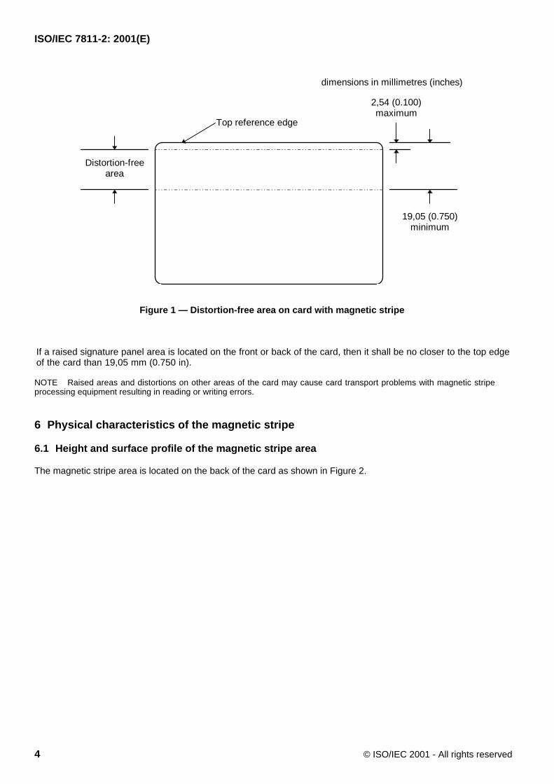
There shall be no surface distortions, irregularities or raised areas on both the front and the back of the card in thearea shown in Figure 1 that might interfere with the contact between the magnetic head and magnetic stripe.
ISO/IEC 7811-2: 2001(E)
4 © ISO/IEC 2001 - All rights reserved
Top reference edge
Distortion-freearea
2,54 (0.100)maximum
19,05 (0.750)minimum
dimensions in millimetres (inches)
Figure 1 — Distortion-free area on card with magnetic stripe
If a raised signature panel area is located on the front or back of the card, then it shall be no closer to the top edgeof the card than 19,05 mm (0.750 in).
NOTE Raised areas and distortions on other areas of the card may cause card transport problems with magnetic stripeprocessing equipment resulting in reading or writing errors.
6 Physical characteristics of the magnetic stripe
6.1 Height and surface profile of the magnetic stripe area
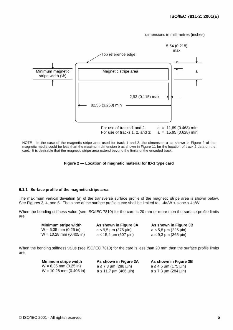
The magnetic stripe area is located on the back of the card as shown in Figure 2.
ISO/IEC 7811-2: 2001(E)
© ISO/IEC 2001 - All rights reserved 5
aMagnetic stripe area
5,54 (0.218)max
82,55 (3.250) min
2,92 (0.115) max
Top reference edge
Minimum magneticstripe width (W)
For use of tracks 1 and 2: a = 11,89 (0.468) minFor use of tracks 1, 2, and 3: a = 15,95 (0.628) min
dimensions in millimetres (inches)
NOTE In the case of the magnetic stripe area used for track 1 and 2, the dimension a as shown in Figure 2 of themagnetic media could be less than the maximum dimension b as shown in Figure 11 for the location of track 2 data on thecard. It is desirable that the magnetic stripe area extend beyond the limits of the encoded track.
Figure 2 — Location of magnetic material for ID-1 type card
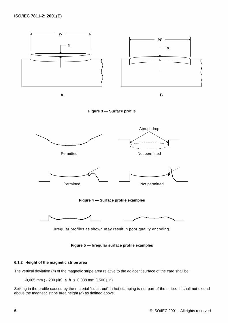
6.1.1 Surface profile of the magnetic stripe area
The maximum vertical deviation (a) of the transverse surface profile of the magnetic stripe area is shown below.See Figures 3, 4, and 5. The slope of the surface profile curve shall be limited to: -4a/W < slope < 4a/W
When the bending stiffness value (see ISO/IEC 7810) for the card is 20 mm or more then the surface profile limitsare:
Minimum stripe width As shown in Figure 3A As shown in Figure 3BW = 6,35 mm (0.25 in) a ≤ 9,5 µm (375 µin) a ≤ 5,8 µm (225 µin)W = 10,28 mm (0.405 in) a ≤ 15,4 µm (607 µin) a ≤ 9,3 µm (365 µin)
When the bending stiffness value (see ISO/IEC 7810) for the card is less than 20 mm then the surface profile limitsare:
Minimum stripe width As shown in Figure 3A As shown in Figure 3BW = 6,35 mm (0.25 in) a ≤ 7,3 µm (288 µin) a ≤ 4,5 µm (175 µin)W = 10,28 mm (0.405 in) a ≤ 11,7 µm (466 µin) a ≤ 7,3 µm (284 µin)
ISO/IEC 7811-2: 2001(E)
6 © ISO/IEC 2001 - All rights reserved
W
a a
W
A B
Figure 3 — Surface profile
Abrupt drop
Not permittedPermitted
Not permittedPermitted
Figure 4 — Surface profile examples
Irregular profiles as shown may result in poor quality encoding.
Figure 5 — Irregular surface profile examples
6.1.2 Height of the magnetic stripe area
The vertical deviation (h) of the magnetic stripe area relative to the adjacent surface of the card shall be:
-0,005 mm ( - 200 µin) ≤ h ≤ 0,038 mm (1500 µin)
Spiking in the profile caused by the material "squirt out" in hot stamping is not part of the stripe. It shall not extendabove the magnetic stripe area height (h) as defined above.
ISO/IEC 7811-2: 2001(E)
© ISO/IEC 2001 - All rights reserved 7
6.2 Surface roughness
The average surface roughness (Ra) of the magnetic stripe area shall not exceed 0,40 µm (15.9 µin) in both thelongitudinal and transverse directions. Refer to ISO 4287.
6.3 Adhesion of stripe to card
The stripe shall not separate from the card under normal use.
6.4 Wear of magnetic stripe from read/write head
Average signal amplitude (UA) and individual signal amplitude (Ui) are measured before and after 2 000 wear cyclesand shall result in:
UA after ≥ 0,60 UA before and Ui after ≥ 0,80 UA after
6.5 Resistance to chemicals
Average signal amplitude (UA) and individual signal amplitude (Ui) are measured before and after short-termexposure (as defined in the referenced Test Method document) shall result in:
UA after ≥ 0,90 UA before and Ui after ≥ 0,90 UA after
Average signal amplitude (UA) and individual signal amplitude (Ui) are measured before and after long-termexposure (24 hours) to acid and alkaline artificial perspiration, as defined in the referenced Test Method document.
UA after ≥ 0,90 UA before and Ui after ≥ 0,90 UA after
7 Performance characteristics for the magnetic material
The purpose of this section is to enable magnetic interchangeability between card and processing systems. Mediacoercivity is not specified. The media's performance criteria, regardless of coercivity, is specified in 7.3.
7.1 General
This method uses a reference card whose material is traceable to the primary standard (see clause 4). All signalamplitude results from the use of the secondary reference card must be corrected by the factor supplied with thesecondary reference card.
7.2 Testing and operating environment
The testing environment for signal amplitude measurements is 23 °C ± 3 °C (73 °F ± 5 °F) and 40% to 60% relativehumidity. When tested under otherwise identical conditions, the average signal amplitude measured at 8 ft/mm(200 ftpi) shall not deviate from its value in the above test environment by more than 15% after 5 minute exposureover the following operating environment range:
temperature -35 °C to 50 °C (-31 °F to 122 °F)relative humidity 5% to 95%
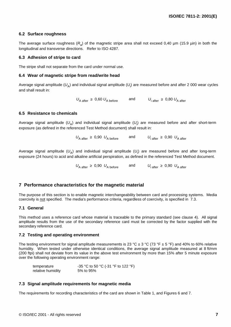
7.3 Signal amplitude requirements for magnetic media
The requirements for recording characteristics of the card are shown in Table 1, and Figures 6 and 7.
ISO/IEC 7811-2: 2001(E)
8 © ISO/IEC 2001 - All rights reserved
Table 1 — Signal amplitude requirements for unused unencoded cards
Description Densityft/mm (ftpi)
Test recordingcurrent
Signal amplituderesult
Requirement
Signal amplitude 8 (200) Imin UA1 0,8 UR ≤ UA1 ≤ 1,3 UR
Signal amplitude 8 (200) Imin Ui1 Ui1 ≤ 1,36 UR
Signal amplitude 8 (200) Imax UA2 UA1 ≥ UA2 ≥ 0,8 UR
Signal amplitude 20 (500) Imax Ui2 Ui2 ≥ 0,65 UR
Resolution 20 (500) Imax UA3 UA3 ≥ 0,7 UA2
Erasure 0 Imin, DC UA4 UA4 ≤ 0,03 UR
Extra pulse 0 Imin, DC Ui4 Ui4 ≤ 0,05 UR
The slope of the saturation curve shall never be positive between Imin and Imax
NOTE It is not permissible to combine the above requirements mathematically.
UA1
UA2
20
40
80
60
100
Readbackvoltage
(%UR)
Example curve
Reference card curvecorrected to theprimary standard
IminIR Imax Recording current
UR
120130
Figure 6 — Saturation curve example showing tolerance area at 8 ft/mm (200 ftpi)
NOTE The curve defines the primary standard response (on a card). The window parameters define a card that will befunctional in the machine readable environment. The corrected reference curve depicted above may not meet thespecifications defined in clause 7.
ISO/IEC 7811-2: 2001(E)
© ISO/IEC 2001 - All rights reserved 9
base line
flux transitionflux transition
flux transitionflux transition
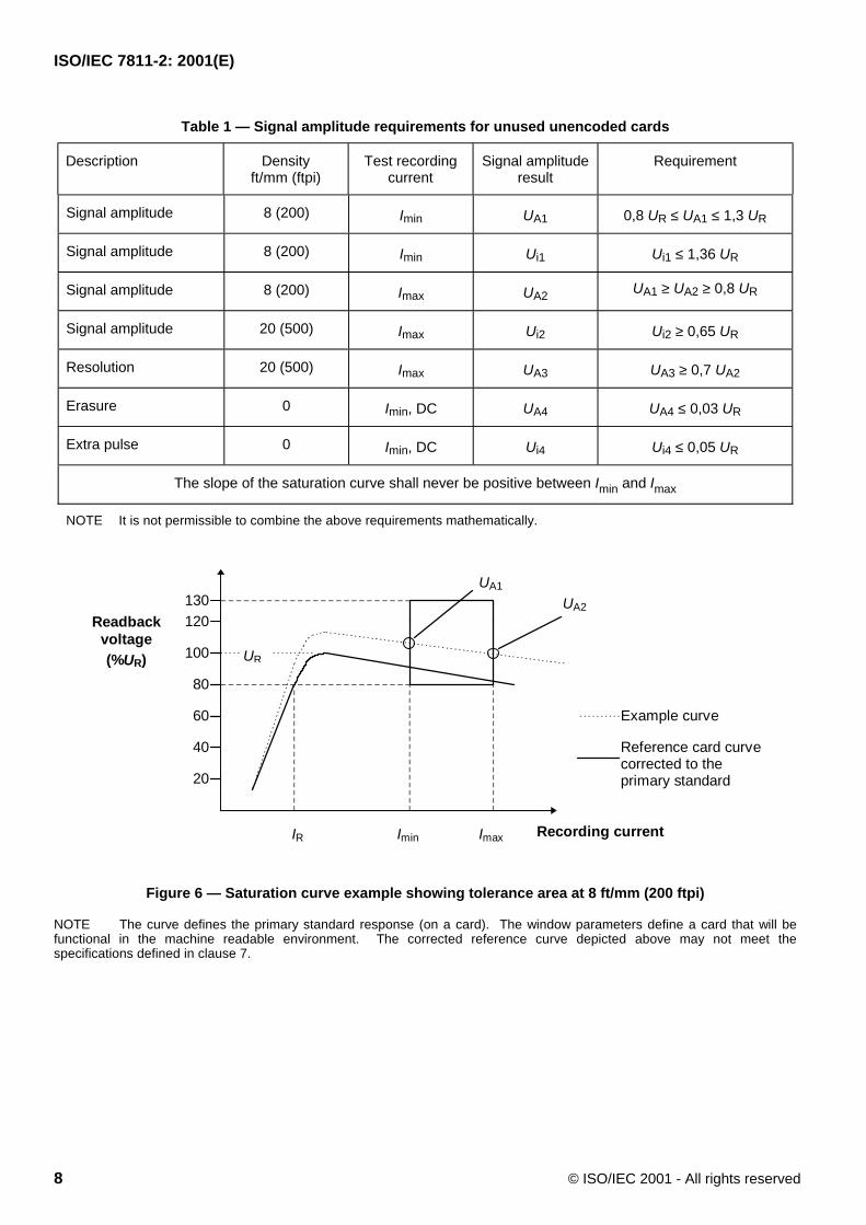
Figure 7 — Waveform example
8 Encoding technique
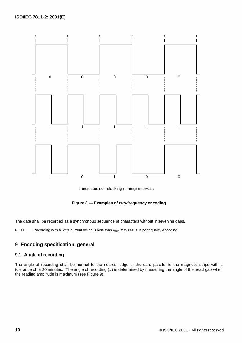
The encoding technique for each track is known as two-frequency recording. This method allows for serialrecording of self-clocking data. The encoding comprises data and clocking transitions together. A flux transitionoccurring between clocks signifies that the bit is a "one" and the absence of a flux transition between clockingtransitions signifies that the bit is a "zero" (see Figure 8).
ISO/IEC 7811-2: 2001(E)
10 © ISO/IEC 2001 - All rights reserved
t t t t t t
0 0 0 00
1 1 1 11
1 0 1 00
t, indicates self-clocking (timing) intervals
Figure 8 — Examples of two-frequency encoding
The data shall be recorded as a synchronous sequence of characters without intervening gaps.
NOTE Recording with a write current which is less than Imin may result in poor quality encoding.
9 Encoding specification, general
9.1 Angle of recording
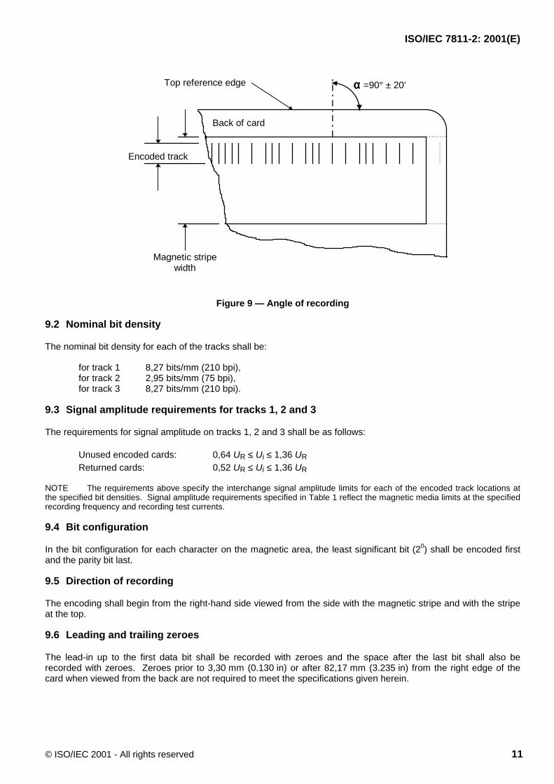
The angle of recording shall be normal to the nearest edge of the card parallel to the magnetic stripe with atolerance of ± 20 minutes. The angle of recording (α) is determined by measuring the angle of the head gap whenthe reading amplitude is maximum (see Figure 9).
ISO/IEC 7811-2: 2001(E)
© ISO/IEC 2001 - All rights reserved 11
αααα =90° ± 20’
Encoded track
Top reference edge
Back of card
Magnetic stripewidth
Figure 9 — Angle of recording
9.2 Nominal bit density
The nominal bit density for each of the tracks shall be:
for track 1 8,27 bits/mm (210 bpi),for track 2 2,95 bits/mm (75 bpi),for track 3 8,27 bits/mm (210 bpi).
9.3 Signal amplitude requirements for tracks 1, 2 and 3
The requirements for signal amplitude on tracks 1, 2 and 3 shall be as follows:
Unused encoded cards: 0,64 UR ≤ Ui ≤ 1,36 URReturned cards: 0,52 UR ≤ Ui ≤ 1,36 UR
NOTE The requirements above specify the interchange signal amplitude limits for each of the encoded track locations atthe specified bit densities. Signal amplitude requirements specified in Table 1 reflect the magnetic media limits at the specifiedrecording frequency and recording test currents.
9.4 Bit configuration
In the bit configuration for each character on the magnetic area, the least significant bit (20) shall be encoded firstand the parity bit last.
9.5 Direction of recording
The encoding shall begin from the right-hand side viewed from the side with the magnetic stripe and with the stripeat the top.
9.6 Leading and trailing zeroes
The lead-in up to the first data bit shall be recorded with zeroes and the space after the last bit shall also berecorded with zeroes. Zeroes prior to 3,30 mm (0.130 in) or after 82,17 mm (3.235 in) from the right edge of thecard when viewed from the back are not required to meet the specifications given herein.
ISO/IEC 7811-2: 2001(E)
12 © ISO/IEC 2001 - All rights reserved
10 Encoding specifications
10.1 Alphanumeric track, track 1
10.1.1 Average bit density
The average bit density (Ba) shall be 8,27 bits/mm (210 bpi) ± 8% measured in a longitudinal direction parallel to thetop reference edge.
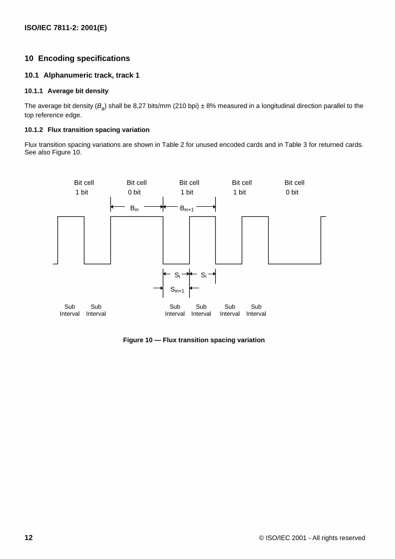
10.1.2 Flux transition spacing variation
Flux transition spacing variations are shown in Table 2 for unused encoded cards and in Table 3 for returned cards.See also Figure 10.
Bit cell1 bit 0 bit 1 bit 0 bit1 bit
Bit cell Bit cell Bit cell Bit cell
SubInterval
SubInterval
SubInterval
SubInterval
SubInterval
SubInterval
Bin Bin+1
Si Si
Sin+1
Figure 10 — Flux transition spacing variation
ISO/IEC 7811-2: 2001(E)
© ISO/IEC 2001 - All rights reserved 13
Table 2 — Flux transition spacing variation for unused encoded cards-Track 1 and 3
Term Description Requirement Variation
Ba Average lengthbetween clocking fluxtransitions
111 µm (4381 µin) ≤ Ba ≤ 131 µm (5143 µin) ± 8%
Bin Individual lengthbetween clocking fluxtransitions
109 µm (4286 µin) ≤ Bin ≤ 133 µm (5238 µin) ± 10%
Bin+1 Adjacent bit-to-bitvariation
0,90 Bin ≤ Bin+1 ≤ 1,10 Bin ± 10%
Sin Subinterval length 53 µm (2095 µin) ≤ Sin ≤ 68 µm (2667 µin) ± 12%
Sin+1 Adjacent subintervallength
0,88 Bin/2 ≤ Sin+1 ≤ 1,12 Bin/2 ± 12%
Bin+1 or Sin+1 is the length between flux transitions immediately following and adjacent to Bin.
Table 3 — Flux transition spacing variation for returned cards-Track 1 and 3
Term Description Requirement Variation
Ba Average length betweenclocking flux transitions
111 µm (4381 µin) ≤ Ba ≤ 131 µm (5143 µin) ± 8%
Bin Individual length betweenclocking flux transitions
103 µm (4048 µin) ≤ Bin ≤ 139 µm (5476 µin) ± 15%
Bin+1 Adjacent bit-to-bit variation 0,85 Bin ≤ Bin+1 ≤ 1,15 Bin ± 15%
Sin Subinterval length 48,4 µm (1905 µin) ≤ Sin ≤ 72,6 µm (2857 µin) ± 20%
Sin+1 Adjacent subinterval length 0,70 Bin/2 ≤ Sin+1 ≤ 1,30 Bin/2 ± 30%
Bin+1 or Sin+1 is the length between flux transitions immediately following and adjacent to Bin.NOTE This table shows only the limits within which cards will function normally and does not imply any guarantee of fluxtransition spacing during valid term for issued card.
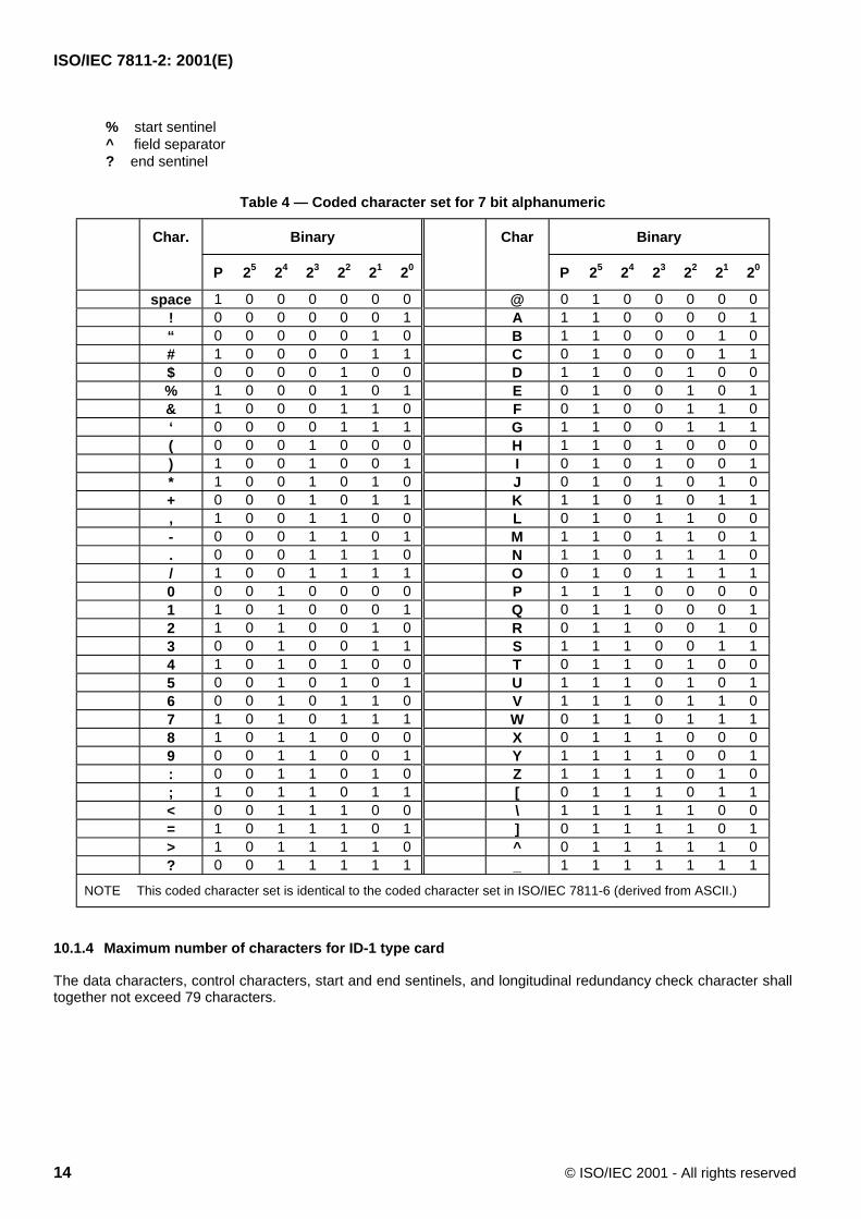
10.1.3 Coded character set
The coded character set for track 1 shall be 7 bit alphanumeric as shown in Table 4.
The 14 characters ! “ & ‘ * + , : ; < = > @ _ are available for hardware control purposes and may not be used forinformation (data content).
The 3 characters [ \ ] are reserved for additional national characters when required. They must not be usedinternationally.
The character # is reserved for optional additional graphic symbols.
The 3 characters % ^ ? shall have the following meaning:
ISO/IEC 7811-2: 2001(E)
14 © ISO/IEC 2001 - All rights reserved
% start sentinel^ field separator? end sentinel
Table 4 — Coded character set for 7 bit alphanumeric
Char. Binary Char Binary
P 25 24 23 22 21 20 P 25 24 23 22 21 20
space 1 0 0 0 0 0 0 @ 0 1 0 0 0 0 0! 0 0 0 0 0 0 1 A 1 1 0 0 0 0 1“ 0 0 0 0 0 1 0 B 1 1 0 0 0 1 0# 1 0 0 0 0 1 1 C 0 1 0 0 0 1 1$ 0 0 0 0 1 0 0 D 1 1 0 0 1 0 0% 1 0 0 0 1 0 1 E 0 1 0 0 1 0 1& 1 0 0 0 1 1 0 F 0 1 0 0 1 1 0‘ 0 0 0 0 1 1 1 G 1 1 0 0 1 1 1( 0 0 0 1 0 0 0 H 1 1 0 1 0 0 0) 1 0 0 1 0 0 1 I 0 1 0 1 0 0 1* 1 0 0 1 0 1 0 J 0 1 0 1 0 1 0+ 0 0 0 1 0 1 1 K 1 1 0 1 0 1 1, 1 0 0 1 1 0 0 L 0 1 0 1 1 0 0- 0 0 0 1 1 0 1 M 1 1 0 1 1 0 1. 0 0 0 1 1 1 0 N 1 1 0 1 1 1 0/ 1 0 0 1 1 1 1 O 0 1 0 1 1 1 10 0 0 1 0 0 0 0 P 1 1 1 0 0 0 01 1 0 1 0 0 0 1 Q 0 1 1 0 0 0 12 1 0 1 0 0 1 0 R 0 1 1 0 0 1 03 0 0 1 0 0 1 1 S 1 1 1 0 0 1 14 1 0 1 0 1 0 0 T 0 1 1 0 1 0 05 0 0 1 0 1 0 1 U 1 1 1 0 1 0 16 0 0 1 0 1 1 0 V 1 1 1 0 1 1 07 1 0 1 0 1 1 1 W 0 1 1 0 1 1 18 1 0 1 1 0 0 0 X 0 1 1 1 0 0 09 0 0 1 1 0 0 1 Y 1 1 1 1 0 0 1: 0 0 1 1 0 1 0 Z 1 1 1 1 0 1 0; 1 0 1 1 0 1 1 [ 0 1 1 1 0 1 1< 0 0 1 1 1 0 0 \ 1 1 1 1 1 0 0= 1 0 1 1 1 0 1 ] 0 1 1 1 1 0 1> 1 0 1 1 1 1 0 ^ 0 1 1 1 1 1 0? 0 0 1 1 1 1 1 _ 1 1 1 1 1 1 1
NOTE This coded character set is identical to the coded character set in ISO/IEC 7811-6 (derived from ASCII.)
10.1.4 Maximum number of characters for ID-1 type card
The data characters, control characters, start and end sentinels, and longitudinal redundancy check character shalltogether not exceed 79 characters.
ISO/IEC 7811-2: 2001(E)
© ISO/IEC 2001 - All rights reserved 15
10.2 Numeric track, Track 2
10.2.1 Average bit density
The average bit density (Ba) shall be 2,95 bits/mm (75 bpi) ± 5% measured in a longitudinal direction parallel to thetop reference edge.
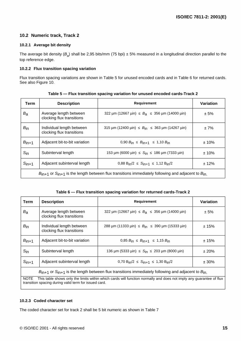
10.2.2 Flux transition spacing variation
Flux transition spacing variations are shown in Table 5 for unused encoded cards and in Table 6 for returned cards.See also Figure 10.
Table 5 — Flux transition spacing variation for unused encoded cards-Track 2
Term Description Requirement Variation
Ba Average length betweenclocking flux transitions
322 µm (12667 µin) ≤ Ba ≤ 356 µm (14000 µin) ± 5%
Bin Individual length betweenclocking flux transitions
315 µm (12400 µin) ≤ Bin ≤ 363 µm (14267 µin) ± 7%
Bin+1 Adjacent bit-to-bit variation 0,90 Bin ≤ Bin+1 ≤ 1,10 Bin ± 10%
Sin Subinterval length 153 µm (6000 µin) ≤ Sin ≤ 186 µm (7333 µin) ± 10%
Sin+1 Adjacent subinterval length 0,88 Bin/2 ≤ Sin+1 ≤ 1,12 Bin/2 ± 12%
Bin+1 or Sin+1 is the length between flux transitions immediately following and adjacent to Bin.
Table 6 — Flux transition spacing variation for returned cards-Track 2
Term Description Requirement Variation
Ba Average length betweenclocking flux transitions
322 µm (12667 µin) ≤ Ba ≤ 356 µm (14000 µin) ± 5%
Bin Individual length betweenclocking flux transitions
288 µm (11333 µin) ≤ Bin ≤ 390 µm (15333 µin) ± 15%
Bin+1 Adjacent bit-to-bit variation 0,85 Bin ≤ Bin+1 ≤ 1,15 Bin ± 15%
Sin Subinterval length 136 µm (5333 µin) ≤ Sin ≤ 203 µm (8000 µin) ± 20%
Sin+1 Adjacent subinterval length 0,70 Bin/2 ≤ Sin+1 ≤ 1,30 Bin/2 ± 30%
Bin+1 or Sin+1 is the length between flux transitions immediately following and adjacent to Bin.NOTE This table shows only the limits within which cards will function normally and does not imply any guarantee of fluxtransition spacing during valid term for issued card.
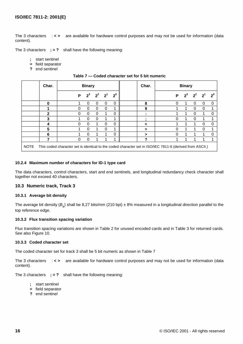
10.2.3 Coded character set
The coded character set for track 2 shall be 5 bit numeric as shown in Table 7
ISO/IEC 7811-2: 2001(E)
16 © ISO/IEC 2001 - All rights reserved
The 3 characters : < > are available for hardware control purposes and may not be used for information (datacontent).
The 3 characters ; = ? shall have the following meaning:
; start sentinel= field separator? end sentinel
Table 7 — Coded character set for 5 bit numeric
Char. Binary Char. Binary
P 23 22 21 20 P 23 22 21 20
0 1 0 0 0 0 8 0 1 0 0 01 0 0 0 0 1 9 1 1 0 0 12 0 0 0 1 0 : 1 1 0 1 03 1 0 0 1 1 ; 0 1 0 1 14 0 0 1 0 0 < 1 1 1 0 05 1 0 1 0 1 = 0 1 1 0 16 1 0 1 1 0 > 0 1 1 1 07 0 0 1 1 1 ? 1 1 1 1 1
NOTE This coded character set is identical to the coded character set in ISO/IEC 7811-6 (derived from ASCII.)
10.2.4 Maximum number of characters for ID-1 type card
The data characters, control characters, start and end sentinels, and longitudinal redundancy check character shalltogether not exceed 40 characters.
10.3 Numeric track, Track 3
10.3.1 Average bit density
The average bit density (Ba) shall be 8,27 bits/mm (210 bpi) ± 8% measured in a longitudinal direction parallel to thetop reference edge.
10.3.2 Flux transition spacing variation
Flux transition spacing variations are shown in Table 2 for unused encoded cards and in Table 3 for returned cards.See also Figure 10.
10.3.3 Coded character set
The coded character set for track 3 shall be 5 bit numeric as shown in Table 7
The 3 characters : < > are available for hardware control purposes and may not be used for information (datacontent).
The 3 characters ; = ? shall have the following meaning:
; start sentinel= field separator? end sentinel
ISO/IEC 7811-2: 2001(E)
© ISO/IEC 2001 - All rights reserved 17
10.3.4 Maximum number of characters for ID-1 type card
The data characters, control characters, start and end sentinels, and longitudinal redundancy check character shalltogether not exceed 107 characters.
11 Error detection
Two techniques of error detection, as described below, shall be encoded. In both techniques, the leading andtrailing zeroes shall not be regarded as data characters.
11.1 Parity
A parity bit for each encoded character shall be used. The value of the parity bit is defined such that the totalquantity of one bits recorded, for each character, including the parity bit, shall be odd.
11.2 Longitudinal redundancy check (LRC)
The longitudinal redundancy check (LRC) character shall appear for each data track. The LRC character shall beencoded so that it immediately follows the end sentinel when the card is read in a direction giving the start sentinelfirst, followed by data and the end sentinel. The bit configuration of the LRC character shall be identical to the bitconfiguration of the data characters.
The LRC character shall be calculated using the following procedure:
The value of each bit in the LRC character, excluding the parity bit, is defined such that the total count of one bitsencoded in the corresponding bit location of all characters of the data track, including the start sentinel, data, endsentinel, and LRC characters, shall be even.
The LRC characters parity bit is not a parity bit for the individual parity bits of the data track, but is only the parity bitfor the LRC character encoded as described in 11.1.
ISO/IEC 7811-2: 2001(E)
18 © ISO/IEC 2001 - All rights reserved
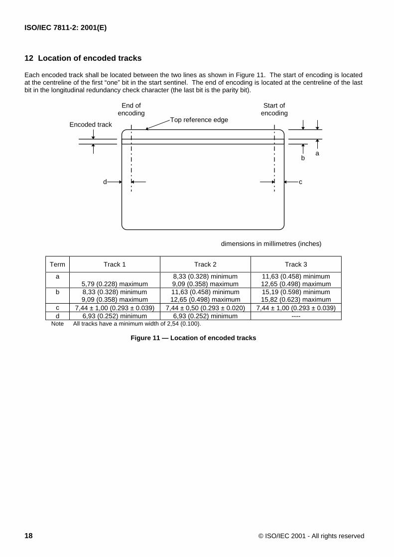
12 Location of encoded tracks
Each encoded track shall be located between the two lines as shown in Figure 11. The start of encoding is locatedat the centreline of the first “one” bit in the start sentinel. The end of encoding is located at the centreline of the lastbit in the longitudinal redundancy check character (the last bit is the parity bit).
b
Encoded trackTop reference edge
a
c
dimensions in millimetres (inches)
d
Start ofencoding
End ofencoding
Term Track 1 Track 2 Track 3
a5,79 (0.228) maximum
8,33 (0.328) minimum9,09 (0.358) maximum
11,63 (0.458) minimum12,65 (0.498) maximum
b 8,33 (0.328) minimum9,09 (0.358) maximum
11,63 (0.458) minimum12,65 (0.498) maximum
15,19 (0.598) minimum15,82 (0.623) maximum
c 7,44 ± 1,00 (0.293 ± 0.039) 7,44 ± 0,50 (0.293 ± 0.020) 7,44 ± 1,00 (0.293 ± 0.039)d 6,93 (0.252) minimum 6,93 (0.252) minimum ----
Note All tracks have a minimum width of 2,54 (0.100).
Figure 11 — Location of encoded tracks
ISO/IEC 7811-2: 2001(E)
© ISO/IEC 2001 - All rights reserved 19
Annex A(informative)
Read compatibility of magnetic stripes (ISO/IEC 7811-2 and ISO/IEC 7811-6)
The purpose of this annex is to explain to users the limitations of the term 'read compatibility' as mentioned in thescope of this standard, and applied to ISO/IEC 7811-2 and ISO/IEC 7811-6.
Ideally, high coercivity magnetic stripes would have significantly improved resistance to erasure but would beidentical in read-back signal characteristics to 'low coercivity' magnetic stripes (i.e. those magnetic stripesconforming to ISO/IEC 7811-2). In practice, however, the difference in magnetic characteristics between high andlow coercivity magnetic stripes causes the read-back signal characteristics to differ sufficiently to make evaluationof relative read-back signal amplitude dependent on the measuring equipment.
In general, it is to be expected that read-back sub-systems with greater sensitivity to shorter recorded wavelengthswill produce an increase in high coercivity read-back signal amplitudes relative to low coercivity read-back signalamplitudes.
Users of ISO/IEC 7811-6 should therefore take careful note of the fact that obtaining comparable read-back signalamplitudes from magnetic stripes conforming to ISO/IEC 7811-2 is dependent upon reproducing the exactconditions of measurement given in ISO/IEC 10373-2.
ISO/IEC 7811-2: 2001(E)
20 © ISO/IEC 2001 - All rights reserved
Annex B(normative)
Signal amplitude measurements
This test method in this annex will be superseded by the next edition of ISO/IEC 10373-2.
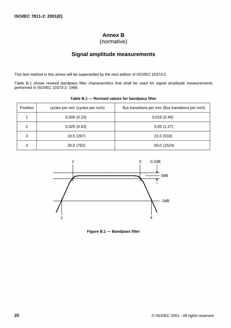
Table B.1 shows revised bandpass filter characteristics that shall be used for signal amplitude measurementsperformed in ISO/IEC 10373-2: 1998.
Table B.1 — Revised values for bandpass filter
Position cycles per mm (cycles per inch) flux transitions per mm (flux transitions per inch)
1 0,009 (0.23) 0,018 (0.46)
2 0,025 (0.63) 0,05 (1.27)
3 10,5 (267) 21,0 (533)
4 30,0 (762) 60,0 (1524)
1
2 3
4
-3dB
0dB
0.2dB
Figure B.1 — Bandpass filter
ISO/IEC 7811-2: 2001(E)
© ISO/IEC 2001 - All rights reserved 21
Annex C(informative)
Magnetic stripe abrasivity
The purpose of this annex is to explain why the abrasive properties of magnetic stripes as it relates to head life arenot among the physical characteristics governed by this standard. The absence of any specification for abrasiveproperties reflects the difficulty of defining the parameters of abrasive wear and devising an accurate, repeatabletest for measuring abrasive properties. Although no repeatable test methods are available, there are knowntechnologies available for extending head life such as improved head materials, magnetic stripe formulationadditives, or overcoats on magnetic stripe.
A quantified stripe abrasivity would seem to be an essential prerequisite to any attempt to predict magnetic headlifetimes. However, just as there is considerable variation in the abrasive nature of different magnetic stripes, thereare a multitude of magnetic stripe reader/writer environments. The variety of combinations of influences and thecomplexity of the manner in which these affect abrasivity makes it extremely difficult to predict magnetic headlifetimes even when the environmental, mechanical and magnetic stripe conditions are specified.
Current equipment-specific abrasivity testing is done on a purely comparative basis. It is time consuming andusually expensive in terms of the number of cards used. The results of such tests are simply rankings that showone stripe to be some degree more or less abrasive than others under the specific conditions of test. There are noaccurate absolute values and the rankings may change from one set of conditions to another.
Performing a successful read or write operation on a magnetic stripe requires the stripe and magnetic head to be incontact for the whole operation. The relative movement between the magnetic head and magnetic stripe produceswear of both. Initially the abrasivity of the magnetic stripe falls rapidly with the number of head passes, so that theabrasivity of a new unused magnetic stripe may be much greater than that of a magnetic stripe which has only beenwritten once, but as the number of head passes increases the rate of change of abrasivity decreases.
The influences affecting magnetic stripe abrasivity are known to include temperature, humidity, head material (andits state of wear and finish), head pressure, card speed, the specific physical properties of the magnetic stripesurface in contact
with the head, surface roughness, and contamination on the magnetic stripe. Under field conditions dust, dirt andgrease from the environment are deposited at the head/stripe interface often producing major discrepanciesbetween abrasive wear measured under laboratory conditions and that actually achieved.
It may be seen, therefore, that not only are there difficulties involved in achieving an acceptable level ofmeasurement uncertainty for abrasivity testing but that there are significant doubts regarding the applicability of theresults of abrasivity tests on cards under laboratory conditions to predictions of performance in the real world.Unless these problems are resolved, there can be no useful standard specification and test.
ISO/IEC 7811-2:2001(E)
ICS 35.240.15Price based on 21 pages
© ISO/IEC 2001 – All rights reserved
Related Documents


![ETSI ETR 165 TECHNICAL REPORT · 2000-02-02 · stored and read (read/write or read-only) in analogue or digital form (cf. ISO 7811-2 [8], ISO 7811-4 [9] and ISO 7811-5 [10]). optical](https://static.cupdf.com/doc/110x72/5e8c1ad7e3c59057b239ca45/etsi-etr-165-technical-report-2000-02-02-stored-and-read-readwrite-or-read-only.jpg)