Edition 3.003 August 2006 M4 INTERNATIONAL HYDROGRAPHIC ORGANIZATION REGULATIONS OF THE IHO FOR INTERNATIONAL (INT) CHARTS AND CHART SPECIFICATIONS OF THE IHO Edition 3.003 – August 2006 PUBLISHED BY THE INTERNATIONAL HYDROGRAPHIC BUREAU MONACO

Welcome message from author
This document is posted to help you gain knowledge. Please leave a comment to let me know what you think about it! Share it to your friends and learn new things together.
Transcript
Edition 3.003
August 2006
M4
INTERNATIONAL HYDROGRAPHIC ORGANIZATION
REGULATIONS OF THE IHO FOR INTERNATIONAL (INT) CHARTS
AND CHART SPECIFICATIONS OF THE IHO
Edition 3.003 – August 2006
PUbLISHED bY THE INTERNATIONAL HYDROGRAPHIC bUREAU MONACO

Page intentionally left blank
Edition 3.003
August 2006
M4
INTERNATIONAL HYDROGRAPHIC ORGANIZATION
REGULATIONS OF THE IHO FOR INTERNATIONAL (INT) CHARTS
AND CHART SPECIFICATIONS OF THE IHO
PART A REGULATIONS OF THE IHO FOR INTERNATIONAL (INT) CHARTS SECTIONS 100-600
PART B CHART SPECIFICATIONS OF THE IHO MEDIUM- AND LARGE-SCALE NATIONAL AND INTERNATIONAL (INT) CHARTS (SCALES LARGER THAN 1:2 MILLION) SECTIONS 100-500
PART C CHART SPECIFICATIONS OF THE IHO SMALL-SCALE INTERNATIONAL (INT) CHARTS (SCALES 1:2 MILLION AND SMALLER) SECTIONS 100-500
Published by the International Hydrographic Bureau4, Quai Antoine 1er
B.P. 445 - MC 98011 MONACO CedexPrincipauté de Monaco
Telefax: (377) 93 10 81 40E-mail: [email protected]
Web-site: www.iho.shom.fr
III

Page intentionally left blank
Edition 3.003
August 2006
M4
�
PREFACE
The publication M-4 “Regulations of the IHO for International (INT) Charts and Chart Specifications of the IHO”, brings together in one comprehensive volume the “Regulations of the IHO for International (INT) Charts” (Part A); the “Chart Specifications of the IHO for Medium- and Large-scale National and International Charts” (Part B); and the “Chart Specifications of the IHO for Small-Scale International (INT) Charts” (Part C).
This publication is available in separate English, French and Spanish versions. The numbering system is identical in all three versions.
Publications INT 1, INT 2 and INT 3 are reference documents supplementary to Parts B and C of M-4. The symbols from INT 1 are also included in the text of Part B for ease of reference.
The three Parts of M-4 are further subdivided into Sections dealing with specific topics. Regulations and Specifications relating to particular topics may be found either by their subject matter in the Contents page at the beginning of each Section, or by reference to column 5 of INT 1 for Part B and the index for Part C. Cross-referencing draws attention to related Regulations and Specifications.
The procedures for correcting and updating M-4 are described in the Introduction to each Part. The adoption of a digital format has eliminated the need for new editions and extensive hand-corrections, as revised sections or sub-sections will be posted on the IHO web-site whenever amendments come into force. Whenever such a revision is made, a new version of M-4 will be made available on the web-site. The edition number at the foot of each page is followed by a version number to the right of the full stop, which will be increased by one whenever a revised version of M-4 is produced. The Record of Corrections at the beginning of Parts A and C, and at the beginning of each section of Part B, provides a history and summary of the changes.
CoPyRIghT. This publication is the property of the International Hydrographic Organization. The total or partial reproduction of this publication, by any organization or individual who is not a member of the IHO, is not permitted without the authorization of the International Hydrographic Bureau

Page intentionally left blank
Regulations of the Iho for INT Charts
Edition 3.003
August 2006M4 Part A
PART A
SECTIONS 100 - 600
REGULATIONS OF THE IHO
FOR INTERNATIONAL (INT) CHARTS
A

Page intentionally left blank
Regulations of the Iho for INT Charts
Edition 3.003
August 2006M4 Part A
A Page iii
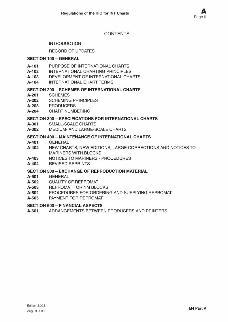
CONTENTS
INTRODUCTION
RECORD OF UPDATES
SECTIoN 100 – gENERAL
A-101 PURPOSE OF INTERNATIONAL CHARTSA-102 INTERNATIONAL CHARTING PRINCIPLESA-103 DEVELOPMENT OF INTERNATIONAL CHARTSA-104 INTERNATIONAL CHART TERMS
SECTIoN 200 – SChEMES oF INTERNATIoNAL ChARTSA-201 SCHEMESA-202 SCHEMING PRINCIPLESA-203 PRODUCERSA-204 CHART NUMBERING
SECTIoN 300 – SPECIFICATIoNS FoR INTERNATIoNAL ChARTSA-301 SMALL-SCALE CHARTSA-302 MEDIUM- AND LARGE-SCALE CHARTS
SECTIoN 400 – MAINTENANCE oF INTERNATIoNAL ChARTSA-401 GENERALA-402 NEW CHARTS, NEW EDITIONS, LARGE CORRECTIONS AND NOTICES TO
MARINERS WITH BLOCKSA-403 NOTICES TO MARINERS - PROCEDURESA-404 REVISED REPRINTS
SECTIoN 500 – EXChANgE oF REPRoDUCTIoN MATERIALA-501 GENERALA-502 QUALITY OF REPROMATA-503 REPROMAT FOR NM BLOCKSA-504 PROCEDURES FOR ORDERING AND SUPPLYING REPROMATA-505 PAYMENT FOR REPROMAT
SECTIoN 600 – FINANCIAL ASPECTSA-601 ARRANGEMENTS BETWEEN PRODUCERS AND PRINTERS

Page intentionally left blank
Regulations of the Iho for INT Charts
Edition 3.003
August 2006M4 Part A
A Page v
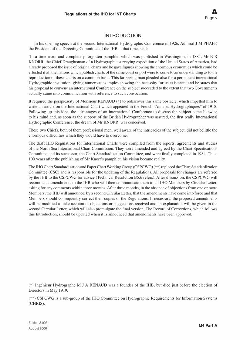
INTRODUCTION
In his opening speech at the second International Hydrographic Conference in 1926, Admiral J M PHAFF, the President of the Directing Committee of the IHB at that time, said:
‘In a time-worn and completely forgotten pamphlet which was published in Washington, in 1884, Mr E R KNORR, the Chief Draughtsman of a Hydrographic surveying expedition of the United States of America, had already proposed the issue of original charts and he gave figures showing the enormous economies which could be effected if all the nations which publish charts of the same coast or port were to come to an understanding as to the reproduction of these charts on a common basis. This far-seeing man pleaded also for a permanent international Hydrographic institution, giving numerous examples showing the necessity for its existence, and he states that his proposal to convene an international Conference on the subject succeeded to the extent that two Governments actually came into communication with reference to such convocation.
It required the perspicacity of Monsieur RENAUD (*) to rediscover this same obstacle, which impelled him to write an article on the International Chart which appeared in the French “Annales Hydrographiques” of 1918. Following up this idea, the advantages of an international Conference to discuss the subject came likewise to his mind and, as soon as the support of the British Hydrographer was assured, the first really International Hydrographic Conference, the dream of Mr KNORR, was conceived.
These two Chiefs, both of them professional men, well aware of the intricacies of the subject, did not belittle the enormous difficulties which they would have to overcome.’
The draft IHO Regulations for International Charts were compiled from the reports, agreements and studies of the North Sea International Chart Commission. They were amended and agreed by the Chart Specifications Committee and its successor, the Chart Standardization Committee, and were finally completed in 1984. Thus, 100 years after the publishing of Mr Knorr’s pamphlet, his vision became reality.
The IHO Chart Standardization and Paper Chart Working Group (CSPCWG) (**) replaced the Chart Standardization Committee (CSC) and is responsible for the updating of the Regulations. All proposals for changes are referred by the IHB to the CSPCWG for advice (Technical Resolution B5.6 refers). After discussion, the CSPCWG will recommend amendments to the IHB who will then communicate them to all IHO Members by Circular Letter, asking for any comments within three months. After three months, in the absence of objections from one or more Members, the IHB will announce, by a second Circular Letter, that the amendments have come into force and that Members should consequently correct their copies of the Regulations. If necessary, the proposed amendments will be modified to take account of objections or suggestions received and an explanation will be given in the second Circular Letter, which will also promulgate the final version. The Record of Corrections, which follows this Introduction, should be updated when it is announced that amendments have been approved.
(*) Ingénieur Hydrographe M J A RENAUD was a founder of the IHB, but died just before the election of Directors in May 1919.
(**) CSPCWG is a sub-group of the IHO Committee on Hydrographic Requirements for Information Systems (CHRIS).

Page intentionally left blank
Regulations of the Iho for INT Charts
Edition 3.003
August 2006M4 Part A
A Page vii
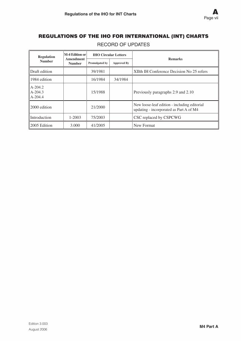
REGULATIONS OF THE IHO FOR INTERNATIONAL (INT) CHARTS
RECORD OF UPDATES
Regulation Number
M-4 Edition or Amendment
Number
IHO Circular LettersRemarks
Promulgated by Approved By
Draft edition 39/1981 XIIth IH Conference Decision No 25 refers
1984 edition 16/1984 34/1984
A-204.2A-204.3A-204.4
15/1988 Previously paragraphs 2.9 and 2.10
2000 edition 21/2000New loose-leaf edition - including editorial updating - incorporated as Part A of M4
Introduction 1-2003 75/2003 CSC replaced by CSPCWG
2005 Edition 3.000 41/2005 New Format

Page intentionally left blank
Regulations of the Iho for INT Charts
Edition 3.003
August 2006
M4 Part ASection 100 – General
A – 100Page 1
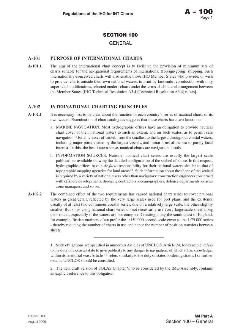
SECTION 100
GENERAL
A-101 PURPOSE OF INTERNATIONAL CHARTS
A-101.1 The aim of the international chart concept is to facilitate the provision of minimum sets of charts suitable for the navigational requirements of international (foreign-going) shipping. Such internationally-conceived charts will also enable those IHO Member States who provide, or wish to provide, charts outside their own national waters, to print by facsimile reproduction with only superficial modifications, selected modern charts under the terms of a bilateral arrangement between the Member States [IHO Technical Resolution A3.4 (Technical Resolution A3.4) refers].
A-102 INTERNATIONAL CHARTING PRINCIPLES
A-102.1 It is necessary first to be clear about the function of each country’s series of nautical charts of its own waters. Examination of chart catalogues suggests that these charts have two functions:
a. MARINE NAVIGATION. Most hydrographic offices have an obligation to provide nautical chart cover of their national waters to such an extent, and on such scales, as to permit safe navigation1, 2 for all classes of vessel, from the smallest to the largest, throughout coastal waters, including major ports visited by the largest vessels, and minor arms of the sea of purely local interest. In this, the best known sense, nautical charts are navigational tools.
b. INFORMATION SOURCES. National nautical chart series are usually the largest scale publications available showing the detailed configuration of the seabed offshore. In this respect, hydrographic offices have a de facto responsibility for their national waters similar to that of topographic mapping agencies for land areas1, 2. Such information about the shape of the seabed is required by a variety of national users other than navigators: construction engineers concerned with offshore developments, dredging contractors, oceanographers, defence departments, coastal zone managers, and so on.
A-102.2 The combined effect of the two requirements has caused national chart series to cover national waters in great detail, reflected by the very large scales used for port plans, and the existence usually of at least two continuous coastal series, one on a relatively large scale, the other slightly smaller. But ships using national chart series do not necessarily use every large-scale sheet along their tracks, especially if the waters are not complex. Coasting along the south coast of England, for example, British mariners often prefer the 1:150 000 second-scale cover to the 1:75 000 series - thereby reducing the number of charts in use and hence the number of position transfers between sheets.
1. Such obligations are specified in numerous Articles of UNCLOS. Article 24, for example, refers to the duty of a coastal state to give publicity to any danger to navigation, of which it has knowledge, within its territorial seas; Article 44 refers similarly to the duty of states bordering straits. For further details, UNCLOS should be consulted.
2. The new draft version of SOLAS Chapter V, to be considered by the IMO Assembly, contains an explicit reference to this obligation.
Regulations of the Iho for INT Charts
Edition 3.003
August 2006
M4 Part ASection 100 – General
A – 100Page 2
A-102.3 This concept is the basis of the choice of scale - 1:150 000 or thereabouts - by France and Germany for their largest- scale continuous coastal series of the south coast of England. The use of scales smaller than the largest of the national series, provided they are adequate for navigation, may also be possible for harbours and port approaches - Plymouth and the Solent are examples. Of course, in exceptionally complex areas, such as river mouths like the Schelde, no reduction in the scale of the national series may be desirable.
A-102.4 Another feature of chart series like those of France and Germany is their concentration on the foreign ports most used by their own vessels. Usually only for such most-frequented ports are large-scale charts of harbours and of the approaches to them included in the series.
A-102.5 Thus, by judicious choice of port and scale, and by varying the latter according to the complexity of the area, France and Germany are able, in those parts of their chart series which cover foreign waters - where visiting French and German ships are in the role of foreign-going international shipping - to keep the total sizes of their world-wide chart outfits within manageable limits, to the advantage of the shipping using them.
A-102.6 Another aspect of the economy in the size of such world outfits is the limitation, outside national waters, of the number of Notices to Mariners by which they are kept corrected. The careful selection, in a variety of ways, of the detail on these charts, allows Notices to be restricted to items which are essential to foreign-going shipping. The updating of the outfit is thereby kept to manageable proportions.
A-102.7 The principles just described formed the basis of the original concept of an international set of medium- and large-scale charts, a set less unwieldy than would be obtained by simply combining existing national chart series in full. From such an internationally-conceived set, all nations who wished to do so could benefit - in the words of Technical Resolution K2.2 (now cancelled), it would “enable those IHO Member States who provide, or wish to provide, charts outside their national waters, to print by facsimile with minimum modification selected modern charts”. By following the principle of producer nations making reproduction material for international charts available to printer nations, the intention was:
a. firstly, to allow countries which do not print charts outside their national waters at present to do so
b. secondly, and more importantly, by sharing the production effort, to make it easier for all countries to keep their charts of foreign waters updated, and thereby to use their resources with greater efficiency, one of the prime needs of hydrographic offices.
A-102.8 More recently the generation of international charts can provide a basis on which to build Electronic Navigational Chart cover for a nation’s waters, and provides a framework for the agreement of cover suitable for adoption of charts by one nation in another’s waters under the terms of a bilateral arrangement (Technical Resolution A3.4 refers).
A-103 DEVELOPMENT OF INTERNATIONAL CHARTS
A-103.1 The idea of international charts was first advanced formally to the IHO at its 9th Conference in 1967 in a motion put by France and the Netherlands. A resolution of that Conference established the Commission on the International Chart, Small Scales (CICSS). The CICSS devised the limits of two series of small-scale charts covering the whole world - a series of 19 charts at scale 1:10 000 000 and another of 60 charts at scale 1:3 500 000. Specifications for the production of these charts were also drawn up and included as Annex 3 to the report of the Commission, issued by the IHO in 1970. They subsequently became Appendix 1 to the IHO Regulations for International Charts. This appendix was revised and republished as Part C of M-4 in 2003. Production of these small-scale international charts was completed in 1987.
Regulations of the Iho for INT Charts
Edition 3.003
August 2006
M4 Part ASection 100 – General
A – 100Page �
A-103.2 In 1972, the 10th IH Conference resolved that a study be conducted into applying the international concept to medium- and large-scale charts also. The North Sea International Chart Commission (NSICC) was accordingly formed to carry out the study on behalf of the IHO. The NSICC devised a scheme of international charts covering NW Europe and the NE Atlantic; full details were published in the NSICC Report to the 11th IH Conference.
A-103.3 However, the major task of the NSICC proved to be the production of a comprehensive set of detailed chart specifications for use in preparing international charts at medium and large scales. This work provided the opportunity for considerable advances in the standardization of chart content. This was recognised at the 1977 IH Conference, which constituted a Chart Specifications Committee (CSC) ‘to adapt and extend the specifications for International Charts to cover all navigational charts in the interests of standardization’.
A-103.4 The CSC modified the NSICC Specifications as necessary to produce the Chart Specifications of the IHO (M-4 Part 1, now re-numbered Part B) which now form the standard for the production of all medium- and large-scale nautical charts, both national and international. Other parts of the NSICC’s work concerned the formulation and operation of various bilateral arrangements between nations relating to international charts. The development of bilateral arrangements covering charts is now covered in Technical Resolution A3.4 (see A-601).
A-104 INTERNATIONAL CHART TERMS
A-104.1 An ‘INTERNATIONAL (INT) CHART’ is a chart which:
a. is produced with limits and scale in conformity with an internationally agreed scheme of such charts
b. carries the INT number of that sheet,
c. conforms to the Chart Specifications of the IHO (M-4 Parts B and C),
d. conforms to the Regulations of the IHO for International Charts (M-4 Part A).
A-104.2 A ‘PRODUCER NATION’ is a Member State of the IHO which undertakes the production of an international chart.
A-104.3 A ‘PRINTER NATION’ is a Member State of the IHO which uses reproduction material from a producer nation to print an international chart, with only superficial modifications, for inclusion in its own chart series. Bilateral arrangements between IHO Member States covering such charting are the subject of Technical Resolution A3.4.
A-104.4 ‘REPROMAT’ is an abbreviation for reproduction material; see A-500.
A-104.5 ‘NATIONAL WATERS’ is used loosely to include adjacent sea areas normally surveyed by any national hydrographic office.
A-104.6 ‘BILATERAL ARRANGEMENT’ is a formal arrangement between two Member States of the IHO, including the detailed financial and administrative arrangements, for charting in each other’s waters. Until bilateral arrangements are in place, or where it is mutually agreed that bilateral procedures are not appropriate or economical, hydrographic offices may operate according to other procedures mutually agreed between them (Technical Resolution A3.4 refers).Guidelines for bilateral arrangements between hydrographic offices are provided in IHO Circular Letter 48/1995.

Page intentionally left blank
Regulations of the Iho for INT Charts
Edition 3.003
August 2006
M4 Part ASection 200 – Schemes of International Charts
A – 200Page 1
SECTION 200
SCHEMES OF INTERNATIONAL CHARTS
A-201 SCHEMES
A-201.1 Two schemes of small-scale international charts covering the world were developed by the CICSS.
A-201.2 Schemes of medium- and large-scale international charts are devised by regional groupings of hydrographic offices concerned with particular regions (see A-204.8).
A-201.3 Details of international chart schemes and of scheming principles are shown in M-11, Catalogue of International Charts:
Part A Guidance for the Preparation and Maintenance of International Chart Schemes (to be published in 2005, formerly S-48)
Part B Catalogue of International (INT) Charts
A-202 SCHEMING PRINCIPLES
A-202.1 Adequacy for international (foreign-going) shipping is the keynote, as explained in A-102.3 to A-102.5. Applying this basic principle, the following detailed guidelines may be followed, inter alia, when devising international schemes:
a. the scales used by hydrographic offices when charting other countries’ waters should be used for guidance in the choice of scales for the international series;
b. wherever possible, sheet limits and scales should be made to conform to those of corresponding charts in the various national chart series, present or projected, which can thereby most readily be modified, or prepared from the beginning, to conform to international specifications or regulations;
c. the need for a separate chart may sometimes be avoided by adding it in modified form as an inset plan to another sheet, in order to reduce the total number of international charts;
d. chart dimensions shall follow the standards laid down in B-222.
A-202.2 The choice of scales (see A-202.1a) will depend upon the navigational requirements of international shipping. It will usually be possible to identify scale bands which fulfil different types of navigational function, eg coastal navigation. The precise structure of the scheme may vary from area to area, reflecting differing hydrographic circumstances. For example, in the NSICC scheme the continuous coastal series varies in scale between 1:130 000 and 1:350 000, and all the chosen scales are considered adequate for coastal navigation in the areas to which they apply.
A-202.3 The selection of ports to be covered in the international series should be related to the frequency of use by foreign shipping. Initially, production priority should be given to major ports. The choice of ports will need to be kept under review in the light of new developments, and the scheme adjusted accordingly.
A-202.4 For more detailed consideration of the principles behind the scheming of international charts and for more detailed guidance, for example if a consensus cannot be achieved, Guidance for the Preparation and Maintenance of International Chart Schemes (Part A of M-11) should be consulted.
Regulations of the Iho for INT Charts
Edition 3.003
August 2006
M4 Part ASection 200 – Schemes of International Charts
A – 200Page 2
A-203 PRODUCERS
A-203.1 Producers of medium- and large-scale international charts will normally be the hydrographic offices with a national responsibility for the waters concerned. However, some special cases may be identified:
a. The allocation of medium scale charts covering more than one nation’s waters should be agreed and preferably shared between the nations concerned: in the interests of efficiency of production a single producer nation should normally be identified for each chart.
b. Where for any reason a single producer nation cannot be agreed for an international chart, the nations involved may collaborate on the production of a single international chart which will bear both their official seals (crests).
c. If there is a requirement for an international sheet which a national office may not wish to produce, its production may be undertaken by a potential printer nation after discussion and agreement with the national office concerned.
d. Where two or more bordering Member States cannot agree on which should produce an international chart of their waters, the limits and scale of which they have agreed, then that international chart should not be prepared until such agreement can be reached.
e. Pending agreement as provided for in A-203.1a to A-203.1d, the states concerned, in a spirit of understanding and cooperation, shall make every effort to enter into practical provisional arrangements, including those provided for above, so as not to interfere with the reaching of a final agreement. Such arrangements shall not prejudice the final agreement and shall maintain the regionally approved chart schemes.
f. Where an international chart is desired which will cover waters of a nation which is not a member of the IHO, the producer nation will be agreed by the IHO Regional body concerned with international charts. It is not necessary to seek the approval of the non-member nation but consultation on other aspects of charting its waters is recommended.
g. The addition or omission of inset plans or the omission of internal detail, on or from international sheets which would otherwise correspond to national charts, may be undertaken by a printer nation but only under the technical terms of a bilateral arrangement agreed with the producer nation concerned (Technical Resolution A3.4 refers)
NB: Producer nation status for any international chart does not have any political significance.
A-204 CHART NUMBERING
A-204.1 The CICSS recommended a numbering system and made a provisional regional allocation of numbers for international charts. Slight adjustment of this allocation was found necessary by the NSICC - see the NSICC Report to the 11th IH Conference. It is recommended that international charts be numbered in accordance with the principles described in the following paragraphs.
Regulations of the Iho for INT Charts
Edition 3.003
August 2006
M4 Part ASection 200 – Schemes of International Charts
A – 200Page �
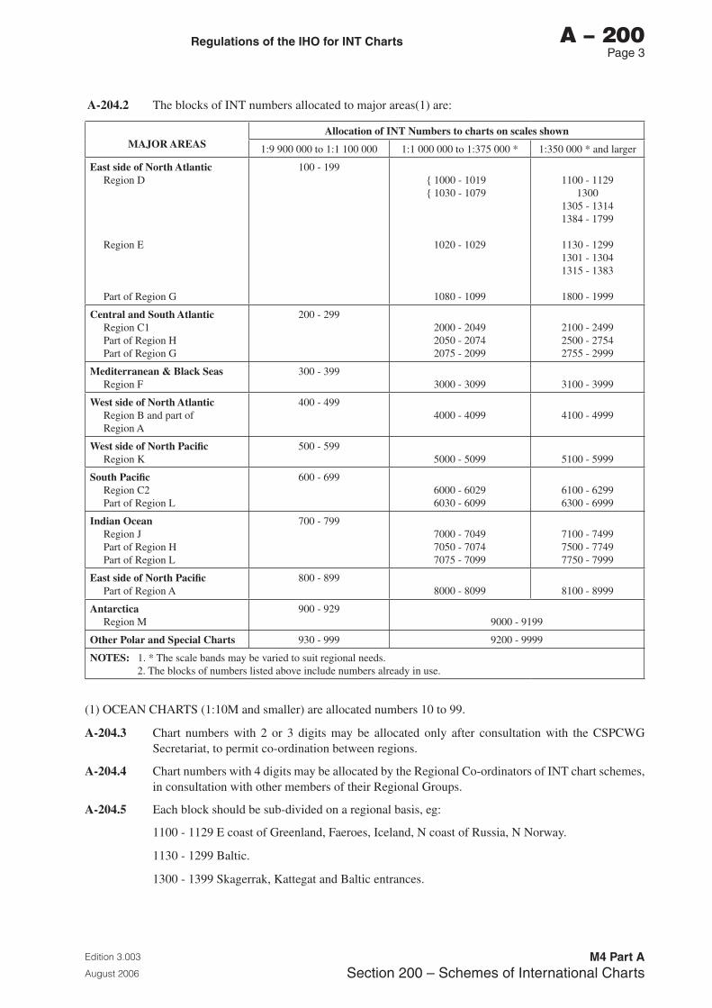
A-204.2 The blocks of INT numbers allocated to major areas(1) are:
MAJOR AREASAllocation of INT Numbers to charts on scales shown
1:9 900 000 to 1:1 100 000 1:1 000 000 to 1:375 000 * 1:350 000 * and larger
East side of North AtlanticRegion D
Region E
Part of Region G
100 - 199{ 1000 - 1019{ 1030 - 1079
1020 - 1029
1080 - 1099
1100 - 11291300
1305 - 13141384 - 1799
1130 - 12991301 - 13041315 - 1383
1800 - 1999
Central and South AtlanticRegion C1Part of Region HPart of Region G
200 - 2992000 - 20492050 - 20742075 - 2099
2100 - 24992500 - 27542755 - 2999
Mediterranean & Black SeasRegion F
300 - 3993000 - 3099 3100 - 3999
West side of North AtlanticRegion B and part of Region A
400 - 4994000 - 4099 4100 - 4999
West side of North PacificRegion K
500 - 5995000 - 5099 5100 - 5999
South PacificRegion C2Part of Region L
600 - 6996000 - 60296030 - 6099
6100 - 62996300 - 6999
Indian OceanRegion JPart of Region HPart of Region L
700 - 7997000 - 70497050 - 70747075 - 7099
7100 - 74997500 - 77497750 - 7999
East side of North PacificPart of Region A
800 - 8998000 - 8099 8100 - 8999
AntarcticaRegion M
900 - 9299000 - 9199
Other Polar and Special Charts 930 - 999 9200 - 9999
NOTES: 1. * The scale bands may be varied to suit regional needs.2. The blocks of numbers listed above include numbers already in use.
(1) OCEAN CHARTS (1:10M and smaller) are allocated numbers 10 to 99.
A-204.3 Chart numbers with 2 or 3 digits may be allocated only after consultation with the CSPCWG Secretariat, to permit co-ordination between regions.
A-204.4 Chart numbers with 4 digits may be allocated by the Regional Co-ordinators of INT chart schemes, in consultation with other members of their Regional Groups.
A-204.5 Each block should be sub-divided on a regional basis, eg:
1100 - 1129 E coast of Greenland, Faeroes, Iceland, N coast of Russia, N Norway.
1130 - 1299 Baltic.
1300 - 1399 Skagerrak, Kattegat and Baltic entrances.
Regulations of the Iho for INT Charts
Edition 3.003
August 2006
M4 Part ASection 200 – Schemes of International Charts
A – 200Page �
A-204.6 Further sub-division by scale within a block is also desirable. For example, the international charts of the west coast of the British Isles are numbered within the following sub-blocks:
General charts of the whole area (1:1 500 000) 160 - 169
Passage / Landfall charts (1:1 000 000 - 1:375 000) 1060 - 1069
Continuous coastal cover (1:350 000 - 1:130 000) 1600 - 1629
Larger scales 1630 - 1699
NB: The scale ranges quoted in this example proved convenient in numbering scale groups in this area. Elsewhere, different scale ranges may be more suitable according to the nature of the chart cover.
A-204.7 It is important that gaps be left within both scale groups and regional groups, in order to provide for future additions to the chart series.
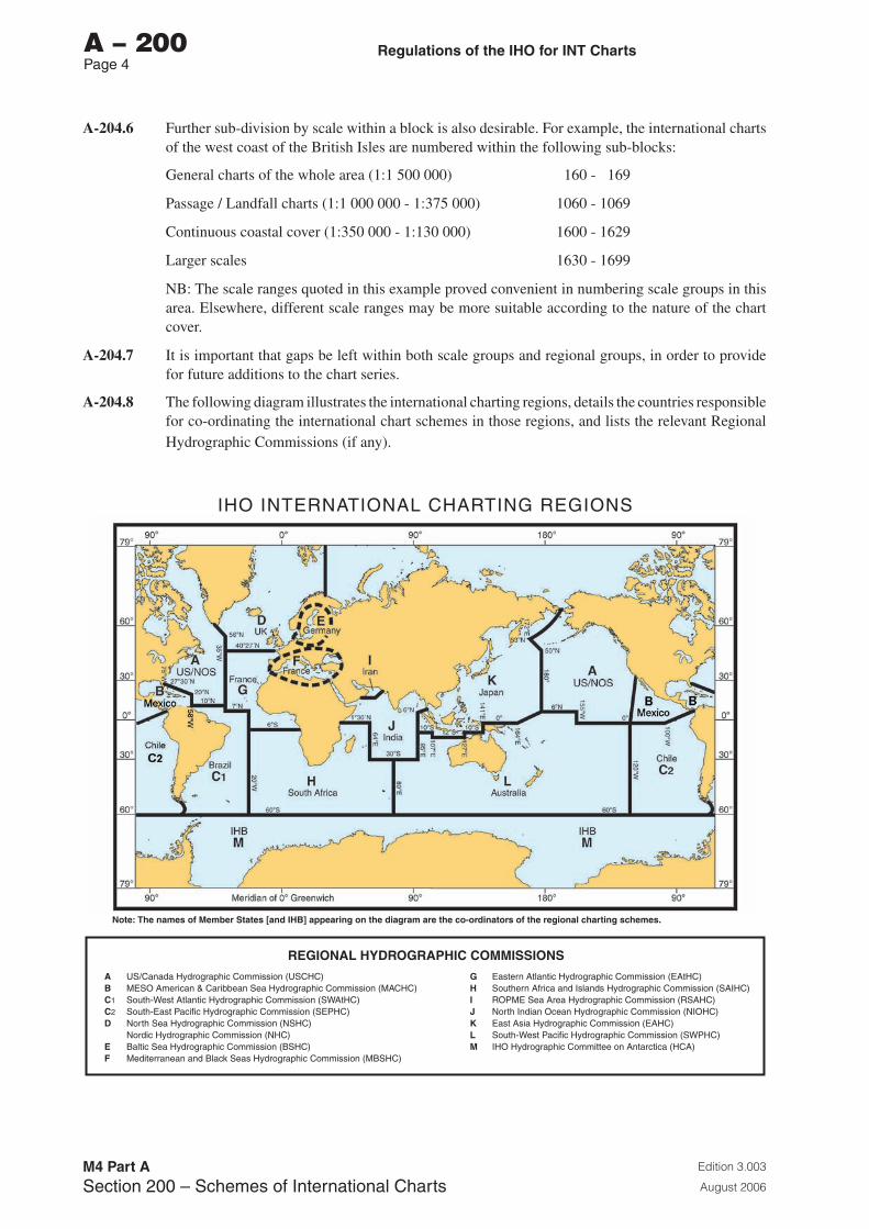
A-204.8 The following diagram illustrates the international charting regions, details the countries responsible for co-ordinating the international chart schemes in those regions, and lists the relevant Regional Hydrographic Commissions (if any).
IHO INTERNATIONAL CHARTING REGIONS
A US/Canada Hydrographic Commission (USCHC)B MESO American & Caribbean Sea Hydrographic Commission (MACHC)C1 South-West Atlantic Hydrographic Commission (SWAtHC)C2 South-East Pacific Hydrographic Commission (SEPHC)D North Sea Hydrographic Commission (NSHC) Nordic Hydrographic Commission (NHC)E Baltic Sea Hydrographic Commission (BSHC)F Mediterranean and Black Seas Hydrographic Commission (MBSHC)
G Eastern Atlantic Hydrographic Commission (EAtHC)H Southern Africa and Islands Hydrographic Commission (SAIHC)I ROPME Sea Area Hydrographic Commission (RSAHC)J North Indian Ocean Hydrographic Commission (NIOHC)K East Asia Hydrographic Commission (EAHC)L South-West Pacific Hydrographic Commission (SWPHC)M IHO Hydrographic Committee on Antarctica (HCA)
REGIONAL HYDROGRAPHIC COMMISSIONS
Note: The names of Member States [and IHB] appearing on the diagram are the co-ordinators of the regional charting schemes.
Regulations of the Iho for INT Charts
Edition 3.003
August 2006
M4 Part ASection �00 – Specifications for International Charts
A – 300Page 1
SECTION 300
SPECIFICATIONS FOR INTERNATIONAL CHARTS
A-301 SMALL-SCALE CHARTS
A-301.1 International charts on scales of 1:2 Million and smaller shall be prepared in accordance with the Chart Specifications of the IHO for Small-Scale International (INT) Charts in Part C.
A-302 MEDIUM- and LARGE-SCALE CHARTS
A-302.1 International charts on scales larger than 1:2 Million shall be prepared in accordance with the Chart Specifications of the IHO contained in Part B. These specifications are published for use in compiling medium- and large-scale charts, both national and international. Some paragraphs or sub-paragraphs are applicable only to international charts. These are distinguished by the suffix “I” to the paragraph number, eg B-351.1(I).
A-302.2 Particular attention is drawn to B-110 which defines various levels of standardization which can be identified throughout the specifications. The intention is to permit some variations between the charting practices of IHO member offices where they would not mislead a navigator, while striving for complete uniformity where essentials are concerned. The depiction of topographic relief is in the first category, as opposed to the definition and use of a submerged rock symbol, which is in the second.
A-302.3 It is likely that, either temporarily or permanently, there will be national requirements, reflecting a country’s needs or preferences, to introduce minor variations into the specifications. Such factors will inevitably affect the degree of modification which a printer nation is obliged, or chooses, to make to a producer nation’s reproduction material. However, the aim of the international chart concept is to produce a series which is capable of being reproduced with minimum modification, and the importance of producer offices adhering closely to the specifications is obvious.
A-302.4 In general, it should be borne in mind that any publisher has a responsibility to the users of any of his publications, and the ultimate decision as to its contents must be his. In the nautical charting context, hydrographic offices publishing national or international charts, whether as producers or printers, are in this position.
A-302.5 The following standard reference graphics are supplementary to the Chart Specifications:
a. INT1 Symbols, Abbreviations, Terms used on Charts
Provides the chart user with a key to symbols and abbreviations used on charts compiled in accordance with these specifications. Although it may be used by cartographers as a quick reference, the specifications should always be used for detailed guidance.
b. INT2 Borders, Graduation, Grids and Linear Scales
Shows specimens of the various patterns of border graduation and linear scales.
c. INT3 Use of Symbols and Abbreviations
A standard reference chart of a fictitious area with as many examples as possible of the use of these specifications.
For the latest edition dates, see P-4, Catalogue of IHO Publications.

Page intentionally left blank
Regulations of the Iho for INT Charts
Edition 3.003
August 2006
M4 Part ASection �00 – Maintenance of International Charts
A – 400Page 1
SECTION 400
MAINTENANCE OF INTERNATIONAL CHARTS
A-401 GENERAL
A-401.1 Chart maintenance is the process of examining relevant data as it is received and taking appropriate action to ensure that all information required for safe navigation is incorporated in the charts in use.
A-401.2 The following terms are used when referring to the issue of charts, and in these Regulations:
a. New Chart (NC): The first publication of a national chart which will either:
• embrace an area not previously charted by that nation to the scale shown; or
• embrace an area different from any existing chart of that nation; or
• consist of a modernised version (in terms of symbology and general presentation) of an existing chart; or
• consist of the adoption by that nation of an international (INT) or national chart, first published by another nation.
A New Chart does not necessarily contain newly received information and all information contained may have been previously made available in other national charts. Reference should always be made to the Source or Zones of Confidence (ZOC) Diagram (see B-295 to B-298) which will contain details of the original survey data used to compile the New Chart. Where a New Chart does contain newly received information, the source diagram will not always reflect certain extensive changes, for example to symbology, buoyage or lights.
b. New Edition and/or Large Correction (NE, LC): A new issue of an existing chart, containing amendments essential to navigation which will normally have been derived from newly received information. It will include changes additional to those previously promulgated in Notices to Mariners, and will render the existing edition obsolete. However, it should be noted that considerable parts of the chart may remain unchanged. The chart number normally remains unchanged except for the addition of INT number when the chart becomes INT. Reference should be made to the Source or ZOC Diagram (see B-295 to B-298) which will contain details of the survey data used to amend the chart. However, the source diagram will not always reflect certain extensive changes, for example to symbology, buoyage or lights.
It should be noted that a Large Correction, a type of correction used by a limited number of nations, is a particularly restricted New Edition.
Exceptionally, certain charting authorities may issue a New Edition or Large Correction including only Notices to Mariners.
c. Reprints (including Revised Reprints - see A-404): A new print of the current edition of a chart incorporating no amendments of navigational significance other than those previously promulgated in Notices to Mariners (if any). It may, however, contain amendments from other sources provided they are not essential to navigation. Previous printings of the current edition of the chart always remain in force.
d. Chartlet / Block / Patch: A small auxiliary chart giving new details of a particular area, to be pasted on the chart by the user. Chartlets are normally included in Notices to Mariners.
A-401.3 Charts will be maintained by the issue of New Charts, New Editions and Notices to Mariners (NM). Nations which employ the Large Correction and / or Revised Reprint in their amendment procedures may also use these for international charts.
Regulations of the Iho for INT Charts
Edition 3.003
August 2006
M4 Part ASection �00 – Maintenance of International Charts
A – 400Page 2
A-401.4 Each nation, in the role of either producer or printer, will accept responsibility for the operation of a system to ensure adequate maintenance of any international chart included in its national series. The required level of maintenance is determined largely by the rate at which significant new information is received. Receipt of new data is not normally predictable so it is rarely feasible to operate on the basis of regular maintenance programmes. Usually the primary factor that determines the frequency of action is rate of change of the critical data in the chart that affects safety of navigation.
A-402 NEW CHARTS, NEW EDITIONS, LARGE CORRECTIONS and NOTICES TO MARINERS WITH BLOCKS
A-402.1 The responsibility for initiating the issue of a replacement New Chart, New Edition, Large Correction or NM Block normally rests with the producer nation. A printer nation receiving data which might give rise to a New Chart, New Edition, Large Correction or NM Block should pass it to the producer nation for action. All other members of the IHO should similarly pass such data to the producer nation for action.
A-402.2 Producer nations will give advance notification in NMs of their intention to replace an existing chart by New Chart, New Edition or Large Correction. Each printer nation is recommended to take appropriate consequential action to keep its adopted national version of the chart in line with the producer’s and will request repromat if required.
A-402.3 On receipt of a Large Correction, a printer nation which does not use that classification may issue the amendment to the adopted version as a New Edition.
A-402.4 Producer nations will indicate to printer nations those charts whose Large Corrections / New Editions include Notices to Mariners only.
A-402.5 Printer nations will normally place a standing order with producer nations for the automatic supply of repromat of NM Blocks affecting all charts adopted by the printer nation.
A-403 NOTICES TO MARINERS - PROCEDURES
A-403.1 The issue of Notices to Mariners (NM) will be in accordance with the procedures detailed in A-403.2 to A-403.10.
A-403.2 The promulgation by the various printer nations involved will normally be based on the NM issued by the hydrographic office (HO) who is the designated producer nation of the international chart. For most medium- and large-scale international charts, the producer nation will be the HO with a national responsibility for the waters concerned (see A-203.1).
A-403.3 Printer nations will arrange with the producer nation for the regular supply of the latter’s NM publications.
A-403.4 Printer nations, using the NM issued by the producer nation, will each draft a corresponding NM, allocate a national number to it, and quote the producer nation’s NM number as the authority.
A-403.5 To accelerate the general release of the information, the producer nation will, if possible, supply advance copies or copies of the draft NM to relevant printer nations.
A-403.6 If the HO with a national responsibility for the waters concerned is not the designated producer nation of the international chart, the producer nation will request that HO to supply at least one copy of the draft NM to the producer who will undertake to forward copies to printer nations. As the first-scale charts in the international series may correspond to the second-scale charts in the national series, it is important that all Notices which affect the national charts one scale step larger than the international chart be supplied. This will ensure that the supply of updating informa-tion is comprehensive enough to maintain all essential items on the international chart.
Regulations of the Iho for INT Charts
Edition 3.003
August 2006
M4 Part ASection �00 – Maintenance of International Charts
A – 400Page �
A-403.7 The international chart often serves as the national chart of the area. The producer nation will therefore need to issue NMs to safeguard the navigation of both national users of all types and vessels trading internationally. Printer nations may be concerned to keep updating of paper products by international mariners to manageable proportions. National producer nations may be concerned that all updating information they issue be represented on all versions of their chart whether produced by them or by a printer nation. Procedures for handling producer nations’ NMs by printer nations will be agreed by bilateral arrangement between producer and printer nations. Whatever procedure is agreed, it is recommended that printer nations incorporate the details contained in all NMs issued by the producer nation in any revised reprint of their national version of the international chart (see A-404.2).
A-403.8 Normally a printer nation will not issue an NM affecting fundamental hydrographic detail on an international chart without prior consultation with the producer nation. However, exceptionally, a printer has the right to initiate and issue an NM for its version of an international chart if immediate promulgation of critical information is considered advisable. In such cases, the printer nation should ensure that copies (preferably advance copies) are sent to the producer nation, to the HO with a national responsibility for the waters concerned (if different from the producer nation) and to the other printer nations. The HO with a national responsibility for the waters concerned should also be supplied with a copy of the report or data on which the NM is based. All other members of the IHO should similarly pass such data to the producer nation for action.
A-403.9 In the list of ‘charts affected’ given in their NM, all nations will quote the international chart number in brackets, adjacent to the national chart number. It is recommended that the number of the previous national NM affecting the chart should also be quoted.
A-403.10 In the index to their Notices to Mariners, all nations will quote the international chart number in brackets, adjacent to the national chart numbers which are usually arranged in sequence. In addition, the index section should also include a separate list of international chart numbers, arranged in sequence under the heading “International Charts” and quoting alongside the numbers of the relevant national NMs affecting each international chart.
A-404 REVISED REPRINTS
A-404.1 The designated producer nation of an international chart may issue a revised reprint of that chart. The revised reprint should incorporate no amendments of navigational significance, other than those previously promulgated in Notices to Mariners (if any). It may however contain amendments from other sources, provided they are not essential to navigation. Previous printings of the current edition will remain in force. Advance notification in NMs, or elsewhere, of the issue of a revised reprint is not normally provided. Copies, preferably with the changes indicated, should therefore be supplied by producers to printers, without demand. A printer nation noting changes indicated may request updated repromat from the producer.
A-404.2 Printer nations may also originate a revised reprint of their national version of an international chart. It is recommended that such a revised reprint should incorporate the amendments resulting from all the NMs issued by the producer nation, even if some of these have not previously been re-promulgated by the printer nation (see A-403.7). This will preserve the homogeneous nature of the international chart series while, at the same time, minimising the correctional task placed on the international mariner. If the revised reprint incorporates other revisions not originated by the producer, a copy (preferably with the changes indicated) will be supplied to the producer, in advance of publication.

Page intentionally left blank
Regulations of the Iho for INT Charts
Edition 3.003
August 2006
M4 Part ASection 500 – Exchange of Reproduction Material
A – 500Page 1
SECTION 500
EXCHANGE OF REPRODUCTION MATERIAL
A-501 GENERAL
A-501.1 Reproduction material (repromat) is material made by the producer nation, at some convenient stage in the preparation of an international chart, from which the chart may be reproduced, without redrafting, in modified facsimile by a printer nation. It may be in analogue or digital form.
A-501.2 Repromat for New Charts, New Editions, Large Corrections or reprints is supplied by producers at the request of printers (see A-402.2 and A-404.1). The terms and conditions for the exchange of repromat will be established bilaterally between individual producer and printer nations (see A-601).
A-501.3 The following paragraphs provide guidance on the procedures for the supply of repromat in analogue form. Procedures for its supply in digital form will be agreed as part of the bilateral arrangements between producer and printer nations.
A-502 QUALITY OF REPROMAT
A-502.1 The producer nation shall ensure that the repromat being provided to another nation meets certain standards given below. These represent a minimum specification and should permit the producer nation to use its normal work materials and procedures.
A-502.2 Material Characteristics: Repromat will be prepared on stable base plastic or film. The size of the repromat will not vary from the computed chart size by more than ± 0,5 mm over the longest dimension of the chart graticule.
A-502.3 Image Quality: Repromat images will be precise and free of blemishes and holes, so as not to require opaquing or other touch-up work.
A-502.4 Amount and Form of Material: The most appropriate form and amount of repromat will be agreed as part of the bilateral arrangements between producer and printer nations. Repromat will be in negative or positive form depending upon the printing processes used by the nations concerned. The repromat will be accompanied by a copy of the chart itself.
A-503 REPROMAT FOR NM BLOCKS
A-503.1 Printer nations will normally place a standing order with producer nations for the automatic supply of repromat of NM Blocks (chartlets, patches) affecting all charts adopted by the printer nation (see A-401.2d).
A-504 PROCEDURES FOR ORDERING AND SUPPLYING REPROMAT
A-504.1 Repromat is sometimes ruined in the process of shipment, or delayed because the parcel was not properly identified. The following procedures should minimise such problems.
A-504.2 Ordering repromat: The printer nation requiring repromat of an international chart shall order such from the producer nation and shall identify the required repromat by the international number, followed by the national number.
A-504.3 Point of Contact: Each producer nation shall designate an addressee for requests for repromat.
Regulations of the Iho for INT Charts
Edition 3.003
August 2006
M4 Part ASection 500 – Exchange of Reproduction Material
A – 500Page 2
A-504.4 Ordering Procedures: The printer nation shall order the repromat by letter or through the use of a requisition form. Requests shall specify that the repromat is being ordered under the relevant bilateral arrangement (see A-601.1).
A-504.5 Wrapping and Packing: Repromat shall be so packaged as to prevent damage in transit. A mailing tube or box of reinforced cardboard shall preferably be used.
A-504.6 Supply Method: The method of shipment shall be determined when the bilateral arrangement is established. Over long distances air shipment is recommended as, although relatively expensive, it is the fastest and least likely to result in damage. Appropriate identification on the parcel shall be made to preclude undue delay to the parcel in the Customs Clearing House of the receiving nation.
A-504.7 Receipt for Material: The receiving nation shall acknowledge receipt of each shipment of repromat and shall provide a documentary receipt to the producing nation.
A-505 PAYMENT FOR REPROMAT
A-505.1 Where financial terms and conditions are agreed, they should in accordance with A-601.
Regulations of the Iho for INT Charts
Edition 3.003
August 2006
M4 Part ASection 600 – Financial Aspects
A – 600Page 1
SECTION 600
FINANCIAL ASPECTS
A-601 ARRANGEMENTS BETWEEN PRODUCERS AND PRINTERS
A-601.1 The exchange of reproduction materials required for the reproduction of international charts as resolved in Technical Resolution A3.4 should be arranged between the producer nations and printer nations, with the financial terms and conditions as agreed by bilateral arrangement.
A-601.2 Financial arrangements should be made that will encourage and not inhibit the early development of a set of worldwide international charts.
A-601.3 There is no obligation for a financial exchange between printers and producers. Arrangements should be made between the parties.
A-601.4 The price of a printer’s chart should be determined when the arrangement is reached between the producer and printer nations. It is recommended that the normal pricing policy should be that the price of a printer’s chart should not be less than that of similar charts in his own national series.

Page intentionally left blank
Chart Specifications of the IhoMedium and Large-scale Charts
Edition 3.003
August 2006
M4 Part BSection 100 – General
b
PART b
SECTIONS 100 - 500
CHART SPECIFICATIONS OF THE IHO
MEDIUM AND LARGE-SCALE
NATIONAL AND INTERNATIONAL (INT) CHARTS
(SCALES LARGER THAN 1:2 000 000)

Page intentionally left blank

Chart Specifications of the IhoMedium and Large-scale Charts
Edition 3.003
August 2006
M4 Part BSection 100 – General
b
INTRODUCTION
Part B of M-4 ‘Chart Specifications of the IHO for Medium and Large scale National and International charts’ is in five sections, the contents of which are:
100 GENERAL200 CHART FRAMEWORK300 TOPOGRAPHY400 HYDROGRAPHY AND NAVIGATIONAL AIDS500 GEOGRAPHIC NAMES, LETTERING, NUMERALS
The conventions used in the Specifications, and other general matters, are explained in Section B-100, which should be read before consulting the other Sections.
Updating of these Specifications is effected by changes announced in the IHO’s Circular Letters. The procedures by which changes are initiated, discussed and promulgated are described in B-160. If an IHO Member State finds it necessary to adopt a new specification or use a new symbol for a feature for which there is no existing symbol, the Member should advise the Bureau of the action taken at the earliest opportunity with a view to its consideration for possible incorporation in these Specifications (IHO Technical Resolution K2.11).
The Record of Corrections, at the beginning of each Section, should be updated when it is announced that changes have been approved.
Charts affected: These Specifications (apart from a few paragraphs suffixed ‘I’, eg. B-351.1(I) which apply only to international charts) are applicable to all large- and medium-scale charts, national and international. Members producing or printing international charts should also consult Part A ‘Regulations of the IHO for International Charts’ and, if concerned with charts on 1:2 000 000 or smaller scale, Part C, which gives specifications for small-scale international charts.
Acknowledgement. Symbology is partially reproduced from Admiralty Chart 5011 (based on INT 1 originally produced by Germany) by permission of the Controller of Her Majesty’s Stationery Office and the UK Hydrographic Office.

Page intentionally left blank

Chart Specifications of the IhoMedium and Large-scale Charts
Edition 3.003
August 2006
M4 Part BSection 100 – General
b – 100Page i
PART b
SECTION 100
GENERAL

Page intentionally left blank
Chart Specifications of the IhoMedium and Large-scale Charts
Edition 3.003
August 2006
M4 Part BSection 100 – General
b – 100Page iii
SECTION 100 - GENERAL
CONTENTS
RECORD OF UPDATESB-100 CHART SPECIFICATIONS OF THE IHO FOR MEDIUM- AND LARGE-SCALE
NATIONAL AND INTERNATIONAL (INT) CHARTSB-101 SPECIFICATIONS: ORIGIN AND PRINCIPLESB-102 PURPOSE OF THE SPECIFICATIONSB-103 SCOPE OF THE SPECIFICATIONS
B-110 STANDARDIZATION LEVELS
B-120 TERMS AND CONVENTIONS USED IN THE SPECIFICATIONSB-121 TRANSLATION TERMSB-122 INTERNATIONAL ABBREVIATIONSB-123 TERMS FOR COLOURSB-124 SPECIFICATIONS FOR INTERNATIONAL CHARTSB-125 DEPICTION OF SYMBOLSB-126 TERMS FOR CHART SCALESB-127 LINE WEIGHTS AND DASHED LINESB-128 TERMS USED WHEN ISSUING CHARTS
B-130 UNITSB-131 GEOGRAPHICAL POSITIONSB-132 BEARINGS: CONVENTIONS
B-140 USE OF COLOURB-141 BLACKB-142 MAGENTAB-143 BUFF (YELLOW) OR GREYB-144 BLUEB-145 GREENB-146 CAUTIONARY NOTES - COLOUR
B-150 ASSOCIATED PUBLICATIONSB-151 INT 1 — SYMBOLS, ABBREVIATIONS, TERMS USED ON CHARTSB-152 INT 2 — BORDERS, GRADUATION, GRIDS AND LINEAR SCALESB-153 INT � — USE OF SYMBOLS AND ABBREVIATIONS
B-160 UPDATING SYSTEM FOR THE SPECIFICATIONS
B-170 NOT CURRENTLY USED
B-180 CATALOGUES; INDEX CHARTS

Page intentionally left blank
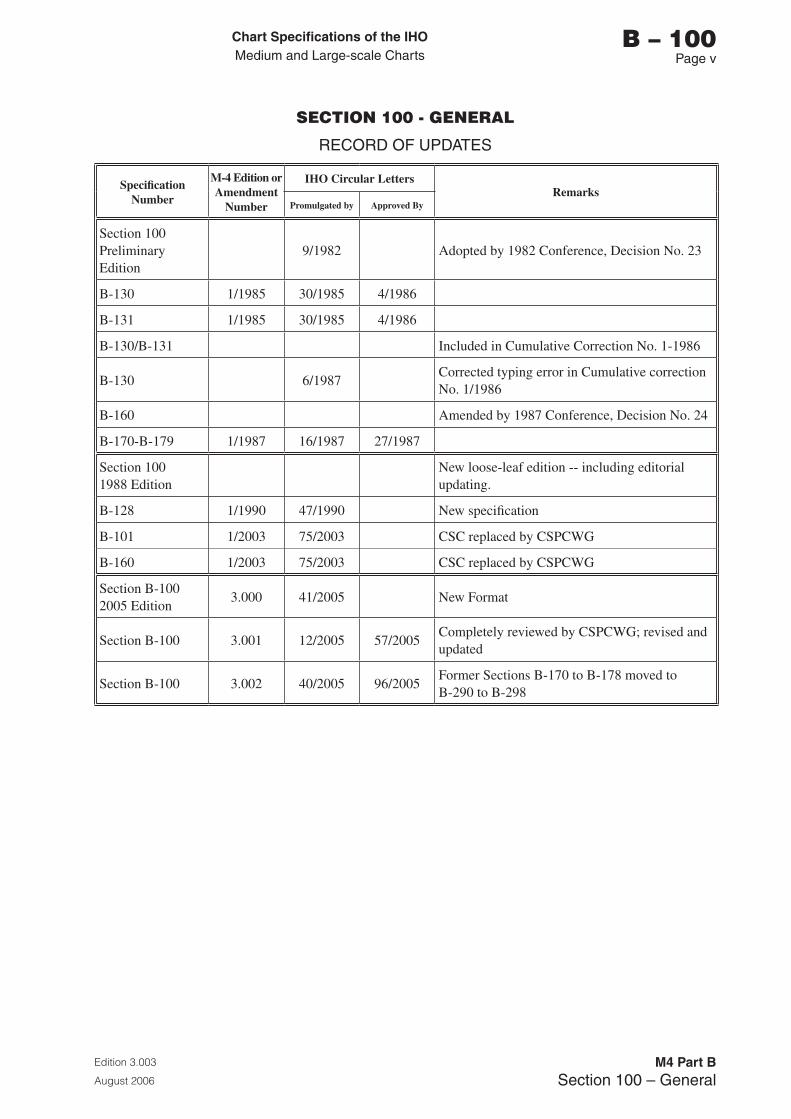
Chart Specifications of the IhoMedium and Large-scale Charts
Edition 3.003
August 2006
M4 Part BSection 100 – General
b – 100Page v
SECTION 100 - GENERAL
RECORD OF UPDATES
Specification Number
M-4 Edition or Amendment
Number
IHO Circular LettersRemarks
Promulgated by Approved By
Section 100 Preliminary Edition
9/1982 Adopted by 1982 Conference, Decision No. 23
B-130 1/1985 30/1985 4/1986
B-131 1/1985 30/1985 4/1986
B-130/B-131 Included in Cumulative Correction No. 1-1986
B-130 6/1987Corrected typing error in Cumulative correction No. 1/1986
B-160 Amended by 1987 Conference, Decision No. 24
B-170-B-179 1/1987 16/1987 27/1987
Section 100 1988 Edition
New loose-leaf edition -- including editorial updating.
B-128 1/1990 47/1990 New specification
B-101 1/2003 75/2003 CSC replaced by CSPCWG
B-160 1/2003 75/2003 CSC replaced by CSPCWG
Section B-100 2005 Edition
3.000 41/2005 New Format
Section B-100 3.001 12/2005 57/2005Completely reviewed by CSPCWG; revised and updated
Section B-100 3.002 40/2005 96/2005Former Sections B-170 to B-178 moved to B-290 to B-298

Page intentionally left blank
Chart Specifications of the IhoMedium and Large-scale Charts
Edition 3.003
August 2006
M4 Part BSection 100 – General
b – 100Page 1
SECTION 100
GENERAL
B-100 CHART SPECIFICATIONS OF THE IHO FOR MEDIUM- AND LARGE-SCALE NATIONAL AND INTERNATIONAL (INT) CHARTS
B-100.1 M-4 Part B provides an internationally-agreed product specification, for both national and international (INT) charts, at medium- and large-scale.
B-100.2 When M-4 Part B was originally prepared, the term ‘charts’ actually referred to paper, sometimes called analogue, charts; digital, sometimes called electronic, charts were yet to become a viable reality. (See B-103.4 for more detailed definitions of different types of digital charts).
The subsequent development of digital charts presented additional Specification requirements, which were met by the development of S-52 and the Electronic Navigational Chart (ENC) Product Specification within S-57 for vector charts, and S-61 for raster charts. Both S-52 and S-57 make full use of the background information already contained in M-4 Part B and include cross-references where appropriate. Similarly, adjustments have been made to M-4 Part B, to reflect better the existence and content of digital (vector) charts.
B-100.3 The role of M-4 Part B is therefore twofold, in that it provides:
a. An explanation of the general concepts and rationale behind the portrayal of features on charts, much of which is relevant to both digital and paper charts.
b. Specific guidance for paper charts, including the use of text and symbology.
B-101 SPECIFICATIONS: ORIGIN AND PRINCIPLES
The Specifications for charts at medium- and large-scale were originally compiled by two groups of member nations of the IHO, forming successively, the North Sea International Chart Commission (NSICC, 1972-1977) and the Chart Specifications Committee (1977-1982). At the XIIth International Hydrographic (IH) Conference (April 1982) the Chart Specifications Committee was renamed the Chart Standardization Committee (CSC) and following the XVIth IH Conference (April 2002) the CSC was replaced by the Chart Standardization and Paper Chart Working Group (CSPCWG) in 2003. The CSPCWG is a working group of the IHO Committee on Hydrographic Requirements for Information Systems (CHRIS), and has a number of functions, one of which is the responsibility for updating these Specifications.
B-101.1 The working procedure followed in the initial compilation of the Specifications was, firstly, the establishment of guidelines for each section by UK, which provided the Secretariat. Preliminary drafts were prepared by France (500), Germany (300), Netherlands (200), UK (100, part 400, 600) and USA (part 400). These were subsequently reviewed by NSICC and CSC members. Comments were reconciled as far as possible and preliminary editions of each Section were published between 1979 and 1982.
Chart Specifications of the IhoMedium and Large-scale Charts
Edition 3.003
August 2006
M4 Part BSection 100 – General
b – 100Page 2
B-101.2 Basic compilation principles followed by the NSICC and CSC in compiling the Specifications were:
a. The starting point was the former Technical Resolutions on charted detail (M-3 Chapter B), now mostly cancelled; but these covered only about one-third of the full range of features to be found on charts.
b. The charting practices of a wide range of IHO members were reviewed by examining their symbols and abbreviations guides and their latest charts.
c. Change for its own sake was avoided.
d. The need was recognized to ensure that each separate item fitted logically into a consistent whole.
e. Self-explanatory symbols were preferred to legends requiring translation.
f. Innovations, i.e. symbols not appearing in any national chart, were introduced when necessary.
g. The effects of new automated drafting techniques were borne in mind, but greatest weight was given to the realities of the existing approach to charting of most IHO members.
h. The layout of each group of items as shown by the Table of Contents follows the principle of working from the general to the particular.
B-101.3 A general review of the Specifications was proposed by the CSC Chairman at the XVth IH Conference in 1997, to include developments which had taken place since the Specifications were first written, together with those identified as a result of the development of digital charts. This review is now being progressed by the CSPCWG.
B-102 PURPOSE OF THE SPECIFICATIONS
The Chart Specifications of the IHO, M-4 Part B, are intended to provide a framework for the standardization by member nations of all nautical charts at medium- and large-scale, both in their national series and in the international (INT) series of the IHO. They must be used in all such chart compilation as far as nautical practices and requirements permit.
Regulation 2 (Definitions) of Chapter V (Safety of Navigation - as amended 2000) of the International Convention on Safety of Life at Sea 1974 (SOLAS 1974) states:
‘Nautical chart or nautical publication is a special-purpose map or book, or a specially compiled database from which such a map or book is derived, that is issued officially by or on the authority of a Government, authorized Hydrographic Office or other relevant government institution and is designed to meet the requirements of marine navigation.*’
‘* Refer to appropriate resolutions and recommendations of the International Hydrographic Organization concerning the authority and responsibilities of coastal States in the provision of charting in accordance with regulation 9.’
Chart Specifications of the IhoMedium and Large-scale Charts
Edition 3.003
August 2006
M4 Part BSection 100 – General
b – 100Page �
B-102.1 The IHO has striven to increase standardization since its inception. Standardization is desirable for navigators who may need to use the charts of two or more nations, in order that transfers from chart to chart can be made without unnecessary hazard or confusion. A high level of standardization is essential for the international chart concept, which may also provide a basis on which to build digital cover (see A-102.8).
Regulation 9 (Hydrographic Services) of Chapter V (Safety of Navigation – as amended 2000) of SOLAS 1974 states that Contracting Governments undertake:
‘to co-operate in carrying out, as far as possible, the following nautical and hydrographic services ... to prepare and issue nautical charts ... and other nautical publications, where applicable, satisfying the needs of safe navigation ...’
‘... to ensure the greatest possible uniformity in charts and nautical publications and to take into account, whenever possible, relevant international resolutions and recommendations.*’
‘* Refer to the appropriate resolutions and recommendations adopted by the International Hydrographic Organization.’
and:
‘to co-ordinate their activities to the greatest possible degree in order to ensure that hydrographic and nautical information is made available on a world-wide scale as timely, reliably, and unambiguously as possible.’
B-102.2 Complete standardization has not yet been achieved. However, as digital charts become more widely used, the more stringent requirements that they present may in themselves serve to accelerate the move to standardization. (It should be noted that, in the electronic world, many variations which may not confuse the mariner would confuse the computer.) The Specifications attempt to distinguish between the fundamental elements of a chart, where standardization is of great importance, and those features where variation would not mislead a navigator. B-110 defines the various levels of standardization which can be identified throughout the Specifications.
B-103 SCOPE OF THE SPECIFICATIONS
B-103.1 Scale of charts covered by the Specifications. These Specifications (M-4 Part B) apply to medium- and large-scale charts, i.e. scales 1:2 000 000 and larger.
Smaller-scale charts (1:2 000 000 and smaller) are covered by the Chart Specifications of the IHO for Small-scale International (INT) charts; see M-4 Part C.
Note: Charts at scale of 1:2 000 000 may be considered to be either Medium-scale charts or Small-scale charts according to the nature of charting in that specific area. Such charts should be compiled in accordance with the Specifications which are appropriate to the purpose of the chart.
B-103.2 General content of charts. The standardization of nautical charts is a more profound matter than the adoption of a standard set of symbols and abbreviations. One requirement is agreement on the place of charts in the full range of navigational documents, and on the extent to which a nautical chart is the appropriate medium for particular categories of information, for example, tidal data. As a general principle, nautical charts should show as much relevant navigational detail as can be clearly represented in graphical form. Another requirement is agreement on the definition, and real significance to chart users, of the individual features charted
Chart Specifications of the IhoMedium and Large-scale Charts
Edition 3.003
August 2006
M4 Part BSection 100 – General
b – 100Page �
B-103.3 Detailed content of charts. The Specifications are intended to be as comprehensive as possible, covering every aspect of chart content and endeavouring to provide a groundwork of reasoned argument to support the rules and recommendations made. Detailed as the Specifications are, they cannot provide a complete and automatic answer to all the questions the chart compiler may ask as they will not always easily fit into a system of cartographic rules. However, the introductory paragraphs in many of the separate Specifications will allow cartographers to see the underlying intention and deal with anomalous features satisfactorily.
B-103.4 Digital charts fall into two main categories: raster and vector. As raster digital charts directly reflect the content of the paper chart, they do not require further mention in these Specifications. Specifications for raster charts are detailed in the IHO publication S-61 (Product Specification for Raster Navigational Charts (RNC)). The term digital in these Specifications (M-4 Part B) is therefore used to refer to vector digital charts. The specific guidance necessary for vector digital charts is provided by IHO publications S-52 (Specifications for Chart Content and Display Aspects of ECDIS) and the ENC Product Specification contained within S-57 (IHO Transfer Standard for Digital Hydrographic Data).
B-103.5 Charts for small craft. Charts designed especially for use by small craft should follow these Specifications for the compilation of charts as far as possible. (Technical Resolution B 1.10 refers).
Chart Specifications of the IhoMedium and Large-scale Charts
Edition 3.003
August 2006
M4 Part BSection 100 – General
b – 110Page 1
B-110 STANDARDIZATION LEVELS
Standardization is the IHO’s ideal and much progress has been made since 1972, to the benefit of chart users. Increasing numbers of International charts are now available; these may provide a basis on which to build digital cover, and also provide a framework for the agreement of cover suitable for adoption of charts by one nation in another’s waters under the terms of bilateral arrangements (see M-4 Part A-104.6 and Technical Resolution A 3.4).
Despite this, complete standardization is unlikely to be achieved between all member nations even on new charts, for good reason, as some aspects of their existing cartographic practice may be of unusual significance. Standards are set in some cases to encourage uniformity rather than enforce it, and consequently such terms as ‘should’ and ‘may’ sometimes occur in the Specifications where it is unlikely that variations from the recommended practice will be misleading, as in the depiction of topographic relief. Complete uniformity is, however, a desirable objective in the case of essentials, for example the definition and use of a submerged rock symbol, and the use of ‘must’ within these Specifications conveys this sense. Publication of S-52 and S-57 for digital charts, much of which is prescriptive, may tend to lead to more prescriptive specifications for paper charts.
As new symbols are added to M-4, a precise specification in respect of dimensions, line weights and colours, etc, will be provided, in the interests of standardization. Symbols without such precise specifications are illustrative only.
It is important to recognize that, in these Specifications, standardization operates on a number of different levels in the various sections, as detailed below.
B-110.1 Standardization of certain fundamentals, particularly units of measurement and horizontal and vertical datums, is incomplete between nations. It is recommended that nations revising their chart cover will take the opportunity to make any of the necessary changes required for standardization. S-57 includes numerous mandatory requirements, e.g. times must be referred to UTC; depth, height and positional accuracy units must be metres; horizontal datum of reference must be WGS 84 (in accordance with Technical Resolutions A 1.8, A 2.1 and B 1.1). It is hoped, in the light of this, that standardization of such fundamentals can be achieved in time.
B-110.2 Standardization of chart scales and limits of International charts is covered in M-4 Part A (Regulations of the IHO for International (INT) Charts), and in M-11 (Catalogue of International (INT) Charts); it is therefore outside the scope of these Specifications (M-4 Part B). Regional or international agreement on chart scales and limits is part of the concept of international charts at medium- and large-scales. Such considerations will probably influence national chart scheming.
B-110.3 Standardization of chart sizes and formats, including the more general aspects of chart design and content, is dealt with in B-200.
Chart Specifications of the IhoMedium and Large-scale Charts
Edition 3.003
August 2006
M4 Part BSection 100 – General
b – 110Page 2
B-110.4 Standardization of symbols and abbreviations in B-300 and B-400 constitutes the largest part of these Specifications, affecting the majority of chart content. It must be preceded by agreement on the meaning, for charts, of the terms used: for example, there are various interpretations of ‘restricted area’, ‘route’, ‘track’, ‘pilot station’, ‘tidal stream’. For this reason, many paragraphs start with explanations and definitions. Concise explanations of terms may also be found in the IHO’s Hydrographic Dictionary (S-32) and in the case of digital charts, S-57, which includes the relevant references to M-4 Part B paragraph numbers and to INT 1 symbols for most object classes. S-57 also includes for each object class, a concise definition taken from a variety of sources including M-4, S-32 and various other publications.
The degree of generalization appropriate to smaller-scale charts varies considerably with the relative significance to the mariner of features in the area in question; these Specifications necessarily cover this aspect in a rather general way.
Agreement on features included or excluded cannot be easily achieved in a small number of cases, particularly where a nation has a different dividing line from other nations between whether information be shown on charts or in other publications. For instance, many nations indicate restricted areas (such as anchoring prohibited areas, cable areas, and exercise areas) by the symbology in B-400; some choose to omit such details from their charts, preferring to provide it in other publications such as Sailing Directions. These Specifications are designed to take such differences into account.
B-110.5 Standardization of geographic names in B-500 conforms to relevant international cartographic practice. General guidelines are given on the use of type styles. With the purpose of obtaining uniformity in the coding of country names, the IHO has agreed to use the two-letter (alpha-2) codes of the International Organization for Standardization (ISO) as published in their International Standard ISO 3166 (see Technical Resolution A 1.19).
Chart Specifications of the IhoMedium and Large-scale Charts
Edition 3.003
August 2006
M4 Part BSection 100 – General
b – 120Page 1
B-120 TERMS AND CONVENTIONS USED IN THE SPECIFICATIONS
B-120.1 Conventions used in writing the Chart Specifications of the IHO for National and International charts are detailed below.
B-120.2 Punctuation
• Decimal places are indicated by commas, e.g. 0,1mm
• Commas are not used to separate thousands, e.g. 150 000 not 150,000
• No spaces are used between figures and abbreviations for units, e.g. 5m not 5 m
• No full stop after abbreviations (unless at end of sentence or in light descriptions)
• Single quotation marks are used except where quotations occur within quotations, when double marks are used around the inner quote
• Single quotation marks are used around abbreviations in the text, but not around abbreviations in graphics.
B-120.3 Terminology
• ‘Dashed’ is used rather than ‘pecked’
• ‘Sans serif’ is used rather than ‘Egyptian’
• ‘Upright’ is used rather than ‘Roman’
• ‘Sloping’ is used rather than ‘Italic’
• ‘Continuous’ line is used rather than ‘firm’ or ‘solid’ line
• ‘Bold’ is used rather than ‘heavy’ for line weights
• ‘Fine’ is used rather than ‘light-weight’ for line weights
• ‘International’ chart is used rather than ‘INT’ chart, except when referring to a specific INT Chart number, e.g. INT 1403.
• ‘Tint’ is used rather than ‘stipple’ for continuous and screened colours.
B-120.4 Strength of wording
• ‘must’ indicates a mandatory requirement
• ‘should’ indicates an optional requirement, that is the recommended process to be followed, but is not mandatory
• ‘may’ means ‘allowed to’ or ‘could possibly’, and is not mandatory.
Examples: The limits of an Area To Be Avoided (ATBA) must be shown by T-shaped dashes in magenta (IN 2.1). The legend ‘Area To Be Avoided (see Note)’ should be inserted, in magenta, within the area of the ATBA if possible, or may be inserted along the limits. Where space is limited, the abbreviated legend ‘ATBA (see Note)’ may be inserted.
B-120.5 Cross references are included in the form ‘see B-123’. However, as these are not exhaustive, the Table of Contents and INT 1 (Column 5) should be consulted.
B-121 TRANSLATION TERMS
The phrase ‘... or equivalent’ means that the legend or abbreviation in question may be in the member nation’s national language.
Chart Specifications of the IhoMedium and Large-scale Charts
Edition 3.003
August 2006
M4 Part BSection 100 – General
b – 120Page 2
B-122 INTERNATIONAL ABBREVIATIONS
The term ‘international abbreviation’ is used to identify those abbreviations which have been agreed internationally and are recommended for use on all nautical charts. Some of the abbreviations selected were already common to several languages. Alternatively, English language abbreviations were adopted or devised, in accordance with the long term policy of the IHO, and because the International Maritime Organization (IMO) suggests the use of English as the language of navigators. See also INT 1 section W.
B-123 TERMS FOR COLOURS
Where no colour is specified for a feature, it is to be shown in black. For details of the use of colour, see B-140.
B-123.1 ‘Tint’ is used both for continuous colours and screened (or stippled) tints (black and colour); the context should make the meaning clear. ‘Solid’, as in ‘solid blue’, is used to indicate a flat (unscreened) colour.
B-124 SPECIFICATIONS FOR INTERNATIONAL CHARTS
Although the Chart Specifications of the IHO, Part B (originally published as Part 1), are published for use in compiling all medium- and large-scale charts, both national and international, a few paragraphs or sub-paragraphs are applicable only to international charts. These are distinguished by the suffix ‘I’ to the paragraph number, e.g. B-351.1(I). (Note: in the original ‘Part 1’ version, before the prefix B was used, the ‘I’ was a prefix, e.g. I-351.1).
B-125 DEPICTION OF SYMBOLS
The symbols shown in the text of the Specifications correspond to those in INT 1 (see B-151), with the INT 1 reference numbers alongside. There is a corresponding reference in INT 1 (column 5) to the specification number in M-4 Part B. The symbols being referred to are for paper charts. A separate set of symbols is also available for ECDIS purposes; see S-52 Appendix 2.
B-126 TERMS FOR CHART SCALES
The scale of a chart is determined by the type of navigation for which it is intended, the nature of the area to be covered and the quantity of information to be shown. Various scale terms are used in the Specifications, such as medium-scale, large-scale, continuous coastal series. These are intended to indicate the type of chart rather than actual scale, which may vary from area to area; the specific scale of charts cannot be defined by universally prescriptive rules.
In the case of paper charts, very generally, the terms ‘medium-scale’ and ‘large-scale’, as in the title of M-4 Part B, cover the following types of chart:
Medium-scale: General: passage/landfall ............................... 1:2 000 000 – 1:350 000
Coastal: coastal navigation ................................. 1:350 000 – 1:75 000
Large-scale: Approach: port approach/intricate or
congested coastal waters ....................................... 1:75 000 – 1:30 000
Harbour: harbour/anchorage/narrow straits .......... larger than 1:30 000
Berthing ...................................................................... very large scales
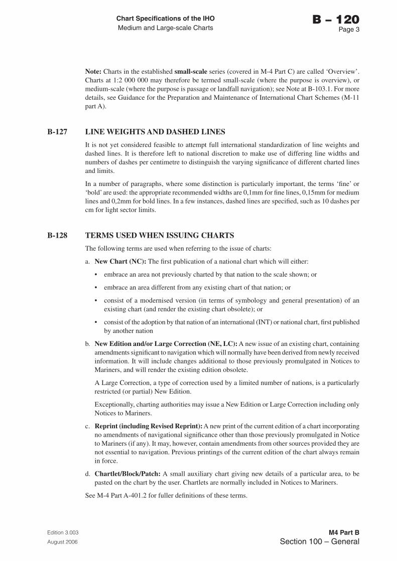
Chart Specifications of the IhoMedium and Large-scale Charts
Edition 3.003
August 2006
M4 Part BSection 100 – General
b – 120Page �
Note: Charts in the established small-scale series (covered in M-4 Part C) are called ‘Overview’. Charts at 1:2 000 000 may therefore be termed small-scale (where the purpose is overview), or medium-scale (where the purpose is passage or landfall navigation); see Note at B-103.1. For more details, see Guidance for the Preparation and Maintenance of International Chart Schemes (M-11 part A).
B-127 LINE WEIGHTS AND DASHED LINES
It is not yet considered feasible to attempt full international standardization of line weights and dashed lines. It is therefore left to national discretion to make use of differing line widths and numbers of dashes per centimetre to distinguish the varying significance of different charted lines and limits.
In a number of paragraphs, where some distinction is particularly important, the terms ‘fine’ or ‘bold’ are used: the appropriate recommended widths are 0,1mm for fine lines, 0,15mm for medium lines and 0,2mm for bold lines. In a few instances, dashed lines are specified, such as 10 dashes per cm for light sector limits.
B-128 TERMS USED WHEN ISSUING CHARTS
The following terms are used when referring to the issue of charts:
a. New Chart (NC): The first publication of a national chart which will either:
• embrace an area not previously charted by that nation to the scale shown; or
• embrace an area different from any existing chart of that nation; or
• consist of a modernised version (in terms of symbology and general presentation) of an existing chart (and render the existing chart obsolete); or
• consist of the adoption by that nation of an international (INT) or national chart, first published by another nation
b. New Edition and/or Large Correction (NE, LC): A new issue of an existing chart, containing amendments significant to navigation which will normally have been derived from newly received information. It will include changes additional to those previously promulgated in Notices to Mariners, and will render the existing edition obsolete.
A Large Correction, a type of correction used by a limited number of nations, is a particularly restricted (or partial) New Edition.
Exceptionally, charting authorities may issue a New Edition or Large Correction including only Notices to Mariners.
c. Reprint (including Revised Reprint): A new print of the current edition of a chart incorporating no amendments of navigational significance other than those previously promulgated in Notice to Mariners (if any). It may, however, contain amendments from other sources provided they are not essential to navigation. Previous printings of the current edition of the chart always remain in force.
d. Chartlet/Block/Patch: A small auxiliary chart giving new details of a particular area, to be pasted on the chart by the user. Chartlets are normally included in Notices to Mariners.
See M-4 Part A-401.2 for fuller definitions of these terms.

Page intentionally left blank
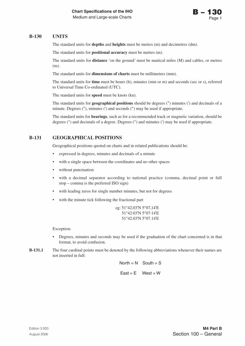
Chart Specifications of the IhoMedium and Large-scale Charts
Edition 3.003
August 2006
M4 Part BSection 100 – General
b – 130Page 1
B-130 UNITS
The standard units for depths and heights must be metres (m) and decimetres (dm).
The standard units for positional accuracy must be metres (m).
The standard units for distance ‘on the ground’ must be nautical miles (M) and cables, or metres (m).
The standard units for dimensions of charts must be millimetres (mm).
The standard units for time must be hours (h), minutes (min or m) and seconds (sec or s), referred to Universal Time Co-ordinated (UTC).
The standard units for speed must be knots (kn).
The standard units for geographical positions should be degrees (°) minutes (') and decimals of a minute. Degrees (°), minutes (') and seconds (") may be used if appropriate.
The standard units for bearings, such as for a recommended track or magnetic variation, should be degrees (°) and decimals of a degree. Degrees (°) and minutes (') may be used if appropriate.
B-131 GEOGRAPHICAL POSITIONS
Geographical positions quoted on charts and in related publications should be:
• expressed in degrees, minutes and decimals of a minute
• with a single space between the coordinates and no other spaces
• without punctuation
• with a decimal separator according to national practice (comma, decimal point or full stop – comma is the preferred ISO sign)
• with leading zeros for single number minutes, but not for degrees
• with the minute tick following the fractional part
eg: 51°42,03'N 5°07,14'E 51°42·03'N 5°07·14'E 51°42.03'N 5°07.14'E
Exception:
• Degrees, minutes and seconds may be used if the graduation of the chart concerned is in that format, to avoid confusion.
B-131.1 The four cardinal points must be denoted by the following abbreviations whenever their names are not inserted in full:
North = N South = S
East = E West = W
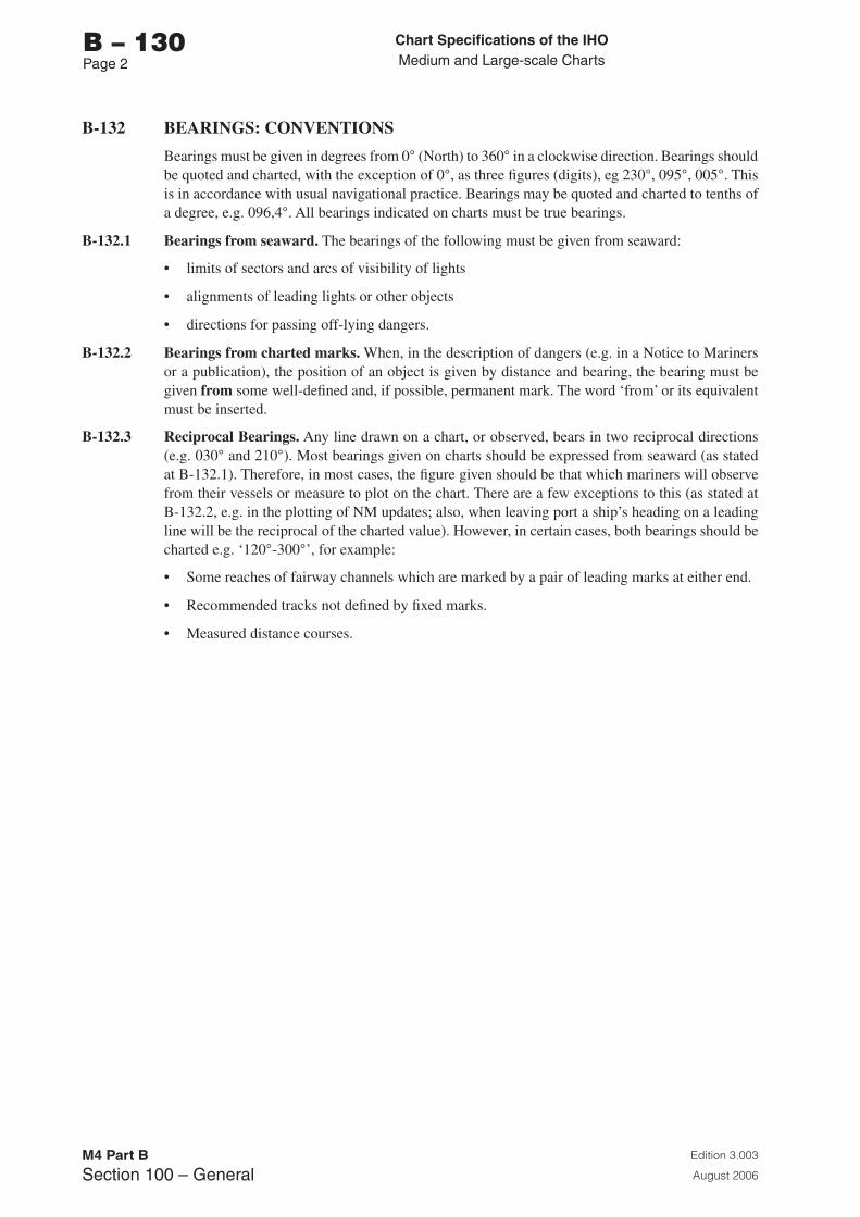
Chart Specifications of the IhoMedium and Large-scale Charts
Edition 3.003
August 2006
M4 Part BSection 100 – General
b – 130Page 2
B-132 BEARINGS: CONVENTIONS
Bearings must be given in degrees from 0° (North) to 360° in a clockwise direction. Bearings should be quoted and charted, with the exception of 0°, as three figures (digits), eg 230°, 095°, 005°. This is in accordance with usual navigational practice. Bearings may be quoted and charted to tenths of a degree, e.g. 096,4°. All bearings indicated on charts must be true bearings.
B-132.1 Bearings from seaward. The bearings of the following must be given from seaward:
• limits of sectors and arcs of visibility of lights
• alignments of leading lights or other objects
• directions for passing off-lying dangers.
B-132.2 Bearings from charted marks. When, in the description of dangers (e.g. in a Notice to Mariners or a publication), the position of an object is given by distance and bearing, the bearing must be given from some well-defined and, if possible, permanent mark. The word ‘from’ or its equivalent must be inserted.
B-132.3 Reciprocal Bearings. Any line drawn on a chart, or observed, bears in two reciprocal directions (e.g. 030° and 210°). Most bearings given on charts should be expressed from seaward (as stated at B-132.1). Therefore, in most cases, the figure given should be that which mariners will observe from their vessels or measure to plot on the chart. There are a few exceptions to this (as stated at B-132.2, e.g. in the plotting of NM updates; also, when leaving port a ship’s heading on a leading line will be the reciprocal of the charted value). However, in certain cases, both bearings should be charted e.g. ‘120°-300°’, for example:
• Some reaches of fairway channels which are marked by a pair of leading marks at either end.
• Recommended tracks not defined by fixed marks.
• Measured distance courses.
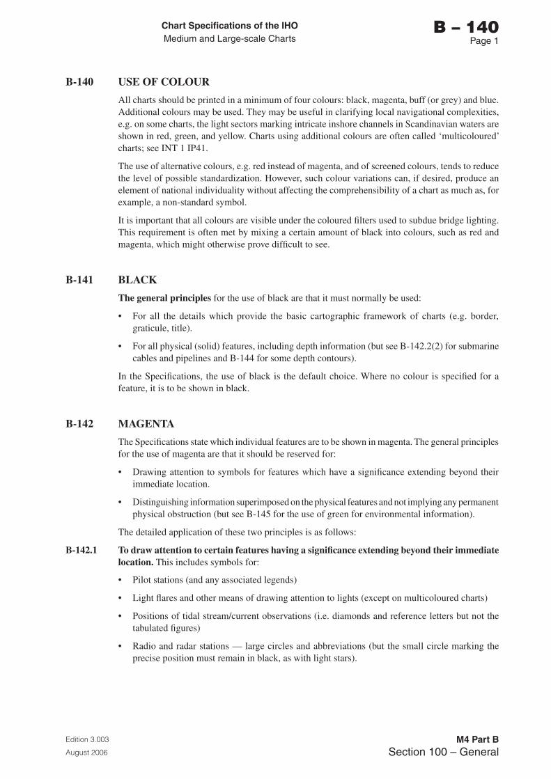
Chart Specifications of the IhoMedium and Large-scale Charts
Edition 3.003
August 2006
M4 Part BSection 100 – General
b – 140Page 1
B-140 USE OF COLOUR
All charts should be printed in a minimum of four colours: black, magenta, buff (or grey) and blue. Additional colours may be used. They may be useful in clarifying local navigational complexities, e.g. on some charts, the light sectors marking intricate inshore channels in Scandinavian waters are shown in red, green, and yellow. Charts using additional colours are often called ‘multicoloured’ charts; see INT 1 IP41.
The use of alternative colours, e.g. red instead of magenta, and of screened colours, tends to reduce the level of possible standardization. However, such colour variations can, if desired, produce an element of national individuality without affecting the comprehensibility of a chart as much as, for example, a non-standard symbol.
It is important that all colours are visible under the coloured filters used to subdue bridge lighting. This requirement is often met by mixing a certain amount of black into colours, such as red and magenta, which might otherwise prove difficult to see.
B-141 BLACK
The general principles for the use of black are that it must normally be used:
• For all the details which provide the basic cartographic framework of charts (e.g. border, graticule, title).
• For all physical (solid) features, including depth information (but see B-142.2(2) for submarine cables and pipelines and B-144 for some depth contours).
In the Specifications, the use of black is the default choice. Where no colour is specified for a feature, it is to be shown in black.
B-142 MAGENTA
The Specifications state which individual features are to be shown in magenta. The general principles for the use of magenta are that it should be reserved for:
• Drawing attention to symbols for features which have a significance extending beyond their immediate location.
• Distinguishing information superimposed on the physical features and not implying any permanent physical obstruction (but see B-145 for the use of green for environmental information).
The detailed application of these two principles is as follows:
B-142.1 To draw attention to certain features having a significance extending beyond their immediate location. This includes symbols for:
• Pilot stations (and any associated legends)
• Light flares and other means of drawing attention to lights (except on multicoloured charts)
• Positions of tidal stream/current observations (i.e. diamonds and reference letters but not the tabulated figures)
• Radio and radar stations — large circles and abbreviations (but the small circle marking the precise position must remain in black, as with light stars).
Chart Specifications of the IhoMedium and Large-scale Charts
Edition 3.003
August 2006
M4 Part BSection 100 – General
b – 140Page 2
B-142.2 To distinguish information superimposed on the physical features. This includes symbols, associated legends, abbreviations and cautionary notes which indicate:
(1) Features representing transitory physical hazards, such as:
• Ferry routes
• Submarine exercise areas and transit lanes
• Firing danger and other military practice areas (but associated beacons, buoys and targets must be in black)
• Sea ice limits (but limit of land ice, representing ‘coastline’, must be in black)
• Miscellaneous (dredging areas, where vessels exploit sand and shingle deposits; incineration areas, etc).
(2) Features representing a restriction on seabed operations, including anchoring, such as:
• Submarine cables and cable areas (but associated beacons and buoys must be in black)
• Submarine pipelines and pipeline areas (but sewers and outfalls, and any pipeline which could be a physical obstruction to navigation must be in black; see B-444)
• Explosives dumping grounds (but spoil grounds must be in black)
• Miscellaneous areas where anchoring and/or fishing are prohibited (shellfish beds, ground chains of moorings, ‘protected’ historic wrecks, etc). Some of these may alternatively be in green, see B-145.
(3) Features representing control or regulation of vessel movement, such as:
• Entry restricted and prohibited areas such as safety zones around offshore installations, IMO ‘Areas to be Avoided’, mined areas and controlled areas near military installations
• Routeing features such as traffic separation schemes, IMO Deep Water routes, safety fairways, radar-guided tracks and limits of radar surveillance, and reporting points
• Designated anchorages and berths, including berth numbers at buoys, quays and in anchorages
• Other designated areas, e.g. seaplane landing areas.
(4) Maritime boundaries of legal authority, such as:
• Fishery limits, territorial waters limits, etc.
• Harbour and dockyard port limits, customs boundaries in ‘free ports’.
(5) Certain marginal or other information to be distinguished or emphasized, such as:
• Compass roses
• Isogonic lines or isogonals
• References to other charts, and their limits
• INT chart number
• ‘DEPTHS IN METRES’, ‘WGS 84 DATUM’, and possibly other marginal notes requiring emphasis, as appropriate
• Certain rectangular grid marks and their co-ordinates
• Small craft facility symbols and tables.
Chart Specifications of the IhoMedium and Large-scale Charts
Edition 3.003
August 2006
M4 Part BSection 100 – General
b – 140Page �
B-142.3 Magenta tint may be used in congested areas where it is important not to obscure black detail, and for specific symbols such as Traffic Separation Zones, Particularly Sensitive Sea Areas and Archipelagic Sea Lanes.
B-143 BUFF (YELLOW) OR GREY
A colour, usually buff or grey, must be used as a land tint. If the minimum four colours are used, the colour may be carefully selected so that a satisfactory colour over inter-tidal areas is derived from printing the land tint over the shallow water blue tint.
B-144 BLUE
The colour blue must be used as a tint to emphasize shallow water. Two (or more) densities of blue tint may be used to show different depth bands of shallow water, the darkest tint showing the shallowest water. The blue tint may be combined with that used for land, as described in B-143, to produce an appropriate colour for inter-tidal areas. Blue may also be used for depth contours, particularly in intricate waters.
B-145 GREEN
The colour green may be used as a tint for inter-tidal areas. This may be achieved by combining the land colour with the shallow water blue colour, as described in B-143. Green may also be used, instead of magenta, for environmental information and limits; see B-437.2b.
B-146 CAUTIONARY NOTES - COLOUR
Cautionary notes must normally be shown in the same colour as the charted features to which they refer, see B-242.3. An exception is that referring to differences between horizontal datums on adjoining or different scale charts, where the note is in black (as it refers to positions) and the legend ‘see Note’ is in magenta (as chart limits and references are in magenta).
If a note refers to two or more features which are charted in different colours, the note should be in the colour of the most navigationally significant feature. For example, when a note about an Environmentally Sensitive Sea Area (charted in green) is combined with a magenta note (e.g. about an associated restriction), then the entire note should be in magenta; see B-437.2b.

Page intentionally left blank
Chart Specifications of the IhoMedium and Large-scale Charts
Edition 3.003
August 2006
M4 Part BSection 100 – General
b – 150Page 1
B-150 ASSOCIATED PUBLICATIONS
A number of other publications are supplementary to these Specifications. They are available from the IHB. They include INT 1, INT 2 and INT 3, the content of which are detailed in the following paragraphs. For the latest edition dates, and details of publications related to digital charts, see P-4, Catalogue of IHO Publications.
B-151 INT 1 — SYMBOLS, ABBREVIATIONS, TERMS USED ON CHARTS
INT 1 provides the chart user with a key to symbols and abbreviations used on paper charts compiled in accordance with the Chart Specifications of the IHO. Although INT 1 may be used by cartographers as a quick reference, these Specifications must be used for detailed guidance. Cross references to the relevant specifications in M-4 Part B are included in the right-hand column of INT 1.
B-151.1 Each Hydrographic Office’s list of symbols and abbreviations must be arranged according to Chart INT 1, which follows the system used in M-4 ‘Chart Specifications of the IHO’. Three official language versions of INT 1 are published by the IHO:
• English - produced by Germany
• French - produced by France
• Spanish - produced by Spain
The reference numbering in national symbols and abbreviations lists must correspond to that used in the official Chart INT 1, with letters used for any additional national items. The lettered entries for national symbols may be placed in the list in an appropriate position or collated at the end of each section or sub-section. One column should be used to show those symbols and abbreviations that have been internationally agreed, with a second column showing national symbols where different, or where no internationally-agreed symbol yet exists.
All numbered items included in INT 1 should be shown in each nation’s standard list, including in their proper place those terms for which the nation concerned has no symbol or abbreviation. This will enable a navigator who possesses a standard booklet, written in a familiar language, to interpret foreign standard booklets.
An index of all abbreviations used should be given in alphabetical order as in INT 1 Section V, with cross references showing the section and number.
The list of symbols and abbreviations is most conveniently published in the form of a booklet, although a sheet format may be used.
The list of symbols and abbreviations should be kept up to date by means of Notices to Mariners, particularly for the introduction of new symbols.
Technical Resolution K1.1 resolves that the IHB must compile a list of the sheets of chart symbols and abbreviations produced by the various nations and distribute this list to Member States. Until 1992, the list constituted a separate publication (MP-008). From 1993-1999, it was published in the IH Bulletin at the beginning of each year. From 2004, it has been published as M-15, ‘List of Booklets on Chart Symbols and Abbreviations Published by Various Maritime Nations’, posted on the IHO website and amended from time to time.
B-152 INT 2 — BORDERS, GRADUATION, GRIDS AND LINEAR SCALES
INT 2 shows specimens of the various patterns of border graduation and linear scales. INT 2 is produced by The Netherlands.

Chart Specifications of the IhoMedium and Large-scale Charts
Edition 3.003
August 2006
M4 Part BSection 100 – General
b – 150Page 2
B-153 INT 3 — USE OF SYMBOLS AND ABBREVIATIONS
INT 3 is a standard reference chart of a fictitious area with as many examples as possible of the use of these Specifications (M-4 Part B and Part C). INT 3 is produced by UK.
Chart Specifications of the IhoMedium and Large-scale Charts
Edition 3.003
August 2006
M4 Part BSection 100 – General
b – 160Page 1
B-160 UPDATING SYSTEM FOR THE SPECIFICATIONS
The Chart Specifications of the IHO must be amended from time to time in response to the developing requirements of nautical charting, including changing navigational procedures and developments in cartographic techniques. The IHO Chart Standardization and Paper Chart Working Group (CSPCWG) is responsible for the updating of the Specifications (Technical Resolution K 2.11 refers). A Member State finding it necessary to adopt a new specification or use a new symbol for a feature for which there is no existing symbol, should advise the IHB of the action taken at the earliest opportunity. All such proposals for changes must be referred by the IHB to the CSPCWG for advice. Members of the CSPCWG, in their capacity as a standing group of experts, should also identify new points requiring standardization action. The CSPCWG must recommend amendments to the Specifications to the IHB, who must communicate them to all IHO Members by Circular Letter, asking Members to make known any major objection within three months. After three months, in the absence of objections from one or more Members, the IHB must update the on-line version of M-4 and announce, by a second Circular Letter, that the amendments have come into force and that members should consequently correct their copies of the Specifications. In the event of disagreement, the proposed amendments should be modified, if appropriate, to take account of objections or suggestions received, and an explanation must be given in the second Circular Letter, which will also promulgate the final version.
B-170 Not currently used

Page intentionally left blank
Chart Specifications of the IhoMedium and Large-scale Charts
Edition 3.003
August 2006
M4 Part BSection 100 – General
b – 180Page 1
B-180 CATALOGUES; INDEX CHARTS
B-180.1 Every Hydrographic Office is strongly recommended to publish a catalogue of its charts and nautical publications and keep the catalogue up-to-date by regular new editions. This information may be made available on-line using the World Wide Web such that this information is continuously maintained and made available in a timely manner.
All catalogues must contain the natural scale of each chart, and may contain the date of publication of the chart, the date of the latest New Edition and a reference to units if not metric.
It is recommended that catalogues of charts which are published in languages other than English, French or Spanish be translated into one of these languages in order that they may be read and more easily understood by mariners of other nationalities. If this is not possible, at least the introduction, preface, headings of columns, etc, should be translated.
B-180.2 It is strongly recommended that all nations publish, at a legible scale, index charts showing the geographical limits of all charts they produce.
B-180.3 References to foreign charts. It is recommended (Technical Resolution B 2.13) that, when a Hydrographic Office considers that its own chart coverage, at various scales, is not adequate for all navigation needs, reference be made in the national Chart Catalogue to those foreign charts which would usefully supplement the coverage. Reference must include the identity of the publishing office, which should be expressed as a two-letter ISO national code (Technical Resolution A 1.19), in front of the chart number.

Page intentionally left blank

Chart Specifications of the IhoMedium and Large-scale Charts
Edition 3.003
August 2006
M4 Part BSection 200 – Chart Framework
b – 200Page i
PART b
SECTION 200
CHART FRAMEWORK (FORMAT, POSITIONS, COMPASS ROSES, SOURCE DIAGRAMS)

Page intentionally left blank

Chart Specifications of the IhoMedium and Large-scale Charts
Edition 3.003
August 2006
M4 Part BSection 200 – Chart Framework
b – 200Page iii
SECTION 200 - CHART FRAMEWORK (FORMAT, POSITIONS, COMPASS ROSES, SOURCE DIAGRAMS)
CONTENTS
RECORD OF UPDATESB-201 ELLIPSOID (SPHEROID) OF REFERENCE AND HORIZONTAL DATUMB-202 INDICATION ON CHARTS OF RELATIONSHIP OF HORIZONTAL DATUM TO
WORLD-WIDE AND OTHER DATUMS B-203 PROJECTIONS
B-210 CHART CONSTRUCTIONB-211 SCALEB-212 GRADUATIONB-213 GRATICULEB-214 CORNER CO-ORDINATES B-215 RECTANGULAR GRIDS
B-220 LINEAR SCALES, DIMENSIONSB-221 LINEAR (GRAPHICAL) SCALESB-222 DIMENSIONS
B-230 NOT CURRENTLY USED
B-240 TITLE, NOTESB-241 TITLE BLOCKSB-242 CAUTIONARY AND EXPLANATORY NOTESB-243 REFERENCE TO OTHER PUBLICATIONS
B-250 CHART NUMBERING, MARGINAL INFORMATIONB-251 CHART NUMBERINGB-252 DATES OF PUBLICATION AND UPDATESB-253 COPYRIGHT LEGENDB-254 REFERENCES TO OTHER CHARTSB-255 OTHER MARGINAL INFORMATION
B-260 COMPASS ROSES B-261 COMPASS ROSES: PATTERNS, TRUE AND MAGNETICB-262 COMPASS ROSES: SIZE AND POSITION
B-270 MAGNETIC DATAB-271 MAGNETIC DATA: SOURCE MATERIALB-272 MAGNETIC DATA: SYMBOLSB-273 MAGNETIC DATA: CORRECTIONSB-274 ABNORMAL MAGNETIC VARIATION
B-280 DEPTH UNIT CONVERSION TABLEB-281 OTHER TABLES
B-290 SOURCE DIAGRAMS B-291 PURPOSE OF SOURCE DIAGRAMSB-292 SCALES OF CHARTS WHICH SHOULD HAVE SOURCE DIAGRAMSB-293 GRAPHICAL REPRESENTATION OF LIMITS OF SURVEYSB-294 DETAILS OF SOURCES: DATE AND SCALEB-295 DETAILS OF SOURCES: ORIGIN AND TYPE

Chart Specifications of the IhoMedium and Large-scale Charts
Edition 3.003
August 2006
M4 Part BSection 200 – Chart Framework
b – 200Page iv
B-296 SOURCE LISTSB-297 ZONES OF CONFIDENCE (ZOC) DIAGRAMSB-298 DUAL-PURPOSE DIAGRAMS
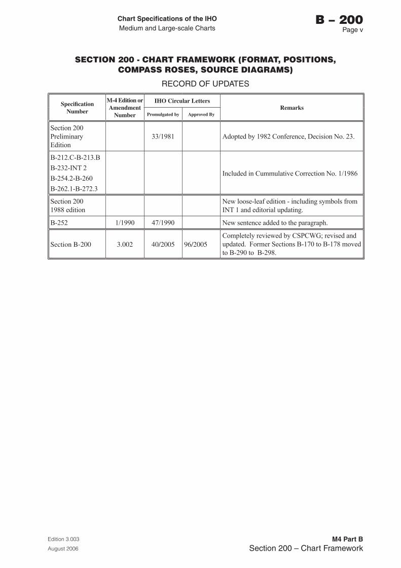
Chart Specifications of the IhoMedium and Large-scale Charts
Edition 3.003
August 2006
M4 Part BSection 200 – Chart Framework
b – 200Page v
SECTION 200 - CHART FRAMEWORK (FORMAT, POSITIONS, COMPASS ROSES, SOURCE DIAGRAMS)
RECORD OF UPDATES
Specification Number
M-4 Edition or Amendment
Number
IHO Circular LettersRemarks
Promulgated by Approved By
Section 200Preliminary Edition
33/1981 Adopted by 1982 Conference, Decision No. 23.
B-212.C-B-213.B
B-232-INT 2
B-254.2-B-260
B-262.1-B-272.3
Included in Cummulative Correction No. 1/1986
Section 200 1988 edition
New loose-leaf edition - including symbols from INT 1 and editorial updating.
B-252 1/1990 47/1990 New sentence added to the paragraph.
Section B-200 3.002 40/2005 96/2005Completely reviewed by CSPCWG; revised and updated. Former Sections B-170 to B-178 moved to B-290 to B-298.

Page intentionally left blank
Chart Specifications of the IhoMedium and Large-scale Charts
Edition 3.003
August 2006
M4 Part BSection 200 – Chart Framework
b – 200Page 1
SECTION 200
CHART FRAMEWORK (FORMAT, POSITIONS, COMPASS ROSES, SOURCE DIAGRAMS)
B-201 ELLIPSOID (SPHEROID) OF REFERENCE AND HORIZONTAL DATUM
B-201.1 IMO Safety of Navigation Circular 213 defines a horizontal datum (also known as a geodetic datum) as follows:
‘A horizontal datum is a reference system for specifying positions on the Earth’s surface. Each datum is associated with a particular reference spheroid that can be different in size, orientation and relative position from the spheroids associated with other horizontal datums. Positions referred to different datums can differ by several hundred metres.’
B-201.2 The World Geodetic System (1984) (WGS84) should be used as a basic worldwide reference system for nautical charts until an adequate alternative geodetic datum is adopted by the relevant international organizations to be used as the international geodetic reference system for cartographic work on land and sea areas.
B-201.3 Internationally recognized regional datums or local datums may continue to be used for the graduation of paper charts in areas where they apply; however, a transformation adjustment to WGS84 should be included on any such chart (see B-202).
B-201.4 IHO Publication S-60 ‘User’s Handbook on Datum Transformations Involving WGS84’, contains transformation constants and formulae to relate local and regional geodetic datums to WGS84. (S-60 has been derived from a comprehensive Technical Report (TR8350.2, 3rd edition, 4 July 1997, corrected to 6/03) published by the National Geospatial Agency (NGA) of the United States and provided to the IHB).
Reproduction of formulae, transformation constants and related local and regional datums does not imply that these data have been officially adopted by the concerned States or by the IHO. Member States are encouraged to refine their own transformation parameters and to report these to the IHB.
B-202 INDICATION ON CHARTS OF RELATIONSHIP OF HORIZONTAL DATUM TO WORLD-WIDE AND OTHER DATUMS
B-202.1 All charts at scales larger than 1:500 000 must include a legend in the title block (see B-241.7) indicating the name (and date, if appropriate) of the geodetic datum upon which the graticule is based. The WGS year, for example WGS84, must be stated on charts of a scale larger than 1:50 000. (See also B-255.3).
B-202.2 Appropriate transformation notes (commonly titled SATELLITE-DERIVED POSITIONS) must be inserted, normally in black, on all charts at scales larger than 1:500 000 to enable the navigator to use directly, or to convert to chart datum and vice-versa, satellite-derived geographical positions which are in the world-wide datum. They should also be inserted on smaller-scale charts if the difference between the datum used and WGS84 datum is plottable at the scale of the chart. In the plotting of geographic positions on charts, for the purposes of these specifications, a plottable difference is considered to be 0.3mm or greater. Where differences are insignificant, or the chart is not based on a single homogeneous datum, the note should so state. Transformation notes should also be included to facilitate transfer between charts on different datums within the same area.
Chart Specifications of the IhoMedium and Large-scale Charts
Edition 3.003
August 2006
M4 Part BSection 200 – Chart Framework
b – 200Page 2
B-202.3 The following standardized wording, to be shown in black, is recommended for transformation notes. Similar wording may be used for other transformation notes, if required, eg to a national mapping datum. Examples:
a. An optional note for charts based on WGS84 datum, or a datum compatible with WGS84, or where the shift is not plottable at chart scale (see B-202.2):
SATELLITE-DERIVED POSITIONSPositions obtained from satellite navigation systems, such as GPS, are normally referred to WGS84 Datum. Such positions can be plotted directly on this chart.
b. For charts on which the relationship between WGS84 Datum and the local datum cannot be determined:
SATELLITE-DERIVED POSITIONSPositions obtained from satellite navigation systems, such as GPS, are normally referred to WGS84 Datum. The differences between satellite-derived positions and positions on this chart cannot be determined. Mariners are warned that these differences MAY BE SIGNIFICANT TO NAVIGATION and are therefore advised to use alternative sources of positional information, particularly when closing the shore or navigating in the vicinity of dangers.
c. For charts on internationally accepted regional or local datums (including charts on previous World Geodetic Datums, such as WGS72):
SATELLITE-DERIVED POSITIONSPositions obtained from satellite navigation systems, such as GPS, are normally referred to WGS84 Datum. Such positions must be adjusted by 0.XX minutes NORTHWARD/SOUTHWARD and 0.XX minutes EASTWARD/WESTWARD to agree with this chart.
d. To facilitate transfer between charts on different datums within the same area:
POSITIONSTo agree with the larger scale / smaller scale / adjoining charts which are referred to [name] Datum, positions read from chart [number] must be adjusted by 0,XX minutes NORTHWARD / SOUTHWARD, and 0,XX minutes EASTWARD / WESTWARD.
Notes for examples c) and d), above:
i. The figure to be inserted at XX is the mean value over the charted area, normally to two decimal places of a minute, of the adjustment to be applied. On scales larger than 1:15 000 the datum shift values should be given to three decimal places of a minute, provided the datum shift is accurate enough to support it. On scales of 1:500 000 and smaller, the values should be given to one decimal place of a minute, if the difference between the datums is plottable at the scale of the chart (see B-202.2).
ii. Where the shift is in one direction only, the reference to the other direction should be omitted.
iii. The datum shift value may also be quoted as a unit of distance, in addition to minutes of latitude/longitude, eg. 0.08 minutes (approximately 96 metres).
iv. A worked example may be included to illustrate the application of the shifts.
B-202.4 Chart Accuracy. In many parts of the world, even the most recent data available may have been gathered when survey methods were less sophisticated than they are now and the achievement of accuracy currently available with GPS was not possible. In these areas, GPS positions available to the navigator may be more accurate than the charted detail. Therefore, in such circumstances, the following note may be combined with the appropriate note at B-202.3:
However, due to the age and quality of some of the source information, such positions may be more accurate than the charted detail.
Chart Specifications of the IhoMedium and Large-scale Charts
Edition 3.003
August 2006
M4 Part BSection 200 – Chart Framework
b – 200Page �
B-203 PROJECTIONS
A projection can generally be regarded as suitable for large scales if the chart will be identified within fractions of a mm to the chart that might have been drawn on any other survey projection, and any suitable grid will plot as a system of practically straight lines on the chart. This will be the case when the projection meets the conditions that its rectangular grid (N,E) or (X,Y) is a function of the Earth’s graticule (φ λ) or (λ φ) and that it has its central meridian, standard parallel, or point of origin within a few hundred km of the area charted.
B-203.1 Charts of scale 1:50 000 and larger may be compiled on any suitable projection, taking into account the possible advantages of using the projection or the rectangular grid used by the national mapping authorities. In latitudes approaching 75°, the limiting scale may be larger than 1:50 000, to minimize apparent distortions.
B-203.2 Charts of scale smaller than 1:50 000 must normally be compiled on the Mercator projection. Exceptions to this rule may be necessary in high latitudes, where the Mercator projection is unsuitable because of gross distortions. For example, the conformal Polar Zenithal Stereographic projection, which shows parallels as concentric circles and meridians as equally-spaced lines radiating from the pole, may be suitable for charts in high latitudes (beyond about 70°).

Page intentionally left blank
Chart Specifications of the IhoMedium and Large-scale Charts
Edition 3.003
August 2006
M4 Part BSection 200 – Chart Framework
b – 210Page 1
B-210 CHART CONSTRUCTION
Note: For high latitudes it may be necessary to make exceptions to the specifications in paragraphs B-211 to B-213.
B-211 SCALE
The natural scale is the ratio between the linear dimensions on the chart and the actual linear dimensions represented, taken at the intersection of spheroid and projection-plane(s); usually the mid-latitude or central meridian of the chart. Natural scales which are multiples of 1 000 or 2 500 eg 1:100 000; 1:12 500 should be used for all charts.
The latitude of reference should be specified for charts on the Mercator projection. As far as possible this latitude should be the middle latitude of the chart, or in the case of a series of adjoining charts, the middle latitude of the area concerned.
See B-241.4 for the description of chart scale as it appears in the title block.
B-212 GRADUATION
The graduation is the division and subdivision of latitude and longitude shown in the borders of a chart at the outside of the neat line. All charts must be graduated. Plans should also be graduated, but may be graduated on 2 sides only; exceptionally, they may be left ungraduated if of very small size or if the numbering of the graduation becomes impracticable, eg if successive half-minute ticks do not occur within the limits.
B-212.1 The pattern of graduation varies with the scale of the chart. See INT 2 for the particulars and for graphical illustration of the various intervals, dicing length (ie highlighting of alternate subdivisions), and mitred corners.
B-212.2 The neat lines of charts should be located on exact graduation (sub) divisions.
B-212.3 Minor subdivisions of border graduations may show, where appropriate to the scale, tenths of a minute and, where considered useful, hundredths of a minute. Where only small portions of minor sub-divisions are shown, these should be applied adjacent to meridians and parallels:
• in N latitudes above and in S latitudes below the parallel
• in W longitudes to the left and in E longitudes to the right of the meridian.
On a plan where there is no meridian (or parallel), one suitable tenth-minute division should be subdivided into hundredths of a minute, preferably near the centre of the border graduation.
B-212.4 Equal intervals of subdivision, numbering and dicing should normally be used for latitude and longitude. All meridians and parallels shown must be numbered. The interval of graduation numbering must be chosen from the sequence 00,5’ — 01’ — 02’ — 05’ — 10’ — 30’ — 1˚ — 5˚, such that the numbers are not less than about 20mm apart.
B-212.5 High latitudes. If the chart extends to a latitude beyond 70˚ it may be necessary to subdivide the longitude graduation at a greater interval than the latitude. In these instances, similar patterns should not be used to denote dissimilar intervals unless the ratio of the lengths of latitude units to longitude units is 5:2 or greater. The dicing must continue to represent the same interval of latitude and longitude (see B-212.1).
Chart Specifications of the IhoMedium and Large-scale Charts
Edition 3.003
August 2006
M4 Part BSection 200 – Chart Framework
b – 210Page 2
B-212.6 Graduation numbering.
a. Degrees: At scales larger than 1:500 000, degree values should be quoted in the form 51˚00’ rather than 51˚, for example. Additional degree values should be inserted (preferably at a meridian or parallel) to satisfy the following requirements:
• The degree value should appear in each half of a folded chart
• Where there is only one whole degree value falling within the limits, one appropriate graduation tick should be additionally numbered with the next lower degree value, as well as the minutes value
• Where the one whole degree value on a side not requiring folding occurs close to a corner, the degree value should be shown again at one of the numbered minutes.
b. Minutes: To encourage the correct reporting of positions, minute values lower than 10’ should be expressed in the form 01’, 02’, 03’, etc. If space is limited however, the leading zeros may be omitted.
c. Tenth-minute values: Where two whole minute divisions do not fall within limits (eg on a small plan), certain tenth-minute ticks should be numbered as follows:
• If neither a whole degree nor whole minute tick falls within limits, the degree value should be added at a half-minute tick (if there is one), or otherwise at a tenth-minute tick near the centre of the border graduation.
• The numbering of tenth-minute ticks must be in minutes and decimals, the decimal value not appearing without its minute value and being on the same line as it, eg 02,4'. A whole minute occurring in a border graduation containing tenth-minute values should be in the form 02,0', not 02'. Decimal points may be used in lieu of commas, in accordance with national practice.
B-212.7 Hemisphere labelling. The longitude of the chart must be referred to the Greenwich meridian. A reference to the hemisphere may be shown, preferably in the lower border. This may be the letter E or W, as appropriate, or the full reference may be given, in the form ‘Longitude East/West from Greenwich’. It should be positioned on a meridian (preferably a graduated one if there is supplementary graduation, see B-212.8) near the centre of the border graduation. On charts comprised only of plans, one hemisphere label on a plan which forms the lowest border of the chart will usually be sufficient (unless there is potential for confusion with plans located on both sides of the Greenwich meridian).
The latitude of the chart must be referred to the Equator. Hemisphere labels N or S, as appropriate, may be included in the border. Paper charts must always be oriented ‘North up’ whichever hemisphere they are in, except for skewed charts (see B-212.9).
B-212.8 Supplementary (subsidiary) internal graduation may be used for skewed charts (see B-212.9). They may also be inserted on other charts (particularly those with additional folds) to facilitate plotting. This is particularly useful for users when the chart is folded back, so that the border graduation is not accessible.
Supplementary graduated meridians and parallels should be spaced not more than 450mm apart. Any plans with a side longer than 450mm should also include additional internal graduation. The graduations should be labelled at the same interval and using the same style as in the main border graduation, with longitude labels normally above the parallel and latitude labels normally to the right of the meridian. At intersections of graduated meridians and parallels, latitude labels (with N/S qualifier to differentiate them from longitude labels) should be inserted to the right of the meridian and below the parallel, while longitude labels (with E/W qualifier) should be inserted above the parallel and to the left of the meridian. This may be varied to avoid important chart detail. At the intersection of a graduated line with an ungraduated line, the latter may be broken to insert a label.
Chart Specifications of the IhoMedium and Large-scale Charts
Edition 3.003
August 2006
M4 Part BSection 200 – Chart Framework
b – 210Page �
B-212.9 Skewed charts. Paper charts must normally be oriented ‘North up’. However, it may occasionally be necessary to configure a chart off North, eg for a water area which trends NW-SE. The graduation of such skewed charts must follow the pattern of the supplementary graduation (see B-212.8).
B-212.10 Insets (including larger-scale and continuation plans, see B-254) should be oriented with their outer borders parallel to the neat line of the main chart and at equal distances from it when near its corners.
B-212.11 Border breaks. Border breaks to insert significant features lying just outside the limits of the neat line should not extend beyond the thick outer border line, and must not extend beyond the outer marginal information. In such cases, the neat line should be broken for a whole number of graduation units, with the graduation divisions indicated on the inside of the outer border wherever possible.
B-213 GRATICULE
The graticule is the network of lines representing meridians and parallels on the chart.
B-213.1 Meridians and parallels must be shown not more than 230mm apart and not closer than 100mm. They should be numbered and shown at equal intervals and preferably at values which are multiples of the interval, eg 24’, 28’, 32’, not 25’, 29’, 33’. If a meridian or parallel falls very close to the inner neat line (ie within 15mm) it may be omitted, but this practice is not recommended as it may cause plotting errors by the user.
B-213.2 Meridians and parallels should be as unbroken as possible and names, legends and notes should be placed clear of them. Where this is unavoidable, meridians and parallels may be broken, eg: for the title of the chart, names, symbols, small reefs, compass roses, notes, diagrams and tables.
B-213.3 On graduated plans, at least one meridian and one parallel should be shown.
B-213.4 On charts with a non-rectangular graticule the neat line should follow the graticule. However, if the neat line is drawn as a rectangle, additional meridians and parallels may be drawn close to the border, to draw attention to the curvature of the graticule. The central meridian must be drawn perpendicular to the N and S borders of the chart, or as near to that as possible.
B-214 CORNER CO-ORDINATES
The geographical co-ordinates of the inner neat line of the chart should be labelled, if possible in the lower left- and upper right-hand neat line corners, as shown in INT 2, to facilitate cataloguing of the charts for both manual and automated cataloguing systems. They should be rounded outwards, where necessary, and normally be expressed to 0,01’ but may be expressed to 0.001’ on larger scales (ie ≥ 1:10 000) or to 0,1’ on smaller scales (ie ≤ 1:500 000).
Chart Specifications of the IhoMedium and Large-scale Charts
Edition 3.003
August 2006
M4 Part BSection 200 – Chart Framework
b – 210Page �
B-215 RECTANGULAR GRIDS
A (rectangular) grid, as distinguished from a graticule, is a referencing system on a flat plane in which points are defined by their distances from two straight axes at right angles to one another; these two distances, measured usually in the same unit, are called grid co-ordinates.
Rectangular Grids may be distinguished as Primary or Construction-Grids and Secondary or Reference-Grids.
The Primary Grid is the grid relating to the projection used; it may serve as the construction-framework of the chart. The Mercator projection does not need a construction-grid, as its graticule is rectangular and straight-lined.
A Secondary Grid is one that is superimposed on the chart for other (eg military) reference purposes. Grids usually have no practical interest for the marine navigator and a grid note should make this clear.
B-215.1 If the primary grid is shown, it must be shown in black, by short ticks in the chart border (see INT 2). The ticks should be approximately 100 mm apart on the chart and the two ticks nearest each corner should be labelled.
B-215.2 If a secondary grid (eg. Universal Transverse Mercator (UTM) or a national mapping grid) is shown, this should be portrayed in magenta with longer ticks, possibly all labelled, at distances representing 1000m or multiples, appropriate to the scale of the chart. A grid note, also in magenta, should be added to the chart’s explanatory notes, explaining the incidence of grid letters, the number of last digits omitted, an example, etc. The note may be included in a diagram showing the incidence of grid letters. Sometimes this diagram can conveniently be combined with a source diagram (see B-298).
Secondary grid ticks and accompanying explanatory notes may be shown in black, especially where no primary grid ticks are charted. If two secondary grids are shown on one chart, eg. because of a change in zone, the labelling of one of these should be distinct, eg. in italics, or one should be shown in black and the other in magenta.
Grids should not be shown on charts of scale smaller than 1: 100 000.
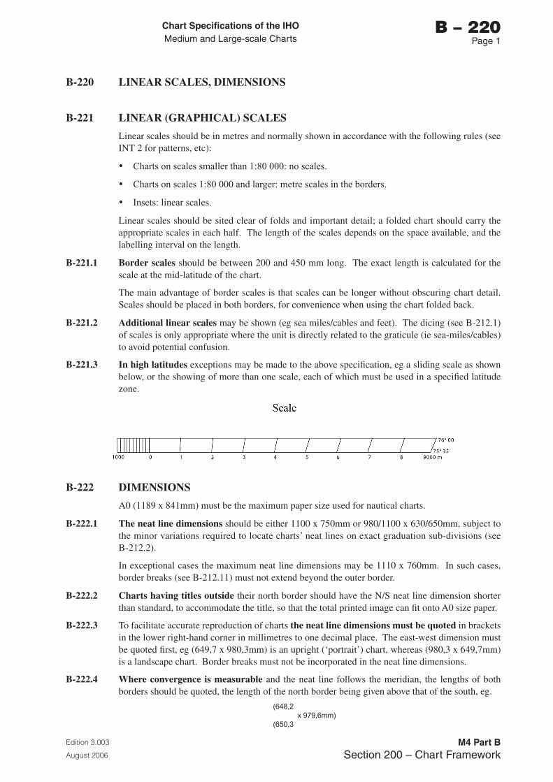
Chart Specifications of the IhoMedium and Large-scale Charts
Edition 3.003
August 2006
M4 Part BSection 200 – Chart Framework
b – 220Page 1
B-220 LINEAR SCALES, DIMENSIONS
B-221 LINEAR (GRAPHICAL) SCALES
Linear scales should be in metres and normally shown in accordance with the following rules (see INT 2 for patterns, etc):
• Charts on scales smaller than 1:80 000: no scales.
• Charts on scales 1:80 000 and larger: metre scales in the borders.
• Insets: linear scales.
Linear scales should be sited clear of folds and important detail; a folded chart should carry the appropriate scales in each half. The length of the scales depends on the space available, and the labelling interval on the length.
B-221.1 Border scales should be between 200 and 450 mm long. The exact length is calculated for the scale at the mid-latitude of the chart.
The main advantage of border scales is that scales can be longer without obscuring chart detail. Scales should be placed in both borders, for convenience when using the chart folded back.
B-221.2 Additional linear scales may be shown (eg sea miles/cables and feet). The dicing (see B-212.1) of scales is only appropriate where the unit is directly related to the graticule (ie sea-miles/cables) to avoid potential confusion.
B-221.3 In high latitudes exceptions may be made to the above specification, eg a sliding scale as shown below, or the showing of more than one scale, each of which must be used in a specified latitude zone.
B-222 DIMENSIONS
A0 (1189 x 841mm) must be the maximum paper size used for nautical charts.
B-222.1 The neat line dimensions should be either 1100 x 750mm or 980/1100 x 630/650mm, subject to the minor variations required to locate charts’ neat lines on exact graduation sub-divisions (see B-212.2).
In exceptional cases the maximum neat line dimensions may be 1110 x 760mm. In such cases, border breaks (see B-212.11) must not extend beyond the outer border.
B-222.2 Charts having titles outside their north border should have the N/S neat line dimension shorter than standard, to accommodate the title, so that the total printed image can fit onto A0 size paper.
B-222.3 To facilitate accurate reproduction of charts the neat line dimensions must be quoted in brackets in the lower right-hand corner in millimetres to one decimal place. The east-west dimension must be quoted first, eg (649,7 x 980,3mm) is an upright (‘portrait’) chart, whereas (980,3 x 649,7mm) is a landscape chart. Border breaks must not be incorporated in the neat line dimensions.
B-222.4 Where convergence is measurable and the neat line follows the meridian, the lengths of both borders should be quoted, the length of the north border being given above that of the south, eg.
(648,2 x979,6mm)
(650,3

Page intentionally left blank
Chart Specifications of the IhoMedium and Large-scale Charts
Edition 3.003
August 2006
M4 Part BSection 200 – Chart Framework
b – 240Page 1
B-230 Not currently used
B-240 TITLE, NOTES
B-241 TITLE BLOCKS
The titles of charts, including associated notes, should be arranged in one block, located in the land area if possible, clear of essential detail. It should be translated into English or French and if the more important information cannot be inserted on the front of the chart, it may be printed on the back. The title block should include the following items, reading from top to bottom:
B-241.1 Seal (or Crest). Most Hydrographic Offices print their seal on the chart, usually above the chart title.
B-241.2(I) On international charts the seal of the producer nation and the IHO seal must be placed above the title, side by side and of equal height, with the producer nation’s seal on the left. In the case of a reproduced international chart, the printer nation’s seal must be placed between the seals of the producer nation (to the left) and the IHO (to the right); the latter two seals must be smaller in height than the seal of the printer nation (about 0.8 of the height).
The words ‘INTERNATIONAL’, or equivalent, above and ‘CHART SERIES’, or equivalent, below the seals must also be shown on international charts.
B-241.3 General geographical area (eg FRANCE – NORTH COAST) and the formal unique chart title, eg. specific geographical description of the location. Countries which do not use the Roman alphabet should print an additional title of the chart in Roman characters.
B-241.4 Scale. The natural scale of the chart must be shown using a colon, thus:
SCALE (or equivalent) 1:10 000
For Mercator projections, the mid-latitude or scale parallel must be added, in brackets or in the form ‘at lat 21°30'’ (Note: no hemisphere identifier is required). See also B-211.
B-241.5 Unit of measure for depths with a general statement about the vertical chart datum used (see B-405).
B-241.6 Unit of measure for heights with a general statement about the plane(s) of reference used (see B-302). Distinctions should be made as appropriate for drying heights (B-413), clearance heights (B-380) and heights of lights (B-471.6), if these are referred to a different datum.
B-241.7 The name (and date) of the horizontal datum used with a statement, as appropriate, about the conversion of geographical positions to the international reference system and the internationally recognized regional datum. See B-201 and B-202.
B-241.8 The IALA Maritime Buoyage region, eg ‘IALA Maritime Buoyage System - Region A (Red to port)’. If the navigational marks within the chart area, or part of it, have not been converted to comply with the IALA system, this should be stated in a cautionary note.
B-241.9 The name of the projection used (see B-203).
B-241.10 A note citing the sources. This may be either noted in the title or the note may refer to a separate Source Diagram. See B-292 to B-298.
B-241.11 Titles blocks of insets should be limited to information that is not contained in, or differs from, the main chart title block.
Chart Specifications of the IhoMedium and Large-scale Charts
Edition 3.003
August 2006
M4 Part BSection 200 – Chart Framework
b – 240Page 2
B-242 CAUTIONARY AND EXPLANATORY NOTES
In addition to those already mentioned in B-241, cautionary and explanatory notes should be added to or put near to the title block. Such a block-arrangement has cartographic advantages and assists the mariner in locating important information. If the land area is too small, it may be necessary to locate these notes away from the title in a water area, clear of important navigational detail.
Notes should be kept to a minimum and be as concise as is compatible with accuracy and intelligibility. Hydrographic terminology (jargon) should be avoided, giving preference to easily understood words, eg ‘depths’ rather than ‘bathymetry’.
B-242.1 Headings. Notes, especially cautionary notes, should have an informative title heading for reference. This title should, where possible, be derived from the description as used in the chart, eg ‘Restricted Area’, ‘Deep Water Route’. This practice is regarded as being more informative and easier for reference than having numbered notes or cautions.
B-242.2 Specimens of various notes are given elsewhere in these specifications.
B-242.3 Cautionary notes must normally be printed in the same colour as their subject, eg. notes about wrecks, currents, magnetic anomalies, etc, in black; notes about exercise areas, anchorages, reporting points, etc, in magenta. Exceptions include notes referring to differences between horizontal datums and notes which refer to two or more features which are charted in different colours. (See B-140 to B-146 for more information about colour conventions). In any case, the reference legend ‘(see Note)’ should be in the colour of the note, to aid identification.
B-242.4 Translation. If space permits, cautionary notes on non-English language charts should be duplicated in English under the national wording. See also B-241.
B-242.5 Explanatory notes, as distinguished from cautionary notes, include those mentioned in B-241 and also notes on the kind of light-ranges shown, glossaries of terms, etc.
B-243 REFERENCE TO OTHER PUBLICATIONS
A reference to other publications may be added as marginal information, eg. outside the border in the upper right-hand corner. A specimen is given below:
Refer to relevant Sailing Directions, List of Lights and other publications to supplement the information shown on this chart. For general information on navigation, charts and hydrographic publications see The Mariners’ Handbook. For an explanation of chart symbols and abbreviations see Chart INT 1.
For references to other charts and other marginal information, see B-250 to B-255.
Chart Specifications of the IhoMedium and Large-scale Charts
Edition 3.003
August 2006
M4 Part BSection 200 – Chart Framework
b – 250Page 1
B-250 CHART NUMBERING, MARGINAL INFORMATION
B-251 CHART NUMBERING
The numbering of charts within national chart series is a matter for national discretion. As a minimum, national numbers should be printed in black in the lower right-hand corner of the chart and, inverted, in the upper left-hand corner. The national prefix (ISO Standard 3166 two-letter code, see Technical Resolution A1.19) may be included.
B-251.1(I) International charts must carry international chart numbers shown in magenta, in Arabic figures, with the prefix ‘INT’. The international number should be placed next to or above the national number.
B-251.2(I) International numbering must follow the principles described in M-4 A-204 and M-11 (Part A).
B-252 DATES OF PUBLICATION AND UPDATES
Charts must bear the date of their original publication, that of the latest edition, and the year date and numbers of the Notices to Mariners, if any, which originated updates (formerly termed corrections).
The wording of these notes is left to national discretion. See A-401 for the definitions of terms referring to the issue of charts.
B-252.1 The publication note (publisher’s imprint), which should include the date of the chart’s original publication (eg. Edition 1), should be placed in the centre of the lower margin of the chart. Copyright acknowledgements (see B-253), or reference to the original chart in the case of reproduced charts (see B-252.4), should be placed underneath the publication note.
B-252.2 Edition date and numbers. Notes giving the edition publication date, and if desired the edition number, of the chart must be shown in accordance with national practice. The preferred position is to the right of the publication note or in the lower left-hand corner of the chart, with other updating details.
B-252.3 Notices to Mariners. Charts must bear the legend ‘Notices to Mariners’, or equivalent (such as ‘Small corrections’), in the lower left-hand corner, outside the border of the chart, where the mariner can insert the relevant references for updates carried out on the chart following their appearance in Notices to Mariners (NMs).
Charts should be brought up to date to the day they leave the Hydrographic Office. At the time of despatch, each chart must have a stamp or note indicating the last NM included, or the date of the last group of NMs consulted for its correction, even if this group and possibly preceding groups did not in fact contain any updates to be made to the chart in question. This stamp or notation should state very clearly the name of the Hydrographic Office concerned.
B-252.4 On reproduced (adopted) charts the publication note must be amplified by the following, or equivalent, note:
(I) For international charts:
‘Modified reproduction of INT (...INT number...), published (...date of the edition of the producer’s chart which has been reproduced...) by (...name of the producer nation...)’.
For national charts:
‘Modified reproduction of (…country…) chart (…producer’s national number...), published (...date of the edition of the producer’s chart which has been reproduced...)’.
Chart Specifications of the IhoMedium and Large-scale Charts
Edition 3.003
August 2006
M4 Part BSection 200 – Chart Framework
b – 250Page 2
B-253 COPYRIGHT LEGEND
This may be shown in accordance with national practice. When data has been included from other nations’ charts, acknowledgment of the owner’s copyright should be made in accordance with any bilateral arrangement between the Hydrographic Offices. It should be located under the publication note, see B-252.1.
B-254 REFERENCES TO OTHER CHARTS
Hydrographic Offices should include on their charts references to similar or larger scale charts published by their own nation. These fall into two categories:
a. References in the border of the chart to adjoining charts of the same or similar scale and to continuation insets.
b. References to larger scale charts or plans which cover part of the area covered by the chart.
Note: Insets, including continuation insets and large-scale plans, are small charts with their own borders included within the limits of a larger chart. A plan is a large scale inset of a nautical chart (eg a port plan). For more detailed definitions, see the Hydrographic Dictionary, S-32.
For references to insets on Source diagrams see B-293.6. For references to foreign charts see B-254.4.
B-254.1 Border references should be shown in magenta and be worded ‘Adjoining chart...’ or ‘Continued in inset’, or equivalent, as appropriate.
B-254.2 The limits of larger scale charts or plans should be identified by numbered outlines in magenta, or by the legend ‘see Plan’ if the plan is on the same sheet. If there is more than one inset on a chart, they should be labelled A, B, C etc, and have letter identifiers added to the reference on the main chart, or in its border.
A charted outline may be other than the actual neat line limits, to show that a water area is not charted in detail at the larger scale (eg because it is cut off from the main sea area, or is an area covered by title, notes or diagrams).
A legend such as ‘see Chart...’ may be inserted (eg under the place name which is covered by the chart or plan) instead of limits if the area is so small that the limits and number cannot be shown with clarity.
An index of larger scale charts may be used in place of charted outlines in some instances, eg. in the case of numerous charts forming a coastal series, where the exact limits of each one are of less consequence. This may be combined with another diagram if space is limited, see B-298.
B-254.3(I) References to INT chart numbers may be included in brackets alongside the national number, eg Adjoining Chart 1234 (INT4321).
B-254.4 References to foreign charts. When a Hydrographic Office considers that its own chart coverage is not adequate for all navigation needs, reference should be made to those foreign charts, preferably original national charts, which would usefully supplement the coverage. Such references must include the identity of the publishing office in front of the chart number. This should be the two-letter ISO national code, see Technical Resolution A1.19 and IHO publication S-62. A different colour may be used to differentiate references to foreign charts from the Hydrographic Office’s own charts.
In particularly important cases, the national Chart Catalogue and Sailing Directions should also refer to the foreign charts mentioned above.
Chart Specifications of the IhoMedium and Large-scale Charts
Edition 3.003
August 2006
M4 Part BSection 200 – Chart Framework
b – 250Page �
B-254.5 If there is a plottable (see B-202.2) horizontal datum difference between scales or adjoining charts, the legend ‘(see Note – POSITIONS)’ or equivalent should be added to the chart number reference, in black, and the relevant note included on the chart (see B-202.3).
B-255 OTHER MARGINAL INFORMATION
B-255.1 The term marginal information, as used here, refers to all information shown between the neat line and the outer edge of the paper. Most marginal information has been covered in the preceding specifications.
B-255.2 Units. Those member countries whose chart series contain charts showing depths in fathoms and/or feet may wish to include a note, eg ‘DEPTHS IN METRES’, ‘DEPTHS IN FATHOMS’, or equivalent, on their charts and this is left to national discretion. Such notes should be shown in large magenta capitals, in the top and bottom margins.
B-255.3 Horizontal datum. A legend to quickly draw the mariner’s attention to the horizontal datum, for its use with satellite navigation equipment, (eg ‘WGS84 POSITIONS can be plotted directly on this chart’ or simply ‘WGS84’), may be inserted in large magenta type, in the margins. An alternative is to state in correspondingly large format the actual datum to which the chart is referred.

Page intentionally left blank
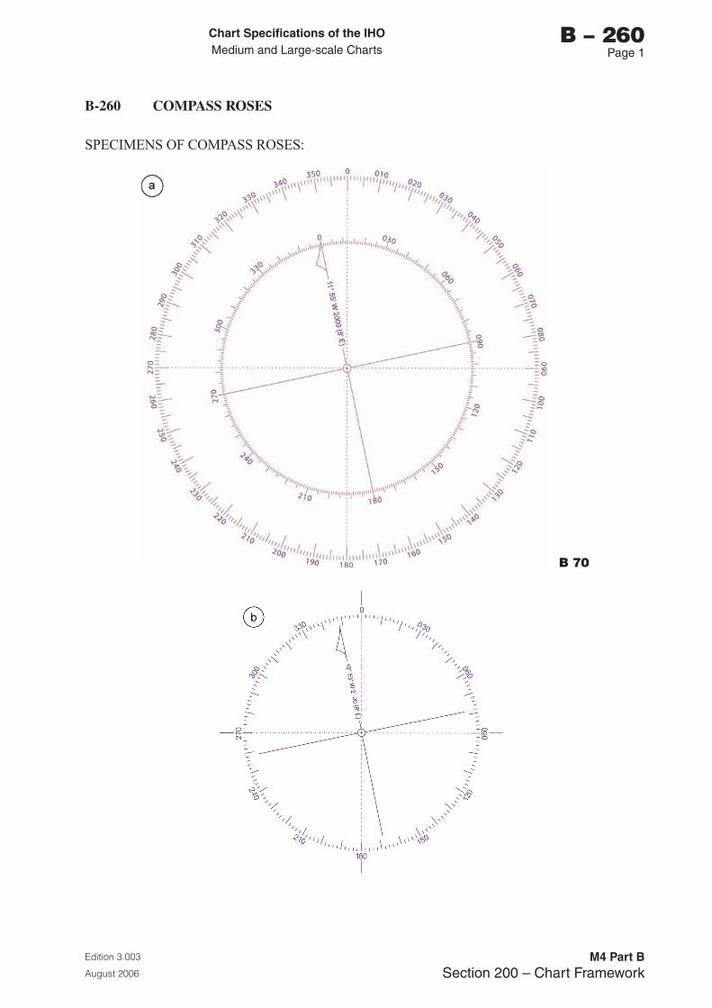
Chart Specifications of the IhoMedium and Large-scale Charts
Edition 3.003
August 2006
M4 Part BSection 200 – Chart Framework
b – 260Page 1
B-260 COMPASS ROSES
SPECIMENS OF COMPASS ROSES:
b 70
Chart Specifications of the IhoMedium and Large-scale Charts
Edition 3.003
August 2006
M4 Part BSection 200 – Chart Framework
b – 260Page 2
B-261 COMPASS ROSES: PATTERNS, TRUE AND MAGNETIC
In this specification ‘pattern’ means (sub)division, labelling and centre indication.
One or more compass roses should be shown on each chart in places particularly selected for their use, see B-262.2.
The value of the magnetic variation, together with the year date and the annual rate of change, must be shown on charts, see B-272.
Compass roses should be in magenta in the form shown at B-260, taking note of the fact that these specimens also illustrate optional features.
B-261.1 The true circle, where combined with a magnetic circle, must be the outer circle; its pattern is illustrated by the specimens at B-260.
These specimens also show optional additions, which are:
• the outward extensions of the 0°-180° and 090°-270° axes,
• the dotted lines joining 0°-180° and 090°-270°.
Another optional addition, not illustrated, is a ‘North Star’.
B-261.2 The magnetic circle is optional: its pattern is illustrated by specimen a. For further particulars on magnetic data, see B-272.
B-262 COMPASS ROSES: SIZE AND POSITION
B-262.1 The diameter of the rose should normally be 100 to 140mm, depending on the size and configuration of the chart – see B-260 specimen a. Smaller roses of 65 to 100mm diameter may be used on insets, or in order to facilitate positioning. Specimen b is recommended for sizes smaller than 80 mm diameter.
B-262.2 Position. Compass roses should be distributed so as to limit the sliding distance of parallel rulers etc as much as possible. Ideally, it should be possible to reach all service areas of a chart, including inland fixing marks, by moving a 450mm rolling parallel ruler (aligned on both the bearing and its reciprocal across a compass rose) without any part of the ruler crossing the limits of the chart paper (which takes account of the limitation in size of chart tables, and the possibility of raised edges). For this reason, no part of a rose should be closer than 50mm to the inner neat line of the chart.
If possible, the centre of the compass rose should either coincide with the intersection of a parallel and a meridian or with one of these lines, or alternatively it should be amply clear of them. They should be kept clear of internally graduated meridians and parallels. On projections with converging meridians, care must be taken to ensure that compasses are oriented on North, wherever they are placed.
When practicable, roses should be placed clear of chart folds and of critical features, (eg dangers, navigational aids, etc). The coincidence of a sounding with a degree label in the rose or with the magnetic variation legend must be avoided, eg by selecting a suitable alternative sounding, or displacing a critical sounding using symbol I 11.
Compass roses should not be placed in the approaches to harbour entrances.
Compass roses may be placed in the land area, but for clarity should not be partly inside and partly outside the land or coloured areas.
Small craft mariners rarely use 450mm parallel rulers and they often fold charts; more and smaller compass roses are therefore appropriate in areas popular with these users.
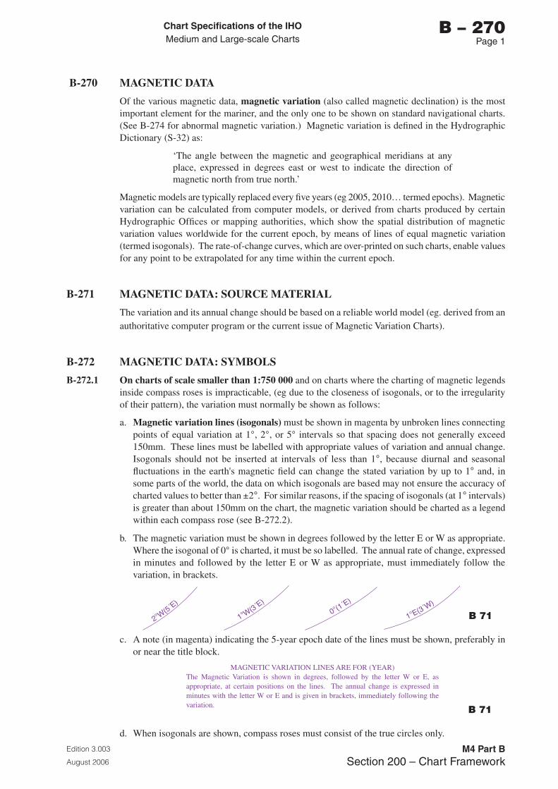
Chart Specifications of the IhoMedium and Large-scale Charts
Edition 3.003
August 2006
M4 Part BSection 200 – Chart Framework
b – 270Page 1
B-270 MAGNETIC DATA
Of the various magnetic data, magnetic variation (also called magnetic declination) is the most important element for the mariner, and the only one to be shown on standard navigational charts. (See B-274 for abnormal magnetic variation.) Magnetic variation is defined in the Hydrographic Dictionary (S-32) as:
‘The angle between the magnetic and geographical meridians at any place, expressed in degrees east or west to indicate the direction of magnetic north from true north.’
Magnetic models are typically replaced every five years (eg 2005, 2010… termed epochs). Magnetic variation can be calculated from computer models, or derived from charts produced by certain Hydrographic Offices or mapping authorities, which show the spatial distribution of magnetic variation values worldwide for the current epoch, by means of lines of equal magnetic variation (termed isogonals). The rate-of-change curves, which are over-printed on such charts, enable values for any point to be extrapolated for any time within the current epoch.
B-271 MAGNETIC DATA: SOURCE MATERIAL
The variation and its annual change should be based on a reliable world model (eg. derived from an authoritative computer program or the current issue of Magnetic Variation Charts).
B-272 MAGNETIC DATA: SYMBOLS
B-272.1 On charts of scale smaller than 1:750 000 and on charts where the charting of magnetic legends inside compass roses is impracticable, (eg due to the closeness of isogonals, or to the irregularity of their pattern), the variation must normally be shown as follows:
a. Magnetic variation lines (isogonals) must be shown in magenta by unbroken lines connecting points of equal variation at 1°, 2°, or 5° intervals so that spacing does not generally exceed 150mm. These lines must be labelled with appropriate values of variation and annual change. Isogonals should not be inserted at intervals of less than 1°, because diurnal and seasonal fluctuations in the earth's magnetic field can change the stated variation by up to 1° and, in some parts of the world, the data on which isogonals are based may not ensure the accuracy of charted values to better than ±2°. For similar reasons, if the spacing of isogonals (at 1° intervals) is greater than about 150mm on the chart, the magnetic variation should be charted as a legend within each compass rose (see B-272.2).
b. The magnetic variation must be shown in degrees followed by the letter E or W as appropriate. Where the isogonal of 0° is charted, it must be so labelled. The annual rate of change, expressed in minutes and followed by the letter E or W as appropriate, must immediately follow the variation, in brackets.
2°W(5´E
)
1°W(3´E
)
1°E(3´W)
0°(1´E)
b 71
c. A note (in magenta) indicating the 5-year epoch date of the lines must be shown, preferably in or near the title block.
MAGNETIC VARIATION LINES ARE FOR (YEAR)The Magnetic Variation is shown in degrees, followed by the letter W or E, as appropriate, at certain positions on the lines. The annual change is expressed in minutes with the letter W or E and is given in brackets, immediately following the variation. b 71
d. When isogonals are shown, compass roses must consist of the true circles only.
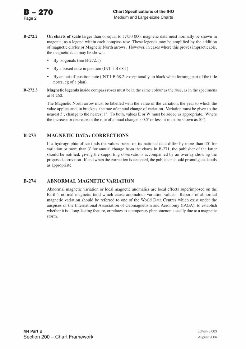
Chart Specifications of the IhoMedium and Large-scale Charts
Edition 3.003
August 2006
M4 Part BSection 200 – Chart Framework
b – 270Page 2
B-272.2 On charts of scale larger than or equal to 1:750 000, magnetic data must normally be shown in magenta, as a legend within each compass rose. These legends may be amplified by the addition of magnetic circles or Magnetic North arrows. However, in cases where this proves impracticable, the magnetic data may be shown:
• By isogonals (see B-272.1)
• By a boxed note in position (INT 1 B 68.1)
• By an out-of-position note (INT 1 B 68.2: exceptionally, in black when forming part of the title notes, eg of a plan).
B-272.3 Magnetic legends inside compass roses must be in the same colour as the rose, as in the specimens at B-260.
The Magnetic North arrow must be labelled with the value of the variation, the year to which the value applies and, in brackets, the rate of annual change of variation. Variation must be given to the nearest 5’, change to the nearest 1’. To both, values E or W must be added as appropriate. Where the increase or decrease in the rate of annual change is 0.5’ or less, it must be shown as (0’).
B-273 MAGNETIC DATA: CORRECTIONS
If a hydrographic office finds the values based on its national data differ by more than 45’ for variation or more than 3’ for annual change from the charts in B-271, the publisher of the latter should be notified, giving the supporting observations accompanied by an overlay showing the proposed correction. If and when the correction is accepted, the publisher should promulgate details as appropriate.
B-274 ABNORMAL MAGNETIC VARIATION
Abnormal magnetic variation or local magnetic anomalies are local effects superimposed on the Earth’s normal magnetic field which cause anomalous variation values. Reports of abnormal magnetic variation should be referred to one of the World Data Centres which exist under the auspices of the International Association of Geomagnetism and Aeronomy (IAGA), to establish whether it is a long-lasting feature, or relates to a temporary phenomenon, usually due to a magnetic storm.
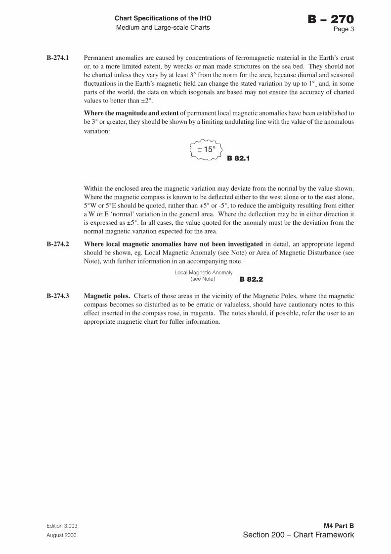
Chart Specifications of the IhoMedium and Large-scale Charts
Edition 3.003
August 2006
M4 Part BSection 200 – Chart Framework
b – 270Page �
B-274.1 Permanent anomalies are caused by concentrations of ferromagnetic material in the Earth’s crust or, to a more limited extent, by wrecks or man made structures on the sea bed. They should not be charted unless they vary by at least 3° from the norm for the area, because diurnal and seasonal fluctuations in the Earth’s magnetic field can change the stated variation by up to 1°¸ and, in some parts of the world, the data on which isogonals are based may not ensure the accuracy of charted values to better than ±2°.
Where the magnitude and extent of permanent local magnetic anomalies have been established to be 3° or greater, they should be shown by a limiting undulating line with the value of the anomalous variation:
b 82.1
Within the enclosed area the magnetic variation may deviate from the normal by the value shown. Where the magnetic compass is known to be deflected either to the west alone or to the east alone, 5°W or 5°E should be quoted, rather than +5° or -5°, to reduce the ambiguity resulting from either a W or E ‘normal’ variation in the general area. Where the deflection may be in either direction it is expressed as ±5°. In all cases, the value quoted for the anomaly must be the deviation from the normal magnetic variation expected for the area.
B-274.2 Where local magnetic anomalies have not been investigated in detail, an appropriate legend should be shown, eg. Local Magnetic Anomaly (see Note) or Area of Magnetic Disturbance (see Note), with further information in an accompanying note.
b 82.2
B-274.3 Magnetic poles. Charts of those areas in the vicinity of the Magnetic Poles, where the magnetic compass becomes so disturbed as to be erratic or valueless, should have cautionary notes to this effect inserted in the compass rose, in magenta. The notes should, if possible, refer the user to an appropriate magnetic chart for fuller information.

Page intentionally left blank
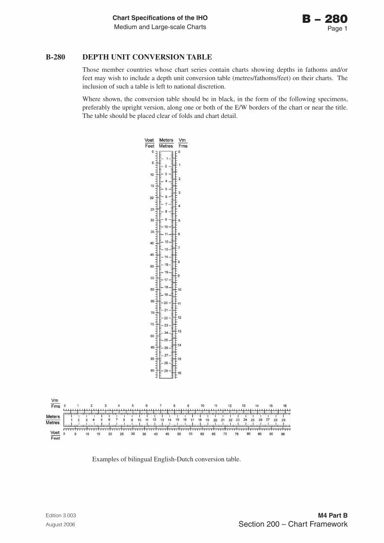
Chart Specifications of the IhoMedium and Large-scale Charts
Edition 3.003
August 2006
M4 Part BSection 200 – Chart Framework
b – 280Page 1
B-280 DEPTH UNIT CONVERSION TABLE
Those member countries whose chart series contain charts showing depths in fathoms and/or feet may wish to include a depth unit conversion table (metres/fathoms/feet) on their charts. The inclusion of such a table is left to national discretion.
Where shown, the conversion table should be in black, in the form of the following specimens, preferably the upright version, along one or both of the E/W borders of the chart or near the title. The table should be placed clear of folds and chart detail.
Examples of bilingual English-Dutch conversion table.
Chart Specifications of the IhoMedium and Large-scale Charts
Edition 3.003
August 2006
M4 Part BSection 200 – Chart Framework
b – 280Page 2
B-281 OTHER TABLES
Depicting other information on charts in tabular form may be considered. In many circumstances, the inclusion of such details in associated publications, such as Sailing Directions, will be more appropriate; however, examples of tables on charts include the following:
• Table of depths in maintained sections of river channels and canals
• Key to berths, jetties and mooring areas
• Table of clearances under bridges
• Key to new or non-standard symbols
• Glossaries of foreign words, particularly on adopted charts
• Table, in magenta, showing marina facilities (see INT 1 U 32) may be used on large scale charts covering small craft centres.
For tidal levels and tidal stream tables, see B-406 to B-407.
Chart Specifications of the IhoMedium and Large-scale Charts
Edition 3.003
August 2006
M4 Part BSection 200 – Chart Framework
b – 290Page 1
B-290 SOURCE DIAGRAMS
Consideration should be given to providing Source diagrams on appropriate new charts, and to adding them to existing charts when the opportunity arises. On charts where routeing measures appear to ‘direct’ vessels into waters where surveys are inadequate, diagrams are particularly important to alert navigators of the need to allow adequate under-keel clearances.
B-290.1 The term ‘Source diagram’, as used in the following paragraphs, includes both the graphic showing the limits of the source data used, and the accompanying text. The diagram should be titled ‘SOURCES’, or equivalent, on charts.
B-290.2 There are two main types of diagrams for summarising hydrographic sources:
• Conventional Source diagrams provide information about source surveys from which the mariner can deduce the degree of confidence to place in charted depth data
• ZOC diagrams (see B-297) are a type of source diagram providing a more qualitative assessment of the source information. They replace the former Reliability diagrams, which are obsolescent.
Dual-purpose diagrams (see B-298) are source diagrams to which other information has been added.
B-290.3 The Explanatory notes under the chart title should draw attention to the presence of a diagram on a chart as mentioned in B-241.10 e.g.:
Source: See the Source diagram for information which may affect the use of this chart.
Source: The origin, scale, date and limits of the hydrographic information used to compile the chart are shown in the Source diagram.
B-290.4 Sources of topography may need to be acknowledged. If so they should be stated in the explanatory note, following the first sentence, e.g.:
The topography is derived chiefly from Ordnance Survey and Institut Géographique National maps.
See B-296.2 for listing topographic source data in the Source diagram.
B-290.5 National navigation manuals should draw attention to Source diagrams and the need to examine them when planning passages. It should be made clear that Source diagrams cannot be expected to convey definitive information about the updating of such charted features as major navigational aids.
B-290.6 Updating: Source diagrams should be updated when New Editions of charts are compiled.
B-291 PURPOSE OF SOURCE DIAGRAMS
B-291.1 The purpose of Source diagrams is to guide navigators, and those planning ‘navigational operations’ (including the planning of new routes and official routeing measures), on the degree of confidence they should have in the adequacy and accuracy of charted depths and their positions. A Source diagram should ideally give details of the survey from which each part of the chart has been compiled. See B-417 for a summary of the ways in which the inadequacy of surveys may be indicated on charts.
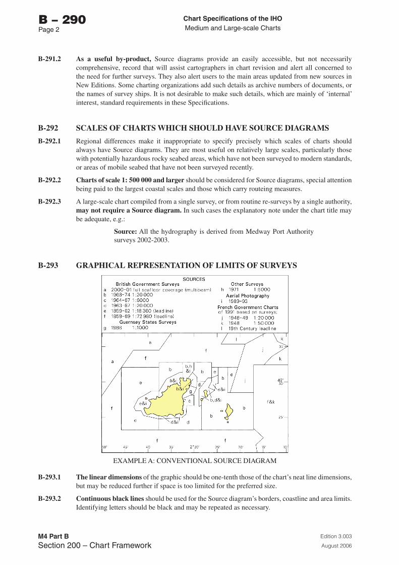
Chart Specifications of the IhoMedium and Large-scale Charts
Edition 3.003
August 2006
M4 Part BSection 200 – Chart Framework
b – 290Page 2
B-291.2 As a useful by-product, Source diagrams provide an easily accessible, but not necessarily comprehensive, record that will assist cartographers in chart revision and alert all concerned to the need for further surveys. They also alert users to the main areas updated from new sources in New Editions. Some charting organizations add such details as archive numbers of documents, or the names of survey ships. It is not desirable to make such details, which are mainly of ‘internal’ interest, standard requirements in these Specifications.
B-292 SCALES OF CHARTS WHICH SHOULD HAVE SOURCE DIAGRAMS
B-292.1 Regional differences make it inappropriate to specify precisely which scales of charts should always have Source diagrams. They are most useful on relatively large scales, particularly those with potentially hazardous rocky seabed areas, which have not been surveyed to modern standards, or areas of mobile seabed that have not been surveyed recently.
B-292.2 Charts of scale 1: 500 000 and larger should be considered for Source diagrams, special attention being paid to the largest coastal scales and those which carry routeing measures.
B-292.3 A large-scale chart compiled from a single survey, or from routine re-surveys by a single authority, may not require a Source diagram. In such cases the explanatory note under the chart title may be adequate, e.g.:
Source: All the hydrography is derived from Medway Port Authority surveys 2002-2003.
B-293 GRAPHICAL REPRESENTATION OF LIMITS OF SURVEYS
EXAMPLE A: CONVENTIONAL SOURCE DIAGRAM
B-293.1 The linear dimensions of the graphic should be one-tenth those of the chart’s neat line dimensions, but may be reduced further if space is too limited for the preferred size.
B-293.2 Continuous black lines should be used for the Source diagram’s borders, coastline and area limits. Identifying letters should be black and may be repeated as necessary.
Chart Specifications of the IhoMedium and Large-scale Charts
Edition 3.003
August 2006
M4 Part BSection 200 – Chart Framework
b – 290Page �
B-293.3 Land tint should cover land areas, and sea areas should be left white (but see B293.8 for special measures).
B-293.4 Graduation of Source diagrams, corresponding with the main chart, should be included for ease of use. To avoid confusion, any internal graticule should have finer lines than the area limits.
B-293.5 Inset plans should be included in Source diagrams, with limits being shown as bold single lines; graduation ticks and figures may be added if considered necessary.
B-293.6 Larger-scale charts and plans: When there is a plan or inset within the chart boundary, the source information should be shown on the section of the diagram of the plan or inset, a note being added to the main chart area of the diagram stating ‘see Plan’. Similarly, when there is a larger scale chart within the area, source information may be omitted and a reference to the larger-scale chart inserted instead. However, if the smaller scale chart is the largest scale International chart, the source information should be included as ‘the content of INT charts must be complete and comprehensive for use by international mariners. They should not require reference to other national charts for any information required by the international mariner’ (Quoted from Guidance for the Preparation and Maintenance of International Chart Schemes - M-11 Part A).
B-293.7 Charts, especially those published by other nations, may be listed as sources where details of their component hydrographic surveys are not known. In such cases the purpose of the Source diagram, or some part of it, cannot be fully achieved because the possibility that the surveys may not fully meet modern standards may not be apparent from the dates and scales of the charts. Wherever possible, qualifying comments on likely deficiencies (e.g. ‘from leadline surveys’) should be given.
B-293.8 Special measures may be taken in cases of particular importance to highlight more clearly where channels lie in relation to the limits of the source data, e.g.:
• Coral reef outlines or the extents of danger lines may be shown
• Intertidal and shallow water tints may be inserted in the same geographical areas on the Source diagram as they are shown on the chart
• Magenta tint may be included to highlight the position of routeing measures, such as Traffic Separation Schemes.
B-294 DETAILS OF SOURCES: DATE AND SCALE
B-294.1 The date of a survey must be given on conventional Source diagrams. It gives an indication of:
• The adequacy of the equipment used
• The thoroughness of examinations of dangers at particular depths (based on the maximum draught of vessels afloat at that date)
• The likelihood of later changes in depths, particularly in areas of mobile or unstable seabed or coral growth.
For ZOC diagrams, see B-297.8.
The date of the edition of a published chart used can be misleading (as the source data may be much older) but may have some value.
Year dates only should normally be used.
B-294.2 Guidance on the practical significance of survey dates should be given in a national publication that advises users on the reliability of charts; see B-290.5.
Chart Specifications of the IhoMedium and Large-scale Charts
Edition 3.003
August 2006
M4 Part BSection 200 – Chart Framework
b – 290Page �
B-294.3 The scale of a controlled survey (see B-295.2) may provide some indication of the thoroughness and the line-spacing, and should be stated in the form 1:5 000, 1:15 000, etc, on conventional Source diagrams. The scale of a chart source may have some value. If considered useful, line-spacing may be added to the details of a survey, e.g. ‘200m’, under the heading ‘Line-spacing’, or equivalent. For surveys gathered by systems using multibeam, interferometric, laser or Lidar technologies, scale has little relevance and a measure of ‘Sounding Density’ may be used instead. However, a statement of whether full sea floor coverage has been achieved will be more informative.
B-295 DETAILS OF SOURCES: ORIGIN AND TYPE
B-295.1 The country of origin should be given explicitly when compiling from foreign data, but may be implicit when using one’s own data, e.g.:
Foreign data own data
French surveys Levés du SHOM
Canadian surveys CHS (or Canadian Hydrographic Service) surveys
British surveys/charts Admiralty surveys/charts
B-295.2 The type of ‘survey’ should be stated on conventional Source diagrams (the terms being translated as necessary):
• ‘Survey’ implies a regular, controlled, or systematic hydrographic survey of any date
• ‘Sketch survey’ or ‘Reconnaissance survey’ implies that there is a significant risk of undetected dangers, even if the ‘survey’ is of recent date
• ‘Passage soundings’ implies soundings acquired on an uncoordinated basis over a period of years
• Qualifying comments, e.g. ‘(leadline)’, ‘(no sonar)’ and ‘(multibeam)’, may be added after the type of survey where the date does not give sufficient indication of the survey methods
• Where a charted survey is supplemented by occasional soundings from older or later sources, only the main survey should normally be listed.
B-295.3 Guidance on the practical significance of survey types should be given in a national publication which advises users on the reliability of charts; see B-290.5.
B-295.4 Surveys made by non-government agencies, such as port authorities, may be identified as such. However, it is usually preferable to use the description ‘Commercial Survey’ or ‘Other surveys’ for surveys made, for example, by oil companies.
B-296 SOURCE LISTS
B-296.1 Sources of similar type, date and scale may have to be grouped together to avoid too long a list or too complex a diagram, e.g.:
‘French surveys 1978-83 1:20 000-1:30 000’.
Surveys of different types, e.g. leadline and echo-sounder surveys, should not be grouped together.
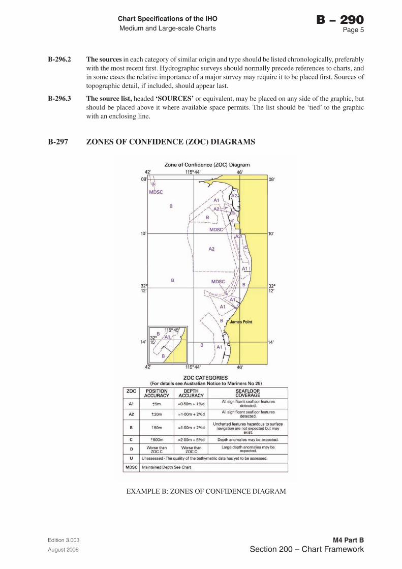
Chart Specifications of the IhoMedium and Large-scale Charts
Edition 3.003
August 2006
M4 Part BSection 200 – Chart Framework
b – 290Page 5
B-296.2 The sources in each category of similar origin and type should be listed chronologically, preferably with the most recent first. Hydrographic surveys should normally precede references to charts, and in some cases the relative importance of a major survey may require it to be placed first. Sources of topographic detail, if included, should appear last.
B-296.3 The source list, headed ‘SOURCES’ or equivalent, may be placed on any side of the graphic, but should be placed above it where available space permits. The list should be ‘tied’ to the graphic with an enclosing line.
B-297 ZONES OF CONFIDENCE (ZOC) DIAGRAMS
EXAMPLE B: ZONES OF CONFIDENCE DIAGRAM
Chart Specifications of the IhoMedium and Large-scale Charts
Edition 3.003
August 2006
M4 Part BSection 200 – Chart Framework
b – 290Page 6
B-297.1 Zones of Confidence (ZOC) diagrams enable mariners to assess the quality of the hydrographic data from which the chart was compiled. The use of ZOC diagrams provide consistency in the display of source data between digital and paper charts, as the Category of Zones of Confidence (CATZOC) definitions are derived directly from S-57. A copy of the CATZOC table from S-57, with relevant footnotes, is included at B-297.9.
B-297.2 Continuous black lines should be used for the ZOC diagram’s borders and coastline. Area limits and identifying CATZOC values may be magenta and may be repeated as necessary.
B-297.3 The linear dimensions of the ZOC diagram shown on paper charts should be one-tenth those of the chart’s neat line dimensions, but may be reduced further if space is too limited for the preferred size, or enlarged if the detail is complex.
B-297.4 The quality of the hydrographic source data is assessed according to six categories: five quality categories for assessed data (A1, A2, B, C and D) and a sixth category (U) for data which has not been assessed. If none of the hydrographic sources used on a chart have been assessed, a ZOC diagram indicating only ‘U’ values should not be added to the chart, as it would not include any information of use to the mariner.
The assessment of hydrographic data quality and classification into zones is based on a combination of:
a. Position accuracy,
b. Depth accuracy, and
c. Sea floor coverage (certainty of significant feature detection).
Where a charted survey is supplemented by occasional soundings from a less accurate source, only the main survey should normally be categorised. The less accurate depths may be indicated as hairline/upright sounding figures (see B-417.3) on the chart.
B-297.5 Guidance on the significance of the quality categories should be given in a national publication which advises users on the reliability of charts; see B-290.5. Other principles applying to Source diagrams in B-290 to B-293 should also be applied to ZOC diagrams.
B-297.6 The higher ZOC categories, A1 and A2, demand full sea floor ensonification or sweep and require very high accuracy standards which have only been achievable with the technology available since about 1980. Therefore many sea lanes which have hitherto been regarded as adequately surveyed may carry a ZOC B classification. Modern surveys of critical areas can be expected to carry ZOC A2 classification whilst ZOC A1 will cover only those areas surveyed under exceptionally stringent conditions for very special reasons.
B-297.7 Additional categories to those listed in S-57 may be added to ZOC diagrams for paper charts, e.g.:
• Maintained Depth (abbreviation MD) and Dredged Area (abbreviation DA). Such areas often do not accurately indicate actual depths, but do indicate minimum depths at the time of dredging.
• Unsurveyed (abbreviation UNS): this should be evident from the face of the chart (see B-418), but may also be indicated on the ZOC Diagram.
B-297.8 The date of a survey may be important, particularly in areas of mobile or unstable sea floor; see B-294.1. The survey date may be inserted in parentheses against the ZOC value on the face of the diagram. To avoid too complex a diagram, dates of surveys may be grouped; see B-296.1 or a suitable note added to the relevant portion of the chart, rather than complicating the diagram.
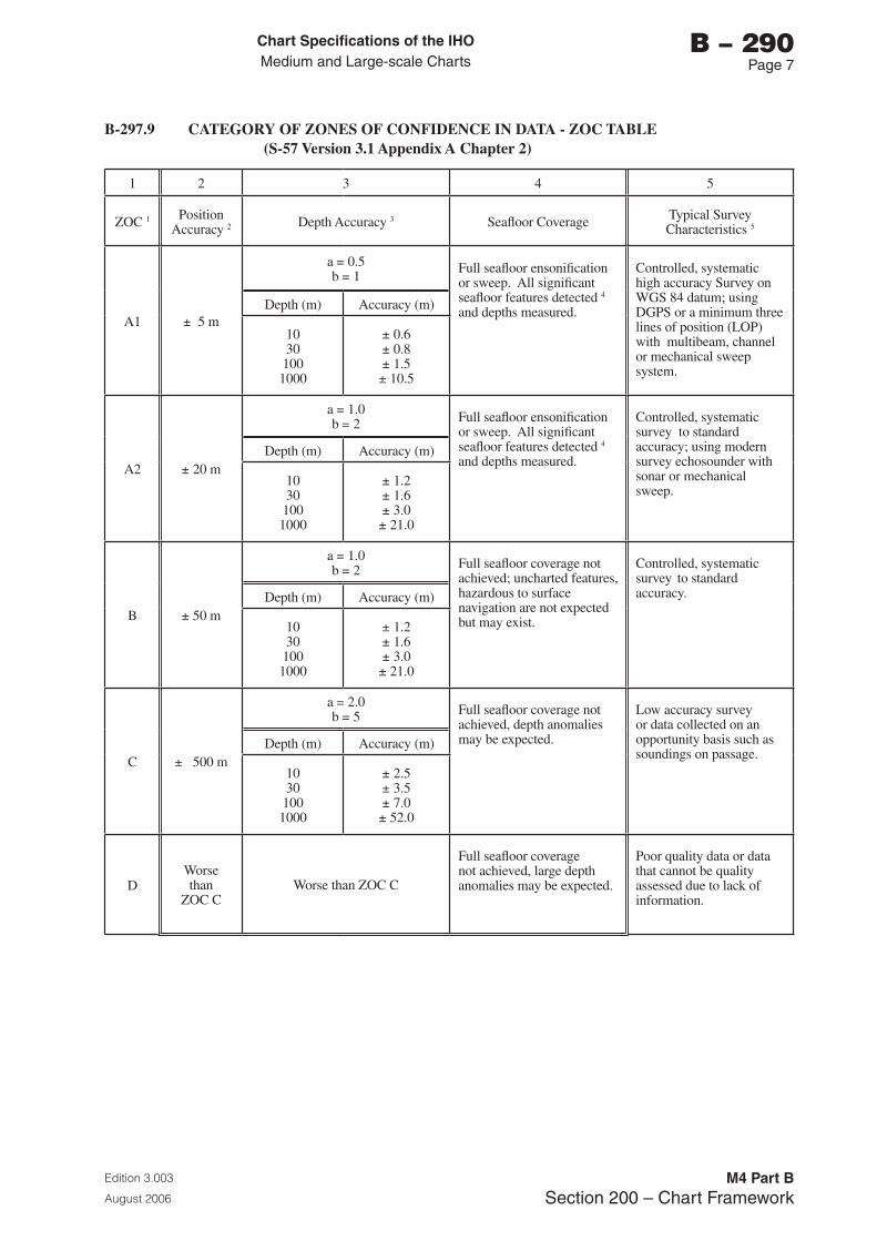
Chart Specifications of the IhoMedium and Large-scale Charts
Edition 3.003
August 2006
M4 Part BSection 200 – Chart Framework
b – 290Page �
B-297.9 CATEGORY OF ZONES OF CONFIDENCE IN DATA - ZOC TABLE (S-57 Version 3.1 Appendix A Chapter 2)
1 2 3 4 5
ZOC 1 Position Accuracy 2 Depth Accuracy 3 Seafloor Coverage Typical Survey
Characteristics 5
A1 ± 5 m
a = 0.5 b = 1
Full seafloor ensonification or sweep. All significant seafloor features detected 4
and depths measured.
Controlled, systematic high accuracy Survey on WGS 84 datum; using DGPS or a minimum three lines of position (LOP) with multibeam, channel or mechanical sweep system.
Depth (m) Accuracy (m)
10301001000
± 0.6± 0.8± 1.5± 10.5
A2 ± 20 m
a = 1.0b = 2 Full seafloor ensonification
or sweep. All significant seafloor features detected 4 and depths measured.
Controlled, systematic survey to standard accuracy; using modern survey echosounder with sonar or mechanical sweep.
Depth (m) Accuracy (m)
10301001000
± 1.2± 1.6± 3.0± 21.0
B ± 50 m
a = 1.0b = 2 Full seafloor coverage not
achieved; uncharted features, hazardous to surface navigation are not expected but may exist.
Controlled, systematic survey to standard accuracy.Depth (m) Accuracy (m)
10301001000
± 1.2± 1.6± 3.0± 21.0
C ± 500 m
a = 2.0 b = 5 Full seafloor coverage not
achieved, depth anomalies may be expected.
Low accuracy survey or data collected on an opportunity basis such as soundings on passage.
Depth (m) Accuracy (m)
10301001000
± 2.5± 3.5± 7.0± 52.0
DWorsethan
ZOC CWorse than ZOC C
Full seafloor coverage not achieved, large depth anomalies may be expected.
Poor quality data or data that cannot be quality assessed due to lack of information.
Chart Specifications of the IhoMedium and Large-scale Charts
Edition 3.003
August 2006
M4 Part BSection 200 – Chart Framework
b – 290Page �
To decide on a ZOC Category, all conditions outlined in columns 2 to 4 of the table must be met.
Footnote numbers quoted in the CATZOC table have the following meanings:
1 This footnote is not applicable to paper charts.
2 Position Accuracy of depicted soundings at 95% Cl (2.45 sigma) with respect to the given datum. It is the cumulative error and includes survey, transformation and digitizing errors etc. Position accuracy need not be rigorously computed for ZOCs B, C and D but may be estimated based on type of equipment, calibration regime, historical accuracy etc.
3 Depth accuracy of depicted soundings = a + (b x d)/100 at 95% Cl (2.00 sigma), where d = depth in metres at the critical depth. Depth accuracy need not be rigorously computed for ZOCs B, C and D but may be estimated based on type of equipment, calibration regime, historical accuracy etc.
4 Significant sea floor features are defined as those rising above depicted depths by more than:
Depth Significant Feature
a. <10 metres >0.1 x depth,
b. 10 to 30 metres >1.0 metre,
c. >30 metres >(0.1 x depth) minus 2.0 metres
5 Controlled, systematic (high accuracy) survey (ZOC A1, A2 and B) - a survey comprising planned survey lines, on a geodetic datum that can be transformed to WGS 84.
Position fixing (ZOC A1) must be strong with at least three high quality Lines of Position (LOP) or Differential GPS.
Modern survey echosounder - a high precision surveying depth measuring equipment, generally including all survey echosounders designed post 1970.
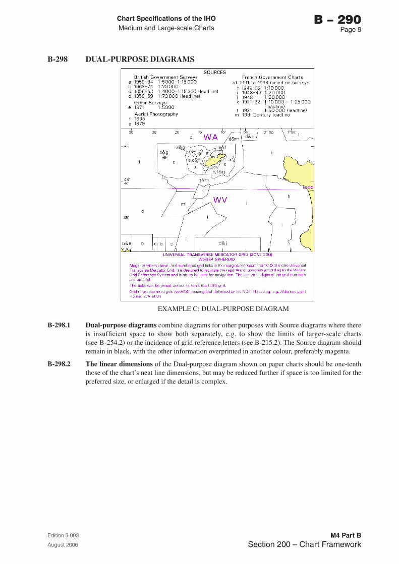
Chart Specifications of the IhoMedium and Large-scale Charts
Edition 3.003
August 2006
M4 Part BSection 200 – Chart Framework
b – 290Page �
B-298 DUAL-PURPOSE DIAGRAMS
EXAMPLE C: DUAL-PURPOSE DIAGRAM
B-298.1 Dual-purpose diagrams combine diagrams for other purposes with Source diagrams where there is insufficient space to show both separately, e.g. to show the limits of larger-scale charts (see B-254.2) or the incidence of grid reference letters (see B-215.2). The Source diagram should remain in black, with the other information overprinted in another colour, preferably magenta.
B-298.2 The linear dimensions of the Dual-purpose diagram shown on paper charts should be one-tenth those of the chart’s neat line dimensions, but may be reduced further if space is too limited for the preferred size, or enlarged if the detail is complex.

Page intentionally left blank

Chart Specifications of the IhoMedium and Large-scale Charts
Edition 3.003
August 2006
M4 Part BSection �00 – Topography
b – 300Page i
PART b
SECTION 300
TOPOGRAPHY

Page intentionally left blank
Chart Specifications of the IhoMedium and Large-scale Charts
Edition 3.003
August 2006
M4 Part BSection �00 – Topography
b – 300Page iii
SECTION 300 - TOPOGRAPHY
CONTENTS
RECORD OF UPDATES
B-301 LAND TINTB-302 PLANE OF REFERENCE FOR HEIGHTSB-303 HEIGHTS ABOVE PHYSICAL GROUND LEVELB-304 SURVEY CONTROL POINTSB-305 OTHER CONTROL POINTSB-306 BOUNDARY MARKSB-307 DISTANCE MARKS
B-310 COASTLINE, GENERALB-311 COASTLINE INADEQUATELY SURVEYEDB-312 COAST, NATURAL FEATURESB-313 COAST, ARTIFICIAL FEATURES
B-320 PORTS AND HARBOURS IN GENERALB-321 QUAYS, PIERS, WHARVES, JETTIES AND MOLESB-322 STRUCTURES NOT INTENDED FOR BERTHING ALONGSIDEB-323 BERTHSB-324 LANDING AND LAUNCHING PLACESB-325 HARBOUR OFFICESB-326 DOCKSB-327 DOLPHINS, POSTS AND PILES, BOLLARDSB-328 DOCKSIDE BUILDINGS AND STRUCTURESB-329 WORKS UNDER CONSTRUCTION AND PROJECTED
B-340 LANDMARKS, CONSPICUOUS OBJECTS: GENERAL
B-350 NATURAL FEATURES IN GENERALB-351 RELIEF: CONTOURS, FORM LINES, SHADINGB-352 RELIEF : SPOT HEIGHTSB-353 RIVERS, LAKES, GLACIERSB-354 VEGETATIONB-355 LAVA FLOW
B-360 ARTIFICIAL FEATURES IN GENERALB-361 CANALSB-362 RAILWAYSB-363 TUNNELS, CUTTINGSB-364 EMBANKMENTS, DAMSB-365 ROADS AND TRACKSB-366 AIRFIELDSB-367 QUARRIES, MINES
B-370 BUILDINGS AND BUILT-UP AREASB-371 STREET AND ROAD NAMESB-372 PUBLIC BUILDINGSB-373 PLACES OF WORSHIP AND ASSOCIATED FEATURESB-374 CHIMNEYS, TOWERS, WINDMILLS, WIND TURBINES, FLAGSTAFFSB-375 RADIO MASTS AND TOWERS

Chart Specifications of the IhoMedium and Large-scale Charts
Edition 3.003
August 2006
M4 Part BSection �00 – Topography
b – 300Page iv
B-376 CYLINDRICAL TANKSB-377 PIPELINES ON LANDB-378 RUINED BUILDINGS AND STRUCTURESB-379 FORTIFIED STRUCTURES
B-380 BRIDGES AND OVERHEAD OBSTRUCTIONS: CLEARANCESB-381 BRIDGESB-382 OVERHEAD CABLESB-383 OVERHEAD PIPES
B-390 VIEWS AND SKETCHES, VIEWPOINTS
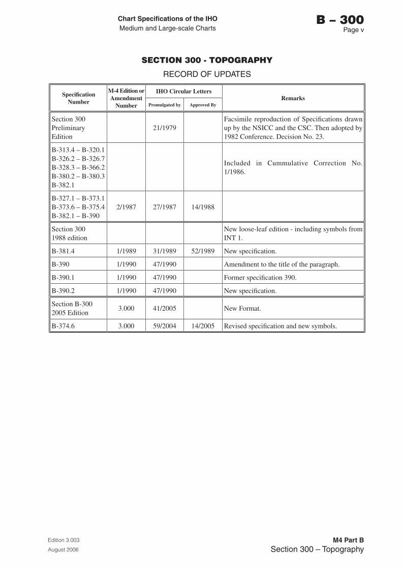
Chart Specifications of the IhoMedium and Large-scale Charts
Edition 3.003
August 2006
M4 Part BSection �00 – Topography
b – 300Page v
SECTION 300 - TOPOGRAPHY
RECORD OF UPDATES
Specification Number
M-4 Edition or Amendment
Number
IHO Circular LettersRemarks
Promulgated by Approved By
Section 300 Preliminary Edition
21/1979Facsimile reproduction of Specifications drawn up by the NSICC and the CSC. Then adopted by 1982 Conference. Decision No. 23.
B-313.4 – B-320.1 B-326.2 – B-326.7 B-328.3 – B-366.2 B-380.2 – B-380.3 B-382.1
Included in Cummulative Correction No. 1/1986.
B-327.1 – B-373.1 B-373.6 – B-375.4 B-382.1 – B-390
2/1987 27/1987 14/1988
Section 300 1988 edition
New loose-leaf edition - including symbols from INT 1.
B-381.4 1/1989 31/1989 52/1989 New specification.
B-390 1/1990 47/1990 Amendment to the title of the paragraph.
B-390.1 1/1990 47/1990 Former specification 390.
B-390.2 1/1990 47/1990 New specification.
Section B-300 2005 Edition
3.000 41/2005 New Format.
B-374.6 3.000 59/2004 14/2005 Revised specification and new symbols.

Page intentionally left blank
Chart Specifications of the IhoMedium and Large-scale Charts
Edition 3.003
August 2006
M4 Part BSection �00 – Topography
b – 300Page 1
SECTION 300
TOPOGRAPHY
B-301 LAND TINT
B-143 states that all charts shall have a colour to be used solely as a land tint except that, overprinted with blue, it shall form a satisfactory intertidal tint. The selection of a colour is left to national discretion provided a clear distinction between land and water tint is maintained.
B-301.1 Land tint shall preferably be shown continuously over all land areas and not be broken for the title, tidal tables, compass roses, conversion tables or scales, etc.
Exceptions to this rule are source diagrams (see B-293.3), and diagrams for other purposes such as those showing the limits of larger-scale charts or the cover provided by an electronic position-fixing system where it is necessary to make a distinction between land and sea, within the diagram; and glaciers (see B-353.8).
B-302 PLANE OF REFERENCE FOR HEIGHTS
This paragraph excludes drying heights, ie heights of features submerged at high water; for drying heights, see B-413.1.
For overhead clearances beneath bridges and other obstructions, see B-380.
B-302.1 The explanatory notes beneath the chart title shall always quote the plane of reference for heights. See B-241.6.
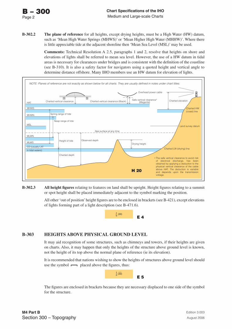
Chart Specifications of the IhoMedium and Large-scale Charts
Edition 3.003
August 2006
M4 Part BSection �00 – Topography
b – 300Page 2
B-302.2 The plane of reference for all heights, except drying heights, must be a High Water (HW) datum, such as ‘Mean High Water Springs (MHWS)’ or ‘Mean Higher High Water (MHHW)’. Where there is little appreciable tide at the adjacent shoreline then ‘Mean Sea Level (MSL)’ may be used.
Comments: Technical Resolution A 2.5, paragraphs 1 and 2, resolve that heights on shore and elevations of lights shall be referred to mean sea level. However, the use of a HW datum in tidal areas is necessary for clearances under bridges and is consistent with the definition of the coastline (see B-310). It is also a safety factor for navigators using a quoted height and vertical angle to determine distance offshore. Many IHO members use an HW datum for elevation of lights.
HAT
MHWS
MHWN
MSL
MLWN
MLWS
CD (usually LATin tidal waters)
Spring range of tide
Charted vertical clearance Charted vertical clearance (Black)Safe vertical clearance*
(Magenta)
Overhead power cable
Charted elevation
Charted HW(coast) line
Charted LW (drying) line
Neap range of tide
Height of tideDrying height
Land survey datum
Charted depth
Observed depth
Sea surface at any time
*
NOTE: Planes of reference are not exactly as shown below for all charts. They are usually defined in notes under chart titles.
The safe vertical clearance to avoid risk of electrical discharge, has been obtained by applying a deduction to the physical vertical clearance of the cable above HAT. The deduction is variable and depends upon the transmission voltage.
B-302.3 All height figures relating to features on land shall be upright. Height figures relating to a summit or spot height shall be placed immediately adjacent to the symbol marking the position.
All other ‘out of position’ height figures are to be enclosed in brackets (see B-421), except elevations of lights forming part of a light description (see B-471.6).
E 4
B-303 HEIGHTS ABOVE PHYSICAL GROUND LEVEL
It may aid recognition of some structures, such as chimneys and towers, if their heights are given on charts. Also, it may happen that only the heights of the structure above ground level is known, not the height of its top above the normal plane of reference (ie its elevation).
It is recommended that nations wishing to show the heights of structures above ground level should use the symbol placed above the figures, thus:
E 5
The figures are enclosed in brackets because they are necessary displaced to one side of the symbol for the structure.
H 20
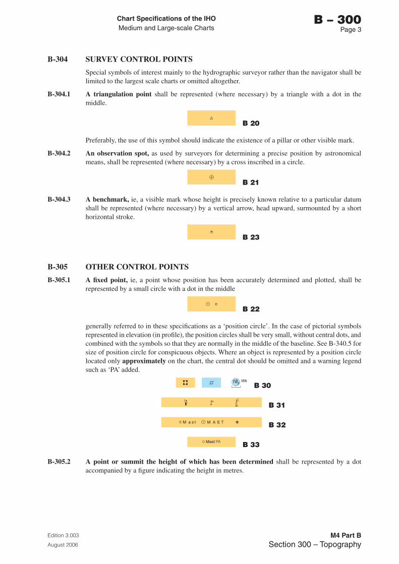
Chart Specifications of the IhoMedium and Large-scale Charts
Edition 3.003
August 2006
M4 Part BSection �00 – Topography
b – 300Page �
B-304 SURVEY CONTROL POINTS
Special symbols of interest mainly to the hydrographic surveyor rather than the navigator shall be limited to the largest scale charts or omitted altogether.
B-304.1 A triangulation point shall be represented (where necessary) by a triangle with a dot in the middle.
b 20
Preferably, the use of this symbol should indicate the existence of a pillar or other visible mark.
B-304.2 An observation spot, as used by surveyors for determining a precise position by astronomical means, shall be represented (where necessary) by a cross inscribed in a circle.
b 21
B-304.3 A benchmark, ie, a visible mark whose height is precisely known relative to a particular datum shall be represented (where necessary) by a vertical arrow, head upward, surmounted by a short horizontal stroke.
b 23
B-305 OTHER CONTROL POINTS
B-305.1 A fixed point, ie, a point whose position has been accurately determined and plotted, shall be represented by a small circle with a dot in the middle
b 22
generally referred to in these specifications as a ‘position circle’. In the case of pictorial symbols represented in elevation (in profile), the position circles shall be very small, without central dots, and combined with the symbols so that they are normally in the middle of the baseline. See B-340.5 for size of position circle for conspicuous objects. Where an object is represented by a position circle located only approximately on the chart, the central dot should be omitted and a warning legend such as ‘PA’ added.
b 30
b 31
b 32
b 33
B-305.2 A point or summit the height of which has been determined shall be represented by a dot accompanied by a figure indicating the height in metres.

Chart Specifications of the IhoMedium and Large-scale Charts
Edition 3.003
August 2006
M4 Part BSection �00 – Topography
b – 300Page �
B-306 BOUNDARY MARKS
It is left to the discretion of each country to choose a conventional sign which corresponds to the natural form of the boundary mark, and, if necessary, to add a legend.
B-307 DISTANCE MARKS
Marks which indicate distances along a channel in either nautical miles, kilometres or some other unit, shall be shown, where considered useful. The symbol shall be shown either ashore or in the channel, and will be chosen at the discretion of each country where it represents visible marks. The unit of measurement (M, km, etc) should be shown.
F 40
Where there are no visible marks, the distance figures, with units, should be shown in magenta with no symbols.
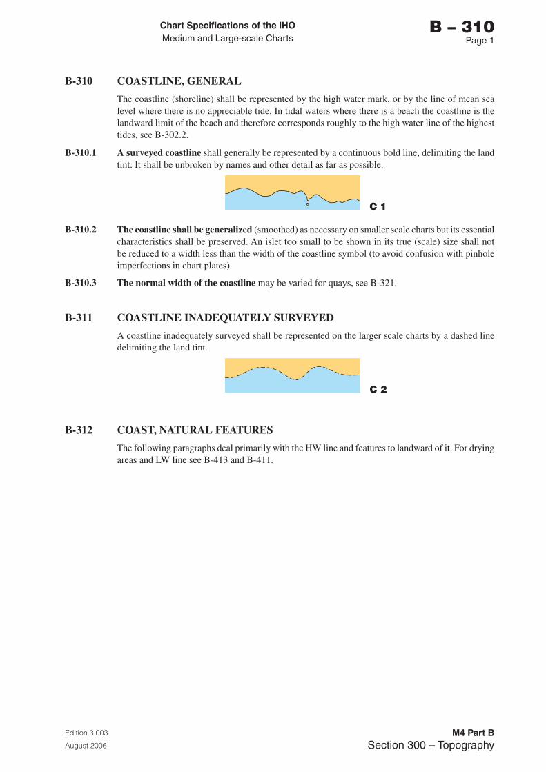
Chart Specifications of the IhoMedium and Large-scale Charts
Edition 3.003
August 2006
M4 Part BSection �00 – Topography
b – 310Page 1
B-310 COASTLINE, GENERAL
The coastline (shoreline) shall be represented by the high water mark, or by the line of mean sea level where there is no appreciable tide. In tidal waters where there is a beach the coastline is the landward limit of the beach and therefore corresponds roughly to the high water line of the highest tides, see B-302.2.
B-310.1 A surveyed coastline shall generally be represented by a continuous bold line, delimiting the land tint. It shall be unbroken by names and other detail as far as possible.
C 1
B-310.2 The coastline shall be generalized (smoothed) as necessary on smaller scale charts but its essential characteristics shall be preserved. An islet too small to be shown in its true (scale) size shall not be reduced to a width less than the width of the coastline symbol (to avoid confusion with pinhole imperfections in chart plates).
B-310.3 The normal width of the coastline may be varied for quays, see B-321.
B-311 COASTLINE INADEQUATELY SURVEYED
A coastline inadequately surveyed shall be represented on the larger scale charts by a dashed line delimiting the land tint.
C 2
B-312 COAST, NATURAL FEATURES
The following paragraphs deal primarily with the HW line and features to landward of it. For drying areas and LW line see B-413 and B-411.
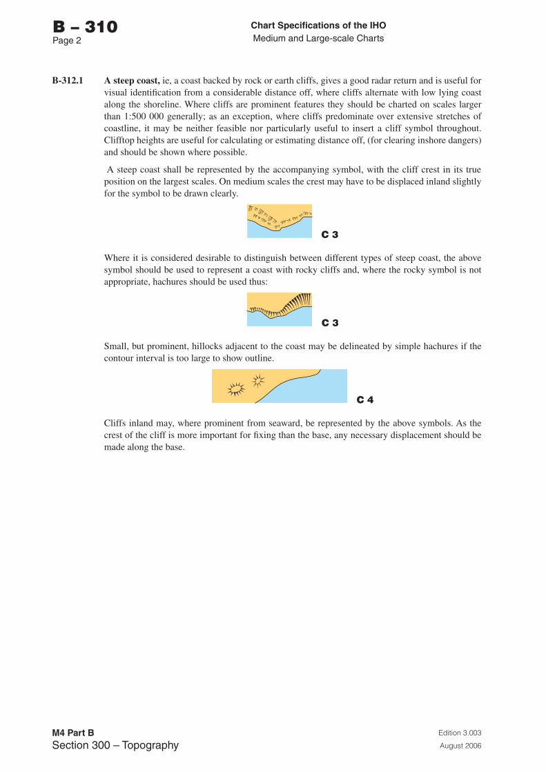
Chart Specifications of the IhoMedium and Large-scale Charts
Edition 3.003
August 2006
M4 Part BSection �00 – Topography
b – 310Page 2
B-312.1 A steep coast, ie, a coast backed by rock or earth cliffs, gives a good radar return and is useful for visual identification from a considerable distance off, where cliffs alternate with low lying coast along the shoreline. Where cliffs are prominent features they should be charted on scales larger than 1:500 000 generally; as an exception, where cliffs predominate over extensive stretches of coastline, it may be neither feasible nor particularly useful to insert a cliff symbol throughout. Clifftop heights are useful for calculating or estimating distance off, (for clearing inshore dangers) and should be shown where possible.
A steep coast shall be represented by the accompanying symbol, with the cliff crest in its true position on the largest scales. On medium scales the crest may have to be displaced inland slightly for the symbol to be drawn clearly.
C 3
Where it is considered desirable to distinguish between different types of steep coast, the above symbol should be used to represent a coast with rocky cliffs and, where the rocky symbol is not appropriate, hachures should be used thus:
C 3
Small, but prominent, hillocks adjacent to the coast may be delineated by simple hachures if the contour interval is too large to show outline.
C 4
Cliffs inland may, where prominent from seaward, be represented by the above symbols. As the crest of the cliff is more important for fixing than the base, any necessary displacement should be made along the base.
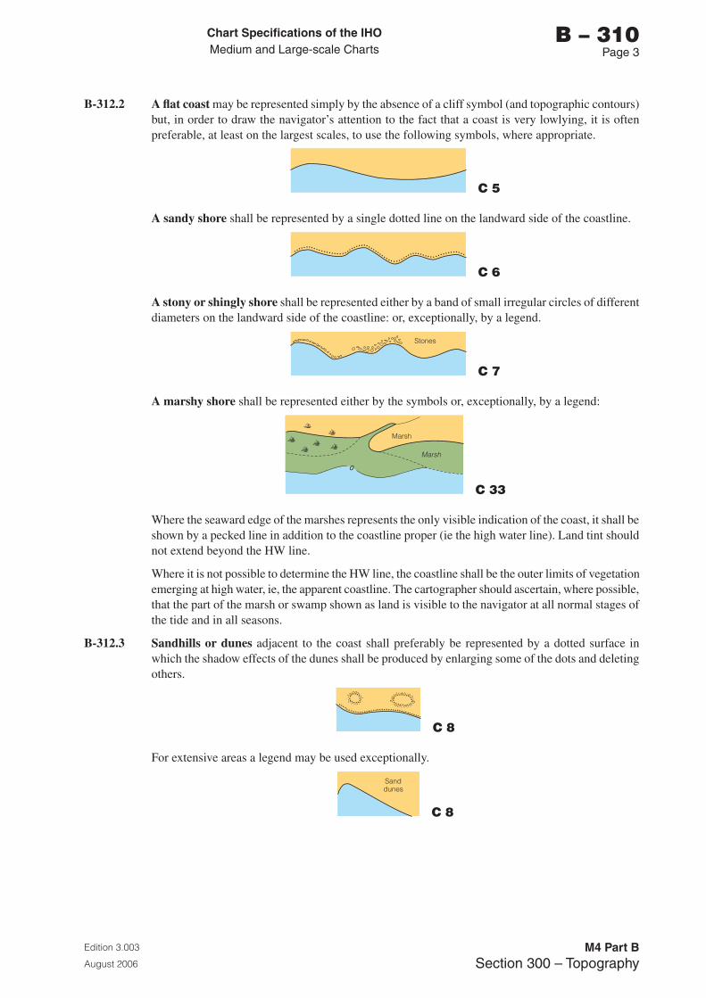
Chart Specifications of the IhoMedium and Large-scale Charts
Edition 3.003
August 2006
M4 Part BSection �00 – Topography
b – 310Page �
B-312.2 A flat coast may be represented simply by the absence of a cliff symbol (and topographic contours) but, in order to draw the navigator’s attention to the fact that a coast is very lowlying, it is often preferable, at least on the largest scales, to use the following symbols, where appropriate.
C 5
A sandy shore shall be represented by a single dotted line on the landward side of the coastline.
���� ���
� ���
� ����� ��
���� �������� ��� ��
���
���
�����
�� �� ������ �������� ��� ��
C 6
A stony or shingly shore shall be represented either by a band of small irregular circles of different diameters on the landward side of the coastline: or, exceptionally, by a legend.
C 7
A marshy shore shall be represented either by the symbols or, exceptionally, by a legend:
C 33
Where the seaward edge of the marshes represents the only visible indication of the coast, it shall be shown by a pecked line in addition to the coastline proper (ie the high water line). Land tint should not extend beyond the HW line.
Where it is not possible to determine the HW line, the coastline shall be the outer limits of vegetation emerging at high water, ie, the apparent coastline. The cartographer should ascertain, where possible, that the part of the marsh or swamp shown as land is visible to the navigator at all normal stages of the tide and in all seasons.
B-312.3 Sandhills or dunes adjacent to the coast shall preferably be represented by a dotted surface in which the shadow effects of the dunes shall be produced by enlarging some of the dots and deleting others.
C 8
For extensive areas a legend may be used exceptionally.
C 8
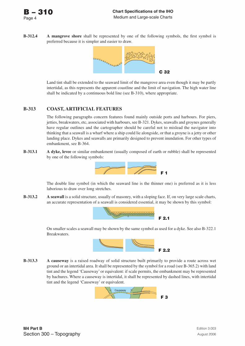
Chart Specifications of the IhoMedium and Large-scale Charts
Edition 3.003
August 2006
M4 Part BSection �00 – Topography
b – 310Page �
B-312.4 A mangrove shore shall be represented by one of the following symbols, the first symbol is preferred because it is simpler and easier to draw.
C 32
Land tint shall be extended to the seaward limit of the mangrove area even though it may be partly intertidal, as this represents the apparent coastline and the limit of navigation. The high water line shall be indicated by a continuous bold line (see B-310), where appropriate.
B-313 COAST, ARTIFICIAL FEATURES
The following paragraphs concern features found mainly outside ports and harbours. For piers, jetties, breakwaters, etc, associated with harbours, see B-321. Dykes, seawalls and groynes generally have regular outlines and the cartographer should be careful not to mislead the navigator into thinking that a seawall is a wharf where a ship could lie alongside, or that a groyne is a jetty or other landing place. Dykes and seawalls are primarily designed to prevent inundation. For other types of embankment, see B-364.
B-313.1 A dyke, levee or similar embankment (usually composed of earth or rubble) shall be represented by one of the following symbols:
F 1
The double line symbol (in which the seaward line is the thinner one) is preferred as it is less laborious to draw over long stretches.
B-313.2 A seawall is a solid structure, usually of masonry, with a sloping face. If, on very large scale charts, an accurate representation of a seawall is considered essential, it may be shown by this symbol:
F 2.1
On smaller scales a seawall may be shown by the same symbol as used for a dyke. See also B-322.1 Breakwaters.
F 2.2
B-313.3 A causeway is a raised roadway of solid structure built primarily to provide a route across wet ground or an intertidal area. It shall be represented by the symbol for a road (see B-365.2) with land tint and the legend ‘Causeway’ or equivalent: if scale permits, the embankment may be represented by hachures. Where a causeway is intertidal, it shall be represented by dashed lines, with intertidal tint and the legend ‘Causeway’ or equivalent.
F 3
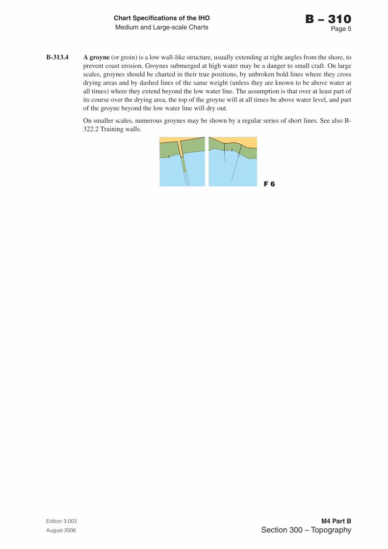
Chart Specifications of the IhoMedium and Large-scale Charts
Edition 3.003
August 2006
M4 Part BSection �00 – Topography
b – 310Page 5
B-313.4 A groyne (or groin) is a low wall-like structure, usually extending at right angles from the shore, to prevent coast erosion. Groynes submerged at high water may be a danger to small craft. On large scales, groynes should be charted in their true positions, by unbroken bold lines where they cross drying areas and by dashed lines of the same weight (unless they are known to be above water at all times) where they extend beyond the low water line. The assumption is that over at least part of its course over the drying area, the top of the groyne will at all times be above water level, and part of the groyne beyond the low water line will dry out.
On smaller scales, numerous groynes may be shown by a regular series of short lines. See also B-322.2 Training walls.
F 6

Page intentionally left blank
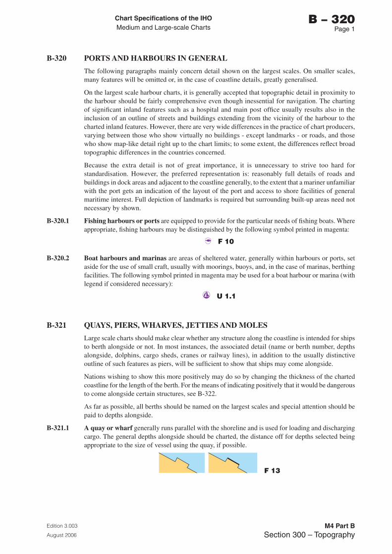
Chart Specifications of the IhoMedium and Large-scale Charts
Edition 3.003
August 2006
M4 Part BSection �00 – Topography
b – 320Page 1
B-320 PORTS AND HARBOURS IN GENERAL
The following paragraphs mainly concern detail shown on the largest scales. On smaller scales, many features will be omitted or, in the case of coastline details, greatly generalised.
On the largest scale harbour charts, it is generally accepted that topographic detail in proximity to the harbour should be fairly comprehensive even though inessential for navigation. The charting of significant inland features such as a hospital and main post office usually results also in the inclusion of an outline of streets and buildings extending from the vicinity of the harbour to the charted inland features. However, there are very wide differences in the practice of chart producers, varying between those who show virtually no buildings - except landmarks - or roads, and those who show map-like detail right up to the chart limits; to some extent, the differences reflect broad topographic differences in the countries concerned.
Because the extra detail is not of great importance, it is unnecessary to strive too hard for standardisation. However, the preferred representation is: reasonably full details of roads and buildings in dock areas and adjacent to the coastline generally, to the extent that a mariner unfamiliar with the port gets an indication of the layout of the port and access to shore facilities of general maritime interest. Full depiction of landmarks is required but surrounding built-up areas need not necessary by shown.
B-320.1 Fishing harbours or ports are equipped to provide for the particular needs of fishing boats. Where appropriate, fishing harbours may be distinguished by the following symbol printed in magenta:
F 10
B-320.2 Boat harbours and marinas are areas of sheltered water, generally within harbours or ports, set aside for the use of small craft, usually with moorings, buoys, and, in the case of marinas, berthing facilities. The following symbol printed in magenta may be used for a boat harbour or marina (with legend if considered necessary):
U 1.1
B-321 QUAYS, PIERS, WHARVES, JETTIES AND MOLES
Large scale charts should make clear whether any structure along the coastline is intended for ships to berth alongside or not. In most instances, the associated detail (name or berth number, depths alongside, dolphins, cargo sheds, cranes or railway lines), in addition to the usually distinctive outline of such features as piers, will be sufficient to show that ships may come alongside.
Nations wishing to show this more positively may do so by changing the thickness of the charted coastline for the length of the berth. For the means of indicating positively that it would be dangerous to come alongside certain structures, see B-322.
As far as possible, all berths should be named on the largest scales and special attention should be paid to depths alongside.
B-321.1 A quay or wharf generally runs parallel with the shoreline and is used for loading and discharging cargo. The general depths alongside should be charted, the distance off for depths selected being appropriate to the size of vessel using the quay, if possible.
F 13
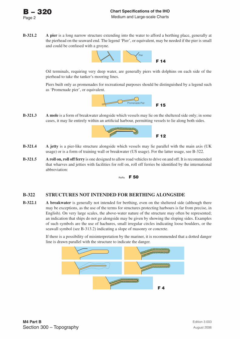
Chart Specifications of the IhoMedium and Large-scale Charts
Edition 3.003
August 2006
M4 Part BSection �00 – Topography
b – 320Page 2
B-321.2 A pier is a long narrow structure extending into the water to afford a berthing place, generally at the pierhead on the seaward end. The legend ‘Pier’, or equivalent, may be needed if the pier is small and could be confused with a groyne.
F 14
Oil terminals, requiring very deep water, are generally piers with dolphins on each side of the pierhead to take the tanker’s mooring lines.
Piers built only as promenades for recreational purposes should be distinguished by a legend such as ‘Promenade pier’, or equivalent.
F 15
B-321.3 A mole is a form of breakwater alongside which vessels may lie on the sheltered side only; in some cases, it may lie entirely within an artificial harbour, permitting vessels to lie along both sides.
F 12
B-321.4 A jetty is a pier-like structure alongside which vessels may lie parallel with the main axis (UK usage) or is a form of training wall or breakwater (US usage). For the latter usage, see B-322.
B-321.5 A roll on, roll off ferry is one designed to allow road vehicles to drive on and off. It is recommended that wharves and jetties with facilities for roll on, roll off ferries be identified by the international abbreviation:
F 50
B-322 STRUCTURES NOT INTENDED FOR BERTHING ALONGSIDE
B-322.1 A breakwater is generally not intended for berthing, even on the sheltered side (although there may be exceptions, as the use of the terms for structures protecting harbours is far from precise, in English). On very large scales, the above-water nature of the structure may often be represented; an indication that ships do not go alongside may be given by showing the sloping sides. Examples of such symbols are the use of hachures, small irregular circles indicating loose boulders, or the seawall symbol (see B-313.2) indicating a slope of masonry or concrete.
If there is a possibility of misinterpretation by the mariner, it is recommended that a dotted danger line is drawn parallel with the structure to indicate the danger.
F 4
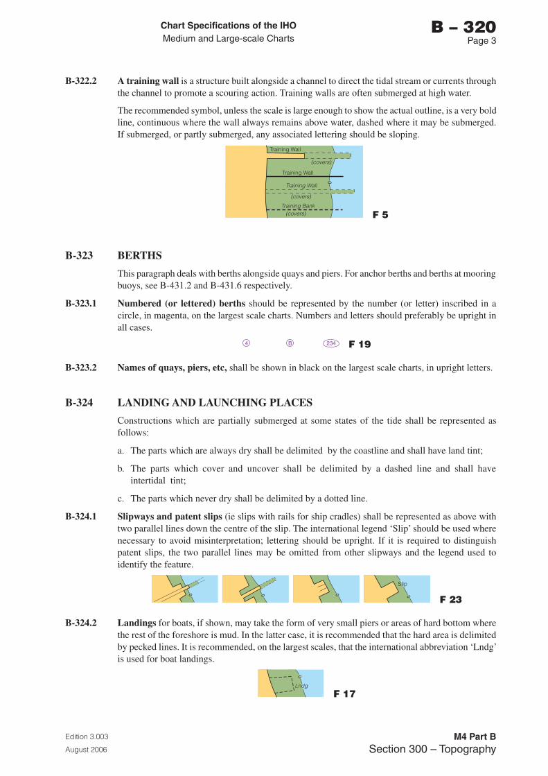
Chart Specifications of the IhoMedium and Large-scale Charts
Edition 3.003
August 2006
M4 Part BSection �00 – Topography
b – 320Page �
B-322.2 A training wall is a structure built alongside a channel to direct the tidal stream or currents through the channel to promote a scouring action. Training walls are often submerged at high water.
The recommended symbol, unless the scale is large enough to show the actual outline, is a very bold line, continuous where the wall always remains above water, dashed where it may be submerged. If submerged, or partly submerged, any associated lettering should be sloping.
F 5
B-323 BERTHS
This paragraph deals with berths alongside quays and piers. For anchor berths and berths at mooring buoys, see B-431.2 and B-431.6 respectively.
B-323.1 Numbered (or lettered) berths should be represented by the number (or letter) inscribed in a circle, in magenta, on the largest scale charts. Numbers and letters should preferably be upright in all cases.
F 19
B-323.2 Names of quays, piers, etc, shall be shown in black on the largest scale charts, in upright letters.
B-324 LANDING AND LAUNCHING PLACES
Constructions which are partially submerged at some states of the tide shall be represented as follows:
a. The parts which are always dry shall be delimited by the coastline and shall have land tint;
b. The parts which cover and uncover shall be delimited by a dashed line and shall have intertidal tint;
c. The parts which never dry shall be delimited by a dotted line.
B-324.1 Slipways and patent slips (ie slips with rails for ship cradles) shall be represented as above with two parallel lines down the centre of the slip. The international legend ‘Slip’ should be used where necessary to avoid misinterpretation; lettering should be upright. If it is required to distinguish patent slips, the two parallel lines may be omitted from other slipways and the legend used to identify the feature.
F 23
B-324.2 Landings for boats, if shown, may take the form of very small piers or areas of hard bottom where the rest of the foreshore is mud. In the latter case, it is recommended that the hard area is delimited by pecked lines. It is recommended, on the largest scales, that the international abbreviation ‘Lndg’ is used for boat landings.
F 17
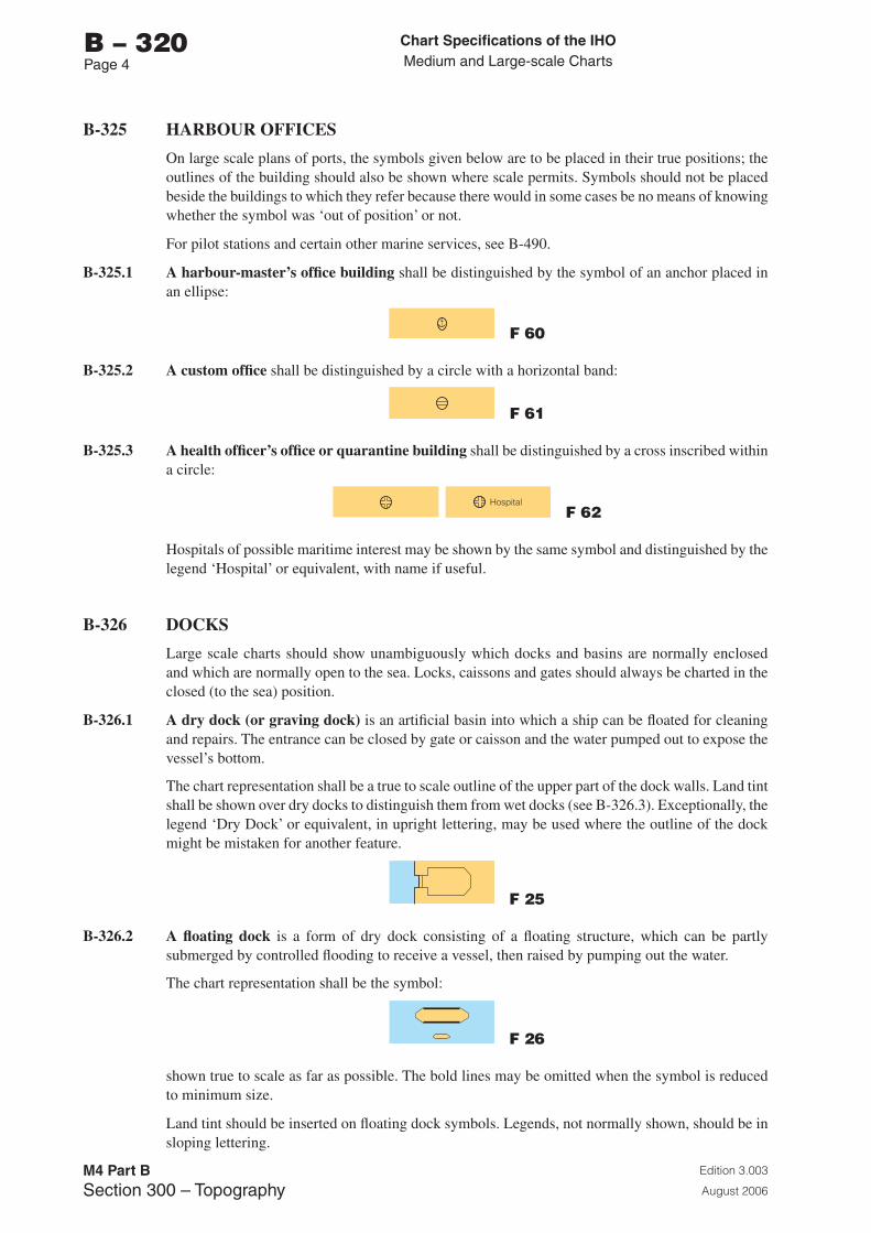
Chart Specifications of the IhoMedium and Large-scale Charts
Edition 3.003
August 2006
M4 Part BSection �00 – Topography
b – 320Page �
B-325 HARBOUR OFFICES
On large scale plans of ports, the symbols given below are to be placed in their true positions; the outlines of the building should also be shown where scale permits. Symbols should not be placed beside the buildings to which they refer because there would in some cases be no means of knowing whether the symbol was ‘out of position’ or not.
For pilot stations and certain other marine services, see B-490.
B-325.1 A harbour-master’s office building shall be distinguished by the symbol of an anchor placed in an ellipse:
F 60
B-325.2 A custom office shall be distinguished by a circle with a horizontal band:
F 61
B-325.3 A health officer’s office or quarantine building shall be distinguished by a cross inscribed within a circle:
F 62
Hospitals of possible maritime interest may be shown by the same symbol and distinguished by the legend ‘Hospital’ or equivalent, with name if useful.
B-326 DOCKS
Large scale charts should show unambiguously which docks and basins are normally enclosed and which are normally open to the sea. Locks, caissons and gates should always be charted in the closed (to the sea) position.
B-326.1 A dry dock (or graving dock) is an artificial basin into which a ship can be floated for cleaning and repairs. The entrance can be closed by gate or caisson and the water pumped out to expose the vessel’s bottom.
The chart representation shall be a true to scale outline of the upper part of the dock walls. Land tint shall be shown over dry docks to distinguish them from wet docks (see B-326.3). Exceptionally, the legend ‘Dry Dock’ or equivalent, in upright lettering, may be used where the outline of the dock might be mistaken for another feature.
F 25
B-326.2 A floating dock is a form of dry dock consisting of a floating structure, which can be partly submerged by controlled flooding to receive a vessel, then raised by pumping out the water.
The chart representation shall be the symbol:
F 26
shown true to scale as far as possible. The bold lines may be omitted when the symbol is reduced to minimum size.
Land tint should be inserted on floating dock symbols. Legends, not normally shown, should be in sloping lettering.
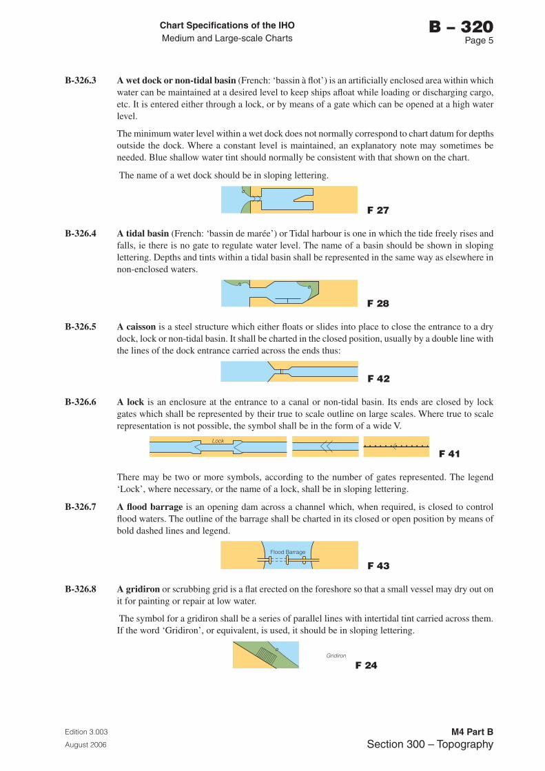
Chart Specifications of the IhoMedium and Large-scale Charts
Edition 3.003
August 2006
M4 Part BSection �00 – Topography
b – 320Page 5
B-326.3 A wet dock or non-tidal basin (French: ‘bassin à flot’) is an artificially enclosed area within which water can be maintained at a desired level to keep ships afloat while loading or discharging cargo, etc. It is entered either through a lock, or by means of a gate which can be opened at a high water level.
The minimum water level within a wet dock does not normally correspond to chart datum for depths outside the dock. Where a constant level is maintained, an explanatory note may sometimes be needed. Blue shallow water tint should normally be consistent with that shown on the chart.
The name of a wet dock should be in sloping lettering.
F 27
B-326.4 A tidal basin (French: ‘bassin de marée’) or Tidal harbour is one in which the tide freely rises and falls, ie there is no gate to regulate water level. The name of a basin should be shown in sloping lettering. Depths and tints within a tidal basin shall be represented in the same way as elsewhere in non-enclosed waters.
F 28
B-326.5 A caisson is a steel structure which either floats or slides into place to close the entrance to a dry dock, lock or non-tidal basin. It shall be charted in the closed position, usually by a double line with the lines of the dock entrance carried across the ends thus:
F 42
B-326.6 A lock is an enclosure at the entrance to a canal or non-tidal basin. Its ends are closed by lock gates which shall be represented by their true to scale outline on large scales. Where true to scale representation is not possible, the symbol shall be in the form of a wide V.
F 41
There may be two or more symbols, according to the number of gates represented. The legend ‘Lock’, where necessary, or the name of a lock, shall be in sloping lettering.
B-326.7 A flood barrage is an opening dam across a channel which, when required, is closed to control flood waters. The outline of the barrage shall be charted in its closed or open position by means of bold dashed lines and legend.
F 43
B-326.8 A gridiron or scrubbing grid is a flat erected on the foreshore so that a small vessel may dry out on it for painting or repair at low water.
The symbol for a gridiron shall be a series of parallel lines with intertidal tint carried across them. If the word ‘Gridiron’, or equivalent, is used, it should be in sloping lettering.
F 24
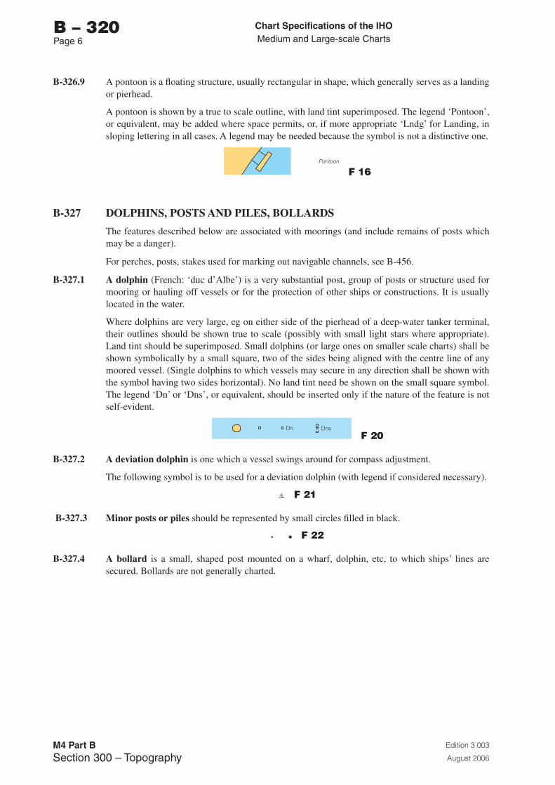
Chart Specifications of the IhoMedium and Large-scale Charts
Edition 3.003
August 2006
M4 Part BSection �00 – Topography
b – 320Page 6
B-326.9 A pontoon is a floating structure, usually rectangular in shape, which generally serves as a landing or pierhead.
A pontoon is shown by a true to scale outline, with land tint superimposed. The legend ‘Pontoon’, or equivalent, may be added where space permits, or, if more appropriate ‘Lndg’ for Landing, in sloping lettering in all cases. A legend may be needed because the symbol is not a distinctive one.
F 16
B-327 DOLPHINS, POSTS AND PILES, BOLLARDS
The features described below are associated with moorings (and include remains of posts which may be a danger).
For perches, posts, stakes used for marking out navigable channels, see B-456.
B-327.1 A dolphin (French: ‘duc d’Albe’) is a very substantial post, group of posts or structure used for mooring or hauling off vessels or for the protection of other ships or constructions. It is usually located in the water.
Where dolphins are very large, eg on either side of the pierhead of a deep-water tanker terminal, their outlines should be shown true to scale (possibly with small light stars where appropriate). Land tint should be superimposed. Small dolphins (or large ones on smaller scale charts) shall be shown symbolically by a small square, two of the sides being aligned with the centre line of any moored vessel. (Single dolphins to which vessels may secure in any direction shall be shown with the symbol having two sides horizontal). No land tint need be shown on the small square symbol. The legend ‘Dn’ or ‘Dns’, or equivalent, should be inserted only if the nature of the feature is not self-evident.
F 20
B-327.2 A deviation dolphin is one which a vessel swings around for compass adjustment.
The following symbol is to be used for a deviation dolphin (with legend if considered necessary).
F 21
B-327.3 Minor posts or piles should be represented by small circles filled in black.
F 22
B-327.4 A bollard is a small, shaped post mounted on a wharf, dolphin, etc, to which ships’ lines are secured. Bollards are not generally charted.

Chart Specifications of the IhoMedium and Large-scale Charts
Edition 3.003
August 2006
M4 Part BSection �00 – Topography
b – 320Page �
B-327.5 Stumps of posts or piles which are wholly submerged at times and may be dangerous to surface navigation shall either be represented by a small dotted circle and the international abbreviation ‘Obstn’ or by the symbols:
K 43.1
In the latter case, when considered advisable to show the exact position of the object, a small circle shall be added at the base of the sloping stroke.
K 43.2
Where stumps of posts or piles exist in groups close together, they may be enclosed by a dotted danger line and accompanied by a legend. Any legend should be in sloping lettering. For wellheads, see B-445.1.
B-328 DOCKSIDE BUILDINGS AND STRUCTURES
The purpose of charting these features is primarily to assist the mariner in identifying particular berths, etc, not to give definitive information on the facilities (such as cranes) available. For Harbour Offices, see B-325. For overhead transporters and conveyors, see B-382.3.
B-328.1 Transit sheds and warehouses are generally to be charted as individual buildings on the largest scales. If they are numbered, the numbers may be charted.
F 51
B-328.2 A timber yard, where stacked timber may be a prominent feature near the coastline, may be indicated by legend or the symbol (which may be repeated for extensive areas).
F 52
B-328.3 A crane shall be represented by a circle cut by a radius which extends beyond the circumference.
Travelling cranes may be represented by crane symbols superimposed on the railway symbol; see B-328.4.
F 53.1
Large container cranes may be represented by the symbol
F 53.2
The lifting capacity of cranes may be shown where considered useful.
Conspicuous sheerlegs (a tripod structure) may be shown by a position circle and legend.
F 53.3
B-328.4 Dock railways should be charted as part of the general detail but sidings should be generalised. For symbol, see B-362.1.
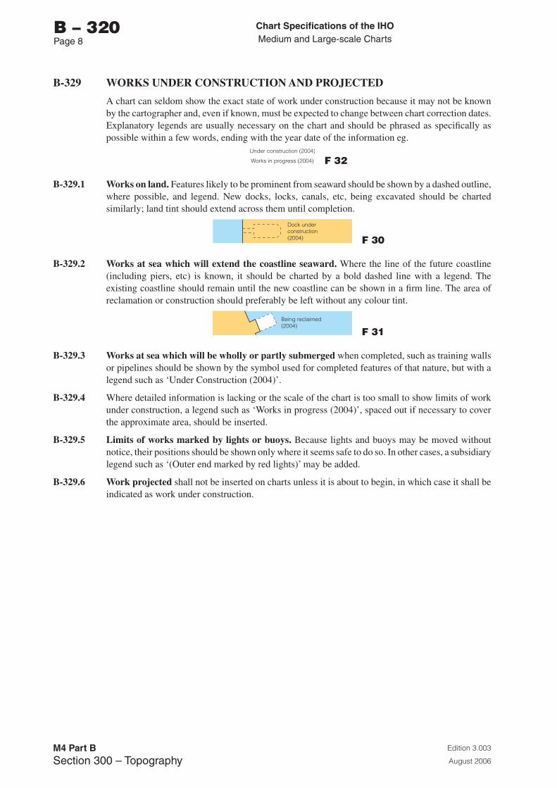
Chart Specifications of the IhoMedium and Large-scale Charts
Edition 3.003
August 2006
M4 Part BSection �00 – Topography
b – 320Page �
B-329 WORKS UNDER CONSTRUCTION AND PROJECTED
A chart can seldom show the exact state of work under construction because it may not be known by the cartographer and, even if known, must be expected to change between chart correction dates. Explanatory legends are usually necessary on the chart and should be phrased as specifically as possible within a few words, ending with the year date of the information eg.
F 32
B-329.1 Works on land. Features likely to be prominent from seaward should be shown by a dashed outline, where possible, and legend. New docks, locks, canals, etc, being excavated should be charted similarly; land tint should extend across them until completion.
F 30
B-329.2 Works at sea which will extend the coastline seaward. Where the line of the future coastline (including piers, etc) is known, it should be charted by a bold dashed line with a legend. The existing coastline should remain until the new coastline can be shown in a firm line. The area of reclamation or construction should preferably be left without any colour tint.
F 31
B-329.3 Works at sea which will be wholly or partly submerged when completed, such as training walls or pipelines should be shown by the symbol used for completed features of that nature, but with a legend such as ‘Under Construction (2004)’.
B-329.4 Where detailed information is lacking or the scale of the chart is too small to show limits of work under construction, a legend such as ‘Works in progress (2004)’, spaced out if necessary to cover the approximate area, should be inserted.
B-329.5 Limits of works marked by lights or buoys. Because lights and buoys may be moved without notice, their positions should be shown only where it seems safe to do so. In other cases, a subsidiary legend such as ‘(Outer end marked by red lights)’ may be added.
B-329.6 Work projected shall not be inserted on charts unless it is about to begin, in which case it shall be indicated as work under construction.
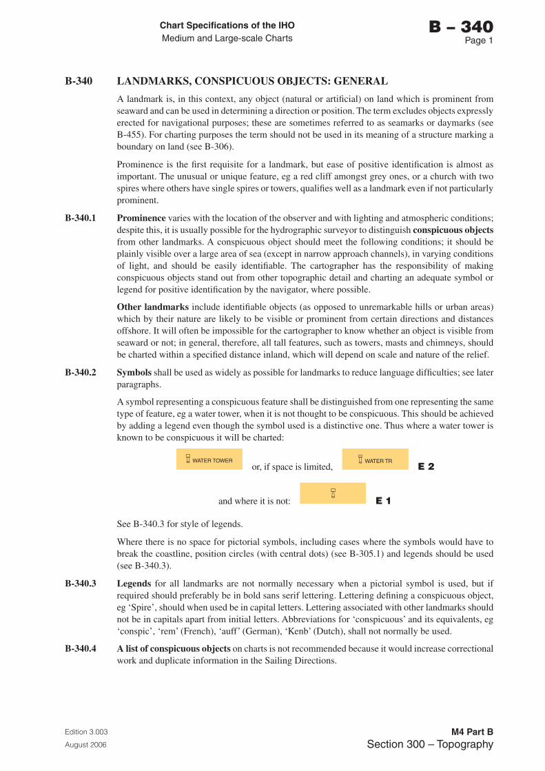
Chart Specifications of the IhoMedium and Large-scale Charts
Edition 3.003
August 2006
M4 Part BSection �00 – Topography
b – 340Page 1
B-340 LANDMARKS, CONSPICUOUS OBJECTS: GENERAL
A landmark is, in this context, any object (natural or artificial) on land which is prominent from seaward and can be used in determining a direction or position. The term excludes objects expressly erected for navigational purposes; these are sometimes referred to as seamarks or daymarks (see B-455). For charting purposes the term should not be used in its meaning of a structure marking a boundary on land (see B-306).
Prominence is the first requisite for a landmark, but ease of positive identification is almost as important. The unusual or unique feature, eg a red cliff amongst grey ones, or a church with two spires where others have single spires or towers, qualifies well as a landmark even if not particularly prominent.
B-340.1 Prominence varies with the location of the observer and with lighting and atmospheric conditions; despite this, it is usually possible for the hydrographic surveyor to distinguish conspicuous objects from other landmarks. A conspicuous object should meet the following conditions; it should be plainly visible over a large area of sea (except in narrow approach channels), in varying conditions of light, and should be easily identifiable. The cartographer has the responsibility of making conspicuous objects stand out from other topographic detail and charting an adequate symbol or legend for positive identification by the navigator, where possible.
Other landmarks include identifiable objects (as opposed to unremarkable hills or urban areas) which by their nature are likely to be visible or prominent from certain directions and distances offshore. It will often be impossible for the cartographer to know whether an object is visible from seaward or not; in general, therefore, all tall features, such as towers, masts and chimneys, should be charted within a specified distance inland, which will depend on scale and nature of the relief.
B-340.2 Symbols shall be used as widely as possible for landmarks to reduce language difficulties; see later paragraphs.
A symbol representing a conspicuous feature shall be distinguished from one representing the same type of feature, eg a water tower, when it is not thought to be conspicuous. This should be achieved by adding a legend even though the symbol used is a distinctive one. Thus where a water tower is known to be conspicuous it will be charted:
or, if space is limited, E 2
and where it is not: E 1
See B-340.3 for style of legends.
Where there is no space for pictorial symbols, including cases where the symbols would have to break the coastline, position circles (with central dots) (see B-305.1) and legends should be used (see B-340.3).
B-340.3 Legends for all landmarks are not normally necessary when a pictorial symbol is used, but if required should preferably be in bold sans serif lettering. Lettering defining a conspicuous object, eg ‘Spire’, should when used be in capital letters. Lettering associated with other landmarks should not be in capitals apart from initial letters. Abbreviations for ‘conspicuous’ and its equivalents, eg ‘conspic’, ‘rem’ (French), ‘auff’ (German), ‘Kenb’ (Dutch), shall not normally be used.
B-340.4 A list of conspicuous objects on charts is not recommended because it would increase correctional work and duplicate information in the Sailing Directions.
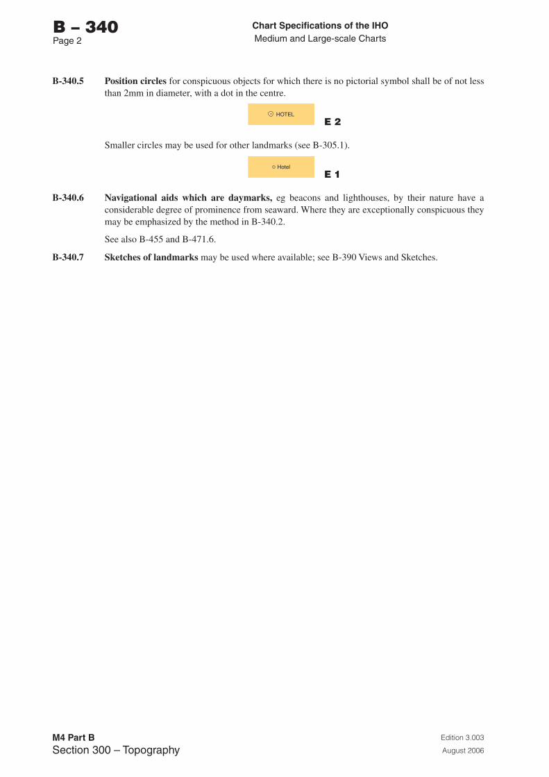
Chart Specifications of the IhoMedium and Large-scale Charts
Edition 3.003
August 2006
M4 Part BSection �00 – Topography
b – 340Page 2
B-340.5 Position circles for conspicuous objects for which there is no pictorial symbol shall be of not less than 2mm in diameter, with a dot in the centre.
E 2
Smaller circles may be used for other landmarks (see B-305.1).
E 1
B-340.6 Navigational aids which are daymarks, eg beacons and lighthouses, by their nature have a considerable degree of prominence from seaward. Where they are exceptionally conspicuous they may be emphasized by the method in B-340.2.
See also B-455 and B-471.6.
B-340.7 Sketches of landmarks may be used where available; see B-390 Views and Sketches.
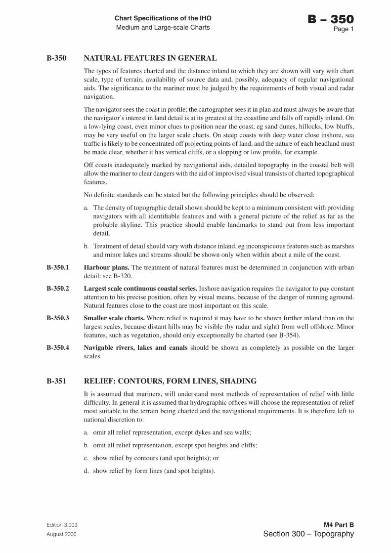
Chart Specifications of the IhoMedium and Large-scale Charts
Edition 3.003
August 2006
M4 Part BSection �00 – Topography
b – 350Page 1
B-350 NATURAL FEATURES IN GENERAL
The types of features charted and the distance inland to which they are shown will vary with chart scale, type of terrain, availability of source data and, possibly, adequacy of regular navigational aids. The significance to the mariner must be judged by the requirements of both visual and radar navigation.
The navigator sees the coast in profile; the cartographer sees it in plan and must always be aware that the navigator’s interest in land detail is at its greatest at the coastline and falls off rapidly inland. On a low-lying coast, even minor clues to position near the coast, eg sand dunes, hillocks, low bluffs, may be very useful on the larger scale charts. On steep coasts with deep water close inshore, sea traffic is likely to be concentrated off projecting points of land, and the nature of each headland must be made clear, whether it has vertical cliffs, or a slopping or low profile, for example.
Off coasts inadequately marked by navigational aids, detailed topography in the coastal belt will allow the mariner to clear dangers with the aid of improvised visual transists of charted topographical features.
No definite standards can be stated but the following principles should be observed:
a. The density of topographic detail shown should be kept to a minimum consistent with providing navigators with all identifiable features and with a general picture of the relief as far as the probable skyline. This practice should enable landmarks to stand out from less important detail.
b. Treatment of detail should vary with distance inland, eg inconspicuous features such as marshes and minor lakes and streams should be shown only when within about a mile of the coast.
B-350.1 Harbour plans. The treatment of natural features must be determined in conjunction with urban detail: see B-320.
B-350.2 Largest scale continuous coastal series. Inshore navigation requires the navigator to pay constant attention to his precise position, often by visual means, because of the danger of running aground. Natural features close to the coast are most important on this scale.
B-350.3 Smaller scale charts. Where relief is required it may have to be shown further inland than on the largest scales, because distant hills may be visible (by radar and sight) from well offshore. Minor features, such as vegetation, should only exceptionally be charted (see B-354).
B-350.4 Navigable rivers, lakes and canals should be shown as completely as possible on the larger scales.
B-351 RELIEF: CONTOURS, FORM LINES, SHADING
It is assumed that mariners, will understand most methods of representation of relief with little difficulty. In general it is assumed that hydrographic offices will choose the representation of relief most suitable to the terrain being charted and the navigational requirements. It is therefore left to national discretion to:
a. omit all relief representation, except dykes and sea walls;
b. omit all relief representation, except spot heights and cliffs;
c. show relief by contours (and spot heights); or
d. show relief by form lines (and spot heights).
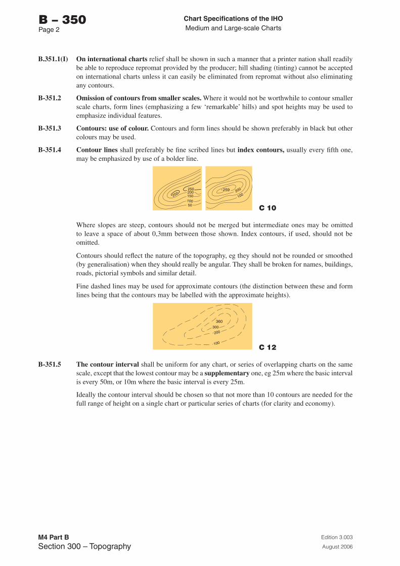
Chart Specifications of the IhoMedium and Large-scale Charts
Edition 3.003
August 2006
M4 Part BSection �00 – Topography
b – 350Page 2
B.351.1(I) On international charts relief shall be shown in such a manner that a printer nation shall readily be able to reproduce repromat provided by the producer; hill shading (tinting) cannot be accepted on international charts unless it can easily be eliminated from repromat without also eliminating any contours.
B-351.2 Omission of contours from smaller scales. Where it would not be worthwhile to contour smaller scale charts, form lines (emphasizing a few ‘remarkable’ hills) and spot heights may be used to emphasize individual features.
B-351.3 Contours: use of colour. Contours and form lines should be shown preferably in black but other colours may be used.
B-351.4 Contour lines shall preferably be fine scribed lines but index contours, usually every fifth one, may be emphasized by use of a bolder line.
C 10
Where slopes are steep, contours should not be merged but intermediate ones may be omitted to leave a space of about 0,3mm between those shown. Index contours, if used, should not be omitted.
Contours should reflect the nature of the topography, eg they should not be rounded or smoothed (by generalisation) when they should really be angular. They shall be broken for names, buildings, roads, pictorial symbols and similar detail.
Fine dashed lines may be used for approximate contours (the distinction between these and form lines being that the contours may be labelled with the approximate heights).
C 12
B-351.5 The contour interval shall be uniform for any chart, or series of overlapping charts on the same scale, except that the lowest contour may be a supplementary one, eg 25m where the basic interval is every 50m, or 10m where the basic interval is every 25m.
Ideally the contour interval should be chosen so that not more than 10 contours are needed for the full range of height on a single chart or particular series of charts (for clarity and economy).
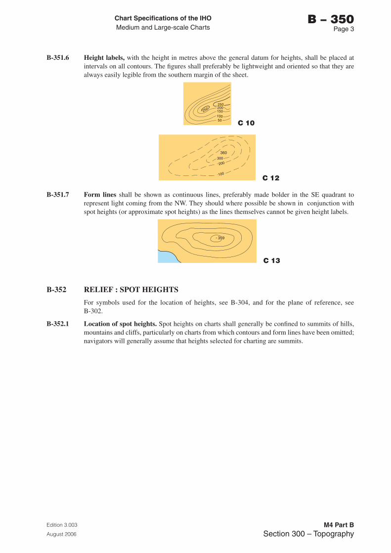
Chart Specifications of the IhoMedium and Large-scale Charts
Edition 3.003
August 2006
M4 Part BSection �00 – Topography
b – 350Page �
B-351.6 Height labels, with the height in metres above the general datum for heights, shall be placed at intervals on all contours. The figures shall preferably be lightweight and oriented so that they are always easily legible from the southern margin of the sheet.
C 10
C 12
B-351.7 Form lines shall be shown as continuous lines, preferably made bolder in the SE quadrant to represent light coming from the NW. They should where possible be shown in conjunction with spot heights (or approximate spot heights) as the lines themselves cannot be given height labels.
C 13
B-352 RELIEF : SPOT HEIGHTS
For symbols used for the location of heights, see B-304, and for the plane of reference, see B-302.
B-352.1 Location of spot heights. Spot heights on charts shall generally be confined to summits of hills, mountains and cliffs, particularly on charts from which contours and form lines have been omitted; navigators will generally assume that heights selected for charting are summits.
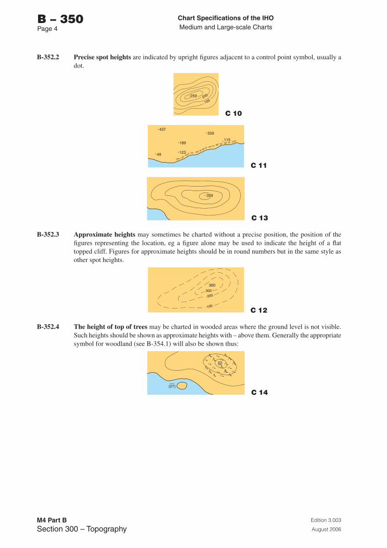
Chart Specifications of the IhoMedium and Large-scale Charts
Edition 3.003
August 2006
M4 Part BSection �00 – Topography
b – 350Page �
B-352.2 Precise spot heights are indicated by upright figures adjacent to a control point symbol, usually a dot.
C 10
C 11
C 13
B-352.3 Approximate heights may sometimes be charted without a precise position, the position of the figures representing the location, eg a figure alone may be used to indicate the height of a flat topped cliff. Figures for approximate heights should be in round numbers but in the same style as other spot heights.
C 12
B-352.4 The height of top of trees may be charted in wooded areas where the ground level is not visible. Such heights should be shown as approximate heights with – above them. Generally the appropriate symbol for woodland (see B-354.1) will also be shown thus:
C 14
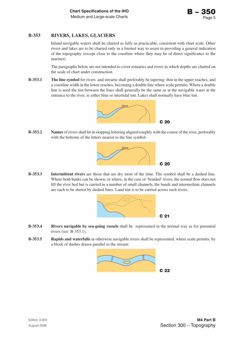
Chart Specifications of the IhoMedium and Large-scale Charts
Edition 3.003
August 2006
M4 Part BSection �00 – Topography
b – 350Page 5
B-353 RIVERS, LAKES, GLACIERS
Inland navigable waters shall be charted as fully as practicable, consistent with chart scale. Other rivers and lakes are to be charted only in a limited way to assist in providing a general indication of the topography (except close to the coastline where they may be of direct significance to the mariner).
The paragraphs below are not intended to cover estuaries and rivers in which depths are charted on the scale of chart under construction.
B-353.1 The line symbol for rivers and streams shall preferably be tapering: thin in the upper reaches, and a coastline width in the lower reaches, becoming a double line where scale permits. Where a double line is used the tint between the lines shall generally be the same as at the navigable water at the entrance to the river, ie either blue or intertidal tint. Lakes shall normally have blue tint.
C 20
B-353.2 Names of rivers shall be in slopping lettering aligned roughly with the course of the river, preferably with the bottoms of the letters nearest to the line symbol.
C 20
B-353.3 Intermittent rivers are those that are dry most of the time. The symbol shall be a dashed line. Where both banks can be shown, or where, in the case of ‘braided’ rivers, the normal flow does not fill the river bed but is carried in a number of small channels, the bands and intermediate channels are each to be shown by dashed lines. Land tint is to be carried across such rivers.
C 21
B-353.4 Rivers navigable by sea-going vessels shall be represented in the normal way as for perennial rivers (see B-353.1).
B-353.5 Rapids and waterfalls in otherwise navigable rivers shall be represented, where scale permits, by a block of dashes drawn parallel to the stream:
C 22
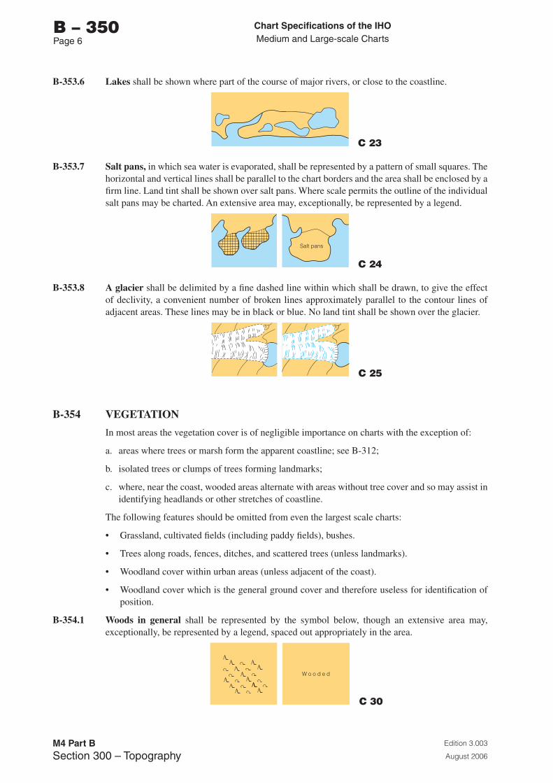
Chart Specifications of the IhoMedium and Large-scale Charts
Edition 3.003
August 2006
M4 Part BSection �00 – Topography
b – 350Page 6
B-353.6 Lakes shall be shown where part of the course of major rivers, or close to the coastline.
C 23
B-353.7 Salt pans, in which sea water is evaporated, shall be represented by a pattern of small squares. The horizontal and vertical lines shall be parallel to the chart borders and the area shall be enclosed by a firm line. Land tint shall be shown over salt pans. Where scale permits the outline of the individual salt pans may be charted. An extensive area may, exceptionally, be represented by a legend.
C 24
B-353.8 A glacier shall be delimited by a fine dashed line within which shall be drawn, to give the effect of declivity, a convenient number of broken lines approximately parallel to the contour lines of adjacent areas. These lines may be in black or blue. No land tint shall be shown over the glacier.
C 25
B-354 VEGETATION
In most areas the vegetation cover is of negligible importance on charts with the exception of:
a. areas where trees or marsh form the apparent coastline; see B-312;
b. isolated trees or clumps of trees forming landmarks;
c. where, near the coast, wooded areas alternate with areas without tree cover and so may assist in identifying headlands or other stretches of coastline.
The following features should be omitted from even the largest scale charts:
• Grassland, cultivated fields (including paddy fields), bushes.
• Trees along roads, fences, ditches, and scattered trees (unless landmarks).
• Woodland cover within urban areas (unless adjacent of the coast).
• Woodland cover which is the general ground cover and therefore useless for identification of position.
B-354.1 Woods in general shall be represented by the symbol below, though an extensive area may, exceptionally, be represented by a legend, spaced out appropriately in the area.
C 30
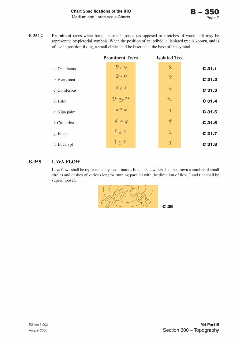
Chart Specifications of the IhoMedium and Large-scale Charts
Edition 3.003
August 2006
M4 Part BSection �00 – Topography
b – 350Page �
B-354.2 Prominent trees when found in small groups (as opposed to stretches of woodland) may be represented by pictorial symbols. When the position of an individual isolated tree is known, and is of use in position-fixing, a small circle shall be inserted at the base of the symbol.
Prominent Trees Isolated Tree
a. Deciduous C 31.1
b. Evergreen C 31.2
c. Coniferous C 31.3
d. Palm C 31.4
e. Nipa palm C 31.5
f. Casuarina C 31.6
g. Filao C 31.7
h. Eucalypt C 31.8
B-355 LAVA FLOW
Lava flows shall be represented by a continuous line, inside which shall be drawn a number of small circles and dashes of various lengths running parallel with the direction of flow. Land tint shall be superimposed.
C 26

Page intentionally left blank
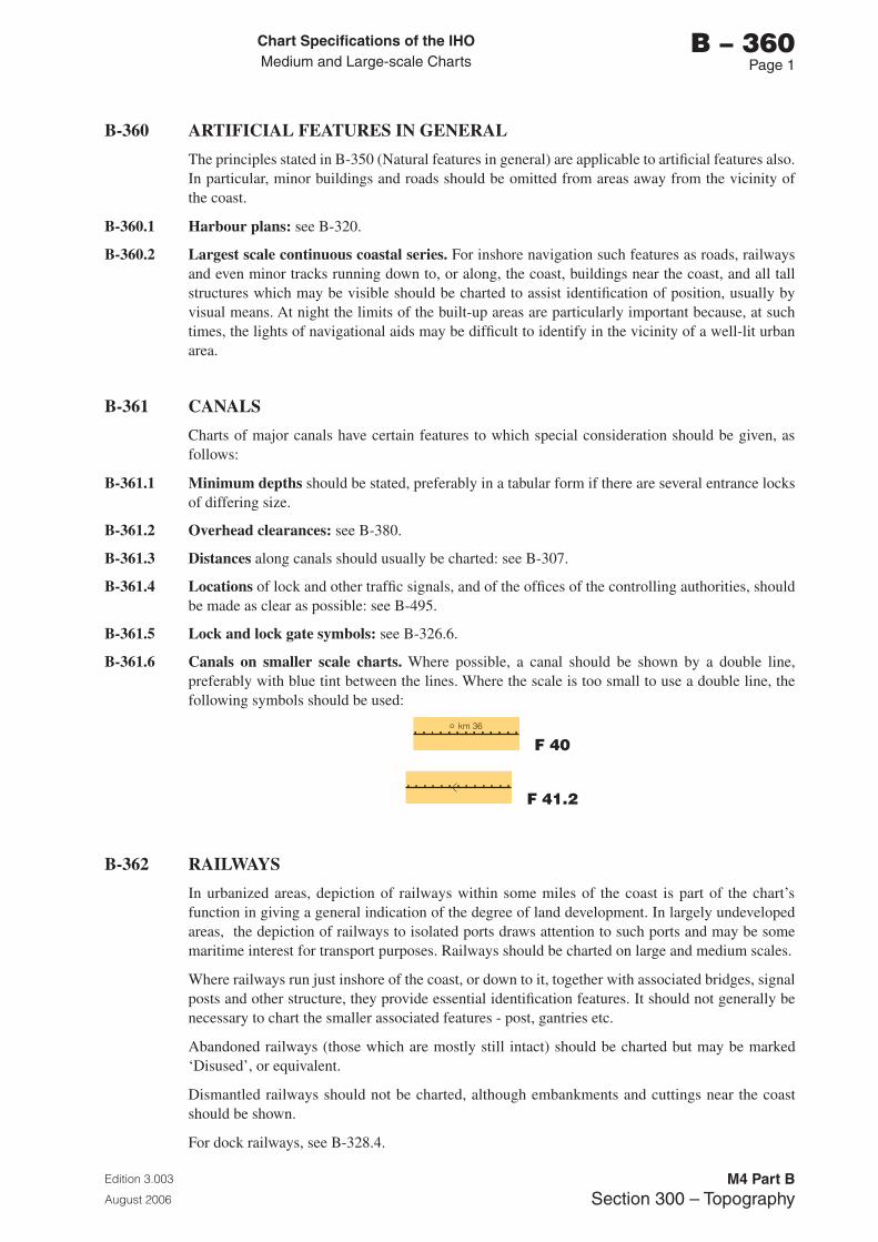
Chart Specifications of the IhoMedium and Large-scale Charts
Edition 3.003
August 2006
M4 Part BSection �00 – Topography
b – 360Page 1
B-360 ARTIFICIAL FEATURES IN GENERAL
The principles stated in B-350 (Natural features in general) are applicable to artificial features also. In particular, minor buildings and roads should be omitted from areas away from the vicinity of the coast.
B-360.1 Harbour plans: see B-320.
B-360.2 Largest scale continuous coastal series. For inshore navigation such features as roads, railways and even minor tracks running down to, or along, the coast, buildings near the coast, and all tall structures which may be visible should be charted to assist identification of position, usually by visual means. At night the limits of the built-up areas are particularly important because, at such times, the lights of navigational aids may be difficult to identify in the vicinity of a well-lit urban area.
B-361 CANALS
Charts of major canals have certain features to which special consideration should be given, as follows:
B-361.1 Minimum depths should be stated, preferably in a tabular form if there are several entrance locks of differing size.
B-361.2 Overhead clearances: see B-380.
B-361.3 Distances along canals should usually be charted: see B-307.
B-361.4 Locations of lock and other traffic signals, and of the offices of the controlling authorities, should be made as clear as possible: see B-495.
B-361.5 Lock and lock gate symbols: see B-326.6.
B-361.6 Canals on smaller scale charts. Where possible, a canal should be shown by a double line, preferably with blue tint between the lines. Where the scale is too small to use a double line, the following symbols should be used:
F 40
F 41.2
B-362 RAILWAYS
In urbanized areas, depiction of railways within some miles of the coast is part of the chart’s function in giving a general indication of the degree of land development. In largely undeveloped areas, the depiction of railways to isolated ports draws attention to such ports and may be some maritime interest for transport purposes. Railways should be charted on large and medium scales.
Where railways run just inshore of the coast, or down to it, together with associated bridges, signal posts and other structure, they provide essential identification features. It should not generally be necessary to chart the smaller associated features - post, gantries etc.
Abandoned railways (those which are mostly still intact) should be charted but may be marked ‘Disused’, or equivalent.
Dismantled railways should not be charted, although embankments and cuttings near the coast should be shown.
For dock railways, see B-328.4.
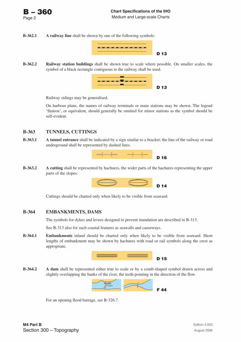
Chart Specifications of the IhoMedium and Large-scale Charts
Edition 3.003
August 2006
M4 Part BSection �00 – Topography
b – 360Page 2
B-362.1 A railway line shall be shown by one of the following symbols:
D 13
B-362.2 Railway station buildings shall be shown true to scale where possible. On smaller scales, the symbol of a black rectangle contiguous to the railway shall be used.
D 13
Railway sidings may be generalised.
On harbour plans, the names of railway terminals or main stations may be shown. The legend ‘Station’, or equivalent, should generally be omitted for minor stations as the symbol should be self-evident.
B-363 TUNNELS, CUTTINGS
B-363.1 A tunnel entrance shall be indicated by a sign similar to a bracket; the line of the railway or road underground shall be represented by dashed lines.
D 16
B-363.2 A cutting shall be represented by hachures, the wider parts of the hachures representing the upper parts of the slopes:
D 14
Cuttings should be charted only when likely to be visible from seaward.
B-364 EMBANKMENTS, DAMS
The symbols for dykes and levees designed to prevent inundation are described in B-313.
See B-313 also for such coastal features as seawalls and causeways.
B-364.1 Embankments inland should be charted only when likely to be visible from seaward. Short lengths of embankment may be shown by hachures with road or rail symbols along the crest as appropriate.
D 15
B-364.2 A dam shall be represented either true to scale or by a comb-shaped symbol drawn across and slightly overlapping the banks of the river, the teeth pointing in the direction of the flow.
F 44
For an opening flood barrage, see B-326.7.
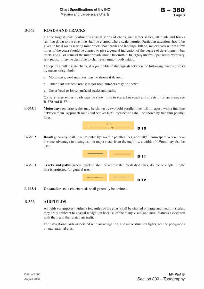
Chart Specifications of the IhoMedium and Large-scale Charts
Edition 3.003
August 2006
M4 Part BSection �00 – Topography
b – 360Page �
B-365 ROADS AND TRACKS
On the largest scale continuous coastal series of charts, and larger scales, all roads and tracks running down to the coastline shall be charted where scale permits. Particular attention should be given to local roads serving minor piers, boat hards and landings. Inland, major roads within a few miles of the coast should be charted to give a general indication of the degree of development, but tracks and all or some of the minor roads should be omitted. In largely undeveloped areas, with very few roads, it may be desirable to chart even minor roads inland.
Except on smaller scale charts, it is preferable to distinguish between the following classes of road by means of symbols:
a. Motorways, road numbers may be shown if desired;
b. Other hard surfaced roads; major road numbers may be shown;
c. Unsurfaced or loose-surfaced tracks and paths.
On very large scales, roads may be shown true to scale. For roads and streets in urban areas, see B-370 and B-371.
B-365.1 Motorways on large scales may be shown by two bold parallel lines 1.8mm apart, with a fine line between them. Approach roads and ‘clover leaf’ intersections shall be shown by two thin parallel lines.
D 10
B-365.2 Roads generally shall be represented by two thin parallel lines, normally 0.5mm apart. Where there is some advantage in distinguishing major roads from the majority, a width of 0.9mm may also be used.
D 11
B-365.3 Tracks and paths (where charted) shall be represented by dashed lines, double or single. Single line is preferred for general use.
D 12
B-365.4 On smaller scale charts roads shall generally be omitted.
B-366 AIRFIELDS
Airfields (or airports) within a few miles of the coast shall be charted on large and medium scales; they are significant to coastal navigation because of the many visual and aural features associated with them and the related air traffic.
For navigational aids associated with air navigation, and air obstruction lights, see the paragraphs on navigational aids.
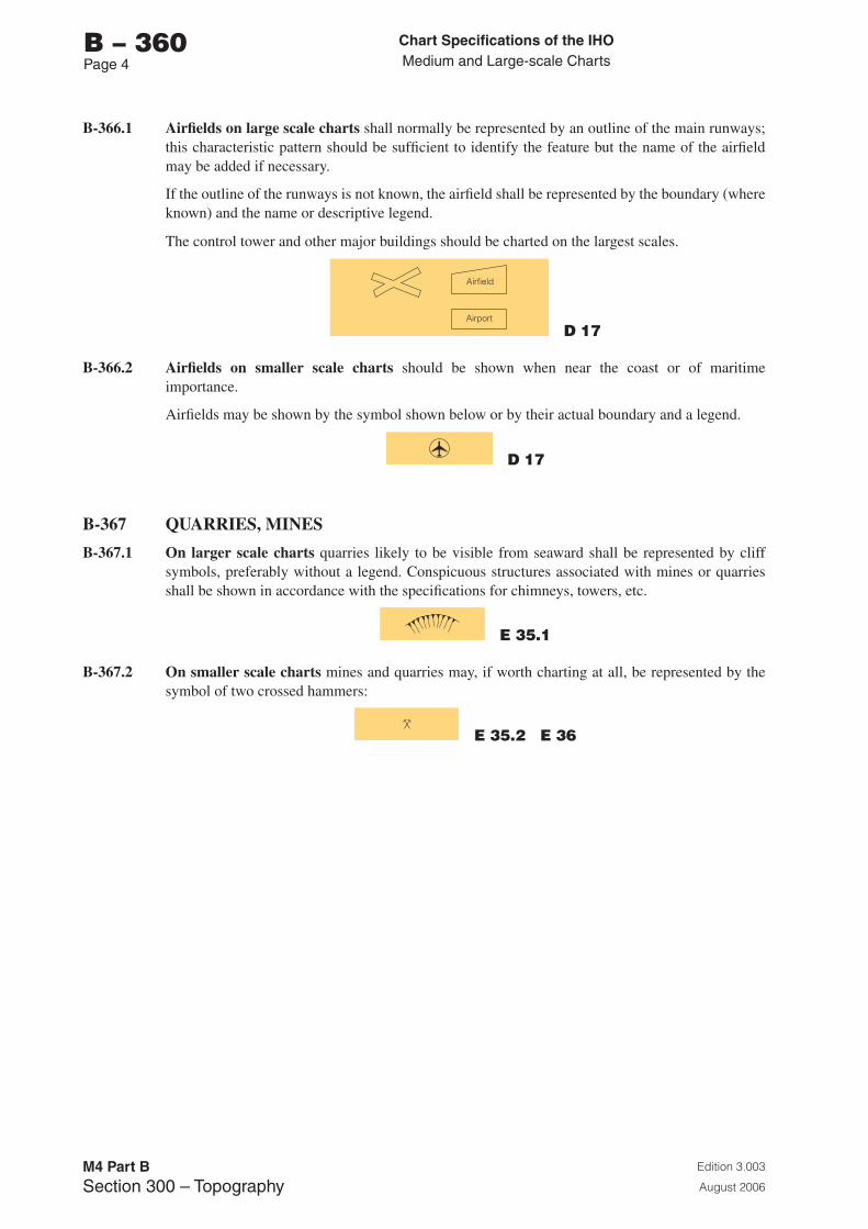
Chart Specifications of the IhoMedium and Large-scale Charts
Edition 3.003
August 2006
M4 Part BSection �00 – Topography
b – 360Page �
B-366.1 Airfields on large scale charts shall normally be represented by an outline of the main runways; this characteristic pattern should be sufficient to identify the feature but the name of the airfield may be added if necessary.
If the outline of the runways is not known, the airfield shall be represented by the boundary (where known) and the name or descriptive legend.
The control tower and other major buildings should be charted on the largest scales.
D 17
B-366.2 Airfields on smaller scale charts should be shown when near the coast or of maritime importance.
Airfields may be shown by the symbol shown below or by their actual boundary and a legend.
D 17
B-367 QUARRIES, MINES
B-367.1 On larger scale charts quarries likely to be visible from seaward shall be represented by cliff symbols, preferably without a legend. Conspicuous structures associated with mines or quarries shall be shown in accordance with the specifications for chimneys, towers, etc.
E 35.1
B-367.2 On smaller scale charts mines and quarries may, if worth charting at all, be represented by the symbol of two crossed hammers:
E 35.2 E 36
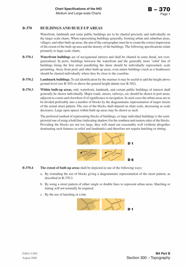
Chart Specifications of the IhoMedium and Large-scale Charts
Edition 3.003
August 2006
M4 Part BSection �00 – Topography
b – 370Page 1
B-370 BUILDINGS AND BUILT-UP AREAS
Waterfront, landmark and some public buildings are to be charted precisely and individually on the larger scale charts. When representing buildings generally, forming urban and suburban areas, villages, and other built-up areas, the aim of the cartographer must be to create the correct impression of the extent of the built-up area and the density of the buildings. The following specifications relate primarily to large scale charts.
B-370.1 Waterfront buildings are of navigational interest and shall be charted in some detail, not over-generalised. In ports, buildings between the waterfront and the generally more ‘solid’ line of buildings lining the first street paralleling the shore should be individually represented, scale permitting. Away from ports and other built-up areas, even minor buildings (such as a boathouse) should be charted individually where they lie close to the coastline.
B-370.2 Landmark buildings. To aid identification by the mariner it may be useful to add the height above ground level (see B-303) or above the general height datum (see B-302).
B-370.3 Within built-up areas, only waterfront, landmark, and certain public buildings of interest shall generally be shown individually. Major roads, streets, railways, etc should be shown in port areas, adjacent to coasts and elsewhere if of significance to navigation. In such cases the urban areas are to be divided preferably into a number of blocks by the diagrammatic representation of major streets of the actual street pattern. The size of the blocks shall depend on chart scale, decreasing as scale decreases. Large open spaces within built-up areas may be shown as such.
The preferred method of representing blocks of buildings, or large individual buildings is the semi-pictorial one of using a bold line (indicating shadow) for the southern and eastern sides of the blocks. Providing the blocks are not too large, they will stand out reasonably well (without altogether dominating such features as relief and landmarks) and therefore not require hatching or tinting.
D 1
D 6
B-370.4 The extent of built-up areas shall be depicted in one of the following ways:
a. By extending the use of blocks giving a diagrammatic representation of the street pattern, as described in B-370.3.
b. By using a street pattern of either single or double lines to represent urban areas. Hatching or tinting will not normally be required.
c. By the use of hatching or a tint.
D 1
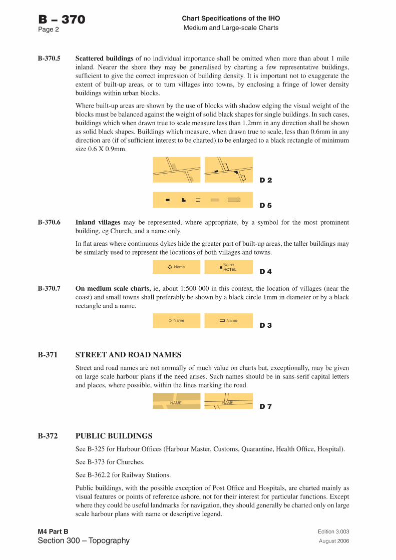
Chart Specifications of the IhoMedium and Large-scale Charts
Edition 3.003
August 2006
M4 Part BSection �00 – Topography
b – 370Page 2
B-370.5 Scattered buildings of no individual importance shall be omitted when more than about 1 mile inland. Nearer the shore they may be generalised by charting a few representative buildings, sufficient to give the correct impression of building density. It is important not to exaggerate the extent of built-up areas, or to turn villages into towns, by enclosing a fringe of lower density buildings within urban blocks.
Where built-up areas are shown by the use of blocks with shadow edging the visual weight of the blocks must be balanced against the weight of solid black shapes for single buildings. In such cases, buildings which when drawn true to scale measure less than 1.2mm in any direction shall be shown as solid black shapes. Buildings which measure, when drawn true to scale, less than 0.6mm in any direction are (if of sufficient interest to be charted) to be enlarged to a black rectangle of minimum size 0.6 X 0.9mm.
D 2
D 5
B-370.6 Inland villages may be represented, where appropriate, by a symbol for the most prominent building, eg Church, and a name only.
In flat areas where continuous dykes hide the greater part of built-up areas, the taller buildings may be similarly used to represent the locations of both villages and towns.
D 4
B-370.7 On medium scale charts, ie, about 1:500 000 in this context, the location of villages (near the coast) and small towns shall preferably be shown by a black circle 1mm in diameter or by a black rectangle and a name.
D 3
B-371 STREET AND ROAD NAMES
Street and road names are not normally of much value on charts but, exceptionally, may be given on large scale harbour plans if the need arises. Such names should be in sans-serif capital letters and places, where possible, within the lines marking the road.
D 7
B-372 PUBLIC BUILDINGS
See B-325 for Harbour Offices (Harbour Master, Customs, Quarantine, Health Office, Hospital).
See B-373 for Churches.
See B-362.2 for Railway Stations.
Public buildings, with the possible exception of Post Office and Hospitals, are charted mainly as visual features or points of reference ashore, not for their interest for particular functions. Except where they could be useful landmarks for navigation, they should generally be charted only on large scale harbour plans with name or descriptive legend.
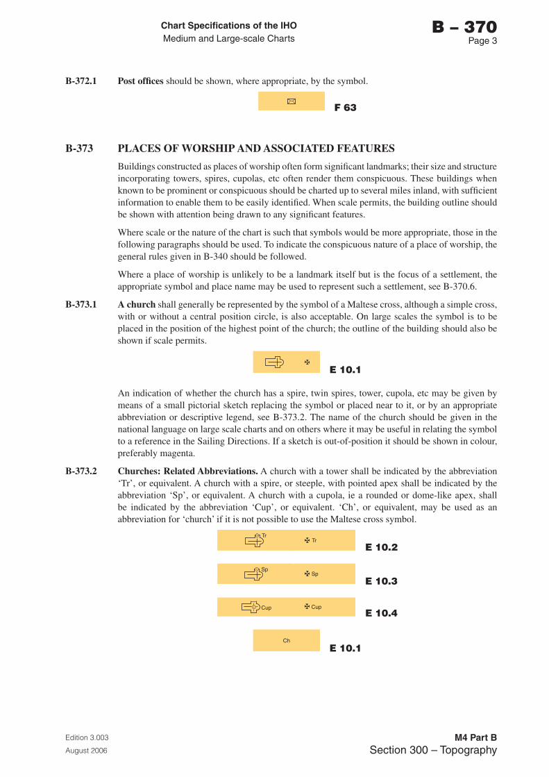
Chart Specifications of the IhoMedium and Large-scale Charts
Edition 3.003
August 2006
M4 Part BSection �00 – Topography
b – 370Page �
B-372.1 Post offices should be shown, where appropriate, by the symbol.
F 63
B-373 PLACES OF WORSHIP AND ASSOCIATED FEATURES
Buildings constructed as places of worship often form significant landmarks; their size and structure incorporating towers, spires, cupolas, etc often render them conspicuous. These buildings when known to be prominent or conspicuous should be charted up to several miles inland, with sufficient information to enable them to be easily identified. When scale permits, the building outline should be shown with attention being drawn to any significant features.
Where scale or the nature of the chart is such that symbols would be more appropriate, those in the following paragraphs should be used. To indicate the conspicuous nature of a place of worship, the general rules given in B-340 should be followed.
Where a place of worship is unlikely to be a landmark itself but is the focus of a settlement, the appropriate symbol and place name may be used to represent such a settlement, see B-370.6.
B-373.1 A church shall generally be represented by the symbol of a Maltese cross, although a simple cross, with or without a central position circle, is also acceptable. On large scales the symbol is to be placed in the position of the highest point of the church; the outline of the building should also be shown if scale permits.
E 10.1
An indication of whether the church has a spire, twin spires, tower, cupola, etc may be given by means of a small pictorial sketch replacing the symbol or placed near to it, or by an appropriate abbreviation or descriptive legend, see B-373.2. The name of the church should be given in the national language on large scale charts and on others where it may be useful in relating the symbol to a reference in the Sailing Directions. If a sketch is out-of-position it should be shown in colour, preferably magenta.
B-373.2 Churches: Related Abbreviations. A church with a tower shall be indicated by the abbreviation ‘Tr’, or equivalent. A church with a spire, or steeple, with pointed apex shall be indicated by the abbreviation ‘Sp’, or equivalent. A church with a cupola, ie a rounded or dome-like apex, shall be indicated by the abbreviation ‘Cup’, or equivalent. ‘Ch’, or equivalent, may be used as an abbreviation for ‘church’ if it is not possible to use the Maltese cross symbol.
E 10.2
E 10.3
E 10.4
E 10.1
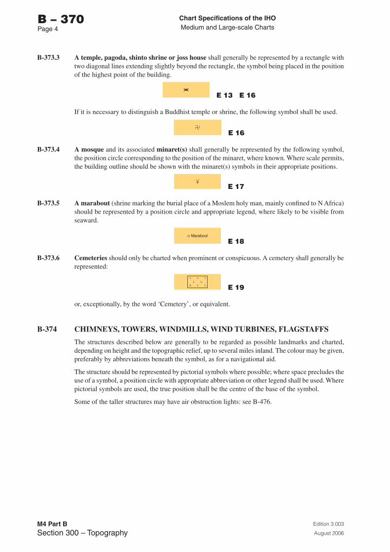
Chart Specifications of the IhoMedium and Large-scale Charts
Edition 3.003
August 2006
M4 Part BSection �00 – Topography
b – 370Page �
B-373.3 A temple, pagoda, shinto shrine or joss house shall generally be represented by a rectangle with two diagonal lines extending slightly beyond the rectangle, the symbol being placed in the position of the highest point of the building.
E 13 E 16
If it is necessary to distinguish a Buddhist temple or shrine, the following symbol shall be used.
E 16
B-373.4 A mosque and its associated minaret(s) shall generally be represented by the following symbol, the position circle corresponding to the position of the minaret, where known. Where scale permits, the building outline should be shown with the minaret(s) symbols in their appropriate positions.
E 17
B-373.5 A marabout (shrine marking the burial place of a Moslem holy man, mainly confined to N Africa) should be represented by a position circle and appropriate legend, where likely to be visible from seaward.
E 18
B-373.6 Cemeteries should only be charted when prominent or conspicuous. A cemetery shall generally be represented:
E 19
or, exceptionally, by the word ‘Cemetery’, or equivalent.
B-374 CHIMNEYS, TOWERS, WINDMILLS, WIND TURBINES, FLAGSTAFFS
The structures described below are generally to be regarded as possible landmarks and charted, depending on height and the topographic relief, up to several miles inland. The colour may be given, preferably by abbreviations beneath the symbol, as for a navigational aid.
The structure should be represented by pictorial symbols where possible; where space precludes the use of a symbol, a position circle with appropriate abbreviation or other legend shall be used. Where pictorial symbols are used, the true position shall be the centre of the base of the symbol.
Some of the taller structures may have air obstruction lights: see B-476.
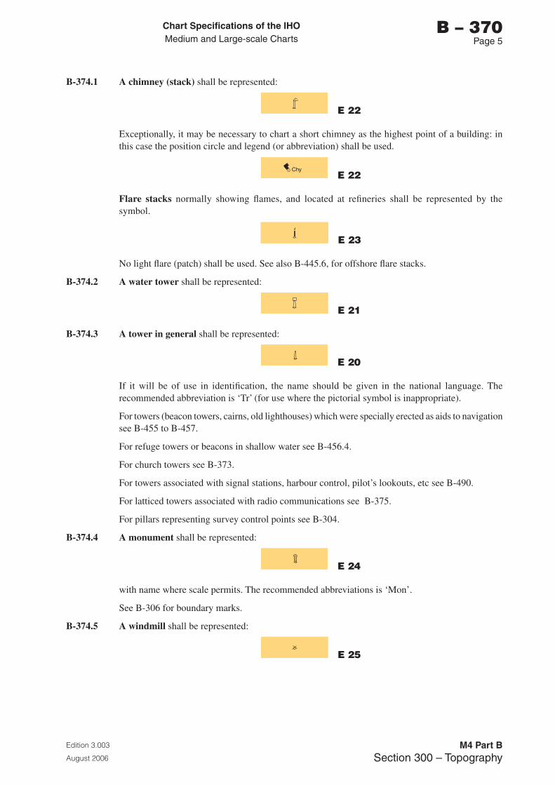
Chart Specifications of the IhoMedium and Large-scale Charts
Edition 3.003
August 2006
M4 Part BSection �00 – Topography
b – 370Page 5
B-374.1 A chimney (stack) shall be represented:
E 22
Exceptionally, it may be necessary to chart a short chimney as the highest point of a building: in this case the position circle and legend (or abbreviation) shall be used.
E 22
Flare stacks normally showing flames, and located at refineries shall be represented by the symbol.
E 23
No light flare (patch) shall be used. See also B-445.6, for offshore flare stacks.
B-374.2 A water tower shall be represented:
E 21
B-374.3 A tower in general shall be represented:
E 20
If it will be of use in identification, the name should be given in the national language. The recommended abbreviation is ‘Tr’ (for use where the pictorial symbol is inappropriate).
For towers (beacon towers, cairns, old lighthouses) which were specially erected as aids to navigation see B-455 to B-457.
For refuge towers or beacons in shallow water see B-456.4.
For church towers see B-373.
For towers associated with signal stations, harbour control, pilot’s lookouts, etc see B-490.
For latticed towers associated with radio communications see B-375.
For pillars representing survey control points see B-304.
B-374.4 A monument shall be represented:
E 24
with name where scale permits. The recommended abbreviations is ‘Mon’.
See B-306 for boundary marks.
B-374.5 A windmill shall be represented:
E 25
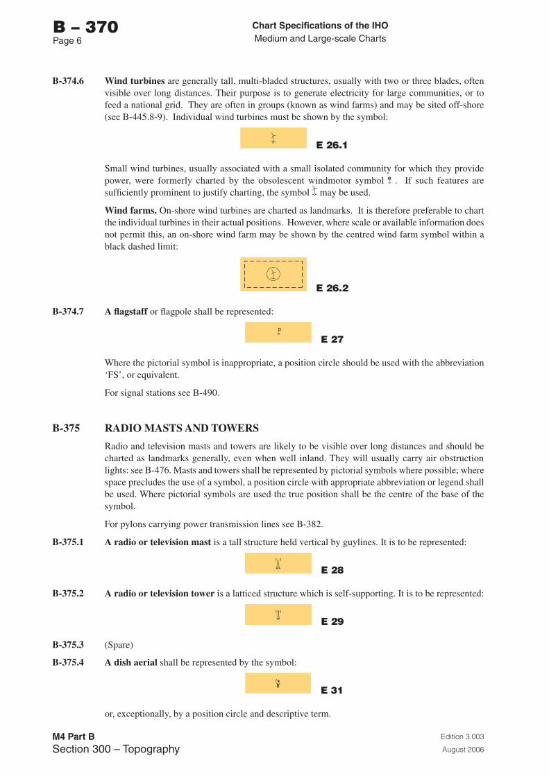
Chart Specifications of the IhoMedium and Large-scale Charts
Edition 3.003
August 2006
M4 Part BSection �00 – Topography
b – 370Page 6
B-374.6 Wind turbines are generally tall, multi-bladed structures, usually with two or three blades, often visible over long distances. Their purpose is to generate electricity for large communities, or to feed a national grid. They are often in groups (known as wind farms) and may be sited off-shore (see B-445.8-9). Individual wind turbines must be shown by the symbol:
E 26.1
Small wind turbines, usually associated with a small isolated community for which they provide power, were formerly charted by the obsolescent windmotor symbol . If such features are sufficiently prominent to justify charting, the symbol may be used.
Wind farms. On-shore wind turbines are charted as landmarks. It is therefore preferable to chart the individual turbines in their actual positions. However, where scale or available information does not permit this, an on-shore wind farm may be shown by the centred wind farm symbol within a black dashed limit:
E 26.2
B-374.7 A flagstaff or flagpole shall be represented:
E 27
Where the pictorial symbol is inappropriate, a position circle should be used with the abbreviation ‘FS’, or equivalent.
For signal stations see B-490.
B-375 RADIO MASTS AND TOWERS
Radio and television masts and towers are likely to be visible over long distances and should be charted as landmarks generally, even when well inland. They will usually carry air obstruction lights: see B-476. Masts and towers shall be represented by pictorial symbols where possible; where space precludes the use of a symbol, a position circle with appropriate abbreviation or legend shall be used. Where pictorial symbols are used the true position shall be the centre of the base of the symbol.
For pylons carrying power transmission lines see B-382.
B-375.1 A radio or television mast is a tall structure held vertical by guylines. It is to be represented:
E 28
B-375.2 A radio or television tower is a latticed structure which is self-supporting. It is to be represented:
E 29
B-375.3 (Spare)
B-375.4 A dish aerial shall be represented by the symbol:
E 31
or, exceptionally, by a position circle and descriptive term.
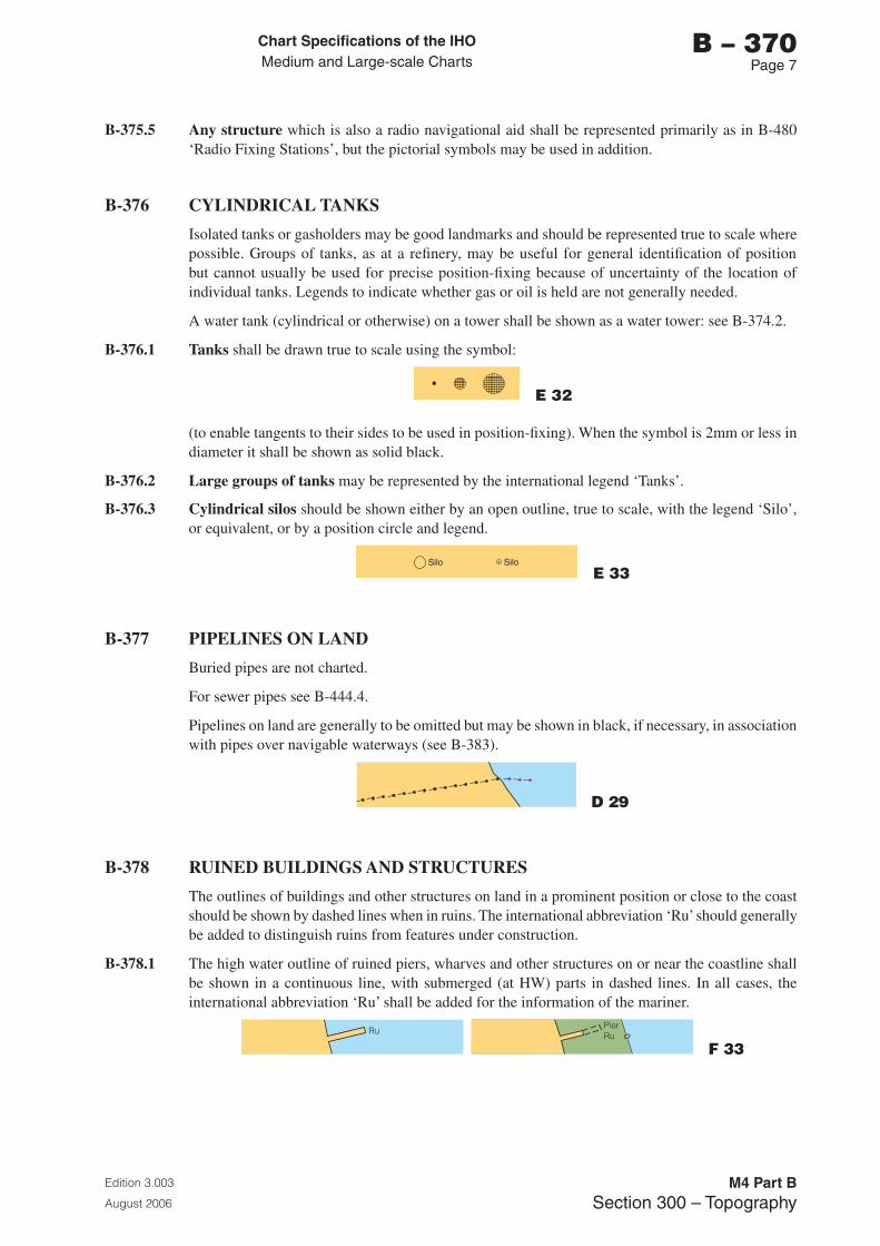
Chart Specifications of the IhoMedium and Large-scale Charts
Edition 3.003
August 2006
M4 Part BSection �00 – Topography
b – 370Page �
B-375.5 Any structure which is also a radio navigational aid shall be represented primarily as in B-480 ‘Radio Fixing Stations’, but the pictorial symbols may be used in addition.
B-376 CYLINDRICAL TANKS
Isolated tanks or gasholders may be good landmarks and should be represented true to scale where possible. Groups of tanks, as at a refinery, may be useful for general identification of position but cannot usually be used for precise position-fixing because of uncertainty of the location of individual tanks. Legends to indicate whether gas or oil is held are not generally needed.
A water tank (cylindrical or otherwise) on a tower shall be shown as a water tower: see B-374.2.
B-376.1 Tanks shall be drawn true to scale using the symbol:
E 32
(to enable tangents to their sides to be used in position-fixing). When the symbol is 2mm or less in diameter it shall be shown as solid black.
B-376.2 Large groups of tanks may be represented by the international legend ‘Tanks’.
B-376.3 Cylindrical silos should be shown either by an open outline, true to scale, with the legend ‘Silo’, or equivalent, or by a position circle and legend.
E 33
B-377 PIPELINES ON LAND
Buried pipes are not charted.
For sewer pipes see B-444.4.
Pipelines on land are generally to be omitted but may be shown in black, if necessary, in association with pipes over navigable waterways (see B-383).
D 29
B-378 RUINED BUILDINGS AND STRUCTURES
The outlines of buildings and other structures on land in a prominent position or close to the coast should be shown by dashed lines when in ruins. The international abbreviation ‘Ru’ should generally be added to distinguish ruins from features under construction.
B-378.1 The high water outline of ruined piers, wharves and other structures on or near the coastline shall be shown in a continuous line, with submerged (at HW) parts in dashed lines. In all cases, the international abbreviation ‘Ru’ shall be added for the information of the mariner.
F 33
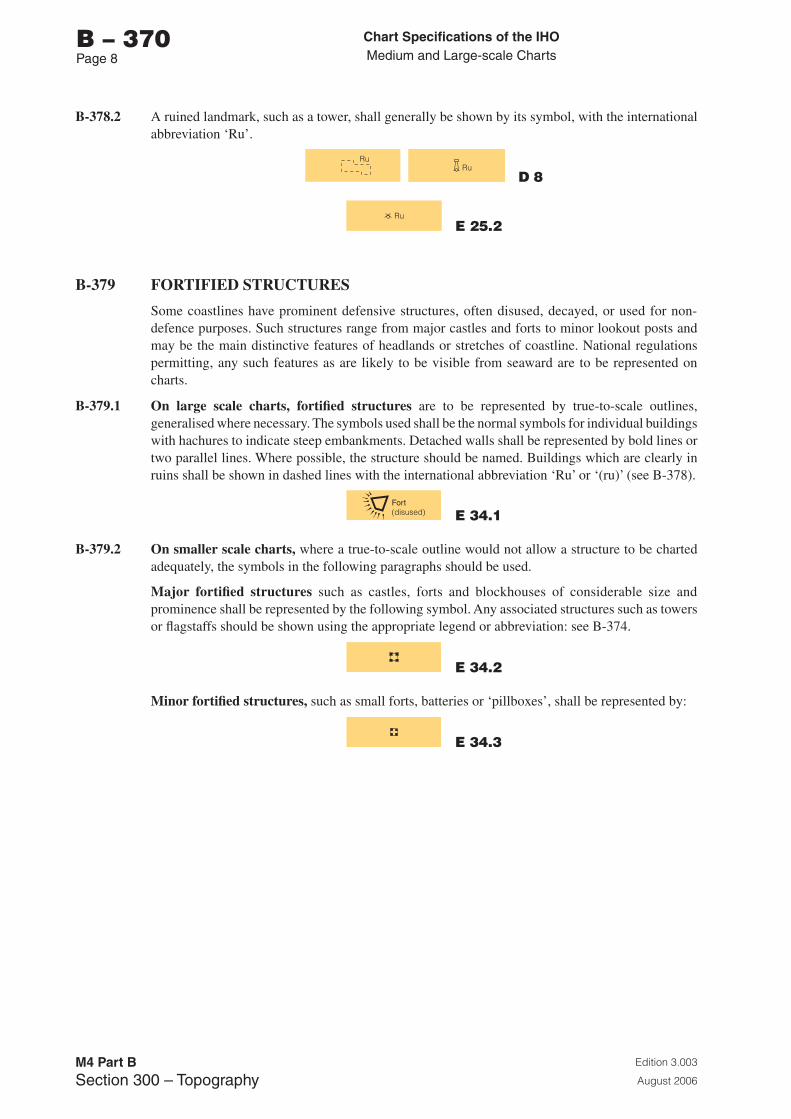
Chart Specifications of the IhoMedium and Large-scale Charts
Edition 3.003
August 2006
M4 Part BSection �00 – Topography
b – 370Page �
B-378.2 A ruined landmark, such as a tower, shall generally be shown by its symbol, with the international abbreviation ‘Ru’.
D 8
E 25.2
B-379 FORTIFIED STRUCTURES
Some coastlines have prominent defensive structures, often disused, decayed, or used for non-defence purposes. Such structures range from major castles and forts to minor lookout posts and may be the main distinctive features of headlands or stretches of coastline. National regulations permitting, any such features as are likely to be visible from seaward are to be represented on charts.
B-379.1 On large scale charts, fortified structures are to be represented by true-to-scale outlines, generalised where necessary. The symbols used shall be the normal symbols for individual buildings with hachures to indicate steep embankments. Detached walls shall be represented by bold lines or two parallel lines. Where possible, the structure should be named. Buildings which are clearly in ruins shall be shown in dashed lines with the international abbreviation ‘Ru’ or ‘(ru)’ (see B-378).
E 34.1
B-379.2 On smaller scale charts, where a true-to-scale outline would not allow a structure to be charted adequately, the symbols in the following paragraphs should be used.
Major fortified structures such as castles, forts and blockhouses of considerable size and prominence shall be represented by the following symbol. Any associated structures such as towers or flagstaffs should be shown using the appropriate legend or abbreviation: see B-374.
E 34.2
Minor fortified structures, such as small forts, batteries or ‘pillboxes’, shall be represented by:
E 34.3
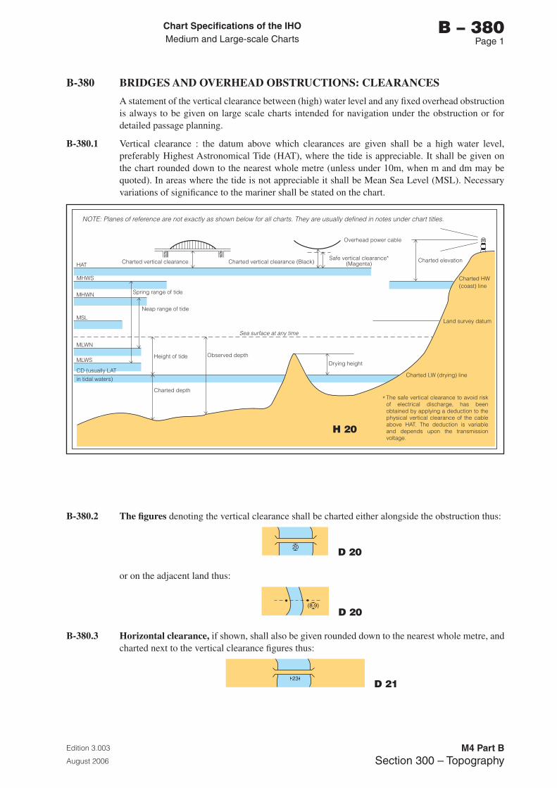
Chart Specifications of the IhoMedium and Large-scale Charts
Edition 3.003
August 2006
M4 Part BSection �00 – Topography
b – 380Page 1
B-380 BRIDGES AND OVERHEAD OBSTRUCTIONS: CLEARANCES
A statement of the vertical clearance between (high) water level and any fixed overhead obstruction is always to be given on large scale charts intended for navigation under the obstruction or for detailed passage planning.
B-380.1 Vertical clearance : the datum above which clearances are given shall be a high water level, preferably Highest Astronomical Tide (HAT), where the tide is appreciable. It shall be given on the chart rounded down to the nearest whole metre (unless under 10m, when m and dm may be quoted). In areas where the tide is not appreciable it shall be Mean Sea Level (MSL). Necessary variations of significance to the mariner shall be stated on the chart.
HAT
MHWS
MHWN
MSL
MLWN
MLWS
CD (usually LATin tidal waters)
Spring range of tide
Charted vertical clearance Charted vertical clearance (Black)Safe vertical clearance*
(Magenta)
Overhead power cable
Charted elevation
Charted HW(coast) line
Charted LW (drying) line
Neap range of tide
Height of tideDrying height
Land survey datum
Charted depth
Observed depth
Sea surface at any time
*
NOTE: Planes of reference are not exactly as shown below for all charts. They are usually defined in notes under chart titles.
The safe vertical clearance to avoid risk of electrical discharge, has been obtained by applying a deduction to the physical vertical clearance of the cable above HAT. The deduction is variable and depends upon the transmission voltage.
B-380.2 The figures denoting the vertical clearance shall be charted either alongside the obstruction thus:
D 20
or on the adjacent land thus:
D 20
B-380.3 Horizontal clearance, if shown, shall also be given rounded down to the nearest whole metre, and charted next to the vertical clearance figures thus:
D 21
H 20
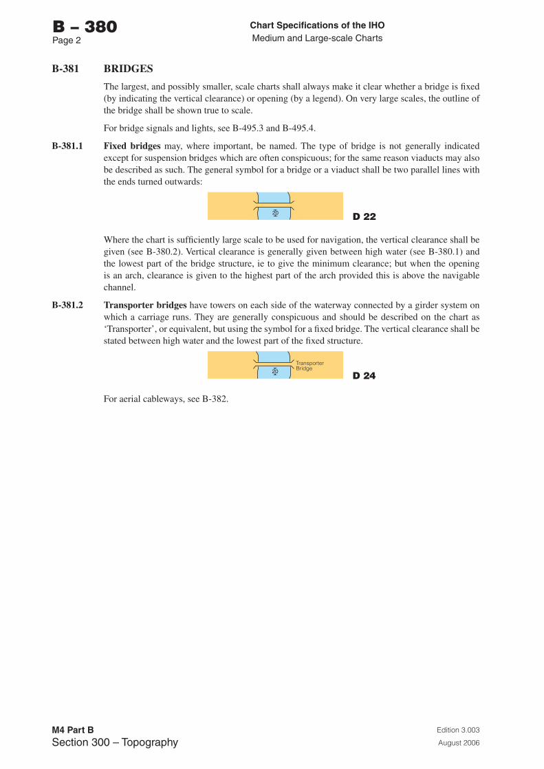
Chart Specifications of the IhoMedium and Large-scale Charts
Edition 3.003
August 2006
M4 Part BSection �00 – Topography
b – 380Page 2
B-381 BRIDGES
The largest, and possibly smaller, scale charts shall always make it clear whether a bridge is fixed (by indicating the vertical clearance) or opening (by a legend). On very large scales, the outline of the bridge shall be shown true to scale.
For bridge signals and lights, see B-495.3 and B-495.4.
B-381.1 Fixed bridges may, where important, be named. The type of bridge is not generally indicated except for suspension bridges which are often conspicuous; for the same reason viaducts may also be described as such. The general symbol for a bridge or a viaduct shall be two parallel lines with the ends turned outwards:
D 22
Where the chart is sufficiently large scale to be used for navigation, the vertical clearance shall be given (see B-380.2). Vertical clearance is generally given between high water (see B-380.1) and the lowest part of the bridge structure, ie to give the minimum clearance; but when the opening is an arch, clearance is given to the highest part of the arch provided this is above the navigable channel.
B-381.2 Transporter bridges have towers on each side of the waterway connected by a girder system on which a carriage runs. They are generally conspicuous and should be described on the chart as ‘Transporter’, or equivalent, but using the symbol for a fixed bridge. The vertical clearance shall be stated between high water and the lowest part of the fixed structure.
D 24
For aerial cableways, see B-382.
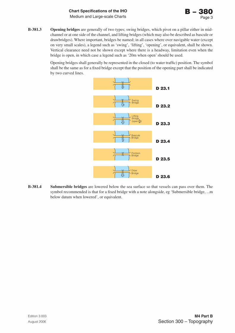
Chart Specifications of the IhoMedium and Large-scale Charts
Edition 3.003
August 2006
M4 Part BSection �00 – Topography
b – 380Page �
B-381.3 Opening bridges are generally of two types; swing bridges, which pivot on a pillar either in mid-channel or at one side of the channel, and lifting bridges (which may also be described as bascule or drawbridges). Where important, bridges be named; in all cases where over navigable water (except on very small scales), a legend such as ‘swing’, ‘lifting’, ‘opening’, or equivalent, shall be shown. Vertical clearance need not be shown except where there is a headway, limitation even when the bridge is open, in which case a legend such as ‘20m when open’ should be used.
Opening bridges shall generally be represented in the closed (to water traffic) position. The symbol shall be the same as for a fixed bridge except that the position of the opening part shall be indicated by two curved lines.
D 23.1
D 23.2
D 23.3
D 23.4
D 23.5
D 23.6
B-381.4 Submersible bridges are lowered below the sea surface so that vessels can pass over them. The symbol recommended is that for a fixed bridge with a note alongside, eg ‘Submersible bridge, ...m below datum when lowered’, or equivalent.
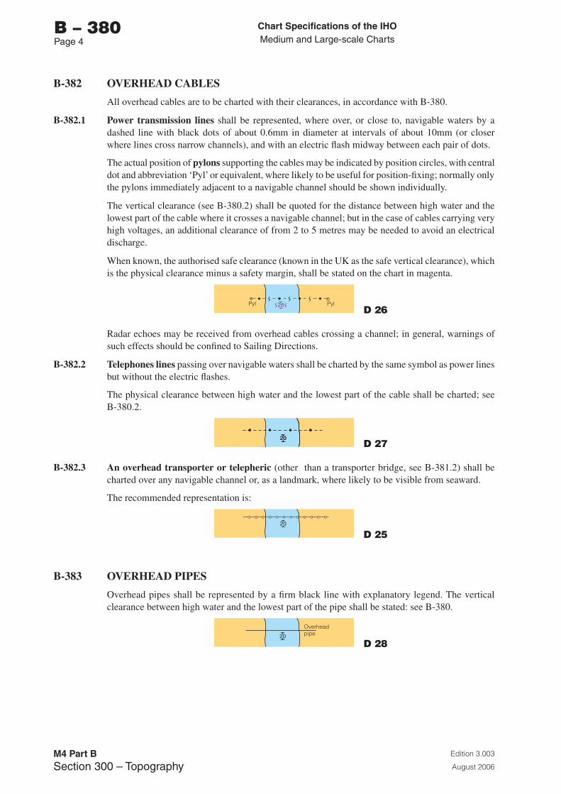
Chart Specifications of the IhoMedium and Large-scale Charts
Edition 3.003
August 2006
M4 Part BSection �00 – Topography
b – 380Page �
B-382 OVERHEAD CABLES
All overhead cables are to be charted with their clearances, in accordance with B-380.
B-382.1 Power transmission lines shall be represented, where over, or close to, navigable waters by a dashed line with black dots of about 0.6mm in diameter at intervals of about 10mm (or closer where lines cross narrow channels), and with an electric flash midway between each pair of dots.
The actual position of pylons supporting the cables may be indicated by position circles, with central dot and abbreviation ‘Pyl’ or equivalent, where likely to be useful for position-fixing; normally only the pylons immediately adjacent to a navigable channel should be shown individually.
The vertical clearance (see B-380.2) shall be quoted for the distance between high water and the lowest part of the cable where it crosses a navigable channel; but in the case of cables carrying very high voltages, an additional clearance of from 2 to 5 metres may be needed to avoid an electrical discharge.
When known, the authorised safe clearance (known in the UK as the safe vertical clearance), which is the physical clearance minus a safety margin, shall be stated on the chart in magenta.
D 26
Radar echoes may be received from overhead cables crossing a channel; in general, warnings of such effects should be confined to Sailing Directions.
B-382.2 Telephones lines passing over navigable waters shall be charted by the same symbol as power lines but without the electric flashes.
The physical clearance between high water and the lowest part of the cable shall be charted; see B-380.2.
D 27
B-382.3 An overhead transporter or telepheric (other than a transporter bridge, see B-381.2) shall be charted over any navigable channel or, as a landmark, where likely to be visible from seaward.
The recommended representation is:
D 25
B-383 OVERHEAD PIPES
Overhead pipes shall be represented by a firm black line with explanatory legend. The vertical clearance between high water and the lowest part of the pipe shall be stated: see B-380.
D 28
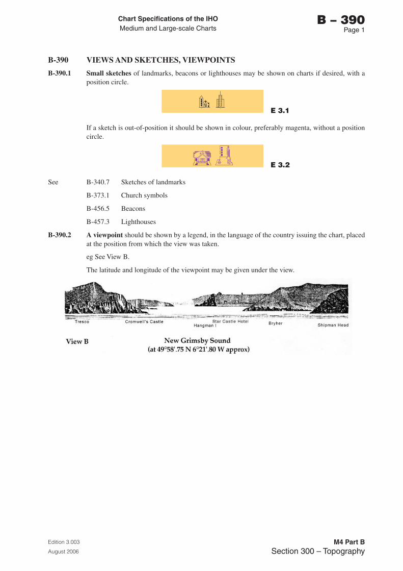
Chart Specifications of the IhoMedium and Large-scale Charts
Edition 3.003
August 2006
M4 Part BSection �00 – Topography
b – 390Page 1
B-390 VIEWS AND SKETCHES, VIEWPOINTS
B-390.1 Small sketches of landmarks, beacons or lighthouses may be shown on charts if desired, with a position circle.
E 3.1
If a sketch is out-of-position it should be shown in colour, preferably magenta, without a position circle.
E 3.2
See B-340.7 Sketches of landmarks
B-373.1 Church symbols
B-456.5 Beacons
B-457.3 Lighthouses
B-390.2 A viewpoint should be shown by a legend, in the language of the country issuing the chart, placed at the position from which the view was taken.
eg See View B.
The latitude and longitude of the viewpoint may be given under the view.

Page intentionally left blank
Chart Specifications of the IhoMedium and Large-scale Charts
Edition 3.003
August 2006
M4 Part BSection �00 – Hydrography and Navigational Aids
b – 400Page i
PART b
SECTION 400
HYDROGRAPHY AND NAVIGATIONAL AIDS

Page intentionally left blank
Chart Specifications of the IhoMedium and Large-scale Charts
Edition 3.003
August 2006
M4 Part BSection �00 – Hydrography and Navigational Aids
b – 400Page iii
SECTION 400 - HYDROGRAPHY AND NAVIGATIONAL AIDS
CONTENTS
RECORD OF UPDATES
B-400 HYDROGRAPHY AND NAVIGATIONAL AIDSB-401 LEVELS OF DETAIL CHARTEDB-402 PARTIAL DEPICTION OF DETAILS: PRINCIPLESB-403 GENERALIZATIONB-404 MINIMAL DEPICTION OF DETAILB-405 CHART DATUMB-406 TIDAL LEVELSB-407 TIDAL STREAMSB-408 CURRENTS (NON-TIDAL)
B-410 REPRESENTATION OF DEPTH: GENERALB-411 DEPTH CONTOURS AND SHALLOW WATER TINTB-412 SOUNDINGSB-413 INTERTIDAL AREAS: DRYING HEIGHTS, TINT, WATERCOURSEB-414 DREDGED AREASB-415 SWEPT DEPTHS AND AREAS; AREAS INVESTIGATED FOR DEEP DRAUGHT VESSELSB-416 AREAS OF CONTINUAL CHANGEB-417 AREAS WITH INADEQUATE DEPTH INFORMATIONB-418 UNSURVEYED AREAS
B-420 DANGERS: GENERAL, DANGER LINEB-421 ROCKS, ROCKY AREAS AND CORAL REEFSB-422 WRECKS, FOUL GROUND, OBSTRUCTIONSB-423 WATER TURBULENCE: OVERFALLS, RACES, TIDE RIPS, BREAKERS, EDDIESB-424 DOUBTFUL DANGERSB-425 NATURE OF THE SEABED: GENERALB-426 NATURE OF THE SEABED: INTERTIDAL AREASB-427 NATURE OF THE SEABED: OUTSIDE THE LOW WATER LINEB-428 SPECIAL SEABED TYPES: SANDWAVES, KELP, SPRINGSB-429 OCEANIC FEATURES
B-430 HARBOURS: REGULATIONS WITHIN HARBOUR LIMITSB-431 HARBOURS: ANCHORAGES AND PROHIBITED ANCHORAGES; MOORINGSB-432 RECOMMENDED TRACKS AND ROUTES: GENERALB-433 LEADING AND CLEARING LINESB-434 RECOMMENDED TRACKSB-435 ROUTEING MEASURESB-436 BOUNDARIES OF ROUTEING MEASURESB-437 ENVIRONMENTALLY SENSITIVE SEA AREA (ESSA)B-438 FERRIESB-439 RESTRICTED AND NON-RESTRICTED AREAS
B-440 INTERNATIONAL BOUNDARIES AND NATIONAL LIMITSB-441 MILITARY PRACTICE AREAS; MINEFIELDSB-442 DUMPING GROUNDS GENERAL; HARMFUL MATERIALSB-443 SUBMARINE CABLESB-444 SUBMARINE PIPELINESB-445 OFFSHORE PRODUCTION FACILITIES
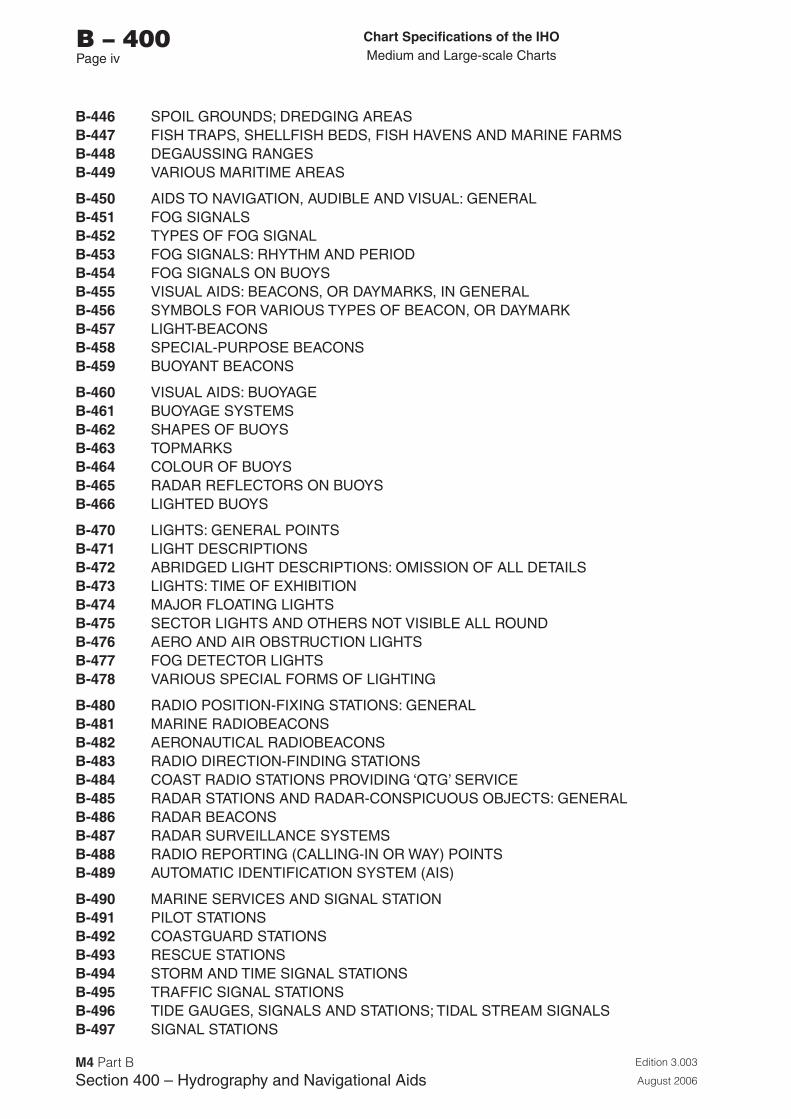
Chart Specifications of the IhoMedium and Large-scale Charts
Edition 3.003
August 2006
M4 Part BSection �00 – Hydrography and Navigational Aids
b – 400Page iv
B-446 SPOIL GROUNDS; DREDGING AREASB-447 FISH TRAPS, SHELLFISH BEDS, FISH HAVENS AND MARINE FARMSB-448 DEGAUSSING RANGESB-449 VARIOUS MARITIME AREAS
B-450 AIDS TO NAVIGATION, AUDIBLE AND VISUAL: GENERALB-451 FOG SIGNALSB-452 TYPES OF FOG SIGNALB-453 FOG SIGNALS: RHYTHM AND PERIODB-454 FOG SIGNALS ON BUOYSB-455 VISUAL AIDS: BEACONS, OR DAYMARKS, IN GENERALB-456 SYMBOLS FOR VARIOUS TYPES OF BEACON, OR DAYMARKB-457 LIGHT-BEACONSB-458 SPECIAL-PURPOSE BEACONSB-459 BUOYANT BEACONS
B-460 VISUAL AIDS: BUOYAGEB-461 BUOYAGE SYSTEMSB-462 SHAPES OF BUOYSB-463 TOPMARKSB-464 COLOUR OF BUOYSB-465 RADAR REFLECTORS ON BUOYSB-466 LIGHTED BUOYS
B-470 LIGHTS: GENERAL POINTSB-471 LIGHT DESCRIPTIONSB-472 ABRIDGED LIGHT DESCRIPTIONS: OMISSION OF ALL DETAILSB-473 LIGHTS: TIME OF EXHIBITIONB-474 MAJOR FLOATING LIGHTSB-475 SECTOR LIGHTS AND OTHERS NOT VISIBLE ALL ROUNDB-476 AERO AND AIR OBSTRUCTION LIGHTSB-477 FOG DETECTOR LIGHTSB-478 VARIOUS SPECIAL FORMS OF LIGHTING
B-480 RADIO POSITION-FIXING STATIONS: GENERALB-481 MARINE RADIOBEACONSB-482 AERONAUTICAL RADIOBEACONSB-483 RADIO DIRECTION-FINDING STATIONSB-484 COAST RADIO STATIONS PROVIDING ‘QTG’ SERVICEB-485 RADAR STATIONS AND RADAR-CONSPICUOUS OBJECTS: GENERALB-486 RADAR BEACONSB-487 RADAR SURVEILLANCE SYSTEMSB-488 RADIO REPORTING (CALLING-IN OR WAY) POINTSB-489 AUTOMATIC IDENTIFICATION SYSTEM (AIS)
B-490 MARINE SERVICES AND SIGNAL STATIONB-491 PILOT STATIONSB-492 COASTGUARD STATIONSB-493 RESCUE STATIONSB-494 STORM AND TIME SIGNAL STATIONSB-495 TRAFFIC SIGNAL STATIONSB-496 TIDE GAUGES, SIGNALS AND STATIONS; TIDAL STREAM SIGNALSB-497 SIGNAL STATIONS
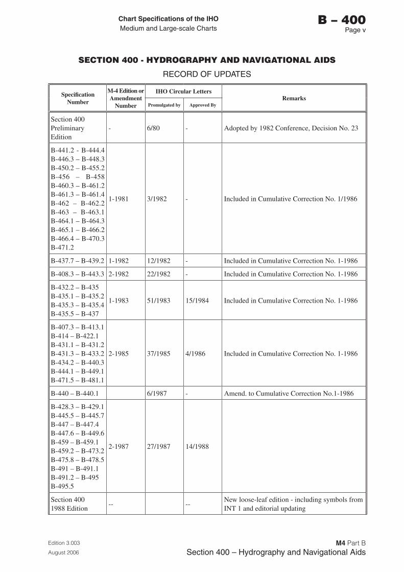
Chart Specifications of the IhoMedium and Large-scale Charts
Edition 3.003
August 2006
M4 Part BSection �00 – Hydrography and Navigational Aids
b – 400Page v
SECTION 400 - HYDROGRAPHY AND NAVIGATIONAL AIDS
RECORD OF UPDATES
Specification Number
M-4 Edition or Amendment
Number
IHO Circular LettersRemarks
Promulgated by Approved By
Section 400 Preliminary Edition
- 6/80 - Adopted by 1982 Conference, Decision No. 23
B-441.2 - B-444.4 B-446.3 – B-448.3 B-450.2 – B-455.2 B-456 – B-458 B-460.3 – B-461.2 B-461.3 – B-461.4 B-462 – B-462.2 B-463 – B-463.1 B-464.1 – B-464.3 B-465.1 – B-466.2 B-466.4 – B-470.3 B-471.2
1-1981 3/1982 - Included in Cumulative Correction No. 1/1986
B-437.7 – B-439.2 1-1982 12/1982 - Included in Cumulative Correction No. 1-1986
B-408.3 – B-443.3 2-1982 22/1982 - Included in Cumulative Correction No. 1-1986
B-432.2 – B-435 B-435.1 – B-435.2 B-435.3 – B-435.4 B-435.5 – B-437
1-1983 51/1983 15/1984 Included in Cumulative Correction No. 1-1986
B-407.3 – B-413.1 B-414 – B-422.1 B-431.1 – B-431.2 B-431.3 – B-433.2 B-434.2 – B-440.3 B-444.1 – B-449.1 B-471.5 – B-481.1
2-1985 37/1985 4/1986 Included in Cumulative Correction No. 1-1986
B-440 – B-440.1 6/1987 - Amend. to Cumulative Correction No.1-1986
B-428.3 – B-429.1 B-445.5 – B-445.7 B-447 – B-447.4 B-447.6 – B-449.6 B-459 – B-459.1 B-459.2 – B-473.2 B-475.8 – B-478.5 B-491 – B-491.1 B-491.2 – B-495 B-495.5
2-1987 27/1987 14/1988
Section 400 1988 Edition
-- --New loose-leaf edition - including symbols from INT 1 and editorial updating
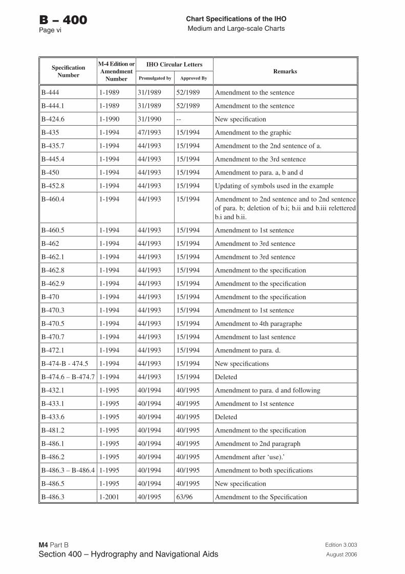
Chart Specifications of the IhoMedium and Large-scale Charts
Edition 3.003
August 2006
M4 Part BSection �00 – Hydrography and Navigational Aids
b – 400Page vi
Specification Number
M-4 Edition or Amendment
Number
IHO Circular LettersRemarks
Promulgated by Approved By
B-444 1-1989 31/1989 52/1989 Amendment to the sentence
B-444.1 1-1989 31/1989 52/1989 Amendment to the sentence
B-424.6 1-1990 31/1990 -- New specification
B-435 1-1994 47/1993 15/1994 Amendment to the graphic
B-435.7 1-1994 44/1993 15/1994 Amendment to the 2nd sentence of a.
B-445.4 1-1994 44/1993 15/1994 Amendment to the 3rd sentence
B-450 1-1994 44/1993 15/1994 Amendment to para. a, b and d
B-452.8 1-1994 44/1993 15/1994 Updating of symbols used in the example
B-460.4 1-1994 44/1993 15/1994 Amendment to 2nd sentence and to 2nd sentence of para. b; deletion of b.i; b.ii and b.iii relettered b.i and b.ii.
B-460.5 1-1994 44/1993 15/1994 Amendment to 1st sentence
B-462 1-1994 44/1993 15/1994 Amendment to 3rd sentence
B-462.1 1-1994 44/1993 15/1994 Amendment to 3rd sentence
B-462.8 1-1994 44/1993 15/1994 Amendment to the specification
B-462.9 1-1994 44/1993 15/1994 Amendment to the specification
B-470 1-1994 44/1993 15/1994 Amendment to the specification
B-470.3 1-1994 44/1993 15/1994 Amendment to 1st sentence
B-470.5 1-1994 44/1993 15/1994 Amendment to 4th paragraphe
B-470.7 1-1994 44/1993 15/1994 Amendment to last sentence
B-472.1 1-1994 44/1993 15/1994 Amendment to para. d.
B-474-B - 474.5 1-1994 44/1993 15/1994 New specifications
B-474.6 – B-474.7 1-1994 44/1993 15/1994 Deleted
B-432.1 1-1995 40/1994 40/1995 Amendment to para. d and following
B-433.1 1-1995 40/1994 40/1995 Amendment to 1st sentence
B-433.6 1-1995 40/1994 40/1995 Deleted
B-481.2 1-1995 40/1994 40/1995 Amendment to the specification
B-486.1 1-1995 40/1994 40/1995 Amendment to 2nd paragraph
B-486.2 1-1995 40/1994 40/1995 Amendment after ‘use).’
B-486.3 – B-486.4 1-1995 40/1994 40/1995 Amendment to both specifications
B-486.5 1-1995 40/1994 40/1995 New specification
B-486.3 1-2001 40/1995 63/96 Amendment to the Specification
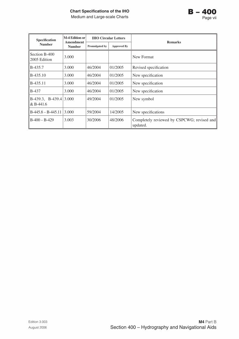
Chart Specifications of the IhoMedium and Large-scale Charts
Edition 3.003
August 2006
M4 Part BSection �00 – Hydrography and Navigational Aids
b – 400Page vii
Specification Number
M-4 Edition or Amendment
Number
IHO Circular LettersRemarks
Promulgated by Approved By
Section B-400 2005 Edition
3.000 New Format
B-435.7 3.000 46/2004 01/2005 Revised specification
B-435.10 3.000 46/2004 01/2005 New specification
B-435.11 3.000 46/2004 01/2005 New specification
B-437 3.000 46/2004 01/2005 New specification
B-439.3, B-439.4 & B-441.6
3.000 49/2004 01/2005 New symbol
B-445.8 – B-445.11 3.000 59/2004 14/2005 New specifications
B-400 – B-429 3.003 30/2006 48/2006 Completely reviewed by CSPCWG; revised and updated.

Page intentionally left blank
Chart Specifications of the IhoMedium and Large-scale Charts
Edition 3.003
August 2006
M4 Part BSection �00 – Hydrography and Navigational Aids
b – 400Page 1
SECTION 400
HYDROGRAPHY AND NAVIGATIONAL AIDS
B-400 HYDROGRAPHY AND NAVIGATIONAL AIDS
This section covers the essential marine features of charts, including all navigational aids, whether on land or sea. Intertidal areas are also included. For landmarks useful to navigation but not expressly established for navigational purposes and for coastline features, see section B-300.
B-401 LEVELS OF DETAIL CHARTED
B-401.1 Full depiction of detail is naturally the cartographer’s aim on the largest scale charts. Strictly, it is impossible because all features are symbolized to an extent which is partly determined by scale and partly by the conventions of charting practice. However, over the greater part of any chart the aim is to include everything essential for safe navigation and this is described as ‘full depiction’. Most of the specifications, from B-405 onwards, deal with full depiction of hydrographic features, except where stated otherwise.
B-401.2 Generalization of detail is the elimination of the least essential information by ‘smoothing’ line symbols, omitting the less significant soundings, simplifying the descriptions of navigational aids, and so on, while still showing as much relevant information as space permits. It is particularly important in the coastal zone on smaller scale charts. See also B-402 and B-403.
B-401.3 Minimal depiction of detail is an extreme case of generalization where most features are omitted even though there is space to show at least some of them. It is most frequently used for semi-enclosed areas such as estuaries and harbours on smaller scale charts, where use of a larger scale chart is essential for all sizes of vessels. See also B-402 and B-404.
B-402 PARTIAL DEPICTION OF DETAILS: PRINCIPLES
B-402.1 The purpose of generalization is primarily to avoid over-crowding charts where space is very limited. It also serves to reduce the maintenance needed and to induce navigators, at least of deeper draught vessels, to use larger scale charts. For generalization of depths see B-403.1
B-402.2 The purpose of minimal depiction is to eliminate almost all maintenance by retaining only the coastline and generalized depth contours and tints, showing the mariner a ‘diagrammatic’ picture of the length and orientation of channels. This minimal depiction is preferable to leaving areas entirely blank. For a further description see B-404.
Chart Specifications of the IhoMedium and Large-scale Charts
Edition 3.003
August 2006
M4 Part BSection �00 – Hydrography and Navigational Aids
b – 400Page 2
B-402.3 The possible risks of omitting detail must be foreseen and avoided by the cartographer, who must study the Sailing Directions and other relevant publications to understand the use made of particular routes and harbours. Some of the possibilities which must be taken into account are:
a. Mariners are not always able to take their intended routes and may have to make for a harbour of refuge or use an alternative passage.
b. Minor navigational aids which would be omitted from an area immediately adjacent to a main channel may have to be charted to prevent confusion in recognizing navigational aids in the main channel.
c. Too radical an elimination of detail could deprive the mariner of the overall picture of an area, such as an indication of the routes used by local traffic, which could be a hazard.
d. The use of smaller scale charts for route planning must be considered; it would be inconvenient for a ‘non-navigating’ user (such as a marine superintendent) to have to refer to many of the larger scale charts when planning a passage.
e (I).Where the second scale national chart is also the largest scale international chart, it must contain sufficient information so that it may be used as a first scale chart for international shipping (see M-11 Part A 2.3).
B-402.4(I) On international charts, printer nations may use partial depiction to reduce maintenance by omitting some detail from the producer’s versions. For example, channels used only by local vessels either because of their limited depth or the fact that they do not lead to a port of international interest, may require extensive maintenance yet be of virtually no value to international traffic on printer nations’ versions.
When a printer nation reproduces a producer nation’s largest scale chart, it will naturally be the printer who is likely to be able to omit certain details without affecting the particular users of that version of the chart, the omissions being from areas of local interest only.
B-402.5(I) Conversely, when a printer nation reproduces the second scale of the producer’s series (without reproducing the largest scale), the printer is unlikely to be able to omit any detail and may conceivably need to add some information by selection from the producer’s largest scale. However, printers should not add detail to a second scale international chart in order to avoid adopting the larger scale chart, where the larger scale chart has been agreed as a necessary part of the international scheme. Producers should bear this aspect in mind in applying partial depiction techniques to second and small scale international charts (see B-402.3e).
B-402.6(I) An alternative to partial depiction on international charts is for the printer nation to reproduce the producer’s chart in full detail, but to indicate that certain areas are of minor interest, and will not be updated by the printer’s Notices to Mariners. This method will be most useful in changeable areas where the producer is likely to publish fairly frequent new editions, making extensive amendment to the repromat by the printer, on each occasion, particularly wasteful. Such areas should be designated by means of a boxed cautionary note. In complicated cases, it may be necessary for the printer to insert a bold magenta line around the areas which are not maintained (between the publication of new editions); a cautionary note should be used to explain the line.
B-403 GENERALIZATION
Guidance on the generalization of specific features is included in many of these chart specifications. General guidance is more easily learned from the study of charts than from written descriptions, but, to demonstrate the need for very careful attention to be paid to this subject, the following paragraph deals with some of the problems of generalizing the most important charted feature: depth.
Chart Specifications of the IhoMedium and Large-scale Charts
Edition 3.003
August 2006
M4 Part BSection �00 – Hydrography and Navigational Aids
b – 400Page �
B-403.1 Generalization of depth portrayal (see also B-410). When a survey or chart is reduced in scale the generalization that is required has several effects:
a. Deeper soundings tend to be eliminated while the shoaler ones are retained for safety. Sufficient numbers of deeper soundings should be retained to show the full range of depth. This is to assist the navigator who uses his echo sounder to help verify his position, or the mariner choosing an anchorage of suitable depth.
b. Generalization proceeds by the inclusion of shoals lying to seaward of the principal contour, and by the smoothing of severely indented contours, with the effect of pushing the contours seaward. However, as a shoal which rises steeply from deep water is much more of a hazard than one which rises gradually, the cartographer must ensure that the contours are not pushed seaward unduly. If he gives the impression that a mariner will get warning of too close an approach to the danger, by relying on his echo sounder to show gradually shoaling depth - when the danger is, in fact ‘steep-to’ - he may seriously mislead and endanger the chart user.
c. With the ‘expansion’ of shoals, described above, it may become increasingly difficult to find space on a chart to show the line of deepest soundings through a channel, or even to show a channel at all. Yet even at small scales it is important to show the usable channels and indicate their least depth. The cartographer may have to make greater use of depth contours than soundings in depicting narrow channels.
d. Even such dangers as drying rocks and islets require generalization in coastal areas. This is in recognition of the principle that, whereas they are particularly dangerous in isolation and must then be shown as precisely as possible, where they occur in groups a selection of representative symbols is permissible, showing the outermost ones as individually as space permits.
B-404 MINIMAL DEPICTION OF DETAIL
B-404.1 The limit of minimal depiction of detail should ideally be a natural line, eg the entrance to a semi-enclosed harbour, the outer edge of an archipelago of islets, or where the open sea gives way to the mouth of an estuary encumbered by sandbanks. Along such lines there is a more or less abrupt change in character of navigation, frequently coinciding with the location of pilotage boarding places.
Occasionally the use of a completely arbitrary line (generally the limit of a larger scale chart) may be justified by special circumstances, eg for an area covered by a large scale inset plan on the same chart. In general, though, the overall picture needed for an appraisal of all the factors involved in planning passages can only be properly shown when the cartographer adheres to natural ‘boundaries’.
In some cases, it may be advisable to omit all soundings, including wrecks, inshore of a particular depth contour. It may be necessary to insert a cautionary note on the chart to the effect that it must not be used for navigation in depth of less than a stated figure, although in most cases the areas of minimal depiction will be obvious.
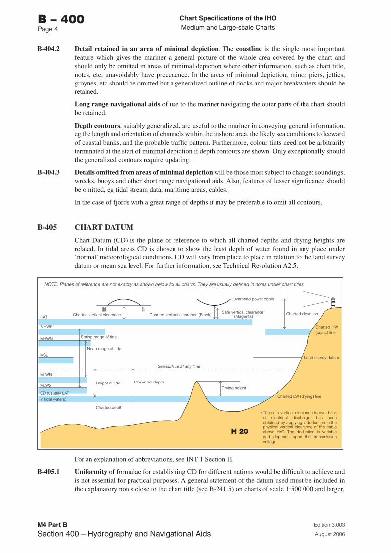
Chart Specifications of the IhoMedium and Large-scale Charts
Edition 3.003
August 2006
M4 Part BSection �00 – Hydrography and Navigational Aids
b – 400Page �
B-404.2 Detail retained in an area of minimal depiction. The coastline is the single most important feature which gives the mariner a general picture of the whole area covered by the chart and should only be omitted in areas of minimal depiction where other information, such as chart title, notes, etc, unavoidably have precedence. In the areas of minimal depiction, minor piers, jetties, groynes, etc should be omitted but a generalized outline of docks and major breakwaters should be retained.
Long range navigational aids of use to the mariner navigating the outer parts of the chart should be retained.
Depth contours, suitably generalized, are useful to the mariner in conveying general information, eg the length and orientation of channels within the inshore area, the likely sea conditions to leeward of coastal banks, and the probable traffic pattern. Furthermore, colour tints need not be arbitrarily terminated at the start of minimal depiction if depth contours are shown. Only exceptionally should the generalized contours require updating.
B-404.3 Details omitted from areas of minimal depiction will be those most subject to change: soundings, wrecks, buoys and other short range navigational aids. Also, features of lesser significance should be omitted, eg tidal stream data, maritime areas, cables.
In the case of fjords with a great range of depths it may be preferable to omit all contours.
B-405 CHART DATUM
Chart Datum (CD) is the plane of reference to which all charted depths and drying heights are related. In tidal areas CD is chosen to show the least depth of water found in any place under ‘normal’ meteorological conditions. CD will vary from place to place in relation to the land survey datum or mean sea level. For further information, see Technical Resolution A2.5.
HAT
MHWS
MHWN
MSL
MLWN
MLWS
CD (usually LATin tidal waters)
Spring range of tide
Charted vertical clearance Charted vertical clearance (Black)Safe vertical clearance*
(Magenta)
Overhead power cable
Charted elevation
Charted HW(coast) line
Charted LW (drying) line
Neap range of tide
Height of tideDrying height
Land survey datum
Charted depth
Observed depth
Sea surface at any time
*
NOTE: Planes of reference are not exactly as shown below for all charts. They are usually defined in notes under chart titles.
The safe vertical clearance to avoid risk of electrical discharge, has been obtained by applying a deduction to the physical vertical clearance of the cable above HAT. The deduction is variable and depends upon the transmission voltage.
For an explanation of abbreviations, see INT 1 Section H.
B-405.1 Uniformity of formulae for establishing CD for different nations would be difficult to achieve and is not essential for practical purposes. A general statement of the datum used must be included in the explanatory notes close to the chart title (see B-241.5) on charts of scale 1:500 000 and larger.
H 20
Chart Specifications of the IhoMedium and Large-scale Charts
Edition 3.003
August 2006
M4 Part BSection �00 – Hydrography and Navigational Aids
b – 400Page 5
B-405.2 Where the tidal range is not appreciable, ie less than about 0.3m, CD may be Mean Sea Level (MSL).
B-405.3 Where the tidal range is appreciable, the Lowest Astronomical Tide (LAT), or as closely equivalent to this level as is practically acceptable to Hydrographic Offices, should be adopted as CD. Alternatively, the differences between LAT and national CD may be specified on nautical documents. If low water levels in a specific area frequently deviate from LAT, CD may be adapted accordingly. Since LAT is the recommended CD with worldwide application, and has the additional merit of removing all negative values from tide tables, this should be adopted as a long term objective, and be considered when opportunity for change arises.
Highest Astronomical Tide (HAT) should be adopted as the datum for vertical clearances. Alternatively the differences between HAT and national datums for vertical clearances may be specified on nautical documents. If high water levels in a specific area frequently deviate from HAT, the datum for vertical clearances may be adapted accordingly. A HW datum should be used for vertical clearances in non-tidal waters (see Technical Resolution A 2.5).
B-405.4 In some offshore areas, co-tidal charts and atlases may be available for use as a basis for reduction of soundings (for new surveys) to CD, eg co-tidal charts for the North Sea compiled under the auspices of the North Sea Hydrographic Commission. In depths greater than 200m, a reduction for tide is not necessary.
B-405.5 Tide Tables and Chart Datum. Whatever CD is used, it is essential that it is the same as the datum adopted for the predictions given in the authoritative Tide Tables. Where, over a long period of time, datums are under adjustment to conform to LAT, or to take account of changes in sea level, the changes to Tide Tables and charts should be co-ordinated as far as possible.
B-405.6 The connection between Chart Datum and land survey datums should not be quoted on charts but should be readily available for the use of surveyors and engineers in national Tide Tables.
B-405.7 Rivers and estuaries. On the largest scale charts it may be desirable to indicate marked changes in CD over short distances by means of a diagram.
B-406 TIDAL LEVELS
The term ‘tide’ (or its equivalent) is used to designate the periodical vertical movements of water, which are astronomical in origin. In coastal navigation, where the tidal range is appreciable, it is useful to the mariner to know the approximate height of water, above chart datum, which may be found at high and low tide at both springs and neaps. This information, which does not normally change from year to year, must be shown as a table on medium and large scale charts, giving the navigator an indication of the significance of the tide in any area so that he knows when to refer to the Tide Tables for details of tidal heights at any particular time.
B-406.1 Places for which tidal levels are given. On large scale harbour charts, and in harbour approaches, it is likely that only one or two sets of figures are required, identified in the table by the name of the place or places.
On the largest scale continuous coastal cover, figures must be given for the main ports and other places which differ significantly. Not more than 10 places should be shown in the table on any chart. Where some places may be difficult to identify on the chart by name only, and exceptionally where the place does not fall within the limits of the chart, latitudes and longitudes (to the nearest minute) may be quoted in addition to the names.
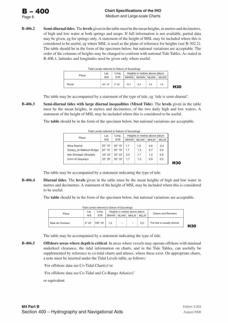
Chart Specifications of the IhoMedium and Large-scale Charts
Edition 3.003
August 2006
M4 Part BSection �00 – Hydrography and Navigational Aids
b – 400Page 6
B-406.2 Semi-diurnal tides. The levels given in the table must be the mean heights, in metres and decimetres, of high and low water at both springs and neaps. If full information is not available, partial data may be given, eg for springs only. A statement of the height of MSL may be included where this is considered to be useful, eg where MSL is used as the plane of reference for heights (see B-302.2). The table should be in the form of the specimen below, but national variations are acceptable. The order of the columns of heights may be changed to conform with national Tide Tables. As stated in B-406.1, latitudes and longitudes need be given only where useful.
PlaceLat. Long.
N/S E/W
Heights in metres above datum
MHWS MHWN MLWN MLWS
Tidal Levels referred to Datum of Soundings
Rozel 49° 14' 2° 02' 10,7 8,2 3,9 1,6 H30
The table may be accompanied by a statement of the type of tide, eg ‘tide is semi-diurnal’.
B-406.3 Semi-diurnal tides with large diurnal inequalities (Mixed Tide). The levels given in the table must be the mean heights, in metres and decimetres, of the two daily high and low waters. A statement of the height of MSL may be included where this is considered to be useful.
The table should be in the form of the specimen below, but national variations are acceptable.
PlaceLat. Long.
N/S E/W
Heights in metres above datum
MHHW MLHW MHLW MLLW
Tidal Levels referred to Datum of Soundings
Mina Rashid 25° 15' 55° 16' 1,7 1,8 0,8 0,4
25° 15' 55° 19' 1,7 1,3 0,7 0,4
Ash Shiraqah (Sharjah) 25° 22' 55° 23' 2,0 1,7 1,2 0,8
Umm Al Qaywayn 25° 35' 55° 35' 1,7 1,5 0,9 0,5
H30
The table may be accompanied by a statement indicating the type of tide.
B-406.4 Diurnal tides. The levels given in the table must be the mean heights of high and low water in metres and decimetres. A statement of the height of MSL may be included where this is considered to be useful.
The table should be in the form of the specimen below, but national variations are acceptable.
PlaceLat. Long.
N/S E/W
Heights in metres above datum
MHHW MLHW MHLW MLLWDatum and Remarks
Tidal Levels referred to Datum of Soundings
Baie de Choiseul 6° 42' 156° 24' 1,2 - - 0,5 The tide is usually diurnal
H30
The table may be accompanied by a statement indicating the type of tide.
B-406.5 Offshore areas where depth is critical. In areas where vessels may operate offshore with minimal underkeel clearance, the tidal information on charts, and in the Tide Tables, can usefully be supplemented by reference to co-tidal charts and atlases, where these exist. On appropriate charts, a note must be inserted under the Tidal Levels table, as follows:
‘For offshore data see Co-Tidal Chart(s)’or
‘For offshore data see Co-Tidal and Co-Range Atlas(es)’
or equivalent.
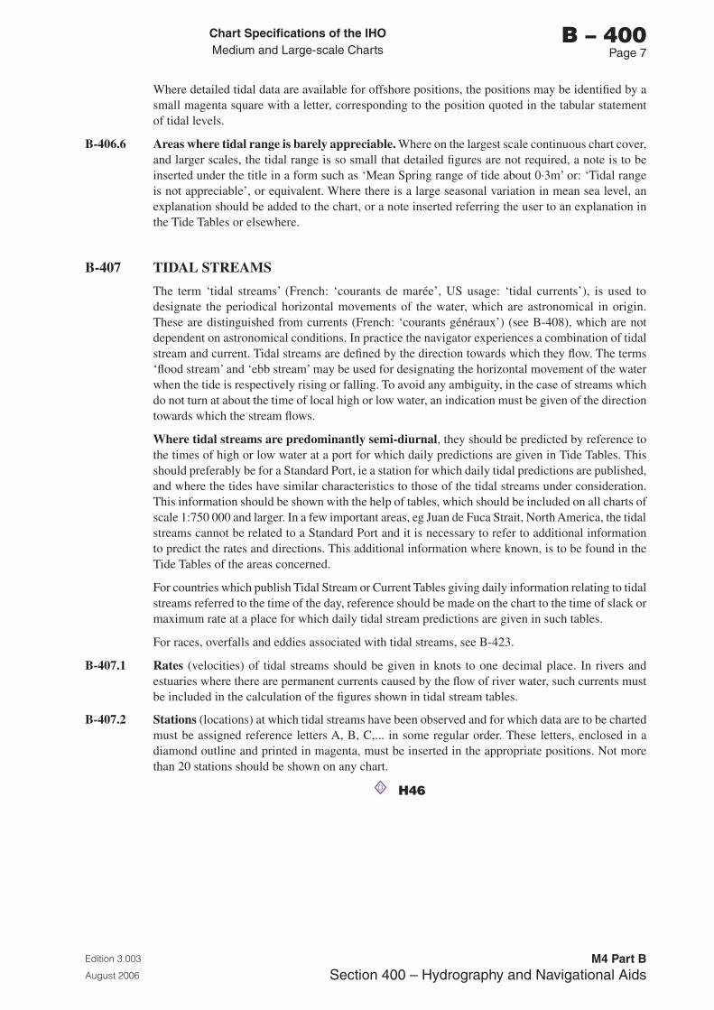
Chart Specifications of the IhoMedium and Large-scale Charts
Edition 3.003
August 2006
M4 Part BSection �00 – Hydrography and Navigational Aids
b – 400Page �
Where detailed tidal data are available for offshore positions, the positions may be identified by a small magenta square with a letter, corresponding to the position quoted in the tabular statement of tidal levels.
B-406.6 Areas where tidal range is barely appreciable. Where on the largest scale continuous chart cover, and larger scales, the tidal range is so small that detailed figures are not required, a note is to be inserted under the title in a form such as ‘Mean Spring range of tide about 0·3m’ or: ‘Tidal range is not appreciable’, or equivalent. Where there is a large seasonal variation in mean sea level, an explanation should be added to the chart, or a note inserted referring the user to an explanation in the Tide Tables or elsewhere.
B-407 TIDAL STREAMS
The term ‘tidal streams’ (French: ‘courants de marée’, US usage: ‘tidal currents’), is used to designate the periodical horizontal movements of the water, which are astronomical in origin. These are distinguished from currents (French: ‘courants généraux’) (see B-408), which are not dependent on astronomical conditions. In practice the navigator experiences a combination of tidal stream and current. Tidal streams are defined by the direction towards which they flow. The terms ‘flood stream’ and ‘ebb stream’ may be used for designating the horizontal movement of the water when the tide is respectively rising or falling. To avoid any ambiguity, in the case of streams which do not turn at about the time of local high or low water, an indication must be given of the direction towards which the stream flows.
Where tidal streams are predominantly semi-diurnal, they should be predicted by reference to the times of high or low water at a port for which daily predictions are given in Tide Tables. This should preferably be for a Standard Port, ie a station for which daily tidal predictions are published, and where the tides have similar characteristics to those of the tidal streams under consideration. This information should be shown with the help of tables, which should be included on all charts of scale 1:750 000 and larger. In a few important areas, eg Juan de Fuca Strait, North America, the tidal streams cannot be related to a Standard Port and it is necessary to refer to additional information to predict the rates and directions. This additional information where known, is to be found in the Tide Tables of the areas concerned.
For countries which publish Tidal Stream or Current Tables giving daily information relating to tidal streams referred to the time of the day, reference should be made on the chart to the time of slack or maximum rate at a place for which daily tidal stream predictions are given in such tables.
For races, overfalls and eddies associated with tidal streams, see B-423.
B-407.1 Rates (velocities) of tidal streams should be given in knots to one decimal place. In rivers and estuaries where there are permanent currents caused by the flow of river water, such currents must be included in the calculation of the figures shown in tidal stream tables.
B-407.2 Stations (locations) at which tidal streams have been observed and for which data are to be charted must be assigned reference letters A, B, C,... in some regular order. These letters, enclosed in a diamond outline and printed in magenta, must be inserted in the appropriate positions. Not more than 20 stations should be shown on any chart.
D H46
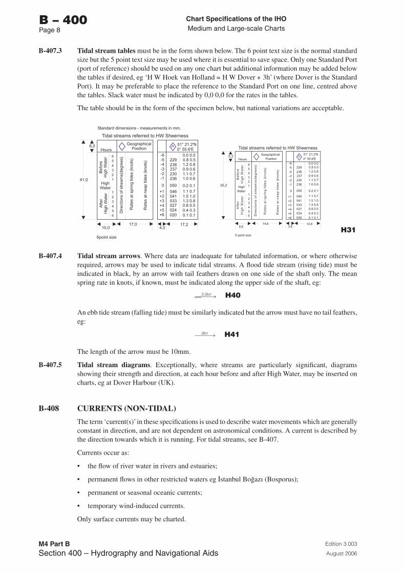
Chart Specifications of the IhoMedium and Large-scale Charts
Edition 3.003
August 2006
M4 Part BSection �00 – Hydrography and Navigational Aids
b – 400Page �
B-407.3 Tidal stream tables must be in the form shown below. The 6 point text size is the normal standard size but the 5 point text size may be used where it is essential to save space. Only one Standard Port (port of reference) should be used on any one chart but additional information may be added below the tables if desired, eg ‘H W Hoek van Holland = H W Dover + 3h’ (where Dover is the Standard Port). It may be preferable to place the reference to the Standard Port on one line, centred above the tables. Slack water must be indicated by 0,0 0,0 for the rates in the tables.
The table should be in the form of the specimen below, but national variations are acceptable.
GeographicalGeographicalPosition
PositionHours
Hours
TidalstreamsreferredtoHWSheernessTidalstreamsreferredtoHWSheerness
Rat
esat
sprin
gtid
es(k
nots
)
Rat
esat
neap
tides
(kno
ts)
Ra
tes
at
sp
rin
gti
de
s(k
no
ts)
Ra
tes
at
ne
ap
tid
es
(kn
ots
)
High HighWater Water
D
D
i
i
r
r
e
e
c
c
t
t
i
i
o
o
n
n
s
s
o
o
f
f
s
s
t
t
r
r
e
e
a
a
m
m
s
s
(
(
d
d
e
e
g
g
r
r
e
e
e
e
s
s
)
)
-6-5-4-3-2-1
654321
654321
+1+2+3+4+5+6
12
45
12
45
0
-6-5-4-3-2-1
+1+2+3+4+5+6
0
B
B
e
e
f
f
o
o
r
r
e
e
H
H
i
i
gh h
W
W
a
a
t
t
e
e
r
r
A A
f ft t
e e
r r
H H
i ig gg
h h
W W
a a
t t
e e
r r
A 51°21.2'N51°21.2'N0°55.6'E0°55.6'E
229229238238237237230230236236
050050
046046041041033033027027024024020020
0.00.00.00.00.80.50.80.51.20.81.20.80.90.60.90.61.10.71.10.71.00.61.00.6
0.20.10.20.1
1.10.71.10.71.51.01.51.01.30.81.30.80.80.50.80.50.40.30.40.30.10.10.10.1
41,0
17,0 17,2
6,0
4,010,0
35,2
14,6 14,8
5,2
3,68,6
6pointsize 5pointsize
Standarddimensions-measurementsinmm.
H31
B-407.4 Tidal stream arrows. Where data are inadequate for tabulated information, or where otherwise required, arrows may be used to indicate tidal streams. A flood tide stream (rising tide) must be indicated in black, by an arrow with tail feathers drawn on one side of the shaft only. The mean spring rate in knots, if known, must be indicated along the upper side of the shaft, eg:
3,5kn H40
An ebb tide stream (falling tide) must be similarly indicated but the arrow must have no tail feathers, eg:
3kn H41
The length of the arrow must be 10mm.
B-407.5 Tidal stream diagrams. Exceptionally, where streams are particularly significant, diagrams showing their strength and direction, at each hour before and after High Water, may be inserted on charts, eg at Dover Harbour (UK).
B-408 CURRENTS (NON-TIDAL)
The term ‘current(s)’ in these specifications is used to describe water movements which are generally constant in direction, and are not dependent on astronomical conditions. A current is described by the direction towards which it is running. For tidal streams, see B-407.
Currents occur as:
• the flow of river water in rivers and estuaries;
• permanent flows in other restricted waters eg ™stanbul BoÔazı (Bosporus);
• permanent or seasonal oceanic currents;
• temporary wind-induced currents.
Only surface currents may be charted.
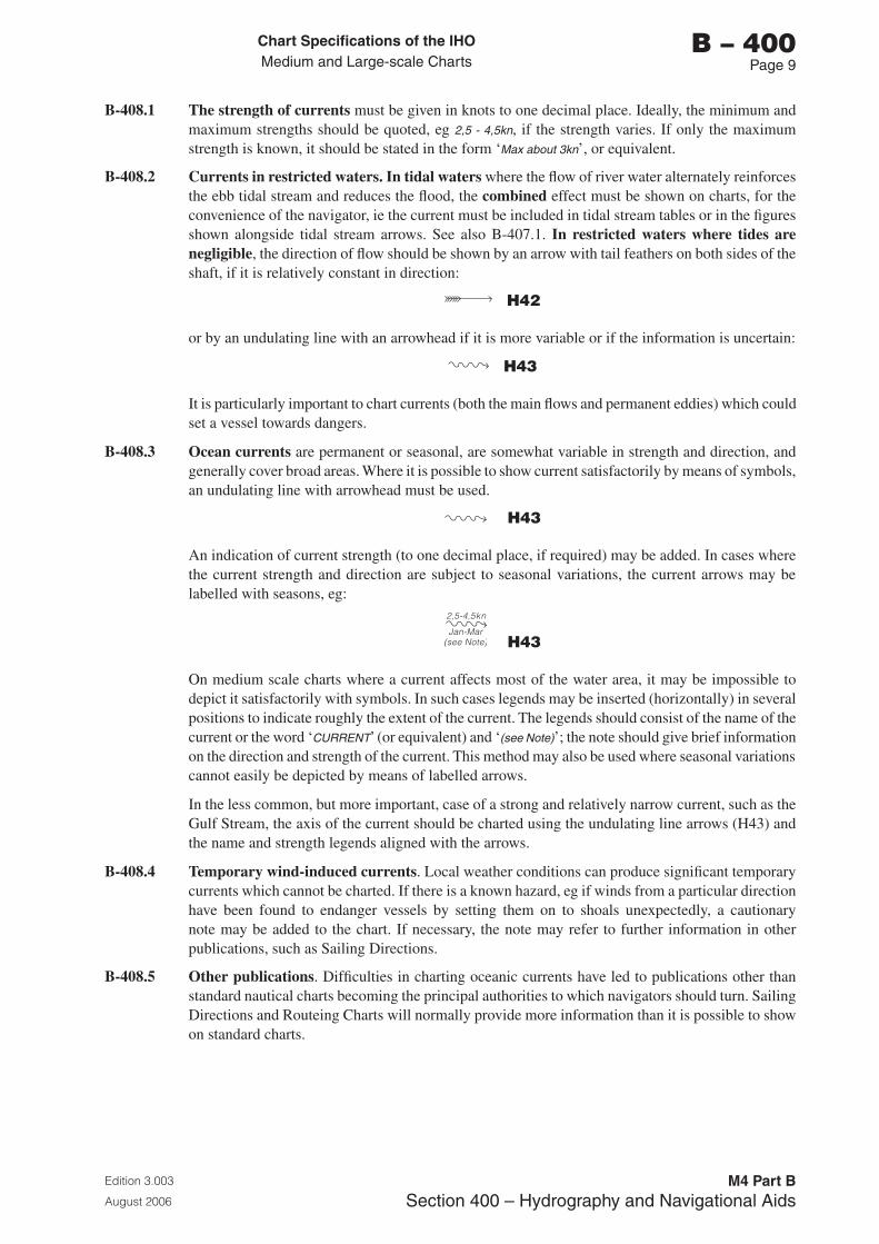
Chart Specifications of the IhoMedium and Large-scale Charts
Edition 3.003
August 2006
M4 Part BSection �00 – Hydrography and Navigational Aids
b – 400Page �
B-408.1 The strength of currents must be given in knots to one decimal place. Ideally, the minimum and maximum strengths should be quoted, eg 2,5 - 4,5kn, if the strength varies. If only the maximum strength is known, it should be stated in the form ‘Max about 3kn’, or equivalent.
B-408.2 Currents in restricted waters. In tidal waters where the flow of river water alternately reinforces the ebb tidal stream and reduces the flood, the combined effect must be shown on charts, for the convenience of the navigator, ie the current must be included in tidal stream tables or in the figures shown alongside tidal stream arrows. See also B-407.1. In restricted waters where tides are negligible, the direction of flow should be shown by an arrow with tail feathers on both sides of the shaft, if it is relatively constant in direction:
H42
or by an undulating line with an arrowhead if it is more variable or if the information is uncertain:
H43
It is particularly important to chart currents (both the main flows and permanent eddies) which could set a vessel towards dangers.
B-408.3 Ocean currents are permanent or seasonal, are somewhat variable in strength and direction, and generally cover broad areas. Where it is possible to show current satisfactorily by means of symbols, an undulating line with arrowhead must be used.
H43
An indication of current strength (to one decimal place, if required) may be added. In cases where the current strength and direction are subject to seasonal variations, the current arrows may be labelled with seasons, eg:
2,5-4,5kn
Jan-Mar(see Note) H43
On medium scale charts where a current affects most of the water area, it may be impossible to depict it satisfactorily with symbols. In such cases legends may be inserted (horizontally) in several positions to indicate roughly the extent of the current. The legends should consist of the name of the current or the word ‘CURRENT’ (or equivalent) and ‘(see Note)’; the note should give brief information on the direction and strength of the current. This method may also be used where seasonal variations cannot easily be depicted by means of labelled arrows.
In the less common, but more important, case of a strong and relatively narrow current, such as the Gulf Stream, the axis of the current should be charted using the undulating line arrows (H43) and the name and strength legends aligned with the arrows.
B-408.4 Temporary wind-induced currents. Local weather conditions can produce significant temporary currents which cannot be charted. If there is a known hazard, eg if winds from a particular direction have been found to endanger vessels by setting them on to shoals unexpectedly, a cautionary note may be added to the chart. If necessary, the note may refer to further information in other publications, such as Sailing Directions.
B-408.5 Other publications. Difficulties in charting oceanic currents have led to publications other than standard nautical charts becoming the principal authorities to which navigators should turn. Sailing Directions and Routeing Charts will normally provide more information than it is possible to show on standard charts.

Page intentionally left blank
Chart Specifications of the IhoMedium and Large-scale Charts
Edition 3.003
August 2006
M4 Part BSection �00 – Hydrography and Navigational Aids
b – 410Page 1
B-410 REPRESENTATION OF DEPTH: GENERAL
Some of the principles of depth depiction are summarized below (see also B-403.1):
a. The least depth over shoals and banks, and over sills (bars) in navigable channels, must be shown. Particular attention should also be paid to full and accurate representation of all other ‘critical’ areas, eg on and adjacent to leading lines, fairways and recommended tracks, in anchorages, alongside jetties, quays and berths and in the entrances to harbours and basins. Maximum as well as minimum depth should be shown where possible, eg to show the line of deepest water in narrow channels. However, deeper soundings on the sloping side of a bank near to the crest line should not be selected if they could give the impression that there is a deeper passage across the crest between shoaler soundings.
b. Soundings and contours must be used to complement each other in giving a reasonable representation of the seabed, including all significant breaks of slope (see also B-411.5).
c. The density of soundings should be determined by the type of seabed. Flat or evenly sloping areas, and banks of unconsolidated sediment, should have a minimum of soundings, fairly evenly spaced, but gradually becoming more widely spaced as the depth increases. Irregular bottom topography should be represented by a denser, and probably irregular, pattern of soundings. A steep gradient should be represented by close contours, undistorted by soundings.
d. In changeable areas, where surveys of different dates adjoin and do not match exactly, gaps in the contours and tints may be left to indicate the discontinuity of depth to the navigator (see B-416.1).
e. Where practicable, soundings on smaller scale charts should be selected from those shown on the larger scales.
f. In areas navigable only at high water, drying heights must be charted according to the same principles as soundings.
g. Where surveys are inadequate, it may be advisable to omit some of the standard contour lines, but those contours outlining blue tints should be as complete as possible (even if shown as approximate contours - see B-411.2).
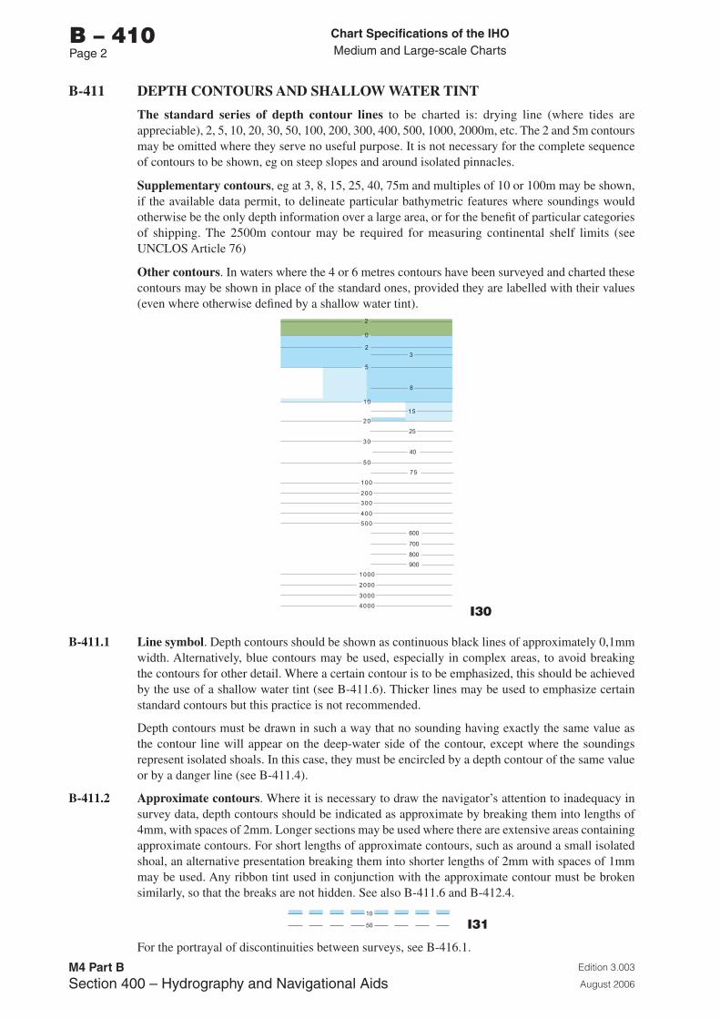
Chart Specifications of the IhoMedium and Large-scale Charts
Edition 3.003
August 2006
M4 Part BSection �00 – Hydrography and Navigational Aids
b – 410Page 2
B-411 DEPTH CONTOURS AND SHALLOW WATER TINT
The standard series of depth contour lines to be charted is: drying line (where tides are appreciable), 2, 5, 10, 20, 30, 50, 100, 200, 300, 400, 500, 1000, 2000m, etc. The 2 and 5m contours may be omitted where they serve no useful purpose. It is not necessary for the complete sequence of contours to be shown, eg on steep slopes and around isolated pinnacles.
Supplementary contours, eg at 3, 8, 15, 25, 40, 75m and multiples of 10 or 100m may be shown, if the available data permit, to delineate particular bathymetric features where soundings would otherwise be the only depth information over a large area, or for the benefit of particular categories of shipping. The 2500m contour may be required for measuring continental shelf limits (see UNCLOS Article 76)
Other contours. In waters where the 4 or 6 metres contours have been surveyed and charted these contours may be shown in place of the standard ones, provided they are labelled with their values (even where otherwise defined by a shallow water tint).
30
50
100
200
300
400
500
2
23
5
10
25
20
0
1000
2000
3000
4000
8
15
40
75
600
700
800
900
I30
B-411.1 Line symbol. Depth contours should be shown as continuous black lines of approximately 0,1mm width. Alternatively, blue contours may be used, especially in complex areas, to avoid breaking the contours for other detail. Where a certain contour is to be emphasized, this should be achieved by the use of a shallow water tint (see B-411.6). Thicker lines may be used to emphasize certain standard contours but this practice is not recommended.
Depth contours must be drawn in such a way that no sounding having exactly the same value as the contour line will appear on the deep-water side of the contour, except where the soundings represent isolated shoals. In this case, they must be encircled by a depth contour of the same value or by a danger line (see B-411.4).
B-411.2 Approximate contours. Where it is necessary to draw the navigator’s attention to inadequacy in survey data, depth contours should be indicated as approximate by breaking them into lengths of 4mm, with spaces of 2mm. Longer sections may be used where there are extensive areas containing approximate contours. For short lengths of approximate contours, such as around a small isolated shoal, an alternative presentation breaking them into shorter lengths of 2mm with spaces of 1mm may be used. Any ribbon tint used in conjunction with the approximate contour must be broken similarly, so that the breaks are not hidden. See also B-411.6 and B-412.4.
10
50 I31
For the portrayal of discontinuities between surveys, see B-416.1.
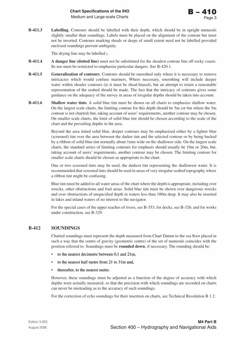
Chart Specifications of the IhoMedium and Large-scale Charts
Edition 3.003
August 2006
M4 Part BSection �00 – Hydrography and Navigational Aids
b – 410Page �
B-411.3 Labelling. Contours should be labelled with their depth, which should be in upright numerals slightly smaller than soundings. Labels must be placed on the alignment of the contour but must not be inverted. Contours marking shoals or deeps of small extent need not be labelled provided enclosed soundings prevent ambiguity.
The drying line may be labelled 0.
B-411.4 A danger line (dotted line) must not be substituted for the shoalest contour line off rocky coasts. Its use must be restricted to emphasize particular dangers. See B-420.1.
B-411.5 Generalization of contours. Contours should be smoothed only where it is necessary to remove intricacies which would confuse mariners. Where necessary, smoothing will include deeper water within shoaler contours (ie it must be shoal-biased), but an attempt to retain a reasonable representation of the seabed should be made. The fact that the intricacy of contours gives some guidance on the adequacy of the survey in areas of irregular depths should be taken into account.
B-411.6 Shallow water tints. A solid blue tint must be shown on all charts to emphasize shallow water. On the largest scale charts, the limiting contour for this depth should be 5m (or 6m where the 5m contour is not charted) but, taking account of users’ requirements, another contour may be chosen. On smaller scale charts, the limit of solid blue tint should be chosen according to the scale of the chart and the prevailing depths in the area.
Beyond the area tinted solid blue, deeper contours may be emphasized either by a lighter blue (screened) tint over the area between the darker tint and the selected contour or by being backed by a ribbon of solid blue tint normally about 1mm wide on the shallower side. On the largest scale charts, the standard series of limiting contours for emphasis should usually be 10m or 20m, but, taking account of users’ requirements, another contour may be chosen. The limiting contour for smaller scale charts should be chosen as appropriate to the chart.
One or two screened tints may be used, the darkest tint representing the shallowest water. It is recommended that screened tints should be used in areas of very irregular seabed topography where a ribbon tint might be confusing.
Blue tint must be added to all water areas of the chart where the depth is appropriate, including over wrecks, other obstructions and foul areas. Solid blue tint must be shown over dangerous wrecks and over obstructions of unspecified depth in waters less than 100m deep. It may also be inserted in lakes and inland waters of no interest to the navigator.
For the special cases of the upper reaches of rivers, see B-353; for docks, see B-326; and for works under construction, see B-329.
B-412 SOUNDINGS
Charted soundings must represent the depth measured from Chart Datum to the sea floor placed in such a way that the centre of gravity (geometric centre) of the set of numerals coincides with the position referred to. Soundings must be rounded down, if necessary. The rounding should be:
• to the nearest decimetre between 0,1 and 21m, to the nearest decimetre between 0,1 and 21m,
• to the nearest half metre from 21 to 31m and, to the nearest half metre from 21 to 31m and,
• thereafter, to the nearest metre. thereafter, to the nearest metre.
However, these soundings must be adjusted as a function of the degree of accuracy with which depths were actually measured, so that the precision with which soundings are recorded on charts can never be misleading as to the accuracy of such soundings.
For the correction of echo soundings for their insertion on charts, see Technical Resolution B 1.2.
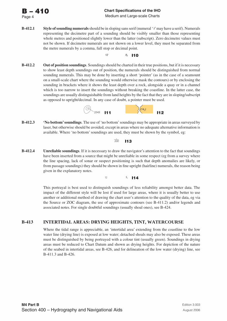
Chart Specifications of the IhoMedium and Large-scale Charts
Edition 3.003
August 2006
M4 Part BSection �00 – Hydrography and Navigational Aids
b – 410Page �
B-412.1 Style of sounding numerals should be in sloping sans serif (numeral ‘1’ may have a serif). Numerals representing the decimetre part of a sounding should be visibly smaller than those representing whole metres and positioned slightly lower than the latter (subscript). Zero decimetre values must not be shown. If decimetre numerals are not shown on a lower level, they must be separated from the metre numerals by a comma, full stop or decimal point.
12 92 I10
B-412.2 Out of position soundings. Soundings should be charted in their true positions, but if it is necessary to show least depth soundings out of position, the numerals should be distinguished from normal sounding numerals. This may be done by inserting a short ‘pointer’ (as in the case of a seamount on a small-scale chart where the sounding would otherwise mask the contours) or by enclosing the sounding in brackets where it shows the least depth over a rock, alongside a quay or in a channel which is too narrow to insert the soundings without breaking the coastline. In the latter case, the soundings are usually distinguishable from land heights by the fact that they are in sloping/subscript as opposed to upright/decimal. In any case of doubt, a pointer must be used.
+ (12) 3349 I11 (14 )7
I12
B-412.3 ‘No bottom’ soundings. The use of ‘no bottom’ soundings may be appropriate in areas surveyed by laser, but otherwise should be avoided, except in areas where no adequate alternative information is available. Where ‘no bottom’ soundings are used, they must be shown by the symbol, eg:
330 I13
B-412.4 Unreliable soundings. If it is necessary to draw the navigator’s attention to the fact that soundings have been inserted from a source that might be unreliable in some respect (eg from a survey where the line spacing, lack of sonar or suspect positioning is such that depth anomalies are likely, or from passage soundings) they should be shown in fine upright (hairline) numerals, the reason being given in the explanatory notes.
12 91 I14
This portrayal is best used to distinguish soundings of less reliability amongst better data. The impact of the different style will be lost if used for large areas, where it is usually better to use another or additional method of drawing the chart user’s attention to the quality of the data, eg via the Source or ZOC diagram, the use of approximate contours (see B-411.2) and/or legends and associated notes. For single doubtful soundings (usually shoal ones), see B-424.
B-413 INTERTIDAL AREAS: DRYING HEIGHTS, TINT, WATERCOURSE
Where the tidal range is appreciable, an ‘intertidal area’ extending from the coastline to the low water line (drying line) is exposed at low water; detached shoals may also be exposed. These areas must be distinguished by being portrayed with a colour tint (usually green). Soundings in drying areas must be reduced to Chart Datum and shown as drying heights. For depiction of the nature of the seabed in intertidal areas, see B-426, and for delineation of the low water (drying) line, see B-411.3 and B-426.
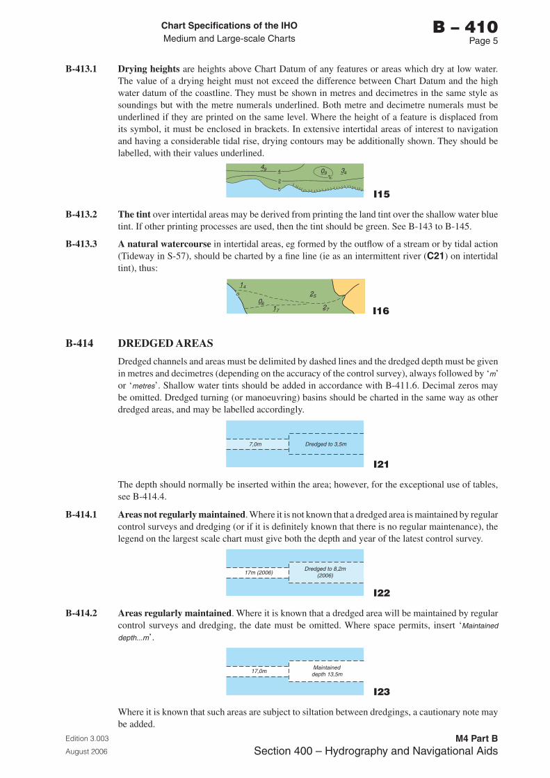
Chart Specifications of the IhoMedium and Large-scale Charts
Edition 3.003
August 2006
M4 Part BSection �00 – Hydrography and Navigational Aids
b – 410Page 5
B-413.1 Drying heights are heights above Chart Datum of any features or areas which dry at low water. The value of a drying height must not exceed the difference between Chart Datum and the high water datum of the coastline. They must be shown in metres and decimetres in the same style as soundings but with the metre numerals underlined. Both metre and decimetre numerals must be underlined if they are printed on the same level. Where the height of a feature is displaced from its symbol, it must be enclosed in brackets. In extensive intertidal areas of interest to navigation and having a considerable tidal rise, drying contours may be additionally shown. They should be labelled, with their values underlined.
I15
B-413.2 The tint over intertidal areas may be derived from printing the land tint over the shallow water blue tint. If other printing processes are used, then the tint should be green. See B-143 to B-145.
B-413.3 A natural watercourse in intertidal areas, eg formed by the outflow of a stream or by tidal action (Tideway in S-57), should be charted by a fine line (ie as an intermittent river (C21) on intertidal tint), thus:
06
25
1727
14
I16
B-414 DREDGED AREAS
Dredged channels and areas must be delimited by dashed lines and the dredged depth must be given in metres and decimetres (depending on the accuracy of the control survey), always followed by ‘m’ or ‘metres’. Shallow water tints should be added in accordance with B-411.6. Decimal zeros may be omitted. Dredged turning (or manoeuvring) basins should be charted in the same way as other dredged areas, and may be labelled accordingly.
7,0m Dredged to 3,5m
I21
The depth should normally be inserted within the area; however, for the exceptional use of tables, see B-414.4.
B-414.1 Areas not regularly maintained. Where it is not known that a dredged area is maintained by regular control surveys and dredging (or if it is definitely known that there is no regular maintenance), the legend on the largest scale chart must give both the depth and year of the latest control survey.
17m (2006)Dredged to 8,2m
(2006)
I22
B-414.2 Areas regularly maintained. Where it is known that a dredged area will be maintained by regular control surveys and dredging, the date must be omitted. Where space permits, insert ‘Maintained
depth...m’.
17,0m Maintained depth 13,5m
I23
Where it is known that such areas are subject to siltation between dredgings, a cautionary note may be added.
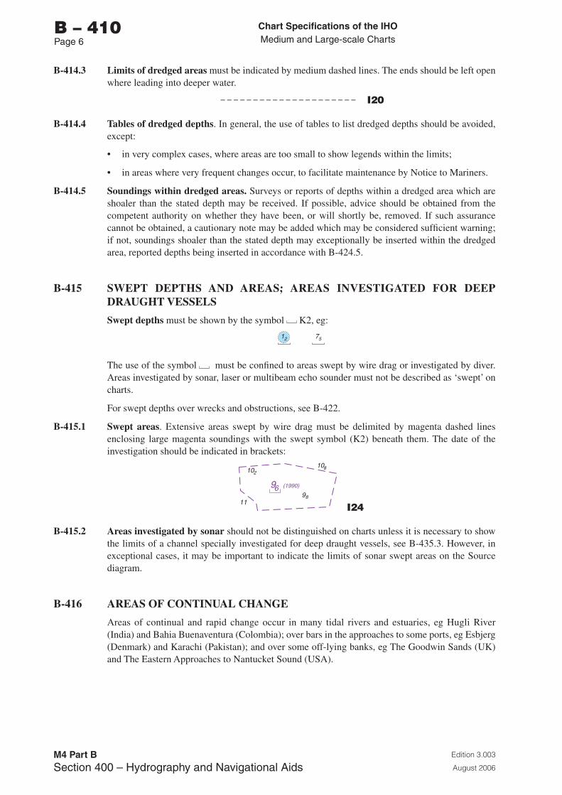
Chart Specifications of the IhoMedium and Large-scale Charts
Edition 3.003
August 2006
M4 Part BSection �00 – Hydrography and Navigational Aids
b – 410Page 6
B-414.3 Limits of dredged areas must be indicated by medium dashed lines. The ends should be left open where leading into deeper water.
I20
B-414.4 Tables of dredged depths. In general, the use of tables to list dredged depths should be avoided, except:
• in very complex cases, where areas are too small to show legends within the limits;
• in areas where very frequent changes occur, to facilitate maintenance by Notice to Mariners.
B-414.5 Soundings within dredged areas. Surveys or reports of depths within a dredged area which are shoaler than the stated depth may be received. If possible, advice should be obtained from the competent authority on whether they have been, or will shortly be, removed. If such assurance cannot be obtained, a cautionary note may be added which may be considered sufficient warning; if not, soundings shoaler than the stated depth may exceptionally be inserted within the dredged area, reported depths being inserted in accordance with B-424.5.
B-415 SWEPT DEPTHS AND AREAS; AREAS INVESTIGATED FOR DEEP DRAUGHT VESSELS
Swept depths must be shown by the symbol K2, eg:
12 75
The use of the symbol must be confined to areas swept by wire drag or investigated by diver. Areas investigated by sonar, laser or multibeam echo sounder must not be described as ‘swept’ on charts.
For swept depths over wrecks and obstructions, see B-422.
B-415.1 Swept areas. Extensive areas swept by wire drag must be delimited by magenta dashed lines enclosing large magenta soundings with the swept symbol (K2) beneath them. The date of the investigation should be indicated in brackets:
102108
9811
96 (1990)
I24
B-415.2 Areas investigated by sonar should not be distinguished on charts unless it is necessary to show the limits of a channel specially investigated for deep draught vessels, see B-435.3. However, in exceptional cases, it may be important to indicate the limits of sonar swept areas on the Source diagram.
B-416 AREAS OF CONTINUAL CHANGE
Areas of continual and rapid change occur in many tidal rivers and estuaries, eg Hugli River (India) and Bahia Buenaventura (Colombia); over bars in the approaches to some ports, eg Esbjerg (Denmark) and Karachi (Pakistan); and over some off-lying banks, eg The Goodwin Sands (UK) and The Eastern Approaches to Nantucket Sound (USA).
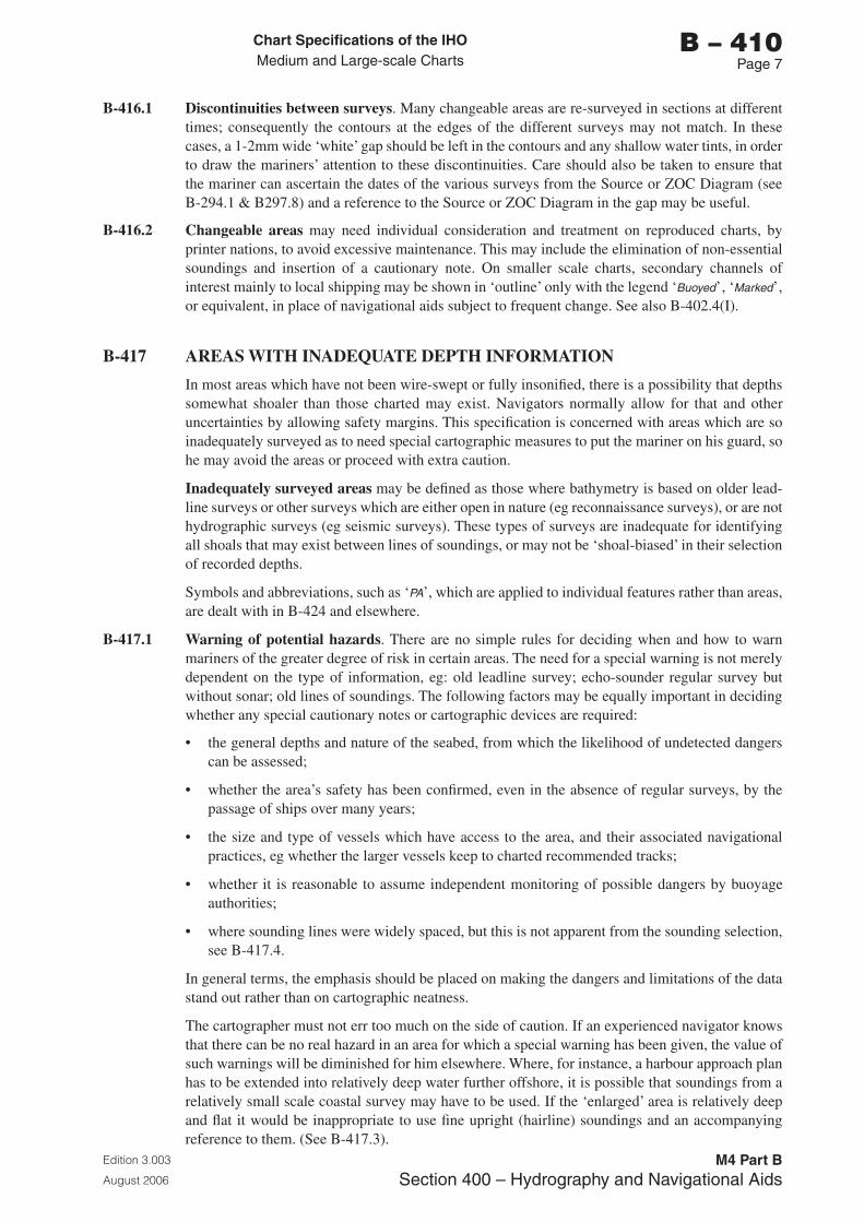
Chart Specifications of the IhoMedium and Large-scale Charts
Edition 3.003
August 2006
M4 Part BSection �00 – Hydrography and Navigational Aids
b – 410Page �
B-416.1 Discontinuities between surveys. Many changeable areas are re-surveyed in sections at different times; consequently the contours at the edges of the different surveys may not match. In these cases, a 1-2mm wide ‘white’ gap should be left in the contours and any shallow water tints, in order to draw the mariners’ attention to these discontinuities. Care should also be taken to ensure that the mariner can ascertain the dates of the various surveys from the Source or ZOC Diagram (see B-294.1 & B297.8) and a reference to the Source or ZOC Diagram in the gap may be useful.
B-416.2 Changeable areas may need individual consideration and treatment on reproduced charts, by printer nations, to avoid excessive maintenance. This may include the elimination of non-essential soundings and insertion of a cautionary note. On smaller scale charts, secondary channels of interest mainly to local shipping may be shown in ‘outline’ only with the legend ‘Buoyed’, ‘Marked’, or equivalent, in place of navigational aids subject to frequent change. See also B-402.4(I).
B-417 AREAS WITH INADEQUATE DEPTH INFORMATION
In most areas which have not been wire-swept or fully insonified, there is a possibility that depths somewhat shoaler than those charted may exist. Navigators normally allow for that and other uncertainties by allowing safety margins. This specification is concerned with areas which are so inadequately surveyed as to need special cartographic measures to put the mariner on his guard, so he may avoid the areas or proceed with extra caution.
Inadequately surveyed areas may be defined as those where bathymetry is based on older lead-line surveys or other surveys which are either open in nature (eg reconnaissance surveys), or are not hydrographic surveys (eg seismic surveys). These types of surveys are inadequate for identifying all shoals that may exist between lines of soundings, or may not be ‘shoal-biased’ in their selection of recorded depths.
Symbols and abbreviations, such as ‘PA’, which are applied to individual features rather than areas, are dealt with in B-424 and elsewhere.
B-417.1 Warning of potential hazards. There are no simple rules for deciding when and how to warn mariners of the greater degree of risk in certain areas. The need for a special warning is not merely dependent on the type of information, eg: old leadline survey; echo-sounder regular survey but without sonar; old lines of soundings. The following factors may be equally important in deciding whether any special cautionary notes or cartographic devices are required:
• the general depths and nature of the seabed, from which the likelihood of undetected dangers can be assessed;
• whether the area’s safety has been confirmed, even in the absence of regular surveys, by the passage of ships over many years;
• the size and type of vessels which have access to the area, and their associated navigational practices, eg whether the larger vessels keep to charted recommended tracks;
• whether it is reasonable to assume independent monitoring of possible dangers by buoyage authorities;
• where sounding lines were widely spaced, but this is not apparent from the sounding selection, see B-417.4.
In general terms, the emphasis should be placed on making the dangers and limitations of the data stand out rather than on cartographic neatness.
The cartographer must not err too much on the side of caution. If an experienced navigator knows that there can be no real hazard in an area for which a special warning has been given, the value of such warnings will be diminished for him elsewhere. Where, for instance, a harbour approach plan has to be extended into relatively deep water further offshore, it is possible that soundings from a relatively small scale coastal survey may have to be used. If the ‘enlarged’ area is relatively deep and flat it would be inappropriate to use fine upright (hairline) soundings and an accompanying reference to them. (See B-417.3).
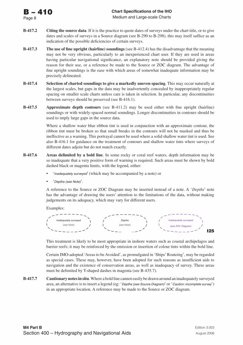
Chart Specifications of the IhoMedium and Large-scale Charts
Edition 3.003
August 2006
M4 Part BSection �00 – Hydrography and Navigational Aids
b – 410Page �
B-417.2 Citing the source data. If it is the practice to quote dates of surveys under the chart title, or to give dates and scales of surveys in a Source diagram (see B-290 to B-298), this may itself suffice as an indication of the possible deficiencies of certain surveys.
B-417.3 The use of fine upright (hairline) soundings (see B-412.4) has the disadvantage that the meaning may not be very obvious, particularly to an inexperienced chart user. If they are used in areas having particular navigational significance, an explanatory note should be provided giving the reason for their use, or a reference be made to the Source or ZOC diagram. The advantage of fine upright soundings is the ease with which areas of somewhat inadequate information may be precisely delineated.
B-417.4 Selection of charted soundings to give a markedly uneven spacing. This may occur naturally at the largest scales, but gaps in the data may be inadvertently concealed by inappropriately regular spacing on smaller scale charts unless care is taken in selection. In particular, any discontinuities between surveys should be preserved (see B-416.1).
B-417.5 Approximate depth contours (see B-411.2) may be used either with fine upright (hairline) soundings or with widely-spaced normal soundings. Longer discontinuities in contours should be used to imply large gaps in the source data.
Where a shallow water blue ribbon tint is used in conjunction with an approximate contour, the ribbon tint must be broken so that small breaks in the contours will not be masked and thus be ineffective as a warning. This portrayal cannot be used where a solid shallow water tint is used. See also B-416.1 for guidance on the treatment of contours and shallow water tints where surveys of different dates adjoin but do not match exactly.
B-417.6 Areas delimited by a bold line. In some rocky or coral reef waters, depth information may be so inadequate that a very positive form of warning is required. Such areas must be shown by bold dashed black or magenta limits, with the legend, either:
• ‘Inadequately surveyed’ (which may be accompanied by a note) or
• ‘Depths (see Note)’.
A reference to the Source or ZOC Diagram may be inserted instead of a note. A ‘Depths’ note has the advantage of drawing the users’ attention to the limitations of the data, without making judgements on its adequacy, which may vary for different users.
Examples:
Inadequately surveyed
(see Note)
Depths
(see Note)
Inadequately surveyed
(see ZOC Diagram)
I25
This treatment is likely to be most appropriate in inshore waters such as coastal archipelagos and barrier reefs; it may be reinforced by the omission or insertion of colour tints within the bold line.
Certain IMO-adopted ‘Areas to be Avoided’, as promulgated in ‘Ships’ Routeing’, may be regarded as special cases. These may, however, have been adopted for such reasons as insufficient aids to navigation and the existence of conservation areas, as well as inadequacy of survey. These areas must be delimited by T-shaped dashes in magenta (see B-435.7).
B-417.7 Cautionary notes in situ. Where a bold line cannot easily be drawn around an inadequately surveyed area, an alternative is to insert a legend (eg: ‘Depths (see Source Diagram)’ or ‘Caution: incomplete survey’) in an appropriate location. A reference may be made to the Source or ZOC diagram.
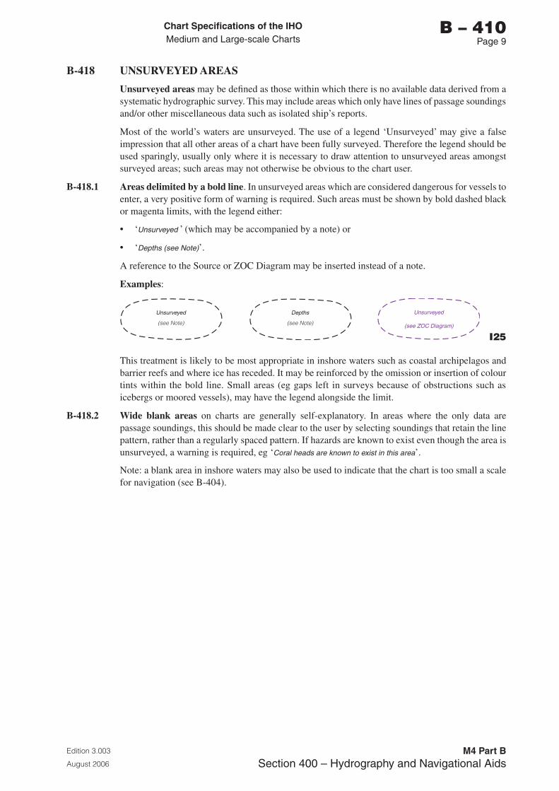
Chart Specifications of the IhoMedium and Large-scale Charts
Edition 3.003
August 2006
M4 Part BSection �00 – Hydrography and Navigational Aids
b – 410Page �
B-418 UNSURVEYED AREAS
Unsurveyed areas may be defined as those within which there is no available data derived from a systematic hydrographic survey. This may include areas which only have lines of passage soundings and/or other miscellaneous data such as isolated ship’s reports.
Most of the world’s waters are unsurveyed. The use of a legend ‘Unsurveyed’ may give a false impression that all other areas of a chart have been fully surveyed. Therefore the legend should be used sparingly, usually only where it is necessary to draw attention to unsurveyed areas amongst surveyed areas; such areas may not otherwise be obvious to the chart user.
B-418.1 Areas delimited by a bold line. In unsurveyed areas which are considered dangerous for vessels to enter, a very positive form of warning is required. Such areas must be shown by bold dashed black or magenta limits, with the legend either:
• ‘Unsurveyed ’ (which may be accompanied by a note) or
• ‘Depths (see Note)’.
A reference to the Source or ZOC Diagram may be inserted instead of a note.
Examples:
Unsurveyed
(see Note)
Depths
(see Note)
Unsurveyed
(see ZOC Diagram)
I25
This treatment is likely to be most appropriate in inshore waters such as coastal archipelagos and barrier reefs and where ice has receded. It may be reinforced by the omission or insertion of colour tints within the bold line. Small areas (eg gaps left in surveys because of obstructions such as icebergs or moored vessels), may have the legend alongside the limit.
B-418.2 Wide blank areas on charts are generally self-explanatory. In areas where the only data are passage soundings, this should be made clear to the user by selecting soundings that retain the line pattern, rather than a regularly spaced pattern. If hazards are known to exist even though the area is unsurveyed, a warning is required, eg ‘Coral heads are known to exist in this area’.
Note: a blank area in inshore waters may also be used to indicate that the chart is too small a scale for navigation (see B-404).

Page intentionally left blank
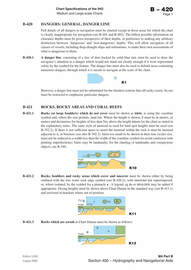
Chart Specifications of the IhoMedium and Large-scale Charts
Edition 3.003
August 2006
M4 Part BSection �00 – Hydrography and Navigational Aids
b – 420Page 1
B-420 DANGERS: GENERAL, DANGER LINE
Full details of all dangers to navigation must be charted except in those areas for which the chart is clearly inappropriate for navigation (see B-401 and B-402). The fullest possible information on clearance depths must be given irrespective of their depths, in preference to making any arbitrary distinction between ‘dangerous’ and ‘non-dangerous’ depths. This will allow navigators of all classes of vessels, including deep-draught ships and submarines, to make their own assessments of what is dangerous to them.
B-420.1 A danger line, consisting of a line of dots backed by solid blue tint, must be used to draw the navigator’s attention to a danger which would not stand out clearly enough if it were represented solely by the symbol for the feature. The danger line must also be used to delimit areas containing numerous dangers, through which it is unsafe to navigate at the scale of the chart.
K1
However, a danger line must not be substituted for the shoalest contour line off rocky coasts. Its use must be restricted to emphasize particular dangers.
B-421 ROCKS, ROCKY AREAS AND CORAL REEFS
B-421.1 Rocks (or large boulders) which do not cover must be shown as islets, ie using the coastline symbol and, where the size permits, land tint. Where the height is shown, it must be in metres, or metres and decimetres for heights of less than 5m, above the height datum for the chart as stated in the explanatory notes. The same style of numeral as used for land spot heights must be used (see B-352.2). If there is not sufficient space to insert the numeral within the rock it must be inserted adjacent to it, in brackets (see also B-302.3). Islets too small to be shown in their true (scale) size, must not be reduced to a width less than the width of the coastline symbol (to avoid confusion with printing imperfections). Islets may be landmarks; for the charting of landmarks and conspicuous objects, see B-340.
HeightdatumCD
(1,7) (3,1) 4,1100 0
K10
B-421.2 Rocks, boulders and rocky areas which cover and uncover must be shown either by being outlined with the low water rock edge symbol (see B-426.2), with intertidal tint superimposed, or, where isolated, by the symbol for a pinnacle . A legend, eg Bo or BOULDER, may be added if appropriate. Drying heights must be shown above Chart Datum in the standard way (see B-413.1) and enclosed in brackets where out of position.
5m
HeightdatumCD
5
(1 )6
(1 )6 37(2 )7
K11
B-421.3 Rocks which are awash at Chart Datum must be shown as follows:
5m
HeightdatumCD
5 0
K12
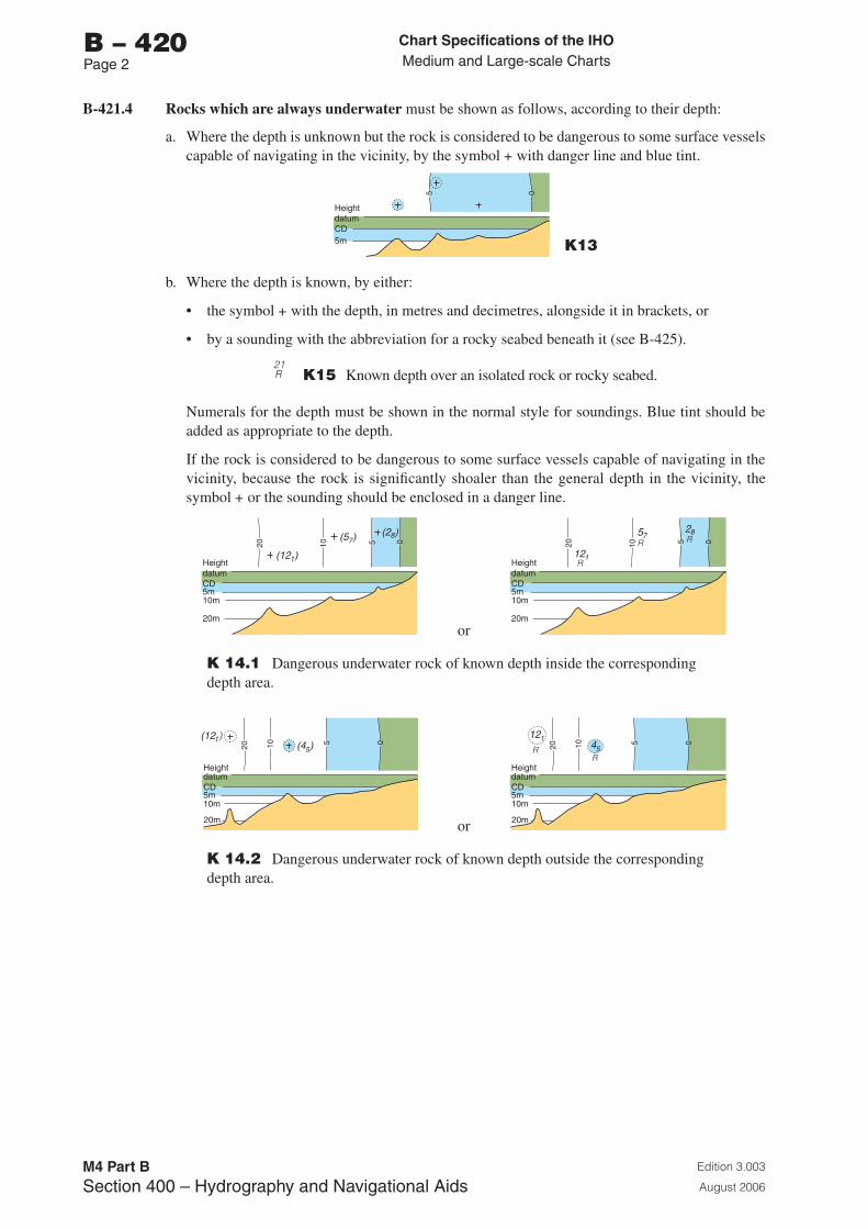
Chart Specifications of the IhoMedium and Large-scale Charts
Edition 3.003
August 2006
M4 Part BSection �00 – Hydrography and Navigational Aids
b – 420Page 2
B-421.4 Rocks which are always underwater must be shown as follows, according to their depth:
a. Where the depth is unknown but the rock is considered to be dangerous to some surface vessels capable of navigating in the vicinity, by the symbol + with danger line and blue tint.
5m
HeightdatumCD
5 0
K13
b. Where the depth is known, by either:
• the symbol + with the depth, in metres and decimetres, alongside it in brackets, or
• by a sounding with the abbreviation for a rocky seabed beneath it (see B-425).
21R K15 Known depth over an isolated rock or rocky seabed.
Numerals for the depth must be shown in the normal style for soundings. Blue tint should be added as appropriate to the depth.
If the rock is considered to be dangerous to some surface vessels capable of navigating in the vicinity, because the rock is significantly shoaler than the general depth in the vicinity, the symbol + or the sounding should be enclosed in a danger line.
5m10m
20m
HeightdatumCD
20 10 5 0(5 )7(2 )8
(12 )1
or
5m10m
20m
HeightdatumCD
20 10 5 0R
R
R57
28
121
K 14.1 Dangerous underwater rock of known depth inside the corresponding depth area.
5m10m
20m
HeightdatumCD
20 10 5 0
(12 )1(4 )5
or
5m10m
20m
HeightdatumCD
20 10 5 0
RR
12145
K 14.2 Dangerous underwater rock of known depth outside the corresponding depth area.
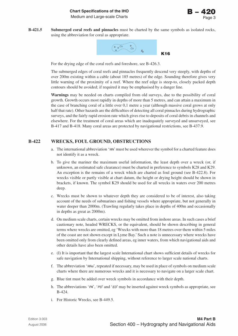
Chart Specifications of the IhoMedium and Large-scale Charts
Edition 3.003
August 2006
M4 Part BSection �00 – Hydrography and Navigational Aids
b – 420Page �
B-421.5 Submerged coral reefs and pinnacles must be charted by the same symbols as isolated rocks, using the abbreviation for coral as appropriate.
58
CoCo
K16
For the drying edge of the coral reefs and foreshore, see B-426.3.
The submerged edges of coral reefs and pinnacles frequently descend very steeply, with depths of over 200m existing within a cable (about 185 metres) of the edge. Sounding therefore gives very little warning of the proximity of a reef. Where the reef edge is steep-to, closely packed depth contours should be avoided; if required it may be emphasised by a danger line.
Warnings may be needed on charts compiled from old surveys, due to the possibility of coral growth. Growth occurs most rapidly in depths of more than 5 metres, and can attain a maximum in the case of branching coral of a little over 0,1 metre a year (although massive coral grows at only half that rate). Other hazards are the difficulties of detecting all coral pinnacles during hydrographic surveys, and the fairly rapid erosion rate which gives rise to deposits of coral debris in channels and elsewhere. For the treatment of coral areas which are inadequately surveyed and unsurveyed, see B-417 and B-418. Many coral areas are protected by navigational restrictions, see B-437.9.
B-422 WRECKS, FOUL GROUND, OBSTRUCTIONS
a. The international abbreviation ‘Wk’ must be used wherever the symbol for a charted feature does not identify it as a wreck.
b. To give the mariner the maximum useful information, the least depth over a wreck (or, if unknown, an estimated safe clearance) must be charted in preference to symbols K28 and K29. An exception is the remains of a wreck which are charted as foul ground (see B-422.8). For wrecks visible or partly visible at chart datum, the height or drying height should be shown in brackets, if known. The symbol K29 should be used for all wrecks in waters over 200 metres deep.
c. Wrecks must be shown to whatever depth they are considered to be of interest, also taking account of the needs of submarines and fishing vessels where appropriate, but not generally in water deeper than 2000m. (Trawling regularly takes place in depths of 400m and occasionally in depths as great as 2000m).
d. On medium scale charts, certain wrecks may be omitted from inshore areas. In such cases a brief cautionary note, headed WRECKS, or the equivalent, should be shown describing in general terms where wrecks are omitted, eg ‘Wrecks with more than 18 metres over them within 5 miles of the coast are not shown except in Lyme Bay.’ Such a note is unnecessary where wrecks have been omitted only from clearly defined areas, eg inner waters, from which navigational aids and other details have also been omitted.
e. (I) It is important that the largest scale International chart shows sufficient details of wrecks for safe navigation by International shipping, without reference to larger scale national charts.
f. The abbreviation ‘Wks’, repeated if necessary, may be used in place of symbols on medium scale charts where there are numerous wrecks and it is necessary to navigate on a larger scale chart.
g. Blue tint must be added over wreck symbols in accordance with their depth.
h. The abbreviations ‘PA’, ‘PD’ and ‘ED’ may be inserted against wreck symbols as appropriate, see B-424.
i. For Historic Wrecks, see B-449.5.
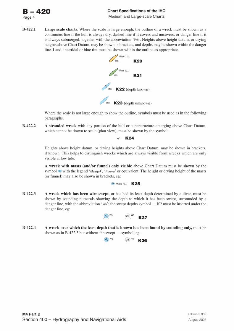
Chart Specifications of the IhoMedium and Large-scale Charts
Edition 3.003
August 2006
M4 Part BSection �00 – Hydrography and Navigational Aids
b – 420Page �
B-422.1 Large scale charts. Where the scale is large enough, the outline of a wreck must be shown as a continuous line if the hull is always dry, dashed line if it covers and uncovers, or danger line if it is always submerged, together with the abbreviation ‘Wk’. Heights above height datum, or drying heights above Chart Datum, may be shown in brackets, and depths may be shown within the danger line. Land, intertidal or blue tint must be shown within the outline as appropriate.
Wk
Mast (1,2)
K20
Wk
Mast (1 )2
K21
Wk52 K22 (depth known)
Wk K23 (depth unknown)
Where the scale is not large enough to show the outline, symbols must be used as in the following paragraphs.
B-422.2 A stranded wreck with any portion of the hull or superstructure emerging above Chart Datum, which cannot be drawn to scale (plan view), must be shown by the symbol:
K24
Heights above height datum, or drying heights above Chart Datum, may be shown in brackets, if known. This helps to distinguish wrecks which are always visible from wrecks which are only visible at low tide.
A wreck with masts (and/or funnel) only visible above Chart Datum must be shown by the symbol with the legend ‘Mast(s)’, ‘Funnel’ or equivalent. The height or drying height of the masts (or funnel) may also be shown in brackets, eg:
Masts (1 )2 K25
B-422.3 A wreck which has been wire swept, or has had its least depth determined by a diver, must be shown by sounding numerals showing the depth to which it has been swept, surrounded by a danger line, with the abbreviation ‘Wk’; the swept depths symbol K2 must be inserted under the danger line, eg:
Wk Wk2546 K27
B-422.4 A wreck over which the least depth that is known has been found by sounding only, must be shown as in B-422.3 but without the swept symbol, eg:
Wk Wk2546 K26
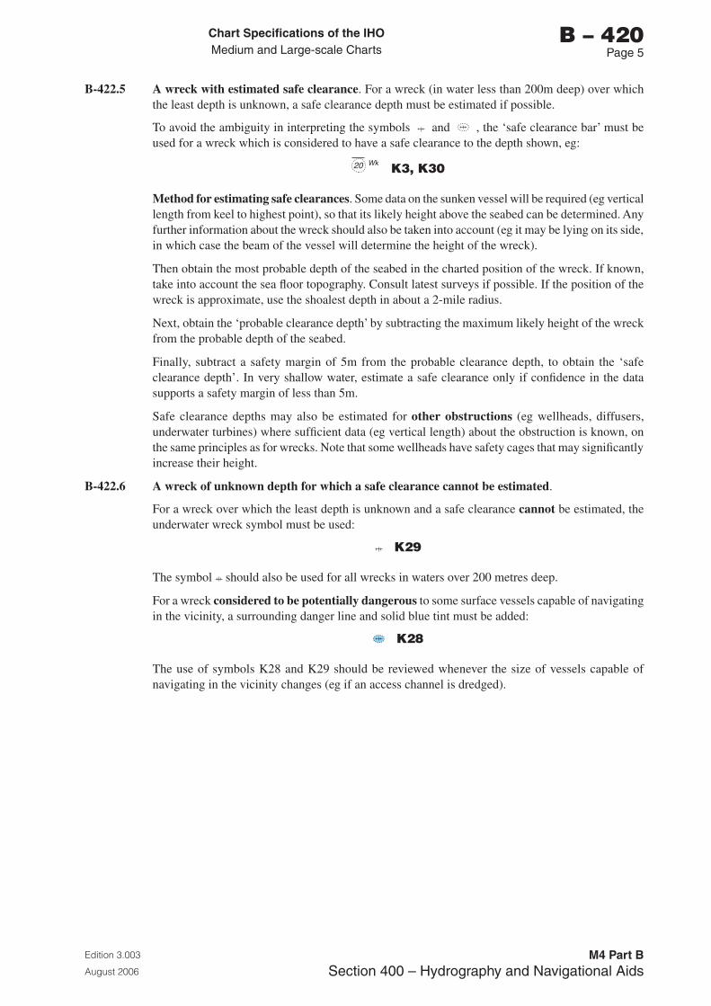
Chart Specifications of the IhoMedium and Large-scale Charts
Edition 3.003
August 2006
M4 Part BSection �00 – Hydrography and Navigational Aids
b – 420Page 5
B-422.5 A wreck with estimated safe clearance. For a wreck (in water less than 200m deep) over which the least depth is unknown, a safe clearance depth must be estimated if possible.
To avoid the ambiguity in interpreting the symbols and , the ‘safe clearance bar’ must be used for a wreck which is considered to have a safe clearance to the depth shown, eg:
Wk20 K3, K30
Method for estimating safe clearances. Some data on the sunken vessel will be required (eg vertical length from keel to highest point), so that its likely height above the seabed can be determined. Any further information about the wreck should also be taken into account (eg it may be lying on its side, in which case the beam of the vessel will determine the height of the wreck).
Then obtain the most probable depth of the seabed in the charted position of the wreck. If known, take into account the sea floor topography. Consult latest surveys if possible. If the position of the wreck is approximate, use the shoalest depth in about a 2-mile radius.
Next, obtain the ‘probable clearance depth’ by subtracting the maximum likely height of the wreck from the probable depth of the seabed.
Finally, subtract a safety margin of 5m from the probable clearance depth, to obtain the ‘safe clearance depth’. In very shallow water, estimate a safe clearance only if confidence in the data supports a safety margin of less than 5m.
Safe clearance depths may also be estimated for other obstructions (eg wellheads, diffusers, underwater turbines) where sufficient data (eg vertical length) about the obstruction is known, on the same principles as for wrecks. Note that some wellheads have safety cages that may significantly increase their height.
B-422.6 A wreck of unknown depth for which a safe clearance cannot be estimated.
For a wreck over which the least depth is unknown and a safe clearance cannot be estimated, the underwater wreck symbol must be used:
K29
The symbol should also be used for all wrecks in waters over 200 metres deep.
For a wreck considered to be potentially dangerous to some surface vessels capable of navigating in the vicinity, a surrounding danger line and solid blue tint must be added:
K28
The use of symbols K28 and K29 should be reviewed whenever the size of vessels capable of navigating in the vicinity changes (eg if an access channel is dredged).
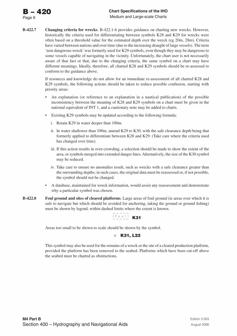
Chart Specifications of the IhoMedium and Large-scale Charts
Edition 3.003
August 2006
M4 Part BSection �00 – Hydrography and Navigational Aids
b – 420Page 6
B-422.7 Changing criteria for wrecks. B-422.1-6 provides guidance on charting new wrecks. However, historically the criteria used for differentiating between symbols K28 and K29 for wrecks were often based on a threshold value for the estimated depth over the wreck (eg 20m, 28m). Criteria have varied between nations and over time (due to the increasing draught of large vessels). The term ‘non-dangerous wreck’ was formerly used for K29 symbols, even though they may be dangerous to some vessels capable of navigating in the vicinity. Unfortunately, the chart user is not necessarily aware of that fact or that, due to the changing criteria, the same symbol on a chart may have different meanings. Ideally, therefore, all charted K28 and K29 symbols should be re-assessed to conform to the guidance above.
If resources and knowledge do not allow for an immediate re-assessment of all charted K28 and K29 symbols, the following actions should be taken to reduce possible confusion, starting with priority areas:
• An explanation (or reference to an explanation in a nautical publication) of the possible inconsistency between the meaning of K28 and K29 symbols on a chart must be given in the national equivalent of INT 1, and a cautionary note may be added to charts.
• Existing K29 symbols may be updated according to the following formula:
i. Retain K29 in water deeper than 100m.
ii. In water shallower than 100m, amend K29 to K30, with the safe clearance depth being that formerly applied to differentiate between K28 and K29. (Take care where the criteria used has changed over time).
iii. If this action results in over-crowding, a selection should be made to show the extent of the area, or symbols merged into extended danger lines. Alternatively, the size of the K30 symbol may be reduced.
iv. Take care to ensure no anomalies result, such as wrecks with a safe clearance greater than the surrounding depths; in such cases, the original data must be reassessed or, if not possible, the symbol should not be changed.
• A database, maintained for wreck information, would assist any reassessment and demonstrate why a particular symbol was chosen.
B-422.8 Foul ground and sites of cleared platforms. Large areas of foul ground (ie areas over which it is safe to navigate but which should be avoided for anchoring, taking the ground or ground fishing) must be shown by legend, within dashed limits where the extent is known.
F o u l K31
Areas too small to be shown to scale should be shown by the symbol.
K31, L22
This symbol may also be used for the remains of a wreck or the site of a cleared production platform, provided the platform has been removed to the seabed. Platforms which have been cut-off above the seabed must be charted as obstructions.
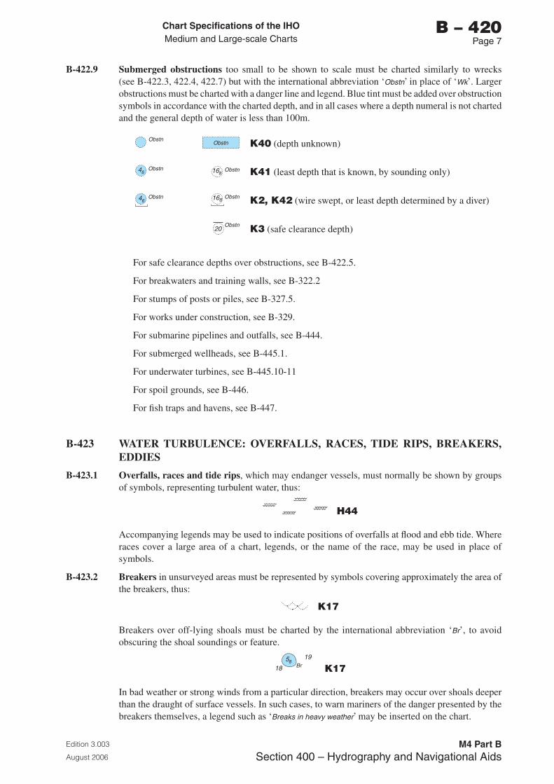
Chart Specifications of the IhoMedium and Large-scale Charts
Edition 3.003
August 2006
M4 Part BSection �00 – Hydrography and Navigational Aids
b – 420Page �
B-422.9 Submerged obstructions too small to be shown to scale must be charted similarly to wrecks (see B-422.3, 422.4, 422.7) but with the international abbreviation ‘Obstn’ in place of ‘Wk’. Larger obstructions must be charted with a danger line and legend. Blue tint must be added over obstruction symbols in accordance with the charted depth, and in all cases where a depth numeral is not charted and the general depth of water is less than 100m.
ObstnObstn K40 (depth unknown)
Obstn Obstn16846 K41 (least depth that is known, by sounding only)
Obstn Obstn16846 K2, K42 (wire swept, or least depth determined by a diver)
Obstn20 K3 (safe clearance depth)
For safe clearance depths over obstructions, see B-422.5.
For breakwaters and training walls, see B-322.2
For stumps of posts or piles, see B-327.5.
For works under construction, see B-329.
For submarine pipelines and outfalls, see B-444.
For submerged wellheads, see B-445.1.
For underwater turbines, see B-445.10-11
For spoil grounds, see B-446.
For fish traps and havens, see B-447.
B-423 WATER TURBULENCE: OVERFALLS, RACES, TIDE RIPS, BREAKERS, EDDIES
B-423.1 Overfalls, races and tide rips, which may endanger vessels, must normally be shown by groups of symbols, representing turbulent water, thus:
H44
Accompanying legends may be used to indicate positions of overfalls at flood and ebb tide. Where races cover a large area of a chart, legends, or the name of the race, may be used in place of symbols.
B-423.2 Breakers in unsurveyed areas must be represented by symbols covering approximately the area of the breakers, thus:
K17
Breakers over off-lying shoals must be charted by the international abbreviation ‘Br’, to avoid obscuring the shoal soundings or feature.
18
1958Br K17
In bad weather or strong winds from a particular direction, breakers may occur over shoals deeper than the draught of surface vessels. In such cases, to warn mariners of the danger presented by the breakers themselves, a legend such as ‘Breaks in heavy weather’ may be inserted on the chart.
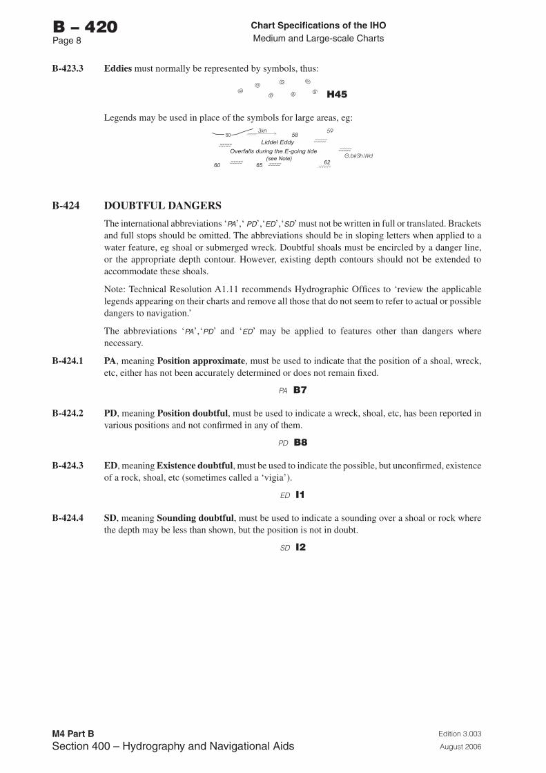
Chart Specifications of the IhoMedium and Large-scale Charts
Edition 3.003
August 2006
M4 Part BSection �00 – Hydrography and Navigational Aids
b – 420Page �
B-423.3 Eddies must normally be represented by symbols, thus:
H45
Legends may be used in place of the symbols for large areas, eg:
B-424 DOUBTFUL DANGERS
The international abbreviations ‘PA’,‘ PD’,‘ED’,‘SD’ must not be written in full or translated. Brackets and full stops should be omitted. The abbreviations should be in sloping letters when applied to a water feature, eg shoal or submerged wreck. Doubtful shoals must be encircled by a danger line, or the appropriate depth contour. However, existing depth contours should not be extended to accommodate these shoals.
Note: Technical Resolution A1.11 recommends Hydrographic Offices to ‘review the applicable legends appearing on their charts and remove all those that do not seem to refer to actual or possible dangers to navigation.’
The abbreviations ‘PA’,‘PD’ and ‘ED’ may be applied to features other than dangers where necessary.
B-424.1 PA, meaning Position approximate, must be used to indicate that the position of a shoal, wreck, etc, either has not been accurately determined or does not remain fixed.
PA b7
B-424.2 PD, meaning Position doubtful, must be used to indicate a wreck, shoal, etc, has been reported in various positions and not confirmed in any of them.
PD b8
B-424.3 ED, meaning Existence doubtful, must be used to indicate the possible, but unconfirmed, existence of a rock, shoal, etc (sometimes called a ‘vigia’).
ED I1
B-424.4 SD, meaning Sounding doubtful, must be used to indicate a sounding over a shoal or rock where the depth may be less than shown, but the position is not in doubt.
SD I2
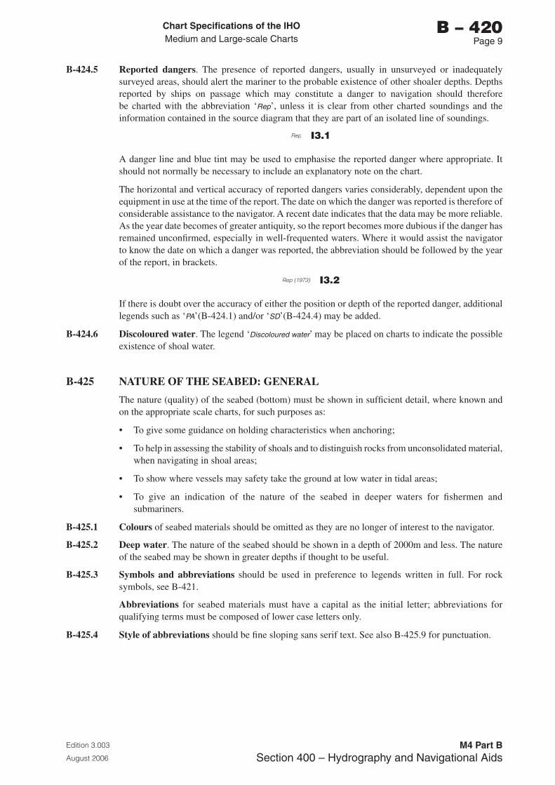
Chart Specifications of the IhoMedium and Large-scale Charts
Edition 3.003
August 2006
M4 Part BSection �00 – Hydrography and Navigational Aids
b – 420Page �
B-424.5 Reported dangers. The presence of reported dangers, usually in unsurveyed or inadequately surveyed areas, should alert the mariner to the probable existence of other shoaler depths. Depths reported by ships on passage which may constitute a danger to navigation should therefore be charted with the abbreviation ‘Rep’, unless it is clear from other charted soundings and the information contained in the source diagram that they are part of an isolated line of soundings.
Rep I3.1
A danger line and blue tint may be used to emphasise the reported danger where appropriate. It should not normally be necessary to include an explanatory note on the chart.
The horizontal and vertical accuracy of reported dangers varies considerably, dependent upon the equipment in use at the time of the report. The date on which the danger was reported is therefore of considerable assistance to the navigator. A recent date indicates that the data may be more reliable. As the year date becomes of greater antiquity, so the report becomes more dubious if the danger has remained unconfirmed, especially in well-frequented waters. Where it would assist the navigator to know the date on which a danger was reported, the abbreviation should be followed by the year of the report, in brackets.
Rep (1973) I3.2
If there is doubt over the accuracy of either the position or depth of the reported danger, additional legends such as ‘PA’(B-424.1) and/or ‘SD’(B-424.4) may be added.
B-424.6 Discoloured water. The legend ‘Discoloured water’ may be placed on charts to indicate the possible existence of shoal water.
B-425 NATURE OF THE SEABED: GENERAL
The nature (quality) of the seabed (bottom) must be shown in sufficient detail, where known and on the appropriate scale charts, for such purposes as:
• To give some guidance on holding characteristics when anchoring;
• To help in assessing the stability of shoals and to distinguish rocks from unconsolidated material, when navigating in shoal areas;
• To show where vessels may safety take the ground at low water in tidal areas;
• To give an indication of the nature of the seabed in deeper waters for fishermen and submariners.
B-425.1 Colours of seabed materials should be omitted as they are no longer of interest to the navigator.
B-425.2 Deep water. The nature of the seabed should be shown in a depth of 2000m and less. The nature of the seabed may be shown in greater depths if thought to be useful.
B-425.3 Symbols and abbreviations should be used in preference to legends written in full. For rock symbols, see B-421.
Abbreviations for seabed materials must have a capital as the initial letter; abbreviations for qualifying terms must be composed of lower case letters only.
B-425.4 Style of abbreviations should be fine sloping sans serif text. See also B-425.9 for punctuation.
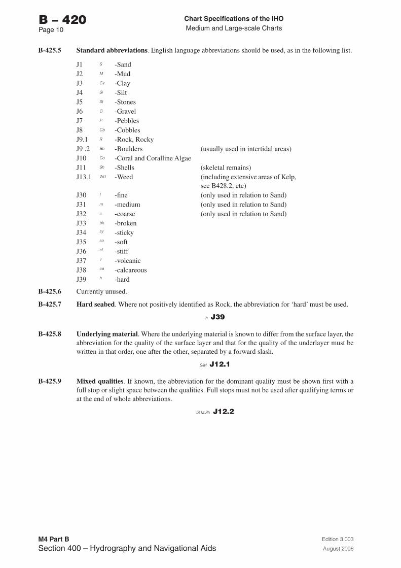
Chart Specifications of the IhoMedium and Large-scale Charts
Edition 3.003
August 2006
M4 Part BSection �00 – Hydrography and Navigational Aids
b – 420Page 10
B-425.5 Standard abbreviations. English language abbreviations should be used, as in the following list.
J1 S -SandJ2 M -MudJ3 Cy -Clay J4 Si -SiltJ5 St -StonesJ6 G -GravelJ7 P -PebblesJ8 Cb -CobblesJ9.1 R -Rock, RockyJ9 .2 Bo -Boulders (usually used in intertidal areas)J10 Co -Coral and Coralline AlgaeJ11 Sh -Shells (skeletal remains)J13.1 Wd -Weed (including extensive areas of Kelp,
see B428.2, etc)J30 f -fine (only used in relation to Sand)J31 m -medium (only used in relation to Sand)J32 c -coarse (only used in relation to Sand)J33 bk -brokenJ34 sy -stickyJ35 so -softJ36 sf -stiffJ37 v -volcanicJ38 ca -calcareousJ39 h -hard
B-425.6 Currently unused.
B-425.7 Hard seabed. Where not positively identified as Rock, the abbreviation for ‘hard’ must be used.
h J39
B-425.8 Underlying material. Where the underlying material is known to differ from the surface layer, the abbreviation for the quality of the surface layer and that for the quality of the underlayer must be written in that order, one after the other, separated by a forward slash.
S/M J12.1
B-425.9 Mixed qualities. If known, the abbreviation for the dominant quality must be shown first with a full stop or slight space between the qualities. Full stops must not be used after qualifying terms or at the end of whole abbreviations.
fS.M.Sh J12.2
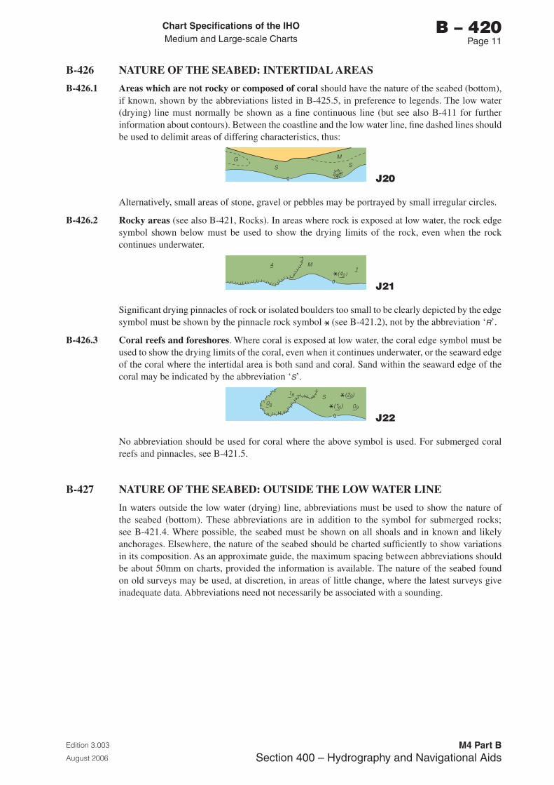
Chart Specifications of the IhoMedium and Large-scale Charts
Edition 3.003
August 2006
M4 Part BSection �00 – Hydrography and Navigational Aids
b – 420Page 11
B-426 NATURE OF THE SEABED: INTERTIDAL AREAS
B-426.1 Areas which are not rocky or composed of coral should have the nature of the seabed (bottom), if known, shown by the abbreviations listed in B-425.5, in preference to legends. The low water (drying) line must normally be shown as a fine continuous line (but see also B-411 for further information about contours). Between the coastline and the low water line, fine dashed lines should be used to delimit areas of differing characteristics, thus:
0
SG M
S
J20
Alternatively, small areas of stone, gravel or pebbles may be portrayed by small irregular circles.
B-426.2 Rocky areas (see also B-421, Rocks). In areas where rock is exposed at low water, the rock edge symbol shown below must be used to show the drying limits of the rock, even when the rock continues underwater.
4 M1
(42 )
0 J21
Significant drying pinnacles of rock or isolated boulders too small to be clearly depicted by the edge symbol must be shown by the pinnacle rock symbol (see B-421.2), not by the abbreviation ‘R’.
B-426.3 Coral reefs and foreshores. Where coral is exposed at low water, the coral edge symbol must be used to show the drying limits of the coral, even when it continues underwater, or the seaward edge of the coral where the intertidal area is both sand and coral. Sand within the seaward edge of the coral may be indicated by the abbreviation ‘S’.
0
(2 )9
(1 )6 09
S18
08
J22
No abbreviation should be used for coral where the above symbol is used. For submerged coral reefs and pinnacles, see B-421.5.
B-427 NATURE OF THE SEABED: OUTSIDE THE LOW WATER LINE
In waters outside the low water (drying) line, abbreviations must be used to show the nature of the seabed (bottom). These abbreviations are in addition to the symbol for submerged rocks; see B-421.4. Where possible, the seabed must be shown on all shoals and in known and likely anchorages. Elsewhere, the nature of the seabed should be charted sufficiently to show variations in its composition. As an approximate guide, the maximum spacing between abbreviations should be about 50mm on charts, provided the information is available. The nature of the seabed found on old surveys may be used, at discretion, in areas of little change, where the latest surveys give inadequate data. Abbreviations need not necessarily be associated with a sounding.
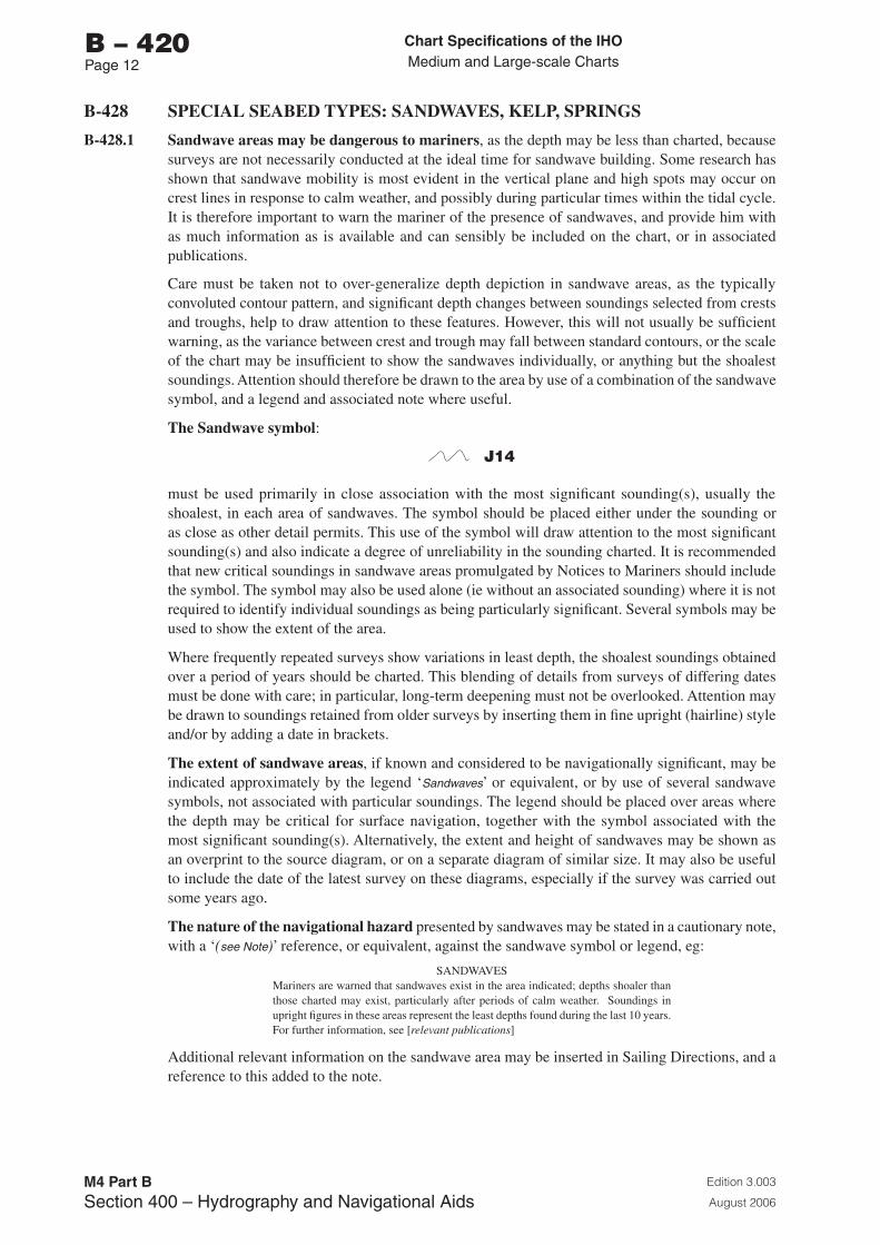
Chart Specifications of the IhoMedium and Large-scale Charts
Edition 3.003
August 2006
M4 Part BSection �00 – Hydrography and Navigational Aids
b – 420Page 12
B-428 SPECIAL SEABED TYPES: SANDWAVES, KELP, SPRINGS
B-428.1 Sandwave areas may be dangerous to mariners, as the depth may be less than charted, because surveys are not necessarily conducted at the ideal time for sandwave building. Some research has shown that sandwave mobility is most evident in the vertical plane and high spots may occur on crest lines in response to calm weather, and possibly during particular times within the tidal cycle. It is therefore important to warn the mariner of the presence of sandwaves, and provide him with as much information as is available and can sensibly be included on the chart, or in associated publications.
Care must be taken not to over-generalize depth depiction in sandwave areas, as the typically convoluted contour pattern, and significant depth changes between soundings selected from crests and troughs, help to draw attention to these features. However, this will not usually be sufficient warning, as the variance between crest and trough may fall between standard contours, or the scale of the chart may be insufficient to show the sandwaves individually, or anything but the shoalest soundings. Attention should therefore be drawn to the area by use of a combination of the sandwave symbol, and a legend and associated note where useful.
The Sandwave symbol:
J14
must be used primarily in close association with the most significant sounding(s), usually the shoalest, in each area of sandwaves. The symbol should be placed either under the sounding or as close as other detail permits. This use of the symbol will draw attention to the most significant sounding(s) and also indicate a degree of unreliability in the sounding charted. It is recommended that new critical soundings in sandwave areas promulgated by Notices to Mariners should include the symbol. The symbol may also be used alone (ie without an associated sounding) where it is not required to identify individual soundings as being particularly significant. Several symbols may be used to show the extent of the area.
Where frequently repeated surveys show variations in least depth, the shoalest soundings obtained over a period of years should be charted. This blending of details from surveys of differing dates must be done with care; in particular, long-term deepening must not be overlooked. Attention may be drawn to soundings retained from older surveys by inserting them in fine upright (hairline) style and/or by adding a date in brackets.
The extent of sandwave areas, if known and considered to be navigationally significant, may be indicated approximately by the legend ‘Sandwaves’ or equivalent, or by use of several sandwave symbols, not associated with particular soundings. The legend should be placed over areas where the depth may be critical for surface navigation, together with the symbol associated with the most significant sounding(s). Alternatively, the extent and height of sandwaves may be shown as an overprint to the source diagram, or on a separate diagram of similar size. It may also be useful to include the date of the latest survey on these diagrams, especially if the survey was carried out some years ago.
The nature of the navigational hazard presented by sandwaves may be stated in a cautionary note, with a ‘(see Note)’ reference, or equivalent, against the sandwave symbol or legend, eg:
SANDWAVESMariners are warned that sandwaves exist in the area indicated; depths shoaler than those charted may exist, particularly after periods of calm weather. Soundings in upright figures in these areas represent the least depths found during the last 10 years. For further information, see [relevant publications]
Additional relevant information on the sandwave area may be inserted in Sailing Directions, and a reference to this added to the note.
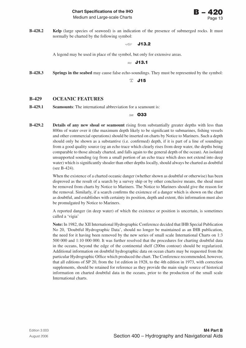
Chart Specifications of the IhoMedium and Large-scale Charts
Edition 3.003
August 2006
M4 Part BSection �00 – Hydrography and Navigational Aids
b – 420Page 1�
B-428.2 Kelp (large species of seaweed) is an indication of the presence of submerged rocks. It must normally be charted by the following symbol:
J13.2
A legend may be used in place of the symbol, but only for extensive areas.
Wd J13.1
B-428.3 Springs in the seabed may cause false echo-soundings. They must be represented by the symbol:
J15
B-429 OCEANIC FEATURES
B-429.1 Seamounts: The international abbreviation for a seamount is:
SMt O33
B-429.2 Details of any new shoal or seamount rising from substantially greater depths with less than 800m of water over it (the maximum depth likely to be significant to submarines, fishing vessels and other commercial operations) should be inserted on charts by Notice to Mariners. Such a depth should only be shown as a substantive (i.e. confirmed) depth, if it is part of a line of soundings from a good quality source (eg an echo trace which clearly rises from deep water, the depths being comparable to those already charted, and falls again to the general depth of the ocean). An isolated unsupported sounding (eg from a small portion of an echo trace which does not extend into deep water) which is significantly shoaler than other depths locally, should always be charted as doubtful (see B-424).
When the existence of a charted oceanic danger (whether shown as doubtful or otherwise) has been disproved as the result of a search by a survey ship or by other conclusive means, the shoal must be removed from charts by Notice to Mariners. The Notice to Mariners should give the reason for the removal. Similarly, if a search confirms the existence of a danger which is shown on the chart as doubtful, and establishes with certainty its position, depth and extent, this information must also be promulgated by Notice to Mariners.
A reported danger (in deep water) of which the existence or position is uncertain, is sometimes called a ‘vigia’
Note: In 1982, the XII International Hydrographic Conference decided that IHB Special Publication No 20, ‘Doubtful Hydrographic Data’, should no longer be maintained as an IHB publication, the need for it having been removed by the new series of small scale International Charts on 1:3 500 000 and 1:10 000 000. It was further resolved that the procedures for charting doubtful data in the oceans, beyond the edge of the continental shelf (200m contour) should be regularized. Additional information on doubtful hydrographic data on ocean charts may be requested from the particular Hydrographic Office which produced the chart. The Conference recommended, however, that all editions of SP 20, from the 1st edition in 1928, to the 4th edition in 1973, with correction supplements, should be retained for reference as they provide the main single source of historical information on charted doubtful data in the oceans, prior to the production of the small scale International charts.

Page intentionally left blank
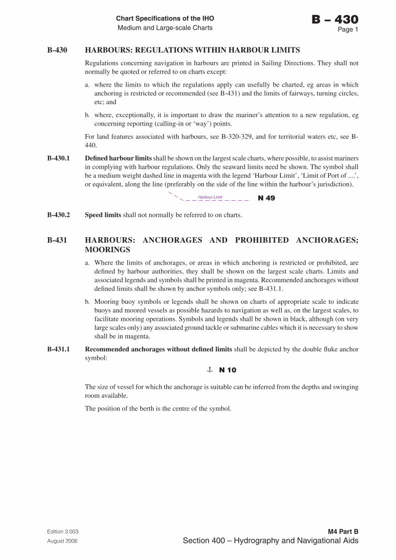
Chart Specifications of the IhoMedium and Large-scale Charts
Edition 3.003
August 2006
M4 Part BSection �00 – Hydrography and Navigational Aids
b – 430Page 1
B-430 HARBOURS: REGULATIONS WITHIN HARBOUR LIMITS
Regulations concerning navigation in harbours are printed in Sailing Directions. They shall not normally be quoted or referred to on charts except:
a. where the limits to which the regulations apply can usefully be charted, eg areas in which anchoring is restricted or recommended (see B-431) and the limits of fairways, turning circles, etc; and
b. where, exceptionally, it is important to draw the mariner’s attention to a new regulation, eg concerning reporting (calling-in or ‘way’) points.
For land features associated with harbours, see B-320-329, and for territorial waters etc, see B-440.
B-430.1 Defined harbour limits shall be shown on the largest scale charts, where possible, to assist mariners in complying with harbour regulations. Only the seaward limits need be shown. The symbol shall be a medium weight dashed line in magenta with the legend ‘Harbour Limit’, ‘Limit of Port of ....’, or equivalent, along the line (preferably on the side of the line within the harbour’s jurisdiction).
Harbour Limit N 49
B-430.2 Speed limits shall not normally be referred to on charts.
B-431 HARBOURS: ANCHORAGES AND PROHIBITED ANCHORAGES; MOORINGS
a. Where the limits of anchorages, or areas in which anchoring is restricted or prohibited, are defined by harbour authorities, they shall be shown on the largest scale charts. Limits and associated legends and symbols shall be printed in magenta. Recommended anchorages without defined limits shall be shown by anchor symbols only; see B-431.1.
b. Mooring buoy symbols or legends shall be shown on charts of appropriate scale to indicate buoys and moored vessels as possible hazards to navigation as well as, on the largest scales, to facilitate mooring operations. Symbols and legends shall be shown in black, although (on very large scales only) any associated ground tackle or submarine cables which it is necessary to show shall be in magenta.
B-431.1 Recommended anchorages without defined limits shall be depicted by the double fluke anchor symbol:
N 10
The size of vessel for which the anchorage is suitable can be inferred from the depths and swinging room available.
The position of the berth is the centre of the symbol.
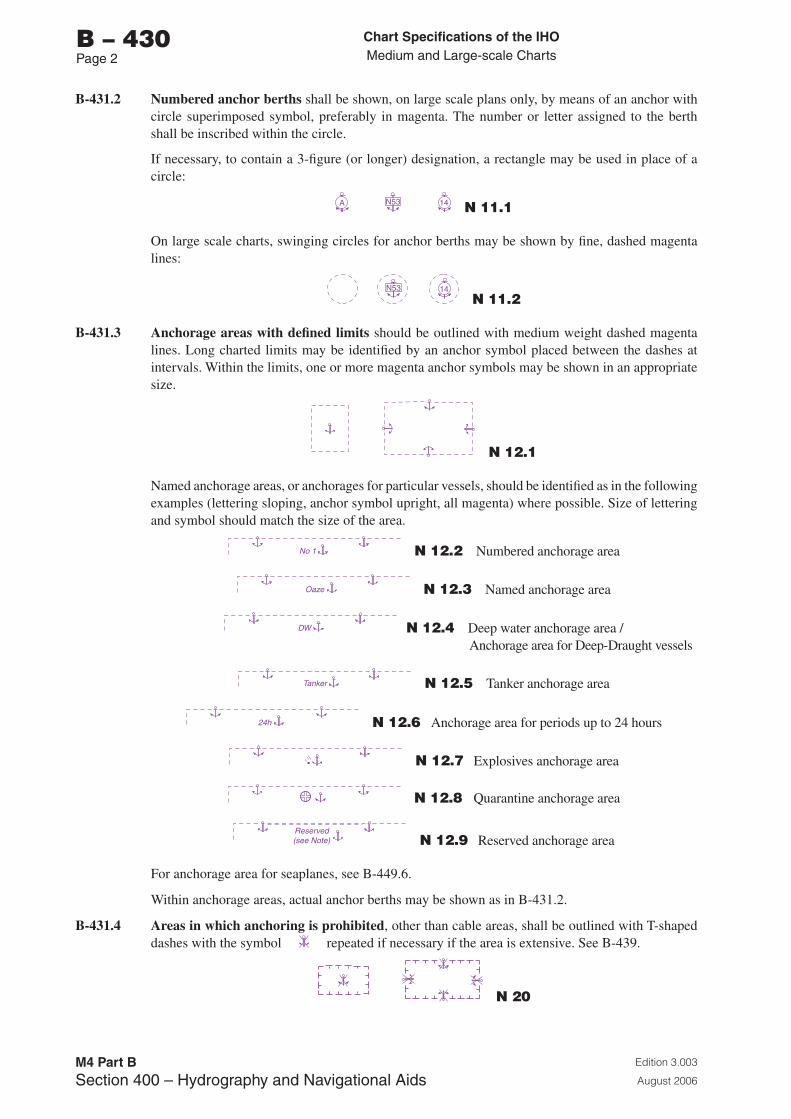
Chart Specifications of the IhoMedium and Large-scale Charts
Edition 3.003
August 2006
M4 Part BSection �00 – Hydrography and Navigational Aids
b – 430Page 2
B-431.2 Numbered anchor berths shall be shown, on large scale plans only, by means of an anchor with circle superimposed symbol, preferably in magenta. The number or letter assigned to the berth shall be inscribed within the circle.
If necessary, to contain a 3-figure (or longer) designation, a rectangle may be used in place of a circle:
A N53 14 N 11.1
On large scale charts, swinging circles for anchor berths may be shown by fine, dashed magenta lines:
N53 14
N 11.2
B-431.3 Anchorage areas with defined limits should be outlined with medium weight dashed magenta lines. Long charted limits may be identified by an anchor symbol placed between the dashes at intervals. Within the limits, one or more magenta anchor symbols may be shown in an appropriate size.
N 12.1
Named anchorage areas, or anchorages for particular vessels, should be identified as in the following examples (lettering sloping, anchor symbol upright, all magenta) where possible. Size of lettering and symbol should match the size of the area.
No 1 N 12.2 Numbered anchorage area
Oaze N 12.3 Named anchorage area
DW N 12.4 Deep water anchorage area / Anchorage area for Deep-Draught vessels
Tanker N 12.5 Tanker anchorage area
24h N 12.6 Anchorage area for periods up to 24 hours
N 12.7 Explosives anchorage area
N 12.8 Quarantine anchorage area
Reserved(see Note) N 12.9 Reserved anchorage area
For anchorage area for seaplanes, see B-449.6.
Within anchorage areas, actual anchor berths may be shown as in B-431.2.
B-431.4 Areas in which anchoring is prohibited, other than cable areas, shall be outlined with T-shaped dashes with the symbol repeated if necessary if the area is extensive. See B-439.
N 20
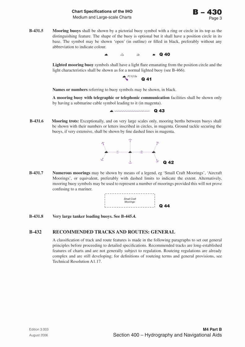
Chart Specifications of the IhoMedium and Large-scale Charts
Edition 3.003
August 2006
M4 Part BSection �00 – Hydrography and Navigational Aids
b – 430Page �
B-431.5 Mooring buoys shall be shown by a pictorial buoy symbol with a ring or circle in its top as the distinguishing feature. The shape of the buoy is optional but it shall have a position circle in its base. The symbol may be shown ‘open’ (in outline) or filled in black, preferably without any abbreviation to indicate colour.
Q 40
Lighted mooring buoy symbols shall have a light flare emanating from the position circle and the light characteristics shall be shown as for a normal lighted buoy (see B-466).
Fl.Y.2·5s Q 41
Names or numbers referring to buoy symbols may be shown, in black.
A mooring buoy with telegraphic or telephonic communication facilities shall be shown only by having a submarine cable symbol leading to it (in magenta).
Q 43
B-431.6 Mooring trots: Exceptionally, and on very large scales only, mooring berths between buoys shall be shown with their numbers or letters inscribed in circles, in magenta. Ground tackle securing the buoys, if very extensive, shall be shown by fine dashed lines in magenta.
21
Q 42
B-431.7 Numerous moorings may be shown by means of a legend, eg ‘Small Craft Moorings’, ‘Aircraft Moorings’, or equivalent, preferably with dashed limits to indicate the extent. Alternatively, mooring buoy symbols may be used to represent a number of moorings provided this will not prove confusing to a mariner.
Small CraftMoorings
Q 44
B-431.8 Very large tanker loading buoys. See B-445.4.
B-432 RECOMMENDED TRACKS AND ROUTES: GENERAL
A classification of track and route features is made in the following paragraphs to set out general principles before proceeding to detailed specifications. Recommended tracks are long-established features of charts and are not generally subject to regulation. Routeing regulations are already complex and are still developing; for definitions of routeing terms and general provisions, see Technical Resolution A1.17.
Chart Specifications of the IhoMedium and Large-scale Charts
Edition 3.003
August 2006
M4 Part BSection �00 – Hydrography and Navigational Aids
b – 430Page �
B-432.1 The term ‘Recommended tracks’ (French: voies recommandées), in its widest sense, includes all channels recommended for hydrographic reasons to lead safely between shoal depths. The use of such tracks is generally left to the discretion of the mariner and will depend on his vessel’s draught, the state of the tide, adequacy of navigational aids and so on. Apart from channels defined only by the depth contours, such tracks include:
a. recommended tracks in the narrow sense which have the recommended course line (and bearing) charted, ie., the centre-line is shown by a firm line where based on fixed marks and, generally, by a dashed line where it is not defined by fixed marks (these are recommended tracks proper);
b. channels which have their outer limits shown, usually in part only, by transits or ‘clearing lines’ based on natural objects or beacons: such lines are generally dashed to distinguish them from leading lines;
c. channels which have their outer limits shown, in part, by light sectors (their detailed representation is described in B-475.5) or direction lights (see B-475.7);
d. tracks which have their centreline shown by a radio bearing line from a directional radio beacon (see B-481.2 and B-486.5).
These chart features may well be combined in any channel. Their common characteristics are that they generally occur fairly close inshore and are used primarily to avoid shoal depths rather than to regulate shipping movements.
Such features are to be charted in black, apart from radio bearing lines which are shown in magenta if not associated with another type of track (see B-481.2 and B-486.5).
Bearings quoted must refer to the true compass; bearings measured from the chart must agree with bearings stated on the chart, in the List of Lights, and in Sailing Directions.
See B-433 and B-434 for detailed specifications of leading and clearing lines, and recommended tracks (in the narrowest sense).
B-432.2 The term ‘Routeing’ is used in these specifications to describe the regulation of navigation for non-hydrographic reasons such as the prevention of collision or avoidance of pollution risks. Routes (French: routes réglementées) subject to regulations are generally laid down by a national or international authority other than the hydrographic authority (although possibly with the latter’s advice).
Routeing measures as designated by IMO, comprises:
a. ‘traffic separation schemes’, with any associated ‘inshore traffic zones’;
b. ‘precautionary areas’;
c. ‘deep water routes’;
d. ‘recommended routes’;
e. ‘recommended directions of traffic flow’;
f. ‘two-way routes’;
g. ‘areas to be avoided’ by certain classes of ships (routeing in a negative sense).
In addition, there are some nationally-adopted types of routeing measures such as ‘safety fairways’ and ‘controlled access channels’ to certain ports.
a to g are to be represented by symbols, in magenta, which have been agreed internationally between IHO and IMO and are reproduced in IMO’s ‘Ships’ Routeing’. See also B-435 and B-436. Definitions of the routeing measures are given in Technical Resolution A1.17.
a (apart from some inshore traffic zones) b, c, f, and g, have limits which are precisely defined in ‘Ships’ Routeing’. As far as possible, all scales of charts on which it is appropriate to show the measures should chart the limits, rather than centre-lines.
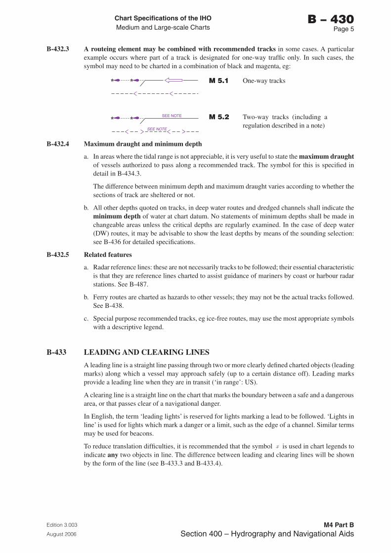
Chart Specifications of the IhoMedium and Large-scale Charts
Edition 3.003
August 2006
M4 Part BSection �00 – Hydrography and Navigational Aids
b – 430Page 5
B-432.3 A routeing element may be combined with recommended tracks in some cases. A particular example occurs where part of a track is designated for one-way traffic only. In such cases, the symbol may need to be charted in a combination of black and magenta, eg:
M 5.1 One-way tracks
SEE NOTE
SEE NOTE M 5.2 Two-way tracks (including a regulation described in a note)
B-432.4 Maximum draught and minimum depth
a. In areas where the tidal range is not appreciable, it is very useful to state the maximum draught of vessels authorized to pass along a recommended track. The symbol for this is specified in detail in B-434.3.
The difference between minimum depth and maximum draught varies according to whether the sections of track are sheltered or not.
b. All other depths quoted on tracks, in deep water routes and dredged channels shall indicate the minimum depth of water at chart datum. No statements of minimum depths shall be made in changeable areas unless the critical depths are regularly examined. In the case of deep water (DW) routes, it may be advisable to show the least depths by means of the sounding selection: see B-436 for detailed specifications.
B-432.5 Related features
a. Radar reference lines: these are not necessarily tracks to be followed; their essential characteristic is that they are reference lines charted to assist guidance of mariners by coast or harbour radar stations. See B-487.
b. Ferry routes are charted as hazards to other vessels; they may not be the actual tracks followed. See B-438.
c. Special purpose recommended tracks, eg ice-free routes, may use the most appropriate symbols with a descriptive legend.
B-433 LEADING AND CLEARING LINES
A leading line is a straight line passing through two or more clearly defined charted objects (leading marks) along which a vessel may approach safely (up to a certain distance off). Leading marks provide a leading line when they are in transit (‘in range’: US).
A clearing line is a straight line on the chart that marks the boundary between a safe and a dangerous area, or that passes clear of a navigational danger.
In English, the term ‘leading lights’ is reserved for lights marking a lead to be followed. ‘Lights in line’ is used for lights which mark a danger or a limit, such as the edge of a channel. Similar terms may be used for beacons.
To reduce translation difficulties, it is recommended that the symbol is used in chart legends to indicate any two objects in line. The difference between leading and clearing lines will be shown by the form of the line (see B-433.3 and B-433.4).
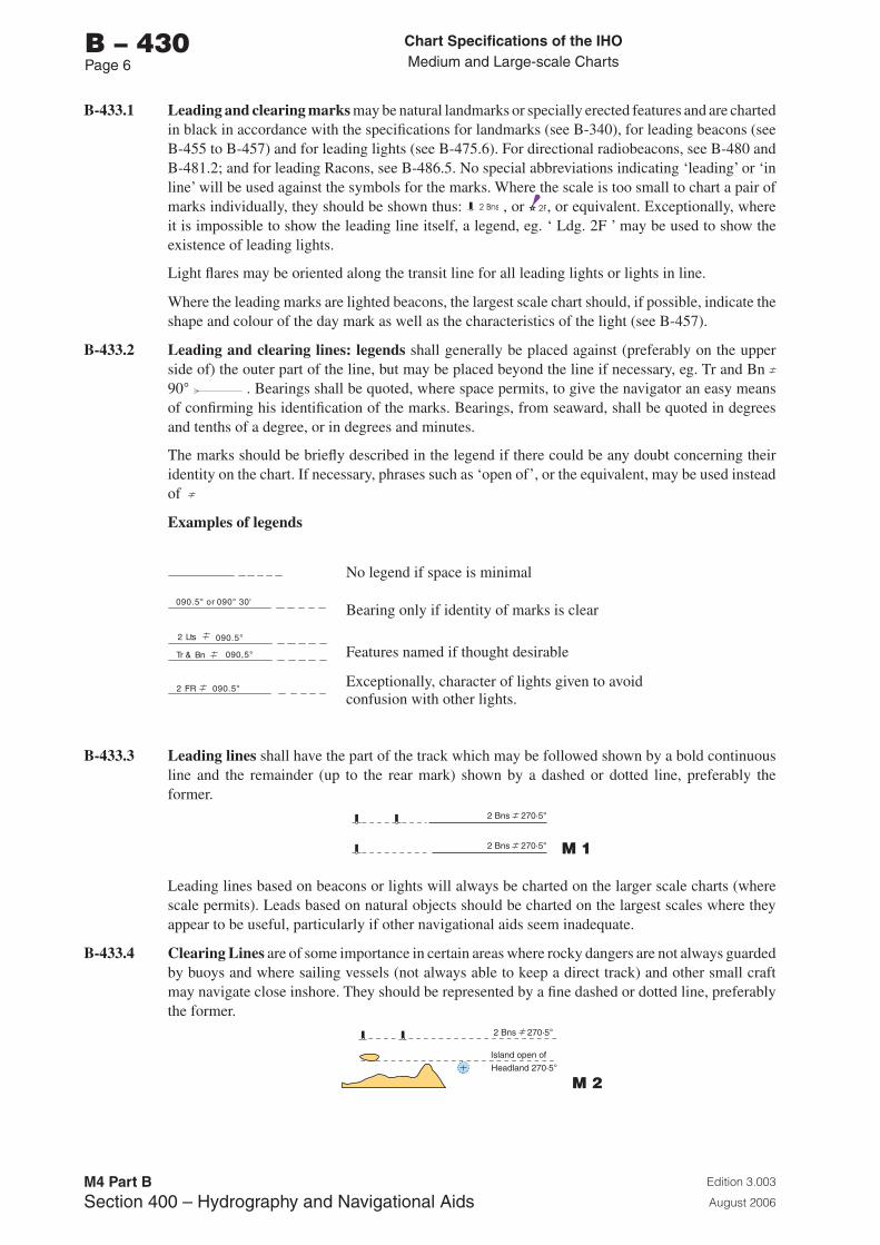
Chart Specifications of the IhoMedium and Large-scale Charts
Edition 3.003
August 2006
M4 Part BSection �00 – Hydrography and Navigational Aids
b – 430Page 6
B-433.1 Leading and clearing marks may be natural landmarks or specially erected features and are charted in black in accordance with the specifications for landmarks (see B-340), for leading beacons (see B-455 to B-457) and for leading lights (see B-475.6). For directional radiobeacons, see B-480 and B-481.2; and for leading Racons, see B-486.5. No special abbreviations indicating ‘leading’ or ‘in line’ will be used against the symbols for the marks. Where the scale is too small to chart a pair of marks individually, they should be shown thus: , or , or equivalent. Exceptionally, where it is impossible to show the leading line itself, a legend, eg. ‘ Ldg. 2F ’ may be used to show the existence of leading lights.
Light flares may be oriented along the transit line for all leading lights or lights in line.
Where the leading marks are lighted beacons, the largest scale chart should, if possible, indicate the shape and colour of the day mark as well as the characteristics of the light (see B-457).
B-433.2 Leading and clearing lines: legends shall generally be placed against (preferably on the upper side of) the outer part of the line, but may be placed beyond the line if necessary, eg. Tr and Bn 90° . Bearings shall be quoted, where space permits, to give the navigator an easy means of confirming his identification of the marks. Bearings, from seaward, shall be quoted in degrees and tenths of a degree, or in degrees and minutes.
The marks should be briefly described in the legend if there could be any doubt concerning their identity on the chart. If necessary, phrases such as ‘open of’, or the equivalent, may be used instead of
Examples of legends
090.5° or 090° 30'
2 Lts 090.5°
Tr & Bn 090,5°
2 FR 090.5°
No legend if space is minimal
Bearing only if identity of marks is clear
Features named if thought desirable
Exceptionally, character of lights given to avoid confusion with other lights.
B-433.3 Leading lines shall have the part of the track which may be followed shown by a bold continuous line and the remainder (up to the rear mark) shown by a dashed or dotted line, preferably the former.
2 Bns
2 Bns
270·5°
270·5° M 1
Leading lines based on beacons or lights will always be charted on the larger scale charts (where scale permits). Leads based on natural objects should be charted on the largest scales where they appear to be useful, particularly if other navigational aids seem inadequate.
B-433.4 Clearing Lines are of some importance in certain areas where rocky dangers are not always guarded by buoys and where sailing vessels (not always able to keep a direct track) and other small craft may navigate close inshore. They should be represented by a fine dashed or dotted line, preferably the former.
2 Bns 270·5°
Headland 270·5°
Island open of
M 2

Chart Specifications of the IhoMedium and Large-scale Charts
Edition 3.003
August 2006
M4 Part BSection �00 – Hydrography and Navigational Aids
b – 430Page �
B-433.5 Transits marking isolated dangers. Occasionally, beacons or other marks are erected on shore to indicate (approximately, unless there are two pairs of beacons) the position of an isolated danger. Such lines should be represented in the same way as clearing lines, as their nature will be apparent from the chart.
2 Bns 270·5°
Headland 270·5°
Island open of
M 2
B-434 RECOMMENDED TRACKS
The specifications in the following paragraphs are concerned with recommended tracks made up, generally, of a number of ‘legs’ or sections leading between rocky dangers lying close on both sides of the track. Such tracks commonly, but not always, include some sections defined by fixed marks (see B-433). Under the present heading, only recommended tracks in the strict sense of those with their centrelines charted are dealt with.
B-434.1 The track, where based on a system of fixed marks, shall be represented by a bold continuous line, as specified for a leading line in B-433.3.
090°- 270° M 3
A recommended track, when not based on a system of fixed marks, shall preferably be represented by a single dashed line in which arrowheads are inserted at regular intervals, in opposing pairs to represent a two-way track.
090°- 270°
M 4
For the representation of one-way tracks, see B-432.3.
B-434.2 Legends on tracks: bearings
a. Where the track is based on fixed marks, the legend referring to its bearing shall be shown as for a leading line (see B-433.2) but with the option of quoting the reciprocal bearing following the bearing from seaward, thus:
090°- 270°2 Bns M 3
b. Where the track is not based on fixed marks, the two bearings only shall be shown, first the bearing from seaward (or in the direction of the buoyage system) followed by its reciprocal, thus:
090°- 270°
M 4
Where a two-way track is of such length that the reciprocal bearings are shown near both extremities, the bearing quoted first shall in each case be that followed by a vessel joining the track at the extremity.
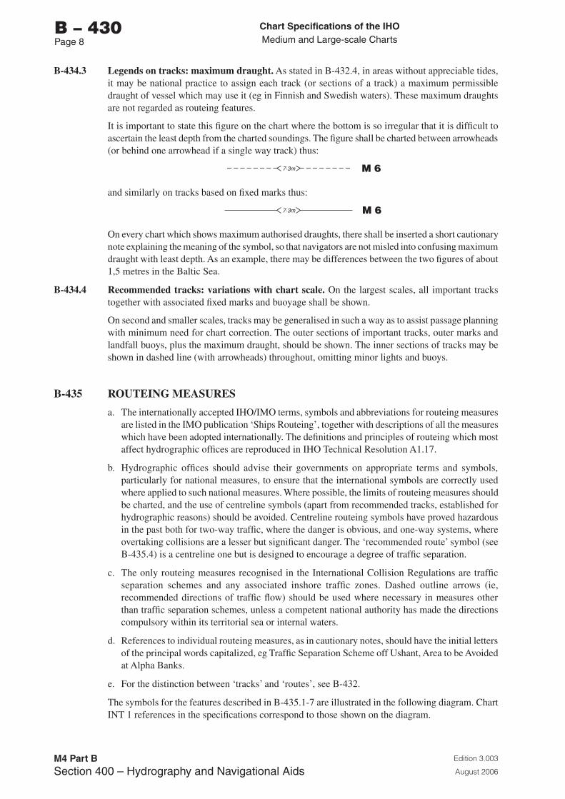
Chart Specifications of the IhoMedium and Large-scale Charts
Edition 3.003
August 2006
M4 Part BSection �00 – Hydrography and Navigational Aids
b – 430Page �
B-434.3 Legends on tracks: maximum draught. As stated in B-432.4, in areas without appreciable tides, it may be national practice to assign each track (or sections of a track) a maximum permissible draught of vessel which may use it (eg in Finnish and Swedish waters). These maximum draughts are not regarded as routeing features.
It is important to state this figure on the chart where the bottom is so irregular that it is difficult to ascertain the least depth from the charted soundings. The figure shall be charted between arrowheads (or behind one arrowhead if a single way track) thus:
7·3m M 6
and similarly on tracks based on fixed marks thus:
7·3m M 6
On every chart which shows maximum authorised draughts, there shall be inserted a short cautionary note explaining the meaning of the symbol, so that navigators are not misled into confusing maximum draught with least depth. As an example, there may be differences between the two figures of about 1,5 metres in the Baltic Sea.
B-434.4 Recommended tracks: variations with chart scale. On the largest scales, all important tracks together with associated fixed marks and buoyage shall be shown.
On second and smaller scales, tracks may be generalised in such a way as to assist passage planning with minimum need for chart correction. The outer sections of important tracks, outer marks and landfall buoys, plus the maximum draught, should be shown. The inner sections of tracks may be shown in dashed line (with arrowheads) throughout, omitting minor lights and buoys.
B-435 ROUTEING MEASURES
a. The internationally accepted IHO/IMO terms, symbols and abbreviations for routeing measures are listed in the IMO publication ‘Ships Routeing’, together with descriptions of all the measures which have been adopted internationally. The definitions and principles of routeing which most affect hydrographic offices are reproduced in IHO Technical Resolution A1.17.
b. Hydrographic offices should advise their governments on appropriate terms and symbols, particularly for national measures, to ensure that the international symbols are correctly used where applied to such national measures. Where possible, the limits of routeing measures should be charted, and the use of centreline symbols (apart from recommended tracks, established for hydrographic reasons) should be avoided. Centreline routeing symbols have proved hazardous in the past both for two-way traffic, where the danger is obvious, and one-way systems, where overtaking collisions are a lesser but significant danger. The ‘recommended route’ symbol (see B-435.4) is a centreline one but is designed to encourage a degree of traffic separation.
c. The only routeing measures recognised in the International Collision Regulations are traffic separation schemes and any associated inshore traffic zones. Dashed outline arrows (ie, recommended directions of traffic flow) should be used where necessary in measures other than traffic separation schemes, unless a competent national authority has made the directions compulsory within its territorial sea or internal waters.
d. References to individual routeing measures, as in cautionary notes, should have the initial letters of the principal words capitalized, eg Traffic Separation Scheme off Ushant, Area to be Avoided at Alpha Banks.
e. For the distinction between ‘tracks’ and ‘routes’, see B-432.
The symbols for the features described in B-435.1-7 are illustrated in the following diagram. Chart INT 1 references in the specifications correspond to those shown on the diagram.
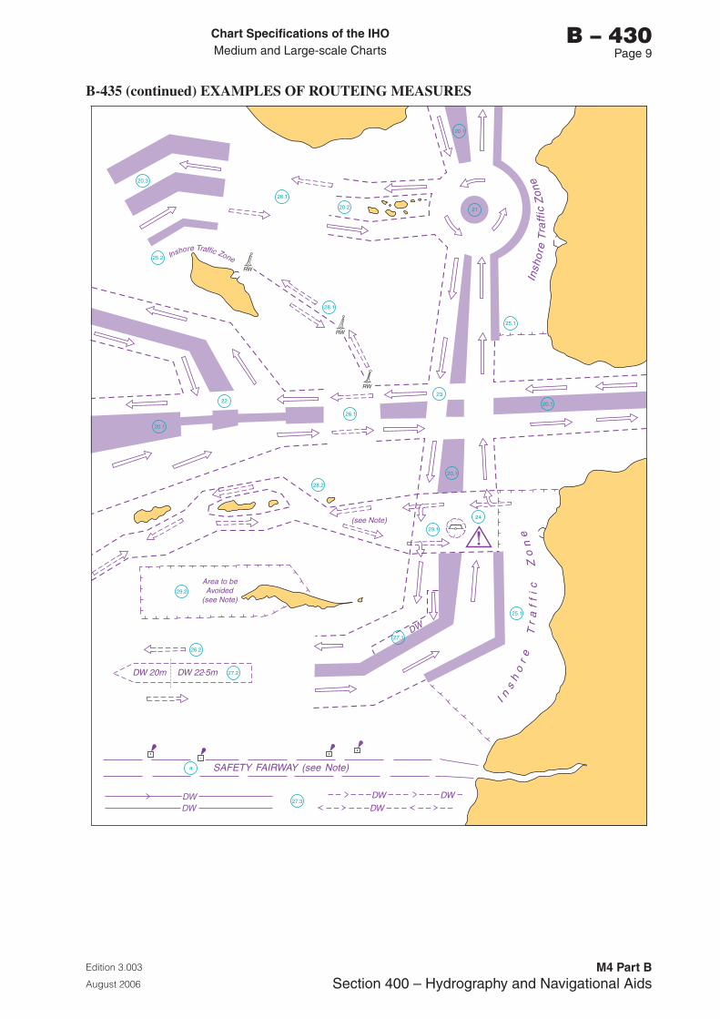
Chart Specifications of the IhoMedium and Large-scale Charts
Edition 3.003
August 2006
M4 Part BSection �00 – Hydrography and Navigational Aids
b – 430Page �
B-435 (continued) EXAMPLES OF ROUTEING MEASURES
25.1
21
25.2
20.3
26.1
28.1
20.2
20.1
23
20.122
20.1
26.1
28.2
29.2
26.2
27.2
27.1
a
27.3
29.1
20.1
25.1
24(see Note)
Area to beAvoided
(see Note)
DW 20m DW 22.5m
DW
I ns
ho
re
Tr
af
fi
cZ
on
eIn
sho
re
Tra
ffic
Zo
ne
Inshore
Traffic ZoneRW
SAFETY FAIRWAY (see Note)
RW
RW
DWDW DW
DW DW
Chart Specifications of the IhoMedium and Large-scale Charts
Edition 3.003
August 2006
M4 Part BSection �00 – Hydrography and Navigational Aids
b – 430Page 10
B-435.1 Traffic separation schemes and inshore traffic zones
a. Traffic separation schemes established by competent national bodies and those adopted by IMO shall be represented on charts in magenta.
b. The outer limits of traffic lanes shall be represented by dashed lines (the symbol for maritime limits in general). In cases where these limits also define the boundary between a traffic separation scheme and an inshore traffic zone, the symbol for a separation line (or a separation zone if one has been adopted) shall be used. (See also B-436).
c. A separation zone shall be shown by a tint light enough to reveal any hydrographic details. A separation line shall be shown by a tinted line 3 mm wide (scale of chart permitting). If the traffic lanes are separated by natural obstructions such as islands or marked shoals, representation of the separation zone may be omitted.
d. The established direction of traffic flow in traffic separation schemes shall be shown by open-outline arrows, in dispersed or staggered formation, where scale permits, to encourage use of the full width of the traffic lanes (subject to the requirement to keep clear of separation zones). M20.1, M20.2, M20.3.
e. Junctions. Full separation of opposing flows of traffic is impossible at junctions where routes meet or cross each other. Types of junction and crossing within traffic separation schemes include:
• Roundabouts with a counter-clockwise direction of traffic flow, and usually with a central circular traffic separation zone. M21
• Junctions, where a central separation zone may be narrowed to a separation line as indication where there will be crossing traffic. Note that arrows are omitted at such intersections to avoid implying priority of one lane over another. M22
• Crossings. Note that arrows are omitted at the intersections. M23
In some cases, a precautionary area is established where routes meet or cross. See B-435.2.
a. Inshore traffic zones may be associated with some traffic separation schemes. They are used to exclude most classes of through traffic. They shall be represented by the legend ‘Inshore Traffic Zone’, or equivalent. Where end-limits are explicitly stated in ‘Ships’ Routeing’, they shall be charted by T-shaped dashes. Traffic in an inshore traffic zone is separated from traffic in the adjacent traffic lane by either a separation zone or a separation line. An inshore traffic zone may abut a precautionary area. For boundary symbols, see B-436. M25.1, M25.2.
b. The conduct of vessels using IMO-adopted traffic separation schemes and inshore traffic zones is governed by Rule 10 of the Collision Regulations, in addition to the other Rules. It is recommended that charts on which schemes are shown should carry notes, either indicating which schemes have been adopted by IMO, or referring the chart user to a document which gives such information. Cartographers should note that traffic separation schemes are not compulsory in the sense that vessels must divert from a course taking them well clear of a scheme, in order to use the scheme.
c. If it is necessary to name particular schemes on charts, the names should be in sloping lettering.
Chart Specifications of the IhoMedium and Large-scale Charts
Edition 3.003
August 2006
M4 Part BSection �00 – Hydrography and Navigational Aids
b – 430Page 11
B-435.2 Precautionary areas
a. Precautionary areas are commonly designated by IMO for certain areas of converging or crossing traffic, in association with traffic separation schemes. The triangular danger symbol, in magenta, should preferably be used to represent a precautionary area, but the words ‘Precautionary Area’ (in sloping lettering) may be used in addition or as an alternative. The limits of precautionary areas shall be dashed magenta lines, which should continue uninterrupted across the ends of traffic lanes. M24.
b. The size of the symbol may be varied to suit the charted size of the precautionary area, and the symbol may be repeated if necessary.
c. Directions of traffic flow may be recommended within the precautionary area. The placing of the arrows should carefully follow that in ‘Ships’Routeing’, where the scale of the charts permits.
B-435.3 Deep water routes
a. The distinction between deep water routes, in the strict IMO sense, and recommended tracks, has been made in B-432. B-435.3 deals only with IMO-designated deep water routes.
b. The international abbreviation DW, in capital letters, shall be inserted on charts at intervals within the limits of DW routes. DW shall be in magenta.
c. Limits of DW routes shall normally be shown as dashed magenta lines except where they coincide with the limits of another routeing measures (see B-436). DW routes are normally to be charted ‘open-ended’ only where one DW route leads directly into another.
d. DW routes combined with other routeing measures. Where a DW route lies within a lane of a traffic separation scheme, arrows representing the established direction of traffic flow shall be charted. M27.1
Where a DW route is combined with a two-way route, arrows representing the recommended directions (see B-435.5) shall be charted. M26.2
A DW route may also continue through a precautionary area. All symbols shall be in magenta.
e. Exceptionally, the centrelines of DW routes may be charted (rather than their limits) by the symbol for recommended tracks, but in magenta, and with the abbreviation DW at regular intervals. Where necessary, arrowheads shall be inserted at regular intervals to indicate one-way tracks. M27.3
f. Depths within a DW route. Deep water routes, unlike dredged areas, are likely to be designated in offshore waters outside the immediate supervision of harbour authorities (although some do form the outer approaches to deep water ports). No least depth quoted can be fully guaranteed in most cases. Normally, least depths shall be depicted by soundings as elsewhere on the chart so that the navigator will not assume that the depths are continually monitored. However, in those cases where a hydrographic authority feels confident to guarantee the existence of a minimum depth of water in a DW route, it may be charted (in magenta). M27.2
g. The notes in IMO’s ‘Ships’ Routeing’ which accompany the descriptions of DW routes may, in a limited number of cases, be appropriate for a charted cautionary note. Where least depths are quoted in ‘Ships’ Routeing’ they should not be regarded as more authoritative than those shown on the latest charts of the responsible authority.
Chart Specifications of the IhoMedium and Large-scale Charts
Edition 3.003
August 2006
M4 Part BSection �00 – Hydrography and Navigational Aids
b – 430Page 12
B-435.4 Recommended routes
a. Recommended routes are defined as routes of undefined width, for the convenience of ships in transit, often marked by centreline buoys.
b. The distinctive characteristic of recommended routes is that they are charted by centreline symbols, with recommended direction of traffic flow arrows alongside. This type of routeing measure was adopted to include such features as the ‘transit routes’ (through former minefields) in the entrances to the Baltic Sea. Symbols and associated legends such as ‘Route T’ are in magenta (sloping lettering). M28.1
c. In contrast to recommended tracks (see B-434), there is usually ample searoom for vessels to keep well to the right of the centreline at all times.
B-435.5 Recommended directions of traffic flow
Recommended directions of traffic flow are represented on charts by dashed outline arrows, in magenta. They are an essential part of the symbols for two-way routes and recommended routes. M26.2, M28.1, M28.2. They may also appear in other routeing measures, such as precautionary areas.
a. Recommended direction of traffic flow arrows may also be used on charts outside the limits of other routeing measures, eg the arrows may link two traffic separation schemes. M26.1. Arrows should usually be charted in dispersed or staggered formation, to reduce the risk of overtaking encounters.
b. Several hydrographic offices, in consultation with their Ministries of Transport, have added recommended directions in areas such as the outer approaches to major ports in order to show the best routes for crossing traffic or to minimise head-on encounters. There seems to be no objection to the careful charting of such arrows as a national measure, even outside territorial waters.
B-435.6 Two-way routes
a. A designated two-way route is a route within defined limits inside which two-way traffic is established in order to provide safe passage through waters where navigation is difficult or dangerous. Such routes are established by competent national bodies and may be adopted by IMO. They shall be represented on charts in magenta.
b. The limits of two-way routes shall normally be shown by means of dashed lines. The two-way nature of the route shall be shown by dashed open-outline arrows indicating the ‘recommended direction of the traffic flow’. The arrows shall be positioned so as to reinforce the ‘keep to starboard where practicable’ rule, and they should preferably be distributed along the route in a dispersed or staggered formation. M28.2
c. One-way sections may exist within two-way routes. M28.2
d. A cautionary note shall normally be charted to explain the reason for the establishment of a designated two-way route (and possibly to give a warning that some vessels may not be able to keep to the starboard side of the route at all times). The note may also indicate whether the route is IMO-approved, and may refer to other publications for more detail.
e. On small-scale charts where the width of a route does not allow arrows to be included within the limits, the legend ‘Two-way Route’ (or equivalent) shall be shown instead, in sloping lettering.
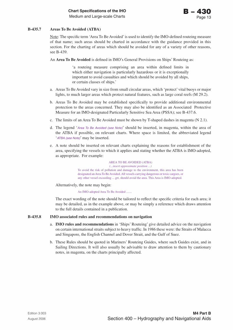
Chart Specifications of the IhoMedium and Large-scale Charts
Edition 3.003
August 2006
M4 Part BSection �00 – Hydrography and Navigational Aids
b – 430Page 1�
B-435.7 Areas To Be Avoided (ATBA)
Note: The specific term ‘Area To Be Avoided’ is used to identify the IMO-defined routeing measure of that name; such areas should be charted in accordance with the guidance provided in this section. For the charting of areas which should be avoided for any of a variety of other reasons, see B-439.
An Area To Be Avoided is defined in IMO’s General Provisions on Ships’ Routeing as:
‘a routeing measure comprising an area within defined limits in which either navigation is particularly hazardous or it is exceptionally important to avoid casualties and which should be avoided by all ships, or certain classes of ships.’
a. Areas To Be Avoided vary in size from small circular areas, which ‘protect’ vital buoys or major lights, to much larger areas which protect natural features, such as large coral reefs (M 29.2).
b. Areas To Be Avoided may be established specifically to provide additional environmental protection to the areas concerned. They may also be identified as an Associated Protective Measure for an IMO-designated Particularly Sensitive Sea Area (PSSA); see B-437.6.
c. The limits of an Area To Be Avoided must be shown by T-shaped dashes in magenta (N 2.1).
d. The legend ‘Area To Be Avoided (see Note)’ should be inserted, in magenta, within the area of the ATBA if possible, on relevant charts. Where space is limited, the abbreviated legend ‘ATBA (see Note)’ may be inserted.
e. A note should be inserted on relevant charts explaining the reasons for establishment of the area, specifying the vessels to which it applies and stating whether the ATBA is IMO-adopted, as appropriate. For example:
AREA TO BE AVOIDED (ATBA)(...insert approximate position ...)
To avoid the risk of pollution and damage to the environment, this area has been designated an Area To Be Avoided. All vessels carrying dangerous or toxic cargoes, or any other vessel exceeding ... grt, should avoid the area. This Area is IMO-adopted.
Alternatively, the note may begin:
An IMO-adopted Area To Be Avoided .......
The exact wording of the note should be tailored to reflect the specific criteria for each area; it may be detailed, as in the example above, or may be simply a reference which draws attention to the full details contained in a publication.
B-435.8 IMO associated rules and recommendations on navigation
a. IMO rules and recommendations in ‘Ships’ Routeing’ give detailed advice on the navigation on certain international straits subject to heavy traffic. In 1986 these were: the Straits of Malacca and Singapore, the English Channel and Dover Strait, and the Gulf of Suez.
b. These Rules should be quoted in Mariners’ Routeing Guides, where such Guides exist, and in Sailing Directions. It will also usually be advisable to draw attention to them by cautionary notes, in magenta, on the charts principally affected.
Chart Specifications of the IhoMedium and Large-scale Charts
Edition 3.003
August 2006
M4 Part BSection �00 – Hydrography and Navigational Aids
b – 430Page 1�
B-435.10 Archipelagic Sea Lanes (ASLs)
a. Definition. Article 53 of the United Nations Convention on the Law of the Sea (UNCLOS) states that:
‘an archipelagic State may designate sea lanes ..., suitable for the continuous and expeditious passage of foreign ships ... through ... its archipelagic waters and the adjacent territorial sea. ... All ships ... enjoy the right of archipelagic sea lanes passage in such sea lanes ... [which] include all normal passage routes used as routes for international navigation … through archipelagic waters’.
(Note: references to aircraft and air routes in UNCLOS have been omitted in these extracts from Article 53).
b. Any archipelagic State which wishes to designate ASLs shall propose them to IMO for adoption as ASLs including all normal passage routes and navigational channels as required by UNCLOS. ASLs are adopted by IMO in accordance with the relevant provisions of UNCLOS.
c. Details of ASLs are given in Part H, General Provisions, of IMO’s Ships’ Routeing. Further information is provided in the IHO publication S-51 (Manual on Technical Aspects of the United Nations Convention on the Law of the Sea).
d. Characteristics. The unique character of the Archipelagic Sea Lanes (ASLs) routeing measure is reflected in the very specific considerations required for charting them. UNCLOS states that:
• ‘ASLs shall be defined by a series of continuous axis lines from the entry points of passage routes to the exit points.’
• ‘Ships in archipelagic sea lanes passage shall not deviate more than 25 nautical miles to either side of such axis lines during passage, provided that such ships shall not navigate closer to the coasts than 10 per cent of the distance between the nearest points on islands bordering the sea lane’ (referred to subsequently as ‘the 10% rule’). (Note: The word “coast” is interpreted by IHO to mean the charted High Water line).
• ‘The archipelagic State shall clearly indicate the axis of the sea lanes…on charts, to which due publicity shall be given.’
e. Traffic within ASLs is not separated, except in any traffic separation schemes which may be designated in an ASL for the safe passage of ships; see B-435.1.
f. The axis line of an archipelagic sea lane is shown on charts for the purpose of defining the sea lane. The axis line does not indicate any routes or recommended tracks as defined in B-434 and Part A of ‘Ships’ Routeing’.
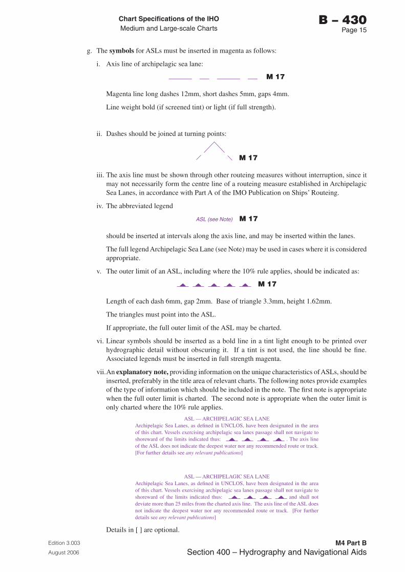
Chart Specifications of the IhoMedium and Large-scale Charts
Edition 3.003
August 2006
M4 Part BSection �00 – Hydrography and Navigational Aids
b – 430Page 15
g. The symbols for ASLs must be inserted in magenta as follows:
i. Axis line of archipelagic sea lane:
M 17
Magenta line long dashes 12mm, short dashes 5mm, gaps 4mm.
Line weight bold (if screened tint) or light (if full strength).
ii. Dashes should be joined at turning points:
M 17
iii. The axis line must be shown through other routeing measures without interruption, since it may not necessarily form the centre line of a routeing measure established in Archipelagic Sea Lanes, in accordance with Part A of the IMO Publication on Ships’ Routeing.
iv. The abbreviated legend
ASL (see Note) M 17
should be inserted at intervals along the axis line, and may be inserted within the lanes.
The full legend Archipelagic Sea Lane (see Note) may be used in cases where it is considered appropriate.
v. The outer limit of an ASL, including where the 10% rule applies, should be indicated as:
M 17
Length of each dash 6mm, gap 2mm. Base of triangle 3.3mm, height 1.62mm.
The triangles must point into the ASL.
If appropriate, the full outer limit of the ASL may be charted.
vi. Linear symbols should be inserted as a bold line in a tint light enough to be printed over hydrographic detail without obscuring it. If a tint is not used, the line should be fine. Associated legends must be inserted in full strength magenta.
vii. An explanatory note, providing information on the unique characteristics of ASLs, should be inserted, preferably in the title area of relevant charts. The following notes provide examples of the type of information which should be included in the note. The first note is appropriate when the full outer limit is charted. The second note is appropriate when the outer limit is only charted where the 10% rule applies.
ASL — ARCHIPELAGIC SEA LANEArchipelagic Sea Lanes, as defined in UNCLOS, have been designated in the area of this chart. Vessels exercising archipelagic sea lanes passage shall not navigate to shoreward of the limits indicated thus: . The axis line of the ASL does not indicate the deepest water nor any recommended route or track. [For further details see any relevant publications]
ASL — ARCHIPELAGIC SEA LANEArchipelagic Sea Lanes, as defined in UNCLOS, have been designated in the area of this chart. Vessels exercising archipelagic sea lanes passage shall not navigate to shoreward of the limits indicated thus: and shall not deviate more than 25 miles from the charted axis line. The axis line of the ASL does not indicate the deepest water nor any recommended route or track. [For further details see any relevant publications]
Details in [ ] are optional.
Chart Specifications of the IhoMedium and Large-scale Charts
Edition 3.003
August 2006
M4 Part BSection �00 – Hydrography and Navigational Aids
b – 430Page 16
B-435.11 No Anchoring Areas
Note: The specific term ‘No Anchoring Area’ is used to identify the IMO routeing measure of that name; such areas should be charted in accordance with the guidance provided in this section. For the charting of areas where anchoring is prohibited for any of a variety of other reasons, see B-439.
a. A No Anchoring Area is defined in IMO’s General Provisions on Ships’ Routeing, as amended by IMO SN/Circ.215 dated 19 January 2001, as:
‘A routeing measure comprising an area within defined limits where anchoring is hazardous or could result in unacceptable damage to the marine environment. Anchoring in a no anchoring area should be avoided by all ships or certain classes of ships, except in case of immediate danger to the ship or the persons on board.’
b. It is worth noting that there is no restriction to navigation over these areas. In considering the initial concept of such areas, IMO concluded that anchoring is a normal part of following a route during a voyage, so that establishment of a No Anchoring Area could be regarded as a routeing measure, the establishment of which should be governed by the General Provisions on Ships’ Routeing. When establishing a No Anchoring Area for all ships or certain classes of ships, the necessity for creating such an area should be well demonstrated and the reasons stated. In general, these areas should be established only in areas where anchoring is hazardous, or where there is a possibility that unacceptable damage to the marine environment could result. The classes of ships which should avoid anchoring in an area should be considered and clearly identified in each particular case.
c. No Anchoring Areas may be adopted in areas where anchoring is unsafe, unstable, hazardous, or it is particularly important to avoid damage to the marine environment, and therefore anchoring should be avoided by all ships or certain classes of ships. In 2001, No Anchoring Areas had been adopted in the Gulf of Mexico.
d. The limits of the No Anchoring Area should be inserted using symbol N 20. For small areas, the symbol should be inserted within the area, instead of in the limit.
e. The legend ‘No Anchoring Area (see Note)’ should be inserted within the area (or alongside for small areas), in accordance with IMO SN/Circ.215.
f. A note should be inserted on relevant charts explaining the reasons for establishment of the area, specifying the vessels to which it applies and stating that the No Anchoring Area is IMO-adopted and that it is mandatory. For example:
NO ANCHORING AREA(..............[insert approximate position]..................)
To avoid the risk of damage to the environment, [all vessels or detail certain classes or sizes of vessels, if appropriate] should avoid anchoring in the charted IMO-adopted mandatory No Anchoring Area.
The exact wording of the note should be tailored to reflect the specific criteria for each area; it may be detailed as in the example above or may be simply a reference which draws attention to the full details contained in an associated publication.
B-436 BOUNDARIES OF ROUTEING MEASURES
B-436.1 The following paragraphs give the rules specifying which symbol (if any) is to be used at the boundary between different routeing measures, or between any measure and the open sea. All symbols are in magenta.
B-436.2 The table below is designed to cover existing problems. As an example, in number 8, where the boundary of a precautionary area coincides with that of an inshore traffic zone, the symbol to be used is a line of T-shaped dashes, with the stems of the Ts towards the inshore traffic zone.
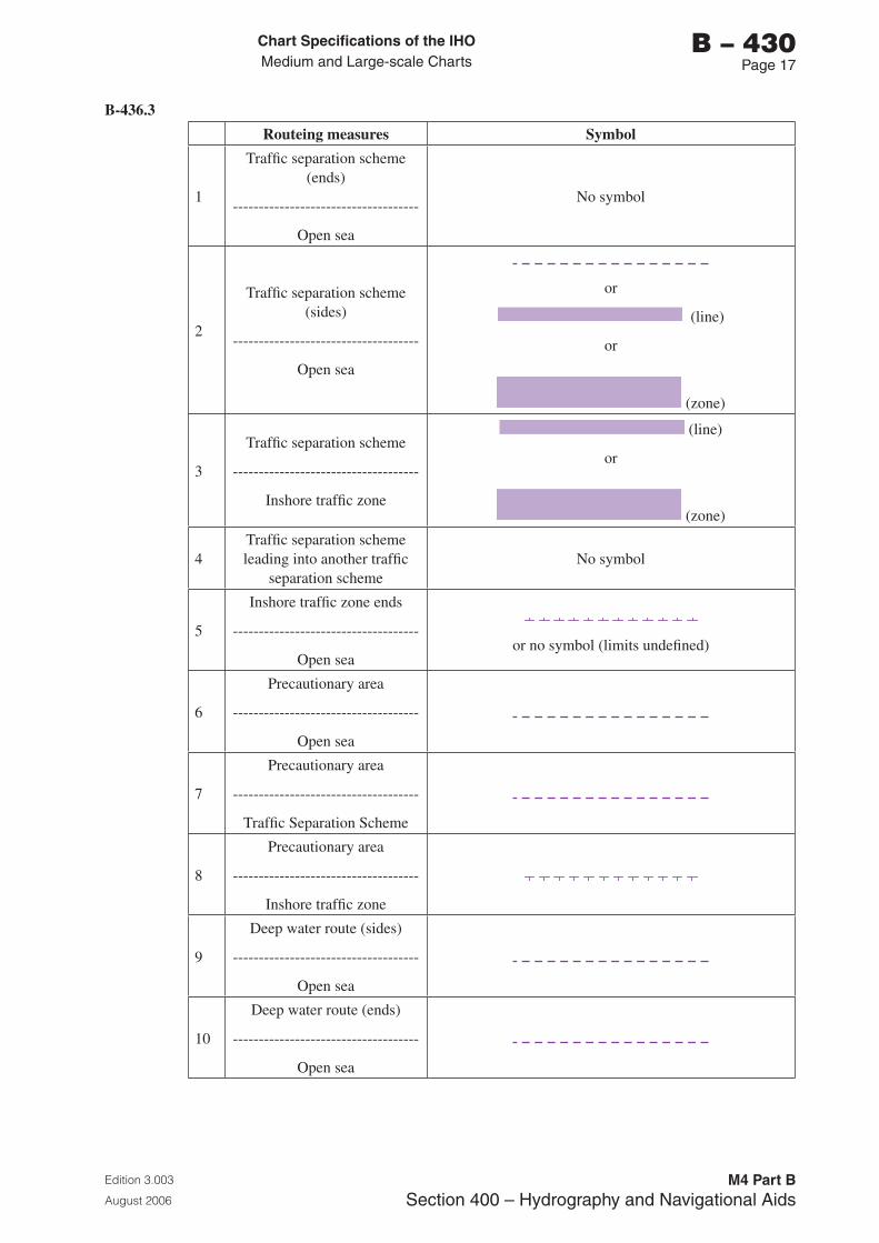
Chart Specifications of the IhoMedium and Large-scale Charts
Edition 3.003
August 2006
M4 Part BSection �00 – Hydrography and Navigational Aids
b – 430Page 1�
B-436.3
Routeing measures Symbol
1
Traffic separation scheme (ends)
------------------------------------
Open sea
No symbol
2
Traffic separation scheme (sides)
------------------------------------
Open sea
or
(line)
or
(zone)
3
Traffic separation scheme
------------------------------------
Inshore traffic zone
(line)
or
(zone)
4Traffic separation scheme leading into another traffic
separation schemeNo symbol
5
Inshore traffic zone ends
------------------------------------
Open seaor no symbol (limits undefined)
6
Precautionary area
------------------------------------
Open sea
7
Precautionary area
------------------------------------
Traffic Separation Scheme
8
Precautionary area
------------------------------------
Inshore traffic zone
9
Deep water route (sides)
------------------------------------
Open sea
10
Deep water route (ends)
------------------------------------
Open sea
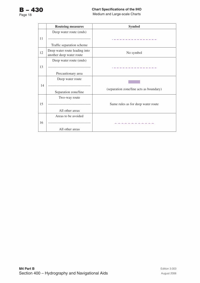
Chart Specifications of the IhoMedium and Large-scale Charts
Edition 3.003
August 2006
M4 Part BSection �00 – Hydrography and Navigational Aids
b – 430Page 1�
Routeing measures Symbol
11
Deep water route (ends)
------------------------------------
Traffic separation scheme
12Deep water route leading into another deep water route
No symbol
13
Deep water route (ends)
------------------------------------
Precautionary area
14
Deep water route
------------------------------------
Separation zone/line(separation zone/line acts as boundary)
15
Two-way route
------------------------------------
All other areas
Same rules as for deep water route
16
Areas to be avoided
------------------------------------
All other areas
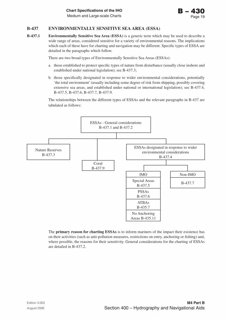
Chart Specifications of the IhoMedium and Large-scale Charts
Edition 3.003
August 2006
M4 Part BSection �00 – Hydrography and Navigational Aids
b – 430Page 1�
B-437 ENVIRONMENTALLY SENSITIVE SEA AREA (ESSA)
B-437.1 Environmentally Sensitive Sea Area (ESSA) is a generic term which may be used to describe a wide range of areas, considered sensitive for a variety of environmental reasons. The implications which each of these have for charting and navigation may be different. Specific types of ESSA are detailed in the paragraphs which follow.
There are two broad types of Environmentally Sensitive Sea Areas (ESSAs):
a. those established to protect specific types of nature from disturbance (usually close inshore and established under national legislation); see B-437.3;
b. those specifically designated in response to wider environmental considerations, potentially ‘the total environment’ (usually including some degree of risk from shipping, possibly covering extensive sea areas, and established under national or international legislation); see B-437.4, B-437.5, B-437.6, B-437.7, B-437.9.
The relationships between the different types of ESSAs and the relevant paragraphs in B-437 are tabulated as follows:
ESSAs - General considerationsB-437.1 and B-437.2
Nature ReservesB-437.3
ESSAs designated in response to wider environmental considerations
B-437.4
CoralB-437.9
Non-IMO
B-437.7
IMO
Special AreasB-437.5
PSSAsB-437.6
ATBAsB-435.7
No Anchoring Areas B-435.11
The primary reason for charting ESSAs is to inform mariners of the impact their existence has on their activities (such as anti-pollution measures, restrictions on entry, anchoring or fishing) and, where possible, the reasons for their sensitivity. General considerations for the charting of ESSAs are detailed in B-437.2.
Chart Specifications of the IhoMedium and Large-scale Charts
Edition 3.003
August 2006
M4 Part BSection �00 – Hydrography and Navigational Aids
b – 430Page 20
B-437.2 General considerations for the charting of ESSAs.
a. Inclusion on charts. ESSAs should be included on charts where there is a specifically identified requirement, and where it is practicable, given the scale of the chart and the extent of the ESSA. If there is no such requirement, or if it is not practicable, details of ESSAs should only be inserted in associated publications, such as Sailing Directions. It should be noted that their inclusion or mention on smaller scale charts may be appropriate for voyage planning purposes.
b. Colour. All details associated with ESSAs should be charted in green (the colour internationally associated with environmental matters) or may be charted in magenta (superimposed information); see B-140-144. The use of green for ESSAs has the advantages of being immediately identifiable as an ESSA and of reducing the amount of detail on the magenta plate. The use of magenta has the advantage of being one of the four basic colours which all Member States use. All other aspects of specification B-437 apply equally, whichever colour is used. It is recommended that Member States move towards the use of green for ESSAs if there are no other considerations preventing this. However, certain areas discussed in B-435 and B-439 should be inserted in magenta for consistency. If green is used for the ESSA limits, all associated symbols, texts and notes should also be green. The exception is when a note about an ESSA is combined with a magenta note (eg about an associated restriction), then the entire note should be in magenta.
c. Options available. The extremely varied extent and complexity of ESSAs means that, in theory, the appropriateness of each of the available options should be considered before charting a specific ESSA. In addition, the options available for consideration may be affected by the scale of the chart; for example, whilst limits may be inserted on larger scale charts, it may be more appropriate to insert just a note on a smaller scale chart of the same area.
The range of options available (which may be used in combination) includes insertion of the following:
• no details or reference on charts; rather, insertion of details in associated publications, such as Sailing Directions and Annual Notices to Mariners, only;
• a simple note on charts referring to details in associated publications, such as Sailing Directions and Annual Notices to Mariners, etc;
• a note giving details of the ESSA;
• legend ‘... [name or type of area] ... (see Note)’;
• legend ‘... [name or type of area] ...’;
• limits of ESSA;
• details of associated restrictions;
• limits of associated restrictions;
• limits of ESSA and details and limits of associated restrictions, incorporated in a multi-feature line; see B-437.2.f;
• point symbol.
In practice, it is possible to define general guidelines for the charting of each general type of ESSA referred to in B-437.1; see B-437.3 and B-437.4.
Chart Specifications of the IhoMedium and Large-scale Charts
Edition 3.003
August 2006
M4 Part BSection �00 – Hydrography and Navigational Aids
b – 430Page 21
d. ESSA limits and associated limits. To ensure that the differing measures and restrictions, which apply in all, or part, of an ESSA’s area, are correctly interpreted, it is important to ensure that any limits which are charted clearly indicate the area of coverage of each of the different areas. The following illustrate the combinations which may occur:
• the limit of the ESSA coincides with that of the measures or restrictions which apply in the ESSA area;
• the limit of the ESSA encompasses several other areas and their limits, for example, anchoring may be prohibited in part of an ESSA, whilst entry is restricted in another part of the ESSA;
• the limit of the ESSA overlaps with the limit of another area, for example an area where anchoring is prohibited.
Such limits should be inserted in accordance with the relevant guidance in B-437, B-435, B-439 and B-449.
e. Charting of ESSA limits. Where it is appropriate to chart the limits of ESSAs (see B-437.1 and B-437.2.a), it should be in accordance with the methods detailed below and, depending on the type of ESSA, in B-437.4 to B-437.9, as appropriate.
Limits may be shown by a symbolized line or, if such a line is not appropriate or available, limits may be charted by a general maritime limit or restricted area limit (see below), with an appropriate legend within the area of the ESSA. Where it is necessary to highlight specific restrictions, reference to a charted note may be included. Where symbols are incorporated in an ESSA limit, they must be oriented to indicate the side of the line on which the area lies.
In all cases, the basic line style employed in the depiction of these limits (which may or may not be amplified by specific ESSA symbology referred to below), should follow the normal conventions for charting of unrestricted and restricted areas (see B-439.2), that is:
• dashed line (N 1.2), the general maritime limit, in green or magenta (see B-437.2.b), implying no restrictions or physical obstructions;
• T-shaped dashed line with down-strokes pointing inwards, in green or magenta (see B-437.2.b), if legislation prohibits certain activities such as anchoring or fishing (N 2.1), or restricts entry to certain types of vessels (N 2.2).
f. Multi-feature lines. Where the limit of the ESSA coincides with other limits which need to be charted, for example associated protective measures such as Areas To Be Avoided which apply within the ESSA, they may be incorporated in the symbolized charted limit. Such limits are described as multi-feature lines and are discussed in B-439.6. –[to be prepared].
Note: where the magenta limit of one area coincides with the green limit of another area, the green limit should normally be broken. A dashed line (N 1) should normally be broken for a T-shaped dashed line (N 2). Alternating green and magenta dashes (or alternating dashes and T-shaped dashes) should not be used.
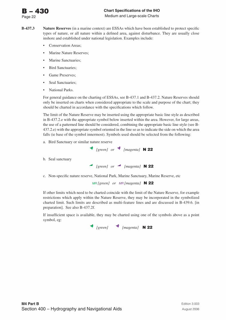
Chart Specifications of the IhoMedium and Large-scale Charts
Edition 3.003
August 2006
M4 Part BSection �00 – Hydrography and Navigational Aids
b – 430Page 22
B-437.3 Nature Reserves (in a marine context) are ESSAs which have been established to protect specific types of nature, or all nature within a defined area, against disturbance. They are usually close inshore and established under national legislation. Examples include:
• Conservation Areas;
• Marine Nature Reserves;
• Marine Sanctuaries;
• Bird Sanctuaries;
• Game Preserves;
• Seal Sanctuaries;
• National Parks.
For general guidance on the charting of ESSAs, see B-437.1 and B-437.2. Nature Reserves should only be inserted on charts when considered appropriate to the scale and purpose of the chart; they should be charted in accordance with the specifications which follow.
The limit of the Nature Reserve may be inserted using the appropriate basic line style as described in B-437.2.e with the appropriate symbol below inserted within the area. However, for large areas, the use of a patterned line should be considered, combining the appropriate basic line style (see B-437.2.e) with the appropriate symbol oriented in the line so as to indicate the side on which the area falls (ie base of the symbol innermost). Symbols used should be selected from the following:
a. Bird Sanctuary or similar nature reserve
[green] or [magenta] N 22
b. Seal sanctuary
[green] or [magenta] N 22
c. Non-specific nature reserve, National Park, Marine Sanctuary, Marine Reserve, etc
MR [green] or MR [magenta] N 22
If other limits which need to be charted coincide with the limit of the Nature Reserve, for example restrictions which apply within the Nature Reserve, they may be incorporated in the symbolized charted limit. Such limits are described as multi-feature lines and are discussed in B-439.6. [in preparation]. See also B-437.2f.
If insufficient space is available, they may be charted using one of the symbols above as a point symbol, eg:
[green] [magenta] N 22
Chart Specifications of the IhoMedium and Large-scale Charts
Edition 3.003
August 2006
M4 Part BSection �00 – Hydrography and Navigational Aids
b – 430Page 2�
A legend, eg ‘Marine Sanctuary (see Note)’ may be inserted (in green or magenta) within the area. (Omit the reference ‘(see Note)’ if a note is not necessary).
A suitably worded note may be inserted in the title area of relevant charts; the following are examples, and may be in green or magenta:
MARINE SANCTUARY(...insert approximate position...)
To avoid the risk of pollution and damage to the environment, this area has been designated a Marine Sanctuary. All vessels carrying dangerous or toxic cargoes, or any other vessel exceeding .... grt, should avoid the area.
NATIONAL PARKS (...insert approximate positions...)
Entry into the national parks shown on this chart is affected by numerous restrictions and prohibitions. For further details, see ... [name of publication] ....
The exact wording of the note should be tailored to cover the specific case, ie location, the type of measures, restrictions, etc; it may be detailed or may be simply a reference which draws attention to the full details contained in a publication. Such a note may be combined with other related notes.
For nature reserves on land, omit the MR from the limit. A note will not usually be necessary.
B-437.4 ESSAs specifically designated in response to wider environmental considerations, potentially ‘the total environment’. The basic reason for the establishment of most of these areas is the coincidence of environmental sensitivity and some degree of risk from shipping. One of the main reasons for charting them is to alert mariners to their existence and to inform them of the reasons for their sensitivity. They may cover extensive sea areas and may be established under national or international legislation. They include:
a. Environmental areas defined or designated by IMO:
• Special Areas (SAs) - see B-437.5;
• Particularly Sensitive Sea Areas (PSSAs) - see B-437.6;
• Areas To Be Avoided - see B-435.7;
• No Anchoring Areas - see B-435.11.
b. Other environmental areas defined nationally or internationally, which include:
• Marine and Estuarine Protected Areas (MEPAs) in Australia;
• Marine Environmentally Sensitive Areas (MESAs) in the European Union;
• Particular Sensitive Areas (PSAs);
• Sites of Special Scientific Interest (SSSIs).
• Protected Areas (PAs) in the Antarctic;
• Specially Protected Areas (SPAs) in the Antarctic;
• Antarctic Specially Protected Areas (ASPAs) combining SPAs and SSSIs;
• Marine Environmental High Risk Areas (MEHRAs) in the United Kingdom.
See B-437.7.
For general points on the charting of ESSAs, see B-437.1 and B-437.2.
Chart Specifications of the IhoMedium and Large-scale Charts
Edition 3.003
August 2006
M4 Part BSection �00 – Hydrography and Navigational Aids
b – 430Page 2�
B-437.5 Special Area
A Special Area is an IMO-adopted measure designated under the International Convention for the Prevention of Pollution from Ships 1973, modified by the Protocol of 1978 (MARPOL 73/78). It is defined in IMO Resolution A.927(22) as:
‘a sea area where for recognized technical reasons in relation to its oceanographical and ecological conditions and to the particular character of its traffic, the adoption of special mandatory methods for the prevention of sea pollution by oil, noxious liquid substances, or garbage, as applicable, is required’.
IMO Resolution A.720(17) states:
‘Sea can be seen as an oceanographical or geographical term; in both cases a sea will, by definition, be a rather large area. Every existing “special area”, is a (semi)-enclosed sea in an oceanographical sense and pursuant to the methods of protection .... a special area has to be rather large.’
A Special Area may encompass the maritime zones of several States, or even an entire enclosed or semi-enclosed area.
Special Areas are defined in terms of the pollution types covered in each of the Annexes to MARPOL 73/78 (Annex I - oil; Annex II - noxious liquid substances; Annex V - garbage; Annex VI - SOx emission control areas). They are designated by IMO’s Marine Environment Protection Committee (MEPC) and include: the Mediterranean Sea area; Baltic Sea area; Black Sea area; Red Sea area; Gulfs area; Gulf of Aden; Antarctic area; North Sea; Wider Caribbean; North West European waters.
Given the wide extent of the area covered by individual designated Special Areas, and the fact that they are not directly related to safety of navigation, their limits should not normally be inserted on navigation charts. It is more appropriate to include details in associated publications, such as Sailing Directions, Annual Notices to Mariners or special charts depicting MARPOL 73/78 limits. If necessary, a note may be inserted (in green or magenta) on appropriate charts referring to the fact that the chart (or a specified part of it) lies within an IMO-designated Special Area:
MARPOL 73/78 SPECIAL AREAThis chart lies within a Special Area designated by IMO under MARPOL 73/78. For details, see ......[name of chart or publication].....
Special Areas may be identified as an Associated Protective Measure for Particularly Sensitive Sea Areas (PSSAs); see B-437.6.
Chart Specifications of the IhoMedium and Large-scale Charts
Edition 3.003
August 2006
M4 Part BSection �00 – Hydrography and Navigational Aids
b – 430Page 25
B-437.6 Particularly Sensitive Sea Area (PSSA)
a. General.
A Particularly Sensitive Sea Area (PSSA) is an IMO-designated measure, established in accordance with IMO Resolution. It is defined in IMO Resolution A.927(22) as:
‘an area that needs special protection through action by IMO because of its significance for recognized ecological, socio-economic or scientific reasons and because it may be vulnerable to damage by international shipping activities.’
PSSAs vary in extent and include the Great Barrier Reef in Australia, the Archipelago of Sabana-Camagüey in Cuba, Malpelo Island in Colombia, Florida Keys in the USA and the Wadden Sea area of The Netherlands, Germany and Denmark.
Identification of areas as PSSAs is approved by the IMO’s Marine Environment Protection Committee (MEPC), but no final determination is made until after the pertinent IMO Sub-Committee or Committee has approved the associated protective measures. In the case of the Great Barrier Reef, the charting of the PSSA is itself considered to be a protective measure.
An Associated Protective Measure is defined in IMO Resolution A.885(21) as:
‘an international rule or standard that falls within the purview of IMO and regulates international maritime activities for the protection of the area at risk.’
Measures within the purview of IMO comprise:
• designation of an area as a Special Area under Annexes of MARPOL 73/78 or to apply special discharge restrictions to vessels operating in a PSSA;
• adoption of ships’ routeing and reporting measures near or in the area;
• other measures such as compulsory pilotage schemes or vessel traffic management systems.
All associated protective measures should be identified on charts to comply with IMO Resolution A.927(22), which specifically states:
‘When a PSSA is finally designated, all associated protective measures should be identified on charts in accordance with symbols and methods of the International Hydrographic Organization (IHO).’
The relevant symbols and methods of the IHO, referred to in the IMO Resolution, are detailed in B-437 in general, and in B-437.6.b and B-437.6.c in particular. They include cross-references, as appropriate, to B-435, B-488 and B-491.
b. Charting of Particularly Sensitive Sea Areas.
A suitably worded note should be inserted on the relevant charts; the following is an example (and may be in green or magenta):
PARTICULARLY SENSITIVE SEA AREA (PSSA)An IMO-approved PSSA is designated in [general area or the area of this chart]. Mariners ... [insert any special requirements, procedures, etc]. For further details, see [insert name of publication].
It is important to indicate that the measure is IMO-adopted. The exact wording of the note should be tailored to cover each specific area, ie location, the type of associated protective measures, etc. It may be detailed or may be simply a reference which draws attention to the full details contained in an associated publication such as Sailing Directions. Such a note may be combined with other related notes. A simple note, providing a reference to an associated publication may be the only way in which some Associated Protective Measures, such as special discharge restrictions, can be identified on charts.
Chart Specifications of the IhoMedium and Large-scale Charts
Edition 3.003
August 2006
M4 Part BSection �00 – Hydrography and Navigational Aids
b – 430Page 26
The legend ‘Particularly Sensitive Sea Area (see Note)’ should be inserted within the area of the PSSA, at appropriate positions on relevant charts. Where space is limited, the abbreviated legend ‘PSSA (see Note)’ may be inserted.
The limit of a PSSA should be charted using a dashed line (in green or magenta), with a tint band of maximum 5 mm width and abbreviation ‘PSSA’ on the PSSA side of the dashed line limit, in green or magenta to match the line colour. The actual width of the band, and density of the tint, should be carefully selected so that the area is not given undue prominence compared with other areas. In general, magenta tint bands tend to be more prominent than green, so a narrower band is likely to be appropriate.
[green or magenta] N 22
[green or magenta] N 22
B-437.6.a indicates the complexities of charting PSSAs. Use of the tint band in addition to the dashed limit serves to emphasize or differentiate the limit and provides visual continuity to the entirety of a PSSA’s area. The dashed limit may be broken for any Associated Protective Measures whose limits coincide with those of the PSSA itself (see B-437.2f). It may be appropriate to reverse this convention (ie instead of breaking the dashed limit, break the tint band and continue the dashes) where the limit coincides with a Traffic Separation Scheme tint band.
c. Charting of the Associated Protective Measures
As stated in B-437.6.a, all associated protective measures should be identified on charts. Such identification on charts should be in accordance with the relevant specification for each specific associated protective measure:
Associated Protective Measure Action on charts
Special Area under Annexes of MARPOL 73/78, or the application of special discharge restrictions to vessels operating in a PSSA.
Combine Special Area note (B-437.5) with PSSA note (B-437.6.b). Limits of Special Area not normally charted.
Adoption of ships’ routeing and reporting measures.
Insert ships’ routeing measures and reporting measures in accordance with appropriate specification (B-435 and (B-488).
Consider combining any associated note with PSSA note (B-437.6.b).
Other measures such as compulsory pilotage schemes or vessel traffic management systems.
Consider combining any associated note with PSSA note (B-437.6.b).
Where the limits of any Associated Protective Measures, which according to the specifications detailed above should be inserted on charts, coincide with those of the PSSA, both limits should be inserted. The Associated Protective Measure limits should be in accordance with the appropriate specifications, one component of the limit of the PSSA (ie the tint band or the dashes) being broken in accordance with (b) above.
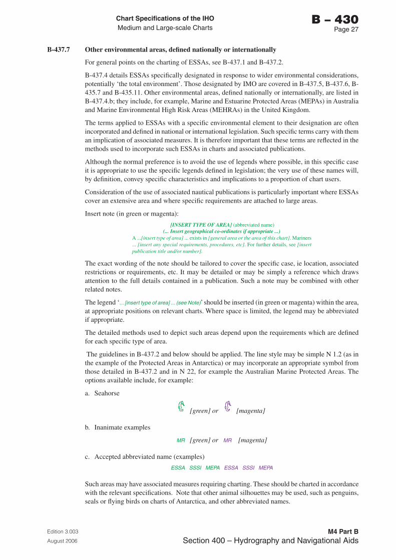
Chart Specifications of the IhoMedium and Large-scale Charts
Edition 3.003
August 2006
M4 Part BSection �00 – Hydrography and Navigational Aids
b – 430Page 2�
B-437.7 Other environmental areas, defined nationally or internationally
For general points on the charting of ESSAs, see B-437.1 and B-437.2.
B-437.4 details ESSAs specifically designated in response to wider environmental considerations, potentially ‘the total environment’. Those designated by IMO are covered in B-437.5, B-437.6, B-435.7 and B-435.11. Other environmental areas, defined nationally or internationally, are listed in B-437.4.b; they include, for example, Marine and Estuarine Protected Areas (MEPAs) in Australia and Marine Environmental High Risk Areas (MEHRAs) in the United Kingdom.
The terms applied to ESSAs with a specific environmental element to their designation are often incorporated and defined in national or international legislation. Such specific terms carry with them an implication of associated measures. It is therefore important that these terms are reflected in the methods used to incorporate such ESSAs in charts and associated publications.
Although the normal preference is to avoid the use of legends where possible, in this specific case it is appropriate to use the specific legends defined in legislation; the very use of these names will, by definition, convey specific characteristics and implications to a proportion of chart users.
Consideration of the use of associated nautical publications is particularly important where ESSAs cover an extensive area and where specific requirements are attached to large areas.
Insert note (in green or magenta):
[INSERT TYPE OF AREA] (abbreviated name)(... Insert geographical co-ordinates if appropriate ...)
A ...[insert type of area] ... exists in [general area or the area of this chart]. Mariners ... [insert any special requirements, procedures, etc]. For further details, see [insert publication title and/or number].
The exact wording of the note should be tailored to cover the specific case, ie location, associated restrictions or requirements, etc. It may be detailed or may be simply a reference which draws attention to the full details contained in a publication. Such a note may be combined with other related notes.
The legend ‘... [insert type of area] ... (see Note)’ should be inserted (in green or magenta) within the area, at appropriate positions on relevant charts. Where space is limited, the legend may be abbreviated if appropriate.
The detailed methods used to depict such areas depend upon the requirements which are defined for each specific type of area.
The guidelines in B-437.2 and below should be applied. The line style may be simple N 1.2 (as in the example of the Protected Areas in Antarctica) or may incorporate an appropriate symbol from those detailed in B-437.2 and in N 22, for example the Australian Marine Protected Areas. The options available include, for example:
a. Seahorse
[green] or [magenta]
b. Inanimate examples
MR [green] or MR [magenta]
c. Accepted abbreviated name (examples)
ESSA SSSI MEPA ESSA SSSI MEPA
Such areas may have associated measures requiring charting. These should be charted in accordance with the relevant specifications. Note that other animal silhouettes may be used, such as penguins, seals or flying birds on charts of Antarctica, and other abbreviated names.
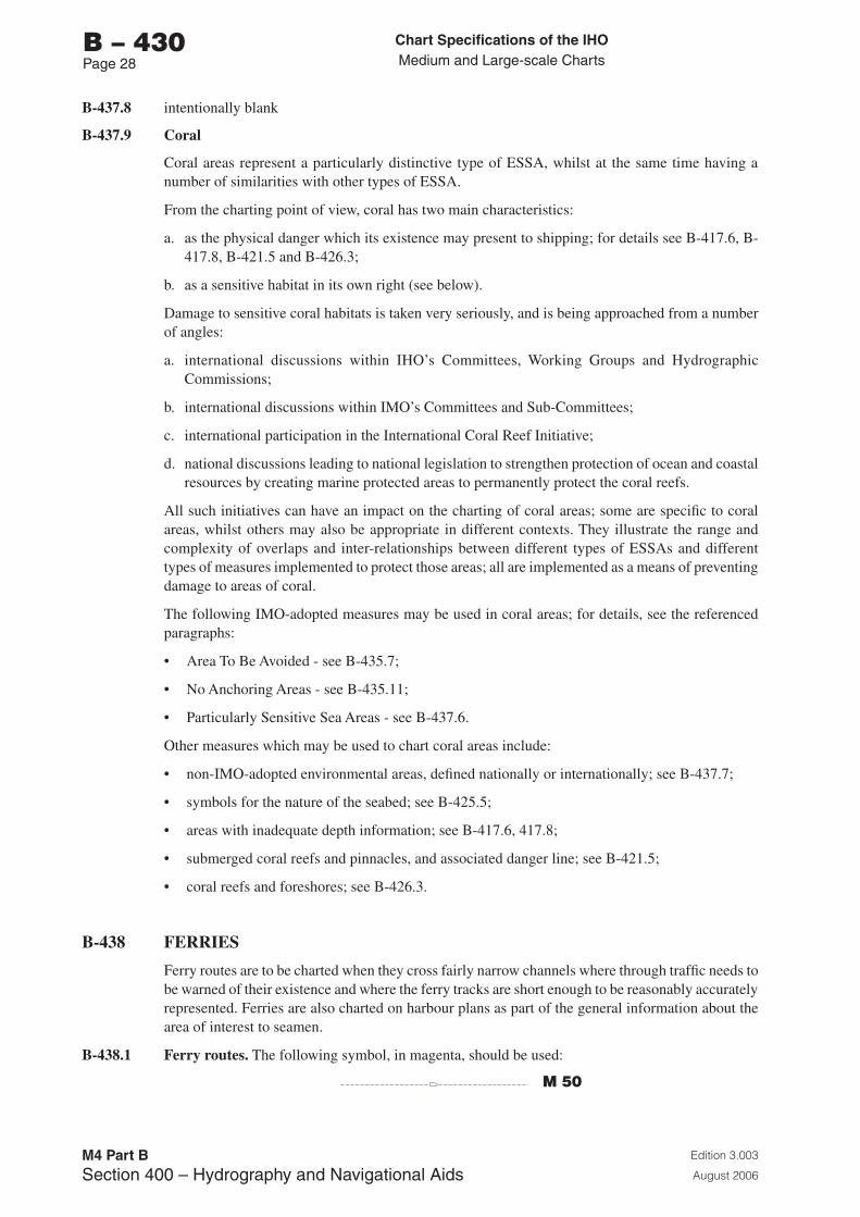
Chart Specifications of the IhoMedium and Large-scale Charts
Edition 3.003
August 2006
M4 Part BSection �00 – Hydrography and Navigational Aids
b – 430Page 2�
B-437.8 intentionally blank
B-437.9 Coral
Coral areas represent a particularly distinctive type of ESSA, whilst at the same time having a number of similarities with other types of ESSA.
From the charting point of view, coral has two main characteristics:
a. as the physical danger which its existence may present to shipping; for details see B-417.6, B-417.8, B-421.5 and B-426.3;
b. as a sensitive habitat in its own right (see below).
Damage to sensitive coral habitats is taken very seriously, and is being approached from a number of angles:
a. international discussions within IHO’s Committees, Working Groups and Hydrographic Commissions;
b. international discussions within IMO’s Committees and Sub-Committees;
c. international participation in the International Coral Reef Initiative;
d. national discussions leading to national legislation to strengthen protection of ocean and coastal resources by creating marine protected areas to permanently protect the coral reefs.
All such initiatives can have an impact on the charting of coral areas; some are specific to coral areas, whilst others may also be appropriate in different contexts. They illustrate the range and complexity of overlaps and inter-relationships between different types of ESSAs and different types of measures implemented to protect those areas; all are implemented as a means of preventing damage to areas of coral.
The following IMO-adopted measures may be used in coral areas; for details, see the referenced paragraphs:
• Area To Be Avoided - see B-435.7;
• No Anchoring Areas - see B-435.11;
• Particularly Sensitive Sea Areas - see B-437.6.
Other measures which may be used to chart coral areas include:
• non-IMO-adopted environmental areas, defined nationally or internationally; see B-437.7;
• symbols for the nature of the seabed; see B-425.5;
• areas with inadequate depth information; see B-417.6, 417.8;
• submerged coral reefs and pinnacles, and associated danger line; see B-421.5;
• coral reefs and foreshores; see B-426.3.
B-438 FERRIES
Ferry routes are to be charted when they cross fairly narrow channels where through traffic needs to be warned of their existence and where the ferry tracks are short enough to be reasonably accurately represented. Ferries are also charted on harbour plans as part of the general information about the area of interest to seamen.
B-438.1 Ferry routes. The following symbol, in magenta, should be used:
M 50
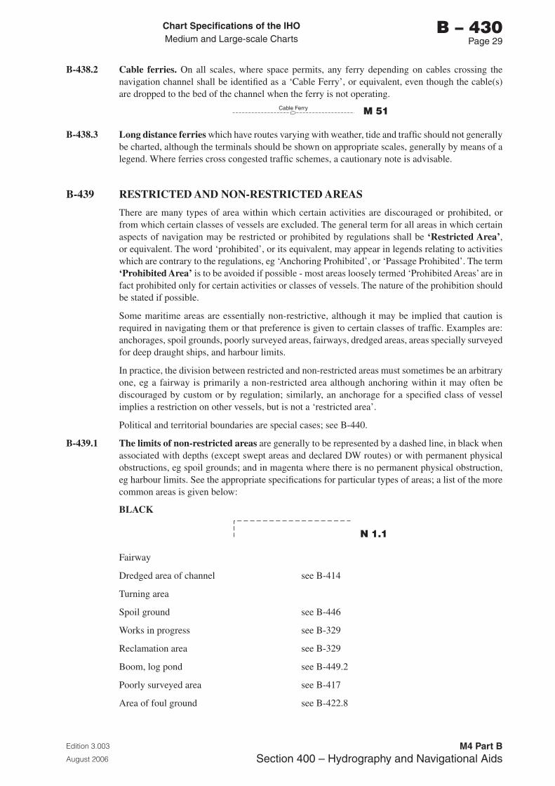
Chart Specifications of the IhoMedium and Large-scale Charts
Edition 3.003
August 2006
M4 Part BSection �00 – Hydrography and Navigational Aids
b – 430Page 2�
B-438.2 Cable ferries. On all scales, where space permits, any ferry depending on cables crossing the navigation channel shall be identified as a ‘Cable Ferry’, or equivalent, even though the cable(s) are dropped to the bed of the channel when the ferry is not operating.
Cable Ferry M 51
B-438.3 Long distance ferries which have routes varying with weather, tide and traffic should not generally be charted, although the terminals should be shown on appropriate scales, generally by means of a legend. Where ferries cross congested traffic schemes, a cautionary note is advisable.
B-439 RESTRICTED AND NON-RESTRICTED AREAS
There are many types of area within which certain activities are discouraged or prohibited, or from which certain classes of vessels are excluded. The general term for all areas in which certain aspects of navigation may be restricted or prohibited by regulations shall be ‘Restricted Area’, or equivalent. The word ‘prohibited’, or its equivalent, may appear in legends relating to activities which are contrary to the regulations, eg ‘Anchoring Prohibited’, or ‘Passage Prohibited’. The term ‘Prohibited Area’ is to be avoided if possible - most areas loosely termed ‘Prohibited Areas’ are in fact prohibited only for certain activities or classes of vessels. The nature of the prohibition should be stated if possible.
Some maritime areas are essentially non-restrictive, although it may be implied that caution is required in navigating them or that preference is given to certain classes of traffic. Examples are: anchorages, spoil grounds, poorly surveyed areas, fairways, dredged areas, areas specially surveyed for deep draught ships, and harbour limits.
In practice, the division between restricted and non-restricted areas must sometimes be an arbitrary one, eg a fairway is primarily a non-restricted area although anchoring within it may often be discouraged by custom or by regulation; similarly, an anchorage for a specified class of vessel implies a restriction on other vessels, but is not a ‘restricted area’.
Political and territorial boundaries are special cases; see B-440.
B-439.1 The limits of non-restricted areas are generally to be represented by a dashed line, in black when associated with depths (except swept areas and declared DW routes) or with permanent physical obstructions, eg spoil grounds; and in magenta where there is no permanent physical obstruction, eg harbour limits. See the appropriate specifications for particular types of areas; a list of the more common areas is given below:
BLACK
N 1.1
Fairway
Dredged area of channel see B-414
Turning area
Spoil ground see B-446
Works in progress see B-329
Reclamation area see B-329
Boom, log pond see B-449.2
Poorly surveyed area see B-417
Area of foul ground see B-422.8
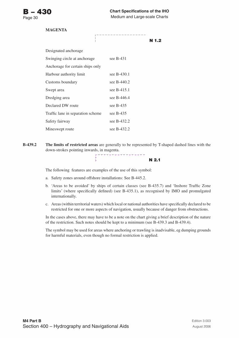
Chart Specifications of the IhoMedium and Large-scale Charts
Edition 3.003
August 2006
M4 Part BSection �00 – Hydrography and Navigational Aids
b – 430Page �0
MAGENTA
N 1.2
Designated anchorage
Swinging circle at anchorage see B-431
Anchorage for certain ships only
Harbour authority limit see B-430.1
Customs boundary see B-440.2
Swept area see B-415.1
Dredging area see B-446.4
Declared DW route see B-435
Traffic lane in separation scheme see B-435
Safety fairway see B-432.2
Mineswept route see B-432.2
B-439.2 The limits of restricted areas are generally to be represented by T-shaped dashed lines with the down-strokes pointing inwards, in magenta.
N 2.1
The following features are examples of the use of this symbol:
a. Safety zones around offshore installations: See B-445.2.
b. ‘Areas to be avoided’ by ships of certain classes (see B-435.7) and ‘Inshore Traffic Zone limits’ (where specifically defined) (see B-435.1), as recognised by IMO and promulgated internationally.
c. Areas (within territorial waters) which local or national authorities have specifically declared to be restricted for one or more aspects of navigation, usually because of danger from obstructions.
In the cases above, there may have to be a note on the chart giving a brief description of the nature of the restriction. Such notes should be kept to a minimum (see B-439.3 and B-439.4).
The symbol may be used for areas where anchoring or trawling is inadvisable, eg dumping grounds for harmful materials, even though no formal restriction is applied.
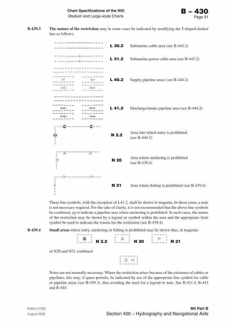
Chart Specifications of the IhoMedium and Large-scale Charts
Edition 3.003
August 2006
M4 Part BSection �00 – Hydrography and Navigational Aids
b – 430Page �1
B-439.3 The nature of the restriction may in some cases be indicated by modifying the T.shaped dashed line as follows:
L 30.2 Submarine cable area (see B-443.2)
L 31.2 Submarine power cable area (see B-443.2)
Oil Gas
Chem Water
L 40.2 Supply pipeline areas (see B-444.2)
Water Sewer
Outfall Intake
L 41.2 Discharge/intake pipeline area (see B-444.2)
N 2.2 Area into which entry is prohibited (see B-444.2)
N 20 Area where anchoring is prohibited (see B-439.4)
N 21 Area where fishing is prohibited (see B-439.4)
These line symbols, with the exception of L41.2, shall be shown in magenta. In these cases, a note is not necessary required. For the sake of clarity, it is not recommended that the above line symbols be combined, eg to indicate a pipeline area where anchoring is prohibited. In such cases, the nature of the restriction may be shown by a legend or symbol within the area and the appropriate limit symbol be used to indicate the reason for the restriction (see B-439.4).
B-439.4 Small areas where entry, anchoring or fishing is prohibited may be shown thus, in magenta:
N 2.2 N 20 N 21
or N20 and N21 combined
Notes are not normally necessary. Where the restriction arises because of the existence of cables or pipelines, this may, if space permits, be indicated by use of the appropriate line symbol for cable or pipeline areas (see B-439.3), thus avoiding the need for a legend or note. See B-431.4, B-443 and B-444.

Chart Specifications of the IhoMedium and Large-scale Charts
Edition 3.003
August 2006
M4 Part BSection �00 – Hydrography and Navigational Aids
b – 430Page �2
B-439.5 Areas charted by special symbols
a. Territorial limits, fishery zones and related features; see B-440.
b. Military practice areas; see B-441.
c. Separation zones; see B-435.1.
Chart Specifications of the IhoMedium and Large-scale Charts
Edition 3.003
August 2006
M4 Part BSection �00 – Hydrography and Navigational Aids
b – 440Page 1
B-440 INTERNATIONAL BOUNDARIES AND NATIONAL LIMITS
In these specifications, the term ‘boundary’ is used for any delimitation between adjacent states or those which face each other each across channels or seas (know as ‘opposite states’). The term ‘limit’ is used for the line marking the seaward extent of any coastal zone where no other state is concerned.
Some charts carry disclaimers to the effect that boundaries shown are only approximate. It is recommended that any such statements should be confined to land boundaries only and preferably should appear in an official navigational handbook rather than on individual charts.
The provision of recommended symbols does not imply a recommendation that any particular boundary or limit should be charted (other than a land boundary). Boundaries and limits of no significance to navigation or fishing should preferably be omitted from navigational charts.
The boundaries and limits dealt with in this specification are described, with their navigational significance, below.
a. International boundaries on land
International boundaries should always be charted, at least in the vicinity of coasts.
Customs limits may be charted (on land and water areas) of ports which have special customs regulations. If shown, they shall be considered authoritative.
b. International maritime boundaries where delimiting lines have been established by agreement between adjacent or opposite states. Boundaries are frequently negotiated on the basis of the equidistance or ‘median’ line principle. For various reasons, however agreed boundaries even when negotiated on this principle are seldom true median lines. The term ‘median line’ should not therefore normally be used on charts or in navigational publications. Navigationally, international boundaries may vary in their significance over different parts of their lengths. Inshore they may represent the delimitation of territorial seas of two states or ‘internal waters’, for example within bay closing lines; offshore, they may constitute shelf boundaries or other lines of delimitation.
c. Limits associated with territorial seas
Territorial sea baselines determine the seaward extents of internal waters, the territorial sea, the contiguous zone and the economic zone.
These baselines may be the low water line of the mainland, islands, or low tide elevations, as depicted on large scale charts officially recognised by the coastal state. In certain circumstances, straight baselines may be used to connect seaward points on a deeply indented coastline; to enclose bays, estuaries or rivers; or for coastal areas fringed with islands. Low tide elevations, ie drying rocks, reefs, banks may comprise elements of the baseline provided they lie within a distance not exceeding the breadth of the territorial sea.
‘Normal’ baselines correspond to the low water line (which is not defined any more precisely) marked on the large scale charts officially recognised by the coastal state; they therefore do not require any special symbol.
Special cases are:
(i) Coral reefs, which are extensive areas which are very nearly dry at low water, with individual drying coral heads generalised to show a simplified edge symbol - the latter is often taken as the low water line.
(ii) Deltaic or other highly unstable coasts, where it has been proposed that appropriate points may be selected along the furthest seaward extent of the low water line to draw straight baselines, notwithstanding subsequent regression, but subject to certain other conditions.
Chart Specifications of the IhoMedium and Large-scale Charts
Edition 3.003
August 2006
M4 Part BSection �00 – Hydrography and Navigational Aids
b – 440Page 2
Straight baselines, or the limits derived therefrom, should be shown on official charts of a scale or scales adequate for determining them. Many coastal states interpret this position as permitting depiction on special charts, not on the standard navigational series.
Internal waters comprise all areas of the sea on the landward side of the territorial sea baselines, as well as inland waters including rivers, lakes, etc. Internal waters form an integral part of the land territory of a state.
The Territorial Sea is a belt of water generally of a defined breadth, measured from the territorial sea baseline. The 1982 UN Convention on the Law of the Sea recognises a breadth of 12 nautical miles. Within the territorial sea, a coastal state has full sovereignty limited only by a right of innocent passage for foreign ships.
The Contiguous Zone is a zone adjacent to the territorial sea where the coastal state may exercise control to prevent infringement of its customs, fiscal, immigration and/or sanitary regulations. Under the 1982 Convention the outer limits of this zone may not extend beyond 24 miles measured from the territorial sea baselines.
d. Limits of zones in which exploitation of natural resources is regulated.
The following limits represent the extent of claims to various rights, from control of fishing to exclusive control of all economic exploitation and conservation, but preserving freedom of navigation. Until international law has been further codified, the cartographic and navigational implications are not wholly predictable.
Limits of exclusive fisheries zones: areas beyond the territorial seas where coastal states proclaim that they alone may regulate fishing. Within any such zone other countries which have traditionally fished the area are often allowed to do so under bilateral agreements. Where states have permitted others to fish in parts of the area, it may be desirable to chart the outer limits of both the full area and the area of special concessionary rights.
In some instances, claims are described as ‘conservation zones’; for practical purposes these may be classed with exclusive fishery zones since their intended function is to institute fishery conservation measures.
Most of the fishery zone claims are limited by fixed distance (200 nautical miles in some cases) from the territorial sea baselines.
Limits of Exclusive Economic Zone (EEZ): under the 1982 Convention, the EEZ extends to a distance of 200 miles from territorial sea baselines, in which the coastal state will have sovereign rights to explore, exploit, conserve and manage the natural resources, whether living or non-living. A number of countries have already claimed exclusive economic zones.
Limits of the Continental Shelf: in juridical terms the ‘Continental Shelf’ of a coastal state has been defined as comprising the seabed and subsoil of the submarine areas that extend beyond its territorial sea throughout the natural prolongation of its land territory. The 1982 Convention defines the limits as extending to the outer edge of the continental margin, or to a distance of 200 nautical miles from the baselines where the outer edge of the margin does not extend up to that distance. The 1982 Convention defines the continental margin as comprising the submerged prolongation of the land mass of the coastal state, and consists of the seabed and subsoil of the shelf, the slope and the rise. It does not include the deep ocean floor with its oceanic ridges or the subsoil thereof. The coastal state exercises sovereign rights for exploration and exploitation of the mineral and other non-living resources of the continental shelf.
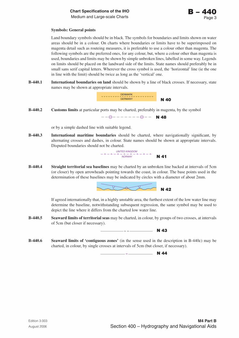
Chart Specifications of the IhoMedium and Large-scale Charts
Edition 3.003
August 2006
M4 Part BSection �00 – Hydrography and Navigational Aids
b – 440Page �
Symbols: General points
Land boundary symbols should be in black. The symbols for boundaries and limits shown on water areas should be in a colour. On charts where boundaries or limits have to be superimposed on magenta detail such as routeing measures, it is preferable to use a colour other than magenta. The following symbols are the preferred ones, for any colour, but, where a colour other than magenta is used, boundaries and limits may be shown by simple unbroken lines, labelled in some way. Legends on limits should be placed on the landward side of the limits. State names should preferably be in small sans serif capital letters. Wherever the cross symbol is used, the ‘horizontal’ line (ie the one in line with the limit) should be twice as long as the ‘vertical’ one.
B-440.1 International boundaries on land should be shown by a line of black crosses. If necessary, state names may be shown at appropriate intervals.
DENMARK
GERMANY N 40
B-440.2 Customs limits at particular ports may be charted, preferably in magenta, by the symbol
N 48
or by a simple dashed line with suitable legend.
B-440.3 International maritime boundaries should be charted, where navigationally significant, by alternating crosses and dashes, in colour. State names should be shown at appropriate intervals. Disputed boundaries should not be charted.
UNITED KINGDOM
NORWAY N 41
B-440.4 Straight territorial sea baselines may be charted by an unbroken line backed at intervals of 5cm (or closer) by open arrowheads pointing towards the coast, in colour. The base points used in the determination of these baselines may be indicated by circles with a diameter of about 2mm.
N 42
If agreed internationally that, in a highly unstable area, the furthest extent of the low water line may determine the baseline, notwithstanding subsequent regression, the same symbol may be used to depict the line where it differs from the charted low water line.
B-440.5 Seaward limits of territorial seas may be charted, in colour, by groups of two crosses, at intervals of 5cm (but closer if necessary).
N 43
B-440.6 Seaward limits of ‘contiguous zones’ (in the sense used in the description in B-440c) may be charted, in colour, by single crosses at intervals of 5cm (but closer, if necessary).
N 44
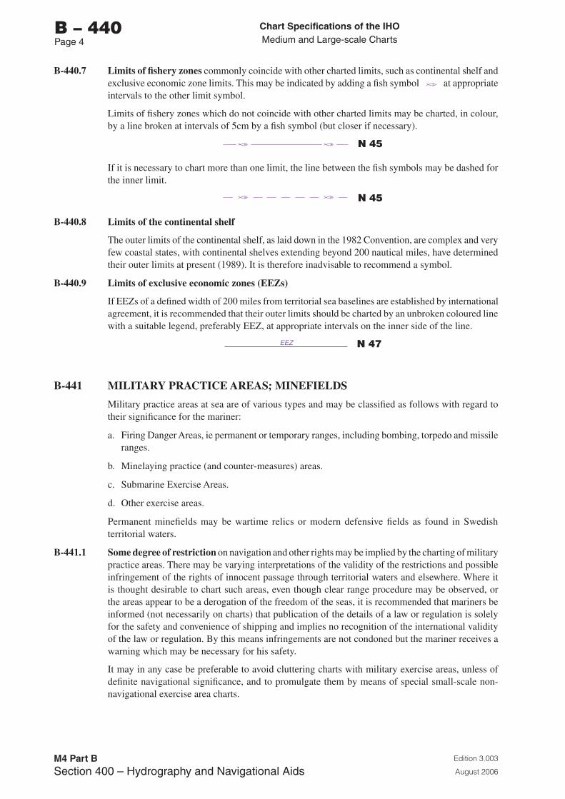
Chart Specifications of the IhoMedium and Large-scale Charts
Edition 3.003
August 2006
M4 Part BSection �00 – Hydrography and Navigational Aids
b – 440Page �
B-440.7 Limits of fishery zones commonly coincide with other charted limits, such as continental shelf and exclusive economic zone limits. This may be indicated by adding a fish symbol at appropriate intervals to the other limit symbol.
Limits of fishery zones which do not coincide with other charted limits may be charted, in colour, by a line broken at intervals of 5cm by a fish symbol (but closer if necessary).
N 45
If it is necessary to chart more than one limit, the line between the fish symbols may be dashed for the inner limit.
N 45
B-440.8 Limits of the continental shelf
The outer limits of the continental shelf, as laid down in the 1982 Convention, are complex and very few coastal states, with continental shelves extending beyond 200 nautical miles, have determined their outer limits at present (1989). It is therefore inadvisable to recommend a symbol.
B-440.9 Limits of exclusive economic zones (EEZs)
If EEZs of a defined width of 200 miles from territorial sea baselines are established by international agreement, it is recommended that their outer limits should be charted by an unbroken coloured line with a suitable legend, preferably EEZ, at appropriate intervals on the inner side of the line.
EEZ N 47
B-441 MILITARY PRACTICE AREAS; MINEFIELDS
Military practice areas at sea are of various types and may be classified as follows with regard to their significance for the mariner:
a. Firing Danger Areas, ie permanent or temporary ranges, including bombing, torpedo and missile ranges.
b. Minelaying practice (and counter-measures) areas.
c. Submarine Exercise Areas.
d. Other exercise areas.
Permanent minefields may be wartime relics or modern defensive fields as found in Swedish territorial waters.
B-441.1 Some degree of restriction on navigation and other rights may be implied by the charting of military practice areas. There may be varying interpretations of the validity of the restrictions and possible infringement of the rights of innocent passage through territorial waters and elsewhere. Where it is thought desirable to chart such areas, even though clear range procedure may be observed, or the areas appear to be a derogation of the freedom of the seas, it is recommended that mariners be informed (not necessarily on charts) that publication of the details of a law or regulation is solely for the safety and convenience of shipping and implies no recognition of the international validity of the law or regulation. By this means infringements are not condoned but the mariner receives a warning which may be necessary for his safety.
It may in any case be preferable to avoid cluttering charts with military exercise areas, unless of definite navigational significance, and to promulgate them by means of special small-scale non-navigational exercise area charts.
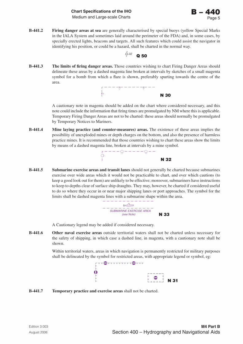
Chart Specifications of the IhoMedium and Large-scale Charts
Edition 3.003
August 2006
M4 Part BSection �00 – Hydrography and Navigational Aids
b – 440Page 5
B-441.2 Firing danger areas at sea are generally characterised by special buoys (yellow Special Marks in the IALA System and sometimes laid around the perimeter of the FDA) and, in some cases, by specially erected lights, beacons and targets. All such features which could assist the navigator in identifying his position, or could be a hazard, shall be charted in the normal way.
DZY Q 50
B-441.3 The limits of firing danger areas. Those countries wishing to chart Firing Danger Areas should delineate these areas by a dashed magenta line broken at intervals by sketches of a small magenta symbol for a bomb from which a flare is shown, preferably spurting towards the centre of the area.
N 30
A cautionary note in magenta should be added on the chart where considered necessary, and this note could include the information that firing times are promulgated by NM where this is applicable. Temporary Firing Danger Areas are not to be charted: these areas should normally be promulgated by Temporary Notices to Mariners.
B-441.4 Mine laying practice (and counter-measures) areas. The existence of these areas implies the possibility of unexploded mines or depth charges on the bottom, and also the presence of harmless practice mines. It is recommended that those countries wishing to chart these areas show the limits by means of a dashed magenta line, broken at intervals by a mine symbol.
N 32
B-441.5 Submarine exercise areas and transit lanes should not generally be charted because submarines exercise over wide areas which it would not be practicable to chart, and over which cautions (to keep a good look out for them) are unlikely to be effective; moreover, submariners have instructions to keep to depths clear of surface ship draughts. They may, however, be charted if considered useful to do so where they occur in or near major shipping lanes or port approaches. The symbol for the limits shall be dashed magenta lines with a submarine shape within the area.
SUBMARINE EXERCISE AREA(see Note) N 33
A Cautionary legend may be added if considered necessary.
B-441.6 Other naval exercise areas outside territorial waters shall not be charted unless necessary for the safety of shipping, in which case a dashed line, in magenta, with a cautionary note shall be shown.
Within territorial waters, areas in which navigation is permanently restricted for military purposes shall be delineated by the symbol for restricted areas, with appropriate legend or symbol, eg:
N 31
B-441.7 Temporary practice and exercise areas shall not be charted.
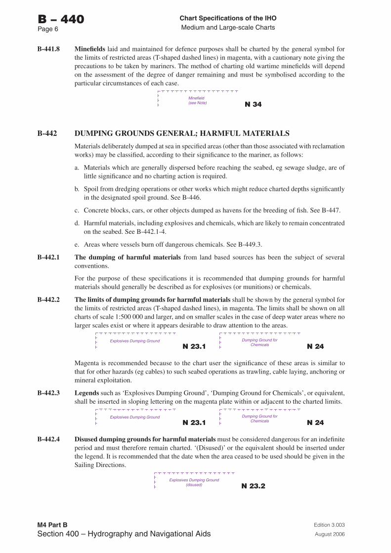
Chart Specifications of the IhoMedium and Large-scale Charts
Edition 3.003
August 2006
M4 Part BSection �00 – Hydrography and Navigational Aids
b – 440Page 6
B-441.8 Minefields laid and maintained for defence purposes shall be charted by the general symbol for the limits of restricted areas (T-shaped dashed lines) in magenta, with a cautionary note giving the precautions to be taken by mariners. The method of charting old wartime minefields will depend on the assessment of the degree of danger remaining and must be symbolised according to the particular circumstances of each case.
Minefield(see Note) N 34
B-442 DUMPING GROUNDS GENERAL; HARMFUL MATERIALS
Materials deliberately dumped at sea in specified areas (other than those associated with reclamation works) may be classified, according to their significance to the mariner, as follows:
a. Materials which are generally dispersed before reaching the seabed, eg sewage sludge, are of little significance and no charting action is required.
b. Spoil from dredging operations or other works which might reduce charted depths significantly in the designated spoil ground. See B-446.
c. Concrete blocks, cars, or other objects dumped as havens for the breeding of fish. See B-447.
d. Harmful materials, including explosives and chemicals, which are likely to remain concentrated on the seabed. See B-442.1-4.
e. Areas where vessels burn off dangerous chemicals. See B-449.3.
B-442.1 The dumping of harmful materials from land based sources has been the subject of several conventions.
For the purpose of these specifications it is recommended that dumping grounds for harmful materials should generally be described as for explosives (or munitions) or chemicals.
B-442.2 The limits of dumping grounds for harmful materials shall be shown by the general symbol for the limits of restricted areas (T-shaped dashed lines), in magenta. The limits shall be shown on all charts of scale 1:500 000 and larger, and on smaller scales in the case of deep water areas where no larger scales exist or where it appears desirable to draw attention to the areas.
Explosives Dumping Ground
N 23.1 Dumping Ground for
Chemicals N 24
Magenta is recommended because to the chart user the significance of these areas is similar to that for other hazards (eg cables) to such seabed operations as trawling, cable laying, anchoring or mineral exploitation.
B-442.3 Legends such as ‘Explosives Dumping Ground’, ‘Dumping Ground for Chemicals’, or equivalent, shall be inserted in sloping lettering on the magenta plate within or adjacent to the charted limits.
Explosives Dumping Ground
N 23.1 Dumping Ground for
Chemicals N 24
B-442.4 Disused dumping grounds for harmful materials must be considered dangerous for an indefinite period and must therefore remain charted. ‘(Disused)’ or the equivalent should be inserted under the legend. It is recommended that the date when the area ceased to be used should be given in the Sailing Directions.
Explosives Dumping Ground(disused) N 23.2
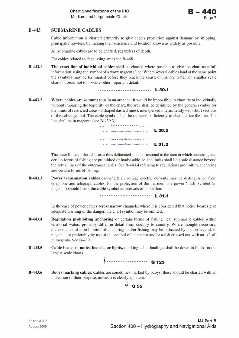
Chart Specifications of the IhoMedium and Large-scale Charts
Edition 3.003
August 2006
M4 Part BSection �00 – Hydrography and Navigational Aids
b – 440Page �
B-443 SUBMARINE CABLES
Cable information is charted primarily to give cables protection against damage by shipping, principally trawlers, by making their existence and location known as widely as possible.
All submarine cables are to be charted, regardless of depth.
For cables related to degaussing areas see B-448.
B-443.1 The exact line of individual cables shall be charted where possible to give the chart user full information, using the symbol of a wavy magenta line. Where several cables land at the same point the symbols may be terminated before they reach the coast, or inshore water, on smaller scale charts in order not to obscure other important detail.
L 30.1
B-443.2 Where cables are so numerous in an area that it would be impossible to chart them individually without impairing the legibility of the chart, the area shall be delimited by the general symbol for the limits of restricted areas (T-shaped dashed lines), interspersed intermittently with short sections of the cable symbol. The cable symbol shall be repeated sufficiently to characterize the line. The line shall be in magenta (see B-439.3).
L 30.2
L 31.2
The outer limits of the cable area thus delineated shall correspond to the area in which anchoring and certain forms of fishing are prohibited or inadvisable, ie, the limits shall lie a safe distance beyond the actual lines of the outermost cables. See B-443.4 referring to regulations prohibiting anchoring and certain forms of fishing.
B-443.3 Power transmission cables carrying high voltage electric currents may be distinguished from telephone and telegraph cables, for the protection of the mariner. The power ‘flash’ symbol (in magenta) should break the cable symbol at intervals of about 5cm.
L 31.1
In the case of power cables across narrow channels, where it is considered that notice boards give adequate warning of the danger, the chart symbol may be omitted.
B-443.4 Regulation prohibiting anchoring or certain forms of fishing near submarine cables within territorial waters probably differ in detail from country to country. Where thought necessary, the existence of a prohibition of anchoring and/or fishing may be indicated by a short legend, in magenta, or preferably by use of the symbol of an anchor and/or a fish crossed out with an ‘x’, all in magenta. See B-439.
B-443.5 Cable beacons, notice boards, or lights, marking cable landings shall be down in black on the largest scale charts.
Q 123
B-443.6 Buoys marking cables. Cables are sometimes marked by buoys; these should be charted with an indication of their purpose, unless it is clearly apparent.
Y Q 55
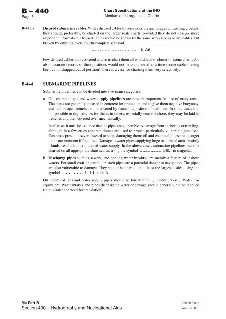
Chart Specifications of the IhoMedium and Large-scale Charts
Edition 3.003
August 2006
M4 Part BSection �00 – Hydrography and Navigational Aids
b – 440Page �
B-443.7 Disused submarine cables. Where disused cables traverse possible anchorages or trawling grounds, they should, preferably, be charted on the larger scale charts, provided they do not obscure more important information. Disused cables should be shown by the same wavy line as active cables, but broken by omitting every fourth complete sinusoid.
L 32
Few disused cables are recovered and so to chart them all would lead to clutter on some charts. As, also, accurate records of their positions would not be complete after a time (some cables having been cut or dragged out of position), there is a case for charting them very selectively.
B-444 SUBMARINE PIPELINES
Submarine pipelines can be divided into two main categories:
a. Oil, chemical, gas and water supply pipelines are now an important feature of many areas. The pipes are generally encased in concrete for protection and to give them negative buoyancy, and laid in open trenches to be covered by natural deposition of sediment. In some cases it is not possible to dig trenches for them; in others, especially near the shore, they may be laid in trenches and then covered over mechanically.
In all cases it must be assumed that the pipes are vulnerable to damage from anchoring or trawling, although in a few cases concrete domes are used to protect particularly vulnerable junctions. Gas pipes present a severe hazard to ships damaging them; oil and chemical pipes are a danger to the environment if fractured. Damage to water pipes supplying large residential areas, mainly islands, results in disruption of water supply. In the above cases, submarine pipelines must be charted on all appropriate chart scales, using the symbol L40.1 in magenta.
b. Discharge pipes such as sewers, and cooling water intakes, are mainly a feature of inshore waters. For small craft, in particular, such pipes are a potential danger to navigation. The pipes are also vulnerable to damage. They should be charted on at least the largest scales, using the symbol L41.1 in black.
Oil, chemical, gas and water supply pipes should be labelled ‘Oil’, ‘Chem’, ‘Gas’, ‘Water’, or equivalent. Water intakes and pipes discharging water or sewage should generally not be labelled (to minimise the need for translation).
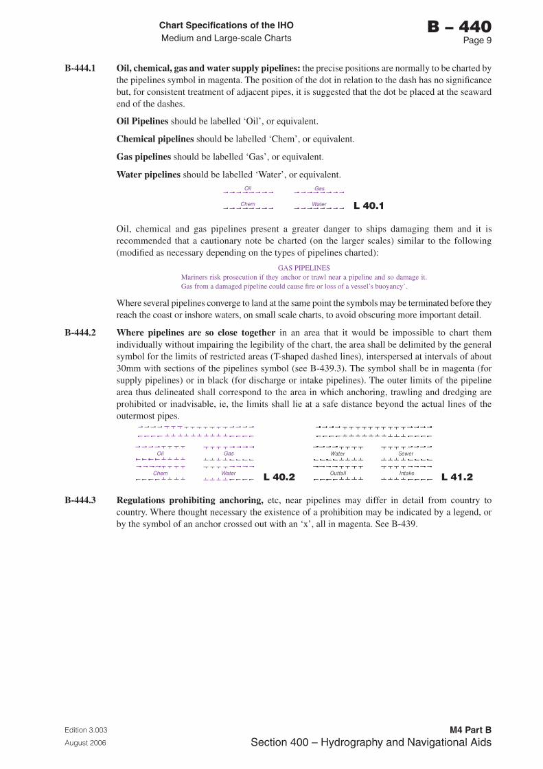
Chart Specifications of the IhoMedium and Large-scale Charts
Edition 3.003
August 2006
M4 Part BSection �00 – Hydrography and Navigational Aids
b – 440Page �
B-444.1 Oil, chemical, gas and water supply pipelines: the precise positions are normally to be charted by the pipelines symbol in magenta. The position of the dot in relation to the dash has no significance but, for consistent treatment of adjacent pipes, it is suggested that the dot be placed at the seaward end of the dashes.
Oil Pipelines should be labelled ‘Oil’, or equivalent.
Chemical pipelines should be labelled ‘Chem’, or equivalent.
Gas pipelines should be labelled ‘Gas’, or equivalent.
Water pipelines should be labelled ‘Water’, or equivalent.Oil
Chem
Gas
Water L 40.1
Oil, chemical and gas pipelines present a greater danger to ships damaging them and it is recommended that a cautionary note be charted (on the larger scales) similar to the following (modified as necessary depending on the types of pipelines charted):
GAS PIPELINESMariners risk prosecution if they anchor or trawl near a pipeline and so damage it. Gas from a damaged pipeline could cause fire or loss of a vessel’s buoyancy’.
Where several pipelines converge to land at the same point the symbols may be terminated before they reach the coast or inshore waters, on small scale charts, to avoid obscuring more important detail.
B-444.2 Where pipelines are so close together in an area that it would be impossible to chart them individually without impairing the legibility of the chart, the area shall be delimited by the general symbol for the limits of restricted areas (T-shaped dashed lines), interspersed at intervals of about 30mm with sections of the pipelines symbol (see B-439.3). The symbol shall be in magenta (for supply pipelines) or in black (for discharge or intake pipelines). The outer limits of the pipeline area thus delineated shall correspond to the area in which anchoring, trawling and dredging are prohibited or inadvisable, ie, the limits shall lie at a safe distance beyond the actual lines of the outermost pipes.
Oil Gas
Chem Water L 40.2 L 41.2
B-444.3 Regulations prohibiting anchoring, etc, near pipelines may differ in detail from country to country. Where thought necessary the existence of a prohibition may be indicated by a legend, or by the symbol of an anchor crossed out with an ‘x’, all in magenta. See B-439.
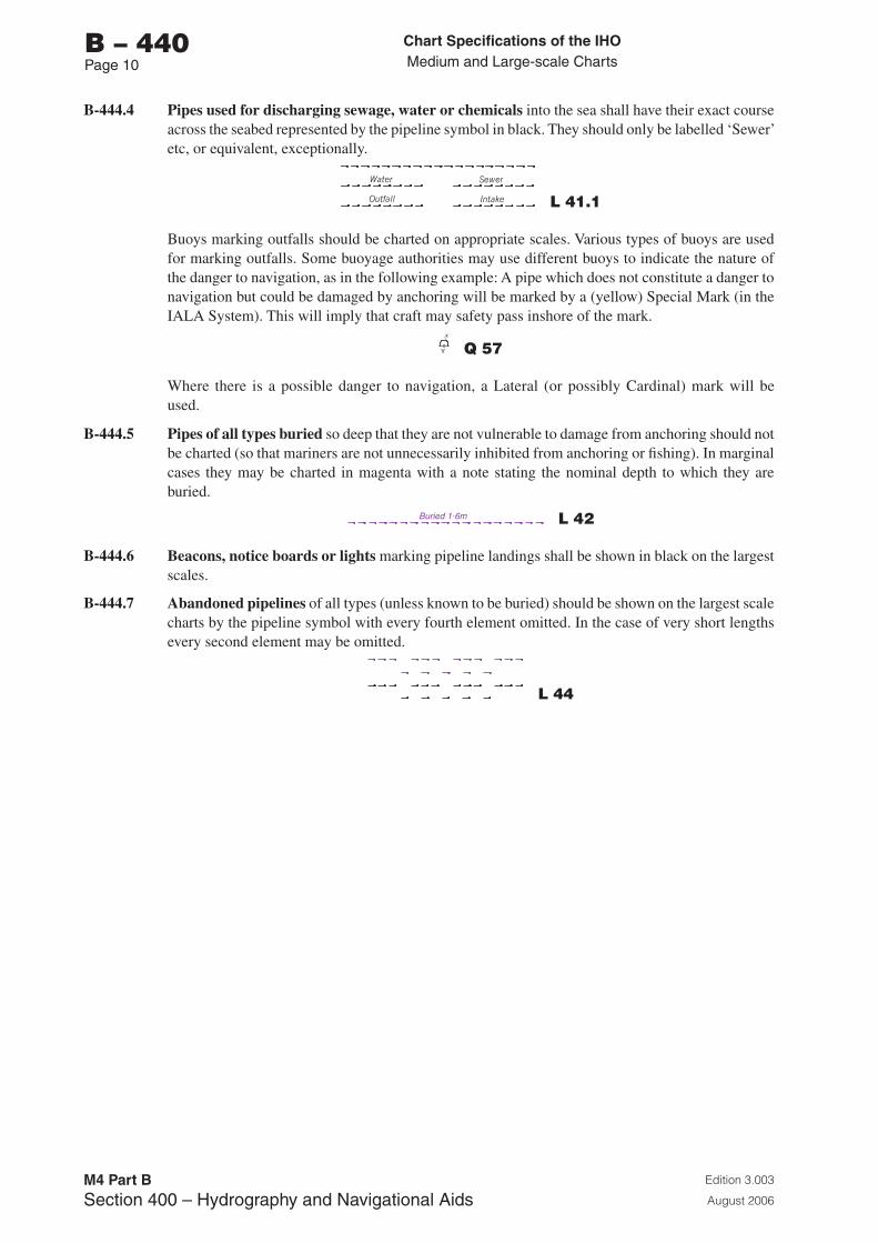
Chart Specifications of the IhoMedium and Large-scale Charts
Edition 3.003
August 2006
M4 Part BSection �00 – Hydrography and Navigational Aids
b – 440Page 10
B-444.4 Pipes used for discharging sewage, water or chemicals into the sea shall have their exact course across the seabed represented by the pipeline symbol in black. They should only be labelled ‘Sewer’ etc, or equivalent, exceptionally.
L 41.1
Buoys marking outfalls should be charted on appropriate scales. Various types of buoys are used for marking outfalls. Some buoyage authorities may use different buoys to indicate the nature of the danger to navigation, as in the following example: A pipe which does not constitute a danger to navigation but could be damaged by anchoring will be marked by a (yellow) Special Mark (in the IALA System). This will imply that craft may safety pass inshore of the mark.
Y Q 57
Where there is a possible danger to navigation, a Lateral (or possibly Cardinal) mark will be used.
B-444.5 Pipes of all types buried so deep that they are not vulnerable to damage from anchoring should not be charted (so that mariners are not unnecessarily inhibited from anchoring or fishing). In marginal cases they may be charted in magenta with a note stating the nominal depth to which they are buried.
Buried 1.6m L 42
B-444.6 Beacons, notice boards or lights marking pipeline landings shall be shown in black on the largest scales.
B-444.7 Abandoned pipelines of all types (unless known to be buried) should be shown on the largest scale charts by the pipeline symbol with every fourth element omitted. In the case of very short lengths every second element may be omitted.
L 44
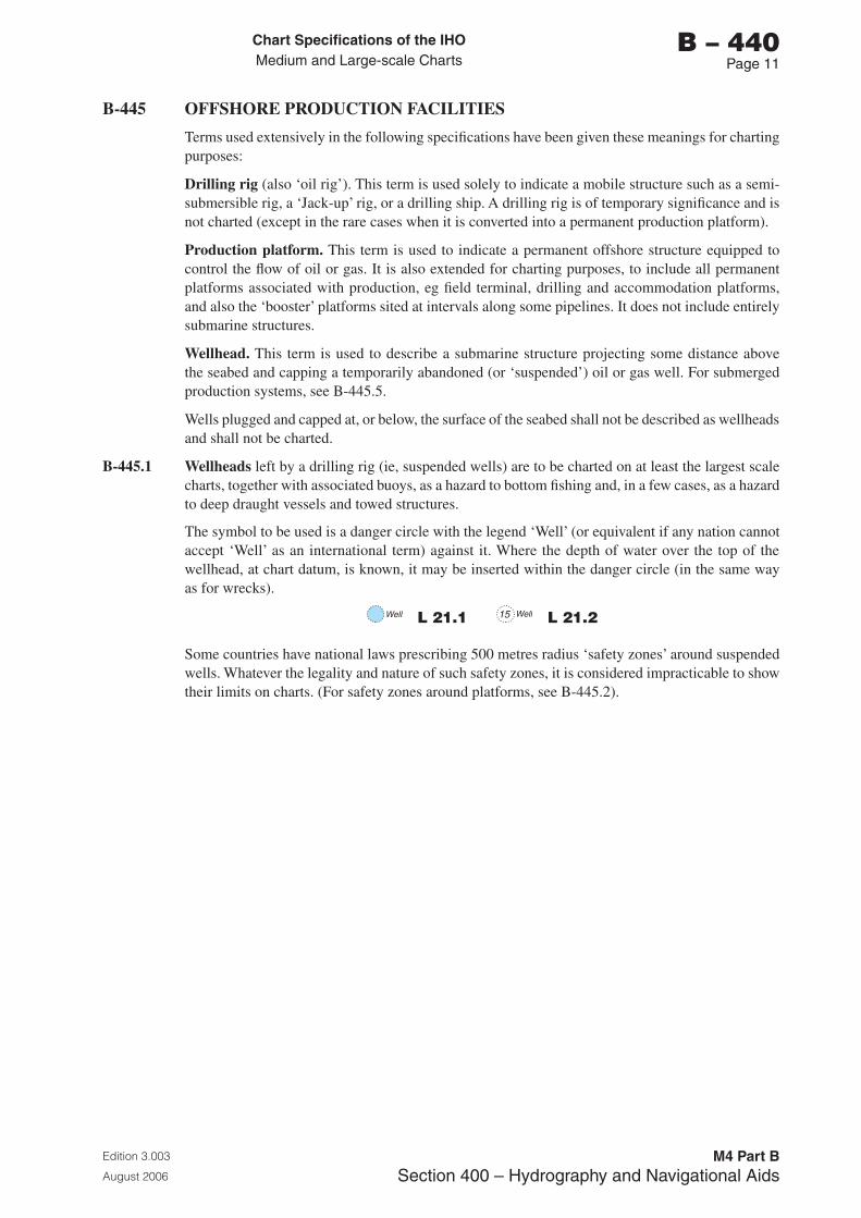
Chart Specifications of the IhoMedium and Large-scale Charts
Edition 3.003
August 2006
M4 Part BSection �00 – Hydrography and Navigational Aids
b – 440Page 11
B-445 OFFSHORE PRODUCTION FACILITIES
Terms used extensively in the following specifications have been given these meanings for charting purposes:
Drilling rig (also ‘oil rig’). This term is used solely to indicate a mobile structure such as a semi-submersible rig, a ‘Jack-up’ rig, or a drilling ship. A drilling rig is of temporary significance and is not charted (except in the rare cases when it is converted into a permanent production platform).
Production platform. This term is used to indicate a permanent offshore structure equipped to control the flow of oil or gas. It is also extended for charting purposes, to include all permanent platforms associated with production, eg field terminal, drilling and accommodation platforms, and also the ‘booster’ platforms sited at intervals along some pipelines. It does not include entirely submarine structures.
Wellhead. This term is used to describe a submarine structure projecting some distance above the seabed and capping a temporarily abandoned (or ‘suspended’) oil or gas well. For submerged production systems, see B-445.5.
Wells plugged and capped at, or below, the surface of the seabed shall not be described as wellheads and shall not be charted.
B-445.1 Wellheads left by a drilling rig (ie, suspended wells) are to be charted on at least the largest scale charts, together with associated buoys, as a hazard to bottom fishing and, in a few cases, as a hazard to deep draught vessels and towed structures.
The symbol to be used is a danger circle with the legend ‘Well’ (or equivalent if any nation cannot accept ‘Well’ as an international term) against it. Where the depth of water over the top of the wellhead, at chart datum, is known, it may be inserted within the danger circle (in the same way as for wrecks).
Well L 21.1 Well15 L 21.2
Some countries have national laws prescribing 500 metres radius ‘safety zones’ around suspended wells. Whatever the legality and nature of such safety zones, it is considered impracticable to show their limits on charts. (For safety zones around platforms, see B-445.2).
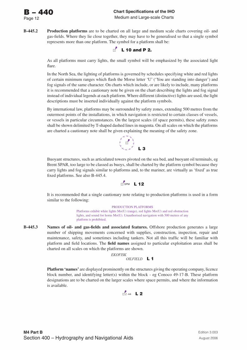
Chart Specifications of the IhoMedium and Large-scale Charts
Edition 3.003
August 2006
M4 Part BSection �00 – Hydrography and Navigational Aids
b – 440Page 12
B-445.2 Production platforms are to be charted on all large and medium scale charts covering oil- and gas-fields. Where they lie close together, they may have to be generalised so that a single symbol represents more than one platform. The symbol for a platform shall be:
L 10 and P 2.
As all platforms must carry lights, the small symbol will be emphasized by the associated light flare.
In the North Sea, the lighting of platforms is governed by schedules specifying white and red lights of certain minimum ranges which flash the Morse letter ‘U’ (‘You are standing into danger’) and fog signals of the same character. On charts which include, or are likely to include, many platforms it is recommended that a cautionary note be given on the chart describing the lights and fog signal instead of individual legends at each platform. Where different (distinctive) lights are used, the light descriptions must be inserted individually against the platform symbols.
By international law, platforms may be surrounded by safety zones, extending 500 metres from the outermost points of the installations, in which navigation is restricted to certain classes of vessels, or vessels in particular circumstances. On the largest scales (if space permits), these safety zones shall be shown delimited by T-shaped dashed lines in magenta. On all scales on which the platforms are charted a cautionary note shall be given explaining the meaning of the safety zone.
L 3
Buoyant structures, such as articulated towers pivoted on the sea bed, and buoyant oil terminals, eg Brent SPAR, too large to be classed as buoys, shall be charted by the platform symbol because they carry lights and fog signals similar to platforms and, to the mariner, are virtually as ‘fixed’ as true fixed platforms. See also B-445.4.
SPM L 12
It is recommended that a single cautionary note relating to production platforms is used in a form similar to the following:
PRODUCTION PLATFORMSPlatforms exhibit white lights Mo(U) (range), red lights Mo(U) and red obstruction lights, and sound for horns Mo(U). Unauthorised navigation with 500 metres of any platform is prohibited.
B-445.3 Names of oil- and gas-fields and associated features. Offshore production generates a large number of shipping movements concerned with supplies, construction, inspection, repair and maintenance, safety, and sometimes including tankers. Not all this traffic will be familiar with platform and field locations. The field names assigned to particular exploitation areas shall be charted on all scales on which the platforms are shown.
EKOFISK OILFIELD L 1
Platform ‘names’ are displayed prominently on the structures giving the operating company, licence block number, and identifying letter(s) within the block - eg Conoco 49-17-B. These platform designations are to be charted on the larger scales where space permits, and where the information is available.
Z- 44 L 2
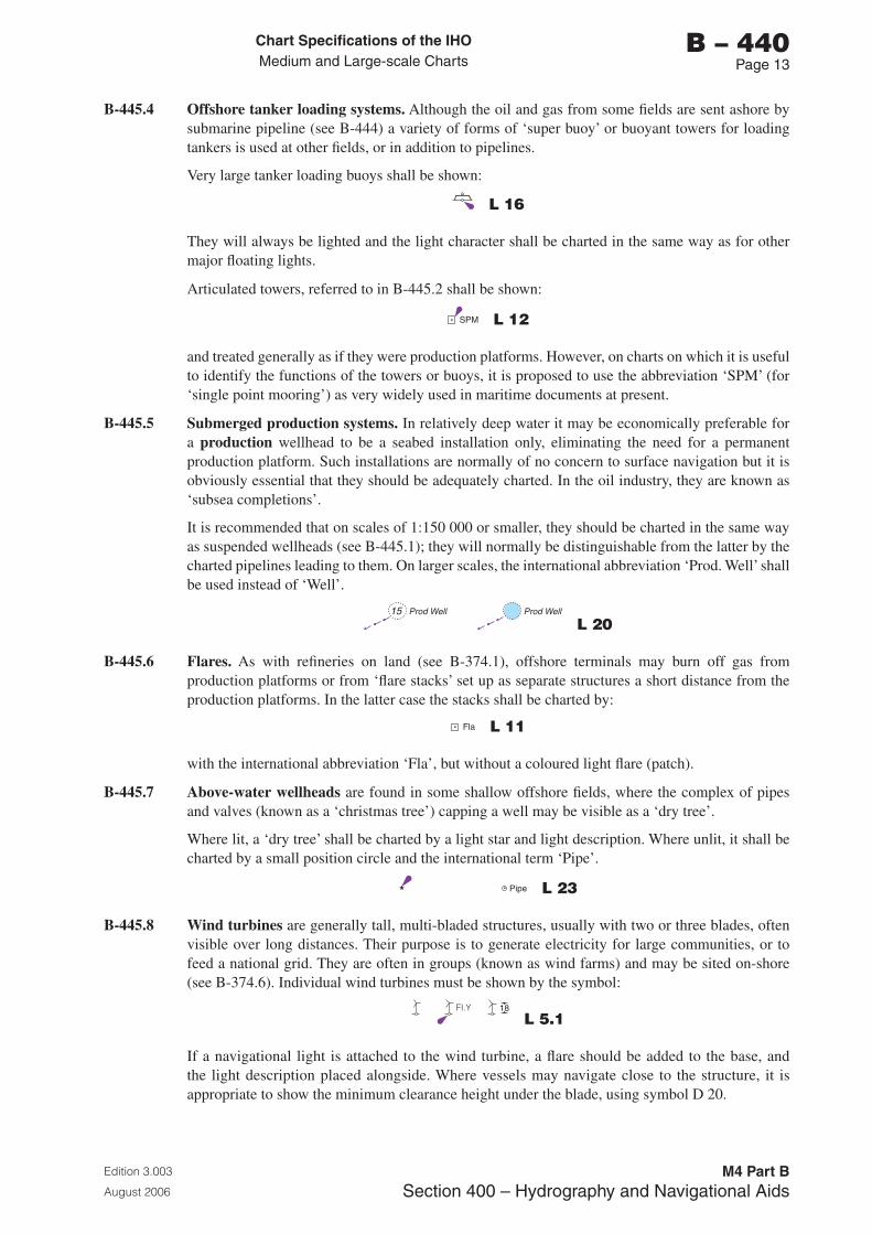
Chart Specifications of the IhoMedium and Large-scale Charts
Edition 3.003
August 2006
M4 Part BSection �00 – Hydrography and Navigational Aids
b – 440Page 1�
B-445.4 Offshore tanker loading systems. Although the oil and gas from some fields are sent ashore by submarine pipeline (see B-444) a variety of forms of ‘super buoy’ or buoyant towers for loading tankers is used at other fields, or in addition to pipelines.
Very large tanker loading buoys shall be shown:
L 16
They will always be lighted and the light character shall be charted in the same way as for other major floating lights.
Articulated towers, referred to in B-445.2 shall be shown:
SPM L 12
and treated generally as if they were production platforms. However, on charts on which it is useful to identify the functions of the towers or buoys, it is proposed to use the abbreviation ‘SPM’ (for ‘single point mooring’) as very widely used in maritime documents at present.
B-445.5 Submerged production systems. In relatively deep water it may be economically preferable for a production wellhead to be a seabed installation only, eliminating the need for a permanent production platform. Such installations are normally of no concern to surface navigation but it is obviously essential that they should be adequately charted. In the oil industry, they are known as ‘subsea completions’.
It is recommended that on scales of 1:150 000 or smaller, they should be charted in the same way as suspended wellheads (see B-445.1); they will normally be distinguishable from the latter by the charted pipelines leading to them. On larger scales, the international abbreviation ‘Prod. Well’ shall be used instead of ‘Well’.
Prod Well Prod Well15
L 20
B-445.6 Flares. As with refineries on land (see B-374.1), offshore terminals may burn off gas from production platforms or from ‘flare stacks’ set up as separate structures a short distance from the production platforms. In the latter case the stacks shall be charted by:
Fla L 11
with the international abbreviation ‘Fla’, but without a coloured light flare (patch).
B-445.7 Above-water wellheads are found in some shallow offshore fields, where the complex of pipes and valves (known as a ‘christmas tree’) capping a well may be visible as a ‘dry tree’.
Where lit, a ‘dry tree’ shall be charted by a light star and light description. Where unlit, it shall be charted by a small position circle and the international term ‘Pipe’.
Pipe L 23
B-445.8 Wind turbines are generally tall, multi-bladed structures, usually with two or three blades, often visible over long distances. Their purpose is to generate electricity for large communities, or to feed a national grid. They are often in groups (known as wind farms) and may be sited on-shore (see B-374.6). Individual wind turbines must be shown by the symbol:
18FI.Y
L 5.1
If a navigational light is attached to the wind turbine, a flare should be added to the base, and the light description placed alongside. Where vessels may navigate close to the structure, it is appropriate to show the minimum clearance height under the blade, using symbol D 20.
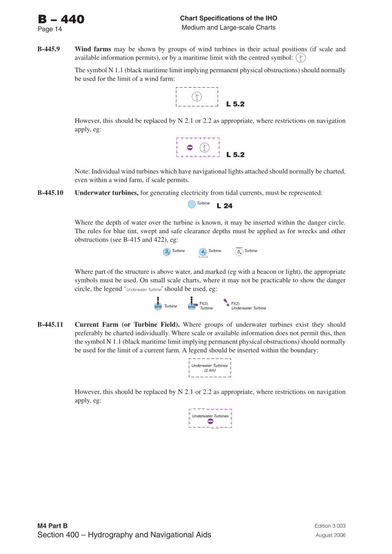
Chart Specifications of the IhoMedium and Large-scale Charts
Edition 3.003
August 2006
M4 Part BSection �00 – Hydrography and Navigational Aids
b – 440Page 1�
B-445.9 Wind farms may be shown by groups of wind turbines in their actual positions (if scale and available information permits), or by a maritime limit with the centred symbol:
The symbol N 1.1 (black maritime limit implying permanent physical obstructions) should normally be used for the limit of a wind farm:
L 5.2
However, this should be replaced by N 2.1 or 2.2 as appropriate, where restrictions on navigation apply, eg:
L 5.2
Note: Individual wind turbines which have navigational lights attached should normally be charted, even within a wind farm, if scale permits.
B-445.10 Underwater turbines, for generating electricity from tidal currents, must be represented:Turbine L 24
Where the depth of water over the turbine is known, it may be inserted within the danger circle. The rules for blue tint, swept and safe clearance depths must be applied as for wrecks and other obstructions (see B-415 and 422), eg:
Turbine47Turbine32
Turbine54
Where part of the structure is above water, and marked (eg with a beacon or light), the appropriate symbols must be used. On small scale charts, where it may not be practicable to show the danger circle, the legend ‘Underwater Turbine’ should be used, eg:
Fl(2)Underwater TurbineTurbineBRB
Fl(2)TurbineBRB
B-445.11 Current Farm (or Turbine Field). Where groups of underwater turbines exist they should preferably be charted individually. Where scale or available information does not permit this, then the symbol N 1.1 (black maritime limit implying permanent physical obstructions) should normally be used for the limit of a current farm. A legend should be inserted within the boundary:
Underwater Turbines(2.4m)
Underwater Turbines
However, this should be replaced by N 2.1 or 2.2 as appropriate, where restrictions on navigation apply, eg:
Underwater Turbines(2.4m)
Underwater Turbines
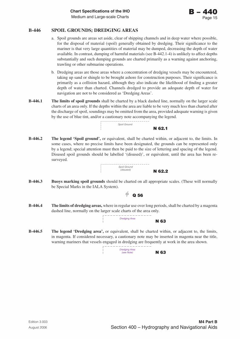
Chart Specifications of the IhoMedium and Large-scale Charts
Edition 3.003
August 2006
M4 Part BSection �00 – Hydrography and Navigational Aids
b – 440Page 15
B-446 SPOIL GROUNDS; DREDGING AREAS
a. Spoil grounds are areas set aside, clear of shipping channels and in deep water where possible, for the disposal of material (spoil) generally obtained by dredging. Their significance to the mariner is that very large quantities of material may be dumped, decreasing the depth of water available. In contrast, dumping of harmful materials (see B-442.1-4) is unlikely to affect depths substantially and such dumping grounds are charted primarily as a warning against anchoring, trawling or other submarine operations.
b. Dredging areas are those areas where a concentration of dredging vessels may be encountered, taking up sand or shingle to be brought ashore for construction purposes. Their significance is primarily as a collision hazard, although they also indicate the likelihood of finding a greater depth of water than charted. Channels dredged to provide an adequate depth of water for navigation are not to be considered as ‘Dredging Areas’.
B-446.1 The limits of spoil grounds shall be charted by a black dashed line, normally on the larger scale charts of an area only. If the depths within the area are liable to be very much less than charted after the discharge of spoil, soundings may be omitted from the area, provided adequate warning is given by the use of blue tint, and/or a cautionary note accompanying the legend.
Spoil Ground
N 62.1
B-446.2 The legend ‘Spoil ground’, or equivalent, shall be charted within, or adjacent to, the limits. In some cases, where no precise limits have been designated, the grounds can be represented only by a legend; special attention must then be paid to the size of lettering and spacing of the legend. Disused spoil grounds should be labelled ‘(disused)’, or equivalent, until the area has been re-surveyed.
Spoil Ground(disused) N 62.2
B-446.3 Buoys marking spoil grounds should be charted on all appropriate scales. (These will normally be Special Marks in the IALA System).
Y Q 56
B-446.4 The limits of dredging areas, where in regular use over long periods, shall be charted by a magenta dashed line, normally on the larger scale charts of the area only.
Dredging Area N 63
B-446.5 The legend ‘Dredging area’, or equivalent, shall be charted within, or adjacent to, the limits, in magenta. If considered necessary, a cautionary note may be inserted in magenta near the title, warning mariners that vessels engaged in dredging are frequently at work in the area shown.
Dredging Area(see Note) N 63
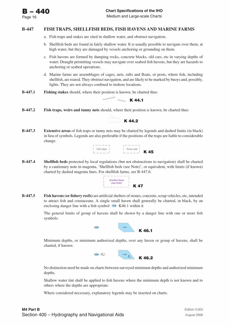
Chart Specifications of the IhoMedium and Large-scale Charts
Edition 3.003
August 2006
M4 Part BSection �00 – Hydrography and Navigational Aids
b – 440Page 16
B-447 FISH TRAPS, SHELLFISH BEDS, FISH HAVENS AND MARINE FARMS
a. Fish traps and stakes are sited in shallow water, and obstruct navigation.
b. Shellfish beds are found in fairly shallow water. It is usually possible to navigate over them, at high water, but they are damaged by vessels anchoring or grounding on them.
c. Fish havens are formed by dumping rocks, concrete blocks, old cars, etc in varying depths of water. Draught permitting vessels may navigate over seabed fish havens, but they are hazards to anchoring or seabed operations.
d. Marine farms are assemblages of cages, nets, rafts and floats, or posts, where fish, including shellfish, are reared. They obstruct navigation, and are likely to be marked by buoys and, possibly, lights. They are not always confined to inshore locations.
B-447.1 Fishing stakes should, where their position is known, be charted thus:
K 44.1
B-447.2 Fish traps, weirs and tunny nets should, where their position is known, be charted thus:
K 44.2
B-447.3 Extensive areas of fish traps or tunny nets may be charted by legends and dashed limits (in black) in lieu of symbols. Legends are also preferable if the positions of the traps are liable to considerable change.
Fish traps Tunny nets K 45
B-447.4 Shellfish beds protected by local regulations (but not obstructions to navigation) shall be charted by a cautionary note in magenta, ‘Shellfish beds (see Note)’, or equivalent, with limits (if known) charted by dashed magenta lines. For shellfish farms, see B-447.6.
Shellfish Beds(see Note)
K 47
B-447.5 Fish havens (or fishery reefs) are artificial shelters of stones, concrete, scrap vehicles, etc, intended to attract fish and crustaceans. A single small haven shall generally be charted, in black, by an enclosing danger line with a fish symbol K46.1 within it
The general limits of group of havens shall be shown by a danger line with one or more fish symbols:
K 46.1
Minimum depths, or minimum authorized depths, over any haven or group of havens, shall be charted, if known:
24
( )24
K 46.2
No distinction need be made on charts between surveyed minimum depths and authorized minimum depths.
Shallow water tint shall be applied to fish havens where the minimum depth is not known and to others where the depths are appropriate.
Where considered necessary, explanatory legends may be inserted on charts.
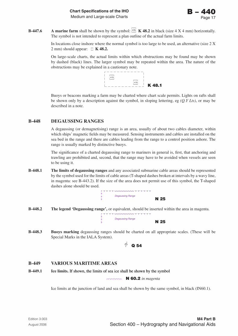
Chart Specifications of the IhoMedium and Large-scale Charts
Edition 3.003
August 2006
M4 Part BSection �00 – Hydrography and Navigational Aids
b – 440Page 1�
B-447.6 A marine farm shall be shown by the symbol: . K 48.2 in black (size 4 X 4 mm) horizontally. The symbol is not intended to represent a plan outline of the actual farm limits.
In locations close inshore where the normal symbol is too large to be used, an alternative (size 2 X 2 mm) should appear: K 48.2.
On large-scale charts, the actual limits within which obstructions may be found may be shown by dashed (black) lines. The larger symbol may be repeated within the area. The nature of the obstructions may be explained in a cautionary note.
K 48.1
Buoys or beacons marking a farm may be charted where chart scale permits. Lights on rafts shall be shown only by a description against the symbol, in sloping lettering, eg (Q.Y Lts), or may be described in a note.
B-448 DEGAUSSING RANGES
A degaussing (or demagnetising) range is an area, usually of about two cables diameter, within which ships’ magnetic fields may be measured. Sensing instruments and cables are installed on the sea bed in the range and there are cables leading from the range to a control position ashore. The range is usually marked by distinctive buoys.
The significance of a charted degaussing range to mariners in general is, first, that anchoring and trawling are prohibited and, second, that the range may have to be avoided when vessels are seen to be using it.
B-448.1 The limits of degaussing ranges and any associated submarine cable areas should be represented by the symbol used for the limits of cable areas (T-shaped dashes broken at intervals by a wavy line, in magenta: see B-443.2). If the size of the area does not permit use of this symbol, the T-shaped dashes alone should be used.
Degaussing Range
N 25
B-448.2 The legend ‘Degaussing range’, or equivalent, should be inserted within the area in magenta.
Degaussing Range
N 25
B-448.3 Buoys marking degaussing ranges should be charted on all appropriate scales. (These will be Special Marks in the IALA System).
Y Q 54
B-449 VARIOUS MARITIME AREAS
B-449.1 Ice limits. If shown, the limits of sea ice shall be shown by the symbolIf shown, the limits of sea ice shall be shown by the symbol
N 60.2 in magenta
Ice limits at the junction of land and sea shall be shown by the same symbol, in black (IN60.1).
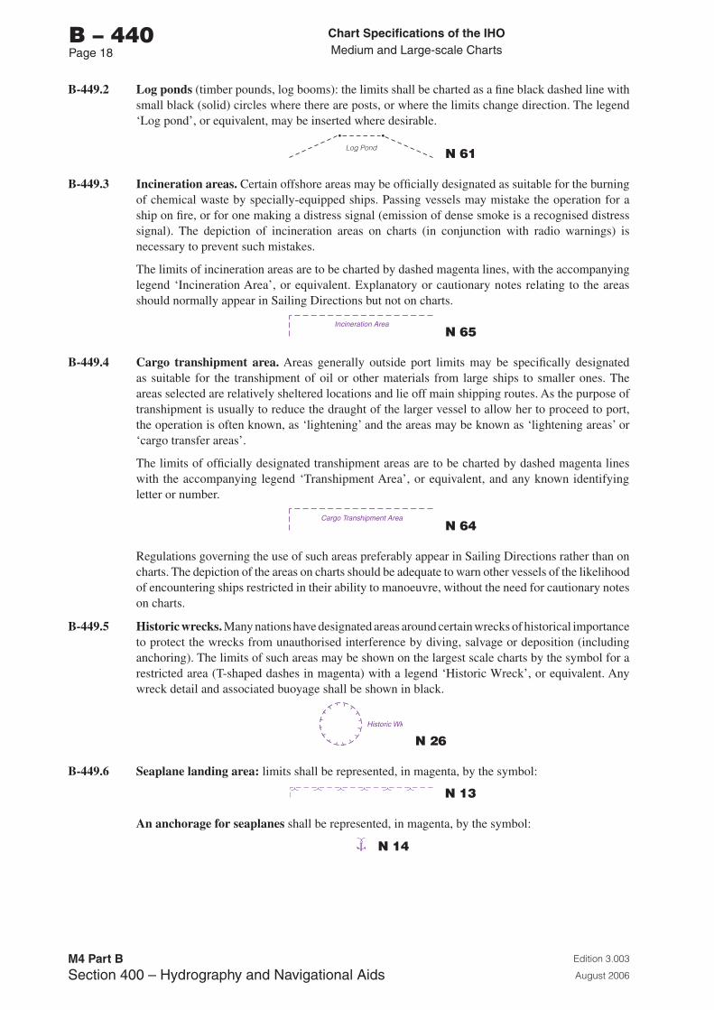
Chart Specifications of the IhoMedium and Large-scale Charts
Edition 3.003
August 2006
M4 Part BSection �00 – Hydrography and Navigational Aids
b – 440Page 1�
B-449.2 Log ponds (timber pounds, log booms): the limits shall be charted as a fine black dashed line with small black (solid) circles where there are posts, or where the limits change direction. The legend ‘Log pond’, or equivalent, may be inserted where desirable.
Log Pond N 61
B-449.3 Incineration areas. Certain offshore areas may be officially designated as suitable for the burning of chemical waste by specially-equipped ships. Passing vessels may mistake the operation for a ship on fire, or for one making a distress signal (emission of dense smoke is a recognised distress signal). The depiction of incineration areas on charts (in conjunction with radio warnings) is necessary to prevent such mistakes.
The limits of incineration areas are to be charted by dashed magenta lines, with the accompanying legend ‘Incineration Area’, or equivalent. Explanatory or cautionary notes relating to the areas should normally appear in Sailing Directions but not on charts.
Incineration Area N 65
B-449.4 Cargo transhipment area. Areas generally outside port limits may be specifically designated as suitable for the transhipment of oil or other materials from large ships to smaller ones. The areas selected are relatively sheltered locations and lie off main shipping routes. As the purpose of transhipment is usually to reduce the draught of the larger vessel to allow her to proceed to port, the operation is often known, as ‘lightening’ and the areas may be known as ‘lightening areas’ or ‘cargo transfer areas’.
The limits of officially designated transhipment areas are to be charted by dashed magenta lines with the accompanying legend ‘Transhipment Area’, or equivalent, and any known identifying letter or number.
Cargo Transhipment Area N 64
Regulations governing the use of such areas preferably appear in Sailing Directions rather than on charts. The depiction of the areas on charts should be adequate to warn other vessels of the likelihood of encountering ships restricted in their ability to manoeuvre, without the need for cautionary notes on charts.
B-449.5 Historic wrecks. Many nations have designated areas around certain wrecks of historical importance to protect the wrecks from unauthorised interference by diving, salvage or deposition (including anchoring). The limits of such areas may be shown on the largest scale charts by the symbol for a restricted area (T-shaped dashes in magenta) with a legend ‘Historic Wreck’, or equivalent. Any wreck detail and associated buoyage shall be shown in black.
Historic Wk
N 26
B-449.6 Seaplane landing area: limits shall be represented, in magenta, by the symbol:
N 13
An anchorage for seaplanes shall be represented, in magenta, by the symbol:
N 14
Chart Specifications of the IhoMedium and Large-scale Charts
Edition 3.003
August 2006
M4 Part BSection �00 – Hydrography and Navigational Aids
b – 450Page 1
B-450 AIDS TO NAVIGATION, AUDIBLE AND VISUAL: GENERAL
In the following paragraphs, audible and visual aids are considered as divided into the categories listed below:
a. Fog signals, which are usually associated with a lighthouse, major floating light or buoy. The lettering of the abbreviations for fog signals may be upright or sloping, depending on the nature of the basic structure.
b. Beacons, cairns, towers, etc, specially erected for navigational purposes. Associated lettering should be upright.
c. Buoys, including minor light-floats. Associated lettering should be sloping.
d. Major floating lights. Associated lettering should be sloping.
e. Lights and lighthouses of all sizes. Associated lettering shall be upright.
B-450.1 Colours of aids to navigation shall have standardised abbreviations when used for:
• colours of bodies or topmarks of buoys and beacons (and lighthouses, where necessary); and
• colours of lights exhibited.
In certain cases, as described under the different types of aids, abbreviations may be omitted.
B-450.2 The standard colour abbreviations shall be:
Principal colours (as used in the IALA system) Subsidiary colours (if necessary)
White - W P11.1 Q5 Blue - Bu P11.4
Black - B Q2 Violet - Vi P11.5
Red - R P11.2 Q3 Amber - Am P11.8
Green - G P11.3 Q2 Orange - Or P11.7
Yellow - Y P11.6 Q3
B-450.3 Colour abbreviations shall be in capital letters in all cases except for the second letter of two-letter abbreviations.
B-451 FOG SIGNALS
The phrase ‘fog signal’ means the sound emitted, not the apparatus. Fog signals are fairly short range aids and are, for various reasons, unreliable as indicators of position. Their importance relative to other aids has declined but they are still considered necessary for the safe navigation of vessels with very limited electronic equipment, and also of well-equipped vessels whose equipment is not functioning.
Brief details of the type and characteristics of fog signals may be on charts on which vessels may navigate within range of the fog signals. However, nations wishing to show only the existence of a fog signal on charts should do so preferably by using the symbol R1 (in magenta) rather than by a national abbreviation. See B-452.8. It is strongly recommended that, on buoys at least, the type of fog signal is indicated by a legend (see B-454). Shore fog signals are always described in Lists of Lights unlike fog signals carried by buoys, which are not always listed in Lists of Lights.
For charting of fog detector lights see B-477.
Chart Specifications of the IhoMedium and Large-scale Charts
Edition 3.003
August 2006
M4 Part BSection �00 – Hydrography and Navigational Aids
b – 450Page 2
B-451.1 The scale of charts on which fog signals should be shown depends on some definition of probable ranges. The ‘usual range’ (defined by IALA as the distance at which there is a 50% probability of hearing it from the wing of a ship’s bridge on a vessel with an average ambient noise level, in relatively calm weather) is not precise enough to be worth charting but, for the guidance of cartographers the following ‘usual’ ranges are given;
• Powerful diaphone: 4 to 5 miles,
• Horn: up to 3 miles, (signals at harbour entrances are usually much weaker).
• Wave actuated bell or whistle: about 1/2 mile or less.
B-451.2 The position from which a fog signal is emitted is usually on a buoy, or close enough to a light as to be treated as sounded from the position of the light. In cases where a fog signal is not closely associated with a light, its position should be shown by a small position circle, and the magenta symbol R1, with a name added if appropriate.
B-451.3 Abbreviations for type, characteristics and period of a fog signal shall be similar for all automatic signals, ashore or afloat. For wave actuated signals on buoys, see B-454.1.
B-451.4 Reserve fog signals, eg a gong sounded when the normal siren is not functioning, shall not normally be charted. For wave actuated signals on buoys sounded in conjunction with automatic signals, see B-454.1.
B-452 TYPES OF FOG SIGNAL
It is impossible to indicate on charts all the variations in the sounds emitted but some major differences can easily be conveyed to the mariner by distinguishing the following types of fog signal.
Where a nation states the type of fog signal on its charts, the following international abbreviations shall preferably be used. If the appropriate international abbreviation is used, the symbol R 1 may be omitted.
B-452.1 Explosive: The short report produced by the sound of an explosion, either discharged from a gun or in mid-air, shall be charted ‘Explos’ R 10. It is now mainly used as a reserve signal and, if so, is not to be charted.
B-452.2 Diaphone: a generally powerful, lowpitched sound (usually ending in a ‘grunt’) produced by release of compressed air controlled by a piston actuated by compressed air. The signal shall be charted ‘Dia’ R 11.
B-452.3 Siren: a sound produced by the escape of compressed air through a rotary shutter; power and pitch vary considerably. The signal shall be charted ‘Siren’ R 12.
B-452.4 Horn: the sound is produced by a vibrating diaphragm and varies greatly in strength and pitch. The nautophone, reed and tyfon are types of horn. The signal shall be charted ‘Horn’ R 13.
B-452.5 Bell: a ringing sound with a short range. The apparatus may be operated automatically, by hand, or by wave action. The signal shall be charted ‘Bell’ R 14.
B-452.6 Whistle: a distinctive sound made by a jet of air passing through an orifice. The apparatus may be operated automatically, by hand, or by air being forced up a tube by waves acting on a buoy. The signal shall be charted ‘Whis’ R 15.
B-452.7 Gong: a sound produced by vibration of a disc, or discs, when struck. The apparatus may be operated automatically, by hand, or by wave action. The signal shall be charted ‘Gong’ R 16.
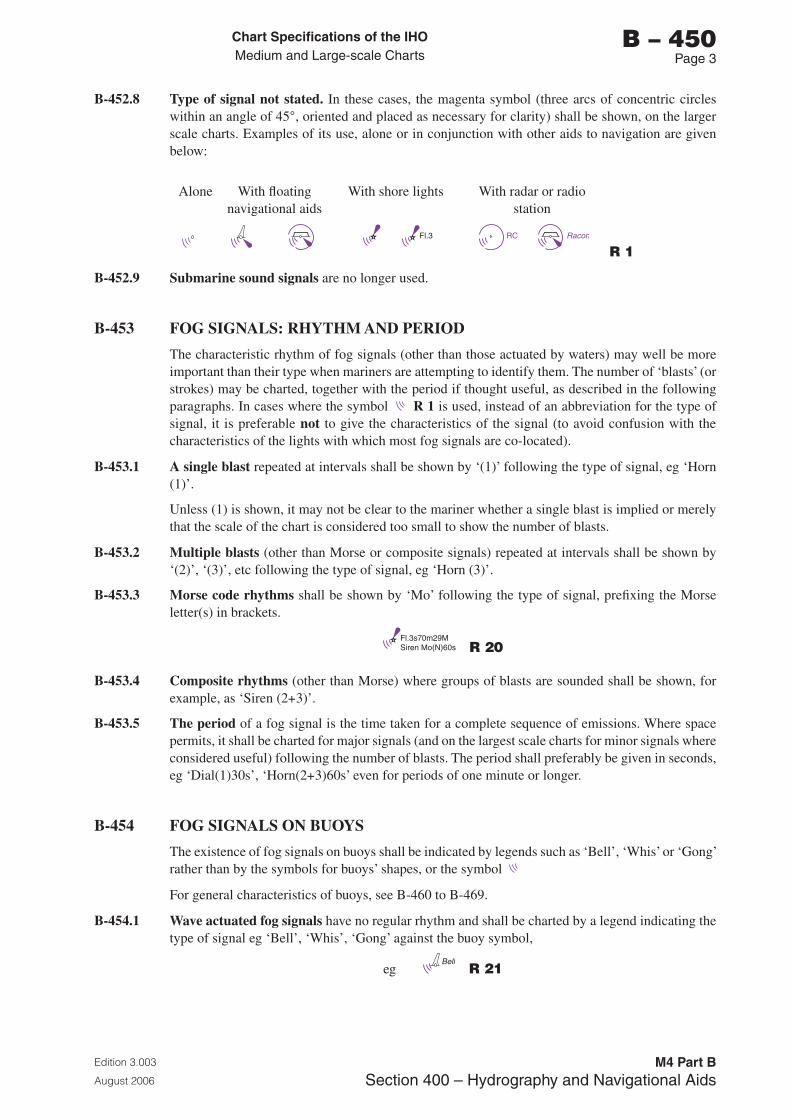
Chart Specifications of the IhoMedium and Large-scale Charts
Edition 3.003
August 2006
M4 Part BSection �00 – Hydrography and Navigational Aids
b – 450Page �
B-452.8 Type of signal not stated. In these cases, the magenta symbol (three arcs of concentric circles within an angle of 45°, oriented and placed as necessary for clarity) shall be shown, on the larger scale charts. Examples of its use, alone or in conjunction with other aids to navigation are given below:
Alone With floating navigational aids
With shore lights With radar or radio station
Fl.3 RC Racon
Fl.3 RC Racon
Fl.3 RC Racon
R 1
B-452.9 Submarine sound signals are no longer used.
B-453 FOG SIGNALS: RHYTHM AND PERIOD
The characteristic rhythm of fog signals (other than those actuated by waters) may well be more important than their type when mariners are attempting to identify them. The number of ‘blasts’ (or strokes) may be charted, together with the period if thought useful, as described in the following paragraphs. In cases where the symbol R 1 is used, instead of an abbreviation for the type of signal, it is preferable not to give the characteristics of the signal (to avoid confusion with the characteristics of the lights with which most fog signals are co-located).
B-453.1 A single blast repeated at intervals shall be shown by ‘(1)’ following the type of signal, eg ‘Horn (1)’.
Unless (1) is shown, it may not be clear to the mariner whether a single blast is implied or merely that the scale of the chart is considered too small to show the number of blasts.
B-453.2 Multiple blasts (other than Morse or composite signals) repeated at intervals shall be shown by ‘(2)’, ‘(3)’, etc following the type of signal, eg ‘Horn (3)’.
B-453.3 Morse code rhythms shall be shown by ‘Mo’ following the type of signal, prefixing the Morse letter(s) in brackets.
Fl.3s70m29MSiren Mo(N)60s R 20
B-453.4 Composite rhythms (other than Morse) where groups of blasts are sounded shall be shown, for example, as ‘Siren (2+3)’.
B-453.5 The period of a fog signal is the time taken for a complete sequence of emissions. Where space permits, it shall be charted for major signals (and on the largest scale charts for minor signals where considered useful) following the number of blasts. The period shall preferably be given in seconds, eg ‘Dial(1)30s’, ‘Horn(2+3)60s’ even for periods of one minute or longer.
B-454 FOG SIGNALS ON BUOYS
The existence of fog signals on buoys shall be indicated by legends such as ‘Bell’, ‘Whis’ or ‘Gong’ rather than by the symbols for buoys’ shapes, or the symbol
For general characteristics of buoys, see B-460 to B-469.
B-454.1 Wave actuated fog signals have no regular rhythm and shall be charted by a legend indicating the type of signal eg ‘Bell’, ‘Whis’, ‘Gong’ against the buoy symbol,
eg Bell
R 21
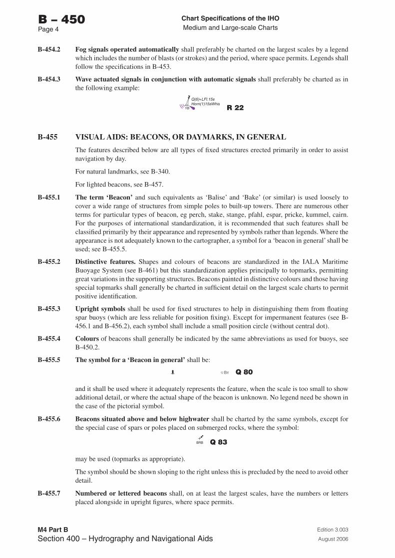
Chart Specifications of the IhoMedium and Large-scale Charts
Edition 3.003
August 2006
M4 Part BSection �00 – Hydrography and Navigational Aids
b – 450Page �
B-454.2 Fog signals operated automatically shall preferably be charted on the largest scales by a legend which includes the number of blasts (or strokes) and the period, where space permits. Legends shall follow the specifications in B-453.
B-454.3 Wave actuated signals in conjunction with automatic signals shall preferably be charted as in the following example:
Q(6)+LFl.15sHorn(1)15sWhis
YB R 22
B-455 VISUAL AIDS: BEACONS, OR DAYMARKS, IN GENERAL
The features described below are all types of fixed structures erected primarily in order to assist navigation by day.
For natural landmarks, see B-340.
For lighted beacons, see B-457.
B-455.1 The term ‘Beacon’ and such equivalents as ‘Balise’ and ‘Bake’ (or similar) is used loosely to cover a wide range of structures from simple poles to built-up towers. There are numerous other terms for particular types of beacon, eg perch, stake, stange, pfahl, espar, pricke, kummel, cairn. For the purposes of international standardization, it is recommended that such features shall be classified primarily by their appearance and represented by symbols rather than legends. Where the appearance is not adequately known to the cartographer, a symbol for a ‘beacon in general’ shall be used; see B-455.5.
B-455.2 Distinctive features. Shapes and colours of beacons are standardized in the IALA Maritime Buoyage System (see B-461) but this standardization applies principally to topmarks, permitting great variations in the supporting structures. Beacons painted in distinctive colours and those having special topmarks shall generally be charted in sufficient detail on the largest scale charts to permit positive identification.
B-455.3 Upright symbols shall be used for fixed structures to help in distinguishing them from floating spar buoys (which are less reliable for position fixing). Except for impermanent features (see B-456.1 and B-456.2), each symbol shall include a small position circle (without central dot).
B-455.4 Colours of beacons shall generally be indicated by the same abbreviations as used for buoys, see B-450.2.
B-455.5 The symbol for a ‘Beacon in general’ shall be:
Bn Q 80
and it shall be used where it adequately represents the feature, when the scale is too small to show additional detail, or where the actual shape of the beacon is unknown. No legend need be shown in the case of the pictorial symbol.
B-455.6 Beacons situated above and below highwater shall be charted by the same symbols, except for the special case of spars or poles placed on submerged rocks, where the symbol:
BRB Q 83
may be used (topmarks as appropriate).
The symbol should be shown sloping to the right unless this is precluded by the need to avoid other detail.
B-455.7 Numbered or lettered beacons shall, on at least the largest scales, have the numbers or letters placed alongside in upright figures, where space permits.
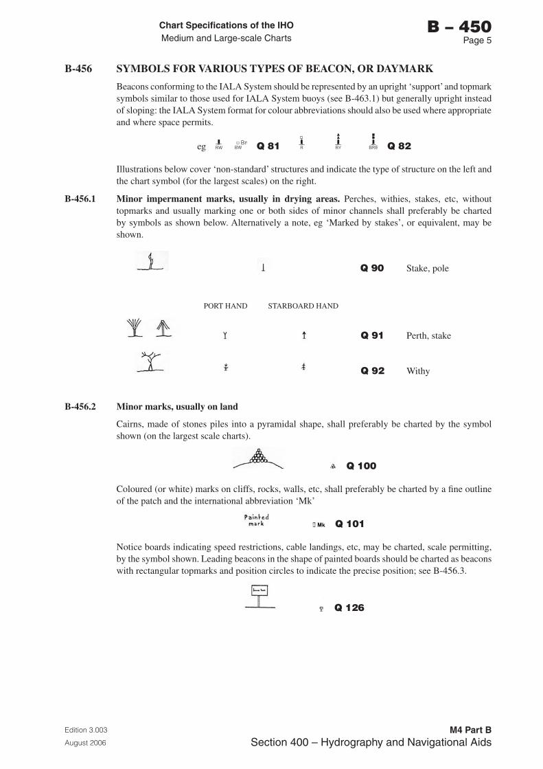
Chart Specifications of the IhoMedium and Large-scale Charts
Edition 3.003
August 2006
M4 Part BSection �00 – Hydrography and Navigational Aids
b – 450Page 5
B-456 SYMBOLS FOR VARIOUS TYPES OF BEACON, OR DAYMARK
Beacons conforming to the IALA System should be represented by an upright ‘support’ and topmark symbols similar to those used for IALA System buoys (see B-463.1) but generally upright instead of sloping: the IALA System format for colour abbreviations should also be used where appropriate and where space permits.
eg BnBW BW Bn
BW BW Q 81 Q 82
Illustrations below cover ‘non-standard’ structures and indicate the type of structure on the left and the chart symbol (for the largest scales) on the right.
B-456.1 Minor impermanent marks, usually in drying areas. Perches, withies, stakes, etc, without topmarks and usually marking one or both sides of minor channels shall preferably be charted by symbols as shown below. Alternatively a note, eg ‘Marked by stakes’, or equivalent, may be shown.
Q 90 Stake, pole
PORT HAND STARBOARD HAND
Q 91 Perth, stake
Q 92 Withy
B-456.2 Minor marks, usually on land
Cairns, made of stones piles into a pyramidal shape, shall preferably be charted by the symbol shown (on the largest scale charts).
Q 100
Coloured (or white) marks on cliffs, rocks, walls, etc, shall preferably be charted by a fine outline of the patch and the international abbreviation ‘Mk’
Q 101
Notice boards indicating speed restrictions, cable landings, etc, may be charted, scale permitting, by the symbol shown. Leading beacons in the shape of painted boards should be charted as beacons with rectangular topmarks and position circles to indicate the precise position; see B-456.3.
Q 126
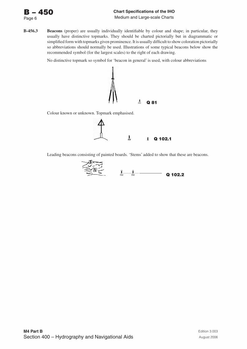
Chart Specifications of the IhoMedium and Large-scale Charts
Edition 3.003
August 2006
M4 Part BSection �00 – Hydrography and Navigational Aids
b – 450Page 6
B-456.3 Beacons (proper) are usually individually identifiable by colour and shape; in particular, they usually have distinctive topmarks. They should be charted pictorially but in diagrammatic or simplified form with topmarks given prominence. It is usually difficult to show coloration pictorially so abbreviations should normally be used. Illustrations of some typical beacons below show the recommended symbol (for the largest scales) to the right of each drawing.
No distinctive topmark so symbol for ‘beacon in general’ is used, with colour abbreviations
Q 81
Colour known or unknown. Topmark emphasised.
Q 102.1
Leading beacons consisting of painted boards. ‘Stems’ added to show that these are beacons.
RW RW Q 102.2
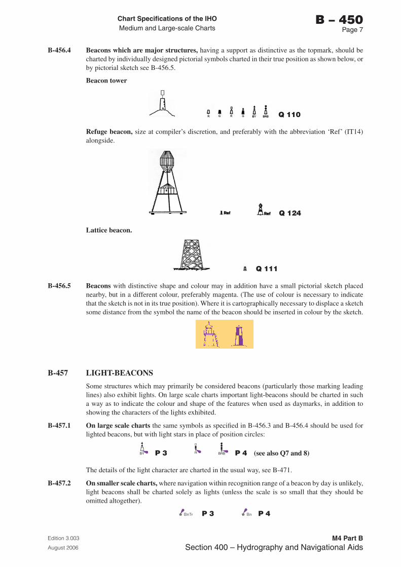
Chart Specifications of the IhoMedium and Large-scale Charts
Edition 3.003
August 2006
M4 Part BSection �00 – Hydrography and Navigational Aids
b – 450Page �
B-456.4 Beacons which are major structures, having a support as distinctive as the topmark, should be charted by individually designed pictorial symbols charted in their true position as shown below, or by pictorial sketch see B-456.5.
Beacon tower
Q 110
Refuge beacon, size at compiler’s discretion, and preferably with the abbreviation ‘Ref’ (IT14) alongside.
Q 124
Lattice beacon.
Q 111
B-456.5 Beacons with distinctive shape and colour may in addition have a small pictorial sketch placed nearby, but in a different colour, preferably magenta. (The use of colour is necessary to indicate that the sketch is not in its true position). Where it is cartographically necessary to displace a sketch some distance from the symbol the name of the beacon should be inserted in colour by the sketch.
B-457 LIGHT-BEACONS
Some structures which may primarily be considered beacons (particularly those marking leading lines) also exhibit lights. On large scale charts important light-beacons should be charted in such a way as to indicate the colour and shape of the features when used as daymarks, in addition to showing the characters of the lights exhibited.
B-457.1 On large scale charts the same symbols as specified in B-456.3 and B-456.4 should be used for lighted beacons, but with light stars in place of position circles:
BY P 3 R BRB P 4 (see also Q7 and 8)
The details of the light character are charted in the usual way, see B-471.
B-457.2 On smaller scale charts, where navigation within recognition range of a beacon by day is unlikely, light beacons shall be charted solely as lights (unless the scale is so small that they should be omitted altogether).
P 3 P 4
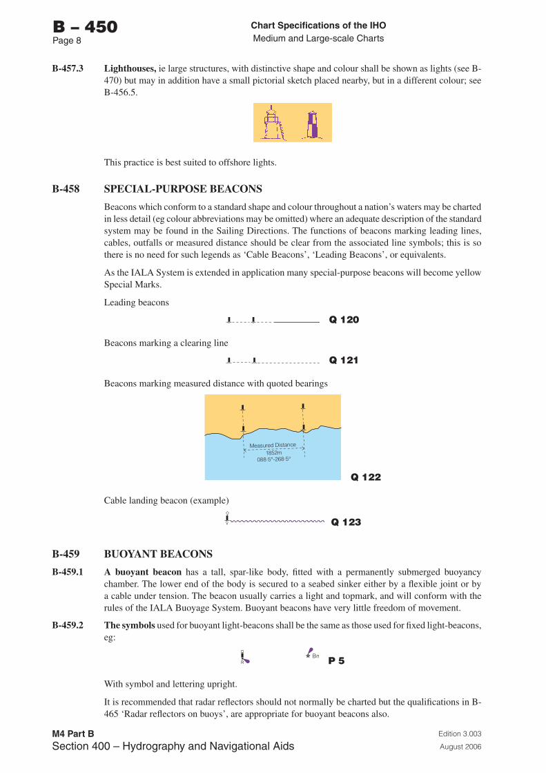
Chart Specifications of the IhoMedium and Large-scale Charts
Edition 3.003
August 2006
M4 Part BSection �00 – Hydrography and Navigational Aids
b – 450Page �
B-457.3 Lighthouses, ie large structures, with distinctive shape and colour shall be shown as lights (see B-470) but may in addition have a small pictorial sketch placed nearby, but in a different colour; see B-456.5.
This practice is best suited to offshore lights.
B-458 SPECIAL-PURPOSE BEACONS
Beacons which conform to a standard shape and colour throughout a nation’s waters may be charted in less detail (eg colour abbreviations may be omitted) where an adequate description of the standard system may be found in the Sailing Directions. The functions of beacons marking leading lines, cables, outfalls or measured distance should be clear from the associated line symbols; this is so there is no need for such legends as ‘Cable Beacons’, ‘Leading Beacons’, or equivalents.
As the IALA System is extended in application many special-purpose beacons will become yellow Special Marks.
Leading beacons
Q 120
Beacons marking a clearing line
Q 121
Beacons marking measured distance with quoted bearings
Measured Distance
1852m088·5°-268·5°
Q 122
Cable landing beacon (example)
Q 123
B-459 BUOYANT BEACONS
B-459.1 A buoyant beacon has a tall, spar-like body, fitted with a permanently submerged buoyancy chamber. The lower end of the body is secured to a seabed sinker either by a flexible joint or by a cable under tension. The beacon usually carries a light and topmark, and will conform with the rules of the IALA Buoyage System. Buoyant beacons have very little freedom of movement.
B-459.2 The symbols used for buoyant light-beacons shall be the same as those used for fixed light-beacons, eg:
P 5
With symbol and lettering upright.
It is recommended that radar reflectors should not normally be charted but the qualifications in B-465 ‘Radar reflectors on buoys’, are appropriate for buoyant beacons also.
Chart Specifications of the IhoMedium and Large-scale Charts
Edition 3.003
August 2006
M4 Part BSection �00 – Hydrography and Navigational Aids
b – 460Page 1
B-460 VISUAL AIDS: BUOYAGE
The following notes apply to navigational and special-purpose buoys, other than mooring buoys. For mooring buoys, see B-431.5-7. Some of the remarks may not apply to spar buoys.
The physical characteristics of buoys affect charting practice and are therefore briefly described below.
B-460.1 Buoy moorings consist usually of a sinker and chain, the length of the latter being generally about three times the depth of water, where tides are significant. There may be a plottable difference between flood and ebb positions of a buoy; also, buoys are liable to drag their moorings out of position at times. The position to be charted is the position assigned by the buoyage authority - which will generally be a mean of flood and ebb positions, and the position to which the mooring will be returned if the buoy is found to have dragged it away.
B-460.2 The body of a buoy is principally a float which may be given a distinctive shape (eg spherical), or may be a support for a superstructure which can be given a distinctive shape by means of lattice-work ‘wings’ or ‘cages’. Some buoys, eg some outer buoys, have a tall superstructure to carry a light, fog signal, radar reflector, and possibly topmark. In such cases, the superstructure may not have been given any special shape; it is recommended that such buoys should be charted as pillar buoys, see B-462.5.
B-460.3 Topmarks are invariably distinctively shaped and may be intended either for identification of a particular buoy in a line of channel-marking buoys, or to be the principal means (other than colour and light-character) of showing where safe water lies in relation to the buoy. Radar reflectors may be almost as prominent on buoys as topmarks, but are to be charted, if at all, solely by the special symbol IS4, not as a topmark. In the case of the IALA System buoyage, it is recommended that radar reflector symbols should normally be omitted; see B-465. Topmarks are liable to be damaged by ice.
B-460.4 The size of buoys varies with both the range of visibility required and the difficulties of the location (deep water and strong tidal streams need longer, heavier moorings and therefore larger floats). It is considered practicable to distinguish on charts between only two sizes of buoys (apart from major floating lights - see B-474, and spar buoys - see B-462.2):
a. ‘Standard’ buoys, including those tall ones sometimes described as ‘high focal plane’.
b. Super-buoys. Very large buoys, generally more than 5m in diameter, which should be emphasized on charts because their unusually large size renders them a potential hazard even to large vessels and/or their function or attachments render them unusually costly, or are such that their destruction could result in a disaster. The two principal types of super-buoy are:
i. Offshore tanker loading/discharge buoys, often known as SPMs (single point moorings). (Very large floating offshore oil terminals, incorporating oil storage and regularly manned, should not be classified as super-buoys - they usually resemble fixed platforms rather than buoys: see B-445.2).
ii. certain very large ODAS (oceanographic data acquisition systems) buoys, usually moored in deep water, for the automatic collection of oceanographic and meteorological information. See B-462.9.
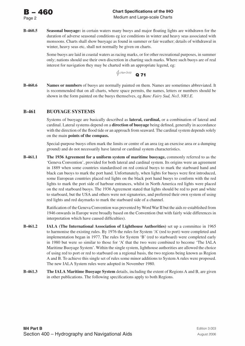
Chart Specifications of the IhoMedium and Large-scale Charts
Edition 3.003
August 2006
M4 Part BSection �00 – Hydrography and Navigational Aids
b – 460Page 2
B-460.5 Seasonal buoyage: in certain waters many buoys and major floating lights are withdrawn for the duration of adverse seasonal conditions eg ice conditions in winter and heavy seas associated with monsoons. Charts shall show buoyage as found in summer or fair weather; details of withdrawal in winter, heavy seas etc, shall not normally be given on charts.
Some buoys are laid in coastal waters as racing marks, or for other recreational purposes, in summer only; nations should use their own discretion in charting such marks. Where such buoys are of real interest for navigation they may be charted with an appropriate legend, eg:
(Apr-Oct))Y Q 71
B-460.6 Names or numbers of buoys are normally painted on them. Names are sometimes abbreviated. It is recommended that on all charts, where space permits, the names, letters or numbers should be shown in the form painted on the buoys themselves, eg Banc Fairy Sud, No3, NR3.E.
B-461 BUOYAGE SYSTEMS
Systems of buoyage are basically described as lateral, cardinal, or a combination of lateral and cardinal. Lateral systems depend on a direction of buoyage being defined, generally in accordance with the direction of the flood tide or an approach from seaward. The cardinal system depends solely on the main points of the compass.
Special-purpose buoys often mark the limits or centre of an area (eg an exercise area or a dumping ground) and do not necessarily have lateral or cardinal system characteristics.
B-461.1 The 1936 Agreement for a uniform system of maritime buoyage, commonly referred to as the ‘Geneva Convention’, provided for both lateral and cardinal system. Its origins were an agreement in 1889 when some countries standardised on red conical buoys to mark the starboard hand and black can buoys to mark the port hand. Unfortunately, when lights for buoys were first introduced, some European countries placed red lights on the black port hand buoys to conform with the red lights to mark the port side of harbour entrances, whilst in North America red lights were placed on the red starboard buoys. The 1936 Agreement stated that lights should be red to port and white to starboard, but the USA and others were not signatories, and preferred their own system of using red lights and red daymarks to mark the starboard side of a channel.
Ratification of the Geneva Convention was prevented by Word War II but the aids re-established from 1946 onwards in Europe were broadly based on the Convention (but with fairly wide differences in interpretation which have caused difficulties).
B-461.2 IALA (The International Association of Lighthouse Authorities) set up a committee in 1965 to harmonise the existing rules. By 1976 the rules for System ‘A’ (red to port) were completed and implementation began in 1977. The rules for System ‘B’ (red to starboard) were completed early in 1980 but were so similar to those for ‘A’ that the two were combined to become ‘The IALA Maritime Buoyage System’. Within the single system, lighthouse authorities are allowed the choice of using red to port or red to starboard on a regional basis, the two regions being known as Region A and B. To achieve this single set of rules some minor additions to System A rules were proposed. The new IALA System rules were adopted in November 1980.
B-461.3 The IALA Maritime Buoyage System details, including the extent of Regions A and B, are given in other publications. The following specifications apply to both Regions.
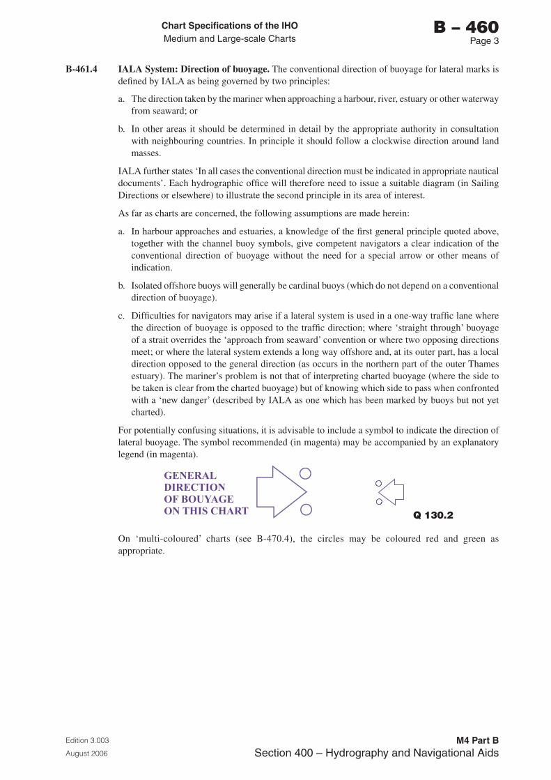
Chart Specifications of the IhoMedium and Large-scale Charts
Edition 3.003
August 2006
M4 Part BSection �00 – Hydrography and Navigational Aids
b – 460Page �
B-461.4 IALA System: Direction of buoyage. The conventional direction of buoyage for lateral marks is defined by IALA as being governed by two principles:
a. The direction taken by the mariner when approaching a harbour, river, estuary or other waterway from seaward; or
b. In other areas it should be determined in detail by the appropriate authority in consultation with neighbouring countries. In principle it should follow a clockwise direction around land masses.
IALA further states ‘In all cases the conventional direction must be indicated in appropriate nautical documents’. Each hydrographic office will therefore need to issue a suitable diagram (in Sailing Directions or elsewhere) to illustrate the second principle in its area of interest.
As far as charts are concerned, the following assumptions are made herein:
a. In harbour approaches and estuaries, a knowledge of the first general principle quoted above, together with the channel buoy symbols, give competent navigators a clear indication of the conventional direction of buoyage without the need for a special arrow or other means of indication.
b. Isolated offshore buoys will generally be cardinal buoys (which do not depend on a conventional direction of buoyage).
c. Difficulties for navigators may arise if a lateral system is used in a one-way traffic lane where the direction of buoyage is opposed to the traffic direction; where ‘straight through’ buoyage of a strait overrides the ‘approach from seaward’ convention or where two opposing directions meet; or where the lateral system extends a long way offshore and, at its outer part, has a local direction opposed to the general direction (as occurs in the northern part of the outer Thames estuary). The mariner’s problem is not that of interpreting charted buoyage (where the side to be taken is clear from the charted buoyage) but of knowing which side to pass when confronted with a ‘new danger’ (described by IALA as one which has been marked by buoys but not yet charted).
For potentially confusing situations, it is advisable to include a symbol to indicate the direction of lateral buoyage. The symbol recommended (in magenta) may be accompanied by an explanatory legend (in magenta).
GENERALDIRECTIONOF BOUYAGEON THIS CHART Q 130.2
On ‘multi-coloured’ charts (see B-470.4), the circles may be coloured red and green as appropriate.
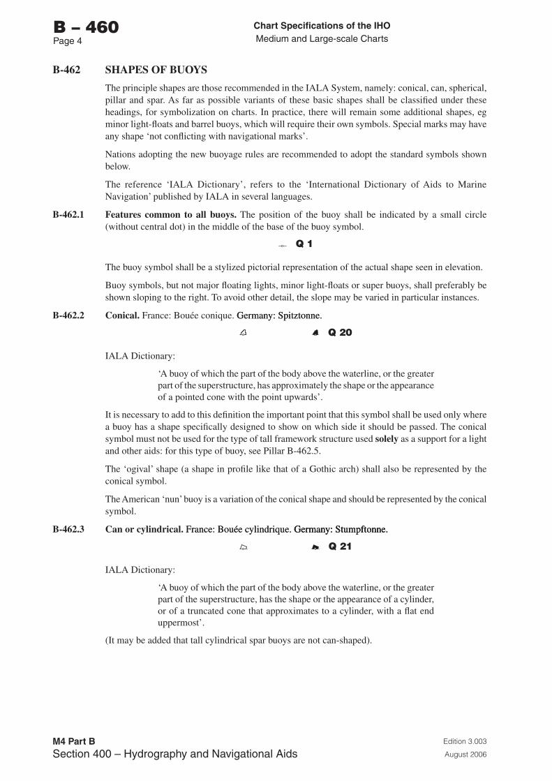
Chart Specifications of the IhoMedium and Large-scale Charts
Edition 3.003
August 2006
M4 Part BSection �00 – Hydrography and Navigational Aids
b – 460Page �
B-462 SHAPES OF BUOYS
The principle shapes are those recommended in the IALA System, namely: conical, can, spherical, pillar and spar. As far as possible variants of these basic shapes shall be classified under these headings, for symbolization on charts. In practice, there will remain some additional shapes, eg minor light-floats and barrel buoys, which will require their own symbols. Special marks may have any shape ‘not conflicting with navigational marks’.
Nations adopting the new buoyage rules are recommended to adopt the standard symbols shown below.
The reference ‘IALA Dictionary’, refers to the ‘International Dictionary of Aids to Marine Navigation’ published by IALA in several languages.
B-462.1 Features common to all buoys. The position of the buoy shall be indicated by a small circle (without central dot) in the middle of the base of the buoy symbol.
Q 1
The buoy symbol shall be a stylized pictorial representation of the actual shape seen in elevation.
Buoy symbols, but not major floating lights, minor light-floats or super buoys, shall preferably be shown sloping to the right. To avoid other detail, the slope may be varied in particular instances.
B-462.2 Conical. France: Bouée conique. Germany: Spitztonne.Germany: Spitztonne.
Q 20
IALA Dictionary:
‘A buoy of which the part of the body above the waterline, or the greater part of the superstructure, has approximately the shape or the appearance of a pointed cone with the point upwards’.
It is necessary to add to this definition the important point that this symbol shall be used only where a buoy has a shape specifically designed to show on which side it should be passed. The conical symbol must not be used for the type of tall framework structure used solely as a support for a light and other aids: for this type of buoy, see Pillar B-462.5.
The ‘ogival’ shape (a shape in profile like that of a Gothic arch) shall also be represented by the conical symbol.
The American ‘nun’ buoy is a variation of the conical shape and should be represented by the conical symbol.
B-462.3 Can or cylindrical. France: Bouée cylindrique. Germany: Stumpftonne.France: Bouée cylindrique. Germany: Stumpftonne.Germany: Stumpftonne.
Q 21
IALA Dictionary:
‘A buoy of which the part of the body above the waterline, or the greater part of the superstructure, has the shape or the appearance of a cylinder, or of a truncated cone that approximates to a cylinder, with a flat end uppermost’.
(It may be added that tall cylindrical spar buoys are not can-shaped).
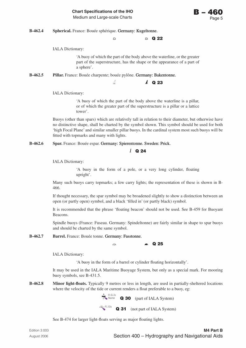
Chart Specifications of the IhoMedium and Large-scale Charts
Edition 3.003
August 2006
M4 Part BSection �00 – Hydrography and Navigational Aids
b – 460Page 5
B-462.4 Spherical. France: Bouée sphérique. Germany: Kugeltonne.Germany: Kugeltonne.
Q 22
IALA Dictionary:
‘A buoy of which the part of the body above the waterline, or the greater part of the superstructure, has the shape or the appearance of a part of a sphere’.
B-462.5 Pillar. France: Bouée charpente; bouée pylône. Germany: Bakentonne.Germany: Bakentonne.
Q 23
IALA Dictionary:
‘A buoy of which the part of the body above the waterline is a pillar, or of which the greater part of the superstructure is a pillar or a lattice tower’.
Buoys (other than spars) which are relatively tall in relation to their diameter, but otherwise have no distinctive shape, shall be charted by the symbol shown. This symbol should be used for both ‘high Focal Plane’ and similar smaller pillar buoys. In the cardinal system most such buoys will be fitted with topmarks and many with lights.
B-462.6 Spar. France: Bouée espar. Germany: Spierentonne. Sweden: Prick.Germany: Spierentonne. Sweden: Prick.
Q 24
IALA Dictionary:
‘A buoy in the form of a pole, or a very long cylinder, floating upright’.
Many such buoys carry topmarks; a few carry lights; the representation of these is shown in B-466.
If thought necessary, the spar symbol may be broadened slightly to show a distinction between an open (or partly open) symbol, and a black ‘filled in’ (or partly black) symbol.
It is recommended that the phrase ‘floating beacon’ should not be used. See B-459 for Buoyant Beacons.
Spindle buoys (France: Fuseau. Germany: Spindeltonne) are fairly similar in shape to spar buoys and should be charted by the same symbol.
B-462.7 Barrel. France: Bouée tonne. Germany: Fasstonne.Germany: Fasstonne.
Q 25
IALA Dictionary:
‘A buoy in the form of a barrel or cylinder floating horizontally’.
It may be used in the IALA Maritime Buoyage System, but only as a special mark. For mooring buoy symbols, see B-431.5.
B-462.8 Minor light-floats. Typically 9 metres or less in length, are used in partially-sheltered locations where the velocity of the tide or current renders a float preferable to a buoy, eg:
Q 30 (part of IALA System)
Q 31 (not part of IALA System)
See B-474 for larger light-floats serving as major floating lights.
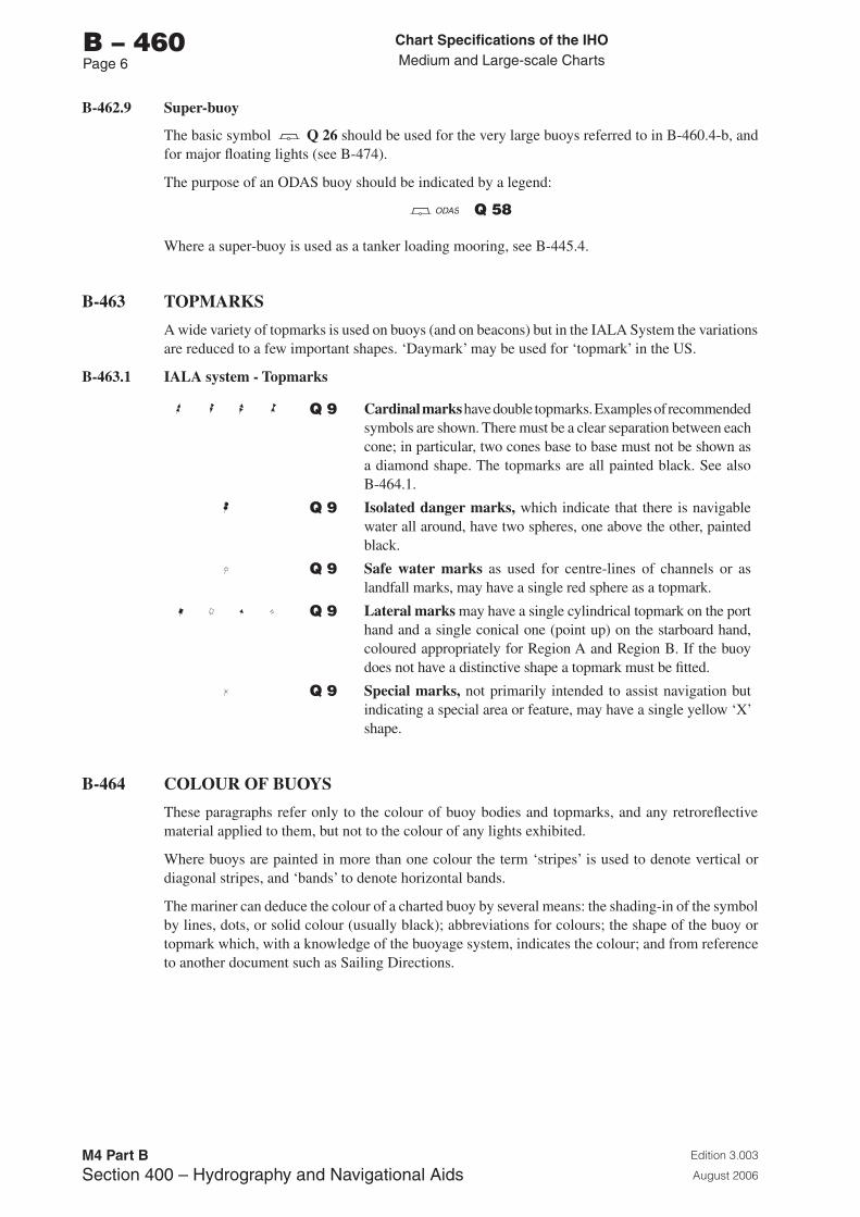
Chart Specifications of the IhoMedium and Large-scale Charts
Edition 3.003
August 2006
M4 Part BSection �00 – Hydrography and Navigational Aids
b – 460Page 6
B-462.9 Super-buoy
The basic symbol Q 26 should be used for the very large buoys referred to in B-460.4-b, and for major floating lights (see B-474).
The purpose of an ODAS buoy should be indicated by a legend:
ODAS Q 58
Where a super-buoy is used as a tanker loading mooring, see B-445.4.
B-463 TOPMARKS
A wide variety of topmarks is used on buoys (and on beacons) but in the IALA System the variations are reduced to a few important shapes. ‘Daymark’ may be used for ‘topmark’ in the US.
B-463.1 IALA system - Topmarks
Q 9 Cardinal marks have double topmarks. Examples of recommended symbols are shown. There must be a clear separation between each cone; in particular, two cones base to base must not be shown as a diamond shape. The topmarks are all painted black. See also B-464.1.
Q 9 Isolated danger marks, which indicate that there is navigable water all around, have two spheres, one above the other, painted black.
Q 9 Safe water marks as used for centre-lines of channels or as landfall marks, may have a single red sphere as a topmark.
Q 9 Lateral marks may have a single cylindrical topmark on the port hand and a single conical one (point up) on the starboard hand, coloured appropriately for Region A and Region B. If the buoy does not have a distinctive shape a topmark must be fitted.
Q 9 Special marks, not primarily intended to assist navigation but indicating a special area or feature, may have a single yellow ‘X’ shape.
B-464 COLOUR OF BUOYS
These paragraphs refer only to the colour of buoy bodies and topmarks, and any retroreflective material applied to them, but not to the colour of any lights exhibited.
Where buoys are painted in more than one colour the term ‘stripes’ is used to denote vertical or diagonal stripes, and ‘bands’ to denote horizontal bands.
The mariner can deduce the colour of a charted buoy by several means: the shading-in of the symbol by lines, dots, or solid colour (usually black); abbreviations for colours; the shape of the buoy or topmark which, with a knowledge of the buoyage system, indicates the colour; and from reference to another document such as Sailing Directions.
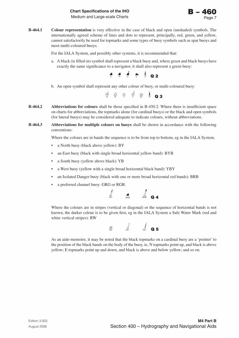
Chart Specifications of the IhoMedium and Large-scale Charts
Edition 3.003
August 2006
M4 Part BSection �00 – Hydrography and Navigational Aids
b – 460Page �
B-464.1 Colour representation is very effective in the case of black and open (unshaded) symbols. The internationally agreed scheme of lines and dots to represent, principally, red, green, and yellow, cannot satisfactorily be used for topmarks and some types of buoy symbols such as spar buoys and most multi-coloured buoys.
For the IALA System, and possibly other systems, it is recommended that:
a. A black (ie filled-in) symbol shall represent a black buoy and, where green and black buoys have exactly the same significance to a navigator, it shall also represent a green buoy:
Q 2
b. An open symbol shall represent any other colour of buoy, or multi-coloured buoy:
R R Y Y Or R Q 3
B-464.2 Abbreviations for colours shall be those specified in B-450.2. Where there is insufficient space on charts for abbreviations, the topmarks alone (for cardinal buoys) or the black and open symbols (for lateral buoys) may be considered adequate to indicate colours, without abbreviations.
B-464.3 Abbreviations for multiple colours on buoys shall be shown in accordance with the following conventions:
Where the colours are in bands the sequence is to be from top to bottom, eg in the IALA System,
• a North buoy (black above yellow): BY
• an East buoy (black with single broad horizontal yellow band): BYB
• a South buoy (yellow above black): YB
• a West buoy (yellow with a single broad horizontal black band): YBY
• an Isolated Danger buoy (black with one or more broad horizontal red bands): BRB
• a preferred channel buoy: GRG or RGR.
BY BRBGRG Q 4
Where the colours are in stripes (vertical or diagonal) or the sequence of horizontal bands is not known, the darker colour is to be given first, eg in the IALA System a Safe Water Mark (red and white vertical stripes): RW
RW RW RW Q 5
As an aide-memoire, it may be noted that the black topmarks on a cardinal buoy are a ‘pointer’ to the position of the black bands on the body of the buoy, ie, N topmarks point up, and black is above yellow; E topmarks point up and down, and black is above and below yellow; and so on.
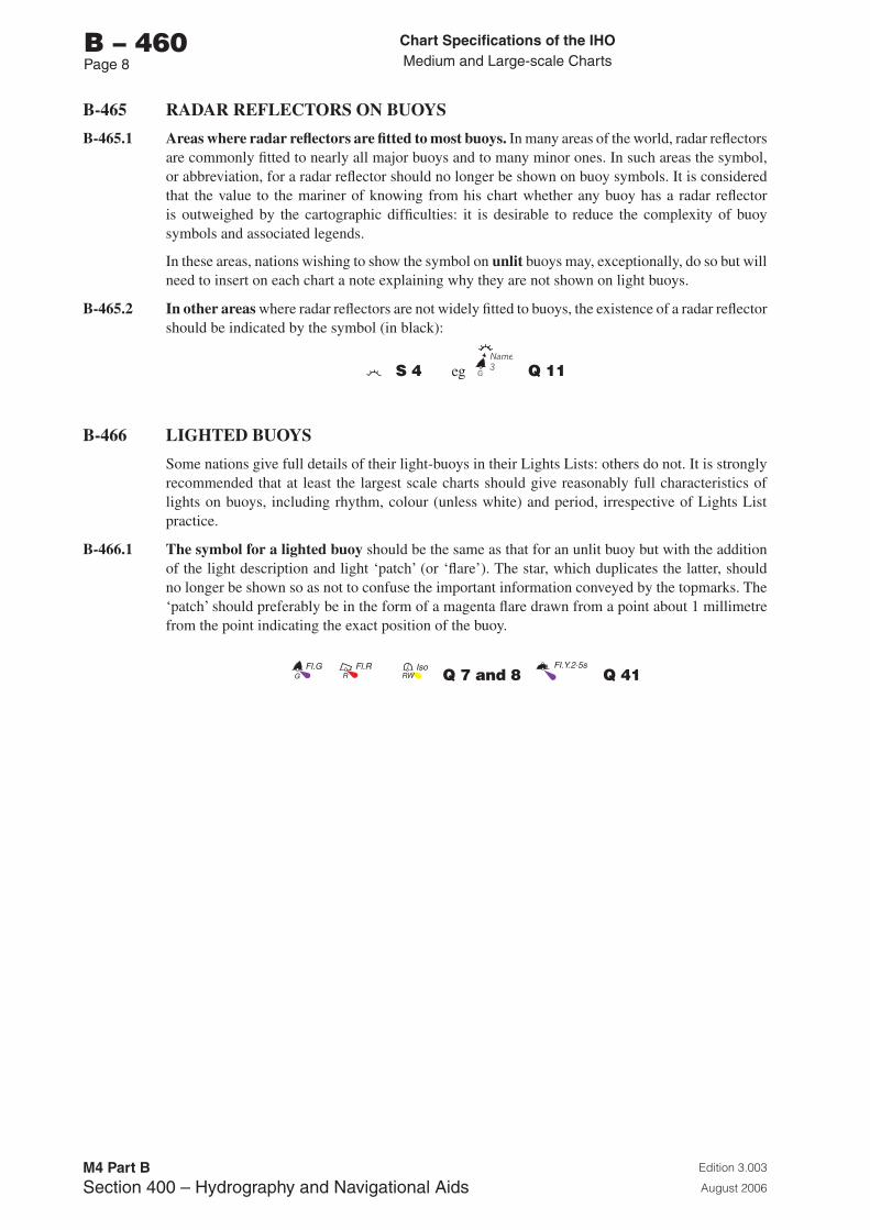
Chart Specifications of the IhoMedium and Large-scale Charts
Edition 3.003
August 2006
M4 Part BSection �00 – Hydrography and Navigational Aids
b – 460Page �
B-465 RADAR REFLECTORS ON BUOYS
B-465.1 Areas where radar reflectors are fitted to most buoys. In many areas of the world, radar reflectors are commonly fitted to nearly all major buoys and to many minor ones. In such areas the symbol, or abbreviation, for a radar reflector should no longer be shown on buoy symbols. It is considered that the value to the mariner of knowing from his chart whether any buoy has a radar reflector is outweighed by the cartographic difficulties: it is desirable to reduce the complexity of buoy symbols and associated legends.
In these areas, nations wishing to show the symbol on unlit buoys may, exceptionally, do so but will need to insert on each chart a note explaining why they are not shown on light buoys.
B-465.2 In other areas where radar reflectors are not widely fitted to buoys, the existence of a radar reflector should be indicated by the symbol (in black):
S 4 eg Q 11
B-466 LIGHTED BUOYS
Some nations give full details of their light-buoys in their Lights Lists: others do not. It is strongly recommended that at least the largest scale charts should give reasonably full characteristics of lights on buoys, including rhythm, colour (unless white) and period, irrespective of Lights List practice.
B-466.1 The symbol for a lighted buoy should be the same as that for an unlit buoy but with the addition of the light description and light ‘patch’ (or ‘flare’). The star, which duplicates the latter, should no longer be shown so as not to confuse the important information conveyed by the topmarks. The ‘patch’ should preferably be in the form of a magenta flare drawn from a point about 1 millimetre from the point indicating the exact position of the buoy.
RGFl.G Fl.R Iso
RW Q 7 and 8 Fl.Y.2·5s
Q 41
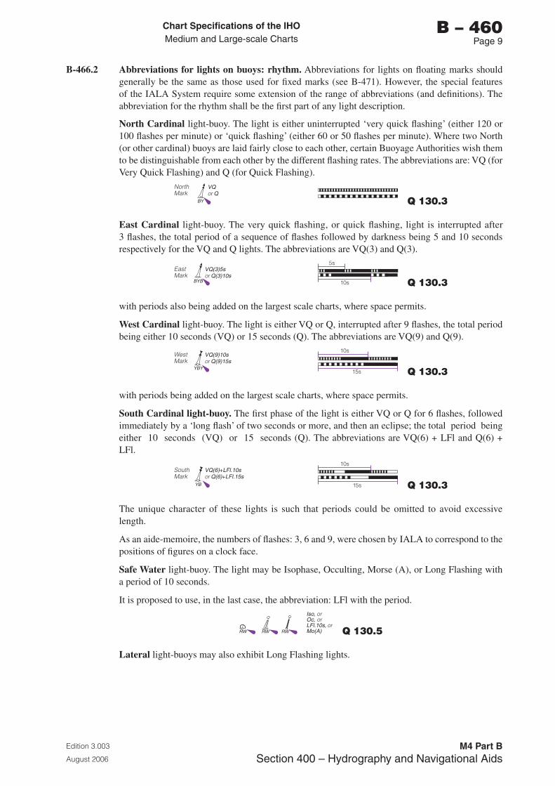
Chart Specifications of the IhoMedium and Large-scale Charts
Edition 3.003
August 2006
M4 Part BSection �00 – Hydrography and Navigational Aids
b – 460Page �
B-466.2 Abbreviations for lights on buoys: rhythm. Abbreviations for lights on floating marks should generally be the same as those used for fixed marks (see B-471). However, the special features of the IALA System require some extension of the range of abbreviations (and definitions). The abbreviation for the rhythm shall be the first part of any light description.
North Cardinal light-buoy. The light is either uninterrupted ‘very quick flashing’ (either 120 or 100 flashes per minute) or ‘quick flashing’ (either 60 or 50 flashes per minute). Where two North (or other cardinal) buoys are laid fairly close to each other, certain Buoyage Authorities wish them to be distinguishable from each other by the different flashing rates. The abbreviations are: VQ (for Very Quick Flashing) and Q (for Quick Flashing).
NorthMark
VQ Qor
BY Q 130.3
East Cardinal light-buoy. The very quick flashing, or quick flashing, light is interrupted after 3 flashes, the total period of a sequence of flashes followed by darkness being 5 and 10 seconds respectively for the VQ and Q lights. The abbreviations are VQ(3) and Q(3).
East Mark
VQ(3)5sQ(3)10sor
5s
10sBYB Q 130.3
with periods also being added on the largest scale charts, where space permits.
West Cardinal light-buoy. The light is either VQ or Q, interrupted after 9 flashes, the total period being either 10 seconds (VQ) or 15 seconds (Q). The abbreviations are VQ(9) and Q(9).
WestMark
VQ(9)10sQ(9)15sor
10s
15sYBY Q 130.3
with periods being added on the largest scale charts, where space permits.
South Cardinal light-buoy. The first phase of the light is either VQ or Q for 6 flashes, followed immediately by a ‘long flash’ of two seconds or more, and then an eclipse; the total period being either 10 seconds (VQ) or 15 seconds (Q). The abbreviations are VQ(6) + LFl and Q(6) + LFl.
SouthMark
VQ(6)+LFl.10s Q(6)+LFl.15sor
10s
15sYB Q 130.3
The unique character of these lights is such that periods could be omitted to avoid excessive length.
As an aide-memoire, the numbers of flashes: 3, 6 and 9, were chosen by IALA to correspond to the positions of figures on a clock face.
Safe Water light-buoy. The light may be Isophase, Occulting, Morse (A), or Long Flashing with a period of 10 seconds.
It is proposed to use, in the last case, the abbreviation: LFl with the period.Iso, or Oc, LFl.10s, Mo(A)
oror
RW RW RW Q 130.5
Lateral light-buoys may also exhibit Long Flashing lights.
Chart Specifications of the IhoMedium and Large-scale Charts
Edition 3.003
August 2006
M4 Part BSection �00 – Hydrography and Navigational Aids
b – 460Page 10
B-466.3 The colour of a light on a light-buoy shall be shown by the standard abbreviations listed in B-450.2, except that the omission of a colour abbreviation from the chart shall mean that a light is white. See also B-450.3 for capitalization of the letters of the abbreviation. The abbreviation for colour (if any) shall follow the abbreviation for the rhythm.
B-466.4 The period of a light on a light-buoy is the time taken to exhibit a full sequence of phases. It shall be expressed in seconds, using the international abbreviation ‘s’ eg 15s (with no space between figure and letter). Periods of less than 3 seconds may be given to the nearest half second, eg 2,5s.
The period shall be the final part of the light-description (except in the case of ‘super’ buoys where height and range may be added). For periods of light-buoys in the IALA System see B-466.2. In general, the period is the least important part of a light description and shall be omitted first if there is no space to give full details, or if the chart is on a relatively small scale.
Chart Specifications of the IhoMedium and Large-scale Charts
Edition 3.003
August 2006
M4 Part BSection �00 – Hydrography and Navigational Aids
b – 470Page 1
B-470 LIGHTS: GENERAL POINTS
These specifications include lights of all types other than those on buoys and minor light-floats. Major floating lights (light-vessels, major light-floats and LANBYs) have functions similar to those of major lights on land; points relating particularly to them are given in B-474.
B-470.1 Charts and other publications. Positions of lights, and bearings of leading and sectored lights, are best shown graphically, but full details of a major light and its structure cannot easily be charted. There is inevitably duplication of information on charts and in the Lists of Lights (LL) and Sailing Directions.
In practice, it has been found best to give reasonably full details of lights on charts (but very limited information about light structures - such as lighthouses) together with an effective means of finding a charted light in the other publications. Normally a light is found first by looking up its name or the name of the locality and then, if necessary, by latitude and longitude.
B-470.2 Definitions of the technical terms used in these specifications are given in the introductory pages of national LL, and are repeated or expanded here only where special distinctions are needed in chart symbols and abbreviations.
Charts and LL should obviously agree in definitions names and abbreviations used, as well as in the characteristics of the aids. However, short term differences may have to be tolerated when major changes, such as in the definition of the range at which a light is visible, are in progress.
B-470.3 The IALA System rules will apply to minor lights but not to leading lights, sectored lights, landfall lights or major floating lights. The System is primarily concerned with buoyage, so general information is given in B-461.
B-470.4 Colours of lights: use of colour plates. Full standardization of the charting of light colours is not practicable at present.
The numerous coloured light sectors in some waters, eg Scandinavian, are complex and most clearly represented by the use of ‘multi-coloured charts’, having a yellow plate for white (and yellow) lights and red and green plates for red and green lights. Unsectored lights naturally also have flares or ‘patches’ of the appropriate colour; features shown in magenta on ‘standard charts’ are, on existing multi-coloured charts, shown in red or yellow or (more rarely) green. It is assumed that nations printing multi-coloured charts will wish to continue the practice.
On the other hand, it is feasible to print charts with complex sector lights using the black plate chiefly to show lights and light sectors, but with a varying degree of use of magenta - at the minimum, merely drawing attention to the positions of lights and, at the maximum, outlining fairway sectors (as on many Swedish charts).
This economical representation does not prevent navigators from hand colouring sectors of interest to them and, indeed, may be quite adequate for the masters of piloted ships. In addition, it has some advantages: it is easier to correct both printed charts and plates, it can be used under red light, and printing is easier and cheaper. In charting the tidal estuaries of the German and Netherlands coasts, where complex light sectors are also common, the correctional problem is very significant, especially for ‘multi-coloured charts’.
In the specifications which follow, emphasis is given to standardizing legends and line symbols on the black plate. The meaning of the terms ‘multi-coloured chart’ and ‘standard chart’ should be clear from the above.
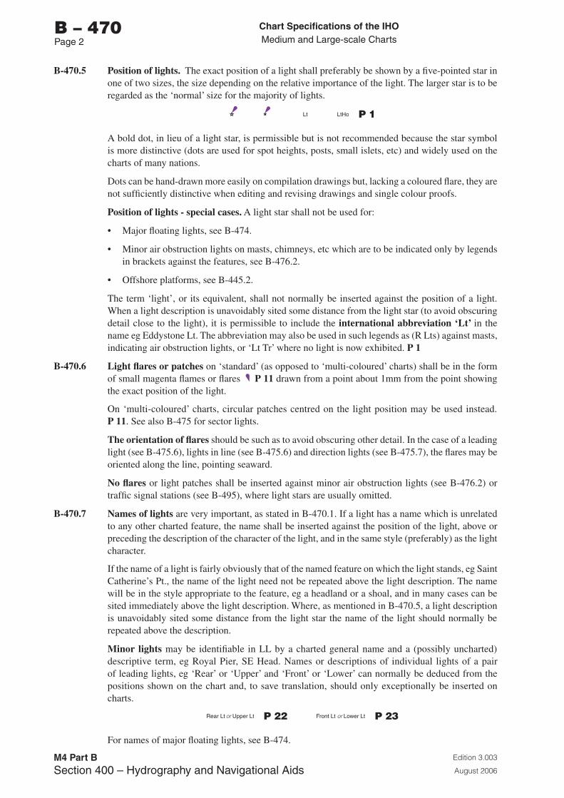
Chart Specifications of the IhoMedium and Large-scale Charts
Edition 3.003
August 2006
M4 Part BSection �00 – Hydrography and Navigational Aids
b – 470Page 2
B-470.5 Position of lights. The exact position of a light shall preferably be shown by a five-pointed star in one of two sizes, the size depending on the relative importance of the light. The larger star is to be regarded as the ‘normal’ size for the majority of lights.
Lt LtHo P 1
A bold dot, in lieu of a light star, is permissible but is not recommended because the star symbol is more distinctive (dots are used for spot heights, posts, small islets, etc) and widely used on the charts of many nations.
Dots can be hand-drawn more easily on compilation drawings but, lacking a coloured flare, they are not sufficiently distinctive when editing and revising drawings and single colour proofs.
Position of lights - special cases. A light star shall not be used for:
• Major floating lights, see B-474.
• Minor air obstruction lights on masts, chimneys, etc which are to be indicated only by legends in brackets against the features, see B-476.2.
• Offshore platforms, see B-445.2.
The term ‘light’, or its equivalent, shall not normally be inserted against the position of a light. When a light description is unavoidably sited some distance from the light star (to avoid obscuring detail close to the light), it is permissible to include the international abbreviation ‘Lt’ in the name eg Eddystone Lt. The abbreviation may also be used in such legends as (R Lts) against masts, indicating air obstruction lights, or ‘Lt Tr’ where no light is now exhibited. P 1
B-470.6 Light flares or patches on ‘standard’ (as opposed to ‘multi-coloured’ charts) shall be in the form of small magenta flames or flares P 11 drawn from a point about 1mm from the point showing the exact position of the light.
On ‘multi-coloured’ charts, circular patches centred on the light position may be used instead. P 11. See also B-475 for sector lights.
The orientation of flares should be such as to avoid obscuring other detail. In the case of a leading light (see B-475.6), lights in line (see B-475.6) and direction lights (see B-475.7), the flares may be oriented along the line, pointing seaward.
No flares or light patches shall be inserted against minor air obstruction lights (see B-476.2) or traffic signal stations (see B-495), where light stars are usually omitted.
B-470.7 Names of lights are very important, as stated in B-470.1. If a light has a name which is unrelated to any other charted feature, the name shall be inserted against the position of the light, above or preceding the description of the character of the light, and in the same style (preferably) as the light character.
If the name of a light is fairly obviously that of the named feature on which the light stands, eg Saint Catherine’s Pt., the name of the light need not be repeated above the light description. The name will be in the style appropriate to the feature, eg a headland or a shoal, and in many cases can be sited immediately above the light description. Where, as mentioned in B-470.5, a light description is unavoidably sited some distance from the light star the name of the light should normally be repeated above the description.
Minor lights may be identifiable in LL by a charted general name and a (possibly uncharted) descriptive term, eg Royal Pier, SE Head. Names or descriptions of individual lights of a pair of leading lights, eg ‘Rear’ or ‘Upper’ and ‘Front’ or ‘Lower’ can normally be deduced from the positions shown on the chart and, to save translation, should only exceptionally be inserted on charts.
Rear Lt Upper Ltor P 22 Front Lt Lower Ltor P 23
For names of major floating lights, see B-474.
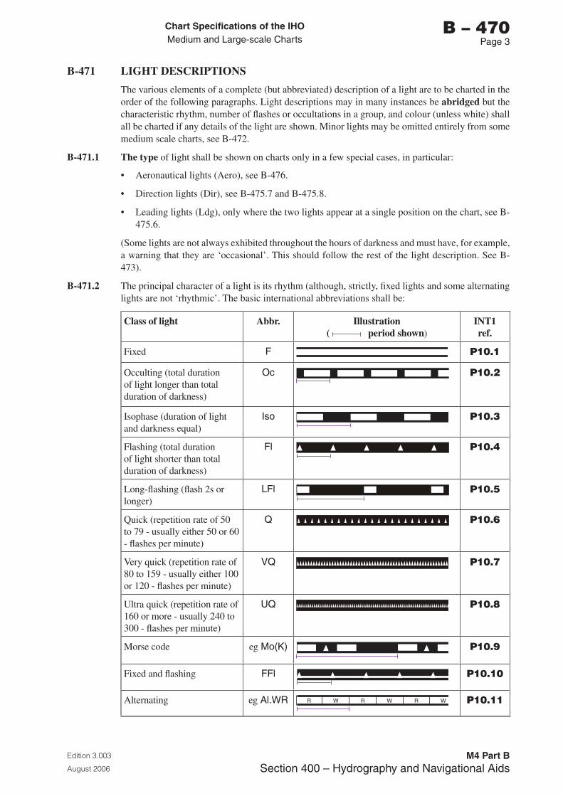
Chart Specifications of the IhoMedium and Large-scale Charts
Edition 3.003
August 2006
M4 Part BSection �00 – Hydrography and Navigational Aids
b – 470Page �
B-471 LIGHT DESCRIPTIONS
The various elements of a complete (but abbreviated) description of a light are to be charted in the order of the following paragraphs. Light descriptions may in many instances be abridged but the characteristic rhythm, number of flashes or occultations in a group, and colour (unless white) shall all be charted if any details of the light are shown. Minor lights may be omitted entirely from some medium scale charts, see B-472.
B-471.1 The type of light shall be shown on charts only in a few special cases, in particular:
• Aeronautical lights (Aero), see B-476.
• Direction lights (Dir), see B-475.7 and B-475.8.
• Leading lights (Ldg), only where the two lights appear at a single position on the chart, see B-475.6.
(Some lights are not always exhibited throughout the hours of darkness and must have, for example, a warning that they are ‘occasional’. This should follow the rest of the light description. See B-473).
B-471.2 The principal character of a light is its rhythm (although, strictly, fixed lights and some alternating lights are not ‘rhythmic’. The basic international abbreviations shall be:
Class of light Abbr. Illustration( period shown)
INT1ref.
Fixed F P10.1
Occulting (total duration of light longer than total duration of darkness)
Oc P10.2
Isophase (duration of light and darkness equal)
Iso P10.3
Flashing (total duration of light shorter than total duration of darkness)
Fl P10.4
Long-flashing (flash 2s or longer)
LFl P10.5
Quick (repetition rate of 50 to 79 - usually either 50 or 60 - flashes per minute)
Q P10.6
Very quick (repetition rate of 80 to 159 - usually either 100 or 120 - flashes per minute)
VQ P10.7
Ultra quick (repetition rate of 160 or more - usually 240 to 300 - flashes per minute)
UQ P10.8
Morse code eg Mo(K) P10.9
Fixed and flashing FFl P10.10
Alternating eg Al.WR WRWRWR P10.11
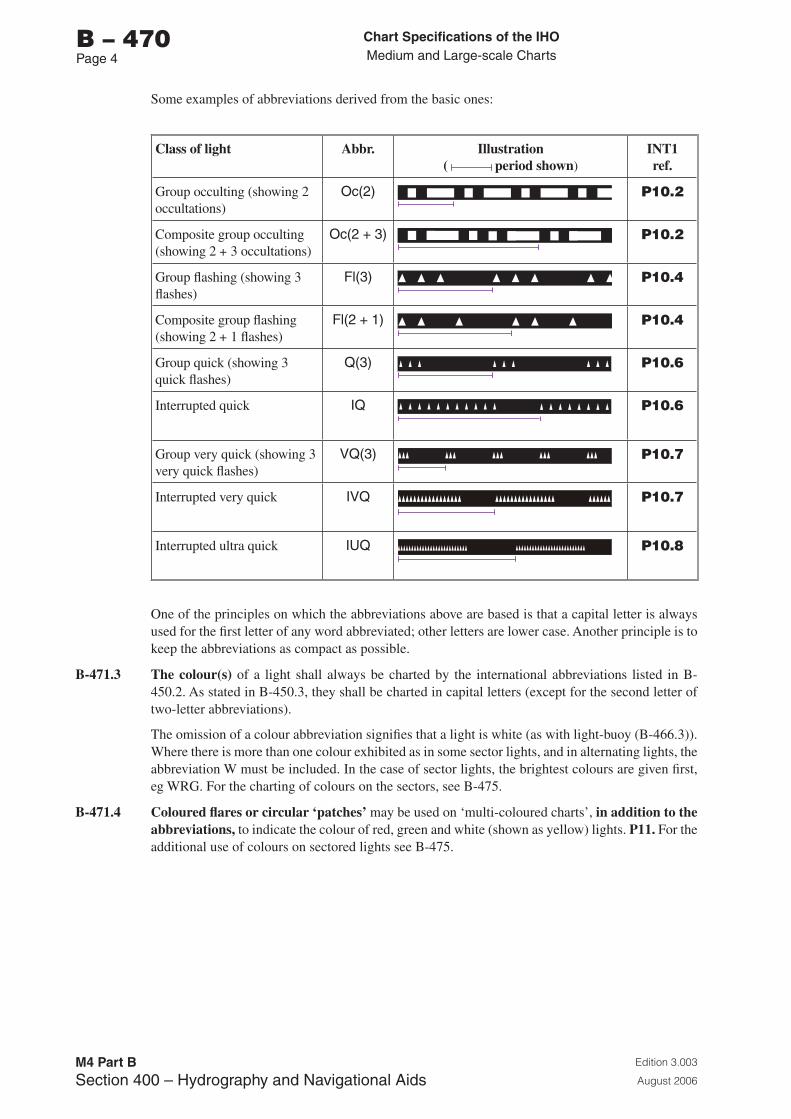
Chart Specifications of the IhoMedium and Large-scale Charts
Edition 3.003
August 2006
M4 Part BSection �00 – Hydrography and Navigational Aids
b – 470Page �
Some examples of abbreviations derived from the basic ones:
Class of light Abbr. Illustration( period shown)
INT1ref.
Group occulting (showing 2 occultations)
Oc(2) P10.2
Composite group occulting (showing 2 + 3 occultations)
Oc(2 + �) P10.2
Group flashing (showing 3 flashes)
Fl(�) P10.4
Composite group flashing (showing 2 + 1 flashes)
Fl(2 + 1) P10.4
Group quick (showing 3 quick flashes)
Q(�) P10.6
Interrupted quick IQ P10.6
Group very quick (showing 3 very quick flashes)
VQ(�) P10.7
Interrupted very quick IVQ P10.7
Interrupted ultra quick IUQ P10.8
One of the principles on which the abbreviations above are based is that a capital letter is always used for the first letter of any word abbreviated; other letters are lower case. Another principle is to keep the abbreviations as compact as possible.
B-471.3 The colour(s) of a light shall always be charted by the international abbreviations listed in B-450.2. As stated in B-450.3, they shall be charted in capital letters (except for the second letter of two-letter abbreviations).
The omission of a colour abbreviation signifies that a light is white (as with light-buoy (B-466.3)). Where there is more than one colour exhibited as in some sector lights, and in alternating lights, the abbreviation W must be included. In the case of sector lights, the brightest colours are given first, eg WRG. For the charting of colours on the sectors, see B-475.
B-471.4 Coloured flares or circular ‘patches’ may be used on ‘multi-coloured charts’, in addition to the abbreviations, to indicate the colour of red, green and white (shown as yellow) lights. P11. For the additional use of colours on sectored lights see B-475.
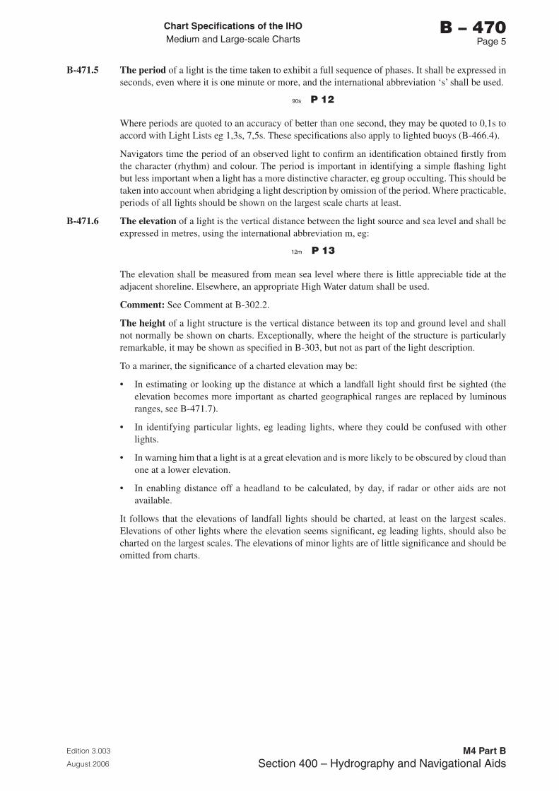
Chart Specifications of the IhoMedium and Large-scale Charts
Edition 3.003
August 2006
M4 Part BSection �00 – Hydrography and Navigational Aids
b – 470Page 5
B-471.5 The period of a light is the time taken to exhibit a full sequence of phases. It shall be expressed in seconds, even where it is one minute or more, and the international abbreviation ‘s’ shall be used.
�0s P 12
Where periods are quoted to an accuracy of better than one second, they may be quoted to 0,1s to accord with Light Lists eg 1,3s, 7,5s. These specifications also apply to lighted buoys (B-466.4).
Navigators time the period of an observed light to confirm an identification obtained firstly from the character (rhythm) and colour. The period is important in identifying a simple flashing light but less important when a light has a more distinctive character, eg group occulting. This should be taken into account when abridging a light description by omission of the period. Where practicable, periods of all lights should be shown on the largest scale charts at least.
B-471.6 The elevation of a light is the vertical distance between the light source and sea level and shall be expressed in metres, using the international abbreviation m, eg:
12m P 13
The elevation shall be measured from mean sea level where there is little appreciable tide at the adjacent shoreline. Elsewhere, an appropriate High Water datum shall be used.
Comment: See Comment at B-302.2.
The height of a light structure is the vertical distance between its top and ground level and shall not normally be shown on charts. Exceptionally, where the height of the structure is particularly remarkable, it may be shown as specified in B-303, but not as part of the light description.
To a mariner, the significance of a charted elevation may be:
• In estimating or looking up the distance at which a landfall light should first be sighted (the elevation becomes more important as charted geographical ranges are replaced by luminous ranges, see B-471.7).
• In identifying particular lights, eg leading lights, where they could be confused with other lights.
• In warning him that a light is at a great elevation and is more likely to be obscured by cloud than one at a lower elevation.
• In enabling distance off a headland to be calculated, by day, if radar or other aids are not available.
It follows that the elevations of landfall lights should be charted, at least on the largest scales. Elevations of other lights where the elevation seems significant, eg leading lights, should also be charted on the largest scales. The elevations of minor lights are of little significance and should be omitted from charts.
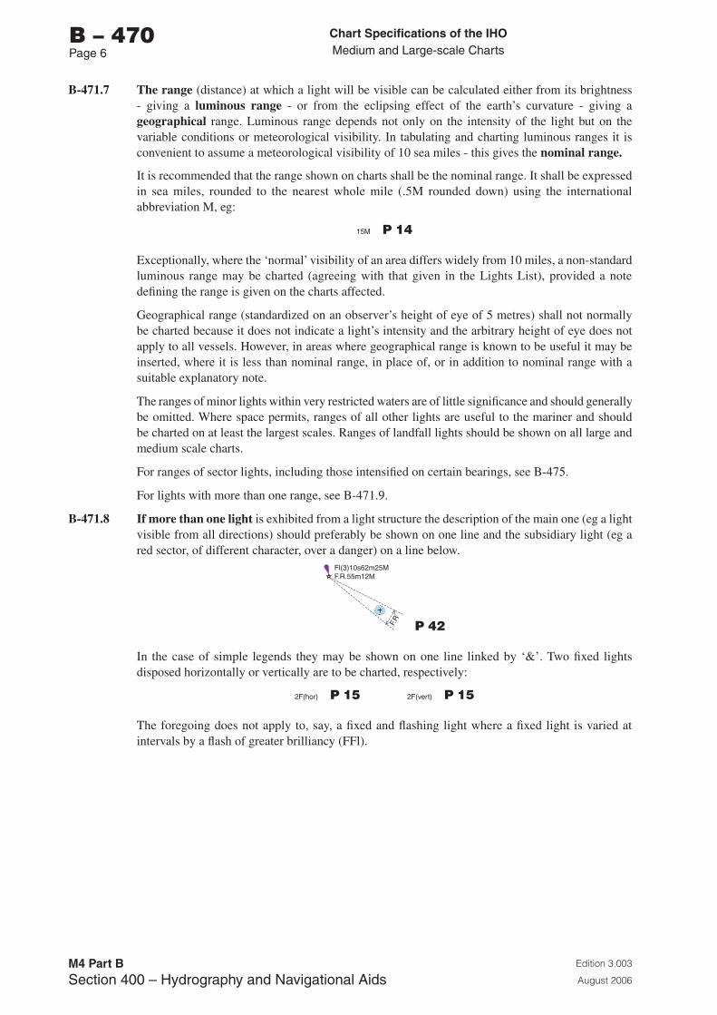
Chart Specifications of the IhoMedium and Large-scale Charts
Edition 3.003
August 2006
M4 Part BSection �00 – Hydrography and Navigational Aids
b – 470Page 6
B-471.7 The range (distance) at which a light will be visible can be calculated either from its brightness - giving a luminous range - or from the eclipsing effect of the earth’s curvature - giving a geographical range. Luminous range depends not only on the intensity of the light but on the variable conditions or meteorological visibility. In tabulating and charting luminous ranges it is convenient to assume a meteorological visibility of 10 sea miles - this gives the nominal range.
It is recommended that the range shown on charts shall be the nominal range. It shall be expressed in sea miles, rounded to the nearest whole mile (.5M rounded down) using the international abbreviation M, eg:
15M P 14
Exceptionally, where the ‘normal’ visibility of an area differs widely from 10 miles, a non-standard luminous range may be charted (agreeing with that given in the Lights List), provided a note defining the range is given on the charts affected.
Geographical range (standardized on an observer’s height of eye of 5 metres) shall not normally be charted because it does not indicate a light’s intensity and the arbitrary height of eye does not apply to all vessels. However, in areas where geographical range is known to be useful it may be inserted, where it is less than nominal range, in place of, or in addition to nominal range with a suitable explanatory note.
The ranges of minor lights within very restricted waters are of little significance and should generally be omitted. Where space permits, ranges of all other lights are useful to the mariner and should be charted on at least the largest scales. Ranges of landfall lights should be shown on all large and medium scale charts.
For ranges of sector lights, including those intensified on certain bearings, see B-475.
For lights with more than one range, see B-471.9.
B-471.8 If more than one light is exhibited from a light structure the description of the main one (eg a light visible from all directions) should preferably be shown on one line and the subsidiary light (eg a red sector, of different character, over a danger) on a line below.
F.R
Fl(3)10s62m25MF.R.55m12M
P 42
In the case of simple legends they may be shown on one line linked by ‘&’. Two fixed lights disposed horizontally or vertically are to be charted, respectively:
2F(hor) P 15 2F(vert) P 15
The foregoing does not apply to, say, a fixed and flashing light where a fixed light is varied at intervals by a flash of greater brilliancy (FFl).
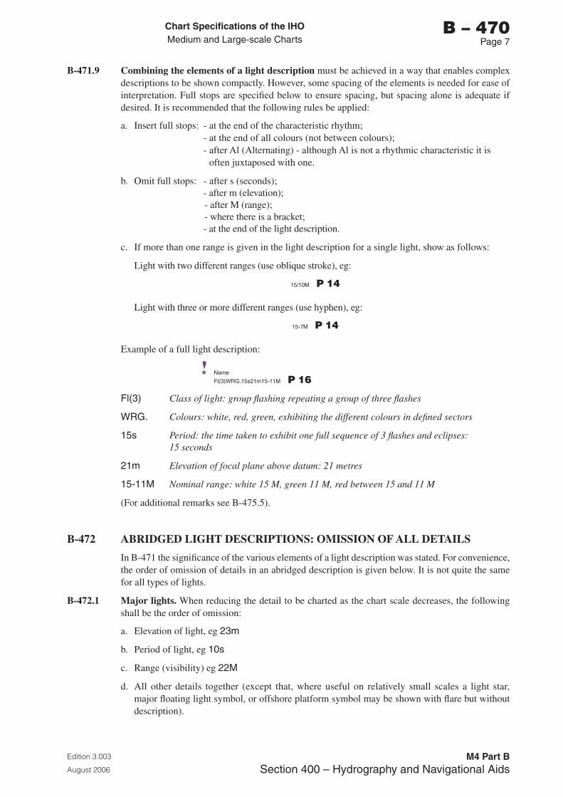
Chart Specifications of the IhoMedium and Large-scale Charts
Edition 3.003
August 2006
M4 Part BSection �00 – Hydrography and Navigational Aids
b – 470Page �
B-471.9 Combining the elements of a light description must be achieved in a way that enables complex descriptions to be shown compactly. However, some spacing of the elements is needed for ease of interpretation. Full stops are specified below to ensure spacing, but spacing alone is adequate if desired. It is recommended that the following rules be applied:
a. Insert full stops: - at the end of the characteristic rhythm; - at the end of all colours (not between colours); - after Al (Alternating) - although Al is not a rhythmic characteristic it is
often juxtaposed with one.
b. Omit full stops: - after s (seconds); - after m (elevation); - after M (range); - where there is a bracket; - at the end of the light description.
c. If more than one range is given in the light description for a single light, show as follows:
Light with two different ranges (use oblique stroke), eg:
15/10M P 14
Light with three or more different ranges (use hyphen), eg:
15-�M P 14
Example of a full light description:
Name
Fl(�)WRG.15s21m15-11M P 16
Fl(�) Class of light: group flashing repeating a group of three flashes
WRG. Colours: white, red, green, exhibiting the different colours in defined sectors
15s Period: the time taken to exhibit one full sequence of 3 flashes and eclipses: 15 seconds
21m Elevation of focal plane above datum: 21 metres
15-11M Nominal range: white 15 M, green 11 M, red between 15 and 11 M
(For additional remarks see B-475.5).
B-472 ABRIDGED LIGHT DESCRIPTIONS: OMISSION OF ALL DETAILS
In B-471 the significance of the various elements of a light description was stated. For convenience, the order of omission of details in an abridged description is given below. It is not quite the same for all types of lights.
B-472.1 Major lights. When reducing the detail to be charted as the chart scale decreases, the following shall be the order of omission:
a. Elevation of light, eg 2�m
b. Period of light, eg 10s
c. Range (visibility) eg 22M
d. All other details together (except that, where useful on relatively small scales a light star, major floating light symbol, or offshore platform symbol may be shown with flare but without description).
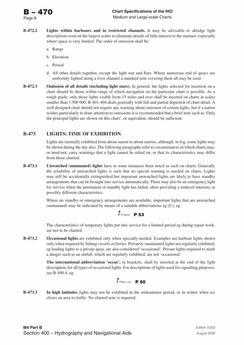
Chart Specifications of the IhoMedium and Large-scale Charts
Edition 3.003
August 2006
M4 Part BSection �00 – Hydrography and Navigational Aids
b – 470Page �
B-472.2 Lights within harbours and in restricted channels. It may be advisable to abridge light descriptions even on the largest scales to eliminate details of little interest to the mariner, especially where space is very limited. The order of omission shall be:
a. Range
b. Elevation
c. Period
d. All other details together, except the light star and flare. Where numerous end of quays are uniformly lighted along a river channel a standard note covering them all may be used.
B-472.3 Omission of all details (including light stars). In general, the lights selected for insertion on a chart should be those within range of which navigation on the particular chart is possible. As a rough guide, only those lights visible from 15 miles and over shall be inserted on charts at scales smaller than 1:500 000. B-401-404 deals generally with full and partial depiction of chart detail. A well designed chart should not require any warning about omission of certain lights, but if a nation wishes particularly to draw attention to omissions it is recommended that a brief note such as ‘Only the principal lights are shown on this chart’, or equivalent, should be sufficient.
B-473 LIGHTS: TIME OF EXHIBITION
Lights are normally exhibited from about sunset to about sunrise, although, in fog, some lights may be shown during the day also. The following paragraphs refer to circumstances in which charts may, or need not, carry warnings that a light cannot be relied on, or that its characteristics may differ from those charted.
B-473.1 Unwatched (unmanned) lights have in some instances been noted as such on charts. Generally the reliability of unwatched lights is such that no special warning is needed on charts. Lights may still be accidentally extinguished but important unwatched lights are likely to have standby arrangements that can be brought into service automatically. There may also be an emergency light for service when the permanent or standby light has failed, often providing a reduced intensity or possibly different characteristics.
Where no standby or emergency arrangements are available, important lights that are unwatched (unmanned) may be indicated by means of a suitable abbreviations eg (U), eg:
Fl.5s(U) P 53
The characteristics of temporary lights put into service for a limited period eg during repair work, are not to be charted.
B-473.2 Occasional lights are exhibited only when specially needed. Examples are harbour lights shown only when required by fishing vessels or ferries. Privately-maintained lights not regularly exhibited; eg leading lights to a private quay, are also considered ‘occasional’. Private lights required to mark a danger such as an outfall, which are regularly exhibited, are not ‘occasional’.
The international abbreviation ‘occas’, in brackets, shall be inserted at the end of the light description, for all types of occasional lights. For descriptions of lights used for signalling purposes, see B-490.4, eg:
F.R(occas) P 50
B-473.3 In high latitudes lights may not be exhibited in the midsummer period, or in winter when ice closes an area to traffic. No charted note is required.
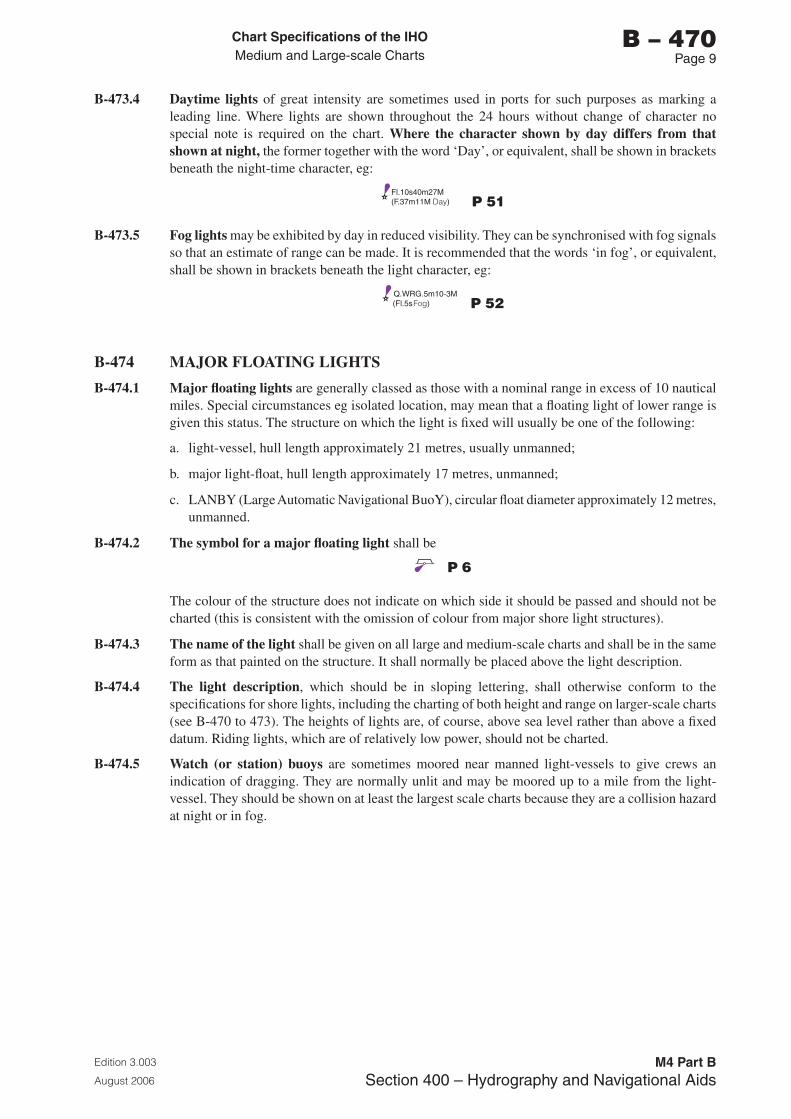
Chart Specifications of the IhoMedium and Large-scale Charts
Edition 3.003
August 2006
M4 Part BSection �00 – Hydrography and Navigational Aids
b – 470Page �
B-473.4 Daytime lights of great intensity are sometimes used in ports for such purposes as marking a leading line. Where lights are shown throughout the 24 hours without change of character no special note is required on the chart. Where the character shown by day differs from that shown at night, the former together with the word ‘Day’, or equivalent, shall be shown in brackets beneath the night-time character, eg:
Fl.10s40m27M(F.37m11M Day) P 51
B-473.5 Fog lights may be exhibited by day in reduced visibility. They can be synchronised with fog signals so that an estimate of range can be made. It is recommended that the words ‘in fog’, or equivalent, shall be shown in brackets beneath the light character, eg:
Q.WRG.5m10-3M(Fl.5sFog) P 52
B-474 MAJOR FLOATING LIGHTS
B-474.1 Major floating lights are generally classed as those with a nominal range in excess of 10 nautical miles. Special circumstances eg isolated location, may mean that a floating light of lower range is given this status. The structure on which the light is fixed will usually be one of the following:
a. light-vessel, hull length approximately 21 metres, usually unmanned;
b. major light-float, hull length approximately 17 metres, unmanned;
c. LANBY (Large Automatic Navigational BuoY), circular float diameter approximately 12 metres, unmanned.
B-474.2 The symbol for a major floating light shall be
P 6
The colour of the structure does not indicate on which side it should be passed and should not be charted (this is consistent with the omission of colour from major shore light structures).
B-474.3 The name of the light shall be given on all large and medium-scale charts and shall be in the same form as that painted on the structure. It shall normally be placed above the light description.
B-474.4 The light description, which should be in sloping lettering, shall otherwise conform to the specifications for shore lights, including the charting of both height and range on larger-scale charts (see B-470 to 473). The heights of lights are, of course, above sea level rather than above a fixed datum. Riding lights, which are of relatively low power, should not be charted.
B-474.5 Watch (or station) buoys are sometimes moored near manned light-vessels to give crews an indication of dragging. They are normally unlit and may be moored up to a mile from the light-vessel. They should be shown on at least the largest scale charts because they are a collision hazard at night or in fog.
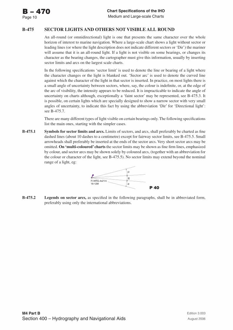
Chart Specifications of the IhoMedium and Large-scale Charts
Edition 3.003
August 2006
M4 Part BSection �00 – Hydrography and Navigational Aids
b – 470Page 10
B-475 SECTOR LIGHTS AND OTHERS NOT VISIBLE ALL ROUND
An all-round (or omnidirectional) light is one that presents the same character over the whole horizon of interest to marine navigation. Where a large-scale chart shows a light without sector or leading lines (or where the light description does not indicate different sectors or ‘Dir’) the mariner will assume that it is an all-round light. If a light is not visible on some bearings, or changes its character as the bearing changes, the cartographer must give this information, usually by inserting sector limits and arcs on the largest scale charts.
In the following specifications ‘sector limit’ is used to denote the line or bearing of a light where the character changes or the light is blanked out. ‘Sector arc’ is used to denote the curved line against which the character of the light in that sector is inserted. In practice, on most lights there is a small angle of uncertainty between sectors, where, say, the colour is indefinite, or, at the edge of the arc of visibility, the intensity appears to be reduced. It is impracticable to indicate the angle of uncertainty on charts although, exceptionally a ‘faint sector’ may be represented, see B-475.3. It is possible, on certain lights which are specially designed to show a narrow sector with very small angles of uncertainty, to indicate this fact by using the abbreviation ‘Dir’ for ‘Directional light’: see B-475.7.
There are many different types of light visible on certain bearings only. The following specifications list the main ones, starting with the simpler cases.
B-475.1 Symbols for sector limits and arcs. Limits of sectors, and arcs, shall preferably be charted as fine dashed lines (about 10 dashes to a centimetre) except for fairway sector limits, see B-475.5. Small arrowheads shall preferably be inserted at the ends of the sector arcs. Very short sector arcs may be omitted. On ‘multi-coloured’ charts the sector limits may be shown as fine firm lines, emphasized by colour, and sector arcs may be shown solely by coloured arcs, (together with an abbreviation for the colour or character of the light, see B-475.5). No sector limits may extend beyond the nominal range of a light, eg:
Fl.WRG.4s21m18-12M
GW
R
P 40
B-475.2 Legends on sector arcs, as specified in the following paragraphs, shall be in abbreviated form, preferably using only the international abbreviations.
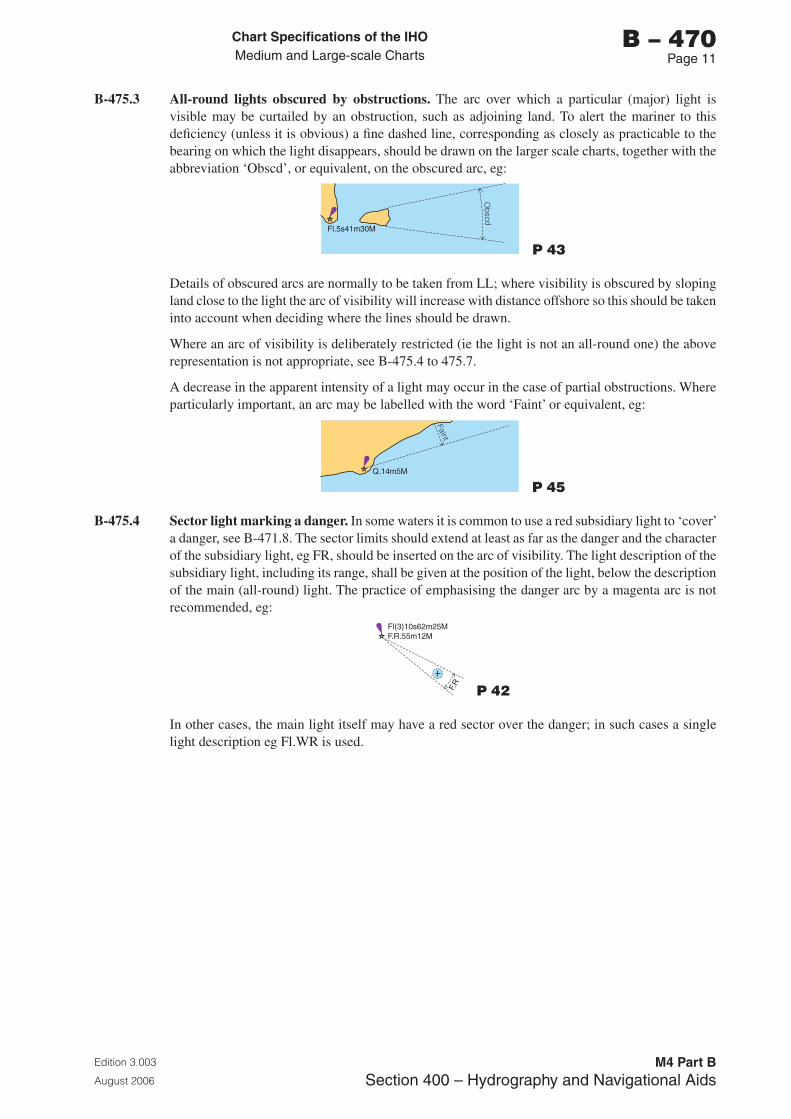
Chart Specifications of the IhoMedium and Large-scale Charts
Edition 3.003
August 2006
M4 Part BSection �00 – Hydrography and Navigational Aids
b – 470Page 11
B-475.3 All-round lights obscured by obstructions. The arc over which a particular (major) light is visible may be curtailed by an obstruction, such as adjoining land. To alert the mariner to this deficiency (unless it is obvious) a fine dashed line, corresponding as closely as practicable to the bearing on which the light disappears, should be drawn on the larger scale charts, together with the abbreviation ‘Obscd’, or equivalent, on the obscured arc, eg:
Obscd
Fl.5s41m30M
P 43
Details of obscured arcs are normally to be taken from LL; where visibility is obscured by sloping land close to the light the arc of visibility will increase with distance offshore so this should be taken into account when deciding where the lines should be drawn.
Where an arc of visibility is deliberately restricted (ie the light is not an all-round one) the above representation is not appropriate, see B-475.4 to 475.7.
A decrease in the apparent intensity of a light may occur in the case of partial obstructions. Where particularly important, an arc may be labelled with the word ‘Faint’ or equivalent, eg:
Faint
Q.14m5M
P 45
B-475.4 Sector light marking a danger. In some waters it is common to use a red subsidiary light to ‘cover’ a danger, see B-471.8. The sector limits should extend at least as far as the danger and the character of the subsidiary light, eg FR, should be inserted on the arc of visibility. The light description of the subsidiary light, including its range, shall be given at the position of the light, below the description of the main (all-round) light. The practice of emphasising the danger arc by a magenta arc is not recommended, eg:
F.R
Fl(3)10s62m25MF.R.55m12M
P 42
In other cases, the main light itself may have a red sector over the danger; in such cases a single light description eg Fl.WR is used.
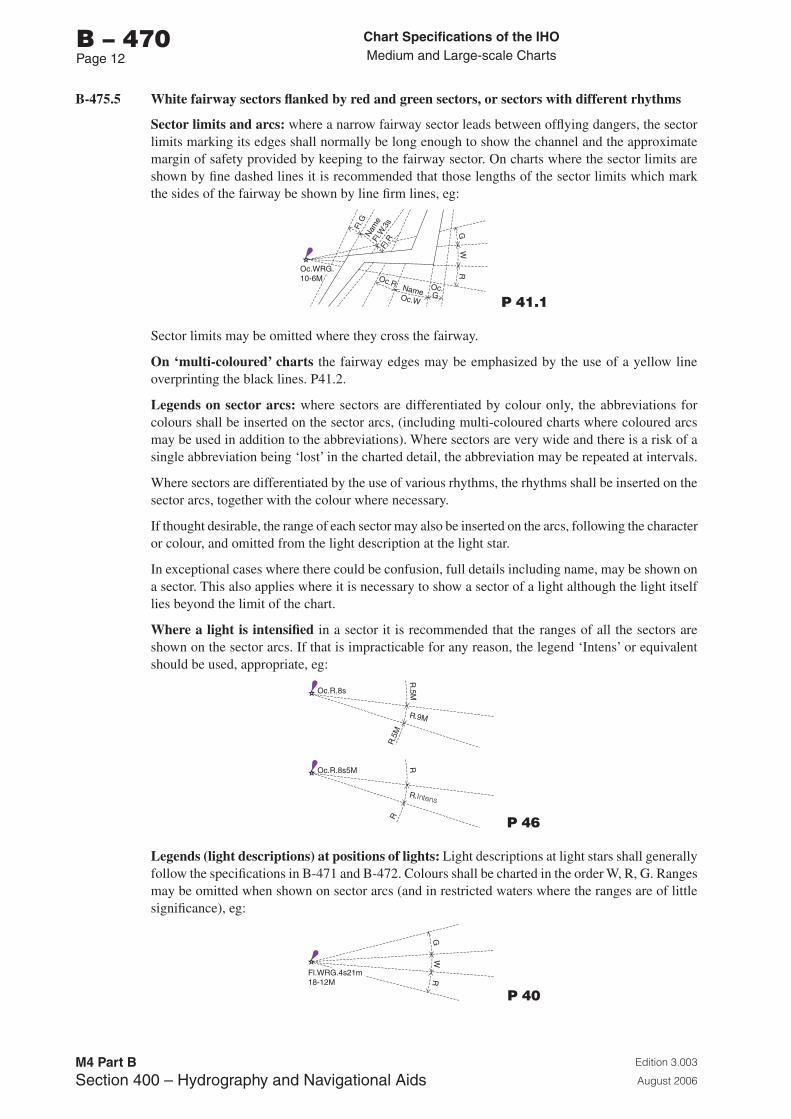
Chart Specifications of the IhoMedium and Large-scale Charts
Edition 3.003
August 2006
M4 Part BSection �00 – Hydrography and Navigational Aids
b – 470Page 12
B-475.5 White fairway sectors flanked by red and green sectors, or sectors with different rhythms
Sector limits and arcs: where a narrow fairway sector leads between offlying dangers, the sector limits marking its edges shall normally be long enough to show the channel and the approximate margin of safety provided by keeping to the fairway sector. On charts where the sector limits are shown by fine dashed lines it is recommended that those lengths of the sector limits which mark the sides of the fairway be shown by line firm lines, eg:
GW
R
Fl.G
Nam
e
Name
Fl.R
Oc.W
Oc.R Oc. G
Fl.W
.3s
Oc.WRG.10-6M
P 41.1
Sector limits may be omitted where they cross the fairway.
On ‘multi-coloured’ charts the fairway edges may be emphasized by the use of a yellow line overprinting the black lines. P41.2.
Legends on sector arcs: where sectors are differentiated by colour only, the abbreviations for colours shall be inserted on the sector arcs, (including multi-coloured charts where coloured arcs may be used in addition to the abbreviations). Where sectors are very wide and there is a risk of a single abbreviation being ‘lost’ in the charted detail, the abbreviation may be repeated at intervals.
Where sectors are differentiated by the use of various rhythms, the rhythms shall be inserted on the sector arcs, together with the colour where necessary.
If thought desirable, the range of each sector may also be inserted on the arcs, following the character or colour, and omitted from the light description at the light star.
In exceptional cases where there could be confusion, full details including name, may be shown on a sector. This also applies where it is necessary to show a sector of a light although the light itself lies beyond the limit of the chart.
Where a light is intensified in a sector it is recommended that the ranges of all the sectors are shown on the sector arcs. If that is impracticable for any reason, the legend ‘Intens’ or equivalent should be used, appropriate, eg:
Oc.R.8s5M
Oc.R.8s
RR
.5M
RR
.5M
R.Intens
R.9M
P 46
Legends (light descriptions) at positions of lights: Light descriptions at light stars shall generally follow the specifications in B-471 and B-472. Colours shall be charted in the order W, R, G. Ranges may be omitted when shown on sector arcs (and in restricted waters where the ranges are of little significance), eg:
Fl.WRG.4s21m18-12M
GW
R
P 40
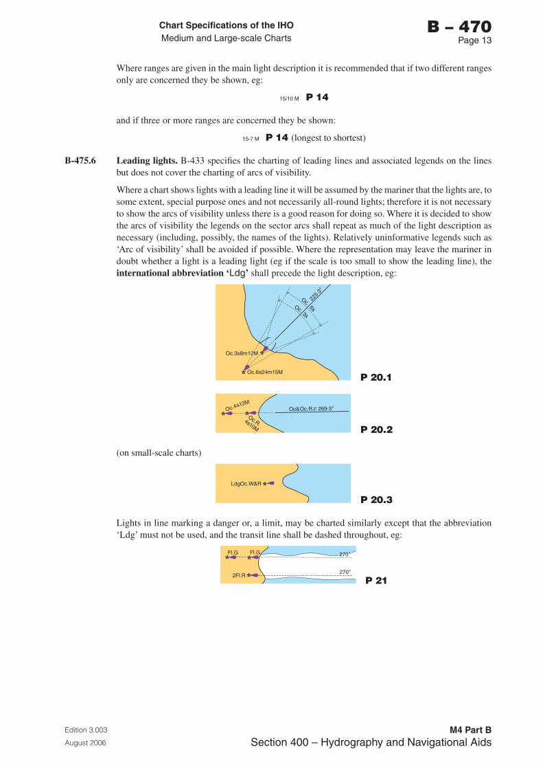
Chart Specifications of the IhoMedium and Large-scale Charts
Edition 3.003
August 2006
M4 Part BSection �00 – Hydrography and Navigational Aids
b – 470Page 1�
Where ranges are given in the main light description it is recommended that if two different ranges only are concerned they be shown, eg:
15/10 M P 14
and if three or more ranges are concerned they be shown:
15-� M P 14 (longest to shortest)
B-475.6 Leading lights. B-433 specifies the charting of leading lines and associated legends on the lines but does not cover the charting of arcs of visibility.
Where a chart shows lights with a leading line it will be assumed by the mariner that the lights are, to some extent, special purpose ones and not necessarily all-round lights; therefore it is not necessary to show the arcs of visibility unless there is a good reason for doing so. Where it is decided to show the arcs of visibility the legends on the sector arcs shall repeat as much of the light description as necessary (including, possibly, the names of the lights). Relatively uninformative legends such as ‘Arc of visibility’ shall be avoided if possible. Where the representation may leave the mariner in doubt whether a light is a leading light (eg if the scale is too small to show the leading line), the international abbreviation ‘Ldg’ shall precede the light description, eg:
Oc.6s24m15M
Oc.3s8m12M
225·
3°
Oc.
3s
6sOc.
P 20.1
Oc 4. s12MOc&Oc.R 269.3°
Oc.R.4s10M P 20.2
(on small-scale charts)
LdgOc.W&R
P 20.3
Lights in line marking a danger or, a limit, may be charted similarly except that the abbreviation ‘Ldg’ must not be used, and the transit line shall be dashed throughout, eg:
Fl.G Fl.G 270°
270°2Fl.R
P 21
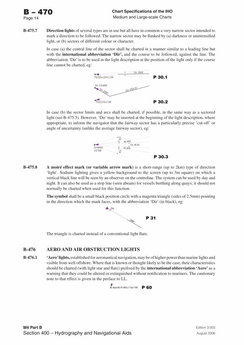
Chart Specifications of the IhoMedium and Large-scale Charts
Edition 3.003
August 2006
M4 Part BSection �00 – Hydrography and Navigational Aids
b – 470Page 1�
B-475.7 Direction lights of several types are in use but all have in common a very narrow sector intended to mark a direction to be followed. The narrow sector may be flanked by (a) darkness or unintensified light, or (b) sectors of different colour or character.
In case (a) the central line of the sector shall be charted in a manner similar to a leading line but with the international abbreviation ‘Dir’, and the course to be followed, against the line. The abbreviation ‘Dir’ is to be used in the light description at the position of the light only if the course line cannot be charted, eg:
P 30.1
P 30.2
In case (b) the sector limits and arcs shall be charted, if possible, in the same way as a sectored light (see B-475.5). However, ‘Dir’ may be inserted at the beginning of the light description, where appropriate, to inform the navigator that the fairway sector has a particularly precise ‘cut-off’ or angle of uncertainty (unlike the average fairway sector), eg:
P 30.3
B-475.8 A moiré effect mark (or variable arrow mark) is a short-range (up to 2km) type of direction ‘light’. Sodium lighting gives a yellow background to the screen (up to 3m square) on which a vertical black line will be seen by an observer on the centreline. The system can be used by day and night. It can also be used as a stop line (seen abeam) for vessels berthing along quays; it should not normally be charted when used for this function.
The symbol shall be a small black position circle with a magenta triangle (sides of 2.5mm) pointing in the direction which the mark faces, with the abbreviation ‘Dir’ (in black), eg:
286°
Dir
P 31
The triangle is charted instead of a conventional light flare.
B-476 AERO AND AIR OBSTRUCTION LIGHTS
B-476.1 ‘Aero’ lights, established for aeronautical navigation, may be of higher power than marine lights and visible from well offshore. Where that is known or thought likely to be the case, their characteristics should be charted (with light star and flare) prefixed by the international abbreviation ‘Aero’ as a warning that they could be altered or extinguished without notification to mariners. The cautionary note to that effect is given in the preface to LL.
AeroAl.Fl.WG.7·5s11M P 60
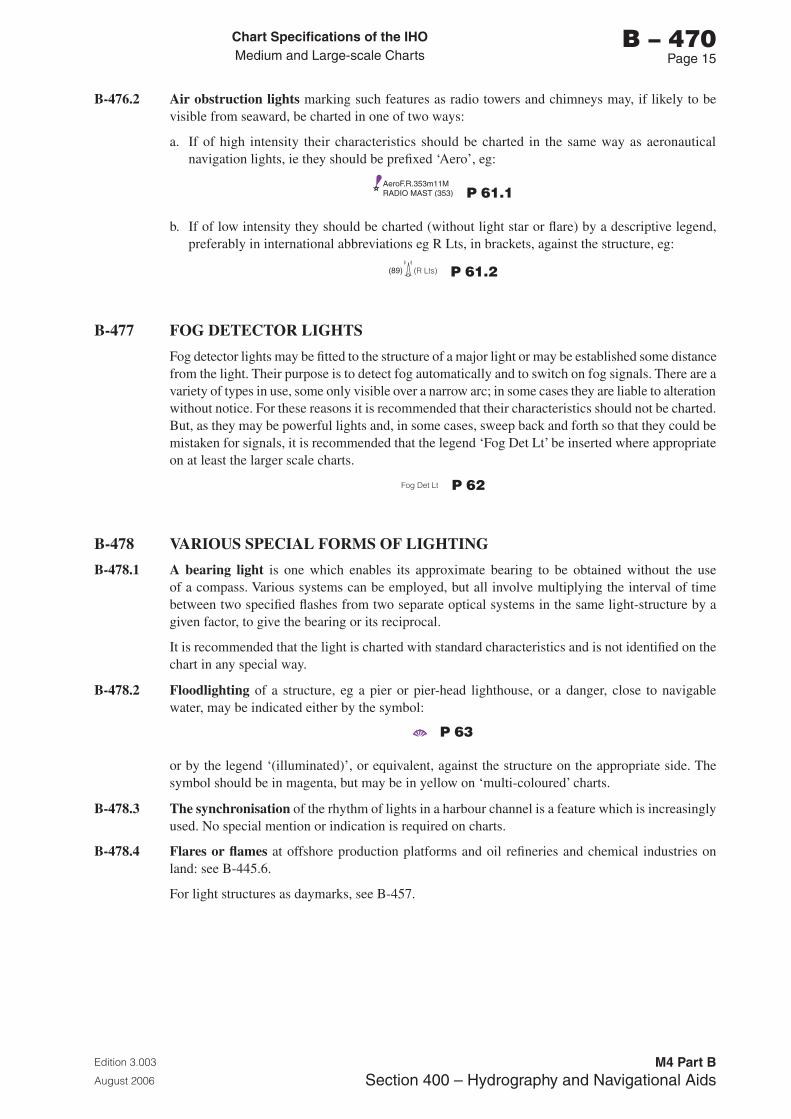
Chart Specifications of the IhoMedium and Large-scale Charts
Edition 3.003
August 2006
M4 Part BSection �00 – Hydrography and Navigational Aids
b – 470Page 15
B-476.2 Air obstruction lights marking such features as radio towers and chimneys may, if likely to be visible from seaward, be charted in one of two ways:
a. If of high intensity their characteristics should be charted in the same way as aeronautical navigation lights, ie they should be prefixed ‘Aero’, eg:
AeroF.R.353m11MRADIO MAST (353) P 61.1
b. If of low intensity they should be charted (without light star or flare) by a descriptive legend, preferably in international abbreviations eg R Lts, in brackets, against the structure, eg:
(89) (R Lts)(( ( (
P 61.2
B-477 FOG DETECTOR LIGHTS
Fog detector lights may be fitted to the structure of a major light or may be established some distance from the light. Their purpose is to detect fog automatically and to switch on fog signals. There are a variety of types in use, some only visible over a narrow arc; in some cases they are liable to alteration without notice. For these reasons it is recommended that their characteristics should not be charted. But, as they may be powerful lights and, in some cases, sweep back and forth so that they could be mistaken for signals, it is recommended that the legend ‘Fog Det Lt’ be inserted where appropriate on at least the larger scale charts.
Fog Det Lt P 62
B-478 VARIOUS SPECIAL FORMS OF LIGHTING
B-478.1 A bearing light is one which enables its approximate bearing to be obtained without the use of a compass. Various systems can be employed, but all involve multiplying the interval of time between two specified flashes from two separate optical systems in the same light-structure by a given factor, to give the bearing or its reciprocal.
It is recommended that the light is charted with standard characteristics and is not identified on the chart in any special way.
B-478.2 Floodlighting of a structure, eg a pier or pier-head lighthouse, or a danger, close to navigable water, may be indicated either by the symbol:
P 63
or by the legend ‘(illuminated)’, or equivalent, against the structure on the appropriate side. The symbol should be in magenta, but may be in yellow on ‘multi-coloured’ charts.
B-478.3 The synchronisation of the rhythm of lights in a harbour channel is a feature which is increasingly used. No special mention or indication is required on charts.
B-478.4 Flares or flames at offshore production platforms and oil refineries and chemical industries on land: see B-445.6.
For light structures as daymarks, see B-457.
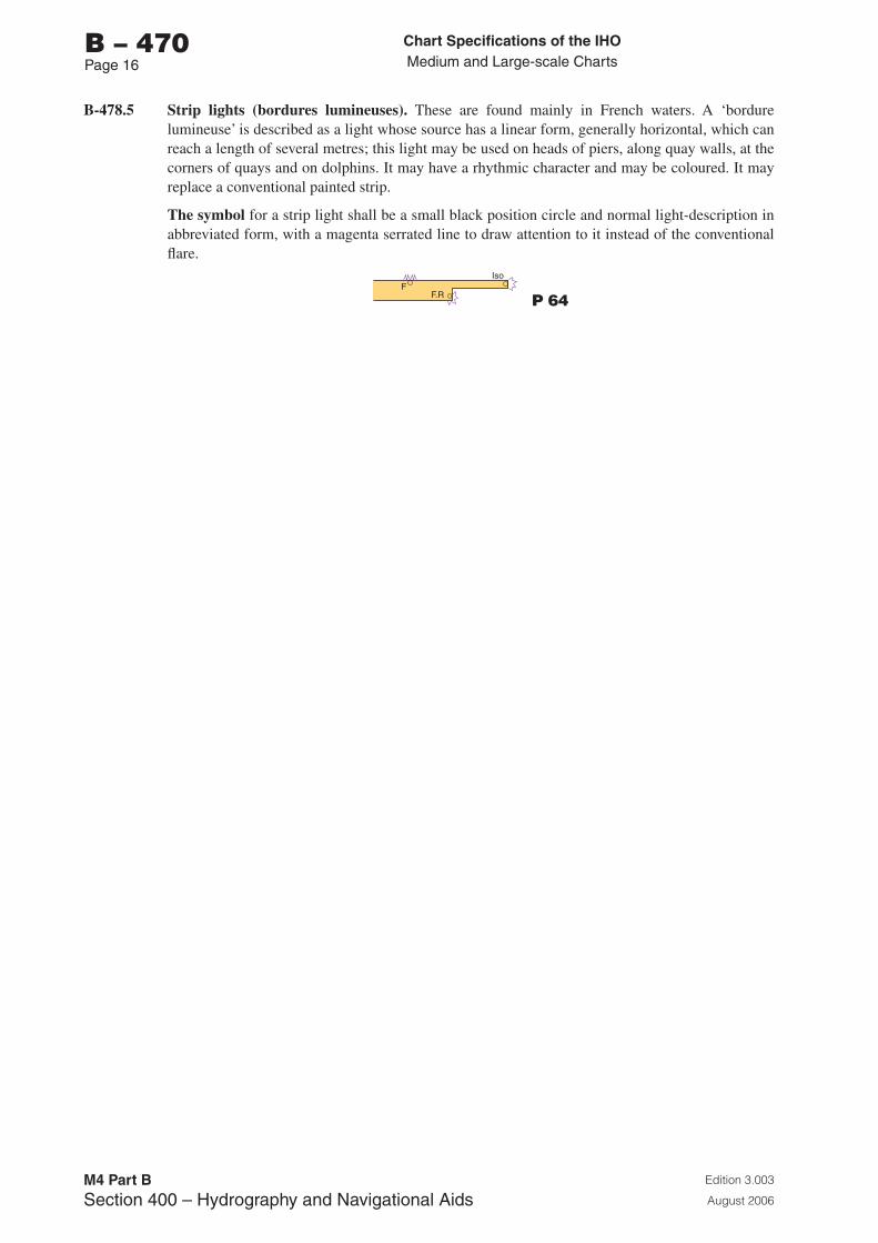
Chart Specifications of the IhoMedium and Large-scale Charts
Edition 3.003
August 2006
M4 Part BSection �00 – Hydrography and Navigational Aids
b – 470Page 16
B-478.5 Strip lights (bordures lumineuses). These are found mainly in French waters. A ‘bordure lumineuse’ is described as a light whose source has a linear form, generally horizontal, which can reach a length of several metres; this light may be used on heads of piers, along quay walls, at the corners of quays and on dolphins. It may have a rhythmic character and may be coloured. It may replace a conventional painted strip.
The symbol for a strip light shall be a small black position circle and normal light-description in abbreviated form, with a magenta serrated line to draw attention to it instead of the conventional flare.
FF.R
Iso
P 64
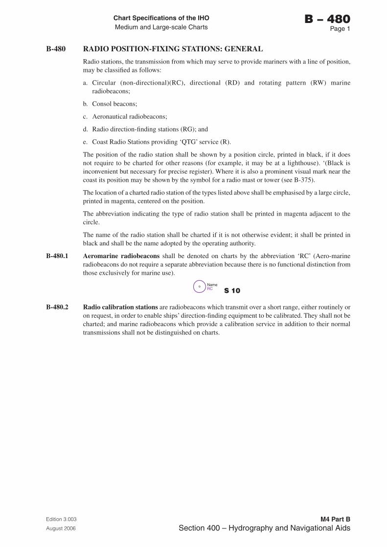
Chart Specifications of the IhoMedium and Large-scale Charts
Edition 3.003
August 2006
M4 Part BSection �00 – Hydrography and Navigational Aids
b – 480Page 1
B-480 RADIO POSITION-FIXING STATIONS: GENERAL
Radio stations, the transmission from which may serve to provide mariners with a line of position, may be classified as follows:
a. Circular (non-directional)(RC), directional (RD) and rotating pattern (RW) marine radiobeacons;
b. Consol beacons;
c. Aeronautical radiobeacons;
d. Radio direction-finding stations (RG); and
e. Coast Radio Stations providing ‘QTG’ service (R).
The position of the radio station shall be shown by a position circle, printed in black, if it does not require to be charted for other reasons (for example, it may be at a lighthouse). ‘(Black is inconvenient but necessary for precise register). Where it is also a prominent visual mark near the coast its position may be shown by the symbol for a radio mast or tower (see B-375).
The location of a charted radio station of the types listed above shall be emphasised by a large circle, printed in magenta, centered on the position.
The abbreviation indicating the type of radio station shall be printed in magenta adjacent to the circle.
The name of the radio station shall be charted if it is not otherwise evident; it shall be printed in black and shall be the name adopted by the operating authority.
B-480.1 Aeromarine radiobeacons shall be denoted on charts by the abbreviation ‘RC’ (Aero-marine radiobeacons do not require a separate abbreviation because there is no functional distinction from those exclusively for marine use).
RCName
S 10
B-480.2 Radio calibration stations are radiobeacons which transmit over a short range, either routinely or on request, in order to enable ships’ direction-finding equipment to be calibrated. They shall not be charted; and marine radiobeacons which provide a calibration service in addition to their normal transmissions shall not be distinguished on charts.
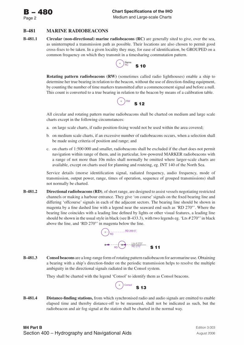
Chart Specifications of the IhoMedium and Large-scale Charts
Edition 3.003
August 2006
M4 Part BSection �00 – Hydrography and Navigational Aids
b – 480Page 2
B-481 MARINE RADIOBEACONS
B-481.1 Circular (non-directional) marine radiobeacons (RC) are generally sited to give, over the sea, as uninterrupted a transmission path as possible. Their locations are also chosen to permit good cross-fixes to be taken. In a given locality they may, for ease of identification, be GROUPED on a common frequency on which they transmit in a timesharing commutation pattern.
RCName
S 10
Rotating pattern radiobeacons (RW) (sometimes called radio lighthouses) enable a ship to determine her true bearing in relation to the beacon, without the use of direction-finding equipment, by counting the number of time markers transmitted after a commencement signal and before a null. This count is converted to a true bearing in relation to the beacon by means of a calibration table.
RW S 12
All circular and rotating pattern marine radiobeacons shall be charted on medium and large scale charts except in the following circumstances:
a. on large scale charts, if radio position-fixing would not be used within the area covered;
b. on medium scale charts, if an excessive number of radiobeacons occurs, when a selection shall be made using criteria of position and range; and
c. on charts of 1:500 000 and smaller, radiobeacons shall be excluded if the chart does not permit navigation within range of them, and in particular, low-powered MARKER radiobeacons with a range of not more than 10n miles shall normally be omitted where larger-scale charts are available, except on charts used for planning and routeing, eg. INT 140 of the North Sea.
Service details (morse identification signal, radiated frequency, audio frequency, mode of transmission, output power, range, times of operation, sequence of grouped transmissions) shall not normally be charted.
B-481.2 Directional radiobeacons (RD), of short range, are designed to assist vessels negotiating restricted channels or making a harbour entrance. They give ‘on course’ signals on the fixed bearing line and differing ‘offcourse’ signals in each of the adjacent sectors. The bearing line should be shown in magenta by a fine dashed line with a legend near the seaward end such as ‘RD 270°’. Where the bearing line coincides with a leading line defined by lights or other visual features, a leading line should be shown in the usual style in black (see B-433.3), with two legends eg. ‘Lts # 270°’ in black above the line, and ‘RD 270°’ in magenta below the line.
RD
RD
RD 269·5°
RD 270°Lts 270°
S 11
B-481.3 Consol beacons are a long-range form of rotating pattern radiobeacon for aeromarine use. Obtaining a bearing with a ship’s direction-finder on the periodic transmission helps to resolve the multiple ambiguity in the directional signals radiated in the Consol system.
They shall be charted with the legend ‘Consol’ to identify them as Consol beacons.
Consol S 13
B-481.4 Distance-finding stations, from which synchronised radio and audio signals are emitted to enable elapsed time and thereby distance-off to be measured, shall not be indicated as such, but the radiobeacon and air fog signal at the station shall be charted in the normal way.
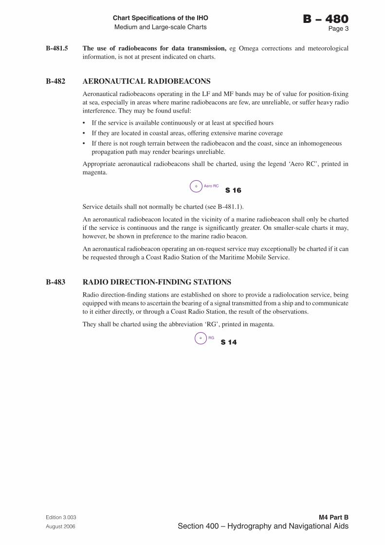
Chart Specifications of the IhoMedium and Large-scale Charts
Edition 3.003
August 2006
M4 Part BSection �00 – Hydrography and Navigational Aids
b – 480Page �
B-481.5 The use of radiobeacons for data transmission, eg Omega corrections and meteorological information, is not at present indicated on charts.
B-482 AERONAUTICAL RADIOBEACONS
Aeronautical radiobeacons operating in the LF and MF bands may be of value for position-fixing at sea, especially in areas where marine radiobeacons are few, are unreliable, or suffer heavy radio interference. They may be found useful:
• If the service is available continuously or at least at specified hours
• If they are located in coastal areas, offering extensive marine coverage
• If there is not rough terrain between the radiobeacon and the coast, since an inhomogeneous propagation path may render bearings unreliable.
Appropriate aeronautical radiobeacons shall be charted, using the legend ‘Aero RC’, printed in magenta.
Aero RC S 16
Service details shall not normally be charted (see B-481.1).
An aeronautical radiobeacon located in the vicinity of a marine radiobeacon shall only be charted if the service is continuous and the range is significantly greater. On smaller-scale charts it may, however, be shown in preference to the marine radio beacon.
An aeronautical radiobeacon operating an on-request service may exceptionally be charted if it can be requested through a Coast Radio Station of the Maritime Mobile Service.
B-483 RADIO DIRECTION-FINDING STATIONS
Radio direction-finding stations are established on shore to provide a radiolocation service, being equipped with means to ascertain the bearing of a signal transmitted from a ship and to communicate to it either directly, or through a Coast Radio Station, the result of the observations.
They shall be charted using the abbreviation ‘RG’, printed in magenta.
RG S 14
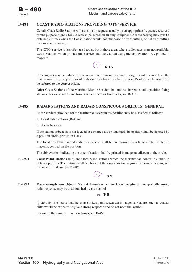
Chart Specifications of the IhoMedium and Large-scale Charts
Edition 3.003
August 2006
M4 Part BSection �00 – Hydrography and Navigational Aids
b – 480Page �
B-484 COAST RADIO STATIONS PROVIDING ‘QTG’ SERVICE
Certain Coast Radio Stations will transmit on request, usually on an appropriate frequency reserved for the purpose, signals for use with ships’ direction-finding equipment. A radio bearing may thus be obtained at times when the Coast Station would not otherwise be transmitting, or not transmitting on a usable frequency.
The ‘QTG’ service is less often used today, but in those areas where radiobeacons are not available, Coast Stations which provide this service shall be charted using the abbreviation ‘R’, printed in magenta.
R S 15
If the signals may be radiated from an auxiliary transmitter situated a significant distance from the main transmitter, the positions of both shall be charted so that the vessel’s observed bearing may be referred to the correct origin.
Other Coast Stations of the Maritime Mobile Service shall not be charted as radio position-fixing stations. For radio masts and towers which serve as landmarks, see B-375.
B-485 RADAR STATIONS AND RADAR-CONSPICUOUS OBJECTS: GENERAL
Radar services provided for the mariner to ascertain his position may be classified as follows:
a. Coast radar stations (Ra); and
b. Radar beacons.
If the station or beacon is not located at a charted aid or landmark, its position shall be denoted by a position circle, printed in black.
The location of the charted station or beacon shall be emphasised by a large circle, printed in magenta, centred on the position.
The abbreviation indicating the type of station shall be printed in magenta adjacent to the circle.
B-485.1 Coast radar stations (Ra) are shore-based stations which the mariner can contact by radio to obtain a position. The stations shall be charted if the ship’s position is given in terms of bearing and distance from them. See B-487.
Ra S 1
B-485.2 Radar-conspicuous objects. Natural features which are known to give an unexpectedly strong radar response may be distinguished by the symbol
S 5
(preferably oriented so that the short strokes point seawards) in magenta. Features such as coastal cliffs would be expected to give a strong response and do not need the symbol.
For use of the symbol on buoys, see B-465.
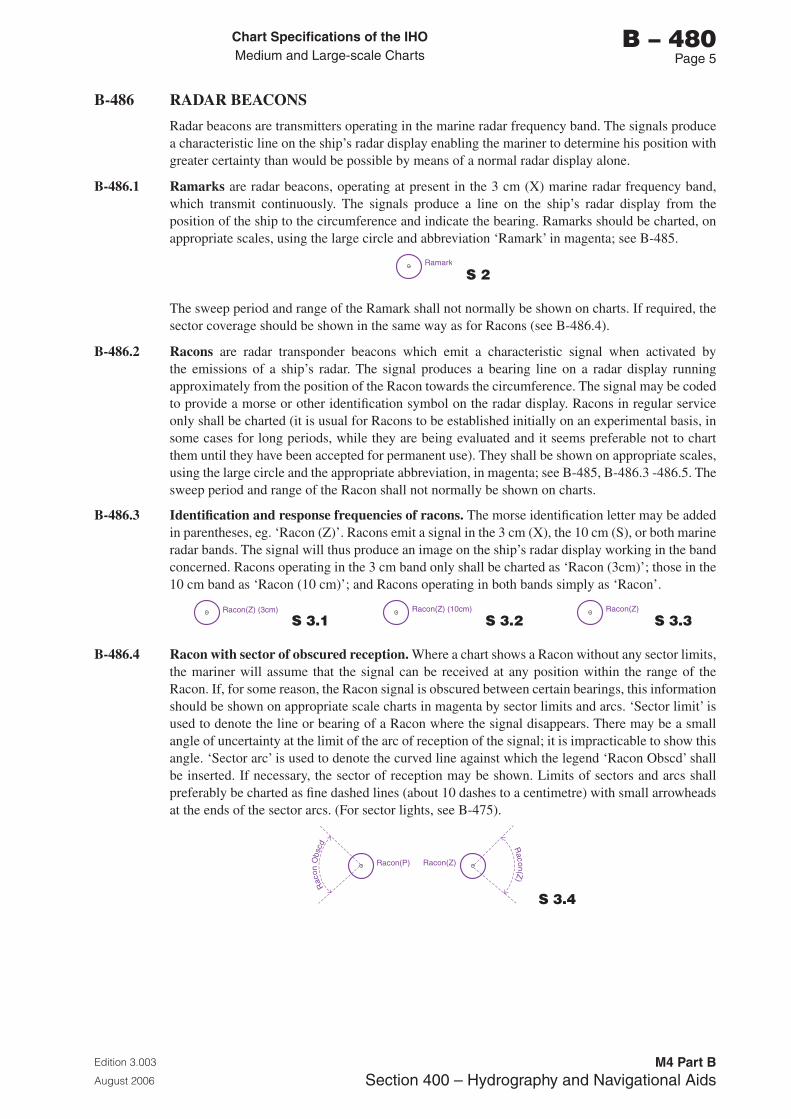
Chart Specifications of the IhoMedium and Large-scale Charts
Edition 3.003
August 2006
M4 Part BSection �00 – Hydrography and Navigational Aids
b – 480Page 5
B-486 RADAR BEACONS
Radar beacons are transmitters operating in the marine radar frequency band. The signals produce a characteristic line on the ship’s radar display enabling the mariner to determine his position with greater certainty than would be possible by means of a normal radar display alone.
B-486.1 Ramarks are radar beacons, operating at present in the 3 cm (X) marine radar frequency band, which transmit continuously. The signals produce a line on the ship’s radar display from the position of the ship to the circumference and indicate the bearing. Ramarks should be charted, on appropriate scales, using the large circle and abbreviation ‘Ramark’ in magenta; see B-485.
Ramark
S 2
The sweep period and range of the Ramark shall not normally be shown on charts. If required, the sector coverage should be shown in the same way as for Racons (see B-486.4).
B-486.2 Racons are radar transponder beacons which emit a characteristic signal when activated by the emissions of a ship’s radar. The signal produces a bearing line on a radar display running approximately from the position of the Racon towards the circumference. The signal may be coded to provide a morse or other identification symbol on the radar display. Racons in regular service only shall be charted (it is usual for Racons to be established initially on an experimental basis, in some cases for long periods, while they are being evaluated and it seems preferable not to chart them until they have been accepted for permanent use). They shall be shown on appropriate scales, using the large circle and the appropriate abbreviation, in magenta; see B-485, B-486.3 -486.5. The sweep period and range of the Racon shall not normally be shown on charts.
B-486.3 Identification and response frequencies of racons. The morse identification letter may be added in parentheses, eg. ‘Racon (Z)’. Racons emit a signal in the 3 cm (X), the 10 cm (S), or both marine radar bands. The signal will thus produce an image on the ship’s radar display working in the band concerned. Racons operating in the 3 cm band only shall be charted as ‘Racon (3cm)’; those in the 10 cm band as ‘Racon (10 cm)’; and Racons operating in both bands simply as ‘Racon’.
Racon(Z) (3cm)
S 3.1 Racon(Z) (10cm)
S 3.2 Racon(Z)
S 3.3
B-486.4 Racon with sector of obscured reception. Where a chart shows a Racon without any sector limits, the mariner will assume that the signal can be received at any position within the range of the Racon. If, for some reason, the Racon signal is obscured between certain bearings, this information should be shown on appropriate scale charts in magenta by sector limits and arcs. ‘Sector limit’ is used to denote the line or bearing of a Racon where the signal disappears. There may be a small angle of uncertainty at the limit of the arc of reception of the signal; it is impracticable to show this angle. ‘Sector arc’ is used to denote the curved line against which the legend ‘Racon Obscd’ shall be inserted. If necessary, the sector of reception may be shown. Limits of sectors and arcs shall preferably be charted as fine dashed lines (about 10 dashes to a centimetre) with small arrowheads at the ends of the sector arcs. (For sector lights, see B-475).
Racon(P) Racon(Z)
Raco n(Z
)
Rac
onO
b scd
S 3.4
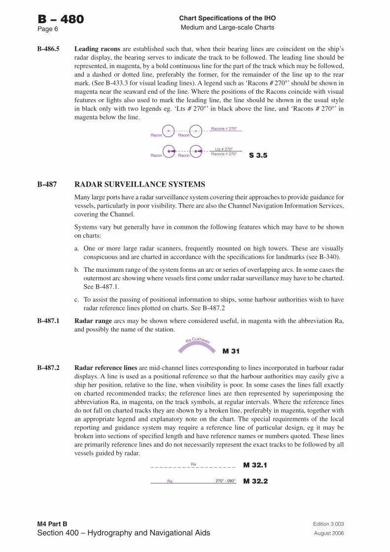
Chart Specifications of the IhoMedium and Large-scale Charts
Edition 3.003
August 2006
M4 Part BSection �00 – Hydrography and Navigational Aids
b – 480Page 6
B-486.5 Leading racons are established such that, when their bearing lines are coincident on the ship’s radar display, the bearing serves to indicate the track to be followed. The leading line should be represented, in magenta, by a bold continuous line for the part of the track which may be followed, and a dashed or dotted line, preferably the former, for the remainder of the line up to the rear mark. (See B-433.3 for visual leading lines). A legend such as ‘Racons # 270°’ should be shown in magenta near the seaward end of the line. Where the positions of the Racons coincide with visual features or lights also used to mark the leading line, the line should be shown in the usual style in black only with two legends eg. ‘Lts # 270°’ in black above the line, and ‘Racons # 270°’ in magenta below the line.
Racon
Racon
Racon
Racon
Lts 270ºRacons 270°
Racons 270°
S 3.5
B-487 RADAR SURVEILLANCE SYSTEMS
Many large ports have a radar surveillance system covering their approaches to provide guidance for vessels, particularly in poor visibility. There are also the Channel Navigation Information Services, covering the Channel.
Systems vary but generally have in common the following features which may have to be shown on charts:
a. One or more large radar scanners, frequently mounted on high towers. These are visually conspicuous and are charted in accordance with the specifications for landmarks (see B-340).
b. The maximum range of the system forms an arc or series of overlapping arcs. In some cases the outermost arc showing where vessels first come under radar surveillance may have to be charted. See B-487.1.
c. To assist the passing of positional information to ships, some harbour authorities wish to have radar reference lines plotted on charts. See B-487.2
B-487.1 Radar range arcs may be shown where considered useful, in magenta with the abbreviation Ra, and possibly the name of the station.
Ra Cuxhaven
M 31
B-487.2 Radar reference lines are mid-channel lines corresponding to lines incorporated in harbour radar displays. A line is used as a positional reference so that the harbour authorities may easily give a ship her position, relative to the line, when visibility is poor. In some cases the lines fall exactly on charted recommended tracks; the reference lines are then represented by superimposing the abbreviation Ra, in magenta, on the track symbols, at regular intervals. Where the reference lines do not fall on charted tracks they are shown by a broken line, preferably in magenta, together with an appropriate legend and explanatory note on the chart. The special requirements of the local reporting and guidance system may require a reference line of particular design, eg it may be broken into sections of specified length and have reference names or numbers quoted. These lines are primarily reference lines and do not necessarily represent the exact tracks to be followed by all vessels guided by radar.
Ra M 32.1
Ra 270° - 090° M 32.2
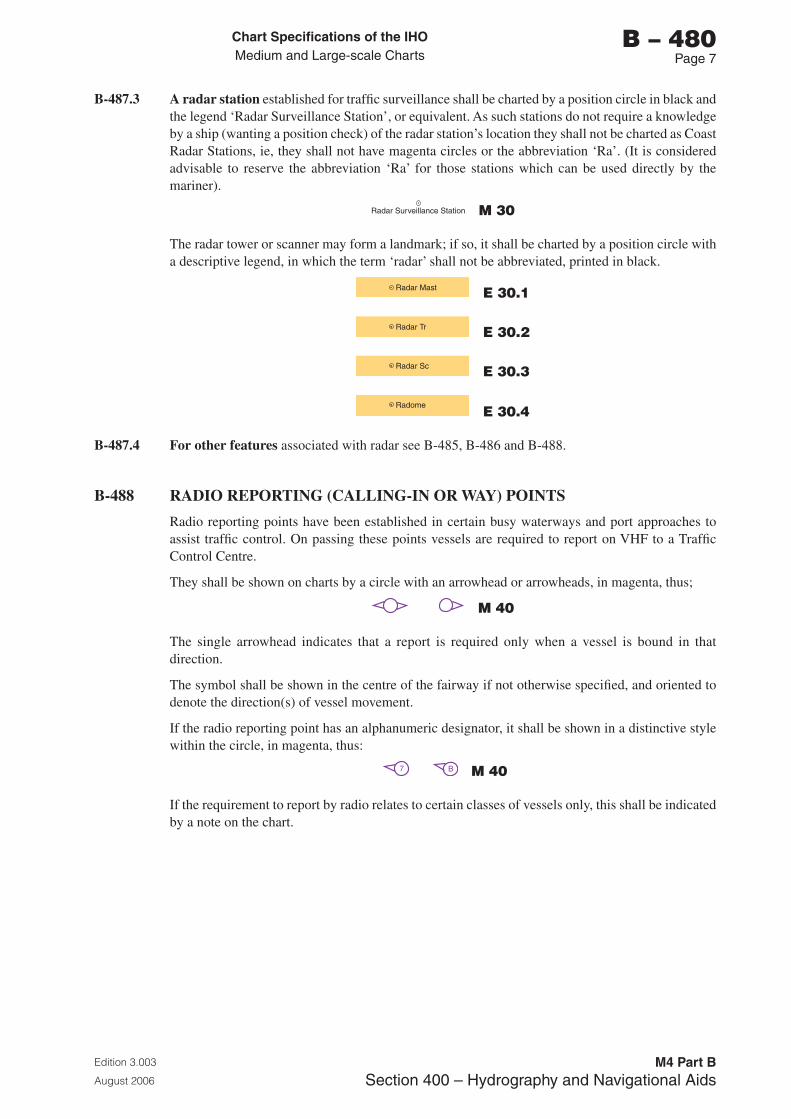
Chart Specifications of the IhoMedium and Large-scale Charts
Edition 3.003
August 2006
M4 Part BSection �00 – Hydrography and Navigational Aids
b – 480Page �
B-487.3 A radar station established for traffic surveillance shall be charted by a position circle in black and the legend ‘Radar Surveillance Station’, or equivalent. As such stations do not require a knowledge by a ship (wanting a position check) of the radar station’s location they shall not be charted as Coast Radar Stations, ie, they shall not have magenta circles or the abbreviation ‘Ra’. (It is considered advisable to reserve the abbreviation ‘Ra’ for those stations which can be used directly by the mariner).
Radar Surveillance Station M 30
The radar tower or scanner may form a landmark; if so, it shall be charted by a position circle with a descriptive legend, in which the term ‘radar’ shall not be abbreviated, printed in black.
Radar Mast E 30.1
Radar Tr E 30.2
Radar Sc E 30.3
Radome E 30.4
B-487.4 For other features associated with radar see B-485, B-486 and B-488.
B-488 RADIO REPORTING (CALLING-IN OR WAY) POINTS
Radio reporting points have been established in certain busy waterways and port approaches to assist traffic control. On passing these points vessels are required to report on VHF to a Traffic Control Centre.
They shall be shown on charts by a circle with an arrowhead or arrowheads, in magenta, thus;
M 40
The single arrowhead indicates that a report is required only when a vessel is bound in that direction.
The symbol shall be shown in the centre of the fairway if not otherwise specified, and oriented to denote the direction(s) of vessel movement.
If the radio reporting point has an alphanumeric designator, it shall be shown in a distinctive style within the circle, in magenta, thus:
7 B M 40
If the requirement to report by radio relates to certain classes of vessels only, this shall be indicated by a note on the chart.
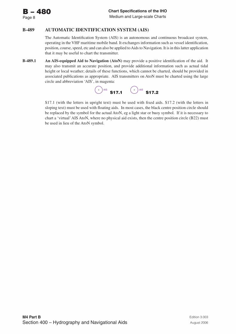
Chart Specifications of the IhoMedium and Large-scale Charts
Edition 3.003
August 2006
M4 Part BSection �00 – Hydrography and Navigational Aids
b – 480Page �
B-489 AUTOMATIC IDENTIFICATION SYSTEM (AIS)
The Automatic Identification System (AIS) is an autonomous and continuous broadcast system, operating in the VHF maritime mobile band. It exchanges information such as vessel identification, position, course, speed, etc and can also be applied to Aids to Navigation. It is in this latter application that it may be useful to chart the transmitter.
B-489.1 An AIS-equipped Aid to Navigation (AtoN) may provide a positive identification of the aid. It may also transmit an accurate position, and provide additional information such as actual tidal height or local weather; details of these functions, which cannot be charted, should be provided in associated publications as appropriate. AIS transmitters on AtoN must be charted using the large circle and abbreviation ‘AIS’, in magenta:
AIS S17.1
AIS S17.2
S17.1 (with the letters in upright text) must be used with fixed aids. S17.2 (with the letters in sloping text) must be used with floating aids. In most cases, the black centre position circle should be replaced by the symbol for the actual AtoN, eg a light star or buoy symbol. If it is necessary to chart a ‘virtual’ AIS AtoN, where no physical aid exists, then the centre position circle (B22) must be used in lieu of the AtoN symbol.
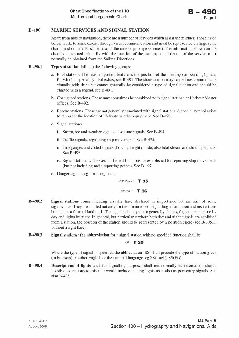
Chart Specifications of the IhoMedium and Large-scale Charts
Edition 3.003
August 2006
M4 Part BSection �00 – Hydrography and Navigational Aids
b – 490Page 1
B-490 MARINE SERVICES AND SIGNAL STATION
Apart from aids to navigation, there are a number of services which assist the mariner. Those listed below work, to some extent, through visual communication and must be represented on large scale charts (and on smaller scales also in the case of pilotage services). The information shown on the chart is concerned primarily with the location of the station; actual details of the service must normally be obtained from the Sailing Directions.
B-490.1 Types of station fall into the following groups:
a. Pilot stations. The most important feature is the position of the meeting (or boarding) place, for which a special symbol exists; see B-491. The shore station may sometimes communicate visually with ships but cannot generally be considered a type of signal station and should be charted with a legend, see B-491.
b. Coastguard stations. These may sometimes be combined with signal stations or Harbour Master offices. See B-492.
c. Rescue stations. These are not generally associated with signal stations. A special symbol exists to represent the location of lifeboats or other equipment. See B-493.
d. Signal stations
i. Storm, ice and weather signals; also time signals. See B-494.
ii. Traffic signals, regulating ship movements. See B-495.
iii. Tide gauges and coded signals showing height of tide; also tidal stream and sluicing signals. See B-496.
iv. Signal stations with several different functions, or established for reporting ship movements (but not including radio reporting points). See B-497.
e. Danger signals, eg, for firing areas.
SS(Danger) T 35
SS(Firing) T 36
B-490.2 Signal stations communicating visually have declined in importance but are still of some significance. They are charted not only for their main role of signalling information and instructions but also as a form of landmark. The signals displayed are generally shapes, flags or semaphore by day and lights by night. In general, but particularly where both day and night signals are exhibited from a station, the position of the station should be represented by a position circle (see B-305.1) without a light flare.
B-490.3 Signal stations: the abbreviation for a signal station with no specified function shall be
SS T 20
Where the type of signal is specified the abbreviation ‘SS’ shall precede the type of station given (in brackets) in either English or the national language, eg SS(Lock), SS(Eis).
B-490.4 Descriptions of lights used for signalling purposes shall not normally be inserted on charts. Possible exceptions to this rule would include leading lights used also as port entry signals. See also B-495.
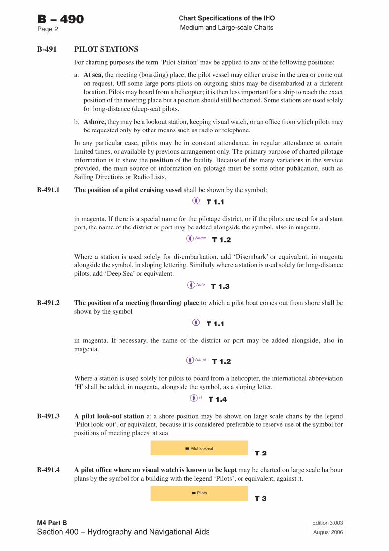
Chart Specifications of the IhoMedium and Large-scale Charts
Edition 3.003
August 2006
M4 Part BSection �00 – Hydrography and Navigational Aids
b – 490Page 2
B-491 PILOT STATIONS
For charting purposes the term ‘Pilot Station’ may be applied to any of the following positions:
a. At sea, the meeting (boarding) place; the pilot vessel may either cruise in the area or come out on request. Off some large ports pilots on outgoing ships may be disembarked at a different location. Pilots may board from a helicopter; it is then less important for a ship to reach the exact position of the meeting place but a position should still be charted. Some stations are used solely for long-distance (deep-sea) pilots.
b. Ashore, they may be a lookout station, keeping visual watch, or an office from which pilots may be requested only by other means such as radio or telephone.
In any particular case, pilots may be in constant attendance, in regular attendance at certain limited times, or available by previous arrangement only. The primary purpose of charted pilotage information is to show the position of the facility. Because of the many variations in the service provided, the main source of information on pilotage must be some other publication, such as Sailing Directions or Radio Lists.
B-491.1 The position of a pilot cruising vessel shall be shown by the symbol:
T 1.1
in magenta. If there is a special name for the pilotage district, or if the pilots are used for a distant port, the name of the district or port may be added alongside the symbol, also in magenta.
Name T 1.2
Where a station is used solely for disembarkation, add ‘Disembark’ or equivalent, in magenta alongside the symbol, in sloping lettering. Similarly where a station is used solely for long-distance pilots, add ‘Deep Sea’ or equivalent.
Note T 1.3
B-491.2 The position of a meeting (boarding) place to which a pilot boat comes out from shore shall be shown by the symbol
T 1.1
in magenta. If necessary, the name of the district or port may be added alongside, also in magenta.
T 1.2
Where a station is used solely for pilots to board from a helicopter, the international abbreviation ‘H’ shall be added, in magenta, alongside the symbol, as a sloping letter.
T 1.4
B-491.3 A pilot look-out station at a shore position may be shown on large scale charts by the legend ‘Pilot look-out’, or equivalent, because it is considered preferable to reserve use of the symbol for positions of meeting places, at sea.
Pilot look-out
T 2
B-491.4 A pilot office where no visual watch is known to be kept may be charted on large scale harbour plans by the symbol for a building with the legend ‘Pilots’, or equivalent, against it.
Pilots
T 3
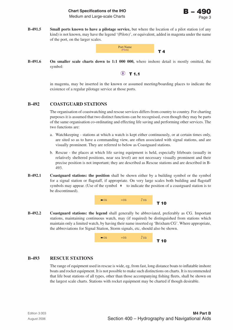
Chart Specifications of the IhoMedium and Large-scale Charts
Edition 3.003
August 2006
M4 Part BSection �00 – Hydrography and Navigational Aids
b – 490Page �
B-491.5 Small ports known to have a pilotage service, but where the location of a pilot station (of any kind) is not known, may have the legend ‘(Pilots)’, or equivalent, added in magenta under the name of the port, on the larger scales.
(Pilots)Port Name
T 4
B-491.6 On smaller scale charts down to 1:1 000 000, where inshore detail is mostly omitted, the symbol:
T 1.1
in magenta, may be inserted in the known or assumed meeting/boarding places to indicate the existence of a regular pilotage service at those ports.
B-492 COASTGUARD STATIONS
The organisation of coastwatching and rescue services differs from country to country. For charting purposes it is assumed that two distinct functions can be recognised, even though they may be parts of the same organisation co-ordinating and effecting life saving and performing other services. The two functions are:
a. Watchkeeping - stations at which a watch is kept either continuously, or at certain times only, are sited so as to have a commanding view, are often associated with signal stations, and are visually prominent. They are referred to below as Coastguard stations.
b. Rescue - the places at which life saving equipment is held, especially lifeboats (usually in relatively sheltered positions, near sea level) are not necessary visually prominent and their precise position is not important; they are described as Rescue stations and are described in B-493.
B-492.1 Coastguard stations: the position shall be shown either by a building symbol or the symbol for a signal station or flagstaff, if appropriate. On very large scales both building and flagstaff symbols may appear. (Use of the symbol to indicate the position of a coastguard station is to be discontinued).
CG CG CG
T 10
B-492.2 Coastguard stations: the legend shall generally be abbreviated, preferably as CG. Important stations, maintaining continuous watch, may (if required) be distinguished from stations which maintain only a limited watch, by having their name inserted eg ‘Brixham CG’. Where appropriate, the abbreviations for Signal Station, Storm signals, etc, should also be shown.
CG CG CG
T 10
B-493 RESCUE STATIONS
The range of equipment used in rescue is wide, eg, from fast, long distance boats to inflatable inshore boats and rocket equipment. It is not possible to make such distinctions on charts. It is recommended that life boat stations of all types, other than those accompanying fishing fleets, shall be shown on the largest scale charts. Stations with rocket equipment may be charted if though desirable.
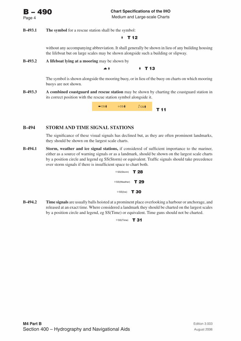
Chart Specifications of the IhoMedium and Large-scale Charts
Edition 3.003
August 2006
M4 Part BSection �00 – Hydrography and Navigational Aids
b – 490Page �
B-493.1 The symbol for a rescue station shall be the symbol:
T 12
without any accompanying abbreviation. It shall generally be shown in lieu of any building housing the lifeboat but on large scales may be shown alongside such a building or slipway.
B-493.2 A lifeboat lying at a mooring may be shown by
T 13
The symbol is shown alongside the mooring buoy, or in lieu of the buoy on charts on which mooring buoys are not shown.
B-493.3 A combined coastguard and rescue station may be shown by charting the coastguard station in its correct position with the rescue station symbol alongside it.
CG CG CG
T 11
B-494 STORM AND TIME SIGNAL STATIONS
The significance of these visual signals has declined but, as they are often prominent landmarks, they should be shown on the largest scale charts.
B-494.1 Storm, weather and ice signal stations, if considered of sufficient importance to the mariner, either as a source of warning signals or as a landmark, should be shown on the largest scale charts by a position circle and legend eg SS(Storm) or equivalent. Traffic signals should take precedence over storm signals if there is insufficient space to chart both.
SS(Storm) T 28
SS(Weather) T 29
SS(Ice) T 30
B-494.2 Time signals are usually balls hoisted at a prominent place overlooking a harbour or anchorage, and released at an exact time. Where considered a landmark they should be charted on the largest scales by a position circle and legend, eg SS(Time) or equivalent. Time guns should not be charted.
SS(Time) T 31
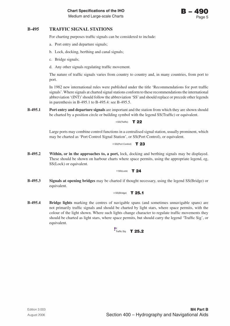
Chart Specifications of the IhoMedium and Large-scale Charts
Edition 3.003
August 2006
M4 Part BSection �00 – Hydrography and Navigational Aids
b – 490Page 5
B-495 TRAFFIC SIGNAL STATIONS
For charting purposes traffic signals can be considered to include:
a. Port entry and departure signals;
b. Lock, docking, berthing and canal signals;
c. Bridge signals;
d. Any other signals regulating traffic movement.
The nature of traffic signals varies from country to country and, in many countries, from port to port.
In 1982 new international rules were published under the title ‘Recommendations for port traffic signals’. Where signals at charted signal stations conform to these recommendations the international abbreviation ‘(INT)’ should follow the abbreviation ‘SS’ and should replace or precede other legends in parenthesis in B-495.1 to B-495.4: see B-495.5.
B-495.1 Port entry and departure signals are important and the station from which they are shown should be charted by a position circle or building symbol with the legend SS(Traffic) or equivalent.
SS(Traffic) T 22
Large ports may combine control functions in a centralised signal station, usually prominent, which may be charted as ‘Port Control Signal Station’, or SS(Port Control), or equivalent.
SS(Port Control) T 23
B-495.2 Within, or in the approaches to, a port, lock, docking and berthing signals may be displayed. These should be shown on harbour charts where space permits, using the appropriate legend, eg, SS(Lock) or equivalent.
SS(Lock) T 24
B-495.3 Signals at opening bridges may be charted if thought necessary, using the legend SS(Bridge) or equivalent.
SS(Bridge) T 25.1
B-495.4 Bridge lights marking the centres of navigable spans (and sometimes unnavigable spans) are not primarily traffic signals and should be charted by light stars, where space permits, with the colour of the light shown. Where such lights change character to regulate traffic movements they should be charted as light stars, where space permits, but should carry the legend ‘Traffic Sig’, or equivalent.
F.Traffic Sig T 25.2
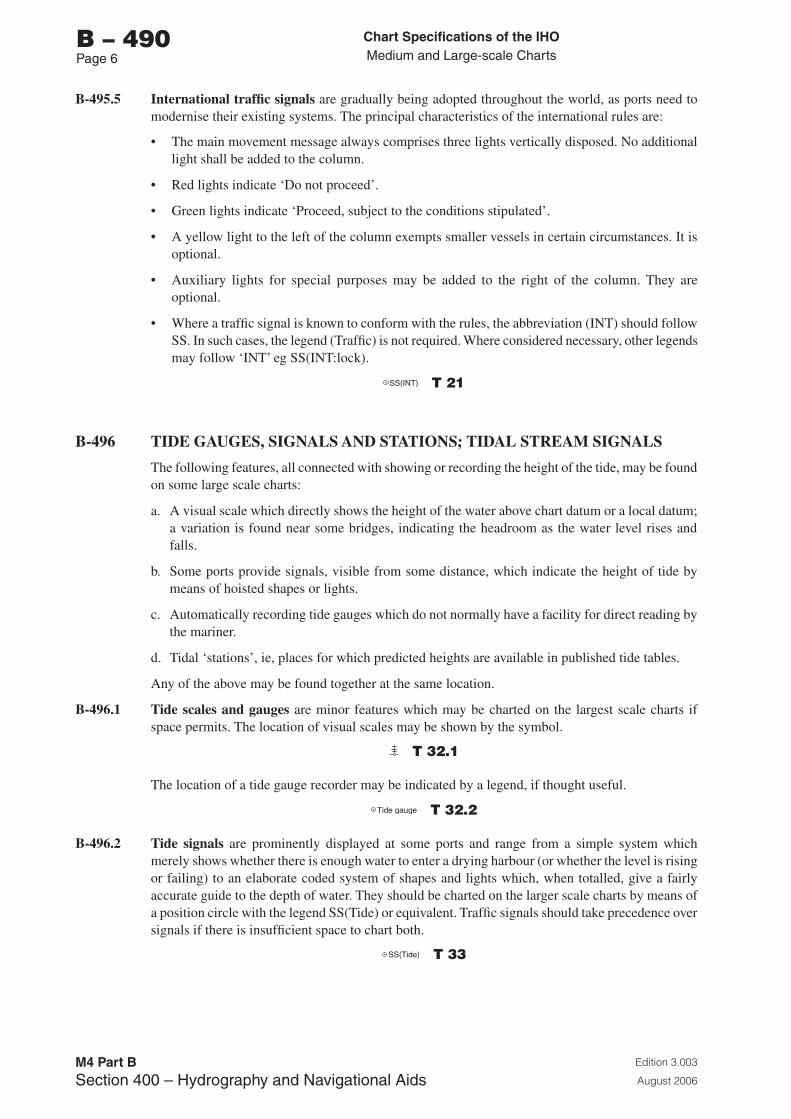
Chart Specifications of the IhoMedium and Large-scale Charts
Edition 3.003
August 2006
M4 Part BSection �00 – Hydrography and Navigational Aids
b – 490Page 6
B-495.5 International traffic signals are gradually being adopted throughout the world, as ports need to modernise their existing systems. The principal characteristics of the international rules are:
• The main movement message always comprises three lights vertically disposed. No additional light shall be added to the column.
• Red lights indicate ‘Do not proceed’.
• Green lights indicate ‘Proceed, subject to the conditions stipulated’.
• A yellow light to the left of the column exempts smaller vessels in certain circumstances. It is optional.
• Auxiliary lights for special purposes may be added to the right of the column. They are optional.
• Where a traffic signal is known to conform with the rules, the abbreviation (INT) should follow SS. In such cases, the legend (Traffic) is not required. Where considered necessary, other legends may follow ‘INT’ eg SS(INT:lock).
SS(INT) T 21
B-496 TIDE GAUGES, SIGNALS AND STATIONS; TIDAL STREAM SIGNALS
The following features, all connected with showing or recording the height of the tide, may be found on some large scale charts:
a. A visual scale which directly shows the height of the water above chart datum or a local datum; a variation is found near some bridges, indicating the headroom as the water level rises and falls.
b. Some ports provide signals, visible from some distance, which indicate the height of tide by means of hoisted shapes or lights.
c. Automatically recording tide gauges which do not normally have a facility for direct reading by the mariner.
d. Tidal ‘stations’, ie, places for which predicted heights are available in published tide tables.
Any of the above may be found together at the same location.
B-496.1 Tide scales and gauges are minor features which may be charted on the largest scale charts if space permits. The location of visual scales may be shown by the symbol.
T 32.1
The location of a tide gauge recorder may be indicated by a legend, if thought useful.
Tide gauge T 32.2
B-496.2 Tide signals are prominently displayed at some ports and range from a simple system which merely shows whether there is enough water to enter a drying harbour (or whether the level is rising or failing) to an elaborate coded system of shapes and lights which, when totalled, give a fairly accurate guide to the depth of water. They should be charted on the larger scale charts by means of a position circle with the legend SS(Tide) or equivalent. Traffic signals should take precedence over signals if there is insufficient space to chart both.
SS(Tide) T 33
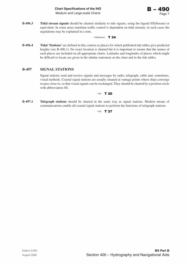
Chart Specifications of the IhoMedium and Large-scale Charts
Edition 3.003
August 2006
M4 Part BSection �00 – Hydrography and Navigational Aids
b – 490Page �
B-496.3 Tidal stream signals should be charted similarly to tide signals, using the legend SS(Stream) or equivalent. In some areas maritime traffic control is dependent on tidal streams; in such cases the regulations may be explained in a note.
SS(Stream) T 34
B-496.4 Tidal ‘Stations’ are defined in this context as places for which published tide tables give predicted heights (see B-406.1). No exact location is charted but it is important to ensure that the names of such places are included on all appropriate charts. Latitudes and longitudes of places which might be difficult to locate are given in the tabular statement on the chart and in the tide tables.
B-497 SIGNAL STATIONS
Signal stations send and receive signals and messages by radio, telegraph, cable and, sometimes, visual methods. Coastal signal stations are usually situated at vantage points where ships converge or pass close-to, so that visual signals can be exchanged. They should be charted by a position circle with abbreviation SS.
SS T 20
B-497.1 Telegraph stations should be charted in the same way as signal stations. Modern means of communications enable all coastal signal stations to perform the functions of telegraph stations.
SS T 27

Page intentionally left blank
Chart Specifications of the IhoMedium and Large-scale Charts
Edition 3.003
August 2006
M4 Part BSection 500 – Geographic Names, Lettering, Numerals
b – 500Page i
PART b
SECTION 500
GEOGRAPHIC NAMES - LETTERING - NUMERALS

Page intentionally left blank

Chart Specifications of the IhoMedium and Large-scale Charts
Edition 3.003
August 2006
M4 Part BSection 500 – Geographic Names, Lettering, Numerals
b – 500Page iii
SECTION 500 - GEOGRAPHIC NAMES, LETTERING, NUMERALS
CONTENTS
RECORD OF UPDATES
B-501 TERMINOLOGY AND DEFINITIONS
B-510 LANGUAGE: GENERAL RULES
B-520 TRANSLITERATION, ALPHABET, PUNCTUATIONB-521 SCRIPT ON INTERNATIONAL CHARTSB-522 PUNCTUATION AND OTHER MARKS
B-530 NUMBERSB-531 VULGAR FRACTIONS AND DECIMAL PARTS
B-540 ABBREVIATIONS
B-550 TOPONYMY - GENERAL RULESB-551 TOPONYMS: AUTHORITIES, INTERNATIONAL AND NATIONALB-552 TOPONYMS: INTERNATIONAL CONSIDERATIONS
B-560 STYLES OF TYPEB-561 EXPLANATION OF APPROACH USEDB-562 GENERAL PRINCIPLESB-563 CHOICE OF TYPE STYLESB-564 COLOUR

Page intentionally left blank
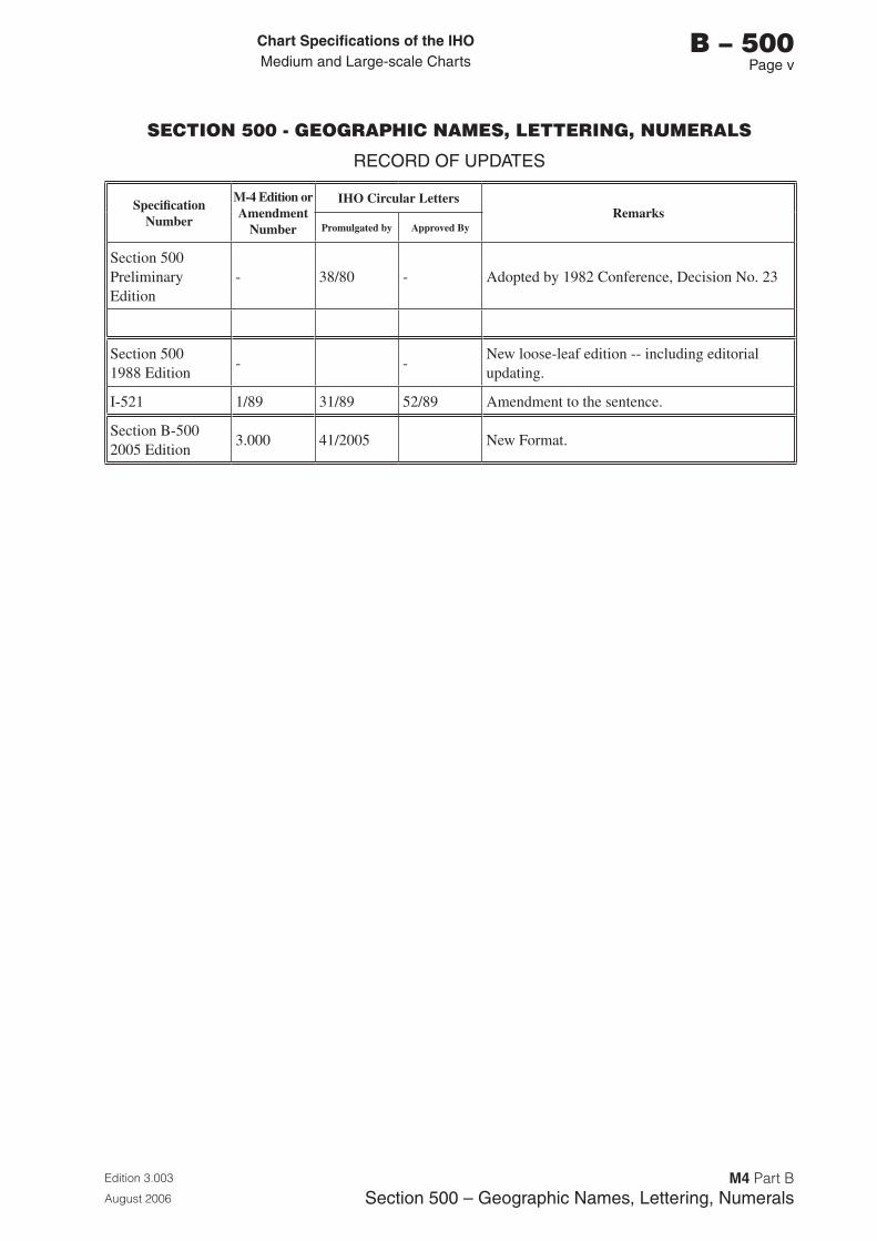
Chart Specifications of the IhoMedium and Large-scale Charts
Edition 3.003
August 2006
M4 Part BSection 500 – Geographic Names, Lettering, Numerals
b – 500Page v
SECTION 500 - GEOGRAPHIC NAMES, LETTERING, NUMERALS
RECORD OF UPDATES
Specification Number
M-4 Edition or Amendment
Number
IHO Circular LettersRemarks
Promulgated by Approved By
Section 500 Preliminary Edition
- 38/80 - Adopted by 1982 Conference, Decision No. 23
Section 500 1988 Edition
- -New loose-leaf edition -- including editorial updating.
I-521 1/89 31/89 52/89 Amendment to the sentence.
Section B-500 2005 Edition
3.000 41/2005 New Format.

Page intentionally left blank
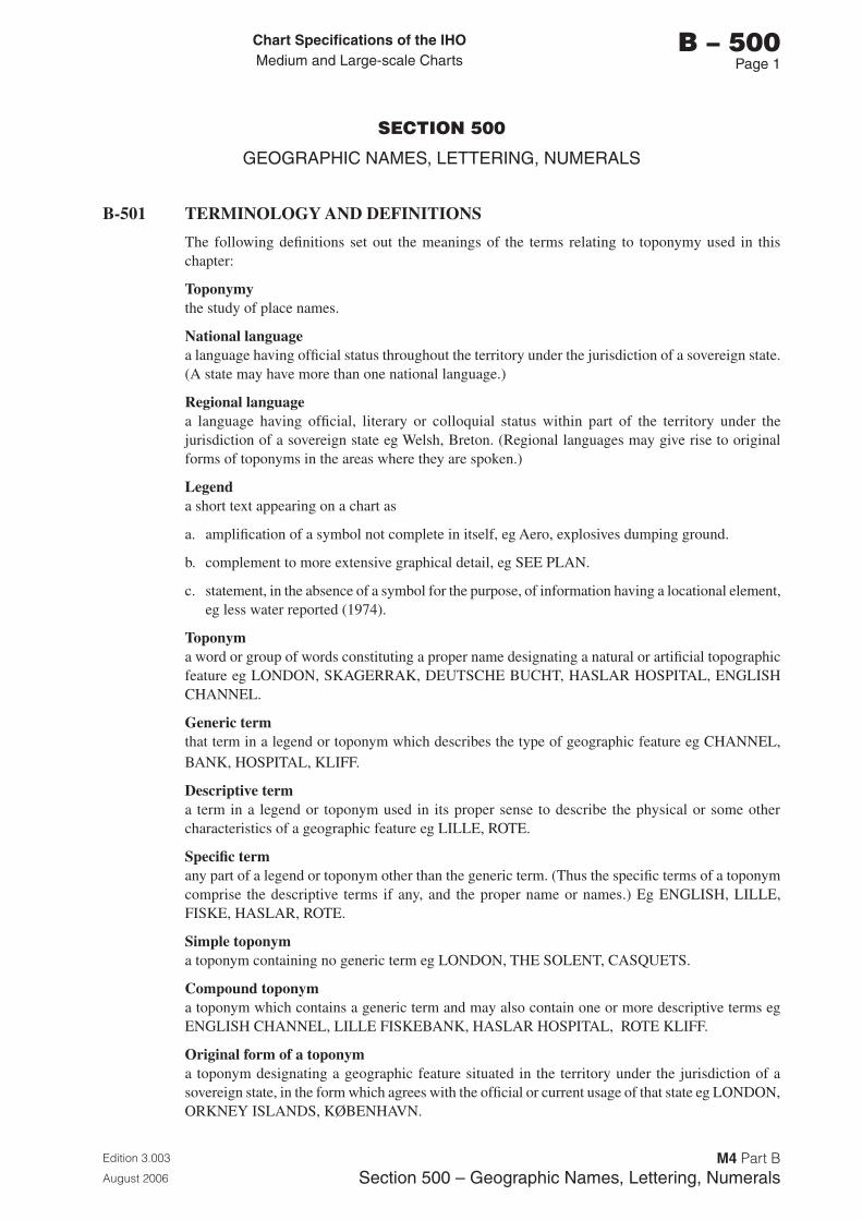
Chart Specifications of the IhoMedium and Large-scale Charts
Edition 3.003
August 2006
M4 Part BSection 500 – Geographic Names, Lettering, Numerals
b – 500Page 1
SECTION 500
GEOGRAPHIC NAMES, LETTERING, NUMERALS
B-501 TERMINOLOGY AND DEFINITIONS
The following definitions set out the meanings of the terms relating to toponymy used in this chapter:
Toponymythe study of place names.
National languagea language having official status throughout the territory under the jurisdiction of a sovereign state. (A state may have more than one national language.)
Regional languagea language having official, literary or colloquial status within part of the territory under the jurisdiction of a sovereign state eg Welsh, Breton. (Regional languages may give rise to original forms of toponyms in the areas where they are spoken.)
Legenda short text appearing on a chart as
a. amplification of a symbol not complete in itself, eg Aero, explosives dumping ground.
b. complement to more extensive graphical detail, eg SEE PLAN.
c. statement, in the absence of a symbol for the purpose, of information having a locational element, eg less water reported (1974).
Toponyma word or group of words constituting a proper name designating a natural or artificial topographic feature eg LONDON, SKAGERRAK, DEUTSCHE BUCHT, HASLAR HOSPITAL, ENGLISH CHANNEL.
Generic termthat term in a legend or toponym which describes the type of geographic feature eg CHANNEL, BANK, HOSPITAL, KLIFF.
Descriptive terma term in a legend or toponym used in its proper sense to describe the physical or some other characteristics of a geographic feature eg LILLE, ROTE.
Specific termany part of a legend or toponym other than the generic term. (Thus the specific terms of a toponym comprise the descriptive terms if any, and the proper name or names.) Eg ENGLISH, LILLE, FISKE, HASLAR, ROTE.
Simple toponyma toponym containing no generic term eg LONDON, THE SOLENT, CASQUETS.
Compound toponyma toponym which contains a generic term and may also contain one or more descriptive terms eg ENGLISH CHANNEL, LILLE FISKEBANK, HASLAR HOSPITAL, ROTE KLIFF.
Original form of a toponyma toponym designating a geographic feature situated in the territory under the jurisdiction of a sovereign state, in the form which agrees with the official or current usage of that state eg LONDON, ORKNEY ISLANDS, KØBENHAVN.

Chart Specifications of the IhoMedium and Large-scale Charts
Edition 3.003
August 2006
M4 Part BSection 500 – Geographic Names, Lettering, Numerals
b – 500Page 2
Exonyma toponym used by one country to designate a geographic feature that lies wholly or partly outside the bounds of its national sovereignty, and which may be situated in territory under the jurisdiction of another state which uses a different original form, eg ATLANTIC OCEAN, ANTARCTIC, LONDRES, ILES ORCADES, COPENHAGEN.
Chart Specifications of the IhoMedium and Large-scale Charts
Edition 3.003
August 2006
M4 Part BSection 500 – Geographic Names, Lettering, Numerals
b – 510Page 1
B-510 LANGUAGE: GENERAL RULES
Each nation shall draw up its charts in accordance with the recommendations contained in Technical Resolution A4.1, as simplified by the following paragraphs:
B-510.1 Two or more official languages. Countries having two or more official languages may adopt double or multiple toponyms on charts of their own territory. In charting the same territory, other states may retain the multiple toponomy or may choose one of the official forms.
B-510.2 Alternative forms. If a nation is charting an area in which the original toponymy is not in that nation’s own language, it may add to the original form an exonym or other alternative from its own language if it considers that a toponym or legend is not self-evident and that the presence of a glossary, if provided, does not cover the case. The alternative form should be shown in a type style or point size which is both different from and subordinate to that of the original toponym or legend.
B-510.3 Toponyms - Translation. Where a nation wishes to use as a toponym a form translated from another language, it is desirable that only the generic term should be translated, and that if possible the translation should make use of the agreed official terminology (see B-552.3).
B-510.4(I) Language on international charts. Printer nations may translate any elements of international charts into their own national language, in whole or in part, or add to those elements such translations, explanations, annotations, etc. as they may deem appropriate. However, toponymy and international abbreviations should not be so translated unless unacceptable conflict with the printer’s national usage will result. Printer nations may add alternative forms (see B-510.2) or substitute their own alternative forms for those of the producer nation.
B-510.5(I) Glossaries. If desired, partial glossaries may be given on international charts reproduced by printer nations in order to permit the user to understand in particular the generic terms appearing in legends and compound toponyms on that chart without having recourse to a separate document (eg glossaries of terms and abbreviations in Sailing Directions).

Page intentionally left blank
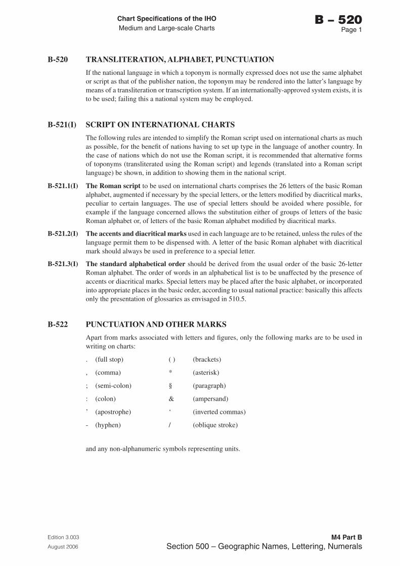
Chart Specifications of the IhoMedium and Large-scale Charts
Edition 3.003
August 2006
M4 Part BSection 500 – Geographic Names, Lettering, Numerals
b – 520Page 1
B-520 TRANSLITERATION, ALPHABET, PUNCTUATION
If the national language in which a toponym is normally expressed does not use the same alphabet or script as that of the publisher nation, the toponym may be rendered into the latter’s language by means of a transliteration or transcription system. If an internationally-approved system exists, it is to be used; failing this a national system may be employed.
B-521(I) SCRIPT ON INTERNATIONAL CHARTS
The following rules are intended to simplify the Roman script used on international charts as much as possible, for the benefit of nations having to set up type in the language of another country. In the case of nations which do not use the Roman script, it is recommended that alternative forms of toponyms (transliterated using the Roman script) and legends (translated into a Roman script language) be shown, in addition to showing them in the national script.
B-521.1(I) The Roman script to be used on international charts comprises the 26 letters of the basic Roman alphabet, augmented if necessary by the special letters, or the letters modified by diacritical marks, peculiar to certain languages. The use of special letters should be avoided where possible, for example if the language concerned allows the substitution either of groups of letters of the basic Roman alphabet or, of letters of the basic Roman alphabet modified by diacritical marks.
B-521.2(I) The accents and diacritical marks used in each language are to be retained, unless the rules of the language permit them to be dispensed with. A letter of the basic Roman alphabet with diacritical mark should always be used in preference to a special letter.
B-521.3(I) The standard alphabetical order should be derived from the usual order of the basic 26-letter Roman alphabet. The order of words in an alphabetical list is to be unaffected by the presence of accents or diacritical marks. Special letters may be placed after the basic alphabet, or incorporated into appropriate places in the basic order, according to usual national practice: basically this affects only the presentation of glossaries as envisaged in 510.5.
B-522 PUNCTUATION AND OTHER MARKS
Apart from marks associated with letters and figures, only the following marks are to be used in writing on charts:
. (full stop) ( ) (brackets)
, (comma) * (asterisk)
; (semi-colon) § (paragraph)
: (colon) & (ampersand)
’ (apostrophe) ‘ (inverted commas)
- (hyphen) / (oblique stroke)
and any non-alphanumeric symbols representing units.

Page intentionally left blank
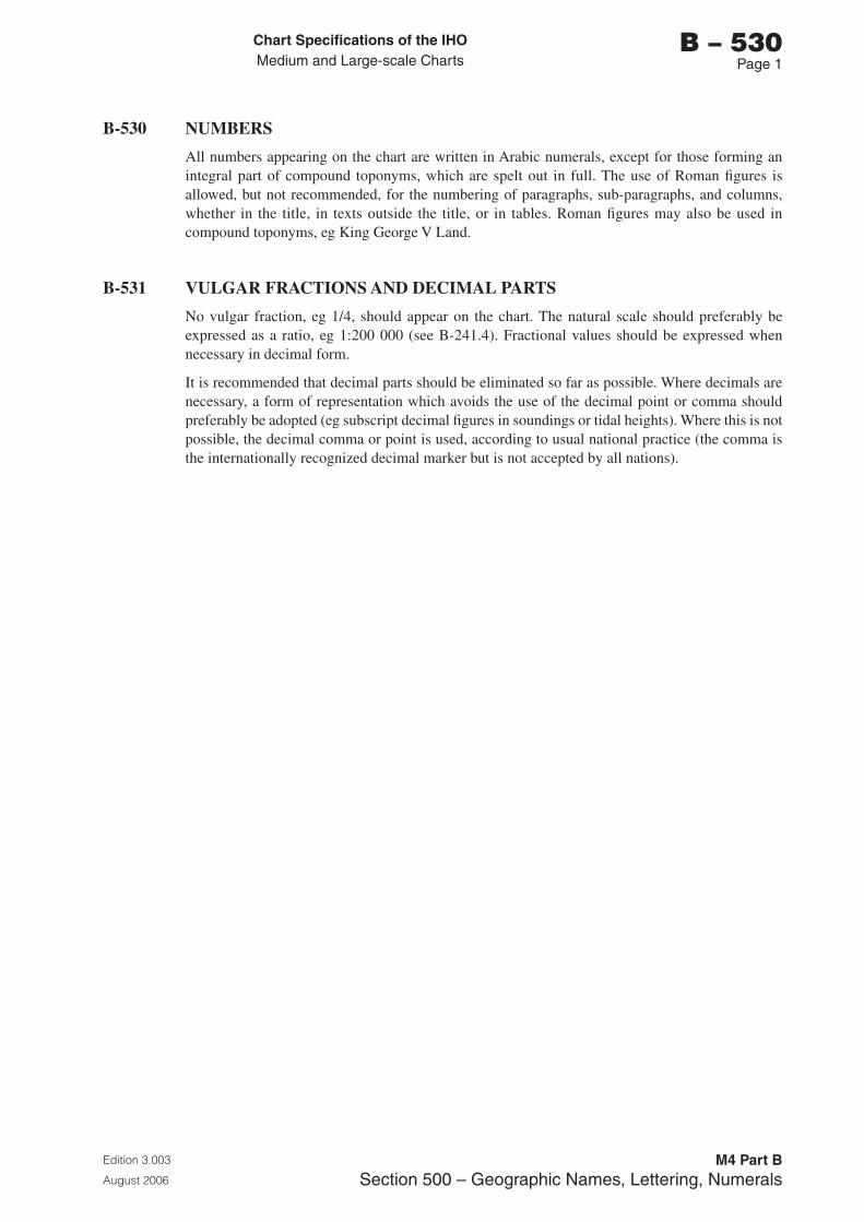
Chart Specifications of the IhoMedium and Large-scale Charts
Edition 3.003
August 2006
M4 Part BSection 500 – Geographic Names, Lettering, Numerals
b – 530Page 1
B-530 NUMBERS
All numbers appearing on the chart are written in Arabic numerals, except for those forming an integral part of compound toponyms, which are spelt out in full. The use of Roman figures is allowed, but not recommended, for the numbering of paragraphs, sub-paragraphs, and columns, whether in the title, in texts outside the title, or in tables. Roman figures may also be used in compound toponyms, eg King George V Land.
B-531 VULGAR FRACTIONS AND DECIMAL PARTS
No vulgar fraction, eg 1/4, should appear on the chart. The natural scale should preferably be expressed as a ratio, eg 1:200 000 (see B-241.4). Fractional values should be expressed when necessary in decimal form.
It is recommended that decimal parts should be eliminated so far as possible. Where decimals are necessary, a form of representation which avoids the use of the decimal point or comma should preferably be adopted (eg subscript decimal figures in soundings or tidal heights). Where this is not possible, the decimal comma or point is used, according to usual national practice (the comma is the internationally recognized decimal marker but is not accepted by all nations).

Page intentionally left blank
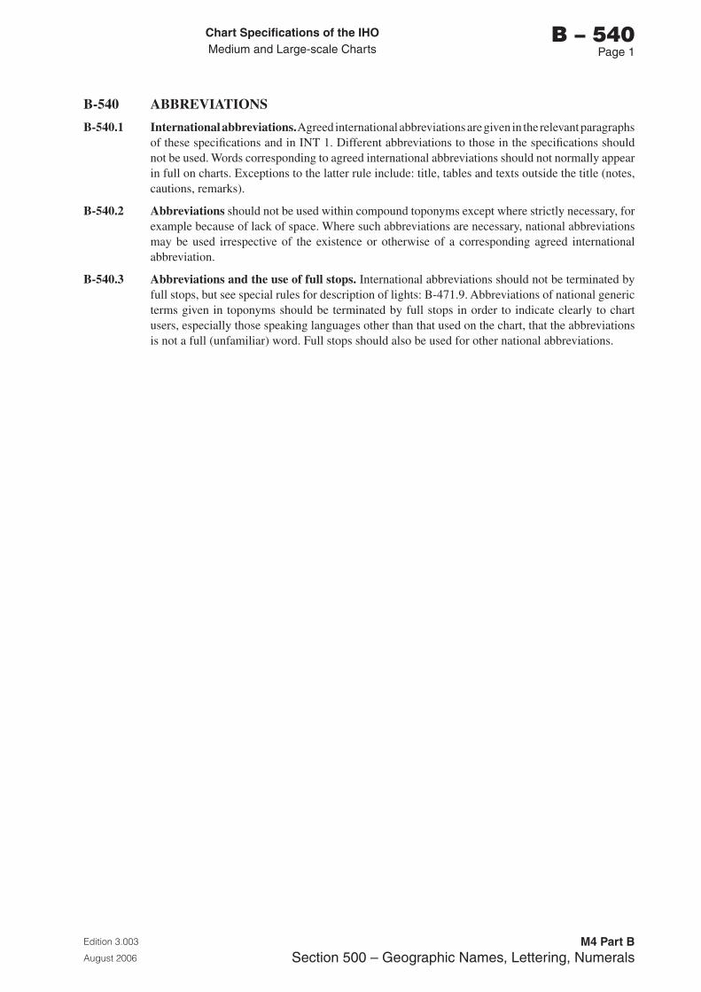
Chart Specifications of the IhoMedium and Large-scale Charts
Edition 3.003
August 2006
M4 Part BSection 500 – Geographic Names, Lettering, Numerals
b – 540Page 1
B-540 ABBREVIATIONS
B-540.1 International abbreviations. Agreed international abbreviations are given in the relevant paragraphs of these specifications and in INT 1. Different abbreviations to those in the specifications should not be used. Words corresponding to agreed international abbreviations should not normally appear in full on charts. Exceptions to the latter rule include: title, tables and texts outside the title (notes, cautions, remarks).
B-540.2 Abbreviations should not be used within compound toponyms except where strictly necessary, for example because of lack of space. Where such abbreviations are necessary, national abbreviations may be used irrespective of the existence or otherwise of a corresponding agreed international abbreviation.
B-540.3 Abbreviations and the use of full stops. International abbreviations should not be terminated by full stops, but see special rules for description of lights: B-471.9. Abbreviations of national generic terms given in toponyms should be terminated by full stops in order to indicate clearly to chart users, especially those speaking languages other than that used on the chart, that the abbreviations is not a full (unfamiliar) word. Full stops should also be used for other national abbreviations.

Page intentionally left blank
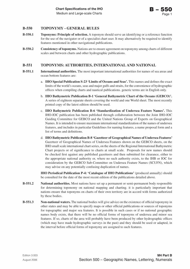
Chart Specifications of the IhoMedium and Large-scale Charts
Edition 3.003
August 2006
M4 Part BSection 500 – Geographic Names, Lettering, Numerals
b – 550Page 1
B-550 TOPONYMY - GENERAL RULES
B-550.1 Toponyms: Principle of selection. A toponym should serve an identifying or a reference function for the use of the navigator or of a specialist chart user. It may alternatively be required to identify features mentioned in other navigational publications.
B-550.2 Consistency of toponyms. Nations are to ensure agreement on toponymy among charts of different scales and between charts and other hydrographic publications.
B-551 TOPONYMS: AUTHORITIES, INTERNATIONAL AND NATIONAL
B-551.1 International authorities. The most important international authorities for names of sea areas and ocean bottom features are:
a. IHO Special Publication S-23 ‘Limits of Oceans and Seas’. This names and defines the exact limits of the world’s oceans, seas and major gulfs and straits, for the convenience of hydrographic offices when compiling charts and nautical publications. generic terms are in English only.
b. IHO Bathymetric Publication B-1 ‘General Bathymetric Chart of the Oceans (GEBCO)’. A series of eighteen separate sheets covering the world and one World sheet. The most recently printed copy of the latest edition should be used.
c. IHO Bathymetric Publication B-6 ‘Standardization of Undersea Feature Names’. This IHO-IOC publication has been published through collaboration between the Joint IHO-IOC Guiding Committee for GEBCO and the United Nations Group of Experts on Geographical Names. It is intended to ensure maximum international standardization of the names of undersea features, and includes in particular Guidelines for naming features, a name proposal form and a list of terms and definitions.
d. IHO Bathymetric Publication B-8 ‘Gazetteer of Geographical Names of Undersea Features’ Gazetteer of Geographical Names of Undersea Features shown on the GEBCO sheets, on the IHO small scale international chart series, on the sheets of the Regional International Bathymetric Chart projects or of significance to charts at small scale. Proposals for new names should be checked first against any published gazetteers and then submitted for clearance, either to the appropriate national authority or, where no such authority exists, to the IHB or IOC for consideration by the GEBCO Sub-Committee on Undersea Feature Names (SCUFN), which may advise on any potentially confusing duplication of names.
IHO Periodical Publication P-4: ‘Catalogue of IHO Publications’ (produced annually) should be consulted for the date of the most recent edition of the publications detailed above.
B-551.2 National authorities. Most nations have set up a permanent or semi-permanent body responsible for determining toponomy on national mapping and charting. it is particularly important that nations ensure that toponyms on charts of their own territory are in accord with forms authorized by these bodies.
B-551.3 Non-national waters. The national bodies will give advice on the existence of official toponymy in other states and may be able to specify maps or other official publications or sources of toponyms for topographic and major sea features. It is possible in such cases or if no national geographic names body exists, that there will be no official forms of toponyms of undersea and minor sea features. If so, charts of the area will probably have been produced by other hydrographic offices (which may have made hydrographic surveys in the past) and they should be used or adapted, in the interval before official forms of toponymy are assigned to such features.
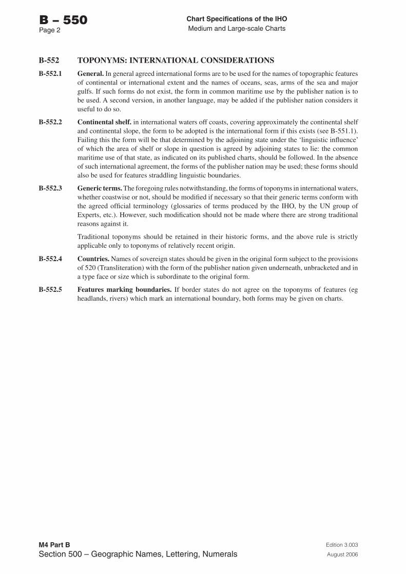
Chart Specifications of the IhoMedium and Large-scale Charts
Edition 3.003
August 2006
M4 Part BSection 500 – Geographic Names, Lettering, Numerals
b – 550Page 2
B-552 TOPONYMS: INTERNATIONAL CONSIDERATIONS
B-552.1 General. In general agreed international forms are to be used for the names of topographic features of continental or international extent and the names of oceans, seas, arms of the sea and major gulfs. If such forms do not exist, the form in common maritime use by the publisher nation is to be used. A second version, in another language, may be added if the publisher nation considers it useful to do so.
B-552.2 Continental shelf. in international waters off coasts, covering approximately the continental shelf and continental slope, the form to be adopted is the international form if this exists (see B-551.1). Failing this the form will be that determined by the adjoining state under the ‘linguistic influence’ of which the area of shelf or slope in question is agreed by adjoining states to lie: the common maritime use of that state, as indicated on its published charts, should be followed. In the absence of such international agreement, the forms of the publisher nation may be used; these forms should also be used for features straddling linguistic boundaries.
B-552.3 Generic terms. The foregoing rules notwithstanding, the forms of toponyms in international waters, whether coastwise or not, should be modified if necessary so that their generic terms conform with the agreed official terminology (glossaries of terms produced by the IHO, by the UN group of Experts, etc.). However, such modification should not be made where there are strong traditional reasons against it.
Traditional toponyms should be retained in their historic forms, and the above rule is strictly applicable only to toponyms of relatively recent origin.
B-552.4 Countries. Names of sovereign states should be given in the original form subject to the provisions of 520 (Transliteration) with the form of the publisher nation given underneath, unbracketed and in a type face or size which is subordinate to the original form.
B-552.5 Features marking boundaries. If border states do not agree on the toponyms of features (eg headlands, rivers) which mark an international boundary, both forms may be given on charts.
Chart Specifications of the IhoMedium and Large-scale Charts
Edition 3.003
August 2006
M4 Part BSection 500 – Geographic Names, Lettering, Numerals
b – 560Page 1
B-560 STYLES OF TYPE
B-561 EXPLANATION OF APPROACH USED
The choice of type styles or designs is an integral aspect of nautical chart standardization and the creation of a homogeneous set of international charts. To achieve full standardization in this respect, a detailed list of instructions, covering every alphanumeric item shown on charts, would be needed. However, there is a very great diversity of national practices in respect of the choice and uses of type styles, and complete standardization would mean very substantial changes for most, if not all, nations, including the loss of most of the national characteristics of their charts. To be fully effective, it would also require nations using non-Roman alphabets to change to the latter. It would be contrary to the overall principles so far followed in the IHO specification to try to enforce changes of such magnitude to national charting. It is also true that most chart users take less notice of differences in type styles than, for instance, the use of different symbols for the same object. It therefore seems, for all these reasons, that it would be unrealistic to expect complete agreement over styles of type, at least in the foreseeable future.
A certain degree of standardization is however required:
a. to achieve a reasonable level of compatibility between the charts of different nations, so that users moving from one to another will perceive no practical difference.
b. so that international charts, or charts subject to bilateral agreements, can be adopted by nations with a minimum of difficulty: it should be made fairly easy for printers to match type styles, well enough for chart users not to be disturbed by the differences.
B-562 GENERAL PRINCIPLES
Except for the title lines and explanatory textual notes, the use of differing type styles on charts should satisfy the following general principles:
a. A distinction should be made between geographic names referring to land features (including islets, above-water rocks, fixed marks, etc) and those referring to water features (whether on land or part of the sea).
b. A distinction should be made between those legends, words and abbreviations which relate to general or ‘background’ geographical information and those which relate to essentially navigational information. The latter should be shown prominently while the former should be subordinated.
B-562.1 Distinction between land names and water names
Names referring to land features should be in an upright (Roman) style and those relating to water features in a style sloping to the right (italic). For features, such as locks and pontoons, which are difficult to define as either ‘land’ or ‘sea’, see specifications for the appropriate feature (in particular, B-326 Docks and B-450 Navigational Aids).
B-562.2 Distinction between general geographic and navigational words and legends should be achieved by making use of either different weights, widths and sizes within a single family of type (all based on the same design), or of different families, eg serif and sans-serif styles. See B-563.4.
Chart Specifications of the IhoMedium and Large-scale Charts
Edition 3.003
August 2006
M4 Part BSection 500 – Geographic Names, Lettering, Numerals
b – 560Page 2
B-562.3 Prominence of navigational information. Type weights and sizes shall be selected according to the relative importance of the various names and legends to be shown, whether general geographic or navigational. However it is particularly important to ensure that all navigational information is especially prominent. Certain classes of features should, irrespective of their relative importance, be shown consistenly in a particular size and weight of lettering. This applies particularly to such features as light descriptions.
B-563 CHOICE OF TYPE STYLES
It is recommended that:
a. the choice of type style be restricted to one or two families of type.
b. if a single type style is used it be a sans-serif family (see B-563.1), and if two type styles are used they comprise one sans-serif and one serif family (see B-563.3).
c. the range of type styles from which the selections are made be limited to those of compatible design.
A number of long-established hydrographic offices have recently changed to using a single sans-serif family of type. New hydrographic offices and others considering a revision of their present styles are advised to study carefully the advantages of this policy.
B-563.1 Sans-serif styles. It is recommended that the sans-serif type style be selected from the following families which are listed in order of preference:
a. Univers
b. Designs with very similar characteristics to Univers, eg Helvetica and Akzidenz-Grotesk
c. Futura, Techno, News Gothic or Lightline Gothic.
B-563.2 Use of sans-serif styles. If a single, sans-serif style is used, navigational marks should be differentiated by the use of bold type.
B-563.3 Serif styles. It is recommended that any serified type style used be selected from the following families which are listed in order of preference:
a. Times
b. Century
B-563.4 Use of serified styles. It is recommended that the serif type style be used for more important geographical names; and that navigational legends, words and abbreviations, be shown in sans-serif style. However the names of geographical features which constitute dangers to navigation, such as shoals and banks, or aids to navigation, such as mountain peaks or conspicuous objects, should also be shown in sans-serif style.
B-563.5 Title. The choice of type style used for the title, explanatory and cautionary notes is left to national discretion.
B-564 COLOUR
Notes, legends, words, and abbreviations should be printed in magenta if they refer to items shown in magenta. See relevant paragraphs throughout the specification for guidance on the use of magenta.
Chart Specifications of the IhoSmall-scale INT Charts
Edition 3.003
August 2006M4 Part C
PART C
SECTIONS 100 - 500
CHART SPECIFICATIONS OF THE IHO
SMALL – SCALE INTERNATIONAL (INT) CHARTS
(SCALES 1:2 000 000 AND SMALLER)
C

Page intentionally left blank
Chart Specifications of the IhoSmall-scale INT Charts
Edition 3.003
August 2006M4 Part C
CPage iii
CHART SPECIFICATIONS OF THE IHO SMALL – SCALE INTERNATIONAL (INT) CHARTS
(SCALES 1:2 000 000 AND SMALLER)
CONTENTS
INTRoDUCTIoN
RECORD OF UPDATES
SECTIoN 100 – gENERAL
C-101 SMALL-SCALE INTERNATIONAL (INT) CHARTSC-102 SCOPE OF THE SPECIFICATIONSC-103 CORRECTION SYSTEM FOR THE SPECIFICATIONS
SECTIoN 200 – FoRMAT
C-201 ELLIPSOID OF REFERENCE AND HORIZONTAL DATUMC-202 PROJECTIONC-203 CHART SCALEC-204 GRADUATIONC-205 GRATICULEC-206 DIMENSIONSC-207 CHART NUMBERING C-208 DATE OF PUBLICATION AND CORRECTIONSC-209 TITLE INFORMATION
C-210 CAUTIONARY AND EXPLANATORY NOTESC-211 INTERNATIONAL ABBREVIATIONSC-212 CORNER CO-ORDINATESC-213 REFERENCES TO OTHER CHARTSC-214 OTHER MARGINAL INFORMATIONC-215 COMPASS ROSESC-216 MAGNETIC VARIATIONC-217 MODIFICATIONS WITHIN THE CHART BORDER
SECTIoN 300 – ToPogRAPhy
C-301 GENERALC-302 COASTLINEC-303 HEIGHTSC-304 LAND TINT
SECTIoN 400 – hyDRogRAPhy AND NA�IgATIoNAL AIDS
C-401 LEVELS OF DETAIL CHARTEDC-402 DEPTH CONTOURS AND SHALLOW WATER TINTC-403 SOUNDINGSC-404 DANGERS TO NAVIGATIONC-405 NATURE OF THE BOTTOMC-406 ROUTEING MEASURES AND RECOMMENDED TRACKSC-407 INTERNATIONAL BOUNDARIES AND NATIONAL LIMITSC-408 SUBMARINE CABLESC-409 SUBMARINE PIPELINES, OIL- AND GAS-FIELDS

Chart Specifications of the IhoSmall-scale INT Charts
Edition 3.003
August 2006M4 Part C
CPage iv
C-410 OCEAN CURRENTSC-411 ICE LIMITSC-412 ANTARCTIC CONVERGENCE C-413 OCEANIC FEATURES - SEAMOUNTSC-414 NAVIGATIONAL AIDS
SECTIoN 500 – gEogRAPhIC NAMES
C-501 GENERALC-502 TYPE STYLES AND SIZESC-503 BATHYMETRIC FEATURES
STyLE ShEET (PoRTIoN oF INT ChART 402)
ALPhABETICAL INDEX
Chart Specifications of the IhoSmall-scale INT Charts
Edition 3.003
August 2006M4 Part C
CPage v
INTRODUCTION
Applicability of these specifications. These Specifications are applicable to all small-scale international (INT) Charts, ie those with a scale of 1:2 000 000 and smaller. Members producing or printing these international charts should also consult the ‘Regulations of the IHO for International (INT) Charts’.
This is the third edition of the ‘Chart Specifications of the IHO for Small-scale International (INT) charts (scales 1:2 000 000 and smaller)’. It is in five sections, the contents of which are:
100 GENERAL200 FORMAT300 TOPOGRAPHY400 HYDROGRAPHY AND NAVIGATIONAL AIDS500 GEOGRAPHIC NAMES
These Specifications have previously been issued as follows:
First Edition published in January 1970 as Annex 3 of the Final Report of the IHO Commission on the International Chart. This resulted from a draft prepared by the US Naval Oceanographic Office, 24 February 1969, which was revised at the second conference of the IHO Commission on the International Chart held in Monaco, 10-12 March 1969 and finalised at the third conference, held in London, 11-12 November 1969.
Re-issued in August 1981 as Appendix 1 to the Regulations of the IHO for International (INT) Charts - Specifications for Small-scale International Charts (scales 1:2 250 000 and smaller), published by the IHB, Monaco, and including amendments promulgated in IHB Circular Letters 14/71, 34/71, 11/72, 33/72, 1/73, 17/73, 9/75, 11/75 and 1/78.
Second Edition published in 2001, included editorial updating and incorporation as Part C of M-4.
An index for these Specifications, prepared by the CSC (Chart Standardization Committee) Secretariat, is given at the end of Part C. The list of items is in alphabetical order.
A style sheet for small-scale international charts is included as Appendix A.
Updating of these specifications is effected by changes announced in the IHB’s Circular Letters. See C-103.1 for details of procedures.
The Record of Corrections which follows should be updated when it is announced that changes are approved. See C-103.2.

Page intentionally left blank
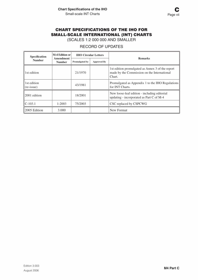
Chart Specifications of the IhoSmall-scale INT Charts
Edition 3.003
August 2006M4 Part C
CPage vii
CHART SPECIFICATIONS OF THE IHO FORSMALL-SCALE INTERNATIONAL (INT) CHARTS
(SCALES 1:2 000 000 AND SMALLER
RECORD OF UPDATES
Specification Number
M-4 Edition or Amendment
Number
IHO Circular LettersRemarks
Promulgated by Approved By
1st edition 21/19701st edition promulgated as Annex 3 of the report made by the Commission on the International Chart.
1st edition (re-issue)
43/1981Promulgated as Appendix 1 to the IHO Regulations for INT Charts.
2001 edition 18/2001New loose-leaf edition - including editorial updating - incorporated as Part C of M-4
C-103.1 1-2003 75/2003 CSC replaced by CSPCWG
2005 Edition 3.000 New Format

Page intentionally left blank
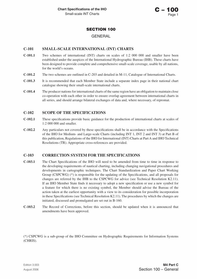
Chart Specifications of the IhoSmall-scale INT Charts
Edition 3.003
August 2006
M4 Part CSection 100 – General
C – 100Page 1
SECTION 100
GENERAL
C-101 SMALL-SCALE INTERNATIONAL (INT) CHARTS
C-101.1 Two schemes of international (INT) charts on scales of 1:2 000 000 and smaller have been established under the auspices of the International Hydrographic Bureau (IHB). These charts have been designed to provide complete and comprehensive small-scale coverage, usable by all nations, for the world’s oceans.
C-101.2 The two schemes are outlined in C-203 and detailed in M-11, Catalogue of International Charts.
C-101.3 It is recommended that each Member State include a separate index page in their national chart catalogue showing their small-scale international charts.
C-101.4 The producer nations for international charts of the same region have an obligation to maintain close co-operation with each other in order to ensure overlap agreement between international charts in all series, and should arrange bilateral exchanges of data and, where necessary, of repromat.
C-102 SCOPE OF THE SPECIFICATIONS
C-102.1 These specifications provide basic guidance for the production of international charts at scales of 1:2 000 000 and smaller.
C-102.2 Any particulars not covered by these specifications shall be in accordance with the Specifications of the IHO for Medium- and Large-scale Charts (including INT 1, INT 2 and INT 3) at Part B of this publication, Regulations of the IHO for International (INT) Charts at Part A and IHO Technical Resolutions (TR). Appropriate cross-references are provided.
C-103 CORRECTION SYSTEM FOR THE SPECIFICATIONS
C-103.1 The Chart Specifications of the IHO will need to be amended from time to time in response to the developing requirements of nautical charting, including changing navigational procedures and developments in cartographic techniques. The Chart Standardization and Paper Chart Working Group (CSPCWG) (*) is responsible for the updating of the Specifications, and all proposals for changes are referred by the IHB to the CSPCWG for advice (see Technical Resolution K2.11). If an IHO Member State finds it necessary to adopt a new specification or use a new symbol for a feature for which there is no existing symbol, the Member should advise the Bureau of the action taken at the earliest opportunity with a view to its consideration for possible incorporation in these Specifications (see Technical Resolution K2.11). The procedures by which the changes are initiated, discussed and promulgated are set out in B-160.
C-103.2 The Record of Corrections, before this section, should be updated when it is announced that amendments have been approved.
(*) CSPCWG is a sub-group of the IHO Committee on Hydrographic Requirements for Information Systems (CHRIS).

Page intentionally left blank
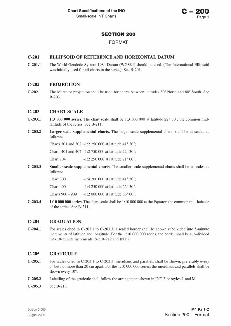
Chart Specifications of the IhoSmall-scale INT Charts
Edition 3.003
August 2006
M4 Part CSection 200 – Format
C – 200Page 1
SECTION 200
FORMAT
C-201 ELLIPSOID OF REFERENCE AND HORIZONTAL DATUM
C-201.1 The World Geodetic System 1984 Datum (WGS84) should be used. (The International Ellipsoid was initially used for all charts in the series). See B-201.
C-202 PROJECTION
C-202.1 The Mercator projection shall be used for charts between latitudes 80º North and 80º South. See B-203.
C-203 CHART SCALE
C-203.1 1:3 500 000 series. The chart scale shall be 1:3 500 000 at latitude 22° 30´, the common mid-latitude of the series. See B-211.
C-203.2 Larger-scale supplemental charts. The larger scale supplemental charts shall be at scales as follows:
Charts 301 and 302 -1:2 250 000 at latitude 41° 30´;
Charts 401 and 402 -1:2 750 000 at latitude 22° 30´;
Chart 704 -1:2 250 000 at latitude 21° 00´.
C-203.3 Smaller-scale supplemental charts. The smaller-scale supplemental charts shall be at scales as follows:
Chart 300 -1:4 200 000 at latitude 41° 30´;
Chart 400 -1:4 250 000 at latitude 22° 30´.
Charts 900 - 909 -1:2 000 000 at latitude 66° 00´.
C-203.4 1:10 000 000 series. The chart scale shall be 1:10 000 000 at the Equator, the common mid-latitude of the series. See B-211.
C-204 GRADUATION
C-204.1 For scales cited in C-203.1 to C-203.3, a scaled border shall be shown subdivided into 5-minute increments of latitude and longitude. For the 1:10 000 000 series, the border shall be sub-divided into 10-minute increments. See B-212 and INT 2.
C-205 GRATICULE
C-205.1 For scales cited in C-203.1 to C-203.3, meridians and parallels shall be shown, preferably every 5° but not more than 20 cm apart. For the 1:10 000 000 series, the meridians and parallels shall be shown every 10°.
C-205.2 Labelling of the graticule shall follow the arrangement shown in INT 2, ie styles L and M.
C-205.3 See B-213.
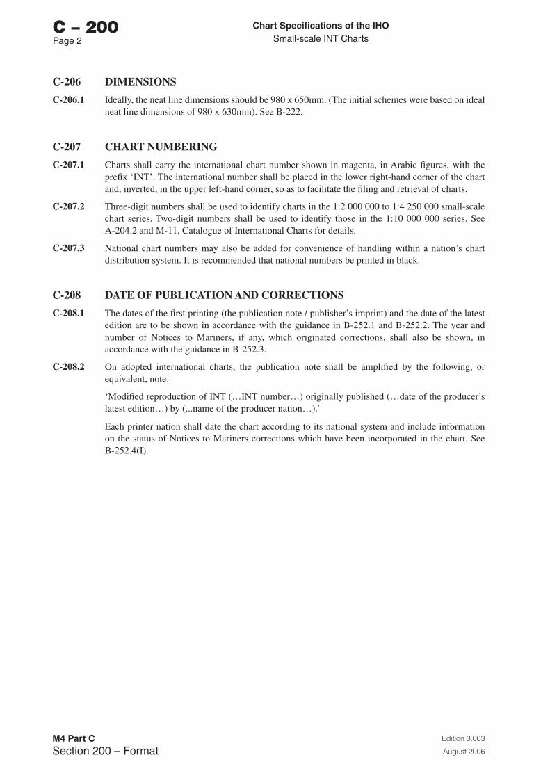
Chart Specifications of the IhoSmall-scale INT Charts
Edition 3.003
August 2006
M4 Part CSection 200 – Format
C – 200Page 2
C-206 DIMENSIONS
C-206.1 Ideally, the neat line dimensions should be 980 x 650mm. (The initial schemes were based on ideal neat line dimensions of 980 x 630mm). See B-222.
C-207 CHART NUMBERING
C-207.1 Charts shall carry the international chart number shown in magenta, in Arabic figures, with the prefix ‘INT’. The international number shall be placed in the lower right-hand corner of the chart and, inverted, in the upper left-hand corner, so as to facilitate the filing and retrieval of charts.
C-207.2 Three-digit numbers shall be used to identify charts in the 1:2 000 000 to 1:4 250 000 small-scale chart series. Two-digit numbers shall be used to identify those in the 1:10 000 000 series. See A-204.2 and M-11, Catalogue of International Charts for details.
C-207.3 National chart numbers may also be added for convenience of handling within a nation’s chart distribution system. It is recommended that national numbers be printed in black.
C-208 DATE OF PUBLICATION AND CORRECTIONS
C-208.1 The dates of the first printing (the publication note / publisher’s imprint) and the date of the latest edition are to be shown in accordance with the guidance in B-252.1 and B-252.2. The year and number of Notices to Mariners, if any, which originated corrections, shall also be shown, in accordance with the guidance in B-252.3.
C-208.2 On adopted international charts, the publication note shall be amplified by the following, or equivalent, note:
‘Modified reproduction of INT (…INT number…) originally published (…date of the producer’s latest edition…) by (...name of the producer nation…).’
Each printer nation shall date the chart according to its national system and include information on the status of Notices to Mariners corrections which have been incorporated in the chart. See B-252.4(I).
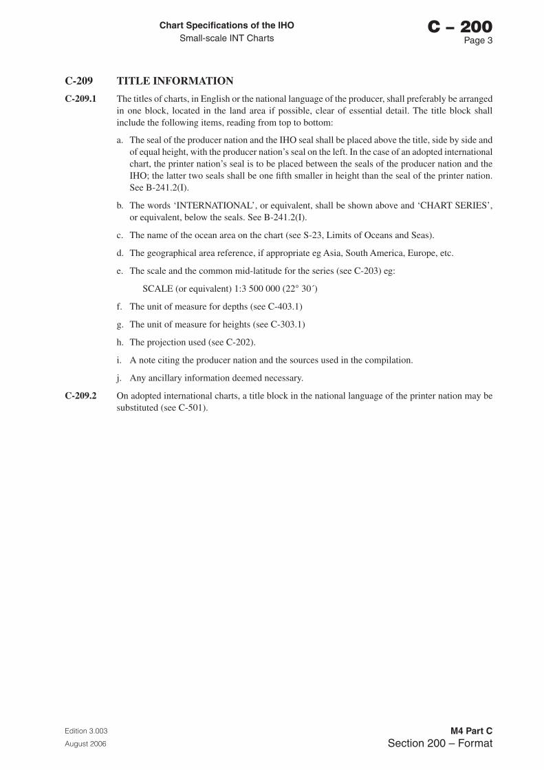
Chart Specifications of the IhoSmall-scale INT Charts
Edition 3.003
August 2006
M4 Part CSection 200 – Format
C – 200Page �
C-209 TITLE INFORMATION
C-209.1 The titles of charts, in English or the national language of the producer, shall preferably be arranged in one block, located in the land area if possible, clear of essential detail. The title block shall include the following items, reading from top to bottom:
a. The seal of the producer nation and the IHO seal shall be placed above the title, side by side and of equal height, with the producer nation’s seal on the left. In the case of an adopted international chart, the printer nation’s seal is to be placed between the seals of the producer nation and the IHO; the latter two seals shall be one fifth smaller in height than the seal of the printer nation. See B-241.2(I).
b. The words ‘INTERNATIONAL’, or equivalent, shall be shown above and ‘CHART SERIES’, or equivalent, below the seals. See B-241.2(I).
c. The name of the ocean area on the chart (see S-23, Limits of Oceans and Seas).
d. The geographical area reference, if appropriate eg Asia, South America, Europe, etc.
e. The scale and the common mid-latitude for the series (see C-203) eg:
SCALE (or equivalent) 1:3 500 000 (22° 30´)
f. The unit of measure for depths (see C-403.1)
g. The unit of measure for heights (see C-303.1)
h. The projection used (see C-202).
i. A note citing the producer nation and the sources used in the compilation.
j. Any ancillary information deemed necessary.
C-209.2 On adopted international charts, a title block in the national language of the printer nation may be substituted (see C-501).
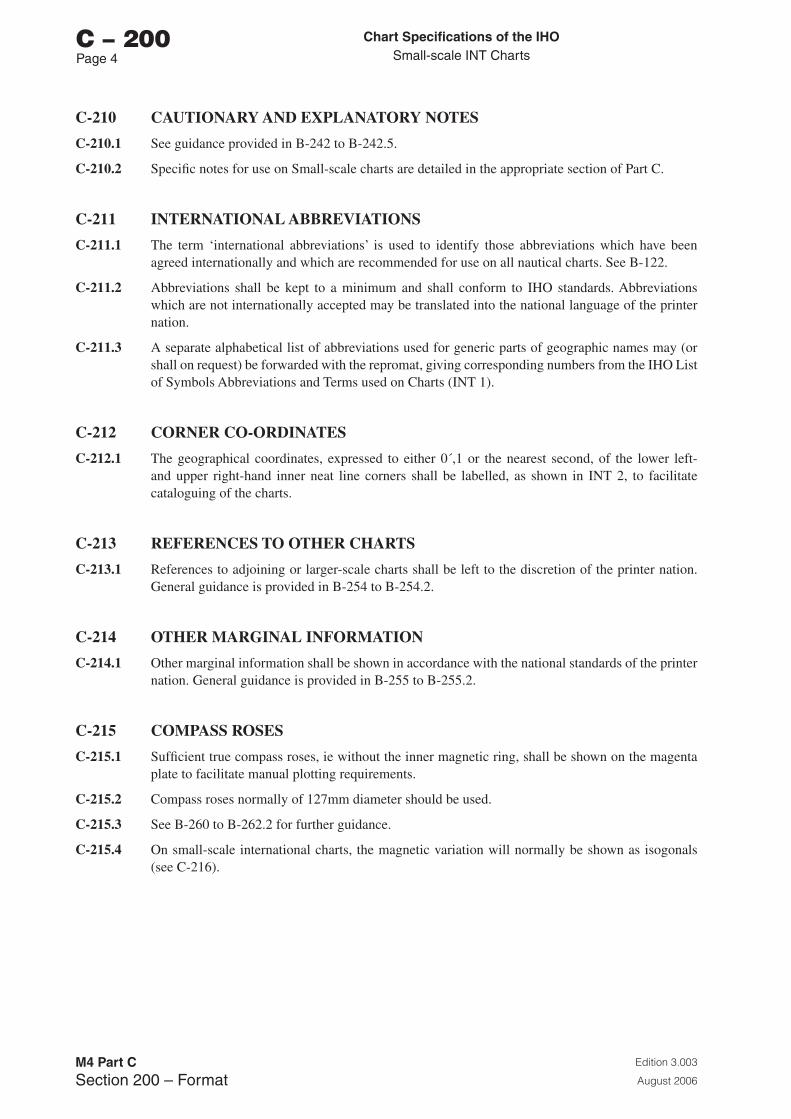
Chart Specifications of the IhoSmall-scale INT Charts
Edition 3.003
August 2006
M4 Part CSection 200 – Format
C – 200Page �
C-210 CAUTIONARY AND EXPLANATORY NOTES
C-210.1 See guidance provided in B-242 to B-242.5.
C-210.2 Specific notes for use on Small-scale charts are detailed in the appropriate section of Part C.
C-211 INTERNATIONAL ABBREVIATIONS
C-211.1 The term ‘international abbreviations’ is used to identify those abbreviations which have been agreed internationally and which are recommended for use on all nautical charts. See B-122.
C-211.2 Abbreviations shall be kept to a minimum and shall conform to IHO standards. Abbreviations which are not internationally accepted may be translated into the national language of the printer nation.
C-211.3 A separate alphabetical list of abbreviations used for generic parts of geographic names may (or shall on request) be forwarded with the repromat, giving corresponding numbers from the IHO List of Symbols Abbreviations and Terms used on Charts (INT 1).
C-212 CORNER CO-ORDINATES
C-212.1 The geographical coordinates, expressed to either 0´,1 or the nearest second, of the lower left- and upper right-hand inner neat line corners shall be labelled, as shown in INT 2, to facilitate cataloguing of the charts.
C-213 REFERENCES TO OTHER CHARTS
C-213.1 References to adjoining or larger-scale charts shall be left to the discretion of the printer nation. General guidance is provided in B-254 to B-254.2.
C-214 OTHER MARGINAL INFORMATION
C-214.1 Other marginal information shall be shown in accordance with the national standards of the printer nation. General guidance is provided in B-255 to B-255.2.
C-215 COMPASS ROSES
C-215.1 Sufficient true compass roses, ie without the inner magnetic ring, shall be shown on the magenta plate to facilitate manual plotting requirements.
C-215.2 Compass roses normally of 127mm diameter should be used.
C-215.3 See B-260 to B-262.2 for further guidance.
C-215.4 On small-scale international charts, the magnetic variation will normally be shown as isogonals (see C-216).
Chart Specifications of the IhoSmall-scale INT Charts
Edition 3.003
August 2006
M4 Part CSection 200 – Format
C – 200Page 5
C-216 MAGNETIC VARIATION
C-216.1 Magnetic variation shall be shown as isogonals on the magenta plate, in accordance with the guidance given in B-272.1. (See also B-271 for the source data, B-273 for guidance on the correction of these values, and B-274 to B-274.3 for guidance on the charting of abnormal magnetic variations).
C-217 MODIFICATIONS WITHIN THE CHART BORDER
C-217.1 On adopted international charts, except as provided for elsewhere in these Specifications, modifications in the body of the chart by printer nations should be limited to the minimum necessary to meet practical national maritime and linguistic requirements. Supplementary information, such as notes or lattices which are of specific national interest, may however be added as required. All modifications and additions made by a printer nation shall be clearly marked on a copy of the chart and furnished to the producer nation.

Page intentionally left blank
Chart Specifications of the IhoSmall-scale INT Charts
Edition 3.003
August 2006
M4 Part CSection �00 – Topography
C – 300Page 1
SECTION 300
TOPOGRAPHY
C-301 GENERAL
C-301.1 Topography shall normally not be portrayed on the 1:10 000 000 series. Heights of prominent peaks and islands may be shown on larger scales.
C-301.2 Major cities and seaports shall be shown on all scales to facilitate the use of the charts as information documents.
C-302 COASTLINE
C-302.1 A surveyed coastline (shoreline) shall be shown as a solid black line of approximately 0,2 mm line weight.
C-302.2 A coastline inadequately surveyed shall be shown as a dashed line of the same weight.
C-302.3 For further guidance, see B-310 to B-310.3 and B-311.
C-303 HEIGHTS
C-303.1 Heights of points or summits shall be indicated by a dot with the height (in metres) adjacent in upright sans-serif style. Heights of small islands and rocks which have to be placed outside the features shall be written immediately adjacent to them and enclosed in brackets.
C-303.2 For guidance on the plane of reference for heights, see B-302 to B-302.3.
C-304 LAND TINT
C-304.1 Land areas should preferably be printed in continuous buff coloured land tint. For further guidance, see B-301 to B-301.1.

Page intentionally left blank
Chart Specifications of the IhoSmall-scale INT Charts
Edition 3.003
August 2006
M4 Part CSection �00 – Hydrography and Navigational Aids
C – 400Page 1
SECTION 400
HYDROGRAPHY AND NAVIGATIONAL AIDS
This section covers the essential marine features of small-scale charts, including all navigational aids, whether on land or sea.
C-401 LEVELS OF DETAIL CHARTED
C-401.1 Generalisation of detail is defined in B-401.2 as ‘the elimination of the least essential information by ‘smoothing’ line symbols, omitting the less significant depth figures, simplifying the descriptions of navigational aids, and so on, while still showing as much information as space permits.’ The primary purpose of generalisation is to avoid over-crowding charts where space is very limited. Generalisation of detail will be required on most small-scale charts. However, parts of a small-scale chart may well be the largest-scale for the area and, in these cases, it is important to ensure that nothing is omitted that is considered essential for safe navigation. The coastline and all long-range navigational aids should, wherever possible, be included on the chart.
C-401.2 Nearshore hydrography shall be generalised, and blue tint added to indicate shoal areas, in accordance with the guidance provided in B-403.1 and B-404.1. Depth contours, suitably generalised, supplemented by a limited number of selected soundings, should portray the bottom configuration.
C-401.3 A conversion table from metres to fathoms may be shown.
C-402 DEPTH CONTOURS AND SHALLOW WATER TINT
C-402.1 The 30 metre and 200 metre depth contours shall be shown. Beyond 200 metres, the 1,000 metre depth contour and every 1,000 metre depth contour thereafter shall be shown. The 30 metre depth contour may be omitted on the 1:10 000 000 series.
C-402.2 Supplementary depth contours beyond the 200 metre depth contour may be used in complex areas of seabed topography on the 1:2 000 000 to 1:4 250 000 series. These supplementary depth contours should be selected from those shown in I 30 of INT 1.
C-402.3 The depth contours shall be shown as continuous black lines of approximately 0,1mm width and labelled in accordance with B-411.3.
C-402.4 Shallow water tint.
a. On the 1:2 000 000 to 1:4 250 000 scale charts, a solid blue tint shall be shown from the coastline to the 30 metre depth contour and on isolated shoals of 30 metres or less. The 200 metre depth contour shall be emphasized by screened tints or, if not possible, by a ribbon of blue tint normally about 1mm wide on the shallower side. When appropriate, the flat blue may be used to the 200 metre contour.
b. On the 1:10 000 000 series, a solid blue tint over the area where the depth is less than 200 metres shall be used.
c. See also B-417.5 for the use of ribbon tint behind broken (or approximate) depth contours.
C-403 SOUNDINGS
C-403.1 Soundings shall be expressed in metres, rounded as necessary. For general guidance on the positioning and style of sounding figures, see B-412 and B-412.1.
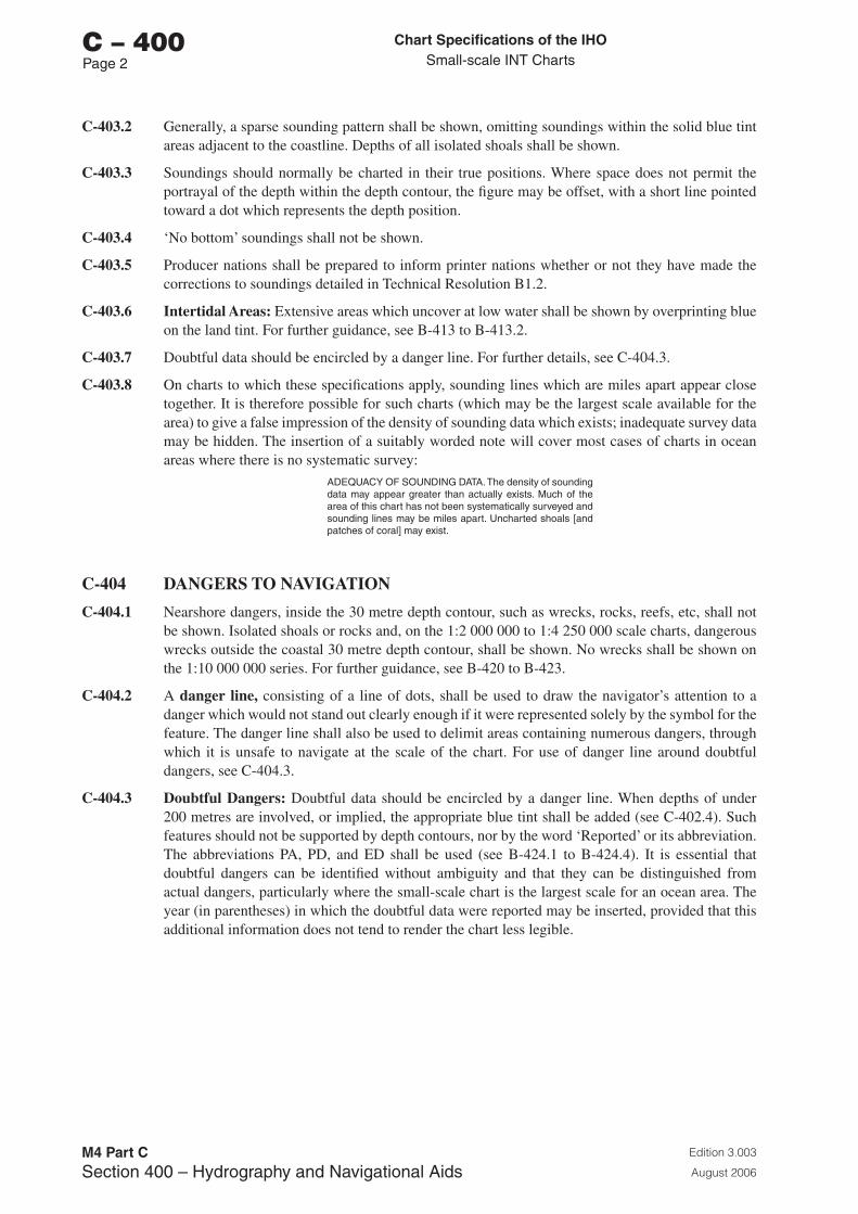
Chart Specifications of the IhoSmall-scale INT Charts
Edition 3.003
August 2006
M4 Part CSection �00 – Hydrography and Navigational Aids
C – 400Page 2
C-403.2 Generally, a sparse sounding pattern shall be shown, omitting soundings within the solid blue tint areas adjacent to the coastline. Depths of all isolated shoals shall be shown.
C-403.3 Soundings should normally be charted in their true positions. Where space does not permit the portrayal of the depth within the depth contour, the figure may be offset, with a short line pointed toward a dot which represents the depth position.
C-403.4 ‘No bottom’ soundings shall not be shown.
C-403.5 Producer nations shall be prepared to inform printer nations whether or not they have made the corrections to soundings detailed in Technical Resolution B1.2.
C-403.6 Intertidal Areas: Extensive areas which uncover at low water shall be shown by overprinting blue on the land tint. For further guidance, see B-413 to B-413.2.
C-403.7 Doubtful data should be encircled by a danger line. For further details, see C-404.3.
C-403.8 On charts to which these specifications apply, sounding lines which are miles apart appear close together. It is therefore possible for such charts (which may be the largest scale available for the area) to give a false impression of the density of sounding data which exists; inadequate survey data may be hidden. The insertion of a suitably worded note will cover most cases of charts in ocean areas where there is no systematic survey:
ADEQUACY OF SOUNDING DATA. The density of sounding data may appear greater than actually exists. Much of the area of this chart has not been systematically surveyed and sounding lines may be miles apart. Uncharted shoals [and patches of coral] may exist.
C-404 DANGERS TO NAVIGATION
C-404.1 Nearshore dangers, inside the 30 metre depth contour, such as wrecks, rocks, reefs, etc, shall not be shown. Isolated shoals or rocks and, on the 1:2 000 000 to 1:4 250 000 scale charts, dangerous wrecks outside the coastal 30 metre depth contour, shall be shown. No wrecks shall be shown on the 1:10 000 000 series. For further guidance, see B-420 to B-423.
C-404.2 A danger line, consisting of a line of dots, shall be used to draw the navigator’s attention to a danger which would not stand out clearly enough if it were represented solely by the symbol for the feature. The danger line shall also be used to delimit areas containing numerous dangers, through which it is unsafe to navigate at the scale of the chart. For use of danger line around doubtful dangers, see C-404.3.
C-404.3 Doubtful Dangers: Doubtful data should be encircled by a danger line. When depths of under 200 metres are involved, or implied, the appropriate blue tint shall be added (see C-402.4). Such features should not be supported by depth contours, nor by the word ‘Reported’ or its abbreviation. The abbreviations PA, PD, and ED shall be used (see B-424.1 to B-424.4). It is essential that doubtful dangers can be identified without ambiguity and that they can be distinguished from actual dangers, particularly where the small-scale chart is the largest scale for an ocean area. The year (in parentheses) in which the doubtful data were reported may be inserted, provided that this additional information does not tend to render the chart less legible.
Chart Specifications of the IhoSmall-scale INT Charts
Edition 3.003
August 2006
M4 Part CSection �00 – Hydrography and Navigational Aids
C – 400Page �
C-405 NATURE OF THE BOTTOM
C-405.1 The nature (quality) of the bottom may be shown within the 200 metre depth contour on the 1:2 000 000 to 1:4 250 000 scale charts.
C-406 ROUTEING MEASURES AND RECOMMENDED TRACKS
C-406.1 The term ‘Routeing’, as defined in B-432.2, is used to describe the regulation of navigation for non-hydrographic reasons, such as the prevention of collision or avoidance of pollution risks. Routes subject to regulations are generally laid down by a national or international authority. The term ‘Recommended tracks’, as defined in B-432.1, includes all channels recommended for hydrographic reasons to lead safely between shoal depths. If there is a requirement to include generalised details on small-scale charts, to assist with passage planning, the guidance provided in B-432 to B-436 should be followed.
C-407 INTERNATIONAL BOUNDARIES AND NATIONAL LIMITS
C-407.1 International boundaries on land should always be shown, at least in the vicinity of coasts. See B-440.1.
C-407.2 International maritime boundaries and other national limits, such as those defining zones in which the exploitation of natural resources is regulated, may be shown on small-scale charts. When it is necessary to show any of these limits, the guidance provided in B-440 should be followed.
C-407.3 A note indicating that international boundaries are approximate shall be made part of the title information.
C-408 SUBMARINE CABLES
C-408.1 Submarine cables are vulnerable to damage from anchoring, trawling or other seabed operations. Their inclusion on charts assists in protecting the cables (and the service they provide) from damage, in addition to warning mariners of the potential hazard presented to their vessel by the existence of submarine cables.
All oceanic submarine cables [that is, those which cross oceans] will normally be indicated, regardless of depth, on the magenta plate, using symbol L 30.1 or 31.1 as appropriate. They are not normally shown on the 1:10 000 000 series. Guidance is provided in B-443. Where the chart is the largest scale, or in areas where it is likely to be used for navigation, submarine cables should be shown if at all possible. However, depiction of the cables may be terminated before they reach the coast, or inshore water, to avoid obscuring other important detail. In these cases, a suitable legend should be inserted on the chart in the vicinity and a note included, in magenta, preferably under the main title block, along the following lines:
NOTE. Submarine cables have been omitted from part of this chart. For details of these, the larger-scale charts should be consulted.
This note may be combined with the note concerning the omission of submarine pipelines (see C-409.2).
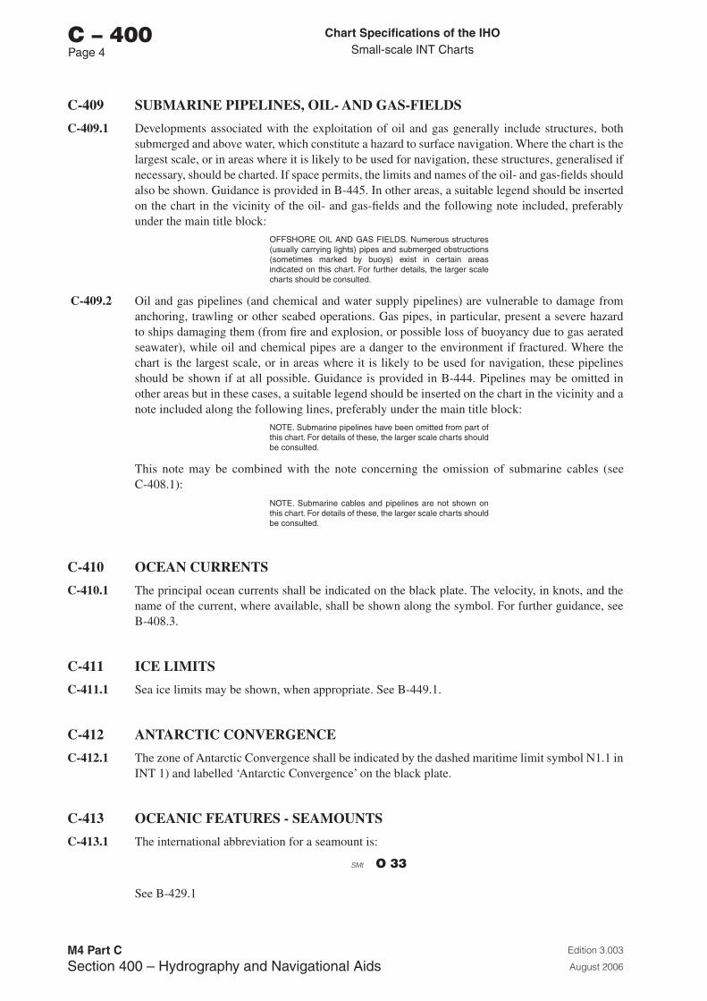
Chart Specifications of the IhoSmall-scale INT Charts
Edition 3.003
August 2006
M4 Part CSection �00 – Hydrography and Navigational Aids
C – 400Page �
C-409 SUBMARINE PIPELINES, OIL- AND GAS-FIELDS
C-409.1 Developments associated with the exploitation of oil and gas generally include structures, both submerged and above water, which constitute a hazard to surface navigation. Where the chart is the largest scale, or in areas where it is likely to be used for navigation, these structures, generalised if necessary, should be charted. If space permits, the limits and names of the oil- and gas-fields should also be shown. Guidance is provided in B-445. In other areas, a suitable legend should be inserted on the chart in the vicinity of the oil- and gas-fields and the following note included, preferably under the main title block:
OFFSHORE OIL AND GAS FIELDS. Numerous structures (usually carrying lights) pipes and submerged obstructions (sometimes marked by buoys) exist in certain areas indicated on this chart. For further details, the larger scale charts should be consulted.
C-409.2 Oil and gas pipelines (and chemical and water supply pipelines) are vulnerable to damage from anchoring, trawling or other seabed operations. Gas pipes, in particular, present a severe hazard to ships damaging them (from fire and explosion, or possible loss of buoyancy due to gas aerated seawater), while oil and chemical pipes are a danger to the environment if fractured. Where the chart is the largest scale, or in areas where it is likely to be used for navigation, these pipelines should be shown if at all possible. Guidance is provided in B-444. Pipelines may be omitted in other areas but in these cases, a suitable legend should be inserted on the chart in the vicinity and a note included along the following lines, preferably under the main title block:
NOTE. Submarine pipelines have been omitted from part of this chart. For details of these, the larger scale charts should be consulted.
This note may be combined with the note concerning the omission of submarine cables (see C-408.1):
NOTE. Submarine cables and pipelines are not shown on this chart. For details of these, the larger scale charts should be consulted.
C-410 OCEAN CURRENTS
C-410.1 The principal ocean currents shall be indicated on the black plate. The velocity, in knots, and the name of the current, where available, shall be shown along the symbol. For further guidance, see B-408.3.
C-411 ICE LIMITS
C-411.1 Sea ice limits may be shown, when appropriate. See B-449.1.
C-412 ANTARCTIC CONVERGENCE
C-412.1 The zone of Antarctic Convergence shall be indicated by the dashed maritime limit symbol N1.1 in INT 1) and labelled ‘Antarctic Convergence’ on the black plate.
C-413 OCEANIC FEATURES - SEAMOUNTS
C-413.1 The international abbreviation for a seamount is:
O 33
See B-429.1
Chart Specifications of the IhoSmall-scale INT Charts
Edition 3.003
August 2006
M4 Part CSection �00 – Hydrography and Navigational Aids
C – 400Page 5
C-414 NAVIGATIONAL AIDS
C-414.1 Significant lights (ie those within range of which navigation on the particular chart is possible) shall be shown, by symbology only - see INT 1. Names of lights are important for cross reference to the Lights List. See B-470.1.
C-414.2 Super-buoys. In general, buoys are not shown on small-scale charts. However, it may be appropriate to show super-buoys on small scale charts. See B-460.4.b.
C-414.3 Selected long-range radio-beacons (marine and aero) shall be shown. See B-481 and B-482.

Page intentionally left blank
Chart Specifications of the IhoSmall-scale INT Charts
Edition 3.003
August 2006
M4 Part CSection 500 – Geographic Names
C – 500Page 1
SECTION 500
GEOGRAPHIC NAMES
C-501 GENERAL
C-501.1 The terminology and definitions of the meanings of the terms relating to toponymy are given in B-501.
C-501.2 For all names associated with land areas, territorial waters, other sea areas and ocean bottom features, the guidance provided in Part B should be followed:
B-510 Language: General Rules, including those pertaining to the adoption of international charts by printer nations (specifically B-510.4 and B-510.5);
B-520 Transliteration, Alphabet, Punctuation, including guidance on the script to be used on international charts;
B-530 Numbers;
B-540 Abbreviations (see C-211);
B-550 Toponymy: General Rules;
B-551 Toponyms: Authorities, International and National, which includes a list of the most important authorities for names of sea areas and ocean bottom features;
B-552 Toponyms: International Considerations.
C-502 TYPE STYLES AND SIZES
C-502.1 The producer nation shall have the option of selecting type styles and sizes to be used for geographic names, notes, legends, etc, in accordance with the guidance provided in B-561, B-562, B-563 and B-564.
C-502.2 Sans-serif type (such as Univers) is preferred for both vertical and sloping (italic) lettering (see B-563).
C-503 BATHYMETRIC FEATURES
C-503.1 Selected names of bathymetric features may be shown on the black plate.

Page intentionally left blank
Chart Specifications of the IhoSmall-scale INT Charts
Edition 3.003
August 2006
M4 Part CSection 600 – Appendix A
C – APPENDIX A Page 1
PART C
APPENDIX A
STYLE SHEET
(PORTION OF INT CHART 402)
NoTE: The attached style sheet is a portion of
an international chart; it does not necessarily
represent all features and details covered by
the specifications. Also, the chart information
is not displayed at the scale indicated.

Page intentionally left blank
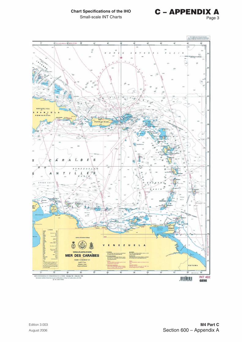
Chart Specifications of the IhoSmall-scale INT Charts
Edition 3.003
August 2006
M4 Part CSection 600 – Appendix A
C – APPENDIX A Page �

Page intentionally left blank

Chart Specifications of the IhoSmall-scale INT Charts
Edition 3.003
August 2006
M4 Part CSection 600 – Index
C – INDEX Page 1
PART C
ALPHAbETICAL INDEX

Page intentionally left blank
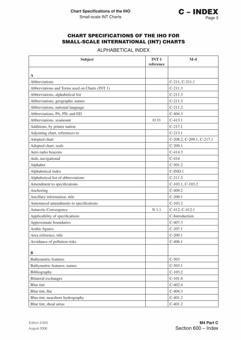
Chart Specifications of the IhoSmall-scale INT Charts
Edition 3.003
August 2006
M4 Part CSection 600 – Index
C – INDEX Page �
CHART SPECIFICATIONS OF THE IHO FOR SMALL-SCALE INTERNATIONAL (INT) CHARTS
ALPHABETICAL INDEX
Subject INT 1 reference
M-4
A
Abbreviations C-211, C-211.1
Abbreviations and Terms used on Charts (INT 1) C-211.3
Abbreviations, alphabetical list C-211.3
Abbreviations, geographic names C-211.3
Abbreviations, national language C-211.2
Abbreviations, PA, PD, and ED C-404.3
Abbreviations, seamount O 33 C-413.1
Additions, by printer nation C-217.1
Adjoining chart, references to C-213.1
Adopted chart C-208.2, C-209.1, C-217.1
Adopted chart, seals C-209.1
Aero radio beacons C-414.3
Aids, navigational C-414
Alphabet C-501.2
Alphabetical index C-IND.1
Alphabetical list of abbreviations C-211.3
Amendment to specifications C-103.1, C-103.2
Anchoring C-409.2
Ancillary information, title C-209.1
Announced amendments to specifications C-103.2
Antarctic Convergence N 1.1 C-412, C-412.1
Applicability of specifications C-Introduction
Approximate boundaries C-407.3
Arabic figures C-207.1
Area reference, title C-209.1
Avoidance of pollution risks C-406.1
B
Bathymetric features C-503
Bathymetric features, names C-503.1
Bibliography C-103.2
Bilateral exchanges C-101.4
Blue tint C-402.4
Blue tint, flat C-404.3
Blue tint, nearshore hydrography C-401.2
Blue tint, shoal areas C-401.2
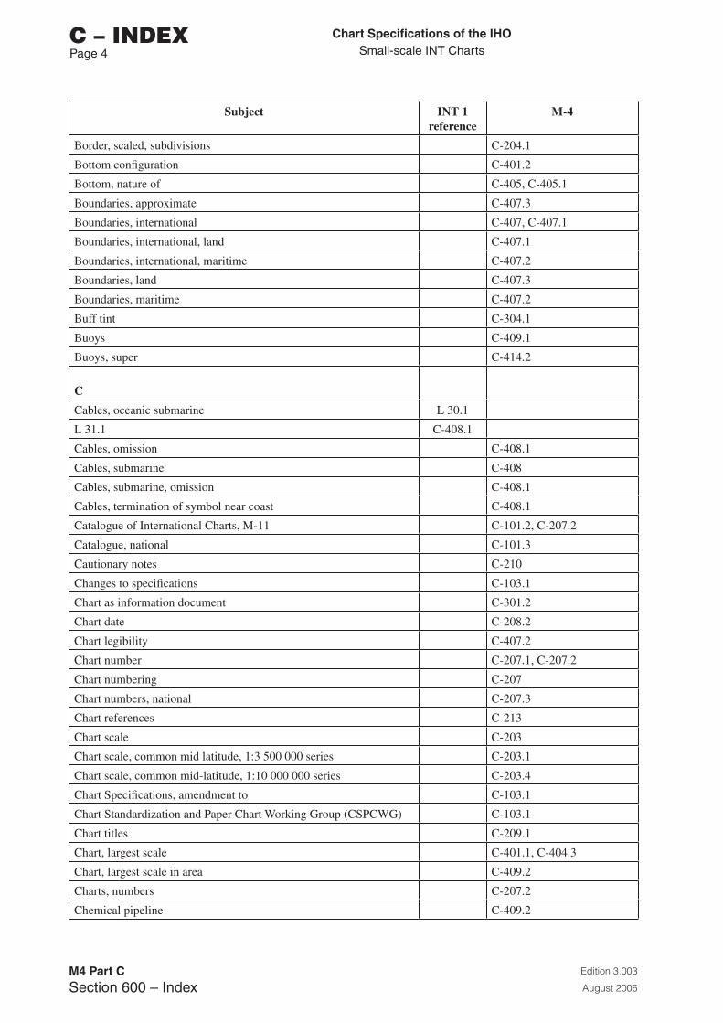
Chart Specifications of the IhoSmall-scale INT Charts
Edition 3.003
August 2006
M4 Part CSection 600 – Index
C – INDEXPage �
Subject INT 1 reference
M-4
Border, scaled, subdivisions C-204.1
Bottom configuration C-401.2
Bottom, nature of C-405, C-405.1
Boundaries, approximate C-407.3
Boundaries, international C-407, C-407.1
Boundaries, international, land C-407.1
Boundaries, international, maritime C-407.2
Boundaries, land C-407.3
Boundaries, maritime C-407.2
Buff tint C-304.1
Buoys C-409.1
Buoys, super C-414.2
C
Cables, oceanic submarine L 30.1
L 31.1 C-408.1
Cables, omission C-408.1
Cables, submarine C-408
Cables, submarine, omission C-408.1
Cables, termination of symbol near coast C-408.1
Catalogue of International Charts, M-11 C-101.2, C-207.2
Catalogue, national C-101.3
Cautionary notes C-210
Changes to specifications C-103.1
Chart as information document C-301.2
Chart date C-208.2
Chart legibility C-407.2
Chart number C-207.1, C-207.2
Chart numbering C-207
Chart numbers, national C-207.3
Chart references C-213
Chart scale C-203
Chart scale, common mid latitude, 1:3 500 000 series C-203.1
Chart scale, common mid-latitude, 1:10 000 000 series C-203.4
Chart Specifications, amendment to C-103.1
Chart Standardization and Paper Chart Working Group (CSPCWG) C-103.1
Chart titles C-209.1
Chart, largest scale C-401.1, C-404.3
Chart, largest scale in area C-409.2
Charts, numbers C-207.2
Chemical pipeline C-409.2
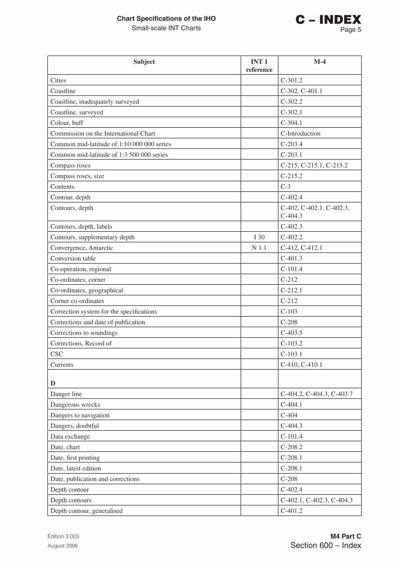
Chart Specifications of the IhoSmall-scale INT Charts
Edition 3.003
August 2006
M4 Part CSection 600 – Index
C – INDEX Page 5
Subject INT 1 reference
M-4
Cities C-301.2
Coastline C-302, C-401.1
Coastline, inadequately surveyed C-302.2
Coastline, surveyed C-302.1
Colour, buff C-304.1
Commission on the International Chart C-Introduction
Common mid-latitude of 1:10 000 000 series C-203.4
Common mid-latitude of 1:3 500 000 series C-203.1
Compass roses C-215, C-215.1, C-215.2
Compass roses, size C-215.2
Contents C-3
Contour, depth C-402.4
Contours, depth C-402, C-402.1, C-402.3, C-404.3
Contours, depth, labels C-402.3
Contours, supplementary depth I 30 C-402.2
Convergence, Antarctic N 1.1 C-412, C-412.1
Conversion table C-401.3
Co-operation, regional C-101.4
Co-ordinates, corner C-212
Co-ordinates, geographical C-212.1
Corner co-ordinates C-212
Correction system for the specifications C-103
Corrections and date of publication C-208
Corrections to soundings C-403.5
Corrections, Record of C-103.2
CSC C-103.1
Currents C-410, C-410.1
D
Danger line C-404.2, C-404.3, C-403.7
Dangerous wrecks C-404.1
Dangers to navigation C-404
Dangers, doubtful C-404.3
Data exchange C-101.4
Date, chart C-208.2
Date, first printing C-208.1
Date, latest edition C-208.1
Date, publication and corrections C-208
Depth contour C-402.4
Depth contours C-402.1, C-402.3, C-404.3
Depth contour, generalised C-401.2
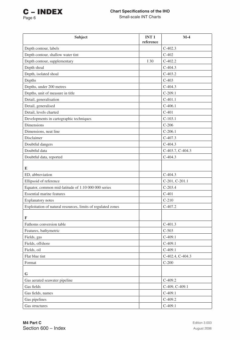
Chart Specifications of the IhoSmall-scale INT Charts
Edition 3.003
August 2006
M4 Part CSection 600 – Index
C – INDEXPage 6
Subject INT 1 reference
M-4
Depth contour, labels C-402.3
Depth contour, shallow water tint C-402
Depth contour, supplementary I 30 C-402.2
Depth shoal C-404.3
Depth, isolated shoal C-403.2
Depths C-403
Depths, under 200 metres C-404.3
Depths, unit of measure in title C-209.1
Detail, generalisation C-401.1
Detail, generalised C-406.1
Detail, levels charted C-401
Developments in cartographic techniques C-103.1
Dimensions C-206
Dimensions, neat line C-206.1
Disclaimer C-407.3
Doubtful dangers C-404.3
Doubtful data C-403.7, C-404.3
Doubtful data, reported C-404.3
E
ED, abbreviation C-404.3
Ellipsoid of reference C-201, C-201.1
Equator, common mid-latitude of 1:10 000 000 series C-203.4
Essential marine features C-401
Explanatory notes C-210
Exploitation of natural resources, limits of regulated zones C-407.2
F
Fathoms conversion table C-401.3
Features, bathymetric C-503
Fields, gas C-409.1
Fields, offshore C-409.1
Fields, oil C-409.1
Flat blue tint C-402.4, C-404.3
Format C-200
G
Gas aerated seawater pipeline C-409.2
Gas fields C-409, C-409.1
Gas fields, names C-409.1
Gas pipelines C-409.2
Gas structures C-409.1
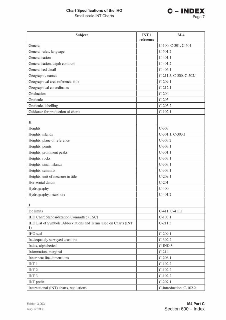
Chart Specifications of the IhoSmall-scale INT Charts
Edition 3.003
August 2006
M4 Part CSection 600 – Index
C – INDEX Page �
Subject INT 1 reference
M-4
General C-100, C-301, C-501
General rules, language C-501.2
Generalisation C-401.1
Generalisation, depth contours C-401.2
Generalised detail C-406.1
Geographic names C-211.3, C-500, C-502.1
Geographical area reference, title C-209.1
Geographical co-ordinates C-212.1
Graduation C-204
Graticule C-205
Graticule, labelling C-205.2
Guidance for production of charts C-102.1
H
Heights C-303
Heights, islands C-301.1, C-303.1
Heights, plane of reference C-303.2
Heights, points C-303.1
Heights, prominent peaks C-301.1
Heights, rocks C-303.1
Heights, small islands C-303.1
Heights, summits C-303.1
Heights, unit of measure in title C-209.1
Horizontal datum C-201
Hydrography C-400
Hydrography, nearshore C-401.2
I
Ice limits C-411, C-411.1
IHO Chart Standardization Committee (CSC) C-103.1
IHO List of Symbols, Abbreviations and Terms used on Charts (INT 1)
C-211.3
IHO seal C-209.1
Inadequately surveyed coastline C-302.2
Index, alphabetical C-IND.3
Information, marginal C-214
Inner neat line dimensions C-206.1
INT 1 C-102.2
INT 2 C-102.2
INT 3 C-102.2
INT prefix C-207.1
International (INT) charts, regulations C-Introduction, C-102.2
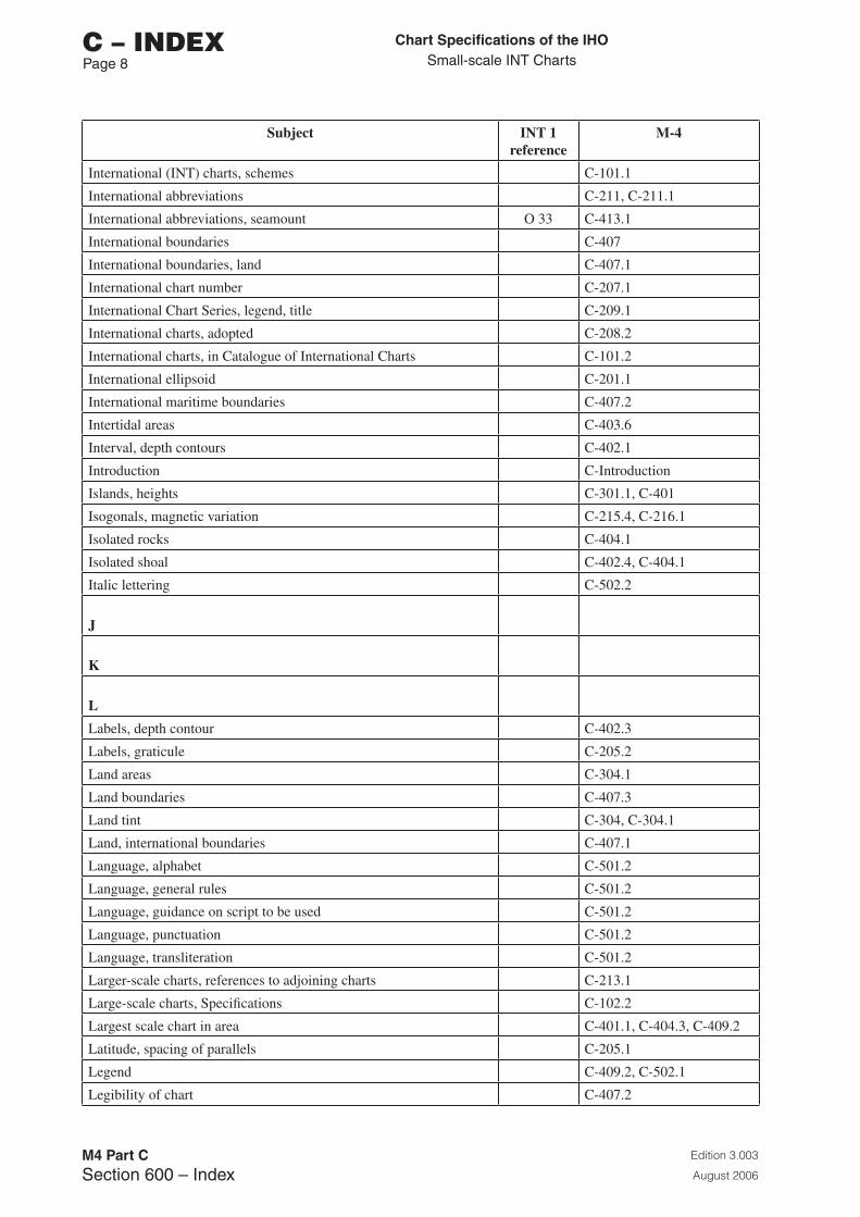
Chart Specifications of the IhoSmall-scale INT Charts
Edition 3.003
August 2006
M4 Part CSection 600 – Index
C – INDEXPage �
Subject INT 1 reference
M-4
International (INT) charts, schemes C-101.1
International abbreviations C-211, C-211.1
International abbreviations, seamount O 33 C-413.1
International boundaries C-407
International boundaries, land C-407.1
International chart number C-207.1
International Chart Series, legend, title C-209.1
International charts, adopted C-208.2
International charts, in Catalogue of International Charts C-101.2
International ellipsoid C-201.1
International maritime boundaries C-407.2
Intertidal areas C-403.6
Interval, depth contours C-402.1
Introduction C-Introduction
Islands, heights C-301.1, C-401
Isogonals, magnetic variation C-215.4, C-216.1
Isolated rocks C-404.1
Isolated shoal C-402.4, C-404.1
Italic lettering C-502.2
J
K
L
Labels, depth contour C-402.3
Labels, graticule C-205.2
Land areas C-304.1
Land boundaries C-407.3
Land tint C-304, C-304.1
Land, international boundaries C-407.1
Language, alphabet C-501.2
Language, general rules C-501.2
Language, guidance on script to be used C-501.2
Language, punctuation C-501.2
Language, transliteration C-501.2
Larger-scale charts, references to adjoining charts C-213.1
Large-scale charts, Specifications C-102.2
Largest scale chart in area C-401.1, C-404.3, C-409.2
Latitude, spacing of parallels C-205.1
Legend C-409.2, C-502.1
Legibility of chart C-407.2
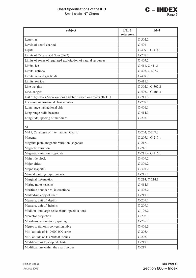
Chart Specifications of the IhoSmall-scale INT Charts
Edition 3.003
August 2006
M4 Part CSection 600 – Index
C – INDEX Page �
Subject INT 1 reference
M-4
Lettering C-502.2
Levels of detail charted C-401
Lights C-409.1, C-414.1
Limits of Oceans and Seas (S-23) C-209.1
Limits of zones of regulated exploitation of natural resources C-407.2
Limits, ice C-411, C-411.1
Limits, national C-407, C-407.2
Limits, oil and gas fields C-409.1
Limits, sea ice C-411.1
Line weights C-302.1, C-302.2
Line, danger C-403.7, C-404.3
List of Symbols Abbreviations and Terms used on Charts (INT 1) C-211.3
Location, international chart number C-207.1
Long range navigational aids C-401.1
Long range radio beacons C-414.3
Longitude, spacing of meridians C-205.1
M
M-11, Catalogue of International Charts C-203, C-207.2
Magenta C-207.1, C-215.1
Magenta plate, magnetic variation isogonals C-216.1
Magnetic variation C-216
Magnetic variation isogonals C-215.4, C-216.1
Main title block C-409.2
Major cities C-301.2
Major seaports C-301.2
Manual plotting requirements C-215.1
Marginal information C-214, C-214.1
Marine radio beacons C-414.3
Maritime boundaries, international C-407.2
Marked-up copy of chart C-217.1
Measure, unit of, depths C-209.1
Measure, unit of, heights C-209.1
Medium- and large-scale charts, specifications C-102.2
Mercator projection C-202.1
Meridians of longitude, spacing C-205.1
Metres to fathoms conversion table C-401.3
Mid-latitude of 1:10 000 000 series C-203.4
Mid-latitude of 1:3 500 000 series C-203.1
Modifications to adopted charts C-217.1
Modifications within the chart border C-217
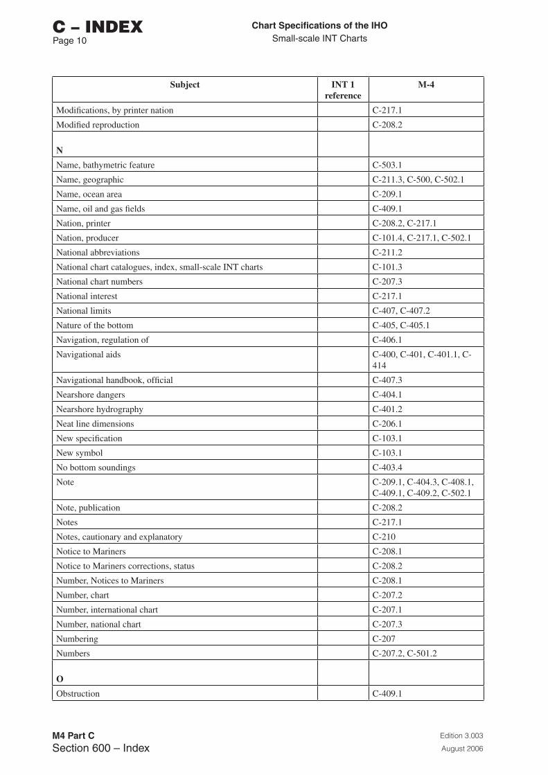
Chart Specifications of the IhoSmall-scale INT Charts
Edition 3.003
August 2006
M4 Part CSection 600 – Index
C – INDEXPage 10
Subject INT 1 reference
M-4
Modifications, by printer nation C-217.1
Modified reproduction C-208.2
N
Name, bathymetric feature C-503.1
Name, geographic C-211.3, C-500, C-502.1
Name, ocean area C-209.1
Name, oil and gas fields C-409.1
Nation, printer C-208.2, C-217.1
Nation, producer C-101.4, C-217.1, C-502.1
National abbreviations C-211.2
National chart catalogues, index, small-scale INT charts C-101.3
National chart numbers C-207.3
National interest C-217.1
National limits C-407, C-407.2
Nature of the bottom C-405, C-405.1
Navigation, regulation of C-406.1
Navigational aids C-400, C-401, C-401.1, C-414
Navigational handbook, official C-407.3
Nearshore dangers C-404.1
Nearshore hydrography C-401.2
Neat line dimensions C-206.1
New specification C-103.1
New symbol C-103.1
No bottom soundings C-403.4
Note C-209.1, C-404.3, C-408.1, C-409.1, C-409.2, C-502.1
Note, publication C-208.2
Notes C-217.1
Notes, cautionary and explanatory C-210
Notice to Mariners C-208.1
Notice to Mariners corrections, status C-208.2
Number, Notices to Mariners C-208.1
Number, chart C-207.2
Number, international chart C-207.1
Number, national chart C-207.3
Numbering C-207
Numbers C-207.2, C-501.2
O
Obstruction C-409.1
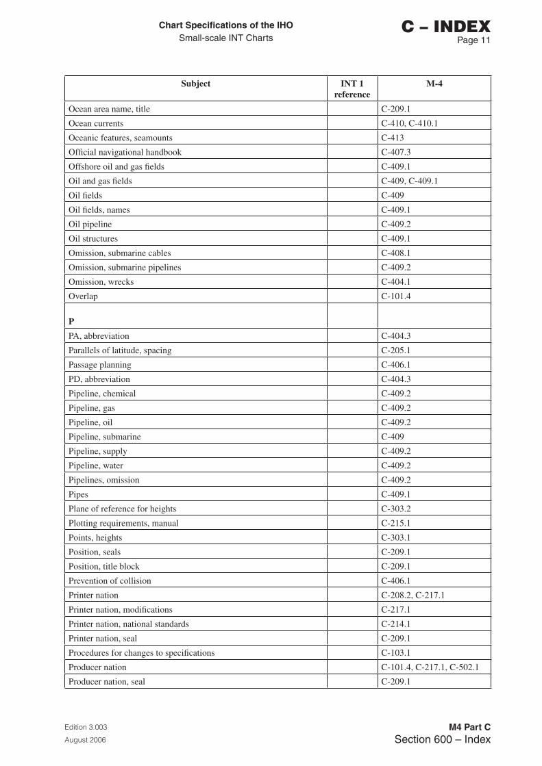
Chart Specifications of the IhoSmall-scale INT Charts
Edition 3.003
August 2006
M4 Part CSection 600 – Index
C – INDEX Page 11
Subject INT 1 reference
M-4
Ocean area name, title C-209.1
Ocean currents C-410, C-410.1
Oceanic features, seamounts C-413
Official navigational handbook C-407.3
Offshore oil and gas fields C-409.1
Oil and gas fields C-409, C-409.1
Oil fields C-409
Oil fields, names C-409.1
Oil pipeline C-409.2
Oil structures C-409.1
Omission, submarine cables C-408.1
Omission, submarine pipelines C-409.2
Omission, wrecks C-404.1
Overlap C-101.4
P
PA, abbreviation C-404.3
Parallels of latitude, spacing C-205.1
Passage planning C-406.1
PD, abbreviation C-404.3
Pipeline, chemical C-409.2
Pipeline, gas C-409.2
Pipeline, oil C-409.2
Pipeline, submarine C-409
Pipeline, supply C-409.2
Pipeline, water C-409.2
Pipelines, omission C-409.2
Pipes C-409.1
Plane of reference for heights C-303.2
Plotting requirements, manual C-215.1
Points, heights C-303.1
Position, seals C-209.1
Position, title block C-209.1
Prevention of collision C-406.1
Printer nation C-208.2, C-217.1
Printer nation, modifications C-217.1
Printer nation, national standards C-214.1
Printer nation, seal C-209.1
Procedures for changes to specifications C-103.1
Producer nation C-101.4, C-217.1, C-502.1
Producer nation, seal C-209.1
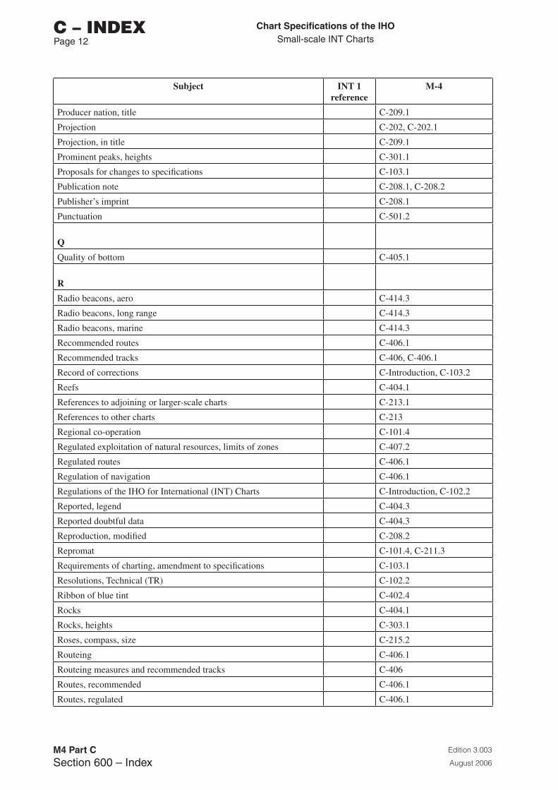
Chart Specifications of the IhoSmall-scale INT Charts
Edition 3.003
August 2006
M4 Part CSection 600 – Index
C – INDEXPage 12
Subject INT 1 reference
M-4
Producer nation, title C-209.1
Projection C-202, C-202.1
Projection, in title C-209.1
Prominent peaks, heights C-301.1
Proposals for changes to specifications C-103.1
Publication note C-208.1, C-208.2
Publisher’s imprint C-208.1
Punctuation C-501.2
Q
Quality of bottom C-405.1
R
Radio beacons, aero C-414.3
Radio beacons, long range C-414.3
Radio beacons, marine C-414.3
Recommended routes C-406.1
Recommended tracks C-406, C-406.1
Record of corrections C-Introduction, C-103.2
Reefs C-404.1
References to adjoining or larger-scale charts C-213.1
References to other charts C-213
Regional co-operation C-101.4
Regulated exploitation of natural resources, limits of zones C-407.2
Regulated routes C-406.1
Regulation of navigation C-406.1
Regulations of the IHO for International (INT) Charts C-Introduction, C-102.2
Reported, legend C-404.3
Reported doubtful data C-404.3
Reproduction, modified C-208.2
Repromat C-101.4, C-211.3
Requirements of charting, amendment to specifications C-103.1
Resolutions, Technical (TR) C-102.2
Ribbon of blue tint C-402.4
Rocks C-404.1
Rocks, heights C-303.1
Roses, compass, size C-215.2
Routeing C-406.1
Routeing measures and recommended tracks C-406
Routes, recommended C-406.1
Routes, regulated C-406.1
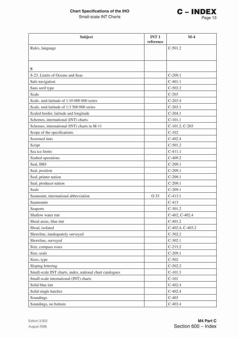
Chart Specifications of the IhoSmall-scale INT Charts
Edition 3.003
August 2006
M4 Part CSection 600 – Index
C – INDEX Page 1�
Subject INT 1 reference
M-4
Rules, language C-501.2
S
S-23, Limits of Oceans and Seas C-209.1
Safe navigation C-401.1
Sans serif type C-502.2
Scale C-203
Scale, mid-latitude of 1:10 000 000 series C-203.4
Scale, mid-latitude of 1:3 500 000 series C-203.1
Scaled border, latitude and longitude C-204.1
Schemes, international (INT) charts C-101.1
Schemes, international (INT) charts in M-11 C-101.2, C-203
Scope of the specifications C-102
Screened tints C-402.4
Script C-501.2
Sea ice limits C-411.1
Seabed operations C-409.2
Seal, IHO C-209.1
Seal, position C-209.1
Seal, printer nation C-209.1
Seal, producer nation C-209.1
Seals C-209.1
Seamount, international abbreviation O 33 C-413.1
Seamounts C-413
Seaports C-301.2
Shallow water tint C-402, C-402.4
Shoal areas, blue tint C-401.2
Shoal, isolated C-402.4, C-403.2
Shoreline, inadequately surveyed C-302.2
Shoreline, surveyed C-302.1
Size, compass roses C-215.2
Size, seals C-209.1
Sizes, type C-502
Sloping lettering C-502.2
Small-scale INT charts, index, national chart catalogues C-101.3
Small-scale international (INT) charts C-101
Solid blue tint C-402.4
Solid single hatches C-402.4
Soundings C-403
Soundings, no bottom C-403.4
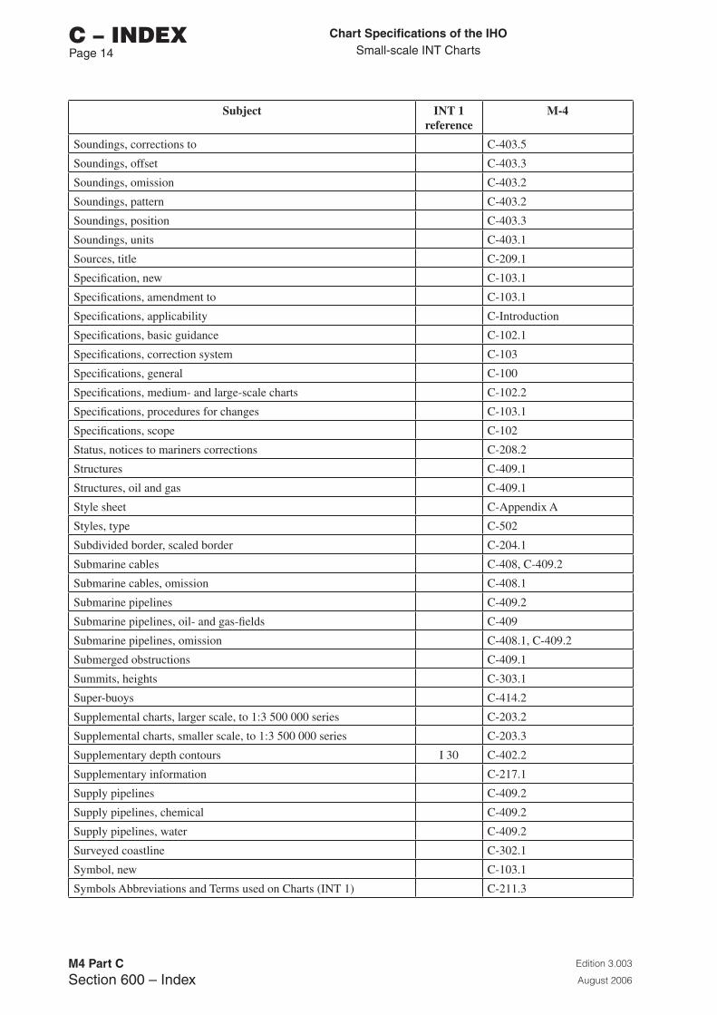
Chart Specifications of the IhoSmall-scale INT Charts
Edition 3.003
August 2006
M4 Part CSection 600 – Index
C – INDEXPage 1�
Subject INT 1 reference
M-4
Soundings, corrections to C-403.5
Soundings, offset C-403.3
Soundings, omission C-403.2
Soundings, pattern C-403.2
Soundings, position C-403.3
Soundings, units C-403.1
Sources, title C-209.1
Specification, new C-103.1
Specifications, amendment to C-103.1
Specifications, applicability C-Introduction
Specifications, basic guidance C-102.1
Specifications, correction system C-103
Specifications, general C-100
Specifications, medium- and large-scale charts C-102.2
Specifications, procedures for changes C-103.1
Specifications, scope C-102
Status, notices to mariners corrections C-208.2
Structures C-409.1
Structures, oil and gas C-409.1
Style sheet C-Appendix A
Styles, type C-502
Subdivided border, scaled border C-204.1
Submarine cables C-408, C-409.2
Submarine cables, omission C-408.1
Submarine pipelines C-409.2
Submarine pipelines, oil- and gas-fields C-409
Submarine pipelines, omission C-408.1, C-409.2
Submerged obstructions C-409.1
Summits, heights C-303.1
Super-buoys C-414.2
Supplemental charts, larger scale, to 1:3 500 000 series C-203.2
Supplemental charts, smaller scale, to 1:3 500 000 series C-203.3
Supplementary depth contours I 30 C-402.2
Supplementary information C-217.1
Supply pipelines C-409.2
Supply pipelines, chemical C-409.2
Supply pipelines, water C-409.2
Surveyed coastline C-302.1
Symbol, new C-103.1
Symbols Abbreviations and Terms used on Charts (INT 1) C-211.3
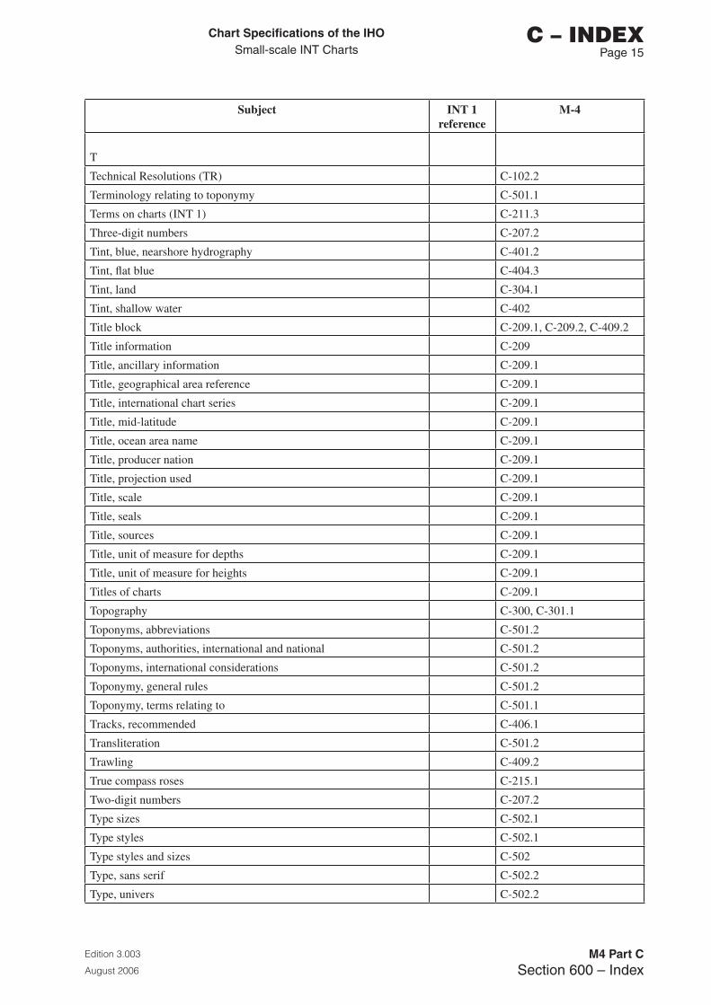
Chart Specifications of the IhoSmall-scale INT Charts
Edition 3.003
August 2006
M4 Part CSection 600 – Index
C – INDEX Page 15
Subject INT 1 reference
M-4
T
Technical Resolutions (TR) C-102.2
Terminology relating to toponymy C-501.1
Terms on charts (INT 1) C-211.3
Three-digit numbers C-207.2
Tint, blue, nearshore hydrography C-401.2
Tint, flat blue C-404.3
Tint, land C-304.1
Tint, shallow water C-402
Title block C-209.1, C-209.2, C-409.2
Title information C-209
Title, ancillary information C-209.1
Title, geographical area reference C-209.1
Title, international chart series C-209.1
Title, mid-latitude C-209.1
Title, ocean area name C-209.1
Title, producer nation C-209.1
Title, projection used C-209.1
Title, scale C-209.1
Title, seals C-209.1
Title, sources C-209.1
Title, unit of measure for depths C-209.1
Title, unit of measure for heights C-209.1
Titles of charts C-209.1
Topography C-300, C-301.1
Toponyms, abbreviations C-501.2
Toponyms, authorities, international and national C-501.2
Toponyms, international considerations C-501.2
Toponymy, general rules C-501.2
Toponymy, terms relating to C-501.1
Tracks, recommended C-406.1
Transliteration C-501.2
Trawling C-409.2
True compass roses C-215.1
Two-digit numbers C-207.2
Type sizes C-502.1
Type styles C-502.1
Type styles and sizes C-502
Type, sans serif C-502.2
Type, univers C-502.2
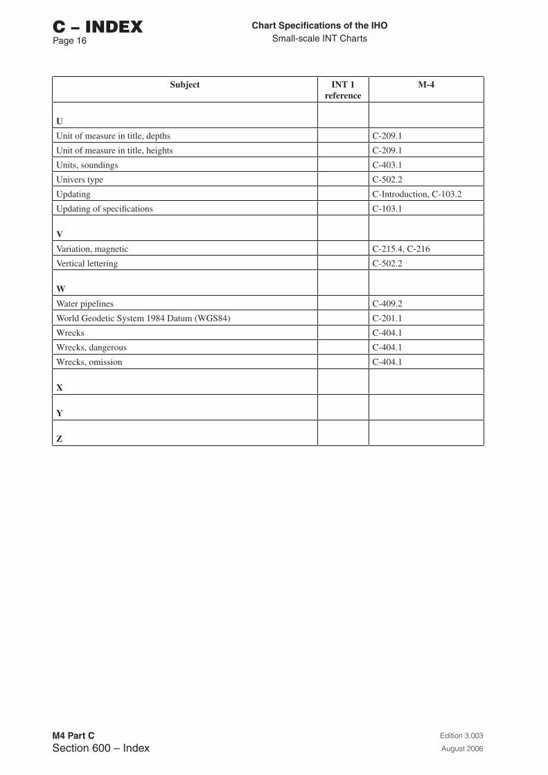
Chart Specifications of the IhoSmall-scale INT Charts
Edition 3.003
August 2006
M4 Part CSection 600 – Index
C – INDEXPage 16
Subject INT 1 reference
M-4
U
Unit of measure in title, depths C-209.1
Unit of measure in title, heights C-209.1
Units, soundings C-403.1
Univers type C-502.2
Updating C-Introduction, C-103.2
Updating of specifications C-103.1
V
Variation, magnetic C-215.4, C-216
Vertical lettering C-502.2
W
Water pipelines C-409.2
World Geodetic System 1984 Datum (WGS84) C-201.1
Wrecks C-404.1
Wrecks, dangerous C-404.1
Wrecks, omission C-404.1
X
Y
Z
Related Documents