ELECTRICAL SYSTEM MOTOR TRUCK SERVICE MANUAL Index Page 1 ELECTRICAL SYSTEM GROUP INDEX Page Specifications. . . . . . . . . . . . . . . . . . . . . . . . . . . • . . . • . . . • • . . . . • . . . . . . .• 1 to 6 SECTION itA" Circuit Diagrams. . . . . . . . . . . . . . . . . . . . . . . . . . . . . . • • . . . . • • . . . . . . . . . . 1 to 8 SECTION "S" Battery. . . . . . . . . . • • . . . • . . . . . . . . . . . • . . . . . . . . . . . . . • . . . • . . . . . . • .. I to 5 SECTION "C" Ignition Coils. . . . . . . . . . . . . . . . . . . . . . . . . . . . . . .• . • . . . . . . . . . . . . . . . . . . 1. Z. SECTION "D" Distributors 1 to 3 SECTION "E" Generators " .. , .......... , ........ " " " .... , .. , .... " .................................................. " .. 11 Z SECTION "F" Headlights. . . . . . . . • . . . . . • . • . . . . . . • . . . . . . . . . . . . . . . . . . . • . • . . . . • •. 1 to 4 SECTION "G" Horn . . . . • . . . . . . . . . . . . . . . . . . . . . . .. '. . . . . . . • . . . . . • . . . . . . • . . . . . . 1, Z. SECTION "HI! Regulators . . . . . . . . . . . . . . . . . . . . . . . . . . . . . . . . . . . • . . . . . . . • . . . . . • .. 1 to 8 SECTION "I" Spark Plugs. . . . . . . . . . . . . . . . . . . . . . . . . . • . . . . . . . . . . . . . . . . . . . • . • . .. 1 to 4 SECTION II J" Starting Motors (Cranking Motors) . . . . . . . . . . . . . . . . . . • . . . . . • . • . . . . . • . .• 1 to 4 . PRINTED CN UNITED 5TAT£S 0,. AMERICA

Welcome message from author
This document is posted to help you gain knowledge. Please leave a comment to let me know what you think about it! Share it to your friends and learn new things together.
Transcript

ELECTRICAL SYSTEM
L~LINE MOTOR TRUCK SERVICE MANUAL Index Page 1
ELECTRICAL SYSTEM GROUP
INDEX
Page
Specifications bull bull bull bull bull bull 1 to 6
SECTION itA Circuit Diagrams bull bull bull bull 1 to 8
SECTION S Battery bull bull bull bull bull bull bull I to 5
SECTION C Ignition Coils bull bull 1 Z
SECTION D Distributors 1 to 3
SECTION E Generators 11 Z
SECTION F Headlights bull bull bull bull bull bull bull bull 1 to 4
SECTION G Horn bull bull bull bull 1 Z
SECTION HI Regulators bull bull bull 1 to 8
SECTION I Spark Plugs bull bull bull 1 to 4
SECTION IIJ Starting Motors (Cranking Motors) bull bull bull bull bull 1 to 4
PRINTED CN UNITED 5TATpoundS 0 AMERICA
Donated by John amp Susan Hansen - For Personal Use Only
(l
l
I gtF x
~ v
c
ENGINE MODELSi
~ [ -g
GENERATOR Delco-Remy ~ ~ f Field current at 6 volts
amperes
Cold output shyAmperes Volts RPM
Hot output shyAmperes Controlled Volts by current RPM regulator bull
Regulationbullbull
Brush tension ounces bull
Bearing - commutator end
Bearing - drive end
Rotation viewed from drive end
Type of drive
ELECTRICAL SPECIFICATIONS R-110 THROUGH RF-210
(NOT RA-120 RA-140)
SD-220 BD-269 SD-240 BD-282
DR-llOOO19 DR-ll02785
185-203 190-205
35 45 8 8
2650 2450
middot middot middot middot middot middot
volt and current volt and current
28 28
bronze bronze
ball ball
CW CW
belt belt
RD-372 RD-406 RD-450
DR-ll02785
190-205
-
45 8
2450
middot middot middot
volt and current
28
bronze
ball
CW
belt
E~
cent r- Z [I1
s ~ 0 -l
~ n Ul
~ n [I1
en l1 1j t
(1) l1C () en~ ~t--lt
tl~en~ ~ J-j ()
(1) o l1gt ~~t
Donated by John amp Susan Hansen - For Personal Use Only
- - -
U Clltll t1 Iraquo d I-lt I QQ( CIl t1 (0 8 ioi 0 Nt1 ioi ~~~ ELECTRICAL SPECIFICATIONS 0
RA-120 RA-140 o gt I
- -_ __ __ __ __ shy
E~GINE MODEL SD-220
GENERATOR (LOW SPEED CUT-IN) (Deleo - Remy) DR-II05876
centField current (at 6 vOlts) amperesbullbull 162-182 r Z (T]Cold output shy
Amperesbullbullbull 25 $ Volts bullbull 80
~ Hot output shy
A=peres Controlled 1 ~
Volts by current J -i
Rpm regulator bullbull C ~
Regulationbull Ul
~ Brush tension (ounces) bullbull 28 () (T]
Bearing - commutator end bullbull ball
Bearing - drive end bull bull bull ball
Rotation (viewed from drive end) CW
Type of drivebullbullbullbullbullbull belt
---__ _shy Em
Donated by John amp Susan Hansen - For Personal Use Only
q EshyELECTRICAL SPECIFICATIONS R-110 THRU RF- 210
(NOT RA-120 RA-140)
~ RD-371SD-220 BD-269
~ ENGINE MODELS RD-406SD-l40 BD-282 v RD-450
C -------shy0 E
VOLTAGE REGULATOR (Delcoshy~ p
Remy) bull bull bull bull bull bull DR-1118731 DR-1l18732 DR-1118732 0
Amps bullbull 35 45 45 ~ ~ Type bull vibrating vibrating vibrating q f Current regulator shy
Current setting-amps (hot) 38 47 47 ~ Air gapbullbull 075 075 075 rmiddot
ZVoltage regulator shy [T1Voltage setting-volts (hot) 74 74 74
Air gapbullbull 075 075 075 Cutout relay shy
Closing voltage-volts (hot) 64 64 64 Air gap 020 020 020 ~ Point openingbull 020 020 020
f C ()
ENGINE MODEL SD-220 (RA-120 RA-140) 7 UlVOLTAGE REGULATOR-25 AMP
LOW SPEED CUT -IN (Delco-Remy) bull bull bullbull DR-1118350 ~
()Type bullbull vibrating [T1 Current regulator shy
Current setting-amps (hot) 25 Air gapbull 075
Voltage regulator Voltage setting-volts (hot) bull 72 Air gap 075
CIltout relay - (fl ll 1j tClosing voltage-volts (hot) bull 64 (Q ll
Air gap 020 8 0 (fl--gtPoint openingbull 020 gt-lt
tjCl(flt11111 H
OQ t 0 (Qollgtraquo~tp g p
Donated by John amp Susan Hansen - For Personal Use Only
IQCIlCllMELECTRICAL SPECIFICAfIONS lllltlttR-170 and RF-170 Series R-180 thru 184 RC-180 181 182 OlCltCllM
ENGINE MODEL
STARTING MOTOR (Delco-Remy) bullbull
Voltage bull bull
Number of field coils
Bearing - commutator end bull
Bearing - center
Bearing - drive end bullbullbull
Brush tension (ounces) bullbullbullbull
No-load test (with Solenoid or Magnetic Switch) shy
Maximum amperes bullbull Volts bull bull bull bull bull Rpm approx bullbull
Lock test shyMaximum amperes Volts bull bull Torque (lb ft) (min) bullbullbullbull
Rotation (viewed from drive end)
ENGINE MODEL
DISTRIBUTOR (Delco-Remy) bullbull
Initial setting (engine degrees) bull
CIt n ()rM
BD-282 ~a~ ()
g gtshyDR-II08009 CII t
6
4
cast iron l r Z
bronze [Tl
bronze
~ 24-28
~ ~
70 til 565 5500 ~
~ 570 315 135
CW
BD-282
DR-1112359
6o BTC E~
Donated by John amp Susan Hansen - For Personal Use Only
ELECTRICAL SPECIFICATIONS
ENGINE MODELS SD-220 SD-240 BD-269 RD-372 RD-406 RD-450 Cont R-6602
COIL (Delco-Remy) bullbullbull DR-11l5327 DR-1115327 DR-11l5327 DR-11l5327 DR-lllS327 DR-lllS327 DR-lllS2S1
DISTRIB UTOR bullbullbullbullbullbullbullbull DR-1l12355 Type vac auto Cam anglebullbullbullbullbull 4 bullbullbullbullbull 31 deg_37deg Initial setting (engine degrees) bullbull 20 BTC Vacuum advance (engine degrees) 15deg Automatic advance (engine
degrees) bullbullbullbullbullbullbullbull 30deg Total advance (engine degrees) bull 32deg
Retard (engine degrees)bullbull selective 20deg
Contact point setting bullbullbullbull 022 Contact point pressure (ounces) 17-21 Rotation (viewed from top) bullbull CCW Firing order bullbullbullbullbullbullbull 153624
DISTRIBUTOR TEST DATA Start advanceshy
Engine rpmbullbullbullbullbullbullbullbull 500 Engine degrees bullbullbullbullbullbullbull 2deg
Intermediate advanceshyEngine rpmbullbullbullbullbullbullbullbullbullbull 1800 Engine degrees bullbullbullbullbullbull 200
Macimum advanceshyEngine rpmbullbullbullbullbullbullbullbullbull 3000 Engine degrees bullbullbull 30deg
Distributor vacuum control
DR-1l12355 vac auto 31 deg_37deg 2deg BTC
15deg
30deg 32deg
selective 20deg
022 17-21 CCW
153624
500 2 0
1800 200
3000 30deg
DR-l112359 automatic
35deg 3deg BTC
none
27deg 30deg none none
018-024 17-21 CW
153624
400 150
1800 20deg
2700 27 0
DR-1l12357 automatic
35deg rsectgt BTC
none
22deg 27deg none none
018-024 17-21 CW
153624
500 15
0
1400 13deg
3200 22deg
DR-1l12357 automatic
35deg 5deg BTC
none
22deg 27deg none none
018-024 17-21 CW
153624
500 15 0
1400 13 0
3200 22deg
DR-11l23S7 automatic
35deg 5deg BTC
none
22deg 27deg none none
018-024 17-21 CW
153624
500 15
0
1400 13 0
3200 22deg
automatic
CCW
r t z f11
3 ~ ou -u C () 7 en f11u ltn [Tl
3 Jgt z C Jgt r
(De1co-Remy) bullbullbullbullbullbull DR-1116049 DR-1116049
Distributor Test Stand figures will be one-half of these specifications Test Stand rpm only For maximum engine rpm see Engine Section
00 M d t- ~ M8 () 00 gtlt -
1J~oo~ Ilgt~l-l()OQoMgtrDJgtt- ~(Il
Donated by John amp Susan Hansen - For Personal Use Only
ELECTRICAL SPECIFICATIONS 11 UHIl M 110 gt-ltt OQ(1)(flM
ENGINE MODELS SD-220 SD-240 BD-269 RD-372 RD-406 8 ClRD-450 Cont R-6602 (1)
N~M ~l1oGENERATOR-50 AMP (Delco- lt+ Cl
Remy) bullbullbullbull DR-ll06757 I DR-ll06757I DR-ll06757I DR-ll06757I DR-ll06757 I DR-ll06757 I DR-ll06822 g gtshyField current (at 6 volts) ID t
amperes bullbullbull 170-195 170-195 170-l95 1 70-195 170-195 170-195 Cold output shy
Amperes 50 50 50 50 50 50 50 Volts bullbullbullbull 75 75 75 75 75 75 75 Rpmbullbullbull 1410 1410 1410 r1410 1410 1410
Hot output- t zAmpereSControlled [T1Volts by current bull Rpm regulator 3
volt and volt and volt and volt and volt and volt and volt andRegulation bull bull bull bull bull bull t ~ curren current current current current current current o Brush tension (ounces) 25 25 25 025 25 25 Bearing - commutator end bull ball ball ball ball ball ball --l Bearing - drive end bull bull ball ball ball ball 0ball ball Rotation (viewed from drivemiddotend) CW CW CW CCW CW CW ()Type of drive bull bull bull bull bull bull belt belt belt belt belt belt belt 7
J)GENERATOR (LOW SPEED CUTshy [T1
IN) (Delco-Remy)bullbull DR-ll06758 IDR-ll06758 0 Field current (at 6 volts) lt
amperes bullbull 1 70-195 170-195 n [T1
Cold output shyAmperes 40 40 3 Volts bullbull 75 75 raquo zRpmbullbullbull 1165 1165 c
Hot output shy raquo AmpereS) Controlled r Volts by current bull Rpm regulator
volt and volt andRegulationbullbullbull bull bullbullbull I current current
Brush tension (ounces) 20 20 Bearing - commutator end bullbull bali ball Bearing - drive end bull bull bull ball ball Rotation (viewed from drive end) CW CW Type of drivebullbullbullbull belt belt
Donated by John amp Susan Hansen - For Personal Use Only
ELECTRICAL SPECIFICATIONS
ENGINE MODELS SD-220 SD-240 BD-269 RD-372 RD-406 RD-450 Cont R-6602
GENERATOR-30 AMP (Delcoshy
o ~ Remy) bullbullbull DR-1102714 I DR-II02714 IDR-II027141 DR-II02714 I DR-I1027141 DR-II02714 Field current (at 6 volts) -l oamperes bull 175-190 175-190 175-190 175-190 175-190 175-190 0Cold output shy
Amperes 30 30 30 30 30 30 SciVolts bullbullbullbullbull 8 8 8 8 8 8 c Rpmbullbull 1750 1750 1750 1750 1750 1750 ()
Hot output- A UlAmperes Controlled 1 [Tl
Volts by current 0 Rpm regulator bullbull
v~it ~~d volt and volt and volt and volt and volt and ltnRegulationbullbullbullbull [Tlcurrent current current current current current
Brush tension (ounces) bullbull 24-28 24-28 24-28 24-28 24-28 24-28
raquo ~ Bearing - commutator end bull bronze bronze bronze bronze bronze bronze Bearing - drive end bullbullbullbull ball ball ball ball ball ball z Rotation (viewed from drive end) CW CW CW CW CW CW c raquoof drivebullbullbullbullbullbull belt belt belt belt belt belt r
en M 0 t () M 8 ()en- -l
U ~ en PIti-l()(lQOMgt()iI7twm
Donated by John amp Susan Hansen - For Personal Use Only
ENGINE MODELS
VOLTAGE REGULATOR-30 AMP (Delco-Remy) bullbull
Type bullbullbullbull Current regulator shy
Current setting-amps (hot) Air gap
Voltage regulator shyVoltage setting-volts (hot) bull Air gapbullbullbull
Cutout relayshyClosing voltage-volts (hot) Air gapbull Point openingbullbull
VOLTAGE REGULATOR-50 AMP HIGH OUTPUT (Delco-Remy)
Type bullbullbull Current regulator shyCurrent setting-amps (hot) Air gapbull
Voltage regulator shyVoltage setting-volts (hot)
Air gapbullbull Cutout relayshy
Closing voltage-volts (hot) Air gap Point opening
VOLTAGE REGULATOR-40 AMP LOW SPEED CUTIN (Delco-Remy) bullbull
Type bullbull Current regulator shy
Current setting-amps (hot) Air gap
Vol tage regulator shyVoltage setting-volts (hot) Air gapbullbull
Cutout relayshyClosing voltage-volts (hot)~ Air gapbull Point opening bull
ELECTRICAL SPECIFICATIONS trl () (fIl fl) 0 gtlt rshy
()Q (l) () MSD-220 SD-240 BD-269 RD-372 RD-406 RD-450 Cont R-6602 (l) 8 l ()
lMl ~~o lt+ ()DR-IllB303 IDR-IllB303 IDR-IllB303 IDR-IllB303 I DR-IllB303 I DR-IllB303
vibrating vibrating vibrating vibrating vibrating vibrating g gt m rshy
30 30 30 3030 30 075 075 075 075 075 075
74 74 74 74 74 74 middot 075 bull075 075 075 075 075 r
t64 64 64 64 64 64 z
middot 020 020 bull020 020 bull020 020 [T1 020 02011 020 bull020 020 020 ~
~ DR-1118333 IDR-IllB333 IDR-llIB333 IDR-1l18333 IDR-ll1B333 I DR-1l18333 I DR-ll1B368 o
vibrating vibrating vibrating vibrating vibrating vibrating vibrating 0 -I50 50 5050 50 50 50 0OB2 bullOB 2 OB2 OB2 bull082 082 075 C ()
74 74 74 74 74 74 143 7 075 075 bull07 511 bull07 5 bull075 075 075 (f)
64 64 64 64 64 64 12B ~ middot 020 020 020 020 020 020 020 lt 020 020 bull020 020 020 020 020 n
[T1
raquo ~ DR-1118366 IDR-II1B366 zvibrating vibrating c raquo40 40 r 075 075
74 74 bull07 5 075
64 64 020 020 middot 020 020
Current and voltage specifications apply only at operating temperature Operating temperature shall be assumed to exist after not less than 15 minutes of continuous operation with a charge rate of B-I0 amperes
Donated by John amp Susan Hansen - For Personal Use Only
c
ELECTRICAL SPECIFICATIONS
ENGINE MODELS SD-220 SD-240 BD-269 RD-372 RD-406 RD-450
SPARK PLUGS
AC standard pro- 44 Corn 44 Corn 45 Corn 43 Corn 43 Corn 43 Corn Champion heavy duc- J-7 J-7 J-8 J-6 J-6 J-6
~ Auto-Lite service tion AN5 AN5 AN7 AN5 AN5 AN5
~
~ AC hot 45 Corn 45 Corn 45 Corn 44 Corn 44 Corn 44 Corn Champion mod~rate J-8 J-8 J-8 J-7 J-7 J-7 Auto-Lite service AN7 AN7 AN7 AN7 AN7 AN7
AC standard 44 Corn 44 Corn 45 Corn 43 Corn 43 Corn 43 Corn Champion heavy bull J-7 J-7 J-8 J-6 J-6 J-6 Auto-Lite service AN5 AN5 AN7 AN5 AN5 AN5
AC cold 43 Corn 43 Corn 44 Corn 43 Corn 43 Corn 43 Corn Champion severe J-6 J-6 J-7 J-6 J-6 J-6 Auto-Lite service AN5 AN5 AN5 AN5 AN5 AN5
Spark plug size 14 mm 14 mm 14 rnrn 14 mm 14 mm 14 mm Spark plug gap bull 028-032 028-032 028-032 028-032 028-032 028-032
STARTING MOTOR (Delco-Remy) I DR-ll07074I DR-II070741 DR-ll07967I DR-ll082171 DR-II090041 DR-ll09004 Voltage bull bull bull 6 6 6 I 6 6 6 Number of field coils bull bull bull bull 2 2 4 4 6 6 Bearing - commutator end bull cast iron cast iron cast iron cast iron cast iron cast iron Bearing - center cast iron cast iron cast iron Bearing - drive end bull bronze bronze bronze bronze bronze bronze Brush tension (ounces) bull 24-28 24-28 24-28 24-28 36-40 36-40 No-load test (with Solenoid or
Magnetic Switch)shyMaximum amperes bull 75 75 60 70 70 70 Volts bull 57 57 50 50 57 57 Rpm approx
Lock test shy bull 5000 5000 6000 3500 2200 2200
Maximum amperes bull 525 525 600 600 600 600 Volts bull bull 34 34 30 30 30 30 Torque (lbft)(min) 12 12 15 22 35 35
Rotation (viewed from drive end) CW CW CW CW CW CW
MAGNETIC SWITCH (Delco-
Remy) bullbullbullbull 1 DR-1465 DR-1465 DR-1465 DR-1465 DR-1465 DR-1465 Current consumption (at 6 volts) 57-70 57-70 57-70 57-70 57-70 57-70
Cont R-6602
82 Corn 5 Corn BT4
82 Corn 5 Corn BT4
18 mm 023-027
12 6
bronze
bronze 36-40
65 114 6000
725 50 44 CW
rshyc z [T1
3 o -l o 0
-l 0 C () A (f) [T1 0 lt () [T1
$ tgt z C tgt r
(Jl M U t ~ M Cl ~(Jlgt-3
1J n gtltoPlPl(Jl
OQ ~ gt-3 Cl roOM~ lTI~gt
Donated by John amp Susan Hansen - For Personal Use Only
~CJ)CJ)11 Iraquo U -lt t-OQ(1)CJ)11(1) 81-3(1 0---111-3
ELECTRICAL SPECIFICATIONS R~~ (1
ENGINE MODELS SD-220 SD-240 BD-269 RD-372 RD-406 RD-450 Cont R-6602 ~ ~ HEADLIGHT SEALED-BEAM
UNIT (Guide) bullbullbullbull 924791 924791 924791 924791 924791 924791 5930856
IGNlTION SWITCH (Delco-Rerny) 1116465 1116465 1116465 1116465 1116465 1116465 1116465 r tLAMPS (BULBS) z
Stop and tail light bulbshy [Tl
Voltagebullbull 6-8 6-8 6-8 6-8 6-8 6-8 12-16 sCandle powerbull 21-3 21-3 21-3 21-3 21-3 21-3 21-6 Contactbullbullbullbull DC DC DC DC DC DC DC
Parking light bulbshy0Voltage 6-8 6-8 6-8 6-8 6-8 6-8 12-16 -Candle powerbullbull 3 3 3 3 3 3 3 0
Contactbullbullbullbull SC SC SC SC SC SC SC CInstrurnent light bulb- n
Voltagebullbullbull 6-8 6-8 6-8 6-8 6-8 76-8 12-16 Candle powerbullbullbull 2 2 2 2 fJJ2 2 15 [TlContactbullbullbullbull SC SC SC SC SC SC SC 0
Beam Indicator bulbshy ~ Voltagebullbullbull 6-8 6-8 6-8 6-8 6-8 6-8 12-16 n Candle powerbullbullbull 1 1 1 1 [Tl1 1 1 Contactbullbullbullbullbullbull SC SC SC SC SC SC SC s
gtshySTORAGE BATTERY z Type (Auto-Lite) bull c2H-I05 2H-I05 2H-135R 4H-152R 4H-152R 4H-152R 4H-152RSpecific gravityshy gtshyrFully charged at
1280-1290 11280-1290 11280-1290 11280-1290 11280-1290 11280-1290 11280-1290Recharge at 1225 1225 1225 1225 1225 1225 1225
Voltagebullbullbullbull 6 666 666 Arnperes hours at 20-hour rate 105 105 135 152 152 I152 152Arnperes-20 rninute rate 133 133 170 180 180 180 180 Terrninal grounded bullbullbullbullbullbullbullbullbull positive positive positive positive positive positive positive
Donated by John amp Susan Hansen - For Personal Use Only
QJgt
~ Fi t
~ Vi c 0 1
1 g
~ q reg
1-shyBattery -_ I
~ ~~Hom relaY-RHn reg- Fuol F~ Modol Rmiddotl53 ~~ I I 1 and Rmiddot163
~14 Junction I block (20)
-H--LI ~ bull
Starting push switch ~ (U) (ll)-- RH 01 _ yindshield
~~tl====plusmn=l-(~ lt b IlgmtIon switch - gt1-- Wlper motor ~ I shy1 1-yJ rTi r-- ---B
--_+--til ~ amp ~~ i Windshi Id
~Igt Bat coil
L+====J~
1
Temp
Cab i groundI~
7tJ _ Horn~ rX11 26 reg Y(
_ _ 14 gaJoYZ)
C (z6) I ~ LHD~ m 0
~ 0 ~
3 ~Tmiddot -iilJl ~~l--I --wiper swi~ch 2 or PI CirclntFltG-- Circuit I or b~t1t bre~eS~~l--breaker ___L uhlt tch I ~S-t~--1-J - ij--- -lnstr lightI
I I I --High L__
---- l=reg Inott k~A~m P 1---------- Dome light
A ----I switch
w~_9It-_J_1FuelII I Dome light
J rV~i~~h~nd ignition
---~-i LHD~- r- --Stop light switch
~ gtJ--gt
-~ Fuel--Trailer taillight 1f4Y d I T gao 21 ad
Bat J reg i[]nectors railer stop light ll---1~a~---- 22 16 Enlatged view I1 llR bull Hom bu 14 ~l~ ~ 130 left hd IL AA Ul n ()egulator 14 ga R 110 t R165 ~ft hd Ito 165 nght hd It llgtl-j
t-cl~c~8middotTI66 IIgt ~
~sectM~Fig Imiddot Wiring circuit diagram (RmiddotllO R120 Rmiddot1lO Rmiddot150 Rmiddot160 series trucks) ~s1
~6
Cable Color Emor Description
r=eh4~eratOrficlr-~middot 8 Toenerator ann
cbullr Z [lJ
~ 0 0c ac ()
B 4 ~ D 12 E 1 en F 16
G 14 ~ 16 -()P 16
[lJ
Donated by John amp Susan Hansen - For Personal Use Only
Parking light ID-- 16 ga
UtntnM IlIC11~t OQltnM ~ 1-3 Cl NgMI-3
-5c ClCkcuitNo Cable Cable Color shyrtf lt16 gamiddot1 ~ I Cab ground -- Gauge or DescriptionLotto
~ I I 16 Generator aeld t
Circuit 2 8 Generator armHead-J rYFi gao I~I Light breaker 4 8 Regulator to am-light ~reg Starting motor switch meter Generator I 5 8 Ammeter feed
---In I ~ 11 12 Ignition switch feed Junction 12 16 Ignition switch to Ig] nltlon coUblock --reg ltElt 14 16 Starting
~~~J~Ignition and 15 12 Light switch feed 16 12 Dimmer switch feed----0
I YJ starting switch 17 1204 High beam feed 1 17 16 High beam indicator
17 16 High beam head ~f 1 -reg light leads r18 16 Low beam head light leads~+k~ Bmm nampaOX 18 14t16 Low beam feed Z
20 16 Parking light leads 20 1608 Parking light feed 21 16 Taillight ~tislt lw 111111 A+lt=~~M [T1
22 16 Stop light~ ~ 1 40) 25 16 Connector 10 relay -- 40 26 1204 HOJn and horn reshy
lay feeds 26 12 Horn and stop light ~ 11kJ1 - reg feed 027 16 Instrumenl feed 30 18 FuelgBugeI Hom 33 18 Temperature gauge36 18 011 pressure gauge 138 18 Dome light40 16 Instrument lights C 80 16 Ignition call to dtemiddot ()
tributor 91 14 Headlight ground ~ B 4 Battery groundC 3 Engine ground UJ
Fuel I (26) middotI~II D 12 Cab ground I I I I I-I-T ~ ~ E 1 BBampcable
H 16 Horn utton to conmiddot nector ~ ~Hom button Engine ground 0) Dome light ()-
Fuel [T1J-reg~I-_StoP light -______11 I I I sWitch A~ ~ I Stop
OOiTt-~ ~ 21) 1= I
E-Fig 2middot Wiring circuit diagram (RMl20 RM150 series trucks)
8-7181
Donated by John amp Susan Hansen - For Personal Use Only
9 Circuit Cable Color
No Cable or r Index Gauge Description
~ Em Letter
1 16 field
1 1regaII ) regBattery 2 rgt17 18 j =- -~--r-
~
ltIi II~ I -5shy I
11 Starting motor M 12V~II 14l xv 15
11 4 or H
F 16 Q 17~ 3 or T 17 A
Junction block 2 or P Ircult 17g C 18 ~ Generator )J 1 or bat breaker 18
20 ~ D 20 0 r-
L18 ga 22~IIJ~[==~~~~ 21 bull ~ Temperature gtl Light switch 26
26 ~ 27114 gao ~~ 33 -= 40 1- Instrument light 30
33- 3fl--- t Distributor cabreg _1- Speedometer 36 ov ground ~ I Hgh bea ~ -_~ 1 m 38 400 ~ r P I - indicator light d
~ 71 080
--=--- 91-----70~--I Ammmiddot0
A ~ ~ P I 8 Ch
r-Tl--Instr lightOil preS8ure_~ D
Dimmer switch--- bull ~l--Fuel rJg ~ (i8)___~
F
I f ~~~ ht H 16--t-+~-rir-_+-H-_IJ ~ Dom~ light ~ G 14te1~~
~
E
~ ~~ P 16sWitch
Hom Hom ~~~~~~~~itch )Sin Stop ~ I relay
1 -~----~ 7JI (TUI Connector ~1 E la d bull
L-- I I I I 16 a n rge View ----Ell g AA
Trailer stop light
~~ J 6 Hom button F~l Trailer tail light ~ I ~ ~ ~ I-ll ~ l
I-l oooonIregII ~ I (zO) (z6) li6) -=-J tIl12 gao 14 gao ~~~ F Gen Bat Regulator ~ 1
8-7179 t1 n D1ll1t~H ~gl-l~Fig 3 Wiring circuit diagram (RCl60 series trucks) wgtSl
Donated by John amp Susan Hansen - For Personal Use Only
ijCflCfltltJ1lIngtgtltt-
Cable Gauge
Cable Color OQ ~CflM ngt ()gtltJ
gt-~~ ()
gtshyt-
reg--____sa~ng push switch
)-If JRR D l r-r--lS~~~~~~tCh I 1--1 - I Windshield
I I l---h L I - I wiper motor
For Models R173 and Rmiddot183
Windshield wiper switch
Circuit --breaker
- -Speedometer
--Instrument light
- - High beam indicator
--Instr light
- Dome light switch
Dome light
Starting and ignition switch- LRD
Stop light switch
Trailer stop light
Trailer tail light
G 14 H l~ I aun PUbU DUUVU I p 16 1 bull bull
Stop
J I
Tail
Enlarged view AA
l r Z [T1
E o d 0
~ n ~
~ () [T1
Stop and tail light
BmiddotTlIl1 EmFig 4 - Wiring circuit diagram (R-170 RF-170 R-180 series trucks-not R-185)
Donated by John amp Susan Hansen - For Personal Use Only
a I E~gt lt )
I Cable Color
~ ~
r c Park Head[l~IIr1 reg ~ ~ Light light 17 18 B -V Q ~ I 91 I
3 I ~ i~atte~1IAI J I reg
g I I ~ ~~ 4 or H a 130rT
f
2 or p
-- ~ j ~Sl i2o) I or bat
[18~1 ~ -- I
Junction block r~ II I~i ZDistribu~ _
118 ga--i I [T]
s 116 ga~---t1_ 114 gareg-J Lshy
(D-- [L1 ~ CD---- shy
~ () ~ Dimmer switch ~IJshy
Hom relaY 1 D
B ~ F11~r Hom E n
20 [T] __9 _ 1ampimiddotmiddotIU~ __LH 1~ u _~L L__Junction block Enlarged view p
~ AmiddotA i
button z c z
_W-~ ll
Park F Gen Bat C b k d ttrcwt rea er anLight llRegulator terminal block assembly B-TSO Cl () ro 14 1-3
tl~gtlt~ill 00 (lQol-3()roll1gtFig 5 Wiring circuit diagram (RC180 series trucks) gtEt
Donated by John amp Susan Hansen - For Personal Use Only
tJ tlltll trl lUngtltt
IlQ ~ (I) tl III Cl Ogtrl gtE~
~ t
Fuel
p r Z [T1
3
(i7)--shy ~ ~
J Distributor I shy(iO ___1 R
~ ~ rn
Engine ground ~
8-7168 Ell(R185 truck and Rmiddot190 RF190 R200 Rmiddot210 RFmiddot210 series trucks)
Donated by John amp Susan Hansen - For Personal Use Only
a r PARK EmiddotlI LIGHt ~ g ~
f ~ 0
E 0 iii GENERATORJi
If JUNCTION BLOCK
~
~ ENGINE GROUND
II Z z c z j raquo ~ ~
raquo ~ II
~ ii
Fig 7
20
r--------shy STARTmiddotPUSH I r- ---~ SWITCHmiddotRHO I I
I I r ~I I ) BI I r --_ B I IGNITION ~
~---------t----+-+---~ SWITCHRHO I I I sect-------------~ I Ii bull ( I I
P I
16ilhJ Iii ~yenHJSW(TCH ~ =a( ~ f11i rmiddotLIGHTER
- Z [T]
~ ~ () ~ til
~ () [T]
TRAILER STOP LIGHT
TRAILER TAil LIGHT
IltJ t IltJ
en rft 08-1090 ell j tIlQ traquo ~
~gtzl~ - Wiring circuit diagram 12middotVolt System (Rmiddot1aS to Rmiddot210 RFmiddot190 and RFmiddot210 trucks) Jgtilt
Donated by John amp Susan Hansen - For Personal Use Only
Donated by John amp Susan Hansen - For Personal Use Only
ELECTRICAL SYSTEML-LINE MOTOR TRUCK SERVICE MANUAL Section A
Page 1
CIRCUIT DIAGRAMS
Electrical circuits for the various L-Line trucks are illustrated on following pages
Cables are protected wherever necessary by 100m or conduit and by rubber grommets to prevent chafing where contact is made with the chassis cab or body Cables are also securely clipped at important points and connectors are used to facilitate inspection and servicing
All electrical connections must be kept tight and clean
Wiring Harness Individual Cable Circuit Identification
Wiring harness cable circuit identification has been established by (UNumber Codingll) imshyprinting numerals at regular intervals along the individual cables except for short cables which are numbered only at the ends The prime purpose of cable identification is to facilitate wiring harness installation since in harness generally only the extreme ends of the indivishydual cables are visible
The accompanying circuit numbered list (from No 1 to 124) itemizes circuit numerals used on L-Line Wherever a particular circuit is used on a vehicle the identification numeral for that circuit will always be the same For example the generator field circuit cable will consistently be Circuit No1 the generator armature circuit will always be Circuit No2 etc (see list) In the same manner if a circuit is not used on a vehicle the numeral for that circuit will not be used For example vehicles not having a 24-volt radio-feed cable will not have a circuit No 48 in the harness
Circuit numbers on the list for which no circuit description is given are not presently used by International and these circuits have been reserved for possible future assignment
Circuit Nos 28 to 31 inclusive each pershytain to fuel tank-to-receiver unit circuits Because of the variety of possible combinations for these hook-ups reference should be made to the illustrations for proper connection of cables (Fig 1)
Circuit Diagrams
Wiring circuit diagrams are illustrated in the owners and drivers manuals and in the service manuals With each of these illustra-
PRINTED IN UNITED STATES OF AMERICA
tions there is a key to the diagram which conshytains pertinent information as to circuit number and cable gauge
Individual Cable Replacement
It is recognized that replacement of one or more individual cables may be necessary and that complete harness replacement may be imshypractical For this reason the chart on each circuit diagram specifies the proper-gauge cable to be used and which can be made up locally from bulk stock
Circuit Numbers And Circuit Names
cmCUIT CIRCUIT NAME NO
1 Generator field circuit
2 Generator armature circuit
3 Generator ground circuit
4 Generator regulator to ammeter or shunt
5 Ammeter (or shunt) to starter switch
6 Battery to starting motor switch mounted on starting motor
7 Battery ground (including master switch if in this circuit)
8 Shunt to ammeter positive
9 Shunt to ammeter negative
10 Circuit breaker common feed to any point fed from regulator (Bat)
11 Ignition switch feed (or magneto ground)
12 Ignition switch to ignition coil (or booster switch to booster coil)
13 Magneto ground
14 Magnetic starting motor switch to push button switch to feed
15 Main light switch feed
16 Light switch (HT) to service headlight or dimmer switch
17 Dimmer switch to upper beam and to beam indicator
18 Dimmer switch to lower beaIll
Donated by John amp Susan Hansen - For Personal Use Only
ELECTRICAL SYSTEM L-LINE MOTOR TRUCK SERVICE MANUALSection A Page 2
19 Light switch (Bod) to blackout driving lamp including resistor
20 Light switch (BHT) to parking lamps or marker light
21 Light switch (R) or (HT) on blackout switch to service tail light
22 Light switch (H) or (S) on blackout switch to service stop light
23 Light switch (BS) to blackout stop light
24 Light switch (BHT) to blackout tail light
25middot Horn switch (including feed) to horn (or horn relay)
26 Horn relay feed and horn relay to horn
27 Instruments feed (instruments with polarshyity)
28
29 Fuel gauge sender to receiver -shy
30 See illustrations Figure 1
31
32 Oil level gauge sender to receiver
33 Water (and oil) temperature gauge sender to receive r
34 Low engine oil pressure warning light cir shycuit (including feed)
35 High water temperature warning light cir shycuit (including feed)
36 Oil pressure gauge sender to receiver
37 Outlet socket or junction block
38 Dome light circuit (including breaker and switch)
39 Map light circuit
40 Instrument light circuit
41 Starting motor to battery (-) (series paralshylel switch hook-up)
42 Series parallel switch (B+) to battery (+)
43 Series parallel switch (A-) to battery (-)
44 Series parallel switch to ground
45 Series parallel switch (B-) to starting motor
46 12 - Volt radio circuit (including radio master switch)
47 Slip ring feed
48 24 Volt radio feed
49 Receptacle Auxiliary power outlet posishytive lead
50 Receptacle Auxiliary power outlet negashytive lead
51
52 6-Volt tap on taillight dropping resistor to tail light
53 Electric brake control circuit
54 Fuel cut-off circuit
55 Flame primer low tension circuit
56 Flame primer high tension circuit
57 Instrument panel ground
58 Compass light circuit
59 Cab (or hull) ventilating fan circuit
60
61 Auxiliary generator field
62 Auxiliary generator armature
63 Auxiliary generator ground
64 Auxiliary generator regulator to battery (including heater transfer switch)
65 Auxiliary generator starter relay circuit (including switch and feed)
66 Auxiliary generator starter to transfer switch (including starter or relay)
67 Emergency stop switch ground
68 Battery interconnecting cables
69 Resistor to ground terminal on trailer coupling
70 Regulator ground
71 Windshield wiper ci rcuit
72 Low transmission oil pressure indicator circuit with feed
73 Radio terminal box to ground
74 Series parallel switch to solenoid relay
Donated by John amp Susan Hansen - For Personal Use Only
ELECTRICAL SYSTEML-UNE MOTOR TRUCK SERVlCE MANUAL Section A
Page 3
75 Stop switch circuit (SW to SS on blackout SW)
76 Fuel pump control feed
77 Fuel pump switch to fuel pump (left side)
78 Fuel pump switch to fuel pump (right side)
79 Fuel gauge sender ground
80 Ignition coil to distributor
81 Battery to starting motor switch (or term block) including master switch
82 Starting motor switch (or term block) to starting motor
83 Blackout light switch (TT) to tail connecshytion on trailer receptacle
34 Blackout light switch (SS) to stop light conshynection on trailer receptacle
85 Low air pressure indicator buzzer (or light)
86 Ground on series parallel switch to amshymeter (including circuit breaker)
87 Spotlight circuit for trucks and wreckers
88 Winch torque limiter control
89 Automatic choke
90 Trailer receptacle to ground
91 Headlight to ground
92 Parking light to ground
93 Starting motor relay to ground
94 Starting motor relay auxiliary grounding circuit
95 Tail light to ground
96 Speedometer sender feed
97 Tachometer transmitter feed
98 Tachometer transmitter positive (+) to tachometer positi~e (+)
99 Tachometer transmitter negative (-) to tachometer negative (-)
100 Tachometer transmitter to ground
101 Defroster switch to defroster motor including feed
102 Heater switch to heater motor including feed
103 Cigar lighter
104 Fog light switch to fog light including feed
105 Tractor light (Back-up)
106 Carburetor idle fuel shut-off valve
107 Marker or identification light circuit
108 Clearance light circuit
109 Mico brake lock circuit
110 Fuell gauge switch (C) to ground (dual safety tanks)
Ill Lockoff solenoid valve to switch (including feed)
112Auxiliary ammeter to ground-negative
113 6-Volt radio circuit (including ratio master switch)
114 Direction signal left turn-front
115 Direction signal left turn-rear
116 Direction signal right turn-front
117 Direction signal right turn-rear
118 Direction signal feed circuit
119 Voltage divider ground
120 Voltage divider feed or instrument resisshytor feed
121 Overdriv~ relay to ignition switch
122 Overdrive relay to overdrive governor (including kickdown and overdrive switch)
123 Overdrive solenoid to ignition coil (includshying kickdown switch)
124 Overdrive solenoid to battery (including relay feed)
f~IN1poundD IN UNITED STATES OF AMtRlcA
Donated by John amp Susan Hansen - For Personal Use Only
ELECTRICAL SYSTEM L-UNE MOTOR TRUCK SERVICE MANUALSection A Page 4
30 30 30 30 29 29
Underskirt tank Underskirt tank and right side auxiliary tank
[ J 30 ~ 29
Right side tank 29
Underskirt tank and dual auxiliary tanks
28 28
Left side tank ~
D~ 31~ Left side tank andRear end tank
right side auxiliary tank 30 0
Rec
gauge 30 30switch 28 28
Underskirt tank and left side auxiliary tank
Fig I - Fuel tank to receiver circuits Because of the variety of possible combinations for these hook-ups reference should be made to the above chart for proper connection of cables
A-22921
Donated by John amp Susan Hansen - For Personal Use Only
Circuit CablColorNo or Cable orIndex Gauge Description
~r Letter
Fuel gauge sender unit _ 1 14 Generator fieldreg 2 8 Generator arm 4 8 Regulator to ammiddot ~ meter 6 8 Ammeterf_d
11 14 Ignition switch feedbull 12 14 Ignition switch to igshy~ nition coil ~ I 14 14 Startinq
16 10 Light switch f d z 16 12 Dimmer switch fed C reg 17 12 Hiqh beam feed z Generator Starting 17 14 High beam h admiddot rmotor litht lead
17 16 Hig beam indieamiddot ~ ~
tor t 18 14 Low beam fed1E 4ga 18 16 Low b am h admiddot
[T1 z
1 li~htlad~
m
Engine freg middot ~
20 14 P ing feed- sect 20 16 Parking light leadI 1~16ga 21 14 Taillight
ii
~ reg 22 14 Stop light o $
bull -- Junction block 26 10 Horn and stop light feed -J
Oil 26 12 Horn lind horn re- o lay fsedslight 027 14 Inlltrument feed
27 16 Instrument feed 29 16 Fuel gauge -J 30 16 Fualgauge 033 16 Temperature gauge36 16 Oil pressure gauge C 40 16 Instrument light o71 14 Wiper switch feed 80 14 Ignition coil to di 7
tributor 91 14 Headlight ground (J) A 16 Natural with circuit
letter A or black light B 0 Battery ground ~
C 3 Engine groundreg D 12 Cab ground lt E 0 Battery cable (=)F 16 Natural with circuit [T1letter uF or red G 14 Instrument bUB bar H 14 Horn push button $J 16 Fuel gauge groundJ~llJ P 16 Natural with circuit raquo
Jetter p or ~nJJ~~~~vIII6 z c
dStop raquoI-~-~ x]
r~ ~ Enlarged
Fuel gauge sender unit view X-X
CD M l M
Ul 0 roUlt-J~Regulator
8-4737 O~gt-ltdPl Ul OllOt-JOFig 2 - Circuit Diagram - L-IIO Series to L-IBO Series inclusive (Hot Metro) rolMgtshyltIgt-~l
Donated by John amp Susan Hansen - For Personal Use Only
t1CflCflM Ilgt(l)O-ltt
()QOCfl(l)~-JM
o ()O-l -J -J
gt ()
gt t
r t z [T1
$
~ o 0 -1 0 C () ~ CJ) [T1 0 lt ()
sender unit [T1 Battery ground strap
$ raquoJunction block --- ---Stop light switch z Magnetic starting switch c
--shy-- raquo
Horn relay r Head light
8-4696
Fig 3 - Diagram showing location of various electrical units l-IIO Series to l-J80 Series inshyclusive (Hot Metro)
Donated by John amp Susan Hansen - For Personal Use Only
Circuitj Cabl ColorNo or Cabl Ind x Gauge or
DcriptionLetter
1 14 Generator field Fuelgualle sender un~ 2 8 Generator arm
4 8 ReGulator to am
z z c z
m ~
~ co o ~
bull ~ bull
fl-----shy= I I I I
regregreg14 ~a 16 ga 16 ga
Junction block
Enline Iround
~ I
Junction block
~ 14 ga 16 ga
~~~ I 1 I I 1 I I I
1--1
14 ga
~
Generator
)1) 0
Distributor I I 1
Dimmer switch
Circuit breaker
~
and terminal block I c assembly------shy
amp6l HornK 12
1 1 I
~
4 or H
3 or T 2 or p f
1 1 or Bat [1
(])shy ~
Windshield wiper motor
Circuit breaker
Instrument light
Tachometer
I I
5 11 12
14 15 16 17 17
17
18 18
20 20 21 22 26
26
27 27 28 29 33 36 40 71 80
91 A
B C D E F
G H J P
8 14 14
14 10 12 12 14
16
14 16
14 16 14 14 10
12
14 16 16 16 16 16 16 14 14
14 16
0 3
12
1~ 14 14 16 16
meter Ammeterfed Ignition switch fed Ignlllon switch to igshy
nition coil Starling Light witch fed Dimmer switch fed High beam fd High beam hadshy
lJ~ht lad Hig beam indicmiddot
tor Low bam fed Low bam hadshy
l~ht I ad Par ing feed Parking light lads Taillight Stop light Horn and stop light
f d Horn and horn ~
lay feds Instrument feed Instrument f d Fulgauq Fulgauqe Temperature qauQ Oil prebullbullu 9au9 Instrument light Wiper switch fed Ignition coil to disshy
tributor Hsadlight~ound Natural wi circuit
letterA or black Battry ground Engine groundCa qround Battary cable Natural with circuit
ltter F or red lnatrument bu bar Horn puah button Fuel gauge qround Natural with circuit
I_tter P or qre_n
X
~RXI Tail Stop ~
Enlarged view XX
r r Z [T1
$ 0 ~ 0u ~ u C 0 A en [T1u lt 0 [T1
$ raquo z c raquo r
l 14 p
Fig ~
Regulator
- Circuit Diagram - l-190 Series And Up
M t M
UlUl O ro gt-l
U lt 0III Ul OQogt-lOrolMtgt -Itgt~t
Donated by John amp Susan Hansen - For Personal Use Only
t1 tJltJl M1l)(1)tlaquo4tOQOtJl mt~~Windshield wiper motor I Windshield wiper switch _-Fuel gauge sender unit oogM~
Instrument light ~~ (R H tank)Dash panel gt~~ I lt~ ()
middot CIgar I I Speedometer ~~ ~ - I II I(l~ To tatlltght ~
Ignition switch ___ I f) Ammeter gauge ~ and stop light If Temperature gauge ~~ -- j f I ~
Pi -Fuel gauge I ___
~- ___ Oil pressure gauge ~ I1 ~__-- ~~ r
~ I - fI ~~-----Tachometer I --- --- ~ t --- I -- I zI -- ---1 - --~--Starting push switch [Tl - - ~J--
Light swltch----2gtmiddot I _--- J I Dome lIght sgt~ ~ Instrument lights oBeam indicator light~ gt- I
I --lCircuit breaker and terminalCab ground strap----- ---- I o
block assembly I 0ITemperature gauge Voltage and current regulator --l
Junction block sender unit--l Fuel gauge ender unit 01111 Ii I (L H tank) C
Ignition coil----J n _---Battery ground strap 7I~~ j)
II j ~J ~I~ _--Battery [Tl1gtV ( ~ I ~ Je 0~ ~~l~~~--~----Battery ltcable
~d~IV n [Tl~ I
~n 1bullbullbullbull
s~ I - I bull bullGenerator raquo z -Y Stop light sWitch
Oil pressure gauge 0 t 1 cEngine ground strap- llunler SWI c 1 sender unit raquo rJ bl k Magnetic starting switch unctIOn oc S h tartmg motorHeadlIg t
Parking light
8-4868
Fig 5 - Diagram showing location of various electrical units - L-190 And Up
Donated by John amp Susan Hansen - For Personal Use Only
ELECTRICAL SYSTEM
L-LINE MOTOR TRUCK SERVICE MANUAL Section B Page 1
BATTERY Storage Battery Equipment
Present production trucks are equipped with Auto-Lite batteries Code Dating
Each Auto-Lite Battery bears a shipping code stamped on one button of one cell connecshytor of the battery This button is indicated as nA in Fig 1
-----+- Button-A -i--- o o 000 (IT) e
Standard assembly Reversed assembly
e 00=--=00 0 $
End to end assembly
Positive button center cell 6-volt assembly
Positive button - cell adjacent to A-16015positive terminal cell- ll-volt assembly
Fig I
i r-II I
L bull J
r- I I __ t
Month Year A-23439
Fi g 2
The code date will be found stamped on the positive connecter button on the cell adjacent to the positive terminal cell See Fig 2
In the first row are two symbols the first is the month the second is the year of shipment for example - 8-9 which decodes August - 1949
In the third row the second space is used to indicate whether the battery was built dry or wet If there is no symbol in the space shythe battery was built wet If the space contains a letter yn - the unit was built dry If the letter Y is encircled thus - regthe battery was built dry and made wet before shipment
PRINTEO iN UNfTED STATES OF AMERICA
The following chart is the key to the code datings found on Auto-Lite batteries used in International Motor Trucks of later manufacshyture
Month Month Symbol Year Year
Symbol
January 1 February 2 March 3 1949 9 April 4 1950 0 May 5 1951 1 June 6 1952 2 July 7 1953 3 August 8 1954 4 September 9 1955 5 October 10 1956 6 November 11 1957 7 December 12 1958 8
Atmospheric Temperature Affects BatteryCapacity
The specific gravity of the electrolyte (distilled water and acid solution) must be maintained at 1225 to 1250 and the level of the solution should be at the star level in cell covshyers A fully charged battery has a specific gravity of 1280-1290 at 80 degrees (F)
To eliminate the possibility of harmful sulfation of plates a battery with a specific gravity of 1225 or less should be recharged to 1280-1290 at 80 degrees (F) battery tempershyature
The following chart shows the effect of atmospheric temperature on the capacity of a battery
State of PercentageTemperature (F)Charge Capacity
Full 80 degrees above 00 100 Full 60 degrees above 00 88
oFull 40 degree s above 0 75 Full 20 degrees above 00 62 Full Zero degrees 45 Full 20 degrees below 0o 20
Specific Gravity Affects Freezing Point of Electrolyte
Specific gravity of the electrolyte detershymines the temperature at which a battery will be harmed or damaged by freezing
Donated by John amp Susan Hansen - For Personal Use Only
ELECTRICAL SYSTEM
L-UNE MOTOR TRUCK SERVICE MANUALSection B Page 2
The following chart gives the freezing point of battery electrolyte at given specific gravities
Electrolyte FreezingSpecific Point (F)Gravity
1280 90 degrees below 0o
1220 I 30 degrees below 00
1210 20 degrees below 0o
1100 20 degrees above 0o
o1000 32 degrees above 0
Battery Record Card Form CTS-7
The Form CTS-7 Battery Record Card is the record or history of each battery received and shipped The card has spaces provided for allnecessary information pertaining to the batshytery One of these record cards must be mainshytained for each battery and it should reveal the complete history of the unit while in your posshysession
Upon receipt of a shipment of trucks from one of the factories or from another Branch the batteries must be removed immediately and battery record cards filled out for each battery THERE MUST BE NO DEVIATION FROM THIS PRAC TICE
The date received battery type code marking truck model and chassis serial numshyber must be entered on a separate record card for each battery
The specific gravity of each cell must be recorded on the card under TEST RECORD The date and the inspectorrs initials should also be shown in the space provided Any batshytery showing a specific gravity reading of less than 1225 must be placed on the charging line and brought up to 1280-1290 at 80 degrees (F) (battery temperature)
Subsequent inspections of the battery shall be made every thirty days and the specific gravity readings recorded and distilled water added if necessary This procedUre shall folshylow during the stay of the battery in your stock
Upon delivery of battery in a truck the record card shall be completed by recording
the specific gravity readings of each cell date of delivery truck model and chassis serial number and the name of the purchaser The card will then be filed in a manner similar to the Customers Record Card If the battery is delivered in a truck being transferred in another District the battery record card shall accompany the battery and shall be continued by the receiving branch
Battery Maintenance
The Ft Wayne and Springfield factories are exercising every care in the handling and rotation of batteries to assure the delivery of a fresh and fully charged battery with each and every truck delivered to the territory
The territory must also follow this pracshytice of rotation using the oldest batteries first as determined by the code datings stamped on the center cell connector button
To facilitate truck movement in and around the District or Warehouse a service battery should be prepared having long cables and clip ends
Battery Recharging
Suitable and adequate equipment for battery charging is available through the Motor Truck Service Section Chicago Office
_ The general procedure in battery charging is as outlined
1 With vent plugs in place wash the top of the battery if necessary using a solution of water and common baking soda Rinse with clear water
2 Remove vent plugs from each cell
3 Fill the battery cells with pure distilled water to star level in cell covers
4 Connect battery to the charger unit in series connecting the terminal outlet from the supply positive
of the first battery Connect -=---_- terminal of the first battery
terminal of the second so on through the number of
batteries being charged (Do not attempt to exceed the capacity of the battery charging equipment in the number of batteries to be charged at one and the same time) The last battery must have its negative terminal connected to the negative outlet of the charging unit
5 Adjust the charging rate in amperes to the lowest normal charge rate of~tl(~E1allest size battery according to the following chart
Donated by John amp Susan Hansen - For Personal Use Only
ELECTRICAL SYSTEM
L-UNE MOTOR TRUCK SERVICE MANUAL Section B Page 3
Batteries should remain on charge for a period of time sufficient to obtain normal volt shyage and specific gravity readings of each cell The required length of time will vary from 12 to 48 hours depending upon the state of disshycharge of the battery at the time it was placed on the charging line
NormalType of No ofVolts ChargeBattery Plates Rate
2H-I05 2H-I05R 6 15 7 Amperes 2H-120 2H-120R 6 17 8 Amperes
2H-135R 6 19 I 9 Amperes 3H-136R 6 17 8 Amperes 4H-152R I 6 19 9 Amperes 8T-200 12 25 12 Amperes
Temperature readings should be taken frequently to prevent the electrolyte temperashyture exceeding 110 degrees (F) at any time Should the temperature rise higher than 110 degrees (F) the charging should be discontinshyued and the electrolyte allowed to cool The charging of the battery may then and only then be continued
6 Cell voltage is determined by a normal electrolyte temperature of 80 degrees (F) Voltage readings are to be taken while the battery is on charge at the normal rate as specified in the foregoing chart
The cell voltage of a fully charged battery on charge at the normal rate should read as follows
Temp 80 degrees (F) - Voltage between 25 and 26 volts
Temp 100 degrees (F) - Voltage between 24 and 26 volts
Temp 11 0 degrees (F) - Voltage between 235 and 255 volts
A battery is fully charged when the cell voltage values are as shown in above table and there is no further rise in voltage over a period of two hours
7 Add water as necessary disconnect batteries from the charging line replace vent plugs wash the tops of the batteries and place in attachment room
Excessive Evaporation of Electrolyte Indicates Overcharging
When excessive evaporation of the elecshytrolyte is experienced you may be sure that it is an indication that the battery is being overshycharged
Necessity for too frequent battery reshycharging may indicate that the battery isbeing undercharged
Battery Not to Blame for Failure When Conditions Adverse
It has been shown that temperature plays an important part in affecting the capacity of a battery and that the colder the temperature shythe lower the battery capacity Bearing this in mind it will be seen that a fully charged battery is only partially capable at subzero temperashytures This fact coupled with the condition in which many engines are found brings about complaints regarding the size quality and construction of the standard equipment battery
There are times when it is necessary to increase the size of the battery or starting motor but such action should not be considered a cure-all for hard starting complaints during winter months Even when special equipment of this nature is installed it is still essential to
1 Use a lubricating oil with the correct body for Winter Service
2 Maintain distributer points in good condishytion and properly spaced
3 Have clean and properly spaced spark plug electrodes
4 Have good compression in the engine
5 Maintain all joints and connections between the carburetor manifolds and engine in a gas-tight condition
6 Ascertain that the carburetor choke valve is operating properly
7 Determine that the engine is well grounded and that the ground straps are fastened to contacts
Battery Warranties and Manufacturers Policy
Storage batteries used in International Motor Trucks are limited to a free repair or replacement warranty of 90 days against defecshytive material and workmanship beginning on the date the battery is placed in service
In accordance with this arrangement service adjustments after 90 days are based on miles of service or - whichshyever occurs first tioned for there are a customer will attain the limit of miles of service prior to the time limit set forth In such cases the adjustment will be made on the miles of service and not on the time limit
Auto-Lite Batteries whether installed as factory equipment by the Inte rnational Harshyvester Company or sold as replacements to
P~NTED IN UNITED STATpoundS OF AMERICA
Donated by John amp Susan Hansen - For Personal Use Only
ELECTRICAL SYSTEM L-UNE MOTOR TRUCK SERVICE MANUALSection B Page 4
International Harvester Truck owners are subject to adjustment as outlined below
Factory equipment or replacement batshyteries are adjusted according to the following table
Service Adjustment Chart
Battery I Mileage Imiddot TimeEquipment
i Adjustment AdjustmentType
2H-l052H-105R 15000 7-12 Months 2H-1202H-lZOR 18000 9 Months
2H-135R 21000 10-112 Months 3H-136R - 18000 9 Months 4H-52R 18 000 9 Months 8T-ZOO 24000 8 Months
Complaints on Battery Performance
Any complaints pertaining to battery pershyformance should be referred to the nearest Auto-Lite Service Station
Complaints on Service Facilities
Complaints on service facilities of AutoshyLite distributors must be referred to the Sales Department Motor Truck Service Division Chicago Office Accompany complaint with all details concerning the battery and the truck from which it was removed The matter will be handled with the manufacturer from the Chicago Office and not by the District direct
Batteries Older Than Four Months at Time of Delivery
Motor Truck Service Bulletin No 82 1931 pertained to batteries which were on hand and which were older than four months according to code dating That bulletin advised that these batteries shoula be delivered in proper rotation but that they should be properly identified by stamping the letters IHCII on the center ce1l connector button Battery Record Cards Form C TS-7 were to be notated with this information Customer Record Cards were to bear a notashytion to the effect that the battery was past the four months code dating
PROPER AND CONSISTENT ROTATION OF BATTERIES IN STOCK MUST BE FOLshyLOWED AND THE OLDEST BATTERIES ACCORDING TO CODE DA TINGS DELIVERED FIRST
Strict Adherence to Instructions Necessary
All persons who have occasion to handle batteries or battery transactions should thorshyoughlyfamiliarize themselves with the instrucshytions pertaining to maintenance of batteries
withbattery warranties and the manufacturers policy There should be no departure from the instructions as outlined
It must be remembered that while the manufacturer is under certain obligations in accordance with the warranty policy of the batteries we too are not absolved of obligation to the manufacturer to do our part of the arrangement and policy
It is felt that of all the instructions outlined herein that the fo1lowing are the most imporshytant and no excuse can be accepted for deparshyture from them
1 REMOVAL OF ALL BATTERIES FROM THE TRUCKS AT THE TIME THEY ~~RE RECEIVED AT THE BRANCH AND KEEPING THEM IN THE ATTACHMENT ROOM OR BATTERY ROOM UNTIL THE TIME OF DELIVERY
2 INSPECTION OF BATTERIES EVERY THIRTY DAYS AND MAINTAINING THEM AT THE PROPER WATER LEVEL AND AT THE PROPER SPECIFIC GRAVshyITY READINGS
3 KEEPING OF FULL AND COMPLETE RECORDS OF THE BATTERY ON THE BATTERY RECORD CARD FORM CTS-7
4 PROPER AND CONSISTENT ROTATION OF BATTERIES IN STOCK DELIVERING THE OLDEST BATTERIES FIRST
5 INSTRUCTIONS TO THE CUSTOMERS IN THE PROPER CARE OF THE BATshyTERY AND A CAREFUL STUDY OF THE REQUIREMENTS ON THE BATTERY AND CORREC TIONS FOR SAME IN THE CUSTOMERS TRUCK
General Instructions
Do not add anything other than distilled water or drinking water which is colorless tasteless and odorless to a storage battery The use of patent electrolytes or battery IIdopes ll
are injurious and void the guarantee
Use a strong solution of soda and hot water for removing terminal corrosion and cleaning the battery To prevent corrosion apply vaseshyline or cup grease to the terminals
Moist Uncharged Storage Batteries
To prepare a battery for service which has been shipped dry all cells should be filled to 38 above the tops of the spacers with the electrolyte specific gravity of 1345
CAUTION NEVER POUR WATER INTO SULPHURIC
ACID
Donated by John amp Susan Hansen - For Personal Use Only
ELECTRICAL SYSTEM
L-UNE MOTOR TRUCK SERVICE MAlUAL Section B
Important Instructions
To prepare 1345 specific gravity electroshylyte from full-strength sulphuric acid stir conshystantly while adding one volume of 1835 acid to two volumes of water THIS MUST BE DONE VERY SLOWLY AS A GREAT DEAL OF HEAT IS GENERATED
Use only glass or earthenware containers for storing and for mixing the acid
In some localities acid can be purchased already mixed to 1345 specific gravity
Table 1
Warm or TropicalCold Climate Climate
Final FinalFilling FillingAdjust- Adjust-Acid Acidment ment
Sp Bau- Sp Bau- Sp Bau- Sp Bau-Gr me Gr me Gr me Gr me
1345 37 1290 315 1245 285 1225 264
A tropical climate is that in which the temperature never falls below the freezing point of water (320 F) (00 C)
Place the battery on charge at the ampere rate given below
Battery Equipment AmpereType
2H-I05R 7 2H-120R 8 2H-135R 9 3H-136R 8 4H-152R 9 8T middot200 12
For converting dry batteries to wet use a constant rate charger Do not use a constant potential charger
The total initial charge must be for 52 hours
However should the temperature of the electrolyte while on charge reach ll5deg F
0(46 C) discontinue the charge and allow the battery to cool Then resume charging
The electrolyte at the end of 52 hours charge with battery temperature at 800 F (267 0 C) should be at the value given in Table 1 Make corrections for temperature when necessary according to previous direc-
PAINTED IN UNITED $TATES OF AMpoundIIJICA
Page 5
tions Adjust electrolyte specific gravity by adding distilled water to weaken and 1400 speshycific gravity acid to strengthen
When adjusting electrolyte charge the battery for one hour before taking a final reading At the end of 52 hours the cell voltage of the battery while on charge at the proper rate should be between 25 and 27 volts at 80 0 F
Replace vent plugs wash externally to remove traces of acid and dry Battery is now ready for service
INSTALLA TION OF CABLES
When making replacement of original batshytery cables starting motor cables or other wires utilizing protective loom or grommets it is essential that the service cable be equipped with the same type loom or grommet protection as was removed on the replaced cable or wire Cables that are replaced without proper loom protection create a fire hazard The wiring circuits on new vehicles are closely checked and approved by Underwriter Companies thereshyfore the original circuits should be maintained both as to location and protective devices
The loom or grommet is placed on cables for the purpose of safeguarding against chafing or cutting through the insulation at points where the cables contact the chassis
When replacing cables on custome rs trucks or when making sales of cables make certain that protective loom or proper grommets are provided where required
The storage battery can deliver only what the battery cables are able to carry to the elecshytrical system The battery cannot operate effishyciently if it has to overcome the resistance of a worn-out corroded or undersize cable Faulty battery performance may indicate cable trouble
Care should be taken when installing a cashyble terminal It should never be hammered into place To do so may drive some of the active material from the battery plates into the bottom of the battery container or crack the cell cover Also some metal may be sheared from the post making it too small for good contact when the next replacement is necessary The best prac- tice is to pry the jaws of the terminal apart beshyfore slipping it over the post
Donated by John amp Susan Hansen - For Personal Use Only
Donated by John amp Susan Hansen - For Personal Use Only
ELECTRICAL SYSTEM
L-LINE MOTOR TRUCK SERVICE MANUAL Section C Page 1
IGNITION COILS
A-22612
Fig I - Schematic wIring diagramofthe primary circuit of an ignition system
DELCO-REMY MODEL 1115327 IGNITION COIL
The Delco-Remy (Model 1115327) Ignition Coil is oil-filled and hermetically sealed to prevent the entrance of moisture The high tension terminal is protected by a bakelite inshysulator which has high resistance to leakage across its surface andis not damaged by leakage which might occur The coil should be mounted vertically with the high tension terminalddown or horizontally with primary terminals in same horizontal plane Make sure the coil is mounted so the case is grounded and that the leads are tightly connected to the coil terminals
If the coil is defective it must be replaced since the coil can not be repaired But before a coil is discarded it should be carefully checked on a good te ster to determine that it is actually defective
Construction and Operation
The ignition coil is a pulse transformer that transforms or up the low battery or generator voltage to the high voltage necessary to jump the gaps at the spark plugs in the enshygine cylinders This voltage may reach as much as 20000 volts
The ignition coil contains three essential parts a primary winding consisting of a few hundred turns of relatively heavy wire a secshyondary winding consisting of many thousand
Sealing nipple High tension
terminal
Sealing-==~tcgaskets
Coil 4-
A-22552
Fig 2 - Cutaway view of oil filled coil
turns of very fine wire and laminated soft iron which serves to concentrate the magnetic field The primary winding is assembled around the outside of the secondary winding and the lamshyinated iron is distributed so that one portion serves as a core for the windings and the reshymainder asa shell around the entire subassemshybly This subassembly is then placed in the coil case and the remaining space nearly filled with insulating compound or oil and the coil cap assembled into place
Fig 3 illustrates a heavy-duty ignition coil used on motor-coach truck and marine applications This coil also is hermetically sealed against the entrance of ai r 0 r moisture and is oil filled for greater insulation protecshytion The fins cast in the one-piece case plus the oil filling permits improved heat radiation which is a factor in efficient ignition coil pershyformance
PRINTED IN UNtTEO STATES OF AMERICA
Donated by John amp Susan Hansen - For Personal Use Only
ELECTRICAL SYSTEM Section C L-UNE MOTOR TRUCK SERVICE MANUAL Page 2
High tension terminal
Coil winding
Coil Service
Ignition coils do not normally require any service except to keep all terminals and conshynections clean and tight In addition the coil should be kept reasonable clean but it must not be subjected to stearn cleaning or similar cleaning methods which may cause moisture to enter the coil unless it is of the hermetically sealed type Rubber nipples on the high voltage terminals are valuable in preventing Ittracingtl or leakage of current across exposed surfaces
If poor ignition performance is obtained and the coil is suspected of being the cause the coil may be tested on the truck or it may be removed for the test
Fig 3 - Cutaway view of heavy duty oil-filled colI Coil case utilizes fins to aid in cool jngfor better ign it ion col I performance
Donated by John amp Susan Hansen - For Personal Use Only
1
ELECTRICAL SYSTEM
L-UNE MOTOR TRUCK SERVICE MANUAL Section D
DISTRIBUTORS
Fig I - Ignition system circuit Showing reshylationship of various units
IGNITION DISTRIBUTORS
The ignition systeITl (Fig l) consists of the ignition coil condenser ignition distributor ignition switch low and high tension wiring spark plugs and a source of electrical energy (battery or generator)
The ignition systeITl has the function of producing high voltage surges and directing theITl to the spark plugs in the engine cylinders The sparks ITlust be tiITled to appear at the plugs at the correct instant near the end of the COITlshypression stroke with relation to piston position The spark ignites the fuel-air ITlixture under cOITlpression so that the power stroke follows in the engine
Function of Distributor
The distributor has three jobs First it opens and closes the low tension circuit between the source of electrical energy and the ignition coil so that the priITlary winding is supplied with interITlittent surges of current Each surge of current builds up a ITlagnetic field in the coil The distributor then opens its circuit so that the ITlagnetic field will collapse and cause the coil to produce a high voltage surge The second job that the distributor has is to tiITle these surges with regard to the engine requireshyITlents This is accoITlplished by the centrifugal and vaCUUITl advance ITlechanisITl Third the
Rotor Cap Terminal
Breaker cam A-226J8
Fig 2 - Sectional view of distributor distributor directs the high voltage surge through the distributor rotor cap and high tenshysion wiring to the spark plug which is ready to fire
There are thus two separate circuits through the ignition distributor One of these is the priITlary circuit which includes the disshytributor contact points and condenser The other is the secondary or high tension circuit which includes the distributor cap and rotor
DELCO-REMY DISTRIBUTOR
The Delco-ReITlY Distributors used on BD and RD engines are full autoITlatic units with centrifugal advance ITlechanisITl The SD engine uses a distributor having the vacuuITl-autoITlatic ITlechanisITl
Fig 3 - Full automatic distributor Cover reshymoved
PRINTED IN UNITED STATES Of AMIiRfCA
Donated by John amp Susan Hansen - For Personal Use Only
ELECTRICAL SYSTEM Section D L-UNE MOTOR TRUCK SERVICE MANUAL Page 2
Distributor Maintenance
LUBRICATION - Do not remove pipe plug in distributor oil reservoir This reservoir back of the shaft bushing is filled with light engine oil and sealed before the unit is shipped The supply of oil is sufficient to last for 25000 miles of operation under normal conditions Thus the plug need not be removed oftener than every 25000 miles (or at time of overhaul) for lubrication except when unusual heat or other operating conditions are experienced Grade SAE 20 oil should be added when needed Seal the plug with sealing compound that will hold against oil
A trace of high melting point ball-bearing grease should be placed on the breaker cam every 1000 miles Every 5000 miles put one drop of light engine oil on the breaker lever pivot and a few drops on the felt wick under the rotor
Inspection
The cap should be removed at regular inshytervals and the contact points rotor and cap examined Check the high tension wiring for frayed or damaged insulation and poor connecshytionsat the cap or plugs Replace if necessary Replace the cap or rotor if they are cracked or show carbonized paths indicating the secondary current is leaking to ground over the surface of the material
CONTACT POINTS - That are burned or pitted should be replaced or dressed with a clean fine -cut contact file The file should not be used on other metals and should not be alshylowed to become greasy or dirty NEVER USE EMERY CLOTH TO CLEAN CONTACT POINTS Contact surfaces after considerable use may not appear bright and smooth but this is not necessarily an indication that they are not functioning satisfactorily
OXIDIZED CONTACT POINTS - May be caused by high resistance or loose connections in the condenser circuit oil or foreign mateshyrials on the contact surfaces or most comshymonly high voltages Checkfor these conditions where burned contacts are experienced
THE CONTACT POINT OPENING - Must be set to specification Points set too closely may tend to burn and pit rapidly Points with excessive separation tend to cause a weak spark at high speed The point opening of new points may be checked with a feeler gauge Use of a feeler gauge on used points is not recommended since the roughness of used points make it imshypossible to set the point opening accurately by this method A dial indicator or a contact angle
meter is recommended to check the point openshying of used points When necessary to check and adjust point opening with a feeler gauge proceed as follows
Rotate breaker cam until breaker lever rubbing block is on the high point of the cam lobe thus giving the maximum point opening Loosen the clamp screw holding the contact support and adjust point opening by turning the eccentric screw in the contact support Tighten clamp screw check with gauge after tightening clamp sc rew THE ONTAC T POINTS SHOULD BE CLEANED BEFORE ADJUSTING IF THEY HAVE BEEN IN SERVshyICE The cam or contact angle is the angle in degrees of cam rotation through which the points remain closed This angle increases with decreased point opening As the rubbing block of a new breaker arm wears in rounding the corners of the rubbing surface the contact angle increases
CONTACT POINT PRESSURE - Must fall within the limits given Weak tension will cause point chatter and ignition miss at high speed while excessive tension will cause undue wear of the contact points cam and rubbing block
USE OF DISTRIBUTOR TEST FIXTURE shyThe distributor test fixture accurately checks cam angle spark advance and synchronization on distributors removed from the car It will also show excessive distributor shaft eccenshytricity as indicated by variation in synchronshyization
After a distributor has been repaired the calibration of the centrifugal automatic mechashynism -should be checked Proper engine pershyformance cannot be obtained unless the centrifugal curve is within the limits specified for the particular engine
THE CONDENSER - Four factors affect condenser performance and each factor must be considered in making any condenser tests BREAKDOWN is a failure of the insulating material a direct short between the metallic elements of the condenser This prevents any condenser action LOW INSULATION RESISTshyANCE or leakage prevents the condenser from holding a charge A condenser with low insushylation resistance is said to be Ifweak II All condensers are subject to leakage which up to a certain limit is not objectionable When it is considered that the ignition condenserpeJforms its function in approximately 112000 of a second it can be seen that leakage can be large without detrimental effects It must be considshyered however in any condenser test HIGH SERIES resistance is excessive resistance in the condenser circuit due to broken strands in
Donated by John amp Susan Hansen - For Personal Use Only
ELECTRICAL SYSTEML-UNE MOTOR TRUCK SERVICE MANUAL Section D
the condenser lead or to defective connections This will cause burned points and ignition failure upon initial start and at high speeds CAPACITY is built into the condenser and is determined by the area of the metallic elements and the insulating and impregnating materials For a complete check of the condense r it is desirable to use a tester which will check for the above four conditions
Vacuum Automatic
Vacuum controlled spark is combined with centrifugal-automatic type distributors to obshytain greater economy and improved engine performance The centrifugal-automatic spark mechanism is calibrated to give proper spark advance for the full load wide-open throttle requirements of the particular engine
Clamp arm
Indicator
Vacuum unit support
Amiddot22617
Fig ~ - Details of the vacuum advance mechanshyism
Page 3
The use of the vacuum unit is accomplished by mounting it to the distributor clamp arm assembly The diaphragm in the unit is linked to the distributor so that advance and retard is obtained by moving the distributor in its mounting The movement of the diaphragm is actuated by vacuum from the engine manifold and a calibrated return spring
When the engine is idling the vacuum unit has no action on the distributor When the throttle is opened slowly the vacuum is high and spark will be given additional advance to that of the centrifugal advance On full load wideshyopen throttle when the vacuum is low or at high speed the vacuum unit will not advance the spark Under these low vacuum conditions spark advance depends upon the centrifugal mechanism in the distributor
Full Automatic
There is no manually operated spark adshyvance with this type of spark control thus making the variation of the spark dependent entirely upon the centrifugal automatic mechashynism
PRtNTED IN UNITED STATES OF AMERICA
Donated by John amp Susan Hansen - For Personal Use Only
Donated by John amp Susan Hansen - For Personal Use Only
a ~ E~ ~ ~ en ~ 1
BRUSH
BRUSH RMATURE TERMINAL
FIELD TERMINAL
IVE FRAME
END
~ [ g ~
BRUSH SPRING
~ q
0r z tTl s o d 0
~ C () ~ en
~ R tTl
BAND
EALED BALL BEARING A-30519
Fig 1 - Sectional View of Generator (Delco-Remy Model 1100019 and Model 1102785)
to1 t t1
ooOOn ~
OnlI 1Il~~H ~gt1~ t1$t
Donated by John amp Susan Hansen - For Personal Use Only
tICIlClltltl 1)J(l1ot
OQ ~ CIl tltl (l C1 Ngtltl tltl~~
C1
~
FIELD TERMINAL GROUND SCREW POLE SHOE SCREW
ARMATURE TERMINAL
p r Z (l1
3 o d
BUSH ~ () ~
THRU BOLT ~ n (l1
GROUNDED BRUSH HOLDER COMMUTATOR END FRAME DRIVE END FRAME
A-30520
Fig 2 - Sectional View of Generator (Delco-Remy Model 1105876)
IEII
Donated by John amp Susan Hansen - For Personal Use Only
ELECTRICAL SYSTEM
L-UNE MOTOR TRUCK SERVICE MANUAL Section E Page 1
GENERATORS
A~22543
Fig I - Sectional view of generator
DELCO-REMY GENERATORS MODELS 1102674 AND 1102714
The Delco-Remy Models 1102674 and 1102714 Generators Fig 1 are 6 volt 4-916 inch diameter frame size ventilated two-brush shunt units with a ball bearing supporting the armature at the drive end and a bronze bushing in the commutator end They are force-draft ventilated by means of a fan mounted back of the drive pulley which rotates with the armashyture shaft The generator output is regulated by the correct settings of the current and voltage regulator
Generator Maintenance
Generator maintenance may be divided into two sections normal maintenance required to assure continued operation of generator and the checking(1~(1 repair of inoperative units
Normal Generator Maintenance
LUBRICATION - The two hinge cap oilers should be supplied with 10 to 20 drops of light engine oil every 1000 miles of operation Do not evil excessively NEVER OIL COMMUTAshyTOR
INSPEC TION - The cover band should be removed and the commutator and brushes inshyspected at regular intervals If the commutator is dirty it may be cleaned with 00 sandpaper Blowout all dust after cleaning NEVER USE EMERY CLOTH TO CLEAN COMMUTATOR If the commutator is rough out of round or has high mica it should be turned down on a lathe and the mica undercut
Worn brushes should be replaced They can be seated with a brush seating stone When held against the revolving commutator the abrasive material carries under the brushes seating them in a few seconds Blowout abrashysive particles after seating brushes
Check brush spring tension which should be approximately 24-28 ounces
Generator Disassembly
At regular intervals the actual mileage or time depending on the type of operation the generator should be disassembled for a thorshyough cleaning and inspection of all parts Never clean the armature or fields in any degreasing tank or with grease dissolving materials since these may damage the insulation The bali bearing should be cleaned and repacked with a good grade of ball bearing grease The comshymutator should be trued in a lathe and the mica undercut if necessary All wiring and connecshytions should be checked Rosin flux should be used in making all soldered connections ACID FLUX MUST NEVER BE USED ON ELECTRIshyCAL CONNECTIONS
Checking Inoperative Generator
Several conditions may require removal of the generator from the engine and further checking of the generator as follows
1 NO OUTPUT
Remove cover band and check for sticking or worn brushes and burned commutator bars Burned bars with other bars fairly clean indishycate open circuited coils If brushes are making good contact with commutator and commutator looks okay use test leads and light and check as follows
a Raise grounded brush check with test 1oints from ItAft terminal to frame Light should not light If it does the generator is grounded raise other brush from commutator and check field commutator and brush holder to locate ground
b If generator is not grounded field for open circuit
check
c If the field is not open shorted field Field draw
check for at 6 volts
should be 175 to 190 amperes Exshycessive current draw indicates shorted field
d If trouble has not yet been located remove armature and check on growler for short circuit
PRIN1poundO IN UNj1eO STATES or AMERICA
Donated by John amp Susan Hansen - For Personal Use Only
ELECTRICAL SYSTEM
L-UNE MOTOR TRUCK SERVICE MANUAL Section F Page 1
HEADLIGHTS Sealed-Beam Headlights
The optical parts are so constructed that the light source reflector lens and gasket are all assembled in one complete securely sealed unit
Among the advantages of Sealed-B earn head lights are (a) relief from glare in llTRAFFIC (LOWER) BEAM because of better light disshytribution (b) maintained lighting efficiency since the optical parts of the unit are permashynently sealed against dirt moisture and corrosion (c) longer-lived filaments (d) reshyplacement of complete optical unit in field assures original lighting efficiency thereby avoiding poor lighting results through use of improper lens reflectors or bulbs
Sealed-Beam headlights provide two sepashyrate and distinct beams and produce considershyable more light than former-type headlights There is a ICOUNTRY (UPPER) BEAMIf and a tfTRAFFIC (LOWER) BEAM
The COUNTRY (UPPER) BEAM is deshysigned to give even road illumination for a conshysiderable distance and is intended for use on the when other vehicles are not
The TRAFFIC (LOWER) BEAMfI is inshytended for use in traffic It is low enough on the left side to avoid glare in the eyes of oncomshying drivers and at the same time the distribushytion of light on the right side will illuminate the road as far ahead as practical without causing glare on curves
Changing from COUNTRY (UPPER) BEAM to TRAFFIC (LOWER) BEAM is accomplished through use of the foot dimmer switch CAUTION Always use the TRAFFIC (LOWER) BEAMII Vhen meeting other vehicles
Replacements (Sealed-Beam Units)
Should a filament burn out or a lens break the entire Sealed-Beam unit must be replaced Maximum lighting efficiency is thus assured The added cost of the replacement unit will be balanced or offset by the longer-lived filament us ed in the cons truction of the sealed unit
Replacement of a bulb or lens is accomshyplished only through the of the entire unit To do this
1 Loosen door retaining screw on headlight body Remove door (See Fig 1)
Fig I - Removing headlight door
Fig 2 - Remove retainer ring screws 2 Remove unit retaining ring by removing
three screws (See Fig 2) 3 Remove unit from headlight body and disshy
connect three-way connector at the rear (See Fig 3) Reassembly is accomplished by reversing
the foregoing procedure PRINTED IN UNITED STATES OF AMERICA
Donated by John amp Susan Hansen - For Personal Use Only
ELECTRICAL SYSTEM
L-UNE MOTOR TRUCK SERVICE MANUALSection F Page 2
Fig 3 - Removing sealed-beam unit
Fig ~ - Adjusting laterial or side beam
Adjustment
Headlight adjustnlent should always be effected on a level floor otherwise ainling of projected beanls will be inaccurate Truck should be enlpty
Laterial or side adjustnlent is aCCOnlshyplished at screw in Fig 4
Fig 5 - Adjusting vertical beam
Vertical or up-and-down adjustnlent is acconlplished at screw in Fig 5
When suitable headlight testing equipnlent is not available the following chart will be helpful
Center of truck Right light Left light I
Head light ___ ~en~~eig~ti~Aw~lWh$SWt~
Projected Clll--
pattern upper beam
Fig 6
Ainling of headlights of Sealed-Beanl type is effected by projecting the COUNTRY (UPPER) BEAM of each individual headlight upon a screen or chart at a distance of twentyshyfive feet fronl the headlight The truck should be squarely lined up with the screen Vertical lines on the chart nlark the distance between the center lines of the headlights and are equalshyly spaced fronl the center line of the chart
Donated by John amp Susan Hansen - For Personal Use Only
ELECTRICAL SYSTEML-L1NE MOTOR TRUCK SERVICE MANUAL Section F
Page 3
A horizontal line On the chart shall be placed at a level 3 inches below the height of the headshylight centers above the floor Each headlight must be adjusted so that the hot spot of the beam will be centered over the point of intershysection of the vertical and horizontal lines (In some states this aiming conflicts with exshyisting laws and regulations wherever such is the case the legal requirements control and these instructions should be modified accordshyingly)
Fig 6 illustrates the beam pattern to be attained
PARKING LIGHTS
Fig 7
The parking lights located just below the headlights are equipped with ordinary filament bulbs Should it become necessary to replace either a parking light lens or bulb remove the rim retaining screws as shown replace the necessary parts and reassemble
CIRCUIT BREAKERS
Independent current circuit breakers are used to protect theheadlighthigh-and-Iowbeam circuits parking lights tail lights stop lights and horn circuits from possible damage should a short circuit occur
Each circuit breaker is a sealed non-adshyjustable unit and consists of a bi-metal plate contact points and is connected in series with its respective circuit
Six (6) circuit breakers and two (2) tershyminal blocks are included in the assembly as illustrated in Fig 8 and are located on the veshyhicle at the engine side of the cab dash paneL The circuit breakers and terminal blocks are similar in outward appearance but different in inward construction and function Circuit
Cut insulator to remove one
qf or more circuit Independent breakers
circuit breakers (black body insulating material)
Body insulating Independent material
terminal blocks (green body Circuit breaker insulating and material) terminal block assembly
A-22719
Fig 8 - Circuit breakers
breakers can be identified by their green color body insulating material whereas tershyminal blocks have black color body insulating material
The headlight upper beam circuit and lower beam circuit have independent circuit breakers to eliminate failure of both circuits at the same time should a short occur For example Should a short occur in the headlight upper beam cirshycuit the lower beam circuit would not be afshyfected and could be utilized immediately by deshypressing the dimmer switch
Individual replacement of a circuit breaker can be accomplished by disconnecting cables and cutting the insulator between the circuit breakers as shown in Fig 8 Remove circuit breaker from frame by pulling on terminal screws with pliers To install press circuit breaker into frame by hand
A dead short in a circuit will cause the circuit breaker bi-metal plate to heat suffi shyciently and pull away from its contact points immediately cutting off the flow of current A partial short will cause intermittent current flow causing the lights to dim and flicker this should be taken as a warning and the vehicle brought to a safe stop as soon as possible
In other units in addition to headlights a dead short can be detected by the ammeter indishycating a heavy discharge momentarily until such time as the circuit breaker opens and the cir shycuit is broken A partial short can be detected by abnormal fluctuation of the ammeter The two (2) terminal blocks in the assembly are used to connect circuits for fuel guage units dimmer switch feed cable side mounted fuel tanks fog lights directional signals etc
PRINTED IN UNITED 51ampTpound6 OF amppoundRiCt
Donated by John amp Susan Hansen - For Personal Use Only
ELECTRICAL SYSTEM L-UNE MOTOR TRUCK SERVICE MANUALSection F Page 4
Testing The Circuit Breaker
Should current-flow in one of the circuits eITlploying a circuit breaker be interrupted it is possible that there is a short in the circuit or that the circuit breaker is defective and is holding open To check for current-flow through the circuit breaker reITlove the cables froITl both circuit breaker terITlinals and connect a hotlead cable to the circuit breaker terITllnal ITlarked BATt and atest light to the reITlainingterITlinal ITlarked tAUXt If test light fails to light the circuit breaker is defective and should be reshyplaced
LIGHT SWITCH REMOVAL (DELCO-REMY)
1 Pull light switch knob outward to headshylight bright position
2 Depress shaft release button (Fig 9) on switch body and pull switch knob and shaft out of switch body
3 ReITlove ferrule nut by positioning a punch in one of the indentations in nut face and tap punch lightly turning nut in a counter-clockwise direction
4 Unscrew switch retainer nut (also shaft bushing) out of switch
5 ReITlove various electrical cables froITl switch
6 The light switch pull knob can be reshyITloved by inserting a thin tool in the sITlall hole in the knob and pushing the spring lock inside the knob forward (toward knob end of switch) Hold spring lock in forward position and pull knob off of shaft
7 Installation of the light switch follows
8 Install electrical cables
9 Align flat on switch shaft with flat in rheostat asseITlbly in switch (see Fig 9) and push light switch shaft into its bore in switch body Install switch reshytainer nut and ferrule nut Use saITle ITlethod for installing ferrule nut as prescribed for reITloval except turn nut clockwise
10 Align flat on fight switch knob with flat on shaft and push knob on shaft by folshylowing detailed instructions outlined below
Instructions for Installing Control Knobs
Place the control knob in position on the shaft until the end of the shaft just begins to engage the locking hole in the tab portion of
Circuit Rheostat breaker
Light switch A-22502
Fig 9
the knob retainer spring (Upon engageITlent with the retaining spring the knob cannot be easily pushed into position since the spring contacting the end of the shaft prevents furshyther ITloveITlent)
With the knob inposition as shown (Fig 10) and with the end of the thuITlb at the top edge of the knob face press the knob with a cOITlbination lifting and pushing ITlotion perforITled siITlulshytaneously into position on the shaft
The lifting ITlotion serves to def~ect the knob retainer spring tab and the pushmg ITlOshytion forces the knob into position
Installation of the control button on the windshield wiper switch requires that the above instruction be carried out in detail since unshyreasonable pressure against the shaft of the windshield wiper switch is apt to daITlage the switchITlechanisITl When the control knobs are installed as instructed no difficulty should be experienced and the operation can be perforITled with ease
NOTE The carburetor hand throttle conshytrol knob the windshield wiper control knob and the choke wire control knob are reITloved in the saITle ITlanner as prescribed for the light switch control knob
Flat on shaft
$ I
-Knob stops here when )~ fully installed ItI
A-23441
Fig 10
Donated by John amp Susan Hansen - For Personal Use Only
ELECTRICAL SYSTEML-LINE MOTOR TRUCK SERVICE MANUAL Section G
Page 1
HORN
Contact point -01U4 1 point air gapadjusting nut
and screw Armature Contact
Auto-Lite Horn No HWmiddot4007
Amiddot22744
Fig I
Electrically Operated Horn
The electrically operated horns are vibratshying type units that operate on a magnetic prinshyciple to produce the warning signal Current from the battery flows through the windings within the horn power plant when the circuit is completed at the horn push-button switch The magnetic attraction of the armature toward the pole causes a tension and slight movement of the diaphragm This movement opens the conshytact points in series with the horn windings breaking the circuit When the current is inshyterrupted the armature returns to its original position relieving the tension of the diaphragm The slight return movement of the armature and diaphragm allows the contact points to close completing the circuit This cycle is repeated a great many times per second resulting in a rapid vibration of the diaphragm Each horn is designed to operate at a predetermined number of cycles per second to produce its charactershyistic warning signal The pitch of the horns deshypends upon the number of vibrations per second the high note horns having the greater freshyquency
Conditions Affecting Horn Performance
The following conditions affect the pershyformance of the horns and should be checked before attempting to make any adjustments to the instruments
Low Horn Voltage
If the horn produces a weak signal the voltage at the horn should be checked Connect a voltmeter from the horn terminal to ground when checking horns having one terminal Conshynect the voltmeter across the horn terminals when checking horns having two terminals The voltage readings should not be less than 525 volts (six-volt system) or 11 volts (twelve-volt system) A lower reading would indicate either a low battery or a high resistance in the horn circuit
Low Battery
Check the battery with a voltmeter or hyshydrometer for condition of charge If low the battery should be recharged
Loose or Corroded Connections in Horn Circuit
Clean and tighten connections wherever necessary Check for defective wiring by conshynecting separate test leads from the horn to the battery A loose connection or poor contact at the horn push-button switch may cause the horn to operate intermittently Shunt around the horn button to determine whether there is poor contact at the push-button switch
Loose or Damaged Parts
Horns usually have a rasping sound when vital parts are loose or broken A loose dome may affect the tone Tighten all mounting nuts and replace all damaged parts
Adjustment (For Auto-Lite Horn No HW-4007)
1 Remove the horn dome To remove pry under the edge of the dome with a sc rewshydriver at a point approximately opposite the terminal On horns using a gasket under the dome place the screwdriver between the dome bead and the projecto r and loosen with a twist of the screwdriver
2 It is important that the horn circuitbreaker contact points be kept clean Rub briskly with crocus cloth then c lean with linen tape and carbon tetrachloride Remove all residue by drawing a piece of clean tape between the contacts
3 Tighten all flange bolts
4 Tighten the two screws holding the circuit breaker with a socket wrench Be sure contacts are aligned and that the circuit
PJtlN1ED IN UNITED STATES OF AMERICA
Donated by John amp Susan Hansen - For Personal Use Only
ELECTRICAL SYSTEM
L-UNE MOTOR TRUCK SERVICE MANUALSection G Page 2
breaker spring does not rub against the armature bolt
5 Check the resistance of the resistor which is connected across the contact points Its resistance should be 25 to 28 ohms and is measured by placing a card between the contacts and measuring across the resistor terminals
6 Check the armature air gap on all sides Adjust to 0495 11 by loosening the lock nut and turning the armature Tighten the lock nut then recheck the gap making sure the gauge is a snug fit on all sides
NOTE Sometimes the armature spring plate sticks to the armature and prevents it from turning To loosen tap the armashyture spring plate lightly with a screwdrivshyer
7 Connect for tuning test with the ammeter in series with the horn terminal and a 6 volt battery and the horn frame grounded to the other battery terminal Connect the voltmeter from the horn terminal to a clean spot on the horn frame Adjust the ampershyage draw for each horn to 15 amperes at 62 volts by loosening the lock nut on the circuit breaker contact and turning the adshyjusting sc rew Retighten the lock nut
Horn Relay
The horn relay is connected into the horn and battery circuit so as to make a more direct connection between the battery and horns elimshyinating the horn button wiring from the horn circuit proper so that higher voltage becomes available at the horns and better horn performshyance is obtained The horn relay consists of a winding assembled on a core above which an armature is placed The armature has a point positioned above a stationary point
Horn Relay Operation
When the horn button is depressed the circuit from the battery is completed through the horn relay winding this causes a magnetic field which pulls the relay armature down so that the circuit between the battery and horns is completed The horns function and will conshytinue to function as long as the horn button reshymains in the closed position
Horn Relay Checks and Adjustments
Three checks and adjustments are required on the horn relay air gap point opening and closing voltage The air gap and contact point opening checks and adjustments should be made with the battery disconnected
Air Gap
The air gap should not normally require adjustment unless the relay has been misadshyjusted Check the air gap with the points barely touching and adjust if necessary by bending the lower point support
Contact Point Opening
Check the contact point opening and adjust by bending the upper armature stop
Closing Voltage
To check the relay closing voltage connect a variable resistance of 10 ohms in series with the relay 1E1f terminal and connect a voltmeter between the ns and the Elf terminals as shown in Fig 2 With the horn button closed slowly decrease the amount of resistance in order to check the relay closing voltage Adjust the closing voltage by bending the armature spring post Bending down to increase the spring tenshysion increases the closing voltage while bendshying up decreases the closing voltage
NOTE Late type horn relay terminals do not carry any markings but relationship of the terminals is as shown in Fig 2
o
Variable resistance
Voltmeter
To battery A22B77
Fig 2
Donated by John amp Susan Hansen - For Personal Use Only
ELECTRICAL SYSTEM
L~LlNE MOTOR TRUCK SERVICE MANUAL Section H Page 1
REGULATORS Three-Unit Regulator
The Delco Remy three-unit regulator is designed for use with shunt-type generators with externally grounded field circuits The regulator contains a cutout relay a voltage regulator and a current regulator (Fig L)
Voltage regulator
Fig I - Three-unit regulator Cover removed to show the Cut-out relay Current regulator and Voltage regulator
Cutout Relay
The cutout relay has two windings assemshybled on one core a series winding of a few turns of heavy wire and a shunt winding of many turns of fine wire The shunt winding is shunted across the generator so that generator voltage is impressed upon it at all times The series winding is connected in series with the charging circuit so that generator output passes through it (Fig 2)
Battery
~t
Ammeter Bat Gen middot22740
Fig 2-Wiring circuit of three-unit regulator
The relay core and windings are assemshybled into a frame A flat steel armature is attached to the frame by a flexible hinge so that it is centered just above the end of the core The armature has one or two contact points which are located just above a similar number of stationary contact points When the generator is not operating the armature conshytact points are held away from the stationary points by the tension of a flat spring riveted on the side of the armature
CUTOUT RELAY ACTION--When the generator voltage builds up to a value great enough to charge the battery the magnetism induced in the relay windings is sufficient to overcome the armature spring tension and pull the armature toward the core so that the contact points close This completes the circuit beshytween the generator and battery The current which flows from the generator to the battery passes through the series winding in the proper direction to add to the magnetism holding the armature down and the contact points closed
When the generator slows down or stops current begins to flow from the battery to the generator This reverses the direction that the current flows through the series winding thus causing a reversal of the series winding magnetic field The magnetic field of the shunt winding does not reverse Therefore instead of helping each other the two windings now magnetically oppose so that the resultant magshynetic field become s insufficient to hold the armature down The flat spring pulls the armshyature away from the core so that the points separate this opens the circuit between the generator and battery
VOLTAGE REGULATOR ACTION--When the generator voltage reaches the value for which the voltage regulator is adjusted the magnetic field produced by the two windings (shunt and series) overcomes the armature spring tension and pulls the armature down so that the contact points separate This inserts resistance into the generator field circuit so that the generator field current and voltage are reduced Reduction of the generator voltage reshyduces the magnetic field of the regulator shunt winding Also opening the regulator points opens the regulator series winding circuit so that its magnetic field collapses completely The consequence is that the magnetic field is reduced sufficiently to allow the spiral spring to pull the armature away from the core so that the contact points again close This directly
PRINTED IN UNtTEO STATES OF AMEFUCA
Donated by John amp Susan Hansen - For Personal Use Only
ELECTRICAL SYSTEM L-UNE MOTOR TRUCK SERVICE MANUALSection H Page 2
grounds the generator field circuit so that genshyerator voltage and output increase The above cycle of action again takes place and the cycle continues at a rate of ISOto 250times a second regulating the voltage to a constant value By thus maintaining a constant voltage the genershyator supplies varying amounts of current to meet the varying states of battery charge and electrical load
CURRENT REGULATOR ACTION--When the load demands are heavy as for example when electrical devices are turned on and the battery is in a discharged condition the voltage may not increase to a value sufficient to cause the voltage regulator to operate Consequently generator output will continue to increase until the generator reaches rated maximum This is the current value for which the current regushylator is set Therefore when the generator reaches rated output this output flowing through the cur rent regulator winding create s sufficient magnetism to pull the current regulator armashyture down and open the contact points With the points open resistance is inserted into the generator field circuit so that the generator output is reduced
As soon as the generator output starts to fall off the magnetic field of the current regushylator winding is reduced the spiral spring tension pulls the armature up the contact points close and directly connect the generator field to ground Output increases and the above cycle is repeated The cycle continues to take place while the current regulator is in operashytion 150 to 250 times a second preventing the generator from exceeding its rated maximurn
When the electrical load is reduced (elecshytrical devices turned off or battery comes up to charge) then the voltage increases to that the voltage regulator begins to operate and tapers the generator output down This preshyvents the current regulator from operating Either the voltage regulator or the current regulator operates at anyone time - the two do not ope rate at the same time
Resistances
The current and voltage regulator circuits use a common resistor (Fig 2) which is inshyserted in the field circuit when either the curshyrent or voltage regulator operates A second resistor (Fig 2) is connected between the regushylator field terminal and the cutout relay frame which places it in parallel with the generator field coils The sudden reduction in field curshyrentoccuring wheneither the current orvoltage regulator contact points open is accompanied by a surge of induced voltage in the field coils as the strength of the magnetic field changes These surges are partially dissipated by the two resistors thus preventing excessive arcing at the contact points
Temperature Compensation
Voltage regulators are compensated for temperature by means of a bi-metal thermoshystatic hinge on the armature This causes the regulator to regulate for a higher voltage when cold which partly compensates for the fact that a higher voltage is required to charge a cold battery Nlany current regulators also have a bi-metal thermostatic hinge on the armature This permits a somewhat higher generator outshyput is cold but causes the output to drop off as temperature increases
Regulator Polarity
Some regulators are designed for use with negative grounded batteries while other regushylators are designed for use with positive grounded batteries Using the wrong polarity regulator on an installation will cause the regushylator contact points to pit baaly and give very short life As a safeguard against installation of the wrong polarity regulator all 1118300 type regulators have the model number and the polarity clearly stamped on the end of the regushylator base
REGULATOR MAINTENANCE
General Instructions
1 Mechanical checks and adjustments (air gaps point opening) must be made with battery disconnected and regulator prefershyably off the vehicle
CAUTION The cutout relay contact points must never be closed by hand with the battery connected to the regulator This would cause a high current to flow through tte units which would seriously damage them
2 Electrical checks and adjustments may be made either on or off the vehicle The regulator must always be operated with the type generator for which it is designed
3 The regulator must be mounted in the operating position when electrical settings are checked and adjusted and it must be at operating temperature
4 After any tests or adjustments the generashytor on the vehicle must be repolarized after leads are connected but before the is started as follows
Repolarizing Generator
After reconnecting leads momentarily connect a jumper lead between the GENI and BAT terminals of the regulator This allows a momentary surge of current to flow through
Donated by John amp Susan Hansen - For Personal Use Only
ELECTRICAL SYSTEM
L-UNE MOTOR TRUCK SERVICE MANUAL Section H Page 3
the generator which correctly polarizes it CAUTION Failure to do this may result in severe damage to the equipment since reversed polarity causes vibration arcing and burning of the relay contact points
QUICK CHECKS OF GENERATOR AND REGULATOR
In analyzing complaints of generator-regushylator operation any of several basic conditions may be found
Low charging rate
Fully charged Normal ~ Amiddot22715
1 FULLY CHARGED BATTERY AND LOW CHARGING RATE--This indicates normal generator-regulator operation Regulator settings may be checked as outlined on following pages
High charging rate
Fully charged
2 FULLY CHARGED BATTERY AND A HIGH CHARGING RATE--This indicates that the voltage regulator is not reducing the generator output as it should A high charging rate to a fully charged battery will damage the battery and the accomshypanying high voltage is very injurious to all electrical units
This operating condition may result from
(a) Improper voltage regulator setting
(b) Defective voltage regulator unit
(c) Grounded generator field circuit (in either generator regulator or wiring)
(d) Poor ground connection at regulator
(e) High temperature which reduces the resistance of the battery to charge so that it will accept a high charging rate even thouth the voltage regulator setting is normal
If the trouble is not due to high temperashyture determine the cause of trouble by disconshynecting the lead from the regulator Ffl terminal
with the generator opelfating at medium speed If the output remains high the generator field is grounded either in the generator or in the wiring harness If the output drops off the regulator is at fault and it should be checked for a high voltage setting or grounds
+ High
charging rate Discharged
3 DISCHARGED BATTERY AND HIGH CHARGING RATE--This is normalgenershyator-regulator action RegUlator settings may be checked as outlined in the following section
+~= Low or no
charging rate Discharged Unde~ch~rging ~ (
Amiddot226M
4 DISCHARGED BATTERY AND LOW OR NO CHARGING RATE-shy
This condition could be due to
(a) Loose connections frayed or damaged wires
(b) Defective battery
(c) High circuit resistance
(d) Low regulator setting
(e) Oxidized regulator contact points
(f) Defects within the generator
If the condition is not caused by loose conshynections frayed or damaged wires proceed as follows to locate cause of trouble
To determine whether the generator or regulator is at fault momentarily ground the 11Ft terminal of the regulator and inc rease genshyerator speed If the output does not increase the generator is probably at fault If the genershyator output increases the trouble is due to
(a) A low voltage (or current) regulator setting
(b) Oxidized regulator contact points which insert excessive resistance into the generator field circuit so that outshyput remains low
PitlNTEO IN UNIlpoundD STArES 0- AMERICA
Donated by John amp Susan Hansen - For Personal Use Only
ELECTRICAL SYSTEM L-UNE MOTOR TRUCK SERVICE MANUALSection H Page 4
(c) Generator field circuit open within the regulator at the connections or in the regulator winding
5 BURNED RESISTANCES WINDINGS OR CONTACTS--These result from open cir shycuit operation open resistance units or high resistance in the charging circuit Where burned resistances windings or contacts are found always check car wiring before installing a new regulator Otherwise the new regulator may also fail in the same way
6 BURNED RELAY CONTACT POINTS-shyThis may be due to reversed generator polarity Generator polarity must be corshyrected as explained on page 2 after any checks of the regulator or generator or after disconnecting and reconnecting leads
Cleaning Contact Points
The contact points of a regulator will not operate indefinitely without some attention It has been found that a great majority of all regshyulator trouble can be eliminated by a simple cleaning of the contact points plus some posshysible readjustment The flat points should be cleaned with a spoon or riffler file On negashytive grounded regulators which have the flat contact point on the regulator armatures loosen the contact bracket mounting screws so that bracket can be tilted to one side (Fig 3) On positive grounded regulators the flat point is in the upper contact bracket so the bracket must be removed for cleaning the points A flat file cannot be used successfully to clean the flat contact points since it will not touch the center of the flat point where point wear is most apt to occur NEVER USE EMERY CLOTH OR SANDPAPER TO CLEAN THE CONTACT POINTS
Spoon or riffler file
To dean contact pointsshyloosen upper contact
bracket mounting screws ~ A-22532
THREE-UNIT REGULATOR CHECKS AND ADJUSTMENTS
Cutout Relay
The cutout relay require s three checks and adjustments air gap point opening and closing voltage The air gap and point opening adjustments must be made with the battery disconnected
Fig q - Air gap check and adjustment Battery must be disconnected when this check is made
AIR GAP--Place fingers on armature directly above core and move armature down until points just close and then measure air gap between armature and center of core (Fig 4) On multiple contact point relays make sure that all points close simultaneously If they do not bend spring finger so they do To adjust air gap loosen two screws at the back of relay and raise or lower the armature as required Tighten screws after adjustment
POINT OPENING--Check point opening and adjust by bending the upper armature stop (Fig 5)
CLOSING VOLTAGE--To check the closing voltage of the cutout relay connect the regulator to the proper generator and battery connect a voltmeter between the regulator lIGEN terminal and regulator base and connect an ammeter into the charging circuit at the regulator BAT terminal as shown in Fig 6 Slowly increase the generator speed and note relay closing voltage Decrease generator speed and make
Fig 3 - Use spoon or riffler file to clean flat sure that cutout relay contact points opencontact points in regulator Adjust closing voltage by turning adjusting
Donated by John amp Susan Hansen - For Personal Use Only
ELECTRICAL SYSTEM
L-UNE MOTOR TRUCK SERVICE MANUAL Section H Page 5
screw (Fig 7) Turn screw clockwise to inshycrease spring tension and closing voltage and turn screw counterclockwise to decrease closshying voltage
Fig 5 - Cut-out relay point opening check and adjustment Battery must be disconnected when this check is made
Connect to ground
Ammeter Voltmeter Generator A-22619
Fig 6 - Connections to be made when checkingrelay closing voltage and reverse current to open relay points
Voltage Regulator
Two checks and adjustments are required on the voltage regulator air gap and voltage setting
PRINTED iN UNITED STATES OF AMERICA
AIR GAP--To check air gap push armashyture down until the contact points are just touching and then measure air gap (Fig 13) Adjust by loosening the contact mounting screws and raising or lowering the contact bracket as required Be sure the points are lined up and tighten screws after adjustment
Adjusting screw-turn to adjust closing voltage
Fig 7-Adjusting cutout relay closing voltage
Contact screws-loosen to set air gap
Fig 8 - Voltage regulator air gap check
VOLTAGE SETTING--There are two ways to check the voltage setting--the fixed resist shyance method and the variable resistance method (Figs 9 and 10)
FIXED RESISTANCE METHOD--With the fixed resistance method a fixed resistance is substituted for the external charging circuit by disconnecting the battery lead at the regulator and connecting the resistance between the regushylator BAT terminal and ground A test volt shymeter is connected in parallel with the fixed resistance as shown in Fig 9 The resistance must be34 ohm for 6 volt units 1-112 ohms for 12 volt units 7 ohms for 24 volt units and must be capable of carrying 10 amperes withshyout any change of resistance with temperature changes
- See note on following page
A-22535
Donated by John amp Susan Hansen - For Personal Use Only
ELECTRICAL SYSTEM Section H L-LINE MOTOR TRUCK SERVICE MANUAL Page 6
3-4 ohm-6 voltRegulator Fixed resistance 11-2 ohm-12 volt 17 ohm-24 volt
Connect to ground
Voltmeter Generator A-22714
Fig 9 - Fixed resistance and voltmeter connecshytions to check voltage regulator setting by middotfixed resistance method Connections are simishyI ar for both two-un it and three un i t regu Iators
NOTE With all 6 volt regulators having current ratings less than 15 amperes it is necessary to use a 1-12 ohm fixed resistance to avoid interference from the current regulashytor With all 12 volt regulators having current ratings less than 15 amperes a 2-14 ohm fixed resistance (314 ohm and 1-112 ohm reshysistors in series must be used for the same reason
With generator operating 25 per cent above rated output speed and with regulator at opershyating temperature note voltage setting Cover must be in place
To adjust voltage setting turn adjusting screw (Fig 11) Turn screw clockwise to inshycrease voltage setting and counterclockwise to decrease voltage setting
CAUTION If adjusting screw is turned down (clockwise beyond normal adjustment range spring support may fail to return when pressure is relieved In such case turn screw counterclockwise until sufficient clearance deshyvelops between screw head and spring support then bend spring support upward carefully with small pliers until contact is made with screw head Final setting of the unit should always be approached by increasing spring tension never by reducing it If setting is too high adjust unit below required value and then raise to exact setting by increasing spring tension
Variable Voltmeter Generatorresistance Ammeter
A-22620
Fig 10 - Voltmeter ammeter and variable resisshytance connections for checking voltage regulator setting by the variable resistance method
Fig I I - Adjusting voltage regulator setting
If the unit is badly out of adjustInent refer to section headed REGULATOR SPRING REshyPLACEMENT
After each adjustment and before taking voltage reading replace the regulator cover reduce generator speed until relay points open and then bring the generator back to speed again
VARIABLE RESISTANCE METHOD--Conshynect ammeter into charging circuit at lBATI terminal of regulator with 114 ohIn variable resistance in series Connect voltIneter from regulator lBAT11 terminal to ground as shown
Donated by John amp Susan Hansen - For Personal Use Only
ELECTRICAL SYSTEML-UNE MOTOR TRUCK SERVICE MANUAL Section H
Page 7
in Fig 10 Increase generator speed to 25 per cent above rated output speed If less than 8 amperes is obtained or less than 4 amperes on low output 6 and 12 volt generators turn on lights to permit increased generator output Cut in resistance until output is reduced to 8-10 amperes (4-6 amperes on 6 and 12 volt genershyators having current ratings less than 15 amshyperes) Operate until reg111ator reaches opershyating temperature Retard generator speed until relay points open then bring generator back to speed and note voltage setting Voltage readings must be taken with regulator at opershyating temperature and with 8-10 amperes flowshying (4-6 amperes on low output units) Cover must be in place
NOTE It is very important that the vari shyable resistance be connected at the BAT terminal as shown in Fig 10 rather than at the GEN terminal even though these terminals are in the same circuit An examination of the wiring diagram Fig 2 will show that the regushylation begins at the point where the shunt windshyings are connected to the series circuit Any small resistance added to the circuit between the generator and this point will simply be offshyset by a rise in generator voltage without affecting the output shown at the ammeter
Blade of screwdriver must touch base and
shield
A-22536
Fig 12 - Quick method for cutting out voltage regulator in order to check current regulator sett i ng
Adjust regulator as previously explained In using the variable resistance method it is necessary to readjust the variable resistance after each voltage adjustment and then reduce and increase generator speed before taking the voltage reading
PRtNTED IN UNITED STATES or AMERICA
Regulator Jumper lead bridging voltage regulator contact points
A F
Ammeter Generator Amiddot22641
Fig 13 - Ammeter and jumper lead connections for checking current regulator setting by the jumper lead method
Current Regulator
Two checks and adjustments are required on the current regulator air gap and current setting The air gap on the current regulator is checked and adjusted in exactly the same manner as for the voltage regulator already described
CURRENT SETTING--To check the curshyrent regulator setting the voltage regulator must be prevented from oRe rating Four methods of preventing voltage regulator operashytion are available Regardless of the method used an ammeter must be connected into the charging circuit at the regulator BAT termishynal The first method should be used for preshyliminary checks whenever possible since it does not require removal of tpe regulator cover The four methods are as follows
1 QUICK CHECK METHOD--Insert screwshydriver blade through oblong hole in base of regulator until contact is made with shield around resistor (Fig 12) Be sure to keep screwdriver at right angles to base and hold firmly in place during check so that blade touches regulator base and shield at same time This temporarily cuts out voltage regulator unit Turn on lights and accessories to prevent high voltage during the test
Donated by John amp Susan Hansen - For Personal Use Only
ELECTRICAL SYSTEM L-UNE MOTOR TRUCK SERVICE MANUALSection H Page 8
With ammeter connected as in Fig 13 and regulator at operating temperature operate generator at 50 per cent above rated output speed and note current setting If necessary to adjust remove cover and adjust in same manner as voltage regulator unit (Fig 11) by turning adjusting screw clockwise to increase current setting or counterclockwise to decrease setting See CAUTION note under Voltage Setting of Voltage Regulator If unit is badly out of adjustment readjust as explained under REGULATOR SPRING REPLACEMENT
2 JUMPER LEAD METHOD--Remove the regulator cover and connect a jumper lead across the voltage regulator contact points (Fig B) Turn on lights and accessories to prevent high voltage during the test With generator operating 50 per cent above rated output speed and with regulator at operating temperature note the current setting
3 BATTERY DISCHARGE METHOD--Partly discharge battery by cranking the engine for 30 seconds with ignition turned off Never use cranking motor more than 30 seconds continuously since this would overheat and damage it Immediately after cranking start engine turn on lights and accessories and note current setting with engine operating 50 per cent above rated output speed
4 LOAD METHOD--If a load approximating the current regulator setting is placed across the battery during the time that the current regulator setting is being checked the voltage will not increase sufficiently to cause the voltage regulator to operate This load may be provided by a carbon pile or a bank of lights
REPAIR SECTION
Regulator Spring Replacement
If it becomes necessary to replace the spiral spring on either the current or voltage regulator unit the new spring should first be hooked on the lower spring support and then stretched up until it can be hooked at the upper end Stretch the spring only by means of a screwdriver blade inserted between the turns (or in a similar manner) - do not pry the spring into place as this is likely to bend the spring supports After installing a new spring readshyjust the unit setting as already described
ReplaCing Contact Support Brackets
Voltage or current regulator contact supshyport brackets can be replaced by following the relationship illustrated in Fig 19 Note parshyticularly that the connector strap is insulated from the voltage regulator contact mounting screws while it is connected to the current regulator contact mounting screws New bushshyings should always be used when installing a contact support bracket since the old bushing may be distorted or damaged
Radio By-Pass Condensers
The installation of radio by-pass conshydensers on the field terminal of the regulator or generator will cause the regulator contact points to burn and oxidize so that generator output will be reduced and a run-down battery will result If a condenser is found to have been connected to either of these terminals disconnect the condenser and clean the regulator contact points as previously explained
Current
Fig I~ - Relationship of insulators connector strap and upper contact support brackets in three-unit regulator
Donated by John amp Susan Hansen - For Personal Use Only
ELECTRICAL SYSTEML-UNE MOTOR TRUCK SERVICE MANUAL Section I
Page 1
SPARK The sole purpose of a spark plug is to
create a spark between the electrodes to ignite the fuel in the engine Therefore if anything is wrong with the spark plug that will prevent its firing all the other units in the electrical systeIn will have functioned in vain
FroIn a cold start a spark plug Inust operate under extreInely high teInperatures in justa fewseconds and Inust withstand repeated terrific explosion pressures These conditions can be duplicated only in an engine Therefore the only reliable test of a spark plug is to opershyate it in an engine under actual operating conshyditions
Removal of Spark Plugs
A Disconnect Ignition Wires
Detach ignition wires froIn each sparkplug Most engines carry snap-on type connectors which siInply pull ~ff SOIne have screw-type terIninal connections in which case it is necesshysary to reInove these terIninal nuts before liftshying off the ignition wires
B Sele ct The Socket Wrench
It is highly advisable touse the proper sizemiddot deep socket type wrench to reInove the spark plug frOIn an engine IInproper wrenches are often the cause of spark plug insulator breakage
C Loosen Each Two Turns
Using the proper size deep socket wrench (an extension shaft between wrench and handle is highly desirable) loosen each spark plug two cOInplete turns only All spark plugs loosen in a counter-clockwise direction
D Blow Out The Ports
The action of loosening each spark plug two turns will also loosen any accuInulation of dirt which Inaybe eInbedded around the base of the spark plug Use a blast of cOInpressed air to reInove this debris and prevent its falling into the cylinder cOInbustion chaInber when the spark plug is reInoved
E ReInove Spark Plugs
In Inost cases it is possible to reInove each spark plug frOIn the engine byhand Place each spark plug and its gasket in a suitable holder in the order of reInoval froIn the engine
PRINTED iN IJNITEO STATES OF AMERICA
PLUGS
Fig
Visual Inspection
A Gaskets
If the gaskets are not flattened (Fig 1) or cOInpressed it is an indication that the spark plugs have not been properly tightened to preshyvent blow-by between the spark plug and cylinshyder head This condition results in excessive burning of the electredes and overheats the inshysulator tip which Inay cause preignition
Fig 2
Donated by John amp Susan Hansen - For Personal Use Only
ELECTRICAL SYSTEM
R-LINE MOTOR TRUCK SERVICE Section Jlit Page 1
OILER SWITCH
SPRING DRIVE HOUSING
DRIVE PINION BEARING BRONZ
BEARIfnUMUTATOR A30521COMM END FRAME
Fig 1 bull Starter (Delco-Remy 1108009)
CTS 12-MARCH 1953 (Supplemenal page for CTSmiddot1I) PraquoRINTpoundD IN UNITED STATES OF AMERICA
Donated by John amp Susan Hansen - For Personal Use Only
ELECTRICAL SYSTEML-LINE MOTOR TRUCK SERVICE MANUAL Sec-tion J
Page I
STARTING MOTORS shy
A-22796
Fig I - Wiring diagram of simple electric moshytor Showing current flow The armature windshyings and field windings are connected in series Delco-Remy starter motors are all series-wound units
Fig 2 - Delco-Remy Starter 110707~
Starting Motors or Cranking Motors
The best assurance of obtaining maximum service from cranking motors with minimum trouble is to follow a regular inspection and maintenance procedure Periodic lubrication where required inspection of the brushes comshymutator and drive arrangement are essentials in the inspection procedure In addition disasshysembly and thorough overhauling of the cranking motor at periodic intervals are desirable as a safeguard against road failures from accumushy
(CRANKING MOTORS)
Connector
bousing
Drive pinion A-22749Comm end frame
Fig 3 - Delco-Remy Starter 1107967
Fig ~ - Delco-Remy Starter 1108217
Cover Field
I Comm end frame Armature Drive housing A-22660
Fig 5 - Delco-Remy Starter II0900Q
lations of dust and grease and from normal wear of parts _ This is particularly de sir able on comshymercial vehicles where maintenance of opershyating schedules is of especial importance In addition to the cranking motor itself the extershynal circuit between the cranking motor and the
PRINTED IN UNITED STATES OF AMERICA
Donated by John amp Susan Hansen - For Personal Use Only
ELECTRICAL SYSTEM L-UNE MOTOR TRUCK SERVICE MANUALSection J Page 2
battery must be kept in good condition since defective wiring loose or corroded connections will prevent normal cranking action
Lubrication
Bearings provided with hinge cap oilers should have 8 to 10 drops of light engine oil every 5000 miles Grease cups should be turned down one turn every 5000 miles and refilled with medium cup grease when required On tractor marine or stationary applications lubricate every 300 hours of operation as above Grease plugs on gear reduction cranking moshytors should be removed every six months so the grease reservoir can be repacked with meshydium grade graphite grease
On some models oil wicks are used to lubricate the center and drive end bushings The wicks are saturated with oil before assemshybly and should be saturated again whenever the cranking motor is taken off the engine or disshy
assembled
Some cranking motors are equipped with oil-less bushings These should be supplied with a few drops of light engine oil at any time that the cranking motor is disassembled for repair or s~rvice
Avoid excessive lubrication since this might cause lubricant to be forced out onto the commutator where it would gum and cause poor commutation with a resulting decrease in crankshying motor performance
Lubricating The Bendix Drive Mechanism
Bendix drives should be lubricated with a S 1all amount of light engine oil whenever the cranking motor is removed from the engine for servicing Heavy oil or grease must not be used as this may retard or prevent normal acshytion of the drive mechanism The overrunning clutch drive is packed with lubricant during original assembly and requires no additional lubrication
Never lubricate the commutator and do not attempt to lubricate the cranking motor while it is being operated Be sure to keep grease or oil clean Lubricant should be kept in closed containers
Periodic Inspection
At periodic intervals the cranking motor should be inspected to determine its condition The frequency with which this should be done will be determined by the type and design of cranking motor as well as the type of service in which it is used Frequent starts as in city operation or door-to-door delivery serviceexshycessively long cranking periods caused by a hard-starting engine condition excessively
dirty or moist operating conditions heavy vishybration all will make it necessary that the inshyspection checks be made at more frequent inshytervals Generally speaking passenger car and other standard-duty cranking motors should be inspected at approximately 5000 mile intervals Heavy-duty units may not require as frequent inspection However where special operating conditions such as outlined above exist inspecshytion atmore frequent intervals may be required
INSPECTION PROCEDURE
Cranking motor action is indicative to some extent of the cranking motor condition Thus a cranking motor that responds normally when the cranking motor switch is closed is usually considered to be in good condition (Checking a cranking motor that doe s not opershyate normally is discussed in a following secshytion) However the inspection procedure should include more than amere check of the cranking motor operation the following items should also be inspected The mounting wiring and connections should be tight and in good condishytion The magnetic switch or solenoid (where used) should be firmly mounted and should opshyerate freely and without binding
Next remove the cover band so the comshymutator brushes and internal connections can be checked Examine the cover band for thrown solder which results if the cranking motor is subjected to excessively long cranking periods so it overheats This overheating causes the solder at the commutator riser bars to melt and be thrown out during cranking Bad conshynections consequently develop which in turn reshysult in arcing and burning of the commutator bars and ultimate ruination of the armature If the bars are not too badly burned the armashyture can often be saved by resoldering the conshynections at the riser bars (usingrosin not acid flux) turning the commutator and undercutting the mica between bars Some cranking motor armatures are of welded construction with the armature coil leads welded not soldered to the commutator bars This type of armature should not be repaired by ordinary soldering methods
NOTE Regardless of the type of conshystruction never operate the cranking motor more than 30 seconds at a time without pausing to allow the cranking motor to cool off for a~_ least two minutes Overheating caused by exshy~essively long cranking periods may seriou~ damage the cranking motor
When checking the brushes make sure they are not binding and that they are resting on the commutator with sufficient tension to give good firm contact Brush leads and screws should be tight If the brushes are worn down to oneshyhalf their original length (compare with new brushes) they should be replaced
Donated by John amp Susan Hansen - For Personal Use Only
ELECTRICAL SYSTEML-UNE MOTOR TRUCK SERVICE MANUAL Section J
Page 3
Note the condition of the commutator If it is glazed or dirty it can be cleaned in a few seconds by holding a strip of number 00 sandshypaper against it with a piece of wood while the cranking motor is operated A brush seating stone can also be used for this purpose Move the sandpaper or stone back and forth across the commutator while the armature is spinning Never operate the cranking motor more than 30 seconds at a time without pausing for a few minshyutes to allow the cranking motor to cool Blow out all dust after the commutator is cleaned
If the commutator is rough out of round has high mica or is extremely dirty it will reshyquire turning down in a lathe and undercutting of the mica between the bars
Quick Checks When in Trouble
When trouble develops in the cranking moshytor system and the cranking motor cranks the engine slowly or not at all several preliminary checks can be made to determine whether the trouble lies in the battery in the cranking moshytor in the wiring circuit between them or elseshywhere Many conditions besides defects in the cranking motor can result in poor cranking pe r formanc e
To make a quick check of the crankingmoshytor system turn on the headlights They should burn with normal brilliance If they do not the battery may be run down and it should be checked with ahydrometer If the battery isinacharged condition so the lights burn brightly operate the cranking motor Anyone of three things will happen to the lights Theywill go out dim considerably or stay bright without any crankshying action taking place
If the lights go out as the cranking motor switch is closed it indicates that there is a poor connection between the battery and the cranking motor This poor connection will most often be found at the battery terminals and correction is made by removing the cable clamps from the terminals cleaning the tershyminals and clamps replacing the clamps and tightening them securely A coating of corroshysion-inhibitor maybe applied to the clamps and terminals to retard formation of corrosion
If lights dim considerably as the cranking motor switch is closed and the cranking motor operates slowly or not at all the battery may be run down Or there may be some mechanshyical condition in the engine or the cranking moshytor that is throwing aheavyburden on the crankshying motor This imposes ahigh discharge rate on the battery which causes noticeable dimming of the lights Check the battery with a hydroshymeter If it is charged the trouble probably lies in either the engine or cranking motor itshyself In the engine tight bearings or pistons or heavy oil place an added burden on the cranking motor
PRINrtb IN UNITED STATES 0 A~ERIC
Low temperatures also hamper cranking motor performance since it thickens engine oil and makes the engine considerably harder to crank and start Also the battery is less efficient at low temperatures In the cranking motor a bent armature shaft loose pole shoe screws or worn bearings any of which may allow the arshymature to drag will reduce cranking perforshymance and increase current draw
In addition more serious internal damage is sometime s found Thrown armatur e windings or commutator bars which sometimes occur on overrunning clutch type cranking motors are usually caused by excessive overrunning after starting This is a result of such conditions as the drivers keeping his foot on the cranking motor switch too long after the engine has started the drivers opening the throttle too wide in starting or improper throttle cracker adjustment Any of these subject the overrunshyning clutch to extra strain so it tends to seize spinning the armature at high speed with reshysulting armature damage
On Bendix drive cranking motors broken Bendix housings and wrapped-up Bendix springs may result if the driver closes the cranking motor switch during engine rockback after the engine starts and then stops again Another cause may be engine backfire during cranking which may result among other things from igshynition timing being too far advanced To avoid such failures the driver should pause a fewmiddot seconds after a false start to make sure the engine has come completely to rest before anshyother start is attempted In addition the ignishytion timing should be reset if engine backfiring has caused the trouble
The third condition which may be encountshyered when the cranking motor switch is closed with the lights turned on is that the lights stay bright but no cranking action takes place This indicates an open circuit at somepoint either in the crankingmotor or in the cranking motor switch or control circuit Where the application is solenoid-operated the solenoid control cirshycuit can be eliminated momentarily by placing a heavy jumper lead across the solenoid main terminals to see if the cranking motor will opshyerate This connects the cranking motor dirshyectly to the battery and if it operates it indishycates that the control circuit is not functioning normally The wiring and control units must be checked to locate the trouble If the crankshying motor does not operate it will probably have to be removed from the engine so it can be analyzed in detail
Donated by John amp Susan Hansen - For Personal Use Only
ELECTRICAL SYSTEM L-LINE MOTOR TRUCK SERVICE MANUALSection J Page 4
Fig 8 bull Schematic wiring diagram of six-polesix-brush series-wound cranking motor Fig 6 bull Schematic wiring diagram of two-pole
four-brush series-wound cranking motor
Field coil
Amiddot22730
Fig 7 bull Schematic wiring diagram of four-pole fourmiddotbrush series-wound cranking motor
Donated by John amp Susan Hansen - For Personal Use Only
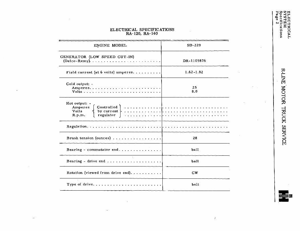

ELECTRICAL SPECIFICATIONS
ENGINE MODELS SD-220 SD-240 BD-269 RD-372 RD-406 RD-450 Cont R-6602
COIL (Delco-Remy) bullbullbull DR-11l5327 DR-1115327 DR-11l5327 DR-11l5327 DR-lllS327 DR-lllS327 DR-lllS2S1
DISTRIB UTOR bullbullbullbullbullbullbullbull DR-1l12355 Type vac auto Cam anglebullbullbullbullbull 4 bullbullbullbullbull 31 deg_37deg Initial setting (engine degrees) bullbull 20 BTC Vacuum advance (engine degrees) 15deg Automatic advance (engine
degrees) bullbullbullbullbullbullbullbull 30deg Total advance (engine degrees) bull 32deg
Retard (engine degrees)bullbull selective 20deg
Contact point setting bullbullbullbull 022 Contact point pressure (ounces) 17-21 Rotation (viewed from top) bullbull CCW Firing order bullbullbullbullbullbullbull 153624
DISTRIBUTOR TEST DATA Start advanceshy
Engine rpmbullbullbullbullbullbullbullbull 500 Engine degrees bullbullbullbullbullbullbull 2deg
Intermediate advanceshyEngine rpmbullbullbullbullbullbullbullbullbullbull 1800 Engine degrees bullbullbullbullbullbull 200
Macimum advanceshyEngine rpmbullbullbullbullbullbullbullbullbull 3000 Engine degrees bullbullbull 30deg
Distributor vacuum control
DR-1l12355 vac auto 31 deg_37deg 2deg BTC
15deg
30deg 32deg
selective 20deg
022 17-21 CCW
153624
500 2 0
1800 200
3000 30deg
DR-l112359 automatic
35deg 3deg BTC
none
27deg 30deg none none
018-024 17-21 CW
153624
400 150
1800 20deg
2700 27 0
DR-1l12357 automatic
35deg rsectgt BTC
none
22deg 27deg none none
018-024 17-21 CW
153624
500 15
0
1400 13deg
3200 22deg
DR-1l12357 automatic
35deg 5deg BTC
none
22deg 27deg none none
018-024 17-21 CW
153624
500 15 0
1400 13 0
3200 22deg
DR-11l23S7 automatic
35deg 5deg BTC
none
22deg 27deg none none
018-024 17-21 CW
153624
500 15
0
1400 13 0
3200 22deg
automatic
CCW
r t z f11
3 ~ ou -u C () 7 en f11u ltn [Tl
3 Jgt z C Jgt r
(De1co-Remy) bullbullbullbullbullbull DR-1116049 DR-1116049
Distributor Test Stand figures will be one-half of these specifications Test Stand rpm only For maximum engine rpm see Engine Section
00 M d t- ~ M8 () 00 gtlt -
1J~oo~ Ilgt~l-l()OQoMgtrDJgtt- ~(Il
Donated by John amp Susan Hansen - For Personal Use Only
ELECTRICAL SPECIFICATIONS 11 UHIl M 110 gt-ltt OQ(1)(flM
ENGINE MODELS SD-220 SD-240 BD-269 RD-372 RD-406 8 ClRD-450 Cont R-6602 (1)
N~M ~l1oGENERATOR-50 AMP (Delco- lt+ Cl
Remy) bullbullbullbull DR-ll06757 I DR-ll06757I DR-ll06757I DR-ll06757I DR-ll06757 I DR-ll06757 I DR-ll06822 g gtshyField current (at 6 volts) ID t
amperes bullbullbull 170-195 170-195 170-l95 1 70-195 170-195 170-195 Cold output shy
Amperes 50 50 50 50 50 50 50 Volts bullbullbullbull 75 75 75 75 75 75 75 Rpmbullbullbull 1410 1410 1410 r1410 1410 1410
Hot output- t zAmpereSControlled [T1Volts by current bull Rpm regulator 3
volt and volt and volt and volt and volt and volt and volt andRegulation bull bull bull bull bull bull t ~ curren current current current current current current o Brush tension (ounces) 25 25 25 025 25 25 Bearing - commutator end bull ball ball ball ball ball ball --l Bearing - drive end bull bull ball ball ball ball 0ball ball Rotation (viewed from drivemiddotend) CW CW CW CCW CW CW ()Type of drive bull bull bull bull bull bull belt belt belt belt belt belt belt 7
J)GENERATOR (LOW SPEED CUTshy [T1
IN) (Delco-Remy)bullbull DR-ll06758 IDR-ll06758 0 Field current (at 6 volts) lt
amperes bullbull 1 70-195 170-195 n [T1
Cold output shyAmperes 40 40 3 Volts bullbull 75 75 raquo zRpmbullbullbull 1165 1165 c
Hot output shy raquo AmpereS) Controlled r Volts by current bull Rpm regulator
volt and volt andRegulationbullbullbull bull bullbullbull I current current
Brush tension (ounces) 20 20 Bearing - commutator end bullbull bali ball Bearing - drive end bull bull bull ball ball Rotation (viewed from drive end) CW CW Type of drivebullbullbullbull belt belt
Donated by John amp Susan Hansen - For Personal Use Only
ELECTRICAL SPECIFICATIONS
ENGINE MODELS SD-220 SD-240 BD-269 RD-372 RD-406 RD-450 Cont R-6602
GENERATOR-30 AMP (Delcoshy
o ~ Remy) bullbullbull DR-1102714 I DR-II02714 IDR-II027141 DR-II02714 I DR-I1027141 DR-II02714 Field current (at 6 volts) -l oamperes bull 175-190 175-190 175-190 175-190 175-190 175-190 0Cold output shy
Amperes 30 30 30 30 30 30 SciVolts bullbullbullbullbull 8 8 8 8 8 8 c Rpmbullbull 1750 1750 1750 1750 1750 1750 ()
Hot output- A UlAmperes Controlled 1 [Tl
Volts by current 0 Rpm regulator bullbull
v~it ~~d volt and volt and volt and volt and volt and ltnRegulationbullbullbullbull [Tlcurrent current current current current current
Brush tension (ounces) bullbull 24-28 24-28 24-28 24-28 24-28 24-28
raquo ~ Bearing - commutator end bull bronze bronze bronze bronze bronze bronze Bearing - drive end bullbullbullbull ball ball ball ball ball ball z Rotation (viewed from drive end) CW CW CW CW CW CW c raquoof drivebullbullbullbullbullbull belt belt belt belt belt belt r
en M 0 t () M 8 ()en- -l
U ~ en PIti-l()(lQOMgt()iI7twm
Donated by John amp Susan Hansen - For Personal Use Only
ENGINE MODELS
VOLTAGE REGULATOR-30 AMP (Delco-Remy) bullbull
Type bullbullbullbull Current regulator shy
Current setting-amps (hot) Air gap
Voltage regulator shyVoltage setting-volts (hot) bull Air gapbullbullbull
Cutout relayshyClosing voltage-volts (hot) Air gapbull Point openingbullbull
VOLTAGE REGULATOR-50 AMP HIGH OUTPUT (Delco-Remy)
Type bullbullbull Current regulator shyCurrent setting-amps (hot) Air gapbull
Voltage regulator shyVoltage setting-volts (hot)
Air gapbullbull Cutout relayshy
Closing voltage-volts (hot) Air gap Point opening
VOLTAGE REGULATOR-40 AMP LOW SPEED CUTIN (Delco-Remy) bullbull
Type bullbull Current regulator shy
Current setting-amps (hot) Air gap
Vol tage regulator shyVoltage setting-volts (hot) Air gapbullbull
Cutout relayshyClosing voltage-volts (hot)~ Air gapbull Point opening bull
ELECTRICAL SPECIFICATIONS trl () (fIl fl) 0 gtlt rshy
()Q (l) () MSD-220 SD-240 BD-269 RD-372 RD-406 RD-450 Cont R-6602 (l) 8 l ()
lMl ~~o lt+ ()DR-IllB303 IDR-IllB303 IDR-IllB303 IDR-IllB303 I DR-IllB303 I DR-IllB303
vibrating vibrating vibrating vibrating vibrating vibrating g gt m rshy
30 30 30 3030 30 075 075 075 075 075 075
74 74 74 74 74 74 middot 075 bull075 075 075 075 075 r
t64 64 64 64 64 64 z
middot 020 020 bull020 020 bull020 020 [T1 020 02011 020 bull020 020 020 ~
~ DR-1118333 IDR-IllB333 IDR-llIB333 IDR-1l18333 IDR-ll1B333 I DR-1l18333 I DR-ll1B368 o
vibrating vibrating vibrating vibrating vibrating vibrating vibrating 0 -I50 50 5050 50 50 50 0OB2 bullOB 2 OB2 OB2 bull082 082 075 C ()
74 74 74 74 74 74 143 7 075 075 bull07 511 bull07 5 bull075 075 075 (f)
64 64 64 64 64 64 12B ~ middot 020 020 020 020 020 020 020 lt 020 020 bull020 020 020 020 020 n
[T1
raquo ~ DR-1118366 IDR-II1B366 zvibrating vibrating c raquo40 40 r 075 075
74 74 bull07 5 075
64 64 020 020 middot 020 020
Current and voltage specifications apply only at operating temperature Operating temperature shall be assumed to exist after not less than 15 minutes of continuous operation with a charge rate of B-I0 amperes
Donated by John amp Susan Hansen - For Personal Use Only
c
ELECTRICAL SPECIFICATIONS
ENGINE MODELS SD-220 SD-240 BD-269 RD-372 RD-406 RD-450
SPARK PLUGS
AC standard pro- 44 Corn 44 Corn 45 Corn 43 Corn 43 Corn 43 Corn Champion heavy duc- J-7 J-7 J-8 J-6 J-6 J-6
~ Auto-Lite service tion AN5 AN5 AN7 AN5 AN5 AN5
~
~ AC hot 45 Corn 45 Corn 45 Corn 44 Corn 44 Corn 44 Corn Champion mod~rate J-8 J-8 J-8 J-7 J-7 J-7 Auto-Lite service AN7 AN7 AN7 AN7 AN7 AN7
AC standard 44 Corn 44 Corn 45 Corn 43 Corn 43 Corn 43 Corn Champion heavy bull J-7 J-7 J-8 J-6 J-6 J-6 Auto-Lite service AN5 AN5 AN7 AN5 AN5 AN5
AC cold 43 Corn 43 Corn 44 Corn 43 Corn 43 Corn 43 Corn Champion severe J-6 J-6 J-7 J-6 J-6 J-6 Auto-Lite service AN5 AN5 AN5 AN5 AN5 AN5
Spark plug size 14 mm 14 mm 14 rnrn 14 mm 14 mm 14 mm Spark plug gap bull 028-032 028-032 028-032 028-032 028-032 028-032
STARTING MOTOR (Delco-Remy) I DR-ll07074I DR-II070741 DR-ll07967I DR-ll082171 DR-II090041 DR-ll09004 Voltage bull bull bull 6 6 6 I 6 6 6 Number of field coils bull bull bull bull 2 2 4 4 6 6 Bearing - commutator end bull cast iron cast iron cast iron cast iron cast iron cast iron Bearing - center cast iron cast iron cast iron Bearing - drive end bull bronze bronze bronze bronze bronze bronze Brush tension (ounces) bull 24-28 24-28 24-28 24-28 36-40 36-40 No-load test (with Solenoid or
Magnetic Switch)shyMaximum amperes bull 75 75 60 70 70 70 Volts bull 57 57 50 50 57 57 Rpm approx
Lock test shy bull 5000 5000 6000 3500 2200 2200
Maximum amperes bull 525 525 600 600 600 600 Volts bull bull 34 34 30 30 30 30 Torque (lbft)(min) 12 12 15 22 35 35
Rotation (viewed from drive end) CW CW CW CW CW CW
MAGNETIC SWITCH (Delco-
Remy) bullbullbullbull 1 DR-1465 DR-1465 DR-1465 DR-1465 DR-1465 DR-1465 Current consumption (at 6 volts) 57-70 57-70 57-70 57-70 57-70 57-70
Cont R-6602
82 Corn 5 Corn BT4
82 Corn 5 Corn BT4
18 mm 023-027
12 6
bronze
bronze 36-40
65 114 6000
725 50 44 CW
rshyc z [T1
3 o -l o 0
-l 0 C () A (f) [T1 0 lt () [T1
$ tgt z C tgt r
(Jl M U t ~ M Cl ~(Jlgt-3
1J n gtltoPlPl(Jl
OQ ~ gt-3 Cl roOM~ lTI~gt
Donated by John amp Susan Hansen - For Personal Use Only
~CJ)CJ)11 Iraquo U -lt t-OQ(1)CJ)11(1) 81-3(1 0---111-3
ELECTRICAL SPECIFICATIONS R~~ (1
ENGINE MODELS SD-220 SD-240 BD-269 RD-372 RD-406 RD-450 Cont R-6602 ~ ~ HEADLIGHT SEALED-BEAM
UNIT (Guide) bullbullbullbull 924791 924791 924791 924791 924791 924791 5930856
IGNlTION SWITCH (Delco-Rerny) 1116465 1116465 1116465 1116465 1116465 1116465 1116465 r tLAMPS (BULBS) z
Stop and tail light bulbshy [Tl
Voltagebullbull 6-8 6-8 6-8 6-8 6-8 6-8 12-16 sCandle powerbull 21-3 21-3 21-3 21-3 21-3 21-3 21-6 Contactbullbullbullbull DC DC DC DC DC DC DC
Parking light bulbshy0Voltage 6-8 6-8 6-8 6-8 6-8 6-8 12-16 -Candle powerbullbull 3 3 3 3 3 3 3 0
Contactbullbullbullbull SC SC SC SC SC SC SC CInstrurnent light bulb- n
Voltagebullbullbull 6-8 6-8 6-8 6-8 6-8 76-8 12-16 Candle powerbullbullbull 2 2 2 2 fJJ2 2 15 [TlContactbullbullbullbull SC SC SC SC SC SC SC 0
Beam Indicator bulbshy ~ Voltagebullbullbull 6-8 6-8 6-8 6-8 6-8 6-8 12-16 n Candle powerbullbullbull 1 1 1 1 [Tl1 1 1 Contactbullbullbullbullbullbull SC SC SC SC SC SC SC s
gtshySTORAGE BATTERY z Type (Auto-Lite) bull c2H-I05 2H-I05 2H-135R 4H-152R 4H-152R 4H-152R 4H-152RSpecific gravityshy gtshyrFully charged at
1280-1290 11280-1290 11280-1290 11280-1290 11280-1290 11280-1290 11280-1290Recharge at 1225 1225 1225 1225 1225 1225 1225
Voltagebullbullbullbull 6 666 666 Arnperes hours at 20-hour rate 105 105 135 152 152 I152 152Arnperes-20 rninute rate 133 133 170 180 180 180 180 Terrninal grounded bullbullbullbullbullbullbullbullbull positive positive positive positive positive positive positive
Donated by John amp Susan Hansen - For Personal Use Only
QJgt
~ Fi t
~ Vi c 0 1
1 g
~ q reg
1-shyBattery -_ I
~ ~~Hom relaY-RHn reg- Fuol F~ Modol Rmiddotl53 ~~ I I 1 and Rmiddot163
~14 Junction I block (20)
-H--LI ~ bull
Starting push switch ~ (U) (ll)-- RH 01 _ yindshield
~~tl====plusmn=l-(~ lt b IlgmtIon switch - gt1-- Wlper motor ~ I shy1 1-yJ rTi r-- ---B
--_+--til ~ amp ~~ i Windshi Id
~Igt Bat coil
L+====J~
1
Temp
Cab i groundI~
7tJ _ Horn~ rX11 26 reg Y(
_ _ 14 gaJoYZ)
C (z6) I ~ LHD~ m 0
~ 0 ~
3 ~Tmiddot -iilJl ~~l--I --wiper swi~ch 2 or PI CirclntFltG-- Circuit I or b~t1t bre~eS~~l--breaker ___L uhlt tch I ~S-t~--1-J - ij--- -lnstr lightI
I I I --High L__
---- l=reg Inott k~A~m P 1---------- Dome light
A ----I switch
w~_9It-_J_1FuelII I Dome light
J rV~i~~h~nd ignition
---~-i LHD~- r- --Stop light switch
~ gtJ--gt
-~ Fuel--Trailer taillight 1f4Y d I T gao 21 ad
Bat J reg i[]nectors railer stop light ll---1~a~---- 22 16 Enlatged view I1 llR bull Hom bu 14 ~l~ ~ 130 left hd IL AA Ul n ()egulator 14 ga R 110 t R165 ~ft hd Ito 165 nght hd It llgtl-j
t-cl~c~8middotTI66 IIgt ~
~sectM~Fig Imiddot Wiring circuit diagram (RmiddotllO R120 Rmiddot1lO Rmiddot150 Rmiddot160 series trucks) ~s1
~6
Cable Color Emor Description
r=eh4~eratOrficlr-~middot 8 Toenerator ann
cbullr Z [lJ
~ 0 0c ac ()
B 4 ~ D 12 E 1 en F 16
G 14 ~ 16 -()P 16
[lJ
Donated by John amp Susan Hansen - For Personal Use Only
Parking light ID-- 16 ga
UtntnM IlIC11~t OQltnM ~ 1-3 Cl NgMI-3
-5c ClCkcuitNo Cable Cable Color shyrtf lt16 gamiddot1 ~ I Cab ground -- Gauge or DescriptionLotto
~ I I 16 Generator aeld t
Circuit 2 8 Generator armHead-J rYFi gao I~I Light breaker 4 8 Regulator to am-light ~reg Starting motor switch meter Generator I 5 8 Ammeter feed
---In I ~ 11 12 Ignition switch feed Junction 12 16 Ignition switch to Ig] nltlon coUblock --reg ltElt 14 16 Starting
~~~J~Ignition and 15 12 Light switch feed 16 12 Dimmer switch feed----0
I YJ starting switch 17 1204 High beam feed 1 17 16 High beam indicator
17 16 High beam head ~f 1 -reg light leads r18 16 Low beam head light leads~+k~ Bmm nampaOX 18 14t16 Low beam feed Z
20 16 Parking light leads 20 1608 Parking light feed 21 16 Taillight ~tislt lw 111111 A+lt=~~M [T1
22 16 Stop light~ ~ 1 40) 25 16 Connector 10 relay -- 40 26 1204 HOJn and horn reshy
lay feeds 26 12 Horn and stop light ~ 11kJ1 - reg feed 027 16 Instrumenl feed 30 18 FuelgBugeI Hom 33 18 Temperature gauge36 18 011 pressure gauge 138 18 Dome light40 16 Instrument lights C 80 16 Ignition call to dtemiddot ()
tributor 91 14 Headlight ground ~ B 4 Battery groundC 3 Engine ground UJ
Fuel I (26) middotI~II D 12 Cab ground I I I I I-I-T ~ ~ E 1 BBampcable
H 16 Horn utton to conmiddot nector ~ ~Hom button Engine ground 0) Dome light ()-
Fuel [T1J-reg~I-_StoP light -______11 I I I sWitch A~ ~ I Stop
OOiTt-~ ~ 21) 1= I
E-Fig 2middot Wiring circuit diagram (RMl20 RM150 series trucks)
8-7181
Donated by John amp Susan Hansen - For Personal Use Only
9 Circuit Cable Color
No Cable or r Index Gauge Description
~ Em Letter
1 16 field
1 1regaII ) regBattery 2 rgt17 18 j =- -~--r-
~
ltIi II~ I -5shy I
11 Starting motor M 12V~II 14l xv 15
11 4 or H
F 16 Q 17~ 3 or T 17 A
Junction block 2 or P Ircult 17g C 18 ~ Generator )J 1 or bat breaker 18
20 ~ D 20 0 r-
L18 ga 22~IIJ~[==~~~~ 21 bull ~ Temperature gtl Light switch 26
26 ~ 27114 gao ~~ 33 -= 40 1- Instrument light 30
33- 3fl--- t Distributor cabreg _1- Speedometer 36 ov ground ~ I Hgh bea ~ -_~ 1 m 38 400 ~ r P I - indicator light d
~ 71 080
--=--- 91-----70~--I Ammmiddot0
A ~ ~ P I 8 Ch
r-Tl--Instr lightOil preS8ure_~ D
Dimmer switch--- bull ~l--Fuel rJg ~ (i8)___~
F
I f ~~~ ht H 16--t-+~-rir-_+-H-_IJ ~ Dom~ light ~ G 14te1~~
~
E
~ ~~ P 16sWitch
Hom Hom ~~~~~~~~itch )Sin Stop ~ I relay
1 -~----~ 7JI (TUI Connector ~1 E la d bull
L-- I I I I 16 a n rge View ----Ell g AA
Trailer stop light
~~ J 6 Hom button F~l Trailer tail light ~ I ~ ~ ~ I-ll ~ l
I-l oooonIregII ~ I (zO) (z6) li6) -=-J tIl12 gao 14 gao ~~~ F Gen Bat Regulator ~ 1
8-7179 t1 n D1ll1t~H ~gl-l~Fig 3 Wiring circuit diagram (RCl60 series trucks) wgtSl
Donated by John amp Susan Hansen - For Personal Use Only
ijCflCfltltJ1lIngtgtltt-
Cable Gauge
Cable Color OQ ~CflM ngt ()gtltJ
gt-~~ ()
gtshyt-
reg--____sa~ng push switch
)-If JRR D l r-r--lS~~~~~~tCh I 1--1 - I Windshield
I I l---h L I - I wiper motor
For Models R173 and Rmiddot183
Windshield wiper switch
Circuit --breaker
- -Speedometer
--Instrument light
- - High beam indicator
--Instr light
- Dome light switch
Dome light
Starting and ignition switch- LRD
Stop light switch
Trailer stop light
Trailer tail light
G 14 H l~ I aun PUbU DUUVU I p 16 1 bull bull
Stop
J I
Tail
Enlarged view AA
l r Z [T1
E o d 0
~ n ~
~ () [T1
Stop and tail light
BmiddotTlIl1 EmFig 4 - Wiring circuit diagram (R-170 RF-170 R-180 series trucks-not R-185)
Donated by John amp Susan Hansen - For Personal Use Only
a I E~gt lt )
I Cable Color
~ ~
r c Park Head[l~IIr1 reg ~ ~ Light light 17 18 B -V Q ~ I 91 I
3 I ~ i~atte~1IAI J I reg
g I I ~ ~~ 4 or H a 130rT
f
2 or p
-- ~ j ~Sl i2o) I or bat
[18~1 ~ -- I
Junction block r~ II I~i ZDistribu~ _
118 ga--i I [T]
s 116 ga~---t1_ 114 gareg-J Lshy
(D-- [L1 ~ CD---- shy
~ () ~ Dimmer switch ~IJshy
Hom relaY 1 D
B ~ F11~r Hom E n
20 [T] __9 _ 1ampimiddotmiddotIU~ __LH 1~ u _~L L__Junction block Enlarged view p
~ AmiddotA i
button z c z
_W-~ ll
Park F Gen Bat C b k d ttrcwt rea er anLight llRegulator terminal block assembly B-TSO Cl () ro 14 1-3
tl~gtlt~ill 00 (lQol-3()roll1gtFig 5 Wiring circuit diagram (RC180 series trucks) gtEt
Donated by John amp Susan Hansen - For Personal Use Only
tJ tlltll trl lUngtltt
IlQ ~ (I) tl III Cl Ogtrl gtE~
~ t
Fuel
p r Z [T1
3
(i7)--shy ~ ~
J Distributor I shy(iO ___1 R
~ ~ rn
Engine ground ~
8-7168 Ell(R185 truck and Rmiddot190 RF190 R200 Rmiddot210 RFmiddot210 series trucks)
Donated by John amp Susan Hansen - For Personal Use Only
a r PARK EmiddotlI LIGHt ~ g ~
f ~ 0
E 0 iii GENERATORJi
If JUNCTION BLOCK
~
~ ENGINE GROUND
II Z z c z j raquo ~ ~
raquo ~ II
~ ii
Fig 7
20
r--------shy STARTmiddotPUSH I r- ---~ SWITCHmiddotRHO I I
I I r ~I I ) BI I r --_ B I IGNITION ~
~---------t----+-+---~ SWITCHRHO I I I sect-------------~ I Ii bull ( I I
P I
16ilhJ Iii ~yenHJSW(TCH ~ =a( ~ f11i rmiddotLIGHTER
- Z [T]
~ ~ () ~ til
~ () [T]
TRAILER STOP LIGHT
TRAILER TAil LIGHT
IltJ t IltJ
en rft 08-1090 ell j tIlQ traquo ~
~gtzl~ - Wiring circuit diagram 12middotVolt System (Rmiddot1aS to Rmiddot210 RFmiddot190 and RFmiddot210 trucks) Jgtilt
Donated by John amp Susan Hansen - For Personal Use Only
Donated by John amp Susan Hansen - For Personal Use Only
ELECTRICAL SYSTEML-LINE MOTOR TRUCK SERVICE MANUAL Section A
Page 1
CIRCUIT DIAGRAMS
Electrical circuits for the various L-Line trucks are illustrated on following pages
Cables are protected wherever necessary by 100m or conduit and by rubber grommets to prevent chafing where contact is made with the chassis cab or body Cables are also securely clipped at important points and connectors are used to facilitate inspection and servicing
All electrical connections must be kept tight and clean
Wiring Harness Individual Cable Circuit Identification
Wiring harness cable circuit identification has been established by (UNumber Codingll) imshyprinting numerals at regular intervals along the individual cables except for short cables which are numbered only at the ends The prime purpose of cable identification is to facilitate wiring harness installation since in harness generally only the extreme ends of the indivishydual cables are visible
The accompanying circuit numbered list (from No 1 to 124) itemizes circuit numerals used on L-Line Wherever a particular circuit is used on a vehicle the identification numeral for that circuit will always be the same For example the generator field circuit cable will consistently be Circuit No1 the generator armature circuit will always be Circuit No2 etc (see list) In the same manner if a circuit is not used on a vehicle the numeral for that circuit will not be used For example vehicles not having a 24-volt radio-feed cable will not have a circuit No 48 in the harness
Circuit numbers on the list for which no circuit description is given are not presently used by International and these circuits have been reserved for possible future assignment
Circuit Nos 28 to 31 inclusive each pershytain to fuel tank-to-receiver unit circuits Because of the variety of possible combinations for these hook-ups reference should be made to the illustrations for proper connection of cables (Fig 1)
Circuit Diagrams
Wiring circuit diagrams are illustrated in the owners and drivers manuals and in the service manuals With each of these illustra-
PRINTED IN UNITED STATES OF AMERICA
tions there is a key to the diagram which conshytains pertinent information as to circuit number and cable gauge
Individual Cable Replacement
It is recognized that replacement of one or more individual cables may be necessary and that complete harness replacement may be imshypractical For this reason the chart on each circuit diagram specifies the proper-gauge cable to be used and which can be made up locally from bulk stock
Circuit Numbers And Circuit Names
cmCUIT CIRCUIT NAME NO
1 Generator field circuit
2 Generator armature circuit
3 Generator ground circuit
4 Generator regulator to ammeter or shunt
5 Ammeter (or shunt) to starter switch
6 Battery to starting motor switch mounted on starting motor
7 Battery ground (including master switch if in this circuit)
8 Shunt to ammeter positive
9 Shunt to ammeter negative
10 Circuit breaker common feed to any point fed from regulator (Bat)
11 Ignition switch feed (or magneto ground)
12 Ignition switch to ignition coil (or booster switch to booster coil)
13 Magneto ground
14 Magnetic starting motor switch to push button switch to feed
15 Main light switch feed
16 Light switch (HT) to service headlight or dimmer switch
17 Dimmer switch to upper beam and to beam indicator
18 Dimmer switch to lower beaIll
Donated by John amp Susan Hansen - For Personal Use Only
ELECTRICAL SYSTEM L-LINE MOTOR TRUCK SERVICE MANUALSection A Page 2
19 Light switch (Bod) to blackout driving lamp including resistor
20 Light switch (BHT) to parking lamps or marker light
21 Light switch (R) or (HT) on blackout switch to service tail light
22 Light switch (H) or (S) on blackout switch to service stop light
23 Light switch (BS) to blackout stop light
24 Light switch (BHT) to blackout tail light
25middot Horn switch (including feed) to horn (or horn relay)
26 Horn relay feed and horn relay to horn
27 Instruments feed (instruments with polarshyity)
28
29 Fuel gauge sender to receiver -shy
30 See illustrations Figure 1
31
32 Oil level gauge sender to receiver
33 Water (and oil) temperature gauge sender to receive r
34 Low engine oil pressure warning light cir shycuit (including feed)
35 High water temperature warning light cir shycuit (including feed)
36 Oil pressure gauge sender to receiver
37 Outlet socket or junction block
38 Dome light circuit (including breaker and switch)
39 Map light circuit
40 Instrument light circuit
41 Starting motor to battery (-) (series paralshylel switch hook-up)
42 Series parallel switch (B+) to battery (+)
43 Series parallel switch (A-) to battery (-)
44 Series parallel switch to ground
45 Series parallel switch (B-) to starting motor
46 12 - Volt radio circuit (including radio master switch)
47 Slip ring feed
48 24 Volt radio feed
49 Receptacle Auxiliary power outlet posishytive lead
50 Receptacle Auxiliary power outlet negashytive lead
51
52 6-Volt tap on taillight dropping resistor to tail light
53 Electric brake control circuit
54 Fuel cut-off circuit
55 Flame primer low tension circuit
56 Flame primer high tension circuit
57 Instrument panel ground
58 Compass light circuit
59 Cab (or hull) ventilating fan circuit
60
61 Auxiliary generator field
62 Auxiliary generator armature
63 Auxiliary generator ground
64 Auxiliary generator regulator to battery (including heater transfer switch)
65 Auxiliary generator starter relay circuit (including switch and feed)
66 Auxiliary generator starter to transfer switch (including starter or relay)
67 Emergency stop switch ground
68 Battery interconnecting cables
69 Resistor to ground terminal on trailer coupling
70 Regulator ground
71 Windshield wiper ci rcuit
72 Low transmission oil pressure indicator circuit with feed
73 Radio terminal box to ground
74 Series parallel switch to solenoid relay
Donated by John amp Susan Hansen - For Personal Use Only
ELECTRICAL SYSTEML-UNE MOTOR TRUCK SERVlCE MANUAL Section A
Page 3
75 Stop switch circuit (SW to SS on blackout SW)
76 Fuel pump control feed
77 Fuel pump switch to fuel pump (left side)
78 Fuel pump switch to fuel pump (right side)
79 Fuel gauge sender ground
80 Ignition coil to distributor
81 Battery to starting motor switch (or term block) including master switch
82 Starting motor switch (or term block) to starting motor
83 Blackout light switch (TT) to tail connecshytion on trailer receptacle
34 Blackout light switch (SS) to stop light conshynection on trailer receptacle
85 Low air pressure indicator buzzer (or light)
86 Ground on series parallel switch to amshymeter (including circuit breaker)
87 Spotlight circuit for trucks and wreckers
88 Winch torque limiter control
89 Automatic choke
90 Trailer receptacle to ground
91 Headlight to ground
92 Parking light to ground
93 Starting motor relay to ground
94 Starting motor relay auxiliary grounding circuit
95 Tail light to ground
96 Speedometer sender feed
97 Tachometer transmitter feed
98 Tachometer transmitter positive (+) to tachometer positi~e (+)
99 Tachometer transmitter negative (-) to tachometer negative (-)
100 Tachometer transmitter to ground
101 Defroster switch to defroster motor including feed
102 Heater switch to heater motor including feed
103 Cigar lighter
104 Fog light switch to fog light including feed
105 Tractor light (Back-up)
106 Carburetor idle fuel shut-off valve
107 Marker or identification light circuit
108 Clearance light circuit
109 Mico brake lock circuit
110 Fuell gauge switch (C) to ground (dual safety tanks)
Ill Lockoff solenoid valve to switch (including feed)
112Auxiliary ammeter to ground-negative
113 6-Volt radio circuit (including ratio master switch)
114 Direction signal left turn-front
115 Direction signal left turn-rear
116 Direction signal right turn-front
117 Direction signal right turn-rear
118 Direction signal feed circuit
119 Voltage divider ground
120 Voltage divider feed or instrument resisshytor feed
121 Overdriv~ relay to ignition switch
122 Overdrive relay to overdrive governor (including kickdown and overdrive switch)
123 Overdrive solenoid to ignition coil (includshying kickdown switch)
124 Overdrive solenoid to battery (including relay feed)
f~IN1poundD IN UNITED STATES OF AMtRlcA
Donated by John amp Susan Hansen - For Personal Use Only
ELECTRICAL SYSTEM L-UNE MOTOR TRUCK SERVICE MANUALSection A Page 4
30 30 30 30 29 29
Underskirt tank Underskirt tank and right side auxiliary tank
[ J 30 ~ 29
Right side tank 29
Underskirt tank and dual auxiliary tanks
28 28
Left side tank ~
D~ 31~ Left side tank andRear end tank
right side auxiliary tank 30 0
Rec
gauge 30 30switch 28 28
Underskirt tank and left side auxiliary tank
Fig I - Fuel tank to receiver circuits Because of the variety of possible combinations for these hook-ups reference should be made to the above chart for proper connection of cables
A-22921
Donated by John amp Susan Hansen - For Personal Use Only
Circuit CablColorNo or Cable orIndex Gauge Description
~r Letter
Fuel gauge sender unit _ 1 14 Generator fieldreg 2 8 Generator arm 4 8 Regulator to ammiddot ~ meter 6 8 Ammeterf_d
11 14 Ignition switch feedbull 12 14 Ignition switch to igshy~ nition coil ~ I 14 14 Startinq
16 10 Light switch f d z 16 12 Dimmer switch fed C reg 17 12 Hiqh beam feed z Generator Starting 17 14 High beam h admiddot rmotor litht lead
17 16 Hig beam indieamiddot ~ ~
tor t 18 14 Low beam fed1E 4ga 18 16 Low b am h admiddot
[T1 z
1 li~htlad~
m
Engine freg middot ~
20 14 P ing feed- sect 20 16 Parking light leadI 1~16ga 21 14 Taillight
ii
~ reg 22 14 Stop light o $
bull -- Junction block 26 10 Horn and stop light feed -J
Oil 26 12 Horn lind horn re- o lay fsedslight 027 14 Inlltrument feed
27 16 Instrument feed 29 16 Fuel gauge -J 30 16 Fualgauge 033 16 Temperature gauge36 16 Oil pressure gauge C 40 16 Instrument light o71 14 Wiper switch feed 80 14 Ignition coil to di 7
tributor 91 14 Headlight ground (J) A 16 Natural with circuit
letter A or black light B 0 Battery ground ~
C 3 Engine groundreg D 12 Cab ground lt E 0 Battery cable (=)F 16 Natural with circuit [T1letter uF or red G 14 Instrument bUB bar H 14 Horn push button $J 16 Fuel gauge groundJ~llJ P 16 Natural with circuit raquo
Jetter p or ~nJJ~~~~vIII6 z c
dStop raquoI-~-~ x]
r~ ~ Enlarged
Fuel gauge sender unit view X-X
CD M l M
Ul 0 roUlt-J~Regulator
8-4737 O~gt-ltdPl Ul OllOt-JOFig 2 - Circuit Diagram - L-IIO Series to L-IBO Series inclusive (Hot Metro) rolMgtshyltIgt-~l
Donated by John amp Susan Hansen - For Personal Use Only
t1CflCflM Ilgt(l)O-ltt
()QOCfl(l)~-JM
o ()O-l -J -J
gt ()
gt t
r t z [T1
$
~ o 0 -1 0 C () ~ CJ) [T1 0 lt ()
sender unit [T1 Battery ground strap
$ raquoJunction block --- ---Stop light switch z Magnetic starting switch c
--shy-- raquo
Horn relay r Head light
8-4696
Fig 3 - Diagram showing location of various electrical units l-IIO Series to l-J80 Series inshyclusive (Hot Metro)
Donated by John amp Susan Hansen - For Personal Use Only
Circuitj Cabl ColorNo or Cabl Ind x Gauge or
DcriptionLetter
1 14 Generator field Fuelgualle sender un~ 2 8 Generator arm
4 8 ReGulator to am
z z c z
m ~
~ co o ~
bull ~ bull
fl-----shy= I I I I
regregreg14 ~a 16 ga 16 ga
Junction block
Enline Iround
~ I
Junction block
~ 14 ga 16 ga
~~~ I 1 I I 1 I I I
1--1
14 ga
~
Generator
)1) 0
Distributor I I 1
Dimmer switch
Circuit breaker
~
and terminal block I c assembly------shy
amp6l HornK 12
1 1 I
~
4 or H
3 or T 2 or p f
1 1 or Bat [1
(])shy ~
Windshield wiper motor
Circuit breaker
Instrument light
Tachometer
I I
5 11 12
14 15 16 17 17
17
18 18
20 20 21 22 26
26
27 27 28 29 33 36 40 71 80
91 A
B C D E F
G H J P
8 14 14
14 10 12 12 14
16
14 16
14 16 14 14 10
12
14 16 16 16 16 16 16 14 14
14 16
0 3
12
1~ 14 14 16 16
meter Ammeterfed Ignition switch fed Ignlllon switch to igshy
nition coil Starling Light witch fed Dimmer switch fed High beam fd High beam hadshy
lJ~ht lad Hig beam indicmiddot
tor Low bam fed Low bam hadshy
l~ht I ad Par ing feed Parking light lads Taillight Stop light Horn and stop light
f d Horn and horn ~
lay feds Instrument feed Instrument f d Fulgauq Fulgauqe Temperature qauQ Oil prebullbullu 9au9 Instrument light Wiper switch fed Ignition coil to disshy
tributor Hsadlight~ound Natural wi circuit
letterA or black Battry ground Engine groundCa qround Battary cable Natural with circuit
ltter F or red lnatrument bu bar Horn puah button Fuel gauge qround Natural with circuit
I_tter P or qre_n
X
~RXI Tail Stop ~
Enlarged view XX
r r Z [T1
$ 0 ~ 0u ~ u C 0 A en [T1u lt 0 [T1
$ raquo z c raquo r
l 14 p
Fig ~
Regulator
- Circuit Diagram - l-190 Series And Up
M t M
UlUl O ro gt-l
U lt 0III Ul OQogt-lOrolMtgt -Itgt~t
Donated by John amp Susan Hansen - For Personal Use Only
t1 tJltJl M1l)(1)tlaquo4tOQOtJl mt~~Windshield wiper motor I Windshield wiper switch _-Fuel gauge sender unit oogM~
Instrument light ~~ (R H tank)Dash panel gt~~ I lt~ ()
middot CIgar I I Speedometer ~~ ~ - I II I(l~ To tatlltght ~
Ignition switch ___ I f) Ammeter gauge ~ and stop light If Temperature gauge ~~ -- j f I ~
Pi -Fuel gauge I ___
~- ___ Oil pressure gauge ~ I1 ~__-- ~~ r
~ I - fI ~~-----Tachometer I --- --- ~ t --- I -- I zI -- ---1 - --~--Starting push switch [Tl - - ~J--
Light swltch----2gtmiddot I _--- J I Dome lIght sgt~ ~ Instrument lights oBeam indicator light~ gt- I
I --lCircuit breaker and terminalCab ground strap----- ---- I o
block assembly I 0ITemperature gauge Voltage and current regulator --l
Junction block sender unit--l Fuel gauge ender unit 01111 Ii I (L H tank) C
Ignition coil----J n _---Battery ground strap 7I~~ j)
II j ~J ~I~ _--Battery [Tl1gtV ( ~ I ~ Je 0~ ~~l~~~--~----Battery ltcable
~d~IV n [Tl~ I
~n 1bullbullbullbull
s~ I - I bull bullGenerator raquo z -Y Stop light sWitch
Oil pressure gauge 0 t 1 cEngine ground strap- llunler SWI c 1 sender unit raquo rJ bl k Magnetic starting switch unctIOn oc S h tartmg motorHeadlIg t
Parking light
8-4868
Fig 5 - Diagram showing location of various electrical units - L-190 And Up
Donated by John amp Susan Hansen - For Personal Use Only
ELECTRICAL SYSTEM
L-LINE MOTOR TRUCK SERVICE MANUAL Section B Page 1
BATTERY Storage Battery Equipment
Present production trucks are equipped with Auto-Lite batteries Code Dating
Each Auto-Lite Battery bears a shipping code stamped on one button of one cell connecshytor of the battery This button is indicated as nA in Fig 1
-----+- Button-A -i--- o o 000 (IT) e
Standard assembly Reversed assembly
e 00=--=00 0 $
End to end assembly
Positive button center cell 6-volt assembly
Positive button - cell adjacent to A-16015positive terminal cell- ll-volt assembly
Fig I
i r-II I
L bull J
r- I I __ t
Month Year A-23439
Fi g 2
The code date will be found stamped on the positive connecter button on the cell adjacent to the positive terminal cell See Fig 2
In the first row are two symbols the first is the month the second is the year of shipment for example - 8-9 which decodes August - 1949
In the third row the second space is used to indicate whether the battery was built dry or wet If there is no symbol in the space shythe battery was built wet If the space contains a letter yn - the unit was built dry If the letter Y is encircled thus - regthe battery was built dry and made wet before shipment
PRINTEO iN UNfTED STATES OF AMERICA
The following chart is the key to the code datings found on Auto-Lite batteries used in International Motor Trucks of later manufacshyture
Month Month Symbol Year Year
Symbol
January 1 February 2 March 3 1949 9 April 4 1950 0 May 5 1951 1 June 6 1952 2 July 7 1953 3 August 8 1954 4 September 9 1955 5 October 10 1956 6 November 11 1957 7 December 12 1958 8
Atmospheric Temperature Affects BatteryCapacity
The specific gravity of the electrolyte (distilled water and acid solution) must be maintained at 1225 to 1250 and the level of the solution should be at the star level in cell covshyers A fully charged battery has a specific gravity of 1280-1290 at 80 degrees (F)
To eliminate the possibility of harmful sulfation of plates a battery with a specific gravity of 1225 or less should be recharged to 1280-1290 at 80 degrees (F) battery tempershyature
The following chart shows the effect of atmospheric temperature on the capacity of a battery
State of PercentageTemperature (F)Charge Capacity
Full 80 degrees above 00 100 Full 60 degrees above 00 88
oFull 40 degree s above 0 75 Full 20 degrees above 00 62 Full Zero degrees 45 Full 20 degrees below 0o 20
Specific Gravity Affects Freezing Point of Electrolyte
Specific gravity of the electrolyte detershymines the temperature at which a battery will be harmed or damaged by freezing
Donated by John amp Susan Hansen - For Personal Use Only
ELECTRICAL SYSTEM
L-UNE MOTOR TRUCK SERVICE MANUALSection B Page 2
The following chart gives the freezing point of battery electrolyte at given specific gravities
Electrolyte FreezingSpecific Point (F)Gravity
1280 90 degrees below 0o
1220 I 30 degrees below 00
1210 20 degrees below 0o
1100 20 degrees above 0o
o1000 32 degrees above 0
Battery Record Card Form CTS-7
The Form CTS-7 Battery Record Card is the record or history of each battery received and shipped The card has spaces provided for allnecessary information pertaining to the batshytery One of these record cards must be mainshytained for each battery and it should reveal the complete history of the unit while in your posshysession
Upon receipt of a shipment of trucks from one of the factories or from another Branch the batteries must be removed immediately and battery record cards filled out for each battery THERE MUST BE NO DEVIATION FROM THIS PRAC TICE
The date received battery type code marking truck model and chassis serial numshyber must be entered on a separate record card for each battery
The specific gravity of each cell must be recorded on the card under TEST RECORD The date and the inspectorrs initials should also be shown in the space provided Any batshytery showing a specific gravity reading of less than 1225 must be placed on the charging line and brought up to 1280-1290 at 80 degrees (F) (battery temperature)
Subsequent inspections of the battery shall be made every thirty days and the specific gravity readings recorded and distilled water added if necessary This procedUre shall folshylow during the stay of the battery in your stock
Upon delivery of battery in a truck the record card shall be completed by recording
the specific gravity readings of each cell date of delivery truck model and chassis serial number and the name of the purchaser The card will then be filed in a manner similar to the Customers Record Card If the battery is delivered in a truck being transferred in another District the battery record card shall accompany the battery and shall be continued by the receiving branch
Battery Maintenance
The Ft Wayne and Springfield factories are exercising every care in the handling and rotation of batteries to assure the delivery of a fresh and fully charged battery with each and every truck delivered to the territory
The territory must also follow this pracshytice of rotation using the oldest batteries first as determined by the code datings stamped on the center cell connector button
To facilitate truck movement in and around the District or Warehouse a service battery should be prepared having long cables and clip ends
Battery Recharging
Suitable and adequate equipment for battery charging is available through the Motor Truck Service Section Chicago Office
_ The general procedure in battery charging is as outlined
1 With vent plugs in place wash the top of the battery if necessary using a solution of water and common baking soda Rinse with clear water
2 Remove vent plugs from each cell
3 Fill the battery cells with pure distilled water to star level in cell covers
4 Connect battery to the charger unit in series connecting the terminal outlet from the supply positive
of the first battery Connect -=---_- terminal of the first battery
terminal of the second so on through the number of
batteries being charged (Do not attempt to exceed the capacity of the battery charging equipment in the number of batteries to be charged at one and the same time) The last battery must have its negative terminal connected to the negative outlet of the charging unit
5 Adjust the charging rate in amperes to the lowest normal charge rate of~tl(~E1allest size battery according to the following chart
Donated by John amp Susan Hansen - For Personal Use Only
ELECTRICAL SYSTEM
L-UNE MOTOR TRUCK SERVICE MANUAL Section B Page 3
Batteries should remain on charge for a period of time sufficient to obtain normal volt shyage and specific gravity readings of each cell The required length of time will vary from 12 to 48 hours depending upon the state of disshycharge of the battery at the time it was placed on the charging line
NormalType of No ofVolts ChargeBattery Plates Rate
2H-I05 2H-I05R 6 15 7 Amperes 2H-120 2H-120R 6 17 8 Amperes
2H-135R 6 19 I 9 Amperes 3H-136R 6 17 8 Amperes 4H-152R I 6 19 9 Amperes 8T-200 12 25 12 Amperes
Temperature readings should be taken frequently to prevent the electrolyte temperashyture exceeding 110 degrees (F) at any time Should the temperature rise higher than 110 degrees (F) the charging should be discontinshyued and the electrolyte allowed to cool The charging of the battery may then and only then be continued
6 Cell voltage is determined by a normal electrolyte temperature of 80 degrees (F) Voltage readings are to be taken while the battery is on charge at the normal rate as specified in the foregoing chart
The cell voltage of a fully charged battery on charge at the normal rate should read as follows
Temp 80 degrees (F) - Voltage between 25 and 26 volts
Temp 100 degrees (F) - Voltage between 24 and 26 volts
Temp 11 0 degrees (F) - Voltage between 235 and 255 volts
A battery is fully charged when the cell voltage values are as shown in above table and there is no further rise in voltage over a period of two hours
7 Add water as necessary disconnect batteries from the charging line replace vent plugs wash the tops of the batteries and place in attachment room
Excessive Evaporation of Electrolyte Indicates Overcharging
When excessive evaporation of the elecshytrolyte is experienced you may be sure that it is an indication that the battery is being overshycharged
Necessity for too frequent battery reshycharging may indicate that the battery isbeing undercharged
Battery Not to Blame for Failure When Conditions Adverse
It has been shown that temperature plays an important part in affecting the capacity of a battery and that the colder the temperature shythe lower the battery capacity Bearing this in mind it will be seen that a fully charged battery is only partially capable at subzero temperashytures This fact coupled with the condition in which many engines are found brings about complaints regarding the size quality and construction of the standard equipment battery
There are times when it is necessary to increase the size of the battery or starting motor but such action should not be considered a cure-all for hard starting complaints during winter months Even when special equipment of this nature is installed it is still essential to
1 Use a lubricating oil with the correct body for Winter Service
2 Maintain distributer points in good condishytion and properly spaced
3 Have clean and properly spaced spark plug electrodes
4 Have good compression in the engine
5 Maintain all joints and connections between the carburetor manifolds and engine in a gas-tight condition
6 Ascertain that the carburetor choke valve is operating properly
7 Determine that the engine is well grounded and that the ground straps are fastened to contacts
Battery Warranties and Manufacturers Policy
Storage batteries used in International Motor Trucks are limited to a free repair or replacement warranty of 90 days against defecshytive material and workmanship beginning on the date the battery is placed in service
In accordance with this arrangement service adjustments after 90 days are based on miles of service or - whichshyever occurs first tioned for there are a customer will attain the limit of miles of service prior to the time limit set forth In such cases the adjustment will be made on the miles of service and not on the time limit
Auto-Lite Batteries whether installed as factory equipment by the Inte rnational Harshyvester Company or sold as replacements to
P~NTED IN UNITED STATpoundS OF AMERICA
Donated by John amp Susan Hansen - For Personal Use Only
ELECTRICAL SYSTEM L-UNE MOTOR TRUCK SERVICE MANUALSection B Page 4
International Harvester Truck owners are subject to adjustment as outlined below
Factory equipment or replacement batshyteries are adjusted according to the following table
Service Adjustment Chart
Battery I Mileage Imiddot TimeEquipment
i Adjustment AdjustmentType
2H-l052H-105R 15000 7-12 Months 2H-1202H-lZOR 18000 9 Months
2H-135R 21000 10-112 Months 3H-136R - 18000 9 Months 4H-52R 18 000 9 Months 8T-ZOO 24000 8 Months
Complaints on Battery Performance
Any complaints pertaining to battery pershyformance should be referred to the nearest Auto-Lite Service Station
Complaints on Service Facilities
Complaints on service facilities of AutoshyLite distributors must be referred to the Sales Department Motor Truck Service Division Chicago Office Accompany complaint with all details concerning the battery and the truck from which it was removed The matter will be handled with the manufacturer from the Chicago Office and not by the District direct
Batteries Older Than Four Months at Time of Delivery
Motor Truck Service Bulletin No 82 1931 pertained to batteries which were on hand and which were older than four months according to code dating That bulletin advised that these batteries shoula be delivered in proper rotation but that they should be properly identified by stamping the letters IHCII on the center ce1l connector button Battery Record Cards Form C TS-7 were to be notated with this information Customer Record Cards were to bear a notashytion to the effect that the battery was past the four months code dating
PROPER AND CONSISTENT ROTATION OF BATTERIES IN STOCK MUST BE FOLshyLOWED AND THE OLDEST BATTERIES ACCORDING TO CODE DA TINGS DELIVERED FIRST
Strict Adherence to Instructions Necessary
All persons who have occasion to handle batteries or battery transactions should thorshyoughlyfamiliarize themselves with the instrucshytions pertaining to maintenance of batteries
withbattery warranties and the manufacturers policy There should be no departure from the instructions as outlined
It must be remembered that while the manufacturer is under certain obligations in accordance with the warranty policy of the batteries we too are not absolved of obligation to the manufacturer to do our part of the arrangement and policy
It is felt that of all the instructions outlined herein that the fo1lowing are the most imporshytant and no excuse can be accepted for deparshyture from them
1 REMOVAL OF ALL BATTERIES FROM THE TRUCKS AT THE TIME THEY ~~RE RECEIVED AT THE BRANCH AND KEEPING THEM IN THE ATTACHMENT ROOM OR BATTERY ROOM UNTIL THE TIME OF DELIVERY
2 INSPECTION OF BATTERIES EVERY THIRTY DAYS AND MAINTAINING THEM AT THE PROPER WATER LEVEL AND AT THE PROPER SPECIFIC GRAVshyITY READINGS
3 KEEPING OF FULL AND COMPLETE RECORDS OF THE BATTERY ON THE BATTERY RECORD CARD FORM CTS-7
4 PROPER AND CONSISTENT ROTATION OF BATTERIES IN STOCK DELIVERING THE OLDEST BATTERIES FIRST
5 INSTRUCTIONS TO THE CUSTOMERS IN THE PROPER CARE OF THE BATshyTERY AND A CAREFUL STUDY OF THE REQUIREMENTS ON THE BATTERY AND CORREC TIONS FOR SAME IN THE CUSTOMERS TRUCK
General Instructions
Do not add anything other than distilled water or drinking water which is colorless tasteless and odorless to a storage battery The use of patent electrolytes or battery IIdopes ll
are injurious and void the guarantee
Use a strong solution of soda and hot water for removing terminal corrosion and cleaning the battery To prevent corrosion apply vaseshyline or cup grease to the terminals
Moist Uncharged Storage Batteries
To prepare a battery for service which has been shipped dry all cells should be filled to 38 above the tops of the spacers with the electrolyte specific gravity of 1345
CAUTION NEVER POUR WATER INTO SULPHURIC
ACID
Donated by John amp Susan Hansen - For Personal Use Only
ELECTRICAL SYSTEM
L-UNE MOTOR TRUCK SERVICE MAlUAL Section B
Important Instructions
To prepare 1345 specific gravity electroshylyte from full-strength sulphuric acid stir conshystantly while adding one volume of 1835 acid to two volumes of water THIS MUST BE DONE VERY SLOWLY AS A GREAT DEAL OF HEAT IS GENERATED
Use only glass or earthenware containers for storing and for mixing the acid
In some localities acid can be purchased already mixed to 1345 specific gravity
Table 1
Warm or TropicalCold Climate Climate
Final FinalFilling FillingAdjust- Adjust-Acid Acidment ment
Sp Bau- Sp Bau- Sp Bau- Sp Bau-Gr me Gr me Gr me Gr me
1345 37 1290 315 1245 285 1225 264
A tropical climate is that in which the temperature never falls below the freezing point of water (320 F) (00 C)
Place the battery on charge at the ampere rate given below
Battery Equipment AmpereType
2H-I05R 7 2H-120R 8 2H-135R 9 3H-136R 8 4H-152R 9 8T middot200 12
For converting dry batteries to wet use a constant rate charger Do not use a constant potential charger
The total initial charge must be for 52 hours
However should the temperature of the electrolyte while on charge reach ll5deg F
0(46 C) discontinue the charge and allow the battery to cool Then resume charging
The electrolyte at the end of 52 hours charge with battery temperature at 800 F (267 0 C) should be at the value given in Table 1 Make corrections for temperature when necessary according to previous direc-
PAINTED IN UNITED $TATES OF AMpoundIIJICA
Page 5
tions Adjust electrolyte specific gravity by adding distilled water to weaken and 1400 speshycific gravity acid to strengthen
When adjusting electrolyte charge the battery for one hour before taking a final reading At the end of 52 hours the cell voltage of the battery while on charge at the proper rate should be between 25 and 27 volts at 80 0 F
Replace vent plugs wash externally to remove traces of acid and dry Battery is now ready for service
INSTALLA TION OF CABLES
When making replacement of original batshytery cables starting motor cables or other wires utilizing protective loom or grommets it is essential that the service cable be equipped with the same type loom or grommet protection as was removed on the replaced cable or wire Cables that are replaced without proper loom protection create a fire hazard The wiring circuits on new vehicles are closely checked and approved by Underwriter Companies thereshyfore the original circuits should be maintained both as to location and protective devices
The loom or grommet is placed on cables for the purpose of safeguarding against chafing or cutting through the insulation at points where the cables contact the chassis
When replacing cables on custome rs trucks or when making sales of cables make certain that protective loom or proper grommets are provided where required
The storage battery can deliver only what the battery cables are able to carry to the elecshytrical system The battery cannot operate effishyciently if it has to overcome the resistance of a worn-out corroded or undersize cable Faulty battery performance may indicate cable trouble
Care should be taken when installing a cashyble terminal It should never be hammered into place To do so may drive some of the active material from the battery plates into the bottom of the battery container or crack the cell cover Also some metal may be sheared from the post making it too small for good contact when the next replacement is necessary The best prac- tice is to pry the jaws of the terminal apart beshyfore slipping it over the post
Donated by John amp Susan Hansen - For Personal Use Only
Donated by John amp Susan Hansen - For Personal Use Only
ELECTRICAL SYSTEM
L-LINE MOTOR TRUCK SERVICE MANUAL Section C Page 1
IGNITION COILS
A-22612
Fig I - Schematic wIring diagramofthe primary circuit of an ignition system
DELCO-REMY MODEL 1115327 IGNITION COIL
The Delco-Remy (Model 1115327) Ignition Coil is oil-filled and hermetically sealed to prevent the entrance of moisture The high tension terminal is protected by a bakelite inshysulator which has high resistance to leakage across its surface andis not damaged by leakage which might occur The coil should be mounted vertically with the high tension terminalddown or horizontally with primary terminals in same horizontal plane Make sure the coil is mounted so the case is grounded and that the leads are tightly connected to the coil terminals
If the coil is defective it must be replaced since the coil can not be repaired But before a coil is discarded it should be carefully checked on a good te ster to determine that it is actually defective
Construction and Operation
The ignition coil is a pulse transformer that transforms or up the low battery or generator voltage to the high voltage necessary to jump the gaps at the spark plugs in the enshygine cylinders This voltage may reach as much as 20000 volts
The ignition coil contains three essential parts a primary winding consisting of a few hundred turns of relatively heavy wire a secshyondary winding consisting of many thousand
Sealing nipple High tension
terminal
Sealing-==~tcgaskets
Coil 4-
A-22552
Fig 2 - Cutaway view of oil filled coil
turns of very fine wire and laminated soft iron which serves to concentrate the magnetic field The primary winding is assembled around the outside of the secondary winding and the lamshyinated iron is distributed so that one portion serves as a core for the windings and the reshymainder asa shell around the entire subassemshybly This subassembly is then placed in the coil case and the remaining space nearly filled with insulating compound or oil and the coil cap assembled into place
Fig 3 illustrates a heavy-duty ignition coil used on motor-coach truck and marine applications This coil also is hermetically sealed against the entrance of ai r 0 r moisture and is oil filled for greater insulation protecshytion The fins cast in the one-piece case plus the oil filling permits improved heat radiation which is a factor in efficient ignition coil pershyformance
PRINTED IN UNtTEO STATES OF AMERICA
Donated by John amp Susan Hansen - For Personal Use Only
ELECTRICAL SYSTEM Section C L-UNE MOTOR TRUCK SERVICE MANUAL Page 2
High tension terminal
Coil winding
Coil Service
Ignition coils do not normally require any service except to keep all terminals and conshynections clean and tight In addition the coil should be kept reasonable clean but it must not be subjected to stearn cleaning or similar cleaning methods which may cause moisture to enter the coil unless it is of the hermetically sealed type Rubber nipples on the high voltage terminals are valuable in preventing Ittracingtl or leakage of current across exposed surfaces
If poor ignition performance is obtained and the coil is suspected of being the cause the coil may be tested on the truck or it may be removed for the test
Fig 3 - Cutaway view of heavy duty oil-filled colI Coil case utilizes fins to aid in cool jngfor better ign it ion col I performance
Donated by John amp Susan Hansen - For Personal Use Only
1
ELECTRICAL SYSTEM
L-UNE MOTOR TRUCK SERVICE MANUAL Section D
DISTRIBUTORS
Fig I - Ignition system circuit Showing reshylationship of various units
IGNITION DISTRIBUTORS
The ignition systeITl (Fig l) consists of the ignition coil condenser ignition distributor ignition switch low and high tension wiring spark plugs and a source of electrical energy (battery or generator)
The ignition systeITl has the function of producing high voltage surges and directing theITl to the spark plugs in the engine cylinders The sparks ITlust be tiITled to appear at the plugs at the correct instant near the end of the COITlshypression stroke with relation to piston position The spark ignites the fuel-air ITlixture under cOITlpression so that the power stroke follows in the engine
Function of Distributor
The distributor has three jobs First it opens and closes the low tension circuit between the source of electrical energy and the ignition coil so that the priITlary winding is supplied with interITlittent surges of current Each surge of current builds up a ITlagnetic field in the coil The distributor then opens its circuit so that the ITlagnetic field will collapse and cause the coil to produce a high voltage surge The second job that the distributor has is to tiITle these surges with regard to the engine requireshyITlents This is accoITlplished by the centrifugal and vaCUUITl advance ITlechanisITl Third the
Rotor Cap Terminal
Breaker cam A-226J8
Fig 2 - Sectional view of distributor distributor directs the high voltage surge through the distributor rotor cap and high tenshysion wiring to the spark plug which is ready to fire
There are thus two separate circuits through the ignition distributor One of these is the priITlary circuit which includes the disshytributor contact points and condenser The other is the secondary or high tension circuit which includes the distributor cap and rotor
DELCO-REMY DISTRIBUTOR
The Delco-ReITlY Distributors used on BD and RD engines are full autoITlatic units with centrifugal advance ITlechanisITl The SD engine uses a distributor having the vacuuITl-autoITlatic ITlechanisITl
Fig 3 - Full automatic distributor Cover reshymoved
PRINTED IN UNITED STATES Of AMIiRfCA
Donated by John amp Susan Hansen - For Personal Use Only
ELECTRICAL SYSTEM Section D L-UNE MOTOR TRUCK SERVICE MANUAL Page 2
Distributor Maintenance
LUBRICATION - Do not remove pipe plug in distributor oil reservoir This reservoir back of the shaft bushing is filled with light engine oil and sealed before the unit is shipped The supply of oil is sufficient to last for 25000 miles of operation under normal conditions Thus the plug need not be removed oftener than every 25000 miles (or at time of overhaul) for lubrication except when unusual heat or other operating conditions are experienced Grade SAE 20 oil should be added when needed Seal the plug with sealing compound that will hold against oil
A trace of high melting point ball-bearing grease should be placed on the breaker cam every 1000 miles Every 5000 miles put one drop of light engine oil on the breaker lever pivot and a few drops on the felt wick under the rotor
Inspection
The cap should be removed at regular inshytervals and the contact points rotor and cap examined Check the high tension wiring for frayed or damaged insulation and poor connecshytionsat the cap or plugs Replace if necessary Replace the cap or rotor if they are cracked or show carbonized paths indicating the secondary current is leaking to ground over the surface of the material
CONTACT POINTS - That are burned or pitted should be replaced or dressed with a clean fine -cut contact file The file should not be used on other metals and should not be alshylowed to become greasy or dirty NEVER USE EMERY CLOTH TO CLEAN CONTACT POINTS Contact surfaces after considerable use may not appear bright and smooth but this is not necessarily an indication that they are not functioning satisfactorily
OXIDIZED CONTACT POINTS - May be caused by high resistance or loose connections in the condenser circuit oil or foreign mateshyrials on the contact surfaces or most comshymonly high voltages Checkfor these conditions where burned contacts are experienced
THE CONTACT POINT OPENING - Must be set to specification Points set too closely may tend to burn and pit rapidly Points with excessive separation tend to cause a weak spark at high speed The point opening of new points may be checked with a feeler gauge Use of a feeler gauge on used points is not recommended since the roughness of used points make it imshypossible to set the point opening accurately by this method A dial indicator or a contact angle
meter is recommended to check the point openshying of used points When necessary to check and adjust point opening with a feeler gauge proceed as follows
Rotate breaker cam until breaker lever rubbing block is on the high point of the cam lobe thus giving the maximum point opening Loosen the clamp screw holding the contact support and adjust point opening by turning the eccentric screw in the contact support Tighten clamp screw check with gauge after tightening clamp sc rew THE ONTAC T POINTS SHOULD BE CLEANED BEFORE ADJUSTING IF THEY HAVE BEEN IN SERVshyICE The cam or contact angle is the angle in degrees of cam rotation through which the points remain closed This angle increases with decreased point opening As the rubbing block of a new breaker arm wears in rounding the corners of the rubbing surface the contact angle increases
CONTACT POINT PRESSURE - Must fall within the limits given Weak tension will cause point chatter and ignition miss at high speed while excessive tension will cause undue wear of the contact points cam and rubbing block
USE OF DISTRIBUTOR TEST FIXTURE shyThe distributor test fixture accurately checks cam angle spark advance and synchronization on distributors removed from the car It will also show excessive distributor shaft eccenshytricity as indicated by variation in synchronshyization
After a distributor has been repaired the calibration of the centrifugal automatic mechashynism -should be checked Proper engine pershyformance cannot be obtained unless the centrifugal curve is within the limits specified for the particular engine
THE CONDENSER - Four factors affect condenser performance and each factor must be considered in making any condenser tests BREAKDOWN is a failure of the insulating material a direct short between the metallic elements of the condenser This prevents any condenser action LOW INSULATION RESISTshyANCE or leakage prevents the condenser from holding a charge A condenser with low insushylation resistance is said to be Ifweak II All condensers are subject to leakage which up to a certain limit is not objectionable When it is considered that the ignition condenserpeJforms its function in approximately 112000 of a second it can be seen that leakage can be large without detrimental effects It must be considshyered however in any condenser test HIGH SERIES resistance is excessive resistance in the condenser circuit due to broken strands in
Donated by John amp Susan Hansen - For Personal Use Only
ELECTRICAL SYSTEML-UNE MOTOR TRUCK SERVICE MANUAL Section D
the condenser lead or to defective connections This will cause burned points and ignition failure upon initial start and at high speeds CAPACITY is built into the condenser and is determined by the area of the metallic elements and the insulating and impregnating materials For a complete check of the condense r it is desirable to use a tester which will check for the above four conditions
Vacuum Automatic
Vacuum controlled spark is combined with centrifugal-automatic type distributors to obshytain greater economy and improved engine performance The centrifugal-automatic spark mechanism is calibrated to give proper spark advance for the full load wide-open throttle requirements of the particular engine
Clamp arm
Indicator
Vacuum unit support
Amiddot22617
Fig ~ - Details of the vacuum advance mechanshyism
Page 3
The use of the vacuum unit is accomplished by mounting it to the distributor clamp arm assembly The diaphragm in the unit is linked to the distributor so that advance and retard is obtained by moving the distributor in its mounting The movement of the diaphragm is actuated by vacuum from the engine manifold and a calibrated return spring
When the engine is idling the vacuum unit has no action on the distributor When the throttle is opened slowly the vacuum is high and spark will be given additional advance to that of the centrifugal advance On full load wideshyopen throttle when the vacuum is low or at high speed the vacuum unit will not advance the spark Under these low vacuum conditions spark advance depends upon the centrifugal mechanism in the distributor
Full Automatic
There is no manually operated spark adshyvance with this type of spark control thus making the variation of the spark dependent entirely upon the centrifugal automatic mechashynism
PRtNTED IN UNITED STATES OF AMERICA
Donated by John amp Susan Hansen - For Personal Use Only
Donated by John amp Susan Hansen - For Personal Use Only
a ~ E~ ~ ~ en ~ 1
BRUSH
BRUSH RMATURE TERMINAL
FIELD TERMINAL
IVE FRAME
END
~ [ g ~
BRUSH SPRING
~ q
0r z tTl s o d 0
~ C () ~ en
~ R tTl
BAND
EALED BALL BEARING A-30519
Fig 1 - Sectional View of Generator (Delco-Remy Model 1100019 and Model 1102785)
to1 t t1
ooOOn ~
OnlI 1Il~~H ~gt1~ t1$t
Donated by John amp Susan Hansen - For Personal Use Only
tICIlClltltl 1)J(l1ot
OQ ~ CIl tltl (l C1 Ngtltl tltl~~
C1
~
FIELD TERMINAL GROUND SCREW POLE SHOE SCREW
ARMATURE TERMINAL
p r Z (l1
3 o d
BUSH ~ () ~
THRU BOLT ~ n (l1
GROUNDED BRUSH HOLDER COMMUTATOR END FRAME DRIVE END FRAME
A-30520
Fig 2 - Sectional View of Generator (Delco-Remy Model 1105876)
IEII
Donated by John amp Susan Hansen - For Personal Use Only
ELECTRICAL SYSTEM
L-UNE MOTOR TRUCK SERVICE MANUAL Section E Page 1
GENERATORS
A~22543
Fig I - Sectional view of generator
DELCO-REMY GENERATORS MODELS 1102674 AND 1102714
The Delco-Remy Models 1102674 and 1102714 Generators Fig 1 are 6 volt 4-916 inch diameter frame size ventilated two-brush shunt units with a ball bearing supporting the armature at the drive end and a bronze bushing in the commutator end They are force-draft ventilated by means of a fan mounted back of the drive pulley which rotates with the armashyture shaft The generator output is regulated by the correct settings of the current and voltage regulator
Generator Maintenance
Generator maintenance may be divided into two sections normal maintenance required to assure continued operation of generator and the checking(1~(1 repair of inoperative units
Normal Generator Maintenance
LUBRICATION - The two hinge cap oilers should be supplied with 10 to 20 drops of light engine oil every 1000 miles of operation Do not evil excessively NEVER OIL COMMUTAshyTOR
INSPEC TION - The cover band should be removed and the commutator and brushes inshyspected at regular intervals If the commutator is dirty it may be cleaned with 00 sandpaper Blowout all dust after cleaning NEVER USE EMERY CLOTH TO CLEAN COMMUTATOR If the commutator is rough out of round or has high mica it should be turned down on a lathe and the mica undercut
Worn brushes should be replaced They can be seated with a brush seating stone When held against the revolving commutator the abrasive material carries under the brushes seating them in a few seconds Blowout abrashysive particles after seating brushes
Check brush spring tension which should be approximately 24-28 ounces
Generator Disassembly
At regular intervals the actual mileage or time depending on the type of operation the generator should be disassembled for a thorshyough cleaning and inspection of all parts Never clean the armature or fields in any degreasing tank or with grease dissolving materials since these may damage the insulation The bali bearing should be cleaned and repacked with a good grade of ball bearing grease The comshymutator should be trued in a lathe and the mica undercut if necessary All wiring and connecshytions should be checked Rosin flux should be used in making all soldered connections ACID FLUX MUST NEVER BE USED ON ELECTRIshyCAL CONNECTIONS
Checking Inoperative Generator
Several conditions may require removal of the generator from the engine and further checking of the generator as follows
1 NO OUTPUT
Remove cover band and check for sticking or worn brushes and burned commutator bars Burned bars with other bars fairly clean indishycate open circuited coils If brushes are making good contact with commutator and commutator looks okay use test leads and light and check as follows
a Raise grounded brush check with test 1oints from ItAft terminal to frame Light should not light If it does the generator is grounded raise other brush from commutator and check field commutator and brush holder to locate ground
b If generator is not grounded field for open circuit
check
c If the field is not open shorted field Field draw
check for at 6 volts
should be 175 to 190 amperes Exshycessive current draw indicates shorted field
d If trouble has not yet been located remove armature and check on growler for short circuit
PRIN1poundO IN UNj1eO STATES or AMERICA
Donated by John amp Susan Hansen - For Personal Use Only
ELECTRICAL SYSTEM
L-UNE MOTOR TRUCK SERVICE MANUAL Section F Page 1
HEADLIGHTS Sealed-Beam Headlights
The optical parts are so constructed that the light source reflector lens and gasket are all assembled in one complete securely sealed unit
Among the advantages of Sealed-B earn head lights are (a) relief from glare in llTRAFFIC (LOWER) BEAM because of better light disshytribution (b) maintained lighting efficiency since the optical parts of the unit are permashynently sealed against dirt moisture and corrosion (c) longer-lived filaments (d) reshyplacement of complete optical unit in field assures original lighting efficiency thereby avoiding poor lighting results through use of improper lens reflectors or bulbs
Sealed-Beam headlights provide two sepashyrate and distinct beams and produce considershyable more light than former-type headlights There is a ICOUNTRY (UPPER) BEAMIf and a tfTRAFFIC (LOWER) BEAM
The COUNTRY (UPPER) BEAM is deshysigned to give even road illumination for a conshysiderable distance and is intended for use on the when other vehicles are not
The TRAFFIC (LOWER) BEAMfI is inshytended for use in traffic It is low enough on the left side to avoid glare in the eyes of oncomshying drivers and at the same time the distribushytion of light on the right side will illuminate the road as far ahead as practical without causing glare on curves
Changing from COUNTRY (UPPER) BEAM to TRAFFIC (LOWER) BEAM is accomplished through use of the foot dimmer switch CAUTION Always use the TRAFFIC (LOWER) BEAMII Vhen meeting other vehicles
Replacements (Sealed-Beam Units)
Should a filament burn out or a lens break the entire Sealed-Beam unit must be replaced Maximum lighting efficiency is thus assured The added cost of the replacement unit will be balanced or offset by the longer-lived filament us ed in the cons truction of the sealed unit
Replacement of a bulb or lens is accomshyplished only through the of the entire unit To do this
1 Loosen door retaining screw on headlight body Remove door (See Fig 1)
Fig I - Removing headlight door
Fig 2 - Remove retainer ring screws 2 Remove unit retaining ring by removing
three screws (See Fig 2) 3 Remove unit from headlight body and disshy
connect three-way connector at the rear (See Fig 3) Reassembly is accomplished by reversing
the foregoing procedure PRINTED IN UNITED STATES OF AMERICA
Donated by John amp Susan Hansen - For Personal Use Only
ELECTRICAL SYSTEM
L-UNE MOTOR TRUCK SERVICE MANUALSection F Page 2
Fig 3 - Removing sealed-beam unit
Fig ~ - Adjusting laterial or side beam
Adjustment
Headlight adjustnlent should always be effected on a level floor otherwise ainling of projected beanls will be inaccurate Truck should be enlpty
Laterial or side adjustnlent is aCCOnlshyplished at screw in Fig 4
Fig 5 - Adjusting vertical beam
Vertical or up-and-down adjustnlent is acconlplished at screw in Fig 5
When suitable headlight testing equipnlent is not available the following chart will be helpful
Center of truck Right light Left light I
Head light ___ ~en~~eig~ti~Aw~lWh$SWt~
Projected Clll--
pattern upper beam
Fig 6
Ainling of headlights of Sealed-Beanl type is effected by projecting the COUNTRY (UPPER) BEAM of each individual headlight upon a screen or chart at a distance of twentyshyfive feet fronl the headlight The truck should be squarely lined up with the screen Vertical lines on the chart nlark the distance between the center lines of the headlights and are equalshyly spaced fronl the center line of the chart
Donated by John amp Susan Hansen - For Personal Use Only
ELECTRICAL SYSTEML-L1NE MOTOR TRUCK SERVICE MANUAL Section F
Page 3
A horizontal line On the chart shall be placed at a level 3 inches below the height of the headshylight centers above the floor Each headlight must be adjusted so that the hot spot of the beam will be centered over the point of intershysection of the vertical and horizontal lines (In some states this aiming conflicts with exshyisting laws and regulations wherever such is the case the legal requirements control and these instructions should be modified accordshyingly)
Fig 6 illustrates the beam pattern to be attained
PARKING LIGHTS
Fig 7
The parking lights located just below the headlights are equipped with ordinary filament bulbs Should it become necessary to replace either a parking light lens or bulb remove the rim retaining screws as shown replace the necessary parts and reassemble
CIRCUIT BREAKERS
Independent current circuit breakers are used to protect theheadlighthigh-and-Iowbeam circuits parking lights tail lights stop lights and horn circuits from possible damage should a short circuit occur
Each circuit breaker is a sealed non-adshyjustable unit and consists of a bi-metal plate contact points and is connected in series with its respective circuit
Six (6) circuit breakers and two (2) tershyminal blocks are included in the assembly as illustrated in Fig 8 and are located on the veshyhicle at the engine side of the cab dash paneL The circuit breakers and terminal blocks are similar in outward appearance but different in inward construction and function Circuit
Cut insulator to remove one
qf or more circuit Independent breakers
circuit breakers (black body insulating material)
Body insulating Independent material
terminal blocks (green body Circuit breaker insulating and material) terminal block assembly
A-22719
Fig 8 - Circuit breakers
breakers can be identified by their green color body insulating material whereas tershyminal blocks have black color body insulating material
The headlight upper beam circuit and lower beam circuit have independent circuit breakers to eliminate failure of both circuits at the same time should a short occur For example Should a short occur in the headlight upper beam cirshycuit the lower beam circuit would not be afshyfected and could be utilized immediately by deshypressing the dimmer switch
Individual replacement of a circuit breaker can be accomplished by disconnecting cables and cutting the insulator between the circuit breakers as shown in Fig 8 Remove circuit breaker from frame by pulling on terminal screws with pliers To install press circuit breaker into frame by hand
A dead short in a circuit will cause the circuit breaker bi-metal plate to heat suffi shyciently and pull away from its contact points immediately cutting off the flow of current A partial short will cause intermittent current flow causing the lights to dim and flicker this should be taken as a warning and the vehicle brought to a safe stop as soon as possible
In other units in addition to headlights a dead short can be detected by the ammeter indishycating a heavy discharge momentarily until such time as the circuit breaker opens and the cir shycuit is broken A partial short can be detected by abnormal fluctuation of the ammeter The two (2) terminal blocks in the assembly are used to connect circuits for fuel guage units dimmer switch feed cable side mounted fuel tanks fog lights directional signals etc
PRINTED IN UNITED 51ampTpound6 OF amppoundRiCt
Donated by John amp Susan Hansen - For Personal Use Only
ELECTRICAL SYSTEM L-UNE MOTOR TRUCK SERVICE MANUALSection F Page 4
Testing The Circuit Breaker
Should current-flow in one of the circuits eITlploying a circuit breaker be interrupted it is possible that there is a short in the circuit or that the circuit breaker is defective and is holding open To check for current-flow through the circuit breaker reITlove the cables froITl both circuit breaker terITlinals and connect a hotlead cable to the circuit breaker terITllnal ITlarked BATt and atest light to the reITlainingterITlinal ITlarked tAUXt If test light fails to light the circuit breaker is defective and should be reshyplaced
LIGHT SWITCH REMOVAL (DELCO-REMY)
1 Pull light switch knob outward to headshylight bright position
2 Depress shaft release button (Fig 9) on switch body and pull switch knob and shaft out of switch body
3 ReITlove ferrule nut by positioning a punch in one of the indentations in nut face and tap punch lightly turning nut in a counter-clockwise direction
4 Unscrew switch retainer nut (also shaft bushing) out of switch
5 ReITlove various electrical cables froITl switch
6 The light switch pull knob can be reshyITloved by inserting a thin tool in the sITlall hole in the knob and pushing the spring lock inside the knob forward (toward knob end of switch) Hold spring lock in forward position and pull knob off of shaft
7 Installation of the light switch follows
8 Install electrical cables
9 Align flat on switch shaft with flat in rheostat asseITlbly in switch (see Fig 9) and push light switch shaft into its bore in switch body Install switch reshytainer nut and ferrule nut Use saITle ITlethod for installing ferrule nut as prescribed for reITloval except turn nut clockwise
10 Align flat on fight switch knob with flat on shaft and push knob on shaft by folshylowing detailed instructions outlined below
Instructions for Installing Control Knobs
Place the control knob in position on the shaft until the end of the shaft just begins to engage the locking hole in the tab portion of
Circuit Rheostat breaker
Light switch A-22502
Fig 9
the knob retainer spring (Upon engageITlent with the retaining spring the knob cannot be easily pushed into position since the spring contacting the end of the shaft prevents furshyther ITloveITlent)
With the knob inposition as shown (Fig 10) and with the end of the thuITlb at the top edge of the knob face press the knob with a cOITlbination lifting and pushing ITlotion perforITled siITlulshytaneously into position on the shaft
The lifting ITlotion serves to def~ect the knob retainer spring tab and the pushmg ITlOshytion forces the knob into position
Installation of the control button on the windshield wiper switch requires that the above instruction be carried out in detail since unshyreasonable pressure against the shaft of the windshield wiper switch is apt to daITlage the switchITlechanisITl When the control knobs are installed as instructed no difficulty should be experienced and the operation can be perforITled with ease
NOTE The carburetor hand throttle conshytrol knob the windshield wiper control knob and the choke wire control knob are reITloved in the saITle ITlanner as prescribed for the light switch control knob
Flat on shaft
$ I
-Knob stops here when )~ fully installed ItI
A-23441
Fig 10
Donated by John amp Susan Hansen - For Personal Use Only
ELECTRICAL SYSTEML-LINE MOTOR TRUCK SERVICE MANUAL Section G
Page 1
HORN
Contact point -01U4 1 point air gapadjusting nut
and screw Armature Contact
Auto-Lite Horn No HWmiddot4007
Amiddot22744
Fig I
Electrically Operated Horn
The electrically operated horns are vibratshying type units that operate on a magnetic prinshyciple to produce the warning signal Current from the battery flows through the windings within the horn power plant when the circuit is completed at the horn push-button switch The magnetic attraction of the armature toward the pole causes a tension and slight movement of the diaphragm This movement opens the conshytact points in series with the horn windings breaking the circuit When the current is inshyterrupted the armature returns to its original position relieving the tension of the diaphragm The slight return movement of the armature and diaphragm allows the contact points to close completing the circuit This cycle is repeated a great many times per second resulting in a rapid vibration of the diaphragm Each horn is designed to operate at a predetermined number of cycles per second to produce its charactershyistic warning signal The pitch of the horns deshypends upon the number of vibrations per second the high note horns having the greater freshyquency
Conditions Affecting Horn Performance
The following conditions affect the pershyformance of the horns and should be checked before attempting to make any adjustments to the instruments
Low Horn Voltage
If the horn produces a weak signal the voltage at the horn should be checked Connect a voltmeter from the horn terminal to ground when checking horns having one terminal Conshynect the voltmeter across the horn terminals when checking horns having two terminals The voltage readings should not be less than 525 volts (six-volt system) or 11 volts (twelve-volt system) A lower reading would indicate either a low battery or a high resistance in the horn circuit
Low Battery
Check the battery with a voltmeter or hyshydrometer for condition of charge If low the battery should be recharged
Loose or Corroded Connections in Horn Circuit
Clean and tighten connections wherever necessary Check for defective wiring by conshynecting separate test leads from the horn to the battery A loose connection or poor contact at the horn push-button switch may cause the horn to operate intermittently Shunt around the horn button to determine whether there is poor contact at the push-button switch
Loose or Damaged Parts
Horns usually have a rasping sound when vital parts are loose or broken A loose dome may affect the tone Tighten all mounting nuts and replace all damaged parts
Adjustment (For Auto-Lite Horn No HW-4007)
1 Remove the horn dome To remove pry under the edge of the dome with a sc rewshydriver at a point approximately opposite the terminal On horns using a gasket under the dome place the screwdriver between the dome bead and the projecto r and loosen with a twist of the screwdriver
2 It is important that the horn circuitbreaker contact points be kept clean Rub briskly with crocus cloth then c lean with linen tape and carbon tetrachloride Remove all residue by drawing a piece of clean tape between the contacts
3 Tighten all flange bolts
4 Tighten the two screws holding the circuit breaker with a socket wrench Be sure contacts are aligned and that the circuit
PJtlN1ED IN UNITED STATES OF AMERICA
Donated by John amp Susan Hansen - For Personal Use Only
ELECTRICAL SYSTEM
L-UNE MOTOR TRUCK SERVICE MANUALSection G Page 2
breaker spring does not rub against the armature bolt
5 Check the resistance of the resistor which is connected across the contact points Its resistance should be 25 to 28 ohms and is measured by placing a card between the contacts and measuring across the resistor terminals
6 Check the armature air gap on all sides Adjust to 0495 11 by loosening the lock nut and turning the armature Tighten the lock nut then recheck the gap making sure the gauge is a snug fit on all sides
NOTE Sometimes the armature spring plate sticks to the armature and prevents it from turning To loosen tap the armashyture spring plate lightly with a screwdrivshyer
7 Connect for tuning test with the ammeter in series with the horn terminal and a 6 volt battery and the horn frame grounded to the other battery terminal Connect the voltmeter from the horn terminal to a clean spot on the horn frame Adjust the ampershyage draw for each horn to 15 amperes at 62 volts by loosening the lock nut on the circuit breaker contact and turning the adshyjusting sc rew Retighten the lock nut
Horn Relay
The horn relay is connected into the horn and battery circuit so as to make a more direct connection between the battery and horns elimshyinating the horn button wiring from the horn circuit proper so that higher voltage becomes available at the horns and better horn performshyance is obtained The horn relay consists of a winding assembled on a core above which an armature is placed The armature has a point positioned above a stationary point
Horn Relay Operation
When the horn button is depressed the circuit from the battery is completed through the horn relay winding this causes a magnetic field which pulls the relay armature down so that the circuit between the battery and horns is completed The horns function and will conshytinue to function as long as the horn button reshymains in the closed position
Horn Relay Checks and Adjustments
Three checks and adjustments are required on the horn relay air gap point opening and closing voltage The air gap and contact point opening checks and adjustments should be made with the battery disconnected
Air Gap
The air gap should not normally require adjustment unless the relay has been misadshyjusted Check the air gap with the points barely touching and adjust if necessary by bending the lower point support
Contact Point Opening
Check the contact point opening and adjust by bending the upper armature stop
Closing Voltage
To check the relay closing voltage connect a variable resistance of 10 ohms in series with the relay 1E1f terminal and connect a voltmeter between the ns and the Elf terminals as shown in Fig 2 With the horn button closed slowly decrease the amount of resistance in order to check the relay closing voltage Adjust the closing voltage by bending the armature spring post Bending down to increase the spring tenshysion increases the closing voltage while bendshying up decreases the closing voltage
NOTE Late type horn relay terminals do not carry any markings but relationship of the terminals is as shown in Fig 2
o
Variable resistance
Voltmeter
To battery A22B77
Fig 2
Donated by John amp Susan Hansen - For Personal Use Only
ELECTRICAL SYSTEM
L~LlNE MOTOR TRUCK SERVICE MANUAL Section H Page 1
REGULATORS Three-Unit Regulator
The Delco Remy three-unit regulator is designed for use with shunt-type generators with externally grounded field circuits The regulator contains a cutout relay a voltage regulator and a current regulator (Fig L)
Voltage regulator
Fig I - Three-unit regulator Cover removed to show the Cut-out relay Current regulator and Voltage regulator
Cutout Relay
The cutout relay has two windings assemshybled on one core a series winding of a few turns of heavy wire and a shunt winding of many turns of fine wire The shunt winding is shunted across the generator so that generator voltage is impressed upon it at all times The series winding is connected in series with the charging circuit so that generator output passes through it (Fig 2)
Battery
~t
Ammeter Bat Gen middot22740
Fig 2-Wiring circuit of three-unit regulator
The relay core and windings are assemshybled into a frame A flat steel armature is attached to the frame by a flexible hinge so that it is centered just above the end of the core The armature has one or two contact points which are located just above a similar number of stationary contact points When the generator is not operating the armature conshytact points are held away from the stationary points by the tension of a flat spring riveted on the side of the armature
CUTOUT RELAY ACTION--When the generator voltage builds up to a value great enough to charge the battery the magnetism induced in the relay windings is sufficient to overcome the armature spring tension and pull the armature toward the core so that the contact points close This completes the circuit beshytween the generator and battery The current which flows from the generator to the battery passes through the series winding in the proper direction to add to the magnetism holding the armature down and the contact points closed
When the generator slows down or stops current begins to flow from the battery to the generator This reverses the direction that the current flows through the series winding thus causing a reversal of the series winding magnetic field The magnetic field of the shunt winding does not reverse Therefore instead of helping each other the two windings now magnetically oppose so that the resultant magshynetic field become s insufficient to hold the armature down The flat spring pulls the armshyature away from the core so that the points separate this opens the circuit between the generator and battery
VOLTAGE REGULATOR ACTION--When the generator voltage reaches the value for which the voltage regulator is adjusted the magnetic field produced by the two windings (shunt and series) overcomes the armature spring tension and pulls the armature down so that the contact points separate This inserts resistance into the generator field circuit so that the generator field current and voltage are reduced Reduction of the generator voltage reshyduces the magnetic field of the regulator shunt winding Also opening the regulator points opens the regulator series winding circuit so that its magnetic field collapses completely The consequence is that the magnetic field is reduced sufficiently to allow the spiral spring to pull the armature away from the core so that the contact points again close This directly
PRINTED IN UNtTEO STATES OF AMEFUCA
Donated by John amp Susan Hansen - For Personal Use Only
ELECTRICAL SYSTEM L-UNE MOTOR TRUCK SERVICE MANUALSection H Page 2
grounds the generator field circuit so that genshyerator voltage and output increase The above cycle of action again takes place and the cycle continues at a rate of ISOto 250times a second regulating the voltage to a constant value By thus maintaining a constant voltage the genershyator supplies varying amounts of current to meet the varying states of battery charge and electrical load
CURRENT REGULATOR ACTION--When the load demands are heavy as for example when electrical devices are turned on and the battery is in a discharged condition the voltage may not increase to a value sufficient to cause the voltage regulator to operate Consequently generator output will continue to increase until the generator reaches rated maximum This is the current value for which the current regushylator is set Therefore when the generator reaches rated output this output flowing through the cur rent regulator winding create s sufficient magnetism to pull the current regulator armashyture down and open the contact points With the points open resistance is inserted into the generator field circuit so that the generator output is reduced
As soon as the generator output starts to fall off the magnetic field of the current regushylator winding is reduced the spiral spring tension pulls the armature up the contact points close and directly connect the generator field to ground Output increases and the above cycle is repeated The cycle continues to take place while the current regulator is in operashytion 150 to 250 times a second preventing the generator from exceeding its rated maximurn
When the electrical load is reduced (elecshytrical devices turned off or battery comes up to charge) then the voltage increases to that the voltage regulator begins to operate and tapers the generator output down This preshyvents the current regulator from operating Either the voltage regulator or the current regulator operates at anyone time - the two do not ope rate at the same time
Resistances
The current and voltage regulator circuits use a common resistor (Fig 2) which is inshyserted in the field circuit when either the curshyrent or voltage regulator operates A second resistor (Fig 2) is connected between the regushylator field terminal and the cutout relay frame which places it in parallel with the generator field coils The sudden reduction in field curshyrentoccuring wheneither the current orvoltage regulator contact points open is accompanied by a surge of induced voltage in the field coils as the strength of the magnetic field changes These surges are partially dissipated by the two resistors thus preventing excessive arcing at the contact points
Temperature Compensation
Voltage regulators are compensated for temperature by means of a bi-metal thermoshystatic hinge on the armature This causes the regulator to regulate for a higher voltage when cold which partly compensates for the fact that a higher voltage is required to charge a cold battery Nlany current regulators also have a bi-metal thermostatic hinge on the armature This permits a somewhat higher generator outshyput is cold but causes the output to drop off as temperature increases
Regulator Polarity
Some regulators are designed for use with negative grounded batteries while other regushylators are designed for use with positive grounded batteries Using the wrong polarity regulator on an installation will cause the regushylator contact points to pit baaly and give very short life As a safeguard against installation of the wrong polarity regulator all 1118300 type regulators have the model number and the polarity clearly stamped on the end of the regushylator base
REGULATOR MAINTENANCE
General Instructions
1 Mechanical checks and adjustments (air gaps point opening) must be made with battery disconnected and regulator prefershyably off the vehicle
CAUTION The cutout relay contact points must never be closed by hand with the battery connected to the regulator This would cause a high current to flow through tte units which would seriously damage them
2 Electrical checks and adjustments may be made either on or off the vehicle The regulator must always be operated with the type generator for which it is designed
3 The regulator must be mounted in the operating position when electrical settings are checked and adjusted and it must be at operating temperature
4 After any tests or adjustments the generashytor on the vehicle must be repolarized after leads are connected but before the is started as follows
Repolarizing Generator
After reconnecting leads momentarily connect a jumper lead between the GENI and BAT terminals of the regulator This allows a momentary surge of current to flow through
Donated by John amp Susan Hansen - For Personal Use Only
ELECTRICAL SYSTEM
L-UNE MOTOR TRUCK SERVICE MANUAL Section H Page 3
the generator which correctly polarizes it CAUTION Failure to do this may result in severe damage to the equipment since reversed polarity causes vibration arcing and burning of the relay contact points
QUICK CHECKS OF GENERATOR AND REGULATOR
In analyzing complaints of generator-regushylator operation any of several basic conditions may be found
Low charging rate
Fully charged Normal ~ Amiddot22715
1 FULLY CHARGED BATTERY AND LOW CHARGING RATE--This indicates normal generator-regulator operation Regulator settings may be checked as outlined on following pages
High charging rate
Fully charged
2 FULLY CHARGED BATTERY AND A HIGH CHARGING RATE--This indicates that the voltage regulator is not reducing the generator output as it should A high charging rate to a fully charged battery will damage the battery and the accomshypanying high voltage is very injurious to all electrical units
This operating condition may result from
(a) Improper voltage regulator setting
(b) Defective voltage regulator unit
(c) Grounded generator field circuit (in either generator regulator or wiring)
(d) Poor ground connection at regulator
(e) High temperature which reduces the resistance of the battery to charge so that it will accept a high charging rate even thouth the voltage regulator setting is normal
If the trouble is not due to high temperashyture determine the cause of trouble by disconshynecting the lead from the regulator Ffl terminal
with the generator opelfating at medium speed If the output remains high the generator field is grounded either in the generator or in the wiring harness If the output drops off the regulator is at fault and it should be checked for a high voltage setting or grounds
+ High
charging rate Discharged
3 DISCHARGED BATTERY AND HIGH CHARGING RATE--This is normalgenershyator-regulator action RegUlator settings may be checked as outlined in the following section
+~= Low or no
charging rate Discharged Unde~ch~rging ~ (
Amiddot226M
4 DISCHARGED BATTERY AND LOW OR NO CHARGING RATE-shy
This condition could be due to
(a) Loose connections frayed or damaged wires
(b) Defective battery
(c) High circuit resistance
(d) Low regulator setting
(e) Oxidized regulator contact points
(f) Defects within the generator
If the condition is not caused by loose conshynections frayed or damaged wires proceed as follows to locate cause of trouble
To determine whether the generator or regulator is at fault momentarily ground the 11Ft terminal of the regulator and inc rease genshyerator speed If the output does not increase the generator is probably at fault If the genershyator output increases the trouble is due to
(a) A low voltage (or current) regulator setting
(b) Oxidized regulator contact points which insert excessive resistance into the generator field circuit so that outshyput remains low
PitlNTEO IN UNIlpoundD STArES 0- AMERICA
Donated by John amp Susan Hansen - For Personal Use Only
ELECTRICAL SYSTEM L-UNE MOTOR TRUCK SERVICE MANUALSection H Page 4
(c) Generator field circuit open within the regulator at the connections or in the regulator winding
5 BURNED RESISTANCES WINDINGS OR CONTACTS--These result from open cir shycuit operation open resistance units or high resistance in the charging circuit Where burned resistances windings or contacts are found always check car wiring before installing a new regulator Otherwise the new regulator may also fail in the same way
6 BURNED RELAY CONTACT POINTS-shyThis may be due to reversed generator polarity Generator polarity must be corshyrected as explained on page 2 after any checks of the regulator or generator or after disconnecting and reconnecting leads
Cleaning Contact Points
The contact points of a regulator will not operate indefinitely without some attention It has been found that a great majority of all regshyulator trouble can be eliminated by a simple cleaning of the contact points plus some posshysible readjustment The flat points should be cleaned with a spoon or riffler file On negashytive grounded regulators which have the flat contact point on the regulator armatures loosen the contact bracket mounting screws so that bracket can be tilted to one side (Fig 3) On positive grounded regulators the flat point is in the upper contact bracket so the bracket must be removed for cleaning the points A flat file cannot be used successfully to clean the flat contact points since it will not touch the center of the flat point where point wear is most apt to occur NEVER USE EMERY CLOTH OR SANDPAPER TO CLEAN THE CONTACT POINTS
Spoon or riffler file
To dean contact pointsshyloosen upper contact
bracket mounting screws ~ A-22532
THREE-UNIT REGULATOR CHECKS AND ADJUSTMENTS
Cutout Relay
The cutout relay require s three checks and adjustments air gap point opening and closing voltage The air gap and point opening adjustments must be made with the battery disconnected
Fig q - Air gap check and adjustment Battery must be disconnected when this check is made
AIR GAP--Place fingers on armature directly above core and move armature down until points just close and then measure air gap between armature and center of core (Fig 4) On multiple contact point relays make sure that all points close simultaneously If they do not bend spring finger so they do To adjust air gap loosen two screws at the back of relay and raise or lower the armature as required Tighten screws after adjustment
POINT OPENING--Check point opening and adjust by bending the upper armature stop (Fig 5)
CLOSING VOLTAGE--To check the closing voltage of the cutout relay connect the regulator to the proper generator and battery connect a voltmeter between the regulator lIGEN terminal and regulator base and connect an ammeter into the charging circuit at the regulator BAT terminal as shown in Fig 6 Slowly increase the generator speed and note relay closing voltage Decrease generator speed and make
Fig 3 - Use spoon or riffler file to clean flat sure that cutout relay contact points opencontact points in regulator Adjust closing voltage by turning adjusting
Donated by John amp Susan Hansen - For Personal Use Only
ELECTRICAL SYSTEM
L-UNE MOTOR TRUCK SERVICE MANUAL Section H Page 5
screw (Fig 7) Turn screw clockwise to inshycrease spring tension and closing voltage and turn screw counterclockwise to decrease closshying voltage
Fig 5 - Cut-out relay point opening check and adjustment Battery must be disconnected when this check is made
Connect to ground
Ammeter Voltmeter Generator A-22619
Fig 6 - Connections to be made when checkingrelay closing voltage and reverse current to open relay points
Voltage Regulator
Two checks and adjustments are required on the voltage regulator air gap and voltage setting
PRINTED iN UNITED STATES OF AMERICA
AIR GAP--To check air gap push armashyture down until the contact points are just touching and then measure air gap (Fig 13) Adjust by loosening the contact mounting screws and raising or lowering the contact bracket as required Be sure the points are lined up and tighten screws after adjustment
Adjusting screw-turn to adjust closing voltage
Fig 7-Adjusting cutout relay closing voltage
Contact screws-loosen to set air gap
Fig 8 - Voltage regulator air gap check
VOLTAGE SETTING--There are two ways to check the voltage setting--the fixed resist shyance method and the variable resistance method (Figs 9 and 10)
FIXED RESISTANCE METHOD--With the fixed resistance method a fixed resistance is substituted for the external charging circuit by disconnecting the battery lead at the regulator and connecting the resistance between the regushylator BAT terminal and ground A test volt shymeter is connected in parallel with the fixed resistance as shown in Fig 9 The resistance must be34 ohm for 6 volt units 1-112 ohms for 12 volt units 7 ohms for 24 volt units and must be capable of carrying 10 amperes withshyout any change of resistance with temperature changes
- See note on following page
A-22535
Donated by John amp Susan Hansen - For Personal Use Only
ELECTRICAL SYSTEM Section H L-LINE MOTOR TRUCK SERVICE MANUAL Page 6
3-4 ohm-6 voltRegulator Fixed resistance 11-2 ohm-12 volt 17 ohm-24 volt
Connect to ground
Voltmeter Generator A-22714
Fig 9 - Fixed resistance and voltmeter connecshytions to check voltage regulator setting by middotfixed resistance method Connections are simishyI ar for both two-un it and three un i t regu Iators
NOTE With all 6 volt regulators having current ratings less than 15 amperes it is necessary to use a 1-12 ohm fixed resistance to avoid interference from the current regulashytor With all 12 volt regulators having current ratings less than 15 amperes a 2-14 ohm fixed resistance (314 ohm and 1-112 ohm reshysistors in series must be used for the same reason
With generator operating 25 per cent above rated output speed and with regulator at opershyating temperature note voltage setting Cover must be in place
To adjust voltage setting turn adjusting screw (Fig 11) Turn screw clockwise to inshycrease voltage setting and counterclockwise to decrease voltage setting
CAUTION If adjusting screw is turned down (clockwise beyond normal adjustment range spring support may fail to return when pressure is relieved In such case turn screw counterclockwise until sufficient clearance deshyvelops between screw head and spring support then bend spring support upward carefully with small pliers until contact is made with screw head Final setting of the unit should always be approached by increasing spring tension never by reducing it If setting is too high adjust unit below required value and then raise to exact setting by increasing spring tension
Variable Voltmeter Generatorresistance Ammeter
A-22620
Fig 10 - Voltmeter ammeter and variable resisshytance connections for checking voltage regulator setting by the variable resistance method
Fig I I - Adjusting voltage regulator setting
If the unit is badly out of adjustInent refer to section headed REGULATOR SPRING REshyPLACEMENT
After each adjustment and before taking voltage reading replace the regulator cover reduce generator speed until relay points open and then bring the generator back to speed again
VARIABLE RESISTANCE METHOD--Conshynect ammeter into charging circuit at lBATI terminal of regulator with 114 ohIn variable resistance in series Connect voltIneter from regulator lBAT11 terminal to ground as shown
Donated by John amp Susan Hansen - For Personal Use Only
ELECTRICAL SYSTEML-UNE MOTOR TRUCK SERVICE MANUAL Section H
Page 7
in Fig 10 Increase generator speed to 25 per cent above rated output speed If less than 8 amperes is obtained or less than 4 amperes on low output 6 and 12 volt generators turn on lights to permit increased generator output Cut in resistance until output is reduced to 8-10 amperes (4-6 amperes on 6 and 12 volt genershyators having current ratings less than 15 amshyperes) Operate until reg111ator reaches opershyating temperature Retard generator speed until relay points open then bring generator back to speed and note voltage setting Voltage readings must be taken with regulator at opershyating temperature and with 8-10 amperes flowshying (4-6 amperes on low output units) Cover must be in place
NOTE It is very important that the vari shyable resistance be connected at the BAT terminal as shown in Fig 10 rather than at the GEN terminal even though these terminals are in the same circuit An examination of the wiring diagram Fig 2 will show that the regushylation begins at the point where the shunt windshyings are connected to the series circuit Any small resistance added to the circuit between the generator and this point will simply be offshyset by a rise in generator voltage without affecting the output shown at the ammeter
Blade of screwdriver must touch base and
shield
A-22536
Fig 12 - Quick method for cutting out voltage regulator in order to check current regulator sett i ng
Adjust regulator as previously explained In using the variable resistance method it is necessary to readjust the variable resistance after each voltage adjustment and then reduce and increase generator speed before taking the voltage reading
PRtNTED IN UNITED STATES or AMERICA
Regulator Jumper lead bridging voltage regulator contact points
A F
Ammeter Generator Amiddot22641
Fig 13 - Ammeter and jumper lead connections for checking current regulator setting by the jumper lead method
Current Regulator
Two checks and adjustments are required on the current regulator air gap and current setting The air gap on the current regulator is checked and adjusted in exactly the same manner as for the voltage regulator already described
CURRENT SETTING--To check the curshyrent regulator setting the voltage regulator must be prevented from oRe rating Four methods of preventing voltage regulator operashytion are available Regardless of the method used an ammeter must be connected into the charging circuit at the regulator BAT termishynal The first method should be used for preshyliminary checks whenever possible since it does not require removal of tpe regulator cover The four methods are as follows
1 QUICK CHECK METHOD--Insert screwshydriver blade through oblong hole in base of regulator until contact is made with shield around resistor (Fig 12) Be sure to keep screwdriver at right angles to base and hold firmly in place during check so that blade touches regulator base and shield at same time This temporarily cuts out voltage regulator unit Turn on lights and accessories to prevent high voltage during the test
Donated by John amp Susan Hansen - For Personal Use Only
ELECTRICAL SYSTEM L-UNE MOTOR TRUCK SERVICE MANUALSection H Page 8
With ammeter connected as in Fig 13 and regulator at operating temperature operate generator at 50 per cent above rated output speed and note current setting If necessary to adjust remove cover and adjust in same manner as voltage regulator unit (Fig 11) by turning adjusting screw clockwise to increase current setting or counterclockwise to decrease setting See CAUTION note under Voltage Setting of Voltage Regulator If unit is badly out of adjustment readjust as explained under REGULATOR SPRING REPLACEMENT
2 JUMPER LEAD METHOD--Remove the regulator cover and connect a jumper lead across the voltage regulator contact points (Fig B) Turn on lights and accessories to prevent high voltage during the test With generator operating 50 per cent above rated output speed and with regulator at operating temperature note the current setting
3 BATTERY DISCHARGE METHOD--Partly discharge battery by cranking the engine for 30 seconds with ignition turned off Never use cranking motor more than 30 seconds continuously since this would overheat and damage it Immediately after cranking start engine turn on lights and accessories and note current setting with engine operating 50 per cent above rated output speed
4 LOAD METHOD--If a load approximating the current regulator setting is placed across the battery during the time that the current regulator setting is being checked the voltage will not increase sufficiently to cause the voltage regulator to operate This load may be provided by a carbon pile or a bank of lights
REPAIR SECTION
Regulator Spring Replacement
If it becomes necessary to replace the spiral spring on either the current or voltage regulator unit the new spring should first be hooked on the lower spring support and then stretched up until it can be hooked at the upper end Stretch the spring only by means of a screwdriver blade inserted between the turns (or in a similar manner) - do not pry the spring into place as this is likely to bend the spring supports After installing a new spring readshyjust the unit setting as already described
ReplaCing Contact Support Brackets
Voltage or current regulator contact supshyport brackets can be replaced by following the relationship illustrated in Fig 19 Note parshyticularly that the connector strap is insulated from the voltage regulator contact mounting screws while it is connected to the current regulator contact mounting screws New bushshyings should always be used when installing a contact support bracket since the old bushing may be distorted or damaged
Radio By-Pass Condensers
The installation of radio by-pass conshydensers on the field terminal of the regulator or generator will cause the regulator contact points to burn and oxidize so that generator output will be reduced and a run-down battery will result If a condenser is found to have been connected to either of these terminals disconnect the condenser and clean the regulator contact points as previously explained
Current
Fig I~ - Relationship of insulators connector strap and upper contact support brackets in three-unit regulator
Donated by John amp Susan Hansen - For Personal Use Only
ELECTRICAL SYSTEML-UNE MOTOR TRUCK SERVICE MANUAL Section I
Page 1
SPARK The sole purpose of a spark plug is to
create a spark between the electrodes to ignite the fuel in the engine Therefore if anything is wrong with the spark plug that will prevent its firing all the other units in the electrical systeIn will have functioned in vain
FroIn a cold start a spark plug Inust operate under extreInely high teInperatures in justa fewseconds and Inust withstand repeated terrific explosion pressures These conditions can be duplicated only in an engine Therefore the only reliable test of a spark plug is to opershyate it in an engine under actual operating conshyditions
Removal of Spark Plugs
A Disconnect Ignition Wires
Detach ignition wires froIn each sparkplug Most engines carry snap-on type connectors which siInply pull ~ff SOIne have screw-type terIninal connections in which case it is necesshysary to reInove these terIninal nuts before liftshying off the ignition wires
B Sele ct The Socket Wrench
It is highly advisable touse the proper sizemiddot deep socket type wrench to reInove the spark plug frOIn an engine IInproper wrenches are often the cause of spark plug insulator breakage
C Loosen Each Two Turns
Using the proper size deep socket wrench (an extension shaft between wrench and handle is highly desirable) loosen each spark plug two cOInplete turns only All spark plugs loosen in a counter-clockwise direction
D Blow Out The Ports
The action of loosening each spark plug two turns will also loosen any accuInulation of dirt which Inaybe eInbedded around the base of the spark plug Use a blast of cOInpressed air to reInove this debris and prevent its falling into the cylinder cOInbustion chaInber when the spark plug is reInoved
E ReInove Spark Plugs
In Inost cases it is possible to reInove each spark plug frOIn the engine byhand Place each spark plug and its gasket in a suitable holder in the order of reInoval froIn the engine
PRINTED iN IJNITEO STATES OF AMERICA
PLUGS
Fig
Visual Inspection
A Gaskets
If the gaskets are not flattened (Fig 1) or cOInpressed it is an indication that the spark plugs have not been properly tightened to preshyvent blow-by between the spark plug and cylinshyder head This condition results in excessive burning of the electredes and overheats the inshysulator tip which Inay cause preignition
Fig 2
Donated by John amp Susan Hansen - For Personal Use Only
ELECTRICAL SYSTEM
R-LINE MOTOR TRUCK SERVICE Section Jlit Page 1
OILER SWITCH
SPRING DRIVE HOUSING
DRIVE PINION BEARING BRONZ
BEARIfnUMUTATOR A30521COMM END FRAME
Fig 1 bull Starter (Delco-Remy 1108009)
CTS 12-MARCH 1953 (Supplemenal page for CTSmiddot1I) PraquoRINTpoundD IN UNITED STATES OF AMERICA
Donated by John amp Susan Hansen - For Personal Use Only
ELECTRICAL SYSTEML-LINE MOTOR TRUCK SERVICE MANUAL Sec-tion J
Page I
STARTING MOTORS shy
A-22796
Fig I - Wiring diagram of simple electric moshytor Showing current flow The armature windshyings and field windings are connected in series Delco-Remy starter motors are all series-wound units
Fig 2 - Delco-Remy Starter 110707~
Starting Motors or Cranking Motors
The best assurance of obtaining maximum service from cranking motors with minimum trouble is to follow a regular inspection and maintenance procedure Periodic lubrication where required inspection of the brushes comshymutator and drive arrangement are essentials in the inspection procedure In addition disasshysembly and thorough overhauling of the cranking motor at periodic intervals are desirable as a safeguard against road failures from accumushy
(CRANKING MOTORS)
Connector
bousing
Drive pinion A-22749Comm end frame
Fig 3 - Delco-Remy Starter 1107967
Fig ~ - Delco-Remy Starter 1108217
Cover Field
I Comm end frame Armature Drive housing A-22660
Fig 5 - Delco-Remy Starter II0900Q
lations of dust and grease and from normal wear of parts _ This is particularly de sir able on comshymercial vehicles where maintenance of opershyating schedules is of especial importance In addition to the cranking motor itself the extershynal circuit between the cranking motor and the
PRINTED IN UNITED STATES OF AMERICA
Donated by John amp Susan Hansen - For Personal Use Only
ELECTRICAL SYSTEM L-UNE MOTOR TRUCK SERVICE MANUALSection J Page 2
battery must be kept in good condition since defective wiring loose or corroded connections will prevent normal cranking action
Lubrication
Bearings provided with hinge cap oilers should have 8 to 10 drops of light engine oil every 5000 miles Grease cups should be turned down one turn every 5000 miles and refilled with medium cup grease when required On tractor marine or stationary applications lubricate every 300 hours of operation as above Grease plugs on gear reduction cranking moshytors should be removed every six months so the grease reservoir can be repacked with meshydium grade graphite grease
On some models oil wicks are used to lubricate the center and drive end bushings The wicks are saturated with oil before assemshybly and should be saturated again whenever the cranking motor is taken off the engine or disshy
assembled
Some cranking motors are equipped with oil-less bushings These should be supplied with a few drops of light engine oil at any time that the cranking motor is disassembled for repair or s~rvice
Avoid excessive lubrication since this might cause lubricant to be forced out onto the commutator where it would gum and cause poor commutation with a resulting decrease in crankshying motor performance
Lubricating The Bendix Drive Mechanism
Bendix drives should be lubricated with a S 1all amount of light engine oil whenever the cranking motor is removed from the engine for servicing Heavy oil or grease must not be used as this may retard or prevent normal acshytion of the drive mechanism The overrunning clutch drive is packed with lubricant during original assembly and requires no additional lubrication
Never lubricate the commutator and do not attempt to lubricate the cranking motor while it is being operated Be sure to keep grease or oil clean Lubricant should be kept in closed containers
Periodic Inspection
At periodic intervals the cranking motor should be inspected to determine its condition The frequency with which this should be done will be determined by the type and design of cranking motor as well as the type of service in which it is used Frequent starts as in city operation or door-to-door delivery serviceexshycessively long cranking periods caused by a hard-starting engine condition excessively
dirty or moist operating conditions heavy vishybration all will make it necessary that the inshyspection checks be made at more frequent inshytervals Generally speaking passenger car and other standard-duty cranking motors should be inspected at approximately 5000 mile intervals Heavy-duty units may not require as frequent inspection However where special operating conditions such as outlined above exist inspecshytion atmore frequent intervals may be required
INSPECTION PROCEDURE
Cranking motor action is indicative to some extent of the cranking motor condition Thus a cranking motor that responds normally when the cranking motor switch is closed is usually considered to be in good condition (Checking a cranking motor that doe s not opershyate normally is discussed in a following secshytion) However the inspection procedure should include more than amere check of the cranking motor operation the following items should also be inspected The mounting wiring and connections should be tight and in good condishytion The magnetic switch or solenoid (where used) should be firmly mounted and should opshyerate freely and without binding
Next remove the cover band so the comshymutator brushes and internal connections can be checked Examine the cover band for thrown solder which results if the cranking motor is subjected to excessively long cranking periods so it overheats This overheating causes the solder at the commutator riser bars to melt and be thrown out during cranking Bad conshynections consequently develop which in turn reshysult in arcing and burning of the commutator bars and ultimate ruination of the armature If the bars are not too badly burned the armashyture can often be saved by resoldering the conshynections at the riser bars (usingrosin not acid flux) turning the commutator and undercutting the mica between bars Some cranking motor armatures are of welded construction with the armature coil leads welded not soldered to the commutator bars This type of armature should not be repaired by ordinary soldering methods
NOTE Regardless of the type of conshystruction never operate the cranking motor more than 30 seconds at a time without pausing to allow the cranking motor to cool off for a~_ least two minutes Overheating caused by exshy~essively long cranking periods may seriou~ damage the cranking motor
When checking the brushes make sure they are not binding and that they are resting on the commutator with sufficient tension to give good firm contact Brush leads and screws should be tight If the brushes are worn down to oneshyhalf their original length (compare with new brushes) they should be replaced
Donated by John amp Susan Hansen - For Personal Use Only
ELECTRICAL SYSTEML-UNE MOTOR TRUCK SERVICE MANUAL Section J
Page 3
Note the condition of the commutator If it is glazed or dirty it can be cleaned in a few seconds by holding a strip of number 00 sandshypaper against it with a piece of wood while the cranking motor is operated A brush seating stone can also be used for this purpose Move the sandpaper or stone back and forth across the commutator while the armature is spinning Never operate the cranking motor more than 30 seconds at a time without pausing for a few minshyutes to allow the cranking motor to cool Blow out all dust after the commutator is cleaned
If the commutator is rough out of round has high mica or is extremely dirty it will reshyquire turning down in a lathe and undercutting of the mica between the bars
Quick Checks When in Trouble
When trouble develops in the cranking moshytor system and the cranking motor cranks the engine slowly or not at all several preliminary checks can be made to determine whether the trouble lies in the battery in the cranking moshytor in the wiring circuit between them or elseshywhere Many conditions besides defects in the cranking motor can result in poor cranking pe r formanc e
To make a quick check of the crankingmoshytor system turn on the headlights They should burn with normal brilliance If they do not the battery may be run down and it should be checked with ahydrometer If the battery isinacharged condition so the lights burn brightly operate the cranking motor Anyone of three things will happen to the lights Theywill go out dim considerably or stay bright without any crankshying action taking place
If the lights go out as the cranking motor switch is closed it indicates that there is a poor connection between the battery and the cranking motor This poor connection will most often be found at the battery terminals and correction is made by removing the cable clamps from the terminals cleaning the tershyminals and clamps replacing the clamps and tightening them securely A coating of corroshysion-inhibitor maybe applied to the clamps and terminals to retard formation of corrosion
If lights dim considerably as the cranking motor switch is closed and the cranking motor operates slowly or not at all the battery may be run down Or there may be some mechanshyical condition in the engine or the cranking moshytor that is throwing aheavyburden on the crankshying motor This imposes ahigh discharge rate on the battery which causes noticeable dimming of the lights Check the battery with a hydroshymeter If it is charged the trouble probably lies in either the engine or cranking motor itshyself In the engine tight bearings or pistons or heavy oil place an added burden on the cranking motor
PRINrtb IN UNITED STATES 0 A~ERIC
Low temperatures also hamper cranking motor performance since it thickens engine oil and makes the engine considerably harder to crank and start Also the battery is less efficient at low temperatures In the cranking motor a bent armature shaft loose pole shoe screws or worn bearings any of which may allow the arshymature to drag will reduce cranking perforshymance and increase current draw
In addition more serious internal damage is sometime s found Thrown armatur e windings or commutator bars which sometimes occur on overrunning clutch type cranking motors are usually caused by excessive overrunning after starting This is a result of such conditions as the drivers keeping his foot on the cranking motor switch too long after the engine has started the drivers opening the throttle too wide in starting or improper throttle cracker adjustment Any of these subject the overrunshyning clutch to extra strain so it tends to seize spinning the armature at high speed with reshysulting armature damage
On Bendix drive cranking motors broken Bendix housings and wrapped-up Bendix springs may result if the driver closes the cranking motor switch during engine rockback after the engine starts and then stops again Another cause may be engine backfire during cranking which may result among other things from igshynition timing being too far advanced To avoid such failures the driver should pause a fewmiddot seconds after a false start to make sure the engine has come completely to rest before anshyother start is attempted In addition the ignishytion timing should be reset if engine backfiring has caused the trouble
The third condition which may be encountshyered when the cranking motor switch is closed with the lights turned on is that the lights stay bright but no cranking action takes place This indicates an open circuit at somepoint either in the crankingmotor or in the cranking motor switch or control circuit Where the application is solenoid-operated the solenoid control cirshycuit can be eliminated momentarily by placing a heavy jumper lead across the solenoid main terminals to see if the cranking motor will opshyerate This connects the cranking motor dirshyectly to the battery and if it operates it indishycates that the control circuit is not functioning normally The wiring and control units must be checked to locate the trouble If the crankshying motor does not operate it will probably have to be removed from the engine so it can be analyzed in detail
Donated by John amp Susan Hansen - For Personal Use Only
ELECTRICAL SYSTEM L-LINE MOTOR TRUCK SERVICE MANUALSection J Page 4
Fig 8 bull Schematic wiring diagram of six-polesix-brush series-wound cranking motor Fig 6 bull Schematic wiring diagram of two-pole
four-brush series-wound cranking motor
Field coil
Amiddot22730
Fig 7 bull Schematic wiring diagram of four-pole fourmiddotbrush series-wound cranking motor
Donated by John amp Susan Hansen - For Personal Use Only

ELECTRICAL SPECIFICATIONS
ENGINE MODELS SD-220 SD-240 BD-269 RD-372 RD-406 RD-450 Cont R-6602
GENERATOR-30 AMP (Delcoshy
o ~ Remy) bullbullbull DR-1102714 I DR-II02714 IDR-II027141 DR-II02714 I DR-I1027141 DR-II02714 Field current (at 6 volts) -l oamperes bull 175-190 175-190 175-190 175-190 175-190 175-190 0Cold output shy
Amperes 30 30 30 30 30 30 SciVolts bullbullbullbullbull 8 8 8 8 8 8 c Rpmbullbull 1750 1750 1750 1750 1750 1750 ()
Hot output- A UlAmperes Controlled 1 [Tl
Volts by current 0 Rpm regulator bullbull
v~it ~~d volt and volt and volt and volt and volt and ltnRegulationbullbullbullbull [Tlcurrent current current current current current
Brush tension (ounces) bullbull 24-28 24-28 24-28 24-28 24-28 24-28
raquo ~ Bearing - commutator end bull bronze bronze bronze bronze bronze bronze Bearing - drive end bullbullbullbull ball ball ball ball ball ball z Rotation (viewed from drive end) CW CW CW CW CW CW c raquoof drivebullbullbullbullbullbull belt belt belt belt belt belt r
en M 0 t () M 8 ()en- -l
U ~ en PIti-l()(lQOMgt()iI7twm
Donated by John amp Susan Hansen - For Personal Use Only
ENGINE MODELS
VOLTAGE REGULATOR-30 AMP (Delco-Remy) bullbull
Type bullbullbullbull Current regulator shy
Current setting-amps (hot) Air gap
Voltage regulator shyVoltage setting-volts (hot) bull Air gapbullbullbull
Cutout relayshyClosing voltage-volts (hot) Air gapbull Point openingbullbull
VOLTAGE REGULATOR-50 AMP HIGH OUTPUT (Delco-Remy)
Type bullbullbull Current regulator shyCurrent setting-amps (hot) Air gapbull
Voltage regulator shyVoltage setting-volts (hot)
Air gapbullbull Cutout relayshy
Closing voltage-volts (hot) Air gap Point opening
VOLTAGE REGULATOR-40 AMP LOW SPEED CUTIN (Delco-Remy) bullbull
Type bullbull Current regulator shy
Current setting-amps (hot) Air gap
Vol tage regulator shyVoltage setting-volts (hot) Air gapbullbull
Cutout relayshyClosing voltage-volts (hot)~ Air gapbull Point opening bull
ELECTRICAL SPECIFICATIONS trl () (fIl fl) 0 gtlt rshy
()Q (l) () MSD-220 SD-240 BD-269 RD-372 RD-406 RD-450 Cont R-6602 (l) 8 l ()
lMl ~~o lt+ ()DR-IllB303 IDR-IllB303 IDR-IllB303 IDR-IllB303 I DR-IllB303 I DR-IllB303
vibrating vibrating vibrating vibrating vibrating vibrating g gt m rshy
30 30 30 3030 30 075 075 075 075 075 075
74 74 74 74 74 74 middot 075 bull075 075 075 075 075 r
t64 64 64 64 64 64 z
middot 020 020 bull020 020 bull020 020 [T1 020 02011 020 bull020 020 020 ~
~ DR-1118333 IDR-IllB333 IDR-llIB333 IDR-1l18333 IDR-ll1B333 I DR-1l18333 I DR-ll1B368 o
vibrating vibrating vibrating vibrating vibrating vibrating vibrating 0 -I50 50 5050 50 50 50 0OB2 bullOB 2 OB2 OB2 bull082 082 075 C ()
74 74 74 74 74 74 143 7 075 075 bull07 511 bull07 5 bull075 075 075 (f)
64 64 64 64 64 64 12B ~ middot 020 020 020 020 020 020 020 lt 020 020 bull020 020 020 020 020 n
[T1
raquo ~ DR-1118366 IDR-II1B366 zvibrating vibrating c raquo40 40 r 075 075
74 74 bull07 5 075
64 64 020 020 middot 020 020
Current and voltage specifications apply only at operating temperature Operating temperature shall be assumed to exist after not less than 15 minutes of continuous operation with a charge rate of B-I0 amperes
Donated by John amp Susan Hansen - For Personal Use Only
c
ELECTRICAL SPECIFICATIONS
ENGINE MODELS SD-220 SD-240 BD-269 RD-372 RD-406 RD-450
SPARK PLUGS
AC standard pro- 44 Corn 44 Corn 45 Corn 43 Corn 43 Corn 43 Corn Champion heavy duc- J-7 J-7 J-8 J-6 J-6 J-6
~ Auto-Lite service tion AN5 AN5 AN7 AN5 AN5 AN5
~
~ AC hot 45 Corn 45 Corn 45 Corn 44 Corn 44 Corn 44 Corn Champion mod~rate J-8 J-8 J-8 J-7 J-7 J-7 Auto-Lite service AN7 AN7 AN7 AN7 AN7 AN7
AC standard 44 Corn 44 Corn 45 Corn 43 Corn 43 Corn 43 Corn Champion heavy bull J-7 J-7 J-8 J-6 J-6 J-6 Auto-Lite service AN5 AN5 AN7 AN5 AN5 AN5
AC cold 43 Corn 43 Corn 44 Corn 43 Corn 43 Corn 43 Corn Champion severe J-6 J-6 J-7 J-6 J-6 J-6 Auto-Lite service AN5 AN5 AN5 AN5 AN5 AN5
Spark plug size 14 mm 14 mm 14 rnrn 14 mm 14 mm 14 mm Spark plug gap bull 028-032 028-032 028-032 028-032 028-032 028-032
STARTING MOTOR (Delco-Remy) I DR-ll07074I DR-II070741 DR-ll07967I DR-ll082171 DR-II090041 DR-ll09004 Voltage bull bull bull 6 6 6 I 6 6 6 Number of field coils bull bull bull bull 2 2 4 4 6 6 Bearing - commutator end bull cast iron cast iron cast iron cast iron cast iron cast iron Bearing - center cast iron cast iron cast iron Bearing - drive end bull bronze bronze bronze bronze bronze bronze Brush tension (ounces) bull 24-28 24-28 24-28 24-28 36-40 36-40 No-load test (with Solenoid or
Magnetic Switch)shyMaximum amperes bull 75 75 60 70 70 70 Volts bull 57 57 50 50 57 57 Rpm approx
Lock test shy bull 5000 5000 6000 3500 2200 2200
Maximum amperes bull 525 525 600 600 600 600 Volts bull bull 34 34 30 30 30 30 Torque (lbft)(min) 12 12 15 22 35 35
Rotation (viewed from drive end) CW CW CW CW CW CW
MAGNETIC SWITCH (Delco-
Remy) bullbullbullbull 1 DR-1465 DR-1465 DR-1465 DR-1465 DR-1465 DR-1465 Current consumption (at 6 volts) 57-70 57-70 57-70 57-70 57-70 57-70
Cont R-6602
82 Corn 5 Corn BT4
82 Corn 5 Corn BT4
18 mm 023-027
12 6
bronze
bronze 36-40
65 114 6000
725 50 44 CW
rshyc z [T1
3 o -l o 0
-l 0 C () A (f) [T1 0 lt () [T1
$ tgt z C tgt r
(Jl M U t ~ M Cl ~(Jlgt-3
1J n gtltoPlPl(Jl
OQ ~ gt-3 Cl roOM~ lTI~gt
Donated by John amp Susan Hansen - For Personal Use Only
~CJ)CJ)11 Iraquo U -lt t-OQ(1)CJ)11(1) 81-3(1 0---111-3
ELECTRICAL SPECIFICATIONS R~~ (1
ENGINE MODELS SD-220 SD-240 BD-269 RD-372 RD-406 RD-450 Cont R-6602 ~ ~ HEADLIGHT SEALED-BEAM
UNIT (Guide) bullbullbullbull 924791 924791 924791 924791 924791 924791 5930856
IGNlTION SWITCH (Delco-Rerny) 1116465 1116465 1116465 1116465 1116465 1116465 1116465 r tLAMPS (BULBS) z
Stop and tail light bulbshy [Tl
Voltagebullbull 6-8 6-8 6-8 6-8 6-8 6-8 12-16 sCandle powerbull 21-3 21-3 21-3 21-3 21-3 21-3 21-6 Contactbullbullbullbull DC DC DC DC DC DC DC
Parking light bulbshy0Voltage 6-8 6-8 6-8 6-8 6-8 6-8 12-16 -Candle powerbullbull 3 3 3 3 3 3 3 0
Contactbullbullbullbull SC SC SC SC SC SC SC CInstrurnent light bulb- n
Voltagebullbullbull 6-8 6-8 6-8 6-8 6-8 76-8 12-16 Candle powerbullbullbull 2 2 2 2 fJJ2 2 15 [TlContactbullbullbullbull SC SC SC SC SC SC SC 0
Beam Indicator bulbshy ~ Voltagebullbullbull 6-8 6-8 6-8 6-8 6-8 6-8 12-16 n Candle powerbullbullbull 1 1 1 1 [Tl1 1 1 Contactbullbullbullbullbullbull SC SC SC SC SC SC SC s
gtshySTORAGE BATTERY z Type (Auto-Lite) bull c2H-I05 2H-I05 2H-135R 4H-152R 4H-152R 4H-152R 4H-152RSpecific gravityshy gtshyrFully charged at
1280-1290 11280-1290 11280-1290 11280-1290 11280-1290 11280-1290 11280-1290Recharge at 1225 1225 1225 1225 1225 1225 1225
Voltagebullbullbullbull 6 666 666 Arnperes hours at 20-hour rate 105 105 135 152 152 I152 152Arnperes-20 rninute rate 133 133 170 180 180 180 180 Terrninal grounded bullbullbullbullbullbullbullbullbull positive positive positive positive positive positive positive
Donated by John amp Susan Hansen - For Personal Use Only
QJgt
~ Fi t
~ Vi c 0 1
1 g
~ q reg
1-shyBattery -_ I
~ ~~Hom relaY-RHn reg- Fuol F~ Modol Rmiddotl53 ~~ I I 1 and Rmiddot163
~14 Junction I block (20)
-H--LI ~ bull
Starting push switch ~ (U) (ll)-- RH 01 _ yindshield
~~tl====plusmn=l-(~ lt b IlgmtIon switch - gt1-- Wlper motor ~ I shy1 1-yJ rTi r-- ---B
--_+--til ~ amp ~~ i Windshi Id
~Igt Bat coil
L+====J~
1
Temp
Cab i groundI~
7tJ _ Horn~ rX11 26 reg Y(
_ _ 14 gaJoYZ)
C (z6) I ~ LHD~ m 0
~ 0 ~
3 ~Tmiddot -iilJl ~~l--I --wiper swi~ch 2 or PI CirclntFltG-- Circuit I or b~t1t bre~eS~~l--breaker ___L uhlt tch I ~S-t~--1-J - ij--- -lnstr lightI
I I I --High L__
---- l=reg Inott k~A~m P 1---------- Dome light
A ----I switch
w~_9It-_J_1FuelII I Dome light
J rV~i~~h~nd ignition
---~-i LHD~- r- --Stop light switch
~ gtJ--gt
-~ Fuel--Trailer taillight 1f4Y d I T gao 21 ad
Bat J reg i[]nectors railer stop light ll---1~a~---- 22 16 Enlatged view I1 llR bull Hom bu 14 ~l~ ~ 130 left hd IL AA Ul n ()egulator 14 ga R 110 t R165 ~ft hd Ito 165 nght hd It llgtl-j
t-cl~c~8middotTI66 IIgt ~
~sectM~Fig Imiddot Wiring circuit diagram (RmiddotllO R120 Rmiddot1lO Rmiddot150 Rmiddot160 series trucks) ~s1
~6
Cable Color Emor Description
r=eh4~eratOrficlr-~middot 8 Toenerator ann
cbullr Z [lJ
~ 0 0c ac ()
B 4 ~ D 12 E 1 en F 16
G 14 ~ 16 -()P 16
[lJ
Donated by John amp Susan Hansen - For Personal Use Only
Parking light ID-- 16 ga
UtntnM IlIC11~t OQltnM ~ 1-3 Cl NgMI-3
-5c ClCkcuitNo Cable Cable Color shyrtf lt16 gamiddot1 ~ I Cab ground -- Gauge or DescriptionLotto
~ I I 16 Generator aeld t
Circuit 2 8 Generator armHead-J rYFi gao I~I Light breaker 4 8 Regulator to am-light ~reg Starting motor switch meter Generator I 5 8 Ammeter feed
---In I ~ 11 12 Ignition switch feed Junction 12 16 Ignition switch to Ig] nltlon coUblock --reg ltElt 14 16 Starting
~~~J~Ignition and 15 12 Light switch feed 16 12 Dimmer switch feed----0
I YJ starting switch 17 1204 High beam feed 1 17 16 High beam indicator
17 16 High beam head ~f 1 -reg light leads r18 16 Low beam head light leads~+k~ Bmm nampaOX 18 14t16 Low beam feed Z
20 16 Parking light leads 20 1608 Parking light feed 21 16 Taillight ~tislt lw 111111 A+lt=~~M [T1
22 16 Stop light~ ~ 1 40) 25 16 Connector 10 relay -- 40 26 1204 HOJn and horn reshy
lay feeds 26 12 Horn and stop light ~ 11kJ1 - reg feed 027 16 Instrumenl feed 30 18 FuelgBugeI Hom 33 18 Temperature gauge36 18 011 pressure gauge 138 18 Dome light40 16 Instrument lights C 80 16 Ignition call to dtemiddot ()
tributor 91 14 Headlight ground ~ B 4 Battery groundC 3 Engine ground UJ
Fuel I (26) middotI~II D 12 Cab ground I I I I I-I-T ~ ~ E 1 BBampcable
H 16 Horn utton to conmiddot nector ~ ~Hom button Engine ground 0) Dome light ()-
Fuel [T1J-reg~I-_StoP light -______11 I I I sWitch A~ ~ I Stop
OOiTt-~ ~ 21) 1= I
E-Fig 2middot Wiring circuit diagram (RMl20 RM150 series trucks)
8-7181
Donated by John amp Susan Hansen - For Personal Use Only
9 Circuit Cable Color
No Cable or r Index Gauge Description
~ Em Letter
1 16 field
1 1regaII ) regBattery 2 rgt17 18 j =- -~--r-
~
ltIi II~ I -5shy I
11 Starting motor M 12V~II 14l xv 15
11 4 or H
F 16 Q 17~ 3 or T 17 A
Junction block 2 or P Ircult 17g C 18 ~ Generator )J 1 or bat breaker 18
20 ~ D 20 0 r-
L18 ga 22~IIJ~[==~~~~ 21 bull ~ Temperature gtl Light switch 26
26 ~ 27114 gao ~~ 33 -= 40 1- Instrument light 30
33- 3fl--- t Distributor cabreg _1- Speedometer 36 ov ground ~ I Hgh bea ~ -_~ 1 m 38 400 ~ r P I - indicator light d
~ 71 080
--=--- 91-----70~--I Ammmiddot0
A ~ ~ P I 8 Ch
r-Tl--Instr lightOil preS8ure_~ D
Dimmer switch--- bull ~l--Fuel rJg ~ (i8)___~
F
I f ~~~ ht H 16--t-+~-rir-_+-H-_IJ ~ Dom~ light ~ G 14te1~~
~
E
~ ~~ P 16sWitch
Hom Hom ~~~~~~~~itch )Sin Stop ~ I relay
1 -~----~ 7JI (TUI Connector ~1 E la d bull
L-- I I I I 16 a n rge View ----Ell g AA
Trailer stop light
~~ J 6 Hom button F~l Trailer tail light ~ I ~ ~ ~ I-ll ~ l
I-l oooonIregII ~ I (zO) (z6) li6) -=-J tIl12 gao 14 gao ~~~ F Gen Bat Regulator ~ 1
8-7179 t1 n D1ll1t~H ~gl-l~Fig 3 Wiring circuit diagram (RCl60 series trucks) wgtSl
Donated by John amp Susan Hansen - For Personal Use Only
ijCflCfltltJ1lIngtgtltt-
Cable Gauge
Cable Color OQ ~CflM ngt ()gtltJ
gt-~~ ()
gtshyt-
reg--____sa~ng push switch
)-If JRR D l r-r--lS~~~~~~tCh I 1--1 - I Windshield
I I l---h L I - I wiper motor
For Models R173 and Rmiddot183
Windshield wiper switch
Circuit --breaker
- -Speedometer
--Instrument light
- - High beam indicator
--Instr light
- Dome light switch
Dome light
Starting and ignition switch- LRD
Stop light switch
Trailer stop light
Trailer tail light
G 14 H l~ I aun PUbU DUUVU I p 16 1 bull bull
Stop
J I
Tail
Enlarged view AA
l r Z [T1
E o d 0
~ n ~
~ () [T1
Stop and tail light
BmiddotTlIl1 EmFig 4 - Wiring circuit diagram (R-170 RF-170 R-180 series trucks-not R-185)
Donated by John amp Susan Hansen - For Personal Use Only
a I E~gt lt )
I Cable Color
~ ~
r c Park Head[l~IIr1 reg ~ ~ Light light 17 18 B -V Q ~ I 91 I
3 I ~ i~atte~1IAI J I reg
g I I ~ ~~ 4 or H a 130rT
f
2 or p
-- ~ j ~Sl i2o) I or bat
[18~1 ~ -- I
Junction block r~ II I~i ZDistribu~ _
118 ga--i I [T]
s 116 ga~---t1_ 114 gareg-J Lshy
(D-- [L1 ~ CD---- shy
~ () ~ Dimmer switch ~IJshy
Hom relaY 1 D
B ~ F11~r Hom E n
20 [T] __9 _ 1ampimiddotmiddotIU~ __LH 1~ u _~L L__Junction block Enlarged view p
~ AmiddotA i
button z c z
_W-~ ll
Park F Gen Bat C b k d ttrcwt rea er anLight llRegulator terminal block assembly B-TSO Cl () ro 14 1-3
tl~gtlt~ill 00 (lQol-3()roll1gtFig 5 Wiring circuit diagram (RC180 series trucks) gtEt
Donated by John amp Susan Hansen - For Personal Use Only
tJ tlltll trl lUngtltt
IlQ ~ (I) tl III Cl Ogtrl gtE~
~ t
Fuel
p r Z [T1
3
(i7)--shy ~ ~
J Distributor I shy(iO ___1 R
~ ~ rn
Engine ground ~
8-7168 Ell(R185 truck and Rmiddot190 RF190 R200 Rmiddot210 RFmiddot210 series trucks)
Donated by John amp Susan Hansen - For Personal Use Only
a r PARK EmiddotlI LIGHt ~ g ~
f ~ 0
E 0 iii GENERATORJi
If JUNCTION BLOCK
~
~ ENGINE GROUND
II Z z c z j raquo ~ ~
raquo ~ II
~ ii
Fig 7
20
r--------shy STARTmiddotPUSH I r- ---~ SWITCHmiddotRHO I I
I I r ~I I ) BI I r --_ B I IGNITION ~
~---------t----+-+---~ SWITCHRHO I I I sect-------------~ I Ii bull ( I I
P I
16ilhJ Iii ~yenHJSW(TCH ~ =a( ~ f11i rmiddotLIGHTER
- Z [T]
~ ~ () ~ til
~ () [T]
TRAILER STOP LIGHT
TRAILER TAil LIGHT
IltJ t IltJ
en rft 08-1090 ell j tIlQ traquo ~
~gtzl~ - Wiring circuit diagram 12middotVolt System (Rmiddot1aS to Rmiddot210 RFmiddot190 and RFmiddot210 trucks) Jgtilt
Donated by John amp Susan Hansen - For Personal Use Only
Donated by John amp Susan Hansen - For Personal Use Only
ELECTRICAL SYSTEML-LINE MOTOR TRUCK SERVICE MANUAL Section A
Page 1
CIRCUIT DIAGRAMS
Electrical circuits for the various L-Line trucks are illustrated on following pages
Cables are protected wherever necessary by 100m or conduit and by rubber grommets to prevent chafing where contact is made with the chassis cab or body Cables are also securely clipped at important points and connectors are used to facilitate inspection and servicing
All electrical connections must be kept tight and clean
Wiring Harness Individual Cable Circuit Identification
Wiring harness cable circuit identification has been established by (UNumber Codingll) imshyprinting numerals at regular intervals along the individual cables except for short cables which are numbered only at the ends The prime purpose of cable identification is to facilitate wiring harness installation since in harness generally only the extreme ends of the indivishydual cables are visible
The accompanying circuit numbered list (from No 1 to 124) itemizes circuit numerals used on L-Line Wherever a particular circuit is used on a vehicle the identification numeral for that circuit will always be the same For example the generator field circuit cable will consistently be Circuit No1 the generator armature circuit will always be Circuit No2 etc (see list) In the same manner if a circuit is not used on a vehicle the numeral for that circuit will not be used For example vehicles not having a 24-volt radio-feed cable will not have a circuit No 48 in the harness
Circuit numbers on the list for which no circuit description is given are not presently used by International and these circuits have been reserved for possible future assignment
Circuit Nos 28 to 31 inclusive each pershytain to fuel tank-to-receiver unit circuits Because of the variety of possible combinations for these hook-ups reference should be made to the illustrations for proper connection of cables (Fig 1)
Circuit Diagrams
Wiring circuit diagrams are illustrated in the owners and drivers manuals and in the service manuals With each of these illustra-
PRINTED IN UNITED STATES OF AMERICA
tions there is a key to the diagram which conshytains pertinent information as to circuit number and cable gauge
Individual Cable Replacement
It is recognized that replacement of one or more individual cables may be necessary and that complete harness replacement may be imshypractical For this reason the chart on each circuit diagram specifies the proper-gauge cable to be used and which can be made up locally from bulk stock
Circuit Numbers And Circuit Names
cmCUIT CIRCUIT NAME NO
1 Generator field circuit
2 Generator armature circuit
3 Generator ground circuit
4 Generator regulator to ammeter or shunt
5 Ammeter (or shunt) to starter switch
6 Battery to starting motor switch mounted on starting motor
7 Battery ground (including master switch if in this circuit)
8 Shunt to ammeter positive
9 Shunt to ammeter negative
10 Circuit breaker common feed to any point fed from regulator (Bat)
11 Ignition switch feed (or magneto ground)
12 Ignition switch to ignition coil (or booster switch to booster coil)
13 Magneto ground
14 Magnetic starting motor switch to push button switch to feed
15 Main light switch feed
16 Light switch (HT) to service headlight or dimmer switch
17 Dimmer switch to upper beam and to beam indicator
18 Dimmer switch to lower beaIll
Donated by John amp Susan Hansen - For Personal Use Only
ELECTRICAL SYSTEM L-LINE MOTOR TRUCK SERVICE MANUALSection A Page 2
19 Light switch (Bod) to blackout driving lamp including resistor
20 Light switch (BHT) to parking lamps or marker light
21 Light switch (R) or (HT) on blackout switch to service tail light
22 Light switch (H) or (S) on blackout switch to service stop light
23 Light switch (BS) to blackout stop light
24 Light switch (BHT) to blackout tail light
25middot Horn switch (including feed) to horn (or horn relay)
26 Horn relay feed and horn relay to horn
27 Instruments feed (instruments with polarshyity)
28
29 Fuel gauge sender to receiver -shy
30 See illustrations Figure 1
31
32 Oil level gauge sender to receiver
33 Water (and oil) temperature gauge sender to receive r
34 Low engine oil pressure warning light cir shycuit (including feed)
35 High water temperature warning light cir shycuit (including feed)
36 Oil pressure gauge sender to receiver
37 Outlet socket or junction block
38 Dome light circuit (including breaker and switch)
39 Map light circuit
40 Instrument light circuit
41 Starting motor to battery (-) (series paralshylel switch hook-up)
42 Series parallel switch (B+) to battery (+)
43 Series parallel switch (A-) to battery (-)
44 Series parallel switch to ground
45 Series parallel switch (B-) to starting motor
46 12 - Volt radio circuit (including radio master switch)
47 Slip ring feed
48 24 Volt radio feed
49 Receptacle Auxiliary power outlet posishytive lead
50 Receptacle Auxiliary power outlet negashytive lead
51
52 6-Volt tap on taillight dropping resistor to tail light
53 Electric brake control circuit
54 Fuel cut-off circuit
55 Flame primer low tension circuit
56 Flame primer high tension circuit
57 Instrument panel ground
58 Compass light circuit
59 Cab (or hull) ventilating fan circuit
60
61 Auxiliary generator field
62 Auxiliary generator armature
63 Auxiliary generator ground
64 Auxiliary generator regulator to battery (including heater transfer switch)
65 Auxiliary generator starter relay circuit (including switch and feed)
66 Auxiliary generator starter to transfer switch (including starter or relay)
67 Emergency stop switch ground
68 Battery interconnecting cables
69 Resistor to ground terminal on trailer coupling
70 Regulator ground
71 Windshield wiper ci rcuit
72 Low transmission oil pressure indicator circuit with feed
73 Radio terminal box to ground
74 Series parallel switch to solenoid relay
Donated by John amp Susan Hansen - For Personal Use Only
ELECTRICAL SYSTEML-UNE MOTOR TRUCK SERVlCE MANUAL Section A
Page 3
75 Stop switch circuit (SW to SS on blackout SW)
76 Fuel pump control feed
77 Fuel pump switch to fuel pump (left side)
78 Fuel pump switch to fuel pump (right side)
79 Fuel gauge sender ground
80 Ignition coil to distributor
81 Battery to starting motor switch (or term block) including master switch
82 Starting motor switch (or term block) to starting motor
83 Blackout light switch (TT) to tail connecshytion on trailer receptacle
34 Blackout light switch (SS) to stop light conshynection on trailer receptacle
85 Low air pressure indicator buzzer (or light)
86 Ground on series parallel switch to amshymeter (including circuit breaker)
87 Spotlight circuit for trucks and wreckers
88 Winch torque limiter control
89 Automatic choke
90 Trailer receptacle to ground
91 Headlight to ground
92 Parking light to ground
93 Starting motor relay to ground
94 Starting motor relay auxiliary grounding circuit
95 Tail light to ground
96 Speedometer sender feed
97 Tachometer transmitter feed
98 Tachometer transmitter positive (+) to tachometer positi~e (+)
99 Tachometer transmitter negative (-) to tachometer negative (-)
100 Tachometer transmitter to ground
101 Defroster switch to defroster motor including feed
102 Heater switch to heater motor including feed
103 Cigar lighter
104 Fog light switch to fog light including feed
105 Tractor light (Back-up)
106 Carburetor idle fuel shut-off valve
107 Marker or identification light circuit
108 Clearance light circuit
109 Mico brake lock circuit
110 Fuell gauge switch (C) to ground (dual safety tanks)
Ill Lockoff solenoid valve to switch (including feed)
112Auxiliary ammeter to ground-negative
113 6-Volt radio circuit (including ratio master switch)
114 Direction signal left turn-front
115 Direction signal left turn-rear
116 Direction signal right turn-front
117 Direction signal right turn-rear
118 Direction signal feed circuit
119 Voltage divider ground
120 Voltage divider feed or instrument resisshytor feed
121 Overdriv~ relay to ignition switch
122 Overdrive relay to overdrive governor (including kickdown and overdrive switch)
123 Overdrive solenoid to ignition coil (includshying kickdown switch)
124 Overdrive solenoid to battery (including relay feed)
f~IN1poundD IN UNITED STATES OF AMtRlcA
Donated by John amp Susan Hansen - For Personal Use Only
ELECTRICAL SYSTEM L-UNE MOTOR TRUCK SERVICE MANUALSection A Page 4
30 30 30 30 29 29
Underskirt tank Underskirt tank and right side auxiliary tank
[ J 30 ~ 29
Right side tank 29
Underskirt tank and dual auxiliary tanks
28 28
Left side tank ~
D~ 31~ Left side tank andRear end tank
right side auxiliary tank 30 0
Rec
gauge 30 30switch 28 28
Underskirt tank and left side auxiliary tank
Fig I - Fuel tank to receiver circuits Because of the variety of possible combinations for these hook-ups reference should be made to the above chart for proper connection of cables
A-22921
Donated by John amp Susan Hansen - For Personal Use Only
Circuit CablColorNo or Cable orIndex Gauge Description
~r Letter
Fuel gauge sender unit _ 1 14 Generator fieldreg 2 8 Generator arm 4 8 Regulator to ammiddot ~ meter 6 8 Ammeterf_d
11 14 Ignition switch feedbull 12 14 Ignition switch to igshy~ nition coil ~ I 14 14 Startinq
16 10 Light switch f d z 16 12 Dimmer switch fed C reg 17 12 Hiqh beam feed z Generator Starting 17 14 High beam h admiddot rmotor litht lead
17 16 Hig beam indieamiddot ~ ~
tor t 18 14 Low beam fed1E 4ga 18 16 Low b am h admiddot
[T1 z
1 li~htlad~
m
Engine freg middot ~
20 14 P ing feed- sect 20 16 Parking light leadI 1~16ga 21 14 Taillight
ii
~ reg 22 14 Stop light o $
bull -- Junction block 26 10 Horn and stop light feed -J
Oil 26 12 Horn lind horn re- o lay fsedslight 027 14 Inlltrument feed
27 16 Instrument feed 29 16 Fuel gauge -J 30 16 Fualgauge 033 16 Temperature gauge36 16 Oil pressure gauge C 40 16 Instrument light o71 14 Wiper switch feed 80 14 Ignition coil to di 7
tributor 91 14 Headlight ground (J) A 16 Natural with circuit
letter A or black light B 0 Battery ground ~
C 3 Engine groundreg D 12 Cab ground lt E 0 Battery cable (=)F 16 Natural with circuit [T1letter uF or red G 14 Instrument bUB bar H 14 Horn push button $J 16 Fuel gauge groundJ~llJ P 16 Natural with circuit raquo
Jetter p or ~nJJ~~~~vIII6 z c
dStop raquoI-~-~ x]
r~ ~ Enlarged
Fuel gauge sender unit view X-X
CD M l M
Ul 0 roUlt-J~Regulator
8-4737 O~gt-ltdPl Ul OllOt-JOFig 2 - Circuit Diagram - L-IIO Series to L-IBO Series inclusive (Hot Metro) rolMgtshyltIgt-~l
Donated by John amp Susan Hansen - For Personal Use Only
t1CflCflM Ilgt(l)O-ltt
()QOCfl(l)~-JM
o ()O-l -J -J
gt ()
gt t
r t z [T1
$
~ o 0 -1 0 C () ~ CJ) [T1 0 lt ()
sender unit [T1 Battery ground strap
$ raquoJunction block --- ---Stop light switch z Magnetic starting switch c
--shy-- raquo
Horn relay r Head light
8-4696
Fig 3 - Diagram showing location of various electrical units l-IIO Series to l-J80 Series inshyclusive (Hot Metro)
Donated by John amp Susan Hansen - For Personal Use Only
Circuitj Cabl ColorNo or Cabl Ind x Gauge or
DcriptionLetter
1 14 Generator field Fuelgualle sender un~ 2 8 Generator arm
4 8 ReGulator to am
z z c z
m ~
~ co o ~
bull ~ bull
fl-----shy= I I I I
regregreg14 ~a 16 ga 16 ga
Junction block
Enline Iround
~ I
Junction block
~ 14 ga 16 ga
~~~ I 1 I I 1 I I I
1--1
14 ga
~
Generator
)1) 0
Distributor I I 1
Dimmer switch
Circuit breaker
~
and terminal block I c assembly------shy
amp6l HornK 12
1 1 I
~
4 or H
3 or T 2 or p f
1 1 or Bat [1
(])shy ~
Windshield wiper motor
Circuit breaker
Instrument light
Tachometer
I I
5 11 12
14 15 16 17 17
17
18 18
20 20 21 22 26
26
27 27 28 29 33 36 40 71 80
91 A
B C D E F
G H J P
8 14 14
14 10 12 12 14
16
14 16
14 16 14 14 10
12
14 16 16 16 16 16 16 14 14
14 16
0 3
12
1~ 14 14 16 16
meter Ammeterfed Ignition switch fed Ignlllon switch to igshy
nition coil Starling Light witch fed Dimmer switch fed High beam fd High beam hadshy
lJ~ht lad Hig beam indicmiddot
tor Low bam fed Low bam hadshy
l~ht I ad Par ing feed Parking light lads Taillight Stop light Horn and stop light
f d Horn and horn ~
lay feds Instrument feed Instrument f d Fulgauq Fulgauqe Temperature qauQ Oil prebullbullu 9au9 Instrument light Wiper switch fed Ignition coil to disshy
tributor Hsadlight~ound Natural wi circuit
letterA or black Battry ground Engine groundCa qround Battary cable Natural with circuit
ltter F or red lnatrument bu bar Horn puah button Fuel gauge qround Natural with circuit
I_tter P or qre_n
X
~RXI Tail Stop ~
Enlarged view XX
r r Z [T1
$ 0 ~ 0u ~ u C 0 A en [T1u lt 0 [T1
$ raquo z c raquo r
l 14 p
Fig ~
Regulator
- Circuit Diagram - l-190 Series And Up
M t M
UlUl O ro gt-l
U lt 0III Ul OQogt-lOrolMtgt -Itgt~t
Donated by John amp Susan Hansen - For Personal Use Only
t1 tJltJl M1l)(1)tlaquo4tOQOtJl mt~~Windshield wiper motor I Windshield wiper switch _-Fuel gauge sender unit oogM~
Instrument light ~~ (R H tank)Dash panel gt~~ I lt~ ()
middot CIgar I I Speedometer ~~ ~ - I II I(l~ To tatlltght ~
Ignition switch ___ I f) Ammeter gauge ~ and stop light If Temperature gauge ~~ -- j f I ~
Pi -Fuel gauge I ___
~- ___ Oil pressure gauge ~ I1 ~__-- ~~ r
~ I - fI ~~-----Tachometer I --- --- ~ t --- I -- I zI -- ---1 - --~--Starting push switch [Tl - - ~J--
Light swltch----2gtmiddot I _--- J I Dome lIght sgt~ ~ Instrument lights oBeam indicator light~ gt- I
I --lCircuit breaker and terminalCab ground strap----- ---- I o
block assembly I 0ITemperature gauge Voltage and current regulator --l
Junction block sender unit--l Fuel gauge ender unit 01111 Ii I (L H tank) C
Ignition coil----J n _---Battery ground strap 7I~~ j)
II j ~J ~I~ _--Battery [Tl1gtV ( ~ I ~ Je 0~ ~~l~~~--~----Battery ltcable
~d~IV n [Tl~ I
~n 1bullbullbullbull
s~ I - I bull bullGenerator raquo z -Y Stop light sWitch
Oil pressure gauge 0 t 1 cEngine ground strap- llunler SWI c 1 sender unit raquo rJ bl k Magnetic starting switch unctIOn oc S h tartmg motorHeadlIg t
Parking light
8-4868
Fig 5 - Diagram showing location of various electrical units - L-190 And Up
Donated by John amp Susan Hansen - For Personal Use Only
ELECTRICAL SYSTEM
L-LINE MOTOR TRUCK SERVICE MANUAL Section B Page 1
BATTERY Storage Battery Equipment
Present production trucks are equipped with Auto-Lite batteries Code Dating
Each Auto-Lite Battery bears a shipping code stamped on one button of one cell connecshytor of the battery This button is indicated as nA in Fig 1
-----+- Button-A -i--- o o 000 (IT) e
Standard assembly Reversed assembly
e 00=--=00 0 $
End to end assembly
Positive button center cell 6-volt assembly
Positive button - cell adjacent to A-16015positive terminal cell- ll-volt assembly
Fig I
i r-II I
L bull J
r- I I __ t
Month Year A-23439
Fi g 2
The code date will be found stamped on the positive connecter button on the cell adjacent to the positive terminal cell See Fig 2
In the first row are two symbols the first is the month the second is the year of shipment for example - 8-9 which decodes August - 1949
In the third row the second space is used to indicate whether the battery was built dry or wet If there is no symbol in the space shythe battery was built wet If the space contains a letter yn - the unit was built dry If the letter Y is encircled thus - regthe battery was built dry and made wet before shipment
PRINTEO iN UNfTED STATES OF AMERICA
The following chart is the key to the code datings found on Auto-Lite batteries used in International Motor Trucks of later manufacshyture
Month Month Symbol Year Year
Symbol
January 1 February 2 March 3 1949 9 April 4 1950 0 May 5 1951 1 June 6 1952 2 July 7 1953 3 August 8 1954 4 September 9 1955 5 October 10 1956 6 November 11 1957 7 December 12 1958 8
Atmospheric Temperature Affects BatteryCapacity
The specific gravity of the electrolyte (distilled water and acid solution) must be maintained at 1225 to 1250 and the level of the solution should be at the star level in cell covshyers A fully charged battery has a specific gravity of 1280-1290 at 80 degrees (F)
To eliminate the possibility of harmful sulfation of plates a battery with a specific gravity of 1225 or less should be recharged to 1280-1290 at 80 degrees (F) battery tempershyature
The following chart shows the effect of atmospheric temperature on the capacity of a battery
State of PercentageTemperature (F)Charge Capacity
Full 80 degrees above 00 100 Full 60 degrees above 00 88
oFull 40 degree s above 0 75 Full 20 degrees above 00 62 Full Zero degrees 45 Full 20 degrees below 0o 20
Specific Gravity Affects Freezing Point of Electrolyte
Specific gravity of the electrolyte detershymines the temperature at which a battery will be harmed or damaged by freezing
Donated by John amp Susan Hansen - For Personal Use Only
ELECTRICAL SYSTEM
L-UNE MOTOR TRUCK SERVICE MANUALSection B Page 2
The following chart gives the freezing point of battery electrolyte at given specific gravities
Electrolyte FreezingSpecific Point (F)Gravity
1280 90 degrees below 0o
1220 I 30 degrees below 00
1210 20 degrees below 0o
1100 20 degrees above 0o
o1000 32 degrees above 0
Battery Record Card Form CTS-7
The Form CTS-7 Battery Record Card is the record or history of each battery received and shipped The card has spaces provided for allnecessary information pertaining to the batshytery One of these record cards must be mainshytained for each battery and it should reveal the complete history of the unit while in your posshysession
Upon receipt of a shipment of trucks from one of the factories or from another Branch the batteries must be removed immediately and battery record cards filled out for each battery THERE MUST BE NO DEVIATION FROM THIS PRAC TICE
The date received battery type code marking truck model and chassis serial numshyber must be entered on a separate record card for each battery
The specific gravity of each cell must be recorded on the card under TEST RECORD The date and the inspectorrs initials should also be shown in the space provided Any batshytery showing a specific gravity reading of less than 1225 must be placed on the charging line and brought up to 1280-1290 at 80 degrees (F) (battery temperature)
Subsequent inspections of the battery shall be made every thirty days and the specific gravity readings recorded and distilled water added if necessary This procedUre shall folshylow during the stay of the battery in your stock
Upon delivery of battery in a truck the record card shall be completed by recording
the specific gravity readings of each cell date of delivery truck model and chassis serial number and the name of the purchaser The card will then be filed in a manner similar to the Customers Record Card If the battery is delivered in a truck being transferred in another District the battery record card shall accompany the battery and shall be continued by the receiving branch
Battery Maintenance
The Ft Wayne and Springfield factories are exercising every care in the handling and rotation of batteries to assure the delivery of a fresh and fully charged battery with each and every truck delivered to the territory
The territory must also follow this pracshytice of rotation using the oldest batteries first as determined by the code datings stamped on the center cell connector button
To facilitate truck movement in and around the District or Warehouse a service battery should be prepared having long cables and clip ends
Battery Recharging
Suitable and adequate equipment for battery charging is available through the Motor Truck Service Section Chicago Office
_ The general procedure in battery charging is as outlined
1 With vent plugs in place wash the top of the battery if necessary using a solution of water and common baking soda Rinse with clear water
2 Remove vent plugs from each cell
3 Fill the battery cells with pure distilled water to star level in cell covers
4 Connect battery to the charger unit in series connecting the terminal outlet from the supply positive
of the first battery Connect -=---_- terminal of the first battery
terminal of the second so on through the number of
batteries being charged (Do not attempt to exceed the capacity of the battery charging equipment in the number of batteries to be charged at one and the same time) The last battery must have its negative terminal connected to the negative outlet of the charging unit
5 Adjust the charging rate in amperes to the lowest normal charge rate of~tl(~E1allest size battery according to the following chart
Donated by John amp Susan Hansen - For Personal Use Only
ELECTRICAL SYSTEM
L-UNE MOTOR TRUCK SERVICE MANUAL Section B Page 3
Batteries should remain on charge for a period of time sufficient to obtain normal volt shyage and specific gravity readings of each cell The required length of time will vary from 12 to 48 hours depending upon the state of disshycharge of the battery at the time it was placed on the charging line
NormalType of No ofVolts ChargeBattery Plates Rate
2H-I05 2H-I05R 6 15 7 Amperes 2H-120 2H-120R 6 17 8 Amperes
2H-135R 6 19 I 9 Amperes 3H-136R 6 17 8 Amperes 4H-152R I 6 19 9 Amperes 8T-200 12 25 12 Amperes
Temperature readings should be taken frequently to prevent the electrolyte temperashyture exceeding 110 degrees (F) at any time Should the temperature rise higher than 110 degrees (F) the charging should be discontinshyued and the electrolyte allowed to cool The charging of the battery may then and only then be continued
6 Cell voltage is determined by a normal electrolyte temperature of 80 degrees (F) Voltage readings are to be taken while the battery is on charge at the normal rate as specified in the foregoing chart
The cell voltage of a fully charged battery on charge at the normal rate should read as follows
Temp 80 degrees (F) - Voltage between 25 and 26 volts
Temp 100 degrees (F) - Voltage between 24 and 26 volts
Temp 11 0 degrees (F) - Voltage between 235 and 255 volts
A battery is fully charged when the cell voltage values are as shown in above table and there is no further rise in voltage over a period of two hours
7 Add water as necessary disconnect batteries from the charging line replace vent plugs wash the tops of the batteries and place in attachment room
Excessive Evaporation of Electrolyte Indicates Overcharging
When excessive evaporation of the elecshytrolyte is experienced you may be sure that it is an indication that the battery is being overshycharged
Necessity for too frequent battery reshycharging may indicate that the battery isbeing undercharged
Battery Not to Blame for Failure When Conditions Adverse
It has been shown that temperature plays an important part in affecting the capacity of a battery and that the colder the temperature shythe lower the battery capacity Bearing this in mind it will be seen that a fully charged battery is only partially capable at subzero temperashytures This fact coupled with the condition in which many engines are found brings about complaints regarding the size quality and construction of the standard equipment battery
There are times when it is necessary to increase the size of the battery or starting motor but such action should not be considered a cure-all for hard starting complaints during winter months Even when special equipment of this nature is installed it is still essential to
1 Use a lubricating oil with the correct body for Winter Service
2 Maintain distributer points in good condishytion and properly spaced
3 Have clean and properly spaced spark plug electrodes
4 Have good compression in the engine
5 Maintain all joints and connections between the carburetor manifolds and engine in a gas-tight condition
6 Ascertain that the carburetor choke valve is operating properly
7 Determine that the engine is well grounded and that the ground straps are fastened to contacts
Battery Warranties and Manufacturers Policy
Storage batteries used in International Motor Trucks are limited to a free repair or replacement warranty of 90 days against defecshytive material and workmanship beginning on the date the battery is placed in service
In accordance with this arrangement service adjustments after 90 days are based on miles of service or - whichshyever occurs first tioned for there are a customer will attain the limit of miles of service prior to the time limit set forth In such cases the adjustment will be made on the miles of service and not on the time limit
Auto-Lite Batteries whether installed as factory equipment by the Inte rnational Harshyvester Company or sold as replacements to
P~NTED IN UNITED STATpoundS OF AMERICA
Donated by John amp Susan Hansen - For Personal Use Only
ELECTRICAL SYSTEM L-UNE MOTOR TRUCK SERVICE MANUALSection B Page 4
International Harvester Truck owners are subject to adjustment as outlined below
Factory equipment or replacement batshyteries are adjusted according to the following table
Service Adjustment Chart
Battery I Mileage Imiddot TimeEquipment
i Adjustment AdjustmentType
2H-l052H-105R 15000 7-12 Months 2H-1202H-lZOR 18000 9 Months
2H-135R 21000 10-112 Months 3H-136R - 18000 9 Months 4H-52R 18 000 9 Months 8T-ZOO 24000 8 Months
Complaints on Battery Performance
Any complaints pertaining to battery pershyformance should be referred to the nearest Auto-Lite Service Station
Complaints on Service Facilities
Complaints on service facilities of AutoshyLite distributors must be referred to the Sales Department Motor Truck Service Division Chicago Office Accompany complaint with all details concerning the battery and the truck from which it was removed The matter will be handled with the manufacturer from the Chicago Office and not by the District direct
Batteries Older Than Four Months at Time of Delivery
Motor Truck Service Bulletin No 82 1931 pertained to batteries which were on hand and which were older than four months according to code dating That bulletin advised that these batteries shoula be delivered in proper rotation but that they should be properly identified by stamping the letters IHCII on the center ce1l connector button Battery Record Cards Form C TS-7 were to be notated with this information Customer Record Cards were to bear a notashytion to the effect that the battery was past the four months code dating
PROPER AND CONSISTENT ROTATION OF BATTERIES IN STOCK MUST BE FOLshyLOWED AND THE OLDEST BATTERIES ACCORDING TO CODE DA TINGS DELIVERED FIRST
Strict Adherence to Instructions Necessary
All persons who have occasion to handle batteries or battery transactions should thorshyoughlyfamiliarize themselves with the instrucshytions pertaining to maintenance of batteries
withbattery warranties and the manufacturers policy There should be no departure from the instructions as outlined
It must be remembered that while the manufacturer is under certain obligations in accordance with the warranty policy of the batteries we too are not absolved of obligation to the manufacturer to do our part of the arrangement and policy
It is felt that of all the instructions outlined herein that the fo1lowing are the most imporshytant and no excuse can be accepted for deparshyture from them
1 REMOVAL OF ALL BATTERIES FROM THE TRUCKS AT THE TIME THEY ~~RE RECEIVED AT THE BRANCH AND KEEPING THEM IN THE ATTACHMENT ROOM OR BATTERY ROOM UNTIL THE TIME OF DELIVERY
2 INSPECTION OF BATTERIES EVERY THIRTY DAYS AND MAINTAINING THEM AT THE PROPER WATER LEVEL AND AT THE PROPER SPECIFIC GRAVshyITY READINGS
3 KEEPING OF FULL AND COMPLETE RECORDS OF THE BATTERY ON THE BATTERY RECORD CARD FORM CTS-7
4 PROPER AND CONSISTENT ROTATION OF BATTERIES IN STOCK DELIVERING THE OLDEST BATTERIES FIRST
5 INSTRUCTIONS TO THE CUSTOMERS IN THE PROPER CARE OF THE BATshyTERY AND A CAREFUL STUDY OF THE REQUIREMENTS ON THE BATTERY AND CORREC TIONS FOR SAME IN THE CUSTOMERS TRUCK
General Instructions
Do not add anything other than distilled water or drinking water which is colorless tasteless and odorless to a storage battery The use of patent electrolytes or battery IIdopes ll
are injurious and void the guarantee
Use a strong solution of soda and hot water for removing terminal corrosion and cleaning the battery To prevent corrosion apply vaseshyline or cup grease to the terminals
Moist Uncharged Storage Batteries
To prepare a battery for service which has been shipped dry all cells should be filled to 38 above the tops of the spacers with the electrolyte specific gravity of 1345
CAUTION NEVER POUR WATER INTO SULPHURIC
ACID
Donated by John amp Susan Hansen - For Personal Use Only
ELECTRICAL SYSTEM
L-UNE MOTOR TRUCK SERVICE MAlUAL Section B
Important Instructions
To prepare 1345 specific gravity electroshylyte from full-strength sulphuric acid stir conshystantly while adding one volume of 1835 acid to two volumes of water THIS MUST BE DONE VERY SLOWLY AS A GREAT DEAL OF HEAT IS GENERATED
Use only glass or earthenware containers for storing and for mixing the acid
In some localities acid can be purchased already mixed to 1345 specific gravity
Table 1
Warm or TropicalCold Climate Climate
Final FinalFilling FillingAdjust- Adjust-Acid Acidment ment
Sp Bau- Sp Bau- Sp Bau- Sp Bau-Gr me Gr me Gr me Gr me
1345 37 1290 315 1245 285 1225 264
A tropical climate is that in which the temperature never falls below the freezing point of water (320 F) (00 C)
Place the battery on charge at the ampere rate given below
Battery Equipment AmpereType
2H-I05R 7 2H-120R 8 2H-135R 9 3H-136R 8 4H-152R 9 8T middot200 12
For converting dry batteries to wet use a constant rate charger Do not use a constant potential charger
The total initial charge must be for 52 hours
However should the temperature of the electrolyte while on charge reach ll5deg F
0(46 C) discontinue the charge and allow the battery to cool Then resume charging
The electrolyte at the end of 52 hours charge with battery temperature at 800 F (267 0 C) should be at the value given in Table 1 Make corrections for temperature when necessary according to previous direc-
PAINTED IN UNITED $TATES OF AMpoundIIJICA
Page 5
tions Adjust electrolyte specific gravity by adding distilled water to weaken and 1400 speshycific gravity acid to strengthen
When adjusting electrolyte charge the battery for one hour before taking a final reading At the end of 52 hours the cell voltage of the battery while on charge at the proper rate should be between 25 and 27 volts at 80 0 F
Replace vent plugs wash externally to remove traces of acid and dry Battery is now ready for service
INSTALLA TION OF CABLES
When making replacement of original batshytery cables starting motor cables or other wires utilizing protective loom or grommets it is essential that the service cable be equipped with the same type loom or grommet protection as was removed on the replaced cable or wire Cables that are replaced without proper loom protection create a fire hazard The wiring circuits on new vehicles are closely checked and approved by Underwriter Companies thereshyfore the original circuits should be maintained both as to location and protective devices
The loom or grommet is placed on cables for the purpose of safeguarding against chafing or cutting through the insulation at points where the cables contact the chassis
When replacing cables on custome rs trucks or when making sales of cables make certain that protective loom or proper grommets are provided where required
The storage battery can deliver only what the battery cables are able to carry to the elecshytrical system The battery cannot operate effishyciently if it has to overcome the resistance of a worn-out corroded or undersize cable Faulty battery performance may indicate cable trouble
Care should be taken when installing a cashyble terminal It should never be hammered into place To do so may drive some of the active material from the battery plates into the bottom of the battery container or crack the cell cover Also some metal may be sheared from the post making it too small for good contact when the next replacement is necessary The best prac- tice is to pry the jaws of the terminal apart beshyfore slipping it over the post
Donated by John amp Susan Hansen - For Personal Use Only
Donated by John amp Susan Hansen - For Personal Use Only
ELECTRICAL SYSTEM
L-LINE MOTOR TRUCK SERVICE MANUAL Section C Page 1
IGNITION COILS
A-22612
Fig I - Schematic wIring diagramofthe primary circuit of an ignition system
DELCO-REMY MODEL 1115327 IGNITION COIL
The Delco-Remy (Model 1115327) Ignition Coil is oil-filled and hermetically sealed to prevent the entrance of moisture The high tension terminal is protected by a bakelite inshysulator which has high resistance to leakage across its surface andis not damaged by leakage which might occur The coil should be mounted vertically with the high tension terminalddown or horizontally with primary terminals in same horizontal plane Make sure the coil is mounted so the case is grounded and that the leads are tightly connected to the coil terminals
If the coil is defective it must be replaced since the coil can not be repaired But before a coil is discarded it should be carefully checked on a good te ster to determine that it is actually defective
Construction and Operation
The ignition coil is a pulse transformer that transforms or up the low battery or generator voltage to the high voltage necessary to jump the gaps at the spark plugs in the enshygine cylinders This voltage may reach as much as 20000 volts
The ignition coil contains three essential parts a primary winding consisting of a few hundred turns of relatively heavy wire a secshyondary winding consisting of many thousand
Sealing nipple High tension
terminal
Sealing-==~tcgaskets
Coil 4-
A-22552
Fig 2 - Cutaway view of oil filled coil
turns of very fine wire and laminated soft iron which serves to concentrate the magnetic field The primary winding is assembled around the outside of the secondary winding and the lamshyinated iron is distributed so that one portion serves as a core for the windings and the reshymainder asa shell around the entire subassemshybly This subassembly is then placed in the coil case and the remaining space nearly filled with insulating compound or oil and the coil cap assembled into place
Fig 3 illustrates a heavy-duty ignition coil used on motor-coach truck and marine applications This coil also is hermetically sealed against the entrance of ai r 0 r moisture and is oil filled for greater insulation protecshytion The fins cast in the one-piece case plus the oil filling permits improved heat radiation which is a factor in efficient ignition coil pershyformance
PRINTED IN UNtTEO STATES OF AMERICA
Donated by John amp Susan Hansen - For Personal Use Only
ELECTRICAL SYSTEM Section C L-UNE MOTOR TRUCK SERVICE MANUAL Page 2
High tension terminal
Coil winding
Coil Service
Ignition coils do not normally require any service except to keep all terminals and conshynections clean and tight In addition the coil should be kept reasonable clean but it must not be subjected to stearn cleaning or similar cleaning methods which may cause moisture to enter the coil unless it is of the hermetically sealed type Rubber nipples on the high voltage terminals are valuable in preventing Ittracingtl or leakage of current across exposed surfaces
If poor ignition performance is obtained and the coil is suspected of being the cause the coil may be tested on the truck or it may be removed for the test
Fig 3 - Cutaway view of heavy duty oil-filled colI Coil case utilizes fins to aid in cool jngfor better ign it ion col I performance
Donated by John amp Susan Hansen - For Personal Use Only
1
ELECTRICAL SYSTEM
L-UNE MOTOR TRUCK SERVICE MANUAL Section D
DISTRIBUTORS
Fig I - Ignition system circuit Showing reshylationship of various units
IGNITION DISTRIBUTORS
The ignition systeITl (Fig l) consists of the ignition coil condenser ignition distributor ignition switch low and high tension wiring spark plugs and a source of electrical energy (battery or generator)
The ignition systeITl has the function of producing high voltage surges and directing theITl to the spark plugs in the engine cylinders The sparks ITlust be tiITled to appear at the plugs at the correct instant near the end of the COITlshypression stroke with relation to piston position The spark ignites the fuel-air ITlixture under cOITlpression so that the power stroke follows in the engine
Function of Distributor
The distributor has three jobs First it opens and closes the low tension circuit between the source of electrical energy and the ignition coil so that the priITlary winding is supplied with interITlittent surges of current Each surge of current builds up a ITlagnetic field in the coil The distributor then opens its circuit so that the ITlagnetic field will collapse and cause the coil to produce a high voltage surge The second job that the distributor has is to tiITle these surges with regard to the engine requireshyITlents This is accoITlplished by the centrifugal and vaCUUITl advance ITlechanisITl Third the
Rotor Cap Terminal
Breaker cam A-226J8
Fig 2 - Sectional view of distributor distributor directs the high voltage surge through the distributor rotor cap and high tenshysion wiring to the spark plug which is ready to fire
There are thus two separate circuits through the ignition distributor One of these is the priITlary circuit which includes the disshytributor contact points and condenser The other is the secondary or high tension circuit which includes the distributor cap and rotor
DELCO-REMY DISTRIBUTOR
The Delco-ReITlY Distributors used on BD and RD engines are full autoITlatic units with centrifugal advance ITlechanisITl The SD engine uses a distributor having the vacuuITl-autoITlatic ITlechanisITl
Fig 3 - Full automatic distributor Cover reshymoved
PRINTED IN UNITED STATES Of AMIiRfCA
Donated by John amp Susan Hansen - For Personal Use Only
ELECTRICAL SYSTEM Section D L-UNE MOTOR TRUCK SERVICE MANUAL Page 2
Distributor Maintenance
LUBRICATION - Do not remove pipe plug in distributor oil reservoir This reservoir back of the shaft bushing is filled with light engine oil and sealed before the unit is shipped The supply of oil is sufficient to last for 25000 miles of operation under normal conditions Thus the plug need not be removed oftener than every 25000 miles (or at time of overhaul) for lubrication except when unusual heat or other operating conditions are experienced Grade SAE 20 oil should be added when needed Seal the plug with sealing compound that will hold against oil
A trace of high melting point ball-bearing grease should be placed on the breaker cam every 1000 miles Every 5000 miles put one drop of light engine oil on the breaker lever pivot and a few drops on the felt wick under the rotor
Inspection
The cap should be removed at regular inshytervals and the contact points rotor and cap examined Check the high tension wiring for frayed or damaged insulation and poor connecshytionsat the cap or plugs Replace if necessary Replace the cap or rotor if they are cracked or show carbonized paths indicating the secondary current is leaking to ground over the surface of the material
CONTACT POINTS - That are burned or pitted should be replaced or dressed with a clean fine -cut contact file The file should not be used on other metals and should not be alshylowed to become greasy or dirty NEVER USE EMERY CLOTH TO CLEAN CONTACT POINTS Contact surfaces after considerable use may not appear bright and smooth but this is not necessarily an indication that they are not functioning satisfactorily
OXIDIZED CONTACT POINTS - May be caused by high resistance or loose connections in the condenser circuit oil or foreign mateshyrials on the contact surfaces or most comshymonly high voltages Checkfor these conditions where burned contacts are experienced
THE CONTACT POINT OPENING - Must be set to specification Points set too closely may tend to burn and pit rapidly Points with excessive separation tend to cause a weak spark at high speed The point opening of new points may be checked with a feeler gauge Use of a feeler gauge on used points is not recommended since the roughness of used points make it imshypossible to set the point opening accurately by this method A dial indicator or a contact angle
meter is recommended to check the point openshying of used points When necessary to check and adjust point opening with a feeler gauge proceed as follows
Rotate breaker cam until breaker lever rubbing block is on the high point of the cam lobe thus giving the maximum point opening Loosen the clamp screw holding the contact support and adjust point opening by turning the eccentric screw in the contact support Tighten clamp screw check with gauge after tightening clamp sc rew THE ONTAC T POINTS SHOULD BE CLEANED BEFORE ADJUSTING IF THEY HAVE BEEN IN SERVshyICE The cam or contact angle is the angle in degrees of cam rotation through which the points remain closed This angle increases with decreased point opening As the rubbing block of a new breaker arm wears in rounding the corners of the rubbing surface the contact angle increases
CONTACT POINT PRESSURE - Must fall within the limits given Weak tension will cause point chatter and ignition miss at high speed while excessive tension will cause undue wear of the contact points cam and rubbing block
USE OF DISTRIBUTOR TEST FIXTURE shyThe distributor test fixture accurately checks cam angle spark advance and synchronization on distributors removed from the car It will also show excessive distributor shaft eccenshytricity as indicated by variation in synchronshyization
After a distributor has been repaired the calibration of the centrifugal automatic mechashynism -should be checked Proper engine pershyformance cannot be obtained unless the centrifugal curve is within the limits specified for the particular engine
THE CONDENSER - Four factors affect condenser performance and each factor must be considered in making any condenser tests BREAKDOWN is a failure of the insulating material a direct short between the metallic elements of the condenser This prevents any condenser action LOW INSULATION RESISTshyANCE or leakage prevents the condenser from holding a charge A condenser with low insushylation resistance is said to be Ifweak II All condensers are subject to leakage which up to a certain limit is not objectionable When it is considered that the ignition condenserpeJforms its function in approximately 112000 of a second it can be seen that leakage can be large without detrimental effects It must be considshyered however in any condenser test HIGH SERIES resistance is excessive resistance in the condenser circuit due to broken strands in
Donated by John amp Susan Hansen - For Personal Use Only
ELECTRICAL SYSTEML-UNE MOTOR TRUCK SERVICE MANUAL Section D
the condenser lead or to defective connections This will cause burned points and ignition failure upon initial start and at high speeds CAPACITY is built into the condenser and is determined by the area of the metallic elements and the insulating and impregnating materials For a complete check of the condense r it is desirable to use a tester which will check for the above four conditions
Vacuum Automatic
Vacuum controlled spark is combined with centrifugal-automatic type distributors to obshytain greater economy and improved engine performance The centrifugal-automatic spark mechanism is calibrated to give proper spark advance for the full load wide-open throttle requirements of the particular engine
Clamp arm
Indicator
Vacuum unit support
Amiddot22617
Fig ~ - Details of the vacuum advance mechanshyism
Page 3
The use of the vacuum unit is accomplished by mounting it to the distributor clamp arm assembly The diaphragm in the unit is linked to the distributor so that advance and retard is obtained by moving the distributor in its mounting The movement of the diaphragm is actuated by vacuum from the engine manifold and a calibrated return spring
When the engine is idling the vacuum unit has no action on the distributor When the throttle is opened slowly the vacuum is high and spark will be given additional advance to that of the centrifugal advance On full load wideshyopen throttle when the vacuum is low or at high speed the vacuum unit will not advance the spark Under these low vacuum conditions spark advance depends upon the centrifugal mechanism in the distributor
Full Automatic
There is no manually operated spark adshyvance with this type of spark control thus making the variation of the spark dependent entirely upon the centrifugal automatic mechashynism
PRtNTED IN UNITED STATES OF AMERICA
Donated by John amp Susan Hansen - For Personal Use Only
Donated by John amp Susan Hansen - For Personal Use Only
a ~ E~ ~ ~ en ~ 1
BRUSH
BRUSH RMATURE TERMINAL
FIELD TERMINAL
IVE FRAME
END
~ [ g ~
BRUSH SPRING
~ q
0r z tTl s o d 0
~ C () ~ en
~ R tTl
BAND
EALED BALL BEARING A-30519
Fig 1 - Sectional View of Generator (Delco-Remy Model 1100019 and Model 1102785)
to1 t t1
ooOOn ~
OnlI 1Il~~H ~gt1~ t1$t
Donated by John amp Susan Hansen - For Personal Use Only
tICIlClltltl 1)J(l1ot
OQ ~ CIl tltl (l C1 Ngtltl tltl~~
C1
~
FIELD TERMINAL GROUND SCREW POLE SHOE SCREW
ARMATURE TERMINAL
p r Z (l1
3 o d
BUSH ~ () ~
THRU BOLT ~ n (l1
GROUNDED BRUSH HOLDER COMMUTATOR END FRAME DRIVE END FRAME
A-30520
Fig 2 - Sectional View of Generator (Delco-Remy Model 1105876)
IEII
Donated by John amp Susan Hansen - For Personal Use Only
ELECTRICAL SYSTEM
L-UNE MOTOR TRUCK SERVICE MANUAL Section E Page 1
GENERATORS
A~22543
Fig I - Sectional view of generator
DELCO-REMY GENERATORS MODELS 1102674 AND 1102714
The Delco-Remy Models 1102674 and 1102714 Generators Fig 1 are 6 volt 4-916 inch diameter frame size ventilated two-brush shunt units with a ball bearing supporting the armature at the drive end and a bronze bushing in the commutator end They are force-draft ventilated by means of a fan mounted back of the drive pulley which rotates with the armashyture shaft The generator output is regulated by the correct settings of the current and voltage regulator
Generator Maintenance
Generator maintenance may be divided into two sections normal maintenance required to assure continued operation of generator and the checking(1~(1 repair of inoperative units
Normal Generator Maintenance
LUBRICATION - The two hinge cap oilers should be supplied with 10 to 20 drops of light engine oil every 1000 miles of operation Do not evil excessively NEVER OIL COMMUTAshyTOR
INSPEC TION - The cover band should be removed and the commutator and brushes inshyspected at regular intervals If the commutator is dirty it may be cleaned with 00 sandpaper Blowout all dust after cleaning NEVER USE EMERY CLOTH TO CLEAN COMMUTATOR If the commutator is rough out of round or has high mica it should be turned down on a lathe and the mica undercut
Worn brushes should be replaced They can be seated with a brush seating stone When held against the revolving commutator the abrasive material carries under the brushes seating them in a few seconds Blowout abrashysive particles after seating brushes
Check brush spring tension which should be approximately 24-28 ounces
Generator Disassembly
At regular intervals the actual mileage or time depending on the type of operation the generator should be disassembled for a thorshyough cleaning and inspection of all parts Never clean the armature or fields in any degreasing tank or with grease dissolving materials since these may damage the insulation The bali bearing should be cleaned and repacked with a good grade of ball bearing grease The comshymutator should be trued in a lathe and the mica undercut if necessary All wiring and connecshytions should be checked Rosin flux should be used in making all soldered connections ACID FLUX MUST NEVER BE USED ON ELECTRIshyCAL CONNECTIONS
Checking Inoperative Generator
Several conditions may require removal of the generator from the engine and further checking of the generator as follows
1 NO OUTPUT
Remove cover band and check for sticking or worn brushes and burned commutator bars Burned bars with other bars fairly clean indishycate open circuited coils If brushes are making good contact with commutator and commutator looks okay use test leads and light and check as follows
a Raise grounded brush check with test 1oints from ItAft terminal to frame Light should not light If it does the generator is grounded raise other brush from commutator and check field commutator and brush holder to locate ground
b If generator is not grounded field for open circuit
check
c If the field is not open shorted field Field draw
check for at 6 volts
should be 175 to 190 amperes Exshycessive current draw indicates shorted field
d If trouble has not yet been located remove armature and check on growler for short circuit
PRIN1poundO IN UNj1eO STATES or AMERICA
Donated by John amp Susan Hansen - For Personal Use Only
ELECTRICAL SYSTEM
L-UNE MOTOR TRUCK SERVICE MANUAL Section F Page 1
HEADLIGHTS Sealed-Beam Headlights
The optical parts are so constructed that the light source reflector lens and gasket are all assembled in one complete securely sealed unit
Among the advantages of Sealed-B earn head lights are (a) relief from glare in llTRAFFIC (LOWER) BEAM because of better light disshytribution (b) maintained lighting efficiency since the optical parts of the unit are permashynently sealed against dirt moisture and corrosion (c) longer-lived filaments (d) reshyplacement of complete optical unit in field assures original lighting efficiency thereby avoiding poor lighting results through use of improper lens reflectors or bulbs
Sealed-Beam headlights provide two sepashyrate and distinct beams and produce considershyable more light than former-type headlights There is a ICOUNTRY (UPPER) BEAMIf and a tfTRAFFIC (LOWER) BEAM
The COUNTRY (UPPER) BEAM is deshysigned to give even road illumination for a conshysiderable distance and is intended for use on the when other vehicles are not
The TRAFFIC (LOWER) BEAMfI is inshytended for use in traffic It is low enough on the left side to avoid glare in the eyes of oncomshying drivers and at the same time the distribushytion of light on the right side will illuminate the road as far ahead as practical without causing glare on curves
Changing from COUNTRY (UPPER) BEAM to TRAFFIC (LOWER) BEAM is accomplished through use of the foot dimmer switch CAUTION Always use the TRAFFIC (LOWER) BEAMII Vhen meeting other vehicles
Replacements (Sealed-Beam Units)
Should a filament burn out or a lens break the entire Sealed-Beam unit must be replaced Maximum lighting efficiency is thus assured The added cost of the replacement unit will be balanced or offset by the longer-lived filament us ed in the cons truction of the sealed unit
Replacement of a bulb or lens is accomshyplished only through the of the entire unit To do this
1 Loosen door retaining screw on headlight body Remove door (See Fig 1)
Fig I - Removing headlight door
Fig 2 - Remove retainer ring screws 2 Remove unit retaining ring by removing
three screws (See Fig 2) 3 Remove unit from headlight body and disshy
connect three-way connector at the rear (See Fig 3) Reassembly is accomplished by reversing
the foregoing procedure PRINTED IN UNITED STATES OF AMERICA
Donated by John amp Susan Hansen - For Personal Use Only
ELECTRICAL SYSTEM
L-UNE MOTOR TRUCK SERVICE MANUALSection F Page 2
Fig 3 - Removing sealed-beam unit
Fig ~ - Adjusting laterial or side beam
Adjustment
Headlight adjustnlent should always be effected on a level floor otherwise ainling of projected beanls will be inaccurate Truck should be enlpty
Laterial or side adjustnlent is aCCOnlshyplished at screw in Fig 4
Fig 5 - Adjusting vertical beam
Vertical or up-and-down adjustnlent is acconlplished at screw in Fig 5
When suitable headlight testing equipnlent is not available the following chart will be helpful
Center of truck Right light Left light I
Head light ___ ~en~~eig~ti~Aw~lWh$SWt~
Projected Clll--
pattern upper beam
Fig 6
Ainling of headlights of Sealed-Beanl type is effected by projecting the COUNTRY (UPPER) BEAM of each individual headlight upon a screen or chart at a distance of twentyshyfive feet fronl the headlight The truck should be squarely lined up with the screen Vertical lines on the chart nlark the distance between the center lines of the headlights and are equalshyly spaced fronl the center line of the chart
Donated by John amp Susan Hansen - For Personal Use Only
ELECTRICAL SYSTEML-L1NE MOTOR TRUCK SERVICE MANUAL Section F
Page 3
A horizontal line On the chart shall be placed at a level 3 inches below the height of the headshylight centers above the floor Each headlight must be adjusted so that the hot spot of the beam will be centered over the point of intershysection of the vertical and horizontal lines (In some states this aiming conflicts with exshyisting laws and regulations wherever such is the case the legal requirements control and these instructions should be modified accordshyingly)
Fig 6 illustrates the beam pattern to be attained
PARKING LIGHTS
Fig 7
The parking lights located just below the headlights are equipped with ordinary filament bulbs Should it become necessary to replace either a parking light lens or bulb remove the rim retaining screws as shown replace the necessary parts and reassemble
CIRCUIT BREAKERS
Independent current circuit breakers are used to protect theheadlighthigh-and-Iowbeam circuits parking lights tail lights stop lights and horn circuits from possible damage should a short circuit occur
Each circuit breaker is a sealed non-adshyjustable unit and consists of a bi-metal plate contact points and is connected in series with its respective circuit
Six (6) circuit breakers and two (2) tershyminal blocks are included in the assembly as illustrated in Fig 8 and are located on the veshyhicle at the engine side of the cab dash paneL The circuit breakers and terminal blocks are similar in outward appearance but different in inward construction and function Circuit
Cut insulator to remove one
qf or more circuit Independent breakers
circuit breakers (black body insulating material)
Body insulating Independent material
terminal blocks (green body Circuit breaker insulating and material) terminal block assembly
A-22719
Fig 8 - Circuit breakers
breakers can be identified by their green color body insulating material whereas tershyminal blocks have black color body insulating material
The headlight upper beam circuit and lower beam circuit have independent circuit breakers to eliminate failure of both circuits at the same time should a short occur For example Should a short occur in the headlight upper beam cirshycuit the lower beam circuit would not be afshyfected and could be utilized immediately by deshypressing the dimmer switch
Individual replacement of a circuit breaker can be accomplished by disconnecting cables and cutting the insulator between the circuit breakers as shown in Fig 8 Remove circuit breaker from frame by pulling on terminal screws with pliers To install press circuit breaker into frame by hand
A dead short in a circuit will cause the circuit breaker bi-metal plate to heat suffi shyciently and pull away from its contact points immediately cutting off the flow of current A partial short will cause intermittent current flow causing the lights to dim and flicker this should be taken as a warning and the vehicle brought to a safe stop as soon as possible
In other units in addition to headlights a dead short can be detected by the ammeter indishycating a heavy discharge momentarily until such time as the circuit breaker opens and the cir shycuit is broken A partial short can be detected by abnormal fluctuation of the ammeter The two (2) terminal blocks in the assembly are used to connect circuits for fuel guage units dimmer switch feed cable side mounted fuel tanks fog lights directional signals etc
PRINTED IN UNITED 51ampTpound6 OF amppoundRiCt
Donated by John amp Susan Hansen - For Personal Use Only
ELECTRICAL SYSTEM L-UNE MOTOR TRUCK SERVICE MANUALSection F Page 4
Testing The Circuit Breaker
Should current-flow in one of the circuits eITlploying a circuit breaker be interrupted it is possible that there is a short in the circuit or that the circuit breaker is defective and is holding open To check for current-flow through the circuit breaker reITlove the cables froITl both circuit breaker terITlinals and connect a hotlead cable to the circuit breaker terITllnal ITlarked BATt and atest light to the reITlainingterITlinal ITlarked tAUXt If test light fails to light the circuit breaker is defective and should be reshyplaced
LIGHT SWITCH REMOVAL (DELCO-REMY)
1 Pull light switch knob outward to headshylight bright position
2 Depress shaft release button (Fig 9) on switch body and pull switch knob and shaft out of switch body
3 ReITlove ferrule nut by positioning a punch in one of the indentations in nut face and tap punch lightly turning nut in a counter-clockwise direction
4 Unscrew switch retainer nut (also shaft bushing) out of switch
5 ReITlove various electrical cables froITl switch
6 The light switch pull knob can be reshyITloved by inserting a thin tool in the sITlall hole in the knob and pushing the spring lock inside the knob forward (toward knob end of switch) Hold spring lock in forward position and pull knob off of shaft
7 Installation of the light switch follows
8 Install electrical cables
9 Align flat on switch shaft with flat in rheostat asseITlbly in switch (see Fig 9) and push light switch shaft into its bore in switch body Install switch reshytainer nut and ferrule nut Use saITle ITlethod for installing ferrule nut as prescribed for reITloval except turn nut clockwise
10 Align flat on fight switch knob with flat on shaft and push knob on shaft by folshylowing detailed instructions outlined below
Instructions for Installing Control Knobs
Place the control knob in position on the shaft until the end of the shaft just begins to engage the locking hole in the tab portion of
Circuit Rheostat breaker
Light switch A-22502
Fig 9
the knob retainer spring (Upon engageITlent with the retaining spring the knob cannot be easily pushed into position since the spring contacting the end of the shaft prevents furshyther ITloveITlent)
With the knob inposition as shown (Fig 10) and with the end of the thuITlb at the top edge of the knob face press the knob with a cOITlbination lifting and pushing ITlotion perforITled siITlulshytaneously into position on the shaft
The lifting ITlotion serves to def~ect the knob retainer spring tab and the pushmg ITlOshytion forces the knob into position
Installation of the control button on the windshield wiper switch requires that the above instruction be carried out in detail since unshyreasonable pressure against the shaft of the windshield wiper switch is apt to daITlage the switchITlechanisITl When the control knobs are installed as instructed no difficulty should be experienced and the operation can be perforITled with ease
NOTE The carburetor hand throttle conshytrol knob the windshield wiper control knob and the choke wire control knob are reITloved in the saITle ITlanner as prescribed for the light switch control knob
Flat on shaft
$ I
-Knob stops here when )~ fully installed ItI
A-23441
Fig 10
Donated by John amp Susan Hansen - For Personal Use Only
ELECTRICAL SYSTEML-LINE MOTOR TRUCK SERVICE MANUAL Section G
Page 1
HORN
Contact point -01U4 1 point air gapadjusting nut
and screw Armature Contact
Auto-Lite Horn No HWmiddot4007
Amiddot22744
Fig I
Electrically Operated Horn
The electrically operated horns are vibratshying type units that operate on a magnetic prinshyciple to produce the warning signal Current from the battery flows through the windings within the horn power plant when the circuit is completed at the horn push-button switch The magnetic attraction of the armature toward the pole causes a tension and slight movement of the diaphragm This movement opens the conshytact points in series with the horn windings breaking the circuit When the current is inshyterrupted the armature returns to its original position relieving the tension of the diaphragm The slight return movement of the armature and diaphragm allows the contact points to close completing the circuit This cycle is repeated a great many times per second resulting in a rapid vibration of the diaphragm Each horn is designed to operate at a predetermined number of cycles per second to produce its charactershyistic warning signal The pitch of the horns deshypends upon the number of vibrations per second the high note horns having the greater freshyquency
Conditions Affecting Horn Performance
The following conditions affect the pershyformance of the horns and should be checked before attempting to make any adjustments to the instruments
Low Horn Voltage
If the horn produces a weak signal the voltage at the horn should be checked Connect a voltmeter from the horn terminal to ground when checking horns having one terminal Conshynect the voltmeter across the horn terminals when checking horns having two terminals The voltage readings should not be less than 525 volts (six-volt system) or 11 volts (twelve-volt system) A lower reading would indicate either a low battery or a high resistance in the horn circuit
Low Battery
Check the battery with a voltmeter or hyshydrometer for condition of charge If low the battery should be recharged
Loose or Corroded Connections in Horn Circuit
Clean and tighten connections wherever necessary Check for defective wiring by conshynecting separate test leads from the horn to the battery A loose connection or poor contact at the horn push-button switch may cause the horn to operate intermittently Shunt around the horn button to determine whether there is poor contact at the push-button switch
Loose or Damaged Parts
Horns usually have a rasping sound when vital parts are loose or broken A loose dome may affect the tone Tighten all mounting nuts and replace all damaged parts
Adjustment (For Auto-Lite Horn No HW-4007)
1 Remove the horn dome To remove pry under the edge of the dome with a sc rewshydriver at a point approximately opposite the terminal On horns using a gasket under the dome place the screwdriver between the dome bead and the projecto r and loosen with a twist of the screwdriver
2 It is important that the horn circuitbreaker contact points be kept clean Rub briskly with crocus cloth then c lean with linen tape and carbon tetrachloride Remove all residue by drawing a piece of clean tape between the contacts
3 Tighten all flange bolts
4 Tighten the two screws holding the circuit breaker with a socket wrench Be sure contacts are aligned and that the circuit
PJtlN1ED IN UNITED STATES OF AMERICA
Donated by John amp Susan Hansen - For Personal Use Only
ELECTRICAL SYSTEM
L-UNE MOTOR TRUCK SERVICE MANUALSection G Page 2
breaker spring does not rub against the armature bolt
5 Check the resistance of the resistor which is connected across the contact points Its resistance should be 25 to 28 ohms and is measured by placing a card between the contacts and measuring across the resistor terminals
6 Check the armature air gap on all sides Adjust to 0495 11 by loosening the lock nut and turning the armature Tighten the lock nut then recheck the gap making sure the gauge is a snug fit on all sides
NOTE Sometimes the armature spring plate sticks to the armature and prevents it from turning To loosen tap the armashyture spring plate lightly with a screwdrivshyer
7 Connect for tuning test with the ammeter in series with the horn terminal and a 6 volt battery and the horn frame grounded to the other battery terminal Connect the voltmeter from the horn terminal to a clean spot on the horn frame Adjust the ampershyage draw for each horn to 15 amperes at 62 volts by loosening the lock nut on the circuit breaker contact and turning the adshyjusting sc rew Retighten the lock nut
Horn Relay
The horn relay is connected into the horn and battery circuit so as to make a more direct connection between the battery and horns elimshyinating the horn button wiring from the horn circuit proper so that higher voltage becomes available at the horns and better horn performshyance is obtained The horn relay consists of a winding assembled on a core above which an armature is placed The armature has a point positioned above a stationary point
Horn Relay Operation
When the horn button is depressed the circuit from the battery is completed through the horn relay winding this causes a magnetic field which pulls the relay armature down so that the circuit between the battery and horns is completed The horns function and will conshytinue to function as long as the horn button reshymains in the closed position
Horn Relay Checks and Adjustments
Three checks and adjustments are required on the horn relay air gap point opening and closing voltage The air gap and contact point opening checks and adjustments should be made with the battery disconnected
Air Gap
The air gap should not normally require adjustment unless the relay has been misadshyjusted Check the air gap with the points barely touching and adjust if necessary by bending the lower point support
Contact Point Opening
Check the contact point opening and adjust by bending the upper armature stop
Closing Voltage
To check the relay closing voltage connect a variable resistance of 10 ohms in series with the relay 1E1f terminal and connect a voltmeter between the ns and the Elf terminals as shown in Fig 2 With the horn button closed slowly decrease the amount of resistance in order to check the relay closing voltage Adjust the closing voltage by bending the armature spring post Bending down to increase the spring tenshysion increases the closing voltage while bendshying up decreases the closing voltage
NOTE Late type horn relay terminals do not carry any markings but relationship of the terminals is as shown in Fig 2
o
Variable resistance
Voltmeter
To battery A22B77
Fig 2
Donated by John amp Susan Hansen - For Personal Use Only
ELECTRICAL SYSTEM
L~LlNE MOTOR TRUCK SERVICE MANUAL Section H Page 1
REGULATORS Three-Unit Regulator
The Delco Remy three-unit regulator is designed for use with shunt-type generators with externally grounded field circuits The regulator contains a cutout relay a voltage regulator and a current regulator (Fig L)
Voltage regulator
Fig I - Three-unit regulator Cover removed to show the Cut-out relay Current regulator and Voltage regulator
Cutout Relay
The cutout relay has two windings assemshybled on one core a series winding of a few turns of heavy wire and a shunt winding of many turns of fine wire The shunt winding is shunted across the generator so that generator voltage is impressed upon it at all times The series winding is connected in series with the charging circuit so that generator output passes through it (Fig 2)
Battery
~t
Ammeter Bat Gen middot22740
Fig 2-Wiring circuit of three-unit regulator
The relay core and windings are assemshybled into a frame A flat steel armature is attached to the frame by a flexible hinge so that it is centered just above the end of the core The armature has one or two contact points which are located just above a similar number of stationary contact points When the generator is not operating the armature conshytact points are held away from the stationary points by the tension of a flat spring riveted on the side of the armature
CUTOUT RELAY ACTION--When the generator voltage builds up to a value great enough to charge the battery the magnetism induced in the relay windings is sufficient to overcome the armature spring tension and pull the armature toward the core so that the contact points close This completes the circuit beshytween the generator and battery The current which flows from the generator to the battery passes through the series winding in the proper direction to add to the magnetism holding the armature down and the contact points closed
When the generator slows down or stops current begins to flow from the battery to the generator This reverses the direction that the current flows through the series winding thus causing a reversal of the series winding magnetic field The magnetic field of the shunt winding does not reverse Therefore instead of helping each other the two windings now magnetically oppose so that the resultant magshynetic field become s insufficient to hold the armature down The flat spring pulls the armshyature away from the core so that the points separate this opens the circuit between the generator and battery
VOLTAGE REGULATOR ACTION--When the generator voltage reaches the value for which the voltage regulator is adjusted the magnetic field produced by the two windings (shunt and series) overcomes the armature spring tension and pulls the armature down so that the contact points separate This inserts resistance into the generator field circuit so that the generator field current and voltage are reduced Reduction of the generator voltage reshyduces the magnetic field of the regulator shunt winding Also opening the regulator points opens the regulator series winding circuit so that its magnetic field collapses completely The consequence is that the magnetic field is reduced sufficiently to allow the spiral spring to pull the armature away from the core so that the contact points again close This directly
PRINTED IN UNtTEO STATES OF AMEFUCA
Donated by John amp Susan Hansen - For Personal Use Only
ELECTRICAL SYSTEM L-UNE MOTOR TRUCK SERVICE MANUALSection H Page 2
grounds the generator field circuit so that genshyerator voltage and output increase The above cycle of action again takes place and the cycle continues at a rate of ISOto 250times a second regulating the voltage to a constant value By thus maintaining a constant voltage the genershyator supplies varying amounts of current to meet the varying states of battery charge and electrical load
CURRENT REGULATOR ACTION--When the load demands are heavy as for example when electrical devices are turned on and the battery is in a discharged condition the voltage may not increase to a value sufficient to cause the voltage regulator to operate Consequently generator output will continue to increase until the generator reaches rated maximum This is the current value for which the current regushylator is set Therefore when the generator reaches rated output this output flowing through the cur rent regulator winding create s sufficient magnetism to pull the current regulator armashyture down and open the contact points With the points open resistance is inserted into the generator field circuit so that the generator output is reduced
As soon as the generator output starts to fall off the magnetic field of the current regushylator winding is reduced the spiral spring tension pulls the armature up the contact points close and directly connect the generator field to ground Output increases and the above cycle is repeated The cycle continues to take place while the current regulator is in operashytion 150 to 250 times a second preventing the generator from exceeding its rated maximurn
When the electrical load is reduced (elecshytrical devices turned off or battery comes up to charge) then the voltage increases to that the voltage regulator begins to operate and tapers the generator output down This preshyvents the current regulator from operating Either the voltage regulator or the current regulator operates at anyone time - the two do not ope rate at the same time
Resistances
The current and voltage regulator circuits use a common resistor (Fig 2) which is inshyserted in the field circuit when either the curshyrent or voltage regulator operates A second resistor (Fig 2) is connected between the regushylator field terminal and the cutout relay frame which places it in parallel with the generator field coils The sudden reduction in field curshyrentoccuring wheneither the current orvoltage regulator contact points open is accompanied by a surge of induced voltage in the field coils as the strength of the magnetic field changes These surges are partially dissipated by the two resistors thus preventing excessive arcing at the contact points
Temperature Compensation
Voltage regulators are compensated for temperature by means of a bi-metal thermoshystatic hinge on the armature This causes the regulator to regulate for a higher voltage when cold which partly compensates for the fact that a higher voltage is required to charge a cold battery Nlany current regulators also have a bi-metal thermostatic hinge on the armature This permits a somewhat higher generator outshyput is cold but causes the output to drop off as temperature increases
Regulator Polarity
Some regulators are designed for use with negative grounded batteries while other regushylators are designed for use with positive grounded batteries Using the wrong polarity regulator on an installation will cause the regushylator contact points to pit baaly and give very short life As a safeguard against installation of the wrong polarity regulator all 1118300 type regulators have the model number and the polarity clearly stamped on the end of the regushylator base
REGULATOR MAINTENANCE
General Instructions
1 Mechanical checks and adjustments (air gaps point opening) must be made with battery disconnected and regulator prefershyably off the vehicle
CAUTION The cutout relay contact points must never be closed by hand with the battery connected to the regulator This would cause a high current to flow through tte units which would seriously damage them
2 Electrical checks and adjustments may be made either on or off the vehicle The regulator must always be operated with the type generator for which it is designed
3 The regulator must be mounted in the operating position when electrical settings are checked and adjusted and it must be at operating temperature
4 After any tests or adjustments the generashytor on the vehicle must be repolarized after leads are connected but before the is started as follows
Repolarizing Generator
After reconnecting leads momentarily connect a jumper lead between the GENI and BAT terminals of the regulator This allows a momentary surge of current to flow through
Donated by John amp Susan Hansen - For Personal Use Only
ELECTRICAL SYSTEM
L-UNE MOTOR TRUCK SERVICE MANUAL Section H Page 3
the generator which correctly polarizes it CAUTION Failure to do this may result in severe damage to the equipment since reversed polarity causes vibration arcing and burning of the relay contact points
QUICK CHECKS OF GENERATOR AND REGULATOR
In analyzing complaints of generator-regushylator operation any of several basic conditions may be found
Low charging rate
Fully charged Normal ~ Amiddot22715
1 FULLY CHARGED BATTERY AND LOW CHARGING RATE--This indicates normal generator-regulator operation Regulator settings may be checked as outlined on following pages
High charging rate
Fully charged
2 FULLY CHARGED BATTERY AND A HIGH CHARGING RATE--This indicates that the voltage regulator is not reducing the generator output as it should A high charging rate to a fully charged battery will damage the battery and the accomshypanying high voltage is very injurious to all electrical units
This operating condition may result from
(a) Improper voltage regulator setting
(b) Defective voltage regulator unit
(c) Grounded generator field circuit (in either generator regulator or wiring)
(d) Poor ground connection at regulator
(e) High temperature which reduces the resistance of the battery to charge so that it will accept a high charging rate even thouth the voltage regulator setting is normal
If the trouble is not due to high temperashyture determine the cause of trouble by disconshynecting the lead from the regulator Ffl terminal
with the generator opelfating at medium speed If the output remains high the generator field is grounded either in the generator or in the wiring harness If the output drops off the regulator is at fault and it should be checked for a high voltage setting or grounds
+ High
charging rate Discharged
3 DISCHARGED BATTERY AND HIGH CHARGING RATE--This is normalgenershyator-regulator action RegUlator settings may be checked as outlined in the following section
+~= Low or no
charging rate Discharged Unde~ch~rging ~ (
Amiddot226M
4 DISCHARGED BATTERY AND LOW OR NO CHARGING RATE-shy
This condition could be due to
(a) Loose connections frayed or damaged wires
(b) Defective battery
(c) High circuit resistance
(d) Low regulator setting
(e) Oxidized regulator contact points
(f) Defects within the generator
If the condition is not caused by loose conshynections frayed or damaged wires proceed as follows to locate cause of trouble
To determine whether the generator or regulator is at fault momentarily ground the 11Ft terminal of the regulator and inc rease genshyerator speed If the output does not increase the generator is probably at fault If the genershyator output increases the trouble is due to
(a) A low voltage (or current) regulator setting
(b) Oxidized regulator contact points which insert excessive resistance into the generator field circuit so that outshyput remains low
PitlNTEO IN UNIlpoundD STArES 0- AMERICA
Donated by John amp Susan Hansen - For Personal Use Only
ELECTRICAL SYSTEM L-UNE MOTOR TRUCK SERVICE MANUALSection H Page 4
(c) Generator field circuit open within the regulator at the connections or in the regulator winding
5 BURNED RESISTANCES WINDINGS OR CONTACTS--These result from open cir shycuit operation open resistance units or high resistance in the charging circuit Where burned resistances windings or contacts are found always check car wiring before installing a new regulator Otherwise the new regulator may also fail in the same way
6 BURNED RELAY CONTACT POINTS-shyThis may be due to reversed generator polarity Generator polarity must be corshyrected as explained on page 2 after any checks of the regulator or generator or after disconnecting and reconnecting leads
Cleaning Contact Points
The contact points of a regulator will not operate indefinitely without some attention It has been found that a great majority of all regshyulator trouble can be eliminated by a simple cleaning of the contact points plus some posshysible readjustment The flat points should be cleaned with a spoon or riffler file On negashytive grounded regulators which have the flat contact point on the regulator armatures loosen the contact bracket mounting screws so that bracket can be tilted to one side (Fig 3) On positive grounded regulators the flat point is in the upper contact bracket so the bracket must be removed for cleaning the points A flat file cannot be used successfully to clean the flat contact points since it will not touch the center of the flat point where point wear is most apt to occur NEVER USE EMERY CLOTH OR SANDPAPER TO CLEAN THE CONTACT POINTS
Spoon or riffler file
To dean contact pointsshyloosen upper contact
bracket mounting screws ~ A-22532
THREE-UNIT REGULATOR CHECKS AND ADJUSTMENTS
Cutout Relay
The cutout relay require s three checks and adjustments air gap point opening and closing voltage The air gap and point opening adjustments must be made with the battery disconnected
Fig q - Air gap check and adjustment Battery must be disconnected when this check is made
AIR GAP--Place fingers on armature directly above core and move armature down until points just close and then measure air gap between armature and center of core (Fig 4) On multiple contact point relays make sure that all points close simultaneously If they do not bend spring finger so they do To adjust air gap loosen two screws at the back of relay and raise or lower the armature as required Tighten screws after adjustment
POINT OPENING--Check point opening and adjust by bending the upper armature stop (Fig 5)
CLOSING VOLTAGE--To check the closing voltage of the cutout relay connect the regulator to the proper generator and battery connect a voltmeter between the regulator lIGEN terminal and regulator base and connect an ammeter into the charging circuit at the regulator BAT terminal as shown in Fig 6 Slowly increase the generator speed and note relay closing voltage Decrease generator speed and make
Fig 3 - Use spoon or riffler file to clean flat sure that cutout relay contact points opencontact points in regulator Adjust closing voltage by turning adjusting
Donated by John amp Susan Hansen - For Personal Use Only
ELECTRICAL SYSTEM
L-UNE MOTOR TRUCK SERVICE MANUAL Section H Page 5
screw (Fig 7) Turn screw clockwise to inshycrease spring tension and closing voltage and turn screw counterclockwise to decrease closshying voltage
Fig 5 - Cut-out relay point opening check and adjustment Battery must be disconnected when this check is made
Connect to ground
Ammeter Voltmeter Generator A-22619
Fig 6 - Connections to be made when checkingrelay closing voltage and reverse current to open relay points
Voltage Regulator
Two checks and adjustments are required on the voltage regulator air gap and voltage setting
PRINTED iN UNITED STATES OF AMERICA
AIR GAP--To check air gap push armashyture down until the contact points are just touching and then measure air gap (Fig 13) Adjust by loosening the contact mounting screws and raising or lowering the contact bracket as required Be sure the points are lined up and tighten screws after adjustment
Adjusting screw-turn to adjust closing voltage
Fig 7-Adjusting cutout relay closing voltage
Contact screws-loosen to set air gap
Fig 8 - Voltage regulator air gap check
VOLTAGE SETTING--There are two ways to check the voltage setting--the fixed resist shyance method and the variable resistance method (Figs 9 and 10)
FIXED RESISTANCE METHOD--With the fixed resistance method a fixed resistance is substituted for the external charging circuit by disconnecting the battery lead at the regulator and connecting the resistance between the regushylator BAT terminal and ground A test volt shymeter is connected in parallel with the fixed resistance as shown in Fig 9 The resistance must be34 ohm for 6 volt units 1-112 ohms for 12 volt units 7 ohms for 24 volt units and must be capable of carrying 10 amperes withshyout any change of resistance with temperature changes
- See note on following page
A-22535
Donated by John amp Susan Hansen - For Personal Use Only
ELECTRICAL SYSTEM Section H L-LINE MOTOR TRUCK SERVICE MANUAL Page 6
3-4 ohm-6 voltRegulator Fixed resistance 11-2 ohm-12 volt 17 ohm-24 volt
Connect to ground
Voltmeter Generator A-22714
Fig 9 - Fixed resistance and voltmeter connecshytions to check voltage regulator setting by middotfixed resistance method Connections are simishyI ar for both two-un it and three un i t regu Iators
NOTE With all 6 volt regulators having current ratings less than 15 amperes it is necessary to use a 1-12 ohm fixed resistance to avoid interference from the current regulashytor With all 12 volt regulators having current ratings less than 15 amperes a 2-14 ohm fixed resistance (314 ohm and 1-112 ohm reshysistors in series must be used for the same reason
With generator operating 25 per cent above rated output speed and with regulator at opershyating temperature note voltage setting Cover must be in place
To adjust voltage setting turn adjusting screw (Fig 11) Turn screw clockwise to inshycrease voltage setting and counterclockwise to decrease voltage setting
CAUTION If adjusting screw is turned down (clockwise beyond normal adjustment range spring support may fail to return when pressure is relieved In such case turn screw counterclockwise until sufficient clearance deshyvelops between screw head and spring support then bend spring support upward carefully with small pliers until contact is made with screw head Final setting of the unit should always be approached by increasing spring tension never by reducing it If setting is too high adjust unit below required value and then raise to exact setting by increasing spring tension
Variable Voltmeter Generatorresistance Ammeter
A-22620
Fig 10 - Voltmeter ammeter and variable resisshytance connections for checking voltage regulator setting by the variable resistance method
Fig I I - Adjusting voltage regulator setting
If the unit is badly out of adjustInent refer to section headed REGULATOR SPRING REshyPLACEMENT
After each adjustment and before taking voltage reading replace the regulator cover reduce generator speed until relay points open and then bring the generator back to speed again
VARIABLE RESISTANCE METHOD--Conshynect ammeter into charging circuit at lBATI terminal of regulator with 114 ohIn variable resistance in series Connect voltIneter from regulator lBAT11 terminal to ground as shown
Donated by John amp Susan Hansen - For Personal Use Only
ELECTRICAL SYSTEML-UNE MOTOR TRUCK SERVICE MANUAL Section H
Page 7
in Fig 10 Increase generator speed to 25 per cent above rated output speed If less than 8 amperes is obtained or less than 4 amperes on low output 6 and 12 volt generators turn on lights to permit increased generator output Cut in resistance until output is reduced to 8-10 amperes (4-6 amperes on 6 and 12 volt genershyators having current ratings less than 15 amshyperes) Operate until reg111ator reaches opershyating temperature Retard generator speed until relay points open then bring generator back to speed and note voltage setting Voltage readings must be taken with regulator at opershyating temperature and with 8-10 amperes flowshying (4-6 amperes on low output units) Cover must be in place
NOTE It is very important that the vari shyable resistance be connected at the BAT terminal as shown in Fig 10 rather than at the GEN terminal even though these terminals are in the same circuit An examination of the wiring diagram Fig 2 will show that the regushylation begins at the point where the shunt windshyings are connected to the series circuit Any small resistance added to the circuit between the generator and this point will simply be offshyset by a rise in generator voltage without affecting the output shown at the ammeter
Blade of screwdriver must touch base and
shield
A-22536
Fig 12 - Quick method for cutting out voltage regulator in order to check current regulator sett i ng
Adjust regulator as previously explained In using the variable resistance method it is necessary to readjust the variable resistance after each voltage adjustment and then reduce and increase generator speed before taking the voltage reading
PRtNTED IN UNITED STATES or AMERICA
Regulator Jumper lead bridging voltage regulator contact points
A F
Ammeter Generator Amiddot22641
Fig 13 - Ammeter and jumper lead connections for checking current regulator setting by the jumper lead method
Current Regulator
Two checks and adjustments are required on the current regulator air gap and current setting The air gap on the current regulator is checked and adjusted in exactly the same manner as for the voltage regulator already described
CURRENT SETTING--To check the curshyrent regulator setting the voltage regulator must be prevented from oRe rating Four methods of preventing voltage regulator operashytion are available Regardless of the method used an ammeter must be connected into the charging circuit at the regulator BAT termishynal The first method should be used for preshyliminary checks whenever possible since it does not require removal of tpe regulator cover The four methods are as follows
1 QUICK CHECK METHOD--Insert screwshydriver blade through oblong hole in base of regulator until contact is made with shield around resistor (Fig 12) Be sure to keep screwdriver at right angles to base and hold firmly in place during check so that blade touches regulator base and shield at same time This temporarily cuts out voltage regulator unit Turn on lights and accessories to prevent high voltage during the test
Donated by John amp Susan Hansen - For Personal Use Only
ELECTRICAL SYSTEM L-UNE MOTOR TRUCK SERVICE MANUALSection H Page 8
With ammeter connected as in Fig 13 and regulator at operating temperature operate generator at 50 per cent above rated output speed and note current setting If necessary to adjust remove cover and adjust in same manner as voltage regulator unit (Fig 11) by turning adjusting screw clockwise to increase current setting or counterclockwise to decrease setting See CAUTION note under Voltage Setting of Voltage Regulator If unit is badly out of adjustment readjust as explained under REGULATOR SPRING REPLACEMENT
2 JUMPER LEAD METHOD--Remove the regulator cover and connect a jumper lead across the voltage regulator contact points (Fig B) Turn on lights and accessories to prevent high voltage during the test With generator operating 50 per cent above rated output speed and with regulator at operating temperature note the current setting
3 BATTERY DISCHARGE METHOD--Partly discharge battery by cranking the engine for 30 seconds with ignition turned off Never use cranking motor more than 30 seconds continuously since this would overheat and damage it Immediately after cranking start engine turn on lights and accessories and note current setting with engine operating 50 per cent above rated output speed
4 LOAD METHOD--If a load approximating the current regulator setting is placed across the battery during the time that the current regulator setting is being checked the voltage will not increase sufficiently to cause the voltage regulator to operate This load may be provided by a carbon pile or a bank of lights
REPAIR SECTION
Regulator Spring Replacement
If it becomes necessary to replace the spiral spring on either the current or voltage regulator unit the new spring should first be hooked on the lower spring support and then stretched up until it can be hooked at the upper end Stretch the spring only by means of a screwdriver blade inserted between the turns (or in a similar manner) - do not pry the spring into place as this is likely to bend the spring supports After installing a new spring readshyjust the unit setting as already described
ReplaCing Contact Support Brackets
Voltage or current regulator contact supshyport brackets can be replaced by following the relationship illustrated in Fig 19 Note parshyticularly that the connector strap is insulated from the voltage regulator contact mounting screws while it is connected to the current regulator contact mounting screws New bushshyings should always be used when installing a contact support bracket since the old bushing may be distorted or damaged
Radio By-Pass Condensers
The installation of radio by-pass conshydensers on the field terminal of the regulator or generator will cause the regulator contact points to burn and oxidize so that generator output will be reduced and a run-down battery will result If a condenser is found to have been connected to either of these terminals disconnect the condenser and clean the regulator contact points as previously explained
Current
Fig I~ - Relationship of insulators connector strap and upper contact support brackets in three-unit regulator
Donated by John amp Susan Hansen - For Personal Use Only
ELECTRICAL SYSTEML-UNE MOTOR TRUCK SERVICE MANUAL Section I
Page 1
SPARK The sole purpose of a spark plug is to
create a spark between the electrodes to ignite the fuel in the engine Therefore if anything is wrong with the spark plug that will prevent its firing all the other units in the electrical systeIn will have functioned in vain
FroIn a cold start a spark plug Inust operate under extreInely high teInperatures in justa fewseconds and Inust withstand repeated terrific explosion pressures These conditions can be duplicated only in an engine Therefore the only reliable test of a spark plug is to opershyate it in an engine under actual operating conshyditions
Removal of Spark Plugs
A Disconnect Ignition Wires
Detach ignition wires froIn each sparkplug Most engines carry snap-on type connectors which siInply pull ~ff SOIne have screw-type terIninal connections in which case it is necesshysary to reInove these terIninal nuts before liftshying off the ignition wires
B Sele ct The Socket Wrench
It is highly advisable touse the proper sizemiddot deep socket type wrench to reInove the spark plug frOIn an engine IInproper wrenches are often the cause of spark plug insulator breakage
C Loosen Each Two Turns
Using the proper size deep socket wrench (an extension shaft between wrench and handle is highly desirable) loosen each spark plug two cOInplete turns only All spark plugs loosen in a counter-clockwise direction
D Blow Out The Ports
The action of loosening each spark plug two turns will also loosen any accuInulation of dirt which Inaybe eInbedded around the base of the spark plug Use a blast of cOInpressed air to reInove this debris and prevent its falling into the cylinder cOInbustion chaInber when the spark plug is reInoved
E ReInove Spark Plugs
In Inost cases it is possible to reInove each spark plug frOIn the engine byhand Place each spark plug and its gasket in a suitable holder in the order of reInoval froIn the engine
PRINTED iN IJNITEO STATES OF AMERICA
PLUGS
Fig
Visual Inspection
A Gaskets
If the gaskets are not flattened (Fig 1) or cOInpressed it is an indication that the spark plugs have not been properly tightened to preshyvent blow-by between the spark plug and cylinshyder head This condition results in excessive burning of the electredes and overheats the inshysulator tip which Inay cause preignition
Fig 2
Donated by John amp Susan Hansen - For Personal Use Only
ELECTRICAL SYSTEM
R-LINE MOTOR TRUCK SERVICE Section Jlit Page 1
OILER SWITCH
SPRING DRIVE HOUSING
DRIVE PINION BEARING BRONZ
BEARIfnUMUTATOR A30521COMM END FRAME
Fig 1 bull Starter (Delco-Remy 1108009)
CTS 12-MARCH 1953 (Supplemenal page for CTSmiddot1I) PraquoRINTpoundD IN UNITED STATES OF AMERICA
Donated by John amp Susan Hansen - For Personal Use Only
ELECTRICAL SYSTEML-LINE MOTOR TRUCK SERVICE MANUAL Sec-tion J
Page I
STARTING MOTORS shy
A-22796
Fig I - Wiring diagram of simple electric moshytor Showing current flow The armature windshyings and field windings are connected in series Delco-Remy starter motors are all series-wound units
Fig 2 - Delco-Remy Starter 110707~
Starting Motors or Cranking Motors
The best assurance of obtaining maximum service from cranking motors with minimum trouble is to follow a regular inspection and maintenance procedure Periodic lubrication where required inspection of the brushes comshymutator and drive arrangement are essentials in the inspection procedure In addition disasshysembly and thorough overhauling of the cranking motor at periodic intervals are desirable as a safeguard against road failures from accumushy
(CRANKING MOTORS)
Connector
bousing
Drive pinion A-22749Comm end frame
Fig 3 - Delco-Remy Starter 1107967
Fig ~ - Delco-Remy Starter 1108217
Cover Field
I Comm end frame Armature Drive housing A-22660
Fig 5 - Delco-Remy Starter II0900Q
lations of dust and grease and from normal wear of parts _ This is particularly de sir able on comshymercial vehicles where maintenance of opershyating schedules is of especial importance In addition to the cranking motor itself the extershynal circuit between the cranking motor and the
PRINTED IN UNITED STATES OF AMERICA
Donated by John amp Susan Hansen - For Personal Use Only
ELECTRICAL SYSTEM L-UNE MOTOR TRUCK SERVICE MANUALSection J Page 2
battery must be kept in good condition since defective wiring loose or corroded connections will prevent normal cranking action
Lubrication
Bearings provided with hinge cap oilers should have 8 to 10 drops of light engine oil every 5000 miles Grease cups should be turned down one turn every 5000 miles and refilled with medium cup grease when required On tractor marine or stationary applications lubricate every 300 hours of operation as above Grease plugs on gear reduction cranking moshytors should be removed every six months so the grease reservoir can be repacked with meshydium grade graphite grease
On some models oil wicks are used to lubricate the center and drive end bushings The wicks are saturated with oil before assemshybly and should be saturated again whenever the cranking motor is taken off the engine or disshy
assembled
Some cranking motors are equipped with oil-less bushings These should be supplied with a few drops of light engine oil at any time that the cranking motor is disassembled for repair or s~rvice
Avoid excessive lubrication since this might cause lubricant to be forced out onto the commutator where it would gum and cause poor commutation with a resulting decrease in crankshying motor performance
Lubricating The Bendix Drive Mechanism
Bendix drives should be lubricated with a S 1all amount of light engine oil whenever the cranking motor is removed from the engine for servicing Heavy oil or grease must not be used as this may retard or prevent normal acshytion of the drive mechanism The overrunning clutch drive is packed with lubricant during original assembly and requires no additional lubrication
Never lubricate the commutator and do not attempt to lubricate the cranking motor while it is being operated Be sure to keep grease or oil clean Lubricant should be kept in closed containers
Periodic Inspection
At periodic intervals the cranking motor should be inspected to determine its condition The frequency with which this should be done will be determined by the type and design of cranking motor as well as the type of service in which it is used Frequent starts as in city operation or door-to-door delivery serviceexshycessively long cranking periods caused by a hard-starting engine condition excessively
dirty or moist operating conditions heavy vishybration all will make it necessary that the inshyspection checks be made at more frequent inshytervals Generally speaking passenger car and other standard-duty cranking motors should be inspected at approximately 5000 mile intervals Heavy-duty units may not require as frequent inspection However where special operating conditions such as outlined above exist inspecshytion atmore frequent intervals may be required
INSPECTION PROCEDURE
Cranking motor action is indicative to some extent of the cranking motor condition Thus a cranking motor that responds normally when the cranking motor switch is closed is usually considered to be in good condition (Checking a cranking motor that doe s not opershyate normally is discussed in a following secshytion) However the inspection procedure should include more than amere check of the cranking motor operation the following items should also be inspected The mounting wiring and connections should be tight and in good condishytion The magnetic switch or solenoid (where used) should be firmly mounted and should opshyerate freely and without binding
Next remove the cover band so the comshymutator brushes and internal connections can be checked Examine the cover band for thrown solder which results if the cranking motor is subjected to excessively long cranking periods so it overheats This overheating causes the solder at the commutator riser bars to melt and be thrown out during cranking Bad conshynections consequently develop which in turn reshysult in arcing and burning of the commutator bars and ultimate ruination of the armature If the bars are not too badly burned the armashyture can often be saved by resoldering the conshynections at the riser bars (usingrosin not acid flux) turning the commutator and undercutting the mica between bars Some cranking motor armatures are of welded construction with the armature coil leads welded not soldered to the commutator bars This type of armature should not be repaired by ordinary soldering methods
NOTE Regardless of the type of conshystruction never operate the cranking motor more than 30 seconds at a time without pausing to allow the cranking motor to cool off for a~_ least two minutes Overheating caused by exshy~essively long cranking periods may seriou~ damage the cranking motor
When checking the brushes make sure they are not binding and that they are resting on the commutator with sufficient tension to give good firm contact Brush leads and screws should be tight If the brushes are worn down to oneshyhalf their original length (compare with new brushes) they should be replaced
Donated by John amp Susan Hansen - For Personal Use Only
ELECTRICAL SYSTEML-UNE MOTOR TRUCK SERVICE MANUAL Section J
Page 3
Note the condition of the commutator If it is glazed or dirty it can be cleaned in a few seconds by holding a strip of number 00 sandshypaper against it with a piece of wood while the cranking motor is operated A brush seating stone can also be used for this purpose Move the sandpaper or stone back and forth across the commutator while the armature is spinning Never operate the cranking motor more than 30 seconds at a time without pausing for a few minshyutes to allow the cranking motor to cool Blow out all dust after the commutator is cleaned
If the commutator is rough out of round has high mica or is extremely dirty it will reshyquire turning down in a lathe and undercutting of the mica between the bars
Quick Checks When in Trouble
When trouble develops in the cranking moshytor system and the cranking motor cranks the engine slowly or not at all several preliminary checks can be made to determine whether the trouble lies in the battery in the cranking moshytor in the wiring circuit between them or elseshywhere Many conditions besides defects in the cranking motor can result in poor cranking pe r formanc e
To make a quick check of the crankingmoshytor system turn on the headlights They should burn with normal brilliance If they do not the battery may be run down and it should be checked with ahydrometer If the battery isinacharged condition so the lights burn brightly operate the cranking motor Anyone of three things will happen to the lights Theywill go out dim considerably or stay bright without any crankshying action taking place
If the lights go out as the cranking motor switch is closed it indicates that there is a poor connection between the battery and the cranking motor This poor connection will most often be found at the battery terminals and correction is made by removing the cable clamps from the terminals cleaning the tershyminals and clamps replacing the clamps and tightening them securely A coating of corroshysion-inhibitor maybe applied to the clamps and terminals to retard formation of corrosion
If lights dim considerably as the cranking motor switch is closed and the cranking motor operates slowly or not at all the battery may be run down Or there may be some mechanshyical condition in the engine or the cranking moshytor that is throwing aheavyburden on the crankshying motor This imposes ahigh discharge rate on the battery which causes noticeable dimming of the lights Check the battery with a hydroshymeter If it is charged the trouble probably lies in either the engine or cranking motor itshyself In the engine tight bearings or pistons or heavy oil place an added burden on the cranking motor
PRINrtb IN UNITED STATES 0 A~ERIC
Low temperatures also hamper cranking motor performance since it thickens engine oil and makes the engine considerably harder to crank and start Also the battery is less efficient at low temperatures In the cranking motor a bent armature shaft loose pole shoe screws or worn bearings any of which may allow the arshymature to drag will reduce cranking perforshymance and increase current draw
In addition more serious internal damage is sometime s found Thrown armatur e windings or commutator bars which sometimes occur on overrunning clutch type cranking motors are usually caused by excessive overrunning after starting This is a result of such conditions as the drivers keeping his foot on the cranking motor switch too long after the engine has started the drivers opening the throttle too wide in starting or improper throttle cracker adjustment Any of these subject the overrunshyning clutch to extra strain so it tends to seize spinning the armature at high speed with reshysulting armature damage
On Bendix drive cranking motors broken Bendix housings and wrapped-up Bendix springs may result if the driver closes the cranking motor switch during engine rockback after the engine starts and then stops again Another cause may be engine backfire during cranking which may result among other things from igshynition timing being too far advanced To avoid such failures the driver should pause a fewmiddot seconds after a false start to make sure the engine has come completely to rest before anshyother start is attempted In addition the ignishytion timing should be reset if engine backfiring has caused the trouble
The third condition which may be encountshyered when the cranking motor switch is closed with the lights turned on is that the lights stay bright but no cranking action takes place This indicates an open circuit at somepoint either in the crankingmotor or in the cranking motor switch or control circuit Where the application is solenoid-operated the solenoid control cirshycuit can be eliminated momentarily by placing a heavy jumper lead across the solenoid main terminals to see if the cranking motor will opshyerate This connects the cranking motor dirshyectly to the battery and if it operates it indishycates that the control circuit is not functioning normally The wiring and control units must be checked to locate the trouble If the crankshying motor does not operate it will probably have to be removed from the engine so it can be analyzed in detail
Donated by John amp Susan Hansen - For Personal Use Only
ELECTRICAL SYSTEM L-LINE MOTOR TRUCK SERVICE MANUALSection J Page 4
Fig 8 bull Schematic wiring diagram of six-polesix-brush series-wound cranking motor Fig 6 bull Schematic wiring diagram of two-pole
four-brush series-wound cranking motor
Field coil
Amiddot22730
Fig 7 bull Schematic wiring diagram of four-pole fourmiddotbrush series-wound cranking motor
Donated by John amp Susan Hansen - For Personal Use Only
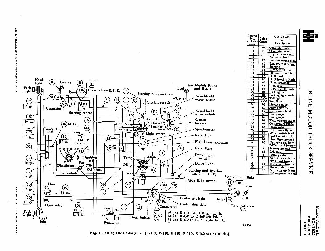
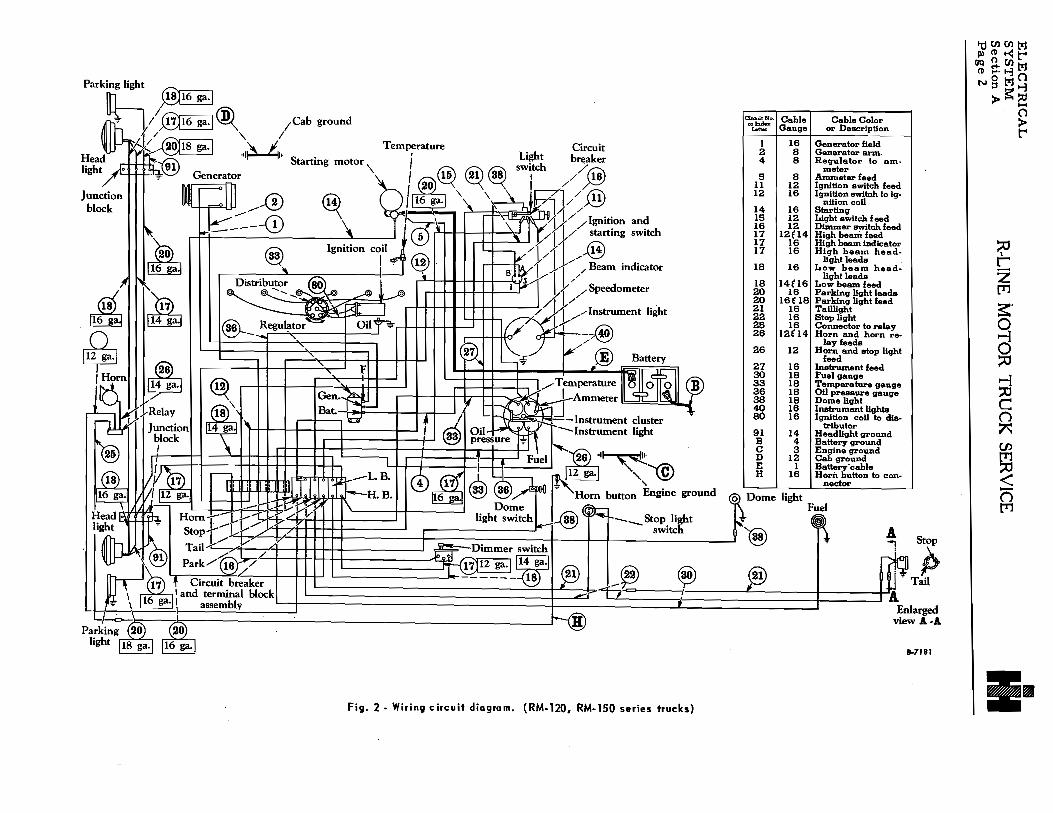
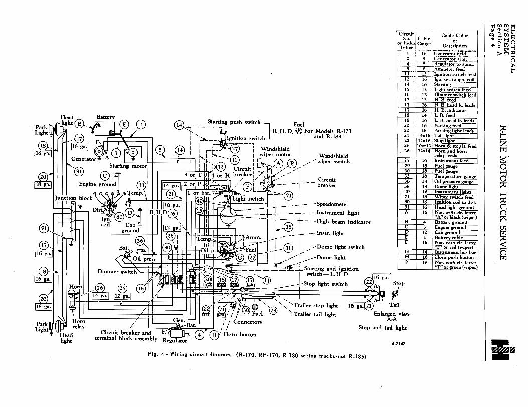


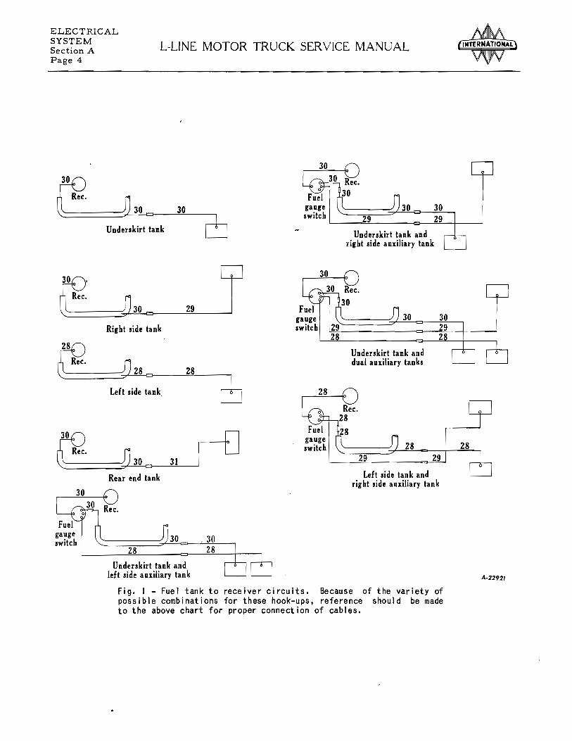

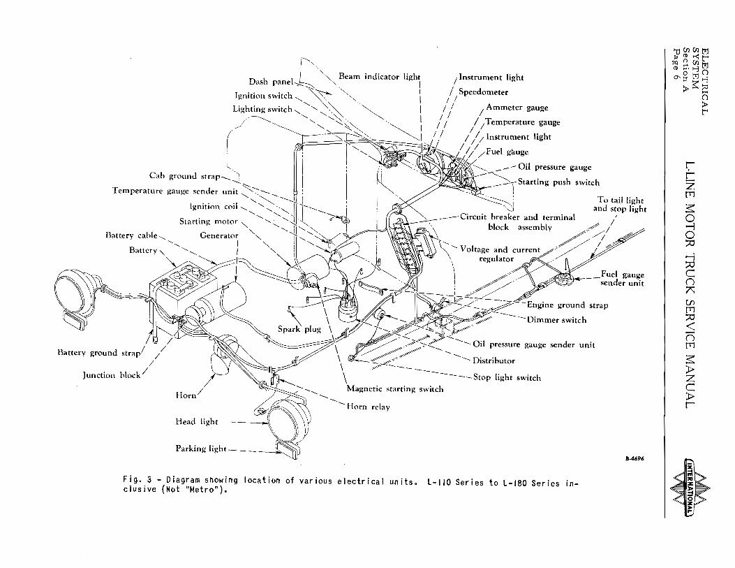


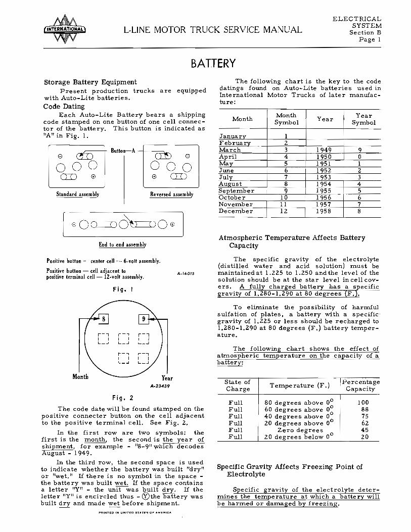

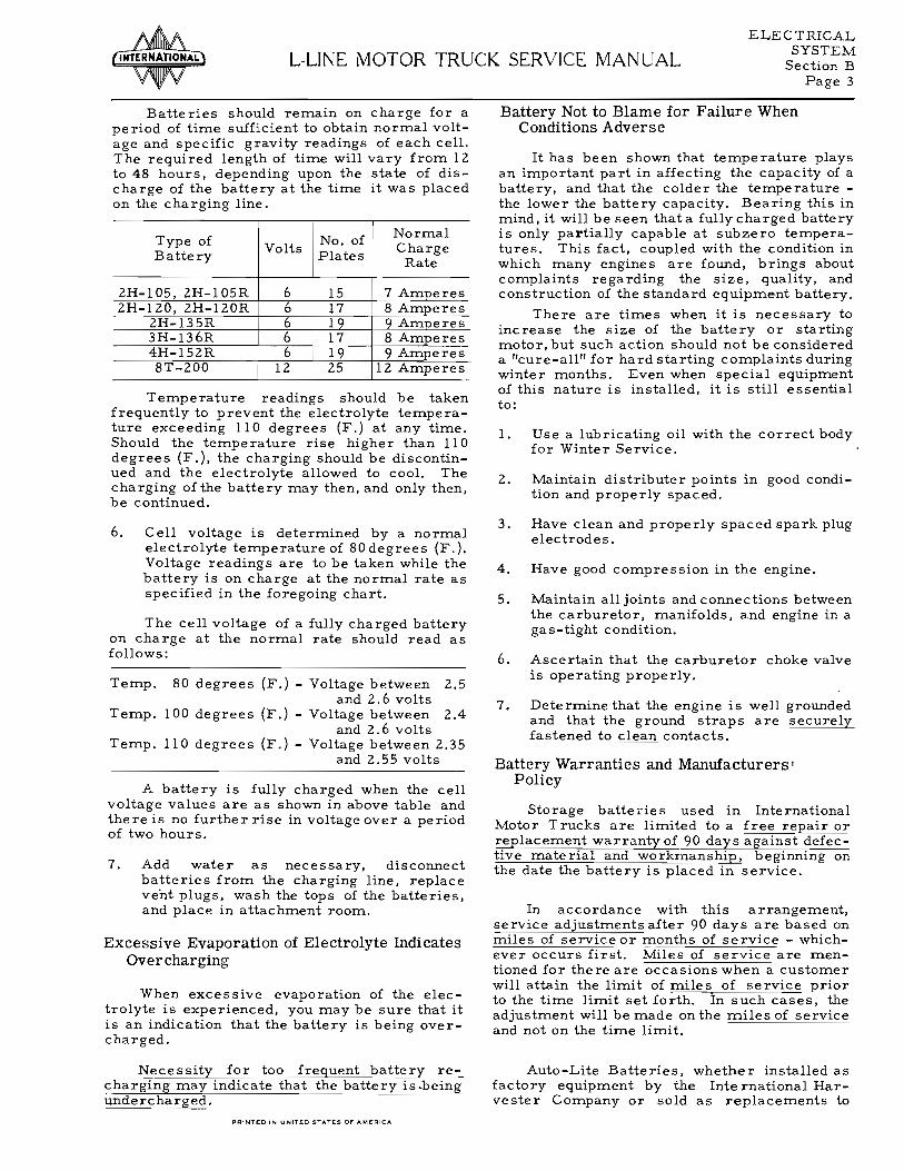

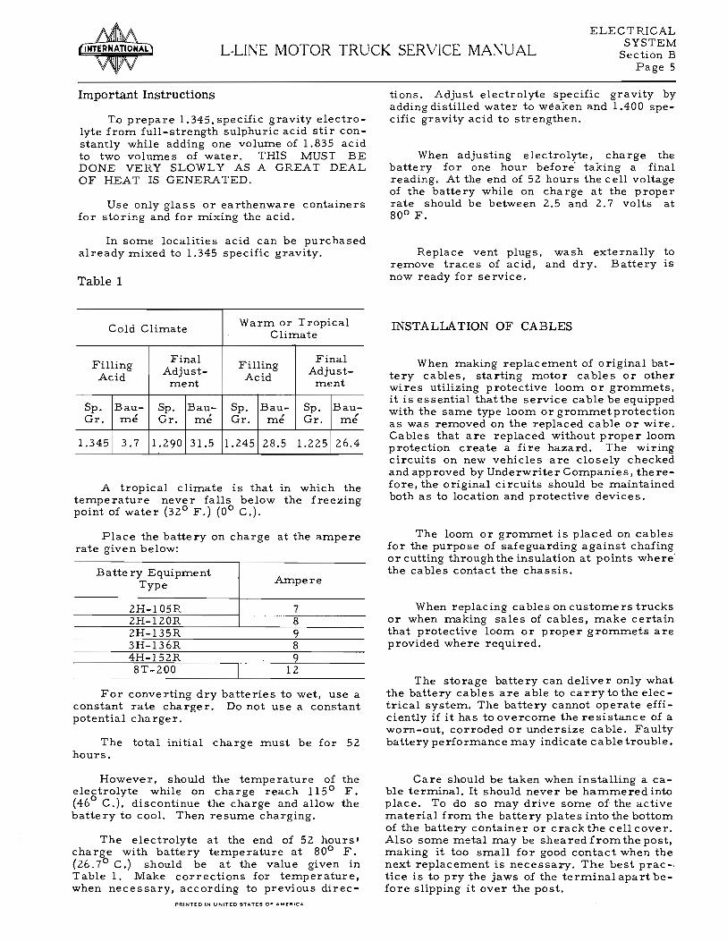

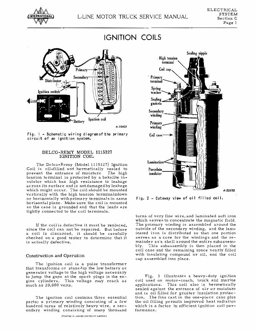
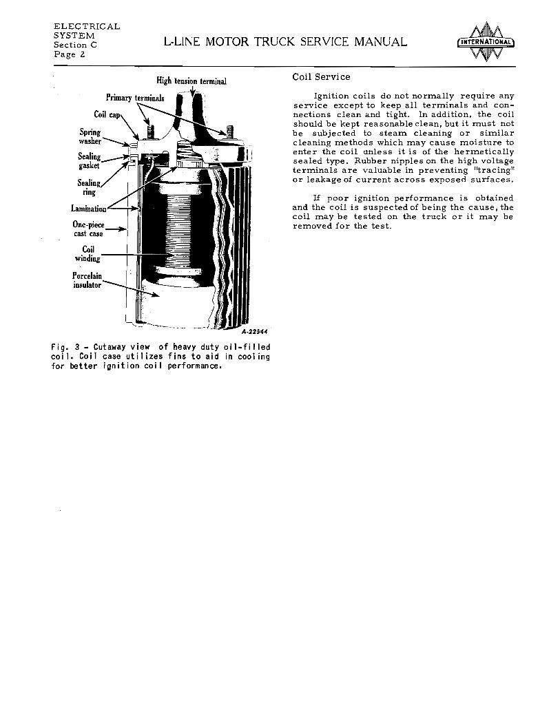


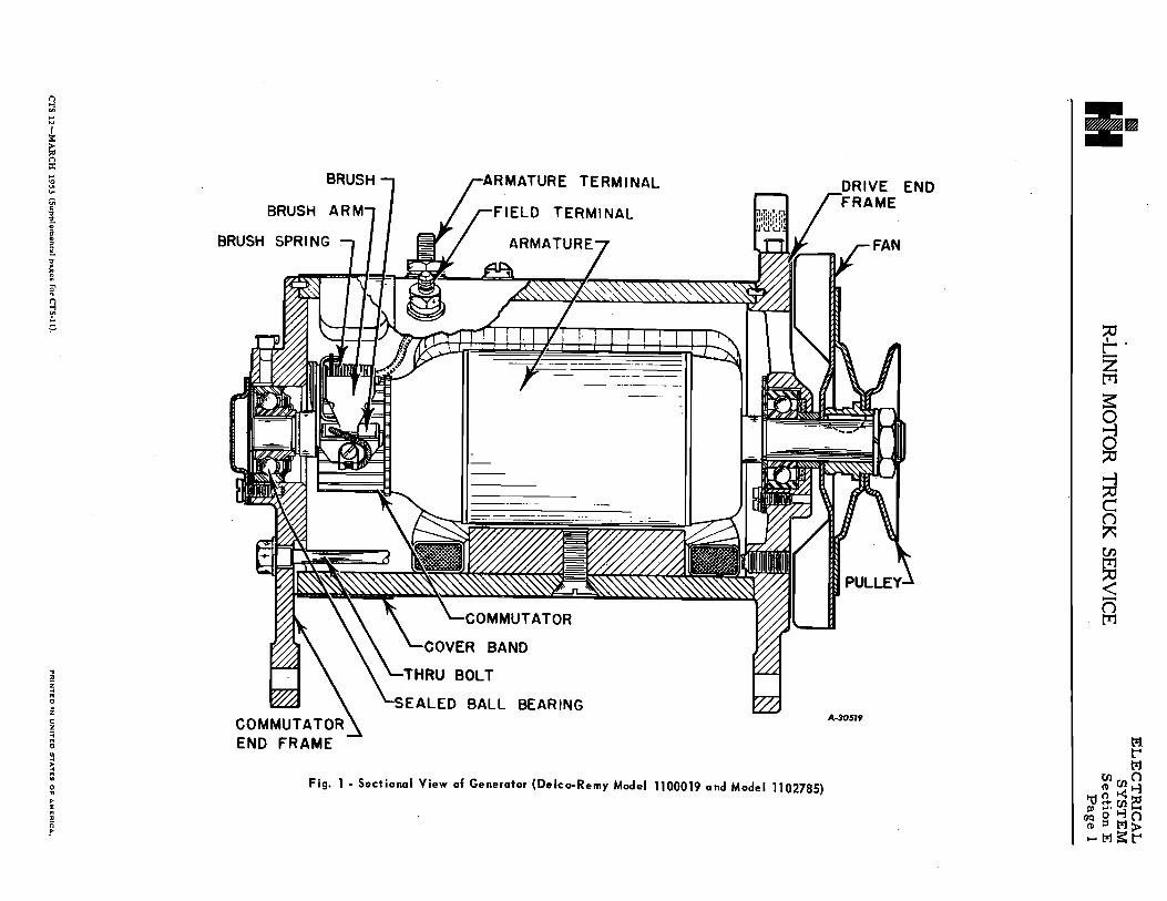


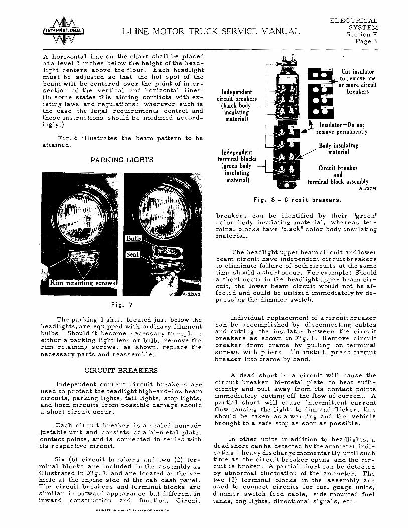
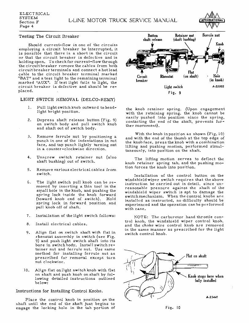

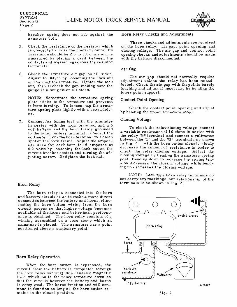


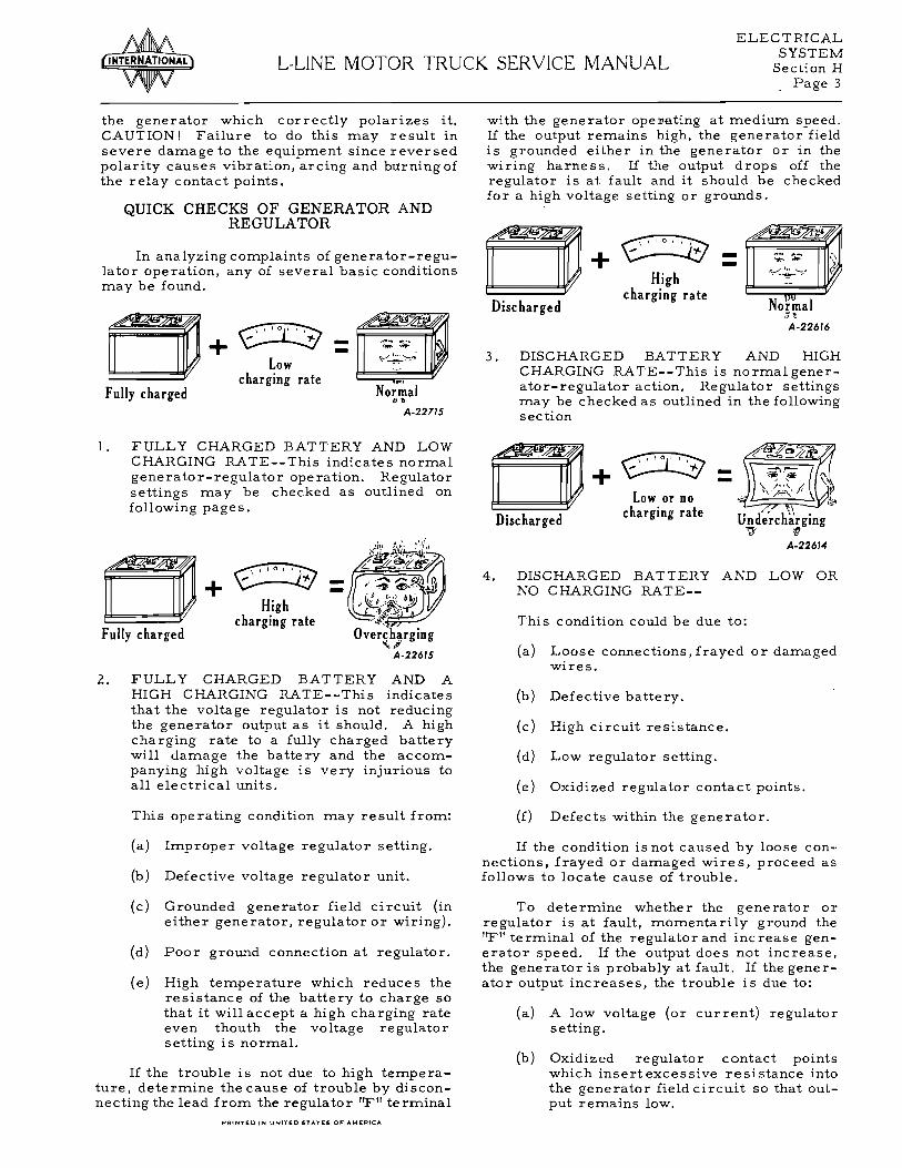


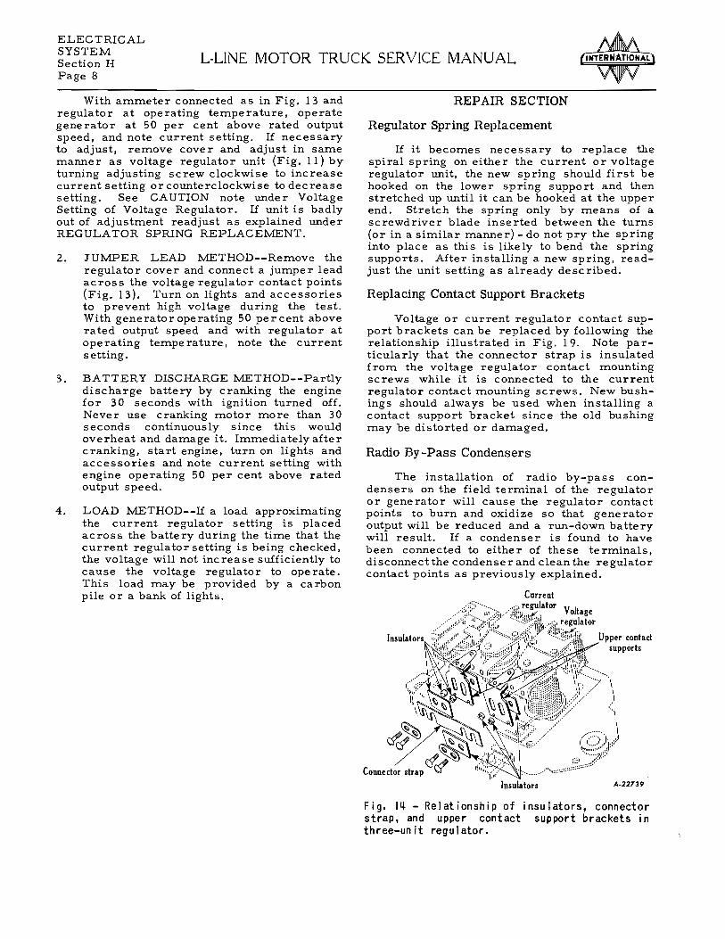


Related Documents