BIOS BIOENERGIESYSTEME GmbH BIOS BIOENERGIESYSTEME GmbH Inffeldgasse Inffeldgasse 21b, A 21b, A - - 8010 Graz, Austria 8010 Graz, Austria TEL.: +43 (316) 481300; FAX: +43 (316) 4813004 TEL.: +43 (316) 481300; FAX: +43 (316) 4813004 E E - - MAIL: MAIL: office@bios office@bios - - bioenergy.at bioenergy.at HOMEPAGE: HOMEPAGE: http:// http:// www www . . bios bios - - bioenergy.at bioenergy.at International experience of wood waste use for heat International experience of wood waste use for heat and electricity production. Technologies and and electricity production. Technologies and equipment for biomass combustion equipment for biomass combustion Dipl.-Ing. Norbert Wildbacher

Welcome message from author
This document is posted to help you gain knowledge. Please leave a comment to let me know what you think about it! Share it to your friends and learn new things together.
Transcript
BIOS BIOENERGIESYSTEME GmbHBIOS BIOENERGIESYSTEME GmbHInffeldgasseInffeldgasse 21b, A21b, A--8010 Graz, Austria8010 Graz, Austria
TEL.: +43 (316) 481300; FAX: +43 (316) 4813004TEL.: +43 (316) 481300; FAX: +43 (316) 4813004EE--MAIL: MAIL: office@[email protected]
HOMEPAGE: HOMEPAGE: http://http://wwwwww..biosbios--bioenergy.atbioenergy.at
International experience of wood waste use for heat International experience of wood waste use for heat and electricity production. Technologies and and electricity production. Technologies and
equipment for biomass combustionequipment for biomass combustion
Dipl.-Ing. Norbert Wildbacher

2
BIOENERGIESYSTEME GmbHInffeldgasse 21b, A-8010 Graz
Presentation Presentation ––overviewoverview
Key information about the company
Domestic combustion technologiesWood stoves, wood log boilers
Wood chip fired units
Wood pellets burners
Industrial combustion technologiesFixed-bed furnaces
Fluidised bed combustion
Dust combustion
Summary
3
BIOENERGIESYSTEME GmbHInffeldgasse 21b, A-8010 Graz
Key information about Key information about BIOS BIOENRGIESYSTEME GmbHBIOS BIOENRGIESYSTEME GmbH
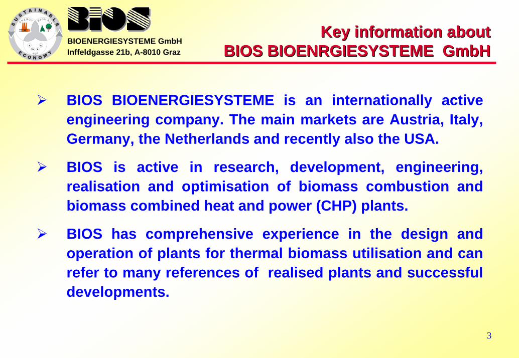
BIOS BIOENERGIESYSTEME is an internationally active engineering company. The main markets are Austria, Italy, Germany, the Netherlands and recently also the USA.
BIOS is active in research, development, engineering, realisation and optimisation of biomass combustion and biomass combined heat and power (CHP) plants.
BIOS has comprehensive experience in the design and operation of plants for thermal biomass utilisation and can refer to many references of realised plants and successful developments.
4
BIOENERGIESYSTEME GmbHInffeldgasse 21b, A-8010 Graz Working Fields (I)Working Fields (I)
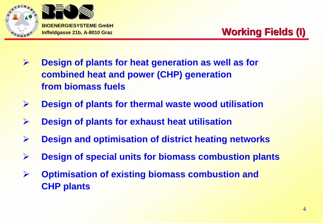
Design of plants for heat generation as well as for combined heat and power (CHP) generationfrom biomass fuels
Design of plants for thermal waste wood utilisation
Design of plants for exhaust heat utilisation
Design and optimisation of district heating networks
Design of special units for biomass combustion plants
Optimisation of existing biomass combustion andCHP plants
5
BIOENERGIESYSTEME GmbHInffeldgasse 21b, A-8010 Graz Working Fields (II)Working Fields (II)
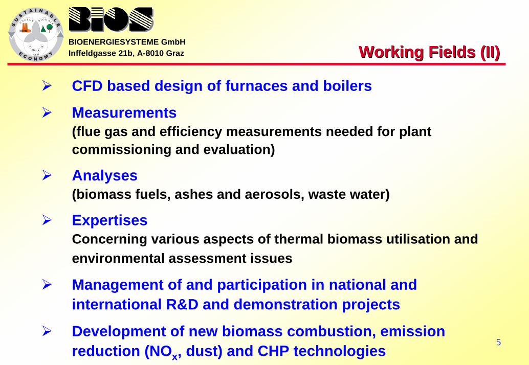
CFD based design of furnaces and boilers
Measurements (flue gas and efficiency measurements needed for plant commissioning and evaluation)
Analyses(biomass fuels, ashes and aerosols, waste water)
ExpertisesConcerning various aspects of thermal biomass utilisation and environmental assessment issues
Management of and participation in national and international R&D and demonstration projects
Development of new biomass combustion, emission reduction (NOx, dust) and CHP technologies

6
BIOENERGIESYSTEME GmbHInffeldgasse 21b, A-8010 Graz Biomass Biomass combustioncombustion
European biomass combustion is mainly applied to the following processes:
Heat generation in small domestic applications for space heating and cooking
Heat production in medium and large scale applications for district and process heat supply
Steam production for driving steam engines or turbines as well as for combined heat and power (CHP) applications
Heat production for power or combined heat and power supply using heat carriers (e.g. thermal oil or air)

7
BIOENERGIESYSTEME GmbHInffeldgasse 21b, A-8010 Graz
Selection and designSelection and designof biomass combustion systemsof biomass combustion systems
Selection and design of a biomass combustion system is mainly determined by
size of the plant (heat only or CHP application)
costs and performance of the equipment
the local environmental legislation
characteristics of the fuel to be usedmoisture content 10 wt% w.b. (dry wood processing residues, pellets) up to 60 wt% w.b. (bark, sawmill by-products)
particle shapes and sizes
ash content, ash sintering temperatures

8
BIOENERGIESYSTEME GmbHInffeldgasse 21b, A-8010 Graz
Domestic Domestic combustion technologiescombustion technologies
Small scale (domestic) combustion:
Units used for heating (or cooking) up to a capacity of about 500 kW.
Domestic combustion technologies:
Wood stoves and fireplaces inserts
Wood log boilers
Wood pellets burners
Wood chip fired units
9
BIOENERGIESYSTEME GmbHInffeldgasse 21b, A-8010 Graz Wood stovesWood stoves
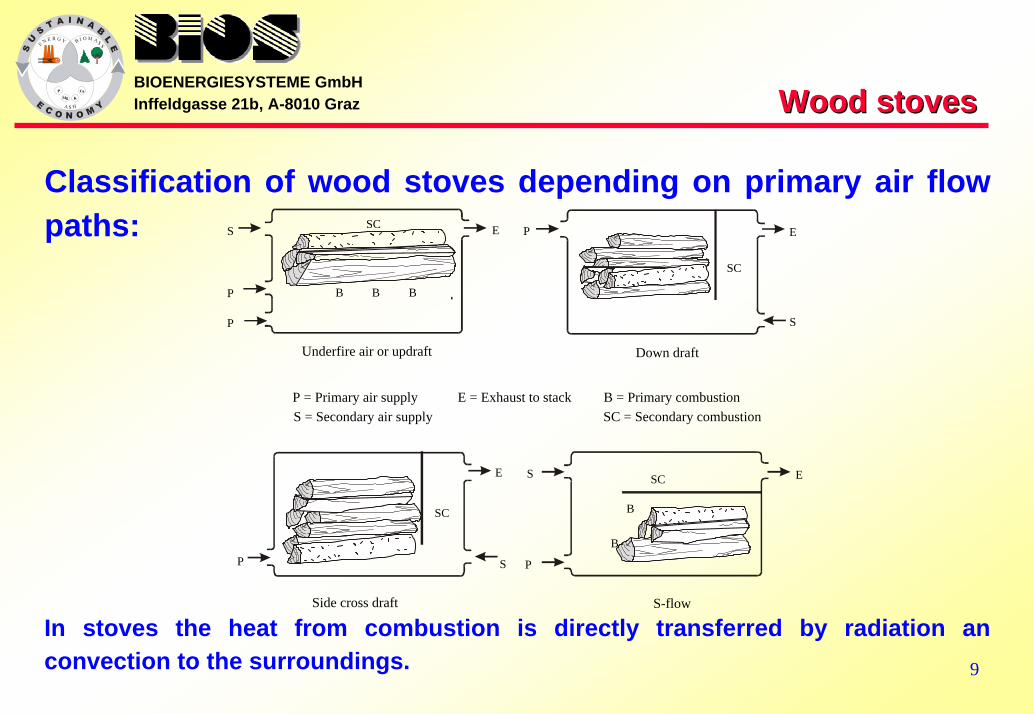
Classification of wood stoves depending on primary air flow paths:
In stoves the heat from combustion is directly transferred by radiation an convection to the surroundings.
P = Primary air supplyS = Secondary air supply
E = Exhaust to stack B = Primary combustionSC = Secondary combustion
Underfire air or updraft Down draft
S-flowSide cross draft
S
S
S
P
P
P
PP
B B B
B
E
E
ESC
SC
SC
SC
E
S
B
10
BIOENERGIESYSTEME GmbHInffeldgasse 21b, A-8010 Graz Wood log Wood log boilersboilers (I)(I)
Downdraft boilers:
Flue gases are forced to flow down through holes in a ceramic grate
Secondary combustion air is introduced directly below the grate (secondary combustion chamber)
In the secondary combustion chamber the final combustion takes place at high temperatures
Combustion air fan or flue gas fan is needed
Include modern combustion control devices (lambda control probes, combustion air control, staged air combustion)
11
BIOENERGIESYSTEME GmbHInffeldgasse 21b, A-8010 Graz Wood log Wood log boilersboilers (II)(II)
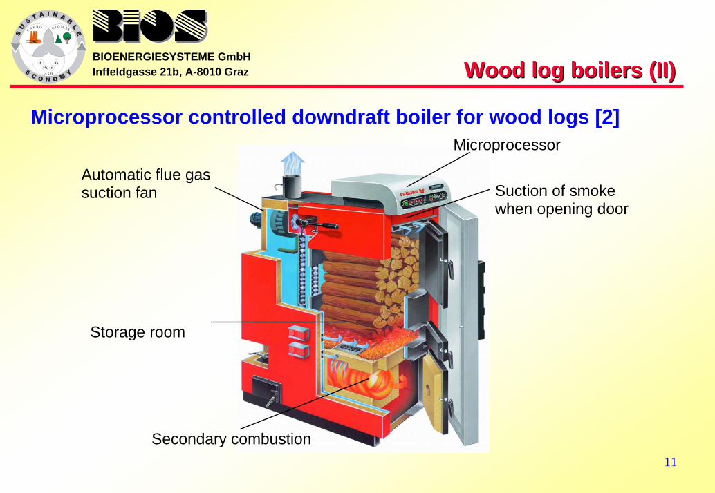
Microprocessor controlled downdraft boiler for wood logs [2]
Automatic flue gas suction fan
Storage room
Microprocessor
Secondary combustion
Suction of smoke when opening door
12
BIOENERGIESYSTEME GmbHInffeldgasse 21b, A-8010 Graz Wood chip fired units (I)Wood chip fired units (I)
The advantages of using wood chips instead of firewood are the automatic operation and much lower emissions because of the continuous combustion principle.
But making and storing them requires a higher investment in machinery an storage space.
Small scale wood chip combustion is often performed in underfeed or horizontally fed stoker burners.
Designed for a heat output range of 10-200 kW.
More common in the countryside heating detached houses and farms.
13
BIOENERGIESYSTEME GmbHInffeldgasse 21b, A-8010 Graz Wood chip fired units (II)Wood chip fired units (II)
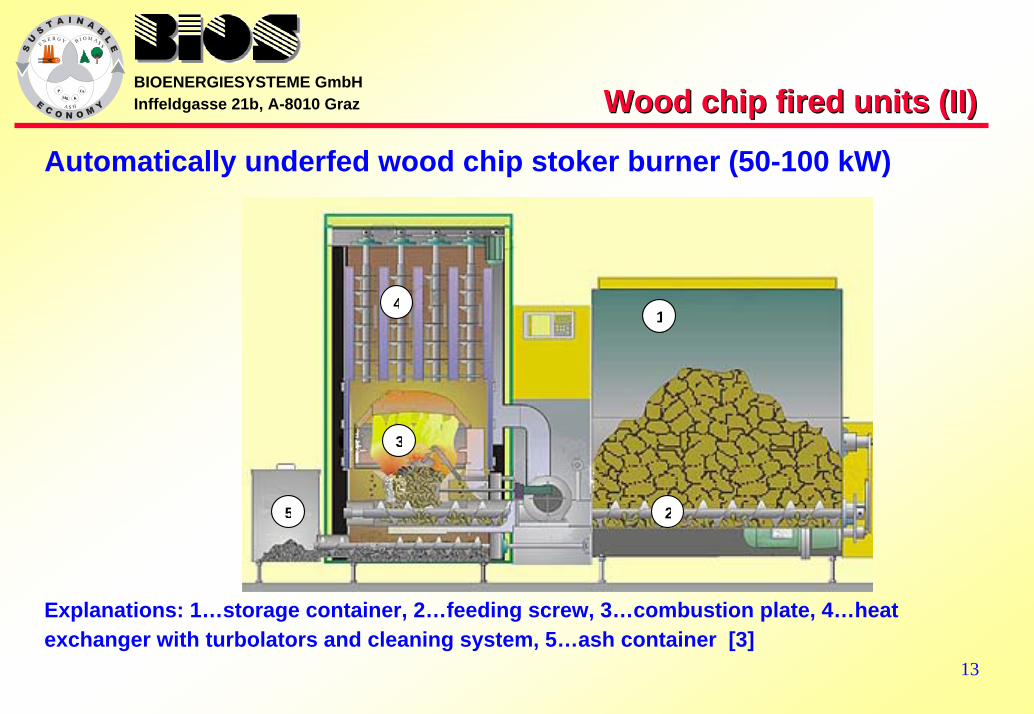
Automatically underfed wood chip stoker burner (50-100 kW)
1
2
3
4
5
Explanations: 1…storage container, 2…feeding screw, 3…combustion plate, 4…heat exchanger with turbolators and cleaning system, 5…ash container [3]
14
BIOENERGIESYSTEME GmbHInffeldgasse 21b, A-8010 Graz Wood pellet Wood pellet burnersburners
A pellet burner is a unit for continuous automatic combustion of a refined and well defined fuel.
Pellet burners for domestic use are usually constructed for a nominal thermal output of less than 25 kW.
Some burners are quipped with a smaller storage unit (enough for one or a few days) that can be refilled manually or by an automatic system from a larger storage unit.
Modern automatic pellet burners comprise air staging with separate primary and secondary combustion zones and microprocessor-controlled combustion systems.
15
BIOENERGIESYSTEME GmbHInffeldgasse 21b, A-8010 Graz
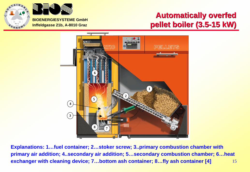
Automatically overfed Automatically overfed pellet boiler (3.5pellet boiler (3.5--15 kW) 15 kW)
1
4
3
2
6
8 7
5
Explanations: 1…fuel container; 2…stoker screw; 3..primary combustion chamber with primary air addition; 4..secondary air addition; 5…secondary combustion chamber; 6…heat exchanger with cleaning device; 7…bottom ash container; 8…fly ash container [4]

16
BIOENERGIESYSTEME GmbHInffeldgasse 21b, A-8010 Graz
Industrial combustion technologiesIndustrial combustion technologiesoverviewoverview
Industrial combustion:
Medium or large scale combustion systems with a nominal thermal capacity exceeding 500 kW
Industrial combustion technologies:
Fixed-bed combustionUnderfeed stokers
Moving grate furnaces
Fluidised bed combustion
Dust combustion

17
BIOENERGIESYSTEME GmbHInffeldgasse 21b, A-8010 Graz Underfeed stokers (I)Underfeed stokers (I)
Fuel is feed into the combustion chamber by screw conveyors
For fine-grained biomass fuels (<50mm) with low ash contentWood shavings
Pellets
Sawdust
Nominal boiler capacity up to 6 MW
In this performance range the investment costs are lower than for other technologies (e.g. grate fired combustion units)

18
BIOENERGIESYSTEME GmbHInffeldgasse 21b, A-8010 Graz Underfeed stokers (II)Underfeed stokers (II)
Underfeed stoker furnace [5]
19
BIOENERGIESYSTEME GmbHInffeldgasse 21b, A-8010 Graz
Moving grate furnacesMoving grate furnacesoverviewoverview
Moving grate furnaces are generally distinguished by the way the grate is moving:
Inclined moving grates
Horizontally moving grates
Travelling grates
Vibrating grates
Rotating grates

20
BIOENERGIESYSTEME GmbHInffeldgasse 21b, A-8010 Graz Inclined moving gratesInclined moving grates
Inclined grate consisting of fixed and moveable rows of grate bars.
By alternating forward and backward movements of the moveable sections, the fuel is transported along the grate.
The movement is achieved by hydraulic cylinders.
primary air
secondary
air
flue gas recirculation
fuel
flue gas
The whole grate is divided into several grate sections, which can be moved at different speeds according to different stages of combustion.
The grate bars themselves are made of heat-resistant steel alloys and can be air-cooled or water-cooled.
[6]
21
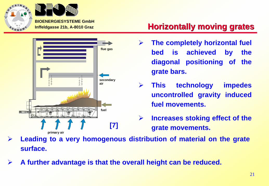
BIOENERGIESYSTEME GmbHInffeldgasse 21b, A-8010 Graz Horizontally moving gratesHorizontally moving grates
The completely horizontal fuel bed is achieved by the diagonal positioning of the grate bars.
This technology impedes uncontrolled gravity induced fuel movements.
Increases stoking effect of the grate movements.
Leading to a very homogenous distribution of material on the grate surface.
A further advantage is that the overall height can be reduced.
flue gas
secondaryair
fuel
primary air [7]

22
BIOENERGIESYSTEME GmbHInffeldgasse 21b, A-8010 Graz Travelling gratesTravelling grates
Consist of grate bars mounted on an endless belt.
The fuel bed itself does not move but is transported by the grate.
At the end of the combustion chamber the grate is cleaned of ash while the belt turns around.
Advantages are the uniform combustion conditions due the uniformbed and the easy maintenance or replacement of grate bars.
In comparison to moving grate furnaces there is a longer burn-out time and a higher primary air input.
primary air
fuel
secondaryair
[8]
23
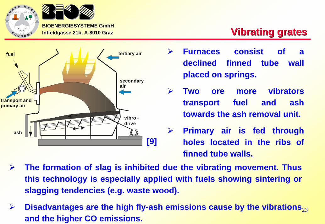
BIOENERGIESYSTEME GmbHInffeldgasse 21b, A-8010 Graz Vibrating gratesVibrating grates
Furnaces consist of a declined finned tube wall placed on springs.
Two ore more vibrators transport fuel and ash towards the ash removal unit.
Primary air is fed through holes located in the ribs of finned tube walls.
The formation of slag is inhibited due the vibrating movement. Thus this technology is especially applied with fuels showing sintering or slagging tendencies (e.g. waste wood).
Disadvantages are the high fly-ash emissions cause by the vibrations and the higher CO emissions.
vibro - drive
secondary air
tertiary air fuel
ash
transport and primary air
[9]

24
BIOENERGIESYSTEME GmbHInffeldgasse 21b, A-8010 Graz Underfeed rotating grateUnderfeed rotating grate
Makes use of conical grate sections that rotate in opposite directions and are supplied with primary air from below.
As a result wet burning fuels are well mixed, which makes the system adequate for burning very wet fuels.
Capable of burning mixtures of solid wood fuels and biological sludge.
The fuel is feed to the grate from below by screw conveyors.
The combustible gases formed are burned out with secondary air in a separate horizontal or vertical combustion chamber .
[10]
25
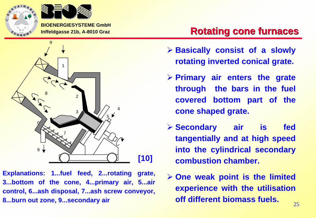
BIOENERGIESYSTEME GmbHInffeldgasse 21b, A-8010 Graz Rotating cone furnacesRotating cone furnaces
Basically consist of a slowly rotating inverted conical grate.
Primary air enters the grate through the bars in the fuel covered bottom part of the cone shaped grate.
Secondary air is fed tangentially and at high speed into the cylindrical secondary combustion chamber.
One weak point is the limited experience with the utilisation off different biomass fuels.
Explanations: 1...fuel feed, 2...rotating grate, 3...bottom of the cone, 4...primary air, 5...air control, 6...ash disposal, 7...ash screw conveyor, 8...burn out zone, 9...secondary air
1
2
3
6
8
5
4
7
9
[10]
26
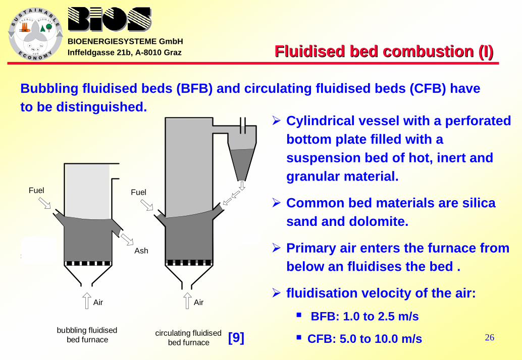
BIOENERGIESYSTEME GmbHInffeldgasse 21b, A-8010 Graz Fluidised bed combustion (I)Fluidised bed combustion (I)
Bubbling fluidised beds (BFB) and circulating fluidised beds (CFB) have to be distinguished.
Ash
Fuel
Ash
Air
bubbling fluidisedbed furnace
circulating fluidisedbed furnace
Air
Fuel
F
Cylindrical vessel with a perforated bottom plate filled with a suspension bed of hot, inert and granular material.
Common bed materials are silica sand and dolomite.
Primary air enters the furnace from below an fluidises the bed .
fluidisation velocity of the air:BFB: 1.0 to 2.5 m/s
CFB: 5.0 to 10.0 m/s[9]
27
BIOENERGIESYSTEME GmbHInffeldgasse 21b, A-8010 Graz Fluidised bed combustion (II)Fluidised bed combustion (II)
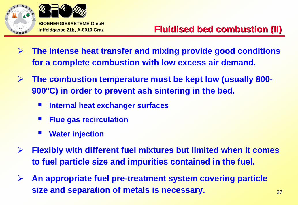
The intense heat transfer and mixing provide good conditions for a complete combustion with low excess air demand.
The combustion temperature must be kept low (usually 800-900°C) in order to prevent ash sintering in the bed.
Internal heat exchanger surfaces
Flue gas recirculation
Water injection
Flexibly with different fuel mixtures but limited when it comes to fuel particle size and impurities contained in the fuel.
An appropriate fuel pre-treatment system covering particle size and separation of metals is necessary.
28
BIOENERGIESYSTEME GmbHInffeldgasse 21b, A-8010 Graz Dust Combustion systems (I) Dust Combustion systems (I)
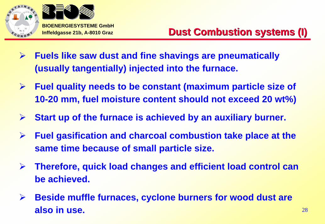
Fuels like saw dust and fine shavings are pneumatically (usually tangentially) injected into the furnace.
Fuel quality needs to be constant (maximum particle size of 10-20 mm, fuel moisture content should not exceed 20 wt%)
Start up of the furnace is achieved by an auxiliary burner.
Fuel gasification and charcoal combustion take place at the same time because of small particle size.
Therefore, quick load changes and efficient load control can be achieved.
Beside muffle furnaces, cyclone burners for wood dust are also in use.

29
BIOENERGIESYSTEME GmbHInffeldgasse 21b, A-8010 Graz Dust Combustion systems (II) Dust Combustion systems (II)
Explanations; 1...primary air supply, 2...fuel feed, 3...gasification and partial combustion, 4...flue gas recirculation, 5...ash disposal, 6...secondary air supply, 7...tertiary air supply, 8...water tube boiler
Muffle furnace in combination with a water-tube steam boiler [9]
A disadvantage is that insulation bricks wear out quickly due to thermal stress and erosion
Thus also other dust combustion systems are built without rotational flow, where dust injection is conducted without a swirl.
30
BIOENERGIESYSTEME GmbHInffeldgasse 21b, A-8010 Graz
Summary of Summary of combustion technologies (I) combustion technologies (I)
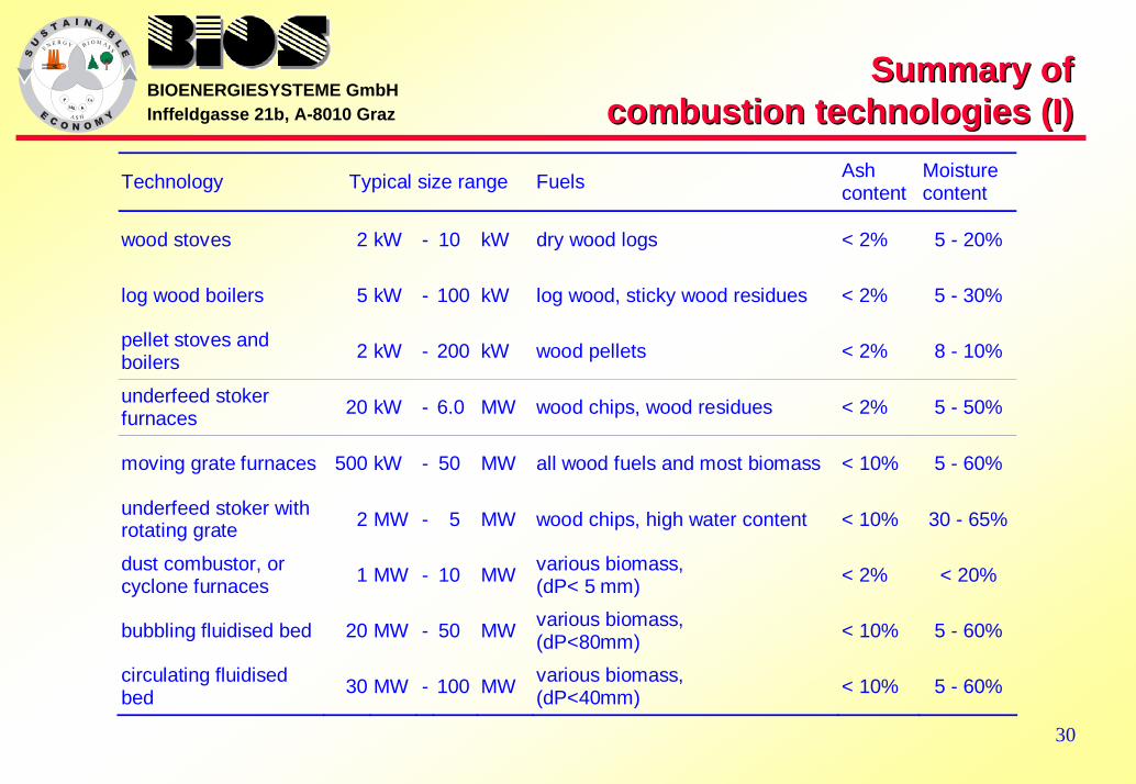
Technology Typical size range Fuels Ash content
Moisture content
wood stoves 2 kW - 10 kW dry wood logs < 2% 5 - 20%
log wood boilers 5 kW - 100 kW log wood, sticky wood residues < 2% 5 - 30%
pellet stoves and boilers 2 kW - 200 kW wood pellets < 2% 8 - 10%
underfeed stoker furnaces 20 kW - 6.0 MW wood chips, wood residues < 2% 5 - 50%
moving grate furnaces 500 kW - 50 MW all wood fuels and most biomass < 10% 5 - 60%
underfeed stoker with rotating grate 2 MW - 5 MW wood chips, high water content < 10% 30 - 65%
dust combustor, or cyclone furnaces 1 MW - 10 MW various biomass,
(dP< 5 mm) < 2% < 20%
bubbling fluidised bed 20 MW - 50 MW various biomass, (dP<80mm) < 10% 5 - 60%
circulating fluidised bed 30 MW - 100 MW various biomass,
(dP<40mm) < 10% 5 - 60%
31
BIOENERGIESYSTEME GmbHInffeldgasse 21b, A-8010 Graz
Summary of Summary of combustion technologies (II) combustion technologies (II)
Advantages Disadvantages
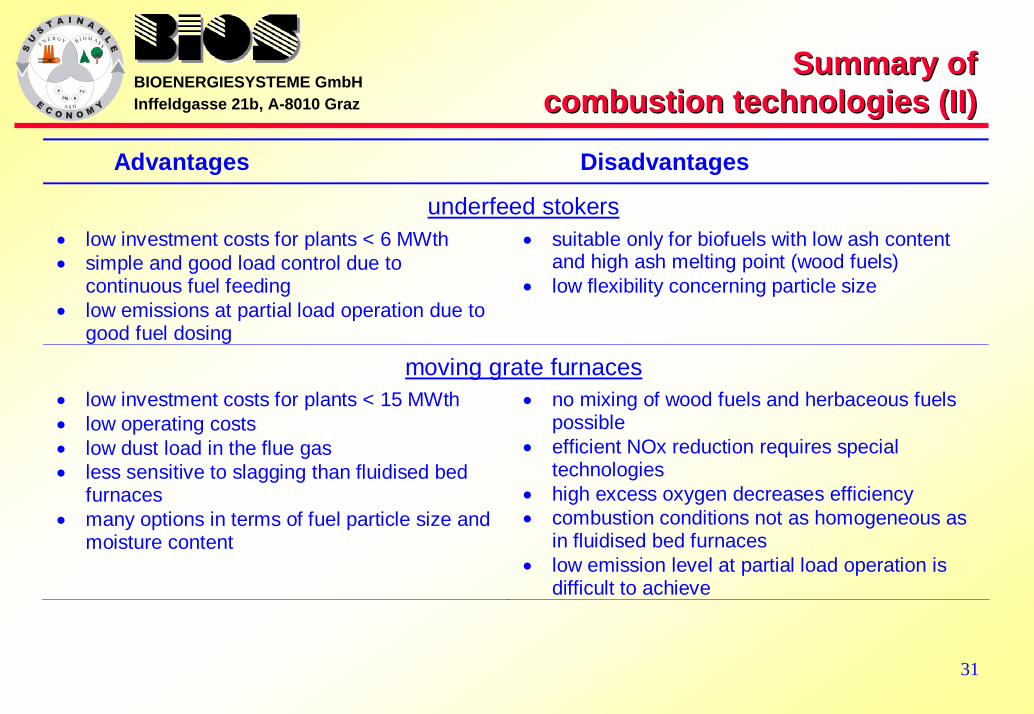
underfeed stokers • low investment costs for plants < 6 MWth • simple and good load control due to
continuous fuel feeding • low emissions at partial load operation due to
good fuel dosing
• suitable only for biofuels with low ash content and high ash melting point (wood fuels)
• low flexibility concerning particle size
moving grate furnaces • low investment costs for plants < 15 MWth • low operating costs • low dust load in the flue gas • less sensitive to slagging than fluidised bed
furnaces • many options in terms of fuel particle size and
moisture content
• no mixing of wood fuels and herbaceous fuels possible
• efficient NOx reduction requires special technologies
• high excess oxygen decreases efficiency • combustion conditions not as homogeneous as
in fluidised bed furnaces • low emission level at partial load operation is
difficult to achieve
32
BIOENERGIESYSTEME GmbHInffeldgasse 21b, A-8010 Graz
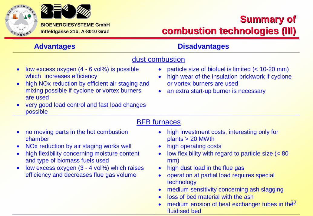
Summary of Summary of combustion technologies (III) combustion technologies (III)
Advantages Disadvantages
dust combustion • low excess oxygen (4 - 6 vol%) is possible
which increases efficiency • high NOx reduction by efficient air staging and
mixing possible if cyclone or vortex burners are used
• very good load control and fast load changes possible
• particle size of biofuel is limited (< 10-20 mm) • high wear of the insulation brickwork if cyclone
or vortex burners are used • an extra start-up burner is necessary
BFB furnaces • no moving parts in the hot combustion
chamber • NOx reduction by air staging works well • high flexibility concerning moisture content
and type of biomass fuels used • low excess oxygen (3 - 4 vol%) which raises
efficiency and decreases flue gas volume
• high investment costs, interesting only for plants > 20 MWth
• high operating costs • low flexibility with regard to particle size (< 80
mm) • high dust load in the flue gas • operation at partial load requires special
technology • medium sensitivity concerning ash slagging • loss of bed material with the ash • medium erosion of heat exchanger tubes in the
fluidised bed

33
BIOENERGIESYSTEME GmbHInffeldgasse 21b, A-8010 Graz
Summary of Summary of combustion technologies (IV) combustion technologies (IV)
Advantages Disadvantages
CFB furnaces • no moving parts in the hot combustion
chamber • NOx reduction by air staging works well • high flexibility concerning moisture content
and type of biomass fuels used • homogeneous combustion conditions in the
furnace if several fuel injectors are used • high specific heat transfer capacity due to
high turbulence • use of additives easy • very low excess oxygen (1 - 2 vol%) raises
efficiency and decreases flue gas flow
• high investment costs, interesting only for plants > 30 MW(th)
• high operating costs • low flexibility with regard to particle size (< 40
mm) • high dust load in the flue gas • partial-load operation requires a second bed • loss of bed material with the ash • high sensitivity concerning ash slagging • medium erosion of heat exchanger tubes in the
furnace
BIOS BIOENERGIESYSTEME GmbHBIOS BIOENERGIESYSTEME GmbHInffeldgasseInffeldgasse 21b, A21b, A--8010 Graz, Austria8010 Graz, Austria
TEL.: +43 (316) 481300; FAX: +43 (316) 4813004TEL.: +43 (316) 481300; FAX: +43 (316) 4813004EE--MAIL: MAIL: office@[email protected]
HOMEPAGE: HOMEPAGE: http://http://wwwwww..biosbios--bioenergy.atbioenergy.at
Thank you Thank you for your attentionfor your attention

35
BIOENERGIESYSTEME GmbHInffeldgasse 21b, A-8010 Graz ReferencesReferences
[1] OBERNBERGER I., DAHL J., 2003: Combustion of solid biomass fuels – a review. Institute for ResourceEfficient and Sustainable Systems, Graz University of Technology, Austria
[2] FRÖLING, 2002: company brochure, FHGTurbo 3000, FRÖLING Heizkessel- und Behälterbau GmbH (ed.), Grieskirchen, Austria
[3] KWB, 2001: company brochure, Hackgut Heizungen, Kraft & Wärme aus Biomasse GmbH (Ed.), St. Margarethen/Raab, Austria
[4] FISCHER GUNTAMATIC, 2000: company brochure, Guntamatik Heiztechnik GmbH (ed.), Peuerbach, Austria[5] MAWERA, 1996: company brochure, MAWERA Holzfeuerungsanlagen GmbH&CoKG (ed.), Hard/Bodensee, Austria[6] OBERNBERGER I., 1996: Decentralized Biomass Combustion - State-of-the-Art and Future Development (keynote
lecture at the 9th European Biomass Conference in Copenhagen), Biomass and Bioenergy, Vol. 14, No.1, pp. 33-56 (1998)
[7] MAWERA, 1996: company brochure, MAWERA Holzfeuerungsanlagen GmbH&CoKG (ed.), Hard/Bodensee, Austria[8] WEISSINGER A., OBERNBERGER I., 1999: NOx Reduction by Primary Measures on a Travelling- Grate Furnace for
Biomass Fuels and Waste Wood. In: Proceedings of the 4th Biomass Conference of the Americas, Sept 1999, Oakland (California), USA, ISBN 0-08-043019-8, Elsevier Science Ltd. (ed.), Oxford, UK, pp 1417-1425
[9] MARUTZKY R., SEEGER K., 1999: Energie aus Holz und anderer Biomasse, ISBN 3-87181-347-8, DRW-Verlag Weinbrenner (ed.), Leinfelden-Echtlingen, Germany
[10] BURK H., HENTSCHEL A., 2000: Brennkegel-Rostfeuerung für Gebrauchtholz. In: Proceedings of the VDI Seminar “Stand der Feuerungstechnik für Holz, Gebrauchtholz und Biomasse”, January 27-28, 2000, Salzburg, VDI Bildungswerk (ed.), Düsseldorf, Germany
Related Documents