Prepared by INTERNATIONAL ASSOCIATION OF GEOSYNTHETIC INSTALLERS HDPE AND LLDPE GEOMEMBRANE INSTALLATION SPECIFICATION International Association of Geosynthetic Installers P.O. Box 18012 St. Paul, MN 55118 USA Telephone: 651-554-1895 Fax: 651-450-6167 Email:[email protected] Revision, May 2007 SDMS DOCID#1142276

Welcome message from author
This document is posted to help you gain knowledge. Please leave a comment to let me know what you think about it! Share it to your friends and learn new things together.
Transcript

Prepared by
INTERNATIONAL ASSOCIATION OF GEOSYNTHETIC INSTALLERS
HDPE AND LLDPE GEOMEMBRANE INSTALLATION
SPECIFICATION
International Association of Geosynthetic Installers
P.O. Box 18012
St. Paul, MN 55118 USA
Telephone: 651-554-1895 Fax: 651-450-6167
Email:[email protected] Revision, May 2007
SDMS DOCID#1142276

The information herein has been composed by IAGI in accordance with current quality control and quality assurance standards of the geomembrane industry. Final determination of the suitability of any information or material for the use contemplated and its manner of use is the sole responsibility of the user.
PART 1 - GENERAL 1.01 Summary
A. This specification includes furnishing and installing HDPE and LLDPE
geomembranes with a formulated sheet density of 0.940 g/cc or greater associated
with HDPE geomembranes and a formulated sheet density of 0.939 or less for
LLDPE geomembranes. Geomembranes with both smooth and textured surfaces are
included.
1.02 References
A. American Society for Testing and Materials (ASTM):
1. D 638, Standard Test Method for Tensile Properties of Plastics.
2. D 751, Standard Test Methods for Coated Fabrics.
3. D 792, Standard Test Methods for Density and Specific Gravity (Relative
Density) of Plastics by Displacement.
4. D 1004, Standard Test Method for Initial Tear Resistance of Plastic Film and
Sheeting.
5. D 1204, Standard Test Method for Linear Dimensional Changes of Non Rigid
Thermoplastic Sheeting or Film at Elevated Temperature.
6. D 1238, Standard Test Method for Flow Rates of Thermoplastics by Extrusion
Plastometer.
7. D 1505, Standard Test Method for Density of Plastics by Density-Gradient
Technique.
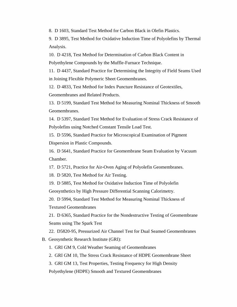
8. D 1603, Standard Test Method for Carbon Black in Olefin Plastics.
9. D 3895, Test Method for Oxidative Induction Time of Polyolefins by Thermal
Analysis.
10. D 4218, Test Method for Determination of Carbon Black Content in
Polyethylene Compounds by the Muffle-Furnace Technique.
11. D 4437, Standard Practice for Determining the Integrity of Field Seams Used
in Joining Flexible Polymeric Sheet Geomembranes.
12. D 4833, Test Method for Index Puncture Resistance of Geotextiles,
Geomembranes and Related Products.
13. D 5199, Standard Test Method for Measuring Nominal Thickness of Smooth
Geomembranes.
14. D 5397, Standard Test Method for Evaluation of Stress Crack Resistance of
Polyolefins using Notched Constant Tensile Load Test.
15. D 5596, Standard Practice for Microscopical Examination of Pigment
Dispersion in Plastic Compounds.
16. D 5641, Standard Practice for Geomembrane Seam Evaluation by Vacuum
Chamber.
17. D 5721, Practice for Air-Oven Aging of Polyolefin Geomembranes.
18. D 5820, Test Method for Air Testing.
19. D 5885, Test Method for Oxidative Induction Time of Polyolefin
Geosynthetics by High Pressure Differential Scanning Calorimetry.
20. D 5994, Standard Test Method for Measuring Nominal Thickness of
Textured Geomembranes
21. D 6365, Standard Practice for the Nondestructive Testing of Geomembrane
Seams using The Spark Test
22. D5820-95, Pressurized Air Channel Test for Dual Seamed Geomembranes
B. Geosynthetic Research Institute (GRI):
1. GRI GM 9, Cold Weather Seaming of Geomembranes
2. GRI GM 10, The Stress Crack Resistance of HDPE Geomembrane Sheet
3. GRI GM 13, Test Properties, Testing Frequency for High Density
Polyethylene (HDPE) Smooth and Textured Geomembranes

4. GRI GM 14, Test Frequencies for Destructive Seam Testing Selecting,
variable intervals for taking geomembrane destructive samples using the method
of attributes.
5. GRI GM 12, Measurement of the Asperity Height of Textured Geomembranes
Using a Depth Gage
6. GRI GM 17, Test Methods, Test Properties and Testing Frequency for Linear
Low Density Polyethylene (LLDPE) Smooth and Textured Geomembranes
7. GRI GM 19, Seam Strength and Related Properties of Thermally Bonded
Polyolefin Geomembranes
1.03 Submittals
A. Submit under provisions of Section 01300, Submittals.
B. Submit the following to the Engineer or Owner, for review and approval, within a
reasonable time so as to expedite shipment or installation of the Geomembrane:
1. Documentation of manufacturer's qualifications as specified in subsection
1.04A of this Section.
2. Manufacturer's Quality Control program manual or descriptive documentation.
3. A material properties sheet, including at a minimum all properties specified in
GRI GM 13, including test methods used.
4. Sample of the material.
5. Documentation of Installer's qualifications, as specified below and in
subsection 1.04B of this Section.
a. Submit a list of at least ten completed facilities. For each installation,
provide: name and type of facility; its location; the date of installation; name
and telephone number of contact at the facility; type and thickness of
geomembrane and; surface area of the installed geomembrane.
b. Submit resumes or qualifications of the Installation Supervisor, Master
Seamer and Technicians to be assigned to this project.
c. Quality Control Program.
6. Example Material Warranty and Liner Installation Warranty

C. Shop Drawings
1. Submit copies of shop drawings for engineer's approval within a reasonable
time so as not to delay the start of geomembrane installation. Shop drawings shall
show the proposed panel layout identifying seams and details. Seams should
generally follow the direction of the slope. Butt seams or roll-end seams should
not occur on a slope unless approved by the Owner's Representative. Butt seams
on a slope, if allowed, should be staggered.
2. Placement of geomembrane should not be allowed to proceed until Owner's
Representative has received and approved the shop drawings.
D. Additional Submittals (In-Progress and at Completion)
1. Manufacturer's warranty (refer to subsection 1.07).
2. Geomembrane installation warranty (refer to subsection 1.08).
3. Daily written acceptance of subgrade surface (refer to subsection 3.01.C).
4. Low-temperature seaming procedures if applicable (refer to subsection
3.03.A).
5. Prequalification test seam samples (refer to subsection 3.05.A.6).
6. Field seam non-destructive test results (refer to subsection 3.05.B.1).
7. Field seam destructive test results (refer to subsection 3.05.C.6).
8. Daily field installation reports (refer to subsection 3.05.G).
9. Installation record drawing, as discussed in subsection 3.05.
1.04 Quality Control
A. Manufacturer's Qualifications: The manufacturer of geomembrane of the type
specified or similar product shall have at least five years experience in the
manufacture of such geomembrane. In addition, the geomembrane manufacturer
shall have manufactured at least 1,000,000 M2 (10,000,000 FT2) of the specified type
of geomembrane or similar product during the last five years.
B. Installer's Qualifications
1. The Geomembrane Installer shall be the Manufacturer, approved
Manufacturer's Installer or a contractor approved by the Owner's Representative
to install the geomembrane.
2. The Geomembrane Installer shall have at least three years experience in the
installation of the specified geomembrane or similar. The Geomembrane Installer
shall have installed at least 10 projects involving a total of 500,000 M2
(5,000,000FT2) of the specified type of geomembrane or similar during the last
three years.
3. Installation shall be performed under the direction of a field Installation
Supervisor who shall be responsible throughout the geomembrane installation, for
geomembrane panel layout, seaming, patching, testing, repairs, and all other
activities of the Geomembrane Installer. The Field Installation Supervisor shall
have installed or supervised the installation and seaming of a minimum of 10
projects involving a total of 500,000 M2 (5,000,000 FT2) of geomembrane of the
type specified or similar product.
4. Seaming shall be performed under the direction of a Master Seamer (who may
also be the Field Installation Supervisor or Crew Foreman) who has seamed a
minimum of 300,000M2 (3,000,000FT2) of geomembrane of the type specified or
similar product, using the same type of seaming apparatus to be used in the
current project. The Field Installation Supervisor and/or Master Seamer shall be
present whenever seaming is performed.
5. All seaming, patching, other welding operations, and testing shall be
performed by qualified technicians employed by the Geomembrane Installer.
1.05 Delivery, Storage and Handling
A. Each roll of geomembrane delivered to the site shall be labeled by the
manufacturer. The label shall be firmly affixed and shall clearly state the
manufacturer's name, product identification, material thickness, roll number, roll
dimensions and roll weight.
B. Geomembrane shall be protected from mud, dirt, dust, puncture, cutting or any
other damaging or deleterious conditions.
C. Rolls shall be stored away from high traffic areas. Continuously and uniformly
support rolls on a smooth, level prepared surface.

1.06 Project Conditions
A. Geomembrane should not be installed in the presence of standing water, while
precipitation is occurring, during excessive winds, or when material temperatures are
outside the limits specified in Section 3.03.
1.07 Material Warranty
As agreed by project participants.
1.08 Geomembrane Installation Warranty
A. The Geomembrane Installer shall guarantee the geomembrane installation against
defects in the installation and workmanship for 1 year commencing with the date of
final acceptance.
1.09 Geomembrane Pre-Construction Meeting
A. A Geomembrane Pre-Construction Meeting shall be held at the site prior to
installation of the geomembrane. At a minimum, the meeting shall be attended by the
Geomembrane Installer, Owner, Owner’s representative (Engineer and/or CQA
Firm), and the Earthwork Contractor.
B. Topics for this meeting shall include:
1. Health and Safety
2. Lines of authority and communication. Resolution of any project document
ambiguity.
3. Methods for documenting, reporting and distributing documents and reports.
4. Procedures for packaging and storing archive samples.
5. Review of time schedule for all installation and testing.
6. Review of panel layout and numbering systems for panels and seams including
details for marking on geomembrane.
7. Procedures and responsibilities for preparation and submission of as-built
panel and seam drawings.
8. Temperature and weather limitations. Installation procedures for adverse
weather conditions. Defining acceptable subgrade, geomembrane, or ambient
moisture and temperature conditions for working during liner installation.

9. Subgrade conditions, dewatering responsibilities and subgrade maintenance
plan.
10. Deployment techniques including allowable subgrade for the geomembrane.
11. Plan for controlling expansion/contraction and wrinkling of the
geomembrane.
12. Covering of the geomembrane and cover soil placement.
13. Measurement and payment schedules.
14. Responsibilities of each party.
C. The meeting shall be documented by a person designated at the beginning of
the meeting and minutes shall be transmitted to all parties.
PART 2 - PRODUCTS
2.01 Source Quality Control
A. Manufacturing Quality Control
1. The test methods and frequencies used by the manufacturer for quality
control/quality assurance of the above geomembrane prior to delivery, shall be in
accordance with GRI GM 13 for HDPE geomembrane or GRI GM 17 for LLDPE
geomembrane, or modified as required for project specific conditions.
2. The manufacturer's geomembrane quality control certifications, including
results of quality control testing of the products, as specified in subsection
2.01.A.3 of this Section, must be supplied to the Owner's Representative to verify
that the materials supplied for the project are in compliance with all product and
or project specifications in this Section. The certification shall be signed by a
responsible party employed by the manufacturer, such as the QA/QC Manager,
Production Manager, or Technical Services Manager. Certifications shall include
lot and roll numbers and corresponding shipping information.
3. The Manufacturer will provide Certification that the geomembrane and
welding rod supplied for the project are made from the same material type and are
compatible.

2.02 Geomembrane
A. The geomembrane shall consist of new, first quality products designed and
manufactured specifically for the purpose of this work which shall have been
satisfactorily demonstrated by prior testing to be suitable and durable for such purposes.
The geomembrane rolls shall be seamless, high density polyethylene (HDPE -
Formulated Sheet Density ≥ 0.94g/cc) or linear low density polyethylene (LLDPE -
Formulated Sheet Density ≤ 0.939 g/cc) containing no plasticizers, fillers or extenders
and shall be free of holes, blisters or contaminants, and leak free verified by 100% in line
spark or equivalent testing. The geomembrane shall be supplied as a continuous sheet
with no factory seams in rolls. The geomembrane will meet the property requirements as
shown in Table A (GRI GM 13) or Table B (GRI GM 17)
B. Material conformance testing by the Owner's Representative, if required, will be
conducted using in-plant sampling or as specified for the project.
C. The geomembrane seams shall meet the property requirements as shown in Table
2, (Attachment B) or as required by project specifications
PART 3 - EXECUTION
3.01 Subgrade Preparation
A. The subgrade shall be prepared in accordance with the project specifications. The
geomembrane subgrade shall be uniform and free of sharp or angular objects that may
damage the geomembrane prior to installation of the geomembrane.
B. The Geomembrane Installer and Owner’s Representative shall inspect the surface
to be covered with the geomembrane on each day's operations prior to placement of
geomembrane to verify suitability.
C. The Geomembrane Installer and Owner’s Representative shall provide daily
written acceptance for the surface to be covered by the geomembrane in that day's
operations. The surface shall be maintained in a manner, during geomembrane
installation, to ensure subgrade suitability.

D. All subgrade damaged by construction equipment and deemed unsuitable for
geomembrane deployment shall be repaired prior to placement of the geomembrane.
All repairs shall be approved by the Owner's Representative and the Geomembrane
Installer. This damage, repair, and the responsibilities of the contractor and
Geomembrane Installer shall be defined in the preconstruction meeting.
3.02 Geomembrane Placement
A. No geomembrane shall be deployed until the applicable certifications and quality
control certificates listed in subsection 1.03 of this Section are submitted to and
approved by the Owner's Representative within the timeframe specified in the
Contract Documents. If the material does not meet project specifications it shall be
removed from the work area.
B. The geomembrane shall be installed to the limits shown on the project drawings
and essentially as shown on approved panel layout drawings.
C. No geomembrane material shall be unrolled and deployed if the material
temperatures are lower than 0 degrees C (32 degrees F) unless otherwise approved by
the Owner's Representative. The specified minimum temperature for material
deployment may be adjusted by the Owner’s Representative .Temperature limitations
should be defined in the preconstruction meeting. Typically, only the quantity of
geomembrane that will be anchored and seamed together in one day should be
deployed.
D. No vehicular traffic shall travel on the geomembrane other than an approved low
ground pressure Vehicle or equivalent.
E. Sand bags or equivalent ballast shall be used as necessary to temporarily hold the
geomembrane material in position under the foreseeable and reasonably - expected
wind conditions. Sand bag material shall be sufficiently close- knit to prevent soil
fines from working through the bags and discharging on the geomembrane.
F. Geomembrane placement shall not be done if moisture prevents proper subgrade
preparation, panel placement, or panel seaming. Moisture limitations should be
defined in the preconstruction meeting.
G. Damaged panels or portions of the damaged panels which have been rejected shall
be marked and their removal from the work area recorded.

H. The geomembrane shall not be allowed to "bridge over" voids or low areas in the
subgrade. The geomembrane shall rest in intimate contact with the subgrade.
I. Wrinkles caused by panel placement or thermal expansion should be minimized in
accordance with section 1.09 B11.
J. Considerations on Site Geometry: In general, seams shall be oriented parallel to
the line of the maximum slope. In corners and odd shaped geometric locations, the
total length of field seams shall be minimized. Seams shall not be located at low
points in the subgrade unless geometry requires seaming at such locations and if
approved by the Owner's Representative.
K. Overlapping: The panels shall be overlapped prior to seaming to whatever extent
is necessary to affect a good weld and allow for proper testing. In no case shall this
overlap be less than 75mm (3 in.).
3.03 Seaming Procedures
A. Cold weather installations should follow guidelines as outlined in GRI GM9.
B. No geomembrane material shall be seamed when liner temperatures are less than
0 degrees C (32 degrees F) unless the following conditions are complied with:
1. Seaming of the geomembrane at material temperatures below 0 degrees C (32
degrees F) is allowed if the Geomembrane Installer can demonstrate to the
Owner's Representative, using pre-qualification test seams, that field seams
comply with the project specifications, the safety of the crew is ensured, and
geomembrane material can be fabricated (i.e. pipeboots, penetrations, repairs.
etc.) at sub-freezing temperatures.
2. The Geomembrane Installer shall submit to the Owner's Representative for
approval, detailed procedures for seaming at low temperatures, possibly including
the following:
1. Preheating of the geomembrane
2. The provision of a tent or other device if necessary to prevent heat losses
during seaming and rapid heat losses subsequent to seaming.
3. Number of test welds to determine appropriate seaming parameters

C. No geomembrane material shall be seamed when the sheet temperature is above
75 degrees C (170 degrees F) as measured by an infrared thermometer or surface
thermocouple unless otherwise approved by the Owner's Representative. This
approval will be based on recommendations by the manufacturer and on a field
demonstration by the Geomembrane Installer using prequalification test seams to
demonstrate that seams comply with the specification.
D. Seaming shall primarily be performed using automatic fusion welding equipment
and techniques. Extrusion welding shall be used where fusion welding is not possible
such as at pipe penetrations, patches, repairs and short (less than a roll width) runs of
seams.
E. Fishmouths or excessive wrinkles at the seam overlaps shall be minimized and
when necessary cut along the ridge of the wrinkles back into the panel so as to effect
a flat overlap. The cut shall be terminated with a keyhole cut (nominal 10 mm (1/2
in) diameter hole) so as to minimize crack/tear propagation. The overlay shall
subsequently be seamed. The key hole cut shall be patched with an oval or round
patch of the same base geomembrane material extending a minimum of 150 mm (6
in.) beyond the cut in all directions.
3.04 Pipe and Structure Penetration Sealing System
A. Provide penetration sealing system as shown in the Project Drawings.
B. Penetrations shall be constructed from the base geomembrane material, flat stock,
prefabricated boots and accessories as shown on the Project Drawings. The pre-
fabricated or field fabricated assembly shall be field welded to the geomembrane as
shown on the Project Drawings so as to prevent leakage. This assembly shall be
tested as outlined in section 3.05.B. Alternatively, where field non destructive testing
can not be performed, attachments will be field spark tested by standard holiday leak
detectors in accordance with ASTM 6365
Spark testing should be done in areas where both air pressure testing and vacuum
testing are not possible.
a. Equipment for Spark testing shall be comprised of but not limited to: A hand
held holiday spark tester and conductive wand that generates a high voltage.

b. The testing activities shall be performed by the Geomembrane Installer by
placing an electrically conductive tape or wire beneath the seam prior to welding.
A trial seam containing a non welded segment shall be subject to a calibration test
to ensure that such a defect (non welded segment) will be identified under the
planned machine settings and procedures. Upon completion of the weld, enable
the spark tester and hold approximately 25mm (1 in) above the weld moving
slowly over the entire length of the weld in accordance with ASTM 6365. If there
is no spark the weld is considered to be leak free.
c. A spark indicates a hole in the seam. The faulty area shall be located, repaired
and retested by the Geomembrane Installer.
d. Care should be taken if flammable gases are present in the area to be tested.
3.05 Field Quality Control
The Owner’s Representative shall be notified prior to all pre qualification and
production welding and testing, or as agreed upon in the pre construction meeting.
A. Prequalification Test Seams
1. Test seams shall prepare and tested by the Geomembrane Installer to verify
that seaming parameters (speed, temperature and pressure of welding equipment)
are adequate.
2. Test seams shall be made by each welding technician and tested in accordance
with ASTM D 4437 at the beginning of each seaming period. Test seaming shall
be performed under the same conditions and with the same equipment and
operator combination as production seaming. The test seam shall be
approximately 3.3 meters (10 feet) long for fusion welding and 1 meter (3 feet)
long for extrusion welding with the seam centered lengthwise. At a minimum,
tests seams should be made by each technician 1 time every 4–6 hours; additional
tests may be required with changes in environmental conditions.
3. Two 25 mm (1 in) wide specimens shall be die-cut by the Geomembrane
Installer from each end of the test seam. These specimens shall be tested by the
Geomembrane Installer using a field tensiometer testing both tracks for peel
strength and also for shear strength. Each specimen should fail in the parent

material and not in the weld, “Film Tear Bond"(F.T.D. failure). Seam separation
equal to or greater than 25% of the track width shall be considered a failing test.
4. The minimum acceptable seam strength values to be obtained for all specimens
tested are listed in Subsection 3.05.C.4 of this Section. Four specimens shall pass
for the test seam to be a passing seam.
5. If a test seam fails, an additional test seam shall be immediately conducted. If
the additional test seam fails, the seaming apparatus shall be rejected and not used
for production seaming until the deficiencies are corrected and a successful test
seam can be produced.
6. A sample from each test seam shall be labeled. The label shall indicate the
date, geomembrane temperature, number of the seaming unit, technician
performing the test seam and pass or fail description. The sample shall then be
given to the Owner's Representative for archiving.
B. Field Seam Non-destructive Testing
1. All field seams shall be non-destructively tested by the Geomembrane Installer
over the full seam length before the seams are covered. Each seam shall be
numbered or otherwise designated. The location, date, test unit, name of tester
and outcome of all non-destructive testing shall be recorded and submitted to the
Owner's Representative.
2. Testing should be done as the seaming work progresses, not at the completion
of all field seaming, unless agreed to in advance by the Owner's Representative.
All defects found during testing shall be numbered and marked immediately after
detection. All defects found should be repaired, retested and remarked to indicate
acceptable completion of the repair.
3. Non-destructive testing shall be performed using vacuum box, air pressure or
spark testing equipment.
4. Non-destructive tests shall be performed by experienced technicians familiar
with the specified test methods. The Geomembrane Installer shall demonstrate to
the Owner's Representative all test methods to verify the test procedures are valid.

5. Extrusion seams shall be vacuum box tested by the Geomembrane Installer in
accordance with ASTM D 4437 and ASTM D 5641 with the following equipment
and procedures:
a. Equipment for testing extrusion seams shall be comprised of but not limited
to: a vacuum box assembly consisting of a rigid housing, a transparent
viewing window, a soft rubber gasket attached to the base, port hole or valve
assembly and a vacuum gauge; a vacuum pump assembly equipped with a
pressure controller and pipe connections; a rubber pressure/vacuum hose with
fittings and connections; a plastic bucket; wide paint brush or mop; and a
soapy solution.
b. The vacuum pump shall be charged and the tank pressure adjusted to
approximately 35 kPa (5 psig).
c. The Geomembrane Installer shall create a leak tight seal between the
gasket and geomembrane interface by wetting a strip of geomembrane
approximately 0.3m (12 in) by 1.2m (48 in) (length and width of box) with a
soapy solution, placing the box over the wetted area, and then compressing the
box against the geomembrane. The Geomembrane Installer shall then close
the bleed valve, open the vacuum valve, maintain initial pressure of
approximately 35 kPa (5 psig) for approximately 5 seconds. The
geomembrane should be continuously examined through the viewing window
for the presence of soap bubbles, indicating a leak. If no bubbles appear after
5 seconds, the area shall be considered leak free. The box shall be
depressurized and moved over the next adjoining area with an appropriate
overlap and the process repeated.
d. All areas where soap bubbles appear shall be marked, repaired and then
retested.
e. At locations where seams cannot be non destructively tested, such as pipe
penetrations, alternate nondestructive spark testing (as outlined in section
3.04.B) or equivalent should be substituted.
f. All seams that are vacuum tested shall be marked with the date tested, the
name of the technician performing the test and the results of the test.

6. Double Fusion seams with an enclosed channel shall be air pressure tested by
the Geomembrane Installer in accordance with ASTM D 5820 and ASTM D 4437
and the following equipment and procedures:
a. Equipment for testing double fusion seams shall be comprised of but not
limited to: an air pump equipped with a pressure gauge capable of generating
and sustaining a pressure of 210 kPa (30 psig), mounted on a cushion to
protect the geomembrane; and a manometer equipped with a sharp hollow
needle or other approved pressure feed device.
b. The Testing activities shall be performed by the Geomembrane Installer.
Both ends of the seam to be tested shall be sealed and a needle or other
approved pressure feed device inserted into the tunnel created by the double
wedge fusion weld. The air pump shall be adjusted to a pressure of 210 kPa
(30 psig), and the valve closed,. Allow 2 minutes for the injected air to come
to equilibrium in the channel, and sustain pressure for 5 minutes. If pressure
loss does not exceed 28 kPa (4 psig) after this five minute period the seam
shall be considered leak tight. Release pressure from the opposite end
verifying pressure drop on needle to ensure testing of the entire seam. The
needle or other approved pressure feed device shall be removed and the feed
hole sealed.
c. If loss of pressure exceeds 28 kPa (4 psig) during the testing period or
pressure does not stabilize, the faulty area shall be located, repaired and
retested by the Geomembrane Installer.
d. Results of the pressure testing shall be recorded on the liner at the seam
tested and on a pressure testing record.
C. Destructive Field Seam Testing
1. One destructive test sample per 150 linear m (500 linear ft) seam length or
another predetermined length in accordance with GRI GM 14 shall be taken by
the Geomembrane Installer from a location specified by the Owner's
Representative. The Geomembrane Installer shall not be informed in advance of
the sample location. In order to obtain test results prior to completion of

geomembrane installation, samples shall be cut by the Geomembrane Installer as
directed by the Owner's Representative as seaming progresses.
2. All field samples shall be marked with their sample number and seam number.
The sample number, date, time, location, and seam number shall be recorded.
The Geomembrane Installer shall repair all holes in the geomembrane resulting
from obtaining the seam samples. All patches shall be vacuum box tested or
spark tested. If a patch cannot be permanently installed over the test location the
same day of sample collection, a temporary patch shall be tack welded or hot air
welded over the opening until a permanent patch can be affixed.
3. The destructive sample size shall be 300 mm (12 in) wide by 1 m (36 in) long
with the seam centered lengthwise. The sample shall be cut into three equal
sections and distributed as follows: one section given to the Owner's
Representative as an archive sample; one section given to the Owner's
Representative for laboratory testing as specified in paragraph 5 below; and one
section retained by the Geomembrane Installer for field testing as specified in
paragraph 4 below.
4. For field testing, the Geomembrane Installer shall cut 10 identical 25 mm (1
in) wide replicate specimens from his sample. The Geomembrane Installer shall
test five specimens for seam shear strength and five for peel strength. Peel tests
will be performed on both inside and outside weld tracks. To be acceptable, 4 of 5
test specimens must pass the stated criteria in section 2.02 with less than 25%
separation. If 4 of 5 specimens pass, the sample qualifies for testing by the testing
laboratory if required.
5. If independent seam testing is required by the specifications it shall be
conducted in accordance with ASTM 5820 or ASTM D4437 or GRI GM 6.
6. Reports of the results of examinations and testing shall be prepared and
submitted to the Owner's Representative.
7. For field seams, if a laboratory test fails, that shall be considered as an
indicator of the possible inadequacy of the entire seamed length corresponding to
the test sample. Additional destructive test portions shall then be taken by the
Geomembrane Installer at locations indicated by the Engineer; typically 3 m (10

ft) on either side of the failed sample and laboratory seem tests shall be
performed. Passing tests shall be an indicator of adequate seams. Failing tests
shall be an indicator of non-adequate seams and all seams represented by the
destructive test location shall be repaired with a cap-strip extrusion welded to all
sides of the capped area. All cap-strip seams shall be non-destructively vacuum
box tested until adequacy of the seams is achieved. Cap strip seams exceeding 50
M in length (150 FT) shall be destructively tested.
D. Identification of Defects
1. Panels and seams shall be inspected by the Installer and Owner's
Representative during and after panel deployment to identify all defects, including
holes, blisters, undispersed raw materials and signs of contamination by foreign
matter.
E. Evaluation of Defects: Each suspect location on the liner (both in geomembrane
seam and non-seam areas) shall be non-destructively tested using one of the methods
described in Section 3.05.B. Each location which fails non-destructive testing shall
be marked, numbered, measured and posted on the daily "installation" drawings and
subsequently repaired.
1. If a destructive sample fails the field or laboratory test, the Geomembrane
Installer shall repair the seam between the two nearest passed locations on both
sides of the failed destructive sample location.
2. Defective seams, tears or holes shall be repaired by reseaming or applying a
extrusion welded cap strip.
3. Reseaming may consist of either:
a. Removing the defective weld area and rewelding the parent material using
the original welding equipment; or
b. Reseaming by extrusion welding along the overlap at the outside seam edge
left by the fusion welding process.
4. Blisters, larger holes, and contamination by foreign matter shall be repaired by
patches and/or extrusion weld beads as required. Each patch shall extend a
minimum of 150 mm (6 in) beyond all edges of the defects.
5. All repairs shall be measured, located and recorded.

F. Verification of Repairs on Seams: Each repair shall be non-destructively tested
using either vacuum box or spark testing methods. Tests which pass the non-
destructive test shall be taken as an indication of a successful repair. Failed tests shall
be reseamed and retested until a passing test results. The number, date, location,
technician and test outcome of each patch shall be recorded.
G. Daily Field Installation Reports: At the beginning of each day's work, the Installer
shall provide the Engineer with daily reports for all work accomplished on the
previous work day. Reports shall include the following:
1. Total amount and location of geomembrane placed;
2. Total length and location of seams completed, name of technicians doing
seaming and welding unit numbers;
3. Drawings of the previous day's installed geomembrane showing panel
numbers, seam numbers and locations of non-destructive and destructive testing;
4. Results of pre-qualification test seams;
5. Results of non-destructive testing; and
6. Results of vacuum testing of repairs.
H. Destructive test results shall be reported prior to covering of liner or within 48
hours.
3.06 Liner Acceptance
A. Geomembrane liner will be accepted by the Owner's Representative when:
1. The entire installation is finished or an agreed upon subsection of the
installation is finished;
2. All Installer’s QC documentation is completed and submitted to the owner
3. Verification of the adequacy of all field seams and repairs and associated
geomembrane testing is complete.
3.07 Anchor Trench
A. Construct as specified on the project drawings.
3.08 Disposal of Scrap Materials
A. On completion of installation, the Geomembrane Installer shall dispose of all
trash and scrap material in a location approved by the Owner, remove equipment used

in connection with the work herein, and shall leave the premises in a neat acceptable
manner. No scrap material shall be allowed to remain on the geomembrane surface.
PART 4 - MEASUREMENT AND PAYMENT As per project specifications.
PART 5 - GRI GM13 SPECIFICATION "This section shall include the current GRI GM13 manufacturer's specification or a
revision of GRI GM13 specific to the unique project requirements and/or standards, as
determined by the owner or owners’ agent."
Attachment A.
Geomembrane Nominal Thickness
20 mils
30 mils
40 mils
50 mils
60 mils
80 mils
100 mils
120 mils
Hot Wedge Seams (1)
shear strength(2), lb/in. shear elongation at break(3) ,
% peel strength (2), lb/in. peel separation, %
30 50 25 25
45 50 38 25
60 50 50 25
75 50 63 25
90 50 75 25
120 50
100 25
150 50
125 25
180 50
150 25
Extrusion Fillet Seams (1)
shear strength(2), lb/in. shear elongation at break(3) ,
% peel strength (2), lb/in. peel separation, %
30 50 25 25
45 50 34 25
60 50 44 25
75 50 57 25
90 50 66 25
120 50 88 25
150 50
114 25
180 50
136 25
Table 1(a) – Seam Strength and related Properties of Thermally Bonded Smooth and Textured Linear Low Density Polyethylene (LLDPE) Geomembrane (English Units)
Notes for Tables 1(a) and 1(b):
1. Also for hot air and ultrasonic seaming methods 2. Value listed for shear and peel strength are for 4 out of 5 test specimens; the 5th specimen
can be low as 80% of the listed values 3. Elongation measurements should be omitted for field testing
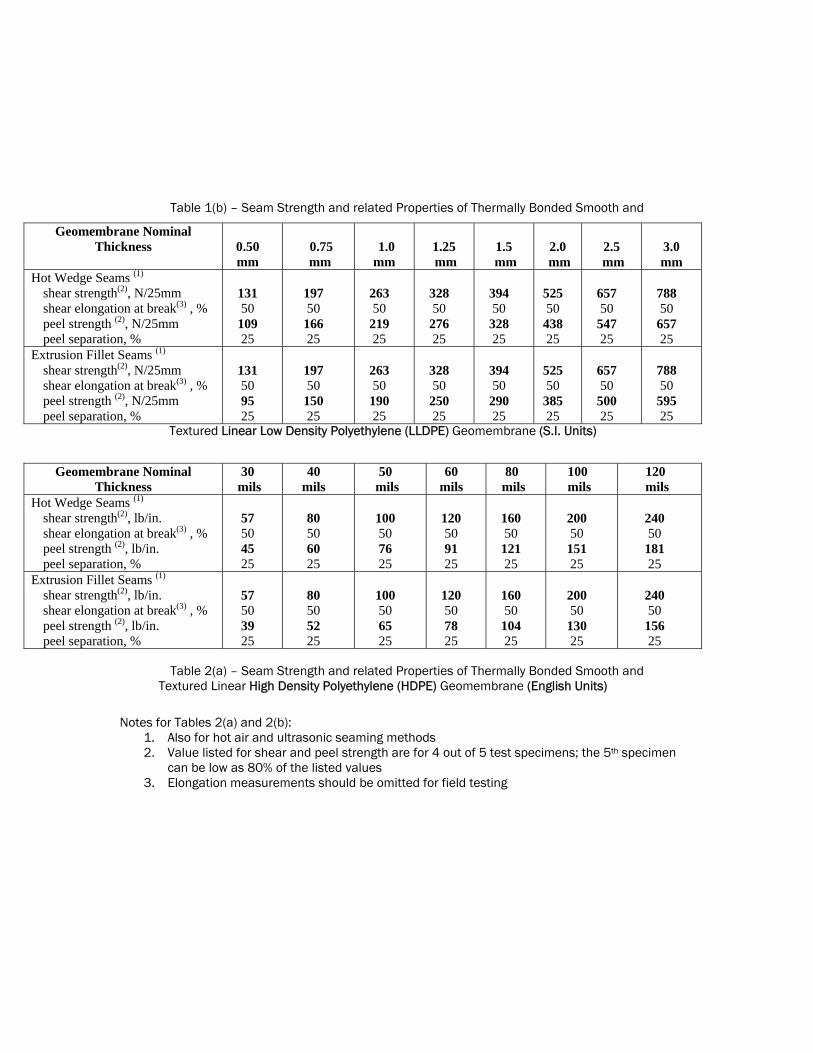
Table 1(b) – Seam Strength and related Properties of Thermally Bonded Smooth and
Textured Linear Low Density Polyethylene (LLDPE) Geomembrane (S.I. Units)
Geomembrane Nominal Thickness
0.50 mm
0.75
mm
1.0
mm
1.25 mm
1.5
mm
2.0
mm
2.5
mm
3.0 mm
Hot Wedge Seams (1)
shear strength(2), N/25mm shear elongation at break(3) , % peel strength (2), N/25mm peel separation, %
131 50
109 25
197 50
166 25
263 50
219 25
328 50
276 25
394 50
328 25
525 50
438 25
657 50
547 25
788 50
657 25
Extrusion Fillet Seams (1)
shear strength(2), N/25mm shear elongation at break(3) , % peel strength (2), N/25mm peel separation, %
131 50 95 25
197 50
150 25
263 50
190 25
328 50
250 25
394 50
290 25
525 50
385 25
657 50
500 25
788 50
595 25
Geomembrane Nominal Thickness
30 mils
40 mils
50 mils
60 mils
80 mils
100 mils
120 mils
Hot Wedge Seams (1)
shear strength(2), lb/in. shear elongation at break(3) , % peel strength (2), lb/in. peel separation, %
57 50 45 25
80 50 60 25
100 50 76 25
120 50 91 25
160 50
121 25
200 50
151 25
240 50
181 25
Extrusion Fillet Seams (1)
shear strength(2), lb/in. shear elongation at break(3) , % peel strength (2), lb/in. peel separation, %
57 50 39 25
80 50 52 25
100 50 65 25
120 50 78 25
160 50
104 25
200 50
130 25
240 50
156 25
Table 2(a) – Seam Strength and related Properties of Thermally Bonded Smooth and Textured Linear High Density Polyethylene (HDPE) Geomembrane (English Units)
Notes for Tables 2(a) and 2(b):
1. Also for hot air and ultrasonic seaming methods 2. Value listed for shear and peel strength are for 4 out of 5 test specimens; the 5th specimen
can be low as 80% of the listed values 3. Elongation measurements should be omitted for field testing

Table 2(b) – Seam Strength and related Properties of Thermally Bonded Smooth and Textured High Density Polyethylene (HDPE) Geomembrane (S.I. Units)
Geomembrane Nominal Thickness
0.75 mm
1.0 mm
1.25 mm
1.5
mm
2.0
mm
2.5
mm
3.0 mm
Hot Wedge Seams (1)
shear strength(2), N/25mm shear elongation at break(3) , % peel strength (2), N/25mm peel separation, %
250 50
197 25
350 50
263 25
438 50
333 25
525 50
398 25
701 50
530 25
876 50
661 25
1050 50
793 25
Extrusion Fillet Seams (1)
shear strength(2), N/25mm shear elongation at break(3) , % peel strength (2), N/25mm peel separation, %
250 50
170 25
350 50
225 25
438 50
285 25
525 50
340 25
701 50
455 25
876 50
570 25
1050 50
680 25
Related Documents