Internal crisis in a second-order non-linear non-autonomous electronic oscillator S.G. Stavrinides a , N.C. Deliolanis a , A.N. Miliou b , Th. Laopoulos a , A.N. Anagnostopoulos a, * a Department of Physics, Aristotle University of Thessaloniki, GR 54124 Thessaloniki, Greece b Department of Informatics, Aristotle University of Thessaloniki, GR 54124, Thessaloniki, Greece Accepted 12 July 2006 Abstract The internal crisis of a second-order non-linear non-autonomous chaotic electronic circuit is studied. The phase por- traits consist of two interacting sub-attractors, a chaotic and a periodic one. Maximal Lyapunov exponents were cal- culated, for both the periodic and the chaotic waveforms, in order to confirm their nature. Transitions between the chaotic and the periodic sub-attractors become more frequent by increasing the circuit driving frequency. The frequency distribution of the corresponding laminar lengths and their average values indicate that an internal crisis takes place in this circuit, manifested in the intermittent behaviour of the corresponding orbits. Ó 2006 Elsevier Ltd. All rights reserved. 1. Introduction Chaotic deterministic signals exhibit several intrinsic features, beneficial to secure communication systems, both ana- log and digital ones. Two key features of deterministic chaos are the ‘‘noise-like’’ time series and the sensitive depen- dence on initial conditions. Both of them grant to the signal low probability of detection in chaotic transmissions and low probability of decoding, in case of interception [1]. Due to their possible application for secure Internet communications, a number of promising non-linear circuits has been presented in the last decade, demonstrating chaotic behaviour [2–5]. Chen has compiled an Internet-downloadable comprehensive bibliography [6]. There are two main issues in studying the control of chaotic electronic circuits suitable for secure communications [7]. The first one is the way a non-linear circuit begins to operate in chaotic mode (route to chaos) [8–10] and the second one is the achievement of synchronization between transmitter–receiver [11,12]. A very interesting electronic circuit exhibiting chaotic behaviour with potential applications in secure communica- tions, is proposed and numerically examined in [13]. The transmitter of this chaotic communication system is a second- order non-linear non-autonomous electronic oscillator and its mode of operation depends on the externally applied 0960-0779/$ - see front matter Ó 2006 Elsevier Ltd. All rights reserved. doi:10.1016/j.chaos.2006.07.025 * Corresponding author. Tel.: +30 231 998203; fax: +30 231 998019. E-mail address: [email protected] (A.N. Anagnostopoulos). Chaos, Solitons and Fractals xxx (2006) xxx–xxx www.elsevier.com/locate/chaos ARTICLE IN PRESS Please cite this article as: S.G. Stavrinides et al., Internal crisis in a second-order non-linear ..., Chaos, Solitons and Fractals (2006), doi:10.1016/j.chaos.2006.07.025

Welcome message from author
This document is posted to help you gain knowledge. Please leave a comment to let me know what you think about it! Share it to your friends and learn new things together.
Transcript

ARTICLE IN PRESS
Chaos, Solitons and Fractals xxx (2006) xxx–xxx
www.elsevier.com/locate/chaos
Internal crisis in a second-order non-linearnon-autonomous electronic oscillator
S.G. Stavrinides a, N.C. Deliolanis a, A.N. Miliou b, Th. Laopoulos a,A.N. Anagnostopoulos a,*
a Department of Physics, Aristotle University of Thessaloniki, GR 54124 Thessaloniki, Greeceb Department of Informatics, Aristotle University of Thessaloniki, GR 54124, Thessaloniki, Greece
Accepted 12 July 2006
Abstract
The internal crisis of a second-order non-linear non-autonomous chaotic electronic circuit is studied. The phase por-traits consist of two interacting sub-attractors, a chaotic and a periodic one. Maximal Lyapunov exponents were cal-culated, for both the periodic and the chaotic waveforms, in order to confirm their nature. Transitions between thechaotic and the periodic sub-attractors become more frequent by increasing the circuit driving frequency. The frequencydistribution of the corresponding laminar lengths and their average values indicate that an internal crisis takes place inthis circuit, manifested in the intermittent behaviour of the corresponding orbits.� 2006 Elsevier Ltd. All rights reserved.
1. Introduction
Chaotic deterministic signals exhibit several intrinsic features, beneficial to secure communication systems, both ana-log and digital ones. Two key features of deterministic chaos are the ‘‘noise-like’’ time series and the sensitive depen-dence on initial conditions. Both of them grant to the signal low probability of detection in chaotic transmissions andlow probability of decoding, in case of interception [1].
Due to their possible application for secure Internet communications, a number of promising non-linear circuits hasbeen presented in the last decade, demonstrating chaotic behaviour [2–5]. Chen has compiled an Internet-downloadablecomprehensive bibliography [6]. There are two main issues in studying the control of chaotic electronic circuits suitablefor secure communications [7]. The first one is the way a non-linear circuit begins to operate in chaotic mode (route tochaos) [8–10] and the second one is the achievement of synchronization between transmitter–receiver [11,12].
A very interesting electronic circuit exhibiting chaotic behaviour with potential applications in secure communica-tions, is proposed and numerically examined in [13]. The transmitter of this chaotic communication system is a second-order non-linear non-autonomous electronic oscillator and its mode of operation depends on the externally applied
0960-0779/$ - see front matter � 2006 Elsevier Ltd. All rights reserved.doi:10.1016/j.chaos.2006.07.025
* Corresponding author. Tel.: +30 231 998203; fax: +30 231 998019.E-mail address: [email protected] (A.N. Anagnostopoulos).
Please cite this article as: S.G. Stavrinides et al., Internal crisis in a second-order non-linear ..., Chaos, Solitons andFractals (2006), doi:10.1016/j.chaos.2006.07.025
2 S.G. Stavrinides et al. / Chaos, Solitons and Fractals xxx (2006) xxx–xxx
ARTICLE IN PRESS
driving frequency. It has already been found that the circuit exhibits period doubling and intermittency routes to chaos[14–17], in two different ranges of driving signal frequency.
In this paper, we focus on the behaviour of this circuit in the frequency range 5.5925 kHz 6 fM 6 5.5946 kHz, wherethe system was found to undergo an internal crisis. The experimental study presented hereby includes maximal Lyapu-nov exponent determination for both the periodic and the chaotic attractors, measurements of average time of laminarlengths between transitions and estimation of the crisis critical exponent.
2. Experimental
2.1. Circuit description
Non-autonomous chaotic oscillators are governed by non-linear differential equations which include an externalexcitation. In the case of electronic circuits this excitation is an externally applied periodic, voltage or current, signal.
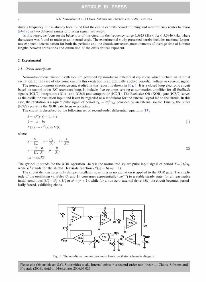
The non-autonomous chaotic circuit, studied in this report, is shown in Fig. 1. It is a closed loop electronic circuitbased on second-order RC resonance loop. It includes five op-amps serving as summation amplifier for all feedbacksignals (IC1/2), integrators (IC1/1 and IC2/2) and comparator (IC2/1). The Exclusive-OR (XOR) gate (IC3/2) servesas the oscillator excitation input and it can be regarded as a modulator for the external signal fed to the circuit. In thiscase, the excitation is a square pulse signal of period TM = 2p/xM, provided by an external source. Finally, the buffer(IC4/2) prevents the XOR gate from overloading.
The circuit is described by the following set of second-order differential equations [13]:
PleaFrac
_x ¼ aF ðy; tÞ � bxþ y
_y ¼ �x� by
F ðy; tÞ ¼ H SðyÞ �MðtÞð1Þ
where
x ¼ U 1
U 0
; y ¼ U 2
U 0
; t ¼ tRC
a ¼ U � � RU 0 � R�
; b ¼ RRs;
x1 ¼ xMRC
ð2Þ
The symbol � stands for the XOR operation. M(t) is the normalized square pulse input signal of period T = 2p/x1,while HS stands for the shifted Heaviside function HS(y) = H(�y + 1).
The circuit demonstrates only damped oscillations, as long as no excitation is applied to the XOR gate. The ampli-tude of the oscillating variables U1 and U2 converges exponentially (/e�bt) to a stable steady state, for all reasonableinitial conditions ðU 2
1 þ U 22 < U 2
0 or x2 þ y2 < 1Þ, while for a non zero external drive M(t) the circuit becomes period-ically forced, exhibiting chaos.
Fig. 1. The non-linear non-autonomous chaotic oscillator schematic diagram.
se cite this article as: S.G. Stavrinides et al., Internal crisis in a second-order non-linear ..., Chaos, Solitons andtals (2006), doi:10.1016/j.chaos.2006.07.025
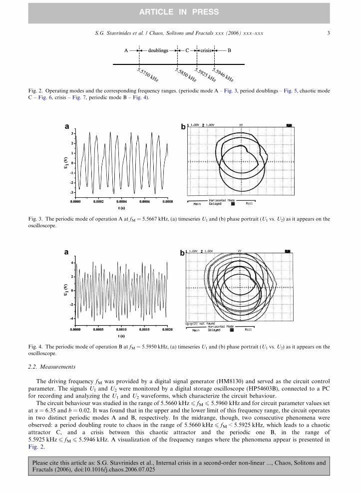
Fig. 2. Operating modes and the corresponding frequency ranges. (periodic mode A – Fig. 3, period doublings – Fig. 5, chaotic modeC – Fig. 6, crisis – Fig. 7, periodic mode B – Fig. 4).
Fig. 3. The periodic mode of operation A at fM = 5.5667 kHz, (a) timeseries U1 and (b) phase portrait (U1 vs. U2) as it appears on theoscilloscope.
Fig. 4. The periodic mode of operation B at fM = 5.5950 kHz, (a) timeseries U1 and (b) phase portrait (U1 vs. U2) as it appears on theoscilloscope.
S.G. Stavrinides et al. / Chaos, Solitons and Fractals xxx (2006) xxx–xxx 3
ARTICLE IN PRESS
2.2. Measurements
The driving frequency fM was provided by a digital signal generator (HM8130) and served as the circuit controlparameter. The signals U1 and U2 were monitored by a digital storage oscilloscope (HP54603B), connected to a PCfor recording and analyzing the U1 and U2 waveforms, which characterize the circuit behaviour.
The circuit behaviour was studied in the range of 5.5660 kHz 6 fM 6 5.5960 kHz and for circuit parameter values setat a = 6.35 and b = 0.02. It was found that in the upper and the lower limit of this frequency range, the circuit operatesin two distinct periodic modes A and B, respectively. In the midrange, though, two consecutive phenomena wereobserved: a period doubling route to chaos in the range of 5.5660 kHz 6 fM < 5.5925 kHz, which leads to a chaoticattractor C, and a crisis between this chaotic attractor and the periodic one B, in the range of5.5925 kHz 6 fM 6 5.5946 kHz. A visualization of the frequency ranges where the phenomena appear is presented inFig. 2.
Please cite this article as: S.G. Stavrinides et al., Internal crisis in a second-order non-linear ..., Chaos, Solitons andFractals (2006), doi:10.1016/j.chaos.2006.07.025

Fig. 5. The first period doubling mode of operation at fM = 5.5800 kHz, (a) timeseries U1 and (b) phase portrait (U1 vs. U2) as itappears on the oscilloscope.
Fig. 6. The chaotic mode of operation C at fM = 5.5920 kHz, (a) timeseries U1 and (b) phase portrait (U1 vs. U2) as it appears on theoscilloscope.
Fig. 7. The intermittent behaviour induced by the crisis between the chaotic attractor C and the periodic one B, at fM = 5.5930 kHz,(a) timeseries U1 and (b) phase portrait (U1 vs. U2) captured on the oscilloscope, with both attractors C and B appearing in the samesnapshot.
4 S.G. Stavrinides et al. / Chaos, Solitons and Fractals xxx (2006) xxx–xxx
ARTICLE IN PRESS
In Fig. 3, the recorded timeseries of signal U1 and an oscilloscope snapshot of the corresponding attractor – as con-structed by U1 and U2 waveforms – are presented, while the circuit is operating in periodic mode A, for a driving fre-quency fM = 5.5667 kHz. In the case of the periodic mode of operation B and for a driving frequency fM = 5.5955 kHzthe corresponding figures are displayed in Fig. 4.
Please cite this article as: S.G. Stavrinides et al., Internal crisis in a second-order non-linear ..., Chaos, Solitons andFractals (2006), doi:10.1016/j.chaos.2006.07.025

S.G. Stavrinides et al. / Chaos, Solitons and Fractals xxx (2006) xxx–xxx 5
ARTICLE IN PRESS
Beginning from the lower limit 5.5560 kHz and as the frequency fM increases the circuit undergoes the period dou-bling route to chaos. In Fig. 5 a typical recorded time series of signal U1 and a snapshot of the corresponding attractorare displayed for the case of the first period doubling. In this case, the circuit driving signal was set to fM = 5.5800 kHz.For higher values of driving frequency, a cascade of period doublings appears, converting gradually the periodic attrac-tor A into the chaotic one C [14,15]. In this case of chaotic mode of operation, the timeseries of U1 and the oscilloscopesnapshot of the corresponding attractor are presented in Fig. 6, for fM = 5.5920 kHz.
As the driving frequency further increases, the chaotic attractor C begins to interact with the periodic attractor B,forming a ‘‘composite’’ attractor. The transitions between the two sub-attractors become more frequent, i.e. the timeintervals between successive bursts become shorter, with increasing frequency. A typical signal U1 showing this inter-mittent behaviour appears in Fig. 7(a), for a driving frequency fM = 5.5930 kHz. In Fig. 7(b) the corresponding phaseportrait as captured from the oscilloscope screen, shows the chaotic sub-attractor colliding with the periodic attractor Binside its basin of attraction giving rise to an interior crisis [9].
3. Evaluation
In order to confirm the periodic nature of attractors A and B, as well as the chaotic nature of attractor C, threemaximal Lyapunov exponents Kmax were calculated in each case [8]. In Fig. 8 the corresponding plots of Kmax vs.the embedding dimension m, for all three cases, are presented. It is obvious that for the attractors A and B, Kmax tendsto zero, while for the chaotic attractor C, Kmax tends to the constant positive value 0.01. Moreover, Kmax does notchange significantly for m > 3, which denotes that m = 3 is the minimum embedding dimension of the system.
According to the theory developed by Ott, Grebogi and Yorke about crises in dynamical systems [18] the transitionprobability P(s) of the time intervals s, for which the orbit stays in the periodic attractor (laminar lengths), obeys thefollowing law:
Fig. 8.(C).
PleaFrac
PðsÞ ¼ 1
hsi eð�s=hsiÞ ð3Þ
where hsi is the average time between successive transitions. It must be noted that this law holds for a smooth distri-bution of the initial conditions. A typical distribution plot of the probability P(s) vs. s is shown in Fig. 9, forfM = 5.5946 kHz. An exponential decay fitting on Eq. (3) gives an estimate for factor 1/hsi and can lead to the calcu-lation of hsi. For this particular plot, the value obtained was hsi = 0.25 ± 0.01 s, while the value calculated by directlyaveraging the measured laminar lengths was found to be hsi = 0.344 s. Similar results were also obtained for every driv-ing frequency fM in the range 5.5928–5.5946 kHz, where the crisis takes place.
The average time hsi of the laminar lengths between two successive transitions from chaotic to periodic mode ofoperation is decreasing with increasing driving frequency fM, according to [18]:
hsi / ðfM � fcrÞ�c ¼ e�c ð4Þ
Maximal Lyapunov exponents Kmax vs. the embedding dimension m for the periodic modes (A and B) as well as the chaotic one
se cite this article as: S.G. Stavrinides et al., Internal crisis in a second-order non-linear ..., Chaos, Solitons andtals (2006), doi:10.1016/j.chaos.2006.07.025
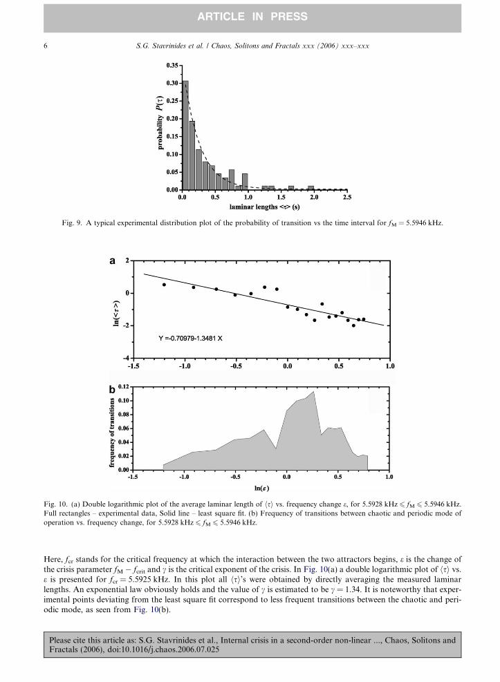
Fig. 10. (a) Double logarithmic plot of the average laminar length of hsi vs. frequency change e, for 5.5928 kHz 6 fM 6 5.5946 kHz.Full rectangles – experimental data, Solid line – least square fit. (b) Frequency of transitions between chaotic and periodic mode ofoperation vs. frequency change, for 5.5928 kHz 6 fM 6 5.5946 kHz.
Fig. 9. A typical experimental distribution plot of the probability of transition vs the time interval for fM = 5.5946 kHz.
6 S.G. Stavrinides et al. / Chaos, Solitons and Fractals xxx (2006) xxx–xxx
ARTICLE IN PRESS
Here, fcr stands for the critical frequency at which the interaction between the two attractors begins, e is the change ofthe crisis parameter fM � fcrit and c is the critical exponent of the crisis. In Fig. 10(a) a double logarithmic plot of hsi vs.e is presented for fcr = 5.5925 kHz. In this plot all hsi’s were obtained by directly averaging the measured laminarlengths. An exponential law obviously holds and the value of c is estimated to be c = 1.34. It is noteworthy that exper-imental points deviating from the least square fit correspond to less frequent transitions between the chaotic and peri-odic mode, as seen from Fig. 10(b).
Please cite this article as: S.G. Stavrinides et al., Internal crisis in a second-order non-linear ..., Chaos, Solitons andFractals (2006), doi:10.1016/j.chaos.2006.07.025
S.G. Stavrinides et al. / Chaos, Solitons and Fractals xxx (2006) xxx–xxx 7
ARTICLE IN PRESS
4. Discussion
The evaluation of the critical exponent c from Eq. (4) assumes that no noise is present in the system or that the noiselevel is very low. In the case of noisy signals of strength r, the average time is described by [19]:
PleaFrac
hsi / r�cgðjfM � fcrj=rÞ ð5Þ
where the function g depends on the system and the form of noise. All standard precautions were taken to avoid externalnoise influences during measurements. However, the generation of low-level internal noise, for example at semiconductor-metal contacts in the circuit parts, cannot be excluded. Although the experimental results follow Eq. (4), a fitting with Eq.(5) could also be possible if the unknown function g has the proper form. It has to be mentioned here that the phase portraitsas obtained from the oscilloscope during the crisis do not provide any evidence for noise supported intermittency.
The value, Kmax = 0.01 at which the maximum Lyapunov exponent saturates in the case of the chaotic attractor C,although positive, is low. This is expected since in this case the chaos present in the attractor is rather weak, i.e., thedeviations of the chaotic orbits from the original periodic ones are not very strong.
In this paper we have presented the intermittent behaviour of internal crisis of a non-linear non autonomous electronicoscillator. We have observed that the crisis between the chaotic and the periodic mode of operation evolves smoothly andthat the laminar lengths decrease exponentially, as the driving frequency forces the circuit to its periodic behaviour.
Acknowledgements
This work was supported by the EU, PRAMA project (G5MA-CT-2002-04014), NATO (PST.CLG.979003) andPYTHAGORAS II project of the Greek Ministry of National Education and Religious Affairs.
References
[1] Yang T, Chua L. Impulsive stabilazation for control and synchronization of chaotic systems: theory and application to securecommunication. IEEE Trans Circuits Syst I 1997;44(10):976–88.
[2] See for instance: In: Proceedings of the 12th international workshop on non-linear dynamics of electronic systems NDES’2004,Evora, Portugal; 2004.
[3] See for instance: In: Proceedings of the 2005 IEEE international symposium on circuits and systems ISCAS’2005. Kobe, Japan;2005.
[4] Yang T. A survey of chaotic secure communication systems. Int J Comp Cognition 2004;2:81–130.[5] Chen G, Ueta T. Chaos in circuits and systems. Singapore: World Scientific; 2002.[6] Chen G. Control and synchronization of chaotic systems (a bibliography). Available from: ftp://ftp.egr.uh.edu/pub/TeX/
chaos.tex.[7] Ott E, Grebogi C, Yorke JA. Controlling chaos. Phys Rev Lett 1990;64:1196–9.[8] Shuster HG. Deterministic chaos. Weinhaim: VCH; 1989.[9] Ott E. Chaos in dynamical systems. Cambridge: Cambridge University Press; 2002.
[10] Ogorzalek MJ. Chaos and complexity in non-linear electronic circuits. Singapore: World Scientific; 1997.[11] Pecora LM, Carroll TL. Synchronization in chaotic systems. Phys Rev Lett 1990;64:821–4.[12] Pikovsky A, Rosenblum M, Kurths J. Synchronization a universal concept in non-linear sciences. UK: Cambridge University
Press; 2003.[13] Mykolaitis G, Tamasevicious A, Cenys A, Namajunas A, Navionis K, Anagnostopoulos A. Globally synchronizable non-
autonomous chaotic oscillator. In: Proceedings of seventh international workshop on non-linear dynamics of electronic systemsNDES’99. Rønne, Denmark; 1999. p. 277–80.
[14] Stavrinides SG, Kyritsi KG, Deliolanis NC, Anagnostopoulos AN, Tamasevicious A, Cenys A, et al. The period doubling routeto chaos of a second-order non-linear non-autonomous chaotic oscillator – Part I. Chaos, Solitons & Fractals 2004;20:849–54.
[15] Stavrinides SG, Kyritsi KG, Deliolanis NC, Anagnostopoulos AN, Tamasevicious A, Cenys A, et al. The period doubling routeto chaos of a second-order non-linear non-autonomous chaotic oscillator – Part II. Chaos, Solitons & Fractals 2004;20:843–7.
[16] Stavrinides SG, Laopoulos Th, Anagnostopoulos AN. The intermittency route to chaos of a second-order non-linear non-autonomous oscillator. Int J Birurcat Chaos, accepted for publication.
[17] Stavrinides SG, Deliolanis NC, Laopoulos Th, Kyprianidis IM, Miliou AN, Anagnostopoulos AN. The intermittent behaviour ofa second-order non-linear non-autonomous oscillator. Chaos, Solitons & Fractals, in press, doi:10.1016/j.chaos.2006.07.049.
[18] Grebogi C, Ott E, Yorke JA. Crises, sudden changes in chaotic attractors and transient chaos. Physica D 1983;7:181–200.[19] Sommerer J, Ditto W, Grebogi C, Ott E, Spano M. Experimental confirmation of the scaling theory for noise induced crises. Phys
Rev Lett 1991;66:1947–50.
se cite this article as: S.G. Stavrinides et al., Internal crisis in a second-order non-linear ..., Chaos, Solitons andtals (2006), doi:10.1016/j.chaos.2006.07.025
Related Documents

![HARMONIC OSCILLATOR arXiv:math/0511178v2 …arXiv:math/0511178v2 [math.DS] 17 May 2006 NON-ERGODICITY OF THE NOSE-HOOVER THERMOSTATTED´ HARMONIC OSCILLATOR FRED´ ERIC LEGOLL, MITCHELL](https://static.cupdf.com/doc/110x72/5f987a88cb27cb6698642163/harmonic-oscillator-arxivmath0511178v2-arxivmath0511178v2-mathds-17-may-2006.jpg)