Intermediate Course Appalachian Underground Corrosion Short Course West Virginia University Morgantown, West Virginia Copyright © 2022

Welcome message from author
This document is posted to help you gain knowledge. Please leave a comment to let me know what you think about it! Share it to your friends and learn new things together.
Transcript

Intermediate Course
Appalachian Underground Corrosion Short CourseWest Virginia UniversityMorgantown, West Virginia
Copyright © 2022

APPALACHIAN UNDERGROUND CORROSION SHORT COURSEINTERMEDIATE COURSE
CHAPTER 1 ‐ CORROSION CELLS IN ACTION. . . . . . . . . . . . . . . . . . . . . . . . . . . . . . 1‐1
INTRODUCTION . . . . . . . . . . . . . . . . . . . . . . . . . . . . . . . . . . . . . . . . . . . . . . . . . 1‐1
REVIEW OF BASIC CONCEPTS . . . . . . . . . . . . . . . . . . . . . . . . . . . . . . . . . . . . . . 1‐1
Basic Course Reference . . . . . . . . . . . . . . . . . . . . . . . . . . . . . . . . . . . . . . . . 1‐1
A Corrosion Cell Concept . . . . . . . . . . . . . . . . . . . . . . . . . . . . . . . . . . . . . . . 1‐1
Dry Cell Example of a Corrosion Cell . . . . . . . . . . . . . . . . . . . . . . . . . . . . . . 1‐3
DEMONSTRATION . . . . . . . . . . . . . . . . . . . . . . . . . . . . . . . . . . . . . . . . . . . . . . . 1‐5
Dissimilar Metal Corrosion Cell . . . . . . . . . . . . . . . . . . . . . . . . . . . . . . . . . . 1‐6
Corrosion Cell Showing Effect of Electrolyte pH Characteristics on DissimilarMetal Corrosion . . . . . . . . . . . . . . . . . . . . . . . . . . . . . . . . . . . . . . . . . . . . . . 1‐7
Corrosion Cell Demonstrating Corrosion Caused by Differential OxygenConcentration . . . . . . . . . . . . . . . . . . . . . . . . . . . . . . . . . . . . . . . . . . . . . . . . 1‐8
Corrosion Cell Demonstrating Corrosion Caused by Dissimilar SurfaceConditions on Steel . . . . . . . . . . . . . . . . . . . . . . . . . . . . . . . . . . . . . . . . . . . . 1‐9
Demonstration Showing the Corrosion Cell Resulting from Differences inElectrolyte Concentration. . . . . . . . . . . . . . . . . . . . . . . . . . . . . . . . . . . . . . 1‐10
Demonstration to Show the Effect of Anode‐Cathode Ratio on CorrosionRate . . . . . . . . . . . . . . . . . . . . . . . . . . . . . . . . . . . . . . . . . . . . . . . . . . . . . . . 1‐11
Demonstration to Show the Corrosive Effect of Stress in Metal. . . . . . . 1‐13
Demonstration to Show Effect of Cathodic Protection on a CorrosionCell . . . . . . . . . . . . . . . . . . . . . . . . . . . . . . . . . . . . . . . . . . . . . . . . . . . . . . . . 1‐14

Demonstration Flexibility . . . . . . . . . . . . . . . . . . . . . . . . . . . . . . . . . . . . . . 1‐15
Demonstration Equipment. . . . . . . . . . . . . . . . . . . . . . . . . . . . . . . . . . . . . 1‐15
CONCLUSIONS. . . . . . . . . . . . . . . . . . . . . . . . . . . . . . . . . . . . . . . . . . . . . . . . . . 1‐17
CHAPTER 2 ‐ INSTALLATION OF GALVANIC ANODES. . . . . . . . . . . . . . . . . . . . . . . 2‐1
INTRODUCTION . . . . . . . . . . . . . . . . . . . . . . . . . . . . . . . . . . . . . . . . . . . . . . . . . 2‐1
REVIEW OF FUNDAMENTALS. . . . . . . . . . . . . . . . . . . . . . . . . . . . . . . . . . . . . . . 2‐1
The Galvanic Corrosion Cell . . . . . . . . . . . . . . . . . . . . . . . . . . . . . . . . . . . . . 2‐1
Galvanic Anodes and Cathodic Protection . . . . . . . . . . . . . . . . . . . . . . . . . 2‐2
Galvanic Anodes Plus Coatings and Electrical Isolation . . . . . . . . . . . . . . . 2‐2
GALVANIC ANODE APPLICATIONS. . . . . . . . . . . . . . . . . . . . . . . . . . . . . . . . . . . 2‐3
General Uses . . . . . . . . . . . . . . . . . . . . . . . . . . . . . . . . . . . . . . . . . . . . . . . . . 2‐3
Specific Uses . . . . . . . . . . . . . . . . . . . . . . . . . . . . . . . . . . . . . . . . . . . . . . . . . 2‐4
Advantages and Disadvantages . . . . . . . . . . . . . . . . . . . . . . . . . . . . . . . . . . 2‐7
GALVANIC ANODE CHARACTERISTICS. . . . . . . . . . . . . . . . . . . . . . . . . . . . . . . . 2‐8
Galvanic Anode Materials. . . . . . . . . . . . . . . . . . . . . . . . . . . . . . . . . . . . . . . 2‐8
Magnesium Anodes . . . . . . . . . . . . . . . . . . . . . . . . . . . . . . . . . . . . . . . . . . . 2‐8
Zinc Anodes . . . . . . . . . . . . . . . . . . . . . . . . . . . . . . . . . . . . . . . . . . . . . . . . . . 2‐9
Aluminum Anodes. . . . . . . . . . . . . . . . . . . . . . . . . . . . . . . . . . . . . . . . . . . . 2‐10
Use of Special Chemical Backfill . . . . . . . . . . . . . . . . . . . . . . . . . . . . . . . . . 2‐10

GALVANIC ANODE INSTALLATION PROCEDURES . . . . . . . . . . . . . . . . . . . . . . 2‐12
Single Anode Installation . . . . . . . . . . . . . . . . . . . . . . . . . . . . . . . . . . . . . . 2‐12
Multiple Anode Installation . . . . . . . . . . . . . . . . . . . . . . . . . . . . . . . . . . . . 2‐12
Anode Lead Attachment. . . . . . . . . . . . . . . . . . . . . . . . . . . . . . . . . . . . . . . 2‐13
Test Points . . . . . . . . . . . . . . . . . . . . . . . . . . . . . . . . . . . . . . . . . . . . . . . . . . 2‐13
CONCLUSIONS. . . . . . . . . . . . . . . . . . . . . . . . . . . . . . . . . . . . . . . . . . . . . . . . . . 2‐13
CHAPTER 3 ‐ INSTALLATION OF IMPRESSED CURRENT CATHODICPROTECTION SYSTEMS . . . . . . . . . . . . . . . . . . . . . . . . . . . . . . . . . . . . . . . . . . . . . . 3‐1
INTRODUCTION . . . . . . . . . . . . . . . . . . . . . . . . . . . . . . . . . . . . . . . . . . . . . . . . . 3‐1
DEFINITIONS . . . . . . . . . . . . . . . . . . . . . . . . . . . . . . . . . . . . . . . . . . . . . . . . . . . . 3‐1
Impressed Current Cathodic Protection System. . . . . . . . . . . . . . . . . . . . . 3‐1
Remote Anode Bed . . . . . . . . . . . . . . . . . . . . . . . . . . . . . . . . . . . . . . . . . . . . 3‐1
Distributed Anode Bed . . . . . . . . . . . . . . . . . . . . . . . . . . . . . . . . . . . . . . . . . 3‐2
Deep Anode Bed . . . . . . . . . . . . . . . . . . . . . . . . . . . . . . . . . . . . . . . . . . . . . . 3‐3
POWER SUPPLIES FOR IMPRESSED CURRENT CATHODIC PROTECTION SYSTEMS . . . . . . . . . . . . . . . . . . . . . . . . . . . . . . . . . . . . . . . . . . . . . . . . . . . . . . . 3‐3
Rectifiers . . . . . . . . . . . . . . . . . . . . . . . . . . . . . . . . . . . . . . . . . . . . . . . . . . . . 3‐3
Solar Cells. . . . . . . . . . . . . . . . . . . . . . . . . . . . . . . . . . . . . . . . . . . . . . . . . . . . 3‐4
Thermoelectric Generators . . . . . . . . . . . . . . . . . . . . . . . . . . . . . . . . . . . . . 3‐5
Engine ‐ Generator Sets . . . . . . . . . . . . . . . . . . . . . . . . . . . . . . . . . . . . . . . . 3‐5

Turbine ‐ Generator Sets . . . . . . . . . . . . . . . . . . . . . . . . . . . . . . . . . . . . . . . 3‐5
Wind Powered Generators. . . . . . . . . . . . . . . . . . . . . . . . . . . . . . . . . . . . . . 3‐5
ANODE BED MATERIALS. . . . . . . . . . . . . . . . . . . . . . . . . . . . . . . . . . . . . . . . . . . 3‐6
Anodes . . . . . . . . . . . . . . . . . . . . . . . . . . . . . . . . . . . . . . . . . . . . . . . . . . . . . . 3‐6
Packaged Anodes . . . . . . . . . . . . . . . . . . . . . . . . . . . . . . . . . . . . . . . . . . . . . 3‐8
Anode‐Lead Connection Insulation . . . . . . . . . . . . . . . . . . . . . . . . . . . . . . . 3‐8
Cables. . . . . . . . . . . . . . . . . . . . . . . . . . . . . . . . . . . . . . . . . . . . . . . . . . . . . . . 3‐8
Cable Connections . . . . . . . . . . . . . . . . . . . . . . . . . . . . . . . . . . . . . . . . . . . . 3‐9
Cable Splices and Repairs . . . . . . . . . . . . . . . . . . . . . . . . . . . . . . . . . . . . . . . 3‐9
SELECTING AN ANODE BED SITE . . . . . . . . . . . . . . . . . . . . . . . . . . . . . . . . . . . 3‐10
Soil Resistivity . . . . . . . . . . . . . . . . . . . . . . . . . . . . . . . . . . . . . . . . . . . . . . . 3‐10
Soil Moisture . . . . . . . . . . . . . . . . . . . . . . . . . . . . . . . . . . . . . . . . . . . . . . . . 3‐11
Interference with Foreign Structures . . . . . . . . . . . . . . . . . . . . . . . . . . . . 3‐11
Power Supply Availability . . . . . . . . . . . . . . . . . . . . . . . . . . . . . . . . . . . . . . 3‐12
Accessibility for Maintenance and Testing . . . . . . . . . . . . . . . . . . . . . . . . 3‐12
Vandalism . . . . . . . . . . . . . . . . . . . . . . . . . . . . . . . . . . . . . . . . . . . . . . . . . . 3‐12
Purpose of Anode Bed and Site Availability . . . . . . . . . . . . . . . . . . . . . . . 3‐13
INSTALLATION PRACTICES . . . . . . . . . . . . . . . . . . . . . . . . . . . . . . . . . . . . . . . . 3‐13
Anodes ‐ General. . . . . . . . . . . . . . . . . . . . . . . . . . . . . . . . . . . . . . . . . . . . . 3‐13
Vertical Installation . . . . . . . . . . . . . . . . . . . . . . . . . . . . . . . . . . . . . . . . . . . 3‐14

Horizontal Installation . . . . . . . . . . . . . . . . . . . . . . . . . . . . . . . . . . . . . . . . 3‐14
Deep Anode Installation . . . . . . . . . . . . . . . . . . . . . . . . . . . . . . . . . . . . . . . 3‐15
Cable Installation. . . . . . . . . . . . . . . . . . . . . . . . . . . . . . . . . . . . . . . . . . . . . 3‐15
Rectifier Installation . . . . . . . . . . . . . . . . . . . . . . . . . . . . . . . . . . . . . . . . . . 3‐16
CONCLUSIONS. . . . . . . . . . . . . . . . . . . . . . . . . . . . . . . . . . . . . . . . . . . . . . . . . . 3‐17
CHAPTER 4 ‐ CRITERIA FOR CATHODIC PROTECTION . . . . . . . . . . . . . . . . . . . . . . 4‐1
INTRODUCTION . . . . . . . . . . . . . . . . . . . . . . . . . . . . . . . . . . . . . . . . . . . . . . . . . 4‐1
CRITERIA FOR STEEL AND CAST IRON PIPING. . . . . . . . . . . . . . . . . . . . . . . . . . 4‐1
100 mV of Polarization Criterion . . . . . . . . . . . . . . . . . . . . . . . . . . . . . . . . . 4‐2
Polarization Formation . . . . . . . . . . . . . . . . . . . . . . . . . . . . . . . . . . . . . . 4‐3
Polarization Decay . . . . . . . . . . . . . . . . . . . . . . . . . . . . . . . . . . . . . . . . . . 4‐4
Application of the 100 mV of Polarization Criterion . . . . . . . . . . . . . . . 4‐4
Limitations of the 100 mV of Polarization Criterion . . . . . . . . . . . . . . . 4‐5
Polarized Potential of ‐850 mV Criterion. . . . . . . . . . . . . . . . . . . . . . . . . . . 4‐6
Application of the Polarized Potential of ‐850 mV Criterion . . . . . . . . 4‐6
Limitations of the Polarized Potential of ‐850 mV Criterion. . . . . . . . . 4‐7
Current‐Applied Potential of ‐850 mV Criterion . . . . . . . . . . . . . . . . . . . . . 4‐9
Voltage (IR) Drop Measurements. . . . . . . . . . . . . . . . . . . . . . . . . . . . . 4‐10
Cathodic Protection Coupons . . . . . . . . . . . . . . . . . . . . . . . . . . . . . 4‐10

Application of the Current‐Applied Potential of ‐850 mV Criterion. . 4‐11
Limitations of the Current‐Applied Potential of ‐850 mV Criterion . . 4‐12
Using Multiple Criteria to Meet Compliance . . . . . . . . . . . . . . . . . . . . 4‐14
OTHER CRITERIA DOCUMENTED THROUGH EMPIRICAL EVIDENCE . . . . . . . 4‐15
Net Protective Current Criterion . . . . . . . . . . . . . . . . . . . . . . . . . . . . . 4‐15
Application of the Net Protective Current Criterion . . . . . . . . . . . 4‐16
Limitations of the Net Protective Current Criterion . . . . . . . . . . . 4‐16
300 mV Potential Shift Criterion. . . . . . . . . . . . . . . . . . . . . . . . . . . . . . 4‐16
E‐Log I Curve Criterion. . . . . . . . . . . . . . . . . . . . . . . . . . . . . . . . . . . . . . 4‐18
SPECIAL CONSIDERATION FOR APPLICATION OF CP . . . . . . . . . . . . . . . . . . . 4‐19
Criterion for Aluminum Piping . . . . . . . . . . . . . . . . . . . . . . . . . . . . . . . 4‐19
Criterion for Copper Piping . . . . . . . . . . . . . . . . . . . . . . . . . . . . . . . . . . 4‐20
Criterion for Dissimilar Metal Piping . . . . . . . . . . . . . . . . . . . . . . . . . . 4‐20
CHAPTER 5 ‐ STATIC STRAY CURRENT INTERFERENCE TESTING. . . . . . . . . . . . . . 5‐1
INTRODUCTION . . . . . . . . . . . . . . . . . . . . . . . . . . . . . . . . . . . . . . . . . . . . . . . . . 5‐1
DEFINITIONS . . . . . . . . . . . . . . . . . . . . . . . . . . . . . . . . . . . . . . . . . . . . . . . . . . . . 5‐1
STATIC INTERFERENCE . . . . . . . . . . . . . . . . . . . . . . . . . . . . . . . . . . . . . . . . . . . . 5‐2
INTERPRETATION OF DATA . . . . . . . . . . . . . . . . . . . . . . . . . . . . . . . . . . . . . . . . 5‐3
Finding the Source of Static Interference . . . . . . . . . . . . . . . . . . . . . . . . . . 5‐6

Determining the Point of Maximum Exposure . . . . . . . . . . . . . . . . . . . . . . 5‐7
MITIGATION OF STATIC INTERFERENCE . . . . . . . . . . . . . . . . . . . . . . . . . . . . . . 5‐8
Mitigation by Bonds . . . . . . . . . . . . . . . . . . . . . . . . . . . . . . . . . . . . . . . . . . . 5‐8
Mitigation by Addition of Cathodic Protection . . . . . . . . . . . . . . . . . . . . . . 5‐9
Natural Potential Criterion . . . . . . . . . . . . . . . . . . . . . . . . . . . . . . . . . . . . . 5‐10
TYPICAL EXAMPLES OF STATIC INTERFERENCE . . . . . . . . . . . . . . . . . . . . . . . 5‐11
Summary of Examples . . . . . . . . . . . . . . . . . . . . . . . . . . . . . . . . . . . . . . . . 5‐17
Things to Watch Out For. . . . . . . . . . . . . . . . . . . . . . . . . . . . . . . . . . . . . . . 5‐17
CHAPTER 6 ‐ CORROSION CONTROL FOR PIPELINES. . . . . . . . . . . . . . . . . . . . . . . 6‐1
INTRODUCTION . . . . . . . . . . . . . . . . . . . . . . . . . . . . . . . . . . . . . . . . . . . . . . . . . 6‐1
PREFACE . . . . . . . . . . . . . . . . . . . . . . . . . . . . . . . . . . . . . . . . . . . . . . . . . . . . . . . 6‐1
COATINGS . . . . . . . . . . . . . . . . . . . . . . . . . . . . . . . . . . . . . . . . . . . . . . . . . . . . . . 6‐2
History of the Use of Coating Systems . . . . . . . . . . . . . . . . . . . . . . . . . . . . 6‐2
General . . . . . . . . . . . . . . . . . . . . . . . . . . . . . . . . . . . . . . . . . . . . . . . . . . . . . 6‐3
Types of Underground Coatings . . . . . . . . . . . . . . . . . . . . . . . . . . . . . . . . . 6‐4
Enamels . . . . . . . . . . . . . . . . . . . . . . . . . . . . . . . . . . . . . . . . . . . . . . . . . . . . . 6‐5
Fusion Bonded Epoxy ‐ FBE . . . . . . . . . . . . . . . . . . . . . . . . . . . . . . . . . . . . . 6‐6
Extruded Plastic Coatings . . . . . . . . . . . . . . . . . . . . . . . . . . . . . . . . . . . . . . . 6‐7
Hot Applied Mastics . . . . . . . . . . . . . . . . . . . . . . . . . . . . . . . . . . . . . . . . . . . 6‐8

Cold Liquid Coatings . . . . . . . . . . . . . . . . . . . . . . . . . . . . . . . . . . . . . . . . . . . 6‐9
Two Part Epoxy Coatings . . . . . . . . . . . . . . . . . . . . . . . . . . . . . . . . . . . . . . 6‐10
Hot Applied Waxes . . . . . . . . . . . . . . . . . . . . . . . . . . . . . . . . . . . . . . . . . . . 6‐11
Cold Applied Wax . . . . . . . . . . . . . . . . . . . . . . . . . . . . . . . . . . . . . . . . . . . . 6‐12
Prefabricated Films and Tapes . . . . . . . . . . . . . . . . . . . . . . . . . . . . . . . . . . 6‐13
Heat Shrink Sleeves and Tapes. . . . . . . . . . . . . . . . . . . . . . . . . . . . . . . . . . 6‐14
Directional Drilled Crossings. . . . . . . . . . . . . . . . . . . . . . . . . . . . . . . . . . . . 6‐14
Desired Coating System Qualities . . . . . . . . . . . . . . . . . . . . . . . . . . . . . . . 6‐15
Surface Preparation . . . . . . . . . . . . . . . . . . . . . . . . . . . . . . . . . . . . . . . . . . 6‐18
Coating Specification . . . . . . . . . . . . . . . . . . . . . . . . . . . . . . . . . . . . . . . . . 6‐20
HANDLING COATED STEEL PIPE. . . . . . . . . . . . . . . . . . . . . . . . . . . . . . . . . . . . 6‐23
Transportation and Handling of Mill Coated Pipe . . . . . . . . . . . . . . . . . . 6‐23
Pipe Coating Over or In the Ditch . . . . . . . . . . . . . . . . . . . . . . . . . . . . . . . 6‐24
Holiday Detection and Repair . . . . . . . . . . . . . . . . . . . . . . . . . . . . . . . . . . 6‐25
Inspection . . . . . . . . . . . . . . . . . . . . . . . . . . . . . . . . . . . . . . . . . . . . . . . . . . 6‐26
Procedures for Laying Coated Pipe . . . . . . . . . . . . . . . . . . . . . . . . . . . . . . 6‐27
HOLIDAY DETECTION AFTER BACKFILLING . . . . . . . . . . . . . . . . . . . . . . . . . . . 6‐27
SYSTEM MAINTENANCE. . . . . . . . . . . . . . . . . . . . . . . . . . . . . . . . . . . . . . . . . . 6‐28
CASED CROSSINGS . . . . . . . . . . . . . . . . . . . . . . . . . . . . . . . . . . . . . . . . . . . . . . 6‐28
What is a Cased Crossing? . . . . . . . . . . . . . . . . . . . . . . . . . . . . . . . . . . . . . 6‐28

Component Parts of a Cased Crossing. . . . . . . . . . . . . . . . . . . . . . . . . . . . 6‐29
Proper Methods for Installing Cased Crossings . . . . . . . . . . . . . . . . . . . . 6‐29
Testing Cased Crossings for Electrical Isolation . . . . . . . . . . . . . . . . . . . . 6‐30
ISOLATING JOINTS . . . . . . . . . . . . . . . . . . . . . . . . . . . . . . . . . . . . . . . . . . . . . . 6‐32
What Does an Isolating Joint Do? . . . . . . . . . . . . . . . . . . . . . . . . . . . . . . . 6‐32
Applications of Isolating Joints. . . . . . . . . . . . . . . . . . . . . . . . . . . . . . . . . . 6‐32
Isolating Flanges . . . . . . . . . . . . . . . . . . . . . . . . . . . . . . . . . . . . . . . . . . . . . 6‐33
Installation of Isolating Flanges . . . . . . . . . . . . . . . . . . . . . . . . . . . . . . . . . 6‐35
Isolating Unions. . . . . . . . . . . . . . . . . . . . . . . . . . . . . . . . . . . . . . . . . . . . . . 6‐36
Monolithic Isolation Joint . . . . . . . . . . . . . . . . . . . . . . . . . . . . . . . . . . . . . . 6‐36
Isolating Couplings . . . . . . . . . . . . . . . . . . . . . . . . . . . . . . . . . . . . . . . . . . . 6‐36
Testing Isolating Joints . . . . . . . . . . . . . . . . . . . . . . . . . . . . . . . . . . . . . . . . 6‐37
Repair of Shorted Isolating Flange. . . . . . . . . . . . . . . . . . . . . . . . . . . . . . . 6‐38
TEST POINTS . . . . . . . . . . . . . . . . . . . . . . . . . . . . . . . . . . . . . . . . . . . . . . . . . . . 6‐39
The Purpose of Test Points. . . . . . . . . . . . . . . . . . . . . . . . . . . . . . . . . . . . . 6‐39
Types of Test Points . . . . . . . . . . . . . . . . . . . . . . . . . . . . . . . . . . . . . . . . . . 6‐39
Installation of Test Points . . . . . . . . . . . . . . . . . . . . . . . . . . . . . . . . . . . . . . 6‐46
CONCLUSIONS. . . . . . . . . . . . . . . . . . . . . . . . . . . . . . . . . . . . . . . . . . . . . . . . . . 6‐47

CHAPTER 7 ‐ RECTIFIERS . . . . . . . . . . . . . . . . . . . . . . . . . . . . . . . . . . . . . . . . . . . . . 7‐1
INTRODUCTION . . . . . . . . . . . . . . . . . . . . . . . . . . . . . . . . . . . . . . . . . . . . . . . . . 7‐1
CATHODIC PROTECTION SYSTEM POWER SUPPLIES . . . . . . . . . . . . . . . . . . . . 7‐1
REVIEW OF ELECTRICAL FUNDAMENTALS . . . . . . . . . . . . . . . . . . . . . . . . . . . . 7‐2
THEORY . . . . . . . . . . . . . . . . . . . . . . . . . . . . . . . . . . . . . . . . . . . . . . . . . . . . . . . . 7‐2
Rectifying Circuits . . . . . . . . . . . . . . . . . . . . . . . . . . . . . . . . . . . . . . . . . . . . . 7‐5
Components of a Rectifier . . . . . . . . . . . . . . . . . . . . . . . . . . . . . . . . . . . . . . 7‐6
Circuit Breakers . . . . . . . . . . . . . . . . . . . . . . . . . . . . . . . . . . . . . . . . . . . . . . . 7‐6
Transformers . . . . . . . . . . . . . . . . . . . . . . . . . . . . . . . . . . . . . . . . . . . . . . . . 7‐8
Rectifying Elements. . . . . . . . . . . . . . . . . . . . . . . . . . . . . . . . . . . . . . . . . . . . 7‐9
Selenium Cell . . . . . . . . . . . . . . . . . . . . . . . . . . . . . . . . . . . . . . . . . . . . . . . . 7‐9
Silicon Diodes . . . . . . . . . . . . . . . . . . . . . . . . . . . . . . . . . . . . . . . . . . . . . . . 7‐10
Accessory Equipment . . . . . . . . . . . . . . . . . . . . . . . . . . . . . . . . . . . . . . . . . 7‐11
TYPES OF RECTIFIERS . . . . . . . . . . . . . . . . . . . . . . . . . . . . . . . . . . . . . . . . . . . . 7‐12
RECTIFIER SAFETY . . . . . . . . . . . . . . . . . . . . . . . . . . . . . . . . . . . . . . . . . . . . . . . 7‐13
PREVENTIVE MAINTENANCE . . . . . . . . . . . . . . . . . . . . . . . . . . . . . . . . . . . . . . 7‐14
RECTIFIER EFFICIENCY . . . . . . . . . . . . . . . . . . . . . . . . . . . . . . . . . . . . . . . . . . . 7‐16
RECTIFIER SELECTION . . . . . . . . . . . . . . . . . . . . . . . . . . . . . . . . . . . . . . . . . . . 7‐17
CONCLUSIONS. . . . . . . . . . . . . . . . . . . . . . . . . . . . . . . . . . . . . . . . . . . . . . . . . . 7‐18

CHAPTER 8 ‐ CATHODIC PROTECTION SYSTEM MAINTENANCE ANDTROUBLESHOOTING PROCEDURES. . . . . . . . . . . . . . . . . . . . . . . . . . . . . . . . . . . . . 8‐1
INTRODUCTION . . . . . . . . . . . . . . . . . . . . . . . . . . . . . . . . . . . . . . . . . . . . . . . . . 8‐1
MAINTENANCE PROGRAM . . . . . . . . . . . . . . . . . . . . . . . . . . . . . . . . . . . . . . . . 8‐1
Periodic Surveys . . . . . . . . . . . . . . . . . . . . . . . . . . . . . . . . . . . . . . . . . . . . . . 8‐1
Coating Maintenance . . . . . . . . . . . . . . . . . . . . . . . . . . . . . . . . . . . . . . . . . . 8‐1
Rectifier and Anode Bed Maintenance . . . . . . . . . . . . . . . . . . . . . . . . . . . . 8‐2
Galvanic Anode Maintenance . . . . . . . . . . . . . . . . . . . . . . . . . . . . . . . . . . . 8‐3
Test Station Maintenance . . . . . . . . . . . . . . . . . . . . . . . . . . . . . . . . . . . . . . 8‐3
PERIODIC SURVEYS. . . . . . . . . . . . . . . . . . . . . . . . . . . . . . . . . . . . . . . . . . . . . . . 8‐4
REPAIRS AND/OR REPLACEMENTS . . . . . . . . . . . . . . . . . . . . . . . . . . . . . . . . . . 8‐9
Coatings . . . . . . . . . . . . . . . . . . . . . . . . . . . . . . . . . . . . . . . . . . . . . . . . . . . . 8‐10
Rectifiers . . . . . . . . . . . . . . . . . . . . . . . . . . . . . . . . . . . . . . . . . . . . . . . . . . . 8‐10
Impressed Current Anode Beds . . . . . . . . . . . . . . . . . . . . . . . . . . . . . . . . . 8‐13
Galvanic Anodes . . . . . . . . . . . . . . . . . . . . . . . . . . . . . . . . . . . . . . . . . . . . . 8‐14
Test Stations . . . . . . . . . . . . . . . . . . . . . . . . . . . . . . . . . . . . . . . . . . . . . . . . 8‐14
TESTS USED IN CATHODIC PROTECTION SYSTEM TROUBLESHOOTING . . . . 8‐16
Percent Leakage Current Tests . . . . . . . . . . . . . . . . . . . . . . . . . . . . . . . . . 8‐16
System Current Profile . . . . . . . . . . . . . . . . . . . . . . . . . . . . . . . . . . . . . . . . 8‐17
Surface Potential Surveys . . . . . . . . . . . . . . . . . . . . . . . . . . . . . . . . . . . . . . 8‐19
Testing for Pipelines in Contact with Casings . . . . . . . . . . . . . . . . . . . . . . 8‐23

CONCLUSIONS. . . . . . . . . . . . . . . . . . . . . . . . . . . . . . . . . . . . . . . . . . . . . . . . . . 8‐24
April 5, 2022 Revision
To submit comments, corrections, etc. for this text, please email:[email protected]
COPYRIGHT NOTICE:
All content on the Appalachian Underground Corrosion Short Course (AUCSC) website is protected by copyright of AUCSC and may not be reproduced, duplicated ordistributed without the express written permission of AUCSC.
The Fundamentals, Basic, Intermediate and Advanced textbooks may be reproducedonly as single copies for study and review only by an individual solely for his or herown use who personally and directly downloads the document from the AUCSCwebsite.

Chapter 1 ‐ Corrosion Cells in Action
INTRODUCTION
This first chapter of the Intermediate Course is intended to accomplish two things. Thefirst will be a review of the basic concepts involved in a corrosion cell ‐ what is necessaryfor corrosion to occur on underground pipeline systems and the development of a basiccorrosion formula for steel. The second intended accomplishment is the developmentof methods for practical classroom demonstrations showing, visually, (1), how variouscorrosion cell conditions can result in active corrosion and, (2), how cathodic protectioncan be used to prevent corrosion. Demonstration tests will be outlined to show a varietyof corrosion‐causing conditions and to show the beneficial effect of cathodic protection.
REVIEW OF BASIC CONCEPTS
A thorough understanding of how a corrosion cell functions is essential for the corrosionworker on underground structures. Full knowledge in this basic area permits the workerto analyze more readily and understand corrosion problems encountered in the field.This in turn permits an informed approach to the development of corrective solutionsto the corrosion problems encountered.
Basic Course Reference
The essential basic concepts of corrosion cell operation and the various field conditionswhich can result in active corrosion cells on pipelines are covered in Chapter 2,"Corrosion Fundamentals", of the Basic Course. The following material on basics issummarized from the source.
A Corrosion Cell Concept
Figure 1‐1, will serve to illustrate basic points.
First ‐ and important to understand ‐ is that there are four essential elements of anycorrosion cell if active corrosion is to occur. These are:
1. There must be an anode
2. There must be a cathode
3. There must be a conducting electrolyte in which both anode and cathode are
Chapter 1 ‐ Corrosion Cells in Action1‐1

�����������������
��� ������
����������� ���������������
� ���������
�����������
��������������
�������
������������������
������������������������������������������
���� �����������������������������������������
��� �� ���
���
��� ������
���
���
���
���������
��
��
��
��
��
��
��
��
��
�������������������
� �
��
��� � ��������� ���
��������������������
����
�������������������
����������
����
�������������������
����������
����������
����������������������
�������������������������������!�������������
��������
��������
�������� ��������
���������
���������
�
�

immersed.
4. There must be a metallic conductor between the anode and the cathode.
All of these are present in Figure 1‐1. In the figure, the electrolyte is shown as water.This could just as well be moist earth or an aqueous chemical solution. In any case, theaqueous component is naturally ionized with positively charged hydrogen ions (H+) andnegatively charged hydroxyl ions (OH‐).
The anode is that metallic element of the cell which discharges ions into the electrolyteand corrodes. The cathode is that metallic element which collects ions from theelectrolyte and does not corrode. For there to be a current flowing between the anodeand cathode there has to be a driving voltage between the anode and cathode. Ingalvanic corrosion cells encountered in the field, there will naturally be (for a variety ofreasons) a voltage between theanode and cathode. In Figure 1‐1, both the anode and cathode of the laboratory cellillustrated are iron such that (under the uniform conditions shown) there would not bea voltage difference between them. For the purpose of the illustration, then, the drivingvoltage is represented by a battery inserted in the wire connecting the anode to thecathode.
Now we can review the electrochemical reactions that can occur at the anode andcathode under Figure 1‐1 conditions. First, as discussed in the Basic Course reference,there is a flow of electrons migrating in the opposite direction from the ions discussedabove. Actually, current flow is a flow of electrons ‐ one ampere flowing for one secondin the conventional fashion represents a transfer of 6.28 x 10¹⁸ electrons. This is basicand directly related to the corrosion process.
At the iron (or steel) anode of Figure 1‐1, conventional current discharging from theanode into the electrolyte must be accompanied by electron migration from the anodethrough the metallic connection (wire) to the cathode. These electrons become availableas a result of the ionization of iron atoms. Each atom of iron breaks down (ionizes) intoone positively charged iron ion (Fe++) and two negatively charged electrons (e‐, e‐). As asurplus of positively charged iron ions builds up at the anode surface, they are attractedto and combine with negatively charged hydroxyl ions (OH‐) in the ionized electrolyticenvironment. This results in the reaction (as shown on Figure 1‐1):
OH‐ + OH‐ + Fe++ = Fe(OH‐)2
Chapter 1 ‐ Corrosion Cells in Action1‐2
Fe(OH‐)2 is ferrous hydroxide.
As this process continues, the iron (or steel disappears (corrodes) and is replaced bycorrosion products. The basic reaction developing ferrous hydroxide (typically a whitishor pale greenish corrosion product) as shown is to form ferric hydroxide which is thefamiliar reddish brown rust.
At the cathode, the negatively charged electrons that have migrated there from theanode combine with positively charged hydrogen ions in the electrolytic environment.This can be represented (as shown on Figure 1‐1) by:
e‐ + e‐ + H+ + H+ = H2
H2 is hydrogen.
The hydrogen so developed forms on the surface of the cathode as a cathodicpolarization film. There is no attack on the iron cathode during this process.
Earlier, it was indicated that the aqueous component of the electrolyte in which theanode and cathode are immersed is naturally ionized. The representation of thebreakdown of water molecules into positively charged hydrogen ions and negativelycharged hydroxyl ions is given as follows:
2H2O = 2H+ + 2(OH‐)
Granting the necessary presence of these ions in the electrolyte, a fundamentalequation for the corrosion of iron at the anode can berepresented by:
Fe + 2H2O = Fe++ + 2H+ + 2(OH‐)
Where the 2H+ (after combining with negatively charged electrons) represents thecathodic polarization film and where the Fe++ combines with the 2(OH‐) to form Fe(OH‐)2‐ the ferrous hydroxide corrosion product.
Dry Cell Example of a Corrosion Cell
A simple, yet effective, example of a corrosion cell with which everyone is familiar is thecommon zinc‐carbon flashlight cell although the average user seldom, if ever, thinks of
Chapter 1 ‐ Corrosion Cells in Action1‐3

it as a corrosion cell. But it is.
Figure 1‐2 illustrates the components of the flashlight cell. In the cell by itself we haveonly three of the four requirements for an active corrosion cell: an anode (the zinc can),a cathode (the carbon rod central electrode), and an electrolyte (the ammoniumchloride). This, then, is an inactive corrosion cell.
When the cell is placed in a flashlight and the switch is pressed, a metallic circuit isactivated between the anode and cathode through the flashlight bulb. This is the fourthnecessary component for an active corrosion cell. Current is now discharged from thezinc can anode into the electrolyte and the anode then corrodes. The carbon rodcathode is not affected.
In Figure 1‐1 discussed earlier, a cell in the connecting circuit between anode andcathode caused current to flow in the cell between the similar‐material electrodes. Inthe case of the zinc‐carbon flashlight cell, however, there is a natural potential (voltage)between the dissimilar materials comprising the anode and cathode. In the case of anew zinc‐carbon flashlight cell, this potential is approximately 1.6 volts.
The galvanic potential difference between zinc and carbon which is used to advantagein the flashlight battery is an example of the use of the practical galvanic series of metalsfrom Table 2‐1 of the Basic Course, shown as Table 1‐2 in this chapter. This table listsmetals and certain other conducting materials from least noble (or most likely to beanodic) to most noble (or most likely to be cathodic). Any two materials from such atable will (when connected together in an electrically conducting environment) form acorrosion cell in which the more noble of the two will be the cathode.
The practical galvanic series from the Basic Course as referenced above gives potentialswith respect to a copper‐copper sulfate reference electrode. A more complete listing iscontained in Table 1‐1. This table, refers to the listing as a “solution potential series"(synonymous with "electromotive series") with potentials shown with respect to ahydrogen electrode which has been arbitrarily set at zero. In both tables, materials listedhigher in the table will be anodic (and will corrode) when connected in a corrosion cellto a more noble material which appears at a lower point in the table.
Although the principal of Tables 1‐1 and 1‐2 is the same, the voltage difference betweenany two materials appearing in one table may not agree with the voltage differencebetween the same two materials in the other table. There is a good reason for this.Whereas the practical series lists typical potential values measured with respect to a
Chapter 1 ‐ Corrosion Cells in Action1‐4

��� ��� ���
���
���
���������� ������������������������� ���������������������
������������� �������������!��������� �
���
���������������������
������������� ����������������������� ��������������������
�����������!�������������������
����������������
������������� ������������������������
������������������������������
��� �����
���

TABLE 1-1
SOLUTION POTENTIAL SERIES (ELECTROMOTIVE SERIES) OF SOME BASIC METALS AND MATERIALS
Pro
gres
sive
ly m
ore
anod
ic º
(less
nob
le) a
nd m
ore
corr
osiv
e
Metal or MaterialPotential(Emf, V) Metal or Material
Potential(Emf, V)
Lithium -2.96 Nickel -0.23
Rubidium -2.93 Tin -0.14
Potassium -2.92 Lead -0.12
Strontium -2.92 Iron (ferric) -0.04
Barium -2.90 HYDROGEN 0.00
Calcium -2.87 Antimony +0.10
Sodium -2.71 Bismuth +0.23
Magnesium -2.40 Arsenic +0.30
Aluminum -1.70 Copper (cupric) +0.34
Beryllium -1.69 Copper (cuprous) +0.47
Manganese -1.10 Tellurium +0.56
»P
rogr
essi
vely
mor
e ca
thod
ic
(nob
le) a
nd le
ss c
orro
sive
Zinc -0.76 Silver +0.80
Chromium -0.56 Mercury +0.80
Iron (ferrous) -0.44 Palladium +0.82
Cadmium -0.40 Carbon +0.84
Indium -0.34 Platinum +0.86
Thallium -0.33 Gold (auric) +1.36
Cobalt -0.28 Gold (aurous) +1.50
NOTE: Polarities shown are applicable to the external circuit between materials.

TABLE 1-2
A GALVANIC SERIES OF CERTAIN METALSAND ALLOYS ARRANGED IN ORDER OF CORROSIVITY
ANODIC (LEAST NOBLE) ENDMaterial Material (continued)
Magnesium Brasses
Magnesium alloys Copper
Zinc Bronzes
Aluminum 2S Copper-nickel alloys
Cadmium Monel
Aluminum 175S Silver solder
Steel or iron Nickel (passive)
Cast iron Inconel (passive)
Chromium-iron (active) Chromium-iron (passive)
Ni-Resist 18-8 Chromium-nickel-iron (passive)
18-8 Chromium-nickel-iron (active) 18-8-3 Chromium-nickel-molybdenum-iron(passive)
18-8-3 Chromium-nickel-molybdenum-iron(active) Hastelloy C (passive)
Lead-tin solders Silver
Lead Carbon and graphite
Tin Platinum
Nickel (active) Gold
Inconel (active)CATHODIC (MOST NOBLE) END
Hastelloy C (active)

copper‐copper sulfate reference electrode in neutral soils or waters, laboratorydetermined values such as those in Table 1‐1 are typically determined for each materialwith reference to hydrogen electrode when the material being tested is immersed in asolution of its own salts.
From the above it would appear that the practical series (Table 1‐2) will be more usefulto the corrosion worker dealing with underground structures than would a laboratory‐determined series. But here again, the practical galvanic series should be used as a guideonly because if there are local or general deviations from neutral soil or water conditionsalong a buried structure, there can be distortions in the potential values.
As further assistance in determining the anodic‐cathodic relationship between materials, (from most anodic to most cathodic) Table 1‐2 tabulates a series of metals and metalalloys that may be encountered. It will be noted that potential values with respect to acommon reference are not given as is the case with Table 1‐1. Table 1‐2 is most usefulin making an initial determination of the probable anodic‐cathodic relationship. Thegeneral order of the probable potential between them may be estimated by using Table1‐2 and may be confirmed by test in the specific environment of the actual application.
DEMONSTRATION
Hearing and reading about various corrosion cells and how they operate gives an initialbackground. However, there is no better way to get the full impact of the manner inwhich these cells work than to see an actual demonstration of corrosion cells in action.
Colonel George C. Cox (deceased) developed a demonstration lecture for use at theAppalachian Underground Corrosion Short Course which illustrates effectively howvarious cells work. The following material describes how the demonstration isaccomplished and details several experiments undertaken during the demonstration.
The problems involved with such demonstrations were, first, how to present them sothat they could be seen equally well by all members of a large group and, second, howto show that areas which are supposed to be anodic in a given cell actually areperforming in an anodic manner ‐ and, likewise, how to show the cathodic areas.
The first problem was solved by placing the experimental corrosion cells in transparentcontainers filled with liquid electrolyte. Then, using optical projection equipment, theimage of the corrosion cell could be projected on a screen so that all could see. Thisillustrates the corrosion cell framework but without some additions there would be little
Chapter 1 ‐ Corrosion Cells in Action1‐5
that could be seen during a reasonably short lecture time interval to show that therewas anything going on in the corrosion cell.
This second problem was solved by the use of chemical indicators in the electrolytesolutions used in the corrosion cells. For the anodic indicator, 2 or 3 drops (not morethan 3) of a saturated aqueous solution of potassium ferricyanide is added to each 100milliliters of stock solution. The resulting precipitate will give a brilliant bluish greencolor by transmitted projector light in anodic areas. For the cathodic indicator, 5milliliters of a 1% alcohol solution of phenolphthalein is added to (and well shaken into)each 95 milliliters of electrolyte solution just before placing in the projection cell. Themeasurements are critical. The phenolphthalein indicator will show a bright pink orcrimson color by projected light in cathodic areas.
The combination of the on‐screen projection capability plus the means of positivelyidentifying anodic and cathodic areas makes itpossible for classroom groups actually to see the action taking place in corrosion cellsof various types.
The following sections will illustrate some of the corrosion cells which can bedemonstrated using the Cox methods. It should be noted thatdemonstrations of this same nature can be used effectively for corrosion worker trainingpurposes within company organizations. Additionally, such demonstrations can be auseful tool when conducting corrosion familiarization sessions for companymanagement personnel.
Dissimilar Metal Corrosion Cell
This demonstration cell is used to show that when two dissimilar metals are connectedtogether in a corrosion cell, one will be an anode (and will corrode) while the other willbe cathodic and unaffected.
The demonstration cell to be used in this case is shown diagrammatically by Figure 1‐3.Note that the two materials used are steel and platinum immersed in a low resistivitysodium chloride solution. Inspection of Table 1‐1 indicates that we could expect apotential difference between ferrous iron and platinum of approximately 1.30 volt andthat the iron should be the anodic (corroding) member. Accordingly, in thedemonstration cell, the indicators should show a bluish‐green coloration around thesteel anode and a pink or crimson coloration at the platinum cathode.
Chapter 1 ‐ Corrosion Cells in Action1‐6

��������
��������������
���� ������
�������������"����������
�#$����� ������������� ����������������
�����������������������������
��� �����%

The high galvanic voltage between steel and platinum permits fairly rapid action in thecell so that the indicator colors should develop in less than five minutes after the cell isactivated by the demonstrator.
The demonstration visually indicates that corrosion can occur when dissimilar metals arein electrical contact with one another in a conducting electrolyte. There are quite a fewdissimilar metal combinations that can be encountered when working on undergroundmetallic structures.
Some of the more common are:
C Steel and cast ironC Plain steel and galvanized steelC Galvanized steel and cast ironC Copper and steel or cast ironC Brass and steel or cast ironC Lead and copper
Plus other combinations involving stainless steel, aluminum, cinders (carbon), etc.
Corrosion Cell Showing Effect of Electrolyte pH Characteristics on Dissimilar MetalCorrosion
The objective of this demonstration cell is to show that a dissimilar metal corrosion cellwill remain active under different pH conditions.
In the preceding demonstration, the electrolyte in the steel‐platinum dissimilar metalcell was a uniform mixture of sodium chloride in contact with both elements of the cell.In this demonstration, as shown by Figure 1‐4, the same two dissimilar metals are usedbut the steel is (for the first part of the demonstration immersed in a 10% sodiumchloride solution (alkaline) while the platinum is immersed in 1% hydrochloric acidsolution. A porous bridge separates the two electrolytes preventing free intermixing ofthe solutions. However, it becomes saturated with the solution and permits corrosioncurrent interchange between the steel and platinum.
When the cell arranged as described above is placed in operation by the demonstrator,the color indicators will show the steel in the alkaline environment to be anodic andcorroding as shown by a blue‐green coloration while the platinum in the acidenvironment will
Chapter 1 ‐ Corrosion Cells in Action1‐7

��������
���� �������
��������������
���� ������
�#$����� ������������� ����������������
�$�������������������� ����������������
�������������"����������
������������������������������������������������������������
��� �����&

show the pink cathodic coloration.
Once the above demonstration is shown on the screen, the demonstrator will reversethe positions of the steel and platinum placing thesteel in the acid solution and the platinum in the alkaline environment. Again the colorindicators will show the steel to be anodic and the platinum cathodic with generallysimilar reaction times.
A successful demonstration as described shows that differing pH conditions along anunderground structure do little to change the anode‐cathode relationship of corrosioncells.
On underground structures, particularly long structures such as pipelines, it is not at allunusual to find alkaline, neutral, and acid conditions at different locations along thestructure. Although some pipelines may be in predominantly neutral soils, they can passthrough industrial areas where contamination can produce either alkaline or acidconditions. Some soils can be naturally acid or alkaline.
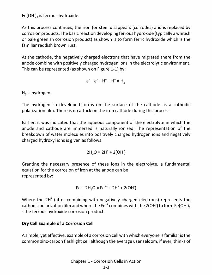
Corrosion Cell Demonstrating Corrosion Caused by Differential Oxygen Concentration
The intent of this demonstration is to show that a single metal (such as steel) in anenvironment of uniform chemical composition, (such as uniform soil) can suffercorrosion if part of the metal surface receives a greater supply of oxygen than others.Further, it is intended to show that those areas having the least oxygen availability willbe anodic and corroding.
The schematic arrangement of the demonstration corrosion cell is shown by Figure 1‐5.Bright steel electrodes are placed in each of the two cell compartments; these areconnected together to establish electrical continuity between the two. This can beaccomplished with a single strip of steel bent into a U‐shape as shown. Eachcompartment is filled with a uniform solution of 1% sodium chloride with colorindicators added. A porous bridge is used between the two compartments to preventfree interchange of electrolytes from the two compartments but still provide electricalcontinuity between the two.
To obtain the differential oxygen concentration, oxygen is bubbled through onecompartment (which will be the anodic side. In Figure 1‐5 the means of accomplishingthis is shown schematically for the demonstration cell which has been used in the
Chapter 1 ‐ Corrosion Cells in Action1‐8
�����������������������' (����� ���� ��������
�������� �!����
��������������"����������
�$����� ������������� ���)�������������
������������!�������������������������������
��� �����*

classroom experiments. This is done by using a DC voltage (supplied by a variabletransformer and AC to DC rectifier) between two platinum electrodes in a separatecompartment of the demonstration cell. This separate compartment is filled with a 20%solution of sodium hydroxide (NaOH). Oxygen is evolved at the positive platinumelectrode and is channeled, as shown on the figure, through the cathodic half of thedemonstration cell. Likewise, hydrogen is evolved at the negative platinum electrodeand is channeled through the anodic half of the cell. The DC applied voltage is adjustedby the demonstrator to obtain a good flow of gas from the two platinum electrodes. Thiswill require approximately 18 volts DC.
The reaction time for the demonstration to show the anodic and cathodic indicatorcolorations (pink at the cathode and blue‐green at the anode) may range from one totwo hours. This necessitates the demonstrator placing the cell in operation prior to thestart of the classroom demonstration so that the reaction can be shown during theclassroom time period.
A successful demonstration will show that the steel strip in the oxygen‐poorenvironment will be anodic while the steel strip in the oxygen‐rich environment will becathodic.
As discussed in the Chapter 2 of the Basic Course, differential oxygen concentration isreferred to as "differential aeration". A typical example of such a corrosion cell is apipeline in a relatively porous well aerated soil passing under a paved highway wherethe pavement restricts air (and thereby oxygen) access to the pipe. This causes relativelyoxygen‐poor environment around the pipe under the pavement ‐ and this is where thecorrosion occurs in the absence of adequate protective measures.
Corrosion Cell Demonstrating Corrosion Caused by Dissimilar Surface Conditions onSteel
The purpose of this demonstration is to illustrate that there is an anode‐cathoderelationship between new steel and rusted steel in electrical contact with each other ina conducting environment ‐ even though both steels are of the same alloy. Further, itis the intent to show that the new steel is anodic and will corrode.
Figure 1‐6 shows the schematic arrangement of the demonstration corrosion cell. Abright steel electrode is placed in one compartment of the cell and a rusted steelelectrode is placed in the other. Both compartments are filled with a 10% sodiumchloride solution with color indicators added. The two electrodes are electrically
Chapter 1 ‐ Corrosion Cells in Action1‐9

� �������������
�������������
��������������
��������������"����������
�#$����� ������������� ���)�������������)����������������
��������������������������������� ������������������ ��������������
��� �����+

interconnected to complete the corrosion cell.
Once the cell is placed in operation by the demonstrator, the time required to obtaincolor indications will be in the order of 30 to 60 minutes. When the reaction becomesapparent, the blue‐green anodic coloration will be seen in the compartment containingthe bright steel electrode. Similarly, the pink cathodic coloration will show in thecompartment containing the rusted steel electrode.
A similar result would be obtained if the comparison were made between a bright steelelectrode and a steel electrode coated with mill scale ‐ with the bright steel electrodebeing anodic and corroding.
In pipeline work, the new steel‐rusted steel relationship was learned the hard waybefore the advent of adequate corrosion control measures. Typically, when corrosionfailures occurred in a "hot‐spot" area necessitating replacement after, say, ten years, thepipe was replaced with a new piece of steel pipe of the same type as used originally. Theexpectation was that it would be another ten years before replacement would berequired again. Then when it was found that the replacement section only lasted, forexample, five years, the unusual reaction was, "they just don't make steel like they useto". Actually, the difference in performance time was not the fault of the steel itself, itwas the anode‐cathode relationship between new (bright) steel and old (rusted) steelas shown by the demonstration described above.
The steel to mill scale anode‐cathode relationship may be encountered on steel from ahot rolling mill from which the mill scale has not been properly removed. The mill scaleis strongly cathodic (more noble) with respect to the base steel. This gives rise to strongdissimilar‐surface‐condition corrosion cells at breaks in the mill scale coating. The basesteel is anodic and corrodes at such breaks in the absence of adequate corrosion controlmeasures.
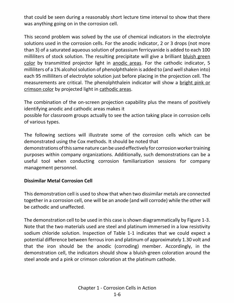
Demonstration Showing the Corrosion Cell Resulting from Differences in ElectrolyteConcentration
This demonstration is intended to show that a steel structure (such as a pipeline) passingthrough a similar electrolytic environment, but of differing concentration from point topoint, can be affected by corrosion cells caused by the variations in concentration.Additionally, it is intended to show that the steel structure in the more highlyconcentrated electrolyte will be anodic (and corroding) with respect to those parts ofthe structure in less concentrated electrolyte.
Chapter 1 ‐ Corrosion Cells in Action1‐10

A corrosion demonstration cell to illustrate the differential concentration effect is shownby Figure 1‐7. A bright steel electrode is placed in each of the two cell compartments.They are electrically interconnected (a single strip bent into a U‐Shape. as shownaccomplishes this). One of the compartments is filled with a 1% solution (lowconcentration) of sodium chloride. The other compartment is filled with a 10% (higherconcentration) of sodium chloride. Anodic and cathodic color indicators are added to thesolution. A porous barrier between the two compartments prevents free intermixing ofthe two solutions but permits passage of electric current between the twocompartments.
Once the cell is placed in operation by the demonstrator, time required to obtain anodicand cathodic color indications will typically range from 30 to 60 minutes. A successfuldemonstration will show the blue‐green anodic reaction coloration at the steel electrodein the high concentration (10% sodium chloride) compartment and the pink cathodicreaction coloration at the steel electrode in the low concentration compartment.
Various conditions can give rise to the differential‐concentration corrosion cells onoperating pipelines. An example is a pipeline crossing a marine tidal flat with some freshwater influx. At high tide, the entire structure may be covered with concentrated seawater but as the tide recedes, part of the structure willbe in concentrated sea water while part will be in diluted sea water. Corrosion will beconcentrated in that part of the structure still in the more concentrated sea water. Thisis a moving situation as the tide flows in and out.
Another example can be chemical contamination in industrial areas. Where suchcontamination occurs, the concentration will typically be greatest at the center of thespill area. This would be the area of greatest anodic effect. As the concentration tapersoff as the edges of the spill area are approached, the structure becomes relativelycathodic.
Demonstration to Show the Effect of Anode‐Cathode Ratio on Corrosion Rate
The purpose of this demonstration is to show that if a small anode is coupled to a largecathode in a corrosion cell, the rate of corrosion will be high at the small anodic area.
The demonstration cell arrangement to accomplish this is shown by Figure 1‐8. In thiscell, one compartment contains a bright steel electrode which has been given a paintcoating with two pinholes (approx 1/16" in diameter) cut through the coating near oneedge of the electrode. The other compartment contains a rusty steel electrode; a
Chapter 1 ‐ Corrosion Cells in Action1‐11
���������������� �� ������������
�������������������
���������������������� ������� �������
����������������������� ������� �������
��� ������ ������������������� ������������� ��� ������������ � ������
���������
� ��
������
������� ��� ���� ���� ���

�������������
����� �������������
�������������"����������
�#$����� ������������� ���)�����������������������������
���������������������������������������������������������������
��� �����-
����������������������������.�+(�������������� ���� ��������

preceding demonstration has shown that the bright steel will be anodic and the rustysteel cathodic. The two electrodes are electrically interconnected. Both compartmentsare filled with a 10% solution of sodium chloride to which the anode and cathode colorindicators leave been added. Typically, with this arrangement, the ratio of cathodic areato the small anodic area will be in the order of 150:1.
Typically, a successful demonstration will show a relatively intense blue‐green anodiccoloration showing at the small anodic area pinholes before pink cathodic colorationappears at the larger rusty steel cathodic area. This is an indication that the corrosionrate at the anodic pin‐holes is relatively intense as compared to that observed during theprior demonstration in which a bare bright steel electrode was coupled to a bare rustysteel electrode.
If the situation were reversed such that the anodic area is large and the cathodic areasmall by the same ratio, there would be an intense pink indicator appearing at the smallcathodic area before the blue‐green anodic coloration becomes apparent oil the largeanodic area ‐ an indication that the corrosion rate in the anodic area is much less intensethan in the preceding case.
This all illustrates the basic rule that if anodic materials must be coupled to cathodicmaterials on an underground structure, a small cathode coupled to a large anode ismuch to be preferred to a small anode coupled to a large cathode. This rule does not,however, apply to cathodic protection installations where relatively small anodes(galvanic or impressed current) are connected to large cathodic areas being protected ‐but here the anodes are corroded in order to cathodically protect the workingunderground structure.
Some examples can be cited to illustrate the effects of anode‐cathode ratio inunderground piping systems.
As one example, if a brass valve is used in galvanized steel piping, there is a dissimilarmetal corrosion problem. However, there is a small cathode (the brass valve) workingagainst a relatively large anode (the galvanized piping). Under this condition, thecorrosive effect is distributed over a large area of the galvanized piping. Further, thecorrosion current from the galvanized piping can polarize the small brass cathode whichacts to reduce the corrosion current interchange. Coating the brass valve can furtherreduce the current interchange to a negligible amount by reducing the already‐smallcathode to just any brass cathodic material exposed at defects in the valve coating. Thisemphasizes the wisdom of using the small cathode, large anode relationship on
Chapter 1 ‐ Corrosion Cells in Action1‐12

underground structures.
As a reverse‐situation example, if a galvanized steel valve were to be used inunderground copper piping, the undesirable small anode large cathode would result.Under this condition, there would be intense corrosion current discharge from the smallanode (the galvanized steel valve). Further, this current flowing to the relatively largecopper pipe cathodic area would have little expectation of polarizing the copper ‐ sothere would be little or no reduction in the corrosion current interchange from thissource. Also, coating the galvanized valve anode in this situation would be the wrongthing to do since the ratio of large cathode to small anode would be made even greater.Current discharge from the anode surface exposed at defects in the coating would beeven more intense than if the galvanized valve were left bare leading to even earliercorrosion penetration of the valve body. This emphasizes the wisdom of avoiding thesmallanode, large cathode relationship on underground structures wherever possible.
A final example relates to the use of coatings on non‐cathodically protectedunderground structures. A good coating can prevent corrosion on more than 99% of thestructure surface area. But the remaining surface area is exposed to earth at minorcoating defects or pinholes inevitably exist or will develop on underground structuresin practical applications. Some of the pinholes will be in naturally cathodic areas andsome in naturally anodic areas. Where pinholes exist in a relatively small anodic areaworking against pinholes in large cathodic areas on either side of the anodic area,corrosion current discharge from the pinholes in the anodic area can be intense. This canresult in the development of corrosion penetrations on the non‐cathodically protectedstructure earlier than if the structure had been installed bare, even though the totalmetal loss is not so great.
Demonstration to Show the Corrosive Effect of Stress in Metal
It is the intent of this demonstration to show that residual stresses in metal are anodicwith respect to non‐stressed portions of the same metal sample.
Figure 1‐9 illustrates the arrangement to show the effect. A single compartmentdemonstration cell is used. The compartment is filled with a 10% solution of sodiumchloride to which anodic and cathodic color indicators have been added. A common ironnail is placed in the compartment. The cold worked nail head and point contain residualstresses from the cold working process. A successful demonstration will result in aconcentration of the blue‐green anodic coloration around the head and point of the nail
Chapter 1 ‐ Corrosion Cells in Action1‐13

�����������������������/�������������
�����������������
��
������������
��
�����������������������
�#$����� ������������� ����������������
�����������������������������0�����������������������
��� �����1

with the pink cathodic coloration along the shank of the nail. Occasionally, dependingon the surface condition of the nail shank, there may be secondary lesser anodic areasalong the shank of the nail.
Because of the low driving potential between the stressed and non‐stressed portions ofthe nail, the time required for the color development on on‐screen projection may befrom one to two hours making it necessary to place the cell in operation prior to thestart of the lecture period.
Stress corrosion can occur on working pipelines where stress‐induced corrosion caninitiate cracking and pipeline failure. This is an involved study in itself but appears to bemost apt to occur on the higher strength pipeline steels in the absence of adequateprotective measures.
The use of rivets and bolts on structures in a conducting environment can be a problem.Stress is present in such fasteners but if rivet and bolt materials are selected such thatthe stressed material is slightly cathodic to the material in the body of the structure, thedesirable large anode small cathode relationship will be attained. Under this condition,the stressed bolts or rivets will be cathodically protected to a degree by the structureitself. Since the anodic area (the body of the structure) is large, the corrosive impact onit will be slight as discussed in the preceding section.
Demonstration to Show Effect of Cathodic Protection on a Corrosion Cell
In this demonstration, the intent is to show the beneficial effect of cathodic protectionon a known corrosion cell. This accomplished with a two‐part demonstration.
In the first part of the demonstration, a single‐compartment cell is used as shownschematically by Figure 1‐10. A dissimilar metal couple (bright steel anode and coppercathode electrically interconnected as shown) is placed in the compartment. Thecompartment is filled with a 10% solution of sodium chloride to whichthe anodic and cathodic color indicators have been added. Within five to ten minutesafter placing the cell in operation, the bright steel anode should show the blue‐greenanodic coloration while the copper cathode shows the pink cathodic coloration. Thisestablishes the corrosion pattern for a non‐cathodically protected steel‐copper cell.
In the second part of the demonstration, a two‐compartment cell is used as illustratedby Figure 1‐11. A bright steel‐copper dissimilar metal couple (identical to that used inthe first part of the demonstration) is placed in one compartment. Either a zinc or
Chapter 1 ‐ Corrosion Cells in Action1‐14

��������������
��������������
�����������
�������������"����������
�#$����� ������������� ���������������
������������������������������
������������������������
��� ������#

������ �������������
��������������
��������������������� ���
�������������"����������
�#$����� ������������� ���)������������)����������������
�����������������������������
���������������
��� �������
magnesium electrode is placed in the second compartment (either one is less noble thanboth steel and copper). The zinc or magnesium electrode is electrically connected to thesteel‐copper couple. Both compartments are filled with a 10% solution of sodiumchloride to which the color indicators have been added. Within five minutes (ifmagnesium is used), both the steeland the copper in the other compartment will show the pink cathodic coloration. Thisdemonstrates that the steel portion of the steel‐copper couple is now collecting currentfrom the environment (rather than discharging current as shown in the first part of thedemonstration) and has changed from anodic to cathodic ‐ and is thus cathodicallyprotected.
This demonstration is a simple visual illustration of an effective application of cathodicprotection using galvanic anodes. This procedure is used widely on pipelines and otherunderground structures. Further information on the use of galvanic anodes is includedin Chapter 2.
Where impressed current cathodic protection systems are used, the principal is exactlythe same. The only difference is the source of the cathodic protection current. Whereaswith galvanic anode protection dissimilar metals areused as the source of current, impressed current cathodic protection systems usecurrent from an outside voltage source to force currentto flow from low‐consumption‐ratio anodes to the structure to be cathodically protected‐ but the result is the same.
Impressed current systems are discussed further in Chapter 3.
Demonstration Flexibility
Although the various demonstration cells which have been discussed show a number ofexamples of corrosion in action, the lecturer conducting the demonstration may chooseto add to or modify some of them for further clarification where lecture time permits.
Demonstration Equipment
For those who may wish to prepare similar demonstrations, the following informationis included in equipment and techniques that have been used for this purpose to dateas developed by Colonel Cox.
The projector used is a 3¼ inch by 4 inch slide projector. The transparent plastic
Chapter 1 ‐ Corrosion Cells in Action1‐15

demonstration cells are made to fit the slide carrier slot in the projector. The cells aremade of Plexiglass or Lucite. Two types are needed. The cell construction illustrated byFigure 1‐12 includes two two‐compartment cells and one single compartment cell. Theunit can be moved, as needed, to place any one of the three cells in the path of theprojection beam.
The cell construction used for the oxygen concentration demonstration cell is illustratedby Figure 1‐13. This cell includes the hydrogen and oxygen generation compartmentwhich is not needed for the other demonstration cells.
The various projection cells have to be placed in the projector in an upright position inorder to prevent electrolyte spillage. When projected in the normal manner, the imageon the screen will be upside down. Accordingly, the projector is pointed away from thescreen and the image reversed (appears upright) by using the twofront‐reflecting‐surface mirrors, one above the other, to deflect the projector towardthe screen. Each mirror should be held in a frame which is mounted in a supportingbracket with pivots on the center horizontal axis so that the mirror angle can beadjusted and then held in position with thumb‐ screws or wing nuts.
The lower mirror should be 6 by 9 inches in size with the long axis horizontal. It shouldbe placed directly in line with the projector beam with the center of the mirrorapproximately 3 inches from the projector lens.
The upper mirror should be 9 by 12 inches and placed directly above the lower mirror.The center point of the upper mirror should be 10 to 12 inches (but not more than 12)above the center point of the lower mirror. By adjusting the angle of each mirror toabout 45 degrees, the projector beam is deflected across the top of the projectortoward the screen ‐ and the image on the screen will be upright.
With appropriate modifications in the projection cells, it should be possible to utilize astandard overhead projector which would give the demonstrator added flexibility inchanging cells during the presentation.
In those demonstration cells requiring a porous bridge between the two compartmentsof a two‐ compartment demonstration cell, cotton balls may be packed into the spacebetween the compartments. These will become saturated with the electrolytes in thecompartments and permit electric current to flow between the twowithout permitting free intermixing of the differing electrolytes. Nevertheless, bothcompartments should be filled at the same time
Chapter 1 ‐ Corrosion Cells in Action1‐16

������
�� ��
��� ��
����������������������������������������������������������������
����������������������������������������������� �������������������
� ��������
���
����
����
!�"�
��
��"�
������
��"�
��"�
��"����� ��
�������� ����#����������������$ ���
������������%������������$ ���
���
����
����

%.-(
�.-(
���0����.-(
������������)�� ���������!����
�������0��������)� ����������!����
������������������ ���*������
�������� &��
��������
���� ����
�!�3���3
(�(
%.&(%�+
�
,#$����� �������!������� ������������������������������������
�����0���
���� ���������
����� �����������"��������������������� �����%��.&(�2�&(����"����3�������������������!����
������������������������� ����������� �����*
��� ������%
��-
��-
*.-(
�*(
�(
�(
�(
*.�+(

and at the same rate in order to prevent seepage from one compartment to the otherthrough the porous bridge.
Fresh solutions should be prepared for each demonstration. Aqueous solutions shouldbe made using distilled water. Observe the instructions given earlier on the addition ofanodic and cathodic color indicators. It is helpful to have solutions in small separatepouring bottles for easy handling during a demonstration. It takes approximately 20milliliters to fill a single compartment of a demonstration cell.
When using the oxygen concentration demonstration cell, the lower compartmentcontaining the 20% sodium hydroxide solution should be filled only as far as the bottomof the glass bead columns and the fill holes carefully stoppered to prevent escape of thegas. The function of the glass bead columns is to condense any entrained vapors andreturn the condensate to the reservoir.
The color indicators reach a peak of brilliance at which the projected effect is mostsatisfactory. The length of time required for thisrespect is given for the various demonstrations described herein but it is desirable thatthe first‐time demonstrator make "dry runs" beforean actual presentation in order to gain adequate experience with the cells.
Metal electrode strips should be about a quarter inch wide of approximately 20‐gagematerial. These may be bent into "L" shape ‐ or, in some cases, a "U" shape where thesame material is used in both compartments of a two‐compartment cell. Zinc ormagnesium anodes need not be thin sheet but may be rods or strip that will fit into thed" thick compartment of a cell. Platinum anodes, where used, are electrolysisdemonstration electrodes stocked by chemical equipment supply houses.
CONCLUSIONS
In this chapter, we have reviewed the electrochemical features of the basic corrosioncell showing the consumption of steel (the mostprevalent material used in underground structures). Based on this, fundamentalcorrosion formulas for iron are given.
The common flashlight battery was used as a good practical example of a corrosion cellbased on dissimilar materials in electrical contact with each other in a corrosive medium.The anode‐ cathodic arrangement of dissimilar metals in tabular form was reviewed.
Chapter 1 ‐ Corrosion Cells in Action1‐17

The various types of corrosion cells affecting an iron (or steel) structure were illustratedby visual demonstration to show that conditions which, in theory, should causecorrosion do, just that. The relative speed of reaction among the several demonstrationsshow that some conditions resulting in rapid reaction time tend to be more severe ineffect than those having slower reaction times.
Finally, the visual demonstrations were concluded by showing that if cathodic protectionis applied to a corrosion cell, the cathodic protection prevents the formation of theanodic areas, which would develop had the cathodic protection not been present. Thisdemonstration showed also, that the material used as a source of the cathodicprotection current is anodic and corrodes to provide cathodic protection for theprotected structure.
REFERENCE
Col. George C. Cox "Demonstrating Electrochemical Corrosion Reactions by the Use ofTransparent Cells in an Optical Projector." Proceedings of the 3rd Annual AppalachianUnderground Corrosion Short Course (1958).
Chapter 1 ‐ Corrosion Cells in Action1‐18

Chapter 2 ‐ Installation of Galvanic Anodes
INTRODUCTION
This chapter is concerned with the use of galvanic anodes for cathodic protection onunderground structures. Although use on pipelines is the major application, galvanicanodes may be used on many other types of underground metallic structures.
Within the framework of this chapter, it is intended that the following general categoriesof information will be covered:
1. A brief review of the fundamentals applying to this specific subject.
2. The normally accepted applications where galvanic anodes can be used economicallyand advantageously for cathodic protection of underground structures.
3. General data on the physical and electrical characteristics of galvanic anodes madefrom magnesium, zinc, and aluminum.
4. Guideline material on field installation practices for various types of cathodicprotection installations using galvanic anodes as the source of electrical energy.
REVIEW OF FUNDAMENTALS
The Galvanic Corrosion Cell
The galvanic corrosion cell was discussed in detail in the Basic Course (Chapter 2 ‐Corrosion Fundamentals) and has been reviewed in Intermediate Chapter 1 ‐ CorrosionCell in Action.
The galvanic corrosion cell includes four basic parts:
1. An anode
2. A cathode
3. A metallic path between the anode and cathode
4. A conducting electrolyte in which both the anode and cathode are immersed
The fact that there is an anode and a cathode implies that there is a driving voltage
Chapter 2 ‐ Installation of Galvanic Anodes2‐1

(potential or emf) between the anode and cathode which will cause corrosion currentto flow between the two. There will be no corrosion unless current flows between theanode and the cathode.
Galvanic Anodes and Cathodic Protection
The cells established between steel and magnesium, zinc or aluminum are stronger (theyhave a higher driving voltage) than the usual galvanic corrosion cell encountered on asteel structure. Accordingly, the higher driving voltage of the galvanic anode cellovercomes the lower driving voltage of the corrosion cell. The points which had beenanodic (discharging current and corroding) are forced by the galvanic anode cell tocollect current and become cathodic. Corrosion is therefore stifled. This is the basicconcept of cathodic protection with galvanic anodes. Figure 2‐1 illustrates this concept.
Galvanic Anodes Plus Coatings and Electrical Isolation
Although, as will be described later, galvanic anode cathodic protection can be used onbare underground structures, it is most efficiently used on well coated structures whichare electrically isolated from all other structures. Here's why.
In Chapter 3 of the Basic Course text, Introduction to Pipeline Coatings, coatings aredescribed as insulating barriers that prevent current discharge from areas that tend tobe anodic on underground structures. It is also pointed out that, from a practicalstandpoint, one can always expect that there will be "holidays" (scrapes, gouges,pinholes, rock penetrations, etc.) which will expose small areas of the structure surfaceto the surrounding environment. The current flow from a galvanic cathodic protectioninstallation will seek out and flow onto the underground structure at the holidays andprovide cathodic protection. Typically, there will not be a significant measurable amountof the galvanic anode current flowing through sound coating onto the structure.
Assuming a reasonably good coating carefully applied and handled, the actual exposedmetal structure surface area could be less than 1% of the total surface area. This simplymeans that the amount of current from a galvanic anode cathodic protection installationneeded to protect one square foot area of bare metal (such as on a bare steel pipeline)could cathodically protect several hundred square feet of coated structure.
Electrical isolation of a coated structure (or portion of such a structure) to becathodically protected with galvanic anodes may be necessary for an effective system.The current output of galvanic anode installations on underground structures is typically
Chapter 2 ‐ Installation of Galvanic Anodes2‐2

������ �������
���� � �
�������������
������������
������ ���������������������������������������� ����������������������������������������������������������������������������������������������������������������������������� � ��
������� �������
���� � �
�������������
������������
��������������������������������������������� ����������� �������������� ��������������������������������������������� �������������������������������������
���������� ������������ ����������������������������
����������
much less than that which can be obtained from impressed current cathodic protectionsystems (See the following Chapter). For this reason, the current output of galvanicanode installations on coated structures needs to be confined to that part of thestructure which is to be cathodically protected.
As an example, if a one‐mile section of a ten‐mile‐total‐length coated pipeline were tohave galvanic anodes installed, and if the installations were designed to provide onlyenough current to protect the one‐mile section, it would not be cathodically protectedunless it were electrically isolated from the other nine miles in the pipeline. This isbecause, without electrical isolation, much of the galvanic anode current would flow tothe other nine miles of pipe rather than to the one‐mile section to be protected. In viewof the limited current available from the galvanic anode installations, the result couldbe that no part of the one‐mile section and no part of the remaining nine miles in thepipeline would receive full and adequate cathodic protection.
Although galvanic anodes are most efficiently used on electrically isolated coatedstructures, they can be used on bare structures. Such use has been very extensive onbare pipelines. The difference is that, in most applications, enough current for cathodicprotection will reach the structure surface only in the immediate vicinity of the anode(within its potential gradient field). Galvanic anodes (normally magnesium) used in thismanner are said to provide "hot spot" protection. This type of protection and thegradient field concept will be discussed in more detail later in this Chapter.
GALVANIC ANODE APPLICATIONS
General Uses
As has been indicated in the preceding material, galvanic anode installations tend to beused mostly on underground structures in applications where cathodic protectioncurrent requirements are small and where soil resistivities are acceptably low. Theimportance of the soil resistivity is that the current output of a galvanic anode cathodicprotection installation is primarily controlled by two factors: the anode‐to‐structurepotential (driving voltage) and the resistance to earth of the galvanic anode installation.The former is restricted within narrow limits whereas the latter is a function of the soilresistivity. The lower soil resistivities permit obtaining a low enough resistance to earthto permit the flow of an economically acceptable driving voltage.
Chapter 2 ‐ Installation of Galvanic Anodes2‐3

Specific Uses
There are numerous ways in which galvanic anodes are used on underground structures.The following descriptions comprise a representative listing of uses.
1. For sections of piping in distribution systems having a small cathodic protectioncurrent requirement, galvanic anode installations can be more practical (lessexpensive, less complicated, and easier to maintain) than an impressed currentinstallation (rectifier or other impressed current power source).
2. Galvanic anodes (usually magnesium) are used for "hot spot" protection on barepipelines. Typically, these are installed at locations where leaks are repaired or atlocations where corrosion surveys indicate that corrosion is active.
3. Galvanic anodes can be used to supplement impressed current cathodic protectionsystems. If the overall protection afforded by an impressed current installation hassome deficient areas (not quite enough current reaching them to attain fullprotective potentials), galvanic anodes can be used in such areas to provide theadditional current needed. This can be less expensive than reinforcing the impressedcurrent installation and can lead to fully adequate overall protection.
4. Galvanic anodes frequently are well suited to providing cathodic protection to shortpipeline replacement sections. This is true where soil conditions are favorable andwhere the replacement pipe is well coated and is electrically isolated from theremainder of the pipeline system and from any other underground metallicstructure
5. Galvanic anodes can be used to prevent stray current discharge from undergroundstructures (particularly pipelines) where the degree of interference is not severe.This is accomplished in the interference area by so placing and installing the anodesthat the galvanic voltage difference between the anode metal and structure metal(steel for example) will force the stray current interference current to dischargefrom the anode material rather than from the structure.
Where stray current interference effects are stronger, the voltage drop across thestructure‐to‐ground resistance caused by the stray current discharge in theinterference area may be greater than the counter polarity galvanic voltage betweengalvanic anode metal and the structure. In such instances, the interference effectmay be reduced but not eliminated unless unusually elaborate galvanic anode
Chapter 2 ‐ Installation of Galvanic Anodes2‐4

installations are used.
6. Where pipelines are buried in the ocean bottom or in other sea‐water‐coveredareas, galvanic anode "bracelets" (usually zinc) are attached to the well‐coatedpipeline as it is assembled on the lay barge and fed off into the water andunderwater trench or simply laid on the ocean floor. The very low resistivity marineenvironment permits high current output, when needed, from individuals anodes.The anode bracelets are typically placed at close intervals along such lines. Thispermits excellent uniformity of protective current distribution along the pipeline andpermits making available enough weight of galvanic anode material to ensure longanode life. The relationship between anode weight and useful life is discussed laterin this Chapter.
7. Well coated warm pipelines (such as oil pipelines) in a permafrost arcticenvironment can be cathodically protected effectively with continuous strip galvanicanodes (ribbon anodes). A warm oil pipeline creates a thaw zone in the permafrostalong the pipeline. By placing the strip galvanic anode material parallel to thepipeline in the surrounding envelope of thawed earth, uniformly distributedprotective current is attained. Anode life can be adjusted by selecting the size andnumber of paralleling continuous strip galvanic anodes.
It should be noted that this does not work on a cold pipeline in a permafrostenvironment where there is no thawing of the environment surrounding thepipeline. This is because earth which is below the freezing point has a very highresistivity (even though low resistivity when thawed); accordingly, anode‐to‐earthresistances are so high that the limited driving voltage available with galvanic anodeswill not force the flow of a significant amount of current.
8. Continuous strip galvanic anodes can be used for the coated internal surfaces ofpipelines carrying a corrosive material. In this case, the anodes are best attached tothe interior of each pipe length as it is laid and welded (or otherwise joined) to thepipeline being built. Again, the amount of anode material can be adjusted to give thedesired installation life.
9. An adaptation of Item 8 involves the use of continuous strip anodes to serve as asource of backup cathodic protection for the carrier pipe inside a casing at a road orrailroad crossing. As long as the casing pipe remains electrically isolated from thecarrier pipe, current from the overall pipeline cathodic protection system will passthrough the casing wall (and any electrolyte enclosed by the casing) to reach the
Chapter 2 ‐ Installation of Galvanic Anodes2‐5

carrier pipe and afford protection. Should, however, the casing pipe becomeelectrically short circuited to (develop a direct metallic contact with) the carrier pipe,any cathodic protection current from the overall system collected by the casing willflow directly to the carrier through the point of metallic contact between the two.No protection will then be available to the carrier pipe throughout the lengthenclosed by the casing.
When contact develops as described, strip galvanic anodes attached to the carrierinside the casing (if such anodes were installed) will automatically provide cathodicprotection to the carrier pipe where covered with any conducting electrolyte whichhas accumulated in the annular space between carrier and casing.
10. A highly specialized application is the use of two or more galvanic anodes, closelyspaced, used as a high voltage dissipation gap (or grounding cell) connected acrosspipelines isolating joints. High voltages are possible across isolating joints duringelectrical storms or as a result of faults on paralleling high voltage electrical systems.If these high voltages are not controlled, the isolating joints may arc across andbecome short circuited necessitating expensive repair or replacement.
The galvanic anode dissipation gap is made up with sets of anodes rigidly heldmechanically, at close spacing (½ to 1 inch). The anode assembly is packaged in a lowresistivity special backfill. Half the anodes (typically one or 2) are connected to thepipe on one side of the isolating joint while the other half are connected to theopposite side.
In normal operation (assuming a DC voltage across the isolating joint as a result ofdifferent cathodic protection levels on the two electrically separated systems),current will tend to flow from the system having less (or no) protection through thelow internal resistance of the anode gap to the system having a higher level ofprotection. However, the anode or anodes which tend to collect current polarize inthe negative direction. This causes a “back voltage” which opposes the flow ofcurrent through the anode gap. Because of this characteristic, there is little loss ofcathodic protection current through such anode gaps.
When a high voltage is impressed across an isolating joint equipped with an anodegap, the high voltage overcomes the back voltage (which restricts current loss undernormal conditions) and passes current in an amount primarily determined by theimpressed high voltage and the circuit resistance.
Chapter 2 ‐ Installation of Galvanic Anodes2‐6

As an example, assume that a high voltage is impressed across an isolating jointequipped with a dissipation gap grounding cell having a gap resistance of 0.3 ohmsand that 1000 amperes passes through the anode gap. The current flow through theanode gap restricts the voltage drop across the isolating joint, by Ohm's Law (E = IR),to 1000 amperes x 0.3 ohms = 300 volts. In the absence of the anode gaps, thevoltage drop across the isolating joint could be, easily, thousands of volts.
Advantages and Disadvantages
Although some of the advantages and disadvantages of galvanic anodes areundoubtedly apparent from the preceding material, the more significant items in eachcategory are summarized below:
Advantages
1. Since galvanic anodes are “self‐powered,” they require no external power source.
2. Installations may be designed with sufficient weight of anode material to produce thedesired current output for many years before replacement is necessary.
3. The field installation of galvanic anodes is simple. Relatively little training is requiredto attain acceptable construction skills.
4. Maintenance requirements are very low. Out ages on commercial power supplies donot affect them. They cannot be short circuited.As long as they are in electrical contact with the protected structure, they willcontinue to provide protective current until the anode material has been consumed.
5. Galvanic anodes tend to be more economical than impressed current installationswhere small amounts of protective current are needed and where earth resistivitiesare low.
6. Galvanic anodes are less likely to cause stray current interference on other structuresthan is the case with impressed current systems. Such interference is possible withgalvanic anodes if there is not sufficient clearance between the anodes and foreignstructures. Typically, five feet or more will be sufficient to prevent significantinterference in most instances.
Chapter 2 ‐ Installation of Galvanic Anodes2‐7

Disadvantages
1. Galvanic anodes have a low driving voltage. This driving voltage is limited by thegalvanic voltage difference between the metal of the structure being protected andthe metal of the galvanic anode.
2. Because of the low driving voltage, galvanic anodes normally are limited to use in lowresistivity soil. This is so that the anode‐to‐earth contact resistance will be low enoughto permit the flow of useful amounts of cathodic protection current.
3. The usual galvanic anode installations have insufficient capacity for controllingdynamic stray current effects on protected structures.
4. Except in unusual situations, galvanic anodes are not an economical source of largeamounts of cathodic protection current.
GALVANIC ANODE CHARACTERISTICS
It is to be noted at the outset of this section that there are different alloys available ofthe various galvanic anode metals and that manufacturers offer many sizes and shapesof anode material. Accordingly, the corrosion control worker should keep informed ofthe latest catalog information on the available galvanic anode materials.
Galvanic Anode Materials
The following three metals are the most common galvanic anode materials:
MagnesiumZincAluminum
The characteristics of these anode metals are included in the following section alongwith comments on their limitations, energy content, efficiency, and backfillrequirements.
Magnesium Anodes
The technical data applicable to magnesium anodes is included in Table 2‐1.
Chapter 2 ‐ Installation of Galvanic Anodes2‐8

TABLE 2-1
COMMON ALLOY SPECIFICATIONS - MAGNESIUM
Element High Potential Grade A Grade B Grade C
Al 0.010% max 5.3 to 6.7% 5.3 to 6.7% 5.0 to 7.0%
Mn 0.50 to 1.30% 0.15 to 0.70% 0.15 to 0.70% 0.15 to 0.70%
Zn 0 2.5 to 3.5% 2.5 to 3.5% 2.0 to 4.0%
Si 0.05 % max 0.10% max 0.30% max 0.30% max
Cu 0.02% max 0.02% max 0.05% max 0.10% max
Ni 0.001% max 0.002% max 0.003% max 0.003% max
Fe 0.03 % max 0.003% max 0.003% max 0.003% max
Other 0.05% each or0.30% max
total
0.30 % max 0.30 % max 0.30 % max
Magnesium Remainder Remainder Remainder Remainder
SolutionPotential
-1.80 V -1.55 V -1.55 V -1.55 V

Magnesium anodes are used to a greater extent than zinc for earth burial installationson pipelines and other underground metallic structures. This is because the galvanic celldriving potential is higher, permitting practical amounts of cathodic protection currentin higher resistivity soils.
There are many different sizes and shapes of magnesium anodes available frommanufacturers. The corrosion worker should obtain up‐to‐date catalogs so that correctinformation will be available to permit matching the optimum anode weight and shapeto specific design needs.
The most popular magnesium anode for general use is the 17‐pound anode packagedin special chemical backfill. Most of the magnesium weights and shapes can be obtainedeither bare or packaged in special backfill. The advantages of special chemical backfillfor use with galvanic anodes is covered in a separate section.
Approximately similar weights of magnesium may be available in short chunky shapesor in long slender shapes. There is a reason for this. The resistance‐to‐earth of a galvanicanode determines the current output at the fixed galvanic anode cell potential. A longslender anode has a lower resistance‐to‐earth in a given soil resistivity than does a shortchunky anode. This means that long slender anodes can be the better choice in thehigher soil resistivities.
Although either zinc or magnesium installations may be designed for use in any soilresistivity, various considerations tend to dictate that zinc anodes have their best usagein low resistivity soils with lesser advantage as the resistivity increases up to arule‐of‐thumb maximum (which may be exceeded in special cases) of about 1500ohm‐cm. Allowing for some range overlap, a guide for magnesium usage could bebetween 1000 and 5000 ohm‐cm. Again, both limits can be exceeded where designconditions warrant.
Zinc Anodes
The technical data applicable to zinc anodes is included in Table 2‐2.
As was the case with magnesium anodes, zinc anodes can be obtained in many differentweights and shapes. They may be obtained packaged in special backfill. Again, thecorrosion worker should obtain the latest catalog information on currently available zincanodes.
Chapter 2 ‐ Installation of Galvanic Anodes2‐9

TABLE 2-2
COMMON ALLOY SPECIFICATIONS - ZINC
Zinc (Mil-A 18001) Zinc (ASTM B418-67 Type II)
Seawater Use Underground Use
Element Percent Element Percent
Aluminum 0.1 to 0.3% Special high-grade Zinc
99.99% pure
Cadmium 0.025 to 0.06%
Iron 0.005% max
Special high-grade zinc
Balance
Solution potential -1.10 V Solution potential -1.10 V

As indicated earlier, zinc anodes work best in very low resistivity environments such assea water, salt marshes, and similar low resistivity material. In such environments, shortchunky zinc anodes work best. As the resistivity gets higher, the long anodes would bepreferred. This could, for example, be in the general range of 750 to 1500 ohm‐cmresistivity.
A later section in this Chapter will discuss the advantage of using a lower potentialanode such as zinc in low resistivity environments.
Aluminum Anodes
Although investigated extensively in the past, there is not currently a type of chemicalbackfill that is in common usage to permit the practical and economical installation ofaluminum anodes in earth burial applications. They do not work well directly buried inthe usual earth environments.
Proprietary aluminum alloy anodes are available which work very well in a sea waterenvironment. Cathodic protection current from anodes so located but connected toburied pipelines or other underground structures can protect such structures effectively.
Table 2‐3 contains technical data pertaining to aluminum anodes.
Use of Special Chemical Backfill
For best performance over the long term, magnesium or zinc anodes are best used witha special chemical backfill surrounding the anode. As indicated earlier, suitable chemicalbackfills are not commonly available for use with aluminum anodes in earth burialapplications.
The special backfills have the following advantages:
1. The chemical backfill provides homogeneous mixture contacting the anode surfaceas opposed to, typically, heterogeneous earth backfill contacting the anode if thechemical backfill is not used. This uniform environment reduces the amount of selfcorrosion on the anode surface with improved anode current efficiency.
2. The chemical backfill isolates the anode from soil chemicals which could have apassivating effect ‐ an effect which can reduce or even completely stifle usefulcathodic protection current output from the anode.
Chapter 2 ‐ Installation of Galvanic Anodes2‐10

TABLE 2-3
COMMON ALLOY SPECIFICATIONS - ALUMINUM
Element SeawaterGalvalum I
Saline MudGalvalum II
SeawaterBrackish Saline Mud
Galvalum III
Zinc 0.35 to 0.50% 3.5 to 5.0% 3.0%
Silicon 0.10% max - 0.1%
Mercury 0.035 to 0.048% 0.035 to 0.048% -
Indium - - 0.015%
Aluminum Remainder Remainder Remainder
Solution Potential -1.10 V -1.10 V -1.10 V

3. Typically, chemical backfills used with magnesium or zinc anodes have low resistivitycompared to most soils in which the anodes are installed. Assuming that an anode isto be installed in earth having a resistivity higher than that of the envelope ofchemical backfill being used around it, the net effect will be an apparent increase inanode size. This means that the anode resistance to earth will be lower than wouldbe the case if the anode were installed without chemical backfill. This lower resistancein turn means higher current output at the fixed galvanic anode cell potential.
4. The chemical backfills commonly used with zinc and magnesium anodes have theability to absorb and hold moisture. This characteristic is valuable in that it resistsearly anode drying out which would increase anode resistance to earth and decreaseuseful current output.
Chemical backfills are made with various mixtures of gypsum (CaSO4), Bentonite clay,and sodium sulfate (Na2SO4). A simple mix that works well with zinc consists of 50%Plaster of Paris (calcined gypsum) and 50% Bentonite clay. The resistivity of this mixtureafter water wetting is in the order of 250 ohm‐cm.
Another chemical backfill mixture commonly used with packaged anodes from suppliersconsists of 75% hydrated gypsum, 20% Bentonite clay, and 5% sodium sulphate. Theresistivity of this mixture after water wetting is in the order of 50 ohm‐cm. This mixturecan be used both with zinc and magnesium anodes. The low resistivity is a distinctadvantage in reducing anode‐to‐earth resistance as indicated earlier.
Purchasing galvanic anodes of zinc or magnesium complete with attached connectingwire and chemical backfill in a bag or porous container surrounding and centered on theanode is an advantage from the standpoint of convenience and speed of installation.
The disadvantage of using anodes complete with packaged backfill, particularly long (5ft.) anodes in vertically augered holes, is the possibility that voids may be leftunintentionally below or around the package. After the backfill bag or porous containerdeteriorates with time, the chemical backfill can then settle into the voids leaving partof the anode surface without the benefit of the chemical backfill. In turn, less thanoptimum anode performance will occur.
The above‐described hazard may be offset by construction methods and practices thatwill ensure proper backfilling of the packaged anode.
Chapter 2 ‐ Installation of Galvanic Anodes2‐11

Chemical backfills may be purchased separately from galvanic anodes. Some operatorsprefer this, particularly when installing multiple anode beds with long anodes.
GALVANIC ANODE INSTALLATION PROCEDURES
Single Anode Installation
Where a single anode such as a 17‐pound standard size magnesium anode is to be used,general practice is to use a packaged anode. This would typically be installed as shownon Figure 2‐2. Care is taken when backfilling the anode to be sure that there are no voidswhich will cause later trouble after the package container deteriorates.
If longer packaged anodes are used, the auger hole in which the anodes are installed,as shown also in Figure 2‐2, should be large enough so that when the packaged anodeis placed in position in the hole, the backfill may be placed and tamped to prevent voids.
If, in specific situations, anodes are installed in congested areas where they cannot beplaced at an adequate lateral distance from the pipeline or other structure, they may beplaced in deeper holes below the protected structure with the required clearancebetween the bottom of the structure and the top of the anode. This is illustrated byFigure 2‐3.
The installation of a single bare anode and separate chemical backfill is illustrated byFigure 2‐4. Using separate backfill with long vertical anodes makes it possible to placethe anode centrally in the hole and place and tamp the chemical backfill powder (whichis installed dry) so that the entire annular space surrounding the anode is filledcompletely with no voids.
Multiple Anode Installation
Where amounts of cathodic protection current are needed at one location which arelarger than available from a single anode, multiple anode installations may be used. Suchan installation is illustrated by Figure 2‐5.
Anodes in a multiple anode installation may be either packaged or bare with separatelyinstalled chemical backfill. The latter method is less likely to involve later problems withvoids, particularly when using long anodes. Separate chemical backfill is preferablyinstalled dry. It can either be wet down from the top after installation to start anodeactivation or allowed to take up moisture from the earth. As the backfill mix becomes
Chapter 2 ‐ Installation of Galvanic Anodes2‐12

�� ������������������� ����������������������������
����������
�����������������������������������������
� � � �
�����
���������
� �������������������������������
��� ���������������
� ������������� � ��� �����������!��� ��������� ��� ������������!������������ ������������������
���!����� ������������� ��������������������������������
�������������� ��!����������������"����������������������
����� ��!����������������������������������������� ������
�#� ����� ��!������������������������������ �����������

������������������ ��������������������������������������
��������
�����
��������� ��������������������������������������������������������� ���������
����
������������� ���� �����������������
� �������� ��������������� �� ���
���� �������������������������������������������
������������� ��������������������������������
���������������������������!������"
����#
$���������������������������������� ��������������� �������%�
���������������������������������������������������������������������������������������� ���������
��� ������������������������������������

�� �������������������������������������������� �����������������!����
���������$
�����
����������������������������� �������������������
������������������������������������������ ��������������������������%�����������&�����������������������������
������������������ ������'������������!�����!�����������������
������������ �������������������������������������
���������������������
������������ �('������������!���������������������� ��������������������������������������������� ������!������� �����('��������� ����������
����������!������ ����
����������
('
�)'���
('
��������� ����
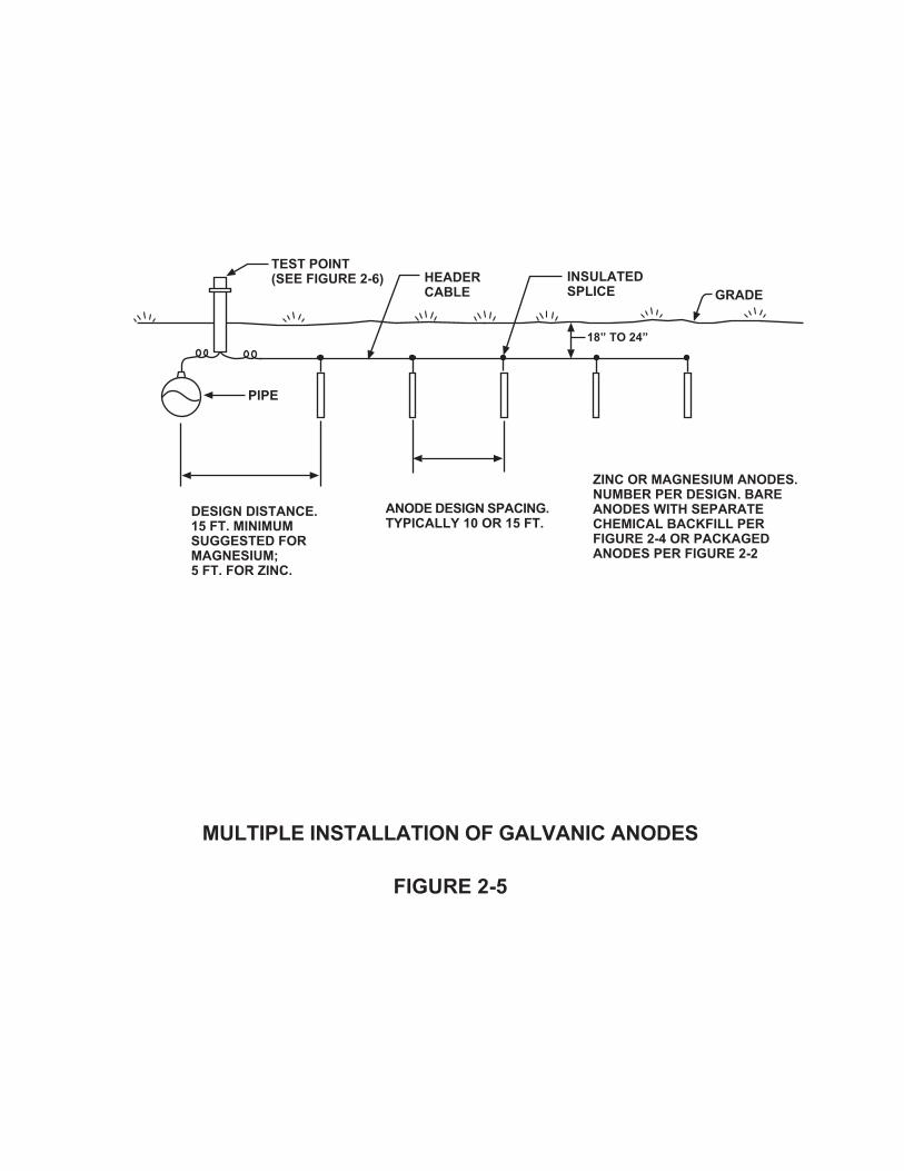
����������������� ��������� ���
���������
�����
��� ���������� ����������������������� ������������������������������������������� ���������� ���������������
����� ��������������� ������
�������������������
����
!"#� ��#
� ���������������$������$!% �!����
�������������!�������������������� ���������&����� �����

water saturated it tends to swell which further ensures good contact with the sides ofthe anode auger hole.
Anode Lead Attachment
The insulated lead wire from the anode may be connected to the pipeline or otherunderground structure by some form of exothermic welding process to ensure long termlow resistance in the connection. Welding kits are available which permit making acopper wire‐to‐steel connection quickly and economically. The copper metal nub at thepoints of connection must be thoroughly insulated with suitable coating material toavoid having a copper‐to‐steel galvanic corrosion cell at the junction between the twometals.
Test Points
Test points may be desired or required to permit periodic testing of galvanic anodeperformance. In order to accurately determine IR drop considerations, the anodeinstallations should be installed to allow testing of current output and interruptedpotential readings. This type of testing necessitates surface test point installation.
Ready made terminal box test points of various designs are available from suppliers. Atypical test point installation is illustrated by Figure 2‐6.
CONCLUSIONS
This Chapter has described the different types of galvanic anodes used for cathodicprotection and their general and specific uses. It also lists some of the advantages anddisadvantages as they relate to impressed current systems.
The Chapter also includes some installation suggestions.
REFERENCE:
Peabody, A. W., “Control of Pipeline Corrosion”, National Association of CorrosionEngineers.
Chapter 2 ‐ Installation of Galvanic Anodes2‐13

�� ��������� ����������������
���������(
� �� �������������� �������������������%���������������������&
�����������������
� �����������������������%������&
�� �����������������
�������������������
*�*��������*����� � ��
�������������
��������������%�������������&
���� ������ ���� ������������������������������������������ ������ � ����� ������� ����������������������������
�����
��
���������������������������� ���������
, -
��������������

Chapter 3 ‐ Installation of Impressed CurrentCathodic Protection Systems
INTRODUCTION
The objective of this chapter is to describe the different types of impressed currentanode beds, the materials and equipment used, and the installation proceduresfollowed, to insure adequate performance of the installed systems.
This chapter will cover the three basic types of impressed current anode beds:
• Remote Anode Bed• Distributed Anode Bed• Deep Anode Bed
It will also discuss materials and installation practices. The advantages anddisadvantages of each type of anode bed will also be reviewed.
In Chapter 2, Installation of Galvanic Anodes, the parameters for galvanic anode systemswere discussed. The main difference between the two systems is that galvanic anodesystems make use of the difference in potential between the anode material and thestructure while the impressed current system uses an outside DC power source.
DEFINITIONS
The following definitions are pertinent to the text of this Chapter:
Impressed Current Cathodic Protection System
An impressed current cathodic protection system is a cathodic protection system thatutilizes an external source of DC power in order to force current flow off an anode bedand onto an underground structure, hence mitigating the discharge of corrosion currentfrom the structure to the electrolyte and reducing the loss of metal from the structure.
Remote Anode Bed
Sometimes referred to as a “conventional anode bed” or a “point‐type” anode bed, aremote anode bed is a group of anodes installed remote (usually 100 feet or more) fromthe structure and spaced on 10 to 30 foot centers. The individual anodes can be installed
Chapter 3 ‐ Installation of Impressed Current Cathodic Protection Systems3‐1

vertically or horizontally. Some remote anode beds are installed with anodes placedhorizontally, end to end, in a continuous bed of coke breeze backfill.
Distributed Anode Bed
A group of anodes, or one long anode, installed close to and parallel to the structure tobe protected. The anode bed can be installed on one or both sides of the structure ata distance of 5 to 20 feet from the structure. Distributed anode beds are used to protectsections of pipelines which have poor coating or which are bare. They are also used forlocalized protection and in areas where shielding does not allow the current from aremote anode bed to reach the structure. For the latter reason, distributed anode bedsare very often used to protect structures within plant complexes, especially when thestructure may not be electrically isolated.
A distributed anode bed can be a group of individual anodes, installed on 25 to 500 footcenters, connected by a continuous header cable.
A distributed anode bed can also be one long continuous anode. This is referred to asa “linear anode”.
The distributed anode bed is laid out or distributed along the entire length of thestructure. As a result, installation costs are usually more expensive than for a remoteanode bed. Because of the long cable runs associated with distributed anode beds, largegauge cables are required to reduce the voltage drop along the cable runs. A distributedanode bed used to protect a long pipeline may require the installation of two rectifiers,one at each end of the anode bed, to reduce the voltage drop on the cable. Theinstallation of the distributed anode bed requires more care than the remote anode bedbecause the anode bed is located close to the structure being protected and care mustbe taken to avoid damage to the structure.
An advantage of a distributed anode bed, over a remote anode bed, is that it can beinstalled within a complex underground network with little or no stray current problemsbeing caused on the foreign metallic structures in the area, due to the close proximityof the anode bed to the structure and the relatively low current output per unit length.
One disadvantage of the distributed anode bed system is that due to its close proximityto the protected structure, the possibility of damage to the anode bed during excavationof the structure for maintenance or during construction activity is greatly increased.
Chapter 3 ‐ Installation of Impressed Current Cathodic Protection Systems3‐2

Deep Anode Bed
A group of anodes, a continuous pipe, or wire anodes, installed in a vertically drilled holeat selected points along the route of a structure, or between several structures in a plantarea. The holes normally range from 100 to 600 feet deep; individual anodes are usuallylocated on 10 to 30 foot centers. One variation of this type of anode bed is the semi‐deep anode bed where the depth of the hole ranges from 50 to 150 feet. When it isdesirable to install an anode bed system which has many of the operating characteristicsof a remote anode bed but for which there is no space available at the desired sitelocation, the only way to install the anodes at a distance from the pipeline/structure isto install them deep below the pipeline/structure.
Deep anode beds are also used when the soil strata are so arranged that the upperlayers of soil are of high resistivity with underlying layers of lower resistivity.
A deep anode bed is usually more expensive to build than a remote anode bed ofcomparable capacity. In addition, the anodes of a deep anode bed are well below gradelevel and are therefore inaccessible for maintenance should failure occur in the anodematerial used or in the connecting cables. It is often more economical to abandon amalfunctioning system in place and install a new anode bed close to the original onethan to attempt system repairs.
POWER SUPPLIES FOR IMPRESSED CURRENT CATHODIC PROTECTION SYSTEMS
There are several types of equipment that can be used as power sources for impressedcurrent cathodic protection systems. Among these are rectifiers, solar cells,engine‐generator sets, wind powered generators and turbine‐generators. Althoughrectifiers are by far the most commonly used source of DC power for impressed currentsystems, a general basic description of each of the sources is given in the followingparagraphs.
Rectifiers
A device which takes alternating current from a power distribution system and convertsit to direct current. Rectifiers have as their major components:
C a transformer to step down AC line voltage, which has taps on the secondary windingto allow selecting a wide range of voltages
Chapter 3 ‐ Installation of Impressed Current Cathodic Protection Systems3‐3

C a rectifying element which converts the AC to DC
C a cabinet.
Other components normally found in rectifiers are AC circuit breakers, DC outputmeters, lightning arresters (on both AC and DC sides) and current measuring shunts.
Rectifiers are manufactured with many different ratings for single‐phase and three‐phase AC service. The rectifying element consists of either selenium stacks or silicondiodes. Figure 3‐1 shows a wiring diagram for a single‐phase rectifier and Figure 3‐2shows a wiring diagram for a three‐phase rectifier.
Rectifiers are manufactured with air cooled or oil cooled enclosures. For hazardousareas, oil cooled explosion‐proof cabinets are available. Rectifiers can be of theconventional type (manual tap changing arrangement) or of the automatic type: 1)constant potential which maintains a preset potential between the structure andpermanent reference electrode, and 2) constant current which maintains a presetcurrent output. Figure 3‐3 shows a wiring diagram for a constant potential rectifier.
Solar Cells
In areas where sunlight is available for a large percentage of the time, solar cells incombination with storage batteries can be used to produce a steady flow of directcurrent. Silicon solar cells are made by coating silicon crystals with phosphorus(produces negative charge carriers) and with boron (produces positive charge carriers).When light hits the silicon slices, a photocurrent flows, voltage develops, and electricityis generated.
The cathodic protection unit consists of the solar panels, storage batteries and a controlcabinet. Panels are connected in series to increase the voltage output and in parallel toincrease the current output.
Solar cells are a viable power source where regular AC power is not available. Figure 3‐4shows a schematic of a cathodic protection solar cell.
Thermoelectric Generators
Thermoelectric generators produce power by the direct conversion of heat intoelectricity. Power is produced by maintaining a temperature difference across a
Chapter 3 ‐ Installation of Impressed Current Cathodic Protection Systems3‐4

A
V
(+)
(+)(-)
(-)
STEP DOWNTRANSFORMER WITHVOLTAGEADJUSTING TAPS ONSECONDARY WINDINGS
GROUNDING SHIELDBETWEEN PRIMARY ANDSECONDARY WINDINGS
BRIDGE-CONNECTEDRECTIFIER STACKS
ARROW HEAD INDICATES DIRECTION OF UNIDIRECTIONAL CURRENT FLOW THRUELEMENT
GROUND CONNECTION FORRECTIFIERCABINET
TO ANODE BEDTO PIPELINE ORPROTECTEDSTRUCTURE
SINGLE PHASE RECTIFIER UNITSCHEMATIC DIAGRAM
FIGURE 3-1
ACSINGLE PHASE
SUPPLY
SHUNT

A
V
(-) (+)
AC3 PHASESUPPLY
GROUNDED SHIELD BETWEEN PRIMARY AND SECONDARY WINDINGS
STEP-DOWNTRANSFORMER WITH VOLTAGEADJUSTING TAPS ONSECONDARY WINDINGS
ARROW HEADINDICATESDIRECTION OF UNIDIRECTIONALCURRENT FLOWTHRU ELEMENT
BRIDGE-CONNECTEDRECTIFIER STACK
GROUND CONNECTION FOR RECTIFIERCABINET
TO ANODE BEDTO PIPELINE ORPROTECTEDSTRUCTURE
THREE-PHASE RECTIFIER UNITSCHEMATIC DIAGRAM
FIGURE 3-2

A
V
CIRCUIT BREAKER
SATURABLECOREREACTOR
TRANSFORMER
RECTIFIERSTACK
VOLTMETER
AMMETER
TO ANODE BED
SHUNT
MAGNETICRECTIFIER
PIPE REFERENCEELECTRODE
AC SUPPLY
TYPICAL CONSTANT POTENTIAL RECTIFIER SCHEMATIC DIAGRAM
FIGURE 3-3

SUN
SOLAR CELL
NEGATIVECHARGEDSILICON
POSITIVE CHARGED SILICON
DC
CU
RR
ENT
BATTERY PACK
GRADE
(-)(+
)
(-) (+)
CONVENTIONALANODE BED
SOLAR POWERED DC POWER SUPPLYFOR CATHODIC PROTECTION INSTALLATION
FIGURE 3-4

thermopile, an assembly of semi‐conductor thermoelectric elements. Combustion ofNatural Gas or Propane provides the heat while natural convection provides the coolingrequired to create this temperature differential.
Engine ‐ Generator Sets
These units consist of a fuel‐powered engine and an AC generator used to provide theinput power for a rectifier unit. The fuel required to operate the engine can be tappedfrom the pipeline as shown in Figure 3‐5, if the product can be utilized as a fuel source.An alternative source of engine fuel could be a storage tank installed in the area. Atypical engine‐generator set may require 1500 gallons of diesel fuel to operate for abouta month.
Turbine ‐ Generator Sets
Turbine generator sets utilize the product or gas flow to drive a small turbine which inturn drives a DC generator which supplies the cathodic protection current for the anodebed.
Figure 3‐6 shows a typical turbine‐generator set for a natural gas pipeline. The gas isdiverted to the turbine through a bypass line, installed across a delivery station wherea drop in gas pressure is present, and returned to the system. Note the application ofthis system can only be used at locations where there is reasonably constant gaspressure drop or decrease in available product flow.
Wind Powered Generators
These systems provide a practical and very economical electrical power supply forcathodic protection installations which require a completely independent power source.
A typical wind‐powered generator consists of a turbine assembly, generator assembly,rectifying unit and a battery. The turbine assembly, which usually consists of threeblades, approximately 15 feet in length, is directly coupled to a slow speed generatorwhich can produce 200 watts at wind speeds of 20 mph and can maintain a 700 wattcontinuous load at a location with average winds of 12 mph. The AC voltage from thegenerator is converted to DC voltage via a rectifying unit. This DC voltage is used tocharge batteries which supply the required cathodic protection current. Figure 3‐7shows a typical wind powered generator set.
Chapter 3 ‐ Installation of Impressed Current Cathodic Protection Systems3‐5

(+)
TANK FORLUBRICATING OIL
EXHAUST STACKAC SUPPLY LINETO RECTIFIER
ALTERNATOR CONTROL CENTER
ISOLATINGFLANGE
FUEL GASSUPPLY LINETO ENGINE
PROTECTEDNATURAL GASPIPELINE
REGULATOR AC GENERATORGASPOWEREDENGINE
(-)
REMOTEANODE BED
ENGINE GENERATOR SETDC POWER SUPPLY
CATHODIC PROTECTION INSTALLATION
FIGURE 3-5
CATHODICPROTECTIONRECTIFIER

TRANSMISSIONPIPELINE
ISOLATINGFLANGE
TO PROTECTEDSTRUCTURE
REGULATOR (IF REQUIRED)
TO ANODE BEDPRESSURE REDUCTION EQUIPMENT ATTOWNDELIVERY STATION
GAS DISTRIBUTIONSYSTEM MAIN
DC GENERATOR
TURBINE
- +
TYPICAL TURBINE GENERATOR SET INSTALLATION
FIGURE 3-6

BLADE
NOSE CONE
GENERATOR/RECTIFIER ASSEMBLY
TAIL
STORAGE BATTERY
DC OUTPUT
(-)
TO PROTECTEDPIPELINE/STRUCTURE
(+)
GRADE
REMOTE ANODE BED
WIND-POWERED DC POWER SUPPLYFOR CATHODIC PROTECTION INSTALLATION
FIGURE 3-7

ANODE BED MATERIALS
Anodes
Various types of materials are available for use as impressed current anodes. Thefollowing paragraphs present a list of some of the materials used and some of theircharacteristics:
a. Scrap Iron
Scrap iron in the form of an old pipeline was the original impressed current anodeused to protect an underground structure. Scrap iron anodes are still used today,particularly in areas where regular anode materials are expensive or hard to obtain.
Impressed current systems have been designed utilizing anything from scrap railroadcar wheels welded together to form an anode for protection of an undergroundstructure to a half‐sunken barge used as a remote anode to protect a dock structure.Some of the disadvantages of using scrap iron are the high consumption rates,nonuniform consumption, and colored corrosion products which may causediscoloration of the surroundings.
b. Graphite
Graphite anodes are manufactured from petroleum coke particles. The process fromcoke particles to an almost pure graphite can take as long as 16 weeks because of themany steps involved in it. Graphite anodes are normally impregnated with hot linseedoil or microcrystalline wax to inhibit moisture from penetrating the anode and causingmechanical and chemical decomposition. Disadvantages of the graphite anode are itssoftness and brittleness. Therefore, they must be handled with care during shippingand installation. Figure 3‐8 shows a typical graphite anode. These anodes aremanufactured in different sizes.
c. High Silicon Cast Iron
The typical alloy for cast iron anodes is ASTM A518 Grade 3. They containapproximately 15% silicon and 4.5% chromium. Like graphite anodes, they are verybrittle and must be handled with care. Figure 3‐9 shows a typical high silicon cast ironanode. These anodes are also manufactured in different sizes.
Chapter 3 ‐ Installation of Impressed Current Cathodic Protection Systems3‐6

ANODELEAD WIRE
EPOXY CAP
GRAPHITE ANODE
4”
80”
TYPICAL GRAPHITE ANODE
FIGURE 3-8

ANODELEAD WIRE
HEAT SHRINKABLE CAP
2”
60”
HIGH SILICON CONTENT CAST IRON ANODE
TYPICAL HIGH SILICON CONTENTCAST IRON ANODE
FIGURE 3-9

d. Platinized Titanium
Platinum works very well as an impressed current anode because of its extremely lowconsumption rate and high current density. Because of the cost of platinum, it isusually applied in a very thin layer onto a less expensive material. Titanium is used assuch a material. These anodes are manufactured by either electrodepositing theplatinum on the metal substrate or by the cladding process. If there are voids in theplatinum surface, current can discharge from the titanium substrate. Titanium isgenerally passivated at low DC potentials and does not discharge current to theelectrolyte. At voltages in excess of 10 volts, the passivation film breaks down rapidlyand current flows to the electrolyte from the titanium resulting in rapid corrosion ofthe titanium in the form of pitting. This can lead to failure of the anode. Someengineers recommend that the voltage at the surface of the titanium substrate bekept below 10 volts. It is important to note that this 10 volt limit is the voltage at thetitanium substrate, not necessarily the rectifier output voltage. With a packagedanode, the voltage across the titanium/backfill interface is much less than the outputvoltage measured at the rectifier terminals.
e. Platinized Niobium/Tantalum
These anodes are used where there is concern over the use of platinized titaniumanodes because the system design requires a driving voltage greater than 10 volts.Niobium or tantalum as base metals can withstand higher driving voltages. (Thebreakdown voltage of niobium oxide film is approximately 120 volts). These types ofmetal substrates are the most commonly used for anode bed anodes installed in thesoil. Figure 3‐11 shows one type of anode detail and specification for a platinizedniobium anode.
f. Mixed Metal Oxide Anodes
These anodes consist of a titanium substrate with a dimensionally stable mixed metaloxide coating. Like platinum, mixed metal oxide anodes have an extremely lowconsumption rate and can be used at very high current densities. Like platinizedtitanium anodes, the voltage limitations of the titanium substrate must be consideredin the design process.
g. Magnetite
These anodes have been used in Europe for many years. Magnetite anodes have been
Chapter 3 ‐ Installation of Impressed Current Cathodic Protection Systems3‐7

STEEL CANISTER/STOVE PIPECRIMPED
1/2” INTERIORGRADE PLYWOOD(TYP.)
WELLCOMPACTEDCOKE-BREEZEBACKFILL
96”
8”
TYPICAL PREPACKAGED CANISTER ANODE
FIGURE 3-10
ANODE
ANODE LEAD WIRE

ANODE LEAD WIRE
CONNECTION
ENDSEAL
2” STEELCONDUIT PLATINIZED
NIOBIUM ANODEWIRE
PLATINIZED NIOBIUM WIRE ANODE
FIGURE 3-11
ENDSEAL

improved in recent years and are now readily available in the western hemisphere forunderground and marine use.
Magnetite (Fe3O4) is a corrosion product itself therefore, there is little or no corrosioninvolved with the discharge of current from the surface of the anode. Although theseanodes are expensive, their long life expectancy makes them an economical choicein some applications. See Figure 3‐12 for typical magnetite details and specifications.
Packaged Anodes
With the exception of scrap iron anodes, all of the anodes describe above are availablein prepackaged form. The anodes are centered in a galvanized “stove pipe type”container or electrical conduit, which is filled with low resistivity backfill such as cokebreeze. Figure 3‐10 shows a typical prepackaged anode and canister specification.
Anode‐Lead Connection Insulation
It is good practice to specify anodes with some type of epoxy, polyethylene, or Kynar®cap to protect the lead end of the anode from current leakage which could lead topremature anode failure. Figures 3‐8, 3‐9, 3‐11 and 3‐12 outline typical details ofanode/lead connection insulations used to prevent these types of problems.
Cables
Impressed current cathodic protection systems normally require the installation ofconsiderable lengths of direct buried cables. The primary insulation material used is highmolecular weight low density polyethylene insulation (HMWPE). This insulation materialhas outstanding dielectric strength and moisture resistance. It also has a high resistanceto corrosive chemicals (mineral acids, fixed alkaline petroleum oils, etc.) usually existingin environments requiring cathodic protection.
Where severe conditions exist and polyethylene insulated cables are not suitable, specialinsulated cables such as Kynar® and Halar® are used. These insulations are resistant tochlorine and therefore are usually recommended for use in deep anode beds wherechlorine is usually present. Selecting a cable size has both a practicable and economicaspect. The cable should be large enough to carry the intended current based on one ofthe many ampacity tables that are available. The cable should also be large enough tolimit the voltage drop which would require a bigger power source. In addition, the cableshould also be large enough to withstand mechanical stresses encountered during
Chapter 3 ‐ Installation of Impressed Current Cathodic Protection Systems3‐8

ANODELEAD WIRE
TYPICAL MAGNETITE ANODE
FIGURE 3-12
MAGNETITE ANODE
COPPERLAYER
MAGNETITE
POROUSBODY
PLASTICCAP
PLASTICCOMPOUND
system installation.
Cable Connections
Impressed current cathodic protection system negative return cables are normallyconnected to the pipeline/structure using an exothermic weld process. Exothermic weldconnections are made by filling a graphite mold (see Figure 3‐13) which houses theconductor and the weld metal (copper oxide and aluminum), and by igniting the powderwith a flint gun. The exothermic reaction which results produces molten copper whichflows into the weld cavity and welds the conductor to the pipe. The molds are specifiedbased on conductor size and on surface type/pipe size.
Exothermic weld connections should be adequately coated using a minimum of twolayers of coal tar and glass fiber or equal. Patch coating should overlap existing pipelinecoating a minimum of 2 inches.
When making header cable to header cable or anode lead to header cable connectionsvarious methods can be used, among them are solder, exothermic weld, andcompression type and split bolt connectors. The compression type connection isprobably the most recommended method because the connection is made without heatand there is no danger of damage to the cable insulation or wire at the connection. Thecompression connector is applied with a special tool which lets the user know thatadequate compression has been reached, assuming that the proper tool and dies havebeen used. This is an advantage over the split bolt connector where it is up to the userto estimate if sufficient torque has been applied.
Cable Splices and Repairs
The cables associated with the anode bed, connected to the positive terminal of the DCpower supply, are the most anodic part of the impressed current system. Taking voltagedrops in the cables into consideration, the cables operate at a higher voltage than theanodes themselves. The impressed current anode material is formulated for lowconsumption rates, but copper wires are not. One can readily see that any damage tocable insulation or splices in an impressed current system can cause a relatively largeamount of current to discharge to earth from a small area. Rapid corrosion leading tocable failure would occur.
Splice insulation and cable insulation repair must be absolutely waterproof; otherwisecurrent will discharge to the electrolyte and cable failure will occur. The insulation
Chapter 3 ‐ Installation of Impressed Current Cathodic Protection Systems3‐9

MOLDHANDLE
MOLD COVER
STARTING POWDER
WELD MOLD
WELD METAL
SEALING DISK
COPPER SLEEVE(IF REQUIRED)
CLOSE COVER ANDIGNITE STARTINGPOWDER WITHSPARK GUN
HOLD MOLDFIRMLY AGAINSTPIPE WALL
PIPE WALL/STRUCTURE SURFACE
TYPICAL EXOTHERMIC WELD PROCESS
FIGURE 3-13
CABLE

material use must also have high resistance to corrosive chemicals. For this reason, apoured two‐part epoxy system has been used with good success on impressed currentcable splices and repairs. The two‐component epoxy system is poured into a specialmold which is placed around the splice. The connection and adjacent cable insulationmust be cleaned and abraded with emery cloth. Hardening of the epoxy usually takesone‐half hour depending on ambient temperature. Backfill or immersion should not takeplace until the epoxy is fully hardened. Figure 3‐14 shows a typical epoxy splice processfor connection of anode lead wire to anode header cable.
An alternative method used to insulate a connection is a hand wrapped joint. In orderto achieve a good joint insulation, the connection and surrounding area of insulationmust first be cleaned and abraded using emery cloth. The next step is to fill all voids witha soft rubber splicing compound and then wrapping connection with several layers ofrubber tape followed by several layers of PVC electrical tape. Taping should start in thecenter of the collection and end in the center. The first layers of tape should bestretched while being applied and the tension should be relaxed on subsequent layersto achieve a smooth surface. The final step is painting the taped joint completely withelectrical shellac compound. Note: Shellac must be allowed to dry completely beforeallowing joint to contact earth.
SELECTING AN ANODE BED SITE
The corrosion control professional should take the following factors into account whenconsidering an anode bed site:
C Soil ResistivityC Soil MoistureC Interference with Foreign StructuresC Power Supply AvailabilityC Accessibility for Maintenance and TestingC VandalismC Purpose of Anode Bed and Site Availability
Soil Resistivity
Soil resistivity is one of the most important factors to consider when selecting an anodebed site location. The number of anodes required, the DC voltage output rating of therectifier and the resulting AC power costs are all directly related to the soil resistivity.In theory, the lower the soil resistivity, the fewer the number of anodes required and the
Chapter 3 ‐ Installation of Impressed Current Cathodic Protection Systems3‐10

TYPICAL ANODE LEAD WIRE TOANODE HEADER CABLE
EPOXY INSULATED SPLICE
FIGURE 3-14
COPPER COMPRESSION CONNECTOR
FILLING ORIFICE ANODE LEAD WIRE
INSULATING RESIN
EPOXY MOLD
ANODE HEADER CABLE 1/2” MAX., 1/4” MIN.
lower the rectifier DC voltage output required. Ideally, the area with the lowest soilresistivity should be considered for the anode bed site.
Soil Moisture
Another factor to consider in the selection of an anode bed site is the soil moisture atthe proposed anode depth. In most cases, the resistivity of the soil decreases as themoisture content increases until the soil becomes saturated. When possible, anodesshould be installed below the water table (assuming the water resistivity is not too high),or in areas of high moisture content such as swamps, ditches, creek beds, etc.
One factor that should be considered when analyzing the moisture content of the soil,is the seasonal variations. Moisture content and water table elevation vary at differenttimes of the year and these variations would have an impact on the performance of theanode bed. When anode beds are to be installed near the ocean or a river, tidalvariations could have an effect on the water table elevation.
One phenomenon that affects the moisture content of the soil around the anodes iscalled electro‐osmosis. This phenomenon will be dealt with in the Advanced Course andis just mentioned in this Chapter to make the corrosion control worker aware of it.When DC current is discharged to the soil from an anode, this current pushes the wateraway from the surface of the anode and could result in an increase of the anode bedresistance. In the case of an anode bed being installed in high clay content soil, theremoval of moisture from the clay may seriously reduce the conductivity of the soil,possibly rendering the anode bed ineffective.
Interference with Foreign Structures
Before selecting an anode bed site, local utilities should be contacted and area systemmaps should be obtained to determine if any underground metallic structures exist inthe area. Structures such as pipelines, underground metallic sheathed electrical cables,or well casings may be subjected to stray current interference problems therefore,whenever possible, anode beds should be located away from foreign structures.
When the anode bed must be located in the vicinity of foreign structures, tests shouldbe conducted before the installation of the anode bed to determine the possibility andmagnitude of interference problems that could be expected and whether correctiveaction, if required, is feasible. Subsequent to the installation of the anode bed,cooperative interference testing should always be conducted to ascertain remedial
Chapter 3 ‐ Installation of Impressed Current Cathodic Protection Systems3‐11
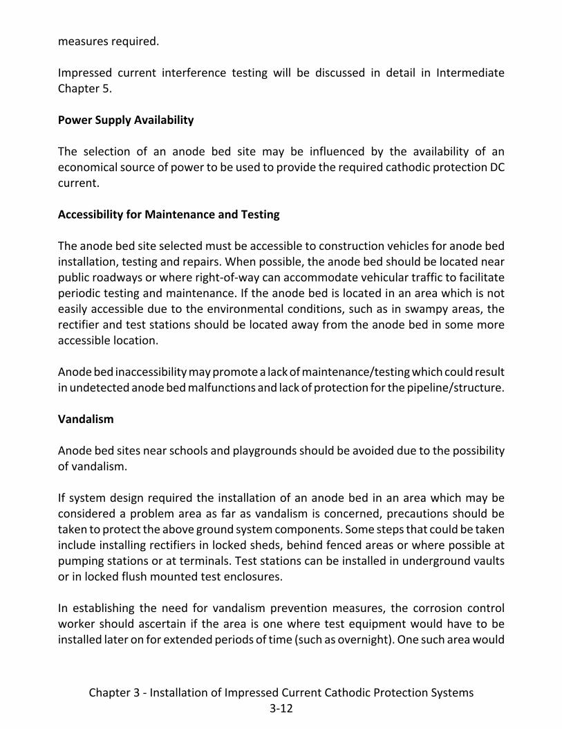
measures required.
Impressed current interference testing will be discussed in detail in IntermediateChapter 5.
Power Supply Availability
The selection of an anode bed site may be influenced by the availability of aneconomical source of power to be used to provide the required cathodic protection DCcurrent.
Accessibility for Maintenance and Testing
The anode bed site selected must be accessible to construction vehicles for anode bedinstallation, testing and repairs. When possible, the anode bed should be located nearpublic roadways or where right‐of‐way can accommodate vehicular traffic to facilitateperiodic testing and maintenance. If the anode bed is located in an area which is noteasily accessible due to the environmental conditions, such as in swampy areas, therectifier and test stations should be located away from the anode bed in some moreaccessible location.
Anode bed inaccessibility may promote a lack of maintenance/testing which could resultin undetected anode bed malfunctions and lack of protection for the pipeline/structure.
Vandalism
Anode bed sites near schools and playgrounds should be avoided due to the possibilityof vandalism.
If system design required the installation of an anode bed in an area which may beconsidered a problem area as far as vandalism is concerned, precautions should betaken to protect the above ground system components. Some steps that could be takeninclude installing rectifiers in locked sheds, behind fenced areas or where possible atpumping stations or at terminals. Test stations can be installed in underground vaultsor in locked flush mounted test enclosures.
In establishing the need for vandalism prevention measures, the corrosion controlworker should ascertain if the area is one where test equipment would have to beinstalled later on for extended periods of time (such as overnight). One such area would
Chapter 3 ‐ Installation of Impressed Current Cathodic Protection Systems3‐12

be where variable stray currents are prevalent and 24‐hour recordings may be requiredduring periodic surveys. Steps could be taken during the construction stages of theanode bed to provide protective enclosure for the test equipment.
Purpose of Anode Bed and Site Availability
Two additional factors that have to be considered in the process of selecting an anodebed site are the intended purpose of the anode bed and the possibility of acquiring therequired right‐of‐way for the installation. Is the intent of the anode bed to protect a longsection of a pipeline (assuming the pipeline is well coated) or is it the intent to affordlocalized protection to a short section of a pipeline (poor coating) or a small structure?In the first case, the approach could be the installation of one remote type anode bednear the midpoint of the pipeline section or perhaps the installation of a deep anodebed near the midpoint area.
In the second case, the approach could be the installation of a distributed anode bed.
Once a determination has been made as to the intent and purpose of the installationand the most suitable type of installation, the land availability should be investigated.
If the installation consists of a distributed anode bed or even a deep anode bed, it is verypossible that the installation can be made within the existing right‐of‐way agreementin which case, the only requirement may be to notify the land owner (through thecompany's Right‐of‐Way Department). If on the other hand, a remote type of anode bedis contemplated, the company's Right‐of‐Way Department should be requested toinvestigate availability of land at the desired and at possible alternate locations. It isdesirable to select a location where the entire installation can be within one property.
INSTALLATION PRACTICES
Anodes ‐ General
Before installing anodes, the decision to install anodes either vertically or horizontallymust be made. The decision usually depends upon various factors such as soil resistivityand equipment availability.
Regardless of the type of installation, graphite and cast iron anodes are brittle and haveto be handled with care. Do not handle anodes by the lead as this could put too muchstress on the anode‐lead connection, causing the loss of the anode.
Chapter 3 ‐ Installation of Impressed Current Cathodic Protection Systems3‐13

Vertical Installation
After determining that the area is suitable for this type of installation (no shallowunderlying rock), a typical vertical anode can be installed as shown in Figure 3‐15.Generally, fewer vertical anodes are required than horizontal anodes to protect thesame structure. The main reason for this is that vertical anodes can usually be placed inpermanently moist soil which generally results in lower anode resistance.
When installing a vertical anode system, the first step is to install the anode header orfeeder cable. The next step is to auger a hole for the anode. The depth of the hole isbased on design calculations and type of anode being used. An extra foot or more ofdepth is required when installing an anode which is not prepackaged to allow cokebreeze to be installed and compacted below and above the anode. After augering theanode hole and installing and compacting a layer of coke breeze, if required, the anodeshould be lowered into hole using support rope tied around the anode. Center theanode in the hole and backfill with coke breeze or native soil as required. Native soilbackfill should be tamped above anode and coke breeze backfill taking care not todamage anode lead wire.
After completing the anode hole backfill, the anode lead wire should be spliced to theheader cable. Sufficient slack should be left on the lead wire to prevent damage due tosoil settlement.
See Figure 3‐16 for a typical prepackaged vertical anode.
For a distributed anode bed system, the exact location of the installed anodes andsplices should be noted on the design drawings for future reference.
Horizontal Installation
Where it is necessary to horizontally install anodes because of soil resistivity orequipment limitations, the first step, as with the vertical anode installation, is to installthe anode header cable. The next step depends on the spacing required between theanodes. If the anode spacing is larger than 10 feet, a separate excavation may berequired for each anode to be installed. If however, the spacing is less than 10 feet, itmay be more economical to dig one continuous trench for the length of the anode bedinstallation.
Prepackaged anodes can be simply lowered into the trench by hand or by means of
Chapter 3 ‐ Installation of Impressed Current Cathodic Protection Systems3‐14

ANODE HEADER CABLE
TAMPED NATIVESOIL BACKFILL
ANODE LEAD WIRETO HEADER CABLESPLICE
TYPICAL IMPRESSEDCURRENT ANODE
COKE BREEZE BACKFILL
TYPICAL VERTICAL ANODE INSTALLATION
FIGURE 3-15

GRADE
SPLICE SOIL FREE OF STONE, 3”THICKNESS#8 AWG
HMWPEANODECABLE
ANODE HEADERCABLE
DEPTH TO BEDETERMINEDBY DESIGN
BACKFILL
PREPACKAGEDANODE
TYPICAL VERTICALLY INSTALLED PREPACKAGED ANODE
FIGURE 3-16

support ropes and backfilled with native backfill tamping periodically as required.
Anodes requiring the placement of coke breeze backfill during installation require atrench deep enough to allow the placement of at least 6 inches of compacted cokebreeze on all sides of the anode. Figure 3‐17 shows a typical horizontally installedprepackaged anode.
Deep Anode Installation
Installation of a deep anode bed such as the one shown in Figure 3‐18 begins with thedrilling of a hole to the required anode depth. In the case shown in Figure 3‐18 thiswould be a 10‐inch x 100 foot hole. The next step in this installation is to install the 40‐foot section of PVC casing followed by the installation of the 10‐inch diameter, 60 footlong steel pipe through the PVC casing. The anodes are securely fastened to the 2 inchperforated PVC support/vent pipe using straps. Similarly, the anode lead wires arefastened to the pipe and run to the top of the pipe. The PVC support/vent with theanodes is then installed and centered in the hole. The next step is to pump fluidized cokebreeze backfill into the first 60 feet of the hole, using the PVC support/vent pipe or aseparate hose and pipe inserted into the hole. A plug of cement or clay is normally usedto seal off the deep anode. The top 40 feet of the hole is backfilled with native backfilltamping periodically as required.
Figure 3‐19 shows a similar installation using an uncased hole. A deep anode using aplatinized anode wire is shown in Figure 3‐20. Figure 3‐21 shows a capsule type ofinstallation that can be used to contain one of a number of types of anodes.
The last step in the deep anode bed installation would be the installation of an anodedistribution box and the termination of the anode lead wires therein.
Cable Installation
Anode header cables and system negative return cables are normally installed byexcavating a trench and installing the cables at a minimum depth of 2 feet below grade.Before laying cables in the trench, remove any large stones or foreign material whichmay damage the insulation of the cable. The first three or more inches of backfill aroundthe cables should be free of stones and foreign material and thoroughly tamped. Therest of the trench is backfilled with native soil tamping periodically as required.
When installing anode header cables for a distributed anode bed system, it is
Chapter 3 ‐ Installation of Impressed Current Cathodic Protection Systems3‐15

SPLICE
WOOD PLANKOVER CABLE
YELLOW WARNINGTAPE OVER WOOD PLANK
GRADE
DEPTH TO BE DETERMINEDBY DESIGN
ANODE HEADER CABLE
#8 AWG HMWPEANODE CABLE
PREPACKAGEDANODE
TYPICAL HORIZONTALLY INSTALLED PREPACKAGED ANODE
FIGURE 3-17

VENTED COVER ANODE DISTRIBUTION BOXGRADE
TO RECTIFIERPOSITIVE TERMINAL
ANODE LEAD WIRES
12”
40’12-INCH SCH 80 PVC CASING
NATIVE BACKFILL
HIGH SILICON CONTENTCAST IRON ANODE (TYP)STRAP (TYP)
10-INCH STEEL PIPE60’
FLUIDIZED COKE BREEZE BACKFILL
2-INCH SCH 80 PERFORATED PVCSUPPORT/VENT PIPE
TYPICAL DEEP ANODE BED INSTALLATION DETAIL
FIGURE 3-18

RECTIFIER
VENTED AND SECUREDCASING CAP
GRADE
PROTECTEDPIPELINE
CARBONACEOUSBACKFILL MATERIAL
PIPE CASING THROUGH LOOSE SURFACE SOILSPERFORATED PIPE SUPPORT/VENT
MEDIUM GRAVEL ABOVE CARBONACEOUSBACKFILL TO HOLD HOLE OPEN AND VENT ANY GASSES
ANODE STRAPPED TO PIPE SUPPORT
(-) (+)
WORKING PORTION OF ANODE BED
CENTERING DEVICEPIPE FOOT
UNCASED HOLEDIAMETER AND DEPTHPER DESIGN
CABLED INDIVIDUALANODE LEADS
DEEP ANODE BED DESIGN USING PERFORATED PIPE SUPPORT/VENT AND CARBONACEOUS
BACKFILL
FIGURE 3-19

(-) (+)
BOTTOM ASSEMBLY
BORE HOLE
PLATINIZED ANODE
CABLE CHUTE
VENT PIPE
CASING
TIE-WRAPS
PROTECTEDPIPELINE
GRADE1” DIA. SUPPORT
PVC CAP W/VENT1 1/4” PVCCONDUITRECTIFIER
TYPICAL PLATINIZED DEEP ANODE BED INSTALLATION
FIGURE 3-20

GROUND LEVEL
SOLID 4”PLASTIC CASING
POROUS FILL
COKE BREEZEBACKFILL
ANODE SECTION - 4”PERFORATEDPLASTIC CASING
OPE
N50
’
STEEL LEAD PIPE
TWO-WAY FLOWCONTROL VALVE
CAPSULE TYPE DEEP ANODE INSTALLATION
FIGURE 3-21

recommended that wood planks or plastic warning tape be installed over the cable asshown in Figure 3‐17 to afford some protection to the ground during later constructionin the area or excavation of the protected structure.
Distributed anode bed header cables, where the installation of the wood plank orwarning tape is not deemed necessary, can be plowed in. When this is done, extremecare must be taken so as not to damage the cable insulation and more importantly, caremust be taken to avoid possible damage to the pipe due to the close proximity of theheader cable to the pipe.
Any damage to the anode header cable or its insulation shall be repaired in accordancewith one of the methods described in the previous section, Cable Splices/Repairs.Repairs to damaged negative return cables, shall also be made as described in thatsection.
Rectifier Installation
When selecting a rectifier location, efforts should be made, when possible, to select alocation which is accessible for periodic inspection and maintenance. Rectifiers aretypically either pole mounted, wall mounted, or pedestal mounted as shown in Figures3‐22, 3‐23 and 3‐24 at the end of this Chapter. Type of mounting used depends on thesize and location of the unit. Units weighing in excess of 450 lbs. are normally pedestalor pad mounted, as shown in Figure 3‐22. If the rectifier is to be located in an area whichis prone to flooding problems the unit should preferably be either wall or pole mountedabove the maximum water level. When wall or pole mounting a rectifier it should beinstalled, if possible, at a convenient working height, for maintenance and periodictesting.
Before installing a rectifier unit, local electrical codes should be checked. By conformingto local code requirements during installation, time and possibly money may be savedin areas where local electrical inspector's certification is required before the localutilities will supply AC power.
The rectifier cabinet should be grounded for safety reasons. Rectifiers located near anexisting grounding system should be tied into it if possible. Where no grounding systemexists in the area, a ground grid should be installed and the rectifier connected to itusing AWG #4 stranded copper cable.
Chapter 3 ‐ Installation of Impressed Current Cathodic Protection Systems3‐16

POWER SUPPLY LINESPOLE
DISCONNECTRECTIFIER
GRADE
AC FEED TO RECTIFIER
CONCRETEMOUNTING PAD
#6 AWG BARESTRANDEDCOPPER CABLE
TO ANODE BED(POSITIVE TERMINAL) GROUND ROD
CONNECTED TO RECTIFIERCABINET
TO PIPELINE/STRUCTURE(NEGATIVE TERMINAL)
PAD MOUNTED RECTIFIER
FIGURE 3-22

RECTIFIER
SUGGESTEDHEIGHT 4’-4”
CONDUIT BUSHING
SIDE VIEW
CABLES TOPIPELINE ANDTO ANODE BED
KWH METERKWH METER
6’ OR LOCALSTANDARD
DC CONDUITSSTRAPPEDTO POLE
REAR VIEW
GROUND RODAND CLAMP
GROUNDING WIREFROM RECTIFIERCABINET
RECTIFIER
WEATHERHEADLEADS FOR CONNECTION BY LOCAL UTILITY COMPANY
POLE MOUNTED RECTIFIER
FIGURE 3-23
DISCONNECT

CONCLUSIONS
The Chapter has described the different types of impressed current anode beds and hasalso described the steps that the corrosion control worker has to take to obtain thenecessary data to install an impressed current anode bed.
In addition, the different anode materials and DC Power sources have been describedas well as other miscellaneous items such as backfill, splice and insulation materials, etc.The chapter concluded with some installation suggestions for the different types ofanode beds.
Chapter 3 ‐ Installation of Impressed Current Cathodic Protection Systems3‐17

- +
AC FEED
RECTIFIER
CONDUITS APPROXIMATELY4’-4”CONDUIT
AC FEED
RECTIFIER
SIDE VIEW
CONDUIT BUSHING (TYP.)
TO ANODE BEDTO PROTECTEDPIPELINE/STRUCTURE
#6 AWG BARE STRANDED COPPERCABLE CONNECTED TO GROUND RODOR EXISTING GROUNDING SYSTEM
FRONT VIEW
WALL
WALL MOUNTED RECTIFIER
FIGURE 3-24
DISCONNECT

Chapter 4 – Criteria for Cathodic Protection
4‐1
Chapter 4 – Criteria for Cathodic Protection
INTRODUCTION
In Chapter 3 of the Basic Course, the theory and principles of how cathodic protection
works were presented and discussed. To assure that cathodic protection is applied in
accordance with these principles, criteria and methods of assessment are required.
This chapter describes the industry accepted criteria. The discussion found below is a
review of the NACE criteria presented in NACE Standard Practice SP0169‐2013
"Control of External Corrosion of Underground or Submerged Metallic Piping
Systems." This document "lists criteria and other considerations for cathodic
protection that will indicate, when used either separately or in combination, whether
adequate cathodic protection of a metallic piping system has been achieved." This
standard is intended for use on new or existing piping systems. The systems can be
either coated or uncoated. Section 6 of this document addresses criteria and other
specifications for cathodic protection.
CRITERIA FOR STEEL AND CAST IRON PIPING
Three primary criteria for cathodic protection of underground or submerged steel or
cast‐iron piping systems are listed in Section 6 of SP0169‐2013. They are as follows:
1. A Minimum of 100 mV of cathodic polarization. Either the formation or the decay
of polarization can be measured to satisfy this criterion.
2. A structure‐to‐electrolyte potential of ‐850 mV or more negative as measured with
respect to a saturated copper/copper sulfate (CSE) reference electrode. This
potential may be a direct measurement of the polarized potential or a current‐
applied potential. Interpretation of a current‐applied measurement requires
consideration of the significance of the voltage drops in the earth and metallic
paths.
3. Criteria that have been documented through empirical evidence to indicate
corrosion control effectiveness on specific pipeline systems may be used on those
piping systems or others with the same characteristics.

Chapter 4 – Criteria for Cathodic Protection
4‐2
Examples of the third criterion could be:
i. Net Protective Current
ii. 300 mV Potential Shift Criterion
iii. E‐Log‐I Criterion
In this chapter, we will discuss each of these criterion. The first criterion to be covered
is the 100 mV of polarization.
100 mV of Polarization Criterion
This criterion states that adequate protection is achieved with "A minimum of 100 mV
of cathodic polarization between the structure surface and a stable reference
electrode contacting the electrolyte. The formation or decay of polarization can be
measured to satisfy this criterion." Of the three criteria, this criterion has the most
sound fundamental basis. As described in previous chapters, the corrosion rate
decreases and the rate of the reduction reaction on the metal surface increases as the
underground structure is polarized in the negative direction from the native potential.
The difference between the corrosion rate (expressed as a current) and the rate of the
reduction reaction is equal to the applied cathodic protection current. These
processes can be shown graphically in an E versus Log I diagram, referred to as an
Evans diagram. The slope of the anodic (corrosion) reaction is referred to as the anodic
Tafel slope and typically has a value of about 100 mV per decade of current. With this
Tafel slope, the corrosion rate of a structure decreases by a factor of ten (order of
magnitude) for every 100 mV cathodic shift in the polarized potential. An order of
magnitude decrease in the corrosion rate of an underground structure typically is
more than adequate to effectively mitigate corrosion.
The cathodic polarization also promotes beneficial changes in the environment at the
pipe surface, such as reducing oxygen, increasing the pH, and moving halides such as
chlorides away from the metal surface, further decreasing the corrosion rate. These
beneficial changes in the environment at the metal surface are referred to as
environmental polarization in that the environmental changes typically result in a shift
in the free corrosion potential of the pipe in the negative direction. Thus, the total
potential shift from the native potential (excluding voltage drops in the soil), includes
components due to environmental polarization and cathodic polarization.

Chapter 4 – Criteria for Cathodic Protection
4‐3
Polarization Formation
As described in the criterion, the magnitude of the polarization shift can be
determined by measuring its formation or decay. In order to determine the magnitude
of the shift as a result of the formation of polarization, it is first necessary to determine
the native potential of the underground structure at test locations before cathodic
protection is applied. The potential measurement is then repeated after the cathodic
protection system is energized and the structure has had sufficient time to polarize.
Typically, the on‐potential is continuously monitored at one test location directly
following energization of the cathodic protection system and an off‐potential reading
is made when there is no measurable shift in the on‐potential reading with time over
a period of several minutes (see Figure 4‐1). The off‐potential is then compared with
the native potential; if the difference is greater than 100 mV, then the 100 mV criterion
has been satisfied at that location. Off‐potential readings are then obtained at the
other test locations to determine whether the criterion is met at these locations. The
time required for sufficient polarization to develop is highly dependent on the nature
of the structure (coating condition, underground environment, types and number of
bonds, etc.) and the design of the cathodic protection system. From a practical
standpoint, it is wise to re‐examine the overall structure‐CP system if a reasonable
amount of polarization does not develop within a few hours of energizing the cathodic
protection system.
An alternative method of assessing the formation of cathodic polarization is to
measure the on‐potential immediately following energization of the cathodic
protection system and then to remeasure the on‐potential after a few hours to days
of operation of the CP system. If the on‐potential shifts in the cathodic (negative)
direction by more than 100 mV, then it can be conservatively assumed that the
criterion has been met. This is because the applied CP current generally decreases with
time, decreasing the magnitude of the voltage drop. Thus, the total shift in the on‐
potential must be a result of the sum of additional cathodic polarization and
environmental polarization of the structure; both of which reduce the corrosion rate
of the structure and are included in the 100 mV of polarization in the criterion. If this
method is used, it should be confirmed that the applied cathodic protection current
decreased with time.

Polarization Formation
Figure 4‐1

Chapter 4 – Criteria for Cathodic Protection
4‐4
Polarization Decay
Measuring the positive potential shift associated with polarization decay that occurs
following de‐energizing the cathodic protection system is the most common method
of determining the amount of polarization. When a cathodic protection system is de‐
energized, an instantaneous positive shift in the structure‐ to‐soil potential occurs as
a result of the elimination of the voltage drop in the soil. The potential measured at
this time is referred to as the off‐potential, as previously described, and is used as the
starting point for assessing the polarization shift. There may be a spike in the potential
reading immediately following interruption of the CP system as a result of inductive
effects of the pipeline and CP system. This spike may last a few hundred milliseconds
such that the off‐potential is typically measured 200 to 500 milliseconds following
interruption.
The potential will then exhibit an exponential decay in the positive direction as the
capacitor across the structure to electrolyte boundary discharges (See Figure 4‐2). This
component of the potential shift is the cathodic polarization of the structure as a result
of the applied cathodic current. A gradual linear decay in the potential will then occur
over minutes to weeks as a result of a return of the environment at the pipe surface
to a native condition. This component of the potential shift is the environmental
polarization. To obtain the total polarization shift, the final potential after polarization
decay is measured and subtracted from the off‐potential. If this difference is greater
than 100 millivolts, then the criterion has been satisfied.
An example of this can also be seen by conducting line surveys on the pipeline in
question. The On and Off lines on Figure 4‐3 are data obtained from a Close Interval
Potential Survey. A depolarization survey was then conducted to show the
depolarization curve for this segment of pipeline. To check the compliance with the
100 mV polarization criterion a theoretical line was created. This plot shows a pipeline
segment that is compliant because the actual depolarization data never goes above
the theoretical line.
Application of the 100 mV of Polarization Criterion
The 100 mV of Polarization Criterion is most commonly used on poorly‐coated or bare
structures where it is difficult or costly to achieve either of the ‐850 mV criteria. In
many cases, 100 mV of polarization can be achieved where the off‐potential is less
negative than ‐850 mV CSE. The application of the 100 mV of Polarization Criterion has
the advantage of minimizing coating degradation and hydrogen embrittlement, both
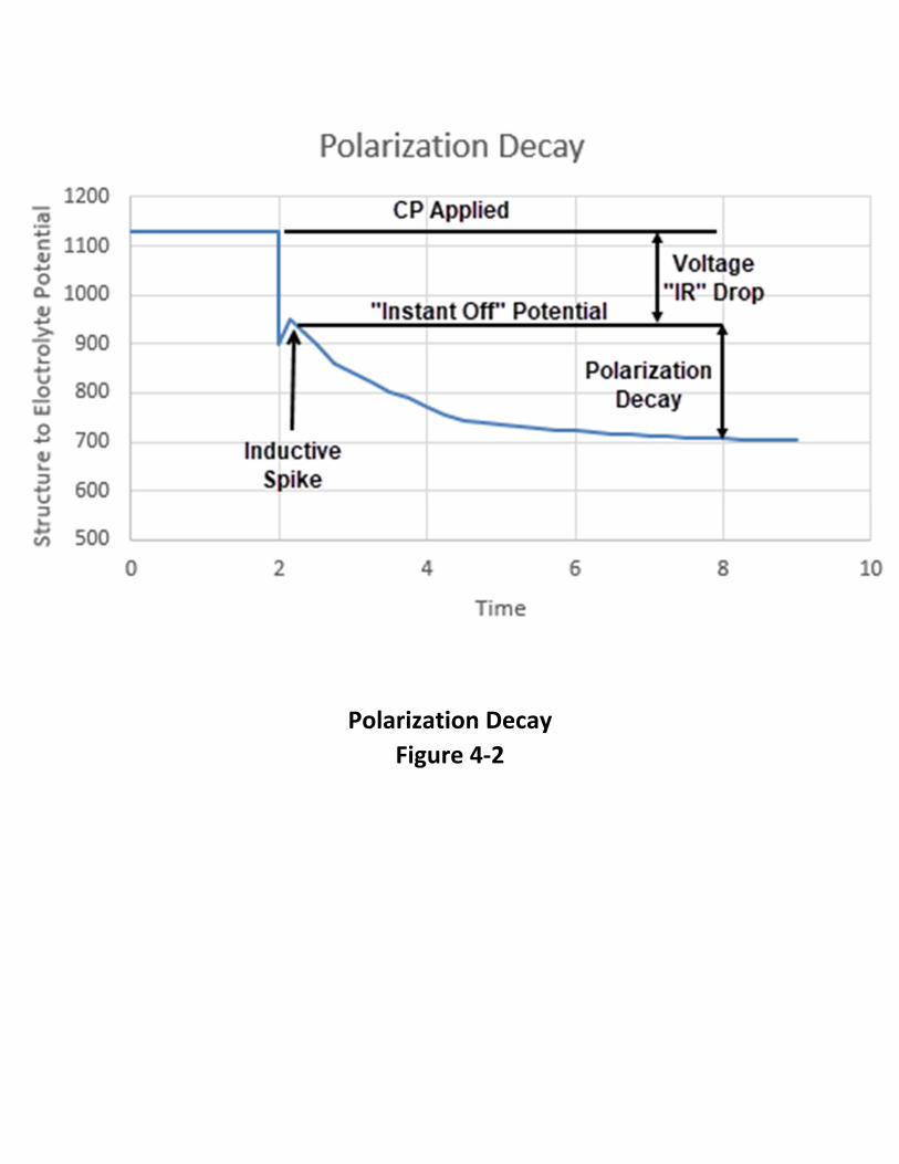
Polarization Decay
Figure 4‐2

Illustration of 100mV Polarization Compliance
Figure 4‐3

Chapter 4 – Criteria for Cathodic Protection
4‐5
of which can occur as a result of over protection. In piping networks, the 100 mV of
Polarization Criterion can be used for the older, poorly‐coated pipes while the
Polarized Potential of ‐850 mV Criterion can be used for the newer piping in the
network. Because of its fundamental underpinnings, the 100 mV of Polarization
Criterion can also be used on metals other than steel where a specific potential
required for protection has not been established.
Limitations of the 100 mV of Polarization Criterion
There are a number of limitations with this criterion. The time required for full
depolarization of a poorly‐coated or bare structure can be several days to several
weeks, making the method very time consuming and leaving the structure
unprotected for an extended period of time. Fortunately, much of the depolarization
occurs within a few hours and it frequently is not necessary to wait for the full decay,
except where the total polarization is very close to 100 mV. Once the criterion has
been met, it is not necessary to continue waiting for further depolarization. At the
other extreme, if a depolarization of less than 50 mV is measured within a few hours,
it is questionable whether the 100 mV of Polarization Criterion can be achieved. At this
point, it may be prudent to assess whether a longer wait for total depolarization is
justified.
The 100 mV of Polarization Criterion is frequently used to minimize the costs for
upgrading cathodic protection systems, and the associated increase in power costs, in
areas with degrading coatings. Because of the complicated nature of the
measurements, the cost of conducting surveys for the assessment of the 100 mV of
Polarization Criterion is considerably higher than for the ‐850 mV criteria. Thus, an
economic analysis may be required to determine whether there is actually a cost
savings associated with application of the 100 mV of Polarization Criterion.
The 100 mV of Polarization Criterion should not be used in areas subject to stray
currents because 100 mV of polarization may not be sufficient to mitigate corrosion in
these areas. It is generally not possible to interrupt the source of the stray currents in
order to accurately measure the depolarization. All DC current sources affecting the
structure, including rectifiers, sacrificial anodes, and bonds must be interrupted in
order to apply this criterion. In many instances, this is not possible, especially on older
structures where the criterion is most likely to be used.
The 100 mV of Polarization Criterion should not be used on structures that contain
dissimilar metal couples because 100 mV of polarization may not be adequate to

Chapter 4 – Criteria for Cathodic Protection
4‐6
protect the active metal in the couple. This criterion also should not be used in areas
where the intergranular form of external stress corrosion cracking, also referred to as
high‐pH or classical SCC, is suspected. This is because the potential range for cracking
lies between the native potential and ‐850 mV CSE such that application of the 100 mV
of Polarization Criterion may place the structure in the potential range for cracking.
Polarized Potential of ‐850 mV Criterion
This method states that adequate protection is achieved with "A negative polarized
potential of at least 850 mV relative to a saturated copper/copper sulfate reference
electrode." The polarized potential is defined as "The potential across the
structure/electrolyte interface that is the sum of the corrosion potential and the
cathodic polarization." The polarized potential is measured directly following
interruption of all current sources and is often referred to as the off or "instant off"
potential. The difference in potential between the native potential and the off or
polarized potential is the amount of polarization that has occurred as a result of the
application of the cathodic protection. As previously stated, the difference in potential
between the on‐potential and the off‐potential is the error in the on‐potential
introduced as a result of voltage drops in the electrolyte (soil) and metallic return path
in the measuring circuit.
Application of the Polarized Potential of ‐850 mV Criterion
This method of measuring potential is more direct than the with the current‐applied
method in that it clearly defines the method by which voltage drops errors are
considered; in this criterion they are minimized or eliminated. The voltage drop errors,
which are often referred to as ohmic potential drop or IR drop errors, occur as a result
of the flow of cathodic protection or stray current in the electrolyte (soil) or in the
structure. They are measurement errors in that the cathodic polarization at the
structure‐to‐ electrolyte interface is the only part of the on‐ potential measurement
that contributes to a reduction in the rate of corrosion of the structure. As described
above, polarization is defined as the difference in potential between the native
potential and the off or polarized potential. It is referred to as cathodic polarization if
the potential shift is in the negative direction.
This method is most commonly applied to coated structures where the sources of DC
current can be readily interrupted. An example would be a fusion bonded epoxy (FBE)
coated gas transmission pipeline in a rural area with an impressed current cathodic
protection system.

Chapter 4 – Criteria for Cathodic Protection
4‐7
Limitations of the Polarized Potential of ‐850 mV Criterion
A significant limitation of this method is the requirement that all sources of DC current
be interrupted. For standard survey techniques, the interruption must be performed
simultaneously on all current sources. On gas transmission pipelines, interrupting all
current sources may require the use of a large number of synchronous interrupters
for all rectifiers, sacrificial anodes, and bonds affecting the section of pipeline that is
being evaluated. In some cases, the number of rectifiers affecting a test section is not
known without experimental verification. On gas distribution systems, sacrificial
anodes are more commonly used for cathodic protection and the electrical leads for
the anodes are usually bonded directly to the pipe with no means available to
interrupt the current. For these situations, this method cannot be used. Achieving the
criterion through this method may require the application of high CP currents,
resulting in over‐protection of some portions of the structure, and related problems
such as cathodic disbondment of coatings, and hydrogen embrittlement of susceptible
steels.
There are a number of limitations with this criterion. The potential reading should be
taken with the reference electrode contacting the electrolyte directly over the
structure, to minimize ohmic voltage drop errors in the measurement and to minimize
the extent of averaging over large areas of the structure. Alternative criteria may be
required where the reference electrode cannot be properly placed, such as at river
crossings or road crossings. The criterion also is most commonly used for well coated
structures, where it can be economically met. For poorly‐coated or bare structures,
the high CP currents required to meet this criterion can be prohibitive, such that
alternative criteria are typically used.
Potentials can vary significantly from one area of an underground structure to another
as a result of varying soil conditions, coating damage, interference effects, etc. This
creates the possibility that potentials less negative than ‐850 mV CSE exist between
the measurement points. This problem can be addressed for pipelines by means of
close‐interval surveys. If the close‐interval survey establishes that this problem exists,
it is possible to maintain more negative potentials at the test stations to ensure that
adequate protection is achieved on the entire structure. However, the more negative
potentials required will result in increased power consumption.
More negative potentials than ‐850 mV CSE also are required in the presence of
bacteria or with a hot pipeline. In the latter case, the current required for CP can

Chapter 4 – Criteria for Cathodic Protection
4‐8
increase by a factor of two for every 10° C (18° F) increase in temperature of the pipe.
The potential criterion is adjusted to compensate for the increased anodic current
kinetics. Typically, a potential of ‐950 mV CSE is used for hot pipelines. In the case of
microbes, the kinetics of the corrosion reaction and the environment at the pipe
surface are altered such that a more negative potential is typically required to mitigate
corrosion. Where the presence of microbes are confirmed or suspected, a minimum
potential criterion of ‐950 mV CSE is typically used.
Care should be exercised to avoid overprotection, which can result in coating damage
and may promote hydrogen damage of susceptible steels. The potential above which
coating damage can occur is a function of many variables, including the soil
composition and moisture content, temperature, coating type, the quality of the
coating application, and the presence of microbes. The general consensus in the
industry is to avoid polarized (instant off) potentials more negative than ‐1.200 V CSE.
The older steels generally contain higher levels of impurities, such as sulfur and
phosphorus, and exhibit higher susceptibility to hydrogen damage than the newer
cleaner steels. In these older steels, the microstructures associated with hard spots
and welds typically are much more susceptible to hydrogen damage than the
microstructure of the wrought base metal. Again, the general consensus in the
industry is to avoid polarized (instant off) potentials more negative than ‐1.200 V CSE
in order to minimize hydrogen damage in these steels.
Potentials also can vary on a seasonal basis as a result of variation in the soil moisture
content. Thus, some pipeline companies perform annual surveys at the same time
each year, such that trends in the behavior can be properly interpreted. It should be
cautioned that this approach does not preclude the possibility that the criterion is not
being met on some parts of the structure during portions of the year.
Limitations also exist in the ability to accurately measure the potential of the structure
in the presence of telluric currents and where shielding by disbonded coatings, rocks,
thermal insulation, etc. has occurred. Similarly, the accuracy of the potential
measurement is compromised by the presence of multiple pipelines in a right‐of‐way
where the pipelines have varying coating conditions, and by stray currents that cannot
be interrupted.
Dynamic stray currents, from sources such as DC transit systems and mining activities,
pose a significant challenge in applying this criterion. Where dynamic stray currents
are suspected, it is generally necessary to obtain potential values over the duration of

Chapter 4 – Criteria for Cathodic Protection
4‐9
the stray current activity, typically twenty‐four hours or longer. For example, for DC
transit systems, it is often possible to obtain fairly stable on‐potentials of the structure
in the early morning hours when the transit system is not operated. These potentials
can provide base‐line data for which to evaluate other measurements. Of course,
significant interpretation of such data is required. DC stray currents not only affect the
ability to obtain accurate off‐potentials, they also influence the polarized potential of
the pipe. Nevertheless, the ‐850 mV with the Current‐Applied Criterion is the most
common criterion used in areas of significant dynamic stray current activity. It is
generally accepted that the structure is protected at a test location if the potential of
the structure remains more negative than ‐850 mV at all times, even with significant
fluctuations associated with the dynamic stray currents. It may be necessary to
increase the number of test points and the frequency of surveys in areas of dynamic
stray DC currents over those used on other parts of a system to ensure that adequate
protection is being achieved.
An example of this ‐850 mV criterion with polarized readings can also be seen by
conducting line surveys on the pipeline in question. The On and Off lines on Figure 4‐
4 are data obtained from a Close Interval Potential Survey. To check the compliance
with the ‐850 mV criterion a theoretical line was created. This plot shows a pipeline
segment that is compliant because the actual polarized data (Instant ‐Off) data never
goes above the theoretical ‐850 mV line.
Current‐Applied Potential of ‐850 mV Criterion
This method states that adequate protection is achieved with "A negative polarized
potential of at least 850 mV relative to a saturated copper/copper sulfate reference
electrode." The polarized potential is defined as "The potential across the
structure/electrolyte interface that is the sum of the corrosion potential and the
cathodic polarization." When potentials are taken with the current applied, the
voltage drops other than those across the structure‐to‐electrolyte boundary must be
considered for valid interpretation of this voltage measurement."
"Consideration is understood to mean application of sound engineering practice in
determining the significance of voltage drops by methods such as:
• Measuring or calculating the voltage drop(s) to determine in ‐850 mV or
more negative have been achieve
• Performing a technical evaluation
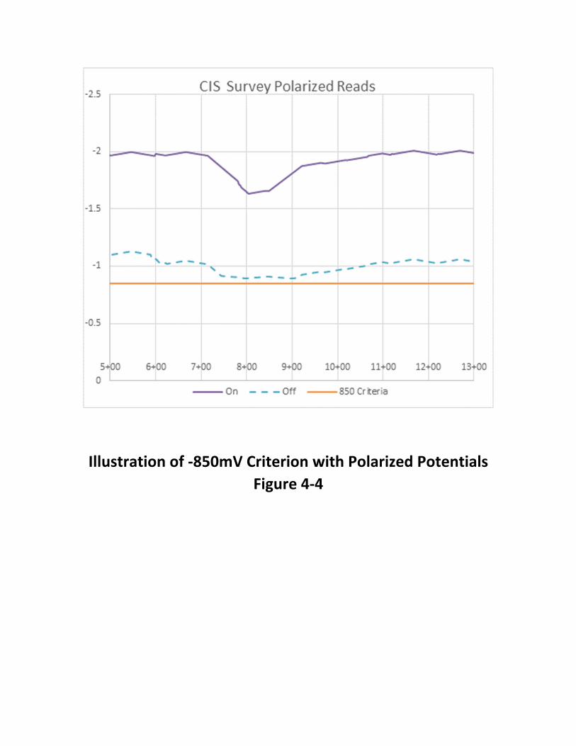
Illustration of ‐850mV Criterion with Polarized Potentials
Figure 4‐4
Chapter 4 – Criteria for Cathodic Protection
4‐10
o Reviewing the historical performance of the cathodic protection
system,
o Determining whether or not there is physical evidence of corrosion
o Evaluating the physical and electrical characteristics of the pipe and its environment,
o Evaluating physical characteristics and operational data o Review Inspection data o Use Coupons o And Others
Voltage (IR) Drop Measurements
Cathodic Protection Coupons
A cathodic protection coupon is metal sample that is intended to represent a structure
at a coating holiday. The coupon has a lead wire attached to it which is normally
bonded to the structure through a test station so that it receives cathodic protection
current just as the structure does at a coating holiday. Cathodic protection coupons
are used to help determine the level of cathodic protection of a buried or submerged
metallic structure.
Tests that can be made with cathodic protection coupons include:
measuring the coupon‐to‐electrolyte potential with the coupon connected to
the structure,
measuring the coupon‐to‐electrolyte potential after disconnecting the coupon
from the structure (coupon instant‐off potential),
measuring the current flow between the coupon and the structure
The coupon‐to‐electrolyte potential is typically measured with the reference electrode
in close proximity to the coupon. This is accomplished using a permanently installed
reference electrode near the coupon or by placing a portable reference electrode in a
soil‐access tube. Measurements made with coupons can help determine if a criterion
has been met:
since the coupon‐to‐electrolyte potential is measured with the reference
electrode in close proximity to the coupon,
the voltage drop is minimized for a current‐applied potential
Chapter 4 – Criteria for Cathodic Protection
4‐11
measuring the coupon‐to‐electrolyte potential after disconnecting the coupon
from the structure is a way of interrupting all sources of cathodic protection
current in order to obtain a direct measurement of the polarized potential.
measuring the coupon‐to‐electrolyte potential after disconnecting the coupon
from the structure is a way of interrupting all sources of cathodic protection
current in order to obtain an “off” reading to be used in determining the level
of polarization.
These measurements are especially useful in the situations where interrupting all
sources of cathodic protection current is impractical. Situations where using an IR
coupon could be advised include:
• Current interruption on multiple rectifiers affecting the structure that
cannot be synchronized
• Foreign CP systems that are affecting the structure being tested cannot be
interrupted
• The presence of directly connected sacrificial anodes
Figures 4‐5 and 4‐6 are examples of a CP coupon Installation.
Application of the Current‐Applied Potential of ‐850 mV Criterion
Of the criterion listed above, the ‐850 mV with the Current‐Applied Criterion is
probably the most widely used for determining if a buried or submerged steel or cast‐
iron structure has attained an acceptable level of cathodic protection. In the case of a
buried steel or cast iron structure, an acceptable level of protection is achieved, based
on this criterion, if the potential difference between the structure and a saturated
copper‐copper sulfate reference electrode contacting the soil directly above and as
close as possible to the structure is equal to or more negative (larger in absolute value)
than ‐850 mV. As described above, voltage drops other than those across the
structure‐to‐electrolyte boundary must be considered for valid interpretation of this
voltage measurement. These voltage drops are a result of current flow in the
electrolyte (soil) and are generally referred to as ohmic or IR voltage drops. Voltage
drops are more prevalent in the vicinity of an anode bed or in areas where stray
currents are present and generally increase with increasing soil resistivity.
For bare or very poorly‐coated structures, voltage drops can be reduced by placing the
reference electrode as close as possible to the structure. For the majority of coated
structures, most of the voltage drop is across the coating and the measurement is less

IR Coupon Installation
Figure 4‐5

IR Coupon Installation
Figure 4‐6

Chapter 4 – Criteria for Cathodic Protection
4‐12
affected by reference electrode placement. The voltage drop can also be minimized
or eliminated by interrupting all of the DC current sources of the cathodic protection
system and measuring the instantaneous "off” potential. The off‐potential will be free
of the voltage drop errors if all of the current sources, including sources of stray
current, have been properly interrupted and if long‐line currents are negligible. Long‐
line currents occur on a structure as a result of the presence of macro‐cells. The
difference between the on‐ and the off‐potential indicates the magnitude of the
voltage drop error when the measurement is made with the protective current
applied.
This criterion was originally adopted based on the observation that the most negative
native potential observed for coated underground steel structures was about ‐800 mV
CSE. The assumption was made that macro‐cell corrosion would be mitigated if
sufficient CP current is applied to raise (in the negative direction) the potential of the
entire structure to a value that is more negative than the native potential of the local
anodic sites. A potential of ‐850 mV was adopted to provide a 50 mV margin of
protection. The effectiveness of the criterion has been demonstrated over many years
of application.
Limitations of the Current‐Applied Potential of ‐850 mV Criterion
There are a number of limitations with this criterion. The potential reading should be
taken with the reference electrode contacting the electrolyte directly over the
structure, to minimize ohmic voltage drop errors in the measurement and to minimize
the extent of averaging over large areas of the structure. Alternative criteria may be
required where the reference electrode cannot be properly placed, such as at river
crossings or road crossings. The criterion also is most commonly used for well coated
structures, where it can be economically met. For poorly‐coated or bare structures,
the high CP currents required to meet this criterion can be prohibitive, such that
alternative criteria are typically used.
Potentials can vary significantly from one area of an underground structure to another
as a result of varying soil conditions, coating damage, interference effects, etc. This
creates the possibility that potentials less negative than ‐850 mV CSE exist between
the measurement points. This problem can be addressed for pipelines by means of
close‐interval surveys. If the close‐interval survey establishes that this problem exists,
it is possible to maintain more negative potentials at the test stations to ensure that

Chapter 4 – Criteria for Cathodic Protection
4‐13
adequate protection is achieved on the entire structure. However, the more negative
potentials required will result in increased power consumption.
More negative potentials than ‐850 mV CSE also are required in the presence of
bacteria or with a hot pipeline. In the latter case, the current required for CP can
increase by a factor of two for every 10° C (18° F) increase in temperature of the pipe.
The potential criterion is adjusted to compensate for the increased anodic current
kinetics. Typically, a potential of ‐950 mV CSE is used for hot pipelines. In the case of
microbes, the kinetics of the corrosion reaction and the environment at the pipe
surface are altered such that a more negative potential is typically required to mitigate
corrosion. Where the presence of microbes is confirmed or suspected, a minimum
potential criterion of ‐950 mV CSE is typically used.
Care should be exercised to avoid overprotection, which can result in coating damage
and may promote hydrogen damage of susceptible steels. The potential above which
coating damage can occur is a function of many variables, including the soil
composition and moisture content, temperature, coating type, the quality of the
coating application, and the presence of microbes. The general consensus in the
industry is to avoid polarized (instant off) potentials more negative than ‐1.200 V CSE.
The older steels generally contain higher levels of impurities, such as sulfur and
phosphorus, and exhibit higher susceptibility to hydrogen damage than the newer
cleaner steels. In these older steels, the microstructures associated with hard spots
and welds typically are much more susceptible to hydrogen damage than the
microstructure of the wrought base metal. Again, the general consensus in the
industry is to avoid polarized (instant off) potentials more negative than ‐1.200 V CSE
in order to minimize hydrogen damage in these steels.
Potentials also can vary on a seasonal basis as a result of variation in the soil moisture
content. Thus, some pipeline companies perform annual surveys at the same time
each year, such that trends in the behavior can be properly interpreted. It should be
cautioned that this approach does not preclude the possibility that the criterion is not
being met on some parts of the structure during portions of the year.
Limitations also exist in the ability to accurately measure the potential of the structure
in the presence of telluric currents and where shielding by disbonded coatings, rocks,
thermal insulation, etc. has occurred. Similarly, the accuracy of the potential
measurement is compromised by the presence of multiple pipelines in a right‐of‐way

Chapter 4 – Criteria for Cathodic Protection
4‐14
where the pipelines have varying coating conditions, and by stray currents that cannot
be interrupted.
Dynamic stray currents, from sources such as DC transit systems and mining activities,
pose a significant challenge in applying this criterion. Where dynamic stray currents
are suspected, it is generally necessary to obtain potential values over the duration of
the stray current activity, typically twenty‐four hours or longer. For example, for DC
transit systems, it is often possible to obtain fairly stable on‐potentials of the structure
in the early morning hours when the transit system is not operated. These potentials
can provide base‐line data for which to evaluate other measurements. Of course,
significant interpretation of such data is required. DC stray currents not only affect the
ability to obtain accurate off‐potentials, they also influence the polarized potential of
the pipe. Nevertheless, the ‐850 mV with the Current‐Applied Criterion is the most
common criterion used in areas of significant dynamic stray current activity. It is
generally accepted that the structure is protected at a test location if the potential of
the structure remains more negative than ‐850 mV at all times, even with significant
fluctuations associated with the dynamic stray currents. It may be necessary to
increase the number of test points and the frequency of surveys in areas of dynamic
stray DC currents over those used on other parts of a system to ensure that adequate
protection is being achieved.
An example of the Current‐Applied Potential of ‐850 mV Criterion can also be seen by
conducting line surveys on the pipeline in question. The On and Corrected lines on
shown Figure 4‐7. The “On” data taken directly from Close interval potential survey.
The corrected line is generated from applying the data from IR drop coupons to the
“On” data points. To check the compliance with the ‐850 mV criterion a theoretical
line was created. This plot shows a pipeline segment that is out of compliance because
there are to locations where corrected data falls below the theoretical ‐850 mV line.
Using Multiple Criteria to Meet Compliance
It may be necessary to use multiple criteria to prove the compliance of a facility. An
example would be using the ‐850 mV criterion with the 100 mV of Polarization
Criterion. An example of this can be seen in Figure 4‐8.

Illustration of ‐850mV Criterion with CP Current Applied
Figure 4‐7

Illustration of Multiple Criteria
Figure 4‐8

Chapter 4 – Criteria for Cathodic Protection
4‐15
OTHER CRITERIA DOCUMENTED THROUGH EMPIRICAL EVIDENCE
Net Protective Current Criterion
SP0169‐2013 states in 6.2.1.1 that: “Criteria that have been documented through
empirical evidence to indicate corrosion control effectiveness on specific pipeline
systems may be used on those piping systems or others with the same characteristics”.
On bare or ineffectively coated pipelines where long‐line corrosion activity is of
primary concern, the measurement of a net protective current at predetermined
current discharge points from the electrolyte to the pipe surface, as measured by an
earth current technique, may be sufficient for cathodic protection to be achieved.
This criterion for cathodic protection of underground piping, referred to as the Net
Protective Current Criterion. This criterion was originally based on the concept that, if
the net current at any point on a structure is flowing from the electrolyte to the
structure, there cannot be any corrosion current discharging from that point on the
structure. The theory of electrochemical kinetics shows that corrosion can occur at a
point on a structure that is collecting net cathodic current from the electrolyte as long
as the polarized potential is more positive than the equilibrium potential.
Nevertheless, the criterion can be effective, from a practical standpoint, because the
collection of net cathodic current at any point along the structure produces beneficial
cathodic polarization and also promotes beneficial changes in the environment at the
structure surface, as described above.
Typically, the criterion is applied by first performing a close‐interval structure‐to‐soil
potential survey or a cell‐to‐cell potential survey with the cathodic protection system
de‐ energized in order to locate the anodic discharge points along the pipeline. For the
surveys to be effective, the CP systems must be de‐energized for a sufficiently long
time such that all polarization has decayed. The CP system is then energized and the
structure is allowed to polarize. A side drain method is then used at the anodic
discharge points to determine whether the structure is receiving cathodic current at
these locations. With the side drain method, the potential difference between an
electrode placed directly over the structure and one placed on either side of the
structure is measured. If the electrode located over the pipe is negative with respect
to the other two electrodes, then current is collecting on the pipe at the location and
the criterion is satisfied.

Chapter 4 – Criteria for Cathodic Protection
4‐16
Application of the Net Protective Current Criterion
The Net Protective Current Criterion is normally used on poorly‐coated or uncoated
structures where the primary concern is long‐line corrosion activity. The technique
also is normally only used in situations where other criterion cannot be easily or
economically met. With the exception of these applications, this criterion is not a
standard criterion for establishing the effectiveness of a cathodic protection system.
Limitations of the Net Protective Current Criterion
There are a number of limitations with this criterion. First and foremost is the fact that
the criterion essentially states that any magnitude of net current flow to the structure
(and therefore, any amount of cathodic polarization of the structure) is adequate to
mitigate corrosion. In general, this is not the case and therefore, the criterion should
only be considered for use as a last resort. Application of the criterion should be
avoided in areas of stray current activity or in common pipeline corridors because of
the possibility of misinterpretation of the potential readings. The criterion also may
not be effective in areas with high resistivity soils, for deeply buried pipelines, or where
the separation distance of the corrosion cells is small. Finally, the side drain
measurements at a given location are only indicative of the direction of current flow
at that location and are not necessarily representative of behavior elsewhere on the
pipeline. Thus, for the application of this criterion, it is generally necessary to perform
side‐drain measurements at close intervals (2 to 20 feet) along the pipeline.
300 mV Potential Shift Criterion
The 300 mV Potential Shift Criterion was contained in the original version of RP0169
(the predecessor of SP0169‐2007) and stated that adequate protection is achieved
with "A negative (cathodic) voltage shift of at least 300 mV as measured between the
structure surface and a saturated copper‐copper sulfate half cell contacting the
electrolyte. Determination of this voltage shift is to be made with the protective
current‐applied." This criterion has been removed from the standard but may still
have applications in the field.
This criterion is similar to the 100 mV of Polarization Criterion, where the latter is
assessed based on the formation of polarization on a structure. With both criteria, it
is first necessary to determine the native potential of the underground structure at
test locations before cathodic protection is applied. The potential measurement is
then repeated after the cathodic protection system is energized and the structure has
had sufficient time to polarize. The difference between the two criteria is that, in the

Chapter 4 – Criteria for Cathodic Protection
4‐17
case of the 300 mV Potential Shift Criterion, the on‐potential is used for assessment of
the criterion while, in the case of the 100 mV of Polarization Criterion, the off‐potential
is used for assessment. In the 300 mV Potential Shift Criterion, it is stated that "The
Corrosion Engineer shall consider voltage (IR) drops other than those across the
structure‐electrolyte boundary for valid interpretation of the voltage measurements."
Thus the relationship between the 300 mV Potential Shift Criterion and the 100 mV of
Polarization Criterion is analogous to the relationship between the ‐850 mV with the
Cathodic Protection Applied Criterion and the Polarized Potential of ‐850 mV Criterion.
The 300 mV Potential Shift Criterion has mainly been used for mitigation of moderate
rates of uniform corrosion of bare steel structures. It has been applied for protection
of entire structures and also for hot‐spot protection. On these structures, native
potentials of ‐200 mV to ‐500 mV CSE are commonly observed and it has been found
that a 300 mV shift is adequate to mitigate corrosion in some instances. Thus, the
development of the criterion was empirical. The 300 mV Potential Shift Criterion is
more applicable to impressed current CP systems than to galvanic anode systems
because galvanic anodes may not have sufficient driving voltage to meet the criterion
where (when) more negative native potentials are encountered.
Probably the most successful application of this criterion has been on steel reinforced
concrete structures. These structures typically have noble native potentials (‐200 mV
to ‐400 mV CSE), and passive steel surfaces, with the exception of hot spots, such that
a potential shift of 300 mV can be readily achieved. Application of this criterion avoids
problems associated with over‐protection.
Many of the limitations associated with the 100 mV of Polarization Criterion are
applicable to the 300 mV Potential Shift Criterion as well. These include the time
required for polarization, the possibility of moving the potential into the cracking
range for SCC, and difficulties in areas containing stray currents or galvanic couples. In
general, the 300 mV Potential Shift Criterion should not be used where high‐pH SCC is
confirmed or suspected, or where stray currents or galvanic couples are present. In
the original version of RP0169 it is stated "This criterion of voltage shifts applies to
structures not in contact with dissimilar metals."
Probably the single greatest limitation of the 300 mV Potential Shift Criterion is that
situations will exist in the field where the criterion appears to be applicable, yet
corrosion may not be adequately mitigated. In some situations, the majority of the
potential shift will be the result of voltage drops in the soil or across the coating and

Chapter 4 – Criteria for Cathodic Protection
4‐18
very little polarization of the structure will occur. This is the reason that this criterion
was removed from the primary list of criteria in the 1992 version of RP0169.
E‐Log I Curve Criterion
The E‐Log I Curve Criterion also is found in the original version of RP0169. The criterion
states that adequate protection is achieved with "A voltage at least as negative
(cathodic) as that originally established at the beginning of the Tafel segment of the E‐
Log I curve. This voltage shall be measured between the structure surface and a
saturated copper‐ copper sulfate half cell contacting the electrolyte." The criterion
was originally developed based on an incorrect interpretation of an E‐Log I curve. It
was thought that a break in the cathodic curve exists as the structure is polarized from
the native potential and that the "break" has some fundamental significance. This
break was thought to occur at the beginning of the "Tafel Region." A review of the
theory of cathodic protection indicates that the net cathodic current measured at any
applied cathodic potential is equal to the difference between the rate of the reduction
reaction and the rate of the oxidation reaction. An Evans diagram (potential versus log
current plot) shows that there is a smooth transition from zero current, at the native
potential, to the linear Tafel region. The Tafel region starts when the rate of the
oxidation (corrosion) reaction is negligibly small in comparison to the rate of the
reduction reaction. Depending on the Tafel slopes for the oxidation and reduction
reactions, the beginning of the Tafel region can vary between 50 mV and 100 mV
cathodic from the native potential.
Presently, the E‐Log I Curve Criterion is rarely used for evaluating existing cathodic
protection systems. However, the measurement technique, originally developed for
applying the E‐Log I Curve Criterion, is now most commonly used to determine the
minimum current required for protection. The structure‐to‐soil potential, using a
remote reference electrode, is plotted as a function of the current output of a cathodic
protection system. Typically, it is necessary to use an interruption technique and off‐
potentials for making the E‐Log I plot in order to accurately establish the curve. The
potential required to achieve a desired minimum current value is identified on the
curve. This value should be at least as negative as the value at the beginning of the
Tafel region of the E‐Log I curve. Once the potential and current values have been
established, future surveys consist of checking the current output of the cathodic
protection system and the potential of the structure with respect to the remote
reference electrode, placed in the same location as that used in the original E‐Log I
tests.

Chapter 4 – Criteria for Cathodic Protection
4‐19
Because of the elaborate nature of the technique, its use is generally limited to
structures where conventional means of assessment are difficult. Examples include
river crossings for pipelines, well casings, and piping networks in concentrated areas
such as industrial parks. The technique can give erroneous results in areas of stray
currents. The reference electrode must be placed in the same location each time the
potential is measured. Furthermore, there is no guarantee that a repeat E‐Log I curve
will yield the same results as the original curve.
SPECIAL CONSIDERATION FOR APPLICATION OF CP
Criterion For Aluminum Piping
SP0169‐2013 lists a criterion for aluminum piping. This criterion is a minimum of 100
mV of cathodic polarization between the structure and a stable reference electrode
contacting the electrolyte. The formation or decay of this polarization can be used in
this criterion." The standard also denotes that other criterion that has been
documented through empirical evidence may be used.
There are two precautionary notes come from the standard:
• A polarized potential more negative than 1200 mV should not be used
unless previous test results indicate that no appreciable corrosion will occur
in the particular environment.
• Aluminum may suffer from corrosion under high‐pH conditions and
application of cathodic protection tends to increase the pH at the metal
surface. Therefore, careful investigation or testing should be made before
applying cathodic protection to stop pitting attack on aluminum in
environments with a natural pH in excess of 8.0.”
The basis for these cautionary notes is the incompatibility of aluminum in high pH
environments. The protective passive films on aluminum break down in high pH
electrolytes, leading to significant increases in the corrosion rate, even at relatively
negative potentials.
In addition to these precautionary notes, several of the limitations for the 100 mV
Polarization Criterion for steel and cast iron also apply to aluminum. These include the
time‐consuming nature of the measurement technique, difficulties associated with

Chapter 4 – Criteria for Cathodic Protection
4‐20
interrupting all current sources, and limitations in applying the criterion on structures
with dissimilar metals and in the presence of stray currents. Because no other criterion
is applicable to aluminum, good engineering practice must be used to address these
limitations. For example, sources of stray current should be identified and eliminated,
if possible. Aluminum piping should be isolated from other metals before cathodic
protection is applied.
Criterion For Copper Piping
SP0169‐2013 lists a criterion for copper piping. This criterion for copper piping is a
minimum of 100 mV of cathodic polarization between the structure and a stable
reference electrode contacting the electrolyte. The formation or decay of this
polarization can be used in this criterion. The standard also denotes that other
criterion that has been documented through empirical evidence may be used.
This criterion is identical to the 100 mV of Polarization Criterion used for cast iron,
steel and aluminum. There are no precautionary notes with this criterion but several
of the limitations with the 100 mV of Polarization Criterion for steel and cast iron also
apply to copper. These include the time‐consuming nature of the measurement
technique, difficulties associated with interrupting all current sources, and limitations
in applying the criterion on structures with dissimilar metals and in the presence of
stray currents. Sources of stray current should be identified and eliminated, if possible.
Since copper is a noble metal, steel, cast iron, or other metals usually will undergo
preferential galvanic attack when coupled to copper. Therefore, it is desirable to
eliminate such dissimilar metals couples before the application of cathodic protection.
Criterion For Dissimilar Metal Piping
In SP0169‐2013, there is a single criterion for dissimilar metal piping. Under paragraph
6.2.5.1, the following criterion is listed: "A negative voltage between all pipe surfaces
and a stable reference electrode contacting the electrolyte equal to that required for
the protection of the most anodic metal should be maintained." There is one
precautionary note, under Paragraph 6.2.5.2:
“Amphoteric materials that could be damaged by high alkalinity created by CP should
be electrically isolated and separately protected." Amphoteric metals include
aluminum, titanium and zirconium.
In practice, this criterion only applies where carbon steel or cast iron is coupled to a
more noble metal such as copper.

Chapter 4 – Criteria for Cathodic Protection
4‐21
ACKNOWLEDGMENT
This chapter was originally written by J. A. Beavers and K. C. Garrity and was edited as
needed by the AUCSC Curriculum Committee until 2019. A significant rewrite was
completed in 2019 by R. D. Fultineer Jr. and N. T. Zafris and approved by AUCSC
Curriculum Committee.
REFERENCES
1. NACE Standard Practice SP0169‐2013 “Control of External Corrosion on Underground or Submerged Metallic Piping Systems”, NACE International,
Houston.
2. NACE Standard Practice TM0497‐2018 “Measurement Techniques Related to
Criteria for Cathodic Protection on Underground or Submerged Metallic Piping
Systems”, NACE International, Houston.

Chapter 5 ‐ Static Stray Current Interference Testing
INTRODUCTION
The objective of this chapter is to provide enough information to allow the CorrosionProfessional, first to recognize an interference problem based on pipe‐to‐soil potentialdata and then determine what steps are required to eliminate or control the problem. The primary cause of interference currents or stray currents was initially related tooperation of direct current traction systems, such as rail systems, mining carts, and thelike. Due to the increased use of impressed current cathodic protection systems forpipelines and other underground and submerged metallic structures, these types ofcathodic protection systems have also become another major cause of interferenceproblems. This chapter will discuss how to determine the source of the interference current,determine the point of maximum exposure, and describe methods to mitigate theproblem.
Please note that all pipe‐to‐soil voltages shown in this chapter are with respect to asaturated copper/copper sulfate reference electrode (CSE). DEFINITIONS
Interference currents, or stray currents, are defined as currents performing work in onegrounded plant, which leaks to, and flow through electrolytic paths, and are picked upby nearby grounded plants. Interference currents are normally separated into two mainclassifications as follows: 1. Static Interference ‐ These stray currents are those which maintain constant
amplitude and constant geographical paths. Examples of typical sources are railroadsignal batteries and impressed current cathodic protection systems.
2. Dynamic Interference ‐ These stray currents are those, which are continually varying
in amplitude and/or continually, changing their electrolytic paths. They can beman‐made or caused by natural phenomena. Typical examples of man‐made sourcesare DC welding equipment and DC electrical railway systems. Natural sources suchas telluric currents are caused by disturbances in the earth's magnetic fields causedby sun spot activity.
Chapter 5 ‐ Static Stray Current Interference Testing5‐1

Although the Corrosion Professional needs a good working knowledge of both types ofinterference currents, we will only focus on static interference for this chapter. DynamicInterference will be discussed in the Advanced Course. STATIC INTERFERENCE During this chapter you will find that all forms of interference correction requireconsiderable field work and testing. It can be time consuming and therefore veryexpensive. Much of the expense can be saved if careful planning is done in the designstage before a cathodic protection system is installed. This means that all involved knowof the potential problem, and are aware of foreign lines, and other undergroundstructures, in the vicinity of the newly proposed system. One of the easiest ways of keeping abreast of possible interference problems in an areais through a Corrosion Coordinating Committee. These committees are sometimesknown as "electrolysis committees” and are composed of individuals representingcompanies that operate, maintain, or engineer underground structures, such aspipelines, cables, tanks and their associated cathodic protection systems. By beinginvolved or requesting information from one of these committees, the CorrosionProfessional can possibly avoid costly, time‐consuming field testing in the design phaseof the system. Most companies conduct periodic corrosion surveys on their underground structures(pipelines). Pipe‐to‐soil potential measurements are normally taken along the pipelineduring the survey and the data plotted on a long strip chart or graph, distance(horizontal axis) vs. potentials (vertical axis). Figure 5‐1 shows a typical potential surveyplot with no interference problems. The pipe‐to‐soil potential survey is the best way toensure proper operation of a company's own cathodic protection system.
This survey is also a means of determining the existence of interference problems.Figure 5‐2 and 5‐3 show potential plots for coated and bare pipelines respectively, whichare experiencing stray current interference. Based on the plotted data, interference maybe suspected if: C Voltage curve profile shows abnormal variation from previous survey curves. C High negative values are noted remote from any cathodic protection system on the
surveyed line.
Chapter 5 ‐ Static Stray Current Interference Testing5‐2

��������������������� ����
����
����
����
����
����
���
���
���
���
� � � � � �� ��
��������������
�������� �������������
��� !�����
� � � � �� �� ��

�������������������
����
����
����
����
���
���
���
���
���
� � � � � � � �
��������������
������������"��#����!��!����������������
��� !�����
���!��!����� ���!��!��������������
�$ $
�
� !!�������#�!��������!��!�����
� !!������%� ���!�����!��!��������&��

����
����
����
����
���
���
���
���
���
� � � � � � � �
��������������
�������������������
$ �
���!��!�����
$ �$ �
���!��!�������&�!��
������������"��#����!��!���&�!��������
��� !�����
� !!�������#�!��������!��!�����
� !!������%� ���!�����!��!��������&��

C Low negative or positive voltages are present.
Note: Plots of coated lines normally have smoother voltage attenuation curves asopposed to bare lines which often have jagged curves making them more difficult tointerpret.
Small variations in potential can normally be ignored provided that adequate levels ofcathodic protection are maintained. Although Figures 5‐2 and 5‐3 only show one survey or one year’s worth of data, theCorrosion Professional can now utilize computer software which can plot several yearsof pipe‐to‐soil data on one graph. This allows for an easy comparison of voltage curvesof previous surveys. INTERPRETATION OF DATA Interpretation of data can best be illustrated through an example. Let us look at a coatedpipeline section being cathodically protected by a conventional impressed current anodebed. There are four foreign pipelines crossing our protected line, as shown in Figure 5‐4,and a test station exists at each line crossing us, as shown in Figure 5‐5. All pipe‐to‐soil potentials should be taken using a high impedance (10 megohms orgreater) voltmeter, connected as shown in Figure 5‐5, while interrupting the rectifierassociated with or influencing the line being tested. When taking potentials at linecrossings, the reference electrode should be placed in contact with the soil directlyabove the pipe crossing. A pipe locator should be utilized to locate this point.
When interpreting data on multiple pipelines, it is best to look at each crossingindividually, as shown in the examples. Crossing A ‐ Figure 5‐6
The example shows that with our rectifier "on" the pipe‐to‐soil potential for our line is‐0.89 V. Pipeline A has a pipe‐to‐soil potential of ‐0.86 V.
When the rectifier is switched "off" our potential becomes more positive (‐0.85 V).Where Pipeline A has become more negative (‐0.88 V).
The pipeline under test is considered to be protected, based on the recorded test data.
Chapter 5 ‐ Static Stray Current Interference Testing5‐3

��!�������
��!������&
���% �
�����&����������
��!�������
!�������!
� !!�����!! ���!
����������$���
����������$���
�����������$���
�����������$���
�����&��
��!�������
�!���������� ��!����
!�������!
��!��������!������
��� !�����
$�
$�
���������$���

�$
������!����������
!���!��������!���
�!���
��&��%����
��"#�������
��!�����
�!���������
�'�������!��������!���������������
��� !�����

FOREIGN
LINE A
ANODE BED
INSTALLATION
OUR RECTIFIER
CURRENT
INTERRUPTER
OUR LINE
FOREIGN LINE CROSSING A
FIGURE 5-6
+
-
STATION 15+00
OUR LINE
ON 0.89V
OFF 0.85 V
V 0.04 V
�
�
��
FOREIGN LINE A
ON 0.86 V
OFF 0.88 V
V 0.02 V
�
�
��

It can be expected however, that a coating holiday exists near the point of crossing. Thisconclusion is based on the fact that the potential of the foreign line decreased (orbecame more positive) when our rectifier was switched "on”. This is an indication thatthere is an appreciable amount of current flowing to our line, thus creating an area ofmore negative soil locally around the foreign line. The foreign line at the crossing is cathodically protected. Its potential at the crossing (alocal condition) is decreased by energizing our rectifier. However, the reduction is notsufficient to indicate loss of protection. In this particular case no corrective measureswould be required.
Crossing B ‐ Figure 5‐7
The example shows that with our rectifier "on" the pipe‐to‐soil potential for our line is‐1.85 V. Pipeline "B" has a pipe‐to‐soil potential of ‐0.48 V. When the rectifier is switched"off" our potential becomes more positive (‐1.04 V). Where Pipeline "B" has becomemore negative (‐0.71 V). The data indicates that our pipeline is cathodically protected. The foreign pipeline at thiscrossing is not protected because its potential is much less negative than ‐0.85 V withour rectifier "off”. When the rectifier was energized, the foreign line potential wasdrastically shifted in the positive direction, indicating that severe damage may beoccurring on the foreign line. In this example corrective measures would be deemednecessary. Due to the close proximity of the foreign pipeline to the anode bed, as shown, theinterference can be expected to occur as a result of current picked up by the foreignpipeline where it passes through the gradient field surrounding the anode bed. Twotests should be conducted to verify the influence of the anode bed. First, if the potentialof our line is the same or almost the same with respect to a remote electrode as it is tothe electrode directly over the point of crossing, this would tend to indicate that nocoating damage is present on our line. Second, if the potential of the foreign pipeline,measured with respect to a reference electrode placed directly above it, in areas nearthe anode bed, swings in the negative direction when the rectifier is switched "on”,current pick‐up by the foreign line is indicated. Where interference is found, it is necessary to determine if the actual crossing is thepoint of maximum exposure (explained later in this chapter). This is done by moving areference electrode, in contact with the electrolyte, several feet at a time, first in one
Chapter 5 ‐ Static Stray Current Interference Testing5‐4

FOREIGN
LINE B
CURRENT PICKUP
ANODE BED
INSTALLATION
OUR RECTIFIER
CURRENT
INTERRUPTER
STATION
910+00
OUR LINE
FOREIGN LINE CROSSING B
FIGURE 5-7
+
-
FOREIGN LINE B
ON 0.48 V
OFF 0.71 V
V 0.23 V
�
�
��
OUR LINE
ON 1.85 V
OFF 1.04 V
V 0.81 V
�
�
��

direction and then in the other, away from the point of crossing and directly above theforeign line. If an area exists where the positive swing is greater than at the actualcrossing, the electrode should then be moved in smaller increments until the maximumpoint of exposure is located in this area. All information such as location, "on" and "off"potentials, and voltage changes (ΔV) at this point should be recorded. It would rarely be necessary to move the electrode more than 100 feet in eitherdirection from the point of the actual pipeline crossing. The point of maximum exposuremay be located in an area other than the point of the actual crossing if the soil resistivityvaries considerably in the crossing area or it the coating (if any) on the foreign pipelinevaries in quality. Crossing C ‐ Figure 5‐8
This example shows, that with our rectifier "on" the pipe‐to‐soil potential for our line is‐0.71 V. Pipeline "C" potential is ‐0.75 V. When our rectifier is switched "off" ourpotential becomes more positive (‐0.65 V), where Pipeline "C" potential show no change(‐0.75 V).
Based on the data, our line is not receiving adequate levels of cathodic protection in thisarea. This could be due to interference caused by the cathodic protection system forPipeline "C". If the potential of our line is measured with respect to a referenceelectrode located remotely to both the foreign and our line and the potential is foundto be representative of normal protective potentials, the less negative potential at thecrossing is shown to be a local condition. The foreign pipeline crossing most likely causesthis condition. Corrective measures must be taken in this case. Determine the length ofthe tested line that is less negative than ‐0.85 V, can be done by taking close pipe‐to‐soilpotential readings directly above the line in both directions from the point of crossing.Measured data should be recorded and then plotted, potential versus distance. If theresulting graph is similar to the one shown in Figure 5‐9, then interference from thecathodic protection system on the foreign line is confirmed.
Another test to confirm this interference is to interrupt the rectifier on the foreign lineand take pipe‐to‐soil potentials on our line, with the reference electrode located directlyover the crossing. If the potential of the pipe shifts in the positive direction when therectifier is energized, then the interference is confirmed. The foreign pipeline in this caseis not adversely affected.
Chapter 5 ‐ Static Stray Current Interference Testing5‐5
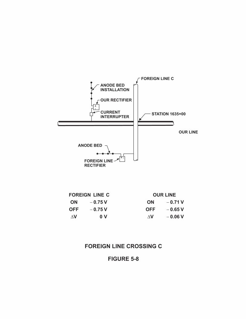
ANODE BED
INSTALLATION
FOREIGN LINE C
OUR RECTIFIER
CURRENT
INTERRUPTERSTATION 1635+00
ANODE BED
OUR LINE
FOREIGN LINE
RECTIFIER
FOREIGN LINE CROSSING C
FIGURE 5-8
+
-
+-
OUR LINE
ON 0.71 V
OFF 0.65 V
V 0.06 V
�
�
��
FOREIGN LINE C
ON 0.75 V
OFF 0.75 V
V 0 V
�
�
�

������������� ������
�������
����������
������������������������� ��������������
������������������������� ������
�������������������������
�������������������������� �
���������
�
����
����
����
����
�����
� ��� �
����� ������
�������� ����������
� ������������������������������������� ��������������
��������!

Crossing D This example is shown in Figure 5‐10. This example shows, that with our rectifier "on"the pipe‐to‐soil potential for our line is ‐0.97 V. Pipeline "D" potential is ‐0.65 V. Whenour rectifier is switched "off" our potential becomes more positive (‐0.93 V), wherePipeline "C" potential shows no change (‐0.65 V).
Based on the potentials our line appears to be adequately protected. The potentialsmeasured on Pipeline "C" indicate that this line is not cathodically protected or the levelof protection achieved is not satisfactory. The cathodic protection system protecting theline under test has no effect on the foreign line. Therefore, nomitigation is required. Finding the Source of Static Interference
As discussed in Chapter 2 of the Basic Course, the presence of static stray currents is notreadily apparent due to their steady state characteristics. In such cases, the presence ofstatic stray current effects is picked up by detailed potential measurements on astructure, which reveal typically concentrated areas of anodic condition. Structurecurrents flowing in both directions toward an area of current discharge may also revealthem. As indicated, a detailed potential survey in the vicinity of the protected structureis normally required to locate the source of the interference. Potential measurementsare normally taken with respect to a copper‐copper sulfate reference electrode. If lownegative or positive pipe‐to‐soil potentials are noted, this is a good indication that aforeign structure may exist nearby, whose protective current is affecting the surveyedstructure. That foreign structure should be considered as the prime suspect forcontaining a current source which is creating interference problems and should beinvestigated. The first step is to locate the structure and identify it. The next step is to search for acurrent generating device or another structure in the vicinity of the known structure,which may contain a current source. The following steps should be followed in thesearch: 1. Inquire of its Owners.
2. Follow the foreign pipeline geographically.
3. Examine its route maps.
Chapter 5 ‐ Static Stray Current Interference Testing5‐6

ANODE BED
INSTALLATION
RECTIFIER
CURRENT
INTERRUPTER
STATION 1915 + 00
FOREIGN
LINE D
OUR LINE
FOREIGN LINE CROSSING D
FIGURE 5-10
+
-
OUR LINE
ON 0.97V
OFF 0.93 V
V 0.04 V
�
�
��
FOREIGN LINE D
ON 0.65 V
OFF 0.65 V
V 0 V
�
�
�

In the case where no foreign structure is evident in the vicinity of the low negative orpositive pipe‐to‐soil potential measurements, it will be necessary to conduct aninvestigation through local utility companies, local citizens, or as previously mentionedthrough information available from Corrosion Coordinating Committees in the area.Corrosion Professionals can use other tests, such as earth current readings, to track thepath of the current back to the source. The easiest way to trace the current is with theuse of two identical reference electrodes and a high impedance voltmeter. By measuringthe potential between the two electrodes spaced approximately 25 feet apart, thedirection of current flow can be determined and its path traced. When the suspected source is found, testing as shown on previous examples must beperformed to confirm that this is indeed the cause of the abnormal pipe‐to‐soilpotentials. Because these tests require interrupting the current source, you must receivethe Owner's permission, prior to conducting any testing. If the suspected source is notthe cause of the abnormal potentials the search must go on until the actual currentsource is located. Determining the Point of Maximum Exposure The point of maximum exposure is defined as the geographical location at which themost adverse electrolytic effect exists. This point coincides with the location where thebulk of the stray currents are flowing from the metallic structure/pipeline into theelectrolyte. It is important to understand that at this point electrolytic corrosion willoccur on the affected structure unless the interference current is mitigated. The point of maximum exposure can be located by measuring the pipe‐to‐soil potentialsin the suspected drainage area while interrupting the interfering current source. Thelocation where the maximum positive voltage change is measured when the currentsource is energized indicates the point of maximum exposure as shown in Figure 5‐11.
The interference at the point of maximum exposure must be cleared. This may notalways be the most convenient place to establish a current drainage bond to theinterfering structure. If the drainage bond is installed elsewhere, the interference at thepoint of maximum exposure must still be cleared. Figure 5‐12 shows a bond installedbetween the two pipelines at the fence. This bond, however, has to clear theinterference at the point of maximum exposure, to mitigate the problem.
Chapter 5 ‐ Static Stray Current Interference Testing5‐7

��������������������� ����
��������������
����
����
����
����
����
����
����
��� ��� ��� ��� ��� ��� ��� ��� ���
���!��!���� $�
���!��!����
���������!�������!��!����� !������!! ����
��� !������
���!��!��!�������!�(�)
��*�� ��*��� !�
��*�� ���� ��� ����&'���!��!���!�������!
���!��!��!�������!�(���)

�$
��� �$�
*
*
*
*
*
��"�!�� !��
#��#�!�������� ������!
!���!��������!���������������������*�� ���*��� !�
�����&��
��!���������
������ ��!�����
&��������
�����"�!�������#������
���� !�����! �� !�����������������������������*�� ���*��� !��"��#
���!��!����&���������#�!�������
��� !������

MITIGATION OF STATIC INTERFERENCE Mitigation by Bonds After it has been established that an interference problem exists and the point ofmaximum exposure has been located, a bond can be installed between the twostructures. A bond is a means of draining the stray currentsoff the affected structure by a non‐electrolytic condition. This is due to the fact thatelectrolytic corrosion occurs at the point of maximum exposure or where current entersthe soil (electrolyte). To mitigate the electrolytic corrosion process, a low resistancecurrent discharge path must be provided between the two structures. A metallicconductor can be used to provide this path if the polarity is correct and the potentialdifference between the two pipes is large enough to draw sufficient current through theconductor. At the point of connection or bond, the potential of the interfering structure must bemore negative than the structure effected. If this is not the case, current will not flowin the proper direction. If the current flows in the wrong direction, from the interferingstructure to the effected structure, the results would be increased interference. Thiscondition of reversed current flow is known as negative resistance. An ideal point to connect the bond would be the negative terminal of the DC source ofinterference. In the case where the DC source is a cathodic protection rectifier, theeffected pipe/structure could be bonded to the structure through the negative side ofthe rectifier. The interfering structure is actually an extension of the rectifier's negativeterminal. Bond or drain conductors are normally installed between structures at the point ofcrossing. This keeps bond conductor lengths short, thus keeping the resistance low andmaximizing current flow. Bond conductor size is a resistance factor and therefore, mustbe taken into account. Cable sizes for bonds typically range from AWG No. 6 to AWG No.10 but in some rare cases these sizes may not be large enough. It is also important toinstall the proper "shunt" size or rating. If the current to be drained is 1 A, the shuntmust be rated for 1 A or slightly larger. If the shunt is rated lower than the 1 A the bondconnection could be lost.
Note: The Owner or operator of the pipeline/structure causing the interference must bein agreement with the remedial measures prior to installation or connection to theirpipeline/structure. You must obtain their permission prior to making any connections.
Chapter 5 ‐ Static Stray Current Interference Testing5‐8

It is also recommended to receive permission from all effected parties prior to removalof any established bond or remedial measures. The bonding method is used extensively and when installed correctly, provides somebenefit to the effected pipeline/structure, but at the same time always results in someloss of protection on the interfering structure. Various factors such as the distancebetween the anode bed and the affected or foreign structure, the rectifier currentoutput, and the coating resistance of both structures are some of the items whichdetermine the degree of benefit and detriment. The following is an example of mutual effects which could occur when bondinginterfering pipelines/structures. It is only a guideline; each location must be testedproperly and evaluated on an individual basis (see Figure 5‐13). 1. A coated cathodically protected line bonded to a bare unprotected line has a
detrimental effect on the coated line and a negligible effect on the bare line.
2. A bare cathodically protected line bonded to a bare unprotected line has adetrimental effect on the bare line and little effect on the unprotected line.
3. A bare cathodically protected line bonded to a coated unprotected line has anegligible effect on the bare line but has a great effect on the coated line.
4. A well‐coated cathodically protected line bonded to a well‐coated unprotected linehas moderate effect on both lines.
Mitigation by Addition of Cathodic Protection A cathodic protection system utilizing galvanic anodes or an impressed current systemmay be regarded as a device which "draws" current off the protected structure througha metallic path and "pumps" some of that current back to the structure through anelectrolytic or solution path giving it protection. The galvanic anode(s) or the drainrectifier, whichever is used, provides the driving potential for the drained current. Agalvanic anode or impressed current system of sufficient strength will cause the flow ofcurrent back to the interfered structure in a greater magnitude than was draining off,causing a protective current flow. All drain current then uses the metallic lead, whichconnects to either the galvanic anode or the negative terminal of the drain rectifier. Ifthe pipe‐to‐soil potential of the draining pipeline/structure is maintained at a potentialmore negative than ‐0.85 both at the point of maximum exposure, there will no longer
Chapter 5 ‐ Static Stray Current Interference Testing5‐9

�
������ ����!��� ����!��� ������
�!'�!��� �!���
�����&� �����&�
���� �!���&�!� &�!�
&��������������*�������"��#�����!�����������&������
��� !������
� �
�
���!������ ���!��
&'��!�����������&������������&'
���!�����������

be a detrimental flow of current. The most attractive aspect of using a galvanic orrectifier anode bed drain as opposed to a bond, is that there is no detrimental effectplaced upon the interfering protection system Rarely is a rectifier and anode bedinstalled for the sole purpose of mitigating stray currents. However in areas wherepipelines/structures of several companies are adequately protected and tests show thatat crossings no structure is less negative than ‐0.85 volt, then anode beds are effectivelyacting as mitigationdrains. Galvanic anode drains are commonly used in lieu of bonds where small amounts of draincurrents flow. In areas of large current drains, the use of galvanic anode drains wouldbe impractical due to the high consumption rate of the anode, which would result infrequent anode replacement. The amount of drain current can be determinedexperimentally by installing temporary galvanic drainage to clear the interference andmeasuring the current through the drain wire to the anode(s) using an ammeter. Themeasured current can be correlated with consumption rates of the anode material todetermine the theoretical life of the galvanic anode. The consumption rate can beobtained from the manufacturer of the anode. One test anode can be used to obtaindata required to extrapolate the requirements for adequate interference clearance. Natural Potential Criterion The natural potential criterion is often used to determine if the clearance of interferencecurrents through remedial measures such as bonds, galvanic or impressed current anodebed drains, has been achieved. The basis of this criterion is that the effected structurehas its pipe‐to‐soil potential restored to its original or natural potential which existed atthe point of maximum exposure before the interfering current shifted it in the positivedirection. The installation of a galvanic anode usually increases the pipe‐to‐soil voltageof the structure to a more negative level than the natural potential. If requested orrequired a variable resistor in the galvanic anode drain lead could be used to limit thedrain current to a level where the natural potential is restored. This will also lower theconsumption rate and increase the life of the galvanic anode. The natural potential is the most commonly used criterion in the setting of interferencemitigation measures, because in most instances it is the simplest and most economicalapproach. It is also considered, by most, to be an equitable solution to the interferenceproblem as the foreign line is returned to its original potential. Figure 5‐14 shows asimple example of the natural potential criterion.
Chapter 5 ‐ Static Stray Current Interference Testing5‐10

���!��!���!�������!����
&����&��
���!��!���!�������!��������!�!��������������������#���������
�� !��������������������(���� ��#�)
��� !������

The following are step‐by‐step procedures which should be used to set a resistance bondbased on the natural potential criterion. Step 1: Observe and record the natural potential of the interfered structure beforeenergizing the rectifier and before making any connections between the two structures. Step 2: Connect a current interrupter in series with the positive output terminal of therectifier. Set interrupter at a convenient cycle, such as 10 seconds "on" and 5 seconds"off". Step 3: Place portable copper‐copper sulfate reference electrode in contact with theelectrolyte at the point of maximum exposure and observe and record the shift inpipe‐to‐soil potentials. Step 4: Install a variable resistor between the effected and interfering structures. Withthe rectifier "on", vary the resistance value until the pipe‐to‐soil potential on theeffected structure reaches the same value as the natural potential recorded during Step1.
Step 5: Measure the final resistance of the test bond between the two structures andrecord it. Step 6: Reinstall resistance of a proper type for permanent installation or fabricate awire resistor with the same resistance. Make sure the size of the wire used is adequatefor the maximum current drain. Step 7: Retest if deemed necessary. Mitigation of the interference current is complete when the final bond is installed andthe pipe‐to‐soil potential of the interfered structure has been restored to its original ornatural potential.
TYPICAL EXAMPLES OF STATIC INTERFERENCE As stated before, every interference problem is a special case because there are toomany variables involved and therefore, it is doubtful that there will be two exactly thesame. Interference cases however, can be put into groups or classifications. If theCorrosion Professional can learn to recognize into which classification(s) an interferenceproblem falls, he can use the basic concepts shown in the following examples to mitigate
Chapter 5 ‐ Static Stray Current Interference Testing5‐11

the interference.
Case #1 This is a situation where a protected pipeline is crossed by several unprotected foreignlines (see Figure 5‐15). It is always good practice to begin testing at the crossing closestto the impressed current anode bed and then work progressively away from the anodebed along the interfering structure. After all bonds have been made to the structures,which are adversely affected, each bond should be reexamined and, if necessary,readjusted as required. It is usually found that subsequent bonding will normally reduceall preceding bond currents. Adjustment of any given bond may necessitate theadjustment or readjustment ofother bonds so that all bonds should be examined and reexamined in a "round robin"fashion until no appreciable readjustment is necessary. Figure 5‐15 shows four foreign lines crossing the protected line, which is protected byan impressed current system using one rectifier. The four lines cross the protected linein the area of influence of its anode bed. Foreign Line #1 and #2 appear to be connectedto each other and should be electrically continuous. Since only one current source isinvolved, the "natural potential" criterion testing procedure should be used at eachcrossing. As stated above, start with Foreign Line #2 because it is closest to the anodebed. The natural pipe‐to‐soil potential of Foreign Line #2 should be measured andrecorded. A bond should not be installed however, until the natural potential of ForeignLine #1 is measured and recorded because it appears to be electrically continuous withForeign Line #2. When the natural potentials are measured on both lines, a bond shouldbe installed between the interfering line and Foreign Line #2. The resistance should beadjusted to clear the interference from Foreign Line #2. Conduct tests at Foreign Line #1crossing to determine if the bond installed on Foreign Line #2 has cleared Foreign Line#1 or whether a tolerable increase of Foreign Line #2 bond current will clear Foreign Line#1. If adjusting the bond at Foreign Line #2 cannot attain Foreign Line #1 clearance, it willthen be necessary to treat Foreign Line #1 as a separate structure and clear theinterference with a separate bond to the interfering line.
Next, using the same criterion, clear Foreign Line #3 and Foreign Line #4. At this pointall necessary bonds will have been established, but they must be retested to determineif the bond current at any pipeline crossing is now excessive. This would be due to theweakened influence of the impressed current anode bed at all crossings. Retesting at
Chapter 5 ‐ Static Stray Current Interference Testing5‐12

�$�
���
�����&��
��!������+�
!�������!
��!������+�
��!������+�
��!������+�
�!���������
����!����������������!�����&'��� �!�����!�����������
��� !������

crossings and readjustments of bond resistances (if necessary), should be conducted inthe same order as the original tests. If substantial adjustments are made during thesecond round of tests, a third round of testing should be conducted. Case #2 In this case we have a cathodically protected line, with two or more impressed currentanode bed systems, crossing an unprotected foreign line (see Figure 5‐16). When more than one interference source such as many closely spaced rectifiers on agiven pipeline/structure are causing interference on a foreign line, the sum of theinterference from allthe current sources must be cleared at the point of maximum exposure.
The natural potential of the foreign line can be measured by de‐energizing both/allrectifiers or current sources on the protected line. Rectifiers may then be re‐energizedand a current drain bond installed from the foreign line to the protected line, restoringthe foreign line to its natural potential.
In a situation where there are many rectifiers protecting one pipeline and influencinga foreign pipeline, testing may be simplified by interrupting rectifiers separately. As eachrectifier is de‐energized, the effect at the crossing should be measured and recorded.All recorded changes should then be added and the sum effect cleared by a bond at thecrossing.
Let's consider the following example: 1. Assume that the measured foreign pipe‐to soil potential at the point of crossing with
both rectifiers energized is ‐0.30 V.
2. When Rectifier #1 is de‐energized the foreign pipe‐to‐soil potential shifts from ‐0.30V to ‐0.60 V, a voltage change of +0.30 V.
3. When Rectifier #2 alone is de‐energized the foreign pipe‐to‐soil potential shifts from‐0.30 V to ‐0.40 V, a voltage change of +0.10 V.
4. Add both voltage changes, 0.30 + 0.10 = 0.40 V.
5. Install a resistance bond between the two pipelines so that with both rectifiers
Chapter 5 ‐ Static Stray Current Interference Testing5‐13

�����&�������&��
�$�
���
�$�
���
��!�����������!�����
!�������!�+� !�������!�+�
�!�������������
�"���!���!��!�������!����������������������#����#�!���
��� !������

operating the 0.40 V positive shift on the foreign line is cancelled. This condition willbe reached when the foreign pipe‐to‐soil potential reads ‐0.70 V (which is thenatural potential) with both rectifiers operating.
The Corrosion Professional can simplify this procedure by utilizing synchronized currentinterrupters. This allows us to interrupt several rectifiers simultaneously. Mitigation ofinterference caused by several sources can be done at the same time. Case #3 In this situation we have two pipelines which are both protected by their individualimpressed current anode bed systems. A mutual interference exists between the linesbut effects are tolerable to both structures. If all underground structures are adequately protected there will be no need formitigation. Cases such as this frequently exist where balanced conditions are presentand both pipeline Owners are satisfied that the interference from the other is tolerable.
Figure 5‐17 shows a somewhat balanced situation where near‐equal mutual influencebetween structures exists. With Rectifier #2 energized and Rectifier #1 interrupted aninterference survey is conducted on Pipeline #2. When Rectifier #1 cycles "on", thepotential readings on Pipeline #2 at points away from the crossing shift in the negativedirection. At the point of crossing, potentials are shifted in the positive direction. Basedon this test we can see that current from Rectifier #1 is being picked up by Pipeline #2from the soil at points remote from the crossing, while current is being discharged to thesoil at the point of the crossing. Now determine the effects of Rectifier #2 in this area, while assuming that it is providingadequate levels of cathodic protection on Pipeline #2. Because it is maintainingadequate levels of protection, a substantial amount of current is flowing from the soilto the pipe throughout the area influenced by Rectifier #1. As a result, Rectifier #1current output is additive with that of Rectifier #2 at pick‐up areas remote from thecrossing, while cancelling out a portion of Rectifier #2 current pick‐up at the point ofcrossing.
Provided that the cancellation of Rectifier #2 current is not excessive to the point wherepipe‐to‐soil potentials become more positive than ‐0.85 V at the point of maximumexposure, there is no cause for alarm. It should be noted that although interference stillexists, its detrimental effect is cancelled by the interfered structures own cathodic
Chapter 5 ‐ Static Stray Current Interference Testing5‐14

!�������!�+�
�$�
���
�����&��
�!��������������+�
!�������!�+�
��� �$�
�!��������������+�
� � �����!��!����� � ����"����������#�������������"#��#��!�����!�&�
����#�������������! �� !�
��� !������
�����&��

protection current thereby rendering the interference harmless. Referring back to Figure 5‐17, imagine that an impressed current system was installedon the interfered pipeline in the vicinity of the crossing. Operated at a typical output, theanode bed system could shift the entire curve more negative, which would raise thegraph to a condition where the lowest point on the curve was more negative than ‐0.85V. That being the case, the foreign line's interference would be rendered harmless.
Note: The interference is not eliminated but merely rendered harmless or consideredtolerable. That is why the term "mitigation" is often used when dealing with straycurrent interference. It is defined as the act of rendering or making interference milderor harmless. In cases such as this example, Corrosion Professionals representing each Owner'spipeline/structure should desire adequate levels of cathodic protection at crossings andshould endeavor to attain them by: 1. Cooperatively adjusting both rectifier outputs.
2. The installation of additional cathodic protection devices installed as required atcrossings. Galvanic anodes can be strategically located at the crossings.
3. The least preferable approach in this case would be installing a mitigation bondbetween the two structures.
The installation of a bond is normally required only if one party is exerting anoverwhelming influence upon the other structure, as is the case in the next example.
Case #4 Figure 5‐18 illustrates an example where two structures, which are protected byindividual impressed current cathodic protection systems, are experiencing mutualinterference but one structure is exerting an overwhelming influence.As shown, Pipeline #1 crosses Pipeline #2 and each line has an anode bed which isinfluencing the other line, but due to its close proximity, the anode bed of Rectifier #1has an overwhelming effect on Pipeline #2, as can be seen by the followingmeasurements.
1. With Rectifier #2 "on" and Rectifier #1 interrupted, Pipeline #2 potential at the
Chapter 5 ‐ Static Stray Current Interference Testing5‐15

!�������!�+�
�$�
���
�����&��
�!��������������+�
!�������!�+�
��� �$�
�!��������������+�
� � �����!��!����� � ����"���������"#�!���������*�!����� �!"#������� ���
���#����#�!
��� !������
�����&��

crossing shifts from ‐0.50 V (on) to ‐0.80 V (off); voltage change equals +0.30 V.
2. With Rectifier #1 "on" and Rectifier #2 interrupted, Pipeline #1 potential at crossingshifts from ‐1.10 V (on) to ‐1.20 V (off), voltage change equals +0.10 V.
The above data indicates that Rectifier #1 is the most influential of the two units and isshifting the potential of Pipeline #2 in the positive direction by 0.30 V. Rectifier #2 doesnot provide adequate levels of protection at the crossing, so the Owner of Pipeline #2is justifiably concerned by the positive shift. If the Owner of Pipeline #2 requested theinstallation of a drain bond to change his pipe potential from ‐0.50 V to ‐0.80 V, it wouldbe an unfair demand due to the fact that his rectifier system current has caused the ‐0.80 V potential, while causing a small, but positive potential shift on Pipeline #1 of 0.10V. A fair solution in this case may be to subtract the smaller voltage change (0.10 V) fromthe larger one (0.30 V). This way, the bond should be set so that the current flowbetween the structures will raise the potential of Pipeline #2 by the voltage difference(0.20 V). The installation of the bond will stabilize Pipeline #2 at ‐0.70 V with someresultant decrease in Pipeline #1 pipe‐to‐soil potential. In a case such as this, Pipeline #1 will often have sufficient current available to allowexcess bond current to flow so that Pipeline #2 may obtain adequate current to raise itsvoltage above the desired cathodic protection criterion. This help may be afforded toPipeline #2 in lieu of Pipeline #2 installing an additional cathodic protection devicenearby which would complicate matters. Or, if the Owner of Pipeline #2 decides to install an additional impressed current systemanode bed nearby, the Owner of Pipeline #1 might offer temporary help in the form ofexcessive bond current.
Case #5
It should be mentioned that the most extreme unbalanced condition encountered wouldbe if Pipeline #2 passes through the anode bed of Pipeline #1. Pipeline #2 would pick upcurrent near the anodes. The interference current must somehow return to Pipeline #1.If the current on Pipe #2 flows away from the crossing, it will discharge at a remotelocation. This situation is described as "end‐wise interference", a term often used byCorrosion Engineering personnel. The following measurements are an example of end‐wise interference:
Chapter 5 ‐ Static Stray Current Interference Testing5‐16

1. As is shown in Figure 5‐19, with Rectifier #1 interrupted, the current flow on Pipeline#2 shifts from +3.52 A (on) to +0.44 A (off), a current change of +3.08 A. With thepolarity shown, the 3.08 A of current is flowing away from the crossing and the anodebed for Rectifier #1. In order to mitigate this interference, a bond must be installedso that the current flow is reversed (or made equal to 0) when Rectifier #1 isinterrupted. Mitigation of this condition is shown in Figure 5‐20.
2. After the bond has been installed and adjusted so that the end‐wise current flow hasbeen mitigated, Pipeline #2 should be tested at the crossing with Pipeline #1 todetermine if an interference condition exists at that location. If interference still existsat the crossing with the bond in place, the bond resistance must be lowered toincrease the bond current drain so that the pipe‐to‐soil voltage on Pipeline #2 isrestored to its natural potential or ‐0.85 V.
Summary of Examples
Corrosion Control personnel usually get alarmed when they see any positive pipe‐to‐soilpotential shifts as a result of interrupted foreign current sources affecting their plant.The reason for their alarm is usually due to their limited knowledge of the subject andinability to adopt generally accepted test procedures that were set up for the "idealinterference problem".
The following important conclusions should be derived from the above examples:
1. A positive potential shift at the point of maximum exposure is not always harmful andmay well be tolerable. If the pipeline is cathodically protected at the point ofmaximum exposure, there is no need to install mitigation.
2. In a small percentage of situations, the point of maximum exposure is not at thecrossing but at a remote site, know as current draining "end‐wise" from the crossing.
Things to Watch Out For The following are some items which the Corrosion Professional needs to take intoaccount when testing for and implementing mitigative measures. 1. Extreme care must be taken when installing resistance bonds to drain current from
lines which are not electrically continuous. Pipelines using compression couplings orbell and spigot joints are normally not electrically continuous. Segmented lines such
Chapter 5 ‐ Static Stray Current Interference Testing5‐17

END-WISE INTERFERENCE
FIGURE 5-19
CURRENT FLOW ON PIPELINE #2 WITH
RECTIFIER #1 INTERRUPTED
ON 3.52 A
OFF 0.44 A
I 3.08 A
�
�
��
PROTECTED
PIPELINE #1RECTIFIER #1
(-) (+)
PROTECTED
PIPELINE #2
ANODE BED
VOLTMETER AT
CURRENT MEASURING
TEST STATION
(-)(+)
CURRENT FROM
RECTIFIER #1
I = 58AR

END-WISE INTERFERENCE MITIGATED
FIGURE 5-20
CURRENT FLOW ON PIPELINE #2 WITH
RECTIFIER #1 INTERRUPTED
ON 0.24 A
OFF 0.44 A
I 0.20 A
�
�
��
PROTECTED
PIPELINE #1RECTIFIER #1
(-) (+)
PROTECTED
PIPELINE #2
ANODE BED
VOLTMETER AT
CURRENT MEASURING
TEST STATION
(-)(+)
CURRENT FROM
RECTIFIER #1
I = 58AR
(+)
(-)IB
BOND INSTALLED:
I = 6.0 AB

as these could be prone to increased corrosion. The joint or pipe section which isbonded would not be adversely affected, but the adjacent sections would be becausethey would tend to discharge to the bonded section. The installation of galvanicanodes on the draining ends of the joints at the exposure area would normallyprovide sufficient current output to mitigate interference. An alternative approachwould be to install jumper cables across joints to make the line electricallycontinuous.
2. The mitigation of interference through the use of a bond is not possible if thepipe‐to‐soil potentials of the interfered line are more negative than the potentials ofthe protected line. As previously stated this is known as negative resistance conditionwhereby the current will drain or flow opposite to the desired direction.
Chapter 5 ‐ Static Stray Current Interference Testing5‐18
Chapter 6 ‐ Corrosion Control for Pipelines
INTRODUCTION
Corrosion control measures are taken into account during the initial design of a pipelinesystem and should be taken into account during the construction/installation of thepiping system. This chapter will discuss design and installation practices which shouldbe implemented to assure that the piping system meets its designed service life.
PREFACE
Mr. A.W. Peabody stated in the NACE Publication "Control of Pipeline Corrosion" thefollowing:
First attempts to control pipeline corrosion relied on the use of coating materials withthe reasoning that if the pipeline metal could be isolated from contact with thesurrounding earth, no corrosion could occur. This concept is entirely reasonable andlogical. Furthermore, a coating will be completely effective as a means of stoppingcorrosion if:
1. The coating material is an effective electrical insulator,
2. It is applied with no breaks (holidays) whatsoever and will remain so during thebackfilling process, and
3. It constitutes an initially perfect film, which will remain so with time.
In the past, this was asking more than can be expected from presently available coatingswhich were in a price range making them economical for pipeline use. Today, the costof high performance coatings has come down and they are economically viable.Although coatings, by themselves, may not be the one perfect answer to corrosioncontrol, they are an extremely effective weapon when properly used. A properlyselected and applied coating will provide all the protection necessary on most of thepipeline surface to which it is applied. On a typical well‐coated pipeline this should bebetter than 99 percent.
The engineer who is well informed on pipeline coating and then advises his company onthe best technical and economical coating to use will find that this probably is the mostimportant single area where his talents can benefit his company. Other facets of pipeline
Chapter 6 ‐ Corrosion Control for Pipelines6‐1

corrosion engineering are important also but a mistake in the selection of a coatingmaterial can mean many lost dollars during the useful life of the pipeline. On the otherhand, the right coating material properly used will make all other aspects of corrosioncontrol relatively easy.
Good practice in modern pipeline corrosion control work comprises the use of goodcoatings in combination with cathodic protection as the main lines of defense.Supplementary tactics, such as the use of electrical isolation, local environmentalcontrol, etc. may be used to reinforce these basic control methods.
In selecting a coating system for a given pipeline project, the most importantcharacteristic to design for is stability. By this we mean a coating combination, whichwill:
1. Have a high electrical resistance after the pipeline has been installed and the backfillstabilized and will;
2. Have the least reduction in electrical resistance with time.
The four fundamental elements of a successful coating system involve:
1. Material Selection2. Specification3. Application4. Inspection
The desirable characteristics of a coating system, along with the selection, specification,application, inspection procedures, and field test methods will be discussed. Internal andatmospheric coatings, while important, will not be covered in much detail.
COATINGS
The first line of defense against corrosion is the use of coatings.
History of the Use of Coating Systems
Pipelines were laid bare (uncoated) in the early 20th century and as a result,deterioration of the uncoated system was rapid. This sparked the research for practicalcorrosion control methods, which resulted in the development of coating systems.
Chapter 6 ‐ Corrosion Control for Pipelines6‐2

By the late 1920's, forerunners of today's hot enamel coatings were well established,and by the 1940's, technological advances had resulted in vast improvements on theseenamel type coating materials. The implementation of cathodic protection systems forthe mitigation of corrosion on underground piping systems was also introduced. Testingand experience soon indicated that corrosion mitigation could be done more effectivelyand economically by using a combination of coatings and cathodic protection.
The selection, application and performance of available coating materials should beconsidered for each specific corrosion control situation.
General
The best method of protecting a structure, whether it is made of steel, concrete, woodor other construction material, is by the use of protective paints and coatings.
Paints and protective coatings provide protection in one of three ways:
1. Providing a barrier between the substrate and the environment.
2. By inhibitive action changing the environment to a less aggressive one.
3. Providing cathodic protection by sacrificing themselves to protect the more noblestructure.
Coatings are used in four areas in pipeline work:
1. Atmospheric Coatings
2. Transition Area Coatings – Air/Soil Interface
3. Linings and Internal Coatings
4. Underground Coatings
Atmospheric Coatings are used to protect surfaces exposed to the atmosphere. Varioustypes of coatings are specified depending on service requirements – industrial, marine,urban, high temperature, etc.
Transition Area Coatings are coatings used to transition an underground coating to
Chapter 6 ‐ Corrosion Control for Pipelines6‐3

above ground service. These coatings normally cover up the underground coating toprotect it from ultraviolet light, abrasion, ground movement, etc. and transition from 6inches above ground to 12 inches below ground.
Linings and Internal Coatings can be broken down into linings used for internal corrosioncontrol and product quality inside tanks and vessels and internal pipeline coatings usedfor corrosion control or improved flow in pipelines.
Underground Coatings are used to provide a barrier coating between the pipeline andthe electrolyte. Without the application of a protective coating (or cathodic protection)to the metallic surfaces, the surfaces will corrode if they are in contact with a conductiveelectrolyte such as soil or water. Corrosion will occur due to the formation of galvaniccells on the surface of the metal, which will have anodic and cathodic areas, as shownin Figure 6‐1.
If the metallic surfaces are coated with an isolating type coating, it will not be in contactwith the electrolyte and thus no corrosion will take place as shown in Figure 6‐2.
If a conductive type coating is used that contains a metallic pigmentation anodic to thesubstrate, it will provide cathodic protection to the substrate where the coatingpigmentation is damaged all the way to the metallic surface, thus preventing corrosionof the substrate, as shown in Figure 6‐3.
To obtain the best of both systems, a conductive inhibitive primer can be used which isin turn top coated with an isolation type coating, as is shown in Figure 6‐4.
In general, each generic class of coating, such as epoxy, urethane, chlorinated rubber,vinyl, etc., provides particular performance characteristics that should be consideredduring the coating selection process.
Types of Underground Coatings
Since the start of large scale piping installation there has been, and will continue to be,many developments in coating materials and protective coating systems. Manufacturersare striving to find materials or combinations of materials, which have the best possibleelectrical and mechanical strength, ease of application and stability in long termperformance ‐ all at a cost compatible with economical pipeline construction. Somematerials now available will be described briefly. Detailed information on each type ofcoating may be obtained from manufacturers.
Chapter 6 ‐ Corrosion Control for Pipelines6‐4

���������� ���������������������
��������������������������������
���������������
���������
������������������������������
����������������������������������������������
���������

����������� ������ ���� ��������� � ������� ������������������ ����� ��������������������� ���� � ������� �
���������� ������������ ������
� ��������������
�������� ������������ ������
����������������� ����������������� ������ ���� ������
���� ���
� �������

��������������������� ������������������������������������������������������������
������������������������������������������������������
���������������
�������������������������������������
������������������������������������������������������������
��������
������������������������������������������! �������������������������������������������

������������ ����� ������������������ ��� �������� ������������������������� ����� ��������������������� ��� ��������������������
������� ���������
������������������� ����� ����������������������������������������� ��������
��� ��� ����������������������� ��� ����������������� ����� �����
����� �������� ���
����������
��� �������
��� ���������������� ���� ���������������� ������ ���� ������������� �� ����
��� �������

Enamels
This term is usually applied to hot‐applied coatings of coal tar or asphalt, both of whichhave been used for many years. Only Coal Tar Enamel is available today. These coatingsare formulated from coal tar pitches or petroleum asphalts by combining the processedbase materials with inert mineral fillers, for improved mechanical strength and impactand deformation resistance. The operating temperature requirements for this type ofcoating are achieved by modifying the combined materials with various plasticizers.Application of this coating system requires the use of heating equipment. Hot enamelsare applied over basic tar cutback or synthetic primers to an overall thickness of 3/32"(94 mils) to 5/32" (156 mils) by mill, yard, or over‐the‐ditch application methods. Overthe ditch application commonly known as the "granny rag" method is only used for tiein welds and repairs due to the hot coating and the toxic fumes that are generated.Bond strength is largely dependent on the degree of surface preparation, primerapplication and application temperature.
The quality of the materials used in producing enamels has a direct bearing on the long‐term stability of the system.
The following are some of the advantages and disadvantages of enamel coating systems:
Advantages
• Over 90 years of experience• Minimum holiday susceptibility• Low current requirements for cathodic protection • Good resistance to cathodic disbondment• Good adhesion to steel
• Disadvantages
• Reduced availability• Air quality problems during application• Subject to hydrocarbon attack• Not recommended for above ground use• Cracking problems at low temperatures• Not recommended for high temperatures
Chapter 6 ‐ Corrosion Control for Pipelines6‐5

Fusion Bonded Epoxy ‐ FBE
Commonly referred to as fusion bonded epoxy, FBE or thin film coatings. The firstformulations were introduced in 1959 and became commercially available in 1961. Ofall the pipe coating systems, fusion bonded epoxy systems are the most resistant tohydrocarbons, acids and alkalis. One advantage of the coating is that it does not coverup pipe surface defects due to the thinness of the film, thus permitting excellentinspection of the pipe after coating.
For proper application, fusion bonded epoxy requires special care and attention todetail. Items of concern are: surface cleanliness, removal of non‐visible surfacecontaminants, proper heating, humidity control, uniform application of coating material,adequate cure and effective holiday detection.
The application process consists of uniformly heating the pipe to the recommendedtemperature (450º ‐ 475º F). Each product has its own individual applicationrequirements and tolerances that must be strictly adhered to. Powdered resin is appliedby electrostatic deposition to a 12‐16 mil thickness.
The following are some of the advantages and disadvantages of fusion bonded epoxypowder coating systems:
Advantages
• Over 40 years of experience• Good resistance to cathodic disbondment• Wide operating temperature: ‐40º to 180º F• Excellent adhesion to steel• Excellent resistance to hydrocarbons• Permits excellent steel inspection
Disadvantages
• High application temperature of pipe (450º F) • Difficult to apply consistently• Surface preparation is critical• Surface temperature of pipe is critical
Electrical inspection should be performed as required by NACE Recommended Practice
Chapter 6 ‐ Corrosion Control for Pipelines6‐6
RP0274 "High‐Voltage Electrical Inspection of Pipeline Coatings Prior to Installation".Pipe requiring limited repair, perhaps one holiday per ten square feet, due to surfacedefects or coating imperfections and other minor defects is repaired by a two part epoxypatching compound or a 100 percent solids, liquid epoxy material.
For more details on FBE see NACE Recommended Practice RP0394 “Application,Performance, and Quality Control of Plant‐Applied, Fusion‐Bonded Epoxy External PipeCoating”.
Extruded Plastic Coatings
This system usually consists of high density polyethylene or polypropylene extruded overthe surface of the pipe. Normal coating thickness ranges from 30 to 50 mils and thecoating is applied over approximately 10 mils of hot applied thermoplastic modifiedrubber adhesive by a specialized yard coating process.
Coating repairs in the field are normally made using plastic tapes or heat shrinkablesleeves made of the same basic materials.
The following are some of the advantages and disadvantages of extruded plastic coatingsystems:
Advantages
• Minimum holiday susceptibility i.e. the ability to resist development of holidays withtime
• Wide operating temperature range• Self‐healing adhesive• Non‐polluting, low energy required for application • Ease of application• Excellent handling properties ‐ high impact strength
Disadvantages
• Difficult to remove coating• Higher initial cost• Weld joint coatings can be problematic
Chapter 6 ‐ Corrosion Control for Pipelines6‐7

Hot Applied Mastics
Mastics are commonly referred to as materials which are formulated with selectedsands and other inert materials bound with an insulating compound, which is usuallyasphalt. These materials are normally applied hot over basic tar cutback primers by acontinuous pressure extrusion process at stationary coating yards and are normallythicker than other coatings in common use. Typical thickness applied ranges from ½"(500 mils) to e" (625 mils).
Hot mastics are used because of good coating integrity and performance resultingprimarily from their greater than normal thickness.
Protective wrappers or dielectric wrappers (for increased electrical resistance) are notneeded under normal pipelining conditions because of their thickness and hardness.Grades with various melting points are available to provide compatibility with pipelineoperating temperatures.
The following are some of the advantages and disadvantages of hot applied masticcoating systems:
Advantages
• 70 years of experience• Thickest corrosion coating• Reduces concrete weight requirements• Minimum holiday susceptibility • Excellent resistance to cathodic disbondment• Operating temperature range: 40º to 125º F
Disadvantages
• Higher initial cost• Higher freight costs because of its weight• Subject to hydrocarbon attack• Not recommended for above ground use• Requires torch for patching• Reduced flexibility in below freezing temperature• Poor bonding to steel substrate
Chapter 6 ‐ Corrosion Control for Pipelines6‐8

Cold Liquid Coatings
Coatings in this category include materials which are applied in a cold liquid form andsolidify either by solvent or chemical cure. Evaporative setting coatings include solventcutbacks of tar and asphalt. In the asphaltic category, in addition to the petroleum‐derived asphalts, are what are known as natural asphalts. These natural asphalts, whichare mined in the form of gilsonite stock, are used to make coatings which generally havehigher electrical strength than coatings using petroleum‐based asphalts.
These coatings may be applied with or without primers and fiberglass reinforcement.Normal application thickness ranges from 40 to 60 mils.
The following are some of the advantages and disadvantages of solvent cured cold liquidcoatings:
Advantages
• 70 years of experience
Disadvantages
• Long cure time ‐ 24 hours or more• Subject to hydrocarbon attack• Not recommended for above ground use• Reduced flexibility in below freezing temperature• Poor bonding to steel substrate
Chemically cured coatings include materials such as combinations of epoxy resins andcoal tar or other chemical compounds of similar nature. Such materials are normallyreceived as two components, one of which is a chemical hardener. Once the twomaterials are combined, they will harden chemically within a specific period of time. Thelength of time available for application varies with the type of material and the ambienttemperature during application. Normal application thickness may be up to 20 mils,depending on the material used.
The following are some of advantages and disadvantages of chemically cured cold liquidcoatings:
Chapter 6 ‐ Corrosion Control for Pipelines6‐9
Advantages
• Over 50 years of experience• Good resistance to cathodic disbondment• Wide operating temperature: ‐40º to 180º F• Excellent adhesion to steel• Excellent resistance to hydrocarbons• Permits excellent steel inspection
Disadvantages
• Difficult to apply consistently unless sprayed• Surface preparation is critical• Surface temperature of pipe is critical
Backfilling time must be considered when using all of the above systems because of theirrespective curing time.
Two Part Epoxy Coatings
Coatings in this category include materials which are applied in a hot or cold liquid formand solidify either by solvent or chemical cure. Evaporative setting coatings includesolvent cutbacks of coal tar. These coal tar epoxies are used to make coatings whichgenerally have higher electrical strength than coatings using non epoxy based coal tars.
These coatings may be applied with or without primers and fiberglass reinforcement.Normal application thickness ranges from 20 to 40 mils.
The following are some of the advantages and disadvantages of solvent cured cold liquidcoatings:
Advantages
• Over 70 years of experience
Disadvantages
• Long cure time ‐ 24 hours or more for the coal tar epoxies• Not recommended for above ground use
Chapter 6 ‐ Corrosion Control for Pipelines6‐10

• Reduced flexibility in below freezing temperatures
Chemically cured coatings include materials such as combinations of epoxy resins orother chemical compounds of similar nature. Such materials are normally received astwo components, one of which is a chemical hardener. Once the two materials arecombined, they will harden chemically within a specific period of time. The length oftime available for application varies with the type of material and the ambienttemperature during application. Normal application thickness may be from 20 to 40 mils,depending on the material used.
These materials have a quick cure time and harden to a very tough impact and abrasionresistance.
The following are some of the advantages and disadvantages of chemically cured coldliquid coatings:
Advantages
• Over 60 years of experience• Excellent resistance to cathodic disbondment• Wide operating temperature: ‐40º to 180º F• Excellent adhesion to steel• Excellent resistance to hydrocarbons• Excellent abrasion and impact resistance
Disadvantages
• Difficult to apply consistently unless sprayed• Surface preparation is critical• Surface temperature of pipe is critical• Atmospheric conditions ‐ humidity, dew point, etc. are critical
Backfilling time must be considered when using all of the above systems because of theirrespective curing times.
Hot Applied Waxes
Hot applied petroleum or microcrystalline wax is a refined and blended long‐chain solidhydrocarbon mixture centrifuged from heavy oil stocks. Coating can be used with or
Chapter 6 ‐ Corrosion Control for Pipelines6‐11
without primer. However, when specified, primer must be compatible with the coatingsystem. Coating application minimum average thickness should be no less than 20 mils.When wax coating systems are applied at a coating mill, an outer wrap is normallyapplied to provide additional protection during storage, shipping and installation. Thisouter wrap usually consists of snug fitting a uniform layer of Kraft paper, rag felt or aplastic film over the coating.
The operating temperature limitations are somewhat lower for this system than forenamel coatings.
The following are some of the advantages and disadvantages of hot applied waxcoatings:
Advantages
• Over 90 years of experience• Minimum holiday susceptibility• Low current requirements for cathodic protection • Good resistance to cathodic disbondment• Good adhesion to steel
Disadvantages
• Subject to hydrocarbon attack• Not recommended for above ground use• Not good at high temperatures
Cold Applied Wax
Cold applied wax coatings are grease type materials formulated by blending petroleumwax with plasticizers and inhibitors. These systems are hand‐applied to the pipe surfacewithout primer and over wrapped with a component wrapper, similar to that used forthe hot applied microcrystalline wax system. Coating application thickness is normallya minimum of 20 mils.
The following are some of advantages and disadvantages of cold applied wax coatings:
Chapter 6 ‐ Corrosion Control for Pipelines6‐12

Advantages
• Over 90 years of experience• Minimum holiday susceptibility• Low current requirements for cathodic protection • Good resistance to cathodic disbondment• Good adhesion to steel
Disadvantages
• Subject to hydrocarbon attack• Not good at high temperatures
Prefabricated Films and Tapes
Tape materials are being used frequently as a full coating system. Tapes normally usedare plastic films of polyvinyl chloride (PVC) or polyethylene with a self‐adhesive backingapplied to primed pipe surfaces, or plastic films with butyl rubber backings and plasticfilms with various bituminous backings or combinations of bituminous material andchemical resins.
The following are some of advantages and disadvantages of prefabricated films andtapes:
Advantages
• Over 60 years of experience• Minimum holiday susceptibility• Low current requirements for cathodic protection• Good resistance to cathodic disbondment• Good adhesion to steel
Disadvantages
• Subject to hydrocarbon attack• Not good at high temperatures
Tapes are usually thin film coatings. Best protective results are obtained withapplications ranging from 15 to 35 mils, with a ¾" to 1" overlap, maintaining a tension
Chapter 6 ‐ Corrosion Control for Pipelines6‐13

approximately 5 pounds per inch of tape during the application.
Heat Shrink Sleeves and Tapes
Heat shrinkable polyethylene sleeves and tapes for field application became popular inthe mid‐1980's, particularly the type with an irradiated cross linked polyethylenebacking. They do not generally require a primer and have an exceptionally high dielectricstrength (greater than 500 volts per mil) and adhesion characteristics at immersedtemperatures up to 150º F. The sleeves are used for weld joints and repairing defectareas. Surface preparation consists of proper cleaning as outlined in Surface PreparationStandards.
The following are some of the advantages and disadvantages of heat shrink sleeves andtapes:
Advantages
• Over 30 years of experience• Minimum holiday susceptibility• Low current requirements for cathodic protection • Good resistance to cathodic disbondment• Good adhesion to steel
Disadvantages
• Subject to hydrocarbon attack• Not good at high temperatures
Directional Drilled Crossings
Many pipelines today are installed via horizontal directional drilling (HDD), thrust boringor slick boring. Corrosion control considerations for drilled crossings include the use ofa corrosion coating and the use of an Abrasion Resistant Overlay (ARO) or sacrificialcoating over the corrosion coating.
The overlay coating or sacrificial coating must bond to the corrosion coating and provideprotection for the corrosion coating during the pipe installation process. The mostcommon types of overlay coatings are FBE over FBE, 2 part epoxy over FBE or 2 partepoxy over 2 part epoxy. Other materials or combinations are available based upon the
Chapter 6 ‐ Corrosion Control for Pipelines6‐14

corrosion coating’s properties.
Desired Coating System Qualities
As previously indicated, one of the ways in which a protective coating system providesprotection to the coated structure is by providing a barrier between the substrate andthe environment. In order to provide a permanent barrier, the coating system mustpossess the following qualities:
1. Electrical Resistance
An underground coating system should have good dielectric strength to assure highelectrical resistance per square foot of coated area. For the coating system to beeffective, this resistance value should not change appreciably with time.
The resistance of the coating is somewhat related to the electrical insulating propertyof the coating. Therefore, since the corrosion of the pipe is an electrochemical processresulting from current flowing from the pipe, the insulating properties of the coating willlessen the probability of corrosion occurring.
Another reason why a coating with high dielectric properties is desirable is based on thefact that the higher its electrical resistance, the lower the amount of current requiredto cathodically protect the piping system. Thus, the coating system which provides thehighest resistance for the operating life of the facility is the most desirable for theapplication of cathodic protection.
2. Moisture Absorption
The moisture absorption of the coating is related to its permanent high dielectricstrength. The presence of a water solution is required to initiate and support theelectrochemical attack on buried metallic structures in conjunction with the corrosiveelements in the soil. Therefore, if the structure could be effectively isolated from thesurrounding soil moisture, the corrosion process can be controlled or eliminated. Lowmoisture absorption properties of the coating would therefore limit the influence of theelectrolyte on the buried structure.
3. Water Vapor Transmission
Another desirable coating property is resistance to water vapor transmission. All coating
Chapter 6 ‐ Corrosion Control for Pipelines6‐15

materials, regardless of generic type, have a characteristic water vapor transmissionrate. When selecting a coating the higher the degree of impermeability, the better theprotective coating material.
4. Impact and Abrasion Resistance
From the time that the pipe is coated to the point when it is installed, the pipe will havebeen subjected to considerable handling. For this reason it is desirable to have a coatingsystem that has the ability to withstand physical damage. Its ability to withstand physicaldamage depends largely on its impact, abrasion, and ductile properties.
The greater the coating system's resistance to impact and abuse, the less the chance ofcoating damage resulting during backfilling. Any damage or holidays on the coatedsurface would tend to concentrate corrosion activity at those locations and also increasethe amount of cathodic protection current required to protect the pipeline.
The coating system should have good ductile properties to insure against damage, whichmay otherwise be caused during the installation of the pipeline due to associated flexingand bending.
5. Deformation Resistance
Soil surrounding the coated pipeline can impose stresses on the coating as the earthexpands and contracts, and as it absorbs and dissipates moisture. Some soils may exhibitsufficient gripping action (soil stress) to actually pull the coating from the pipe surface.A satisfactory coating must be able to withstand such stresses without serious damage.
The operating temperature of the pipeline affects the deformation resistance. If the pipeis operating at a temperature near, or at, the softening point of the coating, it will bemore susceptible to deformation by soil movement. Therefore, when selecting a coatingsystem, the operating temperature of the piping system must be taken into account.
6. Bond Strength
In order for a pipe coating to perform satisfactorily it must possess strong andpermanent adhesion properties. Poor bonding or adhesion to the pipe surface may allowmoisture to accumulate between the pipe and coating thus possibly creating a corrosiveenvironment.
Chapter 6 ‐ Corrosion Control for Pipelines6‐16

Voids or gaps created between the coating and pipe surface due to poor bonding mayadversely affect the performance of the coating and the effectiveness of associatedcathodic protection systems.
Bonding strength must be sufficient to prevent the flexing and handling of the pipeduring installation without the loss of adhesion.
It is essential that field joints and coating repairs also have excellent adhesion to thepipe and be compatible with the initial coating system used on the structure.
7. Compatibility with Cathodic Protection
Coating systems used in conjunction with cathodic protection systems must possesssome resistance to electrical potentials to prevent disbonding of the coating due tohydrogen evolution between the structure and the coating.
Coatings must also be compatible with the alkaline environment, which is usuallypresent with the use of cathodic protection systems.
8. Environmental Contaminants
When selecting a coating system for use in a given environment, the presence ofchemicals which may be aggressive toward the coating must be determined and takeninto account. Some materials are better suited to, and have a better resistance to, aparticular environment than others do. Environments which are considered acidic,alkaline, or where hydrocarbons are present, are frequently encountered along a pipingsystem.
9. Bacterial Organisms
Organisms such as fungi and bacteria are commonly found in soils. The severity ofcoating deterioration and resulting corrosion damage attributed to bacterial activity isa controversial issue.
Bacterial activity can be arrested by the application of cathodic protection, whichincreases the pH level of the soil around the pipe creating an environment in whichbacteria cannot exist.
Chapter 6 ‐ Corrosion Control for Pipelines6‐17

10. Weather Resistance
Coating systems must have some resistance to ultraviolet rays and extreme temperaturechanges. These conditions may be encountered by the coated pipe section duringstorage or shipping and therefore must be considered.
11. Ease of Application
A good coating system must be easy to apply. A system, which has all the propertiespreviously discussed but is difficult to apply or requires highly specialized equipment toapply, may not be considered a good coating system from an economic standpoint. Theapplication of the coating system must be as holiday free as possible.
The desired qualities discussed above, when all accomplished, would establish a so‐called "perfect" coating material system. However, such a coating does not exist.Therefore, the individual responsible for specifying a coating system for a given pipingsystem should, taking the above qualities into account, determine which type of coatingwill be compatible with the environment, the piping material, and the operatingtemperature of the system.
Surface Preparation
Buildings, bridges and structures of all types are no better than their foundations. Thearchitect of a corrosion resistant protection coating system faces an analogous situation.The "foundation" for a protective coating system is the surface preparation. To obtainplanned and predictable results, one must start with a controlled, uniform and knownfoundation. Surface preparation is the most critical part of the performance for allcoated surfaces.
There are different types of surface preparation methods such as:
1. Dry abrasive blasting with sand or mineral abrasives
2. Grit blasting
3. Shot blasting
4. Abrasive blasting with shot/grit mixtures
Chapter 6 ‐ Corrosion Control for Pipelines6‐18

5. Acid pickling
6. Wet abrasive blasting
7. Weathering off the mill scale
8. High pressure water blasting with water containing chemical neutralizers or rustconverter additives
9. Solvent cleaning
10. Power tool cleaning, such as needle guns, buffers, etc.
11. Hand tool cleaning, such as scrapers, wire‐brushes, etc.
12 High Pressure Water Jetting
The degrees of cleanliness that can be achieved are:
1. SSPC‐SP5/NACE No. 1 ‐ White Metal Blast Cleaning
2. SSPC‐SP10/NACE No. 2 ‐ Near‐White Metal Blast Cleaning
3. SSPC‐SP6/NACE No. 3 ‐ Commercial Blast Cleaning
4. SSPC‐SP8 ‐ Pickling
5. SSPC‐SP 7/NACE No. 4 – Brush‐Off Blast Cleaning
6. High pressure water blast to remove all loose material
7. Solvent clean to remove oil and grease, and hand tool and power tool cleaning toremove all loose particles, SSPC SP1, SP 2 and SP3
8. Water wash with additives if needed, to remove or neutralize any chemicalcontaminants
9. SSPC‐SP 14/NACE No. 8 – Industrial Blast Cleaning
Chapter 6 ‐ Corrosion Control for Pipelines6‐19

Coating Specification
Corrosion control personnel should develop appropriate specifications to deal with theaspects of a particular project, whether new or rehabilitative. The purpose of thissection is to provide guidance on the more important points to consider whenformulating the document. The specifications should state what will or will not beacceptable and what the vendor or coating contractor is expected to do when conditionsare found to be unacceptable. The important points for consideration are shown below:
1. Condition of the Bare Pipe
a. Pipe Material
b. Size
c. Surface condition
d. Age
2. Handling and Storage ‐ mill, transit, field
a. Pipe handling ‐ bare and coated
b. Handling equipment ‐ acceptable types
c. Protection from weathering and UV
d. Coating material ‐ maximum storage temperatures and shelf life
e. Stacking
3. Atmospheric Conditions ‐ mill or field during surface preparation, application
a. Temperature ranges ‐ ambient, surface
b. Relative humidity
c. Dew point
4. Surface Preparation
a. Methods and standards
b. Pre‐cleaning and pre‐heating
Chapter 6 ‐ Corrosion Control for Pipelines6‐20

c. Abrasives, tools, equipment
d. Cleanliness of surface and profile
e. Accessibility and Inspection
f. Remedial work ‐ repair surface imperfections
g. Personnel qualification
h. Lighting minimum
i. Compressed air quality
5. Application
a. Methods and standards, manufacturer's instructions
b. Materials, solvents, cleaners
c. Tools and equipment
d. Material temperature ‐minimum/maximum
e. Surface temperature minimum/maximum
f. Thickness of coating system ‐ minimum/maximum
g. Drying time, cure time, cool time
h. Accessibility and Inspection
i. Remedial work ‐ cutback trim
j. Personnel qualification
k. Lighting minimum
l. Compressed air quality
6. Inspection
a. Methods and standards
b. Personnel qualification
c. Lighting minimum
d. Work access
Chapter 6 ‐ Corrosion Control for Pipelines6‐21

e. Instrumentation
f. Forms and reports
g. Acceptance of conforming work
h. Handling non‐conforming work
i. Acceptance of remedial work
j. Settling disputes
k. Hold points
7. Post Installation Evaluation
a. Coating efficiency resistance testing
b. Reports
c. Remedial measures
The key to any good coating job is, of course, the design and specification of the system.
There are many causes for coating failures, and the service life of a coating system isdependent on selection of the coating system, surface preparation, coating application,inspection, and maintenance (where feasible). To obtain a good coating system, severalrequirements must be met: a tight specification; selection of the proper coating system,material supplier, and application contractor; and implementation of adequateinspection. The specification stage is a point at which a coating job can go wrong beforeit even begins. A good, tight specification is essential if the requirements for a successfuljob are to be met.
A good specification spells out what is to be coated, how it is to be done, and what thecharacteristics (thickness, freedom from discontinuities, etc.) of the coating film shouldbe. It should be kept simple and to the point. Selection of a coating system is, of course,very important. If the wrong type of coating is chosen for the job, the results achievedare certainly not going to be satisfactory. The coating industry is continually makingadvances in developing new products to do a better job and in learning more about theperformance of older products.
In selecting a primer, the degree of attainable surface cleanliness is of great importance.A surface which has been abrasive blasted is easily wetted by most primers. Hand
Chapter 6 ‐ Corrosion Control for Pipelines6‐22
cleaned or power tool cleaned surfaces are not wetted or penetrated by some of thequick, dry primers. Therefore, slower drying primers are required.
The biggest mistake is to select a coating based on cost/mil‐ft². Buying coatings on thesole criteria of cost/mil‐ft² has led to many poor performances. Once the corrosionengineer has selected the generic type of coating suitable for the intended service, theactual cost differential between one specific coating and another is usually insignificantwhen the total cost of the coating work is considered.
Laboratory panel testing is a method often used for determining the quality of coatingsystems. However, the same system can be given ratings of poor, good, and outstandingwhen tested by three different laboratories in supposedly the same type of salt fogcabinets. The only true evaluation is field performance. Ask suppliers for theirrecommendations and case histories of coating systems, then check with themaintenance people where those systems have been used.
HANDLING COATED STEEL PIPE
Transportation and Handling of Coated Pipe
Pipe sections should be handled carefully during loading for delivery by truck or rail sothat damage will be kept to a minimum. Pipes should be padded and adequately securedin order to avoid coating damage during normal shipping conditions.
When pipe sections are transported by rail, the pipes should be transferred directly tostringing trucks if possible to avoid excessive handling. If not, they should be placed ina field storage location and then loaded onto stringing trucks. Again, efforts should bemade to handle sections as carefully as possible.
When stringing trucks arrive at the job site, facilities must be available for placing thecoated pipe sections on the ground. Sections should not be dumped directly from thetruck. Coated pipe sections should not be placed directly on the ground unless the areais free of materials, which may damage the coating. Preferably, sections should beplaced with skids or supports under the bare pipe ends where the coating has been cutback.
This is seldom possible however, because of the varying lengths of pipes. The bestalternate is to place the sections on padded skids. The coating manufacturer should beconsulted as to the recommended padding material as well as the number of pipe layers
Chapter 6 ‐ Corrosion Control for Pipelines6‐23

permissible in the pipe pile.
Coated pipe sections should be moved about using belt slings or end hooks. The use ofchains or cable wrapped around the pipe should not be permitted, as they can causeserious damage to the coating. Belt slings must be wide enough so that they can bearthe full weight of the section without distorting the pipe coating. End hooks, oneconnected to each end of the section using a cable sling and spreader, should bedesigned so that their use will not distort the pipe ends. If a pipe section is handled witha single belt sling, swing must be restricted using ropes or other suitable means to avoidaccidental swinging into equipment, which could cause coating damage. When thecoated pipe section is taken from the ground after stringing, for lining up and weldingthe section into the pipeline, it should be laid on padded skids under the coated portionsto free the ends for welding. Suitable padded skids should be used to avoid damage tothe coating.
Pipe Coating Over or In the Ditch
Coating pipe sections in the field should be done in strict accordance with coatingspecifications. Coating materials must be handled carefully in the field. They must bekept clean of dirt and other foreign matter. Wrapping material must be kept dry.Excessive moisture in a wrapping felt or mat generates steam when it strikes hot enameland adversely affects the quality of the coating system. Similarly, enamel applied overa moist or wet pipe section will create the same deficiency. The application of coatingin weather below freezing may result in a substandard coating system if a frozen film ofmoisture forms on the pipe. This frozen film of moisture can be so thin that the pipe mayappear dry.
When performing recoating or coating repair in the ditch, the same constraints forweather, environmental conditions, pipe temperature, etc. are applied. Pipe will becoated to the same or better quality than original and inspected and tested to ensurethe quality.
Handling of field coated sections must be done with care, as described in the previoussection.
The manufacturer of the coating materials should be consulted if questions or problemsarise concerning the application of its product. The manufacturer will be more thanhappy to be of assistance because it is very concerned in having its material performwell.
Chapter 6 ‐ Corrosion Control for Pipelines6‐24

Holiday Detection and Repair
Holidays or flaws in the coating system may be detected by visual inspection or throughthe use of a holiday detector.
On new pipeline construction, a best practice is to holiday test the pipe upon receipt,during the unloading from the trucks, after the field joints have been coated and duringthe lowering in. This will ensure you have the best practical coating job prior to backfill.
A holiday detector is a device which impresses an electrical voltage across the coating.An electrode is passed over the entire coating surface. As the electrode passes over acoating defect, there is an electrical discharge between the electrode and the pipe. Thisdischarge or spark actuates a signaling device which alerts the operator that a holiday(coating flaw or discontinuity) is detected. The operator then marks the defect for therepair crew and continues. Upon completion of inspection of the coating system allareas so designated should be repaired. Personnel making such repairs must be trainedto repair defects properly and apply the repair materials in such a fashion that therepaired area will be as strong, electrically and mechanically, as the original coating.
Preparation of the coated area requiring repair includes the removal of broken anddisbonded material and, for best performance when working with enamel or other thickcoatings, feathering the edges of the holiday with a drawknife or equivalent tool. Thisassures a better bond between the repair materials and the original coating. If an outerwrap such as Kraft paper is present, it must be removed from around the holiday areato obtain good bonding of repair materials at the overlap. The repair materialsthemselves must be handled carefully and in accordance with good coating practice.
Hot enamels used for repairs must be hot enough to give a good bond to properlyprimed surfaces. If repriming is required before coating repair, a fast drying syntheticprimer should be considered. When holidays are repaired close to a big temperaturecontrolled enamel kettle, buckets of heated enamel may be used. When such kettles arenot available, enamel can be heated in buckets with kerosene or propane flame guns orover fires. Caution must be taken so as not to heat the enamel too rapidly or useexcessive heat which may "coke" the material, driving off much of the volatile material,thus giving the enamel undesirable coating characteristics.
When holiday repairs consist only of daubing on hot enamel and laying on a patch of feltwrap without prior surface preparation of the damaged area, poor long termperformance of the pipeline coating can be expected. Poorly applied patches are apt to
Chapter 6 ‐ Corrosion Control for Pipelines6‐25

disbond in time resulting in lower effective coating resistance and increased cathodicprotection current requirements.
When repairing holidays with two part epoxy materials, surface preparation is criticalas well as the air and pipe temperature. Retest the repair after the coating has cured.
When repairing holidays with cold or hot applied tape, shrinkable sleeves or patches,again surface preparation is critical. Primer should be used and a coating overlap per themanufacturers requirements achieved. Retest the repair after the coating has cooled.
Inspection
Once the materials and applicator are selected, an important element is inspection.Inspection begins from the time pipe is received at the coating mill and continues rightup to the time of backfill in the ditch. Inspectors must be knowledgeable in the areas ofquality control methods, coating systems, plant facilities, handling, shipping, jointcoating, field conditions, electrical inspection techniques, and repair methods.
Experience and sound engineering judgment in the interpretation of specifications andanalysis of test results will contribute to obtaining the best possible coating results.
To assure that we get what we paid for, it is important to provide proper inspectionduring coating application and pipeline installation.
The purpose of inspection is to make sure that the specifications, which have beenprepared so carefully, are being met.
One of the key factors in achieving successful coatings performance is the quality of thecoating system application. The "best" coating system will fail prematurely if theapplication procedures, conditions or workmanship are unsatisfactory. The majority ofcoatings failures result from poor application techniques.
As we stated above, the specification would describe the material to be used, surfacepreparation, film thickness, etc. It should also include several limitations that theinspector should insure that the coating applicator adheres to:
1. The coating systems and their dry film thickness must be as specified.
2. No thinners or additives be added to the coating except as allowed by the coating
Chapter 6 ‐ Corrosion Control for Pipelines6‐26

manufacturer's written instructions.
3. Coatings must be applied in accordance with Steel Structures Painting CouncilSSPC‐PA1 Shop, Field and Maintenance Painting and the specification. The coatingmanufacturer's instructions regarding the materials, equipment and applicationmethods must be followed unless they are in conflict with the specification.
4. No coating work shall be performed if conditions are outside the ranges allowed bythe coating manufacturer for items such as air and/or surface temperature, relativehumidity, etc. Coatings shall be applied only if the temperature is above 50ºF (10ºC)and at a relative humidity of 80% or less.
5. Surfaces must receive the specified coating in a thorough and workmanlike mannerin accordance with standard practices.
6. Coating material that has been readied for use must be used within the time specifiedby the manufacturer. Coating must be mixed immediately before use in accordancewith standard practices.
7. Coating materials must be dispensed on a "first‐in," "first‐out" basis in order toprevent the shelf life from expiring.
8. Well‐maintained application equipment must be employed.
Procedures for Laying Coated Pipe
Before laying the pipe in the trench, the bottom of the trench must be cleared of anylarge stones or foreign material which may damage the pipe coating.
Piping should be lowered into the trench by means of belt slings or similar means, whichwould enable the pipe to be lowered slowly and carefully into the trench, to avoidcoating damage. After pipe is placed in the trench, the pipeline should again beinspected for coating damage. Damaged coating must be repaired in accordance withthe previous section of this chapter relating to repairs.
HOLIDAY DETECTION AFTER BACKFILLING
There are various techniques that can be used to detect coating defects after backfilling.These include the Pearson Survey, the Direct Current Voltage Gradient (DCVG) survey
Chapter 6 ‐ Corrosion Control for Pipelines6‐27

and the Alternating Current Voltage Gradient (ACVG) survey.
The Pearson Survey was pioneered by J. M. Pearson in the 1930's. The survey consistsof measuring the leakage of an audio signal from the pipeline at coating holidays.
A Direct Current Voltage Gradient (DCVG) survey is performed by interrupting the CPsystem or another DC source and measuring DC voltage gradients over the pipe. DCvoltage gradients will be present at coating holidays.
An Alternating Current Voltage Gradient (ACVG) survey is performed by inducing AC onthe pipeline and measuring AC voltage gradients over the pipe. AC voltage gradients willbe present at coating holidays.
These methods are discussed more fully in the Advanced Course text. SYSTEM MAINTENANCE
During normal operations there frequently are occasions when the line is excavated formaintenance work which may result in coating damage. Coating repairs should be madewith material of equal or better quality than the original coating and should be carriedout by qualified personnel.
Record keeping of actual coating performance encountered during the life of the line willpermit corrosion personnel to evaluate the condition of the coating. Vital informationcan be obtained by training maintenance crews to identify and report the condition ofa coating whenever a section is excavated and examined.
Measuring the effective coating resistance periodically will aid in the assessment ofdeterioration, damage caused by third parties, or other conditions. If testing reveals arapid rate of deterioration, an investigation should be initiated to determine the cause.Pearson Surveys, DCVG surveys and ACVG surveys are suitable for this.
CASED CROSSINGS
What is a Cased Crossing?
A cased crossing is a point where a pipeline is routed through another pipe, usually steel,as shown in Figure 6‐5A. The casing is used to provide mechanical protection to thepipeline. Casings are sometimes installed where pipelines cross under roadways and
Chapter 6 ‐ Corrosion Control for Pipelines6‐28

������������
��������������� ���!�
����
���������������� ���!�
�����
�������
������
���������������������������
��������$�

railways.
Component Parts of a Cased Crossing
Figure 6‐5A shows the components of a typical cased crossing. These componentsconsist of the casing, vents (if specified), isolating spacers, and the end seals.
The casing is usually a steel pipe, although cast iron and concrete pipe have been used.The size of the casing should be a minimum of two sizes larger than the pipeline beingprotected.
The isolating spacers are installed on the pipe being protected and are used toelectrically isolate the pipe from the casing. Spacers are available in various designsranging from all plastic types to models having isolating blocks secured to steel bands(which may be rubber or plastic lined).
End seals are installed at each end of the casing. They are designed to provide protectionagainst the entry of water, soil or other backfill material which may short the pipe to thecasing or cause corrosion in the annular space between the pipe and casing. End sealsare available in various designs. One type of design is shown in Figure 6‐5A. This is asynthetic rubber sleeve, which is sized to fit both the pipe and casing and are securedto them by means of metallic straps. Another type of end seal commonly used isconstructed of solid synthetic rubber as shown in Figure 6‐5B. The end seal is placed inthe annular space between the casing and the pipe, at the end of the casing. As the boltsare tightened, the elongated pressure plates compress the rubber, which in turnexpands to form a continuous seal.
NACE Standard Practice SP0200 "Steel‐Cased Pipeline Practices" is a good reference forthe design, installation and maintenance of casings.
Proper Methods for Installing Cased Crossings
The first step is to install the casing at the required location. The casing should then beinspected. It should be determined that the casing is straight and round to preventbinding of the pipe during installation. All debris should be removed from within thecasing prior to pipe installation.
If the casing is to be provided with vent pipes, as shown in Figure 6‐5A, it isrecommended that they be installed prior to the installation of the pipe. If vent holes are
Chapter 6 ‐ Corrosion Control for Pipelines6‐29

CARRIERPIPE BOLT
CASINGPIPE
NEOPRENE
ELONGATEDPRESSURE PLATE
ELONGATED PRESSURE PLATE
MODULAR WALL & CASING SEAL
FIGURE 6-5B

cut in the casing with the pipe in place, damage to the pipe coating may occur due to theheat of the torch, or the resulting coupon may fall into the casing; the coupon couldcause an electrical short between the pipe and the casing.
Spacers must be installed on the pipe prior to its installation in the casing. They shouldbe designed to protect the carrier pipe and its coating during insertion and toadequately support and electrically isolate the carrier pipe from the casing when full ofproduct. The number of spacers used and the spacing at which they are installed dependon the type of spacer used and the weight of the pipe. Before installing isolating spacers,the manufacturer should be consulted concerning the number and size of the isolatingspacers required. The location of the spacers on the pipe should be planned so thatwhen the pipe is pulled into the casing the end isolating spacers will be close to the endsof the casing. An inspector should make sure that the spacers are not crushed while thetie‐in foreman is trying to get that last fraction of an inch that may be required to set upthe line‐clamps for the welder.
The final step is the installation of the end seals. As previously mentioned, theinstallation of the end seals between the pipe and casing reduce the ingress of waterand debris.
To insure proper installation, the manufacturer of the seal should be consultedconcerning the size and type required for the particular installation and forrecommended installation procedures.
Although the use of cased crossings is widely accepted, it should be pointed out thattheir use is presently under scrutiny due to the corrosion problems which tend todevelop with their use. Alternate means of providing mechanical protection to the pipeat crossings are being explored.
Testing Cased Crossings for Electrical Isolation
After the carrier pipe has been installed in the casing, it should be tested to determineits electrical condition (clear or shorted). It should be tested before and after it has beentied‐in as well as before and after it has been backfilled.
If the carrier pipe is found to be shorted to the casing, this condition must be corrected.
One method of testing the isolation of the pipeline from the casing is by measuring theresistance between the two structures. This resistance can be measured by using an
Chapter 6 ‐ Corrosion Control for Pipelines6‐30

ammeter, a voltmeter, and an external DC power supply connected as shown in Figure6‐6. Another way to measure the resistance is by using a soil resistivity meter connectedbetween the casing and pipe as shown in Figure 6‐7. A resistance measurement, whichis very high or infinite, would indicate that the two structures are electrically isolated.
An alternate method of testing the isolation is by measuring the pipe‐to‐soil andcasing‐to‐soil potentials with respect to a portable reference electrode contacting thesoil above the pipeline. A current should be impressed on one of the two structuresusing an interruptible DC source. Figure 6‐8 shows a typical test set‐up indicating thistype of test.
If available, an existing impressed current cathodic protection system on the pipelinecan be used for this test, as shown in Figure 6‐9, interrupting the rectifier during thetest. The potential readings on both structures should be taken using a high resistancevoltmeter while interrupting the current source.
Regardless of which current source is used, if the potentials of both structures increasein the same direction, as the current source turns on, the two structures may beshorted. If the potential of the structure connected to the power source increases in thenegative direction as the power is turned on, and there is little or no increase in theother structure's potential, then the structures can be considered as being isolated fromone another.
Casings should be periodically checked using test stations normally installed at casedcrossings. Casings may be properly isolated just after installation, but in time maybecome shorted due to one or more of the following conditions:
1. Too much strain on pipe when final tie‐in was made.
2. Earth movement or settlement.
3. Movement of the casing for whatever reason.
4. Movement of the pipeline due to expansion, contraction, or internal pressurestresses.
5. Casing isolators being placed too far apart or made of inferior materials.
In the event that a casing is found to be shorted to the pipeline after construction
Chapter 6 ‐ Corrosion Control for Pipelines6‐31

�������������������������
�� (�
������������������
�������
�������� ���!�
��������������� ���!�
�������
������������
�����������������������
������������������������������������������������������������������)���������������������
���������

��������������������
�������� ���!�
��������������� ���!�
�������������������
����������������������������������������������������������������
��������*
�� ��
�� ��

������������������������
������������������������
������� ���!�
��������������� ���!�
�������
����������������+��������������������������
���������������������������������
�����������������������������������������������
��������,
�����������������
��
(�
�������������������
�����
������������������ �����������������������������

������������������������
��������������� ���!�
������������
���������������������������
������������������������)��������������������������������
��������-
�����������������
��
(�
��������������
����������
��������
������������������

activity in the area has been completed, there are only two acceptable alternativeswhich can be considered:
1. Excavate the cased crossing, locate the point of contact and clear it.
2. Pump a petrolatum or wax type product into the entire annular space through thevent pipes in order to inhibit corrosion.
Another approach that has been used in the past is to allow the short to remain and toincrease the level of cathodic protection at the pipe/casing interface area. This approachdoes not preclude the possibility of corrosion of the pipe within the casing if water hasgotten inside the annular space.
Casing isolation is one of the most important items in a well‐designed pipeline system.Therefore, great effort should be expended to determine the most effective andeconomical method of properly installing the spacers and seals to avoid the possibilityof future electrical shorts due to improper installation.
ISOLATING JOINTS
What Does an Isolating Joint Do?
Isolating joints such as isolating flanges, unions, monolithic joints and couplings are usedto electrically isolate various components of a pipeline system.
They are often used to isolate a pipeline into sections for cathodic protection purposes.
Applications of Isolating Joints
Isolating joints have numerous applications in transmission and distribution pipingsystems. The following is a list of some of the applications of isolating joints:
1. Isolating old pipe from new pipe.
2. Isolating coated pipe from bare pipe.
3. Isolating copper or cast iron pipe from carbon steel pipe.
4. Connecting two pipelines of different ownership.
Chapter 6 ‐ Corrosion Control for Pipelines6‐32

5. Isolating distribution lines from transmission lines.
6. Isolating compressor, regulator, and distribution piping from the main line.
7. Isolating river crossing sections of pipelines.
8. Isolating sections of piping to reduce the magnitude and effects of stray currents.
9. Facilitating the location of contacts in congested areas.
10. Protecting metering devices by isolating the section of pipe on which the meter isinstalled from the meter itself.
11. Isolating protected pipes from unprotected pipes.
Isolating Flanges
The most commonly used isolating joint is the isolating flange. Isolating flanges areavailable in various sizes and configurations and are constructed from a large variety ofmaterials designed for specific temperature, product and pressure applications. Figure6‐10A shows an illustration of a typical isolating flange installation. An isolating flangehas three (3) isolating components. They are the gasket, the sleeves, and the washers.
A. Gaskets
Isolating gaskets are either conventional flat gaskets manufactured of nonconductivematerials or gaskets consisting of nonconductive retainer materials such as phenolic orepoxy glass with special grooves to accommodate O‐ring or quad‐ring seal elements.They are usually c" thick. Factors to consider when selecting gaskets are the materialcompatibility with the piping product and external environment, temperature limitationsand sealing capabilities.
The following is a list of types of gaskets commonly used to isolate flanges, along witha brief description of their material composition, configuration, and operatingcharacteristics:
1. Full Face Gaskets (Type E)
Full face gaskets completely cover the flange face from the flange base to the outside
Chapter 6 ‐ Corrosion Control for Pipelines6‐33

�������������� ���� �������
�� ��������
������� ����
������������������������
������� ��������������������������� ���������
���������
������� ������������ �����
���������
����������������
�������� �����������
��������������

diameter. Full face gaskets are used on flat faced flanges, however, they can be usedwith a raised face flange to eliminate debris build up in raised areas that could causea short.
2. Ring Gasket (Type F)
Ring gaskets are designed to seat inside the bolt circle and are commonly used withraised face flanges.
3. Ring Type Joint (Type D)
The Ring Type Joint (RTJ) is an oval glass epoxy or phenolic gasket designed to workspecifically with RTJ grooved flanges. RTJ gaskets are sized by R numbers.
A filler gasket is sometimes used on the ID of the RTJ gasket. This is to eliminatedebris bridging across and causing a short.
4. Type D ‐ BX
BX gaskets are an octagonal shaped phenolic or glass epoxy gasket designed to workspecifically with a BX grooved flange. BX gaskets are machined from phenolic tubingor glass epoxy materials.
As previously stated, gasket materials should be selected based on operatingrequirements of the pipe. Some of the gasket base materials available are:
Paper (phenolic) with a seal elementGlass Epoxy with a seal elementCanvas Cotton Fabric (phenolic)Neoprene Faced PhenolicSilicon Glass with a seal element
B. Sleeves
Isolating sleeve materials are designed to fit over standard bolts and within standardbolt holes in flange faces. They are normally 1/32" thick and commonly available inMylar®, glass epoxy, phenolic and polyethylene. When feasible, they should be fulllength, extending half way into the steel back‐up washers on both sides of the flange.Factors to consider when selecting sleeve materials include: dielectric strength, product
Chapter 6 ‐ Corrosion Control for Pipelines6‐34

compatibility, temperature limits and physical strength with particular attention to theirresistance to cut‐through from the bolt threads. Mylar® and glass epoxy sleeves typicallyprovide good service in most environments.
C. Washers
Isolating washers should fit under the steel back‐up washers and be sized to fit over theisolating sleeve material within the flange "spot" face. They should have the same ID andOD as the back‐up steel washers. Factors to consider when selecting isolating washermaterials include: dielectric strength, compressive strength, sheer strength, temperaturelimits and compatibility to environment. Glass clad phenolic or epoxy typically providegood service.
Isolating gasket kits can also utilize a molded one‐piece sleeve and washer. Theone‐piece sleeve and washer reduces possible error in washer‐sleeve arrangementsequence and allows the inspector to determine if the flange has been properly isolatedin one glance.
Installation of Isolating Flanges
Isolating flange kits can only be installed on out‐of‐service pipes because the installationrequires the opening of pipeline flanges. Isolating gaskets, bolt sleeves, and isolatingwashers should be installed as per the manufacturer's instructions and the followingrecommendations:
1. Gasket inner diameter should be the same or slightly smaller than the inner diameterof flange.
2. For buried flanges, isolating washers should be installed only on the unprotected sideof the flange, allowing cathodic protection to be provided to studs or bolts.
3. Alignment pins are recommended when possible and should be a minimum of 3/32"(2.381 mm) larger than bolt size.
4. It is important that after the isolating flange is installed, the void area where the twoflange faces meet be taped with two layers of plastic tape or equal. Alternatively, aninhibited grease can be used to fill the void area. This could avoid the accumulationof debris, which may lead to electrical shorting of the flange.
Chapter 6 ‐ Corrosion Control for Pipelines6‐35

5. Replace any broken or cracked sleeves or washers, as they will eventually result in anelectrical short and possibly product leakage.
Upon completion of the isolating flange installation, the flange should be tested foreffectiveness. Periodic maintenance/testing should be conducted on accessible flanges(aboveground and underground with test points) and whenever a buried flange isexcavated.
Isolating Unions
Isolating unions are generally installed aboveground to provide electrical isolation forregulator stations, processing plants, gauge lines, fuel supply lines, water lines, andother pipeline applications.
Isolating unions are available for high and low pressure applications.
They are comprised of two flanged bodies which are screwed onto the end of the pipesto be joined. One flanged end of each body is externally threaded enabling the twosections to be joined using a nut. The nut is isolated from one of the flanged endsthrough the use of a dielectric material. An O‐ring or gasket may be located between thetwo mating surfaces.
Various dielectric materials are used in the construction of isolating unions, but the mostpreferred material is nylon. These dielectric materials are machined and/or molded insuch a fashion so that they will not be damaged when the union is tightened. Figure6‐10B shows a typical isolating union.
Isolating unions should be tested for effectiveness upon completion of their installation.
Monolithic Isolation Joint
The monolithic isolation joint is a complete factory assembled and factory testedisolation fitting. Only two (2) welds are required for installation. A monolithic isolationjoint may be installed either above grade or buried below grade. Figure 6‐10C shows atypical monolithic isolation joint.
Isolating Couplings
The isolation of small low pressure piping (sizes up to 2") is normally accomplished using
Chapter 6 ‐ Corrosion Control for Pipelines6‐36

���
����������������� �����������
���������
���������������
���������������������������
���������.�

TYPICAL MONOLITHIC ISOLATION JOINT
FIGURE 6-10C

fittings with non‐conductive interiors. These fittings are normally constructed ofcloth‐based phenolic, nylon, or Delrin® interior of a quality which permits the machiningof the couplings or bushings.
Larger lines can be effectively isolated by the use of compression ‐ type couplings, withnylon and/or rubber gaskets used to prevent electrical contact between the twosections.
A short section of plastic pipe may also be used as an isolator.
All installations should be tested prior to backfill or upon completion of installation.
Testing Isolating Joints
Testing the effectiveness of the installed isolating joint can be done using one or moreof the following methods:
Method No .1 ‐ Interrupting Cathodic Protection Source
This method consists of setting up a temporary impressed current anode bed or utilizingan existing impressed current cathodic protection system anode bed.
Using the test set‐up shown in Figure 6‐11, measure the pipe‐to‐soil potential on eachside of the isolating joint while interrupting the current output of the source. Potentialreadings should be taken on both sides of the joint using a high resistance voltmeterwith respect to a close copper‐copper sulfate reference electrode.
If the isolating joint is effective, the potential on the side of the joint which is connectedto the impressed current system will change as the source is interrupted, while thepotential of the opposite will remain constant or shift in the opposite direction. Thismethod can be used for underground as well as aboveground isolating joints.
Method No. 2 ‐ Testing for Shorted Bolts on Isolating Flanges Using a High ResistanceVoltmeter
Referring to Figure 6‐12, a battery or other external DC source is connected across theisolating joint. Moving from bolt to bolt, measure the potential between the two endsof each bolt while momentarily closing the switch. If a potential swing is noted when theswitch is closed, this indicates that the bolt is shorted. Satisfactory isolated bolts will
Chapter 6 ‐ Corrosion Control for Pipelines6‐37

������������������������ ���!�
���������������� ���!�
�������/��0�����������������������������1����
����������
���������������������������
��
(������
��������������������������
��������
������������������
�����������
������������
������������������

�����������������������
�������/��0����������������������������)����������������1�������������������������������������
����������
�� (�
��������������������
�����������������)���������������

show no potential swing. This method can be used on aboveground joints or fullyexcavated underground joints.
Method No. 3 ‐ Testing for Shorted Bolts on Isolating Flanges using a Magnetic Compass
As opposed to using a voltmeter, as described in Method No. 2 above, a magneticcompass can be used to locate shorted bolts. While interrupting the DC source, thecompass is placed across the flange and moved from bolt to bolt. The compass needlewill be deflected markedly at a shorted bolt because of the magnetic field surroundingthe bolt through which current is flowing. If there is no deflection of the compass needleas it is placed directly above a bolt, this is a good indication that the bolt is isolated. SeeFigure 6‐13 for a typical test set‐up. This method can be used on fully exposed joints.
In order to determine that the desired test results can be achieved with the test set‐up,and that the current capacity of the DC power supply is sufficient, the flanges can betemporarily shorted with a screwdriver. If the test set‐up is valid, a deflection of thecompass should be noted as it is placed directly above the screwdriver and the testcurrent is applied.
Method No. 4 ‐ Using Isolation Checker Instrument
This method utilizes a test instrument known as an isolation checker. The isolationchecker, as shown in Figure 6‐14, has two test probes on the outside of its casing. Thesetwo probes are placed across the isolating joint and the meter read. A full‐scaledeflection (high reading) on the calibrated meter indicates that the joint is effectivelyisolating. If, however, the joint is shorted, the meter pointer will be deflected to or nearzero on the scale. This method can be used in exposed joints.
Repair of Shorted Isolating Flange
If an isolating joint is found to be shorted/ defective it may be possible to repair itwithout taking the line out of service. This is possible if the short is due to an isolatingbolt sleeve which has broken down or was improperly installed. If this is the case, theshorted bolt can be removed and the isolation replaced or properly reinstalled.
If an isolating flange is found to be shorted, and the above test methods indicate a faultygasket, the line must be taken out of service and the gasket replaced.
Before disassembling the joint for the replacement of the gasket, a thorough visual
Chapter 6 ‐ Corrosion Control for Pipelines6‐38

���������������
�������/ �0����������������������������)����������������1�����������������������������
���������
�� (�
�������������
�������
��������������������������������
����������
(� ��

�������/#�0����������������������������)����������������1���������������������������"��
���������#
�������������
�������
������������"��
��������������

inspection of the joint should be conducted. This inspection may lead to the discoveryof foreign material between the flange faces or the existence of a metallic conductoracross the flanges, which may be shorting the joints.
TEST POINTS
The Purpose of Test Points
Test points are used to electrically contact a buried pipeline to facilitate the monitoringof cathodic protection levels and conducting tests associated with corrosion control.
Ideally, test points should be conveniently located and well‐constructed to provide yearsof reliable service.
Types of Test Points
Each test point/station has a number of wires connected to the pipeline(s) on whichtests are being performed. Usually, each wire is color coded by some scheme developedinternally by the operating company. The color‐coding is used to identify the pipe (orpipes) the wires are connected to and also to indicate the position of each wire withrespect to other wires on the same pipe. Each company also develops names forstandard types of test stations. Thus, a "Type 1" test station for company "A" may be a"Type B" test station for company "C.” Whichever way each type of test station isdesignated, knowledge of the type of test station and the wire identification code isessential.
The following paragraphs contain a brief description of the types of tests that can beconducted at the different types of test stations.
1. Two‐Wire Test Station
The two‐wire test station is basically a structure contacting test station. (See Figure6‐15).
TESTS PERFORMED:
P/S ‐ The Pipe‐to‐Soil Potential measurement is the primary test made at a teststation of this type. The procedure is as follows:
Chapter 6 ‐ Corrosion Control for Pipelines6‐39

����������������������������
���������$
�����
��������
����������������
������������
/������������������������
� (
.&��� ���!�

P/S ‐ Pipe‐to‐Soil, close ‐ One terminal of the voltmeter is connected to one of the testwires. The reference electrode is placed directly over the pipe and connected to theother terminal of the voltmeter.
P/SR ‐ Pipe‐to‐Soil, remote ‐ One terminal of the voltmeter is connected to one of thetest wires. The reference electrode is placed via a long wire at remote earth. Thedistance to remote earth varies with the quality of the pipe coating. It is a locationoutside of the cathodic soil gradient caused by cathodic protection or stray currententering the pipe.
2. IR Drop or Current Measuring Test Station
This four‐wire test station is used for measuring line current flow along a pipeline (SeeFigure 6‐16). The wires are color coded or otherwise identified so that their positionon the pipe with respect to some reference such as product flow is known. When the100 ft. (typical) span between the inner wires is a calibrated span (See Figure 6‐17)the calibration factor, K, can be applied to the Emv (actual) reading and the magnitudeof the line current flow in amperes determined. The direction of line current flow isalso determined by observing the polarity of the reading. In cathodic protectiontesting convention, current flows from (+) to (‐). For the polarities indicated on thesketch, a +Emv reading would indicate a line current flow in the direction opposite topipeline product flow.
To calibrate an IR drop span, carry out the following procedure:
a. Connect the circuit elements as shown on diagram.
b. Close the switch (make contact to ammeter negative terminal).
c. Immediately after the circuit is closed, read current (I) and IR Drop (Emv)simultaneously. Record the readings.
d. Open the switch (break contact).
e. Immediately after the circuit is opened, read the current (I) and IR drop (Emv) again.The current will be "0", but there may be an IR drop (Emv) because of existing linecurrent flow.
f. Record these readings.
Chapter 6 ‐ Corrosion Control for Pipelines6‐40

��������������������
����������
�����
���������������������
����������������
�����������
/������������������������
(� ��
(� ��
�����������������������
.& ���!�
������������������
����+������������������������������
�..���� ���!�

��������������� ������
�����������
��������������������
������
�������������������� �������
������
�������
�� �������
������
������������������
�������� ��������

KI I
E E
I
Eamps / mvon off
mv on mv off mv
K+ 40 0
+16.5 ( 0.05)
40
16.552.417 amps / mv
I 0.05mv 2.417 amps / mv 0.121 amps
Repeat steps a, b, c, d, and e several times in order to avoid possible errors. If thereare no apparent errors, and if the readings vary slightly, (a normal occurrencebecause of battery weakening) calculate average readings for I and Emv.
g. Calculate the calibration factor (K) as follows:
Applying typical numbers that might be found on a 12‐inch pipeline:
Note that there was some residual current flow on the pipe after the circuit wasopened (Emv off was not 0). Note also that the Emv off reading was of the oppositepolarity, indicating that the residual line current flow (caused by factors other thanthe test current) is flowing in the direction of line product flow, as determined by thepolarities observed for this test.
The magnitude of the residual line current flow is easily determined:
A test station having only 1 wire on each side of the measurement span can be used inlieu of a four‐wire calibrated span test station. This requires the use of tables thatindicate the amount of current required for a one millivolt drop for a given length, sizeand wall thickness of pipe. Therefore, if the spacing between the test wire connectionsis known, and the pipe size and wall thickness are known, the calibration factor of themeasurement span can be calculated.
3. Isolating Joint Test Point
As mentioned earlier, isolating joints are used to electrically isolate a pipe for cathodicprotection sectionalizing purposes, or when ownership of the pipe changes, such asat a delivery point at a gas metering station or oil terminal. The inner wires on thediagram (Figure 6‐19) are usually heavier (for low resistance purposes) in case it isnecessary to insert a resistance bond across the isolator.
Chapter 6 ‐ Corrosion Control for Pipelines6‐41
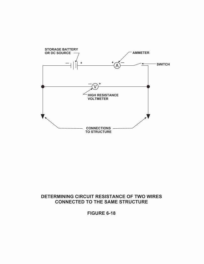
�������������������������������������������������������������������������
���������,
�����������������������
������
���������������������������
(2
�������
(2
�����������������������
( 2
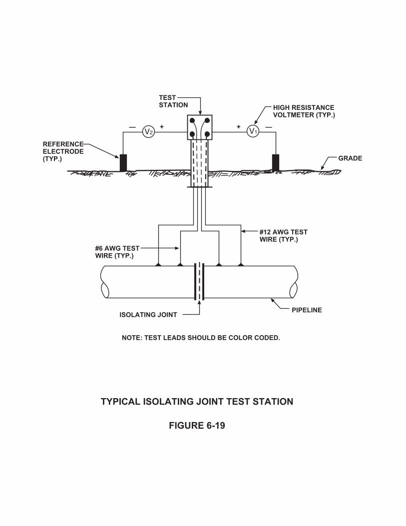
������������������������ ���!�
���������������� ���!�
����������������1�����������������
���������-
����+������������������������������!
�����
�����������
���������1�����������
/���������������� ���!�
( 2(2
/��������������� ���!�

TESTS PERFORMED:
Pipe‐to‐soil potential (P/S) on each side of the isolator
Internal Resistance (RINT) of the isolator (for checking isolation resistance) by:
Measurement of Resistance Across Isolating Joint or
Pipe‐to‐Soil Measurement Method (Figure 6‐20)
In an isolating joint, the effective internal resistance measured will be the sum of theresistance to earth (RE) of each pipe section. These resistances are in series witheach other and in parallel with the actual resistance of the isolating joint. Theresistance to earth of each pipe section is shown in Figure 6‐20 for illustrativepurposes.
Procedure:
a. Connect ammeter, battery and voltmeter No. 1 as shown in Figure 6‐20.
b. Close switch (make contact).
c. Read current and pipe‐to‐soil potential (P/S) values simultaneously. Record thedata.
d. Open switch (break contact).
e. Read current (should be "0") and pipe‐to‐soil potential (P/S) simultaneously.Record the data.
f. Repeat the last four steps several times to ensure there are no errors.
g. Remove voltmeter No. 1. Connect voltmeter No. 2 as shown.
h. Repeat the above procedure.
Chapter 6 ‐ Corrosion Control for Pipelines6‐42

(� ��
(� ��
(� ��
(� ��
� �
�3� �3�
� (� ��
�������������� �������
������
������������������������
��
��
�����
����
������������������� �3������������������������������
�
��������1����
������������������� �3������������������������������
�����������������
�����������������������������������������1����
���������.

R(P / S P / S ) (P / S P / S )
I I
RP / S P / S
I
INT1 ON 1 OFF 2 ON 2 OFF
ON OFF
INT1
RV V
I I
V
IINT
3 ON 3 OFF
ON OFF
3
3
Calculation:
It is very important to make a sketch of the polarities used for the test, because thesemust be taken into account when algebraically adding ΔP/S1 and ΔP/S2. With the testarrangement polarities as shown, ΔP/S1 will be of the opposite polarity to ΔP/S2.
In effect, with the polarities shown, pipe No. 2 is being made an anode with respect topipe No. 1 when the switch is closed (contact made). Hence, cathodic protection isbeing applied to pipe No. 1. The needle on voltmeter No. 1 will move to the right, whilethe needle of voltmeter No. 2 will move to the left.
Potential Across Joint Method
Where it is fairly certain that the isolator is effective, the following procedure may beused to determine resistance.
a. Connect ammeter, battery and voltmeter No. 3 as shown in Figure 6‐20.
b. Close switch (make contact).
c. Read current and voltage values simultaneously.
d. Open switch (break contact).
e. Read current (should be “0") and voltage simultaneously.
f. Repeat the last four steps to ensure there are no errors.
Calculation:
Chapter 6 ‐ Corrosion Control for Pipelines6‐43

Note: In the absence of heavy stray current, a reading other than 0 of V3 OFF, or avoltmeter reading alone (without battery or ammeter) is usually indicative of aneffective isolator.
4. Pipeline Casing Test Station (Figure 6‐21)
Casings are used on pipelines where they cross under railroads, highways or otherlocations where heavy loads are expected. Some authorities require casings in frontof schools (to carry product a distance away in the event of carrier pipe rupture).
Test stations are normally installed at casings in various configurations. If the casingis 50 feet long or longer, a test station similar to the one shown in Figure 6‐21 is alsoinstalled at the other end of the casing.
Some casings are installed with vent pipes. Sometimes there are vent pipes at oneend only, and sometimes there are vent pipes at both ends. The vent pipe can serveas one of the two wires connected to the casing.
TESTS PERFORMED:
P/S ‐ Pipe‐to‐Soil Potential, as previously described.
C/S ‐ Casing‐to‐Soil Potential, as previously described for pipelines.
RP‐C ‐ Pipe‐to‐Casing Resistance ‐ The test arrangement and procedures are exactly thesame as described for measuring the internal resistance (RINT) of an isolating joint.
5. Foreign Pipeline Crossing Test Station (Figure 6‐22)
For purposes of this discussion, a "foreign" pipe is any pipe which is not electricallyconnected to the pipe under test or under cathodic protection.
Test stations are necessary at all crossings of foreign pipelines. If cathodic protectionis applied to either one of the pipes, there is always a possibility of stray currentinterference and corrosion on the other pipe.
TESTS PERFORMED
P/S ‐ Pipe‐to‐Soil Potential ‐ Pipe under test
Chapter 6 ‐ Corrosion Control for Pipelines6‐44
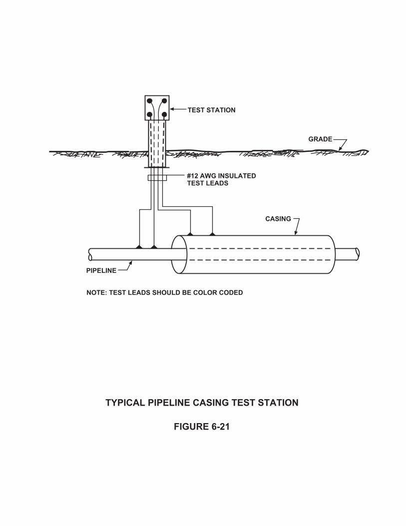
����������������������������������
����������
�����
������������
/������������������������
����+������������������������������
�������
������

�������������������������������������������
����������
�����
�����������
/��������������� ���!�
����+������������������������������
/��������������� ���!�
/������������
�����������������
��������������

P/S ‐ Pipe‐to‐Soil Potential ‐ Foreign pipe
RINT ‐ Internal resistance between pipes
EOC ‐ Open circuit potential between pipes
Combinations of these tests and the calculations of the test results are used fordetermining if stray current interference exists, and if the interference exists, thecalculation of the resistance of the bond required to clear the interference (RBOND) canbe made (See Chapter No. 5).
Pipe‐to‐soil potential measurements at foreign crossings should be made with thereference electrode placed directly over the crossing.
For Open Circuit potential tests, the voltmeter is connected between one wire of thepipe under test and one wire of the foreign pipe, and the reading is taken.
6. Galvanic Anode Test Station (Figure 6‐23)
Galvanic cathodic protection anodes are sometimes connected to pipes through teststations so that their performance may be monitored. Groups of galvanic anodes arealso sometimes connected to a single header cable, which is usually brought up to atest station for testing purposes.
TESTS PERFORMED:
P/S ‐ Pipe‐to‐soil potential, with anodes connected or disconnected. Pipe‐to‐soilpotentials are always measured through a wire, which is not carrying current.
IANODE ‐ Anode current. This is measured by breaking the anode to pipe connection andinserting an ammeter between the pipe wire and the anode wire. Current flowthrough the ammeter should be from pipe to anode. See Figure 6‐24 ‐ Method A.
Depending on the resistance involved, the ammeter resistance can significantly alterthe circuit resistance, resulting in a current reading that is lower than the actualcurrent.
Small current measuring shunts can be permanently installed in test stations so thatthe anode current can be measured by the IR drop method without disturbing the
Chapter 6 ‐ Corrosion Control for Pipelines6‐45

�����
���������������������������������
���������
/��������������� ���!�
����+������������������������������
/�.������������������
�����������������
������������
/�.���������
�������������
�������������

(� ���������
��������������
�����
�������������
���������������������������������
���������#
(� �������������
�
��������
�����
�������������
��������
��

anode circuit. (See Figure 6‐24 ‐ Method B). The resistance of the chosen shunt shouldbe dependent upon the current anticipated at the test station. Anode currents usuallyvary between a few milliamperes up to several hundred milliamperes, dependingupon the number of anodes and the soil resistivity. The shunt must be selected toprovide a good indication on the millivoltmeter.
Installation of Test Points
Test points/stations should be located so that they are readily accessible for testing. Teststations can be either aboveground mounted or flush mounted.
Flush mounted test stations are normally used in areas where an aboveground mountedtest station may not be feasible due to vehicular traffic in the area or due to right‐of‐waylimitations. Flush mounted test stations are less vulnerable to vandalism and therefore,their use in problem areas may be desirable. Figure 6‐25 illustrates a typical flushmounted test station installation.
Aboveground post mounted test stations, as shown in Figure 6‐26, are normally used oncross country pipeline installations to facilitate the locating of test points for testing.
Regardless of the type of test station installed, the following basic installation practicesshould be followed:
1. Test stations should be located as close as possible to the pipeline(s) being tested,preferably directly above it. This will reduce the chances of test leads being damagedby construction in the area of the pipeline. Installation costs would also be reducedand any required troubleshooting simplified.
2. Test lead connections to pipe should be made using an exothermic weld process. Theweld connection should be thoroughly inspected and tapped lightly with a nonferrousmetal hammer to make sure it is secure.
3. The weld and surrounding exposed pipe and wire should be coated with a coatingsystem that is compatible with the existing coating.
4. Sufficient slack should be left in the test wires just below the test points, to preventany damage or breaks due to soil settlement after backfill.
5. Any damage to test wire insulation during installation must be repaired. Repairs
Chapter 6 ‐ Corrosion Control for Pipelines6‐46

�������������������������������
���������$
�����
�����������������)
�������������
���������

�������������������������������
����������
�����
�������������������������
���������
����������� ���!�
4#&�����&��������
�������������������������

should be made using two half‐lapped layers of rubber electrical tape followed by twohalf‐lapped layers of plastic electrical tape.
6. Approximately 9 inches of coiled test wire should be provided inside the test box sothat the wires can be raised out of the box for testing.
7. Backfill for test wires should be free of stones larger than ¼ inch and other foreignmaterial which may damage the wire insulation.
8. Accurate test station location drawings and electrical termination details should beprepared showing each test point. The importance of color coding and recordingwires and their positions on the pipe cannot be overemphasized. Inaccurate data maybe worst than none at all. Drawings should be kept for permanent record, to bereferred to for future testing.
CONCLUSIONS
Counter corrosion methods should be considered when designing a new pipelineinstallation. Corrosion control measures should include, but not be limited to, the useof protective coatings. A knowledgeable coatings engineer should make the selectionof the protective coating system to be used. Cathodic protection systems must be usedin conjunction with a good protective coating to ensure that the pipeline meets itsdesigned life expectancy.
Cased crossings are used for mechanical protection of a pipeline and isolating joints areused to electrically separate sections of a pipeline. Both of these appurtenances canshort out and tests should be conducted to ascertain isolation. Test points are installedalong a pipeline to allow conducting tests. Others may be required for cathodicprotection purposes.
Chapter 6 ‐ Corrosion Control for Pipelines6‐47

Chapter 7 ‐ Rectifiers
INTRODUCTION
This chapter will discuss the basic operation of cathodic protection rectifiers, preventivemaintenance procedures and important information that is necessary when specifyingand purchasing rectifiers.
CATHODIC PROTECTION SYSTEM POWER SUPPLIES
As discussed in Chapter 3 of this course, various types of equipment can be used toprovide DC power for impressed current cathodic protection systems. These sourcesinclude the following:
1. Rectifiers
Sometimes called transformer/rectifiers, these are the most commonly used DCsource for cathodic protection system applications. A rectifier converts AC power toDC power.
2. Solar Power Supplies
These units are used in areas where sunlight is available for a large percentage of thetime. Photovoltaic solar arrays convert sunlight to DC power.
3. Thermoelectric Generators
Thermoelectric Generators produce power by the direct conversion of heat intoelectricity. Power is produced by maintaining a temperature difference across athermopile, an assembly of semi‐conductor thermoelectric elements. Combustion ofNatural Gas or Propane provides the heat while natural convection provides thecooling required to create this temperature differential.
4. Engine Generator Sets
These units consist of a fuel‐powered engine and an AC generator used to provide theinput power to a rectifier unit.
Chapter 7 ‐ Rectifiers7‐1

5. Turbine Generator Sets
Turbine generator sets utilize the product flow or gas pressure in the pipeline to drivea small turbine that in turn drives a DC power generator.
6. Wind Powered Generators
These units are used in areas where a fairly constant breeze/wind is blowing. Thewind drives a turbine assembly that in turn drives a generator assembly that providesthe input to a rectifier unit.
REVIEW OF ELECTRICAL FUNDAMENTALS
Following is a review of the fundamentals concerning the generation of AC power andits conversion to DC power. The review of these principals will help corrosion personnelunderstand the operation of a cathodic protection rectifier.
THEORY
A rectifier converts or rectifies alternating current (AC) electricity to direct current (DC).DC current is defined as a current that is always flowing in the same direction. ACcurrent on the other hand is current which periodically reverses its direction of flow. Inthe United States, our AC power is supplied at a frequency of 60 cycles per second,which means that the direction of the current flow reverses every 8.33 milliseconds.
The following discussion will review the principles of converting AC power to DC power.During this discussion, we will be assuming “conventional” current flow where currentis assumed to flow from positive to negative through the load.
A relationship exists between electricity and magnetism. This relationship provides themeans of converting electrical energy into mechanical energy and vice versa. We canalso convert electrical quantities to magnetic and back to electrical quantities again.
Current can be defined as the flow of electrons through a conductor, and when currentflows through a conductor, a magnetic field is formed around it. The direction of theinvisible magnetic lines of force can be determined by using the “right hand thumb rule”as shown in Figure 7‐1. The magnitude and direction of the magnetic field is directionallyproportional to the amount and direction of electric current flow.
Chapter 7 ‐ Rectifiers7‐2

������������ �� ��
�������������� ���������� ���� �
���������
��������������������������� ���� ������������������������������� ��������������� � ��������� ������������� �������������� � ������������������������� �� ���

An extension of the “right hand thumb rule” is shown in Figure 7‐2. When a currentflows through a coil of wire, an additive effect occurs between adjacent turns of wirethus creating a stronger magnetic field.
Just as current flow creates a magnetic field around a conductor, magnetic lines of forceacross a conductor creates a voltage or electromotive force (EMF) in it. If there is anelectrical path or circuit, electrical current will begin to flow. The direction of the EMFcan be determined using Fleming’s “3‐Finger Rule” as shown in Figure 7‐3.
These relationships are always the same and are used in the operation of generators,motors, transformers, meters, and many other pieces of electrical equipment. This isillustrated by Figure 7‐4. Figure 7‐4A shows that a current is induced or caused to flowwhen magnetic lines of force are cut by a conductor. This principal is used in theoperation of a current generator that converts mechanical energy to electrical energy.
Figure 7‐4B illustrates that when a current flows in a magnetic field, a force is exertedon the conductor. This is the opposite effect of that shown in Figure 7‐4A. Electricalenergy is converted to mechanical energy. This is the principal behind the operation ofan electric motor.
If the magnetic field influencing the conductor were changed in direction alternately,the induced current in the conductor would be alternating. This principal is used in theoperation of electric transformers and is illustrated in Figure 7‐4C. Figures 7‐3 and 7‐4show how electrical current can be generated by moving a conductor within a magneticfield, cutting lines of flux. This principal can be extended to generate alternating current.
AC power is generated as follows (refer to Figure 7‐5). Starting clockwise from theposition shown, “A” first moves up through the magnetic field as “B” moves down untilthey have exchanged positions. Continued rotation brings “A” down as “B” moves up,reversing the polarity of the generated voltage. Each revolution of this simple generatorrepresents one cycle of alternating current. Alternating current is plotted with respectto time in the form of a sinusoidal (sine) wave form, as shown in the figure.
The frequency of the AC current refers to the number of complete cycles per second(hertz). Half a cycle is the period of time during which the AC flows in one directionbefore reversing.
Figure 7‐6 shows a pure sine wave before and after rectification. If rectification isperfect, meaning there is no forward voltage drop across the diodes used for
Chapter 7 ‐ Rectifiers7‐3

�������������� ���������� ���� �
���������
�������������������
�������� ���������������������������������� �������������� � ��������� ��������������������� ��������������� � �������������������������� ���� ���
�� �!

�������"�#����������
��������#
� �� �
�����
� �
���

��������� ��������������� �
��������$
������
�����
�����
������������ ��������
�������
�������������� �
�
�
�
�� ��
�����
������%
�������������� �
�
�
�
�������

�������� � ��� ���
��������&
������������
�
�
� �
�������� ����%��
�'(
�
�(
)( ��(
���� ���� �
��( #'( �'( )(
*+

������������
���������� �
��������,
������������
���-��(��.�
�����-�,#,�.�

rectification, certain relationships will exist between the peak value of the voltagewaveform and the root mean square value (RMS ‐ see next paragraph) and the DCaverage as shown in the figure. The average value of the unrectified sine wave is zero,and that is what a DC voltmeter would read at the output of a sine wave source. Therectified wave does have an average value that can be measured with a DC voltmeter.This average value can also be calculated by multiplying the peak value of the full waverectified sine wave by 0.636.
A full wave rectified sine wave has been found to produce more heat (dissipate power)in a specific resistor than a pure DC voltage (as produced by a battery) of the sameaverage value as the rectified sine wave. For this reason another way of expressing thetrue value of the waveform is expressed as the RMS value. RMS stands for “root meansquare”, which is a mathematical description of the process used. The value of thewaveform is first squared. Squaring the value of the waveform determines its mean oraverage value. If this value were used, it would be a voltage squared term. Since anequivalent voltage is what is desired, the square root must be taken, thus the meaningof RMS.
When using the root mean square process for a sine wave or a full wave rectified sinewave, the RMS value is found to be 0.707 times the peak value of the waveform. For asingle phase full wave rectifier, the RMS voltage value is greater than the DC average bya factor of 1.11.
All of the factors discussed above with respect to voltage are also valid for currentcalculations. The RMS value of the current from a single phase full wave rectifier is 1.11times the DC average value. Therefore, the total output power from a single phase fullwave rectifier can be calculated as follows:
Total Power Output =
1.11 EDC x 1.11 IDC = 1.23 EDC x IDC
Note: There is really 23% more power being delivered from a single‐phase full waverectifier than the DC values of the voltage and current would indicate.
Since it is the average DC power which contributes to the electrolytic polarizationnecessary for cathodic protection, we state conversion efficiency rather thanrectification efficiency. The maximum theoretical conversion efficiency of a single phasefull wave rectifier is calculated as:
Chapter 7 ‐ Rectifiers7‐4

DC Power Output 100
Total Power Output
E I 100
1.11E 1.11I81%
DC DC
DC DC
This percentage can be increased by the use of efficiency filters in the DC output circuit.Filters reduce the amount of ripple voltage in the output and are able to reduce theinput power of the rectifier while essentially maintaining the same DC power output.
Note: The above formulas apply only to single phase full wave rectifiers and cannot beused for single phase half wave or three phase circuits.
Rectifying Circuits
The following sections discuss the four most commonly used rectifying circuits. Thesecircuits include the single‐phase bridge, single phase center‐tap, three phase bridge, andthe three phase wye.
1. Single Phase Bridge
The rectifying stack in single phase bridge consists of four legs. A leg is a circuitelement, which conducts or allows the flow of current in only one direction. As AC isapplied to the stack, two of these legs are used on each half cycle. Figure 7‐7illustrates the wiring diagram and the operation of the single phase bridge rectifyingcircuit. The DC produced by a single‐phase bridge is not pure DC, as is a batteryoutput. It is a full wave pulsating current. The single‐phase bridge is by far the mostcommon single phase rectifying circuit available today.
2. Single Phase Center‐Tap
The single phase center‐tap rectifying circuit, as shown in Figure 7‐8, also producesfull wave rectification. This center‐tap configuration however, requires only two legsinstead of four. Only one leg conducts during each half cycle.
The single phase center‐tap transformer is larger in size than the single phase bridgetransformer and tapping is more difficult. It is however, an efficient circuit and offersmany design opportunities in rectifiers which are electronically controlled and wheretapping is not required.
Single phase center‐tap rectifying circuits are an older technology that is notcommonly used in industry today.
Chapter 7 ‐ Rectifiers7‐5

����� ����
����������������������
���������
� ��
��
� �
!
��%��
���� ����
� �
�
���������������������������
��
��
��
��
��
��

� �����
�������������������������
��������'
��
�
!
��%��
�
�
� �����
��
��
��
������

3. Three Phase Bridge
The most commonly used circuit in cathodic protection rectifiers when three phasepower is available, is the three phase rectifying bridge circuit. This circuit consists ofsix legs, but as with the single phase bridge, only two legs conduct current at anyspecific time. Figure 7‐9 shows a typical three phase bridge wiring diagram andassociated waveforms.
The three phase rectifying bridge circuit is very efficient and seldom requires filtering.
4. Three Phase Wye
The rectifying stack in a three phase wye circuit consists of three legs, as illustratedin Figure 7‐10. The DC output of this circuit is not as smooth as that of the three phasebridge, but it is much better than that of the single phase circuits.
The transformer for this type of rectifying circuit requires more iron than otherrectifying circuits in order to prevent saturation of the core. This is due to thepulsating DC current present in each winding.
Components of a Rectifier
A standard cathodic protection rectifier is considered as being a simple electrical device.The heart of the rectifier consists of the transformer and the rectifying stack(s). Thesetwo components alone could provide the DC power required for a cathodic protectionsystem. Other components, or accessories, are added to the unit to enhance itsperformance and provide safety functions.
1. Circuit Breakers
The primary function of a circuit breaker is to provide overload protection for thecircuit in which it is installed. It also serves as an on‐off switch for the unit.
There are three types of circuit breakers that are commonly used in rectifiers. Theyare as follows:
A. Thermal Breakers
These breakers are constructed with a bimetallic element through which the circuit
Chapter 7 ‐ Rectifiers7‐6

�������������������������� �����
��������)
��%��
�
�
��
��
��� ���
��
�
� �
� ��
�
#
� � �
��
��
��
�
�#
��
� �
���
����������� ����%���������% ��
�� #
��
��� ���
��
��

�����������%������
���������(
��%��
�
�
��
�
�
�
�
�
�
��
��
��
��
��
��
�
�
�� �� �
��

current flows, with the breaker in the “On” position. Should the current rating ofthe breaker be exceeded, the heat generated by the excessive current flow willcause the two metals to expand. As a result of their differing temperaturecoefficients, one metal expands at a different rate than the other. This causes thebonded metallic strips to bend to one side, thus releasing a movable contact andopening the circuit. See Figure 7‐11 for an illustration of a typical thermal breaker.
A disadvantage of this type of breaker is that it is very sensitive to ambienttemperatures, tending to respond (open) quickly on warm days and slowly on colddays. Often this type of breaker cannot be reset immediately after tripping becauseit must be allowed to cool down.
B. Thermal‐Magnetic Breakers
The operation of the thermal‐magnetic breaker is nearly identical to that of thethermal breaker. Figure 7‐12 shows a typical thermal magnetic breaker. Note themagnetic plate attached to the bimetal element. The purpose of this magneticplate is to speed up the opening of the contacts in the event of a short circuit orextremely large current surge. A large surge of current will set up a magnetic fieldaround the plate, which causes it to be attracted to another plate located near it,immediately opening the contact. During normal loads or light overloads, themagnetic plate performs no function whatsoever.
This type of breaker has a slower reaction time than the fully magnetic circuitbreaker. For this reason they are recommended for use on rectifiers that will beinterrupted during system testing, as these breakers will not trip during testing.
C. Fully Magnetic Breaker
This type of breaker is considered the most suitable for cathodic protectionrectifiers because it only responds to overload currents. The current rating of thistype of breaker is determined by the number of turns and wire size of the magneticcoil which is wound around a sealed tube in the circuit breaker, as shown in Figure7‐13. This tube contains an iron core retained by a compression spring immersedin silicone fluid.
As long as the breaker operates within its rating, the iron core will remainstationary. Should an overload occur however, the core will be drawn towards thepoleface on the end of the tube by the magnetic action of the coil. The closer the
Chapter 7 ‐ Rectifiers7‐7

����%����������������.��
����������
����� ��
��������
� ��
����� �������
������
��������������
�������/�����

�����������������������.��
����������
����
� ��
���������������
������� ����� ��
����

����%����������������.��
���������#
���� ��
����
����� �������
���������
������
�������/�����
� �����
� ��
������
� ����� ��
����
����� ��

core comes to the poleface, the stronger the magnetic pull becomes on the armthat holds the contacts closed. The lever will trip and the contact will open whenthe magnetic pull becomes great enough.
Under short circuit conditions, the magnetic action of the coil itself will trip thebreaker instantaneously. The operation of this breaker is entirely independent oftemperature, making it very suitable for various rectifier applications.
Circuit breakers are normally placed in every “hot” input line of a rectifier unit. In a 115volt single phase circuit, one breaker would be placed in the “hot” line and none wouldbe required in the ground or neutral lead. For higher single phase input voltages, suchas 230, 460, etc., both input lines should be protected with a breaker. Three phase unitsshould have breakers installed on all three input lines.
It is recommended that circuit breakers always be ganged (mechanically tied together)so that when one breaker “trips”, the breakers on all other input lines will be “tripped”or opened. This will help prevent personal injury and/or circuit damage.
2. Transformers
A transformer consists of a laminated iron core with one or more coils of wire woundaround it as shown in Figure 7‐14A. A transformer is used to step up a voltage, stepdown a voltage, or to isolate a voltage from its source.
The primary winding of the transformer is connected to the voltage source. Thesecondary winding of the transformer receives voltage from the primary windingthrough magnetic coupling. An alternating magnetic field is set up in the core whenan AC voltage is applied to the primary winding of the transformer. The magnetic fieldinduces a voltage into the secondary winding at the same volts per turn ratio as thatof the primary. Therefore, the ratio of secondary volts to secondary turns is the sameas the ratio of primary volts to primary turns. This is only true under no‐loadconditions. Under load conditions a reduced voltage is seen on the secondary. Thisreduced voltage is due primarily to losses in the core and in the lamination.
Placing taps at intervals along the secondary winding will produce or supply voltagescorresponding to the number of turns at which they are connected. By locating thetaps in “coarse” and “fine” arrangements, it is possible to produce a considerablenumber of evenly spaced voltage adjustments with relatively few taps.
Chapter 7 ‐ Rectifiers7‐8

�%���������� �����������
���������$�
� ��
�������� �0� ���
������% ��
������������
�� � ��
�� ����% ��

Primary Voltage
Secondary Voltage
Number of Turns on Primary
Number of Turns on Secondary
Secondary Voltage =
Primary Voltage Number of Turns on Secondary
Number of Turns on Primary
30 120
10360 volts
The voltage output of the transformer can be determined by using the following ratio:
Example:
An ideal transformer (no losses) has 10 turns on the primary and 30 turns on thesecondary or output. A 120 volt, 60 cycles per second (hertz) power supply, is connectedto the primary. The output voltage can be calculated as follows:
The transformer in this example would be referred to as a step‐up transformer with a1:3 turns ratio.
A desirable feature sometimes added to rectifier transformers is a grounded shield. Thegrounded shield is installed between the primary and secondary windings, as shown inFigure 7‐14B, to intercept high voltage pulses (switching surges or lightning initiatedpulses). These pulses could otherwise damage rectifying elements, particularly silicondiodes.
3. Rectifying Elements
The function of a rectifying element or cell is to allow current to flow in a circuit in onlyone direction. This can be accomplished with the use of various materials, but the mostcommonly used materials in cathodic protection rectifiers are selenium and silicon.
Selenium Cell
The selenium cell is generally made up of an aluminum plate varying in size from 1 to 8inches square, with a deposit of selenium crystals covered with a metal film to provide
Chapter 7 ‐ Rectifiers7‐9

��
������ ���������� �����������
���������$�
������������
���
������ ������ ����%
�� ���
������ ����������%

a contact area. Special processing creates a barrier layer on the selenium side of theplate, which prevents current from passing from the selenium to the aluminum. Figure7‐15 shows a typical selenium cell. Advantages of the use of selenium stacks over siliconstacks are as follows:
a. Selenium stacks will withstand surges due to possible lightning strikes much betterthan silicon stacks.
b. Selenium stacks are more economical in lower voltage output circuits where currentrequirements are small.
c. Selenium stacks can withstand severe short term circuit overloads.
Some of the disadvantages associated with the use of selenium stacks are:
a. High voltage and current output units are very expensive due to the number of cellswhich must be arranged in series and parallel to achieve these ratings.
b. Selenium stacks cannot be practically replaced.
c. Maintaining an adequate stock of replacement stacks can be expensive.
Silicon Diodes
Figure 7‐16 illustrates a typical silicon diode rectifying element. Unlike the seleniumplate, the silicon diode has a single crystalline rectifying junction. The rectifying area ofthe diode is many times smaller than that of the selenium plate. As shown the figure,the diode is manufactured in a physical configuration that allows it to be installed in atapped metal plate. The mounting of the diode on the plate will serve as heat sink whichdraws heat away from the junction area thus increasing its power handling capacity.
The following list indicates some of the advantages of silicon diodes over seleniumstacks:
a. The use of silicon diodes in units providing high current and voltage outputs is moreefficient and therefore, more economical.
b. Replacement cells are more easily installed and stored.
Chapter 7 ‐ Rectifiers7‐10
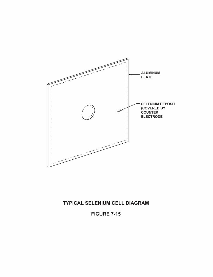
�%����������������������
���������&
����������� ���� ������% ���������� ��
�������������

�%�������� ��� ���������
���������,
�����%���/���� �������
� �����%
�������� ���� �

c. Silicon diodes have a longer operating life than selenium stacks.
Some of the disadvantages of silicon diodes are:
a. Additional protection must be added to these units to protect them from lightningstrikes or other overvoltages.
b. The use of silicon diodes may be more expensive initially.
4. Accessory Equipment
Optional equipment such as meters, lightning arresters, filters, and shunts can besupplied with the rectifier unit.Voltmeters and ammeters are normally installed on the rectifier to facilitate themonitoring of its voltage and current output. Sometimes, only one meter is suppliedwhich, through the use of a selector switch, will read both volts and amperes.
Lightning arresters are normally installed on both the AC input and the DC outputcircuits of the rectifier when, due to the location of the unit, the possibility of lightningsurges exists. Lightning surges can enter the cathodic protection rectifier from both theAC and DC sides. Installation of lightning arresters will prevent damage to the unit andits components due to these surges.
Efficiency filters can be added to single phase bridge and center‐tap circuits. The filtersimprove the conversion efficiency by reducing the ripple component in the rectifieroutput. Ripple in the output can be reduced as much as 20 to 25 percent.
Filters can be used to eliminate electronic noise/interference on electronic circuits andat the same time provide increased lightning protection to the DC circuits of the unit.The installation of these efficiency filters may increase the cost of the rectifier, but inmost cases they will pay for themselves within the first year of operation. Conversionefficiency is usually increased by 10 to 15 percent.
Rectifier units can be provided with shunts installed in series with the positive outputterminals of the unit. These shunts provide a means of measuring the output current ofthe rectifier, using a portable voltmeter, without interrupting the service of the unit. Thesize/rating of the shunt selected must be compatible with the output rating of therectifier.
Chapter 7 ‐ Rectifiers7‐11
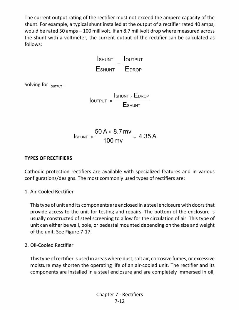
I
E
I
E
SHUNT
SHUNT
OUTPUT
DROP
II E
EOUTPUT =
SHUNT DROP
SHUNT
I50 A 8.7 mv
100 mv4.35 ASHUNT =
The current output rating of the rectifier must not exceed the ampere capacity of theshunt. For example, a typical shunt installed at the output of a rectifier rated 40 amps,would be rated 50 amps – 100 millivolt. If an 8.7 millivolt drop where measured acrossthe shunt with a voltmeter, the current output of the rectifier can be calculated asfollows:
Solving for IOUTPUT :
TYPES OF RECTIFIERS
Cathodic protection rectifiers are available with specialized features and in variousconfigurations/designs. The most commonly used types of rectifiers are:
1. Air‐Cooled Rectifier
This type of unit and its components are enclosed in a steel enclosure with doors thatprovide access to the unit for testing and repairs. The bottom of the enclosure isusually constructed of steel screening to allow for the circulation of air. This type ofunit can either be wall, pole, or pedestal mounted depending on the size and weightof the unit. See Figure 7‐17.
2. Oil‐Cooled Rectifier
This type of rectifier is used in areas where dust, salt air, corrosive fumes, or excessivemoisture may shorten the operating life of an air‐cooled unit. The rectifier and itscomponents are installed in a steel enclosure and are completely immersed in oil,
Chapter 7 ‐ Rectifiers7‐12

�%������� �����������
����������
���������
���������.���
���������� ��� ��
����������
�������� ��������������
�������������1� ���
� �
���� ����
�
� $� &
�
#
� ���
����
&(���&��������
�� ��� ������
����������������

thus isolating them from extreme environments.
Modified oil‐cooled rectifiers are available with explosion proof fittings. Theseexplosion proof rectifiers are for use in refineries, chemical plants, and other areaswhere explosive or flammable vapors, liquids or powders are present.
Oil‐cooled units are normally pedestal mounted due to their weight. See Figure 7‐18for a typical oil‐cooled rectifier detail.
3. Constant Current Rectifiers
These rectifiers have a special circuit that enables the rectifier to provide a nearlyconstant current output regardless of load resistance. This type of unit is used inapplications where the load resistance changes drastically and the output currentwould be exceeded with a normal rectifier. A typical constant current rectifier circuitis shown in Figure 7‐19.
4. Automatic Potential Controlled Rectifiers
This type rectifier monitors the structure‐to‐electrolyte potential and maintains it ata desired level. The use of this type of rectifier requires the use of a permanentlyinstalled reference electrode and an additional test wire connection to the structure.Both are connected to a transistorized control circuit as shown in Figure 7‐20. Thecontroller adjusts the output voltage to keep the reference cell potential at a presetdesired level. Automatic potential controlled rectifiers are very useful in the controlof corrosion on structures such as water storage tanks, harbor structures, and whereit is necessary or desirable to maintain a constant potential on the structure.
RECTIFIER SAFETY
Cathodic protection rectifiers can pose electrical shock and arc flash hazards. Onlyqualified personnel should access cathodic protection rectifiers. Qualified personnelaccessing cathodic protection rectifiers must follow appropriate safety procedures.
Most companies have developed safety procedures for personnel accessing cathodicprotection rectifiers.
Chapter 7 ‐ Rectifiers7‐13

�%���� �� �����������
���������'
������
� .��������
���� ��� ������
� ������%
� �����
�����������
�������������
������������������������ ��� �������������

�������� �����
��� �����
��� ��������
�%���� �������������������������
���������)
�����
��������.
����
����
��� ���� ����
������
��
��� ����.
�!

� ��� ��� ���������
������������� ��
�%������� ����� ������� ��� �����������������
���������(
�����
��� ����
������
��
�!
�
�� �������������
�� �����

PREVENTIVE MAINTENANCE
In order to maintain proper operation, rectifiers must be inspected on a regular basis.Rectifiers that are subject to PHMSA regulations must be inspected at least six timeseach year with no more than 2½ months between inspections to insure the units areoperating properly.
Inspecting a rectifier at least every 2 months is a good practice even if it is not subjectto any regulations.
Units that are located in areas that are prone to lightning strikes or power surges mayneed to be inspected more frequently. This is necessary so that loss of protection (asfrom a blown fuse or component failure) will not go undetected for long periods of time.
Rectifiers can also be fitted with remote monitoring units (RMUs). RMUs are devicesthat will measure the operating parameters of a rectifier and allow that information tobe accessed remotely. RMUs are available in radio, satellite and cellular communicationconfigurations. Some systems allow the measurement data to be accessed through aninternet web interface. Some systems will send notification of rectifier operatinganomalies by email or text messaging.
A routine inspection of a rectifier should include, at the least, measuring and recordingthe DC voltage and current output of the unit. These values can be determined byreading the built in voltmeter and ammeter but it is more reliable to use a portablemultimeter. The DC voltage output is determined by measuring the voltage across therectifier output terminals with a multimeter. The DC current is determined by measuringthe millivolt drop across the rectifier shunt with a multimeter and converting toamperes. Readings should be recorded in a permanent log and compared to previousreadings to observe unusual variations.
If, during maintenance rounds, a rectifier is found to be off, the inspector should checkto see if the trouble is due to a blown fuse or a tripped circuit breaker. These are thetwo most common causes of rectifier malfunctions. If this is the case, resetting thebreaker or replacing the fuse may be all that is required in order to restore the rectifierto service.
If the inspector can restore the rectifier to service he/she should do so. Regardless ofwhether or not he/she can do so, the responsible corrosion engineer should be notifiedas soon as possible so that he/she can investigate the trouble and take corrective action
Chapter 7 ‐ Rectifiers7‐14

as required.
At least once each year a rectifier should be thoroughly inspected. The following is atypical list of items that should be checked in order to ensure that the rectifier continuesto function properly.
1. Clean and tighten all bolted current‐carrying connections.
2. Clean all ventilating screens in air‐cooled units so that airflow will be completelyunobstructed.
3. Check all meters for accuracy by using a properly certified portable meter to “zero”meters that are built into the rectifier unit.
4. Replace all wires on which the insulation has been damaged.
5. If the unit is an oil immersed unit, the oil level and cleanliness of the oil should bechecked. The oil should be clear and nearly colorless. Failing oil is usuallycharacterized by a murky or cloudy appearance with loss of transparency and shouldbe replaced with good grade oil. Facilities are available for testing the oil andsalvaging it by filtration where practical.
6. Check all protective devices (fuses, circuit breakers, and lightning arresters) to be surethat they are undamaged and in satisfactory operating condition. Defective devicesshould be replaced immediately.
7. Turn the rectifier off and feel the components. Watch for excessively hot componentsor uneven heating of rectifier stacks. Temperatures of electrical connections are alsoimportant. No component should be too hot to touch.
8. Inspect all components, including lightning arresters, for signs of lightning damage –arc traces across insulators or panels; discolored parts. If their appearance has beenaltered or if damage is suspected, the component should be replaced.
9. Remove excessive dust accumulations and any type of insect nests. Plug any holesthrough which insects or rodents can enter the rectifier.
The objective of any good maintenance program should be the prevention of unitfailures before they occur, and prompt repair in the event that a failure does occur.
Chapter 7 ‐ Rectifiers7‐15

EfficiencyE I 100%
3600KN
T
=DC DC
Efficiency32 12 100%3600 14 1
89
67.8% =
RECTIFIER EFFICIENCY
As rectifiers get older they tend to become less efficient as the rectifier stacks age. Atsome point, due to the decrease in efficiency, it may become economical to replace therectifying stacks. Many manufacturers recommend stack replacement when anefficiency drop of 20% is experienced.
An abrupt decrease in rectifier efficiency may also indicate the unit is malfunctioning.In order to detect any changes, the efficiency may be calculated and recorded duringperiodic inspection/maintenance.
If the rectifier has an analog watt‐hour meter, its efficiency can be determined by usingthe following formula:
Where:
EDC = DC output voltage measured across the terminals
IDC= DC output current calculated by measuring the voltage across the total outputshunt, using a voltmeter, and calculating the current.
K = Kh of watt‐hour meter. Shown on face of watt‐hour meter.
N = Number of revolutions of watt‐hour meter disk. For this method N =1.
T= Time for disk to make one revolution
Example:
The measured DC output of a rectifier is 12 amperes @ 32 volts. A watt‐hour meter hasa constant (K) of 14, and it takes 89 seconds for the disk to make one completerevolution.
Chapter 7 ‐ Rectifiers7‐16

Note: When checking efficiency, care must be taken so that the original load will beduplicated at each efficiency check because efficiency varies with output voltage andcurrent. If loading is not the same, comparison with previously recorded efficiencies willbe meaningless.
RECTIFIER SELECTION
Selecting the correct rectifier is a very detailed and important task. It is important toprovide the manufacturer with a specification which is as detailed as possible. This willhelp assure that the unit supplied is exactly that which is required. The following listindicates the minimum information that should be included in a rectifier procurementspecification.
1. AC Input – Specify voltage, number of phases (single or three phase), and frequency.Example: 480 volts, 3 phase, and 60 hertz.
2. DC Output – Specify in volts and amperes. Remember to include spare capacity.
3. Rectifier Type – Air‐cooled, oil cooled, oil cooled and explosion proof, constantcurrent, or automatic potential controlled.
4. Rectifying Elements and Configuration – Specify element: silicon or selenium. Specifyconfiguration: full wave bridge or full wave center tap.
5. Mounting – Indicate desired mounting hardware to be included for either pole, wall,or pedestal mounting.
6. Operating Temperatures – Minimum and maximum ambient operating temperatures.
7. Instruments – Voltmeter and ammeter. Specify scales and accuracy.
8. Voltage and Current Control – Specify number of transformer taps required formanual adjustments.
9. Protective Devices – Specify ratings and types of circuit breakers, fuses, lightningarresters, and filters as required. Shielded transformer winding if required.
10. Output Terminals – Specify number of positive and negative terminals/circuitsrequired.
Chapter 7 ‐ Rectifiers7‐17

11. Shunts – Specify the number of shunts required and their ratings.
When possible, units should be ordered from the manufacturer’s standard line. Custommade units will be more costly and delivery time may be lengthy.
CONCLUSIONS
A cathodic protection rectifier converts AC power into DC power, which is required forcathodic protection of a metallic structure.
Typical rectifiers utilize either full wave bridge or full wave center tap rectifying circuitswith selenium or silicon rectifying elements.
There are various types of rectifiers such as air cooled, oil cooled, constant current, andautomatic potential controlled. Each type is designed for use in a specificenvironment/application. Rectifiers can be purchased with optional features that willfacilitate testing during periodic maintenance, protect the unit from power surges(lightning), and increase its efficiency.
To make sure that the manufacturer supplies the exact type of rectifier desired, adetailed procurement specification should be written and forwarded to the supplier. Theeffective operation of the impressed current cathodic protection system depends on theproper operation of the rectifier. Therefore, a good maintenance program should bedeveloped to help keep the rectifier operating. Malfunctioning rectifiers should berepaired as soon as possible, as long outages may be detrimental to the protectedstructure. Rectifier troubleshooting techniques will be discussed in Chapter 8 of thiscourse.
Chapter 7 ‐ Rectifiers7‐18

Chapter 8 ‐ Cathodic Protection System Maintenance and Troubleshooting Procedures
INTRODUCTION
Corrosion control measures as discussed in the previous chapters, will be highly effectiveproviding they are properly designed and installed as well as adequately maintained.Without a suitable maintenance program, the funds spent in the design and installationof any corrosion control system could be wasted. There have been many instances, forexample, of system Owners spending the money to have a cathodic protection systemdesigned and installed on a section of their system without establishing any proceduresfor looking after it. Although the Owner may feel that his/her corrosion related problemsare over, this false sense of security will be short‐lived if corrosion failures continue tooccur. Although the tendency is to blame the design, the fault in most cases is simply thefailure of keeping the system(s) operating continuously and effectively. The purpose ofthis Chapter is to present suggestions for maintenance programs that will help keepcorrosion control systems operating at maximum effectiveness.
MAINTENANCE PROGRAM
A corrosion control system maintenance program should include but not be limited tothe following items, as applicable:
Periodic Surveys
Periodic Surveys are performed to determine the status of cathodic protection andrelated items. Periodic surveys will be discussed in detail in one of the following sections.
Coating Maintenance
Steps should be taken to maintain coating systems on aboveground structures as wellas on buried or submerged structures.
Coating maintenance on buried or submerged structures is more difficult to perform,but steps can be effectively taken. During normal operations of buried structures suchas pipelines, there are frequent occasions when it is necessary to uncover or makeaccessible various appurtenances for other maintenance work. This work may involvedamage to or removal of the coating.
Chapter 8 ‐ Cathodic Protection System Maintenance and Troubleshooting Procedures
8‐1

Any apparent damage to the coating, be it on a buried, submerged, or an abovegroundstructure, should be repaired or the coating replaced. Coating repair or replacementshould be of a quality at least as good as the original coating system. In addition, it isimportant that any repair coating be compatible with the original coating. Maintenancecrews should be trained in good coating application procedures including allowing timefor certain materials to cure before backfilling, care of materials, and compliance withthe manufacturer's specifications. As previously discussed, when certain hot appliedenamels are used, particular care is essential when heating small quantities to be surethat the material is not overheated and rendered useless. If this happens, much of theeffectiveness of this type of coating may be lost.
Keeping a factual performance record of coating systems will help the corrosionengineer to prepare and present recommendations for materials to be used for newconstruction. The general condition of the coating system in terms of its effectiveresistance‐to‐earth can be obtained from the periodic corrosion surveys. Other specificinformation may be obtained by training all system maintenance crews to report oncoating conditions whenever possible, such as when coated pipelines are excavated.Information to be included in such a report is the date and specific location of the work,coating type and description, and other identifying information as available orapplicable. The report should also include data on environmental conditions surroundingthe pipe/structure that could have an adverse effect on the coating system, evidence ofsoil stress effects, bond quality, evidence of cold flow, and evidence of moisture underthe coating. If there is evidence of corrosion damage at coating faults (holidays), i.e.,pitting, the report should include data on the number of pits, depth range and range ofpit diameters.
This information will enable the corrosion engineer to assess the condition/quality of theexisting coating system and determine what corrective measures are required, if any.
Rectifier and Anode Bed Maintenance
Rectifier maintenance should be conducted as discussed in the previous chapter.Impressed current anode bed maintenance is normally limited to the visual inspectionof the anode bed site during maintenance rounds.
Any abnormal activity or occurrences should be reported to the responsible corrosionengineer as soon as possible so that he or she can determine the effect, if any, on theanode bed and take corrective action as required. For example, if any part of an anodebed is subject to washout by storm water that will result in exposure of the DC output
Chapter 8 ‐ Cathodic Protection System Maintenance and Troubleshooting Procedures
8‐2

cable(s), arrangements should be made to have this area inspected regularly and to havethe cable(s) recovered when necessary. This should be done only after making sure thatthere has been no damage to the cable insulation. Any damage found should berepaired. Keep in mind that if the anode cable conductor is exposed to the electrolyte,this then will discharge current and eventually result in a cable break. Corrective actionshould also be taken to prevent re‐exposure of the cable(s) if at all possible.
If construction activity is to be performed in the vicinity of an anode bed, the corrosionengineer should have the location of the anode bed staked out so that inadvertentdamage may be avoided.
If the construction activity involves the installation of new underground or submergedmetallic structures, the corrosion engineer should be notified. New structures in thevicinity of the anode bed may be subject to possible stray current damage. Provisionsshould be made in the design of the new structures so that there are adequate facilitiesavailable to test for and to mitigate stray current interference.
Galvanic Anode Maintenance
Other than routine electrical tests conducted during periodic surveys, maintenance ofgalvanic anode installations, as in the impressed current anode beds previouslydiscussed, is limited to visual observations by maintenance personnel. When damageto anode lead cables, anode header cable(s), pipeline lead wires, etc. is found, it shouldbe reported to the corrosion engineer so that prompt repairs can be scheduled.
At test stations that contain galvanic anodes, a clean connection must be maintainedbetween the anodes and the structure. Because of the low driving potentials associatedwith galvanic anodes, any resistance in the connections can cause a marked decreasein anode current output. The connections should be checked on an annual basis andcleaned when required.
The use of a test station allows for the measurement of polarized potentials on thestructure as well as measurement of the current output from the galvanic anode system.Measurement of the anode system current output will aid in determining both theanode consumption rate and prediction of expected service life.
Test Station Maintenance
Test stations are the principal means by which the protection afforded to a structure can
Chapter 8 ‐ Cathodic Protection System Maintenance and Troubleshooting Procedures
8‐3

be evaluated. If they are to continue to fulfill this function, they must be maintained ingood order.
Test stations may, from time to time, require replacement of box covers or coverretention screens, cover gaskets or terminal nuts or screws within the receptacle.Occasionally, a receptacle may be broken or missing as a result of vandalism. Flushmounted or grade level test stations often become filled with silt or covered by pavingmaterial when located in roadways. Efforts should be made to keep these test pointsaccessible for testing. Corrosion personnel making routine surveys should carry spareparts and hardware so minor maintenance can be performed while still on site. In thisway, especially on systems utilizing a large number of test stations, this type ofmaintenance can be kept up to date. Screws should be kept greased for ease ofoperation (using graphite lubricant or petrolatum) and contacting surfaces in electricalcircuits should be kept clean to ensure the lowest practicable contact resistance.
If electrically discontinuous test leads are found during periodic surveys ortroubleshooting testing, these test leads should be replaced as soon as possible. Leavinginvalid test leads in place can lead to erroneous data that may indicate a lack of cathodicprotection, a possible open circuit, or other types of problems.
PERIODIC SURVEYS
Federal and State laws dictate what surveys must be made on facilities such as gaspiping, oil lines and tanks containing hazardous material. All cathodic protection systemsneed to be tested periodically, however, and the following data, as required andapplicable, should be taken at least on an annual basis. The most common testemployed to evaluate the effectiveness of an existing cathodic protection system is thestructure‐to‐electrolyte or pipe‐to‐soil potential measurement. In fact, the majority ofthe existing criteria for determining whether a structure is cathodically protected are allbased on the this particular measurement.
1. A pipe‐to‐soil potential survey should be conducted on the protected structure. Thepotential survey is conducted using a high resistance voltmeter and a portablereference electrode, typically a saturated copper/copper sulfate reference electrode(CSE). The reference electrode should be placed directly above the pipe in contactwith the soil. Where the soil is dry, the electrode should be dug in slightly. If the soilis extremely dry, moisten the soil with water to assure good reference electrodecontact with the earth. It is important to minimize any inaccuracy in the potentialmeasurement by insuring that the reference electrode is in good contact with the
Chapter 8 ‐ Cathodic Protection System Maintenance and Troubleshooting Procedures
8‐4

electrolyte. There should be no loose stone or debris between the tip of the referenceelectrode and the soil. The presence of petroleum products or chemical contaminantsmay also affect the measurement.
The recommended connection to the voltmeter has the reference electrodeconnected to the negative terminal of the meter and the structure to the positiveterminal. This will normally result in a negative value.
Figure 8‐1 depicts how a potential survey is sometimes conducted over a long lengthof pipeline. During this type of survey, potentials are taken along the length of thepipeline and then plotted as a function of structure‐to‐earth potential versusreference electrode location. The connection to the structure under test can be avalve, riser pipe, test station, etc., any place that is electrically continuous with thatportion of pipe being evaluated. It is important to insure that the structure underevaluation is electrically continuous for the length of pipe to be surveyed. Potentialsmeasured on the other side of an electrically discontinuous point such as an isolatingflange, are essentially potentials measured to remote earth and are not indicative ofthe actual pipe‐to‐soil potential.
During the potential survey, the pipeline’s resistance‐to‐earth can be calculated if itis possible to interrupt the current source(s). Figure 8‐2 shows the method forinterrupting a rectified system. The resistance‐to‐earth value provides historical dataon changes in system parameters such as failures at isolating joints. Using the changein the potential readings measured while interrupting the current, and the value ofthe current, the resistance‐to‐earth is calculated. The resistance‐to‐earth is equal tothe potential change (ΔV) divided by the output current (I). The unit is ohms.
The resistance‐to‐earth can be used to determine the amount of current required tochange the potential of an unprotected structure.
EXAMPLE
The current output of a rectifier is 3 amps. Measured pipe‐to‐soil potentials are ‐0.82 VOn and ‐0.65 V Off with the rectifier output interrupted. Determine the additionalamount of current required (ΔIrqd) to change the On potential of the structure to ‐0.85V (ΔVrqd = 0.03V).
Chapter 8 ‐ Cathodic Protection System Maintenance and Troubleshooting Procedures
8‐5

�������������������� ����
��� �����
����������������������
�������
�����
�����������
���� ���
���������
���������
���������
�����������������������

������ ���������������
��� �����
� �� �� ��
���� ������ ���
�����������������
������!����
���������� �� ���������
� ����������"����
�� ��
������ ����
�
�
� #� $
�
�
����
����
$%���$����� ��
�������������
��� �� ����������
����&�
�������� ���������!��'������������������� �������������������� ���������������������!������������������������
���������������� ����������� ������������������������������!������� �������� ������ �� ��
��� ����������� ����
������������������� ������ �� �!������!���� ���������� ������������� ���
��������������

RV
I
0.17 V
3 A
0.057 ohms
vg
IV
R
0.03 volts
0.057 ohms
0.53 amps
rqdrqd
vg
Step #1 ‐ Calculate the potential change (ΔV):
ΔV= V on ‐ V off = ‐0.82 ‐ (‐0.65) = 0.17 volt
Step #2 ‐ Calculate the resistance‐to‐earth (Rvg):
Step #3 ‐ Calculate the additional current required to change the On potential of thestructure to the 0.85 volt value:
2. On coated structures, data required for the calculation of effective coating resistanceshould be taken. Although not essential, this information is valuable for monitoringthe performance of a specific coating system.
This measure of coating effectiveness or quality is based on considering theresistance‐to‐earth of the line as if it were comprised of many parallel resistances,each section having a surface area of one square foot.
The quality of the coating (average resistance = Rc) can be calculated using thefollowing formula:
Rc = Rvg x Surface Area of the Structure
Normally, good construction practices will result in average coating resistance valuesof 300,000 ohm‐ft² and greater, upon completion of the installation. The acceptableresistance value for a given set of conditions is a function of various factors and mustbe determined by experience and the judgement of the corrosion engineer. One ofthe most influential factors is soil resistivity. For example, a line laid in 1000 ohm‐cm
Chapter 8 ‐ Cathodic Protection System Maintenance and Troubleshooting Procedures
8‐6

soil will have a lower average coating resistance than an identical line laid in 10,000ohm‐cm soil.
EXAMPLE
A 12‐inch pipeline has a resistance‐to‐earth (Rvg) of 8 ohms. The length of the pipelineis 32,000 feet. Determine the average coating resistance.
Step #1 ‐ Calculate total surface area (SA) of the pipeline.
SA = ( x diameter (ft) x length(ft) = (3.14) x (1) x 32,000 = 100,480 ft²
Step #2 ‐ Calculate average coating resistance (Rc).
Rc = Rvg x Surface Area = 8 x 100,480 = 803,840 ohm‐ft²
The sample calculated resistance indicates a coating of good quality.
3. At each rectifier installation, DC current and voltage should be measured. SeeFigures 8‐3 and 8‐4 for the methods to measure the rectifier voltage and current.The kilowatt hour meter reading should be taken and the rectifier efficiencycalculated, as described in an earlier chapter. The rectifier should be visuallyexamined for any signs of damage such as a burnt or blistered stack, loose wiringconnections, missing equipment locks, etc. If it is an air‐cooled unit, the bottomscreen should be free of any obstructions. If it is an oil‐cooled unit, check the oil leveland examine the oil for any evidence of foreign material such as water or debris.
4. At other DC power sources, the DC current and voltage as well as pertinentsupplementary information that may apply to the particular power source shouldbe taken.
5. Data to calculate the resistance of each impressed current anode bed should betaken.
6. The current output and resistance of each galvanic anode installation should bemeasured. The current output of the anode is measured by placing an ammeter inseries with the anode lead, as shown in Figure 8‐5, or by connecting a voltmeteracross current shunts installed in an anode distribution box as shown in Figure 8‐6.
Chapter 8 ‐ Cathodic Protection System Maintenance and Troubleshooting Procedures
8‐7

���� �������������������
��� �����
� �� �� ��
���� ������ ���
�����������������
������!����
���������� �� ���������
� ����������"����
�� ��
������ ����
�
�
� #� $
�
�
����
����
$%���$����� ��
�������������
��� �� ����������
����&�
����������

���� �������������� �����
��� ����#
� �� �� ��
���� ������ ���
�����������������
������!����
���������� �� ���������
�� ��
������ ����
�
�
� #� $
�
�
����
����
������ ��
�������������
��� �� ����������
����&�
���������
��������������
����&�
�������������
�!��������(
�������������������!������������������ �������������������������
����������������������!��������� ������������� ��!� � �������������������� ���

���� ����� ������ �� ���������������
��� ����$
������������
��������!���
�����
�����������
��� � ����������������!����������������������������
�
�������
�������
��������������������
7. Potentials of the protected pipeline and of foreign lines at any crossing points shouldalso be measured. Where inter‐system bonds exist, measure the bond current anddirection of current flow.
8. At pipeline cased crossings, the resistance between carrier pipe and casing shouldbe measured plus the potential to a close reference electrode of both the pipelineand casing.
9. In dynamic stray current areas, verify that bonds, electrolysis switches or othercorrective measures are operating properly and are providing the required degreeof protection. In those areas, recording voltmeters should be used for potential andcurrent measurements.
10. Verify that isolating joints are effective and that any protective lightning arresters,spark gaps or grounding cells are performing their function effectively.
11. In an impressed current anode system measure the current output of each anodeat the anode distribution box, if available. Again, see Figure 8‐6 for the proper meterconnections.
12. Verify continuity between structures where jumpers were installed as part of thecathodic protection system.
13. Make notes on maintenance records of any special physical features associated withthe corrosion control system. Maintain these notes with the associated circuits.
The corrosion engineer should establish as part of his/her maintenance program a listcontaining the items listed above that are applicable to each installation/system, and thefrequency at which each test should be performed.
In addition to the complete annual survey, a recheck of protective potentials may bemade at intermediate intervals. The need for intermediate surveys may be a matterbased on operating experience. In general, intermediate surveys are usually conductedin congested areas where stray current interference may be a problem, or whereparticularly critical or hazardous environmental conditions exist. At areas that areconsidered critical, more frequent checks should be made.
The above compiled data should be recorded in a permanent log so that previous surveydata can be compared and analyzed. As soon as a periodic survey is completed, data
Chapter 8 ‐ Cathodic Protection System Maintenance and Troubleshooting Procedures
8‐8

���������������� ���������� ������������������ ��������������
���������
� ��
���������
�� ����� ������������
�����������������
����������������������������
�����������
�������������

should be analyzed promptly. The data can be computerized. With the use of the propersoftware, the computer can compare the data with that of previous surveys and indicatethe problem areas. Corrective action should be taken immediately.
The importance of clear, accurate, and understandable data cannot be over‐emphasized.Record all pertinent information on approved forms. Field sketches that may accompanydata sheets must be as complete as possible with dimensions given to "permanent"objects. Data sheets should make sense and be clear enough to be analyzed well afterthe fieldwork has been completed.
Information to be included on the data sheets:
C Date and time taken (and by whom)
C Structure/circuit designation
C Where/at what point on the structure (sketches are often necessary with dimensions
to "permanent" objects)
C Instruments used with model and serial numbers
C Polarity of all measurements (+/‐)
C Meter scale used for each reading
C Shunt used
C Under what conditions was the data taken:
C Rectifier On/Off
C Bonds In/Out
C Current source
C Type of reference electrode and its placement
C Soil conditions: wet, dry, frozen
C Any other unusual conditions that are pertinent
REPAIRS AND/OR REPLACEMENTS
Based on data compiled during the periodic survey or as a result of routine maintenance,it may be deemed necessary to repair and/or replace various cathodic protection systemcomponents. Following is a brief discussion of repairs and/or replacements that may be
Chapter 8 ‐ Cathodic Protection System Maintenance and Troubleshooting Procedures
8‐9

required on a typical cathodic protection system.
Coatings
While recoating a buried structure such as a pipeline is expensive, it may be necessaryin some instances. This is apt to be true where coating deterioration has been severeover a length of a pipeline or part of a structure due to unusual environmentalconditions. If deterioration has been great enough to divert so much of the cathodicprotection current that satisfactory protection of other parts of the structure has beenlost, recoating the defective section could restore effective levels of cathodic protectionto the entire structure with no change in the cathodic protection system. The economicjustification for recoating versus simply adding local cathodic protection in the effectedarea would have to be studied by the corrosion engineer in each such instance. Thematerial used for recoating buried structures should be selected specifically for its abilityto stand up under the particular environmental conditions encountered. It is probablethat the original coating, assuming that it was properly applied, was not a suitableselection for conditions in that environment.
Coating damage/failure on aboveground structures detected by maintenance personneland reported to the corrosion engineer should be repaired or replaced promptly tomaintain the integrity of the structure. Coating repair or replacement shall be made asper coating manufacturer's guidelines/recommendations.
Rectifiers
As previously discussed, any wires or components found to be damaged duringmaintenance checks of a rectifier should be repaired or replaced. If the reason forrectifier malfunction is not apparent, the following typical rectifier troubleshootingprocedures should be followed.
a) Rectifier Troubleshooting Precautions
The following precautions should be observed when troubleshooting rectifiers:
1) Turn rectifier unit OFF when handling components within the unit. Open the ACdisconnect switch ahead of the rectifier as well as the internal circuit breakers.
2) Consult the rectifier wiring diagram BEFORE starting to troubleshoot.
Chapter 8 ‐ Cathodic Protection System Maintenance and Troubleshooting Procedures
8‐10

3) Make certain that meters used in troubleshooting are properly connected. Thevoltmeter should be connected across the points where the voltage is to bemeasured, while the ammeter should be placed in series with the circuit beingtested. A millivoltmeter, when used to measure output current, should beconnected across the terminals on the rectifier shunt. Correct polarity must beobserved when using DC instruments. Turn the rectifier OFF before using anohmmeter to avoid harming the instrument.
b) Troubleshooting Equipment
The following equipment is required for basic troubleshooting:
1) A multimeter for reading AC and DC voltages and DC current up to 10 amperes.This meter should also be capable of resistance measurements.
2) A millivoltmeter that can be used for checking rectifier DC output current bymeasuring the millivolt drop across the shunt on the rectifier panel.
3) Miscellaneous small tools, shorting cables and several jumper leads approximatelythree (3) feet long with booted alligator clips are also needed.
c) Simple Rectifier Troubleshooting Techniques
Many rectifier malfunctions have symptoms that are obvious. The obvious shouldnever be overlooked. Strange odors, loose connections, charred components, signsof arcing, loose connections, etc., indicate problems which do not require elaboratetest procedures to uncover. Some helpful troubleshooting techniques are:
1) If there is no current or voltage at the output terminals, the trouble and remedymay be:
a) Breaker tripped (or fuse blown). If apparently due to steady over‐load, reduce theoutput slightly. If the breaker continues to trip or the fuse continues to blow evenwith the output reduced, the cause may be a short circuit in some component.Isolate the component and repair or replace as required.
If the breaker trips occasionally for no obvious reason, the cause may be:
C line voltage surges
Chapter 8 ‐ Cathodic Protection System Maintenance and Troubleshooting Procedures
8‐11

C intermittent short circuits
Check for loose connections or brackets. Check connections using an ohmmeterwhile moving leads, connectors, etc. Check that power is turned OFF before usingohmmeter.
2) No AC line voltage. Check with AC voltmeter at rectifier input terminals. Do notoverlook the possibility that the AC panel‐board circuit breaker may have tripped.
3) Open circuited component or connection:
a) Check all connections, fine and course transformer tap adjustments and stackconnections.
b) Rectifier stacks. Use an AC voltmeter to check if voltage is being supplied to therectifying elements. If so, they may be open‐circuited and should be checkedusing an ohmmeter and, if required, replaced.
4) Defective Meters
Faulty meters may give the indication that the unit is not operating properly whenindeed it is. The rectifier meters should be checked with portable meters knownto be accurate.
5) Defective Transformer
If AC line voltage, as checked with an AC voltmeter, is being applied to the primaryof the transformer, but none is present at the secondary, check to see whetherthere is an audible hum coming from the transformer. If so, the primary isoperating, but the secondary is probably open.
6) If DC voltage is measured at the output terminals of the rectifier but no currentoutput is measured, there is an open in one of the external DC leads. In order todetermine which external DC lead is open, proceed with the following steps:
C Turn off power to the rectifier. Disconnect the positive (+) lead from the rectifierand install a temporary jumper cable from the (+) output lug to some type ofgrounded structure, other than the pipeline to which the rectifier is connected,which can be used as a temporary anode. This would include structures such as
Chapter 8 ‐ Cathodic Protection System Maintenance and Troubleshooting Procedures
8‐12

a copper ground wire installed at the rectifier pole or a metal fence or guardrail.Reduce the AC tap settings to their lowest setting to prevent exceeding therectifier rating. Restore power to the rectifier and measure the resultant currentoutput. Increase the tap settings one increment at a time until the current canbe measured.
C If installing a temporary anode jumper does not result in rectifier current, theproblem may be in the structure lead. Reconnect the (+) lead wire anddisconnect the structure (‐) lead and install a temporary jumper cable from the(‐) output lug to the pipeline. Restore power to the rectifier and measure theresultant current output. It is often convenient to have a structure connectionpoint readily available near a rectifier in order to troubleshoot a rectifier system.
As previously indicated, most rectifier troubles are simple to detect and do not requireextensive detailed troubleshooting procedures. If, however, the trouble is more difficultto locate it is usually better to systematically isolate the rectifier components until thedefective part is found. See Figure 8‐7 for a wiring schematic of a typical three‐phaserectifier. The same schematic applies to a single phase rectifier although it is simplifiedsince it will have only one transformer.
Impressed Current Anode Beds
Impressed current anode bed failure is usually a result of one of the following:
a) Broken or damaged anode leads or header cable
b) Physically damaged or broken anodes
c) Consumed anodes
Probably the most common reasons for premature failure are broken or damaged anodelead or header cables. These failures can often be tied to construction activity in closevicinity to the anode bed or to improperly made cable splices. All splices must be madecompletely waterproof using encapsulating resin splice kits or similar insulation.
Anodes may be damaged or broken during installation or as a result of constructionactivity near the anode bed. Damaged or broken anodes are not usually worth repairingand should be replaced. From a technical point of view, a consumed anode should notbe considered a failure even though it will no longer provide adequate levels of cathodic
Chapter 8 ‐ Cathodic Protection System Maintenance and Troubleshooting Procedures
8‐13

������������������� ��
��� ����,
����
�����������������
���� ������ ���
��� �����������
����
�����������
�����������������������
�������������
��
�� ��
����������������
��� �� �
� ��
#*% ��%
)#)�
)�)�
�#��
����
-#-�
-�-�
-
)#)� )
)
�
-#-� -�
-�
)
)#)� )�
)�
#*% ��%#*% ��%
� .�)�-
� .
� /
� �

protection current. Ideally, anode life calculations should have been conducted duringsystem design so that anodes can be replaced before they are completely consumed orconsumed to a point where they can no longer provide adequate protection. Galvanic Anodes
As galvanic anodes approach the end of their useful life, current output will diminish.Replacement will be required when they no longer can furnish enough current tomaintain protective potentials on the structure. Current output should be measuredduring annual surveys at those installations having test points installed for that purpose.
A marked decrease in the output of a galvanic anode which, based on anode lifecalculations, is not reaching the end of its life may be an indication of a broken headercable, lead cable, or possibly a physically damaged anode. As is the case with impressedcurrent anode beds, header and lead cables can become damaged or broken. Repair orreplace damaged cables as required, to restore system operation. Like impressedcurrent anodes, physically damaged anodes should be replaced.
Test Stations Broken wires at test stations can be hard to repair if the break location is not accessible.Test wires may snap if sufficient slack was not provided during installation to allow forsoil settlement.
Occasionally, an open circuit indication at the test station may be the result of adefective or improperly made exothermic weld connection of the test lead to thestructure.
At locations where the test station is located close to a buried structure, the excavationrequired to locate and repair the damage (unless the structure is very deep) is arelatively simple job requiring one relatively small excavation. If the break is in a longwire span, however, the question of where to dig becomes more difficult and additionaltests are required to determine the location of the break.
Where the wire has been broken and pulled apart, the break in most cases can belocated by conducting an "over‐the‐wire" survey using a pipe locator, see Figure 8‐8.This is done by connecting the wire being tested to the pipe locator transmitter terminallabeled "pipe" and connecting the terminal labeled "ground" to a separate ground suchas a ground rod. When the pipe locator transmitter is turned on, an audio frequency
Chapter 8 ‐ Cathodic Protection System Maintenance and Troubleshooting Procedures
8‐14

�������!���� ���� ��������������
��� �����
������������������ ���
�����
��� ��
����������
�������!��� ����
�������� �����������

signal is transmitted along the wire being tested. Walking over the route of the wirecarrying the pipe locator audio receiver, an audio signal will be heard. The audio signallevel will gradually decrease as the distance from the transmitter increases. An abruptdecrease or loss of the audio signal will indicate the point of the wire break.
If the "over‐the‐wire" survey does not detect a break in the wire, the route of the wiremust be excavated to locate the break. Excavation should start at the connection of thewire to the structure point so that the possibility of a defective exothermic weldconnection can be ruled out. If the wire break is in the long lead wires used for millivoltmeasurements, it may prove to be more economical to install a new two wire teststation at the point where the long lead connections were originally made. This is in lieuof excavating along the length of the pipeline to find the wire break. Testing done in thefuture would then require the use of a wire reel extended along the ground between thetwo test stations.
Where two test wires are thought to be shorted below ground at a test station, thedistance from the terminal board to the point of the short circuit may be determined bymeasuring the resistance between the two wires, see Figure 8‐9. Knowing the wire size,the resistance per foot for that particular size can be obtained from an electricalhandbook or a cable manufacturer's manual. Based on this resistance, it is possible tocalculate the number of feet of wire from the terminal board to the short circuit andback. Half of this length will be the distance from the terminal board to the short circuit.
EXAMPLE
Using an ohmmeter, the resistance between terminals 1 and 2 is measured at the teststation shown in Figure 8‐9. The measured resistance is 0.074 ohm. According to anelectrical handbook, the resistance of No. 12 AWG wire is 0.00162 ohm/ft. Locate theshort as follows:
Distance (x) = ½ (measured resistance/wire resistance)
x = ½ (0.074/0.00162)
x = 22.84 ft.
The point at which the wires are shorted together is approximately 23 ft. from the testpoint terminals.
On occasion, test wires are found to be in contact or shorted to the test station conduit.
Chapter 8 ‐ Cathodic Protection System Maintenance and Troubleshooting Procedures
8‐15

�����������!��������������!����
��� ����0
����!����
�������!����!��������������
�����������
�����
�������� ��������)

K (amp / mv)calibration current
calibration voltage drop
or
KI
E E
k
k 1
Percent LeakageK (E E )
I100
TEST 1
TEST
This usually occurs where the wires emerge from the conduit edges that have not beenproperly reamed to eliminate sharp edges. This is usually a result of incompleteprovisions in the installation specifications or inadequate inspection during construction.
Test station repairs should be made as soon as possible. Failure to repair test stationsmay lead to cathodic protection system problems going undetected for long periods oftime.
TESTS USED IN CATHODIC PROTECTION SYSTEM TROUBLESHOOTING
Percent Leakage Current Tests
Due to lightning or other causes, isolating joints or fittings may become partially orcompletely shorted. Because the integrity of these devices is generally critical to theproper operation of the cathodic protection system, they must be tested periodically.In order to measure accurately the percent of leakage, a test set‐up similar to thatshown in Figure 8‐10 is used.
A calibration current (IK) from an external DC source must be provided. This current isallowed to flow through a short section of the pipeline and return as shown in the figure.
Begin the test by measuring any voltage drop present in the calibration section (E1).Then connect the calibration current (IK). The current flow will cause a voltage drop (EK).Both the current flow and its associated voltage drop are measured so that a calibrationfactor for the test set‐up can be calculated using the following formula:
Using the external DC source again, make connections to the pipe as shown in the figureto enable test current to flow from one side of the isolating joint to the other. Thevoltage drop across the calibrated section (ETEST), and the test current (ITEST) are thenmeasured. The percent leakage through this isolating joint can then be calculated usingthese measured values and the previously calculated calibration factor as follows:
Chapter 8 ‐ Cathodic Protection System Maintenance and Troubleshooting Procedures
8‐16

VOLTMETER:
E AND EK TEST
E ,1
MEASURING PERCENT LEAKAGE
THROUGH ISOLATING JOINT
FIGURE 8-10
PIPELINEISOLATING
FLANGE
ITEST
EXTERNAL DC
SOURCE AMMETER: IK TEST
AND I
A
MV+
+ +
IK
IKAND I
TEST

KI
E E
34
28 11.26 amps / mv
k
K 1
Percent LeakageK (E E )
I100
1.26 (4.7 1)
5100
Percent Leakage 93.2%
TEST 1
TEST
EXAMPLE
A calibration current of 34 amperes (IK) is allowed to flow from the line side of theisolating joint through the pipeline causing a voltage drop of 28 millivolts (EK). A testcurrent of 5 amperes (ITEST) is allowed to flow across the isolating joint through the pipecausing a voltage drop of 4.7 millivolts (ETEST). Determine the percent leakage current.E1 was found to be 1.0 mV.
Step #1 ‐ Calculate the calibration factor (k):
Step #2 ‐ Calculate percent leakage current:
System Current Profile
The plotting of the system current profile can help to isolate a corrosion problem areawithin a system. The current profile is developed using millivolt drop measurementsalong the pipeline system.
The current profile is a plot of test station location versus percent test current. Thecurrent profile of a pipeline section with a perfect coating and no electrical contact withforeign structures would look like the plot shown in Figure 8‐11.
This plot shows that a uniform amount of current is entering onto the pipeline per unitlength of pipe.
Chapter 8 ‐ Cathodic Protection System Maintenance and Troubleshooting Procedures
8‐17

����� ����������������������������������
��� ������
�������������
��������1���� ����2� ����2� ����2� ����2# ��������
1����
��������1����
����2� ����2� ����2� ����2# ��������1����
3����� �����

Figure 8‐12 shows a more typical current profile of a protected pipeline section. Theprofile, when analyzed, provides the following information:
1. The large drop of current between test stations C and D (dashed line ) indicates thata large amount of current is flowing onto the pipeline in this area. This may be a resultof physical contact with a foreign structure. In the case of a "short" to anotherunderground metallic structure, there will be very little to no current from theprotection system on the other side of the contact point. Current will pick up on thelower resistant structure such as a bare water distribution pipe and return to thesource via the metallic contact point.
2. The large drop of current and the increased slope of the plot between test stationsC and B (solid line) indicates that a coating problem exists in this area. A largerpercentage of the current will be required to protect the bare steel in that particulararea.
After problem areas are located through the use of the current profile, further testsshould be conducted in these areas. These tests should include the use of specialelectronic equipment such as short locators and/or surface potential survey techniques,or more extensive mill‐volt drop tests.
To determine the amount of current, the resistance of the pipeline span must first becalculated as shown for the Percent Leakage Test. Figure 8‐13 depicts the typical testingarrangement for the calculation of resistance for a particular pipeline span. To insure theaccuracy of the calibration factor, it is recommended that four (4) separate connectionsbe made to the structure under test. The calibration test begins with the connection ofa power source such as a 12‐volt battery in series with an ammeter. The source ofcurrent is then interrupted and the resulting voltage drop caused by the current flow isthen measured between the inside test wire connections. Calculation of the calibrationfactor or "K" factor is determined by dividing the change in the test current by thechange in the voltage drop. This calculated K factor then becomes part of the permanentrecord of the pipeline system. Any future testing which requires determination of theamount of current flow on the pipeline at this particular point can use this K factor tocalculate the current flow. This is provided that the voltage drop is measured across thesame original inside test wires. The original calibration test should be repeated asufficient number of times to insure that the data is accurate, particularly in straycurrent areas. The units for the K factor are in amps/mV. See Figure 8‐14 for a typicalmillivolt drop test.
Chapter 8 ‐ Cathodic Protection System Maintenance and Troubleshooting Procedures
8‐18

4� �����������5����� ����������6 ����
��� ������
�����������������������
������������� �����
�%%
�%
*%
#%
�%
����������������������
��������1����
������ ��������1����
������ ������ ������
��������������� ����
�������������������������� �� ��
&�
���)�������
�������������
��������1����
� �
�)��������������������

CALIBRATION OF IR DROP SPAN
FIGURE 8-13
VOLTMETER
SWITCH
12V STORAGE BATTERY
OR DC SOURCE
(+)(-)
AMMETER
PRODUCT FLOW
(+)(-)
OUTER WIREOUTER WIRE
INNER WIRE INNER WIRE
K
I
E
X A mv
MV
� ��
�
WHERE: I AMPS
E MILLIVOLTSMV
�
�
�
�

INDIRECT MEASUREMENT OF CURRENT
FIGURE 8-14
VOLTMETER
(+)(-)
PRODUCT FLOW
I = E K
%I =
E K 100%
I
CALCULATED MV
TEST
MV
TEST
�
�
�
� �
WHERE: K CALIBRATION FACTOR IN AMPS / MV�

The direction of current flow can be determined by noting which polarity connection onthe voltmeter results in a positive meter deflection. The direction of current flow will befrom positive to negative. Therefore, if the upstream test lead is connected to thepositive terminal of the voltmeter and the resulting voltage drop has a positive polarity,then the direction of current flow is upstream to downstream.
Knowing the direction of the current flow is always useful information, particularly whentracing galvanic currents caused by an underground contact to another metallicstructure. In this case the ultimate goal of the testing is to determine the point ofcontact or "short" and eliminate it. Endwise galvanic current flow on a structure can betracked by measuring voltage drops along the structure at various points where aphysical connection to the structure can be made. Provided that your structure iselectrically continuous, the point of underground contact will be between those two testlocations where the polarity of the measured voltage drop will reverse.
The data obtained can be used to calculate the resistance‐to‐earth of either the entirepiping system or of individual sections of pipe within the system. By incorporating Ohm'sLaw, Kirchhoff's current law, and current profile measurements, data can be compiled.When making these calculations it is important to remember that calculations involvingthe entire system must use total system current and voltage measurements. On theother hand, data calculations for individual sections must incorporate only the currentand voltage measurements obtained in that section of the system.
Surface Potential Surveys
Surface potential surveys are conducted using two identical reference electrodes anda high resistance voltmeter. The potential measured between the electrodes, due to atest or protective current applied to the structure under test, can be used to locatecoating holidays or anodes.
Holiday (cathodic) gradients are caused by the flow of current onto a pipeline, leadingto voltage drops in the earth. If cathodic protection current is applied to the pipelinethat has holidays, about one‐half of the total voltage drop will occur within one foot ofthe pipe surface, see Figure 8‐15.
The voltage gradients caused by an anode(s) dissipating current will follow the samepattern as at a holiday except the directions will be reversed. The largest gradientpotential will be measured closest to the operating anode.
Chapter 8 ‐ Cathodic Protection System Maintenance and Troubleshooting Procedures
8‐19

���������������
��� �����$
� �#%,
� �#��
� �#�$
� �##*
� �#$#
� �#$0� �#*#
� �#�%1 �$%%
����� ����
�7,7
*7
$%7
$7#7�7
07
�7
�����
1 � � � � � � � � � � � � � � � 1
������������������������������������������������������� ������������������������������������%�$%�����

Surface potential surveys used to locate holidays or anodes can be conducted usingeither the one electrode or two electrode method. Both surveys are commonly referredto as a "cell to cell" surveys and both surveys use two identical reference electrodes. Inthe one electrode survey, one reference electrode remains stationary while the otherelectrode is moved during testing. During the two electrode survey, both referenceelectrodes are moved. When two reference electrodes are both moved, it is importantto retain the same separation between electrodes as well as the same polarityconfiguration. In this case the polarity sign of the potential difference measured willchange once both electrodes are past either the coating fault or anode. The use of thesetwo methods is illustrated in the following examples.
Example #1 ‐ Measuring Holiday Gradients
Referring to Figure 8‐16, the two methods of surface potentials can be used to measurethe holiday voltage gradients caused by a test current applied at the isolating flangewhich changes the pipe‐to‐soil potential by 2.0 volts.
First, using the one electrode method, the positive or stationary electrode is place atpoint J. The moving or negative electrode is placed at point H. The measured potentialdifference at this point is +0.08 volt. Subsequent testing consists of moving the negativeelectrode to points G through A and measuring the potential at these various points withrespect to the reference left in place at point J. These readings will become morepositive. In this example, the potential difference between points J and A is +0.50 volt.As the negative electrode is moved past point A through points B through H and thepotential differences are measured, the readings become less positive. Plotting both setsof potential measurements on a graph will indicate the location of the holiday. Thelocation of the holiday will coincide with that of the most positive potentialmeasurement.
The second method, the two electrode method, involves moving both the positive andnegative electrodes. A test current is applied at the isolating joint as previouslyillustrated in Figure 8‐16. A potential difference of +0.06 volt is measured when thepositive electrode is placed at point H and the negative electrode at point G. The positiveelectrode is placed at point G and the negative electrode at point F for the secondreading. The positive electrode is then placed at point F and the negative electrode atpoint E for the third reading. All subsequent readings must follow this same pattern. Thesixth reading will be the highest positive reading (+0.170 volt), which is measured withthe positive electrode at point A and the negative electrode at point B. The seventhreading taken between points A and B, with the positive electrode at point A and the
Chapter 8 ‐ Cathodic Protection System Maintenance and Troubleshooting Procedures
8‐20

� �������������� �������� ������������������������
��� �����*
���������
�����
���������
� ���$%
� ���*,
� ���,#
� ���,�
� �����
� ����#� ����*
� ���0�1 ���%%
����� ���
� � � � � �� � �& �& & & �& �&
1 � � � � � � � � � � � � � � � 1
�&
07�7,7
*7
$%7
$7#7�7
� �������! � �������!
��������1����
�7
�&

negative electrode at point B, will be a negative reading (‐0.170 volt).
The change in the potential measurement from positive to negative indicates a closureof current around the coating holiday. A potential reading of zero would be obtained ifthe positive and negative electrodes were placed at point B on either side of point Adirectly over the holiday. The most positive and most negative readings will be locatedon each side of the holiday and the zero reading directly above its center.
Figure 8‐17 illustrates the two graphs obtained when plotting the data from theexamples discussed above. The top graph represents the readings from the oneelectrode method. Using this method, if one holiday exists on a pipeline, a definite peakwill show on the plot. However, if there are two or more holidays located close together,the resulting graph will not show two or more definitive peaks. Rather, the graph willindicate a holiday that is approximately 5 to 10 feet long. A base line is defined by theabsence of significant peaks on the graph. The magnitude of peaks on the graph will beproportional to the size of the holiday.
The lower graph represents the data obtained using the two electrode method. Asopposed to the single electrode method, the two electrode method will show definitepeaks for multiple holidays that are located in close proximity to each other.
Example #2 ‐ Locating Anodes
Figure 8‐18 illustrates the typical voltage gradients created around an operating anodeburied in the earth. These gradients follow the same pattern as those found at a coatingfault except that the direction of the gradient field is reversed. Using the one electrodemethod, the stationary or negative electrode is placed between 50 and 100 feet awayfrom the anode string. The moving or positive electrode is placed above the anode stringand then moved along its length. Positive potential peaks will be observed over eachanode. If the anode output is interrupted, the potential changes will be related to thepattern of current discharge of the anodes into the earth. A potential change of +1.30volts is measured between the negative and positive electrodes located at points J andH respectively. When moving the positive electrode over points G through A andmeasuring the potentials with respect to point J, the readings will become morepositive. The measured potential in this example between points J and A is +8.30 volts.Moving the positive electrode over points B through H and again measuring thepotential difference with respect to point J, the readings will become less positive.
As stated earlier, when using the two electrode method, both the positive and negative
Chapter 8 ‐ Cathodic Protection System Maintenance and Troubleshooting Procedures
8‐21
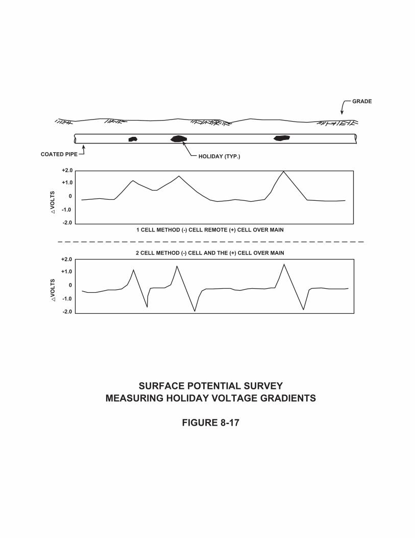
� �������������� �������� �������������������������
��� �����,
����
����
���%
���%
%
���%
���%
���%
���%
%
���%
���%
���������������������������������
���������������������������������
�����
����������������������

� �������������� �������� ������������������������
��� ������
���������
�����
���������
� �!���
��������������� ����
� ���$%
� �*�%%
� �#�%%
� ���$%
� ���%%
� ���$%� ���%%
� ���$%1 �%��%
����� ���
� � � � � �� � �& �& & & �& �&
1 � � � � � � � � � � � � � � � 1
�����
�
&
07�7,7
*7
$%7
$7#7�7
� �������! � �������!

electrodes must be moved with each reading. With the anode output interrupted andthe positive electrode at point G and the negative electrode at point H, the potentialdifference is +0.50 volt. Refer again to Figure 8‐18. Subsequent readings must follow thesame pattern as that discussed in Example # 1. A positive potential of +2.50 volts ismeasured at the sixth location with the positive electrode at point A and the negativeelectrode at point B. The seventh reading between points A and B with the positiveelectrode on B and the negative electrode on A will give reading of ‐2.50 volts. If thepositive and negative electrodes are placed at both points B, on either side of point Adirectly over the anode, the measured potential difference will be zero. The areabetween the most positive and the most negative readings will be over the anode. Azero potential difference will be over the anode. Figure 8‐19 shows the data plotted forboth types of survey. The spacing between each anode can be determined from thegraph. The top graph represents the data from the one electrode method. The highpositive readings or peaks occur directly over the anodes. This type of survey can behelpful when trying to locate a break in an anode string since it can identify the lastoperating anode. The data obtained using the two electrode method is shown in thebottom graph of Figure 8‐19.
The one electrode and the two electrode surveys are useful in locating individualgalvanic anodes directly connected to a pipeline. By interrupting the test current acrossan isolating joint, the galvanic anodes will appear as large holidays on the pipeline. There are times when a break in an anode cable is excavated but it is not knownwhether this is the first break in the cable from the rectifier and that there is power tothis point. One way to determine that there are not other breaks in the cable betweenthis point and the rectifier is to measure the potential‐to‐earth of the cable at this pointto a standard reference electrode and compare this value to the operating voltageoutput of the rectifier. These two values should be similar. Proper safety precautionsshould be taken when connecting to the anode cable in the ditch and a high outputrectifier should be adjusted to a lower setting for this testing.
Another type of potential survey that uses two reference electrodes is known as a sidedrain survey that is often used to delineate possible areas of active corrosion,particularly on bare or poorly coated pipe. For this survey the first electrode is placeddirectly above the pipe, in contact with the soil. The second electrode is placed incontact with the soil at a 90‐degree angle to the pipe at a distance approximately equalto 2½ times the pipe depth. During testing, the electrode placed directly above the pipeshould be connected to the positive terminal of the voltmeter and the other electrodeto the negative terminal. Positive side‐drain readings indicate that current is being
Chapter 8 ‐ Cathodic Protection System Maintenance and Troubleshooting Procedures
8‐22

� �������������� �������� ������������������������
��� �����0
������
������
���%
���%
���%
%
���%
���%
���%
%
���%
���%
����������������������������������������
����������������������������������������
�����������
�����
���� �������� �!���
�� �����-�

discharged from the pipe at this point, making it an anodic area. Negative side‐drainreadings normally indicate that current is flowing towards or onto the pipe at this point,making it a cathodic area. The side‐drain measurements should be continued at no morethan 5‐foot intervals. Tests must be made on both sides of the pipe, until the extent ofthe possible problem section has been determined. However, under certain conditionsa relatively strong localized anodic cell could exist on the bottom of the pipe with thetop of the pipe serving as a cathode and negative side‐drain readings could be measuredwhile severe corrosion is actually occurring on the bottom of the pipe at this location.
Testing for Pipelines in Contact with Casings
Two types of contacts are typically considered when evaluating whether a pipeline is incontact with its casing. These two types are known as either an electrolytic couple or ametallic contact. An electrolytic couple refers to a situation where the annular spacebetween the pipeline and the casing is filled with water or some combination ofelectrolyte that provides a low resistant path between the carrier pipe and the casing.A metallic contact refers to the situation where the carrier pipe is in direct metalliccontact with the casing. There is also the case where both of these situations are presentat the same time.
A low resistant electrolytic couple or metallic contact between the carrier pipe and thecasing will affect the operation of a cathodic protection system. The casing is typicallya large bare section of steel pipe that will act as a large coating holiday that may divertcurrent away from any local coating holidays on the carrier pipe. In the case of anelectrolytic couple, the return path for the cathodic protection current will be throughthe low resistant electrolyte in the annular space between the two structures. In thecase of a metallic contact, the return path for the cathodic protection current will bethrough the point of metallic contact. Therefore, piping with coating faults near a"shorted" casing may not receive the proper current density required for protection. A"shorted" casing will also diminish the amount of current attenuation from a protectionsystem since the current will be drawn to this rather large coating fault.
Any areas of bare metal found at coating faults on the carrier pipe inside of a casingfilled with electrolyte will require protection against corrosion. In this instance, cathodicprotection current must pass from the earth to the casing, through the electrolyte, andthen on to the pipe. This series of resistances causes a voltage drop that may result inless than adequate protection.
Identifying possible "shorted" casings is usually accomplished through a comparison of
Chapter 8 ‐ Cathodic Protection System Maintenance and Troubleshooting Procedures
8‐23

the "on/off" structure‐to‐earth potentials of both the carrier pipe and the casing. Usuallythere is a significant potential difference between the carrier pipe and the isolatedcasing when the carrier pipe is well coated and the casing is bare. These potentialdifferences become less when the carrier pipe is poorly coated and the surrounding soilis of low resistivity. When both the carrier pipe and the casing exhibit the same potentialvalues there is a strong indication that some type of "short" is present.
Another indication of a "shorted" casing is a significant change in the amount of currentflow measured on the pipeline at a point on the far side of the casing from the cathodicprotection system. If the carrier pipe has a fairly uniform coating, the amount of currentmeasured along the pipeline should gradually decrease as the distance from thecathodic protection system becomes greater. However, since a "shorted" casing has thesame effect as a large coating fault, there should be a significant decrease in the amountof current measured on the far side of the casing. This difference in the amount of linecurrent measured on both sides of the casing would be approximately equal to theamount of protective current going to the "shorted" casing. This measurement of linecurrent should be made with the test current interrupted.
One field test that can be performed to determine whether a casing is "shorted" to thecarrier pipe involves using the casing as a temporary anode bed. In this instance thecasing is deliberately depolarized as current is discharged from the casing into the earthand then on to the carrier pipe. The indication that the casing is isolated from the carrierpipe is given by casing potential readings becoming less negative with increasingamounts of test current. The carrier pipe potential readings can vary in either direction,however if the two structures are not in metallic contact, the potentials measured onthe carrier pipe will probably become more negative with increasing amounts of testcurrent. Figure 8‐20 depicts this particular testing arrangement.
CONCLUSIONS
The establishment of a cathodic protection maintenance program is vital if the systemis to operate as intended. A system that is not properly maintained will undoubtedlyexperience premature failure.
Any system malfunctions detected during periodic surveys or maintenance operationsshould be repaired as soon as possible. A system that is malfunctioning or not operatingfor an extended period of time may be detrimental to the protected structure.
This Chapter has presented some troubleshooting techniques that can help corrosion
Chapter 8 ‐ Cathodic Protection System Maintenance and Troubleshooting Procedures
8‐24

DC POWER SUPPLY
PIPELINE
CASING
DETERMINATION OF TYPE OF CASING “SHORT”
FIGURE 8-20
LOCAL REFERENCE
ELECTRODE
(+)
(-)
TEMPORARY
REMOTE
STRUCTURE
EOC
Vg
REMOTE REFERENCE
ELECTRODE
TAKE THE FOLLOWING MEASUREMENTS
FOR 3 DIFFERENT CURRENT VALUES WITH
AT LEAST 3 SETS FOR EACH VALUE
1. TEST CURRENT WITH CASING AS ANODE
2. Vg PIPE-TO-SOIL (LOCAL)
3. Vg PIPE-TO-SOIL (REMOTE)
4. Vg CASING-TO-SOIL (LOCAL)
5. Vg CASING-TO-SOIL (REMOTE)
6. Eoc BETWEEN PIPE AND CASING

personnel to determine where the problem may be in a cathodic protection system thatis not functioning properly. The use of these techniques and the implementation ofsubsequent repairs will result in reducing the down time of the cathodic protectionsystem to a minimum.
Chapter 8 ‐ Cathodic Protection System Maintenance and Troubleshooting Procedures
8‐25
Related Documents