University of Warwick institutional repository: http://go.warwick.ac.uk/wrap A Thesis Submitted for the Degree of PhD at the University of Warwick http://go.warwick.ac.uk/wrap/2768 This thesis is made available online and is protected by original copyright. Please scroll down to view the document itself. Please refer to the repository record for this item for information to help you to cite it. Our policy information is available from the repository home page.

Interlocking Bricks
Oct 28, 2015
Interlocking Bricks
Welcome message from author
This document is posted to help you gain knowledge. Please leave a comment to let me know what you think about it! Share it to your friends and learn new things together.
Transcript

University of Warwick institutional repository: http://go.warwick.ac.uk/wrap
A Thesis Submitted for the Degree of PhD at the University of Warwick
http://go.warwick.ac.uk/wrap/2768
This thesis is made available online and is protected by original copyright.
Please scroll down to view the document itself.
Please refer to the repository record for this item for information to help you tocite it. Our policy information is available from the repository home page.

DESIGN OF INTERLOCKING BRICKS
FOR ENHANCED WALL CONSTRUCTION
FLEXIBILITY, ALIGNMENT ACCURACY
AND LOAD BEARING
A thesis submitted in partial fulfilment of the requirements of the degree of Doctor of Philosophy in Engineering
By Simion Hosea Kintingu
The University of Warwick, School of Engineering May 2009
ii
TABLE OF CONTENTS
LIST OF FIGURES.................................................................................................................................... V
LIST OF TABLES ................................................................................................................................... VII
LIST OF GRAPHS ................................................................................................................................... IX
ACKNOWLEDGEMENT ......................................................................................................................... X
ABSTRACT ............................................................................................................................................. XI
DECLARATION ..................................................................................................................................... XII
LIST OF ABBREVIATIONS AND VARIABLES ................................................................................. XIII
CHAPTER 1 ................................................................................. 16
1.0 INTRODUCTION ........................................................................................................................... 16
1.1 BACKGROUND ............................................................................................................................. 16
1.1.1 HOUSING DEFICIT ............................................................................................................. 16 1.1.2 POVERTY ............................................................................................................................. 17
1.1.3 APPROPRIATE HOUSING SOLUTIONS .......................................................................... 18 1.1.4 EARTH WALLING .............................................................................................................. 18 1.1.5 MORTARLESS WALL BUILDING .................................................................................... 19
1.2 RESEARCH JUSTIFICATION ...................................................................................................... 20 1.3 RESEARCH METHODOLOGY .................................................................................................... 22 1.4 STRUCTURE OF THE THESIS ..................................................................................................... 22
CHAPTER 2 ................................................................................. 24
2.0 LITERATURE REVIEW FOR MORTARLESS CONSTRUCTION ............................................. 24 2.1 HISTORY OF INTERLOCKING BRICKS .................................................................................... 24
2.2 INTERLOCKING MORTARLESS BRICKS/BLOCKS FOR HOUSE CONSTRUCTION .......... 26 2.2.1 DEFINITIONS ...................................................................................................................... 27 2.2.2 INTERLOCKING HOLLOW-BLOCKS .............................................................................. 28 2.2.3 THAI INTERLOCK BRICKS ............................................................................................... 30 2.2.4 SOLBRIC SYSTEM FROM SOUTH AFRICA .................................................................... 31
2.2.5 HYDRAFORM SYSTEM FROM SOUTH AFRICA ........................................................... 33
2.2.6 BAMBA SYSTEM FROM SOUTH AFRICA ...................................................................... 35
2.2.7 AURAM SYSTEM FROM INDIA ....................................................................................... 37 2.2.8 TANZANIAN INTERLOCK BRICK (TIB) SYSTEM ....................................................... 38
2.3 WALL PERFORMANCE FACTORS ............................................................................................ 40
2.4 CHARACTERISTICS OF MORTARLESS WALLING ................................................................ 42 2.5 SELF-ALIGNMENT AND INTERLOCKING ............................................................................... 43
2.6 WALL ALIGNMENT ACCURACY .............................................................................................. 46
2.7 LOAD BEARING CAPACITY OF MORTARLESS WALL ......................................................... 47 2.8 PRODUCTION OF BRICKS/BLOCKS ......................................................................................... 56
2.9 SELECTION OF SUITABLE SOIL FOR STABILISATION ........................................................ 57 2.9.1 SHRINKAGE BOX FOR SOIL TESTING .......................................................................... 59
2.10 BRICK CURING ........................................................................................................................ 62 2.10.1 BRICK HANDLING ....................................................................................................... 62 2.10.2 CURING CONDITION ................................................................................................... 63
2.11 SUBJECTS WORTHY OF FURTHER ANALYSIS ................................................................. 64 2.12 CONCLUSION TO LITERATURE REVIEW ........................................................................... 72
CHAPTER 3 ................................................................................. 73
3.0 RESOURCE USE IMPLICATIONS OF EMPLOYING MORTARLESS TECHNOLOGY .......... 73 3.1 INTRODUCTION ........................................................................................................................... 73
3.2 NATURAL RESOURCE USE ........................................................................................................ 75
iii
3.2.1 CEMENT ............................................................................................................................... 75
3.2.2 CEMENT REDUCTION ....................................................................................................... 77 3.2.3 CEMENT & GREENHOUSE GASES .................................................................................. 78 3.2.4 SOIL ...................................................................................................................................... 80
3.2.5 WATER ................................................................................................................................. 80
3.3 MT PERFORMANCE AND COST REDUCTION ........................................................................ 82
3.3.1 ELEMENTS OF COST REDUCTION ................................................................................. 82 3.3.2 WALL CONSTRUCTION STAGES .................................................................................... 83
3.4 SUMMARY .................................................................................................................................... 88
CHAPTER 4 ................................................................................. 89
4.0 INTERLOCK-BRICK WALLING FLEXIBILITY ........................................................................ 89
4.1 INTRODUCTION ........................................................................................................................... 89
4.1.1 BACKGROUND ................................................................................................................... 90 4.1.3 BRICKWORK PATTERNS .................................................................................................. 92 4.1.4 BRICK SHAPE ..................................................................................................................... 92 4.1.5 WALL CONFIGURATIONS ................................................................................................ 93
4.2 BRICK-SET DESIGN TO ENHANCE THE FLEXIBILITY OF INTERLOCK WALLING ......... 94 4.2.1 COMMON PART-BRICKS .................................................................................................. 94 4.2.2 HALF-BRICK WALL ........................................................................................................... 95 4.2.3 DEVELOPMENT OF A NEW PART-BRICK ..................................................................... 96
4.3 USES OF C½B’S IN THE ASSEMBLY OF INTERLOCKING BRICK - WALL ......................... 99 4.3.1 PIERS .................................................................................................................................... 99
4.4 FORMATION OF NEW BOND ................................................................................................... 102 4.4.1 SHOKSE BOND ................................................................................................................. 103 4.4.2 LIJUJA BOND .................................................................................................................... 107
4.5 SPECIAL BRICKS ....................................................................................................................... 110 4.5.1 TEE BRICK (TB) ................................................................................................................ 110 4.5.2 ANGLE BRICKS ................................................................................................................ 112 4.5.3 CURVED WALLS .............................................................................................................. 114
4.6 IMPROVEMENT IN FLEXIBILITY ACHIEVED ...................................................................... 116
4.6 SUMMARY .................................................................................................................................. 117
CHAPTER 5 ............................................................................... 119
5.0 BRICK IRREGULARITIES AND THEIR IMPLICATIONS FOR WALL QUALITY ............... 119 5.1 BRICK IRREGULARITIES ......................................................................................................... 119 5.2 SOIL-CEMENT BRICK CURING PRACTICE ........................................................................... 124
5.3 SUMMARY ............................................................................................................................. 126
CHAPTER 6 ............................................................................... 127
6.0 THE RELATIONSHIP BETWEEN WALL ALIGNMENT AND BRICK GEOMETRIC
IMPERFECTION ................................................................................................................................... 127
6.1 INTRODUCTION ......................................................................................................................... 127
6.1.1 THE EXPERIMENTAL OBJECTIVES.............................................................................. 128 6.2 PRIMARY PREPARATION FOR EXPERIMENT ...................................................................... 129
6.2.1 MOULD DESIGN AND FABRICATIONS........................................................................ 130
6.2.2 BRICK PRODUCTION ...................................................................................................... 136 6.2.3 DETERMINATION OF BRICK CHARACTERISTICS .................................................... 139
6.3 REPRESENTING BRICK GEOMETRY IN ALIGNED POSITION ........................................... 150 6.3.1 BRICK ALIGNMENT FACTORS ..................................................................................... 150 6.3.2 Brick-to-brick contact .......................................................................................................... 151
6.3.3 REAL BRICK GEOMETRY............................................................................................... 153 6.3.4 EFFECTS OF ROLL AND PITCH WEDGE ANGLES TO WALL ALIGNMENT .......... 154

iv
6.4 RESEARCH TECHNIQUES FOR EXAMINING BRICK-TO-COLUMN ALIGNMENT
RELATIONSHIP .................................................................................................................................... 156
6.5 THEORETICAL ANALYSIS OF BRICK COLUMN .................................................................. 158 6.5.1 THE RELATIONSHIP BETWEEN BRICK CHARACTERISTIC CONDITIONS AND COLUMN-ALIGNMENT ................................................................................................................. 158
6.5.2 SUMMARY OF THEORETICAL ANALYSIS.................................................................. 164
6.6 PHYSICAL EXPERIMENTS AND TESTING TECHNIQUES ................................................... 165 6.6.1 INTRODUCTION ............................................................................................................... 165 6.6.2 COLUMNS AND WALLS ALIGNMENT ACCURACY TEST ....................................... 166
6.6.3 PHYSICAL ALIGNMENT ACCURACY TEST RESULTS & DISCUSSIONS .............. 171 6.7.2 COMPUTER MODEL ........................................................................................................ 186 6.7.3 COMPUTATION OF COLUMN/WALL OUT-OF-PLUMB DEVIATION ...................... 190 6.7.4 THE RELATION BETWEEN THE STATISTICS OF COLUMN OUT-OF-PLUMB DEVIATION AND THE SIZE OF THE BRICK-PILE FROM WHERE THE SET OF BRICKS WAS PICKED ................................................................................................................................... 193
6.7.5 SENSITIVITY OF SD OF OUT-OF-PLUMB DEVIATIONS (σx) TO COLUMN HEIGHT 205
6.8 WALL ALIGNMENT ANALYSIS .............................................................................................. 207 6.8.1 EXPERIMENTAL DATA FOR WALLS ........................................................................... 208 6.8.2 BRICK INACCURACY LIMITS FOR ALLOWABLE WALL LEAN ............................. 213
CHAPTER 7 ............................................................................... 217
7.0 STIFFNESS OF DRY-STACKED BRICK COLUMNS ............................................................... 217 7.1 INTRODUCTION ......................................................................................................................... 217
7.2 THEORETICAL ANALYSIS FOR A COLUMNS’ RESISTANCE TO LATERAL FORCES .... 220 7.2.1 A VERTICAL COLUMN WITH ALL BRICKS GLUED TOGETHER ............................ 222 7.2.2 DRY-STACKED BRICKS WITH PERFECT SURFACES ............................................... 223
7.2.3 DRY-STACKED BRICKS WITH IRREGULAR SURFACES .......................................... 225
7.2.4 THE COLUMN OVERTURNING POINT ANALYSIS .................................................... 227
7.1.5 SUMMARY OF THEORETICAL ANALYSIS.................................................................. 231
7.3 EXPERIMENTAL APPLICATION OF LATERAL FORCE TO THE TOP OF COLUMNS ...... 232
CHAPTER 8 ............................................................................... 239
8.0 CONCLUSIONS AND RECOMMENDATIONS ........................................................................ 239
8.1 INTERLOCK BRICKS’ OPPORTUNITIES ENHANCED .......................................................... 239 8.2 MEASURES TO REDUCE BRICK IRREGULARITIES............................................................. 241 8.3 DEFLECTION PREDICTIONS FOR WALLS & COLUMNS .................................................... 242 8.4 AREAS FOR FURTHER RESEARCH ......................................................................................... 246
REFERENCES ........................................................................... 247

v
LIST OF FIGURES Figure 2.1 Interlocking hollow-blocks .............................................................................. 29 Figure 2.2 Thai interlocking brick .................................................................................... 31 Figure 2.3 SOLBRIC interlock brick ................................................................................ 32 Figure 2.4 Hydraform block ............................................................................................. 33 Figure 2.5 Typical Hydraform block-laying (diagram from Hydraform Manual 2004) .. 34
Figure 2.6 Bamba interlocking brick ................................................................................ 35 Figure 2.7 Available Bamba brick parts in the market ..................................................... 36 Figure 2.8 the use of Bamba interlocking brick units in stretcher bond ........................... 37
Figure 2.9 Auram Interlocking Brick ................................................................................ 38 Figure 2.10 Tanzanian Interlocking Brick (TIB) .............................................................. 39 Figure 2.11 Osteomorphic bricks ...................................................................................... 44 Figure 2.12 Alan Blocks ................................................................................................... 45 Figure 2.13 Test brick prism ............................................................................................. 48 Figure 2.14 simply supported panel tested for differential settlement .............................. 50
Figure 2.15 Brick surfaces of different imperfections ...................................................... 51 Figure 2.16 Cracks due to bending movements caused by unequal height of bricks in a course ................................................................................................................................ 52
Figure 2.17 brick early cracks caused by unevenness of brick surfaces ........................... 52
Figure 2.18 Stages of contact area from overall solid block to mortarless to effective contact ............................................................................................................................... 53
Figure 2.19 Behaviour of dry-stacked brick joint under full loading ............................... 55
Figure 2.20 Specification of bricks’ sides as used on block-work position ...................... 62
Figure 2.21 Press machine operations schema ................................................................. 67 Figure 3.1 Limit of soils for stabilisation that reduce cement use in the brick production77
Figure 3.2 Comparison of construction cost between MT and CB ................................... 86
Figure 4.1 Common bond for interlocking bricks (2003 technology) .............................. 95
Figure 4.2 Two ½-bricks for the Tanzanian interlocking brick (TIB) system .................. 96
Figure 4.3 Details of a Centre-half bat (C½B) .................................................................. 97 Figure 4.4 Typical single story brick wall foundation ...................................................... 98 Figure 4.5 Piers providing restraint to wall ...................................................................... 98 Figure 4.6 Construction of attached piers enhanced by centre-half bats ........................ 100
Figure 4.7 Attached one and a half-brick wide pier ........................................................ 101 Figure 4.8 An isolated solid two-brick square column ................................................... 102 Figure 4.9 One-Brick thick wall in Shokse bond ............................................................ 104 Figure 4.10 Front elevation of a wall in Shokse bond .................................................... 105 Figure 4.11 Plan views of course 1 and 2 of 1-brick thick wall in Shokse bond ............ 105
Figure 4.12 TIB closer is a half-brick cut perpendicular to end face ............................. 106
Figure 4.13 Tanzanian Interlock Brick (TIB) Closer ...................................................... 107 Figure 4.14 One brick thick wall in Lijuja bond ............................................................. 108 Figure 4.15 Plans of alternate courses of 1-brick quoin and junction wall in Lijuja bond ......................................................................................................................................... 109
Figure 4.16 Tee brick (TB) (all measurements are in millimetres) ................................ 110
Figure 4.17 TB specific positional orientation ............................................................... 111

vi
Figure 4.18 One-brick wide pier attached to wall junction assembled using TB ........... 111
Figure 4.19 Angle bricks ................................................................................................. 113 Figure 4.20 Common polygonal wall assembled using angle brick ............................... 114
Figure 4.21 Isometric view of curved wall ..................................................................... 115 Figure 4.22 Performance improvement level of TIB ...................................................... 117
Figure 5.1 Typical poor curing conditions in low-cost building-material production sites ......................................................................................................................................... 124
Figure 5.2 Implications of brick irregularities on wall assembly ................................... 125
Figure 6.1 Full brick (FB) moulding inserts ................................................................... 132 Figure 6.2 End-half bat (E½B) moulding inserts ............................................................ 132 Figure 6.3 Three-quarter bat (¾B) moulding inserts ...................................................... 133 Figure 6.4 Centre-half bat (C½B) moulding inserts ....................................................... 133 Figure 6.5 Tee brick mould inserts ................................................................................. 134 Figure 6.6 Common moulding inserts components ........................................................ 135
Figure 6.7 New cover for MultiBloc press ..................................................................... 135 Figure 6.8 Multibloc press with new cover and moulding inserts .................................. 136
Figure 6.9 Positions on brick for determination of its (i) length and (ii) width .............. 139
Figure 6.10 Brick in position for dimensional and surface flatness determination ........ 140
Figure 6.11 Brick marked for surface flatness determination ......................................... 142
Figure 6.12 Representing top and bottom brick planes as in position ............................ 144
Figure 6.13 Orientation assuming bottom of brick is laid on a true horizontal base ...... 145
Figure 6.14 The brick imperfection characteristics as implied on wall .......................... 155
Figure 6.15 Analysis of an imperfect dry-stack brick in position ................................... 159
Figure 6.16 Effect of brick irregularity on column height .............................................. 160 Figure 6.17 Column/wall vertical alignment test rig ...................................................... 168 Figure 6.18 Wall out-of-plumb deviation measurement-taking in reference to rig-vertical-datum ............................................................................................................................... 169
Figure 6.19 Theoretical brick surface contact distance .................................................. 175 Figure 6.20 Experimental grooved bricks (GB) (the half scale bricks) .......................... 176
Figure 6.23 Flowchart of a Column Assembly Simulation Model (CASM) for random brick laying strategy ........................................................................................................ 187 Figure 6.24 Flowchart of a Column Assembly Simulation using alternate wedge-angle189
Figure 6.25 Imperfect bricks placed in position showing successive vertical deviation ......................................................................................................................................... 191
Figure 6.26 Brick surface divided into 20 equal parallel contact bands ......................... 196
Figure 6.27 Restraining options for experimental walls ................................................. 209 Figure 6.28 Test wall with both sides restrained ............................................................ 210 Figure 7.1 Moment and Deflection Model to examine hinging formation for a dry-stacked column ............................................................................................................................. 219
Figure 7.3 The displacement behaviour of dry-stacked column built from perfect and imperfect bricks .............................................................................................................. 224
Figure 7.4 Brick interface contact points ........................................................................ 225 Figure 7.5 Application of lateral load to the top of dry-stacked brick column ............... 233
vii
LIST OF TABLES Table 2.1 Categories of interlock-brick systems ............................................................... 27 Table 2.2 Level of soil shrinkage with recommended compression pressure .................. 58
Table 2.3 Linear shrinkage moulds used in different parts of the world .......................... 60
Table 2.4 Advantages and disadvantages of compaction scenarios.................................. 69
Table 3.1 Characteristics of walls compared .................................................................... 74 Table 3.2 Reduction of carbon emission by minimum use of cement .............................. 79
Table 3.3 Water quantity for production and curing ......................................................... 82 Table 3.4 Cost comparison of one square metre wall in Tanzanian Shillings (Tsh.) ....... 85
Table 3.5 Productivity enhancement as a means of labour cost reduction ....................... 87
Table 3.6 Costs of materials and labour separated ........................................................... 88 Table 4.1 Wall construction flexibility of CT and IBs (year 2000 technology) ............... 91
Table 4.2 Common brick elements ................................................................................... 94 Table 4.3 Wall construction flexibility achieved by TIB ............................................... 116
Table 6.1 Sand particle distribution test results .............................................................. 137 Table 6.2 Data comparison between experimental and standards .................................. 141
Table 6.3 Determination of a bricks’ upper plane .......................................................... 143 Table 6.4 Determination of a bricks’ bottom plane ........................................................ 143 Table 6.5 Brick length (ℓ) ............................................................................................... 146
Table 6.6 Brick width (w) ............................................................................................... 146 Table 6.7a Experimental interlocking bricks’ measured data for flatness determination147
Table 6.7b Experimental interlocking bricks’ measured data for flatness determination ......................................................................................................................................... 148
Table 6.8 Brick-plane inclinations of top(upper) and bottom surfaces .......................... 149
Table 6.9 Research techniques and the variables each can allow ................................... 157
Table 6.11 Physical columns assembled using random laying strategy (C1) ................. 173
Table 6.12 Physical columns assembled using ‘allowed to reverse’ strategy (C2) ........ 173
Table 6.13 Physical columns assembled using ‘select and replace’ strategy (C3) ......... 174
Table 6.14 The comparison of assembly strategies ........................................................ 174 Table 6.16 Practical column assemblies using grooved-bricks randomly stacked ......... 181
Table 6.17 the comparison of out-of-plumb deviation between normal-brick and grooved-brick columns & theoretical predictions ......................................................................... 182 Table 6.18 Table of f 1 factors, ........................................................................................ 197
Table 6.19 SD of out-of-plumb deviations (σx mm) for 1440 simulated column assemblies ....................................................................................................................... 201
Table 6.20 Scaling factor K ............................................................................................ 201 Table 6.21Simulations of 480 column assemblies of indented-bricks i.e. using 30mm spacing between the contact points ................................................................................. 203 Table 6.22 Correction of experimental data using Kλ factors ......................................... 204
Table 6.23 the out-of-plumb deviations comparison between practical, simulations and theory for ungrooved-indented bricks ............................................................................. 204 Table 6.24 Wall assembling sequence ............................................................................ 208 Table 6.25 SD of out-of-plumb deviations (σx mm) of experimental walls for three strategies ......................................................................................................................... 211

viii
Table 6.26 SD of out-of-plumb deviations (σx mm) for 720 simulated wall assemblies 212
Table 6.27 the out-of-plumb deviations comparison between practical and simulations for ungrooved-indented brick walls ...................................................................................... 212 Table 6.28 SD of out-of-plumb deviations (σx mm) for 720 simulated column assemblies for D = 60mm (corresponding to grooved- experimental bricks) ................................... 215
Table 6.29 The effect of brick bump variation on allowable wall lean limits using grooved bricks (D = 60mm) ............................................................................................ 215 Table 7.1 Stiffness comparison between mortarless and mortared columns .................. 235
Table 7.2 Normal brick column (NBC) stiffness test results .......................................... 236
Table 7.3 Grooved brick columns (GBC) stiffness test results ...................................... 237

ix
LIST OF GRAPHS Graph 6.1 Particle size distribution curve ....................................................................... 137 Graph 6.2 Influence of brick population on out-of-plumb variations ............................. 206
Graph 7.1 NBC stiffness test .......................................................................................... 237 Graph 7.2 GBC stiffness test .......................................................................................... 238

x
ACKNOWLEDGEMENT I would like to acknowledge the assistance of the following people: -
• Dr Thomas T.H., School of Engineering, The University of Warwick, for
guidance, encouragement, understanding and supervision of the research without
him none of the findings would have been possible.
• Dr Oram C.E., School of Engineering, The University of Warwick, for guidance
and supervision of the design and fabrication of brick moulds, without him the
task wouldn’t have been easy.
• To all laboratory and workshop staff members, to mention just a few;
o Mr Banks C. – Laboratory technician, for the support from preparations,
production, construction and testing. He made my work easier.
o Mr Meesum P. – Head of mechanical workshop and his team Whitehouse
M. and Dexter P. for their job well-done made the brick production
simple, easy and perfect.
• The library staff for their efficient and effective service; provision of literatures
within and outside the University at the appropriate time.
• Dr GM Kawiche – The Director General of the National Housing and Building
Research Agency of Tanzania, for the permission to study in UK, for obtaining
financial support from the Government of Tanzania, and for his persistent
encouragement over the whole period of my study.
• To my wife Liz and my twin daughters Jully and Jane, for being patient and
supportive, and for making my life in the UK interesting and interactive.

xi
ABSTRACT The worldwide housing shortage has stimulated a search for appropriate, easy, fast and cost-effective new ways of wall construction. Among many technologies found to have promise is mortarless technology using dry-stack interlocking bricks/blocks. This thesis is about such mortarless walling technology and in particular: how to improve wall-construction flexibility, the effects of brick irregularities on wall alignment accuracy and wall behaviour (stiffness, strength) when subject to lateral forces. The flexibility of mortarless technology (MT) has been enhanced by the development of new bricks (centre-half bat and tee brick): the introduction of closer bricks led to the formation of two new bonds (patterns) namely Shokse and Lijuja bonds. It is now possible to construct more than half-brick-thick walls, to attach more than half-brick-wide piers (buttresses) onto walls, and, using special bricks, to construct polygonal and curved walls using interlocking bricks. Three methods (theoretical modeling, physical experiments and computer simulation) were used to analyze the effects of brick imperfections on wall alignment accuracy. Theoretical analysis confirmed that brick moulders should concentrate on achieving parallel top and bottom faces rather than achieving true square-ness. Physical column assembly compared three brick-laying strategies namely: “random”, “reversing” and “replace”. The columns assembled using the “reversing” and “replace” strategies realized alignment improvement factors of 1.6 and 2.9 respectively over “random” strategy. The research also revealed that grooving, to prevent bricks making contact near their centre lines, improved column alignment by factor 2.13 and stiffness by factor 2.0, thus allowing construction of longer and higher walls without strengthening measures. In order to attain alignment accuracy in accordance with BS 5628-3:2005 in a dry-stack mortarless wall, this research recommends using full bricks with top and bottom surface irregularities not exceeding ±0.5mm for un-grooved bricks, and up-to ±0.9mm for grooved bricks. Further analysis was undertaken with respect to resource-use implications (cement, water, soil) of employing MT. Using MT will save 50% of wall construction cost and 50% cement consumption, which ultimately will reduce 40% of carbon emissions.

xii
DECLARATION This declaration confirms that this thesis is original and sole work of the author alone.
The thesis does not include any previous material submitted by any other researcher in
any form not acknowledged as required by existing regulations.
No material contained in this thesis has been used elsewhere for publication prior the
production of this work.
This declaration also officially affirms that this thesis is being submitted for the degree of
Doctor of Philosophy of the University of Warwick only and not to any other similar
institution of higher learning for the same purposes.

xiii
LIST OF ABBREVIATIONS AND VARIABLES Note: Variables are in Italics ½B Half bat
¾B Three-quarter bat
Aef Effective surface area
Anom Nominal surface area
BIB Burnt Interlocking Brick
Bn Number of bricks selected from a set
Bs Set of bricks
BS British Standards
C½B Centre half bat
C1 Column built using random strategy
C2 Column built using reverse strategy
C3 Column built using replace strategy
CEB Compressed earth bricks
CSSB Cement soil stabilised blocks
C: S Cement to Soil ratio
D Spacing between brick contact points
E Young’s modulus of brick material
Eq Equation
FB full brick
Fconst. Constant load
fcw Wall compressive strength
g Mass due to gravity
G groove width
GB Grooved brick
GBC Grooved brick column
h Intermediate height of structure
H Height of a structure
I Second moment of area of brick face

xiv
ISSB Interlocking soil stabilised brick
IB Interlocking brick
L Brick length
LL Liquid limit
LS Linear shrinkage
M Moment
MBC Mortarless brick construction
Mf Moment caused by applied force
MPa Mega Pascal
Mw Moment caused by weight
N Number of courses
NB Normal brick
NBC Normal brick column
NHBRA National Housing and Building Research Agency
OMC Optimum moisture content
Ost Osteomophic
OPC Ordinary Portland cement
P&D Protrusions and depressions
S Sensitivity
SD Standard deviation
ST Stack
t Thickness/Height deviation from ideal
T The ideal brick thickness/height
TB Tee brick
TE Theoretical equation
T&G Tongue and grooved
TIB Tanzanian interlocking brick
VITA Volunteer in Technical Assistance
w Weight
W Brick width (depth of column/wall thickness)
x Horizontal deflection of the top brick from wall plumbline

xv
y Height error of structure (wall/column)
α Internal angle between brick bottom and front surface (refer figure 6.1)
β Internal angle between brick top and front surface (refer figure 6.1)
χ2 Chi-Square
δ Horizontal deflection of the front top edge of the ith course from its bottom edge
γ Role ‘wedge’ angle formed by top and bottom surfaces of a brick
ηo Ratio of effective to nominal areas
λ Brick-set size divide by column/wall height (n – course number)
ω An interface angle between to merged surfaces
θ Face angle formed by deflected Nth course in reference to plumb line
ρ Density
σγ Standard deviation of wedge-angle
σef Effective stress
σnom Nominal stress

16
CHAPTER 1
1.0 INTRODUCTION
1.1 BACKGROUND
1.1.1 HOUSING DEFICIT
Housing is one of the basic human needs and is usually ranked third after food and clothing.
In most developing countries housing is inadequate and the housing backlog has been
increasing rapidly. One key reason for housing inadequacy is the increase in population
Racodi (1997). It is estimated that the World’s population is rising weekly by more than a
million people, a rate that new construction does not match Earth from the air. [Online].
(URL http://www.earthfromtheair.com.html). 2004. (Accessed 15 December 2004) due to
the high pace of urbanisation and socio-economic factors that include the rise in prices of
land and building materials, Those classified as poor are the majority and they cannot afford
proper housing McAuslan (1985). The outcome of this can be seen by the poor quality of the
houses of this majority in both urban and rural environments (Gilbert & Gugler 1992, Basu
1988).
The provision of affordable housing for the poor needs to be facilitated through the
development of innovative strategies (Webb 1983, Hamdi 1995). The persisting problem for
urban housing authorities in Africa is the worsening condition of slums and squatter
settlements due to the high rate of population growth. Public provision of mass low-cost
housing is always far below the actual demand Maasdorp & Humphreys, (1975). The
situation is being exacerbated because the more city facilities are improved; the faster is

17
rural-urban migration. This must not be considered for its negative impact only, but should be
regarded as an inevitable and irreversible consequence of continuing development Spence &
Cook, (1983).
1.1.2 POVERTY
Despite the fact that most African countries have large resources of indigenous building
materials, to date the housing situation has not improved, due to economic hardship. New
housing by its nature requires capital. World trade market data shows that between 1990 and
2000 the capital of the 50 poorest countries fell from 4% to 2% of global capital Earth from
the air. [Online]. (URL http://www.earthfromtheair.com.html). 2004. (Accessed 15
December 2004). Several studies have revealed that more than 50% of African people live
below the poverty line, and more than 80% of the population living in rural areas have poor
shelter as well as inadequate sanitation, transport and communication systems. About 70% of
the urban population now lives in slums and squatter settlements, which lack the basic
facilities for a decent life World Bank, (1995). Worse, is the continent’s dependence on
imported building materials that are too expensive for the poor majority to afford.
Example: Tanzania is one of 20 poorest countries on earth. In the year 2000, the annual
housing demand was about 800,000 units, but supply was below 20% of this figure. In that
year there were about 9.8 million urban dwellers needing about 2.4 million housing units.
The actual number of units built was only 0.6 million indicating a 75% deficit URT –
NHSDP, (2000). This poor situation is reflected in other developing countries.

18
1.1.3 APPROPRIATE HOUSING SOLUTIONS
However, researchers worldwide have made significant efforts to find sustainable and
affordable technologies to arrest the situation. The best approach so far is the development of
technologies to increase the utilization of locally available building materials.
Appropriate solution for affordable housing will vary from one location to another. Some
general rules, however, apply to construction methods and housing systems. Affordability
and availability of course are the basic requirements for the low-cost housing industry
(Harlae and Marten, 1990, Laquian, 1983, Spence & Cook, 1983). But, the cultural
backgrounds and the particular needs of the communities must also be considered. With the
increasing rate of unemployment in Africa, there is still a need for labour-intensive
production methods in some parts of the industry. To enable the community to profit from
construction projects, systems making effective use of unskilled labour and local resources
are usually the most appropriate.
Development of appropriate technologies for the production of low-cost building materials of
good quality will speed up the provision of affordable urban housing in developing countries.
One such technology is the use of stabilised-soil bricks. These have been in use in developing
(African) countries for many years and have passed various stages of improvement in the
production processes and quality of the products.
1.1.4 EARTH WALLING
Recent research has been conducted at Warwick University (Gooding 1994, Kerali 2001,
Montgomery 2002) on building materials for low-cost housing, including literature reviews
from the 18th century to the end of 20th century, on the use of earth or soil as a dominant
building material. It was found that soil can be much improved through stabilisation. The

19
durability of cement soil stabilised blocks (CSSB) can further be improved by using best-
practice curing regimes Kerali, (2001) and their strength increased by impact compaction,
which gives better material consolidation than simple pressing Montgomery, (2002).
Burroughs, (2001) discussed selection of soil for wall construction and made a contribution
to the development of stabilised soil for rammed-earth walls. A valuable survey by
Maniatidis & Walker, (2003) shows clearly the development of rammed-earth construction
worldwide. The economic analysis in these various studies suggests use of earth material for
wall construction will continue and that such material will remain a cost effective and low-
energy alternative to more ‘modern’ walling materials in the coming centuries.
1.1.5 MORTARLESS WALL BUILDING
Mortarless brick construction, usually employing interlocking bricks, is growing in popularity
round the world, indicative of acceptability. Mortarless techniques demonstrate the following
advantages: increase of construction productivity (Grimm 1974, Whelan 1985), reduction in
construction duration and labour (Anand & Ramamurthy 2003, Ramamurthy & Nambiar
2004) and reduced construction cost. Because of its technological simplicity and local
resource dependence, mortarless-brick construction is more appropriate to many local
communities than conventional mortared-brick techniques.
Designers have developed machines of different types (manually operated, hydraulic,
electrically operated, automatic or semi-automatic) for producing different shapes and sizes
of stabilised-soil bricks/blocks for Mortarless wall: Allan block system, Auram system,
Bamba systems and Haener blocks, Hydraform systems, Putra blocks and Solbric systems
etc. A variety of interlocking brick/block shapes was analysed by Thanoon et al. (2004),
20
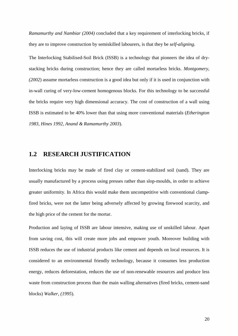
Ramamurthy and Nambiar (2004) concluded that a key requirement of interlocking bricks, if
they are to improve construction by semiskilled labourers, is that they be self-aligning.
The Interlocking Stabilised-Soil Brick (ISSB) is a technology that pioneers the idea of dry-
stacking bricks during construction; hence they are called mortarless bricks. Montgomery,
(2002) assume mortarless construction is a good idea but only if it is used in conjunction with
in-wall curing of very-low-cement homogenous blocks. For this technology to be successful
the bricks require very high dimensional accuracy. The cost of construction of a wall using
ISSB is estimated to be 40% lower than that using more conventional materials (Etherington
1983, Hines 1992, Anand & Ramamurthy 2003).
1.2 RESEARCH JUSTIFICATION
Interlocking bricks may be made of fired clay or cement-stabilized soil (sand). They are
usually manufactured by a process using presses rather than slop-moulds, in order to achieve
greater uniformity. In Africa this would make them uncompetitive with conventional clamp-
fired bricks, were not the latter being adversely affected by growing firewood scarcity, and
the high price of the cement for the mortar.
Production and laying of ISSB are labour intensive, making use of unskilled labour. Apart
from saving cost, this will create more jobs and empower youth. Moreover building with
ISSB reduces the use of industrial products like cement and depends on local resources. It is
considered to an environmental friendly technology, because it consumes less production
energy, reduces deforestation, reduces the use of non-renewable resources and produce less
waste from construction process than the main walling alternatives (fired bricks, cement-sand
blocks) Walker, (1995).

21
However concerning ISSB, little has been published about:
• Modes of deterioration,
• Failure mechanisms,
• Maintenance requirements,
• Construction procedures
• Architectural (design) flexibilities,
• The relationship between brick accuracy and wall alignment, and
• The stability and stiffness of mortarless wall (Marzahn, 1999).
These unknown parameters need to be established by experimentation.
The objectives of the work reported in this thesis were to investigate: -
• ISSB wall architectural flexibility in terms of patterns, bonds and buildable
configurations.
• Factors that influence the accuracy of mortarless walls.
• Stability and stiffness of mortarless wall during and after construction.
• Maximum height and length of ISSB walling that can be managed before requiring
strengthening,
• Economics of ISSB walls compared to conventional systems.
Forecasting the prospects for ISSB use in developing countries is difficult Croft, (1993)
because existing building standards, regulations and rules create negative attitudes towards
new technologies Beall, (2000). However the adoption of new technologies requires enough
time to prove their durability and advantages compared to existing ones, so it may take

22
decades before they are widely accepted (Kua and Lee 2000, Spence & Cook 1983). The role
of the building industry should be both to develop and adopt beneficial changes Housing
Forum, (2001).
1.3 RESEARCH METHODOLOGY
The research recorded in this thesis employed three main methods, namely:
1. Literature review
2. Survey of existing structures built of ISSB (mortarless bricks) and design of a more
(architecturally) flexible form of ISSB.
3. Analysis, and experimentation;
a. Theoretical analysis of dry-stacking of interlocking bricks,
b. Physical testing of using half-scale interlocking bricks and
c. Computer simulation of dry-stacking interlocking bricks into walls and
columns.
1.4 STRUCTURE OF THE THESIS
The thesis is presented in seven chapters as follows:
Chapter 1 introduces the research topic, constructs the rationale for the study, and
develops the objectives of the research.
Chapter 2 has the literature review that surveys the existing knowledge of “Mortarless
Technology”, and presents a history of interlocking bricks. The review identifies the
knowledge gaps that determined the work developed in chapters 3 to 7.

23
Chapter 3 discusses the benefits of using MT to minimise environmental impact. It
analyses the cost comparison between mortarless technology and conventional.
Chapter 4 describes the many patterns/bonds used by tradition bricklaying (compared to
the only one bond used by mortarless technology before this research). The design of new
ISSB parts enabled the invention of two new brick-bonds and the application of ISSB to a
wide range of conventional bonds. The chapter demonstrates the performance improvement
in the construction of variety of joints, thicker walls, and different wall configurations i.e.
polygon, curve etc.
Chapter 5 discusses the types of brick irregularity, their causes and remedial measures to
reduce them.
Chapter 6 describes the series of laboratory experiments performed in this research. It
addresses the variables to be measured and the measuring techniques that were employed to
obtain the required test results. It relates theoretical analyses to physical experiments and
scrutinises disagreements between them with the help of the computer model. It draws
conclusions concerning the relationship between the variability of a wall and the accuracy of
the ISSBs with which it is built.
Chapter 7 theoretically analyses the difference between solid column and dry-stacked
column subjected to lateral forces. It relates theoretical analysis to physical experiment.
Chapter 8 summarises and comments on the thesis findings. The chapter also highlights
the applications of the research findings and identifies areas for further research.
The References are presented at the end of the thesis.

24
CHAPTER 2
2.0 LITERATURE REVIEW FOR MORTARLESS CONSTRUCTION
This part of the thesis will go through the development history of interlocking bricks and the
existing techniques, technologies and practices. It will try to identify the knowledge gaps in
our topic of interest (“Mortarless Technology”- MT for wall construction) for planning the
studies that constitute the new contribution reported in subsequent Chapters.
2.1 HISTORY OF INTERLOCKING BRICKS
Mortarless technology is directly associated with interlocking bricks: so the two terms will be
used interchangeably. In this work we are going to deal with use of interlocking bricks,
stacked dry to build a wall while observing building construction rules of proper bonding.
Bonding is the arrangement of bricks in an interlocking pattern that result in a stable wall.
The stretcher bond was the only (main) such pattern used in interlocking brickwork before
this research.
The history of interlocking bricks started in the early 1900s with the construction of toys for
children’s McKusick (1997), Love and Gamble (1985). Among the first inventors of toy
systems that contributed to the mortarless technology (arrangement of parts that construct
ideal structures) were:
• The Englishman Frank Hornby (1863 – 1936) of Liverpool, with Meccano sets.
• A.C Gilbert (1884 – 1962) of Salem, Oregon with Erector sets.

25
• Charles Pajeau who invented Tinker Toy construction sets in 1913. He was a
stonemason from Evanston, Illinois, USA.
• John Lloyd Wright who invented Lincoln Logs in 1920.
• Ole Kirk Christiansen (1891 – 1958), who invented Lego.
From the beginning most toy mechanisms were designed to teach the principles of creativity
and were a tool for learning scientific, engineering and architectural principles. The original
materials used for toy construction were tin, metal, wood and clay, though now most toys are
made from plastic. Of these various systems, Lego has the most similarity to walling. “An
Interlocking Brick construction for toys (Automatic Binding Brick) was first developed in
Denmark in 1949. In 1951 the “Automatic Binding Brick” was renamed as “Lego Mursten”
“Lego Brick” in English”, and first produced commercially in 1958” (Museum of American
Heritage. [Online]. (URL http://www.moah.org/exhibits/archives/buildex.html). 2005 march
9. (Accessed 16 March 2006).
The 1958 version of interlocking bricks with stubby cylinders and matching studs moulded
into the surface allowed the Lego bricks to be firmly attached to one another
(http://inventors.about.com). In 1967 a simplified version called “Duplo” bricks was
launched: is the latest version available in variety of sizes, shapes and colours that form the
basis for mortarless technology using interlocking bricks/blocks (The history of Legos.
[Online]. (URL http://www.shop.lego.com). 2006. (Accessed 21 March 2006).
Since 1970s the interlocking mortarless bricks/blocks for house construction, made from
sand-cement, stabilised soil and burnt/baked soil, have been pioneered in Africa, Canada, the
Middle East and India.

26
2.2 INTERLOCKING MORTARLESS BRICKS/BLOCKS
FOR HOUSE CONSTRUCTION
Interlocking bricks/blocks (IBs) can be produced as solid, perforated or hollow bricks. The
demarcation between hollow and perforated bricks depends on the surface area of holes. If
they occupy less than 25% of the surface area, they are called ̀perforated bricks`, if more we
define them as `hollow blocks` (BS 6073-1:1981 clause 3.3). We can characterise bricks in
terms of their solidity as follows: -
• The more solid the brick the more material required and the more powerful the press
needed to attain enough brick density, but less binder will be needed for satisfactory
brick strength.
• The more perforations, increasing up to 50%, the more binder will be required in the
mix to achieve the higher strength needed for thin membranes formed onto a hollow
block.
The two solidity characteristics of blocks above, each have extreme conditions that increase
cost of blocks. The best percentage of perforation is that which minimise some combination
of weight, material and the power requirement of the press. To reduce the cement/sand ratio
in the mix for hollow blocks, the size of perforations should be reduced.
Interlocking requires a variety of shapes/parts to construct different wall joints. The existing
commercial interlock designs have different configurations (Ramamurthy & Nambiar 2004,
Dyskin et al. 2005, Thanoon et al. 2004, Croft 1993. Harris et al. 1992) and thus vary the
number of part-bricks necessary to perform the same construction operations. Table 2.1
divides interlocking bricks/blocks into two groups, according to their locking systems.
Category A bricks have interlocks that restrict movement both horizontally and transverse to

27
the wall surface, Category B bricks allow horizontal movement and only limit transverse
movement during wall assembly.
Interlocking bricks have three types of locking (jointing) methods; Tongue and Groove
(T&G), Protrusions and Depressions (P&D), and Topological non-planar locking. The T&G
and P&D are the typical locking methods, while topological method is not a popular one.
Table 2.1 Categories of interlock-brick systems Category A Both horizontal and transversal brick movements restricted
Category B Free horizontal and restricted transversal movements
Auram Alan block
Bamba Hydraform
Haener Interlocking System Solbric
Osteomorphic
Sparlock System
Tanzanian
Thai
Before involving ourselves in the descriptions of interlocking bricks/blocks, let’s be
acquainted with the terms used in brickwork.
2.2.1 DEFINITIONS
For the purpose of this research as per BS 6073-1:1981 clause 3.1.2, a “brick is a masonry
unit not exceeding 337.5mm in length, 225mm in width or 112.5mm in height”. Units with
more than these measurements to any of the sides are termed blocks. The following
definitions also apply.

28
Bat is a piece (formed by cutting perpendicular to the face) of a brick with
a reduced length.
Brick size measure equal to the length of one brick
Centre-half is the piece (formed by cutting perpendicular to the brick face) of a
brick left after removal of both end quarters.
Closer is a piece (formed by cutting parallel to the brick face) of a brick with
reduced width.
Half brick a length equal to the width or half-length of a brick.
Quarter brick a length equal to half the width or quarter the length of the brick
Half-brick wall is a wall with thickness equal to half the length of the brick, e.g. a
wall of bricks laid as stretchers.
One-brick wall is a wall with thickness equal to a brick’s length, e.g. a wall of bricks
laid as headers
2.2.2 INTERLOCKING HOLLOW -BLOCKS
Interlocking hollow-blocks are made from sand-cement that can compete with conventional
technologies in terms of quality, strength and cost. There are many promising types of
interlock blocks in Canada, to mention just a few:
• Alternate face-shell components figure 2.1a, known as Sparlock system Hines,
(1993).
• Projecting lug system components figure 2.1b, known as Haener system Gallegos,
(1988) and Harris et al. (1992).
Figure 2.1 shows Canadian interlocking hollow-blocks with general measurements of 16” x
8” x 8” (400 x 200 x 200mm) representing more than thirty existing types as discussed by
29
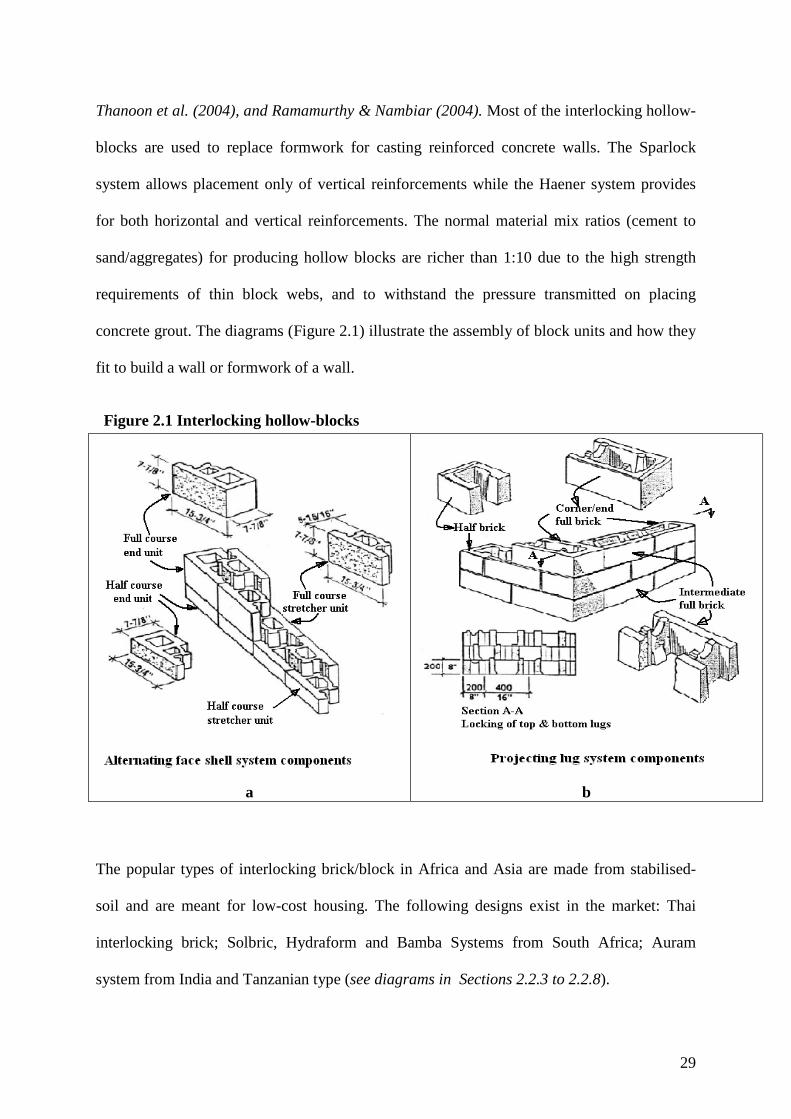
Thanoon et al. (2004), and Ramamurthy & Nambiar (2004). Most of the interlocking hollow-
blocks are used to replace formwork for casting reinforced concrete walls. The Sparlock
system allows placement only of vertical reinforcements while the Haener system provides
for both horizontal and vertical reinforcements. The normal material mix ratios (cement to
sand/aggregates) for producing hollow blocks are richer than 1:10 due to the high strength
requirements of thin block webs, and to withstand the pressure transmitted on placing
concrete grout. The diagrams (Figure 2.1) illustrate the assembly of block units and how they
fit to build a wall or formwork of a wall.
Figure 2.1 Interlocking hollow-blocks
a b
The popular types of interlocking brick/block in Africa and Asia are made from stabilised-
soil and are meant for low-cost housing. The following designs exist in the market: Thai
interlocking brick; Solbric, Hydraform and Bamba Systems from South Africa; Auram
system from India and Tanzanian type (see diagrams in Sections 2.2.3 to 2.2.8).

30
The above listed types of interlocking bricks were invented by different people at different
times to reduce mortar costs, enhance construction productivity and wall characteristics
(accuracy, stability and strength); achieved by the proper choice of production method, wall
construction technique, and locking mechanism.
2.2.3 THAI INTERLOCK BRICKS
The Thai interlocking brick (Figure 2.2) with dimensions 300 x 150 x 100mm, was developed
in the early 1980s, by the Human Settlement Division of the Asian Institute of Technology
(HSD-AIT), Bangkok, in co-operation with Thai Institute of Scientific and Technical
Research (TISTR). This is an interlocking brick as defined in Section 2.2.1 (BS 6073-
1:1981), although the developer calls it a block.
The Thai interlocking brick is produced using a modified CINVA-Ram manual press
developed in Colombia in 1956 (VITA 1975). Figure 2.2b shows a wall with vertical grooves
run through the full height that provide good keys for render. Vertical holes also run through
the full height of a wall, serving the following purposes:
• They reduce weight
• They can house reinforcement or mortar to increase wall stability at chosen locations
(corners, junctions, opening ends etc.)
• They may be used for electrical and communication conduits.

31
Figure 2.2 Thai interlocking brick
a) Brick length = 300mm, width = 150mm and height = 100mm
b) Wall thickness = 150mm,
course height = 100mm
The grooves may however increase the amount of render required for internal plastering. The
holes in combination with the grooves may reduce the overall strength of a brick and hence
the strength of the wall built using these bricks. The locking mechanism is not well secured
as the knobs and depressions are too small (<5mm). The strength of such interlocks depend
on surface render, or on grout filled into vertical holes with additional reinforcements if need
arises.
2.2.4 SOLBRIC SYSTEM FROM SOUTH AFRICA
The SOLBRIC system uses solid interlocking bricks (Figure 2.3a), formed by pressing on
their ends (the compacting stroke moves parallel to the longer side), with guided or controlled
width and height. In bricklaying, SOLBRICs are arranged at the normal bed surface (Figure
2.3c). The size of a SOLBRIC is 250 x 200 x 100mm. SOLBRIC provides small horizontal
cavities between the courses (Figure 2.3b) in which conduits and pipes can be installed or
reinforcements placed to strengthen the wall at certain locations (cill and lintel levels). The
SOLBRIC wall has a flat internal surface and externally a pointed joint surface (Figure 2.3b)
from the chamfered edges of the bricks on one side. The flat internal surface of SOLBRIC

32
reduces the thickness of required plaster mortar and the external pointed joint makes the
external appearance attractive. However this difference means that bricks may not be
reversed (front to back).
Figure 2.3 SOLBRIC interlock brick
Although the SOLBRIC interlocking brick system seems to be easy to use, the shape of the
bricks and the parts made from the machine make it possible to build only the external walls
because there is no means of connecting partitions i.e. of making a tee or cross joints. The
small thicknesses (<15mm) of the vertical and horizontal tongues that provide the

33
interlocking are questionable due to the material used (soil stabilised with cement that is
brittle in nature).
2.2.5 HYDRAFORM SYSTEM FROM SOUTH AFRICA
Hydraform is the simplest type of interlocking block (Figure 2.4) in shape, when interlocked
makes a tongue and grooved joint at the sides and top and bottom. Being free to slide along
the course horizontally, it can be pushed along to achieve tighter perpends (vertical joints)
Figure 2.5.
Figure 2.4 Hydraform block
Hydraform block is moulded by pressing along its length from the ends, as for the SOLBRIC.
It is also a solid block, but slightly shorter, wider and thicker in size (240 x 220 x 115mm)
than the SOLBRIC (Figure 2.3). The stability of the wall built from the Hydraform blocks is
not provided by the locking mechanism but by the width and weight (massiveness) of the
block. In production they require considerable power to mould (compress) due to their large
volume, 30% more soil is used compared to the other five reported types. Moreover the
34
compression must be sufficient to allow a fresh block to withstand the squeezing forces
occurring when it is manually moved from machine to the curing area. A powerful (moulding
pressure 4MPa to 10MPa) and expensive motorised machine (Hydraform Manual, 2004) is
required to compact such a volume of soil. This can be compared to the cheaper manual
presses (with pressures under 2MPa) used to produce Bamba, Tanzanian and Thai types
(VITA 1975, Weinhuber 1995).
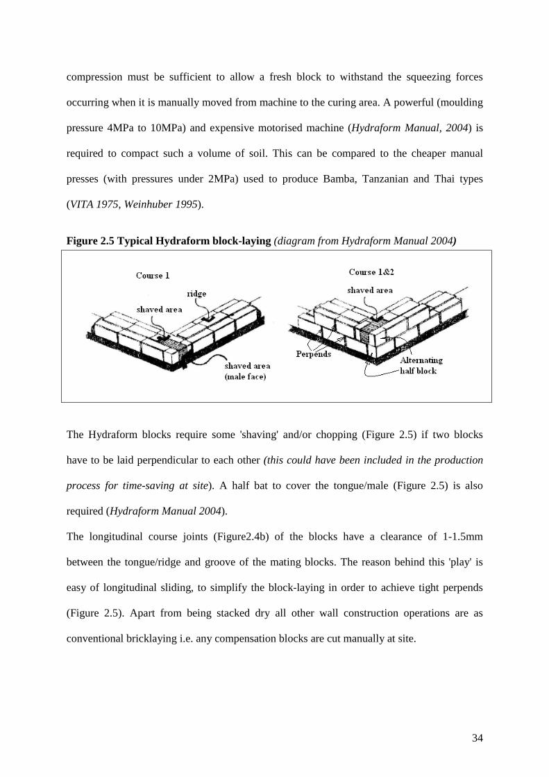
Figure 2.5 Typical Hydraform block-laying (diagram from Hydraform Manual 2004)
The Hydraform blocks require some 'shaving' and/or chopping (Figure 2.5) if two blocks
have to be laid perpendicular to each other (this could have been included in the production
process for time-saving at site). A half bat to cover the tongue/male (Figure 2.5) is also
required (Hydraform Manual 2004).
The longitudinal course joints (Figure2.4b) of the blocks have a clearance of 1-1.5mm
between the tongue/ridge and groove of the mating blocks. The reason behind this 'play' is
easy of longitudinal sliding, to simplify the block-laying in order to achieve tight perpends
(Figure 2.5). Apart from being stacked dry all other wall construction operations are as
conventional bricklaying i.e. any compensation blocks are cut manually at site.

35
2.2.6 BAMBA SYSTEM FROM SOUTH AFRICA
The Bamba interlocking brick (Figure 2.6) is perforated, with protrusions and depressions.
The top and bottom faces of Bamba brick have negative symmetry: configurations opposite
to each other that allow them to fit (lock).
Figure 2.6, if the brick is rotated 180 degrees around its Z-axis, the bottom view will appear
as top view; this give the option of reversing to find a better orientation or position during
brick-laying.
Figure 2.6 Bamba interlocking brick

36
Figure 2.7 Available Bamba brick parts in the market
Bamba brick interlock better than all other types due to its shape, provided that high accuracy
is maintained. This accuracy depends on: proper soil selection, proper determination of
material mix (cement to soil and water to cement ratios), observation of good practice in
production and curing. Though the shape can yield a rigid structure, it is very difficult to
correct if bricks have defects. With these contradictory characteristics, the system is not fit
for use in developing countries because it requires accurate machinery and high skills in soil
selection to make sure that the production will be of one consistency. If every thing is perfect,
you can lay the bricks of a whole house in a day, like a puzzle game. Otherwise, with low

37
accuracy in size and shape due its complicated configuration, it consumes a lot of time
shaving and shimming to compensate for brick irregularities.
Figure 2.8 the use of Bamba interlocking brick units in stretcher bond
The occurrences of tee or cross joints alternate the use of three quarter bats from right to left, this does not depend on the distance from each joint, but the rotation of three quarter bats to meet at the centre of the joint that changes the orientation of the following brick
The author developed three-quarter bats Figure 2.7a and 2.7b (Kintingu 2003) for Bamba
interlocking brick to perform tee and cross joints. The available Bamba interlocking units
(Figures 2.6 and 2.7) can assemble wall as shown in Figure 2.8, but is restricted to half brick
wall and to just stretcher bond.
2.2.7 AURAM SYSTEM FROM INDIA
This type of interlocking brick has some similarities with Bamba and Thai types, but of a
simpler shape with size 295 x 145 x 95mm. Figure 2.9 shows its family of bricks
(intermediate, three quarter bat, half bat and channel) makes it relate more closely to the Thai
system but with no grooves and reduced perforations.

38
Figure 2.9 Auram Interlocking Brick
The Auram system reduces the number of three quarter bats required to just one due to shape
similarity, compared to the two required with Bamba interlocking brick (Figure 2.7). In this
type of interlock a three-quarter bat is used as a corner brick; this has flat ends, to avoid a
semi-circle notch appearing at the external surface of the wall. The Auram brick is more solid
and heavier at between 9Kg and 10Kg than the Thai and Bamba types at 7 to 8Kg. But the
locking mechanism depends entirely upon the bosses and depressions; this will require
experiments to examine the optimum height of male and depth of female features (<10mm) to
give enough wall punch-through strength.
2.2.8 TANZANIAN INTERLOCK BRICK (TIB) SYSTEM
The TIB system Figure 2.10 was designed by the author after observing the weaknesses in the
Bamba system (Kintingu 2003). The new system (TIB), it was developed for appropriate
technology applications; thus taking into considerations availability and affordability to the

39
users. The machine, which is locally made and manually operated, is a modification of
CINVA-Ram press machine (VITA 1975, Weinhuber 1995).
Figure 2.10 Tanzanian Interlocking Brick (TIB)
The author made important modifications to improve the interlock brick to suit Tanzanian
requirements. The size of the brick is 300 x 150 x 100mm, the same as that of Thai and
Bamba types respectively. The locking knobs and depression are two as for the Auram type,
but they are of pyramid shape with holes running through the centre of the knobs. The brick
is chamfered to the front and back edges, providing pointed horizontal and vertical wall
joints. This chamfer, gives a good key to the plaster if plastering is needed (the bricks from
the machine are normally smooth enough to provide good finishing without plastering). The
chamfer also reduces corner friction during brick production; thus reducing the ejection force
required.

40
The number of different brick parts was reduced to four (Figure 2.10), from the six of Bamba
(Figures 2.6 and 2.7) as follows: -
Tanzanian type (TIB) - Full brick, three quarter bat, half bat and beam channel.
Bamba system - Base brick, intermediate brick, left and right three quarter bats, half bat and
channel.
TIB (Figure 2.10), apart from its good locking mechanism, needs investigation of the shear
strength of its knobs and webs, to determine the optimum size that will provide sufficient
wall stability during construction. Also it seems that the vertical joint is not secured well, as
the brick ends meet at flat surfaces with no mechanical interlocking. It should have been
provided with a groove of at least 2.5mm radius at both brick ends, to create a void for a
minimum mortar to be placed (pumped) to fill the vertical gap. The TIB as other designs
available on market fails to satisfy some of the demands from the building industry, such as
the construction of:
• Various brick bonding joints,
• Piers (wider than half of brick length) attached into walls, which conventional
(mortared) brickwork can easily perform,
• Thicker walls (thickness more than half of brick length) and
• Different wall configurations (circular, polygonal, etc.).
Correcting these deficiencies of mortarless technology is a further work of this research
addressed in Chapter 4.
2.3 WALL PERFORMANCE FACTORS
A wall is the base/background to roofing, ceiling, doors and windows, beams, plaster,
painting and decorations, installation of electrical and water accessories, etc. According to

41
Collins (1995), a wall is defined as a vertical structure made of stone, bricks or wood, with a
length and height much greater than its thickness, used to enclose a building and divide it into
cubes or rooms and support other elements/parts. The above-mentioned elements that are
supported by the wall comprise more than 50% of the total cost of the building. The wall
skeleton itself hardly accounts for 10% of the overall construction costs. We require the wall
to be fit for purpose and durable in order to secure all the elements fixed to it for the entire
life of the building. When we say a brick wall, we mean bricks arranged in certain pattern
(see bond as defined in Section 2.1) and joined with whatever material or means. According
to Hendry et al. (1997) the vertical compressive strength of a wall rises with only the square
root of the nominal crushing strength of a brick, or with the fourth or cube root of the mortar
cube strength. This is for walls that fail by crushing rather than by buckling. Also the
relationship of the wall strength to the thickness of mortar, shows that the lower the thickness
(down to one millimetre) the higher the wall strength. Spence and Cook (1983) show that
mortar does not contribute much to the compressive strength of a wall, even if the mortar
used is stronger in compression than brick. There is a need to find out if the mortar joint
thickness can be limited to maximum of three millimetres (with the aim of filling the gaps
after the bricks are laid). However wall strength does not only depend on the strength of the
basic elements (brick/block and mortar) alone, but also on:
• The shape (height, width, length and configuration) of the wall
• Brick design
• The way bricks are laid (the bond/pattern employed) (Hendry et al. 1997 and Spence
& Cook 1983)

42
2.4 CHARACTERISTICS OF MORTARLESS WALLING
The worldwide housing shortage has stimulated a search for appropriate, easy, fast and cost-
effective ways of constructing walls. Among many technologies found to have promise is
mortarless technology (MT) using dry-stack interlocking bricks/blocks.
Although MT is quite new, it is booming around the world with diverse use in the building
industry, and it is now under study for space (extraterrestrial) applications. It comes in a
variety of forms, shapes, configurations, and sizes (Beall, 2000. Ramamurthy and Nambiar,
2004. Croft, 1993. Thanoon et al. 2004. Dyskin et al. 2005). Interlocking bricks are often
considered as ‘specials’ because of their need for unique moulds and their unsuitability for
the extrusion technique widely employed in brick-making. Interlocking bricks' are normally
produced using machines that guarantee good face texture (accurate and with appealing
surfaces that are smooth and even), thus giving the bricks an attractive finish that requires
little or no rendering, just joint sealing for protection from weather, achieving privacy and
avoiding health hazards. The reduction or even omission of joint mortar and plastering saves
construction time and materials.
The elimination of bedding mortar, although it reduces cost and accelerates the construction
process Ramamurthy and Nambiar, (2004), also induces structural weaknesses. Architectural
inflexibility (Chapter 4 subject matter) and structural instability are caused by geometric
imperfections in the brick-bed surfaces and any non-uniformity in the heights of adjacent
bricks Marzahn (1999). Moreover the complexity of some common ISSB configurations is a
further barrier to design and construction flexibility. All these imperfections cause difficulty
in keeping within maximum tolerable deviations from wall plumbness and straightness, and
may prevent construction of particular wall configurations. This requires further
investigations.
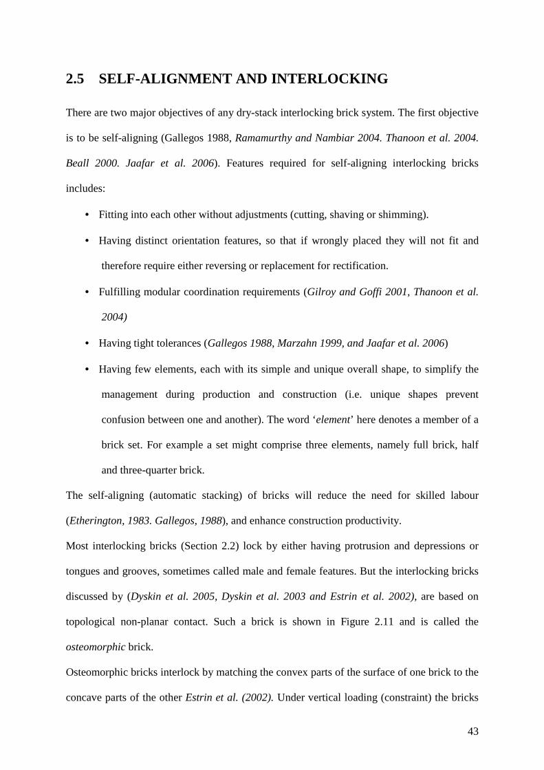
43
2.5 SELF-ALIGNMENT AND INTERLOCKING
There are two major objectives of any dry-stack interlocking brick system. The first objective
is to be self-aligning (Gallegos 1988, Ramamurthy and Nambiar 2004. Thanoon et al. 2004.
Beall 2000. Jaafar et al. 2006). Features required for self-aligning interlocking bricks
includes:
• Fitting into each other without adjustments (cutting, shaving or shimming).
• Having distinct orientation features, so that if wrongly placed they will not fit and
therefore require either reversing or replacement for rectification.
• Fulfilling modular coordination requirements (Gilroy and Goffi 2001, Thanoon et al.
2004)
• Having tight tolerances (Gallegos 1988, Marzahn 1999, and Jaafar et al. 2006)
• Having few elements, each with its simple and unique overall shape, to simplify the
management during production and construction (i.e. unique shapes prevent
confusion between one and another). The word ‘element’ here denotes a member of a
brick set. For example a set might comprise three elements, namely full brick, half
and three-quarter brick.
The self-aligning (automatic stacking) of bricks will reduce the need for skilled labour
(Etherington, 1983. Gallegos, 1988), and enhance construction productivity.
Most interlocking bricks (Section 2.2) lock by either having protrusion and depressions or
tongues and grooves, sometimes called male and female features. But the interlocking bricks
discussed by (Dyskin et al. 2005, Dyskin et al. 2003 and Estrin et al. 2002), are based on
topological non-planar contact. Such a brick is shown in Figure 2.11 and is called the
osteomorphic brick.
Osteomorphic bricks interlock by matching the convex parts of the surface of one brick to the
concave parts of the other Estrin et al. (2002). Under vertical loading (constraint) the bricks

44
are pressed together and achieve more surface contact. Such configurations restrict brick
movements both perpendicular to the wall surface and along the wall, so osteomorphic brick
fall under category A in Table 2.1 (Figure 2.11b).
Figure 2.11 Osteomorphic bricks
The topological interlocking with non-planar surfaces (if sufficiently smooth) reduces stress
concentration. Being self-aligning and self-adjusting, osteomorphic bricks provide some
relaxation of the accuracy requirements of both brick production and wall assembly.
However the system being insensitive to the surface imperfection will lead to unevenness of
wall surfaces (Dyskin, et al. 2005) and so require a thicker layer of render mortar. Therefore
accuracy (smoothness and matching of the curvatures) requirements remain paramount as in
other MT configurations.
Another brick shape with similar characteristics to the osteomorphic brick is the Allan Block
(AB) see figure 2.12. It uses a “ball and socket joint”.

45
AB blocks were tested by Shrive et al. 2003 who showed they have good potential for
tolerating both differential settlement and loading perpendicular to the wall surface (i.e. wind
forces). The panel block Figure 12a restricts perpendicular movement but allows horizontal
sliding during block-laying (category B Table 2.1).
Figure 2.12 Alan Blocks
However the mechanism of self-aligning just discussed (osteomorphic brick and Alan block)
is not typical. Most of the MT systems that Least Developed Countries use (described in
Section 2.2) employ T&G or P&D interlocks, which are the focus of this research.
The second objective of a dry-stack interlocking brick system is to have an effective locking
means that allows dry-stacking to achieve straight, plumb and stable block-wall (Vasco
Costa, 1993) that can withstand different forces (horizontal shear and vertical bearing) under
loads applied (Gallegos 1988, Thanoon, et al. 2004) during and after construction. Table 2.1
divides the locking modes into two categories; one-way and two-way. Though each mode has
advantages and disadvantages, this research is in favour of category A that restrict
movements both perpendicular to the wall surface and horizontally along the wall. The
protrusions and depressions provide interlocking and control of brick positioning that reduce

46
the use of levelling and aligning instruments Gallegos (1988). The ability of IB to accurately
locate brick positions improves the bonding value of mortarless technology. The precision of
overlapping between courses improve masonry appearance and the distribution of loads Nash
(1991).
2.6 WALL ALIGNMENT ACCURACY
An accurately aligned masonry wall should be vertical to plumb, with truly straight and
horizontal (level) courses. The vertical joints (perpends) at alternating courses should be in
line and truly vertical throughout the wall height. The masonry panel face should have a flat
and true surface Nash (1983). Conventional masonry gives an acceptable range of vertical
deviation, which for a wall height up to 3m should not exceed 10mm (BS 5606:1990 Table 1
T.1.3).
All who have worked with interlocking bricks agree that in order to achieve good alignment,
the bricks should be geometrically accurate (Marzahn 1999, Beall 2000, Estrin et al. 2002,
Jaafar et al. 2006). However no critical analysis has been made of wall alignment. Research
so far has only addressed the important issue of performance in direct load-bearing of
interlocking dry-stacking systems.
Beall (2000) observed that the physical locking feature is a mechanism to improve the
accuracy of dry stacked masonry; it makes it easier to align the wall vertical and straight and
therefore speeds up construction Jaafar et al. (2006). However the relationship between wall
alignment accuracy and brick imperfection requires further research.

47
2.7 LOAD BEARING CAPACITY OF MORTARLESS WALL
A substantial amount of research has been performed to ascertain the behaviour of mortarless
walls under applied loads (Gazzola & Drysdale 1989, Drysdale & Gazzola 1991, Marzahn
1999, Marzahn and Konig 2002, Shrive et al. 2003, Jaafar et al. 2006,) both in-plane and
out-of-plane. Dry-stacked mortarless blocks have been tested under compressive, tensile and
shear loads, and their performance related to that of conventional (mortared) brickwork, for
which standards and codes for materials and structure quality are defined.
Gazzola & Drysdale (1989) tested dry-stacked interlocking hollow-block walls under
compressive, tensile and shear forces. Their results suggest MT masonry construction is
adequate for low rise buildings. Moreover any additional surface render enhances tensile and
shear strengths and gives some improvement in compressive strength.
In further work, Drysdale & Gazzola (1991) studied the strength properties and load-bearing
capacity of grouted dry-stacked mortarless hollow-block walls.
The blocks used to build test prisms had an average material compressive strength of 30.4
MPa. The test results of grouted prisms (Figure 2.13) attained an average flexural tensile
strength of 1.7MPa. This is over six times the minimum value allowable in the North
American building codes ACI-ASCE (1988) and CAN3-S304-M84 (1984).
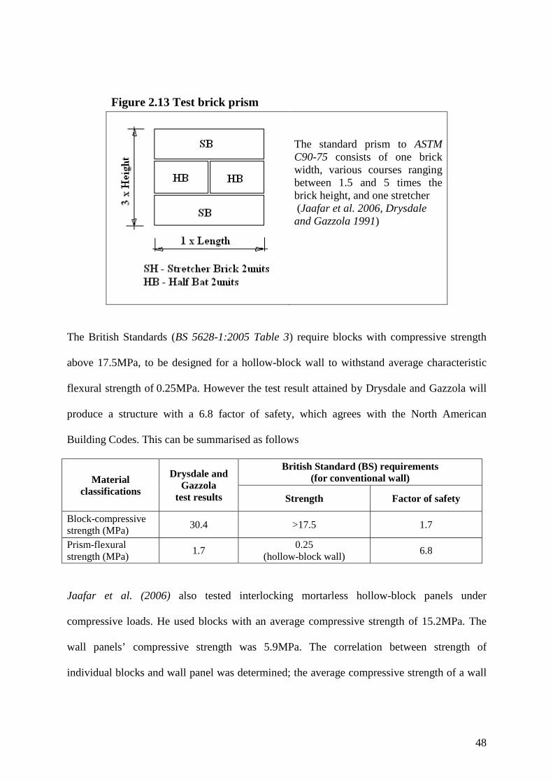
48
Figure 2.13 Test brick prism
The standard prism to ASTM C90-75 consists of one brick width, various courses ranging between 1.5 and 5 times the brick height, and one stretcher (Jaafar et al. 2006, Drysdale and Gazzola 1991)
The British Standards (BS 5628-1:2005 Table 3) require blocks with compressive strength
above 17.5MPa, to be designed for a hollow-block wall to withstand average characteristic
flexural strength of 0.25MPa. However the test result attained by Drysdale and Gazzola will
produce a structure with a 6.8 factor of safety, which agrees with the North American
Building Codes. This can be summarised as follows
Material classifications
Drysdale and Gazzola
test results
British Standard (BS) requirements (for conventional wall)
Strength Factor of safety
Block-compressive strength (MPa) 30.4 >17.5 1.7
Prism-flexural strength (MPa) 1.7 0.25
(hollow-block wall) 6.8
Jaafar et al. (2006) also tested interlocking mortarless hollow-block panels under
compressive loads. He used blocks with an average compressive strength of 15.2MPa. The
wall panels’ compressive strength was 5.9MPa. The correlation between strength of
individual blocks and wall panel was determined; the average compressive strength of a wall
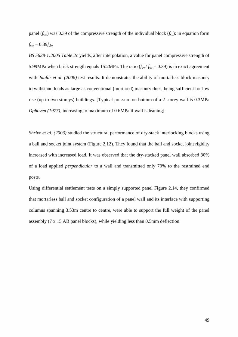
49
panel (fcw) was 0.39 of the compressive strength of the individual block (fcb): in equation form
fcw = 0.39fcb.
BS 5628-1:2005 Table 2c yields, after interpolation, a value for panel compressive strength of
5.99MPa when brick strength equals 15.2MPa. The ratio (fcw/ fcb = 0.39) is in exact agreement
with Jaafar et al. (2006) test results. It demonstrates the ability of mortarless block masonry
to withstand loads as large as conventional (mortared) masonry does, being sufficient for low
rise (up to two storeys) buildings. [Typical pressure on bottom of a 2-storey wall is 0.3MPa
Ophoven (1977), increasing to maximum of 0.6MPa if wall is leaning]
Shrive et al. (2003) studied the structural performance of dry-stack interlocking blocks using
a ball and socket joint system (Figure 2.12). They found that the ball and socket joint rigidity
increased with increased load. It was observed that the dry-stacked panel wall absorbed 30%
of a load applied perpendicular to a wall and transmitted only 70% to the restrained end
posts.
Using differential settlement tests on a simply supported panel Figure 2.14, they confirmed
that mortarless ball and socket configuration of a panel wall and its interface with supporting
columns spanning 3.53m centre to centre, were able to support the full weight of the panel
assembly (7 x 15 AB panel blocks), while yielding less than 0.5mm deflection.

50
Figure 2.14 simply supported panel tested for differential settlement (Diagram from Shrive et al. (2003) report)
Marzahn (1999) investigated the “effects of the geometric imperfections in the bed joints to
the structural behaviour of mortarless masonry under axial compression”. In order to
undertake the tests, the brick bedding surfaces were specially machined to create different
bedding conditions. Six bedding surfaces were created (Figure 2.15).
It was observed that for the brick units with uneven bed surfaces, they had to even-out before
a uniform stress transfer was generated. Such uneven surfaces of dry-stacked masonry
demonstrated extensive deformation/settlement during initial loading. Tensile and bending
stresses occurred (Figures 2.16 and 2.17), that led to vertical cracks running through the
bricks. This flexural cracking is a common feature of dry-stacked masonry;

51
Figure 2.15 Brick surfaces of different imperfections (From Marzahn 1999)
Figure 2.16 shows the effect of irregular brick heights in one course. In Figure 2.17 the bricks
show cracking only from wall self weight (initial loading) even before they receive loading
from roof structure, ceiling and other finishing materials.
The early cracking (Figure 2.17) of bricks indicates the low strength of material used. It can
be minimised by the use of bricks with equal height in a course. Marzahn show that the
quality of surfaces influenced the strength of brick units: the more uneven the bed planes the
lower the strength because it causes initial deformation. However the initial
deformation/settlement (joints evening-out) lowered load bearing capacity by only 5 to 15%
compared to mortared masonry Marzahn (1999).

52
Figure 2.16 Cracks due to bending movements caused by unequal height of bricks in a course
Figure 2.17 brick early cracks caused by unevenness of brick surfaces
Analysis by Marzahn (1999) Photo graph taken in 2006, at Mbezi-beach Dar es Salaam Tanzania by the author during site visit.
The settlement of dry-stacked masonry is influenced by the deformation of individual bricks
and the unevenness of contact surfaces of the joint. However the movement of joints occurs
only at the lower/initial stresses: they are directly influenced by the quality of bedded
surfaces of units. It was revealed by Marzahn that the main objective of a wall structure is to
have stiff joints, so that the internal movements are minimised to prevent masonry from
experiencing tensile and bending stresses.
If the applied load/force (vertical or horizontal) is constant
Vertical load (force) F = σnomAnom = σefAef
Horizontal shear force S = τnomAnom = τefAef
Where suffix ‘nom’ indicates the nominal area (in plan) of the wall and suffix ‘ef’ indicates
the effective contact area in plan.
σ and τ are respectively normal and shear stress at brick-to-brick contact surfaces.

53
Anom is the ideal area (overall plan Figure 2.18a) designed to bear the load applied on the
block. For a block-laid on its bottom surface, the ideal area is ‘length x width’ if the brick
surface is 100% in contact (this may be achieved under mortared condition).
In the case of dry-stacked bricks with imperfect surfaces, stacked or assembled without
mortar, the ratio of effective (Aef) to nominal (Anom) contact areas (represented by symbol ηo)
is initially much less than one. As load increases, and small bumps are flattened, the ratio (ηo)
increases.
nom
ef
A
A=0η Where 10 0 ≤< η
The contact area ratio for interlocking bricks is less than one (ηo < 1) for two reasons:
• With interlocking and hollow bricks (Figure 2.18), often not all the interface area is
meant to make contact. For example with the Tanzania interlock brick (Figure 2.10),
only 47% makes contact, while for some hollow blocks this solidity or designed
contact area may be under 30%.
• With bedding surfaces, imperfections (Figure 2.18c) reduce the contact area further,
unless there is elastic deformation or bump crushing.
Figure 2.18 Stages of contact area from overall solid block to mortarless to effective contact
Figure 2.18 shows:
(a) Overall plan area, of which a full contact area (Anom) may be achieved only under
mortared condition.

54
(b) The designed interlocking or hollow contact area (AMT) is less than overall plan area
(Anom). We can represent the ratio of mortarless brick area (AMT) to (Anom) by the
symbol ηMT (effect of reduced contact area).
(c) Any deviation from flatness (irregularity of surface) reduces the surface in contact
(Figure 2.18c) on loading to an effective area (Aef). Aef that is less than AMT and
further less than Anom. Thus ηo = Aef/Ao = ηMT x ηef
The combined effect of surface imperfection and hollowness is represented by a ‘surface
utilisation factor’ ηo, where ηo<1, thereby increasing average stresses, to:
o
nom
ef
nomnomef A
A
ησσσ =×= , and therefore
efMT
nomef ηη
σσ =
Marzahn (1999) compared bricks with varying degrees of (artificially generated) surface
roughness, taking as his datum (ideal) a brick with a machined and polished surface (PLS).
He measured joint deformations (εi) under load for the six brick surfaces described in Figure
2.14 and from their deformations defined relative deformations (ki): PLS
iik
εε
= for i = RS,
NLS, NCS…etc. (Figure 2.15), where εPLS is a joint deformation for the PLS bricks.
From the computed relative joint deformations, and assuming that surface, utilisation-factor (η) for
the PLS is ηPLS= 0.97. Marzahn calculated surface efficiencies for the remaining five brick surfaces
(under full load), using the equation; i
PLSi k
ηη = . He found that the values for η vary strongly with
load, generally in the form closer to one (Figure 2.19).
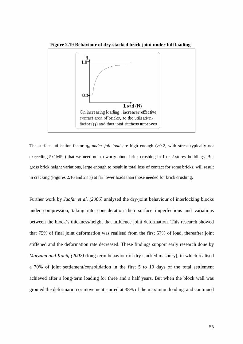
55
Figure 2.19 Behaviour of dry-stacked brick joint under full loading
The surface utilisation-factor ηo under full load are high enough (>0.2, with stress typically not
exceeding 5x1MPa) that we need not to worry about brick crushing in 1 or 2-storey buildings. But
gross brick height variations, large enough to result in total loss of contact for some bricks, will result
in cracking (Figures 2.16 and 2.17) at far lower loads than those needed for brick crushing.
Further work by Jaafar et al. (2006) analysed the dry-joint behaviour of interlocking blocks
under compression, taking into consideration their surface imperfections and variations
between the block’s thickness/height that influence joint deformation. This research showed
that 75% of final joint deformation was realised from the first 57% of load, thereafter joint
stiffened and the deformation rate decreased. These findings support early research done by
Marzahn and Konig (2002) (long-term behaviour of dry-stacked masonry), in which realised
a 70% of joint settlement/consolidation in the first 5 to 10 days of the total settlement
achieved after a long-term loading for three and a half years. But when the block wall was
grouted the deformation or movement started at 38% of the maximum loading, and continued

56
until splitting of block webs occurred. The stiffness of the joint is due to the bond between
the grout and the surrounding block shells.
In their evaluation of test results both research groups assumed that the movement under
loading was in the direction of applied force, effectively disregarding unevenness in the
surface bumps, i.e. they assumed bumps of equal height. With this assumption, vertical
loading has no effect on wall alignment: there can be no out-of-plane deviation caused by
brick rolling or rocking perpendicular to the wall surface making the wall lean from plumb.
So there remains a requirement for a study of the relationship between wall alignment and
brick irregularity i.e. how surface bumps cause a wall to lean out of plumb. Any leaning
results in a couple being superimposed on the direct inter-brick vertical loading, thereby
increasing the peak inter-brick pressure by a factor up to 2. This in turn reduces the load
bearing capacity of a wall.
2.8 PRODUCTION OF BRICKS/BLOCKS The production process for the basic elements of the wall i.e. brick/blocks and mortar, from
soil (mud) involves either stabilisation (usually with cement) or firing. The process starts with
soil identification and testing (at site and laboratory), followed by preparation
(winning/excavations, pulverising and sieving), mixing and moulding (by hand, machine
pressing or ramming between shutters). Finally, curing is needed for all elements containing
cement or drying and burning for clay elements. These various processes are well covered by
Montgomery (2002), Kerali (2001), Norton (1997), Craig (1997), Houben and Guillaud
(1994), Gooding (1993), Stulz and Mukerji (1993) and ILO (1987).
57
In this competitive world, the production process is the most important part of the building
materials industry. It assures standardised quality and adequate quantity of materials to fulfil
the needs of the market. In this thesis, we shall look at the production of Interlocking Bricks
(IB), using soil as a main raw material, bearing in mind, that
“The use of soil that is readily available, for construction, across the economic spectrum and
across the various stages of social and technological development, makes available an
appropriate and sustainable technology for the creation of the built environment” Morris and
Booysen (2000).
2.9 SELECTION OF SUITABLE SOIL FOR STABILISATION
Low-quality stabilized bricks result from lack of control or monitoring of materials and of the
whole production process. The field of soil-selection involves identification of the
distribution of gravel, sand and fines (silt and clay) within a sample. To limit the size of
gravel and remove other large particles, after being first pulverised, soil is passed through a
standardised sieve with 4-6mm openings. An important factor in soil stabilization is the soil’s
cohesion that depends in its fines fraction. Soil selection is often conceived as a once-off
process of testing to confirm the soil passes the criteria for stabilization and to determine the
best ratio of soil to stabiliser. However to maintain soil consistency, it is necessary in practice
to constantly monitor the soil’s properties and compensate for any changes that occur.
The test procedure and the coherent test plan described by Gooding (1993), for preliminary
on-site testing is one of major steps of soil selection. Although the bottle/sedimentation and
linear shrinkage tests were recommended as ‘laboratory tests’, The author is of the opinion
that such tests could be used in the field and provide reliable guidance for determining
mixing ratios for cement to soil (Gooding 1993, Houben & Guillaud 1994, Norton 1997,
Burroughs 2001). The information reported in Table 2.2 suggest that a soil with a shrinkage

58
less than 2.5% or greater than 9% should be discarded for stabilization unless it can be
modified to achieve adequate cohesion (clay content between 10% and 35% BRU-B2 (1974).
Any soil modified by blending should be tested repeatedly until the attained shrinkage is
between 2.5 and 9%. Data in table 2.2 is a result of field experience in agreement with the
calibrations after VITA (1975) for a low-pressure machine up to 2MPa, and higher-pressure
machine of up to 10MPa after Webb (1988). Linear shrinkage (LS) test results determine the
ratio that allow calculation of the amount of stabilizer to be used as well as the compression
needed. Also agreeing with Webb and Lockwood (1987) recommendations concerning choice
of machine;
• Low shrinkage soils (high sand content) are better stabilized with Portland cement
(PC) and compressed by high power (> 4MPa) machines, while
• High shrinkage soils (high clay content) are better-stabilized using lime and low
power (to 2MPa) press machines.
Table 2.2 Level of soil shrinkage with recommended compression pressure (Data using Alcock’s shrink-box - 600x40x40 mm)
Source Measured shrinkage
(mm)
Shrinkage (%)
Recommended cement to soil ratio (C: S)
Cement (C %)
Remarks
Gooding (1993) Hauben & Gullaud (1994) ILO (1987). Norton (1997), UN (1992) VITA (1975) Webb & Lockwood (1987)
6 – 15
1 to 2.5
1:20
4.8
Only for heavy compression above 4MPa provided soil proves to have enough clay to reduce handling breakages
15 – 25 2.5 to 4,17 1:18 5.3 Satisfactory for normal compression up to 4MPa
25 – 35 4.17 to 5.83 1:16 5.9 Best soil for compression as low as 2MPa
35 – 45 5.83 to 7.5 1:14 6.7 Satisfactory soil for compression as low as 2MPa
45 – 55
7.5 to 9.17
1:12
7.7
Fair soil for compression even lower than 2MPa but of low production pace due to sticking Characteristics (high clay content).
55 – 60
9.17 to 10
1:10
9.1
Poor soil; may need blending to reduce sticking or may need more Cement thus more expensive. Acceptable only when no alternative.

59
After measurement of fractional distribution of the soil, its linear shrinkage and selection of
appropriate ratio (cement to soil – C: S), the final stage is to produce trial bricks; at least ten
blocks from each soil batch. This is used to verify appropriateness of the soil for stabilisation
using the proposed soil to cement and water to cement ratios (Table 2.3). The following
observations to be made:
• The mixing process: if it is difficult, it indicates too high a clay content in the mix.
The soil requires modification, either by the addition of extra cement or by blending with
sandier soil.
• The rate of breakages on carrying the fresh bricks to their curing place. Too high (>
10%) a rate indicates there is too little clay in the mix.
• Crack developments, warping and any significant shrinkage during the first three days
of curing. If this is too severe, indicates a too-high clay content that may require either sand
blending or addition of extra cement.
• Testing the compressive strength at three, seven and fourteen days to check the
effectiveness of stabiliser (minimum strength after 14 days >1MPa). The test depends on the
availability of a suitably-equipped laboratory and demands of the project Gooding (1993).
The above quality control checks normally will continue for the whole period of production
for every fresh soil batch even if the soil is from one source. Less checking is required if the
soil is prepared all at one time.
2.9.1 SHRINKAGE BOX FOR SOIL TESTING
The shrinkage box is a mould for linear shrinkage test. Linear shrinkage is defined as “the
change in length of a bar-sample of soil when dried from about its liquid limit, expressed as a
percentage of the wet length” (BS 1377-1:1990 clause 2.2.15). A wide variety of shrinkage

60
box dimensions (Table 2.3) are used in different parts of the world. The variation in the
suggested initial moisture content of soil test samples between one researcher and publisher
to another is also confusing, but we can clarify this by defining the two moisture conditions;
Liquid Limit (LL) and Optimum Moisture Content (OMC).
Table 2.3 Linear shrinkage moulds used in different parts of the world S/No Source Box shape Box size in mm
(Internal dimensions) Initial
Moisture Content (MC)
Where more
Applicable 1 BS 1377 (1990) Half round 140 x 25Ø To LL
Consistency Laboratory
2 CML-TLM1999 (2000) Half round 140 x 25Ø Within 1% of LL Laboratory 3 California
Test 228 (2000) Polygon Tapered
Top 127 x 19.05 x 19.05 Base 127 x 17.48 x 17.48
Wetter than LL
Laboratory
4 Burroughs (2001) SAA (1977)
Half round 250 x 25Ø a) 250 x 25Ø b) 135 x 25Ø it is used only with small soil sample
Near LL At the LL
Laboratory
5 Keefe (2005) Rectangular 600 x 50 x 50 OMC Site 6 Gooding (1993)
Houben & Guillaud (1994) Stulz & Mukerji (1993) Adam & Agib (2001)
Rectangular Alcock shrink (box) mould 600 x 40 x 40
Near LL OMC OMC OMC
Site
7 Norton (1997)
Rectangular a) 600 x 40 x 40 b) 300 x 20 x 20
OMC (Controlled by drop test)
Site
8 Wolfskill at el. (1963) Rectangular 127 x 19.05 x 19.05 (5” x ¾” x ¾”)
Slightly wetter than LL
Site and Laboratory
Liquid limit (LL) is moisture content in a mix that allows the mix to start flowing i.e. a
change of consistency from plastic to liquid state.
Optimum Moisture Content (OMC) is the moisture content in a cementitious mix
that contains enough water for cement to complete its hydration reaction (normally is 0.25 of
water to cement ratio) plus additional free water to fill pores improve mix workability.

61
Usually the extra water is just enough to enhance densification (Wolfskill et al, 1963) on
compaction “Optimum moisture content at which a specified amount of compaction will
produce its maximum dry-density” (BS 1924-1:1990 clause 2.23).
The free water can be specified and verified by trial mix because of its dependence on various
soil characteristics;
• The type of aggregates (porous or impermeable)
• Shape of aggregates from round to sharp that affect workability of mix
• Type and amount of fines
From the definitions above, it is evident that LL and OMC are two different conditions for
the moisture content in a mix, meant for different purposes. They therefore cannot be
considered to be interchangeably, a wrong assumption used in the work of Keefe (2005),
Houben & Guillaud (1994), Adam & Agib (2001), Norton (1997), Stulz and Mukerji (1993)
(Table 2.2). OMC is a proper mix consistency for brick production (Hydraform Manual,
2004) that can be checked by simple field drop test; if the soil ball breaks into few (4-6)
lumps then the water content is right (near to OMC).
However the author agree with BS 1377:1990, Burroughs (2001), Gooding (1993) and
Wolfskill et al. (1963) that the moisture content (Table 2.2) at the start of a linear shrinkage
test should be near the LL (“This moisture content is not critical to within a few percent” BS
1377-2: 1990 clause 6.5.4.2 NOTE), with the aim of checking the soil plasticity and getting a
rough idea of how much stabiliser is required to modify the soil for safe use in severe
conditions.

62
2.10 BRICK CURING
2.10.1 BRICK HANDLING
In traditional concrete block production, the block is ejected together with a pallet from a
machine and placed at the curing area until next day. However during production of
stabilized-soil bricks, it is common practice for each brick to be removed from the machine
manually without a pallet to support it. The brick is then placed on the curing floor either on
its end-face or on its front/back-face (Figure 2.20). The faces likely to be affected by warping
and a flexure are the top and bottom (Figure 2.20). Such distortion is likely to happen if both
these two faces are left free during curing, so one of these faces should be placed on a hard,
straight and level base for the first two to three days.
The reason why bricks are traditionally not placed on their bottom or top faces is to avoid
these faces torching the dirty and uneven surfaces of poorly prepared curing floors. We
recommend with flat floors, place bricks on their bottom and with poor prepared floors place
them on their sides or ends.
Figure 2.20 Specification of bricks’ sides as used on block-work position

63
The controlling factors for deciding how and where the brick are placed on the curing surface
are as follows: -
• As handling is a significant component of labour input, it should be made as fast and
comfortable as possible, for example by mounting the press at ergonomic height
(waist-high) table into which bricks will be place until they harden.
• The quality of the curing floor; if the floor is not well prepared (is not level, or has
loose sand or aggregates that may stick on the surface) it may cause the bricks to have
a curved face. Many professionals recommend that a plastic sheet should cover the
floor. This does not change the floor surface level, but it does prevent loose material
from sticking on to the brick surface. Any irregularity of the floor will still however
be stamped on the brick surface, giving it a shape distorted from that desired.
2.10.2 CURING CONDITION
Hardening of any concrete products requires the continued presence of water in the brick to
enable cement to complete hydration process (Kerali, 2001). The strength of the concrete
components made from Ordinary Portland Cement (OPC) increase gradually with time (ILO,
1987). The purpose of curing is to maintain moisture in the concrete component for the whole
period required of hydration process. To achieve proper curing, it is necessary to control
curing duration and site conditions (Kerali 2001). Curing duration is dictated by the type of
binder used, for OPC as per BS 12, (1971) and ILO, (1987) 28days is recommend. In brick-
making this would be expensive to maintain, and 7 days is probably a better compromise
between maximizing strength and minimizing curing cost. The curing conditions depend on
environment (wet, dry, temperature, wind etc.) the component is placed (Kerali, 2001). For
Interlocking bricks meant for dry stacking, there are additional important conditions that
64
affect surface tolerance, such as poorly prepared curing floors, curing in open air and without
cover.
A poorly prepared curing floor (not level, permeable, with loose sand or aggregates) is most
damaging to brick quality, because in such condition the green (fresh) brick is denied the
ability to retain sufficient moisture, therefore inhibiting the cement hydration process. This
can result into a low strength brick (Kerali 2001, and Odul, 1984), warped, curved and with
severe shrinkage.
Therefore curing requires proper support and good moisture control, shading, covering and
frequent watering to maximize the cured strength. However placement of bricks on flat,
clean, firm and impermeable surfaces for the first four hours prevents bricks from warping
and curving. So poor curing is one of the major sources of poor quality (inaccurate and
unstable) of dry-stacked (mortarless) walls because it inculcates irregularity of bricks.
2.11 SUBJECTS WORTHY OF FURTHER ANALYSIS
From the literature review, seven topics/issues were identified as deserving further research
and are very briefly analysed below. However only the last two of these topics are taken
forward for fuller analysis in the ensuing chapters: the others require the attention of other
researchers.
1. The relationship between the shape of IBs and the proportion of stabilizer
required for the production mix .
There is a direct relationship between brick configuration and the quantity of
stabilizer/cement needed to strengthen the soil. The simpler the shape of the interlocking
brick (i.e. solid or with minimum perforations) the less the stabiliser fraction needed to meet

65
strength requirements. More complicated shapes, with thin features (protrusions or tongues),
require stronger materials. Therefore there is a need to develop or choose the most favourable
shape of interlocking bricks to give best results, by using the minimum stabiliser and simple
moulding machine to attaining the required wall stability and strength.
2. Optimising the size of brick grooves and chamfers acting as key to plaster
mortar .
The grooves made in bricks, for example of the Thai type (Figure 2.2) appear on the wall
face. Also the chamfers on the free edges of the brick form grooves where bricks meet. These
grooves differ in magnitude, and because of their volume may increase the render mortar
required, or they may reduce it because of the better “key” which they provide (allowing
thinner mortar). For best plaster and wall strength, the minimum size of groove consistent
with good keying should be identified. If un-plastered, big grooves are better as they save
material in brick. If plastered, small grooves are better because plaster is more expensive than
brick.
3. Constant-volume versus constant-pressure production of IBs
Blocks made in press moulding machines, i.e. where a defined pressure is applied, will vary
in size for several reasons. There are:
(i) Incorrect amounts of soil
(ii) Inconsistency of soil
(iii)Different moisture contents of soil
(iv) Incorrect pressure applied
By contrast, bricks made in machines with a fixed mould size (constant volume) will vary in
density due to reason (i) to (iii) above and hence have variable strength. The preferable

66
method is the constant-volume, which can easily control brick dimensions, which is more
important than achieving constant density in IBs. The first test is to check the density of fresh
brick from the press. If it resists the handling pressure to move brick from machine, it is
believed that both the volume of material and the moulding pressure are satisfactory. The
second test proposed by Montgomery (2002), is the “Indentation testing for green brick”. It’s
application therefore requires further experiment. This test defines the weight of a ‘rod
punch’, the height it is to be dropped from and the maximum allowable indentation it
produces. The indentation test may be easily tracked throughout curing duration.
4. Choice of direction of compacting/pressing bricks and dimensional error
consequences on bricklaying
When moulding bricks, the compacted/compressed side in normal cases is the top or bottom.
The conventional method of pressing bricks with a piston and a moulding rectangular will
closely control two of the three-dimensions of the brick and less closely the third dimension.
The poorly controlled dimension is that in the direction of the piston stroke (Figure 2.21), for
example the brick height is impinges on the top of the brick. Moreover which the mould
walls will be parallel, the piston may not be exactly parallel with the base: thus the pressed
face may be at a slight angle to the opposite face. Depending on the type of locking features
the compaction force can be applied perpendicular to the end, top or front-back faces of the
brick.
(i) Compaction force is applied perpendicular to brick end faces (as for the Solbric
and Hydraform blocks)
For any given compaction pressure this will minimise the force that has to be applied since
the area of the brick end is small. Minimising force allows the press linkages to be made less

67
strong. As shown Figure 2.21 the pressures inside the brick during moulding are likely to be
more variable, as which the piston-end (F2) of the brick experiences full pressure (P).
Figure 2.21 Press machine operations schema
Ppiston = F2/Aend-face
The opposite end of the brick experience a lower pressure
Pmould = (F1-τ)/Aend-face
Where, τ is the shear-force between the soil and the sides of the mould. For a length to width
ratio of 2:1, Pmould may be as little as Ppiston/2 (Gooding 1993). Variability in pressure along a
brick implies variability of density on ejection from the mould. F1 = F2, but while all of F2 is
transmitted to soil, only some of F1 is.
If the brick is controlled in its height and width, so a wall built using these bricks will have
level courses with minimum gaps between courses. Also wall will have even internal and
external surfaces, which leads to minimum thickness of plaster. However to allow for
variable brick length requires larger gaps at perpend (per-course).

68
(ii) Forces applied perpendicular to the brick’s top/bottom faces (as in Thai, Bamba,
Auram and Tanzanian types).
This mode of pressing is essential if the top and/or bottom face are of complex shape. It will
control brick width and length; so that, both internal and external wall surfaces will be flat
because of uniform brick width. From the accuracy of brick length it is easy to maintain
equal and constant overlaps for alternating courses, and therefore simplifies the process of
estimating the brick quantity required in the construction. It also facilitates the
standardisation of house measurements to multiples of brick length or width. Although for
constant-volume pressing all dimensions are fixed, only certain surfaces are ‘wiped’ during
moulding and ejection, which does not affect dimensions. However variation in brick
dimensions made in a fixed-volume press might be caused by:
• Air trapped at piston or at mould-end
• Expansion on release of pressure (in the direction of retreating piston)
• Distortion during de-moulding
• Rocking of the piston, so the pressed face is not perpendicular to other faces.
(iii) Force applied perpendicular to brick front/back faces
It will control the height and length of the brick, which will allow the wall to have one
uneven (internal) surface. To make the surface straight and even will lead to a small increase
in thickness of plaster.
Table 2.4 summarises the effects of brick pressing to each of the three dimensional directions,
the strength and weaknesses are given for each compaction scenario and the errors expected
and how they affect the wall alignments.

69
Table 2.4 Advantages and disadvantages of compaction scenarios
S/No Compaction
Stroke Direction
Loading Direction
Advantages Disadvantages Remarks
(i) Along the brick length i.e. force applied to end faces
Perpendicular to compaction
a). Easy to lay (level and plumb) bricks of controlled thickness and width.
b). Straight and flat wall surfaces resulting in min. thickness of plaster. c). Low force for a given pressure as end area is small.
a). Unequal brick overlaps in alternating courses. Give unpleasant appearance. b). In a given wall length may lead to brick cutting at site, which will increase - construction time, labour cost, also material waste. c). Likely to have a high variation in density 4(i). d). Only compatible with sliding interlock.
Brick load bearing strength not known if compaction and loading are on different direction and surfaces.
(ii) Parallel with brick height i.e. onto top or bottom face
Normal to the surface of compaction
a). Min. thickness of plaster. b). Automatic laying equal and constant brick overlap (half brick). c). Simplifies house measurement, (standardisation to multiples of brick length or width). d). Easy and accurate estimate of brick quantity.
Levelling of brick courses may delay the construction speed with dimensional differences in brick thickness.
a). A small amount of mortar will be needed to compensate or level the wall courses. b). Scraping to reduce excess brick thickness delays construction, and hence increases labour cost.
(iii) Parallel with brick width i.e. pressed front-to-back
Perpendicular to compaction direction
a). Easy to lay bricks. b). Equal and constant overlaps automatically formed. c). Simplifies standardisation. d). It is easy and accurate to estimate number of bricks.
Require thicker plaster on uneven wall surface to make it straight and flat. Not compatible with any interlock.
Unknown strength of brick as direction and surface of compaction during production different to those of loading.
5. The effect of the brick locking mechanism on wall stability.
Wall alignment (stability) in mortarless construction depends entirely on the locking
mechanism, whereas in a conventional wall stability depends on mortar joints. Control is
needed over both the height and the length of a wall. To keep the dry bonded wall straight
horizontally and vertically may need an effective locking system that requires particular
shapes of bricks. Large rooms with walls which do not contain a major opening but exceeds
2.5m height and not more than 3m in length BS 8103-2:2005 other straightening mechanisms
such as shimming or mortaring, piers and beams will be required.

70
Piers are inbuilt columns, protruding from the wall surface by a half brick or more. They are
built at intervals depending on the distance from one support to the next and on the height of
the wall. By building the piers, ribbed wall panel are formed. With piers less or equal to 3m
apart, the wall may be built up to three metres high without need for horizontal strengthening.
Increasing the distance between centres of piers up to 4.5m will require the wall to be
strengthened horizontally (Weinhuber, 1995) by beams at both cill level and lintel or below
the roof at ring beam level. Strengthening methods need to be assessed for economic
comparison for their comparative cost.
6. Brick tolerances
Dimensions
The dimensions of the brick are the measurement of length (l), width (b) and height (T) as
shown in Figure 2.20.
In a mortarless technology, the bricks are to be laid one over the other with their top and
bottom surfaces in direct contact, so the dimensions of each brick needs to be to a tolerance
of ±1 millimetres. This will make the wall formed by these bricks to be flat (depending on the
constancy of the width of the bricks) on its surfaces, and the overlaps (depending on the
length) of the bricks will be equal or of a certain interval required. The horizontal and straight
rows will be affected by the uniformity of height of the bricks.

71
Surfaces
A brick (Figure 2.20) has three pairs of parallel outside faces (two ends, front and back, top
and bottom). The flatness of the surfaces of these faces is paramount in mortarless brick
technology because of the absence of mortar.
In particular, the top and bottom surfaces of the bricks need to be flat, parallel and without
any deformations, which in practice is very difficulty to achieve. That’s why, in conventional
masonry, mortar is used to compensate and take care of gaps caused by brick inaccuracy. In
some cases the material needs to be flexible, so that when loaded will automatically adjust to
fit in whatever the tolerance will be. Usually we put conditions of tolerance in accordance
with allowable standard deviations that for interlocking brick have yet to be established. The
limits of allowable brick inaccuracy should be known for production quality control,
standardization, and wall construction accuracy performance.
Accuracy of alignment
Mortarless technology will not work if the bricks, to be assembled do not fit and lock to each
other. This locking mechanism, allows the units be arranged (bonded) one over the other to
form stable wall in a designed height and width, to a certain accuracy of verticality and
horizontality. The locking features (knobs and depressions) should provide enough tolerance
(±1 mm along the brick) to allow flexibility and ±¼ mm transversally for a minimal
allowance between male and female in arranging the bricks. This need to be done so, because
the material is brittle (stabilised soil can be easily broken if forced to fit).
7. Construction flexibility
The interlocking bricks and part bricks available to date allow only one pattern of brick
assembly that abides to the rules of bricklaying good practice (The BDA Guide 2000. Nash

72
1991. Nash 1983). All interlocking bricks support stretcher bond only (Figures 2.1, 2.2, 2.3,
2.5, 2.8, 2.11 and 2.12), and so have limited construction flexibility compared to
conventional/mortared bricks. Therefore we need to investigate alternatives and possibilities
of increasing mortarless-wall construction flexibility.
2.12 CONCLUSION TO LITERATURE REVIEW
Of the seven subjects discussed above, the critical ones for mortarless technology are
construction flexibility and brick accuracy.
Interlock-bricks configurations restrict the builder to only constructing stretcher bond, half-
brick-thick walls and right-angled quoins. Thorough analysis of brick configurations, parts,
bonding or patterns and joining techniques is needed to remove this weakness and so rescue
the technology from being rejected by architects for not providing enough construction
flexibility (Chapter 4).
The wall straightness, plumbness, stability and stiffness will not be attained if the bricks are
not made with good tolerance or are distorted in shape. There is a need to find the main
reasons for the irregularities found in current brick systems that hinder the ease and accuracy
of wall construction by mortarless technology. It is time to identify the maximum brick
deviations that MT can tolerate yet achieve acceptable wall accuracy. This research focuses
on the causes of brick irregularities, how to minimise them (Chapter 5) and the implications
of different degrees of irregularity. Also the investigation describes brick uniformity
tolerance in relation with mortarless wall alignment (Chapter 6 and Chapter 7).

73
CHAPTER 3
3.0 RESOURCE USE IMPLICATIONS OF EMPLOYING MORTARLESS TECHNOLOGY
3.1 INTRODUCTION
The construction of walls makes use of natural resources, including labour, which has
significant cost consequences. Interlocking stabilised-soil bricks (ISSB), whose use is known
as Mortarless Technology (MT), are produced from the following physical resources: cement,
soil, water, equipment and energy. Any new technology will be attractive (Co-Create 2004,
Stewart 1987, Moustafa 1990) if, in comparison with what is currently used (conventional),
it: -
• Reduces use of limited (natural) resources
• Reduces cost
• Reduces constraints, by being more accommodating
• Better matches the context of use, and
• Increases performance (appearance, durability, productivity etc.)
In this chapter we compare the cost of MT walls using two variants of dry-stacked ISSB
(Hydraform – ISSB-SA Figure 2.4 & Tanzanian – ISSB-T Figure 2.10), with walls
constructed using Conventional (mortared solid-sand-cement) Blocks CB, currently the most
popular modern form of wall construction in Tanzania. With CBs we can build a 150mm
thick wall by laying bricks (CB-1) as stretchers on their front face, or a 230mm thick wall by
laying CB-2 as stretchers on their bottom face (see Figure 2.20). The descriptions of the
bricks/blocks used for the walls compared are summarised in Table 3.1. In each case we
assume one square metre of walling is to be produced by a competent brick/block maker and

74
a skilled mason. We might have compared MT with hollow CBs instead of solid ones, but
field experience shows that hollow blocks are not cheaper than solid as they require richer
mixes and during construction waste a lot of mortar, which is more expensive than block.
Also hollow blocks allows fewer courses be laid in a day than solid blocks as for stability
purposes the mortar needs more time to strengthen.
Table 3.1 Characteristics of walls compared
S/No System Brick type
Brick volume (litres)
Mortared wall
Un-mortared
wall
Wall-thickness
mm
No. of bricks per m2
1
Mortarless Technology
(MT)
Perforated ISSB-T*
300x150x100mm
4.5
Optionally
grouted 150 33
2 MT Solid ISSB-SA**
230x220x115mm
5.8
¼ of courses are mortared
¾ of courses un-mortared 230 40
3 Conventional
Block one CB-1
Solid CB-1 450x230x150mm
15.5
Laid on its front face
150 9
4 Conventional
Block two CB-2
Solid CB-2 450x230x150mm
15.5
Laid on its bottom face
230 14
NOTE: * Interlocking Stabilised-Soil Brick Tanzanian type
** Interlocking Stabilised-Soil Block South African type (Hydraform system)
In general MT is less flexible than mortared block, because there is no option of cutting
bricks on site. However Chapter 4 shows as an outcome of this research, that the Tanzanian
MT-set meets most architectural requirements (Table 4.1), so the flexibility objective is met
but only at the level of ‘not less flexible than’ conventional technology.

75
3.2 NATURAL RESOURCE USE
Most building materials are created by labor from naturally occurring substances, such as
clay, sand, wood and rock. The production of bricks is the system of processing the raw
material supplied by the earth. This section describes the three main constituents of
stabilised-soil brick production:
• Cement, which require the resource of land from where raw material are obtained,
plus much energy for manufacture, usually from fossil fuel
• Soil (sand and clay), which require land for quarrying
• Water
The comparison is made of how much each technology (ISSB and CB) utilises cement,
whose production is the major generator of greenhouse gases in the building industry.
Therefore any measure to reduce cement use will help preserve the environment.
A simple method for determining how much water is needed for production is also shown.
3.2.1 CEMENT
Cement is a vital component for soil-stabilized bricks, enhancing both strength and durability.
Cement, an expensive element, can be kept down to the range of 3 to 10 % of the mix without
compromising performance (Section 2.9). From Tanzanian experience, a ratio of 1:16
(cement to soil) can produce an average of 100 stabilised-soil bricks (ISSB-T) from one 50kg
bag of cement Table 3.1. This is equivalent to 450 litres of wall volume. By contrast CB with
cement-to-sand ratio of typically 1:8 can only produce 20 blocks per 50kg bag of cement
(equivalent to 310 litres of wall volume). Therefore ISSB yields 31% more wall volume than
CB.

76
To make a fair comparison of cement consumption between the two systems of production
and construction, we first need to explain the reason for the difference in cement content
between the two systems.
Soil stabilization as shown in Table 2.2 (presented in diagram form Figure 3.1) has the
characteristic that the less the clay (less shrinkage) the less the cement required in the mix,
but the more powerful the press (more than 4MPa) that is needed. With a higher clay fraction
(higher shrinkage) the more the cement required but a low pressure (up to 2MPa) press is
satisfactory. CB traditionally employs only ‘clean sand’; in consequence CB requires extra
cement to compensate for the sand’s lack of cohesion and to fulfil the high early strength
required for remoulding from pallets after twenty four hours.
With ISSB it is normal to use soils with some clay in them (Table 2.2 and Figure 3.1). This
clay gives a number of advantages in production:
• No pallets are required,
• The technology is tolerant of a wide range of soils, and
• Less cement is required, which may further be of benefit to the environment as
discussed below.

77
Figure 3.1 Limit of soils for stabilisation that reduce cement use in the brick production
3.2.2 CEMENT REDUCTION
Interlocking stabilised-soil bricks (ISSB) can save cement in both brick production and
bricklaying compared to Conventional blocks (CB), as shown in Table 3.2, where a one story
house of three bed-rooms built using ISSB-T is compared to one built with CB. The house
wall area is 182m2, requiring 6000 ISSB or 1638 bricks for CB-1 and 2548 blocks for CB-2
respectively (Table 3.1 show number of bricks in one square metre for each type of brick). In
section 3.2.1 we compared the number of brick produced from one bag of cement. The
quantity of cement per unit volume (litre) computed as follows:
ISSB-T consumeslitresbricks
kg
5.4100
50
×= 0.111 kg of cement per volume (litre) of brick-mix,
with the same formulae we get CB-1 consumes 0.161kg cement per litre block-mix.

78
In conventional walling mortar is compulsory. The density of OP cement mortar is 2162
kg/m3 = 2.162 kg/litre. If the mortar ratio is 1:4 (cement to sand) the cement content will be
(1/5 = 0.2) of the total volume. In practice volume batching is normally used, which increases
the weight of cement because cement has a higher density than sand. And due to the fact that
mortar require more workability and hence more water, a cement content of up to 0.5kg per
litre mortar may be employed (increased from 2.162 x 0.2 = 0.4324kg/litre).
One CB-1 plus its joint mortar occupies 460 x 240mm of a wall surface area, of which the
block occupies 94% and mortar joint (10mm) occupies 6%. The total cement consumption for
block and mortar will be:
94% is block @ 0.161kg cement per unit volume (litre) of block
6% is mortar @ 0.5kg cement per litre of mortar,
Giving:
(0.94 x 0.161) + (0.06 x 0.5) = 0.151 + 0.03 = 0.181 kg/litre of wall
Therefore {(0.181 - 0.111)/0.181 = 0.39} CB-1 consumes 39% more cement than ISSB in a
wall unit volume.
3.2.3 CEMENT & GREENHOUSE GASES
The threat of climate change has pushed the reduction in emission of greenhouse gases high
on the world political agenda. This has motivated professionals to find new ways of
designing buildings to create zero-carbon development Eco-towns (2008). Cement is
fundamental to building; it is a key component of concrete, essential for building and civil
engineering i.e. houses, bridges, airport runways, modern reservoirs, underground stations,
etc. BCA (2007). However cement is fast growing to be a major barrier on the world’s route
to the low-carbon economy, since as the production of cement grows, so too do greenhouse
gas emissions (The Guardian 2006).
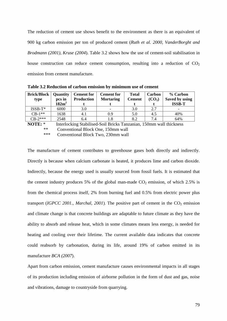
79
The reduction of cement use shows benefit to the environment as there is an equivalent of
900 kg carbon emission per ton of produced cement (Ruth et al. 2000, VanderBorght and
Brodmann (2001), Kruse (2004). Table 3.2 shows how the use of cement-soil stabilisation in
house construction can reduce cement consumption, resulting into a reduction of CO2
emission from cement manufacture.
Table 3.2 Reduction of carbon emission by minimum use of cement
Brick/Block type
Quantity pcs in 182m2
Cement for Production
t
Cement for Mortaring
t
Total Cement
t
Carbon (CO2)
t
% Carbon Saved by using
ISSB-T ISSB-T* 6000 3.0 - 3.0 2.7 - CB-1** 1638 4.1 0.9 5.0 4.5 40% CB-2*** 2548 6.4 1.8 8.2 7.4 64%
NOTE: * Interlocking Stabilised-Soil Bricks Tanzanian, 150mm wall thickness ** Conventional Block One, 150mm wall *** Conventional Block Two, 230mm wall
The manufacture of cement contributes to greenhouse gases both directly and indirectly.
Directly is because when calcium carbonate is heated, it produces lime and carbon dioxide.
Indirectly, because the energy used is usually sourced from fossil fuels. It is estimated that
the cement industry produces 5% of the global man-made CO2 emission, of which 2.5% is
from the chemical process itself, 2% from burning fuel and 0.5% from electric power plus
transport (IGPCC 2001., Marchal, 2001). The positive part of cement in the CO2 emission
and climate change is that concrete buildings are adaptable to future climate as they have the
ability to absorb and release heat, which in some climates means less energy, is needed for
heating and cooling over their lifetime. The current available data indicates that concrete
could reabsorb by carbonation, during its life, around 19% of carbon emitted in its
manufacture BCA (2007).
Apart from carbon emission, cement manufacture causes environmental impacts in all stages
of its production including emission of airborne pollution in the form of dust and gas, noise
and vibrations, damage to countryside from quarrying.

80
3.2.4 SOIL
Although site planning is a well-known subject in the building industry, the full utilization of
available resources at the individual sites (plots) is rarely achieved. Every site produces
enough soil for brick production from three sources: the foundation trenches, the septic tank
and the soak-away pit. Tanzanian experience shows that the soil from the three sources
mentioned above can produce more than six thousand perforated interlocking bricks, which
are enough to build a medium-size single-story house. What is required here is to test the soil
available on site first before going anywhere else. Proper soil selection for stabilization is, as
argued in Chapter 2, a well covered theme. Soil is a major raw material for stabilized brick; it
requires only labour for its preparation and therefore in a low-wage country is the cheapest
material for brick production.
3.2.5 WATER
The importance of water in construction and in building material production is well known,
but the quantity needed is normally not clearly assessed, nor its availability checked nor did
its significant cost realise. It is assumed to be readily available and cheaply obtained when
needed. In developing countries (African ones in particular) lack of clean water is among
things that hinder health and development in general.
The cost of water for brick-making is sometimes higher than the cost of soil when the latter is
obtained in the vicinity of the site. Many African rural districts, villages, and even suburbs of
towns have no permanent source of water (pipe water) and thus the quality is not guaranteed.
Water cost varies from one location to another depending on source and labour. Here we
meet a major obstacle of least developed countries; scarcity of quality water that makes such
water expensive. However the production of ISSB doesn’t have requirements for water
quality differing from other concrete works as recommended by (BS EN 206-1:2000 and BS

81
8500-2:2006). Water suitable for making concrete should be free from impurities and
harmful ingredients (chlorides and sulfates, alkalis, organic and suspended solids). It is
generalised that water fit for drinking is the suitable one (BS 5328-1:1997 and BS 5628-
3:2005).
Water requirements depend on the following factors:
• Production – water consumption depends on water-to-cement and soil-to-cement
ratios
• Curing – depends on duration in days (minimum 7days). The potential strength of
any Ordinary Portland Cement (OPC) product will be maximised by curing under
moist conditions. The highest rate of reaction (hydration) between cement and
water takes place in the first three to seven days, which therefore require proper
curing/attention (BS 5328-1:1997 and BS 5628-3:2005). .
• Cleaning – depends on number of labourers and tools
The following is a simple example of estimating the volume of water for production and
curing, based on author’s practical experience with stabilised-soil brick production in
Tanzania (summary Table 3.3). Knowing the average ratio of cement to soil (1:16) and
assuming a water/cement ratio of 0.5:1, one bag of cement (50kg) requires on average three
buckets of water (60 litres) to produce 100 bricks. With one brick press, three labourers can
comfortably produce 500 bricks a day, namely a batch, and to cure one batch we require two
buckets (40 litres of water) per day for 7 days. Washing of three labourers and tools requires
five buckets of water (100 litres) per batch.

82
Table 3.3 Water quantity for production and curing
Brick Quantity
Water requirements in litres Cost (Tsh*.)
Production include cleaning
Curing for 7days
Total for Production & curing
One litre = Tsh. 12.5
One brick 0.8 0.56 1.36 17.0 One batch -500 pieces (day production)
400 280 680 8,500
* Tanzanian shillings, in 2008 £1 = Tsh. 2500
This water cost, if omitted from the project costing, may give a significant negative impact on
any project development. As the value of one brick is 250 Tsh, the cost of water is about 7%
of sale price (yet normal profit margin is typically only 7.5% of the brick value) that means if
water cost is excluded from expenditure the profit margin cover no more than 0.5%. Such
under-estimation of water requirement in brick production can prevent further development
of projects, because to minimise production cost bricks are often not cured properly.
3.3 MT PERFORMANCE AND COST REDUCTION
3.3.1 ELEMENTS OF COST REDUCTION
A major objective for an efficient and effective new technology is to make a saving in
material and/or labour time. Early in Section 2.5 it was shown that for Mortarless
Technology (MT) to operate properly bricks, need to be self-aligning and provide an effective
locking. The use of MT in bricklaying reduces or even removes a number of operations:
mortaring joints, aligning operations (levelling and straightening), and rendering. From
reduced construction operations, MT results in a reduction of construction duration of up to
60% Whelan (1985), Hines (1993), Anand and Ramamurthy (2003). Due to the simplicity of
the construction process of MT, it can be easily managed by semiskilled labour and therefore

83
cuts the labour cost up to 80% Harris et al. (1992), Hines (1993) and VanderWerf (1999).
Changing to MT also can enhance the labour productivity of wall construction by more than
80% Whelan (1985), Anand and Ramamurthy (2003).
Table 3.4 Compares the costs for the construction of one square meter masonry walls using
respectively: (1) solid Hydraform Stabilized-Soil Interlocking Blocks (ISSB-SA, Figure 2.4,
South African type – 230mm thick wall), (2) perforated Interlocking Stabilized-Soil Bricks
(ISSB-T, Figure 2.10, Tanzanian type – 150mm thick wall), (3 and 4) walls constructed from
Solid Conventional Blocks (CB-1 and CB-2, with 150mm and 230mm thick walls
respectively). Although the wall thicknesses of the four options are not the same, this can be
allowed for. All costs of materials, transport, labour and the construction processes are for
Tanzania in 2005/2006. Materials costs include site delivery.
3.3.2 WALL CONSTRUCTION STAGES
The wall construction process includes the cost of materials and only four stages are
considered (Table 3.4): Bricklaying (BL), Pointing/jointing (P/J), Rendering/plastering (R/P),
and Wall-strengthening (WS). Painting and decoration is not included, assumed to be the
same as the wall surfaces are well prepared.
The interlocking bricks are assumed perfectly produced and in good condition, likewise the
sand-cement blocks. The bricks are built in the following wall construction stages: -
1. Bricklaying [costs per piece include materials (brick) and bricklaying labour per
piece].
2. Jointing (cost is based on cement, sand and water per cubic meter (m3) of mortar).
3. Pointing of interlocking bricks (externally only); (unit cost includes mortar and
labour per m2).

84
4. Rendering/Plastering (a standardized construction cost per square meter (m2), that
includes mortar and labour). Some saving could be realized here by rendering soil-
stabilized walls with a stabilised-soil plaster that matches the lean mix used for the
bricks themselves; such lean plaster cannot be used on conventional blocks because
it will not adhere properly. This option is not generally considered, but it should be
in practice. Because of the machined MT brick quality, their external surfaces do not
require rendering; only pointing to prevent insects breeding and moisture
penetration. By contrast CB is usually given an external render to improve their
appearance.
5. Strengthening interlocking brick walls by pouring grout through vertical holes.
Hollow/Perforated interlocking brick walls optionally require strengthening by
pouring grout (soil/sand-cement slurry) into the vertical holes through the wall
Kintingu (2003), forming 50mm diameter cores at 300mm centres throughout the
wall.
This task (grouting) is normally done after completion of wall erection, while preparing the
wall to receive a ring beam. Before doing so, we insert all conduit pipes in the required
positions and any reinforcement if required. Placement of grout can be accomplished in one
lift for single-story walls less than 8.5 ft (2.60 m) high. Grout lifts must be consolidated with
an internal vibrator with a head size less than 25 mm NCMA TEK 14-22 (2003).
The Hydraform solid interlocking block wall is by contrast strengthened by laying the first
two to three courses and the four last/top courses with mortar like a conventional wall
Hydraform Manual (1988). Thus about a quarter of all courses are mortared and the
remaining three-quarter is un-mortared (Table 3.2).
Other costs not included in the calculations are: -
• Supervision by:

85
o High-level expert (Engineers or Architects), which may be done on call
(temporary) or on permanent basis.
o The foreman, on a daily routine.
• Material wastage
• Security of the site.
The above three listed items (supervision, material wastage and security) are normally
categorised under ‘sundries’ and assumed to cost not more than 5% of the above four main
wall construction stages.
Table 3.4 Cost comparison of one square metre wall in Tanzanian Shillings (Tsh.)
S/No Stages of wall construction (cost for material and labour)
Wall Type Interlocking Soil- Stabilized Bricks
(ISSB)
Conventional Sand Cement Blocks
(CB) Tanzanian
ISSB-T 150mm
Hydraform ISSB-SA 230mm
Solid CB-1
150mm
Solid CB-2
230mm
1 Bricklaying (BL) 7755 11600 14400 22400
2 Jointing/Pointing (J/P) 1 3 1196 1589
3
Rendering/Plastering (R/P) 3675 3675 7350 7350
4
Wall Strengthening (WS) (filling vertical holes with mortar)
482 0 0 0.0
Total cost for each type of wall including 5% sundries
12509 16042 24093 32906
150 mm wall equivalence 12509 10462 24093 21460 Normalised to ISSB-T costs 1 0.84 1.93 1.72 Average for each wall type 11485 22776

86
3.3.3 COST ANALYSIS
Table 3.4, which combines labour-costs with material costs, compares the average 150mm-
equivalent costs (Tsh.11485 and 22776) of MT and CB is summarised in Figure 3.2. It shows
that using mortarless technology we can reduce construction cost by 50% (i.e. MT/CB
=11485/22776 = 0.50) due to the use of cheaper material and elimination of some of the
construction operations.
An alternative approach (Table 3.5) is to look at materials costs and labour separately in the
following order:
(a) The CB material cost to labour cost ratio is assumed as 70:30 UN (1965).
(b) Estimates of MT/CB cost ratios for material (Rm) and labour (RL) are
respectively made
(c) Finally the data is combined to obtain MT/CB overall cost ratio.
For the value of Rm, the material cost ratio, we adopt the approximate value MT/CB = 0.5
from Figure 3.2 the extraction of Table 3.4.
Figure 3.2 Comparison of construction cost between MT and CB

87
The value of RL, the labour cost ratio, was estimated after a number of considerations were
made. Interlocking bricklaying is three to five times faster than conventional bricklaying
Whelan (1985), Anand and Ramamurthy (2003). This can be best compared in terms of wall
area covered per day rather than number of bricks laid per day. Taking an average laying rate
of 1150 pieces per day of interlocking bricks Hines (1993), VanderWarf (1999), and knowing
33 pieces of ISSB-T cover one square meter (Table 3.1), gives that 35m2 of wall can be
completed in a day by one mason and one helper. With conventional blocks and the same
wall thickness (CB-1) the same masons can lay an average of 225 pieces (each weighing over
30 kg), equivalent to only 25m2 of wall per day. Here we can see that the labour productivity
has been increased by 40% if we use the CB-1 as the datum for comparison. (Taking CB-2
this increases to 120 %.). We can support the above arguments by the summarised efforts
towards improving construction productivities reported by Anand and Ramamurthy (2003)
Table 3.5.
Table 3.5 Productivity enhancement as a means of labour cost reduction
S/No. Source Type of interlocking block
Productivity % increase
Labour cost ratio (RL)
1. Whelan (1985) WHB hollow block 79 0.50 2. Adamus and Spevak (1986) TSZ hollow block 0.35 3. Hines (1993) Haener hollow block 60 4. VanderWerf (1999) Haener hollow block 80 0.35 VanderWerf (1999) Sparlock hollow block 80 0.33 VanderWerf (1999) Azar hollow block 50 0.33
5. Anand and Ramamurthy (2003) SILBLOCK/HILBLOCK 80 Average 71.5 0.37
According to Harris et al. (1992) and Hines (1993) with the combined effect of less skilled
labour and increased output, MT is estimated to reduce labour cost by as much as 80%. From
this estimate; we determine that RL ≥ 0.2.
We may adapt a value of RL = 0.3 (interpolating between 0.37 from Table 3.5, and 0.2 from
Harris and Hines. Table 3.6 thus results into:

88
Table 3.6 Costs of materials and labour separated
Bricklaying system
Material Cost
Labour Cost
Total Cost
CB* 70% 30% 100% Ratio of MT/CB 0.5 0.3 -
MT** 35% 9% 44% NOTE: * Conventional Blocks.
** Mortarless Technology, partial costs expressed as % of CB Total Cost for given wall area.
MT/BC - assumed ratio of (MT to CB) costs for each input.
The value of MT labour cost being 9% of the conventional total cost, and therefore making
MT total cost equals 44%. However MT realises 56% cost saving compared to CB.
3.4 SUMMARY
Building industry can make a step forward to protect the environment by making the
revolutionary choice of using alternative walling materials (dry-stacked stabilised-soil bricks)
to replace conventional (sand-cement-blocks) that consumes more cement. The use of dry-
stacked stabilised-soil bricks realised more than 50% cement saving, thus a reduction of up to
40% of CO2 released by cement production.
The study identified the importance of water in the quality control of material using cement,
showing a simple method for estimating the water quantity needed for production and curing.
It estimated that water cost equalled 7% of brick value (selling price), equivalent to the
normal net profit margin. So omitting water costs in estimating production expenditure can
result in losses and ultimately the death of brick-production projects.
Finally the chapter compared the cost of wall construction using mortarless and conventional
technologies. MT shows a potential serving of more than 50%, this may make a substantial
contribution to making housing affordability to the low income people.

89
CHAPTER 4
4.0 INTERLOCK-BRICK WALLING FLEXIBILITY
4.1 INTRODUCTION
The difficulties of getting interlocking brick systems to adapt to a variety of conventional
wall construction configurations and shapes, joints and thicknesses, led to the study of how to
enhance the flexibility of dry-stack interlock-brick walling.
Chapter 2 described six types of interlocking stabilised-soil bricks/blocks (ISSB), the low-
cost building material for wall construction. The existing range of interlock brick designs in
the market as reported by Thanoon et al. (2004) is an indicator of popularity of Mortarless
Technology (MT) in the world; the ISSB technology is gaining more popularity in
Developing Countries. The author developed the Tanzanian Interlocking Brick (TIB) Figure
2.10, after studying the deficiencies of the Bamba interlocking brick system (Figures 2.6, 2.7
and 2.8) Kintingu (2003). This Chapter describes new developments of TIB under this PhD
program in response to building industry demands, from which interlocking bricks (IBs) have
demonstrated weakness compared to hitherto, i.e. MT using IBs has been incapable of
constructing:
(a) Various brick-bonding joints
(b) Piers attached into walls
(c) Thicker walls (thickness more than half brick length)
(d) Circular and polygonal wall configurations
There are terminologies used in the previous Chapters requires further description for better
elaboration of dry-stacked interlock-brick walling technology.

90
Technology flexibility is the ability to perform variable tasks
Common element is a regularly or normally used element, and can be produced
with a normal or standard machine.
Conventional technology is the existing standard (i.e. mortared brick) technology
4.1.1 BACKGROUND
The efforts to improve construction performance of interlocking bricks in Tanzania starts
back in year 2000 when the author faced one of the fundamental requirements of the building
construction using Bamba interlocking brick (Figures 2.6 and 2.7), namely: to provide means
of joining interlock brick walls when they meet to form tee joints or cross joints Figure 2.8.
The solution was to produce a three-quarter bat, Kintingu (2003), which raised the
performance of mortarless technology by 2 scores (tasks 3 and 4 in Table 4.1). Before the
development of Three-quarter bat the general performance of interlocking bricks was only 2
scores (tasks 1 and 2 in Table 4.1). In 2003, the further improvement of Bamba system
resulted into the formation of TIB Figure 2.10, which we can take as the starting point for this
PhD programme. We now compare the MT (Interlocking Bricks-IB) vis-à-vis Conventional
Technology (CT).
The wall construction flexibility of CT and the IB before this PhD programme is compared in
Table 4.1. The number of tasks the technology performs shows how flexible the technology
is. The existing or conventional (mortared) bricks used here as a base line. We can see that IB
in 2000 could not solve some common wall-construction tasks and therefore require more
effort to improve them.

91
Table 4.1 Wall construction flexibility of CT and IBs (year 2000 technology)
S/No. Construction Operations
Types of Interlocking brick/block (IB) Conventional Technology
(CT)*
Canadian & USA Indian South African
Thai
Haener interlock system
Sparlock interlock system
Auram Bamba Hydraform Solbric
1 Setting a right angled corner for a ½B wall
� � � � � � � �
2 Bricklaying in stretcher bond
� � � � � � � �
3 Construction of cross and tee joints of ½B walls
X X X X Special
preparations X
Site cutting �
4 Attachment of ½B wide piers to ½B thick wall
X X X X By shaving X Site
cutting �
5 Attachment of piers wider than ½B to ½B wall
X X X X X X X �
6 Construction of isolated piers wider than 1½B
X X X X X X X �
7 Construction of 1-Brick thick wall
X X X X X X X �
8 Attachment of piers to 1-Brick thick wall
X X X X X X X �
9 Construction of curved wall
X X X X X X X �
10 Construction of polygonal wall X X X X
Cutting and shaving
X X �
Flexibility score 2 2 2 2 2 2 2 10
Brick-parts (elements)* 3 3 3 2 2* 4 1* 1*
* - Typically a full brick (FB), distinct elements are created by cutting on site (half bat - ½B, three-quarter bat - ¾B and closer – CL)
From this table we can see that, in the stage of development reached by IB systems in 2000,
none had a flexibility score exceeding 2 points of 10 unless some cutting or shaving on site
is employed. Such site work removes the fundamental advantages of IB.
Before we address the outstanding problems, which are the subject matter of this Chapter
(listed in Section 4.1), it is important to get enlightened to brickwork patterns, brick shapes,
wall configurations and the importance of brick-parts for brickwork bonding.
92
4.1.3 BRICKWORK PATTERNS
The construction of masonry wall is an arrangement of brickwork into a defined pattern
known as bonding. These patterns are formed into consecutive courses (horizontal layers)
with uniform and constant overlaps of individual bricks laid one over the other. The vertical
joints (perpends) in alternate courses should be in line and truly vertical throughout the
height of the wall, however there should be no continuity in the perpend-lines from any
course to the course immediately above it. And the courses should be level (The BDA Guide
2000, Nash 1991). For constructing one-brick (230mm thick) walls, many types of bonding
pattern have been used for centuries: the most popular ones are Stretcher and Header,
English, Flemish and Garden bonds. For half-brick walls only the Stretcher bond is feasible.
English, Flemish and Garden bonds are combinations of stretcher and header bonds. In
English bonding the stretcher and header patterns alternate in consecutive courses, while in
Flemish bonding the stretchers and headers alternate in the same course. The Garden bond is
a variation of English and Flemish bonding with increased number of stretcher courses (3 or
5) for every one-header course in English bond, and for Flemish bonding headers are
inserted after every 3 or 5 stretchers of the same course.
None of the above patterns are perfect or correct without the addition of part-bricks to fulfil
the objectives of true and proper bonding of a masonry wall. Therefore part-bricks are
important units to enhance bonding accuracy, effectiveness and flexibility. Also if the part-
bricks are ready-made, not cut at site, it will save time, labour and material (Knight, 1997).
4.1.4 BRICK SHAPE
Different brick-set designs vary in configurations/shapes. But at the same time from one
design it is possible to form several shapes (Figure 2.10) by cutting the brick into parts as
demanded by the pattern. In conventional bricklaying, such cutting is a normal process, used

93
to achieve the desired pattern during construction. However, it is difficult to cut accurately
without high-standard equipment and skills, the process requires labour-time and wastes
substantial amount of material. Mortarless technology (MT) assumes production of all part-
bricks right from the mould/machine as standard, instead of cutting at site: this gives
precision and economic advantages.
4.1.5 WALL CONFIGURATIONS
The simplest wall configuration is a straight and right-angled wall that forms a rectangular
room or yard boundary. Whenever we require more complex wall configurations, then we
should think about special patterns (bonds), and the cutting of bricks to different shapes (BS
4729: 2005) to fit the proposed wall configuration and therefore allow stacking to a
particular pattern. The main purpose of building different wall configurations in a house is
to break the monotony of wall appearance and thus increase the building’s aesthetic appeal.
One major constraint on using interlocking bricks is the difficulty of employing them in the
construction of curved and polygonal walls. Although there are special bricks for such wall
configurations, in remote areas (especially of developing countries) it is not easy to get
them.
Curved and polygonal walls are however normal architectural features and designers will
not appreciate any new technology not providing such flexibility. Interlocking brick by its
shape is restricted to a particular pattern of half brick overlaps. Due to geometric rigidity,
for most interlocking bricks it is considered not possible to build curved and polygonal
walls unless special bricks are made. In this chapter the author analyses and describes a
few alternative ways to resolve the problem.

94
4.2 BRICK-SET DESIGN TO ENHANCE THE FLEXIBILITY OF INTERLOCK WALLING
In chapter 2, Figure 2.10, introduced the particular interlock system “Tanzanian” on which all
subsequent PhD work would be based.
4.2.1 COMMON PART-BRICKS
“Common element” was defined in Section 4.1 as a part-brick, which is regularly used and
can be produced using a standard machine. We can summarise the common part-bricks
available made by cutting on site, used in CT and counter check its availability and use in
the IB2003 (Table 4.2).
Table 4.2 Common brick elements
Part- bricks CT IB 2003
Full brick � � Three-quarter bat � � Half bat � � Closer (quarter bat) � X
With part-bricks we change the length of the brick in order to enable the overlaps (half or
quarter brick) between two consecutive courses to abide to the rules of the chosen bond
type. Common part-bricks used for decades (defined in Section 2.2.1) are the half bat, three-
quarter bat and the closer Nash (1991), The BDA Guide (2004) Table 4.2.
Using the common part-bricks shown in Figure 2.10, Mortarless Technology (MT) can
construct in stretcher bond only a half-brick thick wall Figure 4.1. The common bond
(stretcher) is used in MT because of the configurations and locking features provided. The
locking features make the difference between the two technologies (MT and conventional).
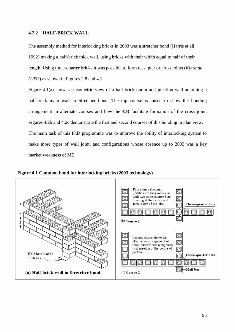
95
4.2.2 HALF-BRICK WALL
The assembly method for interlocking bricks in 2003 was a stretcher bond (Harris et all.
1992) making a half-brick thick wall, using bricks with their width equal to half of their
length. Using three-quarter bricks it was possible to form tees, pier or cross joints (Kintingu
(2003) as shown in Figures 2.8 and 4.1.
Figure 4.1(a) shows an isometric view of a half-brick quoin and junction wall adjoining a
half-brick main wall in Stretcher bond. The top course is raised to show the bonding
arrangement in alternate courses and how the ¾B facilitate formation of the cross joint.
Figures 4.2b and 4.2c demonstrate the first and second courses of this bonding in plan view.
The main task of this PhD programme was to improve the ability of interlocking system to
make more types of wall joint, and configurations whose absence up to 2003 was a key
market weakness of MT.
Figure 4.1 Common bond for interlocking bricks (2003 technology)

96
4.2.3 DEVELOPMENT OF A NEW PART-BRICK
In CT we have a half bat i.e. an element usually cut on site, which is half the length of the
brick. Once made, this element can be placed in line with one end of the brick below or in
line with the centre of the brick below. In the case of IB, half-size bricks have so far been
designed to align with the end of the brick below Figures 2.7 and 2.10, and strictly we might
call them ‘end-half bats’ (E½B) Figure 4.2(a). We now wish to introduce a second type of
half brick for location above the centre of the brick below, which we will call ‘centre-half
bat’ (C½B) Figure 4.2(b). Unlike CT, in IB construction, due to interlocking requirements the
C½B and E½B are not the same: they are different elements.
Figure 4.2 Two ½-bricks for the Tanzanian interlocking brick (TIB) system
(a) (b)
This PhD program started with the brick-set available shown in figure 2.10, which includes
E½B Figure 4.2(a). Many trials of laying half-brick and one-brick walls attached to different
sizes of piers (brick columns of 1-Brick, 1½-Brick and 2-Bricks), confirmed the potential of
a new part-brick (Centre-half bat - C½B) shown in Figures 4.2(b) and 4.3. The C½B is a
brick modified to exclude the two end quarters and remain with the centre half potion.
Bricklaying using the C½B does not follow the well-known bond types, but it conforms to
the basic rule of bonding, namely the prevention of continuous straight joints (vertical and
cross) running through consecutive courses.

97
Figure 4.3 Details of a Centre-half bat (C½B)
The major contribution of C½B is in enabling:
• the attachment of buttresses wider than ½-brick to walls
• the construction of isolated piers wider than 1½-brick
• the formation of two new bonds (Shokse and Lijuja Figures 4.9 and 4.14)
The common thickness for solid walls has been taken as 150mm. Foundation walls are
normally twice the width (300mm) of solid walls. Figure 4.4 show a ½-brick wall built on a
1-brick foundation wall, a typical foundation used for single story buildings.
This research has therefore adopted 150mm thickness as standard for solid walls and
300mm as a maximum thickness for foundation walls (Figure 4.4).

98
Figure 4.4 Typical single story brick wall foundation
The minimum width for a buttressing pier is ½-brick (150mm) Figure 4.5, and a maximum
width for a buttressing pier and of an isolated solid brick pier has been taken to be 2-bricks
(600mm).
Figure 4.5 Piers providing restraint to wall

99
4.3 USES OF C½B’S IN THE ASSEMBLY OF
INTERLOCKING BRICK - WALL
Because there is no mortar to bind them, dry-stacked bricks are vulnerable to shaking during
construction. They require strengthening to achieve tolerable plumbness and straightness in
walls over 3m long (Figure 4.5) or over 2.5m high. In Tanzania, cheap farmers’ stores are
built using concrete partial frames with a centre-to-centre distance of 4.5m to 6.0m and height
more than 3.5m. To build a masonry wall to infill the spaces, requires the formation of
buttressing piers wider than ½-brick. The invention of C½B allows construction of piers of
different widths (1-brick, 1½-brick, 2-brick etc.) attached to wall at their ends, corners,
middle and at junctions. The following subsections illustrate both attached piers to ½-brick
thick walls (buttressing) and isolated piers.
4.3.1 PIERS
A pier is a localised wall thickening, designed to increase a wall’s vertical and horizontal
stability and lateral strength. Piers may be isolated from, or attached to, the wall. Isolated
piers are simple brick columns. Attached piers are combined or joined to the wall and form
protrusions of ½-brick or 1-brick depth or even more. Accordance to BS 8103-2:2005, the
minimum length of buttressing pier is three-wall thicknesses Figure 4.5. Using the new brick
shapes it is possible to construct sizes of isolated piers and attached piers (at wall quoin,
junctions and along the walls). These piers can be reinforced if required. Let’s look at a few
examples of how to bond the joints formed by attaching piers to walls.

100
4.3.2 ATTACHED PIERS
The use of C½B is illustrated in Figure 4.6 showing a pier attached along a wall of half-brick
thickness. In the top course Figure 4.6(b) shows how to alternate the joints from first course
by the use of C½B, it is bridging between the two parallel bricks of the pier and shift perpend
(vertical joint) to the centre of the two bricks.
The ends of the C½B are joined or closed by the ¾Bs at both sides to regulate the normal
overlaps to half brick for the proceeding brickwork.
Figure 4.6 Construction of attached piers enhanced by centre-half bats
The same pattern appears in Figure 4.7, where even courses employ three parallel headers
and the odd courses employ a mix of C½B and ¾B parts.

101
Figure 4.7 Attached one and a half-brick wide pier
4.3.3 ISOLATED PIERS
Figure 4.8 show the only possible brick pattern for a square column with side length of two-
brick lengths. It uses sets of two ¾Bs bats and one C½B alternating directions in
consecutive courses. The normal size of isolated piers are one-brick (1 x 1), 1 x 1½, or 1½ x
1½ because they require few variety of part-bricks, therefore they are simple to assemble,
save construction time and hence labour cost (because labour is normally paid per piece of
brick laid).

102
Figure 4.8 An isolated solid two-brick square column
4.4 FORMATION OF NEW BOND
The new bond is needed, as the classical bonds cannot be formed from previously available
interlock brick elements (FB, E½B and ¾B). The development of a new interlocking
element (C½B, Figure 4.3) facilitated the formation of two new bricklaying patterns (Shokse
bond - Figure 4.9 and Lijuja bond - Figure 4.14) similar to English and Flemish bonds. The
bases of new bonds start with Flemish bond. They differ in the second course, where the
Shokse bond is similar to English bond and the Lijuja bond requires closers in a regular
pattern, as other brick elements. This is contrary to conventional bonding, which allows use
of closers only after quoin header. The new bonds make possible the construction of walls
thicker than half-brick, which is a new practice to mortarless technology. The author

103
considers one-brick thick (300mm) wall to be a maximum thickness for conventional load
bearing walls (Figure 4.4) and retaining walls, because of the cost implications of going any
thicker. Compared with half-brick walls, such walls will double the requirements of material
and labour work, which will add cost on both brick production and construction.
4.4.1 SHOKSE BOND
The bond developed to enable full-brick wall construction has been named ‘Shokse Bond’ –
the word shokse is the author’s nick-name. Figures 4.9, 4.10 and 4.11 show consecutive
courses for Shokse bond alternating as follows: the odd numbered (1) courses encompass
stretchers (S) and headers (H) alternating in the same course Figure 4.10, the following even
numbered (2) courses starts with a header followed by ¾-stretchers (Figure 4.9) meeting at
the centre of the headers of the odd numbered courses. This makes a continuous and
repeatedly pattern of one and a half brick-length units. At the tee junction of the second
course Figures 4.9 and 4.10, the header is replaced by two C½B units laid as stretchers in
the even courses, bridging the two headers, side by side, in the odd courses.

104
Figure 4.9 One-Brick thick wall in Shokse bond
Figure 4.11 show plans of the two alternate courses in a one-brick quoin and junction wall
in Shokse bond. Odd-number courses (1) are in Flemish bond, alternating stretchers and
headers on the wall face, expect at the tee junction. Even-number (2) courses start with a
quoin header continues with ¾ bats.

105
Figure 4.10 Front elevation of a wall in Shokse bond
Figure 4.11 Plan views of course 1 and 2 of 1-brick thick wall in Shokse bond
Walls constructed using Shokse bond are shown in Figures 4.9 and 4.10, It can be observed
that except at the tee junction, there is a continuous joint between the inner and outer leafs
making up even courses. Moreover a similar joint exists along ⅔ of each odd course. This

106
internal joint running throughout the wall height requires some means of blocking or locking.
A solution was found by the use of a closer (CL). This solution effectively defines another
new pattern (Lijuja bond) Figures 4.14 and 4.15. Lijuja bond is thus stronger but requires an
extra component in the brick set.
CL is a common part-brick in conventional brickwork (Table 4.2); TIB closer Figures 4.12
and 4.13 was incorporated for the first time in interlocking bricks under this research
program.
Figure 4.12 TIB closer is a half-brick cut perpendicular to end face
The traditional CL is a quarter-brick and according to The BDA Guide (2004) is named
‘quarter bat’. By contrast, the TIB CL is twice the length of conventional CL. The TIB closer
has the measurements (300 x 75 x 100mm); it is in effect a half-brick (see Figure 4.12 how is
cut from a brick).

107
Figure 4.13 Tanzanian Interlock Brick (TIB) Closer
(all measurements are in mm)
4.4.2 LIJUJA BOND
Lijuja bond incorporate CLs for the first time in the history of MT. Lijuja bond starts with
the first course in Flemish bond as the Shokse bond (Figures 4.11). In the second course,
after the quoin header, are found sets comprising one ¾B, one C½B and one CL repeated
throughout the course. See Figures 4.14 and 4.15.
Most literature on brickwork does not recommend the use of CLs in the face of wall except
next to the quoin header. However the Masonry Code of Practice (BS 5628-3:2005 clause
5.11.1.1) recommends that “the horizontal distance between cross-joints in successive
courses of brickwork should normally be not less than one-quarter of the masonry unit
length, in no case less than 50mm for bricks and 75mm for blocks”. This condition is
observed in Lijuja bond, as the minimum horizontal distance of the cross-joints between the
consecutive courses in Lijuja bond is equal to a quarter-brick length (75mm).

108
Figure 4.14 One brick thick wall in Lijuja bond
The purpose of adding CLs (see Figure 4.14 course 2) throughout the course is to reduce
the inherent continuous vertical joints (Knight, 1997) and to tie stretcher bricks at their
middle, preventing them from opening up.

109
Figure 4.15 Plans of alternate courses of 1-brick quoin and junction wall in Lijuja bond
The range of application of C½Bs was thoroughly evaluated by trial and error. It was
found that some other peculiar joints that were not possible to arrange even using C½B.
After many attempts at masonry joint construction, it was observed that perpendicular wall
junctions forming tee joints, centrally attached to piers of 1-brick width Figure 4.16
require a special brick, the ‘Tee Brick’(TB) shown in Figure 4.16. This is ‘special’ not
because it requires a different shape of mould box (it doesn’t), but because it can not be
produced with cores in their normal positions.

110
4.5 SPECIAL BRICKS
A special brick is one that can not be produced using a normal brick-moulding box. This
research briefly examines special bricks. It shows that with interlocking bricks it is also
possible to produce and use special bricks (angle and tee) to cater for the demands of special
structure configurations.
4.5.1 TEE BRICK (TB)
The TB was developed to construct particular (but uncommon) joints that were not possible
using existing common brick elements (i.e. FB, E½B and ¾B of Figure 2.10, C½B of Figure
4.3 and the CL of Figure 4.13). This TB is shown in Figure 4.16; its use is illustrated by the
wall construction example in Figure 4.18.
Figure 4.16 Tee brick (TB) (all measurements are in millimetres)
TB has a specific orientation; as illustrated in Figure 4.17 showing the front and back sides,
which should be observed during the construction of joints (Figurer 4.18).

111
Figure 4.17 TB specific positional orientation
In Figure 4.18 the triangles mark where and how we must position a TB in a joint. The TB
should be always positioned in such a way that the front (see Figure 4.17) is hidden in the
wall. This is shown in Figure 4.18(a) for the joint between buttress and main wall, and in
Figure 4.18(b) for the joint between the two parallel bricks forming a pier attached to the
main wall.
Figure 4.18 One-brick wide pier attached to wall junction assembled using TB
The joints illustrated in Figure 4.18 are those identified in this research that makes use of the
special (TB) brick.
There may be alternative configurations that avoid the occurrence of this type of joint,
which therefore do not require TB. For example we could alter the room sizes or change the
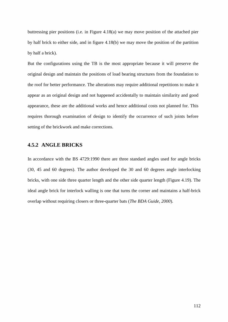
112
buttressing pier positions (i.e. in Figure 4.18(a) we may move position of the attached pier
by half brick to either side, and in figure 4.18(b) we may move the position of the partition
by half a brick).
But the configurations using the TB is the most appropriate because it will preserve the
original design and maintain the positions of load bearing structures from the foundation to
the roof for better performance. The alterations may require additional repetitions to make it
appear as an original design and not happened accidentally to maintain similarity and good
appearance, these are the additional works and hence additional costs not planned for. This
requires thorough examination of design to identify the occurrence of such joints before
setting of the brickwork and make corrections.
4.5.2 ANGLE BRICKS
In accordance with the BS 4729:1990 there are three standard angles used for angle bricks
(30, 45 and 60 degrees). The author developed the 30 and 60 degrees angle interlocking
bricks, with one side three quarter length and the other side quarter length (Figure 4.19). The
ideal angle brick for interlock walling is one that turns the corner and maintains a half-brick
overlap without requiring closers or three-quarter bats (The BDA Guide, 2000).

113
Figure 4.19 Angle bricks
IB angle bricks differ from conventional angle bricks because they have locking features.
This requires that IB consecutive courses alternate with left-hand (LH) and right-hand (RH)
bricks (Figure 4.19). By contrast in conventional bricklaying only a single angle brick is
required, since LH can be converted to RH by inverting the brick.
Note that the shape of locking feature at the centre of the short side of the angle bricks has
been changed from square to round to ease the production. The alternative would be to use a
hexagonal-shaped protrusion. However such a hexagonal-shaped locking feature would
increase roughness and make the mix stick into the mould during production, which would
slow the pace of production resulting into low productivity.
The polygonal shaped wall in Figure 4.20 demonstrates a common use of special angle
bricks. Such bays are employed in the front elevations of many UK houses Lynch (1994). The
wall is normally offsetting from the main wall of the building for decorative purposes, an
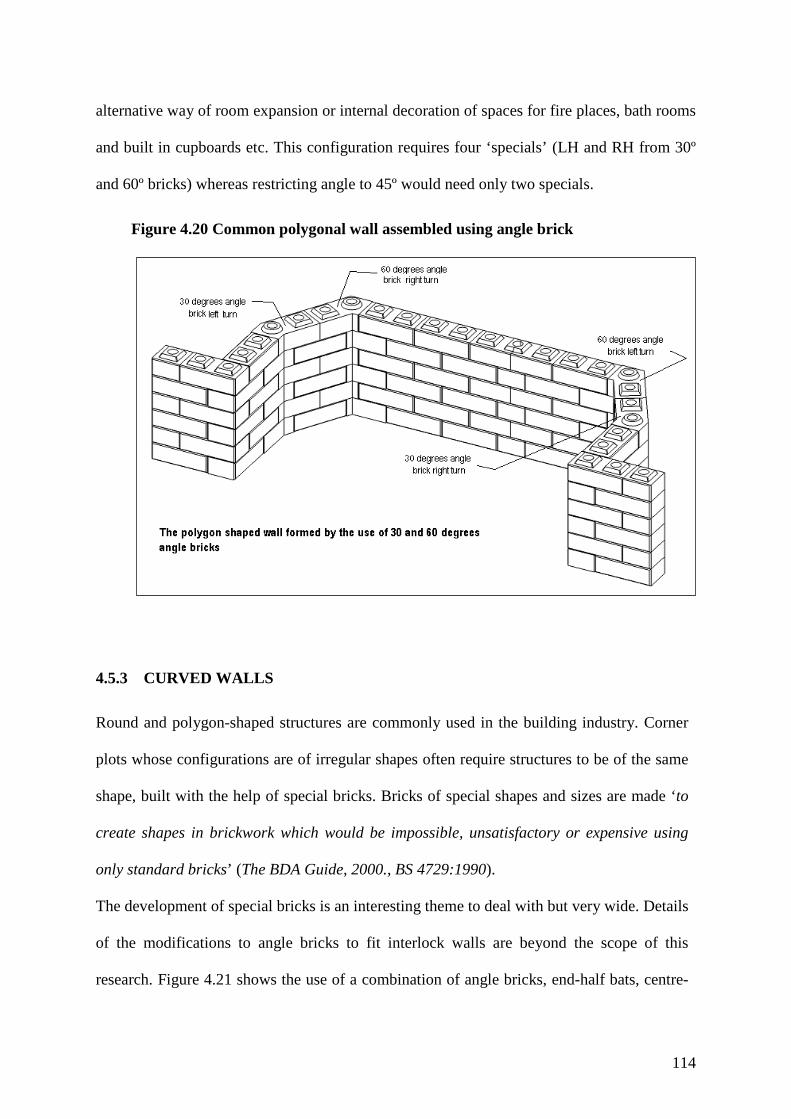
114
alternative way of room expansion or internal decoration of spaces for fire places, bath rooms
and built in cupboards etc. This configuration requires four ‘specials’ (LH and RH from 30º
and 60º bricks) whereas restricting angle to 45º would need only two specials.
Figure 4.20 Common polygonal wall assembled using angle brick
4.5.3 CURVED WALLS
Round and polygon-shaped structures are commonly used in the building industry. Corner
plots whose configurations are of irregular shapes often require structures to be of the same
shape, built with the help of special bricks. Bricks of special shapes and sizes are made ‘to
create shapes in brickwork which would be impossible, unsatisfactory or expensive using
only standard bricks’ (The BDA Guide, 2000., BS 4729:1990).
The development of special bricks is an interesting theme to deal with but very wide. Details
of the modifications to angle bricks to fit interlock walls are beyond the scope of this
research. Figure 4.21 shows the use of a combination of angle bricks, end-half bats, centre-

115
half bats, three-quarter bats and normal bricks to construct a curved wall, as an example of
future development of interlocking bricks (MT).
Figure 4.21 Isometric view of curved wall
Modification to the interlocking E½Bs and C½Bs will allow the construction of curved or
circular structures. Bricks and part-bricks are cut with a bevel to give perfect joints and
curve (Figure 4.21). The bevel shape can be cut on site, using the simple gauge and hand
saw to the designed curve following line from striking point (The BDA Guide, 2000).
However if we maintain the policy of no site-cutting, then we must mould special bevelled
C½Bs and E½Bs. Moreover the portion of locking features of C½Bs may need to be
angled too (by half the bevel angle) to achieve proper interlock. Alternatively, as discussed
early in section 4.5.3, square interlocks can be replaced by circular ones.

116
4.6 IMPROVEMENT IN FLEXIBILITY ACHIEVED
Finally we can compare the performance of TIB to other interlock systems Table 4.3, after
the development of new TIB part-bricks (C½B Figure 4.3, CL Figure 4.13, TB Figure 4.16
and angle bricks Figure 4.19), and formation of new patterns (Figures 4.9 and 4.14). Ten
construction operations compared between three development stages of interlocking
systems.
Table 4.3 Wall construction flexibility achieved by TIB
S/No. Tasks (construction operations) Development stages of interlocking bricks (IB) Typical IB system
(IB 2000) Bamba System
(IB 2003) TIB system
(IB 2008)
1 Setting a right angled corner for a ½B wall
� � �
2 Bricklaying in stretcher bond � � �
3 Construction of cross and tee joints of ½B walls
X � �
4 Attachment of ½B wide piers to ½B thick wall
X � �
5 Attachment of piers wider than ½B to ½B wall
X X �
6 Construction of isolated piers wider than 1½B
X X �
7 Construction of 1-Brick thick wall X X �
8 Attachment of piers to 1-Brick thick wall
X X �
9 Construction of curved wall X X * 10 Construction of polygonal wall X X **
Flexibility score 2 4 8 Brick-parts (elements) 2 6 5 * - Formation of bevelled brick by cutting at site ** - The use of special bricks Note: Mortarless strictly don’t allow cutting or shaving at site for best performance
The bar chart Figure 4.22 summarises score data of Table 4.3, it shows the development of
new part-bricks improved the TIB system performance by 4 points above IB2003. TIB with
five brick elements (FB, ¾B, E½B, C½B and CL) scores eight points. The addition of
specials (angle and TB), which didn’t require cutting scores one point more, making a total

117
of nine out of ten. With an advantage of not cutting at site will improve construction
productivity and saving more construction time and labour.
Figure 4.22 Performance improvement level of TIB
4.6 SUMMARY
The development of the new part-bricks (C½B & CL), initially only for the Tanzanian
interlocking brick set, which could also benefit other interlocking bricks in the same category
Table 2.1. These part-bricks enable the construction of most masonry wall joints. From Table
4.3 it is evident that the TIB system offers higher flexibility in the wall construction.
In this chapter we have demonstrated the increase in flexibility obtained by using a new part-
brick (C½B) and identified interlock specials (tee and angle bricks) with the potential to
further increase the flexibility of interlock bricklaying. The contribution of the C½B and CL
to MT includes the formation of two new bonds (Shokse and Lijuja). With these two bonds, it
is now possible to build one-brick thick (e.g. 300mm) walls that can be used for foundations
and other load-bearing structures like retaining walls. It is also possible to attach different

118
sizes (from 1-brick to 2-brick) of piers to walls and build-isolated piers more than 1½-brick
wide, which was not possible before. The uses of the two new brick shapes C½B and CL will
improve the craftsmanship quality of masons and simplify interlock bricklaying for most
masonry joints. However the accuracy requirements of interlocking brick for smooth
bricklaying will need more attention during production and curing. Tee and angle bricks will
remain special bricks to be produced to order as in conventional practice, because they
require special moulds and attention that adds more cost per unit. Professionals designing and
specifying materials should be aware of the cost implications of such bricks.
The task ahead for this research (Chapters 5 and 6) is to analyse the alignment accuracy of
MT construction (plumbness, straightness, and course levels) during construction (per BS
8000-3:2001 – Table 2), and establish the limits of wall length and height to be allowed
before the need of strengthening.

119
CHAPTER 5
5.0 BRICK IRREGULARITIES AND THEIR IMPLICATIONS FOR WALL QUALITY
In chapter 2 we discussed the tolerance requirements of interlocking bricks for mortarless
technology. It was pointed out how brick irregularity affects the accuracy of dry-stack
interlock-bricklaying alignment. In this chapter we are going to describe types of brick
irregularity, their causes, the implications of these irregularities and the measures to be taken
to minimise them. In the following two Chapters one of the major implication of brick
irregularities, namely poor wall alignment is examined in detail.
5.1 BRICK IRREGULARITIES
For a brick to be irregular, one of the following imperfection (types of brick irregularity) is
present: variation in size (due to variable shrinkage), warping or curvature, taper and surface
roughness. These are considered in turn in the following sections, where the causes,
consequences and avoidance of each are discussed.
5.1.1 VARIABLE SIZE
These are variations in the size of bricks within or between mix/batches, which cause the
bricks not to lock or fit with each other.
120
a) Causes of variable shrinkage
Brick shrinkage occurs because of moisture evaporation during the drying process. However
this is of small impact unless the soil used contains a high fraction of clay that is prone to
excess shrinkage. If there were constant shrinkage within or between the batches there
wouldn’t be any problem. Non-uniform shrinkage may be caused by one or more of the
following: -
• Excess water in the mix,
• Poor mixing,
• Changes in soil properties,
• Differential compacting pressure caused by poor batching (uneven amount of mix
placed in a mould for each compacting cycle)
• Poor curing (described in more detail in section 5.2)
b) Implication of variable shrinkage on wall alignment
The poor matching (in height, length are easily visible) of bricks during wall assembly delay
construction and cause additional activities (selection, shaving, shimming and replacement of
rejects) that increase construction cost.
c) Remedial measures to control shrinkage
To minimize the outcome of excess shrinkage will require systematic monitoring and close
supervision of all processes to brick production, which include: -
• Treating soil with the correct type and amount of stabilizer (proper designed ratio of
cement to soil)
• Mixing with proper water/moisture content (proper water/cement ratio)
• Proper soil preparation: -

121
o Pulverizing to remove hard particles
o Sieving to a required size/limits
o Mixing to a standard consistency (by sight)
• Use of adequate compacting pressure during moulding
• Proper curing conditions: -
o Under a roof and on a level floor or
o In the open air with proper flooring and covering materials (plastic sheets,
grass, sawdust etc.)
However the occurrences of variations in brick size due to shrinkage are in general practice
minimised and not eliminated. The remedial measures taken are to prepare and correct them
to be fit for use, as described in Section 5.2.
5.1.2 WARP (CURVED OR TWISTED BRICKS)
These are the changes in brick shape not in right form (twisted), which at the same time may
change the size of the brick.
a) Causes of warped, curved or twisted bricks
In soil stabilization, warping and twisting may occur mainly due to two causes (both
considered in 5.2 below): -
One is rapid drying of bricks cured at the open air without cover. This practice has been
inherited from the production of mud bricks, which normally are left in the open air to dry.
Apart from causing warping, rapid drying will result in low strength because of incomplete
cement hydration.
Secondly using poorly prepared curing-floor surfaces is a major cause of brick curving.
Poorly prepared curing floors are especially common and damaging in (hot) developing

122
countries. For these two reasons bricks are often of poor quality having irregular shapes
(warped, curved and with severe shrinkage).
b) Implications of warped, curved or twisted bricks for wall alignment
The implications of warped and curved bricks to the wall alignment are more severe than
shrinkage alone, because shrinkage is a linear change to all sides, so to deal with it is simpler,
but warping forms surfaces with ditches and humps. Warped and curved bricks when dry-
stacked make contact at specific points (bumps). If these points are scattered over the surface,
during assembly the contact of the two brick faces will induce rocking, rolling and pitching
until a stable position is found. Moreover placing another brick above may change the lower
brick’s balanced position. This may result in the phenomenon of ‘lateral softness’ that causes
difficulties in maintaining good vertical wall alignment. To stabilise, the structure will require
strengthening i.e. shimming, addition of buttresses etc.
Due to having low contact surface areas between them, bricks develop load concentrations at
their contact points. This concentrated loading easily surpasses the crushing strength of bricks
and therefore resulting in cracking or failure of individual bricks. To prevent cracking in the
case of severe warping, bricks may require a lot of shimming as in traditional bricklaying,
which of course mortarless technology is trying to avoid.
c) Remedial measures to reduce warping, curving and twisting of bricks
Warping, curving and twisting for stabilised bricks can be reduced by proper curing i.e. under
a roof and or under the covering of plastic sheets, grass or any other material to reduce
exposure to air and sun and thus prevent quick evaporation of moisture. The other remedial
measure is making curing-floor surfaces level and hard to reduce moisture percolation into
the ground from the fresh bricks. We can conclude that poor curing regime is the major cause

123
of brick irregularities; so curing require proper control and close monitoring for effective
performance. Warping and curving can be much minimised on fulfilling the above-
recommended remedial measures. But shrinkage, which is associated with the soil properties,
will remain a task to be addressed by proper soil selection and proper design of the ratios of
cement to soil and water to cement.
5.1.3 BRICK SURFACE ROUGHNESS
The rough-surfaces (random localised bumpiness) of the brick’s faces designed to form
contact, normally are the top and bottom faces that the mortarless technology should direct
more attention. The causes and consequences don’t differ much with those described in
Section 5.1.2, so, do the remedial measures. The emphasize should be on the quality of curing
places and the stacking practice, to keep floor always clean, flat and smooth will protect brick
faces from roughness.
5.1.4 TAPER
These are uneven brick shape changes due to general wear and tear of the press, changes in
mould box dimensions due to bulging or twisting to one side and rocking of movable plate of
press. We leave aside intentional vertical taper introduced to make demoulding easier,
although with wear this may grow to exceed the allowable tolerances. Close monitoring and
control of any source of taper (i.e. having non-parallel top and bottom faces) will give a
warning of brick biases forming. Consistent bias can be corrected by reversing alternate
courses. But when having bricks with variable bias, it will be difficult to control wall leaning.

124
5.2 SOIL-CEMENT BRICK CURING PRACTICE
Mortarless technology makes use of pressing as a normal brick production method, and
requires that proper soil-selection and soil-preparation are practiced. The major stumbling
block causing block irregularity is poor curing practice. From a survey in 2006 and 2007 for
this research and the general Tanzanian experience of stabilized cement-soil blocks, it was
found that most of all production sites have no curing-shade, no proper floors (flat, hard and
impermeable), and bricks are uncovered during curing as shown in Figure 5.1.
Figure 5.1 Typical poor curing conditions in low-cost building-material production sites
a) Production of more than 100,000 interlocking bricks produced in 2006 by the National Housing and Building Research Agency (NHBRA) in Iringa - Tanzania for the National Housing Cooperation (NHC).
b) A private site of interlocking brick production in Mbezi-beach Dar Es Salaam Tanzania was inspected by the author in 2007
The outcome of using such poor curing conditions (Figure 5.1) is the formation of irregular
bricks. The photos in Figures 5.2(a) and 5.2(b) show the construction problems caused by
using such bricks in wall construction. With irregular bricks it is difficult to attain level
courses or to avoid forming load concentrations at the points of contact. As the load increases
the brick are forced to flatten and the enclosed stress field can lead to tension cracking
(Marzahn 1999).

125
If differences in size occur during brick production, then the following are the additional
efforts required to select or correct them for use:
• Selection and grouping of bricks of approximately equal height.
• Reduce those too big to size by shaving or grinding them to match with the most
common.
• Those appear to be too small will need shimming during construction to match with
the rest. Alternatively an entire thin course will be laid, if there are in enough quantity
to complete one course.
Figure 5.2 Implications of brick irregularities on wall assembly
a) Wall courses undulations because of the brick irregularities
b) Brick cracking because of the load concentrations that forces them to straighten/flatten.
These adjustments will create rejects or breakages that require additional production for
replacement. The extra time spent for preparation, extra material to be used for shimming and
any extra production, are thus consequences of brick irregularity. They cause delays in
construction and increase the construction cost, which jeopardize the good image of
mortarless technology. That is why a further analysis of brick irregularity is necessary.

126
5.3 SUMMARY
Brick irregularities impact negatively on wall alignment and weaken the performance of the
wall. Mortarless walling by its nature is vulnerable to shaking due to brick units being
stacked dry; it therefore requires careful handling before any strengthening stage. Irregular
bricks increase wall instability’ as the bricks are difficult to place in their proper position. The
more the wall grows in height and length, the more flexible and unstable it becomes.
Irregularity of bricks can be graded by how difficult or easy it is building an accurate wall
with them, and attain straight and level courses that are vertical to plumb, and sustain an
accurate position during construction. Of the various imperfections in brick-shape, the most
serious are:
• Variation in height – causing cracking,
• Warping or extreme roughness – causing both instability and cracking
• Variable lateral taper - ‘roll taper’ – causing loss of verticality
Poor curing and stacking practice are the main cause of these brick imperfections. The effect
of irregular bricks on mortarless wall alignment is analysed in Chapters 6 and 7.
127
CHAPTER 6
6.0 THE RELATIONSHIP BETWEEN WALL ALIGNMENT AND BRICK GEOMETRIC IMPERFECTION
6.1 INTRODUCTION
The elimination of mortar layers between the courses of interlocking brick wall is the main
characteristic of mortarless technology (MT) compared to conventional masonry. The mortar
joint is replaced by physical locking features to enable the wall to withstand lateral and
flexural loads Gazzola & Drysdale (1989), Marzahn (1998), Drysdale & Gazzola (1991),
Marzahn (1999), Shrive et al. (2003) and Jaafar et al. (2006).
A mortar layer that traditionally separates brick courses performs a number of functions.
Well-pointed mortar may add to a wall’s aesthetic appeal – though the crudely smeared
mortaring commonly found in villages of Least-Developed (African) Countries certainly does
not. In ‘gluing’ the bricks together, mortar increases resistance to localised forces, such as
those that might punch an individual brick through a wall; however interlocking can also
perform this particular function (Shrive et al. 2003). Mortar may help the wall to act as a
beam spanning across soft spots in its foundation or across openings. It seals the wall against
wind and noise penetration, whereas a mortarless wall has to be (internally) rendered to
achieve this and other purposes. Mortar removes stress concentrations due to point contact
between bricks in successive courses and it may reduce ‘binary’ deviations (one brick
rocking between two rival seats on the brick below). In MT, greater brick accuracy is
required since the mechanism of levelling each course using mortar is no longer available.

128
As the key function of conventional mortar is to allow good wall alignment to be achieved
despite irregularities in the individual bricks, the research here reported was undertaken to
assess how accurately bricks need to be made if in mortarless assembly they are to give
satisfactory overall alignment. The wall parameters of most interest are course straightness
(deviation from horizontal) and wall-lean (displacement of the top brick’s front face from a
plumb line touching the bottom brick’s front face). It is the accuracy of the top and bottom
faces of the individual bricks whose interaction determines these two measures.
6.1.1 THE EXPERIMENTAL OBJECTIVES
Mortarless technology (MT) replaces mortar by making mating brick surfaces (top and
bottom) more accurate. The main objective of the following experiments is to identify what
accuracy (of flatness and parallelism of top and bottom brick surfaces) is needed to ensure
wall alignment lean is within the limits prescribed by BS 8000-3:2001 and BS5628-3:2005,
namely that the straightness deviation in any 5m length wall does not exceed ±5mm, and
verticality lean up to 3m wall height is within ±10mm. Although these permissible wall
deviations are meant for mortared technology, they will be used here as benchmark data. The
other important objective for these experiments is to contribute to the formation of production
quality control measures and IB walling standards.
In the absence of mortar in a brick wall we would expect;
a) The wall alignment to be poorer than when connecting course mortar is used to maintain
vertical, level and uniform course spacing i.e. mortar corrects geometric imperfections.
Dry-stacking bricks produces cumulative imperfections, which the bricklayer has little
mechanism for correcting.

129
b) The wall to be less stable when subjected to (small) horizontal forces because at some of
the brick-to-brick interfaces rocking is possible (if the contact points are few and too
close to the brick’s centreline) ; also there is increased chance of wall wobbling under
vertical forces.
c) The contact forces to be localised rather than spread over the whole brick top/bottom
surfaces, leading to brick failure (by cracking) to occurring at lower vertical loading
than it would in a mortared wall Marzahn (1999), Jaafar et al. (2006).
Each of these weaknesses of dry-stack bricks are caused by brick surface (top and bottom)
imperfections that were analysed and tested for. The two measures developed to ameliorate
problem (a) and (b) above were: (i) modifications to brick shape and (ii) special bricklaying
procedures. These were tested for effectiveness as described in Chapter 4.
Because bricks imperfections are essentially random (though with measurable statistics), very
many experiments are required to obtain a single performance measure. For example to
assess within ±10% with 90% confidence the standard deviation in straightness of a specified
course in a column would need the construction and measurement of over 100 columns.
Because such large-scale physical experimentation is too costly of time, more limited
experiments were performed whose primary purpose was to calibrate and confirm the
performance of theoretical formulae and computer simulations.
6.2 PRIMARY PREPARATION FOR EXPERIMENT
The experiments involve the assembling of columns and walls, which require preparation of
brick components. The brick components to be produced are the TIB described in Chapter 4.
The following activities were deeming necessary for the primary preparations:
130
• Design and fabrication of ISSB component moulding inserts to enable production of
(FB, ¾B, E½B, C½B and TB) brick types.
• Production of bricks for experiment
• Determination of brick characteristics
o Dimensions
o Flatness and parallelism of top and bottom faces
o Statistical analysis of brick characteristics for a substantial measured sample
6.2.1 MOULD DESIGN AND FABRICATIONS
The available brick press (MultiBloc Figure 6.8c) in the Engineering laboratory of the
University of Warwick, is a CINVA Ram type (VITA 1975, UN 1992, Weinhuber 1995),
which can produce solid bricks of size 290 x 140 x 90mm. The interlock brick design and its
elements in Chapter 4, required design of mould inserts to permit production of the interlock
brick components. The study required about 500 bricks, which is a fairly big number. To save
production time, material and the limited space in the laboratory, a half-scale was adopted.
The available press mould box was sub-divided into three equal compartments to produce, in
each pressing cycle, three bricks of size 140 x 70 x 50mm. Mould inserts were designed by
the author and fabricated in the Engineering mechanical workshop, for the following
components: full brick (FB) shown in Figure 6.1 and end-half bat (E½B) shown in Figure
6.2. Each unit need separate top and bottom inserts. In one compartment of the three a plate
was inserted (Figure 6.2c) to produce two E½Bs. Three-quarter bats (¾B) Figure 6.3, and
centre-half bats (C½B) Figure 6.4, as well their top and bottom moulding inserts, required a

131
quarter block (Figure 6.4c) to cut off one end to make the ¾B and two such blocks to make
the C½B. The assembly of inserts in press mould are shown in Figures 6.8a and 6.8b. The tee
brick (TB) moulding inserts were also fabricated: details shown in Figure 6.5. All moulding
inserts are used with spacer blocks (Figure 6.6a) to divide the press moulding box into three
equal spaces (see assembly Figure 6.8). To form the large vertical perforations, steel rods
were used (Figure 6.6b). The design incorporated tolerances on interlock features of 1mm
clearance between protrusion and depression and the edge chamfers are 1.75 x 1.75mm, all
halved from the original design (A Tanzanian interlocking brick (TIB) with – tolerance =
2mm and chamfer = 3.5 x 3.5mm Figure 2.10). The materials specified for pattern making
were aluminium and mild steel. A new press cover (Figure 6.7) was designed to allow
production of interlock brick because the original solid cover was not fit for the purpose.

132
Figure 6.1 Full brick (FB) moulding inserts (measurements in millimetres)
Figure 6.2 End-half bat (E½B) moulding inserts (dimensions in millimetres)
NOTE: These inserts were for making half-scale experimental bricks; for full-size bricks, all
dimensions should be doubled.
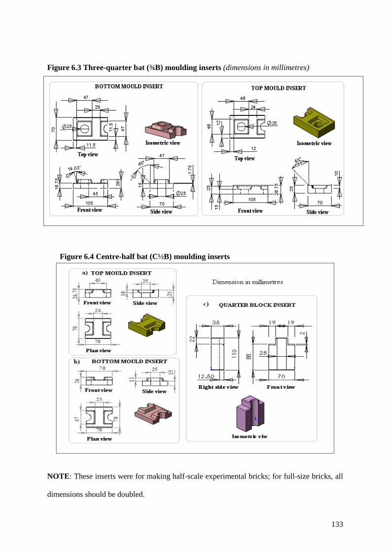
133
Figure 6.3 Three-quarter bat (¾B) moulding inserts (dimensions in millimetres)
Figure 6.4 Centre-half bat (C½B) moulding inserts
NOTE: These inserts were for making half-scale experimental bricks; for full-size bricks, all
dimensions should be doubled.

134
Figure 6.5 Tee brick mould inserts (dimensions in millimetres)
NOTE: These inserts were for making half-scale experimental bricks; for full-size bricks, all
dimensions should be doubled.

135
Figure 6.6 Common moulding inserts components (dimensions in millimetres)
Figure 6.7 New cover for MultiBloc press (dimensions in millimetres)
Overall dimensions of assembled press cover Detail of separate parts for new cover
NOTE: These inserts were for making half-scale experimental bricks; for full-size bricks, all
dimensions should be doubled.

136
Figure 6.8 Multibloc press with new cover and moulding inserts
6.2.2 BRICK PRODUCTION
I Soil preparations and mix design
The material ordered from Coventry building material suppliers using normal procedures was
builder’s sand sieved through a 4mm sieve. That is good enough for stabilised-soil cement
brick production. Sand particle-size distribution test was performed (Table 6.1 and Graph 6.1
showing a uniform medium sand with only 5% fines passing sieve 0.075) before adding
kaolin to achieve the required fines (clay) content and thus adequate mix cohesion.

137
The soil was formed by mixing builder’s sand and kaolin at the ratio of 8: 1 by weight (3: 1
by volume). The material ratio used for the brick production is 1:14 (cement to “soil” – C: S,
where soil includes kaolin and sand).
Graph 6.1 Particle size distribution curve
Table 6.1 Sand particle distribution test results
S/No. Sieve diameter
(mm)
Sample A (500g) Sample B (500g)
Sand retained in each sieve
(g)
Sand passing each sieve
(%)
Sand retained in each sieve
(g)
Sand passing each sieve
(%)
1 5 0 100.00 0 100.0
2 2.36 3.5 99.3 6 98.8
3 1.18 2.5 98.8 6.5 97.5
4 0.6 21 94.5 27 92.0
5 0.3 160 62.1 167.5 58.3
6 0.15 195 22.7 191 19.8
7 0.075 87 5.1 78 4.1
8 bottom dish 25 - 20.5 -
Lost sand 6 3.5
Total 500 - 500 -
138
Thus during production the mix ratio used for cement, kaolin and sand was 1:3.5:10.5 (C: K:
S) by volume. From total material by volume C = 6.7%; K = 23.3%; S = 70%, and by weight
C= 7.5%; K = 10.7%; S = 81.8%.
The normally recommended maximum ratio of free water to cement is 0.8 (Lea, 1976 and BS
5328-1:1997 Table 6). However this did not work for manual brick pressing. It was increased
to 1.4, which was found to be sufficient for easy moulding and handling. The high W: C ratio
to achieve workability arise from (a) the very lean mix C:S (1:14) and (b) the presence of
clay, both sand and clay having a water demand in addition to the water available to the
cement.
II Brick pressing and curing
The bricks produced for experiment were intended to portray real site conditions, but due to
laboratory constraints on time and space, brick size was halved to 140 x 70 x 50mm from the
original machine moulding box size - 290 x 140 x 90 mm available in the laboratory. All
brick sample produced using one mix ratio (1:14 cement to soil). The bricks were cured for
28 days, covered by wet-sacking and plastic sheets for the whole period.
The numbers of brick components made were; 441 FBs, 80 ¾Bs, 94 E½Bs, 85 C½Bs and 14
TBs. The bricks were produced from one press with three equal compartments (as described
in the section 6.2.1), to allow production of three bricks in a stroke. It was expected that all
bricks from one machine would be the same, but when inspected and measured were found to
have variations of less than one millimetre. So the three compartments act like different and
independent machines. Nonetheless during production the bricks from different
compartments were not separated, the only separation made was between day production
batches to control curing duration.

139
6.2.3 DETERMINATION OF BRICK CHARACTERISTICS
I) Brick dimensions
Variability of bricks develops through the three processing stages (production, setting-out and
assembly), resulting in deviation from the designed (desired or target) size BS ISO
1803:1997. The deviations due to human error and limitations of moulding instruments are
termed induced deviations. A second type of variability, known as inherent deviations, is
caused by variations in temperature, moisture content or chemical reactions, which may cause
reversible or permanent change. In practice, to check the compliance of components’
dimension and tolerance limits are set (BS ISO 1803:1997).
Figure 6.9 Positions on brick for determination of its (i) length and (ii) width
(Bottom of brick is shown shaded, diagrams per BS EN -16:2000)
The method used to determine the dimension compliance of experimental IBs is that
described in BS EN 772-16:2000 see Figure 6.9, ten sample bricks were measured. The brick
sizes were measured by the use of laser “LK micro four” (Figure 6.10) as follows: to measure
the length of a brick, the difference between four end to end corner points’ (aa, bb, cc and dd)

140
readings Figure 6.9(i) (Z-axis readings displayed by digipac screen Figure 6.10), and to
measure the width Figure 6.9(ii), the brick was laid on its back with front face on top. Using
the laser table as zero datum, readings of six points (e, f, g, h, j, k) were taken i.e.y-axis
readings were recorded as brick widths.
The heights were measured at the eight points marked for the flatness determination between
bottom and top faces (Figure 6.10 shows bottom face and top face is shown in Figure 6.11).
Figure 6.10 Brick in position for dimensional and surface flatness determination
The summarised experimental data in Table 6.2 (obtained from raw data Tables 6.5, 6.6 and
6.8) were compared with the permitted tolerances from BS EN 771-3:2003 category D4 Table
1 and BS 6649:1985 Table 3, in reference to the designed brick size 140 x 70 x 50mm. In the
BS 6649:1985 Table 3, it is given a tolerance of ±2mm for all brick side dimensions, with the
condition that of the ten sample bricks measured, nine shall be within the given limits. Table
6.2 shows that the standard tolerance compliance was met only for the length and width. The

141
measured height did not meet the given standards in comparison to the designed height.
However using the average (µ) height and standard deviation (σ) of the measured samples,
give a coefficient of variation (COV = σ/µ) of only 0.01 (Tables 6.8), confirming the
similarity of brick heights.
Table 6.2 Data comparison between experimental and standards
Measured Item
Designed size (mm)
Actual* mean size
(mm)
Design minus actual size
(mm)
BS EN 771-3:2003 Category D
Tolerance (mm) between
BS 6649:1985 Table 3 (limits of
manufacturing) (mm)
Length 140 139.96 -0.04 -3 and +1 ±2
Width 70 70.54 +0.54 -3 and +1 ±2
Height 50 48.30 -1.70 -1 and +1 ±2
*See Tables 6.5, 6.6 and 6.8
II Brick flatness and parallelism
For IBs the important parameters are the flatness and parallelism of top and bottom surfaces,
and the height variations that require more attention of this research programme. BS EN 772-
20:2000 recommends a diagonal method for determining surface flatness, using a straight
edge and a set of feeler gauges. The method was not used for IBs because of their
protrusions, which prevent measurement along diagonals.
Possible alternative measures were the mean square, least square and local flatness, as
described in BS 7307:1:1990 (ISO 7976-1:1989). The experimental data was generated using
laser “LK micro four”, from the marked points on top and bottom surfaces (Figures 6.10 and
6.11). One bottom point (Figure 6.10 point 1) of each brick was set to zero as a bench mark
(Table 6.7 a bottom front reading B1) from which other point levels were calculated for both
top and bottom faces.

142
Figure 6.11 Brick marked for surface flatness determination
To prepare the experimental bricks for measurements, they were marked along the plane
surfaces lying to front and rear of the interlock depressions (bottom face Figure 6.10), and the
interlock protrusions (top face Figure 6.11). By the use of a template, all sample bricks (44
pieces) were marked to maintain similarity of the point’s positions and distances. The
position of a stylus point (in contact with the brick) was displayed on a laser digipac screen
(Figure 6.10 in three dimensions x,y and z).
The raw data (Table 6.7) for brick flatness were recorded in the order of 1, 3, 5, 7 (front
points) and 2, 4, 6, 8 (rear points) for the top/upper surface, and similarly for the bottom
surface.
III Analysis of brick data measurements
The raw data in Table 6.7 was processed using an Excel programme to determine planes
representing the top and bottom surfaces respectively, and the angles α and β between these
actual planes and an ideal plane perpendicular to the front face Table 6.8.

143
Data for the top (upper – U) of a particular example brick is displayed in Table 6.3. The table
also shows as derived data:
− The average of the four front readings (Uf) measured upwards from a reference plane
passing through point 1 on bottom of brick (B1).
− The average of the four rear readings (Ur)
− The inclination β (defined in Figure 6.12) = tan-1{(U r – Uf)/58}, where 58mm is the
distance between the front and rear lines of the measurements shown in Figure 6.11.
Table 6.3 Determination of a bricks’ upper plane
S/No
Bricks’ upper coordinates readings (as laid) Average Angle (β)
Front readings (Uf) Rear readings (Ur) Uf Ur (Ur - Uf)/58
U1 U3 U5 U7 U2 U4 U6 U8 1,3,5,7 2,4,6,8 Tan-1(-0.396/58)
1 48.376 48.530 48.598 47.682 48.068 47.920 47.906 47.708 48.296 47.900 -0.39º
For example Table 6.3 show a result of top face of brick sample 1 (raw data Table 6.7), with
the rear of the top face lower than the front by 0.396mm (δyU = Ur - Uf = -0.396), it causes
the top face to incline by β = - 0.39º (i.e. downwards to the rear) when the brick front face is
vertical.
Table 6.4 Determination of a bricks’ bottom plane
S/No
Bricks’ bottom coordinates readings (as laid) Average Angle (α)
Front readings (Bf) Rear readings (Br) Bf Br (Br– Bf)/ 58
B1 B3 B5 B7 B2 B4 B6 B8 1,3,5,7 2,4,6,8 Tan-1(-0.225/58)
1 0.000 0.740 0.428 0.112 0.130 0.298 -0.086 0.038 0.32 0.095 -0.09º
Table 6.4 shows the same data processing for the bottom surface of the brick. The rear side is
lower than the front by 0.225mm (δyB = Br – Bf = - 0.225) Figure 6.12.

144
Figure 6.12 Representing top and bottom brick planes as in position (Ideal planes, perpendicular to front face, are shown dashed)
So the brick bottom plane inclines by α = -0.09º (i.e. downwards to the rear) when the front
face maintained vertical (Figure 6.12). Figure 6.13 shows the same brick but with its actual
bottom face laid horizontal. The front face is now no longer vertical but leans at angle θ = α =
-0.09º (i.e. leans forward by 0.09°)
Note that α and β are permanent properties of the brick, whereas θ varies according to how
the brick is laid. θ = 0 in Figure 6.12 because the bricks’ bottom face is laid on its ideal face
perpendicular to front face, while θ = α in figure 6.13 as the brick is laid on its actual bottom
surface. γ = β – α.

145
Figure 6.13 Orientation assuming bottom of brick is laid on a true horizontal base
Although the datum for all point measurements was the location of bottom front point one
(Bf1), the derived angles α and β for the imperfection of top and bottom mean planes are not
affected by which datum point employed i.e. we would not expect due to datum choice alone
any difference in the statistics; SDα and SDβ. The difference in these two SDs (Table 6.8)
actually observed is therefore due to real production factors such as rocking of the top or
bottom plate of the press.

146
Table 6.5 Brick length (ℓ)
S/No Measurements (mm) SUM Mean
a-a b-b c-c d-d ∑x µ 1 140.589 140.948 140.434 140.704 562.675 140.669 2 139.796 140.464 140.220 140.512 560.992 140.248 3 139.754 140.312 140.042 140.466 560.574 140.144 4 139.346 139.226 139.372 139.140 557.084 139.271 5 139.722 139.243 139.498 139.306 557.769 139.442 6 140.064 139.938 140.420 139.922 560.344 140.086 7 141.038 141.296 140.744 141.154 564.232 141.058 8 139.592 140.100 139.960 140.438 560.090 140.023 9 139.452 139.098 139.092 138.874 556.516 139.129 10 139.806 139.530 139.618 139.340 558.294 139.574
Whole sample set 5598.570 139.964٭ STDEV of mean of (ℓ) 0.617
COV of (ℓ) 0.004 Mean of all 40 points equals mean of the each sample means ٭
Table 6.6 Brick width (w)
S/No Measurements (mm) Sum Mean
e f g h j k ∑x µ 1 70.108 70.064 70.164 70.184 70.436 70.388 421.344 70.224 2 70.536 70.780 70.568 70.358 70.546 70.382 423.170 70.528 3 70.480 70.540 70.358 70.330 70.278 70.238 422.224 70.371 4 70.418 70.358 70.484 70.586 70.502 70.548 422.896 70.483 5 70.422 70.518 70.606 70.756 70.682 70.798 423.782 70.630 6 70.890 70.840 71.000 71.138 71.028 71.150 426.046 71.008 7 70.638 70.718 70.628 70.658 70.604 70.554 423.800 70.633 8 70.500 70.440 70.444 70.388 70.318 70.378 422.468 70.411 9 70.420 70.500 70.620 70.634 70.648 70.811 423.633 70.606 10 70.492 70.550 70.546 70.612 70.522 70.594 423.316 70.553
Whole sample set 4232.68 70.545 STDEV of mean of (w) 0.208
COV of (w) 0.003
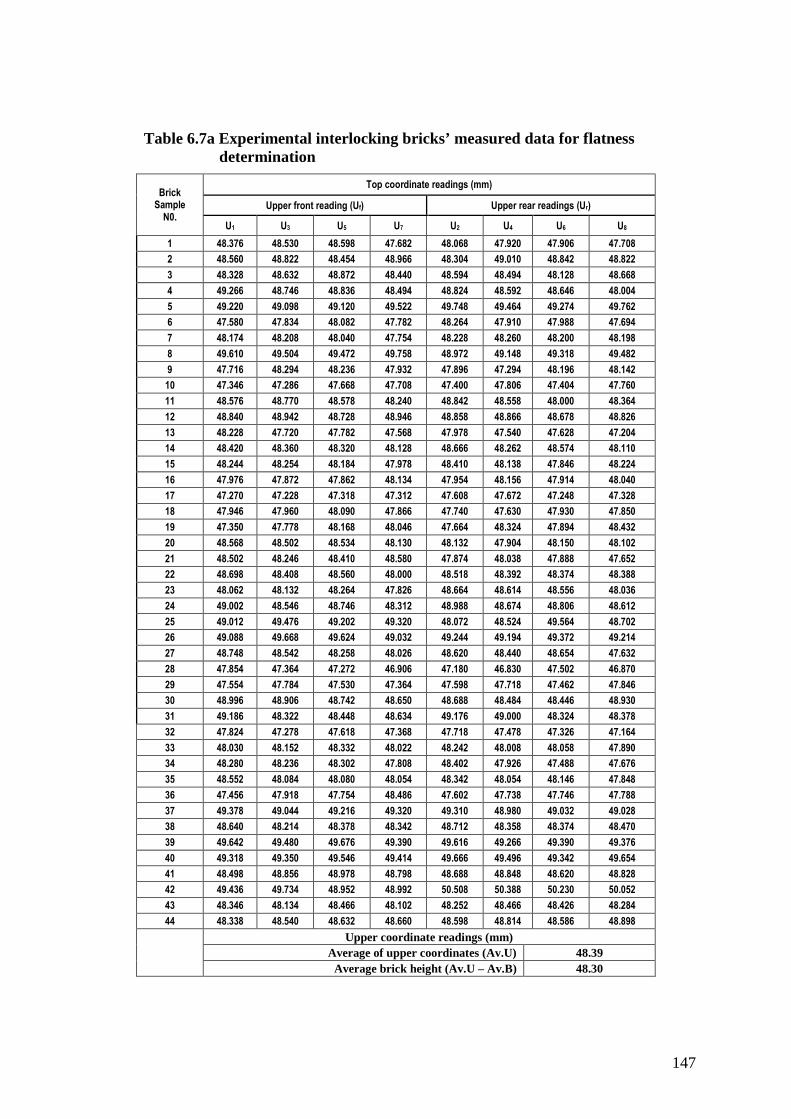
147
Table 6.7a Experimental interlocking bricks’ measured data for flatness determination
Brick Sample
N0.
Top coordinate readings (mm)
Upper front reading (Uf) Upper rear readings (Ur)
U1 U3 U5 U7 U2 U4 U6 U8
1 48.376 48.530 48.598 47.682 48.068 47.920 47.906 47.708
2 48.560 48.822 48.454 48.966 48.304 49.010 48.842 48.822
3 48.328 48.632 48.872 48.440 48.594 48.494 48.128 48.668
4 49.266 48.746 48.836 48.494 48.824 48.592 48.646 48.004
5 49.220 49.098 49.120 49.522 49.748 49.464 49.274 49.762
6 47.580 47.834 48.082 47.782 48.264 47.910 47.988 47.694
7 48.174 48.208 48.040 47.754 48.228 48.260 48.200 48.198
8 49.610 49.504 49.472 49.758 48.972 49.148 49.318 49.482
9 47.716 48.294 48.236 47.932 47.896 47.294 48.196 48.142
10 47.346 47.286 47.668 47.708 47.400 47.806 47.404 47.760
11 48.576 48.770 48.578 48.240 48.842 48.558 48.000 48.364
12 48.840 48.942 48.728 48.946 48.858 48.866 48.678 48.826
13 48.228 47.720 47.782 47.568 47.978 47.540 47.628 47.204
14 48.420 48.360 48.320 48.128 48.666 48.262 48.574 48.110
15 48.244 48.254 48.184 47.978 48.410 48.138 47.846 48.224
16 47.976 47.872 47.862 48.134 47.954 48.156 47.914 48.040
17 47.270 47.228 47.318 47.312 47.608 47.672 47.248 47.328
18 47.946 47.960 48.090 47.866 47.740 47.630 47.930 47.850
19 47.350 47.778 48.168 48.046 47.664 48.324 47.894 48.432
20 48.568 48.502 48.534 48.130 48.132 47.904 48.150 48.102
21 48.502 48.246 48.410 48.580 47.874 48.038 47.888 47.652
22 48.698 48.408 48.560 48.000 48.518 48.392 48.374 48.388
23 48.062 48.132 48.264 47.826 48.664 48.614 48.556 48.036
24 49.002 48.546 48.746 48.312 48.988 48.674 48.806 48.612
25 49.012 49.476 49.202 49.320 48.072 48.524 49.564 48.702
26 49.088 49.668 49.624 49.032 49.244 49.194 49.372 49.214
27 48.748 48.542 48.258 48.026 48.620 48.440 48.654 47.632
28 47.854 47.364 47.272 46.906 47.180 46.830 47.502 46.870
29 47.554 47.784 47.530 47.364 47.598 47.718 47.462 47.846
30 48.996 48.906 48.742 48.650 48.688 48.484 48.446 48.930
31 49.186 48.322 48.448 48.634 49.176 49.000 48.324 48.378
32 47.824 47.278 47.618 47.368 47.718 47.478 47.326 47.164
33 48.030 48.152 48.332 48.022 48.242 48.008 48.058 47.890
34 48.280 48.236 48.302 47.808 48.402 47.926 47.488 47.676
35 48.552 48.084 48.080 48.054 48.342 48.054 48.146 47.848
36 47.456 47.918 47.754 48.486 47.602 47.738 47.746 47.788
37 49.378 49.044 49.216 49.320 49.310 48.980 49.032 49.028
38 48.640 48.214 48.378 48.342 48.712 48.358 48.374 48.470
39 49.642 49.480 49.676 49.390 49.616 49.266 49.390 49.376
40 49.318 49.350 49.546 49.414 49.666 49.496 49.342 49.654
41 48.498 48.856 48.978 48.798 48.688 48.848 48.620 48.828
42 49.436 49.734 48.952 48.992 50.508 50.388 50.230 50.052
43 48.346 48.134 48.466 48.102 48.252 48.466 48.426 48.284
44 48.338 48.540 48.632 48.660 48.598 48.814 48.586 48.898
Upper coordinate readings (mm)
Average of upper coordinates (Av.U) 48.39 Average brick height (Av.U – Av.B) 48.30

148
Table 6.7b Experimental interlocking bricks’ measured data for flatness determination
Bottom coordinate readings (mm)
Bottom front reading (Bf) Bottom rear readings (Br)
B1 B3 B5 B7 B2 B4 B6 B8
0.000 0.740 0.428 0.112 0.130 0.298 -0.086 0.038
0.000 -0.102 0.018 -0.068 -0.550 -0.490 -0.628 -0.478
0.000 0.022 0.062 0.136 0.158 0.076 -0.156 -0.164
0.000 0.114 -0.072 0.044 -0.500 -0.400 -0.272 -0.436
0.000 -0.318 -0.206 -0.012 -0.470 0.000 -0.174 -0.202
0.000 0.034 -0.050 0.086 0.160 0.392 0.570 0.404
0.000 0.050 0.088 -0.016 0.364 0.578 0.566 0.624
0.000 0.074 0.162 0.046 -0.536 -0.616 -0.500 -0.576
0.000 0.020 0.116 0.226 -0.074 -0.016 0.002 0.152
0.000 -0.156 0.030 0.302 0.708 0.694 0.656 0.680
0.000 0.070 -0.136 -0.136 -0.238 -0.298 -0.340 -0.048
0.000 -0.146 -0.126 0.088 0.012 0.056 0.240 0.110
0.000 0.200 0.334 0.156 -0.260 -0.140 -0.238 -0.248
0.000 0.170 0.114 -0.010 0.160 0.328 0.160 0.254
0.000 0.126 0.002 0.198 0.034 0.014 -0.030 -0.038
0.000 0.056 0.022 0.010 -0.240 -0.108 0.016 -0.066
0.000 0.116 0.100 0.206 0.662 0.664 0.634 0.600
0.000 -0.188 -0.288 -0.040 0.538 0.632 0.588 0.502
0.000 0.116 0.088 0.114 -0.214 -0.098 -0.038 -0.126
0.000 0.306 0.306 0.312 0.522 0.846 0.664 0.500
0.000 0.360 0.388 0.270 -0.486 -0.336 -0.042 -0.384
0.000 0.288 0.294 0.138 0.652 0.872 0.764 0.712
0.000 0.218 -0.002 0.042 -0.288 -0.238 -0.014 -0.266
0.000 0.190 0.172 -0.032 -0.278 -0.076 -0.152 -0.168
0.000 0.380 0.426 0.608 -0.018 0.498 0.352 0.394
0.000 0.232 0.046 0.274 -0.292 0.190 -0.288 -0.082
0.000 0.276 0.256 0.180 -0.640 -0.524 -0.516 -0.486
0.000 0.072 0.066 0.132 -0.016 0.200 0.414 0.144
0.000 0.424 -0.324 0.306 -0.088 -0.008 0.002 0.114
0.000 0.374 0.146 0.016 0.910 0.558 0.676 0.438
0.000 0.248 0.430 0.272 0.358 0.510 0.456 0.438
0.000 -0.062 0.122 0.266 0.470 0.478 0.838 0.442
0.000 0.090 0.040 -0.004 -0.134 0.116 -0.040 -0.072
0.000 0.174 0.332 0.118 -0.410 -0.214 -0.344 -0.382
0.000 0.140 0.250 0.338 0.250 0.468 0.430 0.338
0.000 0.032 -0.078 -0.172 0.300 0.514 0.494 0.488
0.000 0.226 0.230 0.100 -0.214 0.120 0.174 -0.030
0.000 0.162 0.126 0.082 -0.070 -0.052 0.058 0.046
0.000 0.084 0.194 0.102 0.482 0.560 0.668 0.552
0.000 0.268 0.144 0.112 -0.198 -0.184 0.066 -0.126
0.000 0.018 -0.006 -0.096 -0.074 0.036 0.022 0.120
0.000 0.144 0.192 0.298 0.678 0.652 0.634 0.704
0.000 0.260 0.322 0.582 -0.354 -0.222 -0.266 0.080
0.000 0.114 0.328 -0.070 -0.412 0.044 -0.088 -0.378
Bottom coordinate readings (mm) Average of bottom coordinates (Av.B) 0.096

149
Table 6.8 Brick-plane inclinations of top(upper) and bottom surfaces
Brick Sample
N0
Upper coordinates (mm) Bottom coordinates (mm) Alpha(α) Beta(β) Gamma(γ) Average Brick height
Av. Uf Av. Ur Av. Bf Av. Br (Br-Bf)/58 (Ur-Uf)/58 β-α {(Av.Uf+Av.Ur)-(Av.Bf+Av.Br)}/2
1 48.2965 47.9005 0.3200 0.0950 -0.0039 -0.0068 -0.0029 47.891
2 48.7005 48.7445 -0.0380 -0.5365 -0.0086 0.0008 0.0094 49.010
3 48.5680 48.4710 0.0550 -0.0215 -0.0013 -0.0017 -0.0004 48.503
4 48.8355 48.5165 0.0215 -0.4020 -0.0073 -0.0055 0.0018 48.866
5 49.2400 49.5620 -0.1340 -0.2115 -0.0013 0.0056 0.0069 49.574
6 47.8195 47.9640 0.0175 0.3815 0.0063 0.0025 -0.0038 47.692
7 48.0440 48.2215 0.0305 0.5330 0.0087 0.0031 -0.0056 47.851
8 49.5860 49.2300 0.0705 -0.5570 -0.0108 -0.0061 0.0047 49.651
9 48.0445 47.8820 0.0905 0.0160 -0.0013 -0.0028 -0.0015 47.910
10 47.5020 47.5925 0.0440 0.6845 0.0110 0.0016 -0.0095 47.183
11 48.5410 48.4410 -0.0505 -0.2310 -0.0031 -0.0017 0.0014 48.632
12 48.8640 48.8070 -0.0460 0.1045 0.0026 -0.0010 -0.0036 48.806
13 47.8245 47.5875 0.1725 -0.2215 -0.0068 -0.0041 0.0027 47.731
14 48.3070 48.4030 0.0685 0.2255 0.0027 0.0017 -0.0011 48.208
15 48.1650 48.1545 0.0815 -0.0050 -0.0015 -0.0002 0.0013 48.122
16 47.9610 48.0160 0.0220 -0.0995 -0.0021 0.0009 0.0030 48.027
17 47.2820 47.4640 0.1055 0.6400 0.0092 0.0031 -0.0061 47.000
18 47.9655 47.7875 -0.1290 0.5650 0.0120 -0.0031 -0.0150 47.659
19 47.8355 48.0785 0.0795 -0.1190 -0.0034 0.0042 0.0076 47.977
20 48.4335 48.0720 0.2310 0.6330 0.0069 -0.0062 -0.0132 47.821
21 48.4345 47.8630 0.2545 -0.3120 -0.0098 -0.0099 -0.0001 48.178
22 48.4165 48.4180 0.1800 0.7500 0.0098 0.0000 -0.0098 47.952
23 48.0710 48.4675 0.0645 -0.2015 -0.0046 0.0068 0.0114 48.338
24 48.6515 48.7700 0.0825 -0.1685 -0.0043 0.0020 0.0064 48.754
25 49.2525 48.7155 0.3535 0.3065 -0.0008 -0.0093 -0.0084 48.654
26 49.3530 49.2560 0.1380 -0.1180 -0.0044 -0.0017 0.0027 49.295
27 48.3935 48.3365 0.1780 -0.5415 -0.0124 -0.0010 0.0114 48.547
28 47.3490 47.0955 0.0675 0.1855 0.0020 -0.0044 -0.0064 47.096
29 47.5580 47.6560 0.1015 0.0050 -0.0017 0.0017 0.0034 47.554
30 48.8235 48.6370 0.1340 0.6455 0.0088 -0.0032 -0.0120 48.341
31 48.6475 48.7195 0.2375 0.4405 0.0035 0.0012 -0.0023 48.345
32 47.5220 47.4215 0.0815 0.5570 0.0082 -0.0017 -0.0099 47.153
33 48.1340 48.0495 0.0315 -0.0325 -0.0011 -0.0015 -0.0004 48.092
34 48.1565 47.8730 0.1560 -0.3375 -0.0085 -0.0049 0.0036 48.106
35 48.1925 48.0975 0.1820 0.3715 0.0033 -0.0016 -0.0049 47.868
36 47.9035 47.7185 -0.0545 0.4490 0.0087 -0.0032 -0.0119 47.614
37 49.2395 49.0875 0.1390 0.0125 -0.0022 -0.0026 -0.0004 49.088
38 48.3935 48.4785 0.0925 -0.0045 -0.0017 0.0015 0.0031 48.392
39 49.5470 49.4120 0.0950 0.5655 0.0081 -0.0023 -0.0104 49.149
40 49.4070 49.5395 0.1310 -0.1105 -0.0042 0.0023 0.0064 49.463
41 48.7825 48.7460 -0.0210 0.0260 0.0008 -0.0006 -0.0014 48.762
42 49.2785 50.2945 0.1585 0.6670 0.0088 0.0175 0.0087 49.374
43 48.2620 48.3570 0.2910 -0.1905 -0.0083 0.0016 0.0099 48.259
44 48.5425 48.7240 0.0930 -0.2085 -0.0052 0.0031 0.0083 48.691
Average 48.4120 48.3779 0.0950 0.0961 -0.0013 0.0008 -0.0020 48.30
STDEV 0.5994 0.6516 0.1070 0.3742 0.0037 0.0015 0.0038 0.67
COV of brick heights (T) 0.01

150
6.3 REPRESENTING BRICK GEOMETRY IN ALIGNED POSITION
6.3.1 BRICK ALIGNMENT FACTORS
Mortarless bricks are generally made with an interlock between successive courses: this takes
various forms; some of these only constrain the location of a brick perpendicular to the wall
face whilst others also constrain the brick longitudinally along the course. However these
constraints are designed to include a considerable vertical clearance so that the vertical
position of a laid brick is determined by the meeting of parts of the top and bottom brick
faces other than the interlock protuberances. Irregularities or biases in these faces will result
in a wall leaning out of plumb (henceforth called ‘x-deviation’) and courses undulating
(henceforth called y-deviation) – effects that can or might magnify strongly as the wall gets
higher.
As well as the degree of imperfection in the bricks themselves (as expressed by bias across
the whole set and by random variation from brick to brick), several other factors affect the
plumb (x-deviation) of a wall built of mortarless interlocking bricks. The author notes the
following as ideas guiding the series of tests performed.
Most obvious is the number of courses; doubling this number will normally more than double
the x-deviation at the top of the wall. A typical number of courses are between 26 and 28 for
a single-storey house, and between 52 and 56 for a two-storey house.
Second is brick orientation namely; whether a brick is laid as randomly picked up by the
mason or is laid reversed. Most bricks, even those with interlocks, can be reversed – their
inside and outside faces are of similar quality. There is no advantage in rotating bricks at
random. However if the brick is somehow marked to show its orientation during moulding or

151
if the mason can note any lack of brick-to-brick symmetry, then this information can enable
the assembly of a straighter wall.
Thirdly, is brick selection, in which the mason selects the most suitable brick from his stack
to fit a particular location on a wall, again it is desirable that the mason can observe the
properties of an individual brick before laying it (although the mason can also test its
suitability by ‘trying’ it in the wall, an option only available if there is no mortar).
Fourthly comes build sequence, namely whether corners, the sides of openings and other
joints are raised before, after or on a level with the intervening walls. Normally corners are
raised a few courses ahead of straight walls and this practice is even more attractive when
using interlocking bricks.
Fifthly there is the accuracy of levelling the first course onto its (possibly irregular)
foundation. The penalty for imperfect orientation of this first course is so high in mortarless
construction that it is usual to lay it on mortar (Figure 6.14).
Lastly we may mention bond (Chapter 4). New MT bonds that allow assembly of double
thickness wall (e.g. 300mm) will generally produce walls that vary less than a single
thickness wall.
In this thesis we disregard the last two factors by assuming our wall is of single-thickness
stretcher-bond laid onto a perfectly level and bump-free foundation.
6.3.2 Brick-to-brick contact
When a new mortarless brick is laid onto an existing course, it will normally touch at three
points on its bottom surface. The centre of gravity of the brick will lie inside the triangular
wedge formed by raising vertical planes along the three lines connecting these three points.
To achieve this pattern of contact, we may imagine the mason firstly presenting the brick to

152
the wall horizontal, parallel to the course below in the correct longitudinal position and
guided perhaps by the locking features (Jafaar et al. 2006. Haener, 1984). There then
follows, not necessarily in the order given, the following four movements:
i. The brick is aligned so that its front face is parallel to and vertically above the front
faces of normally two bricks below;
ii. The brick is lowered until contact is made (at the point of greatest vertical
interference);
iii. The brick is rolled about its longitudinal axis until a second point of contact is made;
iv. The brick is pitched (in the same sense as fore-and-aft pitching of an aeroplane or
ship) until a third point contact results.
The first of these movements may be relaxed slightly, within the constraints of the interlock,
however most masons try to avoid any steps in the vertical face of the wall they are building.
The other motions of the brick are largely determined by the two mating surfaces.
Contact at just three points implies a strong concentration of vertical loads on the brick’s
underside. (Although local deformations will convert each ‘point’ into a disc of contact
maybe 3mm in diameter.) This concentration will generally result in bending moments
occurring within the brick. However even where such local redistributions are highest (e.g.
low down in the wall) the deformation they generate in a brick’s surface are low (Marzahn
(1999), Jaafar et al. (2006). Surface irregularities are usually much bigger than this, so the
bending does not usually result in additional points of contact forming. However the laying of
subsequent courses may so load an already-laid brick that it rocks to a new 3-point contact no
longer surrounding its own centre of gravity. This complex possibility we shall ignore in our
wall-simulations by computer but may well be present in the physical experimental walls.
153
6.3.3 REAL BRICK GEOMETRY
To fully describe a real (as opposed to an ideal) brick requires hundreds of data. This is both
impractical and confusing. Moreover there is difficulty in choosing from what datum to
measure the location of points or the angular orientation of faces (Jaafar et al. 2006). A
sample of the half-size experimental bricks (44 pieces) was measured by laser (Figure 6.10)
using a stylus erected perpendicular to its front face. 8 points on the top and 8 on the bottom
of each brick were measured (sample brick 1 Tables 6.3 and 6.4). Brick length and brick
width were also measured (Tables 6.5 and 6.6); but these have little effect on plumbness (x-
deviation) of a built wall or course straightness (y-deviation/height error).
If we are to discuss the accuracy of a set of bricks, we cannot avoid defining an ideal brick
(Figure 6.12 brick ABCDEFGH), perfectly rectangular and having specified height, length
and width. It is the deviations from height and rectangularity that concern us, so it is
convenient to consider only three faces: the front, top and bottom. The back will also interest
us if the brick is reversed before placement, but we may normally assume that both front and
back are parallel and flat, since they were formed in contact with the sides of the same mould.
In addition to the ideal brick, we can easily imagine an average brick whose size and angles
equal the average of all bricks in the set. For example its height (T) might be 0.5mm greater
or smaller than the specified ideal brick height. Now we can describe each individual brick by
its deviations from the average brick and statistically we could describe the consistency of
the whole set by the standard deviations SD of these deviations.
The simplest approximation we can use is to describe each brick (Figure 6.12) by:
• The angles α and β that the bottom and top faces respectively are out of square with
the front face of the brick. (Thus α = -0.09o Table 6.4) means the bottom face of the

154
brick falls 0.09o bellow a plane perpendicular to the brick’s front – the angle between
bottom and front is 90.09o instead of the ideal 90o.)
• The deviation/brick error - eT (from its average) of the brick height/thickness (T)
between the centre of the top and bottom faces.
And for the whole set of bricks we could record the average and standard deviations of these
three variables eT, α and β. It is often useful to record the angle between the top and bottom
faces, namely
‘Roll-wedge angle’ γ = β - α (Figure 6.13) and its associated average (mγ) and S.D.
(σγ) Table 6.8.
In using this simplification we are effectively treating the top and bottom surfaces as planes,
disregarding their bumpiness, and we are taking no notice of longitudinal pitch angle (Figure
6.12).
6.3.4 EFFECTS OF ROLL AND PITCH WEDGE ANGLES TO WAL L
ALIGNMENT
Any surface deviations (in mm) of a brick-top and/or brick-bottom from the ideal brick will
result in roll and pitch deviations once one brick is placed on another. Because a brick is less
wide than it is long, the roll angle resulting from such deviations tends to be about twice the
size of the resulting pitch angle. Moreover the long length of a course of overlapping
stretcher-bonded bricks tends to reduce pitch angles, whereas there is no corresponding
‘length’ to reduce roll-angles. In consequence the roll angle (outward lean) of the top of a
mortarless wall will generally be much more than the pitch angle there (Figure 6.14). It
follows that the x-displacement at the top of the wall is normally much greater than any ‘y-

155
displacement’ (parallel to the wall top – z-axis). As a ‘worst case’ we may consider a single-
brick column and look only at its x-deviation (xN) from plumb and its y-deviation (yN) from
its intended height. Figure 6.14 show an imperfect wall which reduces pitching by
longitudinal overlapping.
Figure 6.14 The brick imperfection characteristics as implied on wall
There will be some relationship between brick properties (surface irregularity expressed via
some statistical measure) and wall properties (expressed statistically). This relationship,
mainly for a column of bricks but also extended to a wall of interlocked and overlapping
bricks, has been derived:
(i) From a simple theory (as a formula),
(ii) From physical measurements (in this case using half-size bricks) and
(iii) From computer simulations in which simulated bricks are ‘assembled’ into
columns.
In this last case, two different approaches were employed, one using a pile of simulated
bricks based directly on the actual measured set, and the other using a pile of random bricks
156
whose dimensions were generated using a random number generator so as to have the
statistical properties as the set of measured bricks.
The relationship between column accuracy and brick accuracy is affected by the brick-laying
strategy – for which several variants were considered. The relationship between wall
accuracy and brick accuracy is further determined by such wall parameters as its length and
the degree of constraint at the wall ends.
The study considered a column of 20 courses of mortarless bricks laid on an exactly
horizontal base, recording the statistics of the vertical, horizontal and angular displacements
(from ideal) of the top surface of the 5th, 10th and 20th courses. So the underside of course-1 is
taken as the datum in terms of orientation. This does not universally reflect wall-building
practice (Figure 6.14), since the mortar under course-1 could be adjusted to make the top
surface of course-1 horizontal; however our modelling simplifies the comparisons.
6.4 RESEARCH TECHNIQUES FOR EXAMINING BRICK-
TO-COLUMN ALIGNMENT RELATIONSHIP
The task ahead is to relate column alignment in accuracy to brick geometric imperfection,
their measurement and characteristics described in section (6.2.3-III) for the randomly
selected brick sample from the production batches. Ten percent (44 pieces) of the
manufactured FBs were measured for their top and bottom surface flatness. The readings
were statistically processed in Table 6.8, to facilitate their use in:
i) The theoretical statistical analysis of column alignment and
ii) The computer simulation of column alignment using a stack of imaginary bricks
whose statistical properties have been predetermined.

157
Both theoretical and simulation results be compared to;
iii) The physical repeatedly assembling of column of actual-bricks whose deviations from
ideal have been measured.
Table 6.9 Research techniques and the variables each can allow
Technique Variables Advantages Problems
Theory • Brick statistics
• Number of courses (N)
Universality Very crude control model
Laboratory
(physical test)
• N,
• Bricklaying options,
• Length of wall,
• Constraints on walls
Realism Expensive on material
and time
Simulation
• N,
• Brick statistics,
• Sample size,
• laying options,
• Number of assemblies
Reliable statistic data Only approximate modelling of brick-to-brick contact
The three methods supplement each other to fulfil the research objectives as shown in Table
6.9 that, with physical column assembling, it is not easy to vary the characteristics of bricks
although you can change the method of bricklaying i.e. random picking and placing, or
reversing, or selecting and replacing bricks for better orientation and positioning. Using
simplified theoretical equation and knowing certain brick characteristics, it is possible to
predict the column lean at any course number (height). With computer simulation we can
vary brick characteristics, increase the number of assemblies to improve statistical data and
vary the orientation of laid bricks. However the simulation results are limited in accuracy by
approximations in modelling brick-to-brick contact.

158
6.5 THEORETICAL ANALYSIS OF BRICK COLUMN
6.5.1 THE RELATIONSHIP BETWEEN BRICK CHARACTERISTIC
CONDITIONS AND COLUMN-ALIGNMENT
The theoretical analysis is for a column with a horizontal cross-sectional area of a single
brick. Each brick is assumed to have a flat (bump-free) top, bottom and front face, but
these faces are not always parallel/perpendicular to each other. We considered only three
brick types:
• Bricks with constant height but non-zero roll-wedge angle
• Top and bottom faces are parallel but non-square to front face
• Randomly-varying bricks whose average dimensions are however perfect
6.5.1.1 Brick with constant height but non-zero roll-wedge angle
Theory If both angles α and β are zero, and brick thickness (T = T0 + δy), where T0
is the intended thickness and δy is constant height deviation. Then y-deviation (total
vertical deviation) of the top of the Nth course will be simply: -
yN Ny δ= (6.1)

159
Figure 6.15 Analysis of an imperfect dry-stack brick in position
If however α and β are equal in size but opposite in sign, the brick will be simply
trapezoidal (Figure 6.15), there will be a small negative addition to y-axis direction. We
take the nominal brick height (T) as occurring half way between the front and the back
faces of the brick.
The roll angle γ is equal to β – α = 2β. This will reduce the rise of one course by the
quantity
Vy HT −=δ
Where; γsinRH = and γT
R = (from trigonometry equality) then
−=−=γ
γγγ
δ sin1sin T
TTy

160
For a column of N courses (Figure 6.16); ∑=
=
=Ny
yyNy
1
δ
Figure 6.16 Effect of brick irregularity on column height
So,
−=γ
γN
NNTyN
sin1
Using the small angle approximation and taking only the first two non-zero terms of the
Maclaurin expression for sin(Nγ).
We get:
2361
2233
6
1
161 γγ
γγ
γ
γγTN
N
NN
NTN
NN
NTyN =
−
−=
−
−=

161
2317.0 γTNyN = (6.2)
Thus a constant roll angle per brick of say γ = 0.01 radians (0.60) will reduce a 20-course
wall height by only 0.7%. (If some of these bricks are laid with alternate orientations, the
reduction in wall height will be very much less, indeed so small that we can neglect it in
any analysis).
The x-deviation perpendicular to wall face is more complicated.
Consider the case2
a=−= αβ , so that the roll wedge angle a=−= αβγ for every
brick. Also suppose the first course is laid in mortar to make the top surface horizontal.
The angle that the front of any course (Nth brick) Figure 6.16 makes with the vertical is θN
and if the horizontal deviation (out of plumb) of each brick’s top front edge relative to its
bottom first edge is δxN (Figure 6.13), then: ( )NN Tx θδ sin= .
Or to a very good approximation for small angles:
NN Tx θδ = Where ( )21−= NaNθ , hence ( )2
1−= NTaxNδ
The horizontal error (δx) of the top front of the Nth brick relative to the column base will
be
∑=
=
=Nx
xxNx
1
δ Is the sum of the horizontal-deviations of N individual course.
( ) ( ){ }NNTaNTaxN 21
21
21
21
21
21 ....321]...321[ −++++=−+++++=
221 TaNxN = (6-3)

162
Thus the x-deviation of a column built with identical but imperfect (roll wedge angle = a)
bricks are:
• Proportional to a
• Proportional to the square of the number of courses
So doubling the wall height will increase its x-deviation (out of plumb) 4-fold.
6.5.1.2 Parallel but not-square bricks
If the bricks have parallel top and bottom faces (hence wedge angle γ equals 0) but these
faces are not square to the front face, i.e.:
β = a; α =- a; γ = β - α = 0
Then the whole wall has a leaning front face and the deviation at the top of N courses
each of height (T) will simply be; aNTxN sin. = and for the approximation of small
angles, then
NTaxN ≅. (6-4)
This deviation equation 6-4 (confirmed by simulation) is generally 10-fold or more less
than the deviation equation 6.3 caused by the corresponding degree of roll-wedge
distortion. Thus the brick moulder must place achieving parallel top and bottom faces
much higher than achieving true square.
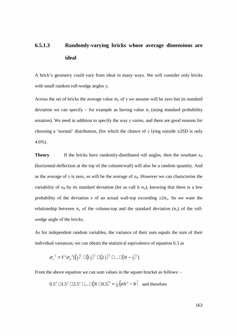
163
6.5.1.3 Randomly-varying bricks whose average dimensions are
ideal
A brick’s geometry could vary from ideal in many ways. We will consider only bricks
with small random roll-wedge angles γ.
Across the set of bricks the average value mγ of γ we assume will be zero but its standard
deviation we can specify – for example as having value σγ (using standard probability
notation). We need in addition to specify the way γ varies, and there are good reasons for
choosing a ‘normal’ distribution, (for which the chance of γ lying outside ±2SD is only
4.6%).
Theory If the bricks have randomly-distributed roll angles, then the resultant xN
(horizontal-deflection at the top of the column/wall) will also be a random quantity. And
as the average of γ is zero, so will be the average of xN. However we can characterise the
variability of xN by its standard deviation (let us call it σx), knowing that there is a low
probability of the deviation x of an actual wall-top exceeding ±2σx. So we want the
relationship between σx of the column-top and the standard deviation (σγ) of the roll-
wedge angle of the bricks.
As for independent random variables, the variance of their sum equals the sum of their
individual variances; we can obtain the statistical equivalence of equation 6.3 as
( ) ( ) ( ) ( ) ]...21[ 2
212
212
212
21222 −++++= NTx γσσ
From the above equation we can sum values in the square bracket as follows: -
( ) ( )NNN −=+++++ 31212222 45.0...5.25.15.0 and therefore

164
( )43
31 NNTx −= γσσ (6-5)
Since in practice 43 NN >> , and for 5≥N , the approximation error of neglecting the N/4
is less than ½%. Therefore we can use the approximate and simplified equation as,
5.1577.0 NTx γσσ = (6.6)
Where:
T is the brick average height/thickness
σγ SD of roll-wedge angle (γ) of sample bricks
N Column course numbers
6.5.2 SUMMARY OF THEORETICAL ANALYSIS
6.5.2.1 Models comparison
The out-come of the three cases (i) roll wedge-angle constant, (ii) roll wedge-angle zero
but front face sloping and (iii) random roll wedge-angle, exhibit a more than ten-fold
difference between the first and second cases, and therefore confirm that brick moulders
should place achieving parallel top and bottom faces much higher than achieving true
square-ness.
With the randomly varying bricks, equation 6.6 was formulated to the column lean for
given brick statistics.

165
6.6 PHYSICAL EXPERIMENTS AND TESTING TECHNIQUES
6.6.1 INTRODUCTION
The primary experiment was to identify the relationship between brick accuracy and wall
alignment accuracy measured in two dimensions, namely wall plumb-error (x–deviation)
and height-error (y–deviation) as shown in Figure 6.14. To study how the plumb-error is
magnified as the column/wall height increases, measurements were recorded at three
levels (courses 5, 10 and 20) from the steel rig-structure (Figure 6.17) to a built
column/wall. Figure 6.17a shows a rig (to be discussed in section 6.6.2) with three
vertical members from where the walls’/columns’ plumb is checked at selected heights
Figure 6.17b.
Three assembly strategies were compared to observe how the accuracy and quality of
bricks and the method of bricklaying contribute to the wall alignment quality. In the
investigations, shimming (insertion of filling material to correct for roll or pitch) was not
permitted, as doing so would have hidden the accumulative column/wall plumb-error
under scrutiny caused by the inaccuracy of bricks. Three types of walls (1400mm long by
1000mm high) were built, see Figures 6.27 and 6.28; first a wall with both ends free,
second a wall with one free end and the other end restrained or fixed, and third a wall
with both ends restrained.
The columns/walls were assembled using three different brick-laying strategies. The first
named as Column one (C1) or Wall one (W1), bricks are randomly picked from a pile
and placed as found, with no reversing for proper orientation or selection for proper
brick. In the second (C2/W2), the bricks are also randomly picked from the pile, i.e. no

166
selection, but are then allowed to be reversed by the brick-layer for best orientation. In
the third (C3/W3), bricks are laid with both selection and orientation permitted. The
bricklayer is allowed to measure using a spirit level or plumb and rectify horizontal out-
of-plumb deviations if need arises. Also use a straight-level on the front face (the same
for all assembly strategies) to make the wall course straight.
6.6.2 COLUMNS AND WALLS ALIGNMENT ACCURACY TEST
6.6.2.1 Experimental design
Bricklaying, even in mortarless wall construction, entails placing and fitting the bricks
one over the other, to make them straight in line with the building line, spirit level or
plumb. A series of actions (pushing, pulling, rolling, pitching and squeezing) are
performed. These actions cause a lot of disturbance to the already-built courses of a
block-wall with bricks dry-stacked. Due to the absence of joint mortar the wall’s
accuracy entirely depends on the locking mechanism between bricks, and on the top and
bottom surface flatness and parallelism of these bricks. However the disturbances cause
the wall to wobble. As the height and length increases, it will reach a point where the
block wall may not be stable enough to resist any further creation of vibration. That’s
why in conventional bricklaying there is a limit of 6 to 9 courses to be laid in a day (to
allow mortar to strengthen before continuing), otherwise the wall will not be stable
enough to resist further accidental on normal shaking from masons during brick
assembling and thus unable to retain positional accuracy.
We need to investigate the maximum allowable brick error that will allow building a

167
stable mortarless wall to the designed height (2.4 to 2.8m) without excessive vertical
deviation.
Rig structure
Tables 6.5 to 6.8 showed the governing dimensions measured on a sample of bricks.
From these sample bricks, was derived statistical characterisation of the whole brick
population.
To measure column/wall deviations required a vertical reference datum (Figure 6.17 a).
Several structure frame alternatives were considered, and the Optical Bench System from
Newport X-48 Series Rails and Carriers was found to be the most appropriate for the
purpose. The horizontal base member of the rig was set level and rigidly fixed on the
standard laboratory strong floor designed to carry heavy loads; the three vertical members
were fixed one at the centre and the two at 420mm (three lengths of experimental brick)
from the centre. The two end vertical rig members were are also set 280mm (two lengths
of experimental bricks) from the ends of experimental wall with assumptions that when
the wall is fixed at both ends any deflections start at the second brick not the first. For
measurement of column out-of-plumb deviations only the central reference member was
used.
The plumbness of the rig vertical members were accurately checked by theodolite and
safely and strongly fixed to the steel mechano (Figure 6.17). The permanent (built-in and
mortared) first course of the experimental wall was set 390mm from the horizontal base
member of the rig.

168
Figure 6.17 Column/wall vertical alignment test rig
a) Rig with permanent brick first course in mortar parallel to the rig base b) Selected column heights and horizontal distances to be measured to check plumbness
in reference to rig-datum
6.6.2.3 Instrumentation
There are number of instruments for measuring out-of plumb displacements. For dry-
stacked structures as the height increases the more the wall becomes unstable; therefore
we need an instrument that would not exert any significant lateral force (>0.5N) on the
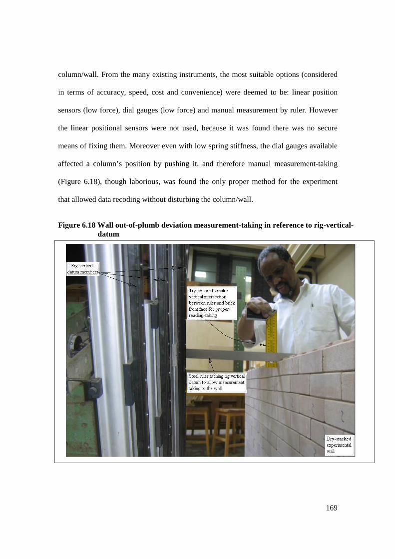
169
column/wall. From the many existing instruments, the most suitable options (considered
in terms of accuracy, speed, cost and convenience) were deemed to be: linear position
sensors (low force), dial gauges (low force) and manual measurement by ruler. However
the linear positional sensors were not used, because it was found there was no secure
means of fixing them. Moreover even with low spring stiffness, the dial gauges available
affected a column’s position by pushing it, and therefore manual measurement-taking
(Figure 6.18), though laborious, was found the only proper method for the experiment
that allowed data recoding without disturbing the column/wall.
Figure 6.18 Wall out-of-plumb deviation measurement-taking in reference to rig-vertical-datum

170
As shown in Figure 6.17 b, the measurements were taken at three wall levels, the fifth,
tenth and twentieth courses respectively. For each column, six measurements were made
i.e. three out-of-plumb displacements and three heights (at 5th, 10th and 20th courses
respectively). For each wall, twenty-one measurements were made, namely at each level
seven readings were taken from the three courses (Figure 6.28): length of the course,
three heights and three measurements of horizontal distance from rig vertical members to
the wall.
6.6.2.4 Test procedure
Column and wall construction
The experimental wall used for the analysis was a half-scale model of a wall 2m high (20
courses) and 3m long (10 bricks). These measurements were derived from the size of the
reference (Tanzanian) interlocking brick (300 x 150 x 100mm). The base or first course
was properly prepared i.e. straight, level and vertical to plumb (Figure 6.17).
Three methods of fixing (free ends, one end restrained and both ends fixed) the wall
panels were used to test the plumbness control of mortarless technology (MT). Three
bricklaying strategies (randomly stacking, reversing, reversing and selecting) were used
during brick assembly to construct nine walls and three columns types. And each wall or
column type was assembled five times using bricks newly selected from the brick-pile, to
observe the change or variation in alignment accuracy.
Table 6.10 columns assembling sequence Designation Method of assembling Size of set built
C1 Random picking and stacking 5 C2 Reverse allowed 5 C3 Reversing and replacement allowed 5
171
Assembling sequence
In reference to rig Figure 6.17a, the experimental columns were assembled in the
sequence as summarised in Table 6.10. After each assembly the out-of-plumb and height
deviations of columns were measured as shown in Figure 6.17, and then measurements
were processed to obtain the standard deviations of the column out-of-plumb
displacement (x-deviations) and height-error (y-deviations) as shown in Figure 6.14. The
same procedure was applied to each (of three) selected vertical sections along walls in
Section 6.8.
6.6.3 PHYSICAL ALIGNMENT ACCURACY TEST RESULTS AND DISCUSSIONS
6.6.3.1 Bricklaying analysis approach
Columns were constructed using the three brick-laying strategies, as described in Section
6.6.1 i.e. bricks randomly picked and assembled to a column (C1), bricks reversal
allowed when forming column (C2) and the assembly of column (C3) with the provision
of selecting and replacing for better orientation.
The first expectation of the experiments was that moving from strategy C1 to C2 to C3
would give successive improvements in column alignment – as measured by the SD of
the displacement from plumb of various courses in a 20-course column. The other
expectation, is that reducing the variably of the brick themselves (as measured by the SD
of the roll wedge-angle within the brick set) would improve the column’s alignment.
While we could not control the brick variability in the physical experiments, we did so in
the computer simulations reported in Section 6.7. The theoretical equation 6.6 (given in

172
Section 6.5.1.3) was developed only for randomly placed bricks i.e. strategy C1.
Therefore, when applied using as data the roll-angle characteristics of the experimental
bricks, it should agree with the experimental results for randomly laid bricks columns C1.
For strategies C2 and C3, the column assembly is no longer random, so the assumptions
underlying the theory are no longer valid. In fact the displacements for a given height are
not only less than for strategy C1, but also obey a lower power-law than that (SD ∝ N1.5)
shown by the strategy C1 columns.
6.6.3.2 Experimental data for columns
The three data sets shown in Tables 6.11, 6.12, and 6.13 correspond to the three
bricklaying strategies used in the research (namely: random, reverse and replace). A set
of 20 bricks randomly selected from a pile of 44 bricks.
The ‘reverse’ and ‘replace’ strategies were performed to check if (and by how much) they
make any improvement compared to the random picking and placing strategy (Table
6.11). Five columns were assembled for each of reverse and replace strategies: results
presented in Tables 6.12 and 6.13. Note that five is a very small set of data and the
consequent statistical data is very approximate.
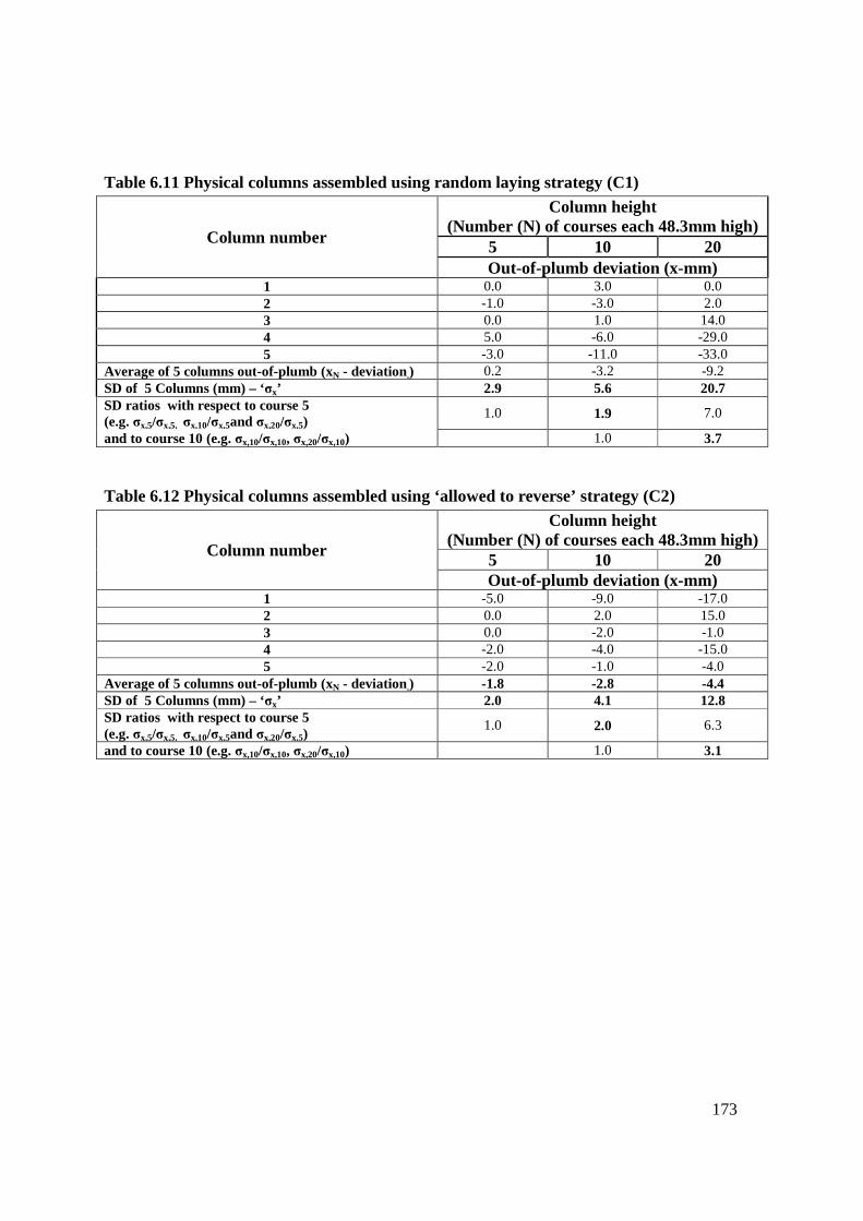
173
Table 6.11 Physical columns assembled using random laying strategy (C1)
Column number
Column height (Number (N) of courses each 48.3mm high)
5 10 20 Out-of-plumb deviation (x-mm)
1 0.0 3.0 0.0 2 -1.0 -3.0 2.0 3 0.0 1.0 14.0 4 5.0 -6.0 -29.0 5 -3.0 -11.0 -33.0
Average of 5 columns out-of-plumb (xN - deviation.) 0.2 -3.2 -9.2 SD of 5 Columns (mm) – ‘σx’ 2.9 5.6 20.7 SD ratios with respect to course 5 (e.g. σx,5/σx,5, σx,10/σx,5and σx,20/σx,5)
1.0 1.9 7.0
and to course 10 (e.g. σx,10/σx,10, σx,20/σx,10) 1.0 3.7
Table 6.12 Physical columns assembled using ‘allowed to reverse’ strategy (C2)
Column number
Column height (Number (N) of courses each 48.3mm high)
5 10 20 Out-of-plumb deviation (x-mm)
1 -5.0 -9.0 -17.0 2 0.0 2.0 15.0 3 0.0 -2.0 -1.0 4 -2.0 -4.0 -15.0 5 -2.0 -1.0 -4.0
Average of 5 columns out-of-plumb (xN - deviation.) -1.8 -2.8 -4.4 SD of 5 Columns (mm) – ‘σx’ 2.0 4.1 12.8 SD ratios with respect to course 5 (e.g. σx,5/σx,5, σx,10/σx,5and σx,20/σx,5)
1.0 2.0 6.3
and to course 10 (e.g. σx,10/σx,10, σx,20/σx,10) 1.0 3.1

174
Table 6.13 Physical columns assembled using ‘select and replace’ strategy (C3)
(Up to 2 attempts permitted)
Column number
Column height (Number (N) of courses each 48.3mm high)
5 10 20
Out-of-plumb deviation (x-mm) 1 -3.0 -7.0 -14.0
2 0.0 -1.0 -3.0
3 -2.0 -2.0 -3.0
4 -3.0 -5.0 -11.0
5 -1.0 0.0 4.0
Average of 5 columns out-of-plumb (xN - deviation.) -1.8 -3.0 -5.4
SD of 5 Columns (mm) – ‘σx’ 1.3 2.9 7.2 SD ratios with respect to course 5 (e.g. σx,5/σx,5, σx,10/σx,5and σx,20/σx,5)
1.0 2.2 5.5
and to course 10 (e.g. σx,10/σx,10, σx,20/σx,10) 1.0 2.5
6.6.3.3 Comparison of the three assembly strategies
Table 6.14 exhibits the benefit of reversing (strategy 2) the bricks for better orientation
during construction, and the further benefit of allowing a poorly aligned brick to be
replaced (strategy 3) by a second choice from the available bricks in a pile. The data in
Table 6.14 have been up-scaled by suitable value of factor K (see Table 6.20) to correct
for the small brick-pile size.
Table 6.14 The comparison of assembly strategies SD of out-of-plumb deviation (x-mm) for experimental columns
Course No. Strategy Scaling factor C 1 C2 C 3 K
5 3.2 2.2 1.4 1.1 10 6.7 4.9 3.5 1.2 20 29.0 17.9 10.1 1.4
Data based on 5columns 5columns 5columns
Taking C1 as the worse case yielding a datum for out-of-plumb deviation, then the
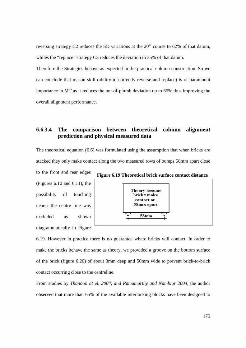
175
reversing strategy C2 reduces the SD variations at the 20th course to 62% of that datum,
whiles the “replace” strategy C3 reduces the deviation to 35% of that datum.
Therefore the Strategies behave as expected in the practical column construction. So we
can conclude that mason skill (ability to correctly reverse and replace) is of paramount
importance in MT as it reduces the out-of-plumb deviation up to 65% thus improving the
overall alignment performance.
6.6.3.4 The comparison between theoretical column alignment prediction and physical measured data
The theoretical equation (6.6) was formulated using the assumption that when bricks are
stacked they only make contact along the two measured rows of bumps 58mm apart close
to the front and rear edges
(Figures 6.10 and 6.11); the
possibility of touching
nearer the centre line was
excluded as shown
diagrammatically in Figure
6.19. However in practice there is no guarantee where bricks will contact. In order to
make the bricks behave the same as theory, we provided a groove on the bottom surface
of the brick (figure 6.20) of about 3mm deep and 50mm wide to prevent brick-to-brick
contact occurring close to the centreline.
From studies by Thanoon at el. 2004, and Ramamurthy and Nambiar 2004, the author
observed that more than 65% of the available interlocking blocks have been designed to
Figure 6.19 Theoretical brick surface contact distance
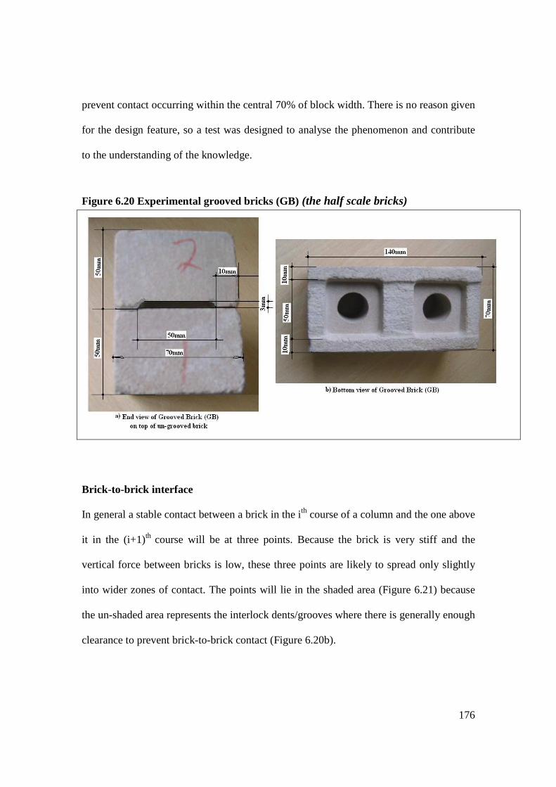
176
prevent contact occurring within the central 70% of block width. There is no reason given
for the design feature, so a test was designed to analyse the phenomenon and contribute
to the understanding of the knowledge.
Brick-to-brick interface
In general a stable contact between a brick in the i th course of a column and the one above
it in the (i+1)th course will be at three points. Because the brick is very stiff and the
vertical force between bricks is low, these three points are likely to spread only slightly
into wider zones of contact. The points will lie in the shaded area (Figure 6.21) because
the un-shaded area represents the interlock dents/grooves where there is generally enough
clearance to prevent brick-to-brick contact (Figure 6.20b).
Figure 6.20 Experimental grooved bricks (GB) (the half scale bricks)

177
Figure 6.21 schema representing a grooved brick bottom surface
Normally the contact points will straddle this ‘no-contact’ zone. The three contact points
define a plane. This shaded plane can be considered to have a small ‘roll’ component, a
smaller ‘pitch’ component, and a negligible ‘yaw’ component. It is the roll component
that concerns us. The (roll) angle between this plane and the front face (Figure 6.13) of
the lower brick we call 90+βi where βi is a geometric property of that lower brick. If the
lower brick were perfect, βi would equal zero.
The plane through the three contact points similarly makes an angle (90+αi+1) with the
front face of the upper brick.
If, relative to vertical, the front faces of bricks i and i+1 subtend small angles θi and θi+1
respectively (ideally θ would equal zero), then geometry shows that
θi+1 = θi + βi - αi+1
and thus we have a formula for recording the change in forward lean as we rise course by
course through a column (Figure 6.16). We can also defined a ‘roll wedge angle’ for each
brick
γ = β – α,

178
which would equal zero for an ideal brick. There remains the task of calculating αi+1 and
βi from the 16 spot-measurements made on the two bricks.
Although it would take an infinity of measurements to fully define each brick surface,
only 8 measurements, each expressed as a deviation from an ideal surface perpendicular
to the brick’s front face, were made for each top and bottom surface – 4 distributed along
each of the bold dashed axes B – B (back edge) and F – F (front edge) Figure 6.21.
In the development of a theoretical model (Figures 6.10 and 6.11), the way used to define
the top surface roll angle β of a brick was to average the four measured surface deviations
(‘bump heights’ Table 6.8) along the back edge B – B, subtract the average of the four
measured deviations along the front edge F – F and divide by the spacing D. A similar
process was used to derive the bottom surface roll angle α. We call this approximation
‘averaged contacts model’. Observe that αi+1 is derived just from the (bottom face)
measurements of brick i+1 and βi just from the (top face) measurements of brick i. There
is no ‘joint’ modelling involving the measurements of both upper and lower brick.
For theory purposes we just model bricks with plane tops and bottoms (though there is
the issue of how we measure the alpha, beta and hence SD of gamma for the real bricks to
plug into the theory so it can be compared with experiment Tables 6.7 and 6.8).
For experiment we don’t need to discuss MODELLING brick-to-brick contact. So it is
only for simulation that we need to explain how we get from 16 surface deviation
measurements to the quantity [θi+1 - θi].

179
6.6.3.4 The alignment accuracy: comparison between columns built using grooved and un-grooved bricks
From the normal-bricks (NB) 30 column assemblies were made Table 6.15, which were
compared with the 30 column assemblies made from grooved-bricks (GB) Table 6.16.
For fair comparison between the grooved-brick columns (GBC) and un-grooved (normal)
brick columns (NBC), equal set of bricks were prepared and the same number of runs
assembled using strategy one (random stacking) i.e. 30 columns were assembled for each
type using 20 bricks shuffled before each new assembly.
The grooved-brick columns (GBC) Table 6.16 exhibit improved alignment accuracy
compared to normal-brick columns (NBC) Table 6.15 e.g. SD of out-of plumb deviation
of NBC at 20th course (σNB,20 = 19.5mm) whereas SD of GBC (σGB,20 = 9.2mm). This is a
53% reduction of columns’ out-of-plumb deviation achieved from using GBs. However
as commented in Section 6.6.3.2, the statistics are drawn from a very small sample and
therefore have considerable uncertainty, thus the same 20 bricks ‘shuffled’. This
difference in pile size and set of bricks selected from it, for column assembly was
investigated separately and discussed later in Section 6.7.

180
Table 6.15 Normal-brick columns (NBC) randomly assembled
Column number
Column height (Number (N) of courses each 48.3mm
high) 5 10 20
Out-of-plumb deviation (x-mm) 1 -5.5 -18.0 18.0 2 0.0 0.0 5.0 3 -6.0 -13.0 -15.0 4 -3.5 -7.0 -14.0 5 -1.0 -3.0 -7.0 6 -3.0 -5.0 -16.0 7 -2.0 -13.0 -27.0 8 2.0 21.0 27.0 9 -2.0 -3.0 -15.0 10 -1.0 -3.0 -26.0 11 -8.0 -19.0 -12.0 12 4.0 11.0 28.0 13 -1.0 -8.0 -21.0 14 -5.0 -5.0 -4.0 15 -3.0 -9.0 -33.0 16 0.0 4.0 15.0 17 -2.5 -5.0 -19.0 18 0.5 -1.0 -4.0 19 -1.5 -4.5 -5.0 20 0.5 5.0 9.0 21 -1.0 -1.5 4.0 22 -1.0 3.0 9.0 23 -4.0 -7.0 -19.0 24 0.0 5.0 16.0 25 1.0 3.0 6.5 26 1.0 3.5 16.0 27 0.0 4.0 1.0 28 7.0 16.5 47.0 29 2.0 -3.0 -23.0 30 7.0 12.5 27.0
Average out-of-plumb (xN - deviation.) in mm of 30 columns -0.9 -1.3 -1.1 SD of out-of-plumb – ‘σx’ in mm of 30 Columns 3.3 9.2 19.5 SD ratios with respect to course 5 (e.g. σx,5/σx,5, σx,10/σx,5and σx,20/σx,5)
1.0 2.7 5.8
and to course 10 (e.g. σx,10/σx,10, σx,20/σx,10) 1.0 2.1

181
Table 6.16 Practical column assemblies using grooved-bricks randomly stacked (Strategy C1 – 20 bricks reshuffled each assembly)
Column number
Column height (Number (N) of courses each 48.3mm high)
5 10 20 Out-of-plumb deviation (x-mm)
1 -1.0 4.5 5.0
2 -2.0 -5.0 -0.5
3 1.5 4.0 15.0
4 -1.0 3.0 -6.0
5 -1.0 -4.0 -13.0
6 1.5 5.0 14.0
7 1.0 -1.0 2.0
8 4.0 -5.0 3.0
9 2.0 1.0 0.0
10 0.0 -3.0 -6.0
11 5.0 -1.0 -3.5
12 -2.0 -1.0 12.0
13 0.0 4.5 23.0
14 -1.0 4.0 21.0
15 -1.5 0.0 14.0
16 -1.5 -0.5 -11.0
17 2.0 19.5 10.0
18 2.0 2.0 10.0
19 0.0 2.0 -3.5
20 0.0 -1.5 9.0
21 -0.5 -3.5 13.0
22 -1.0 -0.5 5.0
23 -2.0 1.0 -2.0
24 0.0 0.0 5.0
25 -5.0 -5.0 -4.0
26 0.5 -3.0 -4.0
27 -1.5 -4.5 -3.0
28 0.0 0.0 1.0
29 -1.0 -3.0 -7.0
30 0.5 -2.0 -3.0
Average out-of-plumb (xN - deviation.) in mm of 30 columns -0.1 0.2 3.2
SD of out-of-plumb – ‘σx’ in mm of 30 Columns 1.9 4.8 9.2 SD ratios with respect to course 5 (e.g. σx,5/σx.5, σx,10/σx,5 & σx,20/σx,5)
0.6 1.4 2.7
and to course 10 (e.g. σx,10/σx,10 & σx,20/σx,10) 0.5 1.0

182
The theoretical formulae 6.6 ( 5.1577.0 NTx γσσ = ) uses measured bricks statistical values
from Tables 6.7 and 6.8 (T = 48.3, σγ = 0.0038) to calculate SD of out-of-plumb
deviations (σx) of columns at Nth course i.e. 5, 10 and 20, values shown in Table 6.17.
Table 6.17 the comparison of out-of-plumb deviation between normal-brick and grooved-brick columns & theoretical predictions
Course number (N) SD of columns out-of-plumb deviations
NBC GBC TE
5 3.3 1.9 1.2
10 9.2 4.8 3.4
20 19.5 9.2 9.5
Table 6.16 shows for course 20 a ratio of 0.97 between theory and experimental GBC for
σx, the standard deviation of out-of-plumb. However with a sample of 30 columns, any
estimates of SD will (for 90% certainty and using Chi-square (χ2) table) lie between ±9%
of the true (population) value. Therefore as a difference between theory and physical
experiment for course N = 20 lies within that 9% range, we can conclude that there is
acceptable.
However, as already argued, the former has statistical uncertainty due to limited sample
size. The theory is based on a value for roll-wedge angle SD (σγ), which is hard to
measure accurately from experimental bricks. The modelling of contact distance between
the rear and front bumps relates with grooved bricks but not ungrooved-indented bricks,
so this modelling will be discussed and analysed in Section 6.7.
So we can say theory is broadly confirmed by physical experiment using grooved bricks
and indeed variation in out-of-plumb deviation is driven by variations in roll-wedge
angle. Out-of-plumb deviation rises with height to the power of 1.5.
183
6.7 SIMULATION OF COLUMN ASSEMBLY
A Column Assembly Simulation Model (CASM) is a computer model used for
simplifying the process of brick assembling and arrangement of columns and walls. Thus,
permitting many random runs made in order to achieve acceptable statistical data
representation. This work done by computer took hours otherwise it would have taken
months to complete the physical practical laboratory works.
The use of CASM made it possible to assemble simulated columns/walls of more than 40
courses high compared to actual physical columns/walls. However, due to practical
conditions and time constraints, it was found not easy to build up to 40 courses of thin
columns/walls using half scale experimental bricks. Similarly, a 40 course walls would
have required many hundreds of bricks (manufactured and measured) hence, more time
than was available.
In the practical experiments 20 course columns/walls were assembled for each brick
laying strategy. A total of 75 columns and 45 walls were built. These are very small
sample representative from which to deduce acceptable statistical properties yet they are
sufficient number to be used for control purposes. By using simulation up to 240
assemblies were made for each strategy.
6.7.1 DEFINITIONS AND CLARIFICATIONS
Measured bricks and Measured brick Pile is a physical measurement (see section 6.2.3
in Tables 6.2 and 6.3) for one brick while Tables 6.7a and 6.7b shows measurements of a

184
pile of 44 brick sample. From a pile/batch of bricks is where one can select few bricks (a
set) for a certain purpose i.e. column or wall assembly.
Simulated brick and Simulated brick pile are measurements representing brick
characteristics generated using random numbers combined with the statistics taken from
Measured bricks (Tables 6.7a, 6.7b and 6.8).
Simulated brick stack assuming face to face contact this is where the top and bottom
of the surfaces of two bricks touch one another and their surfaces of contact are assumed
plane. At the surface contact planes the roll-wedge angle is determined. The two methods
used for determining these planes are:
Average of bumps method is the average heights of a row of 4 marked points at the rear
and front predetermined points in the contact plains of the two bricks (figure 6.22). The
differences of the two is divided by 58mm which is the distance between the opposite
points (rear and front e.g. 1 and 2 in Figure 6.22)
Point to point contact (“kissing”) method is the re-alignment angle ω = βi - αi+1 as
described in section 6.7.2, and computed by combining data from the top surface of the
lower brick with data of the bottom surface of the upper brick (Figure 6.22) in a way that
mimics the four steps used by a mason when placing one brick on top of the other (see
details in section 6.3.2). The angle (ω) gives the brick re-alignment and hence the
orientation of the angle θi+1 = (θi + ω) of the brick above the contact brick surface

185
Brick set: are defined numbers of bricks picked from a pile to make a column or a wall
Column or Wall statistics were obtained by observing the building (real or
computerized) of many columns or walls, each with a new set of bricks.
Whereby:
N is the size of the brick set needed to build a column of N courses
M is a pile of bricks where N is selected
K is a function of a ratio λ = M/N
If the pile from which bricks are selected (‘with replacement’) is of size M, then M should
be much bigger than N. If this condition is not met then the variability of the columns
(and hence the SD derived from the set of columns) will be biased, i.e. too small.
However we can correct these biased statistics using a multiplier K, where K is a function
of the ratio λ = M/N, (K = 1 when M>>N)
Figure 6.22 Highest kissing (butting) bumps of the rear and front of meeting surfaces

186
6.7.2 COMPUTER MODEL
The Column Assembly Simulation model (CASM, see Figure 6.23) uses Excel to
simulate column/wall assemblies for the alignment accuracy analysis, whose purpose is
to relate the column/wall characteristics to the brick irregularities. Two sources of data
are used in the simulations:
• From the experimental bricks measurement, brick data is set into the CASM as
Brick Pile - BP5. From this pile, the statistics (mean and variance) for the bumps
across the brick surfaces were computed.
• From Excel the random numbers were generated and multiplied by the
experimental brick statistics from BP5 to formulate an imaginary Brick Pile Raw
(BPR). From this BPR three piles were formulated as follows:
BP1 bricks randomly piled (simply by copying BPR)
BP2 all bricks reversed (opposite of BPR)
BP3 some bricks reversed - to give alternating +ve and –ve wedge-
angles
The three brick piles saved into different working sheets and viewed through a common
button selector (positioned in the column working sheet). The selection of piles, one at a
time (BP1 and BP3) and their respective bricks specifications are displayed on the Brick
Stack (BST) working sheet.

187
Figure 6.23 Flowchart of a Column Assembly Simulation Model (CASM) for random brick laying strategy
In the BST (common displaying screen) two methods are used to process brick-to-brick
contact data (as described in the definitions) i.e. averaging the bumps and the maximum
kissing points. For the convenience of recording and processing brick specifications into
a computer working sheet (see Table 6.7 and 6.8), the pile of bricks are stacked into
columns and subsequent statistics of each brick along the row. The merging angles (ω)
and out-of plumb angles (θ) for each brick course are computed in this working sheet
(BST).

188
BPR working sheet is the main working area of CASM, in order to make rearrangement
of bricks before every new run (new column/wall assembly), the brick order is shuffled.
This effectively creates a new random brick-set. When we shuffle BPR means as well
change the order of bricks in BP1 and BP2 but not BP3. A new BP3 set has to be created
using the shuffled BP1 and BP2 piles, the sequence is shown in Figure 6.24.
The necessary data for out-of-plumb deviation and height errors are displayed on the
column/wall working sheet and data for courses 5, 10 and 20 are recorded for each run
(assembly) see Figure 6.23.
To simplify and accelerate the shuffling, recording, editing and copying of data to the
appropriate location, a ‘macro’ programme was used to automate the whole process.

189
Figure 6.24 Flowchart of a Column Assembly Simulation using alternate wedge-angle
The shuffling is done in the BPR, and then bricks are piled in two opposite orientations
(BP1 and BP2). ) One of the brick from either of the stack is chosen to create BP3. This
third order stacked column observe alternate wedge-angle signs aiming to reduce out-of-
plumb deviation of a column

190
The conditions used to process BP1 and BP2 and create BP3 depend on the values of
wedge-angles (γ1 of BP1 and γ2 of BP2):
• If the columns’ course number (n) is even and γ2 > 0 then use pile BP2
• If n is even and γ1 < 0 then use pile BP1
• If n is odd and γ1 > 0 then use pile BP1
• If n is odd and γ2 < 0 then use pile BP2
6.7.3 COMPUTATION OF COLUMN/WALL OUT-OF-PLUMB
DEVIATION
The theory and the simulation assume that the orientation of any brick depends in part on
that of the brick below it. But the lowest (base) brick’s orientation depends only on its
bottom surface inclination named alpha (α) as in Figures 6.12 and 6.13. Considering the
first three bricks from Figure 6.16 and the details of surface contacts are illustrated in
Figure 6.25.
However, the deviation of the column at any height can be re-expressed in terms of the
roll-wedge angles for each brick γi = βi - αi. So the value of γi was computed for each
brick in a brick stack (BST - this is a sets of brick selected after shuffling and assembled
into a column).
The simulation of brick assembly sequence is represented by the formula inserted in the
computer to perform assembly operations and automatically give out the result in form of

191
out-of-plumb deviation. The placement of brick one (Figure 6.25) in position with its
bottom surface horizontal will make its front face to form an angle theta (θ1) with the
plumb line (y axis).
Figure 6.25 Imperfect bricks placed in position showing successive vertical deviation
Therefore; θ1 = α1, as the bottom brick is assumed to be placed on a horizontal mortar
bed, θ2 = θ1 + (β1 - α2), and
θ3 = θ2 + (β2 - α3) and in general;
θi = θi-1 + (βi-1 - αi) = θ i-1 + ωi (6.7)

192
The computation of the angle ωi = θi – θi-1 assumes the top surface of brick one (figure
6.25) is a plane of contact making an internal angle (90 + β) with its front face, the
bottom surface of brick two is a plane of contact making an internal angle of (90 - α) to
its front face, and assembly makes these two planes coincide. There are several options
for modelling these planes of contact: two options were considered in the simulations
described in the definitions.
Note that ωi is a function of the irregularity of the top surface of brick i-1 and the bottom
surface of brick i (ωi = βi-1 - αi) For ideal bricks ωi = 0 for all i. We can now
generalize this sequence of face angle computation as;
nn ωωωαθ ++++= ...321
Where; n is the top course
θn is the angle that the front face of the nth brick makes with the
plumb line
Given this angle theta for each course, and the course height (T) we can calculate the
change δi as the horizontal out-of-plumb deviation of individual brick i, and xi as the sum
the individual out-of-plumb deviations up to brick-course i see Figure 6.25.
Overall out-of-plumb deviation will be:
∑=
=i
iiix
1
δ .
In Section 6.5.1.1 it was analysed that:
δi = Ti*sin(θi), and as for small angles sin(θi) ≈ θi and assuming all bricks are the
same height (T),

193
1−+×= nnn xTx θ , (6.8)
6.7.4 THE RELATION BETWEEN THE STATISTICS OF COLUMN OUT-OF-PLUMB DEVIATION AND THE SIZE OF THE BRICK-PILE FROM WHERE THE SET OF BRICKS WAS PICKED
6.7.4.1 Brick selection
The method used (to select the bricks for a particular column-assembly) in the
simulations was done as follows: A large pile of brick-data was randomly shuffled and
then the first 20 ‘bricks’ (N) were used to construct a simulated column. The research
was particularly interested in the ratio λ20 = brick-pile size/20. Where λ is large, the
procedure is a good mapping of the process of choosing bricks from an infinite
population. For most simulation runs, λ20 had the value 25, since as shown in Figure 6.24
the brick pile employed for simulations had 500 bricks. Indeed when looking at the
properties of say the nth course in a column, the effective ratio λn (now = brick-pile
size/n) was even greater than 25 for all courses except the 20th. These ratios λ are
sufficiently high to give confidence to the simulation results to represent selecting bricks
from a very large population.
However, the brick pile for simulation could be made larger, that set used for practical
experiments could not. Indeed for column experiments using only the 44 measured
ungrooved bricks and the 20 grooved bricks (Brick pile BP5), λ20 only lay in the range 1
to 2.2. With λ20 = 1 we are effectively only shuffling (changing the order of) the same 20
bricks to form each column: in consequence such a column shows less variation in
deflection than one built from a very large brick-set. In fact a scaling factor is needed to

194
raise any value for σx20 (SD of x-deviation of top of 20th course) obtained from such
experiments to a value representative of working with an infinite brick-pile.
Before we simulate the assembly of columns using piles with large number of bricks to
generate realistic statistical data there are number of decisions were made.
• This researcher considered that a pile size greater than twenty times the set size would
approximate an infinite pile size (N<<M). Thus if N = 20 and λ = 20, then we need to
use M ≥ 400).
• In the physical experiment we used two types of bricks; grooved and ungrooved.
With grooved bricks we know that brick-to-brick contact can only occur closer to the
front and rear edges of the meeting surfaces. This is what the simulation models, in
assuming contact is only along lines respectively near the front and near the back.
However the ungrooved bricks may contact anywhere on their top/bottom surfaces
(provided that at least one contact point is in the rear-half of the surfaces and at least
one in the front-half).
Thus for the simulation of ungrooved bricks we need to identify a suitable (‘average’)
distance (D see Figure 6.26) between front and rear contact points. This distance will
lie between a minimum of 0 and a maximum of W. Separate calculations were
therefore made to obtain a value for D.
• From the two methods of determining the brick contact planes considered in the
simulation modelling, after trials the statistical data from butting method were found
to overestimate the outputs i.e. the wedge-angle gamma (γ), the surface merging plane
angle omega (ω) and ultimately the stack inclination angle theta (θ) Figure 6.25,

195
which resulted into unrealistic high figures of SD of out-of-plumb deviations (σx).
Therefore this research accepted averaging as a proper contact modelling method.
6.7.4.2 The effective contact-spacing between rear and front
contact bands
We wish to represent all possible combinations of front-half bands and rear-half bands
and their corresponding spacing (s = b - a) Figure 6.26. However in the determination of
experimental brick statistics (Table 6.8), we use the reciprocal of the spacing (s) in our
calculation of the roll wedge-angles, causing the column to tilt. Therefore we need to
average not s but 1/s.
In simulation we use a conversion factor (linear error to angular error) of f = reciprocal of
normalised spacing of contact points. Thus if contacts were only along front and back
edges then f = W/W =1. Nonetheless contacts are generally closer than this, so if contact
spacing is s = b-a Figure 6.26, then:
( )abWf −= (6.9)
Where:
a is distance from front face to centre of the relevant front-half band
b is distance from front face to centre of the relevant rear-half band
f is a reciprocal of normalised spacing of contact points;
W is a brick width

196
Figure 6.26 Brick surface divided into 20 equal parallel contact bands
Thus in calculating for example the out-of-square angle between a brick’s bottom and
front faces:
α = (vertical displacement at rear – vertical displacement at front) (spacing between front & rear contact points).
We could instead use a factor f i.e.
α = f x (εrear – εfront) / W,
where for contact only along back edge and front edge, f = 1, but normally f > 1.
To obtain an average value of f to use in simulation we evaluate: fAv. = average of f for all
possible pairs of contact points, weighted according to their probability of occurring.

197
For ease of computation we assign possible contact points into a limited number of equal-
width bands. Figure 6.26 shows ten such bands for the rear-half and ten for the front-half
of the contact surface, 20 bands being a reasonable approximation to the real-world
continuum. The centre-lines of these bands (measured from the front face) are at
distances 0.025W, 0.075W, ..., to 0.975W from the front brick face (Table 6.18). Thus (a)
is now restricted to the 10 values 0.025W to 0.475W and (b) to the 10 values 0.525W to
0.975W.
With an ungrooved brick, we can assume the rear contact points are uniformly distributed
over the rear half of brick, the b values; b1 = 0.525W, b2 = 0.575W etc. are equally likely.
Similarly the a values; a1 = 0.025W, a2 = 0.075W etc. are equally likely for the front half
of brick. For each (of 100) combinations of rear and front bands we calculate f using
Equation 6.9 and then average the 100 values, so obtained, to get fav.
In the case of grooved bricks we remove from the computation the bands corresponding
to the groove (as grooving prevents contact in those bands). In this case fav is the average
of values obtained from all combinations of the remaining bands (Table 6.18).
Table 6.18 Table of f 1 factors,
a = Normalised distance from front face to front mid-band
b = Normalised distance from front face to rear mid-band Band 11 12 13 14 15 16 17 18 19 20 b = 0.525 0.575 0.625 0.675 0.725 0.775 0.825 0.875 0.925 0.975
Band 1 a = 0.025 2.00 1.82* 1.67 1.54 1.43 1.33 1.25 1.18 1.11 1.05 2 0.075 2.22 2.00 1.82 1.67 1.54 1.43 1.33 1.25 1.18 1.11 3 0.125 2.50 2.22 2.00 1.82 1.67 1.54 1.43 1.33 1.25 1.18 4 0.175 2.86 2.50 2.22 2.00 1.82 1.67 1.54 1.43 1.33 1.25 5 0.225 3.33 2.86 2.50 2.22 2.00 1.82 1.67 1.54 1.43 1.33 6 0.275 4.00 3.33 2.86 2.50 2.22 2.00 1.82 1.67 1.54 1.43 7 0.325 5.00 4.00 3.33 2.86 2.50 2.22 2.00 1.82 1.67 1.54 8 0.375 6.67 5.00 4.00 3.33 2.86 2.50 2.22 2.00 1.82 1.67 9 0.425 10.00 6.67 5.00 4.00 3.33 2.86 2.50 2.22 2.00 1.82 10 0.475 20.00 10.00 6.67 5.00 4.00 3.33 2.86 2.50 2.22 2.00
Groove to width ratio, G/W 0.002 0.10 0.20 0.30 0.40 0.50 0.60 0.70 0.80 0.90 0.713
Conversion factor = fav 2.68 2.10 1.82 1.62 1.47 1.36 1.26 1.18 1.11 1.05 1.17

198
Notes (see note numbers in Table 6.18)
1. f is the reciprocal of the contact normalised distance between front and rear points of laid bricks, quantised to 5% bands and normalised to brick width.
* is where f’= 1.82 (rear contact point lies in band 12 and front contact point in band 1)
2. G/W = 0 indicates no groove (representing ungrooved brick contact surface)
3. Highlights cells represent the grooved bricks actually used in the experiments
The spacing between two strips/bands, s can be expressed as a function s(i,j)
Where: i is the number of the front strips, i =1 to 10
j is the number of the rear strips, j = 11 to 20 s is a distance between the ith (front) strip and the jth (rear) strip
Or for simplicity we define the factor f = f(i,j) = W/s(i,j)
Then,
fAv. = sum over all functions i,j of {f(i,j) x pi x pj}
( )∑∑××=i jn
i
n
jjiAv jifppf , (6.10)
Where: pi is probability that front contact lies in strip i pj is probability that rear contact lies in strip j
If all allowed contact points are equally likely, then pi = area of strip i divide by the area
A of allowed front half of brick surface, and from different surface conditions i.e.
uniform, full grooved and only indented will have various permitted-contact areas.
a) A = ½Wℓ for a uniform surface
b) A = ½(W-G)ℓ for a grooved surface with groove width G (Figure 6.20)
c) A = ½(Wℓ-2t2) for an indented surface, assuming two indentations each size tt ×
Moreover as ℓ = 2W and say t = ψW (ψ typically equals 0.7), then for our three cases above become:
a) A = W2, b) A = W2 – WG c) A = W2 (1 – ψ2).

199
Uniform bricks (neither grooved nor indented) of width (W)
From Table 6.18, fav = 2.68 so effective contact-point spacing is D = W / 2.68 = 26 mm
Indented bricks (Figure 6.20b)
For the experimental bricks (indent) ψ = t/W = 0.7 and therefore A = 0.51W2.
Thus if both halves are split into ten strips, width is split into twenty strips (W/20). The
probability of contact point occurrences will be;
pi = 0.1 if i≤3; pi = 0.03 if i>3
pj = 0.1 if j≥18; pj = 0.03 if j<18
For ψ = 0.7, where 3 strips are full length and 7 strips are 30% length, we can expect the
following cases:
(i) i ≤3, j≥18 0384.051.02
1.051.02
1.0 22 =×= wwl
wwl
pp ji
(ii) i >3, j≥18 0115.051.02
1.051.02
03.0 22 =×= wwl
wwl
pp ji
(iii) i ≤3, j<18 0115.051.02
03.051.02
1.0 22 =×= wwl
wwl
pp ji
(iv) i >3, j<18 0035.051.02
03.051.02
03.0 22 =×= wwl
wwl
pp ji
So knowing the probability values, we can calculate fAv using equation 6.10 as the sum
of:
( ) ( ) ( ) ( )∑∑∑∑∑∑∑∑= == == == =
+++10
4
17
11
3
1
17
11
10
4
20
18
3
1
20
18
,0035.0,0115.0,0115.0,0384.0i ji ji ji j
jifjifjifjif
From Table 6.16 we get the sum of the functions i,j:
fAv. = 0.0384x10.64 + 0.0115x36.22 + 0.0115x36.22 + 0.0035x184.44 = 2.3
fAv = 2.3 for ungrooved bricks (provided with indentations of width of 70%W)
Thus the effective contact-point spacing is only D = W / 2.3.

200
For the ungrooved (indented) bricks used in experiments (width W = 70mm), D = 30
mm.
Grooved bricks
For grooved bricks, fAv depends on G/W, the normalised width of the grooving. Thus with
50% grooving, fav falls to 1.36 and hence D = 51 mm.
However the grooving actually made in the grooved experimental bricks was 50 mm
wide, namely 70% of width, giving G/W = 0.71, fAv = 1.17. Hence D = 60 mm.
Comparisons
Comparing grooved with uniform ungrooved bricks, the factor fAv has fallen by 56%
(from 2.68 to 1.17), so we should expect grooving to reduce column deviation by the
same large percentage.
Comparing grooved with indented bricks the factor fav falls by 49% (from 2.30 to 1.17)
which is also substantial enough to justify the grooving even of already indented bricks.
6.7.4.3 Influence of brick pile size on SD of columns’ out-of-plumb
deviations (x-variations)
Using the appropriate value for a contact distance (D = 30mm) between the bumps for
indented (experimental ungrooved/normal) bricks, a large number (240) of simulated
column assemblies were made to analyse the out-of-plumb deviations variations for each
strategy i.e. random (BP1) and alternate wedge angle (BP3) in form of computer working
sheets BP1 and BP3 and each was tested using averaging bumps method.

201
Table 6.19 is a result of computer simulations for twenty-brick high column assemblies
using different pile sizes and corresponding scaling factors K were obtained. From brick-
piles of size 20, and 20 x λ, for λ = 1, λ = 2, λ = 4, λ = 8, λ = 16 and λ = 25.
Table 6.19 SD of out-of-plumb deviations (σx mm) for 1440 simulated column assemblies
Strategy Column height at (Nth- course)
Brick piles size (M) Mean σx M=10 M=20 M=40 M=80 M=160 M=320 M=500
Random 5 3.5 4.2 4.3 4.7 4.9 4.9 4.9 4.5 10 7.4 10.8 12.0 13.3 13.8 13.8 14.2 12.2 20 21.3 29.5 34.9 37.0 37.6 41.1 33.6
Sensitivity {S = ln(σx20/σx5)/ln(N20/N5)} 1.17 1.39 1.45 1.46 1.47 1.53
From the simulation results (SD of out-of-plumb deviation values) Table 6.19 determined
scaling factors K corresponding to λ – the brick set N of respective column height (Table
6.20).
Table 6.20 Scaling factor K
λ = M/N 1 2 4 8 16 ≥25 K for N = 5 - 1.40 1.17 1.14 1.04 1.00* K for N = 10 1.92 1.31 1.18 1.07 1.03 1.00* K for N = 20 1.93 1.39 1.18 1.11 1.09 1.00*
K - average 1.92 1.37 1.18 1.11 1.05 1.00
* Definition as λ≥25 is taken to indicate a very large brick pile, used as a datum for comparing σx values for small piles.
NOTE:
• These results are from simulations and although the modelling of brick-to-brick may
be imperfect, we could expect the ratios to reflect those in experiment.
• K (for any specified values of λ=M/N) is the ratio of σxN for λ of very large pile to σxN
for λ of specified value.

202
• Reassuringly the K values (for a given λ) are similar whether derived from N=5 data,
N=10 data or N=20 data.
• We will now use these K values to upscale those experimental results obtained using
low values of λ to what they might have been with λ>25 (brick pile >25 times the set
of brick for one column)
However the value of K20 was obtained from simulation result, which using 240 runs
were still subject to statistical uncertainty. According to χ2 analysis, with 50% certainty,
K20 lies within ±9% of the values 1.9 shown in the Tables 6.20, thus there is this to
uncertainty about the ‘corrected’ values Table 6.22 of σx,20. In addition the practical data
is subject to small-sample uncertainty in the raw (experimental) values of σx,20 also of
±9%. So there is an overall uncertainty of about ±13% even after ‘K correction’.
6.7.4.4 Effect of brick-laying strategy on out-of-plumb deviations.
Table 6.21 is a summary of 480 assemblies of simulated columns, from two strategies
using higher batch of 500 bricks, from each strategy a total of 240 assemblies were made.
Before we compare the data from simulation with theory and practical, we need to check
if they obey the expected improvement from random to reverse to alternate wedge-angle
signs.

203
Table 6.21Simulations of 480 column assemblies of indented-bricks i.e. using 30mm spacing between the contact points
SD of out-of-plumb deviations (σx in mm) Contact surface inclination by Nth course Random strategy
(BP1) Alternate wedge-angle strategy
(BP3)
Averaging bumps
5 4.9 3.6 10 14.2 9.8 20 41.1 28.7
BP1 represents basic assembly; bricks are chosen and assembled at random.
BP3 Is a partial representation of ‘skilled’ brick-laying - the column is built by alternating bricks with positive and negative roll wedge-angles.
Examining the SD of out-of-plumb deviations and considering only the 20th course Table
6.21. The “alternate wedge-angle” columns (BP3) display an improvement of 30% over
BP1. Comparing the simulation results from BP3/BP1 in comparison with the physical
results from strategies C2 and C3 Table 6.14 we found that the improvement in column
accuracy due to better laying strategy is less than that observed in physical experiments,
only up to half of the experimental results. This confirms that simulation could not model
the masons’ intelligent decisions of reversing or replacing appropriately. However the
alternate wedge-angle is a better model than random, which requires further improvement
to perform intelligent brick-laying.
6.7.4.5 Comparison of simulation, experimental and theoretical data
Experimental data needs correcting (by scaling factor derived in Table 6.20) for the small
size of the brick-pile from which columns were assembled.

204
Table 6.22 Correction of experimental data using Kλ factors
Description Indented bricks’ columns Grooved bricks’ columns Height (course numbers-N) 5 10 20 5 10 20 SD out-of-plumb (σx,N) mm 3.3 9.2 19.5 1.9 4.8 9.2 λ (pile size-M to set-N ratio) 4 2 1 4 2 1 Kλ (correction factor) 1.2 1.4 1.9 1.2 1.4 1.9 σx, N corrected 4.0 12.9 37.0 2.3 6.7 17.5
Table 6.22 show results after the small-brick-set correction factor Kλ had been applied to
the experimentally observed SD of x-deviations (Tables 6.15 and 6.16). We can observe a
reasonable agreement of 91% in Table 6.23 (i.e. is within ±13%) between simulations
and the corrected experimental values of the SD of the out-of-plumb deviations at the top
of course 20. However various factors may reduce this further in practice i.e. by reversing
or select-and-replace for better orientation.
Table 6.23 the out-of-plumb deviations comparison between practical, simulations and theory for ungrooved-indented bricks
SD of column out-of-plumb deviations (σx,20) Simulation (using D = 30mm) Theory (D = 30mm) Practical (corrected values) 33.6 18.4 37.0
The level of agreement gives confidence that the simulation is realistic and therefore:
a) The out-of-plumb deviations of columns really are proportional to the roll-
wedge-angle deviations in the bricks.
b) Out-of-plumb rises with the scaling factor and column height
The theoretical value Table 6.23 should be compared with values of indented bricks
before corrections because the σγ obtained from practical data by replacing D = 58mm a

205
practical measured spacing (Figures 6.11), which give results equivalent to grooved
bricks, and the derived average D = 30mm (Section 6.7.3.2) for indented bricks. However
the theoretical values using D = 30mm in Table 6.21 is in agreement by 95% with values
of indented (NBC) Table 6.16. This confirms that the theoretical assumption and the
computations of average contact points spacing give realistic results.
6.7.5 SENSITIVITY OF SD OF OUT-OF-PLUMB DEVIATIONS (σx)
TO COLUMN HEIGHT
Theoretical analysis equation 6.6 showed that σx rises with column height to the power of
1.5 (i.e. N1.5), thus giving a sensitivity S of 1.5. Table 6.22 shows an increase of σx to
height as the brick-pile population increases. Theory has been calculated on the
assumption that from course 1 to course 20 there is a fixed sensitivity S, so that SDx of
deviations at Nth heightS is:
S = ln(σx-20/σx-5) / ln(H20/H5)
Where;
H20 and H5 the heights at courses 20 and 5 in course numbers
S is sensitivity of column out-of-plumb deviation to column
height
σx-20 and σx-5 the standard deviations of out-of-plumb deviations at
courses 20 and 5 respectively
206
Graph 6.2 Influence of brick population on out-of-plumb variations
Table 6.22 show the correction for standard deviations at course 5, 10 and 20 to the raw
data from Tables 6.15 and 6.16. From the corrected value (Table 6.21), then we can
compare the practical and theoretical power (sensitivity) of 20th course as;
SGBC = ln(17.5/2.3)/ln(20/5) = 1.46 for grooved bricks and
SNBC = ln(37.0/4.0)/ln(20/5) = 1.6 for indented (ungrooved) ones
The values for S so obtained are 1.46 and 1.6 which differ from theoretical value of 1.5.
The degree of disagreement between the practical and theoretical is due to double
uncertainties mentioned in section 6.7.3.3 (±13%). From the above, the use of K-value
reduced the sensitivity difference from 0.3 to 0.03 and 0.07 between physical columns
and theoretical computations.
Both scaling factor and sensitivity (Graph 6.2) shows that if the brick pile population is
more than four times the brick-set (N) required for an assembly height, there are no
remarkable out-of-plumb variations (Table 6.20). In contrary a ratio between brick pile

207
size and brick-set (N) for assembly below four (λ4) require higher correcting factor (Kλ)
(Table 6.20).
Scaling effects, going from half size bricks to full size will:
a) Reduce the roll-wedge angle for a given surface roughness/bumpiness (in mm)
b) Double the height of each brick.
These two effects cancel each other, so the deviation (in mm) expected at a given course
(e.g. N = 20) for full-size brick will have the same statistics (including SD) as these
experimentally observed for half-size bricks.
6.8 WALL ALIGNMENT ANALYSIS
In section 6.6.2.4 it was described the construction procedure of assembling
physical/experimental walls in three strategies i.e. random, reverse and replace Table
6.10. In additional walls were provided with end restraints to control vertical alignment
(figures 6.27 and 6.28). Simulation successively modelled wall assembly by random
brick-stacking without end constraints, which allowed the comparison between physical
and simulation in the same condition. However end constraint compared only practical
walls.

208
6.8.1 EXPERIMENTAL DATA FOR WALLS
6.8.1.1 Physical walls
To generate data for alignment analysis from walls employed three strategies and three
end restraint options were provided (Figure 6.27 and 6.28) making total of nine sets (each
set equal 5 walls) of test walls to be built.
Table 6.24 Wall assembling sequence
Designation Method of assembling End constraints Size of set WA
Random picking and stacking None 5
WB One end fixed 5 WC Both ends fixed 5 WD
Reverse allowed None 5
WE One end fixed 5 WF Both ends fixed 5 WG
Reversing and replacement allowed None 5
WH One end fixed 5 WI Both ends fixed 5
The wall assembling sequences summarised in Table 6.24 were constructed in the
following order:
Walls (WA, WD, WG): are straight with free ends (Figure 6.27a):
A. The wall assembled using randomly picked bricks from a pile without reversing
or selection. As normal the courses were made as straight as possible (relative to a
building line or straight-edge).
D. Randomly stacked bricks as picked from the pile as in A, and each brick were
allowed to be reversed to find the best orientation, but no replacement permitted.
G. The same wall as in A, and both brick reversing and replacement permitted for
proper orientation.

209
Figure 6.27 Restraining options for experimental walls
Walls (WB, WE, WH) with one end fixed by a cross wall (Figure 6.27b), and Walls (WC,
WF, WI) with both ends fixed (Figure 6.28).
Walls built without end restraint (free ends) used 200 bricks; while one end restrained
used 240 bricks and both ends restrained used 280 bricks. After building a wall and
taking the neccessary measurements as shown in Figure 6.28, the wall disassembled and
bricks were thoroughly shuffled and then reassembled into the next wall using the same
bricks i.e. pile size M equals set size N, thus λ = M/N = 1 for all experimental walls
assembled.

210
Figure 6.28 Test wall with both sides restrained
Table 6.25 is a summary of wall measurement results of three assembly strategies, in
three restraining options at the selected levels/courses (5, 10, and 20 see figure 6.28). The
averages of three measurements along the selected course level are recorded in a single

211
line like column data. The expectations of the research were that the wall alignment will
produce higher accuracy than column because of the following reasons: -
• The overlapping of successive courses act as a correcting measure
• The average of selected courses (at three points) reduce lean error
• The restraints also should add-up the reduction of out-of-plumb deviations
Table 6.25 SD of out-of-plumb deviations (σx mm) of experimental walls for three strategies
Wall course Nos.
Random strategy Reverse strategy Replace strategy None
restraint One end
restrained Both ends restrained
None restraint
One end restrained
Both ends restrained
None restraint
One end restrained
Two end restrained
5 1.01 0.86 0.92 1.10 0.40 0.73 2.28 2.02 0.51
10 1.44 2.82 2.10 2.10 1.66 2.10 3.30 2.67 1.99
20 8.88 8.83 6.90 6.70 4.71 2.99 6.56 4.61 2.80
σx reduction in % 1% 22% - 30% 55% - 30% 57%
We can observe a small out-of-plumb deviation reduction in Table 6.25 as you move
from random to reverse to replace strategies and from none-restraint to one end restrained
to both ends restrained i.e. with a none restraint option from random to reverse to replace
realise only a reduction of 25% and 26%. From such a small change in the wall assembly
it indicates that skill is less important as unskilled can perform up to 74% of the skill
tactics.
The additional restraint in random stacking did not make a substantial alignment
improvement in the random strategy. However it shows the same improvement between
reverse and replace of which we can recommend to use reverse because ultimately is a
cheaper alternative than replace, because the reverse and replace strategies require more
skill and hence more time to construct the same volume of work and therefore add more
cost of the overall construction.

212
6.8.1.2 Simulated walls
The simulations generated a pile of 500 bricks (Figure 6.23) from where we can pick
brick sets for wall assembly. Three pile sizes (M = 120, 240 and 480) were used and from
each 240 wall assemblies were made and results are shown in Table 6.26. The average
scaling factor K for the smallness of sample size is computed from these results.
Table 6.26 SD of out-of-plumb deviations (σx mm) for 720 simulated wall assemblies
Strategy Wall height at (Nth- course)
Brick piles size (M) Mean σx M=120 M=240 M=480
Random 5 1.29 1.30 1.39 1.33 10 2.64 2.87 3.06 2.86 20 9.96 11.11 12.24 11.10
Average scaling factor (K.) 1.23 1.13 1.05
The physical wall assembly data from Table 6.25 (random strategy and none restrained
wall) need correction for small-pile-size (Section 6.7.3.3) before comparing with the
simulations. Table 6.27 show results after the small-pile-size correction factor (K - from
Table 6.26) had been applied to the experimentally observed SD of x-deviations.
We can observe an agreement of 98% in Table 6.27 (i.e. is within ±13% Section 6.7.3.3)
between simulations and the corrected experimental values of the SD of the out-of-plumb
deviations at the top of course 20.
Table 6.27 the out-of-plumb deviations comparison between practical and simulations for ungrooved-indented brick walls
Courses SD of wall out-of-plumb deviations (σx mm)
Physical (up-scaled using K) Simulation
5 1.06 1.33
10 2.57 2.86
20 10.92 11.10

213
If we compare practical results for column assembly Table 6.17 and column simulation
Table 6.19 with that of walls, for both practical and simulation Tables 6.25 and 6.26
respectively, it is evident that wall yields less overall out-of-plumb deviations and
therefore confirm that wall alignment behaves as expected in the practical wall
construction. So we can conclude that mason skill (ability to correctly reverse and
replace) is less important in MT as experiment show that random stacking (un-skilled
bricklaying) reduces the out-of-plumb deviation up to 74% thus improving the overall
alignment performance, and an addition of restraint on both sides reduce further out-of-
plumb deviations by 21%, which will increase stability and hence vertical accuracy.
6.8.2 BRICK INACCURACY LIMITS FOR ALLOWABLE WALL LEAN
The column out-of-plumb deviations at any height was analysed theoretically by the use
of standard deviation (SD) of roll-wedge angle (Eq. 6.6) for a given brick sample. The
British Standards (BS) does not encourage column deflection. However BS 5628-3: 2005
Table A-2 and BS 5606:1990 Table 1 permit the following deviation limits for the wall
out-of-plumb deviations: for the height up to 2m the deviation shall not exceed 9mm, and
up to 7m shall not exceed ±14mm.
The physical experimental walls built using bricks (results shown in Table 6.25) with
standard deviation of surface variations equal to 0.66mm for the top surface and bottom
surface 0.3mm giving an average of 0.48mm, resulted in an average wall lean of 8.88mm
at the twentieth course (equivalent to 2m height). Although it is in agreement with BS,
but such accuracy is a result of under-estimation caused by small brick set available,

214
which tolerate replication of the same bricks in all assemblies. Simulation investigated for
the small brick sample, it generated up to four times the set required for wall assembly
i.e. a wall requires 120 bricks and a pile of 500 bricks was generated see Figure 6.23.
Results of sample size increase are shown in table 6.26 and compared in Table 6.27 after
corrections. Although they agree with simulations but require more accurate bricks to
meet standard wall lean limits (not more than 9mm).
Practical could not produce grooved bricks enough for wall assembly. However
simulation investigated for the effective contact spacing between rear and front contact
bands (Section 6.7.3.2). Using appropriate contact spacing (D) i.e. D = 30mm for the
ungrooved-indented (experimental) bricks and D = 60mm for grooved (experimental)
bricks, with simulated wall assemblies obtain promising results. As for the expectations
from the theoretical analysis moving from contact spacing D = 30mm to D = 60mm
(using fAv in Table 6.18) would improve alignment accuracy by 49%. Table 6.26 show
results for simulated walls using D = 30mm and Table 6.28 show results for simulated
walls using D = 60mm.
Comparing the two set of results and taking into consideration of only 20th course for the
indented and grooved walls Tables 6.26 and 6.28, we realise an improvement of up to
50%. The author believes that results are realistic within ±13% coupled with several
uncertainties i.e. accuracy of practical data used for simulations, estimate of effective
spacing and the appropriateness of modelling the wall assembly.

215
Table 6.28 SD of out-of-plumb deviations (σx mm) for 720 simulated column assemblies for D = 60mm (corresponding to grooved- experimental bricks)
Strategy Column height at
(Nth- course) Brick piles size (M) Mean
σx M=120 M=240 M=480
Random 5 0.67 0.68 0.70 0.68 10 1.33 1.47 1.52 1.44 20 4.89 5.59 5.94 5.47
Simulation investigated for the highest brick bump variation that would give allowable
wall inclinations; this was possible by changing the SD of brick-bump variations for a
given brick set (batch). Various SD of bump variations were investigated using
experimental bricks as datum (0.66mm of the top and 0.3 of the bottom from Table 6.8),
the variation were increased by 25%, 50%, 75% and 100% respectively see Table 6.29,
from each bump assembled 240 walls and determined their out-of-plumb statistics at
courses 5, 10 and 20 respectively.
Table 6.29 The effect of brick bump variation on allowable wall lean limits using grooved bricks (D = 60mm)
Average SD of bump variations of the top and bottom surfaces (mm) increased from the measured by 25% up to 100%
0.48 0.6 0.72 0.84 0.96
SD of out-of-plumb deviations at respective course levels
5 0.70 0.82 1.03 1.18 1.29 10 1.52 1.73 2.25 2.41 2.73 20 5.94 6.65 8.08 9.93 10.63
The brick variations that passed the BS wall lean limits are those under 0.5mm SD of
bumps variations using ungrooved bricks Table 6.26. However the use of grooved bricks
Table 6.29 show that brick accuracy requirements may be reduced by more than 75% and
hence achieve the limits of wall vertical alignment in accordance with the BS 5606:1990

216
Table 1. This reduction in brick accuracy will have construction cost impact as it will
allow less expensive machinery and less-skilled labour.
.

217
CHAPTER 7
7.0 STIFFNESS OF DRY-STACKED BRICK COLUMNS
7.1 INTRODUCTION
In the proceeding Chapter we examined the inaccuracies (out-of-plumb deviations) of
columns and walls built with dry-stacked bricks. These deviations were solely
attributable to imperfections in brick geometry and no account was taken of additional
deviations caused by lateral forces. Lateral forces may occur, due to wind, earthquakes,
collisions etc. Additional lateral displacements can also result from moments that are
themselves the result of gravity acting on a leaning wall.
In this Chapter, the response of dry-stacked (i.e. mortarless) walling to lateral forces is
explored. Three responses are of interest, namely: The stiffness of a wall to forces
perpendicular to its face, extra deflection due to application of such forces, and
overturning due to a hinge forming somewhere in the wall, following applications of such
forces See figure 7.2.
Secondary experiments were set up to test the stiffness of dry-stacked, single-brick,
mortarless columns, loaded transversally at the top (20th) course. Half-size bricks were
used to build two types of columns; those built with normal bricks (NBC), and those built
using grooved bricks (GBC). The grooved bricks (see figure 6.23) forced brick-to-brick
contacts to lie in two bands (see Figure 6.28) extending respectively 10mm from the front

218
and back edges. Thus only 28% (20mm/70mm) of the brick surface was available for
contact.
The tests were designed to explore the capacity of columns to withstand transversal
loading, and methods of improving stability and control of their vertical position.
It has been observed during construction of dry-stacked columns is that they can easily
sway under application of small transversal forces. This flexibility can cause difficulties
in maintaining alignment accuracy and may result in accidental structural collapsing
before a wall is secured with a ring beam. Slender and hence flexible walls in practice are
inevitable: they appear between windows or between doors and windows. They have
typically a thickness of half-brick and width less than two brick-lengths. The vertical
position of a column assembled using irregular bricks is difficult to control, poor surface
contact causes pliable behaviour that magnifies as the height increases, and column
become less stable; even wind pressure can make the column to easily sway.
The test objectives were to identify means of improving the stiffness and alignment
accuracy of dry-stacked brick column.
Before physical testing of dry-stacked brick columns, a theoretical analysis was made for
a columns’ resistance to lateral forces. To guide the analysis a theoretical model was
designed Figure 7.1.
Figure 7.1 is a flow diagram modelling the sequence of a loaded dry-stacked column. We
can observe three types of deflection (due to respectively brick imperfections, forces and
gravity). In response to forces and brick surface characteristics, the column will deflect.
Model shows also the sequence leading to net restoring moment that may cause a hinge at
any point of interface.
219
Figure 7.1 Moment and Deflection Model to examine hinging formation for a dry-stacked column
Where;
xe,i for all i, are deflections from plumb in the absence of any forces xf,i for all i, are deflections just due to forces xg,i are extra deflections due to gravity acting on column (“2nd order affects”) M i is restoring moment at interface i Mf,i is upsetting moment at interface i - due to applied force F M ’ i = Mi - Mfi (M
’i = 0 at onset of hinging at i)

220
7.2 THEORETICAL ANALYSIS FOR A COLUMNS’ RESISTANCE TO LATERAL FORCES
Starting with a perfect column i.e. vertical to plumb, the application of a lateral force at
its top causes a displacement in the direction of line of action of force. With different
characteristics of bricks used to assemble column, the effects of resistance to lateral
forces take various stages of displacement to finally may result into overturning.
For example if the top of a column height H, is subjected to lateral force (F), the total
displacement of the column top will be; gifiiN xxxx ++=
Where:
Nx is final (total) displacement at the Nth course
ix is a displacement due to brick irregularity, and
fix is a displacement due to applied force.
gix is a second order effect displacement due to weight of leaning column
above interface
In the analysis of a vertical brick column subject to lateral force (Figure 7.2) at its top, we
may consider three cases: -
• All bricks are glued together (full continuity where jointing is ignored and the
column is of the brick material throughout)
• Dry-stacked bricks with perfect surfaces

221
• Dry-stacked bricks with irregular surfaces causing some of the contact points
between successive bricks to lie not at front and back of bricks but near their
centre line (Figure 7.4)
Symbols
The brick (Figure 2.20) placed on a column has plan area A = L x W.
Young’s Modulus for brick material is E,
Second moment of area of brick surface about a lengthwise axis is I = L x W3/12,
Column weight pressing on any interface is ( )hHKw −= , where gAK ρ= and (H – h) is
a distance (height) from interface up to the top of the column (Figure 7.2). The column’s
bottom interface we can call ‘0’, and its top interface (underside of top brick) ‘ 1−N ’.
Figure 7.2 Column subject to lateral force

222
7.2.1 A VERTICAL COLUMN WITH ALL BRICKS GLUED
TOGETHER
The column acts as one solid beam, before the displacement takes place it will develop
areas of tension and compression. Considering a free-standing column fixed at its base
(Figure 7.2), the front side from the direction of applied force will develop tensions and
the back compression.
A force applied at the top of a column Figure 7.2 will initiate a moment (Mfo = FH) at the
columns base, and at the ith interface a moment Mfi = F(H-h). Where h is the height of at
this interface.
The behaviour of a mortared column and of a dry-stacked column will be the same until
hinges form in the latter (onset of toppling). So for analysing the force to initiate hinging
we need not distinguish between mortared and dry-stacked columns.
From the glued column we can calculate initial displacement caused by the applied lateral
force;
( )EIHFx f 63= (7.1)
So we have elastic deformation (x is proportional to force), where stiffness )3( 3HEI=
falls rapidly with increase in wall height (H).
If the direction of the applied force (Figure 7.2) is from front to back so the column will
be forced to lean backwards. From the above information, maximum compressive stress
at height h within the column and at the back edge will be;

223
( ) ( )
( )
+−=
−+−=
2
2
6
LW
FghH
I
hHFghH
back
W
back
ρσ
ρσ
The compressive stress at the front edge will be less than at the back (negative) due to the
force applied forcing the joints to open-up and lean backwards.
( )
−−=2
6
LW
FghHfront ρσ (7.2)
As the force (F) increased, displacement will also increase; and so will the overturning
moment applied to lower courses. When force reaches some value F = Fh (and the
corresponding displacement is hxx = the front compressive stress σfront falls to zero, thus;
From (7.2) 6
2 gLWFh
ρ= , and as 12
3lWI = so;
33
36H
EW
g
EI
HFx h
H
ρ==
(7.3)
Note that the toppling force Fh is not dependent on column height, but that xH – the top
deflection at onset of toppling is highly dependent on height H.
With a glued column, lateral force F may be increased beyond Fh, putting the front face
into tension.
7.2.2 DRY-STACKED BRICKS WITH PERFECT SURFACES
For dry-stacked bricks, as soon as front face compressive stress falls to zero at F = Fh,
‘hinging’ will take place at any or all of the interfaces. After this, deflection x will
increase indefinitely but F will stay at Fh.
224
The movement of the column pushed by lateral force can be represented in diagram form
Figure 7.3; line A (Force - F against displacement ( )( )EIhHFx f 63−= ) with the slope
of the inclined solid line representing stiffness/rigidity of a column requiring more force
to attain further displacement.
Figure 7.3 The displacement behaviour of dry-stacked column built from perfect and imperfect bricks
Figure 7.3 compares the displacement behaviour of a perfect brick column (line A)
represented by solid inclined line of an irregular brick column (line B). For the latter,
sloping solid short lines show stiffness before starting displacement, followed by
spiralling dashed lines representing softness of a column easy to push with a small force,
and finally the horizontal short lines representing balancing points where the column
rocks from one seating to another.

225
7.2.3 DRY-STACKED BRICKS WITH IRREGULAR SURFACES
The geometric imperfections have produced some lean even before force is applied
(Figure 6.16). Then hinging will occur at lower value of F than FH and toppling will
occur. Moreover due to surface irregularities, the actual contact area will be less than the
brick face area A, so local stresses will be higher and displacements a little bigger than
Section 7.2.2 The irregular bricks interface on points rather than surfaces, when lateral
forces applied form rocking movement as represented schematic Figure 7.2 line B.
We can observe a rocking movement when brick contacts initially lie between the centre
line and the edges: xi
Brick contact points between the centre line and the edges
Let the distance from the central axis to initial contact point (Figure 7.4) at ith interface be
bi (i = 1, 2, 3… N), rocking of the interface i will occur when moment about contact point
falls to zero }0)()({ =−−−= iii bhHgAhHFM ρ
Figure 7.4 Brick interface contact points
Thus as long as F < min (F1, F2 …FN), the column will act like a glued beam.

226
When F = min (F1, F2 …FN) = K min (b1, b2 …bN) = Ffirst, rocking will occur at the
interface for which bi is the lowest.
The wall top will move (displacement xN increases) until the interface rocks onto a new
seating. We assume bi becomes b/2. The column now again acts as a glued column, and F
increases with small increase in x-displacement until some other interface reaches the
rocking point at jond KbFF == sec , where bj is second smallest offset (Figure 7.3 line B
represent such stepped column movement). Again the column top will move at a constant
force (F = Fsecond) until interface j reseats at its back edge. This continues (with rising
applied force F) until all interface contact at their back edges (point P Figure 7.2). The
interfaces to develop into a hinge will depend on the combination of moments caused by
applied force to that interface, namely;
• An overturning moment directly due to F [Mfi = F(H-h)]
• A restoring moment Mi due to the part of the column supported by the interface
whose its centre of gravity is distance( ) ihiW xxb −+−2 from the contact point.
Rocking take place (Figure 7.2) when; Mfi ≥ Mi (see Figure 7.1) thus,
( ) ( ) ( ){ }ihiW
i xxbAhHgM −+−−= 2ρ .
If M fi = Mi
( ) ( ) ( ) ( ){ }ihiW xxbAhHghHF −+−−=− 2ρ
( ) ( ){ }ihiW xxbgAF −+−= 2ρ (7.4)

227
7.2.4 THE COLUMN OVERTURNING POINT ANALYSIS
We are interested in under what circumstances a ‘leaning’ column will fall over and at
what height ‘hinging’ (the start of falling over) begins. The analysis is unfortunately, too
complex attempt a ‘general algebraic solution’, since lateral forces (or imperfect brick
geometry) produces leaning and leaning gravity results in increased bending moments
causing an increase in leaning.
We consider 2 scenarios
i) Leaning due to imperfect brick geometry (non-zero roll-wedge angle) and no
lateral forces are applied.
ii) Force F is applied to an initially straight column, resulting in leaning and
combination of lean plus applied force causes toppling.
The shape of leaning column is expressed by some function (f) when deviation from
plumb at height y (= H i; where H is a small height but not less than one brick) is
)(yfxi =
If we express f(y) as a Binomial theorem
...)( 44
33
2210 +++++== yayayayaayfx And we know the column is vertical at its
base, then 010 == aa
To keep the analysis practical we will neglect high order terms so that:
33
22)( yayayf +≅ (7.5)

228
CASE 1
Analysis of a column leaning because all bricks have a fixed wedge-angle γ = γ0 yields
22)( yayfx ≈= , where
Ha
20
2
γ= ….. See the derivation below
[To check the value of x will consider the ith course in Figure 6.16, the centre line is an
arc with top and bottom points forming an angle (iγ) between two radiuses from the
striking point 0, thus;
( )γiRxR cos=−
( ) ( )[ ]γγ iRiRRx cos1cos −=−=
( )[ ]γiRx cos1−= (7.6)
From trigonometry,γH
R= , substituting the value of R in equation 7.6, using Maclaurin
series which observes conditions of small angles that,
( ) ( ) ( )...
!4!21cos
42 γγγ iii −+= (Neglecting high order terms)
( ) ( ) ( )2
2
2
22
2
11 γγγ
γγ ix HiHiH y ==
−−=
From Figure 6.16, yHi =× , a column height composed of i small parts; thusH
yi = .
And therefore:
22
222
222y
HH
yH
H
yHx
γγγ
γγ
=
=
=

229
2
2y
Hx
γ= (7.7)
The basic assumption is that the lowest course is laid perpendicular to the ideal horizontal
line Figure 7.2. Formation of a hinge in a dry-stacked column of bricks due to the applied
lateral force F at its top. Hinging will occur at any brick-edge point such as P at height h,
if the direction of net moment is clockwise. The net moment is Mf + Mw (equals 0 at the
onset of hinging), where Mf is due to the applied force, Mf = F(H – h) and Mw is due to
the weight of the bricks in the column above P.
The weight of the element from height yi to height ii yy δ+ is
iweight ygA δρδ = (7.8)
Where A is top face area of brick, its contribution to moment about P is
( )dxxx ihW
weightMw −+= 2δδ (7.9)
Thus; ( ) ( )∫=
−+−=H
hx
ihW
hw xdxxKM 2,
where gAK ρ= . For hinging at y = h (7.10)
( )hHFMM hfhw −−=−=, ,
So;
( )hH
MF hw
h −−= , (7.11)
For this case the column lean due to non-zero roll-wedge angle is 2Kixi =
Now,

230
( ) ( )hHKkhhH
KkhHKW
M
xk
xkhWx
KdxkxkhW
KM
hw
H
h
H
hi
hw
−−
−+−−=
−+−=
−+−= ∫=
233
,
3222,
332
322
So;
( )22233
, 23232
hhHHKkKW
khhH
hHKkKW
hH
MF hw
h −++=+
−−+=
−−=
( )22 232
hhHHKkKb
Fh −++= (7.12)
From case 1; Kb/2 = 0, so hinging will occur at height h for which Fh is a minimum i.e.
where 02 22 =−+= hhHHdh
dFh ; then H – 4h = 0, hinging occurs at quarter height;
( h = H/4).
CASE 2
Analysis of a column acting as a vertical cantilever beam with force F applied laterally to
its top.
33
22)( yayayfx +== , where
EI
Hwa
32 = ;
EI
Wa −=3
We can determine the overturning column point by using the cantilever beam theory
32 CiCixi += from Cartwright (2006) data book.
Now;

231
( ) ( ) ( ) 34433, 422
hhHKChHKC
hHKW
dxCxChW
kMH
hi
hW −−−+−−=
−+−= ∫=
From equation 7.11 we get;
( )32230
344
, 34
442
hHhhHHKC
FhhH
hHKCKW
hH
MF hw
h −++−=
−
−−−=
−−=
( )32230 3
4hHhhHH
KCFFh −++−= (7.13)
In this case Fw minimum when 092 22 =−+= hHhHdh
dFh
Therefore; HHHHH
h 46.018
402
18
3642 22
=
±=+±=
So hinging occurs just below mid height; at h = 0.46H
7.1.5 SUMMARY OF THEORETICAL ANALYSIS
7.1.5.1 Resistance to lateral force
The theoretical analysis for dry-stacked column when subject to lateral forces looked at
three variants: - when all bricks glued together, dry-stacked bricks with perfect surfaces,
dry-stacked bricks with irregular surfaces making contact points some of which are near
the centre line. The dry-stack column forms a rocking movement induced by the contact
points shifting the equilibrium position as force changes. This phenomenon is represented
by a stepped diagram (Figure7.3) showing phases of stiffness interspaced by phases of
softness (during rocking).

232
7.1.5.2 Columns’ overturning point
In practice we superimpose two mechanisms, namely lean due to brick imperfections and
lean due to applied forces. If the force is large enough, a hinge will form at one of the
brick-to-brick contacts in the column, causing collapse. This force is lower for a column
of imperfect bricks than for an initially vertical column of perfect bricks.
Depending on brick surface imperfection this hinging occurs at a height between 25%
and 46% of column height.
7.3 EXPERIMENTAL APPLICATION OF LATERAL FORCE TO THE TOP OF COLUMNS
The column’s stiffness and stability were also investigated see the test setup Figure 7.5: -
each time columns were assembled via the “random” strategy C1, using normal bricks
and grooved bricks respectively. Column was subjected to increasing transverse force
applied to the 20th course by adding weight cells in the plastic bag see figure 7.5 extreme
left. Through the line cord the column is pulled perpendicular to the direction of force see
Figure 7.5 top arrow. The force measured through spring balance and deflection
measured as horizontal distance (xi minus the starting point x0 of the assembled column)
from rig vertical member was recorded at intervals until overturning occurred.

233
Figure 7.5 Application of lateral load to the top of dry-stacked brick column
Table 7.1 and Graph 7.1 show the displacement-force versus xi for five normal-brick
columns. Table 7.2 and Graph 7.2 show the displacement-force versus xi for grooved-
brick columns.
The physical experiment and theory are in good agreement as concerns the shape of these
kxi, Figure 7.3 in section 7.2.2 and Graphs 7.1 and 7.2 show similar steps on increasing
lateral forces.
The column makes rocking movement as the imperfect bricks roll and take up new
balancing position, it stiffens and then makes another movement. The overturning hinge

234
occurs between 20% and 65% of the height of the column (theory predicted between 25
and 46%, which is within the range of physical experiment).
An expected consequence of the ‘contact area fraction’ fcA being very small is that at each
brick interface of a column of bricks, the second moment of area I about a longitudinal
axis will be much less than its (mortared brickwork) full face value I0.
I0 = W 3 L / 12, where W is brick width and L is brick length
The higher the value of I the higher the column stiffness – for example for a column
height H, the stiffness to lateral forces applied at the top of the column is
k = 3E I / H3
Suppose (see diagram) that fcA has the value 0.01 and brick-to-brick contact is limited to
two small zones each of area W L / 200 whose centres are a distance s apart; then the 2nd
moment for the unmortared brick interface is:
IU = 0.01 L W s2 / 4, where s = b - a
And if the two contact zones are
randomly located, then the expected
value of s 2 is W 2 / 6, giving
IU = 0.01 L W W 2/ 24 = 0.01 I0

235
If however, in order to increase IU , the two zones are constrained to lie in opposite
deciles of the brick surface, namely, as shown dotted, one in each of the light shaded
areas in the diagram, then the expected value of s2 increases to 0.811 W 2 and
IU = 0.00811 L W W 2/ 24 = 0.024 I0
Both these values for IU are much less than I0 . Unfortunately, even if I is known it is too
difficult to calculate the stiffness of a column whose value of I fluctuates greatly with
height – falling by a factor of a hundred or more at each brick joint. So we can only
predict that an unmortared column will be much less stiff - maybe 100 times less stiff -
than a mortared one.
Response to the application of lateral forces to the top of a 20-course column was
measured for 5 columns of indented bricks and 5 of grooved bricks. The average force to
initiate toppling and the corresponding average of displacements x20 were calculated and
their ratio was deemed to be the stiffness of the column.
Table 7.1 Stiffness comparison between mortarless and mortared columns
Unit Indented bricks
Grooved bricks
Ratio grooved/indented
Mortared bricks
Average force at failure N 3.6 4.1 1.15
Av deflection x20 at failure mm 12.3 7.2 0.58
Stiffness kN/m 0.29 0.57 2.0 255*
NOTE: *Stiffness = 3EI/H 3 calculated using L=140 mm; B=70 mm; height H=980 mm; E=10 GPa (measured from experimental bricks);
Although grooved brick column demonstrates higher stiffness by a factor of 2 than
indented brick column, but in general the unmortared column is less stiff compared with

236
mortared by a factor of more than hundred times. This requires means of strengthening
during construction as their vulnerable to very small lateral forces.
Table 7.2 Normal brick column (NBC) stiffness test results
S/No NBC 1 NBC 2 NBC 3 NBC 4 NBC 5
Deflection mm
Force (N)
Deflection mm
Force (N)
Deflection mm
Force (N)
Deflection mm
Force (N)
Deflection mm
Force (N)
1 0.0 0.0 0.0 0.0 0.0 0.0 0.0 0.0 0.0 0.0
2 0.5 0.2 1.0 0.2 0.5 0.2 2.0 0.3 2.0 0.3
3 1.0 0.8 1.5 0.8 1.0 0.8 4.0 0.5 2.5 0.5
4 1.5 1.0 2.0 1.1 1.5 1.0 6.5 0.6 3.0 0.6
5 2.0 1.3 3.0 1.7 1.5 1.1 7.0 0.8 3.5 0.8
6 3.5 1.5 3.0 2.1 2.0 1.5 8.0 1.0 4.0 1.0
7 4.0 1.8 3.5 2.7 2.5 1.9 8.5 1.1 4.0 1.1
8 4.5 2.0 5.0 2.9 3.0 2.2 9.5 1.4 5.0 1.4
9 5.0 3.0 6.0 3.2 3.5 2.4 10.5 1.6 6.0 1.6
10 5.5 3.2 6.5 3.4 3.5 2.6 12.0 1.8 7.0 1.8
11 6.0 3.6 8.0 3.7 4.5 2.9 13.0 2.0 8.0 2.0
12 6.0 3.9 9.0 3.9 5.5 3.1 15.0 2.3 9.0 2.3
13 6.5 3.6 17.0 2.5 10.0 2.5
14 Average at collapse 8.5 3.8 18.5 2.8 11.0 2.8
15 Deflection Force 22.0 3.0 13.0 3.0
16 12.3 3.6 15.0 3.2
17 Stiffness 0.29N/mm 19.0 3.5
NOTE: Average deflection (at start of overturning) = 12.3mm; Average of corresponding lateral forces = 3.6N, so effective lateral stiffness of NBC at top of column = 290 kN/m (ranging widely from 136 kN/m to 650 kN/m) and Force to give 6mm deflection – see highlights table entries - for NBC (average of 5 columns = 2.5N)

237
Graph 7.1 NBC stiffness test
NOTE: Normal brick columns (NBC) 1, 2, 3, 4 and 5
Table 7.3 Grooved brick columns (GBC) stiffness test results
S/No GBC 1 GBC 2 GBC 3 GBC 4 GBC 5
Deflection mm
Force (N)
Deflection mm Force (N) Deflection
mm Force (N)
Deflection mm
Force (N)
Deflection mm
Force (N)
1 0.0 0.0 0.0 0.0 0.0 0.0 0.0 0.0 0.0 0.0
2 1.0 0.8 1.0 0.8 0.5 0.8 1.0 0.8 0.5 0.8
3 1.5 1.3 1.5 1.3 1.0 1.0 1.5 1.1 1.0 1.0
4 2.0 1.5 2.0 2.0 1.5 1.3 2.0 1.7 1.5 1.1
5 3.0 2.2 2.5 2.9 2.0 1.5 3.0 2.1 1.5 1.5
6 3.5 2.8 3.0 3.2 2.5 1.8 3.0 2.7 2.0 1.9
7 4.5 3.7 3.0 3.7 4.0 2.0 3.5 2.9 2.5 2.2
8 4.5 4.0 8.0 3.9 4.5 3.0 5.0 3.2 3.0 2.4
9 5.5 3.2 6.0 3.4 3.5 2.6
10 5.5 3.6 6.5 3.7 4.0 2.9
11 6.0 3.9 8.0 3.9 4.5 3.1
12 Average at collapse 6.0 4.1 9.0 4.1 5.5 3.6
13 Deflection Force 6.5 3.8
14 7.2 4.1 8.5 4.3
15 Stiffness 0.57N/mm
NOTE: Stiffness at threshold of tipping = 4.1N/7.2mm = 570 KN/m (ranging from 455 KN/m to 950 KN/m)

238
Graph 7.2 GBC stiffness test
NOTE: Grooved brick columns (GBC) 1, 2, 3, 4 and 5
239
CHAPTER 8
8.0 CONCLUSIONS AND RECOMMENDATIONS The objectives of this study were to; i) examine the performance of interlock bricks for
the construction of walls, ii) identify patterns/bonds, joints and configurations, iii)
develop remedial measures to reduce the effect of brick irregularities, iv) measure how
brick imperfections affect dry-stack wall/column alignment accuracy and stability during
construction. Below are the findings of the study.
8.1 INTERLOCK BRICKS’ OPPORTUNITIES ENHANCED
A major weakness of Mortarless Technology (MT) using interlocking dry-stack bricks
before this research began was its poor architectural and construction flexibility. MT
could only be used for stretcher-bond walling with right-angled corners. The introduction
of the developed new brick shapes has much improved the flexibility of interlock
construction. A summary comparison of performance improvements for few major wall
construction operations are shown in Table 4.3 and Figure 4.22 demonstrate level of
performances between new development and available practice.

240
The development of the new part-bricks (centre-half bat - C½B and closer - CL), enable
the construction of most masonry wall joints. From Table 4.3 it is evident that the TIB
system offers higher flexibility in the wall construction.
This study have demonstrated the increase in flexibility obtained by using a new part-
brick (C½B) and identified interlock specials (tee and angle bricks) with the potential to
further increase the flexibility of interlock bricklaying. The contribution of the C½B and
CL to MT includes the formation of two new bonds (Shokse and Lijuja Figures 4.9 and
4.14). With these two bonds, it is now possible to build one-brick thick (e.g. 300mm)
walls that can be used for foundations and other load-bearing structures like retaining
walls. It is also possible to attach different sizes (from 1-brick to 2-brick) of piers to walls
and build-isolated piers more than 1½-brick wide, which was not possible before. The
uses of the two new brick shapes C½B and CL will improve the craftsmanship quality of
masons and simplify interlock bricklaying for most masonry joints.
The new interlock brick type examined in this study is of simple shape, designed to
minimize weight yet maintain adequate web thickness/strength.
Although throughout this research the use of stabilised soil has been assumed, the main
focus of the study was on brick shape design for the purpose of flexibility improvement.
The proposed shapes may in fact be produced using any available and affordable material
like burnt clay and sand-cement.
The bricks produced (at half scale) were used to physically test the applications of new
centre-half bat, tee brick and closer units in the construction of various walls. The use of
these three new bricks in unison with full bricks, half bats and three-quarter bats allowed
construction of most joints, much faster, and more accurately than when using traditional

241
(mortared) bricks. The formation these two new bonds (Shokse and Lijuja) and therefore
for the first time in the history of interlock bricks, it is possible to construct a double wall
(full-brick thick wall). After the new developments, MT can be used for special load-
bearing structures like retaining walls (to hold earth or rock etc.).
The introduction of angle bricks further extends the prospects for interlocking bricks in
the building industry. Three types of angle bricks were proposed in the course of this
research i.e. with 30, 45 and 60 degrees. The assemblies and fittings of angle bricks to
assess the resemblance to other units were evaluated using SolidWorks programme
(Figure 4.20).
We can conclude that the flexibility requirements on MT for wall construction can be
fully met, which will further boost market opportunities of interlock bricks. The self-
aligning characteristic of interlock bricks eases brick-laying, encourage the use of less-
skilled manpower and realizing higher productivity. Apart from savings of material, MT
saves time due to higher productivity resulting in an ultimate cost saving of around 50%
Whelan (1989), Hines (1993), Anand and Ramamurthy (2003).
8.2 MEASURES TO REDUCE BRICK IRREGULARITIES
It is evident that the major cause of brick irregularities is poor curing. Curing conditions
require proper control and close monitoring for effective performance. The types of
physical brick irregularity analysed are warping and curvature of the faces. It was argued
that irregularity can be reduced if proper curing (under a roof and or under the covering
of plastic sheets, grass or any other materials) is performed. Further it was recommended
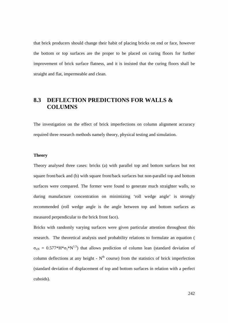
242
that brick producers should change their habit of placing bricks on end or face, however
the bottom or top surfaces are the proper to be placed on curing floors for further
improvement of brick surface flatness, and it is insisted that the curing floors shall be
straight and flat, impermeable and clean.
8.3 DEFLECTION PREDICTIONS FOR WALLS & COLUMNS
The investigation on the effect of brick imperfections on column alignment accuracy
required three research methods namely theory, physical testing and simulation.
Theory
Theory analysed three cases: bricks (a) with parallel top and bottom surfaces but not
square front/back and (b) with square front/back surfaces but non-parallel top and bottom
surfaces were compared. The former were found to generate much straighter walls, so
during manufacture concentration on minimizing ‘roll wedge angle’ is strongly
recommended (roll wedge angle is the angle between top and bottom surfaces as
measured perpendicular to the brick front face).
Bricks with randomly varying surfaces were given particular attention throughout this
research. The theoretical analysis used probability relations to formulate an equation (
σxN = 0.577*H*σγ*N1.5) that allows prediction of column lean (standard deviation of
column deflections at any height - Nth course) from the statistics of brick imperfection
(standard deviation of displacement of top and bottom surfaces in relation with a perfect
cuboids).

243
Confirmation of theory
Theory indicated that for a randomly laid column, the SD of out-of-plumb deviations of a
particular course σx,N is proportional to the SD of roll wedge angle σγ and rises with
column height to the power 1.5. Experiments with grooved bricks (which interface
roughly in the manner assumed in the theory) showed σx,N rising with N to the power 1.46
and thereby confirmed the theory. Computer simulations confirmed that this relationship
extends to columns higher than could practically be built. However for a given course
number N, the practical columns showed a 54% higher out-of-plumb deviations (as
computed by σx,N) than theory predicted, indicating that the model of brick-to-brick
contact used in the theory was oversimplified. Remodelling this contact (effectively by
changing the way in which roll wedge angle is to be measured by determining average
spacing D for grooved and ungrooved) brought the practical and theoretical results in
closer agreement. In addition, χ2 analysis also showed that the small sample size (30) for
practical columns would give estimates for σx,N with considerable statistical uncertainty.
The simulations confirmed the proportionality between deflection and roll-wedge SDs
(respectively σx,N and σγ).
Corrections for small brick-pile population
It was observed that when the brick pile size (from which the brick set to build sample
columns was selected) were small, the deviations σx,N were reduced. A correction factor
Kλ was developed, by randomized simulation studies, to convert deviations measured for
small brick pile into deviations expected when bricks are drawn from a large brick pile.

244
Defining λ as the ratio of brick-pile size to column brick-set enough to assemble one
column (height), Kλ was found to fall from 1.9 at λ = 1 to unity for λ>20.
Effect of laying strategy (and brick-laying skill)
This research demonstrated various possible ways of improving column/wall alignment
from the inferior bricklaying (‘random’ strategy) related to unskilled bricklaying, through
‘reverse’ and ‘replace’ strategies (skilled way of bricklaying) and the use of modified
(grooved) bricks.
Using ‘reverse’ strategy reduced the column out-of-plumb deviation to only 62% of that
observed with ‘random’ laying. Using a more attentive but slower ‘replace’ strategy, that
allowed the replacing of any brick with a better second choice from the stock, further
reduced the column deflection to 35% of the random value.
Another improvement from a different method other than laying strategy was the
provision of a groove to prevent bricks making contact near their centre lines. Although
with grooved bricks only assemblies using the random brick-laying strategy were built, it
demonstrated that the out-of-plumb deviation was reduced to 49% of the value obtained
with un-grooved bricks laid using the same “random” strategy.
Assuming the benefit of more-skilled bricklaying and grooving can be superimposed,
then the best (grooving and replacing) would give column deviations of only 49% x 35%
= 17% of the worst case (un-grooved, random-laid column). This is an improvement of
83%.
Moving from column to wall assemblies was a step further to enhance alignment using
the same bricks. Walls of ten un-grooved bricks long and twenty courses high were

245
constructed using the ‘random’ laying strategy. The longitudinal overlapping of the
walls’ bricks was found to produce a reduction in wall out-of-plumb deviation to 45% of
that of columns assembled using the same laying strategy.
So if a superior strategy (‘reverse’) were combined with grooving of bricks and applied to
a wall assembly; we could expect the wall deflection to fall to 14% (62% x 49% x 45%),
of the random-un-grooved-column deflections taken as our datum (worst case). This is an
overall improvement of 86%.
Lateral stiffness of columns
Dry-stack columns demonstrate hinging and rocking mechanisms. Observations showed
improvements to lateral stiffness by factor of 2 are obtainable by grooving to prevent
inter-brick contact near the roll centreline. The out-of-plumb deviations were reduced by
the factor of 2. From the benefits of grooving both on stiffness and on accuracy, we can
recommend that all MT brick designs should be designed to prevent rocking contacts by
at least groove G = 70%W.
Extension from column to wall
The factor by which walls are less variable than columns of the same height (reduction
factor for σx,N ) – and the dependence of that factor on distance to constraints (cross
walls, reinforced columns or corners) and type of constraint were all examined. All wall
data is derived from experiments with un-grooved bricks, but we expect similar column-
to-wall improvement factors to apply to grooved bricks. The specification of brick
tolerances needed to meet defined out-of-plumb tolerances (BS 5628-3:2005;

246
BS5606:1990) for walls was calculated. It was found that with grooved bricks we may
accept a surface (bumps) standard deviation of up to 0.8mm. With un-grooved bricks we
require greater brick uniformity, namely a surface SD of under 0.5mm.
.
8.4 AREAS FOR FURTHER RESEARCH
Most experiments in this research were performed for the first time, therefore resulted
into primary findings which necessitate more practical for perfections. These verdicts
however enlightened a number of prospective matters for future research. The following
are the areas for further research that were not possible to undertake within this study.
• A feasibility study to be performed for practical implementation of the research
findings, to extend and perfect the construction flexibility performance described
in this thesis.
• Further work required to incorporate special interlock bricks for mortarless
technology to ease building of complicated wall configurations as suggested by
this research.
• Investigations of the appropriate and simple methods for measuring surface
imperfections of dry-stack interlock bricks as a quality control measure.
• Burglar resistance test for dry-stack interlocking brick wall is necessary to
enhance trust of most clients not believing in mortarless technology.
• A long term study for interlock wall strength following lifetime disturbances to be
performed on the local movements: of foundations, mechanical shocks (due to
door slamming) and major shocks (caused by earthquakes).

247
REFERENCES
ACI-ASCE Committee 530 (1988) “Building Code Requirements for
Masonry Structures (ACI 530-88/ASCE 5-88)”, ACI, Michigan, U.S.A.,
18pages.
Adam, E.A. and Agib, A.R.A., (2001). “Compressed Stabilised Earth Blocks
manufactured in Sudan.” United Nations Education Scientific and Cultural
Organization (UNESCO). 7 Place de fontenoy, 75352 Paris 07 SP, France.
Adamus, L. and Spevak, V. (1986) “Dry stone walling technology-
manufacturing and using building blocks without mortar”. Proc., 10th Trienial
Congress of Int. Council for building Research, Studies and Documentation,
Washington, D.C., 27090-2716.
Anand KB & Ramamurthy K. (2003). Laboratory-based productivity study
on alternative masonry systems. ASCE Journal of Construction Engineering
and Management: 129(3): 237–242.
ASTM C90-75 (1975). Standard Specification for hollow load-bearing
concrete masonry.
Basu, A.R., (1988), Urban Housing in third World, Delhi, India: Mittal
Publications.
BCA (2007) British Cement Association, Cement Industry Sets out its Work to
help Climate Change, Thursday, 12 April, 12:34
248
Beall C. (2000). New masonry products, materials. Progress in Structural
Engineering and Materials 2: 296–303.
BRU-B2 (1974) Soil-Stabilizations, building Research Unit data sheet,
Ministry of Lands, Housing and Urban Development’s. Dar Es Salaam,
Tanzania.
British Standards Institution. (1971). BS 12: 1971: Specifications for
Portland cement (ordinary and rapid hardening) BSI, London, England.
British Standards Institution. (1981). BS 6073: 1981: Precast concrete
masonry units – Part 1: Specification for precast concrete masonry units. BSI.
London, England. ISBN 0 580 121895
British Standards Institution. (1985). BS 6649: 1985: Specification for Clay
and calcium silicate modular bricks. BSI. London, England. ISBN o 580
14641 3.
British Standards Institution. (1990). BS 1377: Part 2: 1990: Method of test
for soils for civil engineering purposes. Part 2 Classification test. BSI.
London, England
British Standards Institution. (1990). BS1924: Part 1: 1990. Stabilised
materials for civil engineering purposes. Part 1. General requirements,
sampling, sample preparation and tests on materials before stabilization. BSI.
London, England.
British Standards Institution. (1990). BS 4729: 1990. Specification for
‘Dimensions of bricks of special shapes and sizes’ BSI. London, England.
ISBN 0 580 17952 2.

249
British Standards Institution. (1990). BS 5606: 1990: Guide to Accuracy in
Building. BSI. London, England. ISBN 0 580 18657 1.
British Standards Institution. (1990). BS 7307-1: 1990 (ISO 7976-1: 1989):
Building tolerances- measurement of buildings and building products. BSI.
London, England. ISBN 0 580 18490 0.
British Standards Institution. (1997). BS 5328-1: 1997: Concrete – Part 1:
Guide to specifying concrete. British Standard Institution, BSI. London,
England. ISBN 0 580 26722 9.
British Standards Institution. (1997). BS ISO 1803: 1997: Building
construction. Tolerances. Expression of dimensional accuracy Principales and
Technology. British Standard/International Organization Standardization/15-
Feb-1998/16pages. ISBN 0 580 29203 7.
British Standards Institution. (2000). BS EN 206-1: 2000: Concrete: Part 1:
Specifications, Performance, Production and Conformity. BSI. London,
England.
British Standards Institution. (2000). BS EN 772-1: 2000: Methods of test
for masonry units- Part 1: Determination of compressive strength. BSI.
London, England. ISNB 0.580 32726 4.
BS EN 772-20:2000. Methods of tests for Masonry Units. Determination of
flatness of faces of masonry units. BSI. London, England.
British Standards Institution. (2001). BS 8000-3: 2001: Workmanship on
building sites – Part 3: Code of practice for masonry. BSI. London, England.
ISBN 0 580 33301 9.

250
British Standards Institution. (2003). BS EN 771-3: 2003: Specification for
masonry units- Part 3: Aggregate masonry units (dense and light-weight
aggregates). BSI. London, England. INBN o580 43559 8.
British Standards Institution. (2005). BS 4729: 2005: Clay and calcium
silicate bricks of special shapes and sizes – recommendations. BSI. London,
England. ISBN 0 580 46694 9.
British Standards Institution. (2005). BS 5628-1: 2005: Code of practice for
the use of masonry – Part 1: Structural use of unreinforced masonry. BSI.
London, England. ISBN 0 580 46718 X.
British Standards Institution. (2005). BS 5628-3: 2005: Code of practice for
the use of masonry – Part 3: Materials and components, design and
workmanship. BSI. London, England. ISBN 0 580 46682 5.
British Standards Institution. (2005). BS 8103-2: 2005: Structural design of
low rise buildings – Part 2: Code of practice for masonry wall for housing.
BSI. London, England. BSI 14 March 2005 Second edition, IBSN 0 580 45463
0.
British Standards Institution. (2006). BS 8500-1: 2006: Concrete:
Complementary British Standard to BS EN 206-1 Specification for Constituent
Materials and Concrete. British Standard Institution 30-Nov-2006, 146 pages.
ISBN 058 0482529.
Burroughs, V.S. (2001). Quantitative criteria for the selection of soils for
rammed earth wall construction. Thesis presented at the Faculty of built
environment, University of New South Wales, Australia.

251
California Test 228 (2000). Method of test for linear shrinkage of soils (bar
method). Gepartment of transportation, Engineering service centre.
Transportation Laboratory, P.O.Box 19128, Sacramento, California 95819.
CAN3-S304-M84, (1984) Canadian Standard Association, “Masonry Design
for Buildings, CSA, Ontario, Canada, 69pages.
CML - TLM1999, (2000). Central Material Laboratory, Testing Laboratory
Manual, Ministry of Works (MoW), Dar Es Salaam, Tanzania
Co-Create working document (2004). Protocol on Appropriate Technologies for
Water and Sanitation a definition of the basic characteristics, Co-Create
international business development, The Hague, Netherlands (www.co.create.nl)
Collins (1995), Paperback English Dictionary, Major New Edition.
HarperCollins Publisher, Caledonian International Book Manufacturing Ltd.
Glasgow G64, Great Britain. ISBN 0 00 470780-X
Craig, R.F., (1997) Soil Mechanics, E & FN Spon, London, England.
Crofts FS. (1993) State of the art of mortarless concrete masonry in South
Africa. Proceedings of the 6th North American Masonry Conference,
Pennsylvania Philadelphia, June 6-9, vl.1 or 2, pp. 875–884. ISSBN/ISSN
1053-2366.
Drysdale R. G. and Gazzola E. A. (1991). Strength and deformation
properties of a grouted, dry-stacked, Interlocking Concrete Block System.
Proceedings of the 9th International Brick/Block Masonry Conference, Berlin,
pp. 164–171.

252
Dyskin, A.V. Estrin, Y. Pasternak, E. Khor H.C. and Kanel-Belov, A.J.
(2003). Fracture resistant structures based on topological interlocking with
non-planar contacts, Advanced Engineering Materials 5 (3), pp. 116–119.
Dyskin, A.V. Estrin, Y. Pasternak, E. Khor H.C. and Kanel-Belov, A.J.
(2005). The principle of topological interlocking in extraterrestrial
construction, Acta Astronatica 57, 10-21
Eco-towns (2008) Living a green future, Communities and Local Government
Eland House, Bressenden Place, London SW1E 5DU. Tel. 020 7944 4400,
Website: www.commities.go.uk © Queens Printer and Controller her
Majesty’s Stationary Office.
Estrin, Y., Dyskin, A.V., Kanel-Belov A.J. and Pasternak, E. (2002).
Materials with novel architectonics assemblies of interlocked elements. B. L
Karihaloo (Ed), IUTAM Symposium on Analytical and Computational Fracture
Mechanics of Non-homogeneous Materials, 51-55 Kluwer Academic
Publishers, Dordrecht, pp. 51–56. ISBN/ISSN 1402005105
Etherington BA. (1983) Interlocking cement and concrete components for low
cost house construction: The building together experience in Thailand.
Proceedings of the Symposium on Appropriate Building Materials for Low-
cost Housing, Nairobi, 236–243. ISBN/ISSN: 0419132805
253
Gallegos, H. (1988). Mortarless masonry: the Mecano system. International
Journal of Housing Science and its Applications V12, No. 2, 145–157.
ISBN/ISSN: 0146-6518
Gazzola EA & Drysdale RG. (1989). Strength and deformation properties of
dry-stacked surface bonded low density block masonry. Proceedings of the 5th
Canadian Masonry Symposium, Vancouver 5-7 Vol. 5, pp. 609–618.
Gilbert A, & Gugler, J. (1992). Cities, Poverty, and Development:
Urbanization in the third World, Oxford: Oxford University Press.
Gilroy, D. Goffi, E.D. (2001). Modular interlocking brick system in wide use
at BHP, AISE Steel Technology, January.
Gooding, D.E.M. (1993). Soil Testing for Soil-Cement Block Preparation.
Working Paper No. 38. Development Technology Unit, University of
Warwick. Coventry. England.
Gooding, D.E.M. (1994). Improved Processes for Production Soil-Cement
Building Blocks. Development Technology Unit, University of Warwick.
Coventry. England.
Grimm, C.T., (1974) Masonry Construction Operations, Journal of the
Construction divisions, ASCE Vol. 100, No. CO2 – pgs 71-185
Haener. (1984). Stacking mortarless block system. In Engineering Design
Manual, Atkinson Engineering, Inc., Hamilton, Ontario, 1984.
Hamdi, N. (1995). Housing without Houses: Participation, Flexibility, and
Enablement. Intermediate Technology Publications. London, England.

254
Harlae, M. and Marten, M. (1990). New Ideas for Housing: The experience
of three countries. London, Shelter.
Harris H. G., Oh K. and Hamid A. A. (1992). Development of new
interlocking and mortarless block masonry units for efficient building systems.
Proceedings of the 6th Canadian Masonry Symposium, Saskatoon
Saskatchewan, Canada, pp. 15–17.
Hendry, A. W., Sinha, B. P., Davis, S. R. (1997). Design of Masonry
Structures. London: E & F.N. Spon
Hines, T (1992). The use of mortarless, dry-stack, concrete masonry as a
contributor to affordable construction. Proceedings of the 4th International
Seminar on Structural Masonry for Developing Countries, Madras, 176–186.
Hines, T (1993). Benefits of dry-stack interlocking concrete masonry as a
component of cost effective construction. Proceedings of the 6th North
American Masonry Conference, Philadelphia, 849–861.
Houben, H. Guillaud, H. (1994). Earth Construction: A Comprehensive
Guide. CRATerre – EAG. Intermediate Technology Publications. London,
England.
Housing Forum, (2001), The Green Guide to Housing Specification – Six
Guiding Principles to Improve the Sustainability of the Housing Construction
Industry. July Issue
Hydraform (1988). Illustrations of the Hydraform Building Systerm,
Hydraform Africa (Pty) Limited, Johannesburg, South Africa.

255
Hydraform, (2004). Hydraform Training Manual. Johannesburg 220
Rondebult road, Libradene boksburt. P.O.Box 17570, Sunward park 1470.
(www.hydraform.com)
IGPCC (2001). Intergovernmental Panel on Climate Change: Special report
on Emissions. http://www.grida.no/climate
ILO, (1987). Small - Scale Manufacture of Stabilised Soil Blocks. International
Labour Organization Office, Geneva, Switzerland.
International Labour Organization, (1990). Small-scale Brick Making:
Technical Memorandum No. 6. Technology Series, International Labour
Office. Geneva, Switzerland.
Jaafar M. S., Thanoon W. A., Najm A. M., Abdulkadir M. R. and ALI A.
A. (2006). Strength correlation between individual block, prism and basic wall
panel for load bearing interlocking mortarless hollow block masonry.
Construction and Building Materials, 20, No. 7, 492–498.
Jaafar, M.S. Alwathaf, A.H Thanoon, W.A Noorzai, J. Abdulkadir,
M.R.(2006) Behaviour of interlocking mortarless block masonry, Proceedings
of Institute of Engineering, Construction Materials 159 August, Issue CM3 pp.
111-117.
Keef L. (2005) Earth Building “Methods and Materials, Repair and
Conservation”. Taylor and Francis, 2 Park Square, Milton, Abington, Oxon
OX14 4RN. ISBN 0-415-32322-3.
Kerali, A.G., (2001), Durability of Compressed and Cement-Stabilised
Building Blocks. PhD. Thesis, University of Warwick – School of Engineering.

256
Kintingu, S.H. (2003). Interlocking Bricks Presser Machine an Appropriate
Technology for Brick Production. Construction Industry Forum proceedings
pgs. 51 - 67. – Dar es Salaam. Tanzania.
Knight, T. (1997). On behalf of the Brick Development Association. Creative
Brick work. By Arnold, 338 Euston Road, London NW1 3BH. ISBN 0 340
67643 4.
Kruse, C. (2004) International Investors Group on Climate Change (IIGCC)
Brief Note, Climate Change and the Construction Sector, ISIS Asset
Management.
Kua, H., Lee, S., (2001), Demonstration Intelligent Building – A methodology
for the Promotion of Total Sustainability in the built Environment. Building
and Environment
Laquian, A, A. (1983). Basic Housing: Policies for Urban sites, Services and
shelter in Developing Countries. IDRC–708C. Ottawa, Canada
Lea, F.M. (1976). The chemistry of cement and concrete. 3rd Edition. Edward
Anorld (Pblishers) Limited. London, England.
Love, B and Gamble, J. (1985). The Meccano System and the Special
Purpose Meccano sets, New Cvendish books, London.
Lynch, G. (1994). Brickwork Volume 1; History, Technology and Practice,
Vol.1. London, Donhead Publishing ltd. 28 Southdean Garden, Wimbledon,
London SW19 6NU. ISBN 1 8733 940 20.

257
Maasdorp, G.G. and Humphreys, A.S.B. (1975). From Shantytown to
township: an economic study of African poverty and rehousing in a South
African City, Cape Town: Juta.
Maniatidis, V. & Walker, P. (2003). A Review of Rammed Earth
Construction for DTI Partners in Innovation Project ‘Developing Rammed
Earth for UK Housing’. Natural Building Technology Group, Department of
Architecture & Civil Engineering, University of Bath, Bath BA2 7AY.
Marchal, G. (2001). ‘Decreasing Pollution,' cement and Building Materials
Review 3, (AUCBM).
Marzahn G. (1998). The shear strength of dry-stacked masonry walls. Leipzig
Annual Civil Engineering Report, (3), 247–262.
Marzahn G. (1999). Investigation on the initial settlement of dry-stacked
masonry under compression. Leipzig Annual Civil Engineering Report: 4:
253–269. ISBN/ISSN: 1432-6590
Marzahn, G. and G. Konig (2002). Experimental Investigation of Long-Term
Behavior of Dry-Stacked Masonry, Journal of the Masonry Society, December,
pp. 9-21.
McAuslan, P., (1985), Urban Land and Shelter for the Poor. London:
Earthscan.
McGinley. (1995) Development of dry stacked clay masonry wall systems.
Proceedings of the 7th Canadian Masonry Symposium, Hamilton, 147–159.
McKusick, M. (1997). Discavaring Late Erector 1963-1988, Ashton Press,
Lowa City.

258
Montgomery, D.E., (2002). Dynamically Compacted Cement-Stabilised Soil
Blocks for Low-cost Walling. PhD. Thesis, University of Warwick – School of
Engineering.
Morris, J. Booysen, Q. (2000). Earth Construction in Africa. Proceedings:
Strategies for a Sustainable Built Environment, Pretoria, 23-25 August 2000.
Moustafa, M.E. (1990). Management of technology transfer. International
Labour Organization, Geneva, Switzerland.
Nash, W.G. (1983). Brickwork 1, Third Edition reprinted 2001 by Nelson
Thornes Ltd, Delta Place 27 Bath Road, Cheltenham GL53 7TH United
Kingdom. ISBN 0 7487 0266 0.
Nash, W.G. (1991). Construction Competences for NVQ level 2, Bricklaying.
Nelson Thornes Ltd, Delta Place 27 Bath Road, Cheltenham GL53 7TH,
United Kingdom. ISBN 0 7487 1292 5.
NCMA TEK 14-22 Structural (2003). “Design and construction of dry-stack
masonry walls”, National Concrete Masonry Association 2302 Horse Pen Road,
Herndon, Virginia 20171 – 3499 (www.ncma.org).
Norton, J., (1997). Building with Earth: A handbook. London: Intermediate
Technology.
Odul, (1984). Case Studies on Earth Construction: Synthesis. PDC-HS.
Katholieke Universiteit Leuven, Belgium.
Ophoven, P. (1977). Compressive strength of walls built up of mud-blocks and
soil cement-blocks. Building Research Unit, Ministry of Lands, Housing and
Urban Development, Dar Es Salaam, Tanzania.

259
Racodi, C. (1997). The urban challenge in Africa – Growth and management
of its large Cities – UNUP – 952.
Ramamurthy, K. and Nambiar, E.K. (2004). Accelerated masonry
construction: Review and future prospects. Proceedings of Structural
Engineering materials (2004); 6:1-9 (DOI: 10.1002/pse.162)
Ruth, M., Price, L., Worrell, E. (2000). Evaluating Clean Development
Mechanism Projects in the Cement Industry using Process-Step Benchmarking
Approach, Report No. LBNL 45346 Lawrence Berkeley National Laboratory
US.
SAA (1977) “Methods of testing soils for engineering purposes”, Standard
Association of Australia, Australian Standard 1289.
Sanders, S.R. Thomas, R.H. (1991). Factors affecting masonry labor
productivity, Journal of construction Engineering Management 1991, Vol.117
N4, pp.626-644. ISBN/ISSN: 0733-9364.
Shrive, N. Bakay, R. Scholelfield, B. (2003). AB fence executive summary for
structural testing. University of Galgarry (alanblock.com).
Spence, R.J.S, Cook, D.J. (1983). Building Materials in Developing
Countries. John Wiley & Sons Ltd. Chichester, England.
Stewart, F. (1987). Macro-policies for Appropriate Technology in Developing
Countries. Westview Press, Boulder, CO, USA.
Stulz, R., Mukerji, R. (1993). Appropriate Building Materials: a catalogue of
potential solutions. St. Gallen: Skat.

260
Thanoon W. A., Jaafar M. S., Abdulkadir M. R., Ali A. A., Trikha D. N.
and Najm A. M. (2004). Development of an innovative interlocking load
bearing hollow block system in Malaysia. Construction and Building Materials,
18, No. 6, 445–454.
The BDA Guide, (2000). The Brick Development Association Guide to
successful brickwork, second edition. Elsevier Butterworth-Heinemann,
Linacre House, Jordan Hill, Oxford OX2 8DP, 30 Corporative Drive,
Burlington, MA 01803. ISBN 0 340 75899 6.
The Guardian (2006). Article History, June 11. The Guardian.co.uk
UN. (1992). “Earth Construction Technology” United Nations Centre for
Human Settlements, Nairobi.
URT – NHSDP (2000). United Republic of Tanzania, National Human
Settlements Development Policy. Ministry of Lands and Human Settlements
Developments (MLHSD), Dar es Salaam, Tanzania.
VanderBorght, B. and Brodman, U. (2001). The Cement CO2 Protocol: CO2
Emission Monitoring and Reporting, Protocol for the Cement Industry, Guide
to the Protocol, Version 1.6. WBCSD Working Group Cement.
VanderWerf P., Munsel, W. (1999). Concrete Home Building Systems, the
Portland Cement Associations Guide.
Vasco Costa, F. (1993) Plea for placement armour blocks in orderly patterns,
Proceedings of the 23rd International Conference on Coastal Engineering
October 4–9, 1992, Venice, Italy pp. 1091–1100. ISBN/ISSN: 0872-62933

261
VITA (1975). “Making building blocks with the CINVA-Ram block press”,
Volunteers in Technical Assistance, Intermediate Technology Publications,
London.
Walker, P. (1995). Performance of Stabilised Soil Block Masonry under
Uniform and Concentrated Compressive Loading. Proceedings British
Masonry Society Vol. 7 pgs 49-57 ISBN/ISSN 0950-9615.
Webb, D.T.J. (1983). Stabilised Soil Construction in Kenya. Proceedings of the
International Conference on Economic Housing in Developing Countries,
UNESCO/RILEM, 25-27 January 1983, Paris, France.
Webb, D.T.J., Lockwood, A.J. (1987). BREPAK Operators Manual.
Overseas Development Administration. Building Research Establishment
Client Report. Department of the Environment. Garston, England.
Weinhuber, K., (1995). Building with Interlocking Blocks. Published by
GATE.
Whelan M.L. (1985). Hollow concrete masonry unit shape modification to
improve productivity of placement: results of the preliminary research effort.
Proceedings of the 3rd North American Masonry Conference, Arlington,
Texas, 1985, Vol.9.1–9. ISBN/ISSN: 1053-2366.
Wolfskill, L.A., Dunlap, W., & Gallaway, B.M. (1963). “Handbook for
building homes of earth” , Texas Transportation Institute, Report for the
Agency for International Development, Bulletin 21, E 14-63, Texas A&M
University, College Station, Texas.

262
World Bank, (1995). Labor and growth Crisis in Sub-Sahara Africa,
Washington, D.C.
Related Documents