Athar Qureshi: Interference Diagnosis in Wireless Systems by using NI USRP DOI 10.5013/IJSSST.a.16.02.24 1 ISSN: 1473-804x online, 1473-8031 print Interference Diagnosis in Wireless Systems by using NI USRP Athar Qureshi, Faculty of Engineering & Science, University of Greenwich, Chatham, United Kingdom [email protected] Abstract— In both industrial and domestic environments, there will be a large increase of wireless communication systems. The density of wireless devices and need of additional bandwidth is expanding which is increasing the wireless interference. Interference emerges from unintended radiators is the main cause of degrading the Electromagnetic Compatibility and wireless communication performance in near field region and far field region and decrease the robustness and reliability. This paper presents methods of detection and removal of interference to improve EMC performance and wireless communication. We used NI USRP equipment for the diagnosis and provided the solutions to remove interference. The presented methods of interference diagnosis can efficiently optimize the performance of any wireless network. Keywords- NI USRP, EMI, EMC, RFID, Bluetooth, NFC, Zigbee, Wifi, Wimax, GSM (2G), UMTS (3G), LTE (4G) I. INTRODUCTION Wireless communication can be defined as the transfer of information over electromagnetic waves. In both industrial and domestic environments, there will be a large increase of wireless communication systems. In next years, wireless will be a most important technology to enable the Internet of Things (IoT), Machine to Machine Communication (M2M) and Industry 4.0. Besides this, there is also increased use of sensor networks and cellular mobile networks. Wireless communication is the most crucial and fast growing technology of the world. From EU only in UK, only the numbers of mobile phone devices are 85 million. If we include other wireless devices, it would be in the range of half of billion. From TV remote to satellite communication the number of wireless devices increasing enormously. Cellular mobile phone always operates on very low power but their cumulative effects of interference are increasing with the growing numbers of users. Also with smaller base station cell size the aggregate effect of interference is also intensifying. Abnormal usage of the systems, age of the wireless equipment, global climate change, special interactions among base-station and its immediate environment are some of the other factors that escalating the interference. Also with the increase in bandwidth (data) and transmitting power requirement, the amount of interference is increasing. In short, smaller size of the systems and the increasing density of devices causing interference issues. Interference will be an expanding problem as new wireless systems are being introduced. For example, next generation cellular systems uses “femtocells” operating in an overlay network may potentially create interference to the macro-cell downlink. Next generation wireless systems development raises two main problems: The first problem is the co-existence of all these systems, which can be solved by standardization. The second problem is the interference from unintended radiators, making wireless communication more vulnerable. In this work, we have presented the methods of diagnosis/detection of interference to enhance the robustness of communication from external interference at various commonly used wireless frequencies. This work also explores the intrinsic nature of interference which would provide practical industrial solutions to design Electromagnetic Compatibility (EMC) and management of wireless interference. Electromagnetic Compatibility (EMC) is related to near field interference of the wireless devices. It can be defined as the operations of low radiative electronic communication devices in the presence of high electromagnetic radiations. A Simple Wireless Communication System is shown in the Figure 1. It consists up of the following: 1. Coded information is modulated into in-phase (I) and quadrature (Q) signals at baseband/intermediate frequency (IF) signal. This is known as IQ sampling. 2. Baseband further upconverted to Carrier or high frequency (HF) and wireless signal transmitted from Tx-Antenna through wireless channel. 3. Carrier signal receive at Rx-Antenna and downconverted to baseband/ IF level. 4. I and Q component are separated, demodulated and decoded the information. There are many types of modulation schemes in wireless communication. The encoded information may be modulated into some of the following modulation schemes at baseband IF level. i. Amplitude Modulation ii. Phase Modulation iii. Frequency Modulation iv. Pulse Width and Pulse Distance Modulation (PWM and PDM) v. Pulse Amplitude Modulation (PAM)

Welcome message from author
This document is posted to help you gain knowledge. Please leave a comment to let me know what you think about it! Share it to your friends and learn new things together.
Transcript
Athar Qureshi: Interference Diagnosis in Wireless Systems by using NI USRP
DOI 10.5013/IJSSST.a.16.02.24 1 ISSN: 1473-804x online, 1473-8031 print
Interference Diagnosis in Wireless Systems by using NI USRP
Athar Qureshi, Faculty of Engineering & Science,
University of Greenwich, Chatham, United Kingdom
Abstract— In both industrial and domestic environments, there will be a large increase of wireless communication
systems. The density of wireless devices and need of additional bandwidth is expanding which is increasing the wireless
interference. Interference emerges from unintended radiators is the main cause of degrading the Electromagnetic Compatibility
and wireless communication performance in near field region and far field region and decrease the robustness and reliability. This
paper presents methods of detection and removal of interference to improve EMC performance and wireless communication. We
used NI USRP equipment for the diagnosis and provided the solutions to remove interference. The presented methods of
interference diagnosis can efficiently optimize the performance of any wireless network.
Keywords- NI USRP, EMI, EMC, RFID, Bluetooth, NFC, Zigbee, Wifi, Wimax, GSM (2G), UMTS (3G), LTE (4G)
I. INTRODUCTION
Wireless communication can be defined as the transfer of
information over electromagnetic waves. In both industrial
and domestic environments, there will be a large increase of
wireless communication systems. In next years, wireless will
be a most important technology to enable the Internet of
Things (IoT), Machine to Machine Communication (M2M)
and Industry 4.0. Besides this, there is also increased use of
sensor networks and cellular mobile networks. Wireless
communication is the most crucial and fast growing
technology of the world. From EU only in UK, only the
numbers of mobile phone devices are 85 million. If we include
other wireless devices, it would be in the range of half of
billion. From TV remote to satellite communication the
number of wireless devices increasing enormously. Cellular
mobile phone always operates on very low power but their
cumulative effects of interference are increasing with the
growing numbers of users. Also with smaller base station cell
size the aggregate effect of interference is also intensifying.
Abnormal usage of the systems, age of the wireless
equipment, global climate change, special interactions among
base-station and its immediate environment are some of the
other factors that escalating the interference. Also with the
increase in bandwidth (data) and transmitting power
requirement, the amount of interference is increasing. In short,
smaller size of the systems and the increasing density of
devices causing interference issues. Interference will be an
expanding problem as new wireless systems are being
introduced. For example, next generation cellular systems uses
“femtocells” operating in an overlay network may potentially
create interference to the macro-cell downlink.
Next generation wireless systems development raises two
main problems: The first problem is the co-existence of all
these systems, which can be solved by standardization. The
second problem is the interference from unintended radiators,
making wireless communication more vulnerable. In this
work, we have presented the methods of diagnosis/detection
of interference to enhance the robustness of communication
from external interference at various commonly used wireless
frequencies. This work also explores the intrinsic nature of
interference which would provide practical industrial solutions
to design Electromagnetic Compatibility (EMC) and
management of wireless interference. Electromagnetic
Compatibility (EMC) is related to near field interference of
the wireless devices. It can be defined as the operations of low
radiative electronic communication devices in the presence of
high electromagnetic radiations.
A Simple Wireless Communication System is shown in the
Figure 1. It consists up of the following:
1. Coded information is modulated into in-phase (I) and
quadrature (Q) signals at baseband/intermediate
frequency (IF) signal. This is known as IQ sampling.
2. Baseband further upconverted to Carrier or high
frequency (HF) and wireless signal transmitted from
Tx-Antenna through wireless channel.
3. Carrier signal receive at Rx-Antenna and
downconverted to baseband/ IF level.
4. I and Q component are separated, demodulated and
decoded the information.
There are many types of modulation schemes in wireless
communication. The encoded information may be modulated
into some of the following modulation schemes at baseband IF
level.
i. Amplitude Modulation
ii. Phase Modulation
iii. Frequency Modulation
iv. Pulse Width and Pulse Distance Modulation (PWM
and PDM)
v. Pulse Amplitude Modulation (PAM)

Athar Qureshi: Interference Diagnosis in Wireless Systems by using NI USRP
DOI 10.5013/IJSSST.a.16.02.24 2 ISSN: 1473-804x online, 1473-8031 print
vi. Pulse Position Modulation (PPM)
In addition to IQ sampling, the amplification and filtration
of the signal is also performed at IF frequency level both in
transmitter and receiver. To transmit data for longer distance
and to increase the frequency band separation, signal
upconverted to HF carrier. Multiplexing can also be
performed at this stage, in the case of multiuser
communication systems. Then the antenna transmits
information by propagation of electromagnetic waves through
wireless channel. During the propagation of unwanted signals
(interference) adds to the information carrying
electromagnetic radiations and destroy the transmitted
information. The aim of optimum wireless communication is
to minimize the effects of interference so that useful
transmitted information can be retrieved at the receiver. There
can be many types of wireless channels types or channel
models. The amount and nature of wireless interference is not
the same in different channels. Hence, various types of
wireless channels impact on the signal differently [1][2]. For
example, urban wireless channel would be different compared
to line of sight long distance communication due to more
multipath wireless communication in urban environment.
Therefore, different wireless channel models are important to
design specific receiver for the wireless communication. On
wireless receiver signals reach through multiple paths and at
different time intervals cause delay spread. This causes one of
the specific type interference known as intersysmbol
interference. In higher modulation schemes this delay spread
is more obvious which can be overcome by channel estimation
and equalisation. In this paper for the simplicity of
experimentation, we considered lower modulation schemes
and neglect the effect of intersymbol interference. Multipath
propagation also causes many other types of far field
interferences that mentioned earlier including co-channel
interference, adjacent channel interference and common mode
interference. EMI affects the wireless signals only at near far
region near to transmitter. Their impact can be very severe if
EMC of the devices not properly managed. In industries, it is
common practice to periodically test the EMI from the
electrical and electronic devices for the raised interference.
At the receiver carrier signal received, amplified and
downconverted to IF frequency level, reconstructed and
filtered. Then IQ components separated. The information from
IQ is retrieved and decoded. Reconstruction of the signal is to
remove the wireless channel impacts on the wireless signal so
that original information can be retrieved accurately. Multi
access schemes like code division multiplexing access also
support to mitigate interference but in reality the production of
orthogonal codes for multiple access is a trivial problem. To
retrieve the information accurately we may also use error
control coding on the communicated information data. In
addition to the above for wireless communication, we usually
encrypt the data before sending and decrypt the data after
receiving for the security of the communicated information.
But this is not mandatory and depends on the wireless
communication application. For example, for the patient X-
Ray imaging we don’t required encoding, whereas, cellular
mobile systems use advance encryption standard for
information security.
Interference is defined as unwanted signal that adversely
affects the wireless Communication. The interference source
can be both internal and external. Some of the different types
of wireless interferences are as follow:
1. Electromagnetic Interference (EMI)
2. Co channel Interference
3. Adjacent channel Interference
4. Intersymbol Interference
5. Inter carrier Interference
6. Common mode Interference
Figure 1. Simple Wireless Communication with Interference
Electromagnetic Compatibility (EMC) of electrical and
electronic devices is the study that analyses the operations of
low radiative electronic devices in high environmental
radiations or electromagnetic interference. EMC is related to
wireless interference in near field region. We can define
Electromagnetic Compatibility (EMC) in simple words as the
study of fine gadgets that operates in harsh industrial
environment. In technical words Electromagnetic
Compatibility (EMC) of the devices is the application that
analyze the operations of low radiative electronic devices in
high industrial interference. EMC is a characteristic of
electrical and electronic equipment that allow it to operate in
the presence of other electrical and electronic equipment, and
not to adversely interfere with the other equipment. EMC has
two aspects emission and susceptibility. All of the electrical
and electronic equipment emits electromagnetic radiation
energy, and some of that emitted energy may interact and
interfere with other equipment. Equally, equipment may be
susceptible to receiving energy emitted from other sources.
Sometime wireless communication intentionally blocked by
generating interference from intruder and create information
security issues. The experiments presented in the paper are
also useful to find any jamming of the communication.
Apparently, radio transmitters and receivers are intended to
Athar Qureshi: Interference Diagnosis in Wireless Systems by using NI USRP
DOI 10.5013/IJSSST.a.16.02.24 3 ISSN: 1473-804x online, 1473-8031 print
emit and receive electrical energy, but other equipment may
not be intended to do so. Even transmitters and receivers may
emit and receive unwanted energy that may prevent those
devices, or others, from functioning as intended. It is aim of
the EMC to design and operate equipment so that it is both
prevented from emitting spurious energy that can cause
interference, and is immune to the adverse effects of any
spurious energy that it may receive. Increasing bandwidth,
number of Wireless systems, industrial vibrations, mechanical
motion, leakage of the current, electrical contacts, hysteresis
and reflections can cause EMI and interference, decrease
wireless communication performance and create interference
issues. There are generally two types of EMI that effects on
EMC and wireless communication in near field region
communication region:
1. Narrow Band EMI (Normally from other Radios and
Reflectors)
2. Broad Band EMI (From Machineries, High Power
Transmission etc).
Wireless communication and EMC has been
comprehensively discussed in previous literature [2][3][4]. In
next session we discuss NI USRP equipment [5] and test
Narrow Band EMI and interference impact on wireless
communication. In principal, it is equally valid for Broadband
interference.
II. SOFTWARE DEFINED RADIO, NI USRP
We used the National Instrument USRP equipment known
as Software Defined Radio (SDR) which has been used
successfully for various wireless communication lab
experiments in the previous literature [6][7][8][9][10]. The
other radio test equipment like Agilent and Anritsu equipment
etc can also use to measure interference to perform the same
interference measurements. This paper has used an
experimental setup to diagnose/detect interference in various
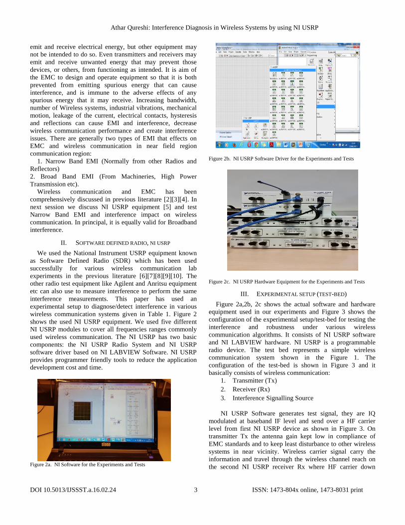
wireless communication systems given in Table 1. Figure 2
shows the used NI USRP equipment. We used five different
NI USRP modules to cover all frequencies ranges commonly
used wireless communication. The NI USRP has two basic
components: the NI USRP Radio System and NI USRP
software driver based on NI LABVIEW Software. NI USRP
provides programmer friendly tools to reduce the application
development cost and time.
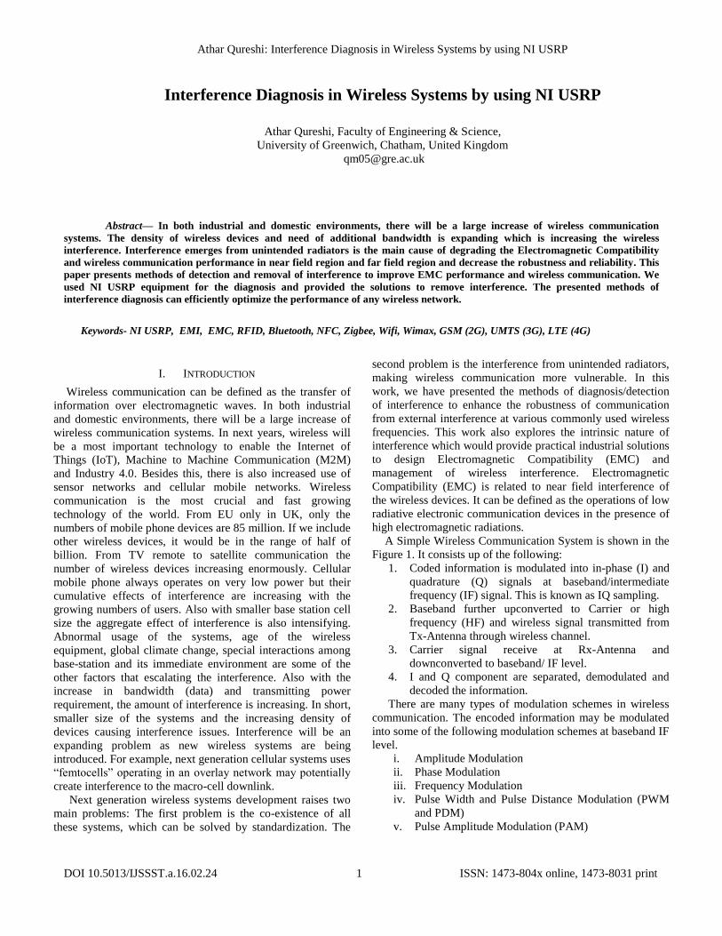
Figure 2a. NI Software for the Experiments and Tests
Figure 2b. NI USRP Software Driver for the Experiments and Tests
Figure 2c. NI USRP Hardware Equipment for the Experiments and Tests
III. EXPERIMENTAL SETUP (TEST-BED)
Figure 2a,2b, 2c shows the actual software and hardware
equipment used in our experiments and Figure 3 shows the
configuration of the experimental setup/test-bed for testing the
interference and robustness under various wireless
communication algorithms. It consists of NI USRP software
and NI LABVIEW hardware. NI USRP is a programmable
radio device. The test bed represents a simple wireless
communication system shown in the Figure 1. The
configuration of the test-bed is shown in Figure 3 and it
basically consists of wireless communication:
1. Transmitter (Tx)
2. Receiver (Rx)
3. Interference Signalling Source
NI USRP Software generates test signal, they are IQ
modulated at baseband IF level and send over a HF carrier
level from first NI USRP device as shown in Figure 3. On
transmitter Tx the antenna gain kept low in compliance of
EMC standards and to keep least disturbance to other wireless
systems in near vicinity. Wireless carrier signal carry the
information and travel through the wireless channel reach on
the second NI USRP receiver Rx where HF carrier down

Athar Qureshi: Interference Diagnosis in Wireless Systems by using NI USRP
DOI 10.5013/IJSSST.a.16.02.24 4 ISSN: 1473-804x online, 1473-8031 print
converted to IF baseband level, IQ demodulated and
information is recovered. We only consider the carrier wave
to keep our experiments simple as we are mostly interested in
the interference diagnosis in frequency domain. We kept
antenna gain high at receiver ‘Rx’, same as normally in
practical wireless receivers. Third NI USRP equipment sends
a narrow band interference signal of near carrier frequency
ranges. For the simplicity the interference kept sinusoidal. All
of these steps observed by NI USRP software plots in
frequency domain and time domain on all three devices. We
used NI USRP software spectrum analyzer for frequency
domain and time domain measurement for the amplitude and
frequency on second NI USRP ‘Rx’ device. We performed
various experiments by increasing and decreasing antenna
gain and distances on all of the three NI USRP devices. This
test-bed represents a prototype of wireless communication in
an industrial environment with interference.
For the simplicity, interference signal assumed to be
periodic, continuous and reached on receiver asynchronously.
It represents the narrow band interference from external
devices. In practice this could be random and broadband
which also can be detected with this experimental setup.
Mathematically transmitted carrier signal is given in time
domain
And interference signal is given by ∑ I .
By the superposition of interfering signal and carrier signal,
the mathematical equation of the received signal is given as:
x(t) = AC cos C t + ∑ I (2)
Let we assume that external interference is sinusoidal then
above equation can be written as:
x(t) = AC cos C t + I cos I t (3)
And consider that it has the same phase as of the carrier then
above equation becomes:
x(t) = AC cos C t + I cos C t (4)
Simplifying the above yields:
x(t) = (AC + I ) cos C t (5)
The above equation clearly shows that the amplitude of the
received signal would be summation of the carrier and
interference signal and consequently increase the amplitude of
the received signal. Therefore, unexpected amplitude of the
received signal also represents the presence of the
interference. The result is consistent with our experiments in
next sessions and appendices.
The aim of the diagnosis experiments is to analyzed and view
the first term and second term of the above equation
separately. The above equation shows that the amplitude of
both transmissions could be added and it is consistent with
experimental results given in Appendices that shows with
external interference can increase the amplitude of the signal
when it is in phase with the carrier signal. In practical wireless
systems this type of interference is very common called
intermodulation interference. We increase and decrease the
gain of the received signal and transmitted signal to recognize
the received information carrying signal and interference by
keeping interference signal constant. If first term and second
term of equation 3 orthogonal then we can separately analyze
both received signal and interference separately but in practice
orthogonal codes are extremely difficult to produce and
interference signal destruct the received signal and
information. Particularly, from interference from external
source always destroy the received signal if both lies on same
frequency ranges.
Figure 3. Experimental Configuration
IV. EXPERIMENTAL MEASUREMENT AND RESULTS
Table 1 represents some of the commonly used industrial
wireless systems standards and their frequency ranges. We
carried out various experiments on these wireless
communication. Some of the results are shown in the
Appendices. In the experimental result we examined the
800MHz, 400MHz, 68-69MHz, 1.9GHz, 2.2GHz wireless
communication between two NI USRP Tx and Rx. We send
the test interference signal of near frequency ranges of
wireless communication from a third NI USRP. And we
observed the spectrum by amplitude-frequency and amplitude-
time plots on the NI USRP Rx. We increased and decreased
the gain of transmit and receive signal to recognize the
communicated signals and interference. This setup can
precisely diagnose any interference in industrial environment.

Athar Qureshi: Interference Diagnosis in Wireless Systems by using NI USRP
DOI 10.5013/IJSSST.a.16.02.24 5 ISSN: 1473-804x online, 1473-8031 print
This test-bed is prototype of industrial wireless
communication and ready to test EMI and interference in any
in industrial environment. As earlier discussed that EMI and
interference can be of two types: Narrow band and wide band
in near field region and far field region. We are able to detect
both of the types by using this type of setup. With the help of
this test-bed we can diagnose narrow band interference,
random interference, wideband interference and propose a
suitable wireless communication systems and transmission
power for the specific industrial environment. Even wide band
and random interference can be analyzed on the NI USRP
software frequency-amplitude plot with same setup. This
experimental setup can diagnose other types of far field
interferences mention in section I and affectively identify the
interference source. We can also adjust transmitting and
receive power of the devices according to the communication
requirement. As discuss earlier that unnecessary transmitting
power can produce destructive effects on other wireless
devices in the vicinity. By using this test-bed we can
recommend appropriate power of communication signals. In
our experiments we analyzed only sinusoidal interference
impact on the communication but this method can also
observe other types of interferences by programming the third
device to generate different types of interference signals or
with industrial wireless interference source. We have
performed various experiments in the presence of narrow band
interference and observed the variation on the received signal
when we shifted the interference signal at various positions in
the range of communication frequency to diagnose
interference. The EMI and interference is already presented in
previous research literature with some of the practical
demonstration [11][12][13][14][15] but we found that detailed
practical were missing in previous literature, particularly with
NI USRP equipment. Also the theoretical analysis already has
been presented in previous literature [16][17][18].
Observed experimental results provide the complete
pictures of constructive and destructive interference pattern in
time domain. It is also observed that whenever interference
signal impacting severely the communication information
signals, we observe increase in the amplitude of the signal in
frequency domain. Unusual signal amplitude, more than the
expected amplitude of received signal also reveals the
presence of interference in wireless communication.
Therefore, when conducting the EMC and interference test of
the factories, we should keep in mind that un-usual amplitude
or abnormal amplitude of the Rx signal some time represents
the presence of interference and we have to check more
magnified view of the signal in frequency domain and time
domain to precisely observed the interference and actual
received signal. We should also shift the communication
frequency to have better picture of interference. Closer the
interference signal band to the communication signal provide
clearer pattern of interference in time domain. As expected
that if we shift the interference signal far from the
communication frequency, less affects would be on the
communication and we should always observe in both plots in
frequency domain and time domain. NI USRP plots in time
and frequency domain provide clear picture of the quality of
communication. We have shown the experimental results in
appendices. In case of the interference from a broad band
signal, we would see a clear picture Rx amplitude and
interference signal.
Table 1. Used Wireless Standards and Frequencies in Experiments
V. CONCLUSIONS
We have presented a test-bed to examine EMI in wireless
communication systems. We can improve the EMC
performance, diagnose interference and optimize wireless
communication by using the developed test bed in any
industrial environments. The developed test-bed is also useful
for developing wireless communication systems and devices
for the Industry.
We have performed various experiments on the developed
test-bed. The experiment shows that higher the amplitude of
Rx signal than normal could be the presence of EMI and
constructive interference. We have presented several
experiments on industrial wireless communication systems
shown in Appendices. Our experiments reveal that to improve
the performance of Wireless Communication (RFID, NFC,
Bluetooth, Wifi, 2.5G, 3G, 4G etc.) we need to perform
following steps:
Step 1. Adjust the power of wireless devices, Observe and
keep the record of the receive spectrum of communication
Devices in Anechoic Chamber or in EMI and interference free
environment (Normal Spectrum).
Step 2. Switched off the Industrial Machines and insulate the
possible sources of EMI/interference and observe the Receive
Spectrum, it should be close to the observation and according
to the record of the Step 1.
Step 3. Switched on the Industrial Machines and observe the
Spectrum. Keep repeating Step 2 until all necessary shielding
Athar Qureshi: Interference Diagnosis in Wireless Systems by using NI USRP
DOI 10.5013/IJSSST.a.16.02.24 6 ISSN: 1473-804x online, 1473-8031 print
made on the possible sources of interference. And all the
unwanted source of interference removed.
NI USRP software provide the programming interface, it
would be exciting to develop code to obtain interference
graphs/plots of various kind other than frequency domain and
time domain measurement and observation of the
communication.
ACKNOWLEDGMENT
This research work is generously funded by i-MOSYDE,
Cluster, INTERREG-IV Project and University of Greenwich,
UK, from August, 2014 to September, 15. It was presented in
the IMOSYDE Workshop, University of Greenwich, UK.
REFERENCES
[1] A. Goldsmith, Wireless Communication, Cambridge
Univ. Press, 2005.
[2] Agilent Digital Modulation in Communications Systems. An Introduction Application Note 1298, USA 14, March, 2001.
[3] Electromagnetic Compatibility Aspects of Radio-based Mobile Telecommunications Systems, Link Collaborative Research Personal Communication Programme, Final Report.
[4] Vasquez, Horacio, et al. "Simple device for electromagnetic interference shielding effectiveness measurement", Institute of Electrical and Electronics Engineers. 2009.
[5] “An Introduction to Software Defined Radio With LabVIEW and NI USRP”, NI USRP Resources.
[6] S.Costanzo, F,Spadafora, Borgia, H.O. Moreno, A. Costanzo, G. DiMansanza, High rsolution software defined radar system for target detection, Journal of Electrical and Computer Engineering, vol 2013, ANo 7, January 2013.
[7] Shahin, N, LaSorte, N.J. ; Rajab, S.A. and Refai, H.H, “802.11g channel characterization utilizing labview and NI-USRP”, Instrumentation and Measurement Technology Conference (I2MTC), 2013 IEEE International, Minneapolis, USA, Pages, 753 –75, 6-9 May 2013.
[8] Samaan, and Alex Perdomo Elian, “Global Positioning System Signal Acquisition Using USRP”, Florida International University, Department of Computer and Electrical Engineering, April, 2014
[9] Kim, N., N. Kehtarnavaz, and M. Torlak. "LabVIEW Based Software-Defined Radio: 4-QAM Modem." framework 10 (2007): 11.
[10] Bruce A. Black, “Basic Communication Systems Lab Exercises using the NI-USRP, Rose-Hulman Institute of Technology, NI USRP Resource.
[11] Espino, J., Markendahl, J., "Analysis of macro-femtocell interference and implications for spectrum allocation,"IEEE 20th International Symposium on Personal, Indoor and Mobile Radio Communications, September 2009.
[12] Lui, P.L., "Passive intermodulation interference in communication systems," Electronics & Communication Engineering Journal, June 1990.
[13] Betts, J.A., "Intermodulation interference in mobile multiple-transmission communication systems operating at high frequencies (3-30 MHz)," Proceedings of the Institution of Electrical Engineers, November, 1973.
[14] Jabbar, M., Rahman, M, "Radio frequency interference of electric motors and controls," Conference Record of the 1989 IEEE Industry Applications Society Annual Meeting, October,1989.
[15] 3GPP, “Technical Report: Feasibility Study for Evolved Universal Terrestrial Radio Access (UTRA) and Universal Terrestrial Radio Access Network (UTRAN),” 2011.
[16] Y. Patenaude, J. Dallaire, F. Menard, and S. Richard, “Antenna pim measurements and associated test facilities,” IEEE Antennas and Propagation Society International Symposium, vol. 4, pp. 620–623, Jul. 2001.
[17] J. Henrie, A. Christianson, and W. Chappell, “Prediction of passive intermodulation from coaxial connectors in microwave networks,” IEEE Trans. on Microwave Theory and Techniques, vol. 56, no. 1, pp. 209–216, Jan. 2008.
[18] S. Hienonen, V. Golikov, , P. Vainikainen, and A. Raisanen, “Near-field scanner for the detection of passive intermodulation sources in base station antennas,” IEEE Trans. on Electromagnetic Compatibility, vol. 46, no. 4, pp. 661–667, Nov. 2004
Athar Qureshi: Interference Diagnosis in Wireless Systems by using NI USRP
DOI 10.5013/IJSSST.a.16.02.24 7 ISSN: 1473-804x online, 1473-8031 print
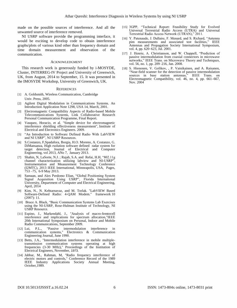
APPENDICES
Appendix 1: 800MHz received carrier signals (2G GSM, 4G LTE, RFID, Zigbee)
Plot 1 represents amplitude-time plot (time domain)
Plot 2,3,4 are same plots in frequency-time(frequency domain)
Figure 4. Carrier without Interference
Figure 5. With Interference, the frequency band separation is 6000Hz between
carrier and Interference.
Figure 6. With Interference, the frequency band separation is 1200Hz
between carrier and Interference.
Figure 7. With Interference, the frequency band separation is 500Hz between
carrier and Interference.
Figure 8. With Interference, the frequency band separation is 25Hz between
carrier and Interference.
Athar Qureshi: Interference Diagnosis in Wireless Systems by using NI USRP
DOI 10.5013/IJSSST.a.16.02.24 8 ISSN: 1473-804x online, 1473-8031 print
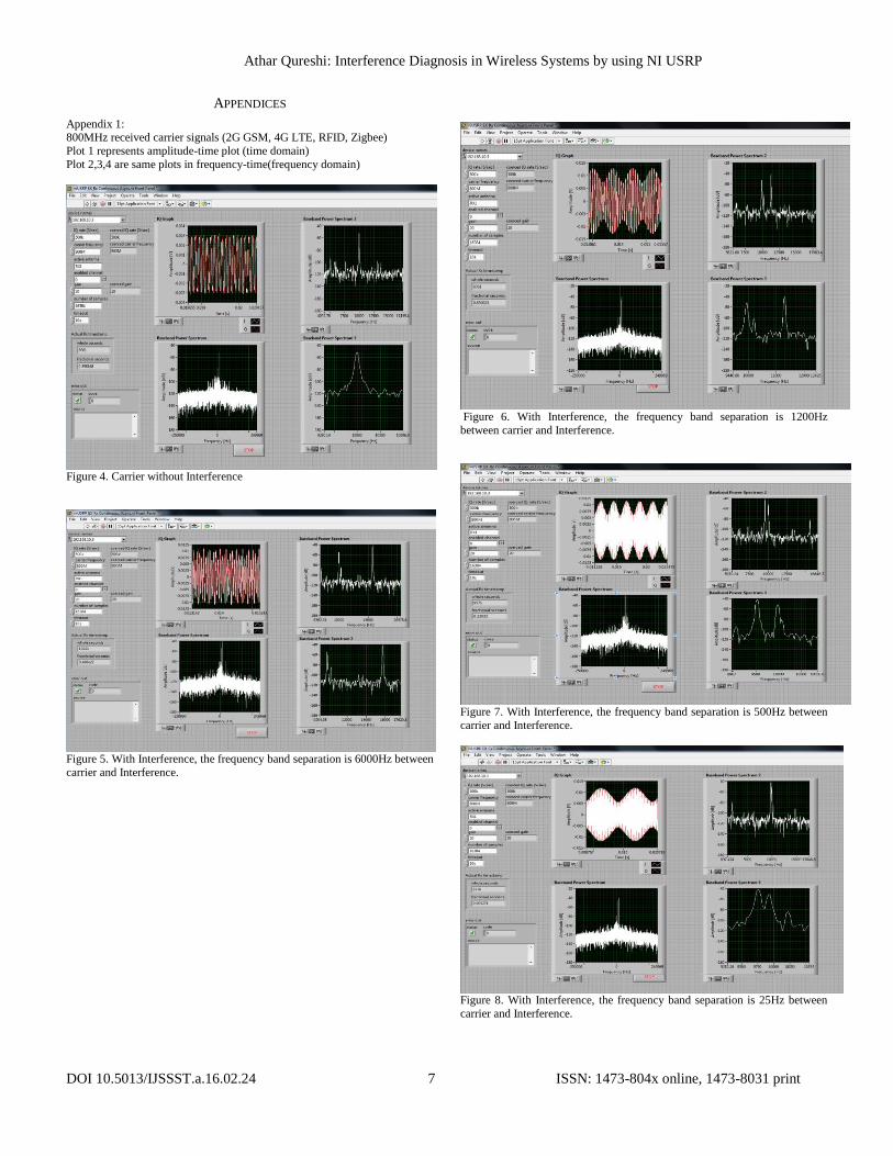
Appendix 2:
400MHz received carrier signals (Zigbee, 2G GSM, 1G AMPS)
Plot 1 represents amplitude-time plot (time domain)
Plot 2,3,4 are same plots in frequency-time(frequency domain)
Figure 9. Carrier without Interference
Figure 10. With Interference, the frequency band separation is 1000Hz between carrier and Interference
Figure 11. With Interference, the frequency band separation is 10000Hz
between carrier and Interference.
Appendix 3: 68-69MHz received carrier signals (NFC)
Plot 1 represents amplitude-time plot (time domain)
Plot 2,3,4 are same plots in frequency-time(frequency domain)
Figure 12. Carrier without Interference
Figure 13. With four Interference from various environmental signal
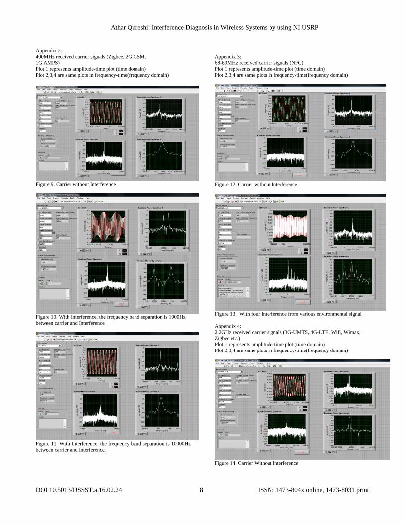
Appendix 4: 2.2GHz received carrier signals (3G-UMTS, 4G-LTE, Wifi, Wimax,
Zigbee etc.) Plot 1 represents amplitude-time plot (time domain)
Plot 2,3,4 are same plots in frequency-time(frequency domain)
Figure 14. Carrier Without Interference
Athar Qureshi: Interference Diagnosis in Wireless Systems by using NI USRP
DOI 10.5013/IJSSST.a.16.02.24 9 ISSN: 1473-804x online, 1473-8031 print
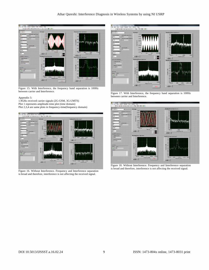
Figure 15: With Interference, the frequency band separation is 100Hz between carrier and Interference.
Appendix 5: 1.9GHz received carrier signals (2G-GSM, 3G-UMTS)
Plot 1 represents amplitude-time plot (time domain)
Plot 2,3,4 are same plots in frequency-time(frequency domain)
Figure 16. Without Interference. Frequency and Interference separation is broad and therefore, interference is not affecting the received signal.
Figure 17. With Interference, the frequency band separation is 100Hz between carrier and Interference.
Figure 18. Without Interference. Frequency and Interference separation
is broad and therefore, interference is not affecting the received signal.
Related Documents