International Journal on Future Revolution in Computer Science & Communication Engineering ISSN: 2454-4248 Volume: 4 Issue: 3 72 – 80 _______________________________________________________________________________________________ 72 IJFRCSCE | March 2018, Available @ http://www.ijfrcsce.org _______________________________________________________________________________________ Interfacing a Stepper Motor with ARM Controller LPC2148 Md. Moyeed Abrar Assistant Professor, Department of Computer Science & Engineering. Khaja Banda Nawaz College of Engineering Kalaburagi, Karnataka, India E-mail: [email protected] Abstract—Another useful machine interfaced to the computer system is the Stepper motor. A Stepper motor is a digital motor because each input pulse results in discrete output or discrete steps as it traverses through 360 0 which means the shaft rotation by definite angle called step angle. Stepper motors are DC motors that move in discrete steps. They possess multiple coils that are organized in groups referred to as phases. By energizing each phase in sequence, the motor will rotate one step at a time. Stepper motors are available in various sizes and styles as well as electrical characteristics. Nowadays, the use of ARM controllers is in limelight. The ARM controllers are basically designed to target the 32 bit microcontrollers. These controllers provide excellent performance and are available with latest and enhanced features. The ARM controllers are suitable for 32 bit embedded applications. The state of the art presented in this paper is the interfacing of Stepper motor with ARM controller LPC 2148. Keywords-Stepper motor, discrete steps, shaft rotation, step angle, 32 bit embedded applications, ARM controller LPC2148, interfacing. __________________________________________________*****_________________________________________________ I. INTRODUCTION A Stepper motor is an electrical machine that translates the electrical pulses into mechanical movement. Stepper motors are also referred to as stepping motors or step motors because they rotate through a fixed angular step in response to each input current pulse from its controller. Stepper motors are designed to develop torques ranging from 1 μNm (in tiny wrist watch motor of 3 mm diameter) up to 40 Nm in a motor of 15 cm used for machine tool applications. The output power of stepper motor ranges from about 1 Watt to about 2500 Watt. The only moving part in a stepper motor is its rotor which has no windings. Hence it does not require commutator and brushes. In applications such as disk drives, dot matrix printers and robotics, the stepper motor is used for position control. A common stepper motor is geared to move perhaps 150 per step in inexpensive motor, to 10 per step in a more costly, high precision stepper motor. In all cases, these steps are gained through many magnetic poles and/or gearing. Every Stepper motor has a permanent magnet rotor (also known as the shaft) surrounded by the stator. This is depicted in fig.1 The most common stepper motors have four stator windings that are paired with a Center tapped common as shown in fig.2. This type of stepper motor is commonly referred to as a four phase stepper motor. The center tap allows the change of current direction in each of two coils when a winding is grounded, which results in a polarity change of the stator. The internal construction of the stepper motor, to be more precise the number of teeth on the stator and the rotor, decides how much movement is associated with a single step. The step angle is the minimum degree of rotation associated with a single step. Various motors have different step angles. Table 1illustrates some step angles for various motors. The term steps per revolution is the total number of steps needed to rotate one complete rotation or 360 degrees. (For example, 180 steps x 2 degrees = 360). [1] [2]. Fig.1 Internal schematic of Stepper motor Fig.2 Four phase stepper motor

Welcome message from author
This document is posted to help you gain knowledge. Please leave a comment to let me know what you think about it! Share it to your friends and learn new things together.
Transcript

International Journal on Future Revolution in Computer Science & Communication Engineering ISSN: 2454-4248 Volume: 4 Issue: 3 72 – 80
_______________________________________________________________________________________________
72
IJFRCSCE | March 2018, Available @ http://www.ijfrcsce.org
_______________________________________________________________________________________
Interfacing a Stepper Motor with ARM Controller LPC2148
Md. Moyeed Abrar
Assistant Professor, Department of Computer Science & Engineering.
Khaja Banda Nawaz College of Engineering
Kalaburagi, Karnataka, India
E-mail: [email protected]
Abstract—Another useful machine interfaced to the computer system is the Stepper motor. A Stepper motor is a digital motor because each
input pulse results in discrete output or discrete steps as it traverses through 3600 which means the shaft rotation by definite angle called step angle. Stepper motors are DC motors that move in discrete steps. They possess multiple coils that are organized in groups referred to as phases. By energizing each phase in sequence, the motor will rotate one step at a time. Stepper motors are available in various sizes and styles as well as electrical characteristics. Nowadays, the use of ARM controllers is in limelight. The ARM controllers are basically designed to target the 32 bit microcontrollers. These controllers provide excellent performance and are available with latest and enhanced features. The ARM controllers are suitable for 32 bit embedded applications. The state of the art presented in this paper is the interfacing of Stepper motor with ARM controller LPC 2148.
Keywords-Stepper motor, discrete steps, shaft rotation, step angle, 32 bit embedded applications, ARM controller LPC2148, interfacing.
__________________________________________________*****_________________________________________________
I. INTRODUCTION
A Stepper motor is an electrical machine that translates the
electrical pulses into mechanical movement. Stepper motors are
also referred to as stepping motors or step motors because they
rotate through a fixed angular step in response to each input
current pulse from its controller. Stepper motors are designed
to develop torques ranging from 1 µNm (in tiny wrist watch
motor of 3 mm diameter) up to 40 Nm in a motor of 15 cm
used for machine tool applications. The output power of
stepper motor ranges from about 1 Watt to about 2500 Watt.
The only moving part in a stepper motor is its rotor which has
no windings. Hence it does not require commutator and
brushes. In applications such as disk drives, dot matrix printers
and robotics, the stepper motor is used for position control. A
common stepper motor is geared to move perhaps 150 per step
in inexpensive motor, to 10 per step in a more costly, high
precision stepper motor. In all cases, these steps are gained
through many magnetic poles and/or gearing. Every Stepper
motor has a permanent magnet rotor (also known as the shaft)
surrounded by the stator. This is depicted in fig.1 The most common stepper motors have four stator
windings that are paired with a Center tapped common as shown in fig.2. This type of stepper motor is commonly referred to as a four phase stepper motor. The center tap allows the change of current direction in each of two coils when a winding is grounded, which results in a polarity change of the stator. The internal construction of the stepper motor, to be more
precise the number of teeth on the stator and the rotor, decides
how much movement is associated with a single step. The step
angle is the minimum degree of rotation associated with a
single step. Various motors have different step angles. Table
1illustrates some step angles for various motors. The term steps
per revolution is the total number of steps needed to rotate one
complete rotation or 360 degrees. (For example, 180 steps x 2
degrees = 360). [1] [2].
Fig.1 Internal schematic of Stepper motor
Fig.2 Four phase stepper motor

International Journal on Future Revolution in Computer Science & Communication Engineering ISSN: 2454-4248 Volume: 4 Issue: 3 72 – 80
_______________________________________________________________________________________________
73
IJFRCSCE | March 2018, Available @ http://www.ijfrcsce.org
_______________________________________________________________________________________
TABLE I. STEP ANGLES FOR VARIOUS MOTORS
SL.NO STEP ANGLE STEPS PER REVOLUTION
1.
0.72
500
2.
1.8
200
3.
2.0
180
4.
2.5
144
5.
5.0
72
6.
7.5
48
7.
15
24
In this paper the interfacing of a Stepper motor with Arm
controller LPC 2148 is presented. The rest of the paper is organized into sections as follows: section II describes the overview of ARM controller LPC2148. Section III focuses on the system design. Results and discussion are reported in section IV. Finally section V summarizes the paper and presents the concluding remark.
II. OVERVIEW OF ARM CONTROLLER LPC2148
The ARM7TDMI-S LPC2148 is a general-purpose 32-bit
microprocessor, which offers high performance and very low
power consumption. The ARM controller is based on Reduced
Instruction Set (RISC) architecture, And the instruction set and
related decode mechanism are much simpler than those of
micro programmed Complex Instruction Set Computers. This
simplicity results in a high instruction throughput and
impressive real-time interrupt response from a small and cost-
effective processor Core.
Pipeline techniques are employed so that all parts of the
processing and memory systems can operate continuously.
Typically, while one instruction is being executed, its successor
is being decoded, and a third instruction is being fetched from
memory.
The ARM7TDMI-S processor also employs a unique
architectural strategy known as THUMB, which makes it
ideally suited to high-volume applications with memory
restrictions, or applications where code density is an issue. The
key idea behind THUMB is that of a super reduced instruction
set. Essentially, the ARM7TDMI-S processor has two
Instruction sets:
The standard 32-bit ARM instruction set.
A 16-bit THUMB instruction set.
The THUMB set‟s 16-bit instruction length allows it to
approach twice the density of standard ARM code while
retaining most of the Arm‟s performance advantage over a
traditional 16-bit processor using 16-bit registers. This is
possible because THUMB code operates on the same 32-bit
register set as ARM code. THUMB code is able to provide up
to 65% of the code size of ARM, and 160% of the performance
of an equivalent ARM Processor connected to a 16-bit memory
system [1], [3]. The important features of the 16 bit /32 bit LPC2148 Arm Microcontroller.
PHILIPS LPC2148 is a 16-bit or 32-bit
Microcontroller in a LQFP64-pin Package.
40 KB of on-chip static RAM and 512 KB of on-chip
flash memory. 128-bit wide interface/accelerator
enables high-speed 60 MHz operation.
The LPC2148 provides 100000 erase/write cycles and
20 years of Data-retention.
In-System Programming/In-Application Programming
(ISP/IAP) via on-chip boot loader software. Single
flash sector or full chip erase takes 400ms and Flash
programming takes 1ms per 256-byte line. USB 2.0
Full speed compliant device controller with 2 KB of
endpoint RAM. In addition, the LPC2148 provides 8
KB of on-chip RAM accessible to USB by DMA.
Embedded ICE-RT and Embedded Trace Macro cell
(ETM) interfaces offer real time debugging with on-
chip Real Monitor software and high-speed real-time
tracing of instruction execution.
Two 10-bit ADCs provide a total of 14 analog inputs,
with conversion times as low as 2.44μs per channel.
Single 10-bit DAC provides variable analog output.
Two 32-bit Timers/External event Counters (with four
Capture and four Compare channels each), PWM unit
(six outputs) and watchdog.
Low power Real-Time Clock (RTC) with independent
power and 32 kHz clock input.
Multiple serial interfaces including two UARTs
(16C550 equivalent), two Fast I2C bus (400 kbit/s),
SPI and SSP with buffering and variable data length
capabilities.
Vectored interrupt controller (VIC) with configurable
priorities and vector addresses. Up to 45 numbers of 5
V tolerant fast general purpose I/O pins in a tiny
LQFP64 package.
Up to nine edge or level sensitive external interrupt
pins available.
60 MHz maximum CPU clock available from
programmable on-chip PLL with settling time of 100
μs.
On-chip integrated oscillator operates with an external
crystal in range from 1 MHz to 30 MHz and with an
external oscillator up to 50 MHz
Power saving modes include Idle and Power-down.
Individual power enable/disable of peripheral
functions as well as peripheral clock scaling for
additional power optimization.
Processor wake-up from Power-down mode via
external interrupt, USB, Brown-Out Detect (BOD) or
Real-Time Clock (RTC).
Single power supply chip with Power-On Reset (POR)
and BOD circuits: CPU operating voltage range of 3.0
V to 3.6 V (3.3 V+- 10 %) with 5 V tolerant I/O pads
[3].
III. SYSTEM DESIGN
A. Board specifications of the Arm evaluation system
The board has important features which are listed as follows
LPC2148 16/32 bit ARM7TDMI-S with 512K bytes
program flash, 42K bytes RAM.

International Journal on Future Revolution in Computer Science & Communication Engineering ISSN: 2454-4248 Volume: 4 Issue: 3 72 – 80
_______________________________________________________________________________________________
74
IJFRCSCE | March 2018, Available @ http://www.ijfrcsce.org
_______________________________________________________________________________________
LCD 16x2 alphanumeric display.
Stepper motor interface with direction and speed
control.
Temperature sensor interface using internal DAC.
12 MHz crystal for easy communication set up.
External interrupt through key with LED indication.
Standard JTAG connector with ARM 2x10 pin layout
for programming/debugging with ARM-JTAG.
Reset push button for resetting the controller.
Standard 26-pin FRC connectors to connect to on-
board interface
Dip switch for enabling ISP.
One on board voltage regulator for generating 3.3V.
Input to this will be from external +5V DC power
supply through a 9-pin DSUB connector.
One RS232 interface circuit with 9 pin DSUB
connector, using UART0. This is used by the boot
loader program to program the LPC2148 flash
memory without external programmer. User can also
use this as other UART0 application program.
One RS232 interface circuit with 3 way male
reliamate connector using UART1. This is used as
additional UART to communicate with external
peripheral via serial communication interface.
The photographic view of the ARM-09 NXP LPC2148
Microcontroller board is shown in fig.3
Fig.3 photographic view of the ARM-09 NXP LPC2148
Microcontroller board
B. System specifications
The system specifications are illustrated in table 1.
TABLE II. SYSTEM SPECIFICATIONS
SL.NO SPECIFICATIONS
1. Domain: Microprocessors and Microcontrollers, Arm controllers, Assembly language Programming.
2. Arm Microcontroller: LPC2148 32-bit RISC microcontroller from NXP founded by Philips.
3. Stepper motor: 1Ampere, 5 volts, 1.80 , step angle
4. Desktop computer: Dual core, 1 GB RAM, processor speed
2.5 GHz
5. Port line: P0.20-P0.23
6. Software: Keil µ vision-4
7.
In-system Programming (ISP): Flash magic software can be
used to download the HEX files to the flash magic of the
controller.
8.
Serial communication: RS 232 cross cable connections
required for establishing communication between the
evaluation board and a display terminal/host computer.
9. Applications: Rotation of stepper motor in clockwise and
Anticlockwise direction.
C. Stepper Motor interface
The Stepper motor can be interfaced to the board by connecting
it into the Power Mate PM1. It is interfaced through the high
current driver ULN2803. These lines will have high current
(max 300 mA) with low voltage level of 0.7V. The rotating
direction of the stepper motor can be changed through
software. Port lines used for Stepper motor are P0.20 –P0.23.
The circuit schematic for the Stepper motor interface system is shown in fig.4
Fig.4 Stepper motor schematic
International Journal on Future Revolution in Computer Science & Communication Engineering ISSN: 2454-4248 Volume: 4 Issue: 3 72 – 80
_______________________________________________________________________________________________
75
IJFRCSCE | March 2018, Available @ http://www.ijfrcsce.org
_______________________________________________________________________________________
The photographic view of the Stepper motor used in the system is illustrated in fig 5.
Fig.5 Photographic view of stepper motor
D. System set up
The experimental set and its conduction were done in the
Microprocessors laboratory. The system consists of a Desktop
computer, the ARM-09 NXP LPC2148 Microcontroller board,
adapter, USB cable and RS 232 cable and the Stepper motor.
The desktop computer was switched ON. The adapter was
plugged in the socket and the adapter pin was connected to the
slot provided on the ARM-09 NXP LPC2148 Microcontroller
board. The USB cable was connected to the USB port of the
desktop computer and the other end of the USB cable, that is,
the male connector was connected to the female connector of
the RS232 cable and the male connector of the RS232 cable
was connected to the female connector provided on the ARM-
09 NXP LPC2148 Microcontroller board. Lastly the female
power mate of the Stepper motor was also connected to the
male power mate PM1present on the ARM-09 NXP LPC2148
Microcontroller board. Fig.6 illustrates the photographic view
of the system.
Fig.6 photographic view of the system
On the desktop computer my computer icon was right clicked
and manage option was chosen and further the device
manager option was selected and then the ports option was
clicked which depicted the communication port as port 1 and
the USB to serial port as port 3. The keil µ-vision 4 software
was used to write the C program for the rotation of the stepper
motor in anticlockwise and clockwise direction interfaced with
ARM-09 NXP LPC2148 Microcontroller board [7]. The
following sequence of steps was followed in order to get the
desired output.
The keil µ-vision 4 software was opened by double clicking on
the keil µ-vision 4 icon located on the desktop screen [7]. The
project option was right clicked and then new µ-vision project
was chosen as illustrated in fig.7
Fig.7 selecting new µ-vision project
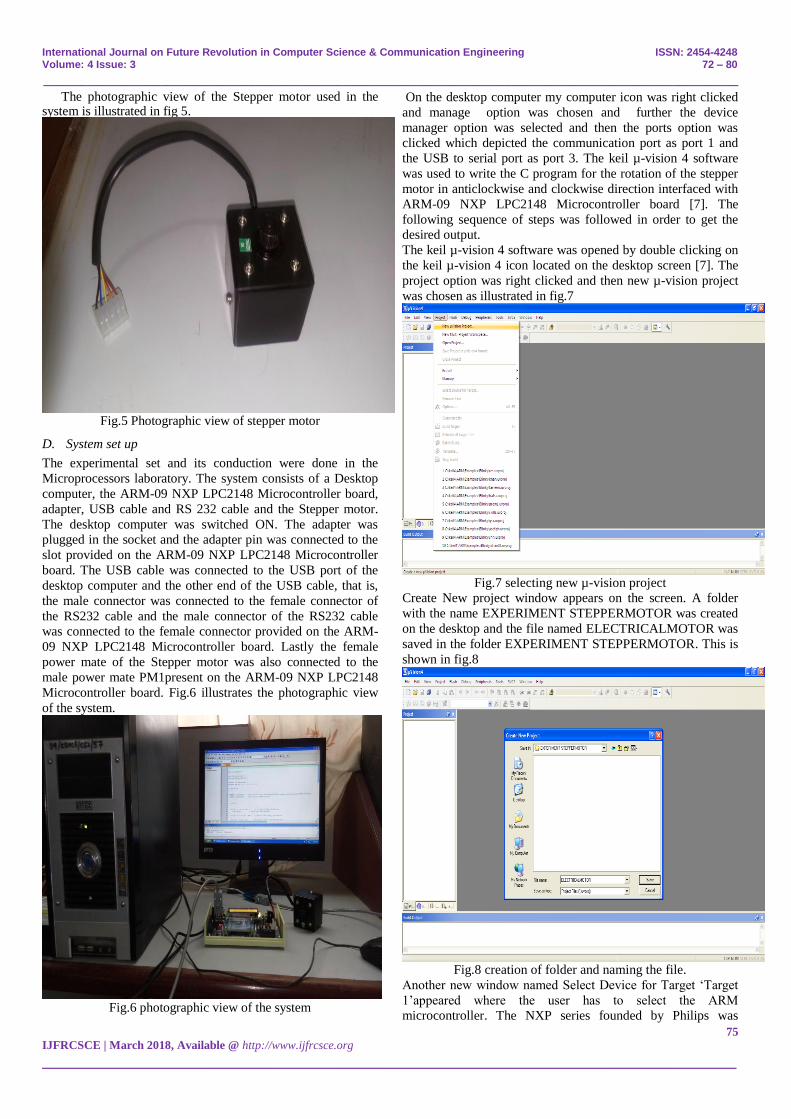
Create New project window appears on the screen. A folder
with the name EXPERIMENT STEPPERMOTOR was created
on the desktop and the file named ELECTRICALMOTOR was
saved in the folder EXPERIMENT STEPPERMOTOR. This is
shown in fig.8
Fig.8 creation of folder and naming the file.
Another new window named Select Device for Target „Target
1‟appeared where the user has to select the ARM
microcontroller. The NXP series founded by Philips was
International Journal on Future Revolution in Computer Science & Communication Engineering ISSN: 2454-4248 Volume: 4 Issue: 3 72 – 80
_______________________________________________________________________________________________
76
IJFRCSCE | March 2018, Available @ http://www.ijfrcsce.org
_______________________________________________________________________________________
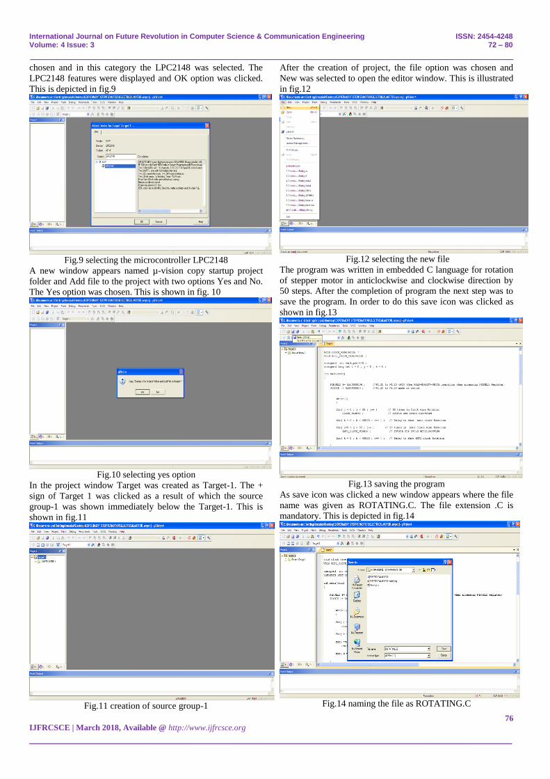
chosen and in this category the LPC2148 was selected. The
LPC2148 features were displayed and OK option was clicked.
This is depicted in fig.9
Fig.9 selecting the microcontroller LPC2148
A new window appears named µ-vision copy startup project
folder and Add file to the project with two options Yes and No.
The Yes option was chosen. This is shown in fig. 10
Fig.10 selecting yes option
In the project window Target was created as Target-1. The +
sign of Target 1 was clicked as a result of which the source
group-1 was shown immediately below the Target-1. This is
shown in fig.11
Fig.11 creation of source group-1
After the creation of project, the file option was chosen and
New was selected to open the editor window. This is illustrated
in fig.12
Fig.12 selecting the new file
The program was written in embedded C language for rotation
of stepper motor in anticlockwise and clockwise direction by
50 steps. After the completion of program the next step was to
save the program. In order to do this save icon was clicked as
shown in fig.13
Fig.13 saving the program
As save icon was clicked a new window appears where the file
name was given as ROTATING.C. The file extension .C is
mandatory. This is depicted in fig.14
Fig.14 naming the file as ROTATING.C

International Journal on Future Revolution in Computer Science & Communication Engineering ISSN: 2454-4248 Volume: 4 Issue: 3 72 – 80
_______________________________________________________________________________________________
77
IJFRCSCE | March 2018, Available @ http://www.ijfrcsce.org
_______________________________________________________________________________________
Color syntax highlighting was enabled once the file
ROTATING.C was saved as shown in fig.15
Fig.15 color syntax highlighting after saving the file
The source group 1 located below the Target 1 in the project
window was right clicked and the option Add existing files in
Group „Source Group 1‟ was selected in order to add the .C
source file to the group. After adding this source file this file
was viewed in the project window. This is illustrated in fig.16
Fig.16 adding existing files to source group-1.
A new window named Add Files to Group „Source Group 1‟
appeared where the file ROTATING was selected and then
Add and Close options were clicked sequentially. This is
shown in fig.17
Fig.17 selection of file ROTATING
The most important task was to compile the files. In order for
compilation the translate option was clicked as depicted in
fig.18
Fig.18 choosing translate option for compilation
The build output window was checked where the message was
displayed as „ROTATING.C‟ 0 errors and 0 warnings, which
ensured that the program was error free. This is shown in fig.19
Fig.19 obtaining the error free program
In the project window Target-1 was right clicked and the
options for Target, Target 1 was chosen as shown in fig.20
Fig.20 choosing options for Target, Target-1
A new window appeared named options for Target „Target 1‟
where first Target option was selected. In this Target option the
International Journal on Future Revolution in Computer Science & Communication Engineering ISSN: 2454-4248 Volume: 4 Issue: 3 72 – 80
_______________________________________________________________________________________________
78
IJFRCSCE | March 2018, Available @ http://www.ijfrcsce.org
_______________________________________________________________________________________
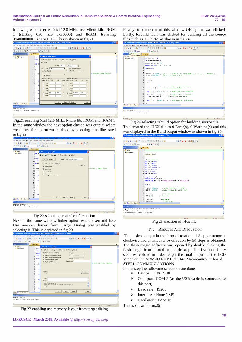
following were selected Xtal 12.0 MHz; use Micro Lib, IROM
1 (starting 0x0 size 0x80000) and IRAM 1(starting
0x40000000 size 0x8000). This is shown in fig.21
Fig.21 enabling Xtal 12.0 MHz, Micro lib, IROM and IRAM 1
In the same window the next option chosen was output, where
create hex file option was enabled by selecting it as illustrated
in fig.22
Fig.22 selecting create hex file option
Next in the same window linker option was chosen and here
Use memory layout from Target Dialog was enabled by
selecting it. This is depicted in fig.23
Fig.23 enabling use memory layout from target dialog
Finally, to come out of this window OK option was clicked.
Lastly, Rebuild icon was clicked for building all the source
files such as .C, .h etc. as shown in fig.24
Fig.24 selecting rebuild option for building source file
This created the .HEX file as 0 Error(s), 0 Warning(s) and this
was displayed in the Build output window as shown in fig.25
Fig.25 creation of .Hex file
IV. RESULTS AND DISCUSSION
The desired output in the form of rotation of Stepper motor in
clockwise and anticlockwise direction by 50 steps is obtained.
The flash magic software was opened by double clicking the
flash magic icon located on the desktop. The five mandatory
steps were done in order to get the final output on the LCD
screen on the ARM-09 NXP LPC2148 Microcontroller board.
STEP1: COMMUNICATIONS
In this step the following selections are done
Device : LPC2148
Com port: COM 3 (as the USB cable is connected to
this port)
Baud rate : 19200
Interface : None (ISP)
Oscillator : 12 MHz
This is shown in fig.26
International Journal on Future Revolution in Computer Science & Communication Engineering ISSN: 2454-4248 Volume: 4 Issue: 3 72 – 80
_______________________________________________________________________________________________
79
IJFRCSCE | March 2018, Available @ http://www.ijfrcsce.org
_______________________________________________________________________________________
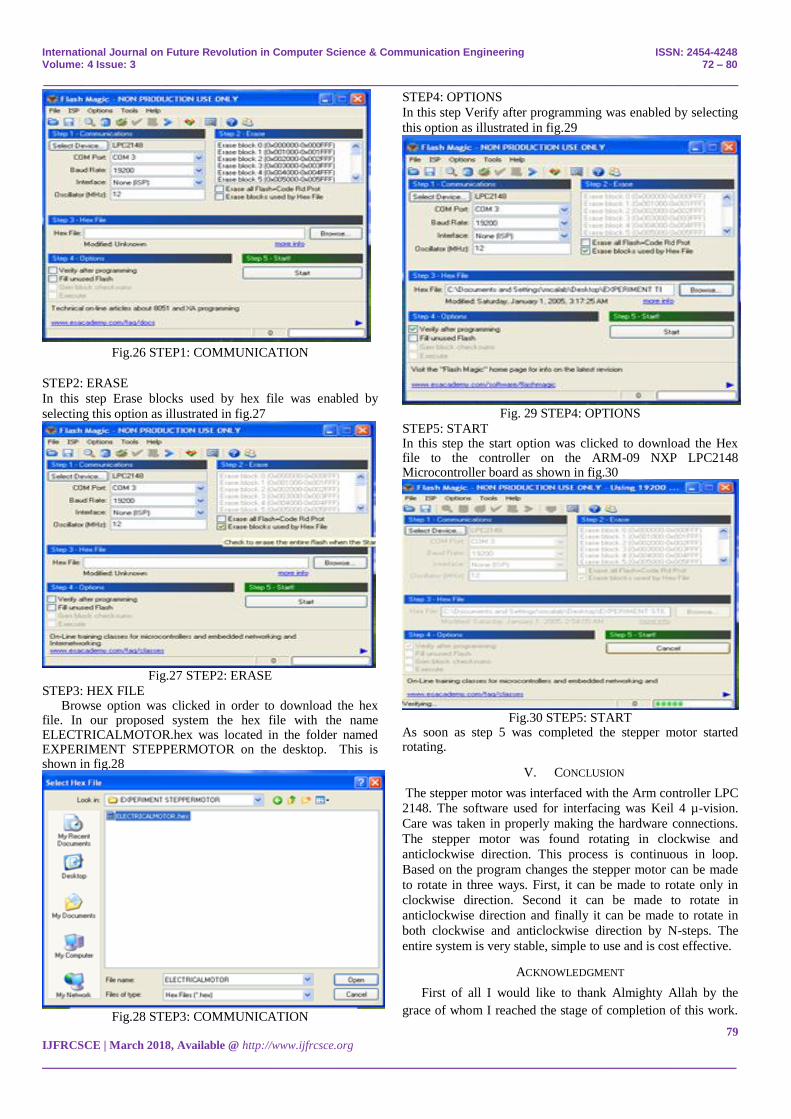
Fig.26 STEP1: COMMUNICATION
STEP2: ERASE
In this step Erase blocks used by hex file was enabled by
selecting this option as illustrated in fig.27
Fig.27 STEP2: ERASE
STEP3: HEX FILE Browse option was clicked in order to download the hex
file. In our proposed system the hex file with the name ELECTRICALMOTOR.hex was located in the folder named EXPERIMENT STEPPERMOTOR on the desktop. This is shown in fig.28
Fig.28 STEP3: COMMUNICATION
STEP4: OPTIONS
In this step Verify after programming was enabled by selecting
this option as illustrated in fig.29
Fig. 29 STEP4: OPTIONS
STEP5: START In this step the start option was clicked to download the Hex file to the controller on the ARM-09 NXP LPC2148 Microcontroller board as shown in fig.30
Fig.30 STEP5: START
As soon as step 5 was completed the stepper motor started rotating.
V. CONCLUSION
The stepper motor was interfaced with the Arm controller LPC
2148. The software used for interfacing was Keil 4 µ-vision.
Care was taken in properly making the hardware connections.
The stepper motor was found rotating in clockwise and
anticlockwise direction. This process is continuous in loop.
Based on the program changes the stepper motor can be made
to rotate in three ways. First, it can be made to rotate only in
clockwise direction. Second it can be made to rotate in
anticlockwise direction and finally it can be made to rotate in
both clockwise and anticlockwise direction by N-steps. The
entire system is very stable, simple to use and is cost effective.
ACKNOWLEDGMENT
First of all I would like to thank Almighty Allah by the
grace of whom I reached the stage of completion of this work.

International Journal on Future Revolution in Computer Science & Communication Engineering ISSN: 2454-4248 Volume: 4 Issue: 3 72 – 80
_______________________________________________________________________________________________
80
IJFRCSCE | March 2018, Available @ http://www.ijfrcsce.org
_______________________________________________________________________________________
This avenue has been a turning point in my career to mold me
into a thorough and dynamic Professional. My sincere thanks to
the Principal Dr. S Kamal Mohd. Azam, Vice Principal Dr.
Ruksar Fatima and Dr. Asma Parveen H.O.D Computer
Science and Engineering department of my esteemed
institution for their inspiration and support. Lastly I am also
thankful to my beloved Parents who have helped me pave this
path to success.
REFERENCES
[1] Muhammad Ali Mazidi, Janice Gillespie Mazidi and Danny
Causey, The x86 PC Assembly Language, Design and
Interfacing, fifth edition, Dorling Kindersley, India pvt.ltd.2011.
[2] D.C Kulshreshtha, Basic Electrical Engineering, Revised first
edition, Mc Graw Hill education India private limited 2012.
[3] Datasheet LPC2141/42/44/46/48, Philips semiconductor,
October 2005 pp.1-2.
[4] Barry B. Brey, The Intel Microprocessors – Architecture,
Programming and Interfacing Pearson-Prentice Hall Eighth
Edition 2009.
[5] Muhammad Ali Mazidi, Janice Gillespie Mazidi and R.D Mc
Kinlay, The 8051 Microcontroller and Embedded System,
prentice-Hall, India 2006.
[6] Andrew N.Sloss, Dominic Symes, Chris Wright, ARM System
Developer‟s guide Designing and optimizing system software,
Morgan Kaufman publications, 2004.
[7] Trevor Martin, The Insiders guide to the Philips ARM7-based
Microcontrollers, February 2005, pp124-126.
[8] Hausila Singh, Sudhansu Sharma, “Some Novel microprocessor
based configurations for controlling Remotely Located Stepper
motors as Actuators of Control Valves”, IEEE transaction on
Industrial electronics, vol.38 No.4, August 1991, pp. 283-287.
[9] Sagarika Pal, Niladri S. Tripathy, “Remote Position Control
system of Stepper Motor using DTMF Technology”,
International Journal of Control and Automation, Vol.4 No.2
June 2011, pp.35-42.
[10] M.V Ramesh, Gorantla.S Rao, J.Amarnath, S.Kamakshaiah,
B.Jawaharlal, “Speed Torque Characteristics of Brushless DC
motor in Either Direction on Load using ARM controller”,
IEEE conferences PES Innovative Smart Grid Technologies-
India, 2011, pp. 217-222.
[11] M.A. Perez-Quinones; J.L. Cruz-Rivera, “Integrated
development environment for a microcontroller systems
laboratory”, Frontiers in Education conference FIE 1999, 29th
Annual IEEE conferences, 10-13 November 1999, vol.2, pp.
12C6/11-12C6/16
[12] Sasko Ristov, Nevena Ackovska, Vesna Kirandziska, Darko
Martinovikj, “The Significant progress of the Microprocessors
and Microcontrollers coursse for Computer Science Students”,
37th International Convention on Information and
CommunicationTechnology, Electronics and Microelectronics
(MIPRO), IEEE 2014, pp. 818-823.
[13] Chris Herring, “Microprocessors, Microcontrollers and Systems
in the New Millenium”, IEEE Micro, vol.20, issue 6, 2000, pp-
45-51.
Related Documents