Interface Damage Model for Thermomechanical Degradation of Heterogeneous Materials * K. Willam, I. Rhee & B. Shing University of Colorado at Boulder, USA ABSTRACT: In this paper we examine the degradation of interface transition zones in heterogeneous materials due to thermal and mechanical damage. After a brief introduction of zero-thickness interface models, we will address three topics, (a) the interaction of normal and tangential damage at the interface level of observation, (b) the interaction of thermal and mechanical damage when thermal softening is coupled with mechanical degradation, and (c) the effect of interface damage on the load resistance of heterogeneous composites such as concrete when thermal softening leads to massive degradation of their load resistance. 1 INTRODUCTION Ever since Charles A. Coulomb articulated the classical law of dry friction over 200 years ago, a pre- cise mathematical description of material interface behavior has been one of the central themes in en- gineering mechanics and materials. Interfaces are normally the weak link in heterogeneous media. A successful predictive model will have enormous implications for design, analysis, fabrication, and life cycle performance of multi-material structures. It also has a strategic role in capturing discontinuous failure processes in materials which are considered homogeneous at the macroscale. The main problem is that current interface models are calibrated not directly but indirectly by inverse identification since no established theory exists how to construct zero-thickness interface properties from micro-structural features of the adherent materials. Interface adhesion, cohesion and friction are important in many technological realms ranging from the scales of kilometers in geosciences to micro- and nanometers in microelectronics and nano device applications. In all cases, computationally-efficient modeling strategies are lacking that pass information between lower and higher length scales and thus facilitate the rational analysis and design of engineering systems. In the back of these fundamental issues on multiscale analysis and design of material systems is the field of material failure where degradation of material interfaces play a central role in multi-materials under extreme events. Specifically, this paper will examine high temperature effects on heterogeneous materials and the fields of fire protection and fire resistance of cement-based materials. Thereby, the exploratory study is intended as a proof of concept for multi-scale multi-physics engineering to reduce ablation and spall effects in thermal shock problems when fire safety issues are considered. * accepted for publication in Special WCCMV Issue on Computational Failure Mechanics in CMAME, 2003 1

Welcome message from author
This document is posted to help you gain knowledge. Please leave a comment to let me know what you think about it! Share it to your friends and learn new things together.
Transcript
Interface Damage Model for Thermomechanical Degradation ofHeterogeneous Materials∗
K. Willam, I. Rhee & B. ShingUniversity of Colorado at Boulder, USA
ABSTRACT: In this paper we examine the degradation of interface transition zones in heterogeneousmaterials due to thermal and mechanical damage. After a brief introduction of zero-thickness interfacemodels, we will address three topics, (a) the interaction of normal and tangential damage at the interfacelevel of observation, (b) the interaction of thermal and mechanical damage when thermal softening iscoupled with mechanical degradation, and (c) the effect of interface damage on the load resistance ofheterogeneous composites such as concrete when thermal softening leads to massive degradation of theirload resistance.
1 INTRODUCTIONEver since Charles A. Coulomb articulated the classical law of dry friction over 200 years ago, a pre-cise mathematical description of material interface behavior has been one of the central themes in en-gineering mechanics and materials. Interfaces are normally the weak link in heterogeneous media. Asuccessful predictive model will have enormous implications for design, analysis, fabrication, and lifecycle performance of multi-material structures. It also has a strategic role in capturing discontinuousfailure processes in materials which are considered homogeneous at the macroscale. The main problemis that current interface models are calibrated not directly but indirectly by inverse identification sinceno established theory exists how to construct zero-thickness interface properties from micro-structuralfeatures of the adherent materials.
Interface adhesion, cohesion and friction are important in many technological realms ranging fromthe scales of kilometers in geosciences to micro- and nanometers in microelectronics and nano deviceapplications. In all cases, computationally-efficient modeling strategies are lacking that pass informationbetween lower and higher length scales and thus facilitate the rational analysis and design of engineeringsystems. In the back of these fundamental issues on multiscale analysis and design of material systems isthe field of material failure where degradation of material interfaces play a central role in multi-materialsunder extreme events. Specifically, this paper will examine high temperature effects on heterogeneousmaterials and the fields of fire protection and fire resistance of cement-based materials. Thereby, theexploratory study is intended as a proof of concept for multi-scale multi-physics engineering to reduceablation and spall effects in thermal shock problems when fire safety issues are considered.
∗accepted for publication in Special WCCMV Issue on Computational Failure Mechanics in CMAME, 2003
1
2 SCOPEIn the paper we examine thermal and mechanical deterioration effects of interfacial transition zonesin heterogeneous two-phase materials such as concrete. After a brief introduction we consider specialforms of damage in zero-thickness interface models. To this end we present a systematic discussionof normal and tangential interface damage and their interaction as well as the coupling of elastic andthermal degradation when heat transfer takes place in a heterogeneous material system subject to strongdiscontinuities along some of the interfaces. For illustration the thermal degradation formulation is ap-plied to model-based simulations of two-phase composites considering a single inclusion problem andthe thermal sweep analysis of a two-phase particle composite. The first application shows the effects ofdegradation when thermo-mechanical mismatch of the two-phase material introduces localized degra-dation at the interfaces between the constituents. The second application is motivated by experimentalobservations on concrete specimens that were subjected to the combined thermal and mechanical loadhistories leading to overall degradation of load resistance during thermal sweeps.
3 BACKGROUNDTraditionally, material interfaces are considered to exhibit tensile bond and shear resistance at the macro-scopic continuum level. While in most applications this approach may be adequate, progressive deco-hesion processes can only be explained properly by considering micro-structural details at the interface.This requires characterization of the two adherent constituents and the interface bond conditions. Thesetypes of studies are very demanding in terms of manpower and computing power, in spite of the recentdevelopment of high performance modeling of materials at the micro- and macroscopic levels in 3-Dspace and time.
3.1 Zero-Thickness Interface Behavior
The notion of a zero-thickness interface results in elastic stiffness properties which relate surface trac-tions to relative displacements. In 2-D the normal and tangential shear components lead in local coordi-nates to the elementary stiffness relationship,
[tnts
]=
[knn 00 kss
][∆un
∆us
](1)
Thereby it is understood that the relative displacements are discontinuous across the zero-thickness inter-face. In other terms we should write∆un = u+
n − u−n = [|un|] and∆us = u+s − u−s = [|us|]. Considering
an interfacial transition zone of the thickness`el we may interpret the relative displacements as normalstrain and shear strain, where∆un = εn `el and∆us = γns `el. Consequently, the elastic finite thicknessinterface relation results in, [
tnts
]=
[E 00 G
][εn
γns
](2)
This implies that zero-thickness interface stiffness properties are related to the elastic moduli of elasticityby,
knn = E/`el and kss = G/`el (3)
This asymptotic argument illustrates the fundamental role of the elastic interface thickness`el. Its pur-pose is to account for the dimensional reduction when we map the elastic moduli of the bulk materialonto zero-thickness interface properties with the help of the length scale`el. Aside from the dimensional
2
reduction process of volume vs surface dominated energy arguments, the elastic interface stiffness pro-vides the repository for elastic damage when tensile separation and shear slip are considered in terms ofa surface dominated degradation process governed by constant fracture energy release ratesGI
c andGIIc ,
in mode I and mode II (as well asGIIIc in Mode III in 3-D). Thereby, the volume dominated degradation
process is transformed into a surface dominated fracture process. The dimensional reduction localizesdegrading softening phenomena to the interface surface thereby regularizing the failure process withregard to fracture energy release rate. The role of the interface is to trap the formation of large gradi-ents in the continuum into a discontinuous interface similarly to‘wall-laws’ in fluid-structure interactionproblems.
3.2 Elastic Interface Damage Based on Two Damage Variables
The nature of material interfaces is inherently local when the strong kinematic discontinuities of zero-thickness interfaces are considered. Conceptually, there are two points of view possible:
(a) the interface properties are projections of the adherent material bulk properties. This concept is nor-mally adopted in embedded crack methodologies where localization of kinematic discontinuitiesleads to an appropriate dimensional reduction of the bulk properties, see Simo, Oliver and Armero[1993], Oliver, Huespe, Pulido and Chaves [2001].
(b) the interface properties have a life of their own, Rots & Schellekens [1990], Stankowski, Runessonand Sture [1993], Lofti & Shing [1994], Carol, Prat and Lopez [1997]. The interfacial transitionzone of bimaterials are an example where the thickness is normally so small that it may be assumedto be zero when compared to the scale of adjacent bulk materials. This concept is normally adoptedfor the formulation of joint elements, fictitious crack models and zero-thickness cohesion models,see Xu & Needleman [1994], Camacho & Ortiz [1996] and Espinosa & Zavattieri [2003], whichhave been motivated by binding forces at the atomistic level.
In what follows we adopt the latter philosophy with focus on zero-thickness interface elements for de-cohesion and frictional slip based on microstructural features of the adherent materials. The‘FictitiousCrack Approach’of Hillerborg, Modeer and Petersson [1976] is well established to formulate the loss ofcohesion in a zero-thickness bond layer in mode I. An additional aspect of constitutive interface model-ing arises when we consider the geometry of contact surfaces which is rarely smooth and planar, but fullof asperities providing localized points of contact. Consequently, the classical interpretation of contin-uum damage mechanics of Kachanov [1958] is highly appropriate, where the effective load bearing areaprovides the skeleton for stress transfer as opposed to the nominal surface area,1− d = Aeff/Anom with0 ≤ d ≤ 1. In this context, the‘Disturbed State Concept’of Desai [2001] introduced some innovativebut still intuitive ideas to the field of interface modeling.
Although the thermodynamic setting of interface constitutive models is not well established, one canstart from the postulate that there exists a free surface energy in the spirit of Helmholtz. There are anumber of issues related to the‘coupling’ effects when dissipative interface processes are subjected todecohesion and frictional slip in a transient thermomechanical environment. For illustration we considerthe free Helmholtz energy format in a 2-D setting omitting for the time being thermal and inelasticdissipation effects for the sake of argument.
Redefining the specific free surface energy per unit mass in terms of a potential per unit surface, thenadditive expansion of damage in the normal and tangential energy components,
3
Ψ([|un|], [|us|], dn, ds) =1
2[1− dn]k o
nn[|un|]2 +1
2[1− ds]k
oss[|us|]2 (4)
yields the normal and tangential interface tractions :
tn =∂Ψ
∂[|un|] = [1− dn]konn[|un|] and ts =
∂Ψ
∂[|us|] = [1− ds]koss[|us|] (5)
and the thermodynamic conjugate forces :
Yn = − ∂Ψ
∂dn
=1
2ko
nn[|un|]2 and Ys = −∂Ψ
∂ds
=1
2ko
ss[|us|]2 (6)
The mechanical dissipation inequality for isothermal conditions,
Dm = Yndn +Ysds ≥ 0 (7)
is satisfied as long as the damage parameters are monotonically increasing functions,dn > 0 andds > 0,since the thermodynamic forcesYn,Ys are strictly positive.
Introducing two independent damage functions,
Fn = Yn − rn(dn) ≤ 0 and Fs = Ys − rs(ds) ≤ 0 (8)
the internal energy demand due to the load is expressed in terms of the thermodynamic forcesYn,Ys,and the resistance by the scalar function of the damage variable,r(dn), rs(ds). Under persistent damagein the normal and tangential components the two consistency conditions,
Fn =∂Fn
∂YnYn +
∂Fn
∂dn
dn = 0 and Fs =∂Fs
∂YsYs +
∂Fs
∂ds
ds = 0 (9)
yield the evolution equations of normal and tangential damage:
dn =1
Hn
teffn 〈[|un|]〉 where teff
n = konn[|un|] and ds =
1
Hs
teffs [|us|] where teff
s = koss[|us|]
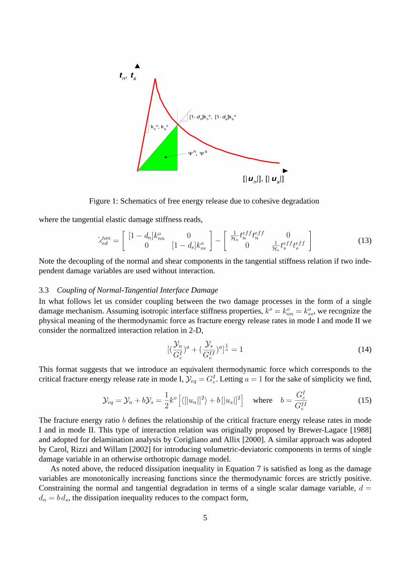
(10)where the hardening/softening parametersHn,Hs characterize the rate of damage evolution of the nor-mal and tangential interface properties. The hardening/softening moduli,Hn,Hs, define the rate ofchange of degradation of the cohesive properties in tension and shear which may be expressed by anexponential function of the damage variable leading to the traction relation illustrated in Figure 1.
In what follows, normal damage is considered to be a unilateral process of crack closure. It is activeonly in tension but not in compression inferred by the Macaulay brackets,〈[|un|]〉, used to activatepositive values of interface opening in the normal direction.
Differentiating the constitutive relationship of interface tractions,[
tnts
]=
[[1− dn]ko
nn 00 [1− ds]k
oss
][〈[|un|]〉[|us|]
](11)
leads to the tangential traction relationship,[
tnts
]= ktan
ed
[〈[|un|]〉[|us|]
](12)
4
[| u n |], [| u
s |]
t n , t
s
k n
o , k s o
[1- d n ]k
n o , [1- d
s ]k
s o
Ψ n
Ψ s
,
Figure 1: Schematics of free energy release due to cohesive degradation
where the tangential elastic damage stiffness reads,
ktaned =
[[1− dn]ko
nn 00 [1− ds]k
oss
]−
[1Hn
teffn teff
n 0
0 1Hs
teffs teff
s
](13)
Note the decoupling of the normal and shear components in the tangential stiffness relation if two inde-pendent damage variables are used without interaction.
3.3 Coupling of Normal-Tangential Interface Damage
In what follows let us consider coupling between the two damage processes in the form of a singledamage mechanism. Assuming isotropic interface stiffness properties,ko = ko
nn = koss, we recognize the
physical meaning of the thermodynamic force as fracture energy release rates in mode I and mode II weconsider the normalized interaction relation in 2-D,
[(Yn
GIc
)a + (Ys
GIIc
)a]1a = 1 (14)
This format suggests that we introduce an equivalent thermodynamic force which corresponds to thecritical fracture energy release rate in mode I,Yeq = GI
c . Lettinga = 1 for the sake of simplicity we find,
Yeq = Yn + bYs =1
2ko
[〈[|un|]2〉+ b [|us|]2
]where b =
GIc
GIIc
(15)
The fracture energy ratiob defines the relationship of the critical fracture energy release rates in modeI and in mode II. This type of interaction relation was originally proposed by Brewer-Lagace [1988]and adopted for delamination analysis by Corigliano and Allix [2000]. A similar approach was adoptedby Carol, Rizzi and Willam [2002] for introducing volumetric-deviatoric components in terms of singledamage variable in an otherwise orthotropic damage model.
As noted above, the reduced dissipation inequality in Equation 7 is satisfied as long as the damagevariables are monotonically increasing functions since the thermodynamic forces are strictly positive.Constraining the normal and tangential degradation in terms of a single scalar damage variable,d =dn = b ds, the dissipation inequality reduces to the compact form,
5
Gf roro
ft
[|u |]o [|u |]
106
t
0
ko= MPa/mm
Figure 2: Fracture energy-based separation law of interface traction
Dm = Yndn +Ysds = Yeqd ≥ 0 (16)
In this case the evolution of scalar damage is activated by the single damage function,
Fd = Yeq − r(d) = 0 (17)
Thus, under persistent loading the consistency condition,Fd = 0, furnishes the rate of damage,
d =Yeq
Hd
=1
Hd
[teffn 〈[|un|]〉+ b teff
s [|us|]]
where Hd = −∂Fd
∂d=
∂r(d)
∂d(18)
The hardening functionHd is calibrated from mode I decohesion experiments conceptually shown inFigure 2.
Introducing damage in the form of an exponential function,
d = 1−√
ro
reγ(1−
√rro
) (19)
where,γ = 2ro
Gf−ro, ro = 1
2ko[|uo|]2, r = 1
2ko[|u|]2, then the tangential relation reads:
t = (1− d)ko ˙[|u|]− dteff (20)
where,d = ∂d∂r
∂r∂[|u|] = 1
Hdteff
˙[|u|], with 1Hd
= ∂d∂r
, and ∂r∂[|u|] = teff
˙[|u|]. In this case the harden-ing/softening damage law is described by,
1
H d=
roeγ(1−
√rro
)
2r2√
ro
r
+γ eγ(1−
√rro
)√
ro
r
2ro
√rro
(21)
In summary, the evolution law involves three parameters, the elastic interface stiffnessko = E/`el,the cohesive strengthft, and through the exponential softening parameterγ the fracture energy releaserateGI
f in mode I. They determine the resistance in terms of the elastic surface energy at crack initiation,ro, and the exponential softening response due to damage thereafter.
6
The tangential stiffness properties result from differentiation of the interface traction relations inEquation 11,
ktan =1
2[1− d]
∂2ψo
∂[|un|]⊗ ∂[|us|] −d
1− dteff (22)
In expanded form this results in the tangential stiffness for elastic damage,
ktaned =
[[1− d ]ko 0
0 [1− d ]ko
]− 1
Hd
[teffn teff
n b[teffn teff
s ]b[teff
s teffn ] b2[teff
s teffs ]
](23)
which is symmetric as opposed to the formulation proposed by Tijssens [2000]. The coupled formatshould be compared with the uncoupled format in Equation 13 which involves the two independent dam-age variables[1− dn] and[1− ds]. It might be surprising that the simple format of a single scalar damagevariable leads to the coupled format above. However, the interaction of normal and tangential damageproperties in the tangential format simply reflects the nonlinearity during loss of cohesion, whereby, thesingle damage variable[1− d] introduces the interaction among normal and tangential damage.
3.4 Computational Aspects
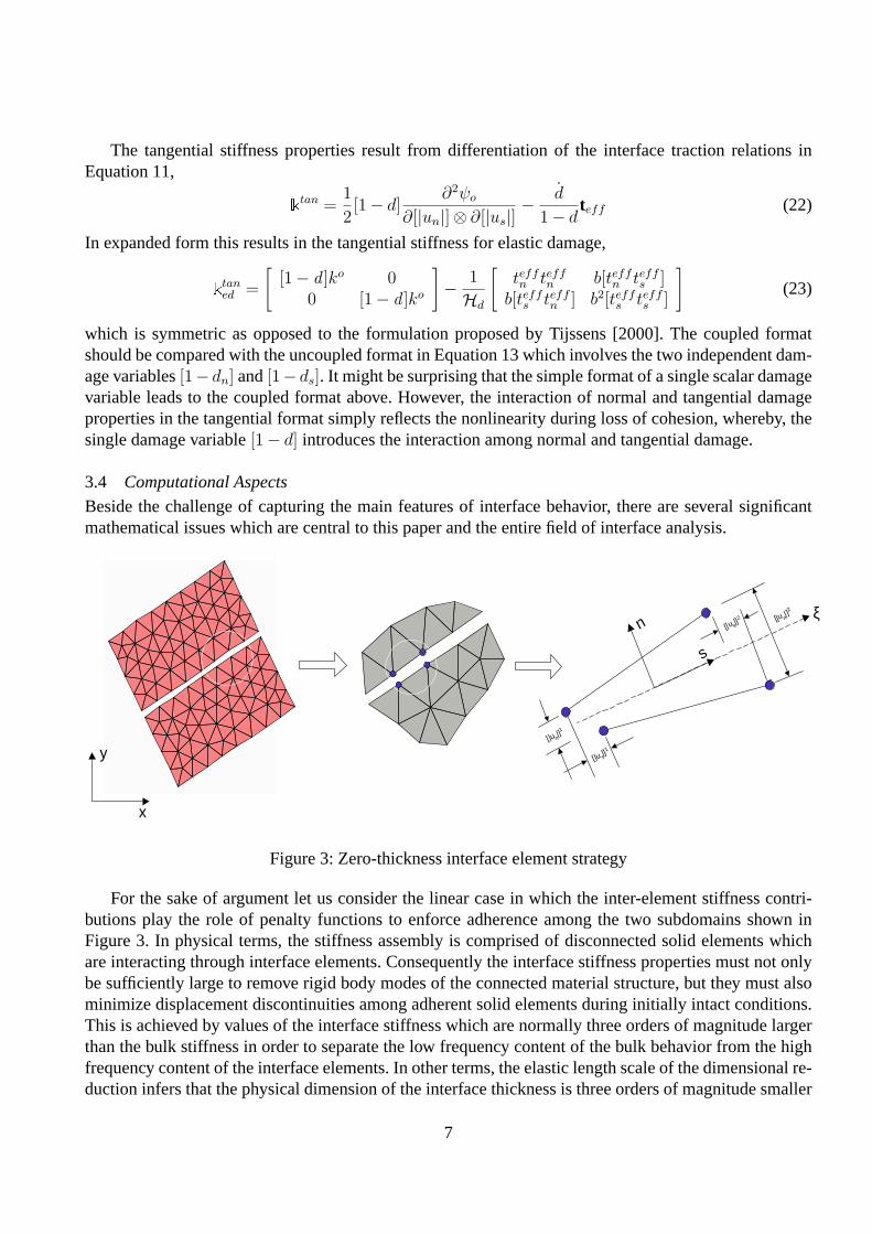
Beside the challenge of capturing the main features of interface behavior, there are several significantmathematical issues which are central to this paper and the entire field of interface analysis.
x
y[|un
|]1
n
s
[|u s|]1
ξ[|u n|]2
[|us|]2
Figure 3: Zero-thickness interface element strategy
For the sake of argument let us consider the linear case in which the inter-element stiffness contri-butions play the role of penalty functions to enforce adherence among the two subdomains shown inFigure 3. In physical terms, the stiffness assembly is comprised of disconnected solid elements whichare interacting through interface elements. Consequently the interface stiffness properties must not onlybe sufficiently large to remove rigid body modes of the connected material structure, but they must alsominimize displacement discontinuities among adherent solid elements during initially intact conditions.This is achieved by values of the interface stiffness which are normally three orders of magnitude largerthan the bulk stiffness in order to separate the low frequency content of the bulk behavior from the highfrequency content of the interface elements. In other terms, the elastic length scale of the dimensional re-duction infers that the physical dimension of the interface thickness is three orders of magnitude smaller
7
than that of the adherent solid domain. Considering degradation of the thickness of the elastic interfaceis initially `el = E
[1−d]ko ∼ 10−3 in the appropriate length units whend = 0. For increasing damage theelastic length scale, or in other terms, the width of the interface increases asd→ 1.
In this context we should be aware that Irwin’s characteristic dimension`ch = E Gc
(ft)2is a measure of the
length of the fracture process zone, Hillerborg et al [1976]. In quasi-brittle materials this length scale issufficiently small such that fracture initiation and propagation is governed by the stress intensity factor atthe crack tip. In cement-based materials typical values are in the range of`ch ∼ 103 [mm], partly becauseof the heterogeneous nature of concrete materials with aggregate sizes in the range of10− 100 [mm].This strongly suggests that self-similarity arguments for crack propagation are no longer valid and thatconcrete fracture is a NLFM process governed by decohesion and loss of frictional resistance in theinterfacial transition zones. In fact, considering the elastic interface length scale above,`el = E
[1−d]ko , we
can correlate the two length scales in the form`ch = β`el, whereβ = [1−d]ko Gc
(ft)2. For concrete materials
this length ratio initially is in the rangeβ ∼ 105 whend = 0. During progressive degradation, as the‘fictitious crack’ widens the ratio of the fracture process zoneβ = `ch
`eldecreases asd→ 1. In other terms,
the degradation of the cohesive-frictional process zone is emulated quite realistically in the interfacelayer of zero-thickness.
Aside from the modeling aspects of interface computations there is also an exciting theoretical aspectwhich changes the normal conformity arguments of‘compatible’finite element displacement methods.This is the field of‘Discontinuous Galerkin Methods’which has received considerable attention bythe mathematically-oriented finite element community. In this case the discretization of bulk elementsis freed from conformity arguments when displacement as well as traction continuity is enforced byLagrange multipliers.
On the numerical side, there are issues of interdependent interpolation when we consider the variationof interface tractions and the variation of bulk stresses in adherent solid elements, see Gens, Carol andAlonso [1990] and Schellekens & de Borst [1993]. Using conforming displacement expansions for theinterface and adherent solid elements, it is apparent that the variation of interface tractions is of higherorder than the variation of stresses in neighboring solid elements. Consequently, provisions have tomade to suppress oscillations in the interface traction field. In our case of linear interpolants, Lobattointegration is used which results in interface stiffness properties which turn out to be diagonal (includingthe coupling partitions) if a natural numbering of nodes is used.
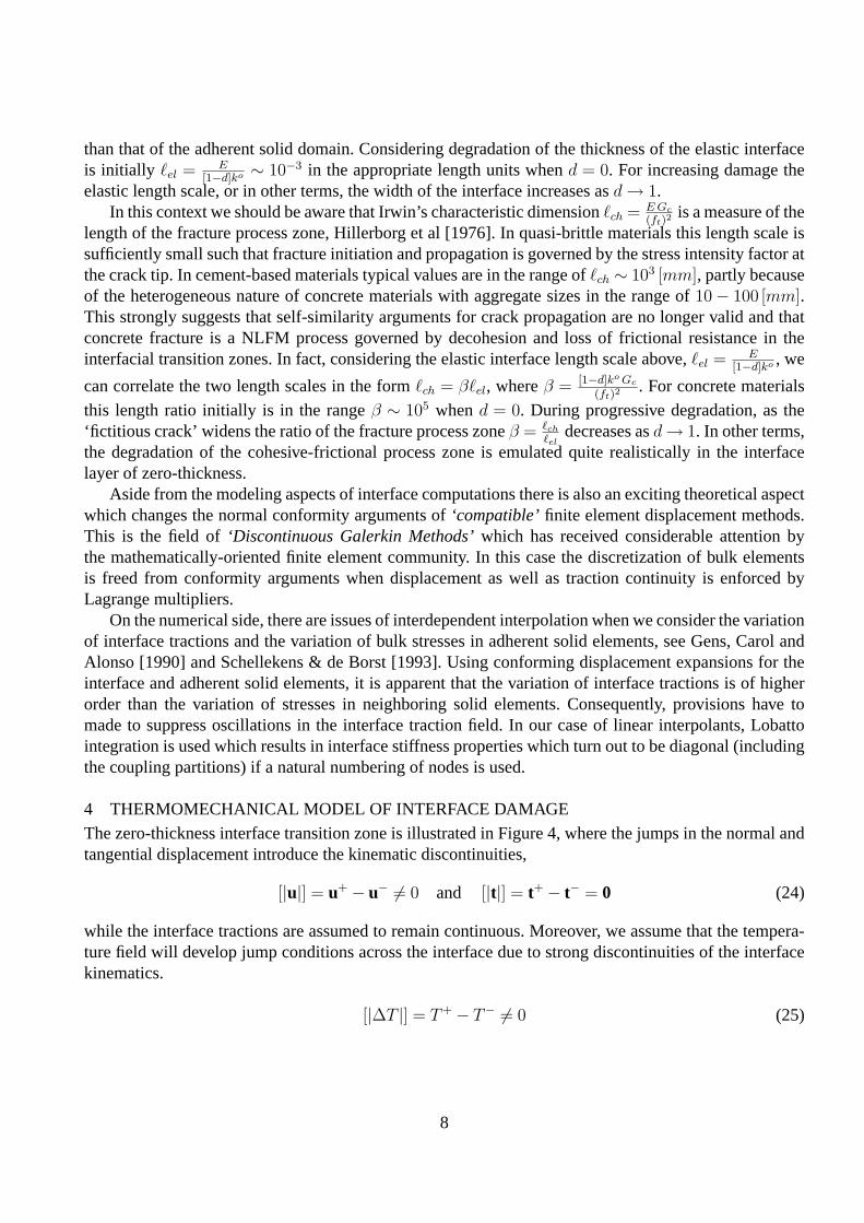
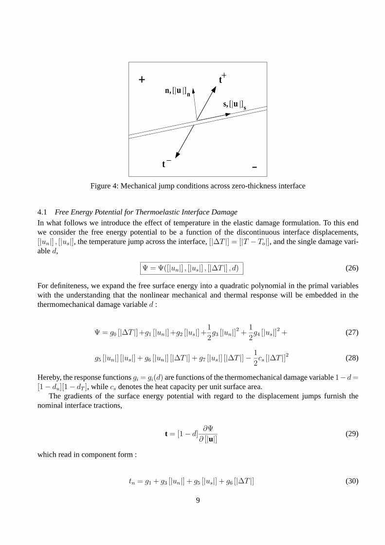
4 THERMOMECHANICAL MODEL OF INTERFACE DAMAGEThe zero-thickness interface transition zone is illustrated in Figure 4, where the jumps in the normal andtangential displacement introduce the kinematic discontinuities,
[|u|] = u+ − u− 6= 0 and [|t|] = t+ − t− = 0 (24)
while the interface tractions are assumed to remain continuous. Moreover, we assume that the tempera-ture field will develop jump conditions across the interface due to strong discontinuities of the interfacekinematics.
[|∆T |] = T+ − T− 6= 0 (25)
8
n,
s,n
s
t
t[|u |]
[|u |]
Figure 4: Mechanical jump conditions across zero-thickness interface
4.1 Free Energy Potential for Thermoelastic Interface Damage
In what follows we introduce the effect of temperature in the elastic damage formulation. To this endwe consider the free energy potential to be a function of the discontinuous interface displacements,[|un|] , [|us|], the temperature jump across the interface,[|∆T |] = [|T − To|], and the single damage vari-abled,
Ψ = Ψ([|un|] , [|us|] , [|∆T |] , d) (26)
For definiteness, we expand the free surface energy into a quadratic polynomial in the primal variableswith the understanding that the nonlinear mechanical and thermal response will be embedded in thethermomechanical damage variabled :
Ψ = g0 [|∆T |]+g1 [|un|]+g2 [|us|]+1
2g3 [|un|]2 +
1
2g4 [|us|]2 + (27)
g5 [|un|] [|us|] + g6 [|un|] [|∆T |] + g7 [|us|] [|∆T |]− 1
2cs [|∆T |]2 (28)
Hereby, the response functionsgi = gi(d) are functions of the thermomechanical damage variable1−d =[1− du][1− dT ], while cs denotes the heat capacity per unit surface area.
The gradients of the surface energy potential with regard to the displacement jumps furnish thenominal interface tractions,
t = [1− d]∂Ψ
∂ [|u|] (29)
which read in component form :
tn = g1 + g3 [|un|] + g5 [|us|] + g6 [|∆T |] (30)
9
ts = g2 + g4 [|us|] + g5 [|un|] + g7 [|∆T |] (31)
For the sake of argument we assume isotropic interface behavior, where the damage interface stiff-nessg3 = g4 = [1− d]ko, and where the initial thermal stress is the same in the normal and tangentialdirections,g6 = g7 =−[1−d]αo
sko. Thereby, we understand that the coefficient of thermal surface expan-
sion depends on the characteristic length,αos = α`el, because of the definition of the interface stiffness
ko. This assures consistent units similarly to the heat capacity per unit surface mass which is subject tothermomechanical damage,cs = [1− d]c. Further, we omit initial interface tractions,g1 = g2 = 0, andwe delete anisotropic coupling of the normal and tangential components in the interface jump conditionsassumingg5 = 0. In this case, the normal and tangential interface traction expressions reduce to,
tn = [1− d]ko [|un,el|] where [|un,el|] = [|un|]− αos [|∆T |] (32)
ts = [1− d]ko{[|us,el|] where [|us,el|] = [|us|]− αos [|∆T |] (33)
In matrix form, the tractions are a linear map of the interface displacement and temperature jumps,
[tnts
]= [1− d]
[k0 00 k0
][[|un|]− α0
s [|∆T |][|us|]− α0
s [|∆T |]]
(34)
which highlights the isotropic features of the thermoelastic damage model.The thermodynamic conjugate forces follow the interaction relation between normal and tangential
components developed in Equation 15. In this case the thermodynamic forceYeq is equivalent to thefracture energy release rate for mode I fracture,
Yeq = −∂Ψ
∂d=
1
2ko{[|un,el|]2 + b [|us,el|]2} where b =
GIc
GIIc
(35)
4.2 Clausius-Duhem Inequality
Recalling the local form of the second law of continuum thermodynamics and writing the Clausius-Duhem inequality in terms of the Helmholtz free energy we find,
σ : ε− ρΨ− ρsθ− q·∇xθθ
≥ 0 (36)
wheres denotes the local entropy andθ the absolute temperature. A sufficient condition of the inequalitymay be expressed in terms of the modified dissipation inequality,
Dmod = σ : ε− ρΨ− ρsθ ≥ 0 (37)
when the contribution of the conduction inequality is strictly negative using the Fourier law,q·∇xθθ
< 0.
Forming the total differential of the free energy,Ψ, and invoking the Coleman relations for the surfacetractions, Equations 32, 33, a sufficient condition for mechanical dissipation may be developed in thereduced form in analogy to Equation 16,
Dmech = Yeqd ≥ 0 (38)
10
Thereby, elastic interface damage is a function of the interface displacement jump,du = 1− k(u)ko , and
thermal damage is a function of the mean value of the temperature jump across the interface,dT =1− αs(∆Tavg)
αos
. The combined damage factor is the product of thermal and mechanical damage,
[1− d] = [1− du][1− dT ] such that d = du[1− dT ] + dT [1− du] (39)
The two-way coupling of mechanical and thermal degradation becomes more apparent if we considerthe entropy,
s = − ∂Ψ
∂ [|∆T |] = −go + [1− d]αosk
o [|un,el|] + [1− d]αosk
o [|us,el|] + cs[1− d] [|∆T |] (40)
This raises the issue of positive entropy production which is satisfied only whend ≤ 1 and [|un,el|] >
0, [|us,el|] > 0 and[∣∣∣∆T
∣∣∣]
> 0, and when damage decreases for positive values of displacement and
temperature jumps,−d > 0.
4.3 Rate Form of Interface Tractions
The tangential damage relations are obtained from differentiating the traction expressions in Equation34,
tn = [1− d]ko [|un,el|]− d teffn,el where teff
n,el = ko{[|un,el|] (41)
ts = [1− d]ko [|us,el|]− d teffs,el where teff
s,el = ko{[|us,el|] (42)
For persistent thermoelastic damage, the consistency conditions furnish the evolution law for the rateof mechanical damage in analogy to Equation 18,
d =1
Hd
Yeq =1
Hd
{teffn,el〈[|un,el|]〉+ b teff
s,el [|us,el|]} (43)
Consequently, the rate of normal and tangential interface tractions is driven by the rate of interfacedisplacement and temperature jumps, such that
t = ktanted [|u|]−βtan
ted
[∣∣∣∆T∣∣∣]
(44)
The tangential interface stiffness for elastic degradation expands into,
ktanted = [1− d]ko
[1 00 1
]− 1
Hd
[teffn,eltn,el
eff b[teffn,elt
effs,el ]
b[teffs,el t
effn,el] b2[teff
s,el teffs,el ]
](45)
and the thermal interface tractions associated with the temperature rate read :
βtanted = −[1− d]αo
sko
[1 00 1
]+
αos
Hd
[teffn,eltn,el
eff b[teffn,elt
effs,el ]
b[teffs,el t
effn,el] b2[teff
s,el teffs,el ]
](46)
11
n
s
n
n
q
q
Figure 5: Thermal jump condition across zero-thickness interface
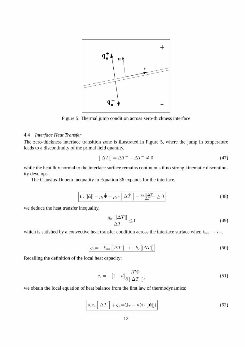
4.4 Interface Heat Transfer
The zero-thickness interface transition zone is illustrated in Figure 5, where the jump in temperatureleads to a discontinuity of the primal field quantity,
[|∆T |] = ∆T+ −∆T− 6= 0 (47)
while the heat flux normal to the interface surface remains continuous if no strong kinematic discontinu-ity develops.
The Clausius-Duhem inequality in Equation 36 expands for the interface,
t : [|u|]− ρsΨ− ρss[∣∣∣∆T
∣∣∣]− qn·[|∆T |]
∆T≥ 0 (48)
we deduce the heat transfer inequality,
qn· [|∆T |]∆T
≤ 0 (49)
which is satisfied by a convective heat transfer condition across the interface surface whenknn → hc,
qn= −knn [|∆T |]→−hc [|∆T |] (50)
Recalling the definition of the local heat capacity:
cs = −[1− d]∂2Ψ
∂ [|∆T |])2(51)
we obtain the local equation of heat balance from the first law of thermodynamics:
ρscs
[∣∣∣∆T∣∣∣]+ qn=QT − κ(t · [|u|]) (52)
12
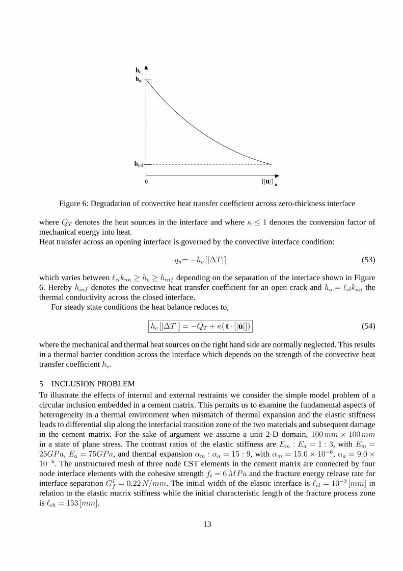
[|u |]
hc
ho
hinf
0 n
Figure 6: Degradation of convective heat transfer coefficient across zero-thickness interface
whereQT denotes the heat sources in the interface and whereκ ≤ 1 denotes the conversion factor ofmechanical energy into heat.Heat transfer across an opening interface is governed by the convective interface condition:
qn= −hc [|∆T |] (53)
which varies betweenelknn ≥ hc ≥ hinf depending on the separation of the interface shown in Figure6. Herebyhinf denotes the convective heat transfer coefficient for an open crack andho = `elknn thethermal conductivity across the closed interface.
For steady state conditions the heat balance reduces to,
hc [|∆T |] = −QT + κ( t · [|u|]) (54)
where the mechanical and thermal heat sources on the right hand side are normally neglected. This resultsin a thermal barrier condition across the interface which depends on the strength of the convective heattransfer coefficienthc.
5 INCLUSION PROBLEMTo illustrate the effects of internal and external restraints we consider the simple model problem of acircular inclusion embedded in a cement matrix. This permits us to examine the fundamental aspects ofheterogeneity in a thermal environment when mismatch of thermal expansion and the elastic stiffnessleads to differential slip along the interfacial transition zone of the two materials and subsequent damagein the cement matrix. For the sake of argument we assume a unit 2-D domain,100mm × 100mmin a state of plane stress. The contrast ratios of the elastic stiffness areEm : Ea = 1 : 3, with Em =25GPa, Ea = 75GPa, and thermal expansionαm : αa = 15 : 9, with αm = 15.0× 10⁻⁶, αa = 9.0×10⁻⁶. The unstructured mesh of three node CST elements in the cement matrix are connected by fournode interface elements with the cohesive strengthft = 6MPa and the fracture energy release rate forinterface separationGI
f = 0.22N/mm. The initial width of the elastic interface isel = 10−3 [mm] inrelation to the elastic matrix stiffness while the initial characteristic length of the fracture process zoneis `ch = 153 [mm].
13
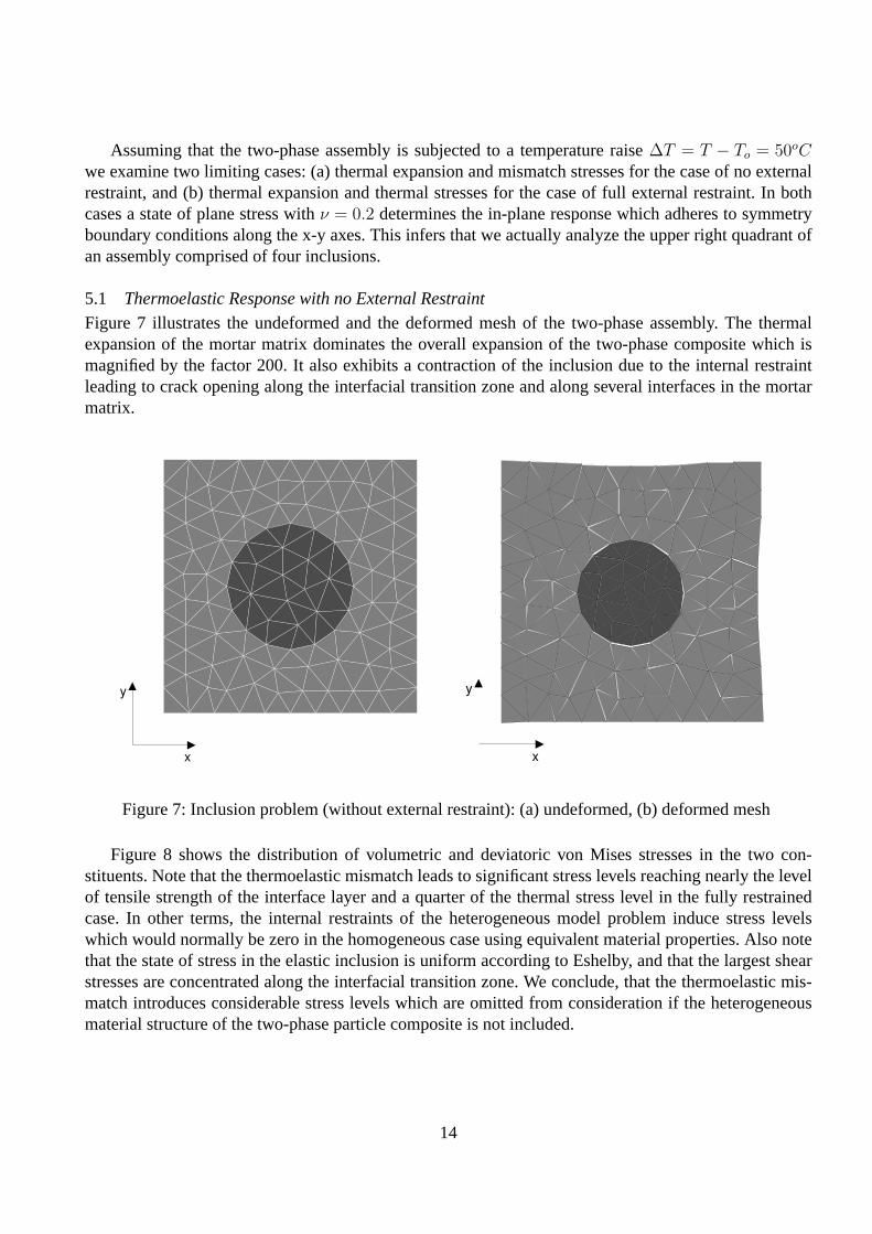
Assuming that the two-phase assembly is subjected to a temperature raise∆T = T − To = 50oCwe examine two limiting cases: (a) thermal expansion and mismatch stresses for the case of no externalrestraint, and (b) thermal expansion and thermal stresses for the case of full external restraint. In bothcases a state of plane stress withν = 0.2 determines the in-plane response which adheres to symmetryboundary conditions along the x-y axes. This infers that we actually analyze the upper right quadrant ofan assembly comprised of four inclusions.
5.1 Thermoelastic Response with no External Restraint
Figure 7 illustrates the undeformed and the deformed mesh of the two-phase assembly. The thermalexpansion of the mortar matrix dominates the overall expansion of the two-phase composite which ismagnified by the factor 200. It also exhibits a contraction of the inclusion due to the internal restraintleading to crack opening along the interfacial transition zone and along several interfaces in the mortarmatrix.
x
y
x
y
Figure 7: Inclusion problem (without external restraint): (a) undeformed, (b) deformed mesh
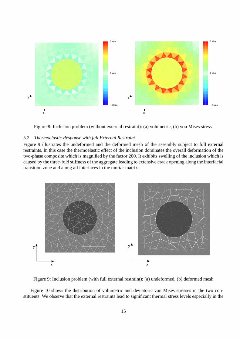
Figure 8 shows the distribution of volumetric and deviatoric von Mises stresses in the two con-stituents. Note that the thermoelastic mismatch leads to significant stress levels reaching nearly the levelof tensile strength of the interface layer and a quarter of the thermal stress level in the fully restrainedcase. In other terms, the internal restraints of the heterogeneous model problem induce stress levelswhich would normally be zero in the homogeneous case using equivalent material properties. Also notethat the state of stress in the elastic inclusion is uniform according to Eshelby, and that the largest shearstresses are concentrated along the interfacial transition zone. We conclude, that the thermoelastic mis-match introduces considerable stress levels which are omitted from consideration if the heterogeneousmaterial structure of the two-phase particle composite is not included.
14
x
y
6 Mpa
-6 Mpa
0 Mpa
x
y
7 Mpa
-7 Mpa
0 Mpa
Figure 8: Inclusion problem (without external restraint): (a) volumetric, (b) von Mises stress
5.2 Thermoelastic Response with full External Restraint
Figure 9 illustrates the undeformed and the deformed mesh of the assembly subject to full externalrestraints. In this case the thermoelastic effect of the inclusion dominates the overall deformation of thetwo-phase composite which is magnified by the factor 200. It exhibits swelling of the inclusion which iscaused by the three-fold stiffness of the aggregate leading to extensive crack opening along the interfacialtransition zone and along all interfaces in the mortar matrix.
x
y
x
y
Figure 9: Inclusion problem (with full external restraint): (a) undeformed, (b) deformed mesh
Figure 10 shows the distribution of volumetric and deviatoric von Mises stresses in the two con-stituents. We observe that the external restraints lead to significant thermal stress levels especially in the
15
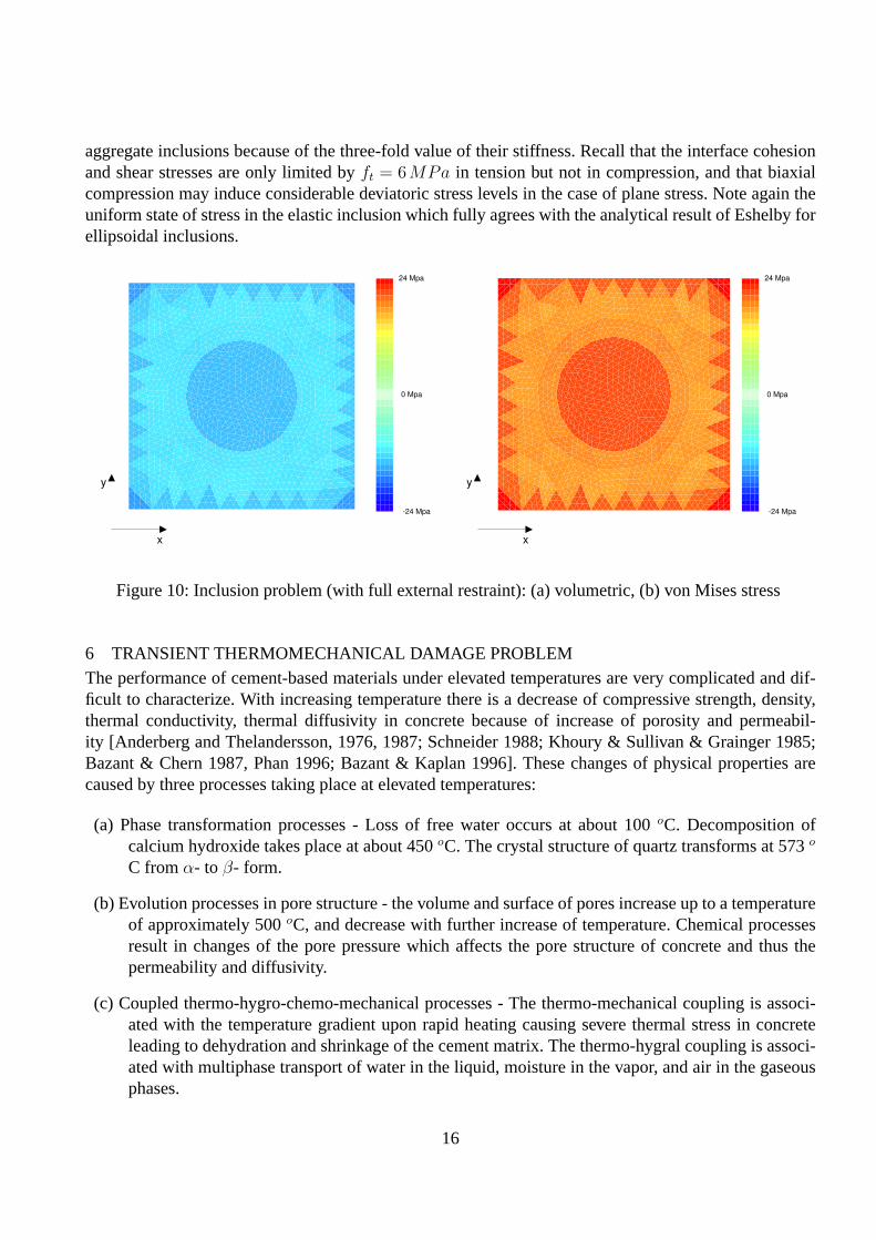
aggregate inclusions because of the three-fold value of their stiffness. Recall that the interface cohesionand shear stresses are only limited byft = 6MPa in tension but not in compression, and that biaxialcompression may induce considerable deviatoric stress levels in the case of plane stress. Note again theuniform state of stress in the elastic inclusion which fully agrees with the analytical result of Eshelby forellipsoidal inclusions.
x
y
24 Mpa
-24 Mpa
0 Mpa
x
y
24 Mpa
-24 Mpa
0 Mpa
Figure 10: Inclusion problem (with full external restraint): (a) volumetric, (b) von Mises stress
6 TRANSIENT THERMOMECHANICAL DAMAGE PROBLEMThe performance of cement-based materials under elevated temperatures are very complicated and dif-ficult to characterize. With increasing temperature there is a decrease of compressive strength, density,thermal conductivity, thermal diffusivity in concrete because of increase of porosity and permeabil-ity [Anderberg and Thelandersson, 1976, 1987; Schneider 1988; Khoury & Sullivan & Grainger 1985;Bazant & Chern 1987, Phan 1996; Bazant & Kaplan 1996]. These changes of physical properties arecaused by three processes taking place at elevated temperatures:
(a) Phase transformation processes - Loss of free water occurs at about 100oC. Decomposition ofcalcium hydroxide takes place at about 450oC. The crystal structure of quartz transforms at 573o
C fromα- to β- form.
(b) Evolution processes in pore structure - the volume and surface of pores increase up to a temperatureof approximately 500oC, and decrease with further increase of temperature. Chemical processesresult in changes of the pore pressure which affects the pore structure of concrete and thus thepermeability and diffusivity.
(c) Coupled thermo-hygro-chemo-mechanical processes - The thermo-mechanical coupling is associ-ated with the temperature gradient upon rapid heating causing severe thermal stress in concreteleading to dehydration and shrinkage of the cement matrix. The thermo-hygral coupling is associ-ated with multiphase transport of water in the liquid, moisture in the vapor, and air in the gaseousphases.
16
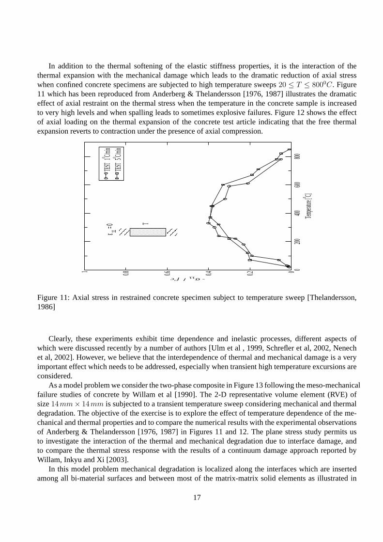
In addition to the thermal softening of the elastic stiffness properties, it is the interaction of thethermal expansion with the mechanical damage which leads to the dramatic reduction of axial stresswhen confined concrete specimens are subjected to high temperature sweeps20 ≤ T ≤ 8000C. Figure11 which has been reproduced from Anderberg & Thelandersson [1976, 1987] illustrates the dramaticeffect of axial restraint on the thermal stress when the temperature in the concrete sample is increasedto very high levels and when spalling leads to sometimes explosive failures. Figure 12 shows the effectof axial loading on the thermal expansion of the concrete test article indicating that the free thermalexpansion reverts to contraction under the presence of axial compression.
0200
400600
800Tem
perature
[o C]
00.20.40.60.81
- σ11 / f’c
TEST
1o C/min
TEST
5o C/min
T
ε 11 = 0
Figure 11: Axial stress in restrained concrete specimen subject to temperature sweep [Thelandersson,1986]
Clearly, these experiments exhibit time dependence and inelastic processes, different aspects ofwhich were discussed recently by a number of authors [Ulm et al , 1999, Schrefler et al, 2002, Nenechet al, 2002]. However, we believe that the interdependence of thermal and mechanical damage is a veryimportant effect which needs to be addressed, especially when transient high temperature excursions areconsidered.
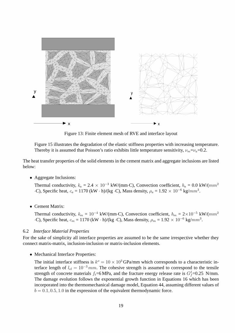
As a model problem we consider the two-phase composite in Figure 13 following the meso-mechanicalfailure studies of concrete by Willam et al [1990]. The 2-D representative volume element (RVE) ofsize14mm× 14mm is subjected to a transient temperature sweep considering mechanical and thermaldegradation. The objective of the exercise is to explore the effect of temperature dependence of the me-chanical and thermal properties and to compare the numerical results with the experimental observationsof Anderberg & Thelandersson [1976, 1987] in Figures 11 and 12. The plane stress study permits usto investigate the interaction of the thermal and mechanical degradation due to interface damage, andto compare the thermal stress response with the results of a continuum damage approach reported byWillam, Inkyu and Xi [2003].
In this model problem mechanical degradation is localized along the interfaces which are insertedamong all bi-material surfaces and between most of the matrix-matrix solid elements as illustrated in
17

0200
400600
800Tem
perature
[o C]
-10-5051015
STRAIN %
σ a = 0
σ a = - 0.
225f’c
σ a = - 0.
450f’c
σ a = - 0.6
75f’c
T σ a
Figure 12: Axial strain in concrete specimen subject to temperature sweep at different confinement levelsσa [Thelandersson, 1986]
the right inset of Figure 13. The interface properties are the same irrespective whether they representbi-material adhesion or mono-material cohesion. The solid elements consider temperature effects on theelastic properties and the coefficient of thermal expansion differently for aggregate inclusions and thecement matrix.
The thermal stress analysis is carried out with the explicit time marching strategy outlined in theAppendix. This staggered format decouples the heat transfer analysis from the mechanical degradationanalysis. Thereby, the Gough-Joule effect of mechanical cooling is neglected in the heat balance equa-tion, however the crack opening of the interfaces is considered in the form of the convection coefficientwhich controls heat transfer across the interface as detailed previuosly.
6.1 Solid Material Properties
The thermoelastic properties of the solid elements in the cement matrix and aggregate inclusions arelisted below:
• Coefficient of Thermal Expansion:
Cement Matrix :α0m=15.5× 10⁻⁶ /C, and αm= 0.00555557α0
m(200-T)Aggregate Inclusions :α0
a=9.0× 10⁻⁶ /C and αa=αa(e0.05T/100-0.01)Figure 13 illustrates the effect increasing expansion with increasing temperature for the aggregate.The thermal expansion of the cement matrix was modified to include the effect of drying shrinkage.This results in an overall decrease of the coefficient of expansion with increasing temperature asindicated in Figure 14.
• Temperature Dependence of Elastic Modulus:
E=E0(0.03921+e−0.002T ) with Em=25 GPa,Ea=75 GPa.
18
x
y
x
y
Figure 13: Finite element mesh of RVE and interface layout
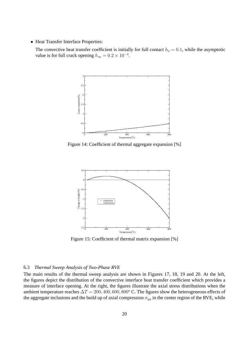
Figure 15 illustrates the degradation of the elastic stiffness properties with increasing temperature.Thereby it is assumed that Poisson’s ratio exhibits little temperature sensitivity,νm=νa=0.2.
The heat transfer properties of the solid elements in the cement matrix and aggregate inclusions are listedbelow:
• Aggregate Inclusions:
Thermal conductivity,ka = 2.4× 10⁻³ kW/(mm·C), Convection coefficient,ha = 0.0 kW/(mm2
·C), Specific heat,ca = 1170 (kW· h)/(kg ·C), Mass density,ρa = 1.92× 10⁻⁶ kg/mm3.
• Cement Matrix:
Thermal conductivity,km = 10−4 kW/(mm·C), Convection coefficient,hm = 2×10⁻⁵ kW/(mm2
·C), Specific heat,cm = 1170 (kW· h)/(kg ·C), Mass density,ρm = 1.92× 10⁻⁶ kg/mm3.
6.2 Interface Material Properties
For the sake of simplicity all interface properties are assumed to be the same irrespective whether theyconnect matrix-matrix, inclusion-inclusion or matrix-inclusion elements.
• Mechanical Interface Properties:
The initial interface stiffness isko = 10× 103 GPa/mm which corresponds to a characteristic in-terface length oflel = 10−3 mm. The cohesive strength is assumed to correspond to the tensilestrength of concrete materialsft=6 MPa, and the fracture energy release rate isGI
f=0.25 N/mm.The damage evolution follows the exponential growth function in Equations 16 which has beenincorporated into the thermomechanical damage model, Equation 44, assuming different values ofb = 0.1,0.5,1.0 in the expression of the equivalent thermodynamic force.
19
• Heat Transfer Interface Properties:
The convective heat transfer coefficient is initially for full contactho = 0.1, while the asymptoticvalue is for full crack openingh∞ = 0.2× 10⁻⁴.
0 200 400 600 800Temperature(
oC)
0
0.5
1
1.5
2
2.5
3L
inea
r ex
pans
ion(
%)
Figure 14: Coefficient of thermal aggregate expansion [%]
0 200 400 600 800Temperature(
oC)
-2.5
-2
-1.5
-1
-0.5
0
0.5
Cha
nge
in le
ngth
(%
)
+ expansion - contraction
Figure 15: Coefficient of thermal matrix expansion [%]
6.3 Thermal Sweep Analysis of Two-Phase RVE
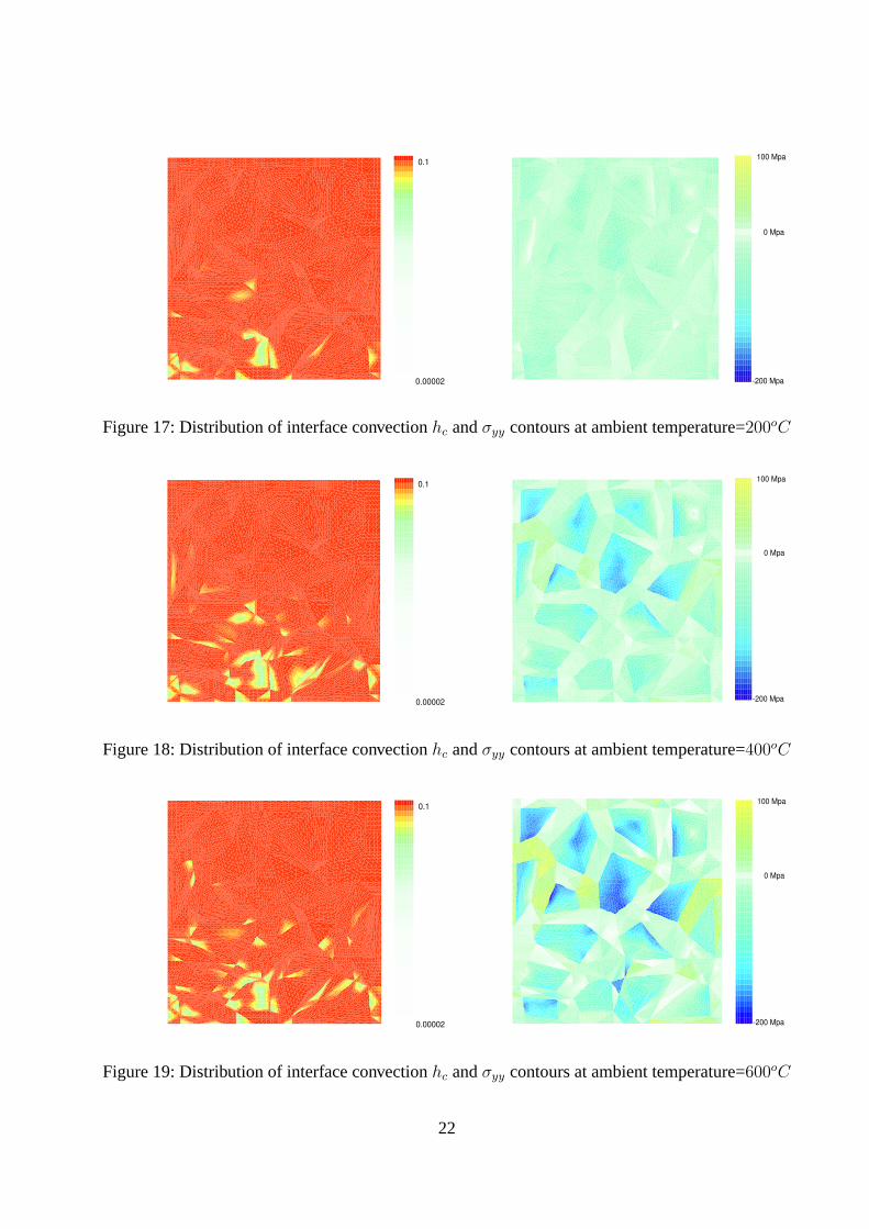
The main results of the thermal sweep analysis are shown in Figures 17, 18, 19 and 20. At the left,the figures depict the distribution of the convective interface heat transfer coefficient which provides ameasure of interface opening. At the right, the figures illustrate the axial stress distributions when theambient temperature reaches∆T = 200,400,600,800o C. The figures show the heterogeneous effects ofthe aggregate inclusions and the build up of axial compressionσyy in the center region of the RVE, while
20
0 200 400 600Temperature(
oC)
0
20
40
60
80
100
Mod
ulus
of
elas
ticity
, E
% o
f in
itial
Eo
E=E(θ)
Figure 16: Reduction of elastic modulus with rising temperature,E = E(T )
the cement matrix near the midheight of the outside surfaces exhibits tension indicating the tendency ofcracking and spalling.
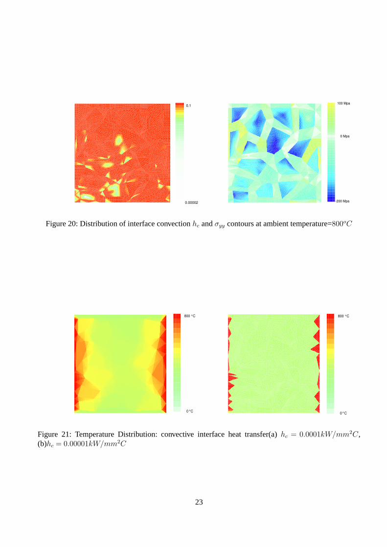
Figure 21 shows the influence of the convective heat transfer coefficient on the temperature distri-bution in the RVE resulting in a high concentration of temperature gradients along the outside surfacessimilar to a thermal barrier for low values ofhc.
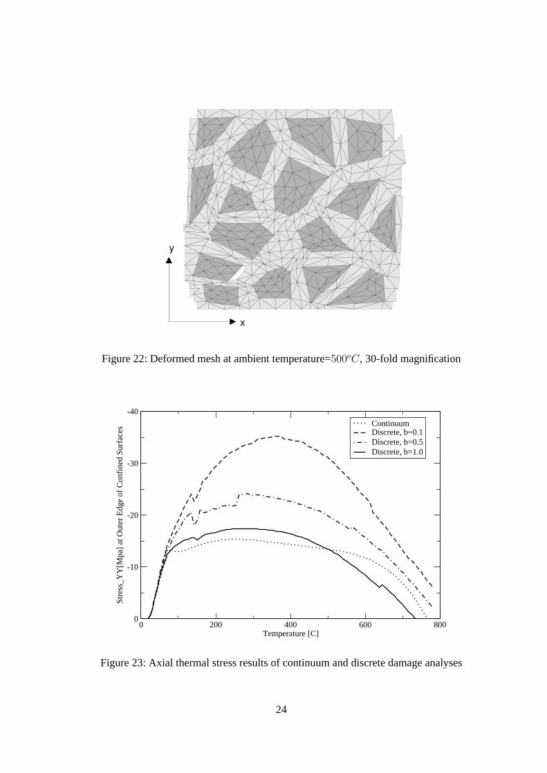
The deformed mesh in Figure 22 illustrates the diagonal shear failure mode and the lateral expansionof the deformed mesh (30-fold magnification), when the ambient temperature reaches∆T = 500o. Theprevalent degradation of mechanical cohesion introduces slip and crack opening primarily at the bi-material interfaces forming a diagonal failure mechanism across the two-phase composite (the resultsare shown for the friction ratiob = 1.0 with equal normal to tangential energy interaction).
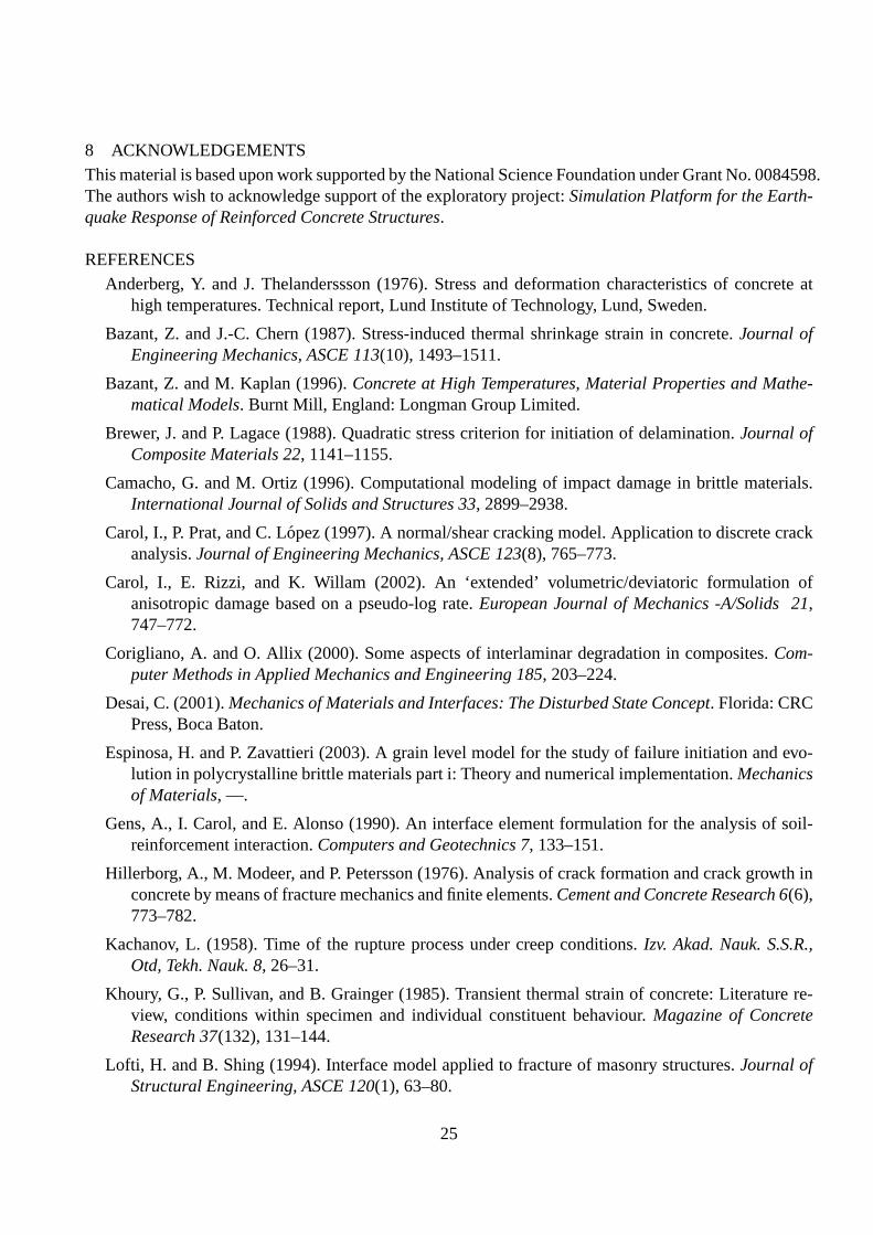
The interface damage leads to an overall release of the axial thermal stress depicted in Figure 23. Thisfigure illustrates the axial thermal stressσyy near the top left corner of the restrained RVE specimen. Itcompares the predictions of different normal to tangential degradation ratiosb = 0.1,0.5,1.0 with theresults of a volumetric-deviatoric damage model without interfaces, see Willam, Rhee and Xi [2003].Increasing values of the fracture energy ratiob activate tangential damage and reduce the thermal stresseffects which reach a maximum value when the ambient temperature approaches∆T = 300o. The trendsof interface damage are similar to those of the continuous damage model considering volumetric anddeviatoric degradation due to thermal and mechanical damage. They reproduce rather well the overallreduction of axial load resistance with increasing temperature and the reversal of axial thermal stressshown in the experiment, see Figure 11.
7 CONCLUSIONSThe paper addressed model issues of zero-thickness cohesive-frictional interfaces which are subjected tothermal and mechanical damage. The damage model, which incorporates degradation in the normal andtangential components, captures degradation effects in heterogeneous media. The two model problemsindicate significant stress levels in heterogeneous composites due to thermal mismatch and the prevalentreduction of thermal stress under high temperature sweeps down to nearly zero resistance atT = 800o.The combination of both thermal and mechanical degradation mechanisms is the principal feature whichdrives the reduction process of axial thermal stress.
21
0.1
0.00002 -200 Mpa
100 Mpa
0 Mpa
Figure 17: Distribution of interface convectionhc andσyy contours at ambient temperature=200oC
0.1
0.00002 -200 Mpa
100 Mpa
0 Mpa
Figure 18: Distribution of interface convectionhc andσyy contours at ambient temperature=400oC
0.1
0.00002 -200 Mpa
100 Mpa
0 Mpa
Figure 19: Distribution of interface convectionhc andσyy contours at ambient temperature=600oC
22
0.1
0.00002 -200 Mpa
100 Mpa
0 Mpa
Figure 20: Distribution of interface convectionhc andσyy contours at ambient temperature=800oC
800 o C
0 o C
800 o C
0 o C
Figure 21: Temperature Distribution: convective interface heat transfer(a)hc = 0.0001kW/mm2C,(b)hc = 0.00001kW/mm2C
23
x
y
Figure 22: Deformed mesh at ambient temperature=500oC, 30-fold magnification
0 200 400 600 800Temperature [C]
-40
-30
-20
-10
0
Stre
ss_Y
Y[M
pa]
at O
uter
Edg
e of
Con
fine
d Su
rfac
es
ContinuumDiscrete, b=0.1Discrete, b=0.5Discrete, b=1.0
Figure 23: Axial thermal stress results of continuum and discrete damage analyses
24
8 ACKNOWLEDGEMENTSThis material is based upon work supported by the National Science Foundation under Grant No. 0084598.The authors wish to acknowledge support of the exploratory project:Simulation Platform for the Earth-quake Response of Reinforced Concrete Structures.
REFERENCESAnderberg, Y. and J. Thelanderssson (1976). Stress and deformation characteristics of concrete at
high temperatures. Technical report, Lund Institute of Technology, Lund, Sweden.
Bazant, Z. and J.-C. Chern (1987). Stress-induced thermal shrinkage strain in concrete.Journal ofEngineering Mechanics, ASCE 113(10), 1493–1511.
Bazant, Z. and M. Kaplan (1996).Concrete at High Temperatures, Material Properties and Mathe-matical Models. Burnt Mill, England: Longman Group Limited.
Brewer, J. and P. Lagace (1988). Quadratic stress criterion for initiation of delamination.Journal ofComposite Materials 22, 1141–1155.
Camacho, G. and M. Ortiz (1996). Computational modeling of impact damage in brittle materials.International Journal of Solids and Structures 33, 2899–2938.
Carol, I., P. Prat, and C. Lopez (1997). A normal/shear cracking model. Application to discrete crackanalysis.Journal of Engineering Mechanics, ASCE 123(8), 765–773.
Carol, I., E. Rizzi, and K. Willam (2002). An ‘extended’ volumetric/deviatoric formulation ofanisotropic damage based on a pseudo-log rate.European Journal of Mechanics -A/Solids 21,747–772.
Corigliano, A. and O. Allix (2000). Some aspects of interlaminar degradation in composites.Com-puter Methods in Applied Mechanics and Engineering 185, 203–224.
Desai, C. (2001).Mechanics of Materials and Interfaces: The Disturbed State Concept. Florida: CRCPress, Boca Baton.
Espinosa, H. and P. Zavattieri (2003). A grain level model for the study of failure initiation and evo-lution in polycrystalline brittle materials part i: Theory and numerical implementation.Mechanicsof Materials, —.
Gens, A., I. Carol, and E. Alonso (1990). An interface element formulation for the analysis of soil-reinforcement interaction.Computers and Geotechnics 7, 133–151.
Hillerborg, A., M. Modeer, and P. Petersson (1976). Analysis of crack formation and crack growth inconcrete by means of fracture mechanics and finite elements.Cement and Concrete Research 6(6),773–782.
Kachanov, L. (1958). Time of the rupture process under creep conditions.Izv. Akad. Nauk. S.S.R.,Otd, Tekh. Nauk. 8, 26–31.
Khoury, G., P. Sullivan, and B. Grainger (1985). Transient thermal strain of concrete: Literature re-view, conditions within specimen and individual constituent behaviour.Magazine of ConcreteResearch 37(132), 131–144.
Lofti, H. and B. Shing (1994). Interface model applied to fracture of masonry structures.Journal ofStructural Engineering, ASCE 120(1), 63–80.
25
Nenech, W., F. Meftah, and J. Reynouard (2002). An elasto-plastic damage model for plain concretesubjected to high temperatures.Engineering Structures 24, 597–611.
Oliver, X., A. Huespe, M. Pulido, and E. Chaves (2001). From continuum mechanics to fracturemechanics: the strong discontinuity approach.Engineering Fracture Mechanics 69, 113–136.
Phan, L. (1996). Fire performance of high strength concrete: A report of the state-of-the-art. Technicalreport, Building and Fire Research Laboratory, National Institute of Standards and Technology,Maryland.
Rots, J. and J. Schellekens (1990).Interface elements in concrete mechanics. Swansea, UK:Computer-aided Analysis and Design of Concrete Structures, N. Bicanic and H. Mang editors,Pineridge Press, pp.909–918.
Schellekens, J. and R. de Borst (1993). On the numerical integration of interface elements.Interna-tional Journal for Numerical Methods in Engineering 36(7), 43–66.
Schneider, U. (1988). Concrete at high temperature - a general review.Fire Safety Journal 13(1),55–68.
Schrefler, B., G. Khoury, D. Gawin, and C. Majorana (2002). Thermo-hydro-mechanical modellingof high performance concrete at high temperatures.Engineering Computations 19(7), 787–819.
Simo, J., J. Oliver, and F. Armero (1993). An analysis of strong discontinuities induced by strain-softening in rate-independent inelastic solids.Computational Mechanics 12, 277–296.
Stankowski, T., K. Runesson, and S. Sture (1993). Fracture and slip of interfaces in cementitiouscomposites.Journal of Engineering Mechanics, ASCE 119(2), 292–306.
Thelandersson, S. (1987). Modeling of combined thermal and mechanical action in concrete.Journalof Engineering Mechanics, ASCE 113(6), 893–906.
Tijssens, M. (2000).On the Cohesive Surface Methodology for Fracture of Brittle HeterogeneousSolids. Maastricht, The Netherlands: Ph.D. Dissertation TU-Delft, Shaker Publ. B.V.
Ulm, F.-J., P. Acker, and M. Levy (1999). The“chunnel” fire ii: analysis of concrete damage.Journalof Engineering Mechanics, ASCE 125(3), 283–289.
Ulm, F.-J., O. Coussy, and Z. Bazant (1999). The“chunnel” fire i: chemoplastic softening of rapidlyheated concrete.Journal of Engineering Mechanics, ASCE 125(3), 272–282.
Willam, K., I. Rhee, and Y. Xi (2003). Thermal degradation in heterogeneous concrete materials.Journal of Engineering Materials, ASCE 129, –.
Willam, K., T. Stankowski, K. Runesson, and S. Sture (1990).Simulation Issues of Distributed andLocalized Failure Computations, Proceedings on Cracking and Damage-Strain Localization andSize Effects. London and New York: Mazars, J. and Bazant, Z. Eds., Elsevier Applied Sciences.
Xu, X.-P. and A. Needleman (1994). Numerical simulations of fast crack growth in brittle solids.J.Mech. Phys. Solids 42(9), 1397–1434.
26
Related Documents