ORIGINAL ARTICLE Interdisciplinary studies on the technical and economic feasibility of deep underground coal gasification with CO 2 storage in bulgaria Yong Sheng & Aleksey Benderev & Donka Bukolska & Kenneth Imo-Imo Eshiet & Carlos Dinis da Gama & Torsten Gorka & Michael Green & Nikolay Hristov & Ismini Katsimpardi & Thomas Kempka & Jordan Kortenski & Nikolaos Koukouzas & Natalie Nakaten & Vasilis Sarhosis & Ralph Schlueter & Vidal Navarro Torres & Ana Carina Veríssimo & Velemir Vesselinov & Dongmin Yang Received: 14 June 2013 /Accepted: 11 June 2014 # Springer Science+Business Media Dordrecht 2014 Abstract This paper presents the outcome of a feasibility study on underground coal gasifi- cation (UCG) combined with direct carbon dioxide (CO 2 ) capture and storage (CCS) at a selected site in Bulgaria with deep coal seams (>1,200 m). A series of state-of-the-art geological, geo-mechanical, hydrogeological and computational models supported by exper- imental tests and techno-economical assessments have been developed for the evaluation of UCG-CCS schemes. Research efforts have been focused on the development of site selection Mitig Adapt Strateg Glob Change DOI 10.1007/s11027-014-9592-1 Y. Sheng (*) : K. I.<. Eshiet : V. Sarhosis : D. Yang School of Civil Engineering, University of Leeds, LS2 9JT Leeds, UK e-mail: [email protected] K. I.<. Eshiet e-mail: [email protected] V. Sarhosis e-mail: [email protected] D. Yang e-mail: [email protected] M. Green UCG Engineering Ltd, Meadow House, 17 Brighton Rd., KT6 5LR London, UK e-mail: [email protected] T. Kempka : N. Nakaten GFZ German Research Centre for Geosciences, Section 5.3 - Hydrogeology, Telegrafenberg, 14473 Potsdam, Germany T. Kempka e-mail: [email protected] N. Nakaten e-mail: [email protected]

Welcome message from author
This document is posted to help you gain knowledge. Please leave a comment to let me know what you think about it! Share it to your friends and learn new things together.
Transcript

ORIGINAL ARTICLE
Interdisciplinary studies on the technical and economicfeasibility of deep underground coal gasificationwith CO2 storage in bulgaria
Yong Sheng & Aleksey Benderev & Donka Bukolska &
Kenneth Imo-Imo Eshiet & Carlos Dinis da Gama &
Torsten Gorka & Michael Green & Nikolay Hristov &
Ismini Katsimpardi & Thomas Kempka & Jordan Kortenski &Nikolaos Koukouzas & Natalie Nakaten & Vasilis Sarhosis &Ralph Schlueter & Vidal Navarro Torres &Ana Carina Veríssimo & Velemir Vesselinov & Dongmin Yang
Received: 14 June 2013 /Accepted: 11 June 2014# Springer Science+Business Media Dordrecht 2014
Abstract This paper presents the outcome of a feasibility study on underground coal gasifi-cation (UCG) combined with direct carbon dioxide (CO2) capture and storage (CCS) at aselected site in Bulgaria with deep coal seams (>1,200 m). A series of state-of-the-artgeological, geo-mechanical, hydrogeological and computational models supported by exper-imental tests and techno-economical assessments have been developed for the evaluation ofUCG-CCS schemes. Research efforts have been focused on the development of site selection
Mitig Adapt Strateg Glob ChangeDOI 10.1007/s11027-014-9592-1
Y. Sheng (*) : K. I.<. Eshiet :V. Sarhosis : D. YangSchool of Civil Engineering, University of Leeds, LS2 9JT Leeds, UKe-mail: [email protected]
K. I.<. Eshiete-mail: [email protected]
V. Sarhosise-mail: [email protected]
D. Yange-mail: [email protected]
M. GreenUCG Engineering Ltd, Meadow House, 17 Brighton Rd., KT6 5LR London, UKe-mail: [email protected]
T. Kempka : N. NakatenGFZ German Research Centre for Geosciences, Section 5.3 - Hydrogeology, Telegrafenberg,14473 Potsdam, Germany
T. Kempkae-mail: [email protected]
N. Nakatene-mail: [email protected]

requirements for UCG-CCS, estimation of CO2 storage volumes, review of the practicalengineering requirements for developing a commercial UCG-CCS storage site, considerationof drilling and completion issues, and assessments of economic feasibility and environmentalimpacts of the scheme. In addition, the risks of subsidence and groundwater contaminationhave been assessed in order to pave the way for a full-scale trial and commercial applications.The current research confirms that cleaner and cheaper energy with reduced emissions can beachieved and the economics are competitive in the future European energy market. Howeverthe current research has established that rigorous design and monitor schemes are essential forproductivity and safety and the minimisation of the potential environmental impacts. Aplatform has been established serving to inform policy-makers and aiding strategies devisedto alleviate local and global impacts on climate change, while ensuring that energy resourcesare optimally harnessed.
Keywords UndergroundCoalGasification(UCG).CO2storage.Deepcoalseams.Energy.SiteSelection .Well engineering . Bulgaria
1 Introduction
UCG is an in-situ process of coal extraction and conversion which is conducted between twowells drilled into the seam, one for injecting gasifying agents (air, oxygen or steam) to thereaction zone, and the other to extract the produced gases via the production well. This processdevelops cavities and the roof will collapse, resulting in further growth of the cavity. Once thequality of product gas has declined in the reaction zone, new coal is exposed by moving theinjection point and the process continues until the length of the borehole is exhausted. The sizeof the cavity formed during UCG impacts directly on economic and environmental factors.
T. Gorka : R. SchlueterDMT GmbH and Co. KG, Am Technologiepark 1, 45307, Essen, Germany
T. Gorkae-mail: [email protected]
R. Schluetere-mail: [email protected]
D. Bukolska :N. Hristov : J. KortenskiOvergas Inc. AD, 5 Philip Kutev St., 1407, Sofia, Bulgaria
D. Bukolskae-mail: [email protected]
N. Hristove-mail: [email protected]
J. Kortenskie-mail: [email protected]
I. Katsimpardi :N. KoukouzasCentre for Research and Technology Hellas, Chemical Process and Energy Resources Institute (CERTHCPERI), Egialias 52, GR-15125, Marousi, Athens, Greece
I. Katsimpardie-mail: [email protected]
N. Koukouzase-mail: [email protected]
Mitig Adapt Strateg Glob Change

Reuse of the cavity and surrounding stressed areas of coal for the storage of carbon dioxide(CO2) is an ideal solution for reducing CO2 emissions. UCG is rapidly becoming a viablecommercial activity in Australia, South Africa and China, while many Eastern Europeancountries are intensively working for its commercialization (e.g. Poland and Hungary).
At the pilot scale UCG has been successfully implemented in countries such as formerSoviet Union, Australia and United States (U.S.). Although trial operations of UCG began inthe 1930’s (Zamzow 2010), the capture and sequestration of CO2 as an integral part of theoperation has only been considered in recent years. UCG-CCS entails injecting and storing theCO2 produced by stripping the synthetic product gas. CO2 is produced as a by-product of theshift reaction in which the carbon monoxide (CO) in the extracted synthetic gas is reacted withsteam to produce hydrogen and CO2 as a by-product. Aside from the benefit of injecting theseparated CO2 into adjacent coal seams, the UCG cavities, boreholes and created fracturescould provide an additional capacity for CO2 storage (Pei et al. 2010). Case studies of thepotential for UCG-CCS storage have been carried out in the Powder River basin of Wyoming,U.S. (Shafirovich and Varma 2009, Zamzow 2010) and the Williston basin, North Dakota,U.S. (Pei et al. 2010). In Europe, a consortium funded by the European Union (EU) has carriedout a pilot investigation of in-situ hydrogen production incorporating UCG-CO2 management(Rogut 2008, Zamzow 2010).
This project evaluates the potential of deep lying coal seams (>1,200 m) for the developmentof UCG and the subsequent sequestration of CO2 in the affected areas, i.e. the abandoned UCGcavity itself, the adjacent stressed coal or the overlying/underlying strata using the same boreholeinfrastructure with technical modification. The key objectives were to investigate the factors thatdetermine the technical suitability, environmental and economic feasibility of the scheme and todemonstrate that the deep lying coal fields of the target area have the potential for deep UCG andare suitable for both energy production and CO2 storage using the same drilling infrastructure. Iffavourable, a future field test of the scheme with industry will be recommended.
State-of-the-art geological, geo-mechanical, hydro-geological and coupled thermo-mechanical models were developed to better understand the UCG-CO2 storage processesand aid the determination of site selection requirements for evaluation of deep coal locationsin the specific site in Bulgaria and elsewhere. The practical engineering requirements fordeveloping the scheme and its environmental and economic benefits were also assessed.
The work covered the following: the development of a geological model for the selectedsite in Bulgaria; the development of geo-mechanical and cavity models for UCG-CCS; the
C. D. da Gama : V. N. Torres :A. C. VeríssimoInstituto Superior Técnico, Pavilhão de Minas, 3 piso Av. RoviscoPais 1, 1049-001 Lisbon, Portugal
C. D. da Gamae-mail: [email protected]
V. N. Torrese-mail: [email protected]
A. C. Veríssimoe-mail: [email protected]
A. Benderev : V. VesselinovGeological Institute, Bulgarian Academy of Sciences, Sofia, Bulgaria
A. Bendereve-mail: [email protected]
V. Vesselinove-mail: [email protected]
Mitig Adapt Strateg Glob Change

development of a hydro-geological model of the study area; engineering, drilling and com-pletion requirements for UCG and CO2 storage; environmental assessment of UCG-CO2
storage; economic assessment of UCG-CCS. The non-technical part of the study includedthe review of regulatory requirements and an assessment of the overall feasibility of theprocess; and a research management process that strategised and harnessed results from theindividual modules towards the overall aim of the research.
2 Technical assessment
2.1 Modelling the UCG process
2.1.1 Site investigation and construction of geological models
A complete survey of the existing geological information about the target area was undertaken.Digitising the data and re-processing well log correlation led to renewed insights into thespatial behaviour and geometric characteristics of the different formations, and laid the basisfor the further modelling and mapping of data for the subsequent geo-technical andhydrogeological modelling of the study.
Using specialised digitising software, all coal seams of the main formations were identifiedand basic structural and thickness maps and cross-sections were prepared. The coal propertiesof the different seams were studied (e.g. ash content (A), volatiles (Vs), sulphur (S) andmoisture content (W). Coal resources of the seams were calculated from seam thickness andactual surface area).
Structural and tectonic research was undertaken for the purpose of fault modelling – theexisting tectonic units were identified and studied, and the bedding angle of the faults wascalculated. Using up-to-date modelling software (Petrel software product), a 3D tectonic modelfor the deposit was developed by pillar gridding method (Fig. 1a), as well as a 3-D interpre-tative geological model (Fig. 1b). The latter included the creation of the key horizons of themodel (e.g. the top formation, erosion surface and top Mesozoic aquifer) followed by a 3-Dgrid editing and zone creation. An investigation of the cap rocks in the upper carboniferoussediments showed that the top formation (of all coal bearing formations) had no effect on theUCG process.
The developed 3-D interpretative tectonic and geological models for the study areaimproved the understanding of the geological structure of the deposit and the geo-mechanical,
a) b)
Fig. 1 a a 3D view of the fault structure, and b the geological model of the study area
Mitig Adapt Strateg Glob Change

hydro-geological and environmental data pertaining to it. The models were a crucial part of thework on assessing the feasibility of the UCG-CCS process for the deep lying coals of the studyarea and the modelling results were used for the development of the other state-of-the-artmodels and further assessment.
The study confirmed that the study area has a complicated tectonic structure. Major faults(Triassic age) have been identified around the target area, and while these can be avoided, littleis known about any minor faults that exist in the horsts between them. A 3D seismic surveyaround the target should resolve the structure to within 1–5 m, which is less than seamthickness and sufficient to confirm the site for a UCG test. Additional coal and rock samplingis also required in order to clarify the conditions of gasification and CO2 injection at the targetarea.
Taking into account the world experience, some generalised site selection criteria for UCGwere developed that were additionally assessed and applied to the case of the study area,(Tables 1, 2, 3 and 4). On the basis of a detailed lithological correlation, two sites were chosenthat best satisfied the UCG site selection criteria (selected also in a way that would not causesettlements on the surface). Tables 1, 2, 3 and 4 were formulated based on results fromgeological, geo-mechanical, hydro-geological, environmental, economic and drilling modelsdeveloped as part of this feasibility study. Some of these criteria are also supported by generalknowledge from previous and common practices.
The preliminary results identified the study sites which were bounded by faults and had thebest potential for UCG-CCS. The selected coal seams associated with them were between1,100 m and 1,500 m deep and contained a total of over 75 MT of UCG compliant coal. Inorder to minimise the influence of the UCG process on the overburden rocks and overlyingcoal seams, the coal seams were selected on the rule of thumb that the mimimum separationshould be ten times the lower seam thickness distance to the upper coal seam’ (Healy and Head1984). Cavities created by UCG activities are much smaller than in conventional mining andaccordingly the impact will always be less.
The coal seams were also chosen for the best quantitative and qualitative characteristicssuitable for UCG such as low moisture content, density (<2 g/cm3) low content of sulphur andlow coal porosity. The data concerning the sites and the coal seams had been incorporated fromadditional studies and calculations which are described below.
2.1.2 Modelling of the geomechanical and thermal effect of the UCG and CO2 storageprocesses
For the purpose of thermo-geomechanical investigation, the first coal seam to gasify is thethickest coal seam in the sequence, which is a seam approximately 10 m thick, located at adistance of 1,500 m below ground level (Overgas Inc. 2011). Finite element software package
Table 1 Coal seam bedding depth in the study area in terms of its suitability for UCG
Mitig Adapt Strateg Glob Change

ABAQUS was used for the thermo-geomechanical modelling. To represent the geologic faults,the surfaces of both sides of the fault were constrained by a Bcontact^ feature in ABAQUS, inwhich the coefficient of friction between the two surfaces of the fault was assumed constantand equal to 0.2. The ignition line and channel were placed at 2m above the bed of the coalseam studied (i.e. 1498 m below ground).
The material properties were calculated approximately by averaging the individual rockproperties with the corresponding thickness fraction of each geologic section. A detailedlibrary of mechanical and thermal properties of coal and rocks under the effect of heat wasestablished from literature references. Details of the ABAQUS modelling and the laboratorytests are given in (Yang et al. 2013). The temperature distributions after ignition, capturedevery 6 h during 1 day of the gasification process, are shown in Fig. 2. The thermal affectedarea increase for each time increment and, the temperature is found to be extremely high in thearea nearby the ignition centre due to constant heat flux applied at this point. From theliterature, (Couch 2009), coal would be pyrolized at a temperature around 400 °C, so tomaintain the heat transfer and model integrity elements with a temperature larger than 400 °Cheat transfer from the element was allowed. However, in order to realistically represent themechanical failure of coal after gasification, the elastic modulus of coal was graduallydecreased with temperature.
Figure 3 illustrates the temperature distribution for a period of 3 days after ignition,combining view cuts in the X-Y and Y-Z planes to create a 3D view. As expected, when the
Table 2 Coal seam thickness in terms of its suitability for UCG
Table 3 Thickness of the rocks and their filtration properties
Mitig Adapt Strateg Glob Change

ignition point is moved, the position with the highest temperature changes accordingly. Thehighest temperature as well as the overall thermal affected area is increased gradually. Thesurface subsidence after gasification is shown in Fig. 4. Since a geologic fault is included in themodel, the subsidence curve is not smooth and there is an obvious jump at the location of thefault. Also, from the results, it was found that as the ignition process is taking place, the surfacesubsidence is slightly increased. The maximum surface subsidence is approximately 0.025 mmafter the first day of the gasification and 0.08 mm after the third day of the gasification.
The 3D coupled thermal-mechanical models provide a detailed analysis of the UCG processin terms of heat transfer, cavity growth and surface subsidence. The 3D models incorporatedthe real lithological structure from the site and the thermal-dependent material properties fromexperiments and literature references (Kim 1983, Lee et al. 1986) to simulate the real timegasification process. The modelling results showed that a minimum distance of 150 m shouldbe kept between the gasification channels and the nearby faults in the site to avoid riskygeologic interaction which could lead to potential gas or CO2 leakage.
The developed 3D ABAQUS numerical model was further extended in order to investigatethe faults’ behavior, the stresses and permeability in strata around the UCG cavities, thepossible roof collapse as well as the CO2 storage capacity of the selected site. The modelincorporated a detailed geologic structure of the site including the positions and depths of thefaults as well as the thickness of the coal seam and depth of the coal seam, as shown in Fig. 5.A sensitivity analysis on the acceptable cavity distance away from the faults has been assessedby incorporating a series of assessment criteria and assumptions for pressure distribution andother parameters (Fig. 6). It was found that a distance of 150 m away from the fault would alsobe applicable. It is also calculated that 12.6 million m3 of cavity volume can be utilized forCO2 storage for the case of 150 m distance (considering a produced amount of 52.9 Mt CO2
during UCG and CCGT within 20 years of operation).
2.1.3 Hydro-geological modelling of the selected site
Analysis of archival hydro-geological information about the target sites A detailed analysis ofexisting archival and published information about the regional and local hydro-geological andgeothermal conditions in the study area was conducted (Antonov and Danchev 1980,Bojadgieva et al. 1998, Hristov 1988, Stanev 1970, Yovchev and Riizova 1962). The mostinformative reference sources were analysed and lithological - stratigraphic data from deepwells located in the Varna Artesian Basin was collected (including data about availablehydrogeological parameters). The regional and local geological and hydro-geological
Table 4 Reflectivity of vitrinite in the study area in terms of coal suitability for UCG
Mitig Adapt Strateg Glob Change

conditions were clarified for their further utilisation in the conceptual hydrogeological modeldevelopment. 344 wells in total were examined but only 238 of them provided information onthe regional spreading and parameters of hydrogeological units. The regional data provides alarge-scale perspective of the regional hydrogeological conditions but not sufficient informa-tion about the local site conditions; as a result, the regional data is augmented with additionalsite-specific data and information specifically for the site-scale hydrogeological model.
The obtained data provided information about the 3D spatial extent of the existing hydro-stratigraphic units, the hydraulic connections between them, their hydraulic properties (averageestimates) and the magnitude and direction of hydraulic gradients. A 3D representation of thetop surface and maps of isopachytes were drawn up for the main hydrogeological complexesand aquifers in the area (Fig. 7).
c) After 12 hrs d) After 18 hrs
e) after 24 hrs (one day)
Y
X
Cutting plane is Z=0for the views of all three ignitions
2m
Ignition point
Coal seam
a) After 1 hr b) After 6 hrs
Fig. 2 Transient temperature transfer under the ignition for 1 day Note: NT is the Node Temperature
Mitig Adapt Strateg Glob Change

The best studied water-bearing horizon was that of Upper Jurassic–Lower Cretaceousaquifer. This is the most widely spread and the thickest aquifer in North Bulgaria and hasthe highest impact on the hydrogeological condition in the study area. The least studied aquiferis the deep Devonian aquifer, which is situated below the Carboniferous coal bearing complex.
a) Day one b) Day two
c) Day three
Y
Z X
2m
Fig. 3 Temperature distributions under ignition for 3 days (view in 3D X-Y-Z coordinates) Note: NT is the NodeTemperature
0 200 400 600 800 1000
0.00
0.01
0.02
0.03
0.04
0.05
0.06
0.07
0.08
0.09
First ignitionSecond ignitionThird ignition
Distance to the left of the model (m)
Ver
tical
dis
plac
emen
t (m
m)
First day after ignition
Second day after ignition
Third day after ignition
Fig. 4 Surface subsidence across the cross section during UCG for 3 days
Mitig Adapt Strateg Glob Change

Groundwater samples taken from different aquifers and complexes showed that the chem-ical composition of the different water complexes varied considerably. It was mainly influ-enced by the hydro-geological conditions of the water bearing complexes and less by the depthof formation. Analyses of 27 coal samples from the study area were undertaken. The elementalanalysis of coal was conducted by using a Perkin Elmer CHNS/O Analyser. The data was usedfor the prediction of mineral characterisation of cavities and coal seams for potential CO2 sites.The main characteristics of the geothermal field of the target area were also studied (e.g.temperature, geothermal gradient, thermal properties of the rocks and heat flow). Data fromtemperature measurements in a large number of deep wells (over 200) in the study area wasobtained and the thermal properties of about 170 rock samples (taken from 10 structural wells)were measured at laboratory conditions (Bojadgieva and Gasharov 2001).
The region of studied coal basin is located close to the Bulgarian Uplift which is a rechargezone for the main aquifers in the north-eastern part of the country. The geothermal field isstrongly disturbed by the presence of the Malm-Valanginian aquifer both in vertical andhorizontal directions. The hydro geological regime of the Malm-Valanginian in the studiedarea is closely related to the permeability changes of the built up karst and the small distance tothe recharge zone. Negative geothermal gradients are registered within the Malm-Valanginian
Fig. 6 Contact pressure distribu-tions on the faults
a) b)
Fig. 5 3-D geomechamical model of the selected site: a faults structure in pink and b coal seams in red. (smallyellow circles are the reference points for the surfaces of the parts)
Mitig Adapt Strateg Glob Change

interval in the western and central part of the coal basin and close to zero gradients – in theeastern part. The temperature field distribution in the Carboniferous stratum is presented inFig. 8. The temperature increases from west to east direction. The zone of lowest temperatureis marked between Gurkovo (in the west) and Mogilishte (in the east) and is associated withthe intensive cooling taking place in the Malm-Valanginian.
The analysis of hydrogeological and geothermal data allowed fixing of the scope of theregional hydro-geological model. After analysing the uncertainties and possible alternatives, aconceptual model was adopted as a base for the future modelling. The conducted analysishelped to clarify the existing regional and local hydro-geological conditions and to create aconceptual model that served as a base for the further development of regional and local scalenumerical models.
Development of regional- and local-scale numerical models of the hydro-geologicalconditions The developed 3D regional groundwater model represents groundwater flow inthe Vranino tectonic block (Fig. 9). The model (Fig. 10) was built using the computer programMODFLOW (Harbaugh et al. 2000, McDonald and Harbaugh 1988). The coalfield is overlaidby several regional aquifers but the most important to be affected by UCG and CCS activitiesis the Upper Jurassic-Lower Cretaceous aquifer (Malm-Valanginian). This aquifer is the mainsource of municipal water supply throughout north-eastern Bulgaria, and needs to be protectedagainst both UCG-CSS activities and wellbore leaks.
The UCG produces a range of potential contaminants such as benzene, toluene, phenol,ammonium, sodium and sulphate. Currently, there is a data gap because of limited work on tarand contaminant production during UCG (Burton et al. 2008, Burton et al. 2004), althoughrecent tests have published contaminant compositions. The temperature, pressure, porousmedia properties, and composition of the liquid and gaseous phases (including contaminantconcentrations in the groundwater) in the subsurface after the UCG were some of the key
Fig. 7 Schematic hydrogeological cross-section of the main aquifers above the Carboniferous coal bearingcomplex
Mitig Adapt Strateg Glob Change

model parameters addressed by the local numerical model of the test site. These represent theflow and transport of fluids, gases and contaminants in the zone surrounding the study area.The mathematical model was developed using the code FEHM (Finite Element Heat and MassTransfer) (Los Alamos National Laboratory 2013) allowing for the numerical representationand simulation of all process complexities.
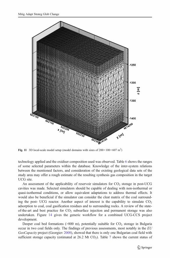
The local-scale model (Fig. 11) accounted for non-isothermal groundwater flow andcontaminant transport (benzene was considered to be the primary contaminant of concern).
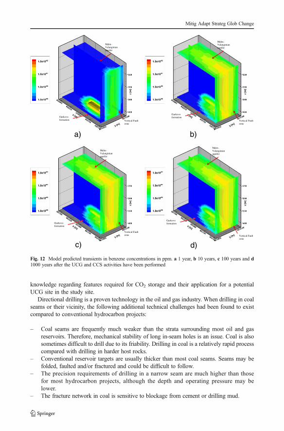
Feasibility evaluation of UCG and CO2 storage Non-isothermal groundwater flow andcontaminant transport was accounted for in the local-scale. Benzene was considered to bethe primary contaminant of concern. It was assumed that the gasification of 1 tonne of thestudy coal would produce about 36 l of coal tar and a relatively small fraction (0.1 %) of thattar would be benzene. Benzene was assumed to be a key contaminant and a ‘canary’ forpotential migration of UCG contaminants in the subsurface environment (due to relatively highproduction during the in-situ UCG and relatively low detection limits). The highest initialconcentration of benzene that could be produced during the in-situ gasification of the studiedcoal seams would be about 425 ppm assuming a production zone size of 20×20×5 m andporosity approaching 1. This is a conservative estimate that ignores the time it took for theUCG activities to be performed. It is assumed that peak concentration (425 ppm) is instanta-neously released at the beginning of the simulation (t=0). The volume of the production zone(20×20×5 m) is assumed to be formed at the end of the UCG activities within the simulatedstrip (200×100×20 m). The modelling results showed that contaminant concentrations wouldexceed 1 ppb after one year of UCG operations but in a relatively small area in the vicinity ofthe impacted zone. For the later years, the concentrations would be substantially below 1 ppmdue to contaminant dilution (Fig. 12).
The physical processes which were accounted for in the numerical model, were fluid, heatand contaminant flow. The contaminant migration was dominated by advection and dispersion.The vertical groundwater flow and contaminant transport between the UCG zones (Gurkovoand Makedonka coal formations) and the Regional aquifer above (the Malm-Valangianformation) was expected to be facilitated by vertical fault zones. The contaminants wereassumed to be non-reactive and unaffected by attenuation and decay due to geochemical
Fig. 8 Temperature distribution at 1500 m below the surface in the studied site (wells are marked by dots)
Mitig Adapt Strateg Glob Change

processes. The numerical model did not account for potential dissolution of contaminants inthe liquid CO2 phase. The simulations were applied to evaluate the potential for contamination
Fig. 9 Location and boundaries of the model domain
Mitig Adapt Strateg Glob Change

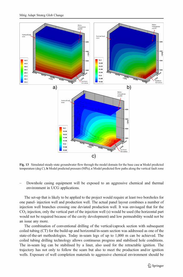
of the Malm-Valanginian aquifer taking into account uncertainties in the subsurface properties.The models predicting temperature, liquid pressure and flow paths from the Gurkovo forma-tion (bottom) along the vertical fault zone are presented in Fig. 13. The modelling resultsshowed that the heat flow was increasing and the liquid pressures gradient was relativelyuniform along the fault due to high vertical hydraulic conductivity.
The developed local-scale numerical hydro-geological model and the performed analysesshowed that the UCG-CO2 storage activities at the studied site would have limited impact onthe groundwater quality and would not cause unacceptable environmental impacts on the mainaquifer in the region – the Malm-Valangian aquifer. The injected CO2 mass was predominantlydissolved in the groundwater. The model demonstrated that the performance of UCG and CCSactivities at a distance of 100 m from a vertical fault zone with high vertical permeability willnot cause unacceptable environmental impacts on the Malm-Valanginian aquifer. A set ofcriteria for UCG-CCS in the study area is listed in Table 5. They are established criteria fromgeo-mechanical, cavity and hydro-geological feasibility studies based on conceptual modelelements and mechanical/ physical properties of the subsurface.
2.2 Engineering, drilling and completion requirements for UCG and CO2 storage
2.2.1 Evaluation of technical issues of dual use wells and CO2 storage in UCG cavities
A comprehensive data base had been established including accessible data from all previousUCG projects in order to identify the most suitable design and to assess the assignedparameters based on coal composition and type of oxidant. It includes detailed historical,technical and chemical information about the UCG process for 81 worldwide UCG projectssince 1933 (Couch, 2009). Based on existing literature, this may be the most comprehensivedata base of its kind. The analysis of database confirmed that the UCG synthesis gas quality issignificantly influenced by parameters such as initial coal composition, oxidant composition,injection pressure and coal seam depth (reservoir pressure). The influence of the UCG
Fig. 10 Spatial distribution of the model layers in the model domain
Mitig Adapt Strateg Glob Change
technology applied and the oxidiser composition used was observed. Table 6 shows the rangesof some selected parameters within the database. Knowledge of the inter-system relationsbetween the mentioned factors, and consideration of the existing geological data sets of thestudy area may offer a rough estimate of the resulting synthesis gas composition in the targetUCG site.
An assessment of the applicability of reservoir simulators for CO2 storage in post-UCGcavities was made. Selected simulators should be capable of dealing with non-isothermal orquasi-isothermal conditions, or allow equivalent adaptations to address thermal effects. Itwould also be beneficial if the simulator can consider the cleat matrix of the coal surround-ing the post- UCG reactor. Another aspect of interest is the capability to simulate CO2
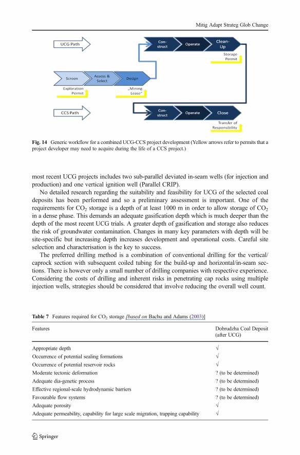
adsorption to coal, coal gasification residues and to surrounding rocks. A review of the state-of-the-art and best practice for CO2 subsurface injection and permanent storage was alsoundertaken. Figure 14 gives the generic workflow for a combined UCG-CCS projectdevelopment.
Deeper coal bed formations (>800 m), potentially suitable for CO2 storage in Bulgariaoccur in two coal fields only. The findings of previous assessments, most notably in the EUGeoCapacity project (Georgiev 2008), showed that there is only one Bulgarian coal field withsufficient storage capacity (estimated at 26.2 Mt CO2). Table 7 shows the current status of
Fig. 11 3D local-scale model setup (model domains with sizes of 200×100×607 m3)
Mitig Adapt Strateg Glob Change
knowledge regarding features required for CO2 storage and their application for a potentialUCG site in the study site.
Directional drilling is a proven technology in the oil and gas industry. When drilling in coalseams or their vicinity, the following additional technical challenges had been found to existcompared to conventional hydrocarbon projects:
– Coal seams are frequently much weaker than the strata surrounding most oil and gasreservoirs. Therefore, mechanical stability of long in-seam holes is an issue. Coal is alsosometimes difficult to drill due to its friability. Drilling in coal is a relatively rapid processcompared with drilling in harder host rocks.
– Conventional reservoir targets are usually thicker than most coal seams. Seams may befolded, faulted and/or fractured and could be difficult to follow.
– The precision requirements of drilling in a narrow seam are much higher than thosefor most hydrocarbon projects, although the depth and operating pressure may belower.
– The fracture network in coal is sensitive to blockage from cement or drilling mud.
Malm-Valanginian aquifer
Gurkovo formation Vertical Fault
zone
Malm-Valanginian aquifer
Gurkovo formation
Vertical Fault zone
a) b)
Malm-Valanginian aquifer
Gurkovo formation
Vertical Fault zone
Malm-Valanginian aquifer
Gurkovo formation
Vertical Fault zone
c) d)
Fig. 12 Model predicted transients in benzene concentrations in ppm. a 1 year, b 10 years, c 100 years and d1000 years after the UCG and CCS activities have been performed
Mitig Adapt Strateg Glob Change
– Downhole casing equipment will be exposed to an aggressive chemical and thermalenvironment in UCG applications.
The set-up that is likely to be applied to the project would require at least two boreholes forone panel- injection well and production well. The actual panel layout combines a number ofinjection well branches crossing one deviated production well. It was envisaged that for theCO2 injection, only the vertical part of the injection well (s) would be used (the horizontal partwould not be required because of the cavity development) and low permeability would not bean issue any more.
The combination of conventional drilling of the vertical/caprock section with subsequentcoiled tubing (CT) for the build-up and horizontal/in-seam section was addressed as one of thestate-of-the-art methodologies. Today in-seam legs of up to 1,000 m can be achieved. Thecoiled tubing drilling technology allows continuous progress and stabilised hole conditions.The in-seam leg can be stabilised by a liner, also used for the retractable ignition. Thetrajectory has not only to follow the seam but also to meet the production and/or ignitionwells. Exposure of well completion materials to aggressive chemical environment should be
a) b)
c)
Fig. 13 Simulated steady-state groundwater flow through the model domain for the base case aModel predictedtemperature (deg C), bModel predicted pressure (MPa), cModel predicted flow paths along the vertical fault zone
Mitig Adapt Strateg Glob Change
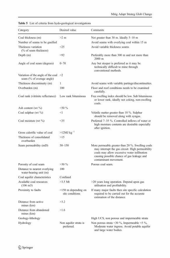
Table 5 List of criteria from hydo-geological investigations
Category Desired value Comments
Coal thickness (m) >2 m Not greater than 30 m. Ideally 5–10 m
Number of seams to be gasified Avoid seams with overlying coal within 15 m
Thickness variation(% of seam thickness)
<25 Avoid variable thickness seams
Depth (m) >92 Preferably more than 300 m and not more than2000 m
Angle of coal seam (degrees) 0–70 Any but steeper is preferred as it may betechnically difficult to mine throughconventional methods.
Variation of the angle of the coalseam (% of average angle)
<2
Thickness discontinuity (m) 1 Avoid seams with variable partings/discontinuities.
Overburden (m) 100 Floor and roof conditions needs to be examinedcarefully.
Coal rank (vitrinite reflectance) Low rank bituminous Free swelling index should be low. Sub bituminousor lower rank, ideally not coking, non-swellingcoals.
Ash content (wt %) <50 %
Coal sulphur (wt %) <1 Volatile matter greater than 10 %. Sulphurshould be removed along with syngas.
Coal moisture (wt %) <35 Preferred 7–35 %. Controlled inflows of water orhigh moisture contents are desirable especiallyafter ignition.
Gross calorific value of coal >12MJ kg−1
Thickness of consolidatedoverburden
>15
Seam permeability (mD) 50–150 More permeable greater than 20 %. Swelling coalsmay interrupt the gas circuit. High permeabilitycoals may allow excessive water infiltrationcausing possible chance of gas leakage andcontaminant movement.
Porosity of coal seam >30 % Porous coal seam.
Distance to nearest overlyingwater-bearing unit (m)
100
Coal aquifer characteristics Confined
Available coal resources(106 m3)
>3.5 Mt >20 years long operation. Depend upon gasutilisation and profitability.
Proximity to faults >150 m depending onsite conditions
If many major faults then site specific calculationrequired to be carried out for the accurateestimation of the distance.
Distance from activemines (km)
>3.2
Distance from abandonedmines (km)
>1.6
Geology-lithology High UCS, non porous and impermeable strata
Hydrology Non aquifer strata ispreferred.
Non porous strata <30 %, Impermeable <5 %,Moderate water ingress. Avoid potable aquiferand large water bodies.
Mitig Adapt Strateg Glob Change

checked. No significant risk of steel corrosion is expected in wells where CO2 is injected andmaintained in a dry and supercritical state (scCO2), since the corrosion rate is quite low in thepresence of dry CO2.
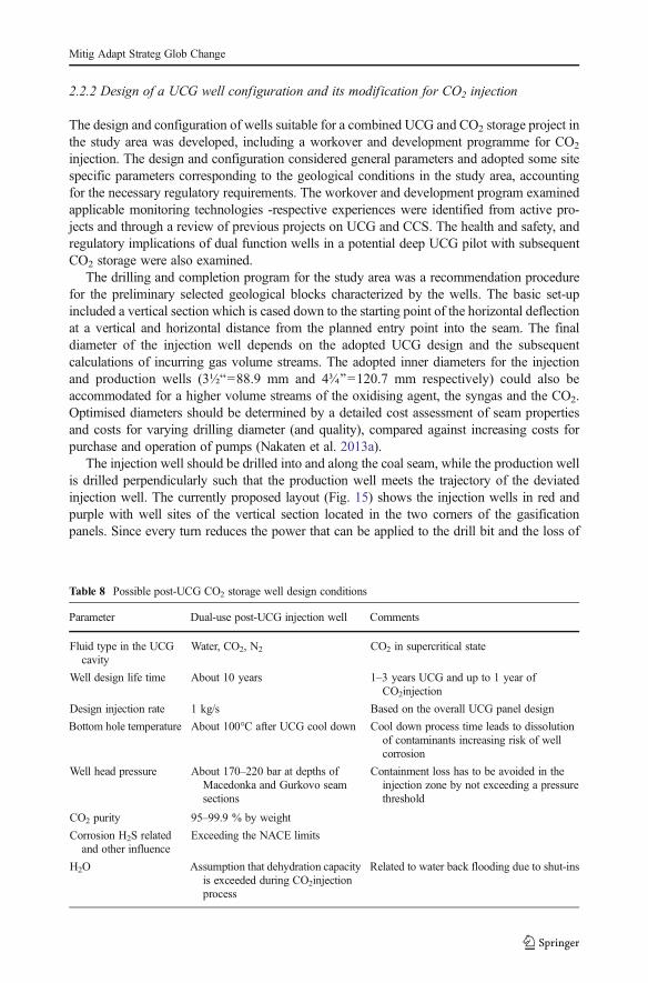
With regard to well integrity during UCG-CCS operations, the operational period of a dual-use well is relatively short (two to three years). Taking into account the influence of the UCGprocess, the performance of materials has to be considered for each stage. Injection rates,pressure, the fluid saturation in the UCG cavity as well as geochemistry, volume, viscosity andcontent of injectant (s) play an important role in the overall well design. The completion typerequired to ensure CO2 injectivity over the entire well life cycle has to meet performancerequirements. Certain general and site specific parameters have been adopted as a basis fordetailed planning (Table 8). Final closure of the well bore will follow the general rules thathave to be applied to all abandoned CO2 injection wells.
UCG and CO2 storage are two technologies that have been tested and to some extentalready applied commercially. Except for some research and development (R and D) studies,no site test trials have been performed combining those two technologies. Deep sited UCGprojects are also relatively rare but the available information on them helped to identify andevaluate technical issues related to UCG and CO2 storage projects. The preferred set-up of the
Table 6 The ranges of selectedparameters Parameter Minimum Maximum
Average seam depth (m) 15 1,200
Average seam thickness (m) 0.75 18
Seam angle (°) 0 56
Well spacing (m) 10 210
Coal gasified (t) 0.3 2,781,800
Injection (kmol/h) 7 1,223
Injection pressure (kPa) 120 7,500
Production pressure (kPa) 110 1,000
System pressure (kPa) 207 8,000
Total coal wet production (kmol/h) 22 4,860
Coal (dry) heat value [MJ/m3 (dry STP)] 2.57 12.17
Gas recovery (%) 43 110.30
Synthesis gas heat value (MJ/m3) 2.8 14.60
Table 5 (continued)
Category Desired value Comments
Geotechnical strata properties Rock strength: Uniaxialcompressive strengthrange 50 to 250 MPa.Density greater than2000 kg/m3
Avoid excessively fractured, faulted and brokenrocks as they may cause water inrush or productgas and contaminant leakage
Infrastructure availability Roads, electricity and power transmission lines
Presence of coal bed methane Depends upon economics or commercial value ofCBM deposit and its interoperability with UCG.
Mitig Adapt Strateg Glob Change
most recent UCG projects includes two sub-parallel deviated in-seam wells (for injection andproduction) and one vertical ignition well (Parallel CRIP).
No detailed research regarding the suitability and feasibility for UCG of the selected coaldeposits has been performed and so a preliminary assessment is important. One of therequirements for CO2 storage is a depth of at least 1000 m in order to allow storage of CO2
in a dense phase. This demands an adequate gasification depth which is much deeper than thedepth of the most recent UCG trials. A greater depth of gasification and storage also reducesthe risk of groundwater contamination. Changes in many key parameters with depth will besite-specific but increasing depth increases development and operational costs. Careful siteselection and characterisation is the key to success.
The preferred drilling method is a combination of conventional drilling for the vertical/caprock section with subsequent coiled tubing for the build-up and horizontal/in-seam sec-tions. There is however only a small number of drilling companies with respective experience.Considering the costs of drilling and inherent risks in penetrating cap rocks using multipleinjection wells, strategies should be considered that involve reducing the overall well count.
Fig. 14 Generic workflow for a combined UCG-CCS project development (Yellow arrows refer to permits that aproject developer may need to acquire during the life of a CCS project.)
Table 7 Features required for CO2 storage [based on Bachu and Adams (2003)]
Features Dobrudzha Coal Deposit(after UCG)
Appropriate depth √Occurrence of potential sealing formations √Occurrence of potential reservoir rocks √Moderate tectonic deformation ? (to be determined)
Adequate dia-genetic process ? (to be determined)
Effective regional-scale hydrodynamic barriers ? (to be determined)
Favourable flow systems ? (to be determined)
Adequate porosity √Adequate permeability, capability for large scale migration, trapping capability √
Mitig Adapt Strateg Glob Change
2.2.2 Design of a UCG well configuration and its modification for CO2 injection
The design and configuration of wells suitable for a combined UCG and CO2 storage project inthe study area was developed, including a workover and development programme for CO2
injection. The design and configuration considered general parameters and adopted some sitespecific parameters corresponding to the geological conditions in the study area, accountingfor the necessary regulatory requirements. The workover and development program examinedapplicable monitoring technologies -respective experiences were identified from active pro-jects and through a review of previous projects on UCG and CCS. The health and safety, andregulatory implications of dual function wells in a potential deep UCG pilot with subsequentCO2 storage were also examined.
The drilling and completion program for the study area was a recommendation procedurefor the preliminary selected geological blocks characterized by the wells. The basic set-upincluded a vertical section which is cased down to the starting point of the horizontal deflectionat a vertical and horizontal distance from the planned entry point into the seam. The finaldiameter of the injection well depends on the adopted UCG design and the subsequentcalculations of incurring gas volume streams. The adopted inner diameters for the injectionand production wells (3½B=88.9 mm and 4¾^=120.7 mm respectively) could also beaccommodated for a higher volume streams of the oxidising agent, the syngas and the CO2.Optimised diameters should be determined by a detailed cost assessment of seam propertiesand costs for varying drilling diameter (and quality), compared against increasing costs forpurchase and operation of pumps (Nakaten et al. 2013a).
The injection well should be drilled into and along the coal seam, while the production wellis drilled perpendicularly such that the production well meets the trajectory of the deviatedinjection well. The currently proposed layout (Fig. 15) shows the injection wells in red andpurple with well sites of the vertical section located in the two corners of the gasificationpanels. Since every turn reduces the power that can be applied to the drill bit and the loss of
Table 8 Possible post-UCG CO2 storage well design conditions
Parameter Dual-use post-UCG injection well Comments
Fluid type in the UCGcavity
Water, CO2, N2 CO2 in supercritical state
Well design life time About 10 years 1–3 years UCG and up to 1 year ofCO2injection
Design injection rate 1 kg/s Based on the overall UCG panel design
Bottom hole temperature About 100°C after UCG cool down Cool down process time leads to dissolutionof contaminants increasing risk of wellcorrosion
Well head pressure About 170–220 bar at depths ofMacedonka and Gurkovo seamsections
Containment loss has to be avoided in theinjection zone by not exceeding a pressurethreshold
CO2 purity 95–99.9 % by weight
Corrosion H2S relatedand other influence
Exceeding the NACE limits
H2O Assumption that dehydration capacityis exceeded during CO2injectionprocess
Related to water back flooding due to shut-ins
Mitig Adapt Strateg Glob Change

torque is greater for narrower radii, the first deviation is planned with a radius ri1 greater thanri2 but not greater than rp, so as to keep an appropriate distance from the next potential fault(i.e. the geological boundary). The respective build-up rates for the applied diameters are 20°and 60°. The narrow radius for the production wells is quite ambitious for a 4¾B well diameter,while the greater diameter will be in a medium range even for a 6½^ well diameter (productionwell, in green).
A number of in-seam sections will be drilled from a single vertical well, thus, only a limitednumber of vertical wells will be required. After the completion of the vertical drilling theinjection wells should be cased from the surface down to the top of the build-up section.Following build-up and in-seam-drilling, this section is to be lined and the well temporarilycapped. The production well is expected to be drilled after the deviated injection well and willbe cased all the way to the top of the build-up section. Once Bcommunication^ with therespective leg of the injection well is established, a liner should be installed in the well, whichshould be temporarily capped.
Appropriate shut-down procedures have to be applied when an UCG reactor (the gasifica-tion channel or entire UCG panel) is closed down. The main goal is to avoid the escape oftoxic UCG by-products and the potential for subsequent contamination of freshwater aquifers.The so called ‘clean cavity’ concept has been developed and tested within the scope ofprevious UCG projects. However, the experience with the concept is still very limited andrequires further field work and research.
The shutdown of the UCG reactor is undertaken in three steps. The injection of theoxidant is reduced and ultimately stopped. The cool-down process can be supported byinjection of water into the cavity (being again converted into steam underground) and itssubsequent production (Yang et al. 2013). In the next step the gasification is finallyextinguished, hence, any wells not required for further operation may be abandonedaccording to best practise and national regulations. Finally, the water from theextinguished UCG reactor is recovered by pumping. This process may be repeated untilcontaminants concentration (mainly the contaminants with high water solubility) isreduced to a degree required by the local regulations on water protection. In case of
Fig. 15 Proposed panel layout (left: plan view, right: 3D block view, both not to scale) The block view on theright exemplifies one half of the total panel; the other part is symmetrical to this block
Mitig Adapt Strateg Glob Change
low water ingress or a weak aquifer connectivity of the UCG cavity, the clean-upprocess can be supported by cycling water through the shutdown reactor in order touse it as a solvent for contaminants. After shutdown and cleaning, water quality ismonitored with regard to required parameters. If the required national standards at thesite are not met, water has to be produced and treated at the surface. Several months/years may pass between the single operations.
2.2.3 Post-injection management of CO2 storage in UCG spaces
A best practice guide for the sealing of wells after CO2 injection was completed. Itspecifies the general technical terms and requirements (e.g. well design and sealing)needed to assure a safe long-term CO2 storage and recommended options for long-termmonitoring of the cavity, well and storage space. The best practice guide can be used asa tool to determine essential technical terms and monitoring requirements to assure asafe long-term CO2 storage in compliance with the EU Directive on the geologicalstorage of CO2. Yet, the process of defining a particular monitoring program for a safelong-term CO2 storage must always consider the local site-specific (geological) condi-tions and circumstances.
3 Environmental assessment of UCG-CO2 storage
3.1 State-of-the-art for the potential for environmental impacts of UCG-CO2 storage
A detailed study of the state-of-the-art in potential environmental impacts from UCG and UCGassociated with CCS was carried out addressing issues including the impact on the ground-water environment, the environmental impact during the transition of the abandoned cavity toequilibrium and CO2 injection, and the long-term impacts of CO2 storage in the cavity and thesubsequent mineralisation.
3.1.1 UCG impact on the groundwater environment
The risk assessment techniques currently used for groundwater contamination are applicable tothe concept of UCG–CCS. Groundwater pollution is likely to be a key element for anysuccessful UCG operation. It is known that a suitable site selection process (where keyhydrogeological attributes are compared to assess suitability) with adequate engineeringplanning and realistic environmental impact assessment (EIA) are required to obtain appro-priate authorisations for these endeavours.
In order to evaluate the risk to groundwater presented by both contaminant production andtransport mechanisms, a comprehensive evaluation of geological and hydrogeological factorsat the site is required. A key parameter of the risk analysis is the regulatory regime concerninggroundwater of the particular country. The practical application of the theory together withunderstanding the expected UCG contamination is essential for the assessment of the risk togroundwater in a deep environment.
Evaluation of the influence of UCG on groundwater covers a number of phases includingthe following:
– Contaminant migration: potential underground pathways that allow these contaminants tomigrate to aquifers that are economically or ecologically significant.
Mitig Adapt Strateg Glob Change

– Human activities and their effect on these potential mechanisms.– The risk of contaminant migration beyond the permanently unsuitable zone (PUZ) in
significant quantities that may cause concern to the regulators.– The risks of surface activities to groundwater.
3.1.2 Human impact in modifying migration pathways
Human activities can have a large impact on contaminant migration pathways at the site andmay cause existing migration pathways to become more permeable and even provide newpathways through which potential contaminants associated with UCG can migrate. The mainimpacts that need to be considered in terms of contaminant migration are collapse of the UCGreactor, mineral workings and resource extraction activities such as coal bed methane extrac-tion, and deep site investigation boreholes and wells.
3.1.3 Geological and hydro-geological evaluation
In simple terms, the evaluation of geological and hydrogeological characteristics in a typicallow risk deep environment requires two main activities: identifying the main potentiallytransmissive features and links between them that could provide a continuous transmissionpathway beyond the PU zone, and determining whether hydro-geological conditions are likelyto promote transmission of contaminants through potentially transmissive features. This willneed a good understanding of the geology and conceptual hydrogeology at a site, supported bydesk study and site investigation data.
A summary of data on study are used for EIA studies include
– Detailed descriptions of the host rocks.– Data on the permeability and transmissivity of Carboniferous rocks and geological
formations within the field deposited above them.– Data on the chemical composition of carboniferous water and of the aquifers above it.– Detailed regional hydro-geological information for the Upper Jurassic-Lower
Cretaceous aquifer most vulnerable to future underground gasification – such asmap of thickness distribution, hydrodynamic map and data on hydraulic geologicalparameters.
Other required data are
– The role of tectonic disturbances as possible ways of contaminants migration is unclear.– Information for drawing hydrodynamic maps for Carboniferous and Devonian aquifers.– The technical condition of preserved wells.
3.1.4 CO2 storage - environmental impacts related to UCG
CCS is a method of abating atmospheric emissions of CO2. It is assumed that UCG wouldleave highly porous cavities and stressed strata in its wake. As these areas cool down, theabandoned cavities would be accessed by directional drilling or through the existing produc-tion boreholes. CO2 would then be injected at high pressure for storage and retention. Forpermanent CO2sequestration, the depth and strata conditions must be suitable. The
Mitig Adapt Strateg Glob Change

environmental impact of CO2 sequestration in a UCG scheme is also affected by the environ-mental factors considered for the UCG process.
3.2 Development of a mathematical model to assess the environmental sustainabilityof UCG-CO2storage
The main purpose of the UCG process is to obtain a sustainable energy source. Thisprocess should be aimed to achieve an adequate balance between financial, environ-mental and social factors in the energy generation process. As a scientific contribution toan effective sustainable environmental management of the UCG process, an innovativenumerical model has been developed (expressed in terms of an EnvironmentalSustainability Index (ESI)) to quantify the environmental sustainability situation of theBin-situ^ UCG process with CO2 storage. In a given time and space this parameterallows the definition of an environmental sustainability standard or a minimum permis-sible level of sustainability for future projects. This approach is based on four environ-mental indicators: (i) atmosphere quality, (ii) rock and soil subsidence, (iii) groundwaterquality, and (iv) surface water quality. The main purpose of this index will be theestablishment of acceptability criteria for new underground coal gasification projects, aswell as optimisation of studies for existing installations.
The developed ESI quantitative model is a function of 4 component indexes: SubsidenceSustainability Index (SSI), Groundwater Sustainability Index (GWSI), Surface WaterSustainability Index (SWSI) and Atmosphere Sustainability Index (ASI). The calculation ofthese indexes considers the condition of sustainability of each pollutant based on thresholdlimit values, given by the existing standards.
The basic equation used for the calculation of the Environmental Sustainability Index ofUCG/CCS is:
ESI UCGCCS
¼ 1
4SSI þ GWSI þ SWSI þ ASIð Þ ð4Þ
The graphic representation of the results is given by Fig. 16.
Fig. 16 Structure of Environmental Sustainability index of UCG
Mitig Adapt Strateg Glob Change
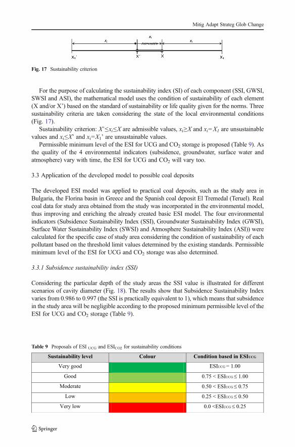
For the purpose of calculating the sustainability index (SI) of each component (SSI, GWSI,SWSI and ASI), the mathematical model uses the condition of sustainability of each element(X and/or X’) based on the standard of sustainability or life quality given for the norms. Threesustainability criteria are taken considering the state of the local environmental conditions(Fig. 17).
Sustainability criterion: X’≤xi≤X are admissible values, xi≥X and xi=X1 are unsustainablevalues and xi≤X’ and xi=X1’ are unsustainable values.
Permissible minimum level of the ESI for UCG and CO2 storage is proposed (Table 9). Asthe quality of the 4 environmental indicators (subsidence, groundwater, surface water andatmosphere) vary with time, the ESI for UCG and CO2 will vary too.
3.3 Application of the developed model to possible coal deposits
The developed ESI model was applied to practical coal deposits, such as the study area inBulgaria, the Florina basin in Greece and the Spanish coal deposit El Tremedal (Teruel). Realcoal data for study area obtained from the study was incorporated in the environmental model,thus improving and enriching the already created basic ESI model. The four environmentalindicators (Subsidence Sustainability Index (SSI), Groundwater Sustainability Index (GWSI),Surface Water Sustainability Index (SWSI) and Atmosphere Sustainability Index (ASI)) werecalculated for the specific case of study area considering the condition of sustainability of eachpollutant based on the threshold limit values determined by the existing standards. Permissibleminimum level of the ESI for UCG and CO2 storage was also determined.
3.3.1 Subsidence sustainability index (SSI)
Considering the particular depth of the study areas the SSI value is illustrated for differentscenarios of cavity diameter (Fig. 18). The results show that Subsidence Sustainability Indexvaries from 0.986 to 0.997 (the SSI is practically equivalent to 1), which means that subsidencein the study area will be negligible according to the proposed minimum permissible level of theESI for UCG and CO2 storage (Table 9).
Fig. 17 Sustainability criterion
Table 9 Proposals of ESI UCG and ESICO2 for sustainability conditions
Mitig Adapt Strateg Glob Change

3.3.2 Groundwater sustainability index (GWSI)
The Groundwater Sustainability Index for the study area is simulated based on six typicalenvironmental indicators in UCG processes (n=6): Sulphates (SO4), Ammonia (NH3),Phenols (C6H5OH), Polyciclic Aromatic Hydrocarbons (P.A.H.), pH and Calcium (Ca2+),and using the groundwater quality standard as per the Bulgarian Regulation Nº1 of 10 October2007 on the Exploration. The index was calculated for two cases: (a) for pH values <6.5 andunsustainable pH=0, and (b) for pH>9.5 and unsustainable pH=14. The results from simu-lations of GWSI behaviour illustrate the great variability and sensitivity of diverse pollutants ofgroundwater. So, it is important to apply preventive measures in the study area because of theaquifers in it.
3.3.3 Surface water sustainability index (SWSI)
While there is no significant presence of rivers on the surface of the study area, appropriatepreventive measures should be used mainly because of the recharge areas of the aquifers. Thesustainability index of surface water is assumed to be very good (with mean values near 1).
Fig. 18 Scenarios of Subsidence Sustainability Index in the study area for three selected coal seams and fordifferent cavity diameters (5 m, 7 m and 10 m). Note: p3, m9 and m5 are designated coal seams within the samesite
Fig. 19 a ASI behaviour for CO2, H2=3 %, CH4=0 and CH4=5 %, when CO=25 ppm; b ASI behaviour forCO, CH4=25 %, H2=74.2 % and H2=100 %, when CO2=1000 ppm
Mitig Adapt Strateg Glob Change
3.3.4 Atmosphere sustainability index (ASI)
The ASI simulation for a hypothetic UCG study area is based on four environmental indicators(r=4), using average values of Atmospheric Quality Standards. The ASI is calculated for twocases: (a) for H2<4 % and CH4<5 % and unsustainable H2=0 and CH4=0, and (b) for H2>74.2 % andCH4>14 % and unsustainable H2=100 and CH4=100. The simulation results forASI behaviour for CO2 gas variation of 0 to 8000 ppm, for H2=3 %, CH4=0 and CH4=4,CO=25 ppm are shown in Fig. 19a. The simulation results for ASI behaviour for CO gasvariation of 0 to 100 ppm, for CH4=25 %, H2=74.2 % and H2=100 % and CO2=1000 ppmare shown in Fig. 19b.
Applying the ESI model to the selected sites show that the subsidence in the study area willbe negligible, the Groundwater Sustainability Index is expected to be high, the Surface WaterSustainability Index should be very good (due to the absence of surface waters in the area) andthe Atmosphere Sustainability Index behaviour with several environmental pollutants shows ahigh ASI sensitivity with CO2 concentration increment when compared to the CO emission.
These results show that the mathematical model developed for ESI has an excellentapplicability for quantitative sustainability assessment of the UCG and CO2 storage process.But in order to improve the quality of such an evaluation there is a need to introduce additionalinformation not only from bibliographic sources but also field data that should be gathered inaccordance with the requirements of the sustainability analysis.
4 Economic assessment
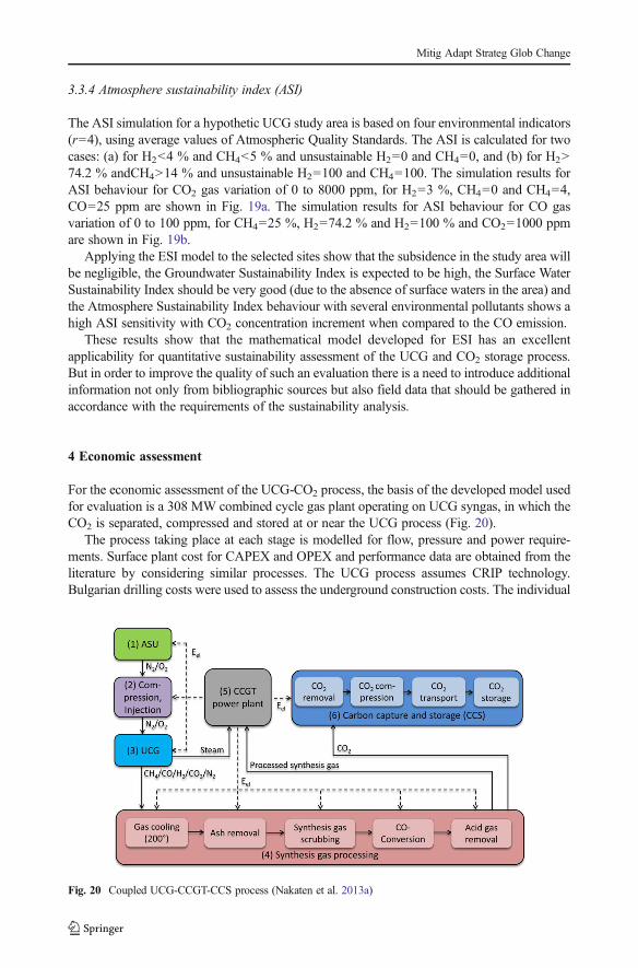
For the economic assessment of the UCG-CO2 process, the basis of the developed model usedfor evaluation is a 308 MW combined cycle gas plant operating on UCG syngas, in which theCO2 is separated, compressed and stored at or near the UCG process (Fig. 20).
The process taking place at each stage is modelled for flow, pressure and power require-ments. Surface plant cost for CAPEX and OPEX and performance data are obtained from theliterature by considering similar processes. The UCG process assumes CRIP technology.Bulgarian drilling costs were used to assess the underground construction costs. The individual
Fig. 20 Coupled UCG-CCGT-CCS process (Nakaten et al. 2013a)
Mitig Adapt Strateg Glob Change
component and fuel costs such as land acquisition, fees (e.g. concession fee for extraction),piping-, measuring-, control equipment, drilling, synthesis gas processing as well as oxidisercompression and injection, were brought together in a calculation which takes into account thelevelised costs of electricity (COE) and CCS costs (Nakaten et al. 2013a). It is assumed that thecoal, because of the depth, has no intrinsic value and royalties payment will not be required.
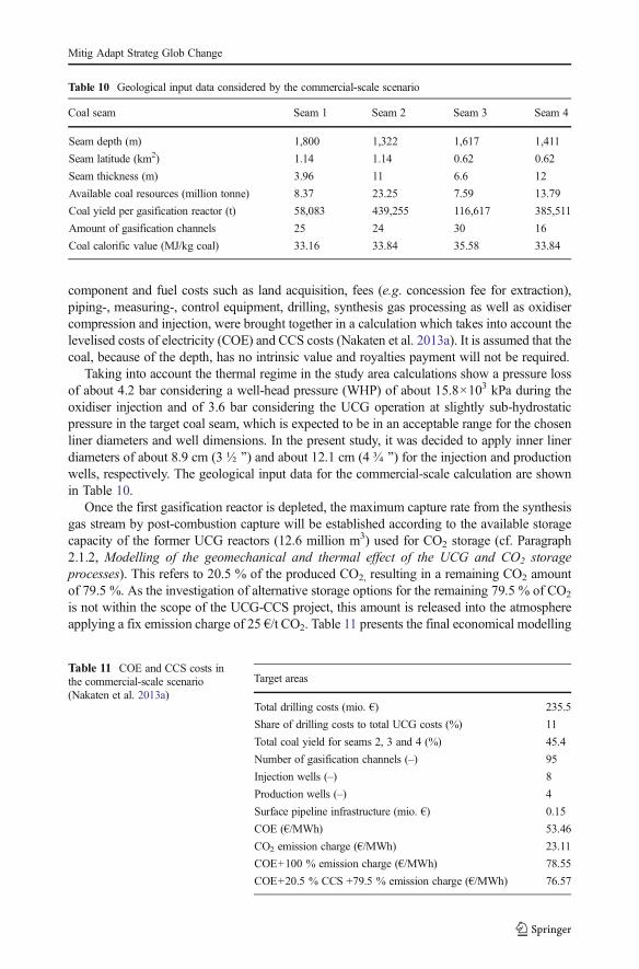
Taking into account the thermal regime in the study area calculations show a pressure lossof about 4.2 bar considering a well-head pressure (WHP) of about 15.8×10³ kPa during theoxidiser injection and of 3.6 bar considering the UCG operation at slightly sub-hydrostaticpressure in the target coal seam, which is expected to be in an acceptable range for the chosenliner diameters and well dimensions. In the present study, it was decided to apply inner linerdiameters of about 8.9 cm (3 ½ ^) and about 12.1 cm (4 ¾ ^) for the injection and productionwells, respectively. The geological input data for the commercial-scale calculation are shownin Table 10.
Once the first gasification reactor is depleted, the maximum capture rate from the synthesisgas stream by post-combustion capture will be established according to the available storagecapacity of the former UCG reactors (12.6 million m3) used for CO2 storage (cf. Paragraph2.1.2, Modelling of the geomechanical and thermal effect of the UCG and CO2 storageprocesses). This refers to 20.5 % of the produced CO2, resulting in a remaining CO2 amountof 79.5 %. As the investigation of alternative storage options for the remaining 79.5 % of CO2
is not within the scope of the UCG-CCS project, this amount is released into the atmosphereapplying a fix emission charge of 25 €/t CO2. Table 11 presents the final economical modelling
Table 10 Geological input data considered by the commercial-scale scenario
Coal seam Seam 1 Seam 2 Seam 3 Seam 4
Seam depth (m) 1,800 1,322 1,617 1,411
Seam latitude (km2) 1.14 1.14 0.62 0.62
Seam thickness (m) 3.96 11 6.6 12
Available coal resources (million tonne) 8.37 23.25 7.59 13.79
Coal yield per gasification reactor (t) 58,083 439,255 116,617 385,511
Amount of gasification channels 25 24 30 16
Coal calorific value (MJ/kg coal) 33.16 33.84 35.58 33.84
Table 11 COE and CCS costs inthe commercial-scale scenario(Nakaten et al. 2013a)
Target areas
Total drilling costs (mio. €) 235.5
Share of drilling costs to total UCG costs (%) 11
Total coal yield for seams 2, 3 and 4 (%) 45.4
Number of gasification channels (–) 95
Injection wells (–) 8
Production wells (–) 4
Surface pipeline infrastructure (mio. €) 0.15
COE (€/MWh) 53.46
CO2 emission charge (€/MWh) 23.11
COE+100 % emission charge (€/MWh) 78.55
COE+20.5 % CCS +79.5 % emission charge (€/MWh) 76.57
Mitig Adapt Strateg Glob Change
results undertaken in the context of the study. COE for the coupled UCG-CCGT-CCS processare about 77 €/MWh for the combined utilisation of the study area coal blocks.
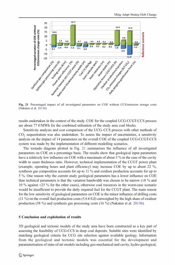
Sensitivity analysis and cost comparison of the UCG–CCS process with other methods ofCO2 sequestration was also undertaken. To assess the impact of uncertainties, a sensitivityanalysis on the impact of 14 parameters on the overall COE of the coupled UCG-CCGT-CCSsystem was made by the implementation of different modelling scenarios.
The tornado diagram plotted in Fig. 21 summarises the influence of all investigatedparameters on COE on a percentage basis. The results show that geological input parametershave a relatively low influence on COE with a maximum of about 3 % in the case of the cavitywidth to seam thickness ratio. However, technical implementation of the CCGT power plant(example, operating hours and plant efficiency) may increase COE by up to about 22 %,synthesis gas composition accounts for up to 11 % and oxidiser production accounts for up to5 %. One reason why the current study geological parameters has a lower influence on COEthan technical parameters is that the variation bandwidth was chosen to be narrow (±8 % and10 % against ±25 % for the other cases), otherwise coal resources in the worst-case scenariowould be insufficient to provide the daily required fuel for the CCGT plant. The main reasonfor the low sensitivity of geological parameters on COE is the minor influence of drilling costs(11 %) on the overall fuel production costs (5.6 €/GJ) outweighed by the high share of oxidiserproduction (58 %) and synthesis gas processing costs (16 %) (Nakaten et al. 2013b).
5 Conclusion and exploitation of results
3D geological and tectonic models of the study area have been constructed as a key part ofassessing the feasibility of UCG-CCS in deep coal deposits. Suitable sites were identified bymatching geological criteria for UCG site selection against available geology. Informationfrom the geological and tectonic models was essential for the development andparameterisation of state-of-art models including geo-mechanical and cavity, hydro-geological,
Fig. 21 Percentaged impact of all investigated parameters on COE without CCS/emission storage costs(Nakaten et al. 2013b)
Mitig Adapt Strateg Glob Change

environmental and techno-economic models. The study area has a complicated tectonicstructure. Major faults (of Triassic age) have been identified around the target area, and whilethese can be avoided, little is known about any minor faults that exist in the Horsts betweenthem.
The identification of suitable sites for UCG was based on a correlation between thegeological features, physical parameters and techno-economic aspects of the studied areas.The suitability of coal seams was made on the basis of a set of quantitative and qualitativecriteria that may be used and applied to other deposits with similar geological conditions. Partof these criteria refer to geometry and quality of the coal seams and are treated by the 3Dgeological model. Another part considers the tectonic structure of the deposit, hydrogeologicalfeatures, and parameters pertaining to geomechanical, engineering and environmental issues.The preliminary selected sites that mostly satisfied the UCG-site selection criteria and had thebest potential for UCG and subsequent CO2 storage were bounded by faults. The selected coalseams pertaining to them were between 1,100m and 1,500m deep, amounting in total to over75 Mt of UCG compliant coal.
A set of thermal-mechanical coupled models have been developed for the prediction ofUCG cavity growth, surface subsidence as well as geologic faults reaction. These models canbe employed in future feasibility studies and risk assessments of UCG-CCS projects, giventhat the lithological information and material properties of the rock and coal from the specificcoal sites are available. A safety distance of at least 150m between the gasification channelsand the geologic faults has been proposed to avoid any potential fault reactivation andconsequent leakage of UCG gases, contaminants or CO2. Even though each assessment of aprospective UCG-CCS area has to be site-specific, the presented results can be used asguidance for future UCG feasibility studies. Also, a set of UCG-CCS site selection criteriais prescribed, which can be taken into account for future UCG site design and risk assessmentdemanded by the mining and environmental authorities.
The hydro-geological environment was also simulated to characterise the pre and postgasification conditions, as well as conditions during the stages of UCG. Regional scale andlocal scale hydro-geological models were developed, whereas the latter were applied to assessthe temporal and spatial changes during the different stages of the UCG-CCS process. Themodels were also used to assess environmental risks related to transport of UCG contaminants.The analyses show that the UCG-CCS activities at the study area would not have a significantimpact on the groundwater quality considering the given assumptions. Thus, It is not to beexpected that given regulations on water quality will be compromised related to the waterquality of the MalmValanginian aquifer located above the study area and representing the mostrelevant source of freshwater in the region.
Drilling and completion technologies are generally available and can be readily applied fordual use wells required for UCG and CO2 injection. A combination of conventional and coiledtube drilling is proposed. The conventional methods should be used to drill the vertical/caprock sections, while coiled tubing is suggested for the build-up and horizontal/in-seamssections. It is recommended that the UCG injection wells, rather than the production wells, beused for CO2 injection due to potential corrosion in UCG production wells resulting from hightemperatures and the composition of the UCG synthesis gas before processing at the surface.
As part of the environmental assessment, a mathematical model was developed andsensitivity analyses of Environmental Sustainability Index (ESI) conducted. The mathematicalmodel used to establish the ESI for the processes of UCG and CCS. Its application to the studyarea indicates negligible subsidence as supported by geomechanical modelling, no significantimpacts on freshwater bearing aquifers and a contribution to greenhouse gas emission mitiga-tion, if UCG is combined with CO2 storage. The economic benefit of combining CCS with
Mitig Adapt Strateg Glob Change

UCG was assessed. In addition to sensitivity analyses, a cost comparison of the UCG-CCSprocess with alternative methods of CO2 storage was carried out. Preliminary studies indicatethat UCG-CCS is economic as emission charges exceed 15 €/t CO2. Geological parametershave a great effect on drilling costs; however, their effect on the overall cost of electricity(COE) is relatively low in comparison to the technical model-input parameters.
The feasibility study indicates that it is technically possible to conduct UCG-CCS opera-tions in the selected sites without significant environmental impacts. It is also economicallyviable, especially if the charge for CO2 emission is considered. While it may technicalachievable to embark on UCG projects, their viability depends strongly on set guidelines thatborder on general and site-specific threshold conditions. Moreover, the incorporation of CCSimproves the economies of the operation since external storage requirements are no longeressential. These guidelines and standards as determined herein can be adopted either directly orindirectly during establishment of policies and the deployment of strategies to combat globalclimate change.
Acknowledgment This work was supported by the European Commission, Research Fund for Coal and Steel(RFCS) under the grant RFC-PR-09022. The European Union source report ‘Study of deep underground coalgasification and the permanent storage of CO2 in the affected areas’ is not publicly available at the moment butwill be put in the public domain in due course. When published it may be found through the address: http://www.ucg-co2.eu/.
References
Antonov H, Danchev D (1980) Ground waters in PRB. PH Technika, Sofia, 359Bachu S, Adams JJ (2003) Sequestration of CO2 in geological media in response to climate change: capacity of
deep saline aquifers to sequester CO2 in solution. Energy Convers Manag 44(20):3151–3175Bojadgieva K, Gasharov S (2001) Catalogue of geothermal data of Bulgaria. GorexPres, Sofia, 163 pBojadgieva K, Gasharov S, Vesselinov S (1998) Geothermal study of the hydrothermal regime in the region of
the Dobrudja Coal Deposit (NE Bulgaria). Bulg. Gerophys. J, Vol. XXIV, No 3 - No 4, Sofia, 127 – 136.Burton EA, Upadhye R, Friedmann SJ (2008) Best practices in underground coal gasification. Lawrence
Livermore National Laboratory, LivermoreBurton EA, Upadhye R, Friedmann SJ, Leif R, McNab W, Knauss K, Ezzedine S, Smith JR (2004) Assessment
of UCG site locations. Lawrence Livermore NationalLaboratory, LivermoreCouch G R (2009) Underground coal gasification. IEA Clean Coal CentreGeorgiev G (2008) CO2 Emissions and Geological Storage Options in Bulgaria. Slovak Geol. Mag., pp. 43-52.Harbaugh A, Banta E, R. Hill M C, McDonald M G (2000) MODFLOW-2000 - The U.S. Geological Survey
modular groundwater model – user guide to modularization concepts and the groundwater flow process.Open-File Report 00-92, USGS, Reston, VA, 130 p.
Healy P R, Head J M (1984) Construction over Abandoned Mine Workings. Construction Industry Research andInformation Association (CIRIA), Special Publication 32, London.
Hristov Z (1988) Geology of the dobrudja coal deposit (NE Bulgaria). PH Technika, Sofia, 170 pKim O K (1983) Finite element modelling of themo-mechanical responses associated with underground coal
conversion. Phd Thesis, Ohio State University.Lee J K, Advani S H, Avasthi J M, Chen K S (1986) Application of rock mechanics and the finite element
method to underground coal gasification process. Rock Mechanics : Key to Energy Production, 27TH U.S.Symposium on Rock Mechanics, Chapter 101 - Oil Sands and Coalbed Methane.
Los Alamos National Laboratory. (2013) Finite Element Heat and Mass Transfer Code (FEHM) [Online].Available: https://fehm.lanl.gov/ [Accessed September 2013].
McDonald M G, Harbaugh A W (1988) A modular three-dimensional finite-difference flow model. In:Techniques of Water Resources Investigations of the U.S.G.S., Book 6, Ch. A1, 586 p.
Nakaten N, Azzam R, Kempka T (2013b) Scenario analysis on UCG-CCS economics. Energy (in review)Nakaten N, Schlüter R, Azzam R, Kempka T (2013a) Development of a techno-economic model for dynamic
calculation of COE, energy demand and CO2 emissions of an integrated UCG-CCS process. Energy (inreview)
Mitig Adapt Strateg Glob Change

Overgas Inc. (2011) Geological and geomechanical data for the Dobrudzha coal field area (DCF).Pei P, Zeng Z, He J (2010) Feasibility Study of Underground Coal Gasification Combined with CO2 Capture and
Sequestration in Williston Basin, North Dakota. The 44th US Rock Mechanics Symposium and 5th U.S.-Canada Rock Mechanics Symposium, held in Salt Lake City, UT June 27–30.
Rogut J ( 2008) Hydrogen Oriented Underground Coal Gasification. Twenty-Fifth Annual InternationalPittsburgh Coal Conference. Paper 20-3. Pittsburgh, PA.
Shafirovich E, Varma A (2009) UCG: a brief review of current status. Ind Eng Chem Res 48:7865–7875Stanev I (1970) Old and new karst in upper Jurassic-lower creatceous aquifer in north Bulgaria. Rev Bulg Grol
Soc XXXI(2):241–249Yang D, Sarhosis V, Sheng Y (2013) Thermal-Mechanical Modelling around the Cavities of Underground Coal
Gasification Jounral of Energy Institute, 2013, in press.Yovchev R, Riizova V (1962) Groundwaters in North Bulgaria.S., GUGOZN, 222 p.Zamzow KL (2010) Underground coal gasification: history, environmental issues, and the proposed project at
beluga. Center for Science in Public Participation, Alaska
Mitig Adapt Strateg Glob Change
Related Documents