Interatomic Coulombic decay in noble gas clusters of varying sizes investigated by photon-induced (dispersed) fluorescence spectrometry Dissertation zur Erlangung des akademischen Grades Doktor der Naturwissenschaften (Dr. rer. nat.) im Fachbereich 10 - Mathematik und Naturwissenschaften der Universität Kassel Presented by: Ltaief Ben Ltaief Referees: Prof. Dr. Arno Ehresmann Prof. Dr. Thomas Giesen Prof. Dr. Philipp Demekhin Dr. Arne Senftleben Kassel, February 2018 Date of defense: 23 Mars 2018

Welcome message from author
This document is posted to help you gain knowledge. Please leave a comment to let me know what you think about it! Share it to your friends and learn new things together.
Transcript

Interatomic Coulombic decay in noble gasclusters of varying sizes investigated byphoton-induced (dispersed) fluorescence
spectrometry
Dissertationzur Erlangung des akademischen Grades Doktor der
Naturwissenschaften (Dr. rer. nat.)im Fachbereich 10 - Mathematik und Naturwissenschaften der
Universität Kassel
Presented by: Ltaief Ben Ltaief
Referees: Prof. Dr. Arno Ehresmann
Prof. Dr. Thomas Giesen
Prof. Dr. Philipp Demekhin
Dr. Arne Senftleben
Kassel, February 2018 Date of defense: 23 Mars 2018

To my family

AbstractThe main topic of this thesis is to study experimentally an ultrafast and efficient nonradiative mechanism – the well-known interatomic Coulombic decay (ICD) – in noblegas clusters by employing fluorescence spectrometry technique in combination withsynchrotron radiation. Using Neon clusters as prototype systems, a special variety ofICD, termed resonant ICD (RICD), has been investigated by a selective excitation ofone component of the cluster and for different mean cluster sizes.
The first part of the thesis was devoted to observe new open cluster fluorescingdecay channels following ICD, reveal the associated resonant ICD (RICD) process,and hence, extensively characterize its radiative final states. Here, simultaneous mea-surements of undispersed vacuum ultraviolet (VUV) and UV/visible photons emittedfrom 2s inner-valence-excited Neon clusters were made. At first glance, the observedcluster features in the measured VUV fluorescence yield suggest that the initiallycreated 2s inner-valence state in Neon cluster relaxes predominantly by a specta-tor RICD. At second glance, the direct correspondence of the structures observed inthe measured VUV and UV/visible cluster fluorescence signals implies that the finalstates of the spectator RICD release their excess energy by photon emission cascade:First, by the Rydberg-to-Rydberg transitions in the UV/visible spectral range, andthen, by the Rydberg-to-valence transition in the VUV range. To trace the decaypathway during this radiative cascade, an additionally dispersed VUV fluorescencemeasurement was performed for the most intense RICD fluorescence feature.
The second part of the thesis concerns investigation of VUV fluorescence emis-sion from Neon clusters of varying sizes after excitation with photons of energiesnear and far below the 2s-electron photoionization thresold of Neon atoms. In theNeon 2s-regime, the cluster size-dependent VUV fluorescence excitation functions ofNeon clusters show a series of distinct cluster fluorescence features; four of which areattributed to the resonant 2s → np (n = 3, 4, 5, 6) excitations of cluster-surfaceatoms and one to 2s → 3p excitation of cluster-bulk atoms. Included in these arethe ones emerged from spectator RICD which are found to be visible for all clustersizes but appear to be less prominent in the VUV fluorescence excitation functions ofthe larger clusters due to additional structureless fluorescence emission that increaseswith increasing cluster size. This emission has a threshold energy of 35.8 eV and isobserved increasing almost linearly with energy at lower exciting-photon energy. It isinterpreted as due to inelastic scattering of the initially outgoing 2p photoelectronswith condensed neutral Neon atoms.
Due to the longer escape length of photons versus electrons emitted from densematter, this work in general brings about a possibility of using fluorescence spec-trometry as a potential detection sheme to reveal interatomic/molecular electronicprocesses in real dense media towards understanding, for example, the details of ra-diation damage in living tissues such as DNA double-strand breaks.

ZusammenfassungDas Hauptthema der vorliegenden Arbeit ist die experimentelle Untersuchung einesultraschnellen und effizienten nicht-strahlenden Mechanismus - des bekannten in-teratomaren Coulomb-Zerfalls (ICD) - in Edelgasclustern mittels Fluoreszenzspek-trometrie nach Anregung durch Synchrotronstrahlung. Unter Verwendung von Neon-Clustern als Prototypsystemen wurde eine spezielle Variante von ICD, resonante ICD(RICD) genannt, durch selektive Anregung einer Komponente des Clusters und fürverschiedene Clustergrößen untersucht.
Der erste Teil dieser Arbeit ist der Beobachtung neuer offener Fluoreszenz-Cluster-Zerfallskanäle, die nur nach ICD auftreten können, gewidmet. Dazu war es nötig,den zugehörigen resonanten ICD (RICD)-Prozess zu enthüllen und seine radiativenEndzustände zu charakterisieren. Hier werden simultane Messungen von im Vakuu-multravioletten (VUV) und ultravioletten (UV)/sichtbaren Photonen durchgeführt,die von 2s-Valenz-angeregten Neonclustern emittiert werden. Außerdem wurden Mes-sungen an undispergierten (VUV) und unter UV-Licht sichtbaren Photonen, dieaus 2s inner-Valenz-angeregten Neon Clustern emittiert wurde, durchgeführt. Aufden ersten Blick deuten die beobachteten Clustermerkmale in der gemessenen VUV-Fluoreszenzausbeute darauf hin, dass der anfänglich erzeugte Neoncluster mit inneremValenzzustand hauptsächlich durch RICD eines benachbarten Atoms (sogenannterspectator RICD) relaxiert. Auf den zweiten Blick impliziert die direkte Übereinstim-mung der beobachteten Strukturen in den gemessenen VUV- und UV/sichtbaren-Cluster-Fluoreszenzsignalen, dass die Endzustände des RICD ihre überschüssige En-ergie durch die Photonenemissionskaskade freisetzen: Erstens durch die Rydberg-Rydberg-Übergänge in den UV/sichtbaren Spektralbereich und dann durch denRydberg-zu-Valenz-Übergang im VUV-Bereich. Um den Zerfallspfad während dieserStrahlungskaskade zu verfolgen, wurde eine zusätzlich dispergierteVUV-Fluoreszenzmessung für das intensivste RICD-Fluoreszenzmerkmal durchge-führt.
Der zweite Teil der Arbeit beschäftigt sich mit der Untersuchung derVUV-Fluoreszenzemission von Neonclustern unterschiedlicher Größe nach Anregungmit Photonen mit Energien nahe und weit unterhalb der2s-Elektronen-Photoionisationsschwelle von Neonatomen. Im Neon-2s-Regime zeigendie Clustergrößen-abhängigen VUV-Fluoreszenzanregungsfunktionen von Neonclus-tern eine Reihe von ausgeprägten Clusterfluoreszenzmerkmalen; Vier davon werdenden resonanten 2s → np (n = 3, 4, 5, 6) Anregungen vonCluster-Oberflächenatomen und einer der 2s→ 3pAnregung von Cluster-Bulk-Atomenzugeschrieben. In diesen enthalten sind die aus dem RICD hervorgegangen Merk-male, die für alle Clustergrößen sichtbar waren; aufgrund zusätzlichen strukturlosenFluoreszenzemission, die mit zunehmender Clustergröße zunimmt, erscheinen dieseMerkmale in den VUV-Fluoreszenzanregungsfunktionen der größeren Cluster wenigerauffällig. Diese Emission hat eine Schwellenenergie von 35.8 eV . Ihre Intensitätsteigt annähernd linear mit der Energie bei geringerer Anregungsphotonenenergie.

Dies wird als Folge einer inelastischen Streuung der ursprünglich emittierten 2p Pho-toelektronen mit kondensierten neutralen Neonatomen interpretiert.
Aufgrund der längeren Austrittslänge von Photonen im Vergleich zu Elektronen,die von dichter Materie emittiert werden, entwickelt diese Arbeit im Allgemeinendie Möglichkeit, die Fluoreszenzspektrometrie als potentielles Detektionsschema zuverwenden, um interatomare und intermolekulare elektronische Prozesse in realendichten Medien zu entdecken, um z.b. die Strahlenschäden in lebenden Geweben wieDNA-Doppelstrangbrüchen zu verstehen.

Contents
1 Introduction 1
2 Noble gas clusters 52.1 Cluster formation and size distribution . . . . . . . . . . . . . . . . . 52.2 Bonding of noble-gas clusters . . . . . . . . . . . . . . . . . . . . . . 92.3 Structure of noble gas clusters . . . . . . . . . . . . . . . . . . . . . . 13
3 Light-matter interaction 163.1 Quantum mechanics of atoms . . . . . . . . . . . . . . . . . . . . . . 17
3.1.1 Electron configuration . . . . . . . . . . . . . . . . . . . . . . 173.1.2 Spin-orbit interaction . . . . . . . . . . . . . . . . . . . . . . . 193.1.3 LS coupling . . . . . . . . . . . . . . . . . . . . . . . . . . . . 19
3.2 Interaction Hamiltonian . . . . . . . . . . . . . . . . . . . . . . . . . 203.3 Transition rate . . . . . . . . . . . . . . . . . . . . . . . . . . . . . . 213.4 Spectral line broadening . . . . . . . . . . . . . . . . . . . . . . . . . 223.5 Selection rules . . . . . . . . . . . . . . . . . . . . . . . . . . . . . . . 233.6 Excited states configuration . . . . . . . . . . . . . . . . . . . . . . . 243.7 Atomic Rydberg states . . . . . . . . . . . . . . . . . . . . . . . . . . 263.8 Photoionization . . . . . . . . . . . . . . . . . . . . . . . . . . . . . . 273.9 Extended systems . . . . . . . . . . . . . . . . . . . . . . . . . . . . . 28
3.9.1 Example: noble gas dimers . . . . . . . . . . . . . . . . . . . . 283.9.2 Potential energy curves of ionized Ne2 . . . . . . . . . . . . . 29
3.10 Relaxation prcocesses . . . . . . . . . . . . . . . . . . . . . . . . . . . 303.10.1 Intra-atomic decay processes . . . . . . . . . . . . . . . . . . . 313.10.2 Interatomic/molecular Coulombic decay . . . . . . . . . . . . 323.10.3 Resonant interatomic Coulombic decay . . . . . . . . . . . . . 41
3.11 Cluster size effect on ICD probability . . . . . . . . . . . . . . . . . . 453.12 Intracluster scattering processes . . . . . . . . . . . . . . . . . . . . . 46
4 Experimental set-up 484.1 An overview of the experimental set-up . . . . . . . . . . . . . . . . . 484.2 Synchrotron radiation . . . . . . . . . . . . . . . . . . . . . . . . . . 49
4.2.1 Emission mechanism . . . . . . . . . . . . . . . . . . . . . . . 494.2.2 Insertion devices . . . . . . . . . . . . . . . . . . . . . . . . . 504.2.3 Synchrotron radiation facility SOLEIL . . . . . . . . . . . . . 534.2.4 PLEIADES beamline . . . . . . . . . . . . . . . . . . . . . . . 56
4.3 Experimental station . . . . . . . . . . . . . . . . . . . . . . . . . . . 594.4 Cluster source . . . . . . . . . . . . . . . . . . . . . . . . . . . . . . . 61
4.4.1 Design considerations . . . . . . . . . . . . . . . . . . . . . . . 624.4.2 Cluster source parameters . . . . . . . . . . . . . . . . . . . . 64
4.5 Fluorescence detection modes . . . . . . . . . . . . . . . . . . . . . . 664.6 Detection systems and signals processing . . . . . . . . . . . . . . . . 68
4.6.1 Open-face MCPs detector . . . . . . . . . . . . . . . . . . . . 684.6.2 Quantar-detector system . . . . . . . . . . . . . . . . . . . . . 704.6.3 Wedge and stripe anode detector . . . . . . . . . . . . . . . . 73
5 Results 775.1 Resonant interatomic Coulombic decay (RICD) in Neon clusters . . . 775.2 Radiative decay of RICD final states . . . . . . . . . . . . . . . . . . 835.3 VUV fluorescence emission from Ne clusters of varying sizes . . . . . 87
5.3.1 Photoelectron impact induced VUV fluorescence emission . . . 925.3.2 Background contribution of scattered SR . . . . . . . . . . . . 995.3.3 Surface and bulk cluster fluorescence features . . . . . . . . . 102
6 Conclusion 108
Bibliography 116
Publications by the author 135
Acknowledgements 139

Chapter 1
Introduction
The three major states of matter, i.e. gas, liquid and solid, are often described in
an easy way. For example, a gas expands to fill a container completely, and a liquid
takes on the shape of its container, whereas a solid requires considerable force to
effect changes in its shape. Such descriptions, however, are inadequate in a strict
sense when one consider, for example, thixotropic fluids (e.g. some clays and gels)
which flow only upon considerable application of stress, or glasses which have the
properties of supercooled liquids instead of solids [DS01]. These definitions become
even more limited when one consider systems of small dimension, that is, clusters
[CJ06], which are aggregates of atoms or molecules that are bound together and have
properties between gaseous and condensed states. As a rule of thumb, any finite
system somewhere between 2 and ≈ 3 × 10⁷ atomic or molecular units is considered
a cluster. Clusters therefore play a central role in forming a natural bridge between
an isolated system and macroscopic matter. The study of their properties has grown
tremendously for many years in the aim of gaining an explanation of the gradual
transition from single atom or molecule to the condensed state with increasing cluster
size [Jor84, GS05, CJK86, CB96, JKR92, Hab94].
In the first instance, clusters are distinguished from condensed matter in so far
as their properties are strongly affected by the existence of an appreciable number of
their component sites on the surface. For example, in a cluster of 55 atoms of Sodium
or Argon, at least 32 atoms are located on its surface. With increasing cluster size, the
1

surface fraction decreases compared to the fraction of sites situated in the interior of
the cluster, the so-called bulk. The nature of forces binding the particles inside clusters
rules their classification. Some clusters are held together by strong forces of attraction
that make ionic or covalent chemical bonds which lead to the specific features of
salt clusters (e.g. (NaCl)n) or Carbon clusters (e.g. C60), respectively [Hab94].
Others are held together by the kind of bonding which is provided by the delocalized
valence electrons such as in clusters of metal atoms [Hab94] (e.g. cluster of Sodium,
Copper or Iron). Clusters belong to the class of loosely bound systems and which
are held together by weak forces such as van der Waals clusters (e.g. cluster of noble
gases) or hydrogen-bonded clusters (e.g. cluster of water molecules). Most of these
clusters provide an excellent medium for investigating various intracluster dynamic
processes. When these systems interact, for instance, with high-energy photons, a
non-equilibrium configuration of their electronic and nuclear structures is prepared
and the initially deposited energy into their electronic system can be released by
a variety of relaxation processes. What are the relevant and important decaying
mechanisms which can occur once a site is perturbed in a cluster? How to probe
them? How do these mechanisms evolve with cluster size? Also of great interest is
studying secondary processes occurring outside the perturbed site, e.g. intracluster
electron scattering process, and how these processes can be treated.
This work deals with an ultrafast and efficient non-radiative decay process that
only occurs if the perturbed site belongs to a weakly-bound systems, e.g. noble gas
clusters or hydrogen bonded clusters, and hence different from decay processes which
take place in an isolated system, a process termed interatomic/molecular Coulombic
decay (ICD). ICD was first predicted in the late 1990s by Cederbaum et al. [CZT97]
and since that time it has been the focus of numerous experimental and theoretical
investigations [ADK11, Her11, Jah15]. The important consequence of ICD is that
the excess energy of an electronically excited site is used to eject a low-kinetic energy
electron (the ICD electron) from a neighboring site, thereby ionizing this entity. These
electrons are generally proven to be genotoxic and may induce irreparable damage in
living tissues [BCH00, MBC04, AOS15].
2
It has been shown experimentally [BJM05, AIH06, TWW13, ORB13] and theoret-
ically [GAC06, KGC09, JKC14], that ICD process can also be triggered by resonant
excitation of one component of noble gas dimers and clusters, the process termed
resonant ICD (RICD). RICD faces competition from intra−atomic autoionization
(AI) which occurs roughly on a similar femtosecond time scale and which lead to elec-
tron emission from the initially excited atomic site within the cluster. As shown in
[GAC06, KGC09] AI is dominant after resonant excitations to lower principal quan-
tum numbers (n) while the RICD process becomes the dominating decay channel with
increasing n. RICD leads therefore to the formation of singly charged and excited
clusters which in some cases cannot release their energy by further electron emission.
For such cases fluorescence emission is the only decay channel. Close to all experi-
mental investigations aiming at ICD used electron and/or ion spectroscopy techniques
(e.g. Cold Target Recoil Ion Momentum Spectrscopy (COLTRIMS) [DMJ00]) for the
probe of the process. These techniques, however, cannot easily be extended to systems
of biological relevance in their natural environment as the necessary vacuum condi-
tions cannot be met and the charged particles cannot be detected inside a medium
due to their very short mean free path. Although detection of emitted photons is less
straightforward experimentally they may be used to probe ICD as the mean free path
of photons is orders of magnitude larger than for electrons. This may open a door
to investigate interatomic/molecular processes inside dense media. Here, the overall
goal of this thesis is to study experimentally RICD in Neon clusters after excitation
with synchrotron radiation (SR) by employing fluorescence spectrometry method.
The thesis consists of six chapters, including the introduction, and is structured
as follows. Chapter two and three will discuss the method and concept relevant to the
understanding of this thesis. Chapter two addresses the production, composition, and
structure of pure noble gas clusters. Chapter three gives the underlying physics and
the research method which motivate this work. Chapter four provides an overview of
the experimental details. It is divided into three parts. The first part gives general
comments on the basis and properties of SR. In the second part, the apparatus for
photon-induced fluorescence spectroscopy (PIFS) measurements such as experimental
3

station and cluster source used for the production of the noble gas clusters will be
described. The third part gives a description of the used detection devices for collect-
ing fluorescence from excited noble gas clusters and also the employed procedures for
data acquisition. Chapter five presents results on radiative final states of spectator
RICD occuring in 2s-excited Neon cluster. In this chapter, also results connected
with photoelectron impact induced VUV photon emission from excited Neon clus-
ters of varying size will be presented and interpreted. Finally, in the last chapter, a
short conclusion and some remarks on the suitability of the fluorescence spectrometry
technique in studying relaxation phenomena in dense media will be given.
4

Chapter 2
Noble gas clusters
2.1 Cluster formation and size distribution
Clusters from noble gases can be produced by supersonic expansion; i.e. generally, by
expanding adiabatically a gas of atoms with random velocity through a small nozzle
of diameter d from a region of higher pressure into a region of lower pressure, as
shown schematically in figure 2.1.
Gassupply
Stagnationchamber
xp0, T0
StreamlineNozzle
Figure 2.1: Free jet expansion of a gas emerging from a chamber held at high pressure
through a small nozzle of diameter d into vacuum.
This can take place only if the mean free path of the atoms becomes shorter than
the nozzle diameter. In this case, atoms escaping through the nozzle will incur many
collisions and the enthalpy1 of the gas in the stagnation chamber will be converted
into kinetic energy and rest enthalpy of a directed mass flow along the expansion1The atomic gas in the stagnation chamber is at rest. Its enthalpy under constant pressure can
thus be regarded as an added heat that is defined as H0 = CpT0 where Cp is the specific heat atconstant pressure.
5
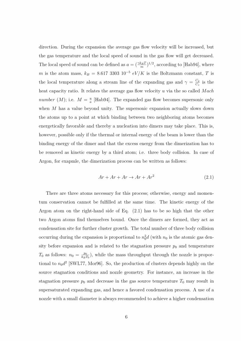
direction. During the expansion the average gas flow velocity will be increased, but
the gas temperature and the local speed of sound in the gas flow will get decreased.
The local speed of sound can be defined as a = (γkBTm
)1/2, according to [Hab94], where
m is the atom mass, kB = 8.617 3303 10−5 eV/K is the Boltzmann constant, T is
the local temperature along a stream line of the expanding gas and γ = Cp
Cvis the
heat capacity ratio. It relates the average gas flow velocity u via the so called Mach
number (M); i.e. M = ua[Hab94]. The expanded gas flow becomes supersonic only
when M has a value beyond unity. The supersonic expansion actually slows down
the atoms up to a point at which binding between two neighboring atoms becomes
energetically favorable and thereby a nucleation into dimers may take place. This is,
however, possible only if the thermal or internal energy of the beam is lower than the
binding energy of the dimer and that the excess energy from the dimerization has to
be removed as kinetic energy by a third atom; i.e. three body collision. In case of
Argon, for exapmle, the dimerization process can be written as follows:
Ar + Ar + Ar → Ar + Ar2 (2.1)
There are three atoms necessary for this process; otherwise, energy and momen-
tum conservation cannot be fulfilled at the same time. The kinetic energy of the
Argon atom on the right-hand side of Eq. (2.1) has to be so high that the other
two Argon atoms find themselves bound. Once the dimers are formed, they act as
condensation site for further cluster growth. The total number of three body collision
occurring during the expansion is proportional to n20d (with n0 is the atomic gas den-
sity before expansion and is related to the stagnation pressure p0 and temperature
T0 as follows: n0 = p0kBT0
), while the mass throughput through the nozzle is propor-
tional to n0d2 [SWL77, Mor96]. So, the production of clusters depends highly on the
source stagnation conditions and nozzle geometry. For instance, an increase in the
stagnation pressure p0 and decrease in the gas source temperature T0 may result in
supersaturated expanding gas, and hence a favored condensation process. A use of a
nozzle with a small diameter is always recommended to achieve a higher condensation
6

rate. It should be noted here that only a fraction of gas atoms taking part in the ex-
pansion ends up in a cluster. This means that there is always a significant amount of
uncondensed gas, i.e. a residual gas, around the condensed beam. Collisions between
the residual gas and the formed clusters may lead to a decrease of the pressure in
the expanding beam, and hence shock waves2 [Mor96] can be formed which may heat
up the cluster beam. As a result, clustering will diminish. In this case a skimmer
is recommended to be placed at a defined distance from the nozzle and along the
expansion axis (figure 2.2) to cut off partially the uncondensed atoms and hence to
avoid the formation of the shock waves. The skimmer now serves to transmit the
main part of the condensed beam from the expansion chamber into a second chamber
that operates at much lower pressure (Experimental chamber). Atoms not passing
through the skimmer may cause a high background pressure in the expansion cham-
ber that can lead to a significant attenuation of the transmitted beam through the
skimmer. Therefore, the residual gas needs to be pumped by a high capacity pump
to maintain a low background pressure in the expansion chamber.
The principles described above provide the conditions necessary to create a par-
tially condensed beam made up of small, medium or large noble gas clusters where
the atoms are held together by Van der Waals forces. The degree of cluster conden-
sation in the beam can be characterized by the Hagena′s reduced scaling parameter
Γ∗ [Hag87, Hag92, KJS93] that depends on the stagnation pressure p0 in mbar, the
nozzle temperature T0 in Kelvin (K) and the nozzle diameter d in µm. It is given by:
Γ∗ = p0d0.85
T 2.28750
k (2.2)
where k is a gas specific constant that can be determined, according to [Hag87, HO72,
Hag92], from the sublimation enthalpy per atom ∆h00 at 0 K and the van der Waals
bond length, which is roughly equivalent to r = (mρ
)1/3 where m is the atom mass and
ρ is the density of the respective solid. Numerical values of k have been calculated2A shock wave generally starts to form when the properties of the expanding beam becomes
similar to that of the background gas. It is thus characterized by an abrupt change in the densityof the expanding beam.
7

Gassupply
Stagnationchamber
(p0 ∼ 2 bar)
Expansion chamber(P ∼ 10−4 mbar)
Experimental chamber(P ∼ 10−6 mbar)
High-capacitypump
Pump
SkimmerNozzle
Figure 2.2: Illustration of supersonic cluster jet. The different chambers needed for the
cluster production are labeled along with the typical pressure in mbar. The expanded
gas atoms from the stagnation chamber and through the nozzle are partially cutted off
by a skimmer inserted between the expansion chamber and the experimental chamber.
by Karnbach et al. [KJS93] and are presented in table 2.1. In case of conical nozzles
the nozzle diameter d has to be replaced by an equivalent diameter deq, which is a
relation between the orifice d and half opening cone angle θ [Hag81]:
deq = 0.74d/θ (2.3)
Elements Neon Argon Krypton Xenonk 185 1646 2980 5554
Table 2.1: Gas specific constants for noble gas elements calculated from the molar
sublimation enthalpy ∆h00 at 0 K (see Karnbach et al. [KJS93] and references therein).
The clusters created in the beam are distributed around a certain mean size < N >
which is only a function of Γ∗. Cluster beams produced under different conditions
but with the same Γ∗ should have the same mean cluster size < N >. For the case of
8
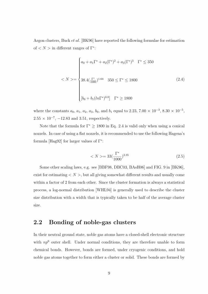
Argon clusters, Buck et al. [BK96] have reported the following formulae for estimation
of < N > in different ranges of Γ∗:
< N >=
a0 + a1Γ∗ + a2(Γ∗)2 + a3(Γ∗)3 Γ∗ ≤ 350
38.4( Γ∗1000)1.64 350 ≤ Γ∗ ≤ 1800
[b0 + b1(lnΓ∗)0.8] Γ∗ ≥ 1800
(2.4)
where the constants a0, a1, a2, a3, b0, and b1 equal to 2.23, 7.00 × 10⁻³, 8.30 × 10⁻⁵,
2.55 × 10⁻⁷, −12.83 and 3.51, respectively.
Note that the formula for Γ∗ ≥ 1800 in Eq. 2.4 is valid only when using a conical
nozzels. In case of using a flat nozzels, it is recommended to use the following Hagena’s
formula [Hag92] for larger values of Γ∗:
< N >= 33( Γ∗1000)2.35 (2.5)
Some other scaling laws, e.g. see [BBF98, DBC03, BAsH06] and FIG. 9 in [BK96],
exist for estimating < N >, but all giving somewhat different results and usually come
within a factor of 2 from each other. Since the cluster formation is always a statistical
process, a log-normal distribution [WHL94] is generally used to describe the cluster
size distribution with a width that is typically taken to be half of the average cluster
size.
2.2 Bonding of noble-gas clusters
In their neutral ground state, noble gas atoms have a closed-shell electronic structure
with np6 outer shell. Under normal conditions, they are therefore unable to form
chemical bonds. However, bonds are formed, under cryogenic conditions, and hold
noble gas atoms together to form either a cluster or solid. These bonds are formed by
9

van der Waals force originated from instantaneous dipoles which arise as a result
of fluctuations on the electron clouds of two neighbour atoms. The interaction be-
tween two noble gas atoms at large interatomic distance is attractive, of long-range
type and varies as −R−6, where R is the separation between the two involved atoms
[Lon30]. As the atoms are brought together their electron distribution gradually over-
laps and the electrostatic energy of the system consequently changes. At sufficiently
close separations any two electrons in the system are prohibited from having the same
quantum state according to the Pauli exclusion principle. The electronic clouds of
a two neighbouring atoms can thereby overlap at a short interatomic distance only if
the electrons are partially promoted to higher energy states of the atoms. The overlap
thus increases the total energy of the system and gives a repulsive contribution to the
interaction. The overlap energy for two atoms at close separation actually depends
on the radial distribution of the electrons surrounding each atomic nucleus. An expo-
nential form e−aR, where a is a constant, that falls off very rapidly with increasing the
interatomic distance R are widely used to describe the repulsive interaction between
two noble gas atoms near to each other [Sla28, BM34, Buc38]. Being used together
with the long range attractive interaction, Lennard-Jones aprroximates the repulsive
interaction as being proportionnal to the 12th of the separation distance R in order
to determine the total potential energy (U(R)) of two atoms holding each other by
van der Waals forces [Jon24, Len30, LJ31]:
U(R) = ε
[(Req
R
)12− 2
(Req
R
)6](2.6)
where ε is the well depth that measures of how strongly two atoms attract each other
and Req is the equilibrium interatomic separation at which the energy passes through
a minimum.
The approximation mentioned above on the repulsive term of the Lennard-Jones
potential energy (U(R)) usually gives a good agreement with experimental data.
Typical potentials of homogeneous noble gas dimers are displayed in figure 2.3.
10

2 3 4 5 6 7 8 9 10-25
-20
-15
-10
-5
0
5
10
15
He-He Ne-Ne Ar-Ar Kr-Kr Xe-Xe
Pot
entia
l ene
rgy
[meV
]
Interatomic distance [Å]
Figure 2.3: Lennard-Jones potential energy curves of homogeneous noble gas dimers.
The ε and Req values which are used to obtain the numerical data of figure 2.3
were taken from reference [TT03]. The displayed potential curves illustrate that the
well depth and the equilibrium distance increase as the noble gas species become
heavier and more polarisable3 (Table 2.2). This means that the strength of the van
der Waals bond increases with increasing the electric dipole polarizability4 [MB78].
He-He Ne-Ne Ar-Ar Kr-Kr Xe-Xe
ε (meV) 0.95 3.64 12.35 17.36 24.38
Req (Å) 2.97 3.09 3.76 4.01 4.36
α (Å3) 0.205 0.395 1.64 2.48 4.04
Table 2.2: Well depth (ε) and interatomic distance (Req) at the equilibrium [TT03]
for noble gas dimers. The table also shows the static electric dipole polarizabilities α
for noble gas elements [MB78].
In the cluster growth, means from dimers to the condensed bulk, the pairwise3More the system contains electrons, higher is the polarizability.4The electric dipole polarizability reflects the degree to which the electronic structure of an atom
can be deformed by a potential binding partner.
11
interaction between bulk atoms contributes the most to the total interaction energy
of the system and thereby leads to higher cohesive energy [Kit96], i.e. greater bonding
strength, as compared to the case of dimers. The cohesive energy can thus be regarded
as the total binding energy per atom that a system gains by being in a condensed
bulk phase in comparison with the phase in which atoms are so far apart. Therefore,
the more bulk coordination a cluster contains, the higher the binding energy per
atom is. This also means that when a majority of atoms are in a position within the
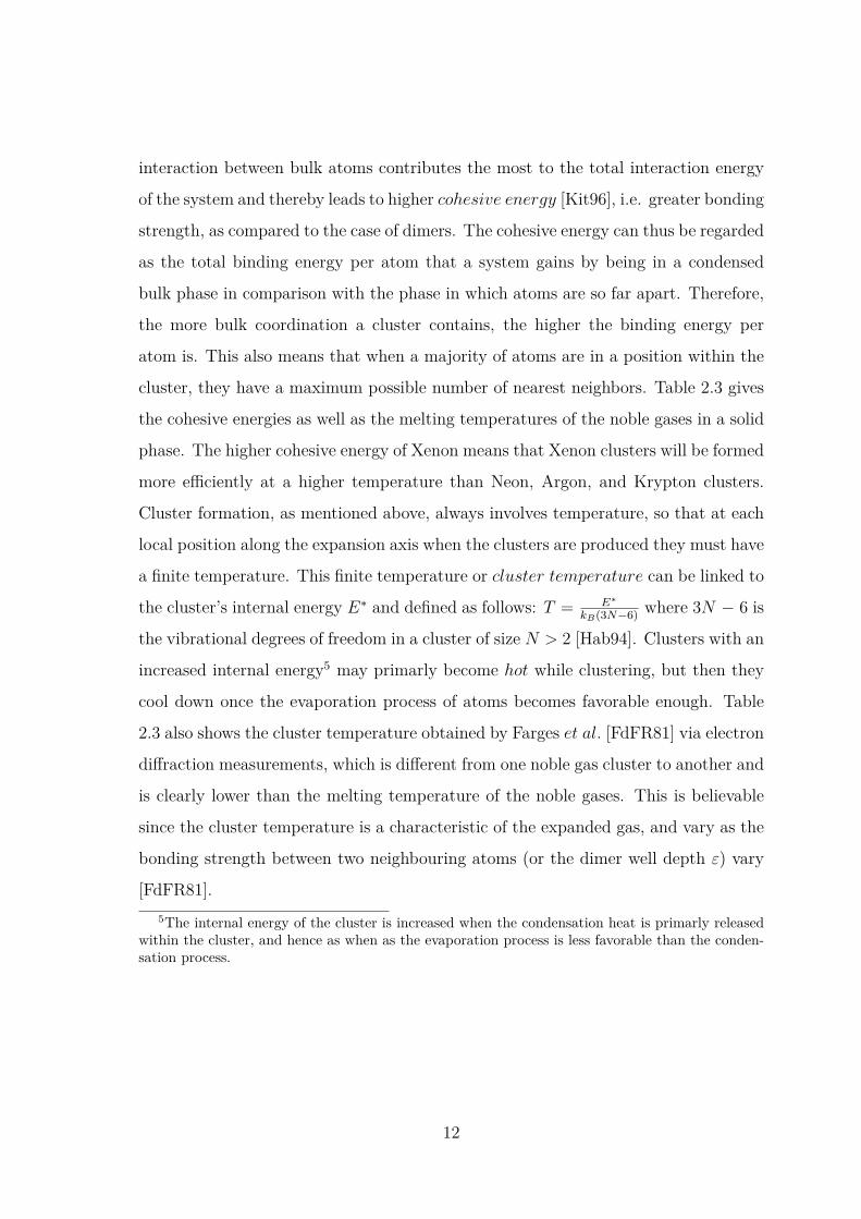
cluster, they have a maximum possible number of nearest neighbors. Table 2.3 gives
the cohesive energies as well as the melting temperatures of the noble gases in a solid
phase. The higher cohesive energy of Xenon means that Xenon clusters will be formed
more efficiently at a higher temperature than Neon, Argon, and Krypton clusters.
Cluster formation, as mentioned above, always involves temperature, so that at each
local position along the expansion axis when the clusters are produced they must have
a finite temperature. This finite temperature or cluster temperature can be linked to
the cluster’s internal energy E∗ and defined as follows: T = E∗
kB(3N−6) where 3N − 6 is
the vibrational degrees of freedom in a cluster of size N > 2 [Hab94]. Clusters with an
increased internal energy5 may primarly become hot while clustering, but then they
cool down once the evaporation process of atoms becomes favorable enough. Table
2.3 also shows the cluster temperature obtained by Farges et al. [FdFR81] via electron
diffraction measurements, which is different from one noble gas cluster to another and
is clearly lower than the melting temperature of the noble gases. This is believable
since the cluster temperature is a characteristic of the expanded gas, and vary as the
bonding strength between two neighbouring atoms (or the dimer well depth ε) vary
[FdFR81].5The internal energy of the cluster is increased when the condensation heat is primarly released
within the cluster, and hence as when as the evaporation process is less favorable than the conden-sation process.
12

Neon Argon Krypton Xenon
Cohesive energy (eV/atom) 0.02 0.08 0.116 0.16
Melting temperature (K) 24.56 83.81 115.8 161.4
Cluster temperature (K) 10 ± 4 37 ± 5 53 ± 6 79 ± 8
Table 2.3: Cohesive energy (at 0 K and 1 atm.) and melting temperature (at 1 atm.)
of solid Ne, Ar, Kr and Xe [Kit96]. The temperatures of large noble gas clusters
measured by electron diffraction at about 5 cm after the nozzle (see [FdFR81] and
[Hab94] p. 216) are also included in the table.
2.3 Structure of noble gas clusters
Clusters made of noble gases are the most weakly bound of all clusters, and are known
by their different favored and stable structures at different cluster sizes. The stability
of noble gas clusters is mainly based on the bonding strength; i.e. the most stable
clusters those which have the maximum number of bonds between nearest neighbors.
The overall evolution of noble gas cluster structure as a function of cluster size is
well established before [Hab94, JKR92, GSS93]. Small noble-gas clusters adopt an
icosahedral structure. The smallest member of an icosahedron contains N = 13 as
number of atoms;i.e. a central atom with two pentagon caps. The clusters grow by
addition of atoms to their sides until the next larger icosahedron is built, having N =
55, 147, 309, 561, etc6. These number of atoms, including N = 13, are called magic
numbers [ESR81] and are elements of the following series [Hab94]:
N = 1 +n∑k=1
(10k2 + 2) (2.7)
where n gives the number of concentric atomic layers in the icosahedron and (10k2 +
2) is the number of atoms in the kth shell.
All the icosahedra N = 13, 55, 147, 309, 561, etc. have five-fold symmetry and6The details of this growing sequence have been discussed in details in [Nor87].
13
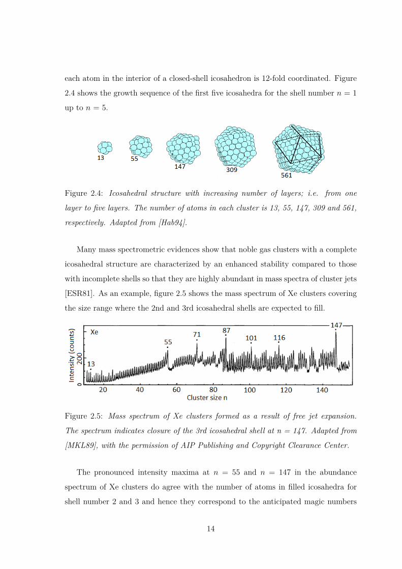
each atom in the interior of a closed-shell icosahedron is 12-fold coordinated. Figure
2.4 shows the growth sequence of the first five icosahedra for the shell number n = 1
up to n = 5.
Figure 2.4: Icosahedral structure with increasing number of layers; i.e. from one
layer to five layers. The number of atoms in each cluster is 13, 55, 147, 309 and 561,
respectively. Adapted from [Hab94].
Many mass spectrometric evidences show that noble gas clusters with a complete
icosahedral structure are characterized by an enhanced stability compared to those
with incomplete shells so that they are highly abundant in mass spectra of cluster jets
[ESR81]. As an example, figure 2.5 shows the mass spectrum of Xe clusters covering
the size range where the 2nd and 3rd icosahedral shells are expected to fill.
Figure 2.5: Mass spectrum of Xe clusters formed as a result of free jet expansion.
The spectrum indicates closure of the 3rd icosahedral shell at n = 147. Adapted from
[MKL89], with the permission of AIP Publishing and Copyright Clearance Center.
The pronounced intensity maxima at n = 55 and n = 147 in the abundance
spectrum of Xe clusters do agree with the number of atoms in filled icosahedra for
shell number 2 and 3 and hence they correspond to the anticipated magic numbers
14

in the size range n 6 147. The structure between these numbers also exhibits many
additional intensity maxima, e.g. at n = 71, 87, 116, which can be attributed to
subshell closures with some adjacent faces being completly unfilled [MEK89, HKN84,
MKL89]. A drop in intensity is clearly seen at or very close to each of these intensity
maxima, especially close to n = 55 and n = 147. The reader can refer to Ref. [MKL89]
for the mass spectra of large noble gas clusters which indicate the closure of the 4th,
5th and 6th icosahedral shell at n = 309, 561 and 923, respectively.
In an icosahedron, the interatomic spacing is not uniform, and most atoms are
surface atoms. Therefore, this structure is favorable in small clusters with a large
surface-to-bulk ratio. The number of surface atoms Ns in an icosahedral cluster with
n layers can be calculated by [Lun07]:
Ns(n > 1) = 10n2 − 20n+ 12 (2.8)
With an increasing number of atoms, the icosahedron structure becomes increasingly
strained as a result of atom-atom radial compression pointing towards the center of
the icosahedron. This induces a mechanical stress that destabilizes the icosahedral
structure so that at some cluster size the fcc structure becomes favored. Large noble
gas clusters are actually known to adopt an fcc structure. Whether, how and at which
cluster size the system undergoes a phase transition to the fcc structure is still unclear.
For instance, Argon clusters formed via supersonic expansion and studied by electron
diffraction are known to have a polyicosahedral when 20 < N < 50 [FdFR83] and
a multilayer icosahedral when 50 < N < 750 [FdFR83]. However, for large Argon
clusters containing up to about 750 atoms, a transition to the fcc crystalline bulk
structure was found to occur [FdFR86].
15
Chapter 3
Light-matter interaction
In considering the interaction of electromagnetic (EM) radiation, i.e. light, with
atoms, absorption and radiative emission processes are known to occur in the form of
quanta of energy commonly referred as photons. In the context of quantum electro-
dynamics, the quantum Hamiltonian of the EM radiation is equal to the sum of an
infinite number of Hamiltonians of harmonic oscillators [Wei78]. Each oscillator is as-
sociated with a mode of radiation field characterized by a wave vector k (where |k| =2πνc
with ν is the frequency and c is the speed of light) and unit vector of polarization
ek. The energy of each mode can only take one of the following values: E = hν (n +12) where n > 0 is an integer, defining the number of photons with an energy of hν in
the radiation field. If an atom in initial state i absorbs a photon with a given energy
hν lower than its electronic binding energy, it therefore undergoes a transition to a
final state f through an induced dipole charge oscillations and the leading process
is called photoexcitation. In the final state f , the atom is electronically excited and
often relaxes by emission of a photon. If the energy of the absorbed photon is now
higher than the electronic binding energy of the atom, an electron from the atomic
ground state can be removed as a photoelectron and the process in that case called
a photoionization. All of these processes and their consequences will be described in
greater details in this chapter in case of isolated and extended systems after a brief
quantum mechanics description of atoms.
16

3.1 Quantum mechanics of atoms
3.1.1 Electron configuration
In quantum mechanics, an atom can be viewed as a positively-charged nucleus and
a surrounding cloud of electrons where the angular momentum of each electron must
be an integer multiple of the reduced Planck constant ~ = h2π . For Hydrogen as sim-
plest atom, the Schrödinger equation, i.e. H|Ψ〉 = E|Ψ〉 (where H, Ψ and E are the
Hamiltonian, the total wave function and energy of the atomic system, respectively),
can be solved analytically to determine the energy of the atomic levels. The Hamil-
tonian H is here regarded as the total energy operator of the system and expressed
as follows:
H = p2
2m + V (3.1)
where V is the potential energy of the system, p is the momentum operator given by
−i ~ ∇ (i is an imaginary unit and ∇ is a gradient operator) and m is the mass of
the system.
Unlike Hydrogenic case, the Schrödinger equation of many electron atoms, e.g.
noble gas atoms, can not be solved analytically because the interaction between the
electrons should be taken into account in addition to the interaction between the
electrons and the nucleus. Therefore, approximation methods are used for better
description of these atoms. This is often treated by using perturbation theory based,
for example, on the so-called central field approximation [BJ83] where one thinks
that each electron moves in an effective centrally symmetric potential created by the
nucleus and all the other electrons and which depends only on the electron-nucleus
distance r. Formally, this approximation means separating the Hamiltonian H of Eq.
(3.1) in two terms; one denoted by H0 representing the sum of the kinetic energy and
the effective potential energy Vc(r) of an electron in the central field, and the other
one denoted by H1 containing the spherical and non-spherical parts of the mutual
17

interaction between the electrons [BJ83]:
H = H0 +H1 (3.2)
where
H0 =N∑i=1
[ P2i
2m + Vc(ri)] (3.3)
and the perturbation H1 is usually neglected since it is a small correction to the
central potential field. The Schrödinger equation for the spatial part of N electrons
central field wave function Ψ0 then reads
N∑i=1
[ P2i
2m + Vc(ri)]Ψ0 = E0Ψ0 (3.4)
The solutions of this equation can be a quite formidable endeavor [BJ83] since Ψ0 is
a product of the individual electron orbitals which can be determined as in the case
of the hydrogenic system. However, contrary to the hydrogenic case, the total energy
E0 in that case is the sum of the individual electron energy which depends on the
principal quantum number n and the electron angular momentum l, namely
E0 =N∑i=1
Enili (3.5)
with n > l + 1.
Therefore, the total energy E0 is entirely determined by the electron configuration;
i.e. by the distribution of the electrons with respect to the quantum number n and l.
For a given value of n, l can take the values 0, 1, 2, ... n−1 which are usually denoted
with lower-case letters s, p, d, f ,.... Thus the state n = 1, l = 0 is denoted 1s, the
state n = 2, l = 1 is denoted 2p, and so on. For each value of the electron angular
momentum l there are in fact 2l + 1 states differing by the values of the magnetic
quantum number ml = −l, −l + 1, ..., l − 1, l. Each ml state can accommodate up
to two electrons with opposite spins; i.e. s = ± 12 . The assignment of an electron
configuration of an atom thus requires the enumeration of the value n and l for all
the electrons. If there are several electrons with the same values of n and l, this is
18

denoted as (nl)k, where k is the number of the electrons. For instance, noble gas
atoms have a particularly simple electron configuration, since all the shells are filled,
e.g. the electron configuration of Neon is 1s22s22p6.
3.1.2 Spin-orbit interaction
For an atom in a Coulomb field the energy levels are in fact n2-fold degenerate as in
case of hydrogen atom; each state have a sub-shells characterized by l. For certain n
the degeneracy is partly lifted because of spin-orbit interaction:
E = En + Eso (3.6)
where Eso is a perturbation term that depends on the mutual orientation of the
angular momenta l and the spin s of the electron; i.e. on the value of the total
angular momentum of the atom j = l + s. Since the magnitude of the spin is ±12 ,
thus the spin-orbit interaction leads to a splitting of the atom energy level nl into two
components l + 12 and l − 1
2 . The value of j is usually written as a subscript after the
spectroscopic notation of l. For example, the state n, l = 1, j = 12 is denoted np1/2,
the state n = 4, l = 2, j = 32 is 4d3/2, and so on.
3.1.3 LS coupling
When the spin-orbit interaction is weak, e.g. in the case of multi-electron atoms with
smaller nuclear charge (Z), the electrostatic interaction between electrons dominates,
and the orbital angular momenta couple together to form a combined angular momen-
tum L = ∑i li. The weak spin-orbit interaction now couples the total spin S = ∑
i si
to the combined orbital angular momenta, and so the total angular momentum J
is the resultant of L and S: J = L + S. Depending on which values are possible
for L, S and J , a variety of terms can arise from any given configuration. Such a
spectroscopic term is often called LS coupling or Russell − Saunders term [Sob92]
and designated as2S+1LJ (3.7)
19

where 2S + 1 is called multiplicity, L can have the values 0, 1, 2, 3, 4, etc. with the
symboles S, P , D, F , G, etc. and J can take the values | L − S | 6 J 6 L + S.
The state of an atom with more electrons can thus be described using L, J , and
S, instead of l and s for each electron. For instance, the ground state of a Neon atom
in the Russel-Saunders notation is 1S0.
3.2 Interaction Hamiltonian
The most basic representation of the mutual interaction between light and matter is
the minimal coupling that relates the momentum of a charge particle to the vector
potential of the light field. In presence of EM field, the electron Hamiltonian expressed
in Eq. (3.1) has now the following form [Deg14, Wei78]:
H = (p+ eA(r, t))2
2m − eΦ(r, t) + V (r) (3.8)
where A(r, t) and Φ(r, t) are the spatial-time-dependent vectorial and scalar potentials
of the EM field, respectively.
In accordance with the principle of electrodynamics [Jac99], Gauge invariance
ensures that the dynamic of such physical operator should remain unchanged following
a gauge transformation on the scalar and vector potentials. By setting Φ(r, t) = 0
and substituting p by −i~∇, the Hamiltonian H of Eq. (3.8) becomes (after taken
into account the Coulomb Gauge: ∇ · A(r, t) = 0) as follows:
H = − ~2
2m∇2 + V − ie~
mA(r, t) · ∇+ e2
2m |A(r, t)|2 (3.9)
where the vector potential A(r, t) can be viewed as a transverse plane waves oscillating
in time t at angular frequency ω and propagating in space in the direction along the
wave vector k:
A(r, t) = A0ei(k.r−ωt) + c.c (3.10)
with c.c indicates the complex conjugate and A0 is a vector perpendicular to the
20

wave vector k and which describes both the amplitude and the polarization of EM
radiation wave.
In the case of a weak EM radiation field, the last term in A2 in Eq. (3.9) is so small
compared to the term in A. This means while the atom interacting with light only
the absorption or emission of one photon should be considered. The absorption or
simultaneous emission of two photons is generally negligible in this case. By neglecting
eA2, the field-matter interaction Hamiltonian Hint can be defined as follow:
Hint(r, t) = −ie~mA(r, t) · ∇ (3.11)
Hint is relatively small compared to the left hand term (− ~2
2m∇2 + V ) of Eq. (3.9).
It is therefore convenient to regard it as a perturbation term to the total Hamiltonian
H of the system.
There is another (and widely used) equivalent form of Hint(t) within the so called
electric dipole approximation. This approximation says that if the wavelength of
the radiation field (e.g. UV, visible, and infrared (but not X-ray) radiation)1 is much
larger than the atomic dimension (∼ the radius of Bohr atom a0 = 0.529 177 Å),
then the exponentials eikr and e−ikr which appear in the vector potential A(r, t) of
Eq. (3.10) can be replaced by unity since the quantity (kr) is so small. In this
approximation, Hint(t) defined in Eq. (3.11) becomes
Hint(t) = −ie~m
[e−iωt + eiωt]A0 · ∇ = − ie
mωE(t) · p (3.12)
where the electric field E(t) = 2E0cos(ωt) with E0 = iωA0 since E(t) = −∂A(t)∂t
.
3.3 Transition rate
When an atomic system (or even a molecular system) is exposed to an oscillating
perturbation of frequency w and which has, for example, a time-dependent form as1The dipole approximation becomes less accurate as the frequency of the radiation increases, and
is so inadequate for X-ray radiation.
21

Hint(t) = Hint(eiwt + e−iwt), after a time t it may undergo a transition from a certain
discrete energy level to another energy level. Time-dependent perturbation theory
shows that the probability of finding such system in a state f with energy Ef if
initially it was in a state i (e.g. ground state) with energy Ei raises linearly in time
as Pf (t) = Γi→f × t where Γi→f is the transition rate and given by Fermi′s Golden
rule as follows:
Γi→f = dPf (t)dt
= 2π~|〈f |Hint|i〉|2ρ(Ef ) (3.13)
Here |〈f |Hint|i〉|2 is the square of the transition matrix element and ρ(Ef ) is the
density of final states, where Ef = Ei + ~ω which states the energy-conservation
condition. The appearence of ρ(Ef ) as a factor in the transition rate Γi→f is in fact
due to that atoms or molecules often have numerous states with the same energies,
e.g. degenerate states – so that a transition normally takes place to a band of states
covering a narrow band of energies. Note that the Fermi′s Golden rule used in Eq.
(3.13) can also be used to determine the rate of the transition f → i that corresponds
to an emission process.
The transition matrix element |〈f |Hint|i〉|, and thus the transition rate Γi→f , can
be evaluated easily within the electric dipole approximation. By using the Hamilto-
nian Hint of Eq. (3.12) and taking into account that 〈f |p|i〉 = m(Ei−Ef )i~ 〈f |r|i〉 since
p = im~ [H0, r], Γi→f reads
Γi→f = 2π~ωfiωE2
0 |〈f |µ|i〉|2ρ(Ef ) (3.14)
where ωfi = Ei−Ef
~ , 〈f |µ|i〉 is the transition dipole matrix and µ = er is the electric
dipole moment of the system.
3.4 Spectral line broadening
According to the transition rate described in Eq. (3.14), any radiation emitted or
absorbed between the atomic level of energies Ei and Ef is therefore associated with
an exact amount of energy E = Ei − Ef and thus has an infinitely sharp spectral
22
line. However, if this radiation will be measured by means of some spectroscopic
techniques, its spectral line will not be sharp even when an infinitely narrow resolution
is considered. The spectral line of the radiation will rather appear with a particular
broad shape. Numerous effects can contribute to the spectral line broadening. Among
of these effects are:
• Natural width: It is connected with the uncertainty principle which states that
the energy of such a level can not be precisely determined, but must be uncertain by
an amount of order ~τwhere τ is the finite lifetime of the state to which the transition
occurs.
• Pressure broadening effect: It arises due to the collisions between atoms in a
gas while emitting or absorbing a radiation. These collisions depend on the pressure
of the gas (the targed density). During collision when excited atoms collide with the
surrounding gas, there will be an exchange of energy which will lead to a broadening
of the atomic energy levels, and hence to a decrease in the lifetime of the atomic
excited states.
• Doppler effect: This effect happens when the atoms are moving relative to the
observer. It mainly leads to a frequency shift of the radiation emitted by the moving
atoms.
3.5 Selection rules
Experiments show that the absorption or emission spectrum of an atom, e.g., hydro-
gen atom, does not contain all possible frequencies ν according to the transition rate
described above. There must be certain selection rules which constrains the possible
transition of the atom from one quantum state to another. Finding the conditions un-
der which the transition dipole matrix described in Eq. (3.14) is non-zero is actually
equivalent to finding the selection rules for which a transition is allowed.
In general, any electron transition which involves an absorption or emission of a
photon must involves, within the electric dipole approximation, a change of unity in
the atom’s angular momentum since the photon has an intrinsic angular momentum of
23
one. The photon in that case can only exchange up to one unit of angular momentum
with the atom, so that the angular momentum of the atomic system conserves; i.e.
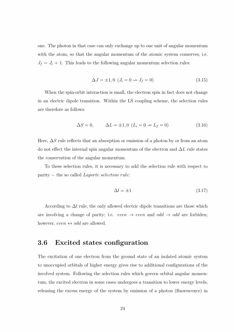
Jf = Ji + 1. This leads to the following angular momentum selection rules:
∆J = ±1, 0 (Ji = 0 9 Jf = 0) (3.15)
When the spin-orbit interaction is small, the electron spin in fact does not change
in an electric dipole transition. Within the LS coupling scheme, the selection rules
are therefore as follows:
∆S = 0, ∆L = ±1, 0 (Li = 0 9 Lf = 0) (3.16)
Here, ∆S rule reflects that an absorption or emission of a photon by or from an atom
do not effect the internal spin angular momentum of the electron and ∆L rule states
the conservation of the angular momentum.
To these selection rules, it is necessary to add the selection rule with respect to
parity − the so called Laporte selection rule:
∆l = ±1 (3.17)
According to ∆l rule, the only allowed electric dipole transitions are those which
are involving a change of parity; i.e. even → even and odd → odd are forbiden;
however, even ↔ odd are allowed.
3.6 Excited states configuration
The excitation of one electron from the ground state of an isolated atomic system
to unoccupied orbitals of higher energy gives rise to additional configurations of the
involved system. Following the selection rules which govern orbital angular momen-
tum, the excited electron in some cases undergoes a transition to lower energy levels,
releasing the excess energy of the system by emission of a photon (fluorescence) in
24

the ∼ ns timescale regime. The spectral lines which are originated from an electronic
radiative decay may fall into an emission line series with different spectral ranges2.
To find out a notation of such emission spectral lines, one should first understand
the mechanism of interaction between the electrons. The electrostatic interaction of
the electrons of the atomic core with the excited electron is small in comparison with
their spin-orbit interaction. So, the LS coupling scheme in that case is not applicable.
However, the atomic core can be described using the LS notation 2S+1Lj (with L,
S, j is the orbital angular momentum, the spin, and the total angular momentum
of the atomic core, respectively) as it has equivalent electron configuration (e.g. np5
configuration for noble gas atoms) for which the electrostatic interaction is always
large. In comparison with the weak coupling between the spin of the excited electron
and the atomic core electrons, the electrostatic interaction of the excited electron
with the atomic core electrons is actually strong enough to give a series of levels, each
of which can be described by an angular momentum vector K that arises from the so
called jl coupling [Sob92]:
K = j + l (3.18)
with l is the orbital angular momentum vector of the excited electron, j is the total
orbital angular momentum vector of the atomic core and K can take the values j +
l, j + l − 1, ... | j − l |.
Finally, the coupling between the spin of the excited electron and the quantum
number K leads to two components of the total angular momentum vector J of the
atom:
J = K ± 12 (3.19)
Any excited state described by the set of quantum numbers LSjlKJ is often given2The simplest atom of hydrogen, for example, exhibits a regular lines series with a decrease of
intensity and separation towards shorter wavelengths; i.e. Lyman series, Balmer series, Paschenseries, etc.. While noble gas atoms exhibit irregular spectral lines lying in the vacuum ultravioletregion (transition to the ground level), visible and infrared regions (transition between excited levels).
25

by the following notation [Sob92]:
2S+1Ljnl[K]J (3.20)
For example, in the case of an outer-shell excitation of a 2p electron in Neon atom
to the 4s unoccupied state, on can have the following four levels: 2p5 2P3/24s[3/2]2,1;
2p5 2P1/24s[1/2]0,1.
3.7 Atomic Rydberg states
Rydberg states of an atom are highly excited states which can generally be described
in term of series that converge on energy levels of the atomic ion core. They can
nowadays easily be prepared, due to the availability of tunable excitation sources
such as SR, by promoting one electron from the ground state of the atom to an
unoccupied state with a very high principal quantum number n. When an electron
from an atom with many electrons is excited to higher energy unoccupied state (nl),
it becomes effectively shielded from the electric field of the nucleus by the electronic
cloud of the atom. As a result, the excited electron generally ”sees” the atomic core
as one nucleus and will behave much like the electron of the hydrogen atom as long
as it does not come too close to the core. If the excited atom is further facing various
perturbations, the excited electron can, however, easily be removed apart since it is so
weakly bound to the atomic core. The energy of an excited electron in such Rydberg
state nl can be determined by using the following Rydberg formula:
En = Eth −R
(n− δ)2 (3.21)
where R is the Rydberg constant equal to 1.097 373 × 105 cm−1, n is the principal
quantum number, δ is the quantum defect [RI97] and Eth is the threshold energy
which represents the convergence limit of the Rydberg series as n tends to infinity.
A highly excited atom is often called Rydberg atom [Met80], after the Swedish
spectroscopist Johannes Rydberg.
26

3.8 Photoionization
The minimum amount of energy that is required to remove an electron from an atomic,
molecular or ionic system is called ionization energy (IE) or more commonly electron
binding energy (Ebind). When an atom, for instance, absorbs a photon with an energy
hν ≥ IE, it therefore becomes ionized. This is known by the photoionization process
or, when a metal is ionized, the process is called photoelectric effect as pointed out
by Einstein in 1905 [Ein05]. The photoelectric effect principle is based on a simple
but fundamental rule: an electron can be ejected as a photoelectron from a metal
only if it receives an energy at least equivalent to its binding energy; i.e. the work
function for the metal involved. When the energy of the photon hν exceeds the work
function and a photoelectron is emitted, any excess of photon energy over the work
function must appear as a kinetic energy of the emitted electron. In other words, the
kinetic energy Ekin of the photoelectron is directly related to its binding energy via:
Ekin = hν − Ebind (3.22)
In fact, not every photon encounters an atom, molecule or ion will eject an electron
from the atomic, molecular or ionic ground state. The probability of photoionization is
related to a photoionization cross section that depends on the energy of the photon
and the target being considered. According to [BS96], the photoionization cross-
section can be given as follows:
σ(hν) = 4π2αa20hν
3 |〈f |µ|i〉|2 (3.23)
where α = 1137.036 is the fine-structure constant, a0 = 0.529 177 Å is the Bohr radius,
hν is the photon energy and µ is the electric dipole moment of the the system.
If several nl orbital levels are involved in the photoionization process, then the
summation of partial photoionization cross section should bring about the total pho-
toionization cross section σtot:
27
σtot(hν) =∑nl
σnl(hν) (3.24)
The differential form of σ, gives information on the angular distribution of the
ejected electron; i.e. dσdΩ . For linearly polarized incident light, dσ
dΩ has the following
general form [Sch92, BS96, CZ68]:
dσ(hν)dΩ = σ(hν)
4π
[1 + β
2 (3cos2Θ− 1)]
(3.25)
where β is an asymmetry parameter [CZ68] and Θ measures the angle between the
direction of the ejected electron and the polarization of the incident light.
3.9 Extended systems
3.9.1 Example: noble gas dimers
When two neutral noble gas atoms combine to form a dimer, an interaction between
their atomic valence orbitals rises up and valence molecular-like orbitals may tend
to form since the valence electrons are likely delocalized. For instance, from the 1s
atomic orbitals of Helium one can construct two molecular orbitals: a bonding σg and
an antibonding σu. The indices g and u designate the gerade and ungerade symmetry
state of the wave function with respect to interchange of the nuclei, respectively. He2
possesses inversion symmetry as in case of diatomic systems (e.g. the molecule of
Oxygen O2 or Nitrogen N2), so that under inversion the bonding σg is unaffected
wherease the antibonding σu changes sign. Each σ orbital can accommodate up to
two electrons of opposite spin. For other homonuclear noble gas species the orbital
energies are different enough, so that only orbitals of the same energy interact to a
significant degree to form bonding and antibonding orbitals. As an example, for the
Ne2 dimer one can construct six full valence molecular-like orbitals correlated with
the localazed 2s and 2p valence orbitals in the separated atoms limit, namely,
28

2σg, 2σu, 3σg, 1πu, 1πg, 3σu (3.26)
Here, the bonding and antibonding effects nearly cancel each other, so that the
well depth of the Ne2 interaction potential is only of about few meV (≈ 3.64 meV ).
Here also, note that the bonding 1πu and the antibonding 1πg both accommodates
four electrons.
3.9.2 Potential energy curves of ionized Ne2
The removal of an electron from one of the six valence molecular-like orbitals of the
Ne2 system leads to a strong chemical bond for the formed Ne+2 -ion, and hence to
an energetic increase in the well depth. Figure 3.1 enphasizes this fact. It shows the
qualitative potential energy curve of the neutral ground state of Ne2 as well as of the
outer- and inner-valence states of Ne+2 . Due to the weak van der Waals interaction,
the Ne2 dimer is initially in its electronic ground state3 1Σg. The corresponding
potential curve is quite flat, has a very shallow minimum at about 3.2 Å and is
supporting only two vibrational levels [SZC00]. By outer-valence ionization of a 2p
electron, the Ne2 ground state wave function can be lifted up to four outer-valence
(ov) cationic states Ne+2 (ov). Two of them are lower lying states denoted by 1 2Σ+
u
and 1 2Π+g , and which possess distinct minima. The two other are higher lying states
denoted by 1 2Π+u and 1 2Σ+
g , and which are purely repulsives. In contrast to the
outer-valence ionization, the removal of a 2s electron out of the Ne2 system can
result to two inner-valence (iv) cationic states Ne+2 (iv), i.e. 2 2Σ+
u and 2 2Σ+g . The
inner-valence 2 2Σ+u state has a distinct energy minimum at about 2.2 Å, supporting
11 vibrational bound states, whereas the 2 2Σ+g state is purely repulsive and has a
very shallow minimum with a single vibrational level [SCM03].3The ground state of the Ne2 diatomic system is a singlet (S = 0) and has a term symbol of 1Σg
because the net orbital angular momentum is zero and all the electrons must be paired so that theoverall parity is gerade (g) according to the multiplication rule g × u = u, g × g = g, u × u = g.See e.g. [Atk83] for more details concenring the term symbols for diatomic molecules.
29

48
49
50
51
20
21
22
1.0 1.5 2.0 2.5 3.0 3.5 4.0 4.5 5.0-1
0
1
2
Ne+(iv)Ne2 2 +
u
2 2 +g
1 2 +g
1 2 +u1 2 +
g
1 2 +u
Ne+(ov)Ne
Ener
gy [e
V]
Interatomic distance [Å]
Ne2 ground state
Figure 3.1: Qualitative potential energy curves for the electronic state of Ne2 (bot-
tom), the outer-valence states of Ne+2 (middle) and the inner-valence states of
Ne+2 (top). Adapted with permission from [MSZ01]. Copyright 2001 by AIP Pub-
lishing LLC.
3.10 Relaxation prcocesses
Upon outer-shell photoexcitation, an atomic or molecular system often relaxes radia-
tively into its ground state or photoionizes as long as one of its outer-valence electrons
is removed apart. Upon inner or core-shell photoexcitation, the system may, how-
ever, undergo different relaxation processes since it still possesses an excess energy
after the primary excitation. Among these relaxation decays the so-called intra− and
inter atomic decay processes according to whether the system is isolated or belongs
to a chemical environment, respectively. In this section, I will present the most rele-
30

vant relaxation mechanisms which can occur when a high energetic photon efficiently
interacts with an isolated and extended system.
3.10.1 Intra-atomic decay processes
An intra-atomic decay process or more commonly autoionization (AI) is a process by
which an isolated system in an excited state spontaneously emits one of its outer-shell
electrons, thus going from a state with charge Z to a state with charge Z + 1. For a
core-ionized system, the process is called normal Auger decay process [Mei22, Aug23].
Generally, in Auger decay process, an initially prepared core-shell vacancy is filled
with an electron from energetically higher valence shells while the remaining excess
energy in the system is released by emission of an electron from the outermost-valence
shell. The isolated system is then left with two outer-valence vacancies final states,
as illustrated in Figure 3.2(a).
1s
2s
2p
(a): Auger decay
Ne++
1s
2s
2p
(b): Autoionization
Ne+
1s
2s
2p
(c): Radiative decay
Ne+
Figure 3.2: Illustration of possible relaxation mechanisms that may occur in an iso-
lated Neon atom, after absorbing an incident photon. (a) Auger decay, (b) Autoion-
ization (AI) and (c) Radiative decay.
Auger decay can only happen, if the excess energy is sufficient to overcome the
binding energy of the outer-valence shell electron. Otherwise, the energy is released
in terms of an X-ray photon (fluorescence).
31

Other possibilities for AI can also exist following a resonant excitation of an elec-
tron from the core shell of a given isolated system into an unoccupied bound state.
Here, the uncharged-excited system likely decays via emission of an electron. If the
initially excited electron participates in the decay, the process is called participator
Auger decay and the system is left with one final state vacancy. If not, it is called
spectator Auger decay where the system is left with two vacancies final states as long
as the initially excited electron is removed apart.
AI process may also occur following a resonant excitation of an electron from
the inner-shell of the isolated system to an unoccupied energy level nl. For example,
following excitation of an inner-valence 2s electron of a Neon atom into an unoccupied
bound state nl, an autoionizing states may exist beyond the first ionization limit of
Neon due to the interference between the nl discrete states and the continuum final
states far above the first ionization limit. Here, the AI occurs via the np → 2s
de-excitation which provides the energy needed to remove one 2p electron from the
outer-valence shells and form the Ne+ ground state. The excited Neon atom has
also the same final state Ne+ when the generated excess energy from the 2p → 2s
de-excitation used to kick out the initially excited nl electron, as illustrated in Figure
3.2(b). For an inner-valence ionized state, the isolated system likely decays by photon
emission, as shown in figure 3.2(c) for the case of an ionized Neon atom; i.e. a photon
is emitted due to the electronic transition 2p → 2s.
Due to electron correlation, one absorbed photon by an isolated system may also
excite two electrons simultaneously, e.g. from the outer valence shell, into the con-
tinuum. If one of the electrons relaxes, it transfers its energy to the other excited
electron, which is consequently ejected and the system is left with one final state
vacancy. This process is also called AI.
3.10.2 Interatomic/molecular Coulombic decay
The removal of an electron from an isolated system by photoionization often leads
to dissociation of that system or produces energetic ions which give off their excess
energy by photon emission (as illustrated in figure 3.2(c)) or−if energy permits−by
32

electron emission (as illustrated in figure 3.2(a) and (b)). However, in a cluster with
one or more neighboring sites, the situation can be different since the environment
may influence the relaxation process of the excited entity. In the late 1990s it has
been found theoretically by Cederbaum et al., [CZT97] that an ultrafast (v tens
of femtoseconds (fs)) and efficient decay channel termed interatomic or molecualr
Coulombic decay (ICD) indeed occurs in weakly bound systems, e.g. hydrogen
bonded clusters or noble gas clusters, by which the excess energy of an inner-shell
ionized atom or molecule is transferred to a neighboring site, thereby ionizing it.
ICD as a non radiative cluster specific decay can set in only if the initially per-
turbed atom or molecule is in a state energetically higher than the ionization threshold
of other neighboring sites. If one consider, for example, an inner valence vacancy in
a given cluster with an energy above the double ionization threshold of the cluster, it
might then decay by ICD such that the cluster is doubly ionized in the final state and
end up with two vacancies located on two different sites. This is because the double
ionization threshold of the cluster lies much lower than the one of the isolated system
[MC06, RSS92]. Few year later after its discovery, ICD has been verified experimen-
tally [MKH03, JCS04] and since then has been the focus of numerous experimental
and theoretical investigations [Her11, Her12, Jah15, ADK11]. Extended systems, for
which ICD is relevant, range from van-der-Waals to polar water clusters and from
inorganic to biological samples such that the ICD scientific community claims: ICD
appears everywhere [SSO11]!
• Aspects and nature of ICD process: The important aspect of ICD is that
the excess energy of the excited site is used to eject a low kinetic energy electron
(the ICD electron) from the neighboring site. These electrons are generally proven to
be genotoxic and may induce irreparable damage in living tissue [BCH00, MBC04,
AOS15]. ICD therefore leads to a subsequent fragmentation of the involved system
into smaller units at specific sites, repelling each other due to Coulomb explosion.
Figure 3.3 illustrates the ICD process in Neon dimer.
33
2s
2p
2s
2p
(a): Photoionization
Ne+ Ne
2s
2p
2s
2p
(b): Energy transfer
Ne+ Ne
2s
2p
2s
2p
(c): Coulomb explosion
Ne+ Ne+
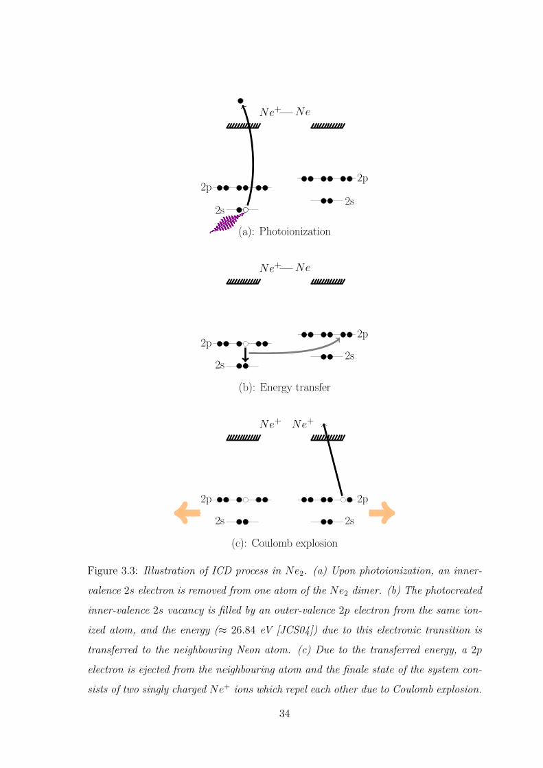
Figure 3.3: Illustration of ICD process in Ne2. (a) Upon photoionization, an inner-
valence 2s electron is removed from one atom of the Ne2 dimer. (b) The photocreated
inner-valence 2s vacancy is filled by an outer-valence 2p electron from the same ion-
ized atom, and the energy (≈ 26.84 eV [JCS04]) due to this electronic transition is
transferred to the neighbouring Neon atom. (c) Due to the transferred energy, a 2p
electron is ejected from the neighbouring atom and the finale state of the system con-
sists of two singly charged Ne+ ions which repel each other due to Coulomb explosion.
34

At first an absorbed photon with an energy higher than the Neon 2s-electron
photoionization threshold (∼ 48.475 eV [SDP96]) removes an inner-valence 2s electron
from one of the atoms of the dimer (figure 3.3(a)). After that, an outervalence 2p
electron fills the photocreated inner-valence 2s vacancy. The amount of excess energy,
∼ 26.84 eV [JCS04], due to the electronic transition 2p→ 2s, is not sufficient to kick
out an outer-valence 2p electron from the singly charged ion Ne+, which requires
more than 40 eV ; i.e. local autoionization is energetically forbidden. However, it is
sufficient to remove an outer-valence 2p electron from the neighboring neutral Neon
atom, which has a binding energy of about 21.56 eV ; i.e. ICD is energetically allowed
(figure 3.3(b and c)). As consequence of ICD, the final state of the system is two
singly charged ions Ne+ 2p−1 repelling each other due to Coulomb explosion (figure
3.3(c)). The energy difference to a final state consisting of two atomicNe+ 2p−1 ions is
48.475 eV − 2 × 21.56 eV = 5.35 eV . Due to energy conservation, this amount of
energy will be shared between the kinetic energy of the ICD electron and the kinetic
energy release (KER) [JCS04, JCS07] of the Ne+ 2p−1 ion pair.
• ICD final states: The relevant potential energy curves for all the electronic
states involved in the excitation and ICD processes described above are shown in
figure 3.4. The Ne2 system is initially in the lowest vibrational level of its ground
state which has a minimum at about 3.2 Å. Upon inner-valence ionization, the
ground state wave function is lifted up to 2 2Σ+u and 2 2Σ+
g states of Ne+2 . The
probability that the Ne2 system can end up in any particular vibrational level of
the 2 2Σ+u and 2 2Σ+
g states of Ne+2 is, according to the Franck-Condon principle 4
[Atk83], proportional to the square of the overlap of the vibrational wavefunctions of
the ground and final state. In the region of interatomic distance where the transition
occurs, mainly in the Franck − Condon region5, these inner-valence cationic states
are relatively flat, which means that the excitation of the vibrational states, which are
spatially extended, is favored. The 2 2Σ+u and 2 2Σ+
g states both can undergo electron4Franck-Condon principle states that a transition from one vibrational level to another will be
more likely to happen if the two vibrational wave functions overlap more significantly.5The Franck Condon region is the spatial extension of the vibrational wavefunctons of the ground
state. Outside this geometric limit, the vibrational wavefunction become very small, effectively zero.An electronic transition to upper state can therefore only be reached within this region.
35

emission resulting in two outer valence cationic states Ne+(ov) having one vacancy
on each of the Neon atoms [SZC00]. These Ne+(ov) states are found to be lower
in energy than the inner-valence states for the most interatomic distance [SZC00],
and hence giving rise to an efficient ICD. At the contrary, the Ne2+2 states with both
vacancies being localized on the same Neon atom are actually much higher in energy
≈ 60.9 eV [SZC00]. They are therefore like the dicationic states in the isolated Neon
atom, not accessible for an electronic decay of the inner-valence cationic states. One
of the potential energy curves of the two Ne+(ov) states is plotted in dark yellow in
figure 3.4. Since the two Ne+(ov) states repelling one another by the Coulomb force
acting between them, their potential enrgy curves are highly repulsive, intersecting
the 2 2Σ+u state at approximately 2.1 Å and very similar to each other.
36

47.0
47.5
48.0
48.5
49.0
49.5
50.0
1.0 1.5 2.0 2.5 3.0 3.5 4.0 4.5 5.00.000
0.002
0.004
0.014
Ne+(2s-1)Ne
Interatomic distance [Å]
2 2 +g
2 2 +u
Ne+(2p-1)Ne+(2p-1)
Frank-Condon region
Ne2 GS (enlarged)
Ener
gy [e
V]
47.0
Figure 3.4: Qualitative potential energy curves of the electronic ground states Ne2,
inner-valence states of Ne+2 and the two-site outer-valence states of Ne2+
2 . Since
these dicationic state are all very similar to each other, only one is plotted in dark
yellow. By inner-valence ionization the vibrational ground state wave function of Ne2
is lifted up to the 2Σ+u and 2 2Σ+
g states of Ne+2 . For most interatomic distances the
dicationic two-site states are lower in energy than the inner-valence state, giving rise
to an efficient ICD. The separation between the two vertical dashed lines highlights
the Frank-Condon region. Adapted with permission from [MSZ01]. Copyright 2001
by AIP Publishing LLC.
• ICD transition rate: Like autoionization process, ICD is driven by the Coulomb
interaction between the electrons involved in the transition. The decay rate of an
inner valence vacancy is proportionnal according to the Fermi′s Golden rule to the
transition matrix element of the process:
Γiv ∝ |Vov1,ov2[iv,k]|2 (3.27)
where iv, ov1, ov2, and k denotes the inner-valence, the two outer-valence and the con-
37

tinuum orbitals participating in the process and Vov1,ov2[iv,k] = Vov1,ov2,iv,k−Vov1,ov2,k,iv
is the electron-electron Coulomb repulsion operator where Vov1,ov2,iv,k and Vov1,ov2,k,iv
are designated as direct and exchange term, respectively.
The direct term Vov1,ov2,iv,k is associated with an energy transfer mechanism that
occurs between an initially inner-valence ionized atom in a cluster and its neighbor,
as illustrated in figure 3.3 (b and c) for the case of Neon dimers. The exchange
term Vov1,ov2,k,iv, however, describes a charge transfer process in which, for example,
an initially inner-valence 2s vacancy created in one atom of a Neon cluster is filled
up with an outer-valence 2p electron from a neighboring Neon atom and the excess
energy due to this electronic transition is used to eject an outer-valence 2p electron
from the same initially ionized Neon atom into the continuum. By denoting ϕ as the
wavefunction of such orbital involved in the decay process, the integral forms of the
direct and exchange ICD terms can be written, respectively, as follows [Jah15]:
Vov1,ov2,iv,k = e2∫ ∫
ϕov1(r1)ϕiv1(r1) 1|r1 − r2|
ϕov2(r2)ϕk(r2)d3r1d3r2 (3.28)
and
Vov1,ov2,k,iv = e2∫ ∫
ϕov1(r1)ϕk(r1) 1|r1 − r2|
ϕov2(r2)ϕiv1(r2)d3r1d3r2 (3.29)
The contribution of these two terms to the decay rate depends very differently on
the internuclear distance R separating the two atoms involved in the decay process.
The exchange ICD term arises at small R due to the increasing overlap between the
orbitals ov2 and iv, and its matrix element die off exponentially with increasing R
[AMC04]. Neglecting the overlap between ov2 and iv at sufficiently large R, the direct
ICD matrix element behave as R−6 – characteristic of a dipole-dipole interaction –
as demonstrated in [SC02] via expanding Vov1,ov2,iv,k(R) in inverse-power series6 in R.
In realistic cases however, finite overlap between the orbitals strongly modifies the
ICD rate. That is saying, when R is decreased from assymptotically large distances6See Ref. [LR73] and references therein for more details concerning the validity of the inverse-
power expansion in approximating the long-range Coulombic interaction potential V (R).
38

the ICD rate increases much faster than R−6 as overlap sets in [AMC04]. Since noble
gas clusters are usually characterized by large equilibrium internuclear distances, the
exchange ICD matrix element is expected to be small and it is rather the direct ICD
matrix element that dominates by far. Jahnke et al. [JCS07] showed experimentally
that this is the case in the ICD of Neon 2p shake-up states. It was also found that
for the case of inner-valence ionization of Neon dimer/clusters and other noble gas
clusters ICD occurs almost completely due to the direct contribution [AMC04].
As reported in [TMW02, AMC04], ICD rate can also be approximated at large
R using the interatomic Auger rate expression obtained by Mathew and Komninos
[MK75]:
Γ = 3~4π
c4
ω4τ−1σvir.ph
R6 (3.30)
where τ is the radiative lifetime of the vacancy on the initially ionized atom and
σvir.ph is the total photoionization cross section of an electron from a neighbor atom
by a virtual photon of frequency ω.
The characteristic R−6 behaviour of the direct ICD rate is known as well from
other non-local process of energy transfer – the so called Förster resonant energy
transfer (FRET ) [Cle09]. FRET is a mechanism of energy transfer that can also
occur via a non-radiative dipole-dipole interaction between two biological molecules;
i.e. between a donor and acceptor. In FRET, the energy which is used to resonantly
excite one molecule A is transferred to another molecule B in vicinity. In turn, the
former molecule B resonantly absorbs that energy, becomes excited, and then releases
the absorbed energy via fluorescence emission. Direct ICD is however different from
FRET since it is not a resonant process. It is rather mediated by an exchange of a
virtual photon [AMC04]. Moreover, FRET occurs efficiently at separation distances
typically in the range of 1 to 10 nm which are more larger than the required inter-
atomic distance for the occurence of ICD in weakly bound systems. Although the
description of the direct ICD term is basically equivalent to the theoretical descrip-
tion of FRET as it incorporates the dipole-dipole coupling, the description of the
exchange ICD term is, however, in line with that of the non-local character of charge
39
exchange in Penning ionization (PI) [Jah15, Sha74, MM77, HN69] which also re-
quires an orbital overlap between the two atomic or molecular species involved in the
process. PI is a collisional (non-local) autoionization process and mainly a result of
a chemical reaction in which an electronically excited gas-phase atom or molecule
X∗ collides with a neutral target atom or molecule Y , thereby forming together a
metastable excited quasi − molecule (XY )∗ that may release its stored energy by
charge transfer that leads to an emission of an electron from the system and produce
the following final state: (XY )∗ → X + Y + + e−. Regardless the non-local and
short range character of PI, the exchange ICD as well as the direct ICD are however
distinguishable from PI as they both involves a dipole-allowed transition, for example
the 2s → 2p electronic transiton in case of 2s-ionized Ne2 dimer, to occur, whereas
the occurence of PI requires the involvement of a metastable states or a long-lived
excited states where a transition to the ground state is forbidden by selection rules
governing orbital angular momentum and electron spin [Sha74]. Thus, metastable
states are the main source of PI as compared to ICD.
• ICD related processes: Independent of what kind of electronic excitation is
at hand, various ICD related interatomic/molecular processes may also occur when
an electronically excited atom or molecule is in a state energetically higher than
the ionization threshold of other neighbouring entity. Among of these ICD related
processes are the electron-transfer-mediated decay (ETMD) [ZSC01, FMA11], ra-
diative charge transfer (RCT ) [KJW08, HOS10, RJAMD16, HSH18], Auger-ICD
cascade [SC03, MLS06] and excitation-transfer-ionization (ETI) [GTS05]. Similar
to ICD, all of the aforementioned relaxation processes are non-local autoionizing de-
cay channels accessible in weakly-bound systems where energy is transferred between
nearst neighbours. In ETMD, for instance, the energy transfer is mediated through
charge transfer triggering the excess energy to either electron donator, ETMD (2),
or a third neighbouring atom, ETMD (3) [BSC03, SGC16]. ETMD is relatively a
weaker decay channel as compared to ICD with a lower decay widths of several or-
ders of magnitude at typical noble gas cluster interatomic distances [ZSC01]. For
systems where ICD is energetically forbidden, it has recently been shown that ETMD
40

is the dominant decay pathway and much stronger than its radiative charge transfer
counterparts; i.e. ETMD proceeds on a time scale of magnitude faster than RCT
[SKcvG13, SKG14, LSG16]. It should also be noted here that for high concentrated-
noble gases maintained at ambient temperature RCT can occur as a result of three-
body collision process as experimentally reported before and for the first time in
[JB78].
3.10.3 Resonant interatomic Coulombic decay
The direct ICD process described above and illustrated in figure 3.3 is a characteristic
of an inner-valence ionized state of the cluster. We may now ask what are the lead-
ing decay processes when an inner-valence electron of one component of the cluster
is selectively promoted to an unoccupied nl state? This question has been experi-
mentally addressed in the past by Barth et al., [BJM05] to investigate the possible
open channel decays following a resonant excitation of an inner-valence 2s electron
in Neon clusters. Their results show that the resonant excitation of one component
of the cluster also triggers ICD. They first resonantly photoexcited a 2s electron of
a Neon atom belonging to about 70 Neon atoms per cluster into 3p Rydberg state
and then detected the emitted ICD electrons from a neighboring entity as a result
of transfer of energy which is being stored in the initially excited atom due to the
electronic transion 2s → 2p. The leading relaxation process in that case has been
called resonant ICD (RICD) since the excited 3p electron does not participate in the
ICD process. This non-local decay phenomenon can also be classified more precisely
as spectator RICD. In fact, RICD can be classified as spectator RICD or participator
RICD according to whether the initially excited electron is active or inactive in the
energy transfer process, respectively.
While the direct ICD is typically orders of magnitude faster than its only com-
peting process-radiative decay, RICD may face competition from intra-atomic au-
toionization which occurs roughly on a similar timescale, i.e. fs regime, and leads
to the emission of an electron from the initially excited cluster site. As shown in
[GAC06, KGC09], the autoionization process is dominant for lower principal quan-
41
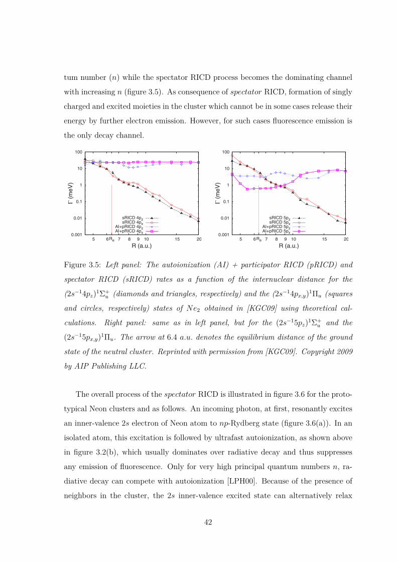
tum number (n) while the spectator RICD process becomes the dominating channel
with increasing n (figure 3.5). As consequence of spectator RICD, formation of singly
charged and excited moieties in the cluster which cannot be in some cases release their
energy by further electron emission. However, for such cases fluorescence emission is
the only decay channel.
slightly higher, is the 2s−14pz1u
+ inner-valence-excitedstate. The WW-TDA results for the AI+ pRICD and thesRICD widths of this resonance are shown in Fig. 3. It standsout that the AI width as a function of R is not a constant, butrather exhibits pronounced minima and maxima. These fluc-tuations originate from interactions with neighboring states.On the other hand, the corresponding -type resonance,2s−13px,y
1u+, is characterized by nearly geometry-
independent AI+ pRICD width see Fig. 3, since the decay-ing state is not affected strongly by the interactions withother states of u
+ symmetry. Overall, the rate for the sRICDshows the expected power-law decrease,8 but fluctuates. Atthe equilibrium distance of the neutral cluster, the autoioniz-ation rate is five times larger than the sRICD rate. Comparedto the case of the 2s−13pz
1u+ resonance the suppression of
the sRICD is clearly reduced. This originates from the muchlower AI rate and the slightly higher sRICD rate which madeit possible for Aoto et al. to see this resonance see Fig. 3 inRef. 7. Since the increase in the sRICD rate is not largeenough to compensate for the decrease of the AI rate, thelifetimes of the 2s−14p resonances are significantly largerthan the lifetime of the 2s−13p resonances.
The next higher Rydberg state is the 2s−15pz1u
+. TheWW-TDA results for the AI+ pRICD and the sRICD of thisexcited state are shown in Fig. 4. As in the previous case, therates for AI+ pRICD and sRICD are strongly affected byinteractions with energetically closely lying states. At theequilibrium distance, the AI+ pRICD and sRICD rates areclose to each other with the sRICD becoming now the domi-nant decay channel. Similar trends are observed also for theAI+ pRICD and the sRICD widths of the corresponding-type resonance, 2s−15px,y
1u+ see Fig. 4. Given that the
AI widths of the 2s−1np1 states of Ne decrease with n, weconclude that the sRICD is the dominant decay channel alsofor the higher n5 resonances.
VI. CONCLUSIONS
We have presented a scheme for calculation of the decaywidths of excited states delocalized due to inversion symme-try which is based on the WW theory and the TDA. Using
the approach of the adapted final states of the decay, we haveshown that one can separate the sRICD process from the AIand pRICD processes see Fig. 1. This is achieved by con-structing the 2h2p final states out of pairs of 2h2p RHF con-figurations involving symmetry-related gerade-ungeradeMOs. It has been found that a similar separation of the AIand the pRICD processes is impractical, at least if one usesthe MOs obtained from the RHF solution of the neutral clus-ter.
We have applied the new scheme to the intra- and inter-atomic decay widths of a few lowest inner-valence-excitedstates of Ne2 which are accessible by optical excitations fromthe ground state. More specifically, we have calculated thecombined AI+ pRICD and sRICD widths for the2s−1npz
1u+ and the 2s−1npx,y
1u, n=3,4 ,5 resonancestates. The results show that the decay of Ne2s−13pNestates is dominated by the very efficient AI. Thus, in theexperiment of Aoto et al. these states could not give rise toproduction of Ne+ ion pairs characteristic of the sRICD pro-cess see Fig. 3 of Ref. 7. While Ne2 has been a naturalchoice as the paradigm ICD system3,9 and a subject of arecent experimental work,7 the suggested scheme can be ap-plied to any excited state in an arbitrary centrosymmetriccluster that decays by electron emission.
The results for the Ne2s−14pNe and Ne2s−15pNeresonances show that with increasing n, the sRICD processbecomes the dominating decay channel while the AI ratedecreases. Since the enhancement of the sRICD is not suffi-ciently large to compensate for the decrease in the AI withthe growing quantum number n, the lifetime of the 2s−1npstates still increases with increasing n. At large n, one wouldexpect the lifetime to approach that of 2s−1Ne+Ne deter-mined by regular ICD. Furthermore, we have shown that thedecay rates do not depend strongly on the excited state sym-metry, i.e., or . Only for the Ne2s−14pNe resonancewe could find a significant difference between the decaywidths stemming from the strong interaction of the -statewith the neighboring states and the relative “isolation” of its-counterpart.
While the present theory constitutes a clear improvement
0.001
0.01
0.1
1
10
100
201510987Re65
Γ(m
eV)
R (a.u.)
sRICD 4pzsRICD 4px
AI+pRICD 4pzAI+pRICD 4px
FIG. 3. Color online Same as Fig. 2 for the 2s−14pz1u+ and the
2s−14px,y1u states.
0.001
0.01
0.1
1
10
100
201510987Re65
Γ(m
eV)
R (a.u.)
sRICD 5pzsRICD 5px
AI+pRICD 5pzAI+pRICD 5px
FIG. 4. Color online Same as Fig. 2 for the 2s−15pz1u+ and the
2s−15px,y1u states.
144103-8 Kopelke et al. J. Chem. Phys. 130, 144103 2009
Figure 3.5: Left panel: The autoionization (AI) + participator RICD (pRICD) and
spectator RICD (sRICD) rates as a function of the internuclear distance for the
(2s−14pz)1Σ+u (diamonds and triangles, respectively) and the (2s−14px,y)1Πu (squares
and circles, respectively) states of Ne2 obtained in [KGC09] using theoretical cal-
culations. Right panel: same as in left panel, but for the (2s−15pz)1Σ+u and the
(2s−15px,y)1Πu. The arrow at 6.4 a.u. denotes the equilibrium distance of the ground
state of the neutral cluster. Reprinted with permission from [KGC09]. Copyright 2009
by AIP Publishing LLC.
The overall process of the spectator RICD is illustrated in figure 3.6 for the proto-
typical Neon clusters and as follows. An incoming photon, at first, resonantly excites
an inner-valence 2s electron of Neon atom to np-Rydberg state (figure 3.6(a)). In an
isolated atom, this excitation is followed by ultrafast autoionization, as shown above
in figure 3.2(b), which usually dominates over radiative decay and thus suppresses
any emission of fluorescence. Only for very high principal quantum numbers n, ra-
diative decay can compete with autoionization [LPH00]. Because of the presence of
neighbors in the cluster, the 2s inner-valence excited state can alternatively relax
42
via ICD, in which the excess energy is transferred to a neighboring atom to release
a slow ICD electron from it (figure 3.6(b)). After the ICD took place, the initially
excited atom still stores a part of its excess energy remaining the excited electron.
This energy is not sufficient to ionize the system further and can only be released
by emission of a photon. As the radiative decay rate grows significantly with the
energy of the emitted photon, one can expect that the Rydberg-to-valence np → 2p
transition will dominate over the Rydberg-to-Rydberg np → 3s one. A predominant
fluorescence emission in the VUV range due to the np → 2p electronic decay transi-
tion would likely occur as expected in [KHF14]. In spite of the above argumentation
and for a centrosymmetric system, the still excited atom may, however, release its
excess energy by a cascade of radiative decays; e.g. first by UV/visible fluorescence
due to a Rydberg-to-Rydberg transition, and subsequently by VUV fluorescence due
to a Rydberg-to-valence transition (figure 3.6(c)). Part of this PhD work is devoted
to prove experimentally this fluorescence cascade following the occurrence of ICD in
2s-excited Neon cluster.
43

2s
2p
3s
np
2s
2p
np
3s
(a): Resonant excitation
Ne∗ Ne
2s
2p
3s
np
2s
2p
np
3s
Ne∗ Ne
3s
np
2s
2p2s
2p
np
3s
Ne∗ Ne+
3s
np
2s
2p2s
2p
np
3s
(c): Fluorescence cascade
Ne Ne+
Vis.
VUV
(b): Spectator RICD
Figure 3.6: Illustration of spectator RICD (sRICD) process in neon cluster. (a) An
incident photon resonantly excites an inner-valence 2s electron into an unoccupied
np-Rydberg state. (b) In the presence of the excited np electron, the photocreated
2s vacancy is filled by a 2p electron from the same excited atom, while the energy
released by that is transferred to a neighboring Neon atom resulting in an ejection
of a slow electron (ICD electron) from its 2p outer-valence shell; i.e. occurence of
sRICD process. (c) After sRICD took place, the still excited Neon atom likely relaxes
by fluorescence cascade [HLF17]: First, by an np-Rydberg → 3s transition emitting
a UV/visible photon, and then, by a 3s → 2p transition releasing a VUV photon.
44
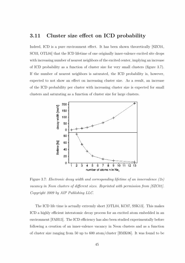
3.11 Cluster size effect on ICD probability
Indeed, ICD is a pure environment effect. It has been shown theoretically [SZC01,
SC03, OTL04] that the ICD lifetime of one originally inner-valence excited site drops
with increasing number of nearest neighbors of the excited center, implying an increase
of ICD probability as a function of cluster size for very small clusters (figure 3.7).
If the number of nearest neighbors is saturated, the ICD probability is, however,
expected to not show an effect on increasing cluster size. As a result, an increase
of the ICD probability per cluster with increasing cluster size is expected for small
clusters and saturating as a function of cluster size for large clusters.
The number of relevant decay channels should be propor-tional to n21, n being the number of atoms in the cluster,because for efficient coupling one of the final-state holesmust be localized on the central neon atom. In fact, as acareful analysis of our numerical data has confirmed, decaychannels withboth final-state holes in the coordination shellof the central monomer do not give any appreciable contri-bution toG iv . The coupling of the relevant decay channels tothe innervalence hole state might be affected by the inter-atomic distanceswithin the coordination shell—the distancesof all shell atoms to the central atom are identical, but thedistances between shell atoms decrease with increasing clus-ter size. The consequence would be a noticeable dependenceof the average partial decay width on the number of atoms.This is one possible reason why the calculated ICD width isnot linear as a function of cluster size~see Fig. 5!. Anotherreason might be the quality of the Gaussian basis set used:the basis set improves with the size of the cluster. This im-plies that the description of the ICD electron is best for Ne13.
By focusing on an innervalence hole on the central mono-mer we simulated the situation inside the solid. The ICDlifetime found in Ne13 is a restrictive upper bound for theICD lifetime of a 2s hole in a neon crystal. For surfaceatoms, which do not possess a complete coordination shell ofnearest neighbors, our data suggest that the ICD lifetime is ofthe order of 10 fs.
In principle the innervalence ionized cluster can give offits excess energy by photon emission. The fluorescence de-cay width of an innervalence excited Ne atom is of the orderof 1 meV ~see Ref. 47, and references therein!. That quan-tity is expected to be of similar magnitude in a neon cluster.We have shown that ICD is faster by at least three orders ofmagnitude than relaxation by photon emission, which maytherefore be neglected. In Ne2, nuclear dynamics and ICDtake place on comparable time scales, giving rise to interest-ing dynamical effects accompanying ICD.15,34 However, inview of the ultrashort lifetimes found in the larger neon clus-ters, it is very likely that for these systems ICD is the fastestprocess occurring.
IV. SUGGESTIONS FOR EXPERIMENTS
Based on our work it seems likely that intermolecularCoulombic decay of innervalence vacancies plays an impor-tant role in the huge class of weakly bound clusters andcondensed matter, comprising such systems as water, carbondioxide, and ethanole. If energy conservation allows ICD totake place, it is expected to dominate the relaxation of inner-valence holes. The only competing processes typically occuron a longer time scale. The kinetic energy distribution of theICD electrons extends from 0 up to several electronvolts. Itsdetailed structure depends on the available electronic decaychannels and on effects induced by the motion of the atomicnuclei, which we have found to make a particularly pro-nounced impact due to the Coulomb repulsion acting in thedicationic final state.15,34 From these considerations it is evi-dent that ICD deserves attention.
A simple experimental approach to ICD is suggested bythe results of the previous section. One could sort the clustersaccording to size and measure, with a high resolution, thespectral line of the innervalence photoelectron for each clus-ter size. While the line position is insensitive to cluster size~see, for example, Fig. 3!, the width is expected to be sizedependent~Fig. 5!. Pursuing this strategy is, presumably, nottoo difficult, but the wealth of information the ICD effectcontains cannot be revealed in this way. To that end a mea-surement of the kinetic energy distribution of the ICD elec-tron is needed.
There are, however, a few obstacles to observing ICDelectrons in a routine experiment. First, electron spectros-copy in the energy range of a few electronvolts is more prob-lematic than for faster electrons. This is a technical difficulty,and experimentalists certainly are making progress in thisdirection. The second problem is somewhat more fundamen-tal. In order to investigate the decay of an innervalence holeone would expose a given system to photons whose energy issufficient to produce such a vacancy. Obviously, for systemsthat can undergo ICD this photon energy is above the doubleionization threshold. Thus it may happen that an absorbedphoton simultaneously ejects two outervalence electrons, in-stead of ionizing an innervalence electron that is followed, ina second step, by the spontaneous emission of an ICDelectron.
The emission of correlated electron pairs from the surfaceof a solid following one-photon absorption has been investi-gated experimentally by Biester and co-workers26 and byHerrmann et al.,48 and within a theoretical approach byBerakdar.49 With the restriction of energy conservation, theenergy of each of the electrons in a correlated pair can takeon any value between 0 andEmax, which is the energy of theabsorbed photon minus the double ionization potential of thegenerated dication. The two correlated electrons share thetotal energy available to them,Emax, in a complementaryfashion, that is, if one of the electrons has kinetic energy«,the other one has kinetic energyEmax2«. The correspondingcontinuous spectrum, which can be influenced by varying thephoton energy, may interfere with the measurement of thekinetic energy distribution of the ICD electrons.
The question now is how electrons stemming from two-
FIG. 5. Electronic decay width and corresponding lifetime of aninnervalence (2s) hole in neon clusters of different sizes. The datawere calculated by means of Eq.~20!.
ROBIN SANTRA, JURGEN ZOBELEY, AND LORENZ S. CEDERBAUM PHYSICAL REVIEW B64 245104
245104-8
Figure 3.7: Electronic decay width and corresponding lifetime of an innervalence (2s)
vacancy in Neon clusters of different sizes. Reprinted with permission from [SZC01].
Copyright 2009 by AIP Publishing LLC.
The ICD life time is actually extremly short [OTL04, KC07, SSK13]. This makes
ICD a highly efficient interatomic decay process for an excited atom embedded in an
environment [FAH13]. The ICD efficiency has also been studied experimentally before
following a creation of an inner-valence vacancy in Neon clusters and as a function
of cluster size ranging from 50 up to 600 atom/cluster [BMK06]. It was found to be
45
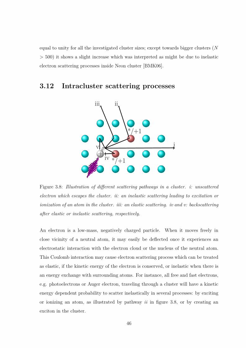
equal to unity for all the investigated cluster sizes; except towards bigger clusters (N
> 500) it shows a slight increase which was interpreted as might be due to inelastic
electron scattering processes inside Neon cluster [BMK06].
3.12 Intracluster scattering processes
+e-
*/+1
*/+1
i
iiiii
ivv
Figure 3.8: Illustration of different scattering pathways in a cluster. i: unscattered
electron which escapes the cluster. ii: an inelastic scattering leading to excitation or
ionization of an atom in the cluster. iii: an elastic scattering. iv and v: backscattering
after elastic or inelastic scattering, respectively.
An electron is a low-mass, negatively charged particle. When it moves freely in
close vicinity of a neutral atom, it may easily be deflected once it experiences an
electrostatic interaction with the electron cloud or the nucleus of the neutral atom.
This Coulomb interaction may cause electron scattering process which can be treated
as elastic, if the kinetic energy of the electron is conserved, or inelastic when there is
an energy exchange with surrounding atoms. For instance, all free and fast electrons,
e.g. photoelectrons or Auger electron, traveling through a cluster will have a kinetic
energy dependent probability to scatter inelastically in several processes: by exciting
or ionizing an atom, as illustrated by pathway ii in figure 3.8, or by creating an
exciton in the cluster.
46

Inelastic photoelectron scattering in noble gas clusters was investigated before
by photoemission methods, and it was shown to lead to the production of excitonic
satellites which are not present in the atomic case [JBM06, HKR02], and also to the
formation of zero-kinetic-energy photoelectrons (ZEKE) [KJK94].
Eventually, most of the primary energy of photoelectrons that inelastically scat-
tered in cluster is converted to kinetic energy of slow electrons [PL07]. These slow
electrons from inelastic intracluster scattering may experimentally mask the low-
kinetic energy electrons created as the outcome of ICD process. These two effects
have been investigated in the past [MAF15, BMK06] on Neon clusters using electron-
electron coincidence spectroscopy technique. Additionally, it was shown that the
probability for inelastic scattering increases with cluster size. Intracluster inelastic
scattering of emitted ICD electrons may occur as well in cluster as shown for Neon
clusters multiply excited by intense free electron laser (FEL) radiation [INF16], and
it was found that it affects the ICD relaxation of Neon bulk atoms.
A fast electron can also back scattered inside cluster, as illustrated by pathway
v and iv in figure 3.8. This was demonstrated before in case when an Auger decay
occurs in a core-ionized cluster [LLÖ08]. Backscattering is thereby a mechanism
in which an arbitrary kinetic energy-photoelectron is backscattered by neighboring
atoms in the cluster, loses its energy, and then recaptured in a Rydberg orbital of
the core-ionized atom before the Auger decay. It is thus so similar to the so called
postcollision− interaction (PCI) induced recapture process [EBJ88], but also with
a significant difference since the PCI occurs only near threshold where the kinetic
energy of the photoelectron is too small [TAW90, FWS05]. Elastic scattering and
backscattering processes are not the focus of this thesis, however, inelastic electron
scattering that induces secondary processes is of great interest and will be discussed
further in the results chapter.
47

Chapter 4
Experimental set-up
4.1 An overview of the experimental set-up
The experiment was carried out for fluorescence measurements on noble gas clus-
ters. It was performed with an established photon-induced fluorescence spectroscopy
set-up (PIFS) [SLV01] in the synchrotron radiation (SR) facility SOLEIL, Paris at
the PLEIADES beamline in its multi-bunch operation mode. The set-up consists of
the light source (SR beam), a cluster source for formation of Neon cluster beam and
several detection devices for collecting emitted photons from excited clusters. The
Neon cluster jet is produced by supersonic expansion through a 32 µm diameter flat
copper nozzle separating a high pressure stagnation chamber from the vacuum in the
expansion chamber with being cooled by a liquid Helium flow cryostat. After passing
through a skimmer of 1.5 mm diameter, the cluster jet entered the interaction cham-
ber, where it crossed the linear polarized photon beam of the monochromatized SR
at an angle of 45. Undispersed vacuum-ultraviolet (VUV) and UV/visible photons
emitted from excited Neon clusters were collected by an open face microchannel plates
(MCPs) stack (λfl < 120 nm) and MCP detector (300 nm < λfl < 630 nm) equipped
with a bialkali photocathode and fused silica window, respectively. A position sensi-
tive MCP detector (40 nm < λfl < 120 nm) based on wedge and stripe anode was
used to collect the VUV photons which were dispersed by a 1-m-normal-incidence
photon spectrometer equipped with a coated gold grating 1200 l/mm. Before getting
48

dispersed by the grating, the emitted VUV photons went through a 1 mm width slit
located in the entrance of 1-m-normal-incidence monochromator. This slit was also
connected to a voltage source of −19.3 V , and hence used as an electrically connected
electrode in order to measure the yield of positively-charged Ne+ ions. A Faraday
cup was used behind the interaction region for monitoring the transmitted light.
4.2 Synchrotron radiation
4.2.1 Emission mechanism
Synchrotron radiation (SR) is electromagnetic radiation that is emitted from acceler-
ated charged particles moving almost at the speed of light; i.e. at relativistic veloc-
ities. The phenomenon is named after its discovery in Schenectady, New York from
the General Electric Synchrotron accelerator [EGL47]. Similar radiation can also be
produced naturally in the interstellar medium, e.g. Crab nebula, when charged par-
ticles enter in a region of strong magnetic field [Hes08]. Today electron storage rings
are routinely used to provide SR in a wide spectral range to users for investigating the
properties of matter in many different fields, like, e.g. molecular and atomic physics,
cell biology, nanotechnology and cultural heritage. The peculiar characteristic of the
electron storage ring is that the electrons are stored in orbit and traveling with high
energy through magnetic fields. The emission mechanism of radiation from the accel-
erated electrons in a storage ring is similar to that of a radio antenna, but with the
difference that the relativistic speed of electrons will change the observed frequency
since the radiation source is moving. The radiation, in this case, can be seen as col-
limated in the direction of the electrons motion. Figure 4.1 illustrates the radiation
pattern from a moving electron with two different velocity fractions, β = vcwhere c
and v are the speed of light and the accelerated electron, respectively.
49

Figure 4.1: Qualitative radiation patterns related to charged particles moving in a
circular orbit. The dipole pattern achieved for slow particle (β ≺≺ 1) (left) is distorted
into a narrow cone when β ≈ 1 (right). The symbols v, A and ψ show the direction
of the traveling electron, the direction of the acceleration and the half opening angle
of the cone-radiation, respectively. Adapted with permission from [TH56]. Copyright
1956 by American Physical Society.
The collimation is particularly effective for highly relativistic electrons β ≈ 1. This
results in a very intense radiation beam where most of the radiation is concentrated
into a small cone around the forward direction with a half opening angle ψ = 1γ,
typically between 0.05 to 0.5 mrad, given by
1γ
=√
1− β2 (4.1)
where γ is the Lorentz factor.
4.2.2 Insertion devices
To further improve the intensity of the radiation, the storage rings are often equipped
with magnetics tools called insertion devices such as undulators or wigglers. For
instance, an undulator consists of a periodic structure of dipole magnets generating
an alternating static magnetic field which deflects the electrons sinusoidally along the
50
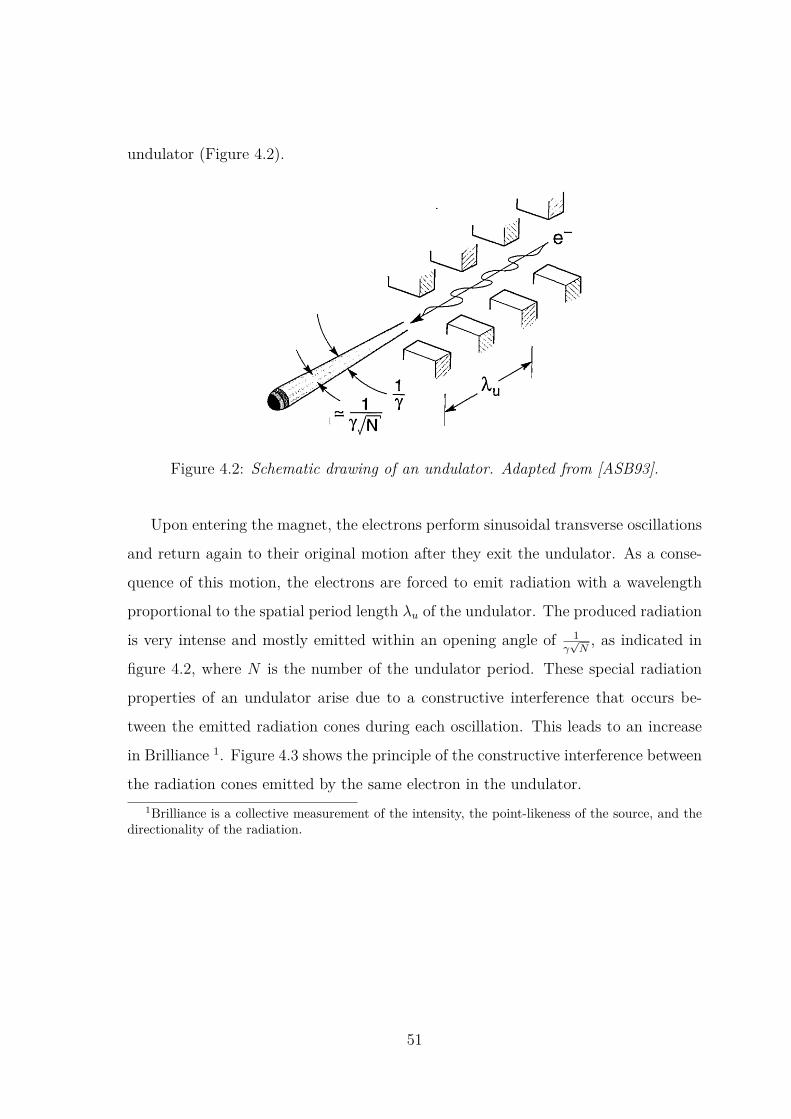
undulator (Figure 4.2).
N periods
e-
1cen Y N
Fig. 1. Continuously tunable short-wavelength undulator radia-tion is generated by the passage of relativistic electrons through aperiodic magnet structure.
odic magnet structure.' 6-' 8 The observed wave-length is described by the equation
Au IX. =x1
K 22
(1)
where X, is the undulator period, -y = 1/[1 - (v2 /c2 )]1/2
is the Lorentz contraction factor familiar from stud-ies of relativistic motion, v is the axial electronvelocity, c is the velocity of light in vacuum, 0 is theobservation angle measured from the axis of symme-try, and K is a dimensionless measure of the magneticfield in a periodic structure,' 7 given by
K = eBO0M .u (2)2'rrmc
B0 is the maximum magnetic-field strength on axis,and e and m are the electron charge and the restmass, respectively.
Typical parameters of interest here'9 include an8-cm magnetic period, y 3000, and K varying from0.5 to 3.9. This gives a broad tuning range extend-ing from 45 to 400 A. A typical value for the relativespectral bandwidth is
AX 1(3)
where N is the number of magnetic periods (electronoscillations), 0.016 for a 4.96-m-long undulatorwith 62 periods of 8.0 cm each. This can be accom-plished with a simple aperture of angular acceptance,
1Ocen = y*V` ' (4)
where the asterisk denotes a modified Lorentz factor,
ly= '(1 + 2
which accounts for the decreased axial velocity in aperiodic magnetic field (where a portion of the con-served energy is directed to transverse motion). Thecentral radiation cone, of half-angle 0
cen, contains tofirst order the radiation of bandwidth 1/N. Toobtain radiation with a narrower spectral bandwidth,a monochromator must be used, albeit with reducedphoton flux because of both the narrower bandwidthand the finite efficiency of the various components.
The average power radiated in the central radiationcone is readily determined' 6 in analytic form fromconsiderations of classical dipole radiation and appro-priate use of Lorentz transformations for the case ofK < 1. For K substantially larger than 1, numericalsimulations are required because strongly nonsinusoi-dal motion sets in and because the dipole approxima-tion begins to fail. For modest field strength (K < 1)the power in the central cone (Ocen = 1/y*FN, X/AXN) can be written as
rreK 2 ,2
Pcen lTreK 2 2 (5)
EOX, 1 + 2
where eo is the permittivity of free space, and I is theaverage current. As used here, expression (5) repre-sents only that power radiated in the fundamental(n = 1). At the Advanced Light Source (ALS), cur-rently under construction at the Lawrence BerkeleyLaboratory, where a current of 0.4 A is expected aty = 2940, expression (5) indicates that a central conepower of 1.1 W can be expected within a 1.6%relative spectral bandwidth (1/N) at X = 130 A froman 8.0-cm undulator operated at a magnet strengthcorresponding to K = 1.9. Numerical simulations2 0
show the radiated power at K = 1.9 to be 0.93 W at130 A in a spectral pattern that is approximated byAX/X = 1/N. Figure 2 graphs power in the centralradiation cone (n = 1, AX/X 1/N), according toexpression (5), through typical tuning ranges of 5.5-and 8.0-cm periodic undulators at the ALS. Becauseboth magnetic structures are constrained to 5-m totallengths, values of N and thus of nominal values ofAX/X differ for the two cases, as indicated by expres-sion (3). Thus, although the powers are quite simi-lar, the powers per unit bandwidth are not. Notethat the conversion from wavelength to photon en-ergy (E = hw) is
EX = 12,399 eVA. (6)
For K values greater than unity, electron motion ina periodic magnetic structure becomes nonsinusoidal,that is, the motion becomes more complex than asingle frequency, exhibiting ever larger componentsof multiples of the fundamental frequency. That is,the motion has significant harmonic content for K >1 and radiates accordingly into harmonics of wave-length X/n with interesting polarization and phaseeffects. Numerical simulations that account for thenonsinusoidal motion at a high K value and for the
7024 APPLIED OPTICS / Vol. 32, No. 34 / 1 December 1993
Figure 4.2: Schematic drawing of an undulator. Adapted from [ASB93].
Upon entering the magnet, the electrons perform sinusoidal transverse oscillations
and return again to their original motion after they exit the undulator. As a conse-
quence of this motion, the electrons are forced to emit radiation with a wavelength
proportional to the spatial period length λu of the undulator. The produced radiation
is very intense and mostly emitted within an opening angle of 1γ√N, as indicated in
figure 4.2, where N is the number of the undulator period. These special radiation
properties of an undulator arise due to a constructive interference that occurs be-
tween the emitted radiation cones during each oscillation. This leads to an increase
in Brilliance 1. Figure 4.3 shows the principle of the constructive interference between
the radiation cones emitted by the same electron in the undulator.1Brilliance is a collective measurement of the intensity, the point-likeness of the source, and the
directionality of the radiation.
51
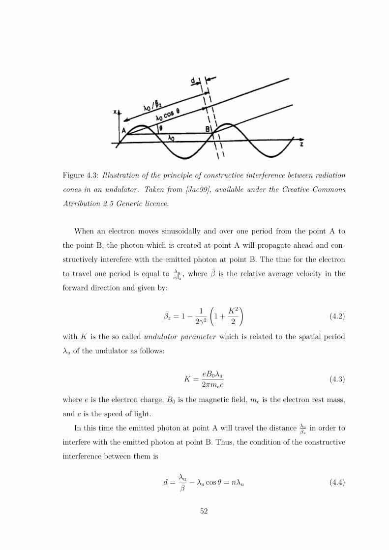
Figure 4.3: Illustration of the principle of constructive interference between radiation
cones in an undulator. Taken from [Jac99], available under the Creative Commons
Atrribution 2.5 Generic licence.
When an electron moves sinusoidally and over one period from the point A to
the point B, the photon which is created at point A will propagate ahead and con-
structively interefere with the emitted photon at point B. The time for the electron
to travel one period is equal to λu
cβz, where β is the relative average velocity in the
forward direction and given by:
βz = 1− 12γ2
(1 + K2
2
)(4.2)
with K is the so called undulator parameter which is related to the spatial period
λu of the undulator as follows:
K = eB0λu
2πmec(4.3)
where e is the electron charge, B0 is the magnetic field, me is the electron rest mass,
and c is the speed of light.
In this time the emitted photon at point A will travel the distance λu
βzin order to
interfere with the emitted photon at point B. Thus, the condition of the constructive
interference between them is
d = λu
β− λu cos θ = nλn (4.4)
52
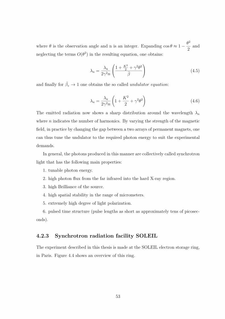
where θ is the observation angle and n is an integer. Expanding cos θ ≈ 1− θ2
2 and
neglecting the terms O(θ2) in the resulting equation, one obtains:
λn = λu
2γ2n
1 + K2
2 + γ2θ2
β
(4.5)
and finally for βz → 1 one obtains the so called undulator equation:
λn = λu
2γ2n
(1 + K2
2 + γ2θ2)
(4.6)
The emitted radiation now shows a sharp distribution around the wavelength λn
where n indicates the number of harmonics. By varying the strength of the magnetic
field, in practice by changing the gap between a two arrays of permanent magnets, one
can thus tune the undulator to the required photon energy to suit the experimental
demands.
In general, the photons produced in this manner are collectively called synchrotron
light that has the following main properties:
1. tunable photon energy.
2. high photon flux from the far infrared into the hard X-ray region.
3. high Brilliance of the source.
4. high spatial stability in the range of micrometers.
5. extremely high degree of light polarization.
6. pulsed time structure (pulse lengths as short as approximately tens of picosec-
onds).
4.2.3 Synchrotron radiation facility SOLEIL
The experiment described in this thesis is made at the SOLEIL electron storage ring,
in Paris. Figure 4.4 shows an overview of this ring.
53

Figure 4.4: Overview of SOLEIL electron storage ring with the different SR beamlines
[sto].
The ring has a circumference of 354 m. In each turn in the ring, the electrons
pass through the insertion devices which force them to follow a wavy path and in
the process, photons are emitted. These emitted photons are captured, selected,
focused, and then directed in a SR beam center called beamline toward the sample
being studied, as shown by arrows in Figure 4.4. Each time an electron bunch passes
in front of a beamline, the beamline receives a flash of intense light pulses. Some
scientists use these light pulses to study phenomena evolving over time. To do that,
they must synchronize their devices with bunches of electrons flying inside the storage
ring and added delays to compensate the cable and device time offsets. The SOLEIL
electron storage ring launches three main bunch filling patterns; i.e. single bunch
mode, eight bunch mode, and multi-bunch mode. In multi-bunch mode operation,
54
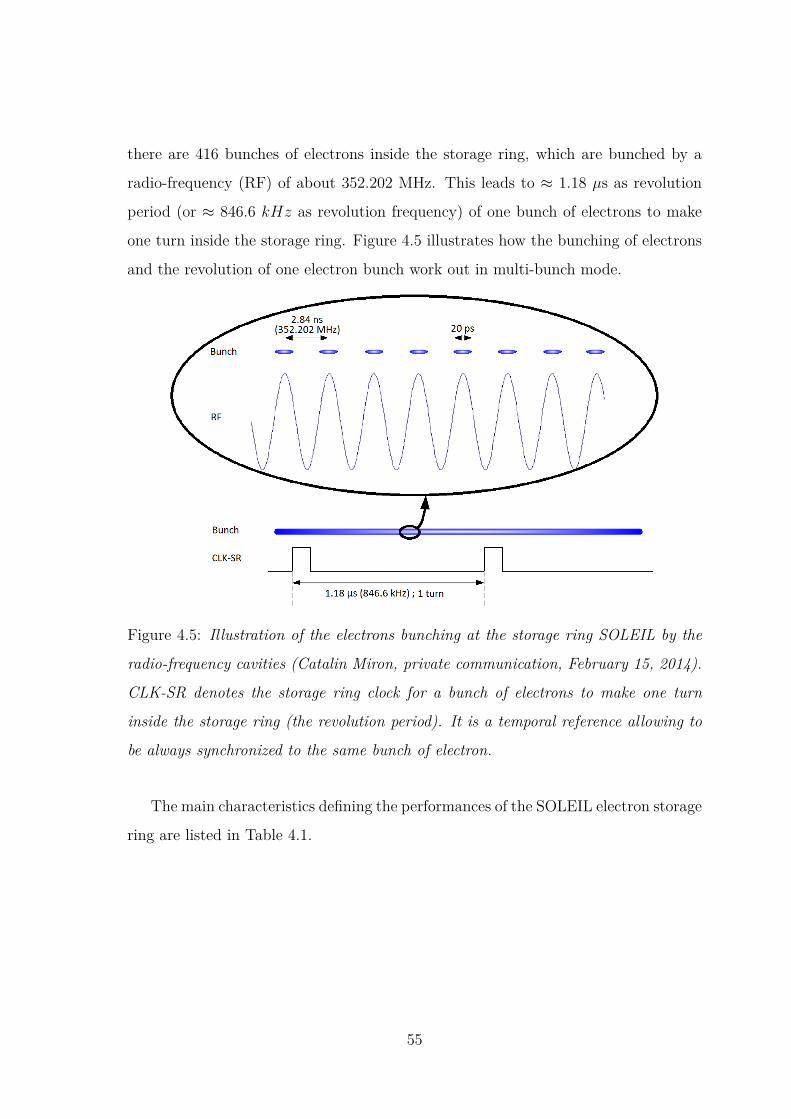
there are 416 bunches of electrons inside the storage ring, which are bunched by a
radio-frequency (RF) of about 352.202 MHz. This leads to ≈ 1.18 µs as revolution
period (or ≈ 846.6 kHz as revolution frequency) of one bunch of electrons to make
one turn inside the storage ring. Figure 4.5 illustrates how the bunching of electrons
and the revolution of one electron bunch work out in multi-bunch mode.
Figure 4.5: Illustration of the electrons bunching at the storage ring SOLEIL by the
radio-frequency cavities (Catalin Miron, private communication, February 15, 2014).
CLK-SR denotes the storage ring clock for a bunch of electrons to make one turn
inside the storage ring (the revolution period). It is a temporal reference allowing to
be always synchronized to the same bunch of electron.
The main characteristics defining the performances of the SOLEIL electron storage
ring are listed in Table 4.1.
55

SOLEIL
Electron energy 2.75 GeV
Circumference 354 m
Revolution frequency 846.64 kHz
Maximum stored current 400 mA
Horizental emittence 3.9 nm.rad
Bunch length 18 ps
Average pressure 6.510−10 mbar
Lifetime 18 h
Number of beamlines 29
Table 4.1: Characteristics of the SOLEIL electron storage ring.
4.2.4 PLEIADES beamline
The experimental results presented in this work were obtained at PLEIADES beam-
line at the SR facility SOLEIL. PLEIADES is an ultra-high resolution soft X-ray
beamline (ultimate resolving power of about 1000000 at 50 eV) dedicated to study
spectroscopically the atomic and molecular physics of diluted samples [PLE]. Figure
4.6 shows the optical layout of the PLEIADES beamline.
56
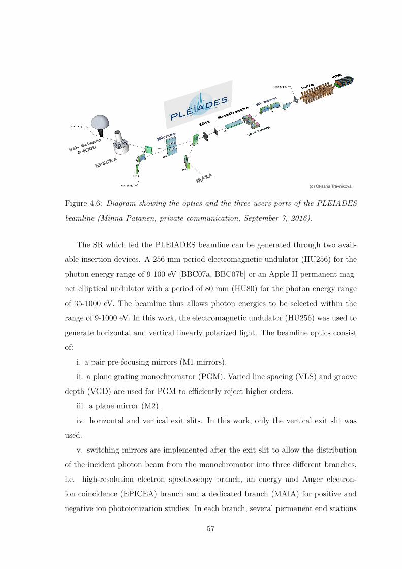
(c) Oksana Travnikova
Figure 4.6: Diagram showing the optics and the three users ports of the PLEIADES
beamline (Minna Patanen, private communication, September 7, 2016).
The SR which fed the PLEIADES beamline can be generated through two avail-
able insertion devices. A 256 mm period electromagnetic undulator (HU256) for the
photon energy range of 9-100 eV [BBC07a, BBC07b] or an Apple II permanent mag-
net elliptical undulator with a period of 80 mm (HU80) for the photon energy range
of 35-1000 eV. The beamline thus allows photon energies to be selected within the
range of 9-1000 eV. In this work, the electromagnetic undulator (HU256) was used to
generate horizontal and vertical linearly polarized light. The beamline optics consist
of:
i. a pair pre-focusing mirrors (M1 mirrors).
ii. a plane grating monochromator (PGM). Varied line spacing (VLS) and groove
depth (VGD) are used for PGM to efficiently reject higher orders.
iii. a plane mirror (M2).
iv. horizontal and vertical exit slits. In this work, only the vertical exit slit was
used.
v. switching mirrors are implemented after the exit slit to allow the distribution
of the incident photon beam from the monochromator into three different branches,
i.e. high-resolution electron spectroscopy branch, an energy and Auger electron-
ion coincidence (EPICEA) branch and a dedicated branch (MAIA) for positive and
negative ion photoionization studies. In each branch, several permanent end stations
57

are available together with free ports offering the external users the possibility of
installing their own set-ups.
vi. a focalization mirror is implemented in each branch to focus the photon beam
into the end of the station.
The experimental set-up used for this work is attached to the last valve of the high-
resolution electron spectroscopy branch where the VG Scienta R4000 hemispherical
electron energy analyzer is implemented. The last mirror (M6) which was used to
focus the photon beam into the experimental chamber is made of silica and coated
with titanium. A photodiode was used to measure the current on the last mirror of
the beamline. The photon beam size and divergence at the focus is 180 (Horizontal)
× 100 (Vertical) µm2 and 2 mrad horizontally (0.6 mrad vertically), respectively.
58

4.3 Experimental station 1
1
2
2
3
3
4
4
5
5
6
6
7
7
8
8
A A
B B
C C
D D
SHEET 1 OF 1
DRAWN
CHECKED
QA
MFG
APPROVED
Ltaief 11.12.2016
DWG NO
Complet_exp_setup
TITLE
SIZE
D
SCALE
REV
1 : 4
IIII
II
IV
Beam dump
xyz-Manipulator
cluster source
Pfeiffer vacuum pump
interaction chamber
Edw
ards STP-XA2703c
turbo m
olecular pum
p
bypass valve
pressure-gauge
Variant 551
turbomolecular
pump
jet dump
entrance-slit
skimmer
expansion chamber
1m-normal incidence
McPherson spectromete
differential pumping stage
t
o
t
h
e
b
e
a
m
l
i
n
e
Figure 4.7: Top view of the experimental station before implementing the cryostat,
detectors and electronics. I, II, III and IV indicates the position of the cryostat, open
face MCPs stack detector, Quantar-MCP detector and the position sensitive open face
MCP detector, respectively.
The station is a rigid body mounted on an adjustable frame. It is mainly formed by
three differentiated vacuum chambers to which pumps, pressure gauges, valves, and
detectors are attached. Figure 4.7 shows a technical drawing of the station. The first
part of the station is the expansion chamber where a movable cluster source with a
flat nozzle of diameter 32 is implemented to prepare the cluster beam. The end of the
cluster source is perpendicularly connected to the cryostat cold tip in the center of the
expansion chamber. The cryostat is located on the top of the expansion chamber and
attached to xyz-manipulator via a rotatable CF63 flange for adjusting the cluster
source in xyz motions. This assembly, i.e. expansion chamber, cluster source with a
flat nozzle of diameter 32 µm, cryostat and manipulator, was provided as an attached
part from the group of Prof. Reinhard Dörner at the Goethe-Universität Frankfurt.
59

The expansion chamber is pumped with a high capacity Edwards STP − XA2703c
turbo molecular pump provided from the PLEIADES beamline team at SR facility
SOLEIL in Paris to maintain the expansion pressure at about 10−3 mbar. The second
part of the station is the main chamber (experimental chamber designed by Andreas
Hans) where the interaction between the SR beam and the cluster beam takes place.
It is attached to the expansion chamber via a CF 150-CF 100 adapter and pumped
with a Pfeiffer vacuum pump to keep maintaining the experimental pressure at about
10−5 mbar. To transfer the partially condensed beam into the main chamber, a skim-
mer with a diameter of 1.5 mm was installed between the interaction chamber and
the expansion chamber. Along the expansion axis of the cluster beam and after the
interaction region, a jet dump differentially pumped with a V ariant Turbo molecular
pump was attached to the main chamber. The bottom side of the interaction cham-
ber is connected to 1-m-normal incidence McPherson spectrometer equipped with
a gold-coated 1200 l/mm grating used for spectrally resolved fluorescence measure-
ments. The spectrometer is implemented in a separated pumped chamber to reach
a background pressure of typically 10−7 mbar. A small slit of 1 mm width was im-
plemented in the entrance of the spectrometer for the propagation of the emitted
photons from the interaction region towards the spectrometer. The third part of the
station is the differential pumping stage situated at 45 from the interaction chamber.
It consists of two Pfeiffer pumps and an aperture with two pumping sides. The role of
this differential pumping stage is to reduce the high experimental pressure of about
10−5 mbar to about 10−7 mbar with the aim to preserve the high vacuum in the
beamline. A Faraday cup was attached to the main chamber via a CF40 behind
the interaction region to monitor the transmitted light. Figure 4.8 shows the com-
plete assembly of the experimental setup in real life, after being get attached to the
PLEIADES beamline and while running the cluster source.
60

Figure 4.8: The experimental setup in real life at the PLEIADES bemline with im-
plemented detectors and cryostat, and which obviously can be very different from
schematic illustrations. The flexible tube connecting the big Helium tank to the Cryo-
stat is the cryogenic transfer line.
4.4 Cluster source
The cluster source utilized in this work was designed by Gregor Kastirke from the ex-
perimental atomic physics group of professor Reinhard Dörner at Goethe-Universität
Frankfurt. It is a system which allows the production of noble gas clusters by super-
sonic expansion through a small nozzle. The technical drawing of the used cluster
source is given in appendix B. To give great details about the cluster source and its
most relevant working parameters, I will present in this section a bi− nozzle cluster
source that I designed during my Ph.D. project and which is mainly inspired from the
aforestated designed one by Gregor Kastirke. The main differences between the two
cluster sources are the nozzle head and the Cryostat adapter. The objective behind
the built of a bi−nozzle cluster source is in fact to have the choice of using two nozzles
with different diameters in vaccuum; one for example can be used for producing a
cluster jet with high cluster density and another one for producing a cluster jet with
low cluster density. For future investigation, the production of a cluster jet with high
61

cluster density will likely permit to acheive a high photon energy resolution through
using a narrower bandwidth of the incident photons from the beamline, and hence to
extract information about the details of atomic properties inside the cluster.
4.4.1 Design considerations
Figure 4.9: Home-built bi-nozzle cluster source for noble gas clusters production. The
technical drawing of the cluster source is given in appendix C.
Figure 4.9 shows the bi-nozzle cluster source with its cylindrical shape in real. It is
made in copper and consists of four main parts:
i. Two heads where the distance between them is 16 mm. Each head has, on the
top side, one hole with a diameter of 2 mm surround by 4 holes with a diameter of
2 mm for connecting the nozzle to the cluster source via screws. In addition to the
connection with screws, the nozzles were sealed to the cluster source-heads with an
Indium gasket to avoid any loss of gas during the cooling or heating procedures. The
need to use a gasket made with Indium is because most other sealing materials work at
standard operating temperatures and will crack and break at cryogenic temperatures
of about 123.15 K. However, Indium remains malleable at cryogenic temperatures
and even soft and pliable, so it fills the imperfections in mating the back side surface
of the nozzle to the surface of the cluster source head, thereby, creates a hermetic seal
between them.
ii. Two conical nozzles with the same half opening angle of 15, but with different
opening diameters d; e.g. d = 60 µm and d = 20 µm. A technical drawing of a conical
nozzle with an opening diameter of d = 60 µm is shown in figure 4.10.
62

Figure 4.10: Sketch of a typical conical nozzle with a diameter of 60 µm and half
opening angle of 15.
iii. Two gas inlets located at a distance of 170 mm to the nozzles to let in the
incoming gas from the gas cylinder into the cluster source.
iv. One Cryostat adapter located at the end of the cluster source with three holes
for connecting perpendicularly the cold tip of an LT -4B cryostat. The cold tip of the
LT -4B cryostat has a length of 25 mm, a diameter of 19 mm and a 1/4-28 tapped
hole in the center. For controlling the temperature at the region of the cluster source
adapter, a Silicon diode temperature sensor (model: DT -670B-SD) with a stability
of about 2 mK was connected to the LT -4B cold tip. The silicon diode sensor is
sensitive to the temperature range of 1.4 K to 325 K and has an accuracy of about
25 mK over the temperature range of 30 K to 325 K. The complete cold head
assembly of the LT -4B cryostat is displayed in Figure 4.11.
63
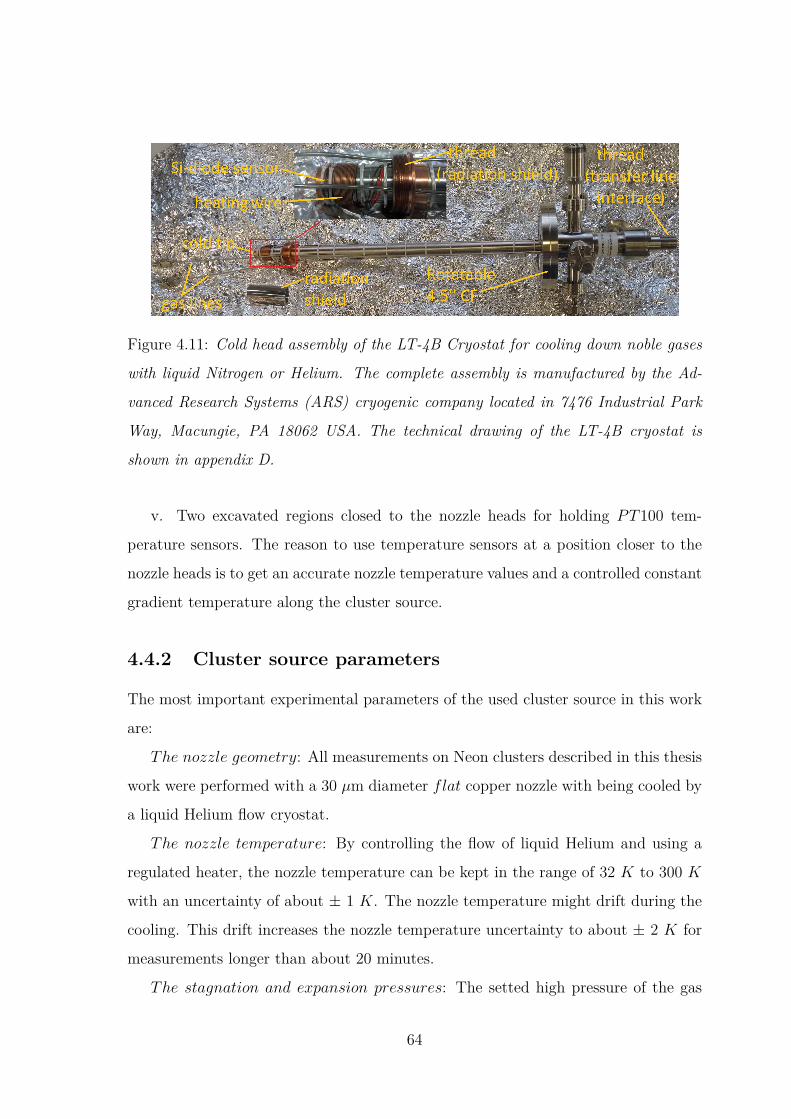
Figure 4.11: Cold head assembly of the LT-4B Cryostat for cooling down noble gases
with liquid Nitrogen or Helium. The complete assembly is manufactured by the Ad-
vanced Research Systems (ARS) cryogenic company located in 7476 Industrial Park
Way, Macungie, PA 18062 USA. The technical drawing of the LT-4B cryostat is
shown in appendix D.
v. Two excavated regions closed to the nozzle heads for holding PT100 tem-
perature sensors. The reason to use temperature sensors at a position closer to the
nozzle heads is to get an accurate nozzle temperature values and a controlled constant
gradient temperature along the cluster source.
4.4.2 Cluster source parameters
The most important experimental parameters of the used cluster source in this work
are:
The nozzle geometry: All measurements on Neon clusters described in this thesis
work were performed with a 30 µm diameter flat copper nozzle with being cooled by
a liquid Helium flow cryostat.
The nozzle temperature: By controlling the flow of liquid Helium and using a
regulated heater, the nozzle temperature can be kept in the range of 32 K to 300 K
with an uncertainty of about ± 1 K. The nozzle temperature might drift during the
cooling. This drift increases the nozzle temperature uncertainty to about ± 2 K for
measurements longer than about 20 minutes.
The stagnation and expansion pressures: The setted high pressure of the gas
64
atoms which fed the stagnation chamber was in the range of 3-11 bar. After passing
through the cooled nozzle, the gas atoms enter the expansion chamber and the cluster
starts to form up. The majority of the introduced gas atoms never end up in a cluster.
This means that even after the formation of the clusters there is still a lot of free
atoms in the expansion chamber. Since the cluster formation takes place on the axis
of the supersonic beam, a skimmer with a diameter of 1.5 mm was placed at about
5 mm from the nozzle to separate the cluster beam from most of the uncondensed
atoms. The atoms not passing through the skimmer is pumped away by a high-
capacity turbo pump that kept the pressure in the expansion chamber in the range
of 10−4/10−3 mbar.
Mounting and adjusting of the cluster source: The assembly cluster source +
cryostat were mounted on a xyz-manipulator via a rotatable CF 63. The manipulator
can move along the x and y directions up to ± 12.5 mm and along z direction up
to 250 mm. Before starting the measurement, two essential and consecutive steps
were considered for the alignment and the optimization of the cluster jet along the
skimmer axis and are as follows: in a first step, the nozzle was kept at a far distance
from the skimmer and the yz positions of the cluster source were roughly adjusted
by the manipulator. In a second step, the cluster jet was optimized by maximizing
the obtained count rate of emitted photons from the excited cluster while keeping
the exciting-photon energy at a certain fixed value. To maximize further the fluores-
cence count rate, a fine adjustment of the cluster source position was done in all xyz
directions. Parallel to these two steps, the behavior of the jet dump pressure while
adjusting the position of the cluster source was also used as an index to optimize the
cluster jet. The distance between nozzle and skimmer was kept at about 5 mm after
optimizing the cluster jet.
Figure 4.12 shows an example of how the expansion and jet dump pressures behave
while an optimized Neon cluster jet is running for different high-gas pressures and at
nozzle temperature of 60 K.
65

1 2 3 4 5 6 7 8 9 10 11 1210-6
10-5
10-4
10-3
10-2
Pres
sure
[mba
r]
Stagnation pressure (p0) [bar]
PExpansion
PJet dump
Tnozzle = 60 K
Figure 4.12: Expansion pressure as well as jet dump pressure as a function of stag-
nation pressure p0 while running an optimized Neon cluster jet.
By taking into account all the above mentioned and most important experimental
parameters, Neon clusters with a mean cluster size of 40 up to about
7000 atoms/cluster were produced in this work. The average cluster sizes for small
and medium Neon clusters were estimated according to [BK96], whereas those for
bigger Neon clusters, e.g. 7000 atoms/cluster, were estimated according to [Hag92].
4.5 Fluorescence detection modes
The fluorescence measurements made in this work were performed on Neon clusters
with an established photon-induced fluorescence spectroscopy (PIFS) set-up [SLV01].
The experimental set-up mainly consists of SR beam, a Neon cluster source for pro-
ducing Neon cluster jet and detection devices for collecting fluorescence from excited
Neon cluster jet. The experimental arrangements are schematically outlined in Figure
4.13.
66

nozzle
(D=32µm
)x ≈5 m
m
skimm
er
(d=1.5
mm)
synchrotron radiation
MCPsstack
detector
WSA
detector
Quant
ar-MC
P
detector
optical grating
slit
x y
z
Figure 4.13: A schematic showing the interaction region as well as the used detec-
tion devices for collecting fluorescence from excited clusters. The schematic of the
detection devices are used here after kind permission from Philipp Reiß.
The Neon cluster jet is produced by supersonic expansion through a flat copper
nozzle of 32 µm diameter separating the high pressure-stagnation inlet from the vac-
uum in the expansion chamber with being cooled by a liquid Helium flow cryostat. A
skimmer with a diameter of 1.5 mm distant from the nozzle and along the expansion
axis by about 5 mm was used to transfer a beam of partially condensed Neon atoms
into the interaction chamber. There in the interaction chamber, the partially con-
67
densed beam crossed with a linearly polarized photon beam of the monochromatized
SR at an angle of 45. To study the various cluster specific relaxation processes,
mainly the RICD, by means of fluorescence spectroscopy, two different modes of flu-
orescence detection were used:
I. Registration of undispersed VUV and UV/visible photons emitted from excited
Neon clusters as a function of exciting-photon energy. A stack of two bare MCPs, i.e.
open face MCPs stack detector, was used to collect undispersed VUV fluorescence.
As the MCP quantum efficiency for photons drops below 1 % for photon wavelengths
longer than about 120 nm (see, e.g. [Hes08, Ham]) and remains at around 10 %
for shorter wavelengths this detector is essentially capable to detect only photons
with wavelengths below 120 nm. A Quantar-MCP detector equipped with a bialkali
photocathode and combined with a fused silica window was used to collect undispersed
UV/visible fluorescence in a wavelength range from 300 nm to 630 nm.
II. Spectrally resolved detection of emitted VUV photons with a 1-m-normal-
incidence monochromator equipped with a gold-coated 1200l/mm grating and a po-
sition sensitive open-face MCP detector based on wedge and stripe anode readout.
The detector was mounted at the focusing plane of the grating for collecting dis-
persed VUV photons in a wavelength range between 40 and 120 nm [KHF14] in
the first order of diffraction. The low wavelength cutoff, i.e. at about 40 nm, can
be explained by the angle of reflection of the grating that may lead to a drop in
the grating efficiency at edges [MMH74]. The high wavelength cutoff, i.e. at about
120 nm, can be explained by the quantum efficiency of the used bare MCPs that
drops below 1 % for photon wavelengths longer than about 120 nm [Hes08, Ham].
4.6 Detection systems and signals processing
4.6.1 Open-face MCPs detector
To perform the undispersed VUV fluorescence measurements, the used open-face
MCPs stack detector was mounted in a differentially pumped chamber, separated
68
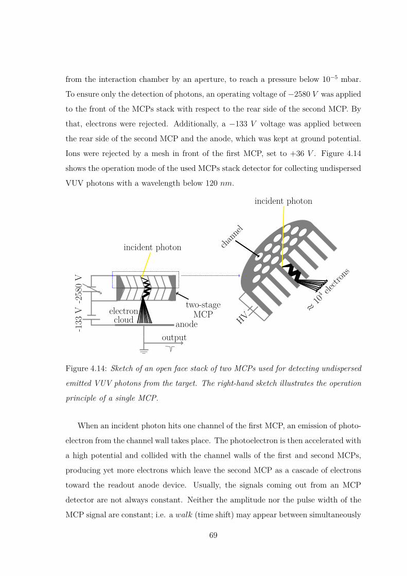
from the interaction chamber by an aperture, to reach a pressure below 10−5 mbar.
To ensure only the detection of photons, an operating voltage of −2580 V was applied
to the front of the MCPs stack with respect to the rear side of the second MCP. By
that, electrons were rejected. Additionally, a −133 V voltage was applied between
the rear side of the second MCP and the anode, which was kept at ground potential.
Ions were rejected by a mesh in front of the first MCP, set to +36 V . Figure 4.14
shows the operation mode of the used MCPs stack detector for collecting undispersed
VUV photons with a wavelength below 120 nm.
channel
incident photon
≈10
4 electrons
HV
outputanode-1
33V
-2580V
incident photon
two-stageMCPelectron
cloud
Figure 4.14: Sketch of an open face stack of two MCPs used for detecting undispersed
emitted VUV photons from the target. The right-hand sketch illustrates the operation
principle of a single MCP.
When an incident photon hits one channel of the first MCP, an emission of photo-
electron from the channel wall takes place. The photoelectron is then accelerated with
a high potential and collided with the channel walls of the first and second MCPs,
producing yet more electrons which leave the second MCP as a cascade of electrons
toward the readout anode device. Usually, the signals coming out from an MCP
detector are not always constant. Neither the amplitude nor the pulse width of the
MCP signal are constant; i.e. a walk (time shift) may appear between simultaneously
69
produced MCP signals. With the aim to minimize signal degradation and eliminate
the walk, the output MCP signals must be first amplified by a Quad Fast Amplifier
(FA 4000) and then discriminated by a constant fraction discriminator (CFD). This
is done while operating this detector by splitting each amplified MCP signal which
acts as an unipolar input signal in the CFD into two signals with a different ratio.
One of the signals is attenuated while the other delayed and inverted. Adding both
signals again will produce a bipolar CFD signal with a zero crossing point which must
be constant. The delay or the walk must be tuned up to get maximal oscillations in
the CFD signal, so that the zero− crossing appears when the CFD signal becomes
strong on its high level as well as on its low level. The CFD threshold must be ad-
justed as needed to filter out any noise or interfering signals and should always be as
low as possible. The discriminated MCP signal is then transferred as a NIM output
signal to a TTL output signal and finally acquired by a home-built acquisition PC
software packages written in Python programming language by Philipp Schmidt.
4.6.2 Quantar-detector system
To perform the undispersed UV/visible fluorescence measurements, a Quantar −
technology model 2600 photon counting detector system in combination with a fused
silica window was used to detect emitted UV/visible photons in the wavelength range
of 300 to 630 nm.
The Quantar detector system is a permanently vacuum-sealed assembly and con-
tains multiple elements; i.e. a bialkali photocathode, a stack of three MCPs and a
resistive anode designed for a 2-D photon imaging detection. Figure 4.15 illustrates
the operation principle of the detector system and the elements mentioned above.
The Photocathode and the MCPs were operated at high voltages, whereas the
anode was kept at ground potential. The detector system also contains an electronic
sensing circuit for reducing any bias voltage between the photocathode and the first
MCP to a slightly positive voltage, and also to electronically shutter the detector
system when the detected count rate exceeds preset count rate limit. This provides a
substantial level of protection of the detector system against permanent damage that
70
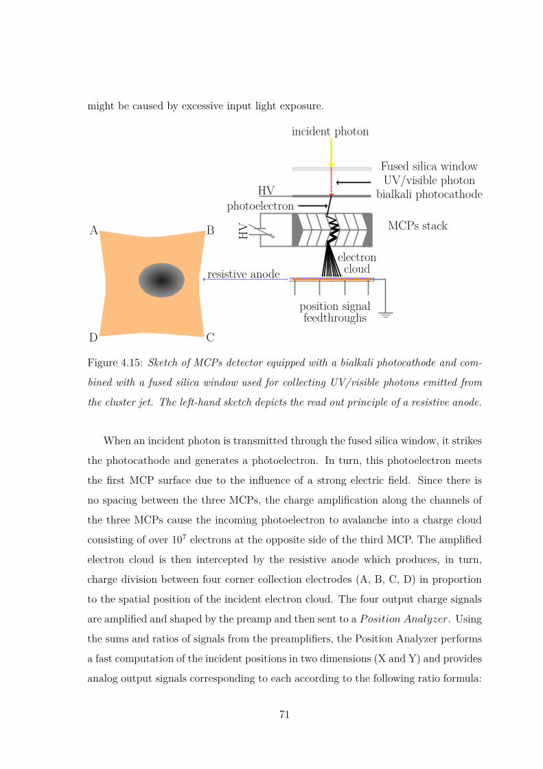
might be caused by excessive input light exposure.
A B
CD
position signalfeedthroughs
resistive anode
HV
Fused silica windowUV/visible photon
bialkali photocathodeHV
incident photon
photoelectronMCPs stack
electroncloud
Figure 4.15: Sketch of MCPs detector equipped with a bialkali photocathode and com-
bined with a fused silica window used for collecting UV/visible photons emitted from
the cluster jet. The left-hand sketch depicts the read out principle of a resistive anode.
When an incident photon is transmitted through the fused silica window, it strikes
the photocathode and generates a photoelectron. In turn, this photoelectron meets
the first MCP surface due to the influence of a strong electric field. Since there is
no spacing between the three MCPs, the charge amplification along the channels of
the three MCPs cause the incoming photoelectron to avalanche into a charge cloud
consisting of over 107 electrons at the opposite side of the third MCP. The amplified
electron cloud is then intercepted by the resistive anode which produces, in turn,
charge division between four corner collection electrodes (A, B, C, D) in proportion
to the spatial position of the incident electron cloud. The four output charge signals
are amplified and shaped by the preamp and then sent to a Position Analyzer. Using
the sums and ratios of signals from the preamplifiers, the Position Analyzer performs
a fast computation of the incident positions in two dimensions (X and Y) and provides
analog output signals corresponding to each according to the following ratio formula:
71
X ∝ B + C
A+B + C +D, Y ∝ A+B
A+B + C +D(4.7)
The X and Y analog signals can be digitized via an analog-to-digital converter
(ADC) and then acquired by a required acquisition software package in the PC.
In fact, the readout of the X and Y analog signals by external devices can be done
only when the ADC is triggered by an analog TTL STROBE signal; i.e. as to when
all data events are sampled and recorded. In this undispersed visible fluorescence
measurement, the digital STROBE signal that starts immediately at the end of the
ADC conversion was actually used to monitor the total number of the events in the
detector area (total counts). This was done by connecting the TTL STROBE output
channel on the rear side of the Position Analyzer to a data acquisition device driver
in order to transfer the signal to the PC for display and analysis by a home-built
acquisition software packages written in Python programming language.
Note that this Quantar-detector system is operated simultanously with the open
face MCPs detector being described above during the experiment with the aim to per-
form simultaneous measurements of UV/Vis and VUV emitted photons from excited
Neon clusters. Before conducting an experiment on Neon clusters, the electronics
of both detectors are checked and tested. For testing the operation mode of both
detectors, a reference gas of Neon atoms excited with photons of energies below the
first ionization energy limit of Neon atoms (21.56 eV [KM72]) was used. Figure
4.16 shows a simultanously recorded VUV and UV/visible fluorescence excitation
functions of isolated Neon atoms at different exciting-photon energy ranges below
the 2p-electron binding energy of Neon atoms (21.56 eV [KM72]). In the shown
exciting-photon energy range of 19.50-21.60 eV , both excitation functions exhibit the
well-known atomic Ne−2p5nl(nl 6= 3s) resonances as a form of sharp features. In the
shown exciting-photon energy range of 16.66-16.68 eV , only the VUV fluorescence ex-
citation function of Neon atoms does show the atomic Ne− 2p5(2P3/2)3s resonance
which is obvious since no UV/Vis photons should be detected in this energy range.
72
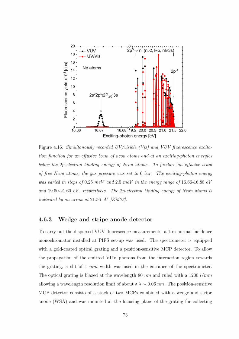
16.66 16.67 16.68 19.5 20.0 20.5 21.0 21.5 22.00
2
4
6
8
10
12
14
16
18
202p5 nl (n l p, nl 3s)
VUV UV/Vis
Fluo
resc
ence
yie
ld x
103 [c
ps]
Exciting-photon energy [eV]
2s22p5(2P3/2)3s
2p-1Ne atoms
Figure 4.16: Simultanously recorded UV/visible (Vis) and VUV fluorescence excita-
tion function for an effusive beam of neon atoms and at an exciting-photon energies
below the 2p-electron binding energy of Neon atoms. To produce an effusive beam
of free Neon atoms, the gas pressure was set to 6 bar. The exciting-photon energy
was varied in steps of 0.25 meV and 2.5 meV in the energy range of 16.66-16.88 eV
and 19.50-21.60 eV , respectively. The 2p-electron binding energy of Neon atoms is
indicated by an arrow at 21.56 eV [KM72].
4.6.3 Wedge and stripe anode detector
To carry out the dispersed VUV fluorescence measurements, a 1-m-normal incidence
monochromator installed at PIFS set-up was used. The spectrometer is equipped
with a gold-coated optical grating and a position-sensitive MCP detector. To allow
the propagation of the emitted VUV photons from the interaction region towards
the grating, a slit of 1 mm width was used in the entrance of the spectrometer.
The optical grating is blazed at the wavelength 80 nm and ruled with a 1200 l/mm
allowing a wavelength resolution limit of about δ λ ∼ 0.06 nm. The position-sensitive
MCP detector consists of a stack of two MCPs combined with a wedge and stripe
anode (WSA) and was mounted at the focusing plane of the grating for collecting
73

dispersed VUV photons in a wavelength range between 40 and 120 nm [KHF14]. To
ensure only the detection of photons, an operating voltage of −1200 V was applied
to the front of each MCP with respect to their rear side. By that, electrons were
rejected. Additionally, a −300 V voltage was applied between the rear side of the
second MCP and the anode, which was kept at ground potential. Ions were rejected
by a mesh in front of the first MCP, set to +151 V . The working principle of the
position-sensitive detector based on wedge and stripe anode is illustrated in figure
4.17 and as follows.
S
W
M
MCP1
MCP2
output signals
WSAelectronsoutput
-1200V
-1200V
-300
V
incident photon
Figure 4.17: Sketch of an open face MCPs stack detector with a wedge and stripe
anode (WSA) used for collecting dispersed emitted VUV photons from the target.
The right-hand sketch depicts the read out principle of wedge and stripe anode.
When an incoming photon hits a channel wall of the first MCP, it leads to an
emission of a photoelectron that starts a cascade of secondary electrons along the
channel, after being accelerated with the high potential. These secondary electrons
exit the first MCP on the opposite side and start another cascade of electrons in the
second MCP, resulting in an amplified electron cloud which exit in turn the opposite
side of the second MCP. Then, the amplified electron cloud, containing about 105 to
106 electrons, travel toward the anode which consists of electrically separated areas
with a wedge and stripe structure at a typical periodicity, as illustrated in the left-
hand sketch of figure 4.17. The charge cloud centroid can be deduced from the ratio
74
of charge on all anode segments as long as the cloud covers an area larger than one
period of the anode structure. To extract information on the charge cloud centroid
position, the charge signals of the wedge and stripe segments have therefore to be
normalized to the collected total charge, which varies from event to event. The total
charge is given by the charge sum of all anode segments. Since the wedge area varies
linearly with position in one axis, and the stripe area also varies linearly with position
in the other axis so the charge cloud centroid position in each axis is given by
X ∝ QS
QS +Qw +QM
, Y ∝ Qw
QS +Qw +QM
(4.8)
where Qw, Qs and QM are the charge signals on the wedge, strip and meander elec-
trodes, respectively.
All the three charge signals Qw, Qs and QM are first amplified in separate charge-
sensitive preamplifiers and subsequent TENNELEC amplifiers (TC 241 amplifier)
operated in an NIM -rack, and then acquired by home-built acquisition PC software
packages written in Python programming language. The event-by-event normaliza-
tion and calibration procedure was done separately.
Figure 4.18 shows two typical images of the WSA detector used in this work while
performing a dispersed VUV fluorescence measurement on effusive atomic Neon beam
and Neon cluster beam at two different exciting-photon energies, but at same grating
position. It also shows the integrated fluorescence intensities in pixel of the atomic
and cluster VUV fluorescence features seen in the images of the detector.
75

0 20 40 60 80 100 120 140 160 180 200 2200
50
100
150
200
250
300 Ne Cluster
fluorescence line Ne atomic
fluorescence line
Cou
nts
[arb
. uni
ts]
Channels [px]
Figure 4.18: Tow images of the WSA detector obtained while performing dispersed
VUV fluorescence measurements on effusive atomic Neon beam and Neon cluster beam
at exciting-photon energy of 16.7 eV and 47.09 eV , respectively. The grating position
is the same for the two measurements. The data in black and red shows the integrated
VUV fluorescence intensity in pixel obtained for a free atomic jet of Neon atoms and
Neon clusters beam, respectively. The pixel channel axis used in this figure corresponds
to a wavelength windows of about 58 − 85 nm. Each data is obtained by integrating
over the selected rectangle width in the corresponding detector image. The integration
time for the shown cluster fluorescence spectrum is 20 minutes, whereas for the atomic
fluorescence spectrum it is 5 minutes.
The images of the detector obtained for dispersed VUV fluorescence measurement
on Neon clusters and effusive beam do not show the same data distributions. The data
distribution obtained in case of an effusive beam may reflect the geometry of the used
slit in the entrance of the 1-m-normal incidence spectrometer. In case of cluster, the
detector image, however, shows a spot that somehow reflects the interaction region
where the incident SR beam crosses the produced cluster beam.
76
Chapter 5
Results
5.1 Resonant interatomic Coulombic decay (RICD)
in Neon clusters
Figure 5.1 shows a total VUV fluorescence yield recorded for a mixed beam of
Neon atoms and clusters (upper panel) with an average cluster size of < N >
∼ 40 in the exciting-photon energy range of 46.8 − 48.8 eV ; i.e. near the 2s-
electron photoionization threshold of Neon atom (48.475 eV [SDP96]). To per-
form this measurement, a slit-width of 300 µm of the plane grating monochro-
mater (PGM) of the beamline was chosen to obtain a bandwidth of the exciting-
photons of about 13 meV at 44 eV . The exciting-photon energy was varied in en-
ergy steps of 25 meV with a timing of 15 s for each energy step. The same yield
recorded for effusive beam of Neon atoms is also plotted in figure 5.1 (lower panel)
for comparison, after being background-corrected. The background observed in the
atomic fluorescence signal behaves linearly and is interpreted as mainly due to the
electronic noise of the detector and the scattered SR that falls into the sensitiv-
ity of the detector. The only prominent feature in the VUV fluorescence yield of
monomers starts at the Neon 2s-electron photoionization threshold, above which sub-
sequent fluorescence transitions, i.e. 2s12p6 2S1/2 → 2s22p5 2P3/2,1/2 at 46.0 nm and
46.2 nm within NeII [SMM92], can take place. It is also seen in the VUV fluorescence
77

signal recorded for the mixed beam of Neon atoms and clusters used for calibrating
the exciting-photon energy axes.
4
6
8
10
46.8 47.2 47.6 48.0 48.4 48.80.0
0.5
1.0
1.5
2.0
VU
V fl
uore
scen
ce y
ield
x10
3 [arb
. uni
ts]
Ne clusters
resonant ICD
~ 40
2s-1
518 mbar
Exciting-photon energy [eV]
Ne monomers
Figure 5.1: Total VUV fluorescence yield measured for Neon monomers (lower panel)
and a mixed monomers+clusters beam (upper panel) for a mean cluster size of
< N > ∼ 40 in the exciting-photon energy range of 46.8 − 48.8 eV .
The fluorescence yield of Neon monomers exhibit prominent features only close
to the 2s electron photoionization threshold. An interpretation is given in
the text. They are also seen in the VUV fluorescence signal recorded for
the clusters and atoms mixture (upper panel). The VUV fluorescence sig-
nal from clusters shows two additional new features which are interpreted in
[KHF14] as originated from RICD. The exciting-photon energy axis is roughly
calibrated against the 2s-electron photoionization threshold of Neon atoms at
48.475 eV according to [SDP96]. The VUV fluorescence data from Neon monomers
has been measured at the SR facility BESSY and was used here after kind permission
from André Knie.
Indications of the narrow features corresponding to resonant excitations of the
NeI 2s12p6np-Rydberg states with subsequent fluorescence decay in the Neon atoms
already observed by other authors [LPH00] are seen close to the 2s-electron ionization
78

threshold in the VUV-fluorescence signal for free Neon atoms as well as for the mixed
beam of Neon atoms and clusters. The absence of features in the fluorescence signal of
Neon monomeres (lower panel) at lower energies below the Neon 2s-electron photoion-
ization threshold is known to be due to the fast autoionization of the 2s → np reso-
nances, suppress any fluorescence emission. For the mixed jet of atoms and clusters,
two additional peaks are seen in the
46.8 − 47.7 eV region of the total VUV fluorescence yield of cluster. These two
features are originated from resonant interatomic Coulombic decay (RICD), as well
interpreted before in [KHF14] for < N > ∼ 20, following a photoexcitation of a 2s-
inner valence electron of a Neon atom within a cluster to unoccupied orbital (nl).
More precisely, they are due to the radiative decay of the final states of the spectator
RICD process. This observation chiefly entails that the VUV fluorescence emission
cross section of Neon clusters changes dramatically compared to Neon atoms; i.e.
atomic radiative decay paths are quenched by ICD while ICD following resonant ex-
citation opens new fluorescence paths. The overall RICD process that occurs in Neon
clusters excited with an incident photon of energy hν below the Neon 2s-electron
photoionization threshold is as follows:
NeN(2s22p6) + hν → Ne(2s−12p6nl)NeN−1(2s22p6)
→ Ne(2s22p5nl)Ne+(2s22p5)NeN−2(2s22p6) + e−ICD
→ Ne(2s22p6)Ne+(2s22p5)NeN−2(2s22p6) + e−ICD + hν′
where e−ICD and hν′ designates an ICD electron and photon, respectively, emitted
after the ICD took place, and N is the number of atoms in the cluster.
The sudden intensity increase in the fluorescence signal measured for free Neon
atoms and also for the mixed beam of Neon atoms and clusters at the Neon 2s-
electron emission threshold does not show a steep or an ideal edge but rather a
sigmoide edge that can be explained as a result of the interplay of the instrumental
apparatus inherent in the measurement process (e.g. the exit slit of the beamline).
79

Mathematically, an ideal edge can be described by a step function [AS12]. The only
use of a step function is, however, not applicable in that case. Whereas a convolution
of an apparatus function, e.g. a Gaussian function, with a step function can be used
as a mathematical tool to model the observed shape of the VUV fluorescence signal
at the Neon 2s-electron emission threshold in figure 5.1. One means of defining the
aforestated convolution is the so-called error function (erf). The step increase in
intensity at the Neon 2s-electron emission threshold of figure 5.1 can thus be modeled
by the following expression (see Appendix A):
C(hν) = C0 + A
2 erf(hν − Ethw√
2) (5.1)
where A measures the magnitude of the step, Eth identifies the location of the step,
w is the width of the Gaussian and C0 represents a constant offset.
Figure 5. 2 shows the obtained simulation using Eq. (5.1) of the measured fluores-
cence intensity increase seen in the upper panel of figure 5.1 at the Neon 2s-electron
emission threshold. It also shows a Gaussian fit of the 1st derivative of the fluo-
rescence intensity increase in the exciting-photon energy range of 48.30-48.65 eV .
The fit with a Gaussian function reveals information on the location of the Neon
2s-electron photoionization threshold as well on the experimental width of the instru-
mental Gaussian response inherent in the measurement process (see figure 5.2). The
obtained width (w) of the instrumental Gaussian function used is about 29.4 meV . It
is almost consistent with the resolution of the experiment which can be viewed as the
lower boundary of the experimental error and has a value of about 28.2 meV . The
28.2 meV is deduced from the combination of the used beamline energy bandwidth
(13 meV ) and the chosen energy scanning step width interval (25 meV ) via using the
propagation of uncertainties formula [Ku66], i.e.√
(0.013)2 + (0.025)2 ≈ 28.2 meV .
80

4
5
6
7
8
9
10
w = 29.4 meV
2s-1 (a)
VU
V fl
uore
scen
ce y
ield
x1
03 [arb
. uni
ts]
uncondensed Ne atoms
C(h ) =C0+erf[(h -Eth)/w sqrt(2)] A/2
48.30 48.35 48.40 48.45 48.50 48.55 48.60 48.65-12
0
12
24
36
48
60Eth = (48.475 0.002) eV
1st d
eriv
ativ
e x
103 [a
rb. u
nits
] (b)
Exciting-photon energy [eV]
fwhm = 2 sqrt(2 ln(2)) w 50 meV
Exp. data Simulated data
1st Deriv Gaussian fit
Figure 5.2: (a) A convolution of a Gaussian function with a step function was used
to model the observed fluorescence intensity increase at the Neon 2s-electron pho-
toionization threshold. (b) A Gaussian fit of the 1st derivative of the shown flu-
orescence intensity increase in panel (a). The deviation w = 29.4 meV obtained
from the simulation using a convolution is in good agreement with the width value
which is obtained from the fitted Gaussian. The center of the fitted Gaussian
(48.475 ± 0.002) eV was used to determine the location of the 2s-electron photoion-
ization threshold Eth at 48.475 eV according to [SDP96] and hence to roughly calibrate
the exciting-photon energy axis.
Section summary
In this section, the VUV fluorescence yield recorded for a Neon cluster jet with a mean
cluster size of < N > ∼ 40 and for effusive beam of Neon atoms are compared and
interpreted. The VUV fluorescence emission signal of Neon cluster changes dramat-
ically compared to Neon atoms. It exhibits two additional prominent fluorescence
81

features below the Neon 2s-electron photoionization threshold. These features are
connected with spectator RICD. Furthermore, care has been taken in this section to
roughly calibrate the exciting-photon energy axis through using the observed Neon
monomers fluorescence signal at the Neon 2s-electron photoionization threshold.
82

5.2 Radiative decay of RICD final states
20
25
30
35
40
46.9 47.0 47.1 47.2 47.3 47.4 47.5 47.6 47.754
57
60
63
66
69
72
56To
tal V
UV
fluor
esce
nce
yiel
d x
103 [a
rb.u
nits
]
4p
5p
(a)resonant ICD
(b)
Exciting-photon energy [eV]
Tota
l UV/
visib
le fl
uore
scen
ce
yiel
d x
102 [a
rb.u
nits
]
56
Figure 5.3: Total yields for VUV fluorescence (panel a) and UV/visible (panel b)
recorded simultanously across the 2s → 4p and 2s → 5p excitations [FKKG14] in
Neon clusters. To guide the eye, the UV/visible signal is additionally smoothed by
FFT (Fast Fourier Transform) filter (black line). More details are given in the text
and [HLF17].
Figure 5.3 compares the total VUV (panel (a)) and UV/visible (panel (b)) fluores-
cence yields of Neon clusters measured simultaneously for < N > ∼ 56 as mean
cluster size in a narrower exciting-photon energy range of 46.9-47.7 eV . The two
distinct resonant features seen in the total VUV fluorescence are arising from spec-
tator RICD, as mentioned above and interpreted before in previous work [KHF14].
According to the calculation performed by Flesch et al. [FKKG14], they are assigned
to the 2s → np (n = 4, 5) Rydberg excitations in Neon clusters. These 2s → np (n
= 4, 5) cluster excitations will be discussed in more details in section 5.3. After the
83

RICD took place, the excited cluster still possesses a part of the excess energy, which
can only be released by the emission of photon. Because the radiative decay rate
grows significantly with the energy of the emitted photon (Γr ∼ ω3fl, see for example
Ref. [Deg14], pages 273-274), one would expect that the Rydberg-to-valence np →
2p transition 1 will dominate over the Rydberg-to-Rydberg np → 3s one, and hence
a predominant fluorescence emission in the VUV range can be expected as implied
in [KHF14]. However, the direct correspondence of the resonant structure observed
in the VUV and UV/visible fluorescence signals displayed in figure 5.3 unequivocally
suggests that the latter fluorescence emerges owing to spectator RICD as well. This
entails that the spectator RICD final states release their excess energy by photon
emissions cascade in different spectral ranges, consecutively in the UV/visible and
VUV ranges as schematically illustrated in figure 3.6 in section (3.9.3) of chapter
III. From the energy consideration, the UV/visible photon can only be released by
a Rydberg-to-Rydberg transition and solely in the first step of this cascade; i.e. via
np (n = 4, 5) → 3s radiative decay. The VUV photon, in turn, is emitted by a
Rydberg-to-valence transition in the second relaxation step; i.e. via 3s → 2p tran-
sition. To trace the decay pathway during this radiative cascade, an additionally
dispersed VUV fluorescence measurement was performed for the most intense 2s →
4p cluster fluorescence resonance. In this separate measurement, the emitted VUV
photons are dispersed by a 1 −m−normal-incidence monochromator equipped with
a gold-coated 1200 l/mm grating and then detected by a position-sensitive open
face MCP detector capable of detecting photons within a wavelength range between
40 and 120 nm [KHF14]. The dispersed VUV fluorescence spectrum of Neon clusters
in the wavelength interval of 58 − 85 nm is depicted in red in figure 5.4 in com-
parison with the Neon atomic fluorescence spectrum (depicted in black) that was
recorded at an exciting-photon energy of 16.7 eV . The spectral resolution ∆ λ has
been determined to be about 1.5 nm full width at half maximum (FWHM) by fitting
a Gaussian curve over the Neon atomic fluorescence line seen at about 74.37 nm.
With the present wavelength resolution, only one cluster fluorescence line at about1Note that the np → 2p transition is forbidden only in systems with central symmetry.
84

74 nm was observed. No VUV signal with larger wavelengths (smaller photon ener-
gies), even in the wavelength range above 85 nm (not shown in the figure) was seen.
Thus, one concluded that the observed fluorescence line corresponds to the relaxation
of the lowermost outer-valence excited state, i.e., to the 3s → 2p transition in Neon
clusters. This cluster fluorescence line is the analogue of the atomic fluorescence lines
2s22p5(2P3/2)3s → 2s22p6 [SS04, KYR15] seen at about 74.37 nm, as indicated in
figure 5.4, which supports the presently suggested assignment.
58 60 62 64 66 68 70 72 74 76 78 80 82 840.0
0.2
0.4
0.6
0.8
1.0
h = 47.09 eV
2s22p5(2P3/2)3s 2s22p6
atoms clusters
Fl
uore
scen
ce in
tens
ity [c
ps]
Fluorescence wavelength [nm]
h = 16.7 eV
Neon
Figure 5.4: Dispersed VUV fluorescence spectrum of Neon clusters recorded at an
exciting-photon energy of 47.09 eV [HLF17], which corresponds to the 2s → 4p res-
onant feature [FKKG14]. The cluster fluorescence line observed around 74 nm is
the analogue of the atomic fluorescence line 2s22p5(2P3/2)3s → 2s22p6 in the neon
atom [SS04, KYR15], as plotted in black. The fluorescence wavelength scale is cal-
ibrated against the shown atomic transition line at 74.37 nm. The integration time
for the shown cluster fluorescence spectrum is 40 minutes, whereas for the atomic
fluorescence spectrum it is 5 minutes.
Importantly, no VUV fluorescence line with shorter wavelengths (larger photon
85

energies) was observed. It was implied in [KHF14] that such a fluorescence signal
could be expected as the result of the direct relaxation of the spectator RICD final
state; i.e. by the direct radiative decay of the outer-valence excited cluster in its
ground electronic state via 4p → 2p transition. According to atomic data tables
[KYR15], one would expect this VUV fluorescence line around 61 nm. The absence
of the signal in the wavelength range between 58 nm and 72 nm (see figure 5.4)
can only be explained by the validity of the dipole selection rules, which shows the
atomic character of the excited states inside the cluster. As a consequence, the
spectator RICD final state has only one possible relaxation pathway via the np→ 3s
Rydberg-to-Rydberg radiative decay in the UV/visible fluorescence range.
Section summary
Fluorescence emission cascade evoked by spectator RICD of 2s inner-valence excited
Neon clusters are presented and discussed in this section. The fluorescence cascade is
experimentally observed by combining VUV and UV/visible fluorescence spectroscopy
and additionally dispersing the VUV fluorescence. In the first step of this cascade,
the spectator resonant interatomic Coulombic decay (RICD) efficiently quenches au-
toionization of the excited Neon atom and opens thereby a possibility for subsequent
fluorescence relaxation pathways. In the second step, the spectator RICD final states
emit UV/visible fluorescence by a transition to the lowest 3s-Rydberg state. Fi-
nally, the VUV photon is released by the relaxation of this Rydberg electron into the
ground state in the third step of the cascade of decays. This finding demonstrates a
possibility of detecting interatomic electronic processes in dense media by UV/visible
fluorescence spectroscopy.
86

5.3 VUV fluorescence emission from Ne clusters
of varying sizes
0.040.080.120.160.200.240.280.320.36
44 45 46 47 48 490
1
2
3
4
5(b)
Ne+
monomers
Rel
ativ
e io
n yi
eld
(a)
2s-1
7000
VU
V fl
uore
scen
ce y
ield
x
103 [c
ps]
Exciting-photon energy [eV]
4p5p 6p
3p
700 490 270 100
40
2s-1
6542s12p6np3
Figure 5.5: (a) Relative Ne+-ion yields of free Neon atoms normal-
ized on the photocurrent of the last refocussing mirror [LHS18]. (b)
VUV fluorescence yields below the 2s ionization threshold for different av-
erage sizes of Neon clusters [LHS18]. The grey-shaded region from 46.9
eV to 47.6 eV highlights the two spectator RICD features at about
47.06 eV and 47.51 eV [KHF14]. The assignement have been made according to
[SDP96] for atomic 2s → np excitation energies in (a), and [FKKG14] for the 2s →
np (n=3, 4, 5, 6) cluster excitations in (b). The 2s-electron photoionization threshold
of Neon atoms is pointed out by a vertical solid line at 48.475 eV [SDP96, JBM06]
in (a) and (b).
Figure 5.5(a) shows yield of Ne+-ions recorded for an effusive pure Neon jet (no clus-
ters in the jet) following photoionization of Neon atoms for exciting-photon energies
87

between 44.0 eV − 48.7 eV , and after being normalized for the flux of the exciting-
photons. The exciting-photon energy range was varied in energy steps of 10meV with
a timing of 10 s for each energy step. The Ne+-ion yield is dominated by a series of
Fano-profile [Fan61, FC65] features corresponding to autoionizing 2s12p6np-Rydberg
states embedded in the 2p-electron continuum. This Rydberg series converges to the
Neon 2s-electron ionization threshold at 48.475 eV [SDP96, JBM06]. In addition
the atomic Ne+-ion yield exhibits a feature at around 44.98 eV due to the atomic
2p4(3P )3s(2P1/2,3/2)3p-transition and its subsequent autoionization [SDP96].
Figure 5.5(b) displays the undispersed-VUV-fluorescence excitation functions mea-
sured in the exciting-photon energy range of 44.0−48.7 eV for Neon clusters of varying
cluster size from ∼ 40 up to ∼ 7000 atoms per cluster. The exciting-photon energy
range was varied in energy steps of 25 meV with a timing of 15 s for each energy step.
To record the VUV fluorescence signals of Neon clusters with an averange cluster size
from ∼ 40 up to ∼ 700 atoms per cluster, the nozzle temperature was fixed at 60 K,
whereas the stagnation pressure was changed consecutively by 2 bar from 3 bar to 11
bar. The VUV fluorescence signal of Neon cluster for a cluster condition of < N > ∼
7000 was recorded at a nozzle temperature of 40 K and for a stagnation pressure of
9 bar. To perform all of these measurements, a slit-width of 300 µm of the plane
grating monochromater (PGM) of the beamline was chosen to obtain a bandwidth
of the exciting-photons of about 13 meV at 44 eV ; except for the measurement
with a cluster condition of ∼ 7000 the exit slit of the beamline was opened up to
400 µm. Here, the raison behind opening the exit slit of the beamline is to increase
the flux of the exciting-photons energy in order to measure a decent cluster signal
under a cluster conditions (where the nozzle temperature lowered up to 40 K and
the stagnation pressure fixed at 9 bar) by which the mean cluster size is increased up
to ∼ 7000 but the net atomic density would decrease as compared to the case with
a cluster condition of ∼ 700 where the stagnation pressure was set to 11 bar. For
all of these measurements, a signal of atomic Ne+-ions was simultanously recorded
with each of the VUV fuorescence signals displayed in figure 5.5(b) since the cluster
jet does contain uncondensed atoms. Figure 5.6(a) shows the typical four atomic
88
Ne+-ion yields measured simultanously with the first four VUV fluorescence yields
recorded for different mixed beams of Neon atoms and clusters produced at a fixed
nozzle temperature of T = 60 K and for a stagnation pressures of p0 = 3 bar, 5 bar,
7 bar and 9 bar, consecutively. With the resolution of these experiments no cluster
features are essentially observed in all of these Ne+-ions signals. The well-known Fano
profile features observed in these atomic Ne+-ion yields together with those which are
presented in figure 5.5(a) have been used to calibrate the scale of the exciting-photon
energy and to check the linearity of the nominal versus the true photon-energy scale of
the beamline. As an example, figure 5.6(a) shows simulated 2s→ 3p, 4p and 5p Fano
resonances at 45.5442 eV , 47.1193 eV and 47.6952 eV [CME67], respectively, used to
calibrate the exciting-photon energy axis of the atomic Ne+-ion signal recorded for
effusive beam and also for different mixed jets of Neon atoms and clusters. Table 5.1
shows the values of the resonance parameters used to perform the simulation of the
2s12p6np (n=3, 4 and 5) Rydberg series of free Neon atoms with the following Fano
formula [FC65]:
σ(ε) = σa(q − ε)2
1 + ε2 + σb (5.2)
where σ is the excitation cross section as a function of the de-tuning
ε = 2(hν − hνres)/Γ (with hνres is the resonance energy (Eres) and Γ is the reso-
nance width), q is the line shape parameter, and σa and σb denote the cross sections
of the continua that do and do not interact with the resonant state, respectively.
The ratio between the cross sections σa and σb can be determined through using the
coupling index ρ where ρ2 = σa
σa+σb[FC65].
89

0.00.20.40.60.81.01.21.41.6
44 45 46 47 48 494
5
6
7
8
9
(a) Simulated data Exp. data
Ion
yiel
d [n
A]
(b)
atoms+cluster jet
Tota
l VU
V fl
uore
scen
ce
yiel
d x1
03 [arb
. uni
ts]
Exciting-photon energy [eV]
2s-1
effusive beam
2s 3p2s 4p2s 3p 3 bar
5 bar
7 bar
9 bar
40
P0 = 3 bar, T = 60 K
Exp. data Simulated data
Figure 5.6: (a) Yields of atomic Ne+-ions recorded for an effusive beam of Neon
atoms and different mixed Neon atoms+cluster jets. The different jets are produced
at a nozzle temperature of T = 60 K and a stagnation pressure of p0 = 3 bar, 5 bar,
7 bar and 9 bar, while the effusive beam was produced at 6 bar as a gas pressure.
An offset of 0.2 nA was set between each two Ne+-ion signals for better displaying
the graphs. The 2s → 3p, 4p and 5p atomic transitions were simulated by a Fano
formula at a resonance energy of 45.547 eV , 47.123 eV and 47.694 eV , respectively,
according to [CME67] to calibrate the exciting-photon energies. (b) Total yield of
emitted VUV photons recorded simultanously with the yield of atomic Ne+-ions while
running a mixed beam of Neon atoms+clusters for p0= 3 bar and T = 60 K. The
exciting-photon energy axis was calibrated according to the exciting-photon energy axis
calibrated in (a), and also by simulating the fluorenscence intensity increase at the
Neon 2s-electron photoionization threshold, i.e. at 48.475 eV according to [SDP96],
with a convolution of a Gaussian function with a step function.
90

Table 5.1: Resonance parameters taken from [SDP96, CME67] and used to perform
the simulatiton of the 2s12p6np (n=3, 4 and 5) Rydberg series of free Neon atoms
with the given Fano formula in Eq. 5.2.
2s12p63p 2s12p64p 2s12p65p
Eres(eV ) 45.5442 47.1193 47.6952
q -1.6 -1.6 -1.6
Γ(eV ) 0.013 0.0045 0.002
σb(cm−1) 230 215 220
ρ2 = σa
σa+σb0.70 0.70 0.70
Figure 5.5(b) is not normalized for the exciting-photon flux and is mainly used here
for the discussion of the spectral features. The recorded VUV fluorescence excitation
functions of the Neon cluster jet exhibits for all cluster sizes a sudden increase of the
VUV fluorescence yield at an exciting-photon energy of 48.475 eV . This fluorescence
increase is due to the 2s-electron photoionization in Neon atoms and the subsequent
fluorescence transitions 2s12p6 2S1/2 → 2s22p5 2P3/2, 1/2 at 46.0 nm and 46.2 nm
within NeII [SMM92], as mentioned above. Together with the scale calibration of
figure 5.6(a) it is used for the exciting-photon energy calibration, as shown in figure
5.6(b) for a typical example of total VUV fluorescence yield of Neon cluster for cluster
condition of < N > ∼ 40.
In the present experiment the following observations are made which display char-
acteristic changes with increasing cluster size:
(1) At lower energies within the investigated exciting-photon energy range the
fluorescence intensity slowly and continuously increases with exciting-photon energy
and with a more pronounced increase for the beam conditions producing larger average
91

cluster sizes.
(2) The fluorescence signal recorded for the smallest cluster size shows a series
of features, which may be identified as 2s → np excitations of cluster-surface atoms
[FKKG14] ending in VUV fluorescence emission. These features are visible for all
cluster sizes but appear to be less prominent in the fluorescence excitation functions
of the larger clusters due to increasing continuous fluorescence intensity around the
features. The grey-shaded exciting-photon energy region of figure 5.5(b) highlights
the two fluorescence features at about 47.06 eV and 47.51 eV which were interpreted
in [KHF14] as originated from RICD.
(3) A number of additional comparatively broad features appear which are getting
more prominent as the average cluster size increases. The most obvious example is
the feature centered at around 46.66 eV .
All of these observations will be discussed in details in the following subsections.
5.3.1 Photoelectron impact induced VUV fluorescence emis-
sion
+e-
*+1
ii i
Figure 5.7: Illustration of possible inelastic electron scattering pathways in cluster.
i: Inelastic electron scattering leading to excitation of a neutral cluster atom. ii:
Inelastic electron scattering leading to ionization of a neutral cluster atom.
92

The structurelessly increasing intensity observed at small exciting-photon energies in
figure 5.5 is proposed to be interpreted as due to fluorescence excitation by inelas-
tically scattered 2p photoelectrons (photoelectron impact induced fluorescence). All
2p photoelectrons which travel through the mixed cluster+atoms beam will have a
kinetic energy dependent probability to scatter inelastically in several pathways: by
exciting or ionizing a neutral atom, as sketched with scenario i or ii in figure 5.7 for
the case of cluster, or by creating an exciton in the cluster.
Excitation processes leading to VUV-fluorescence emission after photoelectron
impact may include atomic excitation or exciton excitation in the cluster. Forma-
tion of excited ions with VUV fluorescence emission is not possible for the present
exciting-photon energies. In order to experimentally investigate this hypothesis the
exciting-photon energy range has been widened as compared to the experiments of
figure 5.5: Figure 5.8 shows the VUV fluorescence excitation functions of Neon clus-
ters for exciting-photon energies from 34.0 eV up to 49.0 eV and for four selected
average cluster sizes (< N > ∼ 40, 270, 700 and 7000). The onset of the almost
continuous fluorescence signal increase lies at ≈ 35.8 eV . In the data displayed in
figure 5.8 the constant background of the detector due to electronic noise and a small
contribution of stray light from incident synchrotron beam has been determined for
exciting-photon energies below 35.5 eV and assumed to be constant throughout the
whole exciting-photon energy range (See figure 5.12 for more details). This back-
ground has then been subtracted from the raw data. Then the background-corrected
data has been normalized for the mirror current of the last refocusing mirror in the
beam line, being a measure for the incoming photon-flux. Care has been taken that
beam position variations during data acquisition did not influence the proportionality
between measured mirror current and photon flux in the interaction region by com-
paring the mirror current to a signal measured by the Faraday cup mounted behind
the interaction region.
93

34 35 36 37 38 39 40 41 42 43 44 45 46 47 48 49
2s-1
VUV
fluor
esce
nce
yiel
d [a
rb. u
nits
]
Exciting-photon energy [eV]
40
270
700
7000
2s np
x1.5
Figure 5.8: VUV fluorescence excitation functions for four average cluster sizes
(< N > ∼ 40, 270, 700 and 7000) of Neon clusters in the exciting-photon energy
range of 34.0 − 49.0 eV , after being first background-corrected and then normalized
for the flux of the exciting photons [LHS18]. The prominent features in the exciting-
photon energy range of 45.0 − 46.8 eV are corresponding to the 2s → np resonant
excitations [FKKG14]. The structureless increase of the fluorescence signal observed
at lower exciting-photon energies and above the exciton excitation is interpreted as
due to fluorescence excitation by inelastically scattered 2p photoelectrons, more de-
tails are given in the text. The onset of the measured VUV fluorescence signals of the
clusters and the 2s-electron photoionization threshold of atomic Neon are indicated by
a vertical arrow at about 35.8 eV and by short dots at 48.475 eV [SDP96, JBM06],
respectively.
As an example figure 5.9 shows how the ratio between the measured mirror current
and faraday cup current varies while scanning the exciting-photon energy from 34.0
eV to 48.7 eV and running a cluster jet with a cluster condition of < N > ∼ 700.
94

1.401.441.481.521.561.60
36
40
44
48
34 35 36 37 38 39 40 41 42 43 44 45 46 47 48 493.03.23.43.63.8
(b)
Mirr
or c
urre
nt[a
rb. u
nits
] (a)
C
up c
urre
nt
[nA
]
(c)
Rat
io/1
07
Exciting-photon energy [eV]
Figure 5.9: (a) Recorded current of the last refocusing mirror of the PLEIADES
beamline (a) as well as the recorded one by the Faraday cup (b) while measuring a
VUV fluorescence signal of a Neon cluster in the exciting-photon energy range of
34.0− 48.70 eV and for a cluster condition of < N > ∼ 700. (c) Ratio of the mirror
current in (a) to the Farady cup current in (b). By scanning the exciting-photon
energy in energy steps of 100 meV from 34 eV to 48.7 eV , the current ratio in (c)
changes by about 25 %.
Closely above the onset energy (≈ 35.8 eV ) in figure 5.8 a broad feature at ≈
37.9 eV is seen and becomes more and more prominent with increasing cluster size.
It is attributed to photoelectron impact excitation of the lowest excitonic state in
the cluster [HKR02]. The required electron energy to excite this state is about
17.6 eV [SJ85, BFJ96], which together with the 2p-electron binding energy in solid
Neon (20.3 eV [SHS75]) corresponds to 37.9 eV , in good agreement with the observa-
tion. At exciting-photon energies above the exciton excitation the observed fluores-
cence signal increases approximately linearly with energy with a larger increase for
gas jet conditions resulting in larger clusters. If this signal is due to inelastically scat-
tered 2p-photoelectron, the cross section of the VUV fluorescence emission σfl(hν)
seen by the detector must be proportional to the product of the cross sections of
95

2p-electron photoionization σ2p(hν) and for VUV fluorescence emission by electron
impact σfl,EI(Ekin) = σfl,EI(hν − EB,2p):
σfl(hν) ∝ σ2p(hν) · σfl,EI(hν − EB,2p) (5.3)
where hν is the exciting-photon energy, Ekin is the kinetic energy of the photoelectron,
and EB,2p is the binding energy of the Neon 2p electron in solid Neon (20.3 eV
[SHS75]). The measured VUV emission onset energy of ≈ 35.8 eV is smaller than
the sum of EB,2p and the threshold energy for electron induced VUV fluorescence
excitation in Neon atoms (16.683 eV [BKR77, ZBN98], corresponding to the decay
of the 2p5 2P3/2 3s[3/2] level to the Neon ground state). Spectrally resolved VUV
fluorescence of solid Neon after 2.5 keV electron impact, however, revealed a smooth
onset of fluorescence between 15 eV and 16 eV emitted-photon energy [CDZ85].
The corresponding fluorescence feature has been attributed to molecular type self-
trapped excitons [Zim79]. In the spectrum of these authors a huge peak with fine-
structure at around 16.7 eV is visible, which has been attributed to atomic-type
self-trapped excitons [Zim79]. As measured VUV fluorescence excitation functions of
solid Neon do not exist in literature the cited work can only be used for identifying
possible spectral features but not for an analysis of corresponding cross sections for
the relevant processes. One conclude that these excitonic features can well be excited
by 2p photoelectrons in our experiment and that observed VUV fluorescence emission
close above the fluorescence onset energy in the present experiment is due to clusters
(excitonic excitations) only. At higher exciting-photon energies also fluorescence from
monomers may contribute. The 2p-electron photoionization cross section does not
vary significantly in the exciting-photon energy range between 34 eV and 49.0 eV ,
when resonances are neglected for the moment [BS96]. It is therefore assumed to
be constant. The electron impact induced VUV fluorescence excitation function of
Neon atoms, however, has a steep, almost linear increase with electron energy in
the energy range between fluorescence onset and about 15 eV above onset energy
[KAJ96]. If one assume a similar dependence of fluorescence excitation on the electron
96
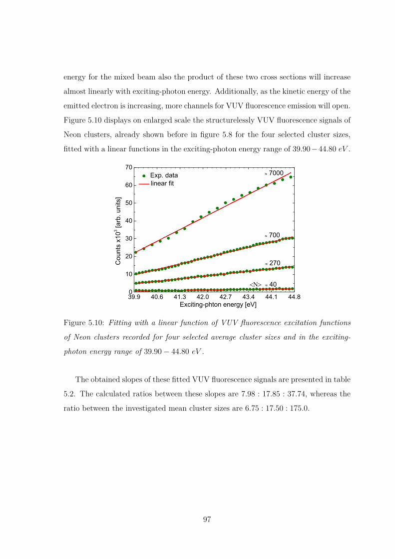
energy for the mixed beam also the product of these two cross sections will increase
almost linearly with exciting-photon energy. Additionally, as the kinetic energy of the
emitted electron is increasing, more channels for VUV fluorescence emission will open.
Figure 5.10 displays on enlarged scale the structurelessly VUV fluorescence signals of
Neon clusters, already shown before in figure 5.8 for the four selected cluster sizes,
fitted with a linear functions in the exciting-photon energy range of 39.90−44.80 eV .
39.9 40.6 41.3 42.0 42.7 43.4 44.1 44.80
10
20
30
40
50
60
70 Exp. data linear fit
Cou
nts
x103 [a
rb. u
nits
]
Exciting-phton energy [eV]
40
270
700
7000
Figure 5.10: Fitting with a linear function of VUV fluorescence excitation functions
of Neon clusters recorded for four selected average cluster sizes and in the exciting-
photon energy range of 39.90− 44.80 eV .
The obtained slopes of these fitted VUV fluorescence signals are presented in table
5.2. The calculated ratios between these slopes are 7.98 : 17.85 : 37.74, whereas the
ratio between the investigated mean cluster sizes are 6.75 : 17.50 : 175.0.
97

Table 5.2: Obtained slopes by a linear fit of VUV fluorescence excitation functions of
Neon clusters recorded for four selected average cluster sizes.
< N > 40 270 700 7000
Slopes 248.8 1985.3 4440.2 9389.0
The different slopes of the fluorescence excitation functions for beams with condi-
tions producing different average cluster sizes are also qualitatively understandable,
however, very difficult to explain on a quantitative basis. For the latter discussion
the density distribution of the target material and the condensation rate distribution
in the beam must be known, which was not in the present experiment. Here, one
could only say that the increase of the slopes of the observed fluorescence excitation
functions for jet conditions producing larger average cluster sizes is likely related to
the increase in the size of the cluster.
Consequently, the presented evidences suggest that the fluorescence intensity in-
crease indicates an intracluster photoelectron-impact induced fluorescence excitation,
which gets more and more significant with increasing cluster size. Regardless of the
energy transfer process that leads to the occurrence of ICD in a cluster, in the present
experiment self−absorptionmay also appear in Neon clusters when a photon is firstly
emitted by an excited atom and then absorbed by a neighboring atom. This effect,
however, cannot be quantified in the present experiment.
98

5.3.2 Background contribution of scattered SR
34 35 36 37 38 39 40 41 42 43 44 45 46 47 48 490
10
20
30
40
50
60
70
80
90
100
700
270
Tota
l VU
V fl
uore
scen
ce y
ield
x
103 [a
rb. u
nits
]
Exciting-photon energy [eV]
40
2s-1
Figure 5.11: Total VUV fluorescence signal of Neon cluster for < N > ∼ 40, 270 and
700 as a function of the exciting-photon energy in the range of 34.0 − 48.7 eV . The
red dashed box at lower exciting-photon energies shows the different plateau heights of
the VUV fluorescence signals, which were interpreted as mainly due to the scattered
incident SR that depends highly on the cluster size.
Additional to the VUV fluorescence contribution due to the inelastically scattered 2p
photoelectron with the neutral atoms of the produced cluster jet, each of the VUV
fluorescence signal of Neon clusters displayed in figure 5.8 shows in fact a significant
background contribution of stray light from incident SR and also of the detector due
to electronic noise. This can be understood from figure 5.11 which displays the row
data of the plotted VUV fluorescence yields of Neon clusters in figure 5.8 for < N >
∼ 40, 270 and 700.
The VUV fluorescence signals plotted in figure 5.11 are recorded one after the
other after varying the exciting-photon energy in energy steps of 100 meV (15 s as
a timing for each energy step) from 34.0 eV to 48.7 eV . To record these three VUV
fluorescence signals, an exit slit-width of 500 µm of the plane grating monochromater
99

(PGM) of the beamline was chosen to obtain a bandwidth of the exciting-photons of
about 22 meV at 47.1 eV . The only experimental parameter that was changed after
recording each of these three VUV fluorescence signals is the stagnation pressure p0
which was set to 3 bar, 7 bar and 11 bar, consecutively. The nozzle temperature was
kept fixed at the same value of 60 K. While recording each of these VUV fluorescence
signals and also the signal for a cluster condition of < N > ∼ 7000 (p0 = 9 bar, T
= 40 K), an atomic Ne+-ion signal was simultaneously recorded. Together with the
fluorescence intensity increase seen at the Neon 2s-electron photoionization threshold,
the strongest 2s12p6np Fano profile features observed in each of these atomic Ne+-
ion signals were used to calibrate the scale of the exciting-photon energy, as shown
in panel (a) and (b) of figure 5.12 for a cluster condition of < N > ∼ 40.
Since the time of measurements for each energy step width (100 meV ) of the three
VUV fluorescence signals displayed in figure 5.11 is the same (15 s), the observed
different plateau heights at lower exciting-photon energies and for different cluster
sizes can only be explained by an increased scattering of that part of the incoming
SR which falls into the sensitivity of the detector and contributes together with the
detector electronic noise as a background to the measured VUV fluorescence signals.
This constant background has been determined at exciting photon energies below
35.5 eV and assumed to be constant throughout the whole exciting-photon energy
range. The different plateaus heights at lower exciting-photon energies are therefore
used to define the background level for each recorded VUV fluorescence signal of Neon
clusters in the exciting-photon energy range of 34.0 − 48.7 eV . Figure 5.12 shows,
as an example, the defined background level of the VUV fluorescence yield of Neon
cluster measured for < N > ∼ 40. It also shows the current of the last refocusing
mirror of the beamline which is used to perform the normalization of the row data
after being first background-corrected.
100
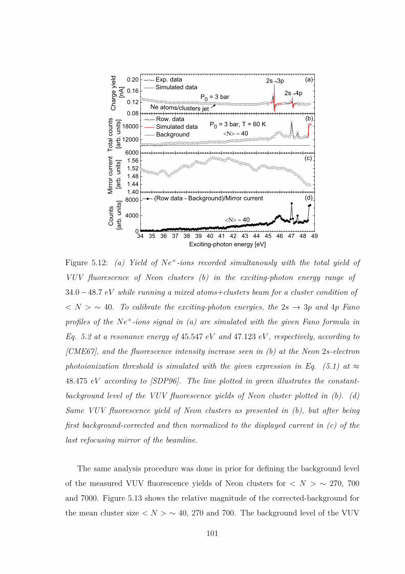
0.08
0.12
0.16
0.20
6000
12000
18000
1.401.441.481.521.56
34 35 36 37 38 39 40 41 42 43 44 45 46 47 48 490
4000
8000
P0 = 3 bar 2s 4p
Exp. data Simulated data
Cha
rge
yiel
d [n
A]
(a)2s 3p
Ne atoms/clusters jet
P0 = 3 bar, T = 60 K
(d)
(c)
(b) Row. data Simulated data Background
40
Mirr
or c
urre
nt
[arb
. uni
ts]
40
Tota
l cou
nts
[arb
. uni
ts]
(Row data - Background)/Mirror current
Cou
nts
[arb
. uni
ts]
Exciting-photon energy [eV]
Figure 5.12: (a) Yield of Ne+-ions recorded simultanously with the total yield of
VUV fluorescence of Neon clusters (b) in the exciting-photon energy range of
34.0−48.7 eV while running a mixed atoms+clusters beam for a cluster condition of
< N > ∼ 40. To calibrate the exciting-photon energies, the 2s → 3p and 4p Fano
profiles of the Ne+-ions signal in (a) are simulated with the given Fano formula in
Eq. 5.2 at a resonance energy of 45.547 eV and 47.123 eV , respectively, according to
[CME67], and the fluorescence intensity increase seen in (b) at the Neon 2s-electron
photoionization threshold is simulated with the given expression in Eq. (5.1) at ≈
48.475 eV according to [SDP96]. The line plotted in green illustrates the constant-
background level of the VUV fluorescence yields of Neon cluster plotted in (b). (d)
Same VUV fluorescence yield of Neon clusters as presented in (b), but after being
first background-corrected and then normalized to the displayed current in (c) of the
last refocusing mirror of the beamline.
The same analysis procedure was done in prior for defining the background level
of the measured VUV fluorescence yields of Neon clusters for < N > ∼ 270, 700
and 7000. Figure 5.13 shows the relative magnitude of the corrected-background for
the mean cluster size < N > ∼ 40, 270 and 700. The background level of the VUV
101

fluorescence yield measured for < N > ∼ 7000 lies at 5768 counts. While recording
the VUV fluorescence excitation function of Neon cluster for the cluster condition
< N > ∼ 7000, the exit slit of the beamline was set to 400 µm and the exciting-
photon energy is varied in steps of 250 meV with a timing of 10 s for each energy
step.
0 100 200 300 400 500 600 700 8008
10
12
14
16
18
20
22
Cor
rect
ed-B
ackg
roun
d x1
03 [a
rb. u
nits
]
mean cluster size <N>
Figure 5.13: Corrected-background as a function of the mean cluster size.
5.3.3 Surface and bulk cluster fluorescence features
Figure 5.14 shows separately the VUV fluorescence excitation functions observed for
the smallest average cluster sizes (< N > ∼ 40, 100, 270), and which are already
presented above in figure 5.5(b). As for such experimental conditions photoelectron
impact induced fluorescence is still weak, features belonging to cluster excitations
and subsequent decays are most clearly seen in the recorded fluorescence excitation
function for < N > ∼ 40. Apart from the fluorescence features caused by resonant
excitations of the NeI 2s12p6np-Rydberg states of Neon atoms and their subsequent
fluorescence decays [LPH00] other features in the fluorescence excitation function
for < N > ∼ 40 as well for < N > ∼ 100 and 270 belong to cluster excitations.
A comparison between VUV fluorescence excitation functions measured for a pure
102

atomic Ne jet and a cluster beam produced with an average cluster size of <N> 20
have been already reported in previous works [KHF14, HKF16].
44 45 46 47 48 49
Ref. [FKKG14]This work
VU
V fl
uore
scen
ce y
ield
[arb
. uni
ts]
Exciting-photon energy [eV]
40
100
270
3p (bulk)
2s-1
6p5p4p3p
Figure 5.14: VUV fluorescence yields below the 2s ionization threshold for
< N > ∼ 40, 100 and 270 as average sizes of Neon clusters [LHS18]. The vertical
solid lines in red indicate the energies of the 2s → np excitations in Neon clusters for
< N > = 140 according to [FKKG14]. The vertical arrow indicates the observed clus-
ter bulk-excitation at about 46.66 eV . The Neon 2s-electron photoionization threshold
is indicated by a dotted line at 48.475 eV [SDP96, JBM06]. The narrow features in
the VUV fluorescence signal for < N > ∼ 40 and close to the 2s-electron photoioniza-
tion threshold of Neon atom are the resonant excitations of the NeI 2s12p6np-Rydberg
states with subsequent fluorescence decay in the free Neon atoms [SDP96].
The exciting-photon energies of peaks in the fluorescence excitation functions do
agree with energies calculated and measured for 2s → np (n > 2) cluster excitations
resulting in ion production [FKKG14], except for the energy of the 2s → 3p clus-
ter excitation which in this thesis work is observed shifted to lower energy by about
0.21 eV compared to the observation in [FKKG14] for < N > = 140, as indicated in
figure 5.12. Table 5.1 compares the energy positions of the 2s→ np cluster transitions
103
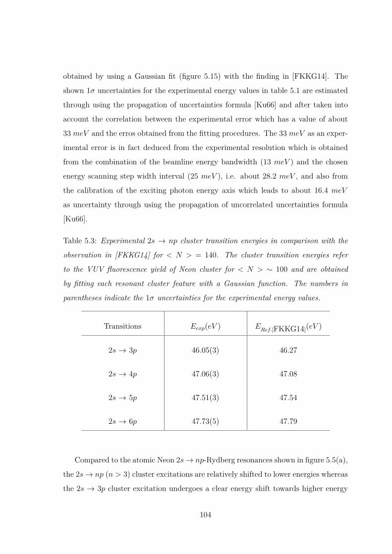
obtained by using a Gaussian fit (figure 5.15) with the finding in [FKKG14]. The
shown 1σ uncertainties for the experimental energy values in table 5.1 are estimated
through using the propagation of uncertainties formula [Ku66] and after taken into
account the correlation between the experimental error which has a value of about
33 meV and the erros obtained from the fitting procedures. The 33 meV as an exper-
imental error is in fact deduced from the experimental resolution which is obtained
from the combination of the beamline energy bandwidth (13 meV ) and the chosen
energy scanning step width interval (25 meV ), i.e. about 28.2 meV , and also from
the calibration of the exciting photon energy axis which leads to about 16.4 meV
as uncertainty through using the propagation of uncorrelated uncertainties formula
[Ku66].
Table 5.3: Experimental 2s → np cluster transition energies in comparison with the
observation in [FKKG14] for < N > = 140. The cluster transition energies refer
to the VUV fluorescence yield of Neon cluster for < N > ∼ 100 and are obtained
by fitting each resonant cluster feature with a Gaussian function. The numbers in
parentheses indicate the 1σ uncertainties for the experimental energy values.
Transitions Eexp(eV ) ERef.[FKKG14](eV )
2s → 3p 46.05(3) 46.27
2s → 4p 47.06(3) 47.08
2s → 5p 47.51(3) 47.54
2s → 6p 47.73(5) 47.79
Compared to the atomic Neon 2s→ np-Rydberg resonances shown in figure 5.5(a),
the 2s→ np (n > 3) cluster excitations are relatively shifted to lower energies whereas
the 2s → 3p cluster excitation undergoes a clear energy shift towards higher energy
104
by about 0.51 eV . Essentially no shifts of the exciting-photon energies of the ob-
served peaks with changing cluster size are seen within the resolution of the current
experiment. Whereas the 4p, 5p, and 6p excitations appear as well defined peaks
(apart from the 6p excitation which is observed weak for < N > ∼ 40) in the fluores-
cence excitation functions the feature around the energy of the 3p excitation is rather
broad. With increasing cluster size (< N > > 40) the features at the 4p and 5p are
less and less prominent due to an increasing contribution of photoelectron-induced
fluorescence. The observed feature at 46.66 eV increases in intensity relative to the
2s → np excitation peaks with increasing average cluster size. It appears weak at
cluster smaller than < N > < 100 and becomes more and more prominent when the
cluster get bigger than< N >∼ 100. As in cluster the number of bulk atoms increases
relative to the one of surface atoms with increasing size, this feature can therefore be
assigned to bulk transition, as highlighted by an arrow in figure 5.14. The exciting-
photon energy (≈ 46.66 eV ) at which this feature emerges can be compared with
published works on the total electron [WEM95, KF12] and ion desorption [WEM95]
yields from condensed Neon. In [WEM95] and [KF12], the bulk components of the
2s→ 3p excitation is observed at 46.9 eV and 46.85 eV , respectively. Although these
exciting-photon energies are 0.24 eV and 0.19 eV higher than the one which is mea-
sured in this thesis work, one tentatively identifies the observed feature at ≈ 46.66 eV
with the 2s → 3p excitation at bulk. Note that in [BJM05] the same identification
is also used for the observed bulk feature in Neon cluster for < N > = 70 which is,
however, seen at higher exciting-photon energy as compared to the observed bulk fea-
ture in this thesis work and the observation in [WEM95, KF12] for condensed Neon;
i.e. at 47.5 eV . Similar to the 2s → np cluster-surface features, the bulk feature
at ≈ 46.66 eV does not essentially exhibit an energy shift with increasing cluster
size. However, it gets significantly broad with increasing cluster size; especially for
< N > ∼ 7000 (see figure 5.5(b)) where the shape of the VUV fluorescence excitation
function is comparable with the previously obtained absorption cross section of solid
Neon [HKK70].
105

44 45 46 47 48 498
10
12
14
16
18
20 Gaussian fit (y = y0 + A exp[-(E-E0)2/2w2] Exp. data
Tota
l VU
V fl
uore
scen
ce y
ield
x1
03 [arb
. uni
ts]
Exciting-photon energy [eV]
100
Figure 5.15: Gaussian fit of the observed 2s → np resonant cluster features in the
measured VUV fluorescence yield of Neon cluster for < N > ∼ 100 as mean cluster
size.
Section summary
Measured VUV fluorescence yields of Neon clusters of varying sizes after excitation
with photons of energies near and far below the Neon 2s-electron photoionization
thresold are presented and discussed in this section.
In the Neon 2s-regime, the cluster size-dependent VUV fluorescence excitation
functions of Neon clusters show a series of distinct cluster fluorescence features; four
of which are attributed to the resonant 2s → np (n = 3, 4, 5, 6) excitations of
cluster-surface atoms and one to cluster-bulk excitation. Included in these are the
ones previously identified to emerge from spectator RICD. The excitation energies
of the cluster surface features are compared with the energies of the atomic Neon
2s→ np-Rydberg resonance observed in the measured ion yield as well as with energies
measured for 2s → np cluster excitations resulting in ion production [FKKG14].
The excitation energy of the observed bulk cluster feature is compared with energy
106

measured previously for 2s→ 3p bulk excitation in condensed Neon [WEM95, KF12].
The spectator RICD features are found to be visible for all cluster sizes but appear
to be less prominent in the VUV fluorescence excitation functions of the larger clusters
due to additional fluorescence emission around the resonant cluster features, which
increases with increasing cluster size. This fluorescence emissin has a threshold energy
of 35.8 eV and found to be structurelessly and linearly increasing with energy at lower
exciting-photon energies. It is interpreted as due to inelastic scattering of the initially
outgoing 2p photoelectrons with condensed and uncondensed neutral Neon atoms.
107

Chapter 6
Conclusion
The studies presented in this thesis bring about investigation of interatomic electronic
processes occuring in Neon clusters after excitation with synchrotron radiation (SR)
by employing fluorescence spectroscopy technique. Among these processes is the
well-known interatomic Coulombic decay (ICD) mechanism which has inspired a lot
of subsequent experimental and theoretical investigations since its discovery in the
late 1990s by Cederbaum and co-workers [CZT97]. The combination of selective
excitation and fluorescence spectroscopy was used in this work to probe a special
variety of ICD, the resonant ICD (RICD) process, in Neon clusters and characterize
its final radiative states.
The initial electronic excitation triggering RICD in Neon clusters is produced by
promoting an inner-valence 2s electron of a Neon cluster into a np-Rydberg state. The
emission of vacuum ultraviolet (VUV) and UV/visible fluorescence radiation from ex-
cited Neon cluster is investigated in the Neon 2s-regime. The observed features in the
measured VUV fluorescence signal following 2s → np (n = 4, 5) excitations suggests
that the initially created inner-valence state in Neon cluster relaxes predominantly
by a spectator RICD. The correspondence in structure of the observed features in
the VUV and UV/visible fluorescence signals unequivocally entails that the spectator
RICD final states release their excess energy by photon emission cascade in the visible
and VUV spectral ranges.
Furthermore, the spectrally resolved VUV fluorescence spectrum recorded at
108
exciting-photon energy of 47.09 eV , which correspond to the 2s→ 4p resonant feature,
shows only one fluorescence line around 74 nm similar to the Neon atomic fluorescence
line. This was explained by the validity of the dipole selection rules, which shows the
atomic character of the excited states inside the cluster. The spectator RICD final
state has therefore only the following relaxation cascade: First, by a transition from
the Rydberg state to the lowest 3s-Rydberg state in the UV/visible spectral range,
and then, by a transition from the lowest 3s-Rydberg state to outer-valence state in
the VUV range.
The emission of VUV fluorescence from Neon clusters of varying sizes after ex-
citation with photons of energies near and far below the 2s-electron photoionization
thresold of Neon atoms is also investigated in this thesis work. In the Neon 2s-regime,
the cluster size-dependent VUV fluorescence excitation functions of Neon clusters
show a series of distinct cluster fluorescence features; four of which are attributed to
the resonant 2s → np (n = 3, 4, 5, 6) excitations of cluster-surface atoms and one
to 2s → 3p excitation of cluster-bulk atoms. Included in these are the ones emerged
from spectator RICD which are found to be visible for all cluster sizes but appear to
be less prominent in the VUV fluorescence excitation functions of the larger clusters
due to additional structureless fluorescence emission that increases with increasing
cluster size. This emission has a threshold energy of 35.8 eV and is observed increas-
ing almost linearly with exciting-photon energy. It is interpreted as caused by 2p
photoelectron impact induced VUV fluorescence.
The electronic decay processes investigated in this work are done by employing
photon-induced fluorescence spectroscopy (PIFS) technique. With the no need of
high-vacuum conditions and the use of synchrotron radiation as excitation source,
this technique overcomes its major inconveniences; i.e. the low collection efficiency.
Therefore, PIFS should find a position among the most common detection meth-
ods in the study of various and complex systems under the effect of radiation. The
experimental proof of the ICD process as a non-radiative mechanism in Neon gas
clusters by detecting VUV and UV/visible fluorescences is a case in point in which
fluorescence spectrometry technique yields new information that complement electron
109
and/or ion spectroscopy techniques towards probing ICD process. Although, detec-
tion of charged particle is a direct proof of ICD. This tool, however, may not be useful
for investigating electronic decay processes in denser medium, e.g. large clusters or
biological samples, due to the very short mean free path of the charged particles, and
hence to the increase of scattering events in the surrounding matter. On the contrary,
detection of fluorescence provides similar information on the occurrence of ICD and
is still applicable to probe interatomic process in dense media since the mean free
path of photons is larger by order of magnitude compared to charged particles.
110
Appendix A
The error function (erf) is a special function of sigmoid shape and defined as follows:
erf(x) = 2√π
∫ x
0e−u
2du (1)
It is, essensially, related to the cumulative distribution function D [Gre93] (means to
the integral of a Gaussian distribution function G) by
D(x) =∫ x
−∞G(u)du = 1
2 + 12erf(−x√
2) (2)
with
G(x) = 1√2πe−
x22 (3)
where the pre-factor 1√2π ensures that the total area under the curve G(x) is equal to
1 and the factor 12 in the exponent ensures that the distribution has unit standard
deviation. For a generic distribution G with non-zero mean µ and deviation σ, the
distribution D becomes as follows:
C(x) = D(x− µσ
) = 12 + 1
2erf(x− µσ√
2) (4)
In the limit when the deviation σ approaches zero, the cumulative distribution D can
be viewed as the analytic approximation of a Heaviside step function H(x− µ):
H(x− µ) = limσ→0
(12 + 1
2erf(x− µσ√
2)) (5)
By defining the Heaviside step function in this way, the error function erf can pro-
vide a means of modeling such measured data. A further observation cementing the
relationship between the Heaviside step function and the error function is that the
error function can be viewed as a convolution of a Gaussian with the Heaviside step
function. Based on Eq. 4 and 5, the observed increase in fluorescence at the 2s-
electron photoionization threshold of Neon atoms (see Figures 5.1) can be modeled
through using the following expression:
111
C(hν) = C0 + A
2 erf(hν − Ethw√
2) (6)
where hν is the exciting-photon energy, C0 represents a constant offset, A measures
the magnitude of the step, Eth identifies the location of the step, w is the width of
the Gaussian instrumental response inherent in the measurement process.
112

Appendix B
B-B
( 1 : 1
)
A ( 2
: 1 )
C ( 2
: 1 )
BB
A
C
1 1
2 2
3 3
4 4
5 5
6 6
7 7
8 8
AA
BB
CC
DD
EE
FF
1 A2Kr
yost
atad
apte
rSt
atus
Ände
rung
enDa
tum
Name
Geze
ichne
t
Kont
rollier
t
Norm
Datu
mNa
me27
.05.20
13ka
stirk
e
3,0
5,0
100,0
94,0
12,0
13,6
19 SW
10,0
44,7
5,5
5,0
10,0 5,0
25,0
20,0
2,0
M2x0.25
1,0
1,6
5,0
5,0
7,5
14,5
10,5
14,5
7,5 16,5
25,6
200,0
287,0
243,0
25,0
30,0
2,0x
45°
100,0
32,0
M14x
1 -
6H
4,0
60°
0.75
" 2,7
15,5
34,5
Mate
rial:
Cu
Technical drawing of the cluster source used in the experiment (Gregor Kastirke, group
of Prof. Dr. Reinhard Dörner (Frankfurt), private communication, Mai 05, 2015).
113

Appendix C
Maßstab:2:1
LT C
lust
erqu
elle 2
Düs
enB
auteilnam
e:
AG E
hres
mann
29.07.20
15
ISO
2768
m
043.41
0.100
Ltaief
/Neh
ls
Datum
:
Material:
Nam
e:
Teilnr.:
Norm
.:
1 1
2 2
3 3
4 4
5 5
6 6
AA
BB
CC
DD
32,00
16,00
398,00
Nozz
les-
head
sPT
100
Temp
erat
ure
sens
ors
positio
ns
2,00
LT4-
B Cr
yost
at a
dapt
er
170,00
23,00
2xM8
x15
,00
11,00
Noble
gas
inlets
Gas
flow
line
55,00
10,00
M8x1.25 -
6H
AA
Section
view
A-A
(1:2
)
2,00
M2x0.4
- 6H
Technical drawing of bi-nozzle cluster source.
114
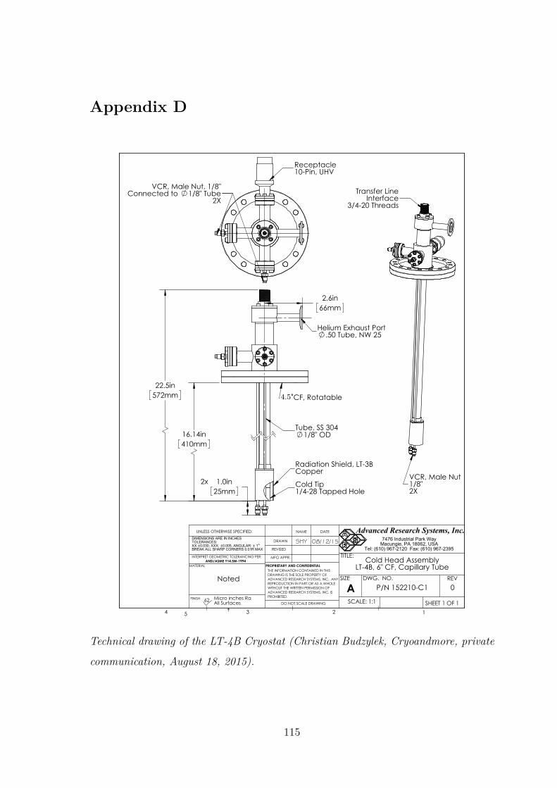
Appendix D
Interface3/4-20 Threads
Transfer Line
VCR, Male Nut1/8"2X
10.005, ANGULAR:
WITHOUT THE WRITTEN PERMISSION OF
DO NOT SCALE DRAWING SHEET 1 OF 1
UNLESS OTHERWISE SPECIFIED:
SCALE: 1:1
REVDWG. NO.
ASIZE
TITLE:
NAME DATE
MFG APPR.
REVISED
DRAWN
2
ADVANCED RESEARCH SYSTEMS, INC. IS
1
62
5
INTERPRET GEOMETRIC TOLERANCING PER:
PROHIBITED.
MATERIAL
0.030, XXX:
34
PROPRIETARY AND CONFIDENTIAL
BREAK ALL SHARP CORNERS 0.01R MAX
All Surfaces
SHY
Advanced Research Systems, Inc.
ANSI/ASME Y14.5M-1994
FINISH Micro inches Ra
DIMENSIONS ARE IN INCHESTOLERANCES:XX:
THE INFORMATION CONTAINED IN THISDRAWING IS THE SOLE PROPERTY OFADVANCED RESEARCH SYSTEMS, INC. ANY REPRODUCTION IN PART OR AS A WHOLE
7476 Industrial Park WayMacungie, PA 18062, USA
Tel: (610) 967-2120 Fax: (610) 967-2395
0
08/12/15
LT-4B, 6" CF, Capillary Tube
P/N 152210-C1
Cold Head Assembly
Noted
Receptacle10-Pin, UHV
VCR, Male Nut, 1/8"Connected to 1/8" Tube
2X
Radiation Shield, LT-3B
6" CF, Rotatable
Cold Tip
Helium Exhaust Port
1/4-28 Tapped Hole
Copper
.50 Tube, NW 25
Tube, SS 3041/8" OD
66mm
2.6in
16.14in 410mm
572mm
22.5in
2x 1.0in25mm
4.5"
Technical drawing of the LT-4B Cryostat (Christian Budzylek, Cryoandmore, private
communication, August 18, 2015).
115

Bibliography
[ADK11] Averbukh V., Demekhin P., Kolorenč P., Scheit S., Stoychev S., Kuleff
A., Chiang Y.-C., Gokhberg K., Kopelke S., Sisourat N. and Cederbaum
L. Interatomic electronic decay processes in singly and multiply ionized
clusters. Journal of Electron Spectroscopy and Related Phenomena,
183(1–3), 36 (2011).
[AIH06] Aoto T., Ito K., Hikosaka Y., Shigemasa E., Penent F. and Lablanquie
P. Properties of Resonant Interatomic Coulombic Decay in Ne Dimers.
Phys. Rev. Lett., 97, 243401 (2006).
[AMC04] Averbukh V., Müller I. B. and Cederbaum L. S. Mechanism of In-
teratomic Coulombic Decay in Clusters. Phys. Rev. Lett., 93, 263002
(2004).
[AOS15] Alizadeh E., Orlando T. M. and Sanche L. Biomolecular Damage In-
duced by Ionizing Radiation: The Direct and Indirect Effects of Low-
Energy Electrons on DNA. Annual Review of Physical Chemistry, 66(1),
379 (2015).
[AS12] Abramowitz M. and Stegun I. Handbook of Mathematical Functions:
with Formulas, Graphs, and Mathematical Tables. Dover Books on
Mathematics. Dover Publications (2012).
[ASB93] Attwood D., Sommargren G., Beguiristain R., Nguyen K., Bokor J.,
Ceglio N., Jackson K., Koike M. and Underwood J. Undulator radi-
116
ation for at-wavelength interferometry of optics for extreme-ultraviolet
lithography. Applied optics, 32(34), 7022 (1993).
[Atk83] Atkins P. W. Molecular Quantum Mechanics, 2nd Edition. Oxford
University Press, New York, NY, (1983).
[Aug23] Auger P. Sur les rayons β secondaires produits dans un gaz par des
rayons X. C.R.A.S., 177, 169 (1923).
[BAsH06] Bergersen H., Abu-samha M., Harnes J., Bjorneholm O., Svensson S.,
Saethre L. J. and Borve K. J. Size of neutral argon clusters from core-
level photoelectron spectroscopy. Phys. Chem. Chem. Phys., 8, 1891
(2006).
[BBC07a] Batrakov A., Briquez F., Chubar O., Churkin I., Couprie M.-E., Dael A.,
Ilyin I., Kolokolnikov Y., Roux G., Rouvinski E., Semenov E., Steshov
A., Valleau M. and Vobly P. Magnetic design and manufacture of ellip-
tical undulators HU256. Nuclear Instruments and Methods in Physics
Research Section A: Accelerators, Spectrometers, Detectors and Associ-
ated Equipment, 575(1–2), 29 (2007).
[BBC07b] Batrakov A., Briquez F., Chubar O., Churkin I., Dael A., Ilyin I.,
Kolokolnikov Y., Marcouile O., Marteau F., Roux G., Rouvinski E.,
Semenov E., Steshov A., Valleau M. and Vobly P. Elliptical Undulators
HU256 for Synchrotron SOLEIL. AIP Conference Proceedings, 879(1),
396 (2007).
[BBF98] Bush A. M., Bell A. J., Frey J. G. and Mestdagh J.-M. Rayleigh Scat-
tering of Laser and Synchrotron Radiation from Pulsed Free Jets of Arn
and (N2O)n Clusters. The Journal of Physical Chemistry A, 102(32),
6457 (1998).
117
[BCH00] Boudaïffa B., Cloutier P., Hunting D., Huels M. a. and Sanche L. Res-
onant formation of DNA strand breaks by low-energy (3 to 20 eV) elec-
trons. Science, 287(5458), 1658 (2000).
[BFJ96] Björneholm O., Federmann F., Joppien M., Fössing F., Kakar S.,
Von Pietrowski R. and Möller T. Valence- and Inner-shell spectroscopy
on rare-gas clusters. Surface Review and Letters, 03(01), 299 (1996).
[BJ83] Bransden B. and Joachain C. Physics of Atoms and Molecules. Pearson
Education. Longman (1983).
[BJM05] Barth S., Joshi S., Marburger S., Ulrich V., Lindblad A., Öhrwall G.,
Björneholm O. and Hergenhahn U. Observation of resonant Interatomic
Coulombic Decay in Ne clusters. The Journal of Chemical Physics,
122(24), 241102 (2005).
[BK96] Buck U. and Krohne R. Cluster size determination from diffractive He
atom scattering. The Journal of Chemical Physics, 105(13), 5408 (1996).
[BKR77] Brunt J. N. H., King G. C. and Read F. H. Near-threshold electron
impact excitation of ultraviolet-emitting levels of neon, argon, krypton
and xenon atoms. Journal of Physics B: Atomic and Molecular Physics,
10(18), 3781 (1977).
[BM34] Bleick W. E. and Mayer J. E. The Mutual Repulsive Potential of Closed
Shells. The Journal of Chemical Physics, 2(5), 252 (1934).
[BMK06] Barth S., Marburger S., Kugeler O., Ulrich V., Joshi S., Bradshaw A.
and Hergenhahn U. The efficiency of interatomic Coulombic decay in
Ne clusters. Chemical physics, 329(1), 246 (2006).
[BS96] Becker U. and Shirley D. VUV and Soft X-Ray Photoionization. Plenum
Press, New York (1996).
118
[BSC03] Buth C., Santra R. and Cederbaum L. S. Impact of interatomic elec-
tronic decay processes on Xe4d hole decay in the xenon fluorides. The
Journal of Chemical Physics, 119(20), 10575 (2003).
[Buc38] Buckingham R. A. The classical equation of state of gaseous helium,
neon and argon. In Proceedings of the Royal Society of London A:
Mathematical, Physical and Engineering Sciences, Volume 168, Seiten
264–283. The Royal Society (1938).
[CB96] Castleman A. W. and Bowen K. H. Clusters: Structure, Energetics, and
Dynamics of Intermediate States of Matter. The Journal of Physical
Chemistry, 100(31), 12911 (1996).
[CDZ85] Coletti F., Debever J. M. and Zimmerer G. Time and spectrally resolved
luminescence and relaxation processes in solid neon. The Journal of
Chemical Physics, 83(1), 49 (1985).
[CJ06] Castleman A. W. and Jena P. Clusters: A bridge between disciplines.
Proceedings of the National Academy of Sciences, 103(28), 10552 (2006).
[CJK86] Castleman Jr A. and Keesee R. Clusters: properties and formation.
Annual Review of Physical Chemistry, 37(1), 525 (1986).
[Cle09] Clegg R. M. Chapter 1 Förster resonance energy transfer—FRET what
is it, why do it, and how it’s done. In Fret and Flim Techniques, Vol-
ume 33 of Laboratory Techniques in Biochemistry and Molecular Biology,
Seiten 1 – 57. Elsevier (2009).
[CME67] Codling K., Madden R. P. and Ederer D. L. Resonances in the Photo-
Ionization Continuum of Ne I (20-150 eV). Phys. Rev., 155, 26 (1967).
[CZ68] Cooper J. and Zare R. Erratum: Angular distribution of photoelectrons.
The Journal of Chemical Physics, 49(9), 4252 (1968).
119

[CZT97] Cederbaum L. S., Zobeley J. and Tarantelli F. Giant Intermolecular
Decay and Fragmentation of Clusters. Phys. Rev. Lett., 79, 4778 (1997).
[DBC03] Dorchies F., Blasco F., Caillaud T., Stevefelt J., Stenz C., Boldarev
A. S. and Gasilov V. A. Spatial distribution of cluster size and density
in supersonic jets as targets for intense laser pulses. Phys. Rev. A, 68,
023201 (2003).
[Deg14] Degl’Innocenti E. L. Atomic Spectroscopy and Radiative Processes.
Springer-Verlag Milan (2014).
[DMJ00] Dörner R., Mergel V., Jagutzki O., Spielberger L., Ullrich J., Mosham-
mer R. and Schmidt-Böcking H. Cold target recoil ion momentum spec-
troscopy: a ‘momentum microscope’to view atomic collision dynamics.
Physics Reports, 330(2), 95 (2000).
[DS01] Debenedetti P. G. and Stillinger F. H. Supercooled liquids and the glass
transition. Nature, 410, 259 (2001).
[EBJ88] Eberhardt W., Bernstorff S., Jochims H. W., Whitfield S. B. and
Crasemann B. Photoelectron recapture through post-collision interac-
tion. Phys. Rev. A, 38, 3808 (1988).
[EGL47] Elder F. R., Gurewitsch A. M., Langmuir R. V. and Pollock H. C. Ra-
diation from Electrons in a Synchrotron. Phys. Rev., 71, 829 (1947).
[Ein05] Einstein A. Über einen die Erzeugung und Verwandlung des Lichtes
betreffenden heuristischen Gesichtspunkt. Annalen der Physik, 322(6),
132 (1905).
[ESR81] Echt O., Sattler K. and Recknagel E. Magic Numbers for Sphere Pack-
ings: Experimental Verification in Free Xenon Clusters. Phys. Rev.
Lett., 47, 1121 (1981).
120
[FAH13] Förstel M., Arion T. and Hergenhahn U. Measuring the efficiency of
interatomic Coulombic decay in Ne clusters. Journal of Electron Spec-
troscopy and Related Phenomena, 191, 16 (2013).
[Fan61] Fano U. Effects of Configuration Interaction on Intensities and Phase
Shifts. Phys. Rev., 124, 1866 (1961).
[FC65] Fano U. and Cooper J. W. Line Profiles in the Far-uv Absorption Spectra
of the Rare Gases. Phys. Rev., 137, A1364 (1965).
[FdFR81] Farges J., de Feraudy M., Raoult B. and Torchet G. Structure and tem-
perature of rare gas clusters in a supersonic expansion. Surface Science,
106(1), 95 (1981).
[FdFR83] Farges J., de Feraudy M. F., Raoult B. and Torchet G. Noncrystalline
structure of argon clusters. I. Polyicosahedral structure of ArN clusters,
20<N<50. The Journal of Chemical Physics, 78(8), 5067 (1983).
[FdFR86] Farges J., de Feraudy M. F., Raoult B. and Torchet G. Noncrys-
talline structure of argon clusters. II. Multilayer icosahedral structure
of ArN clusters 50<N<750. The Journal of Chemical Physics, 84(6),
3491 (1986).
[FKKG14] Flesch R., Kosugi N., Knop-Gericke A. and Rühl E. 2S-Excitation and
Photoionization of Neon Clusters. Zeitschrift fur Phys. Chemie, 228(4-
5), 387 (2014).
[FMA11] Förstel M., Mucke M., Arion T., Bradshaw A. M. and Hergenhahn U.
Autoionization Mediated by Electron Transfer. Phys. Rev. Lett., 106,
033402 (2011).
[FWS05] Feng X., Wills A. A., Sokell E., Gorczyca T. W., Wiedenhoeft M. and
Berrah N. Investigation of photoelectron recapture in Ar using two-
dimensional photoelectron spectroscopy. Phys. Rev. A, 72, 042712 (2005).
121
[GAC06] Gokhberg K., Averbukh V. and Cederbaum L. S. Interatomic decay
of inner-valence-excited states in clusters. The Journal of Chemical
Physics, 124(14), 144315 (2006).
[Gre93] Greene W. H. Econometric analysis. Prentice-Hall, p. 926, fn. 11, (1993).
[GS05] Greiner W. and Solov’yov A. Atomic cluster physics: new challenges for
theory and experiment. Chaos, Solitons Fractals, 25(4), 835 (2005).
[GSS93] Goyal S., Schutt D. L. and Scoles G. Molecular solvation in atomic clus-
ters studied by means of molecular beam infrared spectroscopy. Accounts
of chemical research, 26(3), 123 (1993).
[GTS05] Gokhberg K., Trofimov A. B., Sommerfeld T. and Cederbaum L. S.
Ionization of metal atoms following valence-excitation of neighbouring
molecules. EPL (Europhysics Letters), 72(2), 228 (2005).
[Hab94] Haberland H. Clusters of atoms and molecules: theory, experiment, and
clusters of atoms. Springer series in chemical physics. Springer-Verlag
(1994).
[Hag81] Hagena O. F. Nucleation and growth of clusters in expanding nozzle
flows. Surface Science, 106(1), 101 (1981).
[Hag87] Hagena O. F. Condensation in free jets: Comparison of rare gases and
metals. Zeitschrift für Physik D Atoms, Molecules and Clusters, 4(3),
291 (1987).
[Hag92] Hagena O. F. Cluster ion sources (invited). Review of Scientific Instru-
ments, 63(4), 2374 (1992).
[Ham] URL http://www.triumf.ca/sites/default/files/
HamamatsuMCPguide.pdf.
122

[Her11] Hergenhahn U. Interatomic and intermolecular coulombic decay: The
early years. Journal of Electron Spectroscopy and Related Phenomena,
184(3–6), 78 (2011).
[Her12] Hergenhahn U. Production of low kinetic energy electrons and energetic
ion pairs by Intermolecular Coulombic Decay. International Journal of
Radiation Biology, 88(12), 871 (2012).
[Hes08] Hester J. J. The Crab Nebula: An Astrophysical Chimera. Annual
Review of Astronomy and Astrophysics, 46(1), 127 (2008).
[HKF16] Hans A., Knie A., Förstel M., Schmidt P., Reiß P., Ozga C., Hergen-
hahn U. and Ehresmann A. Determination of absolute cross sections
for cluster-specific decays. Journal of Physics B: Atomic, Molecular and
Optical Physics, 49(10), 105101 (2016).
[HKK70] Haensel R., Keitel G., Kunz C. and Schreiber P. Line Shapes in Soft
X-Ray Absorption Spectra of Solidified Rare Gases. Phys. Rev. Lett.,
25, 208 (1970).
[HKN84] Harris I. A., Kidwell R. S. and Northby J. A. Structure of Charged
Argon Clusters Formed in a Free Jet Expansion. Phys. Rev. Lett., 53,
2390 (1984).
[HKR02] Hergenhahn U., Kolmakov A., Riedler M., de Castro A., Löfken O. and
Möller T. Observation of excitonic satellites in the photoelectron spectra
of Ne and Ar clusters. Chemical Physics Letters, 351(3–4), 235 (2002).
[HLF17] Hans A., Ltaief L. B., Förstel M., Schmidt P., Ozga C., Reiß P., Holzapfel
X., Küstner-Wetekam C., Wiegandt F., Trinter F., Hergenhahn U.,
Jahnke T., Dörner R., Ehresmann A., Demekhin P. V. and Knie A. Flu-
orescence cascades evoked by resonant interatomic Coulombic decay of
inner-valence excited neon clusters. Chemical Physics, 482, 165 (2017).
123

[HN69] Hotop H. and Niehaus A. Reactions of excited atoms and molecules
with atoms and molecules. Zeitschrift für Physik A Hadrons and nuclei,
228(1), 68 (1969).
[HO72] Hagena O. F. and Obert W. Cluster Formation in Expanding Supersonic
Jets: Effect of Pressure, Temperature, Nozzle Size, and Test Gas. The
Journal of Chemical Physics, 56(5), 1793 (1972).
[HOS10] Higuchi I., Ouchi T., Sakai K., Fukuzawa H., Liu X.-J., Ueda K.,
Iwayama H., Nagaya K., Yao M., Ding D., Zhang D., Tamenori Y. and
Saito N. Radiative charge transfer and interatomic Coulombic decay fol-
lowing direct double photoionization of neon dimers. Journal of Physics:
Conference Series, 235(1), 012015 (2010).
[HSH18] Hans A., Stumpf V., Holzapfel X., Wiegandt F., Schmidt P., Ozga C.,
Reiß P., Ltaief L. B., Küstner-Wetekam C., Jahnke T., Ehresmann A.,
Demekhin P. V., Gokhberg K. and Knie A. Direct evidence for radia-
tive charge transfer after inner-shell excitation and ionization of large
clusters. New Journal of Physics, 20(1), 012001 (2018).
[INF16] Iablonskyi D., Nagaya K., Fukuzawa H., Motomura K., Kumagai Y.,
Mondal S., Tachibana T., Takanashi T., Nishiyama T., Matsunami K.
et al.. Slow Interatomic Coulombic Decay of Multiply Excited Neon Clus-
ters. Physical review letters, 117(27), 276806 (2016).
[Jac99] Jackson J. D. Classical electrodynamics. Wiley (1999).
[Jah15] Jahnke T. Interatomic and intermolecular Coulombic decay: the com-
ing of age story. Journal of Physics B: Atomic, Molecular and Optical
Physics, 48(8), 082001 (2015).
[JB78] Johnsen R. and Biondi M. A. Measurements of radiative charge-transfer
reactions of doubly and singly charged rare-gas ions with rare-gas atoms
at thermal energies. Phys. Rev. A, 18, 996 (1978).
124

[JBM06] Joshi S., Barth S., Marburger S., Ulrich V. and Hergenhahn U. 2p. Phys.
Rev. B, 73, 235404 (2006).
[JCS04] Jahnke T., Czasch A., Schöffler M. S., Schössler S., Knapp A., Käsz M.,
Titze J., Wimmer C., Kreidi K., Grisenti R. E., Staudte A., Jagutzki
O., Hergenhahn U., Schmidt-Böcking H. and Dörner R. Experimental
Observation of Interatomic Coulombic Decay in Neon Dimers. Phys.
Rev. Lett., 93, 163401 (2004).
[JCS07] Jahnke T., Czasch A., Schöffler M., Schössler S., Käsz M., Titze J.,
Kreidi K., Grisenti R. E., Staudte A., Jagutzki O., Schmidt L. P. H.,
Weber T., Schmidt-Böcking H., Ueda K. and Dörner R. Experimental
Separation of Virtual Photon Exchange and Electron Transfer in Inter-
atomic Coulombic Decay of Neon Dimers. Phys. Rev. Lett., 99, 153401
(2007).
[JKC14] Jabbari G., Klaiman S., Chiang Y.-C., Trinter F., Jahnke T. and
Gokhberg K. Ab initio calculation of ICD widths in photoexcited HeNe.
The Journal of Chemical Physics, 140(22), 224305 (2014).
[JKR92] Jena P., Khanna S. and Rao B. Physics and chemistry of finite systems:
from clusters to crystals. Nummer vol. 1 in NATO ASI series: Mathe-
matical and physical sciences. Kluwer Academic Publishers (1992).
[Jon24] Jones J. E. On the Determination of Molecular Fields. II. From the
Equation of State of a Gas. Proceedings of the Royal Society of Lon-
don A: Mathematical, Physical and Engineering Sciences, 106(738), 463
(1924).
[Jor84] Jortner J. Level Structure and Dynamics of Clusters. Berichte der Bun-
sengesellschaft für physikalische Chemie, 88(3), 188 (1984).
125
[KAJ96] Kanik I., Ajello J. M. and James G. K. Electron-impact-induced emission
cross sections of neon in the extreme ultraviolet. Journal of Physics B:
Atomic, Molecular and Optical Physics, 29(11), 2355 (1996).
[KC07] Kuleff A. I. and Cederbaum L. S. Tracing ultrafast interatomic electronic
decay processes in real time and space. Physical review letters, 98(8),
083201 (2007).
[KF12] Kassühlke B. and Feulner P. Inner valence excitations of condensed
neon. Low Temperature Physics, 38(8), 749 (2012).
[KGC09] Kopelke S., Gokhberg K., Cederbaum L. S. and Averbukh V. Calculation
of resonant interatomic Coulombic decay widths of inner-valence-excited
states delocalized due to inversion symmetry. The Journal of Chemical
Physics, 130(14), 144103 (2009).
[KHF14] Knie A., Hans A., Förstel M., Hergenhahn U., Schmidt P., Reiß P.,
Ozga C., Kambs B., Trinter F., Voigtsberger J., Metz D., Jahnke T.,
Dörner R., Kuleff A. I., Cederbaum L. S., Demekhin P. V. and Ehres-
mann A. Detecting ultrafast interatomic electronic processes in media
by fluorescence. New J. Phys., 16 (2014).
[Kit96] Kittel C. Introduction to Solid State Physics. Wiley, New York, 7th
Auflage (1996).
[KJK94] Knop A., Jochims H., Kilcoyne A., Hitchcock A. and Rühl E. Zero-
kinetic-energy photoelectron spectroscopy of Ar(2p)-excited argon clus-
ters. Chemical Physics Letters, 223(5), 553 (1994).
[KJS93] Karnbach R., Joppien M., Stapelfeldt J., Wörmer J. and Möller T.
CLULU: An experimental setup for luminescence measurements on van
der Waals clusters with synchrotron radiation. Review of Scientific In-
struments, 64(10), 2838 (1993).
126

[KJW08] Kreidi K., Jahnke T., Weber T., Havermeier T., Liu X., Morisita Y.,
Schössler S., Schmidt L. P. H., Schöffler M., Odenweller M., Neumann
N., Foucar L., Titze J., Ulrich B., Sturm F., Stuck C., Wallauer R.,
Voss S., Lauter I., Kim H. K., Rudloff M., Fukuzawa H., Prümper G.,
Saito N., Ueda K., Czasch A., Jagutzki O., Schmidt-Böcking H., Stoy-
chev S., Demekhin P. V. and Dörner R. Relaxation processes following
1s photoionization and Auger decay in Ne2. Phys. Rev. A, 78, 043422
(2008).
[KM72] Kaufman V. and Minnhagen L. Accurate Ground-Term Combinations
in Ne i. J. Opt. Soc. Am., 62(1), 92 (1972).
[Ku66] Ku H. H. Notes on the use of propagation of error formulas. Journal of
Research of the National Bureau of Standards, 70(4) (1966).
[KYR15] Kramida A., Yu. Ralchenko, Reader J. and and NIST ASD
Team. NIST Atomic Spectra Database (ver. 5.3), [Online]. Available:
http://physics.nist.gov/asd [2016, October 3]. National Institute
of Standards and Technology, Gaithersburg, MD. (2015).
[Len30] Perturbation problems in quantum mechanics. Proceedings of the Royal
Society of London A: Mathematical, Physical and Engineering Sciences,
129(811), 598 (1930).
[LHS18] Ltaief L. B., Hans A., Schmidt P., Holzapfel X., Wiegandt F., Reiss P.,
Küstner-Wetekam C., Jahnke T., Doerner R., Knie A. and Ehresmann
A. VUV photon emission from Ne clusters of varying sizes following
photon and photoelectron excitations. Journal of Physics B: Atomic,
Molecular and Optical Physics, 51(6), 065002 (2018).
[LJ31] Lennard-Jones J. E. Cohesion. Proceedings of the Physical Society,
43(5), 461 (1931).
127
[LLÖ08] Lundwall M., Lindblad A., Öhrwall G., Svensson S. and Björneholm O.
Neighbor-induced photoelectron recapture in argon clusters: A photon-
energy-dependent study of Auger spectra. Physical Review A, 78(6),
065201 (2008).
[Lon30] London F. Zur Theorie und Systematik der Molekularkräfte. Zeitschrift
für Physik, 63(3), 245 (1930).
[LPH00] Lablanquie P., Penent F., Hall R. I., Eland J. H. D., Bolognesi P., Cooper
D., King G. C., Avaldi L., Camilloni R., Stranges S., Coreno M., Prince
K. C., Müehleisen A. and Z˘itnik M. Observation and Characterization
of the Fluorescence Decay of the 2s2p6np1Po Excited States of Ne. Phys.
Rev. Lett., 84, 431 (2000).
[LR73] Le Roy R. Energy levels of a diatomic near dissociation. Molecular
spectroscopy, 1(113), 41 (1973).
[LSG16] LaForge A. C., Stumpf V., Gokhberg K., von Vangerow J., Stienkemeier
F., Kryzhevoi N. V., O’Keeffe P., Ciavardini A., Krishnan S. R., Coreno
M., Prince K. C., Richter R., Moshammer R., Pfeifer T., Cederbaum
L. S. and Mudrich M. Enhanced Ionization of Embedded Clusters by
Electron-Transfer-Mediated Decay in Helium Nanodroplets. Phys. Rev.
Lett., 116, 203001 (2016).
[Lun07] Lundwall M. Rare-gas clusters studied by electron spectroscopy. Uppsala
University (2007).
[MAF15] Mucke M., Arion T., Förstel M., Lischke T. and Hergenhahn U. Compe-
tition of inelastic electron scattering and Interatomic Coulombic Decay
in Ne clusters. Journal of Electron Spectroscopy and Related Phenom-
ena, 200, 232 (2015). Special Anniversary Issue: Volume 200.
128

[MB78] Miller T. M. and Bederson B. Atomic and Molecular Polarizabilities-A
Review of Recent Advances. Advances in Atomic and Molecular Physics,
13, 1 (1978).
[MBC04] Martin F., Burrow P. D., Cai Z., Cloutier P., Hunting D. and Sanche
L. DNA Strand Breaks Induced by 0–4 eV Electrons: The Role of Shape
Resonances. Phys. Rev. Lett., 93, 068101 (2004).
[MC06] Müller I. B. and Cederbaum L. S. Ionization and double ionization of
small water clusters. The Journal of Chemical Physics, 125(20), 204305
(2006).
[Mei22] Meitner L. Über die Entstehung der β-Strahl-Spektren radioaktiver Sub-
stanzen. Zeitschrift für Physik, 9(1), 131 (1922).
[MEK89] Miehle W., Echt O., Kandler O., Leisner T. and Recknagel E. Magic
numbers of large rare gas clusters. Zeitschrift für Physik D Atoms,
Molecules and Clusters, 12(1), 273 (1989).
[Met80] Metcalf H. J. Highly excited atoms. Nature, 284, 127 (1980).
[MK75] Matthew J. and Komninos Y. Transition rates for interatomic Auger
processes. Surface Science, 53(1), 716 (1975).
[MKH03] Marburger S., Kugeler O., Hergenhahn U. and Möller T. Experimental
Evidence for Interatomic Coulombic Decay in Ne Clusters. Phys. Rev.
Lett., 90, 203401 (2003).
[MKL89] Miehle W., Kandler O., Leisner T. and Echt O. Mass spectrometric
evidence for icosahedral structure in large rare gas clusters: Ar, Kr, Xe.
The Journal of chemical physics, 91(10), 5940 (1989).
[MLS06] Morishita Y., Liu X.-J., Saito N., Lischke T., Kato M., Prümper G.,
Oura M., Yamaoka H., Tamenori Y., Suzuki I. H. and Ueda K. Experi-
mental Evidence of Interatomic Coulombic Decay from the Auger Final
States in Argon Dimers. Phys. Rev. Lett., 96, 243402 (2006).
129

[MM77] Miller W. H. and Morgner H. A unified treatment of Penning ionization
and excitation transfer. The Journal of Chemical Physics, 67(11), 4923
(1977).
[MMH74] Michels D. J., Mikes T. L. and Hunter W. R. Optical Grating Evaluator:
a Device for Detailed Measurement of Diffraction Grating Efficiencies
in the Vacuum Ultraviolet. Appl. Opt., 13(5), 1223 (1974).
[Mor96] Morse M. D. 2 - Supersonic Beam Sources. In Dunning F. and Hulet
R. G., Editoren, Atomic, Molecular, and Optical Physics: Atoms and
Molecules, Volume 29, Part B of Experimental Methods in the Physical
Sciences, Seiten 21 – 47. Academic Press (1996).
[MSZ01] Moiseyev N., Santra R., Zobeley J. and Cederbaum L. S. Fingerprints of
the nodal structure of autoionizing vibrational wave functions in clusters:
Interatomic Coulombic decay in Ne dimer. The Journal of Chemical
Physics, 114(17), 7351 (2001).
[Nor87] Northby J. A. Structure and binding of Lennard-Jones clusters: 13N147.
The Journal of Chemical Physics, 87(10), 6166 (1987).
[ORB13] O’Keeffe P., Ripani E., Bolognesi P., Coreno M., Devetta M., Callegari
C., Di Fraia M., Prince K. C., Richter R., Alagia M., Kivimäki A. and
Avaldi L. The Role of the Partner Atom and Resonant Excitation Energy
in Interatomic Coulombic Decay in Rare Gas Dimers. The Journal of
Physical Chemistry Letters, 4(11), 1797 (2013). PMID: 26283111.
[OTL04] Öhrwall G., Tchaplyguine M., Lundwall M., Feifel R., Bergersen H.,
Rander T., Lindblad A., Schulz J., Peredkov S., Barth S., Marburger
S., Hergenhahn U., Svensson S. and Björneholm O. Femtosecond Inter-
atomic Coulombic Decay in Free Neon Clusters: Large Lifetime Differ-
ences between Surface and Bulk. Phys. Rev. Lett., 93, 173401 (2004).
130

[PL07] Pimblott S. M. and LaVerne J. A. Production of low-energy electrons
by ionizing radiation. Radiation Physics and Chemistry, 76(8–9), 1244
(2007). Proceedings of the 11th Tihany Symposium on Radiation Chem-
istry.
[PLE] URL http://www.synchrotron-soleil.fr/Recherche/
LignesLumiere/PLEIADES.
[RI97] Rau A. R. P. and Inokuti M. The quantum defect: Early history and
recent developments. American Journal of Physics, 65(3), 221 (1997).
[RJAMD16] Ren X., Jabbour Al Maalouf E., Dorn A. and Denifl S. Direct evidence
of two interatomic relaxation mechanisms in argon dimers ionized by
electron impact. Nature communications, 7, 11093 (2016).
[RSS92] Rühl E., Schmale C., Schmelz H. C. and Baumgärtel H. The double
ionization potentials of argon clusters. Chemical Physics Letters, 191(5),
430 (1992).
[SC02] Santra R. and Cederbaum L. S. Non-Hermitian electronic theory and
applications to clusters. Physics reports, 368(1), 1 (2002).
[SC03] Santra R. and Cederbaum L. S. Coulombic Energy Transfer and Triple
Ionization in Clusters. Phys. Rev. Lett., 90, 153401 (2003).
[Sch92] Schmidt V. Photoionization of atoms using synchrotron radiation. Re-
ports on Progress in Physics, 55(9), 1483 (1992).
[SCM03] Scheit S., Cederbaum L. and Meyer H.-D. Time-dependent interplay be-
tween electron emission and fragmentation in the interatomic Coulombic
decay. The Journal of chemical physics, 118(5), 2092 (2003).
[SDP96] Schulz K., Domke M., Püttner R., Gutiérrez A., Kaindl G., Miecznik G.
and Greene C. H. High-resolution experimental and theoretical study of
131

singly and doubly excited resonances in ground-state photoionization of
neon. Phys. Rev. A, 54, 3095 (1996).
[SGC16] Stumpf V., Gokhberg K. and Cederbaum L. The role of metal ions in
X-ray-induced photochemistry. Nature chemistry, 8(3), 237—241 (2016).
[Sha74] Shaw M. J. Penning ionization. Contemporary Physics, 15(5), 445
(1974).
[SHS75] Schwentner N., Himpsel F. J., Saile V., Skibowski M., Steinmann W.
and Koch E. E. Photoemission from Rare-Gas Solids: Electron Energy
Distributions from the Valence Bands. Phys. Rev. Lett., 34, 528 (1975).
[SJ85] Schwentner K. E. E., N. and Jortner J. Electronic Excitations in Con-
densed Rare Gases, Volume 107. Springer-Verlag, Berlin; Heidelberg;
New York; Tokyo (1985).
[SKcvG13] Stumpf V., Kolorenč P., Gokhberg K. and Cederbaum L. S. Efficient
Pathway to Neutralization of Multiply Charged Ions Produced in Auger
Processes. Phys. Rev. Lett., 110, 258302 (2013).
[SKG14] Stumpf V., Kryzhevoi N. V., Gokhberg K. and Cederbaum L. S. En-
hanced One-Photon Double Ionization of Atoms and Molecules in an
Environment of Different Species. Phys. Rev. Lett., 112, 193001 (2014).
[Sla28] Slater J. C. The Normal State of Helium. Phys. Rev., 32, 349 (1928).
[SLV01] Schmoranzer H., Liebel H., Vollweiler F., Müller-Albrecht R., Ehres-
mann a., Schartner K.-H. and Zimmermann B. Photon-induced fluores-
cence spectroscopy (PIFS). Nucl. Instruments Methods Phys. Res. Sect.
A Accel. Spectrometers, Detect. Assoc. Equip., 467-468, 1526 (2001).
[SMM92] Schartner K.-H., Möbus B., Mentzel G., Ehresmann A., Vollweiler F.
and Schmoranzer H. Threshold scan of the Ne 2s-electron photoioniza-
tion cross section. Physics Letters A, 169(5), 393 (1992).
132
[Sob92] Sobelman I. I. Atomic Spectra and Radiative Transitions, Volume 12.
Springer Berlin Heidelberg, Berlin, Heidelberg (1992).
[SS04] Saloman E. B. and Sansonetti C. J. Wavelengths, Energy Level Classi-
fications, and Energy Levels for the Spectrum of Neutral Neon. Journal
of Physical and Chemical Reference Data, 33(4) (2004).
[SSK13] Schnorr K., Senftleben A., Kurka M., Rudenko A., Foucar L., Schmid
G., Broska A., Pfeifer T., Meyer K., Anielski D. et al.. Time-resolved
measurement of interatomic Coulombic decay in Ne 2. Physical review
letters, 111(9), 093402 (2013).
[SSO11] Sakai K., Stoychev S., Ouchi T., Higuchi I., Schöffler M., Mazza T.,
Fukuzawa H., Nagaya K., Yao M., Tamenori Y., Kuleff A. I., Saito
N. and Ueda K. Electron-Transfer-Mediated Decay and Interatomic
Coulombic Decay from the Triply Ionized States in Argon Dimers. Phys.
Rev. Lett., 106, 033401 (2011).
[sto] URL https://www.synchrotron-soleil.fr/en/beamlines/
position-along-storage-ring.
[SWL77] Smalley R. E., Wharton L. and Levy D. H. Molecular optical spec-
troscopy with supersonic beams and jets. Accounts of Chemical Research,
10(4), 139 (1977).
[SZC00] Santra R., Zobeley J., Cederbaum L. S. and Moiseyev N. Interatomic
Coulombic Decay in van der Waals Clusters and Impact of Nuclear Mo-
tion. Phys. Rev. Lett., 85, 4490 (2000).
[SZC01] Santra R., Zobeley J. and Cederbaum L. S. Electronic decay of valence
holes in clusters and condensed matter. Phys. Rev. B, 64, 245104 (2001).
[TAW90] Tulkki J., Åberg T., Whitfield S. B. and Crasemann B. Quantum ap-
proach to photoelectron recapture in post-collision interaction. Phys.
Rev. A, 41, 181 (1990).
133

[TH56] Tomboulian D. H. and Hartman P. L. Spectral and Angular Distribution
of Ultraviolet Radiation from the 300-Mev Cornell Synchrotron. Phys.
Rev., 102, 1423 (1956).
[TMW02] Thomas T. D., Miron C., Wiesner K., Morin P., Carroll T. X. and Sæthre
L. J. Anomalous Natural Linewidth in the 2p Photoelectron Spectrum of
SiF4. Phys. Rev. Lett., 89, 223001 (2002).
[TT03] Tang K. T. and Toennies J. P. The van der Waals potentials between all
the rare gas atoms from He to Rn. The Journal of Chemical Physics,
118(11), 4976 (2003).
[TWW13] Trinter F., Williams J. B., Weller M., Waitz M., Pitzer M., Voigtsberger
J., Schober C., Kastirke G., Müller C., Goihl C., Burzynski P., Wiegandt
F., Wallauer R., Kalinin A., Schmidt L. P. H., Schöffler M. S., Chiang
Y.-C., Gokhberg K., Jahnke T. and Dörner R. Vibrationally Resolved
Decay Width of Interatomic Coulombic Decay in HeNe. Phys. Rev. Lett.,
111, 233004 (2013).
[Wei78] Weissbluth M. Atoms and molecules: Student edition. Academic Press,
New York (1978).
[WEM95] Wiethoff P., Ehrke H.-U., Menzel D. and Feulner P. Doubly excited Ry-
dberg series in solid neon studied by electron and photodesorption spec-
troscopies. Physical review letters, 74(19), 3792 (1995).
[WHL94] Wang C.-R., Huang R.-B., Liu Z.-Y. and Zheng L.-S. Lognormal size
distributions of elemental clusters. Chemical Physics Letters, 227(1),
103 (1994).
[ZBN98] Zeman V., Bartschat K., Norén C. and McConkey J. W. Near-threshold
electron-impact excitation of the vacuum-ultraviolet resonance transi-
tions in Ne, Ar, Kr, and Xe. Phys. Rev. A, 58, 1275 (1998).
134

[Zim79] Zimmerer G. Luminescence properties of rare gas solids. Journal of
Luminescence, 18, 875 (1979).
[ZSC01] Zobeley J., Santra R. and Cederbaum L. S. Electronic decay in weakly
bound heteroclusters: Energy transfer versus electron transfer. The Jour-
nal of Chemical Physics, 115(11), 5076 (2001).
135

Publications by the author
Journal Papers
• Ben Ltaief L., Hans A., Schmidt Ph., Holzapfel X., Wiegandt F., Reiss Ph.,Küstner-Wetekam C., Jahnke T., Dörner R., Knie A., Ehresmann A. VUV photonemission from Ne clusters of varying sizes following photon and photoelectron excita-tions. J. Phys. B: At. Mol. Opt. Phys. 51 065002 (2018).• Hans A., Ben Ltaief L. Förstel M., Schmidt P., Ozga C., Reiß P., Holzapfel X.,
Küstner-Wetekam C., Wiegandt F., Trinter F., Hergenhahn U., Jahnke T., DörnerR., Ehresmann A., Demekhin P. V. and Knie A. Fluorescence cascades evoked byresonant interatomic Coulombic decay of inner-valence excited Neon clusters. Chem.Phys. 482, 165-168 (2017).• Hans A., Knie A., Schmidt Ph., Ben Ltaief L., Ozga C., Reiß Ph., Huckfeldt H.,
Förstel M., Hergenhahn U. and Ehresmann A. Lyman-series emission after valenceand core excitation of water vapor. Phys. Rev. A. 92, 032511 (2015).• Schmidt Ph., Hans A., Ozga C., Reiß Ph., Ben Ltaief L., Hosaka K., Kitajima
M., Kouchi N., Knie A. and Ehresmann A. Excitation-energy resolved fluorescencespectra of hydrogen molecules in the regime of singly excited molecular states. J.Phys. Conf. Ser. 635, 112130 (2015).• Hans A., Schmidt Ph., Förstel M., Hergenhahn U., Ben Ltaief L., Huckfeldt H.,
Ozga C., Reiß Ph., Knie A. and Ehresmann A. Lyman series emission of valence andinner-shell excited gaseous H2O. J. Phys. Conf. Ser. 635. 112133 (2015).• Tia M., Pitzer M., Kastirke G., Gatzke J., Kim H-K., Trinter F., Rist J., Hartung
A., Trabert D., Siebert J., Henrichs K., Becht J., Zeller S., Gassert H., Wiegandt F.,Wallauer R., Kuhlins A., Schober C., Bauer T., Wechselberger N., Burzynski Ph.,Neff J., Weller M., Metz D., Kircher M., Waitz M., Williams B J., Schmidt Ph H L.,Müller D A., Knie A., Hans A., Ben Ltaief L., Ehresmann A., Berger R., Fukuzawa H.,Ueda K., Schmidt-Böcking H., Dörner R., Jahnke T., Demekhin V Ph., and SchöfflerM. Observation of enhanced chiral asymmetries in the inner-shell photoionization ofuniaxially oriented methyloxirane enantiomers J. Phys. Chem. Lett. 8, 2780–2786(2017).• Reiß Ph., Schmidt Ph., Knie A., Ozga C., Hans A., Ben Ltaief L., Küstner-
136
Wetekam C., Zimmermann T., Richter R., Möller Th. and Ehresmann A. Absolutefluorescence emission and photoionization cross sections of adamantane in the gasphase excited with synchrotron radiation in the range from 6.2 eV to 29 eV and scaledabsolute absorption from 6.2 eV to 8.5 eV. Astrophys. J. (in preparation).• Hans A., Stumpf V., Holzapfel X., Wiegandt F., Schmidt Ph., Ozga Ch., Reiss
Ph., Ben Ltaief L., Küstner-Wetekam C., Jahnke T., Ehresmann A., Demekhin Ph.,Gokhberg K. and Knie A. Direct evidence for radiative charge transfer after inner-shell excitation and ionization of large clusters. New J. Phys. 20, 012001 (2018).
137
Conference contributions
• Ben Ltaief L., Hans A., Schmidt Ph., Reiß Ph., Knie A. and Ehresmann A.Lyman emission after Core Excitation of Water vapor. DPG-Frühjahrstagung derSektion AMOP, Berlin (March 2014).• Ben Ltaief L., Hans A., Förstel M., Hergenhahn U. and Ehresmann A. Inter-
atomic Coulombic Decay ICD in rare gas clusters by fluorescence spectroscopy. ICDSommer school from September 1st to September 5th, 2014 at the PhysikzentrumBad Honnef, Germany.• Ben Ltaief L., Hans A., Schmidt Ph., Reiß Ph., Förstel M., Hergenhahn U.,
Jahnke T., Dörner R., Knie A. and Ehresmann A. Investigation of resonant in-teratomic coulombic decay in Neon clusters by dispersed fluorescence spectroscopy.DPG-Frühjahrstagung der Sektion AMOP, Heidelberg (March 2015).• Schmidt Ph., Hans A., Ozga C., Reiß Ph., Ben Ltaief L., Ehresmann A., Knie
A. and Glass-Maujean M Complete characterization of the Lyman band continuumemissions of molecular hydrogen and deuterium by photon-induced fluorescence spec-trometry. DPG-Frühjahrstagung der Sektion AMOP, Berlin (March 2016).• Holzapfel X., Hans A., Schmidt Ph., Ben Ltaief L., Reiß Ph., Dörner R., Ehres-
mann A. and Knie A. Determination of average cluster sizes by fluorescence: proofof principle on Ne, Ar, and Kr clusters. DPG-Frühjahrstagung der Sektion AMOP,Berlin (March 2017).• Ehresmann A., Hans A., Ozga C., Ben Ltaief L., Küstner-Wetekam C., Pitzer
M., Wilke M., Holzapfel X., Reiß Ph. and Knie A. Electron Emission Processes inAtoms, Molecules, and Clusters upon Single-Photon Interaction: The FluorescenceSpectrometry View. 12th European Conference on Atoms Molecules and Photons(ECAMP12) (Frankfurt, from September 5-9, 2016).• Ben Ltaief L., Hans A., Schmidt Ph., Holzapfel X., Reiß Ph., Küstner-Wetekam
C., Wiegandt F., Jahnke T., Dörner R., Ehresmann A. and Knie A. The effect ofcluster sizes on the probability of ICD. 12th European Conference on Atoms Moleculesand Photons (ECAMP12) (Frankfurt, from September 5-9, 2016).
138

Acknowledgements
Many people have helped me during my Ph.D. study. The first individual who de-serves special thanks is my supervisor, Prof. Dr. Arno Ehresmann, for his immenseguidance and encouragement throughout my Ph.D. project. He has profoundly in-fluenced my work and broadened my knowledge in this research field through hisdemonstration of sharp scientific intuition. Without his guidance, this dissertationwould not have been possible.
I am hugely indebted to Dr. André knie for being ever so kind to show interest inmy research and for giving me much valued comments. I shall remember his incrediblework ethic, which has already provided me with practical advices useful during myresearch study.
To the SOLEIL staff for support, and the PLEIADES team for assistance, helps,and discussions during the beamtime, especially Dr. Catalin Miron, Dr. John Bozek,and Dr. Minna Patanen for finding time to reply to my e-mails and for being ever sokind to provide me with materials and links related to PLEIADES beamline.
To the Prof. Dr. Reinhard Dörner group members at the Goethe-UniversitätFrankfurt for their help and giving us their cluster source and related materials forrunning our experimental set-up, and especially to Gregor Gastrike for his practicaladvices concerning the built of our own cluster source. Without they precious help itwould not be possible to conduct this research.
Many thanks to Prof. Dr. Philipp Demekhin for his fruitful scientific discussionsand Dr. Till Jahnke for his helps in creating the Dissertation cover design whichis primarily used for publication purpose to illustrate in general a meeting betweena dense media and light, and in more details an example of RICD process with itsradiative final states in Neon clusters after being excited by a high-energy photon.
I would like to express my gratitude to Dr. Martin Pitzer for being so generousfor providing me with links and books that I could not possibly have discovered onmy own and for the time that we spent together in talking about different cultures.
I would also like to thank all of my colleagues, past and present, who have assistedme during my Ph.D. studies. I have very fond memories of our stimulating discussionsduring the group meetings, the fun with physics, the days and many nights working
139

together on experiments, and for all the fun we have had over these years.With respect to the preparation of my Dissertation, I am most grateful to Rebekka
Roetger from the ”Didaktik der Physik” group of Prof. Dr. Rita Wodzinski, whohelped me in the check of the grammar and style of some chapters of the thesis.
Last but not the least, I would like to thank my wife and parents for their love,patience and support that gave me faith and strength in the course of my Ph.D.project.
140
Related Documents