GOVERNMENT OF INDIA MINISTRY OF RAILWAYS Ǿट ǐरले इÖटर लॉ ंकंग पर परèपर संवादा×मक Ĥæन कोष Interactive Question Bank on Route Relay Interlocking कै मटेक/एस/Ĥोज/2017-18/एसपी8/1.0 माच[ 2018 CAMTECH/S/PROJ/2017-18/SP8/1.0 March 2018 महाराजपुर , Êवालयर - 474005 Maharajpur, Gwalior (M.P.) - 474005 लêय समूह : एस.एस.ई./जे .ई. (सÊनल) एवं सÊनल अनुर¢क Target Group: SSE/JE(Signal) & Signal Maintainers

Welcome message from author
This document is posted to help you gain knowledge. Please leave a comment to let me know what you think about it! Share it to your friends and learn new things together.
Transcript
GOVERNMENT OF INDIA MINISTRY OF RAILWAYS
ट रल इ टर लॉ कग पर पर पर सवादा मक न कोष Interactive Question Bank on
Route Relay Interlocking
कमटकएस ोज2017-18एसपी810
माच 2018 CAMTECHSPROJ2017-18SP810
March 2018
महाराजपर वा लयर - 474005
Maharajpur Gwalior (MP) - 474005
ल य समह एसएसईजई ( स नल) एव स नल अनर क Target Group SSEJE(Signal) amp Signal Maintainers
ट रल इ टर लॉ कग पर पर पर सवादा मक न कोष Interactive Question Bank on
Route Relay Interlocking
कमटकएस ोज2017-18एसपी810
माच 2018 CAMTECHSPROJ2017-18SP810
March 2018
ा कथन
भारतीय र व म ट रल इटरलॉ कग णाल मख याड हत मह वपण
स न लग णा लय म स एक ह इस णाल का ब नयाद ान स नल का मक
को उसक अतगत आन वाल स थापन क अनर ण एव ट नवारण म सहायक हो
सकता ह
कमटक न सकत एव दरसचार का मक को वय क ान को जाचन क लए इस
वषय पर पर पर सवादा मक नकोष तयार कया ह मझ आशा ह क यह उनक
त दन अनर ण क काय म तथा उनक मता को बढान म सहायक होगा
कमटक वा लयर डी गो वद कमार द 27032018 सपल कायकार नदशक
FOREWORD
Route Relay Interlocking system is one of the important signalling systems for major yards in Indian Railways The basic knowledge of this system can help the signal personnel in maintenance and troubleshooting of the installation under their jurisdiction
CAMTECH has prepared an interactive question bank on the subject for SampT personnel to enable them test their knowledge regarding RRI I hope that this will help them in their day to day maintenance work as well as improve their efficiency
CAMTECH Gwalior D Govind Kumar Date 27032018 Principal Executive Director
भ मका
गा ड़य क कशलतापवक एव सर ा स सचालन हत भारतीय र व क सभी
मख याड म ट रल इटरलॉ कग णाल क स थापन उपल ध ह इस णाल म
ज टल प रपथ होत ह िजसम बड़ी स या म व भ न रल एव उनक नाम प तया
होती ह इस णाल क अनर ण हत कम स कम इसका ब नयाद ान इसम
य त रल तथा उनक काय णाल का ान आव यक ह
कमटक न सकत एव दरसचार का मक क आर आर आई स सबि धत ान म व हत इस पर पर सवादा मक नकोष को तयार कया ह टश तथा सीम स दौन कार क णाल का समावश बह वक प कार तथा सह गलत कार क न क साथ इस नावल म कया गया ह हम इ रसट सकदरबाद स एव दस श ण स थान भायकला म रलव
स एव दस श ण स थान पोदनर द रलव म सीम स ल म बई तथा
भारतीय र व क सकत एव दरसचार क अ धका रय तथा एस एस ईज ई क
अ या धक आभार ह िज ह न इस नावल को तयार करन म सहायता क ह
च क तकनीक उ नयन एव श ण एक मक या ह अतः इस नकोष
म आप कछ जोड़न या सधारन क आव यकता महसस कर सकत ह | य द ऐसा ह
तो कपया अपन सझाव हम ईमल dirsntcamtechgmailcom पर भज अथवा इस पत
पर लख भज भारतीय रल उ च अनर ण ो यो गक क होटल आ द याज़ क
सामन एयरपोट माग महाराजपर वा लयर (म ) 474005
कमटक वा लयर दनश कमार यादव
द27032018 नदशक (सकत एव दरसचार)
PREFACE
Route Relay Interlocking installations are available on every major yard of Indian Railways for efficient and safe movement of trains This system consists of complex circuits with a large number of various relays and their nomenclature To maintain this system one should at least have a basic knowledge about the system its relays and their functions
CAMTECH has prepared this interactive question bank to help SampT personnel improve their knowledge about RRI Both British and Siemens systems have been covered in this question bank with multiple choice type and truefalse type questions
We are sincerely thankful to IRISET Secunderabad SampT Training Institute Byculla CRly SampT Training Institute Podanur SRly MS Siemens Ltd Mumbai and SampT officers and SSEsJEs of Indian Railways who helped us in preparing this question bank
Since technological upgradation and learning is a continuous process you may feel the need for some additionmodification in this handbook If so please give your comments on email address dirsntcamtechgmailcom or write to us at Indian Railways Centre for Advanced Maintenance Technology In front of Adityaz Hotel Airport Road Maharajpur Gwalior (MP) 474005
CAMTECH Gwalior DKMYadav Date 27032018 Director (SampT)
वषय सची Contents
अनभाग Section ववरण Description प ठ Pages ा कथन Foreword i amp ii
भ मका Preface iii amp iv
वषय सची Contents vi
सधार पच Correction Slip vii
ड लमर तथा हमारा उ य Disclaimer amp Our objective viii
कमटक काशन CAMTECH publications ix
ट रल इ टर लॉ कग पर पर पर सवादा मक न कोष
Interactive Question Bank on Route Relay Interlocking
A British RRI (Metal to Carbon Relays)
I Multiple choice type questions (QNo 1 to 50)
1 -8
II TrueFalse type questions (QNo51 to 100)
9 -11
III Short amp descriptive answer type questions (101 to 125)
12
IV Answer Key Section A ndashPart I
13
V Answer Key Section A ndashPart II
14
VI Answer Key Section A ndashPart III
15-26
B Siemens RRI (Metal to Metal Relays)
I Multiple choice type questions (QNo251 to 300)
27-35
II TrueFalse type questions (QNo301 to 350)
36-38
III Short amp descriptive answer type questions (351 to 375)
39
IV Answer Key Section B ndashPart I
40
V Answer Key Section B ndashPart II
41
VI Answer Key Section B ndashPart III
42-51
C References 52
सधार प चय को जार करना
ISSUE OF CORRECTION SLIPS
इस कोष क लए भ व य म जार क जान वाल सधार प चय क माक इस कार स रहग
The correction slips to be issued in future for this question bank will be numbered as follows
कमटकएस ोज2017 ndash 18एसपी 810 XX द
CAMTECHSPROJ2017-18SP810 XX date
जहा ldquoXXrdquo स ब धत सधार पच क म स या ह (01 स श होकर) Where ldquoXXrdquo is the serial number of the concerned correction slip (starting from 01 onwards)
सधार पच या जार क गयी
CORRECTION SLIPS ISSUED
सधार पच क म
स या
Sr No of Correction
Slip
जार करन
क तार ख
Date of issue
सशो धत प ठ माक
एव मद स या
Page no and Item No modified
ट प णया Remarks
ड लमर
यह प ट कया जाता ह क इस नकोष म द गयी जानकार स नल इजी नय रग म यअल रलव बोड काशन तथा आर डी एस ओ काशन क कसी भी वतमान आलख को व था पत नह करती ह | यह
द तावज वधा नक नह ह वरन इसम दए गए नदश कवल माग दशन हत ह | य द कसी ब द पर वरोधाभास ट गोचर होता ह तब स नल इजी नय रग म यअल रलव बोड काशन आर डी एस ओ मागदशन अथवा जोनल रलव क नदश का पालन कर |
DISCLAIMER
It is clarified that the information given in this question bank does not supersede any existing provisions laid down in the Signal Engineering Manual Railway Board and RDSO publications This document is not statuary and instructions given are for the purpose of guidance only If at any point contradiction is observed then Signal Engineering Manual Railway BoardRDSO guidelines may be referred or prevalent Zonal Railways instructions may be followed
---------------------------------------------------------------------------------------------------- हमारा उ य
अनर ण ौ यो गक और काय णाल का उ नयन करना तथा उ पादकता और रलव क प रस पि त एव जनशि त क न पादन म सधार करना िजसस अत वषय म व वसनीयता उपयो गता और द ता ा त क जा सक |
OUR OBJECTIVE To upgrade Maintenance Technologies and Methodologies and achieve improvement in Productivity and Performance of all Railway assets and manpower which inter-alia would cover Reliability Availability and Utilisation
य द आप इस स दभ म कोई वचार और सझाव दना चाहत ह तो कपया हम इस पत पर लख सपक स नदशक (सकत एव दरसचार)
प ाचार का पता भारतीय रल उ च अनर ण ौ यो गक क
महाराजपर वा लयर (म ) पन कोड 474005
टल फोन 0751-2470185
फ स 0751-2470841
ई-मल dirsntcamtechgmailcom If you have any suggestion amp any specific comments please write to us Contact person Director (Signal amp Telecommunication) Postal Address Centre for Advanced Maintenance Technology Maharajpur
Gwalior (MP) Pin Code ndash 474 005 Phone 0751 - 2470185 Fax 0751 ndash 2470841 Email dirsntcamtechgmailcom
कमटक काशन CAMTECH Publications CAMTECH is continuing its efforts in the documentation and up-gradation of information on maintenance
practices of Signalling amp Telecom assets Over the years a large number of publications on Signalling amp
Telecom subjects have been prepared in the form of handbooks pocket books pamphlets and video films
These publications have been uploaded on the internet as well as railnet
For downloading these publications On Internet Visit wwwrdsoindianrailwaysgovin Go to Directorates rarr CAMTECH rarr Publications for download rarr SampT Engineering On Railnet Visit RDSO website at 10100219 Go to Directorates rarr CAMTECH rarr Publications rarr SampT Engineering A limited number of publications in hard copy are also available in CAMTECH library which can be got
issued by deputing staff with official letter from controllong officer The letter should be addressed to
Director (SampT) CAMTECH Gwalior
For any further information regarding publications please contact
Director (SampT) ndash 0751-2470185 (O)(BSNL) SSESignal - 7024141046 (CUG) Or Email at dirsntcamtechgmailcom Or FAX to 0751-2470841 (BSNL) Or Write at Director (SampT) Indian Railways Centre for Advanced Maintenance Technology In front of Hotel Adityaz Airport Road Maharajpur Gwalior (MP) 474005
CAMTECHSPROJ17-18SP8 1
Interactive Question bank on Route Relay Interlocking March 2018
ट रल इ टर लॉ कग पर पर पर सवादा मक न कोष Question bank on Route Relay Interlocking
Section A British RRI (Metal to carbon relays)
I Multiple choice type questions (QNo1 to 50)
Choose correct answer from the given choices (a) (b) (c) amp (d)
Q1 Which of the following is TRUE for British RRI (a) CLS is not compulsory (b) Manual operation of points is not possible (c) Route buttons are compulsory (d) Metal to metal contact relay are used
Q2Which type of wire is used for relay base contact wiring of metal to carbon relays
(a) PVC 16 strand 02 mm dia (b) PVC single strand 06 mm dia (c) PVC single strand 1 mm dia (d) None of the above
Q3 In British RRI when Overlap Stick Relay OVSR drops
(a) Unlocks points in overlap (b) Locks points in route (c) Unlocks points in route (d) Locks points in overlap
Q4 In British RRI Station Masters Control Relay SMRSMCR picks up (a) When SMrsquos panel key is `INrsquo and turned to Normal (b) When SMrsquos panel key is turned to Reverse and taken out from panel (c) Irrespective of whether SMrsquos panel key is IN or OUT (d) None of the above
Q5 In British RRI which of the following is FALSE for Route Checking Relay UCR
(a) Each signal will have its own UCR (b) This relay is normally de-energized relay (c) In UCR circuit all points in route overlap and isolation (setamp locked) are proved (d) None of the above
Q6In British RRI system which of the following is NOT TRUE (a) Concerned LR front contact is proved in UCR Circuit (b) Crank handle key IN (locked) is proved in UCR Circuit (c) UCR front contact is proved in HR circuit (d) UCR front contact is proved in ASR circuit
CAMTECHSPROJ17-18SP8 2
Interactive Question bank on Route Relay Interlocking March 2018
Q7 In British RRI system which of the following is NOT proved in ASR circuit (a) Track locking (b) Indication locking (c) Approach locking (d) Back locking
Q8 In British RRI the Approach Lock Stick Relay ASR can be energized
(a) Only after the train travels on the entire route sequentially and clears the route (b) On cancellation with time delay when dead approach provided or approach
track occupied (c) On cancellation without any time delay when approach track provided and not
occupied by train (d) All of the above
Q9 In British RRI which of the following is TRUE about Approach Lock Stick Relay
ASR (a) ASR is a normally de-energized relay (b) Whenever a route is set and route-checking relay UCR is energized it causes ASR
to drop (c) Once ASR picks up all the points are locked (d) Front contact of ASR is proved in HR circuit
Q10 In British RRI which of the following is NOT TRUE for Sequential Proving Relays
UYRs (a) UYRs are normally in energised condition (b) Front contacts of UYRs are proved in ASR circuits and also in their own stick
path (c) Back contacts of UYRs are proved in HR circuit (d) UYRs are having slow to release feature
Q11 In British RRI which of the following combinations is required for concerned Signal
control Relay HR to pick up (a) RR UCR ASR TSR (b) RR UCR ASR TSR (c) RR UCR ASR TSR (d) RR UCR ASR TSR
Q12In British RRI the Timer initiating Relay JSLR
(a) Picks up through route initiation (b) It ensures the train is within the route set (c) Initiates timer which gives output after the desired time lapse(60120240
seconds) (d) All of the above
CAMTECHSPROJ17-18SP8 3
Interactive Question bank on Route Relay Interlocking March 2018
Q13 In British RRI as per Crank handle Interlocking circuits (a) Crank handle lock Relay CHLR picks up when CH key is inserted in the EKT and
turned (b) Crank handle Free Relay CHFR drops when all concerned signal knobs are
normal (c) Once CHFR drops crank handle key can be extracted (d) When crank handle key is OUT it shall be possible to clear signal concerned
Q14 Which of the following is applicable to Route Relay interlocking using metal to
carbon contact relays (a) Only knob type panels to be used (b) Only automatic operation of points to be provided (c) Back contact proving in Metal To Carbon type relays is not required to avoid the relay
remain permanently in picked up condition (d) All of the above
Q15 In British RRI the relay UNCR (a) Picks up when any Route button is pressed (b) Drops when any Route button is pressed
(c) Picks up when any signal amp concerned Route button are pressed (d) Drops when any signal amp concerned Route button are pressed
Q16 In British RRI the relay NNCR
(a) Drops when any button is stuck up on the panel (b) Picks up when any button is stuck up on the panel (c) Stops the alarm of button stuck up on the panel (d) None of the above
Q17 In British RRI the which of the following is TRUE about relay GXJR
(a) GXJR is a normally energized relay (b) GXJR drops when any of the signals become blank (c) GXJR is made slow to release (d) All of the above
Q18 In British RRI which relay is allowed to pickup along with GNR to throw the signal to danger in case of emergencies irrespective of whether relay SMRSMCR is pick up or drop
(a) EWNR (b) GNCR (c) EGGNR (d) GECR
CAMTECHSPROJ17-18SP8 4
Interactive Question bank on Route Relay Interlocking March 2018
Q19 In British RRI which of the following is the main function of relay WJR (a) It switches heavy duty contact relay WCR (QBCA) (b) It is situated at location box near point location (c) It controls DC 110V to point motor for a fixed time
(d) None of the above Q20 Which of the following is TRUE for Track Stick Relay TSR
(a) There can be one TSR for each signal (b) A common TSR can also be provided among two or more signals for the same
direction of traffic which will not be taken OFF at the same time (c) It picks up through controlling track circuit clear condition (d) All of the above
Q21 In British RRI the point indication relay NWKRRWKR is
(a) Normally de-energized (b) Always energized (c) Normally energized (d) Energized only when route is set
Q22 In British RRI the colour of calling-on signal button on operating panel is
(a) Blue (b) Red (c) Yellow with White dot (d) Red with White dot
Q23 In British RRI the indication for ON aspect of shunt signal below main signal
(dependent shunt) is (a) Horizontal White light (b) No light (c) Vertical White light (d) Cross White light
Q24 In British RRI the relay OVSR picks up in which of the following conditions
(a) After 120 seconds of occupying the berthing track before overlap for a stopping train (b) After passage of train beyond the overlap with starter taken lsquoOFFrsquo
(c) Both (a) and (b) above (d) None of the above
Q25 In British RRI picking up of which relay proves that the interlocked Level Crossing
gates if any in the Route and overlap are locked and closed against Road traffic (LXPR up) (a) LXYPR (b) LX(IN)PR (c) LXNR (d) LXPR
CAMTECHSPROJ17-18SP8 5
Interactive Question bank on Route Relay Interlocking March 2018
Q26 In British RRI the indication for ON aspect of Calling ndashOn signal on operating panel is (a) No light (b) Yellow light (c) Red light (d) White light
Q27 In British RRI when point knob is in centre (where 3 position knobs are provided for point operation) the contacts
(a) N amp NC make (b) R amp RC make (c) NC amp RC make (d) N amp R make
Q28 In British RRI which of the following relays are used in system II only
(a) ASRUCR (b) ZRLRUROCR (c) WLRWNRWRR (d) NWKRRWKR
Q29 In British RRI which of these relays are associated with sectional route release
(a) WNRWRR (b) NWKRRWKR (c) NRRR (d) TRSRTLSR
Q30 In British RRI which of these relays performs the function of one train one signal
(a) ASR (b) UCR (c) TSR (d) SMR
Q31 In British RRI the Station masterrsquos Control Relay SMR
(a) Drops when the SMrsquos panel key is IN and turned (b) Energised when the SMrsquos panel key is IN and turned (c) Energised when the SMrsquos panel key is taken out (d) Does not depend upon the position of SMrsquos panel key
Q32 In British RRI the relay WLR is
(a) used for locking the point (b) normally in pick up condition (c) drops only when the route is initiated (d) drops only when the point knob is turned to N or R position (for individual
operation)
CAMTECHSPROJ17-18SP8 6
Interactive Question bank on Route Relay Interlocking March 2018
Q33In British RRI where there is no track circuit on the approach of the signal the route release is effective only after a time delay then such locking is termed as
(a) Approach locking (b) Dead-approach locking (c) Back locking (d) Indication locking Q34In British RRI the locking which prevents release of route unless the concerned
signal display its normal aspect on arrival of the train or on cancellation of that signal is termed as
(a) Approach locking (b) Dead-approach locking (c) Back locking (d) Indication locking Q35In British RRI which of the following relays is normally in de-energized condition (a) TPR (b) ASR (c) HR (d) All of the above Q36 In British RRI Picking up of ASR after the train movement ensures that
(a) The signal has assumed its normal aspect (b) The concerned signal knob is normal (c) The train has physically moved and reached the berthing track (d) All of the above
Q37 In British RRI the signal control circuit for Home signal ensures that all concerned
points are correctly set and locked (a) In route (b) In route amp isolation (c) In route isolation and overlap (d) None of the above
Q38 In British RRI the signal control circuit for Starter signal ensures that all track circuits
concerned are clear (a) In route up to the next signal in advance (b) In route amp isolation (c) In route isolation and overlap (d) No track circuit in route berthing overlap need be proved
Q39 In British RRI picking up of TSR after the train ensures that
(a) The controlling track is clear (b) The Signal knob is restored to Normal (c) ASR is in up condition (route not locked) (d) All of the above
CAMTECHSPROJ17-18SP8 7
Interactive Question bank on Route Relay Interlocking March 2018
Q40 In British RRI the relays associated with cancellation of route with time delay are (a) ASRUCR ampTSR (b) WLRWNRWRR (c) RJPR JSLR JRamp NJPR (d) HRDRHECRDECR
Q41 In British RRI system II the Relay used for extending point operation supply to the
field location is (a) WRR (b) WNR (c) ZNR (d) PCR
Q42 In British RRI the Point operation initiating relays only for system II are
(a) ZRLRUROCR (b) CRNRRR (c) WLRWNRWRR (d) NWKRRWKR
Q43 In British RRI the Route selectioninitiation relays only for system II are (a) ZRLRUROCR (b) CRNRRR (c) UCRASR (d) TSR TRSRTLSR
Q44 In British RRI the main function of relay UCR is (a) Route releasing (b) Route checking (c) Route initiating (d) Route holding
Q45 In British RRI system II the main function of relay UR is (a) Route releasing (b) Route checking (c) Route initiating (d) Route holding
CAMTECHSPROJ17-18SP8 8
Interactive Question bank on Route Relay Interlocking March 2018
Q46 In British RRI which of the following relays performs the function of route holding (a) UCR (b) ASR (c) TSR (d) WLR
Q47 In British RRI system II which of the following relays performs the function of route locking (a) UCR (b) UR (c) ZR (d) WLR
Q48 In British RRI system II which of the following relays performs the function of route
initiation (a) UCR (b) UR (c) ZR (d) WLR
Q49 In British RRI which of the following timer relays in a thermal timer pick up with
HOT contact (a) JR (b) JSLR (c) JSR (d) NJPR
Q50 In British RRI which of the following is NOT a feature of domino type panel
(a) Self-restoring type of buttons (b) Easy to make deletion and addition on the operating panel during yard
modification (c) The Top plate (console) of the operating panel has only one complete plate and
holesslots are cut to provide switches buttons indications counters keys etc (d) Route gets released as the train clears the route no extra operation is required
CAMTECHSPROJ17-18SP8 9
Interactive Question bank on Route Relay Interlocking March 2018
II TrueFalse type questions (QNo51 to 100) State True or False
Q No Question 51 Route Relay Interlocking system is also known as Non- route setting type Relay
Interlocking 52 When UCR picks up ASR concerned will be dropped in British RRI 53 The points will be set automatically in RRI when signal button and route button are
pressed simultaneously 54 The point switches if used in route setting type inter locking (RRI) will have three
positions ie N C and R 55 For automatic operation of points in RRI the point knob has to be set to required
position (N or R) 56 As per Railway Boardrsquos directions all panels must be of Domino Type with only self
restoring type buttons and have the facility for ldquoRoute setting Typerdquo even for smaller and wayside stations
57 In British RRI the Point Indication Relays NWKR and RWKR are normally in dropped condition
58 In British RRI the Track Left amp Right Stick Relays TRSR and TLSR are normally in pick up condition
59 Relay TRSR is used in British RRI for Sectional Route Release for Leftward movement
60 In British RRI UCR front contact is proved in HR circuit 61 In British RRI the relay OVSR is normally energized and drops whenever the signal
is taken lsquoOFFrsquo leading towards that overlap 62 In UCR circuit of British RRI all points in route overlap and isolation (setamp locked)
are proved 63 In British RRI Calling on signal will not have separate UCR ASR JSLR and HR 64 In British RRI the relays used are proved type metal to metal contact relays 65 In British RRI the power supply normally used for relays is 24 DC 66 For major yards British RRI system I is used 67 In British RRI Emergency point operation is compulsory 68 SMrsquos key is to be provided to lock the panel to prevent unauthorized operation 69 In British RRI the Emergency Signal Cancellation (EGGN) button is kept in sealed
condition 70 In British RRI the relay UCR is a normally de-energized relay 71 In British RRI JSLR and NJPR front contacts are used in the cancellation path of
ASR 72 In British RRI The ON aspect of an independent shunt signal is diagonal white light 73 The metal to carbon contact relays used in British RRI have all independent contacts
except time element relays 74 In metal to carbon relays used in British RRI have 4 nos fixed front contacts namely
A5-A6 A7-A8 B5-B6 amp B7-B8 75 Metal to carbon relays used in British RRI are factory sealed The users are not
allowed to open the relays
CAMTECHSPROJ17-18SP8 10
Interactive Question bank on Route Relay Interlocking March 2018
Q No Question
76 In British RRI the number of LRs will be less than the number of signal routes possible in that yard
77 Picking up of LR in British RRI system ensures that an authorised person carries out the required manual operation at the panel and no conflicting route is initiated
78 In British RRI normally each signal is provided with one ASR Common ASR can be used for two or more adjacent signals for economy purpose
79 In British RRI picking up of ASR relay holds all the points in the route including points in the overlap isolation and cannot be altered unless certain conditions are fulfilled
80 Locking by which the route set cannot be altered when the train has passed the signal and is still in the route entered is termed as back locking
81 For a two-aspect signal two signal controlling relays are used and for a three aspect three relays are used
82 Indication locking is achieved by including front contacts of HR DECRamp HECR in ASR circuit
83 Use of HECR amp DECR back contacts instead of RECR front contact in ASR circuit prevents route locking due to signal lamp fusing
84 HR relay is used to control the aspect of a signal and is normally in the energized condition
85 Normally for Calling- On signals no track circuit in route berthing overlap need be proved in signal control circuit
86 In case of Automatic Signalling territory where there is a possibility of second train coming On Calling ndashon track the first track ahead of the signal and a TSR shall be proved in the calling-on Signal control circuit
87 It is not necessary to prove points in isolation for signal control circuit of shunt signal 88 It is not necessary for a Shunt signal to lock any signal above it (on the same post) if
it is leading on the same route routes 89 Shunt being a subsidiary Signal locks respective main signals on the same line in
same or opposite direction 90 On panel the red indication appears when track is occupied through TPR back
contacts only when the route is locked 91 When a track is not occupied and the signaled movement is not initiated no light
appears in the panel 92 Flashing indication of point indicates the initiation of point operation or when its
position is disturbed 93 In system II for a train movement the points in the overlap are held by a relay OHR
Generally there will be one relay for each road and for each direction 94 In system II as soon as ASR drops the concerned road OHR picks up 95 In British RRI the relay ASR is normally in the de-energized position and picks up
once the points in the initiated route are checked by the UCR relay
CAMTECHSPROJ17-18SP8 11
Interactive Question bank on Route Relay Interlocking March 2018
Q No Question 96 In British RRI dropping of ASR relay holds all the points in the route including
points in the overlap isolation and cannot be altered unless certain conditions are fulfilled
97 In British RRI during the course of operation if the point track fails the point operation should be completed For this purpose the front contact of WLR is shunted across the point TPR up contact
98 As per Railway Boardrsquos directions all panels must be of Domino Type with only self restoring type buttons and have the facility for ldquoRoute setting Typerdquo even for smaller and wayside stations
99 In British RRI whenever a route is electrically locked for clearing a signal through ASR back contact and the relevant TPR front contacts the indication which appears on panel is RED
100 UECR should pick up with three or more lamps fused in the junction type route indicator
CAMTECHSPROJ17-18SP8 12
Interactive Question bank on Route Relay Interlocking March 2018
III Short amp descriptive answer type questions (Q No 101 to 150) Answer the following questions
Q101What is the function of Station Masterrsquos Control Relay SMRSMCR relay in British RRI
Q102 Give brief description about Track Stick Relay TSR circuit
Q103 What is the function of Route Checking Relay UCR in British RRI
Q104 What is the function of Approach Lock Stick Relay ASR in British RRI
Q105 Give brief description of Sequential Route Release circuits in British RRI
Q106 Why are UYRs made slow to release in sequential route release circuits
Q107 What type of relays are used for emergency cancellation of route with time delay
Q108 What is the function of Overlap Stick Relay OVSR in British RRI
Q109 What are the conditions which are required to be proved to pick up signal control relay HR for clearing a signal
Q110 Which track circuits are to be proved in signal control circuit
Q111 Which points are required to be proved correctly set and locked in signal control circuit
Q112 Which track circuits are to be proved in calling on signal control circuit
Q113 What is track locking and how it is achieved in British RRI
Q114 What is approach locking and dead approach locking and how these are
achieved in British RRI
Q115 What is back locking and how it is achieved in British RRI
Q116 What is indication locking and how it is achieved in British RRI
Q117 What type of locking is provided between main and shunt signals
Q118 Briefly explain the function of Track Stick Slow Release Relay TSSLR
Q119 Briefly explain Crank handle interlocking How it is achieved through the relay CHLR in British RRI
Q120 Briefly explain the function of Point Time oriented Relay WJR
Q121 Briefly explain the function of Timer Initiating Relay JSLR
Q122 Briefly explain the function of Time Lag Proving Relay NJPR
Q123 What is British RRI System II How it differs from System I
Q124 Give brief description of crank handle interlocking
Q125 State the function of relays LXRR and LXYR associated with the interlocking of level crossing gate
CAMTECHSPROJ17-18SP8 13
Interactive Question bank on Route Relay Interlocking March 2018
IV Answer Key
Section A Part I
Q No Answer
26 (a) 27 (c) 28 (b) 29 (d) 30 (c) 31 (b) 32 (a) 33 (b) 34 (d) 35 (c) 36 (d) 37 (c) 38 (a) 39 (d) 40 (c) 41 (d) 42 (b) 43 (a) 44 (b) 45 (c) 46 (b) 47 (c) 48 (b) 49 (c) 50 (c)
Q No Answer 1 (c) 2 (a) 3 (d) 4 (a) 5 (d) 6 (d) 7 (a) 8 (d) 9 (b) 10 (a) 11 (b) 12 (c) 13 (a) 14 (c) 15 (b) 16 (a) 17 (d) 18 (c) 19 (c) 20 (d) 21 (c) 22 (d) 23 (b) 24 (c) 25 (d)
CAMTECHSPROJ17-18SP8 14
Interactive Question bank on Route Relay Interlocking March 2018
V Answer Key
Section A
Part II
Q No Answer 76 FALSE 77 TRUE 78 TRUE 79 FALSE 80 TRUE 81 FALSE 82 FALSE 83 TRUE 84 FALSE 85 TRUE 86 TRUE 87 TRUE 88 FALSE 89 TRUE 90 FALSE 91 TRUE 92 TRUE 93 TRUE 94 FALSE 95 FALSE 96 TRUE 97 TRUE 98 TRUE 99 FALSE 100 FALSE
Q No Answer 51 FALSE 52 TRUE 53 TRUE 54 TRUE 55 FALSE 56 TRUE 57 FALSE 58 TRUE 59 FALSE 60 TRUE 61 TRUE 62 TRUE 63 FALSE 64 FALSE 65 TRUE 66 FALSE 67 TRUE 68 TRUE 69 FALSE 70 TRUE 71 TRUE 72 FALSE 73 TRUE 74 FALSE 75 TRUE
CAMTECHSPROJ17-18SP8 15
Interactive Question bank on Route Relay Interlocking March 2018
VI Answer Key
Section A Part III
Ans101 SMCRSMR Station Masters Control Relay
This relay is energized when the SMrsquos panel key is `INrsquo and turned to Normal The energisation of SMCRSMR relay provides authorized operation of all the functions on the panel When SMrsquos key is turned to reverse and taken out from panel by SM prevents unauthorized operation and locks the panel in the last operated position The energised contacts of SMCR are used in knob circuits button circuits point operation circuits route initiation circuits route cancellation circuits emergency circuits crack handle circuits timer circuits etc Repeaters of SMCR may be made as required
FigA1
Ans102 Track Stick Relay (TSR) Circuit This is a one signal-one train (one movement) circuit When a signal is taken off
for a train and the train passes the signal the TSR ensures that the signal is put back to lsquoONrsquo immediately The TSR also ensures that the signal does not re-clear automatically though knob is left in Reverse and all other conditions favourable The stick relay is controlled by the first track circuit immediately in advance of the signal and the normal position of the concerned signal knob Fig A2 (A) is with signal switch Fig A2 (B) is with signal Button
CAMTECHSPROJ17-18SP8 16
Interactive Question bank on Route Relay Interlocking March 2018
FigA2
The pickup contact of the relay is used in the signal control circuit (HR) After the train passes the signal and the control track is occupied TSR drops and the signal is put back to `ONrsquo To pick up TSR again the signal switch has to be made normal andor the dropping of controlling relays RR HR and picking up of ASR Only after picking of TSR the signal knob can be reversed to take off signal for the next train Thereby TSR ensures one signal ndash one train feature A combined TSR circuit can be made for signals leading to the same route (iesignals conflicting in nature) and having common controlling track circuit For Home signal with `COrsquo ON amp Shunt on the same post or starter signals of different lines leading towards same route or a starter signal with shunt below it It is only to economize number of TSR relays wiring and to reduce the circuits size
Fig A3
Fig A3 (A) amp (B) are combined TSR circuits with separate switches for signals It may be noted that the track circuit immediately after the signal or nearest common TC must be taken to replace the signal soon after the train passes Hence in big yards where it is not possible separate TSR may be made
CAMTECHSPROJ17-18SP8 17
Interactive Question bank on Route Relay Interlocking March 2018
Ans103 Route Checking Relay The relay UCR is used to prove that all the points in the initiated routes including points in overlap are operated and locked to the required positions Separate UCRs are provided for each route and are normally in de-energized position Picking up of UCR proves that the points in the initiated route is correctly set and locked Energisation of UCR ensures that I The required manual operation in the panel has been carried out (
Concerned route LR ) II The points in the route including overlap are correctly set locked and
electrically detected ( Concerned points NWKR RWKRrsquos ) III No conflicting movement in that route is initiated ( Conflicting UCRrsquos amp
ASRrsquos )
UCR front contact is included in signal control relay HR- circuit to prove that the initiated route is correctly set for clearing the signal and its back contact is used in route locking relay ASR circuit to ensure that the route cannot be altered without putting back the signal to normal
Ans104 Approach Lock Stick Relay ASR
ASR is a normally energized relay Whenever a route is set and route-checking relay UCR is energized it causes ASR to drop and there by locks the route ie locks all the points in the route including in overlap amp isolation It is necessary to lock the route before a signal is taken off Every signal will be having one ASR and the drop contact of ASR is proved in HR pick up circuit to ensure locking of that signal route before the signal is cleared It mainly consists of 3 circuits (a) Indication locking (b) Back locking (c) Approach locking Once ASR picks up the locking effect on the signal route is released and all the points will become free Hence before a route is released it must be ensured that the signal is normal and the movement is completed and the route tracks are clear To achieve this indication locking route locking amp approach locking applicable to a signal are proved in ASR circuit ASR can be energized in 4 ways (i) Only after the train travels on the entire route sequentially and clears the
route (ii) On cancellation with time delay when dead approach provided or approach track occupied (iii) On cancellation without any time delay when approach track provided and
not occupied by train (iv) Calling on Cancellation When ever due to Back locking track circuit failures
the route is locked (ASR not picked) then calling on knob reversed and calling on ASR drops Immediately calling on knob is normalized and calling on
CAMTECHSPROJ17-18SP8 18
Interactive Question bank on Route Relay Interlocking March 2018
cancellation is applied (CO-CAR up) calling on NJPR picks up after 240 seconds time delay which picks up the Main signal ASRThis way the route is released without SampT Personrsquos intervention
Ans105 Sequential Route release Circuits
The Route locked for a signalled Train movement should get released only after the train has arrived on proper signal in proper direction and the track circuits have been sequentially actuated by the train This is registered by picking up of sequential proving relays UYRrsquos (some railways call them as TPZR TSSLR etc) The pick up contact of UYRrsquos are used to energise ASR in the normal route release path To ensure that the route is getting released only after the sequential occupation of tracks by a train arriving in proper direction the UYRs are picked up in a pre-determined fashion and not by accidental dropping bobbing of back lock track circuits or power supply fluctuations
FigA4
Following is the sequence of train movement and sequential operation of TPRrsquos When the train is on 1st track only 1TPR down 2 TPR up When the train clears 1T and occupies 2T 1TPR up 2TPR down With the first sequence UYR1 picks up With the second sequence and UYR1 picks up UYR2 picks up These above two sequences are possible only with the passage of train and not due to battery failure or track bobbing or power failure Now days in these circuits the de-energized contacts of two consecutive track circuits TPRrsquos are proved together to pick up UYRs Three UYRrsquos - UYR1 UYR2 and UYR3 are energised for more reliability using 3 track circuits sequentially In addition to this it is also a practice to include the back contacts of all track circuits in the route including berthing track in route release circuit relays sequentially to guard against permanent energisation of any track relay either due to mechanical or electrical problems
Ans106 ASR picks up through UYRrsquos front contacts and UYRrsquos will be up through drop
contact of ASR Therefore it is necessary to ensure that after the train arrival UYRrsquos do not drop unless sufficient time is given for ASR to pick up and stick Any failure in the time delay arrangement will not give sufficient time for ASR to pick up resulting to a failure and this aspect is to be taken care during maintenance for a trouble free working
CAMTECHSPROJ17-18SP8 19
Interactive Question bank on Route Relay Interlocking March 2018
Ans107 In British RRI the following type of relays are used for emergency cancellation of route with time delay (a) Mechanical Time Release Relay operated by a Mechanical timer with
reduction gear (b) Thermal element relay (QJ1) (c) Electronic Timer Relay (ET)
In Mechanical Time Release the rotation of a gear system makes the Reverse contact after two minutes The reverse contact is used in picking up ASR This is not used now a days QJ1 is a Q series timer relay which has a thermal coil and a bimetallic strip This is used along with another Q series relay called NJPR (JR) To get the required time delay now-a-days electronic timers are used The electronic timers are having solid state electronic circuits inside This gives an output two minutes after the input is given Since the Electronic circuits using semi conductors which are not treated as fully reliable it is a practice to use two Timers in parallel and their contacts in series for releasing the route
Ans108 Overlap Stick Relay
Whenever a signal is taken off the points in the route in overlap and in isolation are to be held in locked position till the train completely passes and clears them As far as points in the route are concerned they are locked till the train clears and the back lock tracks have picked up and the ASR picks up But once ASR pick up the locking affect on overlap points is released and the points in the overlap can be operated which is undesirable For example home signal S1 ASR is picked up after the train clears the back lock tracks but the train is still rolling on berthing track where as the overlap points beyond starter become free if starter is not given This is considered undesirable If starter is given then they are held further In case starter is not given still the overlap points should be held in locked position for a specified time (120 seconds) to ensure that the train stopped in rear of starter only then the points should become free During this time if the train over shoots then the points cannot be operated To achieve this feature OVSR circuit is adopted OVSR is normally energized and drops whenever the signal is taken lsquoOFFrsquo leading towards that overlap When a signal has more than one route then the no of OVSR relays will be equal to the no of routes available for that signal OVSR relay is designated with starter number beyond which the overlap is considered
CAMTECHSPROJ17-18SP8 20
Interactive Question bank on Route Relay Interlocking March 2018
Ans109 At HR stage the following conditions are to be satisfied for clearing a signal (a) Crank handles are lsquoinrsquo ie proved by CHLRs up and CHFRs down (b) Route Release Relays have de-energized after the last train movement (UYR1 UYR2 etc are down) (In Southern Railways UYR1 and UYR2 are called as
TSSLR and TPZR respectively) (c) No cancellation is initiated ie JSLR down (d) Interlocked LCs if any in the Route and overlap are locked and closed against
Road traffic (LXPR up) and held locked till the passage of that train is over (e) Conflicting signals are at lsquoONrsquo is proved by proving the front contact of ASRs
or back contacts UCRs of conflicting signals (f) All points in the route overlap and isolation are set and locked ie Concerned NWKRs RWKRs are in up condition (g) Concerned to its own signal ie
- RR is up - UCR is up - ASR is down
- One signal - one train feature (TSR up) (h) All Back lock and controlling tracks are clear ie TPRs concerned are up (i) Signal ahead is not blank (GECR up or RECRHECRDECR UP) (j) Route Indicator lamps are not lit for straight line (UHRs UGRs and UECR
down) (compulsory in case of Junction type Indicator) (k) Route Indicator lamps are lit for loop lines (UGR or UHR and UECR up) (l) Sidings in the route amp overlap are kept normal and held (siding KLPRNPR
up) (m) Cross protection is provided for the signal control relay by the Front contact
of ASR or Back contact of UCR These contacts are not favorable for signal clearance
(n) Double cutting is provided by UCR up amp ASR down Ans110 The following track circuits are to be proved in Signal Control Circuit
(i) For Home signal - Track circuits in route concerned berthing track+ overlap (ii) For starter signal - Track circuit in the route up to the next signalling advance (iii) For Shunt Signals - Normally up to next opposing signal in advance - In big yards where intermediate shunts are there the line is clear up to next intermediate shunt signal in advance (iv) For Calling- On signals
No track circuit in route berthing overlap need be proved However it shall be possible to clear Calling - On signal only when the train has come to a stop at the calling-on track In case of Automatic Signalling territory where there is a possibility of second train coming on Calling ndashon track the first track ahead of the signal and a TSR shall be proved in the calling-on Signal circuit
CAMTECHSPROJ17-18SP8 21
Interactive Question bank on Route Relay Interlocking March 2018
Ans111 The following points are required to be proved correctly set and locked in Signal Control Circuit (i) For home Signal - Points in route in isolation and overlap (ii) For Starter Signal - Points in route and in isolation (iii) For Shunt Signal -points in route (isolation not compulsory) (iv) For Calling ndashOn Signal -Points in route and in isolation
Ans112 For Calling- On signals No track circuit in route berthing overlap need be proved However it shall be
possible to clear Calling - On signal only when the train has come to a stop at the calling-on track In case of Automatic Signalling territory where there is a possibility of second train coming on Calling ndashon track the first track ahead of the signal and a TSR shall be proved in the calling-on Signal circuit
Ans113 Track Locking
This locking prevents alteration of a point if the point track is occupied In British RRI it is achieved by proving the point track TPR up contact in WLR circuit During the course of operation if the point track fails the point operation should be completed For this purpose the front contact of WLR is shunted across the point TPR up contact Once point is operated for reverse position picking up of RWKR drops WRR but WLR drops only after the route is locked (ASR down)
Ans114 Approach lockingDead approach locking
By providing Approach Locking the route set cannot be altered in the face of an approaching train unless the train has come to a stop at the signal and the conditions are safe It is achieved by providing track circuits in rear of a stop signal for a sufficient length called approach track Where ever approach track is provided the relay - AR- will be on the main circuitry path of the ASR and the cleared route can be released immediately if approach track is free Since it is not economical and following trains will not be there in absolute block system this track circuit will not be available for home signals of the above section but are provided in automatic signaling area In case of starter signal berthing track becomes the approach track Where there is no track circuit on the approach of the signal the route release is effective only after a time delay and is termed as dead approach locking Normally the time delay is 120 seconds for main line signals and 60 seconds for loop line signals shunt signals Cancellation of the cleared route by normalizing the signal knob has the following options When the Approach track is free ---- AR up (route gets released immediately)
CAMTECHSPROJ17-18SP8 22
Interactive Question bank on Route Relay Interlocking March 2018
Complete arrival of the train (by sequential proving of track circuit) --- TSSLR up
Where there is no track circuit in rear of the signal or when the approach track is occupied- --- JSLR and NJPR up (cancellation path)
Bypassing back lock tracks through emergency route release--- CO-ERR up (Clear and cancel calling- on signal and initiate emergency route release)
Ans115 Back Locking
Locking by which the route set cannot be altered when the train has passed the signal and is still in the route entered that is the train has not cleared the tracks between the signal and the last back lock track in that route In British RRI this is achieved by including those TPR front contacts in ASR circuit As soon as the train passes the cleared signal this locking will be effective and the ASR will pick up only when these tracks are free Signal with sectional route release back lock track will not be extended up to the last point track and ASR picks up by sequential proving and the route ahead will be held by TLSRTRSR
Ans116 Indication Locking This locking prevents release of route unless the concerned signal displays its normal aspect on arrival of the train or on cancellation of that signal In British RRI this is achieved by including back contacts of HR DECRamp HECR in ASR circuit Use of HECR amp DECR back contacts instead of RECR front contact prevents route locking due to signal lamp fusing
Ans117 Locking between Main amp Shunt Signals
Shunt signal locks any signal above it (on the same post) if it is leading on the same route routes Shunt being a subsidiary Signal locks respective main signals on the same line in same or opposite direction Shunt does not require overlap points to be proved Hence any move with main signals (running signals) in the overlap without physical isolation must be locked In smaller yards (way side stations) where only one movement is expected from the same berthing track Starter locks another startershunt leading in opposite direction also provided In busy yards it is dispensed with
CAMTECHSPROJ17-18SP8 23
Interactive Question bank on Route Relay Interlocking March 2018
Ans118 Track stick slow release relay (TSSLR) This relay is used to prove the arrival of a train for which a signal is cleared and also helps in releasing the route after the train movement is completed As such care is taken not to release the locked route by momentary dropping of the tracks before actual train movement is completed This is achieved by using sequential track proving method with additional relays TPZR and TSSLR Up contact of TSSLR is proved in ASR pick up circuit and its down contact are proved in HR circuit Note - As ASR back contact is used in TSSLR pick up circuit and TSSLR front contact in ASR pick up circuit during the transition period of ASR picking up supply to TSSLR will be cut which should not cause the same to drop For that a time delay circuit is provided in TSSLR to make it slow to release Picking up of TSSLR ensures that The train has been received on signal The track is occupied and cleared in a sequential order
Ans119 CHLR Crank handle lock Relay
It picks up when crank handle is inside the EKT equipment and the key is turned Its FC is used in relevant signals UCR amp HR circuit Crank handle can be extracted when all the relevant signals are in normal position It will drop when the crank handle is initiated for extraction from the equipment
Ans120 WJR Point Time oriented relay
Picks up when NWRRWR picked up for normalReverse operation respectively
Picks up through BC of WXR It further switches WXR It further switches WCR (QBCA) heavy duty Drops when the point is operated to required positioncondenser discharged
whichever is earlier Normal supply is cut OFF when WXR picks up WJR is continued to be pick up by charged condenser till such time condenser
discharges Ans121 JSLR Timer initiating Relay
It is used to cancel the set route proves the route is locked before the train could move beyond the signal after the train moved the signal and cleared the route (ASPR BC)
It is designated by prefixing with signal no It picks up through station masterrsquos authorization (SMR FC) It picks up through cancellation initiation by pressing push button
CAMTECHSPROJ17-18SP8 24
Interactive Question bank on Route Relay Interlocking March 2018
It picks through concerned signal normal position (drop condition of HRDRRR UCR
proved) It ensures the train is not within the route set (clear of the route) It initiates timer to activate which gives output after the desired time
lapse(60120240 seconds) If there is a common timer grouped among other signals only one JSLR to
pick up at a time so other JSLR BC to be proved alternately in JSLR pick up circuits
JSLR NJPR together will feed ASR after lapsing of the defined time lag COJSLR NJPR together will feed to clear the calling on signal since calling-
on signal shall be taken to OFF after ensuring the stoppage of the train for the predetermined time
CHJSLR NJPR together will feed CHYR in case emergency crank handle extraction feature under locked condition feature where exists
LXJSLR NJPR together will feed LXYR in case emergency LC gate key extraction feature under locked condition feature where exists
Ans122 NJPR Time- lag Proving Relay
This picks up after initiating timer as per the preset time lag according to selection in the group (generally 120 seconds for all signals but some railways follow 60 sec for shunt signals)
Cancellation press button normally closed contact is used in the NJPR initial path
circuit to prove its integrity Its pick up is used in the respective time lag proving circuits Its back contact is used in the in the JSLR initial pickup circuit to ensure that
NJPR should pick up all the times with a fresh (regulated) time lag For calling on its designation is CONJPR and for route cancellation the time
lag is 240 sec which is followed by most of the Railways Some railways may be following 120 sec
Ans123 In RRI (British) there are two systems British system I for minor yards and
system II for major yards System I System I of British RRI is also called as Route-Setting Type or NX-system (Entrance-Exit System) In this system all the points required for a signal are automatically operated to the required position then UCR picks up and the signals are taken `offrsquo by simply turning the signal switch to reverse or pressing
CAMTECHSPROJ17-18SP8 25
Interactive Question bank on Route Relay Interlocking March 2018
a signal button and by pressing the suitable Route button simultaneously In this system route buttons are compulsory Provision for manual operation of points is also given In this system sectional route release (SRR) also may be provided which facilitates more parallel movements in the yard
System II For big and major yards where traffic is considerably more setting of route by individual operation of points is time consuming as well as sometimes confusing and causes unnecessary delay In major yards more number of parallel movements and shunt signal movements are involved Hence another system of British RRI ie System II is adopted In system II the point control circuits are prepared in geographical manner All other circuits are same as system - I Instead of many LRs in point control circuits only 3 relays ie ANR BNR and RR only will be used in System - II ANR or BNR controls the operation of point to normal and RR will control the operation of points to reverse
Ans124 Crank handle interlocking Where point motors operate points crank handles are provided to facilitate operation of points mechanically (manually) in case of point failure The manual operation of point after a signal is cleared may endanger the train operation Therefore it is necessary that crank-handle be interlocked with signals suitably It is not possible to provide CH interlocking for every point individually At the same time it is not proper to have only one crank handle common for all the points also Therefore points are grouped to achieve optimum flexibility (a) Whenever a signalled movement has to take place over the points it will not be possible to release the concerned CH which is kept locked inside an electrical
key transmitter (HKTRKTEKT) (b) When the crank handle is OUT it shall not be possible to
- Operate the points from panel - Clear any signal concerned
(c) It shall not be possible to insert the crank handle taken out from one group in any other group point machine
To achieve the above interlocking the crank handle should be chained and welded to the EKT key When the key is inserted in the EKT and turned to clockwise crank handle in proving relay CHLR picks up and sticks through its own front contact Crank handle EKT will be kept locked in a glass-fronted box provided with pad lock The keys will be under the personal custody of SM SM has to make entries in CH register whenever crank handle is released for the manual operation of the point Instead of HR back contact ASR front contacts are used to ensure that Signals are at lsquoONrsquo for releasing Crank handle by certain Railways wherever end panels are provided In this case an emergency release system also is to be provided to release crank handle when ASR fails
CAMTECHSPROJ17-18SP8 26
Interactive Question bank on Route Relay Interlocking March 2018
Ans125 LXRR Level crossing gate control reverse relay Picks up when gate control is reversed It picks up LXYR for releasing gate control Its BC is proved in LXPR circuit Its BC is proved in concerned signal RR circuit LXYR Level crossing control releasing relay It picks up through LXRR FC It picks up through LXFR FC in route free condition It picks up through LXJSLR FC in route locked condition (Gate control
release under route locked condition) It picks up LXYPR in RE areas at gate locations Its BC is proved in LXPR circuit
CAMTECHSPROJ17-18SP8 27
Interactive Question bank on Route Relay Interlocking March 2018
Section B Siemens RRI (Metal to metal relays)
I Multiple choice type questions (Q No 251 to 300) Choose correct answer from the given choices (a) (b) (c) amp (d)
Q251Route Relay Interlocking system is also called as (a) Non-Route setting type Relay Interlocking (b) Route setting type Relay Interlocking (c) Electronic Interlocking (d) Solid state Interlocking
Q252As per Railway Board policy Route Relay Interlocking should be provided for
centralized operation of points and signals at stations which have (a) Upto 50 routes (b) 50 to 100 routes (c) 100 to 200 routes (d) Above 200 routes
Q253 In Siemens RRI the Point Group Lock Relay is
(a) WKR1 (b) (RN)WLR (c) W(RN)LR (d) WLR
Q254 The standard contact configuration of Siemens K50 ONOFF ECR is
(a) 6F2B (b) 5F3B (c) 4F4B (d) 3F3B
Q255 In Siemens Route Relay Interlocking the Point detection relays NWKR and RWKR
are (a) Always energized (b) Normally energized and are de-energized when route setting is done (c) Always de-energized (d) Normally de-energized and are energized when route setting is done
Q256 In Route Relay Interlocking system if a point is lying in reverse condition then for
setting a route in which that point is required in normal condition (a) Point is required to be set in normal condition manually (b) Point will be automatically thrown to normal during route setting (c) Point will not be thrown automatically to normal during route setting if it is in
the overlap (d) Point will not be thrown automatically to normal during route setting if it is in
the isolation
CAMTECHSPROJ17-18SP8 28
Interactive Question bank on Route Relay Interlocking March 2018
Q257 In Route Relay Interlocking system the function of Points Chain Group is to ensure that (a) Starting of point machines in a route is one after the other during route setting (b) Starting of all the point machines in a route is simultaneous during route setting (c) Picking up of Z1WR in each Point group is simultaneous during route setting (d) None of the above
Q258 In Siemens RRI the coil resistance of the relay WKR1 in a Major Points Group is
(a) 17 Ohm (b) 523 Ohm (c) 60 Ohm (d) 1840 Ohm
Q259 The K-50 interlocked relay used in Siemens RRI is available with following contact
arrangement (a) 5F3B (b) 6F2B (c) 4F4B (d) All of the above
Q260 In which of the following conditions the relay WKR2 operates in Siemens RRI
(a) During point operation (b) With more than one earth fault on conductors (c) Whenever point remains out of correspondence (d) All of the above
Q261 For point operation the last relay to pick up for switching the feed to the motor is
(a) WKR2 (b) WR (c) WJR (d) W(R)R
Q262 In Siemens RRI the Direction determining relay is
(a) ZU(RN)R (b) W(RN)R (c) W(RN)LR (d) (RN) WLR
Q263 In Siemens RRI which relay circuit ensures that whole route is available for
requested signal movement and prevents partial route setting (a) Z1UR (b) DUCR (c) UDKR (d) ZDUCR
CAMTECHSPROJ17-18SP8 29
Interactive Question bank on Route Relay Interlocking March 2018
Q264 In Siemens RRI which of the following is true for the Signal Lock Stick Relay (GLSR) (a) In main signal group this relay remains normally in energised condition (b) This relay is used to provide one train one signal feature (c) This remains picked up after GR2 picks up (d) All of the above
Q265 Which of these signal control relays is made slow to release in Siemens RRI
(a) GR1 (b) GR2 (c) GR3 (d) GR4
Q266 In Siemens RRI front contacts of which relay are proved in the WNR circuit to
ensure that signal clearance operation does not take place along with point operation (a) GNCR and UNCR (b) GNCR amp WNCR (c) WNCR amp UNCR (d) None of the above
Q267 Which of these relays can pick up in a signal group through button operation on
panel even if SMrsquos key is OUT to facilitate restoration of cleared signal to lsquoONrsquo position in case of emergency (a) GNR (b) EGNR (c) Both GNR amp EGNR (d) None of the above
Q268 If any button is pressed on the panel and not released within 15 seconds or in case the button got stuck up in depressed condition an audio and visual alarm is given to draw the attention of the operator This function is achieved through the relay (a) GNCR (b) UNCR (c) WNCR (d) NNCR
Q269 Which of these relays does not pick up in a 2-aspect main signal group
(a) GR1 (b) GPR1 (c) GR2 (d) GR3
CAMTECHSPROJ17-18SP8 30
Interactive Question bank on Route Relay Interlocking March 2018
Q270Which of these relays does not pick up in a 3-aspect main signal group (a) GR1 (b) GLSR (c) G(R)LR (d) GR3
Q271 In crank handle interlocking circuit which of these relays is provided at site
(a) CHKLR (b) CHKLCR (c) CHKLCPR (d) CHY(RN)R
Q272 Relay provided to achieve interlocking between main signal amp shunt signal leading
towards the same direction (a) SH GZR (b) SH G(RN)R (c) SH GLSR (d) SH GR2
Q273 Which of the following relays is not a relay of point group
(a) WJR (b) Z1WR1 (c) TP1P2R (d) Z1UR
Q274 A Universal Route Group caters for how many route sections
(a) 1 (b) 2 (c) 3 (d) 4
Q275 When the first leftmost yellow indication on a major point group is lit steady then
it means that (a) The point is under operation (b) Point zone track circuits are clear (c) The point group is involved in a route set with points in route overlap or
isolation (d) The point is correctly set locked detected and is in correspondence with the
point group
CAMTECHSPROJ17-18SP8 31
Interactive Question bank on Route Relay Interlocking March 2018
Q276 In Siemens RRI the Sub-route locking relay is (a) U(R)S (b) G(R)LR (c) U(R)LR (d) W(R)LR
Q277 In Siemens RRI the supply used for Internal relays is
(a) 24 V DC (b) 60 V DC (c) 110 V DC (d) 12 V DC
Q278In Siemens RRI the Common Button to introduce Auto working of a Main Signal is
(a) AULR (b) AYN (c) AGRN (d) AGGN
Q279In Siemens RRI the relays used for external circuits of RE area are
(a) K50 Interlocked Relay (b) Non-ACI K50 Neutral Control Relay (c) ACI K50 Neutral Control Relay (d) None of the above
Q280In Siemens RRI the K50 neutral relays are available in following contact
configuration (a) 6F2B (b) 5F3B (c) 4F4B (d) All of the above
Q281In Siemens RRI the standard contact configuration for Route lamp Checking Relay
UECR is (a) 6F2B (b) 6F1B (c) 4F4B (d) 3F3B
Q282In Siemens RRI code pins are provided on the relay base plate of mini groups (a) To prevent the plugging of wrong relay in a base (b) To prevent plugging of relay in a wrong direction (c) To prevent picking up of relay during wrong operation (d) All of the above
CAMTECHSPROJ17-18SP8 32
Interactive Question bank on Route Relay Interlocking March 2018
Q283In Siemens RRI the coil connections for bottom relay of a K50 neutral mini group are terminated on (a) 11-12 (b) 13-14 (c) 91-92 (d) 93-94
Q284In Siemens RRI total no of terminals in rear of major point group are
(a) 150 (b) 180 (c) 120 (d) 240
Q285In Siemens RRI the final permission for signal clearance is given by two
independent relays namely (a) U(R)S amp DUCR (b) WKR1 amp WKR2 (c) AJTR1 amp AJTR2 (d) GR1 amp GR2
Q286In Siemens RRI the relay employed to achieve one operation one movement is (a) G(R)LR (b) GLSR (c) GPR1 (d) GR1 amp GR2
Q287In Siemens RRI on pressing Signal button and Emergency Signal Release button
simultaneously on panel which relays will first operate (a) GNR amp GLSR (b) GNR amp G(R)LR (c) GNR amp ERNR (d) GNR ampEGNR
Q288In Siemens RRI the helper relays for Approach Lock Release Time setting Relay
used to set a pre-determined time for Calling-on Signal clearance as well as for Approach Lock Release (a) ZR1 ZR2 amp ZR3 (b) WKR1 WKR2 amp WKR3 (c) UYR UYR2 amp UYR3 (d) AJTR1 AJTR2 amp AJTR3
CAMTECHSPROJ17-18SP8 33
Interactive Question bank on Route Relay Interlocking March 2018
Q289In Siemens RRI which of the following relays perform the function of conventional green aspect controlling relay DR (a) GR1 (b) GR2 (c) GR3 (d) GR4
Q290In Siemens RRI how may number of terminals are there in rear of a universal route
group (a) 100 (b) 120 (c) 180 (d) 200
Q291In Siemens RRI lsquoBrsquo route section setting relay lsquoBrsquo U(R)S controls (a) Setting of point in the straight route (b) Setting of point in the diverging route
(c) Sequential proving of sub-route track circuits for automatic route release by the passage of tran
(d) Locking of sub-route when it is engaged in a signalled move
Q292In Siemens RRI if point indication relay WKR1 is picked up in the point group it indicates that (a) The point and point group is out of correspondence
(b) Point is set and locked in normal position (c) Point is set and locked in reverse position (d) Point is set and locked in correspondence with point group
Q293In Siemens RRI the coil resistance of relay WKR2 in point group is
(a) 523 Ohm (b) 60 Ohm (c) 100 Ohm (d) 1840 Ohm
Q294In Siemens RRI the major point group consists of total
(a) 17 relays (b) 18 relays (c) 19 relays (d) 20 relays
Q295In Siemens RRI one point chain group can cater for
(a) 5 nos of major point groups (b) 6 nos of major point groups (c) 7 nos of major point groups (d) 8 nos of major point groups
CAMTECHSPROJ17-18SP8 34
Interactive Question bank on Route Relay Interlocking March 2018
Q296In Siemens RRI a sub-route can have (a) 1 no of route section (b) 1 or 2 nos of route sections (c) 3 or 4 nos of route sections (d) 1 or more nos of route sections
Q297In Siemens RRI in the layout shown below which two route sections can be set simultaneously with points in normal for parallel movement
(a) 111A amp 111B (b) 111A amp 111a (c) 111B amp 111a (d) None of the above
CAMTECHSPROJ17-18SP8 35
Interactive Question bank on Route Relay Interlocking March 2018
Q298In Siemens RRI the following symbol indicates
(a) Front contact of a normally energized neutral relay (b) Back contact of a normally energized neutral relay (c) Front contact of a normally de-energized neutral relay (d) Front contact of a normally de-energized neutral relay
Q299In Siemens RRI the number 04 shown in the following figure indicates
(a) Contact termination on tag block (b) Rack number on which the relay is provided (c) Position of the relay in relay rack (d) Contact number of the relay
Q300In Siemens RRI the following symbol is used for
(a) Point locking relay (b) Point detection relay (c) Route checking relay (d) Route locking relay
CAMTECHSPROJ17-18SP8 36
Interactive Question bank on Route Relay Interlocking March 2018
II TrueFalse type questions (Q No301 to 350) State True or False
Q No Question 301 In Siemens RRI the point group used is Major Group only 302 In Siemens RRI the point indication relays are always in pick up condition 303 In Siemens RRI the point locking is done by the relays U(R)S and concerned
OVZ2U(R)R 304 In Siemens RRI Sub route locking is done by U(N)LR for main signal move 305 In Siemens RRI Sub route locking for shunt move is done by U(R)S 306 Point chain group is necessary in Siemens RRI for automatic operation of points 307 Setting of route is compulsory for the picking up of GLSR in Siemens RRI 308 In Siemens RRI there is a major role of relay U(R)S in initiating the point group
operation of points to required position 309 In Siemens RRI diversion selector relay Z1UR1 of all the sub routes in the route
requiring the point in Reserve position operates 310 In Siemens RRI for main signal the Signal Lock Stick Relay GLSR normally
remains energized and drops when the route is initiated 311 In Siemens RRI for shunt signal the Signal Lock Stick Relay GLSR normally
remains energized and drops when the signal button is released 312 In Siemens RRI the Point detection relay WKR1 is normally in drop condition
and picks up when route setting is done 313 In Siemens RRI the relay W(RN) R facilitates super imposed detection of point 314 In Siemens RRI the relay W(R)R is energized for point detection 315 In Siemens RRI the relay W(N)R is energized for point detection 316 In Siemens RRI whenever there is out of correspondence between points and
points relay group the relay WKR2 picks up 317 In Siemens RRI the relay CHKLCR is a normally pick up relay which proves the
condition of Crank Handle key at site This is provided in the cabin 318 In Siemens RRI once the slot for Crank handle (KLCR) is given the point cannot be
operated by route setting 319 In Siemens RRI crank handle contact is provided both in positive and negative
side of point operation circuit of DC machine 320 In Siemens RRI relay SH-G(N)R initiates Shunt signal and route 321 In Siemens RRI relay G(NR)LR is an interlocked relay in a Signal group 322 In Siemens RRI the power supply voltage for operation of metal to metal relays is
60 V DC 323 In Siemens RRI the K-50 AC immunized mini-group relay consists of 5F3B
contacts configuration
CAMTECHSPROJ17-18SP8 37
Interactive Question bank on Route Relay Interlocking March 2018
324 In Siemens RRI the coil connections for top relay in a mini-group are at terminals
no93-94 of base plate 325 In Siemens RRI the picking up of Z1WR in each Point group is ensured one after
another during route setting so that the operation of point relays groupstarting (switching) of point machine is staggered
326 When metal to metal contact relays are used it is mandatory to check for release of relay after each previous operation is proved before any function is controlled through their operated contacts
327 In case of lsquoMetal to metal contactrsquo welding arcing chances are less compared to lsquometal to carbon contactrsquo
328 Use of SilverSilver-palladium Silver- Nickel for contacts in K50 relays ensures less contact resistance
329 K50 relays have independent type contacts 330 Siemens ON amp OFF Lamp Proving relays are available in 4F4B contact
configuration 331 Code pins prevent the plugging of wrong combination relays while guide pins do
not not allow plugging of relay in inverted position 332 Two neutral K-50 relays are latched electrically to form an interlocked relay 333 In Siemens point machine the inner contacts of switch pedestal are detection
contacts and outer contacts are control contacts 334 The internal wiring of point machine installed at the left hand side of point is
different from that fitted at right hand side 335 The position of short and long connection detection rods depends upon the
position of point machine ie LHS or RHS with respect to track 336 Siemens 110 Volts D C point machine has a split field series wound motor where
as 380 V AC 3 phase machine is provided with an induction motor 337 Crank handle contact is provided only in the negative side of point operation
circuit of DC point machine where as they are proved in two phases in the case of 3 phase machine
338 In Siemens RRI by merely looking at the status of relay WKR1 (ie pick up or drop) one can know whether the point is in normal or reverse condition
339 For main signal the relay GLSR normally remains energized and picks up only when the route is initiated
340 In Siemens RRI diversion selector relay Z1UR1 pertains to all the sub routes in the route requiring the point in Reserve position
341 In Siemens RRI a shunt signal group caters for one shunt signal only 342 In Siemens RRI the relay WKR2 operates only when the point and point group is
out of correspondence 343 In Siemens RRI Point Time Element Relay (WJR) once this relay is energized
will be held for 10 Seconds
CAMTECHSPROJ17-18SP8 38
Interactive Question bank on Route Relay Interlocking March 2018
344 In Siemens RRI one relay rack can accommodate 8 nos of major point groups 345 In Siemens RRI one relay rack can accommodate 16 nos of mini-group relays 346 In Siemens RRI no tag block pin should have more than two wires terminated on
it 347 In Siemens RRI when any button on the operating panel is pressed WNCR drops 348 In Siemens RRI when any button on the operating panel is kept pressed for more
than 15 seconds the relay NNCR drops 349 In Siemens RRI unlike other relays the repeater relay U(RN)PS operates earlier
than the main relay U(RN)S 350 In Siemens RRI the crank handle key lock relay CHKLR is provided in the relay
room
CAMTECHSPROJ17-18SP8 39
Interactive Question bank on Route Relay Interlocking March 2018
III Short amp descriptive answer type questions (351 to 375) Q351 In Siemens RRI what is the role of relays GR1 amp GR2 in clearing a signal
Q352 In Siemens RRI how one train one signal is achieved by relay GLSR
Q353 In Siemens RRI what is the function of relays U(R)S and U(N)S
Q354 In Siemens RRI what function does relay U(R)LR perform
Q355 In Siemens RRI what is the function of relay WKR1 in point group
Q356 In Siemens RRI in what conditions the relay WKR2 in a point group operates
Q357 In Siemens RRI what is the function of relay WKR3 in a point group
Q358 In Siemens RRI briefly explain the function of relay WJR in a point group
Q359 In Siemens RRI what is point chain group and how it helps in automatic operation of points
Q360 Give brief description of Major Point Group used in Siemens RRI
Q361 What are the basic differences in features of 110 V DC and 380 V AC 3 phase Siemens Electric Point machines
Q362 Breifly explain the function of relays GNR amp GNCR in Siemens RRI
Q363 Breifly explain the function of relays UNR amp UNCR in Siemens RRI
Q364 Breifly explain the function of relays WNR amp WNCR in Siemens RRI
Q365 Breifly explain the function of relay NNCR in Siemens RRI
Q366 Briefly explain Emergency Route Section release
Q367 In Siemens RRI what is the function of relay SHG(RN)R
Q368 In Siemens RRI what function is performed by relays MNGZR and SHGZR
Q369 In Siemens RRI what function is performed by relay ZDUCR
Q370 In Siemens RRI how the setting of overlap is ensured by relay OVZ2U(R)R
Q371 Give brief description of the function of the relay G(R)LR in Siemens RRI
Q372 How manual route release is done due to traffic emergency in Siemens RRI
Q373 State general characteristics of K50 relays used in Siemens RRI
Q374 What are the design features of lsquometal to metal contactrsquo relays used in Siemens RRI to prevent weldingarcing
Q375What are the advantages of relay grouping in Siemens RRI Is there any disadvantage of relay grouping
Q374 Briefly state the function-wise grouping of K50 type relays used in Siemens RRI
Q375 Briefly state the comparison of K50 type and Style Q relays
CAMTECHSPROJ17-18SP8 40
Interactive Question bank on Route Relay Interlocking March 2018
IV Answer Key
Section B
Part I Q No Answer
251 (b) 252 (d) 253 (c) 254 (d) 255 (d) 256 (b) 257 (a) 258 (d) 259 (c) 260 (d) 261 (b) 262 (a) 263 (d) 264 (b) 265 (a) 266 (a) 267 (c) 268 (d) 269 (d) 270 (c) 271 (a) 272 (b) 273 (d) 274 (b) 275 (d)
Q No Answer 276 (c) 277 (b) 278 (d) 279 (c) 280 (d) 281 (b) 282 (a) 283 (d) 284 (b) 285 (d) 286 (b) 287 (c) 288 (d) 289 (c) 290 (a) 291 (b) 292 (d) 293 (a) 294 (c) 295 (d) 296 (d) 297 (b) 298 (a) 299 (c) 300 (c)
CAMTECHSPROJ17-18SP8 41
Interactive Question bank on Route Relay Interlocking March 2018
V Answer Key
Section B
Part II
301 TRUE 302 FALSE 303 FALSE 304 FALSE 305 TRUE 306 TRUE 307 FALSE 308 TRUE 309 TRUE 310 FALSE 311 TRUE 312 FALSE 313 TRUE 314 FALSE 315 TRUE 316 TRUE 317 TRUE 318 TRUE 319 FALSE 320 FALSE 321 FALSE 322 TRUE 323 TRUE 324 FALSE 325 TRUE
326 TRUE 327 FALSE 328 TRUE 329 TRUE 330 FALSE 331 TRUE 332 FALSE 333 TRUE 334 FALSE 335 TRUE 336 TRUE 337 TRUE 338 FALSE 339 FALSE 340 TRUE 341 FALSE 342 FALSE 343 TRUE 344 TRUE 345 FALSE 346 TRUE 347 FALSE 348 TRUE 349 TRUE 350 FALSE
CAMTECHSPROJ17-18SP8 42
Interactive Question bank on Route Relay Interlocking March 2018
VIAnswer Key
Section B
Part III
Ans351 The signal clearance is done in accordance with the requirements specified in
IRSE manual The final permission for signal clearance is given by two independent energisation ie two relays are used for clearing a signal (Red to Yellow) The first relay GR1 operates proving that all sub routes are set checked and locked Isolation points and overlap is clear To achieve one operation one movement a signal lock stick relay (GSLR) is employed This GLSR relay normally remains de-energized and picks up when the route is initiated and drops before the second signal control relay (GR2) is operates to clear a signal In case of shunt signal this relay is normally energized and drops when the signal button is released GR1 operating energizes the junction indicator lamps for diverging routes and initiates locking of all other signal leading towards that berthing track for which the signal control relay No2 (GR2) operates
Ans352 One train One Signal
GLSR relay normally remains de-energized and picks up when the route is initiated and drops before the second signal control relay (GR2) is operating to clear a signal Soon after Route setting and before buttons are released GLSR picks up to enforce a Signal operation on panel for every train thus achieving one signal one train operation GLSR picking up proves that Route and Signal initiating relays operated to ascertain that the route
sections are not lying set from the previous operation Signal and route buttons are kept pressed The concerned Route sections are set GPR1 dropped after previous operationto disconnect GLSR stick feed
supply when it picks up and EGNR back contact is proved to drop GLSR relay during manual
cancellation effected when the signal control relay GR1 fails to pick up after a route is set amp locked
CAMTECHSPROJ17-18SP8 43
Interactive Question bank on Route Relay Interlocking March 2018
Ans353 Route Setting Relays [U(R)SU(N)S] There are two sets of route setting relays in each universal route group and
cater for two route sections It is an interlocked relay when the uppertop coil is latched it indicates that the route section is set and when the lower armature (bottom relay) latched it indicates that the route section is not set
In RRI when lsquoArsquo route section setting relay AU(R)S is latched it controls the setting of points in the sub-route for straight route and lsquoBrsquo route section setting relay B U(R)S controls the setting of point in the diverging route
Ans354 Sub-route Locking Relay [U(R)LRU(N)LR] This is an interlocked relay used for locking the sub-route when it is engaged in
a signalled move This is common relay for all the route sections in a sub-route The latching of upper relay locks the sub-route and latching of bottom relay indicates that the sub-route is free Picking up of this relay [U(R)LR] ensures that ndash a) the concerned route section setting relay U(R)S is latched b) route section is clear of a train c) relevant DUCR is up(relevant route section is checked) d) concerned buttons are released
Ans355 Point Detection Relay No1 (WKR1) This relay detects the correct setting and locking of point in either position This
relay energies only when the point is set and locked in correspondence with point group Independently it cannot indicate the position of the point W(N)R + (N)WLR + WKR1 = NWKR W(N)R + (R)WLR + WKR1 = RWKR
Ans365 Point Detection Relay No2 (WKR2) This is also called as ldquoCross Protection Relayrdquo It operates during sequence of
relay operation in point group and switches on point time delay relay Once this relay picks up and drops only when the point is set and locked It also energies when the point and point group is out of correspondence and when there is a cable fault It protects the point by causing WKR1 to drop to provide flashing indication
CAMTECHSPROJ17-18SP8 44
Interactive Question bank on Route Relay Interlocking March 2018
Ans357 Point Detection Relay No3 (WKR3) It is double coil relay It is also called as an ldquoEnd Position Proving Relayrdquo This relay operates i) When the point and point group is in correspondence on completion of
operation through point operation supply (IC 110VD) When once energized at the end of Point Operation stick through its 2nd coil till such time W(N)R is latched
ii) It operates during sequence of relay operation in point group when the point operation form in normal to reverse is initiated to disconnect the point detection supply of WKR1
Ans358 Point Time Element Relay (WJR) This is a neutral relay To make it slow to release a 2500 Mfd condenser in a series with 39 Ohms resistance connected across the relay coilOnce this relay is energized will be held for 10 Seconds This relay controls the point contactor relay for a maximum period of 10 Seconds or this relay drops as soon as the WKR3 picked up This feature prevents the overloading of point machine in case of obstacles or failure It operates during sequence of relay operation in point group when the point operation from Reverse to Normal is initiated to disconnect the point detection supply of WKR1
Ans359 Point Chain Relay Group This relay group is used only in Route Relay Interlocking and placed on the top
of the rack just above major point relay group One chain group can cater for eight major point groups There are eight WWR relays in it which pick up one after another and also drop one after another The pick up contact of one relay (WWR) is used for one major point group to energize Z1WR1 relay during automatic operation of point Thus the picking up ofZ1WR1 in each major point group is ensured one after another during route setting so that the operation of point relay groupstarting of point machine is staggered and not simultaneous
Following are the sequence of operation of relays in Point Chain Relay Group Z1WR1 WLR Z3WR1 1WWR WLR 2WWR 3WWR 1WWR 4WWR 2WWR 5WWR 3WWR 6WWR 4WWR 7WWR 5WWR 8WWR 6WWR WWYR 7WWR Z3WR 8WWR WWYR Note - Relay name in bold means they are outside the point chain group
Ans360 Major Point Relay Group
The major Point relay group is used only in Route Relay Interlocking This unit accommodates 5 interlocked relays 13 neutral relays and a contactor relay There are three indication lamps in it The fist lamp is a yellow lamp which lits steady normally when the points are correctly set locked detected and is in correspondence with the point group During operation of points or faulty condition of points it flashes The middle indication (red) lits steady when the
CAMTECHSPROJ17-18SP8 45
Interactive Question bank on Route Relay Interlocking March 2018
point group is involved in a route set as points in route overlap or isolation It flashes when the group initiation fails under route setting condition if initiation stops with Z1WRshy and WLRshy or with both the relays alone operated The third red indication lits when point zone track circuit is occupied or failed The major point relay group operates the point during automatic route setting and individual point operationUnder route setting condition the point group can get operated automatically if the point fails in theroute overlap or isolation In case of individual point operation pressing of WWN and WN or EWNand WN operate the point group
FigB1 Ans361The following are the basic differences I features of 110 V DC and 380 V AC 3
phase Electric Point machines 110 Volts D C machine has a split field series wound motor where as 380 V
AC 3 phase machine is provided with an induction motor The switch pedestals of DC machine and AC machine are similar but
conditions at which their contacts are being made or broken arc different In case of DC machine when the motor starts operation its detection
contacts break first and then the control contacts make Similarly at the end of operation the control contacts break after which the corresponding detection contacts make Thus the detection contacts and the corresponding control contacts (ND and NC or RD and RC) cannot make simultaneously at any instant
For AC machine the switch pedestal contacts are provided in such a way that when the motor starts operation its control contacts make first and then the corresponding detection contacts break Similarly at the end the detection contacts make before the control contacts break Thus ND and NC or RD and RC will be available simultaneously for a short period while starting and stopping the machine
CAMTECHSPROJ17-18SP8 46
Interactive Question bank on Route Relay Interlocking March 2018
Crank handle contact is provided only in the negative side of point operation circuit of DC machine where as they are proved in two phases in the case of 3 phase machine
Relay WKR2 once picked up through Z1RWR or Z2NWR front contact is held through its own stick path in the point relay group of DC machine WKR2 in point group of 3-phase machine is made to hold in picked up condition with the help of induced voltage in the secondary winding of a current transformer provided externally Initially when 3-phase supply is switched on both the primary windings of this transformer will get connected in such a way that the voltage induced in the secondary winding will be added up Once the motor starts and the detection contacts break current can flow through only one primary winding But the induced voltage in the secondary winding is enough to hold WKR2 in picked up position At the end of the operation when the point is set locked and detected both the primary windings of the transformer will be connected in series across the same phase so that the fluxes produced in the two primary windings will cancel each other and therefore the secondary voltage reduces to zero with the result WKR2 drops
Ans362 GNR Signal push button relay GNCR All signal push button normal checking relay
GNR relay is provided in the respective Signal groups When a signal button GN is pressed GNR picks up in the respective signal group EGNR back contact is proved in this circuit to ensure that one operation (clearance or cancellation) is possible at a time Each GNR is repeated by a GNPR The circuit entire station zone are grouped together in a cascading way that only one lsquoGNPRrsquo will pick up at a time SMrsquos control is provided in GNPR circuit to prevent unauthorized clearing of Signals A common relay GNCR is picked up proving all Signal buttons normal (GNRrsquoS down) This relay drops immediately when any one GN is pressed and its GNPR has energised GNR and EGNR relays in the Signal group pick up even when SM key of the panel is taken out This is to facilitate restoration of cleared signal to lsquoONrsquo position in case of emergency but GNPR relay picks up proving the SMrsquos key is IN A front contact of WNCR and back contact of WWNR EWNR is proved in the GNPR circuit to ensure that the point operation does not take place along with signal clearance
Ans363 UNR - Route push button relay UNCR - All route push button normal checking relay
The UNR relays are provided seperately in a K-50 mini group which picks up when the respective route button is pressed on panel The UNRs are repeated by UNPRs as required
CAMTECHSPROJ17-18SP8 47
Interactive Question bank on Route Relay Interlocking March 2018
The UNRs are grouped in the same way as GNPRs such that only one route button relay picks up at a time A common relay UNCR remains in the energised condition through the back contacts of all the UNR and UNPR relays in series This relay drops immediately when any one of the route buttons is pressed on panel and UNR has energised A front contact of WNCR and back contact of WWNR EWNR is proved in the UNPR circuit to ensure that the point operation does not take place with signal clearance The SM key contact is proved in the pick up circuit of UNR UNPR relays
Ans364 UNR - Route push button relay UNCR - All route push button normal checking relay
The UNR relays are provided separately in a K-50 mini group which picks up when the respective route button is pressed on panel The UNRs are repeated by UNPRs as required The UNRs are grouped in the same way as GNPRs such that only one route button relay picks up at a time A common relay UNCR remains in the energized condition through the back contacts of all the UNR and UNPR relays in series This relay drops immediately when any one of the route buttons is pressed on panel and UNR has energized A front contact of WNCR and back contact of WWNR EWNR is proved in the UNPR circuit to ensure that the point operation does not take place with signal clearance The SM key contact is proved in the pickup circuit of UNR UNPR relays
Ans365 NNCR - All (NNCR) button Normal checking relay When all the button checking relays (GNCR UNCR WNCR) EUUYNR EUYNR EGGNR ZDUCR EWNR WWNR their repeater relays are in dropped condition the button-checking relay NNCR relay energizes This relay is made slow to release by the provision of 3000 μfd condenser in series with 100 ohm resistance across the relay coil Releasing time of NNCR is about 15 Sec When any button is pressed the button relay energized the button checking relay drops This in turn breaks the circuit for NNCR relay NNCR now holds for 15 seconds-and then drops if the button is not released or in case the button got stuck up in depressed condition The de-energised condition of this relay gives a visual indication on panel and also audible indication to draw the attention of the operator Both these failures indications continue till the fault is set right Illuminated indications for GNCR UNCR and WNCR are provided on the panel Note
CAMTECHSPROJ17-18SP8 48
Interactive Question bank on Route Relay Interlocking March 2018
GNCR - lsquoSrsquo indication UNCR - lsquoRrsquo indication WNCR - lsquoPrsquo indication
Ans366 Emergency Route Section Release
In case of track circuit failure in any section of the route set the route section concerned cannot get released either in the process of automatic route release or manual route release This situation calls for a joint action of the panel operator along with some responsible official of signalling department to normalize this route section and avoid heavy traffic detentions After getting a specific written request from the operator S amp T key is inserted and turned on the panel Then the operator breaks the seal turns the disc to free EUYN and presses it along with the specific route section point button WN With this the route section gets unlocked and normalized Consequently its points get free from route locking and the signal locking relay concerned also gets normalized
Ans367SH G(RN)R (Main SignalShunt Signal selecting Relay) This is an interlocked relay provided to achieve an interlocking between main signal amp shunt signal leading towards the same direction When SH G(N)R picked up it permits main signalCalling ON Signal route initiation and when SH G(R)R picked up it permits shunt signal route initiation
Following Conditions are proved in Sh G(RN)R (I) SH G(N)R (a) Ensures that no Signal buttons and route buttons are in pressed condition (b) All the route sections amp overlaps falling in the SH-signal route are Normal (c) SH G(R)R front contact is used as a economizer contact (II) Sh G(R)R (a) Shunt signal button and concerned route button is pressed (b) All the route sections amp overlaps falling in the SH-signal route are Normal (c) SH G(N)R front contact is used as a economizer contact (III) Common Conditions for Sh G(RN)R (a) concerned route sections are proved normalised after previous operation (b)Over laps falling in the Shunt signal route are proved normal This prevents initiation of main signal calling ON Signal in Single line section of the road in same direction and opposite direction
CAMTECHSPROJ17-18SP8 49
Interactive Question bank on Route Relay Interlocking March 2018
Ans368 Main GZR - Main Signal Initiation relay Sh GZR - Shunt Signal Initiation relay
These are neutral and common relays for entire station or zone If the station is divided in to two or more zones then each zone will have one such relay Main GZR or SHGZR relay operates when any main shunt Signal is initiated and only when the entire route including the overlap is free for setting Even when any one of the point in the route to be initiated is engaged by a conflicting movement this relay does not operates and makes the push button operation ineffective When it is operated it permits the initiation of route setting and signal clearance circuits
Ans369 ZDUCR - Zonal Route permissibility checking relay
Whenever main signals are to be cleared ZDUCR relay operates only after the energisation of MNGZR and for shunt signal after the energisation of Sh GZR But in case of calling ON signal clearance ZDUCR relay energises directly as there is no GZR for calling On Signal A common relay is used for the entire yard so that only one signal and Route can be initiated at a time
Ans370 Overlap Setting Relay OVZ2U(R)R
After Route Initiation overlap setting takes place It is an Interlocked relay When the main signal or calling on signal in SLine Section is initiated overlap setting relay reverse coil operates and latches to lock the overlap points One such relay is provided for each overlap The energisation of this relay proves that 1 The route initiated is for main signal or for calling ON Signal in Single line
section 2 Concerned signal and route buttons are pressed simultaneously 3 Points in the over lap are set and detected to the required position correctly 4 Conflicting overlaps and Route Section are normal and not set some times
two conflicting overlaps of a signal may require points in the same position 5 OV Z2U(N)R front contact is used as a economizer contact
Ans371 G(R)LR - Signal locking Relay
This relay is an interlocked relay The energisation of top relay G(R)LR locks the signal and bottom relay G(N)LR unlocks the signal The signal lock relay is provided one for every exit track and is common for both directions It prevents the clearance of any other signal for that line from any direction after a signal has been cleared This relay is named after the Exit or Berthing track The relay G(R) LR energizes once GPR1 is energised but before the de-energisation of GLSR It proves ndash (i) One train on one Signal clearance condition (proved a second time in this
stage)
CAMTECHSPROJ17-18SP8 50
Interactive Question bank on Route Relay Interlocking March 2018
(ii) GPR1 operated (iii) Either Route indicator is lit or Route Points are in Normal (this condition is
required only for Signals with Route indicator) (iv) Conflicting Main and Shunt Signals are interlocked (proved a second time
in this stage) and (v) Route tracks are clear Route sections are checked and locked (proved a
second time in this stage) Feed to GLSR is cut off when GPR1 de-energised contact is broken soon after GR1 picks up But both GPR1 energized and GLSR energised are proved to latch G(R)LR Hence GLSR is made slow to drop
Ans372 In emergencies the various locking releases of route are effected by specified
operation on the panel Manual Route Release EGGN is pressed with the concerned GN to release indication locking on all sections of the route set Then a process known as lsquomanual route releasersquo is initiated by the operator by means of three buttons viz EUUYN GN amp UN This operation releases locking and normalizes all the route sections as well as the overlap if set at the same time The locking becomes free soon after the panel operation for route release in case track circuits in approach of signal are not occupied nor failed If they are not clear the release takes place when the three button operation is repeated after a safe time lapse of 120 seconds as read from a stabilized panel indication which started flashing after the first three button operation The route and overlap release leads to the release of signal locking and point lockings
Emergency Route Section Release In case of track circuit failure in any section of the route set the route section concerned cannot get released either in the process of automatic route release or manual route release This situation calls for a joint action of the panel operator along with some responsible official of signalling department to normalise this route section and avoid heavy traffic detentions After getting a specific written request from the operator S amp T key is inserted and turned on the panel Then the operator breaks the seal turns the disc to free EUYN and presses it alongwith the specific route section point button WN With this the route section gets unlocked and normalised Consequently its points get free from route locking and the signal locking relay concerned also gets normalised
Emergency Overlap Release
In case a signal overlap has to be released in emergency the pressing of lsquoOYNrsquo along with the lsquoUNrsquo concerned behind the signal releases the overlap instantly provided the last section of the route concerned is already normal If OYN is not provided on the panel EUYN is used instead of OYN for this purpose
CAMTECHSPROJ17-18SP8 51
Interactive Question bank on Route Relay Interlocking March 2018
Ans373 General Characteristics of K-50 Relays German Standard Spec DIN 57831VDE 0831 Code 736 IRS Spec S4674 Plug-in Proved type DC Miniature Relays Independent Type of contacts PU Time 25- 60 m sec Drop away time 7 ndash 15 m sec
(For AC immunized relays 200 m sec 50 m sec) 60V Operation (Range 50-110V) Contact resistance ndash 005 Ohm Wiping action of contacts (Self cleaning) Guide pins to prevent inverse plugging Code pins to prevent plugging of wrong type Contact current rating 3 A Continuous 5 A for 30 sec (SW)
Ans374 The design features of lsquometal to metal contactrsquo to prevent welding arcing are
Series Double Make amp Break Arrangement Contact making breaking at 2 places simultaneously - Arc is dissipated fast Elliptical shape of contacts Lesser area of contact Tips of contacts specially designed Triangular Cross-section rivets (tips) get connected by cylindrical pin across
their axes Faster operation of relays PU Time 25- 60 m sec Drop away time 7 ndash 15 m sec Lesser area of contact Use of Siler Silver-palladium Silver- Nickel for contactsndashcontact resistance
less Less tractive effort - Faster operation achieved
Ans375 Advantages of relay grouping
Functional Group Arrangement of relays relating to a function in one
enclosure
Uniform gear control methods independent of yard lay-out
Only inter-group wiring is dependent on yard lay-out
Intra-group wiring - Pre-wired (40 of wiring )
Interference prevented due to sealing of group
Indications on groups
Disadvantage of relay grouping
Inventory cost is high
CAMTECHSPROJ17-18SP8 52
Interactive Question bank on Route Relay Interlocking March 2018
C References S12- IRISET notes on Relay Interlocking Metal to Carbon Relays (British)
S14- IRISET notes on Interlocking with Metal to Metal Relays
S15- IRISET notes on Panel Interlocking with Metal to Metal Relays
S16- IRISET notes on Route Relay Interlocking (Siemens)
STTI Podanur SRly literature on Route Relay Interlocking (System I amp System II)
STTI Byculla CRly literature on Siemens RRI
Ms Siemens Sequential line diagrams for circuit explanations
Manual for Siemens Circuit Route Relay Interlocking RT-103-76-01 version 1
गणव ता नी त
रल म या ी और माल यातायात क बढ़ती माग को परा करन क लए
गणव ता बध णाल म अनसधान डजाइन और मानक म उ क टता तथा
सतत सधार क मा यम स सा व धक और नयामक अप ाओ को परा करत
ह ए सर त आध नक और कफायती रल ौ यो गक का वकास करना I
Quality Policy To develop safe modern and cost effective Railway technology
complying with Statutory and Regulatory requirements through
excellence in Research Designs amp Standards and Continual
improvements in Quality Management System to cater to growing
demand of passenger and freight traffic on the Railways
INDIAN RAILWAYS Centre for Advanced Maintenance Technology
Maharajpur Gwalior (MP) Pin Code ndash 474 005
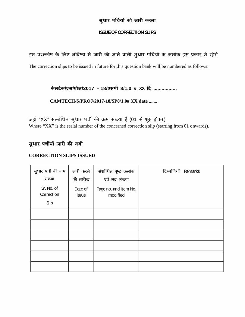
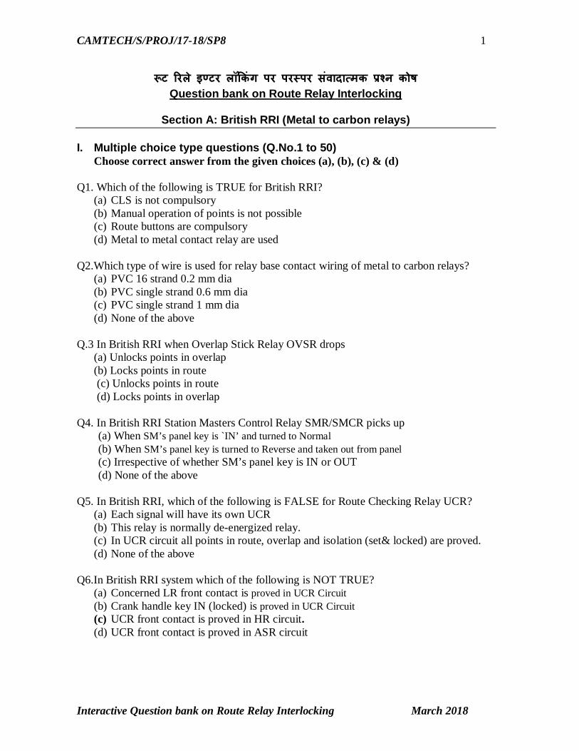
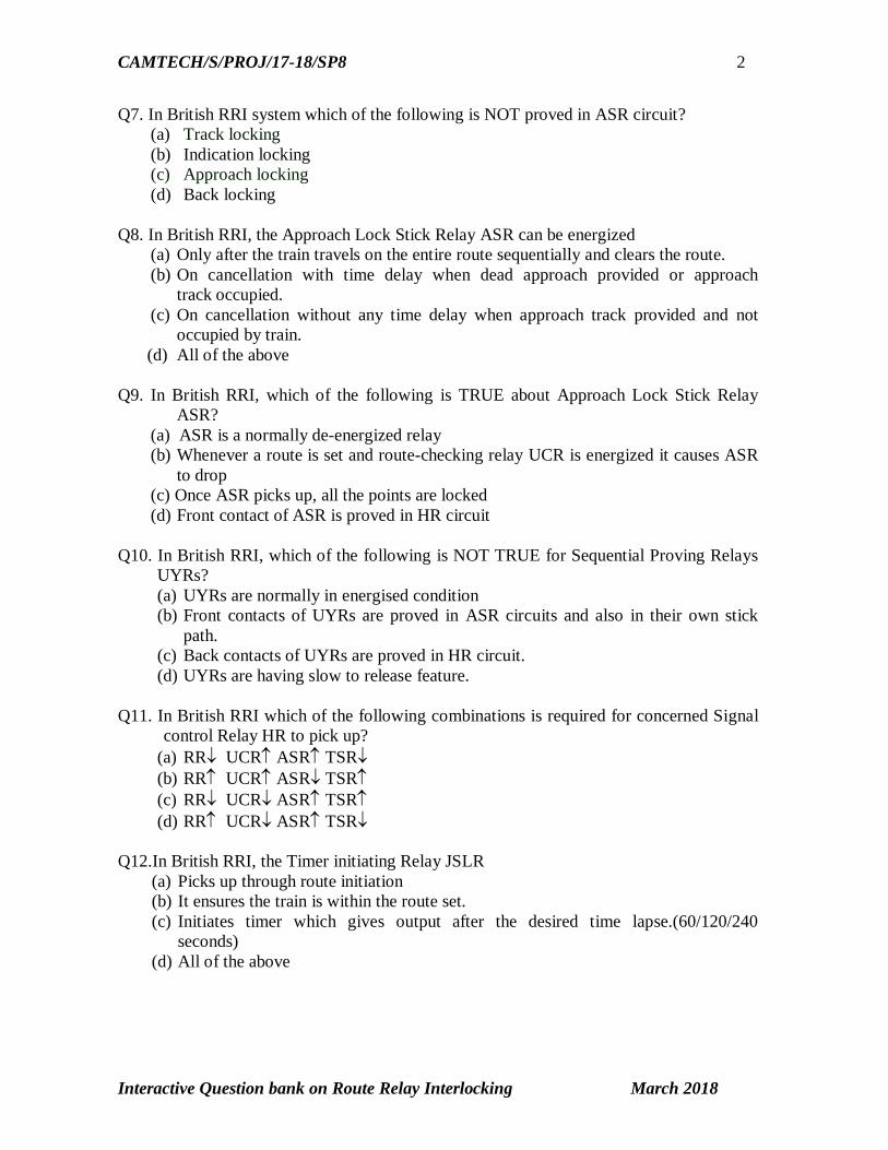
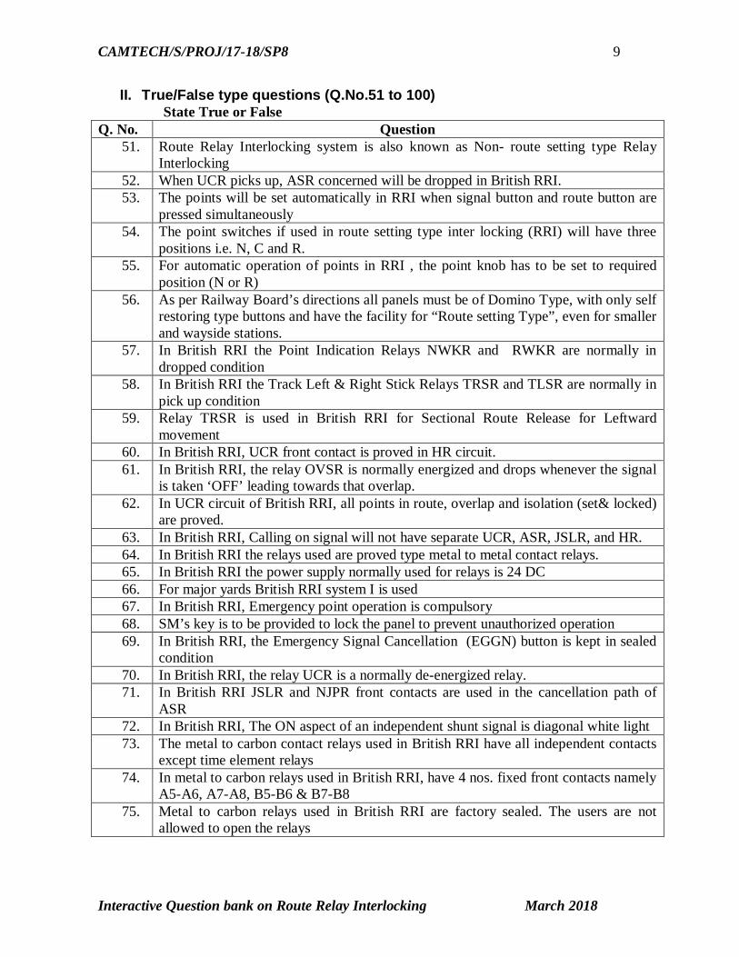
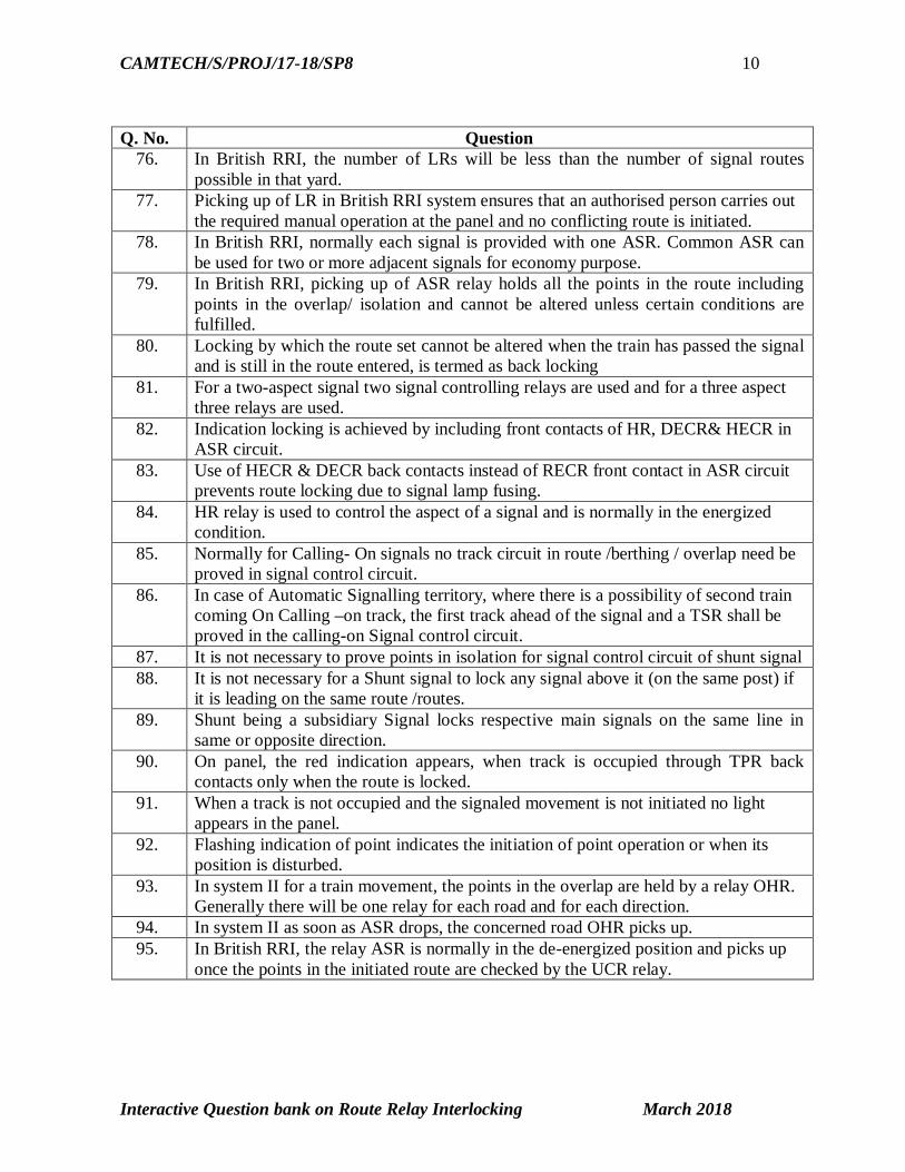
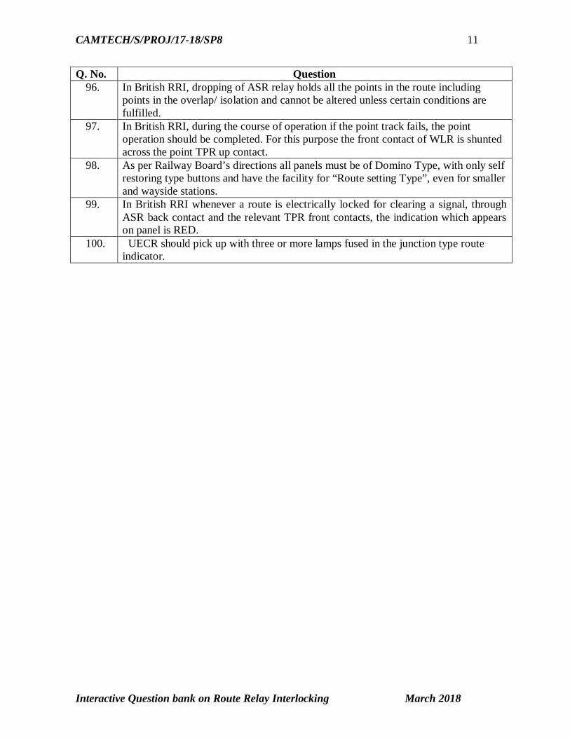
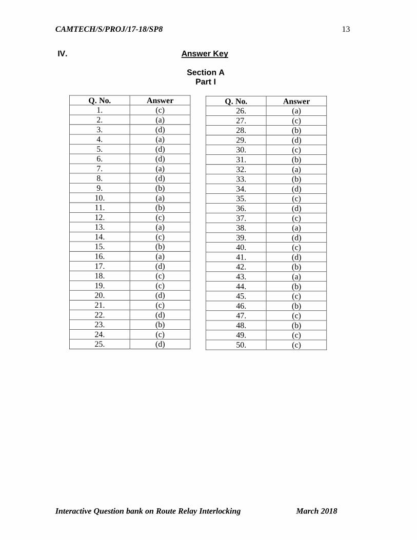
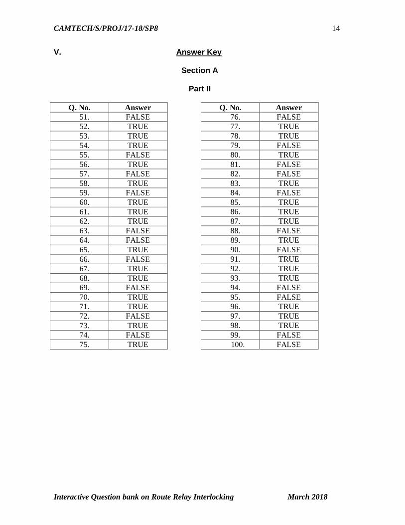
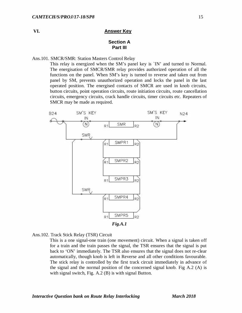
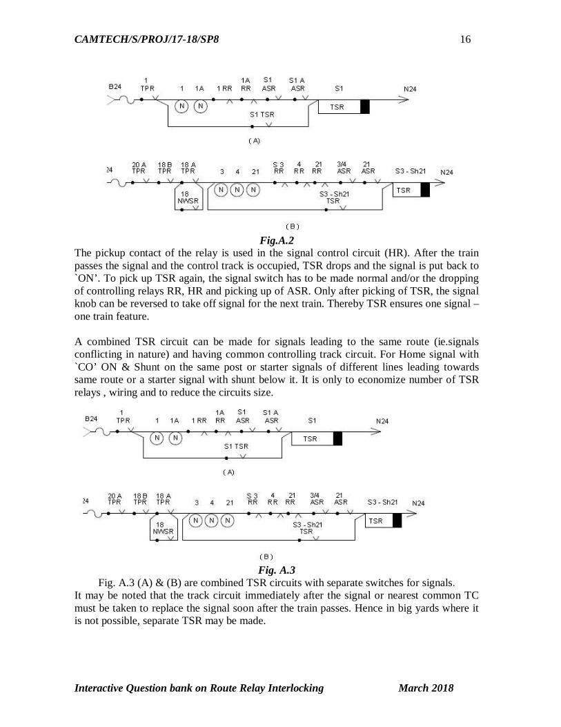
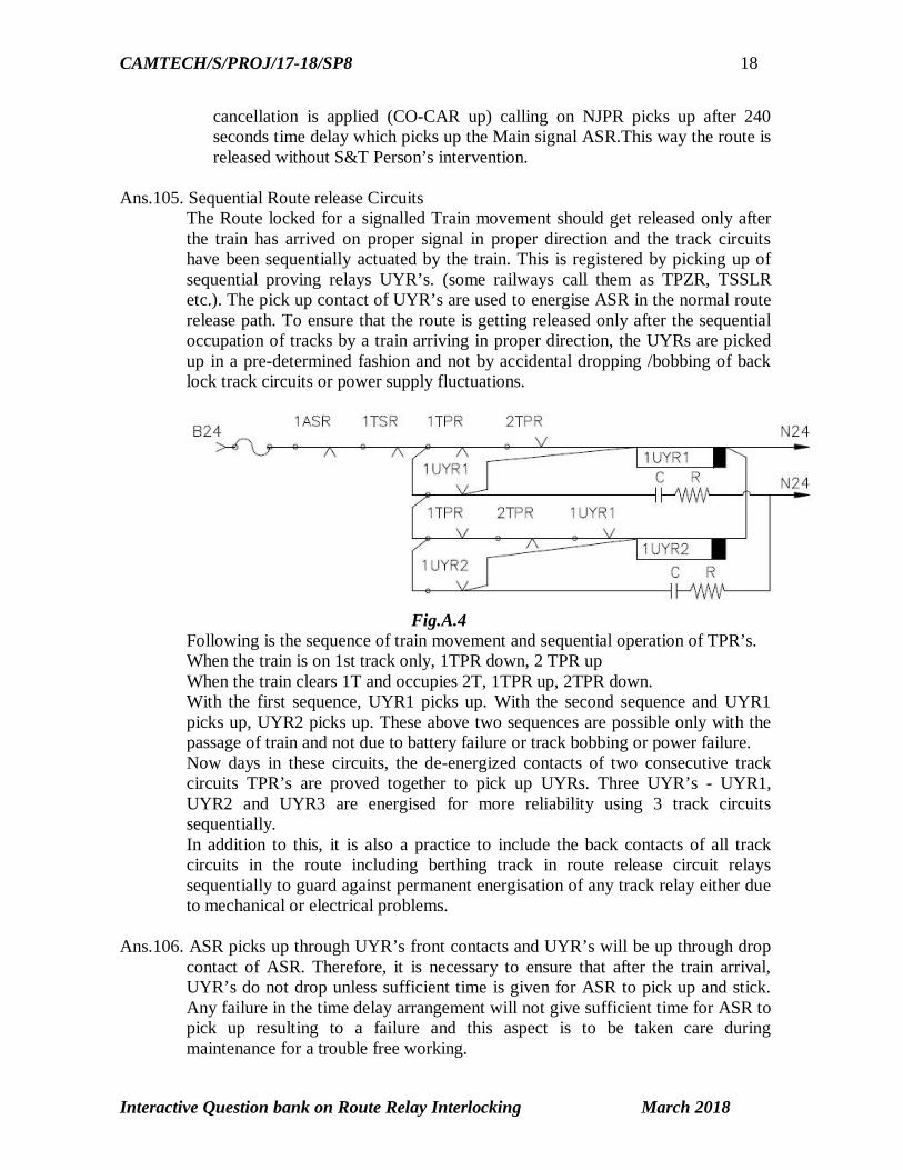
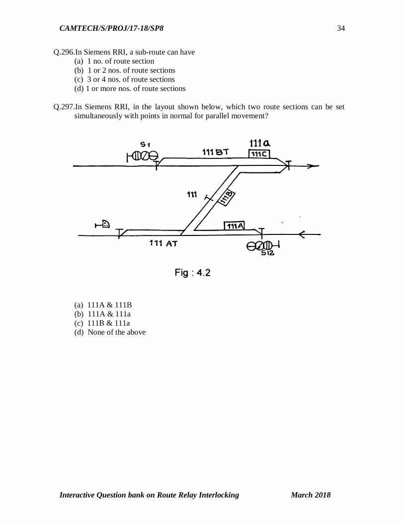
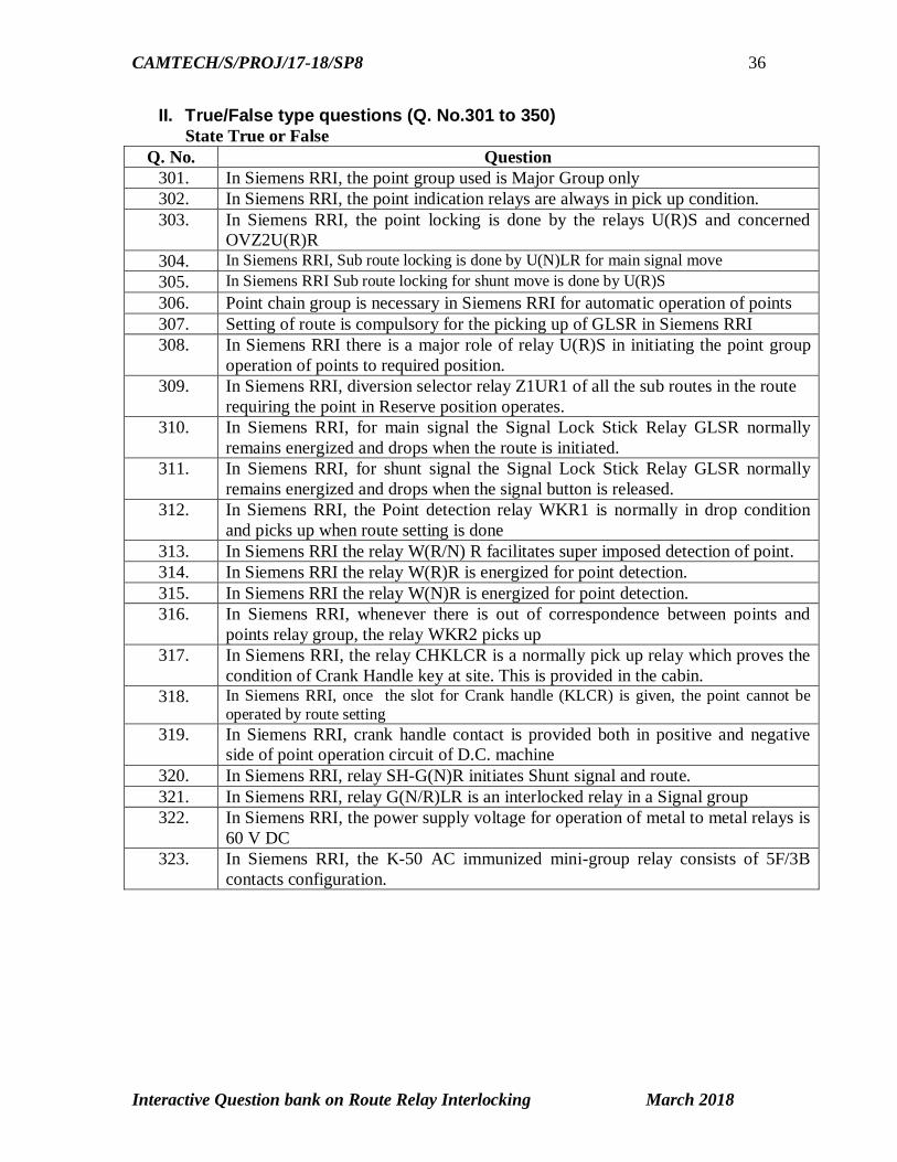
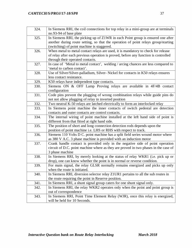
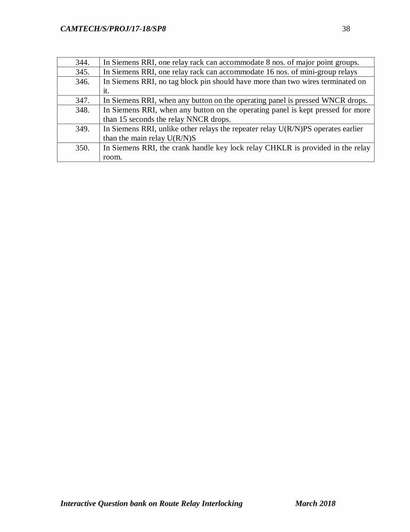
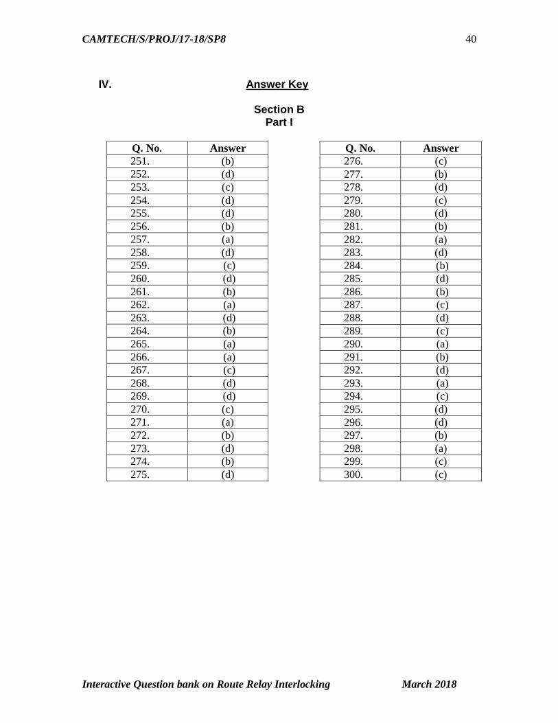
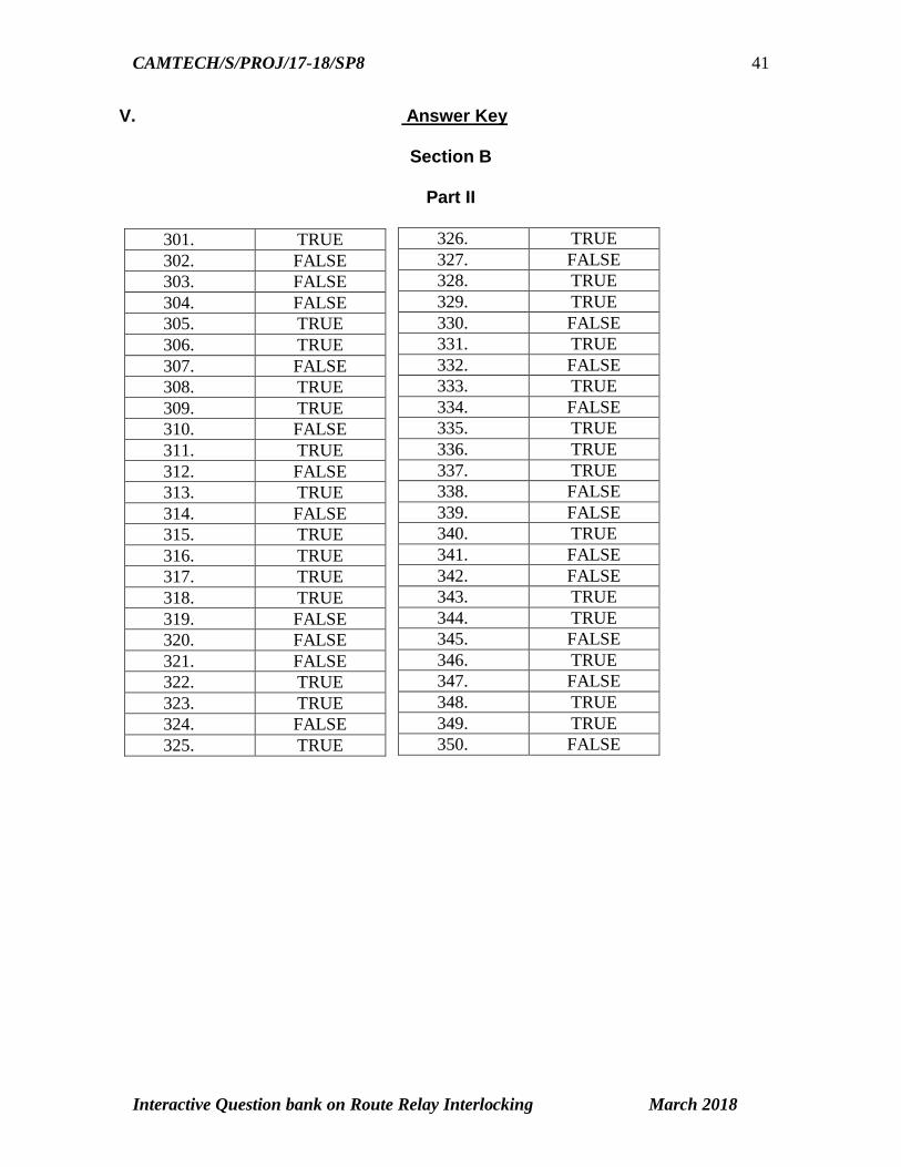
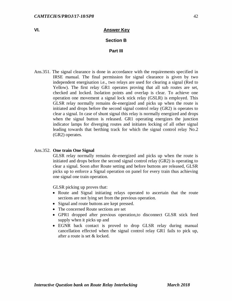
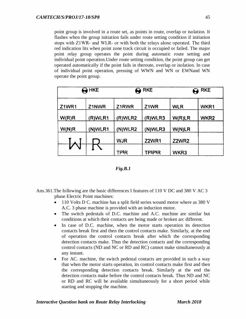
INDIAN RAILWAYS Centre for Advanced Maintenance Technology
Maharajpur Gwalior (MP) Pin Code ndash 474 005
Related Documents