Vision, Modeling, and Visualization (2010) Interactive Multi-View Façade Image Editing Przemyslaw Musialski 1,2 Christian Luksch 1 Michael Schwärzler 1 Matthias Buchetics 1 Stefan Maierhofer 1 Werner Purgathofer 1,2 1 VRVis Research Center, Austria 2 Vienna University of Technology, Austria Figure 1: Steps of the proposed multi-view image generation system. Top-left: one of typical perspective input photographs, please note the occlusion. Top-middle: the result of the proposed ortho-image generation method (note the pedestrians). Second row shows masks indicating source images of the composition by colors: automatic result (left) and interactively post-processed (middle). Right: the final result after interactive post-processing. Abstract We propose a system for generating high-quality approximated façade ortho-textures based on a set of perspective source photographs taken by a consumer hand-held camera. Our approach is to sample a combined orthographic approximation over the façade-plane from the input photos. In order to avoid kinks and seams which may occur on transitions between different source images, we introduce color adjustment and gradient domain stitching by solving a Poisson equation in real-time. In order to add maximum control on the one hand and easy interaction on the other, we provide several editing interactions allowing for user-guided post-processing. Categories and Subject Descriptors (according to ACM CCS): Computing Methodologies [I.3.3]: Computer Graphics—Picture/Image generation; Computing Methodologies [I.4.9]: Image Processing And Computer Vision—Applications; 1. Introduction Modeling and reconstruction of urban environments is cur- rently the subject of intensive research. There is a wide range of possible applications, including virtual environments like cyber-tourism, computer games, and the entertainment in- dustries in general, as well as urban planning and architec- ture, security planning and training, traffic simulation, driv- ing guidance and telecommunications, to name but a few. The research directions are spread across the disciplines of computer vision, computer graphics, image processing, pho- togrammetry and remote sensing, as well as architecture and the geosciences. Reconstruction is a complex problem and requires an entire pipeline of different tasks. In this work we address the problem of texture generation, which remains a challenging task. The generation of high- quality façade imagery is a key element of realistic repre- sentation of urban environments. Ortho-rectified façades are also a prerequisite of several structure detection and segmen- tation algorithms [MZWvG07, MRM * 10]. Our contribution is a system which provides the ability to create such images from a set of perspective photographs taken by a consumer hand-held camera. The novelty is a method for detailed re- moval of occluders by exploiting the multi-view informa- tion. It combines robust automatic processing steps with user interaction and is meant to resolve the still remaining weak points of fully automatic attempts and to improve the quality of the output. c The Eurographics Association 2010.

Welcome message from author
This document is posted to help you gain knowledge. Please leave a comment to let me know what you think about it! Share it to your friends and learn new things together.
Transcript

Vision, Modeling, and Visualization (2010)
Interactive Multi-View Façade Image Editing
Przemyslaw Musialski 1,2 Christian Luksch 1 Michael Schwärzler 1 Matthias Buchetics 1
Stefan Maierhofer 1 Werner Purgathofer 1,2
1 VRVis Research Center, Austria 2 Vienna University of Technology, Austria
Figure 1: Steps of the proposed multi-view image generation system. Top-left: one of typical perspective input photographs,please note the occlusion. Top-middle: the result of the proposed ortho-image generation method (note the pedestrians). Secondrow shows masks indicating source images of the composition by colors: automatic result (left) and interactively post-processed(middle). Right: the final result after interactive post-processing.
AbstractWe propose a system for generating high-quality approximated façade ortho-textures based on a set of perspectivesource photographs taken by a consumer hand-held camera. Our approach is to sample a combined orthographicapproximation over the façade-plane from the input photos. In order to avoid kinks and seams which may occuron transitions between different source images, we introduce color adjustment and gradient domain stitching bysolving a Poisson equation in real-time. In order to add maximum control on the one hand and easy interactionon the other, we provide several editing interactions allowing for user-guided post-processing.
Categories and Subject Descriptors (according to ACM CCS): Computing Methodologies [I.3.3]: ComputerGraphics—Picture/Image generation; Computing Methodologies [I.4.9]: Image Processing And ComputerVision—Applications;
1. Introduction
Modeling and reconstruction of urban environments is cur-rently the subject of intensive research. There is a wide rangeof possible applications, including virtual environments likecyber-tourism, computer games, and the entertainment in-dustries in general, as well as urban planning and architec-ture, security planning and training, traffic simulation, driv-ing guidance and telecommunications, to name but a few.The research directions are spread across the disciplines ofcomputer vision, computer graphics, image processing, pho-togrammetry and remote sensing, as well as architecture andthe geosciences. Reconstruction is a complex problem andrequires an entire pipeline of different tasks.
In this work we address the problem of texture generation,which remains a challenging task. The generation of high-quality façade imagery is a key element of realistic repre-sentation of urban environments. Ortho-rectified façades arealso a prerequisite of several structure detection and segmen-tation algorithms [MZWvG07, MRM∗10]. Our contributionis a system which provides the ability to create such imagesfrom a set of perspective photographs taken by a consumerhand-held camera. The novelty is a method for detailed re-moval of occluders by exploiting the multi-view informa-tion. It combines robust automatic processing steps with userinteraction and is meant to resolve the still remaining weakpoints of fully automatic attempts and to improve the qualityof the output.
c© The Eurographics Association 2010.
P. Musialski et al. / Interactive Multi-View Façade Image Editing
Input Images Structure from Motion Plane Fitting Mulit-View Projection InteractivePostprocessing
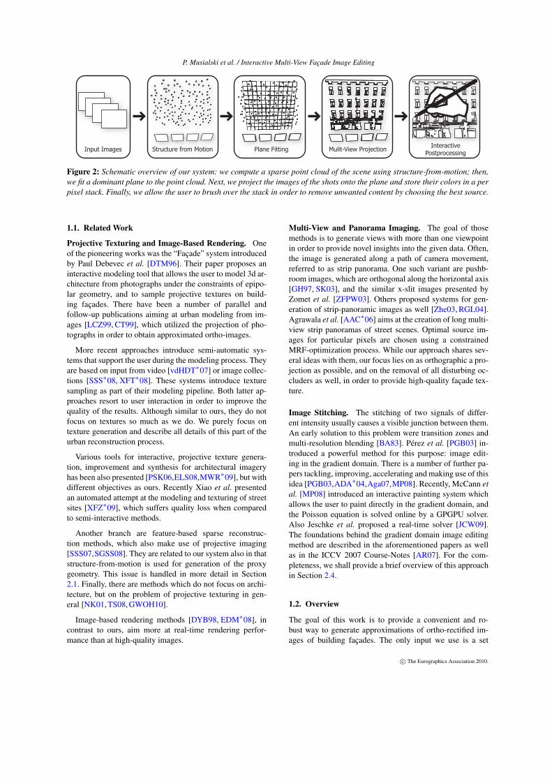
Figure 2: Schematic overview of our system: we compute a sparse point cloud of the scene using structure-from-motion; then,we fit a dominant plane to the point cloud. Next, we project the images of the shots onto the plane and store their colors in a perpixel stack. Finally, we allow the user to brush over the stack in order to remove unwanted content by choosing the best source.
1.1. Related Work
Projective Texturing and Image-Based Rendering. Oneof the pioneering works was the “Façade” system introducedby Paul Debevec et al. [DTM96]. Their paper proposes aninteractive modeling tool that allows the user to model 3d ar-chitecture from photographs under the constraints of epipo-lar geometry, and to sample projective textures on build-ing façades. There have been a number of parallel andfollow-up publications aiming at urban modeling from im-ages [LCZ99, CT99], which utilized the projection of pho-tographs in order to obtain approximated ortho-images.
More recent approaches introduce semi-automatic sys-tems that support the user during the modeling process. Theyare based on input from video [vdHDT∗07] or image collec-tions [SSS∗08, XFT∗08]. These systems introduce texturesampling as part of their modeling pipeline. Both latter ap-proaches resort to user interaction in order to improve thequality of the results. Although similar to ours, they do notfocus on textures so much as we do. We purely focus ontexture generation and describe all details of this part of theurban reconstruction process.
Various tools for interactive, projective texture genera-tion, improvement and synthesis for architectural imageryhas been also presented [PSK06,ELS08,MWR∗09], but withdifferent objectives as ours. Recently Xiao et al. presentedan automated attempt at the modeling and texturing of streetsites [XFZ∗09], which suffers quality loss when comparedto semi-interactive methods.
Another branch are feature-based sparse reconstruc-tion methods, which also make use of projective imaging[SSS07,SGSS08]. They are related to our system also in thatstructure-from-motion is used for generation of the proxygeometry. This issue is handled in more detail in Section2.1. Finally, there are methods which do not focus on archi-tecture, but on the problem of projective texturing in gen-eral [NK01, TS08, GWOH10].
Image-based rendering methods [DYB98, EDM∗08], incontrast to ours, aim more at real-time rendering perfor-mance than at high-quality images.
Multi-View and Panorama Imaging. The goal of thosemethods is to generate views with more than one viewpointin order to provide novel insights into the given data. Often,the image is generated along a path of camera movement,referred to as strip panorama. One such variant are pushb-room images, which are orthogonal along the horizontal axis[GH97, SK03], and the similar x-slit images presented byZomet et al. [ZFPW03]. Others proposed systems for gen-eration of strip-panoramic images as well [Zhe03, RGL04].Agrawala et al. [AAC∗06] aims at the creation of long multi-view strip panoramas of street scenes. Optimal source im-ages for particular pixels are chosen using a constrainedMRF-optimization process. While our approach shares sev-eral ideas with them, our focus lies on as orthographic a pro-jection as possible, and on the removal of all disturbing oc-cluders as well, in order to provide high-quality façade tex-ture.
Image Stitching. The stitching of two signals of differ-ent intensity usually causes a visible junction between them.An early solution to this problem were transition zones andmulti-resolution blending [BA83]. Pérez et al. [PGB03] in-troduced a powerful method for this purpose: image edit-ing in the gradient domain. There is a number of further pa-pers tackling, improving, accelerating and making use of thisidea [PGB03,ADA∗04,Aga07,MP08]. Recently, McCann etal. [MP08] introduced an interactive painting system whichallows the user to paint directly in the gradient domain, andthe Poisson equation is solved online by a GPGPU solver.Also Jeschke et al. proposed a real-time solver [JCW09].The foundations behind the gradient domain image editingmethod are described in the aforementioned papers as wellas in the ICCV 2007 Course-Notes [AR07]. For the com-pleteness, we shall provide a brief overview of this approachin Section 2.4.
1.2. Overview
The goal of this work is to provide a convenient and ro-bust way to generate approximations of ortho-rectified im-ages of building façades. The only input we use is a set
c© The Eurographics Association 2010.
P. Musialski et al. / Interactive Multi-View Façade Image Editing
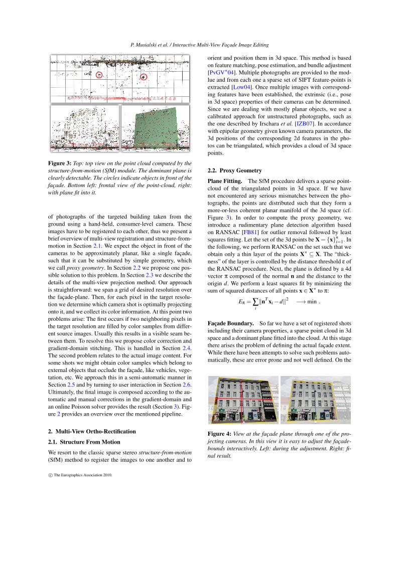
Figure 3: Top: top view on the point cloud computed by thestructure-from-motion (SfM) module. The dominant plane isclearly detectable. The circles indicate objects in front of thefaçade. Bottom left: frontal view of the point-cloud, right:with plane fit into it.
of photographs of the targeted building taken from theground using a hand-held, consumer-level camera. Theseimages have to be registered to each other, thus we present abrief overview of multi-view registration and structure-from-motion in Section 2.1. We expect the object in front of thecameras to be approximately planar, like a single façade,such that it can be substituted by simple geometry, whichwe call proxy geometry. In Section 2.2 we propose one pos-sible solution to this problem. In Section 2.3 we describe thedetails of the multi-view projection method. Our approachis straightforward: we span a grid of desired resolution overthe façade-plane. Then, for each pixel in the target resolu-tion we determine which camera shot is optimally projectingonto it, and we collect its color information. At this point twoproblems arise: The first occurs if two neighboring pixels inthe target resolution are filled by color samples from differ-ent source images. Usually this results in a visible seam be-tween them. To resolve this we propose color correction andgradient-domain stitching. This is handled in Section 2.4.The second problem relates to the actual image content. Forsome shots we might obtain color samples which belong toexternal objects that occlude the façade, like vehicles, vege-tation, etc. We approach this in a semi-automatic manner inSection 2.5 and by turning to user interaction in Section 2.6.Ultimately, the final image is composed according to the au-tomatic and manual corrections in the gradient-domain andan online Poisson solver provides the result (Section 3). Fig-ure 2 provides an overview over the mentioned pipeline.
2. Multi-View Ortho-Rectification
2.1. Structure From Motion
We resort to the classic sparse stereo structure-from-motion(SfM) method to register the images to one another and to
orient and position them in 3d space. This method is basedon feature matching, pose estimation, and bundle adjustment[PvGV∗04]. Multiple photographs are provided to the mod-lue and from each one a sparse set of SIFT feature-points isextracted [Low04]. Once multiple images with correspond-ing features have been established, the extrinsic (i.e., posein 3d space) properties of their cameras can be determined.Since we are dealing with mostly planar objects, we use acalibrated approach for unstructured photographs, such asthe one described by Irschara et al. [IZB07]. In accordancewith epipolar geometry given known camera parameters, the3d positions of the corresponding 2d features in the pho-tos can be triangulated, which provides a cloud of 3d spacepoints.
2.2. Proxy Geometry
Plane Fitting. The SfM procedure delivers a sparse point-cloud of the triangulated points in 3d space. If we havenot encountered any serious mismatches between the pho-tographs, the points are distributed such that they form amore-or-less coherent planar manifold of the 3d space (cf.Figure 3). In order to compute the proxy geometry, weintroduce a rudimentary plane detection algorithm basedon RANSAC [FB81] for outlier removal followed by leastsquares fitting. Let the set of the 3d points be X = {x}n
i=1. Inthe following, we perform RANSAC on the set such that weobtain only a thin layer of the points X∗ ⊆ X. The “thick-ness” of the layer is controlled by the distance threshold ε ofthe RANSAC procedure. Next, the plane is defined by a 4dvector π composed of the normal n and the distance to theorigin d. We perform a least squares fit by minimizing thesum of squared distances of all points x ∈ X∗ to π:
Eπ = ∑i‖nT xi−d‖2 −→min .
Façade Boundary. So far we have a set of registered shotsincluding their camera properties, a sparse point cloud in 3dspace and a dominant plane fitted into the cloud. At this stagethere arises the problem of defining the actual façade extent.While there have been attempts to solve such problems auto-matically, these are error prone and not well defined. On the
Figure 4: View at the façade plane through one of the pro-jecting cameras. In this view it is easy to adjust the façade-bounds interactively. Left: during the adjustment. Right: fi-nal result.
c© The Eurographics Association 2010.

P. Musialski et al. / Interactive Multi-View Façade Image Editing
other hand, this is quite an easy task for a human providedwith an appropriate user interface. For this reason, we pro-pose a GUI that allows the user to (1) navigate in 3d thoughthe scene, (2) look at the scene from the computed shot po-sitions, (3) preview the texture by projecting best single-shotimage onto the plane, (4) adjust the 3d plane by resizing androtating it (see Figure 4) and, finally, (5) align the coordinatesystem of the scene with the one of the proxy plane. After theadjustment of the façade boundary, the application is readyfor the next step: multi-view projective texturing.
2.3. Viewpoint Projection.
Scene Geometry. We distinguish different cases of cameraplacement, where only one is valid and the others are clas-sified as invalid and shots of this class are rejected. Figure 5depicts this issue: the invalid cases occur when the camerais behind the plane (C3 and C4) or when it is in the front,but not all four rays from its center through the corners ofthe frustum intersect the image plane (C1). The valid caseis when the camera is in front of the façade plane and allrays intersect the image plane in a finite distance, such thatthe projected shape is a finite trapezoid that intersects thefaçade rectangle (cf. Figure 5, left). If not all rays intersectthe plane, only a part of the image is finitely projected ontothe plane and a part meets the plane at a line at infinity. Pixelsfrom such a projection are very strongly elongated along theplane and thus prone to cause sampling artifacts. Since weexpect to have enough information from the valid camerasanyway, we simply reject them as invalid ones.
Shot Selection. Our approach is based on the fact that wehave multiple projective centers along the horizontal axisin world space (since we are using ground-based hand-heldcameras). This allows us to compose the target image I insuch a way that each pixel is chosen from an optimal cam-era. As a measure for this optimality, we use an objectivefunction composed of the camera to plane-normal incidenceangle ϕ and a term which expresses the area covered by thefootprint of the original pixel projected onto the proxy plane.
From the law of sines we know that the length of a pro-jected segment depends on the distance of the camera center
n
C1
C2
C3
C4
R
P
RP
Figure 5: Left: Example of valid (C2) and invalid camerasin the system. Right: the area of the intersection R∩ P indetermines the “quality” of the projecting camera.
to the plane and the projection angle. Figure 6, left hand side,depicts this relation, where the length of the segment BC de-pends on the angles α, ϕ1, and the length of AM.
We denote the distance of each camera ck to each pixel inthe target image pi as dik, then we approximate the projec-tion area as Aik = (dik/dmax)
−2 . We normalize dik such thatit lies between 0 and 1, which is a chosen maximum distancedmax (i.e. the most distant camera). For the angular term, weuse the dot product of the plane normal and the normalizedvector vik = ‖ck − pi‖, such that: Bik = nT vik . This valueis naturally distributed in the range 0 . . .1. Both terms areweighted by the empirical parameters λ1 +λ2 = 1, such thatthe final objective function is:
EI = ∑i
∑k
λ1Aik +λ2Bik −→max , (1)
where i iterates over all target pixels and k over all validcameras. We choose λ2 = 0.7 in our experiments.
Image Stacks. In order to accumulate the projections,we span a grid of desired resolution over the detected andbounded façade plane. Then, for each pixel in the target res-olution, we determine a set of cameras which project opti-mally according to the aforementioned constraints. We storethese values in a volume of the size width × height × num-ber of shots attached to the proxy, which we call image stackdue to its layered nature. Right hand side of Figure 6 showsa schematic, 2d top view of this idea.
2.4. Seamless Stitching
One remaining problem are the visible seams along transi-tions between pixels from different sources, which we ad-dress by a gradient-domain stitching algorithm.
GPU Poisson Solver. As presented in Section 1.1, Pois-son image editing dates back to [PGB03]. The beauty of thismethod manifests itself in both the elegance of its formula-tion and the practical results. It is based on the insight that
n
p1p3p2
p3p2p1
1
2
3
4
5
6
7
8
9
10
11
12C1
C2
n
n
C3
321
3
21
A
B
C
M
1
2
Figure 6: Left: The relations of the projection, where thelength of BC only depends on the angles α, ϕ1, and thelength of AM. Right: Projection from the shots onto the im-age stack. For each pixel indicated by the numbers on theright, the best cameras are chosen, and the projected valueis stored in the respective layer of the stack.
c© The Eurographics Association 2010.
P. Musialski et al. / Interactive Multi-View Façade Image Editing
one can stitch the derivatives of two signals instead the sig-nals themselves. The derivative functions have the advantagethat the intensity differences between them are relative, andnot absolute as in the original signals. Thus, any differencesin the amplitude of the original signals vanish in their gra-dient fields. We can compute them in the discrete case of animage I as forward differences:
∂I/∂x = I(x+1,y)− I(x,y)∂I/∂y = I(x,y+1)− I(x,y) .
After editing (e.g., deleting, amplifying) and combining(e.g., blending, averaging) of the derivatives of one or moreimages, one obtains a modified gradient field G = [Gx Gy]
T .Unfortunately, this is usually a non-integrable vector field,since its curl is not equal to zero, and thus one cannot recon-struct the original signal by a trivial summation. This prob-lem is addressed by solving for the best approximation of theprimitive (original) signal by minimizing the following sumof squared differences:
EU = ‖∇U−G‖2 −→min .
In other words, we are looking for a new image U , whosegradient field ∇U is closest to G in the least squares sense.This can be formulated as a Poisson equation:
∇2U =∂Gx
∂x+
∂Gy
∂y,
which results in a sparse system of linear equations that canbe solved using least squares. Since we strive for real-timeperformance, we adapt a GPU solver proposed by [MP08],which is a multi-grid solution [AR07]. It performs at real-time rates with up to four mega pixel images (on an NVIDIAGeForce GTX 285), which allows not only for the stitchingof precomputed layers but also interactive editing of the lay-ers. We elaborate this in Section 2.6.
Color Correction. Despite the fact that we are using aPoisson image editing approach, we perform a simple colorcorrection procedure before the actual stitching process.This provides better initial values and has turned out to beuseful in cases where we have slight transition in the il-lumination of the façade. In practice this happens very of-ten, since the global illumination (sun, clouds) changes. Weresort to a simple approach presented by Reinhard et al.[RAGS01], where we just shift the mean µ and the standarddeviation σ of all images in the stack to common values.Unlike their method, we perform the linear shift in the RGBcolor space, since we do not aim for an appearance changebut just for slight color correction:
cout =σkey
σin(cin−µin)+µkey ,
where c stands for each color channel separately. The key-values are chosen from an input shot with the largest pro-jected area on the bounded façade plane.
u’v’
HPuvxyz
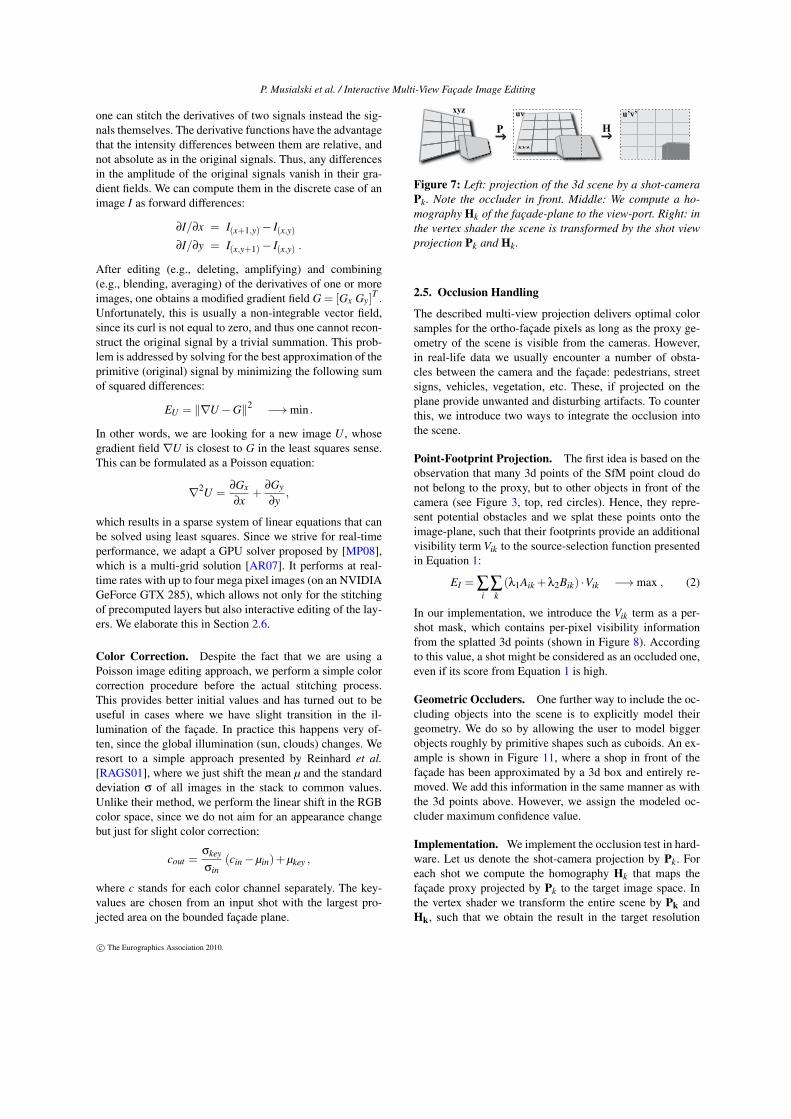
Figure 7: Left: projection of the 3d scene by a shot-cameraPk. Note the occluder in front. Middle: We compute a ho-mography Hk of the façade-plane to the view-port. Right: inthe vertex shader the scene is transformed by the shot viewprojection Pk and Hk.
2.5. Occlusion Handling
The described multi-view projection delivers optimal colorsamples for the ortho-façade pixels as long as the proxy ge-ometry of the scene is visible from the cameras. However,in real-life data we usually encounter a number of obsta-cles between the camera and the façade: pedestrians, streetsigns, vehicles, vegetation, etc. These, if projected on theplane provide unwanted and disturbing artifacts. To counterthis, we introduce two ways to integrate the occlusion intothe scene.
Point-Footprint Projection. The first idea is based on theobservation that many 3d points of the SfM point cloud donot belong to the proxy, but to other objects in front of thecamera (see Figure 3, top, red circles). Hence, they repre-sent potential obstacles and we splat these points onto theimage-plane, such that their footprints provide an additionalvisibility term Vik to the source-selection function presentedin Equation 1:
EI = ∑i
∑k(λ1Aik +λ2Bik) ·Vik −→max , (2)
In our implementation, we introduce the Vik term as a per-shot mask, which contains per-pixel visibility informationfrom the splatted 3d points (shown in Figure 8). Accordingto this value, a shot might be considered as an occluded one,even if its score from Equation 1 is high.
Geometric Occluders. One further way to include the oc-cluding objects into the scene is to explicitly model theirgeometry. We do so by allowing the user to model biggerobjects roughly by primitive shapes such as cuboids. An ex-ample is shown in Figure 11, where a shop in front of thefaçade has been approximated by a 3d box and entirely re-moved. We add this information in the same manner as withthe 3d points above. However, we assign the modeled oc-cluder maximum confidence value.
Implementation. We implement the occlusion test in hard-ware. Let us denote the shot-camera projection by Pk. Foreach shot we compute the homography Hk that maps thefaçade proxy projected by Pk to the target image space. Inthe vertex shader we transform the entire scene by Pk andHk, such that we obtain the result in the target resolution
c© The Eurographics Association 2010.
P. Musialski et al. / Interactive Multi-View Façade Image Editing
(see Figure 7). In the pixel shader, the interpolated depth ofthe projection of the scene is tested with the proxy plane. Ina second pass, 3d points in front of the proxy are splattedby the same mapping as above onto the target. The radiusof their footprints depends on the distance to the target andis weighted using a radial falloff-kernel (see Figure 12). Theresults are accumulated in a per shot mask, which acts as theocclusion term Vik in Equation 2.
2.6. User Interaction
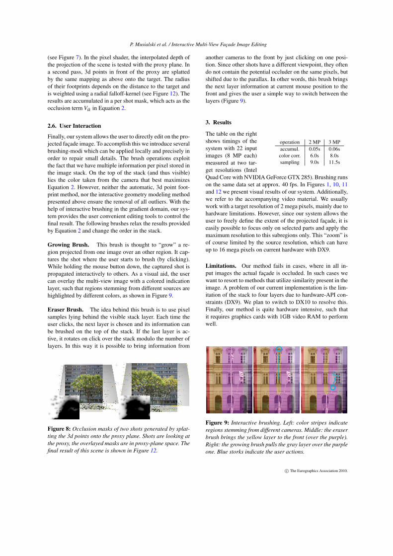
Finally, our system allows the user to directly edit on the pro-jected façade image. To accomplish this we introduce severalbrushing-modi which can be applied locally and precisely inorder to repair small details. The brush operations exploitthe fact that we have multiple information per pixel stored inthe image stack. On the top of the stack (and thus visible)lies the color taken from the camera that best maximizesEquation 2. However, neither the automatic, 3d point foot-print method, nor the interactive geometry modeling methodpresented above ensure the removal of all outliers. With thehelp of interactive brushing in the gradient domain, our sys-tem provides the user convenient editing tools to control thefinal result. The following brushes relax the results providedby Equation 2 and change the order in the stack.
Growing Brush. This brush is thought to “grow” a re-gion projected from one image over an other region. It cap-tures the shot where the user starts to brush (by clicking).While holding the mouse button down, the captured shot ispropagated interactively to others. As a visual aid, the usercan overlay the multi-view image with a colored indicationlayer, such that regions stemming from different sources arehighlighted by different colors, as shown in Figure 9.
Eraser Brush. The idea behind this brush is to use pixelsamples lying behind the visible stack layer. Each time theuser clicks, the next layer is chosen and its information canbe brushed on the top of the stack. If the last layer is ac-tive, it rotates on click over the stack modulo the number oflayers. In this way it is possible to bring information from
Figure 8: Occlusion masks of two shots generated by splat-ting the 3d points onto the proxy plane. Shots are looking atthe proxy, the overlayed masks are in proxy-plane space. Thefinal result of this scene is shown in Figure 12.
another cameras to the front by just clicking on one posi-tion. Since other shots have a different viewpoint, they oftendo not contain the potential occluder on the same pixels, butshifted due to the parallax. In other words, this brush bringsthe next layer information at current mouse position to thefront and gives the user a simple way to switch between thelayers (Figure 9).
3. Results
operation 2 MP 3 MPaccumul. 0.05s 0.06scolor corr. 6.0s 8.0ssampling 9.0s 11.5s
The table on the rightshows timings of thesystem with 22 inputimages (8 MP each)measured at two tar-get resolutions (IntelQuad Core with NVIDIA GeForce GTX 285). Brushing runson the same data set at approx. 40 fps. In Figures 1, 10, 11and 12 we present visual results of our system. Additionally,we refer to the accompanying video material. We usuallywork with a target resolution of 2 mega pixels, mainly due tohardware limitations. However, since our system allows theuser to freely define the extent of the projected façade, it iseasily possible to focus only on selected parts and apply themaximum resolution to this subregions only. This “zoom” isof course limited by the source resolution, which can haveup to 16 mega pixels on current hardware with DX9.
Limitations. Our method fails in cases, where in all in-put images the actual façade is occluded. In such cases wewant to resort to methods that utilize similarity present in theimage. A problem of our current implementation is the lim-itation of the stack to four layers due to hardware-API con-straints (DX9). We plan to switch to DX10 to resolve this.Finally, our method is quite hardware intensive, such thatit requires graphics cards with 1GB video RAM to performwell.
Figure 9: Interactive brushing. Left: color stripes indicateregions stemming from different cameras. Middle: the eraserbrush brings the yellow layer to the front (over the purple).Right: the growing brush pulls the gray layer over the purpleone. Blue storks indicate the user actions.
c© The Eurographics Association 2010.

P. Musialski et al. / Interactive Multi-View Façade Image Editing
4. Conclusions
We present a system for generating approximately ortho-graphic façade textures. We pay particular attention to high-quality, high-resolution and obstacle-free images. Most stepsof our method are fully automatic: image registration, poseestimation, plane fitting as well as per-pixel projection. Onthe other hand, some tasks have proven difficult to solveautomatically with adequate quality. For these cases we in-troduce interactive tools. For the problem of bounding theactual façade, we provide the user with an easy method todefine the extent. Another difficult problem is the detectionand removal of possible occluders in front of the façades. Tosolve this, we propose two approaches: projection of SfMoutliers and modeling of additional geometry. The majorcontribution of our system is the detailed removal of occlud-ers by exploiting the multi-view information. For the future,we are considering to extend the system in a way that al-lows the user to operate in moderate resolutions for real-timeinteraction while calculating higher resolutions offline. Fur-thermore, we want to extend the geometry modeling part ofthe solution. Our system is intended to serve as part of acomplex urban reconstruction pipeline.
Acknowledgments. We would like to thank the Aardvark-Team, especially Robert F. Tobler and Mike Hornacek. Fur-ther, we thank Stefan Jeschke for providing his source-code.
Figure 10: A close-up of the image shown in Figure 11.Pedestrians and their reflections visible in the left imagehave been removed (middle).
References[AAC∗06] AGARWALA A., AGRAWALA M., COHEN M., SALESIN D.,
SZELISKI R.: Photographing long scenes with multi-viewpoint panora-mas. ACM Transactions on Graphics 25, 3 (July 2006), 853. 2
[ADA∗04] AGARWALA A., DONTCHEVA M., AGRAWALA M.,DRUCKER S., COLBURN A., CURLESS B., SALESIN D., COHENM.: Interactive digital photomontage. ACM Transactions on Graphics 23,3 (Aug. 2004), 294. 2
[Aga07] AGARWALA A.: Efficient gradient-domain compositing usingquadtrees. ACM Transactions on Graphics 26, 3 (July 2007), 94. 2
[AR07] AGRAWAL A., RASKAR R.: Gradient domain manipula-tion techniques in vision and graphics. ICCV 2007 Course (http://www.umiacs.umd.edu/~aagrawal/ICCV2007Course/index.html), 2007. 2, 5
[BA83] BURT P. J., ADELSON E. H.: A multiresolution spline with appli-cation to image mosaics. ACM Transactions on Graphics 2, 4 (Oct. 1983),217–236. 2
[CT99] COORG S., TELLER S.: Extracting textured vertical facades fromcontrolled close-range imagery. In Proceedings. 1999 IEEE ComputerSociety Conference on Computer Vision and Pattern Recognition (Cat. NoPR00149) (1999), IEEE Comput. Soc, pp. 625–632. 2
[DTM96] DEBEVEC P. E., TAYLOR C. J., MALIK J.: Modeling and ren-dering architecture from photographs. In Proceedings of the 23rd an-nual conference on Computer graphics and interactive techniques - SIG-GRAPH ’96 (New York, New York, USA, 1996), ACM Press, pp. 11–20.2
[DYB98] DEBEVEC P. E., YU Y., BORSHUKOV G.: Efficient view-dependent image-based rendering with projective texture-mapping. InRendering techniques’ 98: proceedings of the Eurographics Workshopin Vienna, Austria, June 29-July 1, 1998 (1998), Springer Verlag Wien,p. 105. 2
[EDM∗08] EISEMANN M., DE DECKER B., MAGNOR M. A., BEKAERTP., DE AGUIAR E., AHMED N., THEOBALT C., SELLENT A.: FloatingTextures. Computer Graphics Forum 27, 2 (Apr. 2008), 409–418. 2
[ELS08] EISENACHER C., LEFEBVRE S., STAMMINGER M.: TextureSynthesis From Photographs. Computer Graphics Forum 27, 2 (Apr.2008), 419–428. 2
[FB81] FISCHLER M. A., BOLLES R. C.: Random sample consensus: aparadigm for model fitting with applications to image analysis and auto-mated cartography. Communications of the ACM 24, 6 (June 1981), 381–395. 3
[GH97] GUPTA R., HARTLEY R.: Linear pushbroom cameras. IEEETransactions on Pattern Analysis and Machine Intelligence 19, 9 (1997),963–975. 2
[GWOH10] GAL R., WEXLER Y., OFEK E., HOPPE H.: Seamless Mon-tage for Texturing Models. Computer Graphics Forum 29, 2 (2010), toappear. 2
[IZB07] IRSCHARA A., ZACH C., BISCHOF H.: Towards Wiki-basedDense City Modeling. In 2007 IEEE 11th International Conference onComputer Vision (Oct. 2007), IEEE, pp. 1–8. 3
[JCW09] JESCHKE S., CLINE D., WONKA P.: A GPU Laplacian solverfor diffusion curves and Poisson image editing. ACM Transactions onGraphics 28, 5 (Dec. 2009), 1. 2
[LCZ99] LIEBOWITZ D., CRIMINISI A., ZISSERMAN A.: Creating Ar-chitectural Models from Images. Computer Graphics Forum 18, 3 (Sept.1999), 39–50. 2
[Low04] LOWE D. G.: Distinctive Image Features from Scale-InvariantKeypoints. International Journal of Computer Vision 60, 2 (Nov. 2004),91–110. 3
[MP08] MCCANN J., POLLARD N. S.: Real-time gradient-domain paint-ing. ACM Transactions on Graphics 27, 3 (Aug. 2008), 1. 2, 5
[MRM∗10] MUSIALSKI P., RECHEIS M., MAIERHOFER S., WONKA P.,PURGATHOFER W.: Tiling of Ortho-Rectified Façade Images. In SpringConference on Computer Graphics (SCCG’10) (Budmerice, 2010). 1
[MWR∗09] MUSIALSKI P., WONKA P., RECHEIS M., MAIERHOFER S.,PURGATHOFER W.: Symmetry-Based Façade Repair. In Vision, Model-ing, Visualisation (VMV’09) (2009), Magnor M. A., Rosenhahn B., TheiselH., (Eds.), DNB, pp. 3–10. 2
[MZWvG07] MÜLLER P., ZENG G., WONKA P., VAN GOOL L.: Image-based procedural modeling of facades. ACM Transactions on Graphics 26,3 (July 2007), 85. 1
[NK01] NEUGEBAUER P. J., KLEIN K.: Texturing 3D Models of RealWorld Objects from Multiple Unregistered Photographic Views. ComputerGraphics Forum 18, 3 (Sept. 2001), 245–256. 2
[PGB03] PÉREZ P., GANGNET M., BLAKE A.: Poisson image editing.ACM Transactions on Graphics 22, 3 (July 2003), 313. 2, 4
[PSK06] PAVIC D., SCHÖNEFELD V., KOBBELT L.: Interactive imagecompletion with perspective correction. The Visual Computer 22, 9-11(Aug. 2006), 671–681. 2
[PvGV∗04] POLLEFEYS M., VAN GOOL L., VERGAUWEN M., VER-BIEST F., CORNELIS K., TOPS J., KOCH R.: Visual Modeling with aHand-Held Camera. International Journal of Computer Vision 59, 3 (Sept.2004), 207–232. 3
c© The Eurographics Association 2010.
P. Musialski et al. / Interactive Multi-View Façade Image Editing
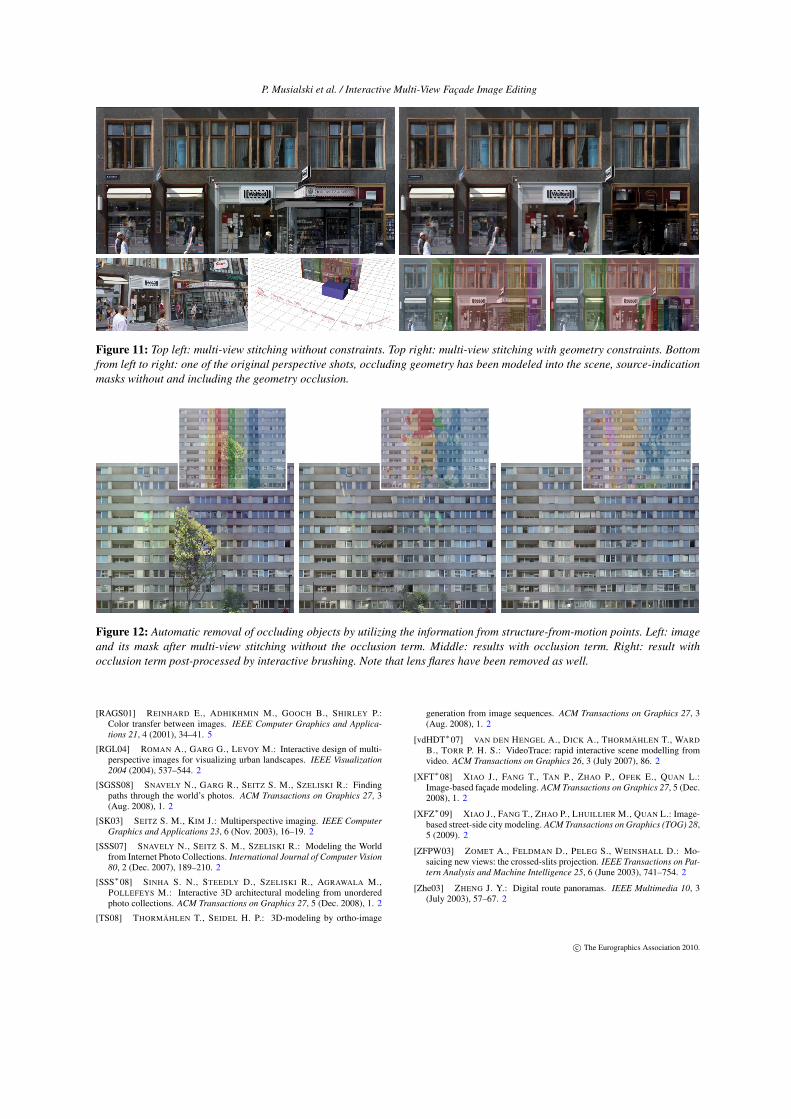
Figure 11: Top left: multi-view stitching without constraints. Top right: multi-view stitching with geometry constraints. Bottomfrom left to right: one of the original perspective shots, occluding geometry has been modeled into the scene, source-indicationmasks without and including the geometry occlusion.
Figure 12: Automatic removal of occluding objects by utilizing the information from structure-from-motion points. Left: imageand its mask after multi-view stitching without the occlusion term. Middle: results with occlusion term. Right: result withocclusion term post-processed by interactive brushing. Note that lens flares have been removed as well.
[RAGS01] REINHARD E., ADHIKHMIN M., GOOCH B., SHIRLEY P.:Color transfer between images. IEEE Computer Graphics and Applica-tions 21, 4 (2001), 34–41. 5
[RGL04] ROMAN A., GARG G., LEVOY M.: Interactive design of multi-perspective images for visualizing urban landscapes. IEEE Visualization2004 (2004), 537–544. 2
[SGSS08] SNAVELY N., GARG R., SEITZ S. M., SZELISKI R.: Findingpaths through the world’s photos. ACM Transactions on Graphics 27, 3(Aug. 2008), 1. 2
[SK03] SEITZ S. M., KIM J.: Multiperspective imaging. IEEE ComputerGraphics and Applications 23, 6 (Nov. 2003), 16–19. 2
[SSS07] SNAVELY N., SEITZ S. M., SZELISKI R.: Modeling the Worldfrom Internet Photo Collections. International Journal of Computer Vision80, 2 (Dec. 2007), 189–210. 2
[SSS∗08] SINHA S. N., STEEDLY D., SZELISKI R., AGRAWALA M.,POLLEFEYS M.: Interactive 3D architectural modeling from unorderedphoto collections. ACM Transactions on Graphics 27, 5 (Dec. 2008), 1. 2
[TS08] THORMÄHLEN T., SEIDEL H. P.: 3D-modeling by ortho-image
generation from image sequences. ACM Transactions on Graphics 27, 3(Aug. 2008), 1. 2
[vdHDT∗07] VAN DEN HENGEL A., DICK A., THORMÄHLEN T., WARDB., TORR P. H. S.: VideoTrace: rapid interactive scene modelling fromvideo. ACM Transactions on Graphics 26, 3 (July 2007), 86. 2
[XFT∗08] XIAO J., FANG T., TAN P., ZHAO P., OFEK E., QUAN L.:Image-based façade modeling. ACM Transactions on Graphics 27, 5 (Dec.2008), 1. 2
[XFZ∗09] XIAO J., FANG T., ZHAO P., LHUILLIER M., QUAN L.: Image-based street-side city modeling. ACM Transactions on Graphics (TOG) 28,5 (2009). 2
[ZFPW03] ZOMET A., FELDMAN D., PELEG S., WEINSHALL D.: Mo-saicing new views: the crossed-slits projection. IEEE Transactions on Pat-tern Analysis and Machine Intelligence 25, 6 (June 2003), 741–754. 2
[Zhe03] ZHENG J. Y.: Digital route panoramas. IEEE Multimedia 10, 3(July 2003), 57–67. 2
c© The Eurographics Association 2010.
Related Documents


