Joint EUROGRAPHICS - IEEE TCVG Symposium on Visualization (2004) O. Deussen, C. Hansen, D.A. Keim, D. Saupe (Editors) Interactive High Quality Trimmed NURBS Visualization Using Appearance Preserving Tessellation M. Guthe 1 , Á. Balázs 1 and R. Klein 1 1 Institute of Computer Science II, Computer Graphics, Bonn University, Bonn, Germany Abstract Trimmed NURBS models are the standard representation used in CAD/CAM systems and accurate visualization of large trimmed NURBS models at interactive frame rates is of great interest for industry. To visualize the quality of a surface several techniques like isophotes, reflection lines, etc. are used. Most existing approaches transform the NURBS surfaces into a fine polygonal representation and build static levels of detail from this representation. This polygonal approximation together with its normals are adjusted in a semi-automatic procedure to achieve the desired visual fidelity during visualization. Since this approach allows only for a fixed maximum accuracy and does not support deformable models, another more recent approach is to keep the NURBS representation and generate view-dependent LODs on the fly up to the currently required preciseness. However, so far this approach took only into account the geometric error of an approximation and thus neglected the various illumination artifacts introduced by the chosen (possibly view-dependent) triangulation. Although this problem can be solved by using normal maps, the resolution of the normal maps again limits the accuracy. Further- more, the normal map generation requires a preprocessing step which prevents the support of deformable NURBS models. In this paper we present a novel automatic tessellation algorithm that considers the illumination artifacts and is well suited both for the generation of static and dynamic LOD schemes with guaranteed visual fidelity. Our new method is also capable of high quality visualization of further attributes like curvature, temperature, etc. on surfaces with little or no modification. Categories and Subject Descriptors (according to ACM CCS): H.5.1 [Information Interfaces and Presentation]: Animations I.3.3 [Computer Graphics]: Display Algorithms, I.3.5 [Computer Graphics]: Curve, Surface, Solid, and Object Representations J.2 [Physical Sciences and Engineering]: Engineering 1. Introduction CAD/CAM systems used in industry for the design of mod- els for prototyping and production are usually based on trimmed NURBS surfaces, since they have the ability to de- scribe almost every shape conveniently. Consequently, the NURBS representation is also used to generate animations in movies or for computer games. Especially in CAD, but also in the growing field of vir- tual prototyping accurate real-time visualization of these NURBS models together with additional information visu- alizing the quality of the model like isophotes and reflec- tion lines becomes more and more important. Since even to- day’s advanced graphics hardware is unable to directly ren- der trimmed NURBS surfaces, they need to be transformed into a suitable (e.g. polygonal) representation. This process is usually referred to as “tessellation”. The two main approaches for real-time visualization of trimmed NURBS models are based on either generating a sufficiently fine tessellation and build static levels of de- tail from it, or on generating the required tessellations on the fly. Since complex models may consist of several thou- sand trimmed NURBS patches, a fast tessellation algorithm that produces few triangles is required for both approaches. Therefore previous algorithms only considered the geomet- ric distance between the polygonal representation and the original surface for the tessellation. Additionally normal c The Eurographics Association 2004.

Welcome message from author
This document is posted to help you gain knowledge. Please leave a comment to let me know what you think about it! Share it to your friends and learn new things together.
Transcript

Joint EUROGRAPHICS - IEEE TCVG Symposium on Visualization (2004)O. Deussen, C. Hansen, D.A. Keim, D. Saupe (Editors)
Interactive High Quality Trimmed NURBS VisualizationUsing Appearance Preserving Tessellation
M. Guthe1, Á. Balázs1 and R. Klein1
1 Institute of Computer Science II, Computer Graphics, Bonn University, Bonn, Germany
Abstract
Trimmed NURBS models are the standard representation used in CAD/CAM systems and accurate visualizationof large trimmed NURBS models at interactive frame rates is of great interest for industry. To visualize the qualityof a surface several techniques like isophotes, reflection lines, etc. are used. Most existing approaches transformthe NURBS surfaces into a fine polygonal representation and build static levels of detail from this representation.This polygonal approximation together with its normals are adjusted in a semi-automatic procedure to achievethe desired visual fidelity during visualization. Since this approach allows only for a fixed maximum accuracyand does not support deformable models, another more recent approach is to keep the NURBS representation andgenerate view-dependent LODs on the fly up to the currently required preciseness.However, so far this approach took only into account the geometric error of an approximation and thus neglectedthe various illumination artifacts introduced by the chosen (possibly view-dependent) triangulation. Although thisproblem can be solved by using normal maps, the resolution of the normal maps again limits the accuracy. Further-more, the normal map generation requires a preprocessing step which prevents the support of deformable NURBSmodels. In this paper we present a novel automatic tessellation algorithm that considers the illumination artifactsand is well suited both for the generation of static and dynamic LOD schemes with guaranteed visual fidelity. Ournew method is also capable of high quality visualization of further attributes like curvature, temperature, etc. onsurfaces with little or no modification.
Categories and Subject Descriptors(according to ACM CCS): H.5.1 [Information Interfaces and Presentation]:Animations I.3.3 [Computer Graphics]: Display Algorithms, I.3.5 [Computer Graphics]: Curve, Surface, Solid,and Object Representations J.2 [Physical Sciences and Engineering]: Engineering
1. Introduction
CAD/CAM systems used in industry for the design of mod-els for prototyping and production are usually based ontrimmed NURBS surfaces, since they have the ability to de-scribe almost every shape conveniently. Consequently, theNURBS representation is also used to generate animationsin movies or for computer games.
Especially in CAD, but also in the growing field of vir-tual prototyping accurate real-time visualization of theseNURBS models together with additional information visu-alizing the quality of the model like isophotes and reflec-tion lines becomes more and more important. Since even to-day’s advanced graphics hardware is unable to directly ren-
der trimmed NURBS surfaces, they need to be transformedinto a suitable (e.g. polygonal) representation. This processis usually referred to as “tessellation”.
The two main approaches for real-time visualization oftrimmed NURBS models are based on either generating asufficiently fine tessellation and build static levels of de-tail from it, or on generating the required tessellations onthe fly. Since complex models may consist of several thou-sand trimmed NURBS patches, a fast tessellation algorithmthat produces few triangles is required for both approaches.Therefore previous algorithms only considered the geomet-ric distance between the polygonal representation and theoriginal surface for the tessellation. Additionally normal
c© The Eurographics Association 2004.

Guthe et al. / Interactive High Quality NURBS Visualization
maps were used to reduce shading artifacts as well as arti-facts in subsequent visualization techniques like isophotesand reflection lines. This technique can be applied to bothstatic levels of detail and on the fly tessellation.
For sophisticated modelling applications (e.g. mirror de-sign, creation of smooth objects, etc.) it is beneficial to inter-actively visualize deformable trimmed NURBS models withreflections or other surface attributes. For such applicationshowever, normal maps cannot be used, since they require apreprocessing step. To overcome this limitation we presenta tessellation algorithm that is capable of generating an ap-pearance preserving tessellation, that does not use normalmaps and requires no preprocessing at all.
While our new method was originally developed for theapproximation of surface normals, it is also well suited forhigh quality visualization of various other surface proper-ties, such as curvature, temperature distribution, or basicallyany surface information that can be represented using scalarvalues or vectors.
The main advantages of our new algorithm are:
• Support of interactive appearance preserving visualizationof deformable trimmed NURBS models since no prepro-cessing is required.
• Furthermore, interactive, high quality information visual-ization of various surface properties like curvature or tem-perature is supported.
• The additional number of vertices/triangles compared toprevious tessellation algorithms is marginal.
• The frame rate of our method is higher compared to pre-vious techniques using textures or normal maps.
2. Previous Work
Since we combine trimmed NURBS tessellation with ap-pearance preserving levels of detail in our work, we give ashort overview of both fields. Then we take a short look atthe field of surface property visualization.
2.1. Trimmed NURBS Tessellation
Researchers have put a lot of effort into the visual-ization of trimmed NURBS surfaces due to its indus-trial relevance. Different approaches emerged for visu-alization, e.g. ray-tracing the surfaces (e.g. [NSK90]),pixel level subdivision (e.g. [SC88]), or polygon tessel-lation (e.g. [HB87, RHD89, FK90]), of which the trianglebased methods are generally much faster due to recent ad-vances in graphics hardware. On a multiprocessor systemthese triangulated models can be rendered at interactiverates [BSGM02], but this requires massive amounts of mem-ory for storing the hierarchical static levels of detail, sinceevery vertex of the finest triangulation needs approximately65 bytes of memory (including vertex normals) [FMEP02].
While these first approaches dealt with individual curves
or surfaces and usually made little or no attempt to overcomethe problems caused by individual tessellation of patches,more recent approaches are able to render trimmed NURBSat interactive frame rates by combining several patches toso-called super-surfaces. An example for this group of algo-rithms is the work of Kumar et al. [KMZH97], which intro-duces the notion of supersurfaces. Based on a priori knownconnectivity information sets of trimmed NURBS patchesare clustered into so-called super-surfaces. An individualview-dependent triangulation is generated at run-time foreach super-surface and in a final step these view-dependenttriangulations are sewn together in order to avoid cracks.The computationally complex sewing part is parallelized toachieve real-time frame rates even for huge models. Anotherapproach [KSSP01] only deals with very specific configu-rations of trimmed NURBS surfaces that are stacked on topof each other. [GMK02] shifted the complex sewing part toa preprocessing step and introduced the seam graph, whichconsists of all trimming curves contained in a model andmanages all connectivity information between the individ-ual LODs. At runtime a view-dependent LOD of the seamgraph is generated in each frame and the individual patchesin the model are re-tesselated according to the LOD of theseam graph.
All these methods have the common disadvantages thatthey either rely on connection information to be supplied,and/or require significant preprocessing time. Therefore,the connectivity information between patches cannot bechanged at runtime, which makes these algorithms unsuit-able for deformable models or models with dynamic neigh-borhood relations. To overcome this limitation another ap-proach was presented by Balázs et al. [BGK04b], where thecracks resulting from the independent tessellation of neigh-boring patches are closed by extruding the patch boundaries.Since this extrusion only depends on the correspondingpatch, no neighborhood information is required and there-fore, the method supports deformable models.
2.2. Appearance Preserving LOD
In the field of appearance preserving levels of detail, twomain approaches exist. The first approach is to use textures,the so called normal maps [COM98], to store the informa-tion required for correct shading. These normal maps can beused for efficient shading in software or on programmablegraphics hardware [TCRS00]. Recently Cole applied nor-mal maps to view-dependent levels of detail [Col01] andshowed their efficiency. Using normal maps dramatically re-duces popping artifacts due to incorrect shading, but gener-ating a normal map texture with a fixed size for every patchlike [COM98] usually needs too much memory.
Therefore, some approaches to compress textures onpolygonal models without loss of quality have been pro-posed in the recent years. Sloan et al. [SWB98] generate animportance map for a given 2D parametrization and warp the
c© The Eurographics Association 2004.

Guthe et al. / Interactive High Quality NURBS Visualization
square texture to evenly distribute this scalar field. Anotherapproach to generate an optimized texture map [TV91] usesa dynamic simulation, where grid edge weights are set ac-cording to local image content. This method was extended to3D surfaces by Balmelli et al. [BTB02] and also by Sanderet al. [SGSH02] using a pre-integrated signal stretch met-ric. They have proven to dramatically reduce the texture sizecompared to a non-specialized parametrization without lossof quality. This method was modified for trimmed NURBSmodels in [GK03].
Due to the preprocessing required, such methods basedon the normal maps are not applicable to deformable mod-els. Therefore, an appearance preserving LOD scheme is re-quired. Garland et al. modified their error quadrics [GH97]to preserve color, texture coordinates and normals [GH98]aswell. However, due to the overestimation of the quadricerror metric, an efficient simplification to a specified er-ror is difficult. Another approach for view-dependent refine-ment of multiresolution meshes was developed by Klein etal. [KSS98]. This approach is also applicable to trimmedNURBS models, but their error measure requires the ex-act position and orientation of the surface on the screen tobe known. Their error measure is also highly dependent onthe position of the highlight, and the derivatives are calcu-lated in screen-space so a complete retessellation of almostall surfaces is necessary in each frame. Since all interactiveNURBS visualization systems rely on the fact that only asmall portion of the surfaces need to be retessellated perframe, this error measure is not directly applicable.
2.3. Surface Property Visualization
The display of surface properties is an important topic forsurface interrogation and scientific visualization. Hagen etal. [HHS∗92] give an overview of different surface interro-gation methods, like orthonomics, isophotes, reflection linesand focal surfaces. In the context of our work we only con-centrate on isophotes and reflection lines, since they canbe visualized on the surface. Additionally to these prop-erties, the visualization of the curvature and curvature re-gions [EC93b, EC93a] deliver valuable information for sur-face design. For visualization so called property surfacesare generated in this approach. However, the calculation andrendering of these property surfaces are often computation-ally expensive and therefore, this method is not well suitedfor complex and/or dynamic models.
Another important surface property for CAD and virtualprototyping is the surface temperature generated by finite el-ement simulations [KSZ∗96]. This method however relieson a fine enough polygonal mesh representation for visual-ization, but for complex models, a static tessellation which isindependent of the current temperature distribution quicklybecomes too large for interactive visualization. More re-cently van Wijk [vW03] employed flow visualization tech-niques to surfaces based on triangular meshes in order to
enhance the visualization of the shape and features of suchmodels. As the root of this approach lies in flow visualiza-tion, it is more geared towards the visualization of time-varying data on static models, while our method is rathersuited to the visualization of properties of deformable para-metric surfaces.
3. Trimmed NURBS Rendering Framework
Our appearance preserving tessellation can be applied forboth static and dynamic LOD schemes. To support de-formable and dynamic NURBS models which require dy-namic LODs, we base our appearance preserving tessella-tion on a view-dependent dynamic LOD approach. Since dy-namic models may also have a dynamically changing neigh-borhood, we cannot rely on any connectivity informationand therefore, we tessellate all trimmed NURBS surfaces in-dependently. This independent tessellation can lead to gapsbetween neighboring NURBS surfaces, which we close us-ing the Fat Borders method [BGK04b]. The artifacts intro-duced by this algorithm are independent from the tessella-tion method as long as the geometric error along the trim-ming stays the same which is the case with our tessellationmethods.
3.1. Tessellation
Traditional runtime tessellation algorithms either use a gridor a quadtree to subdivide the surface for approximation.Since even the quadtree is not completely adaptive, we havedeveloped a new approximation algorithm based on kd-treesubdivision [BGK04a]. The approximation error for the cur-rent subdivision can be calculated using the distance be-tween the control points and the bilinear surface approxi-mation. Since the two triangles that would be generated forthis tree node cannot resemble a bilinear quad patch, an ad-ditional approximation error needs to be taken into accountwhich leads to the following estimated error [KBK02]:
εconservative≤ εbilin +14‖P00−Pm0 +P0n−Pmn‖, with
εbilin ≤i≤m, j≤n
maxi=0, j=0
‖Pi j − S̃(im
,jn)‖, where
S̃(a,b) = (1−b)((1−a)P00+aP0n)+b((1−a)Pm0+aPmn).
Since this error measure is still a (sometimes significant)overestimation, an approximate error measure can also beused if the approximation inside a patch has not to be guaran-teed. In order to calculate this approximate error we still usethe above equations, but replace the control pointPi j withS(αi ,β j ) whereαi and β j are the parameter values corre-sponding to the control pointPi j .
If the estimated approximation error exceeds the desirederror for the NURBS surface the tree node must be subdi-vided. If a quadtree is used, the node is split at the midpoint
c© The Eurographics Association 2004.

Guthe et al. / Interactive High Quality NURBS Visualization
in the parameter domain. On surfaces with high curvature inone direction of the parameter domain and low curvature inthe other direction (e.g. a cylindrical surface) this leads toan unnecessarily high subdivision in the low curvature di-rection. Although using a binary subdivision scheme solvesthis, it still suffers from the problem that unnecessary sub-divisions are applied if the curvature of the surface is highlyvariant.
This can be solved by using a more general binary sub-division of the surface. Since a NURBS surface can only besubdivided either in theu or in thev direction, this leads toa kd-tree subdivision. We subdivide at( k
m, ln) for which the
following equation holds:
‖S(km
,ln)− S̃(
km
,ln)‖=
i≤m, j≤nmax
i=0, j=0‖Pi j − S̃(
im
,jn)‖,
where 0≤ k≤m, 0≤ l ≤ n andS̃ is the bilinear approxima-tion of S. As the direction of the subdivision we choose theone for which the line subdividing the kd-tree node is closerto S( k
m, ln).
4. Appearance Preserving Tessellation
For appearance preserving tessellation, the geometric dis-tance (the Hausdorff error [KLS96]) between the approxi-mated and the original surface is not sufficient. Instead ofthis error, the distance between a point on the approximatedsurface and the closest point on the original surface of thesame color (i.e. normal) has to be measured. This distance isusually higher that the Hausdorff distance and much harderto calculate.
Since previous NURBS tessellation algorithms used anestimation of the geometric distance as error measure for ap-proximation, this has to be modified accordingly.
4.1. Modified Error Measure
Since the generated tessellation has to be independent of theexact position of the viewer, we assume that the Blinn-Phongshading model or any other algorithm using normal vectorinterpolation is used.
Because the tessellation algorithm approximates the sur-face using bilinear quad patches, we need to estimate themaximum combined error over each quad patch. Since thetessellation algorithm already uses discrete points on the sur-face to estimate the geometric error, they provide a straight-forward basis for the approximation of the shading error. Letus assume that the derivatives (−→nu and−→nv) of the surface nor-mal~n are locally smooth around a sample point. This leadsto the following problem:
~n′(~d) = ~n+
−→nux−→nvx
−→nuy−→nvy
−→nuz−→nvz
~d (1)
~nbilin ≈ ~n′(~d)‖~n′(~d)‖
, (2)
where~nbilin is the bilinear approximation of the normal onthe quad patch and~d is the offset of the next correctly shadedpixel in the two dimensional domain space. Since we assume~d to be small, we can also assume the denominator to beone. Therefore a singular value decomposition can be used tofind the smallest~d. Then the position of the correctly shadedpixel can be calculated in Euclidian space and the distancebetween this point and the sample point on the bilinear quadpatch delivers a good estimation of the combined error.
However, while this method is fairly straightforward andprovides a relatively tight error bound, it suffers from highcomputational requirements. This is easy to see, as themethod first involves calculating the sample point – as de-scribed for the tessellation algorithm – with partial deriva-tives, then the nearest correct pixel on the bilinear patch hasto be found by solving Equation1, and finally the surface hasto be evaluated once more to calculate the distance betweenthis new point and the original point on the bilinear patch inorder to decide whether further subdivisions are necessaryor not. In total the surface has to be evaluated twice, andan additional eigenvalue problem must be solved. Since thiswould be computationally too expensive for interactive visu-alization, we use the following further simplified version ofthe approximation method just introduced.
The combined approximation errorε can be viewed as theorthogonal combination of the geometric distance betweenthe approximated patch and the surface and the distance be-tween the surface pixel and the nearest correctly shaded sur-face pixel, as shown in Figure1, these can be combined by:
ε2 = ε2geometric+ ε2
shading.
In this case we are able to take advantage of the fact thatthe estimation of the geometric approximation error remainsthe same as for the non-appearance preserving tessellationand thus the shading error can be estimated without calcu-lating the position of the closest correctly shaded point inEuclidean space.
approximated point
geometric error
shading error combined error
Figure 1: Combination of error measures.
For this estimation, we use the curvatures (cu and cv),which are defined for any point on the surface as the magni-tude of the normal derivatives divided by the magnitude of
c© The Eurographics Association 2004.
Guthe et al. / Interactive High Quality NURBS Visualization
the surface derivatives (δu andδv):
cu =‖−→nu‖‖δu‖
, cv =‖−→nv‖‖δv‖
.
For a curve, the normal deviation error can then be writtenas:
εshading≈‖~n−~nlin‖
c.
When transferring this approximation to a surface, a choicehas to be made whether the minimum, maximum or meancurvature is used. The minimum curvature has the advan-tage that it is conservative, but if it becomes zero, even aslight normal deviation leads to further subdivisions, no mat-ter how high the maximum curvature (and therefore howlow the shading error) is. The mean curvature seems to bea good compromise at first sight, but since the normal de-viation mainly occurs in the direction of the maximum cur-vature, the mean curvature can lead to an unnecessarily highnumber of subdivisions. Therefore, we choose the maximumcurvature resulting in the following formula:
εshading≈‖~n−~nbilin‖max(cu,cv)
.
To save the costly computation of normal derivatives foreach sample point, we simplify our approach even furtherand only calculate the maximum curvature of the bilinearpatch instead of the local curvatures for the sample points.This leads to:
c1 =‖~n(umin,vmin)−~n(umin,vmax)‖‖S(umin,vmin)−S(umin,vmax)‖
c2 =‖~n(umin,vmin)−~n(umin,vmax)‖‖S(umin,vmin)−S(umax,vmin)‖
c3 =‖~n(umax,vmax)−~n(umin,vmax)‖‖S(umin,vmin)−S(umin,vmax)‖
c4 =‖~n(umax,vmax)−~n(umin,vmax)‖‖S(umin,vmin)−S(umax,vmin)‖
εshading ≈‖~n−~nbilin‖
max(c1,c2,c3,c4),
where~n(u,v) is the normal of the surfaceS at (u,v). Whenusing this method to estimate the shading error, the sur-face has to be evaluated for only once each sample pointon the surface. Therefore, the only additional calculation re-quired per sample for the appearance preserving tessellationis the calculation of the vertex normal which needs little ex-tra computation time.
The applicability of this error measure is not limited tosurface normals, it can be employed to accurately visualizeany other surface property as well for example, temperaturedistribution, or curvature. The only modification is that in-stead of – or additionally to – the normal the deviation ofthese attributes have to be taken into account. For vectordata, the error estimation is identical to the estimation of thenormal error and for scalar values the norm of the vector dif-
ference is simply replaced by the absolute difference of thescalar values.
5. Shading
As already mentioned we assume a shading model using nor-mal vector interpolation. On current graphics hardware theBlinn-Phong shading model is supported using vertex andfragment programs. Furthermore, other shading models likeLafortune [LFTG97] or environment mapping can be used.For the additional surface attributes, we assume that theseare linearly interpolated over the surface as well.
5.1. Environment Maps
For the environment mapping required for reflection lines,etc., we use prefiltered environment maps. The prefilteringis basically achieved by folding the environment with thekernel of the diffuse and specular part of the Blinn-Phongshading model.
To speed up this folding process, we apply two strategies.Since the kernel of the Blinn-Phong model covers half of theenvironment, we cut it off using a threshold value (e.g. lessthan 10−8% of the contribution at the kernel center). Thisgreatly reduces the filtering time for high exponents with-out reducing the quality of the generated environment. Whenprefiltering an environment with a low exponent (e.g. for thediffuse environment map), we reduce the size of the environ-ment cube before filtering using mipmapping. To calculatethe required resolution, we first determine the radius ofn%(we use 90%) contribution and then we choose such a reso-lution for the filtered environment that this radius is between1 and 2 pixel. This is reasonable since the kernel is a lowpass filter and thus only little information is lost. After thereduction of the kernel size and the environment resolution,we simply multiply the kernel with the environment for eachpixel. We cannot use a fourier transformation, since the ker-nel is slightly different for each point due to the projectionfrom the sphere onto the cube.
These optimizations allow the interactive prefiltering ofenvironment maps for models containing a couple of mate-rials, as shown in the results section.
6. Results
To evaluate the efficiency of our method, we compare itwith standard tessellation guaranteeing only a geometric er-ror both with and without using previously generated normalmap textures. Then we give some examples for the visual-ization of various surface properties like surface continuityusing isophotes and reflection lines. Finally, we show theapplicability of our approach to deformable NURBS mod-els. During the evaluation of our method, we use the twotrimmed NURBS models listed in Table1.
c© The Eurographics Association 2004.
Guthe et al. / Interactive High Quality NURBS Visualization
model materials trimmed NURBSwheel rim 1 151golf 9 8036
Table 1: Trimmed NURBS models used for evaluation.
6.1. Performance
All performance tests were made using a PC with an Athlon2800+ CPU, 512 MB main memory and a Radeon 9800 Prographics card. We used the same dynamic LOD and loadbalancing approach as described in [BGK04b]. As retessel-lation time, we allow 20ms for each frame, and restrict thescreen-space error to 0.5 pixels unless noted otherwise.
standard normal maps app. pres.max. triangles 314,726 314,736 336,484min. triangles 136,153 139,163 143,737avg. triangles 245,857 245,960 260,773
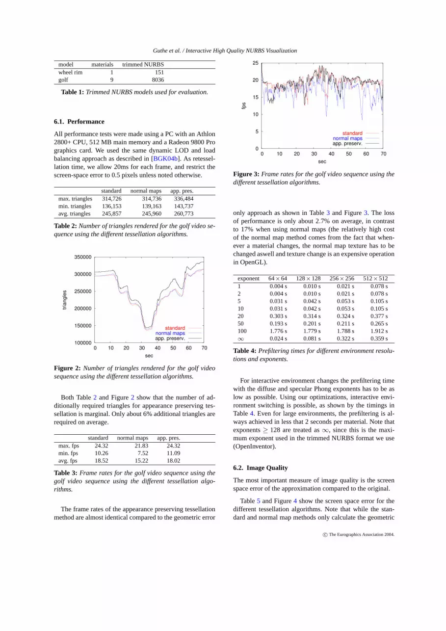
Table 2: Number of triangles rendered for the golf video se-quence using the different tessellation algorithms.
100000
150000
200000
250000
300000
350000
0 10 20 30 40 50 60 70
trian
gles
sec
standardnormal mapsapp. preserv.
Figure 2: Number of triangles rendered for the golf videosequence using the different tessellation algorithms.
Both Table2 and Figure2 show that the number of ad-ditionally required triangles for appearance preserving tes-sellation is marginal. Only about 6% additional triangles arerequired on average.
standard normal maps app. pres.max. fps 24.32 21.83 24.32min. fps 10.26 7.52 11.09avg. fps 18.52 15.22 18.02
Table 3: Frame rates for the golf video sequence using thegolf video sequence using the different tessellation algo-rithms.
The frame rates of the appearance preserving tessellationmethod are almost identical compared to the geometric error
0
5
10
15
20
25
0 10 20 30 40 50 60 70
fps
sec
standardnormal mapsapp. preserv.
Figure 3: Frame rates for the golf video sequence using thedifferent tessellation algorithms.
only approach as shown in Table3 and Figure3. The lossof performance is only about 2.7% on average, in contrastto 17% when using normal maps (the relatively high costof the normal map method comes from the fact that when-ever a material changes, the normal map texture has to bechanged aswell and texture change is an expensive operationin OpenGL).
exponent 64×64 128×128 256×256 512×5121 0.004 s 0.010 s 0.021 s 0.078 s2 0.004 s 0.010 s 0.021 s 0.078 s5 0.031 s 0.042 s 0.053 s 0.105 s10 0.031 s 0.042 s 0.053 s 0.105 s20 0.303 s 0.314 s 0.324 s 0.377 s50 0.193 s 0.201 s 0.211 s 0.265 s100 1.776 s 1.779 s 1.788 s 1.912 s∞ 0.024 s 0.081 s 0.322 s 0.359 s
Table 4: Prefiltering times for different environment resolu-tions and exponents.
For interactive environment changes the prefiltering timewith the diffuse and specular Phong exponents has to be aslow as possible. Using our optimizations, interactive envi-ronment switching is possible, as shown by the timings inTable4. Even for large environments, the prefiltering is al-ways achieved in less that 2 seconds per material. Note thatexponents≥ 128 are treated as∞, since this is the maxi-mum exponent used in the trimmed NURBS format we use(OpenInventor).
6.2. Image Quality
The most important measure of image quality is the screenspace error of the approximation compared to the original.
Table5 and Figure4 show the screen space error for thedifferent tessellation algorithms. Note that while the stan-dard and normal map methods only calculate the geometric
c© The Eurographics Association 2004.

Guthe et al. / Interactive High Quality NURBS Visualization
standard normal maps app. pres.max. error 3.71 3.47 3.67min. error 0.50 0.50 0.50avg. error 1.27 1.06 1.32
Table 5: Screen space error for the golf video sequence us-ing the different tessellation algorithms (for the standard andnormal map algorithms only the geometric error).
0
0.5
1
1.5
2
2.5
3
3.5
4
0 10 20 30 40 50 60 70
pixe
l
sec
standardnormal mapsapp. preserv.
Figure 4: Screen space error for the golf video sequenceusing the different tessellation algorithms (for the standardand normal map algorithms only the geometric error).
error, the screen space error listed for the appearance pre-serving tessellation gives the combined geometric and shad-ing error. Thus even though the average error seems to besomewhat higher for the appearance preserving method (dueto the somewhat larger tessellation and rendering time) inpractice the visual quality of our method is much higher, ascan be seen in Figure10.
In order to compare with the previous normal map basedapproach, we perform a pixel by pixel comparison of the ap-proximated normals with the real normals from the NURBSmodel in a frame. The difference between the real and ap-proximated normals can be extracted using simple imageprocessing as shown in Figure5. It is clearly visible thatthe normal approximation is much better when using the ap-pearance preserving tessellation.
normal maps appearance preservingmax. error 1.22o 1.01o
min. error 0.48o 0.28o
avg. error 0.76o 0.59o
Table 6: Normal approximation error for the golf video se-quence using the different visualization algorithms.
6.3. Surface Properties
In order to present the surface property visualization capabil-ities of our tessellation algorithm, we implemented the visu-
7o
0o
7o
0o
7o
0o
Figure 5: Normal deviation error for a frame of the renderedanimation using geometric approximation without (top) andwith normal maps (middle) and appearance preserving tes-sellation (bottom).
alization of isophotes (Figure6) using the intensity value ofeach pixel after shading to perform a lookup into a stripedone-dimensional texture. As shown on Figure7 our method
Figure 6: Wheel rim model rendered with isophotes (32units).
c© The Eurographics Association 2004.
Guthe et al. / Interactive High Quality NURBS Visualization
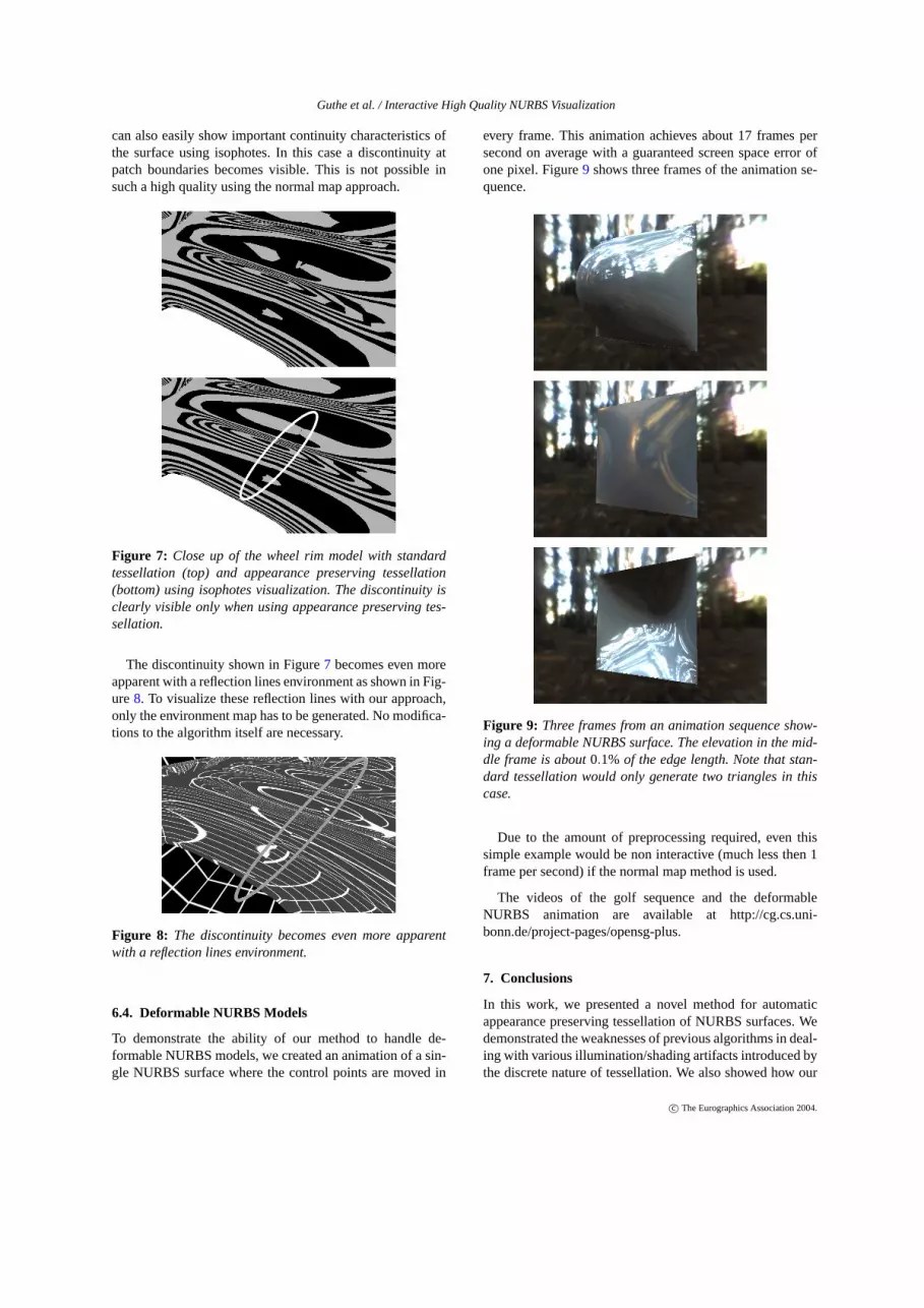
can also easily show important continuity characteristics ofthe surface using isophotes. In this case a discontinuity atpatch boundaries becomes visible. This is not possible insuch a high quality using the normal map approach.
Figure 7: Close up of the wheel rim model with standardtessellation (top) and appearance preserving tessellation(bottom) using isophotes visualization. The discontinuity isclearly visible only when using appearance preserving tes-sellation.
The discontinuity shown in Figure7 becomes even moreapparent with a reflection lines environment as shown in Fig-ure8. To visualize these reflection lines with our approach,only the environment map has to be generated. No modifica-tions to the algorithm itself are necessary.
Figure 8: The discontinuity becomes even more apparentwith a reflection lines environment.
6.4. Deformable NURBS Models
To demonstrate the ability of our method to handle de-formable NURBS models, we created an animation of a sin-gle NURBS surface where the control points are moved in
every frame. This animation achieves about 17 frames persecond on average with a guaranteed screen space error ofone pixel. Figure9 shows three frames of the animation se-quence.
Figure 9: Three frames from an animation sequence show-ing a deformable NURBS surface. The elevation in the mid-dle frame is about0.1% of the edge length. Note that stan-dard tessellation would only generate two triangles in thiscase.
Due to the amount of preprocessing required, even thissimple example would be non interactive (much less then 1frame per second) if the normal map method is used.
The videos of the golf sequence and the deformableNURBS animation are available at http://cg.cs.uni-bonn.de/project-pages/opensg-plus.
7. Conclusions
In this work, we presented a novel method for automaticappearance preserving tessellation of NURBS surfaces. Wedemonstrated the weaknesses of previous algorithms in deal-ing with various illumination/shading artifacts introduced bythe discrete nature of tessellation. We also showed how our
c© The Eurographics Association 2004.

Guthe et al. / Interactive High Quality NURBS Visualization
algorithm only needs a marginal amount of additional tri-angles, achieves nearly the same tessellation and renderingspeed as standard tessellation algorithms, and performs evenbetter than the normal map based methods. Yet it provides amuch higher visualization quality than it was possible withprevious approaches. We also demonstrated the ability of ournew method to visualize surface properties such as continu-ity using isophotes and reflection lines. Since our methodneeds no preprocessing, it is also suitable for the visualiza-tion of deformable models and to have immediate feedbackduring the design and virtual prototyping process.
As future work, we want to exploit the ability of our newalgorithm to visualize various important surface propertieslike temperature distribution or curvature.
Acknowledgements
This work was partially funded by the German Ministryof Education and Research (BMBF) under the project ofOpenSG Plus and by the European Union under the projectof RealReflect (IST-2001-34744).
We would like to thank Volkswagen AG for providing uswith the trimmed NURBS models.
References
[BGK04a] BALÁZS Á., GUTHE M., KLEIN R.: Effi-cient trimmed nurbs tessellation. InJournal ofWSCG(February 2004), vol. 12, pp. 27–33.3
[BGK04b] BALÁZS Á., GUTHE M., KLEIN R.: Fat bor-ders: Gap filling for efficient view-dependentlod rendering. Computers & Graphics 28, 1(2004), 79–86.2, 3, 6
[BSGM02] BAXTER W. V., SUD A., GOVINDARAJU
N. K., MANOCHA D.: Gigawalk: Interactivewalkthrough of complex environments, 2002.2
[BTB02] BALMELLI L., TAUBIN G., BERNADINI F.:Space-optimized texture maps. InComputerGraphics Forum (Eurographics 2002)(2002),vol. 21(3), pp. 411–420.3
[Col01] COLE F.: View dependent appearance preserv-ing simplification. InComputer Graphics Spe-cial Topics)(2001). 2
[COM98] COHEN J., OLANO M., MANOCHA D.:Appearance-preserving simplification. InCom-puter Graphics (Proceedings of SIGGRAPH98) (1998). 2
[EC93a] ELBER G., COHEN E.: Hybrid symbolicand numeric operators as tools for analysisof freeform surfaces. InWorking Conference
on Geometric Modeling in Computer Graph-ics (1993), Falcidieno B., Kurnii T., (Eds.),pp. 275–286.3
[EC93b] ELBER G., COHEN E.: Second-order surfaceanalysis using hybrid symbolic and numeric op-erators. ACM Transactions on Graphics 12, 2(1993), 160–178.3
[FK90] FORSEY D. R., KLASSEN R. V.: An adaptivesubdivision algorithm for crack prevention inthe display of parametric surfaces. InGraphicsInterface ’90(May 1990), Canadian Informa-tion Processing Society, pp. 1–8.2
[FMEP02] FLORIANI L. D., MAGILLO P., EN-RICO PUPPO D. S.: A multi-resolutiontopological representation for non-manifoldmeshes. In7th ACM Symposium on SolidModeling and Applications (Saarbrucken,Germany, 2002).2
[GH97] GARLAND M., HECKBERT P. S.: Surface sim-plification using quadric error metrics.Com-puter Graphics (Proceedings of SIGGRAPH97) 31(1997), 209–216.3
[GH98] GARLAND M., HECKBERT P. S.: Simplifyingsurfaces with color and texture using quadricerror metrics. InIEEE Visualization ’98(1998),pp. 263–270.3
[GK03] GUTHE M., KLEIN R.: Efficient nurbs render-ing using view-dependent lod and normal maps.In Journal of WSCG(February 2003), vol. 11.3
[GMK02] GUTHE M., MESETH J., KLEIN R.: Fastand memory efficient view-dependent trimmednurbs rendering. Inproceedings of PacificGraphics 2002(2002), IEEE Computer Soci-ety, pp. 204–213.2
[HB87] HERZEN B. V., BARR A. H.: Accurate tri-angulations of deformed, intersecting surfaces.In Computer Graphics (Proceedings of SIG-GRAPH 89) (Anaheim, July 1987), vol. 21,pp. 103–110.2
[HHS∗92] HAGEN H., HAHMANN S., SCHREIBER
T., NAKAJIMA Y., WÖRDENWEBER B.,HOLLEMANN -GRUNDSTEDT P.: Surface in-terrogation algorithms. InIEEE Visualizationand Computer Graphics(1992), pp. 53–60.3
[KBK02] KAHLESZ F., BALÁZS Á., KLEIN R.: Mul-tiresolution rendering by sewing trimmedNURBS surfaces. In7th ACM Symposium onSolid Modeling and Applications 2002(Saar-brucken, Germany, June 2002), pp. 281–288.3
[KLS96] KLEIN R., LIEBICH G., STRASSERW.: Mesh
c© The Eurographics Association 2004.
Guthe et al. / Interactive High Quality NURBS Visualization
reduction with error control. InIEEE Visual-ization ’96 (1996), Yagel R., Nielson. G. M.,(Eds.), pp. 311–318.4
[KMZH97] KUMAR S., MANOCHA D., ZHANG H., HOFF
K. E.: Accelerated walkthrough of large splinemodels. In1997 Symposium on Interactive3D Graphics(April 1997), ACM SIGGRAPH,pp. 91–102. ISBN 0-89791-884-3.2
[KSS98] KLEIN R., SCHILLING A. G., STRASSERW.:Illumination dependent refinement of multires-olution meshes. InProceedings of ComputerGraphics International(1998), Wolter F.-E.,Patrikalakis N. M., (Eds.), IEEE Comput. Soc.,pp. 680–687. Conference held in Hannover,Germany, 22–26 June 1998.3
[KSSP01] KUMAR G. V. V. R., SRINIVASAN P., SHAS-TRY K. G., PRAKASH B. G.: Geometry basedtriangulation of multiple trimmed nurbs sur-faces. Computer-Aided Design 33, 6 (May2001), 439–454. ISSN 0010-4485.2
[KSZ∗96] KORZEN M., SCHRIEVER R., ZIENER K.-U.,PAETSCH O., ZUMBUSCH G. W.: Real-time3-D visualization of surface temperature fieldsmeasured by thermocouples on steel structuresin fire engineering. InProceedings of In-ternational Symposium Local Strain and Tem-perature Measurements in Non-Uniform Fieldsat Elevated Temperatures(1996), Ziebs J.,Bressers J., Frenz H., Hayhurst D. R., Klingel-höffer H.„ Forest S., (Eds.), Woodhead Publish-ing, pp. 253–262.3
[LFTG97] LAFORTUNE E. P. F., FOO S.-C., TORRANCE
K. E., GREENBERG D. P.: Non-linear ap-proximation of reflectance functions. InPro-ceedings of the 24th annual conference onComputer graphics and interactive techniques(1997), ACM Press/Addison-Wesley Publish-ing Co., pp. 117–126.5
[NSK90] NISHITA T., SEDERBERGT. W., KAKIMOTO
M.: Ray tracing trimmed rational surface pat-
ches. InComputer Graphics (Proceedings ofSIGGRAPH 90)(Dallas, Texas, August 1990),vol. 24, pp. 337–345. ISBN 0-201-50933-4.2
[RHD89] ROCKWOOD A. P., HEATON K., DAVIS
T.: Real-time rendering of trimmed sur-faces. InComputer Graphics (Proceedings ofSIGGRAPH 89)(Boston, Massachusetts, July1989), vol. 23, pp. 107–116.2
[SC88] SHANTZ M., CHANG S.-L.: Renderingtrimmed nurbs with adaptive forward differ-encing. InComputer Graphics (Proceedingsof SIGGRAPH 88)(Atlanta, Georgia, August1988), vol. 22, pp. 189–198.2
[SGSH02] SANDER P. V., GORTLER S. J., SNYDER J.,HOPPEH.: Signal-specialized parametrization.In 13th Eurographics Workshop on Rendering(2002). 3
[SWB98] SLOAN P.-P. J., WEINSTEIN D. M., BREDER-SON J. D.: Importance driven texture coordi-nate optimization. InComputer Graphics Fo-rum (Eurographics 1998)(1998), Ferreira N.,Göbel M., (Eds.), vol. 17(3), pp. 97–104.2
[TCRS00] TARINI M., CIGNONI P., ROCCHINI C.,SCOPIGNO R.: Real time, accurate, multi-featured rendering of bump mapped surfaces.In Computer Graphics Forum (Eurographics2000) (2000), Gross M., Hopgood F. R. A.,(Eds.), vol. 19(3).2
[TV91] TERZOPOULOSD., VASILESCU M.: Samplingand reconstruction with adaptive meshes. InProceedings of the 1991 IEEE Computer Soci-ety Conference on Computer Vision and PatternRecognition(Lahaina, HI, 1991), pp. 70–75.3
[vW03] VAN WIJK J. J.: Image based flow visualiza-tion for curved surfaces. InIEEE Visualiza-tion (2003), Turk G., van Wijk J.„ MoorheadR., (Eds.), pp. 123–130.3
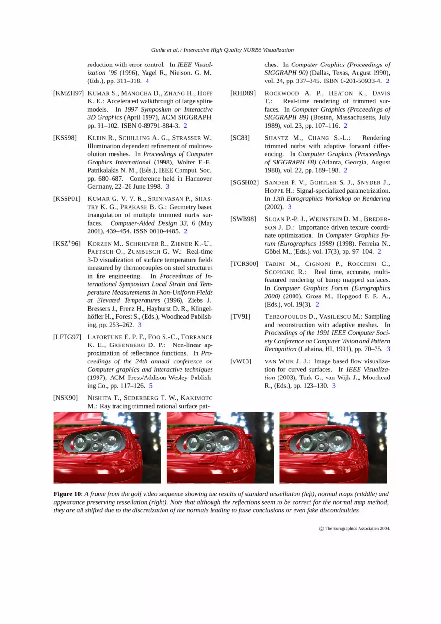
Figure 10: A frame from the golf video sequence showing the results of standard tessellation (left), normal maps (middle) andappearance preserving tessellation (right). Note that although the reflections seem to be correct for the normal map method,they are all shifted due to the discretization of the normals leading to false conclusions or even fake discontinuities.
c© The Eurographics Association 2004.
Related Documents