RA60 605 INTERACTIVE GRAPHICS UTILITY FOR ARMY NEC (NUMERICAL la2 ELECTRONAGNETICS COD.. (U) SYSTEM DEVELOPMENT CORP SAI DIEGO CA J STRAUCH ET AL. SEP 85 NOSC-CR-309 UNCLSSIFIED, N66001-83-D-0094 F/O 9/2 NL

Welcome message from author
This document is posted to help you gain knowledge. Please leave a comment to let me know what you think about it! Share it to your friends and learn new things together.
Transcript

RA60 605 INTERACTIVE GRAPHICS UTILITY FOR ARMY NEC (NUMERICAL la2ELECTRONAGNETICS COD.. (U) SYSTEM DEVELOPMENT CORP SAIDIEGO CA J STRAUCH ET AL. SEP 85 NOSC-CR-309
UNCLSSIFIED, N66001-83-D-0094 F/O 9/2 NL

1.0 ou 0
lul11-,
ILIN
11111.24 1
MICROCOPY RESOLUTION TEST CHARTINATiOI%&L JftIu Oi STif £O&DS-qS3t A
..

'I....
DA 160 605
Contractor Report 308September 1985
l, -. ".°\
INTERACTIVE GRAPHICS UTILITY FORARMY NEC AUTOMATION (IGUANA)User's Guide
J. StrauchS. ThompsonSystem Development Corporation
-:....:
DTIC-W -iLECTE. r11
O OCT 2 5 15
e p
Naval Ocean Systems Center san Diego, California 92152-5000
Approved for public release: The views and conclusions contained indistribution unlimited. this report are those of the authors and
should not be interpreted as representingthe official policies, either expressed orimplied, of the Naval Ocean SystemsCenter or the U.S. Government.
85 10 25 021
* ~ ~~ A- , .

I_
NAVAL OCEAN SYSTEMS CENTER SAN DIEGO. CA 92152
F. M. PESTORIUS, CAPT, USN R.M. HILLYERCommander Technical Director
ADMINISTRATIVE INFORMATION
This document was prepared to explain the capabilities, functions, andoperation of IGUANA. The work was done under the direction of Code 822,J. C. Logan for the Naval Ocean Systems Center.
Released by Under authority of
I. C. Olson, Head G. E. Ereckson, Head
Antenna and RF Systems Shipboard SystemsIntegration Branch Division
JJ
-/. - *---. .- '- 4.* * ******4** *7 .-. \ ; 7% : ,".y ". .; " *A .. ',, - T .' q >-, --- '

t;N([AS'~lf IISECURITY CLASSOICATIOE Or VMM5 AGE
REPORT DOCUMENTATION PAGEa REPORT SCLW'V CLASSIFIATINIII
MFVE"UNCLASSIFIlED A 9 d24 SECURITY CLASSIFICATIONE AUJTHORITY 3 OiSTRIBUT"O,AVAILABIUY OF REPORT
2b DECLSS CATION DOWNGRADING SCHEDULE
Approved for public release;distribution unlimited.4 PERFORMING ORGAN4IZATION REPORT NUMUERISI 5 MONITORING ORGANIZATION REPORT NUMBER(S)
NOSC CR 308GoS NAME Of PERFORMING ORGANIZATION4 T b OFFICE SYMIIOL 76 NAME OF MONIITORINIG ORGANIZATION
System Development Corporation jNaval Ocean Systems Center6C ADDRESS IC4V Stw. od ZIP Codoo 7b ADDRESS (C~y. SW.lo old ZIP Cod.Il
4065 Ilan, otk Street Code 822San Dieszo.CA 9 2110 San Diego, CA 9 215 2-5000
Be NAME Of Fu%34NG SPONSORING ORGANIZATION T b OFFICE SYMBOL. S PROCUREMENT INSTRUMENT IDEFETIFICAToR NUMBER
Space and Naval Warfare Systems Command 614 N66001U83-D0094Sc ADDRESS Cry Sfere end ZIP Code) 10 SOURCE OF FUNDIFNG NUMBERS
PROGRAM ELEMENT No PROJECT NO TAM NO AgencyAccession
Washington, D.C. 20363-5100 62543N CM41 DNO88509I I TITLE ,,nhm.* Seo Cleawxft ,j
INTERACTIVE GRAPHICS UTrILITY I OR ARMY NEC AUTOMATION dGUANA)User's Guide
12 PERSONAL AUThORISI
J. Strauth and S. Thompson* I32 TYPE OF REPORT 1 3b TiME COVERED 14 DATE OF REPORT (Vow.Nof Mrw ~ 5I PAGE COUNT
Final FROM ..Mm.LL= to..~ September 1985 130* is SUPPL.EMENTARY NOTATION
I I COSATI CODES IS SUBJECT TERMS (C".we Iowa 0ees d nwxY ed dON*~ BY SMAO wibwle
FIELD GROUP SUB GROUP Numerical Electromagnetics Code (NEC)I SubdectsI I DOS
lBABSTRACTC ".ee,,y~e4,eeJ ,se ,.W
The Interactive Graphics Utility for Armny NEC Automation (IGUANA) is a system designed to reduce the time required forantenna model evaluation by providing partial automation to both the data entry and the data display processes.
20 DISTRIBUTION AVAKALIuITY OF A$STR(@CT 2' ABSTRACT ffCUR ffCLASIPICATIOFI
Q UNICLASSIED UN4UMTED ShAME AS WP DT1C USERS UNCLASSIFIED2 2A NAME OF RESPONISIBLE INDIVIDUAL 22b TELEPHONIE "'A,**~ Cooe, 2 2c OFFICE SYMBOL
J.C. Logan (619) 225-2646 Code 822
DO FORM 1473. 84 JAN 93 AM EDITION MAYBI SEDUNTIL fXAUSED CL SIlDSECURlv CLAI~sc"TOF OF TIS PAGE
%%

TI 1 ._a ITABLE OF CONTENTS
SL.CTION 1. INTRODUCTION. .. .. .... .... ... ....... 1-1
I1.1 General . . . .. .. .. .. .. .. .. .. .. .. 1-1I1.1.1 Background. .. .. .... ... .... .. . . 1-1
1.1.2 System Limitations . . . . . . . . . .. .. .. .. 1-111.2 System Summary . . . . . . . . . . . . .. .. .. .. 1-2
1.3 System Functions .. .. . .... . ... ....... 1-3
I1.3.1 Function 1 - CARD EDITOR. .. .. . ... ...... 1-41.3.2 Function 2 - MODEL MAKER. .. .. .... ...... 1-5* (1.3.3 Function 3 - SET DEFAULT VALUES . . .. .. .. .. 1-6
1.3.4 Function 4 - CROSSTALK - Transfer Files to/from
AnorrComputer................ 1-6
1.3.5 Function 5 - Plot Utilities . . . . . . . . . . 1-7
I1.3.6 Function 6 - Auxiliary Programs . . . . . . . . . 1-7
I1.3.7 Function 7 - EXIT TO DOS . . . . . . . . . . . . . 1-7
I SECTION 2. DEFINITIONS AND APPLICABLE DOCUMENTS. .. . .. . . . 2-12.1 System Terminology and Definitions . . . . . . . . . 2-1
12.2 Applicable Documents . . . . . . . . . . . . . . . . 2-3
SECTION 3. SYSTEM REQUIREMENTS AND START-UP . . . . . . . . . . o 3-1
13.2 Equipment Requirements . . o . . . . . . o o . . . . 3-1I3.3 System Start-Up . o . . . . . . . o . . . . o . . . 3-2
* I SECTION 4. INFORMATION ENTRY AND FUNCTION KEY USE. .. . .. . . 4-1
4.2 Data Entry Information . . . o . . . . . . . . . . . 4-1
4.2.1 VDT Keyboard Input . . . . . . . . . . . . . . . . 4-1
4.2.2 Digitizer Input . . . . .. .. . 4-3
4.2.3 Mouse Input ..... .. .. . . . . . . 4-6
4.3 Function Key Use. . . . . . . . . . . . . . . . 4-7
SECTION 5. SYSTEM OPERATION... . . . . . . .. . . .5-1
5.2 Presentation. . . . . . . . . . . . . . . . . . 5-1

* TABLE OF CONTENTS (cont.)
Page
5.3 Functional Description and Operating Procedures . 5-1
5.3.1 CARD EDITOR Function . . . . . . . . . . .. .. .. 5-1
5.3.1.1 Option 1 - CREATE NEW NEC INPUT DECK . . . . . . 5-6
5.3.1.1.1 Creating Commient Cards. . . . . . . . . . . 5-85.3.1.1.2 Creating Geometry Cards (Prompted Mode) . .. 5-105.3.1.1.3 Creating Program Control Cards (Prompted Mode) 5-135.3.1.1.4 Creating Geometry/Program Control Cards
(Nonprompted Mode). . . . . . . . . . . . 5-15
5.3.1.2 Option 2 - EDIT EXISTING DECK. . . . . . . . 5-16
5.3.1.3 Option 3 - COPY and RENAMWE EXISTING DECK . . .. 5-21
5.3.1.4 Option 4 - DISPLAY EXISTING DECK .. .. ..... 5-235.3.1.5 Option 5 - DELETE EXISTING DECK. . . . . . . 5-25
5.3.1.6 Option 6 - NEC INPUT DECK MAINTENANCE . . . .. 5-27
5.3.1.6.1 Formatting a Deck for Input to NEC.. . . . . 5-275.3.1.6.2 Displaying/Printing a NEC Input Deck . . . .. 5-295.3.1.6.3 Deleting a Formatted Deck. . . . . . . . . 5-30
5.3.1.6.4 Appending to a Formatted Deck. . . . . . . 5-31
5.3.1.6.5 Editing a Formatted Deck. . . . . . . . . . 5-34
5.3.1.6.6 Preparing a Deck for Transmission.. . . . . 5-345.3.1.6.7 Deleting a Transmit Deck. . . . . . . . . . 5-36
5.3.1.6.8 Translating a File from Another Source . . .. 5-375.3.1.7 Option 7 - DISPLAY DECK FILE STATUS.. . . . . 5-38
5.3.1.8 Option 8 - DISPLAY/UPDATE NEC HOST TABLE . . .. 5-405.3.1.9 Option 9 - ARCHIVE/RESTORE DECKS. . . . . . . 5-42
5.3.1.9.1 Writing Deck(s) to a Floppy Disk (Archiving) . 5-43
5.3.1.9.2 Restoring Deck(s) to the Fixed Disk.. . . . . 5-45
5.3.2 MODEL MAKER Function. . . . . . . . . . . . . . 5-46
5.3.2.1 Option 1 - ENTER NEW MODEL .. . . . . . . . . 5-47
5.3.2.1.1 Enter Structure Data. . . . . . . . . . . . 5-49
5.3.2.1.2 Enter Tower Data. . . . . . . . . . . . . . 5-57
5.3.2.1.3 Enter Pole Data. . . . . . . . . . . . . . 5-59
5.3.2.2 Option 2 - WORK WITH OLD MODELS. . . . . . . 5-61
5.3.2.2.1 2-VIEW File Operations .. . . . . . . . . . 5-63
5.3.2.2.2 SECTIONS File Operations. . . . . . . . . . 5-67
5.3.2.2.3 3-D SECT NO EDIT File Operations. . . . . . 5-69
5.3.2.2.4 3-D SECT EDITED File Operations. . . . . . 5-72

TABLE OF CONTENTS (cont.)
Page5.3.2.2.5 MODEL File Operations ............ 5-73
5.3.2.3 Option 3 - BUILD MODEL FROM GEOMETRY CARDS . . . 5-85
5.3.2.4 Option 4 - ARCHIVE/RESTORE MODELS ....... 5-86
5.3.2.4.1 Writing Model(s) to a Floppy Disk (Archiving). 5-86
5.3.2.4.2 Restoring Model(s) to the Fixed Disk . . . . 5-87
5.3.3 SET DEFAULT VALUES Function ........... . 5-87
5.3.4 CROSSTALK - Transfer Files to/from AnotherIComputer . . . . . . . . . ............ 5-91
5.3.5 Plot Utilities . . . . . . . . . . . . . . . . .. 5-94
5.3.6 Auxiliary Programs . ............... .5-95
5.3.7 EXIT TO DOS . . . . . . . . . ........ . . . 5-96
APPENDIX A CROSSTALK COMMAND AND SCRIPT FILES . . . . . . . . . . A-1
APPENDIX B SYSTEM INSTALLATION GUIDE....... . . . . . . . . B-1" I
ACccsjcn
,= I
.1 : .r -
I C T,":.- !+ L.'a" :U'" I J; I "( "k4

TABLE OF CONTENTS (cont.)
LIST OF FIGURES* Figure Page
3-1 Power and Peripherals Connections. .. ..... ...... 3-3
* 5-1 Master Menu . . . . . . . . . . . .. .. .. . .. . . . 5-2
* 5-2 Sub decksaandFilenames.................. 5-3
5-3 CARD EDITOR Option Menu . . . . . . . . .. .. .. .. .. 5-7
5-4 Create Commnent Cards: First-Level Edit Function KeyDisplay. .. ..... ..... ...... ........ 5-9
* 5-5 Create Geometry Cards (Prompted Mode) .. .... ...... 5-11
5-6 Create Program Control Cards (Prompted Mode). .. ..... 5-145-7 Edit Existing Deck: First-Level Edit Function Key
Display. .. .... . .. .. .. .. .. .. ... .. 5-18
5-8 Edit Existing Deck: Second-Level Edit Function Key
5-9 Appending Structures for NEC Input . . . .. .. .. . .. 5-33
5-1 File Status Display Printout............ 53
5-11 Hidden and End-On Wires ................. 5-515-12 Section Boundaries .. .. .. .. .. ..... . . . . 5-51
5-13 Drawing Placement for Tower Input . .. .. .. .. .. .. 5-58
- 5-14 Sample End View Generation Problem . .. .. .. .. .. .. 5-64
* -5 Rotation Control ........ . . . . . . 57* 5-16 Adding Wires to a Structure . . ....... . . . . . 5-79
5-17 Digitizer Tolerance Illustration ....... . . . . . 5-91
- A-1 Sample Commtand File . . . . . . ....... . . . . . A-3
* A-2 Sample Script File . . . . . . . ....... . . . . . A-6
iv

SECTION 1. INTRODUCTION
1.1 General
1.1.1 Background. The Interactive Graphics Utility for Army NEC Automation
(IGUANA) is a system designed to reduce the time required for antenna model
evaluation by providing partial automation to both the data entry and the data
display processes.
Previous to this system, the use of existing Numerical Electromagnetics Code
(NEC) for antenna evaluation required a lengthy, tedious and error-prone
process involving manual measurement of three-dimensional coordinates of each
significant point of the desired input structure from scale drawings (generally
only Top and Side Views are available), and manual entry via keyboard. The* input structures are in the form of "wire' models. The NEC code requires that
* each wire be entered individually with both end points, radius and segmenta-
tion. Complex models often required several weeks of effort to correct
measurement and keyboard errors.
IGUANA is provided as an aid to NEC input preparation and output display - it
performs no antenna evaluations itself. Therefore, this User's Guide must be
used in conjunction with NOSC TD 116 Vols 1-3 (Numerical Electromagnetics Code
(NEC) - Method of Moments), which descri e the use of the various Comment,
Geometry, and Program Control data sets. 2 This User's Guide has been prepared
to explain the capabilities, functions, and operation of IGUANA.
1.1.2 System Limitations. Version 2 of the IGUANA system is designed to aid
in the preparation and display of data sets used as input to the NEC - Method
of Moments code currently running on the NOSC Code 81 VAX as NEC3.
IGUANA is a compcsite of independently developed subsystems, some of which are
individually copyrighted and do not fall under public domain. CROSSTALK has
been copyrighted by MICROSTUF, Inc. and is licensed for use on a single com-
puter. Problems and/or errors encountered while using CROSSTALK cannot be
addressed by the NOSC IGUANA development team.
Si.
-. , " o' ..-_'. '.rg " ". ",° - '. -' - '. . '. " , '4 ',', .. "° ' - ." " "° " - " " " . " b° . -° " " .' -1-1 " " .
i V" - - -. ,- , ,-,- , '.,. - ,. - ., ; -,, ,. , . .. ',-.- . .- .,.•: ..- ., .. ,.... . S .:' *.. . -,--

1.2 System Summnary. The purpose of IGUANA is to aid the NEC user in the
* preparation of data sets for input to NEC and to provide a capability for
displaying NEC output. The IGUANA data input procedures consist of the
following:
a. Creation of a three-dimensional model
1. Structure definition - user input via digitizer of Top and Side
Views of a structure
2. Program editing of input data for consistency
3. User definition of sections along the long axis of the structure
4. User edit, via mouse, of tentative End Views of each section of
the structure
5. Program generation of a three-dimensional structure for each sec-
tion and combination of all sections into a completed structure
6. Displays of the entire structure with the capability of rotationof the entire structure and magnification of selected portions(zooming)
7. User removal, via mouse, of undesired points and wires8. User addition, via mouse, of desired wires
b. Generation of a set of wire cards representing the three-dimensionalmodel1. Use of user-defined default values for wire radius, segmentation
ratio and automatic wire-tagging (if desired)2. Generation of a card describing the three coordinates of each of
the two endpoints for each wire in the three-dimensional struc-ture; use of the default values to complete the required infor-mati on on each of the wi re cards
3. Saving of the wire cards in a user-named Geometry data set(Geometry subdeck)
c. User entry and maintenance of other required NEC input information1. Creation of Conment data sets (subdecks)2. Creation of Program Control data sets (subdecks)
3. Stand-alone creation of Geometry data sets (subdecks)4. Editing, printing and deletion (upon user request) of any existing
Comment, Geometry, or Program Control subdecks5. Formatting (combining) of Comment, Geometry, and Program Control
subdecks in preparation for input to NEC
1-2

.t . . . . L p
6. Translation of data sets to a sequential file for transmission to
NEC host
d. Transmission of formatted data sets to NEC host
e. Capture and display of NEC output
f. MININEC (Mini-Numerical Electromagnetics Code) - a method of moments
code for the analysis of thin wire antennas
The user is guided in the use of the system functions by way of interactive
lialogues and menus presented via CRT display. All system functions can be
accessed by following the input prompts displayed on the screen.
1.3 System Functions. The system consists of these primary functions:
a. CARD EDITOR - Aids user in creation, editing, deletion, printing, for-
matting and transmission of NEC input decks.
b. MODEL MAKER - Used to generate/edit/display a three-dimensional model
and produce a deck of wire cards.
c. SET DEFAULT VALUES - Allows user to specify default values to be used
when generating wire cards; these include wire radius, segmentation
ratio, starting tag number, tag increment (for automatic wire tagging,
if desired) and digitizer tolerance value.
d. CROSSTALK - Transfers Files to/from another computer - Allows user
selection of computer and enables automatic dial-up, log-on and file
transfers to or from the selected computer.
e. Plot Utilities - Displays/plots NEC input data sets/NEC run results.
f. Auxiliary Programs - Allows user access to MININEC and any miscel-
laneous programs from a sub-menu. By adding to this sub-menu, the
user can provide for easy access to any programs of his own. MININEC
provides a method of moments computer code for the analysis of thin
wire antennas to solve for impedance and current on arbitrarily
oriented wires.
g. EXIT TO DOS - Provides a means for the user to return to the DOS level
to perform functions not provided by the system.
Menus are organized in levels - the seven primary functional areas described
above being the highest level, the Master Menu. When the operator selects a
function from the Master Menu, an appropriate Option Menu (second level) is
1-3

* presented on the screen. Some options are further broken down dnd Sub-Option
Menus are displayed for user selection. The function, option, and Sub-option
* selections provided by the system are described in the following paragraphs.
* 1.3.1 Function 1 - CARD EDITOR
Option 1 - CREATE NEW NEC INPUT DECK
Sub-Option 1 - COM*MENT CARDS
2 - GEOMETRY CARDS
3 - PROGRAM CONTROL CARDS
Option 2 - EDIT EXISTING DECK
Sub-Option 1 - COMMENT CARDS
2 - GEOMETRY CARDS
3 - PROGRAM CONTROL CARDS
Option 3 - COPY and RENAME EXISTING DECK
Sub-Option 1 - COMMENT CARDS
2 - GEOMETRY CARDS
3 - PROGRAM CONTROL CARDS
Option 4 - DISPLAY EXISTING DECK
Sub-Option 1 - COMMENT CARDS
2 - GEOMETRY CARDS
3 - PROGRAM CONTROL CARDS
4 - ALL of the above
Option 5 - DELETE EXISTING DECK
Sub-Option 1 -COMMENT CARDS
2 -GEOMETRY CARDS
3 -PROGRAM CONTROL CARDS
4 -ALL of the above
Option 6 -NEC INPUT DECK MAINTENANCE
Sub-Option 1 - FORMAT DECK FOR NEC INPUT
7 2 - DISPLAY FORMATTED DECK
1-4
_'.ex: 2el

3 - DELETE FORMATTED DECK
4 - APPEND TO FORMATTED DECK
5 - EDIT FORMATTED DECK
6 - PREPARE DECK FOR TRANSMISSION
7 - DELETE TRANSMIT DECK (Sequential File)
8 - TRANSLATE FILE FROM OTHER SOURCE (Sequential File to
Formatted Deck)
Option 7 - DISPLAY DECK FILE STATUS
Option 8 - DISPLAY/UPDATE NEC HOST TABLE
Option 9 - ARCHIVE/RESTORE DECKS
1.3.2 Function 2 - MODEL MAKER. The MODEL MAKER function does not lend itself
* to hierarchical menu displays like the CARD EDITOR function. There are four
primary options:
1 - ENTER NEW MODEL
2 - WORK WITH OLD MODEL
3 - BUILD MODEL FROM GEOMETRY CARDS
4 - ARCHIVE/RESTORE MODELS
Option 1 (ENTER NEW MODEL) guides the user through the creation of Towers,
Poles, or Structures (defined in Section 5.3.2) in order to generate three-
dimensional figures and corresponding wire cards to be saved in a Geometry
subdeck.
During model creation, a series of data files is generated for Top and Side
Views, section data, edited and unedited three-dimensional section data, and
three-dimensional model data.
Option 2 (WORK WITH OLD MODEL) allows the user to display, plot and edit the
data saved in the various model data files.
Option 3 (BUILD MODEL FROM GEOMETRY CARDS) allows the user to create a three-
dimensional model from a NEC data set of Geometry Cards.
1-5
. . *

Option 4 (ARCHIVE/RESTORE MODELS) allows the user to selectively save models on
"- a floppy disk and restore previously saved models onto the system disk.
", 1.3.3 Function 3 - SET DEFAULT VALUES
a. Wire Radius - The wire radius set in the default table is used by the
system when generating the wire cards from the three-dimensional wire
structure and when creating Geometry Cards in the manual (stand-alone)
mode.
b. Segments per Meter - The segments per meter default value set in the
default table is used by the system when generating the wire cards
from the three-dimensional wire structure and when creating Geometry
Cards.
c. Tag Start and Tag Increment - Tag start and tag increment are used for
automatic tagging when generating the wire cards from the three-
dimensional wire structure and when creating Geometry Cards in the
manual (stand-alone) mode.
d. Units used in Original Drawing - Toggles between METERS, FEET, and
INCHES to define the digitizer input of the original drawing. The
system always uses meters for all further processing.
e. Point Entry Tolerance in Digitizer Units - The digitizer tolerance
sets the limits within which digitizer entries are identified as a
point. Larger tolerances allow less precise input; however, discrim-
ination between two points is reduced.
f. Digitizer Available - Toggles between YES and NO to set availability
status of digitizer.
g. Plotter Speed/Available - Toggles between SLOW, FAST, and NO to set
the availability status/speed of the plotter. SLOW speed is best for
transparencies and for use with worn pens.
h. Installation (Label for Plots) - The user may specify the label to be
printed on plotter output.
1.3.4 Function 4 - CROSSTALK - Transfer Files to/from Another Computer. This
function allows the user to select from a user-maintained list of mainframe
computers and associated CROSSTALK Command and Script files and invokes
CROSSTALK (a smart terminal and file transfer program) with the selected
Command file name. Command and Script files can be created to automate
computer dial-up, log-on, and file transfer procedures (refer to Appendix A).
1-6

N N -7r . 7- V7 -- 77- 4- 0
Function 4 has no option or sub-option menus. CROSSTALK menus, functions, and
operating procedures are described in the CROSSTALK-XVI documentation (refer to
* Section 2.2).
*d 1.3.5 Function 5 - Plot Utilities. Plot Utilities are included with IGUANA to
plot NEC input and run results.
1.3.6 Function 6 - Auxiliary Programs. A sub-menu has been created which
*i allows access to MININEC, miscellaneous programs, and any programs the user
- might want to add for the convenience of easy access. MININEC is a method of
* moments computer code used for the analysis of thin wire antennas to solve for
impedance and currents on arbitrarily oriented wires, including configurations
with multiple wire junctions. MININEC operating procedures are documented
under separate cover (refer to Section 2.2).
Included with the Auxiliary Programs are a MININEC Pre-Processor to process theGeometry Cards of a NEC Input Data Set through MININEC, a MININEC Post-
*" Processor to interface the MININEC output with the Plot Utilities, and an
Antenna Network Matching Program which produces Smith Charts.
1.3.7 Function 7 - EXIT TO DOS. This function provides a means for the user
to exit cleanly from the IGUANA system to the DOS level to perform functions
not available through IGUANA. There are no menus associated with this function
and all DOS commands and functions are described in the DOS manual provided
with the user's computer.
1-7
K - .*% ~ ~ ~ % %~. . , * . * . . . '

-I-7- 7 -2
SECTIUN 2. DEFINITIONS AND APPLICABLE DOCUMENTS
2.1 System Terminology and Definitions
< > - Anything between these brackets refers to a key on the keyboard;
for example, <End> and <Esc>.
<? > -The HELP key; used to request help on input for some system func-
tions (not yet totally implemented).
<Alt> -The ALTERNATE key; not currently used.
<Caps Lock> -This key is automatically toggled ON when first starting up, to
ensure that all user input is entered in upper case only. Mostsystem processes translate and echo lower case characters as
upper case (a notable exception is the CARD EDITOR's Option 2
Edit Deck).
* <Ctrl> -The CONTROL key; not currently used.
<Esc> - The ABORT key; when pressed, the current process is halted andprocessing resumes at a previous menu level. Generally, input
and calculations are lost.
<Num Lock> -Many system functions use the cursor control (arrow) keys which
are active only when <Num Lock> is OFF. When the system is first
booted or reset, <Num Lock> is OFF.
* <RETURN> -The <-J. > or ENTER key -also referred to in this document as
<CR>.
cards!/ Refers to a single string of data to be sent to the NEC program.
card image Each string starts with a two-character card code and severaldata items defining the data to be processed, or how that data isto be processed by the NEC program. Card types are Conmment,
Geometry, and Program Control Cards.
2-1

Command file - Special purpose file used by CROSSTALK to set communica-
tions parameters for a particular mainframe computer (see
Appendix A).
CROSSTALK A stand-alone smart terminal and file transfer package
incorporated into IGUANA to provide a computer-to-computer
communications capability.
*deck/subdeck - A subdeck is a NEC data set, consisting of one or more
card images each with a card code as its first two
characters. The user specifies a name for a subdeck
(DECKX, for example) and specifies the card type to be
created for CARD EDITOR Option 1. A Comment subdeck, a
Geometry subdeck, and a Program Control subdeck can be
created with the same deck name. (These subdecks are
actually saved in separate files on the disk.) If all
three subdeck types exist for a given name, the cards
comprising these can be combined into a single deck ready
for NEC input via CARD EDITOR Option 6.1.
Function Keys - Also referred to as FKs and <Fn> where n is a number from
i to 10. These are the ten keys on the left side of the
keyboard. The FKs have different meanings depending on
the function being performed.
Message Scroll Key - The Down Arrow <1 > can be used when in Create Geometry
Cards (Option 1.2) and Create Program Control Cards
(Option 1.3) to display all available prompt aids and
messages for the current data item on line 24 of the
screen.
Script file - A special-purpose file used by CROSSTALK which can provide
automatic log-on and file transfers (see Appendix A).
. wire - The lines connecting points in the MODEL MAKER files are
called wires. All models are constructed of wires in this
version of IGUANA.
2-2
"... .-'.-..- .- . ... .- . ..- -..- .-.. ..-..- .- .. .,- - .- .- ...,.- .- ,. .." - .. -,- " , -... . . ...--.-..-'.... .".. .... . . . ... ..-. .-...-....-.. . .... . . . . . . ;.

' wire card - A Geometry Card beginning with the two-character cdrd code'GW'. These are the only cards generated by the MODEL
MAKER function, Generate Geometry Cards.
.- 2.2 Applicable Documents. The following documents are required reading for
the understanding and the operation of IGUANA. Additionally, all documentation
provided with the purchase of the user's computer should be kept on hand
for reference.
CROSSTALK-XVI Data Communications Software System; MICROSTUF, Inc., 1983
*INTERACTIVE GRAPHICS UTILITY for ARMY NEC AUTOMATION (IGUANA) Computer Program
Package Document; Naval Ocean Systems Center, San Diego, California 92152,
" 19 October 1984
MININEC: A Mini-Numerical Electromagnetics Code;* NOSC TD 516,
6 September 1982
NUMERICAL ELECTROMAGNETICS CODE (NEC) - METHOD OF MOMENTS; NOSC TD 116,
Volumes I and 2, January 1981
NOTE: The installation instructions provided with CROSSTALK can be ignored;
installation of this package is performed during IGUANA installation.
*This document will be superseded at a later date with an updated manual for
MININEC.
2-3
*>."i. > '.-1....-;. . i- .-. ..- .- -'- .. . ...- i.-.. .. *- .....,,,, ,*_,- . .. ',..,* * *,, , * .-" " ' .. '*.. .-. '....-, * ""-.';.'o .. . "'':- '-- . -., . ..-- *.,. ..-.-:. --- *'.'. . _ -. .. .

* SECTION 3. SYSTEM REQUIREMENTS AND START-UP
3.1 General. Section 3 provides an overview of the equipment requirements and
start-up procedures for IGUANA. Only the equipment required for the operation
of the IGUANA functions is described in this document. NEC antenna evaluation
is performed on a mainframe computer not considered a part of IGUANA.
3.2 Equipment Requirements
Item Part ID
*Leading Edge PC-XT, 128K, lOMB MP-1676 L
Hard Disk, 360KB Diskette
*Leading Edge Color Monitor II AT-1332AL
Leading Edge MS-DOS 2.11 and BASICA 2.11 LEPC DA
Intel 8087 Numeric Data Processor
Inmac Switch 112
*Prometheus ProModem 1200
Microstuff Crosstalk-XVI
AST Megaplus Board with
Printer Port, 512K Megapak
Microsoft Mouse
Science Accessories Corp Digitizer GRAFBAR GP-7
*Hewlett-Packard ThinkJet Printer HP 2225C
Hewlett-Packard Graphics Plotter HP 7470A
* or equivalent
3-1
, .%* . . .5 . % -t*~* S~'* -.. *f
*,. . .b%~**%I , .- ",". "-'.' '. '" "-.' ' -' " ' ".'" .' '-''..-'.."". ," ' " % .'" :...'. .? .-. :"" ?'"-':.,? "-: ." ". " . "-"A " .' -",

Item Part ID
Miscellaneous Supplies:
Printer Ribbons, Cables, Paper,
Plotter Pen Tips, etc.
Figure 3-1 shows the peripheral connections to the ports on the CPU chassis.
3.3 System Start-Up. Start-up procedures for IGUANA from an initial OFF con-
dition are performed as follows:
a. Switch the ON/OFF (toggle) switch on the computer to the ON position
b. Switch the ON/OFF (toggle) switch on the plotter to the ON position.
c. Switch the ON/OFF (toggle) switch on the printer to the ON position.
d. Ensure that the printer ONLINE indicator light is ON.
e. Switch the ON/OFF (toggle) switch on the digitizer to the ON position.
f. The Master Menu is displayed, ready for user selection.
g. Select Function 3 (SET DEFAULT VALUES) and enter the applicable values
(see Section 5.3.3).
.3-
,_ 3-2
-.......'. -.. ..". .. ".. " ".'.'-.-." ..--. ' .- .,---". ."." . . .• . I....... . . - .- -, . - - , .--.. . -, ,

.lo
*~~~~(
S. % . b b-.
oA o 0.u 0. 4
L_ a,.
Q) 4)
S : 0 J • -
0.........-
c "a 0t
eo S. 4-1
W L u.J L " ..,-
-0 c c0 W- to
- 1 . . . . . . 1 " o o 0= .3
-o in
1 4 =oi= S JL o CC 4
04 ~ i
0
SC< _ _ 0 = 0c4. - 0 w,
"S ". c .
owA L 41 w 4A (
0 - z a V -Zo
4 -- U 0.0' 0
-- 4
-,- .9
09 w
- .~ * -,~~. CC0. U to 4-
• ..- . - 0 0 o u u 0 1 0 ' A
S.- w 01- C= .,--
r.~~ "L r_-- to 4- 4j_ = ,, ' -
l, 04
-u . o
' ~ ~ ~~ ~~ = - ,=' - ., -3 - 0 ',0 u',, 41 w" 41 4
c= 3-a3 L
W = u I:: :,< 41_. cC j

* SECTION 4. INFORMATION ENTRY AND FUNCTION KEY USE
* 4.1 General. This section provides users with the basics of data entry pro-
cedures and unique aspects of the system's functional capabilities. Included* are explanations of data entry techniques and function key use.
4.2 Data Entry Information. There are, in IGUANA, three input devices:
a. VDT keyboard - main input device
b. Digitizer - for Top and Side View input and edit
c. Mouse - for input editing and three-dimensional editing
Each of these input devices is used to enter data into the system. The user is
informed (via the CRT and this manual) which input device is active at any
given time.
4.2.1 VDT Keyboard Input. Operator input via the keyboard is requested in one
* of three ways:
a. A menu of function, option, or sub-option choices is displayed on thescreen and the user is prompted (by way of a message on the CRT) topress the function key corresponding to the task to be performed.
b. A numbered list of available/acceptable input items is displayed (on
one or more screen pages) and the user is instructed to enter thenumber corresponding to the item desired; for example, when selecting
a data set (deck) name from a list of valid deck names.
c. Data required in the creation of data sets, such as names for the
subdecks, card codes, and items required to complete NEC input infor-
mation, and other technical data are requested using a dialogue
format. The required information is requested via a message (ormessages) on the CRT which may include examples of acceptable input,valid range information, and/or maximum number of characters allowedin the entry. The user types the requested information following the
guidelines provided in the prompt. If more instructions are needed,
the HELP key <?> is available.
All operator entries are made by typing them at the VDT keyboard. To the
system (except when using the editor) an upper case and lower case alpha
character are both interpreted (and echoed) as upper case.
4-1

Generally, there are four input types accepted as valid responses to system
prompts (not including function key use, described later):
a. The requested information - This user input is validated for format
and range (if applicable) and, if valid, is accepted and used in or
used to direct subsequent processing.
b. The HELP key <?> - The user can press the question mark key whenever
an operator input prompt is displayed on the screen. A message is
displayed clarifying the input requirement and/or specifying allowedvalue ranges.
c. The ABORT key <Esc> - The Escape key is used to stop the current
system process and to return to a previous menu level. Generally,
none of the data input and/or calculated for the aborted function can
be recovered.
d. The Message Scroll key < J> - During Geometry and Program Control Card
entry, the Down Arrow key can be used to display all messages avail-
able for the given data item.
Input type (a.) above must always be ended by pressing the <Return> or <End>
key. This completes the user entry and indicates to the system that the entry
is read. for validation. In almost all cases, <Return> and <End> function
identically; where they are different is noted in this user's guide. (<Return>
may also be referred to as <CR>.)
In some cases, <Return>, alone, is accepted as valid input and can mean:
a. Use the displayed value as the default input value.
b. Done with sub-option or option - return to previous menu level.
c. An edit function has been completed - continue processing (see Option
1, Sub-Option 1 and Option 2, Sub-Options 1 through 3 for examples).
d. Display a list of file names (decks or models) for name entry or
selection.
These uses of the <Return> key are explained in the user's input prompts and in
the appropriate paragraphs in Section 5 of this manual - the user will always
be informed when the <Return> key, alone, is a valid input, and what the use of
it means to the system for the given situation.
4-2

4.2.2 Digitizer Input. The digitizer is employed by the MODEL M'AKER function
to enter the points which define the wires of a structure. All digitizer input
is in digitizer units (0.01 centimeter). Before using the digitizer as the
input device, a Setup procedure must be performed by the user. The following
describes the Setup procedure (the user receives prompts to direct Setup for
all but step a., below):
IMPORTANT: Before using the digitizer, the user must be sure the digitizer!modemn switch is set in the digitizer position. Sometimes, after
this switch is first set, the digitizer is not immediately initial-ized. The user is prompted to re-enter the point in such an event.
Once that point has been processed by the digitizer, that devicehas been initialized and all other inputs are processed normally.
a. Prepare Drawing
1. Draw an X and Y axis such thadt the origin (0,0) of this coordinate
system is at the lower left of the drawing and the drawing fitsinto the positive quadrant defined by the axes. The X axis must
be parallel to the horizontal axis of the drawing. The bigger the
axes, the better accuracy you will get.
2. If the drawing being used is too large for digitizer input, itwill need to be broken up (by the user) into several smaller
drawings, each of which will be entered as separate structures and
assembled later. Mark the drawing for these separations ifrequi red.
3. Mark a scale line anywhere on the drawing (this can be a line of
the drawing itself, if desired).4. Mark a point on the drawing to be used as the reference point for
aligning the Top and Side Views.
5. Tape or pin the drawing to the surface in front of the digitizer.
The top of the drawing should be at least 2 inches from the front
of the digitizer and the bottom should be no more than 2 feetaway. The surface should be flat and sturdy. Objects such asbooks and coffee cups should not be in this area since they will
cause the digitizer to take inaccurate readings.
4-3

b. Set Input Type (always METRIC)
1. Position digitizer pen in front of the digitizer bar CANCEL
command and press down on pen.
2. Position digitizer pen in front of the digitizer bar METRIC
command and press down on pen.
c. Establish Origin
1 1. Position the digitizer pen in front of the digitizer bar ORIGIN
command and press down on pen.
2. Position the digitizer pen at coordinate system origin on drawing
and press down on pen.
3. Press the <Return> key to enter this as the coordinate system
ori gin.
d. Establish Screen View
1. Position the digitizer pen on the right end of the X axis and
press down on pen.
2. Position the digitizer pen on the top end of the Y axis and press
down on pen.
3. Verify screen view. After you have entered the end points of the
axes, the coordinates for these points are printed on the screen.
For the X axis you should see a relatively large number followed
by a relatively small number and for the Y axis you should see a
small number followed by a large number. If this is not the case,
your origin was not properly established and you need to back up
(use <Back Space>) and start over at step c.
e. Specify Scale (required for Top View only)
1. Position the digitizer pen at the left end of the scale line on
the drawing and press down on pen.
2. Position the digitizer pen at the right end of the scale line on
the drawing and press down on pen.
3. Type (at keyboard) the length of this scale line (in meters)
* . followed by <Return>.
NOTE: The ASSEMBLE MODELS option prefers to see all scales (for each
separate piece) the same but will perform an automatic adjustment
for scale when assembling two models together (may still not be a
perfect fit).
4-4
- -.--"-. -

f. Establish Register Point
1. Position the digitizer pen on the register point marked on the
drawing and press down on pen.
IMPORTANT: The register point on the Top and Side View drawings MUST BE
THE SAME POINT in the structure.
g. Specify planes of symmetry. The user is prompted to specify the
Vertical axis of symmetry (reflection in the X-Y plane across a line
parallel to the Y axis), the Horizontal axis of symmetry (reflection
in the X-Y plane across a line parallel to the X axis), or No symmetry
for the Top View input and Horizontal axis of symmetry or none forSide View input.1. For the Vertical axi s of symmetry, posi ti on the pen to a pl ace on
the drawing where the line of symmetry is to run parallel to the Yaxis and press down on pen. If no Vertical axis of symmnetry is
desired, do not enter this line of symmetry - instead press the
<Return> key.
2. For the Horizontal axis of symmetry, position the pen to a place
on the drawing where the line of symmetry is to run parallel to
the X axis and press dawn on pen. If no Horizontal axis ofsymmetry is desired, do not enter this line of symmetry - instead
press the <Return> key.
NOTE: Symmetry can be used to reduce input/editing requirements when a
structure view is identical across a given line of symmetry. No
synmmetry can be used for input of a pole (mast) and only the
Horizontal axis of symmetry applies to input of a tower.
NOTES:
* (1) When beginning model entry, ALWAYS start with the Top View.
(2) Before beginning digitizer input use SET DEFAULT VALUES (Function 3) to
V specify the digitizer resolution (tolerance). Refer to Section 5.3.3 fordetails on setting the digitizer tolerance.
4-5

. . ~ .- .1.- - - - -
* After the Setup procedure has been successfully completed, the structure view
* can be input. The user is prompted to enter start points and end points for
* each wire in the view. When prompted for point entry, the user places the
* digitizer pen on a point in the drawing and presses down on the pen. Point
* entry is both audible and visible; that is, when a point is entered, the system
"beeps" and the point is put in the corresponding location on the screen. The
* start point and end point have different tone beeps so that it is not necessary
for the user to continually monitor the screen for input prompts. When both a
start and end point have been entered, a line (wire) is automatically drawn
between these two points. This describes the basics of view input via the
digitizer. Additionally, when being prompted to enter the start and end
points, the user can optionally:
a. Press <L> in response to the Enter Start Point prompt. The system
will use the last entered end point as the start point to "continue a
line."
b. Press <Back Space> key. If entering an end point, the system backs
up to the previous start point and asks for another start point to
replace it. If entering a start point when the <Back Space> key is
pressed, the entire wire defined by the point entry (start and end)
immediately preceding this is erased and the user can enter another
end point.
c. Press the <End> key when completely done entering the points (and
wires) in the view.
See Section 5.3.2 for more details on Top and Side View input.
* 4.2.3 Mouse Input. The mouse is used to aid in the editing of the Top and
Side Views, specifying section boundaries (for manual sectioning), editing
section views, and editing a completed three-dimensional model.
When mouse input is expected, cross hairs are drawn on the screen. The mouse
can be moved about on any flat surface (as long as its wheels are down). The
cross hairs are moved about the screen accordingly. Once the cross hairs are
positioned on a line or point (as required by the function being performed),
* press either of the two buttons on the front of the mouse to hook the point or
line.
4-6

4.3 Function Key Use. In addition to the basic entry methods described in
Section 4.2, the system also provides a variety of multi-use function keys
(FKs). User prompts describe the use of these keys for a particular applica-
tion. Function keys <Fl> through <FlO> are located on the left side of the
keyboard and are used to:
a. Access the options and sub-options from the displayed menus; the user
is prompted to "Use Function Keys I thru n to SELECT OPTION."
b. Aid in model input and editing (in conjunction with the digitizer and
mouse).
c. Specify edit functions to be performed when creating Comment Cards dnd
editing a selected deck; at these times, function key meanings are
displayed on line 25 of the screen. These uses are detailed in
Section 5.3.1.2.
Other special purpose keys referred to as function keys are the cursor control
keys, the <Back Space> key, <Ins> and <Del>, and the Tab key.
a. Cursor control keys:
1. Right Arrow <-> is used to move the cursor one character to the
right when editing a card in a selected deck (CARD EDIT Options
2.1 - 2.3), to move the cursor one field to the right when
creating/altering a Geometry or Program Control Card (in CARD EDIT
Options 1.2 and 1.3), and to position a marker for section entry/
edit in the MODEL MAKER function.
2. Left Arrow <-> Is used to move the cursor one character to the
left when editing a selected deck (CARD EDIT Options 2.1 through
2.3), to move the cursor one field to the left when creating/
altering a Geometry or Program Control Card (in CARD EDIT Options
1.2 and 1.1), and to position a marker for section entry/edit in
the MODEL MAKER function.
3. Up Arrow <t > Is used during CARD EDIT Options 1.1 and 2.1 through
2.3 to move the cursor up one line at a time (the cursor is not
visible at this time - the entire line is brightened, instead) to
the line which is to be edited, inserted after, or deleted. The
<1 > Is also used in the MODEL MAKER function to position a marker
for section entry/edit.
.
4-7

. , . .7-- - . . . . .
4. Down Arrow <1 > is used during CARD EDIT Options 1.1 and 2.1
through 2.3 to move the cursor down one line at a time (again, the
cursor is not visible) to the line which is to be acted upon and
in the MODEL MAKER function to position a marker for section
entry/edit. < 1> is also used to display additional input aids
when creating Geometry and Program Control Cards in the prompted
mode.
b. <Back Space>, the key to the immediate left of <Num Lock>, is used
during CARD EDIT Options 1.1 and 2.1 through 2.3 to back up one
character and delete it. The <Back Space> is also used in the MODEL
MAKER function to restart an input sequence.
c. <Ins> and <Del> can be used during CARD EDIT Options 1.1 and 2.1
through 2.3 instead of the INSERT and DELETE character function keys.
The <Del> key is also used to confirm certain wire and point deletion
requests during model editing.
- Function key use is further explained in the appropriate paragraphs of
. Section 5.
4-8

* SECIUN 5.SY rEM UPERATION
5.1 General. This portion of the User's Guide is written to describe, in
detail, the operational capabilities of IGUANA, and to instruct the user in the* use and operation of each of these capabilities. Detailed input prompt
descriptions and input requirements are not provided here but are available
through system prompts and HELP messages. This section describes each func-tion, option, and sub-option in enough detail to allow a user new to IGUANA to
* quickly become acquainted with all system capabilities.
* 5.2 Presentation. Functions, options, and sub-options are described in theirhierarchical order (see Section 1.3). The method used to reference a system
* capability within a specific function is:
x.y
where x =option
y =sub-option
For example, Option 1.2 from the CARD EDITOR refers to Option 1 (CREATE NEW NEC
IN~PUT DECK), Sub-Option 2 (GEOMETRY CARDS).
Invalid input is rejected by the system and a "beep" and/or error message ispresented on the screen. Therefore, throughout the following descriptions,
user entries are assumed always to be correct - that is, input validation and
* error responses are not discussed other than in this paragraph.
All system functions are accessed from the Master Menu display (Figure 5-1).
5.3 Functional Description and Operating Procedures
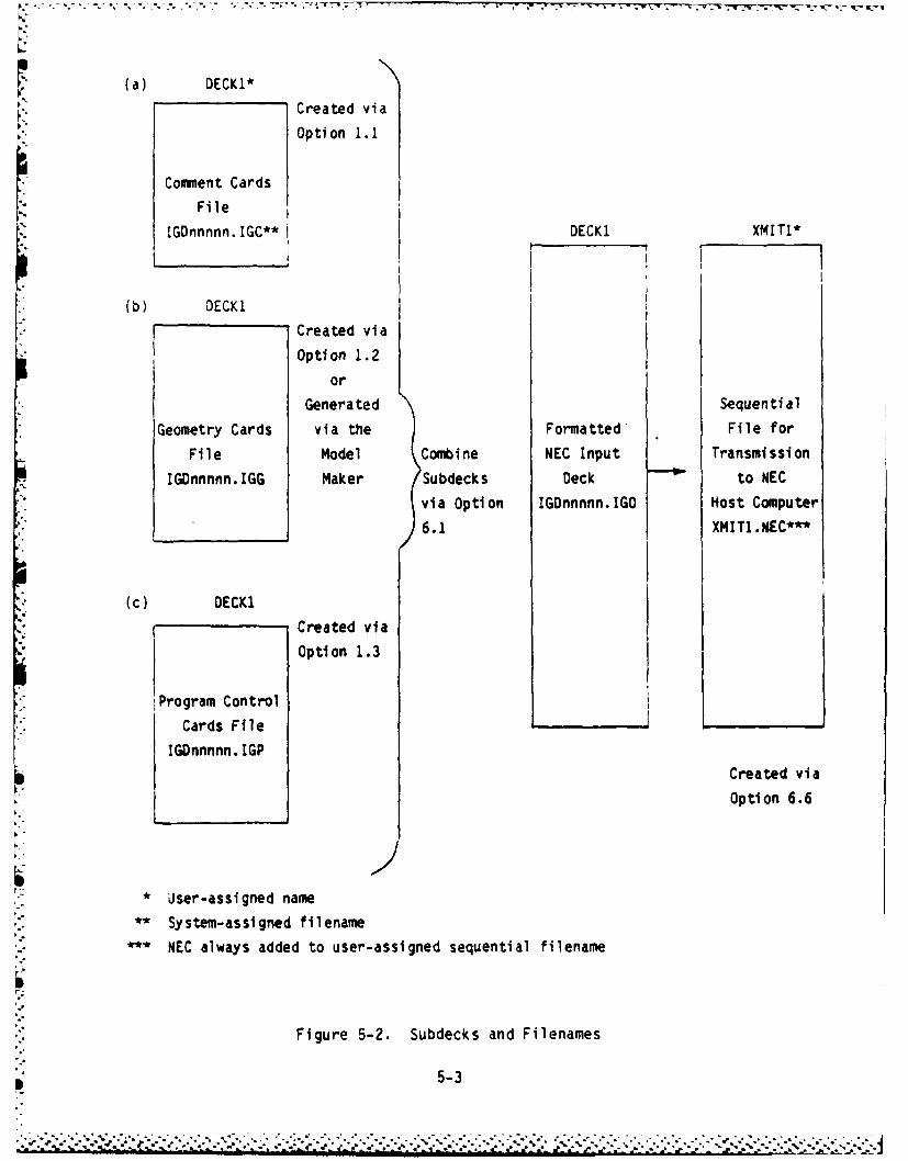
5.3.1 CARD EDITOR Function. The CARD EDITOR provides the user with the means
to create, edit, display, and delete NEC input decks - the data sets neededfor NEC input. Figure 5-2 illustrates the concept of decks as used throughout
* this system.

INITIAL OPTIONS
1 - CARD EDITOR
2 - MODEL MAKER
3 - SET DEFAULT VALUES
4 - CROSSTALK - Transfer Files to/from another computer
5 - Plot Utilities
6 - Auxiliary Programs
7 - EXIT TO DOS
ENTER OPTION INDEX
Figure 5-1. Master Menu
5-2
(a) DECK1*
Created via
Option 1.1
Comment Cards
File
IGDnnnnn.IGC** DECKI XMIT1*
(b) DECKI
Created via
Option 1.2
or
Generated Sequential
Geometry Cards via the Formatted File for
File Model Combine NEC Input Transmission
IGDnnnnn.IGG Maker Subdecks Deck - to NEC
via Option IGDnnnnn.IGO Host Computer
6.1 XMIT1.NE C**
(c) DECK1
Created via
Option 1.3
Program Control
Cards File
IGDnnnnn. IGP
Created viaOption 6.6
-I• User-assigned name
•.-.System-assigned filename* ** NEC always added to user-assigned sequential filename
I,
p.
Figure 5-2. Subdecks and Filenames
5-3

First the user builds a Comment Card subdeck, a Geometry Card subdeck, and a
Program Control Card subdeck (not necessarily in that order), assigning each of
the subdecks the same name; e.g., DECKI. Each of these subdecks can be built
via Option 1 - CREATE NEW NEC INPUT DECK.
NOTE: A Geometry subdeck can also be generated by the MODEL MAKER
function - GENERATE WIRE CARDS.
Once a subdeck has been created it can be:
a. Edited (Option 2)
b. Copied and renamed to create an identical subdeck (Option 3)
c. Displayed on the screen (Option 4)
d. Deleted (Option 5)
If a subdeck has been created for each of the card types (and all have been
given the same name), Option 6 can be used to combine them into a single deck,
*. formatted with or without a comma separating the card code from the data
"- fields, and translated into a sequential file format ready for input to the NEC
-. program.
Option 6 also allows the user to:
a. Display and print any formatted deck
b. Delete a formatted deck
c. Append one or more formatted decks to another
d. Edit a formatted deck
e. Prepare and store a formatted deck as a sequential file for NEC input
f. Delete any prepared transmit decks (sequential files)
g. Translate any sequential file (i.e., a NEC input data set created on
. ,another computer) into a format which can be read and edited via the
CARD EDITOR.
Option 7 provides a means to display or print the names and record counts of
each existing subdeck.
5-4

Notes on Naming Subdecks
When Option 1 is used to create a subdeck for the specified card type, the user
is prompted for entry of a name for this subdeck. This can be any name up to
10 characters in length which should be meaningful to the user (this makes
future retrieval easier). It is important to know that the user-assigned name
is not the filename. The filename is generated by the system in the following
manner:
IGDnnnnn. IGa,
where
nnnnn is a five-digit number from 00001 through 99999 (the same for each
subdeck having the same user-assigned name and for a deck formatted for NEC
l input from these same named subdecks) and
where
"a" is a one-character code indicating the subdeck or deck type.
a oC Comment Cards
G Geometry Cards
P Program Control Cards
0 NEC input deck (formatted)
Thus, the filenames for subdecks having the name DECKi might be:
IGD12345.IGC
IGD12345. IGG
IGD12345. IGP
If a formatted deck has been created from these subdecks its name would be:
1DG12345. IGO
5-5

FI -
5.3.1.1 Option 1 - CREATE NEW NEC INPUT DECK
Function
Option I is used to create Comment Card, Geometry Card, and Program Control
Card subdecks. The user is prompted to specify the subdeck card type to be
created and then is asked to provide a name for the new subdeck. If a subdeck
already exists with the name specified, the user is notified and is asked
whether the old subdeck with this name is to be overwritten. A positive
.. response will result in all subdecks (and the formatted deck, if any) with this
name being deleted. THERE IS NO RECOVERY - SO BE CAREFUL! If the user
responds negatively, he is prompted for another name entry.
For Program Control and Geometry subdeck creation, there are two modes of data
entry: prompted and nonprompted. The nonprompted mode works just like Option
2 (EDIT EXISTING DECK) and is discussed under Option 2. This mode is recom-
mended only for experienced users who know the meanings of the data fields in
NEC card images.
The prompted mode displays the valid card codes and their meanings, and prompts
the user for input to every data field in a card. Most users will find this to
be the easiest way to create Geometry and Program Control Cards until they
become very familiar with the NEC input requirements.
Access
Press <Fl> from the Option Menu (Figure 5-3). The Sub-Option Menu is
displayed:
SUB-OPTION MENU FOR DECK CREATE
I - COMMENT CARDS
2 - GEOMETRY CARDS
3 - PROGRAM CONTROL CARDS
. . . Use Function Keys 1 thru 3 to SELECT OPTION . . .
Press the function key corresponding to the card type you wish to create.
5-6
6 -";"'" '".. :..- ,¢ " ' '""" "" "" "". "*..," ""* "., -.. .. *'""'' " """- : :""- " "-"-"',"-"" -' '" . ', "". . ..- ,-.- : - - (''"" " " " " """

CARD EDITOR FUNCTIONS
I - CREATE NEW NEC INPUT DECK
2 - EDIT EXISTING DECK
3 - COPY and RENAME EXISTING DECK
4 - DISPLAY EXISTING DECK
5 - DELETE EXISTING DECK
6 - NEC INPUT DECK MAINTENANCE
7 - DISPLAY DECK FILE STATUS
8 - DISPLAY/UPDATE NEC HOST TABLE
9 - ARCHIVE/RESTORE DECK(S)
Use Function Keys 1 thru 9 to SELECT OPTION .
Figure 5-3. CARD EDITOR Option Menu
5-7
.- *~K *. *~.-~~%

Once the card type has been specified, a list of the existing deck names is
displayed and the user is prompted for entry of a name for the subdeck about to
be credted:
ENTER NAME FOR NEW (card type) CARDS:
ENTER UP TO 10 CHARACTERS FOR NEW DATA SET NAME (<Return> = NEXT PAGE)
Enter a name and press <Return>. If a subdeck already exists with this name,
the user receives this notice:
Name: (user-specified name) Already used - Do you want to OVERWRITE it?
ENTER 'Y' TO OVERWRITE CURRENT DATA SET FOR SAME NAME
A 'Y' response causes any subdecks with the specified name to be deleted. An
'N' response results in the user being reprompted for name entry.
Next, the user is prompted to select the input mode desired (for Geometry and
Program Control Card input):
DO YOU WANT FIELD-BY-FIELD PROMPTING DURING CARD INPUT?
ENTER 'Y' TO RECEIVE PROMPTS FOR DATA ENTRY
A 'Y' response loads the input prompt program to provide prompts for the user
for each data field. An 'N' response loads the deck edit program, allowing the
user to type cards in the line edit mode (see Option 2 for details). Comment
Cards are always input in the nonprompted mode.
5.3.1.1.1 Creating Comment Cards. The Comment Card create program works just
like the line editor (CARD EDITOR Option 2) with the following exceptions:
a. A 'CE' (Comment End) card is automatically inserted as the first card
in the new Comment Card subdeck (see Figure 5-4). The user may elect
to insert cards in front of the 'CE' card and/or edit the 'CE' card to
add comments after the two-character card code. The 'CE' card must
remain the last card in the Comment Card subdeck.
5-8

o7-
Use or I to find line - Fl thru F8 to select function
CE
SAV 1~2f 34 96 X PGER ELT 1O 9 0
When the create program for Comment Cards is first invoked,a 'CE' card is automatically inserted as the first card image.Use Function Key 2 (<F2> - EDIT) to add a comment after the 'CE'characters; or use Function Key 3 (<F3> - INSERT) to insert a'CM' card before the 'CE' card image.
The first time INSERT is pressed, a 'CM' card is insertedimmediately before the 'CE' card. All following INSERTs willinsert a 'CM' card immediately following the line that ishighlighted on the screen display.
Function Key 4 DELETEs the highlighted card image. FunctionKey 5 PRINTs a copy of the sub-deck on the hard-copy printer.Function Key 7 is used to display the NeXT screen PaGe of 20 cardimages; if there is no NXT PG, the first page is redisplayed.To restart display from the beginning, use Function Key 6,1ST PG. Function Key 8, GOTO #, allows the user to specifya line number. The card image on that line is highlighted anddisplayed towards the center of the screen page.
When all card images for this sub-deck have been created, pressFunction Key 1 to SAVE the completed sub-deck on disk.
Figure 5-4. Create Comment Cards: First-Level Edit Function Key Display
5-9

b. When the user elects to insert a card (or cards) in front of the
Comment End card, the new card is automatically started with 'CM' as
the first two characters. User input begins at character 3.
c. The edit cursor cannot be positioned on the first two characters of a
card image. Therefore, these two characters cannot be altered.
5.3.1.1.2 Creating Geometry Cards (Prompted Mode). Figure 5-5 shows the
screen display during Geometry Card input in the prompted mode. All valid
Geometry Card codes are displayed on the top half of the screen. The bottom
two lines are used for input prompting and user-input display. The last four
* card images input are displayed between the card code list and the user-input
display line.
When entering data in the prompted mode, enter the desired card code first.
The input cursor is automatically positioned at the next field requiring data
entry and the user is prompted appropriately.
Data Entry - Type the value to be placed in the current field and press
<Return>. If the entered value is valid, it is repositioned in
the field and the input cursor is advanced to the next field.
Invalid Input -If the entered value is invalid, an error message is displayed
and the user is prompted to re-enter a value for this field.
Input Aids - Besides the input prompts, there may be other input aid
messages available for a given field. Press the Down Arrow
< J> to display other messages. These may include default
values, value ranges, and current value displays. After an
invalid input message is displayed, the original prompt can be
redisplayed by pressing the <j >.
Default - Input for some fields is optional. A default value is supplied
Values (and can be viewed via the < > key) and will be used as the
field value if the user presses the <Return> key without
entering a value.
5-10
. . . . . .. . .... .... . .... .... ....... . ...

GEOMETRY CARD CODES
GA - WIRE ARC GX - REFLECT STRUCTURE" GF - USE NUMERICAL GREEN'S FUNCTION SP - SPECIFY SURFACE PATCH
GM - SHIFT & DUPLICATE STRUCTURE SC - CONTINUE SP or SM CARDGR - GENERATE CYLINDRICAL STRUCTURE SM - GENERATE MULTIPLE SURFACE PATCHESGW - SPECIFY WIRE GS - SCALE STRUCTURE DIMENSIONSGC - SPECIFY WIRE TAPERING GE - END GEOMETRY SPECIFICATION
Use GE to end Geometry Card entry
* GW 1 10 -350. 0. 150. 0. 150. 150. .1GX 1 100GX 2 100GS 0.30489
GENENTER CARD CODE FROM LIST ABOVE OR <PgUp>
Top half of screen - valid Card Codes and descriptionsLast line - user input promptNext to last line - user input displayScreen lines 18-21 - last four Geometry Cards entered
Figure 5-5. Create Geometry Cards (Prompted Mode)
5-11
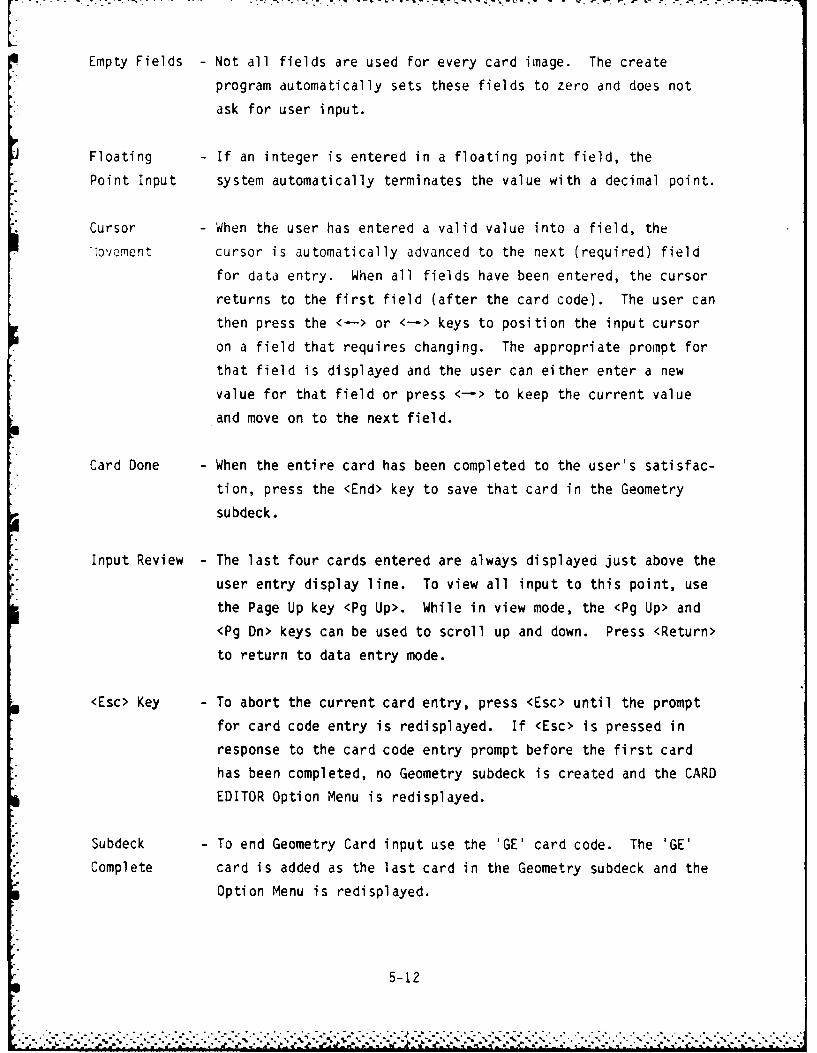
Empty Fields - Not all fields are used for every card image. The create
program automatically sets these fields to zero and does not
ask for user input.
Floating - If an integer is entered in a floating point field, the
Point Input system automatically termindtes the value with a decimal point.
Cursor - When the user has entered a valid value into a field, the
ovement cursor is automatically advanced to the next (required) field
for data entry. When all fields have been entered, the cursor
returns to the first field (after the card code). The user can
then press the <-> or <-> keys to position the input cursor
on a field that requires changing. The appropriate prompt for
that field is displayed and the user can either enter a new
value for that field or press <-> to keep the current value
and move on to the next field.
Card Done - When the entire card has been completed to the user s satisfac-
tion, press the <End> key to save that card in the Geometry
subdeck.
Input Review - The last four cards entered are always displayed just above the
user entry display line. To view all input to this point, use
the Page Up key <Pg Up>. While in view mode, the <Pg Up> and
<Pg Dn> keys can be used to scroll up and down. Press <Return>
to return to data entry mode.
<Esc> Key - To abort the current card entry, press <Esc> until the prompt
for card code entry is redisplayed. If <Esc> is pressed inresponse to the card code entry prompt before the first card
has been completed, no Geometry subdeck is created and the CARD
EDITOR Option Menu is redisplayed.
Subdeck - To end Geometry Card input use the 'GE' card code. The 'GE'
Complete card is added as the last card in the Geometry subdeck and the
Option Menu is redisplayed.
5-12

5.3.1.1.3 Creating Program Control Cards (Prompted Mode). Figure 5-6 shows
*the screen display during Program Control Card input in the prompted mode. All
* valid Program Control Card codes are displayed at the top half of the screen.
The bottom two lines are used for input prompting and user-input display. The
last four card images input are displayed between the card code list and the
* user-input display line.
When entering data in the prompted mode, enter the desired card code first.
The input cursor is automatically positioned at the next field requiring data
* entry and the user is prompted appropriately.
Data Entry - Type the value to be placed in the current field and press
<Return>. If the entered value is valid it is repositioned in
the field and the input cursor is advanced to the next field.
Invalid Input - If the entered value is invalid, an error message is displayed
and the user is prompted to re-enter a value for this field.
* Input Aids -Besides the input prompts, there may be other input aid
messages available for a given field. Press the Down Arrow
< > to display other messages. These may include default
values, value ranges, and current value displays. After aninvalid input message is displayed, the original prompt can beredisplayed by pressing the <j >
*Default - Input for some fields is optional. A default value is supplied*Values (and can be viewed via the <1 key) and will be used as the
field value if the user presses the <Return) key withoutentering a value.
Empty Fields -Not all fields are used for every card image. The Create
Program automatically sets these fields to zero and does not
ask for user input.
Floating -If an integer is entered in a floating point field, the systemPoint Input automatically terminates the value with a decimal point.
5-13

PROGRAM CONTROL CARD CODES:
CP - COUPLING CALCULATION NT - TWO-PORT NETWORKEK - EXTENDED THIN-WIRE KERNEL FLAG PQ - WIRE CHARGE DENSITY PRINT CONTROL
*EX - STRUCTURE EXCITATION PT - WIRE-CURRENT PRINT CONTROL*FR - FREQUENCY RP - RADIATION PATTERN REQUEST
GN - GROUND PARAMETERS TL - TRANSMISSION LINEGD - ADDITIONAL GROUND PARAM4ETERS PL - DATA STORAGE FOR PLOTTINGKH - INTERACTION APPROXIMATION RANGE WG - WRITE NGF FILE
*LD - STRUCTURE IM4PEDANCE LOADING XQ - EXECUTE*NE - NEAR ELECTRIC FIELD REQUEST NX - NEXT STRUCTURE FLAG
NH - NEAR MAGNETIC FIELD REQUEST EN - END OF DATA
Type EN to end Program Control Card entry
FR 130.EX 0 a 5 a 1.GN 1RP 0 10 21301 0. 0. 10. 9.
GNU 0 0 0 6. 1.IE-3ENTER GROUND TYPE PARAMETER (-1,0,1, or 2)
Top half of screen - valid Card Codes and descriptionsLast line - user input promptNext to last line - user input displayScreen lines 18-21 - last four Program Control Cards input
Figure 5-6. Create Program Control Cards (Prompted Mode)
5-14
-RP ,.i* 2 .3. *.. D. l * -.

6 - -- X-
Cursor - When the user has entered a valid value into a field, the
Movement cursor is automatically advanced to the next (required) field
for data entry. When all fields have been entered, the cursor
returns to the first field (after the card code). The user can
then press the <-> or <-> keys to position the input cursor
on a field that requires changing. The appropriate prompt for
that field is displayed and the user can either enter a new
value for that field or press <-> to keep the current value
and move on to the next field.
Card Done - When the entire card has been completed to the user's satisfac-
tion, press the <End> key to save that card in the Program
Control subdeck.
Input Review - The last four cards entered are always displayed just above the
user entry display line. To view the input to this point, use
the <Pg Up> key. While in view mode, <Pg Up> and <Pg Dn> can
be used to scroll. Press <Return> to return to data entry
mode.
<Esc> Key - To abort the current card entry, press <Esc> until the prompt
for card code entry is redisplayed. If <Esc> is pressed in
response to the card code entry prompt before the first card
has been completed, no Program Control subdeck is created and
the CARD EDITOR Option Menu is redisplayed.
- Subdeck - To end Geometry Card input use the 'EN' card code. The 'EN'
Complete card is added as the last card in the Program Control subdeck
and the Option Menu is redisplayed.
5.3.1.1.4 Creating Geometry/Program Control Cards (Nonprompted Mode). When
the user elects to create Geometry or Program Control subdecks in the non-
prompted mode, the system line editor is called up and the user starts with a
blank screen (except for prompts). Refer to Section 5.3.1.2 for the line
*. editor functions and operating instructions.
5-15
*. . . . . . .

7-. 777.7, -u
It is the user's responsibility to ensure, for each card image input, that:
a. The first two characters represent a valid card code
b. The data fields are set to valid values
c. Unused data fields are set to "0" for integer fields and "0." for
real fields
These checks are performed automatically when subdecks are created using the
prompted mode of data entry.
5.3.1.2 Option 2 - EDIT EXISTING DECK
Function
Option 2 is used to edit Comment, Geometry, and Program Control subdecks which
have already been created via Option 1. (Geometry subdecks can also be created
by way of the MODEL MAKER's Generate Wire Cards function.)
The user is prompted to specify the subdeck type to be edited and then the spe-
cific subdeck to be retrieved for editing. The specified deck is retrieved and
is displayed one screen page at a time. Each card image is displayed on one
*screen line (maximum is 100 characters per card image).
This is a line editor; that is, the user must select the line to be edited (or
deleted or inserted) and only that line can be edited until the user indicates
DONE with that line. The edit functions are -identical, regardless of subdeck
- type except for subdeck maximums:
Comment Cards - Maximum = 20 card images
Geometry Cards - Maximum = 1000 card images
Program Control Cards - Maximum = 1000 card images
. Access
Press <F2> from the Option Menu (Figure 5-3).
5-16
..

The Sub-Option Menu is displayed:
SUB-OPTION MENU FOR DECK EDIT
1 - COMMENT CARDS
2 - GEOMETRY CARDS
3 - PROGRAM CONTROL CARDS
.. . Use Function Keys 1 thru 3 to SELECT OPTION . . .
Press the function key corresponding to the card type to edit.
Once the card type has been specified, the user is prompted to specify the sub-
deck to be edited:
ENTER THE NAME OF (card type) TO EDIT OR <CR> TO SEE LIST
This is the name of the deck you want to work with
* The user has two methods of specifying the subdeck to be edited:
a. Enter the name of the subdeck to be edited - this is the name given to
the subdeck by the user when it was created.
* b. Press the <Return> key to view a list of all subdecks of the specified
card type. To select one of these subdecks, type the number
corresponding to the subdeck to be edited, followed by <Return>.
After the subdeck has been selected, it is retrieved and the first screen page
of card images is displayed. At the top of the screen is the first level edit
prompt:
Use I or t to find line - F1 thru F8 to select function
The current (cursor-position) line is highlighted. To select any line for
editing, deleting, or inserting AFTER, use the Up and Down Arrow keys (< > and
"i < >). The first-level edit function keys are displayed on screen line 25 (see
' °Figure 5-7).
p1~5-17

LI
Use or t to find line - Fl thru F8 to select function
Data Set: DECK1 (COMMENT CARDS)CMEXAMPLE 2. CENTER FED LINEAR ANTENNACM CURRENT SLOPE DISCONTINUITY SOURCE.CM 1. THIN PERFECTLY CONDUCTING WIRECE 2. THIN ALUMINUMM WIRE
- I
SAVE 2 EDIT 3ST4ELETE5RINT 6ST PG 7INXT PG 8 9 0
Notice that the last card image includes a misspelled word.Use the Down Arrow <4> to position the cursor (actually tohighlight this card image) for editing. When a card image ishighlighted, it is the current (working) line. After theappropriate card image has been selected, press FunctionKey 2 (<F2> - EDIT) from the first-level Function Key display.The second-level Function Keys are then displayed and theselected card image can be edited (see Figure 5-8).
Card images can also be inserted AFTER a selected (highlighted)line by pressing <F3>, INSERT. A blank line is then insertedimmediately following the highlighted card image and thesecond-level Function Keys are displayed. Type the new cardimage and press <Fl>, DONE, from the second-level Function Keys.
When satisfied that the sub-deck is complete, press FunctionKey 1 from the first-level Function Key display to SAVE theupdated sub-deck on disk.
Figure 5-7. Edit Existing Deck: First-Level Edit Function Key Display
5-18

It is the user's responsibility to ensure that when card images are inserted
and edited that:
a. The first two characters represent a valid card code
b. The data fields are set to valid values
c. Unused data fields are set to "0" for integer fields and "0." for real
fields
These checks are performed automatically when the prompted mode of card input
(Options 1.2 and 1.3) is used.
Once the line has been selected, the following editing functions may be
performed:
a. EDIT <F2> - edit the highlighted line; enables the following
line-edit function keys (second-level edit FKs - see Figure 5-8):
1. DONE <Fl> - saves edited line and returns system to first-level
function keys
2. INSERT <F2> - toggles insert mode (represented by small flashing
cursor) ON/OFF to allow character insertion. Insertion will be
made one character BEFORE the character at the cursor position.
3. DELETE <F3> - deletes character at cursor position and moves the
rest of the line left to close the character gap
4. ERASE <F4> - erases from cursor through end of line
Also enabled are:
1. <-> - moves cursor right one character
2. < -> - moves cursor left one character
3.. <Ins> - same as INSERT FK (<F2>)
4. <Del> - same as DELETE FK (<F3>)
5. <Esc> - returns system to first-level FKs - NO CHANGES to line
6. <End> - same as DONE FK (<Fl>)
7. <Return> - same as DONE FK (<Fl>)
8. <Back Space> - moves cursor left and deletes character
5-19
w~~~~~~ . . . . ... -wl
- -m~ ~ ,
-u~~~k 'l dn nnCt - - - - -

,. -. , . 7- ,-. 1 .5 , . . - - . ' . - - . -.- - . - '- -
Use+- or-. to position cursor -Fl thru F4 or <backspace> for function
Data Set: DEC11 (COMMENT CARDS)CMEXAMPLE 2. CENTER FED LINEAR ANTENNACM CURRENT SLOPE DISCONTINUITY SOURCE.CM 1. THIN PERFECTL; CONDUCTING WIRECE 2. THIN ALUMINUMr WIRE
2DONE 1, SET 3 ]i4FE E5 6 7 a 9
Function Key 2, EDIT, has been pressed from the first-levelFunction Key display (see Figure 5-7) to edit the last cardimage in this sub-deck. The Right Arrow key <--)> is then usedto position the cursor over the last 'MI in the word'ALUMINUMM'. When the cursor is correctly positioned, useFunction Key 3, DELETE, or the <Del> key to erase this char-acter and move the remainder of the line left by one to close upthe space left by the DELETE function.
When all changes have been made to the card image, press <Fl>,DONE, to return to the first-level Function Key display.
Figure 5-8. Edit Existing Deck: Second-Level Edit Function Key Display

b. INSERT <F3> - inserts a new line AFTER the highlighted line, then
automatically goes into EDIT mode for the new line. Everything is
the same as described for EDIT except <Return>. If <Return> is
pressed when in INSERT (line) mode, the new line is saved and another
line is inserted after the one just built. To exit INSERT mode, use
<End> or <Fl>.
c. DELETE <F4> - deletes the highlighted line
d. SAVE <Fl> - writes edited deck to disk and returns to Option Menu
e. PRINT <F5> - outputs the deck being edited to the printer
f. 1ST PG <F6> - displays first page of deck cards (20 cards)
g. NEXT PG <F7> - displays next 20 cards of deck
h. GOTO # <F8> - prompts the user to specify the line number to go to and
displays that card towards the middle of the screen page
If the user aborts out (by pressing the <Esc> key) instead of saving the deckvia the SAVE function key, none of the edits is saved.
.. 5.3.1.3 Option 3 - COPY and RENAME EXISTING DECK
Function
Option 3 is used to duplicate an existing Comment, Geometry, or Program Control
subdeck created via Option 1 or, in the case of Geometry subdecks, by way ofthe MODEL MAKER's Generate Wire Cards function. The copy and rename function
is particularly useful if you wish to create an almost identical subdeck.
Call Option 3 to copy and rename the subdeck you wish to duplicate; then use
Option 2 (EDIT EXISTING DECK) to alter the duplicated deck as needed.
*- Option 3 prompts the user to select the subdeck type to be duplicated and then
requests the user to specify the actual subdeck to be copied. The user is
asked to supply a new name for the copied version (same naming rules apply as
- discussed in Section 5.3.1). The copied version cannot be given the same name
.o as the original version of the subdeck.
5-21

Access
Press <F3> from the Option Menu (Figure 5-3).
The Sub-Option Menu is displayed.
SUB-OPTION MENU FOR DECK COPY/RENAME
1 - COMMENT CARDS
2 - GEOMETRY CARDS
3 - PROGRAM CONTROL CARDS
Use Function Keys 1 thru 3 to SELECT OPTION . . .
Press the function key corresponding to the subdeck type to be duplicated.
Once the card type has been specified, the user is prompted to specify the sub-
deck to be duplicated:
ENTER NAME OF (card type) TO COPY/RENAME OR <CR> TO SEE LIST
This is the name of the deck you want to work with
The user has two methods of selecting the subdeck to be duplicated:
a. Enter the name of the subdeck to be duplicated - this is the name
given to the subdeck by the user when it was created.
b. Press the <Return> key to view a list of all subdecks of the specified
card type. To select one of these subdecks, type the number
corresponding to the subdeck to be duplicated, followed by <Return>.
After the subdeck has been selected, a list of the existing names is displayed
and the user is prompted to enter a new name for the copied deck:
ENTER NAME FOR NEW (card type):
ENTER UP TO 10 CHARACTERS FOR NEW DATA SET NAME (<Return> = NEXT PAGE)
Enter a name, following the guidelines presented in paragraph 5.3.1. Remember
to be careful when using a name that has already been assigned to a subdeck.
5-22

5.3.1.4 Option 4 - DISPLAY EXISTING DECK
Function
Option 4 is used to display selected subdecks on the screen or to print them on
the hardcopy printer.
The user is prompted to select the subdeck type to be retrieved: Comment,Geometry, Program Control, or all of the above. The user is then asked to
specify the name of the subdeck to be retrieved. If the user has specified
'ALL of the above' as the subdeck type, all subdecks having the specified name
will be retrieved. Next, the user is prompted to select the screen or the
" printer as the output device. The specified subdeck(s) is retrieved and
- displayed or printed.
Access
Press <F4> from the Option Menu (Figure 5-3).
The Sub-Option Menu is displayed:
SUB-OPTION MENU FOR DECK PRINT
I - COMMENT CARDS
2 - GEOMETRY CARDS
3 - PROGRAM CONTROL CARDS
4 - ALL of the above
. . . Use Function Keys 1 thru 4 to SELECT OPTION .
Press the function key corresponding to the subdeck type to display or print.
Once the card type has been specified, the user is prompted to select the sub-
deck to be displayed or printed:
ENTER NAME OF (card type) TO PRINT OR <CR> TO SEE LIST
This is the name of the deck you want to work with
5-23
'~~~~~~~~~~..- ...... .... .. .. ........ ?. ....................... "'-."-. ..,'.',' ,,-." , a..............-.-....... ,........,....... "-".-.".'... "....'........'"'...".-.'.'".-..

The user has two methods of selecting the subdeck to be displayed or printed:
a. Enter the name of the subdeck to be retrieved - this is the name given
to the subdeck by the user when it was created.
b. Press the <Return> key to view a list of all candidate subdecks. To
select one of these subdecks, type the number corresponding to the
subdeck to be retrieved, followed by <Return>.
After the subdeck name has been specified, the user is requested to select the
output device:
i - SCREEN OUTPUT
2 - PRINTER OUTPUT
Use Function Keys 1 thru 2 to SELECT OPTION . . .
Press the function key corresponding to the output device desired.
If screen output is selected, the card images of the selected deck are
displayed on the screen. The bottom line prompt reads:
..... PRESS ANY KEY TO STOP/START SCROLL ........
Any key can be used to toggle the screen scrolling OFF or ON. That is, if
lines are being written on the screen, pressing any key will stop the screen
writes. By pressing any key again, the screen writes are continued. After the
last card of a subdeck has been written on the screen, the bottom line reads:
..... PRESS ANY KEY TO EXIT .......
If the user has requested that all subdecks having the specified name be
displayed, the previous prompt is displayed when the end of each subdeck has
been reached. By pressing any key, the user initiates the retrieval and
display of the next subdeck having the specified name. When the last card in
the last subdeck has been displayed, the input of any key redisplays the Option
Menu.
5-24

When the printer is chosen as the output device, the user is prompted to
specify single- or double-spaced output:
DOUBLE OR SINGLE SPACED OUTPUT?
ENTER '2' FOR DOUBLE SPACE (Default = Single Space)
All card images from the selected subdeck(s) are printed single- or double-
spaced as specified. There is no further user action required.
5.3.1.5 Option 5 - DELETE EXISTING DECK
Function
Option 5 is used to delete Comment, Geometry, and Program Control subdecks from
the disk when they are no longer needed. This is done purely to free up disk
space and keep subdeck lists down to a manageable number for scanning.
The user is prompted to select the subdeck type to be deleted. This can be any
one of the three types or 'ALL' types existing with the user-specified name.
The user is then asked to specify the name of the subdeck(s) to be deleted.
The subdeck(s) of the specified type and name are retrieved and one screen page
is displayed for each. The user is prompted to confirm the deletion request
*. after examining the displayed page to make sure it is from the subdeck to be
deleted.
-" Access
Press <F5> from the Option Menu (Figure 5-3).
The Sub-Option Menu is displayed:
SUB-OPTION MENU FOR DECK DELETE
1 - COMMENT CARDS
2 - GEOMETRY CARDS
3 - PROGRAM CONTROL CARDS
4 - ALL of the above
. Use Function Keys I thru 4 to SELECT OPTION . .
5-25

Press the function key corresponding to the subdeck type to be deleted.
Once the card type has been specified, the user is prompted to select the sub-deck to be deleted:
ENTER NAME OF (card type) TO DELETE OR <CR> TO SEE LIST
This is the name of the deck you want to work with
The user has two methods of selecting the subdeck to be deleted:
a. Enter the name of the subdeck to be deleted - this is the name given
to the subdeck by the user when it was created.
b. Press the <Return> key to view a list of all candidate subdecks. To
select one of these subdecks, type the number corresponding to the
subdeck to be deleted, followed by <Return>.
The specified subdeck is retrieved and the first screen page of card images is
displayed on the screen. Examine the display carefully, then respond to the
prompt at the bottom of the screen:
ARE THESE THE (card type) YOU WANT TO DELETE?
TYPE 'DEL' TO CONFIRM DELETION ACTION - ANY OTHER KEY TO EXIT
If these cards are from the subdeck you want deleted, type 'DEL' <Return> to
delete this subdeck from the disk.
CAUTION: Be sure this is the subdeck you want erased before confirming the
deletion request - THERE IS NO MEANS OF RECOVERY once the deletion
has been performed.
If 'ALL of the above' was chosen instead of a specific card type, the display
and confirmation process is repeated for each existing subdeck having the
specified name.
5-26
... . . ..... . . . . . . . . . . . . ... . .. '.. . . - , . . .. . . .- .

- 5.3.1.6 option 6 -NEC INPUT DECK MAINTENANCE
* Function
Figure 5-2 illustrates the relationship of the subdecks created and maintained
via Options 1 through 5 to a formatted NEC input deck. Option 6 is used to*combine the three subdecks having the same user-assigned name, into a single
deck ready for translation to a sequential file and subsequent input to the NEC
progrdin. Opti on 6 is al so used to di splay and/or print a NEC input deck, to
* delete NEC input decks which have become obsolete, to append one or more* formatted input decks to another, to edit a formatted deck, to prepare or
delete a deck (as a sequential file) for input to the NEC program, or to
* translate a sequential file into a format which can be read and edited via the
- CARD EDITOR (a formatted data set).
Access
Press <F6> from the Option Menu (Figure 5-3).
* The Sub-Option Menu is displayed:
NEC INPUT DECK MAINTENANCE
1 - FORMAT DECK FOR NEC INPUT
2 - DISPLAY FORMATTED DECK3 - DELETE FORMATTED DECK
4 - APPEND TO FORMATTED DECK
5 - EDIT FORMATTED DECK
6 - PREPARE DECK FOR TRANSMISSION
7 - DELETE TRANSMIT DECK (Sequential File)
8 - TRANSLATE FILE FROM OTHER SOURCE (Sequential File to Formatted Deck)
...Use Function Keys 1 thru 8 to SELECT OPTION...
Press the function key corresponding to the sub-option choice desired.
5.3.1.6.1 Formatting a Deck for Input to NEC. When Sub-Option 1 is selected,
the user must specify the name of the subdecks to be combined into a NEC input
deck:
5-27

*ENTER NAME OF DECK TO FORMAT OR <CR> TO SEE LISTThis is the name of the deck you want to work with
*The user has two methods of specifying the name:
a. Enter the user-assigned name of the deck to be formatted, followed by
<Return>.b. Press <Return> to display the list of candidate subdecks for for-
matting. Type the number corresponding to the name you wish, followed
by <Return>.
NOTE: In order for a NEC input deck to be formatted, a subdeck must have
already been created for all three card types (Comment, Geometry, and
Program Control Cards).
* Next, the user is required to specify the format type desired:
FORMAT WITH COMMA AFTER CARD CODE?
ENTER 'Y' TO SEPARATE CARD CODE FROM DATA FIELDS WITH A COMMA
* If the response to the above prompt is Yes (Y), each card image in the NEC
input deck will be formatted with a commna between fields 1 and 2 (for example,* PL,3,1,,4,).
Any other response results in the card images being written with no delimiter
* between the first and second fields (PL3,1,,4,).
- Commas are inserted and extraneous blanks removed between all other fields inthe card image. A commna is added as the last character of the card image.
* If the selected deck was previously formatted, a warning is displayed on thescreen:
(deckname) already formatted - Do you want to OVERWRITE it?
ENTER 'Y' TO OVERWRITE FORMATTED NEC INPUT DECK
CAUTION: If you choose to overwrite the formatted deck with this new one,
the original formatted data set is lost -there is no recovery
capability.
5-28

* once the selected deck has been formatted (all three card types combined) the* user is asked if another deck is to be appended for NEC input:
DO YOU WANT TO APPEND A DECK FOR ANOTHER STRUCTURE?
ENTER 'Y' TO APPEND A DECK
* If another structure is to be computed in the planned NEC run, this function
allows the user to combine the cards for that structure with the cards for the
- first structure selected. If an 'EN' card was included in the first deck, that
- card is replaced with an 'NX' card (next structure). After responding 'Y' to* the above prompt, the user is asked to select the deck to be appended. Any
deck may be selected.
Any number of decks may be appended in this manner. 'NX' cards will be placed
in appropriate locations and the last card will always be 'EN'.
- 5.3.1.6.2 Displaying/Printing a NEC Input Deck. Once a deck has been format-
ted for input to NEC (see Section 5.3.1.6.1), it can be displayed on the screen
* or output to the printer via Sub-Option 2 of the NEC INPUT DECK MAINTENANCE
function (Option 6).
* The user is prompted to specify the deck name to be displayed or printed:
ENTER NAME OF DECK TO PRINT OR <CR> TO SEE LIST
This is the name of the deck you want to work with
*The user has two methods of specifying the deck name:
a. Enter the name assigned to this deck by the user when it was created.
b. Press <Return> to display the list of all formatted decks. Type the
number corresponding to the deck to be retrieved, followed by
<Return>.
After the deck has been specified, the user is prompted for selection of the
output device:
1 - SCREEN OUTPUT
2 - PRINTER OUTPUTL. . . Use Function Keys 1 thru 2 to SELECT OPTION .. .
5-29

Press the function key corresponding to the output device desired.
If screen output is selected, the card images of the selected deck are
displayed on the screen. The bottom line prompt reads:
..... PRESS ANY KEY TO STOP/START SCROLL .....
* Any key can be used to toggle the screen scrolling OFF or ON. That is, if
lines are being written on the screen, pressing any key will stop the screen
writes. By pressing any key again, the screen writes are continued. After the
last card of the deck has been written on the screen, the bottom line reads:
..... PRESS ANY KEY TO EXIT .....
When the printer is selected as the output device, the user is prompted to
specify single- or double-spaced output:
DOUBLE OR SINGLE SPACED OUTPUT?
ENTER '2' FOR DOUBLE SPACE (Default = Single Space)
All card images from the selected deck are printed single- or double-spaced as
S"specified. There is no further user action required.
5.3.1.6.3 Deleting a Formatted Deck. Any deck formatted for input to the NEC
program via Sub-Option 1 (Section 5.3.1.6.1) can be deleted when no longer
needed in order to free up disk space.
The user is prompted to select the NEC input deck to be deleted:
ENTER NAME OF DECK TO DELETE OR <CR> TO SEE LIST
This is the name of the deck you want to work with
S"The user has two methods of selecting the deck to be deleted:
a. Enter the user-assigned name of the formatted deck to be deleted.
b. Press <Return> to view the list of all formatted decks. Type the
number corresponding to the deck to be deleted, followed by <Return>.
5-30

* The specified deck is retrieved and the first screen page Of Card imdgeS is
* displayed. Examine the display carefully, then respond to the prompt at the
* bottom of the screen:
ARE THESE THE FORM4ATTED CARDS YOU WANT TO DELETE?
TYPE 'DEL' TO CONFIRM DELETION ACTION - ANY OTHER KEY TO EXIT
If the card images displayed are from the deck you want to delete, type 'DEL'
* <Return> to delete this deck from the disk.
CAUTION: Be sure this is the deck you want erased before confirming the
deletion request. If a deck is mistakenly deleted, it can be
recovered by reformatting it via Sub-Option 1, providing the
three subdecks are still resident on disk.
5.3.1.6.4 Appending to a Formatted Deck. This function allows the user to
* format and append one input deck to an already formatted NEC input deck.
* First, the user is prompted to select the formatted deck to append to:
ENTER NAME OF DECK TO APPEND TO OR <CR> TO SEE LISTThis is the name of the deck you want to work with
There are two methods of specifying the deck to append to:
a. Enter the name of the formatted deck to which you want to append
another deck.
b. Press <Return> to display the list of formatted decks. Type thenumber corresponding to the deck to be appended to, followed by
<Return>.
* Next, the user is prompted to indicate if a commna is to be used as a separator
* between the card code and the first data fields in the deck(s) being appended:
* FORMAT WITH COMMA AFTER CARD CODE?
ENTER 'Y' TO SEPARATE CARD CODE FROM DATA FIELDS WITH A COMMA
5-31

L L- V.
If 'Y' is input, all card images appended to the specified formatted deck will
be formatted with a comma between characters two and three. Otherwise, there
will be no delimiter between the second and third characters.
.* IMPORTANT: The format type specified must be the same as was used when the
first specified deck was formatted.
The user is then prompted to:
ENTER THE NAME OF THE DECK TO APPEND
This is the name of the deck you want to work with
Specify the name of the deck to append in the same way as the deck to be
appended to (described above). The name specified must have a Comment,
Geometry, and Program Control subdeck associated with it. These subdecks are
formatted and appended to the end of the previous deck. The two decks are
separated with an 'NX' (Next Structure) card. (This card replaces the 'EN'
card at the end of the deck being appended to.)
After the second structure has been appended to the first, the user is asked if
." another structure is to be appended:
DO YOU WANT TO APPEND A DECK FOR ANOTHER STRUCTURE?
ENTER 'Y' TO APPEND A DECK
If the response is 'Y', the user is asked to specify the next deck to be
-. appended to the previous structures. This process continues until the user
responds with 'N' (or any character other than 'Y') to the above prompt. The
system then ensures that the last card in the multistructure deck is an 'EN'
card.
NOTE: The deck chosen to append to must be a previously formatted deck, while
the deck(s) chosen to be appended must be unformatted Comment, Geometry,
and Program Control subdecks (see Figure 5-9).
5-32

* a I- S- *0S -
4 , 4 J~~~t 4.1 1-- sE- * 1J L '-lug ~ CW4f to~ cCI,.U sU ofl
LDVLJ" *L " i OVIJ sLV
(D 3AJ W I IL I ME2c IL) I meI I U C-) 11 IL
*1 0 4)"
E 06
- LA.
0 41
030
4J 4A 0-
E IM 4-) L
La~ "V
L. CA
411
V, cg
a 41 4J 04J W 1.(
SM-. 0.-L.4 03 L.Vl
2 wo
03~~~~L CMA 4JJ~ IE'0 U a
5.3.1.6.5 Editing a Formatted Deck. Once a deck has been formatted for input
to the NEC program, it can be edited using CARD EDITOR Option 6.5. The user is
prompted to enter the name of the formatted deck to be edited:
ENTER NAME OF FORMATTED DECK TO EDIT OR <CR> TO SEE LIST
This is the name of the deck you want to work with
The user has two methods of specifying the deck to be edited:
a. Enter the name of the deck to be edited.
b. Press the <Return> key to view a list of all formatted decks. To
select one of these decks, type the number corresponding to the deck
to be edited, followed by <Return>.
After the.deck has been selected, it is retrieved and the first screen page of
card images is displayed. At the top of the screen is the first-level edit
prompt:
Use I or t to find line - F1 thru F8 to select function
i The edit function is described in detail in Section 5.3.1.2 (EDIT EXISTING
DECK).
Be very careful to maintain the format of the card images in the formatted
deck.
5.3.1.6.6 Preparing a Deck for Transmission. When a deck has been formatted
- for input to the NEC program (via CARD EDITOR Option 6.1), it is written to a
random disk file. This file can be edited, displayed, deleted, and appended
to, as necessary. When this data set is ready for input to the NEC program, it
-. must be written to a sequential file before transmission to the NEC host
- computer. This is accomplished by way of the CARD EDITOR's Option 6.6 (PREPARE
DECK FOR TRANSMISSION).
The user is prompted to:
ENTER NAME OF DECK TO TRANSMIT OR <CR> TO SEE LIST
This is the name of the deck you want to work with
5-34

* The user has two methods for specifying the deck name:
*a. Enter the name assigned by the user when the deck was created.
b. Press <Return> to display the list of all formatted decks and type the
number corresponding to the deck to be transmitted, followed by
<Return>.
Once the formatted deck has been selected, the following is displayed on the
screen:
ENTERING A VALID FILENAME
- Maximum = 8 characters
- Do not add a file type extension
- Do not include embedded spaces
- Start with a letter- Use letters and numbers only
ENTER FILENAME:
ENTER UP TO 8 CHARS or <Return> FOR LIST OF EXISTING NAMES
The user is being instructed to enter a name for the sequential file that will
* be transmitted to the NEC host computer. Guidelines are provided on the
screen. The file type extension is provided by the system - it is always .NEC,
* therefore, the user is not to enter this as part of the filename.
* The deck name can be used as the filename if it is a valid filename according
* to the rules outlined above (also as described in the BASIC manual supplied
* with the computer). Otherwise, the user needs to come up with another name.
Once the name is entered, the system checks to see if that name has already
been used. If it has, a warning message is displayed:
(filename) Already exists - Do you want to OVERWRITE it?
Enter 'Yin to overwrite (filename)
5-35

If 'Y' is entered to the above question, the file previously created with this
name will be deleted dnd there is NO RECOVERY. If the user does not wtint to
delete the old file with the specified filename, the prompt should be answered
with 'N' (or any key other than 'Y'). The user will then be reprompted for
filename entry.
As soon as a valid filename has been entered (and confirmed), the card images
from the specified formatted deck are read one at a time and are rewritten to
the current disk as a sequential file with the user-assigned filename. A card
image count is displayed on the screen during this process.
IGUANA provides no capabilities for editing, displaying, or otherwise tampering
*with the sequential files created for transmission to a NEC host computer. To
*'i perform any of these functions, the user will need to exit to DOS and use DOS
commands and a line editor (such as EDLIN).
• .The user is responsible for remembering the names he has assigned to the
* sequential files created via this option when transferring these files to a NEC
'. host for processing (see Section 5.3.4).
5.3.1.6.7 Deleting a Transmit Deck. The sequential files created via
,. Sub-Option 6 (see Section 5.3.1.6.6) can be deleted when no longer needed to
free up disk space.
'* The user is prompted to select the transmit deck to be deleted:
ENTER NAME OF TRANSMIT DECK TO DELETE OR <CR> TO SEE LIST
This is the name of the sequential file you want to delete
". The user has two methods of selecting the deck to be deleted:
a. Enter the user-assigned name of the transmit deck.
b. Press <Return> to view the list of all transmit decks and type the
number corresponding to the deck to be deleted, followed by <Return>.
5-36

rhe specified deck is retrieved and the first screen page of cdrd images is
displayed. The user should examine the display carefully, then respond to the
prompt at the bottom of the screen:
ARE THESE THE TRANSMIT CARD IMAGES YOU WANT TO DELETE?
TYPE 'DEL' TO CONFIRM DELETION ACTION - ANY OTHER KEY TO EXIT
If the card images displayed are from the deck to be deleted, type DEL <Return>
to delete this deck from the disk.
CAUTION: Be sure this is the deck to be erased before confirming the deletion
request. If a transmit deck is mistakenly deleted it can be
recreated via Sub-Option 6, providing that the corresponding
formatted deck is still resident on disk.
5.3.1.6.8 Translating a File from Another Source. This function provides a
means for translating NEC input data sets (either those created via IGUANA or
those created on another computer) into a format which can be read and edited
via the IGUANA CARD EDITOR. The translated file becomes a Formatted Deck, and
can then be retrieved, edited, printed, and deleted like any IGUANA Formatted
Deck via Option 6.
The user is prompted for the name of the sequential file to be translated:
ENTER NAME OF SEQUENTIAL FILE TO BE TRANSLATED:
This is the name of the data set retrieved from another source
Use the full filename; for example, "ANTENNA1.EXT" if the file is on the system
disk or "A:ANTENNAI.EXT" if the file is on a floppy diskette which has been
loaded in the floppy drive.
A list of the current names of formatted decks is presented on the screen and
the user is prompted to:
ENTER NAME FOR NEW FORMATTED DECK:
ENTER UP TO 10 CHARACTERS FOR NEW DATA SET NAME
5-37

Type the name for the translated deck or use <Return> to display another page
of existing names (if any). A name that has been used air-eddy can be assigned
*for the formatted deck, in which case the user is warned that the name has
already been used and is asked if that file is to be overwritten.
As the sequential file is being translated into a formatted data set, theold and new names are displayed on the screen along with the number of the
image currently being translated. When the operation is complete, the NEC
Input Deck Maintenance M1enu is displayed on the screen, ready for the next
operation.
5.3.1.7 Option 7 - DISPLAY DECK FILE STATUS
Functi on
Option 7 is used to display or print a list of all existing subdecks and for-
matted NEC input decks. The user-assigned name for each is presented, alongwith the card image counts for the Comment, Geometry, Program Control, and for-
matted subdecks (see Figure 5-10).
Access
Press <F7> from the Option Menu (Figure 5-3).
The user is prompted to specify the output device:
1 - SCREEN OUTPUT
2 - PRINTER OUTPUT
...Use Function Keys I thru 2 to SELECT OPTION ...
Press the function key corresponding to the output device desired.
5-38

COMMENT GEOMETRY PROGRAM CTPL FORMATTEDDECK NAME CARDS CARDS CARDS CARDS
ANT1 0 6 00ANT2 2 31 a
*ANT3 0 0 40NEW1 2 A 30NEW2
is 31* 'IRE5 0 a 00
Figure 5-10. File Status Display Drintout

If SCREEN OUTPUT is selected, the deck file status is displayed on the screen.
The bottom line prompt reads:
..... PRESS ANY KEY TO STOP/START SCROLL .......
Any key can be used to toggle the screen scrolling OFF or ON. That is, if sta-
tus lines are being written on the screen, pressing any key will stop screen
writes. By pressing any key again, the screen writes are continued. After the
last stat:s line has been written on the screen, the bottom line reads:
..... PRESS ANY KEY TO EXIT .......
When te printer is selected as the output device, the user is prompted to
specify single- or double-spaced output:
DOUBLE OR SINGLE SPACED OUTPUT?
ENTER '2' FOR DOUBLE SPACE (Default : Single Space)
The file status display is output to the printer single- or double-spaced, as
specified. No further user action is required.
5.3.1.8 Option 8 - DISPLAY/UPDATE NEC HOST TABLE
* Function
. In order to send prepared NEC input data sets to a host computer or to capture
NEC results from a NEC host for plotting on the PC-XT a communications package,
CROSSTALK-XVI, has been incorporated into the IGUANA system. CROSSTALK employs
Command and Script files and user-prepared special purpose files to automate
computer dial-up, log-on, and file transfer functions. These special purpose
* files are stored on disk and can be invoked with CROSSTALK, eliminating much of
the user interface with CROSSTALK.
5-40
.............................................
........................................................

* The NEC Host Table is maintained by the user and can hold up to 20 computer
* host names, Command file names, and a brief functional description of each.
* When the file transfer function is invoked from the Initial Option Menu
(Function 4), this table is displayed so that the user may select the Command
file, if any, to be loaded and executed with CROSSTALK. The NEC Host Names and
* functional description for each are included in the table for the user's
benefit only. CROSSTALK uses only the Command file name in the far left column
when the user makes a selection from this table.
Option 8 is used to display and maintain the current contents of the NEC Host
* Table.
* Access
* Press <F8> from the Option Menu (Figure 5-3).
The current contents of the NEC Host Table are displayed on the screen; the
* current cell is displayed in reverse video. Use the cursor control (arrow)
keys to move to the cell you want to change. As the current cell position is
changed, the input prompt at the bottom of the screen displays the appropriate
message for the changing of the cell.
* To change the contents of the current cell, type the new name or description in
response to the prompt at the bottom of the screen and press <Return> to enter
* the change into the cell. The table has the following limits:
Cell Maximum Character Count
NEC Host Name 15 (any characters)
Functional Description 40 (any characters)
CROSSTALK Command File 8 (valid filename)*
*Refer to Appendix A and the CROSSTALK manual for more details on Command
file names. Command files, when they are created, always have the form
nnnnnnnn.XTK, where .XTK is the filename extension. Do not include the
extension in this table when entering Command file names in the left
column.
5-41
*... ,*..
N
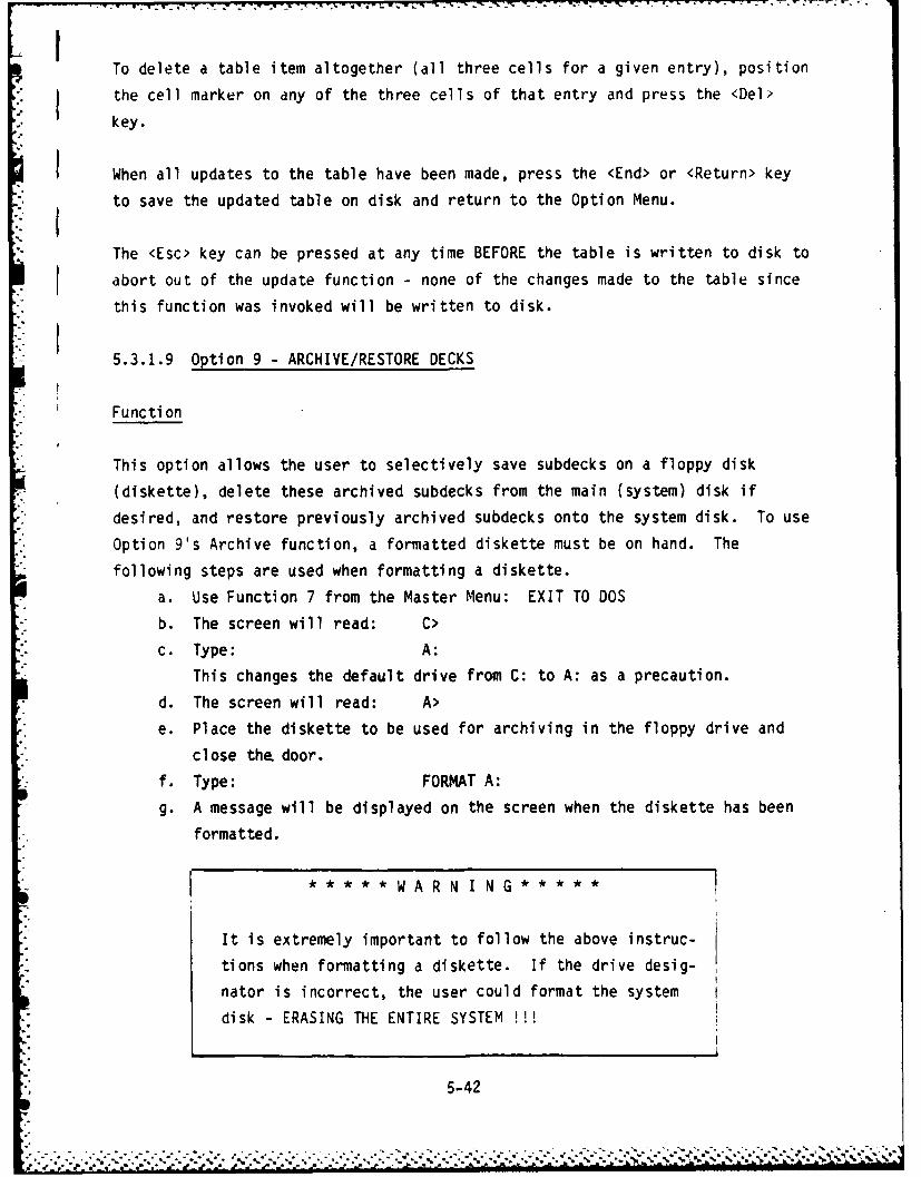
ITo delete a table item altogether (all three cells for a given entry), position
the cell marker on any of the three cells of that entry and press the <Del>
key.
When all updates to the table have been made, press the <End> or <Return> key
to save the updated table on disk and return to the Option Menu.
The <Esc> key can be pressed at any time BEFORE the table is written to disk to
abort out of the update function - none of the changes made to the table since
this function was invoked will be written to disk.
5.3.1.9 Option 9 - ARCHIVE/RESTORE DECKS
Functi on
This option allows the user to selectively save subdecks on a floppy disk
(diskette), delete these archived subdecks from the main (system) disk if
desired, and restore previously archived subdecks onto the system disk. To use
Option 9's Archive function, a formatted diskette must be on hand. The
" following steps are used when formatting a diskette.
a. Use Function 7 from the Master Menu: EXIT TO DOS
b. The screen will read: C>
c. Type: A:
This changes the default drive from C: to A: as a precaution.
d. The screen will read: A>
e. Place the diskette to be used for archiving in the floppy drive and
close the door.
f. Type: FORMAT A:
g. A message will be displayed on the screen when the diskette has been
formatted.
i ***** WA R N I N G*****
It is extremely important to follow the above instruc-
tions when formatting a diskette. If the drive desig-
nator is incorrect, the user could format the system
disk - ERASING THE ENTIRE SYSTEM !!
* •5-42
. .. . .. . .- %.-. -.-. ...-. ..-.-. ..-- ; ... ........... ..- % ....... %-. .\.. . .%.%.. ... ..... .. ,% . % %

To use Option 9's Restore function, the user must already have a diskette that
has been used to archive subdecks.
Access
Press <F9> from the Option Menu (Figure 5-3).
The user is prompted to specify the operation to be performed:
ARCHIVE FUNCTIONS
1 - WRITE DECK(S) TO FLOPPY DISK
2 - RESTORE DECK(S) FROM FLOPPY TO FIXED DISK
Press the function key corresponding to the sub-option choice desired.
5.3.1.9.1 Writing Deck(s) to a Floppy Disk (Archiving). When Sub-Option 1 is
selected from the Archive Function Menu, the names and card counts for each of
the existing Comment, Geometry, and Program Control subdecks are displayed on
the screen (to see more, use the <Return> key). The user is prompted to select
the subdecks to be archived. The formatted decks and the transmit decks cannot
be archived. Any cards which exist for the same selected deck name will be
archived; i.e., the user cannot select to archive the Comment Cards from a deck
and not the Geometry or Program Control Cards.
To select subdecks for archiving:
a. Use the Down and Up Arrows, <i > and < 0 >, to highlight the line for
the subdecks to be archived.
b. When the desired subdeck is highlighted, press <+> to mark it to be
archived. This line will be marked with an *.
c. To select ALL subdecks on the system disk for archiving, press <A>
instead of locating a specific deck name and pressing <+>.
To deselect subdecks which have been marked for archiving:
a. Locate the starred line to be deselected using the <i > and 0 > keys.
b. When the appropriate line has been located (it is highlighted), press
<-> to deselect it. The * is erased from this line.
5-43

V. When all selections have been made, press the <End> key to start the archiving
process.
A formatted diskette must now be loaded into the floppy drive (drive A:); see
5.3.1.9 for instructions for formatting a diskette. This will be the Archive
diskette. The user is prompted to indicate when the diskette is ready for
archiving:
Place FORMATTED Diskette in Drive A:
Press <Return> when READY
(Press <Esc> to ABORT)
If the <Esc> key is pressed, no archiving is performed; the Archive Function
* iMenu is redisplayed.
*When the <Return> key is pressed, the archive function begins. As the selected
. decks are being read from the fixed disk and written to the floppy disk, the
-* screen display shows the current deck name, deck type (Comment, Geometry, or
"- Program Control) and record number.
After all selected decks have been archived, the user is asked whether the
archived decks are now to be deleted from the system disk:
DO YOU WANT TO DELETE THE ARCHIVED FILES FROM THE FIXED DISK?
Type DELETE to erase archived decks from fixed disk
Type SAVE to keep archived.decks on fixed disk
DELETE or SAVE ARCHIVED DECKS?
If the user types DELETE, all decks which have been archived on the floppy disk
*will be deleted from the fixed disk. If a formatted deck exists for an
archived deck, the formatted deck will NOT be deleted. To retain all archived
decks on the fixed disk, type SAVE.
5-44
S.** *J**b *-**' ~*' . - *. ,* ~ J 4A -...

NOTE: If the diskette fills up before all decks have been archived, the useris notified via a screen message. The DELETE function will not erase
decks which have not been successfully archived.
- 5.3.1.9.2 Restoring Deck(s) to the Fixed Disk. When Sub-Option 2 is selected* from the Archive Function Menu, the user is prompted to load the Archive* diskette in the floppy drive (drive A:). An Archive diskette is any floppy
disk which has previously been used to store decks via the Archive function.* The screen display shows:
Place ARCHIVE Diskette in Drive A:Press <Return> when READY
(Press <Esc> to ABORT)
* If the <Esc> key is pressed, no restoring is performed; the Archive FunctionMenu i s redi spl ayed.
When the Archive diskette is loaded on the A: drive and <Return> is pressed,* the names and card counts for each of the existing Commnent, Geometry, and
Program Control subdecks are displayed on the screen (to see more, use the- <Return> key). The user is prompted to select the deck(s) to be restored. All
- cards for each of the existing subdecks with the selected name will be restoredto the fixed disk. In other words, the user cannot choose to restore only theConmment Cards if Geometry and Program Control Cards also exist for the selecteddeck name.
To select and deselect decks to be restored, use the same procedures described
for selecting decks for archiving (Section 5.3.1.9.1).
When the selection process is completed, press the <End> key to restore theselected deck(s). If a name of the deck to be restored already exists on the
F: fixed disk, the user is prompted to rename the deck being restored so that noK ( data will be inadvertantly overwritten. As soon as a name is input that does
not conflict with the deck names on the fixed disk, the restore process
continues. As a deck is being read from the floppy disk and written to the
* fixed disk, the name and record count of each of the existing subdecks aredisplayed on the screen.
* 5-45

5.3.2 MODEL MAKER Function. The MODEL MAKER is used to enter, edit, and
display the information required for the generation of a three-dimensional
wire model. Four options are provided:
I - ENTER NEW MODEL
2 - WORK WITH OLD MODEL
3 - BUILD MODEL FROM GEOMETRY CARDS
4 - ARCHIVE/RESTORE MODELS
a. ENTER NEW MODEL consists of digitizer input of Top and Side View
drawings and the specification of section boundaries perpendicular to
the X axis on the Side View. When entering a new model, the system
automatically takes the user through all steps required for building a
3-D model. However, the user can choose to stop after Side View sec-
tioning to continue model generation using the WORK WITH OLD MODEL
Option. The user must have identically scaled drawings of the Top and
Side View before starting model entry.
b. WORK WITH OLD MODEL allows the user to pick up the model build process
at any one of the (completed) five stages. There are many functions
available for editing, displaying, and restructuring the model. These
are described in detail under MODEL MAKER Option 2.
IMPORTANT: Sections 4.2.2 and 4.2.3 describe digitizer and mouse input pro-
cedures used throughout the MODEL MAKER function. Review and
understand these procedures before attempting to use the MODEL
MAKER.
c. BUILD MODEL FROM GEOMETRY CARDS provides the capability for generating
a three-dimensional model (which can be rotated, zoomed, plotted,
edited, etc.) from a Geometry subdeck. This is an efficient way to
edit and recreate data sets generated on other computers (i.e., model
input was not via IGUANA).
d. ARCHIVE/RESTORE MODELS allows the user to selectively save models on a
floppy disk, delete these archived models from the hard (system) disk
if desired, and restore previously archived models onto the system
disk.
5-46
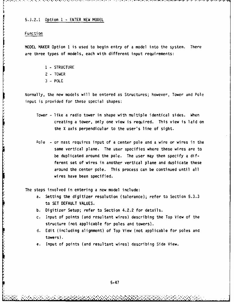
5.3.2.1 Option 1 ENTER NEW MODEL
Function
MODEL MAKER Option 1 is used to begin entry of a model into the system. Thereare three types of models, each with different input requirements:
1 - STRUCTURE
2 - TOWER
3 - POLE
Normally, the new models will be entered as Structures; however, Tower and Pole
input is provided for these special shapes:
Tower -like a radio tower in shape with multiple identical sides. When
creating a tower, only one view is required. This view is laid on
the X axis perpendicular to the user's line of sight.
Pole -or mast requires input of a center pole and a wire or wires in the
same vertical plane. The user specifies where these wires are to
be duplicated around the pole. The user may then specify a dif-
ferent set of wires in another vertical plane and duplicate these
around the center pole. This process can be continued until all
wires have been specified.
The steps involved in entering a new model include:
a. Setting the digitizer resolution (tolerance); refer to Section 5.3.3
to SET DEFAULT VALUES.
b. Digitizer Setup; refer to Section 4.2.2 for details.
c. Input of points (and resultant wires) describing the Top View of the
structure (not applicable for poles and towers).
d. Edit (including alignment) of Top View (not applicable for poles and
towers).
e. Input of points (and resultant wires) describing Side View.
5-47

NOTE: From this point, all processes are applicable for Structure input only.
f. Edit (including alignment) of Side View.
g. Sectioning of Side View.h. Input of wires to describe each Section View.
i. Generation (automatic) of three-dimensional sections from Top, Side,
and Section View data.j. Edit of three-dimensional sections, one at a time, to delete unwanted
points dnd lines.k. Generation of a three-dimensional model from the edited three-
dimensi onal secti ons.
During the model building processes, input data is saved in various files onthe disk:
a. 2-VIEW file - holds the Top and Side View and section boundary data;
i.e., all data entered through step g., above.b. SECTIONS file - holds the data entered for each section in step h.,
above.
c. 3-D SECT NO EDIT file - holds the data generated during step i.,
above, for each section.
d. 3-D SECT EDIT file - holds the data resulting from the editing of each
section in step J., above.
e. MODEL file - holds the data generated during the assembly of a three-
dimensional model from the edited 3-D sections in step k., above.
* When entering a new model, the user must complete at least through step g.,
* such that the 2-VIEW file can be created. At this point, the user can exit the- MODEL MAKER and return at some other time to continue model building at step
h., or whichever step is the next step in the build process. The functions* provided under MODEL MAKER Option 2 (WORK WITH OLD MODEL) allow the user to
pick up from any of the saved files and continue through the build process.Therefore, these functions (steps h. through k.) will be discussed under
* Option 2.
5-48

A ccess
Press <Fl> from MODEL MAKER Option Menu.
The user is then prompted to enter a name for the model; this can be anything
up to 20 characters long.
Next, the data entry options for the new model are displayed and the user is
* prompted to select the data entry option desired:
1I STRUCTURE
2 -TOWER
3 -POLE
- Based on the entry type selected, the Digitizer Setup procedure prompts the
* user for the entry of the information required for defining the origin,
coordinate system, scale, register point and plane(s) of symmetry (if any) for
the point (and wire) input. This is described in detail in Section 4.2.2.
ps 5.3.2.1.1 Enter Structure Data
Function
After Digitizer Setup has been accomplished (see Section 4.2.2), Top View point
entry begins. After all Top View points (and resultant wires) have been input,
the system goes into edit mode for that view. The vertical points are auto-
K: matically aligned (using the digitizer tolerance established via the SETDEFAULT VALUES function). If the vertical points are not aligned to the user's
satisfaction, manual alignment can be accomplished using the mouse. The user
V. then has the choice of using automatic or manual horizontal point alignment.(Caution: Auto-alignment will place all points within the given digitizertolerance on the same vertical line.) After points are aligned horizontally
and vertically, the Top View should be plotted and examined. The user is
* allowed to edit and plot until the Top View is satisfactorily completed.
p Next, the Digitizer Setup process is repeated for the Side View. When that has
* been completed, the user enters the Side View points in the same way as for the
I 5-49

7,KKT sS7Z-. . 7'
Top View. For Side View point entry, however, the system does not accept d
point which does not have a corresponding X coordinate in the Top View. (Point
correspondence is based on the digitizer tolerance. If the tolerance is large,* Side View point entry is easier but there is an increased risk of matching to
the wrong Top View point.)
IMPORTANT: Because of the point-matching requirement, the user must be surewhen entering the Top and Side Views that all hidden wires and
end-on wires (Figure 5-11) are input.
For points appearing in the Top View which have no corresponding point in the
Side View, the system draws a dotted line where it assumes a missing wire
* should be. The user must add points and wires on the Side View to complete the* view before exiting. Even if the point does not belong in the Top View, the- Side View must be completed using this point. The Top View can then be edited
- for this extra point, automatically deleting the erroneous wire from the Side* View. Side View editing is the same as for the Top View except there is no
vertical alignment. (Vertical alignment is forced when points are matched to- the Top View on input.)
* After the Top and Side Views have been completed, the Side View must be sec-
* tioned. This involves the placement of section lines perpendicular to the X
* axis. Two options are available: automatic sectioning whereby a section lineis placed through every point perpendicular to the X axis; and manual, which
* allows the user, with the aid of the mouse, to define the section boundaries.
in either case, sections are defined as the section boundary and all wires to
* the left of that boundary (up to the next section line to the left). A section* line must not be placed at the left-most end of the Side View (see Figure
5-12).
Once the section lines have been defined, the Top and Side View data is saved
- in a 2-VIEW file under the name given to this structure. The user has theoption of continuing through section entry and edit and generation of the 3-D
* model, or stopping at this point and picking up at a later time with the
* section entry function under the WORK WITH OLD MODEL option. Therefore, allfurther processing is discussed under that option.
5-50

e a b c d
e a b c d
end-on Hidden,• wi re wi res
Side View
Top View
Figure 5-11. Hidden and End-On Wires
1' 2 3 456 7 8
Figure 5-12. Section Boundaries
5-51
* . ~ ~ .L 1.~LA * * *~... ... . . . . '' * :.

Access
Press <Fl> from the MODEL MAKER Option Menu (ENTER NEW MODEL).
The user is prompted for input of a name for the new model. Enter up to 20
characters as a model name.
The Sub-Option Menu is then displayed; Press <Fl> (STRUCTURE) from this menu.
* The Digitizer Setup process is begun for initializing the digitizer for Top
* View input. (See Section 4.2.2).
* Operation
Follow the steps outlined in Section 4.2.2 to set up the digitizer (and the
drawing) for Top View entry. Once the Setup procedure has been successfully
completed, point entry may begin.
i'1IPORTANT: When using the digitizer to enter points, hold the digitizer pen
the same way for each point. That is, attempt to keep the digi-
tizer pen at the same angle and in the same direction relative to
the digitizer bar. A small change in the relative position of the
pen can make point entry and edit much more difficult -especially
when entering the Side View.
a. Point Entry (Top View)
* 1. The user receives a prompt on the bottom of the screen accompanied
by an audible tone:
ENTER START POINT:
2. Place the digitizer pen on the point in the drawing which starts aline (wire) and push down on the pen. A point is placed at thecorresponding screen location.
NOTE: Points and wires may be entered in any order.
5-52

3. When the system has accepted that point, the user receives a
second prompt accompanied by a different audible tone:
ENTER END POINT:
4. Position the digitizer pen on the point in the drawing which endsthe wire just started by the previous input and push down on theI. pen. A wire is drawn on the screen between the last start point
K5. The prompts for entering the start and end points are presentedV. alternately while the user continues entering each point on the
Top View. (In a short time, the user will learn to use the
audible tones as the prompts and will not need to look at the
screen at all.)
6. During point entry, the user has two alternatives to entering a
point with the digitizer pen in response to a prompt:
a) <L> - the <L> key can be used in response to the start point
prompt, to automatically use the last entered end point as the
next start point to "continue line.' (The <L> is ignored if
entered in response to the ENTER END POINT prompt.)
b) <Back Space> -this key can be used to erase the last start
point (in response to ENTER END POINT) and a new start pointis requested. If <Back Space> is pressed in response to the
ENTER START POINT prompt, the entire line preceding the last
end point is erased and a new end point is requested.
7. Point entry continues in this manner until all points have beeninput. When done with point entry, the user presses the <End> key
in response to the point entry prompt. The system then goes into
the edit mode for this view.b. Edit Top View
1. Once the user presses the <End> key in response to the point entry
prompt, the system automatically switches to edit mode for the Top
View and performs vertical alignment on all points. The alignm-n't
process uses the digitizer tolerance established via the SETDEFAULT VALUES function to eliminate point entry errors caused by
the digitizer pen position.
S 5-53

2. The user should then carefully examine the figure on the screen to
determine if all points which should be aligned vertically
actually have been. If not, the user must perform manual vertical
alignment.
3. When the user opts for manual alignment, cross hairs are posi-
tioned on the screen.
4. Use the mouse to position the cross hairs anywhere on a line
having points requiring alignment. (See Section 4.2.3 for cross
hairs movement.)
5. Once the cross hairs have been correctly positioned, press one of
the two buttons on the front of the mouse, hooking that line.
The system now employs four times the screen resolution for point
alignment selections.
6. A marker is placed at the bottom-most point as defined by the
cross hairs placement.
7. The user must now specify the action to be taken on that point by
A pressing:
a) <A> -align this point; point is marked for alignment and
marker moves to the next point up
b) <U> -don't align this point; the point is left as is and
marker is moved to the next point up
c) <L> - align all points marked with <A> and processing
returns to Step 3
d) <End> - done with manual alignment process; begin horizontal
alignment
8. After vertical alignment has been accomplished, the user has the
option of performing automatic and/or manual horizontal alignment.
CAUTION: Automatic horizontal alignment can distort the figure,depending on the pre-establ ished di gi tizer tolerance.
9. Manual horizontal alignment is done in the same mai,ner as verticalalignment except that the marker is moved from left to right
instead of bottom to top on the screen.
10. After both vertical and horizontal alignment have been performed,
plot the view, watching the plotter movements carefully to ensure
that all necessary lines (especially hidden lines) have been
entered.
5-54

11. Examine the plotter output carefully. If the figure has extra
wires or if it is missing wires, you will need to DELETE from and/
or ADD to the view.
12. To ADD a wire to the view, select the ADD function at the bottom
of the screen.
13. Use the mouse as described in Section 4.2.3 to position the cross
hairs on each of the two endpoints of the new line; press either
of the mouse buttons to hook each point. A new line is added to
the structure between the two hooked points.
14. To DELETE a point or wire from the view, select the DELETE
function at the bottom of the screen.
15. Use the mouse as described in Section 4.2.3 to position the crosshairs on the point or line to be deleted and press either of the
mouse buttons to hook this point or line; the line or point is
del eted.
NOTES:
(1) If the hooked wire overlaps another wire, the wire that was
input first is deleted. If this is not the correct one to
delete, use delete again to delete the one desired then, ADD
back the erroneously deleted wire.
(2) When a point is deleted, all wires attached to that point
are also deleted.
16. Continue to edit and plot this view until completely satisfied.17. When Top View input and edit are complete, press <End> to begin
Side V.iew input.
c. Point Entry (Side View)
1. When the user signals the completion of Top View entry and edit,the Digitizer Setup procedure is executed to initialize the digi-
tizer for Side View input. This is exactly like the process forTop View initialization except scale is not requested and axis ofvertical symmetry is not offered as an optCion.
IMPORTANT: When prompted for the register point, be sure to use the SAMEPOINT used for the Top View. This point is used when matching
Top and Side View points.
5-55

2. Point entry for the Side View is performed in the same way as forthe Top View with one important exception: the system checks eachpoint entered by the user, accepting only those having an X coor-
dinate matching a point in the Top View. If no matching point is
found in the Top View, the user input is rejected with an audible
tone.
3. Point acceptance/rejection is determined by the pre-establisheddigitizer tolerance. If the tolerance is relatively large, point
entry is easier, however, there is then a greater chance of
matching to the wrong point in the Top View.
4. When point input is complete, press <End> to switch into edit made
for the Side View.
d. Edit Side View
1. The system attempts to match each point entered in the Side View
to a point in the Top View. For any point found in the Top Viewwhich has no corresponding point in the Side View, the system
draws a dotted line on the screen where it assumes a missing wire
should be.2. The user must complete the Side View for missing wires - even if
the Top View points do not belong there. The user can return to
edit the Top View later to delete those points, thereby deleting
any wires in the Side View connected to these points.3. Automatic and/or manual horizontal alignment only are provided for
Side View editing, as vertical alignment is forced by the point
matching requirement on point entry. Horizontal alignment is the
same as described for Top View editing.4. As for the Top View input and edit process, plot and edit the Side
View until it is correct. Press <End> to exit Side View input andedit.
e. Define Section Boundaries
1. Once the Top and Side Views have been completed, section bound-
aries must be defined on the Side View. The user has two options
for sectioning the structure:
a) Automatic - The system drops a section line perpendicular to
the X axis at every X value point on the Side View, startingat the right-most end point.
5-56

b) Manual -The system places a section line at the right-most
end point on the Side View. The user then may employ the
mouse and cross hairs technique to specify section boundaries.
2. For manual sectioning, use the mouse as described in Section 4.2.3
to position the cross hairs at the desired section boundary and
press either of the mouse buttons to set the boundary line.
NOTE: DO NOT put a section line at the left-most end of the Side
View.
3. If a section line has been entered in error, move the cross hairs
to that line and hit the <Del> key to delete that line.
NOTE: The right-most section line cannot be deleted.
4. When all section boundaries have been defined, the user may plot
the section boundaries or press <End> to save the Top and Side
View data in a 2-VIEW file.
NOTE: For a very simple figure requiring only one section, choose
the manual sectioning mode and press <End>. One section
line is placed at the right-most end of the figure.
Continue New Model Input as described under MODEL MAKER Option 2 (Section
* 5.3.2.2).
5.3.2.1.2 Enter Tower Data
* Function
* This option is provided to enable the user to generate a multi-sided tower
having n identical sides (for example, a radio tower). Digitizer Setup is
performed first - only the Horizontal axis of symmetry is allowed as an option.
The drawing should be placed in front of the digitizer bar such that its long
axis is parallel to the X axis, one side of the tower is parallel to the Yi
axis, and the base of the tower is to the left (see Figure 5-13).
5-57
......................................... ~.......-..Z*...

Horizontalaxis ofsymmetry
x
Figure 5-13. Drawing Placement for Tower Input
Point entry and edit are performed as for structures but for one view only.
The user specifies the number of sides in the tower and the system automati-
cally generates a three-dimensional tower based on this information.
Access
Press <Fl> from the MODEL MAKER Option Menu (ENTER NEW MODEL).
The user is prompted for input of a name for the new model. Enter up to 20
characters as a model name.
The Sub-Option Menu is then displayed; Press <F2> (TOWER) from this menu.
Operati on
a. Initialization. Follow the steps outlined in Section 4.2.2 to set up
the digitizer and proceed as follows:
1. Establish the origin, the X axis, and the Y axis using the
digitizer.
2. Enter the length of the side in meters using the keyboard.
3. Establish the Horizontal axis of symmetry using the digitizer or
press the <Return> key for no symmetry.
4. Press the <End> key to indicate that setup is done.
5. Enter the register point as the lower left point of the side
(tower base on left). Establish the boundaries of the side by
entering, in order, the upper left point, the lower right point,
5-58

and the upper right point. If a line of symmetry has been
established, the upper points should coincide (or be below) the
line of symmetry. After entering the four points, a dotted
outline of the side will appear on the screen.
6. Enter the number of sides using the keyboard.
7. Enter <Y> if a cap is desired.
b. Point Entry. Point entry for Towers is the same as described for
Structures (Top View point entry). If a line of Vertical symmetry has
been defined, enter only those points below this line - they will
automatically be reflected above the line on the screen.
c. Edit View. Align points and ensure that the figure is correct before
exiting. The system generates a three-dimensional model having the
specified number of identical sides and stores it in a MODEL file.
Note that it is not possible to edit the Side View after-exiting.
5.3.2.1.3 Enter Pole Data
Function
This option is provided to enable the user to generate a "maypole-like" model.
* .A pole consists of a center pole with wires hanging off in different direc-
* tions, each connecting to the ground or to another (shorter) pole. After
- Digitizer Setup is accomplished, the user enters the end points required to
define the center pole and any wires in a single vertical plane. These wires
can be duplicated around the pole and the user can specify another set of wires
in a different vertical plane to be duplicated until the entire structure has
been defined. The three-dimensional model is generated as the duplication
parameters are specified.
• .Access
_| Press <Fl> from the MODEL MAKER function (ENTER NEW MODEL).
" The user is prompted for input of a name for the new model. Enter up to 20
characters as a model name.
The Sub-Option Menu is then displayed; press <F3> (POLE) from this menu.
5-59

• The Digitize Setup process is begun for initializing digitizer input (see
Section 4.2.2).
* Operation
a. Initialization. Follow the steps outlined in Section 4.2.2 to set up
the digitizer and proceed as follows:
1. Establish origin, X axis, and Y axis using the digitizer.
2. Enter the height of pole in meters using the keyboard. If a scale
S-nei ,rl you may enter 7Prn fnr the heiaht of the pole, then
enter the left and right points of the scale using the digitizer
followed by the length of the scale using the keyboard.
3. Press the <End> key to indicate that setup is done.
4. Enter the register point as the pole base on the left side of the
screen, but to the right of the Y axis and above the X axis.
Enter the top point of the pole. A dotted line will appear on the
screen.
b. Point Entry. Point entry for poles is the same as described for
structures (Top View point entry). Remember, you are entering the
lines in one vertical plane.
c. Edit View. As described for the Top View of structures, except that
the only options are add lines, delete lines, and plot. When editing
is done, press the <End> key.
d. Specify Placement of Vertical Plane. Enter the start angle, the step
angle, and the number of copies for this plane. For example, to have
the plane pointing east, northeast, and north, enter 0, 45, 3. You
may repeat the placement of the plane as often as desired. Press the
<End> key when finished with this plane.
e. Enter Additional Vertical Planes. If you wish to enter other wire
patterns in different vertical planes, answer 'Y' to the question.
You will then need to specify the origin, the X axis, the Y axis, and
the register point as in item (a.). Note that the height of the pole,
the top of the pole and <End> are not entered. Repeat steps (b.)
through (d.) until all planes have been entered. Press <End> when
finished. The system generates a three-dimensional model and stores
it in a MODEL file. Note that it is not possible to edit the vertical
plane views after exiting.
5-60

5.3.2.2 Option 2 - WORK WITH OLD MODELS
Function
MODEL MAKER Option 2 allows the user to work with model data at any of the five
stages of the model generation process, providing a flexible model edit
capability. The operations allowed for each of the files marking the five
stages are:Paragraph
2. -VTFW 5.3.2.2.1
1. ENTER SECTION DATA 5.3.2.2.1.1
2. EDIT FILE 5.3.2.2.1.2
3. COPY FILE WITH NEW NAME 5.3.2.2.1.3
4. DELETE FILE 5.3.2.2
b. SECTIONS 5.3.2.2.2
1. GENERATE 3-D SECTIONS 5.3.2.2.2.1
2. EDIT FILE 5.3.2.2.2.2
3. DELETE FILE 5.3.2.2
c. 3-D SECT NO EDIT 5.3.2.2.3
1. EDIT FILE 5.3.2.2.3.1
2. DELETE FILE 5.3.2.2
d. 3-D SECT EDITED 5.3.2.2.4
1. GENERATE MODEL 5.3.2.2.4.1
2. DELETE FILE 5.3.2.2
e. MODEL 5.3.2.2.5
1. LOOK AT FILE 5.3.2.2.5.1
2. EDIT FILE 5.3.2.2.5.2
3. COPY FILE WITH NEW NAME 5.3.2.2.5.3
4. GENERATE GEOMETRY DECK 5.3.2.2.5.4
5. DELETE FILE 5.3.2.2
6. ASSEMBLE MODELS 5.3.2.2.5.5
7. RE-SORT MODEL 5.3.2.2.5.6
The DELETE FILE function is the only function available for all file types.
It is, therefore, discussed here and not repeated under each of the file
sub-option descriptions to follow.
5-61
I-I

L1 Access
Press <F2> from the MODEL MAKER Option Menu (WORK WITH OLD MODEL).
* The user is prompted for entry of the name of the model to be worked with. If
the name is not known, press <Return> to scan all model names. When the model
name is identified, enter the index corresponding to that model on the
* displayed list.
The file status display for the selected model is presented on the screen:
MODEL-X FILE STATUS
I MODE-X 2 VIEW DT
2 MODEL-X SECTIONS DATA
3 MODEL-X 3-0 SECT NO EDIT DATA
4 MODEL-X 3-D SECT EDITED DATA
5 MODEL-X MODEL NO DATA
6 DELETE FILE
Select :ne file to be worked with from this status display (any file with a
DATA status is valid) by pressing the corresponding function key. The sub-
options available for the selected file are displayed as described on theprevious page.
DELETE FILE
Functi on
The DELETE FILE function allows the user to selectively delete obsolete files
thereby freeing up disk space. This function should be used with extreme care
as once a file is deleted it cannot be recovered.
Access
Follow the ACCESS instructions for Option 2.
* Select the file to be deleted (1, 2, 3, 4, or 5).
5-62
a *

Select the DELETE FILE function from the Sub-Option Menu (the function key
varies depending on the file type selected for deletion).
Operation
The user gets a chance to change his mind before the specified file is deleted.
To confirm the deletion request and complete the dction, the user must type:
DEL <Return>
NOTE: The <Del> key will not cause file deletion.
If you decide not to delete this file, press <Return>.
5.3.2.2.1 2-VIEW File Operations
Functi on
A 2-VIEW file is created at the completion of new model data entry and consists
of the Top and Side View points and wires and the section boundary information
for a given model. The following functions are available for any 2-VIEW file:
a. ENTER SECTION DATA - the user is required to define the End View for
each defined section in the model (with points and wires placed in the
Y-Z plane).
b. EDIT FILE - the Top and Side Views can be edited to add or delete
points and/or wires and the Side View can be resectioned.
c. COPY FILE WITH A NEW NAME - the 2-VIEW file can be copied and renamed,
thereby allowing the user to edit the Top and Side Views to generate a
slightly different structure while leaving the original file intact.
Access
Press <F2> from the MODEL MAKER Option Menu (WORK WITH OLD MODEL).
Select model to be worked with.
Press <Fl> for the 2-VIEW file for that model.
5-63

- 5.3.2.2.1.1 Enter Section Data
* Function
* This option provides the user with the means for describing each of the defined
sections (one at a time) for a given model.
The computer generates a tentative drawing of the End View of each section,
based on the Top and Side View entry and section boundaries. The screen
* represents the Y-Z plane. The user is required to edit this tentative view to
* complete the End View for each section. Generally, this tentative view should
- be a fairly accurate representation of the End View; however, wires which
* appear in the Top and Side Views as vertical lines with the same X coordinates
* are represented in the tentative view as a rectangle and may require editing.
* See Figure 5-14 for a graphic representation of this problem. If the tentative
view is missing wires that should be included, it is very likely that the wire- is missing in the Top or Side View as well. It will be necessary to edit the
appropriate view for the missing wire.
Top View Side View Tentative End View
Other Possible End Views
Figure 5-14. Sample End View Generation Problem
Access
Press <F2> from the MODEL MAKER Option M1enu (WORK WITH OLD MODEL).
Select model to be worked with.
Press <Fl> for the 2-VIEW file for that model.
Press <Fl> from the Sub-Option Mlenu (ENTER SECTION DATA).
5-64

Operation-
* Complete the following steps:
a. A tentative drawing of the End View of the section is displayed on the
screen.
b. Remembering that you are looking at the Y-Z plane (End View), decide
whether wires must be added or deleted.
c. if a wire needs to be added, press <1>.
1. Using the cursor keys, position the displayed fnarker to a point
which is to Start a wire;
<->- marker left < t> - marker up
<- > - marker right < > - marker down
2. When the marker is positioned to the start point, press <H> to
hook this point.
3. Using the same cursor keys, position the marker for end point
entry; press <H>. A wire is drawn connecting the two specified
points.
4. Press <End> when done adding wires to this view.
d. If a wire needs to be deleted, press <2>. Use the mouse as described
in Section 5.3.2.1.1.b, steps 14-15, to delete wires. Press <End>
when done deleting wires from this view.
IMPORTANT: ALL WIRES MUST BE ENTERED, INCLUDING OVERLAPPING AND END-ON
WIRES. (For end-on wires, position the marker at the proper
point and press <H> twice.)
e. To plot the End View of the section, press <3>.
f. The above procedure is repeated for each of the defined sections of
the structure, until all have been entered.
g. The completed section data is used to generate 3-D sections. The
system attempts to generate a 3-D section for each of the sectionsdefined. If unsuccessful, the user will be required to re-edit the
section or sections in question. When a 3-D section can be success-
fully generated, it is saved in the 3-D SECT NO EDIT file for that
model (see Section 5.3.2.2.3).
5-65

5.3.2.2.1.2 Edit 2-VIEW File
Function
This MODEL MAKER option allows the user to edit the Top and/or Side Views of a
given model in the same way as described under Section 5.3.2.1.1. This option
also provides a means to resection a model.
Access
Press <F2> from the MODEL MAKER Option Menu (WORK WITH OLD MODEL).
Select model to be worked with.
Press <Fl> for the 2-VIEW file for that model.
Press <F2> from the Sub-Option Menu (EDIT FILE).
Operation
Refer to Section 5.3.2.1.1 b., d., and e. for descriptions of Top and Side
View edit procedures using the mouse as an input device.
5.3.2.2.1.3 Copy 2-VIEW File With New Name
Function
This option allows the user to copy the 2-VIEW file to a new file with a new
name. This is particularly useful if a new structure is to be generated which
is just slightly different from the original. After the new 2-VIEW file is
created, the user can enter Section data (Section 5.3.2.2.1.1) and Edit File
(Section 5.3.2.1.1) for this new file to create the new SECTIONS file for the
copied structure.
5-66
" '_'- -' '-.. " "- .'"..r " " °. -" " " ' "' . '-'. '.'.'. ."...'.'w -,'_ " , . - •",.'.", '1A. .

* Operation
*Complete the following steps:a. A tentative drawing of the End View of the section is displayed on the
screen.
b. Remembering that you are looking at the Y-Z plane (End View), decide
whether wires must be added or deleted.
c. if a wire needs to be added, press <1>.
1. Using the cursor keys, position the displayed inark(er to a point
wIB[-I I~ LV 1 41 s os t3 r
< - > - marker left < t> - marker up
<- > - marker right <i> - marker down
2. When the marker is positioned to the start point, press <H> tohook this point.
3. Using the same cursor keys, position the marker for end pointentry; press <H>. A wire is drawn connecting the two specified
points.
4. Press <End> when done adding wires to this view.
d. If a wire needs to be deleted, press <2>. Use the mouse as describedin Section 5.3.2.1.1.b, steps 14-15, to delete wires. Press <End>
when done deleting wires from this view.
IMPORTANT: ALL WIRES MUST BE ENTERED, INCLUDING OVERLAPPING AND END-ON
WIRES. (For end-on wires, position the marker at the proper
point and press <H> twice.)
e. To plot the End View of the section, press <3>.f. The above procedure is repeated for each of the defined sections of
the structure, until all have been entered.g. The completed section data is used to generate 3-0 sections. The
system attempts to generate a 3-D section for each of the sectionsdefined. If unsuccessful, the user will be required to re-edit thesection or sections in question. When a 3-0 section can be success-fully generated, it is saved in the 3-0 SECT NO EDIT file for thatmodel (see Section 5.3.2.2.3).
5-65

* 5.3.2.2.1.2 Edit 2-VIEW File
-* Function
This MODEL MAKER option allows the user to edit the Top and/or Side Views of a
given model in the same way as described under Section 5.3.2.1.1. This option
*also provides a means to resection a model.
Access
Press <F2> from the MODEL MAKER Option Menu (WORK WITH OLD MODEL).
Select model to be worked with.
Press <Fl> for the 2-VIEW file for that model.
Press <F2> from the Sub-Option Menu (EDIT FILE).
* Operation
Refer to Section 5.3.2.1.1 b., d., and e. for descriptions of Top and Side
View adit procedures using the mouse as an input device.
5.3.2.2.1.3 Copy 2-VIEW File With New Name
Function
This option allows the user to copy the 2-VIEW file to a new file with a new
name. This is particularly useful if a new structure is to be generated which
is just slightly different from the original. After the new 2-VIEW file is
created, the user can enter Section data (Section 5.3.2.2.1.1) and Edit File
(Section 5.3.2.1.1) for this new file to create the new SECTIONS file for the
copied structure.
5-66
......, - .* % . . . .. *l-i~--i "- -- , i," .. ' .... I. * '* . " , " ."_

AD-A±60 695 INTERACTIVE GRAPHICS UTILITY FRAYNC(UEIA /ELECTROMAGNETICS COD.. (U) SYSTEM DEVELOPMENT CORP SANDIEGO CA J STRAUCH ET AL. SEP 85 NOSC-CR-366UNCLASSSIFIED N66S6±-83-D-8894 F/G 9/2 NM h~hEhE7hEE~h~h
I lffllf~lffllff

1111.0 6L 8 .32
u2.2bg 14
11111-125 111 .4 11 1 1 1 11 1.6
MICROCOPY RESOLUTION TEST CHARTmATONA. S.AU OF STANDADS-1,03
S 1.. .. .. . . . . . . . . . . . . . . . . . . . . . ..
.. % .* .

5.3.2.2.2.2 Edit SECTIONS File
Function
This option allows the user to selectively edit any (or all of the section
End Views) stored in the SECTIONS file for a given model. Edit functions are
the same as those described in Section 5.3.2.1.1.
Access
Press <F2> from the MODEL MAKER Option Menu (WORK WITH OLD MODEL).
*Select model to be worked with.
Select the SECTIONS file from the status display (press <F2>).
Press <F2> from the Sub-Option Menu (EDIT FILE).
Operation
*; The operator is prompted to enter the number of the section to be edited or
S,.<Return> to edit all (displayed for editing sequentially).
Edit functions are described in Section 5.3.2.2.1.1, step i.
*. 5.3.2.2.3 3-D SECT NO EDIT File Operations
Functi on
The 3-D SECT NO EDIT file is generated by the system (see Section 5.3.2.2.2.1)
*, from the End Views saved in the SECTIONS file for a given model. Only one
function other than DELETE FILE can be performed on this file:
a. EDIT FILE - the user is presented with the 3-D (unedited) views of
each section for the specified model (one at a time). The section canbe edited to add lines and delete unwanted points and lines. Zoom and
plot functions are also available to aid in the editing process.
5-69
................. ....... ......................... ............. .. -....-.: , -. , . .. . ,.- '-.' . ,--.' ... ,., ' ,' ,

Access
Press <F2> from the MODEL MAKER Option Menu (WORK WITH OLD MODEL).
Select model to be worked with.
Select the 3-0 SECT NO EDIT file by pressing <F3> from the file status display.
5.3.2.2.3.1 Edit (Unedited) 3-D SECTIONS File
Function
This option enables the user to examine (on the screen) each of the 3-D sec-
tions generated as described in Section 5.3.2.2.2.1 and to rotate the screen
figure so that it can be edited for unwanted points and lines. This is almost
always necessary because, if Top, Side, and End Views have been correctly
* input, there will be more wires in the structure than needed. Missing lines
may be added to the 3-D sections as long as the end points for these lines are
* present. A missing line is usually an indication that there is at least one
error in the Top, Side, or End View. This Add Line capability saves the user
*the trouble of having to back up and correct earlier errors in other views.
Access
Press <F2> from the MODEL MAKER Option Menu (WORK WITH OLD MODEL).
Select model to be worked with.
Select the 3-D SECT NO EDIT file from the status display (press <F3>).
* Press <Fl> (EDIT FILE) from the Sub-Option Menu.
Operati on
a. An unedited section is displayed on the screen. The user may rotate
this display (see Section 5.3.2.2.5.1 for description of rotation).
The sections are presented as generated -no symmetry is applied.
5-70

b. Rotate the displayed figure so that its configuration is optimiallyvisible. Press <End> when done rotating.
c. At the bottom of the screen the user is presented with the options of
adding, deleting, plotting, or rotating.
d. To add a line, select Option 1.
*1. Cross hairs are put up on the screen. Use the procedures
described in Section 4.2.3 to position the cross hairs centerwhere the new line is to start (any point in the section).
2. When the cross hairs have been properly positioned, press either
of the two mouse buttons to hook the point at the cross hairs
center.3. The user is then prompted to HOOK OTHER END. Position the cross
hairs center on the other end point and press one of the mouse
buttons.
4. If points have actually been hooked, the specified line is added
to the section view.5. Press <End> to redisplay the Edit Menu when done with the Add
opti on.
e. To delete a point or line, select Option 2.
1. Cross hairs are put up on the screen. Use the proceduresdescribed in Section 4.2.3 to position the cross hairs center on
the point or line to be deleted.2. When the cross hairs have been properly positioned, press either
of the two mouse buttons to hook the point or line to be deleted.3. Make sure this is the point or line to be deleted and press the
<Del> to delete it.4. If a point has been hooked, that point and any lines connected to
it are deleted from the section view. The point is still avail-able as an end point for adding a line. If a line has been hooked(away from the end points), that line is deleted from the section
vi ew.
5. When done deleting wires, press <End> to redisplay the Edit Menu.f. To plot the section view as displayed on the screen, select Option 3.
9. To rotate the view, press <Return>.
h. When done with all edits for this section, press <End>. All stray
points are deleted at this time.
5-71

The edited 3-0 sections are saved in the 3-0 SECT EDITED file, awditing model
* generation.
* 5.3.2.2.4 3-D SECT EDITED File Operations
* Function
- This file is generated during the EDIT FILE function for the 3-D SECT NO EDIT
file (Section 5.3.2.2.3). The only operation that can be performed on this
file (except DELETE FILE) is:
a. GENERATE 3-0 MODEL - This is the goal that has been worked toward all
this time. The system takes each of the 3-0 (edited) sections stored
in the 3-0 SECT EDITED file for a given model and "sticks" them
together at the predefined section boundaries (Section 5.3.2.2.4.1).
* Access
* Press <F2> from the MODEL MAKER Option Menu (WORK WITH OLD MODEL).
Select model to be worked with.
- Select the 3-0 SECT EDITED file by pressing <F4> from the file status display.
* 5.3.2.2.4.1 GENERATE 3-0 MODEL
* The system takes each of the edited 3-D sections stored in the 3-0 SECT EDITED
* file for the specified model and sticks them together end-to-end as defined by
the section boundaries. The entire 3-D model is figuratively "shoved in a
shoebox" and shifted as close to the coordinate system origin as possible. All
* point coordinates and wires are now saved in the MODEL file for this structure.
Access
* Press <F2> from the MODEL MAKER Option Menu (WORK WITH OLD MODEL).
* Select model to be worked with.
Select the 3-0 SECT EDITED file by pressing <F4> from the file status display.
5-72
. * . . . . .. . . . . . . . . . . . . . . *.*. * Ai

- - ' - . r rr .
* Press <Fl> (GENERATE 3-D MODEL) from the Sub-Option Menu.
Operati on
No user interface is required.
5.3.2.2.5 MODEL File Operations
* Function
A MODEL file is generated via the GENERATE 3-D MODEL function (described in
Section 5.3.2.2.4.1) and is the end result of all previous operations. The
* following functions are available for any MODEL file:
a. LOOK AT FILE - This function allows the user to display the model,
view the model on any of the three planes, rotate the picture, zoom,
and plot the model.
b. EDIT FILE - By using this function, the completed model can be edited
to add wires, delete unwanted wires and/or to reproportion the
finished structure.
c. COPY FILE WITH NEW NAME - The user can copy a MODEL file to a new file
with a new name.
d. GENERATE GEOMETRY DECK - This function is used to generate wire cards
for all wires in a completed model. These cards are then used to
build a complete input data set.
e. ASSEMBLE MODELS - This function allows the user to create models from
large drawings which are too large for digitizer input.
f. RE-SORT MODEL - This function allows the user to specify the direction
of wire sorting before generation of Geometry Cards.
* Access
* Press <F2> from the MODEL MAKER Option Menu (WORK WITH OLD MODEL).
* Select model to be worked with.
Select the MODEL file by pressing <F5> from the file status display.
5-73

..
5.3.2.2.5.1 Look at 3-D MODEL File
Functi on
This option provides a flexible model viewing capability which allows the user
to display the model on the screen, view the model on any of the three planes,
rotate the picture in any direction around any of the three axes, zoom (on the
center of the structure only), and plot the model.
Access
Press <F2> from the MODEL MAKER Option Menu (WORK WITH OLD MODEL).
Select the model for viewing.
Select the MODEL file by pressing <F5> from the file status display.
- I Press <Fl> (LOOK AT FILE) from the Sub-Option Menu.
I operation
I )a. The selected model is displayed on the 3creen. At the lower left of
the screen is an X, Y, and Z axis marked for picture scale. (Each
axis is actually the same length - use this information when using the
rotation function.)
b. Rotation - use the following keys to rotate the coordinate system
display into the position in which you wish to view the structure
(also see Figure 5-15):
<Pg Dn> - rotate counter-clockwise around line-of-sight
<Pg Up> - rotate clockwise around line-of-sight
<-> - rotate left around line vertically perpendicular to line-of-
sight
<-> - rotate right around line vertically perpendicular to line-of-
sight
< - rotate down around line horizontally perpendicular to line-of-
sight
.<>- rotate up around line horizontally perpendicular to line-of-
si g ht
5-74
.................. s.. .. . . . . . . . . . . . . . . . . . . . .

(Pg DO>
> <4>
X <Pg Up>
Figure 5-15. Rotation Control
<>- view Y-Z plane fronm positive end of X axis (End View)<>- view X-Z plane from negative end of Y axis (Side View)<>- view X-Y plane from positive end of Z axis (Top View)
<Return> - when the coordinate system has been rotated to your satis-faction, press <Return> to display the rotated picture
<End> -stops rotation process to allow plotting and exit<Home> -redisplay starting view and normal scale
c. Zooming -when using the LOOK AT file function, the user can zoom thedisplayed view around its center with the following keys:
<>- doubles the picture size each time it is pressed
<Back Space> - returns to the original (non-zoomed) size, retainingcurrent view
d. Plotting - align paper in the plotter as shown in the plotter manual.
Use a sturdy, relatively nonporous paper for best results (copier
paper is satisfactory). The picture that is plotted is as large as
5-75

will fit on the plotter paper and still get the whole structure on the
paper. Press <1> to plot the displayed model. To create a plot with
the wire ends marked and the wires numbered, press <2>. The wire
numbers correspond to the sequence of the 'GW' cards generated by this
model.
NOTE: Zooming does not affect plotting - the whole structure is always
plotted, regardless of what is shown on the screen.
e. Exiting - To return to rotating and zooming the model, press
<Return>. To return to the Initial Options Menu, press <End>. To
return to the Model Menu for the current model, press the cursor down
key < >
5.3.2.2.5.2 Edit 3-D MODEL File
Function
The completed model can be edited to add wires, delete unwanted wires, and/or
to reproportion the finished structure using this option. Zoom, rotation, and
plot functions are also available to aid in the editing process.
Access
Press <F2> from the MODEL MAKER Option Menu (WORK WITH OLD MODEL).
Select the model to be edited.
Select the MODEL file by pressing <F5> from the file status display.
Press <F2> (EDIT FILE) from the Sub-Option Menu.
Operation
a. REPROPORTIONING - the user can change the length, width, or height of
the structure, as desired.
5-76
. ........ - - - * .~~wl , .m dm * m . -".. . . ".. . . . . . . . . . . . * .' . *'-

1. The current dimensions of the model (X =length, Y =width,
Z = height) are displayed. To change any or all of the structure
dimensions, press the following keys:
<1> - change X dimension (length)
<2> - change Y dimension (width)
Q>- change Z dimension (height)
2. When a dimension is selected for change, the user is prompted to:
ENTER NEW DIMENSION IN METERS
3. Enter the new dimension, followed by <Return>.
4. Select another dimension for change or press <End> if done repro-
porti oni ng the model.5. The model is then displayed on the screen (in its new proportions,
if any) and the user can rotate and/or zoom the picture so it is
optimally displayed for editing.
b. ROTATION/ZOOMING - Refer to Section 5.3.2.2.5.1 for description.
Zooming occurs at the cross hairs center during the model edit
function. Use the mouse to position the cross hairs for zooming.
When done with rotation and zooming, press (End> to switch to the EDIT
mode.
c. EDIT Mode - The user may add or delete wires on the model. If the
plotter is available, the model may be plotted. Additionally, the
user may return to rotating and/or zooming the model.
d. ADD WIRE - Press <1> to add a wire to the displayed model.
1. Cross hairs are put up on the screen. Use the procedures
described in Section 4.2.3 to position the cross hairs center
where the new wire is to start (on any point or line in the
structure).
NOTE: Use the zoom feature to make cross hairs positioning easier.
2. When the cross hairs have been properly positioned, press either
of the two mouse buttons to hook the point at cross hairs center.
3. The user is then offered a choice between using an existing end
point or defining a new end point:
5-77

a) NEW END POINT -the user is prompted to specify in which
direction from the hooked posi ti on the new wi re is to be
drawn. Choices are X, Y, and Z only. After specifying wire
direction, the user is asked for wire length. Enter length inmeters (positive or negative).
NOTE: If a wire in other than the X, Y, or Z direction is
required, wires must be added in a stepping pattern to
reach the end point of the wire wanted. Use the EXISTING
END POINT function to add the wire, then delete all
wires used to step to the end point (see Figure 5-16).
b) EXISTING END POINT - The user is prompted to position the
cross hairs at the point to which the current point is to be
connected with a wire. Do so and press one of the mouse
buttons.
4. If points have actually been hooked, the specified wire is added
to the structure.
5. Press <End> to redisplay Edit Mend when done with ADD option.
e. DELETE WIRE - Press <2> to delete wire (DELETE WIRE is also used todelete a single point if a point instead of a wire is hooked).
1. Cross hairs are put up on the scrr.en.. Use the proceduresdescribed in Section 4.2.3 to position the cross hairs center cn
the point or wire to be deleted.
NOTE: Use the zoom feature to make cross hairs positioning
easier.
* I2. When the cross hairs have been properly positioned, presseither of the two mouse buttons to hook the wire or point to
be deleted.
3. Make sure this is the point or wire to be deleted and press the
<Del> key to delete it.
4. If a point has been hooked, that point and any wires connected
to that point are deleted from the structure. If a wire has been
hooked (away from the end points), that wire is deleted from
the structure.
5-78
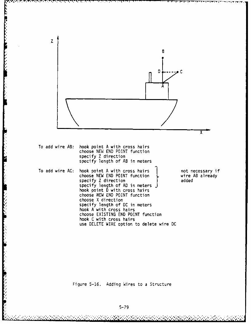
z
D.C
A
x
To add wire AB: hook point A with cross hairschoose NEW END POINT functionspecify Z directionspecify length of AB in meters
To add wire AC: hook point A with cross hairs 1 not necessary ifchoose NEW END POINT function wire AB alreadyspecify Z direction addedspecify length of AD in metershook point D with cross hairschoose NEW END POINT functionchoose X directionspecify length of DC in metershook A with cross hairschoose EXISTING END POINT functionhook C with cross hairsuse DELETE WIRE option to delete wire DC
Figure 5-16. Adding Wires to a Structure
5-79
?' " ' " - •' ."-'- . .' .-. - '-".''-.''U'.-."".--.. -.. -U.'-- . ' '.i.L.I.'- i. • - '- '

NOTE: All stray points are deleted upon exit.
5. When done deleting wires, press <End> to redisplay Edit Aenu.
f. PLOT MODEL - If the plotter is available, press <3> to plot thedisplayed model. To create a plot with wire ends marked and wires
numbered, press <0>. The wire numbers correspond to the sequence of
~ I the 'GW' cards generated by this model.g.EXIT - To return to rotating and zooming, press <Return>. To return
to the Initial Options Menu, press <End>. To return to the Model Menufor the current model, press the cursor down key <J >.
5.3.2.2.5.3 Copy 3-D MODEL File With New Name
Function
This option 3llows the user to copy a MODEL file to a new file with a new name.
This is particularly useful if a new structure is to be generated which is
just slightly different from the original. Only the MODEL file - not the four
preceding files - is copied.
Access
Press <F2> from the MODEL MAKER Option Menu (WORK WITH OLD MODEL).
Select model to be copied.
Select MODEL file for copying by pressing <F5>.
Press <F3> (COPY FILE WITH NEW NAME) from the Sub-Option Menu.
Operation
a. The user is prompted for entry of a new name for the MODEL file to becreated; enter up to 20 characters for the new model name.
b. The selected model is copied to a new file with the specified new
name. Any of the sub-options described in Section 5.3.2.2.5 can be
used on this new file.
5-80

5.3.2.2.5.4 Generate Geometry Deck
Function
This option is used to generate wire cards for all wires in a completed
model. These cards are then used to build a complete NEC input data set'I(deck) via the CARD EDITOR function.
Access
Press <F2> from the MODEL MAKER Option Menu (WORK WITH OLD MODEL).
Specify the model for which wire cards are to be generated.
Select the MODEL file from the file status display (press <F5>).
* Press <F4> (GENERATE GEOMETRY DECK) from the Sub-Option Menu.
* Operation
a. The user is allowed to shift the model along any of the axes or to
center the model on the X and Y axes. The user is also allowed to
change the default values to be used for the generation of this set of
wire cards ('GW' cards). These values are wire radius, segments permeter, tag start, tag increment, and the 'GE' card parameters (see
I NOTE 2, below).Ib. Next, the user is prompted for entry of a name for the Geometry deck
to be generated; enter any 10 characters for a name. If the name hasalready been used for another deck, the user may choose to overwrite
the old deck with this new one or to enter another name.c. The system automatically generates a 'GW' card for each wire in the
selected model in the order in which the wires have been sorted (seeSection 5.3.2.2.5.7). Wire tagging, segmentation, and radius are
based on the currently established values in the Defaults file. Theend points of all wires are specified in terms of metric coordinatesin floating point format.
5-81

N4OTE 1: All wires are expressed in units of meters based on the user-specified
scale. This scale can be changed via CARD EDITOR Option 2.2 (Section
5.3.1.2) by inserting a 'GS' card in the deck just generated.
NOTE 2: The last card image in the generated deck is 'GE'. It contains three
parameters: ground plane, output option, and IRESRY.
5.3.2.2.5.5 DELETE FILE
* This option is described at the beginning of this section (Section 5.3.2.2).
5.3.2.2.5.6 Assemble 3-D Models
Functi on
This option provides the user with the capability of creating models fromdrawings which are too large for digitizer input. The large drawing must bebroken up into several smaller drawings, each of which must be entered as a
separate model. This option, then, allows the user to assemble these models
into a single structure.
K NOTE: This function is also useful for duplicating substructures to producea structure consisting of several identical substructures.
* Access
* Press <F2> from the MODEL MAKER Option Menu (WORK WITH OLD MODEL).
Specify model to start working with.
F Select MODEL file by pressing <FS> from the file status display.
Press <F6> (ASSEMBLE MODELS) from the Sub-Option Menu.
Operation
IMPORTANT: It is the user's responsibility to ensure that the models actuallycan be assembled -the program has no way of telling.
5-82

W~hen specifying the models to be assembled, select in the follow-ing order:
1. left to right for long structures
2. bottom to top for high structures
3. front to back for wide structures
a. Enter, when prompted, the name of the model to be assembled to thisone.
b. Enter, when prompted, the name for the new assembled structure.c. Enter, when prompted, the axis to assemble along (X, Y, or Z).d. The two models are displayed according to the assembly order (speci-
fied above) and the specified axis of the assembly. Points from the
right side (top side, or back side) of the first model are to bematched with points on the left side (bottom side, or front side) of
the second named model.e. Points on the first specified model (the base model) are indicated
with a "0"; points on the second (joined) model are displayed with aI* (Only those points on the selected plane of assembly are
displayed.) A marker, or spot, is placed on one of the points on thebase model. Press the <Return> key to hop this marker around the basemodel points until it rests on the point to be joined to the second
model.f. Press <H> to hook the point of assembly in the base model. Verify
the point selection by entering Y in response to the displayedprompt. (Enter N to reselect the base point of assembly.)
g. Use the same process (described in e. and f., above) to select thepoint of assembly in the second model.
h. Once the two points of assembly have been selected, the systemattempts to line up the two models based on these selected points andthe plane of join. The resulting point alignment is displayed on thescreen and the user is prompted to press <End) to save thiis model or<Return> if the resulting alignment was unsatisfactory (<Return>
allows the user to retry the assembly from step e.).i. Repeat the entire assembly process until all pieces of the desired
larger model have been assembled to form one new model. When modelsare assembled, only the model file is created (no intermediate filesare generated). Only those functions available for model files can be
5-83

used with models which have been created via the model assembly
process.
HINTS: It will take several attempts at using the model assembly function
before it becomes "easy to use." Naturally, the assembly process will
be easiest when there are fewer points on the two models to be lined
up; for example, adding a cap to the top of a pole. When assembling
complex structures, such as the bow and stern of a ship, there can be
I many points of join. The user will want to select two points which
will cause the two models to line up in the best way (usually towards
I the center of the two models). Although the system does some duto-matic alignment trying to best fit the two sections together, they
will not always line up exactly. The user may have to exit the
assembly process and use the EDIT 3-0 MODEL function to change the
* j dimensions of one of the parts before returning to the assemble models
process. Another possibility is to increase the point tolerance (see
SET DEFAULT VALUES, Section 5.3.3) so that automatic alignment will* I produce a better fit.
5.3.2.2.5.7 Re-Sort 3-0 Model
Fun*~ction
This option allows the user to specify the direction of wire sorting beforegeneration of Geometry Cards. (NEC runs faster on sorted wires.)
Access
Press <F2> from the MODEL MAKER Option Menu (WORK WITH OLD MODEL).
Specify the name of the model to be sorted.
Select the MODEL file from the file status display (press <F5>).
* Press <F7> from the Sub-Option Menu (RE-SORT MODEL).
5-84

Operation
The user is prompted to select the direction of the sort:up X axis down X axis
up Y axis down Y axis
Iup Z axis down Z axis
The model is centered on the origin while the system spirals counterclockwisein the specified direction, arranging wires in the model file based on the
midpoint values of each.
OF INTEREST: Sorted wires are observable when plotting.
5.3.2.3 Option 3 -BUILD MODEL FROM GEOMETRY CARDS
Function
I This option allows the user to create a 3-D model from a NEC data set of
Geometry Cards. To use Option 3, the NEC data set must be available in the
IGUANA directory as a sequential file with an extension of ".NEC". Any
Transmit Data Set (a NEC input data set) prepared via the IGUANA CARD EDITOR
function can be used to create a 3-D model. For data sets generated on other
* computers, the card images must be downloaded (using a modem and modem program)
to the IGUANA system and given a filename with the ".NEC" extension.
Access
S Press <F3> from the Option Menu.
* The user is prompted to specify the name of the data set to be used:
NEC Dataset Name (.NEC)
Type in the name of the data set (without the extension) and press <Return>.
The user is then prompted to enter the name for the new model:
ENTER NEW MODEL NAME or <Return> TO SCAN MODELS
5-85

Thl- model will then be created. Program control is automatically trdnsferred
Ito the 3-0 Model Edit function.
5.3.2.4 Option 4 - ARCHIVE/RESTORE MODELS
Function
This option allows the user to save models on a floppy disk (diskette), delete
Ithese archived models from the main (system) disk, if desired, and restore
previously archived models onto the system disk. To use Option 4's Archive
I function, a formatted diskette must be on hand. See Section 5.3.1.9 on how to
* format a diskette. To use Option 4's Restore function, the user must have a
diskette that has already been used to archive models.
Access
Press <F4> from the Option Menu.
The user is prompted to specify the operation to be performed:
ARCHIVE FUNCTIONS
1 - WRITE MODEL(S) TO FLOPPY DISK
2 -RESTORE MODEL(S) FROM FLOPPY TO FIXED DISK
Press the function key corresponding to the sub-option choice desired.
5.3.2.4.1 Writing Model(s) to a Floppy Disk (Archiving). When Sub-Option 1 isselected from the Archive Function Menu, the names and file types for each ofthe existing models are displayed on the screen (to see more, use the <Return>key). The user is prompted to select the model(s) to be archived. See Section
* 5.3.1.9.1 on how to select and deselect models for archiving.
When all selections have been made, press the <End> key to start the archiving
process.
A formatted diskette must now be loaded into the floppy drive (drive A:). The
user is prompted to indicate when the diskette is ready for archiving:
5-86

Place FOR14ATTED Diskette in Drive A:
Select which file types to save (A=AIl)
1- 2-VIEW, 2 - SECTIONS, 3 -3-D SEC NO EDIT, 4-3-D SEC EDIT, 5- MODEL
Press <Return> when READY
(Press <Esc> to ABORT)
if the <Esc> key is pressed, no archiving is performed; the Archive FunctionHenu is redisplayed.
The user types the numbers of the file types that are to be archived, e.g., to
save the 2-VIEW and MODEL files, 15 is typed. A maximum of 112 file names can
* be put into the diskette directory, so additional formatted diskettes should be* available in case needed. When the <Return> key is pressed, model archiving
* begins. As the selected decks are being read from the fixed disk and writtento the floppy disk, the screen display shows the current model name and file
type.
T7he user may then delete or save the archived models as described in Section5.3.1.9.1. Deleted models are completely removed from the system disk, no
-iatter which file types were archived.
5.3.2.4.2 Restoring Model(s) to the Fixed Disk. This procedure is completely
analogous to the Restoring Deck(s) function as described in Section 5.3.1.9.2.
5.3.3 Set DEFAULT VALUES Function. This function allows the user to set
* system default values for use in the generation of wire cards, a digitizer
point entry tolerance value for delimiting digitizer point entry, and thesystem hardware configuration (equipments available).
Function
* The SET DEFAULT VALUES function allows the user to set the values to be usea as
defaults during system execution. The values to be set are:a. Default Wire Radius - this is entered in meters and is used during the
GENERATE GEOMETRY CARDS function to specify the wire radius on each
of the 'GW' cards generated for the specified structure.
5-87

"L
b. Segments per Meter - when wire cards are generated, the number of
segments for each wire is calculated based on the default vilue
entered here. If wires are not to be segmented, enter -1.
c. Tag Start Value - the user can specify a number with which to start
automatic tagging (putting sequential tag numbers on 'GW' cards during
the GENERATE GEOMETRY CARDS function). A starting tag number of -1
indicates no auto tagging.
d. T3g Increment - if automatic tagging has been specified (see above)
the user must also specify a tag increment. This value will be used
to add to the previous tag number to determine the tag number for the
next 'GW' card. If auto tagging has been deactivated (Tag Start
-1), this has no meaning.
e. Point Entry Tolerance - VERY IMPORTANT FOR DIGITIZER INPUT. The user
must carefully determine the best tolerance value for the particular
drawing being input via the digitizer - BEFORE STARTING DIGITIZER
INPUT! This value is expressed in terms of digitizer units and speci-
fies the minimum distance between two points such that these two
points will be distinguished as separate.
f. System Configuration - the user must specify which of the following
equipments are available for use:
1. Digitizer
2. Plotter
Additionally, the installation label for plots must be specified.
* Access
*' Select Option 3 from the Master Menu (SET DEFAULT VALUES).
, The current default values are displayed on the screen, as shown:
.01 1 - WIRE RADIUS (METERS)
1 2 - SEGMENTS PER METER
1 3 - TAG START
1 4 - TAG INCREMENT
METERS 5 - UNITS USED IN ORIGINAL DRAWING
10 6 - POINT ENTRY TOLERANCE IN DIGITIZER UNITS
YES 7 DIGITIZER AVAILABLE
FAST 8 - PLOTTER SPEED/AVAILABLE
9 - INSTALLATION (LABEL FOR PLOTS): IGUANA
5-88
"" ~.. ......"',-" " .- . .... . ..' -'" .. .. . * ,,-, -',,." .. *. ..- '*. ' ' ', ' - - -..-- ,,,-. .- .- .- *- -, . -, . . ,w.

* Operation
* Once the current default settings have been displayed, select the item(s) to be
* changed by pressing the function key corresponding to the item number and
enter the new value(s) as described below:
1. CHANGE WIRE RADIUS
Press 'Fl>. The cursor is positioned atop the current wire radius
setting. Enter the new value for the wire radius (in meters) followed
by <Return). This value, then, will be used as the wire radius in
each of the 'GW' cards generated during the GENERATE GEOMETRY CARDS
function. Thus, it must be set before this function is called.
2. CHANGE SEGMENTS PER METER
Press <F2>. The cursor is positioned atop the current segments per
meter value. Enter the new value for segments per meter followed by
<Return>. This value is then used to calculate the number of segments
in a wire for field 3 of each 'GW' card generated via the GENERATE
GEOMETRY CARDS function. It must be set before this function is
called.
NOTES: (1) The number of segments in a wire is calculated by multi-
plying the wire length (in meters) by the number of
segments per meter set here. This number is rounded to
the nearest integer, not to be less than 1.
(2) If a wire is shorter than 1 meter, the number of segments
for this wire = 1.
(3) If no wire segmentation is desired, set SEGMENTS PER METER
=-1; each generated 'GW' card will have 1 set as the
number of segments, regardless of wire length.
3. CHANGE TAG START
Press <F3>. The cursor is positioned atop the current tag startvalue. Enter the new tag start value followed by <Return>. The first'GW' card generated during the GENERATE GW CARDS function will use
this value as the tag number for this wire. This value can also be
used to generate a default tag number for the CREATE GEOMETRY DECK(prompted mode) option in the CARD EDITOR.
5-89
J.e

NOTES: (1) If automatic wire tagging is not wanted, set TAG START =-1.
(2) Do not use zero as the TAG START vilue.
4. CHANGE TAG INCREMENT
Press 4F0>. The cursor is placed atop the current tag increment
value. Enter the new tag increment value followed by <Return>. The
tag increment is used during the GENERATE GEOMETRY CARDS function and
during the CARD EDITOR's GENERATE GEOMETRY DECK (prompted mode) option
:o calculate tag numbers for each 'GW' card (sequentially) - IF AUTO
7AGGING HAS BEEN SPECIFIED (see above).
NOTE: If auto tagging is deactivated (TAG START -1), TAG INCREMENT is
ignored.
5. CHANGE UNITS USED IN ORIGINAL DRAWING
Press <F5>. The units will cycle through METERS, FEET, and INCHES.
This applies only to the digitizer input for the original drawings;
units are always in meters after this.6. :HANGE POINT ENTRY TOLERANCE
Press <F6>. The cursor is positioned atop the current tolerance
value. Enter the new tolerance value in digitizer units followed by
<Return>. This value is used to distinguish between two points
entered by the user via the digitizer to compensate for the digitizer
pen resolution. A relatively large tolerance value will make digit-izer input and editing much easier for the user. However, a large
tolerance also limits the minimum distance between two entered points,
as the program will "snap" two points together and call them one point
if both fall within the tolerance set here. The way to figure thetolerance is to measure the distance on the drawing between two pointshaving the smallest distance between them. (measure in centimeters.)
Jigitizer tolerance is measured in hundredths of centimeters (1
digitizer unit a 0.01 cm). Using this information and Figure 5-17,
calculate the digitizer tolerance required for the particular drawing.
NOTE: BE SURE TO SET DIGITIZER TOLERANCE BEFORE STARTING DIGITIZER
INPUT!
5-90

A setting of 10 1= 0.10 centimeters) is usually a good value for
keeping points separate, yet compensating for a reasonable -jmounri of
variance in digitizer pen position. Digitizer input must still be
performed with a great deal of care.
D--- a small digitizer tolerance allows 2 relatively closepoints to be distinguished
a large tolerance will cause the same 2 points to be- 0 interpreted as only one (the first point entered)
Figure 5-17. Digitizer Tolerance Illustration
7. CHANGE DIGITIZER AVAILABILITY STATUS
Press <F7>. The status will toggle between YES and NO.
8. CHANGE PLOTTER SPEED/AVAILABILITY STATUS
Press <F8>. The status will cycle through FAST, SLOW, and NO.
Status should be set to SLOW for plotting on transparency film or when
using worn pens.
9. CHANGE INSTALLATION (LABEL FOR PLOTS)
Press <F9>. Enter the label to be printed on the plotter outputs,
followed by <Return>.
. 5.3.4 CROSSTALK - Transfer Files to/from Another Computer. The NEC input
data sets created via IGUANA must be sent to a mainframe computer for process-
- ing. Additionally, NEC results can be captured from a mainframe computer to
the hard disk, edited (via EDLIN), and plotted using the Plot Utilities. These
- computer-to-computer file transfers are accomplished using a communications
package, CROSSTALK-XVI, accessible from the Initial Option Menu.
CROSSTALK is a very powerful communications tool and can also be used independ-
*- ently of IGUANA by typing:
5-91
*i. .......... -.. .. ....-...-.-..-.....- *.... .-....-..- ,.,,..-.-..-.-,, -,
~~. .. . . . ...... a - daml mt, .. . . .. .*.. . .. -N m - 1~.... *%~~~~

XTALK (Command File Name) <Return>
optional
at the DOS level. Refer to the CROSSTALK-XVI documentation for an introduc-
tion to and detailed description of CROSSTALK. This document also provides
operating instructions which the user will need to refer to in order to set up
automated computer dial-up, log-on, and file transfer procedures discussed in
this section and in Appendix A.
IMPORTANT: Before using CROSSTALK, make sure the digitizer/modem switch is
set in the modem position; otherwise CROSSTALK cannot communicate
with another computer.
Function
CROSSTALK is invoked from IGUANA upon user request to enable computer-to-
computer connection and communications. This function allows the user to
specify that the Command file be loaded with CROSSTALK to begin automatic
dial-up, log-on, and file transfer procedures, if any are desired.
Access
CROSSTALK can be invoked by pressing Function Key 4 <F4> from the IGUANA MasterMenu (Figure 5-1).
The user-maintained NEC Host Table is displayed on the screen and the user is
prompted to:
ENTER INDEX OF HOST TO ACCESS
SELECT HOST/FUNCTION - PRESS RETURN IF NO COMMAND FILE WANTED
Enter the number corresponding to the Command file to be executed with
CROSSTALK, followed by <Return>. (The function keys will not work here.) To
load CROSSTALK with no Command file, press <Return>.
CROSSTALK is loaded and the specified Command file (if any) is executed. When
finished with CROSSTALK, return to CROSSTALK's Command Mode (Command ? appears
5-92
*I.- -* .- ...- ,.-- .---..-- : ... ......---.-_- . . -..:..-..- . . -. .* -* -- . i :- ,i , : -* <:,:- .

at the prompt at the bottom of the CROSSTALK screen) and type QU <Return,.
The IGUANA initial Option Menu is redisplayed.
Appendix A includes some sample Command and Script files. These samples plus
the procedures described in the CROSSTALK documentation are used to create the
user's own special purpose files. These Command file names are added to the
NEC Host Table using CARD EDITOR Option 8 (DISPLAY/UPDATE NEC HOST TABLE).
sorqe important things to know when creating Command and Script files and using
CROSSTALK:
a. The telephone number(s) for the mainframe computer to be accessed
b. The character sequence sent from the mainframe computer to the
terminal to prompt for log-on
c. The appropriate log-on sequence, user I-D, and password
d. The log-off sequence
e. When a NEC input data set is prepared using IGUANA's CARD EDITOR
Option 6.6, a sequential file is written to the disk with a user-
assigned name. This is the name the user would include in a Script
file which automated transfer of the NEC input deck to a mainframe
computer.
f. The NEC run job stream can be included in a Script file to automate
not only the dial-up, log-on, and file transfer but to also submit the
job for execution.
g. NEC run results can be captured to the hard disk by CROSSTALK and then
plotted using the Plot Utilities (see Section 5.3.4). The Plot
Utilities require that the filename extension for data files be .NEC.
Therefore, when capturing data, the filenames assigned to them must
be of the form:
xxxxxxxx.NEC
:t is important to note that Script files can only be created at the DCS level
using a utility such as EDLIN. Command files are generated via CROSSTALK.
This document does not provide instruction in using EDLIN and only minimally
describes the creation of Script files. Refer to the DOS manual and the
CROSSTALK-XVI documentation, as well as the samples included in Appendix A.
5-93

The user mnust create a Command file for each Command file ndme included in the
NEC Host Table or CROSSTALK execution will fail.
5.3.5 Plot Utilities. These utilities provide a means to plot NEC input ddti
* sets and NEC run results.
* Function
Plot Utilities are included with IGUANA to allow the user to plot NEC input
and run results. These functions are accessible through the Plot UtilitiesMenu.
Access
To access the Plot Utilities, press Function Key 5 <F5> from the IGUANA
Initial Option Menu. The Plot Utilities Menu is displayed on the screen.
This paragraph details the steps the user will need to take to prepare data for
input to the Plot Utilities. Data preparation must be accomplished BEFORE
entering the Plot Utilities Menu.
a. Preparing a NEC Input Data Set for Plotting. The first utility is
capable of displaying, rotating, and plotting the three-dimensional
structure defined in an input data set. Objects of up to 200 wirescan be plotted. Surface patches and Green's Function are not cur-
rently implemented and will be ignored. The NEC input data sets can
be those prepared via IGUANA (Option 6.6) or any input data resident
on a mainframe computer which is captured to the hard disk by way of
CROSSTALK. The data sets must be prepared (using EDLIN in the case
of transferred files or the IGUANA Prepare Deck function for IGUANA-
generated data sets) as follows:
1. Make sure that no "garbage" is present in the data set, especially
at the beginning and end of a transferred file. (Some system com-mands are captured with the file during the file transfer
process.)*2. The filename for the data set to be plotted must be of the form
xxxxxxxx. NECFiles being captured from a mainframe computer can be named with
the .NEC extension when the captured file is saved on disk (see
5-94

CROSSTALK manual). IGUANA-generated input decks, however, must be
prepared as if they were being sent to the mainframe computer for
processing (CARD EDITOR Option 6.6). The prepared deck is saved
as a sequential file named by the user with a filename extension
of the .NEC.
b. Using the Graphical Plotting System (GRAPS). A wide range of plot
utilities is available in the Graphical Plotting System (GRAPS). For
more information see NOSC TD (to be published).
5.3.6 Auxiliary Programs. A sub-menu has been created for MININEC and other
miscellaneous programs. The user may add his own programs to this sub-menu for
easy access. MININEC is a stand-alone computer program which can be accessed
via the IGUANA Master Menu for the user's convenience.
Function
MININEC is a methods of moments code for the analysis of thin wire antennas
and is used to solve for impedance and currents on arbitrarily oriented wires,
including configurations with multiple wire junctions. Options include lumped
parameter impedance loading of the wires and calculations of far field patterns
in free space and over a flat, perfectly conducting, infinite ground plane.
The MININEC Technical Document (see Section 2.2) provides more detail in tne
background, philosophy, purpose, and operation of MININEC.
Included with the Auxiliary Programs are a 14ININEC Pre-Processor to process the
Geometry Cards of a NEC Input Data Set through MININEC, a MININEC Post-
Processor to interface the MININEC output with the Plot Utilities,. and an
Antenna Network Matching Program which produces Smith Charts.
Access
MININEC is invoked by pressing <F6> from the IGUANA Master Menu (Figure 5-1)
and then pressing <Fl> from the Auxiliary Programs Sub-Menu. Miscellaneous
user programs may also be added to and accessed from the sub-menu.
To add programs to the sub-menu, follow these steps:
a. Press <F7> from the Initial Option Menu to exit to DOS.
b. Type "CD \MISC" to access the Miscellaneous Programs sub-directory.
5-95
.*...% %

c. Copy your program into this sub-directory using one of these commands:
COPY A:(program.ext) (from diskette)
COPY \(dir)\(program.ext) (from your sub-directory)
COPY \(program.ext) (from main directory)
COPY \IGUANAI(program.ext) (from IGUANA directory)
where anything appearing in parentheses is a user-defined name. For
example, COPY \(dir)\(program.ext) will look for the specified program
name (program.ext) in the user's own sub-directory (dir) on the
default drive (the system disk is C:) and copy it into the Miscellan-
eous Programs sub-directory, "MISC," also on the default drive.
d. Add your program to the sub-option menu as follows (system prompts are
underl i ned):
>EDLIN MENU (call line editor)*L (see what the file looks like)
*#I (insert at end of MENU file)
n:"(program description)", "(program name)"
Enter a description and name for each program being added to the
Auxiliary Programs Sub-Menu.
n:<Ctrl-Break> (to exit insert mode)*E (to exit EDLIN)
What has been entered in the program description field will appear on
the Auxiliary Programs Sub-Menu and "program name" is the name of the
program to be executed when that option is selected from the sub-
menu. If an uncompiled Basic program is to be run, "program name"
should be "BASICA program name" and the program itself should be
terminated with "SYSTEM" (not "END").
e. Type "CD \IGUANA", then "I" to return to the IGUANA directory and
reload the Initial Option Menu.
5.3.7 EXIT TO OS. At times it may be necessary to return to the DOS level
to perform operations that are not supported through IGUANA or CROSSTALK. For
5-96
r V.

*~T -1 -7 7-4.. .-
instance, to build d CROSSTALK Script file the user needs to exit to the DOS
level and use EDLIN to create the file. Script file edits are also performed
from the DOS level.
* After returning to the DOS level, refer to the DOS manual provided with the
PC for DOS functions and commands and instruction in the use of EDLIN.
5-9
5-9

APPENDIX A
CROSSTALK COMMAND AND SCRIPT FILES
* CROSSTALK (the data communications package) can use special purpose files
* called Command and Script files to direct processing. These files are created
by the user and include valid CROSSTALK commands which, when CROSSTALK is in
control, are sequentially executed, thus providing a means to automate CROSS-
* TALK operation. Much of the following information has been extracted from the
* GROSSTALK-XVI documentation.
Command Files
* Since the same mainframe computers will be called often, it is convenient to
* create a Command file for each of these computers. Basically, a Command file
is a list of commands stored in a disk file. CROSSTALK can load in and perform
- the commands contained in a Command file just as if the commands were entered
from the keyboard.
Using Command files saves the user from having to enter the phone number, name,
modem speed, function key settings, and other information for a particular com-
puter each time that system is to be called. Instead, the user enters this
information once and saves it in a Command file.
Command file names can be entered in the NEC Host Table (see CARD EDITOR
* Option 8) so that when the user wants to run CROSSTALK the Command file to be
* processed can be specified. When CROSSTALK is executing, the specified Command
* file will be loaded automatically and CROSSTALK will begin dialing the phone
number in that file immediately.
* Command files may contain any CROSSTALK commands. They generally contain all
* of the information that CROSSTALK needs to establish communications with
another computer. In addition to these essentials, Command files contain all
- of the function key settings.
A-i

* Command files can also pass control to another type of special purpose file
called Script file (discussed later). See Figure A-i for a sample Commdnd* file. Note that the last command in the file is a GO command. This causes
CROSSTALK to begin dialing the phone when this file is loaded.
* The easiest way to create a Command file is to use CROSSTALK's SAVE command.
To create a Command file in this way, follow these steps:
a. Invoke CROSSTALK (Function 4 on the IGUANA Initial Option Mlenu)
b. Set the phone number for the computer to be dialed with the NU command
c. Set the location name with the NA commandd. Set any desired function keys with the FK commnande. Set the desired modem speed with the SP commandf. Change any other settings, as desired, (terminal emulation, type,
parity, stop bits, etc.) with the appropriate commands (refer to theCROSSTALK manual)
g. Enter the command:SAVE filename
where filename is the name to be assigned to this Command fileh. The Command file is now saved
*Any number of Command files can be created in this manner; remember to add thisinformation to the NEC Host Table (CARD EDITOR Option 8) for each Command file
created.
* Any combination of coummands can be used1 in a Command file. If any command is
incomplete (such as SPEED command with no baud rate), the program will request
the missing information before proceeding.
Script Files
CROSSTALK provides a means for users to write and run programs in CROSSTALK s* own command language. These programs are called Script files and they add a
* great deal of flexibility to CROSSTALK. Script files are very similar to
Command files. In fact, a Script file can be included in a Command file or it* may be called from a Command file. The major difference between the two types
of files is that Command files are normally used to provide parameters to tell
CROSSTALK how to dial a particular computer, while Script files tell CROSSTALK* what to do once the connection is made.
A- 2

- ~-- - .- ---- 7-:7.-c_---T U
A Ame :OSC VAX Set name to AOSC VAX'IeU.-uer 223-217J Set phone number
-Cept Everytning Allows callar to fuil acc;s zo izvtemAIswoack On Send contents of FK 4 if <Control>E
received from .ainra~neATten Zsc <Esc> key used to ;et CROSSTAL2:'s
attention - switches to Command modeBReak End Set <End> key as BRZAK commandS:7itch Home Set <Home> key to switch between terminal
and status screensC.;aic None No wait between characters when
transmitting data zo mainframe::;ai z ;one 1o wait oetween lines when tran-mi::ing
data co mainframeDEbug Off Don't display incoming control cnaracterzDPrefi.. ATM1DP9,,T Set dialing prefix for modemDSuffix I Set dialing suffix for modemE7lulate VTl0 Emulate VT100 terminalFilter - --------- + - -----------INfilter On Discard incoming control characters7Fauto Off Tells CROSSTALK not to issue a line feed
after receiving a carriage return':Ode Call Tells CROSSTALK to make (as opposed to
answer) callsPOrt 2 Use the IBM's COE42 port for 10Pord No answer passwordTImer On Display online connection time at lower
right of screenTUrnarnd Enter Enter <Return> key used to indicate end
of lineS 3Ksize 1 File transfer data bloc-J 256 byte blockCApture Off Set capture mode off at startup
*[[ COmmand ETX (AC) <Control>C a character a caller wouldsend to issue commands to your system
. DAta 7 Number of data bits - 7DUplex Full Set to full duplex (local echo off)OUtfilter On Discard line feeds when sending text
files to mainframe?Arity None Set for no parityPRinter Off Don't echo screen data to printerSpeed 120 Send/Receive at 1200 oaudSTop 2 Set number of stop bits-2TAbex Off Turn TAB expansion off3Lankex Off Don't convert blank lines to a space
" UConly Off Enable both lower and upper caseF 1 "Useridil Values assigned to Function KeysEK 2 OpasswordV"F 3 "@QUITIOFK 4 "0RWIIDI"FK 5 " ICApture /:M?X 6 " Pinter /inF% 7 03TYpeIlFX 8 "ICApture <24MK 9 *ISIa 1FK 10 "ISNap 241GO q15/20 Dial 'NUmer - if no answer retry in 29
secondsFigure A-i. Sample Command File
A-3
-- o . • . . . °°. o . °o • . - ° .- . - • , • . - . . . . • . -.. ,''''''".,;. .. .... , ,%, . . . . , . . , , ; ,'..'..... . t * b * * .. ,,*.*.. _ ,. . , .. ,.. . ,.

Any CROSSTALK command Ifay be included in a Script file; additionally, the~re are
several commands which are useful ONLY in these files. Refer to the CROSSTALK
manual for more details on valid Script file commands.
A Script file is a disk file consisting of one or more CROSSTALK commands.
* Script file names must have the file type (extension) .XTS. You can create a
Script file with any text editor, such as the EDLIN program provided with DOS.
Iultiple commands inay be pl3ced on the same line as long as they are separated
.vith a space, a3 colon, and another space. Commands in a Script file are per-
* formed in the order they appear in the file.
When CROSSTALK first connects to another computer, the program checks the
* current disk to see if a Script file exists with the same name as the currently
* loaded Commnand file. For example, if the user invoked CROSSTALK with a Commnand
file named HOSTI. (actually, HOST1.XTK) which dialed a given number and waited
for connection to a computer, then when all comumands in the Command file had
been processed, CROSSTALK would look next for a file called HOST1.XTS. If the
* .XTS, or Script file, exists, CROSSTALK would automatically load and execute
* the commands in this file.
* The number of Script files created is limited only by the amount of disk space
available. Remember, however, that only 20 Commaid file names (and by asso-
ciation, Script files) can be stored in the NEC Host Table. Script files may
pass control to other Script files, so that commonly used commands need not be
* repeated in several different files.
Before writing a Script file, it is recommended that the user has in front of
him a printed copy of exactly what it is he wants to do. For example, if the
user wants to write a Script file to call a CRAY, log in, and submit a job for
execution, he will need to know exactly what questions and prompts are sent
from the CRAY so that the Script file can wait for the prompt Characters and
respond with the appropriate sequences.
The easiest way to obtain a printed copy of such an exchange is to call the
system first and either capture the session to a disk file or print it on the
printer while online.
A-4
. . . . . . .. . *. . . * * . .. ~ . % . . . . * **~

* , -' " -" ' " - -
," - '- ": "- . . .'-. -- ' ' ' -"- , -.
Figure A-2 is a sdmple Script file which logs on to the :JU)C Code 61 VAX, sends
, the prepared NEC input data set (XMIT.NEC) to the computer and submits d NEC
*-.run request. The user ID and password in this example are not usable.
It is possible to have many more Command and Script files on the disk than can
be accessed via the NEC Host Table. To use one of these files, invoke CROSS-
TALK from the Initial Option Menu (Function 4) and hit <Return> in response to
the Host selection prompt. After CROSSTALK has been loaded, programs LOad
•and/or DO conmands can be used to execute other Command and Script files. See
the CROSSTALK manual for more details.
A-5
S°.

. . . .. . . . . . w-u-s- .. . - . - ' - . . . - - - . . . . - - . " . . . . .- , .
AL 0 AL Sets audible ALarm to J - no :oneWAIT DELAY 50 Wait for 5 secondsREPLY I Send carriage return to hostUAIT DELAY 5 W'ait .5 secondsREPLY I
-.' AIT DELAY 5""- REPLY I
UAIT DELAY 5REPLY I4AIT DELAY 527-PLY I
7AIT DELAY 5RZPLY ILABEL CALL Label named CALL for repeated cries at
calling the computer.1AIT DELAY 5 Wait .5 secondsREPLY CALL18330I Call NOSC VMS (Code 81) VAXWHE, "COMPLETED0 JUMP LOGIN When the mainframe sends the COMPLETED
message, start the log-on procedure atlabel LOGIN
WAIT DELAY 100 Wait 10 seconds"JX1P CALL Call not complete - try again from label
-CALL
- LABEL LOGIN Label LOGIN starts log-on procedure• REPLY I Send carriage return to mainframe. WAIT CHAR : Wait for mainf-rame to send colon
indicating Userid entry request. REPLY Useridl Send Oserid,carriage return
WAIT CHAR ":' Wait for mainframe to send colonindicating Password entry request
. REPLY passwordI Send password,carriage returnW AIT CHAR 0$0 Wait for VAX prompt - log-on complete
" REPLY CREATE I Send CREATE command to VAX*" .WAIT CHAR W Wait for mainframe to send colon
indicating filename requestREPLY NEC.DATI Send filename 0NEC.DAT0SEND XMIIT.NEC Send IGUANA's data file *XMIT.:IEC*REPLY ^Z Send <Control>Z to mainframeREPLY ASSIGN NEC.DAT FOR0051 Set up files for NEC runW "AIT CHAR 0$0REPLY ASSIGN UEC.OUT FOR0061WAIT CHAR 0$0REPLY RUN NECI Start NiC run
- WAIT LbAMAL Suspend Script file processing until seenters the CROSSTALZ( DO command
REPLY LOGO I Send log-off command to mainframe.WAIT CHAR "4" Wait for logged-off indicatorBYE Hang-up and disconnect
Figure A-2. Sample Script File
A-6
%_.,,%: &Y. -. V N

APPENDIX B
SYSTEM INSTALLATION GUIDE
The IGUANA system is delivered to each site preinstalled on the fixed disk.
This installation guide is to be used ONLY in the event that the fixed disk is
accidentally destroyed and is no longer useable. The floppy diskettes provided
with the system contain all IGUANA, CROSSTALK, PLOT and MININEC system pro-
grains. These diskettes are labeled.
a. ~:UANAI
b. -GJANA2
c. IGUANA3
d. IGUANA4
The only data files included on these backup diskettes are the same sample
files installed on the fixed disk when the system is delivered. ALL MODELS AND
w- DATA SETS (DECKS) CREATED ON THE FIXED DISK WILL NOT BE RECOVERABLE! The only
exception is that any subdecks archived on a floppy diskette via the IGUANA
*archive function can be restored onto the fixed disk after the system is
reinstalled as described below.
* * * * * DO NOT CONTINUE UNTIL READING THE ABOVE * * * * *
To reinstall the system, follow the steps below:
a. Install DOS on the fixed disk (drive C:) according to the instructions
in the DOS Reference Manual.
b. Place the floppy labeled IGUANA1 in the floppy disk drive (drive A:)
c. Type: A:LOAD
(Press Return Key)
d. Load IGUANA2, IGUANA3 and 1GUANA4 diskettes when prompted to do so.
e. When the preceding procedures have been completed, remove the IGUANA4
diskette from the A: drive and reboot the system by simultaneously
pressing <Ctrl>, <Alt>, and <Del>. The system is now ready to be
.sed.
B-
'a
* *. .*..* .*.* *U.* ***

NOTE: If NEC data sets (subdecks) have been archived on floppy diskettesvia the system Archive function, this data can be restored~ to thefixed disk with the system's Restore function. Refer to tote IGUANAUser's Guide for procedures.
B- 2
. ~ .. -5 -A

FILMED
12-85
DTIC-l rr C C C -f* . . . .-
Related Documents