ELSEVIER Coastal Engineering 28 (1996) 249-266 Interaction of non-breaking directional random waves with submerged breakwaters I.J. Losada, R. Silva ‘, M.A. Losada Ocean & Coastal Research Group, Universidad of Cantabria, Dpto. de Ciencias y Tknicas de1 Agua y de1 Media Ambiente E.T.S.I. de Caminos, Canales y Puertos, Avda. de 10s Castros s/n. 39005 Santander, Spain Received 10 July 1995; accepted 5 April 1996 Abstract The effect of wave irregularity on submerged permeable structures is analyzed. Existing literature is summarized, the relevant theory is presented and theoretical results are compared with existing laboratory data. The influence of structure geometry, porous material properties and wave characteristics, including oblique incidence, on the kinematics and dynamics over and inside the breakwater is considered. Results for unidirectional and multidirectional wave spectra are com- pared to those obtained for regular waves. The model presented reproduces the experimental results fairly well and provides a tool for analyzing several engineering problems such as breakwater stability and breakwater performance. 1. Introduction This paper presents two different models to analyze irregular wave transformation due to submerged permeable breakwaters. The interaction with monochromatic waves was the focus of Losada et al. (1996). In a natural environment waves are seldom sinusoidal and a more realistic description must involve the use of random waves. This paper describes the transformation of irregular waves over and inside a submerged permeable structure of an arbitrary shape. Previous theoretical models, to study wave-induced internal flow using numerical models (Wibbeler and Oumeraci, 1992; Van Gent, 19941, or the nonlinearity of waves ’ Present address: Institute de Ingenieria, UNAM, Cd. Universitaria, Apdo. Postal 70-472, 045 10 Mexico, D.F., Mexico. 0378-3839/%/$15.00 Copyright 8 1996 Elsevier Science B.V. All rights reserved. PII SO378-3839(96)00020-S

Welcome message from author
This document is posted to help you gain knowledge. Please leave a comment to let me know what you think about it! Share it to your friends and learn new things together.
Transcript
ELSEVIER Coastal Engineering 28 (1996) 249-266
Interaction of non-breaking directional random waves with submerged breakwaters
I.J. Losada, R. Silva ‘, M.A. Losada Ocean & Coastal Research Group, Universidad of Cantabria, Dpto. de Ciencias y Tknicas de1 Agua y de1
Media Ambiente E.T.S.I. de Caminos, Canales y Puertos, Avda. de 10s Castros s/n. 39005 Santander, Spain
Received 10 July 1995; accepted 5 April 1996
Abstract
The effect of wave irregularity on submerged permeable structures is analyzed. Existing literature is summarized, the relevant theory is presented and theoretical results are compared with existing laboratory data. The influence of structure geometry, porous material properties and wave characteristics, including oblique incidence, on the kinematics and dynamics over and inside the breakwater is considered. Results for unidirectional and multidirectional wave spectra are com- pared to those obtained for regular waves. The model presented reproduces the experimental results fairly well and provides a tool for analyzing several engineering problems such as breakwater stability and breakwater performance.
1. Introduction
This paper presents two different models to analyze irregular wave transformation due to submerged permeable breakwaters. The interaction with monochromatic waves was the focus of Losada et al. (1996). In a natural environment waves are seldom sinusoidal and a more realistic description must involve the use of random waves. This paper describes the transformation of irregular waves over and inside a submerged permeable structure of an arbitrary shape.
Previous theoretical models, to study wave-induced internal flow using numerical models (Wibbeler and Oumeraci, 1992; Van Gent, 19941, or the nonlinearity of waves
’ Present address: Institute de Ingenieria, UNAM, Cd. Universitaria, Apdo. Postal 70-472, 045 10 Mexico, D.F., Mexico.
0378-3839/%/$15.00 Copyright 8 1996 Elsevier Science B.V. All rights reserved. PII SO378-3839(96)00020-S
250 I.J. Lmada et al./Coastal Engineering 28 (1996) 249-266
propagating over a submerged breakwater (Gu and Wang, 1992; Cruz et al., 1992), do not address the randomness of the incident waves.
Masse1 and Mei (1977) presented an analytical model for random waves passing a perforated and porous rectangular emerged breakwater. This theory is approximate for the shallow coastal zone where the energy of the incident wave is concentrated in the long wave part of the spectrum (Masse1 and Mei, 1977). The quadratic damping term is treated by using the stochastic equivalent linearization technique. The statistical trans- mission and reflection coefficients are defined in terms of the standard deviations and the wave spectra.
An extension of Masse1 and Mei (1977) is presented in Masse1 and Butowski (1980). The extension consisted of a more rigorous analysis of wave motion inside a vertical emerged breakwater due to an incident wave spectrum of arbitrary shape. The original nonlinear equation of motion within the porous structure was linearized using a statistical linearization technique.
Rojanakamthom et al. (1989, 1990) approached the randomness of waves impinging on a submerged permeable structure by a mathematical model using an individual wave analysis technique to calculate the transformation of each wave component.
In the present paper, using the linear models in Losada et al. (1996), the hydrodynam- ics induced by an irregular wave train, inside and outside a submerged porous structure of rectangular or trapezoidal cross section, is studied. The influence of wave character- istics including oblique incidence, structure geometry and porous material properties is analyzed. Wave breaking is not considered. Based on linear superposition two different models are presented: for a rectangular breakwater an eigenfunction expansion model is presented, whereas for a trapezoidal breakwater the solution is found in terms of an extended mild slope equation for waves propagating on a porous layer.
This paper is organized in five sections. After the introduction, the theoretical formulation is presented. Special attention is paid to the study of the wave field evolution seaward of the structure. The application of Lorentz’s principle of equivalent work to random waves is extensively analyzed in Section 3. Section 4 includes the results obtained with the models and the comparison with experimental data. Finally, some conclusions are drawn.
2. Theoretical formulation
2.1. Rectangular porous breakwater
For a rectangular permeable breakwater of width, b, and height, a, submerged in a constant water depth, h, Losada et al. (1996) developed a theoretical model for monochromatic small amplitude waves impinging obliquely on the structure.
Separating the flow field into four regions and with the assumption of ii-rotational motion and an incompressible fluid inside and outside the porous structure (Sollitt and Cross, 1972), the Laplace equation must hold in every region (i); i = 1,2,3,4.
Let us assume the incident wave train to be a superposition of a large number of
IJ. Losada et al./Coastal Engineering 28 (1996) 249-266 251
components defined by a directional spectrum which may be expressed as the product of a frequency spectrum, S, and a directional spreading function, G(f,t3>.
The incident frequency spectrum in conjunction with the directional spreading function is divided into discrete wave components characterized by a certain frequency, fj and direction, 8,. Each discrete wave field may be represented by a velocity potential @,$)( x, y, z,t> = Re[ #(x, z)exp( - i( hj, - ujtt))l which satisfies the Laplace equation in every region (i), where hj, = kjsin8, and a; = 2r/fj. Using the appropriate bound- ary and matching conditions, the problem can be solved for each discrete frequency and direction by the eigenfunction expansion method described in Losada et al. (1996).
For instance, in regions 2 and 4, above and inside the porous structure respectively, the velocity potentials are given as
4l(k2)( XJ.) zngo~j,,( z)[ AjknexP(-iQjknX) +B,i,eXP[iQj~.(X-b)]] (1)
+jz)( X,Z) cnFo~j,,( I)[ Ajk,,exP( -iQjk,,x) + B,,,exP[ iQj,n( X- b)]] (2)
where
ig coshKj,( z + h) - Fj,sinhKj,,( z + h) Mjn( z> = a
J cash K,h - Fj,sinh Kj,h
ig [ 1 - Fj,tanh Kj,,a] ‘jn( Z> = F
cash Kjn( z + h)
J (s-if) cash K, h - Fj,sinh Kj, h
(3)
(4)
(5)
and Qjkn=\/ Kfn - hik, E is the porosity of the permeable material, s is an inertial
coefficient, which is taken to be unity and f is a linearized friction coefficient (Sollitt and Cross, 1972). Ajkn and Bjkn are the complex amplitudes of the wave modes in the region above the breakwater.
The complex wavenumbers, K,,, can be determined using the dispersion equation derived by Losada (1991) for wave propagation over a porous medium,
cj2 - gKj,,tanhKj,h= l$,[ aj2tanhKj,h - gKj,] (6)
where Fj,, is defined as in Eq. (5). Note that n = 0 and n > 1 correspond to the principal mode and to the evanescent modes, respectively.
Dispersion equations in dissipative media have been solved by other investigators using a Newton-Raphson procedure. Dalrymple et al. (1991) have shown that under certain conditions, the Newton-Raphson technique leads to mode swapping or the coalescence of modes leading to an individual search for some of the modes which may make the procedure tedious.
Extension of the model to irregular waves demands a correct evaluation of the
252 I.J. Losada et al./Coastal Engineering 28 (1996) 249-266
wavenumbers for each of the components. Therefore, a perturbation method which guarantees a faster convergence has been developed, Losada et al. (1995).
Additionally, Lorentz’s equation of equivalent work (Sollitt and Cross, 1972) is included to evaluate the linearized friction coefficient, f, which can be expressed as,
where K, is the intrinsic permeability of the material, and C,, the turbulent friction coefficient and q(u,u) is the real part of the seepage velocity. The application of Eq. (7) to random waves is discussed in detail in Section 3.
After solving the problem, R,,, i’& Ajkn and Bjkn are known, Losada et al. (1996). Note that because of the linear character of the problem, the incident wave train is assumed to be of unit amplitude and therefore, the complex coefficient, R,,, is the reflection coefficient for the reflected spectral wave component of frequency, fi, travelling in the negative x-direction at an angle 0,.
The reflected, S,, and transmitted, Sr, wave spectra can be evaluated using the following expressions
SR(f,ve,) =St)(J;.)G(fj’ok)JRjk112 (8)
sT(fid-4) = ~~(fj)G(-f;~%)l~,,l’ (9)
For irregular waves the reflection and transmission coefficients can be defined as
H R,,, = rms.R =
Kns,i
H T,,, = * =
Hms,i
(10)
where K,,,s,ir H,,,,, R and Hms,T, are the root-mean-square heights of the incident, reflected and transmitted waves, respectively and may be expressed in terms of their zero-order moments, mou (a = q,R,T).
When waves are reflected from a porous structure, not all the wave energy is reflected; some is absorbed and some is transmitted past the structure. Due to the imperfect reflection, a partial standing wave is built with no true nodes in the wave profile.
To analyze the wave field in front of the structure, the evolution of the total spectrum (incident and reflected), S,, can be evaluated in front of the structure according to Klopman and Van der Meer (per-s. commun., 1994),
s,(f,e,x)=IK,(f,B,x)lZS,(f,B,x) (12)

I.J. Losada et al./Coastal Engineering 28 (1996) 249-266 253
where the modulus of the transfer function, K,, for a horizontal bottom case is expressed as
lK,(.M,x)?= 1 +IR(f,8)12+21R(f,e)/cos(2k,(f)x+~(f,8)) (13)
where R(f,e) and 5 stand for the reflection coefficient and phase shift between incident and reflected wave for each of the frequency components respectively and may be evaluated applying the eigenfunction expansion technique shown above to each of the spectral components. Therefore, IR(f,0>l= I Rjk,l and 5 is the argument of the complex coefficient R jk,.
Nodes are points such that
cos( 5+24x) = -1 (14)
which means
5+2k,x=(2n- 1)Tr n=0,1,2,... (15)
Assuming k = 2nf/c where c is the wave celerity and 5 = 0, the location of the nodes is
X=(-f +$);A n=0,1,2,... (16)
The distance between two nodal frequencies, f, and fi, obtained applying Eq. (16) is,
f, _f, = ;
it ‘2n;Tyo;e- s’)c(f2) - ( (2n;Tyo;- l1 1 I c(.f*)
n=0,1,2,... (17)
where 5, and t2 stand for the phase shift of each component. In order to analyze the root-mean-squared wave height distribution in front of a
reflective structure, the zero order momentum for the total spectrum can be expressed as
%( x)
= llzO,l + mOR + 2mORt ‘1 (18) where X = 5 + 2 k, x,mo,, and moR correspond to the zero-order moment of the incident, S7 and reflected, S, spectra respectively and
mORtX) =Lm jse”“lR(f,e)lCOs(X)S~(f,e)de df mm
(1%
2.54 IJ. Losada et al./Coastal Engineering 28 (1996) 249-266
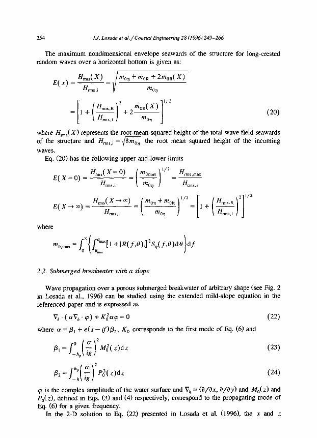
The maximum nondimensional envelope seawards of the structure for long-crested random waves over a horizontal bottom is given as:
Hmls( *I E(x)= H
mOq + mOR + 2mOR( *> =
rmS,l MO2
(20)
where H,,,,,(X) represents the root-mean-squared height of the total wave field seawards of the structure and Hrms.i = 1/8m,, the root mean squared height of the incoming
waves. Eq. (20) has the following upper and lower limits
E(X=O)=
E(X-,m) = Hmls( * + Ml %ls,i
where
+ I~(f.~)l]“s,(f~~)d~ df
2.2. Submerged breakwater with a slope
Wave propagation over a porous submerged breakwater of arbitrary shape (see Fig. 2 in Losada et al., 1996) can be studied using the extended mild-slope equation in the referenced paper and is expressed as
V,.((~v,,.q) +K&p=O (22)
where (Y = p1 + E(S - if)@*, K, corresponds to the first mode of Eq. (6) and
(23)
(24
cp is the complex amplitude of the water surface and V,, = (a/ax, a/ay) and M,(z) and P,(z), defined in Eqs. (3) and (4) respectively, correspond to the propagating mode of Eq. (6) for a given frequency.
In the 2-D solution to Eq. (22) presented in Losada et al. (1996), the x and z

1-J. Losuda et al./Coastal Engineering 28 (1996) 249-266 2.55
dependency of the potentials, above and inside the breakwater, regions 2 and 4 respectively, can be expressed as
&(X?Z> = cpWWl(z) and &(x,z> = ~(x>P,(z) (25)
Eq. (22) can be discretized using a finite difference scheme on a grid dividing the domain in the x-direction with a regular Ax spacing resulting, together with the dispersion relation, boundary conditions and Lorentz’s principle of equivalent work, Eq. (7), in a set of equations simultaneously solved using a Gauss elimination technique. Details on the numerical scheme and boundary conditions as well as how to evaluate the flow field inside the porous structure can be found in Losada et al. (1996).
To extend the solution to irregular waves the linearity of the solution will be used. The incident frequency spectrum is divided into discrete wave components characterized by a certain frequency, 6. The spectrum at any location can be expressed as
where S,(f,x) and S,(f) are the propagated and incident spectra respectively. Similarly to in Eqs. (10) and (11) a propagation coefficient at a given location can be
evaluated using the following expression,
where m,,,, is the zero order moment of the incident spectrum. Therefore, after discretizing the geometry and solving the linear system of equations
for each frequency, the transfer function, (cp( x)1’, and propagation coefficient, C,(X), can be calculated at any point of the domain, inside or outside the porous region.
3. Lorentz’s principle of equivalent work for random waves
Lorentz’s principle of equivalent work, Eq. (7), has to be solved for both the rectangular and trapezoidal breakwaters in order to take friction into account. This expression corresponds to the monochromatic wave case. However, an extension for random waves is needed. This problem can be addressed in several ways. The first one is to apply Eq. (7) using Tr, peak period, and H,,,,s,i. root-mean-squared wave height of the incident wave spectrum and proceed in the same way as for monochromatic waves. This procedure is the easiest one and assumes that the incident spectrum may be represented by H,,,,s,i and Tr. Therefore, the velocity field used in Eq. (7) is calculated based on these two parameters only.
A different procedure is: l to discretize the incident spectrum, S7, and calculate Sr, propagated, S,, horizontal
velocity, and S,, vertical velocity spectra at each point, 1, of the domain using the transfer function for each wave component.
256 IJ. Losada et al./Coastal Engineering 28 (1996) 249-266
0 to calculate u,, for the calculated S, and u,,, for S, at each domain point, I, using, i.e., for the horizontal velocity
(28)
(29) where
. 1 H,(t) = “g -
coshK,( h + z) - F,sinhK,( h + z)
CT 2Ax coshK,h - F,sinhK,h) ( V/- I - P/+ I> (30)
for the fluid region 2, and
ig 1 H,(;) = - -
1 - F&ulhK,a
ii
coshK,( h + Z)
c 2Ax (s-if) cash K, h - Fasinh K, h ( cp/- 1 - ‘pi+ 1)
(31) for porous region 4 and F, is defined in Eq. (5) for the most progressive mode.
0 to evaluate the volume integrals in Eq. (7) using the calculated u,, and u,, values and iterate until a convergent linearized friction coefficient, f, is obtained.
Note, that the time integrals in Eq. (7) are avoided as the use of u,, in the volume integrals guarantees an averaged equivalent work. The second procedure presents the advantage that the velocity field used to evaluate Eq. (7) is based on the contribution of every component in the propagated spectrum Sr.
Both procedures have been used in this paper and, despite being more tedious, the latter seems to better model reality as it takes dissipation due to all components into account.
4. Results
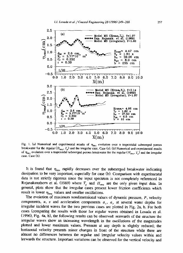
Fig. la, b shows the evolution of ~,.,r,~ evolution over a trapezoidal submerged porous breakwater, obtained via Eq. (22) for regular (H,,,_, T,) and random waves with the experimental results by Rojanakamthom et al. (1989). Geometric characteristics for case (a) are h, = 37.50 cm, h,, = 6.5 cm and b = 10 cm, and for case (b) h, = 39.00 cm, hpb = 8.0 cm and b = 235 cm. The irregular results correspond to the propagation of a standard JONSWAP spectrum with the following characteristics: H,,,,, = 0.0466 m, Tp = 1.82 s, l b = 0.685, v,, = 0.338, qms = 0.0158 m, To, = 1.54 s, To2 = 1.46 s and y = 3.3 for case (a) and H,,,,s = 0.0447 m, Tp = 1.81 s, Ed = 0.685, v,, = 0.338, hs = 0.0152 m, To, = 1.53 s, To2 = 1.457 s and y= 3.3 for case (b); where To, and To, are the first and second order wave periods, v,, and Ed are spectral width parameters and y is the peak-enhancement factor. 64 components have been used to discretize the spectra.
For regular waves the friction coefficient, f, has been calculated using Eq. (7) using H,,,,, and Tp. The friction coefficient, f, for the irregular case has been calculated using the same equation but following the second procedure explained in Section 3.
I.J. Losada et al./ Coastal Engineering 28 (1996) 249-266 257
0.0 1.0 2.0 3.0 4.0 5.0 6.0 7.0 6.0 9.0 10.0
x(m) 3.0 _
0.0 z. l/20
-0.5 kI I I, I I I I (I I I,, I, I I, I I I I, I I I,, I I ,1,! I I I, (I I1 / I I I I 0.0 1.0 2.0 3.0 4.0 5.0 6.0 ‘7.0 6.0 9.0 10.0
x(m)
Fig. 1. (a) Numerical and experimental results of q.,,,$ evolution over a trapezoidal submerged porous breakwater for the regular (If,,,,,, TP) and the irregular case. Case (a>. (b) Numerical and experimental results
of %lS evolution over a trapezoidal submerged porous breakwater for the regular (I&,,, TP) and the irregular case. Case (b).
It is found that q,,,S rapidly decreases over the submerged breakwater indicating dissipation to be very important, especially for case (b). Comparison with experimental data is not strictly rigorous since the input spectrum is not completely referenced in Rojanakamthom et al. (1989) where Tp and HrmS are the only given input data. In general, plots show that the irregular cases present lower friction coefficients which result in lower 71,$ values and smaller oscillations.
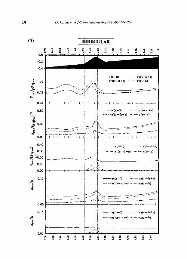
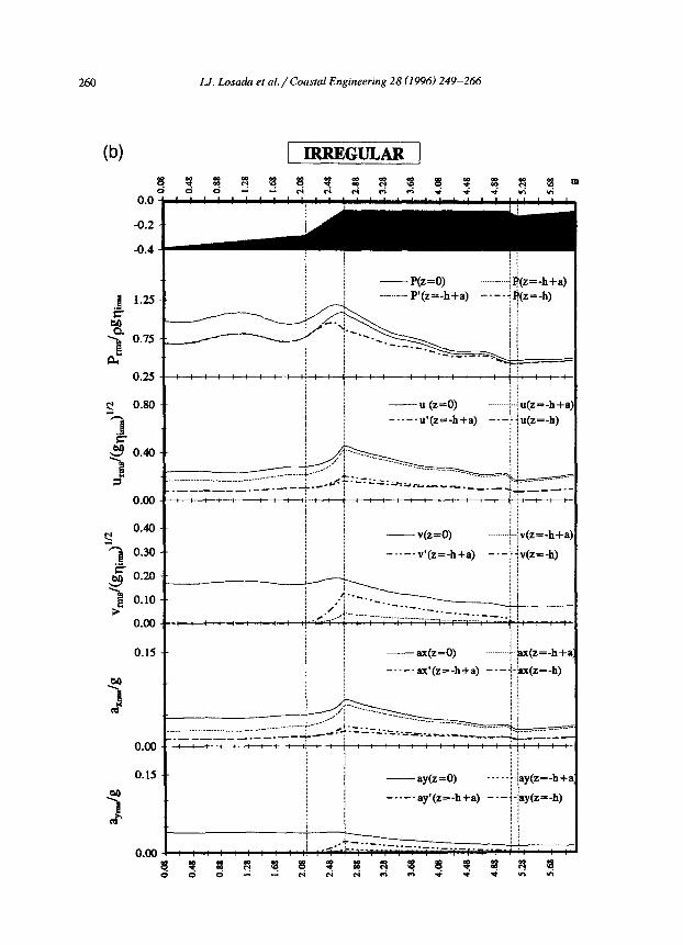
The evolution of maximum nondimensional values of dynamic pressure, P, velocity components, U, u and acceleration components a,, aY at several water depths for irregular incident waves for the two previous cases are plotted in Fig. 2a, b. For both cases (comparing the results with those for regular waves obtained in Losada et al. (1996), Fig. 4a, b), the following results can be observed: seawards of the structure the irregular waves show an increasing wavelength in the oscillations of the magnitudes plotted and lower maximum values. Pressure at any depth is slightly reduced; the horizontal velocity presents minor changes in front of the structure while there are almost no differences between the regular and irregular velocity values within and leewards the structure. Important variations can be observed for the vertical velocity and
258
(a)
0.0
-0.2
-0.4
!I 1.25 k
%
ii! o*75
0.25
%i
0.80
g 0.40
B 0.00
3 :::
q sl.20
2 0.10
0.00
0.15
5
0.00
0.15
,M
B
0.00
8 d
f
IJ. Losada et al./Coastal Engineering 28 (1996) 249-266
( IRREGULAR (
i / / / / ; -+P(z=O) . p(z=_h+a)
-.- p’(z=_h+a) _._.- p@=_,,)
: +u(z=o) ;j /
__..........._ u(z=_h+a)
j / I /
--l.--,qz=_h+a) -.---u(z=_h)
ij / i ! j- v(z=O) . . . ..___ i! :
v(z=_h+a
: / / i
I-----v*(z=_h+a) -.-..,r@=_h)
:I !
/ : !/ : -+--- ax(z=O) .__ @z=_h+a)
ii j ; j -;---a$(zs-h+a) -----ax(z=_h) i) i jj /
! ij i
. . . . . . ; ! -+-- ay(z=O) i/ i
ay(z=-h+a) i i 1 j --/*--ay'@s-h+a) __-.. ay(z--h)
! i / / I /i : /i /
I.J. Lmada et al./Coastal Engineering 28 (1996) 249-266 259
horizontal acceleration values at the free surface mainly in front of the ShuCtUre. These magnitudes present higher values for the irregular case. The most dramatic difference between the regular and irregular values appears for the vertical acceleration where the peak value at the top of the submerged structure is considerably reduced.
In Fig. 3 the evolution of the total spectrum, Sl in front of a submerged porous breakwater is shown. Results correspond to the propagation of a JONSWAF’ spectrum with the following characteristics: H,, = 1.0 m, fr, = 0.125 Hz, ei, = 0.66, vn = 0.33 and y = 3.3. Two different angles of incidence are considered: 19 = O”, left column and 0 = 60”, right column. The breakwater porous material parameters are: d,, = 100 cm, E = 0.437, C, = 0.228, and K, = 5.52 10e4 m2.
It can be observed that the total spectrum contains nodal and anti-nodal frequencies. When moving offshore, the distance in the frequency domain between adjacent spectrum nodes reduces. This behaviour was experimentally observed by Klopman and Van der Meer (pers. commun., 1994) for an emerged impermeable breakwater.
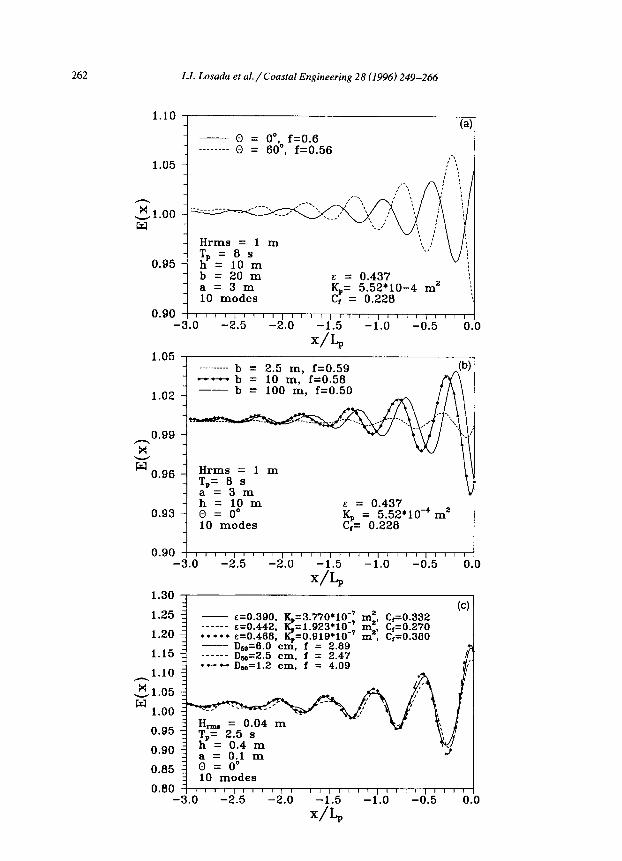
The main features of the spatial evolution of the maximum envelope, E(x), are better presented in Fig. 4a, b and c. Incident waves are characterized by a standard JONSWAP spectrum with y = 3.3 (Fig. 4a, b: H,, = 1 m, TP = 8 s; Fig. 4c H,,,,, = 0.04 m, TP = 2.5 s) discretized into 128 components.
While the evolution for regular waves would show a sinusoidal oscillation with constant wave amplitude and period, the random wave results present a modulation with a maximum at that structure which is damped towards an asymptotic value when moving offshore. Lamberti (19941, explains this pattern as a consequence of the effect of coherence between incident and reflected components, evanescent with increasing distance from the reflecting surface and presents some examples for a vertical imperme- able breakwater.
Fig. 4a, b, c shows that the modulation pattern and damping depend on wave incidence (a>, structure geometry (b) and porous material characteristics (c). This is a consequence of the fact that E(X) depends on the reflection coefficient, which is highly affected by the aforementioned factors. Furthermore, the complex amplitudes of the evanescent modes propagating in the direction of the reflected waves also depend on the same factors.
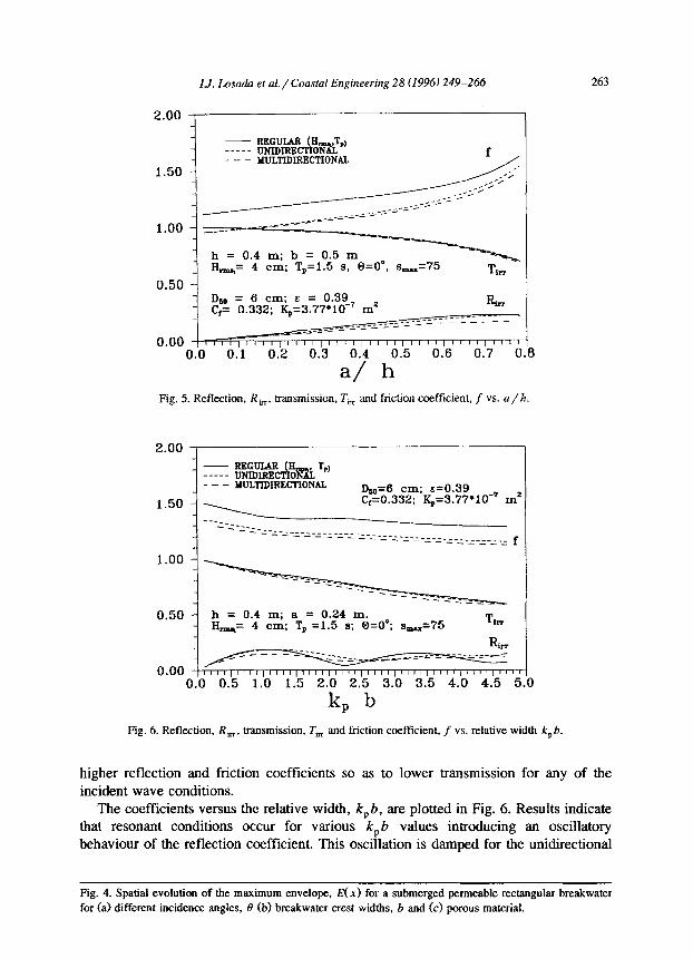
For Figs. 5-7, the irregular results correspond to the propagation of a JONSWAP spectrum with the following characteristics: Hrms = 0.04 m, fP = 0.667 Hz, l b = 0.603, vn = 0.303, y (peakedness factor) = 3.3. For the multidirectional case a directional spreading function of the Mitsuyasu-type has been used with a spreading parameter,
s max = 75.
Fig. 5 shows the reflection, transmission and linearized friction coefficient versus a/h, of a rectangular porous breakwater for regular and irregular unidirectional and multidirectional waves. As expected, increasing the breakwater crest height results in
Fig. 2. (a) Evolution of maximum nondimensional values of dynamic pressure, P, velocity components, U, U,
and acceleration components, a,, aY, at several water depths for irregular incident waves. Case (a). (b)
Evolution of maximum nondimensional values of dynamic pressure, P, velocity components, U, U, and
acceleration components, a,, ay, at several water depths for irregular incident waves. Case (b).
260 I.J. Losada et al./Coastal Engineering 28 (1996) 249-266
(b) 1 IRREGULAR 1
0.0
-0.2
-0.4
i= g 1.25
-Y !J 0.75
0.25
5 Osa
$ 0.40
& 3
0.00
$
0.40
0.30
g 0.2a
b o.la
O.Oa
0.15
,M
1
0.M
0. l!
,M
J
O.o(
1
/ --
, --
. . .
--
/ --
I --
, --
I --
I --
1 --
. .
) --
i --
I+ 8 d
i I i ; i /
- P(z=O) _.._.._..- p’(z=_h+a)
..___ ;j(z=_),+a)
----$Jz=_h)
-u (z=O) /..~u(z=_h+;
--.--,,‘(zs-h+a) --+u(&,) : !
; : j i / /
- v(z=O) ...~.._‘v(z=_~+c ; / --.--v’(z=-h+a) ---i&=-h)
i /

IJ. Losada et al. / Coastal Engineering 28 (1996) 249-266 261
8 7
6
0 = o”, f = 1.10 8 =6 O”, f = 0.84
0.06 0.09 0.12 0.15 0.17 0.20 0.23 0.26 0.29 0.32 0.06 0.09 0.12 0.1s 0.17 0.20 0.23 0.26 0.29 0.32
0.06 0.09 0.12 0.15 0.17 0.20 0.23 0.26 0.29 0.32 1111 006 0.09 0.12 0.1s 0.17 0.20 0.22 0.26 0.29 0.31
7--
6 .-
I- 8-
7 .. 7 -.
6 .. -%(x=4. Lp) 6 .. . ..-- -
Fig. 3. Evolution of the total spectrum, SC, in front of a submerged porous rectangular breakwater for 0 = 0”
and 0=60”.
262 1.J. L.osada et al./Coastal Engineering 28 (1996) 249-266
1.10 (all
- 0 - = 0” f=0.6 - ________ 0 = 6$, f=O_56
1.05 - ,‘:
- Hrms = 1 m - = 6
0.95 - T, h = 10 s m
- b 20 = m E = 0.437 a=3m
_ 10 modes Kp= 5.52’10-4 m2 \k ci = 0.228
0.90 I I I I, I ! 1 I, I I I I,, I I I, I ,I ,,I I /I
-3.0 -2.5 -2.0 -1.5 -1.0 -0.5 0.0
X/Lp
- b = 10 m, f=0.58 - b = 100 m, f=0.50
-3.0 -2.5 -2.0 -1.5 -1.0 -0.5 0.0
X/L,
IJ. Los&a er al./ Coustal Engineering 28 (1996) 249-266 263
2.00
_-- MULTIDIRECTIONAL
h = 0.4 m; b = 0.5 m H,= 4 cm; T,=1.5 s, O=O”, s-=75 Ti,
0.50 -I - Dsa = 6 cm; E = 0.30-r - C,= 0.332; Ka=3.77*10 mz
Ri, _____--
_____z_z-z-;-z-z-_ _ _ - - - ____3_1-;-= - - 0.00 l,,,,,W,<,, IT,, ,,I( ,,I( ,
0.0 0.1 0.2 oh 0.k 0.k ().‘fj “&?I ’ ‘d I.1
Fig. 5. Reflection, R,,, transmission, Ti, and friction coefticient, f vs. a/h.
- REGULAR __--- UNIDIRE CA
I&,.. ‘&.I ONAL
- - MULTIDIRECTI~NAI. Dsa=O cm; &=0.39 crzO.332; K,=3.77*10-r ms
- =-~-=-=-=-=-~-;-~-~-=-~-~“_=__-_____________ ----_--- f
0.50 h = 0.4 m; a = 0.24 m. IS,_,= 4 cm; Tp =1.5 s; 6=0°; s-=75
T *IT
,I111,1111,bII1,1111
0.0 0.5 1.0 1.5 2.0 2.5 3.0 3.5 4.0 4.5 5
k, b
B
Fig. 6. Reflection, R,, transmission, T,, and friction coefftcient, f vs. relative width k,b.
higher reflection and friction coefficients so as to lower transmission for any of the incident wave conditions.
The coeffkients versus the relative width, k, 6, are plotted in Fig. 6. Results indicate that resonant conditions occur for various k, b values introducing an oscillatory behaviour of the reflection coefficient. This oscillation is damped for the unidirectional
Fig. 4. Spatial evolution of the maximum envelope, E(x) for a submerged permeable rectangular breakwater
for (a) different incidence angles, I!I (b) breakwater crest widths, b and (c) porous material.
264 I.J. Losada et al./Coastal Engineering 28 (1996) 249-266
- REGULAR ----- UNILURRC A
II-. T,) ONAL
- - MULTIDIRECTIONAL
_ h = 0.4 m; a = 0.3 m.; b = 0.5 m _ Ii_= 4 cm; Tp=1.5 s; s-=75
Dm = 6 cm; B = 0.39 C, = 0.332; %=3.77*10-’ mz
- I”“I”“I”“I”“I”“I”“l”“l”“I”” 0 10 20 30 40 50 60 70 60 E 3
0 (deg.)
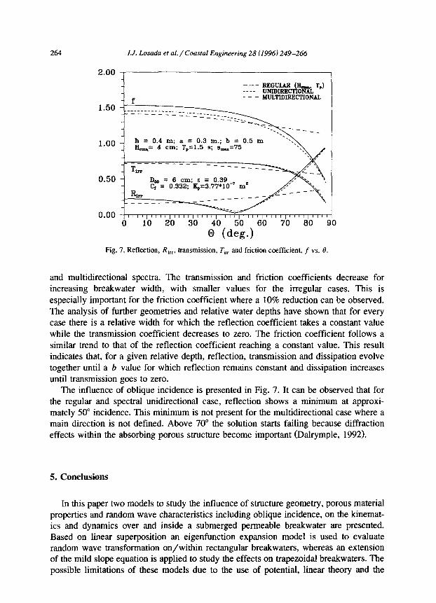
Fig. 7. Reflection, Ri,,, transmission, Tin and friction coefficient, f vs. 0.
and multidirectional spectra. The transmission and friction coefficients decrease for increasing breakwater width, with smaller values for the irregular cases. This is especially important for the friction coefficient where a 10% reduction can be observed. The analysis of further geometries and relative water depths have shown that for every case there is a relative width for which the reflection coefficient takes a constant value while the transmission coefficient decreases to zero. The friction coefficient follows a similar trend to that of the reflection coefficient reaching a constant value. This result indicates that, for a given relative depth, reflection, transmission and dissipation evolve together until a b value for which reflection remains constant and dissipation increases until transmission goes to zero.
The influence of oblique incidence is presented in Fig. 7. It can be observed that for the regular and spectral unidirectional case, reflection shows a minimum at approxi- mately 50” incidence. This minimum is not present for the multidirectional case where a main direction is not defined. Above 70” the solution starts failing because diffraction effects within the absorbing porous structure become important (Dalrymple, 1992).
5. Conclusions
In this paper two models to study the influence of structure geometry, porous material properties and random wave characteristics including oblique incidence, on the kinemat- ics and dynamics over and inside a submerged permeable breakwater are presented. Based on linear superposition an eigenfunction expansion model is used to evaluate random wave transformation on/within rectangular breakwaters, whereas an extension of the mild slope equation is applied to study the effects on trapezoidal breakwaters. The possible limitations of these models due to the use of potential, linear theory and the

I.J. Losada et al./Coastal Engineering 28 (1996) 249-266 265
lack of considering wave breaking and their consequent implications on engineering applications have been extensively discussed in Losada et al. (1996).
The model reproduces the experimental results well and provides a tool to analyze several engineering problems such as breakwater efficiency, stability of armour units, bottom scour and determination of harbour tranquillity.
In general, random waves, unidirectional or multidirectional, induce lower reflection and transmission coefficients than regular waves. The reduction depends highly on the case studied; however, differences greater than 5% of the aforementioned coefficients have not been found for the cases covered. A general trend also is the fact that energy dissipation is more dependent on the spectral width parameters, v,, and eb than on the spreading parameter, s,,, .
Reflection is more sensitive to incident wave characteristics than transmission. The wave randomness decreases friction coefficients considerably. These characteristic dif- ferences between regular and irregular waves are clearly observable for global parame- ters such as reflection or transmission coefficients. While analyzing dynamic or kine- matic variables, some results show a deviation from this pattern.
The relation between reflection and wave incidence is very similar for regular and unidirectional irregular waves, presenting a minimum reflection value in the range of 40” to 65” depending on the wave and structure characteristics. However, the minimum is not present for multidirectional waves.
There are almost no differences between the regular and irregular velocity values within and shorewards of the structure. However, higher values of the vertical velocity and horizontal acceleration are observed in front of the breakwater for the irregular case while the characteristic peak value of the vertical acceleration at the top of the submerged structure observed for regular waves is considerably reduced.
Seawards of the submerged structure, the total spectrum contains nodal and anti-nodal frequencies with reducing distance between two adjacent nodal frequencies when moving offshore. Distance depends on the incident spectrum, as well as on the porous material characteristics and breakwater geometry. Particularly, increasing wave inci- dence angle increases the distance between adjacent nodal frequencies. Furthermore, the kinematic and dynamic variables present an increasing wavelength in their oscillations as well as a decrease of the peak values when compared to regular waves. These results may be used to make a first evaluation for the location of wave gauges in the lab or field.
For a given relative depth and granular material characteristics, increasing crest width takes a maximum value above which reflection remains constant. Resonant conditions observed for regular waves under specific relative widths are also present for random waves. Irregular waves shift the location of resonant conditions towards slightly higher k, b values, and reduce the reflection peaks, especially for the multidirectional case.
Acknowledgements
This paper is part of the “Reflection from natural and man-made coastal structures” research project, which is funded by the Commission of the European Communities in
266 1-I. Losada et al./Coasral Engineering 28 (1996) 249-266
the framework of the Marine Science and Technology Programme (MAST), under contract no. MAS2-CT92-0030. Highly constructive comments by Profs. Oumeraci, Lamberti and an unnamed reviewer were received with sincere gratitude.
References
Cruz, E.C., Isobe, M. and Watanabe, A., 1992. Nonlinear wave transformation over a submerged permeable
breakwater. In: Froc. 23rd Coastal Engineering Conference, Venice. ASCE, New York, pp. 1101-1114.
Dalrymple, R.A., Losada, M.A. and Martin, P.A., 1991. Reflection and transmission from porous structures
under oblique wave attack. J. Fluid Mech., 224: 625-644.
Dahymple, R.A., 1992. Water wave propagation in jettied channels. In: Froc. 23rd Coastal Engineering
Conference, Venice. ASCE, New York, pp. 3040-3053.
Gu, Z.G. and Wang, H., 1992. Numerical modeling for wave energy dissipation within porous submerged
breakwaters of irregular cross section. In: Proc. 23rd Coastal Engineering Conference, Venice. ASCE, New
York, pp. 11 SP- 1202.
Lamb&, A., 1994. Irregular waves reflection and multi-gauge wave measurements near the reflecting
structure. Discussion. In: proceedings of the 2nd Workshop on Rubble Mound Failure Modes (Contract
MAS2-CTP2-0042), Bressanone, 5 pp.
Losada, I.J., 1991. Estudio de la propagaci6n de un tren lineal de ondas por un medio discontinue. Ph.D.
Thesis, Universidad de Cantabria, 183 pp. (in Spanish).
Losada, I.J., Silva, R. and Losada, M.A., 1995. Wave interaction with permeable submerged breakwater. Part
II: Irregular waves. MAS2-CT92-0030 Final report. Paper 1.6, Universidad de Cantabtia, 36 pp.
Losada, I.J., Silva, R. and Losada, M.A., 1996. 3-D non-breaking regular wave interaction with submerged
breakwaters. Coastal Eng., CENG 707.
Masse], S.R. and Mei, CC., 1977. Transmission of random wind waves through perforated or porous
breakwaters. Coastal Eng., l(l): 63-78.
Masse], S.R. and Butowski, P., 1980. Wind waves transmission through porous breakwaters. In: Froc. 17th
Coastal Engineering Conference, Sydney. ASCE, New York, pp. 333-346.
Rojanakamthom, S., Isobe, M. and Watanabe, A., 1989. A mathematical model of wave transformation over a
submerged breakwater. Coastal Eng. Jpn., 32(2): 209-234.
Rojanakamthom, S., Isobe, M. and Watanabe, A., 1990. Modeling of wave transformation on submerged
breakwater. In: Froc. 22nd Coastal Engineering Conference, Delft. ASCE, New York, pp. 1060-1073.
Sollitt, C.K. and Cross, R.H., 1972. Wave transmission through permeable breakwaters. In: Proc. 13th Coastal
Engineering Conference, Vancouver, B.C. ASCE, New York, pp. 1827- 1846. Van Gent, M.R.A., 1994. The modelling of wave action on and in coastal structures. Coastal Eng., 22:
31 l-339.
Wibbeler, H. and Oumeraci, H., 1992. Finite element simulation of wave-induced internal flow in rubble
mound structures. In: Proc. 23rd Coastal Engineering Conference, Venice. ASCE, New York, pp.
1706-1719.
Related Documents


