Interaction of cavitation bubbles on a wall Nicolas Bremond, a Manish Arora, Stephan M. Dammer, and Detlef Lohse Physics of Fluids, Department of Applied Physics, University of Twente, 7500 AE Enschede, The Netherlands Received 27 April 2006; accepted 15 August 2006; published online 8 December 2006 We report experimental and numerical investigations on the dynamics of the cavitation of bubbles on a solid surface and the interaction between them with the help of controlled cavitation nuclei: hemispherical bubbles are nucleated from hydrophobic microcavities that act as gas traps when the substrate is immersed in water. The expansion of these nuclei is triggered by an impulsive lowering of the liquid pressure. The patterning of the substrate allows us to control the number of bubbles and the distance between them. Each hemispherical bubble experiences the effect of its mirror image. Correspondingly, an isolated hemispherical bubble together with its mirror image behaves like a free spherical bubble, i.e., its dynamics is well described by the Rayleigh-Plesset equation. We employ the setup to study the dynamics of two and more bubbles in a row at controlled and fixed distances from each other. For weak interaction, namely when the maximum size of the bubbles is smaller than the bubble distance, the dynamics of the system is well captured by an extended Rayleigh-Plesset equation, where mutual pressure coupling through sound emission is included. Bubble pairs last longer than an isolated bubble as neighboring bubbles modify the surrounding pressure and screen each other. For strong interaction, obtained by increasing the tensile stress or decreasing the bubble distance, the bubbles eventually flatten and form a liquid film between each other which can rupture, leading to coalescence. The film thinning is inertia dominated. A potential flow boundary integral simulation captures the overall shape evolution of the bubbles, including the formation of jets horizontal to the wall. These horizontal jets are caused by symmetry breaking due to the neighboring bubbles. © 2006 American Institute of Physics. DOI: 10.1063/1.2396922 I. INTRODUCTION Liquids rupture and form vapor bubbles when the liquid pressure is decreased beyond a critical tension. This phenom- enon is known as cavitation. 1,2 Homogeneous nucleation re- fers to the cavitation of a pure liquid taking place from mi- croscopic voids due to thermal fluctuations. 3 This type of nucleation has been observed to be initiated at a negative pressure of -140 MPa for ultrapure water at 42 °C Ref. 4. In contrast, heterogeneous nucleation originates from the presence of submicroscopic air pockets at the solid/liquid interface on the wall of the container or on particles present in the liquid. 5 When the pressure is sufficiently reduced, these air pockets expand and bubbles emerge. The contami- nation of liquids in natural or industrial situations therefore weakens the ability of liquids to sustain high tension. For the same reason, cavitation is a very erratic process, notoriously difficult to control. In this paper we demonstrate how we have succeeded to control the cavitation by predetermining nucleation sites on a hydrophobic solid wall immersed in water. In this way we can quantitatively and reproducibly study surface cavitation. Preliminary results on uncontrolled and controlled surface cavitation have been reported in Bremond et al. 6 The mutual interaction of bubbles in a two-dimensional bubble cluster is studied in Ref. 7. Here, we focus on the bubble-bubble inter- action, bubble coalescence, and the comparison between ex- periments and boundary integral simulations. Lord Rayleigh 8 was the first to analyze the dynamics of the collapse of a single and spherical cavity in a surrounding liquid. This pioneering work on cavitation has been followed by many experimental and theoretical studies starting from the 1950s see Ref. 9, the 1977 review of Plesset and Prosperetti, which led to a good understanding of the radial dynamics of an isolated bubble. 5,10 The interest on cavitation rose mainly by the need to better understand damages in- duced by such event. 11–13 The focusing power of collapsing bubbles can also be used for surfaces cleaning see, e.g., Krefting et al. 14 . The knowledge on bubble dynamics got further boosted by the discovery and the explanation of single-bubble sonoluminescence, 15 a light-emitting bubble trapped in an oscillating acoustic field. However, in general, cavitation bubbles in an acoustic field will mutually interact, often in an uncontrolled way. This collective behavior has been addressed theoretically 16–18 and numerically. 19–22 A few experiments have been done on the interaction of bubbles using laser-induced cavitation 23,24 or focusing on the collapse of preexisting bubbles in gelatine, 25 or in salt crystals. 26 The main difficulty occurring in the experiments has been the coupling between radial and translational dynamics of the bubbles. We have therefore designed an experimental procedure for controlling the locations of nucleation by keeping them fixed. The nucleation takes place from hydrophobic micro- cavities etched on a solid surface Sec. II. These cavities act a Present address: Laboratoire Colloïdes et Matériaux Divisés, ESPCI, 10 rue Vauquelin, 75231 Paris, France. PHYSICS OF FLUIDS 18, 121505 2006 1070-6631/2006/1812/121505/10/$23.00 © 2006 American Institute of Physics 18, 121505-1 Downloaded 15 Oct 2008 to 130.89.101.40. Redistribution subject to AIP license or copyright; see http://pof.aip.org/pof/copyright.jsp

Welcome message from author
This document is posted to help you gain knowledge. Please leave a comment to let me know what you think about it! Share it to your friends and learn new things together.
Transcript
Interaction of cavitation bubbles on a wallNicolas Bremond,a� Manish Arora, Stephan M. Dammer, and Detlef LohsePhysics of Fluids, Department of Applied Physics, University of Twente,7500 AE Enschede, The Netherlands
�Received 27 April 2006; accepted 15 August 2006; published online 8 December 2006�
We report experimental and numerical investigations on the dynamics of the cavitation of bubbleson a solid surface and the interaction between them with the help of controlled cavitation nuclei:hemispherical bubbles are nucleated from hydrophobic microcavities that act as gas traps when thesubstrate is immersed in water. The expansion of these nuclei is triggered by an impulsive loweringof the liquid pressure. The patterning of the substrate allows us to control the number of bubbles andthe distance between them. Each hemispherical bubble experiences the effect of its mirror image.Correspondingly, an isolated hemispherical bubble together with its mirror image behaves like a freespherical bubble, i.e., its dynamics is well described by the Rayleigh-Plesset equation. We employthe setup to study the dynamics of two and more bubbles in a row at controlled and fixed distancesfrom each other. For weak interaction, namely when the maximum size of the bubbles is smallerthan the bubble distance, the dynamics of the system is well captured by an extendedRayleigh-Plesset equation, where mutual pressure coupling through sound emission is included.Bubble pairs last longer than an isolated bubble as neighboring bubbles modify the surroundingpressure and screen each other. For strong interaction, obtained by increasing the tensile stress ordecreasing the bubble distance, the bubbles eventually flatten and form a liquid film between eachother which can rupture, leading to coalescence. The film thinning is inertia dominated. A potentialflow boundary integral simulation captures the overall shape evolution of the bubbles, including theformation of jets horizontal to the wall. These horizontal jets are caused by symmetry breaking dueto the neighboring bubbles. © 2006 American Institute of Physics. �DOI: 10.1063/1.2396922�
I. INTRODUCTION
Liquids rupture and form vapor bubbles when the liquidpressure is decreased beyond a critical tension. This phenom-enon is known as cavitation.1,2 Homogeneous nucleation re-fers to the cavitation of a pure liquid taking place from mi-croscopic voids due to thermal fluctuations.3 This type ofnucleation has been observed to be initiated at a negativepressure of −140 MPa for ultrapure water at 42 °C �Ref. 4�.In contrast, heterogeneous nucleation originates from thepresence of submicroscopic air pockets at the solid/liquidinterface on the wall of the container or on particles presentin the liquid.5 When the pressure is sufficiently reduced,these air pockets expand and bubbles emerge. The contami-nation of liquids in natural or industrial situations thereforeweakens the ability of liquids to sustain high tension. For thesame reason, cavitation is a very erratic process, notoriouslydifficult to control.
In this paper we demonstrate how we have succeeded tocontrol the cavitation by predetermining nucleation sites on ahydrophobic solid wall immersed in water. In this way wecan quantitatively and reproducibly study surface cavitation.Preliminary results on uncontrolled and controlled surfacecavitation have been reported in Bremond et al.6 The mutualinteraction of bubbles in a two-dimensional bubble cluster isstudied in Ref. 7. Here, we focus on the bubble-bubble inter-
action, bubble coalescence, and the comparison between ex-periments and boundary integral simulations.
Lord Rayleigh8 was the first to analyze the dynamics ofthe collapse of a single and spherical cavity in a surroundingliquid. This pioneering work on cavitation has been followedby many experimental and theoretical studies startingfrom the 1950s �see Ref. 9, the 1977 review of Plesset andProsperetti�, which led to a good understanding of the radialdynamics of an isolated bubble.5,10 The interest on cavitationrose mainly by the need to better understand damages in-duced by such event.11–13 The focusing power of collapsingbubbles can also be used for surfaces cleaning �see, e.g.,Krefting et al.14�. The knowledge on bubble dynamics gotfurther boosted by the discovery and the explanation ofsingle-bubble sonoluminescence,15 a light-emitting bubbletrapped in an oscillating acoustic field. However, in general,cavitation bubbles in an acoustic field will mutually interact,often in an uncontrolled way. This collective behavior hasbeen addressed theoretically16–18 and numerically.19–22 A fewexperiments have been done on the interaction of bubblesusing laser-induced cavitation23,24 or focusing on the collapseof preexisting bubbles in gelatine,25 or in salt crystals.26 Themain difficulty occurring in the experiments has been thecoupling between radial and translational dynamics of thebubbles.
We have therefore designed an experimental procedurefor controlling the locations of nucleation by keeping themfixed. The nucleation takes place from hydrophobic micro-cavities etched on a solid surface �Sec. II�. These cavities act
a�Present address: Laboratoire Colloïdes et Matériaux Divisés, ESPCI, 10rue Vauquelin, 75231 Paris, France.
PHYSICS OF FLUIDS 18, 121505 �2006�
1070-6631/2006/18�12�/121505/10/$23.00 © 2006 American Institute of Physics18, 121505-1
Downloaded 15 Oct 2008 to 130.89.101.40. Redistribution subject to AIP license or copyright; see http://pof.aip.org/pof/copyright.jsp
as gas traps once the substrate is immersed into water andthey promote liquid fracture when the pressure is reduced.The dynamics of an isolated bubble for different forcing andgeometry of the cavity is first described �Sec. III� and com-pared to the dynamics of a spherical bubble given by theRayleigh-Plesset equation. The interaction of bubble pairs isinvestigated for weak coupling where the bubbles basicallystay spherical �Sec. IV�, and then for strong coupling forwhich they flatten and a thin film is formed between themwhich can rupture, leading to coalescence �Sec. V�. In thestrong-coupling regime obviously the Rayleigh-Plesset ap-proach does not hold any longer due to the loss of sphericalsymmetry. This regime, however, can be studied with thehelp of potential flow boundary integral simulations�Sec. VI�.
II. EXPERIMENTAL PROCEDURES
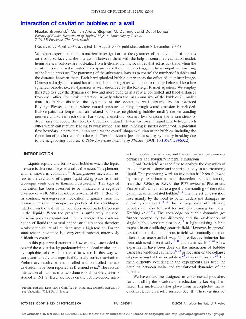
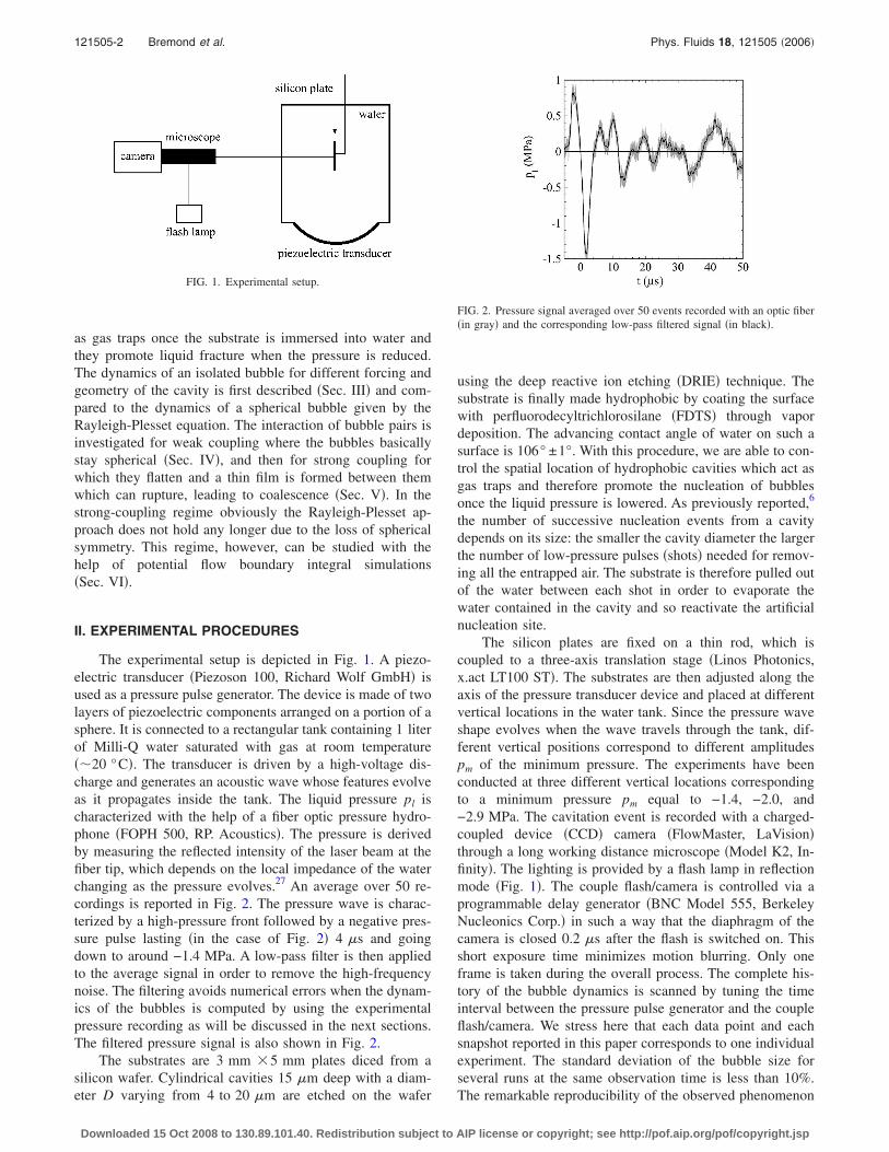
The experimental setup is depicted in Fig. 1. A piezo-electric transducer �Piezoson 100, Richard Wolf GmbH� isused as a pressure pulse generator. The device is made of twolayers of piezoelectric components arranged on a portion of asphere. It is connected to a rectangular tank containing 1 literof Milli-Q water saturated with gas at room temperature��20 °C�. The transducer is driven by a high-voltage dis-charge and generates an acoustic wave whose features evolveas it propagates inside the tank. The liquid pressure pl ischaracterized with the help of a fiber optic pressure hydro-phone �FOPH 500, RP. Acoustics�. The pressure is derivedby measuring the reflected intensity of the laser beam at thefiber tip, which depends on the local impedance of the waterchanging as the pressure evolves.27 An average over 50 re-cordings is reported in Fig. 2. The pressure wave is charac-terized by a high-pressure front followed by a negative pres-sure pulse lasting �in the case of Fig. 2� 4 �s and goingdown to around −1.4 MPa. A low-pass filter is then appliedto the average signal in order to remove the high-frequencynoise. The filtering avoids numerical errors when the dynam-ics of the bubbles is computed by using the experimentalpressure recording as will be discussed in the next sections.The filtered pressure signal is also shown in Fig. 2.
The substrates are 3 mm �5 mm plates diced from asilicon wafer. Cylindrical cavities 15 �m deep with a diam-eter D varying from 4 to 20 �m are etched on the wafer
using the deep reactive ion etching �DRIE� technique. Thesubstrate is finally made hydrophobic by coating the surfacewith perfluorodecyltrichlorosilane �FDTS� through vapordeposition. The advancing contact angle of water on such asurface is 106° ±1°. With this procedure, we are able to con-trol the spatial location of hydrophobic cavities which act asgas traps and therefore promote the nucleation of bubblesonce the liquid pressure is lowered. As previously reported,6
the number of successive nucleation events from a cavitydepends on its size: the smaller the cavity diameter the largerthe number of low-pressure pulses �shots� needed for remov-ing all the entrapped air. The substrate is therefore pulled outof the water between each shot in order to evaporate thewater contained in the cavity and so reactivate the artificialnucleation site.
The silicon plates are fixed on a thin rod, which iscoupled to a three-axis translation stage �Linos Photonics,x.act LT100 ST�. The substrates are then adjusted along theaxis of the pressure transducer device and placed at differentvertical locations in the water tank. Since the pressure waveshape evolves when the wave travels through the tank, dif-ferent vertical positions correspond to different amplitudespm of the minimum pressure. The experiments have beenconducted at three different vertical locations correspondingto a minimum pressure pm equal to −1.4, −2.0, and−2.9 MPa. The cavitation event is recorded with a charged-coupled device �CCD� camera �FlowMaster, LaVision�through a long working distance microscope �Model K2, In-finity�. The lighting is provided by a flash lamp in reflectionmode �Fig. 1�. The couple flash/camera is controlled via aprogrammable delay generator �BNC Model 555, BerkeleyNucleonics Corp.� in such a way that the diaphragm of thecamera is closed 0.2 �s after the flash is switched on. Thisshort exposure time minimizes motion blurring. Only oneframe is taken during the overall process. The complete his-tory of the bubble dynamics is scanned by tuning the timeinterval between the pressure pulse generator and the coupleflash/camera. We stress here that each data point and eachsnapshot reported in this paper corresponds to one individualexperiment. The standard deviation of the bubble size forseveral runs at the same observation time is less than 10%.The remarkable reproducibility of the observed phenomenon
FIG. 1. Experimental setup.
FIG. 2. Pressure signal averaged over 50 events recorded with an optic fiber�in gray� and the corresponding low-pass filtered signal �in black�.
121505-2 Bremond et al. Phys. Fluids 18, 121505 �2006�
Downloaded 15 Oct 2008 to 130.89.101.40. Redistribution subject to AIP license or copyright; see http://pof.aip.org/pof/copyright.jsp
allows this procedure; we can even produce movies of thecavitation event in this way �1 �s between successiveframes�.
III. THE ISOLATED BUBBLE
The time evolution of a spherical bubble is described bythe Rayleigh-Plesset equation,8,9,28
RR +3
2R2 =
1
��pi�t� − pl�t� −
2�
R−
4�
RR� . �1�
Here, R�t� is the bubble radius, � is the liquid density, � isthe surface tension, � is the dynamic viscosity of the liquid,pl�t� is the pressure in the liquid far away from the surface,and pi�t� is the pressure inside the bubble, given by the sumof the gas pressure pg, and the vapor pressure pv. The gasinside the bubble is assumed to follow an isothermal com-pression. The assumption of isothermal behavior holds due
to the small Peclet number RR /��1 �where � is the thermaldiffusivity� apart from the collapse when the spherical-bubble approximation breaks down anyhow. The artificialnuclei are found to be stable against gas diffusion in theliquid. Indeed, even if the negative pressure pulse is appliedas long as 15 h after immersion of the probe, every singlecavity still nucleates a bubble. According to Epstein andPlesset’s analysis29 of a bubble’s lifetime in a liquid, thiswaiting time of 15 h gives a minimum radius of curvature ofa few hundred microns. Making a rough analogy with the airpocket trapped inside the microcavity, the stretched liquid/gas interface on the cavities is therefore expected to benearly flat, or at least the pressure jump across the interfaceis small compared to the atmospheric pressure p0. If thebubble is at equilibrium at t=0, i.e., pi�0�= pg�0�+ pv= p0, thepressure inside the bubble pi�t� is
pi�t� = pv + p0�R0
R�3
. �2�
Here R0 corresponds to the radius of half a sphere having thesame volume of the cylindrical cavity etched in the substratewith a diameter D and a depth H, i.e., R0= �3HD2 /8�1/3.
One can estimate the initial velocity U0 of the bubblewall by equating the kinetic energy of the flow to the workdone by the pressure. Assuming that the far-field pressure isconstant and equal to the amplitude pm of the negative pres-sure pulse reported in Fig. 2, one obtains9
U0 = �2
3
pv − pm
��1/2
. �3�
According to the experimental pressure recordings, the initialvelocity lies between 30 and 44 m/s. This rough estimate,Eq. �3�, seems to well describe the data as shown in Fig. 3for two forcing conditions and will be used later on for thetwo-bubble case.
We use an isolated bubble as a pressure probe by ini-tially assuming that its dynamics obeys Eq. �1�. We first in-terpolate the driving pressure pl�t� from the experimentalpressure recording �Fig. 2� and then numerically integrate theRayleigh-Plesset equation �1�. The pressure amplitude is then
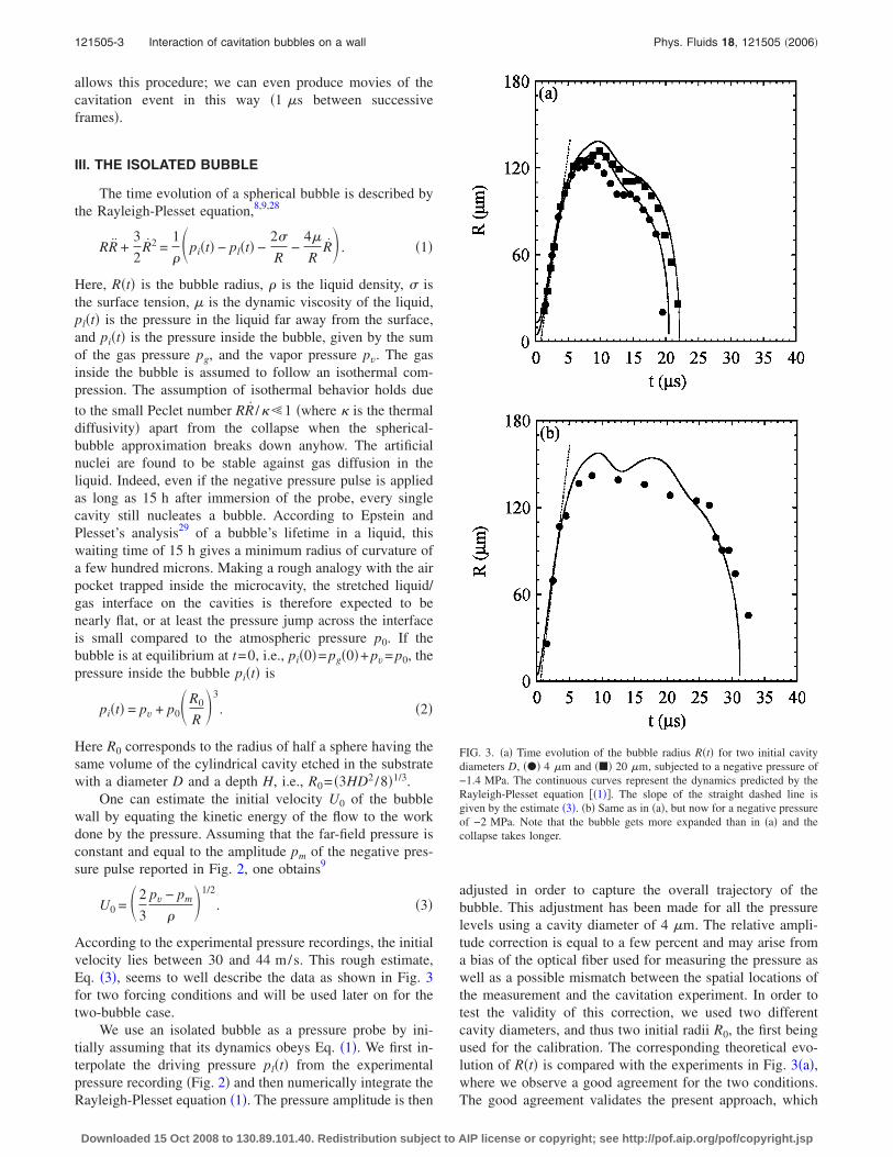
adjusted in order to capture the overall trajectory of thebubble. This adjustment has been made for all the pressurelevels using a cavity diameter of 4 �m. The relative ampli-tude correction is equal to a few percent and may arise froma bias of the optical fiber used for measuring the pressure aswell as a possible mismatch between the spatial locations ofthe measurement and the cavitation experiment. In order totest the validity of this correction, we used two differentcavity diameters, and thus two initial radii R0, the first beingused for the calibration. The corresponding theoretical evo-lution of R�t� is compared with the experiments in Fig. 3�a�,where we observe a good agreement for the two conditions.The good agreement validates the present approach, which
FIG. 3. �a� Time evolution of the bubble radius R�t� for two initial cavitydiameters D, ��� 4 �m and ��� 20 �m, subjected to a negative pressure of−1.4 MPa. The continuous curves represent the dynamics predicted by theRayleigh-Plesset equation ��1��. The slope of the straight dashed line isgiven by the estimate �3�. �b� Same as in �a�, but now for a negative pressureof −2 MPa. Note that the bubble gets more expanded than in �a� and thecollapse takes longer.
121505-3 Interaction of cavitation bubbles on a wall Phys. Fluids 18, 121505 �2006�
Downloaded 15 Oct 2008 to 130.89.101.40. Redistribution subject to AIP license or copyright; see http://pof.aip.org/pof/copyright.jsp
assumes an analogy between a free bubble and the hemi-spherical bubble growing on the substrate where the walleffect is negligible and acts only as a mirror. The comparisonbetween experiment and theory for a higher forcing pressureis also reported in Fig. 3�b�.
We note here that, for convenience, the high-pressurefront has been removed for the integration since it does notplay any role in the expansion phase. We also mention thatfor an even stronger forcing several bubbles emerge fromone single microcavity and rapidly merge into one biggerbubble. This multinucleation event is due to the compressionphase of the pressure wave which may destabilize the liquid/gas interface stretched on the cavity and therefore promotesmany nuclei for cavitation. The real mechanism of this mul-tibubbles formation remains to be understood.
The vorticity generated from the wall should affect aregion near the wall on a thickness � evolving with time like��t�1/2, where � is the kinematic viscosity of the liquid. Theoverall cavitation event lasts less than 100 �s for all theexperiments reported in this paper. Therefore, viscous effectsare confined in a layer close to the wall less than 10 �m,which is small compared to the bubble size for almost all itslifetime.
The viscosity plays an important role in the motion ofthe contact line between the solid, the liquid, and the vapor.Indeed, due to viscous dissipation, the maximum speed ofthe contact line is only of the order of 1 cm/s �see, e.g.,Quéré30� and it is therefore basically pinned close to the cav-ity. The substrate is not dried and a thin liquid film is formedbetween the bubble and the solid wall as observed in Fig. 4.An enlargement of a hemispherical bubble and the corre-sponding thin liquid film, which thickness should be corre-lated to �, is shown in Bremond et al.31
IV. THE BUBBLE PAIR: WEAK INTERACTION
Since the cavitation of an isolated bubble is a rare event,we have designed some substrates dedicated to the study ofthe bubble pair interaction as a first step towards the multi-bubbles interaction. The control parameters are the distanced between the two hydrophobic cavities and the amplitude
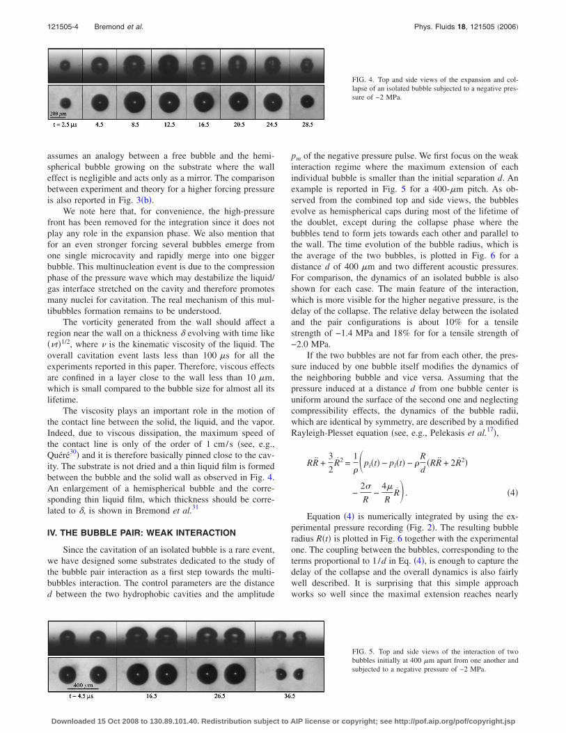
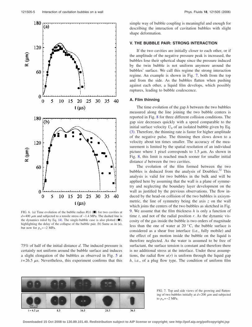
pm of the negative pressure pulse. We first focus on the weakinteraction regime where the maximum extension of eachindividual bubble is smaller than the initial separation d. Anexample is reported in Fig. 5 for a 400-�m pitch. As ob-served from the combined top and side views, the bubblesevolve as hemispherical caps during most of the lifetime ofthe doublet, except during the collapse phase where thebubbles tend to form jets towards each other and parallel tothe wall. The time evolution of the bubble radius, which isthe average of the two bubbles, is plotted in Fig. 6 for adistance d of 400 �m and two different acoustic pressures.For comparison, the dynamics of an isolated bubble is alsoshown for each case. The main feature of the interaction,which is more visible for the higher negative pressure, is thedelay of the collapse. The relative delay between the isolatedand the pair configurations is about 10% for a tensilestrength of −1.4 MPa and 18% for for a tensile strength of−2.0 MPa.
If the two bubbles are not far from each other, the pres-sure induced by one bubble itself modifies the dynamics ofthe neighboring bubble and vice versa. Assuming that thepressure induced at a distance d from one bubble center isuniform around the surface of the second one and neglectingcompressibility effects, the dynamics of the bubble radii,which are identical by symmetry, are described by a modifiedRayleigh-Plesset equation �see, e.g., Pelekasis et al.17�,
RR +3
2R2 =
1
��pi�t� − pl�t� − �
R
d�RR + 2R2�
−2�
R−
4�
RR� . �4�
Equation �4� is numerically integrated by using the ex-perimental pressure recording �Fig. 2�. The resulting bubbleradius R�t� is plotted in Fig. 6 together with the experimentalone. The coupling between the bubbles, corresponding to theterms proportional to 1/d in Eq. �4�, is enough to capture thedelay of the collapse and the overall dynamics is also fairlywell described. It is surprising that this simple approachworks so well since the maximal extension reaches nearly
FIG. 4. Top and side views of the expansion and col-lapse of an isolated bubble subjected to a negative pres-sure of −2 MPa.
FIG. 5. Top and side views of the interaction of twobubbles initially at 400 �m apart from one another andsubjected to a negative pressure of −2 MPa.
121505-4 Bremond et al. Phys. Fluids 18, 121505 �2006�
Downloaded 15 Oct 2008 to 130.89.101.40. Redistribution subject to AIP license or copyright; see http://pof.aip.org/pof/copyright.jsp
75% of half of the initial distance d. The induced pressure iscertainly not uniform around the bubble surface and inducesa slight elongation of the bubbles as observed in Fig. 5 att=26.5 �s. Nevertheless, this experiment confirms that this
simple way of bubble coupling is meaningful and enough fordescribing the interaction of cavitation bubbles with slightshape deformation.
V. THE BUBBLE PAIR: STRONG INTERACTION
If the two cavities are initially closer to each other, or ifthe amplitude of the negative pressure peak is increased, thebubbles lose their spherical shape since the pressure inducedby the twin bubble is not uniform anymore around thebubbles’ surface. We call this regime the strong interactionregime. An example is shown in Fig. 7, both from the topand from the side. As the bubbles flatten when pushingagainst each other, a liquid film develops, which possiblyruptures, leading to bubble coalescence.
A. Film thinning
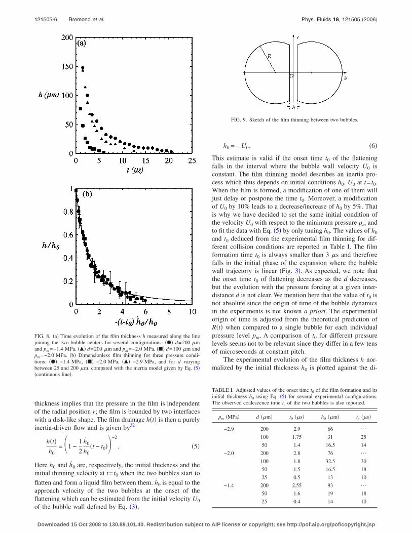
The time evolution of the gap h between the two bubblesmeasured along the line joining the two bubble centers isreported in Fig. 8 for three different collision conditions. Thegap size decreases quickly with a speed comparable to theinitial surface velocity U0 of an isolated bubble given by Eq.�3�. Therefore, the thinning rate is faster for higher amplitudeof the negative pulse. The thinning then slows down to avelocity about ten times smaller. The accuracy of the mea-surement is limited by the spatial resolution of an individualpicture where 1 pixel corresponds to 1.5 �m. As shown inFig. 8, this limit is reached much sooner for smaller initialdistance d between the two cavities.
The evolution of the film formed between the twobubbles is deduced from the analysis of Doubliez.32 Thisanalysis is valid for two bubbles in the bulk and will beapplied here by assuming that the wall is a plane of symme-try and neglecting the boundary layer development on thewall as justified by the previous observations. The flow in-duced by the head-on collision of the two bubbles is axisym-metric, the line of symmetry being the axis z on the wallwhich joins the centers of the two bubbles as sketched in Fig.9. We assume that the film thickness h is only a function oftime t, and not of the radial position r. As the dynamic vis-cosity of the gas inside the bubble is two orders of magnitudeless than the one of water at 20 °C, the bubble surface isconsidered as a shear free interface �i.e., fully mobile� andthe effect of gas motion inside the bubble on the liquid istherefore neglected. As the water is assumed to be free ofsurfactant, the surface tension is constant and therefore thereis no additional stress at the interface. Under these assump-tions, the radial flow u�r� is uniform through the liquid gaph, i.e., of a plug flow type. The condition of uniform film
FIG. 6. �a� Time evolution of the bubble radius R�t� ��� for two cavities atd=400 �m and subjected to a tensile stress of −1.4 MPa. The dashed line isthe dynamics ruled by Eq. �4�. The single-bubble case is also plotted ���,highlighting the delay of the collapse of the bubble pair. �b� Same as in �a�,but now for pm=−2 MPa.
FIG. 7. Top and side views of the growing and flatten-ing of two bubbles initially at d=200 �m and subjectedto pm=−2 MPa.
121505-5 Interaction of cavitation bubbles on a wall Phys. Fluids 18, 121505 �2006�
Downloaded 15 Oct 2008 to 130.89.101.40. Redistribution subject to AIP license or copyright; see http://pof.aip.org/pof/copyright.jsp
thickness implies that the pressure in the film is independentof the radial position r; the film is bounded by two interfaceswith a disk-like shape. The film drainage h�t� is then a purelyinertia-driven flow and is given by32
h�t�h0
= �1 −1
2
h0
h0�t − t0��−2
. �5�
Here h0 and h0 are, respectively, the initial thickness and theinitial thinning velocity at t= t0 when the two bubbles start to
flatten and form a liquid film between them. h0 is equal to theapproach velocity of the two bubbles at the onset of theflattening which can be estimated from the initial velocity U0
of the bubble wall defined by Eq. �3�,
h0 = − U0. �6�
This estimate is valid if the onset time t0 of the flatteningfalls in the interval where the bubble wall velocity U0 isconstant. The film thinning model describes an inertia pro-cess which thus depends on initial conditions h0, U0 at t= t0.When the film is formed, a modification of one of them willjust delay or postpone the time t0. Moreover, a modificationof U0 by 10% leads to a decrease/increase of h0 by 5%. Thatis why we have decided to set the same initial condition ofthe velocity U0 with respect to the minimum pressure pm andto fit the data with Eq. �5� by only tuning h0. The values of h0
and t0 deduced from the experimental film thinning for dif-ferent collision conditions are reported in Table I. The filmformation time t0 is always smaller than 3 �s and thereforefalls in the initial phase of the expansion where the bubblewall trajectory is linear �Fig. 3�. As expected, we note thatthe onset time t0 of flattening decreases as the d decreases,but the evolution with the pressure forcing at a given inter-distance d is not clear. We mention here that the value of t0 isnot absolute since the origin of time of the bubble dynamicsin the experiments is not known a priori. The experimentalorigin of time is adjusted from the theoretical prediction ofR�t� when compared to a single bubble for each individualpressure level pm. A comparison of t0 for different pressurelevels seems not to be relevant since they differ in a few tensof microseconds at constant pitch.
The experimental evolution of the film thickness h nor-malized by the initial thickness h0 is plotted against the di-
TABLE I. Adjusted values of the onset time t0 of the film formation and itsinitial thickness h0 using Eq. �5� for several experimental configurations.The observed coalescence time tc of the two bubbles is also reported.
pm �MPa� d ��m� t0 ��s� h0 ��m� tc ��s�
−2.9 200 2.9 66 ¯
100 1.75 31 25
50 1.4 16.5 14
−2.0 200 2.8 76 ¯
100 1.8 32.5 30
50 1.5 16.5 18
25 0.5 13 10
−1.4 200 2.55 93 ¯
50 1.6 19 18
25 0.4 14 10
FIG. 9. Sketch of the film thinning between two bubbles.
FIG. 8. �a� Time evolution of the film thickness h measured along the linejoining the two bubble centers for several configurations: ��� d=200 �mand pm=−1.4 MPa, ��� d=200 �m and pm=−2.0 MPa, ��� d=100 �m andpm=−2.0 MPa. �b� Dimensionless film thinning for three pressure condi-tions: ��� −1.4 MPa, ��� −2.0 MPa, ��� −2.9 MPa, and for d varyingbetween 25 and 200 �m, compared with the inertia model given by Eq. �5��continuous line�.
121505-6 Bremond et al. Phys. Fluids 18, 121505 �2006�
Downloaded 15 Oct 2008 to 130.89.101.40. Redistribution subject to AIP license or copyright; see http://pof.aip.org/pof/copyright.jsp
mensionless time −�t− t0�h0 /h0 in Fig. 8�b�. Once the initialconditions of the film thinning are adjusted, all the experi-mental data fall on a master curve described by the purelyinertial model given by Eq. �5�. The error bars are estimatedfrom the accuracy of the gap measurement, which corre-sponds to 1.5 �m.
B. Coalescence
A merging event is depicted in Fig. 10. The coalescenceevent is only caught by means of the evolution of the inter-face shape. Since the phenomenon is observed from above inreflection mode, only the light reflected by an area having aweak slope is captured by the camera. Two distinct brightspots, located at the top of each bubble, are visible in the firsttwo frames and are pointed out by white arrows. The coales-cence of the bubbles at t=25 �s is revealed by the mergingof the bright spots. Another morphology change is the disap-pearance of the cusp located along the plane of symmetryand indicated by a black arrow in Fig. 10. Actually, this isnot a real cusp since the bubbles are still separated by a thinliquid film. The interface is smoothed by the surface tensiononce the film breaks and therefore reveals the merging of thebubbles.
According to standard theory, the bursting of the filmleading to coalescence is a thermally activatedphenomenon:33 the energy cost for the nucleation of a hole inthe film is of the order of �h2, with the energy of activationbeing a few kT, and thus the film bursts for thickness of theorder of 1 nm. In contrast, critical film thicknesses prior tobursting are experimentally observed to lie between 10 and100 nm �Ref. 34�. The discrepancy of the critical thicknesscan be explained by the amplification of surface perturba-tions due to the destabilizing van der Waals attraction.35,36
In the present experiment, the lack of optical resolutiondoes not allow us to resolve such small length scales. All thatwe can observe is that bubbles for initial bubble distance dsmaller than 200 �m coalesce; the time of coalescence isreported in Table I. However, the present setup can be usedfor investigations of the effect of dissolved ions on the coa-lescence. Indeed, dissolved ions have been shown to eitherinhibit or enhance coalescence, depending on its type.37
VI. BOUNDARY INTEGRAL „BI… CALCULATIONS
The Rayleigh-Plesset analysis breaks down once thebubbles are too close and lose their hemispherical shape.However, the wall still acts as a mirror and is therefore still aplane of symmetry. In addition, the z-axial symmetry is con-served �where z is the line joining the centers of the bubbles,see Fig. 9�. Taking advantage of the two symmetries of thesystem, we have used an axisymmetrical boundary integralcode38 in order to describe the overall shape evolution of thecavitating bubbles on the wall. The features of the numericalscheme are based on the method developed by Oğuz andProsperetti.39,40 The validity of the code has first been testedfor the one-bubble case by comparing it to the solution of theRayleigh-Plesset equation.
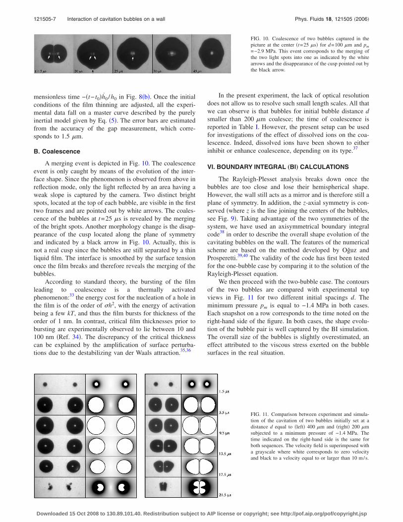
We then proceed with the two-bubble case. The contoursof the two bubbles are compared with experimental topviews in Fig. 11 for two different initial spacings d. Theminimum pressure pm is equal to −1.4 MPa in both cases.Each snapshot on a row corresponds to the time noted on theright-hand side of the figure. In both cases, the shape evolu-tion of the bubble pair is well captured by the BI simulation.The overall size of the bubbles is slightly overestimated, aneffect attributed to the viscous stress exerted on the bubblesurfaces in the real situation.
FIG. 10. Coalescence of two bubbles captured in thepicture at the center �t=25 �s� for d=100 �m and pm
=−2.9 MPa. This event corresponds to the merging ofthe two light spots into one as indicated by the whitearrows and the disappearance of the cusp pointed out bythe black arrow.
FIG. 11. Comparison between experiment and simula-tion of the cavitation of two bubbles initially set at adistance d equal to �left� 400 �m and �right� 200 �msubjected to a minimum pressure of −1.4 MPa. Thetime indicated on the right-hand side is the same forboth sequences. The velocity field is superimposed witha grayscale where white corresponds to zero velocityand black to a velocity equal to or larger than 10 m/s.
121505-7 Interaction of cavitation bubbles on a wall Phys. Fluids 18, 121505 �2006�
Downloaded 15 Oct 2008 to 130.89.101.40. Redistribution subject to AIP license or copyright; see http://pof.aip.org/pof/copyright.jsp
The BI simulations reveal the development of two wall-parallel jets at the final stage of the collapse. These jets aredirected towards the center of the pair. Wall-normal jets arewell known for the collapse of a bubble close to a solidboundary which breaks the spherical symmetry of the innerflow during the collapse:11,41 one side of the bubble acceler-ates inward more rapidly than the opposite side leading tothe formation of the reentrant jets. Here the symmetry break-ing is due to the neighboring bubble and the jets are wallparallel.
To further compare the BI simulations with the experi-ments, the time evolution of the film thickness h squeezedbetween the bubbles is reported in Fig. 12. The good agree-
ment between theory and experiment a posteriori justifiesthe potential flow approach used here for the description ofcavitating hemispherical bubbles on a solid boundary whichacts only as a mirror.
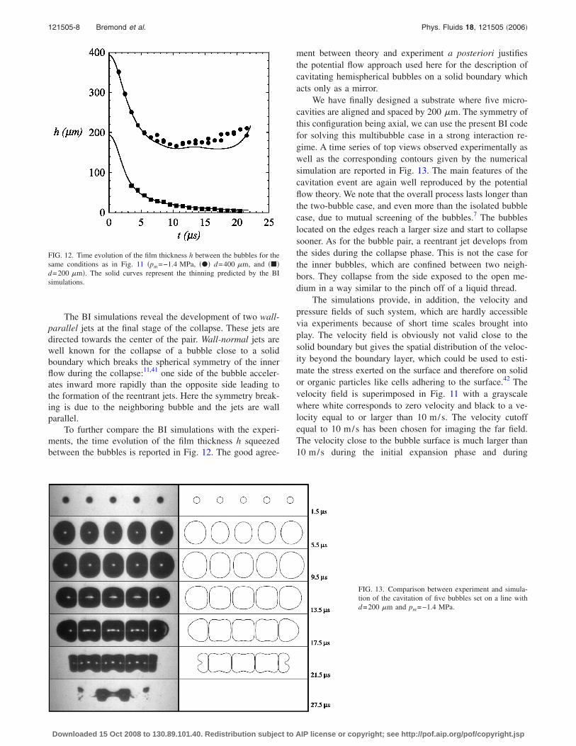
We have finally designed a substrate where five micro-cavities are aligned and spaced by 200 �m. The symmetry ofthis configuration being axial, we can use the present BI codefor solving this multibubble case in a strong interaction re-gime. A time series of top views observed experimentally aswell as the corresponding contours given by the numericalsimulation are reported in Fig. 13. The main features of thecavitation event are again well reproduced by the potentialflow theory. We note that the overall process lasts longer thanthe two-bubble case, and even more than the isolated bubblecase, due to mutual screening of the bubbles.7 The bubbleslocated on the edges reach a larger size and start to collapsesooner. As for the bubble pair, a reentrant jet develops fromthe sides during the collapse phase. This is not the case forthe inner bubbles, which are confined between two neigh-bors. They collapse from the side exposed to the open me-dium in a way similar to the pinch off of a liquid thread.
The simulations provide, in addition, the velocity andpressure fields of such system, which are hardly accessiblevia experiments because of short time scales brought intoplay. The velocity field is obviously not valid close to thesolid boundary but gives the spatial distribution of the veloc-ity beyond the boundary layer, which could be used to esti-mate the stress exerted on the surface and therefore on solidor organic particles like cells adhering to the surface.42 Thevelocity field is superimposed in Fig. 11 with a grayscalewhere white corresponds to zero velocity and black to a ve-locity equal to or larger than 10 m/s. The velocity cutoffequal to 10 m/s has been chosen for imaging the far field.The velocity close to the bubble surface is much larger than10 m/s during the initial expansion phase and during
FIG. 12. Time evolution of the film thickness h between the bubbles for thesame conditions as in Fig. 11 �pm=−1.4 MPa, ��� d=400 �m, and ���d=200 �m�. The solid curves represent the thinning predicted by the BIsimulations.
FIG. 13. Comparison between experiment and simula-tion of the cavitation of five bubbles set on a line withd=200 �m and pm=−1.4 MPa.
121505-8 Bremond et al. Phys. Fluids 18, 121505 �2006�
Downloaded 15 Oct 2008 to 130.89.101.40. Redistribution subject to AIP license or copyright; see http://pof.aip.org/pof/copyright.jsp

the collapse where the reentrant jet can attain 70 m/s ford=200 �m and 90 m/s for d=400 �m.
VII. SUMMARY AND CONCLUSIONS
In this paper we have reported experimental and numeri-cal results on the dynamics of cavitating bubbles on a solidsurface and their interaction. We have developed an experi-mental procedure which allows one to control the spatiallocation of nucleation sites. The artificial nuclei are hydro-phobic microcavities etched on a silicon plate. The micro-voids trap air when the substrate is immersed in water andtherefore promote cavitation of bubbles when the liquid pres-sure is lowered. The presence of the wall is found to act as amirror, allowing a bulk approach for the description of thebubble dynamics. Indeed, an isolated bubble grows with ahemispherical shape with a radius well described by theRayleigh-Plesset equation, which is normally only valid forspherical bubbles.
We have designed probes dedicated to the study ofbubble pair interaction. Two regimes are considered here.The first one corresponds to weak coupling where thebubbles do not come into contact and keep a hemisphericalshape for most of their lifetime, except during the collapsewhere they form a jet directed towards each other. The dy-namics of the doublet is found to be well described once thepressure generated by each individual bubble is taken intoaccount into the Rayleigh-Plesset equation. The collapse ofthe bubble pair is delayed due to mutual screening. Anotherregime is observed when the pressure forcing is increased orthe initial distance between the cavities is decreased. Indeed,the bubbles flatten and form a thin liquid film between eachother which can rupture, leading to coalescence. The filmthinning is found to be driven by inertia of the liquid andtherefore depends on the initial conditions of the film forma-tion, the gap between the two bubbles, and the bubble sur-face velocity. The overall shape of the doublet is well cap-tured by numerical simulations using a boundary integralmethod for both weak and strong interactions. The study hasbeen extended to a line of bubbles where the evolution of thebubbles’ size is a function of their spatial location.
From our study we conclude that despite the presence ofthe wall, the description of the dynamics of cavitationbubbles on a wall is well modeled by a potential flow analy-sis. The use of a boundary integral code is therefore validand can be used for the evaluation of the pressure and veloc-ity fields of such system.
ACKNOWLEDGMENTS
The authors acknowledge Claus-Dieter Ohl for valuablediscussions and Han Garderniers and his collaborators formicrofabrication support. Andrea Prosperetti and MarkStijnman are gratefully acknowledged for developing theboundary integral code. This work is part of the researchprogramme of the Stichting voor Fundamenteel Onderzoekder Materie �FOM�, which is financially supported by theNederlandse Organisatie voor Wetenschappelijk Onderzoek�NWO�.
1J. C. Fisher, “The fracture of liquids,” J. Appl. Phys. 19, 1062 �1948�.2J. Frenkel, Kinetic Theory of Liquids �Dover, New York, 1955�.3S. Balibar and F. Caupin, “Metastable liquids,” J. Phys.: Condens. Matter
15, S75 �2003�.4Q. Zheng, D. J. Durben, G. H. Wolf, and C. A. Angell, “Liquids at largenegative pressure: Water at the homogeneous nucleation limit,” Science254, 829 �1991�.
5C. E. Brennen, Cavitation and Bubble Dynamics �Oxford UniversityPress, New York, 1995�.
6N. Bremond, M. Arora, C. D. Ohl, and D. Lohse, “Cavitation on surfaces,”J. Phys.: Condens. Matter 17, S3603 �2005�.
7N. Bremond, M. Arora, C. D. Ohl, and D. Lohse, “Controlled multibubblesurface cavitation,” Phys. Rev. Lett. 96, 224501 �2006�.
8L. Rayleigh, “On the pressure developed in a liquid during the collapse ofa spherical cavity,” Philos. Mag. 34, 94 �1917�.
9M. S. Plesset and A. Prosperetti, “Bubble dynamics and cavitation,” Annu.Rev. Fluid Mech. 9, 145 �1977�.
10T. G. Leighton, The Acoustic Bubble �Academic, London, 1994�.11T. B. Benjamin and A. T. Ellis, “The collapse of cavitation bubbles and the
pressure thereby produced against solid boundaries,” Philos. Trans. R.Soc. London, Ser. A 260, 221 �1966�.
12A. Philipp and W. Lauterborn, “Cavitation erosion by single laser pro-duced bubbles,” J. Fluid Mech. 361, 75 �1998�.
13N. K. Bourne, “The collapse of cavities,” Shock Waves 11, 447 �2002�.14D. Krefting, R. Mettin, and W. Lauterborn, “High-speed observation of
acoustic cavitation erosion in multibubble systems,” Ultrason. Sonochem.11, 119 �2004�.
15M. P. Brenner, S. Hilgenfeldt, and D. Lohse, “Single-bubble sonolumines-cence,” Rev. Mod. Phys. 74, 425 �2002�.
16E. A. Zabolotskaya, “Interaction of gas bubbles in a sound wave field,”Sov. Phys. Acoust. 30, 365 �1984�.
17N. A. Pelekasis, A. Gaki, A. Doinikov, and J. A. Tsamopoulos, “Second-ary Bjerknes forces between two bubbles and the phenomenon of acousticstreamers,” J. Fluid Mech. 500, 313 �2004�.
18A. A. Doinikov, “Mathematical model for collective bubble dynamics instrong ultrasound fields,” J. Acoust. Soc. Am. 116, 821 �2004�.
19G. Chahine and R. Duraiswami, “Dynamical interactions in a multibubblecloud,” ASME J. Fluids Eng. 114, 680 �1992�.
20J. R. Blake, G. S. Keen, R. P. Tong, and M. Wilson, “Acoustic cavitation:the fluid dynamics of non-spherical bubbles,” Philos. Trans. R. Soc. Lon-don, Ser. A 357, 251 �1999�.
21C. Wang and B. C. Khoo, “An indirect boundary element method forthree-dimensional explosion bubbles,” J. Comput. Phys. 194, 451 �2004�.
22Y. Matsumoto and S. Yoshizawa, “Behaviour of a bubble cluster in anultrasound field,” Int. J. Numer. Methods Fluids 47, 591 �2005�.
23Y. Tomita, A. Shima, and K. Sato, “Dynamic behavior of two-laser-induced bubble in water,” Appl. Phys. Lett. 57, 234 �1990�.
24J. R. Blake, P. B. Robinson, A. Shima, and Y. Tomita, “Interaction of twocavitation bubbles with a rigid boundary,” J. Fluid Mech. 255, 707�1993�.
25J. P. Dear and J. E. Field, “A study of the collapse of an array of cavities,”J. Fluid Mech. 190, 409 �1988�.
26B. Wolfrum, T. Kurz, R. Mettin, and W. Lauterborn, “Shock wave inducedinteraction of microbubbles and boundaries,” Phys. Fluids 15, 2916�2003�.
27J. Staudenraus and W. Eisenmenger, “Fiberoptic probe hydrophone forultrasonic and shock-wave measurements in water,” Ultrasonics 31, 267�1993�.
28M. S. Plesset, “The dynamics of cavitation bubbles,” J. Appl. Mech. 16,277 �1949�.
29P. S. Epstein and M. S. Plesset, “On the stability of gas bubbles in liquid-gas solutions,” J. Chem. Phys. 18, 1505 �1950�.
30D. Quéré, “Fluid coating on a fiber,” Annu. Rev. Fluid Mech. 31, 347�1999�.
31N. Bremond, M. Arora, C. D. Ohl, and D. Lohse, “Cavitation on patternedsurfaces,” Phys. Fluids 17, 091111 �2005�.
32L. Doubliez, “The drainage and rupture of a non-foaming liquid filmformed upon bubble impact with a free surface,” Int. J. Multiphase Flow17, 783 �1991�.
33J. Bibette, F. L. Calderon, and P. Poulin, “Emulsion: Basic principles,”Rep. Prog. Phys. 62, 969 �1999�.
34E. D. Manev and A. V. Nguyen, “Critical thickness of microscopic thinliquid films,” Adv. Colloid Interface Sci. 114, 133 �2005�.
35A. Vrij and J. T. G. Overbeek, “Rupture of thin liquid films due to spon-
121505-9 Interaction of cavitation bubbles on a wall Phys. Fluids 18, 121505 �2006�
Downloaded 15 Oct 2008 to 130.89.101.40. Redistribution subject to AIP license or copyright; see http://pof.aip.org/pof/copyright.jsp
taneous fluctuations in thickness,” J. Am. Chem. Soc. 90, 3074 �1958�.36D. S. Valkovska, K. D. Danov, and I. B. Ivanov, “Stability of draining
plane-parallel films containing surfactants,” Adv. Colloid Interface Sci.96, 101 �2002�.
37V. S. J. Craig, “Bubble coalescence and specific-ion effects,” Curr. Opin.Colloid Interface Sci. 9, 178 �2004�.
38R. Bergmann, D. van der Meer, M. Stijnman, M. Sandtke, A. Prosperetti,and D. Lohse, “Giant bubble pinch-off,” Phys. Rev. Lett. 96, 154505�2006�.
39H. N. Oğuz and A. Prosperetti, “Bubble entrainment by the impact of
drops on liquid surfaces,” J. Fluid Mech. 219, 143 �1990�.40H. N. Oğuz and A. Prosperetti, “Dynamics of bubble growth and detach-
ment from a needle,” J. Fluid Mech. 257, 111 �1993�.41M. S. Plesset and R. B. Chapman, “Collapse of an initially spherical vapor
cavity in the neighborhood of a solid boundary,” J. Fluid Mech. 47, 283�1971�.
42L. Junge, C. D. Ohl, B. Wolfrum, M. Arora, and R. Ikink, “Cell detach-ment method using shock-wave-induced cavitation,” Ultrasound Med.Biol. 29, 1769 �2003�.
121505-10 Bremond et al. Phys. Fluids 18, 121505 �2006�
Downloaded 15 Oct 2008 to 130.89.101.40. Redistribution subject to AIP license or copyright; see http://pof.aip.org/pof/copyright.jsp
Related Documents


![Electrochemical investigations of stable cavitation from bubbles …deymier/deymier_group/refs/cavitation... · 2014. 10. 15. · Rayleigh streaming, and Microstreaming [7]. In acoustic](https://static.cupdf.com/doc/110x72/60a7b9340fce1a14d75ca4a9/electrochemical-investigations-of-stable-cavitation-from-bubbles-deymierdeymiergrouprefscavitation.jpg)

