Interaction Devices for Hands-On Desktop Design Wendy Ju, Sally Madsen, Jonathan Fiene, Mark Bolas, Ian McDowall, and Rolf Faste Mechanical Engineering Department, Design Division Stanford University, Stanford, CA 94305 ABSTRACT Starting with a list of typical hand actions – such as touching or twisting – a collection of physical input device prototypes was created to study better ways of engaging the body and mind in the computer aided design process. These devices were interchangeably coupled with a graphics system to allow for rapid exploration of the interplay between the designer’s intent, body motions, and the resulting on-screen design. User testing showed that a number of key considerations should influence the future development of such devices: coupling between the physical and virtual worlds, tactile feedback, and scale. It is hoped that these explorations contribute to the greater goal of creating user interface devices that increase the fluency, productivity and joy of computer-augmented design. CAD, FIDGET, tangible interfaces, two-handed input, 3D interaction, 3D design, fluent interaction 1. INTRODUCTION Three-dimensional computer-aided design environments use graphical menus to mimic the designer’s traditional toolbox. These iconic representations largely overlook how traditional tools engage the human body - and thus the human mind - in the act of design. To better harness the potential of body-based interaction, we sought to create a range of manipulable interfaces for interacting with desktop design environments. Toward this end, we have created an architecture that enables rapid prototyping and testing of manipulable tools. We designed eight trial interfaces, and have begun the process of user testing and iteration of various designs to extract insights about the creative potential of kinesthetic input devices. This exploratory work is built around a multi-device paradigm, which is not typical for spatial input devices. Rather than trying to create a single general-purpose interface tool, we concentrated on creating a variety of task specific devices. We call these Force Input Devices for Graphical Environment Tweaking, or FIDGETs. 2. MAPPINGS AND METAPHORS A provisional framework was developed to understand the possible modes of physical interaction that users might have with a continuously manipulable device. These modes were then mapped to virtual interactions, particularly those common to CAD. Each is elemental and might be combined with others to form larger gestures. They are: Touching the object is contacted. Pointing one point on the device is mapped to a point in virtual space. Tilting two points or more on the device are translated in space. Stretching the object’s dimensions change along one axis. Rolling the object is translated about one axis. Twisting the object is transformed about its main axis. Bending the object is transformed normal to its main axis. Smushing the object is deformed. Two metaphors were useful when considering how input devices interact with virtual space - the device can act as a tool, or the device can act as the designed object. For instance, in the familiar case of a mouse or tablet pen, or of more exotic devices such as Galyean’s 3D haptic sculpting device[3], the physical input device is a metaphor for a tool, and thus, the pointing corresponds with the planar motion of a tool’s end effector, and the smushing corresponds with the change in

Welcome message from author
This document is posted to help you gain knowledge. Please leave a comment to let me know what you think about it! Share it to your friends and learn new things together.
Transcript

Interaction Devices for Hands-On Desktop Design
Wendy Ju, Sally Madsen, Jonathan Fiene, Mark Bolas, Ian McDowall, and Rolf Faste
Mechanical Engineering Department, Design Division Stanford University, Stanford, CA 94305
ABSTRACT
Starting with a list of typical hand actions – such as touching or twisting – a collection of physical input device prototypes was created to study better ways of engaging the body and mind in the computer aided design process. These devices were interchangeably coupled with a graphics system to allow for rapid exploration of the interplay between the designer’s intent, body motions, and the resulting on-screen design. User testing showed that a number of key considerations should influence the future development of such devices: coupling between the physical and virtual worlds, tactile feedback, and scale. It is hoped that these explorations contribute to the greater goal of creating user interface devices that increase the fluency, productivity and joy of computer-augmented design. CAD, FIDGET, tangible interfaces, two-handed input, 3D interaction, 3D design, fluent interaction
1. INTRODUCTION Three-dimensional computer-aided design environments use graphical menus to mimic the designer’s traditional toolbox. These iconic representations largely overlook how traditional tools engage the human body - and thus the human mind - in the act of design. To better harness the potential of body-based interaction, we sought to create a range of manipulable interfaces for interacting with desktop design environments. Toward this end, we have created an architecture that enables rapid prototyping and testing of manipulable tools. We designed eight trial interfaces, and have begun the process of user testing and iteration of various designs to extract insights about the creative potential of kinesthetic input devices. This exploratory work is built around a multi-device paradigm, which is not typical for spatial input devices. Rather than trying to create a single general-purpose interface tool, we concentrated on creating a variety of task specific devices. We call these Force Input Devices for Graphical Environment Tweaking, or FIDGETs.
2. MAPPINGS AND METAPHORS A provisional framework was developed to understand the possible modes of physical interaction that users might have with a continuously manipulable device. These modes were then mapped to virtual interactions, particularly those common to CAD. Each is elemental and might be combined with others to form larger gestures. They are: Touching the object is contacted. Pointing one point on the device is mapped to a point in virtual space. Tilting two points or more on the device are translated in space. Stretching the object’s dimensions change along one axis. Rolling the object is translated about one axis. Twisting the object is transformed about its main axis. Bending the object is transformed normal to its main axis. Smushing the object is deformed. Two metaphors were useful when considering how input devices interact with virtual space - the device can act as a tool, or the device can act as the designed object. For instance, in the familiar case of a mouse or tablet pen, or of more exotic devices such as Galyean’s 3D haptic sculpting device[3], the physical input device is a metaphor for a tool, and thus, the pointing corresponds with the planar motion of a tool’s end effector, and the smushing corresponds with the change in

mode of the end effector. In analyzing these and other tool-metaphor devices, we notice a wide range of possible actions that could be taken by such tools: hammering, tracing, sculpting, outlining, erasing. These actions are very different from those that could be mapped to a device acting as a metaphorical object, as is the case in commercial products, such as the Spaceball [9], or ShapeTape [5], or in research interfaces such as Piper and Ishii’s Illuminating Clay [6], and other such tangible interfaces. In these cases, the actions of the input device map more directly to changes in the virtual material. The object metaphor makes it easy to do things in graphical applications that are often very difficult to do intuitively with tools, like rotating or positioning an object in space. Much has been done in innovative display interfaces to help mediate the mapping between the virtual and physical worlds by superimposing digital information with physical handles, as in the case of tangible media [8] or stereoscopic displays coupled
with a correspondent physical interface [10, 11]. In our research, we focused on the challenge of developing more innovative physical interfaces with the generic desktop monitor. Previous work by Hinkley begins to show the potential of such an approach [12]. Work by Fitzmaurice and Buxton has asserted that “graspable user interfaces” with a multitude of “space-multiplexed” objects, each with their own dedicated function, are more direct and manipulable than existing mode based or time-multiplexed interfaces [1, 2]. While this and other work shows the strength of using multiple physical devices, we would like to go further and explore the awkwardness experienced when mapping actions from one operating metaphor to another - for example using a Spaceball to control the on-screen mouse cursor. The operating metaphor for an input device is strongly suggested by its physical form (a ball of clay compared to a stick with which to poke at the clay). Thus, it is difficult, and perhaps undesirable, to develop a single form that can fit nicely into both tool and object models. The possible role of sensor feedback, physical properties, constraints, and affordances is suggested by Hinckley and Pausch in their survey of design issues in spatial input [4]. We seek to explore how these factors interrelate in the PC domain and how the range of physical actions can be mapped to devices with different affordances and forms in order to better characterize how mappings and metaphors may mix.
3. SCOPE The first goal of the project was to make eight different devices to explore a range of possible device affordances. Devices for two-handed interaction can be created in a variety of shapes, from sizes as large as outstretched arms to those as small as fingertips. We limited our considerations to objects of handheld scale. Our affordances often use the idea of a primary axis which led our original ideas to center around a basic stick shape as shown in Figure 1. These objects can be conveniently manipulated with two hands, held with one hand and manipulated with the other, or held and manipulated using one hand. The second goal was to create a system to accommodate the devices and to communicate with a 3D graphics program. We decided to communicate with a PC through a serial port, and to display 3D graphics using Java software: later stages of the project will likely involve integration with commercial CAD software, but for initial experimentation with ideas a
Figure 1 - Early concepts of possible metaphors and mappings.

small graphical programming environment is most efficient. To communicate serially, we created hardware to accept and condition the sensor outputs from each device and communicate them via serial transmission to the PC.
4.SYSTEM ARCHITECTURE The FIDGET system consists of several circuit boards, each board responsible for hosting one or more devices and sending their sensor data to the PC. At the core of each FIDGET device is a 40-pin PIC16F877 microprocessor. The PIC supports 8 analog channels so 74HC4053 multiplexers were used to support up to 16 0-5V signals from FIDGET devices. The PIC outputs a data stream to a MAX233 dual channel RS-232 serial transceiver, which converts the logic-level serial output into RS232 standard level signals to send to the PC. Although most of the FIDGET devices are input-only devices, the communications protocol has been set up for bi-directional data transfer. All information sent between the device and the PC is grouped into two or three byte packets consisting of a single status byte followed by one or two data bytes. The status byte always has the most significant bit set, and the lowest 5 bits are used to send the channel address of the data that will follow it. The data bytes always have the most significant bit cleared, and the remaining 14 bits of the two data registers are used to send data. In software, we collect sixteen channels of data from the serial data stream, each channel corresponding to a FIDGET sensor. Based on the sensor data, a series of programs display graphically the ideas connected to FIDGET devices. Data is collected and mapped to graphical displays using the Java software Proce55ing, which enables rapid graphics prototyping through original and predefined graphics functions.
5. DEVICE DESCRIPTIONS 5.1 The Dumbbell The dumbbell device, shown in Figure 2, uses 8 force-sensitive resistors (FSRs) on each end to sense touch. The signal from an FSR is primarily proportional to the amount of its surface area that is contacted. A finger pressing upon an FSR deforms with force, so a harder push means more contact, creating a larger signal. With so many sensors, many different kinds of pressure input can be captured. Two programs, “cube_dumbbell” and “dumbbell,” map different graphics to sensor inputs. Figure 2 - Dumbbell Push-pull: (both programs) When more than one outer sensor is pushed, this implies that the user’s hands are pushing toward each other, trying to compress the object as shown in Figure 3. The corresponding image on the screen shrinks along the selected axis. When more than one inner sensor is pushed, the hands are pulling apart from each other, implying an expanding motion; the image then grows along the selected axis. Translate: (both programs) When only one sensor is pushed, the image translates along the selected axis. A right sensor translates the image in the positive direction, while a left sensor translates the image in the negative direction. Rotate: (cube_dumbbell) When two opposite sensors are pressed, this is interpreted as a command to rotate the object about the normal axis. Bend: (dumbbell_00) If two opposite sensors are pressed, this implies that the hand is trying to bend the dumbbell’s axis by applying torque to its ends. The line of spheres on the screen will move into an arc, showing bending motion in the corresponding direction. Arcs can face up or down, or into or out of the screen as shown in Figure 4.

Figure 3 Figure 4 5.2 Bendy Spring The bendy spring device, shown in Figure 5, has a thin compression spring coil as its housing. The body inside consists of two bend sensors laminated back to back, with a circle of flexible magnet material at the base. This can be combined with information about the device’s rotation to project the string of balls into 3D space. It was coupled with software that displayed a string of balls curling up or down corresponding to the deflection of the spring, shown in Figure 6.
Figure 5 Figure 6 5.3 X-Y Joystick The X-Y joystick, shown in Figure 7, has a pivoting arm which can contact four different FSRs, to give information about position in two directions. The X-Y joystick can be integrated as an accessory on other devices—a moving button at the end, for example. Translate: The object on the screen moves in the direction of the pivoting arm. That is, if the arm is moved to the right, the object will move right (in the +x direction.) The object can move side to side, and up and down, but not diagonally. Figure 7

5.4 Twist Stick The twist stick, shown in Figure 8, is made of two wooden dowels joined by a spring in the center. The two halves are able to be pulled apart, pushed together, bent, or twisted. Two two-axis photo detector tilt sensors are mounted at each end of the stick to determine the angle of rotation of each half; they are initially mounted so that each detector gives the same reading if the device is rolled. Twist motions are detected through the differential angle of rotation of each half. As the stick is twisted, the slices of the stick in the graphical interface show rotation about the x-axis (see Figure 9).
Figure 8 Figure 9
5.5 Zoom Stick The user slides the lever up and down the length of the device, shown in Figure 10, displacing a linear potentiometer, which measures absolute position along one axis. The potentiometer, built for use in DJ soundboards, gives a smooth and precise feeling for small changes in position. We have mapped this to control zoom, as shown in Figure 11, because typically CAD programs lack satisfying ways to zoom in and out.
Figure 10 Figure 11
5.6 Lapjoint Stick The lapjoint stick, shown in Figure 12, consists of two halves that meet in a deformable lap joint in the center. Five small FSRs inside the joints measure push, pull, and twist between the two halves. The gap between the two halves is filled with neoprene material, which allows the user to feel some degree of actual deformation in the tool.
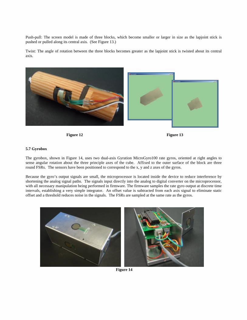
Push-pull: The screen model is made of three blocks, which become smaller or larger in size as the lapjoint stick is pushed or pulled along its central axis. (See Figure 13.) Twist: The angle of rotation between the three blocks becomes greater as the lapjoint stick is twisted about its central axis.
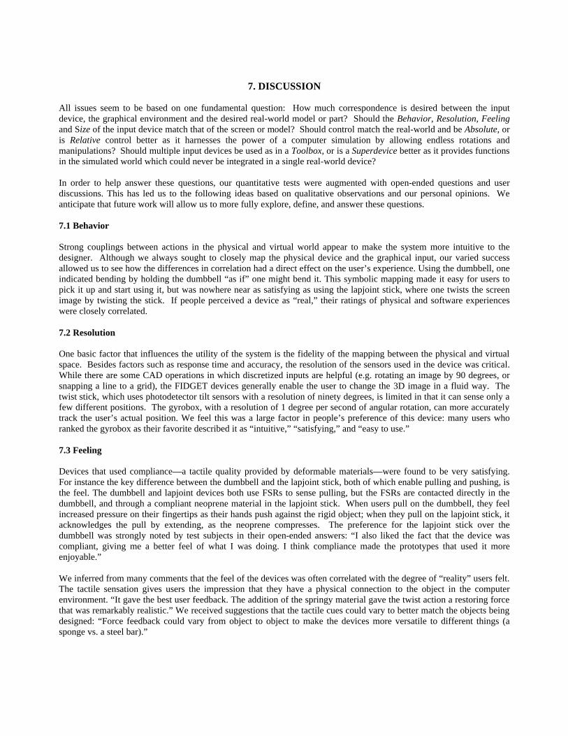
Figure 12 Figure 13 5.7 Gyrobox The gyrobox, shown in Figure 14, uses two dual-axis Gyration MicroGyro100 rate gyros, oriented at right angles to sense angular rotation about the three principle axes of the cube. Affixed to the outer surface of the block are three round FSRs. The sensors have been positioned to correspond to the x, y and z axes of the gyros. Because the gyro’s output signals are small, the microprocessor is located inside the device to reduce interference by shortening the analog signal paths. The signals input directly into the analog to digital converter on the microprocessor, with all necessary manipulation being performed in firmware. The firmware samples the rate gyro output at discrete time intervals, establishing a very simple integrator. An offset value is subtracted from each axis signal to eliminate static offset and a threshold reduces noise in the signals. The FSRs are sampled at the same rate as the gyros.
Figure 14

3D Rotate: As the gyrobox is rotated, a block image on screen rotates correspondingly. Gyro signals are incremental, so the device doesn’t reference itself to an absolute position. This means that over time, there can be drift between the onscreen image and the actual device; however, the correlation is quite close. XYZ Compress: When an FSR on the face of the gyrobox is pushed, the onscreen block will shrink in the direction perpendicular to that face. This feature was added to the gyrobox as an example of integration between separate functions - object orientation and object deformation. 5.8 Turntable Digitizer In the digitizer shown in Figure 15, the object rests on a rotating turntable, and the digitizer arm is made up of two links connected to a stationary base. The user takes data along a vertical plane, and then rotates the turntable to reach other planes. Commercially available digitizers generally use three linked arms to touch a stationary object; user experience reveals that this setup makes it difficult to reach around objects and hit embedded points. The digitizer is constructed using rotational potentiometers, each of which measures the angle between two members— the turntable relative to the base plate, the lower arm relative to the base plate, and the upper arm relative to the lower arm. The device also includes a push-button, mounted at the tip of the digitizer. When users wish to collect data, they position the digitizer tip appropriately and push the button to select the point.
Figure 15 Figure 16 Plot 3D Points: This program plots each selected point in 3D space. The current position of the digitizer tip in 3D space is always visible on the screen, indicated by a red dot. When the user presses the button, the red dot changes to blue and stays permanently on the image. To plot points, the program first translates the 0-5V signals from the potentiometers into angles; it then calculates XYZ point locations using trigonometry. After several points are plotted, the outer form of the object will become more visually clear. In a later stage of the project, a spline function could be used to create lines and surfaces through the points. Figure 16 shows examples of digitizer outputs. In the left image, the button is pushed while the digitizer arm is held in a constant position and the turntable is rotated. On the right, the digitizer tip is moved to several positions, contacting the sides of a block mounted to the turntable, and the button is pushed at each position. The surface interpolated from these points should match the original outer surface.

6.0 USER FEEDBACK After informally testing our devices throughout the design process, our formal user feedback came from a series of tests conducted after the devices were built and fully integrated. The test subjects were 20 students and alumni including experienced CAD users and graphic designers, novice CAD designers, and people with little technical computing experience. Each test session began with a short explanation of the project. We chose eight of the ten devices for the study in which participants played with each device and gave feedback in a standard survey, with questions including: ?? Which prototype was your favorite? (choose one) ?? Why was this your favorite device? (open-ended answer) ?? Which prototype was your least favorite? (choose one) ?? Why was this your least favorite device? (open-ended answer) ?? Please give us any additional feedback about these prototypes. (open-ended answer) The results of the preference questions roughly corresponded with our informal results - the most favored device was the gyrobox, with other votes going to the lapjoint stick, digitizer, and zoom stick. The least favored devices were the dumbbell and XY joystick, with other votes going to the zoom stick and twist stick. The open-ended answers strongly influenced our design insights. User bias was apparent in people’s preferences: some people embrace familiarity, while others appreciate novelty. When people used devices that fit with their set of existing CAD skills (e.g. zoom, pan, rotate) they could sometimes appreciate their usefulness more easily than that of devices with new functionality (e.g. twist, bend). Meanwhile, others dismissed familiar devices like the XY joystick, saying that they don’t add anything conceptually and had better commercial counterparts.
1 2 3 4 5 6 7 8 Dumbbell Bendy Spring XY Joystick Twist Stick Zoom Stick Lapjoint Stick Gyrobox Turntable
7. DISCUSSION All issues seem to be based on one fundamental question: How much correspondence is desired between the input device, the graphical environment and the desired real-world model or part? Should the Behavior, Resolution, Feeling and Size of the input device match that of the screen or model? Should control match the real-world and be Absolute, or is Relative control better as it harnesses the power of a computer simulation by allowing endless rotations and manipulations? Should multiple input devices be used as in a Toolbox, or is a Superdevice better as it provides functions in the simulated world which could never be integrated in a single real-world device? In order to help answer these questions, our quantitative tests were augmented with open-ended questions and user discussions. This has led us to the following ideas based on qualitative observations and our personal opinions. We anticipate that future work will allow us to more fully explore, define, and answer these questions. 7.1 Behavior Strong couplings between actions in the physical and virtual world appear to make the system more intuitive to the designer. Although we always sought to closely map the physical device and the graphical input, our varied success allowed us to see how the differences in correlation had a direct effect on the user’s experience. Using the dumbbell, one indicated bending by holding the dumbbell “as if” one might bend it. This symbolic mapping made it easy for users to pick it up and start using it, but was nowhere near as satisfying as using the lapjoint stick, where one twists the screen image by twisting the stick. If people perceived a device as “real,” their ratings of physical and software experiences were closely correlated. 7.2 Resolution One basic factor that influences the utility of the system is the fidelity of the mapping between the physical and virtual space. Besides factors such as response time and accuracy, the resolution of the sensors used in the device was critical. While there are some CAD operations in which discretized inputs are helpful (e.g. rotating an image by 90 degrees, or snapping a line to a grid), the FIDGET devices generally enable the user to change the 3D image in a fluid way. The twist stick, which uses photodetector tilt sensors with a resolution of ninety degrees, is limited in that it can sense only a few different positions. The gyrobox, with a resolution of 1 degree per second of angular rotation, can more accurately track the user’s actual position. We feel this was a large factor in people’s preference of this device: many users who ranked the gyrobox as their favorite described it as “intuitive,” “satisfying,” and “easy to use.” 7.3 Feeling Devices that used compliance—a tactile quality provided by deformable materials—were found to be very satisfying. For instance the key difference between the dumbbell and the lapjoint stick, both of which enable pulling and pushing, is the feel. The dumbbell and lapjoint devices both use FSRs to sense pulling, but the FSRs are contacted directly in the dumbbell, and through a compliant neoprene material in the lapjoint stick. When users pull on the dumbbell, they feel increased pressure on their fingertips as their hands push against the rigid object; when they pull on the lapjoint stick, it acknowledges the pull by extending, as the neoprene compresses. The preference for the lapjoint stick over the dumbbell was strongly noted by test subjects in their open-ended answers: “I also liked the fact that the device was compliant, giving me a better feel of what I was doing. I think compliance made the prototypes that used it more enjoyable.” We inferred from many comments that the feel of the devices was often correlated with the degree of “reality” users felt. The tactile sensation gives users the impression that they have a physical connection to the object in the computer environment. “It gave the best user feedback. The addition of the springy material gave the twist action a restoring force that was remarkably realistic.” We received suggestions that the tactile cues could vary to better match the objects being designed: “Force feedback could vary from object to object to make the devices more versatile to different things (a sponge vs. a steel bar).”
7.4 Scale In the physical world, small finger movements correspond to minor adjustments, while large arm movements correspond to more dramatic physical change; in the virtual world, small and large movements are not tied to these physical correlations. Allowing a large movement to control a small change enables finer physical control of the change, and using a small change to control a large movement means that changes can be made more quickly. In general, large motions feel good because they are interactive; the challenge is in finding the scale of the motion that’s most comfortable. Small repetitive and restricted movements such as mouse-clicking and typing cause discomfort over time, while motions that are too large may cause users to move around more than may be practical while using a desktop computer. The scale of motion that feels most intuitive may be related to the scale of the object being designed 7.5 Relative Versus Absolute Users had more trouble imagining an interface between the device and the CAD program for the devices which used a direct mapping between the state of the physical device and the state of the computer model—where if the device returned to its starting position, so did the object in the virtual space. Pragmatically, if designers make improvements, they want to be able to keep them after they put down the tool. For this reason, there needs to be an affordance to uncouple the real and virtual worlds, so that actions in the virtual world might “unlatch” at the moment that the desired position has been reached. In some of our later prototypes, particularly the digitizer, we accomplish this latching and unlatching through the use of buttons which acted similar to a virtual clutch. 7.6 Multiple Versus Single Devices We built our devices to illustrate individual modalities, with the intention of integrating them in the future. The integration could combine all functionalities into a “superdevice,” or it could make a tool set of separately functioning devices. The superdevice method offers the convenience of having all functionality in one place, but conceptually it is cluttered: mappings between the function and the object start to become unclear. The tool set is reminiscent of traditional physical design, where each physical tool has a different purpose, but using a different tool for each transformation is encumbering to the design process. We believe that the solution is to have multiple superdevices, with different form factors and sensing capabilities that evoke their different metaphoric roles. For instance, one might have devices that act as the object(s) being modeled, and another set of devices that act as tools, and yet another tablet device that acts as the coordinate space. Each device needs to have sensors appropriate to their form and function; the tool device needs to understand things like pressure and grip, and the object device needs to map the tool’s actions to a spatial location, and all these devices need to understand their orientation. Another advantage to using sets of tools, is that the individual input devices must be spread out over a worksurface. In this way, the user can equate mode information in a spatial fashion: “When I want to cut, I reach way over to the left where I keep the razor blade and the scissors”. In this way, a mental model of expected action is intimately tied with a physical memory of the workspace – our muscle memory becomes part of our thinking. This is distinct from the confusion (or simply the break in the train of thought) which can result from standard graphical interfaces in which the user can become ‘lost’ and forget which mode or layer the system is in. Specific tools also allow the user to physically train for a specific task, as opposed to a more general purpose superdevice. We suspect that the feeling of satisfaction which is often expressed by craftspeople, is linked to the exercise of fine control, or finesse, which is required to precisely executing a manual task toward the realization of a design idea.
8. FUTURE WORK In this project, we mapped out the range of possible physical affordances in a handheld input device, and mapped these affordances to appropriate actions in graphical interface environments. We prototyped over 8 physical input devices to better understand what factors matter in the design of such inventions. The wide range of prototype devices built shows
the flexibility of the embedded system architecture, communication protocol and graphical environment selected. Each individual prototype explores the application of some sensor to some mode of physical input through the FIDGET device. This early exploratory development lays the groundwork for ongoing research in the realm of physical input devices for graphical interfaces. The initial prototype work helps show how different sensors can be used and mapped into the virtual space; future work can build upon these insights to develop integrated devices with a larger range of possible inputs. The hardware designs we have built should enable future devices to be created with minimal need to change hardware or firmware, allowing designers to focus on integrating new sensors and on the device design. Among the additional areas that may be explored in the realm of FIDGET devices are haptic feedback, the enabling of multiple serial channels for interacting devices, and wireless communications. Last, but not least, the utility of the FIDGETs ultimately lies in the hands of the designer who uses them to create something else. Therefore, it is crucial that future work in the creation of FIDGET devices include further user testing to isolate useful combinations of forms and modalities for different applications.
ACKNOWLEDGMENTS We would like to thank Edward Carryer for his continuous advice and support, and Andreas Simon and Bill Verplank. Our work was greatly aided by hardware and support generously provided by Gyration, Inc., and was developed at the Smart Product Design Laboratory. This research is made possible by a grant from Stanford University’s Media X program and the Omron Corporation.
REFRENCES 1. Balakrishnan, R., G. Fitzmaurice, G. Kurtenbach, & W. Buxton. Digital tape drawing. Proc. of UIST, pp.161-169,
1999. 2. Fitzmaurice, G. and Buxton, W. (1997). An Empirical Evaluation of Graspable User Interfaces: towards specialized,
space-multiplexed input. Proceedings of the ACM Conference on Human Factors in Computing Systems (CHI'97). 43-50.
3. Galyean T., J.F. Hughes. Sculpting: An Interactive Volumetric Modeling Technique. Proc. of SIGGRAPH, vol. 25(4), pp. 267-274, 1991.
4. Hinckley, K., Pausch, R., Goble, J. C., Kassell, N. F., A Survey of Design Issues in Spatial Input, Proc. ACM UIST'94 Symposium on User Interface Software & Technology, April 1994, pp. 213-222.
5. Measurand Corporation. http://www.measurand.com/products/shapetape.html 6. Piper B., C. Ratti, and H. Ishii. Illuminating clay: a 3-D tangible interface for landscape analysis, in Proc. of CHI,
ACM Press, pp. 355-362, 2002. 7. Proce55ing, http://www.proce55ing.net 8. Ullmer, B. and Ishii, H. (2000). Emerging Framework for Tangible User Interface, in IBM System Journal Vol.39
NO. 3&4, IBM, pp 915-931. 9. 3Dconnexion, Inc. http://www.3dconnexion.com/ 10. G. Williams, H. Faste, I. McDowall, M. Bolas, Physical Presence – Palettes in Virtual Spaces, SPIE 3639-46, San
Jose California, 1999 11. L. Cutler, B. Frohlich, P. Hanrahan, Two-Handed Direct Manipulation on the Responsive Workbench, Symposium
on Interactive 3D Graphics, 1997. 12. K. Hinkley, Haptic Issues for Virtual Manipulation, PhD Thesis, University of Virginia, 1995
Related Documents