arXiv:cond-mat/0511113v3 [cond-mat.other] 31 Jan 2006 Intense slow beams of bosonic potassium isotopes J. Catani ∗,1 , P. Maioli, L. De Sarlo, F. Minardi 1,2 and M. Inguscio 1,2 LENS - European Laboratory for Non-Linear Spectroscopy and Dipartimento di Fisica, Universit`a di Firenze, via N. Carrara 1, I-50019 Sesto Fiorentino - Firenze, Italy 1 INFN, via G. Sansone 1, I-50019 Sesto Fiorentino - Firenze, Italy 2 CNR-INFM, via G. Sansone 1, I-50019 Sesto Fiorentino - Firenze, Italy (Dated: February 2, 2008) We report on an experimental realization of a two-dimensional magneto-optical trap (2D-MOT) that allows the generation of cold atomic beams of 39 K and 41 K bosonic potassium isotopes. The high measured fluxes up to 1.0 × 10 11 atoms/s and low atomic velocities around 33 m/s are well suited for a fast and reliable 3D-MOT loading, a basilar feature for new generation experiments on Bose-Einstein condensation of dilute atomic samples. We also present a simple multilevel theoretical model for the calculation of the light-induced force acting on an atom moving in a MOT. The model gives a good agreement between predicted and measured flux and velocity values for our 2D-MOT. PACS numbers: 32.80.Pj, 33.80.Ps, 42.50.Vk, 07.77.Gx, 03.75.Be I. INTRODUCTION In the field of atomic physics, experiments and theo- retical studies on degenerate mixtures of cold gases have been acquiring a growing interest in the last few years. The vast majority of works have featured Fermi-Bose mixtures, that have now been realized with several com- binations of atoms: 6 Li- 7 Li [1], 6 Li- 23 Na [2], 40 K- 87 Rb [3], 6 Li- 87 Rb [4]. Many experiments focused on the de- generate Fermi gas, while the bosonic component has only been a tool to reach Fermi degeneracy via sympa- thetic cooling. Remarkable achievements include BCS- BEC crossover [5, 6, 7, 8, 9, 10], fermionic Bloch os- cillations [11], observation of the 3D Fermi surface [12]. Besides, Fermi-Bose systems display a wealth of inter- esting phenomena genuinely related to the presence of F'=3 462 MHz F'=2 F'=1 F'=0 4 P 3/2 766.7 nm F=2 F=1 34 MHz d 1 d 2 d 2 d 2 w 2 d 2 w 1 39 K 93.3% 41 K 6.7% F'=3 254 MHz F'=2 F'=1 F'=0 F=2 F=1 17 MHz d 1 d 2 d 2 d 2 w 2 d 2 w 1 236 MHz 4 P 3/2 4 S 1/2 4 S 1/2 13 MHz 4 MHz FIG. 1: Level diagrams for 39 K and 41 K. In the upper part of the diagram is shown the natural abundance of both isotopes. two species. A few, like interspecies Fano-Feshbach res- onances [13, 14, 15] and boson-induced collapse of the Fermi gas [16, 17], have already been observed but many more have been proposed and still await experimental confirmation, as e.g. boson-induced superfluidity [18] and mixed phases in optical lattices [19]. On the other hand, Bose-Bose mixtures have remained relatively unexplored: after the pioneering work on 41 K- 87 Rb [20], to our knowledge only one other double-specie condensate has been recently produced, namely 174 Yb- 176 Yb [21]. As for the K-Rb mixture, the recent pre- cise determination of the interspecies scattering length by Feshbach spectroscopy [22] promises a rich phase- diagram for the two species loaded in an optical lattice. In view of an experiment on a K-Rb Bose-Bose mixture we realized and characterized an intense, slow beam of cold bosonic potassium isotopes. An intense and reliable source of cold atoms repre- sents a favorable starting point for every degenerate mixture experiment. Two-dimensional magneto-optical traps (2D-MOTs) of rubidium have been investigated by several groups [23, 24] and represent one of the bright- est sources of slow atoms. With an appropriate double- chamber vacuum system, the 2D-MOT provides high atomic flux through a small aperture between the two chambers. Therefore, it appears perfectly suited for load- ing an ordinary 3D-MOT in ultra-high vacuum (UHV) environment, the most widely used pre-cooling stage to- wards quantum degeneracy of dilute gases. In this work we demonstrate an efficient 2D-MOT for bosonic potassium isotopes 39 K and 41 K, starting from a natural abundance sample. Previously, only a 2D-MOT of fermionic 40 K has been implemented [17], while for bosonic isotopes no bright sources have been realized. The peculiarity of bosonic potassium is the tight hyper- fine structure of the D 2 line excited state 4 2 P 3/2 [25, 26]: as shown in Fig. 1, the separation between hyperfine lev- els is comparable to the transition linewidth, Γ = 2π ×6.2 MHz. This feature represents the main physical differ- ence with respect to almost all other alkalis (exception

Welcome message from author
This document is posted to help you gain knowledge. Please leave a comment to let me know what you think about it! Share it to your friends and learn new things together.
Transcript
arX
iv:c
ond-
mat
/051
1113
v3 [
cond
-mat
.oth
er]
31
Jan
2006
Intense slow beams of bosonic potassium isotopes
J. Catani∗,1, P. Maioli, L. De Sarlo, F. Minardi1,2 and M. Inguscio1,2
LENS - European Laboratory for Non-Linear Spectroscopy and Dipartimento di Fisica,
Universita di Firenze, via N. Carrara 1, I-50019 Sesto Fiorentino - Firenze, Italy1INFN, via G. Sansone 1, I-50019 Sesto Fiorentino - Firenze, Italy
2CNR-INFM, via G. Sansone 1, I-50019 Sesto Fiorentino - Firenze, Italy
(Dated: February 2, 2008)
We report on an experimental realization of a two-dimensional magneto-optical trap (2D-MOT)that allows the generation of cold atomic beams of 39K and 41K bosonic potassium isotopes. Thehigh measured fluxes up to 1.0 × 10¹¹ atoms/s and low atomic velocities around 33 m/s are wellsuited for a fast and reliable 3D-MOT loading, a basilar feature for new generation experiments onBose-Einstein condensation of dilute atomic samples. We also present a simple multilevel theoreticalmodel for the calculation of the light-induced force acting on an atom moving in a MOT. The modelgives a good agreement between predicted and measured flux and velocity values for our 2D-MOT.
PACS numbers: 32.80.Pj, 33.80.Ps, 42.50.Vk, 07.77.Gx, 03.75.Be
I. INTRODUCTION
In the field of atomic physics, experiments and theo-retical studies on degenerate mixtures of cold gases havebeen acquiring a growing interest in the last few years.The vast majority of works have featured Fermi-Bosemixtures, that have now been realized with several com-binations of atoms: 6Li-7Li [1], 6Li-23Na [2], 40K-87Rb[3], 6Li-87Rb [4]. Many experiments focused on the de-generate Fermi gas, while the bosonic component hasonly been a tool to reach Fermi degeneracy via sympa-thetic cooling. Remarkable achievements include BCS-BEC crossover [5, 6, 7, 8, 9, 10], fermionic Bloch os-cillations [11], observation of the 3D Fermi surface [12].Besides, Fermi-Bose systems display a wealth of inter-esting phenomena genuinely related to the presence of
F'=3
462 MHz
F'=2
F'=1
F'=0
4 P3/2
766.7 nm
F=2
F=1
34 MHz
d1
d2
d2
d2
w2
d2
w1
39
K
93.3%
41
K
6.7%
F'=3
254 MHz
F'=2
F'=1
F'=0
F=2
F=1
17 MHz
d1
d2
d2
d2
w2
d2
w1
236 MHz
4 P3/2
4 S1/2
4 S1/2
13 MHz 4 MHz
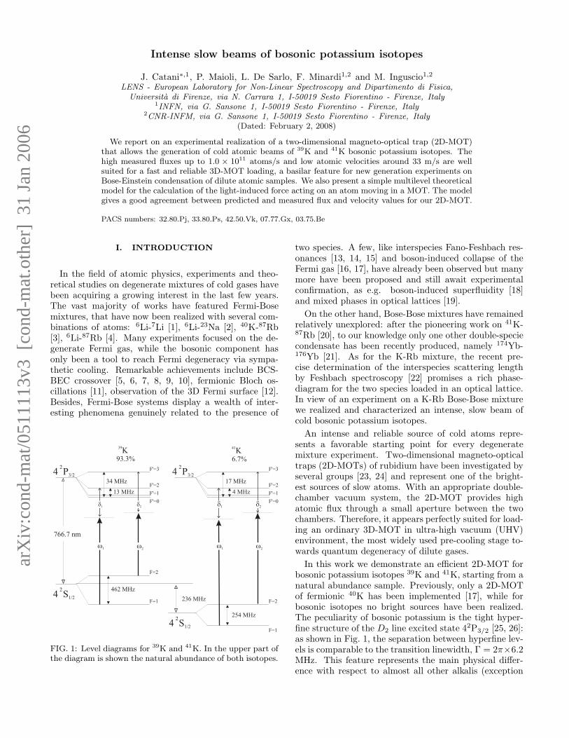
FIG. 1: Level diagrams for 39K and 41K. In the upper part ofthe diagram is shown the natural abundance of both isotopes.
two species. A few, like interspecies Fano-Feshbach res-onances [13, 14, 15] and boson-induced collapse of theFermi gas [16, 17], have already been observed but manymore have been proposed and still await experimentalconfirmation, as e.g. boson-induced superfluidity [18]and mixed phases in optical lattices [19].
On the other hand, Bose-Bose mixtures have remainedrelatively unexplored: after the pioneering work on 41K-87Rb [20], to our knowledge only one other double-speciecondensate has been recently produced, namely 174Yb-176Yb [21]. As for the K-Rb mixture, the recent pre-cise determination of the interspecies scattering lengthby Feshbach spectroscopy [22] promises a rich phase-diagram for the two species loaded in an optical lattice.In view of an experiment on a K-Rb Bose-Bose mixturewe realized and characterized an intense, slow beam ofcold bosonic potassium isotopes.
An intense and reliable source of cold atoms repre-sents a favorable starting point for every degeneratemixture experiment. Two-dimensional magneto-opticaltraps (2D-MOTs) of rubidium have been investigated byseveral groups [23, 24] and represent one of the bright-est sources of slow atoms. With an appropriate double-chamber vacuum system, the 2D-MOT provides highatomic flux through a small aperture between the twochambers. Therefore, it appears perfectly suited for load-ing an ordinary 3D-MOT in ultra-high vacuum (UHV)environment, the most widely used pre-cooling stage to-wards quantum degeneracy of dilute gases.
In this work we demonstrate an efficient 2D-MOT forbosonic potassium isotopes 39K and 41K, starting from anatural abundance sample. Previously, only a 2D-MOTof fermionic 40K has been implemented [17], while forbosonic isotopes no bright sources have been realized.The peculiarity of bosonic potassium is the tight hyper-fine structure of the D2 line excited state 42P3/2 [25, 26]:as shown in Fig. 1, the separation between hyperfine lev-els is comparable to the transition linewidth, Γ = 2π×6.2MHz. This feature represents the main physical differ-ence with respect to almost all other alkalis (exception
2
MOT beams
MOT beams
Push beam
Plugbeam
Probebeam
MOT
coils
Mirror
Atomic
beam
σ+
σ-
xy
z
σ-
σ+
to UHVchamber
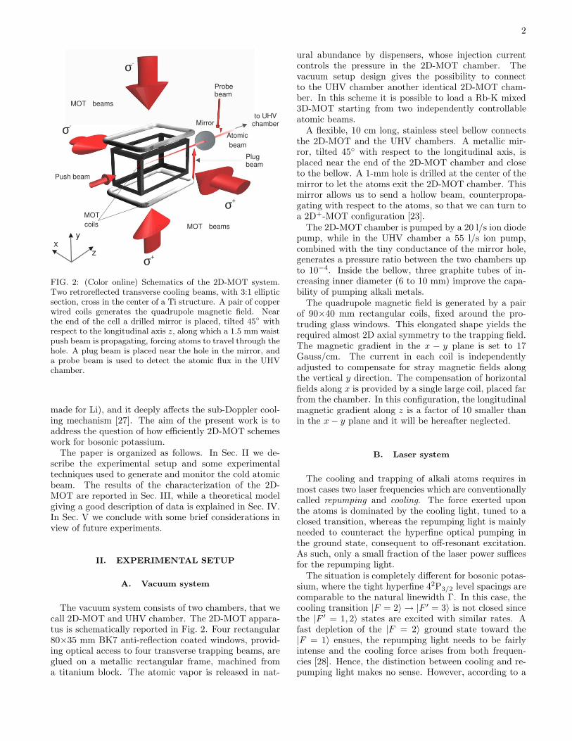
FIG. 2: (Color online) Schematics of the 2D-MOT system.Two retroreflected transverse cooling beams, with 3:1 ellipticsection, cross in the center of a Ti structure. A pair of copperwired coils generates the quadrupole magnetic field. Nearthe end of the cell a drilled mirror is placed, tilted 45◦ withrespect to the longitudinal axis z, along which a 1.5 mm waistpush beam is propagating, forcing atoms to travel through thehole. A plug beam is placed near the hole in the mirror, anda probe beam is used to detect the atomic flux in the UHVchamber.
made for Li), and it deeply affects the sub-Doppler cool-ing mechanism [27]. The aim of the present work is toaddress the question of how efficiently 2D-MOT schemeswork for bosonic potassium.
The paper is organized as follows. In Sec. II we de-scribe the experimental setup and some experimentaltechniques used to generate and monitor the cold atomicbeam. The results of the characterization of the 2D-MOT are reported in Sec. III, while a theoretical modelgiving a good description of data is explained in Sec. IV.In Sec. V we conclude with some brief considerations inview of future experiments.
II. EXPERIMENTAL SETUP
A. Vacuum system
The vacuum system consists of two chambers, that wecall 2D-MOT and UHV chamber. The 2D-MOT appara-tus is schematically reported in Fig. 2. Four rectangular80×35 mm BK7 anti-reflection coated windows, provid-ing optical access to four transverse trapping beams, areglued on a metallic rectangular frame, machined froma titanium block. The atomic vapor is released in nat-
ural abundance by dispensers, whose injection currentcontrols the pressure in the 2D-MOT chamber. Thevacuum setup design gives the possibility to connectto the UHV chamber another identical 2D-MOT cham-ber. In this scheme it is possible to load a Rb-K mixed3D-MOT starting from two independently controllableatomic beams.
A flexible, 10 cm long, stainless steel bellow connectsthe 2D-MOT and the UHV chambers. A metallic mir-ror, tilted 45◦ with respect to the longitudinal axis, isplaced near the end of the 2D-MOT chamber and closeto the bellow. A 1-mm hole is drilled at the center of themirror to let the atoms exit the 2D-MOT chamber. Thismirror allows us to send a hollow beam, counterpropa-gating with respect to the atoms, so that we can turn toa 2D+-MOT configuration [23].
The 2D-MOT chamber is pumped by a 20 l/s ion diodepump, while in the UHV chamber a 55 l/s ion pump,combined with the tiny conductance of the mirror hole,generates a pressure ratio between the two chambers upto 10−4. Inside the bellow, three graphite tubes of in-creasing inner diameter (6 to 10 mm) improve the capa-bility of pumping alkali metals.
The quadrupole magnetic field is generated by a pairof 90×40 mm rectangular coils, fixed around the pro-truding glass windows. This elongated shape yields therequired almost 2D axial symmetry to the trapping field.The magnetic gradient in the x − y plane is set to 17Gauss/cm. The current in each coil is independentlyadjusted to compensate for stray magnetic fields alongthe vertical y direction. The compensation of horizontalfields along x is provided by a single large coil, placed farfrom the chamber. In this configuration, the longitudinalmagnetic gradient along z is a factor of 10 smaller thanin the x − y plane and it will be hereafter neglected.
B. Laser system
The cooling and trapping of alkali atoms requires inmost cases two laser frequencies which are conventionallycalled repumping and cooling. The force exerted uponthe atoms is dominated by the cooling light, tuned to aclosed transition, whereas the repumping light is mainlyneeded to counteract the hyperfine optical pumping inthe ground state, consequent to off-resonant excitation.As such, only a small fraction of the laser power sufficesfor the repumping light.
The situation is completely different for bosonic potas-sium, where the tight hyperfine 42P3/2 level spacings arecomparable to the natural linewidth Γ. In this case, thecooling transition |F = 2〉 → |F ′ = 3〉 is not closed sincethe |F ′ = 1, 2〉 states are excited with similar rates. Afast depletion of the |F = 2〉 ground state toward the|F = 1〉 ensues, the repumping light needs to be fairlyintense and the cooling force arises from both frequen-cies [28]. Hence, the distinction between cooling and re-pumping light makes no sense. However, according to a
3
(a)
(b)
sf
d
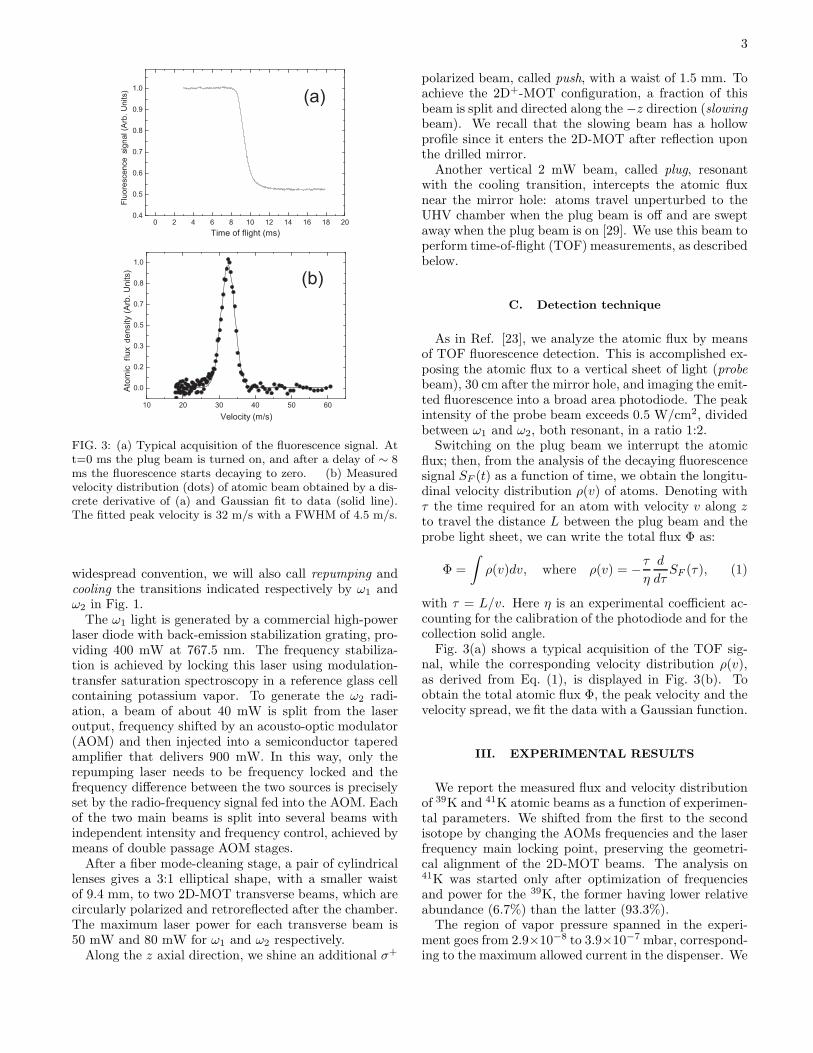
FIG. 3: (a) Typical acquisition of the fluorescence signal. Att=0 ms the plug beam is turned on, and after a delay of ∼ 8ms the fluorescence starts decaying to zero. (b) Measuredvelocity distribution (dots) of atomic beam obtained by a dis-crete derivative of (a) and Gaussian fit to data (solid line).The fitted peak velocity is 32 m/s with a FWHM of 4.5 m/s.
widespread convention, we will also call repumping andcooling the transitions indicated respectively by ω1 andω2 in Fig. 1.
The ω1 light is generated by a commercial high-powerlaser diode with back-emission stabilization grating, pro-viding 400 mW at 767.5 nm. The frequency stabiliza-tion is achieved by locking this laser using modulation-transfer saturation spectroscopy in a reference glass cellcontaining potassium vapor. To generate the ω2 radi-ation, a beam of about 40 mW is split from the laseroutput, frequency shifted by an acousto-optic modulator(AOM) and then injected into a semiconductor taperedamplifier that delivers 900 mW. In this way, only therepumping laser needs to be frequency locked and thefrequency difference between the two sources is preciselyset by the radio-frequency signal fed into the AOM. Eachof the two main beams is split into several beams withindependent intensity and frequency control, achieved bymeans of double passage AOM stages.
After a fiber mode-cleaning stage, a pair of cylindricallenses gives a 3:1 elliptical shape, with a smaller waistof 9.4 mm, to two 2D-MOT transverse beams, which arecircularly polarized and retroreflected after the chamber.The maximum laser power for each transverse beam is50 mW and 80 mW for ω1 and ω2 respectively.
Along the z axial direction, we shine an additional σ+
polarized beam, called push, with a waist of 1.5 mm. Toachieve the 2D+-MOT configuration, a fraction of thisbeam is split and directed along the −z direction (slowingbeam). We recall that the slowing beam has a hollowprofile since it enters the 2D-MOT after reflection uponthe drilled mirror.
Another vertical 2 mW beam, called plug, resonantwith the cooling transition, intercepts the atomic fluxnear the mirror hole: atoms travel unperturbed to theUHV chamber when the plug beam is off and are sweptaway when the plug beam is on [29]. We use this beam toperform time-of-flight (TOF) measurements, as describedbelow.
C. Detection technique
As in Ref. [23], we analyze the atomic flux by meansof TOF fluorescence detection. This is accomplished ex-posing the atomic flux to a vertical sheet of light (probebeam), 30 cm after the mirror hole, and imaging the emit-ted fluorescence into a broad area photodiode. The peakintensity of the probe beam exceeds 0.5 W/cm2, dividedbetween ω1 and ω2, both resonant, in a ratio 1:2.
Switching on the plug beam we interrupt the atomicflux; then, from the analysis of the decaying fluorescencesignal SF (t) as a function of time, we obtain the longitu-dinal velocity distribution ρ(v) of atoms. Denoting withτ the time required for an atom with velocity v along zto travel the distance L between the plug beam and theprobe light sheet, we can write the total flux Φ as:
Φ =
∫
ρ(v)dv, where ρ(v) = −τ
η
d
dτSF (τ), (1)
with τ = L/v. Here η is an experimental coefficient ac-counting for the calibration of the photodiode and for thecollection solid angle.
Fig. 3(a) shows a typical acquisition of the TOF sig-nal, while the corresponding velocity distribution ρ(v),as derived from Eq. (1), is displayed in Fig. 3(b). Toobtain the total atomic flux Φ, the peak velocity and thevelocity spread, we fit the data with a Gaussian function.
III. EXPERIMENTAL RESULTS
We report the measured flux and velocity distributionof 39K and 41K atomic beams as a function of experimen-tal parameters. We shifted from the first to the secondisotope by changing the AOMs frequencies and the laserfrequency main locking point, preserving the geometri-cal alignment of the 2D-MOT beams. The analysis on41K was started only after optimization of frequenciesand power for the 39K, the former having lower relativeabundance (6.7%) than the latter (93.3%).
The region of vapor pressure spanned in the experi-ment goes from 2.9×10⁻⁸ to 3.9×10⁻⁷ mbar, correspond-ing to the maximum allowed current in the dispenser. We
4
41K
20 30 40 50 60 70 80
20
30
40
50
Cooling beams power (mW)
Rep
umpi
ng b
eam
s po
wer
(mW
)
0
0.1
0.2
0.3
0.4
0.5
0.6
0.7
0.8
0.9
1.0
(b)
4.5 5.0 5.5 6.0 6.5 7.03.0
3.5
4.0
4.5
5.0 (a)
Cooling beams detuning (- )
Rep
umpi
ng b
eam
s de
tuni
ng (-
)
00.10.20.20.30.40.50.60.70.70.80.91.0
30 40 50 60 70 80
20
25
30
35
40
45
Cooling beams power (mW)
Rep
umpi
ng b
eam
s po
wer
(mW
)
0
0.1
0.2
0.3
0.4
0.5
0.6
0.7
0.8
0.9
1.0
(d)
1.5 2.0 2.5 3.0 3.5 4.0 4.5
1.0
1.5
2.0
2.5
3.0
3.5
Cooling beams detuning (- )
Rep
umpi
ng b
eam
s de
tuni
ng (-
)
0
0.1
0.2
0.3
0.4
0.5
0.6
0.7
0.8
0.9
1.0(c)
39K
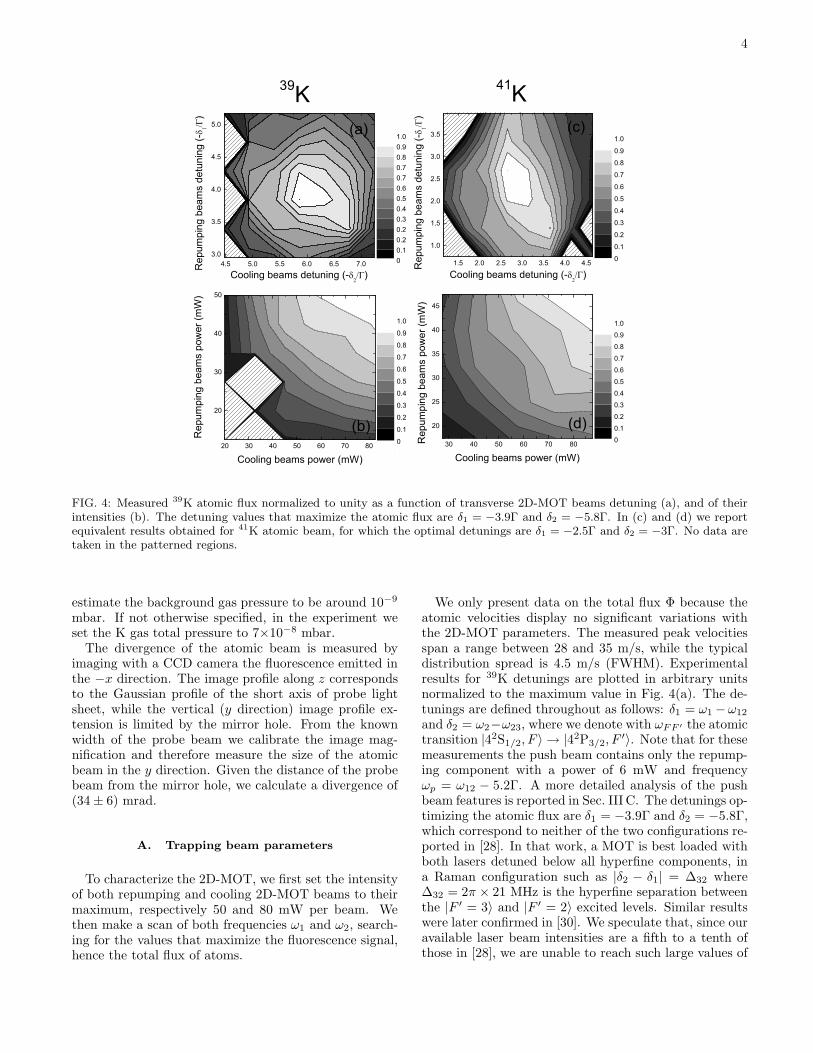
FIG. 4: Measured 39K atomic flux normalized to unity as a function of transverse 2D-MOT beams detuning (a), and of theirintensities (b). The detuning values that maximize the atomic flux are δ1 = −3.9Γ and δ2 = −5.8Γ. In (c) and (d) we reportequivalent results obtained for 41K atomic beam, for which the optimal detunings are δ1 = −2.5Γ and δ2 = −3Γ. No data aretaken in the patterned regions.
estimate the background gas pressure to be around 10−9
mbar. If not otherwise specified, in the experiment weset the K gas total pressure to 7×10⁻⁸ mbar.
The divergence of the atomic beam is measured byimaging with a CCD camera the fluorescence emitted inthe −x direction. The image profile along z correspondsto the Gaussian profile of the short axis of probe lightsheet, while the vertical (y direction) image profile ex-tension is limited by the mirror hole. From the knownwidth of the probe beam we calibrate the image mag-nification and therefore measure the size of the atomicbeam in the y direction. Given the distance of the probebeam from the mirror hole, we calculate a divergence of(34 ± 6) mrad.
A. Trapping beam parameters
To characterize the 2D-MOT, we first set the intensityof both repumping and cooling 2D-MOT beams to theirmaximum, respectively 50 and 80 mW per beam. Wethen make a scan of both frequencies ω1 and ω2, search-ing for the values that maximize the fluorescence signal,hence the total flux of atoms.
We only present data on the total flux Φ because theatomic velocities display no significant variations withthe 2D-MOT parameters. The measured peak velocitiesspan a range between 28 and 35 m/s, while the typicaldistribution spread is 4.5 m/s (FWHM). Experimentalresults for 39K detunings are plotted in arbitrary unitsnormalized to the maximum value in Fig. 4(a). The de-tunings are defined throughout as follows: δ1 = ω1 −ω12
and δ2 = ω2−ω23, where we denote with ωFF ′ the atomictransition |42S1/2, F 〉 → |42P3/2, F
′〉. Note that for thesemeasurements the push beam contains only the repump-ing component with a power of 6 mW and frequencyωp = ω12 − 5.2Γ. A more detailed analysis of the pushbeam features is reported in Sec. III C. The detunings op-timizing the atomic flux are δ1 = −3.9Γ and δ2 = −5.8Γ,which correspond to neither of the two configurations re-ported in [28]. In that work, a MOT is best loaded withboth lasers detuned below all hyperfine components, ina Raman configuration such as |δ2 − δ1| = ∆32 where∆32 = 2π × 21 MHz is the hyperfine separation betweenthe |F ′ = 3〉 and |F ′ = 2〉 excited levels. Similar resultswere later confirmed in [30]. We speculate that, since ouravailable laser beam intensities are a fifth to a tenth ofthose in [28], we are unable to reach such large values of
5
2 3 4 5 6 71
10
100
Pre
ssure
(10
-8m
bar)
Dispenser current (A)
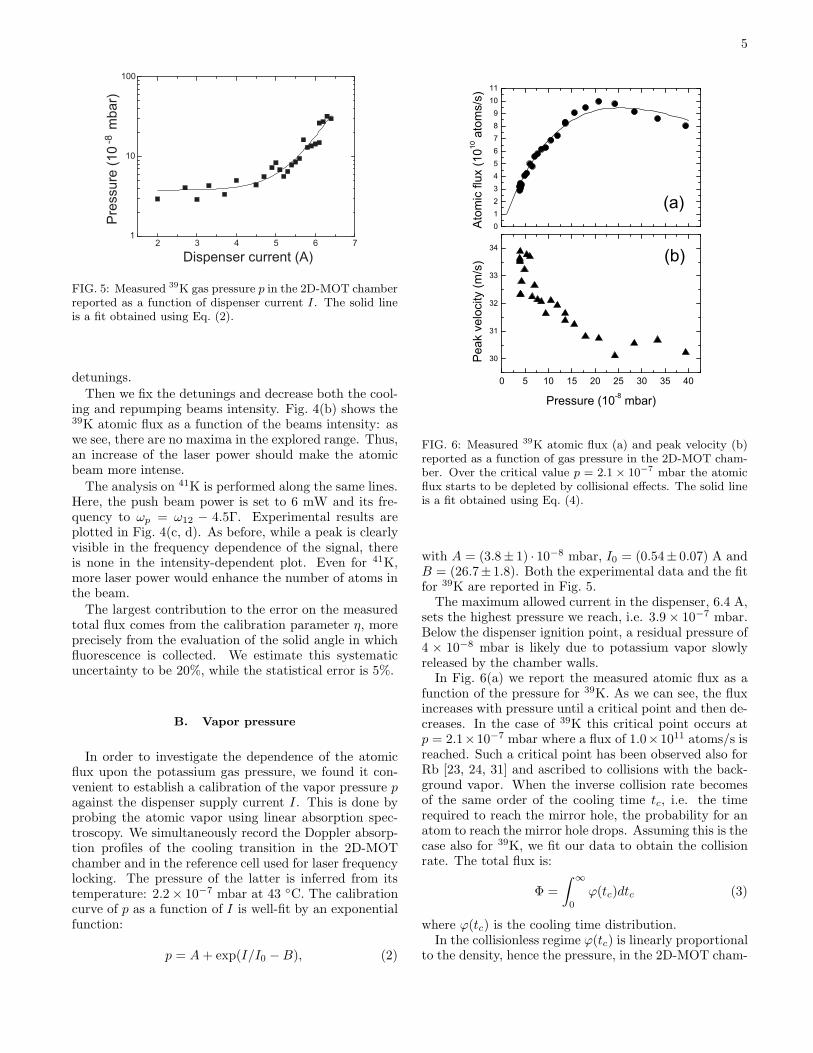
FIG. 5: Measured 39K gas pressure p in the 2D-MOT chamberreported as a function of dispenser current I . The solid lineis a fit obtained using Eq. (2).
detunings.Then we fix the detunings and decrease both the cool-
ing and repumping beams intensity. Fig. 4(b) shows the39K atomic flux as a function of the beams intensity: aswe see, there are no maxima in the explored range. Thus,an increase of the laser power should make the atomicbeam more intense.
The analysis on 41K is performed along the same lines.Here, the push beam power is set to 6 mW and its fre-quency to ωp = ω12 − 4.5Γ. Experimental results areplotted in Fig. 4(c, d). As before, while a peak is clearlyvisible in the frequency dependence of the signal, thereis none in the intensity-dependent plot. Even for 41K,more laser power would enhance the number of atoms inthe beam.
The largest contribution to the error on the measuredtotal flux comes from the calibration parameter η, moreprecisely from the evaluation of the solid angle in whichfluorescence is collected. We estimate this systematicuncertainty to be 20%, while the statistical error is 5%.
B. Vapor pressure
In order to investigate the dependence of the atomicflux upon the potassium gas pressure, we found it con-venient to establish a calibration of the vapor pressure pagainst the dispenser supply current I. This is done byprobing the atomic vapor using linear absorption spec-troscopy. We simultaneously record the Doppler absorp-tion profiles of the cooling transition in the 2D-MOTchamber and in the reference cell used for laser frequencylocking. The pressure of the latter is inferred from itstemperature: 2.2 × 10⁻⁷ mbar at 43 ◦C. The calibrationcurve of p as a function of I is well-fit by an exponentialfunction:
p = A + exp(I/I0 − B), (2)
0 5 10 15 20 25 30 35 40
30
31
32
33
34
01234567891011
(a)
Pea
k ve
loci
ty (m
/s)
Pressure (10-8 mbar)
(b)
Ato
mic
flux
(1010
ato
ms/
s)
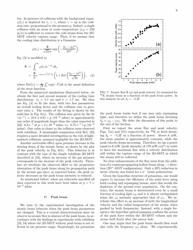
FIG. 6: Measured 39K atomic flux (a) and peak velocity (b)reported as a function of gas pressure in the 2D-MOT cham-ber. Over the critical value p = 2.1 × 10⁻⁷ mbar the atomicflux starts to be depleted by collisional effects. The solid lineis a fit obtained using Eq. (4).
with A = (3.8± 1) · 10−8 mbar, I0 = (0.54± 0.07) A andB = (26.7±1.8). Both the experimental data and the fitfor 39K are reported in Fig. 5.
The maximum allowed current in the dispenser, 6.4 A,sets the highest pressure we reach, i.e. 3.9 × 10⁻⁷ mbar.Below the dispenser ignition point, a residual pressure of4 × 10−8 mbar is likely due to potassium vapor slowlyreleased by the chamber walls.
In Fig. 6(a) we report the measured atomic flux as afunction of the pressure for 39K. As we can see, the fluxincreases with pressure until a critical point and then de-creases. In the case of 39K this critical point occurs atp = 2.1×10⁻⁷ mbar where a flux of 1.0×10¹¹ atoms/s isreached. Such a critical point has been observed also forRb [23, 24, 31] and ascribed to collisions with the back-ground vapor. When the inverse collision rate becomesof the same order of the cooling time tc, i.e. the timerequired to reach the mirror hole, the probability for anatom to reach the mirror hole drops. Assuming this is thecase also for 39K, we fit our data to obtain the collisionrate. The total flux is:
Φ =
∫ ∞
0
ϕ(tc)dtc (3)
where ϕ(tc) is the cooling time distribution.In the collisionless regime ϕ(tc) is linearly proportional
to the density, hence the pressure, in the 2D-MOT cham-
6
ber. In presence of collisions with the background vapor,ϕ(tc) is depleted for tc > γ, where γ = κp is the colli-sion rate, proportional to the pressure p. Indeed, a singlecollision with an atom at room temperature (vth = 250m/s) is sufficient to remove the cold atoms from the 2D-MOT velocity capture range. Then, if we assume thatthe cooling time distribution is a Gaussian
ϕ(tc) =Φ√2πσ
exp
(
− (tc − t0)2
2σ2
)
,
Eq. (3) is modified to
Φ =
∫ ∞
0
ϕ(tc)e−γtcdtc
=Φ
2e−γt0+γ2σ2/2
(
1 + Erf
(
t0 − γσ2
√2σ
))
, (4)
where Erf(x) = 2√π
∫ x
0exp(−t2)dt is the usual definition
of the error function.From the numerical simulations illustrated below, we
obtain the first and second moment of the cooling timedistribution: t0 = 5.1 ms and σ = 1.7 ms. We thenuse Eq. (4) to fit the data, with two free parameters:an overall scaling factor and the collision rate to pres-sure ratio κ. The results of the fitting is shown by thesolid line in Fig. 6(a). The collision rate given by the fitγ(s−1) = (8.6 ± 0.6) × p (10−8 mbar) is approximatelyone order of magnitude larger than the value reported in[32]: 0.3 s−1 at p = 4×10⁻⁹ mbar, i.e. 0.75 s−1×p (10−8
mbar). Our value is closer to the collision rates observedwith rubidium. A meaningful comparison with Ref. [32]requires a more detailed investigation on the role of light-assisted collisions, assumed negligible for the 2D-MOT.
Another noticeable effect upon pressure increase is theslowing down of the atomic beam, as shown by the plotof the peak velocity in Fig. 6(b). This behavior is incontrast with the case of the simple rubidium 2D-MOTdescribed in [24], where an increase of the gas pressurecorresponds to the increase of the peak velocity. There-fore we attribute the observed effect to the progressiveabsorption of the push beam along its propagation pathby the atomic gas since, as reported below, the peak ve-locity decreases as the push beam intensity is reduced.
As mentioned before, when not otherwise specified alldata reported in this work have been taken at p = 7 ×10⁻⁸ mbar.
C. Push beam
We turn to the experimental investigation of theatomic beam behavior when the push beam parametersare changed. This is a crucial characterization since weobserve no atomic flux in absence of the push beam, in ac-cordance with the findings in experiments with rubidium[23, 24] where the 2D-MOT without push beam is not ef-ficient in our pressure range. Surprisingly, for potassium
1 2 3 4 5 6 7 8 9
22
24
26
28
30
32
34
36
0.0
0.2
0.4
0.6
0.8
1.0
1.2
Pea
k ve
loci
ty (m
/s)
Push beam power (mW)
(b)
Ato
mic
flux
(arb
. uni
ts)
(a)
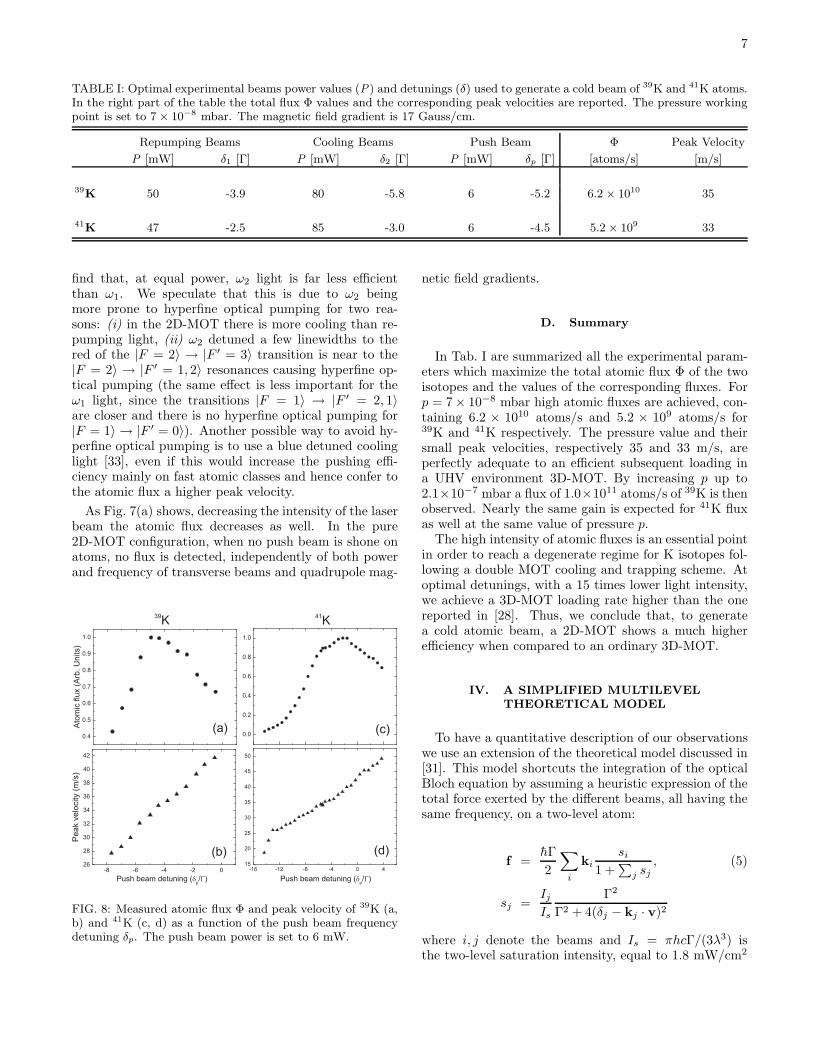
FIG. 7: Atomic flux Φ (a) and peak velocity (b) measured for39K atomic beam as a function of the push beam power. Inthis analysis we set δp = −5.2Γ.
the push beam works best if one uses only repumpinglight, and therefore we define the push beam detuningδp = ωp − ω12. We defer the discussion of this point tothe end of the Section.
First we report the atom flux and peak velocity,Figs. 7(a) and 7(b) respectively, for 39K at fixed detun-ing δp = −5.2Γ as a function of power. Above 6 mW,the atom number is approximately constant, while thepeak velocity keeps increasing. Therefore, we use a powerequal to 6 mW (peak intensity of 170 mW/cm2) in orderto have the maximum flux with a velocity distributionstill within the capture range of the 3D-MOT in whichthe atoms will be collected.
No clear enhancements of the flux stem from the addi-tion of a counterpropagating hollow beam along −z direc-tion (2D+-MOT configuration). Only a 20% reduction inmean velocity was found for a σ− beam polarization.
Given the hyperfine structure of potassium, one wouldexpect to increase the efficiency of the push force usingboth cooling and repumping beams, since this avoids thedepletion of the ground state population. On the con-trary, the atomic beam is deteriorated even by a smallfraction of cooling light ω2 and it is almost extinguishedwhen the ω2 intensity approaches that of ω1. We at-tribute this effect to an increase of both the longitudinalvelocity and the radial temperature of the atoms, whenpushed by both frequencies. Instead, with a single fre-quency the hyperfine optical pumping confines the actionof the push force within the 2D-MOT volume and theatoms drift freely after the mirror hole.
One may argue that the push beam should then workalso with the frequency ω2 alone. We experimentally
7
TABLE I: Optimal experimental beams power values (P) and detunings (δ) used to generate a cold beam of 39K and 41K atoms.In the right part of the table the total flux Φ values and the corresponding peak velocities are reported. The pressure workingpoint is set to 7 × 10⁻⁸ mbar. The magnetic field gradient is 17 Gauss/cm.
Repumping Beams Cooling Beams Push Beam Φ Peak Velocity
P [mW] δ1 [Γ] P [mW] δ2 [Γ] P [mW] δp [Γ] [atoms/s] [m/s]
39K 50 -3.9 80 -5.8 6 -5.2 6.2 × 10¹⁰ 35
41K 47 -2.5 85 -3.0 6 -4.5 5.2 × 10⁹ 33
find that, at equal power, ω2 light is far less efficientthan ω1. We speculate that this is due to ω2 beingmore prone to hyperfine optical pumping for two rea-sons: (i) in the 2D-MOT there is more cooling than re-pumping light, (ii) ω2 detuned a few linewidths to thered of the |F = 2〉 → |F ′ = 3〉 transition is near to the|F = 2〉 → |F ′ = 1, 2〉 resonances causing hyperfine op-tical pumping (the same effect is less important for theω1 light, since the transitions |F = 1〉 → |F ′ = 2, 1〉are closer and there is no hyperfine optical pumping for|F = 1〉 → |F ′ = 0〉). Another possible way to avoid hy-perfine optical pumping is to use a blue detuned coolinglight [33], even if this would increase the pushing effi-ciency mainly on fast atomic classes and hence confer tothe atomic flux a higher peak velocity.
As Fig. 7(a) shows, decreasing the intensity of the laserbeam the atomic flux decreases as well. In the pure2D-MOT configuration, when no push beam is shone onatoms, no flux is detected, independently of both powerand frequency of transverse beams and quadrupole mag-
39K
41K
(a)
(b)
(c)
(d)
FIG. 8: Measured atomic flux Φ and peak velocity of 39K (a,b) and 41K (c, d) as a function of the push beam frequencydetuning δp. The push beam power is set to 6 mW.
netic field gradients.
D. Summary
In Tab. I are summarized all the experimental param-eters which maximize the total atomic flux Φ of the twoisotopes and the values of the corresponding fluxes. Forp = 7 × 10⁻⁸ mbar high atomic fluxes are achieved, con-taining 6.2 × 10¹⁰ atoms/s and 5.2 × 10⁹ atoms/s for39K and 41K respectively. The pressure value and theirsmall peak velocities, respectively 35 and 33 m/s, areperfectly adequate to an efficient subsequent loading ina UHV environment 3D-MOT. By increasing p up to2.1×10−7 mbar a flux of 1.0×10¹¹ atoms/s of 39K is thenobserved. Nearly the same gain is expected for 41K fluxas well at the same value of pressure p.
The high intensity of atomic fluxes is an essential pointin order to reach a degenerate regime for K isotopes fol-lowing a double MOT cooling and trapping scheme. Atoptimal detunings, with a 15 times lower light intensity,we achieve a 3D-MOT loading rate higher than the onereported in [28]. Thus, we conclude that, to generatea cold atomic beam, a 2D-MOT shows a much higherefficiency when compared to an ordinary 3D-MOT.
IV. A SIMPLIFIED MULTILEVEL
THEORETICAL MODEL
To have a quantitative description of our observationswe use an extension of the theoretical model discussed in[31]. This model shortcuts the integration of the opticalBloch equation by assuming a heuristic expression of thetotal force exerted by the different beams, all having thesame frequency, on a two-level atom:
f =hΓ
2
∑
i
kisi
1 +∑
j sj, (5)
sj =Ij
Is
Γ2
Γ2 + 4(δj − kj · v)2
where i, j denote the beams and Is = πhcΓ/(3λ3) isthe two-level saturation intensity, equal to 1.8 mW/cm2
8
for potassium D2 line. Authors of Ref. [31] employ thismodel to analyze a 3D-MOT of Rb with the addition ofa push beam. The extension of this treatment to bosonicpotassium, because of the narrow upper level structure,requires to take into account all the allowed hyperfinetransitions. For this purpose, we introduce the furtherassumption that forces arising from different transitionsadd independently. This consistently disregards coher-ences among the two 4S1/2 hyperfine states, which how-ever play no role in the Doppler cooling mechanism. Inprinciple, we should consider even the Zeeman structureof the hyperfine levels; in practice, to reduce the numberof transitions contributing to the total force, we calculatethe detunings and the line strength in a manner to aver-age out the Zeeman sublevels. For each laser beam i andeach transition |F 〉 → |F ′〉, we define the average detun-
ing ∆FF ′
i as the center-of-mass of all the Zeeman com-ponents weighted by the squared Clebsch-Gordan coeffi-cients |c(F ′, m′; 1, σi, F, m)|2, where σi denotes the beampolarization (all beams are circularly polarized with theMOT required helicity). This detuning depends linearlyon the displacement from the 2D-MOT axis via the mag-netic field gradient. We then define the strength of eachhyperfine transition:
GFF ′
i =
∑
m,m′ |c(F ′, m′; 1, σi, F, m)|2∑
F ′,m,m′ |c(F ′, m′; 1, σi, F, m)|2 .
We incorporate hyperfine optical pumping by break-ing the force into two parts, due to the cooling and therepumping light, weighted by the relative populations inthe F = 2 and F = 1 ground levels. Therefore, theexpression (5) of the total force is generalized as follows:
f =p1
p1 + p2
f1 +p2
p1 + p2
f2 (6)
fF =hΓ
2
∑
i
kisi,F
1 + sF, F = 1, 2 (7)
with
si,F =Ii,F
2Is
∑
F ′
GFF ′
i
Γ2
Γ2 + 4(
δi,F − ki · v − ∆FF ′
i
)2,
where sF =∑
j sj . Here, Ii,1, Ii,2 are respectively therepumping and cooling intensity of the i-th beam, andδ1, δ2 the corresponding detunings as defined earlier. Thepopulations p1, p2 are taken as the equilibrium values ofthe rate equations for the six hyperfine components.
A. Numerical Simulations
A numerical integration of the classical equations ofmotion yields the phase-space trajectories. We consideronly the atoms that, at t = 0, lie on the boundary surface
(a)
(b)
(c)
(d)
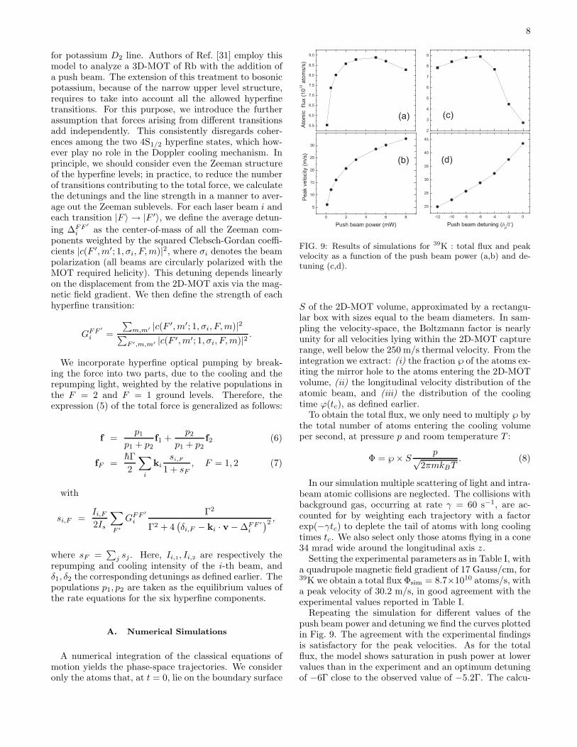
FIG. 9: Results of simulations for 39K : total flux and peakvelocity as a function of the push beam power (a,b) and de-tuning (c,d).
S of the 2D-MOT volume, approximated by a rectangu-lar box with sizes equal to the beam diameters. In sam-pling the velocity-space, the Boltzmann factor is nearlyunity for all velocities lying within the 2D-MOT capturerange, well below the 250 m/s thermal velocity. From theintegration we extract: (i) the fraction ℘ of the atoms ex-iting the mirror hole to the atoms entering the 2D-MOTvolume, (ii) the longitudinal velocity distribution of theatomic beam, and (iii) the distribution of the coolingtime ϕ(tc), as defined earlier.
To obtain the total flux, we only need to multiply ℘ bythe total number of atoms entering the cooling volumeper second, at pressure p and room temperature T :
Φ = ℘ × Sp√
2πmkBT. (8)
In our simulation multiple scattering of light and intra-beam atomic collisions are neglected. The collisions withbackground gas, occurring at rate γ = 60 s−1, are ac-counted for by weighting each trajectory with a factorexp(−γtc) to deplete the tail of atoms with long coolingtimes tc. We also select only those atoms flying in a cone34 mrad wide around the longitudinal axis z.
Setting the experimental parameters as in Table I, witha quadrupole magnetic field gradient of 17 Gauss/cm, for39K we obtain a total flux Φsim = 8.7×10¹⁰ atoms/s, witha peak velocity of 30.2 m/s, in good agreement with theexperimental values reported in Table I.
Repeating the simulation for different values of thepush beam power and detuning we find the curves plottedin Fig. 9. The agreement with the experimental findingsis satisfactory for the peak velocities. As for the totalflux, the model shows saturation in push power at lowervalues than in the experiment and an optimum detuningof −6Γ close to the observed value of −5.2Γ. The calcu-
9
lated dependence of atomic flux on push beam power anddetuning reproduces only qualitatively the experimentalcurves of Figs. 6(a) and 7(a). We believe that coherenteffects ignored in our simulations are likely responsiblefor the discrepancies with data. A more exact analysisbased on the integration of optical Bloch equations isneeded to address these issues but is beyond the scope ofour simplified model.
V. CONCLUSIONS AND OUTLOOK
The main conclusion of this work is that, similar to ru-bidium, potassium atoms can be coaxed into an intenseand cold beam, still preserving the UHV constraints. Re-cently, we have used two separate 2D-MOT beams to loada double-specie K/Rb MOT in the UHV chamber as apreliminary step towards quantum degenerate Bose-Bosemixtures. The combination of potassium and rubidiumoffers a wealth of possibilities to tune the interspeciesinteractions via Feshbach resonances [22]. Broad Fano-Feshbach resonances are predicted for 39K-87Rb and 41K-
87Rb in the absolute ground state at 318 G and 515 G,respectively. For 39K, sympathetic cooling with Rb canbe a route to single condensates with tunable interac-tions, where resonances are expected around 40 G for twoatoms in the magnetically trapped state |F = 1, m = −1〉[34] and around 20 G for the absolute ground state [35].
An exciting perspective is to tune interactions in thepresence of an optical lattice, where a rich diagram ofinsulating and superfluid phases is predicted when theinterspecies scattering length is varied [36]. Also, assuggested in [37], entering the Mott-insulator regime forboth species paves the way to Feshbach-associated long-lived bosonic heteronuclear molecules, since three-bodylosses can be suppressed by tailoring the Mott phase tohave one atom per species in each lattice site.
This work had financial support from Ente Cassa diRisparmio in Firenze and from Istituto Nazionale diFisica Nucleare through project SQUAT. We warmlythank P. Clade for his help, G. Modugno for many fruitfulsuggestions, C. Fort and all the members of the QuantumDegenerate Gas group at LENS for discussions.
[*] E-mail address: [email protected]
[1] F. Schreck, L. Khaykovich, K. L. Corwin, G. Ferrari, T.Bourdel, J. Cubizolles, and C. Salomon, Phys. Rev. Lett.87, 080403 (2001).
[2] Z. Hadzibabic, C.A. Stan, K. Dieckmann, S. Gupta,M.W. Zwierlein, A. Gorlitz, and W. Ketterle, Phys. Rev.Lett. 88, 160401 (2002).
[3] G. Roati, F. Riboli, G. Modugno, and M. Inguscio, Phys.Rev. Lett. 89, 150403 (2002).
[4] C. Silber, S. Gunther, C. Marzok, B. Deh, Ph.W.Courteille, and C. Zimmermann, Phys. Rev. Lett. 95,170408 (2005).
[5] T. Bourdel, L. Khaykovich, J. Cubizolles, J. Zhang, F.Chevy, M. Teichmann, L. Tarruell, S.J.J.M.F. Kokkel-mans, and C. Salomon, Phys. Rev. Lett. 93, 050401(2004).
[6] C. Chin, M. Bartenstein, A. Altmeyer, S. Riedl, S.Jochim, J. Hecker Denschlag, R. Grimm, Science 1128,305 (2004).
[7] C. A. Regal, M. Greiner, D. S. Jin, Phys. Rev. Lett. 92,040403 (2004).
[8] G.B. Partridge, K.E. Strecker, R.I. Kamar, M.W. Jack,and R.G. Hulet, Phys. Rev. Lett. 95, 020404 (2005).
[9] J. Kinast, S. L. Hemmer, M. E. Gehm, A. Turlapov, andJ.E. Thomas, Phys. Rev. Lett. 92, 150402 (2004).
[10] M. W. Zwierlein, J. R. Abo-Shaeer, A. Schirotzek, C. H.Schunck, and W. Ketterle, Nature 435, 1047 (2005).
[11] G. Roati, E. de Mirandes, F. Ferlaino, H. Ott, G. Mod-ugno, and M. Inguscio, Phys. Rev. Lett. 92, 230402(2004).
[12] M. Kohl, H. Moritz, T. Stoferle, K. Gunter, and T.Esslinger, Phys. Rev. Lett. 94, 080403 (2005).
[13] A. Simoni, F. Ferlaino, G. Roati, G. Modugno, and M.Inguscio, Phys. Rev. Lett. 90, 163202 (2003).
[14] S. Inouye, J. Goldwin, M. L. Olsen, C. Ticknor, J. L.
Bohn, and D. S. Jin, Phys. Rev. Lett. 93, 183201 (2004).[15] C. A. Stan, M.W. Zwierlein, C. H. Schunck, S.M. F.
Raupach, and W. Ketterle, Phys. Rev. Lett. 93, 143001(2004).
[16] G. Modugno, G. Roati, F. Riboli, F. Ferlaino, R. J.Brecha, and M. Inguscio, Science 297, 2240 (2002).
[17] C. Ospelkaus, S. Ospelkaus, K. Sengstock, and K. Bongs,Phys. Rev. Lett. 96, 020401 (2006).
[18] L. Viverit, C. J. Pethick, and H. Smith, Phys. Rev. A61, 053605 (2000).
[19] M. Lewenstein, L. Santos, M. A. Baranov, and H.Fehrmann, Phys. Rev. Lett. 92, 050401 (2004).
[20] G. Modugno, M. Modugno, F. Riboli, G. Roati, and M.Inguscio, Phys. Rev. Lett 89, 190404 (2002).
[21] Y. Takahashi, private communication.[22] F. Ferlaino, C. D’Errico, G. Roati, M. Zaccanti, M. In-
guscio, G. Modugno, and A. Simoni, cond-mat/0510630(2005).
[23] K. Dieckmann, R. J. C. Spreeuw, M. Weidemuller, andJ. T. M. Walraven, Phys. Rev. A 58, 3891 (1998).
[24] J. Schoser, A. Batar, R. Low, V. Schweikhard, A.Grabowski, Yu. B. Ovchinnikov, and T. Pfau, Phys. Rev.A 66, 023410 (2002).
[25] E. Arimondo, M. Inguscio, and P. Violino, Rev. Mod.Phys. 49, 31 (1977).
[26] A. Sieradzan, P. Kulatunga, and M. Havey, Phys. Rev.A 52, 4447 (1995).
[27] A. Bambini and A. Agresti, Phys. Rev. A 56, 3040(1997).
[28] C. Fort, A Bambini, L. Cacciapuoti, F. S. Cataliotti, M.Prevedelli, G. M. L. Tino, and M. Inguscio, Eur. Phys.J. D 3, 113 (1998).
[29] P. A. Molenaar, P. van der Straten, H. G. M. Heidemanand H. Metcalf, Phys. Rev. A 55, 605 (1997).
[30] M. Prevedelli, F. S. Cataliotti, E.A. Cornell, J.R. Ensher,

10
C. Fort, L. Ricci, G. M. L. Tino, and M. Inguscio, Phys.Rev. A 59, 886 (1999).
[31] W. Wohlleben, F. Chevy, K. Madison, and J. Dalibard,Eur. Phys. J. D 15, 237 (2001).
[32] R. S. Williamson III, and T.Walker, J. Opt. Soc. Am. B12, 1393 (1995).
[33] T. B. Swanson, D. Asgeirsson, J. A. Behr, A. Gorelov,and D. Melconian, J. Opt. Soc. Am. B 15, 2641 (1998).
[34] J. L. Bohn, J. P. Burke, C. H. Greene, H. Wang, P.
L. Gould, and W. C. Stwalley, Phys. Rev. A. 59, 3660(1999).
[35] E. Tiesinga, private communication.[36] G.-P. Zheng, J.-Q. Liang, and W. M. Liu, Phys. Rev. A
71, 053608 (2005).[37] B. Damski, L. Santos, E. Tiemann, M. Lewenstein, S.
Kotochigova, P. Julienne, and P. Zoller, Phys. Rev. Lett.90, 110401 (2003).
Related Documents